US12042613B2 - Balloon catheter - Google Patents
Balloon catheterDownload PDFInfo
- Publication number
- US12042613B2 US12042613B2US17/137,614US202017137614AUS12042613B2US 12042613 B2US12042613 B2US 12042613B2US 202017137614 AUS202017137614 AUS 202017137614AUS 12042613 B2US12042613 B2US 12042613B2
- Authority
- US
- United States
- Prior art keywords
- projection
- balloon
- tip
- end side
- lesion
- Prior art date
- Legal status (The legal status is an assumption and is not a legal conclusion. Google has not performed a legal analysis and makes no representation as to the accuracy of the status listed.)
- Active, expires
Links
- 230000003902lesionEffects0.000description73
- 210000004204blood vesselAnatomy0.000description11
- 229920001971elastomerPolymers0.000description6
- 239000000806elastomerSubstances0.000description6
- 238000004519manufacturing processMethods0.000description6
- 238000000034methodMethods0.000description6
- 239000004952PolyamideSubstances0.000description5
- 230000000694effectsEffects0.000description5
- 239000012530fluidSubstances0.000description5
- 229920002647polyamidePolymers0.000description5
- 239000000463materialSubstances0.000description4
- 229920005989resinPolymers0.000description4
- 239000011347resinSubstances0.000description4
- 230000008901benefitEffects0.000description3
- 238000000071blow mouldingMethods0.000description3
- 230000002308calcificationEffects0.000description3
- -1polyethylenePolymers0.000description3
- 239000004642PolyimideSubstances0.000description2
- 238000002399angioplastyMethods0.000description2
- 238000004891communicationMethods0.000description2
- 238000010586diagramMethods0.000description2
- 238000005516engineering processMethods0.000description2
- 229920001721polyimidePolymers0.000description2
- 239000004698PolyethyleneSubstances0.000description1
- 239000004743PolypropyleneSubstances0.000description1
- 229910045601alloyInorganic materials0.000description1
- 239000000956alloySubstances0.000description1
- 238000007887coronary angioplastyMethods0.000description1
- 210000004351coronary vesselAnatomy0.000description1
- 238000001125extrusionMethods0.000description1
- 210000001105femoral arteryAnatomy0.000description1
- 210000001035gastrointestinal tractAnatomy0.000description1
- KHYBPSFKEHXSLX-UHFFFAOYSA-NiminotitaniumChemical compound[Ti]=NKHYBPSFKEHXSLX-UHFFFAOYSA-N0.000description1
- 239000007769metal materialSubstances0.000description1
- 229910001000nickel titaniumInorganic materials0.000description1
- 230000002093peripheral effectEffects0.000description1
- 229920000573polyethylenePolymers0.000description1
- 229920000139polyethylene terephthalatePolymers0.000description1
- 239000005020polyethylene terephthalateSubstances0.000description1
- 229920001155polypropylenePolymers0.000description1
- 229920002635polyurethanePolymers0.000description1
- 239000004814polyurethaneSubstances0.000description1
- 210000001147pulmonary arteryAnatomy0.000description1
- 229920002379silicone rubberPolymers0.000description1
- 239000004945silicone rubberSubstances0.000description1
- 239000010935stainless steelSubstances0.000description1
- 229910001220stainless steelInorganic materials0.000description1
- 229920006345thermoplastic polyamidePolymers0.000description1
- 229920005992thermoplastic resinPolymers0.000description1
- 210000000626ureterAnatomy0.000description1
Images


Classifications
- A—HUMAN NECESSITIES
- A61—MEDICAL OR VETERINARY SCIENCE; HYGIENE
- A61B—DIAGNOSIS; SURGERY; IDENTIFICATION
- A61B17/00—Surgical instruments, devices or methods
- A61B17/22—Implements for squeezing-off ulcers or the like on inner organs of the body; Implements for scraping-out cavities of body organs, e.g. bones; for invasive removal or destruction of calculus using mechanical vibrations; for removing obstructions in blood vessels, not otherwise provided for
- A—HUMAN NECESSITIES
- A61—MEDICAL OR VETERINARY SCIENCE; HYGIENE
- A61M—DEVICES FOR INTRODUCING MEDIA INTO, OR ONTO, THE BODY; DEVICES FOR TRANSDUCING BODY MEDIA OR FOR TAKING MEDIA FROM THE BODY; DEVICES FOR PRODUCING OR ENDING SLEEP OR STUPOR
- A61M25/00—Catheters; Hollow probes
- A61M25/10—Balloon catheters
- A61M25/1002—Balloon catheters characterised by balloon shape
- A—HUMAN NECESSITIES
- A61—MEDICAL OR VETERINARY SCIENCE; HYGIENE
- A61M—DEVICES FOR INTRODUCING MEDIA INTO, OR ONTO, THE BODY; DEVICES FOR TRANSDUCING BODY MEDIA OR FOR TAKING MEDIA FROM THE BODY; DEVICES FOR PRODUCING OR ENDING SLEEP OR STUPOR
- A61M25/00—Catheters; Hollow probes
- A61M25/10—Balloon catheters
- A61M25/104—Balloon catheters used for angioplasty
- A—HUMAN NECESSITIES
- A61—MEDICAL OR VETERINARY SCIENCE; HYGIENE
- A61B—DIAGNOSIS; SURGERY; IDENTIFICATION
- A61B17/00—Surgical instruments, devices or methods
- A61B17/22—Implements for squeezing-off ulcers or the like on inner organs of the body; Implements for scraping-out cavities of body organs, e.g. bones; for invasive removal or destruction of calculus using mechanical vibrations; for removing obstructions in blood vessels, not otherwise provided for
- A61B2017/22001—Angioplasty, e.g. PCTA
- A—HUMAN NECESSITIES
- A61—MEDICAL OR VETERINARY SCIENCE; HYGIENE
- A61B—DIAGNOSIS; SURGERY; IDENTIFICATION
- A61B17/00—Surgical instruments, devices or methods
- A61B17/22—Implements for squeezing-off ulcers or the like on inner organs of the body; Implements for scraping-out cavities of body organs, e.g. bones; for invasive removal or destruction of calculus using mechanical vibrations; for removing obstructions in blood vessels, not otherwise provided for
- A61B2017/22051—Implements for squeezing-off ulcers or the like on inner organs of the body; Implements for scraping-out cavities of body organs, e.g. bones; for invasive removal or destruction of calculus using mechanical vibrations; for removing obstructions in blood vessels, not otherwise provided for with an inflatable part, e.g. balloon, for positioning, blocking, or immobilisation
- A—HUMAN NECESSITIES
- A61—MEDICAL OR VETERINARY SCIENCE; HYGIENE
- A61M—DEVICES FOR INTRODUCING MEDIA INTO, OR ONTO, THE BODY; DEVICES FOR TRANSDUCING BODY MEDIA OR FOR TAKING MEDIA FROM THE BODY; DEVICES FOR PRODUCING OR ENDING SLEEP OR STUPOR
- A61M25/00—Catheters; Hollow probes
- A61M25/10—Balloon catheters
- A61M25/1002—Balloon catheters characterised by balloon shape
- A61M2025/1004—Balloons with folds, e.g. folded or multifolded
- A—HUMAN NECESSITIES
- A61—MEDICAL OR VETERINARY SCIENCE; HYGIENE
- A61M—DEVICES FOR INTRODUCING MEDIA INTO, OR ONTO, THE BODY; DEVICES FOR TRANSDUCING BODY MEDIA OR FOR TAKING MEDIA FROM THE BODY; DEVICES FOR PRODUCING OR ENDING SLEEP OR STUPOR
- A61M25/00—Catheters; Hollow probes
- A61M25/10—Balloon catheters
- A61M2025/1043—Balloon catheters with special features or adapted for special applications
- A61M2025/1084—Balloon catheters with special features or adapted for special applications having features for increasing the shape stability, the reproducibility or for limiting expansion, e.g. containments, wrapped around fibres, yarns or strands
- A—HUMAN NECESSITIES
- A61—MEDICAL OR VETERINARY SCIENCE; HYGIENE
- A61M—DEVICES FOR INTRODUCING MEDIA INTO, OR ONTO, THE BODY; DEVICES FOR TRANSDUCING BODY MEDIA OR FOR TAKING MEDIA FROM THE BODY; DEVICES FOR PRODUCING OR ENDING SLEEP OR STUPOR
- A61M25/00—Catheters; Hollow probes
- A61M25/10—Balloon catheters
- A61M2025/1043—Balloon catheters with special features or adapted for special applications
- A61M2025/1086—Balloon catheters with special features or adapted for special applications having a special balloon surface topography, e.g. pores, protuberances, spikes or grooves
- A—HUMAN NECESSITIES
- A61—MEDICAL OR VETERINARY SCIENCE; HYGIENE
- A61M—DEVICES FOR INTRODUCING MEDIA INTO, OR ONTO, THE BODY; DEVICES FOR TRANSDUCING BODY MEDIA OR FOR TAKING MEDIA FROM THE BODY; DEVICES FOR PRODUCING OR ENDING SLEEP OR STUPOR
- A61M25/00—Catheters; Hollow probes
- A61M25/10—Balloon catheters
- A61M2025/1043—Balloon catheters with special features or adapted for special applications
- A61M2025/109—Balloon catheters with special features or adapted for special applications having balloons for removing solid matters, e.g. by grasping or scraping plaque, thrombus or other matters that obstruct the flow
Definitions
- the present inventionrelates to balloon catheter.
- a balloon catheterhas been used for remedies such as PTA (percutaneous transluminal angioplasty) and PTCA (percutaneous transluminal coronary angioplasty), etc.
- the balloon catheterincludes an inflatable (i.e., inflatable and deflatable) balloon on a tip-end side thereof.
- the balloon in a deflated stateis introduced into a spot narrowed or obstructed by a lesion or the like generated in a blood vessel and then the spot is stretched by inflating the balloon.
- the balloonalso includes a straight tube region having a diameter maximized during inflation and a pair of cone regions provided on a base-end side and a tip-end side of the straight tube region and reduced in diameter toward a side away from the straight tube region.
- Patent Literature 1proposes, as a countermeasure against such a case, a technology where a linear element is projectingly provided on an outer surface of the balloon. This element extends in an axial direction across the straight tube region and the cone regions of the balloon.
- the configuration of Patent Literature 1enables making a cut (crack) in the lesion with the element by inflating the balloon, so that the lesion can be broken with the cut serving as a trigger. Therefore, even in a case where the lesion is hardened, it is possible to stretch the lesion.
- a projection height of the element from the outer surface of the balloonis lower at each of the cone regions than at the straight tube region.
- a ballooncannot be introduced inside a spot narrowed by the lesion (in other words, the inside of the lesion) well.
- a straight tube region of the ballooncannot be positioned inside the lesion. Accordingly, in such a case, it is likely that only a cone region in a tapered shape on a tip-end side of the balloon (hereinafter, referred to as a tip-end cone region) is first introduced inside the lesion and the balloon is inflated. It is then likely that only a proximal side of the lesion is first stretched due to the inflation.
- One or more embodiments of the present inventionprovide a balloon catheter configured to, in a case where a lesion generated in the body is large, favorably break the lesion.
- a balloon catheter of one or more embodimentsincludes: an inflatable and deflatable balloon on a tip-end side, the balloon including a straight tube portion having a diameter maximized during inflation and a tip-end tapered portion (i.e., tip-end side tapered portion) reduced in diameter from a tip-end portion (i.e., tip end) of the straight tube portion toward the tip-end side; and a projection projectingly provided on an outer surface of the balloon and linearly extending along the outer surface, the projection including a first projection provided at the straight tube portion and a second projection provided at the tip-end tapered portion, in which at least a part of the second projection in a longitudinal direction is a high projection (i.e., high projecting part) having a larger projection amount from the outer surface than the first projection.
- a high projectioni.e., high projecting part
- the linear projection projectingly provided on the outer surface of the balloonincludes the first projection provided at the straight tube portion and the second projection provided at the tip-end tapered portion.
- at least a part of the second projection in the longitudinal directionis a high projection having a larger projection amount from the outer surface of the balloon than the first projection.
- the high projectionhas a larger width than the first projection.
- the high projectionwhich has the larger projection amount, has a larger width than the first projection. This makes it possible to keep the high projection from leaning in making a cut in a lesion with the high projection, so that a cut can be more easily made in the lesion.
- the second projectionextends in an axial direction of the balloon along an outer surface of the tip-end tapered portion, and the projection amount of the second projection is increased from a base-end side toward a tip-end side thereof, whereby at least the tip-end side is the high projection.
- the second projectionextends in the axial direction of the balloon along the outer surface of the tip-end tapered portion. Further, the projection amount of the second projection is increased from the base-end side toward the tip-end side thereof, whereby at least the tip-end side serves as the high projection.
- the above-described configurationenables the lesion to be favorably broken with the high projection provided on the tip-end side of the tip-end tapered portion.
- the projection amount of the second projectionis continuously increased from the base-end side toward the tip-end side thereof.
- a projection end portion of the second projectioncan be kept from being cornered.
- the effect of the above-described embodimentscan be achieved while keeping canal walls, etc. in the body from being damaged by the second projection.
- a width of the second projectionis increased from the base-end side toward the tip-end side thereof
- the second projectionIn making a cut in a lesion with the second projection, it is supposed that a portion with a larger projection amount is more likely to lean.
- the width of the second projectionin the configuration where the projection amount of the second projection is increased from the base-end side toward the tip-end side, the width of the second projection is increased from the base-end side toward the tip-end side.
- the second projectionin making a cut in a lesion with the second projection, the second projection can be favorably kept from leaning therethroughout in the longitudinal direction.
- the second projectionis kept from leaning by increasing the width of the second projection therethroughout in the longitudinal direction.
- This caseentails a disadvantage such as a decrease in flexibility of the balloon.
- the above-described configurationcan achieve the above-described effects while avoiding such a disadvantage.
- FIG. 1is a schematic overall side view showing a configuration of a balloon catheter.
- FIG. 2is a side view of a balloon in an inflated state and a vicinity thereof, showing the balloon and an outer tube in a longitudinal cross section.
- FIG. 3 Ais a side view showing a configuration of the balloon in the inflated state and the vicinity thereof
- FIG. 3 Bis a cross sectional view taken along an A-A line in FIG. 3 A
- FIG. 3 Cis a cross-sectional view taken along a B-B line in FIG. 3 A
- FIG. 3 Dis a cross sectional view taken along a C-C line in FIG. 3 A .
- FIG. 4 Ais a side view showing a configuration of the balloon in a deflated state and the vicinity thereof and FIG. 4 B is a cross sectional view taken along a D-D line in FIG. 4 A .
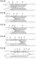
- FIGS. 5 A- 5 Eare diagrams of assistance in explaining a method of using the balloon catheter.
- FIG. 1is a schematic overall side view showing a configuration of the balloon catheter 10 .
- the balloon catheter 10includes a catheter body 11 , a hub 12 attached to a base-end portion (proximal-end portion) of the catheter body 11 , and a balloon 13 attached to a tip-end side (distal-end side) of the catheter body 11 .
- the catheter body 11includes an outer tube 15 and an inner tube 16 inserted in the outer tube 15 .
- the outer tube 15is formed of a resin material; for example, it is formed of polyamide elastomer.
- a base-end portion of the outer tube 15is bonded to the hub 12 , while a tip-end portion thereof is bonded to the balloon 13 .
- the outer tube 15has therein a lumen 15 a (see FIG. 2 ) extending therethroughout in an axial direction thereof.
- the lumen 15 ais in communication with the inside of the hub 12 while being in communication with the inside of the balloon 13 .
- the outer tube 15may be formed by bonding a plurality of tubes aligned in the axial direction to each other.
- one of the tubes on a base-end sideis formed of a metal material such as a Ni—Ti alloy or stainless steel, while one on a tip-end side is formed of a resin material such as polyamide elastomer.
- the inner tube 16is formed of a resin material; for example, it is made of polyamide elastomer.
- the inner tubehas therein a lumen 16 a (see FIG. 2 ) extending therethroughout in an axial direction thereof.
- a base-end portion of the inner tube 16is bonded at an axial middle position of the outer tube 15 , while a part of a tip-end side thereof is extended on a tip-end side relative to the outer tube 15 .
- the balloon 13is provided on the inner tube 16 , externally covering such an extended region.
- the lumen 15 a of the outer tube 15functions as a fluid lumen where a compressed fluid is to flow in inflating or deflating the balloon 13 .
- the lumen 16 a of the inner tube 16functions as a guide wire lumen where a guide wire G is to be inserted.
- a base-end opening 21 of the lumen 16 ais present at an axial middle position of the balloon catheter 10 .
- the present balloon catheter 10is thus in the form of a so-called RX catheter. It should be noted that the base-end opening 21 of the lumen 16 a may be included in a base-end portion of the balloon catheter 10 . In this case, the balloon catheter 10 is in the form of a so-called over-the-wire catheter.
- FIG. 2is a side view of the balloon 13 in an inflated state and the vicinity thereof, showing the balloon 13 and the outer tube 15 in a longitudinal cross section.
- FIG. 3 Ais a side view showing a configuration of the balloon 13 in the inflated state and the vicinity thereof
- FIG. 3 Bis a cross sectional view taken along an A-A line in FIG. 3 A
- FIG. 3 Cis a cross-sectional view taken along a B-B line in FIG. 3 A
- FIG. 3 Dis a cross sectional view taken along a C-C line in FIG. 3 A
- FIG. 4 Ais a side view showing a configuration of the balloon 13 in a deflated state and the vicinity thereof
- FIG. 4 Bis a cross sectional view taken along a D-D line in FIG. 4 A .
- the balloon 13is provided on the inner tube 16 , externally covering the extended region extended on the tip-end side relative to the outer tube 15 .
- a base-end portion of the balloon 13is bonded to the tip-end portion of the outer tube 15 , while a tip-end portion thereof is bonded to the tip-end side of the inner tube 16 .
- the balloon 13is made of a thermoplastic polyamide elastomer.
- the balloon 13may be formed of any other thermoplastic resin instead of polyamide elastomer as long as the balloon 13 can be favorably inflated and deflated with the supply and discharge of the fluid.
- itmay be formed of polyethylene, polyethylene terephthalate, polypropylene, polyurethane, polyamide, polyimide, polyimide elastomer, silicone rubber, or the like.
- the balloon 13is formed of a film 29 with a predetermined thickness.
- the balloon 13includes opposite bonded portions bonded to the catheter body 11 and an inflation/deflation portion provided between the bonded portions and that is to be inflated and deflated.
- the balloon 13includes: a base-end leg region 13 a bonded to the tip-end portion of the outer tube 15 ; a base-end cone region 13 b tapered such that the inner diameter and outer diameter of the balloon 13 are continuously increased toward the tip-end side; a straight tube region 13 c having the same inner diameter and outer diameter therethroughout in a length direction and defining a maximum outer diameter region of the balloon 13 ; a tip-end cone region 13 d tapered such that the inner diameter and outer diameter of the balloon 13 are continuously reduced toward the tip-end side; and a tip-end leg region 13 e bonded to the tip-end side of the inner tube 16 in this order from the base-end side.
- the base-end cone region 13 b , the straight tube region 13 c , and the tip-end cone region 13 dconstitute the inflation/deflation portion, while the base-end leg region 13 a and the tip-end leg region 13 e each constitute the bonded portion.
- straight tube region 13 ccorresponds to a “straight tube portion” and the tip-end cone region 13 d corresponds to a “tip-end tapered portion”.
- the balloon 13is brought into the inflated state when the compressed fluid is supplied into the balloon 13 through the lumen 15 a of the outer tube 15 and brought into the deflated state when a negative pressure is applied to the lumen 15 a to cause the compressed fluid to be discharged out of the balloon 13 .
- the balloon 13includes a plurality of (in the present embodiment, three) wings 25 formed in the deflated state. These wings 25 are provided at predetermined intervals (in particular, regular intervals) in a circumferential direction of the balloon 13 . The wings 25 are formed to extend in the axial direction at the inflation/deflation portion of the balloon 13 .
- the wings 25extend across the base-end cone region 13 b , the straight tube region 13 c , and the tip-end cone region 13 d . With the balloon 13 being in the deflated state, these wings 25 are folded in the circumferential direction of the balloon 13 , being wrapped around the inner tube 16 .
- a pair of contrast rings 23are attached to the inner tube 16 inside the balloon 13 .
- the contrast rings 23are intended to improve the visibility of the balloon 13 during x-ray projection so that the balloon 13 is easily positioned with respect to a targeted treatment spot.
- an outer surface of the balloon 13is provided with a linear projection (hereinafter, referred to as a linear projection 30 ) extending along an axial direction of the balloon 13 .
- a linear projection 30In inflating the balloon 13 to stretch a lesion, the linear projection 30 is intended to make a cut in the lesion. Even in a case where the lesion is hardened due to calcification or the like, the present balloon catheter 10 makes a cut in the lesion by virtue of the linear projection 30 , so that the lesion can be broken with the cut serving as a trigger.
- the present balloon catheter 10is thus configured as a so-called cutting balloon catheter (also referred to as a scoring balloon catheter).
- the linear projection 30continuously extends in the axial direction of the balloon from the base-end leg region 13 a to the tip-end leg region 13 e .
- the linear projection 30extends throughout each of the base-end cone region 13 b , the straight tube region 13 c , and the tip-end cone region 13 d of the balloon 13 with respect to the axial direction.
- a plurality of such linear projections 30are provided in the circumferential direction of the balloon 13 at predetermined intervals (in particular, regular intervals); in the present embodiment, three linear projections 30 are provided.
- These linear projections 30are each integrated with the balloon 13 . Further, in the present embodiment, these linear projections 30 are the same in configuration.
- the linear projections 30each have, therethroughout in a longitudinal direction thereof, a transverse cross section (in particular, a cross section perpendicular to the longitudinal direction) in a triangular shape (the same shape).
- the linear projections 30are each provided in an orientation where one of the corners thereof projects toward an outer circumferential side (radially outside) of the balloon 13 .
- the linear projections 30are each not necessarily in a triangular shape in a transverse cross section but may be in any other shape, such as a semicircular shape or a rectangular shape, in a transverse cross section.
- the linear projections 30each include a first projection 31 provided at the straight tube region 13 c , a second projection 32 provided at the tip-end cone region 13 d , and a third projection 33 provided at the base-end cone region 13 b .
- the first projection 31has a constant projection height H 1 (projection amount) from the outer surface of the balloon 13 therethroughout in the longitudinal direction.
- the first projection 31also has a constant width W 1 (see FIG. 3 C ) therethroughout in the longitudinal direction. It should be noted that the width W 1 of the first projection 31 refers to a length in a direction perpendicular to each of the longitudinal direction and projecting direction of the first projection 31 .
- a projection height H 2 (projection amount) of the second projection 32 from the outer surface of the balloonis larger than the projection height H 1 of the first projection 31 .
- the second projection 32has the projection height H 2 larger than the projection height H 1 of the first projection 31 therethroughout in the longitudinal direction.
- the whole of the second projection 32corresponds to a “high projection” in the present embodiment.
- the projection height H 2 of the second projection 32is increased from a base-end side (a straight tube region 13 c side) toward a tip-end side (a tip-end leg region 13 e side).
- the projection height H 2 of the second projection 32is continuously increased throughout the second projection 32 from the base-end side toward the tip-end side.
- a width W 2 (see FIG. 3 D ) of the second projection 32is larger than the width W 1 of the first projection 31 .
- the second projection 32has the width W 2 larger than the width W 1 of the first projection 31 therethroughout in the longitudinal direction.
- the width W 2 of the second projection 32is increased from the base-end side toward the tip-end side.
- the width W 2 of the second projection 32is continuously increased throughout the second projection 32 from the base-end side toward the tip-end side. It should be noted that the width W 2 of the second projection 32 refers to a length in a direction perpendicular to each of the longitudinal direction and projecting direction of the second projection 32 .
- the third projection 33has, therethroughout in the longitudinal direction, a projection height (projection amount) from the outer surface of the balloon 13 larger than the projection height H 1 of the first projection 31 , and the projection height is continuously increased from the tip-end side (the straight tube region 13 c side) toward the base-end side (the base-end leg region 13 a side). Further, the third projection 33 has a width larger than the width W 1 of the first projection 31 therethroughout in the longitudinal direction, and the width is continuously increased from the tip-end side toward the base-end side.
- the plurality of wings 25are formed at the inflation/deflation portion (the straight tube region 13 c and the cone regions 13 b and 13 d ) of the balloon 13 and these wings 25 are folded in the circumferential direction of the balloon 13 as described above.
- the linear projections 30 of the balloon 13which are in a one-to-one relationship with the wings 25 , are provided on the inside of the folded respective wings 25 . This causes the linear projections 30 (in particular, the majority thereof) to be externally covered by the wings 25 in the deflated state of the balloon 13 .
- a tubular parisonwhich is to be made into the balloon 13 , is produced by extrusion molding.
- the tubular parisonwhich is formed in the shape of a circular tube, has an outer circumferential surface provided with a protruding stripe extending in the axial direction.
- the tubular parisonis stretched in a length direction and then blow-molded under predetermined conditions using a mold with a cavity corresponding to the shape of the balloon 13 .
- Grooves for accommodating the protruding stripesare formed in the mold, and the tubular parison is set in the cavity with the protruding stripes accommodated in these grooves.
- the blow-moldingis then performed in such a set state.
- the tubular parisonis heated to expand within the mold (cavity).
- the tubular parisonis biaxially stretched while the protruding stripes are formed as the linear projections 30 .
- both ends of the stretched tubular parisonare cut, thus completing the manufacturing of the balloon 13 .
- the manufacturing method of the balloon 13is not necessarily limited to the above-described method but another manufacturing method may be employed.
- FIGS. 5 A- 5 Eare diagrams of assistance in explaining such a process.
- a guiding catheteris inserted through a sheath introducer inserted in a blood vessel and a tip-end opening of the guiding catheter is introduced into a coronary ostium.
- the guide wire Gis inserted through the guiding catheter and the inserted guide wire G is introduced from the coronary ostium to a peripheral site via the lesion.
- the balloon catheter 10is introduced into the guiding catheter along the guide wire G.
- the balloon 13is introduced (positioned) toward a lesion 35 while a push/pull operation is performed. It should be noted that the balloon 13 is in the deflated state during this introduction.
- the lesion 35 generated in the blood vesselis relatively large. Further, the lesion 35 is hardened due to calcification. In this case, a spot narrowed by the lesion 35 , i.e., an inner region of the lesion 35 , is considerably narrowed, so that it is assumed that the balloon 13 cannot be introduced (positioned) inside the lesion 35 well. For example, it is assumed that the straight tube region 13 c of the balloon 13 fails to be introduced inside the lesion 35 .
- the tip-end cone region 13 dwhich is in a tapered shape, of the balloon 13 is first introduced inside the lesion 35 as shown in FIG. 5 A .
- the balloon 13is then inflated in such an introduced state. This causes the second projections 32 of the tip-end cone region 13 d to be pressed against the lesion 35 as shown in FIG. 5 B , making a cut (crack) in the lesion 35 with the second projections 32 .
- the second projections 32each have the projection height H 2 larger than the projection height H 1 of each first projection 31 of the straight tube region 13 c , so that a cut can be made in the lesion 35 well with the second projections 32 . Consequently, the lesion can be favorably broken with the cut serving as a trigger. Then, as a result of the breakage of the lesion 35 , the lesion 35 can be stretched outward.
- the balloon 13is deflated.
- the balloon 13 in the deflated stateis then moved further toward the distal side (tip-end side), and the tip-end cone region 13 d of the balloon 13 is introduced inside a non-stretched portion, which has not been stretched yet, of the lesion 35 .
- the straight tube region 13 c of the balloon 13is positioned inside a cone-stretched portion, which has already been stretched by the tip-end cone region 13 d , of the lesion 35 .
- the balloon 13is then inflated again in such an introduced state of the balloon 13 .
- the non-stretched portion of the lesion 35is broken with the second projections 32 of the tip-end cone region 13 d in a similar manner as described above, and the non-stretched portion is stretched due to the breakage (see FIG. 5 D ). Further, the cone-stretched portion of the lesion 35 is stretched further outward by the straight tube region 13 c . In particular, the cone-stretched portion of the lesion 35 is broken with the first projections 31 of the straight tube region 13 c , and the cone-stretched portion is stretched further outward due to the breakage.
- Such a processcauses the non-stretched portion (and the cone-stretched portion) of the lesion 35 to be stretched sequentially from the proximal side toward the distal side. The whole of the lesion 35 is then eventually stretched by the balloon 13 as shown in FIG. 5 E .
- the balloon catheter 10is introduced through a blood vessel and mainly used for the treatment of the blood vessel such as a coronary artery, a femoral artery, or a pulmonary artery as described above, the balloon catheter 10 is also usable for any other “vessel”, such as a ureter and a gastrointestinal tract, in addition to a blood vessel and a “body cavity” in a living body.
- a blood vesselsuch as a coronary artery, a femoral artery, or a pulmonary artery
- the balloon catheter 10is also usable for any other “vessel”, such as a ureter and a gastrointestinal tract, in addition to a blood vessel and a “body cavity” in a living body.
- Each of the second projections 32(corresponding to a high projection), which has a larger projection height than each of the first projections 31 , has the width W 2 larger than the width W 1 of the first projection 31 . This makes it possible to keep the second projection 32 from leaning in making a cut in a lesion with the second projection 32 , so that a cut can be more easily made in the lesion.
- the projection height H 2 of the second projection 32is increased from the base-end side toward the tip-end side.
- the above-described configurationenables the lesion to be favorably broken with the second projection 32 provided on the tip-end side of the tip-end cone region 13 d , i.e., the tip-end side of the second projection 32 with a relatively large projection height.
- the width W 2 of the second projection 32is increased from the base-end side toward the tip-end side.
- the second projection 32in making a cut in the lesion with the second projection 32 , can be favorably kept from leaning therethroughout in the longitudinal direction.
- the second projection 32is kept from leaning by increasing the width of the second projection 32 therethroughout in the longitudinal direction. This case, however, entails a disadvantage such as a decrease in the flexibility of the balloon 13 .
- the above-described configurationcan achieve the above-described effects while avoiding such a disadvantage.
- the present inventionis not limited to the above-described embodiment but may be implemented, for example, as follows.
- the projection height H 2 of the second projection 32is continuously increased from the base-end side toward the tip-end side, but the projection height H 2 may be gradually increased from the base-end side toward the tip-end side.
- the projection height H 2 on the base-end side of the second projection 32is the same as the projection height H 1 of the first projection 31 while the projection height H 2 on the tip-end side of the second projection 32 is set at a predetermined height larger than the projection height H 1 of the first projection 31 .
- the above-described tip-end side of the second projection 32corresponds to a “high projection”.
- the projection height H 2 of the second projection 32is not necessarily increased from the base-end side toward the tip-end side and, for example, the projection height H 2 of the second projection 32 may be the same dimension (however, a dimension larger than the projection height H 1 ) throughout the second projection 32 in the longitudinal direction.
- the width W 2 of the second projection 32is continuously increased from the base-end side toward the tip-end side, but the width W 2 may be gradually increased from the base-end side toward the tip-end side. Further, the width W 2 of the second projection 32 is not necessarily increased from the base-end side toward the tip-end side and, for example, the width W 2 may be the same dimension throughout the second projection 32 in the longitudinal direction.
- the first projection 31 , the second projection 32 , and the third projection 33are provided continuously in the axial direction, but these projections 31 to 33 may be discontinuous with each other.
- the second projection 32 and the third projection 33are offset in the circumferential direction of the balloon 13 with respect to the first projection 31 .
- At least one of these projections 31 to 33may be provided such that it extends in a direction different from the axial direction along the outer surface of the balloon 13 .
- itmay be provided such that it extends in the circumferential direction of the balloon 13 .
- the linear projection 30is integrated with the balloon 13 , but a linear projection (hereinafter, referred to as a linear member) may be formed independent of the balloon 13 .
- a linear projectionhereinafter, referred to as a linear member
- the linear memberis formed of a resin material with elasticity and provided such that it straddles the balloon 13 in the axial direction on the outer circumferential side of the balloon 13 .
- the linear memberis bonded to the outer tube 15 at a base-end portion thereof while bonded to a tip-end portion of the inner tube 16 at a tip-end portion thereof.
- the linear memberis provided such that it extends in the axial direction on the outer surface of the balloon 13 when the balloon 13 is inflated.
- the linear memberprojectingly provided on the outer surface of the balloon 13 , such a configuration also enables a cut to be made in a lesion with the linear member when the balloon 13 is inflated, so that the lesion can be broken with the cut serving as a trigger.
- the above-described linear memberis provided such that it straddles the straight tube region 13 c and the cone regions 13 b and 13 d when the balloon 13 is inflated.
- the linear memberincludes a first linear portion provided on the straight tube region 13 c , a second linear portion provided on the tip-end cone region 13 d , and a third linear portion provided on the base-end cone region 13 b .
- the linear memberis formed such that a projection height of the second linear portion from the outer surface of the balloon 13 is larger than a projection height of the first linear portion.
- the lesioncan be favorably broken as in the above-described embodiment.
- the first linear portioncorresponds to a first projection and the second linear portion corresponds to a second projection.
Landscapes
- Health & Medical Sciences (AREA)
- Life Sciences & Earth Sciences (AREA)
- Heart & Thoracic Surgery (AREA)
- Animal Behavior & Ethology (AREA)
- Veterinary Medicine (AREA)
- Public Health (AREA)
- Engineering & Computer Science (AREA)
- General Health & Medical Sciences (AREA)
- Biomedical Technology (AREA)
- Pulmonology (AREA)
- Hematology (AREA)
- Anesthesiology (AREA)
- Biophysics (AREA)
- Child & Adolescent Psychology (AREA)
- Vascular Medicine (AREA)
- Surgery (AREA)
- Orthopedic Medicine & Surgery (AREA)
- Nuclear Medicine, Radiotherapy & Molecular Imaging (AREA)
- Medical Informatics (AREA)
- Molecular Biology (AREA)
- Media Introduction/Drainage Providing Device (AREA)
Abstract
Description
- Patent Literature 1: Japanese Patent Laid-Open No. 2014-506140
Claims (5)
Applications Claiming Priority (3)
| Application Number | Priority Date | Filing Date | Title |
|---|---|---|---|
| JP2018-130087 | 2018-07-09 | ||
| JP2018130087 | 2018-07-09 | ||
| PCT/JP2019/023088WO2020012850A1 (en) | 2018-07-09 | 2019-06-11 | Balloon catheter |
Related Parent Applications (1)
| Application Number | Title | Priority Date | Filing Date |
|---|---|---|---|
| PCT/JP2019/023088ContinuationWO2020012850A1 (en) | 2018-07-09 | 2019-06-11 | Balloon catheter |
Publications (2)
| Publication Number | Publication Date |
|---|---|
| US20210113820A1 US20210113820A1 (en) | 2021-04-22 |
| US12042613B2true US12042613B2 (en) | 2024-07-23 |
Family
ID=69141893
Family Applications (1)
| Application Number | Title | Priority Date | Filing Date |
|---|---|---|---|
| US17/137,614Active2041-07-27US12042613B2 (en) | 2018-07-09 | 2020-12-30 | Balloon catheter |
Country Status (8)
| Country | Link |
|---|---|
| US (1) | US12042613B2 (en) |
| EP (1) | EP3795199B1 (en) |
| JP (1) | JP6975857B2 (en) |
| KR (1) | KR102491375B1 (en) |
| CN (1) | CN112203713B (en) |
| ES (1) | ES2966107T3 (en) |
| HR (1) | HRP20231672T1 (en) |
| WO (1) | WO2020012850A1 (en) |
Families Citing this family (10)
| Publication number | Priority date | Publication date | Assignee | Title |
|---|---|---|---|---|
| US20230398335A1 (en)* | 2020-11-16 | 2023-12-14 | Kaneka Corporation | Balloon for balloon catheter |
| EP4268881A4 (en) | 2020-12-24 | 2024-11-13 | Kaneka Corporation | Balloon for balloon catheter |
| WO2022158100A1 (en)* | 2021-01-21 | 2022-07-28 | 株式会社カネカ | Balloon for balloon catheter |
| WO2022196166A1 (en)* | 2021-03-15 | 2022-09-22 | 株式会社カネカ | Balloon for balloon catheter |
| CN113476721A (en)* | 2021-07-06 | 2021-10-08 | 深圳麦普奇医疗科技有限公司 | Percutaneous nephrostomy catheter |
| WO2023032522A1 (en) | 2021-08-31 | 2023-03-09 | 株式会社グッドマン | Balloon catheter |
| JP2023070376A (en)* | 2021-11-09 | 2023-05-19 | 株式会社カネカ | balloon catheter |
| WO2024116710A1 (en)* | 2022-11-30 | 2024-06-06 | 株式会社グッドマン | Balloon catheter and method of manufacturing same |
| CN118267594A (en)* | 2022-12-29 | 2024-07-02 | 微创优通医疗科技(上海)有限公司 | A medicine sacculus inflation pipe for non-vascular intervention |
| CN118370918B (en)* | 2024-06-21 | 2024-11-08 | 鼎科医疗技术(苏州)有限公司 | Scoring saccule dilating catheter |
Citations (45)
| Publication number | Priority date | Publication date | Assignee | Title |
|---|---|---|---|---|
| US4796629A (en) | 1987-06-03 | 1989-01-10 | Joseph Grayzel | Stiffened dilation balloon catheter device |
| US5041125A (en)* | 1989-01-26 | 1991-08-20 | Cordis Corporation | Balloon catheter |
| US5196024A (en)* | 1990-07-03 | 1993-03-23 | Cedars-Sinai Medical Center | Balloon catheter with cutting edge |
| US5254091A (en)* | 1991-01-08 | 1993-10-19 | Applied Medical Resources Corporation | Low profile balloon catheter and method for making same |
| US5320634A (en)* | 1990-07-03 | 1994-06-14 | Interventional Technologies, Inc. | Balloon catheter with seated cutting edges |
| US5458572A (en) | 1994-07-01 | 1995-10-17 | Boston Scientific Corp. | Catheter with balloon folding into predetermined configurations and method of manufacture |
| US5624433A (en)* | 1995-04-24 | 1997-04-29 | Interventional Technologies Inc. | Angioplasty balloon with light incisor |
| US5792158A (en)* | 1995-11-15 | 1998-08-11 | Lary; Banning Gray | University dilator with expandable incisor |
| US6013055A (en) | 1997-11-13 | 2000-01-11 | Boston Scientific Corporation | Catheter balloon having selected folding characteristics |
| US6036689A (en)* | 1998-09-24 | 2000-03-14 | Tu; Lily Chen | Ablation device for treating atherosclerotic tissues |
| US20030144677A1 (en)* | 2002-01-25 | 2003-07-31 | Lary Banning Gray | Reciprocating cutting and dilating balloon |
| US20030153870A1 (en)* | 2002-02-14 | 2003-08-14 | Intella Interventional Systems, Inc. | Balloon catheter for creating a longitudinal channel in a lesion and method |
| US6652485B1 (en) | 2000-05-31 | 2003-11-25 | Advanced Cardiovascular Systems, Inc. | Balloon shoulder designs |
| US20030229370A1 (en)* | 2002-06-11 | 2003-12-11 | Miller Paul James | Catheter balloon with ultrasonic microscalpel blades |
| US6746463B1 (en)* | 2003-01-27 | 2004-06-08 | Scimed Life Systems, Inc | Device for percutaneous cutting and dilating a stenosis of the aortic valve |
| US20040133223A1 (en)* | 2003-01-02 | 2004-07-08 | Jan Weber | Medical devices |
| US20040138691A1 (en)* | 2003-01-09 | 2004-07-15 | Richard Goodin | Dilatation catheter with enhanced distal end for crossing occluded lesions |
| US20040193196A1 (en)* | 2003-03-25 | 2004-09-30 | Angiodynamics, Inc, | Device and method for converting a balloon catheter into a cutting ballon catheter |
| US20050038383A1 (en)* | 2003-08-14 | 2005-02-17 | Scimed Life Systems, Inc. | Catheter having a cutting balloon including multiple cavities or multiple channels |
| US20050288629A1 (en)* | 2004-06-23 | 2005-12-29 | Christopher Kunis | Cutting balloon and process |
| US20060015134A1 (en)* | 2004-07-13 | 2006-01-19 | Scimed Life Systems, Inc. | Balloon folding design and method and apparatus for making balloons |
| US20060111736A1 (en)* | 2004-11-23 | 2006-05-25 | Kelley Greg S | Serpentine cutting blade for cutting balloon |
| US20060149308A1 (en)* | 2004-12-30 | 2006-07-06 | Cook Incorporated | Catheter assembly with plaque cutting balloon |
| US20070073329A1 (en)* | 2005-09-27 | 2007-03-29 | Cook Incorporated | Balloon catheter with extendable dilation wire |
| US7270673B2 (en)* | 2003-12-31 | 2007-09-18 | Boston Scientific Scimed, Inc. | Microsurgical balloon with protective reinforcement |
| US7279002B2 (en)* | 2003-04-25 | 2007-10-09 | Boston Scientific Scimed, Inc. | Cutting stent and balloon |
| US7306616B2 (en)* | 2003-05-05 | 2007-12-11 | Boston Scientific Scimed, Inc. | Balloon catheter and method of making same |
| US7338463B2 (en)* | 2003-12-19 | 2008-03-04 | Boston Scientific Scimed, Inc. | Balloon blade sheath |
| JP2008237844A (en) | 2007-03-29 | 2008-10-09 | Goodman Co Ltd | Balloon catheter and manufacturing method thereof |
| US20090234283A1 (en)* | 2008-03-13 | 2009-09-17 | Cook Incorporated | Cutting Balloon With Connector and Dilation Element |
| US7771446B2 (en)* | 2005-09-21 | 2010-08-10 | Rutter Michael John | Balloon dilator |
| US7771447B2 (en)* | 2003-12-19 | 2010-08-10 | Boston Scientific Scimed, Inc. | Balloon refolding device |
| US7931663B2 (en)* | 2001-11-09 | 2011-04-26 | Angioscore, Inc. | Balloon catheter with non-deployable stent |
| US20110160756A1 (en) | 2009-12-29 | 2011-06-30 | William Cook Europe Aps | Cutting or Scoring Balloon, System and Method of Making a Cutting or Scoring Balloon |
| US20120130407A1 (en) | 2010-11-22 | 2012-05-24 | Cook Medical Technologies Llc | Scoring balloon and method of making same |
| US20150150586A1 (en)* | 2013-11-29 | 2015-06-04 | Cook Medical Technologies Llc | Medical balloon |
| US20150360007A1 (en) | 2014-06-17 | 2015-12-17 | Covidien Lp | Medical balloon including pleats |
| US9242076B2 (en)* | 2011-09-02 | 2016-01-26 | Cook Medical Technologies Llc | Ultrasonically visible scoring balloon |
| EP2990069A1 (en) | 2014-09-01 | 2016-03-02 | Cook Medical Technologies LLC | Shaped or textured medical balloon |
| JP2016052452A (en) | 2014-09-04 | 2016-04-14 | テルモ株式会社 | Cutting balloon catheter |
| GB2532099A (en) | 2014-11-07 | 2016-05-11 | Cook Medical Technologies Llc | Medical balloon |
| EP3115077A1 (en) | 2015-07-06 | 2017-01-11 | Terumo Kabushiki Kaisha | Balloon catheter and method for manufacturing balloon |
| CN107206218A (en) | 2015-05-15 | 2017-09-26 | 尼普洛株式会社 | balloon catheter |
| US10166374B2 (en)* | 2015-09-17 | 2019-01-01 | Cagent Vascular, Llc | Wedge dissectors for a medical balloon |
| US10799348B2 (en)* | 2012-10-18 | 2020-10-13 | Loma Vista Medical, Inc. | Reinforced inflatable medical devices |
Family Cites Families (10)
| Publication number | Priority date | Publication date | Assignee | Title |
|---|---|---|---|---|
| US7985234B2 (en) | 2002-02-27 | 2011-07-26 | Boston Scientific Scimed, Inc. | Medical device |
| US6989025B2 (en)* | 2002-10-04 | 2006-01-24 | Boston Scientific Scimed, Inc. | Extruded tubing with discontinuous striping |
| US20060182873A1 (en) | 2005-02-17 | 2006-08-17 | Klisch Leo M | Medical devices |
| US20080077165A1 (en)* | 2006-02-24 | 2008-03-27 | National University Of Ireland, Galway | Minimally Invasive Intravascular Treatment Device |
| US7857786B2 (en)* | 2006-11-03 | 2010-12-28 | Cook Incorporated | Balloon catheter having improved balloon folding capability |
| US20100286593A1 (en)* | 2009-05-11 | 2010-11-11 | Hotspur Technologies, Inc. | Balloon catheter with cutting features and methods for use |
| JP2011098060A (en) | 2009-11-06 | 2011-05-19 | Nipro Corp | Cutting balloon catheter |
| EP2593170A1 (en)* | 2010-07-16 | 2013-05-22 | Abbott Cardiovascular Systems Inc. | Medical device having tissue engaging member and method for delivery of a therapeutic agent |
| CN107405473A (en)* | 2015-04-10 | 2017-11-28 | 株式会社戈德曼 | Foley's tube |
| CN105664338A (en)* | 2016-04-26 | 2016-06-15 | 业聚医疗器械(深圳)有限公司 | Balloon catheter |
- 2019
- 2019-06-11KRKR1020207037568Apatent/KR102491375B1/enactiveActive
- 2019-06-11CNCN201980035521.1Apatent/CN112203713B/enactiveActive
- 2019-06-11HRHRP20231672TTpatent/HRP20231672T1/enunknown
- 2019-06-11EPEP19833984.8Apatent/EP3795199B1/enactiveActive
- 2019-06-11JPJP2020530043Apatent/JP6975857B2/enactiveActive
- 2019-06-11WOPCT/JP2019/023088patent/WO2020012850A1/ennot_activeCeased
- 2019-06-11ESES19833984Tpatent/ES2966107T3/enactiveActive
- 2020
- 2020-12-30USUS17/137,614patent/US12042613B2/enactiveActive
Patent Citations (59)
| Publication number | Priority date | Publication date | Assignee | Title |
|---|---|---|---|---|
| US4796629A (en) | 1987-06-03 | 1989-01-10 | Joseph Grayzel | Stiffened dilation balloon catheter device |
| US5041125A (en)* | 1989-01-26 | 1991-08-20 | Cordis Corporation | Balloon catheter |
| US5196024A (en)* | 1990-07-03 | 1993-03-23 | Cedars-Sinai Medical Center | Balloon catheter with cutting edge |
| US5320634A (en)* | 1990-07-03 | 1994-06-14 | Interventional Technologies, Inc. | Balloon catheter with seated cutting edges |
| US5254091A (en)* | 1991-01-08 | 1993-10-19 | Applied Medical Resources Corporation | Low profile balloon catheter and method for making same |
| US5458572A (en) | 1994-07-01 | 1995-10-17 | Boston Scientific Corp. | Catheter with balloon folding into predetermined configurations and method of manufacture |
| US5624433A (en)* | 1995-04-24 | 1997-04-29 | Interventional Technologies Inc. | Angioplasty balloon with light incisor |
| US5792158A (en)* | 1995-11-15 | 1998-08-11 | Lary; Banning Gray | University dilator with expandable incisor |
| US6013055A (en) | 1997-11-13 | 2000-01-11 | Boston Scientific Corporation | Catheter balloon having selected folding characteristics |
| US6036689A (en)* | 1998-09-24 | 2000-03-14 | Tu; Lily Chen | Ablation device for treating atherosclerotic tissues |
| US6652485B1 (en) | 2000-05-31 | 2003-11-25 | Advanced Cardiovascular Systems, Inc. | Balloon shoulder designs |
| US7931663B2 (en)* | 2001-11-09 | 2011-04-26 | Angioscore, Inc. | Balloon catheter with non-deployable stent |
| US20030144677A1 (en)* | 2002-01-25 | 2003-07-31 | Lary Banning Gray | Reciprocating cutting and dilating balloon |
| US20030153870A1 (en)* | 2002-02-14 | 2003-08-14 | Intella Interventional Systems, Inc. | Balloon catheter for creating a longitudinal channel in a lesion and method |
| US20030229370A1 (en)* | 2002-06-11 | 2003-12-11 | Miller Paul James | Catheter balloon with ultrasonic microscalpel blades |
| US20040133223A1 (en)* | 2003-01-02 | 2004-07-08 | Jan Weber | Medical devices |
| US20040138691A1 (en)* | 2003-01-09 | 2004-07-15 | Richard Goodin | Dilatation catheter with enhanced distal end for crossing occluded lesions |
| US6746463B1 (en)* | 2003-01-27 | 2004-06-08 | Scimed Life Systems, Inc | Device for percutaneous cutting and dilating a stenosis of the aortic valve |
| US20040193196A1 (en)* | 2003-03-25 | 2004-09-30 | Angiodynamics, Inc, | Device and method for converting a balloon catheter into a cutting ballon catheter |
| US7279002B2 (en)* | 2003-04-25 | 2007-10-09 | Boston Scientific Scimed, Inc. | Cutting stent and balloon |
| US7306616B2 (en)* | 2003-05-05 | 2007-12-11 | Boston Scientific Scimed, Inc. | Balloon catheter and method of making same |
| US20050038383A1 (en)* | 2003-08-14 | 2005-02-17 | Scimed Life Systems, Inc. | Catheter having a cutting balloon including multiple cavities or multiple channels |
| US7771447B2 (en)* | 2003-12-19 | 2010-08-10 | Boston Scientific Scimed, Inc. | Balloon refolding device |
| US7338463B2 (en)* | 2003-12-19 | 2008-03-04 | Boston Scientific Scimed, Inc. | Balloon blade sheath |
| US7270673B2 (en)* | 2003-12-31 | 2007-09-18 | Boston Scientific Scimed, Inc. | Microsurgical balloon with protective reinforcement |
| US20050288629A1 (en)* | 2004-06-23 | 2005-12-29 | Christopher Kunis | Cutting balloon and process |
| US7972351B2 (en)* | 2004-07-13 | 2011-07-05 | Boston Scientific Scimed, Inc. | Balloon folding design and method and apparatus for making balloons |
| US20060015134A1 (en)* | 2004-07-13 | 2006-01-19 | Scimed Life Systems, Inc. | Balloon folding design and method and apparatus for making balloons |
| US20060111736A1 (en)* | 2004-11-23 | 2006-05-25 | Kelley Greg S | Serpentine cutting blade for cutting balloon |
| US20060149308A1 (en)* | 2004-12-30 | 2006-07-06 | Cook Incorporated | Catheter assembly with plaque cutting balloon |
| US7771446B2 (en)* | 2005-09-21 | 2010-08-10 | Rutter Michael John | Balloon dilator |
| US20070073329A1 (en)* | 2005-09-27 | 2007-03-29 | Cook Incorporated | Balloon catheter with extendable dilation wire |
| US7708753B2 (en)* | 2005-09-27 | 2010-05-04 | Cook Incorporated | Balloon catheter with extendable dilation wire |
| JP2008237844A (en) | 2007-03-29 | 2008-10-09 | Goodman Co Ltd | Balloon catheter and manufacturing method thereof |
| US20090234283A1 (en)* | 2008-03-13 | 2009-09-17 | Cook Incorporated | Cutting Balloon With Connector and Dilation Element |
| US8192675B2 (en)* | 2008-03-13 | 2012-06-05 | Cook Medical Technologies Llc | Cutting balloon with connector and dilation element |
| US20110160756A1 (en) | 2009-12-29 | 2011-06-30 | William Cook Europe Aps | Cutting or Scoring Balloon, System and Method of Making a Cutting or Scoring Balloon |
| US20120130407A1 (en) | 2010-11-22 | 2012-05-24 | Cook Medical Technologies Llc | Scoring balloon and method of making same |
| JP2014506140A (en) | 2010-11-22 | 2014-03-13 | クック メディカル テクノロジーズ エルエルシー | Scoring balloon and manufacturing method thereof |
| US9242076B2 (en)* | 2011-09-02 | 2016-01-26 | Cook Medical Technologies Llc | Ultrasonically visible scoring balloon |
| US10799348B2 (en)* | 2012-10-18 | 2020-10-13 | Loma Vista Medical, Inc. | Reinforced inflatable medical devices |
| US20150150586A1 (en)* | 2013-11-29 | 2015-06-04 | Cook Medical Technologies Llc | Medical balloon |
| JP2015104671A (en) | 2013-11-29 | 2015-06-08 | クック・メディカル・テクノロジーズ・リミテッド・ライアビリティ・カンパニーCook Medical Technologies Llc | Medical balloon |
| JP2017522078A (en) | 2014-06-17 | 2017-08-10 | コヴィディエン リミテッド パートナーシップ | Medical balloon with pleats |
| US10201683B2 (en)* | 2014-06-17 | 2019-02-12 | Covidien Lp | Medical balloon including pleats |
| US20150360007A1 (en) | 2014-06-17 | 2015-12-17 | Covidien Lp | Medical balloon including pleats |
| EP3157613A1 (en) | 2014-06-17 | 2017-04-26 | Covidien LP | Medical balloon including grooves |
| US20150360008A1 (en)* | 2014-06-17 | 2015-12-17 | Covidien Lp | Medical balloon including pleats |
| WO2015195757A1 (en) | 2014-06-17 | 2015-12-23 | Covidien Lp | Medical balloon including grooves |
| EP2990069A1 (en) | 2014-09-01 | 2016-03-02 | Cook Medical Technologies LLC | Shaped or textured medical balloon |
| US20160058982A1 (en)* | 2014-09-01 | 2016-03-03 | Cook Medical Technologies Llc | Shaped or textured medical balloon |
| JP2016052452A (en) | 2014-09-04 | 2016-04-14 | テルモ株式会社 | Cutting balloon catheter |
| GB2532099A (en) | 2014-11-07 | 2016-05-11 | Cook Medical Technologies Llc | Medical balloon |
| US20160128718A1 (en) | 2014-11-07 | 2016-05-12 | Cook Medical Technologies Llc | Medical balloon |
| CN107206218A (en) | 2015-05-15 | 2017-09-26 | 尼普洛株式会社 | balloon catheter |
| US20180043141A1 (en) | 2015-05-15 | 2018-02-15 | Nipro Corporation | Balloon catheter |
| US20200179662A1 (en) | 2015-05-15 | 2020-06-11 | Nipro Corporation | Balloon catheter |
| EP3115077A1 (en) | 2015-07-06 | 2017-01-11 | Terumo Kabushiki Kaisha | Balloon catheter and method for manufacturing balloon |
| US10166374B2 (en)* | 2015-09-17 | 2019-01-01 | Cagent Vascular, Llc | Wedge dissectors for a medical balloon |
Non-Patent Citations (24)
| Title |
|---|
| Advisory Action issued in corresponding U.S. Appl. No. 17/137,638; dated Jan. 23, 2023 (8 pages). |
| Extended European Search Report issued in the counterpart European Patent Application No. 19833984.8, mailed Jun. 28, 2021 (7 pages). |
| Final Office Action issued in related U.S. Appl. No. 17/137,638 dated Nov. 8, 2022 (6 pages). |
| International Preliminary Report on Patentability issued for PCT/JP2019/023088, mailed Jan. 21, 2021 (11 pages). |
| International Preliminary Report on Patentability issued for PCT/JP2019/023089, mailed Jan. 21, 2021 (13 pages). |
| International Search Report issued in corresponding International Application No. PCT/JP2019/023088 mailed Jul. 23, 2019 (4 pages). |
| International Search Report issued in corresponding International Application No. PCT/JP2019/023089 mailed Jul. 23, 2019 (4 pages). |
| Office Action issued in corresponding Chinese Application No. 201980035516.0; dated Nov. 25, 2022 (13 pages). |
| Office Action issued in corresponding Japanese Patent Application No. 2020-530043, mailed on Aug. 17, 2021 (7 pages). |
| Office Action issued in corresponding Japanese Patent Application No. 2020-530044, mailed on Aug. 17, 2021 (7 pages). |
| Office Action issued in corresponding Korean Patent Application No. 10-2020-7037568 dated Oct. 31, 2022 (9 pages). |
| Office Action issued in related Chinese Patent Application No. 201980035516.0 dated Dec. 24, 2021 (14 pages). |
| Office Action issued in related Chinese Patent Application No. 201980035516.0 dated Jul. 14, 2022 (14 pages). |
| Office Action issued in related Chinese Patent Application No. 201980035516.0 dated May 26, 2023 (12 pages). |
| Office Action issued in related Chinese Patent Application No. 201980035521.1 dated Dec. 24, 2021 (14 pages). |
| Office Action issued in related Chinese Patent Application No. 201980035521.1 dated Jul. 25, 2022 (13 pages). |
| Office Action issued in related European Patent Application No. 19834109.1 dated Apr. 5, 2023 (6 pages). |
| Office Action issued in related Indian Patent Application No. 202017055895 dated Sep. 24, 2021 (5 pages). |
| Office Action issued in related Indian Patent Application No. 202017055896 dated Sep. 16, 2021 (5 pages). |
| Office Action issued in related Japanese Patent Application No. 2020-530044, mailed on Aug. 17, 2021 (7 pages). |
| Office Action issued in related Korean Patent Application No. 10-2020-7037569 dated Oct. 31, 2022 (10 pages). |
| Office Action issued in related U.S. Appl. No. 17/137,638 dated Feb. 2, 2022 (14 pages). |
| Office Action issued in related U.S. Appl. No. 17/137,638 dated Jun. 22, 2022 (8 pages). |
| Rejection Decision issued in corresponding Chinese Application No. 201980035521.1; dated Jan. 5, 2023 (12 pages). |
Also Published As
| Publication number | Publication date |
|---|---|
| EP3795199A4 (en) | 2021-07-28 |
| HRP20231672T1 (en) | 2024-03-15 |
| WO2020012850A1 (en) | 2020-01-16 |
| US20210113820A1 (en) | 2021-04-22 |
| JPWO2020012850A1 (en) | 2021-06-24 |
| CN112203713A (en) | 2021-01-08 |
| JP6975857B2 (en) | 2021-12-01 |
| KR20210013221A (en) | 2021-02-03 |
| EP3795199B1 (en) | 2023-09-20 |
| KR102491375B1 (en) | 2023-01-20 |
| CN112203713B (en) | 2023-06-02 |
| ES2966107T3 (en) | 2024-04-18 |
| EP3795199A1 (en) | 2021-03-24 |
Similar Documents
| Publication | Publication Date | Title |
|---|---|---|
| US12042613B2 (en) | Balloon catheter | |
| US11679242B2 (en) | Balloon catheter | |
| US12337128B2 (en) | Balloon catheter | |
| US20140277062A1 (en) | Medical balloon having tapered or stepped profile | |
| JP7715731B2 (en) | Balloon for balloon catheter | |
| JP5015772B2 (en) | Balloon catheter | |
| WO2022196166A1 (en) | Balloon for balloon catheter | |
| US20240108867A1 (en) | Balloon catheter | |
| RU2814999C2 (en) | Balloon catheter | |
| HK40043633B (en) | Balloon catheter | |
| HK40043633A (en) | Balloon catheter | |
| BR112021025201B1 (en) | BALLOON CATHETER | |
| HK40043640A (en) | Balloon catheter | |
| JP2023069922A (en) | balloon for balloon catheter | |
| JP2016059626A (en) | Baloon catheter | |
| JP2019063138A (en) | Balloon catheter |
Legal Events
| Date | Code | Title | Description |
|---|---|---|---|
| AS | Assignment | Owner name:GOODMAN CO., LTD., JAPAN Free format text:ASSIGNMENT OF ASSIGNORS INTEREST;ASSIGNORS:OKAMOTO, MITSUMASA;KUNISADA, TAKASHI;REEL/FRAME:054776/0959 Effective date:20201110 | |
| FEPP | Fee payment procedure | Free format text:ENTITY STATUS SET TO UNDISCOUNTED (ORIGINAL EVENT CODE: BIG.); ENTITY STATUS OF PATENT OWNER: LARGE ENTITY | |
| STPP | Information on status: patent application and granting procedure in general | Free format text:APPLICATION DISPATCHED FROM PREEXAM, NOT YET DOCKETED | |
| STPP | Information on status: patent application and granting procedure in general | Free format text:DOCKETED NEW CASE - READY FOR EXAMINATION | |
| STPP | Information on status: patent application and granting procedure in general | Free format text:NON FINAL ACTION MAILED | |
| STPP | Information on status: patent application and granting procedure in general | Free format text:RESPONSE TO NON-FINAL OFFICE ACTION ENTERED AND FORWARDED TO EXAMINER | |
| STPP | Information on status: patent application and granting procedure in general | Free format text:FINAL REJECTION MAILED | |
| STPP | Information on status: patent application and granting procedure in general | Free format text:RESPONSE AFTER FINAL ACTION FORWARDED TO EXAMINER | |
| STPP | Information on status: patent application and granting procedure in general | Free format text:NOTICE OF ALLOWANCE MAILED -- APPLICATION RECEIVED IN OFFICE OF PUBLICATIONS | |
| ZAAA | Notice of allowance and fees due | Free format text:ORIGINAL CODE: NOA | |
| ZAAB | Notice of allowance mailed | Free format text:ORIGINAL CODE: MN/=. | |
| STPP | Information on status: patent application and granting procedure in general | Free format text:PUBLICATIONS -- ISSUE FEE PAYMENT VERIFIED | |
| STCF | Information on status: patent grant | Free format text:PATENTED CASE |