US12042413B2 - Delivery of medical devices - Google Patents
Delivery of medical devicesDownload PDFInfo
- Publication number
- US12042413B2 US12042413B2US17/301,560US202117301560AUS12042413B2US 12042413 B2US12042413 B2US 12042413B2US 202117301560 AUS202117301560 AUS 202117301560AUS 12042413 B2US12042413 B2US 12042413B2
- Authority
- US
- United States
- Prior art keywords
- stent
- cover
- distal
- proximal
- catheter
- Prior art date
- Legal status (The legal status is an assumption and is not a legal conclusion. Google has not performed a legal analysis and makes no representation as to the accuracy of the status listed.)
- Active, expires
Links
- 230000007704transitionEffects0.000claimsdescription10
- 230000004044responseEffects0.000claimsdescription7
- 238000000034methodMethods0.000description40
- 239000000463materialSubstances0.000description38
- 206010002329AneurysmDiseases0.000description32
- 210000004204blood vesselAnatomy0.000description18
- 238000005516engineering processMethods0.000description18
- 229920001343polytetrafluoroethylenePolymers0.000description18
- 239000004810polytetrafluoroethyleneSubstances0.000description18
- 210000005166vasculatureAnatomy0.000description16
- 229920001296polysiloxanePolymers0.000description15
- 125000006850spacer groupChemical group0.000description15
- 230000033001locomotionEffects0.000description13
- 238000007598dipping methodMethods0.000description11
- 230000004323axial lengthEffects0.000description9
- 230000008901benefitEffects0.000description9
- 239000004642PolyimideSubstances0.000description8
- 229920001721polyimidePolymers0.000description8
- 230000008569processEffects0.000description8
- 230000036961partial effectEffects0.000description7
- KFZMGEQAYNKOFK-UHFFFAOYSA-NIsopropanolChemical compoundCC(C)OKFZMGEQAYNKOFK-UHFFFAOYSA-N0.000description6
- 230000006378damageEffects0.000description6
- 230000002829reductive effectEffects0.000description6
- 230000017531blood circulationEffects0.000description5
- 208000014674injuryDiseases0.000description5
- 229920000642polymerPolymers0.000description5
- 230000002792vascularEffects0.000description5
- 201000008450Intracranial aneurysmDiseases0.000description4
- 210000001367arteryAnatomy0.000description4
- 238000010276constructionMethods0.000description4
- 229910052751metalInorganic materials0.000description4
- 239000002184metalSubstances0.000description4
- 230000001681protective effectEffects0.000description4
- 230000008733traumaEffects0.000description4
- 208000031481Pathologic ConstrictionDiseases0.000description3
- 238000005452bendingMethods0.000description3
- 210000004556brainAnatomy0.000description3
- 238000005520cutting processMethods0.000description3
- 230000007547defectEffects0.000description3
- 229920001971elastomerPolymers0.000description3
- 238000003384imaging methodMethods0.000description3
- 239000003550markerSubstances0.000description3
- 238000004513sizingMethods0.000description3
- 229920001187thermosetting polymerPolymers0.000description3
- 239000004971Cross linkerSubstances0.000description2
- 229920006362Teflon®Polymers0.000description2
- 208000027418Wounds and injuryDiseases0.000description2
- 238000004026adhesive bondingMethods0.000description2
- 210000003484anatomyAnatomy0.000description2
- 210000004004carotid artery internalAnatomy0.000description2
- 230000006835compressionEffects0.000description2
- 238000007906compressionMethods0.000description2
- 239000000806elastomerSubstances0.000description2
- 230000003073embolic effectEffects0.000description2
- 230000009969flowable effectEffects0.000description2
- 238000002594fluoroscopyMethods0.000description2
- 230000003902lesionEffects0.000description2
- 230000000670limiting effectEffects0.000description2
- 239000000203mixtureSubstances0.000description2
- BASFCYQUMIYNBI-UHFFFAOYSA-NplatinumChemical compound[Pt]BASFCYQUMIYNBI-UHFFFAOYSA-N0.000description2
- -1polytetrafluoroethylenePolymers0.000description2
- 239000011148porous materialSubstances0.000description2
- 230000009467reductionEffects0.000description2
- 230000000717retained effectEffects0.000description2
- 238000000926separation methodMethods0.000description2
- 239000007779soft materialSubstances0.000description2
- 239000010935stainless steelSubstances0.000description2
- 229910001220stainless steelInorganic materials0.000description2
- 230000036262stenosisEffects0.000description2
- 208000037804stenosisDiseases0.000description2
- 230000001225therapeutic effectEffects0.000description2
- 239000011800void materialSubstances0.000description2
- 208000032170Congenital AbnormalitiesDiseases0.000description1
- 208000031816Pathologic DilatationDiseases0.000description1
- 244000208734Pisonia aculeataSpecies0.000description1
- 239000004696Poly ether ether ketoneSubstances0.000description1
- 229920002614Polyether block amidePolymers0.000description1
- 239000004433Thermoplastic polyurethaneSubstances0.000description1
- 208000037063ThinnessDiseases0.000description1
- 208000002223abdominal aortic aneurysmDiseases0.000description1
- 239000000853adhesiveSubstances0.000description1
- 230000001070adhesive effectEffects0.000description1
- 229910045601alloyInorganic materials0.000description1
- 239000000956alloySubstances0.000description1
- 238000004873anchoringMethods0.000description1
- QVGXLLKOCUKJST-UHFFFAOYSA-Natomic oxygenChemical compound[O]QVGXLLKOCUKJST-UHFFFAOYSA-N0.000description1
- 230000004888barrier functionEffects0.000description1
- 230000009286beneficial effectEffects0.000description1
- JUPQTSLXMOCDHR-UHFFFAOYSA-Nbenzene-1,4-diol;bis(4-fluorophenyl)methanoneChemical compoundOC1=CC=C(O)C=C1.C1=CC(F)=CC=C1C(=O)C1=CC=C(F)C=C1JUPQTSLXMOCDHR-UHFFFAOYSA-N0.000description1
- 230000015572biosynthetic processEffects0.000description1
- 230000015556catabolic processEffects0.000description1
- 230000004087circulationEffects0.000description1
- 238000012790confirmationMethods0.000description1
- 238000007796conventional methodMethods0.000description1
- 238000001816coolingMethods0.000description1
- 230000008878couplingEffects0.000description1
- 238000010168coupling processMethods0.000description1
- 238000005859coupling reactionMethods0.000description1
- 238000006731degradation reactionMethods0.000description1
- 230000001419dependent effectEffects0.000description1
- 238000003618dip coatingMethods0.000description1
- 201000010099diseaseDiseases0.000description1
- 208000037265diseases, disorders, signs and symptomsDiseases0.000description1
- 238000005553drillingMethods0.000description1
- 230000010102embolizationEffects0.000description1
- 238000001125extrusionMethods0.000description1
- 239000004744fabricSubstances0.000description1
- 239000012634fragmentSubstances0.000description1
- 238000002513implantationMethods0.000description1
- 230000006872improvementEffects0.000description1
- 229910052741iridiumInorganic materials0.000description1
- GKOZUEZYRPOHIO-UHFFFAOYSA-Niridium atomChemical compound[Ir]GKOZUEZYRPOHIO-UHFFFAOYSA-N0.000description1
- 239000007788liquidSubstances0.000description1
- 238000004519manufacturing processMethods0.000description1
- 229920002529medical grade siliconePolymers0.000description1
- 238000002156mixingMethods0.000description1
- 230000004048modificationEffects0.000description1
- 238000012986modificationMethods0.000description1
- HLXZNVUGXRDIFK-UHFFFAOYSA-Nnickel titaniumChemical compound[Ti].[Ti].[Ti].[Ti].[Ti].[Ti].[Ti].[Ti].[Ti].[Ti].[Ti].[Ni].[Ni].[Ni].[Ni].[Ni].[Ni].[Ni].[Ni].[Ni].[Ni].[Ni].[Ni].[Ni].[Ni]HLXZNVUGXRDIFK-UHFFFAOYSA-N0.000description1
- 229910001000nickel titaniumInorganic materials0.000description1
- 229910052760oxygenInorganic materials0.000description1
- 239000001301oxygenSubstances0.000description1
- 238000012856packingMethods0.000description1
- 238000010422paintingMethods0.000description1
- 230000037361pathwayEffects0.000description1
- 230000000149penetrating effectEffects0.000description1
- 230000002093peripheral effectEffects0.000description1
- 229910052697platinumInorganic materials0.000description1
- 229920002530polyetherether ketonePolymers0.000description1
- 230000002787reinforcementEffects0.000description1
- 230000002441reversible effectEffects0.000description1
- 229920002379silicone rubberPolymers0.000description1
- 239000007787solidSubstances0.000description1
- 230000001954sterilising effectEffects0.000description1
- 238000004659sterilization and disinfectionMethods0.000description1
- 229920002803thermoplastic polyurethanePolymers0.000description1
- 210000003462veinAnatomy0.000description1
- 238000009736wettingMethods0.000description1
Images


Classifications
- A—HUMAN NECESSITIES
- A61—MEDICAL OR VETERINARY SCIENCE; HYGIENE
- A61F—FILTERS IMPLANTABLE INTO BLOOD VESSELS; PROSTHESES; DEVICES PROVIDING PATENCY TO, OR PREVENTING COLLAPSING OF, TUBULAR STRUCTURES OF THE BODY, e.g. STENTS; ORTHOPAEDIC, NURSING OR CONTRACEPTIVE DEVICES; FOMENTATION; TREATMENT OR PROTECTION OF EYES OR EARS; BANDAGES, DRESSINGS OR ABSORBENT PADS; FIRST-AID KITS
- A61F2/00—Filters implantable into blood vessels; Prostheses, i.e. artificial substitutes or replacements for parts of the body; Appliances for connecting them with the body; Devices providing patency to, or preventing collapsing of, tubular structures of the body, e.g. stents
- A61F2/95—Instruments specially adapted for placement or removal of stents or stent-grafts
- A61F2/962—Instruments specially adapted for placement or removal of stents or stent-grafts having an outer sleeve
- A61F2/966—Instruments specially adapted for placement or removal of stents or stent-grafts having an outer sleeve with relative longitudinal movement between outer sleeve and prosthesis, e.g. using a push rod
- A—HUMAN NECESSITIES
- A61—MEDICAL OR VETERINARY SCIENCE; HYGIENE
- A61F—FILTERS IMPLANTABLE INTO BLOOD VESSELS; PROSTHESES; DEVICES PROVIDING PATENCY TO, OR PREVENTING COLLAPSING OF, TUBULAR STRUCTURES OF THE BODY, e.g. STENTS; ORTHOPAEDIC, NURSING OR CONTRACEPTIVE DEVICES; FOMENTATION; TREATMENT OR PROTECTION OF EYES OR EARS; BANDAGES, DRESSINGS OR ABSORBENT PADS; FIRST-AID KITS
- A61F2/00—Filters implantable into blood vessels; Prostheses, i.e. artificial substitutes or replacements for parts of the body; Appliances for connecting them with the body; Devices providing patency to, or preventing collapsing of, tubular structures of the body, e.g. stents
- A61F2/0077—Special surfaces of prostheses, e.g. for improving ingrowth
- A61F2002/0081—Special surfaces of prostheses, e.g. for improving ingrowth directly machined on the prosthetic surface, e.g. holes, grooves
- A—HUMAN NECESSITIES
- A61—MEDICAL OR VETERINARY SCIENCE; HYGIENE
- A61F—FILTERS IMPLANTABLE INTO BLOOD VESSELS; PROSTHESES; DEVICES PROVIDING PATENCY TO, OR PREVENTING COLLAPSING OF, TUBULAR STRUCTURES OF THE BODY, e.g. STENTS; ORTHOPAEDIC, NURSING OR CONTRACEPTIVE DEVICES; FOMENTATION; TREATMENT OR PROTECTION OF EYES OR EARS; BANDAGES, DRESSINGS OR ABSORBENT PADS; FIRST-AID KITS
- A61F2/00—Filters implantable into blood vessels; Prostheses, i.e. artificial substitutes or replacements for parts of the body; Appliances for connecting them with the body; Devices providing patency to, or preventing collapsing of, tubular structures of the body, e.g. stents
- A61F2/82—Devices providing patency to, or preventing collapsing of, tubular structures of the body, e.g. stents
- A61F2002/823—Stents, different from stent-grafts, adapted to cover an aneurysm
- A—HUMAN NECESSITIES
- A61—MEDICAL OR VETERINARY SCIENCE; HYGIENE
- A61F—FILTERS IMPLANTABLE INTO BLOOD VESSELS; PROSTHESES; DEVICES PROVIDING PATENCY TO, OR PREVENTING COLLAPSING OF, TUBULAR STRUCTURES OF THE BODY, e.g. STENTS; ORTHOPAEDIC, NURSING OR CONTRACEPTIVE DEVICES; FOMENTATION; TREATMENT OR PROTECTION OF EYES OR EARS; BANDAGES, DRESSINGS OR ABSORBENT PADS; FIRST-AID KITS
- A61F2/00—Filters implantable into blood vessels; Prostheses, i.e. artificial substitutes or replacements for parts of the body; Appliances for connecting them with the body; Devices providing patency to, or preventing collapsing of, tubular structures of the body, e.g. stents
- A61F2/95—Instruments specially adapted for placement or removal of stents or stent-grafts
- A61F2002/9534—Instruments specially adapted for placement or removal of stents or stent-grafts for repositioning of stents
- A—HUMAN NECESSITIES
- A61—MEDICAL OR VETERINARY SCIENCE; HYGIENE
- A61F—FILTERS IMPLANTABLE INTO BLOOD VESSELS; PROSTHESES; DEVICES PROVIDING PATENCY TO, OR PREVENTING COLLAPSING OF, TUBULAR STRUCTURES OF THE BODY, e.g. STENTS; ORTHOPAEDIC, NURSING OR CONTRACEPTIVE DEVICES; FOMENTATION; TREATMENT OR PROTECTION OF EYES OR EARS; BANDAGES, DRESSINGS OR ABSORBENT PADS; FIRST-AID KITS
- A61F2/00—Filters implantable into blood vessels; Prostheses, i.e. artificial substitutes or replacements for parts of the body; Appliances for connecting them with the body; Devices providing patency to, or preventing collapsing of, tubular structures of the body, e.g. stents
- A61F2/95—Instruments specially adapted for placement or removal of stents or stent-grafts
- A61F2/962—Instruments specially adapted for placement or removal of stents or stent-grafts having an outer sleeve
- A61F2/966—Instruments specially adapted for placement or removal of stents or stent-grafts having an outer sleeve with relative longitudinal movement between outer sleeve and prosthesis, e.g. using a push rod
- A61F2002/9665—Instruments specially adapted for placement or removal of stents or stent-grafts having an outer sleeve with relative longitudinal movement between outer sleeve and prosthesis, e.g. using a push rod with additional retaining means
Definitions
- Walls of the vasculaturemay develop areas of pathological dilatation called aneurysms.
- aneurysmshave thin, weak walls that are prone to rupturing.
- Aneurysmscan be the result of the vessel wall being weakened by disease, injury, or a congenital abnormality.
- Aneurysmscould be found in different parts of the body, and the most common are abdominal aortic aneurysms and brain or cerebral aneurysms in the neurovasculature.
- abdominal aortic aneurysms and brain or cerebral aneurysms in the neurovasculatureWhen the weakened wall of an aneurysm ruptures, it can result in death, especially if it is a cerebral aneurysm that ruptures.
- Aneurysmsare generally treated by excluding the weakened part of the vessel from the arterial circulation.
- such reinforcementis done in many ways including: (i) surgical clipping, where a metal clip is secured around the base of the aneurysm; (ii) packing the aneurysm with small, flexible wire coils (micro-coils); (iii) using embolic materials to “fill” an aneurysm; (iv) using detachable balloons or coils to occlude the parent vessel that supplies the aneurysm; and (v) intravascular stenting.
- Intravascular stentsare well known in the medical arts for the treatment of vascular stenoses or aneurysms.
- Stentsare prostheses that expand radially or otherwise within a vessel or lumen to provide support against the collapse of the vessel.
- Methods for delivering these intravascular stentsare also well known.
- a guiding catheter having a distal tipis percutaneously introduced into the vascular system of a patient.
- the guiding catheteris advanced within the vessel until its distal tip is proximate the stenosis or aneurysm.
- a guidewire positioned within an inner lumen of a second, inner catheter and the inner catheterare advanced through the distal end of the guiding catheter.
- the guidewireis then advanced out of the distal end of the guiding catheter into the vessel until the distal portion of the guidewire carrying the compressed stent is positioned at the point of the lesion within the vessel.
- the stentmay be released and expanded so that it supports the vessel.
- At least one aspect of the disclosureprovides methods and apparatuses for delivering an occluding device or devices (e.g., stent or stents) in the body.
- the occluding devicecan easily conform to the shape of the tortuous vessels of the vasculature.
- the occluding devicecan be used in a variety of applications. For example, in some embodiments, the occluding device can direct the blood flow within a vessel away from an aneurysm. Additionally, such an occluding device can allow adequate blood flow to be provided to adjacent structures such that those structures, whether they are branch vessels or oxygen demanding tissues, are not deprived of the necessary blood flow.
- an intravascular stentto a treatment site within the vessel of a patient requires substantial precision.
- a stentis passed through a vessel to a treatment location.
- the stentcan be expanded at the treatment location, often by allowing a first end of the stent to expand and thereafter slowly expanding the remainder of the stent until the entire stent has been expanded.
- the process of initially contacting the vessel wall as the first end of the stent expandscan be referred to as “landing” the stent.
- the final position of the stent within the vesselis generally determined by its initial placement or landing within the vessel. In some situations, the stent may initially be “landed” in a suboptimal location within the vessel.
- a clinicianmay be very difficult for a clinician to reposition the stent within the vessel. For example, a clinician may be unable to recapture, collapse, withdraw, or resheath the stent back into the catheter after the stent has been partially expanded within the vessel. As such, the initial landing is critical to successful placement of the stent.
- Embodiment 1A system for delivering a stent to a patient's vasculature via a catheter, the system comprising:
- Embodiment 2The system of Embodiment 1, wherein, when the cover is in the first position, the cover is interposed radially between (a) a length of the system within the catheter spanning a distal end region of the shoulder to the proximal end region of the stent, and (b) the inner surface of the catheter.
- Embodiment 3The system of Embodiment 1 or Embodiment 2, wherein the cover comprises one or more longitudinal strips.
- Embodiment 4The system of Embodiment 3, wherein the one or more longitudinal strips are configured to wrap around the proximal end portion of the stent when the cover is in the first position.
- Embodiment 5The system of any of the Embodiments 1-4, wherein the stent comprises an expanded state, and wherein the cover transitions from the first position to the second position in response to the stent transitioning from the compressed state to the expanded state.
- Embodiment 6The system of any of the Embodiments 1-5, wherein the cover at least partially surrounds the shoulder.
- Embodiment 7The system of any of the Embodiments 1-6, wherein the shoulder has a distal face configured to push the stent distally.
- Embodiment 8The system of any of the Embodiments 1-7, wherein the shoulder is spaced apart from the first end of the cover.
- Embodiment 9The system of any of the Embodiments 1-8, wherein a length of the cover is less than an outer diameter of the stent.
- Embodiment 10The system of any of the Embodiments 1-9, wherein a length of the cover is less than half of an outer diameter of the stent.
- Embodiment 11The system of any of the Embodiments 1-10, wherein the cover is a first cover, the system further comprising a second cover, the second cover having a first end coupled to the distal segment of the core member and a second end configured to at least partially surround a distal end of the stent.
- Embodiment 12A system for delivering a stent to a patient's vasculature, the system comprising:
- Embodiment 13The system of Embodiment 12, wherein, when the cover is in the first position, the cover is interposed radially between (a) a length of the system within the catheter spanning a distal end region of the shoulder to a proximal terminus of the stent, and (b) an inner surface of the catheter.
- Embodiment 14The system of Embodiment 12 or 13, wherein the cover comprises one or more longitudinal strips.
- Embodiment 15The system of Embodiment 14, wherein the one or more longitudinal strips are configured to wrap around the proximal portion of the stent when the cover is in the first position.
- Embodiment 16The system of any of the Embodiments 12-15, wherein the stent comprises an expanded state, and wherein the cover transitions from the first position to the second position in response to the stent transitioning from the compressed state to the expanded state.
- Embodiment 17The system of any of the Embodiments 12-16, wherein the cover at least partially surrounds the shoulder member.
- Embodiment 18The system any of the Embodiments 12-17, wherein the shoulder member has a distal face configured to push the stent distally.
- Embodiment 19The system any of the Embodiments 12-18, wherein the shoulder member is spaced apart from the first portion of the cover.
- Embodiment 20The system any of the Embodiments 12-19, wherein a length of the cover is less than an outer diameter of the stent.
- Embodiment 21The system any of the Embodiments 12-20, wherein a length of the cover is less than half of an outer diameter of the stent.
- Embodiment 22The system of any of the Embodiments 12-21, wherein the cover is a first cover, the stent delivery system further comprising a second cover, the second cover having a first portion coupled to the distal region of the manipulation member and a second portion configured to at least partially surround a distal end of the stent.
- Embodiment 23A method of delivering a treatment device to a treatment site within a patient's vasculature, the method comprising:
- Embodiment 24The method of Embodiment 23, wherein the cover is movable between a first position and a second position, and wherein the cover transitions from the first position to the second position in response to the expansion of the stent.
- Embodiment 25The method of any of the Embodiments 23 or 24, wherein the treatment device further comprises a shoulder coupled to the distal portion of the core member at a location distal to the first end portion of the cover, the shoulder configured to abut the proximal end portion of the stent when the stent is in a compressed state and positioned over the core member within the catheter.
- Embodiment 26The method of Embodiment 25, wherein, when the cover is positioned radially between the stent and an inner surface of the catheter, the cover is interposed radially between (a) a length of the device within the catheter spanning a distal end region of the shoulder to a proximal end region of the stent, and (b) the inner surface of the catheter.
- Embodiment 27The method of any of the Embodiments 23-26, wherein the cover comprises one or more longitudinal strips.
- Embodiment 28The method of Embodiment 27, wherein the one or more longitudinal strips are configured to wrap around a proximal portion of the stent when the cover is positioned radially between the stent and an inner surface of the catheter.
- Embodiment 29The method of any of the Embodiments 23-28, wherein the treatment site is an aneurysm.
- Embodiment 30A device for delivering a stent to a patient's vasculature via a catheter, the device comprising:
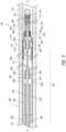
- FIG. 1is a side, cross-sectional view of a medical device delivery system disposed within a body lumen, according to some embodiments.
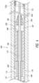
- FIG. 2is a side, cross-sectional view of a core assembly of the medical device delivery system shown in FIG. 1 , according to some embodiments.
- FIG. 3is an enlarged side, cross-sectional view of the delivery system shown in FIG. 1 .
- FIG. 4is another enlarged side, cross-sectional view of the delivery system shown in FIG. 1 .
- FIG. 5is a side, cross-sectional view of a medical device delivery system in a first position, adjacent to a target location, according to some embodiments.
- FIG. 6is a side, cross-sectional view of the delivery system shown in FIG. 5 , wherein the system is in a second position in which a stent thereof is partially expanded and a distal cover is disengaged from the stent, according to some embodiments.
- FIG. 7is a side, cross-sectional view of the delivery system shown in FIG. 5 , wherein the distal cover is moved to an everted position, according to some embodiments.
- FIG. 8is a side, cross-sectional view of the delivery system shown in FIG. 5 , wherein the stent has been retracted into a catheter of the system, according to some embodiments.
- FIG. 9is a side, cross-sectional view of the stent expanded at the target location, according to some embodiments.
- FIGS. 10 and 11are partial perspective views of an engagement member, according to some embodiments.
- FIG. 12is a side, cross-sectional view of a medical device delivery system being advanced through a torturous pathway, according to some embodiments.
- FIG. 13is a is a side, cross-sectional view of a core assembly of the medical delivery device with a proximal cover in a first position, according to some embodiments.
- FIG. 14is a side, cross-sectional view of the delivery system shown in FIG. 13 with the proximal cover in a second position.
- FIGS. 1 - 8depict embodiments of a medical device delivery system 100 which may be used to deliver and/or deploy a medical device, such as but not limited to a stent 200 , into a hollow anatomical structure such as a blood vessel 102 .
- the stent 200can comprise a proximal end 202 and a distal end 204 .
- the stent 200can comprise a braided stent or other form of stent such as a laser-cut stent, roll-up stent, etc.
- the stent 200can optionally be configured to act as a “flow diverter” device for treatment of aneurysms, such as those found in blood vessels including arteries in the brain or within the cranium, or in other locations in the body such as peripheral arteries.
- the stent 200can optionally be similar to any of the versions or sizes of the PIPELINETM Embolization Device marketed by Covidien of Mansfield, Massachusetts USA.
- the stent 200can further alternatively comprise any suitable tubular medical device and/or other features, as described herein.
- the depicted medical device delivery system 100can comprise an elongate tube or catheter 110 which slidably receives a core assembly 140 configured to carry the stent 200 through the catheter 110 .
- FIG. 2illustrates the core assembly 140 without depicting the catheter 110 for clarity.
- the depicted catheter 110(see FIGS. 1 , 3 - 8 ) has a proximal end 112 and an opposing distal end 114 which can be positioned at a treatment site within a patient, an internal lumen 116 extending from the proximal end 112 to the distal end 114 , and an inner surface 118 facing the lumen 116 .
- the catheter 110has a distal opening 120 through which the core assembly 140 may be advanced beyond the distal end 114 in order to expand or deploy the stent 200 within the blood vessel 102 .
- the proximal end 112may include a catheter hub 122 .
- the catheter 110can define a generally longitudinal axis A-A extending between the proximal end 112 and the distal end 114 . When the delivery system 100 is in use, the longitudinal axis need not be straight along some or any of its length.
- the catheter 110can optionally comprise a microcatheter.
- the catheter 110can optionally comprise any of the various lengths of the MARKSMANTM catheter available from Covidien of Mansfield, Massachusetts USA.
- the catheter 110can optionally comprise a microcatheter having an inner diameter of about 0.030 inches or less, and/or an outer diameter of 3 French or less near the distal end 114 .
- the catheter 110can comprise a microcatheter which is configured to percutaneously access the internal carotid artery, or a location within the neurovasculature distal of the internal carotid artery, with its distal opening 120 .
- the core assembly 140can comprise a core member 160 configured to extend generally longitudinally through the lumen 116 of the catheter 110 .
- the core member 160can have a proximal end or section 162 and a terminal or distal end 164 , which can include a tip coil 165 .
- the core member 160can also comprise an intermediate portion 166 located between the proximal end 162 and the distal end 164 , which intermediate portion is the portion of the core member 160 onto or over which the stent 200 is positioned or fitted or extends when the core assembly 140 is in the pre-deployment configuration as shown in FIGS. 1 - 5 .
- the core member 160can generally comprise any member(s) with sufficient flexibility, column strength and thin-ness to move the stent 200 or other medical device through the catheter 110 .
- the core member 160can therefore comprise a wire, or a tube such as a hypotube, or a braid, coil, or other suitable member(s), or a combination of wire(s), tube(s), braid(s), coil(s), etc.
- proximal wire 168is of multi-member construction, comprising a proximal wire 168 , a tube 170 (e.g., a hypotube) connected at its proximal end to a distal end of the proximal wire 168 , and a distal wire 172 connected at its proximal end to a distal end of the tube 170 .
- the proximal wire 168can extend continuously through the entire length of the tube 170 and then form the distal wire 172 , for example, as an integral unit with the proximal wire 168 .
- the outer diameter of the portion of the wire extending through the tube 170can be less than an inner diameter of the tube 170 , leaving an annular gap between the outer surface of the wire and the inner surface of the tube.
- An outer layer 174which can comprise a layer of lubricious material such as PTFE (polytetrafluoroethylene or TEFLONTM) or other lubricious polymers, can cover some or all of the tube 170 and/or proximal wire 168 .
- the proximal and/or distal wires 168 , 172may taper or vary in diameter along some or all of their lengths.
- the proximal wire 168may include one or more fluorosafe markers 176 , and such marker(s) can be located on a portion of the wire 168 that is not covered by the outer layer 174 , e.g., proximal of the outer layer 174 .
- This portion of the wire 168 marked by the marker(s) 176 , and/or proximal of any outer layer 174can comprise a bare metal outer surface.
- the core assembly 140can further comprise a proximal device interface 180 and/or a distal device interface 190 that can interconnect the medical device or stent 200 with the core member 160 .
- the proximal device interface 180can comprise a proximal engagement member 182 that is configured to underlie the stent 200 and engage an inner wall of the stent.
- the proximal engagement member 182cooperates with the overlying inner wall 118 of the catheter 110 to grip the stent 200 such that the proximal engagement member 182 can move the stent 200 along and within the catheter 110 , e.g., as the user pushes the core member 160 distally and/or pulls the core member proximally relative to the catheter 110 , resulting in a corresponding distal and/or proximal movement of the stent 200 within the catheter lumen 116 .
- the core assembly 140 and/or the proximal device interface 180do not include the proximal engagement member 182 of FIGS. 1 - 8 , as described herein.
- the proximal engagement member 182can be fixed to the core member 160 (e.g., to the distal wire 172 thereof in the depicted embodiment) so as to be immovable relative to the core member 160 , either in a longitudinal/sliding manner or a radial/rotational manner.
- the proximal engagement member 182can be coupled to (e.g., mounted on) the core member 160 so that the proximal engagement member 182 can rotate about the longitudinal axis A-A of the core member 160 (e.g., of the distal wire 172 ), and/or move or slide longitudinally along the core member.
- the proximal engagement member 182can have an inner lumen that receives the core member 160 therein such that the proximal engagement member 182 can slide and/or rotate relative to the core member 160 .
- the proximal device interface 180can further comprise a proximal restraint 184 that is fixed to the core member 160 and located proximal of the proximal engagement member 182 , and/or a distal restraint 186 that is fixed to the core member 160 and located distal of the proximal engagement member 182 .
- the proximal and distal restraints 184 , 186can be spaced apart along the core member 160 by a longitudinal distance that is greater than the length of the proximal engagement member, so as to leave one or more longitudinal gaps 187 between the proximal engagement member 182 and one or both of the proximal and distal restraints 184 , 186 , depending on the position of the proximal engagement member between the restraints.
- the longitudinal gap(s) 187allow the proximal engagement member 182 to slide longitudinally along the core member 160 between the restraints 184 , 186 .
- the longitudinal range of motion of the proximal engagement member 182 between the restraints 184 , 186is approximately equal to the total length of the longitudinal gap(s) 187 .
- the proximal device interface 180can comprise a radial gap 188 ( FIG. 3 ) between the outer surface of the core member 160 and the inner surface of the proximal engagement member 182 .
- a radial gap 188can be formed when the proximal engagement member 182 is constructed with an inner luminal diameter that is somewhat larger than the outer diameter of the corresponding portion of the core member 160 .
- the radial gap 188allows the proximal engagement member 182 to rotate about the longitudinal axis A-A of the core member 160 between the restraints 184 , 186 .
- the presence of longitudinal gaps 187 of at least a minimal size on either side of the proximal engagement member 182can also facilitate the rotatability of the proximal engagement member.
- One or both of the proximal and distal restraints 184 , 186can have an outside diameter or other radially outermost dimension that is smaller than the outside diameter or other radially outermost dimension of the proximal engagement member 182 , so that one or both of the restraints 184 , 186 will tend not to contact the inner surface of the stent 200 during operation of the core assembly 140 .
- the stent 200can be moved distally or proximally within the catheter 100 via the proximal engagement member 182 .
- the distal end of the proximal restraint 184bears on the proximal end of the engagement member 182 , and the engagement member urges the stent 200 distally via frictional engagement with the inner surface of the stent 200 (assisted by the overlying catheter 110 ).
- the proximal end of the distal restraint 186bears on the distal end of the engagement member 182 , which in turn moves the stent 200 proximally via such frictional engagement.
- Proximal movement of the stent 200 relative to the catheter 110can be employed when withdrawing or re-sheathing the stent 200 back into the distal end 114 of the catheter 110 , as will be discussed in greater detail below.
- the stent 200can be withdrawn back into the distal opening 120 of the catheter by moving the core assembly 140 (including the engagement member 182 ) proximally relative to the catheter 110 (and/or moving the catheter 110 distally relative to the core assembly 140 ).
- the proximal edge of the proximal engagement member 182can be positioned just distal of the proximal edge of the stent 200 when in the delivery configuration shown in FIGS. 1 - 5 .
- thisenables the stent 200 to be re-sheathed when as little as about 3 mm of the stent remains in the catheter 110 . Therefore, with stents 200 of typical length, resheathability of 75% or more can be provided (i.e. the stent 200 can be re-sheathed when 75% or more of it has been deployed).
- the distal cover 192can be configured as a lubricious, flexible structure having a free first end or section 192 a that can extend over at least a portion of the stent 200 and/or intermediate portion 166 of the core assembly 160 , and a fixed second end or section 192 b that can be coupled (directly or indirectly) to the core member 160 .
- the distal cover 192can have a first or delivery position, configuration, or orientation (see, e.g., FIGS. 1 - 5 ) in which the distal cover can extend proximally relative to the distal tip 164 , or proximally from the second section 192 b or its (direct or indirect) attachment to the core member 160 , and at least partially surround or cover a distal portion of the stent 200 .
- the distal cover 192can be movable from the first or delivery orientation to a second or resheathing position, configuration, or orientation (see, e.g., FIGS.
- distal coverin which the distal cover can be everted such that the first end 192 a of the distal cover is positioned distally relative to the second end 192 b of the distal cover 192 to enable the resheathing of the core assembly 140 , either with the stent 200 carried thereby, or without the stent.
- the distal cover 192can comprise one or more flexible, generally longitudinally extending strips, wings, or elongate portions that are coupled to or integrally formed with the second end 192 b .
- the distal cover 192can be manufactured or otherwise cut from a tube of the material selected for the distal cover or from multiple radial portions of such a tube.
- the first section 192 amay be formed as multiple longitudinal strips cut from the tube, and the second section 192 b may be an uncut (or similarly cut) length of the tube.
- the second section 192 b and the proximally extending strips of the first section 192 amay form a single, integral device or structure.
- the distal cover 192comprises only one, or no more than two strips, wings, or elongate portions.
- the distal cover 192may comprise a tube or a longitudinally slit tube
- the first section 192 acan include two or more semi-cylindrical or partially cylindrical strips or tube portions separated by a corresponding number of generally parallel, longitudinally oriented cuts or separations formed or otherwise positioned in the sidewall of the tube. Therefore, when in the pre-expansion state, as shown in FIGS. 1 - 5 , the first section 192 a may generally have the shape of a longitudinally split or longitudinally slotted tube extending or interposed radially between the outer surface of the stent or device 200 and the inner surface 118 of the catheter 110 .
- the strips, wings, or elongate portions of the first section 192 amay collectively span substantially the entire circumference of the outer surface of the stent 200 (e.g., where the cuts between the strips are splits of substantially zero width) or be sized somewhat less than the entire circumference (e.g., where the cuts between the strips are slots having a nonzero width).
- the width of the strips, wings, or elongate portions of the first section 192 acan be between about 0.5 mm and about 4 mm. The width can be about 0.5 mm to about 1.5 mm. In accordance with some embodiments, the width can be about 1 mm.
- the strips, wings, or elongate portions of the first section 192 acan also extend longitudinally over at least a portion of the distal portion of the stent 200 .
- the first section 192 acan extend between about 1 mm and about 3 mm, or between about 1.5 mm and about 2.5 mm, or about 2 mm, over the distal portion of the stent.
- the first section 192 a and the second section 192 bcan define a total length of the distal cover 192 .
- the total lengthcan be between about 4 mm and about 10 mm.
- the total lengthcan also be between about 5.5 mm and about 8.5 mm. In some embodiments, the total length can be about 7 mm.
- the strips of the first section 192 amay be of substantially uniform size.
- the first section 192 acan comprise two strips spanning approximately 180 degrees each, three strips spanning approximately 120 degrees each, four strips spanning approximately 90 degrees each, or otherwise be divided to collectively cover all or part of the circumference of the stent, etc.
- the stripsmay differ in angular sizing and coverage area without departing from the scope of the disclosure.
- only two strips or tube portionsare employed in the first section 192 a .
- the use of only two stripscan facilitate radial expansion, distal movement and/or fold-over or everting of the first section 192 a , as discussed herein, while minimizing the number of free or uncontained strips in the blood vessel lumen and any potential for injuring the vessel by virtue of contact between a strip and the vessel wall.
- the distal cover 192can be manufactured using a lubricious and/or hydrophilic material such as PTFE or Teflon®, but may be made from other suitable lubricious materials or lubricious polymers.
- the distal covercan also comprise a radiopaque material which can be blended into the main material (e.g., PTFE) to impart radiopacity.
- the distal cover 192can have a thickness of between about 0.0005′′ and about 0.003′′. In some embodiments, the distal cover can be one or more strips of PTFE having a thickness of about 0.001′′.
- the distal cover 192(e.g., the second end 192 b thereof) can be fixed to the core member 160 (e.g., to the distal wire 172 or distal tip 164 thereof) so as to be immovable relative to the core member 160 , either in a longitudinal/sliding manner or a radial/rotational manner.
- the core member 160e.g., to the distal wire 172 or distal tip 164 thereof
- the distal cover 192(e.g., the second end 192 b thereof) can be coupled to (e.g., mounted on) the core member 160 so that the distal cover 192 can rotate about the longitudinal axis A-A of the core member 160 (e.g., of the distal wire 172 ), and/or move or slide longitudinally along the core member.
- the second end 192 bcan have an inner lumen that receives the core member 160 therein such that the distal cover 192 can slide and/or rotate relative to the core member 160 .
- the distal device interface 190can further comprise a proximal restraint 194 that is fixed to the core member 160 and located proximal of the (second end 192 b of the) distal cover 192 , and/or a distal restraint 196 that is fixed to the core member 160 and located distal of the (second end 192 b of the) distal cover 192 .
- the proximal and distal restraints 194 , 196can be spaced apart along the core member 160 by a longitudinal distance that is greater than the length of the second end 192 b , so as to leave one or more longitudinal gaps 197 between the second end 192 b and one or both of the proximal and distal restraints 194 , 196 , depending on the position of the second end 192 b between the restraints.
- the longitudinal gap(s) 197allow the second end 192 b and/or distal cover 192 to slide longitudinally along the core member 160 between the restraints 194 , 196 .
- the longitudinal range of motion of the second end 192 b and/or distal cover 192 between the restraints 194 , 196is approximately equal to the total length of the longitudinal gap(s) 197 .
- the distal device interface 190can comprise a radial gap 198 between the outer surface of the core member 160 (e.g., of the distal wire 172 ) and the inner surface of the second end 192 b .
- a radial gap 198can be formed when the second end 192 b is constructed with an inner luminal diameter that is somewhat larger than the outer diameter of the corresponding portion of the core member 160 .
- the radial gap 198allows the distal cover 192 and/or second end 192 b to rotate about the longitudinal axis A-A of the core member 160 between the restraints 194 , 196 .
- the presence of longitudinal gaps 197 of at least a minimal size on either side of the second end 192 bcan also facilitate the rotatability of the distal cover.
- One or both of the proximal and distal restraints 194 , 196can have an outside diameter or other radially outermost dimension that is smaller than the (e.g., pre-deployment) outside diameter or other radially outermost dimension of the distal cover 192 , so that one or both of the restraints 194 , 196 will tend not to bear against or contact the inner surface 118 of the catheter 110 during operation of the core assembly 140 .
- the second end 192 b of the distal cover 192includes an internal hoop 192 c which can comprise a (metallic or polymeric) coil as depicted, or other generally rigid, tubular or cylindrical internal member such as a short segment of relatively stiff polymeric or metallic tubing.
- the internal hoop 192 ccan be contained in an annular enclosure or loop(s) formed by the second end 192 b , or otherwise attached to or integrated into the second end 192 b in a manner that tends to maintain an inside diameter of the distal cover 192 in the second end 192 b that is larger than the outside diameter of the adjacent portion of the core member 160 (or the wire 172 thereof).
- the hoop 192 ccan help maintain the presence of the radial gap 198 between the inside diameter of the second end 192 b and the outside diameter of the core member 160 or distal wire 172 .
- the annular enclosure or loop(s) of the second end 192 bcan be formed by wrapping a portion of a sheet or tube of the distal cover material (e.g., PTFE) around the sidewall and through the lumen of the hoop 192 c and adhering, gluing or heat bonding an end of the wrapped portion of the sheet or tube to the adjacent, proximally extending portion of the sheet or tube.
- the distal cover materialcomprises PTFE
- unsintered PTFEcan be used to enable bonding the two portions of the material together with heat and pressure, which is not typically possible with “ordinary” or sintered PTFE.
- the distal cover 192can generally cover and protect the distal end 204 of the stent 200 as the stent 200 is moved distally within the catheter 110 .
- the distal cover 192may serve as a bearing or buffer layer that, for example, inhibits filament ends of the distal end 204 of the stent 200 (where the stent 200 comprises a braided stent) from contacting the inner surface 118 of the catheter 110 , which could damage the stent 200 and/or catheter 110 , or otherwise compromise the structural integrity of the stent 200 .
- the distal cover 192may be made of a lubricious material, the distal cover 192 may exhibit a low coefficient of friction that allows the distal end 204 of the stent 200 to slide axially within the catheter 110 with relative ease.
- the coefficient of friction between the distal cover and the inner surface of the cathetercan be between about 0.02 and about 0.4.
- the coefficient of frictioncan be about 0.04.
- Such embodimentscan advantageously improve the ability of the core assembly to pass through the catheter, especially in tortuous vasculature.
- At least a portion of the distal cover 192can at least partially extend or be interposed radially between the distal portion of the stent 200 and the inner surface 118 of the catheter 110 in the first position, configuration, or orientation.
- the first section 192 a of the distal cover 192can extend from the second section 192 b in a proximal direction to a point where the first section is interposed between the distal portion of the stent 200 and the inner surface 118 of the catheter 110 .
- the first section of the distal covercan take on a “proximally oriented” position or configuration.
- the core assembly 140 shown in FIGS. 1 - 4can operate as illustrated in FIGS. 5 - 9 .
- the core assembly 140can be distally advanced until the distal portion of the stent 200 is positioned distally beyond the distal end 114 of the catheter 110 to permit expansion of the distal portion of the stent 200 into a lumen 104 of the blood vessel 102 .
- the covercan proceed to the second orientation as shown in FIG. 7 , as oncoming blood flow and/or other forces urge the first section 192 a distally relative to the core member 160 .
- the distal cover 192can remain substantially in the disengaged, proximally-extending configuration shown in FIG. 6 until the core assembly 140 is withdrawn proximally into the catheter 110 , at which point the distal end 114 of the catheter 110 can force the approaching first section 192 a of the cover 192 to evert or otherwise take on the second configuration as shown in FIGS. 7 - 8 .
- the distal cover 192can move toward an everted position or configuration in which the first section 192 a of the distal cover 192 is flipped, everted or rotated to extend in a distal direction or in a “distally oriented” position or configuration.
- all or at least a portion of the first section 192 ais located distal of all or at least a portion of the second section 192 b.
- the stent 200can be further unsheathed and subsequently released into position in the lumen 104 of the vessel 102 , e.g., across and/or spanning a neck 106 of an aneurysm 108 formed in the wall of the vessel 102 (as shown in FIG. 9 ), or the stent 200 can be retracted and withdrawn back into the catheter 110 (as shown in FIG. 8 ), if needed.
- the distal cover 192can be retracted into the catheter 110 in the second position, configuration, or orientation, in which the distal cover 192 can be at least partially everted, as shown in FIGS. 7 and 8 . This can facilitate complete resheathing of the stent 200 and/or the core assembly 140 within the catheter 110 .
- the first section 192 a of the distal cover 192in the first orientation, is positioned outside of a radial space 210 located between the core assembly 160 or axis A-A (in either case distal of the second section 192 b or the location where the distal cover 192 is connected to the core member) and the inner wall of the catheter 110 , as shown in FIG. 3 .
- the distal cover 192can extend proximally from the second section 192 b and/or connection location, and away from the radial space 210 .
- some or all of the first section 192 a of the distal cover 192can extend distally through the radial space 210 upon retraction of the core assembly 140 into the catheter 110 , as shown in FIG. 8 .
- the first section 192 a of the distal cover 192can radially overlap with the distal end 204 of the stent 200 at an overlap point 212 along the core member 160 .
- the overlap point 212can be located along the core member 160 at or near a distal end 214 of the intermediate portion 166 of the core member 160 , or at any location along the core member 160 that underlies an overlap of the (first section 192 a of the) distal cover 192 over the stent 200 when the core assembly 140 is in its pre-deployment configuration shown in FIGS. 1 - 3 and 5 .
- the first section 192 a of the distal cover 192no longer overlaps with the (distal end 204 of) the stent 200 at the overlap point 212 (and the first section 192 a can be located distally of such location), upon retraction of the core assembly 140 into the catheter 110 , as shown in FIG. 8 .
- the distal cover 192will not overlap the stent 200 or the overlap point 212 after at least partial expansion of the stent 200 when the core assembly 140 is withdrawn into the catheter 110 . Further, once the distal cover 192 is disengaged, the intermediate portion 166 of the core member 160 can be positioned radially adjacent to the distal end 114 of the catheter 110 with the distal cover 192 being positioned outside of the radial space between the intermediate portion 166 and the (inner wall 118 of the) catheter 110 .
- the movement and configuration of the distal cover 192can enable the core assembly 140 to provide radial clearance between the core member 160 or the intermediate portion 166 and the catheter 110 for facilitating resheathing of the core member 160 and stent 200 , as shown in FIGS. 7 - 8 .
- distal cover 192may be used in the core assembly 140 and/or distal device interface 190 to cover or otherwise interface with the distal end 204 of the stent 200 .
- a protective coil or other sleeve having a longitudinally oriented, proximally open lumenmay be employed. Suitable such protective coils include those disclosed in U.S. Patent Application Publication No. 2009/0318947 A1, published on Dec. 24, 2009, titled SYSTEM AND METHOD FOR DELIVERING AND DEPLOYING AN OCCLUDING DEVICE WITHIN A VESSEL.
- the stent 200can be rotatable with respect to the core member 160 about the longitudinal axis A-A thereof, by virtue of the rotatable (connections of the) proximal engagement member 182 and distal cover 192 .
- the stent 200 , proximal engagement member 182 and distal cover 192can rotate together in this manner about the core member.
- the core assembly 140can be advanced more easily through tortuous vessels as the tendency of the vessels to twist the stent and/or core assembly is negated by the rotation of the stent, proximal engagement member and distal cover about the core member.
- the required push force or delivery forceis reduced, as the user's input push force is not diverted into torsion of the stent and/or core member.
- the tendency of a twisted stent and/or core member to untwist suddenly or “whip” upon exiting tortuosity or deployment of the stent, and the tendency of a twisted stent to resist expansion upon deployment,are also reduced or eliminated.
- the usercan “steer” the core assembly 140 via the tip coil 165 , particularly if the coil 165 is bent at an angle in its unstressed configuration.
- a coil tipcan be rotated about the axis A-A relative to the stent 200 , engagement member 182 and/or distal cover 192 by rotating the distal end 162 of the core member 160 .
- the usercan point the coil tip in the desired direction of travel of the core assembly, and upon advancement of the core assembly the tip will guide the core assembly in the chosen direction.
- embodiments of the distal covercan provide various advantages.
- the use of the distal covercan allow the core assembly to be easily urged toward the treatment site within the catheter. This can advantageously reduce the delivery force required to move the core assembly through the catheter.
- a flexible distal coversuch as the depicted distal cover 192 can also allow the distal portion of the stent to open or expand radially immediately as the distal portion of the stent exits the catheter. The distal cover can be easily urged away from the first or encapsulating position or configuration such that the expansion of the stent is not hindered and expansion can be predictable to the clinician.
- thiscan be a significant improvement over prior art devices that used a relatively rigid tube, such as a coil to distally restrain a distal end of the stent, which could impede or make unpredictable the proper expansion or deployment of the distal end of the stent.
- the intermediate portion of the core assemblycan be easily recaptured within the catheter (with or without the stent coupled thereto (e.g., mounted thereon)) to facilitate resheathing.
- the cathetercan remain in place in the vasculature and the entire core assembly can be withdrawn therefrom.
- Thiscan enable the clinician to “telescope” one or more other stents (e.g., delivering more than one stent such that it overlaps with another stent) without having to remove the catheter, saving time and reducing trauma to the patient.
- Thisalso enables the clinician to remove the core assembly and stent entirely from the catheter in the event of a failure to deploy or other evident defect in the stent, and insert another core assembly and stent through the same catheter, with the same time savings and reduction in trauma.
- the distal device interface 190can omit the distal cover 192 , or the distal cover can be replaced with a component similar to the proximal engagement member 182 .
- the distal cover 192can be connected to the distal tip coil 165 , e.g., by being wrapped around and enclosing some or all of the winds of the coil 165 , or being adhered to or coupled to the outer surface of the coil by an adhesive or a surrounding shrink tube.
- the distal device interface 190 (or the proximal device interface 180 )can be omitted altogether.
- the proximal engagement member 182can be of multi-layer construction, which can be useful for facilitating rotation of the engagement member 182 and/or stent 200 about the core member 160 .
- the proximal engagement member 182can comprise a generally tubular or cylindrical inner layer 230 , and another generally tubular or cylindrical outer layer 232 that overlies the inner layer 230 .
- the outer layer 232can be adhered to or otherwise securely joined to the inner layer 230 so that the two cannot rotate or move longitudinally relative to each other during the ordinary use of the core assembly 140 and delivery system 100 .
- the inner layer 230 and outer layer 232can differ in mechanical properties such as hardness.
- the outer layer 232can comprise a relatively soft material to facilitate relatively high-friction or “high-grip” contact with the inner surface of the stent 200 .
- the inner layercan be formed from a relatively hard or stiff material to facilitate low-friction engagement with the adjacent portion of the core member 160 , and high hoop strength to resist inward deflection or collapse of the inner lumen 234 of the proximal engagement member 182 . Such inward deflection or collapse can result in “pinching” the core member 160 with the inner layer 230 and consequent degradation of the ability of the proximal engagement member 182 to rotate and/or move longitudinally with respect to the core member 160 .
- the relatively hard/stiff material of the inner layer 230minimizes the friction resulting from such contact.
- the outer layer 232can be formed from a relatively soft polymer or elastomer such as silicone, rubber (e.g., ChronopreneTM), thermoplastic polyurethane (e.g., TecoflexTM) or polyether block amide (e.g., PebaxTM). Whether made of such materials, or of other materials, the outer layer 232 can have a durometer of between 10 A and 50 A, or between 15 A and 40 A, or about 20 A, or about 25 A.
- a relatively soft polymer or elastomersuch as silicone, rubber (e.g., ChronopreneTM), thermoplastic polyurethane (e.g., TecoflexTM) or polyether block amide (e.g., PebaxTM).
- the outer layer 232can have a durometer of between 10 A and 50 A, or between 15 A and 40 A, or about 20 A, or about 25 A.
- the inner layer 230can be formed from polyimide, e.g., a polyimide tube; alternatively a tubular metallic coil (e.g., a stainless steel coil) could be employed, or a metal tube, either with or without slots or a spiral cut formed in the sidewall. Whether made of such materials, or of other materials, the inner layer 230 can have a higher durometer than the outer layer 232 , e.g., above 70 D or between 70 D and 100 D.
- the inner and outer layers 230 , 232can be integrally formed.
- both layerscould be formed from a single cylinder of soft material wherein the harder/stiffer inner layer comprises the radially inner portions of the cylinder which have been treated or processed to become harder/stiffer.
- the reversecould be done, wherein a cylinder of hard material is processed to make its outer layer softer and/or higher-friction.
- the outer layer 232can be made from a variety of materials, silicone is particularly preferred because it offers a high coefficient of friction, high heat resistance to facilitate sterilization, and high creep resistance to resist being “imprinted” with, or interlocked with, the filament or strut pattern of the adjacent medical device or stent 200 .
- the high coefficient of friction of siliconealso facilitates the use of a relatively short proximal engagement member, e.g., (for delivery of a neurovascular stent) less than 5 mm, less than 3 mm, between 1 mm and 3 mm, or between 2 mm and 2.5 mm.
- thermoset materialsuch as polyimide
- proximal engagement member 182it is difficult to process in a manner useful to form a multi-layer tubular component like the proximal engagement member 182 , e.g., via co-extrusion. Because of this difficulty, it was necessary for the inventors to develop a method of manufacturing the proximal engagement member 182 with a silicone outer layer 232 and an inner layer of higher-durometer thermoset material such as polyimide.
- the proximal engagement member 182can be manufactured as follows. A length of polyimide tubing of approximately 100 mm in length can be placed over a metallic mandrel so that the mandrel passes through the lumen of the tubing. The mandrel is sized to fit closely within the tubing lumen so as to hold the tubing in place on the mandrel via frictional engagement with the inner wall of the tubing. In addition, the close fit of the mandrel helps to seal the tubing lumen from inflow of silicone material during the subsequent dip coating of the tubing. Once the tubing is on the mandrel, the mandrel is mounted on a dipping fixture.
- a silicone reservoiris provided in the form of a vertical, open-topped cylinder, and the cylinder is prepared by wiping the inner surfaces of it with 70% isopropyl alcohol and allowing it to dry for 5 minutes.
- the mounted polyimide tubingis prepared in a similar manner by wiping it twice with a lint-free cloth wetted with 70% isopropyl alcohol and allowing it to dry for 5 minutes.
- the tubingis “painted” with a primer (e.g., MED-163 Primer from NuSil Technology of Carpinteria, California USA) by first wetting the bristles of an applicator brush with a pipette full of the primer, and then painting the tubing (held along with the mandrel in a vertical orientation from the dipping fixture) with the wet brush with a bottom-to-top motion in a first pass, and then in a second pass after rotating the tubing and mandrel 90 degrees about the vertical axis of the tubing and mandrel.
- a primere.g., MED-163 Primer from NuSil Technology of Carpinteria, California USA
- Flowable silicone materialis prepared using, for example, a 2-part medical silicone such as MED-4011 (Parts A and B) from NuSil Technology of Carpinteria, California USA.
- the silicone elastomer (Part A) and liquid crosslinker (Part B)are combined in a mix of 10 parts elastomer with 1 part crosslinker, and mixed in a sealed container in a centrifugal mixer at 3000 rpm for 60 seconds. After mixing, the silicone is allowed to sit for ten minutes before the container is unsealed.
- the flowable siliconeis then poured into the reservoir cylinder, and the reservoir is positioned in a programmable dipping apparatus beneath a vertically moveable dipping actuator.
- the dipping fixture, mandrel and tubingare mounted on the dipping actuator with the mandrel and tubing in a vertical, downward-extending orientation, and the vertical axis of the mandrel and tubing aligned with the central vertical axis of the reservoir cylinder.
- the dipping apparatusis then operated to lower the dipping actuator, mandrel and tubing to a position in which the lower end of the tubing is just above the surface of the silicone.
- the tubing and mandrelare then lowered or dipped into the silicone substantially along a straight line at a velocity of 2.29 mm per minute, over a stroke distance of 110 mm.
- the dipping actuator, tubing and mandrelare raised out of the silicone at a velocity of 400 mm/minute.
- the fixture, mandrel and coated tubingare then removed from the dipping apparatus and placed in an oven at 100° C. temperature for 15 minutes.
- the tubing and mandrelare oriented vertically but inverted relative to their orientation employed during the dipping process.
- the coated tubingis allowed to cool for 5 minutes.
- the tubingis sliced into individual proximal engagement members 182 with a series of cuts made along the tubing orthogonal to the longitudinal axis of the tubing.
- the proximal engagement membercan have an axial length of 2.25 mm, overall outside diameter of 0.02275-0.02500′′, inside diameter of 0.010′′, inner layer 230 thickness (e.g., polyimide tubing wall thickness) of 0.0015′′, outer layer 232 thickness greater than 0.003′′, and inner layer 230 outside diameter of 0.0135′′ or less.
- inner layer 230 thicknesse.g., polyimide tubing wall thickness
- a “high-grip” material such as silicone for the outer layer 232makes practical the use of a proximal engagement member 182 that is relatively short in axial length (i.e., the dimension measured along or parallel to the longitudinal axis A-A).
- the proximal engagement membercan be less than 5.0 mm in axial length, or less than 3.0 mm in axial length, or between 1.3 mm and 5.0 mm in axial length, or between 1.3 mm and 3.0 mm in axial length.
- a shorter proximal engagement member 182is advantageous because shortness tends to reduce the tendency of the engagement member 182 to stiffen the core assembly 140 and delivery system 100 . Accordingly there is made possible in some embodiments an engagement member 182 that not only can rotate about the core member 160 but can also effectively grip the inner surface of the stent 200 even at lengths below 5 mm, or below 3 mm.
- the outer surface 236 of the outer layer 232can comprise a generally smooth surface as shown in FIG. 10 , or a non-smooth surface such as that shown in FIG. 11 , comprising, for example, a number of outwardly projecting and longitudinally extending ridges 238 that alternate with longitudinally extending recesses 240 .
- Other patterns of projecting members and recesses, such as combinations of spikes and recessed portions,can also be employed.
- the distal restraint 186 of the proximal device interface 180can each optionally comprise a tapered portion 250 and a cylindrical or non-tapered portion 252 .
- the distal restraint 186can form a tapered portion 250 that is located distal of its non-tapered portion 252 , and tapers down in diameter or cross-sectional size as it extends distally, away from the proximal engagement member 182 .
- the proximal restraint 194can form a tapered portion 250 that is located proximal of its non-tapered portion 252 , and tapers down in diameter or cross-sectional size as it extends proximally, away from the distal engagement member 192 ;
- the distal restraint 196can form a tapered portion 250 that is located distal of its non-tapered portion 252 , and tapers down in diameter or cross-sectional size as it extends distally, away from the distal engagement member 192 .
- each of the restraints 186 , 194 , 196forms a tapered portion 250 that tapers radially inwardly as it extends away from its respective engagement member 182 / 192 and/or its respective longitudinal gap (s) 187 / 197 .
- the restraint(s) 186 , 194 , 196can provide the benefit of relatively large diameter or cross-sectional size in the non-tapered portion 252 (effective longitudinal restraint of the engagement member 182 / 192 ) and/or relatively long axial length (secure attachment to the core member 160 ) without suffering the drawback of increased stiffness or reduced bendability of the core assembly 140 and delivery system 100 .
- Thismay be understood best with reference to FIG. 12 , which shows the delivery system 100 including the core assembly 140 passing through a bend in the vessel 102 .
- the tapered portion 250 of the distal restraint 186 of the proximal device interface 180provides ample clearance for the sharply bending adjacent portion of the catheter 110 and stent 200 , as compared to a non-tapered restraint of similar length and cross-sectional size or diameter. Accordingly the tapered restraint 186 allows the core assembly 140 and core member 160 to bend more sharply (and/or to bend without the restraint contacting the inner surface of the stent 200 ) in the vessel 102 than would be possible with a non-tapered restraint of similar axial length and cross-sectional size or diameter. In this manner the risk of a distal corner of the restraint 186 impinging on the inner surface of the stent 200 and creating a pressure concentration that can require a higher push force from the user, is reduced.
- the distal restraint 196 of the distal device interface 190may have a smaller (maximum) outside diameter or cross-sectional size than the proximal restraint 194 of the distal interface 190 . Such a smaller distal restraint can help provide radial clearance for the everted first end 192 a of the distal cover 192 during retraction into the catheter 110 .
- one, some, or all of the restraints 184 , 186 , 194 , 196can comprise a tapered coil.
- Such coil(s)can be formed from wire stock with a tapering diameter; when wound into a coil the resulting coil tapers to a smaller diameter in the smaller diameter region of the wire. Restraints in the form of coils can provide a high degree of flexibility and improve the bendability of the core assembly 140 and delivery system 100 .
- One, some or all of the restraints 184 , 186 , 194 , 196can be formed from a radiopaque material (e.g., platinum, iridium, alloys thereof, etc.), so as to facilitate visibility of the respective portions of the core assembly 140 in a patient via fluoroscopy or other imaging.
- a radiopaque materiale.g., platinum, iridium, alloys thereof, etc.
- at least the distal restraint 186 of the proximal device interface 180is radiopaque
- the catheter 110is radiopaque at or near its distal tip, so as to indicate to the user that the proximal engagement member 182 is soon to exit the distal end of the catheter 110 , and the delivery system 100 or core assembly 140 as a result will lose the capability to withdraw the stent 200 back into the catheter 110 .
- the usercan observe via fluoroscopy that the distal restraint 186 is approaching the distal end 114 of the catheter 110 and thereby recognize that the delivery system 100 or core assembly 140 will soon lose the capability to withdraw the stent 200 back into the catheter 110 .
- the core member 160can optionally be of multi-member construction, and can include the tube 170 which can comprise a hypotube.
- the tube 170can have a sidewall that is “uncut” or without openings or voids formed therein.
- the tube 170can have openings, voids or cuts formed in the sidewall to enhance the flexibility of the tube. This may be done by cutting a series of slots in the sidewall along part or all of the length of the tube, or cutting or drilling a pattern of other openings in the sidewall, or cutting a spiral-shaped void in the sidewall.
- the tube 170can be of relatively small outside diameter (e.g., 0.040′′ or less, or 0.030′′ or less, or 0.027′′ or less, or about 0.020′′); have a relatively thin sidewall thickness (e.g., 0.0050′′ or less, or 0.0040′′ or less, or about 0.0030′′, or between 0.0025′′ and 0.0035′′); and/or be of relatively long overall length (e.g., 50 cm or more, or 60 cm or more, or 70 cm or more, or 80 cm or more, or about 91 cm).
- relatively small outside diametere.g., 0.040′′ or less, or 0.030′′ or less, or 0.027′′ or less, or about 0.020′′
- a relatively thin sidewall thicknesse.g., 0.0050′′ or less, or 0.0040′′ or less, or about 0.0030′′, or between 0.0025′′ and 0.0035′′
- relatively long overall lengthe.g., 50 cm or more, or 60 cm or more, or 70 cm
- the tubecan have a relatively long cut length (the length of the portion of the tube in which opening(s), void(s), cut(s), spiral(s) is/are present) of 50 cm or more, or 60 cm or more, or 70 cm or more, or 80 cm or more, or about 86 cm.
- a relatively long, small-diameter and/or thin-walled spiral-cut tubeoffers certain advantages for use in the core member 160 in narrow and/tortuous vasculature, such as the neurovasculature.
- the tubecan be made highly flexible (or inflexible as the case may be) where necessary by use of an appropriate spiral pitch, and the column strength or “pushability” of the tube can be maintained largely independent of its flexibility, as the diameter of the tube can remain constant along its length, in contrast with a long tapering wire which must sacrifice pushability for flexibility as it narrows.
- the combination of high flexibility and pushabilitycan facilitate easier navigation into difficult, tortuous vascular locations.
- the core assembly 140can include a stent engagement assembly 220 that can interconnect the stent 200 with the core member 140 .
- the stent engagement assembly 220can include first and second engagement members 223 a —b (together “engagement members 223 ”) mounted over the core member 160 and/or distal wire 172 and configured to mechanically engage or interlock with the stent 200 .
- engagement members 223can interlock with the stent 200 by projecting into the pores thereof.
- the engagement members 223can additionally or alternatively engage other portions or surfaces of the stent 200 via other coupling means.
- the stent engagement assembly 220cooperates with an overlying inner surface of a surrounding catheter 110 to grip the stent 200 such that the stent engagement assembly 220 can move the stent 200 along and within the catheter 110 , e.g., as the user pushes the core member 160 distally and/or pulls the core member 160 proximally relative to the catheter 110 , resulting in a corresponding distal and/or proximal movement of the stent 205 within the catheter lumen.
- each of the first and second stent engagement members 223 a — bincludes a central aperture configured to receive the core member 160 (such as the distal wire 172 or other components) therethrough.
- the opening of the aperturecan be larger than the diameter of the core member 160 and/or distal wire 172 such that the engagement members 223 can rotate about the long axis of the core member 160 and/or distal wire 172 .
- the aperturecan be sufficiently larger than the diameter of the core member 160 and/or distal wire 172 to permit a degree of tilting of the engagement members 223 with respect to a longitudinal axis of the core member 160 and/or distal wire 172 .
- the engagement members 223can be made to have a relatively thin and/or plate-like or sprocket-like configuration. Such a configuration can facilitate the formation of projections that are small enough to fit inside the pores of the stent 200 .
- the engagement members 223 a —bcan be made to be rigid (e.g., incompressible by the forces encountered in typical use of the delivery system). The rigidity of the engagement members 223 a —b can be due to their material composition, their shape/construction, or both.
- the engagement members 223are made of metal (e.g., stainless steel, Nitinol, etc.) or rigid polymers (e.g., polyimide, PEEK), or both. In some embodiments, even if the engagement members 223 a —b are made of a rigid material, the stent engagement members 223 a —b may be non-rigid and at least partially compressible based on other structural characteristics.
- the core assembly 140includes one or more spacers.
- the core assembly 140 shown in FIGS. 13 and 14includes a first spacer 225 a and a second spacer 225 b .
- the first spacer 225 acan be positioned over the core member 160 between a portion of the core assembly 140 configured to abut a proximal end of the stent 200 (such as shoulder 604 , described herein) and a proximal end of the stent engagement assembly 220 .
- the first spacer 225 acan be positioned between a portion of the core assembly 140 configured to abut a proximal end of the stent 200 and the first stent engagement member 223 a to maintain an axial position of the first stent engagement member 223 a .
- the second spacer 225 bcan be positioned over the core member 160 between the first and second stent engagement members 223 a —b.
- the spacers 225 a —bcan be a substantially cylindrical body having a smaller outer diameter than the largest outer diameter of the stent engagement members 223 .
- the spacers 225 a —bincludes a central aperture sized and configured to allow the spacers 225 a —b to be rotatably mounted over the core member 160 and/or distal wire 172 .
- the spacers 225 a — bcan have end walls that are orthogonal to a long axis of the distal wire 172 . These orthogonal end walls can help preserve the orthogonal orientation of the stent engagement members 223 a - b relative to the distal wire 172 to prevent loss of engagement with stent 200 .
- the engagement members 223 a —bcan be configured to tilt to a desired degree.
- the spacers 225 a —bcan be a wire coil defining a cylindrical body mounted over the core member 160 and/or distal wire 172 , for example a zero-pitch coil.
- the spacers 225 a —bcan take other forms, for example a solid cylindrical tube or other element coupled to the core member 160 and/or distal wire 172 .
- the engagement members 223 a —b and the spacers 225 a — bcan be coupled to (e.g., mounted on) the core member 160 so that the stent engagement assembly 220 can rotate about the longitudinal axis of the core member 160 and/or move or slide longitudinally along the core member 160 .
- the core assembly 140does not include the first spacer 225 a .
- the core assembly 140does not include the second spacer 225 b.
- the stent engagement assembly 220includes a restraint 186 disposed distally to the distal-most engagement member 223 b .
- the restraint 186can be fixed to the core member 160 and/or wire 172 so as to be immovable relative to the core member 202 , either in a longitudinal/sliding manner or a radial/rotational manner.
- the restraint 186can taper in the distal direction down towards the core member 160 . This tapering can reduce the risk of the restraint 186 contacting an inner surface of the overlying stent 200 , particularly during navigation of tortuous vasculature, in which the system 100 can assume a highly curved configuration.
- the restraint 186can have an outside diameter or other radially outermost dimension that is smaller than the outside diameter or other radially outermost dimension of the overall stent engagement assembly 220 , so that restraint 186 will tend not to contact the inner surface of the overlying stent 200 .
- the stent engagement assembly 220can be configured to engage the stent 200 within only a proximal portion (e.g., the proximal most 5%, the proximal most 10%, the proximal most 20%, only a proximal half, etc.) of the stent 200 . In other embodiments, the stent engagement assembly 220 can engage the stent 200 at any location along substantially its entire length.
- the core assembly 140includes a proximal device interface 600 .
- the stent 200is shown in a compressed delivery state within the catheter 110 .
- the catheter 110has been withdrawn and the stent 200 is in a fully expanded state, positioned within the blood vessel lumen.
- the proximal device interface 600can comprise a proximal cover 602 and a bumper or shoulder 604 , both coupled (directly or indirectly) to the core member 160 .
- the shoulder 604can be positioned along the core member 160 at a location proximal of a proximal terminus of the compressed stent 200 .
- a distal face 606 of the shoulder 604can be configured to abut a proximal terminus of the stent 200 .
- the shoulder 604can transmit distal pushing force to the stent 200 .
- the proximal cover 602can be configured to partially or completely cover the interface between the shoulder 604 and the proximal end region of the stent 200 , thereby protecting the proximal end region of the stent 200 and an inner surface of the catheter 110 , as described herein.
- the proximal cover 602can comprise a flexible structure having a fixed first end portion 602 a coupled (directly or indirectly) to the core member 160 and a free second end portion 602 b .
- the proximal cover 602can have a first position in which the second end portion 602 b of the proximal cover 602 extends distally from the first end portion 602 a over at least a portion of the stent 200 and/or intermediate portion 166 of the core assembly 160 . In the first position, the proximal cover 602 is positioned between the stent 200 and the catheter 110 .
- the proximal cover 602can be movable from the first position to a second position in which the proximal cover 602 is uncoupled from the stent 200 .
- the expansion force of the stent 200pushes the proximal cover 602 radially outwardly at least until an outer surface of the stent 200 is radially beyond the radially outermost portion of the proximal cover 602 .
- a length of the proximal cover 602can be less than an outer diameter of the stent 200 so that the proximal cover 602 does not get trapped between the stent 200 and the vessel wall.
- a length of the proximal cover 602is less than half of the outer diameter of the stent 200 .
- the proximal cover 602can be radially and/or axially spaced apart from the stent 200 .
- the proximal cover 602can be everted in the second position such that the first end portion 602 a of the proximal cover 602 is positioned distally relative to the second end portion 602 b of the proximal cover 602 .
- the axially-resistive force of the stent 200 against the shoulder 604can force all or some portions of the proximal end of the stent 200 to bend and/or flare and move radially outward of the shoulder 204 and proximal of the distal face of the shoulder 204 . This is especially true when the stent 200 comprises a plurality of braided wires.
- the barrier provided by the proximal cover 602 combined with the compressive force of the catheter 110prevents the proximal wire ends from bending radially outwardly and potentially penetrating the inner liner of the catheter 110 and/or breaking into smaller fragments that can cause embolic complications.
- the proximal cover 602can be particularly beneficial during resheathing of the stent 200 along a curved segment. In such scenarios, the proximal end of the wires tend to remain straight. Additionally or alternatively, the proximal cover 602 can be configured to reduce friction between the medical device or stent 200 (e.g., the proximal portion or proximal end thereof) and the inner surface 118 of the catheter 110 (see FIG. 1 ).
- the proximal cover 602can comprise one or more flexible, generally longitudinally extending strips, wings, or elongate portions that are coupled to or integrally formed with the first end portion 602 a .
- the proximal cover 602can be manufactured or otherwise cut from a tube of the material selected for the proximal cover 602 or from multiple radial portions of such a tube.
- the second end portion 602 bmay be formed as multiple longitudinal strips cut from the tube, and the first end portion 602 a may be an uncut (or similarly cut) length of the tube. Accordingly, the first end portion 602 a and the distally extending strips of the second end portion 602 b may form a single, integral device or structure.
- the proximal cover 602comprises only one, or no more than two strips, wings, or elongate portions.
- the proximal cover 602may comprise a tube or a longitudinally slit tube
- the second end portion 602 bcan include two or more semi-cylindrical or partially cylindrical strips or tube portions separated by a corresponding number of generally parallel, longitudinally oriented cuts or separations formed or otherwise positioned in the sidewall of the tube. Therefore, when in the pre-expansion state, as shown in FIG. 13 , the second end portion 602 b may generally have the shape of a longitudinally split or longitudinally slotted tube extending or interposed radially between the outer surface of the stent or device 200 and the inner surface 118 of the catheter 110 .
- the strips, wings, or elongate portions of the second end portion 602 bmay collectively span substantially the entire circumference of the outer surface of the stent 200 (e.g., where the cuts between the strips are splits of substantially zero width) or be sized somewhat less than the entire circumference (e.g., where the cuts between the strips are slots having a nonzero width).
- the width of the strips, wings, or elongate portions of the second end portion 602 bcan be between about 0.5 mm and about 4 mm. The width can be about 0.5 mm to about 1.5 mm. In accordance with some embodiments, the width can be about 1 mm.
- the strips, wings, or elongate portions of the second end portion 602 bcan extend longitudinally over at least a portion of the proximal portion of the stent 200 .
- each of the strips, wings, or elongate portions of the proximal cover 602having a length that is less than an outer diameter of the stent 200 .
- the second end portion 602 bcan extend between about 1 mm and about 3 mm, or between about 1.5 mm and about 2.5 mm, or about 2 mm, over the proximal portion of the stent 200 .
- the total lengthcan be between about 4 mm and about 10 mm.
- the total lengthcan also be between about 5.5 mm and about 8.5 mm. In some embodiments, the total length can be about 7 mm.
- the strips of the second end portion 602 bmay be of substantially uniform size.
- the second end portion 602 bcan comprise two strips spanning approximately 180 degrees each, three strips spanning approximately 120 degrees each, four strips spanning approximately 90 degrees each, or otherwise be divided to collectively cover all or part of the circumference of the stent, etc.
- the stripsmay differ in angular sizing and coverage area without departing from the scope of the disclosure.
- only two strips or tube portionsare employed in the second end portion 602 b .
- a single stripis employed and can wrap around the proximal portion of the stent 200 when the proximal cover 602 is in the pre-expanded position.
- the proximal cover 602can be manufactured using a lubricious and/or hydrophilic material such as PTFE or Teflon®, but may be made from other suitable lubricious materials or lubricious polymers.
- the proximal cover 602can also comprise a radiopaque material which can be blended into the main material (e.g., PTFE) to impart radiopacity.
- the proximal cover 602can have a thickness of between about 0.0005′′ and about 0.003′′. In some embodiments, the distal cover can be one or more strips of PTFE having a thickness of about 0.001′′.
- the proximal cover 602(e.g., the first end portion 602 a thereof) can be coupled to the core member 160 so that the proximal cover 602 is fixed to the core member 160 (e.g., to the proximal wire 168 or distal wire 172 ) so as to be immovable relative to the core member 160 , either in a longitudinal/sliding manner or a radial/rotational manner.
- the proximal cover 602(e.g., the first end portion 602 a thereof) can be coupled to (e.g., mounted on) the core member 160 so that the proximal cover 602 can rotate about the longitudinal axis A-A of the core member 160 (e.g., of the proximal wire 168 or distal wire 172 ), and/or move or slide longitudinally along the core member.
- the first end portion 602 acan have an inner lumen that receives the core member 160 therein such that the proximal cover 602 can slide and/or rotate relative to the core member 160 .
- the proximal device interface 600can comprise a radial gap between the outer surface of the core member 160 (e.g., of proximal wire 168 or the distal wire 172 ) and the inner surface of the first end portion 602 a .
- a radial gapcan be formed when the first end portion 602 a is constructed with an inner luminal diameter that is somewhat larger than the outer diameter of the corresponding portion of the core member 160 .
- the radial gapallows the proximal cover 602 and/or first end portion 602 a to rotate about the longitudinal axis A-A of the core member 160 .
- the first end portion 602 a of the proximal cover 602can include an internal hoop 603 .
- the internal hoop 603can include substantially the same components as, and function substantially similar to, the internal hoop 192 c .
- the internal hoop 603can comprise a (metallic or polymeric) coil as depicted, or other generally rigid, tubular or cylindrical internal member such as a short segment of relatively stiff polymeric or metallic tubing, similar to the internal hoop 192 c .
- the internal hoop 603can be contained in an annular enclosure or loop(s) formed by first end portion 602 a , or otherwise attached to or integrated into the first end portion 602 a in a manner that tends to maintain an inside diameter of the proximal cover 602 in the first end portion 602 a that is larger than the outside diameter of the adjacent portion of the core member 160 (or the proximal wire 168 or distal wire 172 thereof).
- the internal hoop 603can help maintain the presence of the radial gap between the inside diameter of the first proximal end portion 602 a and the outside diameter of the core member 160 , proximal wire 168 , or distal wire 172 .
- the annular enclosure or loop(s) of the first end portion 602 acan be formed by wrapping a portion of a sheet or tube of the distal cover material (e.g., PTFE) around the sidewall and through the lumen of the hoop 603 and adhering, gluing or heat bonding an end of the wrapped portion of the sheet or tube to the adjacent, distally extending portion of the sheet or tube. This positioning can form two layers that are adhered together on the distal side of the internal hoop 603 .
- the proximal cover 602 materialcomprises PTFE
- unsintered PTFEcan be used to enable bonding the two portions of the material together with heat and pressure, which is not typically possible with “ordinary” or sintered PTFE.
- the proximal device interface 600can comprise a bumper or shoulder 604 .
- the shoulder 604can be coupled to the core member 160 and located distal of the first end portion 602 a of the proximal cover 602 .
- the shoulder 604can be coupled to the core member 160 so that the shoulder 604 is fixed to the core member 160 (e.g., to the proximal wire 168 or distal wire 172 thereof) so as to be immovable relative to the core member 160 , either in a longitudinal/sliding manner or a radial/rotational manner.
- the shoulder 604can be coupled to (e.g., mounted on) the core member 160 so that the shoulder can rotate about the longitudinal axis A-A of the core member 160 and/or move or slide longitudinally along the core member.
- the shoulder 604can be configured to engage with the stent 200 to assist with adjusting the stent longitudinally. For example, a distal end portion of the shoulder 604 can abut the proximal end portion of the stent 200 so that the shoulder 604 will push the stent 200 distally when the shoulder 604 is moved distally, for example, during distal advancement of the stent 200 toward a treatment location in a patient.
- the shoulder 604is tapered so that the proximal end portion of the shoulder 604 has a smaller circumference than the distal end portion of the shoulder 604 .
- the proximal cover 602is configured to surround at least a portion of the shoulder 604 . For example, as depicted in FIG. 13 , the proximal cover 602 extends past the shoulder 604 and encloses the shoulder 604 when the proximal cover 602 is in the first position.
- the proximal cover 602can generally cover and protect the proximal end 202 of the stent 200 as the stent 200 is moved distally and/or proximally within the catheter 110 .
- the proximal cover 602may serve as a bearing or buffer layer that, for example, inhibits filament ends of the proximal end 202 of the stent 200 from contacting the inner surface 118 of the catheter 110 , which could damage the stent 200 and/or catheter 110 , or otherwise compromise the structural integrity of the stent 200 .
- the proximal cover 602may be made of a lubricious material, the proximal cover 602 may exhibit a low coefficient of friction that allows the proximal end 202 of the stent 200 to slide axially within the catheter 110 with relative ease.
- the coefficient of friction between the distal cover and the inner surface of the cathetercan be between about 0.02 and about 0.4.
- the coefficient of frictioncan be about 0.04.
- Such embodimentscan advantageously improve the ability of the core assembly to pass through the catheter, especially in tortuous vasculature.
- the proximal cover 602can at least partially extend or be interposed radially between the proximal portion of the stent 200 and the inner surface 118 of the catheter 110 in the first position, configuration, or orientation.
- the second end portion 602 b of the proximal cover 602can extend from the first end portion 602 a in a distal direction to a point where the second end portion 602 b is interposed between the proximal portion of the stent 200 and the inner surface 118 of the catheter 110 .
- the second end portion 602 b of the proximal cover 302can take on a “distally oriented” position or configuration.
- the core assembly 140can be distally advanced until the distal portion of the stent 200 is positioned distally beyond the distal end 114 of the catheter 110 to permit expansion of the distal portion of the stent 200 into a lumen 104 of the blood vessel 102 .
- the proximal cover 602can transition from a first position, where the second end portion 602 b of the proximal cover 602 at least partially surrounds a proximal end portion of the stent 200 , and a second position, where the second end portion 602 b of the proximal cover 200 is uncoupled from the stent 200 .
- Expansion of the stent 200may cause the proximal cover 602 to transition between the first and second positions.
- the proximal cover 602will remain in the first position if the proximal end portion of the stent 200 is positioned proximally of the distal end 114 of the catheter 110 .
- the stent 200transitions from a compressed state to an expanded state.
- the proximal cover 602can transition from the first position to the second position.
- the stent 200 expandingcan cause the proximal cover 602 to uncouple from the stent 200 by pushing the free second end portion 602 b of the proximal cover 602 away from the stent 200 .
- the stent 200 transitioning from the compressed state to the expanded statecan cause the proximal cover 602 to evert.
- the proximal cover 602 transitioning from the first position to the second positioncan cause one or more longitudinal strips of the proximal cover 602 to separate. After the proximal cover 602 has become disengaged from the stent 200 , the proximal cover 602 can remain substantially in the disengaged configuration until the core assembly 140 is withdrawn proximally into the catheter 110 .
- proximal cover 602may be used in the core assembly 140 and/or proximal device interface 600 to cover or otherwise interface with the proximal end 202 of the stent 200 .
- a protective coil or other sleeve having a longitudinally oriented, proximally open lumenmay be employed. Suitable such protective coils include those disclosed in U.S. Patent Application Publication No. 2009/0318947 A1, published on Dec. 24, 2009, titled SYSTEM AND METHOD FOR DELIVERING AND DEPLOYING AN OCCLUDING DEVICE WITHIN A VESSEL.
- the stent 200can be rotatable with respect to the core member 160 about the longitudinal axis A-A thereof, by virtue of the rotatable (connections of the) stent engagement members 223 a - b and proximal cover 602 .
- the stent 200 , stent engagement members 223 a - b and proximal cover 602can rotate together in this manner about the core member 160 .
- the core assembly 140can be advanced more easily through tortuous vessels as the tendency of the vessels to twist the stent 200 and/or core assembly 140 is negated by the rotation of the stent 200 , stent engagement members 223 a —b, and proximal cover 602 about the core member 160 .
- the required push force or delivery forceis reduced, as the user's input push force is not diverted into torsion of the stent 200 and/or core member 160 .
- the usercan “steer” the core assembly 140 via the tip coil 165 , particularly if the coil 165 is bent at an angle in its unstressed configuration.
- a coil tip 165can be rotated about the axis A-A relative to the stent 200 , engagement member 182 and/or proximal cover 602 by rotating the distal end 162 of the core member 160 .
- the usercan point the coil tip 165 in the desired direction of travel of the core assembly 140 , and upon advancement of the core assembly 140 the tip 165 will guide the core assembly 140 in the chosen direction.
- proximal cover 602can provide various advantages.
- the use of the proximal cover 602can allow the core assembly 140 to be easily urged toward the treatment site within the catheter 110 and allow for the stent 200 to be retracted within the catheter 110 without damaging the catheter 110 .
- These benefitscan advantageously reduce the delivery force required to move the core assembly 140 through the catheter 110 and prevent damage to or fracture of stent filaments.
- a flexible coversuch as the depicted proximal cover 602 can also allow the proximal portion 202 of the stent 200 to open or expand radially immediately as the proximal portion of the stent 200 exits the catheter 110 .
- the proximal cover 602can be easily urged away from the first or encapsulating position or configuration such that the expansion of the stent 200 is not hindered and expansion can be predictable to the clinician.
- the intermediate portion 166 of the core assembly 140can be easily recaptured within the catheter 110 to facilitate resheathing.
- the catheter 110can remain in place in the vasculature and the entire core assembly 140 can be withdrawn therefrom. This can enable the clinician to “telescope” one or more other stents (e.g., delivering more than one stent such that it overlaps with another stent) without having to remove the catheter 110 , saving time and reducing trauma to the patient.
- Thisalso enables the clinician to remove the core assembly 140 and stent 200 entirely from the catheter in the event of a failure to deploy or other evident defect in the stent 200 and insert another core assembly 140 and stent 200 through the same catheter 110 , with the same time savings and reduction in trauma.
- the proximal device interface 600can be used in addition with the distal device interface 190 .
- the proximal device interface 600can employ a proximal cover 602 to surround the proximal end portion of the stent 200 while the distal device interface 190 can employ a distal cover 192 to surround the distal end portion of the stent 200 .
- FIGS. 1 , 5 - 9 and 12depict some embodiments and methods of use of the medical device delivery system 100 .
- the catheter 110can be inserted into the patient's vasculature via a percutaneous access technique or other suitable method of access.
- the distal end 114 of the catheter 110is then advanced to a treatment site or location in the blood vessel 102 , using for example any of the access routes 400 .
- the blood vessel 102may comprise a vein or artery, such as an artery in a brain or within a cranium of the patient.
- the catheter 110can comprise a microcatheter.
- a guide catheter(not shown) can be used instead of or in addition to the catheter 110 ; for example, the guide catheter can first be placed in the vasculature so that it extends part or all of the way to the treatment site and a microcatheter or other catheter then inserted through the guide catheter to the treatment site.
- the treatment locationmay be near the aneurysm 108 formed in a wall of the blood vessel 102 , and advancing the catheter 110 to the treatment location may include advancing the distal end 114 and/or distal opening 120 to a location that is distal of the aneurysm 108 (e.g., FIG. 5 ). Such advancement of the catheter 110 may include advancing the distal end 114 and/or distal opening 120 distally across the ostium or neck 106 of the aneurysm 108 , to the location in the vessel 102 distal of the aneurysm.
- the catheter 110may extend proximally from the distal end 114 and/or distal opening 120 at the treatment location, through the vascular access site, to the proximal end 112 and/or hub 122 which are preferably situated outside the patient's body.
- the core assembly 140(with the stent 200 carried thereby) can be inserted, distal end first, into the lumen 116 of the catheter 110 via the hub 122 and/or proximal end 112 .
- the core assembly 140is initially at least partially contained within an introducer sheath the distal end of the introducer sheath can be inserted into the proximal end of the catheter 110 and the core assembly 140 is advanced distally through the introducer sheath until the distal core assembly and stent 200 exit the distal end of the introducer sheath and pass into the lumen 116 of the catheter 110 .
- Such advancement of the core assembly 140can comprise gripping the core member 160 in a proximal grip region as a result of its exposure proximal of the proximal end of the sheath (and/or of the sheath preventing the gripping of any other portion of the core assembly 140 ).
- the introducer sheathcan be retracted from the proximal end of the catheter 110 and/or discarded.
- the proximal grip regioncan be exposed for gripping proximal of the catheter proximal end 112 , and the region can be the only portion of the core assembly available for gripping by the user.
- the core assembly 140 and stent 200are at this point disposed in the catheter 110 generally as depicted in FIG. 1 .
- the stent 200 and distal portion of the core assembly 140can be positioned in the lumen 116 of the catheter 110 , with the stent 200 generally in contact with the inner surface 118 of the catheter 110 except where the first section 192 a of the distal cover 192 is extending or interposed radially between the distal end 204 of the stent 200 and the inner surface 118 of the catheter 110 .
- the core member 160can extend proximally of the proximal end 112 and/or hub 122 of the catheter 110 to a location outside of the patient's body, so that the proximal portions (e.g., proximal wire 168 where employed, and/or the proximal grip region) of the core member 160 can be easily accessed.
- proximal portionse.g., proximal wire 168 where employed, and/or the proximal grip region
- the core assembly 140 with the stent 200can be axially advanced distally within the lumen 116 of the catheter 110 , toward the distal end 114 of the catheter 110 and treatment location.
- the core assembly 140includes a proximal engagement member 182 , stent engagement members 223 a —b, a proximal cover 602 , and/or a distal cover 192 that can rotate about the core member 160
- advancing the core assemblyin this method or in any method of advancing the core member 140 through a tortuous catheter, such as when such catheter is disposed in a laboratory model of vasculature
- Thiscan optionally be done without significant twisting of the core member 160 and/or stent 200 .
- advancing the core assembly 140can further comprise bending the core assembly 140 and core member 160 more sharply (and/or without the restraint 184 , 194 and/or 196 contacting the inner surface of the stent 200 ) in the vessel 102 than would be possible with a non-tapered restraint 184 , 194 and/or 196 of similar axial length and cross-sectional size or diameter.
- advancing the core assembly 140can further comprise pulling the stent 200 , or the proximal portions or proximal half thereof through the catheter 110 with the interface 180 , stent engagement members 223 a —b, and/or engagement member 182 .
- a core assembly 140comprises a retraction-only interface in a proximal portion or half of the stent 200
- advancing the core assembly 140can comprise doing so with the retraction-only interface disengaged from the stent 200 .
- the second end portion 602 b of the proximal cover 602remains extending or interposed radially between the outer surface and/or proximal end 202 of the stent 200 and the inner surface 118 of the catheter 110 and the first section 192 a of the distal cover 192 remains extending or interposed radially between the outer surface and/or distal end 204 of the stent 200 and the inner surface 118 of the catheter 110 .
- the proximal cover 602 and the distal cover 192may inhibit the proximal end and the distal end 204 of the advancing stent 200 (e.g., the filament ends thereof) from damaging, abrading, or gouging the catheter 110 , and from thereby impeding progress of the stent 200 along the catheter 110 .
- Thismay, in turn, avoid damage to the stent 200 such as by longitudinal compression resulting from high friction generated between the proximal end 202 and the distal end 204 of the stent 200 and the catheter 110 while distally directed force is applied to the proximal portions of the stent 200 .
- advancement of the core assembly 140 with the stent 200 toward the distal end 114 and treatment locationcan include advancing the distal portion of the core assembly 140 and the distal end 204 of the stent 200 distally through the catheter 110 across the ostium or neck 106 of the aneurysm, to a location in the vessel 102 distal of the aneurysm.
- the usercan observe the fluorosafe marker 176 (when present) approaching the proximal end of the catheter and thereby recognize that the stent is or will soon be close to exiting the distal end of the catheter. Having recognized this, the user can activate fluoroscopic imaging to view the exit of the stent from the distal catheter end via such imaging, and then proceed to urge the core assembly distally and thereby cause the stent to exit the distal end of the catheter.
- the core assembly 140may be held stationary and the catheter 110 may be withdrawn proximally over the stent 200 and distal portion of the core assembly 140 , as shown in FIGS. 6 - 7 .
- the core assembly 140 and stent 200can be advanced distally while performing this step, instead of or in addition to withdrawal of the catheter.
- the stent 200(except for any portion retained within the catheter 110 ) can be released and permitted to expand into engagement with the inner wall of the blood vessel 102 , as shown in FIGS. 6 - 7 .
- Some embodiments of the stent 200can shorten axially while expanding radially.
- the strips or tube portions of the first section 192 a of the distal cover 192can disengage from contact with the distal end 204 of the stent 200 , while in some embodiments separating and moving radially outward as well.
- the distal cover 192As the distal portion of the stent 200 expands, it can cause the distal cover 192 to be opened or moved from the first orientation. When the stent 200 can foreshorten as it expands, the stent 200 can withdraw from engagement with the distal cover 192 , as shown in FIG. 6 . After the distal cover 192 has become disengaged from the stent 200 to reach the state shown in FIG. 6 , the cover can proceed to the second orientation as shown in FIG. 7 , as oncoming blood flow and/or other forces urge the first section 192 a distally. Alternatively, the distal cover 192 can remain substantially in the disengaged, proximally-extending configuration shown in FIG.
- the distal cover 192disengages from the stent 200 , it no longer covers the distal end 204 of the stent 200 ; instead, its first section 192 a is now spaced distally from the stent distal end 204 as shown in FIG. 6 .
- the strips or tube portions forming the first section 192 acan be free or unconfined within the lumen of the blood vessel 102 .
- the strips or tube portionscan have free first ends, as well as second ends that are coupled to the core assembly 140 . The free first ends can cover at least a portion of the stent distal portion during delivery of the stent.
- the strips or tube portionscan be everted, such that free first ends of the strips, wings, or elongate portions are drawn together distal to the second ends thereof.
- the proximal cover 602disengages from the stent 200 , it no longer covers the proximal end 202 of the stent 200 .
- the second end portion 602 bcan be spaced apart distally or proximally from the proximal end 202 of the stent.
- the strips or tube portions forming the second end portion 602 bcan be free or unconfined within the lumen of the blood vessel 102 .
- the strips or tube portionscan be everted, such that free first ends of the strips, wings, or elongate portions are drawn together distal to the second ends thereof.
- the pullback of the catheter 110 (and/or distal movement of the core assembly 140 ) and expansion of the stent 200may be done in multiple discrete steps.
- the catheter 110may initially be pulled back proximally only part of the way as shown in FIGS. 6 - 17 , and only the distal portion 204 of the stent 200 expanded into engagement with the vessel wall.
- Such initial partial expansionfacilitates anchoring the distal portion of the stent in the vessel 102 , which in turn facilitates longitudinal stretching or compression of the stent 200 as desired by the clinician during or prior to expansion of the remaining portions of the stent 200 into the vessel 102 .
- Initial partial expansioncan also facilitate confirmation by the clinician that the distal portion of the stent 200 has “landed” in the desired location in the vessel 102 (e.g., distal of the neck or ostium of any aneurysm formed in the vessel wall) prior to expansion of the remaining portions of the stent 200 .
- proper placement of the stent 200can include positioning a distal portion of the stent 200 in the vessel lumen distal of the aneurysm neck 106 and a proximal portion of the stent in the vessel lumen proximal of the aneurysm neck 106 , such that the stent 200 extends across the neck ( FIG. 9 ).
- the expanded stent 200is appropriately configured, it may then perform a therapeutic flow-diverting function with respect to the aneurysm 108 .
- the partially expanded stent 200can be resheathed or retracted proximally into the catheter 110 as shown in FIG. 8 .
- the engagement member 182 , stent engagement members 223 a - b , and/or catheter 110can secure, grip, or engage the stent 200 to a sufficient degree to permit the catheter 110 to be advanced distally over the partially expanded stent 200 (and/or the core member 160 withdrawn proximally relative to the catheter 110 ) until the stent 200 is again positioned in the lumen 116 of the catheter 110 .
- the engagement member 182 and/or stent engagement members 223 a - bcan exert a proximal force on the stent 200 as the stent 200 is withdrawn or retracted into the catheter 110 .
- the retraction-only interfacecan be activated and employed to retract the stent proximally into the catheter 110 .
- the retraction-only interfacecan exert a proximal force on the stent 200 as the stent 200 is withdrawn or retracted into the catheter 110 .
- FIGS. 6 - 7also show a first aspect of a process of resheathing the stent 200 , during or prior to the stent 204 being drawn into the lumen 116 of the catheter 110 .
- the previously stent-engaging portion (e.g., the first section 192 a ) of the distal cover 192has moved radially outward from the core member 160 (e.g., FIG. 6 ) and/or distally relative to the core member 160 (e.g., FIG. 7 ), it does not impede the entrance of the distal portion and distal end 204 of the stent 200 into the distal opening 120 of the catheter 110 (e.g., to get to the state shown in FIG.
- the resheathing processcan comprise moving the stent 200 (including the distal end 204 ) into the catheter 110 through the distal opening 120 while the previously stent-engaging portion (e.g., the first section 192 a ) of the distal cover 192 is in a second, everted, or resheathing configuration in which the stent-engaging portion is disposed radially outward from the core member 160 and/or the first section 192 a of the distal cover 192 is disposed distally relative to the core member 160 , the second section 192 b , and/or the distal tip 165 , in comparison to a first, encapsulating, or delivery configuration (e.g., FIG. 1 , 3 ) of the stent-engaging portion (e.g., the first section 192 a ) of the distal cover 192 .
- a first, encapsulating, or delivery configuratione.g., FIG. 1 , 3
- FIG. 8shows a second aspect of the resheathing process currently under discussion.
- the core assembly 140can be moved further proximally into the catheter 110 (and/or the catheter 110 is moved further distally over the core assembly 140 ) until the distal cover 192 enters the catheter 110 via the distal opening 120 .
- the first section 192 a of the distal cover 192is preferably sufficiently flexible to evert and thereby attain the second, everted, or resheathing configuration shown in FIGS. 7 - 8 .
- the first section 192 a of the distal cover 192can extend generally in a distal direction, away from the stent 200 , and/or extend distally of the second section 192 b of the distal cover 192 .
- the first section 192 a of the distal cover 192can also radially overlap the distal tip 165 and/or the distal restraint 196 .
- the distal cover 192can be radially small enough to extend into the lumen 116 of the catheter 110 , either partially or wholly as shown in FIG. 8 , and/or the entire distal cover 192 can be spaced distally from the distal end 204 of the stent 200 in the lumen 116 of the catheter 110 .
- a clinicianwhen operating the delivery system 100 , can check the initial partial expansion of the stent 200 (e.g., as shown in FIGS. 6 - 7 ) and, if the initial placement is unsatisfactory or if the initial expansion of the stent 200 is unsatisfactory, the clinician can recapture, collapse, withdraw, or resheath the stent 200 into the catheter 110 , as described above with respect to FIGS. 6 - 8 . After resheathing, the clinician can attempt to deploy the stent again, as described herein, beginning for example with the state depicted in FIG. 8 , and resulting for example, in the state depicted in FIG.
- Resheathingcan also be performed, and the delivery system 100 and stent 200 removed from the patient entirely, if for example, the delivery and/or expansion of the stent 200 damages or reveals a defect in, or improper sizing of, the stent 200 or delivery system 100 .
- the depicted core assembly 140can optionally be entirely removed with the stent 200 from the catheter 110 without need to remove the catheter 110 from the blood vessel 102 . In this manner, access to the treatment site in the blood vessel 102 can be maintained via the catheter 110 and, if desired, additional attempts to deliver the stent 200 can be made through the catheter 110 .
- the proximal end 202 of the stent 200may be released from the catheter 110 by holding the core member 160 stationary and withdrawing the catheter proximally relative to the core member 160 and the stent 200 until the distal opening 120 is proximal of the proximal end 202 of the stent 200 . No longer constrained by the catheter 110 , the proximal end 202 of the stent 200 can now expand into contact with the wall of the vessel 102 , as shown FIG. 9 .
- the partially expanded stent 200had been fully resheathable.
- the fully deployed stent 200extends across the neck 106 of the aneurysm 108 , and can optionally perform a therapeutic flow-diverting function with respect to the aneurysm.
- the core assembly 140can be drawn back into the catheter 110 . Both the catheter 110 and core assembly 140 can be withdrawn from the patient, either simultaneously or sequentially. However, when the stent has been successfully released, the core assembly 140 can also be entirely removed from the catheter 110 , with the catheter 110 remaining in place, and a second core assembly can be inserted into the catheter lumen.
- the second core assemblycan be configured to deliver a second stent to the treatment site in order to perform, e.g., a telescoping procedure.
- the apparatus and methods discussed hereinare not limited to the deployment and use of a medical device or stent within the vascular system but may include any number of further treatment applications.
- Other treatment sitesmay include areas or regions of the body including any hollow anatomical structures.
Landscapes
- Health & Medical Sciences (AREA)
- Engineering & Computer Science (AREA)
- Biomedical Technology (AREA)
- Cardiology (AREA)
- Oral & Maxillofacial Surgery (AREA)
- Transplantation (AREA)
- Heart & Thoracic Surgery (AREA)
- Vascular Medicine (AREA)
- Life Sciences & Earth Sciences (AREA)
- Animal Behavior & Ethology (AREA)
- General Health & Medical Sciences (AREA)
- Public Health (AREA)
- Veterinary Medicine (AREA)
- Media Introduction/Drainage Providing Device (AREA)
Abstract
Description
- a core member having a distal portion, wherein the distal portion is configured to be positioned within a lumen of the stent;
- a cover having a first end portion coupled to the distal portion of the core member and a free second end portion, the cover moveable between a first position and a second position; and
- a shoulder coupled to the distal portion of the core member at a location distal to the first end portion of the cover, the shoulder configured to abut a proximal end portion of the stent when the stent is in a compressed state and positioned over the core member within the catheter,
- wherein,
- when at least a portion of the stent is positioned in the compressed state within the catheter, the cover is in the first position in which the second end portion of the cover is interposed radially between a proximal end region of the stent and an inner surface of the catheter, and
- when the catheter is proximal of the first end portion of the cover, the cover is in the second position.
- a catheter;
- a manipulation member having a distal region and configured to be slidably received within a lumen of the catheter;
- a cover having a first portion coupled to the distal region of the manipulation member and a free second portion, the cover having (a) a first position in which the second portion is configured to at least partially surround a proximal portion of a stent while the stent is compressed within the catheter, and (b) a second position in which the second portion is decoupled from the stent; and
- a shoulder member coupled to the distal region of the manipulation member, the shoulder member configured to abut a proximal terminus of the stent when the stent is compressed within the catheter.
- positioning a treatment device within a blood vessel lumen at a treatment site, the treatment device comprising:
- a catheter defining a lumen therethrough;
- a core member slidably disposed within the catheter lumen;
- a stent in a compressed state positioned within the catheter lumen; and
- a cover having a first end portion coupled to the core member and a free second end portion, wherein the second end portion is positioned radially between the stent and an inner surface of the catheter;
- releasing the stent from the catheter such that the stent self-expands into apposition with the blood vessel wall, and
- in response to expansion of the stent, decoupling the cover from the stent such that at least a portion of the cover is not radially between the stent and the catheter.
- positioning a treatment device within a blood vessel lumen at a treatment site, the treatment device comprising:
- a core member having a distal portion, wherein the distal portion is configured to be positioned within a lumen of the stent;
- a cover having (a) a first end portion coupled to the distal portion of the core member and having a radial position that is substantially fixed relative to the core member, and (b) a second end portion configured to move radially relative to the core member, and
- a shoulder coupled to the distal portion of the core member at a location distal to the first end portion of the cover, the shoulder positioned proximally adjacent a proximal end portion of the stent when the stent is in a compressed state and positioned over the core member within the catheter,
- wherein the cover is moveable between a first position and a second position such that:
- when at least a portion of the stent is positioned in the compressed state within the catheter, the cover is in the first position in which the second end portion of the cover is distal of a proximal terminus of the stent, and
- when the catheter is proximal of the first end portion of the cover, the cover is in the second position in which the second end portion is proximal of a proximal terminus of the stent.
Claims (20)
Priority Applications (3)
| Application Number | Priority Date | Filing Date | Title |
|---|---|---|---|
| US17/301,560US12042413B2 (en) | 2021-04-07 | 2021-04-07 | Delivery of medical devices |
| EP22162685.6AEP4070767A1 (en) | 2021-04-07 | 2022-03-17 | Delivery of medical devices |
| CN202210360938.9ACN115192282A (en) | 2021-04-07 | 2022-04-07 | Delivery of medical devices |
Applications Claiming Priority (1)
| Application Number | Priority Date | Filing Date | Title |
|---|---|---|---|
| US17/301,560US12042413B2 (en) | 2021-04-07 | 2021-04-07 | Delivery of medical devices |
Publications (2)
| Publication Number | Publication Date |
|---|---|
| US20220323246A1 US20220323246A1 (en) | 2022-10-13 |
| US12042413B2true US12042413B2 (en) | 2024-07-23 |
Family
ID=80787338
Family Applications (1)
| Application Number | Title | Priority Date | Filing Date |
|---|---|---|---|
| US17/301,560Active2042-03-01US12042413B2 (en) | 2021-04-07 | 2021-04-07 | Delivery of medical devices |
Country Status (3)
| Country | Link |
|---|---|
| US (1) | US12042413B2 (en) |
| EP (1) | EP4070767A1 (en) |
| CN (1) | CN115192282A (en) |
Families Citing this family (1)
| Publication number | Priority date | Publication date | Assignee | Title |
|---|---|---|---|---|
| US10045867B2 (en) | 2013-08-27 | 2018-08-14 | Covidien Lp | Delivery of medical devices |
Citations (435)
| Publication number | Priority date | Publication date | Assignee | Title |
|---|---|---|---|---|
| US3416531A (en) | 1964-01-02 | 1968-12-17 | Edwards Miles Lowell | Catheter |
| GB1449622A (en) | 1972-10-26 | 1976-09-15 | Medical Products Corp | Catheter assembly |
| US4364391A (en) | 1980-11-14 | 1982-12-21 | Toye Frederic J | Tracheostomy apparatus and method |
| US4425919A (en) | 1981-07-27 | 1984-01-17 | Raychem Corporation | Torque transmitting catheter apparatus |
| US4516972A (en) | 1982-01-28 | 1985-05-14 | Advanced Cardiovascular Systems, Inc. | Guiding catheter and method of manufacture |
| GB2179258A (en) | 1985-08-22 | 1987-03-04 | Ronald Alan Miller | Dilator |
| US4723936A (en) | 1986-07-22 | 1988-02-09 | Versaflex Delivery Systems Inc. | Steerable catheter |
| US4790831A (en) | 1987-03-30 | 1988-12-13 | Baxter Travenol Laboratories, Inc. | Torque-control catheter |
| US4990151A (en) | 1988-09-28 | 1991-02-05 | Medinvent S.A. | Device for transluminal implantation or extraction |
| US5011478A (en) | 1989-01-31 | 1991-04-30 | Cook Incorporation | Recessed dilator-sheath assembly and method |
| US5026377A (en) | 1989-07-13 | 1991-06-25 | American Medical Systems, Inc. | Stent placement instrument and method |
| US5037404A (en) | 1988-11-14 | 1991-08-06 | Cordis Corporation | Catheter having sections of variable torsion characteristics |
| EP0450221A1 (en) | 1990-04-04 | 1991-10-09 | C.R. Bard, Inc. | Expandable soft tip sheath |
| US5098393A (en) | 1988-05-31 | 1992-03-24 | Kurt Amplatz | Medical introducer and valve assembly |
| US5108411A (en) | 1990-03-28 | 1992-04-28 | Cardiovascular Imaging Systems, Inc. | Flexible catheter drive cable |
| US5147370A (en) | 1991-06-12 | 1992-09-15 | Mcnamara Thomas O | Nitinol stent for hollow body conduits |
| US5178158A (en) | 1990-10-29 | 1993-01-12 | Boston Scientific Corporation | Convertible guidewire-catheter with soft tip |
| US5201316A (en) | 1991-03-18 | 1993-04-13 | Cardiovascular Imaging Systems, Inc. | Guide wire receptacle for catheters having rigid housings |
| US5209734A (en) | 1988-03-22 | 1993-05-11 | Brigham And Women's Hospital, Inc. | Continuous spinal anesthesia administering apparatus |
| US5279596A (en) | 1990-07-27 | 1994-01-18 | Cordis Corporation | Intravascular catheter with kink resistant tip |
| US5279562A (en) | 1991-07-24 | 1994-01-18 | Advanced Cardiovascular Systems, Inc. | Low profile perfusion-type dilatation catheter |
| US5292311A (en) | 1989-01-31 | 1994-03-08 | Cook Incorporated | Recessed dilator-sheath assembly and method |
| US5318529A (en) | 1989-09-06 | 1994-06-07 | Boston Scientific Corporation | Angioplasty balloon catheter and adaptor |
| US5318032A (en) | 1992-02-05 | 1994-06-07 | Devices For Vascular Intervention | Guiding catheter having soft tip |
| US5318525A (en) | 1992-04-10 | 1994-06-07 | Medtronic Cardiorhythm | Steerable electrode catheter |
| US5358493A (en) | 1993-02-18 | 1994-10-25 | Scimed Life Systems, Inc. | Vascular access catheter and methods for manufacture thereof |
| US5382259A (en) | 1992-10-26 | 1995-01-17 | Target Therapeutics, Inc. | Vasoocclusion coil with attached tubular woven or braided fibrous covering |
| US5389087A (en) | 1991-09-19 | 1995-02-14 | Baxter International Inc. | Fully exchangeable over-the-wire catheter with rip seam and gated side port |
| US5403292A (en) | 1994-05-18 | 1995-04-04 | Schneider (Usa) Inc. | Thin wall catheter having enhanced torqueability characteristics |
| US5437288A (en) | 1992-09-04 | 1995-08-01 | Mayo Foundation For Medical Education And Research | Flexible catheter guidewire |
| US5445646A (en) | 1993-10-22 | 1995-08-29 | Scimed Lifesystems, Inc. | Single layer hydraulic sheath stent delivery apparatus and method |
| US5454795A (en) | 1994-06-27 | 1995-10-03 | Target Therapeutics, Inc. | Kink-free spiral-wound catheter |
| US5458605A (en) | 1994-04-04 | 1995-10-17 | Advanced Cardiovascular Systems, Inc. | Coiled reinforced retractable sleeve for stent delivery catheter |
| US5474563A (en) | 1993-03-25 | 1995-12-12 | Myler; Richard | Cardiovascular stent and retrieval apparatus |
| US5478349A (en) | 1994-04-28 | 1995-12-26 | Boston Scientific Corporation | Placement of endoprostheses and stents |
| US5484444A (en) | 1992-10-31 | 1996-01-16 | Schneider (Europe) A.G. | Device for the implantation of self-expanding endoprostheses |
| WO1996001591A1 (en) | 1994-07-08 | 1996-01-25 | Microvena Corporation | Method of forming medical devices; intravascular occlusion devices |
| US5496294A (en) | 1994-07-08 | 1996-03-05 | Target Therapeutics, Inc. | Catheter with kink-resistant distal tip |
| US5499975A (en) | 1989-01-31 | 1996-03-19 | Cook Incorporated | Smooth transitioned dilator-sheath assembly and method |
| US5531721A (en) | 1992-07-02 | 1996-07-02 | Scimed Life Systems, Inc. | Multiple member intravascular guide catheter |
| US5534007A (en) | 1995-05-18 | 1996-07-09 | Scimed Life Systems, Inc. | Stent deployment catheter with collapsible sheath |
| US5545209A (en) | 1993-09-30 | 1996-08-13 | Texas Petrodet, Inc. | Controlled deployment of a medical device |
| US5554139A (en) | 1993-12-24 | 1996-09-10 | Terumo Kabushiki Kaisha | Catheter |
| US5569220A (en) | 1991-01-24 | 1996-10-29 | Cordis Webster, Inc. | Cardiovascular catheter having high torsional stiffness |
| US5571135A (en) | 1993-10-22 | 1996-11-05 | Scimed Life Systems Inc. | Stent delivery apparatus and method |
| US5573520A (en) | 1991-09-05 | 1996-11-12 | Mayo Foundation For Medical Education And Research | Flexible tubular device for use in medical applications |
| CA2223399A1 (en) | 1995-06-06 | 1996-12-12 | Corvita Corporation | Endovascular measuring apparatus, loading and deployment means |
| US5584821A (en) | 1992-06-02 | 1996-12-17 | E-Z-Em, Inc. | Soft tip catheter |
| US5599326A (en) | 1994-12-20 | 1997-02-04 | Target Therapeutics, Inc. | Catheter with multi-layer section |
| US5601539A (en) | 1993-11-03 | 1997-02-11 | Cordis Corporation | Microbore catheter having kink-resistant metallic tubing |
| JPH09503945A (en) | 1993-10-22 | 1997-04-22 | シメッド ライフ システムズ インコーポレイテッド | Improved stent delivery device and method |
| US5636641A (en) | 1994-07-25 | 1997-06-10 | Advanced Cardiovascular Systems, Inc. | High strength member for intracorporeal use |
| US5645559A (en) | 1992-05-08 | 1997-07-08 | Schneider (Usa) Inc | Multiple layer stent |
| US5658264A (en) | 1994-11-10 | 1997-08-19 | Target Therapeutics, Inc. | High performance spiral-wound catheter |
| US5662622A (en) | 1995-04-04 | 1997-09-02 | Cordis Corporation | Intravascular catheter |
| US5676659A (en) | 1993-11-12 | 1997-10-14 | Medtronic, Inc. | Small diameter, high torque catheter |
| US5695499A (en) | 1994-10-27 | 1997-12-09 | Schneider (Usa) Inc. | Medical device supported by spirally wound wire |
| US5702418A (en) | 1995-09-12 | 1997-12-30 | Boston Scientific Corporation | Stent delivery system |
| US5702373A (en) | 1995-08-31 | 1997-12-30 | Target Therapeutics, Inc. | Composite super-elastic alloy braid reinforced catheter |
| US5704926A (en) | 1994-11-23 | 1998-01-06 | Navarre Biomedical, Ltd. | Flexible catheter |
| US5709703A (en) | 1995-11-14 | 1998-01-20 | Schneider (Europe) A.G. | Stent delivery device and method for manufacturing same |
| US5725571A (en) | 1992-02-03 | 1998-03-10 | Schneider (Europe) A.G. | Catheter with a stent |
| US5728063A (en) | 1994-11-23 | 1998-03-17 | Micro International Systems, Inc. | High torque balloon catheter |
| US5741429A (en) | 1991-09-05 | 1998-04-21 | Cardia Catheter Company | Flexible tubular device for use in medical applications |
| US5743876A (en) | 1994-03-10 | 1998-04-28 | Schneider (Usa) Inc | Catheter having shaft of varying stiffness |
| US5772641A (en) | 1995-12-12 | 1998-06-30 | Medi-Dyne Inc. | Overlapping welds for catheter constructions |
| US5782811A (en) | 1996-05-30 | 1998-07-21 | Target Therapeutics, Inc. | Kink-resistant braided catheter with distal side holes |
| US5791036A (en) | 1996-12-23 | 1998-08-11 | Schneider (Usa) Inc | Catheter transition system |
| US5833632A (en) | 1995-12-07 | 1998-11-10 | Sarcos, Inc. | Hollow guide wire apparatus catheters |
| US5836925A (en) | 1996-04-03 | 1998-11-17 | Soltesz; Peter P. | Catheter with variable flexibility properties and method of manufacture |
| US5836926A (en) | 1996-05-13 | 1998-11-17 | Schneider (Usa) Inc | Intravascular catheter |
| US5851203A (en) | 1993-09-22 | 1998-12-22 | Cordis Corporation | Neuro-microcatheter |
| US5873866A (en) | 1995-01-13 | 1999-02-23 | Fuji Photo Optical Co., Ltd. | Flexible sheathing tube construction, and method for fabrication thereof |
| US5891112A (en) | 1995-04-28 | 1999-04-06 | Target Therapeutics, Inc. | High performance superelastic alloy braid reinforced catheter |
| US5897537A (en) | 1994-02-14 | 1999-04-27 | Scimed Life Systems, Inc. | Guide catheter having a plurality of filled distal grooves |
| US5897529A (en) | 1997-09-05 | 1999-04-27 | Cordis Webster, Inc. | Steerable deflectable catheter having improved flexibility |
| US5902290A (en) | 1994-03-14 | 1999-05-11 | Advanced Cardiovascular Systems, Inc. | Catheter providing intraluminal access |
| US5906605A (en) | 1997-01-10 | 1999-05-25 | Cardiac Pathways Corporation | Torquable guiding catheter for basket deployment and method |
| US5935161A (en) | 1993-11-04 | 1999-08-10 | C. R. Bard, Inc. | Non-migrating vascular prosthesis and minimally invasive placement system therefor |
| US5938653A (en) | 1997-06-09 | 1999-08-17 | Scimed Life Systems, Inc. | Catheter having controlled flexibility and method of manufacture |
| US5951494A (en) | 1995-02-28 | 1999-09-14 | Boston Scientific Corporation | Polymeric implements for torque transmission |
| US5951539A (en) | 1997-06-10 | 1999-09-14 | Target Therpeutics, Inc. | Optimized high performance multiple coil spiral-wound vascular catheter |
| US5961510A (en) | 1997-09-26 | 1999-10-05 | Medtronic, Inc. | Flexible catheter |
| US5968069A (en) | 1996-08-23 | 1999-10-19 | Scimed Life Systems, Inc. | Stent delivery system having stent securement apparatus |
| US5968053A (en) | 1997-01-31 | 1999-10-19 | Cardiac Assist Technologies, Inc. | Method and apparatus for implanting a graft in a vessel of a patient |
| US5971975A (en) | 1996-10-09 | 1999-10-26 | Target Therapeutics, Inc. | Guide catheter with enhanced guidewire tracking |
| US5984963A (en) | 1993-03-18 | 1999-11-16 | Medtronic Ave, Inc. | Endovascular stents |
| US6017323A (en) | 1997-04-08 | 2000-01-25 | Target Therapeutics, Inc. | Balloon catheter with distal infusion section |
| US6030371A (en) | 1996-08-23 | 2000-02-29 | Pursley; Matt D. | Catheters and method for nonextrusion manufacturing of catheters |
| US6045547A (en) | 1998-06-15 | 2000-04-04 | Scimed Life Systems, Inc. | Semi-continuous co-extruded catheter shaft |
| US6053904A (en) | 1996-04-05 | 2000-04-25 | Robert M. Scribner | Thin wall catheter introducer system |
| US6077295A (en) | 1996-07-15 | 2000-06-20 | Advanced Cardiovascular Systems, Inc. | Self-expanding stent delivery system |
| US6077258A (en) | 1997-10-03 | 2000-06-20 | Scimed Life Systems, Inc. | Braided angiography catheter having full length radiopacity and controlled flexibility |
| US6083152A (en) | 1999-01-11 | 2000-07-04 | Welch Allyn, Inc. | Endoscopic insertion tube |
| US6093177A (en) | 1997-03-07 | 2000-07-25 | Cardiogenesis Corporation | Catheter with flexible intermediate section |
| US6106540A (en) | 1996-01-22 | 2000-08-22 | Baxter International Inc. | Dilator and introducer assembly |
| US6105651A (en) | 1998-08-28 | 2000-08-22 | Integrated Design Corp. | Rotary hot foil stamping apparatus |
| US6106510A (en) | 1998-05-28 | 2000-08-22 | Medtronic, Inc. | Extruded guide catheter shaft with bump extrusion soft distal segment |
| US6123723A (en) | 1998-02-26 | 2000-09-26 | Board Of Regents, The University Of Texas System | Delivery system and method for depolyment and endovascular assembly of multi-stage stent graft |
| US6126685A (en) | 1994-06-08 | 2000-10-03 | Medtronic, Inc. | Apparatus and methods for placement and repositioning of intraluminal prostheses |
| US6135992A (en) | 1994-04-20 | 2000-10-24 | Wang; James C. | Medical catheter |
| US6149680A (en) | 1998-06-04 | 2000-11-21 | Scimed Life Systems, Inc. | Stent loading tool |
| US6152912A (en) | 1997-06-10 | 2000-11-28 | Target Therapeutics, Inc. | Optimized high performance spiral-wound vascular catheter |
| US6152944A (en) | 1997-03-05 | 2000-11-28 | Scimed Life Systems, Inc. | Catheter with removable balloon protector and stent delivery system with removable stent protector |
| US6159219A (en) | 1997-05-16 | 2000-12-12 | Scimed Life Systems, Inc | Stent retrieval device |
| US6165166A (en) | 1997-04-25 | 2000-12-26 | Schneider (Usa) Inc. | Trilayer, extruded medical tubing and medical devices incorporating such tubing |
| US6165163A (en) | 1997-09-30 | 2000-12-26 | Target Therapeutics, Inc. | Soft-tip performance braided catheter |
| US6171295B1 (en) | 1999-01-20 | 2001-01-09 | Scimed Life Systems, Inc. | Intravascular catheter with composite reinforcement |
| US6171297B1 (en) | 1998-06-30 | 2001-01-09 | Schneider (Usa) Inc | Radiopaque catheter tip |
| US6171296B1 (en) | 1998-04-28 | 2001-01-09 | Microtherapeutics, Inc. | Flow directed catheter |
| US6186986B1 (en) | 1998-01-21 | 2001-02-13 | St. Jude Medical Cardiovascular Group, Inc. | Micro-catheters and methods of their manufacture |
| US6193739B1 (en) | 1994-04-21 | 2001-02-27 | B. Braun Celsa | Assembly comprising a blood filter for temporary or definitive use and a device for implanting it, corresponding filter and method of implanting such a filter |
| US6197015B1 (en) | 1998-12-09 | 2001-03-06 | Medi-Dyne Inc. | Angiography catheter with sections having different mechanical properties |
| US6217565B1 (en) | 1998-07-16 | 2001-04-17 | Mark Cohen | Reinforced variable stiffness tubing |
| US6217566B1 (en) | 1997-10-02 | 2001-04-17 | Target Therapeutics, Inc. | Peripheral vascular delivery catheter |
| US6251132B1 (en) | 1993-05-20 | 2001-06-26 | Boston Scientific Corporation | Prosthesis delivery |
| US6258080B1 (en) | 1997-07-01 | 2001-07-10 | Target Therapeutics, Inc. | Kink-free spiral-wound catheter |
| WO2001049212A1 (en) | 1999-12-30 | 2001-07-12 | Advanced Cardiovascular Systems, Inc. | Stent designs for use in peripheral vessels |
| US6264683B1 (en) | 2000-03-17 | 2001-07-24 | Advanced Cardiovascular Systems, Inc. | Stent delivery catheter with bumpers for improved retention of balloon expandable stents |
| US20010020173A1 (en) | 1999-02-26 | 2001-09-06 | Klumb Katherine J. | Endoluminal prosthesis placing method |
| US6287315B1 (en) | 1995-10-30 | 2001-09-11 | World Medical Manufacturing Corporation | Apparatus for delivering an endoluminal prosthesis |
| US20010027310A1 (en) | 2000-02-28 | 2001-10-04 | David M. Crompton | Guide catheter with lubricious inner liner |
| US20010029362A1 (en) | 1991-05-15 | 2001-10-11 | Motasim M. Sirhan | Catheter shaft with an oblong transverse cross-section |
| US20010044591A1 (en) | 1991-07-16 | 2001-11-22 | Heartport, Inc. | System for cardiac procedures |
| US6325807B1 (en) | 1999-06-11 | 2001-12-04 | Scimed Life Systems, Inc. | Variable strength sheath |
| US20010049547A1 (en) | 2000-02-04 | 2001-12-06 | Moore Scott T. | Stent introducer apparatus |
| US20020029046A1 (en) | 1996-08-23 | 2002-03-07 | Lorentzen Cornelius Linda R. | Stent delivery system |
| US6355027B1 (en) | 1999-06-09 | 2002-03-12 | Possis Medical, Inc. | Flexible microcatheter |
| US6355060B1 (en) | 1994-06-08 | 2002-03-12 | Medtronic Ave, Inc. | Apparatus and method for deployment release of intraluminal prostheses |
| US6358238B1 (en) | 1999-09-02 | 2002-03-19 | Scimed Life Systems, Inc. | Expandable micro-catheter |
| US6358460B1 (en) | 1999-12-23 | 2002-03-19 | Tfx Medical Incorporation | Method for tip forming peelable PTFE tubing |
| JP3272716B2 (en) | 1999-06-16 | 2002-04-08 | 株式会社メディテック | catheter |
| US6368316B1 (en) | 1998-06-11 | 2002-04-09 | Target Therapeutics, Inc. | Catheter with composite stiffener |
| US6371953B1 (en) | 1993-03-30 | 2002-04-16 | Intratherapeutics, Inc. | Temporary stent system |
| US20020049412A1 (en) | 1999-07-07 | 2002-04-25 | Gilbert Madrid | Dual wire placement catheter |
| US6383171B1 (en) | 1999-10-12 | 2002-05-07 | Allan Will | Methods and devices for protecting a passageway in a body when advancing devices through the passageway |
| US6387118B1 (en) | 2000-04-20 | 2002-05-14 | Scimed Life Systems, Inc. | Non-crimped stent delivery system |
| US6395017B1 (en) | 1996-11-15 | 2002-05-28 | C. R. Bard, Inc. | Endoprosthesis delivery catheter with sequential stage control |
| US6395008B1 (en) | 1996-08-23 | 2002-05-28 | Scimed Life Systems, Inc. | Stent delivery device using stent cups and mounting collars |
| US6398791B1 (en) | 1999-06-11 | 2002-06-04 | Scimed Life Systems Inc | Variable composite sheath with interrupted sections |
| US20020072789A1 (en) | 2000-12-12 | 2002-06-13 | Hackett Steven S. | Soc lubricant filler port |
| US6425898B1 (en) | 1998-03-13 | 2002-07-30 | Cordis Corporation | Delivery apparatus for a self-expanding stent |
| US6428552B1 (en) | 2001-01-22 | 2002-08-06 | Lumend, Inc. | Method and apparatus for crossing intravascular occlusions |
| US20020107526A1 (en) | 2000-11-03 | 2002-08-08 | Cook Incorporated | Medical grasping device |
| US20020111666A1 (en) | 2001-02-15 | 2002-08-15 | Scimed Life Systems, Inc. | Stent delivery catheter positioning device |
| US6443971B1 (en) | 1999-12-21 | 2002-09-03 | Advanced Cardiovascular Systems, Inc. | System for, and method of, blocking the passage of emboli through a vessel |
| US20020138128A1 (en) | 2001-03-23 | 2002-09-26 | Stiger Mark L. | Stent delivery catheter and method of making same |
| US6458075B1 (en) | 1999-04-27 | 2002-10-01 | Asahi Kogaku Kogyo Kabushiki Kaisha | Endoscopic flexible tube |
| US6464684B1 (en) | 1998-09-09 | 2002-10-15 | Scimed Life Systems, Inc. | Catheter having regions of differing braid densities and methods of manufacture therefor |
| US6468298B1 (en) | 2000-12-28 | 2002-10-22 | Advanced Cardiovascular Systems, Inc. | Gripping delivery system for self-expanding stents and method of using the same |
| US20020156459A1 (en) | 2001-04-20 | 2002-10-24 | Scimed Life Systems, Inc | Microcatheter with improved distal tip and transitions |
| US20020156460A1 (en) | 2001-04-20 | 2002-10-24 | Scimed Life Systems, Inc | Microcatheter with improved distal tip and transitions |
| US6475184B1 (en) | 2000-06-14 | 2002-11-05 | Scimed Life Systems, Inc. | Catheter shaft |
| US20020165523A1 (en) | 2000-03-02 | 2002-11-07 | Chin Albert C. C. | Multilayer medical device |
| US6494907B1 (en) | 1998-04-28 | 2002-12-17 | Intratherapeutics, Inc. | Braided stent |
| US20030004539A1 (en) | 2001-07-02 | 2003-01-02 | Linder Richard J. | Methods, systems, and devices for providing embolic protection and removing embolic material |
| US20030009208A1 (en) | 2001-07-05 | 2003-01-09 | Precision Vascular Systems, Inc. | Torqueable soft tip medical device and method of usage |
| US6508806B1 (en) | 2000-12-13 | 2003-01-21 | Advanced Cardiovascular Systems, Inc. | Catheter with multi-layer wire reinforced wall construction |
| US6508804B2 (en) | 1999-07-28 | 2003-01-21 | Scimed Life Systems, Inc. | Catheter having continuous lattice and coil reinforcement |
| US6517547B1 (en) | 1999-09-07 | 2003-02-11 | Angiomed Gmbh & Co. Medizintechnik Kg | Stent delivery system |
| US20030050600A1 (en) | 2001-05-01 | 2003-03-13 | Velocimed, L.L.C. | Emboli protection devices and related methods of use |
| US6554820B1 (en) | 2000-03-08 | 2003-04-29 | Scimed Life Systems, Inc. | Composite flexible tube for medical applications |
| US6562063B1 (en) | 1993-10-22 | 2003-05-13 | Scimed Life Systems, Inc. | Stent delivery apparatus and method |
| US6562021B1 (en) | 1997-12-22 | 2003-05-13 | Micrus Corporation | Variable stiffness electrically conductive composite, resistive heating catheter shaft |
| US6582460B1 (en) | 2000-11-20 | 2003-06-24 | Advanced Cardiovascular Systems, Inc. | System and method for accurately deploying a stent |
| US6589227B2 (en) | 2000-01-28 | 2003-07-08 | William Cook Europe Aps | Endovascular medical device with plurality of wires |
| US6602271B2 (en) | 2000-05-24 | 2003-08-05 | Medtronic Ave, Inc. | Collapsible blood filter with optimal braid geometry |
| US6607551B1 (en) | 1999-05-20 | 2003-08-19 | Scimed Life Systems, Inc. | Stent delivery system with nested stabilizer |
| US6622367B1 (en) | 1998-02-03 | 2003-09-23 | Salient Interventional Systems, Inc. | Intravascular device and method of manufacture and use |
| US20030191451A1 (en) | 2002-04-05 | 2003-10-09 | Kevin Gilmartin | Reinforced catheter system |
| US6635047B2 (en) | 2001-08-06 | 2003-10-21 | Scimed Life Systems, Inc. | Integrated polymer and braid for intravascular catheters |
| US6638245B2 (en) | 2001-06-26 | 2003-10-28 | Concentric Medical, Inc. | Balloon catheter |
| US6641564B1 (en) | 2000-11-06 | 2003-11-04 | Medamicus, Inc. | Safety introducer apparatus and method therefor |
| US20030212410A1 (en) | 2002-05-08 | 2003-11-13 | Stenzel Eric B. | Method and device for providing full protection to a stent |
| US20030212430A1 (en) | 2002-03-06 | 2003-11-13 | Arani Bose | Medical retrieval device |
| US6648654B1 (en) | 1999-03-10 | 2003-11-18 | Micron Technology, Inc. | Electrical connector |
| US6652508B2 (en) | 2001-11-09 | 2003-11-25 | Scimed Life Systems, Inc. | Intravascular microcatheter having hypotube proximal shaft with transition |
| US6663614B1 (en) | 2000-11-06 | 2003-12-16 | Advanced Cardiovascular Systems, Inc. | Catheter shaft having variable thickness layers and method of making |
| US6669719B2 (en) | 1996-12-09 | 2003-12-30 | Microtherapeutics, Inc. | Intracranial stent and method of use |
| US20040024416A1 (en) | 2000-07-17 | 2004-02-05 | Ofer Yodfat | Implantable braided stroke preventing device and method of manufacturing |
| US6689120B1 (en) | 1999-08-06 | 2004-02-10 | Boston Scientific Scimed, Inc. | Reduced profile delivery system |
| US6699274B2 (en) | 2001-01-22 | 2004-03-02 | Scimed Life Systems, Inc. | Stent delivery system and method of manufacturing same |
| US6702782B2 (en) | 2001-06-26 | 2004-03-09 | Concentric Medical, Inc. | Large lumen balloon catheter |
| US6706055B2 (en) | 2001-04-03 | 2004-03-16 | Medtronic Ave Inc. | Guidewire apparatus for temporary distal embolic protection |
| US20040059292A1 (en) | 2002-06-26 | 2004-03-25 | Terumo Kabushiki Kaisha | Catheter and medical tube |
| US6716207B2 (en) | 2001-05-22 | 2004-04-06 | Scimed Life Systems, Inc. | Torqueable and deflectable medical device shaft |
| US6726659B1 (en) | 1999-12-09 | 2004-04-27 | John E. Stocking | Catheter assembly having a fenestrated dilator |
| US20040092879A1 (en) | 2000-11-06 | 2004-05-13 | Medamicus, Inc. | Safety introducer apparatus and method therefor |
| US20040111095A1 (en) | 2002-12-05 | 2004-06-10 | Cardiac Dimensions, Inc. | Medical device delivery system |
| US6764504B2 (en) | 2001-01-04 | 2004-07-20 | Scimed Life Systems, Inc. | Combined shaped balloon and stent protector |
| US20040143239A1 (en) | 2003-01-17 | 2004-07-22 | Scimed Life Systems, Inc. | Unbalanced reinforcement members for medical device |
| US20040147903A1 (en) | 2002-04-05 | 2004-07-29 | Lucas Latini | Microcatheter having tip relief region |
| US20040158230A1 (en) | 2001-04-06 | 2004-08-12 | Disetronic Licensing Ag, A Swiss Corporation | Soft Cannula |
| US20040181174A2 (en) | 2002-07-25 | 2004-09-16 | Precision Vascular Systems, Inc. | Medical device for navigation through anatomy and method of making same |
| US20040193243A1 (en) | 2003-03-31 | 2004-09-30 | Mangiardi Eric K. | Medical appliance optical delivery and deployment apparatus and method |
| US20040193140A1 (en) | 2003-03-27 | 2004-09-30 | Scimed Life Systems,Inc. | Medical device |
| US6808529B2 (en) | 2000-02-11 | 2004-10-26 | Edwards Lifesciences Corporation | Apparatus and methods for delivery of intraluminal prostheses |
| US20040220585A1 (en) | 2003-03-26 | 2004-11-04 | Cardiomind, Inc. | Implant delivery technologies |
| US6815325B2 (en) | 2000-09-29 | 2004-11-09 | Nec Electronics Corporation | Semiconductor device and test method for manufacturing same |
| US6817995B1 (en) | 2000-04-20 | 2004-11-16 | Isotron ,Inc. | Reinforced catheter connector and system |
| US20040230285A1 (en) | 1999-10-12 | 2004-11-18 | Gifford Hanson S. | Methods and devices for protecting a passageway in a body when advancing devices through the passageway |
| US20040260271A1 (en) | 2003-06-18 | 2004-12-23 | Huyser Richard F. | Extended fenestration catheter with internal coil and method of making the same |
| US20040260384A1 (en) | 2003-06-17 | 2004-12-23 | Medtronic Ave | Superelastic coiled stent |
| US6837890B1 (en) | 2001-12-26 | 2005-01-04 | Advanced Cardiovascular Systems, Inc. | Expanded UHMWPE for guiding catheter liners and other lubricious coatings |
| US6843802B1 (en) | 2000-11-16 | 2005-01-18 | Cordis Corporation | Delivery apparatus for a self expanding retractable stent |
| US20050033403A1 (en) | 2003-08-01 | 2005-02-10 | Vance Products, Inc. D/B/A Cook Urological Incorporated | Implant delivery device |
| US6858024B1 (en) | 1994-02-14 | 2005-02-22 | Scimed Life Systems, Inc. | Guide catheter having selected flexural modulus segments |
| US6866679B2 (en) | 2002-03-12 | 2005-03-15 | Ev3 Inc. | Everting stent and stent delivery system |
| US20050070794A1 (en) | 2003-07-31 | 2005-03-31 | Deal Stephen E. | System for introducing multiple medical devices |
| JP2005110721A (en) | 2003-10-02 | 2005-04-28 | Terumo Corp | Balloon catheter |
| US20050090802A1 (en) | 2003-04-28 | 2005-04-28 | Connors John J.Iii | Flexible sheath with varying durometer |
| US20050125051A1 (en) | 2003-12-05 | 2005-06-09 | Scimed Life Systems, Inc. | Detachable segment stent |
| US20050131449A1 (en) | 2003-12-11 | 2005-06-16 | Scimed Life Systems, Inc. | Nose rider improvement for filter exchange and methods of use |
| US20050143773A1 (en) | 2001-09-10 | 2005-06-30 | Abrams Robert M. | Internal restraint for delivery of self-expanding stents |
| US20050149160A1 (en) | 2003-12-23 | 2005-07-07 | Scimed Life Systems, Inc. | Stent delivery catheter |
| US20050182475A1 (en) | 2003-09-02 | 2005-08-18 | Jimmy Jen | Delivery system for a medical device |
| US6932837B2 (en) | 2000-03-27 | 2005-08-23 | Aga Medical Corporation | Repositionable and recapturable vascular stent/graft |
| US6945970B2 (en) | 2001-12-27 | 2005-09-20 | Scimed Life Systems, Inc. | Catheter incorporating a curable polymer layer to control flexibility and method of manufacture |
| US20050228361A1 (en) | 2004-04-13 | 2005-10-13 | Anthony Tremaglio | Atraumatic ureteral access sheath |
| US20050240254A1 (en) | 2004-04-27 | 2005-10-27 | Michael Austin | Stent delivery system |
| US6960227B2 (en) | 2002-06-24 | 2005-11-01 | Cordis Neurovascular, Inc. | Expandable stent and delivery system |
| US20050273149A1 (en) | 2004-06-08 | 2005-12-08 | Tran Thomas T | Bifurcated stent delivery system |
| US6989024B2 (en) | 2002-02-28 | 2006-01-24 | Counter Clockwise, Inc. | Guidewire loaded stent for delivery through a catheter |
| JP2006021039A (en) | 2004-06-29 | 2006-01-26 | Cordis Neurovascular Inc | Shaft structure of balloon catheter |
| US20060030835A1 (en) | 2004-06-29 | 2006-02-09 | Sherman Darren R | Catheter shaft tubes and methods of making |
| US20060030923A1 (en) | 2004-08-06 | 2006-02-09 | Gunderson Richard C | Stent delivery system |
| US7011675B2 (en) | 2001-04-30 | 2006-03-14 | Boston Scientific Scimed, Inc. | Endoscopic stent delivery system and method |
| US20060058865A1 (en) | 2004-08-26 | 2006-03-16 | Case Brian C | Delivery system with controlled frictional properties |
| US20060064123A1 (en) | 1998-02-06 | 2006-03-23 | Possis Medical, Inc. | Rapid exchange fluid jet thrombectomy device and method |
| US20060074477A1 (en) | 2004-09-29 | 2006-04-06 | Medtronic Vascular, Inc. | Self-expanding stent delivery system |
| US20060089618A1 (en) | 2004-10-21 | 2006-04-27 | Mcferran Sean | Catheter with a pre-shaped distal tip |
| US20060095050A1 (en) | 2004-09-14 | 2006-05-04 | William A. Cook Australia Pty. Ltd. | Large diameter sheath |
| US20060100687A1 (en) | 2004-11-10 | 2006-05-11 | Creganna Technologies Limited | Elongate tubular member for use in medical device shafts |
| US20060129166A1 (en) | 2004-12-15 | 2006-06-15 | Vance Products Incorporated, D/B/A Cook Urological Incorporated | Radiopaque manipulation devices |
| US7074236B2 (en) | 2002-12-31 | 2006-07-11 | Intek Technology L.L.C. | Stent delivery system |
| US20060178698A1 (en) | 2005-02-08 | 2006-08-10 | Mcintyre Jon T | Method and device for canulation and occlusion of uterine arteries |
| US20060184226A1 (en) | 2005-02-16 | 2006-08-17 | Michael Austin | Delivery system for self-expanding stent, a method of using the delivery system, and a method of producing the delivery system |
| US20060212042A1 (en) | 2005-03-17 | 2006-09-21 | Lamport Ronald B | Removal and repositioning device |
| US20060217682A1 (en) | 1998-10-23 | 2006-09-28 | Scimed Life Systems, Inc. | Catheter having improved bonding region |
| US20060235502A1 (en) | 2005-04-18 | 2006-10-19 | Medtronic Vascular, Inc. | Intravascular deployment device with improved deployment capability |
| US20060271153A1 (en) | 2005-05-25 | 2006-11-30 | Chestnut Medical Technologies, Inc. | System and method for delivering and deploying an occluding device within a vessel |
| US7147656B2 (en) | 2001-12-03 | 2006-12-12 | Xtent, Inc. | Apparatus and methods for delivery of braided prostheses |
| US7163523B2 (en) | 2003-02-26 | 2007-01-16 | Scimed Life Systems, Inc. | Balloon catheter |
| US7166099B2 (en) | 2003-08-21 | 2007-01-23 | Boston Scientific Scimed, Inc. | Multilayer medical devices |
| US7166088B2 (en) | 2003-01-27 | 2007-01-23 | Heuser Richard R | Catheter introducer system |
| US20070027520A1 (en) | 2005-07-27 | 2007-02-01 | Sherburne Paul S | Stent removal from a body |
| US7172575B2 (en) | 2003-03-05 | 2007-02-06 | Advanced Cardiovascular Systems, Inc. | Catheter balloon having a lubricious coating |
| US20070032744A1 (en) | 2002-12-20 | 2007-02-08 | Brivant Research & Development Limited | Guide wire for use with a catheter |
| US20070078504A1 (en) | 2003-04-10 | 2007-04-05 | Claude Mialhe | Device for placing a vascular implant |
| US20070088323A1 (en) | 2003-01-17 | 2007-04-19 | Campbell Carey V | Catheter assembly |
| US20070100421A1 (en) | 2005-05-13 | 2007-05-03 | Alveolus, Inc. | Delivery device with anchoring features and associated method |
| US20070117645A1 (en) | 2005-11-21 | 2007-05-24 | Nakashima Golf, Inc. | Golf club and kit having interchangeable heads and shafts |
| US20070129706A1 (en) | 2005-09-21 | 2007-06-07 | Osamu Katoh | Reagent injection apparatus and method of producing the same |
| US7228878B2 (en) | 2002-12-04 | 2007-06-12 | Boston Scientific Scimed, Inc. | Catheter tubing with improved stress-strain characteristics |
| US20070185446A1 (en) | 2006-02-06 | 2007-08-09 | Accisano Nicholas G Iii | Microcatheter tip |
| US20070203563A1 (en) | 2006-02-13 | 2007-08-30 | Stephen Hebert | System for delivering a stent |
| US20070233224A1 (en) | 2006-03-30 | 2007-10-04 | Alexander Leynov | Implantable medical endoprosthesis delivery system |
| US20070239254A1 (en) | 2006-04-07 | 2007-10-11 | Chris Chia | System for percutaneous delivery and removal of a prosthetic valve |
| US20070239261A1 (en) | 2006-04-07 | 2007-10-11 | Arani Bose | Aneurysm occlusion system and method |
| US20070250039A1 (en) | 2006-04-19 | 2007-10-25 | Medtronic Vascular, Inc | Composite Laminated Catheter with Flexible Segment and Method of Making Same |
| US20070250040A1 (en) | 2006-04-19 | 2007-10-25 | Medtronic Vascular, Inc. | Composite laminated catheter with flexible segment and method of making same |
| US20070255255A1 (en) | 2006-04-27 | 2007-11-01 | Sonar Shah | Transvenous Medical Device Delivery System |
| US20070255388A1 (en) | 2004-03-31 | 2007-11-01 | Merlin Md Pte Ltd | Endovascular device with membrane |
| US20070270779A1 (en) | 2006-04-21 | 2007-11-22 | Abbott Laboratories | Support Catheter |
| US7306624B2 (en) | 2001-07-09 | 2007-12-11 | Surpass Medical Ltd. | Implantable intraluminal device and method of using same in treating aneurysms |
| JP2007325639A (en) | 2006-06-06 | 2007-12-20 | Terumo Corp | Catheter tube |
| US20070299424A1 (en) | 2006-05-16 | 2007-12-27 | Sarah Cumming | Steerable catheter using flat pull wires and method of making same |
| US20080009934A1 (en) | 2006-07-07 | 2008-01-10 | Boston Scientific Scimed, Inc. | Endoprosthesis delivery system with stent holder |
| US20080015678A1 (en) | 2004-10-13 | 2008-01-17 | Tryton Medical, Inc. | Prosthesis for placement at a luminal os |
| US20080015558A1 (en) | 2006-04-04 | 2008-01-17 | The Spectranetics Corporation | Laser-assisted guidewire having a variable stiffness shaft |
| US7323000B2 (en) | 1999-10-30 | 2008-01-29 | Dendron Gmbh | Device for implanting of occlusion spirals |
| US20080027528A1 (en) | 2006-07-31 | 2008-01-31 | Boston Scientific Scimed, Inc. | Stent retaining mechanisms |
| US20080033528A1 (en) | 2006-08-01 | 2008-02-07 | Alveolus, Inc. | Stent, stent removal and repositioning device, and associated methods |
| US7331948B2 (en) | 2004-06-18 | 2008-02-19 | Medtronic, Inc. | Catheter and catheter fabrication method |
| US20080051761A1 (en) | 2006-08-23 | 2008-02-28 | Slazas Robert R | Unfused catheter body feature and methods of manufacture |
| US20080051705A1 (en) | 2006-08-18 | 2008-02-28 | Randolf Von Oepen | Bifurcation stent delivery catheter and method |
| US20080071301A1 (en) | 1999-09-20 | 2008-03-20 | Nuvasive, Inc. | Annulotomy closure device and related methods |
| US20080077229A1 (en) | 2004-06-28 | 2008-03-27 | Xtent, Inc. | Custom-length self-expanding stent delivery systems with stent bumpers |
| US20080082083A1 (en) | 2006-09-28 | 2008-04-03 | Forde Sean T | Perforated expandable implant recovery sheath |
| US20080091169A1 (en) | 2006-05-16 | 2008-04-17 | Wayne Heideman | Steerable catheter using flat pull wires and having torque transfer layer made of braided flat wires |
| US20080097398A1 (en) | 2006-07-31 | 2008-04-24 | Vladimir Mitelberg | Interventional medical device component having an interrupted spiral section and method of making the same |
| US20080108974A1 (en) | 2006-10-20 | 2008-05-08 | Vital Signs, Inc. | Reinforced catheter with radiopaque distal tip and process of manufacture |
| US7371248B2 (en) | 2003-10-14 | 2008-05-13 | Medtronic Vascular, Inc. | Steerable distal protection guidewire and methods of use |
| US20080132933A1 (en) | 2006-11-30 | 2008-06-05 | Medtronic, Inc. | Flexible introducer |
| US20080140180A1 (en) | 2006-12-07 | 2008-06-12 | Medtronic Vascular, Inc. | Vascular Position Locating Apparatus and Method |
| US20080147001A1 (en) | 2002-03-22 | 2008-06-19 | Laila Al-Marashi | Rapid-exchange balloon catheter shaft and method |
| US7402151B2 (en) | 2004-12-17 | 2008-07-22 | Biocardia, Inc. | Steerable guide catheters and methods for their use |
| US20080177249A1 (en) | 2007-01-22 | 2008-07-24 | Heuser Richard R | Catheter introducer system |
| US20080188865A1 (en) | 2006-07-21 | 2008-08-07 | John Miller | Devices and methods for removing obstructions from a cerebral vessel |
| US20080188928A1 (en) | 2005-09-16 | 2008-08-07 | Amr Salahieh | Medical device delivery sheath |
| US20080221666A1 (en) | 2006-12-15 | 2008-09-11 | Cardiomind, Inc. | Stent systems |
| US7427288B2 (en) | 2005-06-09 | 2008-09-23 | Medtronic Vascular, Inc. | Mechanically expandable distal protection apparatus and method of use |
| US20080234795A1 (en) | 2007-03-22 | 2008-09-25 | Xtent, Inc. | Devices and methods for controlling expandable prostheses during deployment |
| US20080243225A1 (en) | 2004-10-25 | 2008-10-02 | Pankaj Satasiya | Stent Removal And Repositioning Device And Associated Method |
| US20080255653A1 (en) | 2007-04-13 | 2008-10-16 | Medtronic Vascular, Inc. | Multiple Stent Delivery System and Method |
| US20080255654A1 (en) | 2007-03-22 | 2008-10-16 | Bay Street Medical | System for delivering a stent |
| US20080255541A1 (en) | 2007-04-11 | 2008-10-16 | Brent Hoffman | Percutaneous access system |
| US7438712B2 (en) | 2003-03-05 | 2008-10-21 | Scimed Life Systems, Inc. | Multi-braid exterior tube |
| US20080262472A1 (en) | 2007-04-17 | 2008-10-23 | Medtronic Vascular, Inc. | Catheter With Reinforcing Layer Having Variable Strand Construction |
| US20080262471A1 (en) | 2007-04-17 | 2008-10-23 | Medtronic Vascular, Inc. | Catheter with braided and coiled reinforcing layer |
| US20080262592A1 (en) | 2007-04-23 | 2008-10-23 | Boston Scientific Scimed, Inc. | Intraluminary stent relocating apparatus |
| US7445684B2 (en) | 2003-12-11 | 2008-11-04 | Pursley Matt D | Catheter having fibrous reinforcement and method of making the same |
| US20080275426A1 (en) | 2007-05-03 | 2008-11-06 | Boston Scientific Scimed, Inc. | Flexible and Durable Tip |
| US20080300667A1 (en) | 2007-05-31 | 2008-12-04 | Bay Street Medical | System for delivering a stent |
| US20080312639A1 (en) | 2007-06-13 | 2008-12-18 | Jan Weber | Hardened polymeric lumen surfaces |
| US7473271B2 (en) | 2003-04-11 | 2009-01-06 | Boston Scientific Scimed, Inc. | Stent delivery system with securement and deployment accuracy |
| US7473272B2 (en) | 2005-08-17 | 2009-01-06 | Medtronic Vascular, Inc. | Recapturable stent with minimum crossing profile |
| US20090012500A1 (en) | 2005-02-10 | 2009-01-08 | Kaneka Corporation | Medical Catheter Tube and Method of Producing the Same |
| US7507229B2 (en) | 2002-10-10 | 2009-03-24 | Micro Therapeutics, Inc. | Wire braid-reinforced microcatheter |
| US20090082609A1 (en) | 1997-02-19 | 2009-03-26 | Jose Antonio Condado | Multi-purpose catheters, catheter systems, and radiation treatment |
| US20090105802A1 (en) | 2004-01-23 | 2009-04-23 | Boston Scientific Scimed, Inc. | Stent delivery catheter |
| US7524322B2 (en) | 2001-08-27 | 2009-04-28 | Dendron Gmbh | Device for the implantation of occlusion means |
| US20090125053A1 (en) | 2007-11-12 | 2009-05-14 | Mindframe, Inc. | Aneurysm neck bridging processes with revascularization systems methods and products thereby |
| US20090132019A1 (en) | 2007-11-15 | 2009-05-21 | Medtronic Vascular, Inc. | Bifurcate Stent Delivery Catheter |
| US20090138066A1 (en) | 1996-12-23 | 2009-05-28 | Leopold Eric W | Implant Deployment Apparatus |
| US20090143849A1 (en) | 2007-12-03 | 2009-06-04 | Olympus Medical Systems Corp. | Stent delivery system, stent placement method, and stent attachment method |
| US20090149835A1 (en) | 2007-10-29 | 2009-06-11 | Velasco Regina | Medical device including a metallic substrate component attached to a polymeric component and associated methods |
| US20090157048A1 (en) | 2007-12-18 | 2009-06-18 | Boston Scientific Scimed, Inc. | Spiral cut hypotube |
| US20090160112A1 (en) | 2007-12-19 | 2009-06-25 | Boston Scientific Scimed, Inc. | Structure for use as part of a medical device |
| US20090171319A1 (en) | 2007-12-30 | 2009-07-02 | Xiaoping Guo | Catheter Shaft with Multiple Reinforcing Layers and Method of its Manufacture |
| US7556710B2 (en) | 2005-10-04 | 2009-07-07 | Ilh, Llc | Catheters with lubricious linings and methods for making and using them |
| US7556634B2 (en) | 2001-09-19 | 2009-07-07 | Advanced Cardiovascular Systems, Inc. | Catheter with a multilayered shaft section having a polyimide layer |
| US7569046B2 (en) | 2001-12-27 | 2009-08-04 | Scimed Life Systems, Inc. | Guide-in-guide catheter system |
| US20090204196A1 (en) | 2008-02-11 | 2009-08-13 | Boston Scientific Scimed, Inc. | Self-expandable stent with a constrictive coating and method of use |
| US20090240235A1 (en) | 2004-12-09 | 2009-09-24 | Kaneka Corporation | Medical catheter tube and process for producing the same |
| US20090247878A1 (en) | 2008-03-31 | 2009-10-01 | Terumo Kabushiki Kaisha | Probe for insertion into a living body |
| US7597830B2 (en) | 2003-07-09 | 2009-10-06 | Boston Scientific Scimed, Inc. | Method of forming catheter distal tip |
| US20090264985A1 (en) | 2008-04-17 | 2009-10-22 | Medtronic Vascular, Inc. | Branch Vessel Suture Stent System and Method |
| US20090287292A1 (en) | 2008-05-13 | 2009-11-19 | Becking Frank P | Braid Implant Delivery Systems |
| US20090287183A1 (en) | 2008-05-14 | 2009-11-19 | Onset Medical Corporation | Expandable transapical sheath and method of use |
| US20090287187A1 (en) | 2008-05-07 | 2009-11-19 | Guided Delivery Systems Inc. | Deflectable guide |
| US20090299449A1 (en) | 2005-05-19 | 2009-12-03 | Mikolaj Witold Styrc | Kit for inserting a cavity-treatment element and method for preparing an associated treatment element |
| CA2721902A1 (en) | 2008-06-11 | 2009-12-17 | Angiomed Gmbh & Co. Medizintechnik Kg | Catheter delivery device |
| US20090318947A1 (en) | 2005-05-25 | 2009-12-24 | Chestnut Medical Technologies, Inc. | System and method for delivering and deploying an occluding device within a vessel |
| US7641646B2 (en) | 2006-02-15 | 2010-01-05 | Wilson-Cook Medical Inc. | Catheter aperture with attachable structure |
| WO2010008571A1 (en) | 2008-07-18 | 2010-01-21 | William Cook Europe Aps | Introducer for endovascular implants |
| US7651520B2 (en) | 2006-05-30 | 2010-01-26 | Ostial Solutions, Llc | Means and method for the accurate placement of a stent at the ostium of an artery |
| US20100020354A1 (en) | 2008-07-23 | 2010-01-28 | Canon Kabushiki Kaisha | Image forming apparatus |
| US7655031B2 (en) | 2006-04-28 | 2010-02-02 | Codman & Shurtleff, Inc. | Stent delivery system with improved retraction member |
| US20100036363A1 (en) | 2006-09-13 | 2010-02-11 | Kawasumi Laboratories , Inc. | Microcatheter |
| US20100049293A1 (en) | 2008-06-04 | 2010-02-25 | Zukowski Stanislaw L | Controlled deployable medical device and method of making the same |
| US20100049297A1 (en) | 2008-08-21 | 2010-02-25 | C.R. Bard, Inc. | Method of loading a stent into a sheath |
| US20100057184A1 (en) | 2008-08-29 | 2010-03-04 | Cook Incorporated | Intraluminal system for retrieving an implantable medical device |
| US20100057185A1 (en) | 2008-09-04 | 2010-03-04 | Cook Incorporated | Sliding Split-Sleeve Implant Compressor |
| WO2010027485A1 (en) | 2008-09-05 | 2010-03-11 | Med Institute, Inc. | Apparatus and methods for improve stent deployment |
| US20100069852A1 (en) | 2008-09-17 | 2010-03-18 | Gregory Scott Kelley | Delivery system for deployment of medical devices |
| US20100087913A1 (en) | 2001-12-03 | 2010-04-08 | Intek Technology L.L.C. | Temporary, Repositionable Or Retrievable Intraluminal Devices |
| US20100094258A1 (en) | 2008-10-11 | 2010-04-15 | Asahi Intecc Co., Ltd. | Catheter |
| US20100094395A1 (en) | 2008-10-13 | 2010-04-15 | Boston Scientific Scimed, Inc. | Vaso-occlusive coil delivery system |
| US20100094394A1 (en) | 2008-10-06 | 2010-04-15 | Bradley Beach | Reconstrainable stent delivery system |
| US20100100106A1 (en) | 2008-04-11 | 2010-04-22 | Mindframe, Inc. | Monorail neuro-microcatheter for delivery of medical devices to treat stroke, processes and products thereby |
| US20100160863A1 (en) | 2003-01-27 | 2010-06-24 | Heuser Richard R | Catheter Introducer System |
| US7758624B2 (en) | 2000-11-13 | 2010-07-20 | C. R. Bard, Inc. | Implant delivery device |
| US7766820B2 (en) | 2002-10-25 | 2010-08-03 | Nmt Medical, Inc. | Expandable sheath tubing |
| US7766896B2 (en) | 2006-04-25 | 2010-08-03 | Boston Scientific Scimed, Inc. | Variable stiffness catheter assembly |
| WO2010086320A1 (en) | 2009-01-29 | 2010-08-05 | Angiomed Gmbh & Co. Medizintechnik Kg | Delivery device for delivering a stent device |
| US20100204770A1 (en) | 2009-02-10 | 2010-08-12 | Medtronic Vascular, Inc. | Stent Delivery System Permitting in Vivo Stent Repositioning |
| US20100217235A1 (en) | 2007-02-15 | 2010-08-26 | Thorstenson Chad A | Catheter and method of manufacture |
| US20100256603A1 (en) | 2009-04-03 | 2010-10-07 | Scientia Vascular, Llc | Micro-fabricated Catheter Devices Formed Having Elastomeric Fill Compositions |
| US20100256602A1 (en) | 2009-04-03 | 2010-10-07 | Scientia Vascular, Llc | Micro-fabricated Guidewire Devices Formed With Hybrid Materials |
| US20100262157A1 (en) | 2009-04-14 | 2010-10-14 | Medtronic Vascular, Inc. | Methods and Systems for Loading a Stent |
| US7815608B2 (en) | 2007-04-02 | 2010-10-19 | William Cook Australia Pty. Ltd. | High flex introducer assembly |
| US20100268328A1 (en) | 2009-04-20 | 2010-10-21 | Medtronic Vascular, Inc. | Endovascular Delivery System Having Textile Component for Implant Restraint and Delivery |
| US20100268243A1 (en) | 2009-04-15 | 2010-10-21 | Cook Incorporated | Flexible sheath with polymer coil |
| US20100274270A1 (en) | 2009-04-28 | 2010-10-28 | Patel Himanshu N | Guidewire support catheter |
| US7828790B2 (en) | 2004-12-03 | 2010-11-09 | Boston Scientific Scimed, Inc. | Selectively flexible catheter and method of use |
| US20100298931A1 (en) | 2009-04-15 | 2010-11-25 | Arshad Quadri | Vascular implant and delivery system |
| US20100331951A1 (en) | 2007-04-25 | 2010-12-30 | Abbott Cardiovascular Systems Inc. | Stent delivery catheter system and method of implanting a self-expanding stent with embolic protection |
| US20110009943A1 (en) | 2009-07-09 | 2011-01-13 | Paul Ram H | Delivery system with medical device release by evertable sleeve |
| US20110022157A1 (en) | 2007-10-25 | 2011-01-27 | Jacques Essinger | Stents, Valved-Stents, and Methods and Systems for Delivery Thereof |
| US20110029065A1 (en) | 2009-07-30 | 2011-02-03 | Boston Scientific Scimed, Inc | Reconstrainment Band with Reduced Removal Interference |
| US20110034987A1 (en) | 2009-08-04 | 2011-02-10 | Kennedy Kenneth C | Roll sleeve mechanism for proximal release stent |
| US20110054586A1 (en) | 2009-04-28 | 2011-03-03 | Endologix, Inc. | Apparatus and method of placement of a graft or graft system |
| US20110093055A1 (en) | 2002-05-22 | 2011-04-21 | Boston Scientific Scimed, Inc. | Stent with segmented graft |
| US20110098804A1 (en) | 2009-09-21 | 2011-04-28 | Hubert Yeung | Stented transcatheter prosthetic heart valve delivery system and method |
| US20110106235A1 (en) | 2002-02-22 | 2011-05-05 | Boston Scientific Scimed, Inc. | Method and apparatus for deployment of an endoluminal device |
| US20110112623A1 (en) | 2009-11-10 | 2011-05-12 | Schatz Richard A | System and Method for Placing a Coronary Stent at the Ostium of a Blood Vessel |
| US20110147080A1 (en) | 2009-12-22 | 2011-06-23 | Heraeus Medical Components, Llc | Joined dissimilar materials |
| US20110152760A1 (en) | 2009-12-22 | 2011-06-23 | Cook Incorporated | Deployment and Dilation With An Expandable Roll Sock Delivery System |
| WO2011076408A1 (en) | 2009-12-23 | 2011-06-30 | Acandis Gmbh & Co. Kg | Stent with flaps |
| US20110160763A1 (en) | 2007-10-17 | 2011-06-30 | Mindframe, Inc. | Blood flow restoration and thrombus management methods |
| US7981148B2 (en) | 2007-05-16 | 2011-07-19 | Boston Scientific Scimed, Inc. | Stent delivery catheter |
| US20110190862A1 (en) | 2009-07-30 | 2011-08-04 | Boston Scientific Scimed, Inc. | Stent delivery system |
| US20110190865A1 (en) | 2010-01-29 | 2011-08-04 | Cook Medical Technologies Llc | Mechanically Expandable Delivery and Dilation Systems |
| US7993385B2 (en) | 2002-11-01 | 2011-08-09 | Counter Clockwise, Inc. | Method and apparatus for caged stent delivery |
| WO2011095966A1 (en) | 2010-02-08 | 2011-08-11 | Surpass Medical Ltd. | Method and device for treating cerebrovascular pathologies and delivery system therefor |
| US20110208292A1 (en) | 2010-02-19 | 2011-08-25 | Abbott Laboratories | Hinged sheath assembly and method of use |
| US20110224650A1 (en) | 2010-03-12 | 2011-09-15 | Terumo Kabushiki Kaisha | Catheter |
| US8025692B2 (en) | 2001-10-02 | 2011-09-27 | Angiomed Gmbh & Co. Medizintechnik Kg | Stent delivery system |
| US8042720B2 (en) | 2007-03-29 | 2011-10-25 | Es Vascular Ltd. | Device for affixing of tubular medical accessory to a body passage |
| US8048104B2 (en) | 2000-10-30 | 2011-11-01 | Dendron Gmbh | Device for the implantation of occlusion spirals |
| US20110288626A1 (en) | 2010-05-20 | 2011-11-24 | Helmut Straubinger | Catheter system for introducing an expandable heart valve stent into the body of a patient, insertion system with a catheter system and medical device for treatment of a heart valve defect |
| US8066754B2 (en) | 2005-03-03 | 2011-11-29 | Boston Scientific Scimed, Inc. | Rolling membrane with hydraulic recapture means for self expanding stent |
| US8083791B2 (en) | 2003-04-14 | 2011-12-27 | Tryton Medical, Inc. | Method of treating a lumenal bifurcation |
| US20110319904A1 (en) | 2010-06-23 | 2011-12-29 | Boston Scientific Scimed, Inc. | Delivery system having stent retention structure |
| US8088140B2 (en) | 2008-05-19 | 2012-01-03 | Mindframe, Inc. | Blood flow restorative and embolus removal methods |
| US20120029607A1 (en) | 2010-07-30 | 2012-02-02 | Mchugo Vincent | Controlled release and recapture prosthetic deployment device |
| US8109987B2 (en) | 2003-04-14 | 2012-02-07 | Tryton Medical, Inc. | Method of treating a lumenal bifurcation |
| US20120035700A1 (en) | 2010-08-04 | 2012-02-09 | Boston Scientific Scimed, Inc. | Stent delivery system |
| US20120053681A1 (en) | 2010-08-24 | 2012-03-01 | St. Jude Medical, Inc. | Repositioning of prosthetic heart valve and deployment |
| US8133266B2 (en) | 2007-04-12 | 2012-03-13 | Medtronic Vascular, Inc. | Expandable tip delivery system and method |
| US20120065660A1 (en) | 2007-10-17 | 2012-03-15 | Mindframe, Inc. | Expandable tip assembly for thrombus management |
| WO2012040240A1 (en) | 2010-09-20 | 2012-03-29 | Altura Medical, Inc. | Stent graft delivery systems and associated methods |
| US8147534B2 (en) | 2005-05-25 | 2012-04-03 | Tyco Healthcare Group Lp | System and method for delivering and deploying an occluding device within a vessel |
| US8159219B2 (en) | 2008-10-20 | 2012-04-17 | University Of North Carolina At Charlotte | MEMS 2D and 3D magnetic field sensors and associated manufacturing method |
| US20120123511A1 (en) | 2010-11-17 | 2012-05-17 | Cook Critical Care Incorporated | Prosthesis deployment system for vascular repair |
| US20120136350A1 (en) | 2010-10-21 | 2012-05-31 | Medtronic Ardian Luxembourg S.A.R.L. | Catheter apparatuses, systems, and methods for renal neuromodulation |
| US8257432B2 (en) | 2003-04-14 | 2012-09-04 | Tryton Medical, Inc. | Vascular bifurcation prosthesis with at least one frond |
| US20120253447A1 (en) | 2009-12-28 | 2012-10-04 | Terumo Kabushiki Kaisha | Balloon catheter |
| WO2012158152A1 (en) | 2011-05-13 | 2012-11-22 | Spiration, Inc. | Deployment catheter |
| US8366763B2 (en) | 2009-07-02 | 2013-02-05 | Tryton Medical, Inc. | Ostium support for treating vascular bifurcations |
| US20130085562A1 (en) | 2010-06-24 | 2013-04-04 | Cordis Corporation | Apparatus for and method of pulling a tensile member from a medical device |
| US20130131775A1 (en) | 2011-11-22 | 2013-05-23 | Cook Medical Technologies Llc | Endoluminal prosthesis introducer |
| US20130172979A1 (en) | 2012-01-04 | 2013-07-04 | Biotronik Ag | Medical Implant |
| US8480701B2 (en) | 2004-01-21 | 2013-07-09 | Dendron Gmbh | Device for implanting electrically isolated occlusion helixes |
| US20130226276A1 (en) | 2012-02-23 | 2013-08-29 | Covidien Lp | Methods and apparatus for luminal stenting |
| US20130261730A1 (en) | 2006-04-07 | 2013-10-03 | Penumbra, Inc. | Aneurysm occlusion system and method |
| US20130274859A1 (en) | 2012-04-13 | 2013-10-17 | Medtronic Vascular, Inc. | Stent-graft delivery system having a rotatable single shaft tip capture mechanism |
| US20130274618A1 (en) | 2012-04-17 | 2013-10-17 | Boston Scientific Scimed, Inc. | Guidewire system for use in transcatheter aortic valve implantation procedures |
| US20130282099A1 (en) | 2012-04-23 | 2013-10-24 | Tyco Healthcare Group Lp | Delivery system with hooks for resheathability |
| US20130289693A1 (en) | 2012-04-27 | 2013-10-31 | Medtronic Vascular, Inc. | Reconfigurable stent-graft delivery system and method of use |
| US20140025150A1 (en) | 2012-07-20 | 2014-01-23 | Tyco Healthcare Group Lp | Resheathable stent delivery system |
| US20140171826A1 (en) | 2012-12-19 | 2014-06-19 | Merit Medical Systems, Inc. | Biopsy device and method of use |
| US20140194919A1 (en) | 2013-01-09 | 2014-07-10 | Covidien Lp | Connection of an endovascular intervention device to a manipulation member |
| US20140200648A1 (en) | 2013-01-17 | 2014-07-17 | Covidien Lp | Methods and apparatus for luminal stenting |
| US8790387B2 (en) | 2008-10-10 | 2014-07-29 | Edwards Lifesciences Corporation | Expandable sheath for introducing an endovascular delivery device into a body |
| US20140257452A1 (en)* | 2013-03-11 | 2014-09-11 | DePuy Synthes Products, LLC | Stent delivery system and method |
| US20150032198A1 (en) | 2013-07-25 | 2015-01-29 | Covidien Lp | Methods and apparatus for luminal stenting |
| US8968383B1 (en) | 2013-08-27 | 2015-03-03 | Covidien Lp | Delivery of medical devices |
| US20150080937A1 (en) | 2013-09-13 | 2015-03-19 | Covidien Lp | Endovascular device engagement |
| US20150133990A1 (en) | 2013-11-13 | 2015-05-14 | Covidien Lp | Galvanically assisted attachment of medical devices to thrombus |
| US20150164666A1 (en) | 2013-08-27 | 2015-06-18 | Covidien Lp | Vascular intervention system |
| US9072624B2 (en) | 2012-02-23 | 2015-07-07 | Covidien Lp | Luminal stenting |
| US20150265444A1 (en) | 2013-01-08 | 2015-09-24 | Terumo Kabushiki Kaisha | Stent delivery device |
| US20160113795A1 (en) | 2013-06-13 | 2016-04-28 | Cardiatis S.A. | Stent delivery system |
Family Cites Families (1)
| Publication number | Priority date | Publication date | Assignee | Title |
|---|---|---|---|---|
| US20110238041A1 (en) | 2010-03-24 | 2011-09-29 | Chestnut Medical Technologies, Inc. | Variable flexibility catheter |
- 2021
- 2021-04-07USUS17/301,560patent/US12042413B2/enactiveActive
- 2022
- 2022-03-17EPEP22162685.6Apatent/EP4070767A1/enactivePending
- 2022-04-07CNCN202210360938.9Apatent/CN115192282A/enactivePending
Patent Citations (523)
| Publication number | Priority date | Publication date | Assignee | Title |
|---|---|---|---|---|
| US3416531A (en) | 1964-01-02 | 1968-12-17 | Edwards Miles Lowell | Catheter |
| GB1449622A (en) | 1972-10-26 | 1976-09-15 | Medical Products Corp | Catheter assembly |
| US4364391A (en) | 1980-11-14 | 1982-12-21 | Toye Frederic J | Tracheostomy apparatus and method |
| US4425919A (en) | 1981-07-27 | 1984-01-17 | Raychem Corporation | Torque transmitting catheter apparatus |
| US4516972A (en) | 1982-01-28 | 1985-05-14 | Advanced Cardiovascular Systems, Inc. | Guiding catheter and method of manufacture |
| GB2179258A (en) | 1985-08-22 | 1987-03-04 | Ronald Alan Miller | Dilator |
| US4723936A (en) | 1986-07-22 | 1988-02-09 | Versaflex Delivery Systems Inc. | Steerable catheter |
| US4790831A (en) | 1987-03-30 | 1988-12-13 | Baxter Travenol Laboratories, Inc. | Torque-control catheter |
| US5209734A (en) | 1988-03-22 | 1993-05-11 | Brigham And Women's Hospital, Inc. | Continuous spinal anesthesia administering apparatus |
| US5098393A (en) | 1988-05-31 | 1992-03-24 | Kurt Amplatz | Medical introducer and valve assembly |
| US4990151A (en) | 1988-09-28 | 1991-02-05 | Medinvent S.A. | Device for transluminal implantation or extraction |
| US5037404A (en) | 1988-11-14 | 1991-08-06 | Cordis Corporation | Catheter having sections of variable torsion characteristics |
| US5499975A (en) | 1989-01-31 | 1996-03-19 | Cook Incorporated | Smooth transitioned dilator-sheath assembly and method |
| US5011478A (en) | 1989-01-31 | 1991-04-30 | Cook Incorporation | Recessed dilator-sheath assembly and method |
| US5292311A (en) | 1989-01-31 | 1994-03-08 | Cook Incorporated | Recessed dilator-sheath assembly and method |
| US5026377A (en) | 1989-07-13 | 1991-06-25 | American Medical Systems, Inc. | Stent placement instrument and method |
| US5318529A (en) | 1989-09-06 | 1994-06-07 | Boston Scientific Corporation | Angioplasty balloon catheter and adaptor |
| US5108411A (en) | 1990-03-28 | 1992-04-28 | Cardiovascular Imaging Systems, Inc. | Flexible catheter drive cable |
| EP0450221A1 (en) | 1990-04-04 | 1991-10-09 | C.R. Bard, Inc. | Expandable soft tip sheath |
| US5279596A (en) | 1990-07-27 | 1994-01-18 | Cordis Corporation | Intravascular catheter with kink resistant tip |
| US5178158A (en) | 1990-10-29 | 1993-01-12 | Boston Scientific Corporation | Convertible guidewire-catheter with soft tip |
| US5569220A (en) | 1991-01-24 | 1996-10-29 | Cordis Webster, Inc. | Cardiovascular catheter having high torsional stiffness |
| US5201316A (en) | 1991-03-18 | 1993-04-13 | Cardiovascular Imaging Systems, Inc. | Guide wire receptacle for catheters having rigid housings |
| US20010029362A1 (en) | 1991-05-15 | 2001-10-11 | Motasim M. Sirhan | Catheter shaft with an oblong transverse cross-section |
| US5147370A (en) | 1991-06-12 | 1992-09-15 | Mcnamara Thomas O | Nitinol stent for hollow body conduits |
| US20010044591A1 (en) | 1991-07-16 | 2001-11-22 | Heartport, Inc. | System for cardiac procedures |
| US5279562A (en) | 1991-07-24 | 1994-01-18 | Advanced Cardiovascular Systems, Inc. | Low profile perfusion-type dilatation catheter |
| US5573520A (en) | 1991-09-05 | 1996-11-12 | Mayo Foundation For Medical Education And Research | Flexible tubular device for use in medical applications |
| US5741429A (en) | 1991-09-05 | 1998-04-21 | Cardia Catheter Company | Flexible tubular device for use in medical applications |
| US5389087A (en) | 1991-09-19 | 1995-02-14 | Baxter International Inc. | Fully exchangeable over-the-wire catheter with rip seam and gated side port |
| US5725571A (en) | 1992-02-03 | 1998-03-10 | Schneider (Europe) A.G. | Catheter with a stent |
| US5318032A (en) | 1992-02-05 | 1994-06-07 | Devices For Vascular Intervention | Guiding catheter having soft tip |
| US5318525A (en) | 1992-04-10 | 1994-06-07 | Medtronic Cardiorhythm | Steerable electrode catheter |
| US5645559A (en) | 1992-05-08 | 1997-07-08 | Schneider (Usa) Inc | Multiple layer stent |
| US5584821A (en) | 1992-06-02 | 1996-12-17 | E-Z-Em, Inc. | Soft tip catheter |
| US5531721A (en) | 1992-07-02 | 1996-07-02 | Scimed Life Systems, Inc. | Multiple member intravascular guide catheter |
| US5437288A (en) | 1992-09-04 | 1995-08-01 | Mayo Foundation For Medical Education And Research | Flexible catheter guidewire |
| US5382259A (en) | 1992-10-26 | 1995-01-17 | Target Therapeutics, Inc. | Vasoocclusion coil with attached tubular woven or braided fibrous covering |
| US5522822A (en) | 1992-10-26 | 1996-06-04 | Target Therapeutics, Inc. | Vasoocclusion coil with attached tubular woven or braided fibrous covering |
| US5484444A (en) | 1992-10-31 | 1996-01-16 | Schneider (Europe) A.G. | Device for the implantation of self-expanding endoprostheses |
| US5358493A (en) | 1993-02-18 | 1994-10-25 | Scimed Life Systems, Inc. | Vascular access catheter and methods for manufacture thereof |
| US5984963A (en) | 1993-03-18 | 1999-11-16 | Medtronic Ave, Inc. | Endovascular stents |
| US5474563A (en) | 1993-03-25 | 1995-12-12 | Myler; Richard | Cardiovascular stent and retrieval apparatus |
| US6371953B1 (en) | 1993-03-30 | 2002-04-16 | Intratherapeutics, Inc. | Temporary stent system |
| US6251132B1 (en) | 1993-05-20 | 2001-06-26 | Boston Scientific Corporation | Prosthesis delivery |
| US5851203A (en) | 1993-09-22 | 1998-12-22 | Cordis Corporation | Neuro-microcatheter |
| US5545209A (en) | 1993-09-30 | 1996-08-13 | Texas Petrodet, Inc. | Controlled deployment of a medical device |
| US5571135A (en) | 1993-10-22 | 1996-11-05 | Scimed Life Systems Inc. | Stent delivery apparatus and method |
| JPH09503945A (en) | 1993-10-22 | 1997-04-22 | シメッド ライフ システムズ インコーポレイテッド | Improved stent delivery device and method |
| US5445646A (en) | 1993-10-22 | 1995-08-29 | Scimed Lifesystems, Inc. | Single layer hydraulic sheath stent delivery apparatus and method |
| US6562063B1 (en) | 1993-10-22 | 2003-05-13 | Scimed Life Systems, Inc. | Stent delivery apparatus and method |
| US5601539A (en) | 1993-11-03 | 1997-02-11 | Cordis Corporation | Microbore catheter having kink-resistant metallic tubing |
| US6077297A (en) | 1993-11-04 | 2000-06-20 | C. R. Bard, Inc. | Non-migrating vascular prosthesis and minimally invasive placement system therefor |
| US5935161A (en) | 1993-11-04 | 1999-08-10 | C. R. Bard, Inc. | Non-migrating vascular prosthesis and minimally invasive placement system therefor |
| US5676659A (en) | 1993-11-12 | 1997-10-14 | Medtronic, Inc. | Small diameter, high torque catheter |
| US5554139A (en) | 1993-12-24 | 1996-09-10 | Terumo Kabushiki Kaisha | Catheter |
| US5897537A (en) | 1994-02-14 | 1999-04-27 | Scimed Life Systems, Inc. | Guide catheter having a plurality of filled distal grooves |
| US6858024B1 (en) | 1994-02-14 | 2005-02-22 | Scimed Life Systems, Inc. | Guide catheter having selected flexural modulus segments |
| US7674411B2 (en) | 1994-02-14 | 2010-03-09 | Boston Scientific Scimed, Inc. | Guide catheter having selected flexural modulus segments |
| US5743876A (en) | 1994-03-10 | 1998-04-28 | Schneider (Usa) Inc | Catheter having shaft of varying stiffness |
| US5902290A (en) | 1994-03-14 | 1999-05-11 | Advanced Cardiovascular Systems, Inc. | Catheter providing intraluminal access |
| US5458605A (en) | 1994-04-04 | 1995-10-17 | Advanced Cardiovascular Systems, Inc. | Coiled reinforced retractable sleeve for stent delivery catheter |
| US6135992A (en) | 1994-04-20 | 2000-10-24 | Wang; James C. | Medical catheter |
| US6193739B1 (en) | 1994-04-21 | 2001-02-27 | B. Braun Celsa | Assembly comprising a blood filter for temporary or definitive use and a device for implanting it, corresponding filter and method of implanting such a filter |
| US5478349A (en) | 1994-04-28 | 1995-12-26 | Boston Scientific Corporation | Placement of endoprostheses and stents |
| US5599325A (en) | 1994-05-18 | 1997-02-04 | Schneider (Usa) Inc | Thin wall catheter with reinforcing sleeve |
| US5725513A (en) | 1994-05-18 | 1998-03-10 | Schneider (Usa) Inc | Thin wall catheter with reinforcing sleeve |
| US5403292A (en) | 1994-05-18 | 1995-04-04 | Schneider (Usa) Inc. | Thin wall catheter having enhanced torqueability characteristics |
| US6126685A (en) | 1994-06-08 | 2000-10-03 | Medtronic, Inc. | Apparatus and methods for placement and repositioning of intraluminal prostheses |
| US6355060B1 (en) | 1994-06-08 | 2002-03-12 | Medtronic Ave, Inc. | Apparatus and method for deployment release of intraluminal prostheses |
| US6350278B1 (en) | 1994-06-08 | 2002-02-26 | Medtronic Ave, Inc. | Apparatus and methods for placement and repositioning of intraluminal prostheses |
| US5876386A (en) | 1994-06-27 | 1999-03-02 | Target Therapeutics, Inc. | Kink-free spiral-wound catheter |
| US5695483A (en) | 1994-06-27 | 1997-12-09 | Target Therapeutics Inc. | Kink-free spiral-wound catheter |
| US5454795A (en) | 1994-06-27 | 1995-10-03 | Target Therapeutics, Inc. | Kink-free spiral-wound catheter |
| WO1996001591A1 (en) | 1994-07-08 | 1996-01-25 | Microvena Corporation | Method of forming medical devices; intravascular occlusion devices |
| US5496294A (en) | 1994-07-08 | 1996-03-05 | Target Therapeutics, Inc. | Catheter with kink-resistant distal tip |
| US6419693B1 (en) | 1994-07-25 | 2002-07-16 | Advanced Cardiovascular Systems, Inc. | High strength member for intracorporeal use |
| US5636641A (en) | 1994-07-25 | 1997-06-10 | Advanced Cardiovascular Systems, Inc. | High strength member for intracorporeal use |
| US5695499A (en) | 1994-10-27 | 1997-12-09 | Schneider (Usa) Inc. | Medical device supported by spirally wound wire |
| US5795341A (en) | 1994-11-10 | 1998-08-18 | Target Therapeutics, Inc. | High performance spiral-wound catheter |
| US5853400A (en) | 1994-11-10 | 1998-12-29 | Target Therapeutics, Inc. | High performance spiral-wound catheter |
| US6053903A (en) | 1994-11-10 | 2000-04-25 | Target Therapeutics, Inc. | High performance spiral-wound catheter |
| US5658264A (en) | 1994-11-10 | 1997-08-19 | Target Therapeutics, Inc. | High performance spiral-wound catheter |
| US5759173A (en) | 1994-11-23 | 1998-06-02 | Micro Interventional Systems | High torque balloon catheter |
| US5704926A (en) | 1994-11-23 | 1998-01-06 | Navarre Biomedical, Ltd. | Flexible catheter |
| US5728063A (en) | 1994-11-23 | 1998-03-17 | Micro International Systems, Inc. | High torque balloon catheter |
| US5599326A (en) | 1994-12-20 | 1997-02-04 | Target Therapeutics, Inc. | Catheter with multi-layer section |
| US5873866A (en) | 1995-01-13 | 1999-02-23 | Fuji Photo Optical Co., Ltd. | Flexible sheathing tube construction, and method for fabrication thereof |
| US5951494A (en) | 1995-02-28 | 1999-09-14 | Boston Scientific Corporation | Polymeric implements for torque transmission |
| US5711909A (en) | 1995-04-04 | 1998-01-27 | Cordis Corporation | Intravascular catheter and method of manufacturing |
| US5662622A (en) | 1995-04-04 | 1997-09-02 | Cordis Corporation | Intravascular catheter |
| US5891112A (en) | 1995-04-28 | 1999-04-06 | Target Therapeutics, Inc. | High performance superelastic alloy braid reinforced catheter |
| US5534007A (en) | 1995-05-18 | 1996-07-09 | Scimed Life Systems, Inc. | Stent deployment catheter with collapsible sheath |
| CA2223399A1 (en) | 1995-06-06 | 1996-12-12 | Corvita Corporation | Endovascular measuring apparatus, loading and deployment means |
| US5702373A (en) | 1995-08-31 | 1997-12-30 | Target Therapeutics, Inc. | Composite super-elastic alloy braid reinforced catheter |
| US5702418A (en) | 1995-09-12 | 1997-12-30 | Boston Scientific Corporation | Stent delivery system |
| US6287315B1 (en) | 1995-10-30 | 2001-09-11 | World Medical Manufacturing Corporation | Apparatus for delivering an endoluminal prosthesis |
| US5709703A (en) | 1995-11-14 | 1998-01-20 | Schneider (Europe) A.G. | Stent delivery device and method for manufacturing same |
| US5833632A (en) | 1995-12-07 | 1998-11-10 | Sarcos, Inc. | Hollow guide wire apparatus catheters |
| US5772641A (en) | 1995-12-12 | 1998-06-30 | Medi-Dyne Inc. | Overlapping welds for catheter constructions |
| US6106540A (en) | 1996-01-22 | 2000-08-22 | Baxter International Inc. | Dilator and introducer assembly |
| US5836925A (en) | 1996-04-03 | 1998-11-17 | Soltesz; Peter P. | Catheter with variable flexibility properties and method of manufacture |
| US6053904A (en) | 1996-04-05 | 2000-04-25 | Robert M. Scribner | Thin wall catheter introducer system |
| US5836926A (en) | 1996-05-13 | 1998-11-17 | Schneider (Usa) Inc | Intravascular catheter |
| US5782811A (en) | 1996-05-30 | 1998-07-21 | Target Therapeutics, Inc. | Kink-resistant braided catheter with distal side holes |
| US6077295A (en) | 1996-07-15 | 2000-06-20 | Advanced Cardiovascular Systems, Inc. | Self-expanding stent delivery system |
| US6576006B2 (en) | 1996-07-15 | 2003-06-10 | Advanced Cardiovascular Systems, Inc. | Self-expanding stent delivery system |
| US5968069A (en) | 1996-08-23 | 1999-10-19 | Scimed Life Systems, Inc. | Stent delivery system having stent securement apparatus |
| US20020029046A1 (en) | 1996-08-23 | 2002-03-07 | Lorentzen Cornelius Linda R. | Stent delivery system |
| US6030371A (en) | 1996-08-23 | 2000-02-29 | Pursley; Matt D. | Catheters and method for nonextrusion manufacturing of catheters |
| US6395008B1 (en) | 1996-08-23 | 2002-05-28 | Scimed Life Systems, Inc. | Stent delivery device using stent cups and mounting collars |
| US5971975A (en) | 1996-10-09 | 1999-10-26 | Target Therapeutics, Inc. | Guide catheter with enhanced guidewire tracking |
| US6395017B1 (en) | 1996-11-15 | 2002-05-28 | C. R. Bard, Inc. | Endoprosthesis delivery catheter with sequential stage control |
| US20050119719A1 (en) | 1996-12-09 | 2005-06-02 | Micro Therapeutics, Inc. | Intracranial stent and method of use |
| US6669719B2 (en) | 1996-12-09 | 2003-12-30 | Microtherapeutics, Inc. | Intracranial stent and method of use |
| US5791036A (en) | 1996-12-23 | 1998-08-11 | Schneider (Usa) Inc | Catheter transition system |
| US20090138066A1 (en) | 1996-12-23 | 2009-05-28 | Leopold Eric W | Implant Deployment Apparatus |
| US5906605A (en) | 1997-01-10 | 1999-05-25 | Cardiac Pathways Corporation | Torquable guiding catheter for basket deployment and method |
| US5968053A (en) | 1997-01-31 | 1999-10-19 | Cardiac Assist Technologies, Inc. | Method and apparatus for implanting a graft in a vessel of a patient |
| US20090082609A1 (en) | 1997-02-19 | 2009-03-26 | Jose Antonio Condado | Multi-purpose catheters, catheter systems, and radiation treatment |
| US6152944A (en) | 1997-03-05 | 2000-11-28 | Scimed Life Systems, Inc. | Catheter with removable balloon protector and stent delivery system with removable stent protector |
| US6093177A (en) | 1997-03-07 | 2000-07-25 | Cardiogenesis Corporation | Catheter with flexible intermediate section |
| US6017323A (en) | 1997-04-08 | 2000-01-25 | Target Therapeutics, Inc. | Balloon catheter with distal infusion section |
| US6165166A (en) | 1997-04-25 | 2000-12-26 | Schneider (Usa) Inc. | Trilayer, extruded medical tubing and medical devices incorporating such tubing |
| US6159219A (en) | 1997-05-16 | 2000-12-12 | Scimed Life Systems, Inc | Stent retrieval device |
| US5938653A (en) | 1997-06-09 | 1999-08-17 | Scimed Life Systems, Inc. | Catheter having controlled flexibility and method of manufacture |
| US6152912A (en) | 1997-06-10 | 2000-11-28 | Target Therapeutics, Inc. | Optimized high performance spiral-wound vascular catheter |
| US5951539A (en) | 1997-06-10 | 1999-09-14 | Target Therpeutics, Inc. | Optimized high performance multiple coil spiral-wound vascular catheter |
| US6258080B1 (en) | 1997-07-01 | 2001-07-10 | Target Therapeutics, Inc. | Kink-free spiral-wound catheter |
| US5897529A (en) | 1997-09-05 | 1999-04-27 | Cordis Webster, Inc. | Steerable deflectable catheter having improved flexibility |
| US5961510A (en) | 1997-09-26 | 1999-10-05 | Medtronic, Inc. | Flexible catheter |
| US6165163A (en) | 1997-09-30 | 2000-12-26 | Target Therapeutics, Inc. | Soft-tip performance braided catheter |
| US6217566B1 (en) | 1997-10-02 | 2001-04-17 | Target Therapeutics, Inc. | Peripheral vascular delivery catheter |
| US6077258A (en) | 1997-10-03 | 2000-06-20 | Scimed Life Systems, Inc. | Braided angiography catheter having full length radiopacity and controlled flexibility |
| US6562021B1 (en) | 1997-12-22 | 2003-05-13 | Micrus Corporation | Variable stiffness electrically conductive composite, resistive heating catheter shaft |
| US6186986B1 (en) | 1998-01-21 | 2001-02-13 | St. Jude Medical Cardiovascular Group, Inc. | Micro-catheters and methods of their manufacture |
| US6622367B1 (en) | 1998-02-03 | 2003-09-23 | Salient Interventional Systems, Inc. | Intravascular device and method of manufacture and use |
| US20060064123A1 (en) | 1998-02-06 | 2006-03-23 | Possis Medical, Inc. | Rapid exchange fluid jet thrombectomy device and method |
| US7879022B2 (en) | 1998-02-06 | 2011-02-01 | Medrad, Inc. | Rapid exchange fluid jet thrombectomy device and method |
| US6123723A (en) | 1998-02-26 | 2000-09-26 | Board Of Regents, The University Of Texas System | Delivery system and method for depolyment and endovascular assembly of multi-stage stent graft |
| US6425898B1 (en) | 1998-03-13 | 2002-07-30 | Cordis Corporation | Delivery apparatus for a self-expanding stent |
| US6171296B1 (en) | 1998-04-28 | 2001-01-09 | Microtherapeutics, Inc. | Flow directed catheter |
| US6494907B1 (en) | 1998-04-28 | 2002-12-17 | Intratherapeutics, Inc. | Braided stent |
| US6106510A (en) | 1998-05-28 | 2000-08-22 | Medtronic, Inc. | Extruded guide catheter shaft with bump extrusion soft distal segment |
| US6149680A (en) | 1998-06-04 | 2000-11-21 | Scimed Life Systems, Inc. | Stent loading tool |
| US7104979B2 (en) | 1998-06-11 | 2006-09-12 | Target Therapeutics, Inc. | Catheter with composite stiffener |
| US6368316B1 (en) | 1998-06-11 | 2002-04-09 | Target Therapeutics, Inc. | Catheter with composite stiffener |
| US20070049903A1 (en) | 1998-06-11 | 2007-03-01 | Target Therapeutics, Inc. | Catheter with composite stiffener |
| US6045547A (en) | 1998-06-15 | 2000-04-04 | Scimed Life Systems, Inc. | Semi-continuous co-extruded catheter shaft |
| US6171297B1 (en) | 1998-06-30 | 2001-01-09 | Schneider (Usa) Inc | Radiopaque catheter tip |
| US6217565B1 (en) | 1998-07-16 | 2001-04-17 | Mark Cohen | Reinforced variable stiffness tubing |
| US6105651A (en) | 1998-08-28 | 2000-08-22 | Integrated Design Corp. | Rotary hot foil stamping apparatus |
| US6464684B1 (en) | 1998-09-09 | 2002-10-15 | Scimed Life Systems, Inc. | Catheter having regions of differing braid densities and methods of manufacture therefor |
| US20060217682A1 (en) | 1998-10-23 | 2006-09-28 | Scimed Life Systems, Inc. | Catheter having improved bonding region |
| US6197015B1 (en) | 1998-12-09 | 2001-03-06 | Medi-Dyne Inc. | Angiography catheter with sections having different mechanical properties |
| US6083152A (en) | 1999-01-11 | 2000-07-04 | Welch Allyn, Inc. | Endoscopic insertion tube |
| US20050182388A1 (en) | 1999-01-20 | 2005-08-18 | Scimed Life Systems, Inc. | Intravascular catheter with composite reinforcement |
| US6171295B1 (en) | 1999-01-20 | 2001-01-09 | Scimed Life Systems, Inc. | Intravascular catheter with composite reinforcement |
| US6508805B1 (en) | 1999-01-20 | 2003-01-21 | Scimed Life Systems, Inc. | Intravascular catheter with composite reinforcement |
| US6866660B2 (en) | 1999-01-20 | 2005-03-15 | Scimed Life Systems, Inc. | Intravascular catheter with composite reinforcement |
| US20010020173A1 (en) | 1999-02-26 | 2001-09-06 | Klumb Katherine J. | Endoluminal prosthesis placing method |
| US6648654B1 (en) | 1999-03-10 | 2003-11-18 | Micron Technology, Inc. | Electrical connector |
| US6458075B1 (en) | 1999-04-27 | 2002-10-01 | Asahi Kogaku Kogyo Kabushiki Kaisha | Endoscopic flexible tube |
| US6607551B1 (en) | 1999-05-20 | 2003-08-19 | Scimed Life Systems, Inc. | Stent delivery system with nested stabilizer |
| US7867267B2 (en) | 1999-05-20 | 2011-01-11 | Boston Scientific Scimed, Inc. | Stent delivery system with nested stabilizer and method of loading and using same |
| US6355027B1 (en) | 1999-06-09 | 2002-03-12 | Possis Medical, Inc. | Flexible microcatheter |
| US6398791B1 (en) | 1999-06-11 | 2002-06-04 | Scimed Life Systems Inc | Variable composite sheath with interrupted sections |
| US6325807B1 (en) | 1999-06-11 | 2001-12-04 | Scimed Life Systems, Inc. | Variable strength sheath |
| US6939353B2 (en) | 1999-06-11 | 2005-09-06 | Boston Scientific Scimed. Inc. | Variable composite sheath with interrupted sections |
| US20050277949A1 (en) | 1999-06-11 | 2005-12-15 | Boston Scientific Scimed, Inc. | Variable composite sheath with interrupted sections |
| JP3272716B2 (en) | 1999-06-16 | 2002-04-08 | 株式会社メディテック | catheter |
| US20020049412A1 (en) | 1999-07-07 | 2002-04-25 | Gilbert Madrid | Dual wire placement catheter |
| JP2003504127A (en) | 1999-07-07 | 2003-02-04 | エンドロジックス、インク | Double wire placement catheter |
| US6508804B2 (en) | 1999-07-28 | 2003-01-21 | Scimed Life Systems, Inc. | Catheter having continuous lattice and coil reinforcement |
| US6689120B1 (en) | 1999-08-06 | 2004-02-10 | Boston Scientific Scimed, Inc. | Reduced profile delivery system |
| US6358238B1 (en) | 1999-09-02 | 2002-03-19 | Scimed Life Systems, Inc. | Expandable micro-catheter |
| US6517547B1 (en) | 1999-09-07 | 2003-02-11 | Angiomed Gmbh & Co. Medizintechnik Kg | Stent delivery system |
| US20080071301A1 (en) | 1999-09-20 | 2008-03-20 | Nuvasive, Inc. | Annulotomy closure device and related methods |
| US6383171B1 (en) | 1999-10-12 | 2002-05-07 | Allan Will | Methods and devices for protecting a passageway in a body when advancing devices through the passageway |
| US20040230285A1 (en) | 1999-10-12 | 2004-11-18 | Gifford Hanson S. | Methods and devices for protecting a passageway in a body when advancing devices through the passageway |
| US8597321B2 (en) | 1999-10-30 | 2013-12-03 | Covidien Lp | Device for the implantation of occlusion spirals |
| US7323000B2 (en) | 1999-10-30 | 2008-01-29 | Dendron Gmbh | Device for implanting of occlusion spirals |
| US6726659B1 (en) | 1999-12-09 | 2004-04-27 | John E. Stocking | Catheter assembly having a fenestrated dilator |
| US6443971B1 (en) | 1999-12-21 | 2002-09-03 | Advanced Cardiovascular Systems, Inc. | System for, and method of, blocking the passage of emboli through a vessel |
| US6358460B1 (en) | 1999-12-23 | 2002-03-19 | Tfx Medical Incorporation | Method for tip forming peelable PTFE tubing |
| WO2001049212A1 (en) | 1999-12-30 | 2001-07-12 | Advanced Cardiovascular Systems, Inc. | Stent designs for use in peripheral vessels |
| US6589227B2 (en) | 2000-01-28 | 2003-07-08 | William Cook Europe Aps | Endovascular medical device with plurality of wires |
| US7025758B2 (en) | 2000-01-28 | 2006-04-11 | William Cook Europe Aps | Endovascular medical device with plurality of wires |
| US20010049547A1 (en) | 2000-02-04 | 2001-12-06 | Moore Scott T. | Stent introducer apparatus |
| US6808529B2 (en) | 2000-02-11 | 2004-10-26 | Edwards Lifesciences Corporation | Apparatus and methods for delivery of intraluminal prostheses |
| US20010027310A1 (en) | 2000-02-28 | 2001-10-04 | David M. Crompton | Guide catheter with lubricious inner liner |
| US6648874B2 (en) | 2000-02-28 | 2003-11-18 | Scimed Life Systems, Inc. | Guide catheter with lubricious inner liner |
| US20020165523A1 (en) | 2000-03-02 | 2002-11-07 | Chin Albert C. C. | Multilayer medical device |
| US7582079B2 (en) | 2000-03-08 | 2009-09-01 | Boston Scientific Scimed, Inc. | Composite flexible tube for medical applications |
| US20090299333A1 (en) | 2000-03-08 | 2009-12-03 | Boston Scientific Scimed, Inc. | Composite flexible tube for medical applications |
| US6554820B1 (en) | 2000-03-08 | 2003-04-29 | Scimed Life Systems, Inc. | Composite flexible tube for medical applications |
| US6264683B1 (en) | 2000-03-17 | 2001-07-24 | Advanced Cardiovascular Systems, Inc. | Stent delivery catheter with bumpers for improved retention of balloon expandable stents |
| US6932837B2 (en) | 2000-03-27 | 2005-08-23 | Aga Medical Corporation | Repositionable and recapturable vascular stent/graft |
| US6817995B1 (en) | 2000-04-20 | 2004-11-16 | Isotron ,Inc. | Reinforced catheter connector and system |
| US6387118B1 (en) | 2000-04-20 | 2002-05-14 | Scimed Life Systems, Inc. | Non-crimped stent delivery system |
| US6602271B2 (en) | 2000-05-24 | 2003-08-05 | Medtronic Ave, Inc. | Collapsible blood filter with optimal braid geometry |
| US6475184B1 (en) | 2000-06-14 | 2002-11-05 | Scimed Life Systems, Inc. | Catheter shaft |
| US20040024416A1 (en) | 2000-07-17 | 2004-02-05 | Ofer Yodfat | Implantable braided stroke preventing device and method of manufacturing |
| US6815325B2 (en) | 2000-09-29 | 2004-11-09 | Nec Electronics Corporation | Semiconductor device and test method for manufacturing same |
| US8048104B2 (en) | 2000-10-30 | 2011-11-01 | Dendron Gmbh | Device for the implantation of occlusion spirals |
| US20020107526A1 (en) | 2000-11-03 | 2002-08-08 | Cook Incorporated | Medical grasping device |
| US6663614B1 (en) | 2000-11-06 | 2003-12-16 | Advanced Cardiovascular Systems, Inc. | Catheter shaft having variable thickness layers and method of making |
| US20040092879A1 (en) | 2000-11-06 | 2004-05-13 | Medamicus, Inc. | Safety introducer apparatus and method therefor |
| US6641564B1 (en) | 2000-11-06 | 2003-11-04 | Medamicus, Inc. | Safety introducer apparatus and method therefor |
| US7758624B2 (en) | 2000-11-13 | 2010-07-20 | C. R. Bard, Inc. | Implant delivery device |
| US6843802B1 (en) | 2000-11-16 | 2005-01-18 | Cordis Corporation | Delivery apparatus for a self expanding retractable stent |
| US6582460B1 (en) | 2000-11-20 | 2003-06-24 | Advanced Cardiovascular Systems, Inc. | System and method for accurately deploying a stent |
| US20020072789A1 (en) | 2000-12-12 | 2002-06-13 | Hackett Steven S. | Soc lubricant filler port |
| US6508806B1 (en) | 2000-12-13 | 2003-01-21 | Advanced Cardiovascular Systems, Inc. | Catheter with multi-layer wire reinforced wall construction |
| US6468298B1 (en) | 2000-12-28 | 2002-10-22 | Advanced Cardiovascular Systems, Inc. | Gripping delivery system for self-expanding stents and method of using the same |
| US6764504B2 (en) | 2001-01-04 | 2004-07-20 | Scimed Life Systems, Inc. | Combined shaped balloon and stent protector |
| US20070043430A1 (en) | 2001-01-22 | 2007-02-22 | Stinson Jonathan S | Stent delivery system and method of manufacturing same |
| US6699274B2 (en) | 2001-01-22 | 2004-03-02 | Scimed Life Systems, Inc. | Stent delivery system and method of manufacturing same |
| US6428552B1 (en) | 2001-01-22 | 2002-08-06 | Lumend, Inc. | Method and apparatus for crossing intravascular occlusions |
| US20020111666A1 (en) | 2001-02-15 | 2002-08-15 | Scimed Life Systems, Inc. | Stent delivery catheter positioning device |
| US20020138128A1 (en) | 2001-03-23 | 2002-09-26 | Stiger Mark L. | Stent delivery catheter and method of making same |
| US6706055B2 (en) | 2001-04-03 | 2004-03-16 | Medtronic Ave Inc. | Guidewire apparatus for temporary distal embolic protection |
| US20080033399A1 (en) | 2001-04-06 | 2008-02-07 | Disetronic Licensing Ag | Soft cannula |
| US20040158230A1 (en) | 2001-04-06 | 2004-08-12 | Disetronic Licensing Ag, A Swiss Corporation | Soft Cannula |
| US20020156459A1 (en) | 2001-04-20 | 2002-10-24 | Scimed Life Systems, Inc | Microcatheter with improved distal tip and transitions |
| US20020156460A1 (en) | 2001-04-20 | 2002-10-24 | Scimed Life Systems, Inc | Microcatheter with improved distal tip and transitions |
| US7011675B2 (en) | 2001-04-30 | 2006-03-14 | Boston Scientific Scimed, Inc. | Endoscopic stent delivery system and method |
| US20030050600A1 (en) | 2001-05-01 | 2003-03-13 | Velocimed, L.L.C. | Emboli protection devices and related methods of use |
| US7780646B2 (en) | 2001-05-22 | 2010-08-24 | Boston Scientific Scimed, Inc. | Torqueable and deflectable medical device shaft |
| US6716207B2 (en) | 2001-05-22 | 2004-04-06 | Scimed Life Systems, Inc. | Torqueable and deflectable medical device shaft |
| US6638245B2 (en) | 2001-06-26 | 2003-10-28 | Concentric Medical, Inc. | Balloon catheter |
| US6702782B2 (en) | 2001-06-26 | 2004-03-09 | Concentric Medical, Inc. | Large lumen balloon catheter |
| US20030004539A1 (en) | 2001-07-02 | 2003-01-02 | Linder Richard J. | Methods, systems, and devices for providing embolic protection and removing embolic material |
| US20030009208A1 (en) | 2001-07-05 | 2003-01-09 | Precision Vascular Systems, Inc. | Torqueable soft tip medical device and method of usage |
| US7942925B2 (en) | 2001-07-09 | 2011-05-17 | Surpass Medical Ltd. | Implantable intraluminal device and method of using same in treating aneurysms |
| US7306624B2 (en) | 2001-07-09 | 2007-12-11 | Surpass Medical Ltd. | Implantable intraluminal device and method of using same in treating aneurysms |
| US7572290B2 (en) | 2001-07-09 | 2009-08-11 | Surpass Medical Ltd. | Implantable intraluminal device and method of using same in treating aneurysms |
| US6635047B2 (en) | 2001-08-06 | 2003-10-21 | Scimed Life Systems, Inc. | Integrated polymer and braid for intravascular catheters |
| US7524322B2 (en) | 2001-08-27 | 2009-04-28 | Dendron Gmbh | Device for the implantation of occlusion means |
| US20050143773A1 (en) | 2001-09-10 | 2005-06-30 | Abrams Robert M. | Internal restraint for delivery of self-expanding stents |
| US7556634B2 (en) | 2001-09-19 | 2009-07-07 | Advanced Cardiovascular Systems, Inc. | Catheter with a multilayered shaft section having a polyimide layer |
| US8025692B2 (en) | 2001-10-02 | 2011-09-27 | Angiomed Gmbh & Co. Medizintechnik Kg | Stent delivery system |
| US6652508B2 (en) | 2001-11-09 | 2003-11-25 | Scimed Life Systems, Inc. | Intravascular microcatheter having hypotube proximal shaft with transition |
| US20100198334A1 (en) | 2001-11-23 | 2010-08-05 | Surpass Medical Ltd. | Implantable intraluminal device and method of using same in treating aneurysms |
| US20100087913A1 (en) | 2001-12-03 | 2010-04-08 | Intek Technology L.L.C. | Temporary, Repositionable Or Retrievable Intraluminal Devices |
| US7147656B2 (en) | 2001-12-03 | 2006-12-12 | Xtent, Inc. | Apparatus and methods for delivery of braided prostheses |
| US20080147162A1 (en) | 2001-12-03 | 2008-06-19 | Xtent, Inc. | Apparatus and methods for delivery of braided prostheses |
| US7357812B2 (en) | 2001-12-03 | 2008-04-15 | Xtent, Inc. | Apparatus and methods for delivery of braided prostheses |
| US6837890B1 (en) | 2001-12-26 | 2005-01-04 | Advanced Cardiovascular Systems, Inc. | Expanded UHMWPE for guiding catheter liners and other lubricious coatings |
| US7569046B2 (en) | 2001-12-27 | 2009-08-04 | Scimed Life Systems, Inc. | Guide-in-guide catheter system |
| US6945970B2 (en) | 2001-12-27 | 2005-09-20 | Scimed Life Systems, Inc. | Catheter incorporating a curable polymer layer to control flexibility and method of manufacture |
| US20110106235A1 (en) | 2002-02-22 | 2011-05-05 | Boston Scientific Scimed, Inc. | Method and apparatus for deployment of an endoluminal device |
| US20070299501A1 (en) | 2002-02-28 | 2007-12-27 | Counter Clockwise, Inc. | Guidewire loaded stent for delivery through a catheter |
| US20070299500A1 (en) | 2002-02-28 | 2007-12-27 | Counter Clockwise, Inc. | Guidewire loaded stent for delivery through a catheter |
| US20060036309A1 (en) | 2002-02-28 | 2006-02-16 | Counter Clockwise, Inc. | Guidewire loaded stent for delivery through a catheter |
| US20070299502A1 (en) | 2002-02-28 | 2007-12-27 | Counter Clockwise, Inc. | Guidewire loaded stent for delivery through a catheter |
| US6989024B2 (en) | 2002-02-28 | 2006-01-24 | Counter Clockwise, Inc. | Guidewire loaded stent for delivery through a catheter |
| US20060116750A1 (en) | 2002-02-28 | 2006-06-01 | Counter Clockwise, Inc. | Guidewire loaded stent for delivery through a catheter |
| US20030212430A1 (en) | 2002-03-06 | 2003-11-13 | Arani Bose | Medical retrieval device |
| US20140148893A1 (en) | 2002-03-12 | 2014-05-29 | Covidien Lp | Medical device delivery |
| US8317850B2 (en) | 2002-03-12 | 2012-11-27 | Tyco Healthcare Group Lp | Everting stent and stent delivery system |
| US6866679B2 (en) | 2002-03-12 | 2005-03-15 | Ev3 Inc. | Everting stent and stent delivery system |
| US8579958B2 (en) | 2002-03-12 | 2013-11-12 | Covidien Lp | Everting stent and stent delivery system |
| US7815600B2 (en) | 2002-03-22 | 2010-10-19 | Cordis Corporation | Rapid-exchange balloon catheter shaft and method |
| US20080147001A1 (en) | 2002-03-22 | 2008-06-19 | Laila Al-Marashi | Rapid-exchange balloon catheter shaft and method |
| US20040147903A1 (en) | 2002-04-05 | 2004-07-29 | Lucas Latini | Microcatheter having tip relief region |
| US20030191451A1 (en) | 2002-04-05 | 2003-10-09 | Kevin Gilmartin | Reinforced catheter system |
| US7691138B2 (en) | 2002-05-08 | 2010-04-06 | Boston Scientific Scimed, Inc. | Method and device for providing full protection to a stent |
| US6830575B2 (en) | 2002-05-08 | 2004-12-14 | Scimed Life Systems, Inc. | Method and device for providing full protection to a stent |
| US20050096724A1 (en) | 2002-05-08 | 2005-05-05 | Scimed Life Systems, Inc. | Method and device for providing full protection to a stent |
| US20030212410A1 (en) | 2002-05-08 | 2003-11-13 | Stenzel Eric B. | Method and device for providing full protection to a stent |
| US20110093055A1 (en) | 2002-05-22 | 2011-04-21 | Boston Scientific Scimed, Inc. | Stent with segmented graft |
| US6960227B2 (en) | 2002-06-24 | 2005-11-01 | Cordis Neurovascular, Inc. | Expandable stent and delivery system |
| US20040059292A1 (en) | 2002-06-26 | 2004-03-25 | Terumo Kabushiki Kaisha | Catheter and medical tube |
| US20040181174A2 (en) | 2002-07-25 | 2004-09-16 | Precision Vascular Systems, Inc. | Medical device for navigation through anatomy and method of making same |
| US7507229B2 (en) | 2002-10-10 | 2009-03-24 | Micro Therapeutics, Inc. | Wire braid-reinforced microcatheter |
| US7766820B2 (en) | 2002-10-25 | 2010-08-03 | Nmt Medical, Inc. | Expandable sheath tubing |
| US7993385B2 (en) | 2002-11-01 | 2011-08-09 | Counter Clockwise, Inc. | Method and apparatus for caged stent delivery |
| US7228878B2 (en) | 2002-12-04 | 2007-06-12 | Boston Scientific Scimed, Inc. | Catheter tubing with improved stress-strain characteristics |
| US20040111095A1 (en) | 2002-12-05 | 2004-06-10 | Cardiac Dimensions, Inc. | Medical device delivery system |
| US20070032744A1 (en) | 2002-12-20 | 2007-02-08 | Brivant Research & Development Limited | Guide wire for use with a catheter |
| US7074236B2 (en) | 2002-12-31 | 2006-07-11 | Intek Technology L.L.C. | Stent delivery system |
| US20040143239A1 (en) | 2003-01-17 | 2004-07-22 | Scimed Life Systems, Inc. | Unbalanced reinforcement members for medical device |
| US20070088323A1 (en) | 2003-01-17 | 2007-04-19 | Campbell Carey V | Catheter assembly |
| US7625337B2 (en) | 2003-01-17 | 2009-12-01 | Gore Enterprise Holdings, Inc. | Catheter assembly |
| US7166088B2 (en) | 2003-01-27 | 2007-01-23 | Heuser Richard R | Catheter introducer system |
| US20070161956A1 (en) | 2003-01-27 | 2007-07-12 | Heuser Richard R | Catheter introducer system |
| US20100160863A1 (en) | 2003-01-27 | 2010-06-24 | Heuser Richard R | Catheter Introducer System |
| US7163523B2 (en) | 2003-02-26 | 2007-01-16 | Scimed Life Systems, Inc. | Balloon catheter |
| US7438712B2 (en) | 2003-03-05 | 2008-10-21 | Scimed Life Systems, Inc. | Multi-braid exterior tube |
| US7172575B2 (en) | 2003-03-05 | 2007-02-06 | Advanced Cardiovascular Systems, Inc. | Catheter balloon having a lubricious coating |
| US20040220585A1 (en) | 2003-03-26 | 2004-11-04 | Cardiomind, Inc. | Implant delivery technologies |
| US7001369B2 (en) | 2003-03-27 | 2006-02-21 | Scimed Life Systems, Inc. | Medical device |
| US20040193140A1 (en) | 2003-03-27 | 2004-09-30 | Scimed Life Systems,Inc. | Medical device |
| US20040193243A1 (en) | 2003-03-31 | 2004-09-30 | Mangiardi Eric K. | Medical appliance optical delivery and deployment apparatus and method |
| US20070078504A1 (en) | 2003-04-10 | 2007-04-05 | Claude Mialhe | Device for placing a vascular implant |
| US7473271B2 (en) | 2003-04-11 | 2009-01-06 | Boston Scientific Scimed, Inc. | Stent delivery system with securement and deployment accuracy |
| US8109987B2 (en) | 2003-04-14 | 2012-02-07 | Tryton Medical, Inc. | Method of treating a lumenal bifurcation |
| US8187314B2 (en) | 2003-04-14 | 2012-05-29 | Tryton Medical, Inc. | Prothesis and deployment catheter for treating vascular bifurcations |
| US8083791B2 (en) | 2003-04-14 | 2011-12-27 | Tryton Medical, Inc. | Method of treating a lumenal bifurcation |
| US8257432B2 (en) | 2003-04-14 | 2012-09-04 | Tryton Medical, Inc. | Vascular bifurcation prosthesis with at least one frond |
| US20050090802A1 (en) | 2003-04-28 | 2005-04-28 | Connors John J.Iii | Flexible sheath with varying durometer |
| US20040260384A1 (en) | 2003-06-17 | 2004-12-23 | Medtronic Ave | Superelastic coiled stent |
| US20040260271A1 (en) | 2003-06-18 | 2004-12-23 | Huyser Richard F. | Extended fenestration catheter with internal coil and method of making the same |
| US7597830B2 (en) | 2003-07-09 | 2009-10-06 | Boston Scientific Scimed, Inc. | Method of forming catheter distal tip |
| US20050070794A1 (en) | 2003-07-31 | 2005-03-31 | Deal Stephen E. | System for introducing multiple medical devices |
| US20050033403A1 (en) | 2003-08-01 | 2005-02-10 | Vance Products, Inc. D/B/A Cook Urological Incorporated | Implant delivery device |
| US7166099B2 (en) | 2003-08-21 | 2007-01-23 | Boston Scientific Scimed, Inc. | Multilayer medical devices |
| US7815628B2 (en) | 2003-08-21 | 2010-10-19 | Boston Scientific Scimed, Inc. | Multilayer medical devices |
| US7481804B2 (en) | 2003-08-21 | 2009-01-27 | Boston Scientific Scimed, Inc. | Multilayer medical devices |
| US20050182475A1 (en) | 2003-09-02 | 2005-08-18 | Jimmy Jen | Delivery system for a medical device |
| JP2005110721A (en) | 2003-10-02 | 2005-04-28 | Terumo Corp | Balloon catheter |
| US7371248B2 (en) | 2003-10-14 | 2008-05-13 | Medtronic Vascular, Inc. | Steerable distal protection guidewire and methods of use |
| US20050125051A1 (en) | 2003-12-05 | 2005-06-09 | Scimed Life Systems, Inc. | Detachable segment stent |
| US7445684B2 (en) | 2003-12-11 | 2008-11-04 | Pursley Matt D | Catheter having fibrous reinforcement and method of making the same |
| US20050131449A1 (en) | 2003-12-11 | 2005-06-16 | Scimed Life Systems, Inc. | Nose rider improvement for filter exchange and methods of use |
| US20050149160A1 (en) | 2003-12-23 | 2005-07-07 | Scimed Life Systems, Inc. | Stent delivery catheter |
| US8480701B2 (en) | 2004-01-21 | 2013-07-09 | Dendron Gmbh | Device for implanting electrically isolated occlusion helixes |
| US20090105802A1 (en) | 2004-01-23 | 2009-04-23 | Boston Scientific Scimed, Inc. | Stent delivery catheter |
| US20070255388A1 (en) | 2004-03-31 | 2007-11-01 | Merlin Md Pte Ltd | Endovascular device with membrane |
| US20050228361A1 (en) | 2004-04-13 | 2005-10-13 | Anthony Tremaglio | Atraumatic ureteral access sheath |
| US20050240254A1 (en) | 2004-04-27 | 2005-10-27 | Michael Austin | Stent delivery system |
| US20050273149A1 (en) | 2004-06-08 | 2005-12-08 | Tran Thomas T | Bifurcated stent delivery system |
| US7331948B2 (en) | 2004-06-18 | 2008-02-19 | Medtronic, Inc. | Catheter and catheter fabrication method |
| US20080077229A1 (en) | 2004-06-28 | 2008-03-27 | Xtent, Inc. | Custom-length self-expanding stent delivery systems with stent bumpers |
| US7166100B2 (en) | 2004-06-29 | 2007-01-23 | Cordis Neurovascular, Inc. | Balloon catheter shaft design |
| US20060030835A1 (en) | 2004-06-29 | 2006-02-09 | Sherman Darren R | Catheter shaft tubes and methods of making |
| JP2006021039A (en) | 2004-06-29 | 2006-01-26 | Cordis Neurovascular Inc | Shaft structure of balloon catheter |
| US20060030923A1 (en) | 2004-08-06 | 2006-02-09 | Gunderson Richard C | Stent delivery system |
| US7955370B2 (en) | 2004-08-06 | 2011-06-07 | Boston Scientific Scimed, Inc. | Stent delivery system |
| US20060058865A1 (en) | 2004-08-26 | 2006-03-16 | Case Brian C | Delivery system with controlled frictional properties |
| US20060095050A1 (en) | 2004-09-14 | 2006-05-04 | William A. Cook Australia Pty. Ltd. | Large diameter sheath |
| US20060074477A1 (en) | 2004-09-29 | 2006-04-06 | Medtronic Vascular, Inc. | Self-expanding stent delivery system |
| US7717953B2 (en) | 2004-10-13 | 2010-05-18 | Tryton Medical, Inc. | Delivery system for placement of prosthesis at luminal OS |
| US20080015678A1 (en) | 2004-10-13 | 2008-01-17 | Tryton Medical, Inc. | Prosthesis for placement at a luminal os |
| US7621904B2 (en) | 2004-10-21 | 2009-11-24 | Boston Scientific Scimed, Inc. | Catheter with a pre-shaped distal tip |
| US20060089618A1 (en) | 2004-10-21 | 2006-04-27 | Mcferran Sean | Catheter with a pre-shaped distal tip |
| US20080243225A1 (en) | 2004-10-25 | 2008-10-02 | Pankaj Satasiya | Stent Removal And Repositioning Device And Associated Method |
| US20060100687A1 (en) | 2004-11-10 | 2006-05-11 | Creganna Technologies Limited | Elongate tubular member for use in medical device shafts |
| EP1656963A1 (en) | 2004-11-10 | 2006-05-17 | Creganna Technologies Limited | Elongate tubular member for use in medical device shafts |
| US7828790B2 (en) | 2004-12-03 | 2010-11-09 | Boston Scientific Scimed, Inc. | Selectively flexible catheter and method of use |
| US20090240235A1 (en) | 2004-12-09 | 2009-09-24 | Kaneka Corporation | Medical catheter tube and process for producing the same |
| US20060129166A1 (en) | 2004-12-15 | 2006-06-15 | Vance Products Incorporated, D/B/A Cook Urological Incorporated | Radiopaque manipulation devices |
| US7402151B2 (en) | 2004-12-17 | 2008-07-22 | Biocardia, Inc. | Steerable guide catheters and methods for their use |
| US20060178698A1 (en) | 2005-02-08 | 2006-08-10 | Mcintyre Jon T | Method and device for canulation and occlusion of uterine arteries |
| US20090012500A1 (en) | 2005-02-10 | 2009-01-08 | Kaneka Corporation | Medical Catheter Tube and Method of Producing the Same |
| US20060184226A1 (en) | 2005-02-16 | 2006-08-17 | Michael Austin | Delivery system for self-expanding stent, a method of using the delivery system, and a method of producing the delivery system |
| US8066754B2 (en) | 2005-03-03 | 2011-11-29 | Boston Scientific Scimed, Inc. | Rolling membrane with hydraulic recapture means for self expanding stent |
| US20060212042A1 (en) | 2005-03-17 | 2006-09-21 | Lamport Ronald B | Removal and repositioning device |
| US20060235502A1 (en) | 2005-04-18 | 2006-10-19 | Medtronic Vascular, Inc. | Intravascular deployment device with improved deployment capability |
| US20070100421A1 (en) | 2005-05-13 | 2007-05-03 | Alveolus, Inc. | Delivery device with anchoring features and associated method |
| US20090299449A1 (en) | 2005-05-19 | 2009-12-03 | Mikolaj Witold Styrc | Kit for inserting a cavity-treatment element and method for preparing an associated treatment element |
| US20090318947A1 (en) | 2005-05-25 | 2009-12-24 | Chestnut Medical Technologies, Inc. | System and method for delivering and deploying an occluding device within a vessel |
| US20060271153A1 (en) | 2005-05-25 | 2006-11-30 | Chestnut Medical Technologies, Inc. | System and method for delivering and deploying an occluding device within a vessel |
| US8147534B2 (en) | 2005-05-25 | 2012-04-03 | Tyco Healthcare Group Lp | System and method for delivering and deploying an occluding device within a vessel |
| US7427288B2 (en) | 2005-06-09 | 2008-09-23 | Medtronic Vascular, Inc. | Mechanically expandable distal protection apparatus and method of use |
| US20070027520A1 (en) | 2005-07-27 | 2007-02-01 | Sherburne Paul S | Stent removal from a body |
| US7473272B2 (en) | 2005-08-17 | 2009-01-06 | Medtronic Vascular, Inc. | Recapturable stent with minimum crossing profile |
| US20080188928A1 (en) | 2005-09-16 | 2008-08-07 | Amr Salahieh | Medical device delivery sheath |
| US20070129706A1 (en) | 2005-09-21 | 2007-06-07 | Osamu Katoh | Reagent injection apparatus and method of producing the same |
| US7556710B2 (en) | 2005-10-04 | 2009-07-07 | Ilh, Llc | Catheters with lubricious linings and methods for making and using them |
| US20070117645A1 (en) | 2005-11-21 | 2007-05-24 | Nakashima Golf, Inc. | Golf club and kit having interchangeable heads and shafts |
| US20070185446A1 (en) | 2006-02-06 | 2007-08-09 | Accisano Nicholas G Iii | Microcatheter tip |
| US20070203563A1 (en) | 2006-02-13 | 2007-08-30 | Stephen Hebert | System for delivering a stent |
| US7641646B2 (en) | 2006-02-15 | 2010-01-05 | Wilson-Cook Medical Inc. | Catheter aperture with attachable structure |
| US8092508B2 (en) | 2006-03-30 | 2012-01-10 | Stryker Corporation | Implantable medical endoprosthesis delivery system |
| US20070233224A1 (en) | 2006-03-30 | 2007-10-04 | Alexander Leynov | Implantable medical endoprosthesis delivery system |
| US20120116494A1 (en) | 2006-03-30 | 2012-05-10 | Stryker Nv Operations Limited | Implantable medical endoprosthesis delivery system |
| US20080015558A1 (en) | 2006-04-04 | 2008-01-17 | The Spectranetics Corporation | Laser-assisted guidewire having a variable stiffness shaft |
| US20070239254A1 (en) | 2006-04-07 | 2007-10-11 | Chris Chia | System for percutaneous delivery and removal of a prosthetic valve |
| US20070239261A1 (en) | 2006-04-07 | 2007-10-11 | Arani Bose | Aneurysm occlusion system and method |
| US20130261730A1 (en) | 2006-04-07 | 2013-10-03 | Penumbra, Inc. | Aneurysm occlusion system and method |
| US20070250039A1 (en) | 2006-04-19 | 2007-10-25 | Medtronic Vascular, Inc | Composite Laminated Catheter with Flexible Segment and Method of Making Same |
| US20070250040A1 (en) | 2006-04-19 | 2007-10-25 | Medtronic Vascular, Inc. | Composite laminated catheter with flexible segment and method of making same |
| US20070270779A1 (en) | 2006-04-21 | 2007-11-22 | Abbott Laboratories | Support Catheter |
| US7766896B2 (en) | 2006-04-25 | 2010-08-03 | Boston Scientific Scimed, Inc. | Variable stiffness catheter assembly |
| US20070255255A1 (en) | 2006-04-27 | 2007-11-01 | Sonar Shah | Transvenous Medical Device Delivery System |
| US7655031B2 (en) | 2006-04-28 | 2010-02-02 | Codman & Shurtleff, Inc. | Stent delivery system with improved retraction member |
| US20080091169A1 (en) | 2006-05-16 | 2008-04-17 | Wayne Heideman | Steerable catheter using flat pull wires and having torque transfer layer made of braided flat wires |
| US20070299424A1 (en) | 2006-05-16 | 2007-12-27 | Sarah Cumming | Steerable catheter using flat pull wires and method of making same |
| US20080234660A2 (en) | 2006-05-16 | 2008-09-25 | Sarah Cumming | Steerable Catheter Using Flat Pull Wires and Method of Making Same |
| US7651520B2 (en) | 2006-05-30 | 2010-01-26 | Ostial Solutions, Llc | Means and method for the accurate placement of a stent at the ostium of an artery |
| JP2007325639A (en) | 2006-06-06 | 2007-12-20 | Terumo Corp | Catheter tube |
| US20080009934A1 (en) | 2006-07-07 | 2008-01-10 | Boston Scientific Scimed, Inc. | Endoprosthesis delivery system with stent holder |
| US20080188865A1 (en) | 2006-07-21 | 2008-08-07 | John Miller | Devices and methods for removing obstructions from a cerebral vessel |
| US20080097398A1 (en) | 2006-07-31 | 2008-04-24 | Vladimir Mitelberg | Interventional medical device component having an interrupted spiral section and method of making the same |
| US20080027528A1 (en) | 2006-07-31 | 2008-01-31 | Boston Scientific Scimed, Inc. | Stent retaining mechanisms |
| US7708704B2 (en) | 2006-07-31 | 2010-05-04 | Codman & Shurtleff, Pc | Interventional medical device component having an interrupted spiral section and method of making the same |
| US20080033528A1 (en) | 2006-08-01 | 2008-02-07 | Alveolus, Inc. | Stent, stent removal and repositioning device, and associated methods |
| US20080051705A1 (en) | 2006-08-18 | 2008-02-28 | Randolf Von Oepen | Bifurcation stent delivery catheter and method |
| US20080051761A1 (en) | 2006-08-23 | 2008-02-28 | Slazas Robert R | Unfused catheter body feature and methods of manufacture |
| US20100036363A1 (en) | 2006-09-13 | 2010-02-11 | Kawasumi Laboratories , Inc. | Microcatheter |
| US20080082083A1 (en) | 2006-09-28 | 2008-04-03 | Forde Sean T | Perforated expandable implant recovery sheath |
| US20080108974A1 (en) | 2006-10-20 | 2008-05-08 | Vital Signs, Inc. | Reinforced catheter with radiopaque distal tip and process of manufacture |
| US20080132933A1 (en) | 2006-11-30 | 2008-06-05 | Medtronic, Inc. | Flexible introducer |
| US20080140180A1 (en) | 2006-12-07 | 2008-06-12 | Medtronic Vascular, Inc. | Vascular Position Locating Apparatus and Method |
| US20080221666A1 (en) | 2006-12-15 | 2008-09-11 | Cardiomind, Inc. | Stent systems |
| US20080177249A1 (en) | 2007-01-22 | 2008-07-24 | Heuser Richard R | Catheter introducer system |
| US20100217235A1 (en) | 2007-02-15 | 2010-08-26 | Thorstenson Chad A | Catheter and method of manufacture |
| US20080255654A1 (en) | 2007-03-22 | 2008-10-16 | Bay Street Medical | System for delivering a stent |
| US20080234795A1 (en) | 2007-03-22 | 2008-09-25 | Xtent, Inc. | Devices and methods for controlling expandable prostheses during deployment |
| US8042720B2 (en) | 2007-03-29 | 2011-10-25 | Es Vascular Ltd. | Device for affixing of tubular medical accessory to a body passage |
| US7815608B2 (en) | 2007-04-02 | 2010-10-19 | William Cook Australia Pty. Ltd. | High flex introducer assembly |
| US20080255541A1 (en) | 2007-04-11 | 2008-10-16 | Brent Hoffman | Percutaneous access system |
| US8133266B2 (en) | 2007-04-12 | 2012-03-13 | Medtronic Vascular, Inc. | Expandable tip delivery system and method |
| US20080255653A1 (en) | 2007-04-13 | 2008-10-16 | Medtronic Vascular, Inc. | Multiple Stent Delivery System and Method |
| US20080262471A1 (en) | 2007-04-17 | 2008-10-23 | Medtronic Vascular, Inc. | Catheter with braided and coiled reinforcing layer |
| US20080262472A1 (en) | 2007-04-17 | 2008-10-23 | Medtronic Vascular, Inc. | Catheter With Reinforcing Layer Having Variable Strand Construction |
| US20080262592A1 (en) | 2007-04-23 | 2008-10-23 | Boston Scientific Scimed, Inc. | Intraluminary stent relocating apparatus |
| US20100331951A1 (en) | 2007-04-25 | 2010-12-30 | Abbott Cardiovascular Systems Inc. | Stent delivery catheter system and method of implanting a self-expanding stent with embolic protection |
| US20080275426A1 (en) | 2007-05-03 | 2008-11-06 | Boston Scientific Scimed, Inc. | Flexible and Durable Tip |
| US7981148B2 (en) | 2007-05-16 | 2011-07-19 | Boston Scientific Scimed, Inc. | Stent delivery catheter |
| US20080300667A1 (en) | 2007-05-31 | 2008-12-04 | Bay Street Medical | System for delivering a stent |
| US20080312639A1 (en) | 2007-06-13 | 2008-12-18 | Jan Weber | Hardened polymeric lumen surfaces |
| US20110160763A1 (en) | 2007-10-17 | 2011-06-30 | Mindframe, Inc. | Blood flow restoration and thrombus management methods |
| US20120065660A1 (en) | 2007-10-17 | 2012-03-15 | Mindframe, Inc. | Expandable tip assembly for thrombus management |
| US20110022157A1 (en) | 2007-10-25 | 2011-01-27 | Jacques Essinger | Stents, Valved-Stents, and Methods and Systems for Delivery Thereof |
| US20090149835A1 (en) | 2007-10-29 | 2009-06-11 | Velasco Regina | Medical device including a metallic substrate component attached to a polymeric component and associated methods |
| US20090125053A1 (en) | 2007-11-12 | 2009-05-14 | Mindframe, Inc. | Aneurysm neck bridging processes with revascularization systems methods and products thereby |
| US20090132019A1 (en) | 2007-11-15 | 2009-05-21 | Medtronic Vascular, Inc. | Bifurcate Stent Delivery Catheter |
| US8298276B2 (en) | 2007-12-03 | 2012-10-30 | Olympus Medical Systems Corp. | Stent delivery system, stent placement method, and stent attachment method |
| US20090143849A1 (en) | 2007-12-03 | 2009-06-04 | Olympus Medical Systems Corp. | Stent delivery system, stent placement method, and stent attachment method |
| US20090157048A1 (en) | 2007-12-18 | 2009-06-18 | Boston Scientific Scimed, Inc. | Spiral cut hypotube |
| US20090160112A1 (en) | 2007-12-19 | 2009-06-25 | Boston Scientific Scimed, Inc. | Structure for use as part of a medical device |
| US20090171319A1 (en) | 2007-12-30 | 2009-07-02 | Xiaoping Guo | Catheter Shaft with Multiple Reinforcing Layers and Method of its Manufacture |
| US20090204196A1 (en) | 2008-02-11 | 2009-08-13 | Boston Scientific Scimed, Inc. | Self-expandable stent with a constrictive coating and method of use |
| US20090247878A1 (en) | 2008-03-31 | 2009-10-01 | Terumo Kabushiki Kaisha | Probe for insertion into a living body |
| US20100100106A1 (en) | 2008-04-11 | 2010-04-22 | Mindframe, Inc. | Monorail neuro-microcatheter for delivery of medical devices to treat stroke, processes and products thereby |
| US20090264985A1 (en) | 2008-04-17 | 2009-10-22 | Medtronic Vascular, Inc. | Branch Vessel Suture Stent System and Method |
| US20090287187A1 (en) | 2008-05-07 | 2009-11-19 | Guided Delivery Systems Inc. | Deflectable guide |
| US20090287292A1 (en) | 2008-05-13 | 2009-11-19 | Becking Frank P | Braid Implant Delivery Systems |
| US20090287183A1 (en) | 2008-05-14 | 2009-11-19 | Onset Medical Corporation | Expandable transapical sheath and method of use |
| US20090287182A1 (en) | 2008-05-14 | 2009-11-19 | Onset Medical Corporation | Expandable iliac sheath and method of use |
| US8088140B2 (en) | 2008-05-19 | 2012-01-03 | Mindframe, Inc. | Blood flow restorative and embolus removal methods |
| US20100049293A1 (en) | 2008-06-04 | 2010-02-25 | Zukowski Stanislaw L | Controlled deployable medical device and method of making the same |
| CA2721902A1 (en) | 2008-06-11 | 2009-12-17 | Angiomed Gmbh & Co. Medizintechnik Kg | Catheter delivery device |
| WO2010008571A1 (en) | 2008-07-18 | 2010-01-21 | William Cook Europe Aps | Introducer for endovascular implants |
| US20100020354A1 (en) | 2008-07-23 | 2010-01-28 | Canon Kabushiki Kaisha | Image forming apparatus |
| US20100049297A1 (en) | 2008-08-21 | 2010-02-25 | C.R. Bard, Inc. | Method of loading a stent into a sheath |
| US20100057184A1 (en) | 2008-08-29 | 2010-03-04 | Cook Incorporated | Intraluminal system for retrieving an implantable medical device |
| US8034095B2 (en) | 2008-08-29 | 2011-10-11 | Cook Medical Technologies Llc | Intraluminal system for retrieving an implantable medical device |
| US20100057185A1 (en) | 2008-09-04 | 2010-03-04 | Cook Incorporated | Sliding Split-Sleeve Implant Compressor |
| WO2010027485A1 (en) | 2008-09-05 | 2010-03-11 | Med Institute, Inc. | Apparatus and methods for improve stent deployment |
| US20110178588A1 (en) | 2008-09-05 | 2011-07-21 | Kenneth Haselby | Apparatus and methods for improved stent deployment |
| US20100069852A1 (en) | 2008-09-17 | 2010-03-18 | Gregory Scott Kelley | Delivery system for deployment of medical devices |
| US20100094394A1 (en) | 2008-10-06 | 2010-04-15 | Bradley Beach | Reconstrainable stent delivery system |
| US8790387B2 (en) | 2008-10-10 | 2014-07-29 | Edwards Lifesciences Corporation | Expandable sheath for introducing an endovascular delivery device into a body |
| US20100094258A1 (en) | 2008-10-11 | 2010-04-15 | Asahi Intecc Co., Ltd. | Catheter |
| US20100094395A1 (en) | 2008-10-13 | 2010-04-15 | Boston Scientific Scimed, Inc. | Vaso-occlusive coil delivery system |
| US8159219B2 (en) | 2008-10-20 | 2012-04-17 | University Of North Carolina At Charlotte | MEMS 2D and 3D magnetic field sensors and associated manufacturing method |
| US20120059449A1 (en) | 2009-01-29 | 2012-03-08 | C. R. Bard | Delivery device for delivering a stent device |
| WO2010086320A1 (en) | 2009-01-29 | 2010-08-05 | Angiomed Gmbh & Co. Medizintechnik Kg | Delivery device for delivering a stent device |
| US20100204770A1 (en) | 2009-02-10 | 2010-08-12 | Medtronic Vascular, Inc. | Stent Delivery System Permitting in Vivo Stent Repositioning |
| US20100256603A1 (en) | 2009-04-03 | 2010-10-07 | Scientia Vascular, Llc | Micro-fabricated Catheter Devices Formed Having Elastomeric Fill Compositions |
| US20100256602A1 (en) | 2009-04-03 | 2010-10-07 | Scientia Vascular, Llc | Micro-fabricated Guidewire Devices Formed With Hybrid Materials |
| US20100262157A1 (en) | 2009-04-14 | 2010-10-14 | Medtronic Vascular, Inc. | Methods and Systems for Loading a Stent |
| US20100298931A1 (en) | 2009-04-15 | 2010-11-25 | Arshad Quadri | Vascular implant and delivery system |
| US20100268243A1 (en) | 2009-04-15 | 2010-10-21 | Cook Incorporated | Flexible sheath with polymer coil |
| US20130172925A1 (en) | 2009-04-20 | 2013-07-04 | Tyco Healthcare Group Lp | System and method for delivering and deploying an occluding device within a vessel |
| US20100268328A1 (en) | 2009-04-20 | 2010-10-21 | Medtronic Vascular, Inc. | Endovascular Delivery System Having Textile Component for Implant Restraint and Delivery |
| WO2010123831A1 (en) | 2009-04-20 | 2010-10-28 | Chestnut Medical Technologies, Inc. | System and method for delivering and deploying an occluding device within a vessel |
| US20110054586A1 (en) | 2009-04-28 | 2011-03-03 | Endologix, Inc. | Apparatus and method of placement of a graft or graft system |
| US20100274270A1 (en) | 2009-04-28 | 2010-10-28 | Patel Himanshu N | Guidewire support catheter |
| US8382818B2 (en) | 2009-07-02 | 2013-02-26 | Tryton Medical, Inc. | Ostium support for treating vascular bifurcations |
| US8366763B2 (en) | 2009-07-02 | 2013-02-05 | Tryton Medical, Inc. | Ostium support for treating vascular bifurcations |
| US20110009943A1 (en) | 2009-07-09 | 2011-01-13 | Paul Ram H | Delivery system with medical device release by evertable sleeve |
| US20110190862A1 (en) | 2009-07-30 | 2011-08-04 | Boston Scientific Scimed, Inc. | Stent delivery system |
| US20110029065A1 (en) | 2009-07-30 | 2011-02-03 | Boston Scientific Scimed, Inc | Reconstrainment Band with Reduced Removal Interference |
| US20110034987A1 (en) | 2009-08-04 | 2011-02-10 | Kennedy Kenneth C | Roll sleeve mechanism for proximal release stent |
| US20110098804A1 (en) | 2009-09-21 | 2011-04-28 | Hubert Yeung | Stented transcatheter prosthetic heart valve delivery system and method |
| US20110112623A1 (en) | 2009-11-10 | 2011-05-12 | Schatz Richard A | System and Method for Placing a Coronary Stent at the Ostium of a Blood Vessel |
| US20110147080A1 (en) | 2009-12-22 | 2011-06-23 | Heraeus Medical Components, Llc | Joined dissimilar materials |
| US20110152760A1 (en) | 2009-12-22 | 2011-06-23 | Cook Incorporated | Deployment and Dilation With An Expandable Roll Sock Delivery System |
| WO2011076408A1 (en) | 2009-12-23 | 2011-06-30 | Acandis Gmbh & Co. Kg | Stent with flaps |
| US20120253447A1 (en) | 2009-12-28 | 2012-10-04 | Terumo Kabushiki Kaisha | Balloon catheter |
| US20110190865A1 (en) | 2010-01-29 | 2011-08-04 | Cook Medical Technologies Llc | Mechanically Expandable Delivery and Dilation Systems |
| WO2011095966A1 (en) | 2010-02-08 | 2011-08-11 | Surpass Medical Ltd. | Method and device for treating cerebrovascular pathologies and delivery system therefor |
| US20120316638A1 (en) | 2010-02-08 | 2012-12-13 | Surpass Medical Ltd. | Method and device for treating cerebrovascular pathologies and delivery system therefor |
| US20110208292A1 (en) | 2010-02-19 | 2011-08-25 | Abbott Laboratories | Hinged sheath assembly and method of use |
| US20110224650A1 (en) | 2010-03-12 | 2011-09-15 | Terumo Kabushiki Kaisha | Catheter |
| US20110288626A1 (en) | 2010-05-20 | 2011-11-24 | Helmut Straubinger | Catheter system for introducing an expandable heart valve stent into the body of a patient, insertion system with a catheter system and medical device for treatment of a heart valve defect |
| US20110319904A1 (en) | 2010-06-23 | 2011-12-29 | Boston Scientific Scimed, Inc. | Delivery system having stent retention structure |
| US20130085562A1 (en) | 2010-06-24 | 2013-04-04 | Cordis Corporation | Apparatus for and method of pulling a tensile member from a medical device |
| US20120029607A1 (en) | 2010-07-30 | 2012-02-02 | Mchugo Vincent | Controlled release and recapture prosthetic deployment device |
| US20120035700A1 (en) | 2010-08-04 | 2012-02-09 | Boston Scientific Scimed, Inc. | Stent delivery system |
| US20120053681A1 (en) | 2010-08-24 | 2012-03-01 | St. Jude Medical, Inc. | Repositioning of prosthetic heart valve and deployment |
| WO2012040240A1 (en) | 2010-09-20 | 2012-03-29 | Altura Medical, Inc. | Stent graft delivery systems and associated methods |
| US20120136350A1 (en) | 2010-10-21 | 2012-05-31 | Medtronic Ardian Luxembourg S.A.R.L. | Catheter apparatuses, systems, and methods for renal neuromodulation |
| US20120123511A1 (en) | 2010-11-17 | 2012-05-17 | Cook Critical Care Incorporated | Prosthesis deployment system for vascular repair |
| WO2012158152A1 (en) | 2011-05-13 | 2012-11-22 | Spiration, Inc. | Deployment catheter |
| US20130131775A1 (en) | 2011-11-22 | 2013-05-23 | Cook Medical Technologies Llc | Endoluminal prosthesis introducer |
| US20130172979A1 (en) | 2012-01-04 | 2013-07-04 | Biotronik Ag | Medical Implant |
| US20130304185A1 (en) | 2012-02-23 | 2013-11-14 | Covidien Lp | Methods and apparatus for luminal stenting |
| US8591566B2 (en) | 2012-02-23 | 2013-11-26 | Covidien Lp | Methods and apparatus for luminal stenting |
| US20130226278A1 (en) | 2012-02-23 | 2013-08-29 | Tyco Healthcare Group Lp | Methods and apparatus for luminal stenting |
| US20140031918A1 (en) | 2012-02-23 | 2014-01-30 | Covidien Lp | Luminal stenting |
| US20130226276A1 (en) | 2012-02-23 | 2013-08-29 | Covidien Lp | Methods and apparatus for luminal stenting |
| US9072624B2 (en) | 2012-02-23 | 2015-07-07 | Covidien Lp | Luminal stenting |
| US20130274859A1 (en) | 2012-04-13 | 2013-10-17 | Medtronic Vascular, Inc. | Stent-graft delivery system having a rotatable single shaft tip capture mechanism |
| US20130274618A1 (en) | 2012-04-17 | 2013-10-17 | Boston Scientific Scimed, Inc. | Guidewire system for use in transcatheter aortic valve implantation procedures |
| US20130282099A1 (en) | 2012-04-23 | 2013-10-24 | Tyco Healthcare Group Lp | Delivery system with hooks for resheathability |
| US20130289693A1 (en) | 2012-04-27 | 2013-10-31 | Medtronic Vascular, Inc. | Reconfigurable stent-graft delivery system and method of use |
| US20140025150A1 (en) | 2012-07-20 | 2014-01-23 | Tyco Healthcare Group Lp | Resheathable stent delivery system |
| US20140171826A1 (en) | 2012-12-19 | 2014-06-19 | Merit Medical Systems, Inc. | Biopsy device and method of use |
| US20150265444A1 (en) | 2013-01-08 | 2015-09-24 | Terumo Kabushiki Kaisha | Stent delivery device |
| US20140194919A1 (en) | 2013-01-09 | 2014-07-10 | Covidien Lp | Connection of an endovascular intervention device to a manipulation member |
| US20140200648A1 (en) | 2013-01-17 | 2014-07-17 | Covidien Lp | Methods and apparatus for luminal stenting |
| US20140257452A1 (en)* | 2013-03-11 | 2014-09-11 | DePuy Synthes Products, LLC | Stent delivery system and method |
| US20160113795A1 (en) | 2013-06-13 | 2016-04-28 | Cardiatis S.A. | Stent delivery system |
| US20150032198A1 (en) | 2013-07-25 | 2015-01-29 | Covidien Lp | Methods and apparatus for luminal stenting |
| US20150066129A1 (en) | 2013-08-27 | 2015-03-05 | Covidien Lp | Delivery of medical devices |
| US20150066131A1 (en) | 2013-08-27 | 2015-03-05 | Covidien Lp | Delivery of medical devices |
| US20150164666A1 (en) | 2013-08-27 | 2015-06-18 | Covidien Lp | Vascular intervention system |
| US20150066128A1 (en) | 2013-08-27 | 2015-03-05 | Covidien Lp | Delivery of medical devices |
| US20150238336A1 (en) | 2013-08-27 | 2015-08-27 | Covidien Lp | Delivery of medical devices |
| US20150066130A1 (en) | 2013-08-27 | 2015-03-05 | Covidien Lp | Delivery of medical devices |
| US8968383B1 (en) | 2013-08-27 | 2015-03-03 | Covidien Lp | Delivery of medical devices |
| US20170035592A1 (en) | 2013-08-27 | 2017-02-09 | Covidien Lp | Delivery of medical devices |
| US9827126B2 (en) | 2013-08-27 | 2017-11-28 | Covidien Lp | Delivery of medical devices |
| US11076972B2 (en) | 2013-08-27 | 2021-08-03 | Covidien Lp | Delivery of medical devices |
| US20210386570A1 (en) | 2013-08-27 | 2021-12-16 | Covidien Lp | Delivery of medical devices |
| US20150080937A1 (en) | 2013-09-13 | 2015-03-19 | Covidien Lp | Endovascular device engagement |
| US20150133990A1 (en) | 2013-11-13 | 2015-05-14 | Covidien Lp | Galvanically assisted attachment of medical devices to thrombus |
Non-Patent Citations (13)
| Title |
|---|
| Covidien's Pipeline Embolization Device and Delivery System Product Description and Instructions for Use Jun. 2010. |
| DuPont Product and Properties Handbook Teflon FRP Jan. 1998 accessed Jun. 14, 2016 from http:lwww.rjchase.com/ep_handbook.pdf. |
| International Search Report and Written Opinion dated Jun. 13, 2016; International Application No. PCT/US2016/020382; 12 pages. |
| International Search Report and Written Opinion from PCT/US2014/050270 dated Nov. 18, 2014. |
| Jankowitz et al. "Measurement of Intracranial Arteries using Digital Subtraction Angiography with an Internal Control in 85 Patients" University of Pittsburgh Medical Center 2009. |
| Kim et al. "Sum of the Curve Indices for Estimating the Vascular Tortuousness of the Internal Carotid Arte," Neurointervention 2009; 4: 101-106. |
| Misumi Properties and Characteristics—Polyurethane—Tensile Strength http://us.misumiec.com/maker/misumi/mech/ roduct/ur/detail.html accessed Apr. 19, 2016. |
| Osborn "Diagnostic Cerebral Angiography 2nd Edition" 1999 Lippincott Williams & Wilkins pp. 3-38 31 57-81 83-116 135-151 173-194. |
| Plastics International Hardness Scale—Durometer Comparisons of Materials 2016 accessed Jun. 14, 2016 from http:/www.plasticsintl.com/polyhardness.htm. |
| Sugawara et al. "Carotid-Femoral Pulse Wave Velocity: Impact of Different Arterial Path Length Measurements" Artery Res Mar. 2010 4 (1) : 27-31. |
| Thermal tech Equipment Shore Durometer Conversion Chart accessed Jun. 14, 2016 from http:/www.ttequip/knowledgelibraryfTechPageShoreDurometerConversionChart.htm. |
| Wikipedia Polyether block amide—Tensile Strength https://en.wikipedia.org/wiki/polyether_block_amide accessed Apr. 19, 2016. |
| WS Hampshire Inc. Typical Properties of PTFE—Tensile Strength http://catalog.wshamshire.com/asset/psg_teflon_ptfe.pdf accessed Apr. 19, 2016. |
Also Published As
| Publication number | Publication date |
|---|---|
| CN115192282A (en) | 2022-10-18 |
| EP4070767A1 (en) | 2022-10-12 |
| US20220323246A1 (en) | 2022-10-13 |
Similar Documents
| Publication | Publication Date | Title |
|---|---|---|
| US12343273B2 (en) | Delivery of medical devices | |
| US12042413B2 (en) | Delivery of medical devices |
Legal Events
| Date | Code | Title | Description |
|---|---|---|---|
| AS | Assignment | Owner name:COVIDIEN LP, MASSACHUSETTS Free format text:ASSIGNMENT OF ASSIGNORS INTEREST;ASSIGNORS:NAGESWARAN, ASHOK;PATEL, GOPAN;SIGNING DATES FROM 20210405 TO 20210406;REEL/FRAME:055856/0582 | |
| FEPP | Fee payment procedure | Free format text:ENTITY STATUS SET TO UNDISCOUNTED (ORIGINAL EVENT CODE: BIG.); ENTITY STATUS OF PATENT OWNER: LARGE ENTITY | |
| STPP | Information on status: patent application and granting procedure in general | Free format text:DOCKETED NEW CASE - READY FOR EXAMINATION | |
| STPP | Information on status: patent application and granting procedure in general | Free format text:NON FINAL ACTION MAILED | |
| STPP | Information on status: patent application and granting procedure in general | Free format text:RESPONSE TO NON-FINAL OFFICE ACTION ENTERED AND FORWARDED TO EXAMINER | |
| STPP | Information on status: patent application and granting procedure in general | Free format text:FINAL REJECTION MAILED | |
| STPP | Information on status: patent application and granting procedure in general | Free format text:DOCKETED NEW CASE - READY FOR EXAMINATION | |
| STPP | Information on status: patent application and granting procedure in general | Free format text:NON FINAL ACTION MAILED | |
| STPP | Information on status: patent application and granting procedure in general | Free format text:RESPONSE TO NON-FINAL OFFICE ACTION ENTERED AND FORWARDED TO EXAMINER | |
| STPP | Information on status: patent application and granting procedure in general | Free format text:NOTICE OF ALLOWANCE MAILED -- APPLICATION RECEIVED IN OFFICE OF PUBLICATIONS | |
| STPP | Information on status: patent application and granting procedure in general | Free format text:PUBLICATIONS -- ISSUE FEE PAYMENT VERIFIED | |
| STCF | Information on status: patent grant | Free format text:PATENTED CASE |