US12038310B2 - Encoder apparatus with readhead having circuit board and a folded sheet-metal structure to support a light emitting element - Google Patents
Encoder apparatus with readhead having circuit board and a folded sheet-metal structure to support a light emitting elementDownload PDFInfo
- Publication number
- US12038310B2 US12038310B2US17/773,990US202017773990AUS12038310B2US 12038310 B2US12038310 B2US 12038310B2US 202017773990 AUS202017773990 AUS 202017773990AUS 12038310 B2US12038310 B2US 12038310B2
- Authority
- US
- United States
- Prior art keywords
- light emitting
- sensor
- emitting element
- scale
- readhead
- Prior art date
- Legal status (The legal status is an assumption and is not a legal conclusion. Google has not performed a legal analysis and makes no representation as to the accuracy of the status listed.)
- Active
Links
Images


Classifications
- G—PHYSICS
- G01—MEASURING; TESTING
- G01D—MEASURING NOT SPECIALLY ADAPTED FOR A SPECIFIC VARIABLE; ARRANGEMENTS FOR MEASURING TWO OR MORE VARIABLES NOT COVERED IN A SINGLE OTHER SUBCLASS; TARIFF METERING APPARATUS; MEASURING OR TESTING NOT OTHERWISE PROVIDED FOR
- G01D5/00—Mechanical means for transferring the output of a sensing member; Means for converting the output of a sensing member to another variable where the form or nature of the sensing member does not constrain the means for converting; Transducers not specially adapted for a specific variable
- G01D5/26—Mechanical means for transferring the output of a sensing member; Means for converting the output of a sensing member to another variable where the form or nature of the sensing member does not constrain the means for converting; Transducers not specially adapted for a specific variable characterised by optical transfer means, i.e. using infrared, visible, or ultraviolet light
- G01D5/32—Mechanical means for transferring the output of a sensing member; Means for converting the output of a sensing member to another variable where the form or nature of the sensing member does not constrain the means for converting; Transducers not specially adapted for a specific variable characterised by optical transfer means, i.e. using infrared, visible, or ultraviolet light with attenuation or whole or partial obturation of beams of light
- G01D5/34—Mechanical means for transferring the output of a sensing member; Means for converting the output of a sensing member to another variable where the form or nature of the sensing member does not constrain the means for converting; Transducers not specially adapted for a specific variable characterised by optical transfer means, i.e. using infrared, visible, or ultraviolet light with attenuation or whole or partial obturation of beams of light the beams of light being detected by photocells
- G01D5/347—Mechanical means for transferring the output of a sensing member; Means for converting the output of a sensing member to another variable where the form or nature of the sensing member does not constrain the means for converting; Transducers not specially adapted for a specific variable characterised by optical transfer means, i.e. using infrared, visible, or ultraviolet light with attenuation or whole or partial obturation of beams of light the beams of light being detected by photocells using displacement encoding scales
- G01D5/34707—Scales; Discs, e.g. fixation, fabrication, compensation
- G01D5/34715—Scale reading or illumination devices
- G—PHYSICS
- G01—MEASURING; TESTING
- G01B—MEASURING LENGTH, THICKNESS OR SIMILAR LINEAR DIMENSIONS; MEASURING ANGLES; MEASURING AREAS; MEASURING IRREGULARITIES OF SURFACES OR CONTOURS
- G01B11/00—Measuring arrangements characterised by the use of optical techniques
- G01B11/02—Measuring arrangements characterised by the use of optical techniques for measuring length, width or thickness
- G01B11/04—Measuring arrangements characterised by the use of optical techniques for measuring length, width or thickness specially adapted for measuring length or width of objects while moving
- G01B11/043—Measuring arrangements characterised by the use of optical techniques for measuring length, width or thickness specially adapted for measuring length or width of objects while moving for measuring length
- G—PHYSICS
- G01—MEASURING; TESTING
- G01D—MEASURING NOT SPECIALLY ADAPTED FOR A SPECIFIC VARIABLE; ARRANGEMENTS FOR MEASURING TWO OR MORE VARIABLES NOT COVERED IN A SINGLE OTHER SUBCLASS; TARIFF METERING APPARATUS; MEASURING OR TESTING NOT OTHERWISE PROVIDED FOR
- G01D5/00—Mechanical means for transferring the output of a sensing member; Means for converting the output of a sensing member to another variable where the form or nature of the sensing member does not constrain the means for converting; Transducers not specially adapted for a specific variable
- G01D5/26—Mechanical means for transferring the output of a sensing member; Means for converting the output of a sensing member to another variable where the form or nature of the sensing member does not constrain the means for converting; Transducers not specially adapted for a specific variable characterised by optical transfer means, i.e. using infrared, visible, or ultraviolet light
- G01D5/32—Mechanical means for transferring the output of a sensing member; Means for converting the output of a sensing member to another variable where the form or nature of the sensing member does not constrain the means for converting; Transducers not specially adapted for a specific variable characterised by optical transfer means, i.e. using infrared, visible, or ultraviolet light with attenuation or whole or partial obturation of beams of light
- G01D5/34—Mechanical means for transferring the output of a sensing member; Means for converting the output of a sensing member to another variable where the form or nature of the sensing member does not constrain the means for converting; Transducers not specially adapted for a specific variable characterised by optical transfer means, i.e. using infrared, visible, or ultraviolet light with attenuation or whole or partial obturation of beams of light the beams of light being detected by photocells
- G01D5/347—Mechanical means for transferring the output of a sensing member; Means for converting the output of a sensing member to another variable where the form or nature of the sensing member does not constrain the means for converting; Transducers not specially adapted for a specific variable characterised by optical transfer means, i.e. using infrared, visible, or ultraviolet light with attenuation or whole or partial obturation of beams of light the beams of light being detected by photocells using displacement encoding scales
- G01D5/34746—Linear encoders
Definitions
- This inventionrelates to an encoder apparatus, also known as a position measurement encoder, position encoder, or just “encoder”.
- the inventionrelates to a so-called absolute encoder apparatus.
- Encoder apparatus/position measurement devicesfor measuring the relative position between two moveable objects are well known.
- a series of scale markingsare provided on one object and a readhead for reading the scale markings on another.
- the scale markingscan be formed integrally with the object or can be provided on a scale which can be secured to the object.
- An encoder apparatusis commonly categorised as being either an incremental encoder apparatus or an absolute encoder apparatus.
- the scalehas a plurality of periodic markings which can be detected by the readhead so as to provide an incremental up/down count.
- a scaleis described in European Patent Application no. 0207121.
- Reference markscan be provided, either next to or embedded in the periodic markings so as to define reference points.
- Such a scaleis disclosed in Published International Patent Application WO 2005/124282.
- An absolute position encoder apparatustypically measures relative displacement by a readhead detecting unique series of marks, e.g. codes, and translating those codes into an absolute position.
- Such a scaleis disclosed in International Patent Application no. PCT/GB2002/001629, and such an encoder is described in detail in WO2010/116144.
- An absolute encoder apparatusis distinct from an incremental encoder apparatus in that an absolute encoder apparatus can determine the absolute position of the readhead relative to the scale, on start-up, without requiring relative motion of the readhead in scale. In contrast, in an incremental encoder apparatus, the readhead has to travel to a reference mark in order to determine a zero position.
- Encoder apparatuscan also be categorised based on their primary means of detecting the features on the scale, e.g. optical, magnetic, inductive, capacitive.
- the present inventionrelates to an improved optical encoder apparatus.
- an encoder apparatuscomprising a readhead for reading a reflective scale located adjacent the readhead, the readhead comprising a circuit board on which a sensor comprising one or more photodiodes for detecting light reflected from a scale located adjacent the readhead is mounted, and at least one light emitting element, in which the light emitting element is mounted to the circuit board via a light emitting element support structure which holds the light emitting element away from the circuit board and the sensing plane of the sensor. At least a part of the light emitting element support structure, and optionally the light emitting element(s) too, can extend over the sensor. In other words, the light emitting element support structure can overhang, or can be “in-line” with, the sensor. In particular, the light emitting element support structure can be configured such that such that a line extending perpendicular to the plane of the circuit board (or the sensing plane of the sensor) can pass through both a part of the light emitting element support structure and the sensor chip.
- the light emitting element(s) for a readheadis mounted directly on the same circuit board as the sensor, next to the sensor.
- the inventorshave taken a novel approach whereby the light emitting element(s) is(are) mounted to/supported on (physically/structurally) the same circuit board as the sensor via a light emitting element support structure which holds the light emitting element(s) substantially away from the circuit board and the sensing plane of the sensor, for instance such that at least a part of the light emitting element support structure can extend over the sensor.
- a support configurationopens up a new range of optical configurations for readheads.
- the light emitting element(s)to be placed substantially in-line with (for instance between) the sensor and other optical components, such as for example a lens and/or diffraction element. This can help to reduce the total number of optical components needed, thereby helping to reduce the size and/or cost of the readhead.
- the light emitting element support structureholds the light emitting element(s) away from the circuit board and the sensing plane of the sensor. In other words, this can be such that in a dimension extending perpendicular to the plane of the circuit board (or the sensing plane of the sensor) the light emitting element is spaced apart from the circuit board and the sensor chip. In other words, the light emitting element(s) is located out-of-plane (e.g. in an “elevated position”) with respect to the sensor on the circuit board. In other words, the light emitting element support structure suspends the light emitting element away from the circuit board and sensor.
- the distance between the light emitting element and the sensor, measured in the direction perpendicular to the plane of the sensorcan be at least 1 mm, for example at least 1.5 mm, for instance at least 2 mm. More particularly, the distance between the centre of the light emitting element's emission surface (or emission point) to the sensing plane of the sensor, in the direction perpendicular to the sensing plane of the sensor, can be at least 1 mm, for example at least 1.5 mm, preferably at least 2 mm, for example approximately 2.5 mm. Said distance can be between 2 mm and 3 mm, for example approximately 2.5 mm.
- the light emitting element support structurecould be described as being a “raised” light emitting element support structure, in that it is configured to extend, and hold the light emitting element(s), away from the circuit board and sensor.
- terms such as “raised” and “elevated”are used to aid the description of the relationship between various components, in particular their relative location, but they are not intended to restrict the orientation of the parts described.
- the term “raised”can be used to describe that the light emitting element support structure rises from the circuit board, regardless of its direction.
- the term “raised”can be used even when the readhead is used in an orientation in which, relative to gravity/earth, the light emitting element will be held below the circuit board and sensor.
- the sensorcould be a sensor chip/component. Accordingly, as well as the sensor's photodiode(s), the sensor could comprise additional elements/parts, including a body/shell/casing/housing, for instance for the photodiodes and/or other electrical elements of the sensor.
- the at least one light emitting element and the sensing plane of the sensorcan be separated in the dimension which extends perpendicular to the sensing plane of the sensor.
- the light emitting elementcan be held directly over the sensor. This can be such that a line extending perpendicular to the sensing plane of the sensor passes through both the light emitting element and the sensor.
- the light emitting element support structurecan comprise a frame.
- the light emitting element support structure, e.g. the framecan be mounted to the circuit board separately from the sensor.
- the light emitting element support structure, e.g. the frameis not mounted via the sensor, but rather is mounted directly to the circuit board.
- the apparatuscan be configured such that the light emitting element support structure (e.g. the frame) does not directly touch/engage the sensor, e.g. such that there is a gap between the light emitting element support structure (e.g. the frame) and the sensor.
- the light emitting element support structure(e.g. the frame) can sit astride the sensor.
- light emitting element support structuree.g. the frame
- the light emitting elementcan be mounted on a top surface of the light emitting element support structure (e.g. the frame).
- the top surfacecan be secured to the circuit board via one or more (side) supports extending between the circuit board and the top surface.
- the framecan comprise a table-like structure.
- the top surface and one or more (side) supports of the light emitting element support structurecould comprise a single piece of material.
- the light emitting element support structurecan comprise an opaque material. Accordingly, the light emitting element support structure (e.g. the frame) can be configured/arranged (e.g. shaped, sized and/or located) such that light returning from a scale can pass the light emitting element support structure (e.g. the frame) to reach the sensor.
- the light emitting element support structuree.g. the frame
- the light emitting element support structurecan comprise a transparent material. Accordingly, light returning from a scale could pass through the material of the light emitting element support structure to reach the sensor.
- the light emitting element support structure(e.g. the frame) can comprise a sheet material structure, e.g. a sheet-metal structure.
- a sheet material structurecan provide significant cost benefits, can reduce the mass of the readhead, and can provide a more deformable structure than other structures (e.g. machined, moulded structures) which can be advantageous during assembly, e.g. when trying to set the height of the light source mounted thereon.
- the sheet materialis a folded sheet-material structure, i.e. has been folded to provide the structure/a three-dimensional frame, which holds the light emitting element away from the circuit board, for instance, to provide the top surface and (side) supports.
- the sheet-material/metalcould comprise one or more defined fold lines (e.g.
- the sheet materialcan be coated with another material.
- the light emitting element support structuree.g. the frame
- the thickness of the sheet materialis not more than 2 mm, for example not more than 1 mm, for instance not more than 0.5 mm.
- the light emitting element support structurecan be mounted to the circuit board via the sensor chip.
- the light emitting element support structurecan comprise a transparent material and can cover (in other words “extend over”) the one or more photodiodes.
- the light emitting element support structurecould comprise a piece/block of transparent material (e.g. glass, plastic, sapphire, quartz).
- a plurality of light emitting elementscan be provided.
- the plurality of light emitting elementsare preferably provided together so as to act as a single source of light.
- the readheadcomprises only one light emitting element.
- the light emitting elementcomprises an “un-capped”, “un-packaged” or “un-lensed” semiconductor diode, for example a bare-die semiconductor diode.
- the light emitting elementcould comprise, for example, a light emitting diode (LED) or a laser (e.g. a vertical-cavity surface-emitting laser (VCSEL)).
- LEDlight emitting diode
- VCSELvertical-cavity surface-emitting laser
- the light emitting element support structurecould comprise an electrically conductive material.
- the light emitting element support structurecould comprise the anode and/or cathode for the light emitting element.
- the apparatuscomprises a bond wire support structure extending from the circuit board.
- a bond wirecan extend between it and the light emitting element (so as to provide the anode and/or cathode for the light emitting element).
- the bond wire support structurecan comprise a frame.
- the bond wire support structure, e.g. the framecan be mounted to the circuit board separately from the sensor.
- the bond wire support structure, e.g. the frameis not mounted via the sensor, but rather is mounted directly to the circuit board.
- the apparatuscan be configured such that the bond wire support structure (e.g. the frame) does not directly touch/engage the sensor, e.g. such that there is a gap between the bond wire support structure (e.g. the frame) and the sensor.
- the bond wire support structure(e.g. the frame) can sit astride the sensor.
- bond wire support structuree.g. the frame
- the bond wirecan be connected to a top surface of the bond wire support structure (e.g. the frame).
- the top surfacecan be secured to the circuit board via one or more (side) supports extending between the circuit board and the top surface.
- the bond wire support structuree.g. frame
- the bond wire support structurecan comprise a table-like structure.
- top surface and one or more (side) supports of the bond wire support structurecould comprise a single piece of material.
- the bond wire support structurecan comprise an opaque material. Accordingly, the bond wire support structure (e.g. the frame) can be configured/arranged (e.g. shaped, sized and/or located) such that light returning from a scale can pass the bond wire support structure (e.g. the frame) to reach the sensor.
- the bond wire support structuree.g. the frame
- the bond wire support structurecould comprise one or more holes/windows/openings/apertures through which the light returning from a scale can pass to reach the sensor.
- the bond wire support structurecan comprise a transparent material. Accordingly, light returning from a scale could pass through the material of the bond wire support structure to reach the sensor.
- the bond wire support structure(e.g. the frame) can comprise a sheet material structure, e.g. a sheet-metal structure.
- the sheet materialis a folded sheet-material structure, i.e. has been folded to provide the structure/a three-dimensional frame, which holds the bond wire away from the circuit board, for instance, to provide the top surface and (side) supports.
- the sheet-material/metalcould comprise one or more defined fold lines (e.g. lines of reduced thickness), for example which could have been formed by etching. Suitable metallic materials include brass, aluminium, tin, cadmium, gold, silver, etc.
- the light emitting element support structure(e.g. the frame) can be coated with another material.
- the light emitting element support structuree.g.
- the framecould be coated with brass, aluminium, tin, cadmium, gold, silver, nickel-gold, etc.
- the thickness of the sheet materialis not more than 2 mm, for example not more than 1 mm, for instance not more than 0.5 mm.
- lightrefers to electromagnetic radiation (EMR) anywhere from the ultraviolet to the infrared range.
- EMRelectromagnetic radiation
- the lightmight be ultraviolet light, visible light, infrared light, or a combination thereof.
- the readheadcan comprise an optical device.
- the optical devicecould comprise a lens, for example a singlet lens.
- the optical devicecomprises a diffractive optical element, such as a Fresnel zone plate.
- the optical devicecomprises a holographic optical element, for example a Hologram of a lens.
- the light emitting elementcould be held substantially at the optical device's focal plane, whereas the sensor is held substantially away from the lens' focal plane.
- the encoder apparatuscould be an incremental encoder apparatus. Accordingly, the scale could comprise an incremental scale.
- the incremental encoder apparatuscould comprise one or more reference marks for defining one or more reference positions.
- the encoder apparatusis an absolute encoder apparatus.
- an absolute encoder apparatuscan determine the absolute position of the readhead relative to the scale without requiring relative movement of the readhead and scale.
- An absolute encodercomprises an absolute scale which comprises features defining a series of unique positions along its length.
- the series of unique absolute positionscan be defined by features in a plurality of tracks, for example a plurality of adjacent tracks.
- the series of unique absolute positioncan be defined by features contained in a single track only.
- the absolute position informationcan be determined from the combination of features taken along the measuring length of the scale.
- the encoder apparatuscould be configured to extract absolute position information from the image obtained by the sensor. Such extraction could be performed by the readhead or by a device external to the readhead.
- the readheadis configured to read the scale by obtaining at least one discrete snapshot of the scale (i.e. snapshot image).
- a discrete snapshot of the scalei.e. snapshot image
- an image of the scalecan be obtained by the readhead taking a discrete snapshot of the scale.
- the snapshotcould be taken at one instant in time, or be built up by taking a quick succession of smaller readings of consecutive sections of the scale. Snapshot reading of a scale can provide a number of advantages. For instance, the maximum operating velocity of the scale reader relative to the scale can be greater as it is not limited by the inherent frequency limits of the continuous phase measuring and counting system.
- the light emitting elementonly has to be on for a short amount of time which allows the light intensity to be increased relative to a continuous system without increasing the average power consumption or limiting the life time of the source.
- This increased light intensitycan mean that more photons can be captured by the sensor thus reducing the noise floor of the system giving less position noise.
- the scalecan comprise a series of features which the sensor can detect for determining relative motion/position of the scale and readhead. Such features can be periodically or aperiodically arranged.
- featurescan be defined by markings having particular electromagnetic radiation (EMR) properties, for example particular optical properties, for instance by the particular optical transmissivity or reflectivity of parts of the scale.
- EMRelectromagnetic radiation
- a featurecould for example be defined by parts of the scale having a minimum reflectivity or transmissivity value.
- a featurecould for example be defined by parts of the scale having a maximum reflectivity or transmissivity value.
- a featurecould for example be defined by the way (e.g.
- the featurescan take the form of lines, dots or other configurations which can be detected by the sensor.
- Preferred configurations for one-dimensional scalescan comprise lines extending across the entire width of a track in a dimension perpendicular to the measuring dimension.
- the readheadcan comprise at least one optical device.
- the at least one light emitting element, at least one sensor and at least one optical devicecan together with a reflective scale, form an optical system in which the optical device forms an image of an illuminated region of the reflective scale onto the sensor.
- the system's optical path, from the light emitting element to the sensorpasses through the optical device on its way toward and after reflection from the scale.
- the optical path between the light emitting element and the optical deviceis direct/unreflected.
- the optical path between the optical device and the sensoris direct/unreflected.
- the apparatuse.g. the readhead
- the apparatuscan comprise an unreflected optical path between the light emitting element and the optical device and an unreflected optical path between the optical device and the sensor.
- the optical path of light between the light emitting element and the scaleis direct/unreflected and the optical path of light between the scale and the toward the sensor is also direct/unreflected.
- the readheadcomprises a shell/housing and a window through which light (from the light emitting element) exits and light (reflected by the scale) enters the readhead (in other words, exists and enters the shell/housing)
- the entire optical path within the readhead (or within the shell/housing)is direct/unreflected.
- Such an arrangementcan enable a particularly compact readhead for an optical absolute position measurement device.
- configuring the readhead such that the light emitted from the light emitting element passes through the same optical device on the outward and return pathscan reduce the number of optical components needed.
- ensuring a direct/unreflected optical path between the light emitting element and the optical device and a direct/unreflected optical path between the optical device and the sensormeans that reflective optical components (such as mirrors and/or beam-splitters) are not needed, (for instance, the readhead can be without a reflective optical component in the its optical path). Accordingly, the number of optical components in the readhead can be further reduced and the compactness of the readhead can be improved and the complexity reduced.
- the apparatuse.g. the readhead, in particular for example the light emitting support structure
- the light emitting elementcan be situated/is located between the sensor and the optical device (e.g. such as a lens).
- the light emitting elementcould be located in the space (or the “volume”) between the sensor and the optical device (e.g. delineated by the outer edges/sides of the sensor and optical device).
- the light emitting elementcan be located substantially at the optical device's focal plane such that light emitted thereby is collimated by the optical device.
- the light emitting elementis located not more than 500 ⁇ m (microns) from the optical device's focal plane, more preferably not more than 250 ⁇ m (microns) from the optical device's focal plane, especially preferably not more than 100 ⁇ m (microns) from the optical device's focal plane.
- light reflected by the scale and imaged onto the sensor by the optical deviceconverges toward a point at a particular distance between the optical device and the sensor.
- the light emitting elementcould be located approximately at said particular distance between the optical device and the sensor.
- the ratio of: i) the distance between the centre of the light emitting element's emission surface (or emission point) to the sensing plane of the sensor, in the direction perpendicular to the plane of the sensor, and ii) the distance between the centre of the light emitting element's emission surface (or emission point) to the optical device, in the direction perpendicular to the plane of the sensor,is not less than 35:65, for example not less than 40:60, optionally not less than 50:50, preferably not less than 60:40, and for instance not less than 65:35.
- the light emitting elementcould be positioned such that it is offset from the optical device's optical axis.
- the light emitting elementcould be offset (e.g. measured from the centre of the light source's emission zone) by not more than 1 mm, for example not more than 750 ⁇ m, for instance not more than 500 ⁇ m, from the optical device's optical axis.
- the ratio of the offset to the focal length of the lensis not more than 1:2.5, for example not more than 0.5:2.5.
- the direction of the optical path as it impinges on and/or reflects from the scaleis not perpendicular to the scale.
- the angle between a line extending perpendicular to the scale (at the illuminated region) and the direction of the optical path as it impinges on (and/or reflects from) the scaleis not less than 1° (degrees), for example not less than 2°, for instance not less than 5°, and optionally is not more than 20°, for instance not more than 15°.
- optionally there is an angle between the directions of incidence and reflection (i.e. greater than 0°) of light hitting and reflected from the scalefor example an angle of at least 2°, and for instance at least 4°, optionally at least 10°, and for example not more than 40°, for instance not more than 30°.
- the shape of the optical path as it impinges on and/or reflects from the scaleis V-shaped.
- the system's optical path, from the light emitting element to the sensoris substantially diamond/rhombus-shaped.
- optical paths through the optical device on the way toward and after reflection from the scalecould be laterally offset. Accordingly, for example, for any given ray through the optical system, the point at which it exits the optical device toward the scale and the point at which it re-enters the optical device after it has been reflected from the scale is different/laterally offset. As will be understood, the optical paths (e.g. the optical beam) on the way toward and after reflection from the scale could overlap (e.g. partially, and optionally substantially, but not completely).
- the light emitting element and the sensorboth face the optical device and scale.
- the light emitting element and the sensorcould both face in the same direction.
- the light emitting element and the sensorcould be mounted in the readhead such that the sensor plane is substantially parallel to the emission surface of the light emitting element.
- the senor, and the image of the scale formed by the optical devicelies behind (e.g. directly behind) the light emitting element.
- the light emitting elementis positioned such that rays from the light emitting element reflected by the scale converge to a point so as to by-pass the light emitting element on the return path, and subsequently diverge and form said image of the scale on the sensor (behind the light source).
- an image of the scaleis formed when light rays from any given point on the scale substantially converge to a common, unique point at an image plane (where the sensor is located). (The point is “unique” in that for a different given point on the scale, rays from that point will substantially converge to different common point).
- the imagecould be a spatially filtered image.
- an encoder apparatuscomprising a readhead for reading a reflective scale located adjacent the readhead, the readhead comprising a sensor comprising one or more photodiodes for detecting light reflected from a scale located adjacent the readhead is mounted, and at least one light emitting element, in which the light emitting element is held away the sensing plane of the sensor, such that the distance between the light emitting element and the sensor, measured in the direction perpendicular to the sensing plane of the sensor, is at least 1 mm.
- an encoder apparatuscomprising a readhead for reading a reflective scale located adjacent the readhead, the readhead comprising a circuit board on which a sensor comprising one or more photodiodes for detecting light reflected from a scale located adjacent the readhead is mounted, and at least one light emitting element, in which the light emitting element is mounted to the circuit board via a light emitting element support structure which holds the light emitting element away from the circuit board and the sensing plane of the sensor, such that the distance between the light emitting element and the sensor, measured in the direction perpendicular to the sensing plane of the sensor, is at least 1 mm.
- the distance between the centre of the light emitting element's emission surface (or emission point) to the sensing plane of the sensor, in the direction perpendicular to the sensing plane of the sensorcan be at least 1 mm.
- Said distancecan be at least 1.5 mm, optionally at least 2 mm, for example at least 2.5 mm.
- Said distancecan be between 2 mm and 3 mm, for example approximately 2.5 mm.
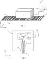
- FIG. 1shows a schematic isometric view of a position measurement device according to the present invention
- FIG. 2is a schematic diagram of the various optical and electronic components of the readhead of the position measurement device of FIG. 1 ;
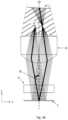
- FIGS. 3 a and 3 bshow schematic diagrams of the optical arrangement of the position measurement device of FIGS. 1 and 2 ;
- FIG. 4shows a cross-sectional view of the readhead of FIG. 1 ;
- FIG. 5shows an isometric view of the circuit board, light source, light source support structure, and sensor of the readhead of FIG. 1 ;
- FIGS. 6 a and 6 bshow isometric front and rear views of the light source's support structure
- FIG. 6 cshows a top plan view of the light source's support structure
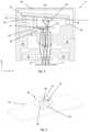
- FIGS. 7 a and 7 bshows isometric front and rear views of the support structure for the light source's bond wire
- FIG. 8shows an alternative embodiment of a readhead according to the present invention
- FIGS. 9 a and 9 bschematically illustrate plan views of a readhead according to the present invention wherein the light source is positioned directly over the sensor.
- an encoder apparatus 2comprising a readhead 4 , scale 6 and controller 7 .
- the readhead 4 and scale 6are mounted to first and second objects respectively (not shown) which are moveable relative to each other.
- the velocity of relative movementcan vary, but in the described embodiment the readhead 4 and scale 6 have a known maximum relative acceleration.
- the scale 6is a linear scale.
- the scale 6could be a non-linear scale, for example a rotary scale (e.g. disc or ring scale).
- the scale 6enables measurement in a single dimension only. However, this need not be the case, and for example the scale could enable measurement in two dimensions.
- the scale 6is an absolute scale and comprises a series of reflective 8 and non-reflective 10 lines arranged to encode unique position data along its length.
- the datacan be in the form of, for instance, a pseudorandom sequence or discrete codewords.
- the scalecould be an incremental scale (with or without a reference mark).
- the width of the linesdepends on the required positional resolution and is typically in the range of 1 ⁇ m to 100 ⁇ m, and more typically in the range of 5 ⁇ m to 50 ⁇ m, for instance in the range of 10 ⁇ m to 30 ⁇ m. In the described embodiment, the width of the lines is in the order of 15 ⁇ m.
- the reflective 8 and non-reflective linesare generally arranged in an alternate manner at a predetermined period. However, select non-reflective lines 10 are missing from the scale 6 so as to encode absolute position data in the scale 6 . For instance, the presence of a non-reflective line can be used to represent a “1” bit and the absence of a non-reflective line can represent a “0” bit.
- the readhead 4comprises a light emitting element/source 12 an optical device 18 , a sensor 20 , and a window 22 .
- the light emitting element/source 12comprises a light emitting diode (LED).
- the optical devicecomprises a lens 18 , but other optical devices could be used.
- a diffractive optical elementsuch as a Fresnel zone plate, and/or a holographic optical element could be used, for example a Hologram of a lens.
- the sensor 20comprises a Complementary Metal-Oxide-Semiconductor (“CMOS”) sensor.
- CMOSComplementary Metal-Oxide-Semiconductor
- other image sensorscould be used instead of a CMOS sensor.
- a CCD or a photodiode arraycould be used instead.
- the readhead 4also comprises a CPU 24 , a memory device 25 (for example, Electrically Erasable Programmable Read-Only Memory (EEPROM) or Flash memory) and an interface 26 .
- the readhead 4may also include an analogue-to-digital converter to digitize the image data from the sensor 20 .
- the analogue-to-digital conversioncould be performed within the sensor 20 or the CPU 24 .
- the scale 6reflects the light back through the window 22 which passes through the lens 18 which in turn forms a two-dimensional image of the scale onto the sensor 20 using the light reflected by the scale. Accordingly, the sensor 20 detects a two-dimensional image of a part of the scale 6 illuminated by the LED 12 .
- the sensorcould comprise a one or two dimensional array of pixels. For instance, the sensor could comprise a one-dimensional array of 256 elongate pixels, whose lengths extend parallel to the lengths of the reflective 8 and non-reflective lines 10 on the scale.
- a one-dimensional imaging arrangementcould be used instead, in which a one-dimensional image of the scale is formed by the lens on the sensor.
- the LED 12is connected to the CPU 24 so that the LED 12 can be operated on demand by the CPU 24 .
- the sensor 20is connected to the CPU 24 such that the CPU 24 can receive an image of the intensity of light falling across the image sensor 20 .
- the sensor 20is also directly connected to the CPU 24 so that the sensor 20 can be operated to take a snapshot of intensity falling across it on demand by the CPU 24 .
- the CPU 24is connected to the memory 25 so that it can store and retrieve data for use in its processing.
- the interface 26is connected to the CPU 24 so that the CPU 24 can receive demands from and output results to an external device such as a controller 7 (shown in FIG. 1 ) via line 40 .
- the line 40also comprises power lines via which the readhead 4 is powered.
- absolute position datacould be encoded in the scale 6 by missing reflective lines 8 , as well as, or instead of, missing non-reflective lines 10 .
- absolute position datacould be embedded in the scale 6 without the addition or removal of reflective 8 or non-reflective lines 10 .
- the width of lines, the distance between them or their colourcould be varied in order to embed the absolute position data in the scale 6 .
- the scalecould have features defining absolute position by the unique combination of features taken along the width of the scale.
- the scalecould comprise a plurality of “barcodes” the length of which extend across the scale, e.g.
- the scalecould comprise a plurality of tracks, in which at least one, optionally at least two and possibly all of these tracks could comprise a plurality of regularly spaced features (i.e. the tracks could essentially comprise incremental scale features of different fundamental frequencies) in which the scale period of the tracks differ from each other such that the combination of features across the scale's width is unique at any one point along the scale's measuring length.
- a series of groups of markingscan be used to encode a series of unique binary codewords along the scale length defining unique, i.e. absolute, position information, whilst still having sufficient information in order to enable phase information to be extracted from the series of markings to enable fine position information to be determined (e.g. position information with a resolution finer than the period of the scale markings).
- the position informationcan be made up from a coarse absolute position (determined from the codeword extracted from the image) as well as a fine position (determined by looking at the phase offset of the substantially periodic markings). Further details of such a so-called hybrid incremental and absolute scale is described in International Patent Application no. PCT/GB2002/001629 (publication no. WO 2002/084223), the content of which is incorporated in this specification by this reference.
- the scalecould comprise an absolute track comprising features defining absolute position information and a separate incremental track comprising regularly spaced features.
- FIGS. 3 a and 3 bschematically illustrate the path light takes through the optical system which forms the image of the scale 6 onto the sensor 20 , from the light source 12 to the sensor 20 .
- the optical device 18comprises a lens 18 having an optical axis OA, a focal length f and a focal plane fp.
- the point light source 12is located substantially at the lens' 18 focal plane fp, but slightly offset from the lens' 18 optical axis OA.
- the light source 12is offset (measured from the centre of the light source's emission zone) by approximately 450 ⁇ m, from the lens' 18 optical axis OA.
- the ratio of the offset to the focal length of the lensis approximately 0.45:2.5. Locating the light source 12 substantially at the lens' focal plane 18 helps to ensure that light emitted therefrom is substantially collimated by the lens 18 as it heads toward the scale 6 .
- the light reflected by the scale 6is then focussed by the lens 18 to a point at the lens' 18 focal plane fp, before diverging and forming a two-dimensional image of the scale 6 at the sensor 20 behind the light source 12 .
- an image of the light source 12will be formed at the focal plane fp. Locating the light source 12 at lens' 18 focal plane fp, but offset from the lens' 18 optical axis OA, means that the light source 12 can be located in the space (or “volume”) between the sensor 20 and the lens 18 (illustrated by the hatched area shown in FIG. 3 b ), helping to make the readhead compact, but not be in the way of the light reflected by the scale on its return path to the sensor 20 .
- both the light source 12 and the sensor 20face the lens 18 (and the window 22 and the scale 6 ).
- the emission surface of the light source 12 , and the sensing surface of the sensor 20face the lens 18 .
- there is an unreflected (in other words “direct”) optical path between the light source 12 and the lens 18and also an unreflected (in other words “direct”) optical path between the lens 18 and the sensor 20 .
- No reflective optical componentsare therefore needed or used to turn or steer the light. Avoiding the use of reflective optical components, such as mirrors and beam-splitters, can help to significantly reduce the size of the readhead.
- the same optical device/lens 18is used to both collimate the light from the light source 12 and to form an image of the scale 6 onto the sensor. Accordingly, the optical arrangement of the described readhead 4 only uses one optical device/lens 18 and so is particularly compact and inexpensive.
- the lens 18is a singlet lens, but could be a different type of lens (e.g. a doublet lens, compound lens or gradient-index (GRIN) lens.
- optical deviceneed not necessarily be a lens, but could be another type of optical device such as a Fresnel Zone Plate or a holographic optical element (HOE), for instance a hologram of a lens.
- HOEholographic optical element
- the light sourceis much closer to the lens 18 than it is to the sensor 20 .
- Such a configurationdeparts from a traditional encoder design where the light source would normally be mounted to the same board as the sensor, approximately in plane with the sensor. As shown in FIG.
- the readheadis configured such that the ratio of i) the distance (D 1 ) between the centre of the light emitting element's emission surface (or emission point) to the sensing plane of the sensor, in the direction perpendicular to the plane of the sensor, and ii) the distance (D 2 ) between the centre of the light emitting element's emission surface (or emission point) to the optical device, in the direction perpendicular to the plane of the sensor, is approximately 70:30.
- the distance between the centre of the light emitting element's emission surface (or emission point) to the sensing plane of the sensor, in the direction perpendicular to the sensing plane of the sensoris approximately 2.5 mm, for instance 2.6 mm.
- the optical path from the source to the sensoris substantially diamond/rhombus-shaped, and the optical path between the lens 18 and scale 6 is substantially V-shaped.
- the angle ⁇ between a line extending perpendicular to the scale (the dotted line in FIG. 3 b ) and the direction of the optical path as it impinges on the scaleis approximately 10°.
- the senor 20can be tilted such that it's sensing surface/plane is not perpendicular to the lens' optical axis. Such tilting can help to compensate for any keystone distortion in the image formed on the sensor, which can be formed due to the image being formed by an off-axis part of the lens 18 .
- the sensor 20is tilted such that the angle ⁇ between a plane extending parallel to their sensing surface (e.g. its sensing plane) and a plane extending perpendicular to the optical axis, is about 3°.
- the sensorcould be configured such that its sensing surface can extend perpendicular to the lens' optical axis (i.e.
- any other components mounted to the sensor 20 or PCB 12can also be titled for mechanical convenience; although this need not necessarily be the case.
- other ways of compensating for the keystone distortionare available, such as by appropriately shaping the sensor elements, e.g. “keystoning” the sensor elements themselves.
- FIGS. 4 and 5an example embodiment of how the readhead can be constructed to achieve the above described optical layout will now be described.
- the readhead 4comprises a body 30 to which the lens 18 , window 22 and a printed circuit board (PCB) 32 are mounted (e.g. via gluing, mechanical and/or frictional means).
- the sensor 20 , LED 12 and other electronic componentsare mechanically and electrically mounted to the PCB 32 .
- the LED 12is mounted to the PCB 32
- the LED 12is mounted to the circuit board “off-board”, in that it is mounted to the PCB 32 , but it is mounted via a raised support structure 34 which holds the LED 12 away from the PCB 32 .
- the support structure 34extends beyond the sensor 20 so as to hold the LED 12 further away from the PCB 32 than the sensor 20 .
- the sensor 20is mounted relatively close to the PCB 32 whereas the LED 12 is mounted relatively far from the PCB 32 .
- the LED 12is much closer to the lens 18 than the PCB 32
- the sensor 20is much closer to the PCB 32 than the lens 18 .
- the light emitting element and the sensorare separated in the dimension which extends perpendicular to the plane of the sensor/circuit board.
- the ratio of: i) the distance between the LED 12 emission surface (or emission point) to the sensor's 20 sensing plane, in the direction parallel to the imaging member's optical axis OA; and ii) the distance between the LED's 12 emission surface (or emission point) to lens 18 , in the direction parallel to the imaging member's optical axis OAis approximately 70:30.
- the above-mentioned support structure 34also forms/provides the electrical connection between the LED 12 and the PCB 32 .
- the support structure 34 for holding the LED 12 away from the PCB 32is the cathode 34 between the LED 12 and the PCB 32 .
- the cathode 34comprises a rigid, electrically-conductive, support structure for the LED 12 , which rises from the PCB 32 .
- the support structure/cathode 34comprises an opening/window 35 through which light reflected by the scale 6 can pass in order to reach the sensor 20 .
- the anode 36also comprises a rigid, electrically-conductive structure which rises from the PCB 32 , and which is wire-bonded to the LED 12 via a bond wire 38 as shown in FIGS. 4 and 5 .
- the readheadcomprises a raised bond wire support structure which extends from the PCB 32 , and wherein a bond wire 38 extends between it and the light emitting element 12 .
- the anode 36could also have an opening/window through which light emitted from the LED 12 can pass toward the lens 18 /scale 6 and through which light reflected by the scale 6 can pass in order to reach the sensor 20 .
- the anode's 36 rigid structurecould be omitted, and the LED 12 could be wire bonded via a bond wire which extends between the LED 12 and the PCB 32 .
- the LED's support structure/cathode 34 and the bond wire support structure/anode 36each comprise a sheet material part, each of which have been folded to provide a three-dimensional frame, and soldered to the PCB 32 .
- the cathode 34is brass
- the anodeis bass, plated with nickel-gold.
- fold-lines 37have been chemi-etched into the sheet material in order to aid folding.
- each of the support structures 34 , 36comprise a top surface 31 and a plurality of side supports (or “legs”) 33 which are soldered to the PCB 32 .
- the support structure/cathode 34could be formed in other ways, for example it could be machined/cut into shape and/or stamp/pressed into shape.
- the bare-die LED 12is mounted directly on the support structure/cathode 34 via conductive epoxy and the wire bond extends between the LED 12 and the top surface 31 of the anode 36 .
- the top surface 31 of the LED's support structure 34extends over/partially covers the sensor 20 (the outline of which is schematically illustrated in FIG. 6 c by the phantom line).
- a line extending through and perpendicular to the plane of the sensor 20 (and PCB 32 )also passes through the top surface 31 of the LED's support structure 34 .
- the readhead 4is assembled by dead-reckoning the lens 18 within the body 30 of the readhead 4 , and the body 30 being crimped in order to hold the lens 18 in place (although other ways of securing the lens 18 to the body can be used, such as by epoxy and/or by pushing the lens 18 into flexures which hold the lens).
- the PCB 32comprising the LED 12 already mounted thereon, is then mounted to the body 30 , e.g. by gluing and/or mechanical means such as crimping. If desired, an alignment process can be used to align the PCB (and hence the sensor and LED thereon) relative to the lens.
- Such an alignment processcould comprise using a camera to look at the position of the PCB/components thereon and make adjustments based on the output of the camera, and/or connect to the PCB/components thereon and use the output of the sensor to make adjustments.
- a lid 46is secured to the body 30 , e.g. via gluing, crimping and/or welding.
- the bond wire support structure 34also forms the cathode, but as will be understood, this need not necessarily be the case, and the support structure 34 could form the anode instead, for example.
- the LED 12is mechanically mounted to the PCB 32 via an electrode 34 , but as will be understood this need not necessarily be the case.
- the LED 12could be mechanically mounted directly to the PCB 32 via one or more non-electrically conductive members, and electrically connected to the PCB 32 via separate members, e.g. one or more wires (for instance, via wire bonding).
- the LED 12need not necessarily be mounted directly to the PCB 32 .
- the LED 12could be mechanically mounted directly to the body 30 , and electrically connected to the PCB 32 via one or more wires (e.g. via wire bonding).
- the LED 12could be electrically connected to a different PCB (i.e. not the same PCB 32 to which the sensor is connected).
- FIG. 8illustrates a readhead 4 ′ according to another embodiment of the invention.
- the readhead 4 ′ of FIG. 8shares many parts which are the same as that of the embodiment of FIGS. 1 to 7 and like parts share like reference numerals.
- the LED 12is mounted to the circuit board via the sensor 20 , by way of a transparent support structure 50 (e.g. a glass block 50 ).
- the glass block 50is secured to the sensor 20 via adhesive epoxy.
- the LED 12then sits on a conductive pad 52 which has been deposited on the side of the glass block 50 which faces the lens 18 and which is distal the sensor 20 .
- the LED 12is electrically connected to the circuit board 32 via an anode 36 ′ and cathode 34 ′ which in this embodiment each comprise raised bond wire support structures extending from the PCB 32 , and bond wires which extend between them and the LED 12 /conductive pad 52 .
- the LED 12could be connected to the circuit board in other ways, e.g. via an anode and cathode which are deposited on and run along the surface/side of the glass block 50 , or even via an anode and cathode which run through the glass block 50 .
- the light emitting element's support structure 34 and/or the light emitting element 12can be held directly over the sensor 20 such that a line extending perpendicular to the plane of the circuit board/sensor passes through both the light emitting element's support structure 34 and the sensor 20 and/or through both the light emitting element 12 and the sensor 20 .
- the sensor 20could comprise at least one, and for example an array of, photosensitive elements 21 , as well as other sub-components and packaging that make up the sensor 20 .
- the sensor 20could be a chip or component which comprises at least one, and for example an array of, photosensitive elements 21 .
- FIG. 9the sensor 20 could be a chip or component which comprises at least one, and for example an array of, photosensitive elements 21 .
- the light emitting element 12can be located directly over the sensor chip 20 in a way which in which it does not sit directly over the photosensitive elements 21 .
- the light emitting element 12can be located directly over the sensor chip 20 in a way which in which the light emitting element 12 sits directly over the photosensitive elements 21 , e.g. such that a line extending perpendicular to the plane of the circuit board/sensor (i.e. parallel to the Y-axis) passes through both the light emitting element 12 and the photosensitive elements 21 .
- the LED 12is mounted “off-board” by the support structure 34 . Whilst this can be beneficial (e.g. so as to place the LED 12 at the lens' 18 focal plane, so as to achieve collimation, whilst enabling an image of the scale to be captured by the sensor 20 ), this need not necessarily be the case.
- the LED 12could be mounted on the PCB 32 such that it sits substantially in-plane with the sensor 20 (in other words, at substantially the same height as the sensor 20 ).
- the light impinging on the scaleis collimated, but this need not necessarily be the case. Furthermore, even if the light impinging on the scale is collimated, the light reflected by the scale need not necessarily be collimated. For example, if the scale is curved, for instance if the scale is a ring scale, then the light reflected by the scale will not be collimated.
Landscapes
- Physics & Mathematics (AREA)
- General Physics & Mathematics (AREA)
- Optical Transform (AREA)
Abstract
Description
Claims (11)
Applications Claiming Priority (4)
| Application Number | Priority Date | Filing Date | Title |
|---|---|---|---|
| GB1916662.8 | 2019-11-15 | ||
| GB1916662 | 2019-11-15 | ||
| GBGB1916662.8AGB201916662D0 (en) | 2019-11-15 | 2019-11-15 | Encoder apparatus |
| PCT/EP2020/081916WO2021094457A1 (en) | 2019-11-15 | 2020-11-12 | Encoder apparatus |
Publications (2)
| Publication Number | Publication Date |
|---|---|
| US20220373364A1 US20220373364A1 (en) | 2022-11-24 |
| US12038310B2true US12038310B2 (en) | 2024-07-16 |
Family
ID=69063317
Family Applications (1)
| Application Number | Title | Priority Date | Filing Date |
|---|---|---|---|
| US17/773,990ActiveUS12038310B2 (en) | 2019-11-15 | 2020-11-12 | Encoder apparatus with readhead having circuit board and a folded sheet-metal structure to support a light emitting element |
Country Status (9)
| Country | Link |
|---|---|
| US (1) | US12038310B2 (en) |
| EP (1) | EP4058757B1 (en) |
| JP (1) | JP2023502080A (en) |
| KR (1) | KR20220097472A (en) |
| CN (1) | CN114729825B (en) |
| ES (1) | ES3010304T3 (en) |
| GB (1) | GB201916662D0 (en) |
| LT (1) | LT4058757T (en) |
| WO (1) | WO2021094457A1 (en) |
Citations (75)
| Publication number | Priority date | Publication date | Assignee | Title |
|---|---|---|---|---|
| DE221828C (en) | ||||
| US2963538A (en)* | 1957-04-11 | 1960-12-06 | Sanders Associates Inc | Flat cables |
| DE1911234U (en) | 1964-12-12 | 1965-03-04 | Wenczler & Heidenhain | DEVICE FOR DETERMINING THE SIZE OF MOVEMENTS OF AN OBJECT. |
| US3344700A (en) | 1961-05-23 | 1967-10-03 | British Aircraft Corp Ltd | Displacement measuring system |
| DE2316248A1 (en) | 1973-03-31 | 1974-10-10 | Leitz Ernst Gmbh | PHOTOELECTRIC STEPPER |
| GB2146765A (en) | 1983-09-01 | 1985-04-24 | Zeiss Jena Veb Carl | Arrangement for photoelectric scanning of graduations in reflected light |
| DE3417176A1 (en) | 1984-05-09 | 1985-11-21 | Dr. Johannes Heidenhain Gmbh, 8225 Traunreut | PHOTOELECTRICAL MEASURING DEVICE |
| EP0207121A1 (en) | 1984-12-22 | 1987-01-07 | Renishaw Plc | Opto-electronic scale-reading apparatus. |
| DE3703327A1 (en) | 1986-02-18 | 1987-08-20 | Mettler Instrumente Ag | METHOD AND DEVICE FOR OPTICAL POSITION MEASUREMENT |
| DE3702836A1 (en) | 1987-01-30 | 1988-08-11 | Brueckner Trockentechnik Gmbh | Stenter machine for continuously conveyed, flatly guided web goods |
| US4776701A (en) | 1984-05-31 | 1988-10-11 | Dr. Johannes Heidenhain Gmbh | Displacement measuring apparatus and method |
| DE3816675A1 (en) | 1987-08-20 | 1989-03-02 | Jenoptik Jena Gmbh | Photoelectric scanning arrangement for detecting the movement of line graduations in the reflected-light method |
| DE3801763C1 (en) | 1988-01-22 | 1989-06-08 | Dr. Johannes Heidenhain Gmbh, 8225 Traunreut, De | |
| DE3837134A1 (en) | 1988-11-02 | 1990-05-03 | Oelsch Kg | Contactless, digital linear transmitter |
| WO1991019163A1 (en) | 1990-06-08 | 1991-12-12 | Oy Partek Ab | An optical reflection detector |
| JPH03295416A (en) | 1990-04-13 | 1991-12-26 | Nikon Corp | encoder |
| JPH0450720A (en) | 1990-06-20 | 1992-02-19 | Futaba Corp | Optical length measuring instrument |
| DE4226683A1 (en) | 1991-08-14 | 1993-02-18 | Copal Co Ltd | Optical movement sensor using periodic pattern of slits - projects moving stripe pattern on to stationary masked photodetector giving electrical output proportional to distance moved |
| US5223708A (en) | 1991-10-04 | 1993-06-29 | The Boeing Company | Alignment insensitive optical position sensor |
| DE4301971A1 (en) | 1992-02-14 | 1993-08-19 | Heidenhain Gmbh Dr Johannes | |
| US5317149A (en) | 1992-11-12 | 1994-05-31 | Hewlett-Packard Company | Optical encoder with encapsulated electrooptics |
| WO1994025803A1 (en) | 1993-04-28 | 1994-11-10 | Daikin Industries, Ltd. | Operation control device for air conditioner |
| DE4316250A1 (en) | 1993-05-14 | 1994-11-17 | Heidenhain Gmbh Dr Johannes | Photoelectric length or angle measuring device |
| DE4436546A1 (en) | 1994-10-13 | 1996-04-18 | Heidenhain Gmbh Dr Johannes | Position measuring device |
| DE19527287A1 (en) | 1995-07-26 | 1997-01-30 | Zeiss Carl Jena Gmbh | Photoelectric path and angle measuring system for measuring the displacement of two objects to each other |
| JPH1054735A (en) | 1996-08-09 | 1998-02-24 | Tamagawa Seiki Co Ltd | Encoder |
| US5751492A (en) | 1996-06-14 | 1998-05-12 | Eastman Kodak Company | Diffractive/Refractive lenslet array incorporating a second aspheric surface |
| US5861953A (en) | 1994-12-10 | 1999-01-19 | Renishaw Plc | Opto-electronic scale reading apparatus with differing optical path lengths |
| DE19843155A1 (en) | 1997-09-26 | 1999-04-08 | Mitutoyo Corp | Optical distance measuring unit |
| US5900983A (en) | 1997-08-22 | 1999-05-04 | Lucent Technologies Inc. | Level-setting optical attenuator |
| US5995299A (en) | 1998-08-13 | 1999-11-30 | Samsung Aerospace Industries, Ltd. | Compact zoom lens system |
| US6198534B1 (en) | 1997-08-07 | 2001-03-06 | Johannes Heidenhain Gmbh | Scanning unit for an optical position measuring system |
| DE10031691A1 (en) | 1999-07-02 | 2001-04-26 | Cis Inst Fuer Mikrosensorik Gg | Optoelectronic measuring system for determining mutual displacement of two objects, has scale grid gages arranged on reflecting measurement material, corresponding to reference grating tracks on sensing plate |
| US6465773B1 (en) | 1999-11-18 | 2002-10-15 | Hera Rotterdam B.V. | Optical measurement module for measuring angles and/or distances |
| WO2002084223A1 (en) | 2001-04-11 | 2002-10-24 | Renishaw Plc | Absolute position measurement |
| US20030076507A1 (en) | 2001-10-23 | 2003-04-24 | Olympus Optical Co., Ltd. | Optical encoder |
| US20030209658A1 (en) | 2002-02-13 | 2003-11-13 | Omron Corporation | Optical encoder |
| EP1447648A1 (en) | 2003-02-12 | 2004-08-18 | Mitutoyo Corporation | Optical Encoder |
| JP2005134391A (en)* | 2003-10-28 | 2005-05-26 | Agilent Technol Inc | Reflective image encoding device |
| US6943888B2 (en) | 1996-08-23 | 2005-09-13 | Pentax Corporation | Pattern reading apparatus |
| US6972402B2 (en) | 2002-06-03 | 2005-12-06 | Mitsubishi Denki Kabushiki Kaisha | Photoelectric rotary encoder |
| WO2005124282A2 (en) | 2004-06-21 | 2005-12-29 | Renishaw Plc | Scale reading apparatus |
| US20060028442A1 (en)* | 2002-12-20 | 2006-02-09 | Itac Systems, Inc. | Cursor control device |
| US20060202113A1 (en) | 2005-03-11 | 2006-09-14 | Mitutoyo Corporation | Photoelectric encoder |
| JP2006284564A (en) | 2005-03-11 | 2006-10-19 | Mitsutoyo Corp | Photoelectric encoder |
| JP2006292728A (en) | 2005-03-17 | 2006-10-26 | Mitsutoyo Corp | Photoelectric encoder |
| US7193204B2 (en) | 2002-07-08 | 2007-03-20 | Gsi Group Corporation | Multi-track optical encoder employing beam divider |
| US20070114283A1 (en) | 2005-11-21 | 2007-05-24 | Foo Siang L | Reflective encoder with lens on code strip |
| US20070120047A1 (en) | 2005-11-25 | 2007-05-31 | Wong Weng F | Ring-configured photodiode array and optical encoders using the same |
| DE102006011540A1 (en) | 2006-02-12 | 2007-08-23 | Samland, Thomas, Dipl.-Math. | Scanning unit for detection of optical measure embodiments, has aperture diaphragm array arranged in picture-sided focal plane of micro lens array, and aperture opening is located in picture-lateral focal point of each micro lens of array |
| US20070241943A1 (en) | 2006-04-14 | 2007-10-18 | Tan Teong S | Flat-top reflection-based optical encoders |
| US20070241270A1 (en) | 2006-04-14 | 2007-10-18 | Saidan Saiful B | Multi-axis optical encoders |
| CN101067560A (en) | 2006-05-05 | 2007-11-07 | 约翰尼斯海登海恩博士股份有限公司 | Position measuring device |
| GB2443113A (en)* | 2004-07-28 | 2008-04-23 | Caterpillar Inc | Reading apparatus with appropriately located optical components |
| US20080100569A1 (en) | 2006-11-01 | 2008-05-01 | Chee Foo Lum | Optical jog wheel |
| US7417218B2 (en) | 2005-05-12 | 2008-08-26 | Olympus Corporation | Triple grating optical encoder with light transmitting area in optical path |
| US7423768B2 (en) | 2005-04-06 | 2008-09-09 | Dr. Johannes Heidenhain Gmbh | Scanning unit for a position measuring system for the optical scanning of a scale and position measuring system utilizing such a scanning unit |
| CN201112407Y (en) | 2007-08-13 | 2008-09-10 | 亿光电子工业股份有限公司 | High-power light-emitting diode structure |
| US20080316492A1 (en) | 2007-06-22 | 2008-12-25 | Chia-Chu Cheng | Optical motion identification device utilizing partial total internal reflection light source and/or partial non-total internal reflection light source |
| US20090057406A1 (en) | 2007-05-25 | 2009-03-05 | Mitutoyo Corporation | Reflection type encoder |
| US20100155586A1 (en) | 2008-12-23 | 2010-06-24 | Avago Technologies Ecbu (Singapore) Pte. Ltd. | Optical Encoder Systems, Devices and Methods |
| US20100243871A1 (en) | 2009-03-26 | 2010-09-30 | Olympus Corporation | Optical encoder for detecting the relative displacement between an encoder scale and an encoder head |
| WO2010116144A2 (en) | 2009-04-08 | 2010-10-14 | Renishaw Plc | Position encoder apparatus |
| JP4713908B2 (en) | 2005-03-17 | 2011-06-29 | 株式会社ミツトヨ | Lens system and photoelectric encoder using the same |
| US7982175B2 (en)* | 2009-06-30 | 2011-07-19 | Avago Technologies Ecbu Ip (Singapore) Pte. Ltd. | Miniaturized single track optical encoder system with integrated index channel(s) |
| CN102197282A (en) | 2008-10-28 | 2011-09-21 | 瑞尼斯豪公司 | Absolute encoder setup indication |
| US20110233391A1 (en) | 2010-03-29 | 2011-09-29 | Mitutoyo Corporation | Optical encoder |
| US20110233390A1 (en) | 2010-03-29 | 2011-09-29 | Mitutoyo Corporation | Optical encoder |
| US20110254032A1 (en)* | 2010-04-20 | 2011-10-20 | Avago Technologies Ecbu Ip (Singapore) Pte. Ltd. | Electronic Assembly |
| US20170089737A1 (en) | 2015-09-29 | 2017-03-30 | Mitutoyo Corporation | Optical encoder |
| EP3150968A1 (en) | 2015-10-02 | 2017-04-05 | SICK STEGMANN GmbH | Optoelectronic sensor |
| WO2017093738A1 (en) | 2015-12-03 | 2017-06-08 | Renishaw Plc | Encoder apparatus |
| US20170219389A1 (en)* | 2014-08-06 | 2017-08-03 | Nsk Ltd. | Sensor and method of manufacturing sensor |
| JP2018072184A (en) | 2016-10-31 | 2018-05-10 | セイコーエプソン株式会社 | Encoder and robot |
| CN116584991A (en) | 2023-05-10 | 2023-08-15 | 浙江德康医疗器械有限公司 | Absorbable interface screw with claw-shaped fixing nail and implantation method thereof |
- 2019
- 2019-11-15GBGBGB1916662.8Apatent/GB201916662D0/ennot_activeCeased
- 2020
- 2020-11-12CNCN202080079573.1Apatent/CN114729825B/enactiveActive
- 2020-11-12USUS17/773,990patent/US12038310B2/enactiveActive
- 2020-11-12LTLTEPPCT/EP2020/081916Tpatent/LT4058757T/enunknown
- 2020-11-12ESES20807002Tpatent/ES3010304T3/enactiveActive
- 2020-11-12KRKR1020227018976Apatent/KR20220097472A/enactivePending
- 2020-11-12JPJP2022528205Apatent/JP2023502080A/enactivePending
- 2020-11-12WOPCT/EP2020/081916patent/WO2021094457A1/ennot_activeCeased
- 2020-11-12EPEP20807002.9Apatent/EP4058757B1/enactiveActive
Patent Citations (115)
| Publication number | Priority date | Publication date | Assignee | Title |
|---|---|---|---|---|
| DE221828C (en) | ||||
| US2963538A (en)* | 1957-04-11 | 1960-12-06 | Sanders Associates Inc | Flat cables |
| US3344700A (en) | 1961-05-23 | 1967-10-03 | British Aircraft Corp Ltd | Displacement measuring system |
| DE1911234U (en) | 1964-12-12 | 1965-03-04 | Wenczler & Heidenhain | DEVICE FOR DETERMINING THE SIZE OF MOVEMENTS OF AN OBJECT. |
| DE2316248A1 (en) | 1973-03-31 | 1974-10-10 | Leitz Ernst Gmbh | PHOTOELECTRIC STEPPER |
| GB2146765A (en) | 1983-09-01 | 1985-04-24 | Zeiss Jena Veb Carl | Arrangement for photoelectric scanning of graduations in reflected light |
| DE3417176A1 (en) | 1984-05-09 | 1985-11-21 | Dr. Johannes Heidenhain Gmbh, 8225 Traunreut | PHOTOELECTRICAL MEASURING DEVICE |
| US4778273A (en) | 1984-05-09 | 1988-10-18 | Dr. Johannes Heidenhain Gmbh | Photoelectric measuring system |
| US4776701A (en) | 1984-05-31 | 1988-10-11 | Dr. Johannes Heidenhain Gmbh | Displacement measuring apparatus and method |
| EP0207121A1 (en) | 1984-12-22 | 1987-01-07 | Renishaw Plc | Opto-electronic scale-reading apparatus. |
| US4959542A (en) | 1984-12-22 | 1990-09-25 | Renishaw Plc | Opto-electronic scale-reading apparatus |
| DE3703327A1 (en) | 1986-02-18 | 1987-08-20 | Mettler Instrumente Ag | METHOD AND DEVICE FOR OPTICAL POSITION MEASUREMENT |
| US4799798A (en) | 1986-02-18 | 1989-01-24 | Mettler Instruments Ag | Method of and an apparatus for an optical measuring of a position |
| DE3702836A1 (en) | 1987-01-30 | 1988-08-11 | Brueckner Trockentechnik Gmbh | Stenter machine for continuously conveyed, flatly guided web goods |
| DE3816675A1 (en) | 1987-08-20 | 1989-03-02 | Jenoptik Jena Gmbh | Photoelectric scanning arrangement for detecting the movement of line graduations in the reflected-light method |
| DE3801763C1 (en) | 1988-01-22 | 1989-06-08 | Dr. Johannes Heidenhain Gmbh, 8225 Traunreut, De | |
| DE3837134A1 (en) | 1988-11-02 | 1990-05-03 | Oelsch Kg | Contactless, digital linear transmitter |
| JPH03295416A (en) | 1990-04-13 | 1991-12-26 | Nikon Corp | encoder |
| WO1991019163A1 (en) | 1990-06-08 | 1991-12-12 | Oy Partek Ab | An optical reflection detector |
| JPH0450720A (en) | 1990-06-20 | 1992-02-19 | Futaba Corp | Optical length measuring instrument |
| US5539519A (en) | 1991-08-14 | 1996-07-23 | Copal Company Limited | Compact, high resolution optical displacement detector |
| DE4226683A1 (en) | 1991-08-14 | 1993-02-18 | Copal Co Ltd | Optical movement sensor using periodic pattern of slits - projects moving stripe pattern on to stationary masked photodetector giving electrical output proportional to distance moved |
| US5223708A (en) | 1991-10-04 | 1993-06-29 | The Boeing Company | Alignment insensitive optical position sensor |
| DE4301971A1 (en) | 1992-02-14 | 1993-08-19 | Heidenhain Gmbh Dr Johannes | |
| US5317149A (en) | 1992-11-12 | 1994-05-31 | Hewlett-Packard Company | Optical encoder with encapsulated electrooptics |
| WO1994025803A1 (en) | 1993-04-28 | 1994-11-10 | Daikin Industries, Ltd. | Operation control device for air conditioner |
| US5592824A (en) | 1993-04-28 | 1997-01-14 | Daikin Industries, Ltd. | Driving control device for air conditioner |
| DE4316250A1 (en) | 1993-05-14 | 1994-11-17 | Heidenhain Gmbh Dr Johannes | Photoelectric length or angle measuring device |
| DE4436546A1 (en) | 1994-10-13 | 1996-04-18 | Heidenhain Gmbh Dr Johannes | Position measuring device |
| US5691814A (en) | 1994-10-13 | 1997-11-25 | Dr. Johannes Heidenhain Gmbh | Position measuring instrument |
| US5861953A (en) | 1994-12-10 | 1999-01-19 | Renishaw Plc | Opto-electronic scale reading apparatus with differing optical path lengths |
| DE19527287A1 (en) | 1995-07-26 | 1997-01-30 | Zeiss Carl Jena Gmbh | Photoelectric path and angle measuring system for measuring the displacement of two objects to each other |
| US5841134A (en) | 1995-07-26 | 1998-11-24 | Carl Zeiss Jena Gmbh | Photo-electric distance- and angle-measurement system for measuring the displacement of two objects with respect to each other |
| US5751492A (en) | 1996-06-14 | 1998-05-12 | Eastman Kodak Company | Diffractive/Refractive lenslet array incorporating a second aspheric surface |
| JPH1054735A (en) | 1996-08-09 | 1998-02-24 | Tamagawa Seiki Co Ltd | Encoder |
| US6943888B2 (en) | 1996-08-23 | 2005-09-13 | Pentax Corporation | Pattern reading apparatus |
| US6198534B1 (en) | 1997-08-07 | 2001-03-06 | Johannes Heidenhain Gmbh | Scanning unit for an optical position measuring system |
| US5900983A (en) | 1997-08-22 | 1999-05-04 | Lucent Technologies Inc. | Level-setting optical attenuator |
| DE19843155A1 (en) | 1997-09-26 | 1999-04-08 | Mitutoyo Corp | Optical distance measuring unit |
| US5995229A (en) | 1997-09-26 | 1999-11-30 | Mitutoyo Corporation | Optical displacement measuring apparatus |
| US5995299A (en) | 1998-08-13 | 1999-11-30 | Samsung Aerospace Industries, Ltd. | Compact zoom lens system |
| DE10031691A1 (en) | 1999-07-02 | 2001-04-26 | Cis Inst Fuer Mikrosensorik Gg | Optoelectronic measuring system for determining mutual displacement of two objects, has scale grid gages arranged on reflecting measurement material, corresponding to reference grating tracks on sensing plate |
| US6465773B1 (en) | 1999-11-18 | 2002-10-15 | Hera Rotterdam B.V. | Optical measurement module for measuring angles and/or distances |
| WO2002084223A1 (en) | 2001-04-11 | 2002-10-24 | Renishaw Plc | Absolute position measurement |
| US20040118758A1 (en) | 2001-04-11 | 2004-06-24 | Gordon-Ingram Iain Robert | Absolute position measurement |
| US7499827B2 (en) | 2001-04-11 | 2009-03-03 | Renishaw Plc | Absolute position measurement |
| US20030076507A1 (en) | 2001-10-23 | 2003-04-24 | Olympus Optical Co., Ltd. | Optical encoder |
| US6940603B2 (en) | 2001-10-23 | 2005-09-06 | Olympus Corporation | Optical encoder |
| US20030209658A1 (en) | 2002-02-13 | 2003-11-13 | Omron Corporation | Optical encoder |
| US6972402B2 (en) | 2002-06-03 | 2005-12-06 | Mitsubishi Denki Kabushiki Kaisha | Photoelectric rotary encoder |
| US7193204B2 (en) | 2002-07-08 | 2007-03-20 | Gsi Group Corporation | Multi-track optical encoder employing beam divider |
| US20060028442A1 (en)* | 2002-12-20 | 2006-02-09 | Itac Systems, Inc. | Cursor control device |
| EP1447648A1 (en) | 2003-02-12 | 2004-08-18 | Mitutoyo Corporation | Optical Encoder |
| JP2005134391A (en)* | 2003-10-28 | 2005-05-26 | Agilent Technol Inc | Reflective image encoding device |
| US20080013105A1 (en) | 2004-06-21 | 2008-01-17 | Renishaw Plc | Scale Reading Apparatus |
| WO2005124282A2 (en) | 2004-06-21 | 2005-12-29 | Renishaw Plc | Scale reading apparatus |
| US7659992B2 (en) | 2004-06-21 | 2010-02-09 | Renishaw Plc | Scale reading apparatus |
| GB2443113A (en)* | 2004-07-28 | 2008-04-23 | Caterpillar Inc | Reading apparatus with appropriately located optical components |
| US20060202113A1 (en) | 2005-03-11 | 2006-09-14 | Mitutoyo Corporation | Photoelectric encoder |
| JP2006284564A (en) | 2005-03-11 | 2006-10-19 | Mitsutoyo Corp | Photoelectric encoder |
| JP2006292728A (en) | 2005-03-17 | 2006-10-26 | Mitsutoyo Corp | Photoelectric encoder |
| JP4713908B2 (en) | 2005-03-17 | 2011-06-29 | 株式会社ミツトヨ | Lens system and photoelectric encoder using the same |
| US7423768B2 (en) | 2005-04-06 | 2008-09-09 | Dr. Johannes Heidenhain Gmbh | Scanning unit for a position measuring system for the optical scanning of a scale and position measuring system utilizing such a scanning unit |
| US7417218B2 (en) | 2005-05-12 | 2008-08-26 | Olympus Corporation | Triple grating optical encoder with light transmitting area in optical path |
| US20070114283A1 (en) | 2005-11-21 | 2007-05-24 | Foo Siang L | Reflective encoder with lens on code strip |
| US20070120047A1 (en) | 2005-11-25 | 2007-05-31 | Wong Weng F | Ring-configured photodiode array and optical encoders using the same |
| DE102006011540A1 (en) | 2006-02-12 | 2007-08-23 | Samland, Thomas, Dipl.-Math. | Scanning unit for detection of optical measure embodiments, has aperture diaphragm array arranged in picture-sided focal plane of micro lens array, and aperture opening is located in picture-lateral focal point of each micro lens of array |
| US20070241943A1 (en) | 2006-04-14 | 2007-10-18 | Tan Teong S | Flat-top reflection-based optical encoders |
| US20070241270A1 (en) | 2006-04-14 | 2007-10-18 | Saidan Saiful B | Multi-axis optical encoders |
| US7525085B2 (en) | 2006-04-14 | 2009-04-28 | Avago Technologies General Ip (Singapore) Pte. Ltd. | Multi-axis optical encoders |
| US7495583B2 (en) | 2006-04-14 | 2009-02-24 | Avago Technologies General Ip (Singapore) Pte. Ltd. | Flat-top reflection-based optical encoders |
| US20070262250A1 (en)* | 2006-05-05 | 2007-11-15 | Ulrich Benner | Position-measuring device |
| CN101067560A (en) | 2006-05-05 | 2007-11-07 | 约翰尼斯海登海恩博士股份有限公司 | Position measuring device |
| US7473886B2 (en) | 2006-05-05 | 2009-01-06 | Dr. Johannes Heidenhain Gmbh | Position-measuring device |
| US20080099669A1 (en) | 2006-11-01 | 2008-05-01 | Chee Foo Lum | Optical jog wheel with spiral coding element |
| TW200921055A (en) | 2006-11-01 | 2009-05-16 | Avago Tech Ecbu Ip Sg Pte Ltd | Optical jog wheel with spiral coding element |
| US7675026B2 (en) | 2006-11-01 | 2010-03-09 | Avago Technologies Ecbu Ip (Singapore) Pte. Ltd. | Optical jog wheel with spiral coding element |
| US20100127162A1 (en) | 2006-11-01 | 2010-05-27 | Avago Technologies Ecbu Ip (Singapore) Pte. Ltd. | Optical jog wheel with spiral coding element |
| US7732756B2 (en) | 2006-11-01 | 2010-06-08 | Avago Technologies Ecbu Ip (Singapore) Pte. Ltd. | User navigation device with a code wheel and an encoder |
| US8247758B2 (en) | 2006-11-01 | 2012-08-21 | Avago Technologies Ecbu Ip (Singapore) Pte. Ltd. | Optical jog wheel with spiral coding element |
| US20080100569A1 (en) | 2006-11-01 | 2008-05-01 | Chee Foo Lum | Optical jog wheel |
| US20090057406A1 (en) | 2007-05-25 | 2009-03-05 | Mitutoyo Corporation | Reflection type encoder |
| US20080316492A1 (en) | 2007-06-22 | 2008-12-25 | Chia-Chu Cheng | Optical motion identification device utilizing partial total internal reflection light source and/or partial non-total internal reflection light source |
| CN201112407Y (en) | 2007-08-13 | 2008-09-10 | 亿光电子工业股份有限公司 | High-power light-emitting diode structure |
| US8505210B2 (en) | 2008-10-28 | 2013-08-13 | Renishaw Plc | Absolute encoder setup indication |
| CN102197282A (en) | 2008-10-28 | 2011-09-21 | 瑞尼斯豪公司 | Absolute encoder setup indication |
| US20100314532A1 (en) | 2008-12-23 | 2010-12-16 | Avago Technologies Ecbu (Singapore) Pte. Ltd. | Optical Encoder Systems, Devices and Methods |
| US8193483B2 (en) | 2008-12-23 | 2012-06-05 | Avago Technologies Ecbu Ip (Singapore) Pte. Ltd. | Optical encoder systems, devices and methods |
| US20100155586A1 (en) | 2008-12-23 | 2010-06-24 | Avago Technologies Ecbu (Singapore) Pte. Ltd. | Optical Encoder Systems, Devices and Methods |
| US7795576B2 (en) | 2008-12-23 | 2010-09-14 | Avago Technologies Ecbu Ip (Singapore) Pte. Ltd. | Single dome lens reflective optical encoder |
| US20100243871A1 (en) | 2009-03-26 | 2010-09-30 | Olympus Corporation | Optical encoder for detecting the relative displacement between an encoder scale and an encoder head |
| US20120007980A1 (en) | 2009-04-08 | 2012-01-12 | Renishaw Plc | Position encoder apparatus |
| WO2010116144A2 (en) | 2009-04-08 | 2010-10-14 | Renishaw Plc | Position encoder apparatus |
| US10132657B2 (en) | 2009-04-08 | 2018-11-20 | Renishaw Plc | Position encoder apparatus |
| US7982175B2 (en)* | 2009-06-30 | 2011-07-19 | Avago Technologies Ecbu Ip (Singapore) Pte. Ltd. | Miniaturized single track optical encoder system with integrated index channel(s) |
| CN102207396A (en) | 2010-03-29 | 2011-10-05 | 株式会社三丰 | Optical encoder |
| CN102279009A (en) | 2010-03-29 | 2011-12-14 | 株式会社三丰 | Optical encoder |
| US20110233390A1 (en) | 2010-03-29 | 2011-09-29 | Mitutoyo Corporation | Optical encoder |
| US20110233391A1 (en) | 2010-03-29 | 2011-09-29 | Mitutoyo Corporation | Optical encoder |
| US8476577B2 (en) | 2010-03-29 | 2013-07-02 | Mitutoyo Corporation | Optical encoder |
| US8637805B2 (en) | 2010-03-29 | 2014-01-28 | Mitutoyo Corporation | Optical encoder using off-axis imaging through a lens |
| US20110254032A1 (en)* | 2010-04-20 | 2011-10-20 | Avago Technologies Ecbu Ip (Singapore) Pte. Ltd. | Electronic Assembly |
| US20170219389A1 (en)* | 2014-08-06 | 2017-08-03 | Nsk Ltd. | Sensor and method of manufacturing sensor |
| US20170089737A1 (en) | 2015-09-29 | 2017-03-30 | Mitutoyo Corporation | Optical encoder |
| EP3150968A1 (en) | 2015-10-02 | 2017-04-05 | SICK STEGMANN GmbH | Optoelectronic sensor |
| WO2017093738A1 (en) | 2015-12-03 | 2017-06-08 | Renishaw Plc | Encoder apparatus |
| US20180321062A1 (en) | 2015-12-03 | 2018-11-08 | Renishaw Plc | Encoder |
| US20180356261A1 (en) | 2015-12-03 | 2018-12-13 | Renishaw Plc | Encoder apparatus |
| EP3384246B1 (en) | 2015-12-03 | 2020-05-06 | Renishaw PLC | Encoder apparatus |
| US10907997B2 (en) | 2015-12-03 | 2021-02-02 | Renishaw Plc | Encoder apparatus |
| US20210123774A1 (en) | 2015-12-03 | 2021-04-29 | Renishaw Plc | Encoder apparatus |
| US11009374B2 (en) | 2015-12-03 | 2021-05-18 | Renishaw Plc | Encoder |
| US20210207981A1 (en) | 2015-12-03 | 2021-07-08 | Renishaw Plc | Encoder |
| JP2018072184A (en) | 2016-10-31 | 2018-05-10 | セイコーエプソン株式会社 | Encoder and robot |
| CN116584991A (en) | 2023-05-10 | 2023-08-15 | 浙江德康医疗器械有限公司 | Absorbable interface screw with claw-shaped fixing nail and implantation method thereof |
Non-Patent Citations (17)
| Title |
|---|
| "Exposed Linear Encoders". Heidenhain, May 2019, pp. 1-71. |
| Abramowitz, Mortimer et al. "Oblique Illumination". https://www.olympus-lifescience.com/en/microscope-resource/primer/techniques/oblique/obliqueintro. |
| Apr. 23, 2024 Notice of Allowance issued in U.S. Appl. No. 17/774,013. |
| Avago Technologies. AEDR-8400 Series Data Sheet, 2015, 8 pages. |
| Broadcom.com. "AEDR-8400-140," 2019, 2 pages. |
| Illustration of the relative offsets between (i) the sensor and (ii) the light emitting element for various encoder readheads made and sold by Renishaw plc before Nov. 15, 2018. |
| Jan. 21, 2021 International Search Report issued in International Patent Application No. PCT/EP2020/081914. |
| Jan. 21, 2021 Written Opinion of the International Searching Authority issued in International Patent Application No. PCT/EP2020/081914. |
| Jan. 26, 2021 International Search Report issued in International Patent Application No. PCT/EP2020/081916. |
| Jan. 26, 2021 Written Opinion of the International Searching Authority issued in International Patent Application No. PCT/EP2020/081916. |
| May 15, 2020 Search Report issued in British Patent Application No. 1916641.2. |
| May 15, 2020 Search Report issued in British Patent Application No. 1916662.8. |
| Muller, Matthew S. et al. "Microscopy: Off-the-Shelf Components Enable a New Generation of Confocal Microscopy". https://www.laserfocusworld.com/optics/article/16550130/microscopy-offtheshelf-components-enable-a-new-generation-of-confocal-microscopy, 2014. |
| Peterson, Alexander W. et al. "High Resolution Surface Plasmon Resonance Imaging for Single Cells". BMC Cell Biology, vol. 15, 2014, https://bmcmolcellbiol.biomedcentral.com/articles/10.1186/1471-2121-15-35. |
| Smilevski, Luka. "Fluorescence Microscopy". https://conductscience.com/fluorescence-microscopy, 2019. |
| U.S. Appl. No. 17/774,013, filed May 3, 2022 in the name of Slack et al. |
| Wikipedia. "Foucault knife-edge test," 2019, 4 pages. |
Also Published As
| Publication number | Publication date |
|---|---|
| JP2023502080A (en) | 2023-01-20 |
| WO2021094457A1 (en) | 2021-05-20 |
| EP4058757A1 (en) | 2022-09-21 |
| CN114729825A (en) | 2022-07-08 |
| EP4058757B1 (en) | 2025-01-01 |
| ES3010304T3 (en) | 2025-04-02 |
| LT4058757T (en) | 2025-02-10 |
| US20220373364A1 (en) | 2022-11-24 |
| CN114729825B (en) | 2025-02-28 |
| KR20220097472A (en) | 2022-07-07 |
| GB201916662D0 (en) | 2020-01-01 |
Similar Documents
| Publication | Publication Date | Title |
|---|---|---|
| US20240377228A1 (en) | Position measurement device | |
| US20090008538A1 (en) | Optical encoder and its manufacturing method | |
| JP2005043192A (en) | Optical encoder, its manufacturing method, and optical lens module | |
| JP3743426B2 (en) | Optical encoder | |
| JP2003307440A5 (en) | ||
| GB2390897A (en) | Optical encoder device | |
| JP4205117B2 (en) | Optical reflective information reading sensor and electronic device | |
| US12038310B2 (en) | Encoder apparatus with readhead having circuit board and a folded sheet-metal structure to support a light emitting element | |
| CN212871099U (en) | Ultra-thin linear array image sensor and displacement detection device | |
| JP5051973B2 (en) | Reflective optical encoder | |
| US6712273B1 (en) | Versatile method and system for VCSEL-based bar code scanner | |
| JPH09288712A (en) | Barcode reader | |
| CN104160249B (en) | Optoelectronic position measurement apparatus and manufacture method thereof | |
| CN111735396A (en) | Ultra-thin linear array image sensor and displacement detection device | |
| US8654425B2 (en) | Optical detection device, optical device, optical information reading device, and light source fixing method | |
| CN220960113U (en) | Photoelectric incremental encoder module integrated with light source | |
| JP2006078376A (en) | Optical displacement sensor | |
| JPH09126815A (en) | Light emitting / light receiving element package and encoder using the same | |
| WO2007132602A1 (en) | Optical encoder and motor with encoder | |
| JP2007333401A (en) | Optical encoder |
Legal Events
| Date | Code | Title | Description |
|---|---|---|---|
| AS | Assignment | Owner name:RENISHAW PLC, UNITED KINGDOM Free format text:ASSIGNMENT OF ASSIGNORS INTEREST;ASSIGNORS:DYSON, JOSH ALEXANDER;CLUFF, JULIAN ALEXANDER;SIGNING DATES FROM 20220203 TO 20220208;REEL/FRAME:059797/0458 | |
| FEPP | Fee payment procedure | Free format text:ENTITY STATUS SET TO UNDISCOUNTED (ORIGINAL EVENT CODE: BIG.); ENTITY STATUS OF PATENT OWNER: LARGE ENTITY | |
| STPP | Information on status: patent application and granting procedure in general | Free format text:DOCKETED NEW CASE - READY FOR EXAMINATION | |
| STPP | Information on status: patent application and granting procedure in general | Free format text:NON FINAL ACTION MAILED | |
| STPP | Information on status: patent application and granting procedure in general | Free format text:RESPONSE TO NON-FINAL OFFICE ACTION ENTERED AND FORWARDED TO EXAMINER | |
| STPP | Information on status: patent application and granting procedure in general | Free format text:FINAL REJECTION MAILED | |
| STPP | Information on status: patent application and granting procedure in general | Free format text:ADVISORY ACTION MAILED | |
| STPP | Information on status: patent application and granting procedure in general | Free format text:DOCKETED NEW CASE - READY FOR EXAMINATION | |
| STPP | Information on status: patent application and granting procedure in general | Free format text:NOTICE OF ALLOWANCE MAILED -- APPLICATION RECEIVED IN OFFICE OF PUBLICATIONS | |
| STPP | Information on status: patent application and granting procedure in general | Free format text:AWAITING TC RESP., ISSUE FEE NOT PAID | |
| STPP | Information on status: patent application and granting procedure in general | Free format text:NOTICE OF ALLOWANCE MAILED -- APPLICATION RECEIVED IN OFFICE OF PUBLICATIONS | |
| STPP | Information on status: patent application and granting procedure in general | Free format text:NOTICE OF ALLOWANCE MAILED -- APPLICATION RECEIVED IN OFFICE OF PUBLICATIONS | |
| STPP | Information on status: patent application and granting procedure in general | Free format text:PUBLICATIONS -- ISSUE FEE PAYMENT VERIFIED | |
| STCF | Information on status: patent grant | Free format text:PATENTED CASE |