US12038029B2 - Mechanical locking system for panels - Google Patents
Mechanical locking system for panelsDownload PDFInfo
- Publication number
- US12038029B2 US12038029B2US17/370,521US202117370521AUS12038029B2US 12038029 B2US12038029 B2US 12038029B2US 202117370521 AUS202117370521 AUS 202117370521AUS 12038029 B2US12038029 B2US 12038029B2
- Authority
- US
- United States
- Prior art keywords
- panel
- groove
- locking
- angle
- edge
- Prior art date
- Legal status (The legal status is an assumption and is not a legal conclusion. Google has not performed a legal analysis and makes no representation as to the accuracy of the status listed.)
- Active, expires
Links
Images


Classifications
- F—MECHANICAL ENGINEERING; LIGHTING; HEATING; WEAPONS; BLASTING
- F16—ENGINEERING ELEMENTS AND UNITS; GENERAL MEASURES FOR PRODUCING AND MAINTAINING EFFECTIVE FUNCTIONING OF MACHINES OR INSTALLATIONS; THERMAL INSULATION IN GENERAL
- F16B—DEVICES FOR FASTENING OR SECURING CONSTRUCTIONAL ELEMENTS OR MACHINE PARTS TOGETHER, e.g. NAILS, BOLTS, CIRCLIPS, CLAMPS, CLIPS OR WEDGES; JOINTS OR JOINTING
- F16B12/00—Jointing of furniture or the like, e.g. hidden from exterior
- F16B12/10—Jointing of furniture or the like, e.g. hidden from exterior using pegs, bolts, tenons, clamps, clips, or the like
- F16B12/12—Jointing of furniture or the like, e.g. hidden from exterior using pegs, bolts, tenons, clamps, clips, or the like for non-metal furniture parts, e.g. made of wood, of plastics
- F16B12/26—Jointing of furniture or the like, e.g. hidden from exterior using pegs, bolts, tenons, clamps, clips, or the like for non-metal furniture parts, e.g. made of wood, of plastics using snap-action elements
- F—MECHANICAL ENGINEERING; LIGHTING; HEATING; WEAPONS; BLASTING
- F16—ENGINEERING ELEMENTS AND UNITS; GENERAL MEASURES FOR PRODUCING AND MAINTAINING EFFECTIVE FUNCTIONING OF MACHINES OR INSTALLATIONS; THERMAL INSULATION IN GENERAL
- F16B—DEVICES FOR FASTENING OR SECURING CONSTRUCTIONAL ELEMENTS OR MACHINE PARTS TOGETHER, e.g. NAILS, BOLTS, CIRCLIPS, CLAMPS, CLIPS OR WEDGES; JOINTS OR JOINTING
- F16B12/00—Jointing of furniture or the like, e.g. hidden from exterior
- F16B12/44—Leg joints; Corner joints
- F16B12/46—Non-metal corner connections
- A—HUMAN NECESSITIES
- A47—FURNITURE; DOMESTIC ARTICLES OR APPLIANCES; COFFEE MILLS; SPICE MILLS; SUCTION CLEANERS IN GENERAL
- A47B—TABLES; DESKS; OFFICE FURNITURE; CABINETS; DRAWERS; GENERAL DETAILS OF FURNITURE
- A47B47/00—Cabinets, racks or shelf units, characterised by features related to dismountability or building-up from elements
- A47B47/04—Cabinets, racks or shelf units, characterised by features related to dismountability or building-up from elements made mainly of wood or plastics
- A47B47/042—Panels connected without frames
- F—MECHANICAL ENGINEERING; LIGHTING; HEATING; WEAPONS; BLASTING
- F16—ENGINEERING ELEMENTS AND UNITS; GENERAL MEASURES FOR PRODUCING AND MAINTAINING EFFECTIVE FUNCTIONING OF MACHINES OR INSTALLATIONS; THERMAL INSULATION IN GENERAL
- F16B—DEVICES FOR FASTENING OR SECURING CONSTRUCTIONAL ELEMENTS OR MACHINE PARTS TOGETHER, e.g. NAILS, BOLTS, CIRCLIPS, CLAMPS, CLIPS OR WEDGES; JOINTS OR JOINTING
- F16B12/00—Jointing of furniture or the like, e.g. hidden from exterior
- F16B12/10—Jointing of furniture or the like, e.g. hidden from exterior using pegs, bolts, tenons, clamps, clips, or the like
- F16B12/12—Jointing of furniture or the like, e.g. hidden from exterior using pegs, bolts, tenons, clamps, clips, or the like for non-metal furniture parts, e.g. made of wood, of plastics
- F16B12/125—Jointing of furniture or the like, e.g. hidden from exterior using pegs, bolts, tenons, clamps, clips, or the like for non-metal furniture parts, e.g. made of wood, of plastics using mortise and tenon joints
- F—MECHANICAL ENGINEERING; LIGHTING; HEATING; WEAPONS; BLASTING
- F16—ENGINEERING ELEMENTS AND UNITS; GENERAL MEASURES FOR PRODUCING AND MAINTAINING EFFECTIVE FUNCTIONING OF MACHINES OR INSTALLATIONS; THERMAL INSULATION IN GENERAL
- F16B—DEVICES FOR FASTENING OR SECURING CONSTRUCTIONAL ELEMENTS OR MACHINE PARTS TOGETHER, e.g. NAILS, BOLTS, CIRCLIPS, CLAMPS, CLIPS OR WEDGES; JOINTS OR JOINTING
- F16B12/00—Jointing of furniture or the like, e.g. hidden from exterior
- F16B12/10—Jointing of furniture or the like, e.g. hidden from exterior using pegs, bolts, tenons, clamps, clips, or the like
- F16B12/12—Jointing of furniture or the like, e.g. hidden from exterior using pegs, bolts, tenons, clamps, clips, or the like for non-metal furniture parts, e.g. made of wood, of plastics
- F16B12/24—Jointing of furniture or the like, e.g. hidden from exterior using pegs, bolts, tenons, clamps, clips, or the like for non-metal furniture parts, e.g. made of wood, of plastics using separate pins, dowels, or the like
- A—HUMAN NECESSITIES
- A47—FURNITURE; DOMESTIC ARTICLES OR APPLIANCES; COFFEE MILLS; SPICE MILLS; SUCTION CLEANERS IN GENERAL
- A47B—TABLES; DESKS; OFFICE FURNITURE; CABINETS; DRAWERS; GENERAL DETAILS OF FURNITURE
- A47B2230/00—Furniture jointing; Furniture with such jointing
- A47B2230/0074—Mortise and tenon joints or the like including some general male and female connections
- A47B2230/0081—Mortise and tenon type joints with some general male and female joints
- A—HUMAN NECESSITIES
- A47—FURNITURE; DOMESTIC ARTICLES OR APPLIANCES; COFFEE MILLS; SPICE MILLS; SUCTION CLEANERS IN GENERAL
- A47B—TABLES; DESKS; OFFICE FURNITURE; CABINETS; DRAWERS; GENERAL DETAILS OF FURNITURE
- A47B2230/00—Furniture jointing; Furniture with such jointing
- A47B2230/0074—Mortise and tenon joints or the like including some general male and female connections
- A47B2230/0096—Assembling sheet parts by male and female parts formed in the sheet thickness
Definitions
- Embodiments of the present disclosurerelate to panels configured to be locked together with a mechanical locking device.
- the panelsmay be panels that may be assembled and locked together to obtain a furniture product, such as a bookshelf, a cupboard, a wardrobe, a box, a drawer or a furniture component and may thereafter be dismantled.
- the mechanical locking devicemay comprise a flexible tongue.
- a furniture product provided with a mechanical locking deviceis known in the art, as evidenced by WO2012/154113 or WO2015/105449.
- the furniture products describedcomprise a first panel connected perpendicularly to a second panel by a mechanical locking device comprising a flexible tongue in an insertion groove.
- Embodiments of the present disclosureaddress a need to provide panels that can be assembled and dismantled, which panels can be easily manufactured.
- a specific objectiveis to improve the ease of manufacture of panels, such as building panels or furniture panels, to be locked together by a mechanical locking device.
- the panelsmay be a part of an assembled product, such as furniture product, such as a furniture component, a drawer, a cupboard, a bookshelf, a wardrobe, a kitchen fixture, or a box.
- a further object of at least certain aspects of the present disclosureis to facilitate assembling and disassembling of panels configured to be assembled with a locking device that is easy to manufacture.
- a further object of at least certain aspects of the present disclosureis to facilitate assembling of panels configured to be assembled with a locking device that is easy to use and install and which reduces the risk of incorrect installation thereof.
- a further object of at least certain aspects of the present disclosureis to facilitate assembling of panels configured to be assembled in a more stable and aesthetic way.
- a set of panelscomprising a first panel with a first main plane, a second panel with a second main plane and a mechanical locking device configured for locking the first panel to the second panel, wherein the first panel comprises a first edge and a first panel surface and the second panel comprises a second edge and a second panel surface, and the first main plane is arranged essentially perpendicular to the second main plane in a locked position of the first panel and the second panel, wherein the mechanical locking device comprises a first tongue and a groove surface at the first panel surface, and a locking groove and an edge surface at the second edge, the first tongue comprises a first locking surface, the locking groove comprises a second locking surface, the first locking surface is configured to interact with the second locking surface in the locked position, wherein the first tongue and/or the locking groove is/are flexible for facilitating locking of the first panel to the second panel, a longitudinal axis of the first tongue extends at a first angle from the first main plane
- the second angleis within the range of about 25° to about 45°, or within the range of about 35° to about 40°. These angular ranges facilitate the manufacturing of the locking device.
- the third angleis within the range of about 65° to about 45°, or within the range of about 55° to about 50°. These angular ranges facilitate the manufacturing of the locking device.
- the fourth angleis within the range of about 65° to about 45°, or within the range of about 55° to about 50°. These angular ranges facilitate the manufacturing of the locking device.
- the first tongueis a flexible tongue.
- the first tongueis positioned in a first insertion groove.
- the flexible tonguemay have longitudinal shape and the first insertion groove may have a longitudinal shape, wherein the flexible tongue is positioned in the first insertion groove with its length direction parallel with the length direction of the first insertion groove.
- the mechanical locking devicefurther comprises at least one rod-shaped element at the first panel surface and/or at the second edge, and at least one second insertion groove at the opposite first panel surface and/or the opposite second edge, and wherein the rod-shaped element is configured to be inserted into the second insertion groove in the locked position.
- the rod-shaped elementis arranged in a rod element groove.
- the rod element grooveis a drill hole.
- the insertion grooveis a drill hole.
- the drill holeis a bottom-ended drill hole.
- the groove surface, the edge surface and/or the second locking surfaceis/are a milled surface.
- a difference between the first angle and the second angleis between 0° and 10°.
- a difference between the third angle and the fourth angleis between 0° and 10°.
- the second edge of the second panelcomprises a second tongue and wherein the second tongue comprises a flexing groove.
- a method of providing a first panel and/or a second panel with a mechanical locking device configured for locking the first panel to the second panelwherein the first panel comprises a first edge and a first panel surface and the second panel comprises a second edge and a second panel surface
- the methodcomprises providing the first panel surface of the first panel with an insertion groove and a groove surface of the locking device by milling using a first milling tool in only a single operation.
- the methodis configured for producing the set according to the above.
- a method of providing a first panel and/or a second panel with a mechanical locking device configured for locking the first panel to the second panelwherein the first panel comprises a first edge and a first panel surface and the second panel comprises a second edge and a second panel surface
- the methodcomprises providing the second edge of the second panel with a second locking surface and an edge surface by milling using a second milling tool only, in only a single operation, and providing the second locking surface and the edge surface at opposite sides of a second tongue.
- the methodcomprises the method of providing a first panel and/or a second panel with a mechanical locking device configured for locking the first panel to the second panel, wherein the first panel comprises a first edge and a first panel surface and the second panel comprises a second edge and a second panel surface, wherein the method comprises providing the first panel surface of the first panel with an insertion groove and a groove surface of the locking device by milling using a first milling tool in only a single operation, as specified above.
- the methodis configured for producing the set as specified above.
- the core of the first panel and/or of the second panelmay be a wood-based core, which may be made of MDF, HDF, OSB, WPC, plywood or particleboard.
- the coremay also be a plastic core comprising thermosetting plastic or thermoplastic, e.g., vinyl, PVC, PU or PET.
- the plastic coremay comprise fillers.
- the first panel and/or the second panelmay also be of solid wood.
- the first panel and/or the second panelmay be provided with a decorative layer, such as a foil or a veneer, on one or more surfaces.
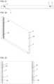
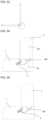
- FIGS. 1 - 6show a set comprising a first and second panel with a locking device, according to an illustrative embodiment of the disclosure.
- FIGS. 1 - 3show the first and second panel before assembling, while FIGS. 4 - 6 show the first and second panel in a locked position.
- the mechanical locking devicecomprises a first tongue and a groove surface at a first panel surface, and a locking groove and an edge surface at a second edge.
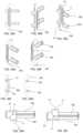
- FIG. 7shows a cross section of an embodiment of a panel according to an illustrative embodiment of the disclosure, the panel comprising a first panel surface and a first edge comprising a first tongue and a groove surface, and further comprising a second edge comprising a locking groove and an edge surface and a second locking surface.
- FIG. 8shows an enlargement of part of the embodiment shown in FIG. 7 , the mechanical locking device comprising a first insertion groove for positioning of a first tongue and further comprising a groove surface.
- FIG. 9shows a cross section of an illustrative embodiment of a panel according to the disclosure, the panel comprising a first panel surface and a first edge comprising a first tongue and a groove surface, and further comprising a second edge comprising a locking groove and an edge surface and a second locking surface.
- FIG. 10shows an enlargement of part of the embodiment shown in FIG. 9 , the panel comprising a second edge comprising a locking groove and an edge surface and a second locking surface.
- FIG. 11shows an enlargement of a set comprising a first and second panel with a locking device, according to an illustrative embodiment of the disclosure.
- the second edge of the second panelcomprises a second tongue comprising a flexing groove.
- FIG. 12shows a cross section of a first and second milling tool when providing a first and/or second edge according to an illustrative embodiment of the disclosure.
- FIG. 13shows an enlargement of part of the embodiment shown in FIG. 12 , comprising a first milling tool according to an illustrative embodiment of the disclosure.
- FIG. 14shows an enlargement of part of the embodiment shown in FIG. 12 , comprising a second milling tool according to an illustrative embodiment of the disclosure.
- FIGS. 15 - 17show different views of a panel according to an illustrative embodiment of the disclosure.
- the panelcomprises a first panel surface and two of a first edge, each first edge comprising a first tongue and a groove surface.
- FIGS. 18 - 20show different views of a panel according to an illustrative embodiment of the disclosure.
- the panelcomprises two of a second edge, each second edge comprising a locking groove and an edge surface and a second locking surface.
- FIGS. 21 - 23show different views of a panel according to an illustrative embodiment of the disclosure.
- the panelcomprises a first panel surface and two of a first edge, each first edge comprising a first tongue and a groove surface.
- the insertion groovesare positioned to be able to connect with at least one clip.
- FIGS. 24 - 29show different views of a panel according to an illustrative embodiment of the disclosure.
- the panelcomprises two of a second edge, comprising at least one clip comprising a locking groove and an edge surface and a second locking surface.
- FIGS. 24 - 26show panels with clips assembled, while FIGS. 27 - 29 show the panel and clips before assembly of the panel and clips.
- FIGS. 30 - 32show different views of a set of panels according to an illustrative embodiment of the disclosure before assembly. At least one clip is assembled with the second panel.
- FIGS. 33 - 35show different views of a set of panels according to an illustrative embodiment of the disclosure after assembly. At least one clip is assembled with the second panel.
- FIGS. 36 A- 36 Ishow different views of a clip according to an illustrative embodiment of the disclosure.
- FIGS. 37 - 40show different views of a set of a first and a second panel according to an illustrative embodiment of the disclosure after assembly.
- FIGS. 1 - 10 , 15 - 20 and 37 - 40including a set of panels comprising a first panel 1 with a first main plane, a second panel 2 with a second main plane.
- the first panel 1 and the second panel 2are provided with a mechanical locking device configured for locking the first panel 1 to the second panel 2 .
- the first panel 1comprises a first edge 11 and a first panel surface 12 and the second panel 2 comprises a second edge 21 and a second panel surface 22 .
- the first main planeis arranged essentially perpendicular to the second main plane in a locked position of the first panel and the second panel.
- the mechanical locking devicecomprises a panel surface groove 13 at the first panel surface 12 , and a locking groove 4 and an edge surface 6 at the second edge 21 .
- the panel surface groove 13comprises a groove surface 5 and an opposite groove surface 14 which comprises a first tongue 3 .
- the first tongue 3comprises a first locking surface 31
- the locking groove 4comprises a second locking surface 41 .
- the first locking surface 31is configured to interact with the second locking surface 41 in the locked position, wherein the first tongue 3 and/or the locking groove 4 is/are flexible for facilitating locking of the first panel to the second panel.
- the mechanical locking devicemay comprise in a locked position a space 15 between the groove surface 5 and the edge surface 6 .
- the groove surface 5 and the edge surface 6may be configured to be adjacent and/or opposite each other in in the locked position.
- a longitudinal axis 34 of the first tongue 3extends at a first angle ⁇ from the first main plane
- the groove surface 5extends at a second angle ⁇ from the first main plane
- the second locking surface 41extends at a third angle ⁇ from the second main plane
- the edge surface 6extends at a fourth angle ⁇ from the second main plane.
- the first angle ⁇is ⁇ the second angle ⁇ and/or the third angle ⁇ is ⁇ the fourth angle ⁇ .
- the first locking surface 31may be configured to interact with the second locking surface 41 in the locked position for a locking in a first direction D 1 which may be parallel with the second main plane.
- the first edge 11may be perpendicular to the first panel surface 12 .
- the first angle ⁇may be within the range of about 25° to about 45°, more or within the range of about 35° to about 40°.
- the second angle ⁇may be within the range of about 25° to about 45°, more or within the range of about 35° to about 40°.
- the third angle ⁇may be within the range of about 65° to about 45°, more or within the range of about 55° to about 50°.
- the fourth angle ⁇may be within the range of about 65° to about 45°, more or within the range of about 55° to about 50°.
- the first tongue 3 of the mechanical locking devicemay be a flexible tongue.
- the first tongue 3may be positioned in a first insertion groove 7 .
- the first insertion groove 7may comprise a wall surface 16 , an opposite wall surface 17 and a bottom surface 18 which extends between the wall surface 16 and the opposite wall surface 17 .
- the flexible tongue 3may be configured to be compressed and or displaced towards the bottom surface 18 during the locking of the first panel to the second panel and spring back towards the second locking surface 41 when the first panel and second panel have reached the locked position.
- a centreline 32may extend between the wall surface 16 and the opposite wall surface 17 .
- the centreline 32may extend at a centreline angle 33 from the first main plane.
- the centreline angle 33may be essentially the same as the first angle ( ⁇ ).
- the flexible tongue 3may have a longitudinal shape and the first insertion groove 7 may have a longitudinal shape, wherein the flexible tongue 3 is positioned in the first insertion groove 7 with its length direction parallel with the length direction of the first insertion groove 7 .
- the flexible tonguemay be configured as shown in, e.g., FIG. 6 a - 7 b in WO2007/015669, or FIG. 8 A-D in WO2014/209213 or FIG. 11 A- 13 B in WO2019/203720.
- the mechanical locking devicemay comprise at least one rod-shaped element 81 in the panel surface groove 13 in the first panel surface 12 and/or at the second edge 21 , and at least one second insertion groove 90 at the opposite first panel surface 12 and/or the opposite second edge 21 .
- the rod-shaped element 81is configured to be inserted into the second insertion groove 90 in the locked position. This can result in an increased stability of the set of panels after assembly.
- the rod-shaped element 81may be arranged in a rod element groove 80 .
- the rod-shaped element 81may be configured to interact with the second insertion groove 90 for a locking in a second direction D 2 which may be perpendicular to the first direction.
- the rod element groove 80may be a drill hole.
- the drill holeis a bottom-ended drill hole.
- the insertion groove 90may be a drill hole.
- the drill holeis a bottom-ended drill hole.
- the groove surface 5 , the edge surface 6 and/or the second locking surface 41may be a milled surface.
- a difference between the first angle ⁇ and the second angle ⁇may be between 0° and 10°.
- a difference between the third angle ⁇ and the fourth angle ⁇may be between 0° and 10°.
- the second edge 21 of the second panel 2may comprise a second tongue 23 .
- the second tongue 23may comprise a flexing groove 24 , as shown in FIG. 11 . This facilitates steering of the first panel 1 and the second panel 2 into the correct locked position during assembly.
- the second edge 21 of the second panel 2is not provided with a second locking surface 41 and an edge surface 6 by milling.
- the second edge 21 of the second panel 2may according to this aspect be provided with a clip 300 .
- the clip 300may be provided with a locking groove 4 comprising a second locking surface 41 , an edge surface 6 , and a rod-shaped element 81 .
- the clip 300may further be provided with a connecting element 302 for connecting the clip 300 to the panel.
- the second panel 2may according to one aspect be provided with one or more connecting groove 301 for receiving the connecting element 302 .
- the connecting element 302may be glued in the connecting groove 301 .
- FIGS. 24 - 26show the second panel 2 with clips 300 assembled, while FIGS. 27 - 29 show the second panel 2 and clips 300 before assembly.
- FIGS. 36 A- 36 Ishow detailed views of the clip 300 .
- the clip 300may be made of plastic or metal.
- the present disclosurealso relates to a method of providing a first panel 1 and/or a second panel 2 with a mechanical locking device configured for locking the first panel 1 to the second panel 2 .
- the first panel 1comprises a first edge 11 and a first panel surface 12 and the second panel 2 comprises a second edge 21 and a second panel surface 22 .
- the methodcomprises providing the first panel surface 12 of the first panel 1 with an insertion groove 7 and a groove surface 5 of the locking device by milling.
- the millingis conducted using a first milling tool 100 in only a single operation. This can result in the production of panels, comprising a locking device, that is easy and quick to produce and may result in reduced production costs. Furthermore, the production tolerances of the locking profile may be improved.
- the first milling tool 100 and the use thereofis shown in FIGS. 12 - 13 .
- the methodmay be configured for producing the set of panels according to the disclosure as described above.
- the present disclosurealso relates to a method of providing a first panel 1 and/or a second panel 2 with a mechanical locking device configured for locking the first panel 1 to the second panel 2 .
- the first panel 1comprises a first edge 11 and a first panel surface 12 and the second panel 2 comprises a second edge 21 and a second panel surface 22 .
- the methodcomprises providing the second edge 21 of the second panel 2 with a second locking surface 41 and an edge surface 6 by milling. The milling is done using a second milling tool 200 only, in only a single operation.
- the methodfurther comprises providing the second locking surface 41 and the edge surface 6 at opposite sides of a second tongue 23 .
- the second milling tool 200 and the use thereofis shown in FIGS. 12 and 14 .
- this methodmay comprise the method as described above.
- the methodmay be configured for producing the set of panels according to the present disclosure as described above.
- the first panel 1 and/or the second 2 panelmay comprise one or more of said first edges 11 .
- the first panel 1 and/or the second 2 panelmay comprise one or more of said second edges 21 .
- a panel comprising one of said first edge 11 and one of said second edge 21is shown, e.g., in FIGS. 7 and 9 .
- a panel comprising two of said first edges 11is, e.g., shown in FIGS. 15 - 17 and 21 - 23
- a panel comprising two of said second edges 21is, e.g., shown in FIGS. 18 - 20 .
- four panels each comprising a first edge 11 and a second edge 21may be assembled into a furniture product.
- the furniture productmay comprise two panels, each comprising two of said first edges 11 , and another two panels, each comprising two of said second edges 21 , may be assembled into a furniture product.
- the core of the first panel 1 and/or of the second panel 2may be a wood-based core, which may be made of MDF, HDF, OSB, WPC, plywood or particleboard.
- the coremay also be a plastic core comprising thermosetting plastic or thermoplastic, e.g., vinyl, PVC, PU or PET.
- the plastic coremay comprise fillers.
- the first panel 1 and/or the second panel 2may also be of solid wood.
- the first panel 1 and/or the second panel 2may be provided with a decorative layer, such as a foil or a veneer, on one or more surfaces.
- the set of panelsare resilient panels.
- the resilient panelsmay comprise a core comprising thermoplastic material.
- the thermoplastic materialmay be foamed.
- the thermoplastic materialmay comprise polyvinyl chloride (PVC), polyester, polypropylene (PP), polyethylene (PE), polystyrene (PS), polyurethane (PU), polyethylene terephthalate (PET), polyacrylate, methacrylate, polycarbonate, polyvinyl butyral, polybutylene terephthalate, or a combination thereof.
- the coremay be formed of several layers.
- the aspects described abovemay comprise a decorative layer, such as a decorative foil comprising a thermoplastic material.
- the thermoplastic material of the decorative layermay be or comprise polyvinyl chloride (PVC), polyester, polypropylene (PP), polyethylene (PE), polystyrene (PS), polyurethane (PU), polyethylene terephthalate (PET), polyacrylate, methacrylate, polycarbonate, polyvinyl butyral, polybutylene terephthalate, or a combination thereof.
- the decorative foilmay be printed, for example by direct printing, rotogravure, or digital printing.
- the decorative layercomprise melamine, a high pressure laminate (HPL) or a veneer.
- the aspects described abovemay comprise a wear layer such as a film or foil.
- the wear layermay comprise thermoplastic material.
- the thermoplastic materialmay be polyvinyl chloride (PVC), polyester, polypropylene (PP), polyethylene (PE), polystyrene (PS), polyurethane (PU), polyethylene terephthalate (PET), polyacrylate, methacrylate, polycarbonate, polyvinyl butyral, polybutylene terephthalate, or a combination thereof.
- the aspects described abovemay comprise a wood base core, such as HDF, MDF, plywood, particleboard, OSB or Masonite.
- a wood base coresuch as HDF, MDF, plywood, particleboard, OSB or Masonite.
- a setcomprising a first panel 1 with a first main plane, a second panel 2 with a second main plane and a mechanical locking device configured for locking the first panel 1 to the second panel 2 , wherein the first panel 1 comprises a first edge 11 and a first panel surface 12 and the second panel 2 comprises a second edge 21 and a second panel surface 22 , and the first main plane is arranged essentially perpendicular to the second main plane in a locked position of the first panel and the second panel, wherein
- the mechanical locking devicefurther comprises at least one rod-shaped element 81 in the panel surface groove 13 in the first panel surface 12 and/or at the second edge 21 , and at least one second insertion groove 90 at the opposite first panel surface 12 and/or the opposite second edge 21 , and wherein the rod-shaped element 81 is configured to be inserted into the second insertion groove 90 in the locked position.
Landscapes
- Engineering & Computer Science (AREA)
- General Engineering & Computer Science (AREA)
- Mechanical Engineering (AREA)
- Life Sciences & Earth Sciences (AREA)
- Wood Science & Technology (AREA)
- Connection Of Plates (AREA)
Abstract
Description
- the mechanical locking device comprises a
first tongue 3 and agroove surface 5 in apanel surface groove 13 in thefirst panel surface 12, and a lockinggroove 4 and anedge surface 6 at thesecond edge 21, - the
first tongue 3 comprises afirst locking surface 31, - the locking
groove 4 comprises asecond locking surface 41, - the
first locking surface 31 is configured to interact with thesecond locking surface 41 in the locked position, wherein thefirst tongue 3 and/or the lockinggroove 4 is/are flexible for facilitating locking of the first panel to the second panel, - a longitudinal axis34 of the
first tongue 3 extends at a first angle α from the first main plane, - the
groove surface 5 extends at a second angle β from the first main plane, - the
second locking surface 41 extends at a third angle γ from the second main plane, - the
edge surface 6 extends at a fourth angle δ from the second main plane, - and wherein the first angle α is greater the second angle β and/or the third angle γ is smaller the fourth angle δ.
- the mechanical locking device comprises a
- providing the
first panel surface 12 of thefirst panel 1 with aninsertion groove 7 and agroove surface 5 of the locking device by milling using afirst milling tool 100 in only a single operation.
- providing the
- providing the
second edge 21 of thesecond panel 2 with asecond locking surface 41 and anedge surface 6 by milling using asecond milling tool 200 only, in only a single operation, and - providing the
second locking surface 41 and theedge surface 6 at opposite sides of asecond tongue 23.
- providing the
Claims (23)
Applications Claiming Priority (2)
| Application Number | Priority Date | Filing Date | Title |
|---|---|---|---|
| SE2050905-5 | 2020-07-17 | ||
| SE2050905 | 2020-07-17 |
Publications (2)
| Publication Number | Publication Date |
|---|---|
| US20220018373A1 US20220018373A1 (en) | 2022-01-20 |
| US12038029B2true US12038029B2 (en) | 2024-07-16 |
Family
ID=79292166
Family Applications (1)
| Application Number | Title | Priority Date | Filing Date |
|---|---|---|---|
| US17/370,521Active2042-03-29US12038029B2 (en) | 2020-07-17 | 2021-07-08 | Mechanical locking system for panels |
Country Status (4)
| Country | Link |
|---|---|
| US (1) | US12038029B2 (en) |
| EP (1) | EP4181732A4 (en) |
| CN (1) | CN115867171A (en) |
| WO (1) | WO2022015222A1 (en) |
Families Citing this family (29)
| Publication number | Priority date | Publication date | Assignee | Title |
|---|---|---|---|---|
| UA109938C2 (en) | 2011-05-06 | 2015-10-26 | MECHANICAL LOCKING SYSTEM FOR CONSTRUCTION PANELS | |
| CN109854597B (en) | 2013-09-16 | 2021-03-19 | 瓦林格创新股份有限公司 | Combination product and method for assembling the same |
| US9726210B2 (en) | 2013-09-16 | 2017-08-08 | Valinge Innovation Ab | Assembled product and a method of assembling the product |
| US9714672B2 (en) | 2014-01-10 | 2017-07-25 | Valinge Innovation Ab | Panels comprising a mechanical locking device and an assembled product comprising the panels |
| EP3851684A1 (en) | 2014-05-09 | 2021-07-21 | Välinge Innovation AB | Mechanical locking system for building panels |
| EP3407765B1 (en) | 2016-01-26 | 2021-03-03 | Välinge Innovation AB | Panels comprising a mechanical locking device to obtain a furniture product |
| HRP20230089T1 (en) | 2017-05-15 | 2023-03-17 | Välinge Innovation AB | Elements and a locking device for an assembled product |
| RU2740868C1 (en) | 2017-12-22 | 2021-01-21 | Велинге Инновейшн Аб | Set of panels, method of their assembling and locking device for furniture product |
| EA202092409A1 (en) | 2018-04-18 | 2021-02-26 | Велинге Инновейшн Аб | SYMMETRIC TONGUE AND T-SHAPED KNOT |
| US11614114B2 (en) | 2018-04-19 | 2023-03-28 | Valinge Innovation Ab | Panels for an assembled product |
| PT3844407T (en) | 2018-08-30 | 2024-06-18 | Vaelinge Innovation Ab | Set of panels with a mechanical locking device |
| EP3730807A1 (en) | 2019-04-26 | 2020-10-28 | Välinge Innovation AB | Set of panels with a mechanical locking device |
| EP3834661A1 (en) | 2019-12-11 | 2021-06-16 | Välinge Innovation AB | Mechanical locking system for panels |
| SE544408C2 (en)* | 2019-12-18 | 2022-05-10 | Vilox Ab | Joining system for furniture, furniture portion comprising the joining system and method for manufacturing the joining element of the joining system |
| KR20220113725A (en) | 2019-12-19 | 2022-08-16 | 뵈린게 이노베이션 에이비이 | set of panels with mechanical locking device |
| WO2021150162A1 (en) | 2020-01-22 | 2021-07-29 | Välinge Innovation AB | Set of panels with a mechanical locking device |
| EP3871560A1 (en) | 2020-02-26 | 2021-09-01 | Välinge Innovation AB | Set of panels with a mechanical locking device |
| EP3871559A1 (en) | 2020-02-26 | 2021-09-01 | Välinge Innovation AB | Set of panels with a mechanical locking device |
| US11702844B2 (en) | 2020-06-05 | 2023-07-18 | Valinge Innovation Ab | Building panels comprising a locking device |
| EP4258943A4 (en) | 2020-12-11 | 2024-10-23 | Välinge Innovation AB | RAIL FOR CABINETS |
| MX2023007995A (en) | 2021-01-07 | 2023-09-18 | Vaelinge Innovation Ab | Wedge-shaped tongue insertion groove. |
| WO2022159013A1 (en) | 2021-01-19 | 2022-07-28 | Välinge Innovation AB | A set of panels, a method for assembly of the same and a locking device for a furniture product |
| US12071769B2 (en) | 2021-02-03 | 2024-08-27 | Valinge Innovation Ab | Building panels comprising a locking device |
| US12247598B2 (en) | 2021-02-08 | 2025-03-11 | Välinge Innovation AB | Mounting bracket |
| WO2022184446A1 (en) | 2021-03-01 | 2022-09-09 | Välinge Innovation AB | Mechanical connection arrangement for panels |
| JP2022158867A (en)* | 2021-03-31 | 2022-10-17 | オールセーフ株式会社 | Panel assembly and panel connection structure |
| EP4352370A4 (en) | 2021-06-11 | 2025-04-09 | Välinge Innovation AB | LOCKING DEVICE WITH A SPRING AND A LOCKING PIN AND SET WITH FURNITURE COMPONENTS AND THE LOCKING DEVICE |
| US20230313823A1 (en)* | 2022-03-30 | 2023-10-05 | Välinge Innovation AB | Set of panels and an associated assembled article |
| US20240254768A1 (en)* | 2023-01-27 | 2024-08-01 | Välinge Innovation AB | Connection arrangement for panels |
Citations (65)
| Publication number | Priority date | Publication date | Assignee | Title |
|---|---|---|---|---|
| US3305992A (en)* | 1964-06-08 | 1967-02-28 | Steed Engineering Inc | Hollow core door construction |
| US3951187A (en)* | 1975-04-24 | 1976-04-20 | Finis Lavell Chisum | Machine to prepare logs for log houses |
| US4168675A (en)* | 1976-04-19 | 1979-09-25 | Chisum Finis L | Machine to prepare logs for log houses |
| US4184525A (en)* | 1977-01-06 | 1980-01-22 | Helmes Machinefabriek B.V. | Milling machine |
| US4674923A (en)* | 1985-08-09 | 1987-06-23 | Ratemaker Tools, Inc. | Access notches for indexing inserts in a groove mill |
| US5611637A (en)* | 1994-08-26 | 1997-03-18 | Julius Blum Gesellschaft M.B.H. | Furniture fitting |
| US5658086A (en)* | 1995-11-24 | 1997-08-19 | Brokaw; Paul E. | Furniture connector |
| US5810505A (en)* | 1996-07-26 | 1998-09-22 | Kimball International, Inc. | Double threaded fastener system |
| US5970675A (en)* | 1997-12-05 | 1999-10-26 | James D. Wright | Modular panel assembly |
| US6045290A (en)* | 1995-08-29 | 2000-04-04 | Ikea International A/S | Corner joint between the end portions of two board-like members |
| US20020102138A1 (en)* | 1998-01-09 | 2002-08-01 | Kanefusa Kabushiki Kaisha | Replacement blade bodies for a slotting milling cutter |
| WO2007015669A2 (en) | 2006-07-11 | 2007-02-08 | Välinge Innovation AB | Mechanical locking of floor panels with a flexible bristle tongue |
| US7451535B2 (en)* | 2003-03-07 | 2008-11-18 | Masterbrand Cabinets, Inc. | Semi-frameless cabinet and method for making the same |
| US20100189492A1 (en)* | 2009-01-27 | 2010-07-29 | Bush Industries, Inc. | Quick Assembly Desk System And Components Therefor |
| US20110085853A1 (en)* | 2009-10-08 | 2011-04-14 | Min-Sheng Liu | Retaining Structure |
| US20120279161A1 (en)* | 2011-05-06 | 2012-11-08 | Välinge Flooring Technology AB | Mechanical locking system for building panels |
| US20130071172A1 (en)* | 2010-06-03 | 2013-03-21 | Unilin, Bvba | Composed element |
| WO2014209213A1 (en) | 2013-06-27 | 2014-12-31 | Välinge Innovation AB | Building panel with a mechanical locking system |
| US20150078819A1 (en) | 2013-09-16 | 2015-03-19 | Valinge Innovation Ab | Assembled product and a method of assembling the product |
| US20150078807A1 (en)* | 2013-09-16 | 2015-03-19 | Valinge Innovation Ab | Assembled product and a method of assembling the assembled product |
| WO2015105449A1 (en) | 2014-01-10 | 2015-07-16 | Välinge Innovation AB | Panels comprising a mechanical locking device and an assembled product comprising the panels |
| WO2015105451A1 (en) | 2014-01-10 | 2015-07-16 | Välinge Innovation AB | An assembled product and a method of assembling the product |
| US20150198191A1 (en) | 2014-01-10 | 2015-07-16 | Valinge Innovation Ab | Furniture panel |
| US20150196118A1 (en) | 2014-01-10 | 2015-07-16 | Valinge Innovation Ab | Panels comprising a mechanical locking device and an assembled product comprising the panels |
| US9175703B2 (en)* | 2008-12-17 | 2015-11-03 | Unilin, Bvba | Composed element, multi-layered board and panel-shaped element for forming this composed element |
| US20160007751A1 (en) | 2014-07-11 | 2016-01-14 | Valinge Innovation Ab | Panel with a slider |
| US20160174704A1 (en) | 2014-12-19 | 2016-06-23 | Välinge Innovation AB | Panels comprising a mechanical locking device and an assembled product comprising the panels |
| US20170079433A1 (en) | 2015-09-22 | 2017-03-23 | Välinge Innovation AB | Panels comprising a mechanical locking device and an assembled product comprising the panels |
| US20170089379A1 (en)* | 2014-05-09 | 2017-03-30 | Välinge Innovation AB | Mechanical locking system for building panels |
| US20170159291A1 (en)* | 2015-12-03 | 2017-06-08 | Välinge Innovation AB | Panels comprising a mechanical locking device and an assembled product comprising the panels |
| US20170208938A1 (en) | 2016-01-26 | 2017-07-27 | Valinge Innovation Ab | Panels comprising a mechanical locking device and an assembled product comprising the panels |
| US20170227032A1 (en)* | 2016-02-09 | 2017-08-10 | Välinge Innovation AB | Element and method for providing dismantling groove |
| US20170227031A1 (en) | 2016-02-09 | 2017-08-10 | Välinge Innovation AB | Set of panel-shaped elements for a composed element |
| US20170227035A1 (en) | 2016-02-04 | 2017-08-10 | Välinge Innovation AB | Set of panels for an assembled product |
| US20170234346A1 (en) | 2016-02-15 | 2017-08-17 | Välinge Innovation AB | Method for forming a panel |
| US20180080488A1 (en) | 2015-04-21 | 2018-03-22 | Välinge Innovation AB | Panel with a slider |
| US20180112695A1 (en)* | 2015-04-30 | 2018-04-26 | Vålinge Innovation Ab | Panel with a fastening device |
| US20180119717A1 (en)* | 2016-10-27 | 2018-05-03 | Valinge Innovation Ab | Set of panels with a mechanical locking device |
| US20180310707A1 (en)* | 2015-10-29 | 2018-11-01 | Ibk Project Srl | Kit for assembling furniture |
| US20180328396A1 (en)* | 2017-05-15 | 2018-11-15 | Välinge Innovation AB | Elements and a locking device for an assembled product |
| US20190195256A1 (en) | 2017-12-22 | 2019-06-27 | Välinge Innovation AB | Set of Panels |
| US20190191870A1 (en) | 2017-12-22 | 2019-06-27 | Välinge Innovation AB | Set of panels |
| US20190269240A1 (en)* | 2016-07-26 | 2019-09-05 | Inovame | Furniture carcass |
| US20190289999A1 (en) | 2018-03-23 | 2019-09-26 | Välinge Innovation AB | Panels comprising a mechanical locking device and an assembled product comprising the panels |
| US20190323533A1 (en)* | 2018-04-18 | 2019-10-24 | Välinge Innovation AB | Set of panels with a mechanical locking device |
| US20190323532A1 (en)* | 2018-04-18 | 2019-10-24 | Välinge Innovation AB | Set of panels with a mechanical locking device |
| WO2019203720A1 (en) | 2018-04-18 | 2019-10-24 | Välinge Innovation AB | Symmetric tongue & t-cross |
| US20190323535A1 (en) | 2018-04-19 | 2019-10-24 | Valinge Innovation Ab | Panels for an assembled product |
| US20190320793A1 (en)* | 2018-04-18 | 2019-10-24 | Välinge Innovation AB | Set of panels with a mechanical locking device |
| US20200069049A1 (en)* | 2018-08-30 | 2020-03-05 | Välinge Innovation AB | Set of panels with a mechanical locking device |
| US20200069048A1 (en)* | 2018-08-30 | 2020-03-05 | Välinge Innovation AB | Set of panels with a mechanical locking device |
| USD885171S1 (en)* | 2015-07-20 | 2020-05-26 | Lockdowel, Inc. | Channel lock fastener |
| US20200340513A1 (en) | 2019-04-26 | 2020-10-29 | Välinge Innovation AB | Set of panels with a mechanical locking device |
| US10844891B2 (en)* | 2014-10-31 | 2020-11-24 | Unilin Bv | Piece of furniture |
| US20210001662A1 (en)* | 2018-03-16 | 2021-01-07 | Inovame | Method for producing a profiled strip having improved connecting means |
| US20210180630A1 (en) | 2019-12-11 | 2021-06-17 | Välinge Innovation AB | Mechanical locking system for panels |
| US20210190112A1 (en) | 2019-12-19 | 2021-06-24 | Välinge Innovation AB | Set of panels with a mechanical locking device |
| US20210222716A1 (en) | 2020-01-22 | 2021-07-22 | Välinge Innovation AB | Set of panels with a mechanical locking device |
| US20210262507A1 (en) | 2020-02-26 | 2021-08-26 | Välinge Innovation AB | Set of panels with a mechanical locking device |
| US20210262508A1 (en) | 2020-02-26 | 2021-08-26 | Välinge Innovation AB | Set of panels with a mechanical locking device |
| US20210276108A1 (en) | 2020-03-03 | 2021-09-09 | Välinge Innovation AB | Machine |
| US20210381251A1 (en) | 2020-06-05 | 2021-12-09 | Välinge Innovation AB | Building panels comprising a locking device |
| US20220049735A1 (en) | 2020-08-12 | 2022-02-17 | Välinge Innovation AB | Panels with edge reinforcement |
| US20220152864A1 (en)* | 2019-02-26 | 2022-05-19 | Flooring Industries Limited, Sarl | Cutting device for a continuous milling machine and method for the manufacture of panels |
| US20230346120A1 (en)* | 2019-12-18 | 2023-11-02 | Vilox Ab | Joining system for furniture |
- 2021
- 2021-07-08CNCN202180046884.2Apatent/CN115867171A/enactivePending
- 2021-07-08USUS17/370,521patent/US12038029B2/enactiveActive
- 2021-07-08EPEP21841306.0Apatent/EP4181732A4/enactivePending
- 2021-07-08WOPCT/SE2021/050697patent/WO2022015222A1/ennot_activeCeased
Patent Citations (127)
| Publication number | Priority date | Publication date | Assignee | Title |
|---|---|---|---|---|
| US3305992A (en)* | 1964-06-08 | 1967-02-28 | Steed Engineering Inc | Hollow core door construction |
| US3951187A (en)* | 1975-04-24 | 1976-04-20 | Finis Lavell Chisum | Machine to prepare logs for log houses |
| US4168675A (en)* | 1976-04-19 | 1979-09-25 | Chisum Finis L | Machine to prepare logs for log houses |
| US4184525A (en)* | 1977-01-06 | 1980-01-22 | Helmes Machinefabriek B.V. | Milling machine |
| US4674923A (en)* | 1985-08-09 | 1987-06-23 | Ratemaker Tools, Inc. | Access notches for indexing inserts in a groove mill |
| US5611637A (en)* | 1994-08-26 | 1997-03-18 | Julius Blum Gesellschaft M.B.H. | Furniture fitting |
| US6045290A (en)* | 1995-08-29 | 2000-04-04 | Ikea International A/S | Corner joint between the end portions of two board-like members |
| US5658086A (en)* | 1995-11-24 | 1997-08-19 | Brokaw; Paul E. | Furniture connector |
| US5810505A (en)* | 1996-07-26 | 1998-09-22 | Kimball International, Inc. | Double threaded fastener system |
| US5970675A (en)* | 1997-12-05 | 1999-10-26 | James D. Wright | Modular panel assembly |
| US20020102138A1 (en)* | 1998-01-09 | 2002-08-01 | Kanefusa Kabushiki Kaisha | Replacement blade bodies for a slotting milling cutter |
| US7451535B2 (en)* | 2003-03-07 | 2008-11-18 | Masterbrand Cabinets, Inc. | Semi-frameless cabinet and method for making the same |
| WO2007015669A2 (en) | 2006-07-11 | 2007-02-08 | Välinge Innovation AB | Mechanical locking of floor panels with a flexible bristle tongue |
| WO2007015669A3 (en) | 2006-07-11 | 2007-06-14 | Vaelinge Innovation Ab | Mechanical locking of floor panels with a flexible bristle tongue |
| US9175703B2 (en)* | 2008-12-17 | 2015-11-03 | Unilin, Bvba | Composed element, multi-layered board and panel-shaped element for forming this composed element |
| US20100189492A1 (en)* | 2009-01-27 | 2010-07-29 | Bush Industries, Inc. | Quick Assembly Desk System And Components Therefor |
| US20110085853A1 (en)* | 2009-10-08 | 2011-04-14 | Min-Sheng Liu | Retaining Structure |
| US20130071172A1 (en)* | 2010-06-03 | 2013-03-21 | Unilin, Bvba | Composed element |
| US8887468B2 (en) | 2011-05-06 | 2014-11-18 | Valinge Flooring Technology Ab | Mechanical locking system for building panels |
| US20120279161A1 (en)* | 2011-05-06 | 2012-11-08 | Välinge Flooring Technology AB | Mechanical locking system for building panels |
| US20150035422A1 (en) | 2011-05-06 | 2015-02-05 | Valinge Flooring Technology Ab | Mechanical locking system for building panels |
| WO2012154113A1 (en) | 2011-05-06 | 2012-11-15 | Välinge Flooring Technology AB | Mechanical locking system for building panels |
| US10871179B2 (en) | 2011-05-06 | 2020-12-22 | Valinge Innovation Ab | Mechanical locking system for building panels |
| US20210207635A1 (en) | 2011-05-06 | 2021-07-08 | Välinge Innovation AB | Mechanical locking system for building panels |
| US20190113061A1 (en) | 2011-05-06 | 2019-04-18 | Välinge Innovation AB | Mechanical locking system for building panels |
| US10202996B2 (en) | 2011-05-06 | 2019-02-12 | Valinge Innovation Ab | Mechanical locking system for building panels |
| US20170097033A1 (en) | 2011-05-06 | 2017-04-06 | Välinge Innovation AB | Mechanical locking system for building panels |
| US9538842B2 (en)* | 2011-05-06 | 2017-01-10 | Valinge Innovation Ab | Mechanical locking system for building panels |
| WO2014209213A1 (en) | 2013-06-27 | 2014-12-31 | Välinge Innovation AB | Building panel with a mechanical locking system |
| US10451097B2 (en) | 2013-09-16 | 2019-10-22 | Valinge Innovation Ab | Assembled product and a method of assembling the assembled product |
| US9726210B2 (en)* | 2013-09-16 | 2017-08-08 | Valinge Innovation Ab | Assembled product and a method of assembling the product |
| US11204051B2 (en)* | 2013-09-16 | 2021-12-21 | Valinge Innovation Ab | Assembled product and a method of assembling the assembled product |
| US20210285480A1 (en) | 2013-09-16 | 2021-09-16 | Välinge Innovation AB | Assembled product and a method of assembling the product |
| US20180087552A1 (en) | 2013-09-16 | 2018-03-29 | Valinge Innovation Ab | Assembled product and a method of assembling the product |
| US10731688B2 (en) | 2013-09-16 | 2020-08-04 | Valinge Innovation Ab | Assembled product and a method of assembling the assembled product |
| US20210148392A1 (en) | 2013-09-16 | 2021-05-20 | Välinge Innovation AB | Assembled product and a method of assembling the assembled product |
| US10876563B2 (en) | 2013-09-16 | 2020-12-29 | Valinge Innovation Ab | Assembled product and a method of assembling the product |
| US20150078819A1 (en) | 2013-09-16 | 2015-03-19 | Valinge Innovation Ab | Assembled product and a method of assembling the product |
| US20150078807A1 (en)* | 2013-09-16 | 2015-03-19 | Valinge Innovation Ab | Assembled product and a method of assembling the assembled product |
| US20200003242A1 (en) | 2013-09-16 | 2020-01-02 | Valinge Innovation Ab | Assembled product and a method of assembling the assembled product |
| US20150196118A1 (en) | 2014-01-10 | 2015-07-16 | Valinge Innovation Ab | Panels comprising a mechanical locking device and an assembled product comprising the panels |
| US20170298973A1 (en) | 2014-01-10 | 2017-10-19 | Valinge Innovation Ab | Panels comprising a mechanical locking device and an assembled product comprising the panels |
| WO2015105451A1 (en) | 2014-01-10 | 2015-07-16 | Välinge Innovation AB | An assembled product and a method of assembling the product |
| US9714672B2 (en)* | 2014-01-10 | 2017-07-25 | Valinge Innovation Ab | Panels comprising a mechanical locking device and an assembled product comprising the panels |
| US10830268B2 (en) | 2014-01-10 | 2020-11-10 | Valinge Innovation Ab | Furniture panel |
| WO2015105449A1 (en) | 2014-01-10 | 2015-07-16 | Välinge Innovation AB | Panels comprising a mechanical locking device and an assembled product comprising the panels |
| US20150198191A1 (en) | 2014-01-10 | 2015-07-16 | Valinge Innovation Ab | Furniture panel |
| US20170089379A1 (en)* | 2014-05-09 | 2017-03-30 | Välinge Innovation AB | Mechanical locking system for building panels |
| US20200300284A1 (en) | 2014-05-09 | 2020-09-24 | Välinge Innovation AB | Mechanical locking system for building panels |
| US10876562B2 (en)* | 2014-05-09 | 2020-12-29 | Valinge Innovation Ab | Mechanical locking system for building panels |
| US20160007751A1 (en) | 2014-07-11 | 2016-01-14 | Valinge Innovation Ab | Panel with a slider |
| US20160270531A1 (en) | 2014-07-11 | 2016-09-22 | Valinge Innovation Ab | Panel with a slider |
| US9375085B2 (en) | 2014-07-11 | 2016-06-28 | Valinge Innovation Ab | Panel with a slider |
| US9723923B2 (en) | 2014-07-11 | 2017-08-08 | Valinge Innovation Ab | Panel with a slider |
| US10844891B2 (en)* | 2014-10-31 | 2020-11-24 | Unilin Bv | Piece of furniture |
| US10506875B2 (en) | 2014-12-19 | 2019-12-17 | Valinge Innovation Ab | Panels comprising a mechanical locking device and an assembled product comprising the panels |
| US20170360193A1 (en) | 2014-12-19 | 2017-12-21 | Välinge Innovation AB | Panels comprising a mechanical locking device and an assembled product comprising the panels |
| US20200337455A1 (en) | 2014-12-19 | 2020-10-29 | Välinge Innovation AB | Panels comprising a mechanical locking device and an assembled product comprising the panels |
| US10034541B2 (en) | 2014-12-19 | 2018-07-31 | Valinge Innovation Ab | Panels comprising a mechanical locking device and an assembled product comprising the panels |
| US20190166989A1 (en) | 2014-12-19 | 2019-06-06 | Välinge Innovation AB | Panels comprising a mechanical locking device and an assembled product comprising the panels |
| US11083287B2 (en) | 2014-12-19 | 2021-08-10 | Valinge Innovation Ab | Panels comprising a mechanical locking device and an assembled product comprising the panels |
| US20160174704A1 (en) | 2014-12-19 | 2016-06-23 | Välinge Innovation AB | Panels comprising a mechanical locking device and an assembled product comprising the panels |
| US9655442B2 (en)* | 2014-12-19 | 2017-05-23 | Valinge Innovation Ab | Panels comprising a mechanical locking device and an assembled product comprising the panels |
| US10670064B2 (en) | 2015-04-21 | 2020-06-02 | Valinge Innovation Ab | Panel with a slider |
| US20180080488A1 (en) | 2015-04-21 | 2018-03-22 | Välinge Innovation AB | Panel with a slider |
| US20180112695A1 (en)* | 2015-04-30 | 2018-04-26 | Vålinge Innovation Ab | Panel with a fastening device |
| US10968936B2 (en)* | 2015-04-30 | 2021-04-06 | Valinge Innovation Ab | Panel with a fastening device |
| USD885171S1 (en)* | 2015-07-20 | 2020-05-26 | Lockdowel, Inc. | Channel lock fastener |
| US20200214447A1 (en) | 2015-09-22 | 2020-07-09 | Valinge Innovation Ab | Panels comprising a mechanical locking device and an assembled product comprising the panels |
| US10448739B2 (en) | 2015-09-22 | 2019-10-22 | Valinge Innovation Ab | Panels comprising a mechanical locking device and an assembled product comprising the panels |
| US20170079433A1 (en) | 2015-09-22 | 2017-03-23 | Välinge Innovation AB | Panels comprising a mechanical locking device and an assembled product comprising the panels |
| US11246415B2 (en) | 2015-09-22 | 2022-02-15 | Valinge Innovation Ab | Panels comprising a mechanical locking device and an assembled product comprising the panels |
| US20180310707A1 (en)* | 2015-10-29 | 2018-11-01 | Ibk Project Srl | Kit for assembling furniture |
| US9945121B2 (en)* | 2015-12-03 | 2018-04-17 | Valinge Innovation Ab | Panels comprising a mechanical locking device and an assembled product comprising the panels |
| US20210079650A1 (en) | 2015-12-03 | 2021-03-18 | Välinge Innovation AB | Panels comprising a mechanical locking device and an assembled product comprising the panels |
| US11098484B2 (en) | 2015-12-03 | 2021-08-24 | Valinge Innovation Ab | Panels comprising a mechanical locking device and an assembled product comprising the panels |
| US10669716B2 (en) | 2015-12-03 | 2020-06-02 | Valinge Innovation Ab | Panels comprising a mechanical locking device and an assembled product comprising the panels |
| US20180202160A1 (en) | 2015-12-03 | 2018-07-19 | Välinge Innovation AB | Panels comprising a mechanical locking device and an assembled product comprising the panels |
| US20170159291A1 (en)* | 2015-12-03 | 2017-06-08 | Välinge Innovation AB | Panels comprising a mechanical locking device and an assembled product comprising the panels |
| US20200121076A1 (en) | 2016-01-26 | 2020-04-23 | Välinge Innovation AB | Panels comprising a mechanical locking device and an assembled product comprising the panels |
| US10548397B2 (en) | 2016-01-26 | 2020-02-04 | Valinge Innovation Ab | Panels comprising a mechanical locking device and an assembled product comprising the panels |
| US20170208938A1 (en) | 2016-01-26 | 2017-07-27 | Valinge Innovation Ab | Panels comprising a mechanical locking device and an assembled product comprising the panels |
| US20170227035A1 (en) | 2016-02-04 | 2017-08-10 | Välinge Innovation AB | Set of panels for an assembled product |
| US20200102978A1 (en) | 2016-02-04 | 2020-04-02 | Välinge Innovation AB | Set of panels for an assembled product |
| US10544818B2 (en) | 2016-02-04 | 2020-01-28 | Valinge Innovation Ab | Set of panels for an assembled product |
| US11137007B2 (en) | 2016-02-04 | 2021-10-05 | Valinge Innovation Ab | Set of panels for an assembled product |
| US20200055126A1 (en) | 2016-02-09 | 2020-02-20 | Valinge Innovation Ab | Element and method for providing dismantling groove |
| US20170227032A1 (en)* | 2016-02-09 | 2017-08-10 | Välinge Innovation AB | Element and method for providing dismantling groove |
| US10486245B2 (en) | 2016-02-09 | 2019-11-26 | Valinge Innovation Ab | Element and method for providing dismantling groove |
| US20170227031A1 (en) | 2016-02-09 | 2017-08-10 | Välinge Innovation AB | Set of panel-shaped elements for a composed element |
| US10415613B2 (en) | 2016-02-09 | 2019-09-17 | Valinge Innovation Ab | Set of panel-shaped elements for a composed element |
| US10830266B2 (en)* | 2016-02-15 | 2020-11-10 | Valinge Innovation Ab | Method for forming a panel |
| US20170234346A1 (en) | 2016-02-15 | 2017-08-17 | Välinge Innovation AB | Method for forming a panel |
| US20190269240A1 (en)* | 2016-07-26 | 2019-09-05 | Inovame | Furniture carcass |
| US10724564B2 (en)* | 2016-10-27 | 2020-07-28 | Valinge Innovation Ab | Set of panels with a mechanical locking device |
| US20180119717A1 (en)* | 2016-10-27 | 2018-05-03 | Valinge Innovation Ab | Set of panels with a mechanical locking device |
| US11506235B2 (en)* | 2017-05-15 | 2022-11-22 | Valinge Innovation Ab | Elements and a locking device for an assembled product |
| US20180328396A1 (en)* | 2017-05-15 | 2018-11-15 | Välinge Innovation AB | Elements and a locking device for an assembled product |
| US11272783B2 (en) | 2017-12-22 | 2022-03-15 | Valinge Innovation Ab | Set of panels |
| US20190195256A1 (en) | 2017-12-22 | 2019-06-27 | Välinge Innovation AB | Set of Panels |
| US20190191870A1 (en) | 2017-12-22 | 2019-06-27 | Välinge Innovation AB | Set of panels |
| US20210001662A1 (en)* | 2018-03-16 | 2021-01-07 | Inovame | Method for producing a profiled strip having improved connecting means |
| US20190289999A1 (en) | 2018-03-23 | 2019-09-26 | Välinge Innovation AB | Panels comprising a mechanical locking device and an assembled product comprising the panels |
| US10736416B2 (en)* | 2018-03-23 | 2020-08-11 | Valinge Innovation Ab | Panels comprising a mechanical locking device and an assembled product comprising the panels |
| US11076691B2 (en)* | 2018-04-18 | 2021-08-03 | Valinge Innovation Ab | Set of panels with a mechanical locking device |
| WO2019203720A1 (en) | 2018-04-18 | 2019-10-24 | Välinge Innovation AB | Symmetric tongue & t-cross |
| US11536307B2 (en)* | 2018-04-18 | 2022-12-27 | Valinge Innovation Ab | Symmetric tongue and t-cross |
| US11448252B2 (en)* | 2018-04-18 | 2022-09-20 | Valinge Innovation Ab | Set of panels with a mechanical locking device |
| US20190323534A1 (en)* | 2018-04-18 | 2019-10-24 | Välinge Innovation AB | Symmetric tongue and t-cross |
| US20190323533A1 (en)* | 2018-04-18 | 2019-10-24 | Välinge Innovation AB | Set of panels with a mechanical locking device |
| US20190323532A1 (en)* | 2018-04-18 | 2019-10-24 | Välinge Innovation AB | Set of panels with a mechanical locking device |
| US20190320793A1 (en)* | 2018-04-18 | 2019-10-24 | Välinge Innovation AB | Set of panels with a mechanical locking device |
| US20190323535A1 (en) | 2018-04-19 | 2019-10-24 | Valinge Innovation Ab | Panels for an assembled product |
| US11614114B2 (en)* | 2018-04-19 | 2023-03-28 | Valinge Innovation Ab | Panels for an assembled product |
| US20200069049A1 (en)* | 2018-08-30 | 2020-03-05 | Välinge Innovation AB | Set of panels with a mechanical locking device |
| US20200069048A1 (en)* | 2018-08-30 | 2020-03-05 | Välinge Innovation AB | Set of panels with a mechanical locking device |
| US20220152864A1 (en)* | 2019-02-26 | 2022-05-19 | Flooring Industries Limited, Sarl | Cutting device for a continuous milling machine and method for the manufacture of panels |
| US20200340513A1 (en) | 2019-04-26 | 2020-10-29 | Välinge Innovation AB | Set of panels with a mechanical locking device |
| US20210180630A1 (en) | 2019-12-11 | 2021-06-17 | Välinge Innovation AB | Mechanical locking system for panels |
| US20230346120A1 (en)* | 2019-12-18 | 2023-11-02 | Vilox Ab | Joining system for furniture |
| US20210190112A1 (en) | 2019-12-19 | 2021-06-24 | Välinge Innovation AB | Set of panels with a mechanical locking device |
| US20210222716A1 (en) | 2020-01-22 | 2021-07-22 | Välinge Innovation AB | Set of panels with a mechanical locking device |
| US20210262508A1 (en) | 2020-02-26 | 2021-08-26 | Välinge Innovation AB | Set of panels with a mechanical locking device |
| US20210262507A1 (en) | 2020-02-26 | 2021-08-26 | Välinge Innovation AB | Set of panels with a mechanical locking device |
| US20210276108A1 (en) | 2020-03-03 | 2021-09-09 | Välinge Innovation AB | Machine |
| US20210381251A1 (en) | 2020-06-05 | 2021-12-09 | Välinge Innovation AB | Building panels comprising a locking device |
| US20220049735A1 (en) | 2020-08-12 | 2022-02-17 | Välinge Innovation AB | Panels with edge reinforcement |
Non-Patent Citations (14)
| Title |
|---|
| Derelöv, Peter, et al., U.S. Appl. No. 17/588,733 entitled "Arrangements for Preparing of Furniture Product," filed in the U.S. Patent and Trademark Office Jan. 31, 2022. |
| International Search Report/Written Opinion dated Aug. 10, 2021 in PCT/SE2021/050697, ISA/SE, Patent-och registreringsverket, Stockholm, SE, 11 pages. |
| Svensson, Johan, et al., U.S. Appl. No. 17/674,262 entitled "Mechanical Connection Arrangement for Panels," filed in the U.S. Patent and Trademark Office Feb. 17, 2022. |
| U.S. Appl. No. 16/386,732, Christian Boo, filed Apr. 17, 2019, (Cited herein as US Patent Application Publication No. 2019/0323532 A1 of Oct. 24, 2019). |
| U.S. Appl. No. 16/386,810, Christian Boo, filed Apr. 17, 2019, (Cited herein as US Patent Application Publication No. 2019/0323533 A1 of Oct. 24, 2019). |
| U.S. Appl. No. 16/553,325, Peter Derelöv and Johan Svensson, filed Aug. 28, 2019, (Cited herein as US Patent Application Publication No. 2020/0069048 A1 of Mar. 5, 2020). |
| U.S. Appl. No. 16/553,350, Peter Derelöv and Johan Svensson, filed Aug. 28, 2019, (Cited herein as US Patent Application Publication No. 2020/0069049 A1 of Mar. 5, 2020). |
| U.S. Appl. No. 16/856,765, Peter Derelöv, filed Apr. 23, 2020, (Cited herein as US Patent Application Publication No. 2020/0340513 A1 of Oct. 29, 2020). |
| U.S. Appl. No. 17/154,344, Peter Derelöv and Johan Svensson, filed Jan. 21, 2021, (Cited herein as US Patent Application Publication No. 2021/0222716 A1 of Jul. 22, 2021). |
| U.S. Appl. No. 17/173,823, Peter Derelöv and Johan Svensson, filed Feb. 11, 2021, (Cited herein as US Patent Application Publication No. 2021/0276108 A1 of Sep. 9, 2021). |
| U.S. Appl. No. 17/185,403, Johan Svensson and Peter Derelöv, filed Feb. 25, 2021, (Cited herein as US Patent Application Publication No. 2021/0262507 A1 of Aug. 26, 2021). |
| U.S. Appl. No. 17/185,428, Johan Svensson and Peter Derelöv, filed Feb. 25, 2021, (Cited herein as US Patent Application Publication No. 2021/0262508 A1 of Aug. 26, 2021). |
| U.S. Appl. No. 17/588,733, Peter Derelöv and Johan Svensson, filed Jan. 31, 2022. |
| U.S. Appl. No. 17/674,262, Johan Svensson and Peter Derelöv, filed Feb. 17, 2022. |
Also Published As
| Publication number | Publication date |
|---|---|
| EP4181732A4 (en) | 2024-08-07 |
| CN115867171A (en) | 2023-03-28 |
| EP4181732A1 (en) | 2023-05-24 |
| US20220018373A1 (en) | 2022-01-20 |
| WO2022015222A1 (en) | 2022-01-20 |
Similar Documents
| Publication | Publication Date | Title |
|---|---|---|
| US12038029B2 (en) | Mechanical locking system for panels | |
| US12286991B2 (en) | Set of panels with a mechanical locking device | |
| EP4110134B1 (en) | Set of panels with a mechanical locking device | |
| US11466717B2 (en) | Mechanical locking system for panels | |
| EP4110135B1 (en) | Set of panels with a mechanical locking device | |
| US11703072B2 (en) | Set of panels with a mechanical locking device | |
| AU2019330606B2 (en) | Set of panels with a mechanical locking device | |
| EP3718437A1 (en) | Method for assembling a piece of furniture | |
| US11821446B2 (en) | Wedge-shaped tongue groove | |
| US20240052867A1 (en) | A set of panels provided with a mechanical locking device for locking a first panel to a second panel at a corner |
Legal Events
| Date | Code | Title | Description |
|---|---|---|---|
| AS | Assignment | Owner name:VAELINGE INNOVATION AB, SWEDEN Free format text:ASSIGNMENT OF ASSIGNORS INTEREST;ASSIGNOR:BOO, CHRISTIAN;REEL/FRAME:056793/0966 Effective date:20210702 | |
| FEPP | Fee payment procedure | Free format text:ENTITY STATUS SET TO UNDISCOUNTED (ORIGINAL EVENT CODE: BIG.); ENTITY STATUS OF PATENT OWNER: LARGE ENTITY | |
| STPP | Information on status: patent application and granting procedure in general | Free format text:DOCKETED NEW CASE - READY FOR EXAMINATION | |
| STPP | Information on status: patent application and granting procedure in general | Free format text:NON FINAL ACTION MAILED | |
| STPP | Information on status: patent application and granting procedure in general | Free format text:RESPONSE TO NON-FINAL OFFICE ACTION ENTERED AND FORWARDED TO EXAMINER | |
| STPP | Information on status: patent application and granting procedure in general | Free format text:FINAL REJECTION MAILED | |
| STPP | Information on status: patent application and granting procedure in general | Free format text:RESPONSE AFTER FINAL ACTION FORWARDED TO EXAMINER | |
| STPP | Information on status: patent application and granting procedure in general | Free format text:NOTICE OF ALLOWANCE MAILED -- APPLICATION RECEIVED IN OFFICE OF PUBLICATIONS | |
| STPP | Information on status: patent application and granting procedure in general | Free format text:PUBLICATIONS -- ISSUE FEE PAYMENT VERIFIED | |
| STCF | Information on status: patent grant | Free format text:PATENTED CASE | |
| CC | Certificate of correction |