US12036353B2 - Apparatus and methods for pressure management within a wound chamber - Google Patents
Apparatus and methods for pressure management within a wound chamberDownload PDFInfo
- Publication number
- US12036353B2 US12036353B2US17/026,822US202017026822AUS12036353B2US 12036353 B2US12036353 B2US 12036353B2US 202017026822 AUS202017026822 AUS 202017026822AUS 12036353 B2US12036353 B2US 12036353B2
- Authority
- US
- United States
- Prior art keywords
- outflow
- inflow
- pressure
- enclosed space
- fluid
- Prior art date
- Legal status (The legal status is an assumption and is not a legal conclusion. Google has not performed a legal analysis and makes no representation as to the accuracy of the status listed.)
- Active, expires
Links
- 238000000034methodMethods0.000titledescription7
- 239000012530fluidSubstances0.000claimsabstractdescription191
- 206010052428WoundDiseases0.000claimsabstractdescription184
- 208000027418Wounds and injuryDiseases0.000claimsabstractdescription184
- 238000002560therapeutic procedureMethods0.000claimsabstractdescription74
- 230000037361pathwayEffects0.000claimsabstractdescription56
- 238000004891communicationMethods0.000claimsabstractdescription28
- 230000008859changeEffects0.000claimsdescription32
- 230000035945sensitivityEffects0.000claimsdescription25
- 230000001788irregularEffects0.000claimsdescription6
- 230000003247decreasing effectEffects0.000claimsdescription5
- 239000007788liquidSubstances0.000description47
- QVGXLLKOCUKJST-UHFFFAOYSA-Natomic oxygenChemical compound[O]QVGXLLKOCUKJST-UHFFFAOYSA-N0.000description40
- 210000003491skinAnatomy0.000description35
- 239000003570airSubstances0.000description31
- 239000001301oxygenSubstances0.000description29
- 229910052760oxygenInorganic materials0.000description29
- 210000000416exudates and transudateAnatomy0.000description21
- 230000002093peripheral effectEffects0.000description12
- 239000000853adhesiveSubstances0.000description11
- 230000001070adhesive effectEffects0.000description11
- 238000009581negative-pressure wound therapyMethods0.000description11
- 210000001519tissueAnatomy0.000description9
- 230000008867communication pathwayEffects0.000description6
- 239000007789gasSubstances0.000description6
- 229920000642polymerPolymers0.000description5
- 208000015181infectious diseaseDiseases0.000description4
- 238000005259measurementMethods0.000description4
- 230000004888barrier functionEffects0.000description3
- 238000009530blood pressure measurementMethods0.000description3
- 239000006260foamSubstances0.000description3
- 238000004519manufacturing processMethods0.000description3
- 239000000463materialSubstances0.000description3
- 230000001105regulatory effectEffects0.000description3
- 238000007789sealingMethods0.000description3
- IJGRMHOSHXDMSA-UHFFFAOYSA-NAtomic nitrogenChemical compoundN#NIJGRMHOSHXDMSA-UHFFFAOYSA-N0.000description2
- 229920000742CottonPolymers0.000description2
- 206010061218InflammationDiseases0.000description2
- MWUXSHHQAYIFBG-UHFFFAOYSA-NNitric oxideChemical compoundO=[N]MWUXSHHQAYIFBG-UHFFFAOYSA-N0.000description2
- 230000005856abnormalityEffects0.000description2
- 238000013459approachMethods0.000description2
- 230000015556catabolic processEffects0.000description2
- 230000030833cell deathEffects0.000description2
- 230000001413cellular effectEffects0.000description2
- 230000001276controlling effectEffects0.000description2
- 238000006731degradation reactionMethods0.000description2
- 238000006073displacement reactionMethods0.000description2
- -1for examplePolymers0.000description2
- 238000009472formulationMethods0.000description2
- 230000004054inflammatory processEffects0.000description2
- 239000010410layerSubstances0.000description2
- 239000000203mixtureSubstances0.000description2
- 229920002635polyurethanePolymers0.000description2
- 239000004814polyurethaneSubstances0.000description2
- 230000008961swellingEffects0.000description2
- 230000001225therapeutic effectEffects0.000description2
- 229920001634CopolyesterPolymers0.000description1
- 206010011985Decubitus ulcerDiseases0.000description1
- 102000035195PeptidasesHuman genes0.000description1
- 108091005804PeptidasesProteins0.000description1
- 239000004743PolypropyleneSubstances0.000description1
- 239000004793PolystyreneSubstances0.000description1
- 239000004372Polyvinyl alcoholSubstances0.000description1
- 208000004210Pressure UlcerDiseases0.000description1
- FAPWRFPIFSIZLT-UHFFFAOYSA-MSodium chlorideChemical compound[Na+].[Cl-]FAPWRFPIFSIZLT-UHFFFAOYSA-M0.000description1
- 230000002745absorbentEffects0.000description1
- 239000002250absorbentSubstances0.000description1
- NIXOWILDQLNWCW-UHFFFAOYSA-Nacrylic acid groupChemical groupC(C=C)(=O)ONIXOWILDQLNWCW-UHFFFAOYSA-N0.000description1
- 239000004676acrylonitrile butadiene styreneSubstances0.000description1
- 229920000122acrylonitrile butadiene styrenePolymers0.000description1
- 239000012080ambient airSubstances0.000description1
- 210000004381amniotic fluidAnatomy0.000description1
- 210000003484anatomyAnatomy0.000description1
- 238000004873anchoringMethods0.000description1
- 230000000845anti-microbial effectEffects0.000description1
- 239000002585baseSubstances0.000description1
- 230000008901benefitEffects0.000description1
- 230000005540biological transmissionEffects0.000description1
- 230000017531blood circulationEffects0.000description1
- 239000012503blood componentSubstances0.000description1
- 239000011248coating agentSubstances0.000description1
- 238000000576coating methodMethods0.000description1
- 238000007906compressionMethods0.000description1
- 230000006835compressionEffects0.000description1
- 230000008602contractionEffects0.000description1
- 230000008878couplingEffects0.000description1
- 238000010168coupling processMethods0.000description1
- 238000005859coupling reactionMethods0.000description1
- 238000013016dampingMethods0.000description1
- 238000001804debridementMethods0.000description1
- 230000001419dependent effectEffects0.000description1
- 210000004207dermisAnatomy0.000description1
- 238000010586diagramMethods0.000description1
- 239000003814drugSubstances0.000description1
- 230000000694effectsEffects0.000description1
- 229920001971elastomerPolymers0.000description1
- 210000002615epidermisAnatomy0.000description1
- 230000008020evaporationEffects0.000description1
- 238000001704evaporationMethods0.000description1
- 239000004744fabricSubstances0.000description1
- 230000006872improvementEffects0.000description1
- 230000007246mechanismEffects0.000description1
- 238000012986modificationMethods0.000description1
- 230000004048modificationEffects0.000description1
- 238000012544monitoring processMethods0.000description1
- 230000001338necrotic effectEffects0.000description1
- 229910052757nitrogenInorganic materials0.000description1
- 230000003287optical effectEffects0.000description1
- 230000002572peristaltic effectEffects0.000description1
- 230000004962physiological conditionEffects0.000description1
- 239000004417polycarbonateSubstances0.000description1
- 229920000515polycarbonatePolymers0.000description1
- 239000002861polymer materialSubstances0.000description1
- 229920001155polypropylenePolymers0.000description1
- 229920001296polysiloxanePolymers0.000description1
- 229920002223polystyrenePolymers0.000description1
- 229920002451polyvinyl alcoholPolymers0.000description1
- 230000001681protective effectEffects0.000description1
- 230000001012protectorEffects0.000description1
- 230000004044responseEffects0.000description1
- 231100000241scarToxicity0.000description1
- 239000002356single layerSubstances0.000description1
- 210000004003subcutaneous fatAnatomy0.000description1
- 230000000287tissue oxygenationEffects0.000description1
- 230000000472traumatic effectEffects0.000description1
- 230000002792vascularEffects0.000description1
- 238000011179visual inspectionMethods0.000description1
- XLYOFNOQVPJJNP-UHFFFAOYSA-NwaterSubstancesOXLYOFNOQVPJJNP-UHFFFAOYSA-N0.000description1
Images


Classifications
- A—HUMAN NECESSITIES
- A61—MEDICAL OR VETERINARY SCIENCE; HYGIENE
- A61M—DEVICES FOR INTRODUCING MEDIA INTO, OR ONTO, THE BODY; DEVICES FOR TRANSDUCING BODY MEDIA OR FOR TAKING MEDIA FROM THE BODY; DEVICES FOR PRODUCING OR ENDING SLEEP OR STUPOR
- A61M1/00—Suction or pumping devices for medical purposes; Devices for carrying-off, for treatment of, or for carrying-over, body-liquids; Drainage systems
- A61M1/90—Negative pressure wound therapy devices, i.e. devices for applying suction to a wound to promote healing, e.g. including a vacuum dressing
- A61M1/91—Suction aspects of the dressing
- A61M1/912—Connectors between dressing and drainage tube
- A—HUMAN NECESSITIES
- A61—MEDICAL OR VETERINARY SCIENCE; HYGIENE
- A61M—DEVICES FOR INTRODUCING MEDIA INTO, OR ONTO, THE BODY; DEVICES FOR TRANSDUCING BODY MEDIA OR FOR TAKING MEDIA FROM THE BODY; DEVICES FOR PRODUCING OR ENDING SLEEP OR STUPOR
- A61M1/00—Suction or pumping devices for medical purposes; Devices for carrying-off, for treatment of, or for carrying-over, body-liquids; Drainage systems
- A61M1/90—Negative pressure wound therapy devices, i.e. devices for applying suction to a wound to promote healing, e.g. including a vacuum dressing
- A61M1/96—Suction control thereof
- A—HUMAN NECESSITIES
- A61—MEDICAL OR VETERINARY SCIENCE; HYGIENE
- A61M—DEVICES FOR INTRODUCING MEDIA INTO, OR ONTO, THE BODY; DEVICES FOR TRANSDUCING BODY MEDIA OR FOR TAKING MEDIA FROM THE BODY; DEVICES FOR PRODUCING OR ENDING SLEEP OR STUPOR
- A61M1/00—Suction or pumping devices for medical purposes; Devices for carrying-off, for treatment of, or for carrying-over, body-liquids; Drainage systems
- A61M1/90—Negative pressure wound therapy devices, i.e. devices for applying suction to a wound to promote healing, e.g. including a vacuum dressing
- A61M1/92—Negative pressure wound therapy devices, i.e. devices for applying suction to a wound to promote healing, e.g. including a vacuum dressing with liquid supply means
- A—HUMAN NECESSITIES
- A61—MEDICAL OR VETERINARY SCIENCE; HYGIENE
- A61M—DEVICES FOR INTRODUCING MEDIA INTO, OR ONTO, THE BODY; DEVICES FOR TRANSDUCING BODY MEDIA OR FOR TAKING MEDIA FROM THE BODY; DEVICES FOR PRODUCING OR ENDING SLEEP OR STUPOR
- A61M1/00—Suction or pumping devices for medical purposes; Devices for carrying-off, for treatment of, or for carrying-over, body-liquids; Drainage systems
- A61M1/90—Negative pressure wound therapy devices, i.e. devices for applying suction to a wound to promote healing, e.g. including a vacuum dressing
- A61M1/94—Negative pressure wound therapy devices, i.e. devices for applying suction to a wound to promote healing, e.g. including a vacuum dressing with gas supply means
- A—HUMAN NECESSITIES
- A61—MEDICAL OR VETERINARY SCIENCE; HYGIENE
- A61M—DEVICES FOR INTRODUCING MEDIA INTO, OR ONTO, THE BODY; DEVICES FOR TRANSDUCING BODY MEDIA OR FOR TAKING MEDIA FROM THE BODY; DEVICES FOR PRODUCING OR ENDING SLEEP OR STUPOR
- A61M2205/00—General characteristics of the apparatus
- A61M2205/33—Controlling, regulating or measuring
- A61M2205/3331—Pressure; Flow
- A—HUMAN NECESSITIES
- A61—MEDICAL OR VETERINARY SCIENCE; HYGIENE
- A61M—DEVICES FOR INTRODUCING MEDIA INTO, OR ONTO, THE BODY; DEVICES FOR TRANSDUCING BODY MEDIA OR FOR TAKING MEDIA FROM THE BODY; DEVICES FOR PRODUCING OR ENDING SLEEP OR STUPOR
- A61M2205/00—General characteristics of the apparatus
- A61M2205/60—General characteristics of the apparatus with identification means
- A61M2205/6036—General characteristics of the apparatus with identification means characterised by physical shape, e.g. array of activating switches
Definitions
- This inventionrelates to medical devices, and more particularly, to wound therapy apparatus and related methods of operation.
- FIG. 1illustrates an exemplary wound bed including some reference anatomy. As illustrated in FIG.
- the wound bedmay include varying degrees of exposure of underlying layers and structures along with possible infections and tissue changes.
- the wound bedincludes a localized region of tissue that has lost skin and been affected by hostile factors resulting in cellular abnormalities such as swelling, inflammation, degradation, infection, or cell death.
- the wound bedmay include varying degrees of exposure of layers and structures that underlie the skin surface, as illustrated, along with possible infection and tissue changes.
- the wound bedmay lie within a wound boundary that extends around the affected region at the skin surface of the skin. Wound boundary, as used herein, refers to the perimeter of the wound bed at the skin surface of the skin.
- the wound bedmay extend contiguously in depth within the dermis, and the wound bed may extend yet deeper, for example, into subcutaneous fat, and deeper structures.
- the wound bedmay include undermined flaps, sinuses, tunnels, and fistulae and the surrounding affected tissues.
- the NPWT interface devicemay include a dressing, a thin flexible sheet of generally fluid impervious polymer that is adhesive coated on portions of a distal side, and a single tube for fluid communication with the dressing.
- the dressingmay be, for example, cotton gauze, or open-cell foam made from polyvinyl alcohol or polyurethane.
- the sheetis then centered over the dressing and wound bed and then secured sealingly adhesively to the skin around the wound bed using the adhesive coating thereby sealing the wound bed and dressing. Finally, an aperture is created in the sheet over the dressing, and a connector and evacuation tube is sealingly engaged with that aperture thus forming the NPWT interface device.
- Air within a region between the sheet and the wound bedis evacuated through the tube to produce a suction pressure p s within the region that is less than the ambient pressure p amb .
- the wound bed and surrounding skincontracts as the pressure within the region is decreased by suction pressure p s , which causes the surrounding ambient pressure p amb to compresses the sheet and dressing upon the wound bed. Exudate from the wound bed may be drawn through the dressing and evacuated through the tube.
- suction pressure p s within the regionis typically alternated between about ⁇ 125 mm Hg and about ⁇ 25 mm Hg in current NPWT therapy regimens.
- this variation in suction pressure p sis almost as ineffective at removing exudate from the wound bed as removing the content of a bottle by sucking at the mouth of the bottle.
- the suction pump and the NPWT interface deviceare typically connected by a tube of long length to accommodate various relative placements.
- the likely redundancy of the tubemay result in the tube forming a dependent loop that may collect some exudate at low points within the tube, much like an elbow in a drain collects liquid. Evaporation is accelerated in such NPWT interface devices that are repeatedly subjected to suction causing exudate within the tube to evaporate forming a clog that at least partially occludes the tube.
- suction pressure p sis sensed within the tube not directly within the region between the sheet and the wound bed, occlusion of the tube may result in a false indication that proper therapy is being delivered to the wound bed when, in fact, proper therapy is not being delivered to the wound bed.
- a suction pressure p s of ⁇ 125 mm Hgmay be sensed within the tube proximal of the occlusion, when, in fact, the suction pressure p s is very low or even non-existent distal of the occlusion (e.g., in the region between the sheet and the wound bed).
- certain NPWT interface deviceshave a tube that includes multiple peripheral lumens formed in the tube peripheral to a central lumen. Fluid is then withdrawn from the region between the sheet and the wound bed through the central lumen, and the peripheral lumens are used for sensing the pressure within the region between the sheet and the wound bed. Pressure in the central lumen is also sensed to detect discrepancies between pressure in the central lumen and pressure in the peripheral lumens.
- the suction pressure p s within the region between the sheet and the wound bed sensed through the central lumenis high and the suction pressure p s within the region between the sheet and the wound bed sensed using the peripheral lumens is low, it may then be inferred that an occlusion such as an exudate plug is likely present in the central lumen.
- peripheral lumensby virtue of being small in size and used only for pressure sensing without communication of fluid therethrough may be prone to occlusion such as clogging with exudate, especially given the proximity of the peripheral lumen to the central lumen through which exudate is communicated.
- the availability of the peripheral lumens as sensing channelsmay be unreliable.
- the peripheral lumenssense suction pressure proximate the central lumen, not at other points within the NPWT interface device.
- peripheral lumens in combination with the central lumenmay not provide an accurate indication of the pressure within the region between the sheet and the wound bed.
- a wound therapy apparatus disclosed hereinincludes a wound interface sealingly securable to a skin surface around a wound bed to form an enclosed space over the wound bed, an inflow port disposed about the wound interface to form a portion of an inflow fluid pathway that communicates an inflow fluid into the enclosed space, and an outflow port disposed about the wound interface to form a portion of an outflow fluid pathway that communicates an outflow fluid out of the enclosed space, in various aspects.
- the outflow portis in spaced relation with the inflow port to define a flow path within the enclosed space having a length equivalent to a characteristic length of the enclosed space, in various aspects.
- An inflow pressure sensoris in communication with the inflow fluid pathway to detect an inflow pressure p in of the inflow fluid
- an outflow pressure sensoris in communication with the outflow fluid pathway to detect an outflow pressure p out of the outflow fluid, in various aspects.
- the inflow pressure p in and the outflow pressure p out in combinationare indicative of a pressure p a within the enclosed space, in various aspects.
- dp out dt of the outflow fluidare measured to determine an operational condition of the wound therapy apparatus.
- FIG. 1illustrates an exemplary wound bed including various anatomical features thereof
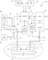
- FIG. 2illustrates by schematic diagram an exemplary implementation of a wound therapy apparatus
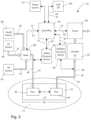
- FIG. 3 Aillustrates by perspective view portions of a second exemplary implementation of a wound therapy apparatus in an open position
- FIG. 3 Billustrates by perspective view the second exemplary implementation of a wound therapy apparatus of FIG. 3 A in a closed position
- FIG. 3 Cillustrates by cross-sectional view portions of the second exemplary implementation of a wound therapy apparatus of FIG. 3 A ;
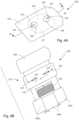
- FIG. 4 Aillustrates by perspective view a third exemplary implementation of a wound therapy apparatus
- FIG. 4 Billustrates by exploded view the third exemplary implementation of a wound therapy apparatus of FIG. 4 A ;
- FIG. 4 Cillustrates by cut-away elevation views portions of the third exemplary implementation of a wound therapy apparatus of FIG. 4 A ;
- FIG. 4 Dillustrates by cut-away elevation views portions of the third exemplary implementation of a wound therapy apparatus of FIG. 4 A ;
- FIG. 4 Eillustrates by cut-away elevation view the third exemplary implementation of a wound therapy apparatus of FIG. 4 A ;
- FIG. 5illustrates by plan view portions of a fourth exemplary implementation of a wound therapy apparatus
- FIG. 6illustrates by plan view portions of a fifth exemplary implementation of a wound therapy apparatus
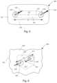
- FIG. 7illustrates by plan view portions of a sixth exemplary implementation of a wound therapy apparatus.
- FIG. 8illustrates by plan view portions of a seventh exemplary implementation of a wound therapy apparatus.
- a wound therapy apparatus disclosed hereinincludes a wound interface sealingly securable to a skin surface around a wound bed to form an enclosed space over the wound bed, an inflow port disposed about the wound interface to form a portion of an inflow fluid pathway that communicates an inflow fluid into the enclosed space, and an outflow port disposed about the wound interface to form a portion of an outflow fluid pathway that communicates an outflow fluid out of the enclosed space, in various aspects.
- the outflow portis in spaced relation with the inflow port to define a flow path within the enclosed space having a length equivalent to a characteristic length of the enclosed space, in various aspects, so that a combination of an inflow pressure p in of the inflow fluid in the inflow fluid pathway and an outflow pressure p out are measured to measure a pressure p a within the enclosed space at the length equivalent to the characteristic length of the enclosed space.
- the inflow pressure p in of the inflow fluida time rate of change of the inflow pressure
- dp out dt of the outflow fluidare measured to determine an operational condition of the wound therapy apparatus. Time rates of change of time rates of change
- d 2 ⁇ p in dt 2 , d 2 ⁇ p out dt 2may be measured, in various aspects.
- the pressure p ais the actual pressure within the enclosed space.
- the characteristic lengthdefines a length scale of the enclosed space, and the characteristic length may be, for example, a diameter, a radius, a diagonal length, a side length, a hydraulic diameter, or a hydraulic radius.
- the inflow pressure p in of the inflow fluid and outflow pressure pour of the outflow fluidare indicative of pressure p a within the enclosed space as measured at a length scale commensurate with the characteristic length of the enclosed space.
- the length at which measurements of the pressure p a within the enclosed spaceis commensurate with the length scale of the enclosed space, in various aspects.
- the characteristic length of the enclosed space and length of the flow pathare both multiples of a diameter of the tube.
- Such aspectsstand in contrast to pressure measurements of pressure p a within the enclosed space at a single location or at multiple locations separated by less than a diameter of the tube.
- Fluidincludes liquid(s), gas(ses), and combinations thereof.
- Liquidmay include, for example, water, saline solution, proteolytic enzyme solutions, antimicrobial lavages, amniotic fluid, and exudate, and combinations thereof.
- Gasmay include, for example, air, oxygen, nitric oxide, nitrogen, therapeutic or inert gasses, and combinations thereof.
- Exudateincludes, for example, proteinaceous liquids exuded from the wound bed, along with various plasma and blood components. Exudate may also include other liquids used in treating the wound bed or produced by the wound bed or by surrounding tissues.
- fluid-tight or related termsmeans sufficiently leak-resistant to allow insufflation or vacuum suction to create a pressure p a within the enclosed space that may be above or below ambient pressure p amb .
- fluid-tightmeans sufficiently leak-resistant to substantially retain fluids including both gasses and liquids within the enclosed space other than by controlled fluid communication through one or more lumen that fluidly communicate through the wound interface with the enclosed space, in certain aspects.
- fluid tightmeans sufficiently leak-resistant to maintain pressure p a within the enclosed space that may be above or below ambient pressure p amb .
- Ambient pressure p ambrefers to the pressure in a region surrounding the wound therapy apparatus.
- Ambient pressure p ambmay refer to atmospheric pressure, hull pressure within an aircraft or submarine where the wound therapy apparatus is being utilized, or pressure maintained generally within a building or other structure where the wound therapy apparatus is being utilized.
- Ambient pressure p ambmay vary, for example, with elevation or weather conditions.
- Pressure p a within the enclosed spacerefers to the pressure actually occurring within the enclosed space.
- Minimum pressure p minrefers to the minimum pressure achieved within the enclosed space of the wound therapy apparatus, and periodically varying of pressure p a , pressure variation, varying pressure, and similar term refer to changes of pressure p a within the enclosed space over time.
- Maximum pressure p maxrefers to the maximum pressure achieved within the enclosed space of the wound therapy apparatus. Pressures such as suction pressure p s , pressure p a , minimum pressure p min , and maximum pressure p max and their associated pressure values are as gauge pressure in this disclosure.
- distal and proximalare defined from the point of view of a physician, including various other healthcare providers, treating a patient with the wound therapy apparatus.
- a distal portion of the wound therapy apparatusis oriented toward the patient and a proximal portion of the wound therapy apparatus is oriented toward the physician.
- a distal portion of a structureis the portion closest to the patient while a proximal portion of the structure is the portion closet to the physician.
- time rates of changemay be indicative of various approximations such as finite differences including other discretizations and approximations, and these approximations may be represented digitally in conformance to engineering, manufacturing, or scientific tolerances, as would be readily recognized by those of ordinary skill in the art upon study of this disclosure.
- finite difference representation of time rates of changesuch as
- dp out dt ⁇ ⁇ and ⁇ ⁇ dp in dtin various implementations may be limited by byte size and may include various errors such as roundoff error and truncation error.
- quantities such as suction pressure p s , pressure p a , inflow pressure p in , outflow pressure p out , minimum pressure p min , and maximum pressure p max and time rates of change of pressureas used in the various mathematical relationships and formulations disclosed herein as well as the various mathematical relationships and formulations disclosed herein may include various errors such as roundoff error and truncation error and may conform to engineering, manufacturing, or scientific tolerances, as would be readily recognized by those of ordinary skill in the art upon study of this disclosure.
- Quantities such as suction pressure p s , inflow pressure p in , and outflow pressure p out as measuredmay be in the form of averages, median values, or other statistical representations of a plurality of measurements made using a sensor, in various implementations, and may include errors inherent in measurement by the sensor as well as errors in digital representations.
- FIG. 2illustrates exemplary wound therapy apparatus 10 .
- wound interface 15 of wound therapy apparatus 10is secured to skin surface 11 to define enclosed space 17 that is fluid tight over a wound bed (e.g., see FIG. 1 ; also wound bed 213 in FIG. 4 E ).
- wound therapy apparatus 10includes oxygen source 82 , air source 83 , and liquid source 84 in fluid communication with enclosed space 17 of wound interface 15 via inflow fluid pathway 26 through inflow port 42 as controlled by valve 88 .
- Inflow fluid pathway 26includes inflow port 42 .
- Valve 88may be positioned by controller 87 to control the communication of oxygen 22 from oxygen source 82 , air 23 from air source 83 , liquid 24 from liquid source 84 , or combinations of oxygen 22 , air 23 , and/or liquid 24 into enclosed space 17 as inflow fluid 16 via fluid pathway 26 , as illustrated.
- Outflow fluid 18may include, for example, inflow fluid 16 and exudate 19 , as illustrated. Liquid, such as liquid 24 and exudate 19 , in outflow fluid 18 is captured in reservoir 57 of canister 50 as outflow fluid 18 is communicated through canister 50 by pump 89 , and only gaseous portions of outflow fluid 18 are communicated from canister 50 to pump 89 , in this implementation. Gaseous portions of outflow fluid 18 are discharged into the ambient environment by pump 89 , as illustrated.
- Canister 50 including reservoir 57may be omitted, for example, when the quantity of exudate 19 is minimal or there is no liquid, such as liquid 24 from liquid source 84 , in outflow fluid 18 .
- Canister 50may be replaceable and disposable, in certain implementations.
- Inflow pressure sensor 91is in operable communication with inflow fluid pathway 26 to detect inflow pressure p in of inflow fluid 16 and the time rate of change of inflow pressure
- Outflow pressure sensor 93is in operable communication with outflow fluid pathway 28 to detect outflow pressure p out of outflow fluid 18 the time rate of change of outflow pressure
- Inflow pressure sensor 91may communicate with inflow fluid pathway 26 at one or more locations along inflow fluid pathway 26 , for example, at or about oxygen source 82 , air source 83 , liquid source 84 , valve 88 , and/or within or about inflow port 42 .
- Outflow pressure sensor 93may communicate with outflow fluid pathway 28 at one or more locations along outflow fluid pathway, for example, within or about outflow port 44 , reservoir 57 of canister 50 , and/or suction side of pump 89 .
- Inflow port 42 and outflow port 44are spaced length L 1 apart, and enclosed space 17 has characteristic length D 1 , as illustrated.
- Characteristic length D 1is a characteristic length of enclosed space 17 such as, for example, diameter, radius, diagonal length, side length, hydraulic diameter, hydraulic radius, and so forth, that defines a scale of enclosed space 17 . Because inflow port 42 is located length L 1 from outflow port 44 , inflow pressure p in detected by inflow pressure sensor 91 and outflow pressure p out detected by outflow pressure sensor 93 are indicative of pressure p a at locations length L 1 apart in enclosed space 17 proximate inflow port 42 and proximate outflow port 44 , respectively.
- length L 1may be commensurate with characteristic length D 1 of enclosed space 17 , so that the inflow pressure p in detected by inflow pressure sensor 91 and outflow pressure p out detected by outflow pressure sensor 93 are commensurate with the scale of enclosed space 17 . That is, in contrast to a single pressure measurement or multiple pressure measurements proximate one another, in exemplary wound therapy apparatus 10 pressure p a within enclosed space 17 is measured by measuring inflow pressure p in and outflow pressure p out at locations length L 1 apart where length L 1 is commensurate with characteristic length D 1 of enclosed space 17 .
- length L 1may be, for example, greater than 50% of characteristic length D 1 .
- length L 1may be, for example, greater than 80% of characteristic length D 1 .
- length L 1may be, for example, greater than 90% of characteristic length D 1 .
- inflow pressure sensor 91 and outflow pressure sensor 93are illustrated as separate pressure sensors for purposes of explanation.
- inflow pressure sensor 91 and outflow pressure sensor 93may be formed as a single pressure sensor configured to detect inflow pressure p in and outflow pressure p out , or inflow pressure sensor 91 or outflow pressure sensor 93 may be formed as multiple pressure sensors.
- Controller 87communicates operably with valve 88 , pump 89 , inflow pressure sensor 91 , outflow pressure sensor 93 , via communication pathway 61 , 62 , 63 , 65 , respectively, to control operations of valve 88 , pump 89 , inflow pressure sensor 91 , and outflow pressure sensor 93 in order to deliver a therapy regimen within enclosed space 17 .
- Controller 87communicates operably with user I/O 86 to allow a user to control the operations of wound therapy apparatus 10 , for example, to select the therapy regimen delivered within enclosed space 17 .
- Controller 87may control the operation of wound therapy apparatus 10 , at least in part, based upon data 74 communicated to controller 87 from user I/O 86 via communication pathway 64 , and controller 87 may control the operation of wound therapy apparatus 10 , at least in part, based upon data 71 , 72 , 73 , 75 communicated between controller 87 and valve 88 , pump 89 , inflow pressure sensor 91 , and outflow pressure sensor 93 via communication pathways 61 , 62 , 63 , 65 , respectively.
- controller 87may direct delivery of various therapy regimens within enclosed space 17 of wound interface 15 .
- controller 87may variously select inflow fluid 16 as oxygen 22 from oxygen source 82 , air 23 from air source 83 , liquid 24 from liquid source 84 , or combinations thereof, and controller 87 may control the actual pressure p a within enclosed space 17 by controlling the inflow of inflow fluid 16 into enclosed space 17 and the withdrawal of outflow fluid 18 from enclosed space 17 through operations of valve 88 and pump 89 .
- Controller 87may alter the selection of inflow fluid 16 as oxygen 22 from oxygen source 82 , air 23 from air source 83 , liquid 24 from liquid source 84 , combinations thereof, and/or the controller 87 may alter the pressure p a within enclosed space 17 over time according to the therapy regimen(s) being delivered.
- outflow fluid 18is being withdrawn from enclosed space 17 while no inflow fluid 16 is being flowed into enclosed space 17 in order to reduce pressure p a to minimum pressure p min ;
- inflow fluid 16is being flowed into enclosed space 17 while no outflow fluid 18 is being withdrawn from the enclosed space 17 in order to increase pressure p a to maximum pressure p max ; or,
- no inflow fluid 16is being flowed into the enclosed space 17 and no outflow fluid 18 is being withdrawn from the enclosed space 17 as pressure p a is held at minimum pressure p min or at maximum pressure p max .
- Data 71may be indicative of the operation of valve 88 , for example, the position of valve 88 —fully closed, fully open, intermediate of fully closed and fully open, allowing flow of oxygen 22 from oxygen source 82 , allowing flow of air 23 from air source 83 , allowing flow of liquid 23 from liquid source 84 .
- Controller 87may communicate data 71 with valve 88 to alter the operation of valve 88 , for example, to select inflow fluid 16 as oxygen 22 from oxygen source 82 , air 23 from air source 83 , liquid 23 from liquid source 84 , and combinations thereof.
- Controller 87may communicate data 71 with valve 88 to alter the operation of valve 88 , for example, to regulate, at least in part, the rate at which oxygen 22 , air 23 , liquid 24 , or combinations thereof are flowed into enclosed space 17 as inflow fluid 16 .
- valve 88is illustrated as a single valve 88 for purposes of explanation, and that, in various implementations, valve 88 may be formed as one or more valves of various types in various arrangements, as would be readily recognized by those of ordinary skill in the art upon study of this disclosure.
- valve 88may include one or more valves disposed about wound therapy apparatus to select inflow fluid 16 as gas 22 , liquid 24 , combinations of gas 22 and liquid 24 , to regulate, at least in part, the inflow of inflow fluid 16 into enclosed space 17 of wound interface 15 , and to regulate, at least in part, the withdrawal of outflow fluid 18 from enclosed space 17 of wound interface 15 .
- Data 72 communicated from pump 89 to controller 87may be indicative of the operation of pump 89 , for example, rate of operation, and quantity of electrical power being supplied.
- Pump 89may be, for example, a centrifugal pump, positive displacement pump, or peristaltic pump, or multiple pumps of various types, in various implementations, and rate of operation refers to rate of rotation, rate of displacement, rate of contraction, etc. as appropriate.
- Data 72 communicated from controller 87 to pump 89may alter the operation of pump 89 , for example, setting pump 89 in an ON state, setting pump 89 in an OFF state, or controlling the rate of operation of pump 89 in order to control, at least in part, the withdrawal of outflow fluid 18 from enclosed space 17 including the rate at which outflow fluid 18 is withdrawn.
- dp in dt detected by inflow pressure sensor 91is communicated with controller 87 via communication pathway 63 , and data 75 indicative of the outflow pressure p out and/or the time rate of change of outflow pressure
- Controller 87may communicate data 73 with inflow pressure sensor 91 to control the operation of inflow pressure sensor 91 such as, for example, the frequency at which inflow pressure p in is detected and locations along inflow fluid pathway 26 at which inflow pressure p in is detected. Controller 87 may communicate data 75 with outflow pressure sensor 93 to control the operation of outflow pressure sensor 93 such as, for example, the frequency at which outflow pressure p out is detected and locations along outflow fluid pathway 28 at which outflow pressure p out is detected.
- Controller 87may control the operation of valve 88 in combination with the operation of pump 89 in order to achieve a specified pressure p a within enclosed space 17 as may be indicated by the inflow pressure p in detected by inflow pressure sensor 91 and outflow pressure p out detected by outflow pressure sensor 93 .
- Controller 87may include, for example, a processor, memory, software operably communicating with the processor, A/D converter, D/A converter, clock, I/O connectors, and so forth, and controller 87 may be configured for example, as a single chip or as an array of chips disposed about a circuit board, as would be readily recognized by those of ordinary skill in the art upon study of this disclosure.
- controller 87may be configured, at least in part, as software operatively received by a computer, and the computer may, for example, communicate by network with valve 88 , pump 89 , inflow pressure sensor 91 , and outflow pressure sensor 93 .
- User I/O 86may include various switches, push buttons, dials, sliders, graphs, and so forth, whether virtual or physical, for obtaining data 74 from the user.
- user I/O 86may be formed, at least in part, as software operably received by a computer.
- Controller 87may communicate data 74 to user I/O 86 that may be indicative of the operation of wound therapy apparatus 10 , and user I/O 86 may display data 74 to the user using physical display(s), virtual display(s), and combinations thereof.
- Oxygen source 82may be, for example, a cylinder of oxygen, an oxygen bag, an oxygen generator, or mains oxygen.
- Air source 83may be, for example, ambient air at ambient pressure or compressed air such as a cylinder of air or mains air.
- Liquid source 84may be, for example, a container of liquid or mains supply of liquid. Oxygen source 82 , air source 83 , and liquid source 84 may include various traps, filters, fittings, and so forth, as would be readily recognized by those of ordinary skill in the art upon study of this disclosure.
- Inflow fluid 16may be communicated under pressure of oxygen source 82 (e.g., a tank of compressed gas), pressure of air source 83 , pressure of liquid source 84 (e.g., piezometric head at liquid source), with respect to pressure p a within enclosed space 17 , suction of pump 89 , and combinations thereof.
- oxygen source 82e.g., a tank of compressed gas
- air source 83e.g., a tank of compressed gas
- pressure of liquid source 84e.g., piezometric head at liquid source
- Wound therapy apparatus 10may include various fluid conveyances, for example hoses, pipes, valves, tubing, connectors, pressure regulators, plenums, and various other fittings, that form inflow fluid pathway 26 for the communication of oxygen 22 , air 23 , and liquid 24 from gas source 82 , air source 83 , and liquid source 84 , respectively, to enclosed space 17 of wound interface 15 as inflow fluid 16 and form outflow fluid pathway 28 for the communication of outflow fluid 18 withdrawn from enclosed space 17 of wound interface 15 .
- at least one of inflow port 42 and outflow port 44may be used for monitoring directly or indirectly parameters within the enclosed space such as pressure p a , temperature, humidity, pH, tissue oxygenation level, blood flow, etc. to affect the therapy regimen delivered to the wound bed.
- Communication pathways 61 , 62 , 63 , 64 , 65may be, for example, wired, wireless, optical (e.g., fiberoptic, infrared), networked (e.g., Internet), or various combinations thereof, in various implementations.
- Valve 88 , pump 89 , inflow pressure sensor 91 , and outflow pressure sensor 93may include, for example, A/D converters, D/A converters, actuators, solenoids, stepper motors, microprocessors, to control the operations of valve 88 , pump 89 , inflow pressures sensor 91 , and outflow pressure sensor 93 using data 71 , 72 , 73 , 75 respectively, or to communicated data 71 , 72 , 73 , 75 to controller 87 indicative of the operation of valve 88 , pump 89 , inflow pressure sensor 91 , and outflow pressure sensor 93 , as would be readily recognized by those of ordinary skill in the art upon study of the present disclosure.
- Data 71 , 72 , 73 , 74 , 75may be digital, analog, or combinations thereof, in various implementations.
- Power source 97includes one or more source(s) of electrical power disposed about wound therapy apparatus 10 in electrical communication with wound therapy apparatus 10 including user I/O 86 , controller 87 , valve 88 , pump 89 , inflow pressure sensor 91 , and outflow pressure sensor 93 to flow electrical power thereupon.
- Power source 97may be, for example, mains electric, battery, or combinations of mains electric and battery, and power source 97 may include, for example, a transformer, an inverter, a rectifier, filter(s), surge protector(s), and so forth, as would be readily recognized by those of ordinary skill in the art upon study of the present disclosure.
- Wound therapy apparatus 10may include various other fluid communication, data communication, electrical communication, and other pathways, as would be readily recognized by those of ordinary skill in the art upon study of this disclosure.
- FIGS. 3 A, 3 B, 3 Cillustrate exemplary wound therapy apparatus 100 .
- exemplary wound therapy apparatus 100includes wound interface 115
- wound interface 115includes base 120 , cushion 130 , and cover 140 , with cushion 130 secured circumferentially about the perimeter of base 120 to enclose the perimeter of base 120 , and cover 140 secured hingedly to base 120 by hinge 147 .
- base 120may be formed, for example, of one or more medical polymers including, for example, ABS, polystyrene or polypropylene, and base 120 may be structurally rigid.
- Cover 140may be transparent, at least in part, to allow visual inspection of enclosed space 117 including a wound bed, such as wound bed 213 (see FIG. 4 E ; also see FIG. 1 ), and portions of skin surface 111 enclosed within enclosed space 117 .
- Cover 140may be formed, for example, from polycarbonate, acrylic, or similar clear polymer material such as copolyester available as Eastman TritanTM from the Eastman Chemical Co.
- cushion 130is annular shaped with footprint corresponding to that of a perimeter of base 120 , as illustrated. Distal portions of cushion 130 may be secured sealingly adhesively around the entire perimeter to a skin surface, and proximal portions of cushion 130 are secured sealingly to base 120 around the entire perimeter of base 120 . Cushion 130 cushions the wound interface 115 against the skin surface, and sealingly conforms to a contour of skin surface 111 , in this implementation.
- cushion 130may be formed, for example, of rubber or a polymer such as PVC or silicone, and cushion 130 may include an inner inflatable chamber.
- fluidincluding air or other gasses or liquids within the inner inflatable chamber may be regulated to inflate cushion 130 to a desired level of cushioning and sealing of wound interface 115 with respect to the skin surface 111 .
- cushion 130may be formed, for example, of various compressible, conformable, fluid-impervious closed cell foams.
- Cover 140is hingedly attached to base 120 by hinge 147 that allows cover 140 to be positionable between open position 103 , illustrated in FIG. 3 A , and closed position 101 , illustrated in FIG. 3 B , to disengage or to engage sealingly, respectively, cover 140 with portions of base 120 .
- Hinge 147may be, for example, a living hinge, pinned hinge, snap-fit disengageable coupling, or other hinge, as would be readily understood by one of ordinary skill in the art upon study of this disclosure.
- Cover 140may be engaged with base 120 by various other mechanisms such as a threaded engagement, or frictional engagement, in other implementations, that allow cover 140 to be sealingly engaged with base 120 and allow cover 140 to be disengaged from base 120 .
- Cover 140may be removably or non-removably engaged with base 120 , in various implementations. Various seals, compression fittings, and so forth may be provided about cover 140 , base 120 , or cover 140 and base 120 to sealingly engage cover 140 with base 120 when cover 140 is positioned in closed position 101 . Note that hinge 147 is optional, and may be omitted in certain implementations, for example, when no direct intervention to the wound bed is contemplated.
- wound interface 115defines enclosed space 117 that is fluid-tight.
- cover 140may be positioned in open position 103 to conduct various direct interventions into enclosed space 117 .
- direct interventionsmay include, for example, application of medicament to the wound bed and surrounding skin, debridement of necrotic tissue using medical maggots, and placement of a skin graft including other tissue graft onto the wound bed.
- Base 120has an annular shape, as illustrated in FIGS. 3 A, 3 B, 3 C , to form a circular shaped enclosed space.
- wound interface 115may assume other geometric shapes such as rectangular, polygonal, or ovoid, to enclose various shaped wounds or regions of skin surface 111 , in various other implementations.
- the term “annular” as used in this disclosureis intended to describe these other geometric shapes, such as, for example, a polygonal, rectangular, or ovoid, base 120 surrounding enclosed space 117 .
- Inflow port 142 and outflow port 144are disposed about cover 140 , as illustrated, to fluidly communicate with enclosed space 117 when cover 140 is in closed position 101 .
- inflow port 142 and outflow port 144are spaced length L 2 apart, and enclosed space 117 has characteristic length D 2 , which is a radius of enclosed space 117 .
- Lumen 143 of inflow part 142has diameter d 1 and lumen 145 of outflow port 144 has diameter d 2 , as illustrated in FIG. 3 C .
- Enclosed space 117is circular in shape in this implementation, with inflow port 142 located proximate periphery 163 of enclosed space 117 , and outflow port 144 , located proximate center 161 of enclosed space 117 .
- outflow port 144may be located proximate periphery 163 and inflow port 142 may be located proximate center 161 .
- Fluid communication with inflow port 142 and with outflow port 144may be at least in part via tubing (not shown) including hoses, pipes, valves, and various other fluid conveyances and fittings that may cooperate with inflow port 142 and outflow port 144 , as would be readily recognized by those of ordinary skill in the art upon study of this disclosure.
- Dressing 150which is cylindrical in shape, extends forth from cover 140 to contact the wound bed when cover is in closed position 101 , in this implementation.
- Dressing 150may be variously sized to occupy various portions of enclosed space 117 , and dressing 150 may be a therapeutic or protective material configured to intermittently contact the wound bed.
- Dressing 150may be formed, for example, of cotton, absorbent foam, or fabric, and dressing 150 absorbs exudate 119 while allowing the transmission of fluids therethrough, in this implementation.
- Inflow port 142is located proximate periphery 163 to introduce inflow fluid 116 into enclosed space 117 via lumen 143 of inflow port 142 .
- Outflow port 144is positioned at center 161 so that lumen 145 of outflow port 144 fluidly communicates with dressing 150 for withdrawal of outflow fluid 118 from enclosed space 117 .
- Outflow fluid 118may include exudate, such as exudate 19 , withdrawn from dressing 150 , as well as inflow fluid 116 and other liquids and gasses that may be present within enclosed space 117 .
- inflow fluid 116inflows into enclosed space 117 via lumen 143 of inflow port 142 at periphery 163 of enclosed space 117 , and outflow fluid 118 withdrawn from enclosed space 117 via lumen 145 of outflow port 144 at center 161 of enclosed space 117 , so that fluid flow is generally from periphery 163 to center 161 of enclosed space 117 along flow path 171 with length L 2 ⁇ D 2 , in this implementation.
- Length L 2 of flow path 171may be multiple times the diameter d 1 of lumen 143 of inflow part 142 and length L 2 of flow path 171 may be multiple times the diameter d 2 of lumen 145 of outflow port 144 .
- length L 2 of flow path 171may be at least 10 times the diameter d 1 of lumen 143 of inflow part 142 .
- Length L 2 of flow path 171may be at least 100 times the diameter d 1 of lumen 143 of inflow part 142 , in certain implementations.
- length L 2 of flow path 171may be greater than 50% of characteristic length D 2 .
- length L 2 of flow path 171may be greater than 80% of characteristic length D 2 .
- length L 2 of flow path 171may be greater than 90% of characteristic length D 2 .
- FIGS. 4 A, 4 B, 4 C, 4 D, 4 EAn exemplary implementation of a wound therapy apparatus 200 that includes wound interface 215 is illustrated in FIGS. 4 A, 4 B, 4 C, 4 D, 4 E wherein wound interface 215 includes sheet 220 , inflow port 242 , outflow port 244 , and dressing 250 .
- Sheet 220 of wound interface 215may be attached to skin surface 211 to enclose wound bed 213 at skin surface 211 , with the entirety of wound boundary 212 enclosed by sheet 220 , as illustrated in FIG. 4 E .
- Distal side 222 of sheet 220faces wound bed 213 , and adhesive 290 on at least portions of distal side 222 secures sheet 220 to skin surface 211 thereby defining portions of enclosed space 217 , as illustrated in FIG. 4 E .
- Dressing 250is packed into wound bed 213 and covered by sheet 220 , as illustrated.
- Enclosed space 217includes at least portions of wound bed 213 , as illustrated.
- Sheet 220may be made of a single layer of material such as polyurethane, in some implementations, or sheet 220 may be made of multiple layers of material, in other implementations.
- inflow port 242 and outflow port 244are in fluid communication with enclosed space 217 between distal side 222 of sheet 220 and proximal side 224 of sheet 220 through lumen 243 , 245 formed within inflow port 242 and outflow port 244 and through apertures 223 , 225 formed in sheet 220 , respectively.
- Lumen 243 , 245have diameters d 3 , d 4 , respectively, as illustrated.
- Inflow fluid 216may be flowed into enclosed space 217 via lumen 243 of inflow port 242 and outflow fluid 218 including exudate, such as exudate 19 , may be withdrawn from enclosed space 217 via lumen 245 of outflow port 244 .
- Inflow of inflow fluid 216 into enclosed space 217 via lumen 243 of inflow port 242 and withdrawal of outflow fluid 218 from enclosed space 217 via lumen 245 of outflow port 244may be sequential with one another, meaning inflow fluid 216 is not being inflowed into enclosed space 217 simultaneously with outflow fluid 218 being withdrawn from enclosed space 217 .
- Inflow fluid 216may be being inflowed into enclosed space 217 while no outflow fluid 218 is being withdrawn from enclosed space 217 , outflow fluid 218 may be being withdrawn from enclosed space 217 while no inflow fluid 216 is being inflowed into enclosed space 217 , or no inflow fluid 216 is being inflow into enclosed space 217 and no outflow fluid 218 is being withdrawn from enclosed space 217 , in various implementations.
- Inflow port 242 and outflow port 244are spaced length L 3 apart to form flow path 271 , and enclosed space 217 has characteristic length D 3 , as illustrated. Inflow port 242 and outflow port 244 are located proximate opposing ends of enclosed space 217 , in this implementation, to form flow path 271 of length L 3 where length L 3 is commensurate with characteristic length D 3 (e.g., D 3 ⁇ L 3 ). implementation. Length L 3 of flow path 271 may be multiple times the diameter d 3 of lumen 243 of inflow part 242 and length L 3 of flow path 271 may be multiple times the diameter d 4 of lumen 245 of outflow port 244 .
- length L 3 of flow path 271may be at least 10 times the diameter d 3 of lumen 243 of inflow part 142 . In various implementations, length L 3 of flow path 271 may be greater than 95% of characteristic length D 3 of enclosed space 217 .
- sheet 220 of wound therapy apparatus 200may be supplied with carrier 284 in adhesive engagement with proximal side 224 of sheet 220 and liners 282 a , 282 b, 282 c in adhesive engagement with distal side 222 of sheet 220 .
- Carrier 284may be made of paper or thin polymer sheet and carrier 284 is used to preserve the shape of sheet 220 , which may be thin and prone to becoming entangled with itself.
- Liners 282 a, 282 b, 282 cmay be made of paper or thin polymer sheet and cover distal side 222 of sheet 220 including adhesive 290 until deployment of wound interface 215 . For example, as wound interface 215 is deployed, dressing 250 is placed in wound bed 213 .
- liner 282 ais peelingly removed from distal side 222 of sheet 220 to expose a portion of adhesive 290 on distal side 222 .
- the portion of adhesive 290 thus exposedis biased against skin surface 211 thereby anchoring sheet 220 to skin surface 211 by adhesive attachment.
- liners 282 b, 282 care then removed and portions of adhesive 290 thus exposed are biased against skin surface 211 to attach distal side 222 of sheet 220 to skin surface 211 .
- Sheet 220covers dressing 250 and wound bed 213 and is adhesively attached to skin surface 211 around its perimeter in a fluid tight manner thus defining enclosed space 217 .
- carrier 284is then removed from proximal side 224 of sheet 220 .
- Inflow port 242 and outflow port 244are then adhesively attached to proximal side 224 of sheet 220 using adhesive 292 a, 292 b on flanges 246 , 248 illustrated in FIGS. 4 C, 4 D , respectively.
- inflow port 242 and outflow port 244are placed with lumen 243 , 245 aligned with apertures 223 , 225 in sheet 220 , respectively, to allow lumen 243 , 245 to fluidly communicate with enclosed space 217 through apertures 223 , 225 in sheet 220 , as illustrated in FIG. 4 E .
- FIGS. 5 , 6 , 7 , 8illustrate exemplary wound therapy apparatus 300 , 400 , 500 , 600 , respectively.
- wound therapy apparatus 300includes wound interface 315
- wound interface 315includes sheet 320 that overlays dressing 350 that has an elongated rectangular shape, and, thus, enclosed space 317 has an elongated rectangular shape of longitudinal characteristic length D 4 .
- Inflow port 342 and outflow port 344are set apart by length L 4 and located proximate ends of the elongated rectangular shape for form flow path 371 of length L 4 that fluid traverses between inflow port 342 and outflow port 344 .
- inflow port 342 and outflow port 344communicate fluidly with enclosed space 317 including dressing 350 proximate ends of the elongated rectangular shape so that length L 4 of flow path 371 is approximately equal to characteristic length D 4 (e.g., D 4 ⁇ L 4 ).
- inflow fluid 316 inflow into enclosed space 317 through inflow port 342is communicated along flow path 371 that is the length of the elongated rectangular shaped enclosed space 317 for withdrawal as at least a portion of outflow fluid 318 through outflow port 344 , in this implementation.
- wound therapy apparatus 400includes wound interface 415 that has a square shape, and wound interface 415 includes sheet 420 that overlays dressing 450 shaped as an irregular pentagon (e.g., an isosceles right pentagon) in conformance to the shape of enclosed space 417 .
- Enclosed space 417has diagonal characteristic length D 5 , in this implementation.
- Inflow port 442 and outflow port 444are located proximate opposite corners of the irregular pentagonal enclosed space 417 set apart from one another by length L 5 , as illustrated.
- Length L 5is approximately equal to diagonal characteristic length D 5 (e.g., D 5 ⁇ L 5 ), in this implementation.
- Inflow fluid 416 inflow into enclosed space 417 through inflow port 442is communicated along flow path 471 with length L 5 for withdrawal as at least a portion of outflow fluid 418 through outflow port 444 , in this implementation.
- the characteristic lengthmay be defined as a longest diagonal of the irregular polygonal shape.
- wound therapy apparatus 500includes wound interface 515 that has a square shape, and wound interface 515 includes sheet 520 that overlays dressing 550 also of rectangular shape in conformance to the shape of sheet 520 .
- Enclosed space 517is thus rectangular in shape with diagonal characteristic length D 6 , in this implementation.
- Inflow port 542 and outflow port 544are located at opposite corners of the square shaped enclosed space 517 set apart from one another by length L 6 .
- Length L 6is approximately equal to diagonal characteristic length D 6 (e.g., D 6 ⁇ L 6 ), in this implementation.
- inflow fluid 516is communicated into enclosed space 517 through inflow port 542 and is communicated along flow path 571 with length L 6 for withdrawal as at least a portion of outflow fluid 518 through outflow port 544 , in this implementation.
- wound therapy apparatus 600includes wound interface 615 , and wound interface 615 includes sheet 620 that overlays dressing 650 .
- wound interface 615is designed for application to a wound bed, such as wound bed 213 (also see FIG. 1 ), located about a heel (e.g., a decubitus ulcer of the heel), and is shaped accordingly.
- Enclosed space 617includes U-shaped barrier 629 , as illustrated, interposed between inflow port 642 and outflow port 644 , to define enclosed space 617 having somewhat of an hourglass shape with mismatched hourglass chambers and characteristic length D 7 .
- Inflow port 642 and outflow port 644are located proximate one another on opposing sides of U-shaped barrier 629 .
- inflow fluid 616is communicated into enclosed space 617 through inflow port 642 , along pathway 671 of length L 7 within enclosed space 617 for withdrawal as outflow fluid 618 through outflow port 644 , in this implementation.
- Length L 7is approximately equal to characteristic length D 7 (e.g., D 7 ⁇ L 7 ), in this implementation.
- a wound interfacesuch as wound interface 15 , 115 , 215 , 315 , 415 , 515 , 615 is attached to a skin surface, such as skin surface 11 , 111 , 211 , to enclose a wound bed, such as wound bed 213 (also see FIG. 1 ), within an enclosed space, such as enclosed space 17 , 117 , 217 , 317 , 417 , 517 , 617 .
- An inflow fluid pathwaysuch as inflow fluid pathway 26
- an inflow portsuch as inflow port 42 , 142 , 242 , 342 , 442 , 542 , 642
- an outflow fluid pathwaysuch as outflow fluid pathway 28
- an outflow portsuch as outflow port 44 , 144 , 244 , 344 , 444 , 544 , 644 .
- Inflow fluidsuch as inflow fluid 16 , 116 , 216 , 316 , 416 , 516 , 616
- outflow fluidsuch as outflow fluid 18 , 118 , 218 , 318 , 418 , 518 , 618
- Liquid, such as liquid 24 and exudate 19 , entrained in the outflow fluidmay be collected in a reservoir of a canister, such as reservoir 57 of canister 50 .
- the therapy regimenmay be selected by a user and communicated to a controller, such as controller 87 , using a user I/O, such as user I/O 86 .
- the inflow fluidmay include oxygen from an oxygen source, such as oxygen 22 from oxygen source 82 , air from an air source, such as air 23 from air source 83 , liquid from a liquid source, such as liquid 24 from liquid source 84 , or various combinations of oxygen, air, or liquid.
- the controllermay select oxygen, air, liquid, or various combinations thereof as inflow fluid by positioning a valve, such as valve 88 .
- the controllermay regulate the inflow of inflow fluid into the enclosed space and withdrawal of outflow fluid from the enclosed space by regulating the valve and by regulating a pump, such as pump 87 , in order to deliver the therapy regimen.
- An inflow pressure sensorsuch as inflow pressure sensor 91 , is in operable communication with the inflow fluid pathway to detect inflow pressure p in of the inflow fluid and the time rate of change of inflow pressure
- An outflow pressure sensorsuch as outflow pressure sensor 93 , is in operable communication with the outflow fluid pathway to detect outflow pressure p out of the outflow fluid and the time rate of change of outflow pressure
- the controllermay operate the valve and the pump and otherwise regulate the operation of the wound therapy apparatus using data, such as data 73 , from the inflow pressure sensor and using data, such as data 75 , from the outflow pressure sensor, where the data are indicative of inflow pressure p in of the inflow fluid, the time rate of change of inflow pressure
- Various operational conditions of wound therapy apparatusmay be detected using the inflow pressure p in of the inflow fluid, the time rate of change of inflow pressure
- dp out dtalone or in combination may be indicative of various operational conditions of the wound therapy apparatus including the wound bed.
- Inflow pressure p in of the inflow fluid in the inflow fluid pathwayis generally equal to the outflow pressure p out of the outflow fluid and therefor indicative of pressure p a within the enclosed space.
- thismay be stated as: p in ⁇ p a ⁇ p out (1) or
- the time rate of change of the inflow pressure p ingenerally tracks the time rate of change in outflow pressure p out . That is:
- the inflow pressure p in detected by the inflow pressure sensor and the outflow pressure p out detected by the outflow pressure sensorare indicative of pressure p a in the enclosed space proximate the inflow port and proximate the outflow port, respectively.
- the inflow port and the outflow portare separated by a length, such as length L 1 , L 2 , L 3 , L 4 , L 5 , L 6 , L 7 , away from the outflow port, and the length may be commensurate with a characteristic length, such as characteristic length D 1 , D 2 , D 3 , D 4 , D 5 , D 6 , of the enclosed space, in various implementations.
- Inflow pressure p in and outflow pressure p outmay, for example, be averaged to determine pressure p a in the enclosed space.
- pressure p a in the enclosed spaceis determined from inflow pressure p in and outflow pressure p out detected at the length apart with respect to the enclosed space.
- the outflow pressure p out of the outflow fluiddeviates from the inflow pressure p in of the inflow fluid by occlusion of the outflow fluid pathway between the enclosed space and the outflow pressure sensor. Because of the occlusion, the outflow pressure p out detected by the outflow pressure sensor is not indicative of pressure p a within the enclosed space and does not generally equal the inflow pressure p in . Occlusion of the outflow fluid pathway may be caused, for example, by exudate, such as exudate 19 , that accumulates and hardens within the outflow fluid pathway or liquid that collects at low points in the outflow fluid pathway. That is:
- the reservoir of the canistermay become filled with liquid, in which case the time rate of change of outflow pressure p out of the outflow fluid increases due to resulting decreased volume within the outflow fluid pathway.
- Inflow pressure p inis generally equal to the outflow pressure p out . That is:
- ⁇is a sensitivity representing, at least in part, a maximum time rate of change outflow pressure
- Two bounding exemplary operational conditionsare as follows. Note that operational conditions intermediate of these two bounding operational conditions may be possible. These bounding exemplary operational conditions are:
- the inflow pressure p inis generally equal to the outflow pressure p out and both are generally equal to ambient pressure p amb . Because the inflow pressure p in and outflow pressure p out are generally unchanged, both
- sensitivitysuch as sensitivity ⁇ , ⁇ 1 , ⁇ 2 , ⁇ , accounts for roundoff error, truncation error, measurement error, provides damping or hysteresis, and so forth, as would be readily recognized by those of ordinary skill in the art upon study of this disclosure.
- the sensitivitymay be a positive finite value that may approach zero as limited by the physical and digital numeric limitations of the wound therapy apparatus.
- the sensitivitymay be experimentally derived, while, in theory, the sensitivity may approach zero.
Landscapes
- Health & Medical Sciences (AREA)
- Heart & Thoracic Surgery (AREA)
- Vascular Medicine (AREA)
- Engineering & Computer Science (AREA)
- Anesthesiology (AREA)
- Biomedical Technology (AREA)
- Hematology (AREA)
- Life Sciences & Earth Sciences (AREA)
- Animal Behavior & Ethology (AREA)
- General Health & Medical Sciences (AREA)
- Public Health (AREA)
- Veterinary Medicine (AREA)
- Media Introduction/Drainage Providing Device (AREA)
Abstract
Description
of the inflow fluid, the outflow pressure poutof the outflow fluid, and a time rate of change of the outflow pressure
of the outflow fluid are measured to determine an operational condition of the wound therapy apparatus.
of the inflow fluid, the outflow pressure poutof the outflow fluid, and a time rate of change of the outflow pressure
of the outflow fluid are measured to determine an operational condition of the wound therapy apparatus. Time rates of change of time rates of change
(e.g., 2ndderivatives) may be measured, in various aspects.
are expressed mathematically as differentials in this disclosure, it should be recognized that such time rates of change may be indicative of various approximations such as finite differences including other discretizations and approximations, and these approximations may be represented digitally in conformance to engineering, manufacturing, or scientific tolerances, as would be readily recognized by those of ordinary skill in the art upon study of this disclosure. For example, the finite difference representation of time rates of change such as
in various implementations may be limited by byte size and may include various errors such as roundoff error and truncation error. In various implementations, quantities such as suction pressure ps, pressure pa, inflow pressure pin, outflow pressure pout, minimum pressure pmin, and maximum pressure pmaxand time rates of change of pressure as used in the various mathematical relationships and formulations disclosed herein as well as the various mathematical relationships and formulations disclosed herein may include various errors such as roundoff error and truncation error and may conform to engineering, manufacturing, or scientific tolerances, as would be readily recognized by those of ordinary skill in the art upon study of this disclosure. Quantities such as suction pressure ps, inflow pressure pin, and outflow pressure poutas measured may be in the form of averages, median values, or other statistical representations of a plurality of measurements made using a sensor, in various implementations, and may include errors inherent in measurement by the sensor as well as errors in digital representations.
detected by
detected by
of the inflow fluid in the inflow fluid pathway. An outflow pressure sensor, such as
of the outflow fluid in the outflow fluid pathway. The controller may operate the valve and the pump and otherwise regulate the operation of the wound therapy apparatus using data, such as
of the inflow fluid, outflow pressure poutof the outflow fluid, and the time rate of change of outflow pressure
of the outflow fluid.
of the inflow fluid, outflow pressure poutof the outflow fluid, and the time rate of change of outflow pressure
of the outflow fluid. Hysteresis of changes in the inflow pressure pin, changes in the outflow pressure pout, the time rate of change of inflow pressure
the time rate of change of outflow pressure
alone or in combination may be indicative of various operational conditions of the wound therapy apparatus including the wound bed.
pin≈pa≈pout (1)
or
|pin−pout<ε (2)
where ε represents a sensitivity. The time rate of change of the inflow pressure pingenerally tracks the time rate of change in outflow pressure pout. That is:
where δ represents another sensitivity. Note that the brackets in the form of vertical lines (e.g., | |) denote absolute values of the quantities enclosed therein. Under normal operational conditions, the inflow pressure pindetected by the inflow pressure sensor and the outflow pressure poutdetected by the outflow pressure sensor are indicative of pressure pain the enclosed space proximate the inflow port and proximate the outflow port, respectively. The inflow port and the outflow port are separated by a length, such as length L1, L2, L3, L4, L5, L6, L7, away from the outflow port, and the length may be commensurate with a characteristic length, such as characteristic length D1, D2, D3, D4, D5, D6, of the enclosed space, in various implementations. Inflow pressure pinand outflow pressure poutmay, for example, be averaged to determine pressure pain the enclosed space. Thus, pressure pain the enclosed space is determined from inflow pressure pinand outflow pressure poutdetected at the length apart with respect to the enclosed space.
ii) Occlusion of the Outflow Fluid Pathway.
Note that:
pin≈pabutpout≠pa (7)
iii) Reservoir Filled.
where δ is a sensitivity representing, at least in part, a maximum time rate of change outflow pressure
at which the reservoir has capacity (i.e., is not filled).
iv) Leak in Sealing Engagement Between Wound Interface and Skin Surface.
where δ1and δ2are sensitivities. Accordingly, pin≈pa≈pout≈pambso that |pin−pout|<ε.
lags the time rate of change of outflow pressure
as net fluid is withdrawn from the enclosed space but inflow pressure pinand outflow pressure equilibrate poutafter withdrawal of fluid is competed, which distinguishes this operational condition from occlusion of the outflow fluid pathway. That is:
Claims (20)
Priority Applications (1)
| Application Number | Priority Date | Filing Date | Title |
|---|---|---|---|
| US17/026,822US12036353B2 (en) | 2017-07-29 | 2020-09-21 | Apparatus and methods for pressure management within a wound chamber |
Applications Claiming Priority (3)
| Application Number | Priority Date | Filing Date | Title |
|---|---|---|---|
| US15/663,709US20190030226A1 (en) | 2017-07-29 | 2017-07-29 | Augmented pressure therapy for wounds |
| US15/663,710US10780201B2 (en) | 2017-07-29 | 2017-07-29 | Control apparatus and related methods for wound therapy delivery |
| US17/026,822US12036353B2 (en) | 2017-07-29 | 2020-09-21 | Apparatus and methods for pressure management within a wound chamber |
Related Parent Applications (2)
| Application Number | Title | Priority Date | Filing Date |
|---|---|---|---|
| US15/663,709Continuation-In-PartUS20190030226A1 (en) | 2017-07-29 | 2017-07-29 | Augmented pressure therapy for wounds |
| US15/663,710Continuation-In-PartUS10780201B2 (en) | 2017-07-29 | 2017-07-29 | Control apparatus and related methods for wound therapy delivery |
Publications (2)
| Publication Number | Publication Date |
|---|---|
| US20210001022A1 US20210001022A1 (en) | 2021-01-07 |
| US12036353B2true US12036353B2 (en) | 2024-07-16 |
Family
ID=74066209
Family Applications (1)
| Application Number | Title | Priority Date | Filing Date |
|---|---|---|---|
| US17/026,822Active2040-03-24US12036353B2 (en) | 2017-07-29 | 2020-09-21 | Apparatus and methods for pressure management within a wound chamber |
Country Status (1)
| Country | Link |
|---|---|
| US (1) | US12036353B2 (en) |
Families Citing this family (13)
| Publication number | Priority date | Publication date | Assignee | Title |
|---|---|---|---|---|
| WO2018037075A1 (en) | 2016-08-25 | 2018-03-01 | Smith & Nephew Plc | Absorbent negative pressure wound therapy dressing |
| EP3519001B1 (en) | 2016-09-30 | 2025-05-21 | Smith & Nephew plc | Negative pressure wound treatment apparatuses and methods with integrated electronics |
| EP3551244A1 (en) | 2016-12-12 | 2019-10-16 | Smith & Nephew PLC | Pressure wound therapy status indication via external device |
| GB201718070D0 (en) | 2017-11-01 | 2017-12-13 | Smith & Nephew | Negative pressure wound treatment apparatuses and methods with integrated electronics |
| CA3074780A1 (en) | 2017-09-13 | 2019-03-21 | Smith & Nephew Plc | Negative pressure wound treatment apparatuses and methods with integrated electronics |
| GB201718072D0 (en) | 2017-11-01 | 2017-12-13 | Smith & Nephew | Negative pressure wound treatment apparatuses and methods with integrated electronics |
| US11497653B2 (en) | 2017-11-01 | 2022-11-15 | Smith & Nephew Plc | Negative pressure wound treatment apparatuses and methods with integrated electronics |
| GB201718054D0 (en) | 2017-11-01 | 2017-12-13 | Smith & Nephew | Sterilization of integrated negative pressure wound treatment apparatuses and sterilization methods |
| GB201903774D0 (en) | 2019-03-20 | 2019-05-01 | Smith & Nephew | Negative pressure wound treatment apparatuses and methods with integrated electronics |
| GB201907716D0 (en) | 2019-05-31 | 2019-07-17 | Smith & Nephew | Systems and methods for extending operational time of negative pressure wound treatment apparatuses |
| GB201914283D0 (en) | 2019-10-03 | 2019-11-20 | Smith & Nephew | Apparatuses and methods for negative pressure wound therapy |
| GB201918593D0 (en) | 2019-12-17 | 2020-01-29 | Smith & Nephew | Systems and methods for operating a wound therapy device in stealth mode |
| FR3121604B1 (en)* | 2021-04-07 | 2024-08-30 | Mumming | System for preparing a woman's genital tract before childbirth |
Citations (139)
| Publication number | Priority date | Publication date | Assignee | Title |
|---|---|---|---|---|
| GB288220A (en) | 1927-04-09 | 1928-08-23 | David Sarason | Dressing-ring |
| US2280915A (en) | 1941-04-03 | 1942-04-28 | John H Johnson | Device for irrigating and treating wounds |
| US3026874A (en) | 1959-11-06 | 1962-03-27 | Robert C Stevens | Wound shield |
| US3300786A (en) | 1964-12-10 | 1967-01-31 | Lloyd K Rosenvold | Eye shield blank and method of assembling same |
| US4163822A (en) | 1975-07-29 | 1979-08-07 | Smith & Nephew Research Limited | Pressure sensitive adhesive material and method of preparation |
| US4328799A (en) | 1980-06-13 | 1982-05-11 | Lopiano Rocco W | Sacral topical hyperbaric oxygen chambers |
| US4399816A (en) | 1980-03-17 | 1983-08-23 | Spangler George M | Wound protector with transparent cover |
| EP0206646A2 (en) | 1985-06-20 | 1986-12-30 | E.R. Squibb & Sons, Inc. | Attachment assembly for use on the human skin |
| US4635618A (en) | 1978-01-19 | 1987-01-13 | Munz Otto J | Skin lifting device for body exercising purposes |
| US5086763A (en) | 1990-08-06 | 1992-02-11 | Hathman Johnnie L | Protective reclosable wound dressing |
| US5154697A (en) | 1991-04-02 | 1992-10-13 | Topox, Inc. | Collapsible topical hyperbaric apparatus |
| GB2265314A (en) | 1989-11-29 | 1993-09-29 | South Glamorgan Health Authori | Protective article for securing around a body part |
| USD364679S (en) | 1994-08-22 | 1995-11-28 | Kinetic Concepts, Inc. | Wound drainage disposable canister |
| WO1996005873A1 (en) | 1994-08-22 | 1996-02-29 | Kinetic Concepts Inc. | Wound drainage equipment |
| US5522794A (en) | 1994-06-16 | 1996-06-04 | Hercules Incorporated | Method of treating human wounds |
| US5562107A (en) | 1995-09-27 | 1996-10-08 | Hollister Incorporated | Reclosable wound cover |
| US5607388A (en) | 1994-06-16 | 1997-03-04 | Hercules Incorporated | Multi-purpose wound dressing |
| US5636643A (en) | 1991-11-14 | 1997-06-10 | Wake Forest University | Wound treatment employing reduced pressure |
| US5667502A (en) | 1995-03-01 | 1997-09-16 | B. Braun Biotrol | Inflatable collecting bag, in particular for an artificial anus |
| US5769806A (en) | 1996-03-01 | 1998-06-23 | Radow; Brett K. | Adjustable pressure eye patch |
| US5792090A (en) | 1995-06-15 | 1998-08-11 | Ladin; Daniel | Oxygen generating wound dressing |
| US5899207A (en) | 1998-03-16 | 1999-05-04 | The Seaberg Company, Inc. | Protecting skin from friction |
| EP0940131A2 (en) | 1998-02-06 | 1999-09-08 | Beiersdorf Aktiengesellschaft | Light occlusive eye patch |
| US5980497A (en) | 1996-03-15 | 1999-11-09 | Yavitz; Edward Q. | Membrane shield for eyes |
| US6062215A (en) | 1997-07-22 | 2000-05-16 | Kinetic Concepts, Inc. | Hyperbaric oxygen patient treatment system |
| US6098628A (en) | 1999-06-28 | 2000-08-08 | Funk; Donald E. | Clear plastic eye shield |
| GB2329127B (en) | 1997-09-12 | 2000-08-16 | Kci Medical Ltd | Surgical drape and suction head for wound treatment |
| WO2000059424A1 (en) | 1999-04-02 | 2000-10-12 | Kinetic Concepts, Inc. | Vacuum assisted closure system with provision for introduction of agent |
| WO2000059418A1 (en) | 1999-04-02 | 2000-10-12 | Kinetic Concepts, Inc. | Vacuum assisted closure system with heating and cooling provision |
| US6142982A (en) | 1995-11-14 | 2000-11-07 | Kci Medical Limited | Portable wound treatment apparatus |
| GB2351025A (en) | 1999-04-22 | 2000-12-20 | Kci Medical Ltd | Wound treatment apparatus using reduced pressure |
| US6222090B1 (en) | 1997-05-05 | 2001-04-24 | Shower-Seal, Inc. | Waterproof injection port cover |
| US20010029956A1 (en) | 1991-11-14 | 2001-10-18 | Argenta Louis C. | Wound treatment employing reduced pressure |
| US20010041188A1 (en) | 1999-12-30 | 2001-11-15 | Gibbins Bruce L. | Methods and compositions for improved delivery devices |
| US6328709B1 (en) | 1998-11-13 | 2001-12-11 | Pro Duct Health, Inc. | Devices and methods to identify ductal orifices during nipple aspiration |
| US6458109B1 (en) | 1998-08-07 | 2002-10-01 | Hill-Rom Services, Inc. | Wound treatment apparatus |
| US20020143286A1 (en) | 2001-03-05 | 2002-10-03 | Kci Licensing, Inc. | Vacuum assisted wound treatment apparatus and infection identification system and method |
| US20020155164A1 (en) | 2001-04-18 | 2002-10-24 | Curtis Figley | System and method for the prevention of infections in human patients using nitric oxide |
| US6484716B1 (en) | 1997-07-22 | 2002-11-26 | Kci Licensing, Inc. | Hyperbaric oxygen patient treatment system with therapeutic surface |
| US20030014022A1 (en) | 2001-07-12 | 2003-01-16 | Lockwood Jeffrey S. | Control of vacuum level rate of change |
| USD469175S1 (en) | 2002-01-16 | 2003-01-21 | Kci Licensing, Inc. | Fluid drainage canister and tube |
| US20030021775A1 (en) | 2001-07-27 | 2003-01-30 | Ramot University Authority For Applied Research & Industrial Development Ltd. | Device for and method of controlled enzymatic removal and retrieval of tissue |
| US20030040687A1 (en) | 2001-08-24 | 2003-02-27 | Kci Licensing, Inc | Vacuum assisted tissue treatment system |
| US20030050594A1 (en) | 2001-04-30 | 2003-03-13 | Kci Licensing, Inc. | Wound therapy and tissue management system and method with fluid differentiation |
| USD475134S1 (en) | 2002-06-26 | 2003-05-27 | Kci Licensing, Inc. | Pump housing for medical equipment |
| WO2003049660A1 (en) | 2001-12-12 | 2003-06-19 | Oxyfast Corporation | Oxygen producing device for woundcare |
| US20030212357A1 (en) | 2002-05-10 | 2003-11-13 | Pace Edgar Alan | Method and apparatus for treating wounds with oxygen and reduced pressure |
| US20030219469A1 (en) | 2002-02-11 | 2003-11-27 | Kci Licensing, Inc. | Environmental control device for tissue treatment |
| US20040006319A1 (en) | 1999-04-09 | 2004-01-08 | Lina Cesar Z. | Wound therapy device |
| US20040010207A1 (en) | 2002-07-15 | 2004-01-15 | Flaherty J. Christopher | Self-contained, automatic transcutaneous physiologic sensing system |
| US20040030304A1 (en) | 2000-05-09 | 2004-02-12 | Kenneth Hunt | Abdominal wound dressing |
| USD488588S1 (en) | 2002-12-13 | 2004-04-13 | James P. Murphy | Finger accessory appliance |
| US20040073151A1 (en) | 2002-09-03 | 2004-04-15 | Weston Richard Scott | Reduced pressure treatment system |
| US20040093026A1 (en) | 2002-11-07 | 2004-05-13 | Rolf Weidenhagen | Endoscopic wound care treatment system and method |
| US6764462B2 (en) | 2000-11-29 | 2004-07-20 | Hill-Rom Services Inc. | Wound treatment apparatus |
| WO2004060148A2 (en) | 2002-12-31 | 2004-07-22 | Kci Licensing, Inc. | Tissue closure treatment system and method with externally-applied patient interface |
| US6767344B2 (en) | 2000-09-29 | 2004-07-27 | Uni-Charm Corporation | Disposable wearing article |
| US6767334B1 (en) | 1998-12-23 | 2004-07-27 | Kci Licensing, Inc. | Method and apparatus for wound treatment |
| US20040153032A1 (en) | 2002-04-23 | 2004-08-05 | Garribotto John T. | Dispenser for patient infusion device |
| US20040170703A1 (en) | 2001-11-29 | 2004-09-02 | Greystone Medical Group, Inc. | Reduction of reactive oxygen species in chronic wound management |
| US6824533B2 (en) | 2000-11-29 | 2004-11-30 | Hill-Rom Services, Inc. | Wound treatment apparatus |
| WO2005009488A2 (en) | 2003-07-22 | 2005-02-03 | Kci Licensing, Inc. | Negative pressure wound treatment dressing |
| US6856821B2 (en) | 2000-05-26 | 2005-02-15 | Kci Licensing, Inc. | System for combined transcutaneous blood gas monitoring and vacuum assisted wound closure |
| WO2005046761A1 (en) | 2003-10-28 | 2005-05-26 | Smith & Nephew Plc | Wound cleansing apparatus with actives |
| US20050137521A1 (en) | 2000-12-26 | 2005-06-23 | Sensormedics Corporation | Device and method for treatment of surface infections with nitric oxide |
| US6936037B2 (en) | 2002-12-31 | 2005-08-30 | Kci Licensing, Inc. | Tissue closure treatment system, patient interface and method |
| US20050220849A1 (en) | 2000-04-28 | 2005-10-06 | Closure Medical Corporation | Medical procedure kit having medical adhesive |
| US20050228340A1 (en) | 2004-03-24 | 2005-10-13 | Cleary Gary W | Transdermal delivery device |
| US20060127462A1 (en) | 2003-08-14 | 2006-06-15 | Canada T A | Wound care device having fluid transfer properties |
| EP1674898A1 (en) | 2004-12-21 | 2006-06-28 | Corning Incorporated | Light polarizing products and method of making same |
| US20060146234A1 (en) | 2004-12-21 | 2006-07-06 | Marie-Maud Bear | Light polarizing products and method of making same |
| WO2006081403A1 (en) | 2005-01-28 | 2006-08-03 | Ossur Hf | Wound dressing and method for manufacturing the same |
| US20060185670A1 (en) | 2005-02-24 | 2006-08-24 | Phillip Loori | Hyperbaric oxygen devices and delivery methods |
| US7154017B2 (en) | 2002-12-31 | 2006-12-26 | Ossur Hf | Method for producing a wound dressing |
| US20070041960A1 (en) | 2004-01-27 | 2007-02-22 | Ramot At Tel-Aviv University Ltd., Enzysurge Ltd. | Apparatus and methods for enzymatic debridement of skin lesions |
| US20070118096A1 (en) | 2005-11-21 | 2007-05-24 | Smith Joshua D | Wound care system |
| US20070265586A1 (en) | 2006-05-11 | 2007-11-15 | Joshi Ashok V | Device and method for wound therapy |
| EP1901686A2 (en) | 2005-05-04 | 2008-03-26 | Edward Lin | Wound protection and therapy system |
| US20080140029A1 (en) | 2006-11-21 | 2008-06-12 | Joshua David Smith | Wound care apparatus |
| US7520866B2 (en) | 2000-12-26 | 2009-04-21 | Sensormedics Corporation | Device and method for treatment of wounds with nitric oxide |
| US7532953B2 (en) | 2005-08-08 | 2009-05-12 | Innovative Therapies, Inc. | Wound irrigation device |
| US20090258058A1 (en) | 2006-05-23 | 2009-10-15 | Dow Corning Corporation | Novel silicone film former for delivery of actives |
| US7608066B2 (en) | 2005-08-08 | 2009-10-27 | Innovative Therapies, Inc. | Wound irrigation device pressure monitoring and control system |
| WO2009141820A1 (en) | 2008-05-21 | 2009-11-26 | Morris Topaz | Wound healing device |
| US20090312723A1 (en) | 2005-04-27 | 2009-12-17 | Blott Patrick L | Wound treatment apparatus and method |
| US20100069858A1 (en) | 2008-09-18 | 2010-03-18 | Jonathan Scott Olson | Laminar dressings, systems, and methods for applying reduced pressure at a tissue site |
| US7790945B1 (en) | 2004-04-05 | 2010-09-07 | Kci Licensing, Inc. | Wound dressing with absorption and suction capabilities |
| US20100268128A1 (en) | 2009-04-14 | 2010-10-21 | Larry Tab Randolph | Reduced-pressure treatment systems and methods employing a variable cover |
| US20100298792A1 (en) | 2008-01-08 | 2010-11-25 | Bluesky Medical Group Inc. | Sustained variable negative pressure wound treatment and method of controlling same |
| US7909805B2 (en) | 2004-04-05 | 2011-03-22 | Bluesky Medical Group Incorporated | Flexible reduced pressure treatment appliance |
| US7964766B2 (en) | 2003-10-28 | 2011-06-21 | Smith & Nephew Plc | Wound cleansing apparatus in-situ |
| US20110160686A1 (en) | 2009-04-24 | 2011-06-30 | Alcare Co., Ltd. | Wound dressing and method for producing it |
| USD642594S1 (en) | 2010-10-14 | 2011-08-02 | Smith & Nephew Plc | Portable pump |
| WO2011130246A2 (en) | 2010-04-13 | 2011-10-20 | Kci Licensing, Inc. | Compositions with reactive ingredients, and wound dressings, apparatuses, and methods |
| US20120029449A1 (en) | 2010-07-01 | 2012-02-02 | Prospera Technologies, LLC | Transmissive dressing for negative pressure wound therapy |
| US8187237B2 (en) | 2008-05-30 | 2012-05-29 | Kci Licensing, Inc | Reduced-pressure, linear wound closing bolsters and systems |
| US20120316538A1 (en) | 2003-09-08 | 2012-12-13 | Jeremy Heiser | Osmotic Wound Vacuum System |
| US20130053806A1 (en) | 2011-08-23 | 2013-02-28 | Zodiac Automotive Division | Pu foam complexed with noveface |
| US20130053795A1 (en) | 2011-04-12 | 2013-02-28 | Richard Daniel John Coulthard | Reduced-pressure dressings, systems, and methods with evaporative devices |
| WO2013066694A2 (en) | 2011-11-01 | 2013-05-10 | J&M Shuler Medical, Inc. | Mechanical wound therapy for sub-atmospheric wound care system |
| US20130165837A1 (en) | 2010-09-03 | 2013-06-27 | Systagenix Wound Management Ip. Co. B.V. | Silicone gel-coated wound dressing |
| US20130211318A1 (en) | 2012-02-11 | 2013-08-15 | Paul Hartmann Ag | Wound therapy device |
| WO2013123005A1 (en) | 2012-02-13 | 2013-08-22 | Integrated Healing Technologies | Wound dressing apparatus |
| US20130231623A1 (en) | 2012-03-05 | 2013-09-05 | Polyremedy, Inc. | Wound Dressing Inhibiting Lateral Diffusion Of Absorbed Exudate |
| US8529548B2 (en) | 2004-04-27 | 2013-09-10 | Smith & Nephew Plc | Wound treatment apparatus and method |
| US8529532B2 (en) | 2007-03-14 | 2013-09-10 | The Board Of Trustees Of The Leland Stanford Junior University | Reduced pressure therapy devices |
| US8563604B2 (en) | 2007-09-30 | 2013-10-22 | Valeant Pharmaceuticals International | Silicone gel-based compositions for wound healing and scar reduction |
| US20130303975A1 (en) | 2012-05-08 | 2013-11-14 | John M. Gvodas, JR. | Wound Treatment Device |
| US20140081192A1 (en) | 2011-03-21 | 2014-03-20 | KET Kunststoff-und Elaststoff-und Elasttechnik GmbH Liegau-Augustustutusbad | Primary dressing for moist wound healing, and method for producing said primary dressing |
| US20140114268A1 (en) | 2011-04-15 | 2014-04-24 | Laboratoires Urgo | Very absorbent, thin adhesive dressing, and uses thereof for the treatment of chronic wounds |
| US20140155790A1 (en) | 2007-01-10 | 2014-06-05 | Wake Forest University Health Sciences | Apparatus and method for wound treatment employing periodic sub-atmospheric pressure |
| US20140207027A1 (en) | 2013-01-24 | 2014-07-24 | The Cleveland Clinic Foundation | Wound cover apparatus and method |
| US8821419B1 (en) | 2011-05-27 | 2014-09-02 | Allen L. Van Beek | Flexible interface external micro vacuum chamber tissue expander |
| CN104024498A (en) | 2011-11-01 | 2014-09-03 | 布莱特维克公司 | Wound dressings, and yarn useful therein |
| US20150088085A1 (en) | 2013-09-22 | 2015-03-26 | Absorbest Ab | Wound dressing |
| US20150119832A1 (en) | 2013-10-30 | 2015-04-30 | Kci Licensing, Inc. | Dressing with sealing and retention interface |
| US20150216733A1 (en) | 2012-08-01 | 2015-08-06 | Smith & Nephew Plc | Wound dressing and method of treatment |
| WO2015193257A1 (en) | 2014-06-18 | 2015-12-23 | Smith & Nephew Plc | Wound dressing |
| US20160000610A1 (en) | 2013-01-09 | 2016-01-07 | Bsn Medical Gmbh | Liquid-permeable primary dressing with a silicone coating |
| US20160038626A1 (en) | 2014-08-11 | 2016-02-11 | Kci Licensing, Inc. | Protease modulating wound interface layer for use with negative pressure wound therapy |
| EP2995324A1 (en) | 2014-09-11 | 2016-03-16 | Mölnlycke Health Care AB | Medical dressing |
| US20160074232A1 (en) | 2008-03-13 | 2016-03-17 | Smith & Nephew, Inc. | Shear resistant wound dressing for use in vacuum wound therapy |
| US20160128894A1 (en) | 2013-05-30 | 2016-05-12 | Koninklijke Philips N.V. | Non-invasive device for rejuvenation of skin tissue using treatment pressure below ambient pressure |
| US20160166781A1 (en) | 2014-08-08 | 2016-06-16 | Neogenix, Llc | Oxygen concentrating device, wound care apparatus, and treatment methods |
| US20160256665A1 (en) | 2013-10-18 | 2016-09-08 | Lightside Md, Llc | Support devices and methods of making and using them |
| US20160262944A1 (en) | 2014-03-11 | 2016-09-15 | Kast Silicon Ltd. | Silicone strip |
| US20170007751A1 (en) | 2014-01-21 | 2017-01-12 | Smith & Nephew Plc | Collapsible dressing for negative pressure wound treatment |
| EP3156016A1 (en) | 2008-05-30 | 2017-04-19 | KCI Licensing, Inc. | See-through, reduced-pressure dressings and systems |
| US20170119940A1 (en) | 2004-07-19 | 2017-05-04 | Thermotek, Inc. | Wound care and infusion method and system utilizing a therapeutic agent |
| US9782512B2 (en) | 2011-09-02 | 2017-10-10 | BLüCHER GMBH | Multi-layered wound dressing containing an hydrocolloid and activated carbon |
| US20180050137A1 (en)* | 2015-03-10 | 2018-02-22 | Cg Bio Co., Ltd. | Wound treatment method and apparatus |
| US9907940B2 (en)* | 2013-12-18 | 2018-03-06 | Kci Licensing, Inc. | Autonomous fluid instillation system and method with tissue site pressure monitoring |
| US9913757B2 (en) | 2008-03-13 | 2018-03-13 | Smith & Nephew, Inc. | Vacuum wound therapy wound dressing with variable performance zones |
| US20190030223A1 (en) | 2017-07-29 | 2019-01-31 | Edward D. Lin | Control apparatus and related methods for wound therapy delivery |
| US20190030224A1 (en) | 2017-07-29 | 2019-01-31 | Edward D. Lin | Wound cover apparatus and related methods of use |
| US20190030226A1 (en) | 2017-07-29 | 2019-01-31 | Edward D. Lin | Augmented pressure therapy for wounds |
| WO2019027809A1 (en) | 2017-07-29 | 2019-02-07 | Lin Edward D | Wound cover apparatus and related methods of use |
| US20190133830A1 (en) | 2016-05-09 | 2019-05-09 | Convatec Technologies Inc. | Negative pressure wound dressing management system |
| US20190151156A1 (en) | 2016-07-21 | 2019-05-23 | Kci Licensing, Inc. | Highly Portable Negative-Pressure Wound Closure System |
- 2020
- 2020-09-21USUS17/026,822patent/US12036353B2/enactiveActive
Patent Citations (170)
| Publication number | Priority date | Publication date | Assignee | Title |
|---|---|---|---|---|
| GB288220A (en) | 1927-04-09 | 1928-08-23 | David Sarason | Dressing-ring |
| US2280915A (en) | 1941-04-03 | 1942-04-28 | John H Johnson | Device for irrigating and treating wounds |
| US3026874A (en) | 1959-11-06 | 1962-03-27 | Robert C Stevens | Wound shield |
| US3300786A (en) | 1964-12-10 | 1967-01-31 | Lloyd K Rosenvold | Eye shield blank and method of assembling same |
| US4163822A (en) | 1975-07-29 | 1979-08-07 | Smith & Nephew Research Limited | Pressure sensitive adhesive material and method of preparation |
| US4635618A (en) | 1978-01-19 | 1987-01-13 | Munz Otto J | Skin lifting device for body exercising purposes |
| US4399816A (en) | 1980-03-17 | 1983-08-23 | Spangler George M | Wound protector with transparent cover |
| US4328799A (en) | 1980-06-13 | 1982-05-11 | Lopiano Rocco W | Sacral topical hyperbaric oxygen chambers |
| EP0206646A2 (en) | 1985-06-20 | 1986-12-30 | E.R. Squibb & Sons, Inc. | Attachment assembly for use on the human skin |
| GB2265314A (en) | 1989-11-29 | 1993-09-29 | South Glamorgan Health Authori | Protective article for securing around a body part |
| US5086763A (en) | 1990-08-06 | 1992-02-11 | Hathman Johnnie L | Protective reclosable wound dressing |
| US5154697A (en) | 1991-04-02 | 1992-10-13 | Topox, Inc. | Collapsible topical hyperbaric apparatus |
| US5636643A (en) | 1991-11-14 | 1997-06-10 | Wake Forest University | Wound treatment employing reduced pressure |
| US20010029956A1 (en) | 1991-11-14 | 2001-10-18 | Argenta Louis C. | Wound treatment employing reduced pressure |
| US5607388A (en) | 1994-06-16 | 1997-03-04 | Hercules Incorporated | Multi-purpose wound dressing |
| US5522794A (en) | 1994-06-16 | 1996-06-04 | Hercules Incorporated | Method of treating human wounds |
| WO1996005873A1 (en) | 1994-08-22 | 1996-02-29 | Kinetic Concepts Inc. | Wound drainage equipment |
| USD364679S (en) | 1994-08-22 | 1995-11-28 | Kinetic Concepts, Inc. | Wound drainage disposable canister |
| EP1219311A2 (en) | 1994-08-22 | 2002-07-03 | Kinetic Concepts, Inc. | Canister |
| US5667502A (en) | 1995-03-01 | 1997-09-16 | B. Braun Biotrol | Inflatable collecting bag, in particular for an artificial anus |
| US5792090A (en) | 1995-06-15 | 1998-08-11 | Ladin; Daniel | Oxygen generating wound dressing |
| US5562107A (en) | 1995-09-27 | 1996-10-08 | Hollister Incorporated | Reclosable wound cover |
| US6142982A (en) | 1995-11-14 | 2000-11-07 | Kci Medical Limited | Portable wound treatment apparatus |
| US5769806A (en) | 1996-03-01 | 1998-06-23 | Radow; Brett K. | Adjustable pressure eye patch |
| US5980497A (en) | 1996-03-15 | 1999-11-09 | Yavitz; Edward Q. | Membrane shield for eyes |
| US6222090B1 (en) | 1997-05-05 | 2001-04-24 | Shower-Seal, Inc. | Waterproof injection port cover |
| US6062215A (en) | 1997-07-22 | 2000-05-16 | Kinetic Concepts, Inc. | Hyperbaric oxygen patient treatment system |
| US6484716B1 (en) | 1997-07-22 | 2002-11-26 | Kci Licensing, Inc. | Hyperbaric oxygen patient treatment system with therapeutic surface |
| GB2329127B (en) | 1997-09-12 | 2000-08-16 | Kci Medical Ltd | Surgical drape and suction head for wound treatment |
| US6814079B2 (en) | 1997-09-12 | 2004-11-09 | Kci Licensing, Inc. | Surgical drape and suction head for wound treatment |
| EP1018967B1 (en) | 1997-09-12 | 2004-08-18 | KCI Licensing, Inc. | Suction head for wound treatment and combination with a surgical drape |
| US6553998B2 (en) | 1997-09-12 | 2003-04-29 | Kci Licensing, Inc. | Surgical drape and suction head for wound treatment |
| US20020017304A1 (en) | 1997-09-12 | 2002-02-14 | Heaton Keith Patrick | Surgical drape and suction head for wound treatment |
| EP0940131A2 (en) | 1998-02-06 | 1999-09-08 | Beiersdorf Aktiengesellschaft | Light occlusive eye patch |
| US5899207A (en) | 1998-03-16 | 1999-05-04 | The Seaberg Company, Inc. | Protecting skin from friction |
| US6458109B1 (en) | 1998-08-07 | 2002-10-01 | Hill-Rom Services, Inc. | Wound treatment apparatus |
| US6328709B1 (en) | 1998-11-13 | 2001-12-11 | Pro Duct Health, Inc. | Devices and methods to identify ductal orifices during nipple aspiration |
| US6767334B1 (en) | 1998-12-23 | 2004-07-27 | Kci Licensing, Inc. | Method and apparatus for wound treatment |
| WO2000059418A1 (en) | 1999-04-02 | 2000-10-12 | Kinetic Concepts, Inc. | Vacuum assisted closure system with heating and cooling provision |
| US7534240B1 (en) | 1999-04-02 | 2009-05-19 | Kci Licensing, Inc. | Negative pressure wound therapy system with provision for introduction of an agent |
| WO2000059424A1 (en) | 1999-04-02 | 2000-10-12 | Kinetic Concepts, Inc. | Vacuum assisted closure system with provision for introduction of agent |
| US20040006319A1 (en) | 1999-04-09 | 2004-01-08 | Lina Cesar Z. | Wound therapy device |
| US6695823B1 (en) | 1999-04-09 | 2004-02-24 | Kci Licensing, Inc. | Wound therapy device |
| GB2351025A (en) | 1999-04-22 | 2000-12-20 | Kci Medical Ltd | Wound treatment apparatus using reduced pressure |
| US6098628A (en) | 1999-06-28 | 2000-08-08 | Funk; Donald E. | Clear plastic eye shield |
| US20010041188A1 (en) | 1999-12-30 | 2001-11-15 | Gibbins Bruce L. | Methods and compositions for improved delivery devices |
| US20050220849A1 (en) | 2000-04-28 | 2005-10-06 | Closure Medical Corporation | Medical procedure kit having medical adhesive |
| GB2365350B (en) | 2000-05-09 | 2004-08-18 | Kci Licensing Inc | Abdominal wound dressing |
| US20040030304A1 (en) | 2000-05-09 | 2004-02-12 | Kenneth Hunt | Abdominal wound dressing |
| US6856821B2 (en) | 2000-05-26 | 2005-02-15 | Kci Licensing, Inc. | System for combined transcutaneous blood gas monitoring and vacuum assisted wound closure |
| US6767344B2 (en) | 2000-09-29 | 2004-07-27 | Uni-Charm Corporation | Disposable wearing article |
| US6824533B2 (en) | 2000-11-29 | 2004-11-30 | Hill-Rom Services, Inc. | Wound treatment apparatus |
| US6764462B2 (en) | 2000-11-29 | 2004-07-20 | Hill-Rom Services Inc. | Wound treatment apparatus |
| US7520866B2 (en) | 2000-12-26 | 2009-04-21 | Sensormedics Corporation | Device and method for treatment of wounds with nitric oxide |
| US20050137521A1 (en) | 2000-12-26 | 2005-06-23 | Sensormedics Corporation | Device and method for treatment of surface infections with nitric oxide |
| US20020143286A1 (en) | 2001-03-05 | 2002-10-03 | Kci Licensing, Inc. | Vacuum assisted wound treatment apparatus and infection identification system and method |
| US20020155164A1 (en) | 2001-04-18 | 2002-10-24 | Curtis Figley | System and method for the prevention of infections in human patients using nitric oxide |
| US7108683B2 (en) | 2001-04-30 | 2006-09-19 | Kci Licensing, Inc | Wound therapy and tissue management system and method with fluid differentiation |
| US20030050594A1 (en) | 2001-04-30 | 2003-03-13 | Kci Licensing, Inc. | Wound therapy and tissue management system and method with fluid differentiation |
| US20030014022A1 (en) | 2001-07-12 | 2003-01-16 | Lockwood Jeffrey S. | Control of vacuum level rate of change |
| US20030021775A1 (en) | 2001-07-27 | 2003-01-30 | Ramot University Authority For Applied Research & Industrial Development Ltd. | Device for and method of controlled enzymatic removal and retrieval of tissue |
| US20030040687A1 (en) | 2001-08-24 | 2003-02-27 | Kci Licensing, Inc | Vacuum assisted tissue treatment system |
| US20040170703A1 (en) | 2001-11-29 | 2004-09-02 | Greystone Medical Group, Inc. | Reduction of reactive oxygen species in chronic wound management |
| WO2003049660A1 (en) | 2001-12-12 | 2003-06-19 | Oxyfast Corporation | Oxygen producing device for woundcare |
| USD469175S1 (en) | 2002-01-16 | 2003-01-21 | Kci Licensing, Inc. | Fluid drainage canister and tube |
| US20030219469A1 (en) | 2002-02-11 | 2003-11-27 | Kci Licensing, Inc. | Environmental control device for tissue treatment |
| US20040153032A1 (en) | 2002-04-23 | 2004-08-05 | Garribotto John T. | Dispenser for patient infusion device |
| WO2003092620A3 (en) | 2002-04-30 | 2004-12-16 | Kci Licensing Inc | Wound therapy and tissue treatment management system and method with fluid differentiation |
| US20030212357A1 (en) | 2002-05-10 | 2003-11-13 | Pace Edgar Alan | Method and apparatus for treating wounds with oxygen and reduced pressure |
| USD475134S1 (en) | 2002-06-26 | 2003-05-27 | Kci Licensing, Inc. | Pump housing for medical equipment |
| US20040010207A1 (en) | 2002-07-15 | 2004-01-15 | Flaherty J. Christopher | Self-contained, automatic transcutaneous physiologic sensing system |
| US20040073151A1 (en) | 2002-09-03 | 2004-04-15 | Weston Richard Scott | Reduced pressure treatment system |
| US20040093026A1 (en) | 2002-11-07 | 2004-05-13 | Rolf Weidenhagen | Endoscopic wound care treatment system and method |
| USD488588S1 (en) | 2002-12-13 | 2004-04-13 | James P. Murphy | Finger accessory appliance |
| US6951553B2 (en) | 2002-12-31 | 2005-10-04 | Kci Licensing, Inc | Tissue closure treatment system and method with externally-applied patient interface |
| US6936037B2 (en) | 2002-12-31 | 2005-08-30 | Kci Licensing, Inc. | Tissue closure treatment system, patient interface and method |
| WO2004060148A2 (en) | 2002-12-31 | 2004-07-22 | Kci Licensing, Inc. | Tissue closure treatment system and method with externally-applied patient interface |
| US7154017B2 (en) | 2002-12-31 | 2006-12-26 | Ossur Hf | Method for producing a wound dressing |
| WO2005009488A2 (en) | 2003-07-22 | 2005-02-03 | Kci Licensing, Inc. | Negative pressure wound treatment dressing |
| US20060127462A1 (en) | 2003-08-14 | 2006-06-15 | Canada T A | Wound care device having fluid transfer properties |
| US20120316538A1 (en) | 2003-09-08 | 2012-12-13 | Jeremy Heiser | Osmotic Wound Vacuum System |
| US8080702B2 (en) | 2003-10-28 | 2011-12-20 | Smith & Nephew Plc | Wound cleansing apparatus in-situ |
| US7964766B2 (en) | 2003-10-28 | 2011-06-21 | Smith & Nephew Plc | Wound cleansing apparatus in-situ |
| WO2005046761A1 (en) | 2003-10-28 | 2005-05-26 | Smith & Nephew Plc | Wound cleansing apparatus with actives |
| US20070041960A1 (en) | 2004-01-27 | 2007-02-22 | Ramot At Tel-Aviv University Ltd., Enzysurge Ltd. | Apparatus and methods for enzymatic debridement of skin lesions |
| US20050228340A1 (en) | 2004-03-24 | 2005-10-13 | Cleary Gary W | Transdermal delivery device |
| US7790945B1 (en) | 2004-04-05 | 2010-09-07 | Kci Licensing, Inc. | Wound dressing with absorption and suction capabilities |
| US7909805B2 (en) | 2004-04-05 | 2011-03-22 | Bluesky Medical Group Incorporated | Flexible reduced pressure treatment appliance |
| US8529548B2 (en) | 2004-04-27 | 2013-09-10 | Smith & Nephew Plc | Wound treatment apparatus and method |
| US20170119940A1 (en) | 2004-07-19 | 2017-05-04 | Thermotek, Inc. | Wound care and infusion method and system utilizing a therapeutic agent |
| US20060146234A1 (en) | 2004-12-21 | 2006-07-06 | Marie-Maud Bear | Light polarizing products and method of making same |
| EP1674898A1 (en) | 2004-12-21 | 2006-06-28 | Corning Incorporated | Light polarizing products and method of making same |
| WO2006081403A1 (en) | 2005-01-28 | 2006-08-03 | Ossur Hf | Wound dressing and method for manufacturing the same |
| US20060185670A1 (en) | 2005-02-24 | 2006-08-24 | Phillip Loori | Hyperbaric oxygen devices and delivery methods |
| US20090312723A1 (en) | 2005-04-27 | 2009-12-17 | Blott Patrick L | Wound treatment apparatus and method |
| CN102008373A (en) | 2005-05-04 | 2011-04-13 | 林正纶 | Wound protection and therapy system |
| US8708982B2 (en) | 2005-05-04 | 2014-04-29 | Edward D. Lin | Wound protection and therapy system |
| US9925361B2 (en) | 2005-05-04 | 2018-03-27 | Edward D. Lin | Methods for wound protection and therapy |
| EP1901686A2 (en) | 2005-05-04 | 2008-03-26 | Edward Lin | Wound protection and therapy system |
| US7532953B2 (en) | 2005-08-08 | 2009-05-12 | Innovative Therapies, Inc. | Wound irrigation device |
| US7837673B2 (en) | 2005-08-08 | 2010-11-23 | Innovative Therapies, Inc. | Wound irrigation device |
| US7608066B2 (en) | 2005-08-08 | 2009-10-27 | Innovative Therapies, Inc. | Wound irrigation device pressure monitoring and control system |
| US8142405B2 (en) | 2005-08-08 | 2012-03-27 | Vogel Richard C | Wound irrigation device pressure monitoring and control system |
| US20070118096A1 (en) | 2005-11-21 | 2007-05-24 | Smith Joshua D | Wound care system |
| US20070265586A1 (en) | 2006-05-11 | 2007-11-15 | Joshi Ashok V | Device and method for wound therapy |
| US20090258058A1 (en) | 2006-05-23 | 2009-10-15 | Dow Corning Corporation | Novel silicone film former for delivery of actives |
| US20080140029A1 (en) | 2006-11-21 | 2008-06-12 | Joshua David Smith | Wound care apparatus |
| US20140155790A1 (en) | 2007-01-10 | 2014-06-05 | Wake Forest University Health Sciences | Apparatus and method for wound treatment employing periodic sub-atmospheric pressure |
| US8529532B2 (en) | 2007-03-14 | 2013-09-10 | The Board Of Trustees Of The Leland Stanford Junior University | Reduced pressure therapy devices |
| US8563604B2 (en) | 2007-09-30 | 2013-10-22 | Valeant Pharmaceuticals International | Silicone gel-based compositions for wound healing and scar reduction |
| US20100298792A1 (en) | 2008-01-08 | 2010-11-25 | Bluesky Medical Group Inc. | Sustained variable negative pressure wound treatment and method of controlling same |
| US9913757B2 (en) | 2008-03-13 | 2018-03-13 | Smith & Nephew, Inc. | Vacuum wound therapy wound dressing with variable performance zones |
| US20160074232A1 (en) | 2008-03-13 | 2016-03-17 | Smith & Nephew, Inc. | Shear resistant wound dressing for use in vacuum wound therapy |
| WO2009141820A1 (en) | 2008-05-21 | 2009-11-26 | Morris Topaz | Wound healing device |
| US8187237B2 (en) | 2008-05-30 | 2012-05-29 | Kci Licensing, Inc | Reduced-pressure, linear wound closing bolsters and systems |
| EP3156016A1 (en) | 2008-05-30 | 2017-04-19 | KCI Licensing, Inc. | See-through, reduced-pressure dressings and systems |
| US20100069858A1 (en) | 2008-09-18 | 2010-03-18 | Jonathan Scott Olson | Laminar dressings, systems, and methods for applying reduced pressure at a tissue site |
| US20100268128A1 (en) | 2009-04-14 | 2010-10-21 | Larry Tab Randolph | Reduced-pressure treatment systems and methods employing a variable cover |
| CN101969902B (en) | 2009-04-24 | 2013-02-13 | 爱乐康株式会社 | Wound-care product and method for producing the same |
| US20110160686A1 (en) | 2009-04-24 | 2011-06-30 | Alcare Co., Ltd. | Wound dressing and method for producing it |
| CN102985096A (en) | 2010-04-13 | 2013-03-20 | 凯希特许有限公司 | Compositions with active ingredients and wound dressings, devices and methods |
| WO2011130246A2 (en) | 2010-04-13 | 2011-10-20 | Kci Licensing, Inc. | Compositions with reactive ingredients, and wound dressings, apparatuses, and methods |
| US20120029449A1 (en) | 2010-07-01 | 2012-02-02 | Prospera Technologies, LLC | Transmissive dressing for negative pressure wound therapy |
| US20130165837A1 (en) | 2010-09-03 | 2013-06-27 | Systagenix Wound Management Ip. Co. B.V. | Silicone gel-coated wound dressing |
| USD648353S1 (en) | 2010-10-14 | 2011-11-08 | Smith & Nephew Plc | Portable pump |
| USD642594S1 (en) | 2010-10-14 | 2011-08-02 | Smith & Nephew Plc | Portable pump |
| US20140081192A1 (en) | 2011-03-21 | 2014-03-20 | KET Kunststoff-und Elaststoff-und Elasttechnik GmbH Liegau-Augustustutusbad | Primary dressing for moist wound healing, and method for producing said primary dressing |
| US20130053795A1 (en) | 2011-04-12 | 2013-02-28 | Richard Daniel John Coulthard | Reduced-pressure dressings, systems, and methods with evaporative devices |
| US20140114268A1 (en) | 2011-04-15 | 2014-04-24 | Laboratoires Urgo | Very absorbent, thin adhesive dressing, and uses thereof for the treatment of chronic wounds |
| US8821419B1 (en) | 2011-05-27 | 2014-09-02 | Allen L. Van Beek | Flexible interface external micro vacuum chamber tissue expander |
| US20130053806A1 (en) | 2011-08-23 | 2013-02-28 | Zodiac Automotive Division | Pu foam complexed with noveface |
| US9782512B2 (en) | 2011-09-02 | 2017-10-10 | BLüCHER GMBH | Multi-layered wound dressing containing an hydrocolloid and activated carbon |
| US20140309574A1 (en) | 2011-11-01 | 2014-10-16 | Brightwake Limited | Wound dressings, and yarn useful therein |
| CN104024498A (en) | 2011-11-01 | 2014-09-03 | 布莱特维克公司 | Wound dressings, and yarn useful therein |
| WO2013066694A2 (en) | 2011-11-01 | 2013-05-10 | J&M Shuler Medical, Inc. | Mechanical wound therapy for sub-atmospheric wound care system |
| GB2496310B (en) | 2011-11-01 | 2015-10-28 | Brightwake Ltd | Wound dressings, and yarn useful therein |
| US20130211318A1 (en) | 2012-02-11 | 2013-08-15 | Paul Hartmann Ag | Wound therapy device |
| US20150005678A1 (en) | 2012-02-13 | 2015-01-01 | Integrated Healing Technologies | Wound dressing apparatus |
| WO2013123005A1 (en) | 2012-02-13 | 2013-08-22 | Integrated Healing Technologies | Wound dressing apparatus |
| US20130231623A1 (en) | 2012-03-05 | 2013-09-05 | Polyremedy, Inc. | Wound Dressing Inhibiting Lateral Diffusion Of Absorbed Exudate |
| US20130303975A1 (en) | 2012-05-08 | 2013-11-14 | John M. Gvodas, JR. | Wound Treatment Device |
| US20150216733A1 (en) | 2012-08-01 | 2015-08-06 | Smith & Nephew Plc | Wound dressing and method of treatment |
| US20160000610A1 (en) | 2013-01-09 | 2016-01-07 | Bsn Medical Gmbh | Liquid-permeable primary dressing with a silicone coating |
| US20140207027A1 (en) | 2013-01-24 | 2014-07-24 | The Cleveland Clinic Foundation | Wound cover apparatus and method |
| US20160128894A1 (en) | 2013-05-30 | 2016-05-12 | Koninklijke Philips N.V. | Non-invasive device for rejuvenation of skin tissue using treatment pressure below ambient pressure |
| US20150088085A1 (en) | 2013-09-22 | 2015-03-26 | Absorbest Ab | Wound dressing |
| US20160256665A1 (en) | 2013-10-18 | 2016-09-08 | Lightside Md, Llc | Support devices and methods of making and using them |
| US20150119832A1 (en) | 2013-10-30 | 2015-04-30 | Kci Licensing, Inc. | Dressing with sealing and retention interface |
| US9907940B2 (en)* | 2013-12-18 | 2018-03-06 | Kci Licensing, Inc. | Autonomous fluid instillation system and method with tissue site pressure monitoring |
| US20170007751A1 (en) | 2014-01-21 | 2017-01-12 | Smith & Nephew Plc | Collapsible dressing for negative pressure wound treatment |
| US20160262944A1 (en) | 2014-03-11 | 2016-09-15 | Kast Silicon Ltd. | Silicone strip |
| WO2015193257A1 (en) | 2014-06-18 | 2015-12-23 | Smith & Nephew Plc | Wound dressing |
| EP3157484B1 (en) | 2014-06-18 | 2020-02-26 | Smith & Nephew plc | Wound dressing |
| CN106659590A (en) | 2014-06-18 | 2017-05-10 | 史密夫及内修公开有限公司 | Wound dressing |
| US20160166781A1 (en) | 2014-08-08 | 2016-06-16 | Neogenix, Llc | Oxygen concentrating device, wound care apparatus, and treatment methods |
| US20160038626A1 (en) | 2014-08-11 | 2016-02-11 | Kci Licensing, Inc. | Protease modulating wound interface layer for use with negative pressure wound therapy |
| EP2995324A1 (en) | 2014-09-11 | 2016-03-16 | Mölnlycke Health Care AB | Medical dressing |
| US20180050137A1 (en)* | 2015-03-10 | 2018-02-22 | Cg Bio Co., Ltd. | Wound treatment method and apparatus |
| US20190133830A1 (en) | 2016-05-09 | 2019-05-09 | Convatec Technologies Inc. | Negative pressure wound dressing management system |
| US20190151156A1 (en) | 2016-07-21 | 2019-05-23 | Kci Licensing, Inc. | Highly Portable Negative-Pressure Wound Closure System |
| US20190030226A1 (en) | 2017-07-29 | 2019-01-31 | Edward D. Lin | Augmented pressure therapy for wounds |
| WO2019027806A1 (en) | 2017-07-29 | 2019-02-07 | Lin Edward D | Deformation resistant wound therapy apparatus and related methods of use |
| WO2019027810A1 (en) | 2017-07-29 | 2019-02-07 | Lin Edward D | Wound therapy apparatus with scar modulation properties and related methods |
| WO2019027807A1 (en) | 2017-07-29 | 2019-02-07 | Lin Edward D | Augmented pressure therapy for wounds |
| WO2019027808A1 (en) | 2017-07-29 | 2019-02-07 | Lin Edward D | Control apparatus and related methods for wound therapy delivery |
| WO2019027809A1 (en) | 2017-07-29 | 2019-02-07 | Lin Edward D | Wound cover apparatus and related methods of use |
| US20190030224A1 (en) | 2017-07-29 | 2019-01-31 | Edward D. Lin | Wound cover apparatus and related methods of use |
| US20190030223A1 (en) | 2017-07-29 | 2019-01-31 | Edward D. Lin | Control apparatus and related methods for wound therapy delivery |
| US10729826B2 (en) | 2017-07-29 | 2020-08-04 | Edward D. Lin | Wound cover apparatus and related methods of use |
| US10780201B2 (en) | 2017-07-29 | 2020-09-22 | Edward D. Lin | Control apparatus and related methods for wound therapy delivery |
Non-Patent Citations (43)
| Title |
|---|
| Application Guide: Pico multisite with softport technology applied to the heel, PCPE-48-0717-UE, Smith & Nephew, Inc. 2017. |
| Avance® Clinician's Guidelines, Revision Feb. 2017, Molnlycke Health Care US, LLC, Norcross, GA 30092. |
| BASF: Superabsorbent Fabric Keeps Feet Dry in All Weathers; Luquafleece from BASF in the IQ-Text Ventilation Element Clams Up in Tight in Wet Conditions, Oct. 7, 2008 (Year: 2008). |
| Borgquist, O., R. Ingemansson, M Malmsjö, Effects of negative pressure wound therapy on regional blood flow, wound contraction and fluid removal—Examining low pressure levels, intermittent and variable therapy, 24th Annual Clinical Symposium on Advances in Skin & Wound Care, San Antonio, Texas, USA—Oct. 22-25, 2009. |
| Borgquist, Ola, et al. Wound Edge Microvascular Blood Flow during Negative-Pressure Woulnd Therapy: Examining the Effects of Pressures from −10 to −175 mmHg, PRSJournal, vol. 125, No. 2, 2010, 502-509. |
| Cardinal Health NPWT Pro Family, Cardinal Health, Waukegan, IL, 2015. |
| Cardinal Health SVED Clinician User Manual, Cardinal Health, Waukegan, IL, 2015. |
| Cardinal Health SVED Patient User Manual, Cardinal Health, Waukegan, IL, 2015. |
| Cardinal Health SVED, "Clinitial Quick Reference Guide", Cardinal Health, the Netherlands, 2015, 2 pages. |
| Chanden K. Sen, Wound healing essentials: Let there be oxygen, Wound Rep Reg (2009) 17 1-18. |
| Eriksson, et al., Wet wound healing: from laboratory to patients to gene therapy, The American Journal of Surgery 188 (Suppl to Jul. 2004) 36S-41S. |
| EZCare Negative Pressure Wound Therapy, V1STA Negative Pressure Wound Therapy, Negative Pressure Wound Therapy Clinical Guidelines, BS-0039-0808, Smith & Nephew. |
| Final Rejection, U.S. Appl. No. 15/663,708, filed Apr. 15, 2020, 20 pages. |
| Final Rejection, U.S. Appl. No. 15/663,709, filed Jun. 5, 2020. |
| Final Rejection, U.S. Appl. No. 15/663,710, filed Nov. 25, 2019. |
| Final Rejection, U.S. Appl. No. 15/663,713, filed Jan. 10, 2020, 9 pages. |
| Final Rejection, U.S. Appl. No. 15/663,714, filed Feb. 3, 2020, 15 pages. |
| Ghatak, Schlanger, Ganesh, Lambert, Gordillo, Martinsek, and Roy, A Wireless Electroceutical Dressing Lowers Cost of Negative Pressure Wound Therapy, Adv Wound Care (New Rochelle) 4(5): 302-311, May 2015. |
| International Search Report for International Application No. PCT/US2018/043953 dated Oct. 9, 2018. |
| International Search Report for International Application No. PCT/US2018/043955 dated Oct. 17, 2018. |
| International Search Report for International Application No. PCT/US2018/043957 dated Oct. 19, 2018. |
| International Search Report for International Application No. PCT/US2018/043959 dated Oct. 15, 2018. |
| International Search Report for International Application No. PCT/US2018/043962 dated Oct. 16, 2018. |
| ITI Brings Hospitals New Value Model For Wound Care, Innovative Therapies, Inc. Copyright 2013 PR Newswire. |
| Leionkiewicz, M. Pawlaczyz, et al. Age-dependent biomechanical properties of the skin. Postepy Dermatol Alergol. 2013;30(5):302-306 (2013). |
| Malsmjo, MD, et al., Negative pressure wound therapy using gauze or polyurethane open cell foam: similar effects on would edge microvascular blood flow, Lund University, 1 page. |
| Merriam, Webster, Definition of Rigid 2022. |
| Niederauer, Mark Q. et al. Continuous diffusion of oxygen improves diabetic foot ulcer healing when compared with a placebo control: a randomised, double-blind, multicentre study, J. Wound Care, N. American Supplement, vol. 27, No. 9, Sep. 2018. |
| Non Final Rejection, U.S. Appl. No. 15/663,710, dated Jul. 11, 2019. |
| Non-Final Office Action, U.S. Appl. No. 15/663,708, dated Nov. 7, 2019. |
| Non-Final Rejection, U.S. Appl. No. 15/663,708, dated Nov. 7, 2019, 31pages. |
| Non-Final Rejection, U.S. Appl. No. 15/663,709, dated Oct. 10, 2019. |
| Non-Final Rejection, U.S. Appl. No. 15/663,713, dated Jun. 28, 2019. |
| Non-Final Rejection, U.S. Appl. No. 15/663,714, dated Sep. 13, 2019. |
| Pawlacqyk, Mariola, et al. Age-dependent biomechanical properties of the skin, Postepy Dermatol Alergol 2013,30(5):302-306;302-306. |
| Prevena Incision Management System, Clinician Guide, 390061 Rev C, KCI Licensing Inc., 2009. |
| Prevena Incision Management System, Product Monograph, KCI Licensing Inc., 2010. |
| Prospera Negaitve Pressure Wound Therapy, Pro-I, Advancing the Art and Science of NPWT, Prospera, Ft. Worth, Tx, 2008. MR-125-04/08. |
| Renasys Negative Pressure Wound Therapy, Pico Single Use Negative Pressure Wound Therapy System, NPCE-48-0613-NAE, Smith & Nephew, Inc., 2013. |
| US 10,688,227, 07/2017, Lin (withdrawn) |
| V.A.C. Ulta Quick Reference Guide, KCI Licensing Inc., 2013. |
| V.A.C.Ulta™ Negative Pressure Wound Therapy System, KCI Licensing Inc., Apr. 17, 2016. |
| Vinidex, PVC Properties, accessed from URL: https://www.vinidex.com.au/technical-resources/material-properties/pvc-properties (2022), pp. 19. |
Also Published As
| Publication number | Publication date |
|---|---|
| US20210001022A1 (en) | 2021-01-07 |
Similar Documents
| Publication | Publication Date | Title |
|---|---|---|
| US12036353B2 (en) | Apparatus and methods for pressure management within a wound chamber | |
| US20220062526A1 (en) | Portable Medical Device System | |
| EP3740179B1 (en) | Systems and methods for controlling negative pressure therapy with fluid instillation therapy | |
| US12097093B2 (en) | Dressing bolster with area pressure indicator | |
| EP1121163B2 (en) | Apparatus for negative pressure therapy using wall suction | |
| US20220087871A1 (en) | Abdominal Negative Pressure Therapy Dressing With Remote Wound Sensing Capability | |
| EP2021047B1 (en) | Device for wound therapy | |
| US6142982A (en) | Portable wound treatment apparatus | |
| WO2020263508A1 (en) | Wound based sensor system with wireless activation | |
| EP3773776B1 (en) | Systems and methods for controlling negative pressure therapy with fluid instillation therapy and cleansing | |
| US20220305192A1 (en) | Abdominal Negative-Pressure Therapy Dressing With Closed-Loop Force Management Control | |
| US11969542B2 (en) | System and apparatus for preventing therapy unit contamination | |
| US12420007B2 (en) | Low profile off-loading fluid and pressure conduit | |
| EP4142669B1 (en) | Apparatuses and methods for negative pressure wound therapy |
Legal Events
| Date | Code | Title | Description |
|---|---|---|---|
| FEPP | Fee payment procedure | Free format text:ENTITY STATUS SET TO UNDISCOUNTED (ORIGINAL EVENT CODE: BIG.); ENTITY STATUS OF PATENT OWNER: SMALL ENTITY | |
| FEPP | Fee payment procedure | Free format text:ENTITY STATUS SET TO SMALL (ORIGINAL EVENT CODE: SMAL); ENTITY STATUS OF PATENT OWNER: SMALL ENTITY | |
| STPP | Information on status: patent application and granting procedure in general | Free format text:APPLICATION DISPATCHED FROM PREEXAM, NOT YET DOCKETED | |
| STPP | Information on status: patent application and granting procedure in general | Free format text:DOCKETED NEW CASE - READY FOR EXAMINATION | |
| STPP | Information on status: patent application and granting procedure in general | Free format text:NON FINAL ACTION MAILED | |
| STPP | Information on status: patent application and granting procedure in general | Free format text:RESPONSE TO NON-FINAL OFFICE ACTION ENTERED AND FORWARDED TO EXAMINER | |
| STPP | Information on status: patent application and granting procedure in general | Free format text:NOTICE OF ALLOWANCE MAILED -- APPLICATION RECEIVED IN OFFICE OF PUBLICATIONS | |
| AS | Assignment | Owner name:SUZANNA LUI LIN REPRESENTATIVE OF THE DECEASED EDWARD DANIEL LIN, FLORIDA Free format text:LETTERS OF ADMINISTRATION;ASSIGNOR:LIN, EDWARD DANIEL;REEL/FRAME:068039/0085 Effective date:20240320 | |
| STPP | Information on status: patent application and granting procedure in general | Free format text:PUBLICATIONS -- ISSUE FEE PAYMENT VERIFIED | |
| STCF | Information on status: patent grant | Free format text:PATENTED CASE | |
| AS | Assignment | Owner name:SUZANNA LUI LIN AS THE SUCCESSOR TRUSTEE OF THE EDWARD DENIEL LIN LIVING TRUST, FLORIDA Free format text:ASSIGNMENT OF ASSIGNORS INTEREST;ASSIGNOR:SUZANNA LUI LIN REPRESENTATIVE OF THE DECEASED EDWARD DANIEL LIN;REEL/FRAME:068836/0842 Effective date:20240725 | |
| AS | Assignment | Owner name:SUZANNA LUI LIN AS THE SUCCESSOR TRUSTEE OF THE EDWARD DANIEL LIN LIVING TRUST, FLORIDA Free format text:CORRECTIVE ASSIGNMENT TO CORRECT THE CORRECT THE ASSIGNEE NAME PREVIOUSLY RECORDED AT REEL: 68836 FRAME: 842. ASSIGNOR(S) HEREBY CONFIRMS THE ASSIGNMENT;ASSIGNOR:SUZANNA LUI LIN REPRESENTATIVE OF THE DECEASED EDWARD DANIEL LIN;REEL/FRAME:069489/0895 Effective date:20240725 | |
| AS | Assignment | Owner name:SUZANNA LUI LIN, AS THE TRUSTEE OF THE SUZANNA LUI LIN LIVING TRUST, FLORIDA Free format text:ASSIGNMENT OF ASSIGNORS INTEREST;ASSIGNOR:SUZANNA LUI LIN AS THE SUCCESSOR TRUSTEE OF THE EDWARD DANIEL LIN LIVING TRUST;REEL/FRAME:069548/0322 Effective date:20240725 |