US12035945B2 - Conforming bone stabilization receiver - Google Patents
Conforming bone stabilization receiverDownload PDFInfo
- Publication number
- US12035945B2 US12035945B2US16/876,515US202016876515AUS12035945B2US 12035945 B2US12035945 B2US 12035945B2US 202016876515 AUS202016876515 AUS 202016876515AUS 12035945 B2US12035945 B2US 12035945B2
- Authority
- US
- United States
- Prior art keywords
- receiver
- base
- extension
- projection
- stabilizing
- Prior art date
- Legal status (The legal status is an assumption and is not a legal conclusion. Google has not performed a legal analysis and makes no representation as to the accuracy of the status listed.)
- Active, expires
Links
- 210000000988bone and boneAnatomy0.000titleclaimsabstractdescription51
- 230000006641stabilisationEffects0.000titleclaimsdescription8
- 238000011105stabilizationMethods0.000titleclaimsdescription8
- 230000000087stabilizing effectEffects0.000claimsabstractdescription61
- 230000033001locomotionEffects0.000claimsabstractdescription37
- 238000000034methodMethods0.000claimsdescription40
- 230000000712assemblyEffects0.000claimsdescription9
- 238000000429assemblyMethods0.000claimsdescription9
- 238000013459approachMethods0.000description16
- 238000001356surgical procedureMethods0.000description8
- 238000002513implantationMethods0.000description7
- 210000000278spinal cordAnatomy0.000description7
- 230000013011matingEffects0.000description6
- 210000000056organAnatomy0.000description5
- 230000000717retained effectEffects0.000description5
- 210000002517zygapophyseal jointAnatomy0.000description5
- 238000013461designMethods0.000description4
- 208000014674injuryDiseases0.000description4
- 230000001537neural effectEffects0.000description4
- 239000003381stabilizerSubstances0.000description4
- 230000001225therapeutic effectEffects0.000description4
- 210000001519tissueAnatomy0.000description4
- 208000008035Back PainDiseases0.000description3
- 230000008901benefitEffects0.000description3
- 210000000845cartilageAnatomy0.000description3
- 239000000835fiberSubstances0.000description3
- 238000009434installationMethods0.000description3
- 239000002184metalSubstances0.000description3
- 238000012986modificationMethods0.000description3
- 230000004048modificationEffects0.000description3
- 208000003618Intervertebral Disc DisplacementDiseases0.000description2
- 208000027418Wounds and injuryDiseases0.000description2
- 210000003423ankleAnatomy0.000description2
- 238000005452bendingMethods0.000description2
- 244000309466calfSpecies0.000description2
- 238000004891communicationMethods0.000description2
- 230000006378damageEffects0.000description2
- 230000007850degenerationEffects0.000description2
- 201000010099diseaseDiseases0.000description2
- 208000037265diseases, disorders, signs and symptomsDiseases0.000description2
- 210000002683footAnatomy0.000description2
- 230000004927fusionEffects0.000description2
- 210000001624hipAnatomy0.000description2
- 239000007943implantSubstances0.000description2
- 210000003127kneeAnatomy0.000description2
- 239000000463materialSubstances0.000description2
- 238000000926separation methodMethods0.000description2
- 210000001032spinal nerveAnatomy0.000description2
- 210000003371toeAnatomy0.000description2
- 230000008733traumaEffects0.000description2
- 210000000689upper legAnatomy0.000description2
- XLYOFNOQVPJJNP-UHFFFAOYSA-NwaterSubstancesOXLYOFNOQVPJJNP-UHFFFAOYSA-N0.000description2
- 210000000707wristAnatomy0.000description2
- 208000002193PainDiseases0.000description1
- 206010033425Pain in extremityDiseases0.000description1
- 206010033799ParalysisDiseases0.000description1
- 239000004696Poly ether ether ketoneSubstances0.000description1
- 229920010741Ultra High Molecular Weight Polyethylene (UHMWPE)Polymers0.000description1
- 241000251539Vertebrata <Metazoa>Species0.000description1
- 210000001015abdomenAnatomy0.000description1
- 239000000853adhesiveSubstances0.000description1
- 230000001070adhesive effectEffects0.000description1
- 210000000709aortaAnatomy0.000description1
- 230000004888barrier functionEffects0.000description1
- 230000009286beneficial effectEffects0.000description1
- JUPQTSLXMOCDHR-UHFFFAOYSA-Nbenzene-1,4-diol;bis(4-fluorophenyl)methanoneChemical compoundOC1=CC=C(O)C=C1.C1=CC(F)=CC=C1C(=O)C1=CC=C(F)C=C1JUPQTSLXMOCDHR-UHFFFAOYSA-N0.000description1
- 239000000560biocompatible materialSubstances0.000description1
- 229920000249biocompatible polymerPolymers0.000description1
- 230000000903blocking effectEffects0.000description1
- 239000000919ceramicSubstances0.000description1
- 239000011248coating agentSubstances0.000description1
- 238000000576coating methodMethods0.000description1
- 210000002808connective tissueAnatomy0.000description1
- 230000001054cortical effectEffects0.000description1
- 230000007423decreaseEffects0.000description1
- 230000007547defectEffects0.000description1
- 230000003412degenerative effectEffects0.000description1
- 230000002939deleterious effectEffects0.000description1
- 230000001419dependent effectEffects0.000description1
- 239000003292glueSubstances0.000description1
- 210000001981hip boneAnatomy0.000description1
- 238000003780insertionMethods0.000description1
- 230000037431insertionEffects0.000description1
- 230000037231joint healthEffects0.000description1
- 210000001930leg boneAnatomy0.000description1
- 210000004705lumbosacral regionAnatomy0.000description1
- 238000004519manufacturing processMethods0.000description1
- 230000003278mimic effectEffects0.000description1
- 210000003205muscleAnatomy0.000description1
- 210000005036nerveAnatomy0.000description1
- 210000004197pelvisAnatomy0.000description1
- 230000002085persistent effectEffects0.000description1
- 229920002530polyetherether ketonePolymers0.000description1
- 229920000642polymerPolymers0.000description1
- 230000002028prematureEffects0.000description1
- 230000035939shockEffects0.000description1
- 239000000126substanceSubstances0.000description1
- 239000013589supplementSubstances0.000description1
- 210000001179synovial fluidAnatomy0.000description1
- 210000000115thoracic cavityAnatomy0.000description1
- 230000002792vascularEffects0.000description1
- 238000003466weldingMethods0.000description1
Images


Classifications
- A—HUMAN NECESSITIES
- A61—MEDICAL OR VETERINARY SCIENCE; HYGIENE
- A61B—DIAGNOSIS; SURGERY; IDENTIFICATION
- A61B17/00—Surgical instruments, devices or methods
- A61B17/56—Surgical instruments or methods for treatment of bones or joints; Devices specially adapted therefor
- A61B17/58—Surgical instruments or methods for treatment of bones or joints; Devices specially adapted therefor for osteosynthesis, e.g. bone plates, screws or setting implements
- A61B17/68—Internal fixation devices, including fasteners and spinal fixators, even if a part thereof projects from the skin
- A61B17/70—Spinal positioners or stabilisers, e.g. stabilisers comprising fluid filler in an implant
- A61B17/7001—Screws or hooks combined with longitudinal elements which do not contact vertebrae
- A61B17/7032—Screws or hooks with U-shaped head or back through which longitudinal rods pass
- A—HUMAN NECESSITIES
- A61—MEDICAL OR VETERINARY SCIENCE; HYGIENE
- A61B—DIAGNOSIS; SURGERY; IDENTIFICATION
- A61B17/00—Surgical instruments, devices or methods
- A61B17/56—Surgical instruments or methods for treatment of bones or joints; Devices specially adapted therefor
- A61B17/58—Surgical instruments or methods for treatment of bones or joints; Devices specially adapted therefor for osteosynthesis, e.g. bone plates, screws or setting implements
- A61B17/68—Internal fixation devices, including fasteners and spinal fixators, even if a part thereof projects from the skin
- A61B17/70—Spinal positioners or stabilisers, e.g. stabilisers comprising fluid filler in an implant
- A61B17/7001—Screws or hooks combined with longitudinal elements which do not contact vertebrae
- A61B17/7035—Screws or hooks, wherein a rod-clamping part and a bone-anchoring part can pivot relative to each other
- A—HUMAN NECESSITIES
- A61—MEDICAL OR VETERINARY SCIENCE; HYGIENE
- A61B—DIAGNOSIS; SURGERY; IDENTIFICATION
- A61B17/00—Surgical instruments, devices or methods
- A61B17/56—Surgical instruments or methods for treatment of bones or joints; Devices specially adapted therefor
- A61B17/58—Surgical instruments or methods for treatment of bones or joints; Devices specially adapted therefor for osteosynthesis, e.g. bone plates, screws or setting implements
- A61B17/68—Internal fixation devices, including fasteners and spinal fixators, even if a part thereof projects from the skin
- A61B17/70—Spinal positioners or stabilisers, e.g. stabilisers comprising fluid filler in an implant
- A61B17/7001—Screws or hooks combined with longitudinal elements which do not contact vertebrae
- A61B17/7041—Screws or hooks combined with longitudinal elements which do not contact vertebrae with single longitudinal rod offset laterally from single row of screws or hooks
Definitions
- the present inventionrelates to the stabilization of the spine, and particularly the stabilization of multiple vertebral levels, preserving natural motion within therapeutic boundaries.
- the vertebrate spineis the axis of the skeleton on which a substantial portion of the weight of the body is supported.
- the normal spinehas seven cervical, twelve thoracic and five lumbar segments.
- the lumbar spinesits upon the sacrum, which then attaches to the pelvis, and in turn is supported by the hip and leg bones.
- the bony vertebral bodies of the spineare separated by intervertebral discs, which act as joints and allow known degrees of flexion, extension, lateral bending, and axial rotation.
- the typical vertebrahas a thick anterior bone mass called the vertebral body, with a neural (vertebral) arch that arises from the posterior surface of the vertebral body.
- the centra of adjacent vertebraeare supported by intervertebral discs.
- Each neural archcombines with the posterior surface of the vertebral body and encloses a vertebral foramen.
- the vertebral foramina of adjacent vertebraeare aligned to form a vertebral canal, through which the spinal sac, cord and nerve rootlets pass.
- the portion of the neural arch which extends posteriorly and acts to protect the spinal cord's posterior sideis known as the lamina. Projecting from the posterior region of the neural arch is the spinous process.
- the vertebraealso contains four articular processes that extend from the posterior region of the vertebra. There are two articular processes on the left side of the vertebra and two articular processes on the right side of the vertebra. Two of the four processes (one on the left and one on the right) extend upwards from the top of the laminae and are referred to as the superior articular processes. The other two processes (again one on the left and one on the right) extend downwards from the bottom of the laminae and are referred as the inferior articular processes.
- the left and right superior articular processes of a vertebraform synovial joints with the left and right inferior articular processes of the superior adjacent vertebra. These joints are also referred to as facet joints.
- the facet jointsare synovial joints as the joints are encapsulated with connective tissue and lubricated by synovial fluid.
- the joint facesare also covered with smooth cartilage, which acts to reduce friction and absorb shock.
- the intervertebral discprimarily serves as a mechanical cushion permitting controlled motion between vertebral segments of the axial skeleton.
- the normal discis a unique, mixed structure, comprised of three component tissues: the nucleus pulpous (nucleus), the annulus fibrosus (annulus) and two vertebral end plates.
- the two vertebral end platesare composed of thin cartilage overlying a thin layer of hard, cortical bone which attaches to the spongy, richly vascular, cancellous bone of the vertebral body.
- the end platesthus act to attach adjacent vertebrae to the disc.
- a transitional zoneis created by the end plates between the malleable disc and the bony vertebrae.
- the annulus of the discis a tough, outer fibrous ring which binds together adjacent vertebrae.
- the fibrous portionwhich is much like a laminated automobile tire, measures about 10 to 15 millimeters in height and about 15 to 20 millimeters in thickness.
- the fibers of the annulusconsist of fifteen to twenty overlapping multiple plies, and are inserted into the superior and inferior vertebral bodies at roughly a 40 degree angle in both directions. This configuration particularly resists torsion, as about half of the angulated fibers will tighten when the vertebrae rotates in either direction, relative to each other.
- the laminated pliesare less firmly attached to each other.
- the healthy nucleusis largely a gel-like substance having high water content, and like air in a tire, serves to keep the annulus tight yet flexible.
- the nucleus-gelmoves slightly within the annulus when force is exerted on the adjacent vertebrae while bending, lifting, and other motions.
- the spinal discmay be displaced or damaged due to trauma, disease, degenerative defects, or wear over an extended period.
- a disc herniationoccurs when the annulus fibers are weakened or torn and the inner tissue of the nucleus becomes permanently bulged, distended, or extruded out of its normal, internal annulus confines.
- the mass of a herniated or slipped nucleus tissuecan compress a spinal nerve, resulting in leg pain, loss of muscle control, or even paralysis.
- the nucleusloses its water binding ability and deflates, as though the air had been let out of a tire.
- the height of the nucleusdecreases causing the annulus to buckle in areas where the laminated plies are loosely bonded.
- these overlapping laminated plies of the annulusbegin to buckle and separate, either circumferential or radial annular tears may occur, which may contribute to persistent or disabling back pain.
- Adjacent, ancillary spinal facet jointswill also be forced into an overriding position, which may create additional back pain.
- the disc spacewill narrow and may lose much of its normal stability.
- the nucleusis removed and the two adjacent vertebrae are surgically fused together. While this treatment alleviates the pain, all discal motion is lost in the fused segment.
- this procedureplaces a greater stress on the discs adjacent to the fused segment as they compensate for lack of motion, perhaps leading to premature degeneration of those adjacent discs.
- prosthetic discsAs an alternative to vertebral fusion, various prosthetic discs have been developed.
- the first prostheticsembodied a wide variety of ideas, such as ball bearings, springs, metal spikes and other perceived aids. These prosthetics are all made to replace the entire intervertebral disc space and are large and rigid. Many of the current designs for prosthetic discs are large and inflexible. In addition, prosthetic disc sizes and other parameters limit the approach a surgeon may take to implant the devices.
- a posterior approach to intervertebral disc implantationavoids the risks of damaging body organs and vessels. Despite this advantage, a posterior approach raises other difficulties that have discouraged it use. For instance, a posterior approach can introduce a risk of damaging the spinal cord.
- vertebral body geometryallows only limited access to the intervertebral discs and a posterior approach usually requires the retraction of the spinal cord to one side, or the other, or both during surgery. Because of the spinal chord's importance in the human body, reducing exposure of the spinal cord to injury during surgery is important.
- the key to successful posterior or posterior lateral implantationis avoiding contact with the spinal cord, as well as being able to place an implant through a limited area due to the shape of the vertebral bones.
- Another known approach to the intervertebral spaceis the transforminal approach.
- This approachhas been used in interbody lumbar fusion surgeries and involves approaching the intervertebral space through the intervertebral foramina.
- This approachoften requires the removal of one facet joint on either the left or right side. After removal, the surgeon gains access to the intervertebral space through the intervertebral foramina.
- One drawback to this methodis that the removal of a facet joint may lead to instability of the spine.
- the transforminal approachis favored in that there is reduced risk to the organs and greater vessels (as compared to the anterior approach) and reduced risk to the spinal cord (as to the posterior approach).
- a stabilization structuremay be utilized on the posterior region of the spine to reduce the potential instability created by the facet removal.
- a devicefor connecting a stabilizing member to one or more bones of a patient, comprising a base having a first and second axis, the base including means for connecting the base to the bone; a receiver having a first and second axis, the receiver positionable upon the base and including means for connecting the receiver to the stabilizing member; a slide rail associated with one of the base or the receiver; and a projection connected to the other of the base or receiver associated with the slide rail, insertable in apposition to the slide rail, operative when inserted to limit respective movement of the base and the receiver in a direction aligned with their respective first axes, and to slideably limit relative movement of the base and the receiver in a direction aligned with their respective second axes.
- a second projectionconnectable to one of the base and the receiver, operable to limit a lateral movement of the receiver relative to the base;
- means for connecting the base to the boneincludes a chamber for a bone screw, and means for clamping the head of the bone screw within the chamber;
- means for connecting the receiver to the stabilizing memberincludes a yoke and a set screw;
- the projectionis polymeric;
- the slide railis a flange extending along at least two sides of the base or receiver to which it is associated;
- the slide railis a face of a channel formed in the base or receiver to which it is associated;
- the projectionis a flange extending along at least two sides of the base or receiver which is not associated with the slide rail;
- the projectionlies between the slide rail and a portion of the base or receiver which is not associated with the slide rail;
- the first axes of the receiver and the baseextend in a direction corresponding to a sagittal plane of the body, when the base is connected to the body, and
- a device of the inventionfor connecting a stabilizing member to one or more bones of a patient, comprising: a base having a first and second axis, the base including a base threaded fastener for connecting the base to the bone; a receiver having a first and second axis, the receiver slidingly positionable upon the base and including a receiver threaded fastener for connecting the receiver to the stabilizing member; a slide rail associated with one of the base or the receiver; a projection connected to the other of the base or receiver to which the slide rail is associated, insertable in apposition to the slide rail, operative when inserted to limit respective movement of the base and the receiver in a direction aligned with their respective first axes, and to slideably limit relative movement of the base and the receiver in a direction aligned with their respective second axes; and an access channel extending in a direction of the first axes of each of the base and the receiver, in communication with the base threaded fastener.
- receiver threaded fasteneris disposed within the channel; and the receiver and base threaded fasteners are positioned within the access channel when the device is connected to the patient.
- a device of the inventionprovides for connecting a stabilizing member to one or more bones of a patient, comprising: a base having a first and second axis, the base including a base threaded fastener for connecting the base to the bone; a receiver having a first and second axis, the receiver slidingly positionable upon the base and including a receiver threaded fastener for connecting the receiver to the stabilizing member; an elongated aperture connected to one of the base or the receiver; a projection connected to the other of the base or receiver to which the elongated aperture is connected, the projection projecting within the elongated aperture, operative thereby to therapeutically limit respective movement of the base and the receiver in a direction aligned with their respective first axes, and to slideably and therapeutically limit relative movement of the base and the receiver in a direction aligned with their respective second axes to a greater extent than the movement aligned with their respective first axes; and an access channel extending in a direction of the first axes of
- FIG. 1is a schematic cross section of a stabilizing receiver in accordance with the invention
- FIGS. 1 A- 1 Cdepict alternative engagement embodiments of the receiver of FIG. 1 ;
- FIG. 2is a perspective view of a stabilizing receiver in accordance with the invention, shifted in a first direction;
- FIG. 3illustrates the receiver in accordance with FIG. 2 , shifted in a second direction
- FIG. 4is a cross sectional illustration of the receiver of FIG. 2 , taken along a longitudinal centerline of the receiver;
- FIG. 5is a cross sectional illustration of the receiver of FIG. 2 , taken along a longitudinal centerline of the receiver, rotated 90 degrees with respect to FIG. 4 ;
- FIG. 6is an alternative perspective view of the receiver of FIG. 2 , together with a bone screw to which it is connected;
- FIG. 7is a schematic cross section of a stabilizing receiver of the invention, provided with a lateral offset
- FIG. 8is a perspective view of a stabilizing receiver having a lateral offset, in accordance with the invention.
- FIG. 9is a schematic view of the receiver of FIG. 8 ;
- FIG. 10is a cross sectional illustration of the receiver of FIG. 8 , taken along a longitudinal centerline of the receiver;
- FIG. 11is a cross sectional illustration of a receiver of the invention having an offset portion, taken along a longitudinal centerline of the receiver;
- FIG. 12is a schematic cross section of a stabilizing receiver in accordance with the invention, provided with an receiver assembly offset in three dimensions;
- FIG. 13is a schematic cross section of a stabilizing receiver in accordance with the invention, enabling conforming shifting in two dimensions;
- FIG. 13 Ais a schematic cross section of an upper portion of the stabilizing receiver of FIG. 13 , rotated 90 degrees with respect to FIG. 13 ;
- FIG. 14is a perspective view of a stabilizing receiver in accordance with the invention, enabling conforming shifting in two dimensions;
- FIG. 15is a cross sectional illustration of the receiver of FIG. 14 , taken along a longitudinal centerline of the receiver;
- FIG. 16is a cross sectional illustration of the receiver of FIG. 14 , taken along a longitudinal centerline of the receiver, rotated 90 degrees with respect to FIG. 15 ;
- FIG. 17is a perspective view of two receivers of FIG. 2 connected to a stabilizing means
- FIGS. 18 A-Bare schematic illustrations of three receivers corresponding to the receiver of FIG. 13 , stabilizing three bones of a patient and using a rigid stabilizing means;
- FIGS. 19 A-Bare schematic illustrations of three receivers corresponding to the receiver of FIG. 2 , stabilizing three bones of a patient and using a flexible stabilizing means;
- FIG. 20is a schematic illustration of receivers in accordance with the invention stabilizing elongated bones of a patent.
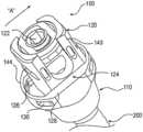
- a stabilizing receiver 100 of the inventionis formed with an anchor base 110 operative to securely connect receiver 100 to an anchor 102 .
- Anchor basemay connect to anchor by any known means, including a threadable attachment, set screw, welding, or may be integrally formed with anchor 200 .
- Anchor 200includes any means for attaching anchor base 110 to the body, including adhesives, projections, screws, pins, or other method.
- anchor 102is advantageously a polyaxial bone screw, as depicted, and anchor base 110 includes a bone screw chamber 112 for conformingly and movably receiving a polyaxial bone screw head 202 .
- Anchor fastener 114is provided, operative to secure bone screw head 202 within anchor base 110 , to thereby lock anchor 200 in a fixed position with respect to anchor base 110 .
- anchor fastener 114depicts a set screw, although other means may be provided to apply pressure or firmly secure an anchor, including collars, sleeves, and the like, as more fully disclosed, for example, in U.S. patent application Ser. Nos. 10/819,994 and 11/146,147, which are incorporated by reference herein.
- FIG. 1further depicts a receiver assembly 120 operative to securely retain a stabilizing means 204 , which may include a rod, depicted, or a pin, brace, spring, cord, resilient extension, or any other stabilizing device, such as are disclosed, for example, in the patents and applications previously incorporated, or as further described in U.S. patent application Ser. Nos. 10/443,755 and 10/762,533, which are incorporated by reference herein.
- Receiver assembly 120advantageously includes a stabilizer fastener 122 , in this embodiment a set screw, operative to secure stabilizing means 204 in a fixed position within receiver assembly 120 .
- receiver assembly 120 and anchor base 110are mutually connected by a flanged connection 124 , formed by a tenon, sash, projection, or tiebar 126 , slideably retained within slide rails, flanges, or channels, including a receiver channel 128 , and an anchor channel 130 .
- Tiebar 126 and or channels 128 , 130are advantageously formed with a lubricious material, favoring smooth movement of channels 128 , 130 in contact with tiebar 126 .
- Example materialsinclude ultra high molecular weight polyethylene (UHMWPE), PEEK, or other biocompatible polymer, or ceramic, polished metal, or other suitable biocompatible material.
- tiebar 126is a polymer
- channels 128 , 130are metal.
- An access bore 132extends from anchor fastener 114 , through receiver assembly 120 , whereby before stabilizing means 204 and stabilizer fastener 122 are installed, anchor 200 may be installed, or anchor fastener 114 may be installed, after which the aforementioned elements may be adjusted or tightened.
- FIGS. 1 A, 1 B, and 1 Cillustrate alternative configurations for flanged connection 124 .
- each of receiver assembly 120 and anchor base 110form a channel on three sides of tiebar 126 A, in the manner of a dovetail.
- the mating engagement of tiebar 126 and channels 128 , 130may incorporate any of the more complex shapes known in the art of forming dovetails, including fan shaped mating components, which avoid a separation of the mated components.
- tiebar 126 Bis formed integrally, as a projection, with anchor base 110
- tiebar 126 Cis formed integrally with receiver assembly 120 .
- the embodiment of FIG. 1 or 1 Aenables the replacement of tiebar 126 without a requirement to remove other implanted components of device 100 .
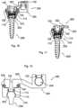
- FIGS. 2 and 3an embodiment of a stabilizing receiver 100 is illustrated in perspective.
- FIG. 2illustrates receiver assembly 120 shifted, in this perspective, to the right with respect to anchor base 110
- FIG. 3illustrates receiver assembly 120 shifted to the left.
- tiebar 126is held stationery within anchor base 110 by a flange 134 , indicated in FIG. 3 .
- tiebar 126may be bent to pass over flange 134 , whereupon after entering the channel, it may resiliently straighten and become trapped within the space between channels 128 , 130 , and flange 134 on each end.
- Other means of retaining tiebar 126would be understood by those skilled in the art, including the use of pins, mating engagements, or a pressure fit.
- receiver assembly 120may slide laterally in connection with anchor base 110 , channel 128 and or 130 sliding along a surface of tiebar 126 .
- Receiver assembly 120may not separate from anchor body 110 , however, as tiebar 126 now occupies a clearance between receiver assembly 120 and anchor body 110 which enable their mutual assembly.
- a projection of one of receiver assembly 120 or anchor base 110was able to be inserted beneath a rail of the other, first on one side, then on another, until receiver assembly 120 was seatable upon anchor base 110 .
- a limiting projection 144 on one of receiver assembly 120 or anchor base 110servers to limit lateral movement of the respective parts.
- limiting projection 144is integrally formed as an edge or rail of anchor base 110 .
- Limiting projectionmay also be installable onto either receiver assembly 120 or anchor base 110 , for example it may have the form of a pin or a screw which blocks the relative movement of the respective parts at an intended limit of travel.
- stabilizing fastener 112engages an aperture formed by two yoke extensions 140 , through an interlocking channel 142 in either stabilizing fastener 112 or yoke extensions 140 , and a corresponding flange 144 in the other of the two elements.
- stabilizing fasteneris turned about 90 degrees to engage interlocking channel 142 and flange 144 , after which set screw 122 may be turned to secure a stabilizing means 204 which has been placed between yoke extensions 140 . Examples of this may be found in U.S. patent application Ser. Nos. 10/819,994 and 11/146,147, which are incorporated by reference herein.
- Other meansmay be provided to apply pressure or firmly secure stabilizing means, including for example collars, sleeves, screws and the like, as are more fully disclosed, for example, in the incorporated patents and applications.
- FIGS. 4 and 5each depict a cross section of the receiver of FIGS. 2 and 6 , taken through a longitudinal centerline thereof, in which bone screw chamber 112 is visible.
- FIG. 5illustrates the cross section of FIG. 4 , rotated 90 degrees along a longitudinal axis.
- One or more wedges 136are advantageously driven into a space between an inner wall 138 of bone screw chamber 112 , and bone screw head 202 , causing wedges 136 to bear against both elements, thereby improving a strength of connection of bone screw 200 within receiver 100 .
- an alternative embodiment of the inventionin the form of an offset receiver 300 , provided with an offset extension 302 operative to displace offset receiving assembly 320 away from an axial centerline of anchor base 310 .
- Elements of anchor base 310are as described for anchor base 110 , although as may be seen in FIGS. 7 - 9 , access bore 132 is not obstructed after the installation of stabilizer fastener 122 , or stabilizing means 204 .
- FIG. 8illustrates offset receiver 300 in perspective, where it can be seen that offset extension 302 enables a location of offset receiving assembly 320 to a location removed from a location of anchor base 310 .
- offset extension 302may advantageously have a complex geometry, and in particular can extend in a first direction, then turn, and then extend in a second direction. In this manner, offset extension 302 can reach around other objects, for example stabilizing elements, or a physiological structure, such as a bone pedicle. Further, offset extension 302 can provide an offset in three dimensions, as may be seen in FIG. 12 .
- FIGS. 10 and 11each depict a cross section of the receiver of FIG. 8 , taken through a longitudinal centerline thereof.
- FIG. 11illustrates the cross section of FIG. 10 , rotated 90 degrees along a longitudinal axis, and with offset receiving assembly 320 not illustrated, for clarity.
- FIGS. 13 - 16another embodiment of the invention is illustrated, in which defined therapeutically effective amounts of both lateral shifting and axial rotation are enabled.
- pin 426is illustrated, operative to replace tiebar 126 , and to provide additional range of motion.
- pin 426is securely retained within channel 430 , for example by being press fit, adhered, or threadably engaged, and extends into channel 428 to be movable received therein; however, it should be understood that pin 426 could be securely retained within channel 428 , and movably extend into channel 430 .
- Channel 428has the shape of an elongated opening, bore, or channel, whereby receiver assembly 420 is retained in connection with anchor base 410 , but is free to rotate around its longitudinal axis to an extent defined by the length of channel 428 , and the relative dimensions of pin 426 . Similarly, receiver assembly 420 is free to shift sideways with respect to anchor base 410 , with an extent of shifting being dependent upon the length of channel 428 , and the relative dimensions of pin 426 .
- a therapeutically effective amount of shifting or rotationis more than that which would be allowed by mere incidental spacing or a manufacturing tolerance needed for smooth relative movement of mating parts, but not more than would be deleterious to the patient.
- pin 426is sufficiently long, and the dimensions of channel 428 sufficient constrained, to retain receiver assembly 420 in engagement with anchor base 410 throughout a full range of motion of receiver assembly 420 and anchor base 410 , relative to each other.
- pin 426is illustrated as being round, other shapes are possible, including elongated shapes. Additionally, pin 426 may fit loosely within both channel 428 and channel 430 , being retained by some other means, for example a retainer engageable with pin 426 , or a blocking member placed at an outlet of channel 428 or 430 . While neither retaining means are illustrated, their design is within the abilities of one skilled in the art.
- pin 426is illustrated in two parts, one on each side of receiver assembly 420 , pin 426 could be formed as a single shaft or elongated pin 426 passing from one side of receiver assembly to another (not shown). In this event, it may be advantageous to tighten anchor fastener 114 prior to insertion of pin 426 .
- FIG. 13 Aillustrates the receiver of FIG. 13 , rotated about a longitudinal axis 90 degrees, with only an outline of anchor base 410 shown, in order to better view an embodiment of channel 428 .
- FIG. 14is a perspective view of an embodiment of the form of receiver depicted in FIG. 13 .
- FIG. 17illustrates two receivers 100 mutually connected to a stabilizing means 204 , such as that shown and described, for example, in incorporated U.S. Patent application 2009/0299411 to Laskowitz.
- Stabilizing means 204in this example, includes spool 258 , end plate 256 , flexible intermediate portion 263 , and cord 254 , all having a form and function as described in the aforementioned application, with the following distinctions.
- Receivers 100in accordance with the instant invention, are used to connect stabilizing means 200 to the patient. As such, certain movements of joint portions are not fully transmitted to mating joint portions, or to the stabilizing means connecting the joint portions. For example, shifting movements of joint portions directionally aligned with the implanted direction of channels 128 , 130 , tend to cause relative movement of anchor base 110 and receiver assembly 120 , and thus less force is transmitted to adjoining joint portions.
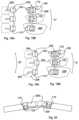
- FIGS. 18 - 19flexion of a simplified series of joints is illustrated, in which three bones are provided with receivers 100 in accordance with the invention.
- the drawingsare diagrammatic, and are not to scale, to best illustrate a functionality of the embodiments to be described.
- Each joint portion 206has been connected to a receiver 100 by anchor 200 , whereby each anchor body 110 moves and rotates with its respective joint portion. It should be understood that while three levels, or jointed portions, are illustrated, any number of receivers and jointed portions may be connected as shown and described herein.
- a single receivermay be used, wherein a portion of stabilizing means 204 are connected to the body in some other way, for example by a different form of connector, or by suture, staple, screw, glue, or any other method, and another portion of stabilizing means is connected to receiver 100 .
- receiver assemblies 120are of the type illustrated in FIG. 13 , and are free to shift laterally and rotate axially, as described herein.
- stabilizing means 204is a rod that is substantially inflexible relative to movement of the jointed bones 206 .
- Each receiver assembly 120is connected to rod 204 , as described elsewhere herein, although this connection is not illustrated, for clarity.
- anchor bases 110are each rotated, and brought closer to one another.
- rod 204does not bend, a rotating and a shifting force is imparted to an interface between anchor bases 110 , and receiver assemblies 120 .
- receiver assemblies 120shift and rotate relative to their respective anchor bases 110 , as illustrated in FIG. 18 B .
- FIG. 18 AViewed from a side, in FIG. 18 A , it can be seen that an anterior/posterior flexion/extension is therapeutically inhibited, while a lateral flexion is enabled.
- stabilizing means 204is a flexible cord 254 that readily bends, but is resistant to stretching, as more fully described in the incorporated references.
- Other stabilizing componentswhich may be used together with cord 254 , as described in the incorporated references, are not shown, for clarity.
- the bones of the jointsare engaged in both lateral flexion, indicated by arrow “C”, and flexion/extension, indicated by arrow “D”.
- Receivers 100are representative of the embodiment shown in FIG. 2 , which enable a lateral shifting of receiving assembly 120 and anchor base 110 .
- cord 254bends as it enters and exits receiver assemblies 120 ; however, a maximum separation of the jointed bones is maintained.
- receiver assembly 120is shifted from a centerline of receiver 100 , particularly in the lower two receivers 100 illustrated. This provides additional range of motion for the patient, while maintaining an effective therapeutic stabilization.
- Receivers 100 of the inventionare useful in a wide variety of clinical situations, including total disc replacements, including situations in which both facets remain, or where one or more facets are removed.
- receiver 100permits lateral or axial rotation, but prevents excess shear forces being exerted upon the spine, which in turn could cause instability and possibly alter the center of rotation of a spinal motion segment.
- the inventionmay thus be used in conjunction with other implanted components, including an artificial or grafted disc replacement component. Examples of other implanted components which may be used in conjunction with embodiments disclosed herein may be found in U.S. patent application Ser. Nos.
- FIG. 20illustrates that a receiver 100 of the invention may be used with elongated bones of a body.
- receivers in accordance with the inventionmay be used with bones or tissue anywhere in the body, including the toe, foot, ankle, calf, knee, thigh, hip, spine, shoulder, head, jaw, upper arm, elbow, lower arm, wrist, hand, and finger.
- Receivers 100 of the inventionmay additionally be used to stabilize rigid tissues, such as bones or cartilage, which have been damaged, for example by disease or trauma.
- the receiversmay be placed on opposite sides of a fracture, permitting therapeutic movement in one plane, but not in another.
- receiver 100prior to installation of receiver 100 , it may be advantageous to first assemble wedges 136 onto anchor 200 , pass anchor 200 through access bore 132 into bone screw chamber 112 , seat receiving assembly 120 onto anchor base 110 , and insert tiebar 126 or pins 426 , after which the assembly may be sterilized and packaged. Other parts are also sterilized and packaged.
- the assembly just describedmay be installed into bone using the methods and tools described in the incorporated references, including the implantation and tightening of anchor 200 and stabilizing means 204 .
- anchor fastener 114Prior to installing stabilizing means 204 , anchor fastener 114 is installed and tightened.
- the same toolmay be used to fasten anchor fastener 114 and stabilizer fastener 122 , for example a single hex head driver.
- the foregoing assembly proceduremay be altered, for example components may be assembled prior to implantation, and disassembled at a time of use.
Landscapes
- Health & Medical Sciences (AREA)
- Orthopedic Medicine & Surgery (AREA)
- Life Sciences & Earth Sciences (AREA)
- Neurology (AREA)
- Surgery (AREA)
- Heart & Thoracic Surgery (AREA)
- Engineering & Computer Science (AREA)
- Biomedical Technology (AREA)
- Nuclear Medicine, Radiotherapy & Molecular Imaging (AREA)
- Medical Informatics (AREA)
- Molecular Biology (AREA)
- Animal Behavior & Ethology (AREA)
- General Health & Medical Sciences (AREA)
- Public Health (AREA)
- Veterinary Medicine (AREA)
- Prostheses (AREA)
- Surgical Instruments (AREA)
Abstract
Description
Claims (19)
Priority Applications (1)
| Application Number | Priority Date | Filing Date | Title |
|---|---|---|---|
| US16/876,515US12035945B2 (en) | 2010-06-08 | 2020-05-18 | Conforming bone stabilization receiver |
Applications Claiming Priority (6)
| Application Number | Priority Date | Filing Date | Title |
|---|---|---|---|
| US35268010P | 2010-06-08 | 2010-06-08 | |
| US13/152,850US9113960B2 (en) | 2010-06-08 | 2011-06-03 | Conforming bone stabilization receiver |
| US14/799,607US9750541B2 (en) | 2010-06-08 | 2015-07-15 | Conforming bone stabilization receiver |
| US15/665,567US10143496B2 (en) | 2010-06-08 | 2017-08-01 | Conforming bone stabilization receiver |
| US16/173,303US10682163B2 (en) | 2010-06-08 | 2018-10-29 | Conforming bone stabilization receiver |
| US16/876,515US12035945B2 (en) | 2010-06-08 | 2020-05-18 | Conforming bone stabilization receiver |
Related Parent Applications (1)
| Application Number | Title | Priority Date | Filing Date |
|---|---|---|---|
| US16/173,303ContinuationUS10682163B2 (en) | 2010-06-08 | 2018-10-29 | Conforming bone stabilization receiver |
Publications (2)
| Publication Number | Publication Date |
|---|---|
| US20200275954A1 US20200275954A1 (en) | 2020-09-03 |
| US12035945B2true US12035945B2 (en) | 2024-07-16 |
Family
ID=45065049
Family Applications (5)
| Application Number | Title | Priority Date | Filing Date |
|---|---|---|---|
| US13/152,850Active2033-04-27US9113960B2 (en) | 2010-06-08 | 2011-06-03 | Conforming bone stabilization receiver |
| US14/799,607Active2031-06-16US9750541B2 (en) | 2010-06-08 | 2015-07-15 | Conforming bone stabilization receiver |
| US15/665,567ActiveUS10143496B2 (en) | 2010-06-08 | 2017-08-01 | Conforming bone stabilization receiver |
| US16/173,303ActiveUS10682163B2 (en) | 2010-06-08 | 2018-10-29 | Conforming bone stabilization receiver |
| US16/876,515Active2033-02-24US12035945B2 (en) | 2010-06-08 | 2020-05-18 | Conforming bone stabilization receiver |
Family Applications Before (4)
| Application Number | Title | Priority Date | Filing Date |
|---|---|---|---|
| US13/152,850Active2033-04-27US9113960B2 (en) | 2010-06-08 | 2011-06-03 | Conforming bone stabilization receiver |
| US14/799,607Active2031-06-16US9750541B2 (en) | 2010-06-08 | 2015-07-15 | Conforming bone stabilization receiver |
| US15/665,567ActiveUS10143496B2 (en) | 2010-06-08 | 2017-08-01 | Conforming bone stabilization receiver |
| US16/173,303ActiveUS10682163B2 (en) | 2010-06-08 | 2018-10-29 | Conforming bone stabilization receiver |
Country Status (4)
| Country | Link |
|---|---|
| US (5) | US9113960B2 (en) |
| EP (1) | EP2579794B1 (en) |
| JP (1) | JP5859520B2 (en) |
| WO (1) | WO2011156431A1 (en) |
Families Citing this family (18)
| Publication number | Priority date | Publication date | Assignee | Title |
|---|---|---|---|---|
| US9044272B2 (en)* | 2009-11-09 | 2015-06-02 | Ebi, Llc | Multiplanar bone anchor system |
| US9113960B2 (en)* | 2010-06-08 | 2015-08-25 | Globus Medical, Inc. | Conforming bone stabilization receiver |
| WO2013070628A1 (en) | 2011-11-07 | 2013-05-16 | Lorio Morgan Packard | Apparatuses for delivering a rod to a plurality of pedicle screws |
| US9987047B2 (en)* | 2013-10-07 | 2018-06-05 | Spine Wave, Inc. | Translating polyaxial screw |
| FR3035318B1 (en)* | 2015-04-24 | 2017-05-19 | Medicrea Int | MATERIAL OF VERTEBRAL OSTEOSYNTHESIS |
| US10321939B2 (en) | 2016-05-18 | 2019-06-18 | Medos International Sarl | Implant connectors and related methods |
| US10517647B2 (en) | 2016-05-18 | 2019-12-31 | Medos International Sarl | Implant connectors and related methods |
| EP4278998B1 (en)* | 2016-07-29 | 2025-05-21 | Zimmer Biomet Spine, Inc. | Bone anchor housing limiter |
| US10398476B2 (en) | 2016-12-13 | 2019-09-03 | Medos International Sàrl | Implant adapters and related methods |
| US10492835B2 (en) | 2016-12-19 | 2019-12-03 | Medos International Sàrl | Offset rods, offset rod connectors, and related methods |
| US10238432B2 (en)* | 2017-02-10 | 2019-03-26 | Medos International Sàrl | Tandem rod connectors and related methods |
| US10966761B2 (en) | 2017-03-28 | 2021-04-06 | Medos International Sarl | Articulating implant connectors and related methods |
| US10561454B2 (en) | 2017-03-28 | 2020-02-18 | Medos International Sarl | Articulating implant connectors and related methods |
| US10258386B2 (en)* | 2017-06-15 | 2019-04-16 | Warsaw Orthopedic, Inc. | Spinal construct and method |
| EP3441028B1 (en) | 2017-08-08 | 2021-10-06 | Biedermann Technologies GmbH & Co. KG | Receiving part and instrument for holding the receiving part |
| US10070897B1 (en)* | 2017-10-10 | 2018-09-11 | Spine Wave, Inc. | Translational posterior cervical polyaxial screw |
| FR3073731A1 (en)* | 2017-11-22 | 2019-05-24 | Hassan Razian | SYSTEM FOR CONNECTING TWO PORTIONS OF BONES BETWEEN THEM WHEN ONE MUST MOVE IN RELATION TO THE OTHER |
| US11076890B2 (en) | 2017-12-01 | 2021-08-03 | Medos International Sàrl | Rod-to-rod connectors having robust rod closure mechanisms and related methods |
Citations (16)
| Publication number | Priority date | Publication date | Assignee | Title |
|---|---|---|---|---|
| JPH06296621A (en) | 1993-03-10 | 1994-10-25 | Biedermann Motech Gmbh | Bone screw |
| US6302888B1 (en)* | 1999-03-19 | 2001-10-16 | Interpore Cross International | Locking dovetail and self-limiting set screw assembly for a spinal stabilization member |
| US20030045879A1 (en)* | 2001-07-04 | 2003-03-06 | Richard Minfelde | Connector for a spinal fixation member |
| US20060235392A1 (en) | 2004-08-27 | 2006-10-19 | Hammer Michael A | Multi-axial connection system |
| US20070244482A1 (en)* | 2006-04-18 | 2007-10-18 | Joseph Aferzon | Pedicle screw with vertical adjustment |
| US20090163955A1 (en)* | 2007-12-19 | 2009-06-25 | Missoum Moumene | Polymeric Pedicle Rods and Methods of Manufacturing |
| US20090318973A1 (en)* | 2006-05-30 | 2009-12-24 | Jean-Pierre Moulin | Bone fixing device |
| US20100030272A1 (en)* | 2007-06-05 | 2010-02-04 | Spartek Medical Inc. | Spinal prosthesis having a three bar linkage for motion preservation and dynamic stabilization of the spine |
| US20100030273A1 (en)* | 2008-02-26 | 2010-02-04 | Spartek Medical, Inc. | Versatile polyaxial connector assembly and method for dynamic stabilization of the spine |
| JP2010505541A (en) | 2006-10-05 | 2010-02-25 | ジャヴィン・ピアス | Anchor assembly for spinal implant system |
| US20100262190A1 (en)* | 2009-04-09 | 2010-10-14 | Warsaw Orthopedic, Inc. | Spinal rod translation device |
| US20100292739A1 (en)* | 2009-05-15 | 2010-11-18 | Warsaw Orthopedic, Inc. | Bone Screws With Improved Locking Mechanisms |
| WO2011056707A2 (en) | 2009-11-09 | 2011-05-12 | Ebi, Llc. | Multiplanar bone anchor system |
| US20110202094A1 (en)* | 2009-11-11 | 2011-08-18 | Pereira Mario L | Trans-polyaxial screw |
| US8636776B2 (en)* | 2003-01-28 | 2014-01-28 | Depuy Spine, Inc. | Spinal rod approximator |
| US20140200618A1 (en)* | 2010-01-13 | 2014-07-17 | Jcbd, Llc | Systems and methods for fusing a sacroiliac joint and anchoring an orthopedic appliance |
Family Cites Families (83)
| Publication number | Priority date | Publication date | Assignee | Title |
|---|---|---|---|---|
| WO2002009603A1 (en)* | 2000-07-28 | 2002-02-07 | Synthes Ag Chur | Spinal fixation system |
| US7833250B2 (en)* | 2004-11-10 | 2010-11-16 | Jackson Roger P | Polyaxial bone screw with helically wound capture connection |
| US6755829B1 (en)* | 2000-09-22 | 2004-06-29 | Depuy Acromed, Inc. | Lock cap anchor assembly for orthopaedic fixation |
| US8377100B2 (en)* | 2000-12-08 | 2013-02-19 | Roger P. Jackson | Closure for open-headed medical implant |
| US8353932B2 (en)* | 2005-09-30 | 2013-01-15 | Jackson Roger P | Polyaxial bone anchor assembly with one-piece closure, pressure insert and plastic elongate member |
| US9539012B2 (en) | 2002-10-30 | 2017-01-10 | Zimmer Spine, Inc. | Spinal stabilization systems with quick-connect sleeve assemblies for use in surgical procedures |
| US7766915B2 (en)* | 2004-02-27 | 2010-08-03 | Jackson Roger P | Dynamic fixation assemblies with inner core and outer coil-like member |
| US7322981B2 (en)* | 2003-08-28 | 2008-01-29 | Jackson Roger P | Polyaxial bone screw with split retainer ring |
| US8377102B2 (en)* | 2003-06-18 | 2013-02-19 | Roger P. Jackson | Polyaxial bone anchor with spline capture connection and lower pressure insert |
| US7776067B2 (en)* | 2005-05-27 | 2010-08-17 | Jackson Roger P | Polyaxial bone screw with shank articulation pressure insert and method |
| US20110040338A1 (en)* | 2003-08-28 | 2011-02-17 | Jackson Roger P | Polyaxial bone anchor having an open retainer with conical, cylindrical or curvate capture |
| US7087057B2 (en)* | 2003-06-27 | 2006-08-08 | Depuy Acromed, Inc. | Polyaxial bone screw |
| US8105367B2 (en)* | 2003-09-29 | 2012-01-31 | Smith & Nephew, Inc. | Bone plate and bone plate assemblies including polyaxial fasteners |
| US8632570B2 (en)* | 2003-11-07 | 2014-01-21 | Biedermann Technologies Gmbh & Co. Kg | Stabilization device for bones comprising a spring element and manufacturing method for said spring element |
| US7717939B2 (en)* | 2004-03-31 | 2010-05-18 | Depuy Spine, Inc. | Rod attachment for head to head cross connector |
| US8951290B2 (en)* | 2004-08-27 | 2015-02-10 | Blackstone Medical, Inc. | Multi-axial connection system |
| US7572280B2 (en)* | 2004-10-05 | 2009-08-11 | Warsaw Orthopedic, Inc. | Multi-axial anchor assemblies for spinal implants and methods |
| US7513905B2 (en)* | 2004-11-03 | 2009-04-07 | Jackson Roger P | Polyaxial bone screw |
| US8926672B2 (en)* | 2004-11-10 | 2015-01-06 | Roger P. Jackson | Splay control closure for open bone anchor |
| DE102004056091B8 (en)* | 2004-11-12 | 2007-04-26 | Aesculap Ag & Co. Kg | Orthopedic fixation device and orthopedic fixation system |
| US9168069B2 (en)* | 2009-06-15 | 2015-10-27 | Roger P. Jackson | Polyaxial bone anchor with pop-on shank and winged insert with lower skirt for engaging a friction fit retainer |
| US20120029568A1 (en)* | 2006-01-09 | 2012-02-02 | Jackson Roger P | Spinal connecting members with radiused rigid sleeves and tensioned cords |
| US20130144346A1 (en)* | 2004-11-23 | 2013-06-06 | Roger P. Jackson | Modular polyaxial bone anchor with retainer having interconnected pieces |
| US8444681B2 (en)* | 2009-06-15 | 2013-05-21 | Roger P. Jackson | Polyaxial bone anchor with pop-on shank, friction fit retainer and winged insert |
| US7875065B2 (en)* | 2004-11-23 | 2011-01-25 | Jackson Roger P | Polyaxial bone screw with multi-part shank retainer and pressure insert |
| US10076361B2 (en)* | 2005-02-22 | 2018-09-18 | Roger P. Jackson | Polyaxial bone screw with spherical capture, compression and alignment and retention structures |
| US20090036929A1 (en)* | 2005-07-22 | 2009-02-05 | Joey Camia Reglos | Offset connector for a spinal stabilization rod |
| US7713288B2 (en)* | 2005-08-03 | 2010-05-11 | Applied Spine Technologies, Inc. | Spring junction and assembly methods for spinal device |
| WO2007022790A1 (en)* | 2005-08-23 | 2007-03-01 | Synthes Gmbh | An osteosynthetic clamp for attaching a bone anchor to a support rod |
| US8034078B2 (en) | 2008-05-30 | 2011-10-11 | Globus Medical, Inc. | System and method for replacement of spinal motion segment |
| US7967847B2 (en) | 2006-07-24 | 2011-06-28 | Warsaw Orthopedic, Inc. | Spinal stabilization and reconstruction with fusion rods |
| US20080051780A1 (en)* | 2006-08-04 | 2008-02-28 | Zimmer Spine, Inc. | Spinal rod connector |
| US8016862B2 (en)* | 2006-09-27 | 2011-09-13 | Innovasis, Inc. | Spinal stabilizing system |
| FR2910267B1 (en)* | 2006-12-21 | 2009-01-23 | Ldr Medical Soc Par Actions Si | VERTEBRAL SUPPORT DEVICE |
| US10792074B2 (en)* | 2007-01-22 | 2020-10-06 | Roger P. Jackson | Pivotal bone anchor assemly with twist-in-place friction fit insert |
| US8926667B2 (en)* | 2007-02-09 | 2015-01-06 | Transcendental Spine, Llc | Connector |
| WO2008134703A2 (en) | 2007-04-30 | 2008-11-06 | Globus Medical, Inc. | Flexible spine stabilization system |
| US8979904B2 (en)* | 2007-05-01 | 2015-03-17 | Roger P Jackson | Connecting member with tensioned cord, low profile rigid sleeve and spacer with torsion control |
| US8021396B2 (en)* | 2007-06-05 | 2011-09-20 | Spartek Medical, Inc. | Configurable dynamic spinal rod and method for dynamic stabilization of the spine |
| US8048123B2 (en)* | 2007-06-05 | 2011-11-01 | Spartek Medical, Inc. | Spine implant with a deflection rod system and connecting linkages and method |
| US8092501B2 (en)* | 2007-06-05 | 2012-01-10 | Spartek Medical, Inc. | Dynamic spinal rod and method for dynamic stabilization of the spine |
| US8083772B2 (en)* | 2007-06-05 | 2011-12-27 | Spartek Medical, Inc. | Dynamic spinal rod assembly and method for dynamic stabilization of the spine |
| WO2009029928A1 (en)* | 2007-08-31 | 2009-03-05 | University Of South Florida | Translational manipulation polyaxial screw head |
| US8025682B2 (en)* | 2007-08-31 | 2011-09-27 | Depuy Spine, Inc. | Method and system for securing a rod to a bone anchor with a connector |
| US20090062822A1 (en)* | 2007-08-31 | 2009-03-05 | Frasier William J | Adaptable clamping mechanism for coupling a spinal fixation element to a bone anchor |
| US20090105756A1 (en)* | 2007-10-23 | 2009-04-23 | Marc Richelsoph | Spinal implant |
| US8114141B2 (en)* | 2007-12-17 | 2012-02-14 | Synthes Usa, Llc | Dynamic bone fixation element and method of using the same |
| EP2242437B1 (en)* | 2008-01-24 | 2014-03-26 | Globus Medical, Inc. | Facet fixation prosthesis |
| WO2009099963A2 (en)* | 2008-01-31 | 2009-08-13 | Cayenne Medical, Inc | Self-tapping biocompatible interference bone screw |
| US20100036437A1 (en)* | 2008-02-26 | 2010-02-11 | Spartek Medical, Inc. | Load-sharing bone anchor having a deflectable post with a compliant ring and method for stabilization of the spine |
| US8057517B2 (en)* | 2008-02-26 | 2011-11-15 | Spartek Medical, Inc. | Load-sharing component having a deflectable post and centering spring and method for dynamic stabilization of the spine |
| FR2927791B1 (en)* | 2008-02-26 | 2011-02-18 | Clariance | ARTICULAR PROSTHESIS POSTERIEURE LUMBAR WITH ROTULE |
| US8007518B2 (en)* | 2008-02-26 | 2011-08-30 | Spartek Medical, Inc. | Load-sharing component having a deflectable post and method for dynamic stabilization of the spine |
| US8097024B2 (en)* | 2008-02-26 | 2012-01-17 | Spartek Medical, Inc. | Load-sharing bone anchor having a deflectable post and method for stabilization of the spine |
| US8337536B2 (en)* | 2008-02-26 | 2012-12-25 | Spartek Medical, Inc. | Load-sharing bone anchor having a deflectable post with a compliant ring and method for stabilization of the spine |
| US8211155B2 (en)* | 2008-02-26 | 2012-07-03 | Spartek Medical, Inc. | Load-sharing bone anchor having a durable compliant member and method for dynamic stabilization of the spine |
| US8333792B2 (en)* | 2008-02-26 | 2012-12-18 | Spartek Medical, Inc. | Load-sharing bone anchor having a deflectable post and method for dynamic stabilization of the spine |
| US8097026B2 (en)* | 2008-02-28 | 2012-01-17 | K2M, Inc. | Minimally invasive retraction device having removable blades |
| US8221473B2 (en)* | 2008-03-13 | 2012-07-17 | Life Spine, Inc. | Spinal rod connector assembly for a vertebral bone screw |
| AU2010260521C1 (en)* | 2008-08-01 | 2013-08-01 | Roger P. Jackson | Longitudinal connecting member with sleeved tensioned cords |
| US20100036434A1 (en)* | 2008-08-05 | 2010-02-11 | Abbott Spine Inc. | Rescue reduction bone anchor |
| US8252025B2 (en)* | 2008-09-03 | 2012-08-28 | Zimmer Spine, Inc. | Vertebral fixation system |
| EP2174608B1 (en)* | 2008-10-08 | 2012-08-01 | Biedermann Technologies GmbH & Co. KG | Bone anchoring device and stabilization device for bone parts or vertebrae |
| US20100094352A1 (en)* | 2008-10-10 | 2010-04-15 | Andrew Iott | Bone screw |
| IT1392200B1 (en)* | 2008-12-17 | 2012-02-22 | N B R New Biotechnology Res | MODULAR VERTEBRAL STABILIZER. |
| ES2375879T3 (en)* | 2008-12-23 | 2012-03-07 | Biedermann Motech Gmbh | RECEPTION AREA OF A ROD FOR COUPLING THE ROD IN AN BONE ANCHORAGE ELEMENT AND BONE ANCHORAGE DEVICE WITH SUCH RECEPTION AREA. |
| US8252030B2 (en)* | 2009-03-10 | 2012-08-28 | Globus Medical, Inc. | Spinal implant connection assembly |
| US9125699B2 (en)* | 2009-05-15 | 2015-09-08 | Smith & Nephew, Inc. | Polyaxial fastener systems and methods |
| US20130103098A1 (en)* | 2009-06-15 | 2013-04-25 | Roger P. Jackson | Polyaxial bone anchor with pop-on shank, friction fit retainer and lateral alignment feature |
| CN103826560A (en)* | 2009-06-15 | 2014-05-28 | 罗杰.P.杰克逊 | Polyaxial Bone Anchor with Socket Stem and Winged Inserts with Friction Fit Compression Collars |
| EP2485654B1 (en)* | 2009-10-05 | 2021-05-05 | Jackson P. Roger | Polyaxial bone anchor with non-pivotable retainer and pop-on shank, some with friction fit |
| WO2011063020A1 (en)* | 2009-11-18 | 2011-05-26 | Seaspine, Inc. | Flexible screw head constructs for spinal stabilization |
| WO2011106339A1 (en)* | 2010-02-23 | 2011-09-01 | K2M, Inc. | Polyaxial bone screw assembly |
| US9113960B2 (en)* | 2010-06-08 | 2015-08-25 | Globus Medical, Inc. | Conforming bone stabilization receiver |
| US8882817B2 (en)* | 2010-08-20 | 2014-11-11 | K2M, Inc. | Spinal fixation system |
| US8979901B2 (en)* | 2010-08-26 | 2015-03-17 | Warsaw Orthopedic, Inc. | Dynamic bone fastener with a preset range of motion |
| US10111694B2 (en)* | 2010-10-05 | 2018-10-30 | Skeletal Design Partnership, Llc | Pedicle screw assembly and method of assembly |
| JP5865479B2 (en)* | 2011-03-24 | 2016-02-17 | ロジャー・ピー・ジャクソン | Multiaxial bone anchor with compound joint and pop-mounted shank |
| US8888827B2 (en)* | 2011-07-15 | 2014-11-18 | Globus Medical, Inc. | Orthopedic fixation devices and methods of installation thereof |
| EP2591739A1 (en)* | 2011-11-14 | 2013-05-15 | Biedermann Technologies GmbH & Co. KG | Polyaxial bone anchoring device |
| US9259247B2 (en)* | 2013-03-14 | 2016-02-16 | Medos International Sarl | Locking compression members for use with bone anchor assemblies and methods |
| US9402660B2 (en)* | 2013-09-05 | 2016-08-02 | Warsaw Orthopedic, Inc. | Surgical instrument and method |
| US9597119B2 (en)* | 2014-06-04 | 2017-03-21 | Roger P. Jackson | Polyaxial bone anchor with polymer sleeve |
- 2011
- 2011-06-03USUS13/152,850patent/US9113960B2/enactiveActive
- 2011-06-07JPJP2013514317Apatent/JP5859520B2/enactiveActive
- 2011-06-07WOPCT/US2011/039528patent/WO2011156431A1/enactiveApplication Filing
- 2011-06-07EPEP11793061.0Apatent/EP2579794B1/enactiveActive
- 2015
- 2015-07-15USUS14/799,607patent/US9750541B2/enactiveActive
- 2017
- 2017-08-01USUS15/665,567patent/US10143496B2/enactiveActive
- 2018
- 2018-10-29USUS16/173,303patent/US10682163B2/enactiveActive
- 2020
- 2020-05-18USUS16/876,515patent/US12035945B2/enactiveActive
Patent Citations (20)
| Publication number | Priority date | Publication date | Assignee | Title |
|---|---|---|---|---|
| JPH06296621A (en) | 1993-03-10 | 1994-10-25 | Biedermann Motech Gmbh | Bone screw |
| US6302888B1 (en)* | 1999-03-19 | 2001-10-16 | Interpore Cross International | Locking dovetail and self-limiting set screw assembly for a spinal stabilization member |
| US20030045879A1 (en)* | 2001-07-04 | 2003-03-06 | Richard Minfelde | Connector for a spinal fixation member |
| US8636776B2 (en)* | 2003-01-28 | 2014-01-28 | Depuy Spine, Inc. | Spinal rod approximator |
| US20060235392A1 (en) | 2004-08-27 | 2006-10-19 | Hammer Michael A | Multi-axial connection system |
| JP2008534075A (en) | 2005-03-25 | 2008-08-28 | ブラックストーン メディカル,インコーポレイティド | Multi-axis connection system |
| US20070244482A1 (en)* | 2006-04-18 | 2007-10-18 | Joseph Aferzon | Pedicle screw with vertical adjustment |
| US20090318973A1 (en)* | 2006-05-30 | 2009-12-24 | Jean-Pierre Moulin | Bone fixing device |
| JP2010505541A (en) | 2006-10-05 | 2010-02-25 | ジャヴィン・ピアス | Anchor assembly for spinal implant system |
| US20100241170A1 (en) | 2006-10-05 | 2010-09-23 | Frank Cammisa | Anchor assembly for spinal implant system |
| US20100030272A1 (en)* | 2007-06-05 | 2010-02-04 | Spartek Medical Inc. | Spinal prosthesis having a three bar linkage for motion preservation and dynamic stabilization of the spine |
| US20090163955A1 (en)* | 2007-12-19 | 2009-06-25 | Missoum Moumene | Polymeric Pedicle Rods and Methods of Manufacturing |
| US20100030273A1 (en)* | 2008-02-26 | 2010-02-04 | Spartek Medical, Inc. | Versatile polyaxial connector assembly and method for dynamic stabilization of the spine |
| US20100262190A1 (en)* | 2009-04-09 | 2010-10-14 | Warsaw Orthopedic, Inc. | Spinal rod translation device |
| US20100292739A1 (en)* | 2009-05-15 | 2010-11-18 | Warsaw Orthopedic, Inc. | Bone Screws With Improved Locking Mechanisms |
| WO2011056707A2 (en) | 2009-11-09 | 2011-05-12 | Ebi, Llc. | Multiplanar bone anchor system |
| US20110112578A1 (en)* | 2009-11-09 | 2011-05-12 | Ebi, Llc | Multiplanar bone anchor system |
| JP2013509952A (en) | 2009-11-09 | 2013-03-21 | イービーアイ,エルエルシー | Multifaceted bone anchor system |
| US20110202094A1 (en)* | 2009-11-11 | 2011-08-18 | Pereira Mario L | Trans-polyaxial screw |
| US20140200618A1 (en)* | 2010-01-13 | 2014-07-17 | Jcbd, Llc | Systems and methods for fusing a sacroiliac joint and anchoring an orthopedic appliance |
Also Published As
| Publication number | Publication date |
|---|---|
| JP5859520B2 (en) | 2016-02-10 |
| US9113960B2 (en) | 2015-08-25 |
| EP2579794B1 (en) | 2021-11-24 |
| US20200275954A1 (en) | 2020-09-03 |
| US9750541B2 (en) | 2017-09-05 |
| EP2579794A4 (en) | 2014-11-05 |
| US10682163B2 (en) | 2020-06-16 |
| US20150313645A1 (en) | 2015-11-05 |
| US20170325848A1 (en) | 2017-11-16 |
| US20110301649A1 (en) | 2011-12-08 |
| EP2579794A1 (en) | 2013-04-17 |
| JP2013528450A (en) | 2013-07-11 |
| WO2011156431A1 (en) | 2011-12-15 |
| US10143496B2 (en) | 2018-12-04 |
| US20190059952A1 (en) | 2019-02-28 |
Similar Documents
| Publication | Publication Date | Title |
|---|---|---|
| US12035945B2 (en) | Conforming bone stabilization receiver | |
| US12251321B2 (en) | Expandable intervertebral implant | |
| US10973653B2 (en) | Intervertebral implant | |
| EP1784147B1 (en) | Implantable spinal device revision system | |
| CA2702964C (en) | Hemi-prosthesis | |
| US8252026B2 (en) | Spinal implant for facet joint | |
| US20080071375A1 (en) | Artificial spinal disc replacement system and method | |
| US20080015698A1 (en) | Spinal disc implant | |
| EP3876873B1 (en) | Intervertebral spinal implant | |
| KR20060129008A (en) | Dual junctional spine device and method |
Legal Events
| Date | Code | Title | Description |
|---|---|---|---|
| AS | Assignment | Owner name:GLOBUS MEDICAL, INC., PENNSYLVANIA Free format text:ASSIGNMENT OF ASSIGNORS INTEREST;ASSIGNOR:HANSELL, NOAH;REEL/FRAME:052687/0195 Effective date:20110726 | |
| FEPP | Fee payment procedure | Free format text:ENTITY STATUS SET TO UNDISCOUNTED (ORIGINAL EVENT CODE: BIG.); ENTITY STATUS OF PATENT OWNER: LARGE ENTITY | |
| STPP | Information on status: patent application and granting procedure in general | Free format text:DOCKETED NEW CASE - READY FOR EXAMINATION | |
| STPP | Information on status: patent application and granting procedure in general | Free format text:NON FINAL ACTION MAILED | |
| STPP | Information on status: patent application and granting procedure in general | Free format text:FINAL REJECTION MAILED | |
| STPP | Information on status: patent application and granting procedure in general | Free format text:NON FINAL ACTION MAILED | |
| STPP | Information on status: patent application and granting procedure in general | Free format text:RESPONSE TO NON-FINAL OFFICE ACTION ENTERED AND FORWARDED TO EXAMINER | |
| STPP | Information on status: patent application and granting procedure in general | Free format text:FINAL REJECTION MAILED | |
| STPP | Information on status: patent application and granting procedure in general | Free format text:RESPONSE AFTER FINAL ACTION FORWARDED TO EXAMINER | |
| STPP | Information on status: patent application and granting procedure in general | Free format text:NOTICE OF ALLOWANCE MAILED -- APPLICATION RECEIVED IN OFFICE OF PUBLICATIONS | |
| STPP | Information on status: patent application and granting procedure in general | Free format text:PUBLICATIONS -- ISSUE FEE PAYMENT VERIFIED | |
| STCF | Information on status: patent grant | Free format text:PATENTED CASE |