US12034600B2 - Method for federating a cluster from a plurality of computing nodes from different fault domains - Google Patents
Method for federating a cluster from a plurality of computing nodes from different fault domainsDownload PDFInfo
- Publication number
- US12034600B2 US12034600B2US16/446,288US201916446288AUS12034600B2US 12034600 B2US12034600 B2US 12034600B2US 201916446288 AUS201916446288 AUS 201916446288AUS 12034600 B2US12034600 B2US 12034600B2
- Authority
- US
- United States
- Prior art keywords
- nodes
- fault
- computing nodes
- computing
- node
- Prior art date
- Legal status (The legal status is an assumption and is not a legal conclusion. Google has not performed a legal analysis and makes no representation as to the accuracy of the status listed.)
- Active, expires
Links
Images


Classifications
- H—ELECTRICITY
- H04—ELECTRIC COMMUNICATION TECHNIQUE
- H04L—TRANSMISSION OF DIGITAL INFORMATION, e.g. TELEGRAPHIC COMMUNICATION
- H04L41/00—Arrangements for maintenance, administration or management of data switching networks, e.g. of packet switching networks
- H04L41/06—Management of faults, events, alarms or notifications
- H04L41/0677—Localisation of faults
- G—PHYSICS
- G06—COMPUTING OR CALCULATING; COUNTING
- G06F—ELECTRIC DIGITAL DATA PROCESSING
- G06F15/00—Digital computers in general; Data processing equipment in general
- G06F15/16—Combinations of two or more digital computers each having at least an arithmetic unit, a program unit and a register, e.g. for a simultaneous processing of several programs
- G06F15/161—Computing infrastructure, e.g. computer clusters, blade chassis or hardware partitioning
- H—ELECTRICITY
- H04—ELECTRIC COMMUNICATION TECHNIQUE
- H04L—TRANSMISSION OF DIGITAL INFORMATION, e.g. TELEGRAPHIC COMMUNICATION
- H04L41/00—Arrangements for maintenance, administration or management of data switching networks, e.g. of packet switching networks
- H04L41/08—Configuration management of networks or network elements
- H04L41/0803—Configuration setting
- H04L41/0806—Configuration setting for initial configuration or provisioning, e.g. plug-and-play
- H—ELECTRICITY
- H04—ELECTRIC COMMUNICATION TECHNIQUE
- H04L—TRANSMISSION OF DIGITAL INFORMATION, e.g. TELEGRAPHIC COMMUNICATION
- H04L41/00—Arrangements for maintenance, administration or management of data switching networks, e.g. of packet switching networks
- H04L41/08—Configuration management of networks or network elements
- H04L41/0803—Configuration setting
- H04L41/084—Configuration by using pre-existing information, e.g. using templates or copying from other elements
- H—ELECTRICITY
- H04—ELECTRIC COMMUNICATION TECHNIQUE
- H04L—TRANSMISSION OF DIGITAL INFORMATION, e.g. TELEGRAPHIC COMMUNICATION
- H04L41/00—Arrangements for maintenance, administration or management of data switching networks, e.g. of packet switching networks
- H04L41/08—Configuration management of networks or network elements
- H04L41/085—Retrieval of network configuration; Tracking network configuration history
- H04L41/0853—Retrieval of network configuration; Tracking network configuration history by actively collecting configuration information or by backing up configuration information
- H—ELECTRICITY
- H04—ELECTRIC COMMUNICATION TECHNIQUE
- H04L—TRANSMISSION OF DIGITAL INFORMATION, e.g. TELEGRAPHIC COMMUNICATION
- H04L41/00—Arrangements for maintenance, administration or management of data switching networks, e.g. of packet switching networks
- H04L41/08—Configuration management of networks or network elements
- H04L41/0876—Aspects of the degree of configuration automation
- H04L41/0886—Fully automatic configuration
- H—ELECTRICITY
- H04—ELECTRIC COMMUNICATION TECHNIQUE
- H04L—TRANSMISSION OF DIGITAL INFORMATION, e.g. TELEGRAPHIC COMMUNICATION
- H04L41/00—Arrangements for maintenance, administration or management of data switching networks, e.g. of packet switching networks
- H04L41/08—Configuration management of networks or network elements
- H04L41/0893—Assignment of logical groups to network elements
- H—ELECTRICITY
- H04—ELECTRIC COMMUNICATION TECHNIQUE
- H04L—TRANSMISSION OF DIGITAL INFORMATION, e.g. TELEGRAPHIC COMMUNICATION
- H04L41/00—Arrangements for maintenance, administration or management of data switching networks, e.g. of packet switching networks
- H04L41/12—Discovery or management of network topologies
- H—ELECTRICITY
- H04—ELECTRIC COMMUNICATION TECHNIQUE
- H04L—TRANSMISSION OF DIGITAL INFORMATION, e.g. TELEGRAPHIC COMMUNICATION
- H04L41/00—Arrangements for maintenance, administration or management of data switching networks, e.g. of packet switching networks
- H04L41/06—Management of faults, events, alarms or notifications
- H04L41/0654—Management of faults, events, alarms or notifications using network fault recovery
- H—ELECTRICITY
- H04—ELECTRIC COMMUNICATION TECHNIQUE
- H04L—TRANSMISSION OF DIGITAL INFORMATION, e.g. TELEGRAPHIC COMMUNICATION
- H04L49/00—Packet switching elements
- H04L49/70—Virtual switches
- Y—GENERAL TAGGING OF NEW TECHNOLOGICAL DEVELOPMENTS; GENERAL TAGGING OF CROSS-SECTIONAL TECHNOLOGIES SPANNING OVER SEVERAL SECTIONS OF THE IPC; TECHNICAL SUBJECTS COVERED BY FORMER USPC CROSS-REFERENCE ART COLLECTIONS [XRACs] AND DIGESTS
- Y02—TECHNOLOGIES OR APPLICATIONS FOR MITIGATION OR ADAPTATION AGAINST CLIMATE CHANGE
- Y02D—CLIMATE CHANGE MITIGATION TECHNOLOGIES IN INFORMATION AND COMMUNICATION TECHNOLOGIES [ICT], I.E. INFORMATION AND COMMUNICATION TECHNOLOGIES AIMING AT THE REDUCTION OF THEIR OWN ENERGY USE
- Y02D30/00—Reducing energy consumption in communication networks
Definitions
- Clustersare systems which function as a closely coupled integrated unit taking a hybrid approach of combining the characteristics of loosely and tightly coupled systems.
- a clusterincludes closely coupled multiple systems running a similar instance of operating system software with the ability to share resources like storage, memory, etc.
- FIG. 1is a block diagram of an example system for federating a cluster from a plurality of computing nodes
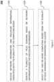
- FIG. 2is a flowchart of an example method for federating a cluster from a plurality of computing nodes
- FIG. 3is an example graph model of a section of a system comprising a plurality of computing nodes
- FIG. 4is another example graph model of another section of a system comprising a plurality of computing nodes
- FIG. 5is a block diagram of an example controller with machine-readable medium for federating a cluster from a plurality of computing nodes.
- FIG. 6is an example domain distance matrix for federating a cluster from a plurality of computing nodes.
- a compute farm including compute devicesis spread as individual rack servers or as blade servers in enclosures.
- LAGLink Aggregation Group
- MC teamingprovide means of accomplishing high availability in such an environment.
- a network faultcan effect a single server, single enclosure, and group of servers, group of VMs inside the enclosure or outside depending on the network topology and the nature of fault.
- the example methodenables to federate clusters with computing nodes spanning across different fault domains in an automated fashion to ensure maximum isolation of computing nodes with respect to any fault in the environment. This ensures that the cluster is highly resilient to multiple levels of fault in such a hybrid environment and also ensures a well-balanced infrastructure in terms of resource usage.
- the current disclosuredescribes an example method for federating the cluster from a plurality of computing nodes to address the above mentioned aspect.
- the methodcomprises receiving network information and enclosure information associated with the plurality of the computing nodes, identifying a plurality of fault domains based on network information and the enclosure information, and selecting the two or more computing nodes from the plurality of fault domains for federating the cluster.
- Network informationis indicative of network topology between the plurality of computing nodes.
- Enclosure informationis indicative of a configuration of an enclosure associated with a corresponding computing node.
- Each fault domainincludes one or more computing nodes impacted by at least one of a corresponding network fault event and a corresponding enclosure fault event.
- the two or more computing nodesincludes a first computing node from a first fault domain and a second computing node from a second fault domain.
- a graph modelis generated from the network information and the enclosure information.
- Each node from the graph modelis indicative of one of a computing node or a network device or any other device which is associated with the computing nodes.
- a plurality of nodes in the graph modelare associated with the plurality of computing nodes.
- Each sub-tree in the graph modelis indicative of a fault domain from the plurality of fault domains and comprises a root node and one or more child nodes where the one or more computing nodes or network devices associated with the child nodes are impacted by a fault associated with a computing node or network device associated with the root node.
- the two or more computing nodes for federating the clusterare selected.
- the first and second fault domainsform a disjoint set such that every node from the first fault domain is distinct from every node of the second fault domain.
- the network informationis determined based on Link Layer Discovery Protocol (LLDP) packets exchanged between the computing nodes and network devices, and a Management Information Database (MIB) of the computing nodes and network devices.
- the network informationcomprises Internet Protocol addresses of the computing nodes, port group information of the ports on the computing nodes, and Local Area Network (LAN) information of the computing nodes.
- the plurality of interconnected computing nodesincludes a first set of physical nodes and a second set of virtual nodes.
- the current disclosurediscloses a cluster management system.
- the cluster management systemcomprises a plurality of computing nodes connected via a plurality of network devices.
- One or more computing nodesare enclosed in server enclosures and share a common power unit.
- Each computing nodeis connected to other computing nodes over one or more network domains.
- a controllerconnected to the plurality of computing nodes.
- the controllerreceives network information and enclosure information associated with the plurality of the computing nodes, identifies a plurality of fault domains based on network information and the enclosure information, selects the two or more computing nodes from the plurality of fault domains for federating the cluster, wherein a first computing node from the two or more computing nodes, is from a first fault domain and a second computing node from the two or more computing nodes is from a second fault domain.
- the current disclosurediscloses a non-transitory machine-readable storage medium storing instructions that, when executed by at least one processor, cause the at least one processor to receive network information and enclosure information associated with the plurality of the computing nodes, identify a plurality of fault domains based on network information and the enclosure information, and select the two or more computing nodes from the plurality of fault domains for federating the cluster.
- Network informationis indicative of network topology between the plurality of computing nodes.
- Enclosure informationis indicative of a configuration of an enclosure associated with a corresponding computing node.
- Each fault domainincludes one or more computing nodes impacted by at least one of a corresponding network fault event and a corresponding enclosure fault event.
- the two or more computing nodesincludes a first computing node from a first fault domain and a second computing node from a second fault domain.
- FIG. 1is a block diagram of a system 100 for federating a cluster from a plurality of interconnected computing nodes.
- the system 100includes three example racks 105 , 110 and 115 .
- Each rackcomprises one or more Top of Rack (ToR) switches ( 107 , 117 and 127 ), and master and satellite switches ( 125 , 135 and 145 ), and a plurality of servers ( 108 , 109 , 118 , 119 , 128 , 137 , 138 , 139 , 147 , 148 , 157 , 158 , and 159 ).
- ToRTop of Rack
- servers108 , 109 , 118 , 119 , 128 , 137 , 138 , 139 , 147 , 148 , 157 , 158 , and 159 .
- Communication between the servers in three racksis enabled via the ToR switches.
- the switches and the serversare housed within the racks.
- rack 105houses ToR switch 107 , servers 108 and 109 , and blade server enclosure or chassis 155 .
- the server enclosure 155contains a master switch 125 and blade servers 137 , 138 and 139 .
- the blade server 137 , 138 and 139share the master switch 125 and communicate to the ToR switch 117 via the master switch 125 .
- rack 110houses ToR switch 117 , servers 118 and 119 , and blade server enclosure 165 .
- the blade server enclosure 165contains a satellite switch 135 and blade servers 147 and 148 .
- the satellite switch 135acts as a port extender for the master switch 125 and accordingly the blade servers 147 and 148 communicate via the master switch 125 .
- rack 115houses ToR switch 127 , server 128 , and server enclosure 175 .
- the server enclosure 175contains a satellite switch 145 and blade servers 157 , 158 and 159 .
- the satellite switch 145acts as a port extender for the master switch 125 and accordingly the blade servers 157 , 158 and 159 communicate via the master switch 125 .
- Servers 108 and 109communicate through the ToR switch 107 .
- server 118 and 119communicate through ToR 117 and server 128 communicate through ToR 127 .
- Each computing node or servercan be either a bare-metal server or can be a hypervisor by itself.
- a hypervisorcan include multiple virtual machine nodes and virtual switches.
- the virtual switchesprovide network connectivity to the virtual machine nodes.
- Link aggregation group (LAG) and Multi-LAG and MC teaming techniquesmay be used to provide high availability and resiliency.
- server 108may comprise two virtual machine nodes and a virtual switch. The virtual nodes are connected to the ToR switch 107 via the virtual switch.
- one or more sets of servers from the plurality of serversare blade servers ( 137 , 138 , 139 , 147 , 148 , 157 , 158 , and 159 ) and are installed within server enclosures ( 155 , 165 and 175 ).
- a server enclosuree.g. enclosure 155
- comprising a plurality of blade servers ( 137 , 138 and 139 )includes a common power source and can communicate with each other using a switch (e.g. master switch 125 ).
- a plurality of blade servers in two enclosures ( 155 and 165 )may share a master switch 125 .
- the servers in the enclosure 165are connected to the master switch 125 via a satellite switch 135 . Communication between servers ( 147 and 148 ) in enclosure 165 and other servers (e.g. server 128 ) happens via the master switch 125 and satellite switch 135 .
- a computing noderefers to a computing device on a network, either a virtual or physical machine, such as a personal computer, a cell phone, a printer, or a server, among others.
- Each nodemay include a set of physical hardware that includes any number of processing resources (e.g., central processing units, graphics processing units, microcontrollers, application-specific integrated circuits, programmable gate arrays, and/or other processing resources), storage resources (e.g., random access memory, non-volatile memory, solid state drives, hard disk drives HDDs, optical storage devices, tape drives, and/or other suitable storage resources), network resources (e.g., Ethernet, IEEE 802.11 Wi-Fi, and/or other suitable wired or wireless network resources), I/O resources, and/or other suitable computing hardware.
- Each nodemay be connected to every other node in the cluster and may be capable transferring data and applications to every other node in the cluster.
- the system 100also includes a controller 129 for federating a cluster from the plurality of the computing nodes.
- User workloadsare deployed on clusters of computing nodes.
- a plurality of clustersmay be created using the plurality of the computing nodes.
- the controller 129selects and group the nodes based on physical placement of the nodes and network topology between the nodes.
- Clustersare systems which function as a closely coupled integrated unit taking the hybrid approach of combining the characteristics of loosely (physical separation of processors and independent instance of operating systems) and tightly coupled systems (physical proximity of processors and sharing of memory/operating systems instance).
- a cluster systemincludes closely coupled multiple systems running a similar instance of operating system software with the ability to share resources like storage, memory. Examples include Kubernetes, vSphere, GlusterFS and other such clustering software which distribute roles across multiple nodes providing both scalability and also resiliency.
- the controller 129dynamically identifies the placement of the nodes in the racks and in the network topology and identifies multiple fault domains.
- the controller 129collect the relevant information about the physical and virtual servers along with the network topology. The information is analyzed and a graph model is created. The graph model is used in order to deploy cluster using a tree traversal alternating between left and right nodes.
- the controller 129Upon receiving a request to dynamically create a cluster, the controller 129 dynamically allocating nodes from different fault domain zones by traversing the graph model. Accordingly, the controller 129 ensures maximum fault isolation among the nodes of cluster while selecting nodes of the cluster and also ensures effective balanced infrastructure. This is further explained in the description of the FIG. 2 .
- FIG. 2illustrates a method 200 for federating a cluster from the plurality of computing nodes.
- the controller 129receives network information and enclosure information associated with the plurality of the computing nodes.
- Network informationis indicative of network topology between the plurality of computing nodes.
- Enclosure informationis indicative of a configuration of an enclosure associated with a corresponding computing node.
- enclosure informationincludes information regarding the power unit utilized by the corresponding computing node.
- network informationis determined based on Link Layer Discovery Protocol (LLDP) packets exchanged between the computing nodes and the network devices. Additionally, the network information is determined on the basis of the Management Information Databases (MIB) of the computing nodes and the network devices.
- MIBManagement Information Databases
- the controller 129utilizes the chassis identifier and port identifier to determine the network device connected to the computing node. Based on this information the network topology is identified.
- the network informationcomprises Internet Protocol addresses of the computing nodes, port group information of the ports on the computing nodes, Local Area Network information of the computing nodes.
- the Local Area Network (LAN) informationincludes information about physical and virtual LANs.
- the plurality of interconnected computing nodesincludes a first set of physical nodes and a second set of virtual nodes.
- one or more computing nodesare interconnected via a virtual switch (vSwitch). Accordingly, the network information comprises details of the virtual switch and nodes connected by the virtual switch.
- vSwitchvirtual switch
- the controller 129identifies a plurality of fault domains based on network information and the enclosure information.
- Each fault domainincludes one or more computing nodes impacted by at least one of a corresponding network fault event and a corresponding enclosure fault event.
- the controller 129generate a graph model from the network information and the enclosure information.
- Each node from the graph modelis indicative of a computing node or a network device or any other device associated with a corresponding computing node.
- Each sub-tree in the graph modelcomprising a root node and one or more child nodes, is indicative of a fault domain.
- the one or more computing nodes associated with the child nodes of the sub-treeare impacted by a fault associated with a device associated with the root node of the sub-tree. Accordingly, based on the sub-trees, the controller 129 identifies the plurality of fault domains. In an example, the controller 129 generates a graph model such that the nodes with the least children are placed in the left most and right most positions and the nodes with more children as compared to the other sibling nodes, are placed closer to the center on the basis of the number of children. For example, based on sections of the network topology as shown in FIG. 1 , the controller 129 generates a graph model 300 and graph model 400 illustrated in FIGS. 3 and 4 .
- the graph model 300includes a root node 310 and two child nodes: node 330 and node 325 .
- the nodes 330 and 325are associated with TOR switches 107 and 117 .
- the root node 310is a hypothetical device and is indicative of the network.
- the node 325has two child nodes 335 and 345 which are associated with the servers 118 and 119 in the second rack 110 . Since the servers 118 and 119 are connected to the other devices in the system 100 via TOR switch 117 , accordingly a fault in the TOR switch 117 would affect both the servers 118 and 119 .
- the node 330has three child nodes 355 , 365 and 350 .
- Nodes 355 and 365are associated with the servers 108 and 109 in the first rack 105 .
- Node 350is associated with master switch 125 . Since the servers 108 and 109 , and master switch 125 are connected to the other devices in the system 100 via TOR switch 107 , accordingly a fault in the TOR switch 107 would affect the servers 108 and 109 , and the master switch 125 . This is reflected by the sub tree comprising the parent node 330 (representative of TOR switch 107 ) and child nodes 350 , 355 and 365 (representative of master switch 125 , and servers 108 and 109 ; and their children).
- the sub tree 317represents a fault domain linked with a fault in the TOR switch 107 . Additionally, since the nodes 355 and 365 have less children (i.e. no children in this case) as compared to node 350 (which has four children), the nodes 355 and 365 are placed in the left and right most positions, while the node 350 is placed in between the two nodes 355 and 365 .
- node 350has four child nodes 375 , 385 , 395 and 360 .
- the child nodes 375 , 385 , 395 and 360are associated with servers 137 , 138 and 139 and satellite switch 135 . Since the servers 137 , 138 and 139 and satellite switch 135 are connected to the TOR switch 107 via the master switch 125 , accordingly a fault in the master switch 125 would affect the servers 137 , 138 and 139 , and satellite switch 135 .
- the sub treerepresents a fault sub-domain linked with a fault in the master switch 125 .
- This fault sub-domainis included within the fault domain associated with the ToR switch 107 .
- the nodes 385 , 395 and 375have less children (i.e. no children in this case) as compared to node 360 (which has two children), the nodes 375 , 385 and 395 are placed in the left and right most positions, while the node 360 is placed in between the nodes 375 and 395 .
- the controller 129determines the fault domains (e.g. two fault domains and two sub fault domains) in the system 100 . For example, based on the graph model 300 , the controller 129 determines a fault domain 317 associated with ToR switch 107 and a fault domain 315 associated with ToR switch 117 . Additionally, the controller 129 determines a fault sub-domain associated with the master switch 125 within the fault domain 317 . Similarly, the controller 129 determines a fault sub-domain associated with the satellite switch 135 within the fault sub-domain associated with the master switch 125 .
- the fault domainse.g. two fault domains and two sub fault domains
- the controller 129selects two or more computing nodes from the plurality of fault domains for federating the cluster.
- a first computing node from the two or more computing nodesis from a first fault domain and a second computing node from the two or more computing nodes is from a second fault domain.
- the first and second fault domainsform a disjoint set, such that every node from the first fault domain is distinct from the nodes of the second fault domain.
- the controller 129utilizes the graph model 300 to select the two or more computing nodes for federating the cluster.
- the controller 129selects the first computing node and the second computing node by traversing from root of the graph model to extreme left most node in the graph model and to the right most node in the graph model.
- the computing node associated with the extreme left most nodeis selected as the first computing node and the computing node associated with the extreme right most node, is selected as the second computing node.
- the controller 129follows the above mentioned sequence of traversing inwards in left and right alternatively from the root of the graph model, selecting nodes from fault domains from which no nodes were previously selected. In no additional fault domains exist i.e. at one node has been selected from all the fault domains, the process is repeated by selecting nodes from existing fault domains.
- the controller 129upon receiving a request to federate a cluster with five nodes, utilizes the graph model 300 to determine the five nodes required.
- the graph model 300is based on a network topology of a section of the system 100 comprises elements of rack 105 and rack 110 . In order to make the example simple, elements of rack 115 have not been considered.
- the controller 129Starting from the root node 310 , the controller 129 traverses to the left most node, which in the current case is node 345 . Then again starting from the root node 310 , the controller 129 traverses to the right most node which in the current case is node 355 . Accordingly, servers associated with nodes 345 and 355 (i.e.
- the controller 129is selected as first and second nodes for federating the cluster. Then the controller 129 repeats the traversal to identify the third and fourth nodes. Starting from the root node 310 , the controller 129 traverses to the left most node, which in the current case is node 335 . Since, the node 335 is from the first fault domain (i.e. fault domain of ToR 117 ), the controller 129 checks from any fault domains from which no node has been allocated yet. Since there are no such fault domains left, the node 335 is selected. Then again starting from the root node 310 , the controller 129 traverses to the right most node which in the current case is node 365 .
- the first fault domaini.e. fault domain of ToR 117
- the controller 129allocates servers 108 , 109 , 118 , 119 and 138 to federate the cluster.
- the controller 129By selecting two nodes from the first fault domain and three nodes from the second fault domain, the resiliency of the cluster from ToR failure is improved.
- the middle nodes with most childrenare lowered in preferrence. Due to this, the physical sense, servers with less dependencies/point of failures are preferred over servers with more dependencies and points of failures. This makes the cluster even more resilient.
- the controller 129determines a node with the minimum distance and from a different fault domain. On the basis of the domain distance matrix, the controller 129 selects one of nodes 455 , 465 and 468 since all these nodes are from a different fault domain and have the least distance of 4 hops (calculated based on the path based on number of edges via the root node 410 ). Node 445 is not selected since it is from the same fault domain (as indicated by an asterisk). Accordingly, the controller 129 determines servers or computing nodes associated with nodes 435 and 455 (servers 109 and 119 ) as first and second computing nodes to be allocated for federating the cluster.
- the edges of the graph modelare assigned weights or scores in accordance with one or more physical properties associated with the computing nodes.
- the edgesare assigned weights based on the bandwidth capacity between the computing nodes and the network devices.
- edge between node 325 and 345 , and edge between node 325 and 335are assigned scores based on the bandwidth capacity between the servers 118 , 119 and the ToR switch 117 of the rack 2 .
- the bandwidth capacity between server 118 and ToR switch 117is 25 mbps and between server 119 and ToR switch 117 is 50 mbps.
- the edge between node 325 and 345is assigned a weight of value 1 and the edge between node 325 and 335 is assigned a weight of value 2.
- the weights on the edgesare assigned based on the life expectancy associated with the network or computing devices.
- the edge weightsare based on processing capability of the computing nodes.
- the controller 129utilizes the edge weights in selecting the computing nodes for federating a cluster.
- the distances in the distance domain matrixby calculated by dividing the sum of the numbers edges by the sum edge weights.
- the graph modelmay be generated using physical and virtual nodes.
- the virtual nodes as mentioned abovemay include virtual computing nodes (virtual machines) and virtual switches. Additionally, protocols such as link aggregation protocol, MC teaming etc., may be represented as single edges in the graph model.
- FIG. 3illustrates an example graph model 300 of a section of the system 100 .
- the section of the system 100comprises elements of rack 105 and rack 110 .
- elements of rack 115have not been considered.
- FIG. 4illustrates an example graph model 400 of a section of the system 100 .
- the section of the system 100comprises elements of rack 105 , rack 110 and ToR switch 127 and server 128 of rack 115 .
- rack 115In order to make the example simple, some elements of rack 115 have not been considered.
- FIG. 5is a block diagram of a controller 500 with machine-readable medium 520 for federating a cluster from a plurality of computing nodes.
- Machine-readable medium 520is communicatively coupled to a processor 510 .
- the controller 500(machine-readable medium 520 and processor 510 ) may, for example, be included as part of computing system 100 illustrated in FIG. 1 (for example as controller 129 ).
- controller 129for example as controller 129 .
- the following descriptionsrefer to a single processor and a single machine-readable storage medium, the descriptions may also apply to a system with multiple processors and/or multiple machine-readable storage mediums.
- the instructionsmay be distributed (e.g., stored) across multiple machine-readable storage mediums and the instructions may be distributed (e.g., executed by) across multiple processors.
Landscapes
- Engineering & Computer Science (AREA)
- Computer Networks & Wireless Communication (AREA)
- Signal Processing (AREA)
- Computer Hardware Design (AREA)
- General Engineering & Computer Science (AREA)
- Theoretical Computer Science (AREA)
- Physics & Mathematics (AREA)
- Automation & Control Theory (AREA)
- Software Systems (AREA)
- General Physics & Mathematics (AREA)
- Mathematical Physics (AREA)
- Data Exchanges In Wide-Area Networks (AREA)
- Computer Security & Cryptography (AREA)
- Computing Systems (AREA)
Abstract
Description
Claims (20)
Priority Applications (1)
| Application Number | Priority Date | Filing Date | Title |
|---|---|---|---|
| US16/446,288US12034600B2 (en) | 2019-06-19 | 2019-06-19 | Method for federating a cluster from a plurality of computing nodes from different fault domains |
Applications Claiming Priority (1)
| Application Number | Priority Date | Filing Date | Title |
|---|---|---|---|
| US16/446,288US12034600B2 (en) | 2019-06-19 | 2019-06-19 | Method for federating a cluster from a plurality of computing nodes from different fault domains |
Publications (2)
| Publication Number | Publication Date |
|---|---|
| US20200403985A1 US20200403985A1 (en) | 2020-12-24 |
| US12034600B2true US12034600B2 (en) | 2024-07-09 |
Family
ID=74037732
Family Applications (1)
| Application Number | Title | Priority Date | Filing Date |
|---|---|---|---|
| US16/446,288Active2039-08-27US12034600B2 (en) | 2019-06-19 | 2019-06-19 | Method for federating a cluster from a plurality of computing nodes from different fault domains |
Country Status (1)
| Country | Link |
|---|---|
| US (1) | US12034600B2 (en) |
Families Citing this family (10)
| Publication number | Priority date | Publication date | Assignee | Title |
|---|---|---|---|---|
| US11347536B2 (en)* | 2020-01-16 | 2022-05-31 | Vmware, Inc. | Architectures for hyperconverged infrastructure with enhanced scalability and fault isolation capabilities |
| US12335099B2 (en) | 2020-10-19 | 2025-06-17 | Google Llc | Enhanced reconfigurable interconnect network |
| CN112527714B (en)* | 2020-11-13 | 2023-03-28 | 苏州浪潮智能科技有限公司 | PECI signal interconnection method, system, equipment and medium of server |
| US11516087B2 (en)* | 2020-11-30 | 2022-11-29 | Google Llc | Connecting processors using twisted torus configurations |
| CN113572633B (en)* | 2021-06-15 | 2023-05-19 | 阿里巴巴新加坡控股有限公司 | Root cause positioning method, system, equipment and storage medium |
| CN116361081A (en)* | 2021-12-21 | 2023-06-30 | 中兴通讯股份有限公司 | A fault handling method, device, electronic equipment and storage medium |
| US11973661B1 (en)* | 2023-03-07 | 2024-04-30 | International Business Machines Corporation | Data center resiliency recommender |
| US12212459B2 (en)* | 2023-03-10 | 2025-01-28 | Dell Products L.P. | Method to recommend failover and reliable connection for remote management of devices |
| US12210624B2 (en) | 2023-03-10 | 2025-01-28 | Dell Products L.P. | Method to clone and/or migrate the applicable bios settings in a device twin/migration environment |
| US12323294B2 (en) | 2023-03-10 | 2025-06-03 | Dell Products L.P. | Method to auto correct the default resource allocation of services in a migration environment |
Citations (44)
| Publication number | Priority date | Publication date | Assignee | Title |
|---|---|---|---|---|
| US6515966B1 (en)* | 2000-05-05 | 2003-02-04 | Fujitsu Network Communications, Inc. | System and method for application object transport |
| US6778531B1 (en)* | 1999-11-04 | 2004-08-17 | Lucent Technologies Inc. | Multicast routing with service-level guarantees between ingress egress-points in a packet network |
| US20080256404A1 (en)* | 2006-10-05 | 2008-10-16 | Nec Electronics Corporation | Fault location estimation system, fault location estimation method, and fault location estimation program for multiple faults in logic circuit |
| US20080304421A1 (en)* | 2007-06-07 | 2008-12-11 | Microsoft Corporation | Internet Latencies Through Prediction Trees |
| US20120005236A1 (en) | 2010-07-01 | 2012-01-05 | International Business Machines Corporation | Cloud Services Creation Based on Graph Mapping |
| US20120131193A1 (en) | 2010-11-23 | 2012-05-24 | Red Hat Inc. | Systems and methods for identifying service dependencies in a cloud deployment |
| US20120290714A1 (en) | 2011-05-13 | 2012-11-15 | Nokia Corporation | Method and apparatus for providing heuristic-based cluster management |
| US20130232480A1 (en) | 2012-03-02 | 2013-09-05 | Vmware, Inc. | Single, logical, multi-tier application blueprint used for deployment and management of multiple physical applications in a cloud environment |
| US20130339991A1 (en)* | 2012-06-14 | 2013-12-19 | Flextronics Ap, Llc | Method and system for customizing television content |
| US20140047227A1 (en)* | 2012-08-07 | 2014-02-13 | Advanced Micro Devices, Inc. | System and method for configuring boot-time parameters of nodes of a cloud computing system |
| US20140372533A1 (en) | 2011-02-09 | 2014-12-18 | Cliqr Technologies, Inc. | Apparatus, systems, and methods for cloud agnostic multi-tier application modeling and deployment |
| US20160036725A1 (en) | 2014-07-31 | 2016-02-04 | Corent Technology, Inc. | Multi-Dimension Topology Mapper for SaaS Applications |
| US20160124742A1 (en) | 2014-10-30 | 2016-05-05 | Equinix, Inc. | Microservice-based application development framework |
| US20160371020A1 (en)* | 2015-06-16 | 2016-12-22 | Vmware, Inc. | Virtual machine data placement in a virtualized computing environment |
| US20170149931A1 (en) | 2015-11-24 | 2017-05-25 | Vmware, Inc. | Methods and apparatus to manage workload domains in virtual server racks |
| US20170171019A1 (en)* | 2015-12-09 | 2017-06-15 | Vmware, Inc. | Storage provisioning and configuration of network protocol parameters |
| US20170242784A1 (en) | 2016-02-19 | 2017-08-24 | International Business Machines Corporation | Failure recovery testing framework for microservice-based applications |
| US20170257432A1 (en) | 2011-02-09 | 2017-09-07 | Cliqr Technologies Inc. | Apparatus, systems and methods for container based service deployment |
| US20170270697A1 (en)* | 2016-03-18 | 2017-09-21 | OpenGov, Inc. | Hierarchical information visualizer and editor |
| US20170295053A1 (en) | 2016-04-11 | 2017-10-12 | Quanta Computer Inc. | Virtualized rack management modules |
| US20180027080A1 (en) | 2016-07-22 | 2018-01-25 | Cisco Technology, Inc. | Scaling service discovery in a micro-service environment |
| US20180026856A1 (en) | 2016-07-21 | 2018-01-25 | Cisco Technology, Inc. | Orchestrating micro-service deployment based on network policy health |
| US20180270125A1 (en)* | 2017-03-17 | 2018-09-20 | Verizon Patent And Licensing Inc. | Deploying and managing containers to provide a highly available distributed file system |
| US10097620B2 (en) | 2014-07-11 | 2018-10-09 | Vmware Inc. | Methods and apparatus to provision a workload in a virtual server rack deployment |
| US20180309630A1 (en) | 2017-04-21 | 2018-10-25 | Microsoft Technology Licensing, Llc | Automated constraint-based deployment of microservices to cloud-based server sets |
| US10120734B1 (en) | 2016-08-29 | 2018-11-06 | Equinix, Inc. | Application programming interface and services engine with application-level multi-tenancy |
| US10148504B2 (en) | 2016-06-14 | 2018-12-04 | ShieldX Networks, Inc. | Dynamic, load-based, auto-scaling network security microservices architecture |
| US20180349121A1 (en) | 2017-05-30 | 2018-12-06 | International Business Machines Corporation | Dynamic deployment of an application based on micro-services |
| US10153941B2 (en)* | 2016-05-17 | 2018-12-11 | Microsoft Technology Licensing, Llc | Distributed operational control in computing systems |
| US10223109B2 (en) | 2016-12-22 | 2019-03-05 | Juniper Networks, Inc. | Automatic scaling of microservices applications |
| US20190188079A1 (en)* | 2017-12-11 | 2019-06-20 | Fungible, Inc. | Durable block storage in data center access nodes with inline erasure coding |
| US20190235775A1 (en)* | 2018-01-31 | 2019-08-01 | Salesforce.Com, Inc. | Techniques for implementing fault domain sets |
| US20190280476A1 (en)* | 2018-03-07 | 2019-09-12 | Southern States, Llc | Direction-to-fault and zone-based distance-to-fault electric power sectionalizer systems |
| US20190340059A1 (en) | 2018-05-02 | 2019-11-07 | International Business Machines Corporation | Isolating service issues in a microservice architecture |
| US20200067763A1 (en) | 2018-08-24 | 2020-02-27 | Cisco Technology, Inc. | Configuring container attribute data on network switches to enable networking functionality |
| US20200192692A1 (en) | 2018-12-18 | 2020-06-18 | Vmware, Inc. | Containerized workload scheduling |
| US20200296017A1 (en) | 2019-01-25 | 2020-09-17 | Red Hat, Inc. | Dynamically visualizing microservices mesh topologies |
| US20200314006A1 (en) | 2019-03-29 | 2020-10-01 | Juniper Networks, Inc. | Scalable multi-tenant underlay network supporting multi-tenant overlay network |
| US20200358876A1 (en) | 2019-05-09 | 2020-11-12 | Sap Se | Provisioning multi-tenant, microservice architecture-based integration service in a cloud computing environment |
| US10841152B1 (en) | 2017-12-18 | 2020-11-17 | Pivotal Software, Inc. | On-demand cluster creation and management |
| US20200401457A1 (en) | 2019-06-18 | 2020-12-24 | Nutanix, Inc. | Deploying microservices into virtualized computing systems |
| US20210019194A1 (en) | 2019-07-16 | 2021-01-21 | Cisco Technology, Inc. | Multi-cloud service mesh orchestration platform |
| US10911558B1 (en) | 2019-05-15 | 2021-02-02 | Pivotal Software, Inc. | On-demand network segmentation |
| US20210072912A1 (en)* | 2019-01-29 | 2021-03-11 | Dell Products L.P. | Method and system for inline deduplication using erasure coding |
- 2019
- 2019-06-19USUS16/446,288patent/US12034600B2/enactiveActive
Patent Citations (44)
| Publication number | Priority date | Publication date | Assignee | Title |
|---|---|---|---|---|
| US6778531B1 (en)* | 1999-11-04 | 2004-08-17 | Lucent Technologies Inc. | Multicast routing with service-level guarantees between ingress egress-points in a packet network |
| US6515966B1 (en)* | 2000-05-05 | 2003-02-04 | Fujitsu Network Communications, Inc. | System and method for application object transport |
| US20080256404A1 (en)* | 2006-10-05 | 2008-10-16 | Nec Electronics Corporation | Fault location estimation system, fault location estimation method, and fault location estimation program for multiple faults in logic circuit |
| US20080304421A1 (en)* | 2007-06-07 | 2008-12-11 | Microsoft Corporation | Internet Latencies Through Prediction Trees |
| US20120005236A1 (en) | 2010-07-01 | 2012-01-05 | International Business Machines Corporation | Cloud Services Creation Based on Graph Mapping |
| US20120131193A1 (en) | 2010-11-23 | 2012-05-24 | Red Hat Inc. | Systems and methods for identifying service dependencies in a cloud deployment |
| US20140372533A1 (en) | 2011-02-09 | 2014-12-18 | Cliqr Technologies, Inc. | Apparatus, systems, and methods for cloud agnostic multi-tier application modeling and deployment |
| US20170257432A1 (en) | 2011-02-09 | 2017-09-07 | Cliqr Technologies Inc. | Apparatus, systems and methods for container based service deployment |
| US20120290714A1 (en) | 2011-05-13 | 2012-11-15 | Nokia Corporation | Method and apparatus for providing heuristic-based cluster management |
| US20130232480A1 (en) | 2012-03-02 | 2013-09-05 | Vmware, Inc. | Single, logical, multi-tier application blueprint used for deployment and management of multiple physical applications in a cloud environment |
| US20130339991A1 (en)* | 2012-06-14 | 2013-12-19 | Flextronics Ap, Llc | Method and system for customizing television content |
| US20140047227A1 (en)* | 2012-08-07 | 2014-02-13 | Advanced Micro Devices, Inc. | System and method for configuring boot-time parameters of nodes of a cloud computing system |
| US10097620B2 (en) | 2014-07-11 | 2018-10-09 | Vmware Inc. | Methods and apparatus to provision a workload in a virtual server rack deployment |
| US20160036725A1 (en) | 2014-07-31 | 2016-02-04 | Corent Technology, Inc. | Multi-Dimension Topology Mapper for SaaS Applications |
| US20160124742A1 (en) | 2014-10-30 | 2016-05-05 | Equinix, Inc. | Microservice-based application development framework |
| US20160371020A1 (en)* | 2015-06-16 | 2016-12-22 | Vmware, Inc. | Virtual machine data placement in a virtualized computing environment |
| US20170149931A1 (en) | 2015-11-24 | 2017-05-25 | Vmware, Inc. | Methods and apparatus to manage workload domains in virtual server racks |
| US20170171019A1 (en)* | 2015-12-09 | 2017-06-15 | Vmware, Inc. | Storage provisioning and configuration of network protocol parameters |
| US20170242784A1 (en) | 2016-02-19 | 2017-08-24 | International Business Machines Corporation | Failure recovery testing framework for microservice-based applications |
| US20170270697A1 (en)* | 2016-03-18 | 2017-09-21 | OpenGov, Inc. | Hierarchical information visualizer and editor |
| US20170295053A1 (en) | 2016-04-11 | 2017-10-12 | Quanta Computer Inc. | Virtualized rack management modules |
| US10153941B2 (en)* | 2016-05-17 | 2018-12-11 | Microsoft Technology Licensing, Llc | Distributed operational control in computing systems |
| US10148504B2 (en) | 2016-06-14 | 2018-12-04 | ShieldX Networks, Inc. | Dynamic, load-based, auto-scaling network security microservices architecture |
| US20180026856A1 (en) | 2016-07-21 | 2018-01-25 | Cisco Technology, Inc. | Orchestrating micro-service deployment based on network policy health |
| US20180027080A1 (en) | 2016-07-22 | 2018-01-25 | Cisco Technology, Inc. | Scaling service discovery in a micro-service environment |
| US10120734B1 (en) | 2016-08-29 | 2018-11-06 | Equinix, Inc. | Application programming interface and services engine with application-level multi-tenancy |
| US10223109B2 (en) | 2016-12-22 | 2019-03-05 | Juniper Networks, Inc. | Automatic scaling of microservices applications |
| US20180270125A1 (en)* | 2017-03-17 | 2018-09-20 | Verizon Patent And Licensing Inc. | Deploying and managing containers to provide a highly available distributed file system |
| US20180309630A1 (en) | 2017-04-21 | 2018-10-25 | Microsoft Technology Licensing, Llc | Automated constraint-based deployment of microservices to cloud-based server sets |
| US20180349121A1 (en) | 2017-05-30 | 2018-12-06 | International Business Machines Corporation | Dynamic deployment of an application based on micro-services |
| US20190188079A1 (en)* | 2017-12-11 | 2019-06-20 | Fungible, Inc. | Durable block storage in data center access nodes with inline erasure coding |
| US10841152B1 (en) | 2017-12-18 | 2020-11-17 | Pivotal Software, Inc. | On-demand cluster creation and management |
| US20190235775A1 (en)* | 2018-01-31 | 2019-08-01 | Salesforce.Com, Inc. | Techniques for implementing fault domain sets |
| US20190280476A1 (en)* | 2018-03-07 | 2019-09-12 | Southern States, Llc | Direction-to-fault and zone-based distance-to-fault electric power sectionalizer systems |
| US20190340059A1 (en) | 2018-05-02 | 2019-11-07 | International Business Machines Corporation | Isolating service issues in a microservice architecture |
| US20200067763A1 (en) | 2018-08-24 | 2020-02-27 | Cisco Technology, Inc. | Configuring container attribute data on network switches to enable networking functionality |
| US20200192692A1 (en) | 2018-12-18 | 2020-06-18 | Vmware, Inc. | Containerized workload scheduling |
| US20200296017A1 (en) | 2019-01-25 | 2020-09-17 | Red Hat, Inc. | Dynamically visualizing microservices mesh topologies |
| US20210072912A1 (en)* | 2019-01-29 | 2021-03-11 | Dell Products L.P. | Method and system for inline deduplication using erasure coding |
| US20200314006A1 (en) | 2019-03-29 | 2020-10-01 | Juniper Networks, Inc. | Scalable multi-tenant underlay network supporting multi-tenant overlay network |
| US20200358876A1 (en) | 2019-05-09 | 2020-11-12 | Sap Se | Provisioning multi-tenant, microservice architecture-based integration service in a cloud computing environment |
| US10911558B1 (en) | 2019-05-15 | 2021-02-02 | Pivotal Software, Inc. | On-demand network segmentation |
| US20200401457A1 (en) | 2019-06-18 | 2020-12-24 | Nutanix, Inc. | Deploying microservices into virtualized computing systems |
| US20210019194A1 (en) | 2019-07-16 | 2021-01-21 | Cisco Technology, Inc. | Multi-cloud service mesh orchestration platform |
Non-Patent Citations (6)
| Title |
|---|
| Animesh Singh, "Make your microservices resilient and fault-tolerant using Istio", available online at <https://developer.ibm.com/code/2017/08/17/make-microservices-resilient-fault-tolerant-using-istio/>, Aug. 22, 2017, 5 pages. |
| Barshan, Maryam, et al. "Algorithms for network-aware application component placement for cloud resource allocation." Journal of Communications and Networks 19.5 (2017): 493-508. (Year: 2017). |
| Dignan, "HPE launches Composable Cloud as it wades deeper into the hybrid cloud fray", available online at <https://www.zdnet.com/article/cloud-customers-pairing-aws-microsoft-azure-more-according-to-kentik/>, Nov. 26, 2018, 27 pages. |
| Fazio, Maria, et al. "Open issues in scheduling microservices in the cloud." IEEE Cloud Computing 3.5 (2016): 81-88. (Year: 2016). |
| Truyen, Eddy, et al. "Towards a container-based architecture for multi-tenant SaaS applications." Proceedings of the 15th international workshop on adaptive and reflective middleware. 2016. (Year: 2016). |
| VMware, "Managing Fault Domains in vSAN Clusters", available online at <https://docs.vmware.com/en/VMware-vSphere/6.5/com.vmware.vsphere.virtualsan.doc GUID-8491C4B0-6F94-4023-8C7A-FD7B40D0368D.html>, Apr. 18, 2018, 2 pages. |
Also Published As
| Publication number | Publication date |
|---|---|
| US20200403985A1 (en) | 2020-12-24 |
Similar Documents
| Publication | Publication Date | Title |
|---|---|---|
| US12034600B2 (en) | Method for federating a cluster from a plurality of computing nodes from different fault domains | |
| US11240345B2 (en) | Method for deploying an application workload on a cluster | |
| US10581884B2 (en) | Channel data encapsulation system and method for use with client-server data channels | |
| Al-Shabibi et al. | OpenVirteX: Make your virtual SDNs programmable | |
| US10630710B2 (en) | Systems and methods of stateless processing in a fault-tolerant microservice environment | |
| US8478878B2 (en) | Placement of virtual machines based on server cost and network cost | |
| US10222986B2 (en) | Tenant-level sharding of disks with tenant-specific storage modules to enable policies per tenant in a distributed storage system | |
| US9979602B1 (en) | Network function virtualization infrastructure pod in a network environment | |
| US9317336B2 (en) | Method and apparatus for assignment of virtual resources within a cloud environment | |
| US9929903B2 (en) | System and method for automated network configuration | |
| TWI570545B (en) | Server systems and computer-implemented methods and non-transitory computer readable storage mediums thereof | |
| CN112513815A (en) | Training data center hardware instance network | |
| US20220337485A1 (en) | Automatic classification of network devices in a network | |
| US12265855B2 (en) | Infrastructure for deploying a security information and event management application on a container platform | |
| US11659026B2 (en) | Service labeling using semi-supervised learning | |
| US20210218757A1 (en) | Generative adversarial network based predictive model for collaborative intrusion detection systems | |
| Luizelli et al. | How physical network topologies affect virtual network embedding quality: A characterization study based on ISP and datacenter networks | |
| US8995424B2 (en) | Network infrastructure provisioning with automated channel assignment | |
| CN119011537A (en) | High availability egress access with consistent source internet protocol address of workload | |
| US10298515B1 (en) | Methods, systems, and computer readable mediums for creating a tenant cloud | |
| US20250030663A1 (en) | Secure service access with multi-cluster network policy | |
| Casado et al. | Ripcord: A modular platform for data center networking | |
| US12401625B2 (en) | Cross cluster connectivity | |
| Paulino | A Deep Dive Into Embedding Algorithms For Secure Network Virtualization | |
| US10367700B2 (en) | Node identification using templates |
Legal Events
| Date | Code | Title | Description |
|---|---|---|---|
| FEPP | Fee payment procedure | Free format text:ENTITY STATUS SET TO UNDISCOUNTED (ORIGINAL EVENT CODE: BIG.); ENTITY STATUS OF PATENT OWNER: LARGE ENTITY | |
| AS | Assignment | Owner name:HEWLETT PACKARD ENTERPRISE DEVELOPMENT LP, TEXAS Free format text:ASSIGNMENT OF ASSIGNORS INTEREST;ASSIGNOR:MAHADEVAN, NILAKANTAN;REEL/FRAME:049696/0775 Effective date:20190619 | |
| STCT | Information on status: administrative procedure adjustment | Free format text:PROSECUTION SUSPENDED | |
| STPP | Information on status: patent application and granting procedure in general | Free format text:DOCKETED NEW CASE - READY FOR EXAMINATION | |
| STPP | Information on status: patent application and granting procedure in general | Free format text:NON FINAL ACTION MAILED | |
| STPP | Information on status: patent application and granting procedure in general | Free format text:RESPONSE TO NON-FINAL OFFICE ACTION ENTERED AND FORWARDED TO EXAMINER | |
| STPP | Information on status: patent application and granting procedure in general | Free format text:FINAL REJECTION MAILED | |
| STPP | Information on status: patent application and granting procedure in general | Free format text:RESPONSE AFTER FINAL ACTION FORWARDED TO EXAMINER | |
| STPP | Information on status: patent application and granting procedure in general | Free format text:ADVISORY ACTION MAILED | |
| STPP | Information on status: patent application and granting procedure in general | Free format text:DOCKETED NEW CASE - READY FOR EXAMINATION | |
| STPP | Information on status: patent application and granting procedure in general | Free format text:NON FINAL ACTION MAILED | |
| STPP | Information on status: patent application and granting procedure in general | Free format text:RESPONSE TO NON-FINAL OFFICE ACTION ENTERED AND FORWARDED TO EXAMINER | |
| STPP | Information on status: patent application and granting procedure in general | Free format text:FINAL REJECTION MAILED | |
| STPP | Information on status: patent application and granting procedure in general | Free format text:DOCKETED NEW CASE - READY FOR EXAMINATION | |
| STPP | Information on status: patent application and granting procedure in general | Free format text:NON FINAL ACTION MAILED | |
| STPP | Information on status: patent application and granting procedure in general | Free format text:RESPONSE TO NON-FINAL OFFICE ACTION ENTERED AND FORWARDED TO EXAMINER | |
| STPP | Information on status: patent application and granting procedure in general | Free format text:EX PARTE QUAYLE ACTION MAILED | |
| STPP | Information on status: patent application and granting procedure in general | Free format text:RESPONSE TO EX PARTE QUAYLE ACTION ENTERED AND FORWARDED TO EXAMINER | |
| ZAAA | Notice of allowance and fees due | Free format text:ORIGINAL CODE: NOA | |
| ZAAB | Notice of allowance mailed | Free format text:ORIGINAL CODE: MN/=. | |
| STPP | Information on status: patent application and granting procedure in general | Free format text:AWAITING TC RESP., ISSUE FEE NOT PAID | |
| STPP | Information on status: patent application and granting procedure in general | Free format text:NOTICE OF ALLOWANCE MAILED -- APPLICATION RECEIVED IN OFFICE OF PUBLICATIONS | |
| ZAAA | Notice of allowance and fees due | Free format text:ORIGINAL CODE: NOA | |
| STPP | Information on status: patent application and granting procedure in general | Free format text:PUBLICATIONS -- ISSUE FEE PAYMENT VERIFIED | |
| STCF | Information on status: patent grant | Free format text:PATENTED CASE |