US12033738B2 - Negative pressure wound therapy system using eulerian video magnification - Google Patents
Negative pressure wound therapy system using eulerian video magnificationDownload PDFInfo
- Publication number
- US12033738B2 US12033738B2US16/613,768US201816613768AUS12033738B2US 12033738 B2US12033738 B2US 12033738B2US 201816613768 AUS201816613768 AUS 201816613768AUS 12033738 B2US12033738 B2US 12033738B2
- Authority
- US
- United States
- Prior art keywords
- wound
- negative pressure
- layer
- dressing
- pump
- Prior art date
- Legal status (The legal status is an assumption and is not a legal conclusion. Google has not performed a legal analysis and makes no representation as to the accuracy of the status listed.)
- Active, expires
Links
- 238000009581negative-pressure wound therapyMethods0.000titleabstractdescription55
- 238000002560therapeutic procedureMethods0.000claimsabstractdescription46
- 208000027418Wounds and injuryDiseases0.000claimsdescription530
- 206010052428WoundDiseases0.000claimsdescription526
- 238000011282treatmentMethods0.000claimsdescription100
- 230000017531blood circulationEffects0.000claimsdescription36
- 238000004891communicationMethods0.000claimsdescription23
- 230000008859changeEffects0.000claimsdescription18
- 230000007423decreaseEffects0.000claimsdescription13
- 238000012800visualizationMethods0.000claimsdescription10
- 230000004044responseEffects0.000claimsdescription6
- 238000000034methodMethods0.000abstractdescription72
- 238000012544monitoring processMethods0.000abstractdescription25
- 239000010410layerSubstances0.000description374
- 239000002250absorbentSubstances0.000description96
- 230000002745absorbentEffects0.000description92
- 239000012530fluidSubstances0.000description90
- 210000001519tissueAnatomy0.000description77
- 239000000463materialSubstances0.000description73
- 230000005540biological transmissionEffects0.000description38
- 210000000416exudates and transudateAnatomy0.000description37
- 230000008569processEffects0.000description37
- 230000002829reductive effectEffects0.000description34
- 239000006260foamSubstances0.000description33
- 239000000835fiberSubstances0.000description32
- 239000007788liquidSubstances0.000description30
- 230000033001locomotionEffects0.000description28
- 239000004744fabricSubstances0.000description26
- 238000007906compressionMethods0.000description21
- 230000006835compressionEffects0.000description21
- 239000010408filmSubstances0.000description20
- 239000000853adhesiveSubstances0.000description18
- 230000001070adhesive effectEffects0.000description18
- 125000006850spacer groupChemical group0.000description18
- 210000000056organAnatomy0.000description16
- 208000004210Pressure UlcerDiseases0.000description15
- 229920002678cellulosePolymers0.000description15
- 239000001913celluloseSubstances0.000description15
- 235000010980celluloseNutrition0.000description15
- 230000006378damageEffects0.000description15
- 239000000203mixtureSubstances0.000description14
- -1alkyl sulphonateChemical compound0.000description13
- 239000000945fillerSubstances0.000description13
- 208000014674injuryDiseases0.000description13
- 230000003287optical effectEffects0.000description13
- 230000000694effectsEffects0.000description12
- 229920000642polymerPolymers0.000description12
- 238000012545processingMethods0.000description12
- 238000007789sealingMethods0.000description12
- 230000002123temporal effectEffects0.000description12
- 238000005516engineering processMethods0.000description11
- 230000001684chronic effectEffects0.000description10
- 239000007789gasSubstances0.000description10
- 230000035876healingEffects0.000description10
- 229920001296polysiloxanePolymers0.000description10
- 238000003860storageMethods0.000description10
- 230000002209hydrophobic effectEffects0.000description9
- 239000012528membraneSubstances0.000description9
- 229920000728polyesterPolymers0.000description9
- 239000004814polyurethaneSubstances0.000description9
- 229920002635polyurethanePolymers0.000description9
- 230000003321amplificationEffects0.000description8
- 238000004422calculation algorithmMethods0.000description8
- 239000000499gelSubstances0.000description8
- 238000003199nucleic acid amplification methodMethods0.000description8
- 229920006264polyurethane filmPolymers0.000description8
- 239000011148porous materialSubstances0.000description8
- 241001465754MetazoaSpecies0.000description7
- 206010030113OedemaDiseases0.000description7
- 239000004820Pressure-sensitive adhesiveSubstances0.000description7
- 230000003187abdominal effectEffects0.000description7
- 230000001580bacterial effectEffects0.000description7
- 230000008901benefitEffects0.000description7
- 230000003247decreasing effectEffects0.000description7
- 239000000758substrateSubstances0.000description7
- XLYOFNOQVPJJNP-UHFFFAOYSA-NwaterChemical compoundOXLYOFNOQVPJJNP-UHFFFAOYSA-N0.000description7
- 239000004698PolyethyleneSubstances0.000description6
- 230000001154acute effectEffects0.000description6
- 239000012790adhesive layerSubstances0.000description6
- 230000015572biosynthetic processEffects0.000description6
- 230000008878couplingEffects0.000description6
- 238000010168coupling processMethods0.000description6
- 238000005859coupling reactionMethods0.000description6
- 238000001514detection methodMethods0.000description6
- 230000006870functionEffects0.000description6
- 208000015181infectious diseaseDiseases0.000description6
- 229920000573polyethylenePolymers0.000description6
- 238000001356surgical procedureMethods0.000description6
- 230000007704transitionEffects0.000description6
- 230000008733traumaEffects0.000description6
- 206010011985Decubitus ulcerDiseases0.000description5
- 229920005830Polyurethane FoamPolymers0.000description5
- 125000000217alkyl groupChemical group0.000description5
- 230000004888barrier functionEffects0.000description5
- 239000008280bloodSubstances0.000description5
- 210000004369bloodAnatomy0.000description5
- 238000004519manufacturing processMethods0.000description5
- 230000035699permeabilityEffects0.000description5
- 239000011496polyurethane foamSubstances0.000description5
- 238000001228spectrumMethods0.000description5
- 230000000007visual effectEffects0.000description5
- 230000029663wound healingEffects0.000description5
- OKTJSMMVPCPJKN-UHFFFAOYSA-NCarbonChemical compound[C]OKTJSMMVPCPJKN-UHFFFAOYSA-N0.000description4
- 208000034656ContusionsDiseases0.000description4
- 208000032843HemorrhageDiseases0.000description4
- 208000002847Surgical WoundDiseases0.000description4
- 239000003522acrylic cementSubstances0.000description4
- 239000004599antimicrobialSubstances0.000description4
- QVGXLLKOCUKJST-UHFFFAOYSA-Natomic oxygenChemical compound[O]QVGXLLKOCUKJST-UHFFFAOYSA-N0.000description4
- 230000002238attenuated effectEffects0.000description4
- 210000004204blood vesselAnatomy0.000description4
- 210000002683footAnatomy0.000description4
- 150000004676glycansChemical class0.000description4
- 239000007943implantSubstances0.000description4
- 238000007726management methodMethods0.000description4
- 239000001301oxygenSubstances0.000description4
- 229910052760oxygenInorganic materials0.000description4
- 230000036407painEffects0.000description4
- 230000036961partial effectEffects0.000description4
- 230000035515penetrationEffects0.000description4
- 229920001282polysaccharidePolymers0.000description4
- 239000005017polysaccharideSubstances0.000description4
- 239000013464silicone adhesiveSubstances0.000description4
- 241000894006BacteriaSpecies0.000description3
- 229920002134Carboxymethyl cellulosePolymers0.000description3
- 229920003043Cellulose fiberPolymers0.000description3
- 206010056340Diabetic ulcerDiseases0.000description3
- 208000035874ExcoriationDiseases0.000description3
- 208000034693LacerationDiseases0.000description3
- 206010048625Skin macerationDiseases0.000description3
- 208000000558Varicose UlcerDiseases0.000description3
- 238000005299abrasionMethods0.000description3
- 238000010521absorption reactionMethods0.000description3
- NIXOWILDQLNWCW-UHFFFAOYSA-Nacrylic acid groupChemical groupC(C=C)(=O)ONIXOWILDQLNWCW-UHFFFAOYSA-N0.000description3
- 230000009471actionEffects0.000description3
- 238000004458analytical methodMethods0.000description3
- 239000003242anti bacterial agentSubstances0.000description3
- 229940088710antibiotic agentDrugs0.000description3
- 230000009286beneficial effectEffects0.000description3
- 230000000740bleeding effectEffects0.000description3
- 238000004364calculation methodMethods0.000description3
- 239000001768carboxy methyl celluloseSubstances0.000description3
- 210000004027cellAnatomy0.000description3
- 230000001413cellular effectEffects0.000description3
- 239000002131composite materialSubstances0.000description3
- 230000009519contusionEffects0.000description3
- 238000013480data collectionMethods0.000description3
- 238000010586diagramMethods0.000description3
- 238000006073displacement reactionMethods0.000description3
- 230000002526effect on cardiovascular systemEffects0.000description3
- 238000005538encapsulationMethods0.000description3
- 239000000834fixativeSubstances0.000description3
- 230000001976improved effectEffects0.000description3
- 208000028867ischemiaDiseases0.000description3
- 150000002632lipidsChemical class0.000description3
- 239000011159matrix materialSubstances0.000description3
- 238000005259measurementMethods0.000description3
- 230000037361pathwayEffects0.000description3
- 239000004810polytetrafluoroethyleneSubstances0.000description3
- 229920001343polytetrafluoroethylenePolymers0.000description3
- 238000003825pressingMethods0.000description3
- 230000002265preventionEffects0.000description3
- 239000000523sampleSubstances0.000description3
- 238000005070samplingMethods0.000description3
- 238000006467substitution reactionMethods0.000description3
- 208000037816tissue injuryDiseases0.000description3
- 230000000699topical effectEffects0.000description3
- 238000002604ultrasonographyMethods0.000description3
- 102000004127CytokinesHuman genes0.000description2
- 108090000695CytokinesProteins0.000description2
- 206010014989Epidermolysis bullosaDiseases0.000description2
- 206010063560Excessive granulation tissueDiseases0.000description2
- 206010015719ExsanguinationDiseases0.000description2
- JVTAAEKCZFNVCJ-UHFFFAOYSA-MLactateChemical compoundCC(O)C([O-])=OJVTAAEKCZFNVCJ-UHFFFAOYSA-M0.000description2
- 239000004952PolyamideSubstances0.000description2
- 239000004743PolypropyleneSubstances0.000description2
- 239000004372Polyvinyl alcoholSubstances0.000description2
- 229920000297RayonPolymers0.000description2
- 208000025865UlcerDiseases0.000description2
- 210000001015abdomenAnatomy0.000description2
- 229920006243acrylic copolymerPolymers0.000description2
- 230000002411adverseEffects0.000description2
- 239000000443aerosolSubstances0.000description2
- 150000008052alkyl sulfonatesChemical class0.000description2
- 230000004075alterationEffects0.000description2
- 230000000844anti-bacterial effectEffects0.000description2
- 230000000845anti-microbial effectEffects0.000description2
- 206010003246arthritisDiseases0.000description2
- 230000008081blood perfusionEffects0.000description2
- QDHFHIQKOVNCNC-UHFFFAOYSA-Nbutane-1-sulfonic acidChemical groupCCCCS(O)(=O)=OQDHFHIQKOVNCNC-UHFFFAOYSA-N0.000description2
- 235000010948carboxy methyl celluloseNutrition0.000description2
- 239000008112carboxymethyl-celluloseSubstances0.000description2
- 239000003795chemical substances by applicationSubstances0.000description2
- 239000003086colorantSubstances0.000description2
- 238000011109contaminationMethods0.000description2
- 229920001971elastomerPolymers0.000description2
- 210000003414extremityAnatomy0.000description2
- 239000003925fatSubstances0.000description2
- 238000001914filtrationMethods0.000description2
- 210000001126granulation tissueAnatomy0.000description2
- 230000037313granulation tissue formationEffects0.000description2
- 239000003102growth factorSubstances0.000description2
- 230000036541healthEffects0.000description2
- 239000000416hydrocolloidSubstances0.000description2
- 238000005286illuminationMethods0.000description2
- 230000004054inflammatory processEffects0.000description2
- 238000003475laminationMethods0.000description2
- 238000002595magnetic resonance imagingMethods0.000description2
- 210000003205muscleAnatomy0.000description2
- 230000001537neural effectEffects0.000description2
- 239000004745nonwoven fabricSubstances0.000description2
- 235000016709nutritionNutrition0.000description2
- 230000000399orthopedic effectEffects0.000description2
- 238000006213oxygenation reactionMethods0.000description2
- 238000012856packingMethods0.000description2
- 239000002245particleSubstances0.000description2
- 230000002093peripheral effectEffects0.000description2
- 230000002572peristaltic effectEffects0.000description2
- 229920003023plasticPolymers0.000description2
- 239000004033plasticSubstances0.000description2
- 229920002647polyamidePolymers0.000description2
- 229920001155polypropylenePolymers0.000description2
- 229920002451polyvinyl alcoholPolymers0.000description2
- 229920000915polyvinyl chloridePolymers0.000description2
- 239000004800polyvinyl chlorideSubstances0.000description2
- 230000035755proliferationEffects0.000description2
- 230000001737promoting effectEffects0.000description2
- KCXFHTAICRTXLI-UHFFFAOYSA-Npropane-1-sulfonic acidChemical groupCCCS(O)(=O)=OKCXFHTAICRTXLI-UHFFFAOYSA-N0.000description2
- 125000001436propyl groupChemical group[H]C([*])([H])C([H])([H])C([H])([H])[H]0.000description2
- APTZNLHMIGJTEW-UHFFFAOYSA-Npyraflufen-ethylChemical compoundC1=C(Cl)C(OCC(=O)OCC)=CC(C=2C(=C(OC(F)F)N(C)N=2)Cl)=C1FAPTZNLHMIGJTEW-UHFFFAOYSA-N0.000description2
- 238000011084recoveryMethods0.000description2
- 230000009467reductionEffects0.000description2
- 230000002441reversible effectEffects0.000description2
- 239000005060rubberSubstances0.000description2
- 239000007787solidSubstances0.000description2
- 230000003595spectral effectEffects0.000description2
- 239000000126substanceSubstances0.000description2
- 125000001273sulfonato groupChemical group[O-]S(*)(=O)=O0.000description2
- 210000001066surgical stomaAnatomy0.000description2
- 229920002994synthetic fiberPolymers0.000description2
- 239000003826tabletSubstances0.000description2
- 239000004753textileSubstances0.000description2
- 238000012546transferMethods0.000description2
- 230000000472traumatic effectEffects0.000description2
- 231100000397ulcerToxicity0.000description2
- 230000035899viabilityEffects0.000description2
- 210000001835visceraAnatomy0.000description2
- 230000010388wound contractionEffects0.000description2
- FKOZPUORKCHONH-UHFFFAOYSA-N2-methylpropane-1-sulfonic acidChemical compoundCC(C)CS(O)(=O)=OFKOZPUORKCHONH-UHFFFAOYSA-N0.000description1
- OURSFPZPOXNNKX-UHFFFAOYSA-N3-sulfopropanoic acidChemical compoundOC(=O)CCS(O)(=O)=OOURSFPZPOXNNKX-UHFFFAOYSA-N0.000description1
- 206010058808Abdominal compartment syndromeDiseases0.000description1
- 206010002091AnaesthesiaDiseases0.000description1
- 238000012935AveragingMethods0.000description1
- 229920000049Carbon (fiber)Polymers0.000description1
- 208000017667Chronic DiseaseDiseases0.000description1
- 102000008186CollagenHuman genes0.000description1
- 108010035532CollagenProteins0.000description1
- 206010010071ComaDiseases0.000description1
- 206010010254ConcussionDiseases0.000description1
- 229920001651CyanoacrylatePolymers0.000description1
- 208000008960Diabetic footDiseases0.000description1
- 206010013786Dry skinDiseases0.000description1
- 229920006347ElastollanPolymers0.000description1
- 239000004593EpoxySubstances0.000description1
- 239000001856Ethyl celluloseSubstances0.000description1
- ZZSNKZQZMQGXPY-UHFFFAOYSA-NEthyl celluloseChemical compoundCCOCC1OC(OC)C(OCC)C(OCC)C1OC1C(O)C(O)C(OC)C(CO)O1ZZSNKZQZMQGXPY-UHFFFAOYSA-N0.000description1
- 208000003790Foot UlcerDiseases0.000description1
- 108010010803GelatinProteins0.000description1
- WQZGKKKJIJFFOK-GASJEMHNSA-NGlucoseNatural productsOC[C@H]1OC(O)[C@H](O)[C@@H](O)[C@@H]1OWQZGKKKJIJFFOK-GASJEMHNSA-N0.000description1
- 206010018852HaematomaDiseases0.000description1
- 239000004831Hot glueSubstances0.000description1
- 229920000663Hydroxyethyl cellulosePolymers0.000description1
- 239000004354Hydroxyethyl celluloseSubstances0.000description1
- 229920002153Hydroxypropyl cellulosePolymers0.000description1
- 208000008454HyperhidrosisDiseases0.000description1
- 206010020772HypertensionDiseases0.000description1
- 206010021143HypoxiaDiseases0.000description1
- 238000004566IR spectroscopyMethods0.000description1
- 206010061598ImmunodeficiencyDiseases0.000description1
- 206010021639IncontinenceDiseases0.000description1
- 206010061245Internal injuryDiseases0.000description1
- 208000002623Intra-Abdominal HypertensionDiseases0.000description1
- 206010023126JaundiceDiseases0.000description1
- GUBGYTABKSRVRQ-QKKXKWKRSA-NLactoseNatural productsOC[C@H]1O[C@@H](O[C@H]2[C@H](O)[C@@H](O)C(O)O[C@@H]2CO)[C@H](O)[C@@H](O)[C@H]1OGUBGYTABKSRVRQ-QKKXKWKRSA-N0.000description1
- 208000005230Leg UlcerDiseases0.000description1
- 208000018501Lymphatic diseaseDiseases0.000description1
- MWCLLHOVUTZFKS-UHFFFAOYSA-NMethyl cyanoacrylateChemical compoundCOC(=O)C(=C)C#NMWCLLHOVUTZFKS-UHFFFAOYSA-N0.000description1
- 206010028885Necrotising fasciitisDiseases0.000description1
- 206010028980NeoplasmDiseases0.000description1
- 239000004677NylonSubstances0.000description1
- CBENFWSGALASAD-UHFFFAOYSA-NOzoneChemical compound[O-][O+]=OCBENFWSGALASAD-UHFFFAOYSA-N0.000description1
- 239000002033PVDF binderSubstances0.000description1
- 206010033799ParalysisDiseases0.000description1
- 102000035195PeptidasesHuman genes0.000description1
- 108091005804PeptidasesProteins0.000description1
- CYTYCFOTNPOANT-UHFFFAOYSA-NPerchloroethyleneChemical groupClC(Cl)=C(Cl)ClCYTYCFOTNPOANT-UHFFFAOYSA-N0.000description1
- 208000005764Peripheral Arterial DiseaseDiseases0.000description1
- 208000030831Peripheral arterial occlusive diseaseDiseases0.000description1
- 239000004365ProteaseSubstances0.000description1
- 208000003251PruritusDiseases0.000description1
- 206010037660PyrexiaDiseases0.000description1
- 229920001247Reticulated foamPolymers0.000description1
- 206010040047SepsisDiseases0.000description1
- 206010040943Skin UlcerDiseases0.000description1
- 206010040880Skin irritationDiseases0.000description1
- 208000006011StrokeDiseases0.000description1
- 206010048222XerosisDiseases0.000description1
- 210000003815abdominal wallAnatomy0.000description1
- 230000001133accelerationEffects0.000description1
- DPXJVFZANSGRMM-UHFFFAOYSA-Nacetic acid;2,3,4,5,6-pentahydroxyhexanal;sodiumChemical compound[Na].CC(O)=O.OCC(O)C(O)C(O)C(O)C=ODPXJVFZANSGRMM-UHFFFAOYSA-N0.000description1
- 230000003213activating effectEffects0.000description1
- 239000013543active substanceSubstances0.000description1
- 230000009692acute damageEffects0.000description1
- 230000002730additional effectEffects0.000description1
- 210000000577adipose tissueAnatomy0.000description1
- 238000005054agglomerationMethods0.000description1
- 230000002776aggregationEffects0.000description1
- 229940045714alkyl sulfonate alkylating agentDrugs0.000description1
- 125000005227alkyl sulfonate groupChemical group0.000description1
- 208000012759altered mental statusDiseases0.000description1
- 238000002266amputationMethods0.000description1
- 230000037005anaesthesiaEffects0.000description1
- 229940035676analgesicsDrugs0.000description1
- 230000033115angiogenesisEffects0.000description1
- 239000000730antalgic agentSubstances0.000description1
- 230000001760anti-analgesic effectEffects0.000description1
- 239000002260anti-inflammatory agentSubstances0.000description1
- 229940121363anti-inflammatory agentDrugs0.000description1
- 230000003110anti-inflammatory effectEffects0.000description1
- 238000003491arrayMethods0.000description1
- 238000003287bathingMethods0.000description1
- 239000011230binding agentSubstances0.000description1
- 230000000975bioactive effectEffects0.000description1
- 230000000903blocking effectEffects0.000description1
- 239000007767bonding agentSubstances0.000description1
- 210000000988bone and boneAnatomy0.000description1
- DQXBYHZEEUGOBF-UHFFFAOYSA-Nbut-3-enoic acid;etheneChemical compoundC=C.OC(=O)CC=CDQXBYHZEEUGOBF-UHFFFAOYSA-N0.000description1
- BRXCDHOLJPJLLT-UHFFFAOYSA-Nbutane-2-sulfonic acidChemical compoundCCC(C)S(O)(=O)=OBRXCDHOLJPJLLT-UHFFFAOYSA-N0.000description1
- 125000000484butyl groupChemical group[H]C([*])([H])C([H])([H])C([H])([H])C([H])([H])[H]0.000description1
- 201000011510cancerDiseases0.000description1
- 125000004432carbon atomChemical groupC*0.000description1
- UBAZGMLMVVQSCD-UHFFFAOYSA-Ncarbon dioxide;molecular oxygenChemical compoundO=O.O=C=OUBAZGMLMVVQSCD-UHFFFAOYSA-N0.000description1
- 239000004917carbon fiberSubstances0.000description1
- 210000000748cardiovascular systemAnatomy0.000description1
- 230000005465channelingEffects0.000description1
- 230000009693chronic damageEffects0.000description1
- 239000012459cleaning agentSubstances0.000description1
- 239000011248coating agentSubstances0.000description1
- 238000000576coating methodMethods0.000description1
- 229920001436collagenPolymers0.000description1
- 230000009514concussionEffects0.000description1
- 210000002808connective tissueAnatomy0.000description1
- 208000006111contractureDiseases0.000description1
- 229920001577copolymerPolymers0.000description1
- 239000013039cover filmSubstances0.000description1
- 230000001186cumulative effectEffects0.000description1
- 238000001804debridementMethods0.000description1
- 230000006837decompressionEffects0.000description1
- 230000002939deleterious effectEffects0.000description1
- 230000001419dependent effectEffects0.000description1
- 230000000994depressogenic effectEffects0.000description1
- 206010012601diabetes mellitusDiseases0.000description1
- 238000003745diagnosisMethods0.000description1
- 208000013219diaphoresisDiseases0.000description1
- 230000004069differentiationEffects0.000description1
- 239000003814drugSubstances0.000description1
- 238000005108dry cleaningMethods0.000description1
- 230000037336dry skinEffects0.000description1
- 230000009977dual effectEffects0.000description1
- 210000002889endothelial cellAnatomy0.000description1
- CCIVGXIOQKPBKL-UHFFFAOYSA-MethanesulfonateChemical compoundCCS([O-])(=O)=OCCIVGXIOQKPBKL-UHFFFAOYSA-M0.000description1
- 229920001249ethyl cellulosePolymers0.000description1
- 235000019325ethyl celluloseNutrition0.000description1
- 125000001495ethyl groupChemical group[H]C([H])([H])C([H])([H])*0.000description1
- 239000005038ethylene vinyl acetateSubstances0.000description1
- 238000011156evaluationMethods0.000description1
- 238000001704evaporationMethods0.000description1
- 230000008020evaporationEffects0.000description1
- 230000002349favourable effectEffects0.000description1
- 210000002950fibroblastAnatomy0.000description1
- 239000002657fibrous materialSubstances0.000description1
- 238000009472formulationMethods0.000description1
- 239000008273gelatinSubstances0.000description1
- 229920000159gelatinPolymers0.000description1
- 235000019322gelatineNutrition0.000description1
- 235000011852gelatine dessertsNutrition0.000description1
- 239000008103glucoseSubstances0.000description1
- 238000003306harvestingMethods0.000description1
- 229920001903high density polyethylenePolymers0.000description1
- 239000004700high-density polyethyleneSubstances0.000description1
- 239000012943hotmeltSubstances0.000description1
- 230000036571hydrationEffects0.000description1
- 238000006703hydration reactionMethods0.000description1
- 239000000017hydrogelSubstances0.000description1
- 235000019447hydroxyethyl celluloseNutrition0.000description1
- 239000001863hydroxypropyl celluloseSubstances0.000description1
- 235000010977hydroxypropyl celluloseNutrition0.000description1
- 239000001866hydroxypropyl methyl celluloseSubstances0.000description1
- 229920003088hydroxypropyl methyl cellulosePolymers0.000description1
- 235000010979hydroxypropyl methyl celluloseNutrition0.000description1
- UFVKGYZPFZQRLF-UHFFFAOYSA-Nhydroxypropyl methyl celluloseChemical compoundOC1C(O)C(OC)OC(CO)C1OC1C(O)C(O)C(OC2C(C(O)C(OC3C(C(O)C(O)C(CO)O3)O)C(CO)O2)O)C(CO)O1UFVKGYZPFZQRLF-UHFFFAOYSA-N0.000description1
- 230000007954hypoxiaEffects0.000description1
- 238000003384imaging methodMethods0.000description1
- 230000006872improvementEffects0.000description1
- 238000010348incorporationMethods0.000description1
- 230000002458infectious effectEffects0.000description1
- 238000003331infrared imagingMethods0.000description1
- 238000001802infusionMethods0.000description1
- 239000012784inorganic fiberSubstances0.000description1
- 229910052500inorganic mineralInorganic materials0.000description1
- 229920000592inorganic polymerPolymers0.000description1
- 210000003127kneeAnatomy0.000description1
- 239000008101lactoseSubstances0.000description1
- 238000000608laser ablationMethods0.000description1
- 210000002414legAnatomy0.000description1
- 230000003902lesionEffects0.000description1
- 230000031700light absorptionEffects0.000description1
- 230000000670limiting effectEffects0.000description1
- 210000003141lower extremityAnatomy0.000description1
- 208000018555lymphatic system diseaseDiseases0.000description1
- 238000012423maintenanceMethods0.000description1
- 230000000873masking effectEffects0.000description1
- 238000002844meltingMethods0.000description1
- 230000008018meltingEffects0.000description1
- 230000002503metabolic effectEffects0.000description1
- VNWKTOKETHGBQD-UHFFFAOYSA-NmethaneChemical compoundCVNWKTOKETHGBQD-UHFFFAOYSA-N0.000description1
- 229920000609methyl cellulosePolymers0.000description1
- 125000002496methyl groupChemical group[H]C([H])([H])*0.000description1
- 239000001923methylcelluloseSubstances0.000description1
- 235000010981methylcelluloseNutrition0.000description1
- 239000012569microbial contaminantSubstances0.000description1
- 230000000813microbial effectEffects0.000description1
- 239000012982microporous membraneSubstances0.000description1
- 239000011707mineralSubstances0.000description1
- 239000002480mineral oilSubstances0.000description1
- 230000000116mitigating effectEffects0.000description1
- 238000012986modificationMethods0.000description1
- 230000004048modificationEffects0.000description1
- 239000004081narcotic agentSubstances0.000description1
- 229920005615natural polymerPolymers0.000description1
- 230000001338necrotic effectEffects0.000description1
- 201000007970necrotizing fasciitisDiseases0.000description1
- 230000007383nerve stimulationEffects0.000description1
- 230000006855networkingEffects0.000description1
- 210000002569neuronAnatomy0.000description1
- 235000015097nutrientsNutrition0.000description1
- 230000035764nutritionEffects0.000description1
- 229920001778nylonPolymers0.000description1
- 239000003921oilSubstances0.000description1
- 239000003960organic solventSubstances0.000description1
- 230000008520organizationEffects0.000description1
- 238000002640oxygen therapyMethods0.000description1
- 206010033675panniculitisDiseases0.000description1
- 244000052769pathogenSpecies0.000description1
- 230000010412perfusionEffects0.000description1
- 230000000737periodic effectEffects0.000description1
- 206010034674peritonitisDiseases0.000description1
- 238000000554physical therapyMethods0.000description1
- 229920001200poly(ethylene-vinyl acetate)Polymers0.000description1
- 229920002401polyacrylamidePolymers0.000description1
- 229920000058polyacrylatePolymers0.000description1
- 229920006254polymer filmPolymers0.000description1
- 229920000098polyolefinPolymers0.000description1
- 229920001289polyvinyl etherPolymers0.000description1
- 229920002981polyvinylidene fluoridePolymers0.000description1
- 229920000036polyvinylpyrrolidonePolymers0.000description1
- 239000001267polyvinylpyrrolidoneSubstances0.000description1
- 235000013855polyvinylpyrrolidoneNutrition0.000description1
- 238000011176poolingMethods0.000description1
- 239000000843powderSubstances0.000description1
- 238000007639printingMethods0.000description1
- 230000000644propagated effectEffects0.000description1
- 230000001681protective effectEffects0.000description1
- 230000001012protectorEffects0.000description1
- 230000000541pulsatile effectEffects0.000description1
- 230000005855radiationEffects0.000description1
- 230000008707rearrangementEffects0.000description1
- 230000001373regressive effectEffects0.000description1
- 230000008439repair processEffects0.000description1
- 230000002940repellentEffects0.000description1
- 239000005871repellentSubstances0.000description1
- 230000029058respiratory gaseous exchangeEffects0.000description1
- 230000037390scarringEffects0.000description1
- 230000035807sensationEffects0.000description1
- 230000035945sensitivityEffects0.000description1
- 238000000926separation methodMethods0.000description1
- 239000002356single layerSubstances0.000description1
- 230000037067skin hydrationEffects0.000description1
- 230000036556skin irritationEffects0.000description1
- 231100000475skin irritationToxicity0.000description1
- 235000019812sodium carboxymethyl celluloseNutrition0.000description1
- 229920001027sodium carboxymethylcellulosePolymers0.000description1
- 230000007480spreadingEffects0.000description1
- 238000003892spreadingMethods0.000description1
- 210000004304subcutaneous tissueAnatomy0.000description1
- 230000008093supporting effectEffects0.000description1
- 239000004094surface-active agentSubstances0.000description1
- 238000011477surgical interventionMethods0.000description1
- 210000004243sweatAnatomy0.000description1
- 229920005613synthetic organic polymerPolymers0.000description1
- 238000012731temporal analysisMethods0.000description1
- 238000012360testing methodMethods0.000description1
- 229950011008tetrachloroethyleneDrugs0.000description1
- 229920001169thermoplasticPolymers0.000description1
- 238000000700time series analysisMethods0.000description1
- 230000009772tissue formationEffects0.000description1
- 239000012780transparent materialSubstances0.000description1
- 230000005068transpirationEffects0.000description1
- 210000002700urineAnatomy0.000description1
- 239000011782vitaminSubstances0.000description1
- 229940088594vitaminDrugs0.000description1
- 239000002699waste materialSubstances0.000description1
- 238000004078waterproofingMethods0.000description1
- 239000001993waxSubstances0.000description1
- 238000003466weldingMethods0.000description1
- 239000002076α-tocopherolSubstances0.000description1
- GVJHHUAWPYXKBD-IEOSBIPESA-Nα-tocopherolChemical compoundOC1=C(C)C(C)=C2O[C@@](CCC[C@H](C)CCC[C@H](C)CCCC(C)C)(C)CCC2=C1CGVJHHUAWPYXKBD-IEOSBIPESA-N0.000description1
- 235000004835α-tocopherolNutrition0.000description1
Images


Classifications
- G—PHYSICS
- G16—INFORMATION AND COMMUNICATION TECHNOLOGY [ICT] SPECIALLY ADAPTED FOR SPECIFIC APPLICATION FIELDS
- G16H—HEALTHCARE INFORMATICS, i.e. INFORMATION AND COMMUNICATION TECHNOLOGY [ICT] SPECIALLY ADAPTED FOR THE HANDLING OR PROCESSING OF MEDICAL OR HEALTHCARE DATA
- G16H20/00—ICT specially adapted for therapies or health-improving plans, e.g. for handling prescriptions, for steering therapy or for monitoring patient compliance
- G16H20/30—ICT specially adapted for therapies or health-improving plans, e.g. for handling prescriptions, for steering therapy or for monitoring patient compliance relating to physical therapies or activities, e.g. physiotherapy, acupressure or exercising
- A—HUMAN NECESSITIES
- A61—MEDICAL OR VETERINARY SCIENCE; HYGIENE
- A61B—DIAGNOSIS; SURGERY; IDENTIFICATION
- A61B5/00—Measuring for diagnostic purposes; Identification of persons
- A61B5/02—Detecting, measuring or recording for evaluating the cardiovascular system, e.g. pulse, heart rate, blood pressure or blood flow
- A61B5/026—Measuring blood flow
- A61B5/0261—Measuring blood flow using optical means, e.g. infrared light
- A—HUMAN NECESSITIES
- A61—MEDICAL OR VETERINARY SCIENCE; HYGIENE
- A61B—DIAGNOSIS; SURGERY; IDENTIFICATION
- A61B5/00—Measuring for diagnostic purposes; Identification of persons
- A61B5/145—Measuring characteristics of blood in vivo, e.g. gas concentration or pH-value ; Measuring characteristics of body fluids or tissues, e.g. interstitial fluid or cerebral tissue
- A61B5/1455—Measuring characteristics of blood in vivo, e.g. gas concentration or pH-value ; Measuring characteristics of body fluids or tissues, e.g. interstitial fluid or cerebral tissue using optical sensors, e.g. spectral photometrical oximeters
- A61B5/14551—Measuring characteristics of blood in vivo, e.g. gas concentration or pH-value ; Measuring characteristics of body fluids or tissues, e.g. interstitial fluid or cerebral tissue using optical sensors, e.g. spectral photometrical oximeters for measuring blood gases
- A—HUMAN NECESSITIES
- A61—MEDICAL OR VETERINARY SCIENCE; HYGIENE
- A61B—DIAGNOSIS; SURGERY; IDENTIFICATION
- A61B5/00—Measuring for diagnostic purposes; Identification of persons
- A61B5/44—Detecting, measuring or recording for evaluating the integumentary system, e.g. skin, hair or nails
- A61B5/441—Skin evaluation, e.g. for skin disorder diagnosis
- A61B5/447—Skin evaluation, e.g. for skin disorder diagnosis specially adapted for aiding the prevention of ulcer or pressure sore development, i.e. before the ulcer or sore has developed
- A—HUMAN NECESSITIES
- A61—MEDICAL OR VETERINARY SCIENCE; HYGIENE
- A61B—DIAGNOSIS; SURGERY; IDENTIFICATION
- A61B5/00—Measuring for diagnostic purposes; Identification of persons
- A61B5/48—Other medical applications
- A61B5/4836—Diagnosis combined with treatment in closed-loop systems or methods
- A—HUMAN NECESSITIES
- A61—MEDICAL OR VETERINARY SCIENCE; HYGIENE
- A61B—DIAGNOSIS; SURGERY; IDENTIFICATION
- A61B5/00—Measuring for diagnostic purposes; Identification of persons
- A61B5/48—Other medical applications
- A61B5/4848—Monitoring or testing the effects of treatment, e.g. of medication
- A—HUMAN NECESSITIES
- A61—MEDICAL OR VETERINARY SCIENCE; HYGIENE
- A61F—FILTERS IMPLANTABLE INTO BLOOD VESSELS; PROSTHESES; DEVICES PROVIDING PATENCY TO, OR PREVENTING COLLAPSING OF, TUBULAR STRUCTURES OF THE BODY, e.g. STENTS; ORTHOPAEDIC, NURSING OR CONTRACEPTIVE DEVICES; FOMENTATION; TREATMENT OR PROTECTION OF EYES OR EARS; BANDAGES, DRESSINGS OR ABSORBENT PADS; FIRST-AID KITS
- A61F13/00—Bandages or dressings; Absorbent pads
- A61F13/05—Bandages or dressings; Absorbent pads specially adapted for use with sub-pressure or over-pressure therapy, wound drainage or wound irrigation, e.g. for use with negative-pressure wound therapy [NPWT]
- A—HUMAN NECESSITIES
- A61—MEDICAL OR VETERINARY SCIENCE; HYGIENE
- A61M—DEVICES FOR INTRODUCING MEDIA INTO, OR ONTO, THE BODY; DEVICES FOR TRANSDUCING BODY MEDIA OR FOR TAKING MEDIA FROM THE BODY; DEVICES FOR PRODUCING OR ENDING SLEEP OR STUPOR
- A61M1/00—Suction or pumping devices for medical purposes; Devices for carrying-off, for treatment of, or for carrying-over, body-liquids; Drainage systems
- A61M1/71—Suction drainage systems
- A61M1/73—Suction drainage systems comprising sensors or indicators for physical values
- A—HUMAN NECESSITIES
- A61—MEDICAL OR VETERINARY SCIENCE; HYGIENE
- A61M—DEVICES FOR INTRODUCING MEDIA INTO, OR ONTO, THE BODY; DEVICES FOR TRANSDUCING BODY MEDIA OR FOR TAKING MEDIA FROM THE BODY; DEVICES FOR PRODUCING OR ENDING SLEEP OR STUPOR
- A61M1/00—Suction or pumping devices for medical purposes; Devices for carrying-off, for treatment of, or for carrying-over, body-liquids; Drainage systems
- A61M1/71—Suction drainage systems
- A61M1/74—Suction control
- A—HUMAN NECESSITIES
- A61—MEDICAL OR VETERINARY SCIENCE; HYGIENE
- A61M—DEVICES FOR INTRODUCING MEDIA INTO, OR ONTO, THE BODY; DEVICES FOR TRANSDUCING BODY MEDIA OR FOR TAKING MEDIA FROM THE BODY; DEVICES FOR PRODUCING OR ENDING SLEEP OR STUPOR
- A61M1/00—Suction or pumping devices for medical purposes; Devices for carrying-off, for treatment of, or for carrying-over, body-liquids; Drainage systems
- A61M1/90—Negative pressure wound therapy devices, i.e. devices for applying suction to a wound to promote healing, e.g. including a vacuum dressing
- A61M1/91—Suction aspects of the dressing
- A61M1/912—Connectors between dressing and drainage tube
- A61M1/913—Connectors between dressing and drainage tube having a bridging element for transferring the reduced pressure from the connector to the dressing
- A—HUMAN NECESSITIES
- A61—MEDICAL OR VETERINARY SCIENCE; HYGIENE
- A61M—DEVICES FOR INTRODUCING MEDIA INTO, OR ONTO, THE BODY; DEVICES FOR TRANSDUCING BODY MEDIA OR FOR TAKING MEDIA FROM THE BODY; DEVICES FOR PRODUCING OR ENDING SLEEP OR STUPOR
- A61M1/00—Suction or pumping devices for medical purposes; Devices for carrying-off, for treatment of, or for carrying-over, body-liquids; Drainage systems
- A61M1/90—Negative pressure wound therapy devices, i.e. devices for applying suction to a wound to promote healing, e.g. including a vacuum dressing
- A61M1/91—Suction aspects of the dressing
- A61M1/916—Suction aspects of the dressing specially adapted for deep wounds
- A—HUMAN NECESSITIES
- A61—MEDICAL OR VETERINARY SCIENCE; HYGIENE
- A61M—DEVICES FOR INTRODUCING MEDIA INTO, OR ONTO, THE BODY; DEVICES FOR TRANSDUCING BODY MEDIA OR FOR TAKING MEDIA FROM THE BODY; DEVICES FOR PRODUCING OR ENDING SLEEP OR STUPOR
- A61M1/00—Suction or pumping devices for medical purposes; Devices for carrying-off, for treatment of, or for carrying-over, body-liquids; Drainage systems
- A61M1/90—Negative pressure wound therapy devices, i.e. devices for applying suction to a wound to promote healing, e.g. including a vacuum dressing
- A61M1/95—Negative pressure wound therapy devices, i.e. devices for applying suction to a wound to promote healing, e.g. including a vacuum dressing with sensors for exudate composition
- A—HUMAN NECESSITIES
- A61—MEDICAL OR VETERINARY SCIENCE; HYGIENE
- A61M—DEVICES FOR INTRODUCING MEDIA INTO, OR ONTO, THE BODY; DEVICES FOR TRANSDUCING BODY MEDIA OR FOR TAKING MEDIA FROM THE BODY; DEVICES FOR PRODUCING OR ENDING SLEEP OR STUPOR
- A61M1/00—Suction or pumping devices for medical purposes; Devices for carrying-off, for treatment of, or for carrying-over, body-liquids; Drainage systems
- A61M1/90—Negative pressure wound therapy devices, i.e. devices for applying suction to a wound to promote healing, e.g. including a vacuum dressing
- A61M1/96—Suction control thereof
- A—HUMAN NECESSITIES
- A61—MEDICAL OR VETERINARY SCIENCE; HYGIENE
- A61M—DEVICES FOR INTRODUCING MEDIA INTO, OR ONTO, THE BODY; DEVICES FOR TRANSDUCING BODY MEDIA OR FOR TAKING MEDIA FROM THE BODY; DEVICES FOR PRODUCING OR ENDING SLEEP OR STUPOR
- A61M1/00—Suction or pumping devices for medical purposes; Devices for carrying-off, for treatment of, or for carrying-over, body-liquids; Drainage systems
- A61M1/90—Negative pressure wound therapy devices, i.e. devices for applying suction to a wound to promote healing, e.g. including a vacuum dressing
- A61M1/98—Containers specifically adapted for negative pressure wound therapy
- G—PHYSICS
- G16—INFORMATION AND COMMUNICATION TECHNOLOGY [ICT] SPECIALLY ADAPTED FOR SPECIFIC APPLICATION FIELDS
- G16H—HEALTHCARE INFORMATICS, i.e. INFORMATION AND COMMUNICATION TECHNOLOGY [ICT] SPECIALLY ADAPTED FOR THE HANDLING OR PROCESSING OF MEDICAL OR HEALTHCARE DATA
- G16H20/00—ICT specially adapted for therapies or health-improving plans, e.g. for handling prescriptions, for steering therapy or for monitoring patient compliance
- G16H20/40—ICT specially adapted for therapies or health-improving plans, e.g. for handling prescriptions, for steering therapy or for monitoring patient compliance relating to mechanical, radiation or invasive therapies, e.g. surgery, laser therapy, dialysis or acupuncture
- G—PHYSICS
- G16—INFORMATION AND COMMUNICATION TECHNOLOGY [ICT] SPECIALLY ADAPTED FOR SPECIFIC APPLICATION FIELDS
- G16H—HEALTHCARE INFORMATICS, i.e. INFORMATION AND COMMUNICATION TECHNOLOGY [ICT] SPECIALLY ADAPTED FOR THE HANDLING OR PROCESSING OF MEDICAL OR HEALTHCARE DATA
- G16H30/00—ICT specially adapted for the handling or processing of medical images
- G16H30/40—ICT specially adapted for the handling or processing of medical images for processing medical images, e.g. editing
- A—HUMAN NECESSITIES
- A61—MEDICAL OR VETERINARY SCIENCE; HYGIENE
- A61B—DIAGNOSIS; SURGERY; IDENTIFICATION
- A61B2576/00—Medical imaging apparatus involving image processing or analysis
- A—HUMAN NECESSITIES
- A61—MEDICAL OR VETERINARY SCIENCE; HYGIENE
- A61B—DIAGNOSIS; SURGERY; IDENTIFICATION
- A61B5/00—Measuring for diagnostic purposes; Identification of persons
- A61B5/0059—Measuring for diagnostic purposes; Identification of persons using light, e.g. diagnosis by transillumination, diascopy, fluorescence
- A61B5/0075—Measuring for diagnostic purposes; Identification of persons using light, e.g. diagnosis by transillumination, diascopy, fluorescence by spectroscopy, i.e. measuring spectra, e.g. Raman spectroscopy, infrared absorption spectroscopy
- A—HUMAN NECESSITIES
- A61—MEDICAL OR VETERINARY SCIENCE; HYGIENE
- A61B—DIAGNOSIS; SURGERY; IDENTIFICATION
- A61B5/00—Measuring for diagnostic purposes; Identification of persons
- A61B5/02—Detecting, measuring or recording for evaluating the cardiovascular system, e.g. pulse, heart rate, blood pressure or blood flow
- A61B5/024—Measuring pulse rate or heart rate
- A—HUMAN NECESSITIES
- A61—MEDICAL OR VETERINARY SCIENCE; HYGIENE
- A61B—DIAGNOSIS; SURGERY; IDENTIFICATION
- A61B5/00—Measuring for diagnostic purposes; Identification of persons
- A61B5/44—Detecting, measuring or recording for evaluating the integumentary system, e.g. skin, hair or nails
- A61B5/441—Skin evaluation, e.g. for skin disorder diagnosis
- A61B5/443—Evaluating skin constituents, e.g. elastin, melanin, water
- A—HUMAN NECESSITIES
- A61—MEDICAL OR VETERINARY SCIENCE; HYGIENE
- A61B—DIAGNOSIS; SURGERY; IDENTIFICATION
- A61B5/00—Measuring for diagnostic purposes; Identification of persons
- A61B5/44—Detecting, measuring or recording for evaluating the integumentary system, e.g. skin, hair or nails
- A61B5/441—Skin evaluation, e.g. for skin disorder diagnosis
- A61B5/445—Evaluating skin irritation or skin trauma, e.g. rash, eczema, wound, bed sore
- A—HUMAN NECESSITIES
- A61—MEDICAL OR VETERINARY SCIENCE; HYGIENE
- A61B—DIAGNOSIS; SURGERY; IDENTIFICATION
- A61B5/00—Measuring for diagnostic purposes; Identification of persons
- A61B5/68—Arrangements of detecting, measuring or recording means, e.g. sensors, in relation to patient
- A61B5/6801—Arrangements of detecting, measuring or recording means, e.g. sensors, in relation to patient specially adapted to be attached to or worn on the body surface
- A61B5/6802—Sensor mounted on worn items
- A61B5/6803—Head-worn items, e.g. helmets, masks, headphones or goggles
- A—HUMAN NECESSITIES
- A61—MEDICAL OR VETERINARY SCIENCE; HYGIENE
- A61B—DIAGNOSIS; SURGERY; IDENTIFICATION
- A61B5/00—Measuring for diagnostic purposes; Identification of persons
- A61B5/68—Arrangements of detecting, measuring or recording means, e.g. sensors, in relation to patient
- A61B5/6801—Arrangements of detecting, measuring or recording means, e.g. sensors, in relation to patient specially adapted to be attached to or worn on the body surface
- A61B5/6802—Sensor mounted on worn items
- A61B5/6804—Garments; Clothes
- A—HUMAN NECESSITIES
- A61—MEDICAL OR VETERINARY SCIENCE; HYGIENE
- A61B—DIAGNOSIS; SURGERY; IDENTIFICATION
- A61B5/00—Measuring for diagnostic purposes; Identification of persons
- A61B5/68—Arrangements of detecting, measuring or recording means, e.g. sensors, in relation to patient
- A61B5/6801—Arrangements of detecting, measuring or recording means, e.g. sensors, in relation to patient specially adapted to be attached to or worn on the body surface
- A61B5/6802—Sensor mounted on worn items
- A61B5/6812—Orthopaedic devices
- A—HUMAN NECESSITIES
- A61—MEDICAL OR VETERINARY SCIENCE; HYGIENE
- A61B—DIAGNOSIS; SURGERY; IDENTIFICATION
- A61B5/00—Measuring for diagnostic purposes; Identification of persons
- A61B5/72—Signal processing specially adapted for physiological signals or for diagnostic purposes
- A61B5/7271—Specific aspects of physiological measurement analysis
- A61B5/7275—Determining trends in physiological measurement data; Predicting development of a medical condition based on physiological measurements, e.g. determining a risk factor
- A—HUMAN NECESSITIES
- A61—MEDICAL OR VETERINARY SCIENCE; HYGIENE
- A61M—DEVICES FOR INTRODUCING MEDIA INTO, OR ONTO, THE BODY; DEVICES FOR TRANSDUCING BODY MEDIA OR FOR TAKING MEDIA FROM THE BODY; DEVICES FOR PRODUCING OR ENDING SLEEP OR STUPOR
- A61M1/00—Suction or pumping devices for medical purposes; Devices for carrying-off, for treatment of, or for carrying-over, body-liquids; Drainage systems
- A61M1/90—Negative pressure wound therapy devices, i.e. devices for applying suction to a wound to promote healing, e.g. including a vacuum dressing
- A61M1/98—Containers specifically adapted for negative pressure wound therapy
- A61M1/982—Containers specifically adapted for negative pressure wound therapy with means for detecting level of collected exudate
- A—HUMAN NECESSITIES
- A61—MEDICAL OR VETERINARY SCIENCE; HYGIENE
- A61M—DEVICES FOR INTRODUCING MEDIA INTO, OR ONTO, THE BODY; DEVICES FOR TRANSDUCING BODY MEDIA OR FOR TAKING MEDIA FROM THE BODY; DEVICES FOR PRODUCING OR ENDING SLEEP OR STUPOR
- A61M2205/00—General characteristics of the apparatus
- A61M2205/33—Controlling, regulating or measuring
- A61M2205/3306—Optical measuring means
- A61M2205/3313—Optical measuring means used specific wavelengths
- A—HUMAN NECESSITIES
- A61—MEDICAL OR VETERINARY SCIENCE; HYGIENE
- A61M—DEVICES FOR INTRODUCING MEDIA INTO, OR ONTO, THE BODY; DEVICES FOR TRANSDUCING BODY MEDIA OR FOR TAKING MEDIA FROM THE BODY; DEVICES FOR PRODUCING OR ENDING SLEEP OR STUPOR
- A61M2205/00—General characteristics of the apparatus
- A61M2205/33—Controlling, regulating or measuring
- A61M2205/3324—PH measuring means
- A—HUMAN NECESSITIES
- A61—MEDICAL OR VETERINARY SCIENCE; HYGIENE
- A61M—DEVICES FOR INTRODUCING MEDIA INTO, OR ONTO, THE BODY; DEVICES FOR TRANSDUCING BODY MEDIA OR FOR TAKING MEDIA FROM THE BODY; DEVICES FOR PRODUCING OR ENDING SLEEP OR STUPOR
- A61M2205/00—General characteristics of the apparatus
- A61M2205/35—Communication
- A61M2205/3546—Range
- A61M2205/3569—Range sublocal, e.g. between console and disposable
- A—HUMAN NECESSITIES
- A61—MEDICAL OR VETERINARY SCIENCE; HYGIENE
- A61M—DEVICES FOR INTRODUCING MEDIA INTO, OR ONTO, THE BODY; DEVICES FOR TRANSDUCING BODY MEDIA OR FOR TAKING MEDIA FROM THE BODY; DEVICES FOR PRODUCING OR ENDING SLEEP OR STUPOR
- A61M2205/00—General characteristics of the apparatus
- A61M2205/35—Communication
- A61M2205/3576—Communication with non implanted data transmission devices, e.g. using external transmitter or receiver
- A61M2205/3592—Communication with non implanted data transmission devices, e.g. using external transmitter or receiver using telemetric means, e.g. radio or optical transmission
- A—HUMAN NECESSITIES
- A61—MEDICAL OR VETERINARY SCIENCE; HYGIENE
- A61M—DEVICES FOR INTRODUCING MEDIA INTO, OR ONTO, THE BODY; DEVICES FOR TRANSDUCING BODY MEDIA OR FOR TAKING MEDIA FROM THE BODY; DEVICES FOR PRODUCING OR ENDING SLEEP OR STUPOR
- A61M2205/00—General characteristics of the apparatus
- A61M2205/50—General characteristics of the apparatus with microprocessors or computers
- A—HUMAN NECESSITIES
- A61—MEDICAL OR VETERINARY SCIENCE; HYGIENE
- A61M—DEVICES FOR INTRODUCING MEDIA INTO, OR ONTO, THE BODY; DEVICES FOR TRANSDUCING BODY MEDIA OR FOR TAKING MEDIA FROM THE BODY; DEVICES FOR PRODUCING OR ENDING SLEEP OR STUPOR
- A61M2210/00—Anatomical parts of the body
- A61M2210/04—Skin
- A—HUMAN NECESSITIES
- A61—MEDICAL OR VETERINARY SCIENCE; HYGIENE
- A61M—DEVICES FOR INTRODUCING MEDIA INTO, OR ONTO, THE BODY; DEVICES FOR TRANSDUCING BODY MEDIA OR FOR TAKING MEDIA FROM THE BODY; DEVICES FOR PRODUCING OR ENDING SLEEP OR STUPOR
- A61M2230/00—Measuring parameters of the user
- A61M2230/04—Heartbeat characteristics, e.g. ECG, blood pressure modulation
- A—HUMAN NECESSITIES
- A61—MEDICAL OR VETERINARY SCIENCE; HYGIENE
- A61M—DEVICES FOR INTRODUCING MEDIA INTO, OR ONTO, THE BODY; DEVICES FOR TRANSDUCING BODY MEDIA OR FOR TAKING MEDIA FROM THE BODY; DEVICES FOR PRODUCING OR ENDING SLEEP OR STUPOR
- A61M2230/00—Measuring parameters of the user
- A61M2230/20—Blood composition characteristics
- A61M2230/205—Blood composition characteristics partial oxygen pressure (P-O2)
Definitions
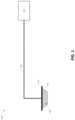
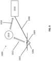
- FIG. 1illustrates a reduced pressure wound therapy system according to some embodiments.
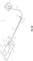
- FIG. 7illustrates an embodiment of a negative pressure wound therapy system.
- the sensor embodiments disclosed hereinmay be used in coordination with surgical devices, for example, the NAVIO surgical system by Smith & Nephew Inc.
- the sensor embodiments disclosed hereinmay be in communication with such surgical devices to guide placement of the surgical devices.
- the sensor embodiments disclosed hereinmay monitor blood flow to or away from the potential surgical site or ensure that there is no blood flow to a surgical site. Further surgical data may be collected to aid in the prevention of scarring and monitor areas away from the impacted area.
- the sensor embodiments disclosed hereinmay be incorporated into implantable devices, such as implantable orthopedic implants, including flexible implants. Such sensor embodiments may be configured to collect information regarding the implant site and transmit this information to an external source. In some embodiments, an internal source may also provide power for such an implant.
- the sensor embodiments disclosed hereinmay encompass sensor printing technology with encapsulation, such as encapsulation with a polymer film Such a film may be constructed using any polymer described herein, such as polyurethane. Encapsulation of the sensor embodiments may provide waterproofing of the electronics and protection from local tissue, local fluids, and other sources of potential damage.
- the sensor embodiments disclosed hereinmay be incorporated into treatments for wounds (disclosed in greater detail below) or in a variety of other applications.
- additional applications for the sensor embodiments disclosed hereininclude: monitoring and treatment of intact skin, cardiovascular applications such as monitoring blood flow, orthopedic applications such as monitoring limb movement and bone repair, neurophysiological applications such as monitoring electrical impulses, and any other tissue, organ, system, or condition that may benefit from improved sensor-enabled monitoring.
- Some embodimentsrelate to methods of treating a wound with the technology disclosed herein in conjunction with one or more of the following: advanced footwear, turning a patient, offloading (such as, offloading diabetic foot ulcers), treatment of infection, systemix, antimicrobial, antibiotics, surgery, removal of tissue, affecting blood flow, physiotherapy, exercise, bathing, nutrition, hydration, nerve stimulation, ultrasound, electrostimulation, oxygen therapy, microwave therapy, active agents ozone, antibiotics, antimicrobials, or the like.
- offloadingsuch as, offloading diabetic foot ulcers
- treatment of infectionsystemix
- antimicrobialantibiotics
- surgeryremoval of tissue, affecting blood flow, physiotherapy, exercise, bathing, nutrition, hydration, nerve stimulation, ultrasound, electrostimulation, oxygen therapy, microwave therapy, active agents ozone, antibiotics, antimicrobials, or the like.
- wound dressingsthat may be utilized in conjunction with the disclosed technology include any known dressing in the art.
- the technologyis applicable to negative pressure therapy treatment as well as non-negative pressure therapy treatment.
- a wound dressingcomprises one or more absorbent layer(s).
- the absorbent layermay be a foam or a superabsorbent.
- Cellulose alkyl sulfonatesmay have varying degrees of substitution, the chain length of the cellulose backbone structure, and the structure of the alkyl sulfonate substituent. Solubility and absorbency are largely dependent on the degree of substitution: as the degree of substitution is increased, the cellulose alkyl sulfonate becomes increasingly soluble. It follows that, as solubility increases, absorbency increases.
- a wound dressingalso comprises a top or cover layer.
- the thickness of the wound dressing disclosed hereinmay be between 1 to 20, or 2 to 10, or 3 to 7 mm.
- the obscuring elementmay be partially translucent.
- the obscuring elementmay be a masking layer.
- the non-negative pressure wound dressingmay further comprise a plurality of openings in the obscuring element for allowing fluid to move therethrough.
- the obscuring elementmay comprise, or may be coated with, a material having size-exclusion properties for selectively permitting or preventing passage of molecules of a predetermined size or weight.
- the obscuring elementmay be configured to at least partially mask light radiation having wavelength of 600 nm and less.
- the non-negative pressure wound dressingmay further comprise at least one of a wound contact layer, a foam layer, an odor control element, a pressure-resistant layer and a cover layer.
- the cover layeris present, and the cover layer is a translucent film
- the translucent filmhas a moisture vapour permeability of 500 g/m2/24 hours or more.
- the translucent filmmay be a bacterial barrier.
- the non-negative pressure wound dressing disclosed hereincomprises the foam layer, and the obscuring element is of a material comprising components that may be displaced or broken by movement of the obscuring element.
- the non-negative pressure wound dressingcomprises an odor control element, and in another embodiment the dressing does not include an odor control element.
- the odor control elementmay be dispersed within or adjacent the absorbent layer or the obscuring element.
- the odor control elementmay be provided as a layer sandwiched between the foam layer and the absorbent layer.
- the disclosed technology for a non-negative pressure wound dressingcomprises a method of manufacturing a wound dressing, comprising: providing an absorbent layer for absorbing wound exudate; and providing an obscuring element for at least partially obscuring a view of wound exudate absorbed by the absorbent layer in use.
- the shielding layerincreases the area over which a pressure applied to the dressing is transferred by 25% or more or the initial area of application.
- the shielding layerincreases the area over which a pressure applied to the dressing is transferred by 50% or more, and optionally by 100% or more, and optionally by 200% or more.
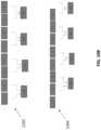
- the shielding layermay comprise 2 or more sub-layers, wherein a first sub-layer comprises through holes and a further sub-layer comprises through holes and the through holes of the first sub-layer are offset from the through holes of the further sub-layer.
- the non-negative pressure wound dressing as disclosed hereinmay further comprise a permeable cover layer for allowing the transmission of gas and vapour therethrough, the cover layer provided over the shielding layer, wherein through holes of the cover layer are offset from through holes of the shielding layer.
- the non-negative pressure wound dressingmay be a multi-layered wound dressing comprising: a fibrous absorbent layer for absorbing exudate from a wound site; and a support layer configured to reduce shrinkage of at least a portion of the wound dressing.
- the multi-layered wound dressing disclosed hereinfurther comprises a liquid impermeable film layer, wherein the support layer is located between the absorbent layer and the film layer.
- the netmay be formed from high density polyethylene.
- the aperturesmay have an area from 0.005 to 0.32 mm2.
- the support layermay have a tensile strength from 0.05 to 0.06 Nm.
- the support layermay have a thickness of from 50 to 150 ⁇ m.
- the support layeris located directly adjacent the absorbent layer.
- the support layeris bonded to fibers in a top surface of the absorbent layer.
- the support layermay further comprise a bonding layer, wherein the support layer is heat laminated to the fibers in the absorbent layer via the bonding layer.
- the bonding layermay comprise a low melting point adhesive such as ethylene-vinyl acetate adhesive.
- the first layer of materialmay comprise one or more of manufactured fibers from synthetic, natural or inorganic polymers, natural fibers of a cellulosic, proteinaceous or mineral source.
- the wound dressingmay comprise two or more layers of the absorbing layer of material vertically lapped material stacked one on top of the other, wherein the two or more layers have the same or different densities or composition.
- the absorbing layer of materialis a blend of natural or synthetic, organic or inorganic fibers, and binder fibers, or bicomponent fibers typically PET with a low melt temperature PET coating to soften at specified temperatures and to act as a bonding agent in the overall blend.
- the absorbing layer of materialmay be a blend of 5 to 95% thermoplastic polymer, and 5 to 95 wt % of a cellulose or derivative thereof.
- the wound dressing disclosed hereinhas a second layer comprises a foam or a dressing fixative.
- the foammay be a polyurethane foam.
- the polyurethane foammay have an open or closed pore structure.
- the dressing fixativemay include bandages, tape, gauze, or backing layer.
- the wound dressing as disclosed hereincomprises the absorbing layer of material connected directly to a second layer by lamination or by an adhesive, and the second layer is connected to a dressing fixative layer.
- the adhesivemay be an acrylic adhesive, or a silicone adhesive.
- the wound dressing as disclosed hereinfurther comprises a backing layer.
- the backing layermay be a transparent or opaque film.
- the backing layercomprises a polyurethane film (typically a transparent polyurethane film).
- the non-negative pressure wound dressingmay comprise an absorbent component for a wound dressing, the component comprising a wound contacting layer comprising gel forming fibers bound to a foam layer, wherein the foam layer is bound directly to the wound contact layer by an adhesive, polymer based melt layer, by flame lamination or by ultrasound.
- the absorbent componentmay be in a sheet form.
- the wound contacting layermay comprise a layer of woven or non-woven or knitted gel forming fibers.
- the foam layermay be an open cell foam, or closed cell foam, typically an open cell foam.
- the foam layeris a hydrophilic foam.
- the wound dressingmay comprise the component that forms an island in direct contact with the wound surrounded by periphery of adhesive that adheres the dressing to the wound.
- the adhesivemay be a silicone or acrylic adhesive, typically a silicone adhesive.
- the wound dressingmay be covered by a film layer on the surface of the dressing furthest from the wound.
- the non-negative pressure wound dressingmay comprise a multi layered wound dressing for use on wounds producing high levels of exudate, characterized in that the dressing comprising: a transmission layer having an MVTR of at least 300 gm2/24 hours, an absorbent core comprising gel forming fibers capable of absorbing and retaining exudate, a wound contacting layer comprising gel forming fibers which transmits exudate to the absorbent core and a keying layer positioned on the absorbent core, the absorbent core and wound contacting layer limiting the lateral spread of exudate in the dressing to the region of the wound.
- the dressingcomprising: a transmission layer having an MVTR of at least 300 gm2/24 hours, an absorbent core comprising gel forming fibers capable of absorbing and retaining exudate, a wound contacting layer comprising gel forming fibers which transmits exudate to the absorbent core and a keying layer positioned on the absorbent core, the absorbent core and wound contacting layer limiting the lateral spread of exudate in
- the wound dressingmay be capable of handling at least 6 g (or 8 g and 15 g) of fluid per 10 cm2 of dressing in 24 hours.
- the wound dressingmay comprise gel forming fibers that are chemically modified cellulosic fibers in the form of a fabric.
- the fibersmay include carboxymethylated cellulose fibers, typically sodium carboxymethylcellulose fiber.
- the absorbent coremay have an absorbency of exudate of at least 10 g/g, and typically a rate of lateral wicking of less the 20 mm per minute.
- the compression bandage systemcomprises: a) an inner skin facing, elongated, elastic bandage comprising: (i) an elongated, elastic substrate, and
- the negative pressure range for some embodiments of the present disclosurecan be approximately ⁇ 80 mmHg, or between about ⁇ 20 mmHg and ⁇ 200 mmHg Note that these pressures are relative to normal ambient atmospheric pressure, which can be 760 mmHg Thus, ⁇ 200 mmHg would be about 560 mmHg in practical terms.
- the pressure rangecan be between about ⁇ 40 mmHg and ⁇ 150 mmHg.
- a pressure range of up to ⁇ 75 mmHg, up to ⁇ 80 mmHg or over ⁇ 80 mmHgcan be used.
- a pressure range of below ⁇ 75 mmHgcan be used.
- a pressure range of over approximately ⁇ 100 mmHg, or even ⁇ 150 mmHgcan be supplied by the negative pressure apparatus.
- increased wound contractioncan lead to increased tissue expansion in the surrounding wound tissue.
- This effectmay be increased by varying the force applied to the tissue, for example by varying the negative pressure applied to the wound over time, possibly in conjunction with increased tensile forces applied to the wound via embodiments of the wound closure devices.
- negative pressuremay be varied over time for example using a sinusoidal wave, square wave, or in synchronization with one or more patient physiological indices (such as, heartbeat). Examples of such applications where additional disclosure relating to the preceding may be found include U.S. Pat. No. 8,235,955, titled “Wound treatment apparatus and method,” issued on Aug. 7, 2012; and U.S. Pat. No. 7,753,894, titled “Wound cleansing apparatus with stress,” issued Jul. 13, 2010. The disclosures of both of these patents are hereby incorporated by reference in their entirety.
- Woundsmay be generally categorized as open or closed, often depending upong how the wound is caused. As described above, the techniques may be applied to both open and to closed wounds, depending on the particulars of the embodiment. Open wounds may be caused by a variety of events, including: incisions, lacerations, abrasions, punctures, penetration, amputation, and other means. Closed wounds may be caused by damage to a blood vessel resulting in formation of a hematoma, and/or by internal injuries caused by crushing. Further, wounds may involve various layers of tissue, for example, shallower wounds may only involve the topmost layers of the skin, while deeper wounds may involve underlying subcutaneous tissue layers such as the hypodermis, including underlying connective tissues and fatty layers. In certain embodiments, wounds may even encompass underlying internal organs, deep beneath the skin. Certain wounds, such as those caused by pressure injuries, may start to occur within the deeper tissue layers without become evident on the surface of the skin until much later.
- the wound cover 120can be located over a wound site to be treated.
- the wound cover 120can form a substantially sealed cavity or enclosure over the wound site.
- the wound cover 120can be configured to have a film having a high water vapor permeability to enable the evaporation of surplus fluid, and can have a superabsorbing material contained therein to safely absorb wound exudate.
- a woundit is to be understood that the term wound is to be broadly construed and encompasses open and closed wounds in which skin is torn, cut or punctured or where trauma causes a contusion, or any other surficial or other conditions or imperfections on the skin of a patient or otherwise that benefit from reduced pressure treatment.
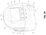
- button 212 ccan be pressed so that the user does not unintentionally alter the delivery of the therapy. Button 212 c can be depressed to unlock the controls. In other embodiments, additional buttons can be used or one or more of the illustrated buttons 212 a , 212 b , or 212 c can be omitted. Multiple key presses or sequences of key presses can be used to operate the pump assembly 230 .
- the canister 220includes a substantially transparent window 216 , which can also include graduations of volume.
- the illustrated 300 mL canister 220includes graduations of 50 mL, 100 mL, 150 mL, 200 mL, 250 mL, and 300 mL.
- Other embodiments of the canistercan hold different volume of fluid and can include different graduation scale.
- the canistercan be an 800 mL canister.
- the canister 220comprises a tubing channel 218 for connecting to the conduit 140 .
- various of these features, such as the gripping portion 214are omitted or various additional features are added to the canister 220 .
- Any of the disclosed canistersmay include or may omit a solidifier.
- the canister 220includes one or more feet 244 for placing the canister on a surface.
- the feet 244can be formed out of rubber, silicone, or any other suitable material and can be angled at a suitable angle so that the canister 220 remains stable when placed on the surface.
- the canister 220comprises a tube mount relief 246 configured to allow one or more tubes to exit to the front of the device.
- the canister 220includes a stand or kickstand 248 for supporting the canister when it is placed on a surface. As explained below, the kickstand 248 can pivot between an opened and closed position. In closed position, the kickstand 248 can be latched to the canister 220 . In some embodiments, the kickstand 248 can be made out of opaque material, such as plastic.
- the kickstand 248can be made out of transparent material.
- the kickstand 248includes a gripping portion 242 formed in the kickstand.
- the gripping portion 242can be configured to allow the user to place the kickstand 248 in the closed position.
- the kickstand 248comprises a hole 249 to allow the user to place the kickstand in the open position.
- the hole 249can be sized to allow the user to extend the kickstand using a finger.
- FIG. 2 Cillustrates a view of the pump assembly 230 separated from the canister 220 according to some embodiments.
- the pump assembly 230includes a vacuum attachment, connector, or inlet 252 through which a vacuum pump communicates negative pressure to the canister 220 .
- the pump assemblyaspirates fluid, such as gas, from the wound via the inlet 252 .
- the pump assembly 230comprises a USB access door 256 configured to allow access to one or more USB ports.
- the USB access dooris omitted and USB ports are accessed through the door 234 .
- the pump assembly 230can include additional access doors configured to allow access to additional serial, parallel, or hybrid data transfer interfaces, such as SD, Compact Disc (CD), DVD, FireWire, Thunderbolt, PCI Express, and the like. In other embodiments, one or more of these additional ports are accessed through the door 234 .
- FIG. 3 Aillustrates an electrical component schematic 300 A of a pump assembly, such as the pump assembly 230 , according to some embodiments.
- Electrical componentscan operate to accept user input, provide output to the user, operate the pump assembly and the TNP system, provide network connectivity, and so on.
- Electrical componentscan be mounted on one or more printed circuit boards (PCBs).
- the pump assemblycan include multiple processors.
- the processor 310can be a general purpose controller, such as a low-power processor. In other embodiments, the processor 310 can be an application specific processor.
- the processor 310can be configured as a “central” processor in the electronic architecture of the pump assembly, and the processor 310 can coordinate the activity of other processors, such as a reduced pressure control processor 370 , communications processor 330 , and one or more additional processors 380 (e.g., processor for controlling the display 206 , processor for controlling the buttons 212 , etc.).
- the processor 310can run a suitable operating system, such as a Linux, Windows CE, VxWorks, etc.
- the reduced pressure control processor 370can be configured to control the operation of a reduced pressure source, such as a pump 390 , and a valve 392 .
- the pump 390can be a suitable pump, such as a diaphragm pump, peristaltic pump, rotary pump, rotary vane pump, scroll pump, screw pump, liquid ring pump, diaphragm pump operated by a piezoelectric transducer, voice coil pump, and the like.
- the valve 392can be a suitable valve, such as a solenoid valve, diaphragm valve, and the like, and be positioned, for instance, downstream (or before) an exhaust for the pump assembly or in a fluid flow path between the pump assembly and a wound dressing.
- the valve 392can be a single valve or composed of multiple different valves.
- the reduced pressure control processor 370can measure pressure in a fluid flow path, using data received from one or more pressure sensors, calculate the rate of fluid flow, and control the pump 390 and the valve 392 .
- the reduced pressure control processor 370can control a pump motor of the pump 390 so that a desired level of negative pressure is achieved in the wound cavity 110 .
- the desired level of negative pressurecan be pressure set or selected by the user.
- the reduced pressure control processor 370controls the pump (e.g., pump motor) using pulse-width modulation (PWM).
- PWMpulse-width modulation
- a control signal for driving the pump 390can be a 0-100% duty cycle PWM signal.
- the reduced pressure control processor 370can control opening and closing of the valve 392 so that a desired level of negative pressure is achieved in the wound cavity 110 .
- the desired level of negative pressurecan be pressure set or selected by the user or set automatically according to a mode of operation or setting for the pump assembly.
- the reduced pressure control processor 370controls the opening and closing of the valve 392 using PWM.
- a control signal for controlling or driving the valve 392can be a 0-100% duty cycle PWM signal.
- the reduced pressure control processor 370can perform flow rate calculations and detect various conditions in a flow path.
- the reduced pressure control processor 370can communicate information to the processor 310 .
- the reduced pressure control processor 370can include internal memory or can utilize memory 350 .
- the reduced pressure control processor 370can be a low-power processor.
- a communications processor 330can be configured to provide wired or wireless connectivity.
- the communications processor 330can utilize one or more antennas 340 for sending and receiving data.
- the communications processor 330can provide one or more of the following types of connections: Global Positioning System (GPS) technology, cellular connectivity (e.g., 2G, 3G, LTE, 4G), WiFi connectivity, Internet connectivity, and the like. Connectivity can be used for various activities, such as pump assembly location tracking, asset tracking, compliance monitoring, remote selection, uploading of logs, alarms, and other operational data, and adjustment of therapy settings, upgrading of software or firmware, and the like.
- the communications processor 330can provide dual GPS/cellular functionality. Cellular functionality can, for example, be 3G functionality.
- the pump assemblycan include a SIM card, and SIM-based positional information can be obtained.
- the communications processor 330can communicate information to the processor 310 .
- the communications processor 330can include internal memory or can utilize memory 350 .
- the communications processor 330can be a low-power processor.
- the devicecan upload any of the data stored, maintained, or tracked by the pump assembly.
- the devicecan also download various operational data, such as therapy selection and parameters, firmware and software patches and upgrades, and the like.
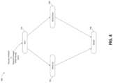
- FIG. 3 Billustrates a block diagram of certain components 300 B of a pump assembly, such as the pump assembly 230 , according to some embodiments.
- the components 300 Binclude an inlet 395 (which can be like the inlet 252 ), the pump 390 , the valve 392 , an exhaust 396 , a pressure sensor 397 , and the reduced pressure control processor 370 .
- the pump 390can provide negative pressure in a fluid flow path connecting the pump 390 (via the inlet 395 ) to a wound dressing placed over the wound, such that the negative pressure is provided to the inlet 395 and then to a wound dressing (for example, through a canister).
- the valve 392can open (for example, partially or fully) to admit air, gas, or other fluid, which thereby provides positive pressure in the fluid flow path.
- the pump 390 under control of the reduced pressure control processor 370can additionally or alternatively provide positive pressure in the fluid flow path, such as by operating the pump 390 in reverse. Additionally or alternatively, another pump different from the pump 390 and controllable by the reduced pressure control processor 370 can be included to provide positive pressure in the fluid flow path.
- the reduced pressure control processor 370can measure the pressure in the fluid flow path near or at the inlet 395 (or at any other location in the fluid flow path, such as at the wound), using data received from one or more pressure sensors, such as the pressure sensor 397 , calculate the rate of fluid flow, and control the pump 390 and the valve 392 .
- the reduced pressure control processor 370can, for instance, control one or more pump actuators, such as a pump motor of the pump 390 , or one or more valve actuators, such as a solenoid of the valve 392 , so that a desired level of negative (or positive) pressure is achieved at the wound.
- the desired level of negative pressure (or pressure setpoint)can be a pressure set or selected by the user or set automatically according to a mode of operation or setting for the pump assembly.
- the components 300 Bcan further include one or more additional sensors (not shown), such as a tachometer, positioned to detect or determine a level of activity of the pump 390 (for example, the pump motor) and provide indications responsive to the level of activity of the pump 390 to the reduced pressure control processor 370 .
- a tachometercan be separate from the pump 390 (for example, external to the pump) and positioned near or coupled to the pump 390 , and the tachometer can detect a rotation (such as a partial rotation, complete rotation, or multiple partial or complete rotations) of a pump motor of the pump 390 .
- At least two pressure sensorscan be positioned in or fluidically connected to the fluid flow path to permit differential measurement of the pressure.
- a first pressure sensorcan be positioned downstream of the wound dressing (such as at or near an inlet of the pump assembly) and a second pressure sensor can be positioned to detect pressure at or near the wound dressing or at or near a canister.
- This configurationcan be accomplished by incorporating, in addition to one or more lumens forming a first fluid flow path connecting the pump assembly to the wound, a second fluid flow path that includes one or more lumens connecting the pump assembly to the wound dressing and through which the second pressure sensor can monitor pressure at or near the wound dressing or at or near the canister.
- the first and second fluid flow pathscan be fluidically isolated from each other.
- the rate of change of pressure (for example, in peak-to-peak pressure or maximum pressure) in the first and second fluid flow pathscan be determined and the difference in pressure detected between the first and second pressure sensors can be determined.
- These valuescan be used separately or together to detect various operational conditions, such as leaks, blockages, canister full, presence of blood in the first fluid flow path or the second fluid flow path, etc.
- multiple redundant pressure sensorscan be provided to protect against failure of one or more of the pressure sensors in some implementations.
- the pump assemblycontrols the vacuum pump to deliver negative pressure therapy to a wound according to a selected or programmed protocol.
- Pump controlcan be performed by the reduced pressure control processor 370 alone or in combination with the processor 310 .
- the usercan select continuous operation at a desired pressure (or negative pressure setpoint).
- the pump assemblycan activate the vacuum pump to reduce or draw down the pressure at the wound (e.g., under the dressing) to reach the setpoint.
- the drawdowncan be performed by increasing the negative pressure at the wound limited by a maximum change in negative pressure per unit time called compression, until the setpoint (or another selected pressure value as explained below) has been achieved.
- Wound drawdowncan be defined as the period of time immediately after therapy has been initiated during which the wound has not yet achieved the setpoint. As explained below, at the end of this period when the setpoint is achieved, the flow rate in the fluid flow path should be below a leak (or high flow) threshold and above a low vacuum threshold, otherwise an appropriate alarm will be activated.
- the usercan select intermittent operation between two desired pressures (or high and low pressure setpoints).
- the pump assemblycan activate the vacuum pump to reduce or draw down the pressure at the wound to reach the high setpoint. Subsequently, the pump assembly can allow pressure at the wound to increase to reach the low setpoint. As explained below, decreasing and increasing negative pressure can be performed in accordance with the compression setting.
- compressioncan be used anytime there is a change in the pressure setpoint (which can include stopping delivery of negative pressure).
- different compression settingscan be used for setpoint changes that result in decreasing or increasing pressure at the wound.
- compression settingcan be adjusted while a pressure setpoint is being achieved.
- FIG. 4illustrates a process 500 for providing negative pressure wound therapy according to some embodiments.
- the process 500can be executed by the reduced pressure control processor 370 alone or in combination with the processor 310 and utilize one or more other components described herein or other systems not shown.
- the process 500can be periodically executed, such as for example every 100 milliseconds (or 10 times per second) or at any other suitable frequency. Alternatively or additionally, the process 500 can be continuously executed.
- the process 500can begin in block 502 , which it can transition to when therapy is initiated or when the setpoint is changed while therapy is being delivered.
- the process 500compares wound pressure, which can be determined as explained below, to the setpoint. For example, the process 500 can subtract the wound pressure from the setpoint or vice versa. If the wound pressure is below the setpoint, the process 500 can transition to block 504 . Conversely, if the wound pressure exceeds or is equal to the setpoint, the process 500 can transition to block 506 .
- the process 500can increment a pump ramp setpoint by an amount that depends on the compression setting as explained below.
- the vacuum pumpwill then attempt to draw down (or make more negative) the wound pressure to reach the current value of the pump ramp setpoint.
- a suitable pump drive signalsuch as voltage or current signal, can be generated and supplied to the pump motor so as to increase the speed of the pump motor to achieve wound draw down.
- the pump motorcan be driven using PWM or any other suitable method.
- the process 500can continue incrementing the pump ramp setpoint until it reaches the setpoint selected by the user.
- the process 500can transition to block 508 when the wound pressure has nearly reached or reached the setpoint, which can correspond to reaching steady state pressure under the wound dressing.
- the process 500can set the pump ramp setpoint to the setpoint selected by the user (or to another set value as explained above).
- the process 500can deactivate the pump so that the wound pressure is allowed to decay, such as due to one or more leaks in the fluid flow path, to reach or almost reach the setpoint. This can be performed in accordance with the compression setting, such as for example, deactivating the pump for a first period of time and then activating the pump for a second period of time so that pressure at the wound increases according to the compression setting.
- NPWTmay be applied to a wound through a self-contained wound dressing, such as a PICOTM wound dressing, as sold by Smith & Nephew.
- FIGS. 5 A-Billustrate embodiments of a negative pressure wound treatment system 10 employing a wound dressing 100 in conjunction with a fluidic connector 110 .
- the fluidic connector 110may comprise an elongate conduit, more preferably a bridge 120 having a proximal end 130 and a distal end 140 , and an applicator 180 at the distal end 140 of the bridge 120 .
- An optional coupling 160is preferably disposed at the proximal end 130 of the bridge 120 .
- a cap 170may be provided with the system (and can in some cases, as illustrated, be attached to the coupling 160 ).
- the cap 170can be useful in preventing fluids from leaking out of the proximal end 130 .
- the system 10may include a source of negative pressure such as a pump or negative pressure unit 150 capable of supplying negative pressure.
- the pumpmay comprise a canister or other container for the storage of wound exudates and other fluids that may be removed from the wound.
- a canister or containermay also be provided separate from the pump.
- the pump 150can be a canisterless pump such as the PICOTM pump, as sold by Smith & Nephew.
- the pump 150may be connected to the coupling 160 via a tube 190 , or the pump 150 may be connected directly to the coupling 160 or directly to the bridge 120 .
- the dressing 100is placed over a suitably-prepared wound, which may in some cases be filled with a wound packing material such as foam or gauze.
- the applicator 180 of the fluidic connector 110has a sealing surface that is placed over an aperture in the dressing 100 and is sealed to the top surface of the dressing 100 .
- the pump 150is connected via the tube 190 to the coupling 160 , or is connected directly to the coupling 160 or to the bridge 120 .
- the pumpis then activated, thereby supplying negative pressure to the wound. Application of negative pressure may be applied until a desired level of healing of the wound is achieved.
- the fluidic connector 110preferably comprises an enlarged distal end, or head 140 that is in fluidic communication with the dressing 100 as will be described in further detail below.
- the enlarged distal endhas a round or circular shape.
- the head 140is illustrated here as being positioned near an edge of the dressing 100 , but may also be positioned at any location on the dressing. For example, some embodiments may provide for a centrally or off-centered location not on or near an edge or corner of the dressing 100 .
- the dressing 10may comprise two or more fluidic connectors 110 , each comprising one or more heads 140 , in fluidic communication therewith.
- the head 140may measure 30 mm along its widest edge.
- the head 140forms at least in part the applicator 180 , described above, that is configured to seal against a top surface of the wound dressing.
- FIG. 6 Billustrates a cross-section through a wound dressing 100 similar to the wound dressing 10 as shown in FIG. 5 B and described in International Patent Publication WO2013175306 A2, which is incorporated by reference in its entirety, along with fluidic connector 110 .
- the wound dressing 100which can alternatively be any wound dressing embodiment disclosed herein or any combination of features of any number of wound dressing embodiments disclosed herein, can be located over a wound site to be treated.
- the dressing 100may be placed as to form a sealed cavity over the wound site.
- the dressing 100comprises a top or cover layer, or backing layer 220 attached to an optional wound contact layer 222 , both of which are described in greater detail below.
- This interior space or chambermay comprise additional structures that may be adapted to distribute or transmit negative pressure, store wound exudate and other fluids removed from the wound, and other functions which will be explained in greater detail below. Examples of such structures, described below, include a transmission layer 226 and an absorbent layer 221 .
- the upper layer, top layer, or layer aboverefers to a layer furthest from the surface of the skin or wound while the dressing is in use and positioned over the wound.
- the lower surface, lower layer, bottom layer, or layer belowrefers to the layer that is closest to the surface of the skin or wound while the dressing is in use and positioned over the wound.
- the wound contact layer 222can be a polyurethane layer or polyethylene layer or other flexible layer which is perforated, for example via a hot pin process, laser ablation process, ultrasound process or in some other way or otherwise made permeable to liquid and gas.
- the wound contact layer 222has a lower surface 224 and an upper surface 223 .
- the perforations 225preferably comprise through holes in the wound contact layer 222 which enable fluid to flow through the layer 222 .
- the wound contact layer 222helps prevent tissue ingrowth into the other material of the wound dressing.
- the perforationsare small enough to meet this requirement while still allowing fluid to flow therethrough.
- perforations formed as slits or holes having a size ranging from 0.025 mm to 1.2 mmare considered small enough to help prevent tissue ingrowth into the wound dressing while allowing wound exudate to flow into the dressing.
- the wound contact layer 222may help maintain the integrity of the entire dressing 100 while also creating an air tight seal around the absorbent pad in order to maintain negative pressure at the wound.
- the wound contact layer 222may also act as a carrier for an optional lower and upper adhesive layer (not shown).
- a lower pressure sensitive adhesivemay be provided on the lower surface 224 of the wound dressing 100 whilst an upper pressure sensitive adhesive layer may be provided on the upper surface 223 of the wound contact layer.
- the pressure sensitive adhesivewhich may be a silicone, hot melt, hydrocolloid or acrylic based adhesive or other such adhesives, may be formed on both sides or optionally on a selected one or none of the sides of the wound contact layer. When a lower pressure sensitive adhesive layer is utilized may be helpful to adhere the wound dressing 100 to the skin around a wound site.
- the wound contact layermay comprise perforated polyurethane film.
- the lower surface of the filmmay be provided with a silicone pressure sensitive adhesive and the upper surface may be provided with an acrylic pressure sensitive adhesive, which may help the dressing maintain its integrity.
- a polyurethane film layermay be provided with an adhesive layer on both its upper surface and lower surface, and all three layers may be perforated together.
- the transmission layer 226comprises a 3D polyester spacer fabric layer including a top layer (that is to say, a layer distal from the wound-bed in use) which is a 84/144 textured polyester, and a bottom layer (that is to say, a layer which lies proximate to the wound bed in use) which is a 10 denier flat polyester and a third layer formed sandwiched between these two layers which is a region defined by a knitted polyester viscose, cellulose or the like mono filament fiber. Other materials and other linear mass densities of fiber could of course be used.
- top spacer fabricthus has more filaments in a yarn used to form it than the number of filaments making up the yarn used to form the bottom spacer fabric layer.
- This differential between filament counts in the spaced apart layershelps control moisture flow across the transmission layer.
- the top layeris made from a yarn having more filaments than the yarn used in the bottom layer, liquid tends to be wicked along the top layer more than the bottom layer.
- this differentialtends to draw liquid away from the wound bed and into a central region of the dressing where the absorbent layer 221 helps lock the liquid away or itself wicks the liquid onwards towards the cover layer where it can be transpired.
- the 3D fabricmay be treated with a dry cleaning agent (such as, but not limited to, Perchloro Ethylene) to help remove any manufacturing products such as mineral oils, fats and/or waxes used previously which might interfere with the hydrophilic capabilities of the transmission layer.
- a dry cleaning agentsuch as, but not limited to, Perchloro Ethylene
- an additional manufacturing stepcan subsequently be carried in which the 3D spacer fabric is washed in a hydrophilic agent (such as, but not limited to, Feran Ice 30 g/l available from the Rudolph Group). This process step helps ensure that the surface tension on the materials is so low that liquid such as water can enter the fabric as soon as it contacts the 3D knit fabric. This also aids in controlling the flow of the liquid insult component of any exudates.
- a layer 221 of absorbent materialis provided above the transmission layer 226 .
- the absorbent materialwhich comprise a foam or non-woven natural or synthetic material, and which may optionally comprise a super-absorbent material, forms a reservoir for fluid, particularly liquid, removed from the wound site.
- the layer 10may also aid in drawing fluids towards the backing layer 220 .
- the material of the absorbent layer 221may also prevent liquid collected in the wound dressing 100 from flowing freely within the dressing, and preferably acts so as to contain any liquid collected within the dressing.
- the absorbent layer 221also helps distribute fluid throughout the layer via a wicking action so that fluid is drawn from the wound site and stored throughout the absorbent layer. This helps prevent agglomeration in areas of the absorbent layer.
- the capacity of the absorbent materialmust be sufficient to manage the exudates flow rate of a wound when negative pressure is applied. Since in use the absorbent layer experiences negative pressures the material of the absorbent layer is chosen to absorb liquid under such circumstances. A number of materials exist that are able to absorb liquid when under negative pressure, for example superabsorber material.
- the absorbent layer 221may typically be manufactured from ALLEVYNTM foam, Freudenberg 114-224-4 and/or Chem-PositeTM11C-450.
- the absorbent layer 221may comprise a composite comprising superabsorbent powder, fibrous material such as cellulose, and bonding fibers.
- the compositeis an airlaid, thermally-bonded composite.
- the absorbent layer 221is a layer of non-woven cellulose fibers having super-absorbent material in the form of dry particles dispersed throughout.
- Use of the cellulose fibersintroduces fast wicking elements which help quickly and evenly distribute liquid taken up by the dressing.
- the juxtaposition of multiple strand-like fibersleads to strong capillary action in the fibrous pad which helps distribute liquid. In this way, the super-absorbent material is efficiently supplied with liquid.
- the wicking actionalso assists in bringing liquid into contact with the upper cover layer to aid increase transpiration rates of the dressing.
- An aperture, hole, or orifice 227is preferably provided in the backing layer 220 to allow a negative pressure to be applied to the dressing 100 .
- the fluidic connector 110is preferably attached or sealed to the top of the backing layer 220 over the orifice 227 made into the dressing 100 , and communicates negative pressure through the orifice 227 .
- a length of tubingmay be coupled at a first end to the fluidic connector 110 and at a second end to a pump unit (not shown) to allow fluids to be pumped out of the dressing.
- a length of tubingmay be coupled at a first end of the fluidic connector such that the tubing, or conduit, extends away from the fluidic connector parallel or substantially to the top surface of the dressing.
- the fluidic connector 110may be adhered and sealed to the backing layer 220 using an adhesive such as an acrylic, cyanoacrylate, epoxy, UV curable or hot melt adhesive.
- the fluidic connector 110may be formed from a soft polymer, for example a polyethylene, a polyvinyl chloride, a silicone or polyurethane having a hardness of 30 to 90 on the Shore A scale. In some embodiments, the fluidic connector 110 may be made from a soft or conformable material.
- the absorbent layer 221includes at least one through hole 228 located so as to underlie the fluidic connector 110 .
- the through hole 228may in some embodiments be the same size as the opening 227 in the backing layer, or may be bigger or smaller.
- a single through holecan be used to produce an opening underlying the fluidic connector 110 .
- multiple openingscould alternatively be utilized.
- one or multiple openingsmay be made in the absorbent layer and the obscuring layer in registration with each respective fluidic connector.
- the use of through holes in the super-absorbent layermay provide a fluid flow pathway which remains unblocked in particular when the absorbent layer is near saturation.
- the aperture or through-hole 228is preferably provided in the absorbent layer 221 beneath the orifice 227 such that the orifice is connected directly to the transmission layer 226 as illustrated in FIG. 6 B .
- no aperturemay be provided in the absorbent layer 221 , or alternatively a plurality of apertures underlying the orifice 227 may be provided.
- additional layerssuch as another transmission layer or an obscuring layer such as described in International Patent Publication WO2014020440, the entirety of which is hereby incorporated by reference, may be provided over the absorbent layer 221 and beneath the backing layer 220 .
- the backing layer 220is preferably gas impermeable, but moisture vapor permeable, and can extend across the width of the wound dressing 100 .
- the backing layer 220which may for example be a polyurethane film (for example, Elastollan SP9109) having a pressure sensitive adhesive on one side, is impermeable to gas and this layer thus operates to cover the wound and to seal a wound cavity over which the wound dressing is placed. In this way an effective chamber is made between the backing layer 220 and a wound site where a negative pressure can be established.
- the backing layer 220is preferably sealed to the wound contact layer 222 in a border region around the circumference of the dressing, ensuring that no air is drawn in through the border area, for example via adhesive or welding techniques.
- the backing layer 220protects the wound from external bacterial contamination (bacterial barrier) and allows liquid from wound exudates to be transferred through the layer and evaporated from the film outer surface.
- the backing layer 220preferably comprises two layers; a polyurethane film and an adhesive pattern spread onto the film.
- the polyurethane filmis preferably moisture vapor permeable and may be manufactured from a material that has an increased water transmission rate when wet. In some embodiments the moisture vapor permeability of the backing layer increases when the backing layer becomes wet. The moisture vapor permeability of the wet backing layer may be up to about ten times more than the moisture vapor permeability of the dry backing layer.
- the absorbent layer 221may be of a greater area than the transmission layer 226 , such that the absorbent layer overlaps the edges of the transmission layer 226 , thereby ensuring that the transmission layer does not contact the backing layer 220 .
- Thisprovides an outer channel of the absorbent layer 221 that is in direct contact with the wound contact layer 222 , which aids more rapid absorption of exudates to the absorbent layer. Furthermore, this outer channel ensures that no liquid is able to pool around the circumference of the wound cavity, which may otherwise seep through the seal around the perimeter of the dressing leading to the formation of leaks.
- the absorbent layer 221may define a smaller perimeter than that of the backing layer 220 , such that a boundary or border region is defined between the edge of the absorbent layer 221 and the edge of the backing layer 220 .
- one embodiment of the wound dressing 100comprises an aperture 228 in the absorbent layer 221 situated underneath the fluidic connector 110 .
- a wound facing portion of the fluidic connectormay thus come into contact with the transmission layer 226 , which can thus aid in transmitting negative pressure to the wound site even when the absorbent layer 221 is filled with wound fluids.
- Some embodimentsmay have the backing layer 220 be at least partly adhered to the transmission layer 226 .
- the aperture 228is at least 1-2 mm larger than the diameter of the wound facing portion of the fluidic connector 11 , or the orifice 227 .
- the fluidic connector 110 and through holemay be located in an off-center position as illustrated in FIG. 6 A .
- Such a locationmay permit the dressing 100 to be positioned onto a patient such that the fluidic connector 110 is raised in relation to the remainder of the dressing 100 . So positioned, the fluidic connector 110 and the filter 214 may be less likely to come into contact with wound fluids that could prematurely occlude the filter 214 so as to impair the transmission of negative pressure to the wound site.
- fluidic connector 110preferred embodiments comprise a sealing surface 216 , a bridge 211 (corresponding to bridge 120 in FIGS. 5 A- 5 B ) with a proximal end 130 and a distal end 140 , and a filter 214 .
- the sealing surface 216preferably forms the applicator previously described that is sealed to the top surface of the wound dressing.
- a bottom layer of the fluidic connector 110may comprise the sealing surface 216 .
- the fluidic connector 110may further comprise an upper surface vertically spaced from the sealing surface 216 , which in some embodiments is defined by a separate upper layer of the fluidic connector. In other embodiments the upper surface and the lower surface may be formed from the same piece of material.
- the sealing surface 216may comprise at least one aperture 229 therein to communicate with the wound dressing.
- the filter 214may be positioned across the opening 229 in the sealing surface, and may span the entire opening 229 .
- the sealing surface 216may be configured for sealing the fluidic connector to the cover layer of the wound dressing, and may comprise an adhesive or weld.
- the sealing surface 216may be placed over an orifice in the cover layer with optional spacer elements 215 configured to create a gap between the filter 214 and the transmission layer 226 .
- the sealing surface 216may be positioned over an orifice in the cover layer and an aperture in the absorbent layer 220 , permitting the fluidic connector 110 to provide air flow through the transmission layer 226 .
- the bridge 211may comprise a first fluid passage 212 in communication with a source of negative pressure, the first fluid passage 212 comprising a porous material, such as a 3D knitted material, which may be the same or different than the porous layer 226 described previously.
- the bridge 211is preferably encapsulated by at least one flexible film layer 208 , 210 having a proximal and distal end and configured to surround the first fluid passage 212 , the distal end of the flexible film being connected the sealing surface 216 .
- the filter 214is configured to substantially prevent wound exudate from entering the bridge, and spacer elements 215 are configured to prevent the fluidic connector from contacting the transmission layer 226 . These elements will be described in greater detail below.
- Some embodimentsmay further comprise an optional second fluid passage positioned above the first fluid passage 212 .
- some embodimentsmay provide for an air leak may be disposed at the proximal end of the top layer that is configured to provide an air path into the first fluid passage 212 and dressing 100 similar to the suction adapter as described in U.S. Pat. No. 8,801,685, which is incorporated by reference herein in its entirety.
- the fluid passage 212is constructed from a compliant material that is flexible and that also permits fluid to pass through it if the spacer is kinked or folded over.
- Suitable materials for the fluid passage 212include without limitation foams, including open-cell foams such as polyethylene or polyurethane foam, meshes, 3D knitted fabrics, non-woven materials, and fluid channels.
- the fluid passage 212may be constructed from materials similar to those described above in relation to the transmission layer 226 .
- such materials used in the fluid passage 212not only permit greater patient comfort, but may also provide greater kink resistance, such that the fluid passage 212 is still able to transfer fluid from the wound toward the source of negative pressure while being kinked or bent.
- the wicking fabricmay comprise several layers of material stacked or layered over each other, which may in some cases be useful in preventing the fluid passage 212 from collapsing under the application of negative pressure.
- the wicking fabric used in the fluid passage 212may be between 1.5 mm and 6 mm; more preferably, the wicking fabric may be between 3 mm and 6 mm thick, and may be comprised of either one or several individual layers of wicking fabric.
- the fluid passage 212may be between 1.2-3 mm thick, and preferably thicker than 1.5 mm.
- a suction adapter used with a dressing which retains liquid such as wound exudatemay employ hydrophobic layers in the fluid passage 212 , and only gases may travel through the fluid passage 212 .
- the materials used in the systemare preferably conformable and soft, which may help to avoid pressure ulcers and other complications which may result from a wound treatment system being pressed against the skin of a patient.
- the filter element 214is impermeable to liquids, but permeable to gases, and is provided to act as a liquid barrier and to ensure that no liquids are able to escape from the wound dressing 100 .
- the filter element 214may also function as a bacterial barrier.
- the pore sizeis 0.2 ⁇ m.
- Suitable materials for the filter material of the filter element 214include 0.2 micron GoreTM expanded PTFE from the MMT range, PALL VersaporeTM 200R, and DonaldsonTM TX6628. Larger pore sizes can also be used but these may require a secondary filter layer to ensure full bioburden containment.
- the filter elementcan be attached or sealed to the port and/or the cover film over the orifice.
- the filter element 214may be molded into the fluidic connector 110 , or may be adhered to one or both of the top of the cover layer and bottom of the suction adapter 110 using an adhesive such as, but not limited to, a UV cured adhesive.
- filter element 214More generally a microporous membrane can be used which is a thin, flat sheet of polymeric material, this contains billions of microscopic pores. Depending upon the membrane chosen these pores can range in size from 0.01 to more than 10 micrometers. Microporous membranes are available in both hydrophilic (water filtering) and hydrophobic (water repellent) forms.
- filter element 214comprises a support layer and an acrylic co-polymer membrane formed on the support layer.
- the wound dressing 100according to certain embodiments of the present disclosure uses microporous hydrophobic membranes (MHMs). Numerous polymers may be employed to form MHMs.
- the MHMsmay be formed from one or more of PTFE, polypropylene, PVDF and acrylic copolymer. All of these optional polymers can be treated in order to obtain specific surface characteristics that can be both hydrophobic and oleophobic. As such these will repel liquids with low surface tensions such as multi-vitamin infusions, lipids, surfactants, oils and organic solvents.
- MHMsblock liquids whilst allowing air to flow through the membranes. They are also highly efficient air filters eliminating potentially infectious aerosols and particles. A single piece of MHM is well known as an option to replace mechanical valves or vents. Incorporation of MHMs can thus reduce product assembly costs improving profits and costs/benefit ratio to a patient.
- the filter element 214may also include an odor absorbent material, for example activated charcoal, carbon fiber cloth or Vitec Carbotec-RT Q2003073 foam, or the like.
- an odor absorbent materialmay form a layer of the filter element 214 or may be sandwiched between microporous hydrophobic membranes within the filter element. The filter element 214 thus enables gas to be exhausted through the orifice. Liquid, particulates and pathogens however are contained in the dressing.
- the wound dressing 100may comprise spacer elements 215 in conjunction with the fluidic connector 110 and the filter 214 . With the addition of such spacer elements 215 the fluidic connector 110 and filter 214 may be supported out of direct contact with the absorbent layer 220 and/or the transmission layer 226 .
- the absorbent layer 220may also act as an additional spacer element to keep the filter 214 from contacting the transmission layer 226 . Accordingly, with such a configuration contact of the filter 214 with the transmission layer 226 and wound fluids during use may thus be minimized.
- some wound dressingscomprise a perforated wound contact layer with silicone adhesive on the skin-contact face and acrylic adhesive on the reverse.
- a transmission layer or a 3D spacer fabric padAbove this bordered layer sits a transmission layer or a 3D spacer fabric pad.
- an absorbent layerAbove the transmission layer, sits an absorbent layer.
- the absorbent layercan include a superabsorbent non-woven (NW) pad.
- the absorbent layercan over-border the transmission layer by approximately 5 mm at the perimeter.
- the absorbent layercan have an aperture or through-hole toward one end. The aperture can be about 10 mm in diameter.
- a backing layerOver the transmission layer and absorbent layer lies a backing layer.
- the backing layercan be a high moisture vapor transmission rate (MVTR) film, pattern coated with acrylic adhesive.
- MVTRmoisture vapor transmission rate
- the high MVTR film and wound contact layerencapsulate the transmission layer and absorbent layer, creating a perimeter border of approximately 20 mm.
- the backing layercan have a 10 mm aperture that overlies the aperture in the absorbent layer.
- a fluidic connectorcan be bonded above the hole, the fluid connector comprising a liquid-impermeable, gas-permeable semi-permeable membrane (SPM) or filter that overlies the aforementioned apertures.
- SPMliquid-impermeable, gas-permeable semi-permeable membrane
- a wound site 106illustrated here as an abdominal wound site, may benefit from treatment with negative pressure.
- Such abdominal wound sitesmay be a result of, for example, an accident or due to surgical intervention.
- medical conditionssuch as abdominal compartment syndrome, abdominal hypertension, sepsis, or fluid edema may require decompression of the abdomen with a surgical incision through the abdominal wall to expose the peritoneal space, after which the opening may need to be maintained in an open, accessible state until the condition resolves.
- Other conditionsmay also necessitate that an opening—particularly in the abdominal cavity—remain open, for example if multiple surgical procedures are required (possibly incidental to trauma), or there is evidence of clinical conditions such as peritonitis or necrotizing fasciitis.
- wounds that have exhibited positive response to treatment by the application of negative pressureinclude infected open wounds, decubitus ulcers, dehisced incisions, partial thickness burns, and various lesions to which flaps or grafts have been attached. Consequently, the application of negative pressure to a wound site 106 can be beneficial to a patient.
- the pad 103may have a thickness between about one inch and about two inches.
- the padmay also have a length of between about 16 and 17 inches, and a width of between about 11 and 12 inches.
- the thickness, width, and/or lengthcan have other suitable values.
- Other embodiments of wound fillers that may be used in place of or in addition to the pad 103are discussed in further detail below.
- a drape 107is used to seal the wound site 106 .
- the drape 107can be at least partially liquid impermeable, such that at least a partial negative pressure may be maintained at the wound site.
- Suitable materials for the drape 107include, without limitation, synthetic polymeric materials that do not significantly absorb aqueous fluids, including polyolefins such as polyethylene and polypropylene, polyurethanes, polysiloxanes, polyamides, polyesters, and other copolymers and mixtures thereof.
- the materials used in the drapemay be hydrophobic or hydrophilic. Examples of suitable materials include Transeal® available from DeRoyal and OpSite® available from Smith & Nephew.
- the drapes in certain embodimentsare at least partly breathable, such that water vapor is able to pass through without remaining trapped under the dressing.
- An adhesive layermay be provided on at least a portion the underside of the drape 107 to secure the drape to the skin of the patient, although certain embodiments may instead use a separate adhesive or adhesive strip.
- a release layermay be disposed over the adhesive layer to protect it prior to use and to facilitate handling the drape 107 ; in some embodiments, the release layer may be composed of multiple sections.
- the negative pressure system 101can be connected to a source of negative pressure, for example a pump 114 .
- a source of negative pressurefor example a pump 114 .
- the drape 107may be connected to the source of negative pressure 114 via a conduit 112 .
- the conduit 112may be connected to a port 113 situated over an aperture 109 in the drape 107 , or else the conduit 112 may be connected directly through the aperture 109 without the use of a port.
- the conduitmay pass underneath the drape and extend from a side of the drape.
- U.S. Pat. No. 7,524,315discloses other similar aspects of negative pressure systems and is hereby incorporated by reference in its entirety and should be considered a part of this specification.
- a container or other storage unit 115may be interposed between the source of negative pressure 114 and the conduit 112 so as to permit wound exudate and other fluids removed from the wound site to be stored without entering the source of negative pressure.
- Certain types of negative pressure sourcesfor example, peristaltic pumps—may also permit a container 115 to be placed after the pump 114 .
- Some embodimentsmay also use a filter to prevent fluids, aerosols, and other microbial contaminants from leaving the container 115 and/or entering the source of negative pressure 114 .
- FIG. 1may also include a shut-off valve or occluding hydrophobic and/or oleophobic filter in the container to prevent overflow; other embodiments may include sensing means, such as capacitive sensors or other fluid level detectors that act to stop or shut off the source of negative pressure should the level of fluid in the container be nearing capacity.
- sensing meanssuch as capacitive sensors or other fluid level detectors that act to stop or shut off the source of negative pressure should the level of fluid in the container be nearing capacity.
- At the pump exhaustit may also be preferable to provide an odor filter, such as an activated charcoal canister.
- EVMEulerian Video Magnification
- EVMcan act to amplify these extremely small changes in pixels over time, therefore allowing detection of previously undetectable changes.
- EVMmay be applied to standard video such as those taken by an optical camera. Minute visual changes in the state of the object and/or person being videoed can then be amplified by EVM and therefore be detected.
- EVMcan detect blood flow under the skin or breathing, such as in neonatal infants. Additional details regarding EVM are provided in an article published by the Massachusetts Institute of Technology titled “Eulerian Video Magnification for Revealing Subtle Changes in the World” by Wu et al, hereby incorporated by reference in its entirety.
- EVMserves to amplify subtle changes in any spatial location in a video (such as a pixel) over time. Such subtle changes may not be visible to the naked eye, therefore EVM allows for the detection of minute phenomena undetectable under normal viewing and monitoring.
- videocan be collected via any suitable means and is not simply limited to video collected within the visible light spectra.
- videomay be collected via: camera, charge-coupled devices (CCDs), oxygen saturation (spO2) detector, magnetic resonance imaging, x-ray imaging, infrared imaging or any form of video data collection over time.
- the amplified change in a pixel valuecan be the result of changes due to variations in color, motion, or any other suitable change depending upon the type of video.
- the EVM system 300first decomposes 304 the input video sequence 302 into different spatial frequency bands 306 , and applies the same temporal filter to all bands 308 .
- the filtered spatial bands 310are then amplified by a given factor ⁇ 312 , added back to the original signal 314 , and collapsed to generate the output video 316 .
- the video sequenceis decomposed into different spatial frequency bands. These bands might be magnified differently because (a) they might exhibit different signal-to-noise ratios or (b) they might contain spatial frequencies for which the linear approximation described later for motion magnification does not hold. In the latter case, amplification for these bands may be reduced to suppress artifacts.
- the goal of spatial processingis simply to increase the temporal signal-to-noise ratio by pooling multiple pixels, the frames of the video may be subjected to a spatially low-pass filter and down sampled for computational efficiency. In the general case, however, a full Laplacian pyramid [Burt and Adelson 1983] may be performed, followed by temporal processing on each spatial band.
- the time series corresponding to the value of a pixel in a frequency bandmay be considered and a bandpass filter may be applied to extract the frequency bands of interest. For example, we might select frequencies within 0.4-4 Hz, corresponding to 24-240 beats per minute, if we wish to magnify a pulse. If we are able to extract the pulse rate, we can use a narrow band around that value.
- the temporal processingis uniform for all spatial levels, and for all pixels within each level.
- This guidelineprovides the largest motion amplification factor, ⁇ , compatible with accurate motion magnification of a given video motion ⁇ (t) and image structure spatial wavelength, ⁇ .
- violating the approximation limitcan be perceptually preferred and we leave the ⁇ cutoff as a user-modifiable parameter in the multiscale processing.
- a userneeds to take: (1) select a temporal bandpass filter; (2) select an amplification factor, ⁇ ; (3) select a spatial frequency cutoff (specified by spatial wavelength, ⁇ c) beyond which an attenuated version of ⁇ is used; and (4) select the form of the attenuation for ⁇ , either force ⁇ to zero for all ⁇ c, or linearly scale ⁇ down to zero.
- the frequency band of interestcan be chosen automatically in some cases, but it is often important for users to be able to control the frequency band corresponding to their application.
- the amplification factor and cut-off frequenciesare all customizable by the user.
- colormay not only represent the optical spectrum.
- the word “color”may at times be used colloquially to identify a spectral frequency range (which may or may not be in the visible range).
- the techniques described hereinmay also function without the use of EVM, for example by detecting a change in green/red. However, such systems without EVM may have a significant reduction in sensitivity.
- Eulerian Video Magnificationmay be used to amplify subtle changes in pixel values relating to color using video collected from a CCD camera or RGB color detector.
- a camera or RGB color detectormay be combined with one or more standard LEDs to light the wound for visualization.
- color changesmay be indicative of favorable blood flow.
- a value in the red spectrum via color detectionmay indicate blood flow, therefore, if the difference between the peak value and trough value of the color is small then it suggests that there is not much blood flow. Conversely, if the difference between the peak value and the trough value is relatively high, then this may indicate good blood flow to the tissue area.
- EVMmay be used on skin near a wound to monitor the motion of the adjacent skin due therefore identify whether the blood pulse is making it to the area of concern.
- absolute valuesneed not be monitored to identify potential issues within the wound or tissue, instead monitoring of the difference in values is sufficient.
- FIG. 9depicts an embodiment of a NPWT system 1000 incorporating EVM.
- a dressing 1002similar to the dressings disclosed previously with respect FIGS. 1 and 5 A- 7 , may contain at least one sensor 1004 .
- the dressingmay contain one sensor, two sensors, three sensors, four sensors, five sensors, at least about 10 sensors, at least about 20 sensors, or more than 20 sensors.
- the sensorsmay be placed in any layer of the dressing, for example, the wound contact layer, the absorbent layer, the transmission layer, or the cover layer.
- the sensorsmay be distributed between multiple layers, such as in the wound contact layer and the absorbent layer, the wound contact layer and the cover layer, etc.
- the sensorsmay be in the form of an array.
- the senor(s)may be separated by an air gap or coated with a barrier layer that is transparent in the wavelengths to be used. Additional layers, such as polyurethane foam, may be used behind the sensor(s) to provide cushioning to minimise the pressure focus generated by the sensor if a patient rests upon the sensor.
- the sensor(s)may further be encapsulated in silicone or polyurethane.
- the sensor(s)may collect information such as: pH, temperature, light, conductivity, impedance, capacitance, or other characteristics of the wound. In some embodiments, the sensors can provide information about the blood flow, moistness or dryness of the wound, lactate levels, or other characteristics of the wound. In some embodiments, all manner of sensor(s) may be incorporated in the system and they may be configured to measure parameters such as temperature, pH, oxygen, carbon dioxide, conductivity, inductance, lactate, metallomatrix proteases, growth factors, optical absorption and reflectance including at infrared and UV frequencies and fluorescence, infection (level of bacterial burden and types of bacteria), or other characteristics of the wound environment. In certain embodiments, ultrasonic sensors with or without transducers may be used.
- thermocouplesmay be used in place of the RGB sensor/CCD and light source described above.
- a grid or matrix of such sensorscould be mounted and close-coupled to the tissue.
- sensorse.g. optical or EEG/ECG
- sensing coilsmay be placed within the dressing in place of or in addition to the CCD/RGB sensor. Coils may be mounted co-axially either nested or offset within the dressing. In some embodiments, a separate probe may be used to contain the coils, such a probe may be held against the tissue and transmit signals by wired or wireless connection.
- optical sensorsmay be used to measure wound appearance using an RGB sensor with an illumination source. Both the RGB sensor and the illumination source may be pressed up against the skin, such that light would penetrate into the tissue and take on the spectral features of the tissue itself.
- Light propagation in tissueis dominated by two major phenomena, scattering and attenuation. For attenuation, as light passes through tissue, the intensity is lost due to absorption by various components of the tissue. Blue light tends to be attenuated heavily, whilst light at the red end of the spectrum tends to be attenuated least.
- the first aspect of scatteringis based on the size of the scattering centre compared with the wavelength of incident light. If the scattering center is much smaller than the wavelength of light, then Rayleigh scattering can be assumed. If the scattering center is on the order of the wavelength of light, then a more detailed Mie scattering formulation must be considered. Another factor involved in scattering light is the distance between input and output of the scattering media. If the mean free path of the light (the distance between scattering events) is much larger than the distance travelled, then ballistic photon transport is assumed. In the case of tissue, scatting events are approximately 100 microns apart—so a 1 mm path distance would effectively randomise the photon direction and the system would enter a diffusive regime.
- Ultra-bright light emitting diodescan be used as components of the optical sensors to measure tissue color differentiation.
- a colorcan be measured from light which has passed through the tissue first for a given geometry. This can include color sensing from diffuse scattered light, from an LED in contact with the skin.
- an LEDcan be used with an RGB sensor nearby to detect the light which has diffused through the tissue.
- the optical sensorscan image with diffuse internal light or surface reflected light.
- Optical sensorscan also be used to measure autofloresence. Autoflourescense is used because the tissue is absorbing light at one wavelength, and emitting at another.
- dead tissuemay not auto-fluoresce and so this could be a very strong indication as to if the tissue is healthy or not. Due to blue light (or even UV light) having such a short penetration depth, it may be very useful for example to have a UV light with a red sensitive photodiode nearby (or some other wavelength shifted band) to act as a binary test for healthy tissue, which would auto-fluoresce at a very particular wavelength.
- dressing 1002 with sensor 1004may be positioned over wound 1006 . Similar to the systems depicted previously in FIGS. 1 , 5 A -B, and 7 , the dressing may be connected to a source of negative pressure, the source of negative pressure configured to deliver negative pressure to the wound 1006 .
- the sensor 1004may be in communication 1012 with controller 1014 , via any suitable wired or wireless means.
- the communication from the sensor to the controllermay be one-way, with the controller only receiving information from the sensor.
- the communication 1012 between the sensor and the controllermay be two-way with the sensor sending information to the controller but also receiving instructions and/or information from the controller. Controller 1014 may then be in communication, via wired or wireless means, with negative pressure source 1010 .
- the controllermay be any processing device capable of executing software.
- the processing devicemay be a processor, PC, tablet, smartphone, or other computer capable of running host software.
- the controllermay be attached to the dressing and/or the pump or it may be separate.
- the sensor 1004collects video data from the wound 1006 over time. This video data may be collected and stored to be transmitted to the controller 1014 at periodic intervals and/or the video data may be continuously transmitted to the controller.
- the wound video data collected by the sensor 1004may be of any data potentially collected from any sensor disclosed herein this section or elsewhere in the specification, but suitably visible optical data or IR data.
- the sensor 1004may detect the edge of the wound 1006 and then collect video of the edge of the wound, for example collecting optical data including motion and color information. Such information may then be transmitted to the controller 1014 , whereby the controller applies EVM to the video.
- EVMcan be used to detect very subtle changes in individual locations/pixels within a video.
- EVMmay be applied to a single pixel. Such a single pixel may be from a single sensor or combined/averaged from multiple sensors. In some embodiments, multiple pixels may be drawn from a single sensor or form multiple sensors such as in an array. For motion detection (i.e. identification of tissue movement due to blood pulsing within it as described elsewhere), multiple, closely aligned pixels may be required. However, in embodiments, single pixels or multiple pixels from a single sensor may be used.
- Changes in color and/or motionmay be indicative of blood flow to the tissue surrounding the wound or to the wound itself.
- change in color, motion, or another parametermay indicate that vacuum at the wound site should be increased, decreased, or remain the same.
- the controllermay communicate 1016 with the source of negative pressure 1010 and direct the source of negative pressure 1010 to increase vacuum or decrease vacuum.
- Such communicationmay be in the form of a feed-back loop, allowing for the source of negative pressure to continue to increase or decrease the vacuum at the wound site until a desired level is reached, for example a desired treatment parameter.
- the source of negative pressurecan be configured to deliver continuous negative pressure or intermittent negative pressure, depending on the desired wound treatment.
- time series analysis algorithmssuch Auto Regressive Integrated Moving Average (ARIMA), Generalized Autoregressive Conditional Heteroskedasticity (GARCH), or Cusum (or cumulative sum) can be used to determine changes in values between pixels locations in video frames over time, such as described herein this section or elsewhere in the specification. For example, indicative of blood flow or motion.
- Cusumcan be defined as the running sum of the difference between each sample and the mean (e.g., in the absence of change, Cusum is zero).
- Cusumcan be used to track variations in the underlying variable, including one or more of redness, delta-red, motion, or a calculated treatment parameter. Determined Cusum value or values can be compared to one or more thresholds to determine blood flow and/or motion and/or any suitable value disclosed herein this section or elsewhere in the specification.
- a proportional integral derivative algorithm (PID) style loopmay be used by the NPWT pump, to ensure that the integrated blood flow is suitable to maintain the tissue in an acceptable condition and optimal pressure may be used to ensure optimal blood flow without producing excessive blood flow.
- PID style loopsare well-known in the art for adjusting the output of a pump as a process variable changes.
- EVMallows the source of negative pressure to be responsive to changes in the wound and surrounding tissue, rather than simply being responsive to detected levels of negative pressure in the wound bed as is known in the art.
- NPWT utilizing EVMcould be tailored to the desired result (the increased blood flow) rather than a nominal vacuum, potentially minimizing power consumption, pain and vacuum damage while generating the correct effect.
- Such a reactive systemmay also be pro-active in avoiding ischemia, as low blood flow could be detected early and treated before traditional detection.
- the vacuummay be increased to provide increased blood flow, then held at such a level as increased vacuum begins to restrict flow.
- system 1000may allow for treatment of oedema by triggering an increase in NPWT upon the identification of areas of oedema, thereby minimizing oedema by increasing effective compression.
- a maximum value of color changemay not be desirable because a high value may indicate that a large blood vessel is close to the surface and strained.
- FIG. 10 Adepicts an embodiment of a method of EVM processing in combination with NPWT 1100 , providing greater detail on the steps taken from collection of video data to alteration in NPWT shown above in FIG. 9 .
- FIG. 10 Amakes reference to “modules,” one of skill in the art will understand that such modules may be software steps that may be completed on one or more computing devices, such as the controller described above in relation to FIG. 8 .
- Such computing devicesmay be any computing device disclosed herein this section or elsewhere in the specification, for example a controller, smartphone, server, or general computer such as a laptop or desktop.
- a video capture device 1102such as a camera or other sensor device, such as disclosed herein this section or elsewhere in the specification, collects video of a wound to be treated with NPWT.
- videomay be taken from a sensor within the dressing, under the dressing, over the dressing, or any suitable location.
- a video clip of a desired length 1104is collected and stored 1104 .
- the video clipmay be of any suitable length, for example, about: 1 second, 5 seconds, 10 seconds, 15 seconds, 30 seconds, 60 seconds, 5 minutes, 1 hours, 12 hours, 24 hours, or more than 24 hours.
- the videois continuously transmitted and continuously processed for analysis. The embodiment disclosed in FIG. 9 may be performed with clips of video or with continuously transmitted video.
- the videomay contain at least about: 5 frames per second, 10 frames per second, 20 frames per second, 30 frames per second, 45 frames per second, 60 frames per second, 75 frames per second, 90 frames per second, 120 frames per second, or more than 120 frames per second.
- EVM 1106the values of each location/pixel within the video are magnified via EVM 1106 .
- EVM algorithmmay be executed within any suitable software medium, for example MATLAB code.
- the EVM algorithmmay serve to amplify the color values of the image.
- the EVM algorithmmay amplify the red color values within the video. As described above, redness may be an indicator of blood perfusion to a particular tissue.
- the change in redness or delta-redmay be determined for every location and/or pixel of interest and used in the calculation of the treatment parameter.
- the treatment parametermay be calculated by the following steps 1110 .
- a region or regions of interestare set within a video frame, by selecting one or more pixels within a particular area of the video frame. In certain embodiments, this can be set by a user via selection of all pixels with a specific range of baseline colors and/or around a particular location on the tissue. In embodiments, the region may make use of all sensors and/or pixels that are collected
- the pixels within the regionare averaged to provide an average value per region per frame.
- the averaging processmay incorporate sophistication to eliminate outliers that may be introduced in to the system.
- an arrayis generated for the average values over time as additional data is collected with each consecutive frame of the video. From these consecutive frames, the highest values and lowest values may be collected, for example the highest and lowest red values. Then, the average peak value may be calculated for the highest values and the average trough value may be calculated from the lowest values. Subtracting this highest average peak value from the lowest average trough value then gives a single value.
- This valuecan then be calibrated 1112 to equate to a single parameter number, referred to as the “treatment parameter.”
- the “treatment parameter”can be compared to a value in a lookup table 1116 to indicate whether a NPWT device should increase or decrease application of negative pressure. If the treatment parameter is determined from changes in red color within a video, then higher treatment parameters would tend to indicate good blood perfusion, while lower treatment parameters would tend to indicate poor blood flow.
- multiple framescould be combined to provide a signal at a lower frame rate.
- the values from frame 1 and frame 2may be combined, along with the values from frame 3 and frame 4 , and so on 1202 .
- the combination of 1+2may be compared with the value of 3+4 to identify both the highest and lowest signals for us in calculation of the treatment parameter.
- the combined valuescould be calculated in a different manner 1204 , for example, by combining frames 2 and 3 , to be compared to a combination of frames 4 and 5 , etc.
- the amplitude of the change in valuesmay be calculated, in a similar fashion as described above by subtraction the average trough value from the average peak value.
- the treatment parametermay be calculated from changes in red value in a video that has undergone EVM.
- any particular color valuemay be used such as blue or green.
- any particular valuemay be used that can be derived from video generated by any of the sensors disclosed herein this section or elsewhere in the specification, such as spO2 or infrared.
- the controllermay compare the treatment parameter 1114 to a pre-set desired value or range.
- a desired value or rangemay be pre-set by the controller or by a clinician.
- Such a desired value or rangemay be determined from literature, via experimentation, via algorithm, or via other suitable means. Regardless, the use of a desired value or range allows the controller to compare the calculated treatment parameter to the desired value or range in order to direct the NPWT device to apply more or less negative pressure.
- the controllermay send a signal to the NPWT device to increase the amount of negative pressure at the wound.
- the controllermay send a signal to the NPWT device to decrease the amount of negative pressure at the wound. If the calculated treatment parameter is already at a desired value or within a desired range, then the controller may send no signal to the NPWT device or a signal to remain steady. In certain embodiments, if the treatment parameter remains at an undesired value or range for a period of time, then an alert may be generated.
- the response to the treatment parameter measurementsmay be self-optimizing such the software may explore optimum responses, per a change in treatment parameter by examining the treatment/response curve. For example, if a particular change in NPWT results in a dramatic shift in treatment parameter, the system may adjust to only change NPWT for a desired amount. For example, NPWT may be adjusted until a maximum difference in the EVM output is achieved. In certain embodiments, it may be advantageous to build in a delay between therapy adjustments to allow time for the body to respond to the previous change in therapy.
- the controllermay reduce the vacuum set point to ⁇ 45 mmHg nominal (with +/ ⁇ 5 mmHg) unless the treatment parameter also reduces to an undesired level at which point the vacuum may be increased.
- the vacuummay be increased increase until the treatment parameter reaches a desired value or ⁇ 125 mmHg whichever comes first. If the treatment parameter is too high then vacuum may be lowered to, for example, (or ⁇ 45 mmHg min), however, if the treatment parameter is too low (i.e. poor blood flow) then vacuum could be moved to a higher level, increasing up to a ⁇ 150 mmHg limit.
- the vacuum limitmay be adjusted for particular phsyiologies.
- the lower limit for vacuummay be set around about: ⁇ 600 mmHg, ⁇ 500 mmHg, ⁇ 400 mmHg, ⁇ 300 mmHg, ⁇ 250 mmHg, 200 mmHg, 175 mm Hg, or about ⁇ 235 mmHg.
- the parametermay be compared to values within a ‘lookup table’ 1116 stored within the one or more computing devices (controller).
- FIG. 11 Ais a table of lookup values for use with the Pico pump system, described earlier in the specification in relation to FIGS. 5 A- 6 B .
- the first columnrepresents various settings associated with set points for the target negative pressure or vacuum.
- the setting within the lookup tablemay be increased by +1, therefore causing the controller to increase the vacuum to the vacuum ranges dictated by the next setting.
- the settingmay be decreased by 1, thereby causing the controller to direct the NPWT device to decrease the setting to the next lower parameter setting.
- This processmay be continued in cycles indefinitely until reaching setting 1 or setting 7. In embodiments, this process may also occur if increasing the vacuum decreases the treatment parameter.
- FIG. 11 Bprovides an embodiment of a lookup table for the RENASYSTM pump described above. The process for adjusting the vacuum based on the treatment parameter and comparing versus the lookup table may be substantially the same as that of FIG. 11 A .
- the lookup table settingmay instead be an equation, whereby the setting value may no longer only be confined to integral values, but may instead be the X-value and the Nominal set point [and pressure set points] on the Y-axis).
- the Parameter (X) valuewould then be set by a PI, PD or PID loop to match the optimal red-delta value.
- the acceptable red-delta valuecould be modified slightly (by the clinician) to allow for pain-susceptible patients where beneficial but sub-optimal therapy is preferable to pain.
- a continuous high-red value (with minimal red-delta)would also be an indicator of bleeding, one of the highest risks of NPWT.
- Such a control systemmay also be suitable for pain management and bleeding-identification systems integrated into software packages, such as software systems associated with Renasys, described above.
- software packagessuch as software systems associated with Renasys, described above.
- a specific location of bleedingmay be detected as pulsatile, once blood flows away from the breach it will no longer have a pulse so the color maybe identified as red and not vary at the pulse rate
- such an indicatorcan be identified as bleeding and flagged as a cause for immediate intervention, therefore trigger the shut-down of NPWT to minimize exsanguination before the intervention is achieved.
- the computing systems described hereinmay include one or more computing devices, for example, a server, a laptop computer, a mobile device (for example, smart phone, smart watch, tablet, personal digital assistant), a kiosk, automobile console, or a media player, for example.
- the computing devicesmay include one or more central processing units (CPUs), which may each include a conventional or proprietary microprocessor.
- Computing devicesmay further includes one or more memory, such as random access memory (RAM) for temporary storage of information, one or more read only memory (ROM) for permanent storage of information, and one or more mass storage devices, such as a hard drive, diskette, solid state drive, or optical media storage device.
- RAMrandom access memory
- ROMread only memory
- mass storage devicessuch as a hard drive, diskette, solid state drive, or optical media storage device.
- the processing device, cloud server, server or gateway devicemay be implemented as a computing system.
- the modules of the computing systemsare connected to the computer using a standard based bus system.
- the standard based bus systemcould be implemented in Peripheral Component Interconnect (PCI), Microchannel, Small Computer computing system Interface (SCSI), Industrial Standard Architecture (ISA) and Extended ISA (EISA) architectures, for example.
- PCIPeripheral Component Interconnect
- SCSISmall Computer computing system Interface
- ISAIndustrial Standard Architecture
- EISAExtended ISA
- the functionality provided for in the components and modules of the computing devices disclosed hereinmay be combined into fewer components and modules or further separated into additional components and modules.
- the computing devices disclosed hereinmay be controlled and coordinated by operating system software, for example, iOS, Windows XP, Windows Vista, Windows 7, Windows 8, Windows 10, Windows Server, Embedded Windows, Unix, Linux, Ubuntu Linux, SunOS, Solaris, Blackberry OS, Android, or other operating systems.
- operating systemmay be any available operating system, such as MAC OS X.
- the computing device 13000may be controlled by a proprietary operating system.
- Conventional operating systemscontrol and schedule computer processes for execution, perform memory management, provide file system, networking, I/O services, and provide a user interface, such as a graphical user interface (GUI), among other things.
- GUIgraphical user interface
- the computing devices disclosed hereinmay include one or more I/O interfaces and devices, for example, a touchpad or touchscreen, but could also include a keyboard, mouse, and printer.
- the I/O interfaces and devices 13110include one or more display devices (such as a touchscreen or monitor) that allow visual presentation of data to a user. More particularly, a display device may provide for the presentation of GUIs, application software data, and multimedia presentations, for example.
- the computing systems disclosed hereinmay also include one or more multimedia devices, such as cameras, speakers, video cards, graphics accelerators, and microphones, for example.
- modulerefers to logic embodied in hardware or firmware, or to a collection of software instructions, possibly having entry and exit points, written in a programming language, such as, for example, Python, Java, Lua, C and/or C++.
- a software modulemay be compiled and linked into an executable program, installed in a dynamic link library, or may be written in an interpreted programming language such as, for example, BASIC, Perl, or Python. It will be appreciated that software modules may be callable from other modules or from themselves, and/or may be invoked in response to detected events or interrupts.
- Software modules configured for execution on computing devicesmay be provided on a computer readable medium, such as a compact disc, digital video disc, flash drive, or any other tangible medium.
- Such software codemay be stored, partially or fully, on a memory device of the executing computing device, for execution by the computing device.
- Software instructionsmay be embedded in firmware, such as an EPROM.
- hardware modulesmay be comprised of connected logic units, such as gates and flip-flops, and/or may be comprised of programmable units, such as programmable gate arrays or processors.
- the block diagrams disclosed hereinmay be implemented as modules.
- the modules described hereinmay be implemented as software modules, but may be represented in hardware or firmware. Generally, the modules described herein refer to logical modules that may be combined with other modules or divided into sub-modules despite their physical organization or storage.
- Each of the processes, methods, and algorithms described in the preceding sectionsmay be embodied in, and fully or partially automated by, code modules executed by one or more computer systems or computer processors comprising computer hardware.
- the code modulesmay be stored on any type of non-transitory computer-readable medium or computer storage device, such as hard drives, solid state memory, optical disc, and/or the like.
- the systems and modulesmay also be transmitted as generated data signals (for example, as part of a carrier wave or other analog or digital propagated signal) on a variety of computer-readable transmission mediums, including wireless-based and wired/cable-based mediums, and may take a variety of forms (for example, as part of a single or multiplexed analog signal, or as multiple discrete digital packets or frames).
- the processes and algorithmsmay be implemented partially or wholly in application-specific circuitry.
- the results of the disclosed processes and process stepsmay be stored, persistently or otherwise, in any type of non-transitory computer storage such as, for example, volatile or non-volatile storage
Landscapes
- Health & Medical Sciences (AREA)
- Heart & Thoracic Surgery (AREA)
- Life Sciences & Earth Sciences (AREA)
- Engineering & Computer Science (AREA)
- General Health & Medical Sciences (AREA)
- Public Health (AREA)
- Veterinary Medicine (AREA)
- Biomedical Technology (AREA)
- Animal Behavior & Ethology (AREA)
- Vascular Medicine (AREA)
- Hematology (AREA)
- Anesthesiology (AREA)
- Medical Informatics (AREA)
- Surgery (AREA)
- Biophysics (AREA)
- Physics & Mathematics (AREA)
- Primary Health Care (AREA)
- Epidemiology (AREA)
- Pathology (AREA)
- Molecular Biology (AREA)
- Nuclear Medicine, Radiotherapy & Molecular Imaging (AREA)
- Radiology & Medical Imaging (AREA)
- Urology & Nephrology (AREA)
- Physical Education & Sports Medicine (AREA)
- Optics & Photonics (AREA)
- Spectroscopy & Molecular Physics (AREA)
- Cardiology (AREA)
- Physiology (AREA)
- Dermatology (AREA)
- Materials For Medical Uses (AREA)
- Media Introduction/Drainage Providing Device (AREA)
- Apparatus For Radiation Diagnosis (AREA)
Abstract
Description
Ĩ(x,t)=I(x,t)+αB(x,t).
Ĩ(x,t)≈f(x+(1+α)δ(t)).
cos(βωδ(t))≈1
sin(βωδ(t))≈βδ(t)ω
Claims (9)
Priority Applications (1)
| Application Number | Priority Date | Filing Date | Title |
|---|---|---|---|
| US16/613,768US12033738B2 (en) | 2017-05-15 | 2018-05-11 | Negative pressure wound therapy system using eulerian video magnification |
Applications Claiming Priority (3)
| Application Number | Priority Date | Filing Date | Title |
|---|---|---|---|
| US201762506524P | 2017-05-15 | 2017-05-15 | |
| US16/613,768US12033738B2 (en) | 2017-05-15 | 2018-05-11 | Negative pressure wound therapy system using eulerian video magnification |
| PCT/EP2018/062207WO2018210693A1 (en) | 2017-05-15 | 2018-05-11 | Negative pressure wound therapy system using eulerian video magnification |
Related Parent Applications (1)
| Application Number | Title | Priority Date | Filing Date |
|---|---|---|---|
| PCT/EP2018/062207A-371-Of-InternationalWO2018210693A1 (en) | 2017-05-15 | 2018-05-11 | Negative pressure wound therapy system using eulerian video magnification |
Related Child Applications (1)
| Application Number | Title | Priority Date | Filing Date |
|---|---|---|---|
| US18/677,755ContinuationUS20240412840A1 (en) | 2017-05-15 | 2024-05-29 | Negative pressure wound therapy system using eulerian video magnification |
Publications (2)
| Publication Number | Publication Date |
|---|---|
| US20200078499A1 US20200078499A1 (en) | 2020-03-12 |
| US12033738B2true US12033738B2 (en) | 2024-07-09 |
Family
ID=62222605
Family Applications (2)
| Application Number | Title | Priority Date | Filing Date |
|---|---|---|---|
| US16/613,768Active2039-02-03US12033738B2 (en) | 2017-05-15 | 2018-05-11 | Negative pressure wound therapy system using eulerian video magnification |
| US18/677,755PendingUS20240412840A1 (en) | 2017-05-15 | 2024-05-29 | Negative pressure wound therapy system using eulerian video magnification |
Family Applications After (1)
| Application Number | Title | Priority Date | Filing Date |
|---|---|---|---|
| US18/677,755PendingUS20240412840A1 (en) | 2017-05-15 | 2024-05-29 | Negative pressure wound therapy system using eulerian video magnification |
Country Status (7)
| Country | Link |
|---|---|
| US (2) | US12033738B2 (en) |
| EP (1) | EP3635733A1 (en) |
| JP (1) | JP7150750B2 (en) |
| CN (1) | CN110870021B (en) |
| AU (2) | AU2018269113A1 (en) |
| CA (1) | CA3062991A1 (en) |
| WO (1) | WO2018210693A1 (en) |
Families Citing this family (71)
| Publication number | Priority date | Publication date | Assignee | Title |
|---|---|---|---|---|
| GB0808376D0 (en) | 2008-05-08 | 2008-06-18 | Bristol Myers Squibb Co | Wound dressing |
| GB0817796D0 (en) | 2008-09-29 | 2008-11-05 | Convatec Inc | wound dressing |
| JP5763751B2 (en) | 2010-05-08 | 2015-08-12 | ザ、リージェンツ、オブ、ザ、ユニバーシティ、オブ、カリフォルニアThe Regents Of The University Of California | SEM scanner detection apparatus, system and method for early detection of ulcers |
| GB201020236D0 (en) | 2010-11-30 | 2011-01-12 | Convatec Technologies Inc | A composition for detecting biofilms on viable tissues |
| WO2012078724A1 (en) | 2010-12-08 | 2012-06-14 | Convatec Technologies Inc. | Apparatus and method for applying pressure to a wound site |
| US10207031B2 (en) | 2010-12-08 | 2019-02-19 | Convatec Technologies Inc. | Integrated system for assessing wound exudates |
| ES2748519T3 (en) | 2010-12-08 | 2020-03-17 | Convatec Technologies Inc | Wound exudate system accessory |
| GB201115182D0 (en) | 2011-09-02 | 2011-10-19 | Trio Healthcare Ltd | Skin contact material |
| GB2497406A (en) | 2011-11-29 | 2013-06-12 | Webtec Converting Llc | Dressing with a perforated binder layer |
| JP2016507663A (en) | 2012-12-20 | 2016-03-10 | コンバテック・テクノロジーズ・インコーポレイテッドConvatec Technologies Inc | Processing of chemically modified cellulosic fibers |
| CA2982249C (en) | 2015-04-24 | 2019-12-31 | Bruin Biometrics, Llc | Apparatus and methods for determining damaged tissue using sub-epidermal moisture measurements |
| US11315681B2 (en)* | 2015-10-07 | 2022-04-26 | Smith & Nephew, Inc. | Reduced pressure therapy device operation and authorization monitoring |
| GB2543544A (en) | 2015-10-21 | 2017-04-26 | Brightwake Ltd | Wound dressing |
| PL3435941T3 (en) | 2016-03-30 | 2022-05-09 | Convatec Technologies Inc. | Detecting microbial infections in wounds |
| AU2017243601A1 (en) | 2016-03-30 | 2018-11-22 | Acib Gmbh | Detecting microbial infection in wounds |
| MX2019000232A (en) | 2016-07-08 | 2019-11-12 | Convatec Technologies Inc | Fluid flow sensing. |
| EP3481348A4 (en) | 2016-07-08 | 2020-02-26 | ConvaTec Technologies Inc. | Fluid collection apparatus |
| DK3481349T3 (en) | 2016-07-08 | 2021-07-12 | Convatec Technologies Inc | Flexible vacuum system |
| GB2591707B (en) | 2017-02-03 | 2021-11-17 | Bruin Biometrics Llc | Measurement of susceptibility to diabetic foot ulcers |
| ES2966366T3 (en) | 2017-02-03 | 2024-04-22 | Bbi Medical Innovations Llc | Tissue viability measurement |
| KR102694209B1 (en) | 2017-02-03 | 2024-08-13 | 브루인 바이오메트릭스, 엘엘씨 | Measurement of edema |
| JP7231227B2 (en) | 2017-02-22 | 2023-03-01 | コーネル ユニヴァーシティー | Mechanical vacuum dressing for mechanical management, protection and aspiration of small incisions |
| EP3592230A1 (en) | 2017-03-09 | 2020-01-15 | Smith & Nephew PLC | Apparatus and method for imaging blood in a target region of tissue |
| JP7091356B2 (en) | 2017-03-09 | 2022-06-27 | スミス アンド ネフュー ピーエルシー | Devices, devices, and methods for determining skin perfusion pressure |
| US11690570B2 (en) | 2017-03-09 | 2023-07-04 | Smith & Nephew Plc | Wound dressing, patch member and method of sensing one or more wound parameters |
| CA3059516A1 (en) | 2017-04-11 | 2018-10-18 | Smith & Nephew Plc | Component positioning and stress relief for sensor enabled wound dressings |
| EP3635733A1 (en) | 2017-05-15 | 2020-04-15 | Smith & Nephew plc | Negative pressure wound therapy system using eulerian video magnification |
| AU2018269112B2 (en) | 2017-05-15 | 2024-05-02 | Smith & Nephew Plc | Wound analysis device and method |
| JP7189159B2 (en) | 2017-06-23 | 2022-12-13 | スミス アンド ネフュー ピーエルシー | Sensor placement for sensor-enabled wound monitoring or therapy |
| GB201804502D0 (en) | 2018-03-21 | 2018-05-02 | Smith & Nephew | Biocompatible encapsulation and component stress relief for sensor enabled negative pressure wound therapy dressings |
| GB201809007D0 (en) | 2018-06-01 | 2018-07-18 | Smith & Nephew | Restriction of sensor-monitored region for sensor-enabled wound dressings |
| SG11202000913XA (en) | 2017-08-10 | 2020-02-27 | Smith & Nephew | Positioning of sensors for sensor enabled wound monitoring or therapy |
| CN111093477B (en) | 2017-09-10 | 2023-09-12 | 史密夫及内修公开有限公司 | Systems and methods for inspecting packages and components in sensor-equipped wound dressings |
| GB201804971D0 (en) | 2018-03-28 | 2018-05-09 | Smith & Nephew | Electrostatic discharge protection for sensors in wound therapy |
| GB201718870D0 (en) | 2017-11-15 | 2017-12-27 | Smith & Nephew Inc | Sensor enabled wound therapy dressings and systems |
| GB201718859D0 (en) | 2017-11-15 | 2017-12-27 | Smith & Nephew | Sensor positioning for sensor enabled wound therapy dressings and systems |
| WO2019063481A1 (en) | 2017-09-27 | 2019-04-04 | Smith & Nephew Plc | Ph sensing for sensor enabled negative pressure wound monitoring and therapy apparatuses |
| WO2019072531A1 (en) | 2017-09-28 | 2019-04-18 | Smith & Nephew Plc | Neurostimulation and monitoring using sensor enabled wound monitoring and therapy apparatus |
| US11559438B2 (en) | 2017-11-15 | 2023-01-24 | Smith & Nephew Plc | Integrated sensor enabled wound monitoring and/or therapy dressings and systems |
| AU2018368707B2 (en) | 2017-11-16 | 2024-03-07 | Bruin Biometrics, Llc | Strategic treatment of pressure ulcer using sub-epidermal moisture values |
| CN111836655A (en) | 2017-11-16 | 2020-10-27 | 康沃特克有限公司 | fluid collection equipment |
| CA3084180A1 (en) | 2017-12-06 | 2019-06-13 | Cornell University | Manually-operated negative pressure wound therapy (npwt) bandage with improved pump efficiency, automatic pressure indicator and automatic pressure limiter |
| AU2019217995B2 (en) | 2018-02-09 | 2024-11-14 | Bruin Biometrics, Llc | Detection of tissue damage |
| US12097040B2 (en) | 2018-06-15 | 2024-09-24 | Coloplast A/S | Wound dressing system and method with data collection based on environmental factor of geographic location |
| WO2019238195A1 (en)* | 2018-06-15 | 2019-12-19 | Coloplast A/S | Wound dressing system, monitor device and related methods |
| GB201814011D0 (en) | 2018-08-29 | 2018-10-10 | Smith & Nephew | Componet positioning and encapsulation for sensor enabled wound dressings |
| EP3849401A1 (en) | 2018-09-12 | 2021-07-21 | Smith & Nephew plc | Device, apparatus and method of determining skin perfusion pressure |
| WO2020064937A1 (en) | 2018-09-28 | 2020-04-02 | T.J.Smith And Nephew,Limited | Optical fibers for optically sensing through wound dressings |
| PL3861601T3 (en) | 2018-10-11 | 2024-06-10 | Bruin Biometrics, Llc | DEVICE WITH A SINGLE-USE ELEMENT |
| GB201816838D0 (en) | 2018-10-16 | 2018-11-28 | Smith & Nephew | Systems and method for applying biocompatible encapsulation to sensor enabled wound monitoring and therapy dressings |
| US20200129339A1 (en)* | 2018-10-24 | 2020-04-30 | Hydrofera, Llc | Sterilization of medical devices with enhanced antimicrobial properties |
| WO2021097403A1 (en)* | 2019-11-15 | 2021-05-20 | Cardiac Assist Holdings, Llc | Vacuum dressing with atmospheric control feedback |
| GB201820388D0 (en) | 2018-12-14 | 2019-01-30 | Smith & Nephew | Changing therapy devices or wound dressings in reduced pressure wound therapy |
| GB201820927D0 (en) | 2018-12-21 | 2019-02-06 | Smith & Nephew | Wound therapy systems and methods with supercapacitors |
| JP7529681B2 (en) | 2019-03-18 | 2024-08-06 | スミス アンド ネフュー ピーエルシー | Design rules for sensor integrated boards |
| WO2020197759A1 (en)* | 2019-03-25 | 2020-10-01 | Kci Licensing, Inc. | Systems and methods for sensing ph of fluids on wound tissue interface |
| JP7490002B2 (en)* | 2019-03-27 | 2024-05-24 | ウィリアム イー バトラー, | Reconstruction of cardiac frequency phenomena in angiographic data. |
| EP4295869A3 (en) | 2019-06-03 | 2024-03-20 | Convatec Limited | Methods and devices to disrupt and contain pathogens |
| GB2588482B (en) | 2019-07-03 | 2022-01-05 | Smith & Nephew | Negative pressure wound therapy dressing recognition, wound status detection, and therapy adjustment |
| GB201911693D0 (en) | 2019-08-15 | 2019-10-02 | Smith & Nephew | Systems and methods for monitoring essential performance of wound therapy |
| EP4017551B1 (en)* | 2019-08-20 | 2024-12-18 | Solventum Intellectual Properties Company | System and method to clear conduits of fluids after instillation to a wound |
| GB201914443D0 (en) | 2019-10-07 | 2019-11-20 | Smith & Nephew | Sensor enabled negative pressure wound monitoring apparatus with different impedances inks |
| US11331221B2 (en) | 2019-12-27 | 2022-05-17 | Convatec Limited | Negative pressure wound dressing |
| US11771819B2 (en) | 2019-12-27 | 2023-10-03 | Convatec Limited | Low profile filter devices suitable for use in negative pressure wound therapy systems |
| US11504457B2 (en)* | 2020-01-29 | 2022-11-22 | Travis L. Perry | Wound irrigation system |
| CA3171933A1 (en)* | 2020-02-20 | 2021-08-26 | Convatec Limited | A wound dressing and a wound therapy apparatus |
| EP4139904A1 (en) | 2020-04-21 | 2023-03-01 | T.J. Smith and Nephew, Limited | Wound treatment management using augmented reality overlay |
| US20220079509A1 (en)* | 2020-09-11 | 2022-03-17 | Cardiac Assist Holdings | Vacuum dressing with control feedback |
| MX2023009108A (en) | 2021-02-03 | 2023-08-09 | Bruin Biometrics Llc | Methods of treating deep and early-stage pressure induced tissue damage. |
| ES2924574A1 (en)* | 2021-03-23 | 2022-10-07 | Fundacion Instituto De Investig Sanitaria Fundacion Jimenez Diaz Fiis Fjd | SENSITIVE DRAINAGE SYSTEM FOR ORGANIC FLUIDS PRESENT IN PATIENT WOUNDS OR STOMA |
| CN119837498B (en)* | 2025-03-18 | 2025-05-23 | 四川省医学科学院·四川省人民医院 | A surgical incision intelligent monitoring method and system |
Citations (446)
| Publication number | Priority date | Publication date | Assignee | Title |
|---|---|---|---|---|
| US3896802A (en) | 1974-04-19 | 1975-07-29 | American Cyanamid Co | Flexible flocked dressing |
| GB1476894A (en) | 1974-04-19 | 1977-06-16 | American Cyanamid Co | Surgical dressing |
| US4334530A (en) | 1980-09-12 | 1982-06-15 | Hassell Donald S | Indicia-bearing adhesive bandages |
| US5090410A (en) | 1989-06-28 | 1992-02-25 | Datascope Investment Corp. | Fastener for attaching sensor to the body |
| US5253654A (en) | 1992-04-30 | 1993-10-19 | Thomas Berten R | Orthopedic weight monitor |
| US5635201A (en) | 1992-03-30 | 1997-06-03 | Molnlycke Ab | Method and an arrangement for manufacturing wound dressings, and a wound dressing manufactured in accordance with the method |
| US5642096A (en) | 1992-03-20 | 1997-06-24 | Paromed Medizintechnik Gmbh | Device for prevention of ulcers in the feet of diabetes patients |
| US5678448A (en) | 1994-01-14 | 1997-10-21 | Fullen Systems, Inc. | System for continuously measuring forces applied by the foot |
| US5690610A (en) | 1991-03-04 | 1997-11-25 | Nichiban Co., Ltd. | Adhesive material for hemostasis and a method for hemostasis |
| GB2316171A (en) | 1996-07-29 | 1998-02-18 | Thames Medical Ltd | Pulse Oximeter |
| US5836990A (en) | 1997-09-19 | 1998-11-17 | Medtronic, Inc. | Method and apparatus for determining electrode/tissue contact |
| WO2000021433A1 (en) | 1998-10-15 | 2000-04-20 | Sensidyne | Reusable pulse oximeter probe and disposable bandage apparatus |
| WO2000043046A2 (en) | 1999-01-21 | 2000-07-27 | Rhoda Zione | Wound management system and wound dressing |
| US6095992A (en) | 1998-04-06 | 2000-08-01 | Augustine Medical, Inc. | Wound treatment apparatus for normothermic treatment of wounds |
| US6178342B1 (en) | 1993-09-09 | 2001-01-23 | Vasamedics | Surface perfusion pressure monitoring system |
| US20020016536A1 (en) | 1999-03-12 | 2002-02-07 | Cas Medical Systems, Inc. | Laser diode optical transducer assembly for non-invasive spectrophotometric blood oxygenation monitoring |
| US6381482B1 (en) | 1998-05-13 | 2002-04-30 | Georgia Tech Research Corp. | Fabric or garment with integrated flexible information infrastructure |
| US20020135752A1 (en) | 2000-03-28 | 2002-09-26 | Konstantin Sokolov | Methods and apparatus for polarized reflectance spectroscopy |
| WO2002083046A1 (en) | 2001-04-16 | 2002-10-24 | Pamela Howard | Wound dressing system |
| US6517484B1 (en) | 2000-02-28 | 2003-02-11 | Wilk Patent Development Corporation | Ultrasonic imaging system and associated method |
| US20030033032A1 (en) | 2001-07-02 | 2003-02-13 | Lind Michael A. | Application specific intelligent microsensors |
| US6551252B2 (en) | 2000-04-17 | 2003-04-22 | Vivometrics, Inc. | Systems and methods for ambulatory monitoring of physiological signs |
| WO2003067229A1 (en) | 2002-02-06 | 2003-08-14 | The University Of Nottingham | Examination of superficial regions of a body |
| US20030208148A1 (en) | 1999-11-01 | 2003-11-06 | Sullivan John Patrick | Adhesive bandage with soft, three-dimensional toy figure |
| US20030210810A1 (en) | 2002-05-08 | 2003-11-13 | Gee, James W. | Method and apparatus for detecting structures of interest |
| US20030216630A1 (en) | 2002-01-25 | 2003-11-20 | Inotech Medical Systems, Inc. | Conductivity reconstruction based on inverse finite element measurements in a tissue monitoring system |
| WO2003105689A1 (en) | 2002-06-14 | 2003-12-24 | Beiersdorf Ag | Pneumatic device for measuring skin elasticity |
| US6731987B1 (en) | 1998-11-09 | 2004-05-04 | Iomed, Inc. | Electrode for the transferring an electric current through a patient's skin |
| US20040136579A1 (en) | 2002-11-19 | 2004-07-15 | Alexander Gutenev | Method for monitoring wounds |
| US20040230132A1 (en) | 2003-02-07 | 2004-11-18 | Alfred E. Mann Institute For Biomedical Engineering At The | Surgical drain with positioning and protective features |
| US20050088832A1 (en) | 2003-10-24 | 2005-04-28 | Po-Chang Su | ESD protection structure and device utilizing the same |
| US20050240107A1 (en) | 2003-04-17 | 2005-10-27 | Research Foundation Of The City University Of New York | Detecting human cancer through spectral optical imaging using key water absorption wavelengths |
| US20050280531A1 (en) | 2004-06-18 | 2005-12-22 | Fadem Kalford C | Device and method for transmitting physiologic data |
| US20060052678A1 (en) | 2004-09-02 | 2006-03-09 | Drinan Darrel D | Monitoring platform for wound and ulcer monitoring and detection |
| US20060058690A1 (en) | 2004-09-10 | 2006-03-16 | Optical Sensors, Inc. | Method and instrument for automated measurement of skin perfusion pressure |
| NL1027236C2 (en) | 2004-10-13 | 2006-04-18 | Innova Medical V O F | Dressing for a wounded part comprises an orientation-indicating device for helping to orient the body part with respect to the horizontal |
| WO2006041997A2 (en) | 2004-10-05 | 2006-04-20 | Tomophase Corporation | Cross-sectional mapping of spectral absorbance features |
| US7077832B2 (en) | 1997-05-27 | 2006-07-18 | Kci Licensing, Inc. | Process and device for application of active substances to a wound surface |
| US7088591B2 (en) | 2002-11-06 | 2006-08-08 | Konica Minolta Holdings, Inc. | Printed circuit board and method for installing printed circuit board onto electro-conductive housing |
| US20060181791A1 (en) | 2003-07-31 | 2006-08-17 | Van Beek Michael C | Method and apparatus for determining a property of a fluid which flows through a biological tubular structure with variable numerical aperture |
| US20060234383A1 (en) | 2003-02-19 | 2006-10-19 | Nigel Gough | Tissue assessment |
| US20060241495A1 (en) | 2005-03-23 | 2006-10-26 | Eastman Kodak Company | Wound healing monitoring and treatment |
| EP1734858A1 (en) | 2004-03-22 | 2006-12-27 | Bodymedia, Inc. | Non-invasive temperature monitoring device |
| US20070055209A1 (en) | 2005-09-07 | 2007-03-08 | Patel Harish A | Self contained wound dressing apparatus |
| WO2007030379A2 (en) | 2005-09-06 | 2007-03-15 | Optical Sensors Incorporated | System for automated measurement of skin perfusion pressure |
| US7201063B2 (en) | 2004-04-30 | 2007-04-10 | Taylor Geoffrey L | Normal force gradient/shear force sensors and method of measuring internal biological tissue stress |
| US7206623B2 (en) | 2000-05-02 | 2007-04-17 | Sensys Medical, Inc. | Optical sampling interface system for in vivo measurement of tissue |
| US20070173892A1 (en) | 2004-03-08 | 2007-07-26 | Jesper Fleischer | Method and an apparatus for measuring of physiological parameters |
| US20070191754A1 (en) | 2006-02-13 | 2007-08-16 | Adel Aali | Wound shield |
| US7289205B2 (en) | 2003-09-19 | 2007-10-30 | The General Hospital Corporation | Fluorescence polarization imaging devices and methods |
| US20070260421A1 (en) | 2006-05-03 | 2007-11-08 | Nike, Inc. | Athletic or other performance sensing systems |
| EP1854342A1 (en) | 2005-02-28 | 2007-11-14 | Commonwealth Scientific and Industrial Researchorganization | Flexible electronic device |
| US20070293748A1 (en) | 2004-06-24 | 2007-12-20 | Redsense Medical Ab | Means and Method for Detection of Blood Leakage from Wounds |
| WO2007144810A1 (en) | 2006-06-12 | 2007-12-21 | Koninklijke Philips Electronics N.V. | Body monitoring device, body data acquiring method and method of determining the presence, location and/or stage of a wound |
| US7316652B2 (en) | 2002-01-23 | 2008-01-08 | Bang & Olufsen Medicom A/S | Blood pressure measuring device with a cuff of two openable concave shell parts |
| WO2008006150A1 (en) | 2006-07-11 | 2008-01-17 | Citech Research Ip Pty Ltd | Bio-activity data capture and transmission |
| WO2008010604A1 (en) | 2006-07-19 | 2008-01-24 | School Juridical Person Kitasato Gakuen | Blood vessel imaging device and system for analyzing blood vessel distribution |
| US20080081973A1 (en) | 2006-09-28 | 2008-04-03 | Nellcor Puritan Bennett Incorporated | System and method for mitigating interference in pulse oximetry |
| US20080167535A1 (en) | 2002-08-22 | 2008-07-10 | Stivoric John M | Devices and systems for contextual and physiological-based reporting, entertainment, control of other devices, health assessment and therapy |
| US20080194928A1 (en) | 2007-01-05 | 2008-08-14 | Jadran Bandic | System, device, and method for dermal imaging |
| US7429255B2 (en) | 1999-04-30 | 2008-09-30 | Medtronic, Inc. | Closed loop medicament pump |
| US20080258717A1 (en) | 2005-12-22 | 2008-10-23 | Claudia Hannelore Igney | Magnetic Induction Tomography System and Method |
| US20080319283A1 (en) | 2007-06-19 | 2008-12-25 | Astron Clinica Limited | Method and apparatus for measuring skin texture |
| US20080319282A1 (en) | 2005-10-16 | 2008-12-25 | Bao Tran | Patient monitoring apparatus |
| US7521292B2 (en) | 2004-06-04 | 2009-04-21 | The Board Of Trustees Of The University Of Illinois | Stretchable form of single crystal silicon for high performance electronics on rubber substrates |
| US7520875B2 (en) | 2001-04-06 | 2009-04-21 | Mattioli Engineering Ltd. | Method and apparatus for skin absorption enhancement and transdermal drug delivery |
| WO2009052607A1 (en) | 2007-10-24 | 2009-04-30 | Perceptronix Medical Inc. | Method and apparatus for microvascular oxygenation imaging |
| US20090149800A1 (en) | 2007-12-10 | 2009-06-11 | Isis Biopolymer Llc | Iontophoretic drug delivery device and software application |
| US20090177051A1 (en) | 2008-01-09 | 2009-07-09 | Heal-Ex, Llc | Systems and methods for providing sub-dressing wound analysis and therapy |
| US20090177110A1 (en) | 2008-01-08 | 2009-07-09 | Cardiac Pacemakers, Inc | Impedance measurement and demodulation using implantable device |
| US7569742B2 (en) | 2005-09-07 | 2009-08-04 | Tyco Healthcare Group Lp | Self contained wound dressing with micropump |
| US20090209830A1 (en) | 2006-07-06 | 2009-08-20 | Richard Nagle | Method and apparatus for monitoring external physical parameters having an influence on the onset or progression of a medical condition |
| US20090234206A1 (en) | 2007-11-27 | 2009-09-17 | Sanna Gaspard | Medical device for diagnosing pressure ulcers |
| US20090245601A1 (en) | 2008-03-31 | 2009-10-01 | Immersion Corporation | Locating Blood Vessels |
| WO2009120951A2 (en) | 2008-03-28 | 2009-10-01 | Nordson Corporation | Automated conformal coating inspection system and methods of use |
| JP2009225863A (en) | 2008-03-19 | 2009-10-08 | Nemoto Kyorindo:Kk | Double-sided adhesive sheet with peeling sheet |
| WO2009141777A1 (en) | 2008-05-23 | 2009-11-26 | Koninklijke Philips Electronics N.V. | A substrate layer adapted to carry sensors, actuators or electrical components |
| US7625117B2 (en) | 2006-03-03 | 2009-12-01 | Haslett James W | Bandage with sensors |
| US20100022990A1 (en)* | 2008-07-25 | 2010-01-28 | Boehringer Technologies, L.P. | Pump system for negative pressure wound therapy and improvements thereon |
| US20100025831A1 (en) | 2003-12-15 | 2010-02-04 | Semiconductor Energy Laboratory Co., Ltd. | Method for manufacturing thin film integrated circuit device, noncontact thin film integrated circuit device and method for manufacturing the same, and idtag and coin including the noncontact thin film integrated circuit device |
| WO2010015863A1 (en) | 2008-08-08 | 2010-02-11 | Health-Smart Limited | Blood analysis |
| WO2010020919A1 (en) | 2008-08-22 | 2010-02-25 | Koninklijke Philips Electronics N.V. | Monitoring of a fluid accumulation in a body of a person |
| US7687678B2 (en) | 2007-05-10 | 2010-03-30 | Cisco Technology, Inc. | Electronic bandage with flexible electronic controller |
| US20100101583A1 (en)* | 2008-10-29 | 2010-04-29 | Industrial Technology Research Institute | Oral appliance with auto negative pressure control and method thereof |
| US20100166252A1 (en) | 2008-12-31 | 2010-07-01 | Motorola, Inc. | Method and apparatus for determining blood oxygenation using a mobile communication device |
| US20100168727A1 (en) | 2006-10-10 | 2010-07-01 | Medical Device Innovations Limited | Oesophageal treatment apparatus |
| WO2010105053A2 (en) | 2009-03-13 | 2010-09-16 | Corventis, Inc. | Acute patient management for military and emergency applications |
| US20100305473A1 (en) | 2006-11-28 | 2010-12-02 | Yuzhakov Vadim V | Tissue conforming microneedle device for drug delivery or biological fluid collection |
| US7846141B2 (en) | 2002-09-03 | 2010-12-07 | Bluesky Medical Group Incorporated | Reduced pressure treatment system |
| US20110004088A1 (en) | 2009-05-13 | 2011-01-06 | Kurt Paul Grossman | The ecg shirt |
| US20110015591A1 (en) | 2009-07-14 | 2011-01-20 | Southwest Research Institute | Wound Healing Sensor Techniques |
| US7877866B1 (en) | 2005-10-26 | 2011-02-01 | Second Sight Medical Products, Inc. | Flexible circuit electrode array and method of manufacturing the same |
| US7884258B2 (en) | 2004-04-13 | 2011-02-08 | Boehringer Technologies, L.P. | Wound contact device |
| US20110054283A1 (en) | 2009-08-13 | 2011-03-03 | Michael Simms Shuler | Methods and dressing systems for promoting healing of injured tissue |
| US7904133B2 (en) | 2004-02-27 | 2011-03-08 | Koninklijke Philips Electronics N.V. | Wearable wireless device for monitoring, analyzing and communicating physiological status |
| US7922676B2 (en) | 2003-09-10 | 2011-04-12 | Power Paper, Ltd. | Disposable electric bandage |
| US20110092958A1 (en)* | 2008-06-13 | 2011-04-21 | Premco Medical Systems, Inc. | Wound treatment apparatus and method |
| US7945302B2 (en) | 2002-12-05 | 2011-05-17 | University Of Ulster | Wound mapping system |
| US7942869B2 (en) | 2004-10-05 | 2011-05-17 | Koninklijke Philips Electronics N.V. | Skin treatment device with radiation emission protection |
| US20110130697A1 (en) | 2007-12-06 | 2011-06-02 | Richard Nagle | Wound treatment device and method |
| US20110140703A1 (en) | 2008-02-13 | 2011-06-16 | Board Of Regents, University Of Texas System | Amorphous irox film ph sensor |
| WO2011082420A1 (en) | 2010-01-04 | 2011-07-07 | John Stephan | Illuminatable apparatus and method of manufacturing same |
| US20110190639A1 (en) | 2010-02-02 | 2011-08-04 | Commissariat a L'Energie Atomique et Aux Energies Altematives | Bi-Spectral Peroperative Optical Probe |
| US20110218757A1 (en) | 2009-10-01 | 2011-09-08 | Mc10, Inc. | Methods and apparatus having power control features for conformal sensing of change in motion of a body part |
| US8019401B1 (en) | 2006-12-04 | 2011-09-13 | Smithmarks, Inc. | Stretchable electrode and method of making physiologic measurements |
| WO2011113070A1 (en) | 2010-03-07 | 2011-09-15 | Centauri Medical, INC. | Systems, devices and methods for preventing, detecting, and treating pressure-induced ischemia, pressure ulcers, and other conditions |
| US8032210B2 (en) | 2005-10-06 | 2011-10-04 | Spinematrix, Inc. | EMG diagnostic system and method |
| WO2011123848A1 (en) | 2010-04-02 | 2011-10-06 | Brightex Bio-Photonics Llc | Methods and systems for imaging and modeling skin using polarized lighting |
| US20110245682A1 (en) | 2010-03-31 | 2011-10-06 | Timothy Mark Robinson | System and method for locating fluid leaks at a drape using sensing techniques |
| US20110242532A1 (en) | 2010-03-31 | 2011-10-06 | Nellcor Puritan Bennett Llc | Biodegradable fibers for sensing |
| US8060174B2 (en) | 2005-04-15 | 2011-11-15 | Dexcom, Inc. | Analyte sensing biointerface |
| US20110301441A1 (en) | 2007-01-05 | 2011-12-08 | Myskin, Inc. | Analytic methods of tissue evaluation |
| US8079247B2 (en) | 2006-12-04 | 2011-12-20 | Zephyr Technology Corporation | Impact detection system |
| US20120029306A1 (en) | 2010-07-27 | 2012-02-02 | Carefusion 303, Inc. | Vital-signs monitor with encapsulation arrangement |
| US20120029307A1 (en) | 2010-07-27 | 2012-02-02 | Carefusion 303, Inc. | Vital-signs monitor with spaced electrodes |
| US20120029410A1 (en) | 2009-02-14 | 2012-02-02 | Christoph Koenig | Apparatus for detecting moisture for an apparatus for monitoring the access to a patient, in particular for monitoring the vascular access during extracorporeal blood treatment |
| US8111165B2 (en) | 2002-10-02 | 2012-02-07 | Orthocare Innovations Llc | Active on-patient sensor, method and system |
| US8116841B2 (en) | 2007-09-14 | 2012-02-14 | Corventis, Inc. | Adherent device with multiple physiological sensors |
| US20120084064A1 (en)* | 2010-09-29 | 2012-04-05 | Nutech Ventures, Inc. | Model-based systems and methods for analyzing and predicting outcomes of vascular interventions and reconstructions |
| US20120112347A1 (en) | 2010-06-11 | 2012-05-10 | Helmut Eckhardt | Flexible electronic devices and related methods |
| EP2451349A1 (en) | 2009-07-10 | 2012-05-16 | University of Strathclyde | Wound dressing with impedance sensor |
| US8182425B2 (en) | 2010-05-18 | 2012-05-22 | Johnson & Johnson Consumer Companies, Inc. | Method for measuring skin hydration |
| EP2454990A2 (en) | 2010-11-17 | 2012-05-23 | Harald Pötzschke | Wound monitoring with textile systems for transforming measuring parameters |
| US20120165717A1 (en) | 2010-12-22 | 2012-06-28 | Convatec Technologies Inc. | Medical compression product, system utilizing such product, and program for use therewith |
| US20120190989A1 (en) | 2009-08-17 | 2012-07-26 | The Regents Of The University Of California | Distributed external and internal wireless sensor systems for characterization of surface and subsurface biomedical structure and condition |
| US8238996B2 (en) | 2006-12-05 | 2012-08-07 | Tyco Healthcare Group Lp | Electrode array |
| US8241231B2 (en) | 2006-03-27 | 2012-08-14 | Siemens Aktiengesellschaft | Device, sensor, sensor element and method for measuring the profile of a spinal column and for measuring changes in the profile of the spinal column |
| WO2012141999A1 (en) | 2011-04-12 | 2012-10-18 | Kci Licensing, Inc. | Absorbent polymer dressings, systems, and methods employing evaporative devices |
| US20120265120A1 (en) | 2011-04-15 | 2012-10-18 | Beisang Iii Art | Systems and methods for reducing the proliferation of microorganisms |
| US20120271265A1 (en) | 2011-04-20 | 2012-10-25 | Frederick Michael Langdon | Zero-Strain Stretch Laminate with Enhanced Strength, Appearance and Tactile Features, and Absorbent Articles Having Components Formed Therefrom |
| KR20120119523A (en) | 2011-04-21 | 2012-10-31 | 방부복 | Blood vessel indicating device |
| US20120277559A1 (en) | 2009-12-08 | 2012-11-01 | Matthias Kohl-Bareis | Apparatus for Measuring Blood Parameters |
| US8332053B1 (en) | 2009-04-28 | 2012-12-11 | Hrl Laboratories, Llc | Method for fabrication of a stretchable electronic skin |
| US20120316538A1 (en) | 2003-09-08 | 2012-12-13 | Jeremy Heiser | Osmotic Wound Vacuum System |
| US8333874B2 (en) | 2005-12-09 | 2012-12-18 | Flexible Medical Systems, Llc | Flexible apparatus and method for monitoring and delivery |
| US20120330252A1 (en) | 2011-06-24 | 2012-12-27 | Benjamin Stokes | Medical drapes, devices, and systems employing a holographically-formed polymer dispersed liquid crystal (h-pdlc) device |
| KR101224629B1 (en) | 2012-09-05 | 2013-01-22 | 주식회사 뉴피아 | Dermal patch using light |
| US8366692B2 (en) | 2008-01-08 | 2013-02-05 | Richard Scott Weston | Sustained variable negative pressure wound treatment and method of controlling same |
| US20130041235A1 (en) | 2009-12-16 | 2013-02-14 | John A. Rogers | Flexible and Stretchable Electronic Systems for Epidermal Electronics |
| WO2013026999A1 (en) | 2011-08-19 | 2013-02-28 | Pulse Innovate Ltd | A wound management system |
| EP2565630A1 (en) | 2011-09-02 | 2013-03-06 | CSEM Centre Suisse D'electronique Et De Microtechnique SA | Dye-doped gelatin-coated optical fibers for in situ monitoring of protease activity in wounds |
| US20130064772A1 (en) | 2011-09-08 | 2013-03-14 | Indicator Systems International, Inc. | Infection activated wound caring compositions and devices |
| WO2013044226A2 (en) | 2011-09-24 | 2013-03-28 | President And Fellows Of Harvard College | Artificial skin and elastic strain sensor |
| US20130123722A1 (en) | 2011-11-11 | 2013-05-16 | Kci Licensing, Inc. | Dressings, systems, and methods for treating a wound on a patient's limb employing liquid control |
| US20130121544A1 (en) | 2010-05-08 | 2013-05-16 | The Regents Of The University Of California | Method, system, and apparatus for pressure image registration |
| US20130151223A1 (en) | 2011-12-12 | 2013-06-13 | David S. Zamierowski | Simulation and control system and method using contact, pressure waves and factor controls for cell regeneration, tissue closure and related applications |
| US20130190655A1 (en) | 2011-12-02 | 2013-07-25 | Neodyne Biosciences, Inc. | Elastic devices, methods, systems and kits for selecting skin treatment devices |
| US20130200268A1 (en) | 2011-09-28 | 2013-08-08 | Mc10, Inc. | Electronics for detection of a property of a surface |
| US20130261409A1 (en) | 2010-11-30 | 2013-10-03 | Srikant Pathak | Sensing Patch Applications |
| US20130271278A1 (en) | 2012-04-12 | 2013-10-17 | Elwha LLC a limited liability company of the State of Delaware | Computational methods and systems for reporting information regarding appurtenances to wound dressings |
| US20130274563A1 (en) | 2012-04-12 | 2013-10-17 | Elwha Llc | Appurtenances to cavity wound dressings |
| US20130274629A1 (en) | 2012-04-12 | 2013-10-17 | Elwha LLC a limited liability company of the State of Delaware | Appurtenances for reporting information regarding wound dressings |
| WO2013155193A1 (en) | 2012-04-12 | 2013-10-17 | Elwha Llc | Appurtenances for reporting information regarding wound dressings |
| US8579872B2 (en) | 2010-10-27 | 2013-11-12 | Kci Licensing, Inc. | Reduced-pressure systems, dressings, and methods employing a wireless pump |
| US20130317367A1 (en) | 2010-05-04 | 2013-11-28 | Michael Simms Shuler | Method and system for providing versatile nirs sensors |
| US20130338480A1 (en)* | 2012-06-18 | 2013-12-19 | Energy Management Athletics, Llc | Intravenous apparatus and method |
| DE102012211015A1 (en) | 2012-06-27 | 2014-01-02 | Robert Bosch Gmbh | Wound dressing device has wound-contact region, wound analysis region, cover layer region and evaluation unit, where wound analysis region is arranged between wound-contact region and cover layer region |
| US20140012108A1 (en) | 2012-07-06 | 2014-01-09 | Covidien | Angiosome-based perfusion monitoring system |
| US20140018637A1 (en) | 2012-07-12 | 2014-01-16 | Oakwell - Cayman Company | Cloud-Based Monitoring of Medical Devices |
| US20140024905A1 (en) | 2011-01-19 | 2014-01-23 | The Regents Of The University Of California | Apparatus, systems, and methods for tissue oximetry and perfusion imaging |
| US20140031663A1 (en) | 2011-02-03 | 2014-01-30 | Isansys Lifecare Limited | Health Monitoring |
| US8644911B1 (en) | 2006-06-30 | 2014-02-04 | Hypermed Imaging, Inc. | OxyVu-1 hyperspectral tissue oxygenation (HTO) measurement system |
| KR20140024743A (en) | 2012-08-21 | 2014-03-03 | 삼성전기주식회사 | Jig for manufacturing touch panel |
| WO2014036577A1 (en) | 2012-09-06 | 2014-03-13 | Ima Integrated Microsystems Austria Gmbh | Method for monitoring wound healing |
| US20140072190A1 (en)* | 2012-09-07 | 2014-03-13 | Massachusetts Institute Of Technology | Linear-Based Eulerian Motion Modulation |
| US20140075658A1 (en) | 2012-03-30 | 2014-03-20 | Aaron McGuin | Wrap for human appendage |
| US8682442B2 (en) | 2008-01-24 | 2014-03-25 | University Of Ulster | Electrical wound healing system and method |
| US20140107495A1 (en) | 2012-10-17 | 2014-04-17 | Nokia Corporation | Wearable Apparatus and Associated Methods |
| US20140107498A1 (en) | 2012-10-17 | 2014-04-17 | Nokia Corporation | Wearable Apparatus and Associated Methods |
| KR20140058041A (en) | 2012-11-06 | 2014-05-14 | 주식회사 오라컴 | Flexible Circuit Board Vacuum Adsorption Jig Device |
| US20140147611A1 (en) | 2012-11-23 | 2014-05-29 | Sure Flash Llc | Conformable Preconditioned Adhesive Sealing Tape |
| US8788009B2 (en) | 2008-07-18 | 2014-07-22 | Flexcon Company, Inc. | High impedance signal detection systems and methods for use in electrocardiogram detection systems |
| US8783948B2 (en) | 2010-06-29 | 2014-07-22 | Indian Institute Of Technology Kanpur | Flexible temperature sensor and sensor array |
| US20140206947A1 (en) | 2013-01-23 | 2014-07-24 | Jonathan Isserow | Heating device using exothermic chemical reaction |
| WO2014116816A1 (en) | 2013-01-23 | 2014-07-31 | Avery Dennison Corporation | Wireless sensor patches and methods of manufacturing |
| US8800386B2 (en) | 2008-03-15 | 2014-08-12 | Stryker Corporation | Force sensing sheet |
| US20140235166A1 (en) | 2013-02-17 | 2014-08-21 | Fitbit, Inc. | System and method for wireless device pairing |
| US8818478B2 (en) | 2011-03-31 | 2014-08-26 | Adidas Ag | Sensor garment |
| US20140243709A1 (en) | 2013-02-28 | 2014-08-28 | Hill-Rom Services, Inc. | Pressure Sensing Pad, Method of Making the Same, Pressure Sensing System, and Pressure Map Display |
| EP2773393A2 (en) | 2011-11-01 | 2014-09-10 | J&M Shuler Medical Inc. | Mechanical wound therapy for sub-atmospheric wound care system |
| US8848187B2 (en) | 2010-03-05 | 2014-09-30 | Seiko Epson Corporation | Spectroscopic sensor device and electronic equipment |
| US20140296749A1 (en) | 2013-03-26 | 2014-10-02 | Lawrence G. Reid, Jr. | Body Monitoring System and Method |
| US20140303463A1 (en) | 2005-02-09 | 2014-10-09 | M. Ries Robinson | Methods and Apparatuses for Noninvasive Determinations of Analytes |
| US20140298927A1 (en) | 2012-04-12 | 2014-10-09 | Elwha LLC, a limited liability company of the State of Delaware | Appurtenances including sensors for reporting information regarding wound dressings |
| US20140298928A1 (en)* | 2012-04-12 | 2014-10-09 | Elwha Llc | Wound dressing monitoring systems including appurtenances for wound dressings |
| US20140313303A1 (en) | 2013-04-18 | 2014-10-23 | Digimarc Corporation | Longitudinal dermoscopic study employing smartphone-based image registration |
| US20140324120A1 (en) | 2012-02-02 | 2014-10-30 | The United States Government, as represented by the Department of Vaterans Affairs | Integrated Surface Stimulation Device for Pain Management and Wound Therapy |
| US20140343478A1 (en) | 2013-05-16 | 2014-11-20 | Excelitas Technologies Corp. | Visible Light Photo-Disinfection Patch |
| US20140340857A1 (en) | 2013-05-14 | 2014-11-20 | Mc10, Inc. | Conformal electronics including nested serpentine interconnects |
| US8894590B2 (en) | 2009-01-13 | 2014-11-25 | Laboratoires Urgo | Interface pressure measurement system |
| US20140350882A1 (en) | 2013-05-21 | 2014-11-27 | Orpyx Medical Technologies Inc. | Pressure data acquisition assembly |
| US8925392B2 (en) | 2012-01-30 | 2015-01-06 | Sensoria Inc. | Sensors, interfaces and sensor systems for data collection and integrated remote monitoring of conditions at or near body surfaces |
| US8934965B2 (en) | 2011-06-03 | 2015-01-13 | The Board Of Trustees Of The University Of Illinois | Conformable actively multiplexed high-density surface electrode array for brain interfacing |
| US8934957B2 (en) | 2005-09-29 | 2015-01-13 | Tilak Kithsiri Dias | Contact sensors |
| US20150018792A1 (en) | 2012-01-30 | 2015-01-15 | Commissariat A L'energie Atomique Et Aux Energies Alternatives | Wound Dressing Provided with a Detection System |
| US20150025343A1 (en) | 2013-07-22 | 2015-01-22 | The Rockefeller University | System and method for optical detection of skin disease |
| US8945030B2 (en) | 2008-03-12 | 2015-02-03 | Bluesky Medical Group, Inc. | Negative pressure dressing and method of using same |
| US8948839B1 (en) | 2013-08-06 | 2015-02-03 | L.I.F.E. Corporation S.A. | Compression garments having stretchable and conductive ink |
| US8943897B2 (en) | 2009-12-30 | 2015-02-03 | Societe de Commercialisation des Produits de la Recherche Appliquee—Socpra-Sciences et Genie S.E.C. | Carbon nanotubes based sensing elements and system for monitoring and mapping force, strain and stress |
| CN204133473U (en) | 2014-10-17 | 2015-02-04 | 昆山韦睿医疗科技有限公司 | A kind of equipment and dressing external member calculating wound area |
| DE102013013013A1 (en) | 2013-08-06 | 2015-02-12 | Daniel Scharfen | Device and method of a signaling channel based on vibration transmission for pairing wireless devices |
| US9000251B2 (en) | 2010-08-26 | 2015-04-07 | Combat Medical Systems, Llc | Draining wound dressing |
| US8997588B2 (en) | 2012-09-29 | 2015-04-07 | Stryker Corporation | Force detecting mat with multiple sensor types |
| US20150138330A1 (en) | 2013-11-19 | 2015-05-21 | Qualcomm Incorporated | Detection of an object's varying features with a non-stationary device |
| US20150141767A1 (en) | 2013-10-02 | 2015-05-21 | The Board Of Trustees Of The University Of Illinois | Organ Mounted Electronics |
| US9042075B2 (en) | 2013-03-04 | 2015-05-26 | Nokia Technologies Oy | Apparatus and method for water protection of an electronic device |
| US20150148760A1 (en)* | 2012-05-22 | 2015-05-28 | Smith & Nephew Plc | Apparatuses and methods for wound therapy |
| US20150150479A1 (en) | 2012-08-14 | 2015-06-04 | Terumo Kabushiki Kaisha | Device for measuring the amount of water in a subject's body |
| US20150182166A1 (en) | 2012-07-10 | 2015-07-02 | Conor L. Evans | System and method for monitoring and treating a surface of a subject |
| WO2015112095A1 (en) | 2014-01-23 | 2015-07-30 | Agency For Science, Technology And Research | Smart belt for breathing and heart rate monitoring |
| US20150223716A1 (en) | 2013-05-15 | 2015-08-13 | Polar Electro Oy | Heart activity sensor structure |
| US20150257644A1 (en) | 2014-03-12 | 2015-09-17 | Zansors Llc | Wireless ecg acquisition and monitoring device and system |
| US20150265191A1 (en) | 2012-11-16 | 2015-09-24 | Philip Harding | Electrochemical determination of infection |
| US20150292968A1 (en) | 2012-10-27 | 2015-10-15 | President And Fellows Of Harvard College | Multi-axis force sensing soft artificial skin |
| US20150310598A1 (en)* | 2014-04-24 | 2015-10-29 | Oregon Health & Science University | Contrast reagent leakage correction in dynamic susceptibility contrast magnetic resonance imaging |
| US20150313476A1 (en) | 2005-04-14 | 2015-11-05 | Hildalgo Limited | Apparatus and system for monitoring |
| US20150313533A1 (en) | 2014-05-04 | 2015-11-05 | Scott J. Rapp | Fiber optic based devices and methods for monitoring soft tissue |
| EP2941195A1 (en) | 2013-01-02 | 2015-11-11 | FibroTx OÜ | Device to measure analytes in the skin |
| WO2015168720A1 (en) | 2014-05-07 | 2015-11-12 | University Of South Australia | Wound sensor, system and method |
| US20150324634A1 (en) | 2012-12-20 | 2015-11-12 | Koninklijke Philips N.V. | Monitoring a waiting area |
| US20150327777A1 (en) | 2014-05-14 | 2015-11-19 | Stryker Corporation | Tissue monitoring apparatus and system |
| US9192531B2 (en) | 2013-11-27 | 2015-11-24 | Chuan-Shih Wu | Intelligent sensing device with warning function |
| US20150335254A1 (en) | 2013-01-08 | 2015-11-26 | Mc10, Inc. | Application For Monitoring A Property Of A Surface |
| US20150335288A1 (en) | 2013-06-06 | 2015-11-26 | Tricord Holdings, Llc | Modular physiologic monitoring systems, kits, and methods |
| US20150351970A1 (en) | 2013-01-11 | 2015-12-10 | Smith & Nephew Plc | Moisture indicator dressing |
| US20150359485A1 (en) | 2014-06-17 | 2015-12-17 | MAD Apparel, Inc. | Biometric signal conduction system and method of manufacture |
| US9220455B2 (en) | 2010-05-08 | 2015-12-29 | The Regents Of The University Of California | SEM scanner sensing apparatus, system and methodology for early detection of ulcers |
| US9226402B2 (en) | 2012-06-11 | 2015-12-29 | Mc10, Inc. | Strain isolation structures for stretchable electronics |
| US20150374309A1 (en) | 2013-02-01 | 2015-12-31 | Daniel L. Farkas | Method and system for characterizing tissue in three dimensions using multimode optical measurements |
| CN105232229A (en) | 2015-10-19 | 2016-01-13 | 中国人民解放军第四军医大学 | Intelligent wireless sensing dressing capable of being used for monitoring wound surface heeling in real time |
| US20160015962A1 (en) | 2014-07-16 | 2016-01-21 | Mehdi Shokoueinejad Maragheh | Smart Patch For Wound Management |
| US20160022223A1 (en) | 2013-03-13 | 2016-01-28 | The Regents Of The University Of California | Multi-modal depth-resolved tissue status monitor |
| US20160030132A1 (en) | 2010-08-20 | 2016-02-04 | Manhattan Technologies, Llc | Surgical component navigation systems and methods |
| US20160029900A1 (en) | 2006-08-29 | 2016-02-04 | Vasamed, Inc. | Method and system for assessing severity and stage of peripheral arterial disease and lower extremity wounds using angiosome mapping |
| US20160038083A1 (en) | 2014-08-08 | 2016-02-11 | Orn, Inc. | Garment including integrated sensor components and feedback components |
| US20160038045A1 (en) | 2014-08-07 | 2016-02-11 | Apple Inc. | Motion artifact removal by time domain projection |
| WO2016025438A1 (en) | 2014-08-11 | 2016-02-18 | The Board Of Trustees Of The University Of Illinois | Epidermal devices for analysis of temperature and thermal transport characteristics |
| US20160051147A1 (en) | 2014-08-21 | 2016-02-25 | Irmed | System and method for noninvasive analysis of subcutaneous tissue |
| WO2016030752A1 (en) | 2014-08-25 | 2016-03-03 | Bainisha Cvba | Elastic sensor |
| US20160058380A1 (en) | 2014-08-26 | 2016-03-03 | Dexcom, Inc. | Systems and methods for securing a continuous analyte sensor to a host |
| US20160066854A1 (en) | 2014-09-05 | 2016-03-10 | VivaLnk Limited (Cayman Islands) | Electronic Stickers with Modular Structures |
| US20160069743A1 (en) | 2014-06-18 | 2016-03-10 | Innopix, Inc. | Spectral imaging system for remote and noninvasive detection of target substances using spectral filter arrays and image capture arrays |
| US9282897B2 (en) | 2012-02-13 | 2016-03-15 | MedHab, LLC | Belt-mounted movement sensor system |
| CN105395184A (en) | 2015-12-04 | 2016-03-16 | 华中科技大学 | Biological tissue blood flow, blood oxygen and blood volume multi-parameter detection method and device |
| US20160074234A1 (en) | 2013-04-16 | 2016-03-17 | Drexel University | Radial compression utilizing a shape-memory alloy |
| US20160081580A1 (en) | 2013-05-23 | 2016-03-24 | Tampereen Teknillinen Yliopisto | Arrangement for facilitating wound healing, a method for measuring wound healing and a wound dressing |
| US20160081601A1 (en) | 2014-09-22 | 2016-03-24 | Qualcomm Incorporated | Pulse Oximeter With An Accelerometer |
| US20160100790A1 (en) | 2014-10-08 | 2016-04-14 | Revealix, Inc. | Automated systems and methods for skin assessment and early detection of a latent pathogenic bio-signal anomaly |
| US20160100987A1 (en) | 2013-05-24 | 2016-04-14 | Smith & Nephew Plc | Moisture indicating system |
| US20160101282A1 (en) | 2013-05-23 | 2016-04-14 | Åbo Akademi University | An arrangement for facilitating wound healing, a method for measuring wound healing and a wound dressing |
| US9314175B2 (en) | 2010-07-08 | 2016-04-19 | TCI3—Pressure Applications, LLC | Compartment syndrome monitoring systems and methods |
| WO2016058032A1 (en) | 2014-10-17 | 2016-04-21 | Andmine Pty Ltd | Improvements to positional feedback devices |
| US9320473B2 (en) | 2007-02-27 | 2016-04-26 | J&M Shuler, Inc. | Method and system for monitoring oxygenation levels of a compartment for detecting conditions of a compartment syndrome |
| US20160129186A1 (en)* | 2014-11-10 | 2016-05-12 | White Bear Medical LLC | Dynamically controlled treatment protocols for autonomous treatment systems |
| WO2016073777A1 (en) | 2014-11-05 | 2016-05-12 | The Regents Of The University Of California | Telemedical wearable sensing system for management of chronic venous disorders |
| US20160129469A1 (en) | 2014-11-11 | 2016-05-12 | The Regents Of The University Of California | Imprinter for conformal coating of three-dimensional surfaces |
| US20160143534A1 (en) | 2014-11-21 | 2016-05-26 | Elwha Llc | Systems to monitor body portions for injury after impact |
| US20160157779A1 (en) | 2014-12-08 | 2016-06-09 | Intel Corporation | Wearable sensor apparatus with multiple flexible substrates |
| US20160165719A1 (en) | 2014-12-05 | 2016-06-09 | VivaLnk Limited (Cayman Islands) | Stretchable electronic patch having a foldable circuit layer |
| US20160166438A1 (en) | 2014-12-16 | 2016-06-16 | Absorbest Ab | Wound dressing with a sensor |
| US9372123B2 (en) | 2013-08-05 | 2016-06-21 | Mc10, Inc. | Flexible temperature sensor including conformable electronics |
| KR20160071044A (en) | 2014-12-11 | 2016-06-21 | 한국과학기술원 | Paper substrare and method of preparing the same, sensor using paper substrare and method of preparing the same |
| WO2016100218A1 (en) | 2014-12-15 | 2016-06-23 | Robert Bosch Gmbh | Modular deformable platform |
| US9378450B1 (en) | 2014-12-05 | 2016-06-28 | Vivalnk, Inc | Stretchable electronic patch having a circuit layer undulating in the thickness direction |
| WO2016109744A1 (en) | 2014-12-31 | 2016-07-07 | Sensoria Inc. | Sensors, interfaces and sensor systems for data collection and integrated monitoring of conditions at or near body surfaces |
| US9386947B2 (en) | 1999-05-27 | 2016-07-12 | Kci Licensing, Inc. | System for combined transcutaneous blood gas monitoring and negative pressure wound treatment |
| WO2016110564A1 (en) | 2015-01-08 | 2016-07-14 | Ecole Polytechnique Federale De Lausanne (Epfl) | Synthetic skin for recording and modulating physiological activities |
| US20160198965A1 (en)* | 2015-01-09 | 2016-07-14 | Xerox Corporation | Selecting a region of interest for extracting physiological parameters from a video of a subject |
| US20160213269A1 (en) | 2015-01-28 | 2016-07-28 | City University Of Hong Kong | Apparatus for detection of electrical signals of a biological subject and electrode thereof, and method of manufacture thereof |
| US9402988B2 (en) | 2014-05-06 | 2016-08-02 | West Affum Holdings Corp. | Wearable medical system with stretch-cable assembly |
| US9408573B2 (en) | 2011-08-11 | 2016-08-09 | Sotera Wireless, Inc. | Patient interface for reusable optical sensor |
| US20160228049A1 (en) | 2015-02-06 | 2016-08-11 | Nxp B.V. | Wound monitoring |
| US20160232807A1 (en) | 2013-10-07 | 2016-08-11 | Mc10, Inc. | Conformal sensor systems for sensing and analysis |
| US20160242331A1 (en) | 2015-02-17 | 2016-08-18 | Samsung Electronics Co., Ltd. | Electromagnetic shield structure for electronic device |
| US9427179B2 (en) | 2007-08-22 | 2016-08-30 | Sensoria Inc. | System, garment and method |
| US20160249810A1 (en) | 2014-03-21 | 2016-09-01 | Hypermed Imaging, Inc. | Compact light sensors with symmetrical lighting |
| US9439599B2 (en) | 2011-03-11 | 2016-09-13 | Proteus Digital Health, Inc. | Wearable personal body associated device with various physical configurations |
| US20160262687A1 (en) | 2013-11-04 | 2016-09-15 | Imperial Innovations Limited | Biomechanical activity monitoring |
| US20160262625A1 (en)* | 2013-11-01 | 2016-09-15 | Koninklijke Philips N.V. | Therapy system with a patient interface for obtaining a vital state of a patient |
| US20160262672A1 (en) | 2013-10-08 | 2016-09-15 | Smith & Nephew Plc | Ph indicator dressing |
| US20160270700A1 (en) | 2015-03-20 | 2016-09-22 | Intel Corporation | Wearable apparatus with a stretch sensor |
| US20160287177A1 (en) | 2013-11-22 | 2016-10-06 | Mc10, Inc. | Conformal Sensor Systems for Sensing and Analysis of Cardiac Activity |
| WO2016164904A1 (en) | 2015-04-10 | 2016-10-13 | Ivan Arbouzov | Multi-sensor, modular, subject observation and monitoring system |
| US20160302729A1 (en) | 2013-12-11 | 2016-10-20 | The Board Of Regents Of The University Of Texas System | Devices and methods for parameter measurement |
| US20160310023A1 (en) | 2013-12-05 | 2016-10-27 | Veriskin, Inc. | Skin perfusion monitoring device |
| US9483726B2 (en) | 2014-12-10 | 2016-11-01 | VivaLnk Inc. | Three dimensional electronic patch |
| US20160317057A1 (en) | 2014-10-22 | 2016-11-03 | VivaLnk, Inc. | Compliant wearable patch capable of measuring electrical signals |
| CN106102322A (en) | 2015-04-30 | 2016-11-09 | 奥瑞卡姆株式会社 | Flexible printed circuit board installs additional uses vacuum fixture system |
| US9494474B2 (en) | 2013-04-03 | 2016-11-15 | Texavie Technologies Inc. | Core-shell nanofiber textiles for strain sensing, and methods of their manufacture |
| US20160331263A1 (en) | 2015-05-13 | 2016-11-17 | Ep Solutions Sa | Customizable Electrophysiological Mapping Electrode Patch Systems, Devices, Components and Methods |
| US20160331322A1 (en) | 2015-03-25 | 2016-11-17 | Misfit, Inc. | Apparatuses, devices, and methods for measuring fluid pressure variation in an insole |
| US20160338591A1 (en) | 2015-05-21 | 2016-11-24 | Hill-Rom Services, Inc. | Systems and methods for mitigating tissue breakdown |
| WO2016187136A1 (en) | 2015-05-15 | 2016-11-24 | Veriskin, Inc. | Cutaneous blood flow monitoring device |
| US9516758B2 (en) | 2008-10-07 | 2016-12-06 | Mc10, Inc. | Extremely stretchable electronics |
| US9511215B2 (en) | 2013-05-02 | 2016-12-06 | Vomaris Innovations, Inc. | Expandable wound dressings |
| US20160354001A1 (en) | 2012-05-07 | 2016-12-08 | Jill Buckley | Patient monitoring devices and systems |
| US20160367189A1 (en) | 2014-01-06 | 2016-12-22 | Interaxon Inc. | Wearable apparatus for brain sensors |
| US20160367406A1 (en) | 2013-03-20 | 2016-12-22 | Kelly Annette Vanscoy Barnett | Intelligent textile soft tissue compression support and method of use |
| US20160367192A1 (en) | 2015-06-16 | 2016-12-22 | Misfit, Inc. | Apparatuses, methods, and systems for measuring insole deformation |
| US9526439B2 (en) | 2004-04-16 | 2016-12-27 | University Of Strathclyde | Wound dressings and performance measurement of such dressings |
| WO2016205881A1 (en) | 2015-06-23 | 2016-12-29 | Ti2 Medical Pty Ltd | Anisotropically conductive material for use with a biological surface |
| WO2016205872A1 (en) | 2015-06-26 | 2016-12-29 | Impedimed Limited | Impedance methods and apparatuses using arrays of bipolar electrodes |
| US20170000407A1 (en) | 2014-01-23 | 2017-01-05 | Smith & Nephew Plc | Systems and methods for wound monitoring |
| US20170007853A1 (en) | 2015-07-10 | 2017-01-12 | Medtronic, Inc. | Physiological monitoring for ultrasound therapy |
| US20170014556A1 (en) | 2005-09-07 | 2017-01-19 | Smith & Nephew Inc. | Wound dressing with vacuum reservoir |
| US9554484B2 (en) | 2012-03-30 | 2017-01-24 | The Board Of Trustees Of The University Of Illinois | Appendage mountable electronic devices conformable to surfaces |
| US20170027498A1 (en) | 2010-04-22 | 2017-02-02 | Leaf Healthcare, Inc. | Devices, Systems, and Methods for Preventing, Detecting, and Treating Pressure-Induced Ischemia, Pressure Ulcers, and Other Conditions |
| WO2017021965A2 (en) | 2015-08-06 | 2017-02-09 | Upright Technologies Ltd. | Body movement feedback system and method |
| WO2017021006A1 (en) | 2015-08-04 | 2017-02-09 | Infineon Technologies Ag | Body parameter monitoring device |
| US9572507B2 (en) | 2014-09-10 | 2017-02-21 | Dymedix Corporation | Combination physiologic sensor |
| US9582072B2 (en) | 2013-09-17 | 2017-02-28 | Medibotics Llc | Motion recognition clothing [TM] with flexible electromagnetic, light, or sonic energy pathways |
| WO2017033058A1 (en) | 2015-08-24 | 2017-03-02 | L.I.F.E. Corporation S.A. | Physiological monitoring garments with enhanced sensor stabilization |
| US9587991B2 (en) | 2008-05-23 | 2017-03-07 | Koninklijke Philips N.V. | Substrate layer adapted to carry sensors, actuators or electrical components |
| US9585620B2 (en) | 2010-07-27 | 2017-03-07 | Carefusion 303, Inc. | Vital-signs patch having a flexible attachment to electrodes |
| WO2017041014A1 (en) | 2015-09-02 | 2017-03-09 | The General Hospital Corporation | Electroencephalogram monitoring system and method of use of the same |
| WO2017037479A1 (en) | 2015-09-04 | 2017-03-09 | Footfalls And Heartbeats (Uk) Limited | Combined textile pressure and optic sensor |
| US9592007B2 (en) | 2014-05-23 | 2017-03-14 | Samsung Electronics Co., Ltd. | Adjustable wearable system having a modular sensor platform |
| WO2017041385A1 (en) | 2015-09-12 | 2017-03-16 | 深圳市前海颐老科技有限公司 | System and method for monitoring extent of wound healing |
| WO2017041387A1 (en) | 2015-09-12 | 2017-03-16 | 深圳市前海颐老科技有限公司 | Smart sensor used for measuring extent of wound healing, and method for fabricating same |
| WO2017041386A1 (en) | 2015-09-12 | 2017-03-16 | 深圳市前海颐老科技有限公司 | System and method for monitoring extent of wound infection |
| US9600922B2 (en)* | 2011-07-20 | 2017-03-21 | Toshiba Medical Systems Corporation | System, apparatus, and method for image processing and medical image diagnosis apparatus |
| US20170079530A1 (en) | 2014-10-29 | 2017-03-23 | Spectral Md, Inc. | Reflective mode multi-spectral time-resolved optical imaging methods and apparatuses for tissue classification |
| US20170079740A1 (en) | 2014-02-21 | 2017-03-23 | Covidien Lp | Instrument for optically detecting tissue attributes |
| US9603560B2 (en) | 2012-01-26 | 2017-03-28 | The University Of Akron | Flexible electrode for detecting changes in temperature, humidity, and sodium ion concentration in sweat |
| US20170086519A1 (en) | 2014-05-15 | 2017-03-30 | Sensoria, Inc. | Gloves with sensors for monitoring and analysis of position, pressure and movement |
| US20170086709A1 (en) | 2014-05-19 | 2017-03-30 | The Regents Of The University Of California | Fetal health monitor |
| US9610388B2 (en) | 2011-10-31 | 2017-04-04 | Smith & Nephew, Inc. | Apparatuses and methods for detecting leaks in a negative pressure wound therapy system |
| US9613911B2 (en) | 2013-02-06 | 2017-04-04 | The Board Of Trustees Of The University Of Illinois | Self-similar and fractal design for stretchable electronics |
| US20170095208A1 (en) | 2014-03-17 | 2017-04-06 | Ait Austrian Institute Of Technology Gmbh | Device For Determining The Condition Of A Person's Skin |
| US9629584B2 (en) | 2010-11-17 | 2017-04-25 | Smart Solutions Technologies, S.L. | Sensor for acquiring physiological signals |
| US20170119258A1 (en)* | 2015-11-03 | 2017-05-04 | Fresenius Medical Care Holdings, Inc. | Method and apparatus of assessment of access flow in hemodialysis patients by video imaging processing |
| WO2017079387A1 (en) | 2015-11-05 | 2017-05-11 | Covidien Lp | System and method for detecting subsurface blood |
| US20170146474A1 (en) | 2015-11-20 | 2017-05-25 | International Business Machines Corporation | Flexible and stretchable sensors formed by patterned spalling |
| US20170156621A1 (en) | 2015-12-08 | 2017-06-08 | Carnegie Mellon University | Electronic Structures on Swollen Hydrogels |
| US20170156658A1 (en) | 2014-06-16 | 2017-06-08 | The Regents Of The University Of California | Methods and apparatus for monitoring wound healing using impedance spectroscopy |
| US20170156594A1 (en) | 2015-12-07 | 2017-06-08 | Bodymedia, Inc. | Systems, methods, and devices to determine and predict physilogical states of individuals and to administer therapy, reports, notifications, and the like therefor |
| US9675238B2 (en) | 2011-08-10 | 2017-06-13 | Fujifilm Corporation | Endoscopic device |
| US20170164865A1 (en) | 2011-09-01 | 2017-06-15 | Mc10, Inc. | Electronics for detection of a condition of tissue |
| US20170164876A1 (en) | 2014-07-17 | 2017-06-15 | Elwha Llc | Monitoring body movement or condition according to motion regimen with conformal electronics |
| US20170172439A1 (en) | 2014-04-07 | 2017-06-22 | North Carolina State University | Electrodes and sensors having nanowires |
| US9687195B2 (en) | 2003-11-04 | 2017-06-27 | The United States Of America As Represented By The Secretary Of The Army | Life sign detection and health state assessment system |
| WO2017119996A1 (en) | 2016-01-06 | 2017-07-13 | Kci Liecensing, Inc. | System and methods for the treatment of wounds with dressing having closed cells |
| US20170202711A1 (en) | 2016-01-19 | 2017-07-20 | Andrei Cernasov | Wound treatment system and method |
| US9717565B2 (en) | 2015-01-21 | 2017-08-01 | Covidien Lp | Wirelessly detectable objects for use in medical procedures and methods of making same |
| US20170224271A1 (en) | 2016-02-10 | 2017-08-10 | Hill-Rom Services, Inc. | Pressure ulcer detection systems and methods |
| US20170231015A1 (en) | 2016-02-05 | 2017-08-10 | Lg Electronics Inc. | Iot device, mobile terminal and method for controlling the iot device with vibration pairing |
| EP3231478A1 (en) | 2016-04-13 | 2017-10-18 | Oncotherm Kft. | Radiofrequency hyperthermia device with double impedance matching system |
| US20170304510A1 (en) | 2012-03-12 | 2017-10-26 | Smith & Nephew, Plc | Reduced pressure apparatus and methods |
| US20170319075A1 (en) | 2014-11-27 | 2017-11-09 | Koninklijke Philips N.V. | Imaging device and method for generating an image of a patient |
| US20170326004A1 (en) | 2016-05-10 | 2017-11-16 | Kci Licensing, Inc. | Flexible Means For Determining The Extent Of Debridement Required To Remove Non-Viable Tissue |
| US9829471B2 (en) | 2013-10-08 | 2017-11-28 | Smith & Nephew Plc | pH indicator device and formulation |
| WO2017205728A1 (en) | 2016-05-26 | 2017-11-30 | Wound Care And Rehab Medicine Llc | Pressure and vacuum sensors, systems, and associated methods |
| WO2017214188A1 (en) | 2016-06-06 | 2017-12-14 | University Of Massachusetts | Systems and methods for prevention of pressure ulcers |
| US20170367644A1 (en) | 2016-06-27 | 2017-12-28 | Claris Healthcare Inc. | Apparatus and Method for Monitoring Rehabilitation from Joint Surgery |
| US20180008177A1 (en) | 2011-08-19 | 2018-01-11 | Murata Manufacturing Co., Ltd. | Biosensor |
| US9907103B2 (en) | 2013-05-31 | 2018-02-27 | Yulong Computer Telecommunication Scientific (Shenzhen) Co., Ltd. | Mobile terminal, wearable device, and equipment pairing method |
| US20180056087A1 (en) | 2016-08-26 | 2018-03-01 | Adolfo Ribeiro | Wearable Micro-LED Healing Bandage |
| WO2018035612A1 (en) | 2016-08-24 | 2018-03-01 | Mimosa Diagnostics Inc. | Multispectral mobile tissue assessment |
| US20180055359A1 (en) | 2015-04-15 | 2018-03-01 | King Abdullah University Of Science And Technology | Wound dressing with reusable electronics for wireless monitoring |
| US20180055697A1 (en) | 2016-08-26 | 2018-03-01 | Vener8 Technologies | Moisture detection and notification system |
| US20180070880A1 (en) | 2015-03-20 | 2018-03-15 | The Trustees Of Dartmouth College | Systems and methods for enhancing uptake of therapeutic agent from bloodstream into disease sit |
| US20180074547A1 (en) | 2016-09-15 | 2018-03-15 | Blackberry Limited | Application of modulated vibrations in docking scenarios |
| WO2018060417A1 (en) | 2016-09-30 | 2018-04-05 | Smith & Nephew Plc | Negative pressure wound treatment apparatuses and methods with integrated electronics |
| WO2018064569A1 (en) | 2016-09-30 | 2018-04-05 | The Regents Of The University Of California | Multi-modal depth-resolved tissue status and contact pressure monitor |
| US20180116877A1 (en) | 2015-07-16 | 2018-05-03 | Carag Ag | Multifunctional wound treatment dressing |
| US20180132287A1 (en) | 2016-11-04 | 2018-05-10 | Htc Corporation | Method, electronic apparatus and recording medium for establishing wireless connection through vibration |
| US10004643B2 (en) | 2011-12-07 | 2018-06-26 | Kci Licensing, Inc. | Synthetic granulating gauze for use with reduced-pressure treatment systems |
| WO2018115461A1 (en) | 2016-12-22 | 2018-06-28 | Fleming Medical Ltd. | A dressing system |
| US20180192514A1 (en) | 2015-08-21 | 2018-07-05 | Amogreentech Co., Ltd. | Wearable flexible printed circuit board and method of manufacturing the same |
| US20180200414A1 (en) | 2014-12-29 | 2018-07-19 | Smith & Nephew Plc | Negative pressure wound therapy apparatus and methods for operating the apparatus |
| US20180206758A1 (en) | 2015-08-26 | 2018-07-26 | Kimberly-Clark Worldwide, Inc. | Hand held devices for magnetic induction tomography |
| WO2018144946A1 (en) | 2017-02-03 | 2018-08-09 | Bruin Biometrics, Llc | Measurement of susceptibility to diabetic foot ulcers |
| WO2018144943A1 (en) | 2017-02-03 | 2018-08-09 | Bruin Biometrics, Llc | Measurement of edema |
| WO2018144941A1 (en) | 2017-02-03 | 2018-08-09 | Bruin Biometrics, Llc | Measurement of tissue viability |
| WO2018144938A1 (en) | 2017-02-03 | 2018-08-09 | Bruin Biometrics, Llc | Bisymmetric comparison of sub-epidermal moisture values |
| US20180235484A1 (en) | 2017-02-22 | 2018-08-23 | Covidien Lp | Methods of determining tissue viability |
| WO2018162736A1 (en) | 2017-03-09 | 2018-09-13 | Smith & Nephew Plc | Wound dressing, patch member and method of sensing one or more wound parameters |
| WO2018162735A1 (en) | 2017-03-09 | 2018-09-13 | Smith & Nephew Plc | Imaging apparatus and method of imaging blood vessels in a target region of tissue |
| WO2018162728A2 (en) | 2017-03-09 | 2018-09-13 | Smith & Nephew Plc | Device, apparatus and method of determining skin perfusion pressure |
| WO2018162732A1 (en) | 2017-03-09 | 2018-09-13 | Smith & Nephew Plc | Apparatus and method for imaging blood in a target region of tissue |
| US10080524B1 (en) | 2017-12-08 | 2018-09-25 | VivaLnk, Inc. | Wearable thermometer patch comprising a temperature sensor array |
| US10086117B2 (en) | 2012-06-28 | 2018-10-02 | Kci Licensing, Inc. | Wound connection pad with RFID and integrated strain gauge pressure sensor |
| WO2018185138A1 (en) | 2017-04-04 | 2018-10-11 | Roche Diabetes Care Gmbh | Body-wearable medical device |
| CA3059516A1 (en) | 2017-04-11 | 2018-10-18 | Smith & Nephew Plc | Component positioning and stress relief for sensor enabled wound dressings |
| WO2018189265A1 (en) | 2017-04-11 | 2018-10-18 | Smith & Nephew Plc | Component positioning and stress relief for sensor enabled wound dressings |
| US20180296397A1 (en) | 2015-04-27 | 2018-10-18 | Smith & Nephew Plc | Reduced pressure apparatuses and methods |
| US10117705B2 (en) | 2011-05-16 | 2018-11-06 | Covidien Lp | Optical recognition of tissue and vessels |
| US20180317774A1 (en) | 2017-05-02 | 2018-11-08 | Covidien Lp | Infection detection devices and methods |
| WO2018209090A1 (en) | 2017-05-11 | 2018-11-15 | Kent State University | Microcirculation assessment device |
| WO2018210692A1 (en) | 2017-05-15 | 2018-11-22 | Smith & Nephew Plc | Wound analysis device and method |
| WO2018211458A1 (en) | 2017-05-17 | 2018-11-22 | Uvic Industry Partnerships Inc. | Wound covering for wound monitoring and therapeutic agent delivery |
| WO2018210693A1 (en) | 2017-05-15 | 2018-11-22 | Smith & Nephew Plc | Negative pressure wound therapy system using eulerian video magnification |
| EP3409190A1 (en) | 2017-05-31 | 2018-12-05 | CutoSense Oy | Measuring wound healing |
| US10152789B2 (en) | 2014-07-25 | 2018-12-11 | Covidien Lp | Augmented surgical reality environment |
| GB2563602A (en) | 2017-06-19 | 2018-12-26 | Middlesex Univ Higher Education Corporation | Method and apparatus for imaging |
| WO2018234443A1 (en) | 2017-06-23 | 2018-12-27 | Smith & Nephew Plc | POSITIONING SENSORS FOR MONITORING OR PROCESSING SENSOR ACTIVATED WAFER |
| US10182740B2 (en) | 2015-04-24 | 2019-01-22 | Bruin Biometrics, Llc | Apparatus and methods for determining damaged tissue using sub-epidermal moisture measurements |
| US20190021911A1 (en) | 2016-03-07 | 2019-01-24 | Smith & Nephew Plc | Wound treatment apparatuses and methods with negative pressure source integrated into wound dressing |
| WO2019020666A1 (en) | 2017-07-25 | 2019-01-31 | Smith & Nephew Plc | Restriction of sensor-monitored region for sensor-enabled wound dressings |
| WO2019020551A1 (en) | 2017-07-25 | 2019-01-31 | Smith & Nephew Plc | Skewing pads for impedance measurement |
| WO2019020550A2 (en) | 2017-07-25 | 2019-01-31 | Smith & Nephew Plc | Biocompatible encapsulation and component stress relief for sensor enabled negative pressure wound therapy dressings |
| WO2019030384A2 (en) | 2017-08-10 | 2019-02-14 | Smith & Nephew Plc | Positioning of sensors for sensor enabled wound monitoring or therapy |
| US10209213B2 (en) | 2014-02-27 | 2019-02-19 | 3M Innovative Properties Company | Flexible sensor patch and method of using the same |
| US10207031B2 (en) | 2010-12-08 | 2019-02-19 | Convatec Technologies Inc. | Integrated system for assessing wound exudates |
| US20190060126A1 (en) | 2017-08-30 | 2019-02-28 | Hill-Rom Services, Inc. | Systems for monitoring wounds and wound dressing status and systems for protecting wounds |
| WO2019048638A1 (en) | 2017-09-10 | 2019-03-14 | Smith & Nephew Plc | Sensor enabled wound therapy dressings and systems implementing cybersecurity |
| WO2019048624A1 (en) | 2017-09-10 | 2019-03-14 | Smith & Nephew Plc | Systems and methods for inspection of encapsulation and components in sensor equipped wound dressings |
| WO2019048626A1 (en) | 2017-09-10 | 2019-03-14 | Smith & Nephew Plc | Electrostatic discharge protection for sensors in wound therapy |
| US20190076298A1 (en) | 2016-03-14 | 2019-03-14 | Smith & Nephew Plc | Wound dressing apparatus with flexible display |
| US20190083025A1 (en) | 2017-09-12 | 2019-03-21 | Hill-Rom Services, Inc. | Devices, systems, and methods for monitoring wounds |
| WO2019067264A1 (en) | 2017-09-29 | 2019-04-04 | Kci Licensing, Inc. | Dressing exhibiting low tissue ingrowth and negative-pressure treatment method |
| WO2019063481A1 (en) | 2017-09-27 | 2019-04-04 | Smith & Nephew Plc | Ph sensing for sensor enabled negative pressure wound monitoring and therapy apparatuses |
| WO2019063488A2 (en) | 2017-09-26 | 2019-04-04 | Smith & Nephew Plc | Sensor positioning and optical sensing for sensor enabled wound therapy dressings and systems |
| WO2019072531A1 (en) | 2017-09-28 | 2019-04-18 | Smith & Nephew Plc | Neurostimulation and monitoring using sensor enabled wound monitoring and therapy apparatus |
| WO2019076967A2 (en) | 2017-10-18 | 2019-04-25 | Smith & Nephew Plc | Fluid management for sensor enabled wound therapy dressings and systems |
| US20190117379A1 (en) | 2016-04-05 | 2019-04-25 | Establishment Labs S.A. | Medical imaging systems, devices, and methods |
| US20190133812A1 (en) | 2017-11-09 | 2019-05-09 | 11 Health and Technologies Inc. | Ostomy monitoring system and method |
| US10285620B2 (en) | 2015-10-07 | 2019-05-14 | Samsung Electronics Co., Ltd. | Apparatus and method of measuring bio signal |
| WO2019096828A1 (en) | 2017-11-15 | 2019-05-23 | Smith & Nephew Plc | Integrated sensor enabled wound monitoring and/or therapy dressings and systems |
| US20190159938A1 (en) | 2016-04-26 | 2019-05-30 | Smith & Nephew Plc | Wound dressings and methods of use with integrated negative pressure source having a fluid ingress inhibition component |
| US20190175098A1 (en) | 2017-12-07 | 2019-06-13 | Bruin Biometrics, Llc | SEM Trend Analysis |
| US10321862B2 (en) | 2011-02-13 | 2019-06-18 | Cas Medical Systems, Inc. | NIRS sensor assembly including electrically conductive and optically transparent EMI shielding |
| EP3499510A1 (en) | 2017-12-14 | 2019-06-19 | Koninklijke Philips N.V. | System and method for monitoring wound healing |
| US20190192066A1 (en) | 2015-12-23 | 2019-06-27 | Coloplast A/S | Moisture Assessment System and Method for Wound Care |
| WO2019140448A1 (en) | 2018-01-15 | 2019-07-18 | Kci Licensing, Inc. | Systems and methods for controlling negative pressure therapy using properties of fluids from a tissue site |
| WO2019140449A1 (en) | 2018-01-15 | 2019-07-18 | Kci Licensing, Inc. | Systems and methods for controlling negative pressure therapy with fluid instillation therapy |
| WO2019140444A1 (en) | 2018-01-15 | 2019-07-18 | Kci Licensing, Inc. | Systems and methods for sensing properties of wound exudates |
| WO2019140441A2 (en) | 2018-01-15 | 2019-07-18 | Kci Licensing, Inc. | Wound sensor and diagnostics system for wound therapy applications |
| US20190231939A1 (en) | 2016-09-29 | 2019-08-01 | Smith & Nephew Plc | Protection of electronics in negative pressure wound therapy systems |
| US10398353B2 (en) | 2016-02-19 | 2019-09-03 | Covidien Lp | Systems and methods for video-based monitoring of vital signs |
| KR20190105898A (en) | 2018-03-06 | 2019-09-18 | 에릭스바이오(주) | Antimicrobial Dressing Band Using Optical Pulse |
| US20190290496A1 (en) | 2016-05-13 | 2019-09-26 | Smith & Nephew Plc | Sensor enabled wound monitoring and therapy apparatus |
| WO2019193141A1 (en) | 2018-04-05 | 2019-10-10 | Smith & Nephew Plc | Negative pressure wound treatment apparatuses and methods with integrated electronics |
| WO2019216883A1 (en) | 2018-05-08 | 2019-11-14 | W.L. Gore & Associates, Inc. | Flexible printed circuits for dermal applications |
| US20190388142A1 (en) | 2011-03-04 | 2019-12-26 | Covidien Lp | System and methods for identifying tissue and vessels |
| US20200000394A1 (en) | 2011-07-26 | 2020-01-02 | Kci Licensing, Inc. | Hyperspectral imaging systems and related methods |
| US10568586B2 (en) | 2012-10-05 | 2020-02-25 | Volcano Corporation | Systems for indicating parameters in an imaging data set and methods of use |
| US20200147407A1 (en) | 2013-03-15 | 2020-05-14 | Pavel V. Efremkin | Apparatus and Method for Treatment of Wounds and Skin Medical Conditions at a Predetermined Skin Area |
| US20200330258A1 (en) | 2017-12-22 | 2020-10-22 | Coloplast A/S | Sensor assembly part and a base plate for a medical appliance and a method for manufacturing a sensor assembly part and a base plate |
| US10857038B2 (en) | 2012-11-12 | 2020-12-08 | Kci Licensing, Inc. | Externally-applied patient interface system and method |
| US11026847B2 (en) | 2014-06-02 | 2021-06-08 | Zdzislaw Harry Piotrowski | Systems and methods for wound healing |
| US20210212855A1 (en) | 2018-02-05 | 2021-07-15 | Coloplast A/S | Medical system and monitor device with sensor unit |
| US11234643B2 (en) | 2015-06-21 | 2022-02-01 | Yaakov Nahmias | Jugular venous assessment |
| US20220079814A1 (en) | 2016-08-16 | 2022-03-17 | Synaptive Medical Inc. | Dressing apparatus and methods for facilitating healing |
| US11389108B2 (en) | 2014-05-15 | 2022-07-19 | Coloplast A/S | Method and device for capturing and digitally storing images of a wound, fistula or stoma site |
| US11647922B2 (en) | 2017-03-15 | 2023-05-16 | California Institute Of Technology | Smart bandage |
Family Cites Families (22)
| Publication number | Priority date | Publication date | Assignee | Title |
|---|---|---|---|---|
| GB9523640D0 (en) | 1995-11-18 | 1996-01-17 | Bristol Myers Squibb Co | Bandaging system |
| US5703225A (en) | 1995-12-13 | 1997-12-30 | Kimberly-Clark Worldwide, Inc. | Sulfonated cellulose having improved absorbent properties |
| US20020099318A1 (en) | 1997-05-16 | 2002-07-25 | Susan Suehr | Multi-layer compression bandage |
| GB0224986D0 (en) | 2002-10-28 | 2002-12-04 | Smith & Nephew | Apparatus |
| ES2348306T3 (en) | 2004-02-13 | 2010-12-02 | Convatec Technologies Inc. | MULTIPLE LAYER LAYOUT FOR WOUNDS. |
| GB0508528D0 (en) | 2005-04-27 | 2005-06-01 | Smith & Nephew | SAI with macrostress |
| US7753894B2 (en) | 2004-04-27 | 2010-07-13 | Smith & Nephew Plc | Wound cleansing apparatus with stress |
| US20060142560A1 (en) | 2004-12-29 | 2006-06-29 | Glasser Wolfgang G | Sulfoalkylated cellulose |
| EP1709947A1 (en) | 2005-04-08 | 2006-10-11 | 3M Innovative Properties Company | Compression bandage system |
| US9221963B2 (en) | 2008-11-27 | 2015-12-29 | Speciality Fibres And Materials Ltd. | Absorbent material |
| GB0919659D0 (en) | 2009-11-10 | 2009-12-23 | Convatec Technologies Inc | A component for a wound dressing |
| AU2010341491B2 (en) | 2009-12-22 | 2015-05-14 | Smith & Nephew, Inc. | Apparatuses and methods for negative pressure wound therapy |
| US8791315B2 (en) | 2010-02-26 | 2014-07-29 | Smith & Nephew, Inc. | Systems and methods for using negative pressure wound therapy to manage open abdominal wounds |
| US9061095B2 (en) | 2010-04-27 | 2015-06-23 | Smith & Nephew Plc | Wound dressing and method of use |
| GB201015656D0 (en) | 2010-09-20 | 2010-10-27 | Smith & Nephew | Pressure control apparatus |
| CN102058932B (en)* | 2010-12-20 | 2013-03-06 | 惠州市华阳医疗电子有限公司 | Negative pressure control device and control method of negative pressure treatment system |
| CN107252383A (en) | 2011-07-14 | 2017-10-17 | 史密夫及内修公开有限公司 | Wound dressing and treatment method |
| US9084845B2 (en) | 2011-11-02 | 2015-07-21 | Smith & Nephew Plc | Reduced pressure therapy apparatuses and methods of using same |
| JP6400570B2 (en) | 2012-05-23 | 2018-10-10 | スミス アンド ネフュー ピーエルシーSmith & Nephew Public Limited Company | Apparatus and method for local negative pressure closure therapy |
| WO2014020440A1 (en) | 2012-08-01 | 2014-02-06 | Smith & Nephew Plc | Wound dressing |
| WO2014140608A1 (en)* | 2013-03-15 | 2014-09-18 | Smith & Nephew Plc | Wound dressing sealant and use thereof |
| US10076594B2 (en) | 2015-05-18 | 2018-09-18 | Smith & Nephew Plc | Fluidic connector for negative pressure wound therapy |
- 2018
- 2018-05-11EPEP18726367.8Apatent/EP3635733A1/enactivePending
- 2018-05-11AUAU2018269113Apatent/AU2018269113A1/ennot_activeAbandoned
- 2018-05-11WOPCT/EP2018/062207patent/WO2018210693A1/ennot_activeCeased
- 2018-05-11CNCN201880045130.3Apatent/CN110870021B/enactiveActive
- 2018-05-11JPJP2019563151Apatent/JP7150750B2/enactiveActive
- 2018-05-11CACA3062991Apatent/CA3062991A1/enactivePending
- 2018-05-11USUS16/613,768patent/US12033738B2/enactiveActive
- 2024
- 2024-04-05AUAU2024202208Apatent/AU2024202208A1/enactivePending
- 2024-05-29USUS18/677,755patent/US20240412840A1/enactivePending
Patent Citations (468)
| Publication number | Priority date | Publication date | Assignee | Title |
|---|---|---|---|---|
| GB1476894A (en) | 1974-04-19 | 1977-06-16 | American Cyanamid Co | Surgical dressing |
| US3896802A (en) | 1974-04-19 | 1975-07-29 | American Cyanamid Co | Flexible flocked dressing |
| US4334530A (en) | 1980-09-12 | 1982-06-15 | Hassell Donald S | Indicia-bearing adhesive bandages |
| US5090410A (en) | 1989-06-28 | 1992-02-25 | Datascope Investment Corp. | Fastener for attaching sensor to the body |
| US5690610A (en) | 1991-03-04 | 1997-11-25 | Nichiban Co., Ltd. | Adhesive material for hemostasis and a method for hemostasis |
| US5642096A (en) | 1992-03-20 | 1997-06-24 | Paromed Medizintechnik Gmbh | Device for prevention of ulcers in the feet of diabetes patients |
| US5635201A (en) | 1992-03-30 | 1997-06-03 | Molnlycke Ab | Method and an arrangement for manufacturing wound dressings, and a wound dressing manufactured in accordance with the method |
| US5253654A (en) | 1992-04-30 | 1993-10-19 | Thomas Berten R | Orthopedic weight monitor |
| US6178342B1 (en) | 1993-09-09 | 2001-01-23 | Vasamedics | Surface perfusion pressure monitoring system |
| US5678448A (en) | 1994-01-14 | 1997-10-21 | Fullen Systems, Inc. | System for continuously measuring forces applied by the foot |
| GB2316171A (en) | 1996-07-29 | 1998-02-18 | Thames Medical Ltd | Pulse Oximeter |
| US7077832B2 (en) | 1997-05-27 | 2006-07-18 | Kci Licensing, Inc. | Process and device for application of active substances to a wound surface |
| US5836990A (en) | 1997-09-19 | 1998-11-17 | Medtronic, Inc. | Method and apparatus for determining electrode/tissue contact |
| US6095992A (en) | 1998-04-06 | 2000-08-01 | Augustine Medical, Inc. | Wound treatment apparatus for normothermic treatment of wounds |
| US6381482B1 (en) | 1998-05-13 | 2002-04-30 | Georgia Tech Research Corp. | Fabric or garment with integrated flexible information infrastructure |
| WO2000021433A1 (en) | 1998-10-15 | 2000-04-20 | Sensidyne | Reusable pulse oximeter probe and disposable bandage apparatus |
| US6731987B1 (en) | 1998-11-09 | 2004-05-04 | Iomed, Inc. | Electrode for the transferring an electric current through a patient's skin |
| WO2000043046A2 (en) | 1999-01-21 | 2000-07-27 | Rhoda Zione | Wound management system and wound dressing |
| US20020016536A1 (en) | 1999-03-12 | 2002-02-07 | Cas Medical Systems, Inc. | Laser diode optical transducer assembly for non-invasive spectrophotometric blood oxygenation monitoring |
| US7429255B2 (en) | 1999-04-30 | 2008-09-30 | Medtronic, Inc. | Closed loop medicament pump |
| US9386947B2 (en) | 1999-05-27 | 2016-07-12 | Kci Licensing, Inc. | System for combined transcutaneous blood gas monitoring and negative pressure wound treatment |
| US20030208148A1 (en) | 1999-11-01 | 2003-11-06 | Sullivan John Patrick | Adhesive bandage with soft, three-dimensional toy figure |
| US6517484B1 (en) | 2000-02-28 | 2003-02-11 | Wilk Patent Development Corporation | Ultrasonic imaging system and associated method |
| US20020135752A1 (en) | 2000-03-28 | 2002-09-26 | Konstantin Sokolov | Methods and apparatus for polarized reflectance spectroscopy |
| US6551252B2 (en) | 2000-04-17 | 2003-04-22 | Vivometrics, Inc. | Systems and methods for ambulatory monitoring of physiological signs |
| US7206623B2 (en) | 2000-05-02 | 2007-04-17 | Sensys Medical, Inc. | Optical sampling interface system for in vivo measurement of tissue |
| US7520875B2 (en) | 2001-04-06 | 2009-04-21 | Mattioli Engineering Ltd. | Method and apparatus for skin absorption enhancement and transdermal drug delivery |
| WO2002083046A1 (en) | 2001-04-16 | 2002-10-24 | Pamela Howard | Wound dressing system |
| US20030033032A1 (en) | 2001-07-02 | 2003-02-13 | Lind Michael A. | Application specific intelligent microsensors |
| US7316652B2 (en) | 2002-01-23 | 2008-01-08 | Bang & Olufsen Medicom A/S | Blood pressure measuring device with a cuff of two openable concave shell parts |
| US20030216630A1 (en) | 2002-01-25 | 2003-11-20 | Inotech Medical Systems, Inc. | Conductivity reconstruction based on inverse finite element measurements in a tissue monitoring system |
| WO2003067229A1 (en) | 2002-02-06 | 2003-08-14 | The University Of Nottingham | Examination of superficial regions of a body |
| US20030210810A1 (en) | 2002-05-08 | 2003-11-13 | Gee, James W. | Method and apparatus for detecting structures of interest |
| WO2003105689A1 (en) | 2002-06-14 | 2003-12-24 | Beiersdorf Ag | Pneumatic device for measuring skin elasticity |
| US20140232516A1 (en) | 2002-08-22 | 2014-08-21 | Bodymedia, Inc. | Contextual and presence sensing to operate electronic devices |
| US8663106B2 (en) | 2002-08-22 | 2014-03-04 | Bodymedia, Inc. | Non-invasive temperature monitoring device |
| US20080167535A1 (en) | 2002-08-22 | 2008-07-10 | Stivoric John M | Devices and systems for contextual and physiological-based reporting, entertainment, control of other devices, health assessment and therapy |
| US20140203797A1 (en) | 2002-08-22 | 2014-07-24 | Bodymedia, Inc. | Social contact sensing |
| US9204806B2 (en) | 2002-08-22 | 2015-12-08 | Bodymedia, Inc. | Apparatus using temperature data to make predictions about an individual |
| US7846141B2 (en) | 2002-09-03 | 2010-12-07 | Bluesky Medical Group Incorporated | Reduced pressure treatment system |
| US8111165B2 (en) | 2002-10-02 | 2012-02-07 | Orthocare Innovations Llc | Active on-patient sensor, method and system |
| US7088591B2 (en) | 2002-11-06 | 2006-08-08 | Konica Minolta Holdings, Inc. | Printed circuit board and method for installing printed circuit board onto electro-conductive housing |
| US20040136579A1 (en) | 2002-11-19 | 2004-07-15 | Alexander Gutenev | Method for monitoring wounds |
| US7945302B2 (en) | 2002-12-05 | 2011-05-17 | University Of Ulster | Wound mapping system |
| US20040230132A1 (en) | 2003-02-07 | 2004-11-18 | Alfred E. Mann Institute For Biomedical Engineering At The | Surgical drain with positioning and protective features |
| US20060234383A1 (en) | 2003-02-19 | 2006-10-19 | Nigel Gough | Tissue assessment |
| US20050240107A1 (en) | 2003-04-17 | 2005-10-27 | Research Foundation Of The City University Of New York | Detecting human cancer through spectral optical imaging using key water absorption wavelengths |
| US20060181791A1 (en) | 2003-07-31 | 2006-08-17 | Van Beek Michael C | Method and apparatus for determining a property of a fluid which flows through a biological tubular structure with variable numerical aperture |
| US20120316538A1 (en) | 2003-09-08 | 2012-12-13 | Jeremy Heiser | Osmotic Wound Vacuum System |
| US7922676B2 (en) | 2003-09-10 | 2011-04-12 | Power Paper, Ltd. | Disposable electric bandage |
| US7289205B2 (en) | 2003-09-19 | 2007-10-30 | The General Hospital Corporation | Fluorescence polarization imaging devices and methods |
| US20050088832A1 (en) | 2003-10-24 | 2005-04-28 | Po-Chang Su | ESD protection structure and device utilizing the same |
| US9687195B2 (en) | 2003-11-04 | 2017-06-27 | The United States Of America As Represented By The Secretary Of The Army | Life sign detection and health state assessment system |
| US20100025831A1 (en) | 2003-12-15 | 2010-02-04 | Semiconductor Energy Laboratory Co., Ltd. | Method for manufacturing thin film integrated circuit device, noncontact thin film integrated circuit device and method for manufacturing the same, and idtag and coin including the noncontact thin film integrated circuit device |
| US7904133B2 (en) | 2004-02-27 | 2011-03-08 | Koninklijke Philips Electronics N.V. | Wearable wireless device for monitoring, analyzing and communicating physiological status |
| US20070173892A1 (en) | 2004-03-08 | 2007-07-26 | Jesper Fleischer | Method and an apparatus for measuring of physiological parameters |
| EP2574275A2 (en) | 2004-03-22 | 2013-04-03 | BodyMedia, Inc. | Non-Invasive Temperature Monitoring Device |
| EP1734858A1 (en) | 2004-03-22 | 2006-12-27 | Bodymedia, Inc. | Non-invasive temperature monitoring device |
| US7884258B2 (en) | 2004-04-13 | 2011-02-08 | Boehringer Technologies, L.P. | Wound contact device |
| US9526439B2 (en) | 2004-04-16 | 2016-12-27 | University Of Strathclyde | Wound dressings and performance measurement of such dressings |
| US7201063B2 (en) | 2004-04-30 | 2007-04-10 | Taylor Geoffrey L | Normal force gradient/shear force sensors and method of measuring internal biological tissue stress |
| US7521292B2 (en) | 2004-06-04 | 2009-04-21 | The Board Of Trustees Of The University Of Illinois | Stretchable form of single crystal silicon for high performance electronics on rubber substrates |
| US20050280531A1 (en) | 2004-06-18 | 2005-12-22 | Fadem Kalford C | Device and method for transmitting physiologic data |
| US20070293748A1 (en) | 2004-06-24 | 2007-12-20 | Redsense Medical Ab | Means and Method for Detection of Blood Leakage from Wounds |
| US20060052678A1 (en) | 2004-09-02 | 2006-03-09 | Drinan Darrel D | Monitoring platform for wound and ulcer monitoring and detection |
| US20100268111A1 (en) | 2004-09-02 | 2010-10-21 | Philometron, Inc. | Monitoring platform for wound and ulcer monitoring and detection |
| US20060058690A1 (en) | 2004-09-10 | 2006-03-16 | Optical Sensors, Inc. | Method and instrument for automated measurement of skin perfusion pressure |
| US7942869B2 (en) | 2004-10-05 | 2011-05-17 | Koninklijke Philips Electronics N.V. | Skin treatment device with radiation emission protection |
| WO2006041997A2 (en) | 2004-10-05 | 2006-04-20 | Tomophase Corporation | Cross-sectional mapping of spectral absorbance features |
| NL1027236C2 (en) | 2004-10-13 | 2006-04-18 | Innova Medical V O F | Dressing for a wounded part comprises an orientation-indicating device for helping to orient the body part with respect to the horizontal |
| US20140303463A1 (en) | 2005-02-09 | 2014-10-09 | M. Ries Robinson | Methods and Apparatuses for Noninvasive Determinations of Analytes |
| EP1854342A1 (en) | 2005-02-28 | 2007-11-14 | Commonwealth Scientific and Industrial Researchorganization | Flexible electronic device |
| US20080287747A1 (en) | 2005-02-28 | 2008-11-20 | Michael Mestrovic | Flexible Electronic Device |
| US20060241495A1 (en) | 2005-03-23 | 2006-10-26 | Eastman Kodak Company | Wound healing monitoring and treatment |
| US20150313476A1 (en) | 2005-04-14 | 2015-11-05 | Hildalgo Limited | Apparatus and system for monitoring |
| US8060174B2 (en) | 2005-04-15 | 2011-11-15 | Dexcom, Inc. | Analyte sensing biointerface |
| WO2007030379A2 (en) | 2005-09-06 | 2007-03-15 | Optical Sensors Incorporated | System for automated measurement of skin perfusion pressure |
| US20070055209A1 (en) | 2005-09-07 | 2007-03-08 | Patel Harish A | Self contained wound dressing apparatus |
| US7838717B2 (en) | 2005-09-07 | 2010-11-23 | Tyco Healthcare Group Lp | Self contained wound dressing with micropump |
| US8207392B2 (en) | 2005-09-07 | 2012-06-26 | Tyco Healthcare Group Lp | Self contained wound dressing with micropump |
| US7569742B2 (en) | 2005-09-07 | 2009-08-04 | Tyco Healthcare Group Lp | Self contained wound dressing with micropump |
| US20170014556A1 (en) | 2005-09-07 | 2017-01-19 | Smith & Nephew Inc. | Wound dressing with vacuum reservoir |
| US8829263B2 (en) | 2005-09-07 | 2014-09-09 | Smith & Nephew, Inc. | Self contained wound dressing with micropump |
| US10201644B2 (en) | 2005-09-07 | 2019-02-12 | Smith & Nephew, Inc. | Self contained wound dressing with micropump |
| US8934957B2 (en) | 2005-09-29 | 2015-01-13 | Tilak Kithsiri Dias | Contact sensors |
| US8032210B2 (en) | 2005-10-06 | 2011-10-04 | Spinematrix, Inc. | EMG diagnostic system and method |
| US20080319282A1 (en) | 2005-10-16 | 2008-12-25 | Bao Tran | Patient monitoring apparatus |
| US7877866B1 (en) | 2005-10-26 | 2011-02-01 | Second Sight Medical Products, Inc. | Flexible circuit electrode array and method of manufacturing the same |
| US8333874B2 (en) | 2005-12-09 | 2012-12-18 | Flexible Medical Systems, Llc | Flexible apparatus and method for monitoring and delivery |
| US20080258717A1 (en) | 2005-12-22 | 2008-10-23 | Claudia Hannelore Igney | Magnetic Induction Tomography System and Method |
| US20070191754A1 (en) | 2006-02-13 | 2007-08-16 | Adel Aali | Wound shield |
| US7625117B2 (en) | 2006-03-03 | 2009-12-01 | Haslett James W | Bandage with sensors |
| US8241231B2 (en) | 2006-03-27 | 2012-08-14 | Siemens Aktiengesellschaft | Device, sensor, sensor element and method for measuring the profile of a spinal column and for measuring changes in the profile of the spinal column |
| US20070260421A1 (en) | 2006-05-03 | 2007-11-08 | Nike, Inc. | Athletic or other performance sensing systems |
| WO2007144810A1 (en) | 2006-06-12 | 2007-12-21 | Koninklijke Philips Electronics N.V. | Body monitoring device, body data acquiring method and method of determining the presence, location and/or stage of a wound |
| US8644911B1 (en) | 2006-06-30 | 2014-02-04 | Hypermed Imaging, Inc. | OxyVu-1 hyperspectral tissue oxygenation (HTO) measurement system |
| US20090209830A1 (en) | 2006-07-06 | 2009-08-20 | Richard Nagle | Method and apparatus for monitoring external physical parameters having an influence on the onset or progression of a medical condition |
| WO2008006150A1 (en) | 2006-07-11 | 2008-01-17 | Citech Research Ip Pty Ltd | Bio-activity data capture and transmission |
| WO2008010604A1 (en) | 2006-07-19 | 2008-01-24 | School Juridical Person Kitasato Gakuen | Blood vessel imaging device and system for analyzing blood vessel distribution |
| US20160029900A1 (en) | 2006-08-29 | 2016-02-04 | Vasamed, Inc. | Method and system for assessing severity and stage of peripheral arterial disease and lower extremity wounds using angiosome mapping |
| US20080081973A1 (en) | 2006-09-28 | 2008-04-03 | Nellcor Puritan Bennett Incorporated | System and method for mitigating interference in pulse oximetry |
| US20100168727A1 (en) | 2006-10-10 | 2010-07-01 | Medical Device Innovations Limited | Oesophageal treatment apparatus |
| US20100305473A1 (en) | 2006-11-28 | 2010-12-02 | Yuzhakov Vadim V | Tissue conforming microneedle device for drug delivery or biological fluid collection |
| US8019401B1 (en) | 2006-12-04 | 2011-09-13 | Smithmarks, Inc. | Stretchable electrode and method of making physiologic measurements |
| US8079247B2 (en) | 2006-12-04 | 2011-12-20 | Zephyr Technology Corporation | Impact detection system |
| US8238996B2 (en) | 2006-12-05 | 2012-08-07 | Tyco Healthcare Group Lp | Electrode array |
| US20080194928A1 (en) | 2007-01-05 | 2008-08-14 | Jadran Bandic | System, device, and method for dermal imaging |
| US20110301441A1 (en) | 2007-01-05 | 2011-12-08 | Myskin, Inc. | Analytic methods of tissue evaluation |
| US9320473B2 (en) | 2007-02-27 | 2016-04-26 | J&M Shuler, Inc. | Method and system for monitoring oxygenation levels of a compartment for detecting conditions of a compartment syndrome |
| US7687678B2 (en) | 2007-05-10 | 2010-03-30 | Cisco Technology, Inc. | Electronic bandage with flexible electronic controller |
| US20080319283A1 (en) | 2007-06-19 | 2008-12-25 | Astron Clinica Limited | Method and apparatus for measuring skin texture |
| US9427179B2 (en) | 2007-08-22 | 2016-08-30 | Sensoria Inc. | System, garment and method |
| US8116841B2 (en) | 2007-09-14 | 2012-02-14 | Corventis, Inc. | Adherent device with multiple physiological sensors |
| WO2009052607A1 (en) | 2007-10-24 | 2009-04-30 | Perceptronix Medical Inc. | Method and apparatus for microvascular oxygenation imaging |
| US20090234206A1 (en) | 2007-11-27 | 2009-09-17 | Sanna Gaspard | Medical device for diagnosing pressure ulcers |
| US20110130697A1 (en) | 2007-12-06 | 2011-06-02 | Richard Nagle | Wound treatment device and method |
| US20090149800A1 (en) | 2007-12-10 | 2009-06-11 | Isis Biopolymer Llc | Iontophoretic drug delivery device and software application |
| US20190001032A1 (en) | 2008-01-08 | 2019-01-03 | Bluesky Medical Group Inc. | Sustained variable negative pressure wound treatment and method of controlling same |
| US8366692B2 (en) | 2008-01-08 | 2013-02-05 | Richard Scott Weston | Sustained variable negative pressure wound treatment and method of controlling same |
| US9192700B2 (en) | 2008-01-08 | 2015-11-24 | Bluesky Medical Group, Inc. | Sustained variable negative pressure wound treatment and method of controlling same |
| US20090177110A1 (en) | 2008-01-08 | 2009-07-09 | Cardiac Pacemakers, Inc | Impedance measurement and demodulation using implantable device |
| US9999711B2 (en) | 2008-01-08 | 2018-06-19 | Bluesky Medical Group Inc. | Sustained variable negative pressure wound treatment and method of controlling same |
| US20090177051A1 (en) | 2008-01-09 | 2009-07-09 | Heal-Ex, Llc | Systems and methods for providing sub-dressing wound analysis and therapy |
| US8682442B2 (en) | 2008-01-24 | 2014-03-25 | University Of Ulster | Electrical wound healing system and method |
| US20110140703A1 (en) | 2008-02-13 | 2011-06-16 | Board Of Regents, University Of Texas System | Amorphous irox film ph sensor |
| US20170258972A1 (en) | 2008-03-12 | 2017-09-14 | Bluesky Medical Group Inc. | Negative pressure dressing and method of using same |
| US8945030B2 (en) | 2008-03-12 | 2015-02-03 | Bluesky Medical Group, Inc. | Negative pressure dressing and method of using same |
| US8800386B2 (en) | 2008-03-15 | 2014-08-12 | Stryker Corporation | Force sensing sheet |
| JP2009225863A (en) | 2008-03-19 | 2009-10-08 | Nemoto Kyorindo:Kk | Double-sided adhesive sheet with peeling sheet |
| WO2009120951A2 (en) | 2008-03-28 | 2009-10-01 | Nordson Corporation | Automated conformal coating inspection system and methods of use |
| US20090245601A1 (en) | 2008-03-31 | 2009-10-01 | Immersion Corporation | Locating Blood Vessels |
| WO2009141777A1 (en) | 2008-05-23 | 2009-11-26 | Koninklijke Philips Electronics N.V. | A substrate layer adapted to carry sensors, actuators or electrical components |
| US9587991B2 (en) | 2008-05-23 | 2017-03-07 | Koninklijke Philips N.V. | Substrate layer adapted to carry sensors, actuators or electrical components |
| US8480641B2 (en) | 2008-06-13 | 2013-07-09 | Premco Medical Systems, Inc. | Negative pressure wound treatment apparatus and method |
| US20110092958A1 (en)* | 2008-06-13 | 2011-04-21 | Premco Medical Systems, Inc. | Wound treatment apparatus and method |
| US8788009B2 (en) | 2008-07-18 | 2014-07-22 | Flexcon Company, Inc. | High impedance signal detection systems and methods for use in electrocardiogram detection systems |
| US20100022990A1 (en)* | 2008-07-25 | 2010-01-28 | Boehringer Technologies, L.P. | Pump system for negative pressure wound therapy and improvements thereon |
| WO2010015863A1 (en) | 2008-08-08 | 2010-02-11 | Health-Smart Limited | Blood analysis |
| WO2010020919A1 (en) | 2008-08-22 | 2010-02-25 | Koninklijke Philips Electronics N.V. | Monitoring of a fluid accumulation in a body of a person |
| US9516758B2 (en) | 2008-10-07 | 2016-12-06 | Mc10, Inc. | Extremely stretchable electronics |
| US20100101583A1 (en)* | 2008-10-29 | 2010-04-29 | Industrial Technology Research Institute | Oral appliance with auto negative pressure control and method thereof |
| US20100166252A1 (en) | 2008-12-31 | 2010-07-01 | Motorola, Inc. | Method and apparatus for determining blood oxygenation using a mobile communication device |
| US8894590B2 (en) | 2009-01-13 | 2014-11-25 | Laboratoires Urgo | Interface pressure measurement system |
| US20120029410A1 (en) | 2009-02-14 | 2012-02-02 | Christoph Koenig | Apparatus for detecting moisture for an apparatus for monitoring the access to a patient, in particular for monitoring the vascular access during extracorporeal blood treatment |
| WO2010105053A2 (en) | 2009-03-13 | 2010-09-16 | Corventis, Inc. | Acute patient management for military and emergency applications |
| US8332053B1 (en) | 2009-04-28 | 2012-12-11 | Hrl Laboratories, Llc | Method for fabrication of a stretchable electronic skin |
| US20110004088A1 (en) | 2009-05-13 | 2011-01-06 | Kurt Paul Grossman | The ecg shirt |
| US20120190956A1 (en) | 2009-07-10 | 2012-07-26 | University Of Strathclyde | Wound dressing with impedance sensor |
| EP2451349A1 (en) | 2009-07-10 | 2012-05-16 | University of Strathclyde | Wound dressing with impedance sensor |
| US20110015591A1 (en) | 2009-07-14 | 2011-01-20 | Southwest Research Institute | Wound Healing Sensor Techniques |
| US20110054283A1 (en) | 2009-08-13 | 2011-03-03 | Michael Simms Shuler | Methods and dressing systems for promoting healing of injured tissue |
| US20120190989A1 (en) | 2009-08-17 | 2012-07-26 | The Regents Of The University Of California | Distributed external and internal wireless sensor systems for characterization of surface and subsurface biomedical structure and condition |
| US20110218757A1 (en) | 2009-10-01 | 2011-09-08 | Mc10, Inc. | Methods and apparatus having power control features for conformal sensing of change in motion of a body part |
| US20120277559A1 (en) | 2009-12-08 | 2012-11-01 | Matthias Kohl-Bareis | Apparatus for Measuring Blood Parameters |
| US20130041235A1 (en) | 2009-12-16 | 2013-02-14 | John A. Rogers | Flexible and Stretchable Electronic Systems for Epidermal Electronics |
| US8943897B2 (en) | 2009-12-30 | 2015-02-03 | Societe de Commercialisation des Produits de la Recherche Appliquee—Socpra-Sciences et Genie S.E.C. | Carbon nanotubes based sensing elements and system for monitoring and mapping force, strain and stress |
| WO2011082420A1 (en) | 2010-01-04 | 2011-07-07 | John Stephan | Illuminatable apparatus and method of manufacturing same |
| US20110190639A1 (en) | 2010-02-02 | 2011-08-04 | Commissariat a L'Energie Atomique et Aux Energies Altematives | Bi-Spectral Peroperative Optical Probe |
| US8848187B2 (en) | 2010-03-05 | 2014-09-30 | Seiko Epson Corporation | Spectroscopic sensor device and electronic equipment |
| WO2011113070A1 (en) | 2010-03-07 | 2011-09-15 | Centauri Medical, INC. | Systems, devices and methods for preventing, detecting, and treating pressure-induced ischemia, pressure ulcers, and other conditions |
| US20110245682A1 (en) | 2010-03-31 | 2011-10-06 | Timothy Mark Robinson | System and method for locating fluid leaks at a drape using sensing techniques |
| US20110242532A1 (en) | 2010-03-31 | 2011-10-06 | Nellcor Puritan Bennett Llc | Biodegradable fibers for sensing |
| WO2011123848A1 (en) | 2010-04-02 | 2011-10-06 | Brightex Bio-Photonics Llc | Methods and systems for imaging and modeling skin using polarized lighting |
| US20170027498A1 (en) | 2010-04-22 | 2017-02-02 | Leaf Healthcare, Inc. | Devices, Systems, and Methods for Preventing, Detecting, and Treating Pressure-Induced Ischemia, Pressure Ulcers, and Other Conditions |
| US20130317367A1 (en) | 2010-05-04 | 2013-11-28 | Michael Simms Shuler | Method and system for providing versatile nirs sensors |
| US20130121544A1 (en) | 2010-05-08 | 2013-05-16 | The Regents Of The University Of California | Method, system, and apparatus for pressure image registration |
| US9220455B2 (en) | 2010-05-08 | 2015-12-29 | The Regents Of The University Of California | SEM scanner sensing apparatus, system and methodology for early detection of ulcers |
| US8182425B2 (en) | 2010-05-18 | 2012-05-22 | Johnson & Johnson Consumer Companies, Inc. | Method for measuring skin hydration |
| US20120112347A1 (en) | 2010-06-11 | 2012-05-10 | Helmut Eckhardt | Flexible electronic devices and related methods |
| US8783948B2 (en) | 2010-06-29 | 2014-07-22 | Indian Institute Of Technology Kanpur | Flexible temperature sensor and sensor array |
| US9314175B2 (en) | 2010-07-08 | 2016-04-19 | TCI3—Pressure Applications, LLC | Compartment syndrome monitoring systems and methods |
| US9585620B2 (en) | 2010-07-27 | 2017-03-07 | Carefusion 303, Inc. | Vital-signs patch having a flexible attachment to electrodes |
| US20120029307A1 (en) | 2010-07-27 | 2012-02-02 | Carefusion 303, Inc. | Vital-signs monitor with spaced electrodes |
| US20120029306A1 (en) | 2010-07-27 | 2012-02-02 | Carefusion 303, Inc. | Vital-signs monitor with encapsulation arrangement |
| US20160030132A1 (en) | 2010-08-20 | 2016-02-04 | Manhattan Technologies, Llc | Surgical component navigation systems and methods |
| US9000251B2 (en) | 2010-08-26 | 2015-04-07 | Combat Medical Systems, Llc | Draining wound dressing |
| US20120084064A1 (en)* | 2010-09-29 | 2012-04-05 | Nutech Ventures, Inc. | Model-based systems and methods for analyzing and predicting outcomes of vascular interventions and reconstructions |
| US8579872B2 (en) | 2010-10-27 | 2013-11-12 | Kci Licensing, Inc. | Reduced-pressure systems, dressings, and methods employing a wireless pump |
| EP2454990A2 (en) | 2010-11-17 | 2012-05-23 | Harald Pötzschke | Wound monitoring with textile systems for transforming measuring parameters |
| US9629584B2 (en) | 2010-11-17 | 2017-04-25 | Smart Solutions Technologies, S.L. | Sensor for acquiring physiological signals |
| US20130261409A1 (en) | 2010-11-30 | 2013-10-03 | Srikant Pathak | Sensing Patch Applications |
| US10207031B2 (en) | 2010-12-08 | 2019-02-19 | Convatec Technologies Inc. | Integrated system for assessing wound exudates |
| US20190134280A1 (en) | 2010-12-08 | 2019-05-09 | Convatec Technologies Inc. | Integrated system for assessing wound exudates |
| US20120165717A1 (en) | 2010-12-22 | 2012-06-28 | Convatec Technologies Inc. | Medical compression product, system utilizing such product, and program for use therewith |
| US20140024905A1 (en) | 2011-01-19 | 2014-01-23 | The Regents Of The University Of California | Apparatus, systems, and methods for tissue oximetry and perfusion imaging |
| US20140031663A1 (en) | 2011-02-03 | 2014-01-30 | Isansys Lifecare Limited | Health Monitoring |
| US10321862B2 (en) | 2011-02-13 | 2019-06-18 | Cas Medical Systems, Inc. | NIRS sensor assembly including electrically conductive and optically transparent EMI shielding |
| US20190388142A1 (en) | 2011-03-04 | 2019-12-26 | Covidien Lp | System and methods for identifying tissue and vessels |
| US9439599B2 (en) | 2011-03-11 | 2016-09-13 | Proteus Digital Health, Inc. | Wearable personal body associated device with various physical configurations |
| US8818478B2 (en) | 2011-03-31 | 2014-08-26 | Adidas Ag | Sensor garment |
| WO2012141999A1 (en) | 2011-04-12 | 2012-10-18 | Kci Licensing, Inc. | Absorbent polymer dressings, systems, and methods employing evaporative devices |
| US20120265120A1 (en) | 2011-04-15 | 2012-10-18 | Beisang Iii Art | Systems and methods for reducing the proliferation of microorganisms |
| US20120271265A1 (en) | 2011-04-20 | 2012-10-25 | Frederick Michael Langdon | Zero-Strain Stretch Laminate with Enhanced Strength, Appearance and Tactile Features, and Absorbent Articles Having Components Formed Therefrom |
| KR20120119523A (en) | 2011-04-21 | 2012-10-31 | 방부복 | Blood vessel indicating device |
| US10117705B2 (en) | 2011-05-16 | 2018-11-06 | Covidien Lp | Optical recognition of tissue and vessels |
| US8934965B2 (en) | 2011-06-03 | 2015-01-13 | The Board Of Trustees Of The University Of Illinois | Conformable actively multiplexed high-density surface electrode array for brain interfacing |
| US20120330252A1 (en) | 2011-06-24 | 2012-12-27 | Benjamin Stokes | Medical drapes, devices, and systems employing a holographically-formed polymer dispersed liquid crystal (h-pdlc) device |
| US9600922B2 (en)* | 2011-07-20 | 2017-03-21 | Toshiba Medical Systems Corporation | System, apparatus, and method for image processing and medical image diagnosis apparatus |
| US20200000394A1 (en) | 2011-07-26 | 2020-01-02 | Kci Licensing, Inc. | Hyperspectral imaging systems and related methods |
| US9675238B2 (en) | 2011-08-10 | 2017-06-13 | Fujifilm Corporation | Endoscopic device |
| US9408573B2 (en) | 2011-08-11 | 2016-08-09 | Sotera Wireless, Inc. | Patient interface for reusable optical sensor |
| WO2013026999A1 (en) | 2011-08-19 | 2013-02-28 | Pulse Innovate Ltd | A wound management system |
| US20180008177A1 (en) | 2011-08-19 | 2018-01-11 | Murata Manufacturing Co., Ltd. | Biosensor |
| US20170164865A1 (en) | 2011-09-01 | 2017-06-15 | Mc10, Inc. | Electronics for detection of a condition of tissue |
| EP2565630A1 (en) | 2011-09-02 | 2013-03-06 | CSEM Centre Suisse D'electronique Et De Microtechnique SA | Dye-doped gelatin-coated optical fibers for in situ monitoring of protease activity in wounds |
| US20130064772A1 (en) | 2011-09-08 | 2013-03-14 | Indicator Systems International, Inc. | Infection activated wound caring compositions and devices |
| WO2013044226A2 (en) | 2011-09-24 | 2013-03-28 | President And Fellows Of Harvard College | Artificial skin and elastic strain sensor |
| US20130200268A1 (en) | 2011-09-28 | 2013-08-08 | Mc10, Inc. | Electronics for detection of a property of a surface |
| US9610388B2 (en) | 2011-10-31 | 2017-04-04 | Smith & Nephew, Inc. | Apparatuses and methods for detecting leaks in a negative pressure wound therapy system |
| US8974428B2 (en) | 2011-11-01 | 2015-03-10 | J&M Shuler Medical, Inc. | Mechanical wound therapy for sub-atmospheric wound care system |
| EP2773393A2 (en) | 2011-11-01 | 2014-09-10 | J&M Shuler Medical Inc. | Mechanical wound therapy for sub-atmospheric wound care system |
| US9393354B2 (en) | 2011-11-01 | 2016-07-19 | J&M Shuler Medical, Inc. | Mechanical wound therapy for sub-atmospheric wound care system |
| US20130123722A1 (en) | 2011-11-11 | 2013-05-16 | Kci Licensing, Inc. | Dressings, systems, and methods for treating a wound on a patient's limb employing liquid control |
| US20130190655A1 (en) | 2011-12-02 | 2013-07-25 | Neodyne Biosciences, Inc. | Elastic devices, methods, systems and kits for selecting skin treatment devices |
| US10004643B2 (en) | 2011-12-07 | 2018-06-26 | Kci Licensing, Inc. | Synthetic granulating gauze for use with reduced-pressure treatment systems |
| US20130151223A1 (en) | 2011-12-12 | 2013-06-13 | David S. Zamierowski | Simulation and control system and method using contact, pressure waves and factor controls for cell regeneration, tissue closure and related applications |
| US9603560B2 (en) | 2012-01-26 | 2017-03-28 | The University Of Akron | Flexible electrode for detecting changes in temperature, humidity, and sodium ion concentration in sweat |
| US20150018792A1 (en) | 2012-01-30 | 2015-01-15 | Commissariat A L'energie Atomique Et Aux Energies Alternatives | Wound Dressing Provided with a Detection System |
| US8925392B2 (en) | 2012-01-30 | 2015-01-06 | Sensoria Inc. | Sensors, interfaces and sensor systems for data collection and integrated remote monitoring of conditions at or near body surfaces |
| US20140324120A1 (en) | 2012-02-02 | 2014-10-30 | The United States Government, as represented by the Department of Vaterans Affairs | Integrated Surface Stimulation Device for Pain Management and Wound Therapy |
| US9282897B2 (en) | 2012-02-13 | 2016-03-15 | MedHab, LLC | Belt-mounted movement sensor system |
| US10046096B2 (en) | 2012-03-12 | 2018-08-14 | Smith & Nephew Plc | Reduced pressure apparatus and methods |
| US20170304510A1 (en) | 2012-03-12 | 2017-10-26 | Smith & Nephew, Plc | Reduced pressure apparatus and methods |
| US9554484B2 (en) | 2012-03-30 | 2017-01-24 | The Board Of Trustees Of The University Of Illinois | Appendage mountable electronic devices conformable to surfaces |
| US20140075658A1 (en) | 2012-03-30 | 2014-03-20 | Aaron McGuin | Wrap for human appendage |
| US20130274629A1 (en) | 2012-04-12 | 2013-10-17 | Elwha LLC a limited liability company of the State of Delaware | Appurtenances for reporting information regarding wound dressings |
| WO2013155193A1 (en) | 2012-04-12 | 2013-10-17 | Elwha Llc | Appurtenances for reporting information regarding wound dressings |
| US20140298928A1 (en)* | 2012-04-12 | 2014-10-09 | Elwha Llc | Wound dressing monitoring systems including appurtenances for wound dressings |
| US20140298927A1 (en) | 2012-04-12 | 2014-10-09 | Elwha LLC, a limited liability company of the State of Delaware | Appurtenances including sensors for reporting information regarding wound dressings |
| US20130274563A1 (en) | 2012-04-12 | 2013-10-17 | Elwha Llc | Appurtenances to cavity wound dressings |
| US20130271278A1 (en) | 2012-04-12 | 2013-10-17 | Elwha LLC a limited liability company of the State of Delaware | Computational methods and systems for reporting information regarding appurtenances to wound dressings |
| US20160354001A1 (en) | 2012-05-07 | 2016-12-08 | Jill Buckley | Patient monitoring devices and systems |
| US20150148760A1 (en)* | 2012-05-22 | 2015-05-28 | Smith & Nephew Plc | Apparatuses and methods for wound therapy |
| US9226402B2 (en) | 2012-06-11 | 2015-12-29 | Mc10, Inc. | Strain isolation structures for stretchable electronics |
| US20130338480A1 (en)* | 2012-06-18 | 2013-12-19 | Energy Management Athletics, Llc | Intravenous apparatus and method |
| DE102012211015A1 (en) | 2012-06-27 | 2014-01-02 | Robert Bosch Gmbh | Wound dressing device has wound-contact region, wound analysis region, cover layer region and evaluation unit, where wound analysis region is arranged between wound-contact region and cover layer region |
| US10086117B2 (en) | 2012-06-28 | 2018-10-02 | Kci Licensing, Inc. | Wound connection pad with RFID and integrated strain gauge pressure sensor |
| US20140012108A1 (en) | 2012-07-06 | 2014-01-09 | Covidien | Angiosome-based perfusion monitoring system |
| US20150182166A1 (en) | 2012-07-10 | 2015-07-02 | Conor L. Evans | System and method for monitoring and treating a surface of a subject |
| US20140018637A1 (en) | 2012-07-12 | 2014-01-16 | Oakwell - Cayman Company | Cloud-Based Monitoring of Medical Devices |
| US20150150479A1 (en) | 2012-08-14 | 2015-06-04 | Terumo Kabushiki Kaisha | Device for measuring the amount of water in a subject's body |
| KR20140024743A (en) | 2012-08-21 | 2014-03-03 | 삼성전기주식회사 | Jig for manufacturing touch panel |
| KR101224629B1 (en) | 2012-09-05 | 2013-01-22 | 주식회사 뉴피아 | Dermal patch using light |
| WO2014036577A1 (en) | 2012-09-06 | 2014-03-13 | Ima Integrated Microsystems Austria Gmbh | Method for monitoring wound healing |
| US20140072190A1 (en)* | 2012-09-07 | 2014-03-13 | Massachusetts Institute Of Technology | Linear-Based Eulerian Motion Modulation |
| US8997588B2 (en) | 2012-09-29 | 2015-04-07 | Stryker Corporation | Force detecting mat with multiple sensor types |
| US10568586B2 (en) | 2012-10-05 | 2020-02-25 | Volcano Corporation | Systems for indicating parameters in an imaging data set and methods of use |
| US20140107498A1 (en) | 2012-10-17 | 2014-04-17 | Nokia Corporation | Wearable Apparatus and Associated Methods |
| US20140107495A1 (en) | 2012-10-17 | 2014-04-17 | Nokia Corporation | Wearable Apparatus and Associated Methods |
| US20150292968A1 (en) | 2012-10-27 | 2015-10-15 | President And Fellows Of Harvard College | Multi-axis force sensing soft artificial skin |
| KR20140058041A (en) | 2012-11-06 | 2014-05-14 | 주식회사 오라컴 | Flexible Circuit Board Vacuum Adsorption Jig Device |
| US10857038B2 (en) | 2012-11-12 | 2020-12-08 | Kci Licensing, Inc. | Externally-applied patient interface system and method |
| US20150265191A1 (en) | 2012-11-16 | 2015-09-24 | Philip Harding | Electrochemical determination of infection |
| US20140147611A1 (en) | 2012-11-23 | 2014-05-29 | Sure Flash Llc | Conformable Preconditioned Adhesive Sealing Tape |
| US20150324634A1 (en) | 2012-12-20 | 2015-11-12 | Koninklijke Philips N.V. | Monitoring a waiting area |
| EP2941195A1 (en) | 2013-01-02 | 2015-11-11 | FibroTx OÜ | Device to measure analytes in the skin |
| US20150335254A1 (en) | 2013-01-08 | 2015-11-26 | Mc10, Inc. | Application For Monitoring A Property Of A Surface |
| US20150351970A1 (en) | 2013-01-11 | 2015-12-10 | Smith & Nephew Plc | Moisture indicator dressing |
| WO2014116816A1 (en) | 2013-01-23 | 2014-07-31 | Avery Dennison Corporation | Wireless sensor patches and methods of manufacturing |
| US20140206947A1 (en) | 2013-01-23 | 2014-07-24 | Jonathan Isserow | Heating device using exothermic chemical reaction |
| US20150374309A1 (en) | 2013-02-01 | 2015-12-31 | Daniel L. Farkas | Method and system for characterizing tissue in three dimensions using multimode optical measurements |
| US9613911B2 (en) | 2013-02-06 | 2017-04-04 | The Board Of Trustees Of The University Of Illinois | Self-similar and fractal design for stretchable electronics |
| US20140235166A1 (en) | 2013-02-17 | 2014-08-21 | Fitbit, Inc. | System and method for wireless device pairing |
| US20140243709A1 (en) | 2013-02-28 | 2014-08-28 | Hill-Rom Services, Inc. | Pressure Sensing Pad, Method of Making the Same, Pressure Sensing System, and Pressure Map Display |
| US9042075B2 (en) | 2013-03-04 | 2015-05-26 | Nokia Technologies Oy | Apparatus and method for water protection of an electronic device |
| US20160022223A1 (en) | 2013-03-13 | 2016-01-28 | The Regents Of The University Of California | Multi-modal depth-resolved tissue status monitor |
| US20200147407A1 (en) | 2013-03-15 | 2020-05-14 | Pavel V. Efremkin | Apparatus and Method for Treatment of Wounds and Skin Medical Conditions at a Predetermined Skin Area |
| US20160367406A1 (en) | 2013-03-20 | 2016-12-22 | Kelly Annette Vanscoy Barnett | Intelligent textile soft tissue compression support and method of use |
| US20140296749A1 (en) | 2013-03-26 | 2014-10-02 | Lawrence G. Reid, Jr. | Body Monitoring System and Method |
| US9494474B2 (en) | 2013-04-03 | 2016-11-15 | Texavie Technologies Inc. | Core-shell nanofiber textiles for strain sensing, and methods of their manufacture |
| US20160074234A1 (en) | 2013-04-16 | 2016-03-17 | Drexel University | Radial compression utilizing a shape-memory alloy |
| US20140313303A1 (en) | 2013-04-18 | 2014-10-23 | Digimarc Corporation | Longitudinal dermoscopic study employing smartphone-based image registration |
| US9511215B2 (en) | 2013-05-02 | 2016-12-06 | Vomaris Innovations, Inc. | Expandable wound dressings |
| US20140340857A1 (en) | 2013-05-14 | 2014-11-20 | Mc10, Inc. | Conformal electronics including nested serpentine interconnects |
| US20150223716A1 (en) | 2013-05-15 | 2015-08-13 | Polar Electro Oy | Heart activity sensor structure |
| US20140343478A1 (en) | 2013-05-16 | 2014-11-20 | Excelitas Technologies Corp. | Visible Light Photo-Disinfection Patch |
| US20140350882A1 (en) | 2013-05-21 | 2014-11-27 | Orpyx Medical Technologies Inc. | Pressure data acquisition assembly |
| US20160101282A1 (en) | 2013-05-23 | 2016-04-14 | Åbo Akademi University | An arrangement for facilitating wound healing, a method for measuring wound healing and a wound dressing |
| US20160081580A1 (en) | 2013-05-23 | 2016-03-24 | Tampereen Teknillinen Yliopisto | Arrangement for facilitating wound healing, a method for measuring wound healing and a wound dressing |
| US20160100987A1 (en) | 2013-05-24 | 2016-04-14 | Smith & Nephew Plc | Moisture indicating system |
| US9907103B2 (en) | 2013-05-31 | 2018-02-27 | Yulong Computer Telecommunication Scientific (Shenzhen) Co., Ltd. | Mobile terminal, wearable device, and equipment pairing method |
| US20150335288A1 (en) | 2013-06-06 | 2015-11-26 | Tricord Holdings, Llc | Modular physiologic monitoring systems, kits, and methods |
| US20150025343A1 (en) | 2013-07-22 | 2015-01-22 | The Rockefeller University | System and method for optical detection of skin disease |
| US9372123B2 (en) | 2013-08-05 | 2016-06-21 | Mc10, Inc. | Flexible temperature sensor including conformable electronics |
| DE102013013013A1 (en) | 2013-08-06 | 2015-02-12 | Daniel Scharfen | Device and method of a signaling channel based on vibration transmission for pairing wireless devices |
| US8948839B1 (en) | 2013-08-06 | 2015-02-03 | L.I.F.E. Corporation S.A. | Compression garments having stretchable and conductive ink |
| US9582072B2 (en) | 2013-09-17 | 2017-02-28 | Medibotics Llc | Motion recognition clothing [TM] with flexible electromagnetic, light, or sonic energy pathways |
| US20150141767A1 (en) | 2013-10-02 | 2015-05-21 | The Board Of Trustees Of The University Of Illinois | Organ Mounted Electronics |
| US20160232807A1 (en) | 2013-10-07 | 2016-08-11 | Mc10, Inc. | Conformal sensor systems for sensing and analysis |
| US10288590B2 (en) | 2013-10-08 | 2019-05-14 | Smith & Nephew Plc | PH indicator device and formulation |
| US9829471B2 (en) | 2013-10-08 | 2017-11-28 | Smith & Nephew Plc | pH indicator device and formulation |
| US20160262672A1 (en) | 2013-10-08 | 2016-09-15 | Smith & Nephew Plc | Ph indicator dressing |
| US20160262625A1 (en)* | 2013-11-01 | 2016-09-15 | Koninklijke Philips N.V. | Therapy system with a patient interface for obtaining a vital state of a patient |
| US20160262687A1 (en) | 2013-11-04 | 2016-09-15 | Imperial Innovations Limited | Biomechanical activity monitoring |
| US20150138330A1 (en) | 2013-11-19 | 2015-05-21 | Qualcomm Incorporated | Detection of an object's varying features with a non-stationary device |
| US20160287177A1 (en) | 2013-11-22 | 2016-10-06 | Mc10, Inc. | Conformal Sensor Systems for Sensing and Analysis of Cardiac Activity |
| US9192531B2 (en) | 2013-11-27 | 2015-11-24 | Chuan-Shih Wu | Intelligent sensing device with warning function |
| US20160310023A1 (en) | 2013-12-05 | 2016-10-27 | Veriskin, Inc. | Skin perfusion monitoring device |
| US20160302729A1 (en) | 2013-12-11 | 2016-10-20 | The Board Of Regents Of The University Of Texas System | Devices and methods for parameter measurement |
| US20160367189A1 (en) | 2014-01-06 | 2016-12-22 | Interaxon Inc. | Wearable apparatus for brain sensors |
| US20170000407A1 (en) | 2014-01-23 | 2017-01-05 | Smith & Nephew Plc | Systems and methods for wound monitoring |
| WO2015112095A1 (en) | 2014-01-23 | 2015-07-30 | Agency For Science, Technology And Research | Smart belt for breathing and heart rate monitoring |
| US20170079740A1 (en) | 2014-02-21 | 2017-03-23 | Covidien Lp | Instrument for optically detecting tissue attributes |
| US10209213B2 (en) | 2014-02-27 | 2019-02-19 | 3M Innovative Properties Company | Flexible sensor patch and method of using the same |
| US20150257644A1 (en) | 2014-03-12 | 2015-09-17 | Zansors Llc | Wireless ecg acquisition and monitoring device and system |
| US20170095208A1 (en) | 2014-03-17 | 2017-04-06 | Ait Austrian Institute Of Technology Gmbh | Device For Determining The Condition Of A Person's Skin |
| US20160249810A1 (en) | 2014-03-21 | 2016-09-01 | Hypermed Imaging, Inc. | Compact light sensors with symmetrical lighting |
| US20170172439A1 (en) | 2014-04-07 | 2017-06-22 | North Carolina State University | Electrodes and sensors having nanowires |
| US20150310598A1 (en)* | 2014-04-24 | 2015-10-29 | Oregon Health & Science University | Contrast reagent leakage correction in dynamic susceptibility contrast magnetic resonance imaging |
| US20150313533A1 (en) | 2014-05-04 | 2015-11-05 | Scott J. Rapp | Fiber optic based devices and methods for monitoring soft tissue |
| US9402988B2 (en) | 2014-05-06 | 2016-08-02 | West Affum Holdings Corp. | Wearable medical system with stretch-cable assembly |
| WO2015168720A1 (en) | 2014-05-07 | 2015-11-12 | University Of South Australia | Wound sensor, system and method |
| US20150327777A1 (en) | 2014-05-14 | 2015-11-19 | Stryker Corporation | Tissue monitoring apparatus and system |
| US20170086519A1 (en) | 2014-05-15 | 2017-03-30 | Sensoria, Inc. | Gloves with sensors for monitoring and analysis of position, pressure and movement |
| US11389108B2 (en) | 2014-05-15 | 2022-07-19 | Coloplast A/S | Method and device for capturing and digitally storing images of a wound, fistula or stoma site |
| US20170086709A1 (en) | 2014-05-19 | 2017-03-30 | The Regents Of The University Of California | Fetal health monitor |
| US9592007B2 (en) | 2014-05-23 | 2017-03-14 | Samsung Electronics Co., Ltd. | Adjustable wearable system having a modular sensor platform |
| US11026847B2 (en) | 2014-06-02 | 2021-06-08 | Zdzislaw Harry Piotrowski | Systems and methods for wound healing |
| US20170156658A1 (en) | 2014-06-16 | 2017-06-08 | The Regents Of The University Of California | Methods and apparatus for monitoring wound healing using impedance spectroscopy |
| US20150359485A1 (en) | 2014-06-17 | 2015-12-17 | MAD Apparel, Inc. | Biometric signal conduction system and method of manufacture |
| US20160069743A1 (en) | 2014-06-18 | 2016-03-10 | Innopix, Inc. | Spectral imaging system for remote and noninvasive detection of target substances using spectral filter arrays and image capture arrays |
| US20160015962A1 (en) | 2014-07-16 | 2016-01-21 | Mehdi Shokoueinejad Maragheh | Smart Patch For Wound Management |
| US20170164876A1 (en) | 2014-07-17 | 2017-06-15 | Elwha Llc | Monitoring body movement or condition according to motion regimen with conformal electronics |
| US10152789B2 (en) | 2014-07-25 | 2018-12-11 | Covidien Lp | Augmented surgical reality environment |
| US20160038045A1 (en) | 2014-08-07 | 2016-02-11 | Apple Inc. | Motion artifact removal by time domain projection |
| US20160038083A1 (en) | 2014-08-08 | 2016-02-11 | Orn, Inc. | Garment including integrated sensor components and feedback components |
| WO2016025438A1 (en) | 2014-08-11 | 2016-02-18 | The Board Of Trustees Of The University Of Illinois | Epidermal devices for analysis of temperature and thermal transport characteristics |
| US20160051147A1 (en) | 2014-08-21 | 2016-02-25 | Irmed | System and method for noninvasive analysis of subcutaneous tissue |
| WO2016030752A1 (en) | 2014-08-25 | 2016-03-03 | Bainisha Cvba | Elastic sensor |
| US20160058380A1 (en) | 2014-08-26 | 2016-03-03 | Dexcom, Inc. | Systems and methods for securing a continuous analyte sensor to a host |
| US20160066854A1 (en) | 2014-09-05 | 2016-03-10 | VivaLnk Limited (Cayman Islands) | Electronic Stickers with Modular Structures |
| US9572507B2 (en) | 2014-09-10 | 2017-02-21 | Dymedix Corporation | Combination physiologic sensor |
| US20160081601A1 (en) | 2014-09-22 | 2016-03-24 | Qualcomm Incorporated | Pulse Oximeter With An Accelerometer |
| US20160100790A1 (en) | 2014-10-08 | 2016-04-14 | Revealix, Inc. | Automated systems and methods for skin assessment and early detection of a latent pathogenic bio-signal anomaly |
| CN204133473U (en) | 2014-10-17 | 2015-02-04 | 昆山韦睿医疗科技有限公司 | A kind of equipment and dressing external member calculating wound area |
| WO2016058032A1 (en) | 2014-10-17 | 2016-04-21 | Andmine Pty Ltd | Improvements to positional feedback devices |
| US20160317057A1 (en) | 2014-10-22 | 2016-11-03 | VivaLnk, Inc. | Compliant wearable patch capable of measuring electrical signals |
| US20170079530A1 (en) | 2014-10-29 | 2017-03-23 | Spectral Md, Inc. | Reflective mode multi-spectral time-resolved optical imaging methods and apparatuses for tissue classification |
| WO2016073777A1 (en) | 2014-11-05 | 2016-05-12 | The Regents Of The University Of California | Telemedical wearable sensing system for management of chronic venous disorders |
| US20160129186A1 (en)* | 2014-11-10 | 2016-05-12 | White Bear Medical LLC | Dynamically controlled treatment protocols for autonomous treatment systems |
| US20160129469A1 (en) | 2014-11-11 | 2016-05-12 | The Regents Of The University Of California | Imprinter for conformal coating of three-dimensional surfaces |
| US20160143534A1 (en) | 2014-11-21 | 2016-05-26 | Elwha Llc | Systems to monitor body portions for injury after impact |
| US20170319075A1 (en) | 2014-11-27 | 2017-11-09 | Koninklijke Philips N.V. | Imaging device and method for generating an image of a patient |
| US20160165719A1 (en) | 2014-12-05 | 2016-06-09 | VivaLnk Limited (Cayman Islands) | Stretchable electronic patch having a foldable circuit layer |
| US9378450B1 (en) | 2014-12-05 | 2016-06-28 | Vivalnk, Inc | Stretchable electronic patch having a circuit layer undulating in the thickness direction |
| US20160157779A1 (en) | 2014-12-08 | 2016-06-09 | Intel Corporation | Wearable sensor apparatus with multiple flexible substrates |
| US9483726B2 (en) | 2014-12-10 | 2016-11-01 | VivaLnk Inc. | Three dimensional electronic patch |
| KR20160071044A (en) | 2014-12-11 | 2016-06-21 | 한국과학기술원 | Paper substrare and method of preparing the same, sensor using paper substrare and method of preparing the same |
| WO2016100218A1 (en) | 2014-12-15 | 2016-06-23 | Robert Bosch Gmbh | Modular deformable platform |
| US20160166438A1 (en) | 2014-12-16 | 2016-06-16 | Absorbest Ab | Wound dressing with a sensor |
| US20180200414A1 (en) | 2014-12-29 | 2018-07-19 | Smith & Nephew Plc | Negative pressure wound therapy apparatus and methods for operating the apparatus |
| WO2016109744A1 (en) | 2014-12-31 | 2016-07-07 | Sensoria Inc. | Sensors, interfaces and sensor systems for data collection and integrated monitoring of conditions at or near body surfaces |
| WO2016110564A1 (en) | 2015-01-08 | 2016-07-14 | Ecole Polytechnique Federale De Lausanne (Epfl) | Synthetic skin for recording and modulating physiological activities |
| US20160198965A1 (en)* | 2015-01-09 | 2016-07-14 | Xerox Corporation | Selecting a region of interest for extracting physiological parameters from a video of a subject |
| US9717565B2 (en) | 2015-01-21 | 2017-08-01 | Covidien Lp | Wirelessly detectable objects for use in medical procedures and methods of making same |
| US20160213269A1 (en) | 2015-01-28 | 2016-07-28 | City University Of Hong Kong | Apparatus for detection of electrical signals of a biological subject and electrode thereof, and method of manufacture thereof |
| US20160228049A1 (en) | 2015-02-06 | 2016-08-11 | Nxp B.V. | Wound monitoring |
| US20160242331A1 (en) | 2015-02-17 | 2016-08-18 | Samsung Electronics Co., Ltd. | Electromagnetic shield structure for electronic device |
| US20160270700A1 (en) | 2015-03-20 | 2016-09-22 | Intel Corporation | Wearable apparatus with a stretch sensor |
| US20180070880A1 (en) | 2015-03-20 | 2018-03-15 | The Trustees Of Dartmouth College | Systems and methods for enhancing uptake of therapeutic agent from bloodstream into disease sit |
| US20160331322A1 (en) | 2015-03-25 | 2016-11-17 | Misfit, Inc. | Apparatuses, devices, and methods for measuring fluid pressure variation in an insole |
| WO2016164904A1 (en) | 2015-04-10 | 2016-10-13 | Ivan Arbouzov | Multi-sensor, modular, subject observation and monitoring system |
| US20180055359A1 (en) | 2015-04-15 | 2018-03-01 | King Abdullah University Of Science And Technology | Wound dressing with reusable electronics for wireless monitoring |
| US10182740B2 (en) | 2015-04-24 | 2019-01-22 | Bruin Biometrics, Llc | Apparatus and methods for determining damaged tissue using sub-epidermal moisture measurements |
| US20180296397A1 (en) | 2015-04-27 | 2018-10-18 | Smith & Nephew Plc | Reduced pressure apparatuses and methods |
| CN106102322A (en) | 2015-04-30 | 2016-11-09 | 奥瑞卡姆株式会社 | Flexible printed circuit board installs additional uses vacuum fixture system |
| US20160331263A1 (en) | 2015-05-13 | 2016-11-17 | Ep Solutions Sa | Customizable Electrophysiological Mapping Electrode Patch Systems, Devices, Components and Methods |
| WO2016187136A1 (en) | 2015-05-15 | 2016-11-24 | Veriskin, Inc. | Cutaneous blood flow monitoring device |
| US20160338591A1 (en) | 2015-05-21 | 2016-11-24 | Hill-Rom Services, Inc. | Systems and methods for mitigating tissue breakdown |
| US20160367192A1 (en) | 2015-06-16 | 2016-12-22 | Misfit, Inc. | Apparatuses, methods, and systems for measuring insole deformation |
| US11234643B2 (en) | 2015-06-21 | 2022-02-01 | Yaakov Nahmias | Jugular venous assessment |
| WO2016205881A1 (en) | 2015-06-23 | 2016-12-29 | Ti2 Medical Pty Ltd | Anisotropically conductive material for use with a biological surface |
| WO2016205872A1 (en) | 2015-06-26 | 2016-12-29 | Impedimed Limited | Impedance methods and apparatuses using arrays of bipolar electrodes |
| US20170007853A1 (en) | 2015-07-10 | 2017-01-12 | Medtronic, Inc. | Physiological monitoring for ultrasound therapy |
| US20180116877A1 (en) | 2015-07-16 | 2018-05-03 | Carag Ag | Multifunctional wound treatment dressing |
| WO2017021006A1 (en) | 2015-08-04 | 2017-02-09 | Infineon Technologies Ag | Body parameter monitoring device |
| WO2017021965A2 (en) | 2015-08-06 | 2017-02-09 | Upright Technologies Ltd. | Body movement feedback system and method |
| US20180192514A1 (en) | 2015-08-21 | 2018-07-05 | Amogreentech Co., Ltd. | Wearable flexible printed circuit board and method of manufacturing the same |
| WO2017033058A1 (en) | 2015-08-24 | 2017-03-02 | L.I.F.E. Corporation S.A. | Physiological monitoring garments with enhanced sensor stabilization |
| US20180206758A1 (en) | 2015-08-26 | 2018-07-26 | Kimberly-Clark Worldwide, Inc. | Hand held devices for magnetic induction tomography |
| WO2017041014A1 (en) | 2015-09-02 | 2017-03-09 | The General Hospital Corporation | Electroencephalogram monitoring system and method of use of the same |
| WO2017037479A1 (en) | 2015-09-04 | 2017-03-09 | Footfalls And Heartbeats (Uk) Limited | Combined textile pressure and optic sensor |
| WO2017041387A1 (en) | 2015-09-12 | 2017-03-16 | 深圳市前海颐老科技有限公司 | Smart sensor used for measuring extent of wound healing, and method for fabricating same |
| WO2017041385A1 (en) | 2015-09-12 | 2017-03-16 | 深圳市前海颐老科技有限公司 | System and method for monitoring extent of wound healing |
| WO2017041386A1 (en) | 2015-09-12 | 2017-03-16 | 深圳市前海颐老科技有限公司 | System and method for monitoring extent of wound infection |
| US10285620B2 (en) | 2015-10-07 | 2019-05-14 | Samsung Electronics Co., Ltd. | Apparatus and method of measuring bio signal |
| CN105232229A (en) | 2015-10-19 | 2016-01-13 | 中国人民解放军第四军医大学 | Intelligent wireless sensing dressing capable of being used for monitoring wound surface heeling in real time |
| US20170119258A1 (en)* | 2015-11-03 | 2017-05-04 | Fresenius Medical Care Holdings, Inc. | Method and apparatus of assessment of access flow in hemodialysis patients by video imaging processing |
| WO2017079387A1 (en) | 2015-11-05 | 2017-05-11 | Covidien Lp | System and method for detecting subsurface blood |
| US20170146474A1 (en) | 2015-11-20 | 2017-05-25 | International Business Machines Corporation | Flexible and stretchable sensors formed by patterned spalling |
| CN105395184A (en) | 2015-12-04 | 2016-03-16 | 华中科技大学 | Biological tissue blood flow, blood oxygen and blood volume multi-parameter detection method and device |
| US20170156594A1 (en) | 2015-12-07 | 2017-06-08 | Bodymedia, Inc. | Systems, methods, and devices to determine and predict physilogical states of individuals and to administer therapy, reports, notifications, and the like therefor |
| US20170156621A1 (en) | 2015-12-08 | 2017-06-08 | Carnegie Mellon University | Electronic Structures on Swollen Hydrogels |
| US20190192066A1 (en) | 2015-12-23 | 2019-06-27 | Coloplast A/S | Moisture Assessment System and Method for Wound Care |
| WO2017119996A1 (en) | 2016-01-06 | 2017-07-13 | Kci Liecensing, Inc. | System and methods for the treatment of wounds with dressing having closed cells |
| US20170202711A1 (en) | 2016-01-19 | 2017-07-20 | Andrei Cernasov | Wound treatment system and method |
| US20170231015A1 (en) | 2016-02-05 | 2017-08-10 | Lg Electronics Inc. | Iot device, mobile terminal and method for controlling the iot device with vibration pairing |
| US20170224271A1 (en) | 2016-02-10 | 2017-08-10 | Hill-Rom Services, Inc. | Pressure ulcer detection systems and methods |
| US10398353B2 (en) | 2016-02-19 | 2019-09-03 | Covidien Lp | Systems and methods for video-based monitoring of vital signs |
| US20190021911A1 (en) | 2016-03-07 | 2019-01-24 | Smith & Nephew Plc | Wound treatment apparatuses and methods with negative pressure source integrated into wound dressing |
| US20190076298A1 (en) | 2016-03-14 | 2019-03-14 | Smith & Nephew Plc | Wound dressing apparatus with flexible display |
| US20190117379A1 (en) | 2016-04-05 | 2019-04-25 | Establishment Labs S.A. | Medical imaging systems, devices, and methods |
| EP3231478A1 (en) | 2016-04-13 | 2017-10-18 | Oncotherm Kft. | Radiofrequency hyperthermia device with double impedance matching system |
| US20190159938A1 (en) | 2016-04-26 | 2019-05-30 | Smith & Nephew Plc | Wound dressings and methods of use with integrated negative pressure source having a fluid ingress inhibition component |
| US20170326004A1 (en) | 2016-05-10 | 2017-11-16 | Kci Licensing, Inc. | Flexible Means For Determining The Extent Of Debridement Required To Remove Non-Viable Tissue |
| US20190290496A1 (en) | 2016-05-13 | 2019-09-26 | Smith & Nephew Plc | Sensor enabled wound monitoring and therapy apparatus |
| WO2017205728A1 (en) | 2016-05-26 | 2017-11-30 | Wound Care And Rehab Medicine Llc | Pressure and vacuum sensors, systems, and associated methods |
| WO2017214188A1 (en) | 2016-06-06 | 2017-12-14 | University Of Massachusetts | Systems and methods for prevention of pressure ulcers |
| US20170367644A1 (en) | 2016-06-27 | 2017-12-28 | Claris Healthcare Inc. | Apparatus and Method for Monitoring Rehabilitation from Joint Surgery |
| US20220079814A1 (en) | 2016-08-16 | 2022-03-17 | Synaptive Medical Inc. | Dressing apparatus and methods for facilitating healing |
| WO2018035612A1 (en) | 2016-08-24 | 2018-03-01 | Mimosa Diagnostics Inc. | Multispectral mobile tissue assessment |
| US20180055697A1 (en) | 2016-08-26 | 2018-03-01 | Vener8 Technologies | Moisture detection and notification system |
| US20180056087A1 (en) | 2016-08-26 | 2018-03-01 | Adolfo Ribeiro | Wearable Micro-LED Healing Bandage |
| US20180074547A1 (en) | 2016-09-15 | 2018-03-15 | Blackberry Limited | Application of modulated vibrations in docking scenarios |
| US20190231939A1 (en) | 2016-09-29 | 2019-08-01 | Smith & Nephew Plc | Protection of electronics in negative pressure wound therapy systems |
| WO2018060417A1 (en) | 2016-09-30 | 2018-04-05 | Smith & Nephew Plc | Negative pressure wound treatment apparatuses and methods with integrated electronics |
| WO2018064569A1 (en) | 2016-09-30 | 2018-04-05 | The Regents Of The University Of California | Multi-modal depth-resolved tissue status and contact pressure monitor |
| US20180132287A1 (en) | 2016-11-04 | 2018-05-10 | Htc Corporation | Method, electronic apparatus and recording medium for establishing wireless connection through vibration |
| WO2018115461A1 (en) | 2016-12-22 | 2018-06-28 | Fleming Medical Ltd. | A dressing system |
| WO2018144941A1 (en) | 2017-02-03 | 2018-08-09 | Bruin Biometrics, Llc | Measurement of tissue viability |
| WO2018144943A1 (en) | 2017-02-03 | 2018-08-09 | Bruin Biometrics, Llc | Measurement of edema |
| WO2018144946A1 (en) | 2017-02-03 | 2018-08-09 | Bruin Biometrics, Llc | Measurement of susceptibility to diabetic foot ulcers |
| WO2018144938A1 (en) | 2017-02-03 | 2018-08-09 | Bruin Biometrics, Llc | Bisymmetric comparison of sub-epidermal moisture values |
| US20180235484A1 (en) | 2017-02-22 | 2018-08-23 | Covidien Lp | Methods of determining tissue viability |
| WO2018162736A1 (en) | 2017-03-09 | 2018-09-13 | Smith & Nephew Plc | Wound dressing, patch member and method of sensing one or more wound parameters |
| WO2018162732A1 (en) | 2017-03-09 | 2018-09-13 | Smith & Nephew Plc | Apparatus and method for imaging blood in a target region of tissue |
| WO2018162735A1 (en) | 2017-03-09 | 2018-09-13 | Smith & Nephew Plc | Imaging apparatus and method of imaging blood vessels in a target region of tissue |
| WO2018162728A2 (en) | 2017-03-09 | 2018-09-13 | Smith & Nephew Plc | Device, apparatus and method of determining skin perfusion pressure |
| US11647922B2 (en) | 2017-03-15 | 2023-05-16 | California Institute Of Technology | Smart bandage |
| WO2018185138A1 (en) | 2017-04-04 | 2018-10-11 | Roche Diabetes Care Gmbh | Body-wearable medical device |
| WO2018189265A1 (en) | 2017-04-11 | 2018-10-18 | Smith & Nephew Plc | Component positioning and stress relief for sensor enabled wound dressings |
| CA3059516A1 (en) | 2017-04-11 | 2018-10-18 | Smith & Nephew Plc | Component positioning and stress relief for sensor enabled wound dressings |
| US20180317774A1 (en) | 2017-05-02 | 2018-11-08 | Covidien Lp | Infection detection devices and methods |
| WO2018209090A1 (en) | 2017-05-11 | 2018-11-15 | Kent State University | Microcirculation assessment device |
| WO2018210693A1 (en) | 2017-05-15 | 2018-11-22 | Smith & Nephew Plc | Negative pressure wound therapy system using eulerian video magnification |
| WO2018210692A1 (en) | 2017-05-15 | 2018-11-22 | Smith & Nephew Plc | Wound analysis device and method |
| WO2018211458A1 (en) | 2017-05-17 | 2018-11-22 | Uvic Industry Partnerships Inc. | Wound covering for wound monitoring and therapeutic agent delivery |
| EP3409190A1 (en) | 2017-05-31 | 2018-12-05 | CutoSense Oy | Measuring wound healing |
| GB2563602A (en) | 2017-06-19 | 2018-12-26 | Middlesex Univ Higher Education Corporation | Method and apparatus for imaging |
| WO2018234443A1 (en) | 2017-06-23 | 2018-12-27 | Smith & Nephew Plc | POSITIONING SENSORS FOR MONITORING OR PROCESSING SENSOR ACTIVATED WAFER |
| WO2019020551A1 (en) | 2017-07-25 | 2019-01-31 | Smith & Nephew Plc | Skewing pads for impedance measurement |
| WO2019020666A1 (en) | 2017-07-25 | 2019-01-31 | Smith & Nephew Plc | Restriction of sensor-monitored region for sensor-enabled wound dressings |
| WO2019020550A2 (en) | 2017-07-25 | 2019-01-31 | Smith & Nephew Plc | Biocompatible encapsulation and component stress relief for sensor enabled negative pressure wound therapy dressings |
| WO2019030384A2 (en) | 2017-08-10 | 2019-02-14 | Smith & Nephew Plc | Positioning of sensors for sensor enabled wound monitoring or therapy |
| US20190060126A1 (en) | 2017-08-30 | 2019-02-28 | Hill-Rom Services, Inc. | Systems for monitoring wounds and wound dressing status and systems for protecting wounds |
| WO2019048638A1 (en) | 2017-09-10 | 2019-03-14 | Smith & Nephew Plc | Sensor enabled wound therapy dressings and systems implementing cybersecurity |
| WO2019048624A1 (en) | 2017-09-10 | 2019-03-14 | Smith & Nephew Plc | Systems and methods for inspection of encapsulation and components in sensor equipped wound dressings |
| WO2019048626A1 (en) | 2017-09-10 | 2019-03-14 | Smith & Nephew Plc | Electrostatic discharge protection for sensors in wound therapy |
| US20190083025A1 (en) | 2017-09-12 | 2019-03-21 | Hill-Rom Services, Inc. | Devices, systems, and methods for monitoring wounds |
| WO2019063488A2 (en) | 2017-09-26 | 2019-04-04 | Smith & Nephew Plc | Sensor positioning and optical sensing for sensor enabled wound therapy dressings and systems |
| WO2019063481A1 (en) | 2017-09-27 | 2019-04-04 | Smith & Nephew Plc | Ph sensing for sensor enabled negative pressure wound monitoring and therapy apparatuses |
| WO2019072531A1 (en) | 2017-09-28 | 2019-04-18 | Smith & Nephew Plc | Neurostimulation and monitoring using sensor enabled wound monitoring and therapy apparatus |
| WO2019067264A1 (en) | 2017-09-29 | 2019-04-04 | Kci Licensing, Inc. | Dressing exhibiting low tissue ingrowth and negative-pressure treatment method |
| WO2019076967A2 (en) | 2017-10-18 | 2019-04-25 | Smith & Nephew Plc | Fluid management for sensor enabled wound therapy dressings and systems |
| US20190133812A1 (en) | 2017-11-09 | 2019-05-09 | 11 Health and Technologies Inc. | Ostomy monitoring system and method |
| WO2019096828A1 (en) | 2017-11-15 | 2019-05-23 | Smith & Nephew Plc | Integrated sensor enabled wound monitoring and/or therapy dressings and systems |
| US20190175098A1 (en) | 2017-12-07 | 2019-06-13 | Bruin Biometrics, Llc | SEM Trend Analysis |
| US10080524B1 (en) | 2017-12-08 | 2018-09-25 | VivaLnk, Inc. | Wearable thermometer patch comprising a temperature sensor array |
| EP3499510A1 (en) | 2017-12-14 | 2019-06-19 | Koninklijke Philips N.V. | System and method for monitoring wound healing |
| US20200330258A1 (en) | 2017-12-22 | 2020-10-22 | Coloplast A/S | Sensor assembly part and a base plate for a medical appliance and a method for manufacturing a sensor assembly part and a base plate |
| WO2019140449A1 (en) | 2018-01-15 | 2019-07-18 | Kci Licensing, Inc. | Systems and methods for controlling negative pressure therapy with fluid instillation therapy |
| WO2019140448A1 (en) | 2018-01-15 | 2019-07-18 | Kci Licensing, Inc. | Systems and methods for controlling negative pressure therapy using properties of fluids from a tissue site |
| WO2019140444A1 (en) | 2018-01-15 | 2019-07-18 | Kci Licensing, Inc. | Systems and methods for sensing properties of wound exudates |
| WO2019140441A2 (en) | 2018-01-15 | 2019-07-18 | Kci Licensing, Inc. | Wound sensor and diagnostics system for wound therapy applications |
| US20210212855A1 (en) | 2018-02-05 | 2021-07-15 | Coloplast A/S | Medical system and monitor device with sensor unit |
| KR20190105898A (en) | 2018-03-06 | 2019-09-18 | 에릭스바이오(주) | Antimicrobial Dressing Band Using Optical Pulse |
| WO2019193141A1 (en) | 2018-04-05 | 2019-10-10 | Smith & Nephew Plc | Negative pressure wound treatment apparatuses and methods with integrated electronics |
| WO2019216883A1 (en) | 2018-05-08 | 2019-11-14 | W.L. Gore & Associates, Inc. | Flexible printed circuits for dermal applications |
Non-Patent Citations (21)
| Title |
|---|
| "Little Miss Plasters", kidstravelclub.co.uk., accessed Aug. 26, 2016, in 2 pages. URL: http://www.kidstravelclub.co.uk/little-miss-girls-childrens-plasters. |
| Aubakir, B. et al., "Vital Sign Monitoring Utilizing Eulerian Video Magnification and Thermography", 2016 38th Annual International Conference of the IEEE Engineering in Medicine and Biology Society, Aug. 16, 2016, pp. 3527-3530, in 4 pages. |
| Bandodkar, A. et al., "Battery-free, skin-interfaced microfluidic/electronic systems for simultaneous electrochemical, colorimetric, and volumetric analysis of sweat", Science Advances, vol. 5(1), Jan. 18, 2019, in 16 pages. URL: http://advances.sciencemag.org/content/5/1/eaav3294. |
| Cauwe, M. et al., "Technology development for a low-cost, roll-to-roll chip embedding solution based on PET foils", 18th European Microelectronics and Packaging Conference (EMPC), IEEE, Sep. 12, 2011, in 6 pages. |
| Dargaville, Tim R., et al. "Sensors and imaging for wound healing: a review." Biosensors and Bioelectronics 41 (2013): 30-42. (Year: 2013).* |
| Farooqui, M. et al., "Low Cost Inkjet Printed Smart Bandage for Wireless Monitoring of Chronic Wounds", Scientific Reports, vol. 6, Jun. 29, 2016, in 14 pages. |
| Geng, Y. et al., "A Hybrid Low Power Biopatch for Body Surface Potential Measurement", IEEE Journal of Biomedical and Health Informatics, vol. 17(3), May 1, 2013, XP011506375. |
| Iannetta, R.A. et al., "Successful case histories of polymer based circuitry on flexible film substrates", Electro/94 International Conference Proceedings Combined Volumes, IEEE, May 10-12, 1994, XP010149465. |
| International Preliminary Report on Patentability for Application No. PCT/EP2018/062207, dated Nov. 28, 2019, 16 pages. |
| International Search Report and Written Opinion, re PCT Application No. PCT/EP2018/062207, dated Aug. 29, 2018. |
| Jinto, G. et al., "Reliability of Plastic-Encapsulated Electronic Components in Supersaturated Steam Environments", IEEE Transactions on Components, Packaging, and Manufacturing Technology, vol. 5, No. 10, Oct. 2015, in 9 pages. |
| Lu, B. et al., "A study of the autofluorescence of parylene materials for [mu]TAS applications", Lab on Chip, vol. 10, No. 14, Jul. 2010, pp. 1826-1834, in 9 pages. |
| McLeod, A. et al., "Motion Magnification for Endoscopic Surgery", Progress in Biomedical Optics and Imaging, SPIE—International Society for Optical Engineering, Mar. 12, 2014, vol. 9036, in 8 pages. |
| Mehmood N., et al., "Applications of Modern Sensors And Wireless Technology In Effective Wound Management: Modern Sensors And Wireless Technology," Journal of Biomedical Materials Research Part B, vol. 102, May 1, 2014, XP055739544, pp. 885-895. |
| Mostafalu, P. et al., "Wireless Flexible Smart Bandage for Continuous Monitoring of Wound Oxygenation", IEEE Transactions on Biomedical Circuits and Systems, vol. 9, No. 5, Oct. 2015, pp. 670-677, in 8 pages. |
| Narusawa, H., "The corona discharge causes short destruction that had bad influence on a power switching circuit", Adphox Corporation, Jan. 1, 2009, in 12 pages. URL: http://www.adphox.co.jp/keisokuki/ke-english-corona/CORONA_DISCHARGE_EN.pdf. |
| Raviglione, A. et al., "Real-Time Smart Textile-Based System to Monitor Pressure Offloading of Diabetic Foot Ulcers", Journal of Diabetes Science and Technology, vol. 11, Sep. 2017, in 5 pages. |
| Rose, D. et al., "Adhesive RFID Sensor Patch for Monitoring of Sweat Electrolytes", IEEE Transactions on Biomedical Engineering, vol. 62(6), Jun. 2015 (first published Nov. 11, 2015), in 9 pages. |
| Wakita, J. et al., "Variations in Optical Absorption and Fluorescence Spectra for Polyimide Thin Films Caused by Structural Isomerism", J. Photopolym. Sci. Technol. Jan. 1, 2003, in 1 page. |
| Willis, B., "Conformal Coating Inspection & Coating Faults", Vision Engineering, Jul. 21, 2016, in 35 pages. URL: http://www.visioneng.com/wp-content/uploads/2017/11/Confirmal-Coating-Inspection-and-Defects.21JUL16.pdf. |
| Willis, B., "Guide to Conformal Coating & Cleaning Defects Contents", Mar. 1, 2014, in 31 pages. URL: http://coatingguide.smartgroup.org/Files%20pdf/Coating%20Defects%20V2%2014March2014.pdf. |
Also Published As
| Publication number | Publication date |
|---|---|
| AU2024202208A1 (en) | 2024-05-02 |
| CN110870021B (en) | 2024-12-20 |
| CN110870021A (en) | 2020-03-06 |
| AU2018269113A1 (en) | 2019-11-21 |
| EP3635733A1 (en) | 2020-04-15 |
| US20200078499A1 (en) | 2020-03-12 |
| JP7150750B2 (en) | 2022-10-11 |
| JP2020520263A (en) | 2020-07-09 |
| WO2018210693A1 (en) | 2018-11-22 |
| CA3062991A1 (en) | 2018-11-22 |
| US20240412840A1 (en) | 2024-12-12 |
Similar Documents
| Publication | Publication Date | Title |
|---|---|---|
| US20240412840A1 (en) | Negative pressure wound therapy system using eulerian video magnification | |
| US12424307B2 (en) | Wound analysis device and method | |
| US12114994B2 (en) | Sensor enabled wound therapy dressings and systems implementing cybersecurity | |
| EP3687466B1 (en) | Sensor positioning and optical sensing for sensor enabled wound therapy dressings and systems | |
| US11076997B2 (en) | Restriction of sensor-monitored region for sensor-enabled wound dressings | |
| US12226565B2 (en) | Wound therapy systems and methods with multiple power sources | |
| US20250114248A1 (en) | Optical fibers for optically sensing through wound dressings |
Legal Events
| Date | Code | Title | Description |
|---|---|---|---|
| FEPP | Fee payment procedure | Free format text:ENTITY STATUS SET TO UNDISCOUNTED (ORIGINAL EVENT CODE: BIG.); ENTITY STATUS OF PATENT OWNER: LARGE ENTITY | |
| STPP | Information on status: patent application and granting procedure in general | Free format text:DOCKETED NEW CASE - READY FOR EXAMINATION | |
| STPP | Information on status: patent application and granting procedure in general | Free format text:NON FINAL ACTION MAILED | |
| STPP | Information on status: patent application and granting procedure in general | Free format text:RESPONSE TO NON-FINAL OFFICE ACTION ENTERED AND FORWARDED TO EXAMINER | |
| STPP | Information on status: patent application and granting procedure in general | Free format text:FINAL REJECTION MAILED | |
| AS | Assignment | Owner name:SMITH & NEPHEW PLC, UNITED KINGDOM Free format text:ASSIGNMENT OF ASSIGNORS INTEREST;ASSIGNOR:T.J.SMITH AND NEPHEW,LIMITED;REEL/FRAME:059612/0142 Effective date:20180104 Owner name:T.J.SMITH AND NEPHEW,LIMITED, UNITED KINGDOM Free format text:ASSIGNMENT OF ASSIGNORS INTEREST;ASSIGNORS:HUNT, ALLAN KENNETH FRAZER GRUGEON;PHILLIPS, MARCUS DAMIAN;GADDE, YESWANTH;SIGNING DATES FROM 20171214 TO 20180102;REEL/FRAME:059612/0106 | |
| STPP | Information on status: patent application and granting procedure in general | Free format text:DOCKETED NEW CASE - READY FOR EXAMINATION | |
| STPP | Information on status: patent application and granting procedure in general | Free format text:NON FINAL ACTION MAILED | |
| STPP | Information on status: patent application and granting procedure in general | Free format text:FINAL REJECTION MAILED | |
| STPP | Information on status: patent application and granting procedure in general | Free format text:ADVISORY ACTION MAILED | |
| STPP | Information on status: patent application and granting procedure in general | Free format text:DOCKETED NEW CASE - READY FOR EXAMINATION | |
| STPP | Information on status: patent application and granting procedure in general | Free format text:NON FINAL ACTION MAILED | |
| STPP | Information on status: patent application and granting procedure in general | Free format text:RESPONSE TO NON-FINAL OFFICE ACTION ENTERED AND FORWARDED TO EXAMINER | |
| STPP | Information on status: patent application and granting procedure in general | Free format text:NOTICE OF ALLOWANCE MAILED -- APPLICATION RECEIVED IN OFFICE OF PUBLICATIONS | |
| ZAAB | Notice of allowance mailed | Free format text:ORIGINAL CODE: MN/=. | |
| STPP | Information on status: patent application and granting procedure in general | Free format text:PUBLICATIONS -- ISSUE FEE PAYMENT VERIFIED | |
| STCF | Information on status: patent grant | Free format text:PATENTED CASE |