US12032802B2 - Panning in a three dimensional environment on a mobile device - Google Patents
Panning in a three dimensional environment on a mobile deviceDownload PDFInfo
- Publication number
- US12032802B2 US12032802B2US17/366,775US202117366775AUS12032802B2US 12032802 B2US12032802 B2US 12032802B2US 202117366775 AUS202117366775 AUS 202117366775AUS 12032802 B2US12032802 B2US 12032802B2
- Authority
- US
- United States
- Prior art keywords
- virtual camera
- target location
- mobile device
- dimensional environment
- touch screen
- Prior art date
- Legal status (The legal status is an assumption and is not a legal conclusion. Google has not performed a legal analysis and makes no representation as to the accuracy of the status listed.)
- Active
Links
Images


Classifications
- G—PHYSICS
- G06—COMPUTING OR CALCULATING; COUNTING
- G06F—ELECTRIC DIGITAL DATA PROCESSING
- G06F3/00—Input arrangements for transferring data to be processed into a form capable of being handled by the computer; Output arrangements for transferring data from processing unit to output unit, e.g. interface arrangements
- G06F3/01—Input arrangements or combined input and output arrangements for interaction between user and computer
- G06F3/048—Interaction techniques based on graphical user interfaces [GUI]
- G06F3/0481—Interaction techniques based on graphical user interfaces [GUI] based on specific properties of the displayed interaction object or a metaphor-based environment, e.g. interaction with desktop elements like windows or icons, or assisted by a cursor's changing behaviour or appearance
- G06F3/04815—Interaction with a metaphor-based environment or interaction object displayed as three-dimensional, e.g. changing the user viewpoint with respect to the environment or object
- G—PHYSICS
- G06—COMPUTING OR CALCULATING; COUNTING
- G06F—ELECTRIC DIGITAL DATA PROCESSING
- G06F1/00—Details not covered by groups G06F3/00 - G06F13/00 and G06F21/00
- G06F1/16—Constructional details or arrangements
- G06F1/1613—Constructional details or arrangements for portable computers
- G06F1/1626—Constructional details or arrangements for portable computers with a single-body enclosure integrating a flat display, e.g. Personal Digital Assistants [PDAs]
- G—PHYSICS
- G06—COMPUTING OR CALCULATING; COUNTING
- G06F—ELECTRIC DIGITAL DATA PROCESSING
- G06F3/00—Input arrangements for transferring data to be processed into a form capable of being handled by the computer; Output arrangements for transferring data from processing unit to output unit, e.g. interface arrangements
- G06F3/01—Input arrangements or combined input and output arrangements for interaction between user and computer
- G06F3/017—Gesture based interaction, e.g. based on a set of recognized hand gestures
- G—PHYSICS
- G06—COMPUTING OR CALCULATING; COUNTING
- G06F—ELECTRIC DIGITAL DATA PROCESSING
- G06F3/00—Input arrangements for transferring data to be processed into a form capable of being handled by the computer; Output arrangements for transferring data from processing unit to output unit, e.g. interface arrangements
- G06F3/01—Input arrangements or combined input and output arrangements for interaction between user and computer
- G06F3/048—Interaction techniques based on graphical user interfaces [GUI]
- G06F3/0484—Interaction techniques based on graphical user interfaces [GUI] for the control of specific functions or operations, e.g. selecting or manipulating an object, an image or a displayed text element, setting a parameter value or selecting a range
- G06F3/0485—Scrolling or panning
- G—PHYSICS
- G06—COMPUTING OR CALCULATING; COUNTING
- G06F—ELECTRIC DIGITAL DATA PROCESSING
- G06F3/00—Input arrangements for transferring data to be processed into a form capable of being handled by the computer; Output arrangements for transferring data from processing unit to output unit, e.g. interface arrangements
- G06F3/01—Input arrangements or combined input and output arrangements for interaction between user and computer
- G06F3/048—Interaction techniques based on graphical user interfaces [GUI]
- G06F3/0487—Interaction techniques based on graphical user interfaces [GUI] using specific features provided by the input device, e.g. functions controlled by the rotation of a mouse with dual sensing arrangements, or of the nature of the input device, e.g. tap gestures based on pressure sensed by a digitiser
- G06F3/0488—Interaction techniques based on graphical user interfaces [GUI] using specific features provided by the input device, e.g. functions controlled by the rotation of a mouse with dual sensing arrangements, or of the nature of the input device, e.g. tap gestures based on pressure sensed by a digitiser using a touch-screen or digitiser, e.g. input of commands through traced gestures
- G06F3/04883—Interaction techniques based on graphical user interfaces [GUI] using specific features provided by the input device, e.g. functions controlled by the rotation of a mouse with dual sensing arrangements, or of the nature of the input device, e.g. tap gestures based on pressure sensed by a digitiser using a touch-screen or digitiser, e.g. input of commands through traced gestures for inputting data by handwriting, e.g. gesture or text
- G—PHYSICS
- G06—COMPUTING OR CALCULATING; COUNTING
- G06T—IMAGE DATA PROCESSING OR GENERATION, IN GENERAL
- G06T19/00—Manipulating 3D models or images for computer graphics
- G06T19/003—Navigation within 3D models or images
- G—PHYSICS
- G06—COMPUTING OR CALCULATING; COUNTING
- G06F—ELECTRIC DIGITAL DATA PROCESSING
- G06F2200/00—Indexing scheme relating to G06F1/04 - G06F1/32
- G06F2200/16—Indexing scheme relating to G06F1/16 - G06F1/18
- G06F2200/163—Indexing scheme relating to constructional details of the computer
- G06F2200/1637—Sensing arrangement for detection of housing movement or orientation, e.g. for controlling scrolling or cursor movement on the display of an handheld computer
- G—PHYSICS
- G06—COMPUTING OR CALCULATING; COUNTING
- G06T—IMAGE DATA PROCESSING OR GENERATION, IN GENERAL
- G06T2200/00—Indexing scheme for image data processing or generation, in general
- G06T2200/24—Indexing scheme for image data processing or generation, in general involving graphical user interfaces [GUIs]
Definitions
- This inventiongenerally relates to navigation in a three dimensional environment.
- the three dimensional environmentincludes a virtual camera that defines what three dimensional data to display.
- the virtual camerahas a perspective according to its position and orientation. By changing the perspective of the virtual camera, a user can navigate through the three dimensional environment.
- a computer-implemented method for navigating a virtual camera in a three dimensional environment on a mobile device having a touch screenA user input is received indicating that an object has touched a first point on a screen of the mobile device and the object has been dragged to a second point on the touch screen. An orientation of the mobile device is received. A panning mode is determined from a plurality of panning modes based on the orientation of the model device.
- FIG. 1is a diagram illustrating a mobile device that navigates through a three dimensional environment.
- FIG. 3is a diagram illustrating a system that accepts user interface gestures to navigate through a three dimensional environment.
- FIGS. 18 A-Bare diagrams illustrating panning through a three dimensional environment on a mobile device.
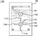
- FIG. 1is a diagram illustrating a mobile device 100 that can navigate through a three dimensional environment.
- mobile device 100may be a PDA, cell phone, handheld game console or other handheld mobile device as known to those of skill in the art.
- mobile device 100may be an IPHONE device, available from Apple Inc.
- mobile device 100may be a device running an ANDROID platform, available from Google Inc.
- mobile device 100may be a tablet computer, laptop computer, or other mobile device larger than a handheld mobile device but still easily carried by a user. These examples are illustrative and are not meant to limit the present invention.
- Mobile device 100enables the user to navigate a virtual camera through a three dimensional environment.
- the three dimensional environmentmay include a three dimensional model, such as a three dimensional model of the Earth.
- a three dimensional model of the Earthmay include satellite imagery texture mapped to three dimensional terrain.
- the three dimensional model of the Earthmay also include models of buildings and other points of interest. This example is merely illustrative and is not meant to limit the present invention.
- mobile device 100may change a perspective of the virtual camera. Based on the virtual camera's new perspective, mobile device 100 may render anew image into view 102 .
- Various user interface gestures that change the virtual camera's perspective and result in anew imageare described in detail below.
- the lens parameter setspecifies the following: horizontal field of view (e.g., telephoto?, normal human eye—about 55 degrees?, or wide-angle?); and vertical field of view (e.g., telephoto?, normal human eye—about 55 degrees?, or wide-angle?).
- the focus parameter setspecifies the following: distance to the near-clip plane (e.g., how close to the “lens” can the virtual camera see, where objects closer are not drawn); and distance to the far-clip plane (e.g., how far from the lens can the virtual camera see, where objects further are not drawn).
- moving the virtual cameraincludes zooming the virtual camera as well as translating the virtual camera.
- angular jump module 312may change the virtual camera's roll to simulate an airplane banking.
- Angular jump module 312may orient the virtual camera such that the target location appears approximately at the center of the view.
- angular jump module 312may change pitch or yaw values of the virtual camera. In this way, a user can double tap on a screen with one hand and easily navigate the virtual camera towards the target. Further, the smooth transition of the virtual camera to its new location may create a pleasing effect to a user.
- Anchor module 320moves the virtual camera in response to other user interface gestures.
- anchor module 320is called when touch receiver 340 receives a two finger touch with one finger stationary and the other finger in motion.
- the relative initial positions of the stationary and moving fingersmay activate one of two navigation modes—an anchored look-around mode or an anchored helicopter mode.
- the anchored look-around modeis activated when the initial position of the first stationary finger is below the initial position of the second finger.
- the anchored helicopter modeis activated when the initial position of the first stationary finger is above the initial position of the second finger.
- the anchored look-around modebe executed by a look-around module 326 , and the anchored helicopter mode may be executed by a helicopter module 324 .
- Each of angular jump module 312 , momentum module 316 , accelerometer navigation module 330 , look-around module 326 , and helicopter module 324accept user interface gestures to move the virtual camera.
- Each of those modulesmay coordinate with momentum module 316 to continue the motion of the virtual camera after the user interface is gesture is complete.
- Momentum module 316may gradually decelerate the motion after the gesture is complete. In this way, momentum module 316 simulates the virtual camera having a momentum and simulates the virtual camera being subjected to friction, such as air resistance.
- the operation of pan module 348may change according to the orientation of the virtual camera.
- the orientation of the virtual cameramay be determined according to an orientation of the mobile device relative to gravity.
- the usermay pan in any direction.
- the virtual camera faces the horizonthe user may pan only forward and backwards. Finger movements to the left and right instead may result in the virtual camera looking to the left or right.
- the operation of pan module 348is described in greater detail with respect to FIG. 17 , FIGS. 18 A-B , and FIGS. 19 A-C .
- an axis of the virtual cameramay be determined based on the position of the first, stationary finger.
- a target locationmay be determined based on the position of the stationary finger.
- the axisis the line connecting the virtual camera and the target location.
- movement of the second fingercauses the virtual camera to rotate about the axis.
- both a pitch and a yaw of the virtual cameramay change.
- the pitch and yawmay change according to the components of the vector of the finger movement along the axes of the mobile device. In this way, by moving two fingers, a user can cause the virtual camera to look-around, viewing the three dimensional environment from different perspectives.
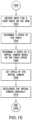
- Method 1300begins with enabling accelerometer navigation at step 1302 .
- Accelerometer navigationmay be enabled, for example, when a user makes a setting change to turn it on or at startup if a default setting is set for accelerometer navigation. In another example, entering a navigation mode such as anchored navigation or look-around navigation may enable accelerometer navigation.
- accelerometer navigationmay be enabled when a change in orientation of the mobile device exceeds a threshold. This way minor changes in orientation do not unintentionally change the perspective of the virtual camera.
- the accelerometer navigationmay be enabled when an orientation of the mobile device relative to gravity exceeds a threshold. If an orientation of the mobile device relative to gravity is below a threshold, the orientation may be in a “dead zone”.
- a usercan navigate through a three dimensional environment by changing an orientation of a mobile device.
- FIG. 15is a flowchart illustrating a method 1500 for navigating a virtual camera using a pinch.
- Method 1500begins by receiving an input for a user pinch on the view at 1502 .
- a user pinchis described is illustrated in FIG. 16 A .
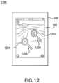
- FIG. 16 Ashows a diagram 1600 illustrating a pinch gesture on a mobile device.
- Diagram 1600shows mobile device 100 with view 102 .
- a userhas touched view with fingers 1604 and 1602 . Both fingers are in motion and their relative motion is a speed of the pinch determined in step 1504 .
- Moving fingers 1604 and 1602 apart as shown with arrows 1612 and 1614may result in a positive pinch speed, whereas moving fingers 1604 and 1602 together as shown with arrows 1624 and 1622 may result in a negative pinch speed.
- a virtual camera speedis determined at step 1506 .
- the virtual camera speedmay be positive (forward) if the pinch speed is positive, and the virtual camera speed may be negative (reverse) if the pinch speed is negative.
- the virtual camera speedmay be linearly interpolated from the pinch speed. This is just an illustrative example and this not meant to limit the present invention.
- the virtual cameraaccelerates to the speed determined at step 1506 .
- the virtual cameramay decelerate gradually. To decelerate the virtual camera, a momentum of the virtual camera may be simulated, and the virtual camera may be exposed to a simulated air resistance. Steps 1508 and 1510 are illustrated in FIG. 16 B .
- FIG. 16 Bshows a diagram 1650 illustrating a virtual camera subjected to a pinch momentum.
- Diagram 1650shows a virtual camera starting at a position 1652 and ending at a position 1654 .
- Diagram 1650shows the virtual camera at several points in time t 0 , t 1 , t 2 , t 3 , t 4 , and t 5 . As time passed, the virtual camera decelerates.
- both fingersneed not be initially in motion.
- One or both fingerscould be initially stationary.
- a pinchmay translate the virtual camera or cause a virtual camera to zoom without any momentum.
- the virtual camerazooms or translates according a distance or speed of the pinch.
- the pinch gestureis completed, the virtual camera may stop zooming or translating.
- the virtual cameramay be translated in a straight line.
- the virtual cameramay stay stationary and the three dimensional model may move.
- the three dimensional modelmay rotate. This motion of the three dimensional model relative to the virtual camera may be referred to as “panning”.
- the virtual camerais both zoomed (or translated) and rotated.
- the rotation of the camerais based on the angle between the two fingers, and the zoom is based on the distance between the two fingers.
- finger 1 and finger 2are in contact with surface at the same time. Further, finger 1 and finger 2 may be in motion at the same time. Rotating finger 1 and finger 2 as illustrated by arrows 1671 and 1673 may result in rotating the camera around a target point.
- the target pointmay be determined by extending a screen ray as described for FIGS. 6 A-B . In examples, the screen ray may be determined based on the location of one the fingers, such as the first finger to touch the screen. Alternatively, the screen ray may be determined based on a midpoint between the fingers. In this way, the target point is not covered by one of the user's fingers on the display.
- the cameramay rotate around the target point.
- the cameramay rotate around the target point by changing an azimuth value as described for FIG. 11 B . In this way, the camera may helicopter around a target point, viewing the target from different perspectives.
- an “invisible” linemay be determined connecting finger 1 and finger 2 .
- an angle between the invisible line and the display of the mobile devicechanges as well.
- an azimuth angle relative to a target pointmay also change.
- the azimuth anglemay change by the same amount, or approximately the same amount, as the angle between the invisible line and the display of the mobile device. In this way, when a user rotates two fingers on the display of the mobile device by 360 degrees, the virtual camera helicopters 360 degrees around the target point.
- changing a distance between finger 1 and finger 2may change a range of virtual camera, e.g., by zooming or translating the virtual camera.
- an invisible line connecting finger 1 and 2is determined as described above. When the invisible line decreases in length, the camera may move away from a target point. Similarly, when the invisible line increases in length, the camera may move toward a target point, or vice versa. Changing the range is described above with respect to FIGS. 16 A-B . Further, a momentum may be applied to continue the gesture as discussed above. A speed of either the rotation, the zoom, or both may diminish gradually after removal of fingers based on a speed at end of gesture.
- the usermay rotate finger 1 and 2 counter-clockwise by 90 degrees and may move finger 1 and 2 apart.
- the virtual cameramay helicopter around the target point by 90 degrees counter-clockwise and may translate closer to the target point.
- the usermay rotate finger 1 and 2 clockwise by 45 degrees and may move finger 1 and 2 closer together.
- the virtual cameramay helicopter around the target point by 45 degrees clockwise and may translate away from the target point.
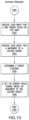
- FIG. 17is a flowchart illustrating a method 1700 for panning on a mobile device.
- Method 1700begins at step 1702 with receiving a first and second position selected by a user of a mobile device. Selecting the first and second positions is illustrated in FIG. 18 A . Each of the first and second position may be defined by an X and Y coordinates on the view.
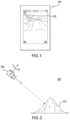
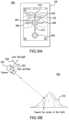
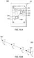
- FIG. 18 Ashows a diagram 1800 illustrating panning on a mobile device.
- Diagram 1800shows mobile device 100 with view 102 .
- a usertouches a position 1802 with his finger and drags his finger to anew position 1804 .
- first and second target pointsare determined at step 1704 .
- the first and second target pointsmay be determined with rays as described with respect to FIG. 6 A-B . If the ray is nearly tangential to the three dimensional model, the target point may need to be damped as described with respect to FIG. 6 B .
- Each target pointmay be defined by, for example, a latitude, longitude, and altitude. Altitude (as the term is meant here) may be the distance from the target point to a center of the three dimensional model.
- the first target pointis determined by intersecting a ray with the three dimensional model and the second target point is determined by intersecting a ray with a virtual surface sphere. Determining the target points is illustrated in FIG. 18 B .
- FIG. 18 Bshows a diagram 1800 with virtual camera 202 facing three dimensional terrain 210 .
- three dimensional terrain 210may be a portion of a three dimensional model.
- the first target point(target point 1854 ) may be determined by extending a ray 1852 to intersect with the three dimensional model at three dimensional terrain 210 .
- a virtual sphere surface 1862is determined.
- Virtual sphere surface 1862may have a center at the center of the three dimensional model and may be tangent target point 1854 .
- a target point 1856is determined.
- a virtual surfacemay not be used and the second target point may be determined by intersecting a ray with the three dimensional model. These two points, target point 1854 and target point 1856 , form a geocentric vector relative to the center of the three dimensional model.
- a rotation axisis determined at step 1706 .
- cross product between the two target pointsmay be determined.
- the two target pointsmay be defined by two vectors V 1 ′ and V 1 .
- the rotation axisis computed by taking the cross product between V 1 ′ and V 1 (V 1 ′ ⁇ V 1 ).
- the three dimensional modelis rotated at step 1708 .
- a rotation matrixis computed based on the angle ⁇ and the rotation axis.
- the three dimensional modelis rotated based on the rotation matrix.
- the last screen space position of the fingermay be recorded. Further, the panning motion may continue after the user gesture is completed. This gives the feeling to the user that he is spinning a globe. The speed of rotation may decrease gradually to simulate friction.
- a target grabbed by a user with his fingerfollows the user's finger movements. To the user, it may feel as if he is touching the planet and manipulating it. Due to the size of the view, the first and second positions of the finger cannot be too far apart. This limits the speed at which a user can pan and improves stability of the pan gesture.
- FIG. 19 Ashows a diagram 1900 illustrating a mobile device 1904 .
- Mobile device 1904has an accelerometer that detects its angle relative to gravity. When the angle of the mobile device is above a threshold a, a user can pan in all directions as illustrated in diagram 1930 in FIG. 19 B . When the of the mobile device is below a threshold a, a touch-and-grab gesture to the left and right does not pan, but causes the virtual camera to look left and right as illustrated in diagram 1960 in FIG. 19 C . The virtual camera may look to the left and right by changing a yaw value of the virtual camera.
Landscapes
- Engineering & Computer Science (AREA)
- Theoretical Computer Science (AREA)
- General Engineering & Computer Science (AREA)
- Physics & Mathematics (AREA)
- General Physics & Mathematics (AREA)
- Human Computer Interaction (AREA)
- Software Systems (AREA)
- Computer Hardware Design (AREA)
- Computer Graphics (AREA)
- Remote Sensing (AREA)
- Radar, Positioning & Navigation (AREA)
- User Interface Of Digital Computer (AREA)
- Position Input By Displaying (AREA)
- Processing Or Creating Images (AREA)
Abstract
Description
Claims (20)
Priority Applications (1)
| Application Number | Priority Date | Filing Date | Title |
|---|---|---|---|
| US17/366,775US12032802B2 (en) | 2008-08-22 | 2021-07-02 | Panning in a three dimensional environment on a mobile device |
Applications Claiming Priority (5)
| Application Number | Priority Date | Filing Date | Title |
|---|---|---|---|
| US9123408P | 2008-08-22 | 2008-08-22 | |
| US12/546,261US9310992B2 (en) | 2008-08-22 | 2009-08-24 | Panning in a three dimensional environment on a mobile device |
| US15/095,442US10222931B2 (en) | 2008-08-22 | 2016-04-11 | Panning in a three dimensional environment on a mobile device |
| US16/291,067US11054964B2 (en) | 2008-08-22 | 2019-03-04 | Panning in a three dimensional environment on a mobile device |
| US17/366,775US12032802B2 (en) | 2008-08-22 | 2021-07-02 | Panning in a three dimensional environment on a mobile device |
Related Parent Applications (1)
| Application Number | Title | Priority Date | Filing Date |
|---|---|---|---|
| US16/291,067ContinuationUS11054964B2 (en) | 2008-08-22 | 2019-03-04 | Panning in a three dimensional environment on a mobile device |
Publications (2)
| Publication Number | Publication Date |
|---|---|
| US20220100350A1 US20220100350A1 (en) | 2022-03-31 |
| US12032802B2true US12032802B2 (en) | 2024-07-09 |
Family
ID=41695929
Family Applications (8)
| Application Number | Title | Priority Date | Filing Date |
|---|---|---|---|
| US12/546,245AbandonedUS20100045703A1 (en) | 2008-08-22 | 2009-08-24 | User Interface Gestures For Moving a Virtual Camera On A Mobile Device |
| US12/546,293Active2030-01-04US8847992B2 (en) | 2008-08-22 | 2009-08-24 | Navigation in a three dimensional environment using an orientation of a mobile device |
| US12/546,261Active2034-07-16US9310992B2 (en) | 2008-08-22 | 2009-08-24 | Panning in a three dimensional environment on a mobile device |
| US12/546,274AbandonedUS20100045666A1 (en) | 2008-08-22 | 2009-08-24 | Anchored Navigation In A Three Dimensional Environment On A Mobile Device |
| US15/095,442Active2030-07-13US10222931B2 (en) | 2008-08-22 | 2016-04-11 | Panning in a three dimensional environment on a mobile device |
| US16/291,063ActiveUS10942618B2 (en) | 2008-08-22 | 2019-03-04 | Panning in a three dimensional environment on a mobile device |
| US16/291,067ActiveUS11054964B2 (en) | 2008-08-22 | 2019-03-04 | Panning in a three dimensional environment on a mobile device |
| US17/366,775ActiveUS12032802B2 (en) | 2008-08-22 | 2021-07-02 | Panning in a three dimensional environment on a mobile device |
Family Applications Before (7)
| Application Number | Title | Priority Date | Filing Date |
|---|---|---|---|
| US12/546,245AbandonedUS20100045703A1 (en) | 2008-08-22 | 2009-08-24 | User Interface Gestures For Moving a Virtual Camera On A Mobile Device |
| US12/546,293Active2030-01-04US8847992B2 (en) | 2008-08-22 | 2009-08-24 | Navigation in a three dimensional environment using an orientation of a mobile device |
| US12/546,261Active2034-07-16US9310992B2 (en) | 2008-08-22 | 2009-08-24 | Panning in a three dimensional environment on a mobile device |
| US12/546,274AbandonedUS20100045666A1 (en) | 2008-08-22 | 2009-08-24 | Anchored Navigation In A Three Dimensional Environment On A Mobile Device |
| US15/095,442Active2030-07-13US10222931B2 (en) | 2008-08-22 | 2016-04-11 | Panning in a three dimensional environment on a mobile device |
| US16/291,063ActiveUS10942618B2 (en) | 2008-08-22 | 2019-03-04 | Panning in a three dimensional environment on a mobile device |
| US16/291,067ActiveUS11054964B2 (en) | 2008-08-22 | 2019-03-04 | Panning in a three dimensional environment on a mobile device |
Country Status (8)
| Country | Link |
|---|---|
| US (8) | US20100045703A1 (en) |
| EP (1) | EP2327010A2 (en) |
| JP (1) | JP2012501016A (en) |
| KR (1) | KR101665034B1 (en) |
| CN (3) | CN103324386A (en) |
| AU (1) | AU2009282724B2 (en) |
| CA (1) | CA2734987A1 (en) |
| WO (1) | WO2010022386A2 (en) |
Families Citing this family (208)
| Publication number | Priority date | Publication date | Assignee | Title |
|---|---|---|---|---|
| US9286941B2 (en) | 2001-05-04 | 2016-03-15 | Legend3D, Inc. | Image sequence enhancement and motion picture project management system |
| US8239132B2 (en)* | 2008-01-22 | 2012-08-07 | Maran Ma | Systems, apparatus and methods for delivery of location-oriented information |
| CN102187694A (en)* | 2008-05-28 | 2011-09-14 | 谷歌公司 | Motion-controlled views on mobile computing devices |
| WO2010022386A2 (en) | 2008-08-22 | 2010-02-25 | Google Inc. | Navigation in a three dimensional environment on a mobile device |
| US20100053151A1 (en)* | 2008-09-02 | 2010-03-04 | Samsung Electronics Co., Ltd | In-line mediation for manipulating three-dimensional content on a display device |
| US20100088632A1 (en)* | 2008-10-08 | 2010-04-08 | Research In Motion Limited | Method and handheld electronic device having dual mode touchscreen-based navigation |
| US8294766B2 (en)* | 2009-01-28 | 2012-10-23 | Apple Inc. | Generating a three-dimensional model using a portable electronic device recording |
| US8108147B1 (en)* | 2009-02-06 | 2012-01-31 | The United States Of America As Represented By The Secretary Of The Navy | Apparatus and method for automatic omni-directional visual motion-based collision avoidance |
| US20100223093A1 (en)* | 2009-02-27 | 2010-09-02 | Hubbard Robert B | System and method for intelligently monitoring subscriber's response to multimedia content |
| US9007379B1 (en)* | 2009-05-29 | 2015-04-14 | Two Pic Mc Llc | Methods and apparatus for interactive user control of virtual cameras |
| US8933925B2 (en)* | 2009-06-15 | 2015-01-13 | Microsoft Corporation | Piecewise planar reconstruction of three-dimensional scenes |
| US8723988B2 (en)* | 2009-07-17 | 2014-05-13 | Sony Corporation | Using a touch sensitive display to control magnification and capture of digital images by an electronic device |
| CN101996021B (en)* | 2009-08-12 | 2013-02-13 | 幻音科技(深圳)有限公司 | Handheld electronic equipment and method for controlling display contents thereby |
| JP5304544B2 (en)* | 2009-08-28 | 2013-10-02 | ソニー株式会社 | Information processing apparatus, information processing method, and program |
| KR20110026066A (en)* | 2009-09-07 | 2011-03-15 | 삼성전자주식회사 | Apparatus and method for switching screen states in a portable terminal |
| JP5464955B2 (en)* | 2009-09-29 | 2014-04-09 | 株式会社ソニー・コンピュータエンタテインメント | Panorama image display device |
| US8913009B2 (en) | 2010-02-03 | 2014-12-16 | Nintendo Co., Ltd. | Spatially-correlated multi-display human-machine interface |
| KR101154636B1 (en)* | 2010-02-03 | 2012-06-08 | 닌텐도가부시키가이샤 | Display device, game system, and game method |
| US8339364B2 (en) | 2010-02-03 | 2012-12-25 | Nintendo Co., Ltd. | Spatially-correlated multi-display human-machine interface |
| US8814686B2 (en) | 2010-02-03 | 2014-08-26 | Nintendo Co., Ltd. | Display device, game system, and game method |
| US20110199516A1 (en)* | 2010-02-12 | 2011-08-18 | Honeywell International Inc. | Method of showing video on a touch-sensitive display |
| US8516063B2 (en) | 2010-02-12 | 2013-08-20 | Mary Anne Fletcher | Mobile device streaming media application |
| US8570286B2 (en)* | 2010-02-12 | 2013-10-29 | Honeywell International Inc. | Gestures on a touch-sensitive display |
| US20110199386A1 (en)* | 2010-02-12 | 2011-08-18 | Honeywell International Inc. | Overlay feature to provide user assistance in a multi-touch interactive display environment |
| US8638371B2 (en)* | 2010-02-12 | 2014-01-28 | Honeywell International Inc. | Method of manipulating assets shown on a touch-sensitive display |
| EP2362302B1 (en)* | 2010-02-26 | 2018-06-06 | Alcatel Lucent | Method for controlling motions of an object in a 3-dimensional virtual environment |
| JP2011197777A (en)* | 2010-03-17 | 2011-10-06 | Sony Corp | Information processing device, information processing method and program |
| US8756522B2 (en) | 2010-03-19 | 2014-06-17 | Blackberry Limited | Portable electronic device and method of controlling same |
| US8937592B2 (en)* | 2010-05-20 | 2015-01-20 | Samsung Electronics Co., Ltd. | Rendition of 3D content on a handheld device |
| WO2011145469A1 (en)* | 2010-05-21 | 2011-11-24 | 日本電気株式会社 | Instructed position determination device of touch panel, touch panel device, electronic apparatus provided with same, instructed position determination method of touch panel and computer program storage medium |
| US8378985B2 (en)* | 2010-05-26 | 2013-02-19 | Sony Mobile Communications Ab | Touch interface for three-dimensional display control |
| US8640020B2 (en)* | 2010-06-02 | 2014-01-28 | Microsoft Corporation | Adjustable and progressive mobile device street view |
| US20110298887A1 (en)* | 2010-06-02 | 2011-12-08 | Maglaque Chad L | Apparatus Using an Accelerometer to Capture Photographic Images |
| US20120326975A1 (en)* | 2010-06-03 | 2012-12-27 | PixArt Imaging Incorporation, R.O.C. | Input device and input method |
| US8977987B1 (en) | 2010-06-14 | 2015-03-10 | Google Inc. | Motion-based interface control on computing device |
| JP2012002568A (en)* | 2010-06-15 | 2012-01-05 | Brother Ind Ltd | Navigation system, portable apparatus and program for portable apparatus |
| US8907943B2 (en)* | 2010-07-07 | 2014-12-09 | Apple Inc. | Sensor based display environment |
| KR20120005124A (en)* | 2010-07-08 | 2012-01-16 | 삼성전자주식회사 | Apparatus and method for performing an operation according to movement in a portable terminal |
| US9626786B1 (en) | 2010-07-19 | 2017-04-18 | Lucasfilm Entertainment Company Ltd. | Virtual-scene control device |
| KR101259598B1 (en)* | 2010-07-30 | 2013-04-30 | 주식회사 팬택 | Apparatus and Method for Providing Road View |
| JP6243586B2 (en) | 2010-08-06 | 2017-12-06 | 任天堂株式会社 | GAME SYSTEM, GAME DEVICE, GAME PROGRAM, AND GAME PROCESSING METHOD |
| US8451192B2 (en) | 2010-08-13 | 2013-05-28 | T-Mobile Usa, Inc. | Utilization of interactive device-adjacent ambiently displayed images |
| US8449118B2 (en)* | 2010-08-13 | 2013-05-28 | T-Mobile Usa, Inc. | Device-adjacent ambiently displayed image |
| US10150033B2 (en) | 2010-08-20 | 2018-12-11 | Nintendo Co., Ltd. | Position calculation system, position calculation device, storage medium storing position calculation program, and position calculation method |
| JP6184658B2 (en)* | 2010-08-20 | 2017-08-23 | 任天堂株式会社 | GAME SYSTEM, GAME DEVICE, GAME PROGRAM, AND GAME PROCESSING METHOD |
| JP5840385B2 (en) | 2010-08-30 | 2016-01-06 | 任天堂株式会社 | GAME SYSTEM, GAME DEVICE, GAME PROGRAM, AND GAME PROCESSING METHOD |
| JP5840386B2 (en) | 2010-08-30 | 2016-01-06 | 任天堂株式会社 | GAME SYSTEM, GAME DEVICE, GAME PROGRAM, AND GAME PROCESSING METHOD |
| JP5664036B2 (en) | 2010-09-07 | 2015-02-04 | ソニー株式会社 | Information processing apparatus, program, and control method |
| JP5609508B2 (en)* | 2010-10-04 | 2014-10-22 | 富士通株式会社 | Object operation device, object operation method, and object operation program |
| DE102010047779A1 (en) | 2010-10-08 | 2012-04-12 | Hicat Gmbh | Computer and method for visual navigation in a three-dimensional image data set |
| GB2487039A (en)* | 2010-10-11 | 2012-07-11 | Michele Sciolette | Visualizing Illustrated Books And Comics On Digital Devices |
| US8780174B1 (en) | 2010-10-12 | 2014-07-15 | The Boeing Company | Three-dimensional vision system for displaying images taken from a moving vehicle |
| US9001053B2 (en)* | 2010-10-28 | 2015-04-07 | Honeywell International Inc. | Display system for controlling a selector symbol within an image |
| US9026359B2 (en) | 2010-11-01 | 2015-05-05 | Nokia Corporation | Visually representing a three-dimensional environment |
| KR101364826B1 (en) | 2010-11-01 | 2014-02-20 | 닌텐도가부시키가이샤 | Operating apparatus and operating system |
| US9342998B2 (en) | 2010-11-16 | 2016-05-17 | Microsoft Technology Licensing, Llc | Techniques to annotate street view images with contextual information |
| US8380427B2 (en)* | 2010-12-03 | 2013-02-19 | Google Inc. | Showing realistic horizons on mobile computing devices |
| US20120194556A1 (en)* | 2011-01-28 | 2012-08-02 | L3 Communications Avionics Systems, Inc. | 3d avionics viewpoint control system |
| US8791911B2 (en) | 2011-02-09 | 2014-07-29 | Robotzone, Llc | Multichannel controller |
| US9407904B2 (en) | 2013-05-01 | 2016-08-02 | Legend3D, Inc. | Method for creating 3D virtual reality from 2D images |
| US9241147B2 (en) | 2013-05-01 | 2016-01-19 | Legend3D, Inc. | External depth map transformation method for conversion of two-dimensional images to stereoscopic images |
| US9282321B2 (en) | 2011-02-17 | 2016-03-08 | Legend3D, Inc. | 3D model multi-reviewer system |
| US9288476B2 (en) | 2011-02-17 | 2016-03-15 | Legend3D, Inc. | System and method for real-time depth modification of stereo images of a virtual reality environment |
| US9632677B2 (en) | 2011-03-02 | 2017-04-25 | The Boeing Company | System and method for navigating a 3-D environment using a multi-input interface |
| EP2497547B1 (en)* | 2011-03-08 | 2018-06-27 | Nintendo Co., Ltd. | Information processing program, information processing apparatus, information processing system, and information processing method |
| JP5792971B2 (en) | 2011-03-08 | 2015-10-14 | 任天堂株式会社 | Information processing system, information processing program, and information processing method |
| US9925464B2 (en) | 2011-03-08 | 2018-03-27 | Nintendo Co., Ltd. | Computer-readable storage medium, information processing system, and information processing method for displaying an image on a display device using attitude data of a display device |
| EP2497544A3 (en) | 2011-03-08 | 2012-10-03 | Nintendo Co., Ltd. | Information processing program, information processing system, and information processing method |
| EP2497545B1 (en) | 2011-03-08 | 2019-08-07 | Nintendo Co., Ltd. | Information processing program, information processing system, and information processing method |
| EP2497543A3 (en) | 2011-03-08 | 2012-10-03 | Nintendo Co., Ltd. | Information processing program, information processing system, and information processing method |
| US8836802B2 (en) | 2011-03-21 | 2014-09-16 | Honeywell International Inc. | Method of defining camera scan movements using gestures |
| WO2016057997A1 (en)* | 2014-10-10 | 2016-04-14 | Pantomime Corporation | Support based 3d navigation |
| GB2489685B (en)* | 2011-03-31 | 2017-01-25 | Geovs Ltd | A Display System |
| JP5689014B2 (en) | 2011-04-07 | 2015-03-25 | 任天堂株式会社 | Input system, information processing apparatus, information processing program, and three-dimensional position calculation method |
| US8760275B2 (en)* | 2011-04-15 | 2014-06-24 | Avaya Inc. | Obstacle warning system and method |
| JP5918618B2 (en) | 2011-06-03 | 2016-05-18 | 任天堂株式会社 | Information processing program, information processing apparatus, information processing system, and information processing method |
| JP5591281B2 (en)* | 2011-06-03 | 2014-09-17 | 任天堂株式会社 | Information processing system, information processing apparatus, information processing program, and moving image reproduction control method |
| US8675049B2 (en)* | 2011-06-09 | 2014-03-18 | Microsoft Corporation | Navigation model to render centered objects using images |
| US9390617B2 (en) | 2011-06-10 | 2016-07-12 | Robotzone, Llc | Camera motion control system with variable autonomy |
| US9508002B2 (en)* | 2011-06-14 | 2016-11-29 | Google Inc. | Generating cinematic flyby sequences following paths and GPS tracks |
| US8914037B2 (en) | 2011-08-11 | 2014-12-16 | Qualcomm Incorporated | Numerically stable computation of heading without a reference axis |
| TWI475471B (en)* | 2011-09-19 | 2015-03-01 | Acer Inc | Method for assisting in video compression using touch screen and monitoring system |
| JP2013084029A (en)* | 2011-10-06 | 2013-05-09 | Sony Corp | Display control device |
| JP5160680B1 (en)* | 2011-10-26 | 2013-03-13 | 株式会社コナミデジタルエンタテインメント | Image processing apparatus, image processing apparatus control method, and program |
| WO2013060085A1 (en)* | 2011-10-27 | 2013-05-02 | The Hong Kong University Of Science And Technology | System and method for constrained manipulations of 3d objects by multitouch inputs |
| US9026951B2 (en)* | 2011-12-21 | 2015-05-05 | Apple Inc. | Device, method, and graphical user interface for selection of views in a three-dimensional map based on gesture inputs |
| US9208698B2 (en)* | 2011-12-27 | 2015-12-08 | Apple Inc. | Device, method, and graphical user interface for manipulating a three-dimensional map view based on a device orientation |
| KR101608423B1 (en)* | 2011-12-27 | 2016-04-01 | 인텔 코포레이션 | Full 3d interaction on mobile devices |
| US10191641B2 (en) | 2011-12-29 | 2019-01-29 | Apple Inc. | Device, method, and graphical user interface for navigation of information in a map-based interface |
| US9124800B2 (en)* | 2012-02-13 | 2015-09-01 | Htc Corporation | Auto burst image capture method applied to a mobile device, method for tracking an object applied to a mobile device, and related mobile device |
| US9594487B2 (en) | 2012-02-27 | 2017-03-14 | Autodesk, Inc | Systems and methods for manipulating a 3D object in a 3D model using a software widget and surface constraints |
| US8626434B1 (en)* | 2012-03-01 | 2014-01-07 | Google Inc. | Automatic adjustment of a camera view for a three-dimensional navigation system |
| US8630458B2 (en)* | 2012-03-21 | 2014-01-14 | Google Inc. | Using camera input to determine axis of rotation and navigation |
| JP5959047B2 (en)* | 2012-04-04 | 2016-08-02 | 任天堂株式会社 | Display control system, display control method, display control program, and display control apparatus |
| TW201343227A (en)* | 2012-04-25 | 2013-11-01 | Fu Li Ye Internat Corp | Interaction game control method having touch panel device media |
| US9997069B2 (en) | 2012-06-05 | 2018-06-12 | Apple Inc. | Context-aware voice guidance |
| US8983778B2 (en) | 2012-06-05 | 2015-03-17 | Apple Inc. | Generation of intersection information by a mapping service |
| US10176633B2 (en) | 2012-06-05 | 2019-01-08 | Apple Inc. | Integrated mapping and navigation application |
| US9230556B2 (en) | 2012-06-05 | 2016-01-05 | Apple Inc. | Voice instructions during navigation |
| US9482296B2 (en) | 2012-06-05 | 2016-11-01 | Apple Inc. | Rendering road signs during navigation |
| US9200919B2 (en)* | 2012-06-05 | 2015-12-01 | Apple Inc. | Method, system and apparatus for selectively obtaining map image data according to virtual camera velocity |
| US8965696B2 (en) | 2012-06-05 | 2015-02-24 | Apple Inc. | Providing navigation instructions while operating navigation application in background |
| US9092900B2 (en)* | 2012-06-05 | 2015-07-28 | Google Inc. | Terrain-based virtual camera tilting, and applications thereof |
| US9311750B2 (en)* | 2012-06-05 | 2016-04-12 | Apple Inc. | Rotation operations in a mapping application |
| US9159153B2 (en) | 2012-06-05 | 2015-10-13 | Apple Inc. | Method, system and apparatus for providing visual feedback of a map view change |
| US9418672B2 (en) | 2012-06-05 | 2016-08-16 | Apple Inc. | Navigation application with adaptive instruction text |
| US9886794B2 (en) | 2012-06-05 | 2018-02-06 | Apple Inc. | Problem reporting in maps |
| WO2013184838A2 (en)* | 2012-06-06 | 2013-12-12 | Google Inc. | System and method for providing content for a point of interest |
| US9786097B2 (en) | 2012-06-22 | 2017-10-10 | Matterport, Inc. | Multi-modal method for interacting with 3D models |
| US10139985B2 (en) | 2012-06-22 | 2018-11-27 | Matterport, Inc. | Defining, displaying and interacting with tags in a three-dimensional model |
| US10163261B2 (en) | 2014-03-19 | 2018-12-25 | Matterport, Inc. | Selecting two-dimensional imagery data for display within a three-dimensional model |
| US10127722B2 (en) | 2015-06-30 | 2018-11-13 | Matterport, Inc. | Mobile capture visualization incorporating three-dimensional and two-dimensional imagery |
| WO2014014806A1 (en)* | 2012-07-15 | 2014-01-23 | Apple Inc. | Disambiguation of multitouch gesture recognition for 3d interaction |
| US9021387B2 (en) | 2012-07-31 | 2015-04-28 | Hewlett-Packard Development Company, L.P. | Re-sizing user interface object on touch sensitive display |
| US9025860B2 (en) | 2012-08-06 | 2015-05-05 | Microsoft Technology Licensing, Llc | Three-dimensional object browsing in documents |
| GB2505404B (en)* | 2012-08-07 | 2016-08-31 | Samsung Electronics Co Ltd | Portable apparatus with a GUI |
| US9507513B2 (en) | 2012-08-17 | 2016-11-29 | Google Inc. | Displaced double tap gesture |
| US8777743B2 (en)* | 2012-08-31 | 2014-07-15 | DeNA Co., Ltd. | System and method for facilitating interaction with a virtual space via a touch sensitive surface |
| US9886795B2 (en)* | 2012-09-05 | 2018-02-06 | Here Global B.V. | Method and apparatus for transitioning from a partial map view to an augmented reality view |
| US20150040073A1 (en)* | 2012-09-24 | 2015-02-05 | Google Inc. | Zoom, Rotate, and Translate or Pan In A Single Gesture |
| US10178188B2 (en)* | 2012-10-01 | 2019-01-08 | Scott R. Copeland | System for a monitored and reconstructible personal rendezvous session |
| US10492053B2 (en)* | 2012-10-01 | 2019-11-26 | Scott R. Copeland | System for a monitored and reconstructible personal rendezvous session |
| CN104769543B (en)* | 2012-10-16 | 2018-10-26 | 田载雄 | Method and system and computer readable recording medium storing program for performing for controlling virtual camera in virtual three-dimensional space |
| US20140109016A1 (en)* | 2012-10-16 | 2014-04-17 | Yu Ouyang | Gesture-based cursor control |
| US9547937B2 (en) | 2012-11-30 | 2017-01-17 | Legend3D, Inc. | Three-dimensional annotation system and method |
| CN103853471B (en)* | 2012-12-03 | 2017-05-10 | 昆达电脑科技(昆山)有限公司 | User touch behavior based map display method |
| US9606709B2 (en) | 2012-12-27 | 2017-03-28 | Google Inc. | System and method for geographic data layer management in a geographic information system |
| US10140765B2 (en) | 2013-02-25 | 2018-11-27 | Google Llc | Staged camera traversal for three dimensional environment |
| US9773346B1 (en)* | 2013-03-12 | 2017-09-26 | Amazon Technologies, Inc. | Displaying three-dimensional virtual content |
| US9712746B2 (en) | 2013-03-14 | 2017-07-18 | Microsoft Technology Licensing, Llc | Image capture and ordering |
| US20140267600A1 (en)* | 2013-03-14 | 2014-09-18 | Microsoft Corporation | Synth packet for interactive view navigation of a scene |
| US9007404B2 (en)* | 2013-03-15 | 2015-04-14 | Legend3D, Inc. | Tilt-based look around effect image enhancement method |
| GB2512628A (en)* | 2013-04-04 | 2014-10-08 | Sony Corp | Method and apparatus |
| US9438878B2 (en) | 2013-05-01 | 2016-09-06 | Legend3D, Inc. | Method of converting 2D video to 3D video using 3D object models |
| US9417835B2 (en)* | 2013-05-10 | 2016-08-16 | Google Inc. | Multiplayer game for display across multiple devices |
| US9786075B2 (en)* | 2013-06-07 | 2017-10-10 | Microsoft Technology Licensing, Llc | Image extraction and image-based rendering for manifolds of terrestrial and aerial visualizations |
| US9329750B2 (en) | 2013-09-10 | 2016-05-03 | Google Inc. | Three-dimensional tilt and pan navigation using a single gesture |
| US10670402B2 (en)* | 2013-11-01 | 2020-06-02 | Invensense, Inc. | Systems and methods for optical sensor navigation |
| WO2015089451A1 (en)* | 2013-12-14 | 2015-06-18 | Handscape Inc. | Method for detecting user gestures from alternative touchpads of a handheld computerized device |
| ITCO20130068A1 (en)* | 2013-12-18 | 2015-06-19 | Nu Tech S A S Di De Michele Marco & Co | METHOD TO PROVIDE USER COMMANDS TO AN ELECTRONIC PROCESSOR AND RELATED PROGRAM FOR PROCESSING AND ELECTRONIC CIRCUIT. |
| TWI497188B (en)* | 2014-02-14 | 2015-08-21 | Dayu Optoelectronics Co Ltd | Method for generating three dimensional image and three dimensional imaging device |
| CN104849953B (en)* | 2014-02-19 | 2017-09-12 | 大昱光电股份有限公司 | Stereoscopic image generation method and stereoscopic image shooting device |
| US9851880B2 (en)* | 2014-03-14 | 2017-12-26 | Adobe Systems Incorporated | Image rotation based on touch gestures |
| WO2015156128A1 (en)* | 2014-04-07 | 2015-10-15 | ソニー株式会社 | Display control device, display control method, and program |
| US10600245B1 (en) | 2014-05-28 | 2020-03-24 | Lucasfilm Entertainment Company Ltd. | Navigating a virtual environment of a media content item |
| KR20170012312A (en)* | 2014-06-02 | 2017-02-02 | 에이펠랩 에스에이알엘 | A method and system for providing interactivity within a virtual environment |
| KR101888566B1 (en) | 2014-06-03 | 2018-08-16 | 애플 인크. | Method and system for presenting a digital information related to a real object |
| US9595130B2 (en)* | 2014-06-17 | 2017-03-14 | Chief Architect Inc. | Virtual model navigation methods and apparatus |
| US9575564B2 (en)* | 2014-06-17 | 2017-02-21 | Chief Architect Inc. | Virtual model navigation methods and apparatus |
| US9589354B2 (en) | 2014-06-17 | 2017-03-07 | Chief Architect Inc. | Virtual model viewing methods and apparatus |
| US10724864B2 (en) | 2014-06-17 | 2020-07-28 | Chief Architect Inc. | Step detection methods and apparatus |
| US9726463B2 (en) | 2014-07-16 | 2017-08-08 | Robtozone, LLC | Multichannel controller for target shooting range |
| US9430142B2 (en) | 2014-07-17 | 2016-08-30 | Facebook, Inc. | Touch-based gesture recognition and application navigation |
| US10007419B2 (en) | 2014-07-17 | 2018-06-26 | Facebook, Inc. | Touch-based gesture recognition and application navigation |
| FR3028330B1 (en)* | 2014-11-07 | 2017-12-08 | Thales Sa | METHOD AND DEVICE FOR CHANGING THE POINT OF VIEW OF A 3D CARD OR IMAGE OF A 3D PHYSICAL OBJECT BY RECOGNIZING A GESTUAL ON A TOUCH SCREEN |
| CN104680588B (en)* | 2015-02-13 | 2017-11-24 | 上海同筑信息科技有限公司 | Event marker method and system based on BIM |
| CN104965653A (en)* | 2015-06-15 | 2015-10-07 | 联想(北京)有限公司 | Control method and electronic equipment |
| EP3106963B1 (en) | 2015-06-16 | 2019-07-24 | Nokia Technologies Oy | Mediated reality |
| US9679413B2 (en)* | 2015-08-13 | 2017-06-13 | Google Inc. | Systems and methods to transition between viewpoints in a three-dimensional environment |
| DK3337585T3 (en)* | 2015-08-17 | 2022-11-07 | Lego As | Method for creating a virtual game environment and interactive game system using the method |
| EP3345184A1 (en)* | 2015-09-02 | 2018-07-11 | THOMSON Licensing | Method, apparatus and system for facilitating navigation in an extended scene |
| US9609307B1 (en) | 2015-09-17 | 2017-03-28 | Legend3D, Inc. | Method of converting 2D video to 3D video using machine learning |
| CN105915877A (en)* | 2015-12-27 | 2016-08-31 | 乐视致新电子科技(天津)有限公司 | Free film watching method and device of three-dimensional video |
| FR3046229A1 (en)* | 2015-12-29 | 2017-06-30 | Thales Sa | METHOD FOR GRAPHIC REPRESENTATION OF A THREE-DIMENSIONAL SYNTHETIC VIEW OF THE EXTERIOR LANDSCAPE IN AN AIRCRAFT VISUALIZATION SYSTEM |
| CN107038682B (en)* | 2016-02-03 | 2020-06-26 | 上海源胜文化传播有限公司 | A system and method for scaling a three-dimensional human body model |
| US20170269712A1 (en)* | 2016-03-16 | 2017-09-21 | Adtile Technologies Inc. | Immersive virtual experience using a mobile communication device |
| US10198861B2 (en) | 2016-03-31 | 2019-02-05 | Intel Corporation | User interactive controls for a priori path navigation in virtual environment |
| US10739157B2 (en) | 2016-06-12 | 2020-08-11 | Apple Inc. | Grouping maneuvers for display in a navigation presentation |
| JP6228267B2 (en)* | 2016-06-20 | 2017-11-08 | 株式会社スクウェア・エニックス | Video game processing apparatus, video game processing method, and video game processing program |
| US20170374276A1 (en)* | 2016-06-23 | 2017-12-28 | Intel Corporation | Controlling capturing of a multimedia stream with user physical responses |
| US10726673B2 (en) | 2016-09-20 | 2020-07-28 | Acres Technology | Automatic application of a bonus to an electronic gaming device responsive to player interaction with a mobile computing device |
| US10041800B2 (en) | 2016-09-23 | 2018-08-07 | Qualcomm Incorporated | Pedestrian sensor assistance in a mobile device during typical device motions |
| US10712836B2 (en)* | 2016-10-04 | 2020-07-14 | Hewlett-Packard Development Company, L.P. | Three-dimensional input device |
| US11061557B2 (en) | 2016-12-22 | 2021-07-13 | ReScan, Inc. | Dynamic single touch point navigation |
| US10373342B1 (en) | 2017-01-10 | 2019-08-06 | Lucasfilm Entertainment Company Ltd. | Content generation in an immersive environment |
| EP3596587A4 (en)* | 2017-03-13 | 2021-01-27 | Rescan, Inc. | Navigation system |
| CN108984087B (en)* | 2017-06-02 | 2021-09-14 | 腾讯科技(深圳)有限公司 | Social interaction method and device based on three-dimensional virtual image |
| AU2017204099A1 (en)* | 2017-06-16 | 2019-01-17 | Canon Kabushiki Kaisha | System and method of configuring a virtual camera |
| CN107436745B (en)* | 2017-06-19 | 2021-01-08 | 广州励丰文化科技股份有限公司 | Picture display method and device of three-dimensional model based on digital artistic landscape device |
| US10663298B2 (en)* | 2017-06-25 | 2020-05-26 | Invensense, Inc. | Method and apparatus for characterizing platform motion |
| US20190007672A1 (en) | 2017-06-30 | 2019-01-03 | Bobby Gene Burrough | Method and Apparatus for Generating Dynamic Real-Time 3D Environment Projections |
| AU2017204643B2 (en) | 2017-07-07 | 2020-05-14 | Canon Kabushiki Kaisha | Method, apparatus and system for encoding and decoding video data |
| CN107506038B (en)* | 2017-08-28 | 2020-02-25 | 荆门程远电子科技有限公司 | Three-dimensional virtual earth interaction method based on mobile terminal |
| US10569172B2 (en)* | 2017-09-19 | 2020-02-25 | Canon Kabushiki Kaisha | System and method of configuring a virtual camera |
| JP6419278B1 (en) | 2017-09-19 | 2018-11-07 | キヤノン株式会社 | Control device, control method, and program |
| CN109550246B (en)* | 2017-09-25 | 2022-03-25 | 腾讯科技(深圳)有限公司 | Control method and device for game client, storage medium and electronic device |
| CN108363531A (en)* | 2018-01-17 | 2018-08-03 | 网易(杭州)网络有限公司 | Exchange method and device in a kind of game |
| WO2019164514A1 (en)* | 2018-02-23 | 2019-08-29 | Google Llc | Transitioning between map view and augmented reality view |
| JP7045218B2 (en)* | 2018-02-28 | 2022-03-31 | キヤノン株式会社 | Information processing equipment and information processing methods, programs |
| CN108379844B (en)* | 2018-03-30 | 2020-10-23 | 腾讯科技(深圳)有限公司 | Method, device, electronic device and storage medium for controlling movement of virtual object |
| CN108509139B (en)* | 2018-03-30 | 2019-09-10 | 腾讯科技(深圳)有限公司 | Control method for movement, device, electronic device and the storage medium of virtual objects |
| US10964110B2 (en)* | 2018-05-07 | 2021-03-30 | Vmware, Inc. | Managed actions using augmented reality |
| JP6916150B2 (en)* | 2018-06-05 | 2021-08-11 | 任天堂株式会社 | Game systems, game programs, game devices, and game processing methods |
| CN110610523B (en)* | 2018-06-15 | 2023-04-25 | 杭州海康威视数字技术股份有限公司 | Method and device for calibrating automobile looking around and computer readable storage medium |
| JP6830473B2 (en)* | 2018-12-13 | 2021-02-17 | 株式会社スクウェア・エニックス | Video game processor, video game processing method, and video game processing program |
| CN109840043B (en)* | 2019-01-30 | 2021-08-10 | 腾讯科技(深圳)有限公司 | Method, apparatus, device and storage medium for building in virtual environment |
| US11216149B2 (en)* | 2019-03-15 | 2022-01-04 | Samsung Electronics Co., Ltd. | 360° video viewer control using smart device |
| CN112130551A (en)* | 2019-06-25 | 2020-12-25 | 北京百度网讯科技有限公司 | Travel path and speed decision planning method and device for unmanned vehicle |
| CN114144753B (en)* | 2019-07-30 | 2025-01-07 | 索尼集团公司 | Image processing device, image processing method, and recording medium |
| CN110523085A (en)* | 2019-08-30 | 2019-12-03 | 腾讯科技(深圳)有限公司 | Control method, device, terminal and the storage medium of virtual objects |
| CN111324253B (en)* | 2020-02-12 | 2021-08-03 | 腾讯科技(深圳)有限公司 | Virtual article interaction method and device, computer equipment and storage medium |
| EP3865984B1 (en)* | 2020-02-13 | 2023-09-27 | Honeywell International Inc. | Methods and systems for searchlight control for aerial vehicles |
| US11625037B2 (en) | 2020-02-13 | 2023-04-11 | Honeywell International Inc. | Methods and systems for searchlight control for aerial vehicles |
| JP2020113314A (en)* | 2020-03-25 | 2020-07-27 | 任天堂株式会社 | Information processing program, information processing apparatus, information processing system, and information processing method |
| CN112087575B (en)* | 2020-08-24 | 2022-03-08 | 广州启量信息科技有限公司 | Virtual camera control method |
| CA3146804A1 (en)* | 2020-11-13 | 2022-05-13 | Tencent Technology (Shenzhen) Company Limited | Virtual object control method and apparatus, storage medium, and electronic device |
| CN112354179B (en)* | 2020-11-23 | 2023-09-05 | 浙江中控信息产业股份有限公司 | Three-dimensional geographic information content display and interaction method |
| US11899204B2 (en) | 2021-06-09 | 2024-02-13 | Snap Inc. | Soft follow and pitch angle effects for VR/AR interface |
Citations (84)
| Publication number | Priority date | Publication date | Assignee | Title |
|---|---|---|---|---|
| US5276785A (en)* | 1990-08-02 | 1994-01-04 | Xerox Corporation | Moving viewpoint with respect to a target in a three-dimensional workspace |
| US5483261A (en)* | 1992-02-14 | 1996-01-09 | Itu Research, Inc. | Graphical input controller and method with rear screen image detection |
| US5557714A (en) | 1993-01-29 | 1996-09-17 | Microsoft Corporation | Method and system for rotating a three-dimensional model about two orthogonal axes |
| US5588098A (en) | 1991-11-22 | 1996-12-24 | Apple Computer, Inc. | Method and apparatus for direct manipulation of 3-D objects on computer displays |
| US5602566A (en) | 1993-08-24 | 1997-02-11 | Hitachi, Ltd. | Small-sized information processor capable of scrolling screen in accordance with tilt, and scrolling method therefor |
| US5689628A (en) | 1994-04-14 | 1997-11-18 | Xerox Corporation | Coupling a display object to a viewpoint in a navigable workspace |
| US5808613A (en) | 1996-05-28 | 1998-09-15 | Silicon Graphics, Inc. | Network navigator with enhanced navigational abilities |
| US5844547A (en) | 1991-10-07 | 1998-12-01 | Fujitsu Limited | Apparatus for manipulating an object displayed on a display device by using a touch screen |
| US6029854A (en) | 1998-09-16 | 2000-02-29 | Wissen; William T. | Portable liquid dispenser |
| US6281877B1 (en) | 1996-03-29 | 2001-08-28 | British Telecommunications Plc | Control interface |
| US6288704B1 (en) | 1999-06-08 | 2001-09-11 | Vega, Vista, Inc. | Motion detection and tracking system to control navigation and display of object viewers |
| US6326846B1 (en) | 2000-04-11 | 2001-12-04 | National Semiconductor Corporation | Low voltage fet differential amplifier and method |
| US6347290B1 (en) | 1998-06-24 | 2002-02-12 | Compaq Information Technologies Group, L.P. | Apparatus and method for detecting and executing positional and gesture commands corresponding to movement of handheld computing device |
| US6388655B1 (en) | 1999-11-08 | 2002-05-14 | Wing-Keung Leung | Method of touch control of an input device and such a device |
| US6400376B1 (en) | 1998-12-21 | 2002-06-04 | Ericsson Inc. | Display control for hand-held data processing device |
| US6466198B1 (en) | 1999-11-05 | 2002-10-15 | Innoventions, Inc. | View navigation and magnification of a hand-held device with a display |
| JP3090450U (en) | 2002-06-04 | 2002-12-13 | 株式会社ワコー | Portable information processing device with azimuth display function |
| US20030132913A1 (en) | 2002-01-11 | 2003-07-17 | Anton Issinski | Touchless computer input device to control display cursor mark position by using stereovision input from two video cameras |
| US6636210B1 (en) | 2000-03-03 | 2003-10-21 | Muse Corporation | Method and system for auto-navigation in a three dimensional viewing environment |
| EP1369822A2 (en) | 2002-05-31 | 2003-12-10 | eIT Co., Ltd | Apparatus and method for controlling the shift of the viewpoint in a virtual space |
| US20040001110A1 (en)* | 2002-06-28 | 2004-01-01 | Azam Khan | Push-tumble three dimensional navigation system |
| US6690387B2 (en) | 2001-12-28 | 2004-02-10 | Koninklijke Philips Electronics N.V. | Touch-screen image scrolling system and method |
| US20040125114A1 (en)* | 2002-12-31 | 2004-07-01 | Hauke Schmidt | Multiresolution image synthesis for navigation |
| US20040128071A1 (en) | 2002-10-23 | 2004-07-01 | Stefan Schradi | Method and apparatus for generating a GPS simulation scenario |
| US20040178997A1 (en) | 1992-06-08 | 2004-09-16 | Synaptics, Inc., A California Corporation | Object position detector with edge motion feature and gesture recognition |
| US6798429B2 (en) | 2001-03-29 | 2004-09-28 | Intel Corporation | Intuitive mobile device interface to virtual spaces |
| US6864886B1 (en) | 2000-08-10 | 2005-03-08 | Sportvision, Inc. | Enhancing video using a virtual surface |
| US6907579B2 (en) | 2001-10-30 | 2005-06-14 | Hewlett-Packard Development Company, L.P. | User interface and method for interacting with a three-dimensional graphical environment |
| US20050187015A1 (en) | 2004-02-19 | 2005-08-25 | Nintendo Co., Ltd. | Game machine and data storage medium having stored therein game program |
| US20050225559A1 (en)* | 2001-03-29 | 2005-10-13 | Microsoft Corporation | 3D navigation techniques |
| US6957380B2 (en) | 2001-12-27 | 2005-10-18 | Electronics And Telecommunications Research Institue | Method for network adaptive error control FolP |
| US6980690B1 (en) | 2000-01-20 | 2005-12-27 | Canon Kabushiki Kaisha | Image processing apparatus |
| US20060026521A1 (en) | 2004-07-30 | 2006-02-02 | Apple Computer, Inc. | Gestures for touch sensitive input devices |
| US20060097991A1 (en) | 2004-05-06 | 2006-05-11 | Apple Computer, Inc. | Multipoint touchscreen |
| US20060103650A1 (en)* | 2001-02-23 | 2006-05-18 | Fujitsu Limited | Display controlling apparatus, information terminal unit provided with display controlling apparatus, and viewpoint location controlling apparatus |
| US20060164382A1 (en) | 2005-01-25 | 2006-07-27 | Technology Licensing Company, Inc. | Image manipulation in response to a movement of a display |
| US7119819B1 (en) | 1999-04-06 | 2006-10-10 | Microsoft Corporation | Method and apparatus for supporting two-dimensional windows in a three-dimensional environment |
| US20060244735A1 (en) | 2005-04-29 | 2006-11-02 | Microsoft Corporation | System and method for fine cursor positioning using a low resolution imaging touch screen |
| US7142205B2 (en) | 2000-03-29 | 2006-11-28 | Autodesk, Inc. | Single gesture map navigation graphical user interface for a personal digital assistant |
| US20060288313A1 (en) | 2004-08-06 | 2006-12-21 | Hillis W D | Bounding box gesture recognition on a touch detecting interactive display |
| JP2006349964A (en) | 2005-06-15 | 2006-12-28 | Denso Corp | Map display apparatus for portable device |
| US7159194B2 (en) | 2001-11-30 | 2007-01-02 | Palm, Inc. | Orientation dependent functionality of an electronic device |
| US20070046661A1 (en) | 2005-08-31 | 2007-03-01 | Siemens Medical Solutions Usa, Inc. | Three or four-dimensional medical imaging navigation methods and systems |
| US7190496B2 (en) | 2003-07-24 | 2007-03-13 | Zebra Imaging, Inc. | Enhanced environment visualization using holographic stereograms |
| US7194816B2 (en) | 2004-07-15 | 2007-03-27 | C&N Inc. | Mobile terminal apparatus |
| US7259778B2 (en) | 2003-07-01 | 2007-08-21 | L-3 Communications Corporation | Method and apparatus for placing sensors using 3D models |
| CN101030982A (en) | 2007-03-22 | 2007-09-05 | 宇龙计算机通信科技(深圳)有限公司 | Apparatus and method for automatically adjusting display-screen content and direction |
| US20070206030A1 (en)* | 2006-03-06 | 2007-09-06 | The Protomold Company, Inc. | Graphical user interface for three-dimensional manipulation of a part |
| US20080024615A1 (en) | 2006-07-28 | 2008-01-31 | Accelerated Pictures, Inc. | Camera control |
| US7330198B2 (en) | 2003-02-26 | 2008-02-12 | Sony Corporation | Three-dimensional object manipulating apparatus, method and computer program |
| US20080042987A1 (en) | 1998-01-26 | 2008-02-21 | Apple Inc. | Touch sensing through hand dissection |
| US20080062126A1 (en) | 2006-07-06 | 2008-03-13 | Algreatly Cherif A | 3D method and system for hand-held devices |
| US20080070684A1 (en) | 2006-09-14 | 2008-03-20 | Mark Haigh-Hutchinson | Method and apparatus for using a common pointing input to control 3D viewpoint and object targeting |
| US20080094358A1 (en) | 2006-09-15 | 2008-04-24 | Industrial Light & Magic | Constrained Virtual Camera Control |
| US20080184173A1 (en)* | 2007-01-31 | 2008-07-31 | Microsoft Corporation | Controlling multiple map application operations with a single gesture |
| US20080180405A1 (en) | 2007-01-31 | 2008-07-31 | Han Jefferson Y | Methods of interfacing with multi-point input devices and multi-point input systems employing interfacing techniques |
| US20080309632A1 (en) | 2007-06-13 | 2008-12-18 | Apple Inc. | Pinch-throw and translation gestures |
| US20090033623A1 (en) | 2007-08-01 | 2009-02-05 | Ming-Yen Lin | Three-dimensional virtual input and simulation apparatus |
| US7587684B2 (en) | 2006-01-23 | 2009-09-08 | Nokia Corporation | Mobile communication terminal and method therefore |
| US7589732B2 (en) | 2002-11-05 | 2009-09-15 | Autodesk, Inc. | System and method of integrated spatial and temporal navigation |
| US20090259976A1 (en)* | 2008-04-14 | 2009-10-15 | Google Inc. | Swoop Navigation |
| US20090256840A1 (en)* | 2008-04-14 | 2009-10-15 | Google Inc. | Panning Using Virtual Surfaces |
| US20090262145A1 (en)* | 2005-11-01 | 2009-10-22 | Takashi Akita | Information display device |
| US7613323B2 (en)* | 2004-06-22 | 2009-11-03 | Sarnoff Corporation | Method and apparatus for determining camera pose |
| US20090292989A1 (en)* | 2008-05-23 | 2009-11-26 | Microsoft Corporation | Panning content utilizing a drag operation |
| US7628698B2 (en) | 2004-10-29 | 2009-12-08 | Nintendo Co., Ltd. | Game program |
| US20100045703A1 (en)* | 2008-08-22 | 2010-02-25 | Google Inc. | User Interface Gestures For Moving a Virtual Camera On A Mobile Device |
| US7707516B2 (en) | 2006-05-26 | 2010-04-27 | Google Inc. | Embedded navigation interface |
| US7728821B2 (en) | 2004-08-06 | 2010-06-01 | Touchtable, Inc. | Touch detecting interactive display |
| US7819748B2 (en) | 2004-10-27 | 2010-10-26 | Nintendo Co., Ltd. | Game apparatus and storage medium storing game program |
| US7859553B2 (en) | 2004-12-30 | 2010-12-28 | Lg Electronics Inc. | Image navigation in a mobile station |
| US7934893B2 (en) | 2004-12-10 | 2011-05-03 | A.V. Custom Style B.V. | Quick-change and plug eject arbor for a hole saw |
| US8018435B2 (en) | 2001-03-29 | 2011-09-13 | Durham Logistics, Llc | Method and apparatus for controlling a computing system |
| US8077153B2 (en) | 2006-04-19 | 2011-12-13 | Microsoft Corporation | Precise selection techniques for multi-touch screens |
| US8089479B2 (en)* | 2008-04-11 | 2012-01-03 | Apple Inc. | Directing camera behavior in 3-D imaging system |
| US8130203B2 (en) | 2007-01-03 | 2012-03-06 | Apple Inc. | Multi-touch input discrimination |
| US8142277B2 (en) | 2008-03-31 | 2012-03-27 | Namco Bandai Games Inc. | Program, game system, and movement control method for assisting a user to position a game object |
| US8294766B2 (en) | 2009-01-28 | 2012-10-23 | Apple Inc. | Generating a three-dimensional model using a portable electronic device recording |
| US8302033B2 (en) | 2007-06-22 | 2012-10-30 | Apple Inc. | Touch screen device, method, and graphical user interface for providing maps, directions, and location-based information |
| US8487957B1 (en) | 2007-05-29 | 2013-07-16 | Google Inc. | Displaying and navigating within photo placemarks in a geographic information system, and applications thereof |
| US8749544B2 (en) | 2007-09-26 | 2014-06-10 | Autodesk, Inc. | Navigation system for a 3D virtual scene |
| US8799821B1 (en)* | 2008-04-24 | 2014-08-05 | Pixar | Method and apparatus for user inputs for three-dimensional animation |
| US9070402B2 (en) | 2006-03-13 | 2015-06-30 | Autodesk, Inc. | 3D model presentation system with motion and transitions at each camera view point of interest (POI) with imageless jumps to each POI |
| US10504285B2 (en) | 2007-09-26 | 2019-12-10 | Autodesk, Inc. | Navigation system for a 3D virtual scene |
Family Cites Families (48)
| Publication number | Priority date | Publication date | Assignee | Title |
|---|---|---|---|---|
| US5111288A (en)* | 1988-03-02 | 1992-05-05 | Diamond Electronics, Inc. | Surveillance camera system |
| US6597347B1 (en)* | 1991-11-26 | 2003-07-22 | Itu Research Inc. | Methods and apparatus for providing touch-sensitive input in multiple degrees of freedom |
| GB9616184D0 (en)* | 1996-08-01 | 1996-09-11 | Philips Electronics Nv | Virtual environment navigation |
| JPH1049290A (en)* | 1996-08-05 | 1998-02-20 | Sony Corp | Device and method for processing information |
| JP4332231B2 (en)* | 1997-04-21 | 2009-09-16 | ソニー株式会社 | Imaging device controller and imaging system |
| GB9721667D0 (en)* | 1997-10-14 | 1997-12-10 | Philips Electronics Nv | Virtual environment navigation aid |
| US7027642B2 (en)* | 2000-04-28 | 2006-04-11 | Orametrix, Inc. | Methods for registration of three-dimensional frames to create three-dimensional virtual models of objects |
| JP2004507724A (en)* | 2000-08-24 | 2004-03-11 | シーメンス アクチエンゲゼルシヤフト | Method for displaying target information, method for navigating in a map screen, computer program product and navigation device |
| US6600475B2 (en)* | 2001-01-22 | 2003-07-29 | Koninklijke Philips Electronics N.V. | Single camera system for gesture-based input and target indication |
| US7030861B1 (en)* | 2001-02-10 | 2006-04-18 | Wayne Carl Westerman | System and method for packing multi-touch gestures onto a hand |
| FI117488B (en)* | 2001-05-16 | 2006-10-31 | Myorigo Sarl | Browse information on a screen |
| US6452544B1 (en)* | 2001-05-24 | 2002-09-17 | Nokia Corporation | Portable map display system for presenting a 3D map image and method thereof |
| US7411594B2 (en)* | 2002-01-15 | 2008-08-12 | Canon Kabushiki Kaisha | Information processing apparatus and method |
| CN1360283A (en)* | 2002-01-15 | 2002-07-24 | 天津大学 | 3D model creating system for actual human head sculpture |
| US7324085B2 (en)* | 2002-01-25 | 2008-01-29 | Autodesk, Inc. | Techniques for pointing to locations within a volumetric display |
| US7107285B2 (en) | 2002-03-16 | 2006-09-12 | Questerra Corporation | Method, system, and program for an improved enterprise spatial system |
| GB2387519B (en) | 2002-04-08 | 2005-06-22 | Canon Europa Nv | Viewing controller for three-dimensional computer graphics |
| JP4096622B2 (en)* | 2002-05-21 | 2008-06-04 | 株式会社セガ | Image processing method and apparatus, program, and recording medium |
| US6975959B2 (en)* | 2002-12-03 | 2005-12-13 | Robert Bosch Gmbh | Orientation and navigation for a mobile device using inertial sensors |
| DE10300527A1 (en)* | 2003-01-09 | 2004-07-22 | Realtime Technology Ag | Display system for virtual three-dimensional scenes, adjusts spatial angles of camera model when trackball is rotated, so that view of virtual three-dimensional scene varies accordingly |
| US7519223B2 (en)* | 2004-06-28 | 2009-04-14 | Microsoft Corporation | Recognizing gestures and using gestures for interacting with software applications |
| US7743348B2 (en)* | 2004-06-30 | 2010-06-22 | Microsoft Corporation | Using physical objects to adjust attributes of an interactive display application |
| US20080300780A1 (en)* | 2005-02-07 | 2008-12-04 | Dmitry Domnin | Method for automating task with portable device |
| US20060271281A1 (en) | 2005-05-20 | 2006-11-30 | Myron Ahn | Geographic information knowledge systems |
| US10198521B2 (en)* | 2005-06-27 | 2019-02-05 | Google Llc | Processing ambiguous search requests in a geographic information system |
| JP4783603B2 (en)* | 2005-08-26 | 2011-09-28 | 株式会社デンソー | MAP DISPLAY DEVICE, MAP DISPLAY METHOD, MAP DISPLAY PROGRAM, AND RECORDING MEDIUM CONTAINING THE PROGRAM |
| JP4404830B2 (en)* | 2005-09-28 | 2010-01-27 | シャープ株式会社 | Operation system |
| JP2007280212A (en)* | 2006-04-10 | 2007-10-25 | Sony Corp | Display control device, display control method and display control program |
| CN101432680A (en)* | 2006-05-02 | 2009-05-13 | 皇家飞利浦电子股份有限公司 | 3D input/navigation device with freeze and resume function |
| US20070257891A1 (en)* | 2006-05-03 | 2007-11-08 | Esenther Alan W | Method and system for emulating a mouse on a multi-touch sensitive surface |
| US7643673B2 (en)* | 2006-06-12 | 2010-01-05 | Google Inc. | Markup language for interactive geographic information system |
| JP4725526B2 (en)* | 2006-08-28 | 2011-07-13 | ソニー株式会社 | Information processing apparatus, imaging apparatus, information processing system, apparatus control method, and program |
| US8106856B2 (en)* | 2006-09-06 | 2012-01-31 | Apple Inc. | Portable electronic device for photo management |
| US7877707B2 (en)* | 2007-01-06 | 2011-01-25 | Apple Inc. | Detecting and interpreting real-world and security gestures on touch and hover sensitive devices |
| US20090046110A1 (en)* | 2007-08-16 | 2009-02-19 | Motorola, Inc. | Method and apparatus for manipulating a displayed image |
| US10180714B1 (en)* | 2008-04-24 | 2019-01-15 | Pixar | Two-handed multi-stroke marking menus for multi-touch devices |
| US20090303251A1 (en) | 2008-06-10 | 2009-12-10 | Andras Balogh | Displaying, processing and storing geo-located information |
| US8700301B2 (en)* | 2008-06-19 | 2014-04-15 | Microsoft Corporation | Mobile computing devices, architecture and user interfaces based on dynamic direction information |
| KR20100041006A (en)* | 2008-10-13 | 2010-04-22 | 엘지전자 주식회사 | A user interface controlling method using three dimension multi-touch |
| KR20100050103A (en)* | 2008-11-05 | 2010-05-13 | 엘지전자 주식회사 | Method of controlling 3 dimension individual object on map and mobile terminal using the same |
| US8788977B2 (en)* | 2008-11-20 | 2014-07-22 | Amazon Technologies, Inc. | Movement recognition as input mechanism |
| US20100188397A1 (en)* | 2009-01-28 | 2010-07-29 | Apple Inc. | Three dimensional navigation using deterministic movement of an electronic device |
| US20100208033A1 (en)* | 2009-02-13 | 2010-08-19 | Microsoft Corporation | Personal Media Landscapes in Mixed Reality |
| US20110205229A1 (en) | 2010-02-23 | 2011-08-25 | Google Inc. | Portable Globe Creation for a Geographical Information System |
| US8683387B2 (en)* | 2010-03-03 | 2014-03-25 | Cast Group Of Companies Inc. | System and method for visualizing virtual objects on a mobile device |
| US8321166B2 (en)* | 2010-03-17 | 2012-11-27 | Qualcomm Incorporated | Methods and systems for wireless platform attitude determination |
| US9134799B2 (en)* | 2010-07-16 | 2015-09-15 | Qualcomm Incorporated | Interacting with a projected user interface using orientation sensors |
| US20120019522A1 (en)* | 2010-07-25 | 2012-01-26 | Raytheon Company | ENHANCED SITUATIONAL AWARENESS AND TARGETING (eSAT) SYSTEM |
- 2009
- 2009-08-24WOPCT/US2009/054727patent/WO2010022386A2/enactiveApplication Filing
- 2009-08-24CNCN201310095018XApatent/CN103324386A/enactivePending
- 2009-08-24CACA2734987Apatent/CA2734987A1/ennot_activeAbandoned
- 2009-08-24CNCN201911350849.0Apatent/CN111522493A/enactivePending
- 2009-08-24USUS12/546,245patent/US20100045703A1/ennot_activeAbandoned
- 2009-08-24AUAU2009282724Apatent/AU2009282724B2/ennot_activeCeased
- 2009-08-24CNCN2009801413564Apatent/CN102187309A/enactivePending
- 2009-08-24USUS12/546,293patent/US8847992B2/enactiveActive
- 2009-08-24USUS12/546,261patent/US9310992B2/enactiveActive
- 2009-08-24EPEP09791827Apatent/EP2327010A2/ennot_activeWithdrawn
- 2009-08-24JPJP2011524067Apatent/JP2012501016A/enactivePending
- 2009-08-24USUS12/546,274patent/US20100045666A1/ennot_activeAbandoned
- 2009-08-24KRKR1020117006535Apatent/KR101665034B1/enactiveActive
- 2016
- 2016-04-11USUS15/095,442patent/US10222931B2/enactiveActive
- 2019
- 2019-03-04USUS16/291,063patent/US10942618B2/enactiveActive
- 2019-03-04USUS16/291,067patent/US11054964B2/enactiveActive
- 2021
- 2021-07-02USUS17/366,775patent/US12032802B2/enactiveActive
Patent Citations (94)
| Publication number | Priority date | Publication date | Assignee | Title |
|---|---|---|---|---|
| US5276785A (en)* | 1990-08-02 | 1994-01-04 | Xerox Corporation | Moving viewpoint with respect to a target in a three-dimensional workspace |
| US5844547A (en) | 1991-10-07 | 1998-12-01 | Fujitsu Limited | Apparatus for manipulating an object displayed on a display device by using a touch screen |
| US5588098A (en) | 1991-11-22 | 1996-12-24 | Apple Computer, Inc. | Method and apparatus for direct manipulation of 3-D objects on computer displays |
| US5483261A (en)* | 1992-02-14 | 1996-01-09 | Itu Research, Inc. | Graphical input controller and method with rear screen image detection |
| US20040178997A1 (en) | 1992-06-08 | 2004-09-16 | Synaptics, Inc., A California Corporation | Object position detector with edge motion feature and gesture recognition |
| US5557714A (en) | 1993-01-29 | 1996-09-17 | Microsoft Corporation | Method and system for rotating a three-dimensional model about two orthogonal axes |
| US5602566A (en) | 1993-08-24 | 1997-02-11 | Hitachi, Ltd. | Small-sized information processor capable of scrolling screen in accordance with tilt, and scrolling method therefor |
| US5689628A (en) | 1994-04-14 | 1997-11-18 | Xerox Corporation | Coupling a display object to a viewpoint in a navigable workspace |
| US6281877B1 (en) | 1996-03-29 | 2001-08-28 | British Telecommunications Plc | Control interface |
| US5808613A (en) | 1996-05-28 | 1998-09-15 | Silicon Graphics, Inc. | Network navigator with enhanced navigational abilities |
| US20080042987A1 (en) | 1998-01-26 | 2008-02-21 | Apple Inc. | Touch sensing through hand dissection |
| US6347290B1 (en) | 1998-06-24 | 2002-02-12 | Compaq Information Technologies Group, L.P. | Apparatus and method for detecting and executing positional and gesture commands corresponding to movement of handheld computing device |
| US6029854A (en) | 1998-09-16 | 2000-02-29 | Wissen; William T. | Portable liquid dispenser |
| US6400376B1 (en) | 1998-12-21 | 2002-06-04 | Ericsson Inc. | Display control for hand-held data processing device |
| US7119819B1 (en) | 1999-04-06 | 2006-10-10 | Microsoft Corporation | Method and apparatus for supporting two-dimensional windows in a three-dimensional environment |
| US6288704B1 (en) | 1999-06-08 | 2001-09-11 | Vega, Vista, Inc. | Motion detection and tracking system to control navigation and display of object viewers |
| US6466198B1 (en) | 1999-11-05 | 2002-10-15 | Innoventions, Inc. | View navigation and magnification of a hand-held device with a display |
| US6388655B1 (en) | 1999-11-08 | 2002-05-14 | Wing-Keung Leung | Method of touch control of an input device and such a device |
| US6980690B1 (en) | 2000-01-20 | 2005-12-27 | Canon Kabushiki Kaisha | Image processing apparatus |
| US7508977B2 (en) | 2000-01-20 | 2009-03-24 | Canon Kabushiki Kaisha | Image processing apparatus |
| US6636210B1 (en) | 2000-03-03 | 2003-10-21 | Muse Corporation | Method and system for auto-navigation in a three dimensional viewing environment |
| US7142205B2 (en) | 2000-03-29 | 2006-11-28 | Autodesk, Inc. | Single gesture map navigation graphical user interface for a personal digital assistant |
| US6326846B1 (en) | 2000-04-11 | 2001-12-04 | National Semiconductor Corporation | Low voltage fet differential amplifier and method |
| US6864886B1 (en) | 2000-08-10 | 2005-03-08 | Sportvision, Inc. | Enhancing video using a virtual surface |
| US20060103650A1 (en)* | 2001-02-23 | 2006-05-18 | Fujitsu Limited | Display controlling apparatus, information terminal unit provided with display controlling apparatus, and viewpoint location controlling apparatus |
| US7271795B2 (en)* | 2001-03-29 | 2007-09-18 | Intel Corporation | Intuitive mobile device interface to virtual spaces |
| US6798429B2 (en) | 2001-03-29 | 2004-09-28 | Intel Corporation | Intuitive mobile device interface to virtual spaces |
| US8018435B2 (en) | 2001-03-29 | 2011-09-13 | Durham Logistics, Llc | Method and apparatus for controlling a computing system |
| US20050225559A1 (en)* | 2001-03-29 | 2005-10-13 | Microsoft Corporation | 3D navigation techniques |
| US6907579B2 (en) | 2001-10-30 | 2005-06-14 | Hewlett-Packard Development Company, L.P. | User interface and method for interacting with a three-dimensional graphical environment |
| US7159194B2 (en) | 2001-11-30 | 2007-01-02 | Palm, Inc. | Orientation dependent functionality of an electronic device |
| US6957380B2 (en) | 2001-12-27 | 2005-10-18 | Electronics And Telecommunications Research Institue | Method for network adaptive error control FolP |
| US6690387B2 (en) | 2001-12-28 | 2004-02-10 | Koninklijke Philips Electronics N.V. | Touch-screen image scrolling system and method |
| US20030132913A1 (en) | 2002-01-11 | 2003-07-17 | Anton Issinski | Touchless computer input device to control display cursor mark position by using stereovision input from two video cameras |
| US20040051709A1 (en)* | 2002-05-31 | 2004-03-18 | Eit Co., Ltd. | Apparatus for controlling the shift of virtual space and method and program for controlling same |
| US7477243B2 (en) | 2002-05-31 | 2009-01-13 | Eit Co., Ltd. | Apparatus for controlling the shift of virtual space and method and program for controlling same |
| EP1369822A2 (en) | 2002-05-31 | 2003-12-10 | eIT Co., Ltd | Apparatus and method for controlling the shift of the viewpoint in a virtual space |
| JP3090450U (en) | 2002-06-04 | 2002-12-13 | 株式会社ワコー | Portable information processing device with azimuth display function |
| US7042449B2 (en)* | 2002-06-28 | 2006-05-09 | Autodesk Canada Co. | Push-tumble three dimensional navigation system |
| US20040001110A1 (en)* | 2002-06-28 | 2004-01-01 | Azam Khan | Push-tumble three dimensional navigation system |
| US20040128071A1 (en) | 2002-10-23 | 2004-07-01 | Stefan Schradi | Method and apparatus for generating a GPS simulation scenario |
| US7589732B2 (en) | 2002-11-05 | 2009-09-15 | Autodesk, Inc. | System and method of integrated spatial and temporal navigation |
| US20040125114A1 (en)* | 2002-12-31 | 2004-07-01 | Hauke Schmidt | Multiresolution image synthesis for navigation |
| US7330198B2 (en) | 2003-02-26 | 2008-02-12 | Sony Corporation | Three-dimensional object manipulating apparatus, method and computer program |
| US7259778B2 (en) | 2003-07-01 | 2007-08-21 | L-3 Communications Corporation | Method and apparatus for placing sensors using 3D models |
| US7190496B2 (en) | 2003-07-24 | 2007-03-13 | Zebra Imaging, Inc. | Enhanced environment visualization using holographic stereograms |
| US20050187015A1 (en) | 2004-02-19 | 2005-08-25 | Nintendo Co., Ltd. | Game machine and data storage medium having stored therein game program |
| US20060097991A1 (en) | 2004-05-06 | 2006-05-11 | Apple Computer, Inc. | Multipoint touchscreen |
| US7613323B2 (en)* | 2004-06-22 | 2009-11-03 | Sarnoff Corporation | Method and apparatus for determining camera pose |
| US7194816B2 (en) | 2004-07-15 | 2007-03-27 | C&N Inc. | Mobile terminal apparatus |
| US20060026521A1 (en) | 2004-07-30 | 2006-02-02 | Apple Computer, Inc. | Gestures for touch sensitive input devices |
| US20060288313A1 (en) | 2004-08-06 | 2006-12-21 | Hillis W D | Bounding box gesture recognition on a touch detecting interactive display |
| US7728821B2 (en) | 2004-08-06 | 2010-06-01 | Touchtable, Inc. | Touch detecting interactive display |
| US7819748B2 (en) | 2004-10-27 | 2010-10-26 | Nintendo Co., Ltd. | Game apparatus and storage medium storing game program |
| US7628698B2 (en) | 2004-10-29 | 2009-12-08 | Nintendo Co., Ltd. | Game program |
| US7934893B2 (en) | 2004-12-10 | 2011-05-03 | A.V. Custom Style B.V. | Quick-change and plug eject arbor for a hole saw |
| US7859553B2 (en) | 2004-12-30 | 2010-12-28 | Lg Electronics Inc. | Image navigation in a mobile station |
| US20060164382A1 (en) | 2005-01-25 | 2006-07-27 | Technology Licensing Company, Inc. | Image manipulation in response to a movement of a display |
| US20060244735A1 (en) | 2005-04-29 | 2006-11-02 | Microsoft Corporation | System and method for fine cursor positioning using a low resolution imaging touch screen |
| JP2006349964A (en) | 2005-06-15 | 2006-12-28 | Denso Corp | Map display apparatus for portable device |
| US20070046661A1 (en) | 2005-08-31 | 2007-03-01 | Siemens Medical Solutions Usa, Inc. | Three or four-dimensional medical imaging navigation methods and systems |
| US20090262145A1 (en)* | 2005-11-01 | 2009-10-22 | Takashi Akita | Information display device |
| US7587684B2 (en) | 2006-01-23 | 2009-09-08 | Nokia Corporation | Mobile communication terminal and method therefore |
| US20070206030A1 (en)* | 2006-03-06 | 2007-09-06 | The Protomold Company, Inc. | Graphical user interface for three-dimensional manipulation of a part |
| US9070402B2 (en) | 2006-03-13 | 2015-06-30 | Autodesk, Inc. | 3D model presentation system with motion and transitions at each camera view point of interest (POI) with imageless jumps to each POI |
| US8077153B2 (en) | 2006-04-19 | 2011-12-13 | Microsoft Corporation | Precise selection techniques for multi-touch screens |
| US7707516B2 (en) | 2006-05-26 | 2010-04-27 | Google Inc. | Embedded navigation interface |
| US20080062126A1 (en) | 2006-07-06 | 2008-03-13 | Algreatly Cherif A | 3D method and system for hand-held devices |
| US20080024615A1 (en) | 2006-07-28 | 2008-01-31 | Accelerated Pictures, Inc. | Camera control |
| US20080070684A1 (en) | 2006-09-14 | 2008-03-20 | Mark Haigh-Hutchinson | Method and apparatus for using a common pointing input to control 3D viewpoint and object targeting |
| US8698735B2 (en)* | 2006-09-15 | 2014-04-15 | Lucasfilm Entertainment Company Ltd. | Constrained virtual camera control |
| US20080094358A1 (en) | 2006-09-15 | 2008-04-24 | Industrial Light & Magic | Constrained Virtual Camera Control |
| US8130203B2 (en) | 2007-01-03 | 2012-03-06 | Apple Inc. | Multi-touch input discrimination |
| US20080180405A1 (en) | 2007-01-31 | 2008-07-31 | Han Jefferson Y | Methods of interfacing with multi-point input devices and multi-point input systems employing interfacing techniques |
| US20080184173A1 (en)* | 2007-01-31 | 2008-07-31 | Microsoft Corporation | Controlling multiple map application operations with a single gesture |
| US20080180406A1 (en)* | 2007-01-31 | 2008-07-31 | Han Jefferson Y | Methods of interfacing with multi-point input devices and multi-point input systems employing interfacing techniques |
| CN101030982A (en) | 2007-03-22 | 2007-09-05 | 宇龙计算机通信科技(深圳)有限公司 | Apparatus and method for automatically adjusting display-screen content and direction |
| US8487957B1 (en) | 2007-05-29 | 2013-07-16 | Google Inc. | Displaying and navigating within photo placemarks in a geographic information system, and applications thereof |
| US20080309632A1 (en) | 2007-06-13 | 2008-12-18 | Apple Inc. | Pinch-throw and translation gestures |
| US8302033B2 (en) | 2007-06-22 | 2012-10-30 | Apple Inc. | Touch screen device, method, and graphical user interface for providing maps, directions, and location-based information |
| US20090033623A1 (en) | 2007-08-01 | 2009-02-05 | Ming-Yen Lin | Three-dimensional virtual input and simulation apparatus |
| US10504285B2 (en) | 2007-09-26 | 2019-12-10 | Autodesk, Inc. | Navigation system for a 3D virtual scene |
| US8749544B2 (en) | 2007-09-26 | 2014-06-10 | Autodesk, Inc. | Navigation system for a 3D virtual scene |
| US8142277B2 (en) | 2008-03-31 | 2012-03-27 | Namco Bandai Games Inc. | Program, game system, and movement control method for assisting a user to position a game object |
| US8089479B2 (en)* | 2008-04-11 | 2012-01-03 | Apple Inc. | Directing camera behavior in 3-D imaging system |
| US20090259976A1 (en)* | 2008-04-14 | 2009-10-15 | Google Inc. | Swoop Navigation |
| US20090256840A1 (en)* | 2008-04-14 | 2009-10-15 | Google Inc. | Panning Using Virtual Surfaces |
| US8799821B1 (en)* | 2008-04-24 | 2014-08-05 | Pixar | Method and apparatus for user inputs for three-dimensional animation |
| US20090292989A1 (en)* | 2008-05-23 | 2009-11-26 | Microsoft Corporation | Panning content utilizing a drag operation |
| US20100045666A1 (en)* | 2008-08-22 | 2010-02-25 | Google Inc. | Anchored Navigation In A Three Dimensional Environment On A Mobile Device |
| US8847992B2 (en)* | 2008-08-22 | 2014-09-30 | Google Inc. | Navigation in a three dimensional environment using an orientation of a mobile device |
| US9310992B2 (en)* | 2008-08-22 | 2016-04-12 | Google Inc. | Panning in a three dimensional environment on a mobile device |
| US20100045703A1 (en)* | 2008-08-22 | 2010-02-25 | Google Inc. | User Interface Gestures For Moving a Virtual Camera On A Mobile Device |
| US8294766B2 (en) | 2009-01-28 | 2012-10-23 | Apple Inc. | Generating a three-dimensional model using a portable electronic device recording |
Non-Patent Citations (6)
| Title |
|---|
| Machine Translated Chinese Search Report Corresponding to Application No. 2019113508490 on Jan. 30, 2024. |
| Matsushita et al., "Dual Touch: A Two-Handed Interface for Pen-Based PDAs", Interaction Laboratory, Sony Computer Science Laboratories Inc., Proceedings of the 13th Annual ACM Symposium on User Interface Software and Technology, Tokyo, Japan, pp. 211-212, date unknown. |
| PCT, Notification of Transmittal of the International Search Report and the Written Opinion of the International Searching Authority, or the Declaration and Written Opinion of the International Search Authority; dated Sep. 23, 2010; International Application. No. PCT/US2009/043727, International Filing Date: Aug. 24, 2009, 14 pages. |
| Shoemake, Ken. "ARCBALL: A user interface for specifying three-dimensional orientation using a mouse." Graphics interface. vol. 92. 1992. (Year: 1992).* |
| Tolba, Osama, Julie Dorsey, and Leonard McMillan. "A projective drawing system." Proceedings of the 2001 symposium on Interactive 3D graphics. 2001. (Year: 2001).* |
| Ware, Colin, and Steven Osborne. "Exploration and virtual camera control in virtual three dimensional environments." Proceedings of the 1990 symposium on Interactive 3D graphics. 1990. (Year: 1990).* |
Also Published As
| Publication number | Publication date |
|---|---|
| US20100053219A1 (en) | 2010-03-04 |
| WO2010022386A3 (en) | 2010-11-04 |
| US20100045666A1 (en) | 2010-02-25 |
| CN111522493A (en) | 2020-08-11 |
| US20190205009A1 (en) | 2019-07-04 |
| AU2009282724B2 (en) | 2014-12-04 |
| US20160224204A1 (en) | 2016-08-04 |
| US20220100350A1 (en) | 2022-03-31 |
| CN102187309A (en) | 2011-09-14 |
| US10222931B2 (en) | 2019-03-05 |
| JP2012501016A (en) | 2012-01-12 |
| KR101665034B1 (en) | 2016-10-24 |
| CN103324386A (en) | 2013-09-25 |
| US11054964B2 (en) | 2021-07-06 |
| US20100045667A1 (en) | 2010-02-25 |
| US10942618B2 (en) | 2021-03-09 |
| CA2734987A1 (en) | 2010-02-25 |
| US9310992B2 (en) | 2016-04-12 |
| WO2010022386A2 (en) | 2010-02-25 |
| US20100045703A1 (en) | 2010-02-25 |
| US20190196691A1 (en) | 2019-06-27 |
| US8847992B2 (en) | 2014-09-30 |
| AU2009282724A1 (en) | 2010-02-25 |
| EP2327010A2 (en) | 2011-06-01 |
| KR20110049873A (en) | 2011-05-12 |
Similar Documents
| Publication | Publication Date | Title |
|---|---|---|
| US12032802B2 (en) | Panning in a three dimensional environment on a mobile device | |
| US20150040073A1 (en) | Zoom, Rotate, and Translate or Pan In A Single Gesture | |
| US11989826B2 (en) | Generating a three-dimensional model using a portable electronic device recording | |
| US8253649B2 (en) | Spatially correlated rendering of three-dimensional content on display components having arbitrary positions | |
| US20100188397A1 (en) | Three dimensional navigation using deterministic movement of an electronic device | |
| US20100171691A1 (en) | Viewing images with tilt control on a hand-held device | |
| US20150169119A1 (en) | Major-Axis Pinch Navigation In A Three-Dimensional Environment On A Mobile Device | |
| EP3616035A1 (en) | Augmented reality interface for interacting with displayed maps | |
| KR20180075191A (en) | Method and electronic device for controlling unmanned aerial vehicle | |
| EP4307232A1 (en) | Cooperative augmented reality map interface | |
| KR20110104096A (en) | User Interface for Mobile Devices | |
| US20250157155A1 (en) | Adaptive Gesture-Based Navigation for Architectural Engineering Construction (AEC) Models |
Legal Events
| Date | Code | Title | Description |
|---|---|---|---|
| FEPP | Fee payment procedure | Free format text:ENTITY STATUS SET TO UNDISCOUNTED (ORIGINAL EVENT CODE: BIG.); ENTITY STATUS OF PATENT OWNER: LARGE ENTITY | |
| STPP | Information on status: patent application and granting procedure in general | Free format text:DOCKETED NEW CASE - READY FOR EXAMINATION | |
| AS | Assignment | Owner name:GOOGLE INC., CALIFORNIA Free format text:ASSIGNMENT OF ASSIGNORS INTEREST;ASSIGNOR:KORNMANN, DAVID;REEL/FRAME:058928/0239 Effective date:20091030 Owner name:GOOGLE LLC, CALIFORNIA Free format text:CHANGE OF NAME;ASSIGNOR:GOOGLE INC.;REEL/FRAME:058983/0422 Effective date:20170929 | |
| STPP | Information on status: patent application and granting procedure in general | Free format text:NON FINAL ACTION MAILED | |
| STPP | Information on status: patent application and granting procedure in general | Free format text:RESPONSE AFTER FINAL ACTION FORWARDED TO EXAMINER | |
| STPP | Information on status: patent application and granting procedure in general | Free format text:ADVISORY ACTION MAILED | |
| STCV | Information on status: appeal procedure | Free format text:NOTICE OF APPEAL FILED | |
| STCV | Information on status: appeal procedure | Free format text:NOTICE OF APPEAL FILED | |
| STCV | Information on status: appeal procedure | Free format text:APPEAL BRIEF (OR SUPPLEMENTAL BRIEF) ENTERED AND FORWARDED TO EXAMINER | |
| STPP | Information on status: patent application and granting procedure in general | Free format text:NOTICE OF ALLOWANCE MAILED -- APPLICATION RECEIVED IN OFFICE OF PUBLICATIONS | |
| STPP | Information on status: patent application and granting procedure in general | Free format text:NOTICE OF ALLOWANCE MAILED -- APPLICATION RECEIVED IN OFFICE OF PUBLICATIONS | |
| STPP | Information on status: patent application and granting procedure in general | Free format text:AWAITING TC RESP, ISSUE FEE PAYMENT VERIFIED | |
| STCF | Information on status: patent grant | Free format text:PATENTED CASE |