US12029683B2 - Ocular implant and delivery system - Google Patents
Ocular implant and delivery systemDownload PDFInfo
- Publication number
- US12029683B2 US12029683B2US16/967,376US201916967376AUS12029683B2US 12029683 B2US12029683 B2US 12029683B2US 201916967376 AUS201916967376 AUS 201916967376AUS 12029683 B2US12029683 B2US 12029683B2
- Authority
- US
- United States
- Prior art keywords
- cannula
- implant
- ocular implant
- schlemm
- canal
- Prior art date
- Legal status (The legal status is an assumption and is not a legal conclusion. Google has not performed a legal analysis and makes no representation as to the accuracy of the status listed.)
- Active, expires
Links
Images


Classifications
- A—HUMAN NECESSITIES
- A61—MEDICAL OR VETERINARY SCIENCE; HYGIENE
- A61F—FILTERS IMPLANTABLE INTO BLOOD VESSELS; PROSTHESES; DEVICES PROVIDING PATENCY TO, OR PREVENTING COLLAPSING OF, TUBULAR STRUCTURES OF THE BODY, e.g. STENTS; ORTHOPAEDIC, NURSING OR CONTRACEPTIVE DEVICES; FOMENTATION; TREATMENT OR PROTECTION OF EYES OR EARS; BANDAGES, DRESSINGS OR ABSORBENT PADS; FIRST-AID KITS
- A61F9/00—Methods or devices for treatment of the eyes; Devices for putting in contact-lenses; Devices to correct squinting; Apparatus to guide the blind; Protective devices for the eyes, carried on the body or in the hand
- A61F9/0008—Introducing ophthalmic products into the ocular cavity or retaining products therein
- A61F9/0017—Introducing ophthalmic products into the ocular cavity or retaining products therein implantable in, or in contact with, the eye, e.g. ocular inserts
- A—HUMAN NECESSITIES
- A61—MEDICAL OR VETERINARY SCIENCE; HYGIENE
- A61F—FILTERS IMPLANTABLE INTO BLOOD VESSELS; PROSTHESES; DEVICES PROVIDING PATENCY TO, OR PREVENTING COLLAPSING OF, TUBULAR STRUCTURES OF THE BODY, e.g. STENTS; ORTHOPAEDIC, NURSING OR CONTRACEPTIVE DEVICES; FOMENTATION; TREATMENT OR PROTECTION OF EYES OR EARS; BANDAGES, DRESSINGS OR ABSORBENT PADS; FIRST-AID KITS
- A61F9/00—Methods or devices for treatment of the eyes; Devices for putting in contact-lenses; Devices to correct squinting; Apparatus to guide the blind; Protective devices for the eyes, carried on the body or in the hand
- A61F9/0008—Introducing ophthalmic products into the ocular cavity or retaining products therein
- A61F9/0026—Ophthalmic product dispenser attachments to facilitate positioning near the eye
- A—HUMAN NECESSITIES
- A61—MEDICAL OR VETERINARY SCIENCE; HYGIENE
- A61F—FILTERS IMPLANTABLE INTO BLOOD VESSELS; PROSTHESES; DEVICES PROVIDING PATENCY TO, OR PREVENTING COLLAPSING OF, TUBULAR STRUCTURES OF THE BODY, e.g. STENTS; ORTHOPAEDIC, NURSING OR CONTRACEPTIVE DEVICES; FOMENTATION; TREATMENT OR PROTECTION OF EYES OR EARS; BANDAGES, DRESSINGS OR ABSORBENT PADS; FIRST-AID KITS
- A61F9/00—Methods or devices for treatment of the eyes; Devices for putting in contact-lenses; Devices to correct squinting; Apparatus to guide the blind; Protective devices for the eyes, carried on the body or in the hand
- A61F9/007—Methods or devices for eye surgery
- A61F9/00781—Apparatus for modifying intraocular pressure, e.g. for glaucoma treatment
- A—HUMAN NECESSITIES
- A61—MEDICAL OR VETERINARY SCIENCE; HYGIENE
- A61L—METHODS OR APPARATUS FOR STERILISING MATERIALS OR OBJECTS IN GENERAL; DISINFECTION, STERILISATION OR DEODORISATION OF AIR; CHEMICAL ASPECTS OF BANDAGES, DRESSINGS, ABSORBENT PADS OR SURGICAL ARTICLES; MATERIALS FOR BANDAGES, DRESSINGS, ABSORBENT PADS OR SURGICAL ARTICLES
- A61L27/00—Materials for grafts or prostheses or for coating grafts or prostheses
- A61L27/28—Materials for coating prostheses
- A61L27/34—Macromolecular materials
- A—HUMAN NECESSITIES
- A61—MEDICAL OR VETERINARY SCIENCE; HYGIENE
- A61F—FILTERS IMPLANTABLE INTO BLOOD VESSELS; PROSTHESES; DEVICES PROVIDING PATENCY TO, OR PREVENTING COLLAPSING OF, TUBULAR STRUCTURES OF THE BODY, e.g. STENTS; ORTHOPAEDIC, NURSING OR CONTRACEPTIVE DEVICES; FOMENTATION; TREATMENT OR PROTECTION OF EYES OR EARS; BANDAGES, DRESSINGS OR ABSORBENT PADS; FIRST-AID KITS
- A61F2250/00—Special features of prostheses classified in groups A61F2/00 - A61F2/26 or A61F2/82 or A61F9/00 or A61F11/00 or subgroups thereof
- A61F2250/0001—Means for transferring electromagnetic energy to implants
- A61F2250/0002—Means for transferring electromagnetic energy to implants for data transfer
- A—HUMAN NECESSITIES
- A61—MEDICAL OR VETERINARY SCIENCE; HYGIENE
- A61F—FILTERS IMPLANTABLE INTO BLOOD VESSELS; PROSTHESES; DEVICES PROVIDING PATENCY TO, OR PREVENTING COLLAPSING OF, TUBULAR STRUCTURES OF THE BODY, e.g. STENTS; ORTHOPAEDIC, NURSING OR CONTRACEPTIVE DEVICES; FOMENTATION; TREATMENT OR PROTECTION OF EYES OR EARS; BANDAGES, DRESSINGS OR ABSORBENT PADS; FIRST-AID KITS
- A61F2250/00—Special features of prostheses classified in groups A61F2/00 - A61F2/26 or A61F2/82 or A61F9/00 or A61F11/00 or subgroups thereof
- A61F2250/0058—Additional features; Implant or prostheses properties not otherwise provided for
- A61F2250/0067—Means for introducing or releasing pharmaceutical products into the body
- A—HUMAN NECESSITIES
- A61—MEDICAL OR VETERINARY SCIENCE; HYGIENE
- A61F—FILTERS IMPLANTABLE INTO BLOOD VESSELS; PROSTHESES; DEVICES PROVIDING PATENCY TO, OR PREVENTING COLLAPSING OF, TUBULAR STRUCTURES OF THE BODY, e.g. STENTS; ORTHOPAEDIC, NURSING OR CONTRACEPTIVE DEVICES; FOMENTATION; TREATMENT OR PROTECTION OF EYES OR EARS; BANDAGES, DRESSINGS OR ABSORBENT PADS; FIRST-AID KITS
- A61F2250/00—Special features of prostheses classified in groups A61F2/00 - A61F2/26 or A61F2/82 or A61F9/00 or A61F11/00 or subgroups thereof
- A61F2250/0058—Additional features; Implant or prostheses properties not otherwise provided for
- A61F2250/0096—Markers and sensors for detecting a position or changes of a position of an implant, e.g. RF sensors, ultrasound markers
- A—HUMAN NECESSITIES
- A61—MEDICAL OR VETERINARY SCIENCE; HYGIENE
- A61L—METHODS OR APPARATUS FOR STERILISING MATERIALS OR OBJECTS IN GENERAL; DISINFECTION, STERILISATION OR DEODORISATION OF AIR; CHEMICAL ASPECTS OF BANDAGES, DRESSINGS, ABSORBENT PADS OR SURGICAL ARTICLES; MATERIALS FOR BANDAGES, DRESSINGS, ABSORBENT PADS OR SURGICAL ARTICLES
- A61L2430/00—Materials or treatment for tissue regeneration
- A61L2430/16—Materials or treatment for tissue regeneration for reconstruction of eye parts, e.g. intraocular lens, cornea
Definitions
- the present disclosurepertains generally, but not by way of limitation, to medical devices, and methods for manufacturing medical devices.
- the present inventionrelates generally to devices that are implanted within the eye. More particularly, the present invention relates to devices that facilitate the transfer of fluid from within one area of the eye to another area of the eye. Additionally, the present disclosure relates to systems, devices and methods for delivering ocular implants into the eye.
- glaucomais now the leading cause of irreversible blindness worldwide and the second leading cause of blindness, behind cataract, in the world.
- NHIHNational Eye Institute
- Glaucoma researchershave found a strong correlation between high intraocular pressure and glaucoma. For this reason, eye care professionals routinely screen patients for glaucoma by measuring intraocular pressure using a device known as a tonometer. Many tonometers make this measurement by blowing a sudden puff of air against the outer surface of the eye.
- the eyecan be conceptualized as a ball filled with fluid.
- fluidThere are two types of fluid inside the eye.
- the cavity behind the lensis filled with a viscous fluid known as vitreous humor.
- the cavity in front of the lensis filled with a fluid known as aqueous humor. Whenever a person views an object, he or she is viewing that object through both the vitreous humor and the aqueous humor.
- the cornea and the lenscan include no blood vessels. Accordingly, no blood flows through the cornea and the lens to provide nutrition to these tissues and to remove wastes from these tissues. Instead, these functions are performed by the aqueous humor.
- a continuous flow of aqueous humor through the eyeprovides nutrition to portions of the eye (e.g., the cornea and the lens) that have no blood vessels. This flow of aqueous humor also removes waste from these tissues.
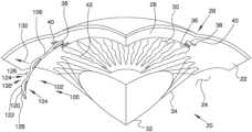
- FIG. 1is a stylized perspective view depicting a portion of a human eye and a portion of an ocular implant disposed in Schlemm's canal.
- references in the specification to “an embodiment”, “some embodiments”, “other embodiments”, etc.indicate that the embodiment(s) described may include a particular feature, structure, or characteristic, but every embodiment may not necessarily include the particular feature, structure, or characteristic. Moreover, such phrases are not necessarily referring to the same embodiment. Further, when a particular feature, structure, or characteristic is described in connection with an embodiment, it would be within the knowledge of one skilled in the art to affect such feature, structure, or characteristic in connection with other embodiments, whether or not explicitly described, unless clearly stated to the contrary.
- Aqueous humoris produced by an organ known as the ciliary body.
- the ciliary bodyincludes epithelial cells that continuously secrete aqueous humor.
- a stream of aqueous humorflows out of the eye as new aqueous humor is secreted by the epithelial cells of the ciliary body. This excess aqueous humor eventually enters the blood stream and is carried away by venous blood leaving the eye.
- aqueous humorflows out of the anterior chamber 30 through the trabecular meshwork 36 and into Schlemm's canal 38 , located at the outer edge of the iris 42 .
- Aqueous humorexits Schlemm's canal 38 by flowing through a number of outlets 40 . After leaving Schlemm's canal 38 , aqueous humor is absorbed into the venous blood stream.
- the therapeutic agents utilized with the ocular implantmay include one or more drugs provided below, either alone or in combination.
- the drugs utilizedmay also be the equivalent of, derivatives of, or analogs of one or more of the drugs provided below.
- the drugsmay include but are not limited to pharmaceutical agents including anti-glaucoma medications, ocular agents, antimicrobial agents (e.g., antibiotic, antiviral, antiparasitic, antifungal agents), anti-inflammatory agents (including steroids or non-steroidal anti-inflammatory), biological agents including hormones, enzymes or enzyme-related components, antibodies or antibody-related components, oligonucleotides (including DNA, RNA, shortinterfering RNA, antisense oligonucleotides, and the like), DNA/RNA vectors, viruses (either wild type or genetically modified) or viral vectors, peptides, proteins, enzymes, extracellular matrix components, and live cells configured to produce one or more biological components.
- antimicrobial agentse.g., antibiotic, antiviral, antiparasi
- the therapeutic agentsmay be combined with any number of excipients as is known in the art.
- excipientsincluding, but not limited to, benzyl alcohol, ethylcellulose, methylcellulose, hydroxymethylcellulose, cetyl alcohol, croscarmellose sodium, dextrans, dextrose, fructose, gelatin, glycerin, mono glycerides, diglycerides, kaolin, calcium chloride, lactose, lactose monohydrate, maltodextrins, polysorbates, pregelatinized starch, calcium stearate, magnesium stearate, silicon dioxide, cornstarch, talc, and the like.
- the one or more excipientsmay be included in total amounts as low as about 1%, 5%, or 10% and in other embodiments may be included in total amounts as high as 50%, 70% or 90%.
- Other therapeutic agentsmay include neuroprotective agents such as lubezole, nimodipine and related compounds, and including blood flow enhancers, sodium channels blockers, glutamate inhibitors such as memantine, neurotrophic factors, nitric oxide synthase inhibitors; free radical scavengers or anti-oxidants; chelating compounds; apoptosis-related protease inhibitors; compounds that reduce new protein synthesis; radiotherapeutic agents; photodynamic therapy agents; gene therapy agents; genetic modulators; and dry eye medications such as cyclosporine A, demulcents, and sodium hyaluronate.
- neuroprotective agentssuch as lubezole, nimodipine and related compounds, and including blood flow enhancers, sodium channels blockers, glutamate inhibitors such as memantine, neurotrophic factors, nitric oxide synthase inhibitors; free radical scavengers or anti-oxidants; chelating compounds; apoptosis-related protease inhibitors
- Other therapeutic agentsinclude: other beta-blocker agents such as acebutolol, atenolol, bisoprolol, carvedilol, asmolol, labetalol, nadolol, penbutolol, and pindolol; other corticosteroidal and non-steroidal anti-inflammatory agents such aspirin, betamethasone, cortisone, diflunisal, etodolac, fenoprofen, fludrocortisone, flurbiprofen, hydrocortisone, ibuprofen, indomethacine, ketoprofen, meclofenamate, mefenamic acid, meloxicam, methylprednisolone, nabumetone, naproxen, oxaprozin, prednisolone, prioxicam, salsalate, sulindac and tolmetin; COX-2 inhibitors like celecoxib, rofe
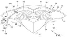
- FIG. 3is an additional perspective view showing volume 152 defined by the body of the ocular implant shown in the previous figure.
- volume 152extends along a generally curved longitudinal axis 134 .
- Volume 152has a longitudinal radius 150 , a lateral radius 148 , and a generally circular lateral cross section 153 .
- the flexibility of body 102is at a maximum when body 102 is bending along first plane 154 , and body 102 has less flexibility when bending along a plane other than first plane 154 (e.g., a plane that intersects first plane 154 ).
- body 102has a second flexibility when bending along second plane 155 that is less than the first flexibility that body 102 has when bending along first plane 154 .
- FIG. 5is an enlarged perspective view showing a portion of ocular implant 100 shown in the previous figure.
- a bending moment Mis being applied to body 102 of ocular implant 100 .
- Bending moment Macts about a first axis 156 that is generally orthogonal to first plane 154 .
- a second axis 158 and a third axis 160are also shown in FIG. 5 .
- Second axis 158is generally perpendicular to first axis 156 .
- Third axis 160is skewed relative to first axis 156 .
- the flexibility of body 102is at a maximum when body 102 is bent by a moment acting about first axis 156 , and body 102 has less flexibility when bent by a moment acting about an axis other than first axis 156 (e.g., second axis 158 and third axis 160 ).
- the bending modulus of body 102is at a minimum when body 102 is bent by a moment acting about first axis 156 , and body 102 has a greater bending modulus when bent by a moment acting about an axis other than first axis 156 (e.g., second axis 158 and third axis 160 ).
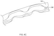
- FIG. 6 Ais an enlarged perspective view showing a portion of ocular implant 100 shown in the FIGS. 2 and 4 .
- the ocular implant 100may further include an intraocular pressure sensor 180 mounted to the inner surface 128 of the ocular implant 100 adjacent to an outlet of the implant 100 , as shown in Detail A. While the pressure sensor 180 is illustrated as mounted to an inner surface 128 of the ocular implant 100 it is contemplated that the pressure sensor 180 may be mounted within one of the openings 124 , 138 or on an outer surface of the ocular implant 100 , as desired.
- the pressure sensor 180may continuously measure the intraocular pressure of a patient, once the ocular implant 100 has been implanted.
- a first pressure sensormay be placed at a first end of the ocular implant 100 and a second pressure sensor may be placed at a second end of the ocular implant.
- the is pressure sensor 180may be provided in the channel 128 adjacent to the proximal end 101 of the implant 100 , as shown in FIG. 6 C . It is contemplated that the pressure sensor 180 may include a protective cover to prevent the delivery device (not explicitly shown) from damaging the sensor 180 during delivery of the ocular implant 100 , although this is not required.
- MEMS pressure sensorsare often formed by anisotropically etching a recess into a back side of a silicon substrate die, leaving a thin flexible diaphragm 182 .
- an input pressuree.g. the ocular pressure
- the diaphragm 182deflects according to the magnitude of the input pressure, which may be detected by one or more electrical components or sense elements 186 (e.g. piezoresistors) positioned on or embedded within the diaphragm 182 .
- the change in resistance of the piezoresistors 186is reflected as a change in an output voltage signal from a resistive bridge formed at least in part by the piezoresistors.
- the diaphragmmay be made thinner with the addition of support bosses, which may help increase the sensitivity of the diaphragm over a flat plate diaphragm.
- Circuit elementsmay be connected so that sensor elements 186 to provide some level of signal processing before providing an output signal to bond pads 188 of the pressure sensor 180 .
- the signal processingmay filter, amplify, linearize, calibrate and/or otherwise process the raw sensor signal produced by the sensor elements (e.g. piezoresistors 186 ). While the sense elements 186 have been described as piezoresistors, it is contemplated that the sense elements may be selected to provide a capacitive pressure sensor 180 .
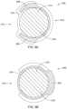
- the pressure sensor 180may include a first substrate 185 and a second substrate 183 , as shown in FIG. 6 B , which is a cross-section of the illustrative pressure sensor 180 taken at line B-B in FIG. 6 A .
- the first substrate 185may be a layered silicon-insulator-silicon substrate or wafer formed with silicon on insulator (SOI) technology, although this is not required. It is contemplated that other substrates may be used, as desired.
- the first substrate 185may include a first silicon layer.
- An insulating, or oxide, layer 187may be disposed on the first silicon layer 185 .
- the insulating layer 187may be formed from silicon dioxide, silicon nitride, sapphire, and/or any other suitable insulating material. While not explicitly shown, the pressure sensor 180 may include a second silicon layer disposed on the insulating layer. In some instances, the second silicon layer may be thinned or removed such that the oxide layer 187 is exposed at the side facing away from the second substrate 183 . Alternatively, and in some cases, the second silicon layer and oxide layer 187 are not provided from the start.
- a change in resistance of the piezoresistors 186may be reflected as a change in an output voltage signal of a resistive bridge that is formed at least partially by the piezoresistors 186 .
- the output voltageprovides a measure of the input pressure exerted on the diaphragm 182 .
- the second substrate 183may be flexible to allow the substrate 183 to be mounted flush against the inner surface 128 of the ocular implant 100 .
- the second substrate 183may have a curved outer surface (facing away from the diaphragm 182 ) shaped to generally correspond to the curved inner surface 128 of the ocular implant 100 .
- the materials forming the pressure sensor 180may be selected such that the pressure sensor 180 is biocompatible.
- pressure sensor 180may take other suitable forms.
- the pressure sensormay be formed in such a way that radio waves can be used to detect changes in pressure without sensor elements incorporated into the device.
- a pressure sensormay include a flexible base substrate, a bottom inductive coil positioned on the base substrate, a layer of pressure sensitive rubber pyramids positioned over the bottom inductive coil, a top inductive coil positioned on top of the rubber pyramids, and a top substrate positioned over the top inductive coil.
- Radio waves (from an applied source) reflected by the inductive coilshave a lower resonance frequency when the coils are positioned closer together.
- the frequency of the radio wavescan indicate the distance between the coils which is then correlated to the pressure exerted on the device.
- the pressure sensor 180may be further provided with an antenna or inductor 184 to allow the data from the pressure sensor 180 to be wirelessly communicated to a readout device.
- the pressure sensor 180may use radiofrequency communication protocols, such as, but not limited to cellular communication, ZigBee®, Bluetooth®, WiFi®, IrDA, dedicated short range communication (DSRC), EnOcean®, Z-Wave, or any other suitable wireless protocols, as desired to transmit the data from the pressure sensor 180 to another device located outside the body.
- the datamay be transmitted to any number so suitably enabled devices, including, but not limited to, cellular phones, tablet or laptop computers, desktop computers, portable handheld devices, such a personal digital assistant (PDA), or a specially designed device, such as, but not limited to a medical device.
- PDApersonal digital assistant
- the pressure datamay be automatically transmitted to a physician from the remote device.
- an enabled remote device 192may be brought within communication range of the patient's 190 eye. This may allow the enabled device 192 to receive the ocular pressure data recorded at the pressure sensor 180 .
- the enabled device 192may be configured to automatically transmit the data to a physician, for example, to a second remote device.
- the implant 200may include a body portion 202 similar in form and function to the body 102 and frame 104 described above with respect to ocular implant 100 .
- the body portion 202may include a frame 206 having a plurality of splines 204 and a plurality of struts 208 extending between the splines 204 .
- the frame 206may include a first opening 210 (or plurality of openings) configured to be positioned in a radially outward positioned (similar to opening 124 described above).
- the frame 206may include a second opening 212 (or plurality of openings) configured to be poisoned in a radially inward position (e.g., facing the anterior chamber 30 ).
- a longitudinally extending channel 220extends from a proximal end 216 of the implant 200 to a distal end 218 of the implant 200 .
- all or a portion of the polymer rod 214may be porous thereby allowing certain substances to permeate or diffuse through a side wall of the polymer rod 214 and into pores or interstitial spaces within the rod 214 .
- the porosity (e.g., the percentage of interstitial volume to total volume) of the polymer rod 214may be about 10% or more, about 20% or more, about 30% or more, about 40% or more, about 50% or more, about 60% or more, about 70% or more, or about 80% or more, for example.
- the polymer rod 214may be loaded with a therapeutic agent 218 (see, for example, FIGS. 9 A and 9 B ).
- a therapeutic agent 218see, for example, FIGS. 9 A and 9 B .
- the interstitial spaces of the polymer rod 214may be filled with one or more therapeutic agent 218 .
- the polymer rod 214may be filled with a therapeutic agent 218 such that the rod 214 has a precise quantity of the therapeutic agent.
- the therapeutic agent 218may diffuse through the porous sidewall of the polymer rod 214 over a predetermined period of time dictated, at least in part, by the average pore size of the porous sidewall of the rod 214 .
- the therapeutic agent 218 and the monomer or polymer for forming the polymer rod 214may be injected into the channel 220 as a liquid or slurry and solidified within the channel 220 . It is contemplated that solidification of the polymer may include exposing the device 200 to a cross-link initiator, such as a UV light source, heat, reagents, etc. In other cases, the polymer rod 214 and therapeutic agent 218 may be formed outside of the channel 220 and is subsequently loaded into the channel 220 .
- FIG. 9 Ais a lateral cross-sectional view of ocular implant 200 taken along section line A-A shown in FIG. 8 .
- Section line A-Aintersects a pair of struts 208 of the frame 206 at the point where the circumferential undulation of these struts is at its maximum.
- the polymer rod 214is positioned within the channel 220 .
- a first opening 212fluidly communicates with channel 126 .
- FIG. 9 Bis a lateral cross-sectional view of ocular implant 200 taken along section line B-B shown in the FIG. 8 .
- Section line B-Bintersects a spine 204 of ocular implant 200 .
- the ocular implant 200may be inserted into Schlemm's canal such that it is fixed and not free floating (as it may if placed in the anterior chamber). This may reduce the likelihood of the implant 200 damaging the cornea or other structures through movement. Further, the placement of the implant 200 in Schlemm's canal may place the therapeutic agent 218 in continuous contact with the aqueous humor that reaches the implant 200 by the trabecular meshwork.
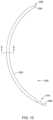
- the implant 300may include an elongated tubular body 302 extending from a proximal end 306 to a distal end 304 .
- a lumen 308extends from the proximal end 306 to the distal end 304 .
- the distal end 304may be tapered or pointed to facilitate advancement through the eye, although this is not required.
- the proximal end 306may include interlocking features 314 configured to engage mating features on a delivery device, similar to that described with respect to FIGS. 19 A and 19 B .
- the elongated tubular body 302may be curved along its longitudinal axis in a similar manner to the implant 100 described above.
- a polymer rod 310 loaded with a therapeutic agent 312is positioned within the lumen 308 , as shown in FIG. 11 which illustrates a lateral cross-sectional view of ocular implant 300 taken along section line A-A shown in FIG. 10 .
- the polymer rod 310may be formed from a biocompatible polymer such as, but not limited to polysiloxanes (e.g., silicone), polyurethane, polylactic acid (PLA), polyvinyl alcohol, poly(lactic-co-glycolic) acid (PLGA), polyethylene, polyethylene oxide, polyethylene terephthalate, or polyester, or mixtures, combinations, blends or co-polymers thereof, or the like.
- the polymer rod 310may be loaded with a therapeutic agent 312 .
- the therapeutic agentmay be an intraocular pressure reducing drug (or any other therapeutic agent, including, but not limited to, those described herein with respect to coating 129 ).
- the interstitial spaces of the polymer rod 310may be filled with one or more therapeutic agent 312 . It is contemplated that the polymer rod 310 may be filled with a therapeutic agent 312 such that the rod 310 has a precise quantity of the therapeutic agent.
- the therapeutic agent 312may diffuse through the porous sidewall of the polymer rod 310 and the porous wall of the tubular body 302 over a predetermined period of time dictated, at least in part, by the average pore size of the porous sidewall of the rod 310 and/or the tubular body 302 .
- the rate of release of the therapeutic agent 312may be known and dictated, at least in part, by the porosity of the rod 310 .
- the porosity of the rod 310 and/or tubular body 302may be chosen to controllably release the therapeutic agent 312 over a period of minutes, hours, days, weeks, months, years, etc.
- the elongated tubular body 302may be coated with heparin or a heparin related coating to prevent the adhesion of tissue or other debris on the surface of the implant 300 which may inhibit drug elution.
- the ocular implant 300may be inserted into Schlemm's canal such that it is fixed and not free floating (as it may if placed in the anterior chamber). This may reduce the likelihood of the implant 300 damaging the cornea or other structures through movement. Further, the placement of the implant 300 in Schlemm's canal may place the therapeutic agent 312 in continuous contact with the aqueous humor that reaches the implant 300 by the trabecular meshwork.
- the length of time the implant 330 is capable of delivering a therapeutic agentmay depend on the size of the implant, the quantity of the therapeutic agent loaded into the stent, the delivery rate of the therapeutic agent, other biological factors dependent on the patient, and/or combinations thereof.
- all or a portion of the elongated body 332may be porous thereby allowing certain substances to permeate or diffuse through a side wall of the elongated body 332 and into pores or interstitial spaces within the elongated body 332 .
- the porositye.g., the percentage of interstitial volume to total volume
- the porosity of the elongated body 332may be about 10% or more, about 20% or more, about 30% or more, about 40% or more, about 50% or more, about 60% or more, about 70% or more, or about 80% or more, for example.
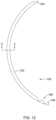
- FIG. 14is a perspective view of another illustrative implant 350 , which may be used to deliver a therapeutic agent to the eye over a length of time either in addition to or in place of an ocular implant, such as implant 100 , configured and positioned to facilitate the flow of aqueous humor out of the anterior chamber.
- the implant 350may be configured to deliver the therapeutic agent at a controlled dosage or rate for a period of hours, days, weeks, or even years.
- the therapeutic agentmay be delivered for a period of one to twenty years, five to fifteen years, or about 10 years.
- the implant 350may be configured to deliver a therapeutic agent for less than a year, or more than twenty years, as desired.
- the therapeutic agent 362may diffuse through the porous plug 364 over a predetermined period of time dictated, at least in part, by the average pore size of the plug 364 .
- the rate of release of the therapeutic agent 362may be known and dictated, at least in part, by the porosity of the plug 364 .
- the porosity of the plug 364may be chosen to controllably release the therapeutic agent 362 over a period of minutes, hours, days, weeks, months, years, etc.
- the duration of release of the therapeutic agent 362 from the implant 350may be about 1 hour, about 2 hours, about 3 hours, about 4 hours, about 5 hours, about 6 hours, about 12 hours, about 1 day, about 2 days, about 3 days, about 4 days, about 5 days, about 6 days, about 1 week, about 2 weeks, about 3 weeks, about 1 month, about 2 months, about 3 months, about 4 months, about 5 months, about 6 months, about 1 year, about 2 years, about 5 years, about 10 years, or longer.
- the polymer rod 310 and/or tubular body 352may be chosen for its porosity such that a desired rate of therapeutic agent release is provided.
- FIG. 17is a stylized representation of a medical procedure in accordance with this detailed description.
- a physicianis treating an eye 400 of a patient P.
- the physicianis holding a hand piece of a delivery system 450 in his or her right hand RH.
- the physician's left hand(not shown) may be used to hold the handle H of a gonio lens 402 .
- some physiciansmay prefer holding the delivery system hand piece in the left hand and the gonio lens handle H in the right hand RH.
- Further details of ocular implant delivery systemsmay be found in U.S. application Ser. No. 11/943,289, filed Nov. 20, 2007, now U.S. Pat. No. 8,512,404, the disclosure of which is incorporated herein by reference.
- the physicianmay view the interior of the anterior chamber using gonio lens 402 and a microscope 404 .
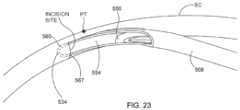
- Detail A of FIG. 17is a stylized simulation of the image viewed by the physician.
- a distal portion of a cannula 452is visible in Detail A.
- a shadow-like lineindicates the location of Schlemm's canal SC which is lying under various tissues (e.g., the trabecular meshwork) that surround the anterior chamber.
- a distal opening 454 of cannula 452is positioned near Schlemm's canal SC of eye 400 .
- Methods in accordance with this detailed descriptionmay include the step of advancing the distal end of cannula 452 through the cornea of eye 400 so that a distal portion of cannula 452 is disposed in the anterior chamber of the eye.
- Cannula 452may then be used to access Schlemm's canal of the eye, for example, by piercing the wall of Schlemm's canal with the distal end of cannula 452 .
- Distal opening 454 of cannula 452may be placed in fluid communication with a lumen defined by Schlemm's canal.
- the ocular implantmay be advanced out of distal opening 454 and into Schlemm's canal. Insertion of the ocular implant into Schlemm's canal may facilitate the flow of aqueous humor out of the anterior chamber of the eye.
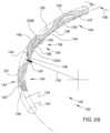
- FIG. 19 Bshows delivery tool 552 of delivery system 500 extending through distal opening 532 of cannula 508 .
- Delivery tool 552includes an interlocking portion 560 that is configured to form a connection with a complementary interlocking portion 562 of ocular implant 550 , as explained in more detail below.
- rotating the tracking wheelwill cause delivery tool 552 and ocular implant 550 to move along a path defined by cannula 508 .
- Cannula 508is sized and configured so that the distal end of cannula 508 can be advanced through the trabecular meshwork of the eye and into Schlemm's canal. Positioning cannula 508 in this way places distal opening 532 in fluid communication with Schlemm's canal.
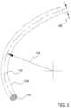
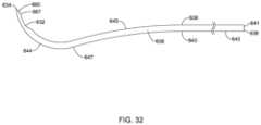
- the ocular implant 650may be desirable to place during another ocular procedure, such as, but not limited to cataract surgery. It is contemplated that the optimal position for an incision for cataract surgery may not be the same as the optimal position of an incision for solely placing an ocular implant, such as implant 650 , into Schlemm's canal. With previous ocular implant delivery system designs, in order to allow for substantially tangential entry of the cannula into Schlemm's canal two separate incisions may be required when the implant is placed in combination with another ocular procedure. The curved configuration of both the distal portion 644 may be configured to allow for substantially tangential entry of the cannula 608 into Schlemm's canal.
- rotating rack gear 620is configured to rotate with sleeve 604 while maintaining the ability to move axially in the distal and proximal directions before, during, and after rotation. As the rotating rack gear 620 moves distally and/or proximally, it causes corresponding movement of the delivery tool relative to cannula 608 . This movement is transferred to ocular implant 650 when delivery tool 652 is coupled to ocular implant 650 . Delivery tool subassembly 670 and cannula subassembly 680 engage one another in a keyed arrangement, as described in more detail below.
- tangential line at second point 647 of intermediate portion 645is tangential to the tangential line of the second point 647 of distal portion 644 .
- the tangential line at distal end 634 of distal portion 644 and the central axis 696 of proximal portionmay have third radius R 3 , for example, having an angle approximately in the range of 90° to 165°.
- cannula 608may be advanced until the distal tip 634 and beveled edge 665 of cannula 608 have been inserted into Schlemm's canal up to the proximal extent 667 of beveled edge 665 . With the passageway of the cannula 608 placed in fluid communication with the lumen of Schlemm's canal, the ocular implant may be advanced out of a distal port of the cannula 608 and into Schlemm's canal.
- the linear elastic and/or non-super-elastic nickel-titanium alloyis an alloy that does not show any martensite/austenite phase changes that are detectable by differential scanning calorimetry (DSC) and dynamic metal thermal analysis (DMTA) analysis over a large temperature range.
- DSCdifferential scanning calorimetry
- DMTAdynamic metal thermal analysis
- the mechanical bending properties of such materialmay therefore be generally inert to the effect of temperature over this very broad range of temperature.
- the mechanical bending properties of the linear elastic and/or non-super-elastic nickel-titanium alloy at ambient or room temperatureare substantially the same as the mechanical properties at body temperature, for example, in that they do not display a super-elastic plateau and/or flag region.
- the linear elastic and/or non-super-elastic nickel-titanium alloymaintains its linear elastic and/or non-super-elastic characteristics and/or properties.
Landscapes
- Health & Medical Sciences (AREA)
- Ophthalmology & Optometry (AREA)
- Animal Behavior & Ethology (AREA)
- Veterinary Medicine (AREA)
- Public Health (AREA)
- General Health & Medical Sciences (AREA)
- Life Sciences & Earth Sciences (AREA)
- Vascular Medicine (AREA)
- Heart & Thoracic Surgery (AREA)
- Biomedical Technology (AREA)
- Engineering & Computer Science (AREA)
- Nuclear Medicine, Radiotherapy & Molecular Imaging (AREA)
- Surgery (AREA)
- Dermatology (AREA)
- Chemical & Material Sciences (AREA)
- Medicinal Chemistry (AREA)
- Oral & Maxillofacial Surgery (AREA)
- Transplantation (AREA)
- Epidemiology (AREA)
- Prostheses (AREA)
- Materials For Medical Uses (AREA)
Abstract
Description
where Larcis the length of the arc, θ is the angle measure of the arc (in degrees), and r is the radius of the circle. In some instances, the angle measure of
Claims (7)
Priority Applications (1)
| Application Number | Priority Date | Filing Date | Title |
|---|---|---|---|
| US16/967,376US12029683B2 (en) | 2018-02-22 | 2019-02-19 | Ocular implant and delivery system |
Applications Claiming Priority (3)
| Application Number | Priority Date | Filing Date | Title |
|---|---|---|---|
| US201862633823P | 2018-02-22 | 2018-02-22 | |
| US16/967,376US12029683B2 (en) | 2018-02-22 | 2019-02-19 | Ocular implant and delivery system |
| PCT/US2019/018559WO2019164834A1 (en) | 2018-02-22 | 2019-02-19 | Ocular implant and delivery system |
Related Parent Applications (1)
| Application Number | Title | Priority Date | Filing Date |
|---|---|---|---|
| PCT/US2019/018559A-371-Of-InternationalWO2019164834A1 (en) | 2018-02-22 | 2019-02-19 | Ocular implant and delivery system |
Related Child Applications (1)
| Application Number | Title | Priority Date | Filing Date |
|---|---|---|---|
| US18/734,714DivisionUS20240398616A1 (en) | 2018-02-22 | 2024-06-05 | Ocular implant and delivery system |
Publications (2)
| Publication Number | Publication Date |
|---|---|
| US20210030590A1 US20210030590A1 (en) | 2021-02-04 |
| US12029683B2true US12029683B2 (en) | 2024-07-09 |
Family
ID=65686019
Family Applications (2)
| Application Number | Title | Priority Date | Filing Date |
|---|---|---|---|
| US16/967,376Active2041-11-24US12029683B2 (en) | 2018-02-22 | 2019-02-19 | Ocular implant and delivery system |
| US18/734,714PendingUS20240398616A1 (en) | 2018-02-22 | 2024-06-05 | Ocular implant and delivery system |
Family Applications After (1)
| Application Number | Title | Priority Date | Filing Date |
|---|---|---|---|
| US18/734,714PendingUS20240398616A1 (en) | 2018-02-22 | 2024-06-05 | Ocular implant and delivery system |
Country Status (8)
| Country | Link |
|---|---|
| US (2) | US12029683B2 (en) |
| EP (2) | EP3755287B1 (en) |
| JP (4) | JP6990321B2 (en) |
| CN (1) | CN112351755A (en) |
| AU (4) | AU2019223946B2 (en) |
| CA (2) | CA3207829A1 (en) |
| ES (1) | ES2980255T3 (en) |
| WO (1) | WO2019164834A1 (en) |
Cited By (1)
| Publication number | Priority date | Publication date | Assignee | Title |
|---|---|---|---|---|
| US20240398616A1 (en)* | 2018-02-22 | 2024-12-05 | Alcon Inc. | Ocular implant and delivery system |
Families Citing this family (21)
| Publication number | Priority date | Publication date | Assignee | Title |
|---|---|---|---|---|
| AU2010271274B2 (en) | 2009-07-09 | 2015-05-21 | Alcon Inc. | Single operator device for delivering an ocular implant |
| US8663150B2 (en) | 2011-12-19 | 2014-03-04 | Ivantis, Inc. | Delivering ocular implants into the eye |
| US9358156B2 (en) | 2012-04-18 | 2016-06-07 | Invantis, Inc. | Ocular implants for delivery into an anterior chamber of the eye |
| US10617558B2 (en) | 2012-11-28 | 2020-04-14 | Ivantis, Inc. | Apparatus for delivering ocular implants into an anterior chamber of the eye |
| WO2017106517A1 (en) | 2015-12-15 | 2017-06-22 | Ivantis, Inc. | Ocular implant and delivery system |
| US11166849B2 (en) | 2017-07-20 | 2021-11-09 | Shifamed Holdings, Llc | Adjustable flow glaucoma shunts and methods for making and using same |
| EP4218692A3 (en) | 2017-07-20 | 2023-09-06 | Shifamed Holdings, LLC | Adjustable flow glaucoma shunts and methods for making and using same |
| EP3911285A4 (en) | 2019-01-18 | 2022-10-19 | Shifamed Holdings, LLC | Adjustable flow glaucoma shunts and methods for making and using same |
| US12263123B2 (en)* | 2019-02-27 | 2025-04-01 | Innfocus, Inc. | Glaucoma device inserter |
| JP2022538347A (en) | 2019-06-27 | 2022-09-01 | レイヤーバイオ,インコーポレーテッド | Ophthalmic device delivery method and system |
| JP2022538906A (en) | 2019-07-01 | 2022-09-06 | マイケル エス. バーリン, | Image guided method and apparatus for glaucoma surgery |
| JP7614193B2 (en) | 2019-10-10 | 2025-01-15 | シファメド・ホールディングス・エルエルシー | Adjustable flow glaucoma shunts and related systems and methods |
| AU2021209698A1 (en) | 2020-01-23 | 2022-08-04 | Shifamed Holdings, Llc | Adjustable flow glaucoma shunts and associated systems and methods |
| US11291585B2 (en) | 2020-02-14 | 2022-04-05 | Shifamed Holdings, Llc | Shunting systems with rotation-based flow control assemblies, and associated systems and methods |
| US11737920B2 (en) | 2020-02-18 | 2023-08-29 | Shifamed Holdings, Llc | Adjustable flow glaucoma shunts having non-linearly arranged flow control elements, and associated systems and methods |
| WO2021188952A1 (en) | 2020-03-19 | 2021-09-23 | Shifamed Holdings, Llc | Intraocular shunts with low-profile actuation elements and associated systems and methods |
| WO2021202313A1 (en) | 2020-03-31 | 2021-10-07 | Berlin Michael S | Endoscopic instrument for ophthalmic surgery |
| CN115867237A (en) | 2020-04-16 | 2023-03-28 | 施菲姆德控股有限责任公司 | Adjustable glaucoma treatment devices and related systems and methods |
| JP7579594B2 (en)* | 2020-05-15 | 2024-11-08 | アイフロー・インコーポレーテッド | Methods and devices for implantation within conventional aqueous humor drainage channels of the mammalian eye |
| US11540940B2 (en) | 2021-01-11 | 2023-01-03 | Alcon Inc. | Systems and methods for viscoelastic delivery |
| EP4281144A4 (en) | 2021-01-22 | 2024-11-27 | Shifamed Holdings, LLC | ADJUSTABLE SHUNTING SYSTEMS WITH PLATE ARRANGEMENTS AND RELATED SYSTEMS AND METHODS |
Citations (506)
| Publication number | Priority date | Publication date | Assignee | Title |
|---|---|---|---|---|
| US703296A (en) | 1901-06-15 | 1902-06-24 | Arnold Nueesch | Cattle-probe. |
| US1601709A (en) | 1924-01-28 | 1926-10-05 | Anderson Windom Edward | Retainable needle construction for syringes |
| US2716983A (en) | 1952-10-08 | 1955-09-06 | Abbott Lab | Piercing needle |
| US3071135A (en) | 1960-01-27 | 1963-01-01 | Mfg Process Lab Inc | Hollow needle |
| US3788327A (en) | 1971-03-30 | 1974-01-29 | H Donowitz | Surgical implant device |
| US3811442A (en) | 1972-03-23 | 1974-05-21 | A Maroth | Hypodermic syringe holder and applicator |
| US3858577A (en) | 1974-04-05 | 1975-01-07 | Univ Southern California | Fiber optic laser light delivery system |
| US3884236A (en) | 1971-10-28 | 1975-05-20 | Mikhail M Krasnov | Method of glaucoma treatment |
| US3948271A (en) | 1972-11-07 | 1976-04-06 | Taichiro Akiyama | Drain for the eardrum and apparatus for introducing the same |
| US3958558A (en) | 1974-09-16 | 1976-05-25 | Huntington Institute Of Applied Medical Research | Implantable pressure transducer |
| US3982541A (en) | 1974-07-29 | 1976-09-28 | Esperance Jr Francis A L | Eye surgical instrument |
| US4037604A (en) | 1976-01-05 | 1977-07-26 | Newkirk John B | Artifical biological drainage device |
| US4134405A (en) | 1977-01-10 | 1979-01-16 | Smit Julie A | Catheter and intestine tube and method of using the same |
| US4273109A (en) | 1976-07-06 | 1981-06-16 | Cavitron Corporation | Fiber optic light delivery apparatus and medical instrument utilizing same |
| US4391275A (en) | 1979-11-28 | 1983-07-05 | Lasag Ag | Method for the surgical treatment of the eye |
| US4428746A (en) | 1981-07-29 | 1984-01-31 | Antonio Mendez | Glaucoma treatment device |
| US4457757A (en) | 1981-07-20 | 1984-07-03 | Molteno Anthony C B | Device for draining aqueous humour |
| US4461294A (en) | 1982-01-20 | 1984-07-24 | Baron Neville A | Apparatus and process for recurving the cornea of an eye |
| US4470407A (en) | 1982-03-11 | 1984-09-11 | Laserscope, Inc. | Endoscopic device |
| US4497319A (en) | 1981-10-28 | 1985-02-05 | Nippon Infrared Industries Co., Ltd. | Laser irradiating apparatus |
| US4501274A (en) | 1981-03-12 | 1985-02-26 | Finn Skjaerpe | Microsurgical instrument |
| US4517973A (en) | 1981-07-07 | 1985-05-21 | Sumitomo Electric Industries, Ltd. | Laser scalpel |
| US4538608A (en) | 1984-03-23 | 1985-09-03 | Esperance Jr Francis A L | Method and apparatus for removing cataractous lens tissue by laser radiation |
| US4548205A (en) | 1982-10-27 | 1985-10-22 | Armeniades C D | Ophthalmic instrument for measuring intraocular fluid pressure |
| US4551129A (en) | 1983-04-08 | 1985-11-05 | Coleman D Jackson | Technique and apparatus for intraocular and microsurgery including lighter-irrigator hypodermic tube |
| US4558698A (en) | 1984-03-01 | 1985-12-17 | Dell Lawrence W O | Laser canaliculostomy eye-treatment |
| US4559942A (en) | 1984-02-29 | 1985-12-24 | William Eisenberg | Method utilizing a laser for eye surgery |
| US4566438A (en) | 1984-10-05 | 1986-01-28 | Liese Grover J | Fiber-optic stylet for needle tip localization |
| US4580559A (en) | 1984-07-24 | 1986-04-08 | Esperance Francis A L | Indirect ophthalmoscopic photocoagulation delivery system for retinal surgery |
| US4583539A (en) | 1982-01-12 | 1986-04-22 | Cornell Research Foundation, Inc. | Laser surgical system |
| US4601713A (en) | 1985-06-11 | 1986-07-22 | Genus Catheter Technologies, Inc. | Variable diameter catheter |
| US4604087A (en) | 1985-02-26 | 1986-08-05 | Joseph Neil H | Aqueous humor drainage device |
| US4633866A (en) | 1981-11-23 | 1987-01-06 | Gholam Peyman | Ophthalmic laser surgical method |
| US4658816A (en) | 1984-11-14 | 1987-04-21 | Concept Incorporated | Lighted canaliculus intubation sets |
| US4660546A (en) | 1984-11-07 | 1987-04-28 | Robert S. Herrick | Method for treating for deficiency of tears |
| US4671273A (en) | 1984-03-19 | 1987-06-09 | Lindsey Ernest J | Laser hand piece, for use in opthalmic, plastic, and ear, nose, and throat surgery |
| US4689040A (en) | 1985-04-29 | 1987-08-25 | Thompson Robert J | Tip for a phacoemulsification needle |
| US4699140A (en) | 1985-07-10 | 1987-10-13 | Iolab Corporation | Instrument for inserting an intraocular lens |
| US4706669A (en) | 1984-01-30 | 1987-11-17 | Schlegel Hans Joachim | Device for perforating the lens capsule front wall in the eye of living beings |
| US4722350A (en) | 1984-09-21 | 1988-02-02 | Armeniades C D | Ophthalmic instrument for measuring intraocular fluid pressure |
| US4722724A (en) | 1986-06-23 | 1988-02-02 | Stanley Schocket | Anterior chamber tube shunt to an encircling band, and related surgical procedure |
| US4729373A (en) | 1986-12-18 | 1988-03-08 | Peyman Gholam A | Laser-powered surgical device with a vibrating crystalline tip |
| US4733665A (en) | 1985-11-07 | 1988-03-29 | Expandable Grafts Partnership | Expandable intraluminal graft, and method and apparatus for implanting an expandable intraluminal graft |
| US4750901A (en) | 1986-03-07 | 1988-06-14 | Molteno Anthony C B | Implant for drainage of aqueous humour |
| EP0168201B1 (en) | 1984-06-28 | 1988-06-22 | Neil Howard Joseph | Aqueous humour drainage device |
| US4770654A (en) | 1985-09-26 | 1988-09-13 | Alcon Laboratories Inc. | Multimedia apparatus for driving powered surgical instruments |
| US4791927A (en) | 1985-12-26 | 1988-12-20 | Allied Corporation | Dual-wavelength laser scalpel background of the invention |
| US4826478A (en) | 1986-06-23 | 1989-05-02 | Stanley Schocket | Anterior chamber tube shunt to an encircling band, and related surgical procedure |
| US4846172A (en) | 1987-05-26 | 1989-07-11 | Berlin Michael S | Laser-delivery eye-treatment method |
| US4861341A (en) | 1988-07-18 | 1989-08-29 | Woodburn Robert T | Subcutaneous venous access device and needle system |
| US4876250A (en) | 1988-10-31 | 1989-10-24 | Alcon Laboratories, Inc. | Methods for controlling ocular hypertension with angiostatic steroids |
| US4880000A (en) | 1987-12-15 | 1989-11-14 | Iolab Corporation | Lens insertion instrument |
| US4886488A (en) | 1987-08-06 | 1989-12-12 | White Thomas C | Glaucoma drainage the lacrimal system and method |
| US4919130A (en) | 1986-11-07 | 1990-04-24 | Nestle S.A. | Tool for inserting compressible intraocular lenses into the eye and method |
| US4925299A (en) | 1987-08-10 | 1990-05-15 | Fresenius Ag | Hemoglobin detector |
| US4934809A (en) | 1988-06-24 | 1990-06-19 | Volk Donald A | Lens positioning device for indirect biomicroscopy of the eye |
| US4934363A (en) | 1987-12-15 | 1990-06-19 | Iolab Corporation | Lens insertion instrument |
| US4936825A (en) | 1988-04-11 | 1990-06-26 | Ungerleider Bruce A | Method for reducing intraocular pressure caused by glaucoma |
| US4946436A (en) | 1989-11-17 | 1990-08-07 | Smith Stewart G | Pressure-relieving device and process for implanting |
| US4968296A (en) | 1989-12-20 | 1990-11-06 | Robert Ritch | Transscleral drainage implant device for the treatment of glaucoma |
| US4994060A (en) | 1984-09-17 | 1991-02-19 | Xintec Corporation | Laser heated cautery cap with transparent substrate |
| US5034010A (en) | 1985-03-22 | 1991-07-23 | Massachusetts Institute Of Technology | Optical shield for a laser catheter |
| US5092837A (en) | 1989-12-20 | 1992-03-03 | Robert Ritch | Method for the treatment of glaucoma |
| US5123902A (en) | 1988-09-13 | 1992-06-23 | Carl-Zeiss-Stiftung | Method and apparatus for performing surgery on tissue wherein a laser beam is applied to the tissue |
| US5127901A (en) | 1990-05-18 | 1992-07-07 | Odrich Ronald B | Implant with subconjunctival arch |
| US5129895A (en) | 1990-05-16 | 1992-07-14 | Sunrise Technologies, Inc. | Laser sclerostomy procedure |
| US5178604A (en) | 1990-05-31 | 1993-01-12 | Iovision, Inc. | Glaucoma implant |
| US5180362A (en) | 1990-04-03 | 1993-01-19 | Worst J G F | Gonio seton |
| US5190552A (en) | 1992-02-04 | 1993-03-02 | Kelman Charles D | Slotted tube injector for an intraocular lens |
| US5213569A (en) | 1992-03-31 | 1993-05-25 | Davis Peter L | Tip for a tissue phacoemulsification device |
| DE4226476C1 (en) | 1992-08-10 | 1993-08-12 | Hans Dr.Med. 3015 Wennigsen De Haindl | |
| US5238004A (en) | 1990-04-10 | 1993-08-24 | Boston Scientific Corporation | High elongation linear elastic guidewire |
| US5246452A (en) | 1992-04-13 | 1993-09-21 | Impra, Inc. | Vascular graft with removable sheath |
| US5254112A (en) | 1990-10-29 | 1993-10-19 | C. R. Bard, Inc. | Device for use in laser angioplasty |
| US5273056A (en) | 1992-06-12 | 1993-12-28 | Alcon Laboratories, Inc. | Use of combinations of viscoelastics during surgery |
| US5290267A (en) | 1991-01-17 | 1994-03-01 | Fresenius Ag | Hypodermic needle |
| US5300020A (en) | 1991-05-31 | 1994-04-05 | Medflex Corporation | Surgically implantable device for glaucoma relief |
| US5359685A (en) | 1991-06-21 | 1994-10-25 | The United States Of America As Represented By The Department Of Health And Human Services | Focusing tips for optical fibers |
| US5360399A (en) | 1992-01-10 | 1994-11-01 | Robert Stegmann | Method and apparatus for maintaining the normal intraocular pressure |
| US5371078A (en) | 1988-10-31 | 1994-12-06 | Alcon Laboratories, Inc. | Angiostatic steroids and methods and compositions for controlling ocular hypertension |
| US5445637A (en) | 1993-12-06 | 1995-08-29 | American Cyanamid Company | Method and apparatus for preventing posterior capsular opacification |
| US5454796A (en) | 1991-04-09 | 1995-10-03 | Hood Laboratories | Device and method for controlling intraocular fluid pressure |
| US5458615A (en) | 1993-07-06 | 1995-10-17 | Advanced Cardiovascular Systems, Inc. | Stent delivery system |
| US5501274A (en) | 1995-03-29 | 1996-03-26 | Halliburton Company | Control of particulate flowback in subterranean wells |
| WO1996020742A1 (en) | 1995-01-06 | 1996-07-11 | Wong Vernon G | Improve eye implant for relief of glaucoma |
| US5536259A (en) | 1995-07-28 | 1996-07-16 | Medisystems Technology Corp | Hypodermic cannula |
| US5575780A (en) | 1995-04-28 | 1996-11-19 | Saito; Yoshikuni | Medical hollow needle and a method of producing thereof |
| US5591223A (en) | 1992-11-23 | 1997-01-07 | Children's Medical Center Corporation | Re-expandable endoprosthesis |
| US5607966A (en) | 1994-12-23 | 1997-03-04 | Alcon Laboratories, Inc. | Esters and amides of non-steroidal anti-inflammatory carboxylic acids which may be used as anti-oxidants, 5-lipoxygenase inhibitors and non-steroidal anti-inflammatory prodrugs |
| US5613972A (en) | 1992-07-15 | 1997-03-25 | The University Of Miami | Surgical cutting heads with curled cutting wings |
| US5626558A (en) | 1995-05-05 | 1997-05-06 | Suson; John | Adjustable flow rate glaucoma shunt and method of using same |
| US5643250A (en) | 1992-08-07 | 1997-07-01 | O'donnell, Jr.; Francis E. | Laser probe hand piece |
| US5653753A (en) | 1994-04-29 | 1997-08-05 | Allergan | Method and apparatus for folding of intraocular lenses |
| US5657760A (en) | 1994-05-03 | 1997-08-19 | Board Of Regents, The University Of Texas System | Apparatus and method for noninvasive doppler ultrasound-guided real-time control of tissue damage in thermal therapy |
| US5676669A (en) | 1993-04-30 | 1997-10-14 | Colvard; Michael | Intraocular capsular shield |
| US5704907A (en) | 1994-07-22 | 1998-01-06 | Wound Healing Of Oklahoma | Method and apparatus for lowering the intraocular pressure of an eye |
| US5713844A (en) | 1997-01-10 | 1998-02-03 | Peyman; Gholam A. | Device and method for regulating intraocular pressure |
| US5722970A (en) | 1991-04-04 | 1998-03-03 | Premier Laser Systems, Inc. | Laser surgical method using transparent probe |
| US5738676A (en) | 1995-01-03 | 1998-04-14 | Hammer; Daniel X. | Laser surgical probe for use in intraocular surgery |
| US5738677A (en) | 1992-04-10 | 1998-04-14 | Premier Laser Systems, Inc. | Apparatus and method for performing eye surgery |
| WO1998018509A1 (en) | 1996-10-28 | 1998-05-07 | Cobe Laboratories, Inc. | A method and apparatus for improving device platelet compatibility |
| EP0766544B1 (en) | 1994-06-22 | 1998-05-13 | Chauvin Opsia | Sclerotomy implant |
| JPH10504978A (en) | 1994-09-01 | 1998-05-19 | ユニバーシティ オブ マイアミ | Adjustable keratoplasty syringe with gel injection |
| US5785658A (en) | 1992-09-14 | 1998-07-28 | Sexant Medical Corporation | In vivo tissue analysis methods and apparatus |
| US5792103A (en) | 1995-02-03 | 1998-08-11 | Schwartz; Daniel M. | Viscosurgical method and apparatus |
| US5792099A (en) | 1995-02-14 | 1998-08-11 | Decamp; Dennis | Syringe and cannula for insertion of viscoelastic material into an eye and method of using same |
| US5807302A (en) | 1996-04-01 | 1998-09-15 | Wandel; Thaddeus | Treatment of glaucoma |
| US5811453A (en) | 1994-12-23 | 1998-09-22 | Alcon Laboratories, Inc. | Viscoelastic compositions and methods of use |
| WO1999001063A1 (en) | 1997-07-01 | 1999-01-14 | Acritec Gmbh | Device for measuring the intra-ocular pressure |
| US5865831A (en) | 1996-04-17 | 1999-02-02 | Premier Laser Systems, Inc. | Laser surgical procedures for treatment of glaucoma |
| US5868697A (en) | 1995-05-14 | 1999-02-09 | Optonol Ltd. | Intraocular implant |
| US5873835A (en) | 1993-04-29 | 1999-02-23 | Scimed Life Systems, Inc. | Intravascular pressure and flow sensor |
| AU7619798A (en) | 1997-08-15 | 1999-02-25 | Grieshaber & Co. Ag Schaffhausen | Method and device to improve aqueous humor drainage in an eye |
| US5893837A (en) | 1997-02-28 | 1999-04-13 | Staar Surgical Company, Inc. | Glaucoma drain implanting device and method |
| US5895831A (en) | 1996-12-04 | 1999-04-20 | Uop Llc | Solid catalyst alkylation process |
| US5919171A (en) | 1994-08-03 | 1999-07-06 | Kanegafuchi Kagaku Kogyo Kabushiki Kaisha | Microcatheter |
| US5948427A (en) | 1996-04-25 | 1999-09-07 | Point Medical Corporation | Microparticulate surgical adhesive |
| WO1999045868A1 (en) | 1998-03-10 | 1999-09-16 | Allergan Sales, Inc. | Temperature controler and method for phacoemulsification |
| US5966058A (en) | 1998-01-13 | 1999-10-12 | The United States Of America As Represented By The Secretary Of The Air Force | Aperture-coupled multiplanar magic-T junction |
| US5990099A (en) | 1988-10-31 | 1999-11-23 | Alcon Laboratories, Inc. | Angiostatic agents and methods and compositions for controlling ocular hypertension |
| EP0957949A1 (en) | 1995-05-14 | 1999-11-24 | Optonol Ltd. | Intraocular implant, delivery device, and method of implantation |
| US5993438A (en) | 1993-11-12 | 1999-11-30 | Escalon Medical Corporation | Intrastromal photorefractive keratectomy |
| US5997531A (en) | 1998-01-29 | 1999-12-07 | Cardiodyne, Inc. | User actuated laser energy device and procedure for forming a channel within tissue |
| US6002480A (en) | 1997-06-02 | 1999-12-14 | Izatt; Joseph A. | Depth-resolved spectroscopic optical coherence tomography |
| US6007511A (en) | 1991-05-08 | 1999-12-28 | Prywes; Arnold S. | Shunt valve and therapeutic delivery system for treatment of glaucoma and methods and apparatus for its installation |
| WO2000007525A1 (en) | 1998-08-05 | 2000-02-17 | Keravision, Inc. | Corneal implant with migration preventer |
| US6050970A (en) | 1997-05-08 | 2000-04-18 | Pharmacia & Upjohn Company | Method and apparatus for inserting a glaucoma implant in an anterior and posterior segment of the eye |
| US6099521A (en) | 1998-05-26 | 2000-08-08 | Shadduck; John H. | Semiconductor contact lens cooling system and technique for light-mediated eye therapies |
| US6102045A (en) | 1994-07-22 | 2000-08-15 | Premier Laser Systems, Inc. | Method and apparatus for lowering the intraocular pressure of an eye |
| WO2000064393A1 (en) | 1999-04-26 | 2000-11-02 | Lynch Mary G | Shunt device and method for treating glaucoma |
| US6142990A (en) | 1997-02-15 | 2000-11-07 | Heidelberg Engineering Optische Messsysteme Gmbh | Medical apparatus, especially for reducing intraocular pressure |
| US6146375A (en) | 1998-12-02 | 2000-11-14 | The University Of Michigan | Device and method for internal surface sclerostomy |
| WO2000067687A1 (en) | 1999-05-05 | 2000-11-16 | Glautec Ag | Device for treating glaucoma of the eye |
| US6177544B1 (en) | 1997-08-18 | 2001-01-23 | Koken Co Ltd | Collagen-based auxiliary agent for ophthalmic surgery |
| US6186974B1 (en) | 1997-01-10 | 2001-02-13 | University College London And Moorfields Eye Hospital Nhs Trust | Device for use in the eye |
| US6217584B1 (en) | 1996-05-09 | 2001-04-17 | Aharon Lehrer | Method and a system for performing cataract surgery |
| US6221078B1 (en) | 1999-06-25 | 2001-04-24 | Stephen S. Bylsma | Surgical implantation apparatus |
| US6238409B1 (en) | 1997-03-10 | 2001-05-29 | Johnson & Johnson Interventional Systems Co. | Articulated expandable intraluminal stent |
| US20010002438A1 (en) | 1994-12-22 | 2001-05-31 | Ivan Sepetka | Implant delivery assembly with expandable coupling/decoupling mechanism |
| US6241721B1 (en) | 1998-10-09 | 2001-06-05 | Colette Cozean | Laser surgical procedures for treatment of glaucoma |
| USD444874S1 (en) | 2000-07-31 | 2001-07-10 | Allergan Sales, Inc. | Self instill twist housing eye drop dispenser |
| US6297228B1 (en) | 1991-11-22 | 2001-10-02 | Alcon Manufacturing, Ltd. | Use of angiostatic steroids in photodynamic therapy |
| US6319274B1 (en) | 1998-06-22 | 2001-11-20 | John H. Shadduck | Devices and techniques for light-mediated stimulation of trabecular meshwork in glaucoma therapy |
| WO2001089437A2 (en) | 2000-05-19 | 2001-11-29 | Berlin Michael S | Laser delivery system and method of use for the eye |
| US6328747B1 (en) | 1996-05-09 | 2001-12-11 | Itos Innovative Technology In Ocular Surgery, Ltd. | Method and a system for performing cataract surgery |
| WO2001097727A1 (en) | 2000-06-19 | 2001-12-27 | Glaukos Corporation | Stented trabecular shunt and methods thereof |
| US20020003546A1 (en) | 2000-05-31 | 2002-01-10 | Agency Of Industrial Science And Technology | Virtual shape generation method and device using the same |
| US20020026200A1 (en)* | 2000-08-22 | 2002-02-28 | Savage James A. | Method and apparatus for treatment of glaucoma |
| US6375642B1 (en) | 2000-02-15 | 2002-04-23 | Grieshaber & Co. Ag Schaffhausen | Method of and device for improving a drainage of aqueous humor within the eye |
| US20020052653A1 (en) | 1998-07-06 | 2002-05-02 | Russell Durgin | Implant system and method for bulking tissue |
| WO2002036052A1 (en) | 2000-11-01 | 2002-05-10 | Glaukos Corporation | Glaucoma treatment device |
| US6398809B1 (en) | 2000-04-12 | 2002-06-04 | Bausch & Lomb Incorporated | Intraocular lens |
| US20020072673A1 (en) | 1999-12-10 | 2002-06-13 | Yamamoto Ronald K. | Treatment of ocular disease |
| US6409752B1 (en) | 1993-07-23 | 2002-06-25 | Cook Incorporated | Flexible stent having a pattern formed from a sheet of material |
| US20020082591A1 (en) | 2000-12-14 | 2002-06-27 | Eduard Haefliger | Device for the treatment of glaucoma |
| US20020133168A1 (en) | 2001-03-16 | 2002-09-19 | Smedley Gregory T. | Applicator and methods for placing a trabecular shunt for glaucoma treatment |
| US20020143284A1 (en) | 2001-04-03 | 2002-10-03 | Hosheng Tu | Drug-releasing trabecular implant for glaucoma treatment |
| WO2002080811A2 (en) | 2001-04-07 | 2002-10-17 | Glaukos Corporation | Glaucoma stent and methods thereof for glaucoma treatment |
| US6471666B1 (en) | 2000-02-24 | 2002-10-29 | Steven A. Odrich | Injectable glaucoma device |
| US20020165504A1 (en) | 2000-06-09 | 2002-11-07 | Inviro Medical Devices Ltd. | Cannula for use with a medical syringe |
| US20020165522A1 (en) | 2001-05-03 | 2002-11-07 | Jorgen Holmen | Method for use in cataract surgery |
| JP2002542872A (en) | 1999-05-03 | 2002-12-17 | ベントリカ, インコーポレイテッド | Methods and apparatus for placing a conduit in fluid communication with a target vessel |
| US6494857B1 (en) | 1998-09-02 | 2002-12-17 | Thomas Neuhann | Device for improving in a targeted manner and/or permanently ensuring the ability of the aqueous humor to pass through the trabecular meshwork |
| US20020193805A1 (en) | 2001-03-19 | 2002-12-19 | Allergan Sales, Inc. | IOL insertion apparatus with IOL engagement structure and method for using same |
| US20030004457A1 (en) | 2001-06-26 | 2003-01-02 | Andersson Stig O. | Hypodermic implant device |
| US20030014092A1 (en) | 2001-04-18 | 2003-01-16 | Thomas Neuhann | Apparatus for the treatment of glaucoma |
| US6508803B1 (en) | 1998-11-06 | 2003-01-21 | Furukawa Techno Material Co., Ltd. | Niti-type medical guide wire and method of producing the same |
| US6517523B1 (en) | 1999-03-15 | 2003-02-11 | Kaneko Kogyo Inc. | Needle for injection syringe and method for manufacturing the same |
| WO2003015659A2 (en) | 2001-08-16 | 2003-02-27 | Gmp Vision Solutions, Inc. | Improved shunt device and method for treating glaucoma |
| US20030040754A1 (en) | 1999-03-18 | 2003-02-27 | Michael Mitchell | Radially expanding stents |
| US6533764B1 (en) | 2000-11-06 | 2003-03-18 | Allergan, Inc. | Twist housing apparatus for instilling a medication into an eye |
| US6533768B1 (en) | 2000-04-14 | 2003-03-18 | The Regents Of The University Of California | Device for glaucoma treatment and methods thereof |
| US20030055372A1 (en) | 1999-04-26 | 2003-03-20 | Lynch Mary G. | Shunt device and method for treating glaucoma |
| US20030060748A1 (en) | 2001-01-19 | 2003-03-27 | Georges Baikoff | Techniques and implants for correcting presbyopia |
| US20030060752A1 (en) | 2000-04-14 | 2003-03-27 | Olav Bergheim | Glaucoma device and methods thereof |
| US20030060784A1 (en) | 1999-02-04 | 2003-03-27 | Hilgers Michael Edward | Needle for body fluid tester |
| US6544208B2 (en) | 2000-12-29 | 2003-04-08 | C. Ross Ethier | Implantable shunt device |
| US6544249B1 (en) | 1996-11-29 | 2003-04-08 | The Lions Eye Institute Of Western Australia Incorporated | Biological microfistula tube and implantation method and apparatus |
| US6551289B1 (en) | 1999-09-14 | 2003-04-22 | Dr. Japan Co., Ltd. | Outer needle of anesthetic needle assembly for epidural |
| US20030093084A1 (en) | 2001-11-13 | 2003-05-15 | Optonol Ltd. | Delivery devices for flow regulating implants |
| US20030097151A1 (en) | 2001-10-25 | 2003-05-22 | Smedley Gregory T. | Apparatus and mitochondrial treatment for glaucoma |
| WO2003045290A1 (en) | 2001-11-21 | 2003-06-05 | Iscience Corporation | Ophthalmic microsurgical system |
| US20030105456A1 (en) | 2001-12-04 | 2003-06-05 | J.T. Lin | Apparatus and methods for prevention of age-related macular degeneration and other eye diseases |
| US20030125351A1 (en) | 1998-08-17 | 2003-07-03 | Mitsuyoshi Azuma | Agent for prophylaxis and treatment of glaucoma |
| US20030167031A1 (en)* | 1997-08-08 | 2003-09-04 | Odland Rick Mathew | System and method for site specific therapy |
| US20030175324A1 (en)* | 2001-03-15 | 2003-09-18 | Robinson Michael R. | Ocular therapeutic agent delivery devices and methods for making and using such devices |
| US20030181848A1 (en) | 2000-04-14 | 2003-09-25 | Bergheim Olav B. | Implant with drug coating |
| US20030212387A1 (en) | 2002-03-23 | 2003-11-13 | Intralase Corp. | System and method for improved material processing using a laser beam |
| US20030229303A1 (en) | 2002-03-22 | 2003-12-11 | Haffner David S. | Expandable glaucoma implant and methods of use |
| US6666841B2 (en) | 2001-05-02 | 2003-12-23 | Glaukos Corporation | Bifurcatable trabecular shunt for glaucoma treatment |
| US20030236483A1 (en)* | 2002-06-25 | 2003-12-25 | Ren David H | Dual drainage ocular shunt for glaucoma |
| US20040024345A1 (en) | 2002-04-19 | 2004-02-05 | Morteza Gharib | Glaucoma implant with valveless flow bias |
| US20040024453A1 (en) | 2001-08-03 | 2004-02-05 | Glaucoma Research Technologies, Inc. | Method and intra sclera implant for treatment of glaucoma and presbyopia |
| US6689085B1 (en)* | 1996-07-11 | 2004-02-10 | Eunoe, Inc. | Method and apparatus for treating adult-onset dementia of the Alzheimer's type |
| US20040030302A1 (en) | 2001-03-28 | 2004-02-12 | Miyako Kamata | Medical syringe, and method of producing the same |
| US6699210B2 (en) | 1999-04-27 | 2004-03-02 | The Arizona Board Of Regents | Glaucoma shunt and a method of making and surgically implanting the same |
| US6702790B1 (en) | 2002-10-31 | 2004-03-09 | Chauncey F. Ross | Hypodermic needle |
| US20040070761A1 (en) | 2002-10-11 | 2004-04-15 | Intralase Corp. | Method and system for determining the alignment of a surface of a material in relation to a laser beam |
| US6726676B2 (en) | 2000-01-05 | 2004-04-27 | Grieshaber & Co. Ag Schaffhausen | Method of and device for improving the flow of aqueous humor within the eye |
| US6730056B1 (en) | 2000-09-21 | 2004-05-04 | Motorola, Inc. | Eye implant for treating glaucoma and method for manufacturing same |
| US20040088048A1 (en) | 1995-05-14 | 2004-05-06 | Jacob Richter | Intraocular implant, delivery device, and method of implantation |
| US20040092856A1 (en) | 2000-09-01 | 2004-05-13 | Elie Dahan | Glaucoma drain |
| USD490152S1 (en) | 2003-02-28 | 2004-05-18 | Glaukos Corporation | Surgical handpiece |
| US20040098124A1 (en) | 2002-11-19 | 2004-05-20 | Freeman Jerre M. | Elongate scleral implants for the treatment of eye disorders such as presbyopia and glaucoma |
| US20040102729A1 (en) | 2002-04-08 | 2004-05-27 | David Haffner | Devices and methods for glaucoma treatment |
| US20040106975A1 (en) | 2001-03-20 | 2004-06-03 | Gmp/Cardiac Care, Inc. | Rail stent |
| US20040111050A1 (en) | 2000-04-14 | 2004-06-10 | Gregory Smedley | Implantable ocular pump to reduce intraocular pressure |
| US20040116909A1 (en) | 2002-12-11 | 2004-06-17 | Ceramoptec Industries Inc. | Multipurpose diode laser system for ophthalmic laser treatments |
| US20040122380A1 (en) | 2002-12-19 | 2004-06-24 | Utterberg David S. | Blunt cannula with bent tip |
| WO2004054643A1 (en) | 2002-12-13 | 2004-07-01 | Terumo Kabushiki Kaisha | Needle body for medical use and liquid-introducing tool |
| US20040127843A1 (en) | 2000-04-14 | 2004-07-01 | Hosheng Tu | Glaucoma implant with therapeutic agents |
| US20040147870A1 (en) | 2002-04-08 | 2004-07-29 | Burns Thomas W. | Glaucoma treatment kit |
| US20040193095A1 (en) | 2003-03-29 | 2004-09-30 | Shadduck John H. | Implants for treating ocular hypertension, methods of use and methods of fabrication |
| US20040193262A1 (en) | 2003-03-29 | 2004-09-30 | Shadduck John H. | Implants for treating ocular hypertension, methods of use and methods of fabrication |
| US20040199149A1 (en) | 1996-03-21 | 2004-10-07 | Myers Raymond I. | Lenticular refractive surgery of presbyopia, other refractive errors, and cataract retardation |
| US20040199171A1 (en) | 2003-04-04 | 2004-10-07 | Takayuki Akahoshi | Phacoemulsification needle |
| US20040210181A1 (en) | 2001-04-26 | 2004-10-21 | Clemens Vass | Drainage implant for draining aqueous humour from the anterior aqueous chamber of the eye into schlemm's canal |
| WO2004093761A1 (en) | 2003-04-16 | 2004-11-04 | Iscience Surgical Corporation | Opthalmic microsurgical instruments |
| US20040216749A1 (en) | 2003-01-23 | 2004-11-04 | Hosheng Tu | Vasomodulation during glaucoma surgery |
| US20040225250A1 (en)* | 2003-05-05 | 2004-11-11 | Michael Yablonski | Internal shunt and method for treating glaucoma |
| US20040225357A1 (en) | 2002-01-23 | 2004-11-11 | Ophtec B.V. | Fixation of an intraocular implant to the iris |
| US20040228013A1 (en) | 2001-10-12 | 2004-11-18 | Intralase Corp. | Closed-loop focal positioning system and method |
| US20040254517A1 (en) | 2003-02-18 | 2004-12-16 | Hugo Quiroz-Mercado | Methods and devices for draining fluids and lowering intraocular pressure |
| US20050043722A1 (en) | 2003-08-22 | 2005-02-24 | Lin J. T. | Methods and apparatus for treatment of eye disorders using articulated-arm-coupled ultraviolet lasers |
| US20050041200A1 (en) | 2001-11-07 | 2005-02-24 | Darren Rich | Gonioscopy assembly |
| US20050049578A1 (en) | 2000-04-14 | 2005-03-03 | Hosheng Tu | Implantable ocular pump to reduce intraocular pressure |
| US6881198B2 (en) | 2001-01-09 | 2005-04-19 | J. David Brown | Glaucoma treatment device and method |
| US20050101967A1 (en) | 2002-09-18 | 2005-05-12 | Weber David A. | Methods and apparatus for delivery of ocular implants |
| US20050107734A1 (en) | 2003-11-14 | 2005-05-19 | Coroneo Minas T. | Ocular pressure regulation |
| US6899717B2 (en) | 2002-09-18 | 2005-05-31 | Allergan, Inc. | Methods and apparatus for delivery of ocular implants |
| US20050119636A1 (en) | 2001-05-02 | 2005-06-02 | David Haffner | Implant with intraocular pressure sensor for glaucoma treatment |
| US20050125003A1 (en) | 2003-12-05 | 2005-06-09 | Leonard Pinchuk | Glaucoma implant device |
| US20050131514A1 (en) | 1999-05-20 | 2005-06-16 | Hijlkema Lukas J. | Delivery system for endoluminal implant |
| US20050149114A1 (en) | 2002-08-29 | 2005-07-07 | Cartledge Richard G. | Apparatus for implanting surgical devices for controlling the internal circumference of an anatomic orifice or lumen |
| US20050154443A1 (en) | 2004-01-09 | 2005-07-14 | Rubicon Medical, Inc. | Stent delivery device |
| US20050165385A1 (en) | 2004-01-22 | 2005-07-28 | Solx, Inc. | Glaucoma treatment method |
| US20050192527A1 (en) | 2001-05-02 | 2005-09-01 | Morteza Gharib | Glaucoma implant with extending members |
| US6939298B2 (en) | 2002-02-28 | 2005-09-06 | Gmp Vision Solutions, Inc | Device and method for monitoring aqueous flow within the eye |
| US20050197667A1 (en) | 2004-03-02 | 2005-09-08 | Scimed Life Systems, Inc. | Occlusion balloon catheter with external inflation lumen |
| US20050203542A1 (en) | 2002-09-18 | 2005-09-15 | Allergan, Inc. | Apparatus for delivery of ocular implants with reduced incidence of ocular adverse events |
| US20050245916A1 (en) | 2004-04-30 | 2005-11-03 | Connor Christopher S | Shielded intraocular probe for improved illumination or therapeutic application of light |
| US20050244464A1 (en) | 2004-04-30 | 2005-11-03 | Allergan, Inc. | Hypotensive lipid-containing biodegradable intraocular implants and related methods |
| US6962573B1 (en) | 2000-10-18 | 2005-11-08 | Wilcox Michael J | C-shaped cross section tubular ophthalmic implant for reduction of intraocular pressure in glaucomatous eyes and method of use |
| WO2005105197A2 (en) | 2003-02-28 | 2005-11-10 | Gmp Vision Solutions, Inc. | Indwelling shunt device and methods for treating glaucoma |
| US20050250788A1 (en) | 2004-01-30 | 2005-11-10 | Hosheng Tu | Aqueous outflow enhancement with vasodilated aqueous cavity |
| US20050260186A1 (en) | 2003-03-05 | 2005-11-24 | Halozyme, Inc. | Soluble glycosaminoglycanases and methods of preparing and using soluble glycosaminoglycanases |
| US20050266047A1 (en) | 2002-04-08 | 2005-12-01 | Hosheng Tu | Injectable glaucoma implants with multiple openings |
| US20050271704A1 (en) | 2002-04-08 | 2005-12-08 | Hosheng Tu | Injectable glaucoma implants with multiple openings |
| US20050273033A1 (en) | 2002-05-29 | 2005-12-08 | Grahn Bruce H | Shunt and method treatment of glaucoma |
| US20050277912A1 (en)* | 2003-07-16 | 2005-12-15 | Sasha John | Programmable medical drug delivery systems and methods for delivery of multiple fluids and concentrations |
| US20050277864A1 (en)* | 2000-04-14 | 2005-12-15 | David Haffner | Injectable gel implant for glaucoma treatment |
| US20050283108A1 (en)* | 2004-06-10 | 2005-12-22 | Savage James A | Apparatus and method for non-pharmacological treatment of glaucoma and lowering intraocular pressure |
| US20050279369A1 (en) | 2004-06-21 | 2005-12-22 | Lin J T | Method and apparatus for the treatment of presbyopia and glaucoma by ciliary body ablation |
| US20050288745A1 (en) | 2004-06-28 | 2005-12-29 | Andersen Dan E | Method and device for optical ophthalmic therapy |
| US20060015089A1 (en)* | 2002-04-04 | 2006-01-19 | Meglin Allen J | Catheter and method of fluid removal from a body cavity |
| US6989007B2 (en) | 2001-02-21 | 2006-01-24 | Solx, Inc. | Devices and techniques for treating glaucoma |
| US20060020247A1 (en) | 2002-11-01 | 2006-01-26 | Jonathan Kagan | Devices and methods for attaching an endolumenal gastrointestinal implant |
| US20060021623A1 (en) | 2004-07-30 | 2006-02-02 | Miller Joan W | Methods and compositions for treating ocular glaucoma |
| US20060032507A1 (en) | 2004-08-11 | 2006-02-16 | Hosheng Tu | Contrast-enhanced ocular imaging |
| US20060052879A1 (en) | 2003-12-05 | 2006-03-09 | Fossa Medical, Inc. | Open lumen stents |
| US7018376B2 (en) | 2001-01-29 | 2006-03-28 | Intralase Corp. | Ocular fixation and stabilization device for ophthalmic surgical applications |
| US20060069340A1 (en) | 2003-06-16 | 2006-03-30 | Solx, Inc. | Shunt for the treatment of glaucoma |
| US20060084954A1 (en) | 2004-08-17 | 2006-04-20 | Intralase Corp. | Apparatus and method for correction of abberations in laser system optics |
| US20060093642A1 (en)* | 2004-11-03 | 2006-05-04 | Ranade Shrirang V | Method of incorporating carbon nanotubes in a medical appliance, a carbon nanotube medical appliance, and a medical appliance coated using carbon nanotube technology |
| US20060106370A1 (en) | 2001-01-18 | 2006-05-18 | The Regents Of The University Of California | Minimally invasive glaucoma surgical instrument and method |
| US20060110428A1 (en) | 2004-07-02 | 2006-05-25 | Eugene Dejuan | Methods and devices for the treatment of ocular conditions |
| US20060116626A1 (en) | 2002-03-07 | 2006-06-01 | Gregory Smedley | Fluid infusion methods for glaucoma treatment |
| US20060117859A1 (en) | 2004-12-02 | 2006-06-08 | Honeywell International, Inc. | Disposable and trimmable wireless pressure sensor for medical applications |
| US20060129141A1 (en) | 2004-12-10 | 2006-06-15 | Lin J T | Treatment of eye disorders using articulated-arm coupled ultraviolet lasers |
| WO2006066103A2 (en) | 2004-12-16 | 2006-06-22 | Iscience Interventional Corporation | Ophthalmic implant for treatment of glaucoma |
| US20060154382A1 (en) | 2001-07-11 | 2006-07-13 | Cem Basceri | Capacitor with high dielectric constant materials and method of making |
| US20060155300A1 (en) | 2002-09-17 | 2006-07-13 | Iscience Surgical, Inc. | Apparatus and method for surgical bypass of aqueous humor |
| US20060154981A1 (en) | 2005-01-12 | 2006-07-13 | Alcon, Inc. | Method of reducing intraocular pressure and treating glaucoma |
| US20060155238A1 (en) | 2002-07-19 | 2006-07-13 | Shields Milton B | Uveoscleral drainage device |
| US20060155265A1 (en) | 1995-03-20 | 2006-07-13 | Intralase Corp. | Method of corneal surgery by laser incising a contoured corneal flap |
| US20060167421A1 (en) | 2005-01-21 | 2006-07-27 | Radius International Ltd. Partnership | Catheter with insert-molded tip |
| US20060167466A1 (en) | 2005-01-21 | 2006-07-27 | Vaclav Dusek | Intraocular lens inserter system components |
| US20060173397A1 (en)* | 2004-11-23 | 2006-08-03 | Hosheng Tu | Ophthalmology implants and methods of manufacture |
| US20060173399A1 (en) | 2005-02-01 | 2006-08-03 | Rodgers M S | MEMS flow module with pivoting-type baffle |
| US20060178674A1 (en) | 2005-02-08 | 2006-08-10 | Mcintyre John | Surgical apparatus having configurable portions |
| US7094225B2 (en) | 2001-05-03 | 2006-08-22 | Glaukos Corporation | Medical device and methods of use of glaucoma treatment |
| US20060189916A1 (en) | 2005-02-21 | 2006-08-24 | Bas Arturo M A | Device for draining aqueous humor in cases of glaucoma |
| US20060189917A1 (en) | 2003-01-23 | 2006-08-24 | Austria Wirtsservice Gellschaft Mit | Implant for draining chamber water from the front eye chamber into the episcleral veins |
| US20060189915A1 (en) | 2005-02-23 | 2006-08-24 | Camras Carl B | Method and apparatus for reducing intraocular pressure |
| US20060200113A1 (en) | 2002-03-07 | 2006-09-07 | David Haffner | Liquid jet for glaucoma treatment |
| US20060204738A1 (en)* | 2003-04-17 | 2006-09-14 | Nanosys, Inc. | Medical device applications of nanostructured surfaces |
| US20060224146A1 (en) | 2005-03-30 | 2006-10-05 | Lin J T | Method and system for non-invasive treatment of hyperopia, presbyopia and glaucoma |
| US7125119B2 (en) | 2003-04-07 | 2006-10-24 | Arkadiy Farberov | Universal gonioscope-contact lens system for observation and intraocular laser surgery |
| US20060241749A1 (en) | 2001-08-28 | 2006-10-26 | Hosheng Tu | Glaucoma stent system |
| JP2006289075A (en) | 2005-03-28 | 2006-10-26 | Alcon Inc | Tip for cleaning |
| US7133137B2 (en) | 2002-06-27 | 2006-11-07 | Visx, Incorporated | Integrated scanning and ocular tomography system and method |
| US20060259021A1 (en) | 2005-05-12 | 2006-11-16 | Lin J T | Diode-laser-pumped ultraviolet and infrared lasers for ablation and coagulation of soft tissue |
| US20060264971A1 (en) | 2005-05-18 | 2006-11-23 | Takayuki Akahoshi | Intraocular lens injection nozzle |
| US20060276759A1 (en) | 2003-01-21 | 2006-12-07 | Peter Kinast | Needle for penetrating a membrane |
| US7147650B2 (en) | 2003-10-30 | 2006-12-12 | Woojin Lee | Surgical instrument |
| US7163543B2 (en) | 2001-11-08 | 2007-01-16 | Glaukos Corporation | Combined treatment for cataract and glaucoma treatment |
| US20070021725A1 (en) | 2005-06-20 | 2007-01-25 | Alain Villette | Penetrating injection needle |
| US20070027452A1 (en) | 2005-05-18 | 2007-02-01 | Varner Signe E | Insertion instrument for non-linear medical devices |
| US7192412B1 (en) | 2002-09-14 | 2007-03-20 | Glaukos Corporation | Targeted stent placement and multi-stent therapy |
| WO2007035356A2 (en) | 2005-09-16 | 2007-03-29 | Bg Implant, Inc. | Glaucoma treatment devices and methods |
| US7207965B2 (en) | 2003-06-16 | 2007-04-24 | Solx, Inc. | Shunt for the treatment of glaucoma |
| US7207980B2 (en) | 2004-01-23 | 2007-04-24 | Iscience Surgical Corporation | Composite ophthalmic microcannula |
| WO2007047744A2 (en) | 2005-10-14 | 2007-04-26 | Alcon, Inc. | Method for treating primary and secondary forms of glaucoma |
| US20070093794A1 (en) | 2005-10-14 | 2007-04-26 | Qi Wang | Device, system and method for dual-path ophthalmic device |
| US20070093796A1 (en) | 2005-10-24 | 2007-04-26 | Intralase Corp. | Disposable patient interface |
| US20070106200A1 (en) | 2005-11-08 | 2007-05-10 | Brian Levy | Intraocular shunt device and method |
| US20070118147A1 (en) | 2002-03-15 | 2007-05-24 | Smedley Gregory T | Combined treatment for cataract and glaucoma treatment |
| US20070121120A1 (en) | 2005-11-16 | 2007-05-31 | Schachar Ronald A | Apparatus and method for measuring scleral curvature and velocity of tissues of the eye |
| US20070135681A1 (en) | 2005-12-08 | 2007-06-14 | Yem Chin | Flexible needle |
| US20070173791A1 (en) | 2006-01-20 | 2007-07-26 | Intralase Corp. | System for ophthalmic laser surgery |
| US20070179520A1 (en) | 2006-01-31 | 2007-08-02 | Stephen West | Embolic device delivery system |
| WO2007087061A2 (en) | 2006-01-17 | 2007-08-02 | Transcend Medical, Inc. | Glaucoma treatment device |
| US20070202186A1 (en) | 2006-02-22 | 2007-08-30 | Iscience Interventional Corporation | Apparatus and formulations for suprachoroidal drug delivery |
| US20070208325A1 (en) | 2006-03-06 | 2007-09-06 | Intralase Corp. | Method of transplanting a cornea |
| US20070219541A1 (en) | 2006-03-14 | 2007-09-20 | Intralase Corp. | System and method for ophthalmic laser surgery on a cornea |
| US20070219509A1 (en) | 2006-03-16 | 2007-09-20 | Fujifilm Corporation | Blood collecting needle, syringe needle, winged needle, test kit and blood collecting kit |
| US20070235543A1 (en) | 2006-04-07 | 2007-10-11 | Intralase Corp. | Adaptive pattern correction for laser scanners |
| US20070236771A1 (en) | 2006-03-29 | 2007-10-11 | Intralase Corp. | Method and system for laser amplification using a dual crystal Pockels cell |
| US20070265582A1 (en) | 2002-06-12 | 2007-11-15 | University Of Southern California | Injection Devices for Unimpeded Target Location Testing |
| US20070270945A1 (en) | 2006-05-18 | 2007-11-22 | Kenichi Kobayashi | Insertion device for intraocular lens |
| US20070282247A1 (en)* | 2003-05-05 | 2007-12-06 | Nanosys, Inc. | Medical Device Applications of Nanostructured Surfaces |
| US20070293872A1 (en) | 2006-06-20 | 2007-12-20 | Minu, L.L.C. | Ocular Drainage Device |
| US20070293807A1 (en)* | 2006-05-01 | 2007-12-20 | Lynch Mary G | Dual drainage pathway shunt device and method for treating glaucoma |
| US20070298068A1 (en) | 2006-06-26 | 2007-12-27 | Badawi David Y | Intraocular implants and methods and kits therefor |
| US20080009781A1 (en)* | 2006-07-07 | 2008-01-10 | Graft Technologies, Inc. | System and method for providing a graft in a vascular environment |
| WO2008005873A2 (en) | 2006-06-30 | 2008-01-10 | Aquesys Inc. | Methods, systems and apparatus for relieving pressure in an organ |
| US20080027519A1 (en) | 2006-07-28 | 2008-01-31 | Guerrero John M | Method of treatment of ocular compartment syndromes |
| US20080039768A1 (en)* | 2006-08-10 | 2008-02-14 | Medtronic, Inc. | Implantable devices with photocatalytic surfaces for treating hydrocephalus |
| US20080051691A1 (en)* | 2006-08-28 | 2008-02-28 | Wyeth | Implantable shunt or catheter enabling gradual delivery of therapeutic agents |
| US20080058704A1 (en) | 2004-04-29 | 2008-03-06 | Michael Hee | Apparatus and Method for Ocular Treatment |
| US20080058777A1 (en) | 2006-09-05 | 2008-03-06 | Intralase Corp. | System and method for resecting corneal tissue using non-continuous initial incisions |
| US20080082088A1 (en) | 2006-09-05 | 2008-04-03 | Intralase Corp. | System and method for resecting corneal tissue |
| US7355216B2 (en)* | 2002-12-09 | 2008-04-08 | The Regents Of The University Of California | Fluidic nanotubes and devices |
| US20080091224A1 (en) | 2006-07-11 | 2008-04-17 | Refocus Group, Inc. | Apparatus and method for securing ocular tissue |
| US20080119827A1 (en) | 2006-11-20 | 2008-05-22 | Intralase Corp. | System And Method For Preparation Of Donor Corneal Tissue |
| US20080125838A1 (en)* | 2006-08-10 | 2008-05-29 | Medtronic, Inc. | Implantable Devices With Photocatalytic Surfaces |
| US20080139959A1 (en) | 2005-04-30 | 2008-06-12 | Aesculap Ag & Co. Kg | Implantable device for recording intracranial pressures |
| US20080228127A1 (en) | 2006-11-10 | 2008-09-18 | Glaukos Corporation | Uveoscleral shunt and methods for implanting same |
| US20080278687A1 (en) | 2007-05-11 | 2008-11-13 | Intralase Corporation | Auto-Alignment and Auto-Focus System and Method |
| US20080288082A1 (en) | 2007-05-14 | 2008-11-20 | Travis Deal | Open lumen stent |
| US20080312661A1 (en) | 2007-06-12 | 2008-12-18 | Downer David A | Lens Injector Lumen Tip for Wound Assisted Delivery |
| US20090005852A1 (en) | 1999-01-15 | 2009-01-01 | Gittings Darin C | Methods and Devices for Placing a Conduit in Fluid Communication with a Target Vessel |
| US20090028953A1 (en) | 1999-12-10 | 2009-01-29 | Yamamoto Ronald K | Method of treatment using microparticulate biomaterial composition |
| US20090030381A1 (en) | 2007-07-23 | 2009-01-29 | Lind Casey J | Arced Hypodermic Needle |
| US20090030363A1 (en) | 2002-10-30 | 2009-01-29 | Gellman Barry N | Linearly expandable ureteral stent |
| US20090036843A1 (en) | 2005-09-30 | 2009-02-05 | Erskine Timothy J | Needle-based medical device including needle guide and method for constructing |
| US7488303B1 (en) | 2002-09-21 | 2009-02-10 | Glaukos Corporation | Ocular implant with anchor and multiple openings |
| US20090043321A1 (en) | 2004-04-29 | 2009-02-12 | Iscience Interventional Corporation | Apparatus And Method For Surgical Enhancement Of Aqueous Humor Drainage |
| US20090054723A1 (en) | 1999-08-09 | 2009-02-26 | Alexander Khairkhahan | Retrievable devices for improving cardiac function |
| US20090069786A1 (en) | 2006-07-05 | 2009-03-12 | Medical Research Products-B, Inc. | Medical apparatus and method for facilitating the management of long term tunneled conduits |
| US20090082862A1 (en) | 2007-09-24 | 2009-03-26 | Schieber Andrew T | Ocular Implant Architectures |
| US20090104248A1 (en)* | 2007-09-07 | 2009-04-23 | Qlt Plug Delivery, Inc. -Qpdi | Lacrimal implants and related methods |
| US20090118716A1 (en) | 2007-11-07 | 2009-05-07 | Intralase, Inc. | System and method for scanning a pulsed laser beam |
| US20090118718A1 (en) | 2007-11-07 | 2009-05-07 | Intralase, Inc. | System and method for incising material |
| US20090118717A1 (en) | 2007-11-07 | 2009-05-07 | Intralase, Inc. | System and method of interfacing a surgical laser with an eye |
| US20090131921A1 (en) | 2007-09-06 | 2009-05-21 | Lensx Lasers, Inc. | Precise Targeting of Surgical Photodisruption |
| US20090137988A1 (en) | 2007-11-02 | 2009-05-28 | Lensx Lasers, Inc | Methods And Apparatus For Improved Post-Operative Ocular Optical Performance |
| US20090157062A1 (en) | 2007-12-13 | 2009-06-18 | Christoph Hauger | Systems and methods for treating glaucoma and systems and methods for imaging a portion of an eye |
| JP2009523545A (en) | 2006-01-17 | 2009-06-25 | フォーサイト ラブズ リミテッド ライアビリティ カンパニー | Drug administration device |
| US20090171327A1 (en) | 2007-09-06 | 2009-07-02 | Lensx Lasers, Inc. | Photodisruptive Laser Treatment of the Crystalline Lens |
| US20090182421A1 (en) | 2007-07-17 | 2009-07-16 | Tom Silvestrini | Ocular implant with hydrogel expansion capabilities |
| US20090198248A1 (en) | 2008-02-04 | 2009-08-06 | Yeung Jeffrey E | Device for disc shunt implantation and peri-shunt injection |
| US20090204053A1 (en) | 2008-02-11 | 2009-08-13 | Optonol Ltd. | Devices and methods for opening fluid passageways |
| US20090247955A1 (en) | 2008-03-27 | 2009-10-01 | Iscience Interventional Corporation | Microliter injector |
| US20090259126A1 (en) | 2008-04-02 | 2009-10-15 | Laurimed, Llc | Methods and devices for delivering injections |
| US20090281520A1 (en) | 2007-11-08 | 2009-11-12 | Brian Highley | Ocular Implantation Device |
| US20090281530A1 (en) | 2005-06-13 | 2009-11-12 | Technolas Perfect Vision Gmbh Messerschmittstrasse 1+3 | Method for treating an organic material |
| US20090291423A1 (en) | 2008-05-22 | 2009-11-26 | Tsutomu Hara | Ophthalmologic model |
| US20100036488A1 (en) | 2008-04-04 | 2010-02-11 | Forsight Labs, Llc | Therapeutic device for pain management and vision |
| US20100057072A1 (en) | 2008-09-02 | 2010-03-04 | Medtronic, Inc. | Irrigated Ablation Catheter System and Methods |
| US20100114309A1 (en)* | 2006-12-26 | 2010-05-06 | De Juan Jr Eugene | Drug delivery implants for inhibition of optical defects |
| US20100137981A1 (en) | 2008-06-25 | 2010-06-03 | Silvestrini Thomas A | Ocular implant with shape change capabilities |
| EP2193821A1 (en) | 2004-04-29 | 2010-06-09 | iScience Interventional Corporation | Apparatus for ocular treatment |
| US7740604B2 (en) | 2007-09-24 | 2010-06-22 | Ivantis, Inc. | Ocular implants for placement in schlemm's canal |
| US20100173866A1 (en) | 2004-04-29 | 2010-07-08 | Iscience Interventional Corporation | Apparatus and method for ocular treatment |
| US20100191176A1 (en) | 2009-01-23 | 2010-07-29 | Iscience Interventional Corporation | Subretinal access device |
| US20100191177A1 (en) | 2009-01-23 | 2010-07-29 | Iscience Interventional Corporation | Device for aspirating fluids |
| WO2010093945A2 (en) | 2009-02-13 | 2010-08-19 | Glaukos Corporation | Uveoscleral drug delivery implant and methods for implanting the same |
| US20100234726A1 (en) | 1998-12-24 | 2010-09-16 | Sirimanne D Laksen | Device and method for safe location and marking of a biopsy cavity |
| US20100262174A1 (en) | 2006-08-11 | 2010-10-14 | The Regents Of The University Of California | Microsurgery for Treatment of Glaucoma |
| WO2010135369A1 (en) | 2009-05-18 | 2010-11-25 | Dose Medical Corporation | Drug eluting ocular implant |
| US20100324543A1 (en) | 2007-09-18 | 2010-12-23 | Kurtz Ronald M | Method And Apparatus For Integrating Cataract Surgery With Glaucoma Or Astigmatism Surgery |
| US20100331858A1 (en) | 2008-01-30 | 2010-12-30 | The Trustees Of Columbia University In The City Of New York | Systems, devices, and methods for robot-assisted micro-surgical stenting |
| US20110028949A1 (en) | 2009-07-29 | 2011-02-03 | Lensx Lasers, Inc. | Optical System for Ophthalmic Surgical Laser |
| US20110028953A1 (en) | 2009-07-29 | 2011-02-03 | Lensx Lasers, Inc. | Optical System for Ophthalmic Surgical Laser |
| US20110028958A1 (en) | 2009-07-29 | 2011-02-03 | Lensx Lasers, Inc. | Optical System for Ophthalmic Surgical Laser |
| US20110028951A1 (en) | 2009-07-29 | 2011-02-03 | Lensx Lasers, Inc. | Optical System with Movable Lens for Ophthalmic Surgical Laser |
| US7931596B2 (en) | 2002-07-12 | 2011-04-26 | Iscience Interventional Corporation | Ultrasound interfacing device for tissue imaging |
| US20110098809A1 (en) | 2009-10-23 | 2011-04-28 | John Wardle | Ocular Implant System and Method |
| WO2011057283A1 (en) | 2009-11-09 | 2011-05-12 | Iscience Interventional Corporation | Expandable cannula for infusion of fluids |
| US20110125090A1 (en) | 2008-11-13 | 2011-05-26 | Peyman Gholam A | Ophthalmic drug delivery system and method |
| US20110144559A1 (en)* | 2009-06-16 | 2011-06-16 | Khalid Lafdi | Medical drainage devices with carbon-based structures for inhibiting growth of fibroblasts |
| US7967772B2 (en) | 2004-01-12 | 2011-06-28 | Iscience Interventional Corporation | Injector for viscous materials |
| US20110196487A1 (en) | 2010-02-05 | 2011-08-11 | Sight Sciences, Inc. | Intraocular implants and related kits and methods |
| WO2011106781A1 (en) | 2010-02-26 | 2011-09-01 | Iscience Interventional Corporation | Apparatus for enhancement of aqueous humor drainage from the eye |
| US8012115B2 (en) | 2003-02-18 | 2011-09-06 | S.K. Pharmaceuticals, Inc. | Optic nerve implants |
| US20110218523A1 (en) | 2010-03-03 | 2011-09-08 | Wavelight Ag | Apparatus for Movable and Weight-Compensating Suspension of a Focusing Objective of a Laser System |
| US20110224597A1 (en) | 2008-12-22 | 2011-09-15 | GRIESHABAR OPHTHALMIC RESARCH FOUNDATION C/O PRICEWATERHOUSE COOPERS AG NEUMARKET 4/KorNHAUSST | Implant for inserting into the schlemm's canal of an eye |
| WO2011150045A1 (en) | 2010-05-27 | 2011-12-01 | Iscience International Corporation | Device for placing circumferential implant in schlemm's canal |
| US20110319806A1 (en)* | 2010-06-23 | 2011-12-29 | John Wardle | Ocular Implants Deployed in Schlemm's Canal of the Eye |
| US20120010702A1 (en) | 2004-12-16 | 2012-01-12 | Iscience Interventional Corporation | Ophthalmic implant for treatment of glaucoma |
| US20120021397A1 (en) | 2010-07-23 | 2012-01-26 | Van Dalen Johan T W | Model Human Eye and Face Manikin for Use Therewith |
| US20120035524A1 (en) | 2010-06-09 | 2012-02-09 | Silvestrini Thomas A | Expandable ocular devices |
| WO2012051575A2 (en) | 2010-10-15 | 2012-04-19 | Iscience Interventional Corporation | Device for ocular access |
| US8172899B2 (en) | 2009-01-28 | 2012-05-08 | Transcend Medical, Inc. | Ocular implant with stiffness qualities, methods of implantation and system |
| WO2012071476A2 (en) | 2010-11-24 | 2012-05-31 | David Haffner | Drug eluting ocular implant |
| WO2012083143A1 (en) | 2010-12-17 | 2012-06-21 | Abbott Medical Optics Inc. | Ophthalmic lens, systems and methods having at least one rotationally asymmetric diffractive structure |
| US20120191064A1 (en) | 2009-05-15 | 2012-07-26 | Iscience Interventional Corporation | Methods and apparatus for sub-retinal catheterization |
| US8267882B2 (en) | 2008-03-05 | 2012-09-18 | Ivantis, Inc. | Methods and apparatus for treating glaucoma |
| US20120283557A1 (en) | 2011-05-05 | 2012-11-08 | Berlin Michael S | Methods and Apparatuses for the Treatment of Glaucoma using visible and infrared ultrashort laser pulses |
| US8308701B2 (en) | 2010-11-15 | 2012-11-13 | Aquesys, Inc. | Methods for deploying intraocular shunts |
| WO2012158910A2 (en) | 2011-05-18 | 2012-11-22 | The Regents Of The University Of California | Compositions and methods for treating retinal diseases |
| US20120302861A1 (en) | 2011-04-27 | 2012-11-29 | Istar Medical | Device and method for glaucoma management and treatment |
| US20120310137A1 (en) | 2011-06-02 | 2012-12-06 | Silvestrini Thomas A | Eye shunt with porous structure |
| US20120323159A1 (en)* | 2011-06-14 | 2012-12-20 | John Wardle | Ocular Implants for Delivery Into the Eye |
| US8337509B2 (en) | 2007-11-20 | 2012-12-25 | Ivantis, Inc. | Methods and apparatus for delivering ocular implants into the eye |
| US20130023837A1 (en) | 2011-07-20 | 2013-01-24 | Becker Bruce B | Punctal plug inserter and method |
| WO2013040079A1 (en) | 2011-09-13 | 2013-03-21 | Dose Medical Corporation | Intraocular physiological sensor |
| US8425449B2 (en) | 2009-07-09 | 2013-04-23 | Ivantis, Inc. | Ocular implants and methods for delivering ocular implants into the eye |
| WO2013074681A1 (en) | 2011-11-14 | 2013-05-23 | Advanced Cell Technology, Inc. | Pharmaceutical preparations of human rpe cells and uses thereof |
| US8475374B2 (en) | 2007-08-23 | 2013-07-02 | Purdue Research Foundation | Intra-occular pressure sensor |
| US20130184631A1 (en)* | 2012-01-12 | 2013-07-18 | Leonard Pinchuk | Method, Surgical Kit and Device for Treating Glaucoma |
| US20130182223A1 (en) | 2012-01-17 | 2013-07-18 | John Wardle | Suspended goniolens system |
| US8512404B2 (en) | 2007-11-20 | 2013-08-20 | Ivantis, Inc. | Ocular implant delivery system and method |
| US20130253437A1 (en) | 2012-03-20 | 2013-09-26 | Sight Sciences, Inc. | Ocular delivery systems and methods |
| US20130253528A1 (en) | 2012-03-26 | 2013-09-26 | Glaukos Corporation | System and method for delivering multiple ocular implants |
| US20130267887A1 (en) | 2010-09-21 | 2013-10-10 | The Regents Of The University Of Colorado | Aqueous humor micro-bypass shunts |
| US20130281908A1 (en) | 2012-04-24 | 2013-10-24 | Transcend Medical, Inc. | Delivery System for Ocular Implant |
| US8629161B2 (en) | 2005-06-21 | 2014-01-14 | Kowa Co., Ltd. | Preventive or remedy for glaucoma |
| WO2014011813A1 (en) | 2012-07-11 | 2014-01-16 | Tissuetech, Inc. | Compositions containing hc-ha/ptx3 complexes and methods of use thereof |
| US20140018720A1 (en) | 2010-11-15 | 2014-01-16 | Aquesys, Inc. | Shunt placement through the sclera |
| US8636647B2 (en) | 2009-04-03 | 2014-01-28 | Transcend Medical, Inc. | Ocular implant delivery systems and methods |
| US8647659B2 (en) | 2010-01-22 | 2014-02-11 | Allergan, Inc. | Intracameral sustained release therapeutic agent implants |
| US8663150B2 (en) | 2011-12-19 | 2014-03-04 | Ivantis, Inc. | Delivering ocular implants into the eye |
| US8663303B2 (en) | 2010-11-15 | 2014-03-04 | Aquesys, Inc. | Methods for deploying an intraocular shunt from a deployment device and into an eye |
| US20140066821A1 (en) | 2005-07-18 | 2014-03-06 | Tearscience, Inc. | Methods, apparatuses, and systems for reducing intraocular pressure as a means of preventing or treating open-angle glaucoma |
| US20140081195A1 (en) | 2012-09-17 | 2014-03-20 | Transcend Medical, Inc. | Expanding ocular implant devices and methods |
| DE102012221350A1 (en) | 2012-11-22 | 2014-05-22 | Universität Rostock | Eye implant of eye implant arrangement for treating and monitoring glaucoma disease in eye, has pressure sensors that are provided in casing to detect intraocular pressure at eye, such that supply or disconnection of pump is effected |
| US8734377B2 (en) | 2007-09-24 | 2014-05-27 | Ivantis, Inc. | Ocular implants with asymmetric flexibility |
| US20140213958A1 (en)* | 2013-01-28 | 2014-07-31 | Transcend Medical, Inc. | Schlemm's canal devices and method for improving fluid flow |
| US8808222B2 (en) | 2007-11-20 | 2014-08-19 | Ivantis, Inc. | Methods and apparatus for delivering ocular implants into the eye |
| US20140275923A1 (en) | 2013-03-13 | 2014-09-18 | David S. Haffner | Intraocular physiological sensor |
| WO2014151070A1 (en) | 2013-03-15 | 2014-09-25 | Glaukos Corporation | Systems and methods for delivering an ocular implant to the suprachoroidal space within an eye |
| WO2014150292A1 (en) | 2013-03-15 | 2014-09-25 | Dose Medical Corporation | Implants with controlled drug delivery features and methods of using same |
| US20140371624A1 (en) | 2013-06-15 | 2014-12-18 | Purdue Research Foundation | Wireless interstitial fluid pressure sensor |
| US20150018746A1 (en) | 2012-01-12 | 2015-01-15 | Geuder Ag | Device for use in glaucoma surgery |
| US20150022780A1 (en) | 2011-10-21 | 2015-01-22 | Transcend Medical, Inc. | Gonio Lens System With Stabilization Mechanism |
| US8939948B2 (en) | 2010-06-01 | 2015-01-27 | Forsight Vision5, Inc. | Ocular insert apparatus and methods |
| US8939906B2 (en) | 2013-03-18 | 2015-01-27 | National Chiao Tung University | Wireless intraocular pressure monitoring device, and detecting module thereof |
| US8951221B2 (en) | 2009-08-20 | 2015-02-10 | Grieshaber Ophthalmic Research Foundation | Method and device for the treatment of glaucoma |
| US20150045714A1 (en) | 2011-12-08 | 2015-02-12 | Aquesys, Inc. | Intrascleral shunt placement |
| US20150057591A1 (en) | 2010-11-15 | 2015-02-26 | Aquesys, Inc. | Methods for intraocular shunt placement |
| US20150057583A1 (en) | 2013-08-24 | 2015-02-26 | Alcon Research, Ltd. | Trabecular meshwork stimulation device |
| US8974511B2 (en) | 2010-11-15 | 2015-03-10 | Aquesys, Inc. | Methods for treating closed angle glaucoma |
| WO2015073571A1 (en) | 2013-11-15 | 2015-05-21 | Dose Medical Corporation | Ocular implants configured to store and release stable drug formulations |
| US20150148836A1 (en) | 2013-11-26 | 2015-05-28 | Novartis Ag | Pressure-Sensing Vitrectomy Surgical Systems and Methods |
| WO2015085251A1 (en) | 2013-12-06 | 2015-06-11 | Envisia Therapeutics Inc. | Intracameral implant for treatment of an ocular condition |
| WO2015108970A1 (en) | 2014-01-14 | 2015-07-23 | University Of Utah Research Foundation | Schlemm's canal stent-sieve |
| US20150305939A1 (en) | 2011-04-10 | 2015-10-29 | Fs-Eye, Llc | Systems and methods to deliver photodisruptive laser pulses into tissue layers of the anterior angle of the eye |
| US20160063898A1 (en) | 2014-08-26 | 2016-03-03 | Bioniko Consulting Llc | Ophthalmic surgical simulation system |
| US9358156B2 (en) | 2012-04-18 | 2016-06-07 | Invantis, Inc. | Ocular implants for delivery into an anterior chamber of the eye |
| EP3060180A1 (en) | 2014-02-24 | 2016-08-31 | National University of Singapore | An ocular drainage device and method of manufacturing thereof |
| WO2016154066A2 (en) | 2015-03-20 | 2016-09-29 | Glaukos Corporation | Gonioscopic devices |
| WO2016159999A1 (en) | 2015-03-31 | 2016-10-06 | Sight Sciences, Inc. | Ocular delivery systems and methods |
| EP3082570A1 (en) | 2013-12-16 | 2016-10-26 | Verily Life Sciences LLC | Contact lens for measuring intraocular pressure |
| US20160310020A1 (en) | 2013-12-23 | 2016-10-27 | Guided Interventions Inc. | System for detection of fluid pressure using a pressure sensing capacitive sensor |
| WO2017030902A2 (en) | 2015-08-14 | 2017-02-23 | Camras Vision Inc. | Apparatus and method for reducing intraocular pressure |
| WO2017030917A1 (en) | 2015-08-14 | 2017-02-23 | Ivantis, Inc. | Ocular inplant with pressure sensor and delivery system |
| US9603741B2 (en) | 2000-05-19 | 2017-03-28 | Michael S. Berlin | Delivery system and method of use for the eye |
| WO2017062347A1 (en) | 2015-10-05 | 2017-04-13 | Massachusetts Eye And Ear Infirmary | Measurement of intraocular pressure |
| US9642746B2 (en) | 2001-05-21 | 2017-05-09 | Michael Berlin | Glaucoma surgery methods and systems |
| EP3164061A1 (en) | 2014-07-01 | 2017-05-10 | Injectsense, Inc. | Methods and devices for implantation of intraocular pressure sensors |
| US20170127941A1 (en) | 2014-06-27 | 2017-05-11 | Implandata Ophthalmic Products Gmbh | Implant for determining intraocular pressure |
| WO2017087713A1 (en) | 2015-11-19 | 2017-05-26 | Glaukos Corporation | Delivery device systems and implants for treating glaucoma |
| WO2017095825A1 (en) | 2015-11-30 | 2017-06-08 | California Institute Of Technology | System and method for measuring intraocular pressure |
| US20170172799A1 (en) | 2013-02-27 | 2017-06-22 | Aquesys, Inc. | Intraocular shunt implantation methods and devices |
| US20170172800A1 (en) | 2011-12-08 | 2017-06-22 | Aquesys, Inc. | Intraocular shunt manufacture |
| US20170172797A1 (en) | 2013-11-14 | 2017-06-22 | Aquesys, Inc. | Intraocular shunt insertion techniques |
| US20170172794A1 (en) | 2001-06-12 | 2017-06-22 | The Johns Hopkins University | Reservoir Device for Intraocular Drug Delivery |
| US20170172795A1 (en) | 2012-04-02 | 2017-06-22 | Ocuject, Llc | Injection devices with a twist-lock safety mechanism |
| WO2017106517A1 (en) | 2015-12-15 | 2017-06-22 | Ivantis, Inc. | Ocular implant and delivery system |
| EP2996648B1 (en) | 2013-05-13 | 2017-06-28 | Ith T3 Plus S.R.L. | Drain valve implantable in the eye of a patient for the treatment of glaucoma |
| JP2017517363A (en) | 2014-05-29 | 2017-06-29 | グローコス コーポレーション | Implant with controlled drug delivery function and method of using the same |
| US9693899B2 (en) | 2009-07-09 | 2017-07-04 | Ivantis, Inc. | Single operator device for delivering an ocular implant |
| WO2017132647A1 (en) | 2016-01-28 | 2017-08-03 | Aq Biomed, Llc | Ophthalamic implant for reduction of intraocular pressure in glaucomatous eyes and method of use |
| WO2017132418A1 (en) | 2016-01-26 | 2017-08-03 | California Institute Of Technology | System and method for intraocular pressure sensing |
| EP1740153B2 (en) | 2004-04-30 | 2017-08-09 | Allergan, Inc. | Biodegradable ocular implants with long-term release characteristics |
| EP1732484B1 (en) | 2004-03-26 | 2017-08-16 | Molteno Ophthalmic Ltd. | Ophthalmic implant for treating glaucoma |
| EP3205333A1 (en) | 2010-04-16 | 2017-08-16 | Allergan, Inc. | Intraocular pressure reduction with intracameral bimatoprost implants |
| US20170239272A1 (en) | 2008-05-12 | 2017-08-24 | University Of Utah Research Foundation | Intraocular drug delivery device and associated methods |
| US20170251921A1 (en) | 2014-10-20 | 2017-09-07 | The Regents Of The University Of California | Optical intraocular sensor and sensing method |
| US9757276B2 (en) | 2011-11-11 | 2017-09-12 | Opr Group Ltd. | Ocular implant with intraocular fluid pressure regulation |
| WO2017156530A1 (en) | 2016-03-11 | 2017-09-14 | The Johns Hopkins University | Partially degradable stents for controlled reduction of intraocular pressure |
| US9775729B2 (en) | 2007-04-17 | 2017-10-03 | Micell Technologies, Inc. | Stents having controlled elution |
| US20170280997A1 (en) | 2016-03-18 | 2017-10-05 | Yong Jun Lai | Non-Invasive Intraocular Pressure Monitor |
| US9782293B2 (en) | 2012-09-28 | 2017-10-10 | Doci Innovations GmbH | Implant for treating glaucoma |
| US9788999B2 (en) | 2013-05-21 | 2017-10-17 | Novartis Ag | Flow promoting ocular implant device and methods |
| US9795503B2 (en) | 2013-10-18 | 2017-10-24 | Rodolfo Alfredo PEREZ GROSSMANN | Method and apparatus for trabeculectomy and suprachoroidal shunt surgery |
| US9808373B2 (en) | 2013-06-28 | 2017-11-07 | Aquesys, Inc. | Intraocular shunt implantation |
| US20170348150A1 (en) | 2016-06-02 | 2017-12-07 | Aquesys, Inc. | Intraocular drug delivery |
| US20170360609A9 (en) | 2007-09-24 | 2017-12-21 | Ivantis, Inc. | Methods and devices for increasing aqueous humor outflow |
| US20180360655A1 (en) | 2017-06-16 | 2018-12-20 | Michael S. Berlin | Methods and systems for oct guided glaucoma surgery |
| WO2019106803A1 (en) | 2017-11-30 | 2019-06-06 | 国立大学法人名古屋大学 | Simulated eyeball, ocular surgery training device, and ocular surgery training method |
| US10617558B2 (en) | 2012-11-28 | 2020-04-14 | Ivantis, Inc. | Apparatus for delivering ocular implants into an anterior chamber of the eye |
| US10709547B2 (en) | 2014-07-14 | 2020-07-14 | Ivantis, Inc. | Ocular implant delivery system and method |
| US20210030590A1 (en)* | 2018-02-22 | 2021-02-04 | Ivantis, Inc. | Ocular implant and delivery system |
Family Cites Families (5)
| Publication number | Priority date | Publication date | Assignee | Title |
|---|---|---|---|---|
| US6007510A (en)* | 1996-10-25 | 1999-12-28 | Anamed, Inc. | Implantable devices and methods for controlling the flow of fluids within the body |
| US6142969A (en)* | 1996-10-25 | 2000-11-07 | Anamed, Inc. | Sutureless implantable device and method for treatment of glaucoma |
| US6881197B1 (en)* | 1996-10-25 | 2005-04-19 | Anamed, Inc. | Sutureless implantable device and method for treatment of glaucoma |
| US20210212858A1 (en)* | 2018-08-31 | 2021-07-15 | New World Medical, Inc. | Ocular implants, ocular core assemblies and methods for making ocular implants |
| JP7180736B1 (en)* | 2021-09-21 | 2022-11-30 | 住友ベークライト株式会社 | Laminated film and package |
- 2019
- 2019-02-19CACA3207829Apatent/CA3207829A1/enactivePending
- 2019-02-19CACA3091154Apatent/CA3091154C/enactiveActive
- 2019-02-19WOPCT/US2019/018559patent/WO2019164834A1/ennot_activeCeased
- 2019-02-19AUAU2019223946Apatent/AU2019223946B2/enactiveActive
- 2019-02-19EPEP19709231.5Apatent/EP3755287B1/enactiveActive
- 2019-02-19JPJP2020544440Apatent/JP6990321B2/enactiveActive
- 2019-02-19ESES19709231Tpatent/ES2980255T3/enactiveActive
- 2019-02-19USUS16/967,376patent/US12029683B2/enactiveActive
- 2019-02-19CNCN201980026785.0Apatent/CN112351755A/enactivePending
- 2019-02-19EPEP24166126.3Apatent/EP4371535A3/enactivePending
- 2021
- 2021-08-06AUAU2021212104Apatent/AU2021212104B2/enactiveActive
- 2021-12-03JPJP2021197098Apatent/JP7250894B2/enactiveActive
- 2023
- 2023-03-22JPJP2023044963Apatent/JP7492623B2/enactiveActive
- 2023-07-13AUAU2023204656Apatent/AU2023204656B2/enactiveActive
- 2024
- 2024-05-17JPJP2024080663Apatent/JP2024100858A/enactivePending
- 2024-06-05USUS18/734,714patent/US20240398616A1/enactivePending
- 2025
- 2025-06-27AUAU2025204899Apatent/AU2025204899A1/enactivePending
Patent Citations (685)
| Publication number | Priority date | Publication date | Assignee | Title |
|---|---|---|---|---|
| US703296A (en) | 1901-06-15 | 1902-06-24 | Arnold Nueesch | Cattle-probe. |
| US1601709A (en) | 1924-01-28 | 1926-10-05 | Anderson Windom Edward | Retainable needle construction for syringes |
| US2716983A (en) | 1952-10-08 | 1955-09-06 | Abbott Lab | Piercing needle |
| US3071135A (en) | 1960-01-27 | 1963-01-01 | Mfg Process Lab Inc | Hollow needle |
| US3788327A (en) | 1971-03-30 | 1974-01-29 | H Donowitz | Surgical implant device |
| US3884236A (en) | 1971-10-28 | 1975-05-20 | Mikhail M Krasnov | Method of glaucoma treatment |
| US3811442A (en) | 1972-03-23 | 1974-05-21 | A Maroth | Hypodermic syringe holder and applicator |
| US3948271A (en) | 1972-11-07 | 1976-04-06 | Taichiro Akiyama | Drain for the eardrum and apparatus for introducing the same |
| US3858577A (en) | 1974-04-05 | 1975-01-07 | Univ Southern California | Fiber optic laser light delivery system |
| US3982541A (en) | 1974-07-29 | 1976-09-28 | Esperance Jr Francis A L | Eye surgical instrument |
| US3958558A (en) | 1974-09-16 | 1976-05-25 | Huntington Institute Of Applied Medical Research | Implantable pressure transducer |
| US4037604A (en) | 1976-01-05 | 1977-07-26 | Newkirk John B | Artifical biological drainage device |
| US4273109A (en) | 1976-07-06 | 1981-06-16 | Cavitron Corporation | Fiber optic light delivery apparatus and medical instrument utilizing same |
| US4134405A (en) | 1977-01-10 | 1979-01-16 | Smit Julie A | Catheter and intestine tube and method of using the same |
| US4391275A (en) | 1979-11-28 | 1983-07-05 | Lasag Ag | Method for the surgical treatment of the eye |
| US4501274A (en) | 1981-03-12 | 1985-02-26 | Finn Skjaerpe | Microsurgical instrument |
| US4517973A (en) | 1981-07-07 | 1985-05-21 | Sumitomo Electric Industries, Ltd. | Laser scalpel |
| US4457757A (en) | 1981-07-20 | 1984-07-03 | Molteno Anthony C B | Device for draining aqueous humour |
| US4428746A (en) | 1981-07-29 | 1984-01-31 | Antonio Mendez | Glaucoma treatment device |
| US4497319A (en) | 1981-10-28 | 1985-02-05 | Nippon Infrared Industries Co., Ltd. | Laser irradiating apparatus |
| US4633866A (en) | 1981-11-23 | 1987-01-06 | Gholam Peyman | Ophthalmic laser surgical method |
| US4583539A (en) | 1982-01-12 | 1986-04-22 | Cornell Research Foundation, Inc. | Laser surgical system |
| US4461294A (en) | 1982-01-20 | 1984-07-24 | Baron Neville A | Apparatus and process for recurving the cornea of an eye |
| US4470407A (en) | 1982-03-11 | 1984-09-11 | Laserscope, Inc. | Endoscopic device |
| US4548205A (en) | 1982-10-27 | 1985-10-22 | Armeniades C D | Ophthalmic instrument for measuring intraocular fluid pressure |
| US4551129A (en) | 1983-04-08 | 1985-11-05 | Coleman D Jackson | Technique and apparatus for intraocular and microsurgery including lighter-irrigator hypodermic tube |
| US4706669A (en) | 1984-01-30 | 1987-11-17 | Schlegel Hans Joachim | Device for perforating the lens capsule front wall in the eye of living beings |
| US4559942A (en) | 1984-02-29 | 1985-12-24 | William Eisenberg | Method utilizing a laser for eye surgery |
| US4558698A (en) | 1984-03-01 | 1985-12-17 | Dell Lawrence W O | Laser canaliculostomy eye-treatment |
| US4671273A (en) | 1984-03-19 | 1987-06-09 | Lindsey Ernest J | Laser hand piece, for use in opthalmic, plastic, and ear, nose, and throat surgery |
| US4538608A (en) | 1984-03-23 | 1985-09-03 | Esperance Jr Francis A L | Method and apparatus for removing cataractous lens tissue by laser radiation |
| EP0168201B1 (en) | 1984-06-28 | 1988-06-22 | Neil Howard Joseph | Aqueous humour drainage device |
| US4580559A (en) | 1984-07-24 | 1986-04-08 | Esperance Francis A L | Indirect ophthalmoscopic photocoagulation delivery system for retinal surgery |
| US4994060A (en) | 1984-09-17 | 1991-02-19 | Xintec Corporation | Laser heated cautery cap with transparent substrate |
| US4722350A (en) | 1984-09-21 | 1988-02-02 | Armeniades C D | Ophthalmic instrument for measuring intraocular fluid pressure |
| US4566438A (en) | 1984-10-05 | 1986-01-28 | Liese Grover J | Fiber-optic stylet for needle tip localization |
| US4660546A (en) | 1984-11-07 | 1987-04-28 | Robert S. Herrick | Method for treating for deficiency of tears |
| US4658816A (en) | 1984-11-14 | 1987-04-21 | Concept Incorporated | Lighted canaliculus intubation sets |
| US4604087A (en) | 1985-02-26 | 1986-08-05 | Joseph Neil H | Aqueous humor drainage device |
| US5034010A (en) | 1985-03-22 | 1991-07-23 | Massachusetts Institute Of Technology | Optical shield for a laser catheter |
| US4689040A (en) | 1985-04-29 | 1987-08-25 | Thompson Robert J | Tip for a phacoemulsification needle |
| US4601713A (en) | 1985-06-11 | 1986-07-22 | Genus Catheter Technologies, Inc. | Variable diameter catheter |
| US4699140A (en) | 1985-07-10 | 1987-10-13 | Iolab Corporation | Instrument for inserting an intraocular lens |
| US4770654A (en) | 1985-09-26 | 1988-09-13 | Alcon Laboratories Inc. | Multimedia apparatus for driving powered surgical instruments |
| US4733665C2 (en) | 1985-11-07 | 2002-01-29 | Expandable Grafts Partnership | Expandable intraluminal graft and method and apparatus for implanting an expandable intraluminal graft |
| US4733665B1 (en) | 1985-11-07 | 1994-01-11 | Expandable Grafts Partnership | Expandable intraluminal graft,and method and apparatus for implanting an expandable intraluminal graft |
| US4733665A (en) | 1985-11-07 | 1988-03-29 | Expandable Grafts Partnership | Expandable intraluminal graft, and method and apparatus for implanting an expandable intraluminal graft |
| US4791927A (en) | 1985-12-26 | 1988-12-20 | Allied Corporation | Dual-wavelength laser scalpel background of the invention |
| US4750901A (en) | 1986-03-07 | 1988-06-14 | Molteno Anthony C B | Implant for drainage of aqueous humour |
| US4826478A (en) | 1986-06-23 | 1989-05-02 | Stanley Schocket | Anterior chamber tube shunt to an encircling band, and related surgical procedure |
| US4722724A (en) | 1986-06-23 | 1988-02-02 | Stanley Schocket | Anterior chamber tube shunt to an encircling band, and related surgical procedure |
| US4919130A (en) | 1986-11-07 | 1990-04-24 | Nestle S.A. | Tool for inserting compressible intraocular lenses into the eye and method |
| US4729373A (en) | 1986-12-18 | 1988-03-08 | Peyman Gholam A | Laser-powered surgical device with a vibrating crystalline tip |
| US4846172A (en) | 1987-05-26 | 1989-07-11 | Berlin Michael S | Laser-delivery eye-treatment method |
| US4886488A (en) | 1987-08-06 | 1989-12-12 | White Thomas C | Glaucoma drainage the lacrimal system and method |
| US4925299A (en) | 1987-08-10 | 1990-05-15 | Fresenius Ag | Hemoglobin detector |
| US4934363A (en) | 1987-12-15 | 1990-06-19 | Iolab Corporation | Lens insertion instrument |
| US4880000A (en) | 1987-12-15 | 1989-11-14 | Iolab Corporation | Lens insertion instrument |
| US4936825A (en) | 1988-04-11 | 1990-06-26 | Ungerleider Bruce A | Method for reducing intraocular pressure caused by glaucoma |
| US5372577A (en) | 1988-04-11 | 1994-12-13 | Ungerleider; Bruce A. | Apparatus for reducing intraocular pressure |
| US4934809A (en) | 1988-06-24 | 1990-06-19 | Volk Donald A | Lens positioning device for indirect biomicroscopy of the eye |
| US4861341A (en) | 1988-07-18 | 1989-08-29 | Woodburn Robert T | Subcutaneous venous access device and needle system |
| US5123902A (en) | 1988-09-13 | 1992-06-23 | Carl-Zeiss-Stiftung | Method and apparatus for performing surgery on tissue wherein a laser beam is applied to the tissue |
| US5990099A (en) | 1988-10-31 | 1999-11-23 | Alcon Laboratories, Inc. | Angiostatic agents and methods and compositions for controlling ocular hypertension |
| US4876250A (en) | 1988-10-31 | 1989-10-24 | Alcon Laboratories, Inc. | Methods for controlling ocular hypertension with angiostatic steroids |
| US5371078A (en) | 1988-10-31 | 1994-12-06 | Alcon Laboratories, Inc. | Angiostatic steroids and methods and compositions for controlling ocular hypertension |
| US4946436A (en) | 1989-11-17 | 1990-08-07 | Smith Stewart G | Pressure-relieving device and process for implanting |
| US4968296A (en) | 1989-12-20 | 1990-11-06 | Robert Ritch | Transscleral drainage implant device for the treatment of glaucoma |
| US5092837A (en) | 1989-12-20 | 1992-03-03 | Robert Ritch | Method for the treatment of glaucoma |
| US5180362A (en) | 1990-04-03 | 1993-01-19 | Worst J G F | Gonio seton |
| US5238004A (en) | 1990-04-10 | 1993-08-24 | Boston Scientific Corporation | High elongation linear elastic guidewire |
| US5129895A (en) | 1990-05-16 | 1992-07-14 | Sunrise Technologies, Inc. | Laser sclerostomy procedure |
| US5127901A (en) | 1990-05-18 | 1992-07-07 | Odrich Ronald B | Implant with subconjunctival arch |
| US5178604A (en) | 1990-05-31 | 1993-01-12 | Iovision, Inc. | Glaucoma implant |
| US5254112A (en) | 1990-10-29 | 1993-10-19 | C. R. Bard, Inc. | Device for use in laser angioplasty |
| US5290267A (en) | 1991-01-17 | 1994-03-01 | Fresenius Ag | Hypodermic needle |
| US5722970A (en) | 1991-04-04 | 1998-03-03 | Premier Laser Systems, Inc. | Laser surgical method using transparent probe |
| US5454796A (en) | 1991-04-09 | 1995-10-03 | Hood Laboratories | Device and method for controlling intraocular fluid pressure |
| US6007511A (en) | 1991-05-08 | 1999-12-28 | Prywes; Arnold S. | Shunt valve and therapeutic delivery system for treatment of glaucoma and methods and apparatus for its installation |
| US5300020A (en) | 1991-05-31 | 1994-04-05 | Medflex Corporation | Surgically implantable device for glaucoma relief |
| US5359685A (en) | 1991-06-21 | 1994-10-25 | The United States Of America As Represented By The Department Of Health And Human Services | Focusing tips for optical fibers |
| US6297228B1 (en) | 1991-11-22 | 2001-10-02 | Alcon Manufacturing, Ltd. | Use of angiostatic steroids in photodynamic therapy |
| US5360399A (en) | 1992-01-10 | 1994-11-01 | Robert Stegmann | Method and apparatus for maintaining the normal intraocular pressure |
| US5190552A (en) | 1992-02-04 | 1993-03-02 | Kelman Charles D | Slotted tube injector for an intraocular lens |
| US5213569A (en) | 1992-03-31 | 1993-05-25 | Davis Peter L | Tip for a tissue phacoemulsification device |
| US5738677A (en) | 1992-04-10 | 1998-04-14 | Premier Laser Systems, Inc. | Apparatus and method for performing eye surgery |
| US5246452A (en) | 1992-04-13 | 1993-09-21 | Impra, Inc. | Vascular graft with removable sheath |
| US5273056A (en) | 1992-06-12 | 1993-12-28 | Alcon Laboratories, Inc. | Use of combinations of viscoelastics during surgery |
| US5613972A (en) | 1992-07-15 | 1997-03-25 | The University Of Miami | Surgical cutting heads with curled cutting wings |
| US5643250A (en) | 1992-08-07 | 1997-07-01 | O'donnell, Jr.; Francis E. | Laser probe hand piece |
| DE4226476C1 (en) | 1992-08-10 | 1993-08-12 | Hans Dr.Med. 3015 Wennigsen De Haindl | |
| US5785658A (en) | 1992-09-14 | 1998-07-28 | Sexant Medical Corporation | In vivo tissue analysis methods and apparatus |
| US5591223A (en) | 1992-11-23 | 1997-01-07 | Children's Medical Center Corporation | Re-expandable endoprosthesis |
| US5873835A (en) | 1993-04-29 | 1999-02-23 | Scimed Life Systems, Inc. | Intravascular pressure and flow sensor |
| US5676669A (en) | 1993-04-30 | 1997-10-14 | Colvard; Michael | Intraocular capsular shield |
| US5458615A (en) | 1993-07-06 | 1995-10-17 | Advanced Cardiovascular Systems, Inc. | Stent delivery system |
| US6409752B1 (en) | 1993-07-23 | 2002-06-25 | Cook Incorporated | Flexible stent having a pattern formed from a sheet of material |
| US5993438A (en) | 1993-11-12 | 1999-11-30 | Escalon Medical Corporation | Intrastromal photorefractive keratectomy |
| US5445637A (en) | 1993-12-06 | 1995-08-29 | American Cyanamid Company | Method and apparatus for preventing posterior capsular opacification |
| US5885279A (en) | 1993-12-06 | 1999-03-23 | Storz Ophthalmics Inc. | Method and apparatus for preventing posterior capsular opacification |
| US5653753A (en) | 1994-04-29 | 1997-08-05 | Allergan | Method and apparatus for folding of intraocular lenses |
| US5657760A (en) | 1994-05-03 | 1997-08-19 | Board Of Regents, The University Of Texas System | Apparatus and method for noninvasive doppler ultrasound-guided real-time control of tissue damage in thermal therapy |
| US5879319A (en) | 1994-06-22 | 1999-03-09 | Chauvin Opsia | Sclerotomy implant |
| EP0766544B1 (en) | 1994-06-22 | 1998-05-13 | Chauvin Opsia | Sclerotomy implant |
| US5704907A (en) | 1994-07-22 | 1998-01-06 | Wound Healing Of Oklahoma | Method and apparatus for lowering the intraocular pressure of an eye |
| US6102045A (en) | 1994-07-22 | 2000-08-15 | Premier Laser Systems, Inc. | Method and apparatus for lowering the intraocular pressure of an eye |
| US5919171A (en) | 1994-08-03 | 1999-07-06 | Kanegafuchi Kagaku Kogyo Kabushiki Kaisha | Microcatheter |
| JPH10504978A (en) | 1994-09-01 | 1998-05-19 | ユニバーシティ オブ マイアミ | Adjustable keratoplasty syringe with gel injection |
| US20010002438A1 (en) | 1994-12-22 | 2001-05-31 | Ivan Sepetka | Implant delivery assembly with expandable coupling/decoupling mechanism |
| US5607966A (en) | 1994-12-23 | 1997-03-04 | Alcon Laboratories, Inc. | Esters and amides of non-steroidal anti-inflammatory carboxylic acids which may be used as anti-oxidants, 5-lipoxygenase inhibitors and non-steroidal anti-inflammatory prodrugs |
| US5811453A (en) | 1994-12-23 | 1998-09-22 | Alcon Laboratories, Inc. | Viscoelastic compositions and methods of use |
| US5738676A (en) | 1995-01-03 | 1998-04-14 | Hammer; Daniel X. | Laser surgical probe for use in intraocular surgery |
| WO1996020742A1 (en) | 1995-01-06 | 1996-07-11 | Wong Vernon G | Improve eye implant for relief of glaucoma |
| US5792103A (en) | 1995-02-03 | 1998-08-11 | Schwartz; Daniel M. | Viscosurgical method and apparatus |
| US5792099A (en) | 1995-02-14 | 1998-08-11 | Decamp; Dennis | Syringe and cannula for insertion of viscoelastic material into an eye and method of using same |
| US20060155265A1 (en) | 1995-03-20 | 2006-07-13 | Intralase Corp. | Method of corneal surgery by laser incising a contoured corneal flap |
| US5501274A (en) | 1995-03-29 | 1996-03-26 | Halliburton Company | Control of particulate flowback in subterranean wells |
| US5575780A (en) | 1995-04-28 | 1996-11-19 | Saito; Yoshikuni | Medical hollow needle and a method of producing thereof |
| US6508779B1 (en) | 1995-05-05 | 2003-01-21 | John Suson | Adjustable flow rate glaucoma shunt and method of using same |
| US5626558A (en) | 1995-05-05 | 1997-05-06 | Suson; John | Adjustable flow rate glaucoma shunt and method of using same |
| US20040088048A1 (en) | 1995-05-14 | 2004-05-06 | Jacob Richter | Intraocular implant, delivery device, and method of implantation |
| US5868697A (en) | 1995-05-14 | 1999-02-09 | Optonol Ltd. | Intraocular implant |
| EP0957949A1 (en) | 1995-05-14 | 1999-11-24 | Optonol Ltd. | Intraocular implant, delivery device, and method of implantation |
| US5536259A (en) | 1995-07-28 | 1996-07-16 | Medisystems Technology Corp | Hypodermic cannula |
| US20040199149A1 (en) | 1996-03-21 | 2004-10-07 | Myers Raymond I. | Lenticular refractive surgery of presbyopia, other refractive errors, and cataract retardation |
| US5807302A (en) | 1996-04-01 | 1998-09-15 | Wandel; Thaddeus | Treatment of glaucoma |
| US5865831A (en) | 1996-04-17 | 1999-02-02 | Premier Laser Systems, Inc. | Laser surgical procedures for treatment of glaucoma |
| US5948427A (en) | 1996-04-25 | 1999-09-07 | Point Medical Corporation | Microparticulate surgical adhesive |
| US6328747B1 (en) | 1996-05-09 | 2001-12-11 | Itos Innovative Technology In Ocular Surgery, Ltd. | Method and a system for performing cataract surgery |
| US6217584B1 (en) | 1996-05-09 | 2001-04-17 | Aharon Lehrer | Method and a system for performing cataract surgery |
| US6689085B1 (en)* | 1996-07-11 | 2004-02-10 | Eunoe, Inc. | Method and apparatus for treating adult-onset dementia of the Alzheimer's type |
| WO1998018509A1 (en) | 1996-10-28 | 1998-05-07 | Cobe Laboratories, Inc. | A method and apparatus for improving device platelet compatibility |
| US6544249B1 (en) | 1996-11-29 | 2003-04-08 | The Lions Eye Institute Of Western Australia Incorporated | Biological microfistula tube and implantation method and apparatus |
| US5895831A (en) | 1996-12-04 | 1999-04-20 | Uop Llc | Solid catalyst alkylation process |
| US6186974B1 (en) | 1997-01-10 | 2001-02-13 | University College London And Moorfields Eye Hospital Nhs Trust | Device for use in the eye |
| US5713844A (en) | 1997-01-10 | 1998-02-03 | Peyman; Gholam A. | Device and method for regulating intraocular pressure |
| US6142990A (en) | 1997-02-15 | 2000-11-07 | Heidelberg Engineering Optische Messsysteme Gmbh | Medical apparatus, especially for reducing intraocular pressure |
| US5893837A (en) | 1997-02-28 | 1999-04-13 | Staar Surgical Company, Inc. | Glaucoma drain implanting device and method |
| US6238409B1 (en) | 1997-03-10 | 2001-05-29 | Johnson & Johnson Interventional Systems Co. | Articulated expandable intraluminal stent |
| US6050970A (en) | 1997-05-08 | 2000-04-18 | Pharmacia & Upjohn Company | Method and apparatus for inserting a glaucoma implant in an anterior and posterior segment of the eye |
| US6002480A (en) | 1997-06-02 | 1999-12-14 | Izatt; Joseph A. | Depth-resolved spectroscopic optical coherence tomography |
| WO1999001063A1 (en) | 1997-07-01 | 1999-01-14 | Acritec Gmbh | Device for measuring the intra-ocular pressure |
| US20030167031A1 (en)* | 1997-08-08 | 2003-09-04 | Odland Rick Mathew | System and method for site specific therapy |
| JPH11123205A (en) | 1997-08-15 | 1999-05-11 | Grieshaber & Co Ag Schatzhausen | Device for improving drainage of aqueous humor in eyeball |
| AU7619798A (en) | 1997-08-15 | 1999-02-25 | Grieshaber & Co. Ag Schaffhausen | Method and device to improve aqueous humor drainage in an eye |
| US20020013546A1 (en) | 1997-08-15 | 2002-01-31 | Grieshaber & Co. Ag Schaffhausen | Method and device to improve aqueous humor drainage in an eye |
| US6177544B1 (en) | 1997-08-18 | 2001-01-23 | Koken Co Ltd | Collagen-based auxiliary agent for ophthalmic surgery |
| US5966058A (en) | 1998-01-13 | 1999-10-12 | The United States Of America As Represented By The Secretary Of The Air Force | Aperture-coupled multiplanar magic-T junction |
| US5997531A (en) | 1998-01-29 | 1999-12-07 | Cardiodyne, Inc. | User actuated laser energy device and procedure for forming a channel within tissue |
| US6083193A (en) | 1998-03-10 | 2000-07-04 | Allergan Sales, Inc. | Thermal mode phaco apparatus and method |
| WO1999045868A1 (en) | 1998-03-10 | 1999-09-16 | Allergan Sales, Inc. | Temperature controler and method for phacoemulsification |
| US6099521A (en) | 1998-05-26 | 2000-08-08 | Shadduck; John H. | Semiconductor contact lens cooling system and technique for light-mediated eye therapies |
| US6319274B1 (en) | 1998-06-22 | 2001-11-20 | John H. Shadduck | Devices and techniques for light-mediated stimulation of trabecular meshwork in glaucoma therapy |
| US20020052653A1 (en) | 1998-07-06 | 2002-05-02 | Russell Durgin | Implant system and method for bulking tissue |
| WO2000007525A1 (en) | 1998-08-05 | 2000-02-17 | Keravision, Inc. | Corneal implant with migration preventer |
| US20030125351A1 (en) | 1998-08-17 | 2003-07-03 | Mitsuyoshi Azuma | Agent for prophylaxis and treatment of glaucoma |
| US6494857B1 (en) | 1998-09-02 | 2002-12-17 | Thomas Neuhann | Device for improving in a targeted manner and/or permanently ensuring the ability of the aqueous humor to pass through the trabecular meshwork |
| US6241721B1 (en) | 1998-10-09 | 2001-06-05 | Colette Cozean | Laser surgical procedures for treatment of glaucoma |
| US6508803B1 (en) | 1998-11-06 | 2003-01-21 | Furukawa Techno Material Co., Ltd. | Niti-type medical guide wire and method of producing the same |
| US6146375A (en) | 1998-12-02 | 2000-11-14 | The University Of Michigan | Device and method for internal surface sclerostomy |
| US20100234726A1 (en) | 1998-12-24 | 2010-09-16 | Sirimanne D Laksen | Device and method for safe location and marking of a biopsy cavity |
| US20090005852A1 (en) | 1999-01-15 | 2009-01-01 | Gittings Darin C | Methods and Devices for Placing a Conduit in Fluid Communication with a Target Vessel |
| US20030060784A1 (en) | 1999-02-04 | 2003-03-27 | Hilgers Michael Edward | Needle for body fluid tester |
| US6517523B1 (en) | 1999-03-15 | 2003-02-11 | Kaneko Kogyo Inc. | Needle for injection syringe and method for manufacturing the same |
| US20030040754A1 (en) | 1999-03-18 | 2003-02-27 | Michael Mitchell | Radially expanding stents |
| US20100004580A1 (en) | 1999-04-26 | 2010-01-07 | Glaukos Corporation | Shunt device and method for treating ocular disorders |
| US6450984B1 (en)* | 1999-04-26 | 2002-09-17 | Gmp Vision Solutions, Inc. | Shunt device and method for treating glaucoma |
| WO2000064393A1 (en) | 1999-04-26 | 2000-11-02 | Lynch Mary G | Shunt device and method for treating glaucoma |
| US20050119601A9 (en) | 1999-04-26 | 2005-06-02 | Lynch Mary G. | Shunt device and method for treating glaucoma |
| US6464724B1 (en) | 1999-04-26 | 2002-10-15 | Gmp Vision Solutions, Inc. | Stent device and method for treating glaucoma |
| US20050090807A1 (en) | 1999-04-26 | 2005-04-28 | Gmp Vision Solutions, Inc. | Shunt device and method for treating glaucoma |
| US6626858B2 (en) | 1999-04-26 | 2003-09-30 | Gmp Vision Solutions, Inc. | Shunt device and method for treating glaucoma |
| US20050090806A1 (en) | 1999-04-26 | 2005-04-28 | Gmp Vision Solutions Inc. | Shunt device and method for treating glaucoma |
| US20040260228A1 (en) | 1999-04-26 | 2004-12-23 | Lynch Mary G. | Stent device and method for treating glaucoma |
| US20030055372A1 (en) | 1999-04-26 | 2003-03-20 | Lynch Mary G. | Shunt device and method for treating glaucoma |
| WO2000064389A1 (en) | 1999-04-26 | 2000-11-02 | Lynch Mary G | Trabeculotomy device and method for treating glaucoma |
| US6827700B2 (en) | 1999-04-26 | 2004-12-07 | Gmp Vision Solutions, Inc. | Shunt device and method for treating glaucoma |
| US6827699B2 (en) | 1999-04-26 | 2004-12-07 | Gmp Vision Solutions, Inc. | Shunt device and method for treating glaucoma |
| US20030220603A1 (en)* | 1999-04-26 | 2003-11-27 | Lynch Mary G. | Shunt device and method for treating glaucoma |
| US20070088432A1 (en) | 1999-04-26 | 2007-04-19 | Kenneth Solovay | Indwelling shunt device and methods for treating glaucoma |
| US20030236484A1 (en) | 1999-04-26 | 2003-12-25 | Gmp Vision Solutions, Inc. | Inflatable device and method for treating glaucoma |
| US7220238B2 (en)* | 1999-04-26 | 2007-05-22 | Gmp Vision Solutions, Inc. | Shunt device and method for treating glaucoma |
| US6524275B1 (en) | 1999-04-26 | 2003-02-25 | Gmp Vision Solutions, Inc. | Inflatable device and method for treating glaucoma |
| US6783544B2 (en) | 1999-04-26 | 2004-08-31 | Gmp Vision Solutions, Inc. | Stent device and method for treating glaucoma |
| US6699210B2 (en) | 1999-04-27 | 2004-03-02 | The Arizona Board Of Regents | Glaucoma shunt and a method of making and surgically implanting the same |
| JP2002542872A (en) | 1999-05-03 | 2002-12-17 | ベントリカ, インコーポレイテッド | Methods and apparatus for placing a conduit in fluid communication with a target vessel |
| WO2000067687A1 (en) | 1999-05-05 | 2000-11-16 | Glautec Ag | Device for treating glaucoma of the eye |
| US20050131514A1 (en) | 1999-05-20 | 2005-06-16 | Hijlkema Lukas J. | Delivery system for endoluminal implant |
| US6221078B1 (en) | 1999-06-25 | 2001-04-24 | Stephen S. Bylsma | Surgical implantation apparatus |
| US20090054723A1 (en) | 1999-08-09 | 2009-02-26 | Alexander Khairkhahan | Retrievable devices for improving cardiac function |
| US6551289B1 (en) | 1999-09-14 | 2003-04-22 | Dr. Japan Co., Ltd. | Outer needle of anesthetic needle assembly for epidural |
| US8123729B2 (en) | 1999-12-10 | 2012-02-28 | Iscience Interventional Corporation | Treatment of ocular disease |
| US20090028953A1 (en) | 1999-12-10 | 2009-01-29 | Yamamoto Ronald K | Method of treatment using microparticulate biomaterial composition |
| US20020072673A1 (en) | 1999-12-10 | 2002-06-13 | Yamamoto Ronald K. | Treatment of ocular disease |
| US6726676B2 (en) | 2000-01-05 | 2004-04-27 | Grieshaber & Co. Ag Schaffhausen | Method of and device for improving the flow of aqueous humor within the eye |
| US6375642B1 (en) | 2000-02-15 | 2002-04-23 | Grieshaber & Co. Ag Schaffhausen | Method of and device for improving a drainage of aqueous humor within the eye |
| US6471666B1 (en) | 2000-02-24 | 2002-10-29 | Steven A. Odrich | Injectable glaucoma device |
| US6398809B1 (en) | 2000-04-12 | 2002-06-04 | Bausch & Lomb Incorporated | Intraocular lens |
| US6638239B1 (en) | 2000-04-14 | 2003-10-28 | Glaukos Corporation | Apparatus and method for treating glaucoma |
| US20070282244A1 (en) | 2000-04-14 | 2007-12-06 | Glaukos Corporation | Glaucoma implant with anchor |
| US20050209549A1 (en) | 2000-04-14 | 2005-09-22 | Bergheim Olav B | Glaucoma implant with multiple openings |
| US20030181848A1 (en) | 2000-04-14 | 2003-09-25 | Bergheim Olav B. | Implant with drug coating |
| US20040249333A1 (en) | 2000-04-14 | 2004-12-09 | Bergheim Olav B. | Glaucoma implant with bi-directional flow |
| US20030187384A1 (en) | 2000-04-14 | 2003-10-02 | Bergheim Olav B. | Implant with a micropump |
| US20040254519A1 (en) | 2000-04-14 | 2004-12-16 | Hosheng Tu | Glaucoma treatment device |
| US20090138081A1 (en) | 2000-04-14 | 2009-05-28 | Glaukos Copporation | Ocular implant with anchor and methods thereof |
| US20050277864A1 (en)* | 2000-04-14 | 2005-12-15 | David Haffner | Injectable gel implant for glaucoma treatment |
| US20080045878A1 (en) | 2000-04-14 | 2008-02-21 | Glaukos Corporation | Therapeutic shunt device and method for treating glaucoma |
| US20060084907A1 (en) | 2000-04-14 | 2006-04-20 | Bergheim Olav B | Shunt device and method for treating glaucoma |
| US20050049578A1 (en) | 2000-04-14 | 2005-03-03 | Hosheng Tu | Implantable ocular pump to reduce intraocular pressure |
| US20100234790A1 (en) | 2000-04-14 | 2010-09-16 | Glaukos Corporation | Ocular implant with therapeutic agents and methods thereof |
| US6736791B1 (en) | 2000-04-14 | 2004-05-18 | Glaukos Corporation | Glaucoma treatment device |
| US20070282245A1 (en) | 2000-04-14 | 2007-12-06 | Glaukos Corporation | Glaucoma implant with valve |
| US20030060752A1 (en) | 2000-04-14 | 2003-03-27 | Olav Bergheim | Glaucoma device and methods thereof |
| US20050209550A1 (en) | 2000-04-14 | 2005-09-22 | Bergheim Olav B | Method of treating glaucoma using an implant having a uniform diameter between the anterior chamber and Schlemm's canal |
| US6955656B2 (en) | 2000-04-14 | 2005-10-18 | Glaukos Corporation | Apparatus and method for treating glaucoma |
| US20060195055A1 (en) | 2000-04-14 | 2006-08-31 | Bergheim Olav B | Shunt device and method for treating glaucoma |
| US7297130B2 (en) | 2000-04-14 | 2007-11-20 | Glaukos Corporation | Implant with anchor |
| US20060195056A1 (en) | 2000-04-14 | 2006-08-31 | Bergheim Olav B | Shunt device and method for treating glaucoma |
| US6533768B1 (en) | 2000-04-14 | 2003-03-18 | The Regents Of The University Of California | Device for glaucoma treatment and methods thereof |
| US20040210185A1 (en)* | 2000-04-14 | 2004-10-21 | Hosheng Tu | Glaucoma implant kit |
| US6780164B2 (en) | 2000-04-14 | 2004-08-24 | Glaukos Corporation | L-shaped implant with bi-directional flow |
| US20040127843A1 (en) | 2000-04-14 | 2004-07-01 | Hosheng Tu | Glaucoma implant with therapeutic agents |
| US20040111050A1 (en) | 2000-04-14 | 2004-06-10 | Gregory Smedley | Implantable ocular pump to reduce intraocular pressure |
| US20060074375A1 (en) | 2000-04-14 | 2006-04-06 | Bergheim Olav B | Shunt device and method for treating glaucoma |
| US8540659B2 (en) | 2000-05-19 | 2013-09-24 | Michael S. Berlin | Delivery system and method of use for the eye |
| US10390993B1 (en) | 2000-05-19 | 2019-08-27 | Ivantis, Inc. | Delivery system and method of use for the eye |
| US20170202708A1 (en) | 2000-05-19 | 2017-07-20 | Michael S. Berlin | Glaucoma Surgery Methods and Systems |
| WO2001089437A2 (en) | 2000-05-19 | 2001-11-29 | Berlin Michael S | Laser delivery system and method of use for the eye |
| US20020013572A1 (en) | 2000-05-19 | 2002-01-31 | Berlin Michael S. | Delivery system and method of use for the eye |
| US20040082939A1 (en) | 2000-05-19 | 2004-04-29 | Berlin Michael S. | Delivery system and method of use for the eye |
| US9820883B2 (en) | 2000-05-19 | 2017-11-21 | Michael S. Berlin | Method for treating glaucoma |
| US9833357B2 (en) | 2000-05-19 | 2017-12-05 | Michael S. Berlin | Delivery system and method of use for the eye |
| US20200261270A1 (en) | 2000-05-19 | 2020-08-20 | Ivantis, Inc. | Delivery system and method of use for the eye |
| US10159601B2 (en) | 2000-05-19 | 2018-12-25 | Ivantis, Inc. | Delivery system and method of use for the eye |
| US10687978B2 (en) | 2000-05-19 | 2020-06-23 | Ivantis, Inc. | Delivery system and method of use for the eye |
| US9603741B2 (en) | 2000-05-19 | 2017-03-28 | Michael S. Berlin | Delivery system and method of use for the eye |
| US10335314B2 (en) | 2000-05-19 | 2019-07-02 | Ivantis, Inc. | Delivery system and method of use for the eye |
| US20020003546A1 (en) | 2000-05-31 | 2002-01-10 | Agency Of Industrial Science And Technology | Virtual shape generation method and device using the same |
| US20020165504A1 (en) | 2000-06-09 | 2002-11-07 | Inviro Medical Devices Ltd. | Cannula for use with a medical syringe |
| WO2001097727A1 (en) | 2000-06-19 | 2001-12-27 | Glaukos Corporation | Stented trabecular shunt and methods thereof |
| USD444874S1 (en) | 2000-07-31 | 2001-07-10 | Allergan Sales, Inc. | Self instill twist housing eye drop dispenser |
| US6699211B2 (en) | 2000-08-22 | 2004-03-02 | James A. Savage | Method and apparatus for treatment of glaucoma |
| US20020026200A1 (en)* | 2000-08-22 | 2002-02-28 | Savage James A. | Method and apparatus for treatment of glaucoma |
| US20040092856A1 (en) | 2000-09-01 | 2004-05-13 | Elie Dahan | Glaucoma drain |
| US6730056B1 (en) | 2000-09-21 | 2004-05-04 | Motorola, Inc. | Eye implant for treating glaucoma and method for manufacturing same |
| US6962573B1 (en) | 2000-10-18 | 2005-11-08 | Wilcox Michael J | C-shaped cross section tubular ophthalmic implant for reduction of intraocular pressure in glaucomatous eyes and method of use |
| WO2002036052A1 (en) | 2000-11-01 | 2002-05-10 | Glaukos Corporation | Glaucoma treatment device |
| US6533764B1 (en) | 2000-11-06 | 2003-03-18 | Allergan, Inc. | Twist housing apparatus for instilling a medication into an eye |
| US20020082591A1 (en) | 2000-12-14 | 2002-06-27 | Eduard Haefliger | Device for the treatment of glaucoma |
| US6544208B2 (en) | 2000-12-29 | 2003-04-08 | C. Ross Ethier | Implantable shunt device |
| US20060079828A1 (en) | 2001-01-09 | 2006-04-13 | Brown J D | Glaucoma treatment device and method |
| US6881198B2 (en) | 2001-01-09 | 2005-04-19 | J. David Brown | Glaucoma treatment device and method |
| US20060106370A1 (en) | 2001-01-18 | 2006-05-18 | The Regents Of The University Of California | Minimally invasive glaucoma surgical instrument and method |
| US20030060748A1 (en) | 2001-01-19 | 2003-03-27 | Georges Baikoff | Techniques and implants for correcting presbyopia |
| US7018376B2 (en) | 2001-01-29 | 2006-03-28 | Intralase Corp. | Ocular fixation and stabilization device for ophthalmic surgical applications |
| US6989007B2 (en) | 2001-02-21 | 2006-01-24 | Solx, Inc. | Devices and techniques for treating glaucoma |
| US20030175324A1 (en)* | 2001-03-15 | 2003-09-18 | Robinson Michael R. | Ocular therapeutic agent delivery devices and methods for making and using such devices |
| US20020133168A1 (en) | 2001-03-16 | 2002-09-19 | Smedley Gregory T. | Applicator and methods for placing a trabecular shunt for glaucoma treatment |
| WO2002074052A2 (en) | 2001-03-16 | 2002-09-26 | Glaukos Corporation | Applicator and methods for placing a trabecular shunt for glaucoma treatment |
| US20020193805A1 (en) | 2001-03-19 | 2002-12-19 | Allergan Sales, Inc. | IOL insertion apparatus with IOL engagement structure and method for using same |
| US20040106975A1 (en) | 2001-03-20 | 2004-06-03 | Gmp/Cardiac Care, Inc. | Rail stent |
| US20040030302A1 (en) | 2001-03-28 | 2004-02-12 | Miyako Kamata | Medical syringe, and method of producing the same |
| US20020143284A1 (en) | 2001-04-03 | 2002-10-03 | Hosheng Tu | Drug-releasing trabecular implant for glaucoma treatment |
| US20040254520A1 (en) | 2001-04-07 | 2004-12-16 | Eric Porteous | Coil implant for glaucoma treatment |
| US7135009B2 (en) | 2001-04-07 | 2006-11-14 | Glaukos Corporation | Glaucoma stent and methods thereof for glaucoma treatment |
| US20070112292A1 (en) | 2001-04-07 | 2007-05-17 | Hosheng Tu | Glaucoma stent and methods thereof for glaucoma treatment |
| WO2002080811A2 (en) | 2001-04-07 | 2002-10-17 | Glaukos Corporation | Glaucoma stent and methods thereof for glaucoma treatment |
| US20030014092A1 (en) | 2001-04-18 | 2003-01-16 | Thomas Neuhann | Apparatus for the treatment of glaucoma |
| US20040210181A1 (en) | 2001-04-26 | 2004-10-21 | Clemens Vass | Drainage implant for draining aqueous humour from the anterior aqueous chamber of the eye into schlemm's canal |
| US20050192527A1 (en) | 2001-05-02 | 2005-09-01 | Morteza Gharib | Glaucoma implant with extending members |
| US6666841B2 (en) | 2001-05-02 | 2003-12-23 | Glaukos Corporation | Bifurcatable trabecular shunt for glaucoma treatment |
| US6981958B1 (en) | 2001-05-02 | 2006-01-03 | Glaukos Corporation | Implant with pressure sensor for glaucoma treatment |
| US20050288619A1 (en) | 2001-05-02 | 2005-12-29 | Morteza Gharib | Biodegradable glaucoma implant |
| US20050119636A1 (en) | 2001-05-02 | 2005-06-02 | David Haffner | Implant with intraocular pressure sensor for glaucoma treatment |
| US20020165522A1 (en) | 2001-05-03 | 2002-11-07 | Jorgen Holmen | Method for use in cataract surgery |
| US20080015488A1 (en)* | 2001-05-03 | 2008-01-17 | Glaukos Corporation | Glaucoma implant with double anchor mechanism |
| US7273475B2 (en) | 2001-05-03 | 2007-09-25 | Glaukos Corporation | Medical device and methods of use for glaucoma treatment |
| US7094225B2 (en) | 2001-05-03 | 2006-08-22 | Glaukos Corporation | Medical device and methods of use of glaucoma treatment |
| US9642746B2 (en) | 2001-05-21 | 2017-05-09 | Michael Berlin | Glaucoma surgery methods and systems |
| US20170172794A1 (en) | 2001-06-12 | 2017-06-22 | The Johns Hopkins University | Reservoir Device for Intraocular Drug Delivery |
| US20030004457A1 (en) | 2001-06-26 | 2003-01-02 | Andersson Stig O. | Hypodermic implant device |
| US20060154382A1 (en) | 2001-07-11 | 2006-07-13 | Cem Basceri | Capacitor with high dielectric constant materials and method of making |
| US20040024453A1 (en) | 2001-08-03 | 2004-02-05 | Glaucoma Research Technologies, Inc. | Method and intra sclera implant for treatment of glaucoma and presbyopia |
| WO2003015659A2 (en) | 2001-08-16 | 2003-02-27 | Gmp Vision Solutions, Inc. | Improved shunt device and method for treating glaucoma |
| US20070010827A1 (en) | 2001-08-28 | 2007-01-11 | Hosheng Tu | Glaucoma stent system |
| US20060241749A1 (en) | 2001-08-28 | 2006-10-26 | Hosheng Tu | Glaucoma stent system |
| US7331984B2 (en) | 2001-08-28 | 2008-02-19 | Glaukos Corporation | Glaucoma stent for treating glaucoma and methods of use |
| US20040228013A1 (en) | 2001-10-12 | 2004-11-18 | Intralase Corp. | Closed-loop focal positioning system and method |
| US20030097151A1 (en) | 2001-10-25 | 2003-05-22 | Smedley Gregory T. | Apparatus and mitochondrial treatment for glaucoma |
| US20050041200A1 (en) | 2001-11-07 | 2005-02-24 | Darren Rich | Gonioscopy assembly |
| US7163543B2 (en) | 2001-11-08 | 2007-01-16 | Glaukos Corporation | Combined treatment for cataract and glaucoma treatment |
| US20030093084A1 (en) | 2001-11-13 | 2003-05-15 | Optonol Ltd. | Delivery devices for flow regulating implants |
| US20060149194A1 (en) | 2001-11-21 | 2006-07-06 | Conston Stanley R | Ophthalmic microsurgical system |
| WO2003045290A1 (en) | 2001-11-21 | 2003-06-05 | Iscience Corporation | Ophthalmic microsurgical system |
| US20030105456A1 (en) | 2001-12-04 | 2003-06-05 | J.T. Lin | Apparatus and methods for prevention of age-related macular degeneration and other eye diseases |
| US20040225357A1 (en) | 2002-01-23 | 2004-11-11 | Ophtec B.V. | Fixation of an intraocular implant to the iris |
| US6939298B2 (en) | 2002-02-28 | 2005-09-06 | Gmp Vision Solutions, Inc | Device and method for monitoring aqueous flow within the eye |
| US20060200113A1 (en) | 2002-03-07 | 2006-09-07 | David Haffner | Liquid jet for glaucoma treatment |
| US20060116626A1 (en) | 2002-03-07 | 2006-06-01 | Gregory Smedley | Fluid infusion methods for glaucoma treatment |
| US7186232B1 (en) | 2002-03-07 | 2007-03-06 | Glaukoa Corporation | Fluid infusion methods for glaucoma treatment |
| US20070118147A1 (en) | 2002-03-15 | 2007-05-24 | Smedley Gregory T | Combined treatment for cataract and glaucoma treatment |
| US20030229303A1 (en) | 2002-03-22 | 2003-12-11 | Haffner David S. | Expandable glaucoma implant and methods of use |
| US20030212387A1 (en) | 2002-03-23 | 2003-11-13 | Intralase Corp. | System and method for improved material processing using a laser beam |
| US20060015089A1 (en)* | 2002-04-04 | 2006-01-19 | Meglin Allen J | Catheter and method of fluid removal from a body cavity |
| US20040102729A1 (en) | 2002-04-08 | 2004-05-27 | David Haffner | Devices and methods for glaucoma treatment |
| US20040147870A1 (en) | 2002-04-08 | 2004-07-29 | Burns Thomas W. | Glaucoma treatment kit |
| US20050266047A1 (en) | 2002-04-08 | 2005-12-01 | Hosheng Tu | Injectable glaucoma implants with multiple openings |
| US20070276315A1 (en) | 2002-04-08 | 2007-11-29 | Glaukos Corporation | Devices and methods for glaucoma treatment |
| US20070276316A1 (en)* | 2002-04-08 | 2007-11-29 | Glaukos Corporation | Devices and methods for glaucoma treatment |
| US20050271704A1 (en) | 2002-04-08 | 2005-12-08 | Hosheng Tu | Injectable glaucoma implants with multiple openings |
| US9301875B2 (en) | 2002-04-08 | 2016-04-05 | Glaukos Corporation | Ocular disorder treatment implants with multiple opening |
| US20040024345A1 (en) | 2002-04-19 | 2004-02-05 | Morteza Gharib | Glaucoma implant with valveless flow bias |
| US20050273033A1 (en) | 2002-05-29 | 2005-12-08 | Grahn Bruce H | Shunt and method treatment of glaucoma |
| US20070265582A1 (en) | 2002-06-12 | 2007-11-15 | University Of Southern California | Injection Devices for Unimpeded Target Location Testing |
| US20030236483A1 (en)* | 2002-06-25 | 2003-12-25 | Ren David H | Dual drainage ocular shunt for glaucoma |
| US7133137B2 (en) | 2002-06-27 | 2006-11-07 | Visx, Incorporated | Integrated scanning and ocular tomography system and method |
| US7931596B2 (en) | 2002-07-12 | 2011-04-26 | Iscience Interventional Corporation | Ultrasound interfacing device for tissue imaging |
| US20060155238A1 (en) | 2002-07-19 | 2006-07-13 | Shields Milton B | Uveoscleral drainage device |
| US20050149114A1 (en) | 2002-08-29 | 2005-07-07 | Cartledge Richard G. | Apparatus for implanting surgical devices for controlling the internal circumference of an anatomic orifice or lumen |
| US7192412B1 (en) | 2002-09-14 | 2007-03-20 | Glaukos Corporation | Targeted stent placement and multi-stent therapy |
| US7699882B2 (en) | 2002-09-17 | 2010-04-20 | Iscience Interventional Corporation | Apparatus and method for surgical bypass of aqueous humor |
| US20060155300A1 (en) | 2002-09-17 | 2006-07-13 | Iscience Surgical, Inc. | Apparatus and method for surgical bypass of aqueous humor |
| US20050101967A1 (en) | 2002-09-18 | 2005-05-12 | Weber David A. | Methods and apparatus for delivery of ocular implants |
| US20050203542A1 (en) | 2002-09-18 | 2005-09-15 | Allergan, Inc. | Apparatus for delivery of ocular implants with reduced incidence of ocular adverse events |
| US6899717B2 (en) | 2002-09-18 | 2005-05-31 | Allergan, Inc. | Methods and apparatus for delivery of ocular implants |
| US7488303B1 (en) | 2002-09-21 | 2009-02-10 | Glaukos Corporation | Ocular implant with anchor and multiple openings |
| US20040070761A1 (en) | 2002-10-11 | 2004-04-15 | Intralase Corp. | Method and system for determining the alignment of a surface of a material in relation to a laser beam |
| US20090030363A1 (en) | 2002-10-30 | 2009-01-29 | Gellman Barry N | Linearly expandable ureteral stent |
| US6702790B1 (en) | 2002-10-31 | 2004-03-09 | Chauncey F. Ross | Hypodermic needle |
| US20060020247A1 (en) | 2002-11-01 | 2006-01-26 | Jonathan Kagan | Devices and methods for attaching an endolumenal gastrointestinal implant |
| US20040098124A1 (en) | 2002-11-19 | 2004-05-20 | Freeman Jerre M. | Elongate scleral implants for the treatment of eye disorders such as presbyopia and glaucoma |
| US7355216B2 (en)* | 2002-12-09 | 2008-04-08 | The Regents Of The University Of California | Fluidic nanotubes and devices |
| US20040116909A1 (en) | 2002-12-11 | 2004-06-17 | Ceramoptec Industries Inc. | Multipurpose diode laser system for ophthalmic laser treatments |
| US20050240168A1 (en) | 2002-12-11 | 2005-10-27 | Ceramoptec Industries, Inc. | Multipurpose diode laser system for ophthalmic laser treatments |
| WO2004054643A1 (en) | 2002-12-13 | 2004-07-01 | Terumo Kabushiki Kaisha | Needle body for medical use and liquid-introducing tool |
| US20040122380A1 (en) | 2002-12-19 | 2004-06-24 | Utterberg David S. | Blunt cannula with bent tip |
| US20060276759A1 (en) | 2003-01-21 | 2006-12-07 | Peter Kinast | Needle for penetrating a membrane |
| US20060189917A1 (en) | 2003-01-23 | 2006-08-24 | Austria Wirtsservice Gellschaft Mit | Implant for draining chamber water from the front eye chamber into the episcleral veins |
| US20040216749A1 (en) | 2003-01-23 | 2004-11-04 | Hosheng Tu | Vasomodulation during glaucoma surgery |
| US20040254517A1 (en) | 2003-02-18 | 2004-12-16 | Hugo Quiroz-Mercado | Methods and devices for draining fluids and lowering intraocular pressure |
| US8012115B2 (en) | 2003-02-18 | 2011-09-06 | S.K. Pharmaceuticals, Inc. | Optic nerve implants |
| JP2006517848A (en) | 2003-02-18 | 2006-08-03 | カラジョージアン、ハンパー | Method and apparatus for draining fluid and reducing intraocular pressure |
| WO2005105197A2 (en) | 2003-02-28 | 2005-11-10 | Gmp Vision Solutions, Inc. | Indwelling shunt device and methods for treating glaucoma |
| USD490152S1 (en) | 2003-02-28 | 2004-05-18 | Glaukos Corporation | Surgical handpiece |
| US20050260186A1 (en) | 2003-03-05 | 2005-11-24 | Halozyme, Inc. | Soluble glycosaminoglycanases and methods of preparing and using soluble glycosaminoglycanases |
| US20040193095A1 (en) | 2003-03-29 | 2004-09-30 | Shadduck John H. | Implants for treating ocular hypertension, methods of use and methods of fabrication |
| US20040193262A1 (en) | 2003-03-29 | 2004-09-30 | Shadduck John H. | Implants for treating ocular hypertension, methods of use and methods of fabrication |
| US20040199171A1 (en) | 2003-04-04 | 2004-10-07 | Takayuki Akahoshi | Phacoemulsification needle |
| US7125119B2 (en) | 2003-04-07 | 2006-10-24 | Arkadiy Farberov | Universal gonioscope-contact lens system for observation and intraocular laser surgery |
| US20070073275A1 (en) | 2003-04-16 | 2007-03-29 | Conston Stanley R | Ophthalmic microsurgical instruments |
| WO2004093761A1 (en) | 2003-04-16 | 2004-11-04 | Iscience Surgical Corporation | Opthalmic microsurgical instruments |
| EP1615604B1 (en) | 2003-04-16 | 2009-08-12 | iScience Interventional Corporation | Opthalmic microsurgical instruments |
| US20060204738A1 (en)* | 2003-04-17 | 2006-09-14 | Nanosys, Inc. | Medical device applications of nanostructured surfaces |
| US20040225250A1 (en)* | 2003-05-05 | 2004-11-11 | Michael Yablonski | Internal shunt and method for treating glaucoma |
| US20070282247A1 (en)* | 2003-05-05 | 2007-12-06 | Nanosys, Inc. | Medical Device Applications of Nanostructured Surfaces |
| US8945038B2 (en) | 2003-05-05 | 2015-02-03 | Transcend Medical, Inc. | Internal shunt and method for treating glaucoma |
| US20060069340A1 (en) | 2003-06-16 | 2006-03-30 | Solx, Inc. | Shunt for the treatment of glaucoma |
| US7207965B2 (en) | 2003-06-16 | 2007-04-24 | Solx, Inc. | Shunt for the treatment of glaucoma |
| US20050277912A1 (en)* | 2003-07-16 | 2005-12-15 | Sasha John | Programmable medical drug delivery systems and methods for delivery of multiple fluids and concentrations |
| US20050043722A1 (en) | 2003-08-22 | 2005-02-24 | Lin J. T. | Methods and apparatus for treatment of eye disorders using articulated-arm-coupled ultraviolet lasers |
| US7147650B2 (en) | 2003-10-30 | 2006-12-12 | Woojin Lee | Surgical instrument |
| US20050107734A1 (en) | 2003-11-14 | 2005-05-19 | Coroneo Minas T. | Ocular pressure regulation |
| US20070106236A1 (en) | 2003-11-14 | 2007-05-10 | Coroneo Minas T | Ocular Pressure Regulation |
| US20050125003A1 (en) | 2003-12-05 | 2005-06-09 | Leonard Pinchuk | Glaucoma implant device |
| US20060052879A1 (en) | 2003-12-05 | 2006-03-09 | Fossa Medical, Inc. | Open lumen stents |
| US20050154443A1 (en) | 2004-01-09 | 2005-07-14 | Rubicon Medical, Inc. | Stent delivery device |
| US7967772B2 (en) | 2004-01-12 | 2011-06-28 | Iscience Interventional Corporation | Injector for viscous materials |
| US20050165385A1 (en) | 2004-01-22 | 2005-07-28 | Solx, Inc. | Glaucoma treatment method |
| EP1715827B1 (en) | 2004-01-23 | 2010-12-29 | iScience Interventional Corporation | Composite ophthalmic microcannula |
| US7207980B2 (en) | 2004-01-23 | 2007-04-24 | Iscience Surgical Corporation | Composite ophthalmic microcannula |
| US20050250788A1 (en) | 2004-01-30 | 2005-11-10 | Hosheng Tu | Aqueous outflow enhancement with vasodilated aqueous cavity |
| US20050197667A1 (en) | 2004-03-02 | 2005-09-08 | Scimed Life Systems, Inc. | Occlusion balloon catheter with external inflation lumen |
| EP1732484B1 (en) | 2004-03-26 | 2017-08-16 | Molteno Ophthalmic Ltd. | Ophthalmic implant for treating glaucoma |
| EP2380622A1 (en) | 2004-04-29 | 2011-10-26 | iScience Interventional Corporation | Method for ocular treatment |
| EP2471563A1 (en) | 2004-04-29 | 2012-07-04 | iScience Interventional Corporation | Apparatus and method for surgical enhancement of aqueous humor drainage |
| US20090043321A1 (en) | 2004-04-29 | 2009-02-12 | Iscience Interventional Corporation | Apparatus And Method For Surgical Enhancement Of Aqueous Humor Drainage |
| EP2468327A1 (en) | 2004-04-29 | 2012-06-27 | iScience Interventional Corporation | Apparatus and method for surgical enhancement of aqueous humor drainage |
| US20080058704A1 (en) | 2004-04-29 | 2008-03-06 | Michael Hee | Apparatus and Method for Ocular Treatment |
| EP2193821A1 (en) | 2004-04-29 | 2010-06-09 | iScience Interventional Corporation | Apparatus for ocular treatment |
| US20100173866A1 (en) | 2004-04-29 | 2010-07-08 | Iscience Interventional Corporation | Apparatus and method for ocular treatment |
| US20050244464A1 (en) | 2004-04-30 | 2005-11-03 | Allergan, Inc. | Hypotensive lipid-containing biodegradable intraocular implants and related methods |
| EP1740153B2 (en) | 2004-04-30 | 2017-08-09 | Allergan, Inc. | Biodegradable ocular implants with long-term release characteristics |
| US20050245916A1 (en) | 2004-04-30 | 2005-11-03 | Connor Christopher S | Shielded intraocular probe for improved illumination or therapeutic application of light |
| US20050283108A1 (en)* | 2004-06-10 | 2005-12-22 | Savage James A | Apparatus and method for non-pharmacological treatment of glaucoma and lowering intraocular pressure |
| US20050279369A1 (en) | 2004-06-21 | 2005-12-22 | Lin J T | Method and apparatus for the treatment of presbyopia and glaucoma by ciliary body ablation |
| US20050288745A1 (en) | 2004-06-28 | 2005-12-29 | Andersen Dan E | Method and device for optical ophthalmic therapy |
| US20060110428A1 (en) | 2004-07-02 | 2006-05-25 | Eugene Dejuan | Methods and devices for the treatment of ocular conditions |
| US20060021623A1 (en) | 2004-07-30 | 2006-02-02 | Miller Joan W | Methods and compositions for treating ocular glaucoma |
| US20060032507A1 (en) | 2004-08-11 | 2006-02-16 | Hosheng Tu | Contrast-enhanced ocular imaging |
| US20060084954A1 (en) | 2004-08-17 | 2006-04-20 | Intralase Corp. | Apparatus and method for correction of abberations in laser system optics |
| US20060093642A1 (en)* | 2004-11-03 | 2006-05-04 | Ranade Shrirang V | Method of incorporating carbon nanotubes in a medical appliance, a carbon nanotube medical appliance, and a medical appliance coated using carbon nanotube technology |
| US20060173397A1 (en)* | 2004-11-23 | 2006-08-03 | Hosheng Tu | Ophthalmology implants and methods of manufacture |
| US20060117859A1 (en) | 2004-12-02 | 2006-06-08 | Honeywell International, Inc. | Disposable and trimmable wireless pressure sensor for medical applications |
| US20060129141A1 (en) | 2004-12-10 | 2006-06-15 | Lin J T | Treatment of eye disorders using articulated-arm coupled ultraviolet lasers |
| EP1833440B1 (en) | 2004-12-16 | 2012-08-22 | Iscience Interventional Corporation | Ophthalmic implant for treatment of glaucoma |
| US20120010702A1 (en) | 2004-12-16 | 2012-01-12 | Iscience Interventional Corporation | Ophthalmic implant for treatment of glaucoma |
| WO2006066103A2 (en) | 2004-12-16 | 2006-06-22 | Iscience Interventional Corporation | Ophthalmic implant for treatment of glaucoma |
| US20060195187A1 (en) | 2004-12-16 | 2006-08-31 | Iscience Surgical Corporation | Ophthalmic implant for treatment of glaucoma |
| US20060154981A1 (en) | 2005-01-12 | 2006-07-13 | Alcon, Inc. | Method of reducing intraocular pressure and treating glaucoma |
| US20060167466A1 (en) | 2005-01-21 | 2006-07-27 | Vaclav Dusek | Intraocular lens inserter system components |
| US20060167421A1 (en) | 2005-01-21 | 2006-07-27 | Radius International Ltd. Partnership | Catheter with insert-molded tip |
| US20060173399A1 (en) | 2005-02-01 | 2006-08-03 | Rodgers M S | MEMS flow module with pivoting-type baffle |
| US20060178674A1 (en) | 2005-02-08 | 2006-08-10 | Mcintyre John | Surgical apparatus having configurable portions |
| US20060189916A1 (en) | 2005-02-21 | 2006-08-24 | Bas Arturo M A | Device for draining aqueous humor in cases of glaucoma |
| US20060189915A1 (en) | 2005-02-23 | 2006-08-24 | Camras Carl B | Method and apparatus for reducing intraocular pressure |
| JP2006289075A (en) | 2005-03-28 | 2006-10-26 | Alcon Inc | Tip for cleaning |
| US20060224146A1 (en) | 2005-03-30 | 2006-10-05 | Lin J T | Method and system for non-invasive treatment of hyperopia, presbyopia and glaucoma |
| US20080139959A1 (en) | 2005-04-30 | 2008-06-12 | Aesculap Ag & Co. Kg | Implantable device for recording intracranial pressures |
| US20060259021A1 (en) | 2005-05-12 | 2006-11-16 | Lin J T | Diode-laser-pumped ultraviolet and infrared lasers for ablation and coagulation of soft tissue |
| US20070027452A1 (en) | 2005-05-18 | 2007-02-01 | Varner Signe E | Insertion instrument for non-linear medical devices |
| US20060264971A1 (en) | 2005-05-18 | 2006-11-23 | Takayuki Akahoshi | Intraocular lens injection nozzle |
| US20090281530A1 (en) | 2005-06-13 | 2009-11-12 | Technolas Perfect Vision Gmbh Messerschmittstrasse 1+3 | Method for treating an organic material |
| US20070021725A1 (en) | 2005-06-20 | 2007-01-25 | Alain Villette | Penetrating injection needle |
| US8629161B2 (en) | 2005-06-21 | 2014-01-14 | Kowa Co., Ltd. | Preventive or remedy for glaucoma |
| US20140066821A1 (en) | 2005-07-18 | 2014-03-06 | Tearscience, Inc. | Methods, apparatuses, and systems for reducing intraocular pressure as a means of preventing or treating open-angle glaucoma |
| WO2007035356A2 (en) | 2005-09-16 | 2007-03-29 | Bg Implant, Inc. | Glaucoma treatment devices and methods |
| US20090036843A1 (en) | 2005-09-30 | 2009-02-05 | Erskine Timothy J | Needle-based medical device including needle guide and method for constructing |
| WO2007047744A2 (en) | 2005-10-14 | 2007-04-26 | Alcon, Inc. | Method for treating primary and secondary forms of glaucoma |
| US20070093794A1 (en) | 2005-10-14 | 2007-04-26 | Qi Wang | Device, system and method for dual-path ophthalmic device |
| US20070093796A1 (en) | 2005-10-24 | 2007-04-26 | Intralase Corp. | Disposable patient interface |
| US20070106200A1 (en) | 2005-11-08 | 2007-05-10 | Brian Levy | Intraocular shunt device and method |
| US20070121120A1 (en) | 2005-11-16 | 2007-05-31 | Schachar Ronald A | Apparatus and method for measuring scleral curvature and velocity of tissues of the eye |
| US20070135681A1 (en) | 2005-12-08 | 2007-06-14 | Yem Chin | Flexible needle |
| JP2009523545A (en) | 2006-01-17 | 2009-06-25 | フォーサイト ラブズ リミテッド ライアビリティ カンパニー | Drug administration device |
| US20070191863A1 (en) | 2006-01-17 | 2007-08-16 | De Juan Eugene Jr | Glaucoma Treatment Device |
| WO2007087061A2 (en) | 2006-01-17 | 2007-08-02 | Transcend Medical, Inc. | Glaucoma treatment device |
| US20070173791A1 (en) | 2006-01-20 | 2007-07-26 | Intralase Corp. | System for ophthalmic laser surgery |
| US20070179520A1 (en) | 2006-01-31 | 2007-08-02 | Stephen West | Embolic device delivery system |
| US20070202186A1 (en) | 2006-02-22 | 2007-08-30 | Iscience Interventional Corporation | Apparatus and formulations for suprachoroidal drug delivery |
| US20070208325A1 (en) | 2006-03-06 | 2007-09-06 | Intralase Corp. | Method of transplanting a cornea |
| US20070219541A1 (en) | 2006-03-14 | 2007-09-20 | Intralase Corp. | System and method for ophthalmic laser surgery on a cornea |
| US20070219509A1 (en) | 2006-03-16 | 2007-09-20 | Fujifilm Corporation | Blood collecting needle, syringe needle, winged needle, test kit and blood collecting kit |
| US20070236771A1 (en) | 2006-03-29 | 2007-10-11 | Intralase Corp. | Method and system for laser amplification using a dual crystal Pockels cell |
| US20070235543A1 (en) | 2006-04-07 | 2007-10-11 | Intralase Corp. | Adaptive pattern correction for laser scanners |
| US20070293807A1 (en)* | 2006-05-01 | 2007-12-20 | Lynch Mary G | Dual drainage pathway shunt device and method for treating glaucoma |
| US20070270945A1 (en) | 2006-05-18 | 2007-11-22 | Kenichi Kobayashi | Insertion device for intraocular lens |
| US20070293872A1 (en) | 2006-06-20 | 2007-12-20 | Minu, L.L.C. | Ocular Drainage Device |
| WO2008002377A1 (en) | 2006-06-26 | 2008-01-03 | Badawi David Y | Intraocular implants and methods and kits therefor |
| US20170143541A1 (en) | 2006-06-26 | 2017-05-25 | Sight Sciences, Inc. | Intraocular implants and methods and kits therefor |
| US20070298068A1 (en) | 2006-06-26 | 2007-12-27 | Badawi David Y | Intraocular implants and methods and kits therefor |
| US9636254B2 (en) | 2006-06-30 | 2017-05-02 | Aquesys, Inc. | Systems for reducing pressure in an organ |
| WO2008005873A2 (en) | 2006-06-30 | 2008-01-10 | Aquesys Inc. | Methods, systems and apparatus for relieving pressure in an organ |
| US20090069786A1 (en) | 2006-07-05 | 2009-03-12 | Medical Research Products-B, Inc. | Medical apparatus and method for facilitating the management of long term tunneled conduits |
| US20080009781A1 (en)* | 2006-07-07 | 2008-01-10 | Graft Technologies, Inc. | System and method for providing a graft in a vascular environment |
| US20080091224A1 (en) | 2006-07-11 | 2008-04-17 | Refocus Group, Inc. | Apparatus and method for securing ocular tissue |
| US20080027519A1 (en) | 2006-07-28 | 2008-01-31 | Guerrero John M | Method of treatment of ocular compartment syndromes |
| US20080039768A1 (en)* | 2006-08-10 | 2008-02-14 | Medtronic, Inc. | Implantable devices with photocatalytic surfaces for treating hydrocephalus |
| US20080125838A1 (en)* | 2006-08-10 | 2008-05-29 | Medtronic, Inc. | Implantable Devices With Photocatalytic Surfaces |
| US20100262174A1 (en) | 2006-08-11 | 2010-10-14 | The Regents Of The University Of California | Microsurgery for Treatment of Glaucoma |
| US20080051691A1 (en)* | 2006-08-28 | 2008-02-28 | Wyeth | Implantable shunt or catheter enabling gradual delivery of therapeutic agents |
| US20080058777A1 (en) | 2006-09-05 | 2008-03-06 | Intralase Corp. | System and method for resecting corneal tissue using non-continuous initial incisions |
| US20080082088A1 (en) | 2006-09-05 | 2008-04-03 | Intralase Corp. | System and method for resecting corneal tissue |
| US20080228127A1 (en) | 2006-11-10 | 2008-09-18 | Glaukos Corporation | Uveoscleral shunt and methods for implanting same |
| JP2010509003A (en) | 2006-11-10 | 2010-03-25 | グローコス コーポレーション | Uveal sclera shunt and method for transplanting the shunt |
| US20080119827A1 (en) | 2006-11-20 | 2008-05-22 | Intralase Corp. | System And Method For Preparation Of Donor Corneal Tissue |
| US20100114309A1 (en)* | 2006-12-26 | 2010-05-06 | De Juan Jr Eugene | Drug delivery implants for inhibition of optical defects |
| US9775729B2 (en) | 2007-04-17 | 2017-10-03 | Micell Technologies, Inc. | Stents having controlled elution |
| US20080278687A1 (en) | 2007-05-11 | 2008-11-13 | Intralase Corporation | Auto-Alignment and Auto-Focus System and Method |
| US20080288082A1 (en) | 2007-05-14 | 2008-11-20 | Travis Deal | Open lumen stent |
| US20080312661A1 (en) | 2007-06-12 | 2008-12-18 | Downer David A | Lens Injector Lumen Tip for Wound Assisted Delivery |
| US20090182421A1 (en) | 2007-07-17 | 2009-07-16 | Tom Silvestrini | Ocular implant with hydrogel expansion capabilities |
| US20090030381A1 (en) | 2007-07-23 | 2009-01-29 | Lind Casey J | Arced Hypodermic Needle |
| US8475374B2 (en) | 2007-08-23 | 2013-07-02 | Purdue Research Foundation | Intra-occular pressure sensor |
| US20090131921A1 (en) | 2007-09-06 | 2009-05-21 | Lensx Lasers, Inc. | Precise Targeting of Surgical Photodisruption |
| US20090171327A1 (en) | 2007-09-06 | 2009-07-02 | Lensx Lasers, Inc. | Photodisruptive Laser Treatment of the Crystalline Lens |
| US20090104248A1 (en)* | 2007-09-07 | 2009-04-23 | Qlt Plug Delivery, Inc. -Qpdi | Lacrimal implants and related methods |
| US20100324543A1 (en) | 2007-09-18 | 2010-12-23 | Kurtz Ronald M | Method And Apparatus For Integrating Cataract Surgery With Glaucoma Or Astigmatism Surgery |
| US8414518B2 (en) | 2007-09-24 | 2013-04-09 | Ivantis, Inc. | Glaucoma treatment method |
| US9402767B2 (en) | 2007-09-24 | 2016-08-02 | Ivantis, Inc. | Ocular implant architectures |
| US8961447B2 (en) | 2007-09-24 | 2015-02-24 | Ivantis, Inc. | Glaucoma treatment method |
| US8734377B2 (en) | 2007-09-24 | 2014-05-27 | Ivantis, Inc. | Ocular implants with asymmetric flexibility |
| US7740604B2 (en) | 2007-09-24 | 2010-06-22 | Ivantis, Inc. | Ocular implants for placement in schlemm's canal |
| US8372026B2 (en) | 2007-09-24 | 2013-02-12 | Ivantis, Inc. | Ocular implant architectures |
| US20170360609A9 (en) | 2007-09-24 | 2017-12-21 | Ivantis, Inc. | Methods and devices for increasing aqueous humor outflow |
| US20200222238A1 (en) | 2007-09-24 | 2020-07-16 | Ivantis, Inc. | Methods and devices for increasing aqueous humor outflow |
| US20190380874A1 (en) | 2007-09-24 | 2019-12-19 | Ivantis, Inc. | Method of implanting an ocular implant |
| US8282592B2 (en) | 2007-09-24 | 2012-10-09 | Ivantis, Inc. | Glaucoma treatment method |
| US9610196B2 (en) | 2007-09-24 | 2017-04-04 | Ivantis, Inc. | Ocular implants with asymmetric flexibility |
| US20090082862A1 (en) | 2007-09-24 | 2009-03-26 | Schieber Andrew T | Ocular Implant Architectures |
| US9039650B2 (en) | 2007-09-24 | 2015-05-26 | Ivantis, Inc. | Ocular implants with asymmetric flexibility |
| US20090137988A1 (en) | 2007-11-02 | 2009-05-28 | Lensx Lasers, Inc | Methods And Apparatus For Improved Post-Operative Ocular Optical Performance |
| US20090118716A1 (en) | 2007-11-07 | 2009-05-07 | Intralase, Inc. | System and method for scanning a pulsed laser beam |
| US20090118718A1 (en) | 2007-11-07 | 2009-05-07 | Intralase, Inc. | System and method for incising material |
| US20090118717A1 (en) | 2007-11-07 | 2009-05-07 | Intralase, Inc. | System and method of interfacing a surgical laser with an eye |
| US20090281520A1 (en) | 2007-11-08 | 2009-11-12 | Brian Highley | Ocular Implantation Device |
| JP2011502649A (en) | 2007-11-08 | 2011-01-27 | アリメラ サイエンス、インコーポレイテッド | Implant device for the eye |
| US8808222B2 (en) | 2007-11-20 | 2014-08-19 | Ivantis, Inc. | Methods and apparatus for delivering ocular implants into the eye |
| US8512404B2 (en) | 2007-11-20 | 2013-08-20 | Ivantis, Inc. | Ocular implant delivery system and method |
| US9351874B2 (en) | 2007-11-20 | 2016-05-31 | Ivantis, Inc. | Methods and apparatus for delivering ocular implants into the eye |
| US8337509B2 (en) | 2007-11-20 | 2012-12-25 | Ivantis, Inc. | Methods and apparatus for delivering ocular implants into the eye |
| US9226852B2 (en) | 2007-11-20 | 2016-01-05 | Ivantis, Inc. | Methods and apparatus for delivering ocular implants into the eye |
| US8551166B2 (en) | 2007-11-20 | 2013-10-08 | Ivantis, Inc. | Methods and apparatus for delivering ocular implants into the eye |
| US9050169B2 (en) | 2007-11-20 | 2015-06-09 | Ivantis, Inc. | Methods and apparatus for delivering ocular implants into the eye |
| US20090157062A1 (en) | 2007-12-13 | 2009-06-18 | Christoph Hauger | Systems and methods for treating glaucoma and systems and methods for imaging a portion of an eye |
| US20100331858A1 (en) | 2008-01-30 | 2010-12-30 | The Trustees Of Columbia University In The City Of New York | Systems, devices, and methods for robot-assisted micro-surgical stenting |
| US20090198248A1 (en) | 2008-02-04 | 2009-08-06 | Yeung Jeffrey E | Device for disc shunt implantation and peri-shunt injection |
| US20090204053A1 (en) | 2008-02-11 | 2009-08-13 | Optonol Ltd. | Devices and methods for opening fluid passageways |
| US8267882B2 (en) | 2008-03-05 | 2012-09-18 | Ivantis, Inc. | Methods and apparatus for treating glaucoma |
| US9066783B2 (en) | 2008-03-05 | 2015-06-30 | Ivantis, Inc. | Methods and apparatus for treating glaucoma |
| US9693902B2 (en) | 2008-03-05 | 2017-07-04 | Ivantis, Inc. | Methods and apparatus for treating glaucoma |
| US8529494B2 (en) | 2008-03-05 | 2013-09-10 | Ivantis, Inc. | Methods and apparatus for treating glaucoma |
| US10537474B2 (en) | 2008-03-05 | 2020-01-21 | Ivantis, Inc. | Methods and apparatus for treating glaucoma |
| US20200085620A1 (en) | 2008-03-05 | 2020-03-19 | Ivantis, Inc. | Methods and apparatus for treating glaucoma |
| WO2009120960A2 (en) | 2008-03-27 | 2009-10-01 | Iscience Interventional Corporation | Microliter injector |
| US20090247955A1 (en) | 2008-03-27 | 2009-10-01 | Iscience Interventional Corporation | Microliter injector |
| US20090259126A1 (en) | 2008-04-02 | 2009-10-15 | Laurimed, Llc | Methods and devices for delivering injections |
| US20100036488A1 (en) | 2008-04-04 | 2010-02-11 | Forsight Labs, Llc | Therapeutic device for pain management and vision |
| US20170239272A1 (en) | 2008-05-12 | 2017-08-24 | University Of Utah Research Foundation | Intraocular drug delivery device and associated methods |
| US20090291423A1 (en) | 2008-05-22 | 2009-11-26 | Tsutomu Hara | Ophthalmologic model |
| US20100137981A1 (en) | 2008-06-25 | 2010-06-03 | Silvestrini Thomas A | Ocular implant with shape change capabilities |
| US20100057072A1 (en) | 2008-09-02 | 2010-03-04 | Medtronic, Inc. | Irrigated Ablation Catheter System and Methods |
| US20110125090A1 (en) | 2008-11-13 | 2011-05-26 | Peyman Gholam A | Ophthalmic drug delivery system and method |
| US20110224597A1 (en) | 2008-12-22 | 2011-09-15 | GRIESHABAR OPHTHALMIC RESARCH FOUNDATION C/O PRICEWATERHOUSE COOPERS AG NEUMARKET 4/KorNHAUSST | Implant for inserting into the schlemm's canal of an eye |
| US20100191176A1 (en) | 2009-01-23 | 2010-07-29 | Iscience Interventional Corporation | Subretinal access device |
| US20100191177A1 (en) | 2009-01-23 | 2010-07-29 | Iscience Interventional Corporation | Device for aspirating fluids |
| US20140066831A1 (en) | 2009-01-28 | 2014-03-06 | Transcend Medical, Inc. | Ocular implant with stiffness qualities, methods of implantation and system |
| US8172899B2 (en) | 2009-01-28 | 2012-05-08 | Transcend Medical, Inc. | Ocular implant with stiffness qualities, methods of implantation and system |
| US20120165933A1 (en) | 2009-02-13 | 2012-06-28 | Dose Medical Corporation | Uveoscleral drug delivery implant and methods for implanting the same |
| WO2010093945A2 (en) | 2009-02-13 | 2010-08-19 | Glaukos Corporation | Uveoscleral drug delivery implant and methods for implanting the same |
| US8636647B2 (en) | 2009-04-03 | 2014-01-28 | Transcend Medical, Inc. | Ocular implant delivery systems and methods |
| US20120191064A1 (en) | 2009-05-15 | 2012-07-26 | Iscience Interventional Corporation | Methods and apparatus for sub-retinal catheterization |
| WO2010135369A1 (en) | 2009-05-18 | 2010-11-25 | Dose Medical Corporation | Drug eluting ocular implant |
| US20170281409A1 (en)* | 2009-05-18 | 2017-10-05 | Dose Medical Corporation | Drug eluting ocular implant |
| US20120078362A1 (en) | 2009-05-18 | 2012-03-29 | Dose Medical Corporation | Drug eluting ocular implant |
| JP2012527318A (en) | 2009-05-18 | 2012-11-08 | ドーズ メディカル コーポレーション | Drug-eluting intraocular implant |
| US20140303544A1 (en) | 2009-05-18 | 2014-10-09 | Dose Medical Corporation | Implants with controlled drug delivery features and methods of using same |
| US20140248454A1 (en)* | 2009-06-16 | 2014-09-04 | Mobius Therapeutics, Llc | Medical drainage devices with carbon-based structures for inhibiting growth of fibroblasts |
| US20110144559A1 (en)* | 2009-06-16 | 2011-06-16 | Khalid Lafdi | Medical drainage devices with carbon-based structures for inhibiting growth of fibroblasts |
| US9693899B2 (en) | 2009-07-09 | 2017-07-04 | Ivantis, Inc. | Single operator device for delivering an ocular implant |
| US10406025B2 (en) | 2009-07-09 | 2019-09-10 | Ivantis, Inc. | Ocular implants and methods for delivering ocular implants into the eye |
| US8425449B2 (en) | 2009-07-09 | 2013-04-23 | Ivantis, Inc. | Ocular implants and methods for delivering ocular implants into the eye |
| US10492949B2 (en) | 2009-07-09 | 2019-12-03 | Ivantis, Inc. | Single operator device for delivering an ocular implant |
| US20190343679A1 (en) | 2009-07-09 | 2019-11-14 | Ivantis, Inc. | Ocular implants and methods for delivering ocular implants into the eye |
| US9211213B2 (en) | 2009-07-09 | 2015-12-15 | Ivantis, Inc. | Ocular implants and methods for delivering ocular implants into the eye |
| US20130231603A1 (en)* | 2009-07-09 | 2013-09-05 | John Wardle | Ocular Implants and Methods for Delivering Ocular Implants Into the Eye |
| US20200060876A1 (en) | 2009-07-09 | 2020-02-27 | Ivantis, Inc. | Single operator device for delivering an ocular implant |
| US20110028951A1 (en) | 2009-07-29 | 2011-02-03 | Lensx Lasers, Inc. | Optical System with Movable Lens for Ophthalmic Surgical Laser |
| US20110028955A1 (en) | 2009-07-29 | 2011-02-03 | Lensx Lasers, Inc. | Optical System For Ophthalmic Surgical Laser |
| US20110028949A1 (en) | 2009-07-29 | 2011-02-03 | Lensx Lasers, Inc. | Optical System for Ophthalmic Surgical Laser |
| US20110028950A1 (en) | 2009-07-29 | 2011-02-03 | Lensx Lasers, Inc. | Optical System for Ophthalmic Surgical Laser |
| US20110028952A1 (en) | 2009-07-29 | 2011-02-03 | Lensx Lasers, Inc. | Optical System with Multiple Scanners for Ophthalmic Surgical Laser |
| US20110028957A1 (en) | 2009-07-29 | 2011-02-03 | Lensx Lasers, Inc. | Optical System for Ophthalmic Surgical Laser |
| US20110028958A1 (en) | 2009-07-29 | 2011-02-03 | Lensx Lasers, Inc. | Optical System for Ophthalmic Surgical Laser |
| US20110028954A1 (en) | 2009-07-29 | 2011-02-03 | Lensx Lasers, Inc. | Optical System for Ophthalmic Surgical Laser |
| US20110028948A1 (en) | 2009-07-29 | 2011-02-03 | Lensx Lasers, Inc. | Optical System for Ophthalmic Surgical Laser |
| US20110028953A1 (en) | 2009-07-29 | 2011-02-03 | Lensx Lasers, Inc. | Optical System for Ophthalmic Surgical Laser |
| US8951221B2 (en) | 2009-08-20 | 2015-02-10 | Grieshaber Ophthalmic Research Foundation | Method and device for the treatment of glaucoma |
| US20140249463A1 (en)* | 2009-10-23 | 2014-09-04 | John Wardle | Ocular implant system and method |
| US20110098809A1 (en) | 2009-10-23 | 2011-04-28 | John Wardle | Ocular Implant System and Method |
| US9579234B2 (en) | 2009-10-23 | 2017-02-28 | Ivantis, Inc. | Ocular implant system and method |
| WO2011053512A1 (en) | 2009-10-30 | 2011-05-05 | Iscience Interventional Corporation | Apparatus and method for ocular treatment |
| WO2011057283A1 (en) | 2009-11-09 | 2011-05-12 | Iscience Interventional Corporation | Expandable cannula for infusion of fluids |
| US8647659B2 (en) | 2010-01-22 | 2014-02-11 | Allergan, Inc. | Intracameral sustained release therapeutic agent implants |
| US20110196487A1 (en) | 2010-02-05 | 2011-08-11 | Sight Sciences, Inc. | Intraocular implants and related kits and methods |
| WO2011106781A1 (en) | 2010-02-26 | 2011-09-01 | Iscience Interventional Corporation | Apparatus for enhancement of aqueous humor drainage from the eye |
| US20110218523A1 (en) | 2010-03-03 | 2011-09-08 | Wavelight Ag | Apparatus for Movable and Weight-Compensating Suspension of a Focusing Objective of a Laser System |
| EP3205333A1 (en) | 2010-04-16 | 2017-08-16 | Allergan, Inc. | Intraocular pressure reduction with intracameral bimatoprost implants |
| WO2011150045A1 (en) | 2010-05-27 | 2011-12-01 | Iscience International Corporation | Device for placing circumferential implant in schlemm's canal |
| US20120022424A1 (en) | 2010-05-27 | 2012-01-26 | Iscience Interventional Corporation | Device for placing circumferential implant in schlemm's canal |
| US8939948B2 (en) | 2010-06-01 | 2015-01-27 | Forsight Vision5, Inc. | Ocular insert apparatus and methods |
| US20120035524A1 (en) | 2010-06-09 | 2012-02-09 | Silvestrini Thomas A | Expandable ocular devices |
| US9510973B2 (en)* | 2010-06-23 | 2016-12-06 | Ivantis, Inc. | Ocular implants deployed in schlemm's canal of the eye |
| US20110319806A1 (en)* | 2010-06-23 | 2011-12-29 | John Wardle | Ocular Implants Deployed in Schlemm's Canal of the Eye |
| US20120021397A1 (en) | 2010-07-23 | 2012-01-26 | Van Dalen Johan T W | Model Human Eye and Face Manikin for Use Therewith |
| US20130267887A1 (en) | 2010-09-21 | 2013-10-10 | The Regents Of The University Of Colorado | Aqueous humor micro-bypass shunts |
| US20120271272A1 (en) | 2010-10-15 | 2012-10-25 | Iscience Interventional Corporation | Device for ocular access |
| WO2012051575A2 (en) | 2010-10-15 | 2012-04-19 | Iscience Interventional Corporation | Device for ocular access |
| US8308701B2 (en) | 2010-11-15 | 2012-11-13 | Aquesys, Inc. | Methods for deploying intraocular shunts |
| US9693901B2 (en) | 2010-11-15 | 2017-07-04 | Aquesys, Inc. | Shunt placement through the sclera |
| US8663303B2 (en) | 2010-11-15 | 2014-03-04 | Aquesys, Inc. | Methods for deploying an intraocular shunt from a deployment device and into an eye |
| US8974511B2 (en) | 2010-11-15 | 2015-03-10 | Aquesys, Inc. | Methods for treating closed angle glaucoma |
| US20150057591A1 (en) | 2010-11-15 | 2015-02-26 | Aquesys, Inc. | Methods for intraocular shunt placement |
| US20140018720A1 (en) | 2010-11-15 | 2014-01-16 | Aquesys, Inc. | Shunt placement through the sclera |
| US20130289467A1 (en) | 2010-11-24 | 2013-10-31 | David Haffner | Drug eluting ocular implant |
| WO2012071476A2 (en) | 2010-11-24 | 2012-05-31 | David Haffner | Drug eluting ocular implant |
| WO2012083143A1 (en) | 2010-12-17 | 2012-06-21 | Abbott Medical Optics Inc. | Ophthalmic lens, systems and methods having at least one rotationally asymmetric diffractive structure |
| US20150313759A1 (en) | 2011-04-10 | 2015-11-05 | Fs-Eye, Llc | Systems and methods to deliver photodisruptive laser pulses into tissue layers of the anterior angle of the eye |
| US20150305940A1 (en) | 2011-04-10 | 2015-10-29 | Fs-Eye, Llc | Systems and methods to deliver photodisruptive laser pulses into tissue layers of the anterior angle of the eye |
| US20150305939A1 (en) | 2011-04-10 | 2015-10-29 | Fs-Eye, Llc | Systems and methods to deliver photodisruptive laser pulses into tissue layers of the anterior angle of the eye |
| US20120302861A1 (en) | 2011-04-27 | 2012-11-29 | Istar Medical | Device and method for glaucoma management and treatment |
| US20120283557A1 (en) | 2011-05-05 | 2012-11-08 | Berlin Michael S | Methods and Apparatuses for the Treatment of Glaucoma using visible and infrared ultrashort laser pulses |
| US20140186309A1 (en) | 2011-05-18 | 2014-07-03 | The Regents Of The University Of California | Compositions and methods for treating retinal diseases |
| WO2012158910A2 (en) | 2011-05-18 | 2012-11-22 | The Regents Of The University Of California | Compositions and methods for treating retinal diseases |
| US9107897B2 (en) | 2011-05-18 | 2015-08-18 | The Regents Of The University Of California | Methods for isolating mammalian retinal progenitor cells |
| US20120310137A1 (en) | 2011-06-02 | 2012-12-06 | Silvestrini Thomas A | Eye shunt with porous structure |
| US10363168B2 (en) | 2011-06-14 | 2019-07-30 | Ivantis, Inc. | Ocular implants for delivery into the eye |
| US9155655B2 (en) | 2011-06-14 | 2015-10-13 | Ivantis, Inc. | Ocular implants for delivery into the eye |
| US20120323159A1 (en)* | 2011-06-14 | 2012-12-20 | John Wardle | Ocular Implants for Delivery Into the Eye |
| US8657776B2 (en) | 2011-06-14 | 2014-02-25 | Ivantis, Inc. | Ocular implants for delivery into the eye |
| US20130023837A1 (en) | 2011-07-20 | 2013-01-24 | Becker Bruce B | Punctal plug inserter and method |
| US20130090534A1 (en) | 2011-09-13 | 2013-04-11 | Thomas W. Burns | Intraocular physiological sensor |
| WO2013040079A1 (en) | 2011-09-13 | 2013-03-21 | Dose Medical Corporation | Intraocular physiological sensor |
| US20150022780A1 (en) | 2011-10-21 | 2015-01-22 | Transcend Medical, Inc. | Gonio Lens System With Stabilization Mechanism |
| US9757276B2 (en) | 2011-11-11 | 2017-09-12 | Opr Group Ltd. | Ocular implant with intraocular fluid pressure regulation |
| WO2013074681A9 (en) | 2011-11-14 | 2013-11-28 | Advanced Cell Technology, Inc. | Pharmaceutical preparations of human rpe cells and uses thereof |
| US20130195806A1 (en) | 2011-11-14 | 2013-08-01 | Advanced Cell Technology, Inc. | Pharmaceutical preparations of human rpe cells and uses thereof |
| WO2013074681A1 (en) | 2011-11-14 | 2013-05-23 | Advanced Cell Technology, Inc. | Pharmaceutical preparations of human rpe cells and uses thereof |
| US20150045714A1 (en) | 2011-12-08 | 2015-02-12 | Aquesys, Inc. | Intrascleral shunt placement |
| US20170172800A1 (en) | 2011-12-08 | 2017-06-22 | Aquesys, Inc. | Intraocular shunt manufacture |
| US9931243B2 (en) | 2011-12-19 | 2018-04-03 | Ivantis, Inc. | Delivering ocular implants into the eye |
| US9066750B2 (en) | 2011-12-19 | 2015-06-30 | Ivantis, Inc. | Delivering ocular implants into the eye |
| US8663150B2 (en) | 2011-12-19 | 2014-03-04 | Ivantis, Inc. | Delivering ocular implants into the eye |
| US20210361479A1 (en) | 2011-12-19 | 2021-11-25 | Ivantis, Inc. | Delivering ocular implants into the eye |
| US20150290033A1 (en) | 2011-12-19 | 2015-10-15 | Ivantis, Inc | Delivering ocular implants into the eye |
| US20130184631A1 (en)* | 2012-01-12 | 2013-07-18 | Leonard Pinchuk | Method, Surgical Kit and Device for Treating Glaucoma |
| US20150018746A1 (en) | 2012-01-12 | 2015-01-15 | Geuder Ag | Device for use in glaucoma surgery |
| WO2013147978A2 (en) | 2012-01-12 | 2013-10-03 | Innfocus, Inc. | Method, surgical kit and device for treating glaucoma |
| US20130182223A1 (en) | 2012-01-17 | 2013-07-18 | John Wardle | Suspended goniolens system |
| US20130253437A1 (en) | 2012-03-20 | 2013-09-26 | Sight Sciences, Inc. | Ocular delivery systems and methods |
| US20130253403A1 (en) | 2012-03-20 | 2013-09-26 | Sight Sciences, Inc. | Ocular delivery systems and methods |
| US20130253438A1 (en) | 2012-03-20 | 2013-09-26 | Sight Sciences, Inc. | Ocular delivery systems and methods |
| US20130253402A1 (en) | 2012-03-20 | 2013-09-26 | Sight Sciences, Inc. | Ocular delivery systems and methods |
| US20130253528A1 (en) | 2012-03-26 | 2013-09-26 | Glaukos Corporation | System and method for delivering multiple ocular implants |
| US20150038893A1 (en) | 2012-03-26 | 2015-02-05 | Glaukos Corporation | System for delivering multiple ocular implants |
| US9554940B2 (en)* | 2012-03-26 | 2017-01-31 | Glaukos Corporation | System and method for delivering multiple ocular implants |
| WO2013148275A2 (en) | 2012-03-26 | 2013-10-03 | Glaukos Corporation | System and method for delivering multiple ocular implants |
| JP2015517836A (en) | 2012-03-26 | 2015-06-25 | グローコス コーポレーション | System and method for delivering multiple ocular implants |
| US20170172795A1 (en) | 2012-04-02 | 2017-06-22 | Ocuject, Llc | Injection devices with a twist-lock safety mechanism |
| US9358156B2 (en) | 2012-04-18 | 2016-06-07 | Invantis, Inc. | Ocular implants for delivery into an anterior chamber of the eye |
| US20210330499A1 (en)* | 2012-04-18 | 2021-10-28 | Ivantis, Inc. | Ocular implants for delivery into an anterior chamber of the eye |
| US20160250072A1 (en) | 2012-04-18 | 2016-09-01 | John Wardle | Ocular implants for delivery into an anterior chamber of the eye |
| US20130281908A1 (en) | 2012-04-24 | 2013-10-24 | Transcend Medical, Inc. | Delivery System for Ocular Implant |
| WO2014011813A1 (en) | 2012-07-11 | 2014-01-16 | Tissuetech, Inc. | Compositions containing hc-ha/ptx3 complexes and methods of use thereof |
| US20150166624A1 (en) | 2012-07-11 | 2015-06-18 | Tissuetech, Inc. | Compositions containing hc-ha/ptx3 complexes and methods of use thereof |
| US20140081195A1 (en) | 2012-09-17 | 2014-03-20 | Transcend Medical, Inc. | Expanding ocular implant devices and methods |
| US9782293B2 (en) | 2012-09-28 | 2017-10-10 | Doci Innovations GmbH | Implant for treating glaucoma |
| DE102012221350A1 (en) | 2012-11-22 | 2014-05-22 | Universität Rostock | Eye implant of eye implant arrangement for treating and monitoring glaucoma disease in eye, has pressure sensors that are provided in casing to detect intraocular pressure at eye, such that supply or disconnection of pump is effected |
| US20200197221A1 (en) | 2012-11-28 | 2020-06-25 | Ivantis, Inc. | Apparatus for delivering ocular implants into an anterior chamber of the eye |
| US10617558B2 (en) | 2012-11-28 | 2020-04-14 | Ivantis, Inc. | Apparatus for delivering ocular implants into an anterior chamber of the eye |
| US20140213958A1 (en)* | 2013-01-28 | 2014-07-31 | Transcend Medical, Inc. | Schlemm's canal devices and method for improving fluid flow |
| US20170172799A1 (en) | 2013-02-27 | 2017-06-22 | Aquesys, Inc. | Intraocular shunt implantation methods and devices |
| WO2014164569A1 (en) | 2013-03-13 | 2014-10-09 | Dose Medical Corporation | Intraocular physiological sensor |
| US9730638B2 (en) | 2013-03-13 | 2017-08-15 | Glaukos Corporation | Intraocular physiological sensor |
| US20140275923A1 (en) | 2013-03-13 | 2014-09-18 | David S. Haffner | Intraocular physiological sensor |
| WO2014150292A1 (en) | 2013-03-15 | 2014-09-25 | Dose Medical Corporation | Implants with controlled drug delivery features and methods of using same |
| WO2014151070A1 (en) | 2013-03-15 | 2014-09-25 | Glaukos Corporation | Systems and methods for delivering an ocular implant to the suprachoroidal space within an eye |
| US20150065940A1 (en) | 2013-03-15 | 2015-03-05 | Glaukos Corporation | Systems and methods for delivering an ocular implant to the suprachoroidal space within an eye |
| US8939906B2 (en) | 2013-03-18 | 2015-01-27 | National Chiao Tung University | Wireless intraocular pressure monitoring device, and detecting module thereof |
| EP2996648B1 (en) | 2013-05-13 | 2017-06-28 | Ith T3 Plus S.R.L. | Drain valve implantable in the eye of a patient for the treatment of glaucoma |
| US9788999B2 (en) | 2013-05-21 | 2017-10-17 | Novartis Ag | Flow promoting ocular implant device and methods |
| US20140371624A1 (en) | 2013-06-15 | 2014-12-18 | Purdue Research Foundation | Wireless interstitial fluid pressure sensor |
| US9808373B2 (en) | 2013-06-28 | 2017-11-07 | Aquesys, Inc. | Intraocular shunt implantation |
| US20150057583A1 (en) | 2013-08-24 | 2015-02-26 | Alcon Research, Ltd. | Trabecular meshwork stimulation device |
| US9795503B2 (en) | 2013-10-18 | 2017-10-24 | Rodolfo Alfredo PEREZ GROSSMANN | Method and apparatus for trabeculectomy and suprachoroidal shunt surgery |
| US20170172798A1 (en) | 2013-11-14 | 2017-06-22 | Aquesys, Inc. | Intraocular shunt inserter |
| US20170172797A1 (en) | 2013-11-14 | 2017-06-22 | Aquesys, Inc. | Intraocular shunt insertion techniques |
| WO2015073571A1 (en) | 2013-11-15 | 2015-05-21 | Dose Medical Corporation | Ocular implants configured to store and release stable drug formulations |
| US20150148836A1 (en) | 2013-11-26 | 2015-05-28 | Novartis Ag | Pressure-Sensing Vitrectomy Surgical Systems and Methods |
| WO2015085251A1 (en) | 2013-12-06 | 2015-06-11 | Envisia Therapeutics Inc. | Intracameral implant for treatment of an ocular condition |
| EP3076948A4 (en) | 2013-12-06 | 2017-08-02 | Envisia Therapeutics Inc. | Intracameral implant for treatment of an ocular condition |
| EP3076948A1 (en) | 2013-12-06 | 2016-10-12 | Envisia Therapeutics Inc. | Intracameral implant for treatment of an ocular condition |
| EP3082570A4 (en) | 2013-12-16 | 2017-09-06 | Verily Life Sciences LLC | Contact lens for measuring intraocular pressure |
| EP3082570A1 (en) | 2013-12-16 | 2016-10-26 | Verily Life Sciences LLC | Contact lens for measuring intraocular pressure |
| US20160310020A1 (en) | 2013-12-23 | 2016-10-27 | Guided Interventions Inc. | System for detection of fluid pressure using a pressure sensing capacitive sensor |
| WO2015108970A1 (en) | 2014-01-14 | 2015-07-23 | University Of Utah Research Foundation | Schlemm's canal stent-sieve |
| EP3060180A4 (en) | 2014-02-24 | 2017-09-13 | National University of Singapore | An ocular drainage device and method of manufacturing thereof |
| EP3060180A1 (en) | 2014-02-24 | 2016-08-31 | National University of Singapore | An ocular drainage device and method of manufacturing thereof |
| JP2017517363A (en) | 2014-05-29 | 2017-06-29 | グローコス コーポレーション | Implant with controlled drug delivery function and method of using the same |
| US20170127941A1 (en) | 2014-06-27 | 2017-05-11 | Implandata Ophthalmic Products Gmbh | Implant for determining intraocular pressure |
| EP3164061A1 (en) | 2014-07-01 | 2017-05-10 | Injectsense, Inc. | Methods and devices for implantation of intraocular pressure sensors |
| US10709547B2 (en) | 2014-07-14 | 2020-07-14 | Ivantis, Inc. | Ocular implant delivery system and method |
| US20160063898A1 (en) | 2014-08-26 | 2016-03-03 | Bioniko Consulting Llc | Ophthalmic surgical simulation system |
| US20170251921A1 (en) | 2014-10-20 | 2017-09-07 | The Regents Of The University Of California | Optical intraocular sensor and sensing method |
| WO2016154066A2 (en) | 2015-03-20 | 2016-09-29 | Glaukos Corporation | Gonioscopic devices |
| WO2016159999A1 (en) | 2015-03-31 | 2016-10-06 | Sight Sciences, Inc. | Ocular delivery systems and methods |
| CN107530190A (en) | 2015-03-31 | 2018-01-02 | 美国商业眼科医疗器械公司 | Ocular delivery systems and methods |
| US20190076296A1 (en) | 2015-08-14 | 2019-03-14 | Ivantis, Inc. | Ocular implant with pressure sensor and delivery system |
| WO2017030902A2 (en) | 2015-08-14 | 2017-02-23 | Camras Vision Inc. | Apparatus and method for reducing intraocular pressure |
| WO2017030917A1 (en) | 2015-08-14 | 2017-02-23 | Ivantis, Inc. | Ocular inplant with pressure sensor and delivery system |
| US20220054314A1 (en)* | 2015-08-14 | 2022-02-24 | Ivantis, Inc. | Ocular implant with pressure sensor and delivery system |
| WO2017062347A1 (en) | 2015-10-05 | 2017-04-13 | Massachusetts Eye And Ear Infirmary | Measurement of intraocular pressure |
| WO2017087713A1 (en) | 2015-11-19 | 2017-05-26 | Glaukos Corporation | Delivery device systems and implants for treating glaucoma |
| WO2017095825A1 (en) | 2015-11-30 | 2017-06-08 | California Institute Of Technology | System and method for measuring intraocular pressure |
| US20170164831A1 (en) | 2015-11-30 | 2017-06-15 | California Institute Of Technology | System and method for measuring intraocular pressure |
| WO2017106517A1 (en) | 2015-12-15 | 2017-06-22 | Ivantis, Inc. | Ocular implant and delivery system |
| US20180369017A1 (en) | 2015-12-15 | 2018-12-27 | Ivantis, Inc. | Ocular implant and delivery system |
| WO2017132418A1 (en) | 2016-01-26 | 2017-08-03 | California Institute Of Technology | System and method for intraocular pressure sensing |
| WO2017132647A1 (en) | 2016-01-28 | 2017-08-03 | Aq Biomed, Llc | Ophthalamic implant for reduction of intraocular pressure in glaucomatous eyes and method of use |
| WO2017156530A1 (en) | 2016-03-11 | 2017-09-14 | The Johns Hopkins University | Partially degradable stents for controlled reduction of intraocular pressure |
| US20170280997A1 (en) | 2016-03-18 | 2017-10-05 | Yong Jun Lai | Non-Invasive Intraocular Pressure Monitor |
| US20170348150A1 (en) | 2016-06-02 | 2017-12-07 | Aquesys, Inc. | Intraocular drug delivery |
| US20180360655A1 (en) | 2017-06-16 | 2018-12-20 | Michael S. Berlin | Methods and systems for oct guided glaucoma surgery |
| WO2019106803A1 (en) | 2017-11-30 | 2019-06-06 | 国立大学法人名古屋大学 | Simulated eyeball, ocular surgery training device, and ocular surgery training method |
| US20210030590A1 (en)* | 2018-02-22 | 2021-02-04 | Ivantis, Inc. | Ocular implant and delivery system |
Non-Patent Citations (43)
| Title |
|---|
| Bahler, et al.; Trabecular bypass stents decrease intraocular pressure in cultured human anterior segments; Amer. Journal of Ophthalmology; vol. 138, No. 6; pp. 988-994.e2; Dec. 2004. |
| Cambridge Dictionary; Sensor (definition); 2 pages; retrived from the internet (http://dictionary.cambridge.org/define.asp?dict=CALD&key=71811 >) on Aug. 14, 2018. |
| Camras et al.; A novel schlemm's canal scaffold increases outflow facility in a human anterior segment perfusion model; Invest. Opthalmol. Vis. Sci. ; 53(10); pp. 6115-6121; Sep. 1, 2012. |
| D'Ermo, et al.; Our results with the operation of ab externo trabeculotomy; Ophthalmologica; vol. 163; pp. 347-355; Feb. 1971. |
| Dietlein et al.; Morphological variability of the trabecular meshwork in glaucoma patients: implications for non-perforating glaucoma surgery: British Journal of Ophthalmology; 84(12); pp. 1354-1359; Dec. 2000. |
| Ellingsen et al.; Trabeculotomy and sinusotomy in enucleated human eyes; Investigative Ophthalmology; vol. 11; pp. 21-28; Jan. 1972. |
| Grant; Experimental aqueous perfusion in enucleated human eyes; Archives of Ophthalmology; vol. 69; pp. 783-801; Jun. 1963. |
| Gulati et al; A novel 8-mm schlemm's canal scaffold reduces outflow resistance in a human anterior segment perfusion model; Invest. Ophthalmol. Vis. Sci.; 54(3); pp. 1698-1704; Mar. 5, 2013. |
| Hays et al.; Improvement in outflow facility by two novel microinvasive glaucoma surgery implants; Invest. Ophthalmol. Vis. Sci.; 55(3); pp. 1893-1900; Mar. 1, 2014. |
| Huang et al.; Optical coherence tomography; Science; 254(5035); pp. 1178-1181; 12 pages (Author Manuscript); Nov. 1991. |
| International Preliminary Report on Patentability, dated Sep. 3, 2020 for International Application PCT/US2019/018559. |
| Johnstone et al.; "Microsurgery of Schlemm's Canal and the Human Aqueous Outflow System;" American Journal of Ophthalmology, vol. 76 (6): 906-917; Dec. 1973. |
| Johnstone et al.; Effects of a schlemm canal scaffold on collector channel ostia in human anterior segments; Exp. Eye. Res.; 119; pp. 70-76; Feb. 2014. |
| Johnstone; Aqueous humor outflow system overview; Becker-Shaffer's Diagnosis and Therapy of the Glaucomas; Part 2 Aqueous Humor Dynamics; Chapter 3; pp. 25-46; Mosby Elseveir; (year of pub. sufficiently earlier than effective US filing date and any foreign priority date) 2009. |
| Kirkness et al.; The Use of Silicone Drainage Tubing to Control Post-Keratoplasty Glaucoma; Eye; 2 (pt 5); pp. 583-590; Apr. 1988. |
| Lazarus et al.; Farrofluid-based stretchable magnetic core inductors; In Journal of Physics: Conference Series; 660(1); Jan. 2007; 5 pages; retrieved from the internet (https://iopscience.iop.org/article/10.1088/1742-6596/660/1/012007/pdf) on Oct. 27, 2020. |
| Lee et al.; Aqueous-venous shunt and intraocular pressure. Preliminary report of animal studies; Investigative Ophthalmology; vol. 5; No. 1; pp. 59-64; Feb. 1966. |
| Lee et al.; Short-pulsed neodymium-YAG laser trabeculotomy. An in vivo morphological study in the human eye; Investigative Ophthalmology and Visual Science; 29(11); pp. 1698-1707; Nov. 1988. |
| Lee, "Aqueous-Venous Shunt and Intraocular Pressure," Investigative Opthalmology, vol. 5, No. 1, pp. 59-64, Feb. 1966. Accessed on Nov. 9, 2020. |
| Lynch, Mary G.; U.S. Appl. No. 60/131,030 entitled "Devices and methods for treating glaucoma by enhancing aqueous outflow through schlemm's canal and anterior chamber angle," filed Apr. 26, 1999. |
| Macmilla Online Dictionary; Detector (definition); Macmilla on Line Dictionary; 2 pages; retrived from the internet (https://www.macmillandictionary.com/dictionary/british/detector) on Aug. 14, 2018. |
| Mäepea et al.; The pressures in the episcleral veins, schlemm's canal and the trabecular meshwork in monkeys: effects of changes in intraocular pressure; Exp. Eye Res.; vol. 49; pp. 645-663; Oct. 1989. |
| Molteno et al.; Long Tube Implants in the Management of Glaucoma; SA Medical Journal; 26; pp. 1062-1066; Jun. 1976. |
| Molteno; New implant for drainage in glaucoma; Brit. J. Ophthal; 53; pp. 606-615; Sep. 1969. |
| Moses, Robert; The effect of intraocular pressure on resistance to outflow; Survey of Ophthalmology; vol. 22; No. 2; pp. 88-100; Sep.-Oct. 1977. |
| Nakamura et al.; Femtosecond laser photodisruption of primate trabecular meshwork; an ex vivo study; Investigative Ophthalmology and Visual Science; 50(3); pp. 1198-1204; Mar. 2009. |
| Noda et al.; U.S. Appl. No. 17/572,064 entitled "Systems and methods for viscoelastic delivery," filed Jan. 10, 2022. |
| Owen; A moving-mirror gonioscope for retinal surgery; British Journal of Ophthalmology; 61(3); pp. 246-247; Mar. 1977. |
| Oxford Dictionaries; Detector (definition); 1 page; retrieved from the internet (https://en.oxforddictionaries.com/definition/detector) on Aug. 14, 2018. |
| Oxford Dictionaries; Sensor (definition); 1 page; retrieved from te internet (http://www.askoxford.com/concise_oed/sensor?view=uk>) on Aug. 14, 2018. |
| Radhakrishnan et al.; Real-time optical coherence tomography of the anterior segment at 1310 nm; Archives of Opthhalmology; 119(8); pp. 1179-1185; Aug. 2001. |
| Rosenquist et al.; Outflow resistance of enucleated human eyes at two different perfusion pressures and different extents of trabeculotomy; Current Eye Res.; vol. 8; No. 12; pp. 1233-1240; Dec. 1989. |
| Savage, James; Gonioscopy in the management of glaucoma; Am. Academy of Ophthalmology; Focal Points; vol. XXIV; No. 3; pp. 1-14; Mar. 2006. |
| Schocket et al.; Anterior Chamber Tube Shunt to an Encircling Band in the Treatment of Neovascular Glaucoma and other Refractory Glaucomas; Ophthalmology; 92; pp. 553-562; Apr. 1985. |
| Schultz, Jared; Canaloplasty procedure shows promise for open-angle glaucoma in European study; Ocular Surgery News; vol. 34; Mar. 1, 2007. |
| Smit et al.; Effects of viscoelastic injection into schlemm's canal in primate and human eyes; J. Am. Academy of Ophthalmology; vol. 109; No. 4; pp. 786-792; Apr. 2002. |
| Spiegel et al.; Schlemm's canal implant: a new method to lower intraocular pressure in patients with POAG?; Ophthalmic Surgery and Lasers; vol. 30; No. 6; pp. 492-494; Jun. 1999. |
| Spiegel et al; "Schlemm's Canal Implant: A New Method to Lower Intraocular Pressure in Patients with POAG?" Ophthalmic Surgery and Lasers Imaging Retina, vol. 30 (6), pp. 492-494. Jun. 1999, Accessed on Nov. 9, 2020. |
| Sugiyama et al.; Micro-Diaphragm Pressure Sensor; 1986 International Electron Devices Meeting; pp. 184-187; Dec. 7, 1986. |
| Toyran et al.; Femtosecond laser photodisruption of human trabecular meshwork: an in vitro study; Experimental Eye Research; 81(3); pp. 298-305; Sep. 2005. |
| Wardle et al.; U.S. Appl. No. 17/548,212 entitled "Single operator device for delivering an ocular implant," filed Dec. 10, 2021. |
| Wilcox et al.; Hypothesis for Improving Accessory Filtration by Using Geometry; Journal of Glaucoma; 3; pp. 244-247; Fall 1994. |
| Yuan et al.; Mathematical modeling of outflow facility increase with trabecular meshwork bypass and schlemm canal dilation; J. Glaucoma; 10 pgs.; Mar. 24, 2015 (Epub ahead of print). |
Cited By (1)
| Publication number | Priority date | Publication date | Assignee | Title |
|---|---|---|---|---|
| US20240398616A1 (en)* | 2018-02-22 | 2024-12-05 | Alcon Inc. | Ocular implant and delivery system |
Also Published As
| Publication number | Publication date |
|---|---|
| JP2022019966A (en) | 2022-01-27 |
| JP2024100858A (en) | 2024-07-26 |
| CA3091154A1 (en) | 2019-08-29 |
| AU2019223946A1 (en) | 2020-08-27 |
| JP7492623B2 (en) | 2024-05-29 |
| US20210030590A1 (en) | 2021-02-04 |
| CA3207829A1 (en) | 2019-08-29 |
| AU2019223946B2 (en) | 2021-05-20 |
| US20240398616A1 (en) | 2024-12-05 |
| WO2019164834A1 (en) | 2019-08-29 |
| JP7250894B2 (en) | 2023-04-03 |
| EP3755287B1 (en) | 2024-04-03 |
| CN112351755A (en) | 2021-02-09 |
| AU2025204899A1 (en) | 2025-07-17 |
| AU2023204656B2 (en) | 2025-04-03 |
| AU2021212104B2 (en) | 2023-04-20 |
| AU2021212104A1 (en) | 2021-08-26 |
| EP3755287A1 (en) | 2020-12-30 |
| ES2980255T3 (en) | 2024-09-30 |
| AU2023204656A1 (en) | 2023-08-03 |
| EP4371535A2 (en) | 2024-05-22 |
| JP2023068098A (en) | 2023-05-16 |
| EP4371535A3 (en) | 2024-08-14 |
| JP6990321B2 (en) | 2022-01-12 |
| JP2021514719A (en) | 2021-06-17 |
| CA3091154C (en) | 2023-10-03 |
Similar Documents
| Publication | Publication Date | Title |
|---|---|---|
| AU2023204656B2 (en) | Ocular implant and delivery system | |
| US20240307225A1 (en) | Ocular implant and delivery system | |
| US12201557B2 (en) | Drug eluting ocular implant and method of treating an ocular disorder | |
| US20220330819A1 (en) | Intraocular physiological sensor | |
| US10188551B2 (en) | Systems and methods for delivering an ocular implant to the suprachoroidal space within an eye | |
| US20250017776A1 (en) | Ocular implant with leading tip and method of deployment |
Legal Events
| Date | Code | Title | Description |
|---|---|---|---|
| FEPP | Fee payment procedure | Free format text:ENTITY STATUS SET TO UNDISCOUNTED (ORIGINAL EVENT CODE: BIG.); ENTITY STATUS OF PATENT OWNER: LARGE ENTITY | |
| FEPP | Fee payment procedure | Free format text:ENTITY STATUS SET TO SMALL (ORIGINAL EVENT CODE: SMAL); ENTITY STATUS OF PATENT OWNER: LARGE ENTITY | |
| STPP | Information on status: patent application and granting procedure in general | Free format text:APPLICATION DISPATCHED FROM PREEXAM, NOT YET DOCKETED | |
| AS | Assignment | Owner name:IVANTIS, INC., CALIFORNIA Free format text:ASSIGNMENT OF ASSIGNORS INTEREST;ASSIGNOR:BLANDA, WENDY;REEL/FRAME:056710/0919 Effective date:20170411 Owner name:IVANTIS, INC., CALIFORNIA Free format text:ASSIGNMENT OF ASSIGNORS INTEREST;ASSIGNOR:SCHIFFMAN, RHETT;REEL/FRAME:056710/0961 Effective date:20170316 | |
| STPP | Information on status: patent application and granting procedure in general | Free format text:DOCKETED NEW CASE - READY FOR EXAMINATION | |
| AS | Assignment | Owner name:ALCON INC., SWITZERLAND Free format text:ASSIGNMENT OF ASSIGNORS INTEREST;ASSIGNOR:IVANTIS, INC.;REEL/FRAME:061161/0697 Effective date:20220719 | |
| STPP | Information on status: patent application and granting procedure in general | Free format text:NON FINAL ACTION MAILED | |
| STPP | Information on status: patent application and granting procedure in general | Free format text:RESPONSE TO NON-FINAL OFFICE ACTION ENTERED AND FORWARDED TO EXAMINER | |
| STPP | Information on status: patent application and granting procedure in general | Free format text:NON FINAL ACTION MAILED | |
| FEPP | Fee payment procedure | Free format text:ENTITY STATUS SET TO UNDISCOUNTED (ORIGINAL EVENT CODE: BIG.); ENTITY STATUS OF PATENT OWNER: LARGE ENTITY | |
| STPP | Information on status: patent application and granting procedure in general | Free format text:RESPONSE TO NON-FINAL OFFICE ACTION ENTERED AND FORWARDED TO EXAMINER | |
| STPP | Information on status: patent application and granting procedure in general | Free format text:NOTICE OF ALLOWANCE MAILED -- APPLICATION RECEIVED IN OFFICE OF PUBLICATIONS | |
| ZAAA | Notice of allowance and fees due | Free format text:ORIGINAL CODE: NOA | |
| ZAAB | Notice of allowance mailed | Free format text:ORIGINAL CODE: MN/=. | |
| STPP | Information on status: patent application and granting procedure in general | Free format text:PUBLICATIONS -- ISSUE FEE PAYMENT RECEIVED | |
| STCF | Information on status: patent grant | Free format text:PATENTED CASE |