US12029498B2 - Optical-fiber connector modules including shape-sensing systems and methods thereof - Google Patents
Optical-fiber connector modules including shape-sensing systems and methods thereofDownload PDFInfo
- Publication number
- US12029498B2 US12029498B2US16/988,452US202016988452AUS12029498B2US 12029498 B2US12029498 B2US 12029498B2US 202016988452 AUS202016988452 AUS 202016988452AUS 12029498 B2US12029498 B2US 12029498B2
- Authority
- US
- United States
- Prior art keywords
- optical
- fiber
- connector module
- fiber connector
- patient
- Prior art date
- Legal status (The legal status is an assumption and is not a legal conclusion. Google has not performed a legal analysis and makes no representation as to the accuracy of the status listed.)
- Active, expires
Links
Images


Classifications
- A—HUMAN NECESSITIES
- A61—MEDICAL OR VETERINARY SCIENCE; HYGIENE
- A61B—DIAGNOSIS; SURGERY; IDENTIFICATION
- A61B5/00—Measuring for diagnostic purposes; Identification of persons
- A61B5/06—Devices, other than using radiation, for detecting or locating foreign bodies ; Determining position of diagnostic devices within or on the body of the patient
- A61B5/061—Determining position of a probe within the body employing means separate from the probe, e.g. sensing internal probe position employing impedance electrodes on the surface of the body
- A—HUMAN NECESSITIES
- A61—MEDICAL OR VETERINARY SCIENCE; HYGIENE
- A61B—DIAGNOSIS; SURGERY; IDENTIFICATION
- A61B34/00—Computer-aided surgery; Manipulators or robots specially adapted for use in surgery
- A61B34/20—Surgical navigation systems; Devices for tracking or guiding surgical instruments, e.g. for frameless stereotaxis
- G—PHYSICS
- G02—OPTICS
- G02B—OPTICAL ELEMENTS, SYSTEMS OR APPARATUS
- G02B6/00—Light guides; Structural details of arrangements comprising light guides and other optical elements, e.g. couplings
- G02B6/02—Optical fibres with cladding with or without a coating
- G02B6/02057—Optical fibres with cladding with or without a coating comprising gratings
- G02B6/02076—Refractive index modulation gratings, e.g. Bragg gratings
- G—PHYSICS
- G02—OPTICS
- G02B—OPTICAL ELEMENTS, SYSTEMS OR APPARATUS
- G02B6/00—Light guides; Structural details of arrangements comprising light guides and other optical elements, e.g. couplings
- G02B6/24—Coupling light guides
- G02B6/36—Mechanical coupling means
- G02B6/38—Mechanical coupling means having fibre to fibre mating means
- G02B6/3807—Dismountable connectors, i.e. comprising plugs
- A—HUMAN NECESSITIES
- A61—MEDICAL OR VETERINARY SCIENCE; HYGIENE
- A61B—DIAGNOSIS; SURGERY; IDENTIFICATION
- A61B34/00—Computer-aided surgery; Manipulators or robots specially adapted for use in surgery
- A61B34/20—Surgical navigation systems; Devices for tracking or guiding surgical instruments, e.g. for frameless stereotaxis
- A61B2034/2046—Tracking techniques
- A61B2034/2048—Tracking techniques using an accelerometer or inertia sensor
- A—HUMAN NECESSITIES
- A61—MEDICAL OR VETERINARY SCIENCE; HYGIENE
- A61B—DIAGNOSIS; SURGERY; IDENTIFICATION
- A61B34/00—Computer-aided surgery; Manipulators or robots specially adapted for use in surgery
- A61B34/20—Surgical navigation systems; Devices for tracking or guiding surgical instruments, e.g. for frameless stereotaxis
- A61B2034/2046—Tracking techniques
- A61B2034/2061—Tracking techniques using shape-sensors, e.g. fiber shape sensors with Bragg gratings
Definitions
- a tip of a peripherally inserted central catheter (“PICC”) or central venous catheter (“CVC”)can move becoming displaced from an ideal position in a patient's superior vena cava (“SVC”).
- SVCsuperior vena cava
- a clinician believing such a PICC or CVC has displacedtypically checks for displacement by chest X-ray and replaces the PICC or CVC if necessary.
- medical devicessuch as PICCs and CVCs are being developed with integrated optical-fiber stylets for clinicians to easily and safely check for displacement thereof.
- optical-fiber connector modulesDisclosed herein are optical-fiber connector modules, shape-sensing systems including the optical-fiber connector modules, and methods thereof.
- the housingincludes a loop extending from the housing, a tether point integrated into the housing, or a ball-lock-pin receiver integrated into the housing configured for attaching a neck strap to the optical-fiber connector module.
- the loop, the tether point, or the ball-lock-pin receiverenables the optical-fiber connector module to be secured to the patient's neck while sitting on the patient's chest.
- a shape-sensing system for medical devicesincluding, in some embodiments, a medical device, a console, and optical-fiber connector module configured for connecting the medical device to the console.
- the medical deviceincludes an integrated optical-fiber stylet having a number of fiber Bragg grating (“FBG”) sensors along a length of the optical-fiber stylet.
- the consoleincludes memory and one or more processors for converting reflected optical signals from the optical-fiber stylet into shapes for the medical device for display.
- the optical-fiber connector moduleincludes a receptacle disposed in a housing, a cable extending from the housing, and an optical fiber within at least the cable.
- the receptacleis configured to accept insertion of a first plug of the medical device for establishing a first optical connection between the optical-fiber connector module and the optical-fiber stylet.
- the cableincludes a second plug for establishing a second optical connection between the optical-fiber connector module and an optical interrogator.
- the optical fiberextends from the receptacle through the cable to the second plug.
- the optical fiberis configured to convey input optical signals from the optical interrogator to the optical-fiber stylet and the reflected optical signals from the optical-fiber stylet to the optical interrogator.
- the optical interrogatoris a stand-alone unit communicatively coupled to the console.
- the optical-fiber connection moduleis configured to sit within a fenestration of a surgical drape adjacent a percutaneous insertion site for a catheter.
- the optical-fiber connection moduleis configured to sit beneath a surgical drape on a patient's chest.
- the first plug of the medical deviceis configured for establishing the first optical connection from a sterile field including the medical device to a non-sterile field including the optical-fiber connection module.
- Also disclosed hereinis a method of an optical-fiber connector module including, in some embodiments, positioning the optical-fiber connector module at a patient's side or on the patient's chest; inserting a first plug of a medical device into a receptacle of the optical-fiber connector module, thereby establishing a first optical connection between the medical device and the optical-fiber connector module; and inserting a second plug of the optical-fiber connector module into a port of a console including an optical interrogator or a standalone optical interrogator, thereby establishing a second optical connection between the optical-fiber connector module and the optical interrogator.
- positioning the optical-fiber connector module at a patient's sideincludes positioning the optical-fiber connection module within a fenestration of a surgical drape.
- the methodfurther includes disinfecting or sterilizing the optical-fiber connector module before positioning the optical-fiber connection module within the fenestration of the surgical drape.
- positioning the optical-fiber connector module on the patient's chestincludes positioning the optical-fiber connection module under a surgical drape or to be under the surgical drape when the surgical drape is placed over the patient.
- the methodfurther includes conveying input optical signals from the optical interrogator to an optical-fiber stylet of the medical device and reflected optical signals from the optical-fiber stylet to the optical interrogator by way of an optical fiber extending from the receptacle along a cable of the optical-fiber connector module to the second plug.
- FIG. 3illustrates the second shape-sensing system in accordance with some embodiments.
- FIG. 5illustrates a detailed section of an optical-fiber connector module in accordance with some embodiments.
- proximal portion or a “proximal end portion” of, for example, a catheter disclosed hereinincludes a portion of the catheter intended to be near a clinician when the catheter is used on a patient.
- proximal lengthof, for example, the catheter includes a length of the catheter intended to be near the clinician when the catheter is used on the patient.
- proximal endof, for example, the catheter includes an end of the catheter intended to be near the clinician when the catheter is used on the patient.
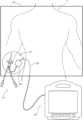
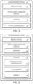
- FIG. 1is a block diagram of a first shape-sensing system 100 in accordance with some embodiments.
- FIG. 2is a block diagram of a second shape-sensing system 200 in accordance with some embodiments.
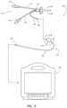
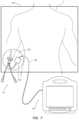
- FIG. 3illustrates the second shape-sensing system 200 in accordance with some embodiments.
- optical-fiber connector module 120Certain features of the optical-fiber connector module 120 are set forth in more detail below with respect to particular embodiments of the optical-fiber connector module 120 such as the optical-fiber connector module 620 and 820 . That said, some features set forth below with respect to one or more embodiments of the optical-fiber connector module 120 are shared among two or more embodiments of the optical-fiber connector module 120 . As such, “the optical-fiber connector module 120 ” is used herein to generically refer to more than one embodiment of the optical-fiber connector module 120 when needed for expository expediency. This is despite certain features having been described with respect to particular embodiments of the optical-fiber connector module 120 such as the optical-fiber connector modules 620 and 820 .
- FIG. 6illustrates the second shape-sensing system 200 with a first optical-fiber connector module 620 in accordance with some embodiments.
- FIG. 7illustrates the second shape-sensing system 200 with the first optical-fiber connector module 620 within a fenestration 601 of a surgical drape 603 in accordance with some embodiments.
- FIG. 8illustrates the second shape-sensing system 200 with a second optical-fiber connector module 820 in accordance with some embodiments.
- FIG. 9illustrates the second shape-sensing system 200 with the second optical-fiber connector module 820 beneath the surgical drape 603 in accordance with some embodiments.
- FIG. 5illustrates a detailed section of the optical-fiber connector module 120 in accordance with some embodiments thereof such as the first optical-fiber connector module 620 or the second optical-fiber connector module 820 .
- the optical-fiber connector module 620 or 820includes the housing 324 , a receptacle 532 disposed in the housing 324 , the cable 326 extending from the housing 324 , and an optical fiber 528 within at least the cable 326 .
- the cable 326includes the plug 330 for establishing an optical connection between the optical-fiber connector module 620 or 820 and the optical interrogator 232 of the console 230 .
- the optical-fiber connector module 620 or 820can further include the one or more sensors 222 selected from the gyroscope, the accelerometer, and the magnetometer disposed within the housing 324 .
- the one or more sensors 222are configured to provide sensor data for determining a reference plane for shape sensing with the optical-fiber stylet of the medical device 110 (e.g., the optical-fiber stylet 424 of the PICC 310 ).
- the optical-fiber connection module 820is configured to sit beneath the surgical drape 603 on a chest of a patient P. As such, the optical-fiber connection module 820 need not require a same level of disinfection or sterilization as the optical-fiber connection module 620 .
- a method of the optical-fiber connector module 620 or 820includes positioning the optical-fiber connector module 620 at the patient's side or the optical-fiber connector module 820 on the patient's chest; inserting the plug of the medical device 110 (e.g., the plug 322 of the PICC 310 ) into the receptacle 532 of the optical-fiber connector module 620 or 820 , thereby establishing a first optical connection between the medical device 110 and the optical-fiber connector module 620 or 820 ; and inserting the plug 330 of the optical-fiber connector module 620 or 820 into a port of the console 230 including the integrated optical interrogator 232 or the standalone optical interrogator 140 , thereby establishing a second optical connection between the optical-fiber connector module 620 or 820 and the optical interrogator 140 or 232 .
- the methodcan further include disinfecting or sterilizing the optical-fiber connector module 620 before positioning the optical-fiber connection module 620 within the fenestration 601 of the surgical drape 603 .
- Inserting the plug of the medical device 110e.g., the plug 322 of the PICC 310 ) into the receptacle 532 of the optical-fiber connector module 820 includes establishing the first optical connection from a sterile field including the medical device 110 to a non-sterile field including the optical-fiber connection module 820 , thereby breaching the surgical drape 603 without compromising the sterile field.
- any of the foregoing methodscan alternatively include the first shape-sensing system 100 including the console 130 and the stand-along optical interrogator 140 .
Landscapes
- Health & Medical Sciences (AREA)
- Life Sciences & Earth Sciences (AREA)
- Engineering & Computer Science (AREA)
- Surgery (AREA)
- Physics & Mathematics (AREA)
- Public Health (AREA)
- Molecular Biology (AREA)
- Veterinary Medicine (AREA)
- General Health & Medical Sciences (AREA)
- Biomedical Technology (AREA)
- Heart & Thoracic Surgery (AREA)
- Medical Informatics (AREA)
- Animal Behavior & Ethology (AREA)
- Robotics (AREA)
- Optics & Photonics (AREA)
- General Physics & Mathematics (AREA)
- Nuclear Medicine, Radiotherapy & Molecular Imaging (AREA)
- Human Computer Interaction (AREA)
- Biophysics (AREA)
- Pathology (AREA)
- Endoscopes (AREA)
Abstract
Description
Claims (16)
Priority Applications (2)
| Application Number | Priority Date | Filing Date | Title |
|---|---|---|---|
| US16/988,452US12029498B2 (en) | 2019-08-08 | 2020-08-07 | Optical-fiber connector modules including shape-sensing systems and methods thereof |
| US18/761,182US20240350206A1 (en) | 2019-08-08 | 2024-07-01 | Optical-Fiber Connector Modules Including Shape-Sensing Systems and Methods Thereof |
Applications Claiming Priority (2)
| Application Number | Priority Date | Filing Date | Title |
|---|---|---|---|
| US201962884602P | 2019-08-08 | 2019-08-08 | |
| US16/988,452US12029498B2 (en) | 2019-08-08 | 2020-08-07 | Optical-fiber connector modules including shape-sensing systems and methods thereof |
Related Child Applications (1)
| Application Number | Title | Priority Date | Filing Date |
|---|---|---|---|
| US18/761,182ContinuationUS20240350206A1 (en) | 2019-08-08 | 2024-07-01 | Optical-Fiber Connector Modules Including Shape-Sensing Systems and Methods Thereof |
Publications (2)
| Publication Number | Publication Date |
|---|---|
| US20210038322A1 US20210038322A1 (en) | 2021-02-11 |
| US12029498B2true US12029498B2 (en) | 2024-07-09 |
Family
ID=74357820
Family Applications (2)
| Application Number | Title | Priority Date | Filing Date |
|---|---|---|---|
| US16/988,452Active2042-04-18US12029498B2 (en) | 2019-08-08 | 2020-08-07 | Optical-fiber connector modules including shape-sensing systems and methods thereof |
| US18/761,182PendingUS20240350206A1 (en) | 2019-08-08 | 2024-07-01 | Optical-Fiber Connector Modules Including Shape-Sensing Systems and Methods Thereof |
Family Applications After (1)
| Application Number | Title | Priority Date | Filing Date |
|---|---|---|---|
| US18/761,182PendingUS20240350206A1 (en) | 2019-08-08 | 2024-07-01 | Optical-Fiber Connector Modules Including Shape-Sensing Systems and Methods Thereof |
Country Status (5)
| Country | Link |
|---|---|
| US (2) | US12029498B2 (en) |
| EP (1) | EP4007932A4 (en) |
| CN (2) | CN112336338A (en) |
| CA (1) | CA3150924A1 (en) |
| WO (1) | WO2021026502A1 (en) |
Families Citing this family (4)
| Publication number | Priority date | Publication date | Assignee | Title |
|---|---|---|---|---|
| US10992078B2 (en) | 2018-01-29 | 2021-04-27 | Bard Access Systems, Inc. | Connection system for establishing an electrical connection through a drape and methods thereof |
| EP3793464A4 (en) | 2018-05-18 | 2021-07-21 | Bard Access Systems, Inc. | CONNECTION SYSTEM AND METHOD FOR MAKING AN ELECTRICAL CONNECTION THROUGH A COVERING CLOTH |
| CN114174878B (en) | 2019-07-29 | 2024-07-30 | 巴德阿克塞斯系统股份有限公司 | Connection system and method for establishing optical and electrical connections through a drape |
| US12029498B2 (en) | 2019-08-08 | 2024-07-09 | Bard Access Systems, Inc. | Optical-fiber connector modules including shape-sensing systems and methods thereof |
Citations (224)
| Publication number | Priority date | Publication date | Assignee | Title |
|---|---|---|---|---|
| US2831174A (en) | 1956-08-14 | 1958-04-15 | Oscar M Hilmo | Electric test prod |
| US2959766A (en) | 1956-03-16 | 1960-11-08 | Jacobsen Edwin | Electrical connector |
| US3329928A (en) | 1964-10-01 | 1967-07-04 | Amp Inc | Adjustable wedge-type electrical connector |
| US3532095A (en) | 1968-06-21 | 1970-10-06 | Weck & Co Inc Edward | Electrosurgical instrument |
| US3597582A (en) | 1969-01-08 | 1971-08-03 | Sybron Corp | Electrode retaining chuck handle assembly with adapter unit |
| US3605743A (en) | 1968-10-14 | 1971-09-20 | Raul Olvera Arce | Hypodermic syringe |
| US3649952A (en) | 1970-03-18 | 1972-03-14 | Chance Co Ab | Gas-separable electrical connector and method |
| US3665372A (en) | 1969-01-08 | 1972-05-23 | Sybron Corp | Electrode retaining chuck handle assembly with adapter unit |
| US3673548A (en) | 1970-10-19 | 1972-06-27 | Itt | Printed circuit board connector |
| US3746814A (en) | 1971-12-20 | 1973-07-17 | Sybron Corp | Finger actuated surgical electrode holder |
| US3824556A (en) | 1972-04-13 | 1974-07-16 | American Optical Corp | Extra-corporeal medical instrument electrical connector |
| US3842394A (en) | 1973-03-06 | 1974-10-15 | Medical Plastics Inc | Electrical connector for plate electrode |
| US4200348A (en) | 1976-08-04 | 1980-04-29 | Bunker Ramo Corporation | Medical clip |
| US4220387A (en) | 1979-04-02 | 1980-09-02 | Bunker Ramo Corporation | Medical clip |
| US4254764A (en) | 1979-03-01 | 1981-03-10 | Neward Theodore C | Clip electrode |
| US4303293A (en) | 1979-10-17 | 1981-12-01 | Harco Electronics Limited | Connection for electrodes |
| US4369794A (en) | 1980-10-30 | 1983-01-25 | Mallinckrodt, Inc. | Probe with electrocardiographic monitoring |
| US4490003A (en) | 1982-01-11 | 1984-12-25 | C. R. Bard, Inc. | Electrical connector |
| US4614395A (en) | 1985-04-04 | 1986-09-30 | Cordis Corporation | Quick connector to medical electrical lead |
| US4632121A (en) | 1985-09-18 | 1986-12-30 | Tronomed, Inc. | Safety medical cable assembly with connectors |
| US4700997A (en) | 1986-11-14 | 1987-10-20 | Minnesota Mining And Manufacturing Company | Electrical connector |
| US4702256A (en) | 1984-10-24 | 1987-10-27 | Andover Medical Incorporated | Electrical connector for a disposable electrode |
| US4761143A (en) | 1987-01-20 | 1988-08-02 | Owens Rick L | Electrode clip |
| US4858810A (en) | 1987-04-30 | 1989-08-22 | Heart Technology, Inc. | Quick acting pin vise for use with angiographic guidewires |
| US4860742A (en) | 1988-05-16 | 1989-08-29 | Medical Innovations Corporation | Assembly of wire inserter and lock for a medical wire |
| US4973329A (en) | 1988-05-16 | 1990-11-27 | Medical Innovations Corporation | Assembly of wire inserter and lock for a medical wire |
| US5159861A (en) | 1991-09-27 | 1992-11-03 | Cook Incorporated | Wire guide control handle |
| US5178159A (en) | 1988-11-02 | 1993-01-12 | Cardiometrics, Inc. | Torqueable guide wire assembly with electrical functions, male and female connectors rotatable with respect to one another |
| US5217435A (en) | 1992-01-07 | 1993-06-08 | Kring Robert S | Cardiac catheter apparatus |
| WO1994013201A1 (en) | 1992-12-15 | 1994-06-23 | Minnesota Mining And Manufacturing Company | Electrode connector |
| US5325868A (en) | 1993-05-04 | 1994-07-05 | Kimmelstiel Carey D | Self-gripping medical wire torquer |
| US5325746A (en) | 1991-09-27 | 1994-07-05 | Cook Incorporated | Wire guide control handle |
| US5334045A (en) | 1992-11-20 | 1994-08-02 | Siemens Pacesetter, Inc. | Universal cable connector for temporarily connecting implantable leads and implantable medical devices with a non-implantable system analyzer |
| US5354326A (en) | 1993-01-27 | 1994-10-11 | Medtronic, Inc. | Screening cable connector for interface to implanted lead |
| US5423877A (en) | 1992-05-04 | 1995-06-13 | David C. Mackey | Method and device for acute pain management by simultaneous spinal cord electrical stimulation and drug infusion |
| US5437277A (en) | 1991-11-18 | 1995-08-01 | General Electric Company | Inductively coupled RF tracking system for use in invasive imaging of a living body |
| US5454739A (en) | 1992-12-15 | 1995-10-03 | Minnesota Mining And Manufacturing Company | Electrode connector |
| US5482038A (en) | 1994-06-28 | 1996-01-09 | Cadwell Industries, Inc. | Needle electrode assembly |
| US5489225A (en) | 1993-12-16 | 1996-02-06 | Ventritex, Inc. | Electrical terminal with a collet grip for a defibrillator |
| US5501675A (en) | 1994-12-27 | 1996-03-26 | Becton, Dickinson And Company | Safety catheter assembly having safety stop push button |
| WO1996019017A1 (en) | 1994-12-14 | 1996-06-20 | Christensson Eddy K G | Clasp structure for biomedical electrodes |
| US5560358A (en) | 1994-09-08 | 1996-10-01 | Radionics, Inc. | Connector design for multi-contact medical electrode |
| US5591119A (en) | 1994-12-07 | 1997-01-07 | Adair; Edwin L. | Sterile surgical coupler and drape |
| US5685855A (en) | 1996-07-23 | 1997-11-11 | Erskine; Timothy J. | Protected needle catheter placement device with sampling provisions and method for its use |
| US5752915A (en) | 1995-10-18 | 1998-05-19 | Pacesetter Ab | Device for manipulating a stylet unit for positioning a medical electrode cable in a body cavity |
| WO1998022180A1 (en) | 1996-11-21 | 1998-05-28 | Cardia Innovation Ab | Electrode device attached to a body part |
| US5766042A (en) | 1995-12-28 | 1998-06-16 | Medtronic, Inc. | Tool-less locking and sealing assembly for implantable medical device |
| US5769786A (en) | 1996-01-26 | 1998-06-23 | B. Braun Melsungen Ag | Catheter set with an ECG contact capabililty |
| US5797880A (en) | 1996-09-05 | 1998-08-25 | Becton And Dickinson And Company | Catheter and placement needle assembly with retractable needle |
| US5840024A (en) | 1993-10-18 | 1998-11-24 | Olympus Optical Co., Ltd. | Endoscope form detecting apparatus in which coil is fixedly mounted by insulating member so that form is not deformed within endoscope |
| US5968082A (en) | 1996-03-04 | 1999-10-19 | Biotronik Mess- Und Therapiegeraete Gmbh & Co. Ingenieurbuero Berlin | Pacemaker lead locking mechanism |
| US5984918A (en) | 1997-12-22 | 1999-11-16 | Garito; Jon C. | Electrosurgical handpiece with multiple electrode collet |
| US6050976A (en) | 1998-12-23 | 2000-04-18 | Specialized Health Products, Inc. | In-line retractable safety catheter needle insertion assembly |
| US6090052A (en) | 1997-03-25 | 2000-07-18 | Radi Medical Systems Ab | Guide wire having a male connector |
| US6102044A (en) | 1999-10-08 | 2000-08-15 | Medical Concepts Development, Inc. | Electrode carrying surgical drape and method |
| US6132368A (en) | 1996-12-12 | 2000-10-17 | Intuitive Surgical, Inc. | Multi-component telepresence system and method |
| US6140722A (en) | 1999-05-24 | 2000-10-31 | Unit Parts Company | Alternator system |
| US6162101A (en) | 1998-09-03 | 2000-12-19 | Pmt Corporation | Connector assembly for electrodes |
| US6319015B1 (en) | 1999-08-23 | 2001-11-20 | Michael J. Faunce | Garment electrical connector |
| US6324416B1 (en) | 1998-09-23 | 2001-11-27 | B. Braun Melsungen Ag | Connecting device for intra-atrial ECG-lead |
| US6350160B1 (en) | 2000-09-20 | 2002-02-26 | Robert Feuersanger | Medical connector system and method of use |
| US6415168B1 (en) | 2000-04-19 | 2002-07-02 | Ad-Tech Medical Instrument Corporation | Electrical connector for multi-contact medical electrodes |
| US6428336B1 (en) | 1997-03-25 | 2002-08-06 | Radi Medical Systems Ab | Female connector |
| US20020197905A1 (en) | 2000-08-02 | 2002-12-26 | Ralf Kaufmann | Electrical connecting element |
| US6546270B1 (en) | 2000-07-07 | 2003-04-08 | Biosense, Inc. | Multi-electrode catheter, system and method |
| EP1318576A1 (en) | 2001-12-07 | 2003-06-11 | Sony International (Europe) GmbH | Jack-type connector for jack plugs of different number of contacts |
| US6620136B1 (en) | 1999-02-18 | 2003-09-16 | Medsafe Technologies, Llc | Retractable I-V catheter placement device |
| US20030199827A1 (en) | 2000-04-28 | 2003-10-23 | Thorne David L. | Passively activated safety shield for a catheter insertion needle |
| US20030216723A1 (en) | 2002-05-17 | 2003-11-20 | Olympus Optical Co., Ltd | Operation system and mounting device for external device for use in the operation system |
| US6663570B2 (en) | 2002-02-27 | 2003-12-16 | Volcano Therapeutics, Inc. | Connector for interfacing intravascular sensors to a physiology monitor |
| US6673078B1 (en) | 2002-07-24 | 2004-01-06 | Robert H. Muncie | Surgical wire and pin extractor |
| US20040039372A1 (en) | 2002-08-21 | 2004-02-26 | Carmody Patrick J. | Over-the-wire catheter having a slidable instrument for gripping a guidewire |
| US6714809B2 (en) | 2000-11-20 | 2004-03-30 | Surgi-Vision, Inc. | Connector and guidewire connectable thereto |
| US20040146252A1 (en) | 2003-01-29 | 2004-07-29 | Agilent Technologies, Inc. | Optical fibre connector |
| US6780065B2 (en) | 2002-06-07 | 2004-08-24 | Nicolay Verwaltungs-Gmbh | Device for electrical connection of a power lead to an electrode, in particular a medical skin electrode |
| US6799991B2 (en) | 2001-09-05 | 2004-10-05 | Medtronic, Inc. | Medical lead connector |
| WO2004101068A1 (en) | 2003-05-13 | 2004-11-25 | Medtronic, Inc. | Medical lead adaptor assembly |
| WO2005016451A1 (en) | 2003-08-06 | 2005-02-24 | Medtronic, Inc. | Implantable medical lead connector sleeves |
| WO2005044332A2 (en) | 2003-10-31 | 2005-05-19 | Arnott Richard J | Quick-release torquer apparatus for delivering and maintaining a medical guidewire |
| US6913478B2 (en) | 2002-07-01 | 2005-07-05 | Dixi Microtechniques, S.A. | Multi-contact connector for electrode for example for medical use |
| US20050177199A1 (en) | 2004-02-09 | 2005-08-11 | Cardiac Pacemakers, Inc. | PSA cable and connector for quadripolar lead terminal |
| WO2005072807A1 (en) | 2004-01-29 | 2005-08-11 | Cube Medical A/S | A lock for a guide wire or an intravascular catheter |
| US20050283216A1 (en) | 2004-06-21 | 2005-12-22 | Pyles Stephen T | Apparatus and method for displacing tissue obstructions |
| US20060025677A1 (en) | 2003-10-17 | 2006-02-02 | Verard Laurent G | Method and apparatus for surgical navigation |
| US20060030864A1 (en) | 2003-07-31 | 2006-02-09 | Wilson-Cook Medical Inc. | Catheter with splittable wall shaft and peel tool |
| US20060161138A1 (en) | 1996-12-12 | 2006-07-20 | Intuitive Surgical Inc. | Sterile surgical adaptor |
| US20060173407A1 (en) | 2005-01-13 | 2006-08-03 | Shaughnessy Michael C | Tubing assembly and signal generator placement control device and method for use with catheter guidance systems |
| US20070062544A1 (en) | 2003-06-02 | 2007-03-22 | Tina Rauk Bergstrom | Drape product for surgical interventions |
| US20070118079A1 (en) | 2005-11-21 | 2007-05-24 | Moberg John R | Medical devices and related systems and methods |
| US20070160327A1 (en) | 2005-03-10 | 2007-07-12 | Lewallen Christopher P | Multi-fiber fiber optic receptacle and plug assembly |
| US7255609B1 (en) | 2005-03-07 | 2007-08-14 | Epstein Stephen T | Biomedical electrode connector device |
| WO2007109285A2 (en) | 2006-03-20 | 2007-09-27 | Merit Medical Systems, Inc. | Torque device for a medical guidewire |
| US20070293719A1 (en) | 2006-06-20 | 2007-12-20 | Boston Scientific Scimed, Inc. | Medical device for use in endoscopic procedure |
| US20080009720A1 (en) | 2006-05-12 | 2008-01-10 | General Electric Company | Catheter connector |
| US20080046062A1 (en) | 2006-08-03 | 2008-02-21 | Medtronic, Inc. | Implantable medical lead with proximal retrieval wire |
| US7402083B2 (en) | 2006-03-23 | 2008-07-22 | Medtronic, Inc. | Medical electrical lead connection systems and methods |
| US20080236598A1 (en) | 2007-03-30 | 2008-10-02 | Fred Gobel | Drape for open tracheal suctioning |
| US7452360B2 (en) | 1999-11-19 | 2008-11-18 | Pioneer Surgical Technology, Inc. | Method and apparatus for clamping surgical wires or cables |
| US20080287876A1 (en) | 2006-06-16 | 2008-11-20 | Ming-Jeng Shue | Intravenous catheter introducing device |
| US20080304793A1 (en) | 2004-06-16 | 2008-12-11 | Benaron David A | Optical and Electrical Hybrid Connector |
| WO2009050599A2 (en) | 2007-10-17 | 2009-04-23 | Gardia Medical Ltd. | Guidewire stop |
| US20090156926A1 (en) | 2007-11-26 | 2009-06-18 | C.R. Bard, Inc. | Integrated System for Intravascular Placement of a Catheter |
| US7585118B1 (en) | 2008-04-18 | 2009-09-08 | Peregrine Surgical, Ltd. | Fiber optic cable connector and adaptor for optical laser transmitter system |
| US20090234328A1 (en) | 2007-11-26 | 2009-09-17 | C.R. Bard, Inc. | Systems and methods for breaching a sterile field for intravascular placement of a catheter |
| US7633023B1 (en) | 2005-10-07 | 2009-12-15 | Pacesetter, Inc. | IS-4 lead to PSA interface cable |
| US20100036227A1 (en) | 2007-11-26 | 2010-02-11 | C. R. Bard, Inc. | Apparatus and display methods relating to intravascular placement of a catheter |
| US20100049126A1 (en) | 2007-01-01 | 2010-02-25 | Sindolor Medical Ltd. | Device and method for piercing a patient's skin with an injector whilst reducing pain caused by the piercing |
| US20100139669A1 (en) | 2008-12-04 | 2010-06-10 | Peter Piferi | Surgical drapes with patches to provide ports |
| US7753696B2 (en) | 2005-05-12 | 2010-07-13 | Cardiac Pacemakers, Inc. | Lead terminal multi-tool |
| US7771394B2 (en) | 2006-06-16 | 2010-08-10 | Ming-Jeng Shue | Intravenous catheter introducing device |
| US20100204569A1 (en) | 2007-11-26 | 2010-08-12 | C. R. Bard, Inc. | System for placement of a catheter including a signal-generating stylet |
| WO2010123701A1 (en) | 2009-04-21 | 2010-10-28 | Medtronic, Inc. | Connector with two pivotably coupled members for an implantable medical lead |
| US20110002821A1 (en) | 2006-03-31 | 2011-01-06 | Searete Llc, A Limited Liability Corporation Of The State Of Delaware | Surveying sterilizer methods and systems |
| US20110000155A1 (en) | 2009-07-02 | 2011-01-06 | Frank Wellershoff | Cable End Anchorage With Overload Protection |
| US20110002951A1 (en) | 1999-12-17 | 2011-01-06 | University Of Guelph | Modified Leukotoxin Gene and Protein |
| WO2011033107A1 (en) | 2009-09-21 | 2011-03-24 | Joline Gmbh & Co. Kg | Guide wire fixation |
| US20110160824A1 (en) | 2009-12-30 | 2011-06-30 | Ware Eric A | Multi-function lead implant tool |
| US20110166528A1 (en) | 2009-06-29 | 2011-07-07 | Don Millerd | Safety catheter |
| US20110250775A1 (en) | 2010-04-07 | 2011-10-13 | Henryk Bies | Actuating device for an electrical connection terminal |
| US20110257503A1 (en) | 2010-04-14 | 2011-10-20 | Medtronic, Inc. | Neurological screening connector |
| US20120002208A1 (en) | 2009-01-15 | 2012-01-05 | Fabien Calandrini | Device for demonstrating and testing the effectiveness of an anti-reflective treatment of an ophthalmic lens |
| US20120001430A1 (en) | 2005-02-15 | 2012-01-05 | Alan Miller | Flow development and cogeneration chamber |
| US8105338B2 (en) | 1996-12-12 | 2012-01-31 | Intuitive Surgical Operations, Inc. | Sterile surgical adaptor |
| US20120071752A1 (en) | 2010-09-17 | 2012-03-22 | Sewell Christopher M | User interface and method for operating a robotic medical system |
| US8147275B1 (en) | 2011-01-27 | 2012-04-03 | Medtronic, Inc. | Interface adapters for implantable medical electrical leads having a sidewall with an opening with a canted edge |
| US8206175B2 (en) | 2007-05-03 | 2012-06-26 | Deringer-Ney, Inc. | Visual indicator of proper interconnection for an implanted medical device |
| US8267873B2 (en) | 2008-09-02 | 2012-09-18 | Olympus Medical Systems Corp. | Guidewire catheter |
| US20130002454A1 (en) | 2011-06-30 | 2013-01-03 | General Electric Company | Method of operating a synthetic vision system in an aircraft |
| US20130000061A1 (en) | 2010-03-24 | 2013-01-03 | Jong Chan Park | Rotating toothbrush |
| US20130000601A1 (en) | 2011-06-30 | 2013-01-03 | Ford Global Technologies, Llc | Engine-load management to reduce particulate emissions |
| US20130023729A1 (en) | 2009-02-06 | 2013-01-24 | Endoclear Llc | Airway cleaning and visualization |
| US20130095689A1 (en) | 2011-08-16 | 2013-04-18 | Green-Lights Inc. | Electrical Connector |
| US20130109980A1 (en) | 2011-11-01 | 2013-05-02 | Tat-Jin Teo | Systems and methods for a wireless vascular pressure measurement device |
| US20130104884A1 (en) | 2010-03-29 | 2013-05-02 | Endoclear Llc | Endotracheal tube coupling adapters |
| US8480427B2 (en) | 2011-07-20 | 2013-07-09 | Bpm Medical, Llc | Cable connector |
| US20130211225A1 (en) | 2009-11-02 | 2013-08-15 | Xialing Zhang | Subdermal needle electrode cable assembly having movable needle safety cover integral therewith |
| US20130247921A1 (en) | 2010-12-06 | 2013-09-26 | Mayo Foundation For Medical Education And Research | Portal for medical instruments |
| US8548601B2 (en) | 2008-09-15 | 2013-10-01 | Boston Scientific Neuromodulation Corporation | Lead connection system for an implantable electrical stimulation system and methods for making and using the systems |
| US20130289417A1 (en) | 2005-05-06 | 2013-10-31 | Sorin Grunwald | Apparatus and method for endovascular device guiding and positioning using physiological parameters |
| US20130308137A1 (en) | 2011-01-27 | 2013-11-21 | Koninklijke Philips N.V. | Integration of fiber optic shape sensing within an interventional environment |
| US8603011B2 (en) | 2008-03-13 | 2013-12-10 | Steven S. Landowski | Surgical guide wire placement and removal tool |
| US20130331688A1 (en) | 2011-03-04 | 2013-12-12 | Rupert Heigl | Fixation system for an image registration matrix |
| US20130337674A1 (en) | 2012-06-18 | 2013-12-19 | Biotronik Se & Co. Kg | Adapter For Mechanically And Electrically Connecting An Implantable Electrode To At Least One Test Terminal Contact |
| US8620412B2 (en) | 2007-04-24 | 2013-12-31 | The Newcastle Upon Tyne Hospitals Nhs Trust | Apparatus for detecting the position of a percutaneously-inserted intravenous catheter |
| US20140001074A1 (en) | 2011-03-15 | 2014-01-02 | Eugenio Longo | Partially Crystalized Polyester Containers |
| US20140000462A1 (en) | 2010-12-17 | 2014-01-02 | Seb S.A. | Food Cooking Appliance Comprising a Stirring Blade |
| US20140000316A1 (en) | 2012-07-02 | 2014-01-02 | Glass Strand Inc. | Glass-Melting Furnace Burner and Method of Its Use |
| US20140001881A1 (en) | 2011-03-13 | 2014-01-02 | Sony Corporation | Detector, power transmitter, power receiver, power feed system, and detection method |
| US20140003034A1 (en) | 2012-06-29 | 2014-01-02 | Hallmark Cards, Incorporated | Light animated objects |
| US20140150782A1 (en) | 2012-12-04 | 2014-06-05 | Endoclear Llc | Closed suction cleaning devices, systems and methods |
| US8869887B2 (en) | 2011-07-06 | 2014-10-28 | Tolteq Group, LLC | System and method for coupling downhole tools |
| US20150000187A1 (en) | 2011-05-13 | 2015-01-01 | ADA-ES, Inc. | Process to reduce emissions of nitrogen oxides and mercury from coal-fired boilers |
| US20150002971A1 (en) | 2011-08-18 | 2015-01-01 | Infineon Technologies Austria Ag | Communication line driver protection circuitry, systems and methods |
| US20150012072A1 (en) | 2013-07-03 | 2015-01-08 | UVL Blood Labs, Inc. | Vascular access device with integrated light guide |
| US8932258B2 (en) | 2010-05-14 | 2015-01-13 | C. R. Bard, Inc. | Catheter placement device and method |
| US20150031987A1 (en) | 2013-07-24 | 2015-01-29 | Cook Medical Technologies Llc | Locating device |
| US8958878B2 (en) | 2010-09-17 | 2015-02-17 | Michael Cejnar | Low profile adapter for continuous connection of pacemaker lead during implantation |
| US20150105654A1 (en) | 2013-10-14 | 2015-04-16 | Volcano Corporation | Intravascular devices, systems, and methods |
| WO2015075002A1 (en) | 2013-11-22 | 2015-05-28 | B. Braun Medical Sas | A device for ecg derivation from a catheter |
| US20150148615A1 (en) | 2013-11-28 | 2015-05-28 | Xcelerator Labs, Llc | Ophthalmic surgical systems, methods, and devices |
| US20150164583A1 (en) | 2002-04-08 | 2015-06-18 | Medtronic Ardian Luxembourg S.A.R.L. | Methods and Apparatus for Pulsed Electric Field Neuromodulation Via an Intra-to-Extravascular Approach |
| US20150177467A1 (en) | 2013-12-20 | 2015-06-25 | Senko Advanced Components, Inc. | Lockable connectors and connection assemblies |
| US20150190615A1 (en) | 2014-01-08 | 2015-07-09 | Covidien Lp | Catheter system |
| US9101775B2 (en) | 2011-10-19 | 2015-08-11 | Boston Scientific Neuromodulation Corportion | Systems and methods for making and using a side-loading operating room cable of an electrical stimulation system |
| US20150223897A1 (en) | 2014-02-11 | 2015-08-13 | KB Medical SA | Sterile handle for controlling a robotic surgical system from a sterile field |
| US9107594B2 (en) | 2007-12-11 | 2015-08-18 | Covidien Lp | ECG electrode connector |
| US9108027B2 (en) | 2013-02-26 | 2015-08-18 | Boston Scientific Scimed, Inc. | Interventional catheter housing assemblies incorporating guide wire brakes and management systems |
| US9144395B2 (en) | 2008-01-23 | 2015-09-29 | MediGuide, Ltd. | Guidewire interconnecting apparatus |
| US20150305816A1 (en) | 2014-04-29 | 2015-10-29 | Admir Hadzic | Nerve block procedure drape |
| US20160018602A1 (en) | 2014-07-18 | 2016-01-21 | Biosense Webster (Israel) Ltd. | Electro-optical connector with hot electrical contact protection |
| US20160213432A1 (en)* | 2013-10-02 | 2016-07-28 | Koninklijke Philips N.V. | Hub design and methods for optical shape sensing registration |
| WO2016146993A1 (en) | 2015-03-17 | 2016-09-22 | Cambridge Medical Robotics Ltd | Supply line for a robotic arm instrument |
| US9456766B2 (en) | 2007-11-26 | 2016-10-04 | C. R. Bard, Inc. | Apparatus for use with needle insertion guidance system |
| US9492097B2 (en) | 2007-11-26 | 2016-11-15 | C. R. Bard, Inc. | Needle length determination and calibration for insertion guidance system |
| US9521961B2 (en) | 2007-11-26 | 2016-12-20 | C. R. Bard, Inc. | Systems and methods for guiding a medical instrument |
| US20170000796A1 (en) | 2012-05-30 | 2017-01-05 | Astex Therapeutics Limited | Pteridines as fgfr inhibitors |
| US20170000205A1 (en) | 2015-07-01 | 2017-01-05 | Generation Tux, Inc. | Garment packaging systems and methods with garment insert |
| US20170000795A1 (en) | 2014-01-24 | 2017-01-05 | Sirtex Medical Limited | Treatment of Neoplasia |
| US20170002810A1 (en) | 2014-01-09 | 2017-01-05 | Shinhang Co., Ltd. | Trochoid pump for transferring high-viscosity liquid under high pressure |
| US20170014194A1 (en)* | 2012-02-03 | 2017-01-19 | Intuitive Surgical Operations, Inc. | Steerable Flexible Needle With Embedded Shape Sensing |
| US9554716B2 (en) | 2007-11-26 | 2017-01-31 | C. R. Bard, Inc. | Insertion guidance system for needles and medical components |
| US9636031B2 (en) | 2007-11-26 | 2017-05-02 | C.R. Bard, Inc. | Stylets for use with apparatus for intravascular placement of a catheter |
| US9656093B2 (en) | 2015-07-16 | 2017-05-23 | Boston Scientific Neuromodulation Corporation | Systems and methods for making and using connector contact arrays for electrical stimulation systems |
| US9662506B2 (en) | 2013-07-18 | 2017-05-30 | Boston Scientific Neuromodulation Corporation | Systems and methods for making and using improved operating-room cables for electrical stimulation systems |
| US9675784B2 (en) | 2007-04-18 | 2017-06-13 | Vascular Pathways, Inc. | Intravenous catheter insertion and blood sample devices and method of use |
| US20170181646A1 (en)* | 2014-10-31 | 2017-06-29 | Lake Region Medical, Inc. | Membrane-Free Fiber Bragg Grating Pressure Sensing Guidewire |
| US20170261699A1 (en) | 2016-03-10 | 2017-09-14 | Corning Optical Communications LLC | Fiber optic connectors having a ferrule with an integral ferrule insertion stop |
| US9808647B2 (en) | 2012-04-05 | 2017-11-07 | Veritas Medical, L.L.C. | Methods and apparatus to inactivate infectious agents on a catheter residing in a body cavity |
| US20170333136A1 (en) | 2014-10-29 | 2017-11-23 | Intellijoint Surgical Inc. | Systems and devices including a surgical navigation camera with a kinematic mount and a surgical drape with a kinematic mount adapter |
| US20180002961A1 (en) | 2015-08-14 | 2018-01-04 | Robert A. Kelley | Garage door noise reduction roller assembly |
| US20180001165A1 (en) | 2015-03-27 | 2018-01-04 | Toray Industries, Inc. | Tubular carbon fiber reinforced composite material and golf club shaft |
| US9872971B2 (en) | 2010-05-14 | 2018-01-23 | C. R. Bard, Inc. | Guidewire extension system for a catheter placement device |
| US20180071509A1 (en) | 2016-09-12 | 2018-03-15 | C. R. Bard, Inc. | Blood Control For A Catheter Insertion Device |
| US9919145B2 (en) | 2013-03-14 | 2018-03-20 | Medtronic, Inc. | Connector assemblies for receiving implantable medical leads |
| US9950139B2 (en) | 2010-05-14 | 2018-04-24 | C. R. Bard, Inc. | Catheter placement device including guidewire and catheter control elements |
| US20180110951A2 (en) | 2014-07-11 | 2018-04-26 | Monitor Mask Inc. | Facial access oxygen face mask and component system |
| US20180140170A1 (en) | 2015-06-03 | 2018-05-24 | Koninklijke Philips N.V. | Medical optical connector system |
| US20180289927A1 (en) | 2017-04-07 | 2018-10-11 | Bard Access System, Inc. | Optical Fiber-Based Medical Device Tracking And Monitoring System |
| US10130806B2 (en) | 2015-06-26 | 2018-11-20 | Boston Scientific Neuromodulation Corporation | Systems and methods for making and using a temporary lead |
| US20190000698A1 (en) | 2015-12-25 | 2019-01-03 | Unicharm Corporation | Method for recovering pulp fiber from used hygiene product |
| US20190000991A1 (en) | 2017-04-14 | 2019-01-03 | National Taiwan University | Gene therapy for aadc deficiency |
| US10201713B2 (en) | 2016-06-20 | 2019-02-12 | Boston Scientific Neuromodulation Corporation | Threaded connector assembly and methods of making and using the same |
| US10238880B2 (en) | 2014-11-12 | 2019-03-26 | Medtronic, Inc. | Medical devices having deformable structures providing medical lead fixation |
| US10307602B2 (en) | 2016-07-08 | 2019-06-04 | Boston Scientific Neuromodulation Corporation | Threaded connector assembly and methods of making and using the same |
| US20190180647A1 (en)* | 2016-08-17 | 2019-06-13 | Telemedica Inc. | Auscultatory sound identification training device and auscultatory sound identification training system |
| US10322253B2 (en) | 2011-03-29 | 2019-06-18 | Teleflex Life Sciences Unlimited Company | Ballooned ventilation tube cleaning device |
| US20190231172A1 (en) | 2018-01-29 | 2019-08-01 | Bard Access Systems, Inc. | Connection Systems And Methods Thereof For Establishing Electrical Connections Across A Sterile Field |
| US20190237902A1 (en) | 2018-01-29 | 2019-08-01 | Bard Access Systems, Inc. | Connection System For Establishing An Electrical Connection Through A Drape And Methods Thereof |
| US10449330B2 (en) | 2007-11-26 | 2019-10-22 | C. R. Bard, Inc. | Magnetic element-equipped needle assemblies |
| US20190350621A1 (en) | 2015-02-26 | 2019-11-21 | Titan Medical Inc. | Method for providing access for a surgical procedure |
| US20190350663A1 (en) | 2018-05-18 | 2019-11-21 | Bard Access Systems, Inc. | Connection Systems And Methods Thereof For Establishing An Electrical Connection Through A Drape |
| US20200000548A1 (en) | 2018-07-02 | 2020-01-02 | Covidien Lp | Method and apparatus related to fabricated wireless transponder devices to be used in medical procedures |
| US20200002372A1 (en) | 2016-06-02 | 2020-01-02 | UNIVERSITé LAVAL | Aminosteroid derivatives and process for producing same |
| US20200001383A1 (en) | 2017-01-04 | 2020-01-02 | Kennametal Inc. | Metal-cutting tool, in particular a reaming tool and method of making the same |
| US10524691B2 (en) | 2007-11-26 | 2020-01-07 | C. R. Bard, Inc. | Needle assembly including an aligned magnetic element |
| EP3673801A1 (en) | 2008-04-17 | 2020-07-01 | C. R. Bard, Inc. | Systems and methods for breaching a sterile field for intravascular placement of a catheter |
| US20200221934A1 (en)* | 2017-09-28 | 2020-07-16 | Koninklijke Philips N.V. | Optical connection device and method |
| US10751509B2 (en) | 2007-11-26 | 2020-08-25 | C. R. Bard, Inc. | Iconic representations for guidance of an indwelling medical device |
| WO2021021408A1 (en) | 2019-07-29 | 2021-02-04 | Bard Access Systems, Inc. | Connection systems and methods for establishing optical and electrical connections through a drape |
| WO2021026502A1 (en) | 2019-08-08 | 2021-02-11 | Bard Access Systems, Inc. | Optical-fiber connector modules including shape-sensing systems and methods thereof |
| USD921884S1 (en) | 2018-07-27 | 2021-06-08 | Bard Access Systems, Inc. | Catheter insertion device |
| US20220110708A1 (en) | 2020-10-13 | 2022-04-14 | Bard Access Systems, Inc. | Procedural Barriers with Integrated Medical Device-Connecting Features and Methods Thereof |
| US20220110707A1 (en) | 2020-10-13 | 2022-04-14 | Bard Access Systems, Inc. | Portal-Establishing Devices and Methods Thereof for Establishing Portals in Procedural Barriers |
| US20220128770A1 (en) | 2020-10-28 | 2022-04-28 | Bard Access Systems, Inc. | Systems and Methods Including Procedural Barrier-Breaching Connectors and Connection-Establishing Devices |
Family Cites Families (3)
| Publication number | Priority date | Publication date | Assignee | Title |
|---|---|---|---|---|
| US20120073572A1 (en)* | 2010-09-24 | 2012-03-29 | Li Michael Y | Intubation Stylet & Endotracheal Tube |
| US10820830B2 (en)* | 2011-01-28 | 2020-11-03 | Koninklijke Philips N.V. | Reference markers for launch point identification in optical shape sensing systems |
| US20130245640A1 (en)* | 2012-03-15 | 2013-09-19 | Civco Medical Instruments Co., Inc. | Device and system for narrow gauge medical instrument navigation |
- 2020
- 2020-08-07USUS16/988,452patent/US12029498B2/enactiveActive
- 2020-08-07CNCN202010790432.2Apatent/CN112336338A/enactivePending
- 2020-08-07CACA3150924Apatent/CA3150924A1/enactivePending
- 2020-08-07WOPCT/US2020/045498patent/WO2021026502A1/ennot_activeCeased
- 2020-08-07EPEP20849119.1Apatent/EP4007932A4/enactivePending
- 2020-08-07CNCN202021636747.3Upatent/CN212755640U/enactiveActive
- 2024
- 2024-07-01USUS18/761,182patent/US20240350206A1/enactivePending
Patent Citations (278)
| Publication number | Priority date | Publication date | Assignee | Title |
|---|---|---|---|---|
| US2959766A (en) | 1956-03-16 | 1960-11-08 | Jacobsen Edwin | Electrical connector |
| US2831174A (en) | 1956-08-14 | 1958-04-15 | Oscar M Hilmo | Electric test prod |
| US3329928A (en) | 1964-10-01 | 1967-07-04 | Amp Inc | Adjustable wedge-type electrical connector |
| US3532095A (en) | 1968-06-21 | 1970-10-06 | Weck & Co Inc Edward | Electrosurgical instrument |
| US3605743A (en) | 1968-10-14 | 1971-09-20 | Raul Olvera Arce | Hypodermic syringe |
| US3597582A (en) | 1969-01-08 | 1971-08-03 | Sybron Corp | Electrode retaining chuck handle assembly with adapter unit |
| US3665372A (en) | 1969-01-08 | 1972-05-23 | Sybron Corp | Electrode retaining chuck handle assembly with adapter unit |
| US3649952A (en) | 1970-03-18 | 1972-03-14 | Chance Co Ab | Gas-separable electrical connector and method |
| US3673548A (en) | 1970-10-19 | 1972-06-27 | Itt | Printed circuit board connector |
| US3746814A (en) | 1971-12-20 | 1973-07-17 | Sybron Corp | Finger actuated surgical electrode holder |
| US3824556A (en) | 1972-04-13 | 1974-07-16 | American Optical Corp | Extra-corporeal medical instrument electrical connector |
| US3842394A (en) | 1973-03-06 | 1974-10-15 | Medical Plastics Inc | Electrical connector for plate electrode |
| US4200348A (en) | 1976-08-04 | 1980-04-29 | Bunker Ramo Corporation | Medical clip |
| US4254764A (en) | 1979-03-01 | 1981-03-10 | Neward Theodore C | Clip electrode |
| US4220387A (en) | 1979-04-02 | 1980-09-02 | Bunker Ramo Corporation | Medical clip |
| US4303293A (en) | 1979-10-17 | 1981-12-01 | Harco Electronics Limited | Connection for electrodes |
| US4369794A (en) | 1980-10-30 | 1983-01-25 | Mallinckrodt, Inc. | Probe with electrocardiographic monitoring |
| US4490003A (en) | 1982-01-11 | 1984-12-25 | C. R. Bard, Inc. | Electrical connector |
| US4702256A (en) | 1984-10-24 | 1987-10-27 | Andover Medical Incorporated | Electrical connector for a disposable electrode |
| US4614395A (en) | 1985-04-04 | 1986-09-30 | Cordis Corporation | Quick connector to medical electrical lead |
| US4632121A (en) | 1985-09-18 | 1986-12-30 | Tronomed, Inc. | Safety medical cable assembly with connectors |
| US4700997A (en) | 1986-11-14 | 1987-10-20 | Minnesota Mining And Manufacturing Company | Electrical connector |
| US4761143A (en) | 1987-01-20 | 1988-08-02 | Owens Rick L | Electrode clip |
| US4858810A (en) | 1987-04-30 | 1989-08-22 | Heart Technology, Inc. | Quick acting pin vise for use with angiographic guidewires |
| US4860742A (en) | 1988-05-16 | 1989-08-29 | Medical Innovations Corporation | Assembly of wire inserter and lock for a medical wire |
| US4973329A (en) | 1988-05-16 | 1990-11-27 | Medical Innovations Corporation | Assembly of wire inserter and lock for a medical wire |
| US5178159A (en) | 1988-11-02 | 1993-01-12 | Cardiometrics, Inc. | Torqueable guide wire assembly with electrical functions, male and female connectors rotatable with respect to one another |
| US5159861A (en) | 1991-09-27 | 1992-11-03 | Cook Incorporated | Wire guide control handle |
| US5325746A (en) | 1991-09-27 | 1994-07-05 | Cook Incorporated | Wire guide control handle |
| US5437277A (en) | 1991-11-18 | 1995-08-01 | General Electric Company | Inductively coupled RF tracking system for use in invasive imaging of a living body |
| US5217435A (en) | 1992-01-07 | 1993-06-08 | Kring Robert S | Cardiac catheter apparatus |
| US5423877A (en) | 1992-05-04 | 1995-06-13 | David C. Mackey | Method and device for acute pain management by simultaneous spinal cord electrical stimulation and drug infusion |
| US5334045A (en) | 1992-11-20 | 1994-08-02 | Siemens Pacesetter, Inc. | Universal cable connector for temporarily connecting implantable leads and implantable medical devices with a non-implantable system analyzer |
| US5454739A (en) | 1992-12-15 | 1995-10-03 | Minnesota Mining And Manufacturing Company | Electrode connector |
| US5538444A (en) | 1992-12-15 | 1996-07-23 | Minnesota Mining And Manufacturing Company | Electrode connector |
| WO1994013201A1 (en) | 1992-12-15 | 1994-06-23 | Minnesota Mining And Manufacturing Company | Electrode connector |
| US5407368A (en) | 1992-12-15 | 1995-04-18 | Minnesota Mining And Manufacturing Company | Electrode connector |
| US5354326A (en) | 1993-01-27 | 1994-10-11 | Medtronic, Inc. | Screening cable connector for interface to implanted lead |
| US5325868A (en) | 1993-05-04 | 1994-07-05 | Kimmelstiel Carey D | Self-gripping medical wire torquer |
| US5840024A (en) | 1993-10-18 | 1998-11-24 | Olympus Optical Co., Ltd. | Endoscope form detecting apparatus in which coil is fixedly mounted by insulating member so that form is not deformed within endoscope |
| US5489225A (en) | 1993-12-16 | 1996-02-06 | Ventritex, Inc. | Electrical terminal with a collet grip for a defibrillator |
| US5482038A (en) | 1994-06-28 | 1996-01-09 | Cadwell Industries, Inc. | Needle electrode assembly |
| US5560358A (en) | 1994-09-08 | 1996-10-01 | Radionics, Inc. | Connector design for multi-contact medical electrode |
| US5591119A (en) | 1994-12-07 | 1997-01-07 | Adair; Edwin L. | Sterile surgical coupler and drape |
| WO1996019017A1 (en) | 1994-12-14 | 1996-06-20 | Christensson Eddy K G | Clasp structure for biomedical electrodes |
| US5624281A (en) | 1994-12-14 | 1997-04-29 | Christensson; Eddy K. G. | Clasp structure for biomedical electrodes |
| US5501675A (en) | 1994-12-27 | 1996-03-26 | Becton, Dickinson And Company | Safety catheter assembly having safety stop push button |
| US5752915A (en) | 1995-10-18 | 1998-05-19 | Pacesetter Ab | Device for manipulating a stylet unit for positioning a medical electrode cable in a body cavity |
| US5766042A (en) | 1995-12-28 | 1998-06-16 | Medtronic, Inc. | Tool-less locking and sealing assembly for implantable medical device |
| US5769786A (en) | 1996-01-26 | 1998-06-23 | B. Braun Melsungen Ag | Catheter set with an ECG contact capabililty |
| US5968082A (en) | 1996-03-04 | 1999-10-19 | Biotronik Mess- Und Therapiegeraete Gmbh & Co. Ingenieurbuero Berlin | Pacemaker lead locking mechanism |
| US5685855A (en) | 1996-07-23 | 1997-11-11 | Erskine; Timothy J. | Protected needle catheter placement device with sampling provisions and method for its use |
| US5797880A (en) | 1996-09-05 | 1998-08-25 | Becton And Dickinson And Company | Catheter and placement needle assembly with retractable needle |
| WO1998022180A1 (en) | 1996-11-21 | 1998-05-28 | Cardia Innovation Ab | Electrode device attached to a body part |
| US6330480B1 (en) | 1996-11-21 | 2001-12-11 | Cardia Innovation Ab | Plastically deformed medical electrode with releasable conductive cable |
| US7666191B2 (en) | 1996-12-12 | 2010-02-23 | Intuitive Surgical, Inc. | Robotic surgical system with sterile surgical adaptor |
| US8105338B2 (en) | 1996-12-12 | 2012-01-31 | Intuitive Surgical Operations, Inc. | Sterile surgical adaptor |
| US20060161138A1 (en) | 1996-12-12 | 2006-07-20 | Intuitive Surgical Inc. | Sterile surgical adaptor |
| US6132368A (en) | 1996-12-12 | 2000-10-17 | Intuitive Surgical, Inc. | Multi-component telepresence system and method |
| US6090052A (en) | 1997-03-25 | 2000-07-18 | Radi Medical Systems Ab | Guide wire having a male connector |
| US6428336B1 (en) | 1997-03-25 | 2002-08-06 | Radi Medical Systems Ab | Female connector |
| US5984918A (en) | 1997-12-22 | 1999-11-16 | Garito; Jon C. | Electrosurgical handpiece with multiple electrode collet |
| US6162101A (en) | 1998-09-03 | 2000-12-19 | Pmt Corporation | Connector assembly for electrodes |
| US6324416B1 (en) | 1998-09-23 | 2001-11-27 | B. Braun Melsungen Ag | Connecting device for intra-atrial ECG-lead |
| US6050976A (en) | 1998-12-23 | 2000-04-18 | Specialized Health Products, Inc. | In-line retractable safety catheter needle insertion assembly |
| US6620136B1 (en) | 1999-02-18 | 2003-09-16 | Medsafe Technologies, Llc | Retractable I-V catheter placement device |
| US6140722A (en) | 1999-05-24 | 2000-10-31 | Unit Parts Company | Alternator system |
| US6319015B1 (en) | 1999-08-23 | 2001-11-20 | Michael J. Faunce | Garment electrical connector |
| US6102044A (en) | 1999-10-08 | 2000-08-15 | Medical Concepts Development, Inc. | Electrode carrying surgical drape and method |
| US7452360B2 (en) | 1999-11-19 | 2008-11-18 | Pioneer Surgical Technology, Inc. | Method and apparatus for clamping surgical wires or cables |
| US20110002951A1 (en) | 1999-12-17 | 2011-01-06 | University Of Guelph | Modified Leukotoxin Gene and Protein |
| US6415168B1 (en) | 2000-04-19 | 2002-07-02 | Ad-Tech Medical Instrument Corporation | Electrical connector for multi-contact medical electrodes |
| US20030199827A1 (en) | 2000-04-28 | 2003-10-23 | Thorne David L. | Passively activated safety shield for a catheter insertion needle |
| US6546270B1 (en) | 2000-07-07 | 2003-04-08 | Biosense, Inc. | Multi-electrode catheter, system and method |
| US20020197905A1 (en) | 2000-08-02 | 2002-12-26 | Ralf Kaufmann | Electrical connecting element |
| US6350160B1 (en) | 2000-09-20 | 2002-02-26 | Robert Feuersanger | Medical connector system and method of use |
| US6714809B2 (en) | 2000-11-20 | 2004-03-30 | Surgi-Vision, Inc. | Connector and guidewire connectable thereto |
| US6799991B2 (en) | 2001-09-05 | 2004-10-05 | Medtronic, Inc. | Medical lead connector |
| EP1318576A1 (en) | 2001-12-07 | 2003-06-11 | Sony International (Europe) GmbH | Jack-type connector for jack plugs of different number of contacts |
| US6663570B2 (en) | 2002-02-27 | 2003-12-16 | Volcano Therapeutics, Inc. | Connector for interfacing intravascular sensors to a physiology monitor |
| US7274956B2 (en) | 2002-02-27 | 2007-09-25 | Volcano Corporation | Connector for interfacing intravascular sensors to a physiology monitor |
| US20150164583A1 (en) | 2002-04-08 | 2015-06-18 | Medtronic Ardian Luxembourg S.A.R.L. | Methods and Apparatus for Pulsed Electric Field Neuromodulation Via an Intra-to-Extravascular Approach |
| US20030216723A1 (en) | 2002-05-17 | 2003-11-20 | Olympus Optical Co., Ltd | Operation system and mounting device for external device for use in the operation system |
| US6780065B2 (en) | 2002-06-07 | 2004-08-24 | Nicolay Verwaltungs-Gmbh | Device for electrical connection of a power lead to an electrode, in particular a medical skin electrode |
| US6913478B2 (en) | 2002-07-01 | 2005-07-05 | Dixi Microtechniques, S.A. | Multi-contact connector for electrode for example for medical use |
| US6673078B1 (en) | 2002-07-24 | 2004-01-06 | Robert H. Muncie | Surgical wire and pin extractor |
| US20040039372A1 (en) | 2002-08-21 | 2004-02-26 | Carmody Patrick J. | Over-the-wire catheter having a slidable instrument for gripping a guidewire |
| US20040146252A1 (en) | 2003-01-29 | 2004-07-29 | Agilent Technologies, Inc. | Optical fibre connector |
| US7130699B2 (en) | 2003-05-13 | 2006-10-31 | Medtronic, Inc. | Medical lead adaptor assembly |
| WO2004101068A1 (en) | 2003-05-13 | 2004-11-25 | Medtronic, Inc. | Medical lead adaptor assembly |
| US20070062544A1 (en) | 2003-06-02 | 2007-03-22 | Tina Rauk Bergstrom | Drape product for surgical interventions |
| US20060030864A1 (en) | 2003-07-31 | 2006-02-09 | Wilson-Cook Medical Inc. | Catheter with splittable wall shaft and peel tool |
| US8639340B2 (en) | 2003-08-06 | 2014-01-28 | Medtronic, Inc. | Implantable medical lead connector sleeves |
| WO2005016451A1 (en) | 2003-08-06 | 2005-02-24 | Medtronic, Inc. | Implantable medical lead connector sleeves |
| US20060025677A1 (en) | 2003-10-17 | 2006-02-02 | Verard Laurent G | Method and apparatus for surgical navigation |
| US7144378B2 (en) | 2003-10-31 | 2006-12-05 | Arnott Richard J | Quick-release torquer apparatus for delivering and maintaining a medical guideware |
| WO2005044332A2 (en) | 2003-10-31 | 2005-05-19 | Arnott Richard J | Quick-release torquer apparatus for delivering and maintaining a medical guidewire |
| US20070161969A1 (en) | 2004-01-29 | 2007-07-12 | Erik Andersen | Lock for a guide wire or an intravascular catheter |
| WO2005072807A1 (en) | 2004-01-29 | 2005-08-11 | Cube Medical A/S | A lock for a guide wire or an intravascular catheter |
| WO2005077453A2 (en) | 2004-02-09 | 2005-08-25 | Cardiac Pacemakers Inc. | Psa cable and connector for quadripolar lead terminal |
| US20050177199A1 (en) | 2004-02-09 | 2005-08-11 | Cardiac Pacemakers, Inc. | PSA cable and connector for quadripolar lead terminal |
| US20080304793A1 (en) | 2004-06-16 | 2008-12-11 | Benaron David A | Optical and Electrical Hybrid Connector |
| US20050283216A1 (en) | 2004-06-21 | 2005-12-22 | Pyles Stephen T | Apparatus and method for displacing tissue obstructions |
| US20060173407A1 (en) | 2005-01-13 | 2006-08-03 | Shaughnessy Michael C | Tubing assembly and signal generator placement control device and method for use with catheter guidance systems |
| US9131956B2 (en) | 2005-01-13 | 2015-09-15 | Corpak Medsystems, Inc. | Tubing assembly and signal generator placement control device and method for use with catheter guidance systems |
| US20120001430A1 (en) | 2005-02-15 | 2012-01-05 | Alan Miller | Flow development and cogeneration chamber |
| US7255609B1 (en) | 2005-03-07 | 2007-08-14 | Epstein Stephen T | Biomedical electrode connector device |
| US20070160327A1 (en) | 2005-03-10 | 2007-07-12 | Lewallen Christopher P | Multi-fiber fiber optic receptacle and plug assembly |
| US20130289417A1 (en) | 2005-05-06 | 2013-10-31 | Sorin Grunwald | Apparatus and method for endovascular device guiding and positioning using physiological parameters |
| US7753696B2 (en) | 2005-05-12 | 2010-07-13 | Cardiac Pacemakers, Inc. | Lead terminal multi-tool |
| US7633023B1 (en) | 2005-10-07 | 2009-12-15 | Pacesetter, Inc. | IS-4 lead to PSA interface cable |
| US20070118079A1 (en) | 2005-11-21 | 2007-05-24 | Moberg John R | Medical devices and related systems and methods |
| WO2007058816A2 (en) | 2005-11-21 | 2007-05-24 | Boston Scientific Limited | Medical devices and related systems and methods |
| WO2007109285A2 (en) | 2006-03-20 | 2007-09-27 | Merit Medical Systems, Inc. | Torque device for a medical guidewire |
| US7972282B2 (en) | 2006-03-20 | 2011-07-05 | Merit Medical Systems, Inc. | Torque device for a medical guidewire |
| US7553193B2 (en) | 2006-03-23 | 2009-06-30 | Medtronic, Inc. | Medical electrical lead connection systems and methods |
| US7402083B2 (en) | 2006-03-23 | 2008-07-22 | Medtronic, Inc. | Medical electrical lead connection systems and methods |
| US20110002821A1 (en) | 2006-03-31 | 2011-01-06 | Searete Llc, A Limited Liability Corporation Of The State Of Delaware | Surveying sterilizer methods and systems |
| US20080009720A1 (en) | 2006-05-12 | 2008-01-10 | General Electric Company | Catheter connector |
| US20080287876A1 (en) | 2006-06-16 | 2008-11-20 | Ming-Jeng Shue | Intravenous catheter introducing device |
| US7771394B2 (en) | 2006-06-16 | 2010-08-10 | Ming-Jeng Shue | Intravenous catheter introducing device |
| WO2007149618A2 (en) | 2006-06-20 | 2007-12-27 | Boston Scientific Limited | Medical devices for use in endoscopic procedure |
| US20070293719A1 (en) | 2006-06-20 | 2007-12-20 | Boston Scientific Scimed, Inc. | Medical device for use in endoscopic procedure |
| US20080046062A1 (en) | 2006-08-03 | 2008-02-21 | Medtronic, Inc. | Implantable medical lead with proximal retrieval wire |
| US20100049126A1 (en) | 2007-01-01 | 2010-02-25 | Sindolor Medical Ltd. | Device and method for piercing a patient's skin with an injector whilst reducing pain caused by the piercing |
| US20080236598A1 (en) | 2007-03-30 | 2008-10-02 | Fred Gobel | Drape for open tracheal suctioning |
| US9675784B2 (en) | 2007-04-18 | 2017-06-13 | Vascular Pathways, Inc. | Intravenous catheter insertion and blood sample devices and method of use |
| US8620412B2 (en) | 2007-04-24 | 2013-12-31 | The Newcastle Upon Tyne Hospitals Nhs Trust | Apparatus for detecting the position of a percutaneously-inserted intravenous catheter |
| US8206175B2 (en) | 2007-05-03 | 2012-06-26 | Deringer-Ney, Inc. | Visual indicator of proper interconnection for an implanted medical device |
| US7819844B2 (en) | 2007-10-17 | 2010-10-26 | Gardia Medical Ltd. | Guidewire stop |
| WO2009050599A2 (en) | 2007-10-17 | 2009-04-23 | Gardia Medical Ltd. | Guidewire stop |
| US10231753B2 (en) | 2007-11-26 | 2019-03-19 | C. R. Bard, Inc. | Insertion guidance system for needles and medical components |
| US9649048B2 (en) | 2007-11-26 | 2017-05-16 | C. R. Bard, Inc. | Systems and methods for breaching a sterile field for intravascular placement of a catheter |
| US10342575B2 (en) | 2007-11-26 | 2019-07-09 | C. R. Bard, Inc. | Apparatus for use with needle insertion guidance system |
| US10238418B2 (en) | 2007-11-26 | 2019-03-26 | C. R. Bard, Inc. | Apparatus for use with needle insertion guidance system |
| US10524691B2 (en) | 2007-11-26 | 2020-01-07 | C. R. Bard, Inc. | Needle assembly including an aligned magnetic element |
| US8781555B2 (en) | 2007-11-26 | 2014-07-15 | C. R. Bard, Inc. | System for placement of a catheter including a signal-generating stylet |
| US10602958B2 (en) | 2007-11-26 | 2020-03-31 | C. R. Bard, Inc. | Systems and methods for guiding a medical instrument |
| US8849382B2 (en) | 2007-11-26 | 2014-09-30 | C. R. Bard, Inc. | Apparatus and display methods relating to intravascular placement of a catheter |
| US20190069877A1 (en) | 2007-11-26 | 2019-03-07 | C. R. Bard, Inc. | System For Placement Of A Catheter Including A Signal-Generating Stylet |
| US10165962B2 (en) | 2007-11-26 | 2019-01-01 | C. R. Bard, Inc. | Integrated systems for intravascular placement of a catheter |
| US10751509B2 (en) | 2007-11-26 | 2020-08-25 | C. R. Bard, Inc. | Iconic representations for guidance of an indwelling medical device |
| US10105121B2 (en) | 2007-11-26 | 2018-10-23 | C. R. Bard, Inc. | System for placement of a catheter including a signal-generating stylet |
| US20090156926A1 (en) | 2007-11-26 | 2009-06-18 | C.R. Bard, Inc. | Integrated System for Intravascular Placement of a Catheter |
| US9999371B2 (en) | 2007-11-26 | 2018-06-19 | C. R. Bard, Inc. | Integrated system for intravascular placement of a catheter |
| US20170231700A1 (en) | 2007-11-26 | 2017-08-17 | C. R. Bard, Inc. | Systems And Methods For Breaching A Sterile Field For Intravascular Placement Of A Catheter |
| US9681823B2 (en) | 2007-11-26 | 2017-06-20 | C. R. Bard, Inc. | Integrated system for intravascular placement of a catheter |
| US20100204569A1 (en) | 2007-11-26 | 2010-08-12 | C. R. Bard, Inc. | System for placement of a catheter including a signal-generating stylet |
| US20090234328A1 (en) | 2007-11-26 | 2009-09-17 | C.R. Bard, Inc. | Systems and methods for breaching a sterile field for intravascular placement of a catheter |
| US8388541B2 (en) | 2007-11-26 | 2013-03-05 | C. R. Bard, Inc. | Integrated system for intravascular placement of a catheter |
| US10449330B2 (en) | 2007-11-26 | 2019-10-22 | C. R. Bard, Inc. | Magnetic element-equipped needle assemblies |
| US9636031B2 (en) | 2007-11-26 | 2017-05-02 | C.R. Bard, Inc. | Stylets for use with apparatus for intravascular placement of a catheter |
| US9554716B2 (en) | 2007-11-26 | 2017-01-31 | C. R. Bard, Inc. | Insertion guidance system for needles and medical components |
| US9549685B2 (en) | 2007-11-26 | 2017-01-24 | C. R. Bard, Inc. | Apparatus and display methods relating to intravascular placement of a catheter |
| US9526440B2 (en) | 2007-11-26 | 2016-12-27 | C.R. Bard, Inc. | System for placement of a catheter including a signal-generating stylet |
| US9521961B2 (en) | 2007-11-26 | 2016-12-20 | C. R. Bard, Inc. | Systems and methods for guiding a medical instrument |
| US9456766B2 (en) | 2007-11-26 | 2016-10-04 | C. R. Bard, Inc. | Apparatus for use with needle insertion guidance system |
| US20100036227A1 (en) | 2007-11-26 | 2010-02-11 | C. R. Bard, Inc. | Apparatus and display methods relating to intravascular placement of a catheter |
| US9492097B2 (en) | 2007-11-26 | 2016-11-15 | C. R. Bard, Inc. | Needle length determination and calibration for insertion guidance system |
| US9107594B2 (en) | 2007-12-11 | 2015-08-18 | Covidien Lp | ECG electrode connector |
| US9144395B2 (en) | 2008-01-23 | 2015-09-29 | MediGuide, Ltd. | Guidewire interconnecting apparatus |
| US8603011B2 (en) | 2008-03-13 | 2013-12-10 | Steven S. Landowski | Surgical guide wire placement and removal tool |
| EP3673801A1 (en) | 2008-04-17 | 2020-07-01 | C. R. Bard, Inc. | Systems and methods for breaching a sterile field for intravascular placement of a catheter |
| US7585118B1 (en) | 2008-04-18 | 2009-09-08 | Peregrine Surgical, Ltd. | Fiber optic cable connector and adaptor for optical laser transmitter system |
| US8267873B2 (en) | 2008-09-02 | 2012-09-18 | Olympus Medical Systems Corp. | Guidewire catheter |
| US8548601B2 (en) | 2008-09-15 | 2013-10-01 | Boston Scientific Neuromodulation Corporation | Lead connection system for an implantable electrical stimulation system and methods for making and using the systems |
| US8666510B2 (en) | 2008-09-15 | 2014-03-04 | Boston Scientific Neuromodulation Corporation | Lead connection system for an implantable electrical stimulation system and methods for making and using the systems |
| US20100139669A1 (en) | 2008-12-04 | 2010-06-10 | Peter Piferi | Surgical drapes with patches to provide ports |
| US20120002208A1 (en) | 2009-01-15 | 2012-01-05 | Fabien Calandrini | Device for demonstrating and testing the effectiveness of an anti-reflective treatment of an ophthalmic lens |
| US20130023729A1 (en) | 2009-02-06 | 2013-01-24 | Endoclear Llc | Airway cleaning and visualization |
| US8597042B2 (en) | 2009-04-21 | 2013-12-03 | Medtronic, Inc | Connector for implantable medical lead |
| WO2010123701A1 (en) | 2009-04-21 | 2010-10-28 | Medtronic, Inc. | Connector with two pivotably coupled members for an implantable medical lead |
| US20110166528A1 (en) | 2009-06-29 | 2011-07-07 | Don Millerd | Safety catheter |
| US20110000155A1 (en) | 2009-07-02 | 2011-01-06 | Frank Wellershoff | Cable End Anchorage With Overload Protection |
| WO2011033107A1 (en) | 2009-09-21 | 2011-03-24 | Joline Gmbh & Co. Kg | Guide wire fixation |
| US20120253320A1 (en) | 2009-09-21 | 2012-10-04 | Joline Gmbh & Co. Kg | Guide wire fixation |
| US9095680B2 (en) | 2009-09-21 | 2015-08-04 | Joline Gmbh & Co. Kg | Guide wire fixation |
| US20130211225A1 (en) | 2009-11-02 | 2013-08-15 | Xialing Zhang | Subdermal needle electrode cable assembly having movable needle safety cover integral therewith |
| WO2011082160A2 (en) | 2009-12-30 | 2011-07-07 | Cardiac Pacemakers, Inc. | Multi-function lead implant tool |
| US20110160824A1 (en) | 2009-12-30 | 2011-06-30 | Ware Eric A | Multi-function lead implant tool |
| US20130000061A1 (en) | 2010-03-24 | 2013-01-03 | Jong Chan Park | Rotating toothbrush |
| US20130104884A1 (en) | 2010-03-29 | 2013-05-02 | Endoclear Llc | Endotracheal tube coupling adapters |
| US20110250775A1 (en) | 2010-04-07 | 2011-10-13 | Henryk Bies | Actuating device for an electrical connection terminal |
| US20110257503A1 (en) | 2010-04-14 | 2011-10-20 | Medtronic, Inc. | Neurological screening connector |
| US9872971B2 (en) | 2010-05-14 | 2018-01-23 | C. R. Bard, Inc. | Guidewire extension system for a catheter placement device |
| US9950139B2 (en) | 2010-05-14 | 2018-04-24 | C. R. Bard, Inc. | Catheter placement device including guidewire and catheter control elements |
| US8932258B2 (en) | 2010-05-14 | 2015-01-13 | C. R. Bard, Inc. | Catheter placement device and method |
| US8958878B2 (en) | 2010-09-17 | 2015-02-17 | Michael Cejnar | Low profile adapter for continuous connection of pacemaker lead during implantation |
| US20120071752A1 (en) | 2010-09-17 | 2012-03-22 | Sewell Christopher M | User interface and method for operating a robotic medical system |
| US20130247921A1 (en) | 2010-12-06 | 2013-09-26 | Mayo Foundation For Medical Education And Research | Portal for medical instruments |
| US20140000462A1 (en) | 2010-12-17 | 2014-01-02 | Seb S.A. | Food Cooking Appliance Comprising a Stirring Blade |
| US8147275B1 (en) | 2011-01-27 | 2012-04-03 | Medtronic, Inc. | Interface adapters for implantable medical electrical leads having a sidewall with an opening with a canted edge |
| US20130308137A1 (en) | 2011-01-27 | 2013-11-21 | Koninklijke Philips N.V. | Integration of fiber optic shape sensing within an interventional environment |
| WO2012102745A2 (en) | 2011-01-27 | 2012-08-02 | Medtronic, Inc. | Interface adapters for implantable medical electrical leads |
| US20130331688A1 (en) | 2011-03-04 | 2013-12-12 | Rupert Heigl | Fixation system for an image registration matrix |
| US20140001881A1 (en) | 2011-03-13 | 2014-01-02 | Sony Corporation | Detector, power transmitter, power receiver, power feed system, and detection method |
| US20140001074A1 (en) | 2011-03-15 | 2014-01-02 | Eugenio Longo | Partially Crystalized Polyester Containers |
| US10322253B2 (en) | 2011-03-29 | 2019-06-18 | Teleflex Life Sciences Unlimited Company | Ballooned ventilation tube cleaning device |
| US20150000187A1 (en) | 2011-05-13 | 2015-01-01 | ADA-ES, Inc. | Process to reduce emissions of nitrogen oxides and mercury from coal-fired boilers |
| US20130002454A1 (en) | 2011-06-30 | 2013-01-03 | General Electric Company | Method of operating a synthetic vision system in an aircraft |
| US20130000601A1 (en) | 2011-06-30 | 2013-01-03 | Ford Global Technologies, Llc | Engine-load management to reduce particulate emissions |
| US8869887B2 (en) | 2011-07-06 | 2014-10-28 | Tolteq Group, LLC | System and method for coupling downhole tools |
| US8480427B2 (en) | 2011-07-20 | 2013-07-09 | Bpm Medical, Llc | Cable connector |
| US20130095689A1 (en) | 2011-08-16 | 2013-04-18 | Green-Lights Inc. | Electrical Connector |
| US20150002971A1 (en) | 2011-08-18 | 2015-01-01 | Infineon Technologies Austria Ag | Communication line driver protection circuitry, systems and methods |
| US9101775B2 (en) | 2011-10-19 | 2015-08-11 | Boston Scientific Neuromodulation Corportion | Systems and methods for making and using a side-loading operating room cable of an electrical stimulation system |
| US9425537B2 (en) | 2011-10-19 | 2016-08-23 | Boston Scientific Neuromodulation Corporation | Systems and methods for making and using a side-loading operating room cable of an electrical stimulation system |
| US20130109980A1 (en) | 2011-11-01 | 2013-05-02 | Tat-Jin Teo | Systems and methods for a wireless vascular pressure measurement device |
| US20170014194A1 (en)* | 2012-02-03 | 2017-01-19 | Intuitive Surgical Operations, Inc. | Steerable Flexible Needle With Embedded Shape Sensing |
| US9808647B2 (en) | 2012-04-05 | 2017-11-07 | Veritas Medical, L.L.C. | Methods and apparatus to inactivate infectious agents on a catheter residing in a body cavity |
| US20170000796A1 (en) | 2012-05-30 | 2017-01-05 | Astex Therapeutics Limited | Pteridines as fgfr inhibitors |
| US20130337674A1 (en) | 2012-06-18 | 2013-12-19 | Biotronik Se & Co. Kg | Adapter For Mechanically And Electrically Connecting An Implantable Electrode To At Least One Test Terminal Contact |
| US9059548B2 (en) | 2012-06-18 | 2015-06-16 | Biotronik Se & Co. Kg | Adapter for mechanically and electrically connecting an implantable electrode to at least one test terminal contact |
| US20140003034A1 (en) | 2012-06-29 | 2014-01-02 | Hallmark Cards, Incorporated | Light animated objects |
| US20140000316A1 (en) | 2012-07-02 | 2014-01-02 | Glass Strand Inc. | Glass-Melting Furnace Burner and Method of Its Use |
| US20140150782A1 (en) | 2012-12-04 | 2014-06-05 | Endoclear Llc | Closed suction cleaning devices, systems and methods |
| US9108027B2 (en) | 2013-02-26 | 2015-08-18 | Boston Scientific Scimed, Inc. | Interventional catheter housing assemblies incorporating guide wire brakes and management systems |
| US9919145B2 (en) | 2013-03-14 | 2018-03-20 | Medtronic, Inc. | Connector assemblies for receiving implantable medical leads |
| US20150012072A1 (en) | 2013-07-03 | 2015-01-08 | UVL Blood Labs, Inc. | Vascular access device with integrated light guide |
| US9662506B2 (en) | 2013-07-18 | 2017-05-30 | Boston Scientific Neuromodulation Corporation | Systems and methods for making and using improved operating-room cables for electrical stimulation systems |
| US20150031987A1 (en) | 2013-07-24 | 2015-01-29 | Cook Medical Technologies Llc | Locating device |
| US20160213432A1 (en)* | 2013-10-02 | 2016-07-28 | Koninklijke Philips N.V. | Hub design and methods for optical shape sensing registration |
| US20150105654A1 (en) | 2013-10-14 | 2015-04-16 | Volcano Corporation | Intravascular devices, systems, and methods |
| WO2015075002A1 (en) | 2013-11-22 | 2015-05-28 | B. Braun Medical Sas | A device for ecg derivation from a catheter |
| US20150148615A1 (en) | 2013-11-28 | 2015-05-28 | Xcelerator Labs, Llc | Ophthalmic surgical systems, methods, and devices |
| US20150177467A1 (en) | 2013-12-20 | 2015-06-25 | Senko Advanced Components, Inc. | Lockable connectors and connection assemblies |
| US20150190615A1 (en) | 2014-01-08 | 2015-07-09 | Covidien Lp | Catheter system |
| US20170002810A1 (en) | 2014-01-09 | 2017-01-05 | Shinhang Co., Ltd. | Trochoid pump for transferring high-viscosity liquid under high pressure |
| US20170000795A1 (en) | 2014-01-24 | 2017-01-05 | Sirtex Medical Limited | Treatment of Neoplasia |
| US20150223897A1 (en) | 2014-02-11 | 2015-08-13 | KB Medical SA | Sterile handle for controlling a robotic surgical system from a sterile field |
| US20150305816A1 (en) | 2014-04-29 | 2015-10-29 | Admir Hadzic | Nerve block procedure drape |
| US20180110951A2 (en) | 2014-07-11 | 2018-04-26 | Monitor Mask Inc. | Facial access oxygen face mask and component system |
| US20160018602A1 (en) | 2014-07-18 | 2016-01-21 | Biosense Webster (Israel) Ltd. | Electro-optical connector with hot electrical contact protection |
| US20170333136A1 (en) | 2014-10-29 | 2017-11-23 | Intellijoint Surgical Inc. | Systems and devices including a surgical navigation camera with a kinematic mount and a surgical drape with a kinematic mount adapter |
| US20170181646A1 (en)* | 2014-10-31 | 2017-06-29 | Lake Region Medical, Inc. | Membrane-Free Fiber Bragg Grating Pressure Sensing Guidewire |
| US10238880B2 (en) | 2014-11-12 | 2019-03-26 | Medtronic, Inc. | Medical devices having deformable structures providing medical lead fixation |
| US20190350621A1 (en) | 2015-02-26 | 2019-11-21 | Titan Medical Inc. | Method for providing access for a surgical procedure |
| WO2016146993A1 (en) | 2015-03-17 | 2016-09-22 | Cambridge Medical Robotics Ltd | Supply line for a robotic arm instrument |
| EP3270817A1 (en) | 2015-03-17 | 2018-01-24 | Cambridge Medical Robotics Ltd | Supply line for a robotic arm instrument |
| US20180001165A1 (en) | 2015-03-27 | 2018-01-04 | Toray Industries, Inc. | Tubular carbon fiber reinforced composite material and golf club shaft |
| US20180140170A1 (en) | 2015-06-03 | 2018-05-24 | Koninklijke Philips N.V. | Medical optical connector system |
| US10130806B2 (en) | 2015-06-26 | 2018-11-20 | Boston Scientific Neuromodulation Corporation | Systems and methods for making and using a temporary lead |
| US20170000205A1 (en) | 2015-07-01 | 2017-01-05 | Generation Tux, Inc. | Garment packaging systems and methods with garment insert |
| US9656093B2 (en) | 2015-07-16 | 2017-05-23 | Boston Scientific Neuromodulation Corporation | Systems and methods for making and using connector contact arrays for electrical stimulation systems |
| US20180002961A1 (en) | 2015-08-14 | 2018-01-04 | Robert A. Kelley | Garage door noise reduction roller assembly |
| US20190000698A1 (en) | 2015-12-25 | 2019-01-03 | Unicharm Corporation | Method for recovering pulp fiber from used hygiene product |
| US20170261699A1 (en) | 2016-03-10 | 2017-09-14 | Corning Optical Communications LLC | Fiber optic connectors having a ferrule with an integral ferrule insertion stop |
| US20200002372A1 (en) | 2016-06-02 | 2020-01-02 | UNIVERSITé LAVAL | Aminosteroid derivatives and process for producing same |
| US10201713B2 (en) | 2016-06-20 | 2019-02-12 | Boston Scientific Neuromodulation Corporation | Threaded connector assembly and methods of making and using the same |
| US10307602B2 (en) | 2016-07-08 | 2019-06-04 | Boston Scientific Neuromodulation Corporation | Threaded connector assembly and methods of making and using the same |
| US20190180647A1 (en)* | 2016-08-17 | 2019-06-13 | Telemedica Inc. | Auscultatory sound identification training device and auscultatory sound identification training system |
| US20180071509A1 (en) | 2016-09-12 | 2018-03-15 | C. R. Bard, Inc. | Blood Control For A Catheter Insertion Device |
| US20200001383A1 (en) | 2017-01-04 | 2020-01-02 | Kennametal Inc. | Metal-cutting tool, in particular a reaming tool and method of making the same |
| US20180289927A1 (en) | 2017-04-07 | 2018-10-11 | Bard Access System, Inc. | Optical Fiber-Based Medical Device Tracking And Monitoring System |
| US20190000991A1 (en) | 2017-04-14 | 2019-01-03 | National Taiwan University | Gene therapy for aadc deficiency |
| US20200221934A1 (en)* | 2017-09-28 | 2020-07-16 | Koninklijke Philips N.V. | Optical connection device and method |
| US20190231172A1 (en) | 2018-01-29 | 2019-08-01 | Bard Access Systems, Inc. | Connection Systems And Methods Thereof For Establishing Electrical Connections Across A Sterile Field |
| WO2019148201A1 (en) | 2018-01-29 | 2019-08-01 | Bard Access Systems, Inc. | Connection system for establishing an electrical connection through a drape and methods thereof |
| US10992078B2 (en) | 2018-01-29 | 2021-04-27 | Bard Access Systems, Inc. | Connection system for establishing an electrical connection through a drape and methods thereof |
| US20190237902A1 (en) | 2018-01-29 | 2019-08-01 | Bard Access Systems, Inc. | Connection System For Establishing An Electrical Connection Through A Drape And Methods Thereof |
| WO2019165011A1 (en) | 2018-02-20 | 2019-08-29 | Bard Access Systems, Inc. | Connection systems and methods thereof for establishing electrical connections across a sterile field |
| US10772696B2 (en) | 2018-05-18 | 2020-09-15 | Bard Access Systems, Inc. | Connection systems and methods thereof for establishing an electrical connection through a drape |
| US20190350663A1 (en) | 2018-05-18 | 2019-11-21 | Bard Access Systems, Inc. | Connection Systems And Methods Thereof For Establishing An Electrical Connection Through A Drape |
| US20220241044A1 (en) | 2018-05-18 | 2022-08-04 | Bard Access Systems, Inc. | Connection Systems and Methods Thereof for Establishing an Electrical Connection Through a Drape |
| US20200345441A1 (en) | 2018-05-18 | 2020-11-05 | Bard Access Systems, Inc. | Connection Systems and Methods Thereof for Establishing an Electrical Connection Through a Drape |
| WO2019221926A1 (en) | 2018-05-18 | 2019-11-21 | Bard Access Systems, Inc. | Connection systems and methods thereof for establishing an electrical connection through a drape |
| US20230248459A1 (en) | 2018-05-18 | 2023-08-10 | Bard Access Systems, Inc. | Connection Systems and Methods Thereof for Establishing an Electrical Connection Through a Drape |
| US20200000548A1 (en) | 2018-07-02 | 2020-01-02 | Covidien Lp | Method and apparatus related to fabricated wireless transponder devices to be used in medical procedures |
| USD921884S1 (en) | 2018-07-27 | 2021-06-08 | Bard Access Systems, Inc. | Catheter insertion device |
| WO2021021408A1 (en) | 2019-07-29 | 2021-02-04 | Bard Access Systems, Inc. | Connection systems and methods for establishing optical and electrical connections through a drape |
| US20210030504A1 (en) | 2019-07-29 | 2021-02-04 | Bard Access Systems, Inc. | Connection Systems and Methods for Establishing Optical and Electrical Connections Through A Drape |
| WO2021026502A1 (en) | 2019-08-08 | 2021-02-11 | Bard Access Systems, Inc. | Optical-fiber connector modules including shape-sensing systems and methods thereof |
| WO2022081591A1 (en) | 2020-10-13 | 2022-04-21 | Bard Access Systems, Inc. | Portal-establishing devices and methods thereof for establishing portals in procedural barriers |
| WO2022081583A1 (en) | 2020-10-13 | 2022-04-21 | Bard Access Systems, Inc. | Procedural barriers with integrated medical device-connecting features and methods thereof |
| US20220110707A1 (en) | 2020-10-13 | 2022-04-14 | Bard Access Systems, Inc. | Portal-Establishing Devices and Methods Thereof for Establishing Portals in Procedural Barriers |
| US20220110708A1 (en) | 2020-10-13 | 2022-04-14 | Bard Access Systems, Inc. | Procedural Barriers with Integrated Medical Device-Connecting Features and Methods Thereof |
| US20220128770A1 (en) | 2020-10-28 | 2022-04-28 | Bard Access Systems, Inc. | Systems and Methods Including Procedural Barrier-Breaching Connectors and Connection-Establishing Devices |
| WO2022093991A1 (en) | 2020-10-28 | 2022-05-05 | Bard Access Systems, Inc. | Systems and methods including procedural barrier-breaching connectors and connection-establishing devices |
Non-Patent Citations (44)
| Title |
|---|
| "Sampling Accessories" Spectrometers Accessories Catalogue, pp. 71-102, XP055014465, retrieved from the Internet URL: http//www.mikropack.de/d/specto/pdfy-downoads/sampling accessories. pdf, Jan. 1, 2004 (Jan. 1, 2004). |
| Design U.S. Appl. No. 29/658,136 Specification and Drawings filed Jul. 27, 2018. |
| EP 20849119.1 filed Mar. 4, 2022 Extended European Search Report dated Jun. 26, 2023. |
| PCT/US19/30470 filed May 2, 2019 International Search Report and Written Opinion dated Jul. 19, 2019. |
| PCT/US2019/015710 filed Jan. 29, 2019 International Preliminary Report on Patentability dated Aug. 13, 2020. |
| PCT/US2019/015710 filed Jan. 29, 2019 International Search Report and Written Opinion dated Apr. 29, 2019. |
| PCT/US2019/018851 filed Feb. 20, 2019 Internation Search Report and Written Opinion dated May 7, 2019. |
| PCT/US2019/018851 filed Feb. 20, 2019 International Preliminary Report on Patentability dated May 7, 2019. |
| PCT/US2020/41267 filed Jul. 8, 2020 Internation Search Report and Written Opinion dated Oct. 1, 2020. |
| PCT/US2020/45498 filed Aug. 7, 2020 International Search Report and Written Opinion dated Oct. 4, 2020. |
| PCT/US2021/054593 filed Oct. 12, 2021 International Search Report and Written Opinion dated Jan. 24, 2022. |
| PCT/US2021/054607 filed Oct. 12, 2021 Internation Search Report and Written Opinion dated Jan. 21, 2022. |
| PCT/US2021/056896 filed Oct. 27, 2021 International Search Report and Written Opinion dated Mar. 22, 2022. |
| U.S. Appl. No. 12/426,175, filed Apr. 17, 2009 Advisory Action dated Nov. 26, 2013. |
| U.S. Appl. No. 12/426,175, filed Apr. 17, 2009 Decision on Appeal dated Nov. 7, 2016. |
| U.S. Appl. No. 12/426,175, filed Apr. 17, 2009 Examiner's Answer dated Oct. 7, 2014. |
| U.S. Appl. No. 12/426,175, filed Apr. 17, 2009 Final Office Action dated Aug. 2, 2013. |
| U.S. Appl. No. 12/426,175, filed Apr. 17, 2009 Final Office Action dated Jan. 31, 2014. |
| U.S. Appl. No. 12/426,175, filed Apr. 17, 2009 Non-Final Office Action dated Dec. 3, 2012. |
| U.S. Appl. No. 12/426,175, filed Apr. 17, 2009 Notice of Allowance dated Dec. 13, 2016. |
| U.S. Appl. No. 12/715,556, filed Mar. 2, 2010 Final Office Action dated Oct. 2, 2013. |
| U.S. Appl. No. 12/715,556, filed Mar. 2, 2010 Non-Final Office Action dated Sep. 13, 2012. |
| U.S. Appl. No. 15/585,051, filed May 2, 2017 Examiner's Answer dated May 2, 2019. |
| U.S. Appl. No. 15/585,051, filed May 2, 2017 Final Office Action dated Feb. 28, 2018. |
| U.S. Appl. No. 15/585,051, filed May 2, 2017 Final Office Action dated Mar. 15, 2018. |
| U.S. Appl. No. 15/585,051, filed May 2, 2017 Non-Final Office Action dated Jul. 14, 2017. |
| U.S. Appl. No. 16/261,368, filed Jan. 29, 2019 Advisory Action dated Jul. 21, 2020. |
| U.S. Appl. No. 16/261,368, filed Jan. 29, 2019 Non-Final Office Action dated Jan. 23, 2020. |
| U.S. Appl. No. 16/261,368, filed Jan. 29, 2019 Notice of Allowance dated Jan. 15, 2021. |
| U.S. Appl. No. 16/281,079, filed Feb. 20, 2019 Board Decision dated Jun. 6, 2023. |
| U.S. Appl. No. 16/281,079, filed Feb. 20, 2019 Examiner's Answer dated Feb. 25, 2022. |
| U.S. Appl. No. 16/281,079, filed Feb. 20, 2019 Final Office Action dated Aug. 25, 2020. |
| U.S. Appl. No. 16/281,079, filed Feb. 20, 2019 Non-Final Office Action dated Apr. 1, 2020. |
| U.S. Appl. No. 16/281,079, filed Feb. 20, 2019 Non-Final Office Action dated Apr. 20, 2021. |
| U.S. Appl. No. 16/402,074, filed May 2, 2019 Non-Final Office Action dated Apr. 16, 2020. |
| U.S. Appl. No. 16/923,912, filed Jul. 8, 2020 Notice of Allowance dated Mar. 27, 2023. |
| U.S. Appl. No. 16/932,425, filed Jul. 17, 2020 Non-Final Office Action dated Jun. 18, 2021. |
| U.S. Appl. No. 16/932,425, filed Jul. 17, 2020 Notice of Allowance dated Jan. 10, 2022. |
| U.S. Appl. No. 17/240,826, filed Apr. 26, 2021, Non-Final Office Action dated Jul. 19, 2023. |
| U.S. Appl. No. 17/512,501, filed Oct. 27, 2021 Non-Final Office Action dated Feb. 17, 2023. |
| U.S. Appl. No. 17/512,501, filed Oct. 27, 2021 Restriction Requirement dated Sep. 30, 2022. |
| U.S. Appl. No. 17/723,246, filed Apr. 18, 2022, Non-Final Office Action dated Sep. 27, 2022. |
| U.S. Appl. No. 17/723,246, filed Apr. 18, 2022, Notice of Allowance dated Jan. 27, 2023. |
| U.S. Appl. No. 18/235,334, filed Aug. 17, 2023, Notice of Allowance dated Apr. 4, 2024. |
Also Published As
| Publication number | Publication date |
|---|---|
| CA3150924A1 (en) | 2021-02-11 |
| WO2021026502A1 (en) | 2021-02-11 |
| EP4007932A1 (en) | 2022-06-08 |
| EP4007932A4 (en) | 2023-07-26 |
| CN112336338A (en) | 2021-02-09 |
| US20240350206A1 (en) | 2024-10-24 |
| CN212755640U (en) | 2021-03-23 |
| US20210038322A1 (en) | 2021-02-11 |
Similar Documents
| Publication | Publication Date | Title |
|---|---|---|
| US12376794B2 (en) | Optical and electrical diagnostic systems and methods thereof | |
| EP4110175B1 (en) | Optical connection systems and methods thereof | |
| US11525670B2 (en) | Shape-sensing systems with filters and methods thereof | |
| US12029498B2 (en) | Optical-fiber connector modules including shape-sensing systems and methods thereof | |
| US11737848B2 (en) | Connection systems and methods for establishing optical and electrical connections through a drape | |
| US12403288B2 (en) | Optical tip-tracking systems and methods thereof |
Legal Events
| Date | Code | Title | Description |
|---|---|---|---|
| FEPP | Fee payment procedure | Free format text:ENTITY STATUS SET TO UNDISCOUNTED (ORIGINAL EVENT CODE: BIG.); ENTITY STATUS OF PATENT OWNER: LARGE ENTITY | |
| STPP | Information on status: patent application and granting procedure in general | Free format text:DOCKETED NEW CASE - READY FOR EXAMINATION | |
| STPP | Information on status: patent application and granting procedure in general | Free format text:RESPONSE TO NON-FINAL OFFICE ACTION ENTERED AND FORWARDED TO EXAMINER | |
| STPP | Information on status: patent application and granting procedure in general | Free format text:FINAL REJECTION MAILED | |
| STPP | Information on status: patent application and granting procedure in general | Free format text:ADVISORY ACTION MAILED | |
| STPP | Information on status: patent application and granting procedure in general | Free format text:DOCKETED NEW CASE - READY FOR EXAMINATION | |
| STPP | Information on status: patent application and granting procedure in general | Free format text:NON FINAL ACTION MAILED | |
| STPP | Information on status: patent application and granting procedure in general | Free format text:RESPONSE TO NON-FINAL OFFICE ACTION ENTERED AND FORWARDED TO EXAMINER | |
| STPP | Information on status: patent application and granting procedure in general | Free format text:NOTICE OF ALLOWANCE MAILED -- APPLICATION RECEIVED IN OFFICE OF PUBLICATIONS | |
| ZAAA | Notice of allowance and fees due | Free format text:ORIGINAL CODE: NOA | |
| ZAAB | Notice of allowance mailed | Free format text:ORIGINAL CODE: MN/=. | |
| STPP | Information on status: patent application and granting procedure in general | Free format text:AWAITING TC RESP., ISSUE FEE NOT PAID | |
| STPP | Information on status: patent application and granting procedure in general | Free format text:NOTICE OF ALLOWANCE MAILED -- APPLICATION RECEIVED IN OFFICE OF PUBLICATIONS | |
| ZAAA | Notice of allowance and fees due | Free format text:ORIGINAL CODE: NOA | |
| STPP | Information on status: patent application and granting procedure in general | Free format text:AWAITING TC RESP, ISSUE FEE PAYMENT VERIFIED | |
| STPP | Information on status: patent application and granting procedure in general | Free format text:PUBLICATIONS -- ISSUE FEE PAYMENT VERIFIED | |
| STCF | Information on status: patent grant | Free format text:PATENTED CASE |