US12023065B2 - Bi-stable spring-latch connector for ultrasonic surgical instruments - Google Patents
Bi-stable spring-latch connector for ultrasonic surgical instrumentsDownload PDFInfo
- Publication number
- US12023065B2 US12023065B2US16/999,215US202016999215AUS12023065B2US 12023065 B2US12023065 B2US 12023065B2US 202016999215 AUS202016999215 AUS 202016999215AUS 12023065 B2US12023065 B2US 12023065B2
- Authority
- US
- United States
- Prior art keywords
- end portion
- horn
- blade
- female
- male
- Prior art date
- Legal status (The legal status is an assumption and is not a legal conclusion. Google has not performed a legal analysis and makes no representation as to the accuracy of the status listed.)
- Active, expires
Links
- 230000006835compressionEffects0.000claimsabstractdescription21
- 238000007906compressionMethods0.000claimsabstractdescription21
- 230000008878couplingEffects0.000claimsdescription20
- 238000010168coupling processMethods0.000claimsdescription20
- 238000005859coupling reactionMethods0.000claimsdescription20
- 230000004913activationEffects0.000description7
- 239000012636effectorSubstances0.000description7
- 239000000463materialSubstances0.000description5
- 229910001069Ti alloyInorganic materials0.000description3
- RTAQQCXQSZGOHL-UHFFFAOYSA-NTitaniumChemical compound[Ti]RTAQQCXQSZGOHL-UHFFFAOYSA-N0.000description3
- 230000001954sterilising effectEffects0.000description3
- 238000004659sterilization and disinfectionMethods0.000description3
- 229910052719titaniumInorganic materials0.000description3
- 239000010936titaniumSubstances0.000description3
- 238000002347injectionMethods0.000description2
- 239000007924injectionSubstances0.000description2
- 238000001746injection mouldingMethods0.000description2
- 238000003780insertionMethods0.000description2
- 230000037431insertionEffects0.000description2
- 230000008901benefitEffects0.000description1
- 238000003754machiningMethods0.000description1
- 238000004519manufacturing processMethods0.000description1
- 239000005300metallic glassSubstances0.000description1
- 238000012986modificationMethods0.000description1
- 230000004048modificationEffects0.000description1
- 230000000717retained effectEffects0.000description1
Images


Classifications
- A—HUMAN NECESSITIES
- A61—MEDICAL OR VETERINARY SCIENCE; HYGIENE
- A61B—DIAGNOSIS; SURGERY; IDENTIFICATION
- A61B17/00—Surgical instruments, devices or methods
- A61B17/32—Surgical cutting instruments
- A61B17/320068—Surgical cutting instruments using mechanical vibrations, e.g. ultrasonic
- A61B17/320092—Surgical cutting instruments using mechanical vibrations, e.g. ultrasonic with additional movable means for clamping or cutting tissue, e.g. with a pivoting jaw
- A—HUMAN NECESSITIES
- A61—MEDICAL OR VETERINARY SCIENCE; HYGIENE
- A61B—DIAGNOSIS; SURGERY; IDENTIFICATION
- A61B17/00—Surgical instruments, devices or methods
- A61B17/32—Surgical cutting instruments
- A61B17/320068—Surgical cutting instruments using mechanical vibrations, e.g. ultrasonic
- A—HUMAN NECESSITIES
- A61—MEDICAL OR VETERINARY SCIENCE; HYGIENE
- A61B—DIAGNOSIS; SURGERY; IDENTIFICATION
- A61B17/00—Surgical instruments, devices or methods
- A61B17/00234—Surgical instruments, devices or methods for minimally invasive surgery
- A—HUMAN NECESSITIES
- A61—MEDICAL OR VETERINARY SCIENCE; HYGIENE
- A61B—DIAGNOSIS; SURGERY; IDENTIFICATION
- A61B17/00—Surgical instruments, devices or methods
- A61B2017/0046—Surgical instruments, devices or methods with a releasable handle; with handle and operating part separable
- A—HUMAN NECESSITIES
- A61—MEDICAL OR VETERINARY SCIENCE; HYGIENE
- A61B—DIAGNOSIS; SURGERY; IDENTIFICATION
- A61B17/00—Surgical instruments, devices or methods
- A61B2017/0046—Surgical instruments, devices or methods with a releasable handle; with handle and operating part separable
- A61B2017/00473—Distal part, e.g. tip or head
- A—HUMAN NECESSITIES
- A61—MEDICAL OR VETERINARY SCIENCE; HYGIENE
- A61B—DIAGNOSIS; SURGERY; IDENTIFICATION
- A61B17/00—Surgical instruments, devices or methods
- A61B2017/00477—Coupling
- A—HUMAN NECESSITIES
- A61—MEDICAL OR VETERINARY SCIENCE; HYGIENE
- A61B—DIAGNOSIS; SURGERY; IDENTIFICATION
- A61B17/00—Surgical instruments, devices or methods
- A61B17/32—Surgical cutting instruments
- A61B17/320068—Surgical cutting instruments using mechanical vibrations, e.g. ultrasonic
- A61B2017/320072—Working tips with special features, e.g. extending parts
- A61B2017/320074—Working tips with special features, e.g. extending parts blade
Definitions
- an ultrasonic surgical instrumentis configured to transmit ultrasonic energy produced by a generator and transducer assembly along a waveguide to an end effector that is spaced-apart from the generator and transducer assembly.
- a portable power sourcee.g., a battery
- the generator and transducer assemblyare mounted on the handheld instrument itself, while the waveguide interconnects the generator and transducer assembly and the end effector.
- Corded ultrasonic instrumentsoperate in similar fashion except that, rather than having the generator and power source mounted on the handheld instrument itself, the handheld instrument is configured to connect to a standalone power supply and/or generator via a corded connection.
- closed ends of the double helixare perpendicular to a longitudinal axis defined through the female end, thereby maintaining the coupling, under compression, of the female end and the male end.
- the double helixis wound counterclockwise such that counterclockwise rotation of the male end relative to the female end decouples the horn and the body.
- a waveguideconfigured for use with an ultrasonic surgical instrument.
- the waveguideincludes a horn configured to receive ultrasonic energy from an ultrasonic transducer, a body extending distally from the horn and configured to transmit the ultrasonic energy therealong, a blade extending distally from the body and configured to apply the ultrasonic energy to tissue in contact therewith to treat the tissue, and a bi-stable spring-latch connector releasably coupling, under compression, the body and the blade.
- the female end of the bi-stable spring-latch connectormay include an open-ended cylinder with a hollow cylindrical interior and a pair of grooves defining a double helix.
- the male end of the bi-stable spring-latch connectoris a cylindrical block having a pair of protrusions disposed on opposite sides of the cylindrical block and extending radially outwardly therefrom.
- the pair of protrusions disposed on the male endis configured to be rotated through the double helix of the female end.
- closed ends of the double helixare perpendicular to a longitudinal axis defined through the female end, thereby maintaining the coupling, under compression, of the female end and the male end.
- the double helixis wound clockwise such that clockwise rotation of the male end relative to the female end couples the body and the blade.
- the bi-stable spring-latch connectorincludes a male end disposed on a distal end of the body and a female end disposed on a proximal end of the blade.
- the female endmay be configured to receive the male end, thereby releasably coupling, under compression, the body and the blade.
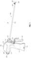
- FIG. 2is a perspective view of the ultrasonic surgical instrument of FIG. 1 with the elongated assembly separated from the handle assembly;
- FIG. 3is an exploded, perspective view of the elongated assembly of FIG. 2 ;
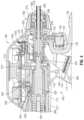
- FIG. 4is an enlarged, longitudinal, cross-sectional view of a portion of the ultrasonic surgical instrument of FIG. 1 illustrating engagement between the elongated assembly and the handle assembly;
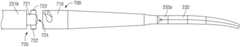
- FIG. 5is a side view of a waveguide in accordance with the present disclosure configured for use with the ultrasonic surgical instrument of FIG. 1 ;
- FIG. 6is a side view of a proximal portion of the waveguide of FIG. 5 illustrating engagement between the horn and the body by a bi-stable spring-latch connector;
- FIG. 8is an end view illustrating the inside of the female receiving end and the pair of protrusions disposed on the male end of the bi-stable spring-latch connector of FIG. 6 ;
- FIG. 9is an enlarged, side view of the female end of the bi-stable spring-latch connector
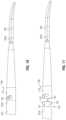
- FIG. 10is a side view of a distal portion of the waveguide of FIG. 5 illustrating engagement between the body and the blade by a bi-stable spring-latch connector;
- FIG. 11is an enlarged, side view of the bi-stable spring-latch connector of FIG. 10 , in a disengaged condition;
- ultrasonic surgical instrument 10provided in accordance with the aspects and features of the present disclosure is shown generally identified by reference numeral 10 .
- reference numeral 10an ultrasonic surgical instrument provided in accordance with the aspects and features of the present disclosure is shown generally identified by reference numeral 10 .
- ultrasonic surgical instrument 10is generally described hereinbelow. Additional features of ultrasonic surgical instrument 10 , including the assembly and use thereof, are detailed in U.S. Pat. No. 10,368,898, the entire contents of which are hereby incorporated herein by reference.
- Ultrasonic surgical instrument 10generally includes a handle assembly 100 and an elongated assembly 200 that is configured to releasably engage handle assembly 100 .
- Handle assembly 100includes a housing 110 defining a body portion 112 configured to support an ultrasonic transducer and generator assembly (“TAG”) 300 , and a fixed handle portion 114 defining a compartment 116 configured to receive a battery assembly 400 ( FIG. 4 ).
- Handle assembly 100further includes an activation button 120 operably positioned to electrically couple between TAG 300 and battery assembly 400 ( FIG. 4 ) when TAG 300 is mounted on body portion 112 of housing 110 and battery assembly 400 ( FIG. 4 ) is engaged within compartment 116 of housing 110 .
- TAGultrasonic transducer and generator assembly
- a clamp trigger 130extends from housing 110 of handle assembly 100 adjacent to fixed handle portion 114 of housing 110 .
- Clamp trigger 130includes a bifurcated drive portion 132 extending into body portion 112 of housing 110 and is selectively movable relative to housing 110 to actuate ultrasonic surgical instrument 10 .
- TAG 300 and battery assembly 400are each removable from handle assembly 100 to facilitate disposal of handle assembly 100 after a single use or to enable sterilization of handle assembly 100 for subsequent use.
- TAG 300may be configured to withstand sterilization such that TAG 300 may be sterilized for repeated use.
- Battery assembly 400( FIG. 4 ), on the other hand, is configured to be aseptically transferred and retained within compartment 116 of fixed handle portion 114 of housing 110 of handle assembly 100 such that battery assembly 400 ( FIG. 4 ) may be repeatedly used without requiring sterilization thereof.
- an underlying two-mode switch assembly 122is activated to supply power from battery assembly 400 to TAG 300 in either a “LOW” power mode or a “HIGH” power mode, depending upon the manner of activation of activation button 120 .
- TAG 300includes a generator 310 and an ultrasonic transducer 320 .
- Generator 310includes a housing 312 configured to house the internal electronics of generator 310 , and a cradle 314 configured to rotatably support ultrasonic transducer 320 .
- Ultrasonic transducer 320includes a piezoelectric stack 322 and a distally-extending horn 324 .
- a set of connectors 330 , 332 and corresponding rotational contacts 334 , 336 associated with generator 310 and ultrasonic transducer 320respectively, enable drive signals to be communicated from generator 310 to piezoelectric stack 322 to drive ultrasonic transducer 320 .
- piezoelectric stack 322 of ultrasonic transducer 320converts a high voltage AC signal received from generator 310 into mechanical motion that is output from horn 324 to elongated assembly 200 , as detailed below.
- Ultrasonic transducer 320further includes a rotation knob 328 disposed at a proximal end thereof to enable rotation of ultrasonic transducer 320 relative to generator 310 .
- elongated assembly 200includes an outer drive sleeve 210 , an inner support sleeve 220 disposed within outer drive sleeve 210 and about which outer drive sleeve 210 is configured to slide, a waveguide 230 extending through inner support sleeve 220 , a torque adapter 240 engaged about waveguide 230 , a drive assembly 250 disposed about outer drive sleeve 210 and operably coupled between outer drive sleeve 210 and bifurcated drive portion 132 of clamp trigger 130 ( FIG.
- Waveguide 230defines the horn 324 , a body 231 extending distally from a distal end 324 a of the horn 324 , and a blade 232 extending distally from a distal end 231 b of the body 231 .
- Elongated assembly 200is configured to releasably engage handle assembly 100 such that mechanical motion output from horn 324 of ultrasonic transducer 320 is transmitted along waveguide 230 to end effector 280 for treating tissue therewith, such that clamp trigger 130 is selectively actuatable to manipulate end effector 280 , and such that rotation knob 270 is selectively rotatable to rotate elongated assembly 200 relative to handle assembly 100 .
- Elongated assembly 200may be configured as a disposable, single-use component or a reusable component that is sterilizable for subsequent use. In embodiments, elongated assembly 200 is integrated with handle assembly 100 and, in such embodiments, is not removable therefrom.
- Blade 232defines a curved configuration wherein the directions of movement of jaw member 282 between the open and clamping positions are perpendicular to the direction of curvature of blade 232 .
- blade 232define a straight configuration or that blade 232 curve towards or away from jaw member 282 , that is, where the directions of movement of jaw member 282 between the open and clamping positions are coaxial or parallel to the direction of curvature of blade 232 .
- closed end segments 533 of the grooves 513 forming the double helix 514are angled to diverge from a pitch axis 910 of the double helix 514 and extend perpendicular to a longitudinal axis 900 defined through the female end 510 . Additionally, there is a closed distal segment axis 920 . By angling off the pitch axis 910 of the double helix 514 , the closed end segments 533 of grooves 513 forming the double helix 514 are positioned such that when the protrusions 522 are received within the closed end segments 533 , the coupling of the female end 510 and the male end 520 is maintained under compression.
- horn 324 and body 231may be coupled via a threaded connection.
- the horn 324may define a threaded female receiver at a distal end thereof.
- a threaded male shaft on a proximal end 231 a of the body 231may be configured for threaded engagement with the threaded female receiver of horn 324 .
- a threaded female receiveris disposed on proximal end of body 231 configured to receive a threaded male shaft from distal end of horn 324 .
- horn 324 and body 231may be formed from a single, monolithic piece or may otherwise be formed as a unitary structure.
- Body 231may be injection molded to solidify and define an interference fit bonding 235 between horn 324 and body 231 , using titanium or titanium alloys to form body 231 .
- blade 232is injection molded to solidify and define an interference fit bonding 235 between body 231 and blade 232 .
- the injection molding processallows for blade 232 to be formed from amorphous materials, e.g., metallic amorphous materials or metallic glass amorphous materials, that have higher material strength properties than the titanium or titanium alloys that are used to form body 231 .
- the injection molding processalso avoids the added manufacturing cost of machining intricate features onto blade 232 .
- a bi-stable spring-latch connector 700is configured to releasbly couple a body 231 and a blade 232 .
- This bi-stable spring-latch connector 700comprises a male end 720 and a female end 710 .
- the female end 710includes an open-ended cylinder 711 with a hollow cylindrical interior 712 .
- the female end 710further includes a pair of grooves 713 defined within the wall of the open-ended cylinder 711 .
- the grooves 713are open at the open end of the open-ended cylinder 711 and define a double helix 714 .
- the protrusions 722 disposed on the male end 720are configured to be inserted through the open ends of the grooves 713 of the female end 710 and, thereafter, the male end 720 is rotated relative to the female end 710 (or vice versa) such that the protrusions 722 are configured to be rotated through the grooves 713 defining the double helix 714 of the female end 710 .
- the protrusions 722are diametrically opposed on opposite sides of the cylindrical block 721 .
- the pair of protrusions 722may be substantially round to be easily inserted into and rotated through the double helix 714 of the female end 510 , thereby facilitating coupling.
- the female end 710 and the male end 720are coupled through a push and twist motion that is simultaneous, near-simultaneous, consecutive, or otherwise effected. More specifically, the pointed cap 724 of the cylindrical block 721 of the male end 720 is pushed into the hollow cylindrical interior 712 of the female end 710 such that the protrusions 722 disposed on the male end 720 are received within the open ends for the grooves 713 .
- the female end 710 of the bi-stable spring-latch connector 700is disposed on a distal end 231 b of the body 231 and the male end 720 of the bi-stable spring-latch connector 700 is disposed on a proximal end 232 a of the blade 232 , although this configuration may be reversed.
- the grooves 713 defining the double helix 714are wound such that clockwise rotation of the male end 720 relative to the female end 710 couples the body 231 and the blade 232 and such that counterclockwise rotation of the male end 720 relative to the female end 710 decouples the body 231 and the blade 232 , although the opposite configuration is also contemplated.
- the bi-stable spring-latch connectors of the present disclosuremay also be utilized to couple different waveguide, ultrasonic system, or other components with one another to provide a releasable bi-stable spring-latch connection.
Landscapes
- Health & Medical Sciences (AREA)
- Surgery (AREA)
- Life Sciences & Earth Sciences (AREA)
- Engineering & Computer Science (AREA)
- Heart & Thoracic Surgery (AREA)
- Nuclear Medicine, Radiotherapy & Molecular Imaging (AREA)
- Biomedical Technology (AREA)
- Medical Informatics (AREA)
- Molecular Biology (AREA)
- Animal Behavior & Ethology (AREA)
- General Health & Medical Sciences (AREA)
- Public Health (AREA)
- Veterinary Medicine (AREA)
- Mechanical Engineering (AREA)
- Dentistry (AREA)
- Surgical Instruments (AREA)
Abstract
Description
This application claims the benefit of and priority to U.S. Provisional Patent Application Ser. No. 62/895,108 filed Sep. 3, 2019, the entire disclosure of which is incorporated by reference herein.
The present disclosure relates to ultrasonic surgical instruments and, more particularly, to a bi-stable spring-latch connector for ultrasonic surgical instruments.
Ultrasonic surgical instruments utilize ultrasonic energy, i.e., ultrasonic vibrations, to treat tissue. More specifically, ultrasonic surgical instruments utilize mechanical vibration energy transmitted at ultrasonic frequencies to coagulate, cauterize, fuse, seal, cut, desiccate, fulgurate, or otherwise treat tissue.
Typically, an ultrasonic surgical instrument is configured to transmit ultrasonic energy produced by a generator and transducer assembly along a waveguide to an end effector that is spaced-apart from the generator and transducer assembly. With respect to cordless ultrasonic instruments, for example, a portable power source, e.g., a battery, and the generator and transducer assembly are mounted on the handheld instrument itself, while the waveguide interconnects the generator and transducer assembly and the end effector. Corded ultrasonic instruments operate in similar fashion except that, rather than having the generator and power source mounted on the handheld instrument itself, the handheld instrument is configured to connect to a standalone power supply and/or generator via a corded connection.
Regardless of the particular type and/or configuration of ultrasonic surgical instrument utilized, proper engagement between the horn and waveguide body, as well as the waveguide body and blade, ensures that the ultrasonic energy is properly transmitted to the end effector for treating tissue therewith.
As used herein, the term “distal” refers to the portion that is being described which is further from a user, while the term “proximal” refers to the portion that is being described which is closer to a user. Further, to the extent consistent any or all of the aspects detailed herein may be used in conjunction with any or all of the other aspects detailed herein.
Provided in accordance with aspects of the present disclosure is a waveguide configured for use with an ultrasonic surgical instrument. The waveguide includes a horn configured to receive ultrasonic energy from an ultrasonic transducer, a body extending distally from the horn and configured to transmit the ultrasonic energy therealong, a blade extending distally from the body and configured to apply the ultrasonic energy to tissue in contact therewith to treat the tissue, and a bi-stable spring-latch connector releasably coupling, under compression, the horn and the body.
In an aspect of the present disclosure, the bi-stable spring-latch connector includes a female end disposed on a distal end of the horn and a male end disposed on a proximal end of the body. The female end may be configured to receive the male end thereby releasably coupling, under compression, the horn and the body.
In another aspect of the present disclosure, the female end of the bi-stable spring-latch connector may include an open-ended cylinder with a hollow cylindrical interior and a pair of grooves defining a double helix.
In still another aspect of the present disclosure, the male end of the bi-stable spring-latch connector is a cylindrical block including a pair of protrusions disposed on opposite sides of the cylindrical block and extending radially outwardly therefrom.
In yet another aspect of the present disclosure, the pair of protrusions disposed on the male end is configured to be rotated through the double helix of the female end.
In still yet another aspect of the present disclosure, closed ends of the double helix are perpendicular to a longitudinal axis defined through the female end, thereby maintaining the coupling, under compression, of the female end and the male end.
In another aspect of the present disclosure, the double helix is wound clockwise such that clockwise rotation of the male end relative to the female end couples the horn and the body.
In an aspect of the present disclosure, the double helix is wound counterclockwise such that counterclockwise rotation of the male end relative to the female end decouples the horn and the body.
In still another aspect of the present disclosure, the bi-stable spring-latch connector includes a male end disposed on a distal end of the horn and a female end disposed on a proximal end of the body. The female end may be configured to receive the male end thereby releasably coupling, under compression, the horn and the body.
Provided in accordance with aspects of the present disclosure is a waveguide configured for use with an ultrasonic surgical instrument. The waveguide includes a horn configured to receive ultrasonic energy from an ultrasonic transducer, a body extending distally from the horn and configured to transmit the ultrasonic energy therealong, a blade extending distally from the body and configured to apply the ultrasonic energy to tissue in contact therewith to treat the tissue, and a bi-stable spring-latch connector releasably coupling, under compression, the body and the blade.
In an aspect of the present disclosure, the bi-stable spring-latch connector includes a female end disposed on a distal end of the horn and a male end disposed on a proximal end of the body. The female end may be configured to receive the male end thereby releasably coupling, under compression, the body and the blade.
In another aspect of the present disclosure, the female end of the bi-stable spring-latch connector may include an open-ended cylinder with a hollow cylindrical interior and a pair of grooves defining a double helix.
In still another aspect of the present disclosure, the male end of the bi-stable spring-latch connector is a cylindrical block having a pair of protrusions disposed on opposite sides of the cylindrical block and extending radially outwardly therefrom.
In yet another aspect of the present disclosure, the pair of protrusions disposed on the male end is configured to be rotated through the double helix of the female end.
In still yet another aspect of the present disclosure, closed ends of the double helix are perpendicular to a longitudinal axis defined through the female end, thereby maintaining the coupling, under compression, of the female end and the male end.
In another aspect of the present disclosure, the double helix is wound clockwise such that clockwise rotation of the male end relative to the female end couples the body and the blade.
In an aspect of the present disclosure, the double helix is wound counterclockwise such that counterclockwise rotation of the male end relative to the female end decouples the body and the blade.
In still another aspect of the present disclosure, the bi-stable spring-latch connector includes a male end disposed on a distal end of the body and a female end disposed on a proximal end of the blade. The female end may be configured to receive the male end, thereby releasably coupling, under compression, the body and the blade.
The above and other aspects and features of the present disclosure will become more apparent in view of the following detailed description when taken in conjunction with the accompanying drawings wherein like reference numerals identify similar or identical elements.
Referring generally toFIGS.1 and2 , an ultrasonic surgical instrument provided in accordance with the aspects and features of the present disclosure is shown generally identified byreference numeral 10. Although detailed with respect to ultrasonicsurgical instrument 10, the aspects and features of the present disclosure are equally applicable for use with any suitable ultrasonic surgical instrument. Thus, ultrasonicsurgical instrument 10 is generally described hereinbelow. Additional features of ultrasonicsurgical instrument 10, including the assembly and use thereof, are detailed in U.S. Pat. No. 10,368,898, the entire contents of which are hereby incorporated herein by reference.
Ultrasonicsurgical instrument 10 generally includes ahandle assembly 100 and anelongated assembly 200 that is configured to releasably engagehandle assembly 100.Handle assembly 100 includes ahousing 110 defining abody portion 112 configured to support an ultrasonic transducer and generator assembly (“TAG”)300, and afixed handle portion 114 defining acompartment 116 configured to receive a battery assembly400 (FIG.4 ).Handle assembly 100 further includes anactivation button 120 operably positioned to electrically couple betweenTAG 300 and battery assembly400 (FIG.4 ) when TAG300 is mounted onbody portion 112 ofhousing 110 and battery assembly400 (FIG.4 ) is engaged withincompartment 116 ofhousing 110.
Aclamp trigger 130 extends fromhousing 110 ofhandle assembly 100 adjacent tofixed handle portion 114 ofhousing 110.Clamp trigger 130 includes a bifurcateddrive portion 132 extending intobody portion 112 ofhousing 110 and is selectively movable relative tohousing 110 to actuate ultrasonicsurgical instrument 10.
TAG300 and battery assembly400 (FIG.4 ), as noted above, are each removable fromhandle assembly 100 to facilitate disposal ofhandle assembly 100 after a single use or to enable sterilization ofhandle assembly 100 for subsequent use.TAG 300 may be configured to withstand sterilization such thatTAG 300 may be sterilized for repeated use. Battery assembly400 (FIG.4 ), on the other hand, is configured to be aseptically transferred and retained withincompartment 116 of fixedhandle portion 114 ofhousing 110 ofhandle assembly 100 such that battery assembly400 (FIG.4 ) may be repeatedly used without requiring sterilization thereof.
With additional reference toFIG.4 , anelectrical connector 140 disposed withinhousing 110 ofhandle assembly 100 includesTAG contacts 142,battery assembly contacts 144, and anactivation button connector 146.Electrical connector 140 electrically couples toactivation button 120 viaactivation button connector 146, is configured to electrically couple to TAG300 viaTAG contacts 142 upon engagement ofTAG 300 withbody portion 112 ofhousing 110 ofhandle assembly 100, and is configured to electrically couple tobattery assembly 400 viabattery assembly contacts 144 upon engagement ofbattery assembly 400 withincompartment 116 of fixedhandle portion 114 ofhousing 110 ofhandle assembly 100. As such, in use, whenactivation button 120 is activated in an appropriate manner, an underlying two-mode switch assembly 122 is activated to supply power frombattery assembly 400 toTAG 300 in either a “LOW” power mode or a “HIGH” power mode, depending upon the manner of activation ofactivation button 120.
Continuing with reference toFIGS.1,2, and4 ,TAG 300 includes agenerator 310 and anultrasonic transducer 320.Generator 310 includes ahousing 312 configured to house the internal electronics ofgenerator 310, and acradle 314 configured to rotatably supportultrasonic transducer 320.Ultrasonic transducer 320 includes apiezoelectric stack 322 and a distally-extendinghorn 324. A set ofconnectors rotational contacts generator 310 andultrasonic transducer 320, respectively, enable drive signals to be communicated fromgenerator 310 topiezoelectric stack 322 to driveultrasonic transducer 320. More specifically,piezoelectric stack 322 ofultrasonic transducer 320 converts a high voltage AC signal received fromgenerator 310 into mechanical motion that is output fromhorn 324 toelongated assembly 200, as detailed below.Ultrasonic transducer 320 further includes arotation knob 328 disposed at a proximal end thereof to enable rotation ofultrasonic transducer 320 relative togenerator 310.
Referring toFIGS.2-3 ,elongated assembly 200 includes anouter drive sleeve 210, aninner support sleeve 220 disposed withinouter drive sleeve 210 and about whichouter drive sleeve 210 is configured to slide, awaveguide 230 extending throughinner support sleeve 220, atorque adapter 240 engaged aboutwaveguide 230, adrive assembly 250 disposed aboutouter drive sleeve 210 and operably coupled betweenouter drive sleeve 210 andbifurcated drive portion 132 of clamp trigger130 (FIG.4 ), atorque housing 260 disposed aboutouter drive sleeve 210 and operably coupled towaveguide 230, arotation knob 270 operably disposed abouttorque housing 260, and an end effector280 (including a jaw member282) disposed at the distal end ofinner support sleeve 220.Waveguide 230 defines thehorn 324, abody 231 extending distally from adistal end 324aof thehorn 324, and ablade 232 extending distally from adistal end 231bof thebody 231.Elongated assembly 200 is configured to releasably engagehandle assembly 100 such that mechanical motion output fromhorn 324 ofultrasonic transducer 320 is transmitted alongwaveguide 230 to endeffector 280 for treating tissue therewith, such thatclamp trigger 130 is selectively actuatable to manipulateend effector 280, and such thatrotation knob 270 is selectively rotatable to rotateelongated assembly 200 relative to handleassembly 100.Elongated assembly 200 may be configured as a disposable, single-use component or a reusable component that is sterilizable for subsequent use. In embodiments,elongated assembly 200 is integrated withhandle assembly 100 and, in such embodiments, is not removable therefrom.
With additional reference toFIGS.4-5 ,waveguide 230, as noted above, extends throughinner support sleeve 220.Waveguide 230 defines thehorn 324, thebody 231, and ablade 232. Thebody 231 extends distally from thedistal end 324aof thehorn 324. Theblade 232 extends from thedistal end 231bof thebody 231.Blade 232 extends distally frominner support sleeve 220 and forms part ofend effector 280 in thatblade 232 is positioned to opposejaw member 282 such that pivoting ofjaw member 282 from the open position to the clamping position enables clamping of tissue betweenjaw member 282 andblade 232.Blade 232 defines a curved configuration wherein the directions of movement ofjaw member 282 between the open and clamping positions are perpendicular to the direction of curvature ofblade 232. However, it is also contemplated thatblade 232 define a straight configuration or thatblade 232 curve towards or away fromjaw member 282, that is, where the directions of movement ofjaw member 282 between the open and clamping positions are coaxial or parallel to the direction of curvature ofblade 232.
Referring toFIG.6-8 , a bi-stable spring-latch connector 500 is configured to releasblycouple horn 324 andbody 231. The bi-stable spring-latch connector 500 includes afemale end 510 and amale end 520. Thefemale end 510 includes an open-endedcylinder 511 with a hollowcylindrical interior 512. Thefemale end 510 further includes a pair ofgrooves 513 defined within the wall of the open-endedcylinder 511. Thegrooves 513 are open at the open end of the open-endedcylinder 511 and define adouble helix 514.
Themale end 520 of the bi-stable spring-latch connector 500 is acylindrical block 521 having a pair ofprotrusions 522 disposed on opposite sides of thecylindrical block 521 and extending radially outwardly therefrom. Thecylindrical block 521 may have a pointedcap 524, resembling a cone, or other suitable configuration facilitating insertion into the open-endedcylinder 511 of thefemale end 510. The hollowcylindrical interior 512 of thefemale end 510 is configured to receive thepointed cap 524 of thecylindrical block 521 of themale end 520. Theprotrusions 522 disposed on themale end 520 are configured to be inserted through the open ends of thegrooves 513 of thefemale end 510 and, thereafter, themale end 520 is rotated relative to the female end510 (or vice versa) such that theprotrusions 522 are configured to be rotated through thegrooves 513 defining thedouble helix 514 of thefemale end 510. Theprotrusions 522 are diametrically opposed on opposite sides of thecylindrical block 521. The pair ofprotrusions 522 may be substantially round to be easily inserted into and rotated through thedouble helix 514 of thefemale end 510, thereby facilitating coupling.
Thefemale end 510 and themale end 520 are coupled through a push and twist motion that is simultaneous, near-simultaneous, consecutive, or otherwise effected. More specifically, thepointed cap 524 of thecylindrical block 521 of themale end 520 is pushed into the hollowcylindrical interior 512 of thefemale end 510 such that theprotrusions 522 disposed on themale end 520 are received within the open ends of thegrooves 513. Then, the pair ofprotrusions 522 disposed on themale end 520 is rotated through thegrooves 513, e.g.,double helix 514 of thegrooves 513, of thefemale end 510 to couple thefemale end 510 and themale end 520 via the hollow cylindrical interior512 and thedouble helix 514, thereby facilitating a secure connection.
With particular reference toFIG.6 , thefemale end 510 of the bi-stable spring-latch connector 500 is disposed on adistal end 324aof thehorn 324 and themale end 520 of the bi-stable spring-latch connector 500 is disposed on aproximal end 231aof thebody 231, although this configuration may be reversed. Thegrooves 513 defining thedouble helix 514 are wound, for example, such that clockwise rotation of themale end 520 relative to thefemale end 510 couples thehorn 324 and thebody 231 and such that counterclockwise rotation of themale end 520 relative to thefemale end 510 decouples thehorn 324 and thebody 231. In other embodiments, thegrooves 513 defining thedouble helix 514 are wound such that counterclockwise rotation couples thehorn 324 and thebody 231 while clockwise rotation decouples thehorn 324 and thebody 231.
Referring toFIG.9 ,closed end segments 533 of thegrooves 513 forming thedouble helix 514 are angled to diverge from apitch axis 910 of thedouble helix 514 and extend perpendicular to alongitudinal axis 900 defined through thefemale end 510. Additionally, there is a closeddistal segment axis 920. By angling off thepitch axis 910 of thedouble helix 514, theclosed end segments 533 ofgrooves 513 forming thedouble helix 514 are positioned such that when theprotrusions 522 are received within theclosed end segments 533, the coupling of thefemale end 510 and themale end 520 is maintained under compression. This compression is configured to limit the loss when ultrasonic vibrations are transmitted along the waveguide. As described above, the pair ofprotrusions 522 may be substantially round to be easily rotated through thedouble helix 514 of thefemale end 510, thereby facilitating coupling. Theclosed end segments 533 of thedouble helix 514, being perpendicular to thelongitudinal axis 900, configure the pair ofprotrusions 522 of themale end 520 to lock into place with theclosed end segments 533 of thedouble helix 514.
In some embodiments,horn 324 andbody 231 may be coupled via a threaded connection. Thehorn 324 may define a threaded female receiver at a distal end thereof. A threaded male shaft on aproximal end 231aof thebody 231 may be configured for threaded engagement with the threaded female receiver ofhorn 324. In other embodiments a threaded female receiver is disposed on proximal end ofbody 231 configured to receive a threaded male shaft from distal end ofhorn 324.
In some embodiments,horn 324 andbody 231 may be formed from a single, monolithic piece or may otherwise be formed as a unitary structure.Body 231 may be injection molded to solidify and define an interference fit bonding235 betweenhorn 324 andbody 231, using titanium or titanium alloys to formbody 231.
Referring toFIG.10 ,blade 232 is fixedly engaged to a distal end of thebody 231b.Blade 232 extends distally from the distal end of thebody 231band is configured to receive ultrasonic energy from thebody 231 for treating tissue in contact withblade 232, e.g., clamped betweenblade 232 and jaw member282 (FIG.1 ). In some embodiments,body 231 is formed from titanium or a titanium alloy, andblade 232 is formed from an amorphous material.
In some embodiments,blade 232 is injection molded to solidify and define an interference fit bonding235 betweenbody 231 andblade 232. The injection molding process allows forblade 232 to be formed from amorphous materials, e.g., metallic amorphous materials or metallic glass amorphous materials, that have higher material strength properties than the titanium or titanium alloys that are used to formbody 231. The injection molding process also avoids the added manufacturing cost of machining intricate features ontoblade 232.
With reference toFIGS.10-12 , a bi-stable spring-latch connector 700 is configured to releasbly couple abody 231 and ablade 232. This bi-stable spring-latch connector 700 comprises amale end 720 and afemale end 710.
Thefemale end 710 includes an open-ended cylinder711 with a hollow cylindrical interior712. Thefemale end 710 further includes a pair of grooves713 defined within the wall of the open-ended cylinder711. The grooves713 are open at the open end of the open-ended cylinder711 and define a double helix714.
Themale end 720 of the bi-stable spring-latch connector 700 is acylindrical block 721 having a pair ofprotrusions 722 disposed on opposite sides of thecylindrical block 721 and extending radially outwardly therefrom. Thecylindrical block 721 may have a pointedcap 724, resembling a cone, or other suitable configuration facilitating insertion into the open-ended cylinder711 of thefemale end 710. The hollow cylindrical interior712 of thefemale end 710 is configured to receive thepointed cap 724 of thecylindrical block 721 of themale end 720. Theprotrusions 722 disposed on themale end 720 are configured to be inserted through the open ends of the grooves713 of thefemale end 710 and, thereafter, themale end 720 is rotated relative to the female end710 (or vice versa) such that theprotrusions 722 are configured to be rotated through the grooves713 defining the double helix714 of thefemale end 710. Theprotrusions 722 are diametrically opposed on opposite sides of thecylindrical block 721. The pair ofprotrusions 722 may be substantially round to be easily inserted into and rotated through the double helix714 of thefemale end 510, thereby facilitating coupling.
Thefemale end 710 and themale end 720 are coupled through a push and twist motion that is simultaneous, near-simultaneous, consecutive, or otherwise effected. More specifically, thepointed cap 724 of thecylindrical block 721 of themale end 720 is pushed into the hollow cylindrical interior712 of thefemale end 710 such that theprotrusions 722 disposed on themale end 720 are received within the open ends for the grooves713. Then, the pair ofprotrusions 722 disposed on themale end 720 is rotated through the grooves713, e.g., double helix714 of the grooves713, of thefemale end 710 to couple thefemale end 710 and themale end 720 via the hollow cylindrical interior712 and the double helix714, thereby facilitating a secure connection.
With particular reference toFIG.10 , thefemale end 710 of the bi-stable spring-latch connector 700 is disposed on adistal end 231bof thebody 231 and themale end 720 of the bi-stable spring-latch connector 700 is disposed on aproximal end 232aof theblade 232, although this configuration may be reversed. The grooves713 defining the double helix714, in embodiments, are wound such that clockwise rotation of themale end 720 relative to thefemale end 710 couples thebody 231 and theblade 232 and such that counterclockwise rotation of themale end 720 relative to thefemale end 710 decouples thebody 231 and theblade 232, although the opposite configuration is also contemplated.
In some embodiments,waveguide 230, defining ahorn 324, abody 231, and ablade 232, may include a plurality of bi-stable spring-latch connectors. In this embodiment, bi-stable spring-latch connector 500 may be used to couple thehorn 324 and thebody 231, and bi-stable spring-latch connector 700 may be used to couple thebody 231 and theblade 232. Further, rather than just connecting a horn, a body, and/or a blade with one another, the bi-stable spring-latch connectors of the present disclosure may also be utilized to couple different waveguide, ultrasonic system, or other components with one another to provide a releasable bi-stable spring-latch connection.
While several embodiments of the disclosure have been shown in the drawings, it is not intended that the disclosure be limited thereto, as it is intended that the disclosure be as broad in scope as the art will allow and that the specification be read likewise. Therefore, the above description should not be construed as limiting, but merely as exemplifications of particular embodiments. Those skilled in the art will envision other modifications within the scope and spirit of the claims appended hereto.
Claims (18)
1. A waveguide configured for use with an ultrasonic surgical instrument, the waveguide comprising:
a horn configured to receive ultrasonic energy from an ultrasonic transducer, the horn including a distal end portion;
a body including a proximal end portion, the body extending distally from the horn and configured to transmit the ultrasonic energy therealong;
a blade extending distally from the body and configured to apply the ultrasonic energy to tissue in contact therewith to treat the tissue; and
a bi-stable spring-latch connector releasably coupling, under an end compression, the horn and the body, the bi-stable spring-latch connector including at least one protrusion disposed on one of the distal end portion of the horn or the proximal end portion of the body and at least one helical groove defined within the other of the distal end portion of the horn or the proximal end portion of the body, the at least one helical groove having an open end portion and extending away from the one of the distal end portion of the horn or the proximal end portion of the body from the open end portion to a closed end portion of the at least one helical groove such that relative rotation between the horn and the body moves the at least one protrusion through the at least one helical groove from the open end portion towards the closed end portion to thereby urge the horn and the body towards one another and increasingly compress the distal end portion of the horn and the proximal end portion of the body against one another until the end compression is achieved when the at least one protrusion reaches the closed end portion of the at least one helical groove.
2. The waveguide according toclaim 1 , wherein the bi-stable spring-latch connector comprises a female end disposed on the distal end portion of the horn and a male end disposed on the proximal end portion of the body, the female end configured to receive the male end thereby releasably coupling, under the end compression, the horn and the body.
3. The waveguide according toclaim 2 , wherein the female end of the bi-stable spring-latch connector is an open-ended cylinder with a hollow cylindrical interior and the at least one helical groove, wherein the at least one helical groove includes a pair of helical grooves defining a double helix.
4. The waveguide according toclaim 3 , wherein the male end of the bi-stable spring-latch connector is a cylindrical block having the at least one protrusion, wherein the at least one protrusion includes a pair of protrusions disposed on opposite sides of the cylindrical block and extending radially outwardly therefrom.
5. The waveguide according toclaim 4 , wherein the pair of protrusions disposed on the male end is configured to be rotated through the double helix of the female end.
6. The waveguide according toclaim 5 , wherein the closed end portions ends of the helical grooves of the double helix are perpendicular to a longitudinal axis defined through the female end, thereby maintaining the coupling, under the end compression, of the female end and the male end.
7. The waveguide according toclaim 6 , wherein the helical grooves of the double helix are wound clockwise such that clockwise rotation of the male end relative to the female end couples the horn and the body.
8. The waveguide according toclaim 6 , wherein the helical grooves of the double helix are wound counterclockwise such that counterclockwise rotation of the male end relative to the female end couples the horn and the body.
9. The waveguide according toclaim 1 , wherein the bi-stable spring-latch connector comprises a male end disposed on a distal end portion of the horn and a female end disposed on a proximal end portion of the body, the female end configured to receive the male end thereby releasably coupling, under the end compression, the horn and the body.
10. A waveguide configured for use with an ultrasonic surgical instrument, the waveguide comprising:
a horn configured to receive ultrasonic energy from an ultrasonic transducer;
a body extending distally from the horn and configured to transmit the ultrasonic energy therealong, the body defining a distal end portion;
a blade extending distally from the body and configured to apply the ultrasonic energy to tissue in contact therewith to treat the tissue, the blade defining a proximal end portion; and
a bi-stable spring-latch connector releasably coupling, under an end compression, the body and the blade, the bi-stable spring-latch connector including at least one protrusion disposed on one of the distal end portion of the body or the proximal end portion of the blade and at least one helical groove defined within the other of the distal end portion of the body or the proximal end portion of the blade, the at least one helical groove having an open end portion and extending away from the one of the distal end portion of the body or the proximal end portion of the blade from the open end portion to a closed end portion of the at least one helical groove such that relative rotation between the body and the blade moves the at least one protrusion through the at least one helical groove from the open end portion towards the closed end portion to thereby urge the body and the blade towards one another and increasingly compress the distal end portion of the body and the proximal end portion of the blade against one another until the end compression is achieved when the at least one protrusion reaches the closed end portion of the at least one helical groove.
11. The waveguide according toclaim 10 , wherein the bi-stable spring-latch connector comprises a female end disposed on the distal end portion of the body and a male end disposed on the proximal end portion of the blade, the female end configured to receive the male end thereby releasably coupling, under the end compression, the body and the blade.
12. The waveguide according toclaim 11 , wherein the female end of the bi-stable spring-latch connector is an open-ended cylinder with a hollow cylindrical interior and the at least one helical groove, wherein the at least one helical groove includes a pair of helical grooves defining a double helix.
13. The waveguide according toclaim 12 , wherein the male end of the bi-stable spring-latch connector is a cylindrical block having the at least one protrusion, wherein the at least one protrusion includes a pair of protrusions disposed on opposite sides of the cylindrical block and extending radially outwardly therefrom.
14. The waveguide according toclaim 13 , wherein the pair of protrusions disposed on the male end is configured to be rotated through the double helix of the female end.
15. The waveguide according toclaim 14 , wherein the closed end portions of the helical grooves of the double helix are perpendicular to a longitudinal axis defined through the female end, thereby maintaining the coupling, under the end compression, of the female end and the male end.
16. The waveguide according toclaim 15 , wherein the helical grooves of the double helix are wound clockwise such that clockwise rotation of the male end relative to the female end couples the body and the blade.
17. The waveguide according toclaim 15 , wherein the helical grooves of the double helix are wound counterclockwise such that counterclockwise rotation of the male end relative to the female end couples the body and the blade.
18. The waveguide according toclaim 10 , wherein the bi-stable spring-latch connector comprises a male end disposed on the distal end portion of the body and a female end disposed on the proximal end portion of the blade, the female end configured to receive the male end thereby releasably coupling, under the end compression, the body and the blade.
Priority Applications (1)
| Application Number | Priority Date | Filing Date | Title |
|---|---|---|---|
| US16/999,215US12023065B2 (en) | 2019-09-03 | 2020-08-21 | Bi-stable spring-latch connector for ultrasonic surgical instruments |
Applications Claiming Priority (2)
| Application Number | Priority Date | Filing Date | Title |
|---|---|---|---|
| US201962895108P | 2019-09-03 | 2019-09-03 | |
| US16/999,215US12023065B2 (en) | 2019-09-03 | 2020-08-21 | Bi-stable spring-latch connector for ultrasonic surgical instruments |
Publications (2)
| Publication Number | Publication Date |
|---|---|
| US20210059705A1 US20210059705A1 (en) | 2021-03-04 |
| US12023065B2true US12023065B2 (en) | 2024-07-02 |
Family
ID=74681942
Family Applications (1)
| Application Number | Title | Priority Date | Filing Date |
|---|---|---|---|
| US16/999,215Active2043-01-21US12023065B2 (en) | 2019-09-03 | 2020-08-21 | Bi-stable spring-latch connector for ultrasonic surgical instruments |
Country Status (1)
| Country | Link |
|---|---|
| US (1) | US12023065B2 (en) |
Families Citing this family (1)
| Publication number | Priority date | Publication date | Assignee | Title |
|---|---|---|---|---|
| WO2023139481A1 (en)* | 2022-01-21 | 2023-07-27 | Covidien Lp | Ultrasonic surgical instrument |
Citations (165)
| Publication number | Priority date | Publication date | Assignee | Title |
|---|---|---|---|---|
| US1813902A (en) | 1928-01-18 | 1931-07-14 | Liebel Flarsheim Co | Electrosurgical apparatus |
| US2235274A (en) | 1938-10-13 | 1941-03-18 | Trehern Joseph Thomas | Grounding clamp |
| US2874470A (en) | 1954-05-28 | 1959-02-24 | James R Richards | High frequency dental tool |
| US2990616A (en) | 1955-03-08 | 1961-07-04 | Cavitron Corp | Ultrasonic cutting tool |
| US3432691A (en) | 1966-09-15 | 1969-03-11 | Branson Instr | Oscillatory circuit for electro-acoustic converter |
| US3489930A (en) | 1968-07-29 | 1970-01-13 | Branson Instr | Apparatus for controlling the power supplied to an ultrasonic transducer |
| US3526792A (en) | 1963-03-18 | 1970-09-01 | Branson Instr | Apparatus for controlling the power supplied to an ultrasonic transducer |
| US3629726A (en) | 1969-08-29 | 1971-12-21 | Surgical Design Corp | Oscillator and oscillator control circuit |
| US3668486A (en) | 1971-01-08 | 1972-06-06 | Crest Ultrasonics Corp | Load-sensitive generator for driving piezo-electric transducers |
| US3809977A (en) | 1971-02-26 | 1974-05-07 | Ultrasonic Systems | Ultrasonic kits and motor systems |
| US3875945A (en) | 1973-11-02 | 1975-04-08 | Demetron Corp | Electrosurgery instrument |
| US3924335A (en) | 1971-02-26 | 1975-12-09 | Ultrasonic Systems | Ultrasonic dental and other instrument means and methods |
| US4012647A (en) | 1974-01-31 | 1977-03-15 | Ultrasonic Systems, Inc. | Ultrasonic motors and converters |
| US4193818A (en) | 1978-05-05 | 1980-03-18 | American Sterilizer Company | Combined ultrasonic cleaning and biocidal treatment in a single pressure vessel |
| US4227110A (en) | 1976-11-10 | 1980-10-07 | Westinghouse Electric Corp. | Transducer control system |
| US4300083A (en) | 1977-07-05 | 1981-11-10 | Automation Devices, Inc. | Constant amplitude controller and method |
| US4302728A (en) | 1978-12-28 | 1981-11-24 | Ohtake Works Company, Ltd. | Ultrasonic wave oscillator circuit with output meter |
| US4370302A (en) | 1980-01-04 | 1983-01-25 | Teijin Limited | Machine for solid phase polymerization |
| US4641053A (en) | 1984-08-14 | 1987-02-03 | Matsushita Seiko Co., Ltd. | Ultrasonic liquid atomizer with an improved soft start circuit |
| US5113116A (en) | 1989-10-05 | 1992-05-12 | Firma J. Eberspacher | Circuit arrangement for accurately and effectively driving an ultrasonic transducer |
| US5224680A (en) | 1991-08-22 | 1993-07-06 | Automated Medical Products Corp. | Surgical instrument holder |
| US5264925A (en) | 1992-06-26 | 1993-11-23 | Life Surgery, Inc. | Single sensor video imaging system and method using sequential color object illumination |
| US5275166A (en) | 1992-11-16 | 1994-01-04 | Ethicon, Inc. | Method and apparatus for performing ultrasonic assisted surgical procedures |
| US5374813A (en) | 1992-10-15 | 1994-12-20 | Life Surgery, Inc. | Surgical instrument recycling and tracking system |
| US5394187A (en) | 1992-06-26 | 1995-02-28 | Apollo Camera, L.L.C. | Video imaging systems and method using a single interline progressive scanning sensor and sequential color object illumination |
| US5408268A (en) | 1992-06-26 | 1995-04-18 | Apollo Camera, L.L.C. | Video imaging system and method using a single full frame sensor and sequential color object illumination |
| US5451220A (en) | 1994-08-15 | 1995-09-19 | Microsonic Engineering Devices Company, Inc. | Battery operated multifunction ultrasonic wire for angioplasty |
| US5490860A (en) | 1993-12-08 | 1996-02-13 | Sofamor Danek Properties, Inc. | Portable power cutting tool |
| US5565520A (en) | 1994-06-03 | 1996-10-15 | Th. Goldschmidt Ag. | Polyolefins, polyolefin blends and elastomer-modified polyolefins with increased surface polarity |
| US5582617A (en) | 1993-07-21 | 1996-12-10 | Charles H. Klieman | Surgical instrument for endoscopic and general surgery |
| US5593414A (en) | 1993-08-25 | 1997-01-14 | Apollo Camera, L.L.C. | Method of applying a surgical ligation clip |
| US5685311A (en) | 1994-10-20 | 1997-11-11 | Olympus Optical Company, Ltd. | Image display system |
| US5717306A (en) | 1994-11-18 | 1998-02-10 | Shipp; John I. | Battery identification and power interrupt system |
| US5728130A (en) | 1996-03-22 | 1998-03-17 | Olympus Optical Co., Ltd. | Ultrasonic trocar system |
| US5776155A (en) | 1996-12-23 | 1998-07-07 | Ethicon Endo-Surgery, Inc. | Methods and devices for attaching and detaching transmission components |
| US5792138A (en) | 1996-02-22 | 1998-08-11 | Apollo Camera, Llc | Cordless bipolar electrocautery unit with automatic power control |
| US5796056A (en) | 1994-01-19 | 1998-08-18 | Nbb Nachrichtentechnik Gmbh & Co. Kg | Multi-stage switch |
| US5810859A (en) | 1997-02-28 | 1998-09-22 | Ethicon Endo-Surgery, Inc. | Apparatus for applying torque to an ultrasonic transmission component |
| US5836897A (en) | 1990-02-02 | 1998-11-17 | Olympus Optical Co., Ltd. | Ultrasonic treatment apparatus |
| US5858018A (en) | 1993-08-25 | 1999-01-12 | Apollo Camera, Llc | Low profile tool for applying spring action ligation clips |
| US5873873A (en) | 1997-10-10 | 1999-02-23 | Ethicon Endo-Surgery, Inc. | Ultrasonic clamp coagulator apparatus having improved clamp mechanism |
| US5897569A (en) | 1997-04-16 | 1999-04-27 | Ethicon Endo-Surgery, Inc. | Ultrasonic generator with supervisory control circuitry |
| US5910152A (en) | 1996-09-24 | 1999-06-08 | Xomed Surgical Products, Inc. | Method for supplying a powered handpiece |
| US5938633A (en) | 1997-07-09 | 1999-08-17 | Ethicon Endo-Surgery, Inc. | Ultrasonic surgical devices |
| US5944737A (en) | 1997-10-10 | 1999-08-31 | Ethicon Endo-Surgery, Inc. | Ultrasonic clamp coagulator apparatus having improved waveguide support member |
| US5947984A (en) | 1997-10-10 | 1999-09-07 | Ethicon Endo-Surger, Inc. | Ultrasonic clamp coagulator apparatus having force limiting clamping mechanism |
| US5954736A (en) | 1997-10-10 | 1999-09-21 | Ethicon Endo-Surgery, Inc. | Coagulator apparatus having indexed rotational positioning |
| US5994855A (en) | 1998-05-07 | 1999-11-30 | Optiva Corporation | Automatic power adjustment system for introductory use of a vibrating device on a human body |
| US6031526A (en) | 1996-08-08 | 2000-02-29 | Apollo Camera, Llc | Voice controlled medical text and image reporting system |
| US6036667A (en) | 1996-10-04 | 2000-03-14 | United States Surgical Corporation | Ultrasonic dissection and coagulation system |
| US6068647A (en) | 1997-10-10 | 2000-05-30 | Ethicon Endo-Surgery, Inc. | Ultrasonic clamp coagulator apparatus having improved clamp arm tissue pad |
| US6095981A (en) | 1998-07-01 | 2000-08-01 | The Regents Of The University Of California | Apparatus for attachment of needle or catheter to endoluminal ultrasound probe |
| US6162194A (en) | 1998-05-20 | 2000-12-19 | Apollo Camera, Llc | Surgical irrigation apparatus and methods for use |
| US6183426B1 (en) | 1997-05-15 | 2001-02-06 | Matsushita Electric Works, Ltd. | Ultrasonic wave applying apparatus |
| US6220098B1 (en) | 1998-05-06 | 2001-04-24 | Csi Technology, Inc. | Multiple sensor ultrasonic monitoring device |
| US6254623B1 (en) | 1999-06-30 | 2001-07-03 | Ethicon Endo-Surgery, Inc. | Ultrasonic clamp coagulator surgical instrument with improved blade geometry |
| US6257241B1 (en) | 1999-03-31 | 2001-07-10 | Ethicon Endo-Surgery, Inc. | Method for repairing tissue defects using ultrasonic radio frequency energy |
| US6278218B1 (en) | 1999-04-15 | 2001-08-21 | Ethicon Endo-Surgery, Inc. | Apparatus and method for tuning ultrasonic transducers |
| US6283981B1 (en) | 1998-06-29 | 2001-09-04 | Ethicon Endo-Surgery | Method of balancing asymmetric ultrasonic surgical blades |
| US6284185B1 (en) | 1995-04-28 | 2001-09-04 | Nippon Kayaku Kabushiki Kaisha | Ultraviolet-curable adhesive composition for bonding opaque substrates |
| US6287344B1 (en) | 1999-03-31 | 2001-09-11 | Ethicon Endo-Surgery, Inc. | Method for repairing tissue defects using an ultrasonic device |
| US6290575B1 (en) | 1999-03-01 | 2001-09-18 | John I. Shipp | Surgical ligation clip with increased ligating force |
| US6306157B1 (en) | 1996-10-30 | 2001-10-23 | Ethicon, Inc. | Surgical tipping apparatus |
| US6309400B2 (en) | 1998-06-29 | 2001-10-30 | Ethicon Endo-Surgery, Inc. | Curved ultrasonic blade having a trapezoidal cross section |
| US6325811B1 (en) | 1999-10-05 | 2001-12-04 | Ethicon Endo-Surgery, Inc. | Blades with functional balance asymmetries for use with ultrasonic surgical instruments |
| US20010048855A1 (en) | 2000-05-15 | 2001-12-06 | Yuan-Ho Lin | Powre drill housing and chuck rotation |
| US6328751B1 (en) | 1998-06-29 | 2001-12-11 | Ethicon Endo-Surgery, Inc. | Balanced ultrasonic blade including a plurality of balance asymmetries |
| US20020002379A1 (en) | 2000-06-30 | 2002-01-03 | Bishop Gregory D. | Method of use of an ultrasonic clamp and coagulation apparatus with tissue support surface |
| US6350269B1 (en) | 1999-03-01 | 2002-02-26 | Apollo Camera, L.L.C. | Ligation clip and clip applier |
| US6352532B1 (en) | 1999-12-14 | 2002-03-05 | Ethicon Endo-Surgery, Inc. | Active load control of ultrasonic surgical instruments |
| US20020077645A1 (en) | 2000-10-20 | 2002-06-20 | Ethicon Endo-Surgery, Inc. | Apparatus and method for altering generator functions in an ultrasonic surgical system |
| US6416486B1 (en) | 1999-03-31 | 2002-07-09 | Ethicon Endo-Surgery, Inc. | Ultrasonic surgical device having an embedding surface and a coagulating surface |
| US20020091339A1 (en) | 2000-08-24 | 2002-07-11 | Timi 3 Systems, Inc. | Systems and methods for applying ultrasound energy to stimulating circulatory activity in a targeted body region of an individual |
| US6423082B1 (en) | 2000-03-31 | 2002-07-23 | Ethicon Endo-Surgery, Inc. | Ultrasonic surgical blade with improved cutting and coagulation features |
| US6432118B1 (en) | 1999-10-05 | 2002-08-13 | Ethicon Endo-Surgery, Inc. | Multifunctional curved blade for use with an ultrasonic surgical instrument |
| US6443968B1 (en) | 1997-10-09 | 2002-09-03 | Ethicon Endo-Surgery, Inc. | Dual cam trigger for a surgical instrument |
| US6449006B1 (en) | 1992-06-26 | 2002-09-10 | Apollo Camera, Llc | LED illumination system for endoscopic cameras |
| US6454781B1 (en) | 1999-05-26 | 2002-09-24 | Ethicon Endo-Surgery, Inc. | Feedback control in an ultrasonic surgical instrument for improved tissue effects |
| US6454782B1 (en) | 1998-04-13 | 2002-09-24 | Ethicon Endo-Surgery, Inc. | Actuation mechanism for surgical instruments |
| US6458142B1 (en) | 1999-10-05 | 2002-10-01 | Ethicon Endo-Surgery, Inc. | Force limiting mechanism for an ultrasonic surgical instrument |
| US6480796B2 (en) | 2000-10-20 | 2002-11-12 | Ethicon Endo-Surgery, Inc. | Method for improving the start up of an ultrasonic system under zero load conditions |
| US6482220B1 (en) | 1996-12-26 | 2002-11-19 | Eclipse Surgical Technologies Inc. | Method and apparatus for creation of drug delivery and/or stimulation pockets in myocardium |
| US6491708B2 (en) | 1999-04-15 | 2002-12-10 | Ethicon Endo-Surgery, Inc. | Ultrasonic transducer with improved compressive loading |
| US6500188B2 (en) | 2001-01-29 | 2002-12-31 | Ethicon Endo-Surgery, Inc. | Ultrasonic surgical instrument with finger actuator |
| US6514267B2 (en) | 2001-03-26 | 2003-02-04 | Iep Pharmaceutical Devices Inc. | Ultrasonic scalpel |
| US6537291B2 (en) | 2000-10-20 | 2003-03-25 | Ethicon Endo-Surgery, Inc. | Method for detecting a loose blade in a hand piece connected to an ultrasonic surgical system |
| US6561983B2 (en) | 2001-01-31 | 2003-05-13 | Ethicon Endo-Surgery, Inc. | Attachments of components of ultrasonic blades or waveguides |
| US6565520B1 (en) | 1996-08-23 | 2003-05-20 | Orthosonics Ltd. | Apparatus for ultrasonic therapeutic treatment |
| US6588277B2 (en) | 2001-05-21 | 2003-07-08 | Ethicon Endo-Surgery | Method for detecting transverse mode vibrations in an ultrasonic hand piece/blade |
| US6589200B1 (en) | 1999-02-22 | 2003-07-08 | Ethicon Endo-Surgery, Inc. | Articulating ultrasonic surgical shears |
| US20030144680A1 (en) | 2002-01-22 | 2003-07-31 | Sontra Medical, Inc. | Portable ultrasonic scalpel/cautery device |
| US20030149424A1 (en) | 2002-02-07 | 2003-08-07 | Barlev B. Alex | Sterile transfer battery container |
| US6623500B1 (en) | 2000-10-20 | 2003-09-23 | Ethicon Endo-Surgery, Inc. | Ring contact for rotatable connection of switch assembly for use in a surgical system |
| US6626926B2 (en) | 2000-10-20 | 2003-09-30 | Ethicon Endo-Surgery, Inc. | Method for driving an ultrasonic system to improve acquisition of blade resonance frequency at startup |
| US6633234B2 (en) | 2000-10-20 | 2003-10-14 | Ethicon Endo-Surgery, Inc. | Method for detecting blade breakage using rate and/or impedance information |
| US20030199794A1 (en) | 2002-04-17 | 2003-10-23 | Olympus Optical Co., Ltd. | Ultrasonic operating apparatus |
| US20030212363A1 (en) | 2001-04-16 | 2003-11-13 | Surgicon, Inc. | Surgical irrigation apparatus and methods for use |
| US6660017B2 (en) | 1998-06-29 | 2003-12-09 | Ethicon Endo-Surgery, Inc. | Balanced ultrasonic blade including a singular balance asymmetry |
| US6662127B2 (en) | 2000-10-20 | 2003-12-09 | Ethicon Endo-Surgery, Inc. | Method for detecting presence of a blade in an ultrasonic system |
| US6666875B1 (en) | 1999-03-05 | 2003-12-23 | Olympus Optical Co., Ltd. | Surgical apparatus permitting recharge of battery-driven surgical instrument in noncontact state |
| US6678621B2 (en) | 2000-10-20 | 2004-01-13 | Ethicon Endo-Surgery, Inc. | Output displacement control using phase margin in an ultrasonic surgical hand piece |
| US6679899B2 (en) | 2000-10-20 | 2004-01-20 | Ethicon Endo-Surgery, Inc. | Method for detecting transverse vibrations in an ultrasonic hand piece |
| US6719776B2 (en) | 2001-03-01 | 2004-04-13 | Ethicon Endo-Surgery, Inc. | Thumb pad actuator for an ultrasonic surgical instrument |
| US6752815B2 (en) | 2001-01-31 | 2004-06-22 | Ethicon Endo-Surgery, Inc. | Method and waveguides for changing the direction of longitudinal vibrations |
| US20040256487A1 (en) | 2003-05-20 | 2004-12-23 | Collins James F. | Ophthalmic drug delivery system |
| US6869439B2 (en) | 1996-09-19 | 2005-03-22 | United States Surgical Corporation | Ultrasonic dissector |
| US20050091770A1 (en) | 2003-11-04 | 2005-05-05 | Mourad Pierre D. | Toothbrush employing an acoustic waveguide |
| US20050107658A1 (en) | 2003-11-19 | 2005-05-19 | Transoma Medical, Inc. | Feedback control of ventricular assist devices |
| US20050113815A1 (en) | 2003-11-26 | 2005-05-26 | Ritchie Paul G. | Medical treatment system with energy delivery device for limiting reuse |
| US20050119677A1 (en) | 2003-06-09 | 2005-06-02 | Shipp John I. | Ligation clip applier |
| US20050149063A1 (en) | 2003-10-21 | 2005-07-07 | Young Wayne P. | Clip applier tool having a discharge configuration and method for use thereof |
| US6915623B2 (en) | 2003-08-14 | 2005-07-12 | Ethicon, Inc. | Method for assembling a package for sutures |
| US20050203329A1 (en) | 2004-02-06 | 2005-09-15 | Akio Muto | Dispensing and injection system for radiopharmaceuticals |
| US6945981B2 (en) | 2000-10-20 | 2005-09-20 | Ethicon-Endo Surgery, Inc. | Finger operated switch for controlling a surgical handpiece |
| US20050234338A1 (en) | 2004-03-30 | 2005-10-20 | Shinya Masuda | Treatment apparatus and treatment device for surgical treatments using ultrasonic vibration |
| US20050234484A1 (en) | 2004-02-27 | 2005-10-20 | Houser Kevin L | Ultrasonic surgical blade having transverse and longitudinal vibration |
| US20060058825A1 (en) | 2004-09-10 | 2006-03-16 | Aloka Co., Ltd. | Ultrasonic surgical apparatus |
| US20060079878A1 (en) | 2004-10-08 | 2006-04-13 | Houser Kevin L | Combination tissue pad for use with an ultrasonic surgical instrument |
| US20060087286A1 (en) | 2004-10-18 | 2006-04-27 | Phillips Steven J | Cordless power system |
| US7037306B2 (en) | 2003-06-30 | 2006-05-02 | Ethicon, Inc. | System for creating linear lesions for the treatment of atrial fibrillation |
| US20060129168A1 (en) | 2002-11-12 | 2006-06-15 | Surgicon, Inc. | Surgical ligation clip |
| US7066895B2 (en) | 2003-06-30 | 2006-06-27 | Ethicon, Inc. | Ultrasonic radial focused transducer for pulmonary vein ablation |
| US7074218B2 (en) | 2003-06-30 | 2006-07-11 | Ethicon, Inc. | Multi-modality ablation device |
| US20060178579A1 (en) | 2004-11-30 | 2006-08-10 | Haynes John T | Determining respiratory or circulatory health condition in animals for improved management |
| US20060178667A1 (en) | 2003-11-20 | 2006-08-10 | Sartor Joe D | Electrosurgical pencil with advanced es controls |
| US20060194567A1 (en) | 2001-10-10 | 2006-08-31 | Kelly Dylan J | Symmetrically and asymmetrically stacked transistor grouping RF switch |
| US20060206100A1 (en) | 2005-03-09 | 2006-09-14 | Brasseler Usa Medical Llc | Surgical apparatus and power module for same, and a method of preparing a surgical apparatus |
| US20060217729A1 (en) | 2005-03-09 | 2006-09-28 | Brasseler Usa Medical Llc | Surgical apparatus and tools for same |
| US7128720B2 (en) | 2003-06-30 | 2006-10-31 | Ethicon, Inc. | Ultrasonic finger probe |
| US7163548B2 (en) | 2003-11-05 | 2007-01-16 | Ethicon Endo-Surgery, Inc | Ultrasonic surgical blade and instrument having a gain step |
| US20070011836A1 (en) | 2005-05-03 | 2007-01-18 | Second Act Partners, Inc. | Oral hygiene devices employing an acoustic waveguide |
| US7179254B2 (en) | 2004-03-09 | 2007-02-20 | Ethicon, Inc. | High intensity ablation device |
| US7217128B2 (en) | 2002-12-12 | 2007-05-15 | Discus Dental Impressions, Inc. | Ultrasonic dental insert having interchangeable plastic and metal tips |
| US7217893B1 (en) | 2006-10-13 | 2007-05-15 | Altek Corporation | Two-stage button structure |
| US7230199B2 (en) | 2005-08-19 | 2007-06-12 | Zippy Technology Corp. | Multi-stage button switch |
| US20070149881A1 (en) | 2005-12-22 | 2007-06-28 | Rabin Barry H | Ultrasonically Powered Medical Devices and Systems, and Methods and Uses Thereof |
| US20070166663A1 (en) | 2006-01-18 | 2007-07-19 | Telles Heidi A | Cordless ultrasonic dental scaler |
| US20070175960A1 (en) | 2006-01-31 | 2007-08-02 | Shelton Frederick E Iv | Surgical instrument having a removable battery |
| US7273483B2 (en) | 2000-10-20 | 2007-09-25 | Ethicon Endo-Surgery, Inc. | Apparatus and method for alerting generator functions in an ultrasonic surgical system |
| US20070227866A1 (en) | 2006-03-30 | 2007-10-04 | Dimig Steven J | Key fob device and method |
| US20070239028A1 (en) | 2006-03-29 | 2007-10-11 | Ethicon Endo-Surgery, Inc. | Ultrasonic surgical system and method |
| US20070239101A1 (en) | 2006-02-21 | 2007-10-11 | David Kellogg | Method for applying serum to a person's skin |
| US20070282333A1 (en) | 2006-06-01 | 2007-12-06 | Fortson Reginald D | Ultrasonic waveguide and blade |
| US20080033248A1 (en) | 2005-02-17 | 2008-02-07 | Toshimasa Akagi | Portable Electronic Device And Capsule Endoscope Diagnosis System |
| US7335997B2 (en) | 2005-03-31 | 2008-02-26 | Ethicon Endo-Surgery, Inc. | System for controlling ultrasonic clamping and cutting instruments |
| US7337010B2 (en) | 2004-10-29 | 2008-02-26 | Medtronic, Inc. | Medical device having lithium-ion battery |
| US20080051693A1 (en) | 2006-08-25 | 2008-02-28 | Bacoustics Llc | Portable Ultrasound Device for the Treatment of Wounds |
| US20080245841A1 (en) | 2006-05-19 | 2008-10-09 | Smith Kevin W | Method for Operating an Electrical Surgical Instrument with Optimal Tissue Compression |
| US20090138006A1 (en) | 2007-11-28 | 2009-05-28 | Bales Thomas O | Cordless power-assisted medical cauterization and cutting device |
| US20090143797A1 (en) | 2007-12-03 | 2009-06-04 | Smith Kevin W | Cordless Hand-Held Ultrasonic Cautery Cutting Device |
| US20100004669A1 (en) | 2007-12-03 | 2010-01-07 | Smith Kevin W | Cordless Hand-Held Ultrasonic Cautery Cutting Device and Method |
| US20100090420A1 (en) | 2004-09-27 | 2010-04-15 | Black & Decker Inc. | Tool chuck with sleeve and clutch mechanism to remove operator variability |
| US20100298743A1 (en) | 2009-05-20 | 2010-11-25 | Ethicon Endo-Surgery, Inc. | Thermally-activated coupling arrangements and methods for attaching tools to ultrasonic surgical instruments |
| US7977587B2 (en) | 2008-10-08 | 2011-07-12 | Research In Motion Limited | Two-stage switch assembly |
| US20120078278A1 (en) | 2007-12-03 | 2012-03-29 | Bales Jr Thomas O | Battery-Powered Hand-Held Ultrasonic Surgical Cautery Cutting Device |
| US20120116263A1 (en) | 2010-11-05 | 2012-05-10 | Houser Kevin L | Gear driven coupling between ultrasonic transducer and waveguide in surgical instrument |
| US20130085419A1 (en) | 2011-09-29 | 2013-04-04 | Tyco Healthcare Group Lp | Transducer/Waveguide Engagement Mechanisms for Ultrasonic Surgical Instruments |
| US20130325047A1 (en)* | 2012-06-01 | 2013-12-05 | Tyco Healthcare Group Lp | Ultrasonic Surgical Instrument |
| US8672959B2 (en) | 1999-10-05 | 2014-03-18 | Ethicon Endo-Surgery, Inc. | Curved clamp arm for use with ultrasonic surgical instruments |
| US20140107684A1 (en) | 2012-10-16 | 2014-04-17 | Covidien Lp | Surgical instrument |
| US20150148830A1 (en) | 2013-11-22 | 2015-05-28 | Ethicon Endo-Surgery, Inc. | Features for coupling surgical instrument shaft assembly with instrument body |
| US20150245850A1 (en) | 2014-02-28 | 2015-09-03 | Ethicon Endo-Surgery, Inc. | Ultrasonic surgical instrument with removable handle assembly |
| US20150323128A1 (en)* | 2014-05-12 | 2015-11-12 | Charles Edward William Garvey | Item mounting apparatus |
| US20170290583A1 (en)* | 2016-04-12 | 2017-10-12 | Applied Medical Resources Corporation | Surgical stapler having a powered handle |
| US20180360486A1 (en)* | 2015-12-08 | 2018-12-20 | Reach Surgical, Inc. | Ultrasonic surgical instrument |
- 2020
- 2020-08-21USUS16/999,215patent/US12023065B2/enactiveActive
Patent Citations (188)
| Publication number | Priority date | Publication date | Assignee | Title |
|---|---|---|---|---|
| US1813902A (en) | 1928-01-18 | 1931-07-14 | Liebel Flarsheim Co | Electrosurgical apparatus |
| US2235274A (en) | 1938-10-13 | 1941-03-18 | Trehern Joseph Thomas | Grounding clamp |
| US2874470A (en) | 1954-05-28 | 1959-02-24 | James R Richards | High frequency dental tool |
| US2990616A (en) | 1955-03-08 | 1961-07-04 | Cavitron Corp | Ultrasonic cutting tool |
| US3526792A (en) | 1963-03-18 | 1970-09-01 | Branson Instr | Apparatus for controlling the power supplied to an ultrasonic transducer |
| US3432691A (en) | 1966-09-15 | 1969-03-11 | Branson Instr | Oscillatory circuit for electro-acoustic converter |
| US3489930A (en) | 1968-07-29 | 1970-01-13 | Branson Instr | Apparatus for controlling the power supplied to an ultrasonic transducer |
| US3629726A (en) | 1969-08-29 | 1971-12-21 | Surgical Design Corp | Oscillator and oscillator control circuit |
| US3668486A (en) | 1971-01-08 | 1972-06-06 | Crest Ultrasonics Corp | Load-sensitive generator for driving piezo-electric transducers |
| US3809977A (en) | 1971-02-26 | 1974-05-07 | Ultrasonic Systems | Ultrasonic kits and motor systems |
| US3924335A (en) | 1971-02-26 | 1975-12-09 | Ultrasonic Systems | Ultrasonic dental and other instrument means and methods |
| US3875945A (en) | 1973-11-02 | 1975-04-08 | Demetron Corp | Electrosurgery instrument |
| US4012647A (en) | 1974-01-31 | 1977-03-15 | Ultrasonic Systems, Inc. | Ultrasonic motors and converters |
| US4227110A (en) | 1976-11-10 | 1980-10-07 | Westinghouse Electric Corp. | Transducer control system |
| US4300083A (en) | 1977-07-05 | 1981-11-10 | Automation Devices, Inc. | Constant amplitude controller and method |
| US4193818A (en) | 1978-05-05 | 1980-03-18 | American Sterilizer Company | Combined ultrasonic cleaning and biocidal treatment in a single pressure vessel |
| US4302728A (en) | 1978-12-28 | 1981-11-24 | Ohtake Works Company, Ltd. | Ultrasonic wave oscillator circuit with output meter |
| US4370302A (en) | 1980-01-04 | 1983-01-25 | Teijin Limited | Machine for solid phase polymerization |
| US4641053A (en) | 1984-08-14 | 1987-02-03 | Matsushita Seiko Co., Ltd. | Ultrasonic liquid atomizer with an improved soft start circuit |
| US5113116A (en) | 1989-10-05 | 1992-05-12 | Firma J. Eberspacher | Circuit arrangement for accurately and effectively driving an ultrasonic transducer |
| US5836897A (en) | 1990-02-02 | 1998-11-17 | Olympus Optical Co., Ltd. | Ultrasonic treatment apparatus |
| US5224680A (en) | 1991-08-22 | 1993-07-06 | Automated Medical Products Corp. | Surgical instrument holder |
| US5264925A (en) | 1992-06-26 | 1993-11-23 | Life Surgery, Inc. | Single sensor video imaging system and method using sequential color object illumination |
| US6449006B1 (en) | 1992-06-26 | 2002-09-10 | Apollo Camera, Llc | LED illumination system for endoscopic cameras |
| US5394187A (en) | 1992-06-26 | 1995-02-28 | Apollo Camera, L.L.C. | Video imaging systems and method using a single interline progressive scanning sensor and sequential color object illumination |
| US5408268A (en) | 1992-06-26 | 1995-04-18 | Apollo Camera, L.L.C. | Video imaging system and method using a single full frame sensor and sequential color object illumination |
| US5374813A (en) | 1992-10-15 | 1994-12-20 | Life Surgery, Inc. | Surgical instrument recycling and tracking system |
| US5275166A (en) | 1992-11-16 | 1994-01-04 | Ethicon, Inc. | Method and apparatus for performing ultrasonic assisted surgical procedures |
| US5582617A (en) | 1993-07-21 | 1996-12-10 | Charles H. Klieman | Surgical instrument for endoscopic and general surgery |
| US5593414A (en) | 1993-08-25 | 1997-01-14 | Apollo Camera, L.L.C. | Method of applying a surgical ligation clip |
| US5993465A (en) | 1993-08-25 | 1999-11-30 | Apollo Camera, Llc | Method of ligating a vessel or duct |
| US6607540B1 (en) | 1993-08-25 | 2003-08-19 | Surgicon, Inc. | Pre-clamping method |
| US5858018A (en) | 1993-08-25 | 1999-01-12 | Apollo Camera, Llc | Low profile tool for applying spring action ligation clips |
| US20040097972A1 (en) | 1993-08-25 | 2004-05-20 | Surgicon, Inc. | Surgical ligation clip and method for use thereof |
| US5490860A (en) | 1993-12-08 | 1996-02-13 | Sofamor Danek Properties, Inc. | Portable power cutting tool |
| US5796056A (en) | 1994-01-19 | 1998-08-18 | Nbb Nachrichtentechnik Gmbh & Co. Kg | Multi-stage switch |
| US5565520A (en) | 1994-06-03 | 1996-10-15 | Th. Goldschmidt Ag. | Polyolefins, polyolefin blends and elastomer-modified polyolefins with increased surface polarity |
| US5451220A (en) | 1994-08-15 | 1995-09-19 | Microsonic Engineering Devices Company, Inc. | Battery operated multifunction ultrasonic wire for angioplasty |
| US5685311A (en) | 1994-10-20 | 1997-11-11 | Olympus Optical Company, Ltd. | Image display system |
| US5717306A (en) | 1994-11-18 | 1998-02-10 | Shipp; John I. | Battery identification and power interrupt system |
| US6284185B1 (en) | 1995-04-28 | 2001-09-04 | Nippon Kayaku Kabushiki Kaisha | Ultraviolet-curable adhesive composition for bonding opaque substrates |
| US5792138A (en) | 1996-02-22 | 1998-08-11 | Apollo Camera, Llc | Cordless bipolar electrocautery unit with automatic power control |
| US5728130A (en) | 1996-03-22 | 1998-03-17 | Olympus Optical Co., Ltd. | Ultrasonic trocar system |
| US6031526A (en) | 1996-08-08 | 2000-02-29 | Apollo Camera, Llc | Voice controlled medical text and image reporting system |
| US6565520B1 (en) | 1996-08-23 | 2003-05-20 | Orthosonics Ltd. | Apparatus for ultrasonic therapeutic treatment |
| US6869439B2 (en) | 1996-09-19 | 2005-03-22 | United States Surgical Corporation | Ultrasonic dissector |
| US5910152A (en) | 1996-09-24 | 1999-06-08 | Xomed Surgical Products, Inc. | Method for supplying a powered handpiece |
| US6036667A (en) | 1996-10-04 | 2000-03-14 | United States Surgical Corporation | Ultrasonic dissection and coagulation system |
| US6306157B1 (en) | 1996-10-30 | 2001-10-23 | Ethicon, Inc. | Surgical tipping apparatus |
| US5776155A (en) | 1996-12-23 | 1998-07-07 | Ethicon Endo-Surgery, Inc. | Methods and devices for attaching and detaching transmission components |
| US6482220B1 (en) | 1996-12-26 | 2002-11-19 | Eclipse Surgical Technologies Inc. | Method and apparatus for creation of drug delivery and/or stimulation pockets in myocardium |
| US5810859A (en) | 1997-02-28 | 1998-09-22 | Ethicon Endo-Surgery, Inc. | Apparatus for applying torque to an ultrasonic transmission component |
| US5897569A (en) | 1997-04-16 | 1999-04-27 | Ethicon Endo-Surgery, Inc. | Ultrasonic generator with supervisory control circuitry |
| US6183426B1 (en) | 1997-05-15 | 2001-02-06 | Matsushita Electric Works, Ltd. | Ultrasonic wave applying apparatus |
| US5938633A (en) | 1997-07-09 | 1999-08-17 | Ethicon Endo-Surgery, Inc. | Ultrasonic surgical devices |
| US6280407B1 (en) | 1997-08-14 | 2001-08-28 | United States Surgical Corporation | Ultrasonic dissection and coagulation system |
| US6443968B1 (en) | 1997-10-09 | 2002-09-03 | Ethicon Endo-Surgery, Inc. | Dual cam trigger for a surgical instrument |
| US6068647A (en) | 1997-10-10 | 2000-05-30 | Ethicon Endo-Surgery, Inc. | Ultrasonic clamp coagulator apparatus having improved clamp arm tissue pad |
| US5944737A (en) | 1997-10-10 | 1999-08-31 | Ethicon Endo-Surgery, Inc. | Ultrasonic clamp coagulator apparatus having improved waveguide support member |
| US5954736A (en) | 1997-10-10 | 1999-09-21 | Ethicon Endo-Surgery, Inc. | Coagulator apparatus having indexed rotational positioning |
| US5873873A (en) | 1997-10-10 | 1999-02-23 | Ethicon Endo-Surgery, Inc. | Ultrasonic clamp coagulator apparatus having improved clamp mechanism |
| US5947984A (en) | 1997-10-10 | 1999-09-07 | Ethicon Endo-Surger, Inc. | Ultrasonic clamp coagulator apparatus having force limiting clamping mechanism |
| US7135030B2 (en) | 1998-04-13 | 2006-11-14 | Ethicon Endo-Surgery, Inc. | Articulating ultrasonic surgical shears |
| US6454782B1 (en) | 1998-04-13 | 2002-09-24 | Ethicon Endo-Surgery, Inc. | Actuation mechanism for surgical instruments |
| US6220098B1 (en) | 1998-05-06 | 2001-04-24 | Csi Technology, Inc. | Multiple sensor ultrasonic monitoring device |
| US5994855A (en) | 1998-05-07 | 1999-11-30 | Optiva Corporation | Automatic power adjustment system for introductory use of a vibrating device on a human body |
| US6162194A (en) | 1998-05-20 | 2000-12-19 | Apollo Camera, Llc | Surgical irrigation apparatus and methods for use |
| US6660017B2 (en) | 1998-06-29 | 2003-12-09 | Ethicon Endo-Surgery, Inc. | Balanced ultrasonic blade including a singular balance asymmetry |
| US6309400B2 (en) | 1998-06-29 | 2001-10-30 | Ethicon Endo-Surgery, Inc. | Curved ultrasonic blade having a trapezoidal cross section |
| US6283981B1 (en) | 1998-06-29 | 2001-09-04 | Ethicon Endo-Surgery | Method of balancing asymmetric ultrasonic surgical blades |
| US6328751B1 (en) | 1998-06-29 | 2001-12-11 | Ethicon Endo-Surgery, Inc. | Balanced ultrasonic blade including a plurality of balance asymmetries |
| US7300446B2 (en) | 1998-06-29 | 2007-11-27 | Ethicon Endo-Surgery, Inc. | Curved ultrasonic end effector |
| US6095981A (en) | 1998-07-01 | 2000-08-01 | The Regents Of The University Of California | Apparatus for attachment of needle or catheter to endoluminal ultrasound probe |
| US6589200B1 (en) | 1999-02-22 | 2003-07-08 | Ethicon Endo-Surgery, Inc. | Articulating ultrasonic surgical shears |
| US7207997B2 (en) | 1999-03-01 | 2007-04-24 | Shipp John I | Ligation clip and clip applier |
| US6290575B1 (en) | 1999-03-01 | 2001-09-18 | John I. Shipp | Surgical ligation clip with increased ligating force |
| US6652545B2 (en) | 1999-03-01 | 2003-11-25 | Surgicon, Inc. | Ligation clip and clip applier |
| US6652539B2 (en) | 1999-03-01 | 2003-11-25 | Surgicon, Inc. | Method for applying a ligation clip |
| US6350269B1 (en) | 1999-03-01 | 2002-02-26 | Apollo Camera, L.L.C. | Ligation clip and clip applier |
| US6666875B1 (en) | 1999-03-05 | 2003-12-23 | Olympus Optical Co., Ltd. | Surgical apparatus permitting recharge of battery-driven surgical instrument in noncontact state |
| US20040116952A1 (en) | 1999-03-05 | 2004-06-17 | Olympus Optical Co., Ltd. | Surgical apparatus permitting recharge of battery-driven surgical instrument in noncontact state |
| US6416486B1 (en) | 1999-03-31 | 2002-07-09 | Ethicon Endo-Surgery, Inc. | Ultrasonic surgical device having an embedding surface and a coagulating surface |
| US6287344B1 (en) | 1999-03-31 | 2001-09-11 | Ethicon Endo-Surgery, Inc. | Method for repairing tissue defects using an ultrasonic device |
| US6257241B1 (en) | 1999-03-31 | 2001-07-10 | Ethicon Endo-Surgery, Inc. | Method for repairing tissue defects using ultrasonic radio frequency energy |
| US6491708B2 (en) | 1999-04-15 | 2002-12-10 | Ethicon Endo-Surgery, Inc. | Ultrasonic transducer with improved compressive loading |
| US6278218B1 (en) | 1999-04-15 | 2001-08-21 | Ethicon Endo-Surgery, Inc. | Apparatus and method for tuning ultrasonic transducers |
| US6454781B1 (en) | 1999-05-26 | 2002-09-24 | Ethicon Endo-Surgery, Inc. | Feedback control in an ultrasonic surgical instrument for improved tissue effects |
| US7108695B2 (en) | 1999-05-26 | 2006-09-19 | Ethicon Endo-Surgery, Inc. | Feedback control in an ultrasonic surgical instrument for improved tissue effects |
| US6254623B1 (en) | 1999-06-30 | 2001-07-03 | Ethicon Endo-Surgery, Inc. | Ultrasonic clamp coagulator surgical instrument with improved blade geometry |
| US6773444B2 (en) | 1999-10-05 | 2004-08-10 | Ethicon Endo-Surgery, Inc. | Blades with functional balance asymmetries for use with ultrasonic surgical instruments |
| US6976969B2 (en) | 1999-10-05 | 2005-12-20 | Ethicon Endo-Surgery, Inc. | Blades with functional balance asymmetries for use with ultrasonic surgical instruments |
| US6325811B1 (en) | 1999-10-05 | 2001-12-04 | Ethicon Endo-Surgery, Inc. | Blades with functional balance asymmetries for use with ultrasonic surgical instruments |
| US8241312B2 (en) | 1999-10-05 | 2012-08-14 | Ethicon Endo-Surgery, Inc. | Blades with functional balance asymmetries for use with ultrasonic surgical instruments |
| US6458142B1 (en) | 1999-10-05 | 2002-10-01 | Ethicon Endo-Surgery, Inc. | Force limiting mechanism for an ultrasonic surgical instrument |
| US8672959B2 (en) | 1999-10-05 | 2014-03-18 | Ethicon Endo-Surgery, Inc. | Curved clamp arm for use with ultrasonic surgical instruments |
| US6432118B1 (en) | 1999-10-05 | 2002-08-13 | Ethicon Endo-Surgery, Inc. | Multifunctional curved blade for use with an ultrasonic surgical instrument |
| US6352532B1 (en) | 1999-12-14 | 2002-03-05 | Ethicon Endo-Surgery, Inc. | Active load control of ultrasonic surgical instruments |
| US6423082B1 (en) | 2000-03-31 | 2002-07-23 | Ethicon Endo-Surgery, Inc. | Ultrasonic surgical blade with improved cutting and coagulation features |
| US20010048855A1 (en) | 2000-05-15 | 2001-12-06 | Yuan-Ho Lin | Powre drill housing and chuck rotation |
| US20020002379A1 (en) | 2000-06-30 | 2002-01-03 | Bishop Gregory D. | Method of use of an ultrasonic clamp and coagulation apparatus with tissue support surface |
| US20020091339A1 (en) | 2000-08-24 | 2002-07-11 | Timi 3 Systems, Inc. | Systems and methods for applying ultrasound energy to stimulating circulatory activity in a targeted body region of an individual |
| US6623500B1 (en) | 2000-10-20 | 2003-09-23 | Ethicon Endo-Surgery, Inc. | Ring contact for rotatable connection of switch assembly for use in a surgical system |
| US6537291B2 (en) | 2000-10-20 | 2003-03-25 | Ethicon Endo-Surgery, Inc. | Method for detecting a loose blade in a hand piece connected to an ultrasonic surgical system |
| US6662127B2 (en) | 2000-10-20 | 2003-12-09 | Ethicon Endo-Surgery, Inc. | Method for detecting presence of a blade in an ultrasonic system |
| US6480796B2 (en) | 2000-10-20 | 2002-11-12 | Ethicon Endo-Surgery, Inc. | Method for improving the start up of an ultrasonic system under zero load conditions |
| US6678621B2 (en) | 2000-10-20 | 2004-01-13 | Ethicon Endo-Surgery, Inc. | Output displacement control using phase margin in an ultrasonic surgical hand piece |
| US6679899B2 (en) | 2000-10-20 | 2004-01-20 | Ethicon Endo-Surgery, Inc. | Method for detecting transverse vibrations in an ultrasonic hand piece |
| US7244262B2 (en) | 2000-10-20 | 2007-07-17 | Ethicon Endo-Surgery, Inc. | Method for detecting transverse vibrations in an ultrasonic hand piece |
| US6633234B2 (en) | 2000-10-20 | 2003-10-14 | Ethicon Endo-Surgery, Inc. | Method for detecting blade breakage using rate and/or impedance information |
| US6626926B2 (en) | 2000-10-20 | 2003-09-30 | Ethicon Endo-Surgery, Inc. | Method for driving an ultrasonic system to improve acquisition of blade resonance frequency at startup |
| US20020077645A1 (en) | 2000-10-20 | 2002-06-20 | Ethicon Endo-Surgery, Inc. | Apparatus and method for altering generator functions in an ultrasonic surgical system |
| US6945981B2 (en) | 2000-10-20 | 2005-09-20 | Ethicon-Endo Surgery, Inc. | Finger operated switch for controlling a surgical handpiece |
| US6908472B2 (en) | 2000-10-20 | 2005-06-21 | Ethicon Endo-Surgery, Inc. | Apparatus and method for altering generator functions in an ultrasonic surgical system |
| US7179271B2 (en) | 2000-10-20 | 2007-02-20 | Ethicon Endo-Surgery, Inc | Method for driving an ultrasonic system to improve acquisition of blade resonance frequency at startup |
| US7273483B2 (en) | 2000-10-20 | 2007-09-25 | Ethicon Endo-Surgery, Inc. | Apparatus and method for alerting generator functions in an ultrasonic surgical system |
| US6500188B2 (en) | 2001-01-29 | 2002-12-31 | Ethicon Endo-Surgery, Inc. | Ultrasonic surgical instrument with finger actuator |
| US6752815B2 (en) | 2001-01-31 | 2004-06-22 | Ethicon Endo-Surgery, Inc. | Method and waveguides for changing the direction of longitudinal vibrations |
| US6561983B2 (en) | 2001-01-31 | 2003-05-13 | Ethicon Endo-Surgery, Inc. | Attachments of components of ultrasonic blades or waveguides |
| US6719776B2 (en) | 2001-03-01 | 2004-04-13 | Ethicon Endo-Surgery, Inc. | Thumb pad actuator for an ultrasonic surgical instrument |
| US6514267B2 (en) | 2001-03-26 | 2003-02-04 | Iep Pharmaceutical Devices Inc. | Ultrasonic scalpel |
| US20030212363A1 (en) | 2001-04-16 | 2003-11-13 | Surgicon, Inc. | Surgical irrigation apparatus and methods for use |
| US6588277B2 (en) | 2001-05-21 | 2003-07-08 | Ethicon Endo-Surgery | Method for detecting transverse mode vibrations in an ultrasonic hand piece/blade |
| US20060194567A1 (en) | 2001-10-10 | 2006-08-31 | Kelly Dylan J | Symmetrically and asymmetrically stacked transistor grouping RF switch |
| US20030144680A1 (en) | 2002-01-22 | 2003-07-31 | Sontra Medical, Inc. | Portable ultrasonic scalpel/cautery device |
| US20030149424A1 (en) | 2002-02-07 | 2003-08-07 | Barlev B. Alex | Sterile transfer battery container |
| US20030199794A1 (en) | 2002-04-17 | 2003-10-23 | Olympus Optical Co., Ltd. | Ultrasonic operating apparatus |
| US20060129168A1 (en) | 2002-11-12 | 2006-06-15 | Surgicon, Inc. | Surgical ligation clip |
| US7217128B2 (en) | 2002-12-12 | 2007-05-15 | Discus Dental Impressions, Inc. | Ultrasonic dental insert having interchangeable plastic and metal tips |
| US20040256487A1 (en) | 2003-05-20 | 2004-12-23 | Collins James F. | Ophthalmic drug delivery system |
| US20050119677A1 (en) | 2003-06-09 | 2005-06-02 | Shipp John I. | Ligation clip applier |
| US7037306B2 (en) | 2003-06-30 | 2006-05-02 | Ethicon, Inc. | System for creating linear lesions for the treatment of atrial fibrillation |
| US7066895B2 (en) | 2003-06-30 | 2006-06-27 | Ethicon, Inc. | Ultrasonic radial focused transducer for pulmonary vein ablation |
| US7074218B2 (en) | 2003-06-30 | 2006-07-11 | Ethicon, Inc. | Multi-modality ablation device |
| US7128720B2 (en) | 2003-06-30 | 2006-10-31 | Ethicon, Inc. | Ultrasonic finger probe |
| US6915623B2 (en) | 2003-08-14 | 2005-07-12 | Ethicon, Inc. | Method for assembling a package for sutures |
| US20050149063A1 (en) | 2003-10-21 | 2005-07-07 | Young Wayne P. | Clip applier tool having a discharge configuration and method for use thereof |
| US20050091770A1 (en) | 2003-11-04 | 2005-05-05 | Mourad Pierre D. | Toothbrush employing an acoustic waveguide |
| US7163548B2 (en) | 2003-11-05 | 2007-01-16 | Ethicon Endo-Surgery, Inc | Ultrasonic surgical blade and instrument having a gain step |
| US20050107658A1 (en) | 2003-11-19 | 2005-05-19 | Transoma Medical, Inc. | Feedback control of ventricular assist devices |
| US20060178667A1 (en) | 2003-11-20 | 2006-08-10 | Sartor Joe D | Electrosurgical pencil with advanced es controls |
| US20050113815A1 (en) | 2003-11-26 | 2005-05-26 | Ritchie Paul G. | Medical treatment system with energy delivery device for limiting reuse |
| US20050203329A1 (en) | 2004-02-06 | 2005-09-15 | Akio Muto | Dispensing and injection system for radiopharmaceuticals |
| US20050234484A1 (en) | 2004-02-27 | 2005-10-20 | Houser Kevin L | Ultrasonic surgical blade having transverse and longitudinal vibration |
| US7179254B2 (en) | 2004-03-09 | 2007-02-20 | Ethicon, Inc. | High intensity ablation device |
| US20050234338A1 (en) | 2004-03-30 | 2005-10-20 | Shinya Masuda | Treatment apparatus and treatment device for surgical treatments using ultrasonic vibration |
| US20060058825A1 (en) | 2004-09-10 | 2006-03-16 | Aloka Co., Ltd. | Ultrasonic surgical apparatus |
| US20100090420A1 (en) | 2004-09-27 | 2010-04-15 | Black & Decker Inc. | Tool chuck with sleeve and clutch mechanism to remove operator variability |
| US20090223033A1 (en) | 2004-10-08 | 2009-09-10 | Houser Kevin L | Combination tissue pad for use with an ultrasonic surgical instrument |
| US20060079879A1 (en) | 2004-10-08 | 2006-04-13 | Faller Craig N | Actuation mechanism for use with an ultrasonic surgical instrument |
| US20060079878A1 (en) | 2004-10-08 | 2006-04-13 | Houser Kevin L | Combination tissue pad for use with an ultrasonic surgical instrument |
| US20060087286A1 (en) | 2004-10-18 | 2006-04-27 | Phillips Steven J | Cordless power system |
| US7337010B2 (en) | 2004-10-29 | 2008-02-26 | Medtronic, Inc. | Medical device having lithium-ion battery |
| US20060178579A1 (en) | 2004-11-30 | 2006-08-10 | Haynes John T | Determining respiratory or circulatory health condition in animals for improved management |
| US20080033248A1 (en) | 2005-02-17 | 2008-02-07 | Toshimasa Akagi | Portable Electronic Device And Capsule Endoscope Diagnosis System |
| US20060206100A1 (en) | 2005-03-09 | 2006-09-14 | Brasseler Usa Medical Llc | Surgical apparatus and power module for same, and a method of preparing a surgical apparatus |
| US20060217729A1 (en) | 2005-03-09 | 2006-09-28 | Brasseler Usa Medical Llc | Surgical apparatus and tools for same |
| US7335997B2 (en) | 2005-03-31 | 2008-02-26 | Ethicon Endo-Surgery, Inc. | System for controlling ultrasonic clamping and cutting instruments |
| US7269873B2 (en) | 2005-05-03 | 2007-09-18 | Ultreo, Inc. | Ultrasonic toothbrushes employing an acoustic waveguide |
| US20070011836A1 (en) | 2005-05-03 | 2007-01-18 | Second Act Partners, Inc. | Oral hygiene devices employing an acoustic waveguide |
| US7230199B2 (en) | 2005-08-19 | 2007-06-12 | Zippy Technology Corp. | Multi-stage button switch |
| US20070149881A1 (en) | 2005-12-22 | 2007-06-28 | Rabin Barry H | Ultrasonically Powered Medical Devices and Systems, and Methods and Uses Thereof |
| US20070166663A1 (en) | 2006-01-18 | 2007-07-19 | Telles Heidi A | Cordless ultrasonic dental scaler |
| US20070175960A1 (en) | 2006-01-31 | 2007-08-02 | Shelton Frederick E Iv | Surgical instrument having a removable battery |
| US20070239101A1 (en) | 2006-02-21 | 2007-10-11 | David Kellogg | Method for applying serum to a person's skin |
| US20070239028A1 (en) | 2006-03-29 | 2007-10-11 | Ethicon Endo-Surgery, Inc. | Ultrasonic surgical system and method |
| US20070227866A1 (en) | 2006-03-30 | 2007-10-04 | Dimig Steven J | Key fob device and method |
| US20080245841A1 (en) | 2006-05-19 | 2008-10-09 | Smith Kevin W | Method for Operating an Electrical Surgical Instrument with Optimal Tissue Compression |
| US20070282333A1 (en) | 2006-06-01 | 2007-12-06 | Fortson Reginald D | Ultrasonic waveguide and blade |
| US20130338691A1 (en) | 2006-06-01 | 2013-12-19 | Ethicon Endo-Surgery, Inc. | Mechanism for Assembly of Ultrasonic Instrument |
| US8435258B2 (en) | 2006-06-01 | 2013-05-07 | Ethicon Endo-Surgery, Inc. | Mechanism for assembly of ultrasonic instrument |
| US20080051693A1 (en) | 2006-08-25 | 2008-02-28 | Bacoustics Llc | Portable Ultrasound Device for the Treatment of Wounds |
| US7217893B1 (en) | 2006-10-13 | 2007-05-15 | Altek Corporation | Two-stage button structure |
| US20090138006A1 (en) | 2007-11-28 | 2009-05-28 | Bales Thomas O | Cordless power-assisted medical cauterization and cutting device |
| US20090143797A1 (en) | 2007-12-03 | 2009-06-04 | Smith Kevin W | Cordless Hand-Held Ultrasonic Cautery Cutting Device |
| US20120078278A1 (en) | 2007-12-03 | 2012-03-29 | Bales Jr Thomas O | Battery-Powered Hand-Held Ultrasonic Surgical Cautery Cutting Device |
| US20100004669A1 (en) | 2007-12-03 | 2010-01-07 | Smith Kevin W | Cordless Hand-Held Ultrasonic Cautery Cutting Device and Method |
| US20090143805A1 (en) | 2007-12-03 | 2009-06-04 | Palmer Matthew A | Cordless Hand-Held Ultrasonic Cautery Cutting Device |
| US7977587B2 (en) | 2008-10-08 | 2011-07-12 | Research In Motion Limited | Two-stage switch assembly |
| US20100298743A1 (en) | 2009-05-20 | 2010-11-25 | Ethicon Endo-Surgery, Inc. | Thermally-activated coupling arrangements and methods for attaching tools to ultrasonic surgical instruments |
| US20120116263A1 (en) | 2010-11-05 | 2012-05-10 | Houser Kevin L | Gear driven coupling between ultrasonic transducer and waveguide in surgical instrument |
| US20130085419A1 (en) | 2011-09-29 | 2013-04-04 | Tyco Healthcare Group Lp | Transducer/Waveguide Engagement Mechanisms for Ultrasonic Surgical Instruments |
| US20130325047A1 (en)* | 2012-06-01 | 2013-12-05 | Tyco Healthcare Group Lp | Ultrasonic Surgical Instrument |
| US20140107684A1 (en) | 2012-10-16 | 2014-04-17 | Covidien Lp | Surgical instrument |
| US20150148830A1 (en) | 2013-11-22 | 2015-05-28 | Ethicon Endo-Surgery, Inc. | Features for coupling surgical instrument shaft assembly with instrument body |
| US20150245850A1 (en) | 2014-02-28 | 2015-09-03 | Ethicon Endo-Surgery, Inc. | Ultrasonic surgical instrument with removable handle assembly |
| US20150323128A1 (en)* | 2014-05-12 | 2015-11-12 | Charles Edward William Garvey | Item mounting apparatus |
| US20180360486A1 (en)* | 2015-12-08 | 2018-12-20 | Reach Surgical, Inc. | Ultrasonic surgical instrument |
| US20170290583A1 (en)* | 2016-04-12 | 2017-10-12 | Applied Medical Resources Corporation | Surgical stapler having a powered handle |
Also Published As
| Publication number | Publication date |
|---|---|
| US20210059705A1 (en) | 2021-03-04 |
Similar Documents
| Publication | Publication Date | Title |
|---|---|---|
| US11266432B2 (en) | Ultrasonic surgical instrument | |
| CN110179526B (en) | Ultrasonic surgical instrument with torque assist feature | |
| JP3600070B2 (en) | Ultrasonic treatment tool | |
| CN103313672B (en) | There is the surgical instruments of modular end effector | |
| US9554820B2 (en) | Ultrasonic surgical instrument | |
| US12150665B2 (en) | Compact ultrasonic transducer and ultrasonic surgical instrument including the same | |
| US20210052293A1 (en) | Hemostat-style ultrasonic surgical instrument with clamp force-limiting feature | |
| CN210185655U (en) | Compact ultrasonic transducer and ultrasonic surgical instrument | |
| US12023065B2 (en) | Bi-stable spring-latch connector for ultrasonic surgical instruments | |
| CN110090067B (en) | Ultrasonic horn, ultrasonic surgical instrument, and method of manufacturing an ultrasonic horn | |
| US20220192696A1 (en) | Ultrasonic waveguide and blade for ultrasonic surgical instruments and method of manufacturing the same | |
| US12004769B2 (en) | Ultrasonic transducer assembly for an ultrasonic surgical instrument | |
| US11806038B2 (en) | Surgical instrument and method facilitating testing jaw force of the surgical instrument | |
| US10932807B2 (en) | Assembly tool for ultrasonic surgical instruments and kits and methods including the same |
Legal Events
| Date | Code | Title | Description |
|---|---|---|---|
| AS | Assignment | Owner name:COVIDIEN LP, MASSACHUSETTS Free format text:ASSIGNMENT OF ASSIGNORS INTEREST;ASSIGNOR:COWLEY, MATTHEW S.;REEL/FRAME:053559/0576 Effective date:20200722 | |
| STPP | Information on status: patent application and granting procedure in general | Free format text:APPLICATION DISPATCHED FROM PREEXAM, NOT YET DOCKETED | |
| STPP | Information on status: patent application and granting procedure in general | Free format text:DOCKETED NEW CASE - READY FOR EXAMINATION | |
| STPP | Information on status: patent application and granting procedure in general | Free format text:NON FINAL ACTION MAILED | |
| STPP | Information on status: patent application and granting procedure in general | Free format text:RESPONSE TO NON-FINAL OFFICE ACTION ENTERED AND FORWARDED TO EXAMINER | |
| STPP | Information on status: patent application and granting procedure in general | Free format text:FINAL REJECTION MAILED | |
| STPP | Information on status: patent application and granting procedure in general | Free format text:ADVISORY ACTION MAILED | |
| STPP | Information on status: patent application and granting procedure in general | Free format text:DOCKETED NEW CASE - READY FOR EXAMINATION | |
| STPP | Information on status: patent application and granting procedure in general | Free format text:NOTICE OF ALLOWANCE MAILED -- APPLICATION RECEIVED IN OFFICE OF PUBLICATIONS | |
| STPP | Information on status: patent application and granting procedure in general | Free format text:PUBLICATIONS -- ISSUE FEE PAYMENT VERIFIED | |
| STCF | Information on status: patent grant | Free format text:PATENTED CASE |