US12023048B2 - Vertical cutter and method of use - Google Patents
Vertical cutter and method of useDownload PDFInfo
- Publication number
- US12023048B2 US12023048B2US16/210,497US201816210497AUS12023048B2US 12023048 B2US12023048 B2US 12023048B2US 201816210497 AUS201816210497 AUS 201816210497AUS 12023048 B2US12023048 B2US 12023048B2
- Authority
- US
- United States
- Prior art keywords
- tube
- cutting
- cutting blade
- cylinder
- tool
- Prior art date
- Legal status (The legal status is an assumption and is not a legal conclusion. Google has not performed a legal analysis and makes no representation as to the accuracy of the status listed.)
- Active
Links
- 238000000034methodMethods0.000titledescription9
- 239000000463materialSubstances0.000claimsabstractdescription22
- 239000007943implantSubstances0.000claimsdescription15
- 239000011800void materialSubstances0.000claimsdescription12
- 229910001285shape-memory alloyInorganic materials0.000claimsdescription5
- 239000000956alloySubstances0.000claimsdescription3
- 238000003780insertionMethods0.000abstractdescription6
- 230000037431insertionEffects0.000abstractdescription6
- 238000000605extractionMethods0.000abstractdescription3
- 210000000988bone and boneAnatomy0.000description13
- 210000001519tissueAnatomy0.000description12
- 230000004927fusionEffects0.000description9
- 238000007790scrapingMethods0.000description6
- 238000002360preparation methodMethods0.000description3
- 241000283984RodentiaSpecies0.000description2
- 238000002513implantationMethods0.000description2
- 230000009021linear effectEffects0.000description2
- 238000001356surgical procedureMethods0.000description2
- 208000013201Stress fractureDiseases0.000description1
- 230000001154acute effectEffects0.000description1
- 238000001574biopsyMethods0.000description1
- 238000004140cleaningMethods0.000description1
- 230000001419dependent effectEffects0.000description1
- 239000012634fragmentSubstances0.000description1
- 230000035876healingEffects0.000description1
- 239000002184metalSubstances0.000description1
- 238000012986modificationMethods0.000description1
- 230000004048modificationEffects0.000description1
- 210000003205muscleAnatomy0.000description1
- 229910001000nickel titaniumInorganic materials0.000description1
- HLXZNVUGXRDIFK-UHFFFAOYSA-Nnickel titaniumChemical compound[Ti].[Ti].[Ti].[Ti].[Ti].[Ti].[Ti].[Ti].[Ti].[Ti].[Ti].[Ni].[Ni].[Ni].[Ni].[Ni].[Ni].[Ni].[Ni].[Ni].[Ni].[Ni].[Ni].[Ni].[Ni]HLXZNVUGXRDIFK-UHFFFAOYSA-N0.000description1
- 239000007787solidSubstances0.000description1
Images


Classifications
- A—HUMAN NECESSITIES
- A61—MEDICAL OR VETERINARY SCIENCE; HYGIENE
- A61B—DIAGNOSIS; SURGERY; IDENTIFICATION
- A61B17/00—Surgical instruments, devices or methods
- A61B17/16—Instruments for performing osteoclasis; Drills or chisels for bones; Trepans
- A61B17/1659—Surgical rasps, files, planes, or scrapers
- A—HUMAN NECESSITIES
- A61—MEDICAL OR VETERINARY SCIENCE; HYGIENE
- A61B—DIAGNOSIS; SURGERY; IDENTIFICATION
- A61B17/00—Surgical instruments, devices or methods
- A61B17/16—Instruments for performing osteoclasis; Drills or chisels for bones; Trepans
- A61B17/1613—Component parts
- A61B17/1615—Drill bits, i.e. rotating tools extending from a handpiece to contact the worked material
- A61B17/1617—Drill bits, i.e. rotating tools extending from a handpiece to contact the worked material with mobile or detachable parts
- A—HUMAN NECESSITIES
- A61—MEDICAL OR VETERINARY SCIENCE; HYGIENE
- A61B—DIAGNOSIS; SURGERY; IDENTIFICATION
- A61B17/00—Surgical instruments, devices or methods
- A61B17/16—Instruments for performing osteoclasis; Drills or chisels for bones; Trepans
- A61B17/1662—Instruments for performing osteoclasis; Drills or chisels for bones; Trepans for particular parts of the body
- A61B17/1671—Instruments for performing osteoclasis; Drills or chisels for bones; Trepans for particular parts of the body for the spine
- A—HUMAN NECESSITIES
- A61—MEDICAL OR VETERINARY SCIENCE; HYGIENE
- A61B—DIAGNOSIS; SURGERY; IDENTIFICATION
- A61B17/00—Surgical instruments, devices or methods
- A61B17/32—Surgical cutting instruments
- A61B17/320016—Endoscopic cutting instruments, e.g. arthroscopes, resectoscopes
- A—HUMAN NECESSITIES
- A61—MEDICAL OR VETERINARY SCIENCE; HYGIENE
- A61B—DIAGNOSIS; SURGERY; IDENTIFICATION
- A61B17/00—Surgical instruments, devices or methods
- A61B17/32—Surgical cutting instruments
- A61B17/3205—Excision instruments
- A61B17/3207—Atherectomy devices working by cutting or abrading; Similar devices specially adapted for non-vascular obstructions
- A61B17/320708—Curettes, e.g. hollow scraping instruments
- A—HUMAN NECESSITIES
- A61—MEDICAL OR VETERINARY SCIENCE; HYGIENE
- A61F—FILTERS IMPLANTABLE INTO BLOOD VESSELS; PROSTHESES; DEVICES PROVIDING PATENCY TO, OR PREVENTING COLLAPSING OF, TUBULAR STRUCTURES OF THE BODY, e.g. STENTS; ORTHOPAEDIC, NURSING OR CONTRACEPTIVE DEVICES; FOMENTATION; TREATMENT OR PROTECTION OF EYES OR EARS; BANDAGES, DRESSINGS OR ABSORBENT PADS; FIRST-AID KITS
- A61F2/00—Filters implantable into blood vessels; Prostheses, i.e. artificial substitutes or replacements for parts of the body; Appliances for connecting them with the body; Devices providing patency to, or preventing collapsing of, tubular structures of the body, e.g. stents
- A61F2/02—Prostheses implantable into the body
- A61F2/30—Joints
- A61F2/44—Joints for the spine, e.g. vertebrae, spinal discs
- A—HUMAN NECESSITIES
- A61—MEDICAL OR VETERINARY SCIENCE; HYGIENE
- A61F—FILTERS IMPLANTABLE INTO BLOOD VESSELS; PROSTHESES; DEVICES PROVIDING PATENCY TO, OR PREVENTING COLLAPSING OF, TUBULAR STRUCTURES OF THE BODY, e.g. STENTS; ORTHOPAEDIC, NURSING OR CONTRACEPTIVE DEVICES; FOMENTATION; TREATMENT OR PROTECTION OF EYES OR EARS; BANDAGES, DRESSINGS OR ABSORBENT PADS; FIRST-AID KITS
- A61F2/00—Filters implantable into blood vessels; Prostheses, i.e. artificial substitutes or replacements for parts of the body; Appliances for connecting them with the body; Devices providing patency to, or preventing collapsing of, tubular structures of the body, e.g. stents
- A61F2/02—Prostheses implantable into the body
- A61F2/30—Joints
- A61F2/46—Special tools for implanting artificial joints
- A61F2/4675—Special tools for implanting artificial joints for cleaning or coating bones, e.g. bone cavities, prior to endoprosthesis implantation or bone cement introduction
- A—HUMAN NECESSITIES
- A61—MEDICAL OR VETERINARY SCIENCE; HYGIENE
- A61B—DIAGNOSIS; SURGERY; IDENTIFICATION
- A61B17/00—Surgical instruments, devices or methods
- A61B17/00234—Surgical instruments, devices or methods for minimally invasive surgery
- A61B2017/00238—Type of minimally invasive operation
- A61B2017/00261—Discectomy
- A—HUMAN NECESSITIES
- A61—MEDICAL OR VETERINARY SCIENCE; HYGIENE
- A61B—DIAGNOSIS; SURGERY; IDENTIFICATION
- A61B17/00—Surgical instruments, devices or methods
- A61B2017/0046—Surgical instruments, devices or methods with a releasable handle; with handle and operating part separable
- A61B2017/00473—Distal part, e.g. tip or head
- A—HUMAN NECESSITIES
- A61—MEDICAL OR VETERINARY SCIENCE; HYGIENE
- A61B—DIAGNOSIS; SURGERY; IDENTIFICATION
- A61B17/00—Surgical instruments, devices or methods
- A61B2017/00831—Material properties
- A61B2017/00867—Material properties shape memory effect
- A—HUMAN NECESSITIES
- A61—MEDICAL OR VETERINARY SCIENCE; HYGIENE
- A61B—DIAGNOSIS; SURGERY; IDENTIFICATION
- A61B17/00—Surgical instruments, devices or methods
- A61B17/22—Implements for squeezing-off ulcers or the like on inner organs of the body; Implements for scraping-out cavities of body organs, e.g. bones; for invasive removal or destruction of calculus using mechanical vibrations; for removing obstructions in blood vessels, not otherwise provided for
- A61B17/221—Gripping devices in the form of loops or baskets for gripping calculi or similar types of obstructions
- A61B2017/2212—Gripping devices in the form of loops or baskets for gripping calculi or similar types of obstructions having a closed distal end, e.g. a loop
- A—HUMAN NECESSITIES
- A61—MEDICAL OR VETERINARY SCIENCE; HYGIENE
- A61B—DIAGNOSIS; SURGERY; IDENTIFICATION
- A61B17/00—Surgical instruments, devices or methods
- A61B17/32—Surgical cutting instruments
- A61B2017/320004—Surgical cutting instruments abrasive
- A61B2017/320008—Scrapers
- A—HUMAN NECESSITIES
- A61—MEDICAL OR VETERINARY SCIENCE; HYGIENE
- A61F—FILTERS IMPLANTABLE INTO BLOOD VESSELS; PROSTHESES; DEVICES PROVIDING PATENCY TO, OR PREVENTING COLLAPSING OF, TUBULAR STRUCTURES OF THE BODY, e.g. STENTS; ORTHOPAEDIC, NURSING OR CONTRACEPTIVE DEVICES; FOMENTATION; TREATMENT OR PROTECTION OF EYES OR EARS; BANDAGES, DRESSINGS OR ABSORBENT PADS; FIRST-AID KITS
- A61F2/00—Filters implantable into blood vessels; Prostheses, i.e. artificial substitutes or replacements for parts of the body; Appliances for connecting them with the body; Devices providing patency to, or preventing collapsing of, tubular structures of the body, e.g. stents
- A61F2/02—Prostheses implantable into the body
- A61F2/30—Joints
- A61F2/46—Special tools for implanting artificial joints
- A61F2/4603—Special tools for implanting artificial joints for insertion or extraction of endoprosthetic joints or of accessories thereof
- A61F2/4611—Special tools for implanting artificial joints for insertion or extraction of endoprosthetic joints or of accessories thereof of spinal prostheses
Definitions
- the present inventionrelates to an improved tissue and bone surface scraping and cutting device for preparation of the spinal disc space for implantation of a fusion implant device.
- the surgeonmakes an incision through the skin and muscle tissue and exposes the area to be worked on using retractors separating the tissue above the adjacent vertebral bodies and the interposed disc.
- cutting devicessuch as a spoon curette or rongeur, the surgeon cuts away the bone and disc material and prepares a space for a spinal fusion device to be placed.
- the present inventionas described hereinafter avoids these issues in a new and improved way to provide the surgeon a much simpler and efficient way to prepare the disc space for implantation.
- a vertical cutter for insertion into a cylinder or tubeis formed as a single unitary structure.
- the single bladehas a pair of tool attachment end portions and a cutting blade extending in a loop between the attachment ends.
- the cutting bladeis inclined vertically relative to a longitudinal axis of a cylinder or tube into which the attachment ends can slide into.
- the cutting bladehas a cutting edge, a portion of which when extended free of the cylinder or tube will extend a distance greater than the tube outside diameter. The cutting edge when pushed inwardly and pulled outwardly between adjacent vertebrae scrapes and cuts disc material. When retracted the cutting blade deflects into the cylinder or tube for insertion or extraction into or from the disc space.
- the bladeis cut from a flat sheet of shaped memory alloy and heat set to form the loop.
- the sheethas a nominal thickness of 0.5 mm or greater.
- the cutting bladehas a nominal width of 2.0 mm or greater.
- the cutting edgesare the inclined outer edges at the intersection of the thickness and the width.
- the cutting bladehas curved opposing sides spanning a nominal maximum width between opposite sides a distance of 10.5 mm or greater.
- a vertical cutting toolhas a shaft, a tube or cylinder and a single cutting blade.
- the shafthas the cutting blade attached at one end and is externally threaded at an opposite end.
- This hollow tube or cylinderis for receiving the shaft internally.
- a rotatable knotis affixed to the hollow tube and is rotatable independent of the tube or cylinder.
- the knobhas internal threads to engage the threads of the shaft. This rotatable knob adjusts the protruding amount to deploy the cutting blade.
- the single vertical cutterhas a pair of tool attachment end portions and a cutting blade extending in a loop between the attachment ends. The cutting blade is inclined vertically relative to a longitudinal axis of a cylinder or tube into which the attachment ends slide into.
- the cutting bladehas a cutting edge, a portion of which when extended free of the cylinder or tube extends a distance above the tube outside diameter.
- the cutting edgewhen pushed inwardly and pulled outwardly scrapes and cuts the disc material, and when retracted deflects into the cylinder or tube for insertion or extraction into or from the disc space.
- the vertical cutting toolfurther comprises a push pull knob fixed to the rotatable knob to cut inwardly and outwardly parallel to the tube or cylinder longitudinal axis.
- the methodcan further include a step of retracting the cutting blade prior to turning the tool 180 degrees.
- the method wherein the cutting edgehas a flat portion extending at least 3 mm above the tool tube and the tool tube has an outside diameter of 8 mm.
- the method wherein the cutting edgecan cut disc tissue and vertebral bone to form a total maximum void space height over 14 mm, 7 mm upwardly and 7 mm downwardly between two adjacent vertebrae.
- the method wherein the cutting bladecan be partially retracted to cut at lower heights.
- a “curette”is a surgical instrument designed for scraping or debriding biological tissue or debris in a biopsy, excision, or cleaning procedure.
- the curetteis a small hand tool, often similar in shape to a stylus; at the tip of the curette is a small scoop, hook, or gouge.
- a “rongeur”is a strongly constructed instrument with a sharp-edged, scoop-shaped tip, used for gouging out bone.
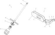
- FIG. 1 Ais an exploded view of the tool assembly of FIG. 1 .
- FIG. 2 Ais a plan view of the tooling tube.
- FIG. 2 Bis side plan view of the internal shaft.
- FIG. 4is a perspective view of the cutting blade of the present invention as formed.
- FIG. 4 Ais a plan view of the cutting blade, the dashed lines representing the sheet from which the cutting blade can be formed.
- FIG. 4 Cis a partial view taken along lines A-A of FIG. 4 B showing one portion of the cutting blade, the opposite portion having been removed.
- FIG. 4 Dis an end view of the cutting blade illustrating the vertical elevation of the cutting blade relative to the attachment portions.
- FIG. 5is a perspective view showing the cutting blade protracted and extending outward from the tooling tube.
- FIG. 6is a side perspective view showing the cutting blade protracted relative to the tooling tube.
- FIG. 7is a side view showing a portion of the cutting blade with dimensions from the attachment knob to the vertical elevation above the attachment means.
- the cutting tool device 100 of the present inventionincludes a detachable vertical cutter 10 , a tool tube 102 , a rotatable retraction and protraction knob 120 and a push pull knob 130 to provide linear cutting capability as the tool 100 is pushed and pulled inward between two vertebral bodies to remove disc tissue and to scrape the bone exposed end plate surfaces.
- a shaft 112further illustrated internal to the tool tube 102 is a shaft 112 .
- the shaft 112provides a way to attach the vertical cutter 10 .
- the tube 102has a “T” shaped end 104 that is adapted to fit in the rotatable knob 120 as illustrated in FIG. 3 .
- the “T” shaped end 104has a knob 120 mounted thereabout so that the knob 120 can rotate without rotating the tube 102 .
- the knob 120has internal threads 122 adapted to engage the threads 110 of the shaft 112 as illustrated in FIG. 2 B .
- the combination of threads 110 , 122are designed so the shaft can be pulled or pushed axially along the longitudinal axis of the tool by the rotation of the knob 120 best illustrated in FIG. 3 .
- a slotis provided in the tool in FIG. 3 exposing the threads 110 of the shaft 112 .
- the threads 110can be moved between positions 105 and 103 or further if so desired.
- This open window 106provides a means for the surgeon to see the amount of travel that the vertical cutter 10 is making relative to the tool tube 102 when it is positioned inside the vertebral bodies.
- the shaft 112has a flat end 116 to which the knob 130 is fixed.
- the vertical cutter 10has attachment ends 12 and 14 with an opening 11 that will conveniently fit on the attachment location 114 of the shaft 112 .
- the openings 11are oriented at 90 degrees to attachment locations 114 .
- the attachment locations 114are positioned on each side of the shaft 112 such that when the vertical cutter 10 is mounted on the attachment shaft 112 and pulled inside the tube 102 it securely holds the vertical cutter 10 in position so that it can be pulled internally within the tube 102 .
- the vertical cutter 10was formed as a single piece, preferably of shaped memory alloy material such as Nitinol wherein the material was cut from a blank sheet approximately 0.5 mm thick.
- the blank sheetis illustrated by dashed lines in FIG. 4 A .
- the attachment ends 12 and 14are at the extremes of this sheet where the cutting blade 20 is interposed between the attachment ends 12 , 14 .
- the width W Bis approximately 2 mm in the exemplary embodiment. Punched through the attachment ends 12 , 14 are the attachment holes 11 as illustrated.
- the cutting blade width W Bis substantially uniform across the cutting blade 20 , however may be slightly narrower at a flat portion 25 .
- the flat portion 25extends about 3 mm in length.
- the cutting blade sides 22 and 24are inclined relative to the attachment ends 12 , 14 and are offset slightly lower than the center line of the attachment ends 12 , 14 . This enables the cutting blade 20 when bent in the configuration shown in FIG. 4 B to take the shape as illustrated.
- the cutting blade sides 22 , 24extend widthwise a distance W T of approximately 10.5 mm in this exemplary embodiment to form a large oval with a flat top.
- the blade side portion 22 on the attachment end 12is shown, the other side of the cutting blade 20 has the end portion 24 and 14 (not illustrated) similarly inclined.
- An acute angleis shown of approximately ⁇ relative to a horizontal plane which can be varied dependent on the length and the amount of height required. However, it is believed important that the angle ⁇ be less than 45 degrees preferably less than 30 degrees as illustrated.
- the cutting blade portion 20has the sides 24 and 22 shown inclined to the flat portion 25 inclined and raised upward relative to the attachment ends 12 , 14 to the flat portion 25 .
- the width of the cutting blade 20is of substantially uniform thickness W B of about 2 mm and has a cutting edge that is also generally uniform in thickness of 0.5 mm or less. This provides a substantially strong and yet flexible blade 20 such that it can be retracted and pulled inside the tube 102 .
- This attachment of the vertical cutter 10is illustrated in FIG. 5 where the thickness of the blade 20 is illustrated as dimension t. In the exemplary vertical cutter 10 , t was about 0.5 mm.
- the vertical cutter 10is also shown in the protracted position where it is free of the tool tube 102 .
- the tool tube 102has an outside diameter OD of approximately 8 mm in this exemplary embodiment with an inside diameter of 6.85 mm.
- the width of the attachment ends 12 , 14is slightly less than the 6.85 mm such that they can slide inwardly to be attached to the shaft 112 at the attachment locations 114 .
- the vertical cutter 10when attached, has a vertical distance from the axis of rotation, this is called the cutting travel distance CT or cutting travel from the axis and it approximately 7.3 mm in the exemplary embodiment. This means that the cutting blade 20 extends above the outside diameter of the tool tube 102 by a distance of approximately 3.3 mm.
- this distance CV extending vertically above or below the tube 102 on an inclinationis achieved when the cutting blade 20 is free from the tube 102 .
- the cutting blade 20will extend vertically upward relative to the axis in such a fashion that the flat end 25 cutting edge can reach a maximum level of 7.3 mm in height to the vertebrae surface above it. This allows the cutting blade 20 to cut not only into the disc material, both the nucleus pulposus and the annulus fibrosus, but also to be able to scrape along the interior surface of the vertebral plate.
- the vertebral platemust be remembered to be somewhat of a saucer shape turned upside down wherein the edges conform inwardly slightly while the inner portion of the vertebral plate is raised in a flattened elevated dome shape. This is important in that the cutting blade 20 is designed to be able to scrape not only the disc material, but also the thin layers of this end plate of the vertebral body. By scraping it, microfractures occur and improved bone surface preparation can be achieved for a fusion implant device. As shown, the flat portion 25 has a width of approximately 3 mm or greater. This enables the device to be pushed and pulled into and out of the disc space without any rotational cutting.
- the cutting blade 20can be slightly retracted and pushed and pulled to cut some material away and then continue to be pushed and pulled in a fully retracted condition due to the flexibility of the cutting blade 20 , it will simply scrape along the bones outer edge removing a thin layer and also provide a good planar surface to receive the fusion implant device.
- This cutting tool 100provides a unique way of removing disc material and preparing two adjacent vertebrae for receiving any spinal fusion implant device.
- the surgeonwill simply locate a position on the patient's back to make an end incision.
- the surgeoncuts the tissue at the location by making a small incision and inserting a solid tapered dilator to allow insertion of an outer guide tube 200 that will hold the tool tube 102 portion of the tool 100 .
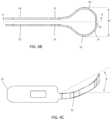
- This outer tube 200is illustrated in FIG. 7 .
- This tube 200is then placed into the small incision in the desired location and inserted partially therein.
- This tube 200will have an outside diameter of approximately 9.2 mm when using a tool tube 102 having an outside diameter of 8 mm.
- the outer tube 200has an inside diameter of approximately slightly greater than 8 mm so that the tool tube 102 can slide freely in and out of this outer sheathing or guide tube 200 .
- the surgeonwill insert the cutting tool 100 with the retracted vertical cutter 10 inside the tool tube 102 which has been sized to pass through the inside diameter of the guide tube 200 while having the cutting blade 10 stowed internally.
- the surgeonwill use the outer tube 200 to space the adjacent vertebral bodies wherein the disc material is intended to be removed. This spacing of the vertebrae allows the tool tube 102 to slide inward to the disc material and extending past the guide tube 200 directly towards or into the disc space. At this point the surgeon protracts the vertical cutter 10 by rotating the knob 120 .
- the surgeoncan either retract if so desired or simply rotate the tool 100 such that it lines up with a vertical downward extension if he has previously cut in a vertical upward position.
- the surgeoncan now cut the lower vertebral body disc tissue above it and prepare that space by repeating the procedure in a push pull manner completing all the cutting without any requirement for rotational cutting of disc material.
- a chamber or void spacethat is basically rectilinear and ideally suited for receiving a spinal implant device is formed.
- the devicecan be retracted and pulled out of the guide tube 200 such that an implant device can be positioned through the guide tube 200 to complete the procedure. While various dimensions have been mentioned for the exemplary embodiment, these dimensions can be varied using the concepts taught herein and will still be within the scope of the present invention.
Landscapes
- Health & Medical Sciences (AREA)
- Life Sciences & Earth Sciences (AREA)
- Surgery (AREA)
- Orthopedic Medicine & Surgery (AREA)
- Engineering & Computer Science (AREA)
- Biomedical Technology (AREA)
- Animal Behavior & Ethology (AREA)
- Public Health (AREA)
- Veterinary Medicine (AREA)
- Heart & Thoracic Surgery (AREA)
- General Health & Medical Sciences (AREA)
- Medical Informatics (AREA)
- Nuclear Medicine, Radiotherapy & Molecular Imaging (AREA)
- Molecular Biology (AREA)
- Oral & Maxillofacial Surgery (AREA)
- Transplantation (AREA)
- Vascular Medicine (AREA)
- Dentistry (AREA)
- Cardiology (AREA)
- Physical Education & Sports Medicine (AREA)
- Neurology (AREA)
- Surgical Instruments (AREA)
- Prostheses (AREA)
Abstract
Description
Claims (14)
Priority Applications (1)
| Application Number | Priority Date | Filing Date | Title |
|---|---|---|---|
| US16/210,497US12023048B2 (en) | 2014-07-31 | 2018-12-05 | Vertical cutter and method of use |
Applications Claiming Priority (4)
| Application Number | Priority Date | Filing Date | Title |
|---|---|---|---|
| US14/448,490US9662123B2 (en) | 2014-07-31 | 2014-07-31 | Vertical cutter and method of use |
| US15/493,783US9918722B2 (en) | 2014-07-31 | 2017-04-21 | Vertical cutter and method of use |
| US15/885,995US10172628B2 (en) | 2014-07-31 | 2018-02-01 | Vertical cutter and method of use |
| US16/210,497US12023048B2 (en) | 2014-07-31 | 2018-12-05 | Vertical cutter and method of use |
Related Parent Applications (1)
| Application Number | Title | Priority Date | Filing Date |
|---|---|---|---|
| US15/885,995ContinuationUS10172628B2 (en) | 2014-07-31 | 2018-02-01 | Vertical cutter and method of use |
Publications (2)
| Publication Number | Publication Date |
|---|---|
| US20190105062A1 US20190105062A1 (en) | 2019-04-11 |
| US12023048B2true US12023048B2 (en) | 2024-07-02 |
Family
ID=55178813
Family Applications (4)
| Application Number | Title | Priority Date | Filing Date |
|---|---|---|---|
| US14/448,490Active2035-07-25US9662123B2 (en) | 2014-07-31 | 2014-07-31 | Vertical cutter and method of use |
| US15/493,783ActiveUS9918722B2 (en) | 2014-07-31 | 2017-04-21 | Vertical cutter and method of use |
| US15/885,995ActiveUS10172628B2 (en) | 2014-07-31 | 2018-02-01 | Vertical cutter and method of use |
| US16/210,497ActiveUS12023048B2 (en) | 2014-07-31 | 2018-12-05 | Vertical cutter and method of use |
Family Applications Before (3)
| Application Number | Title | Priority Date | Filing Date |
|---|---|---|---|
| US14/448,490Active2035-07-25US9662123B2 (en) | 2014-07-31 | 2014-07-31 | Vertical cutter and method of use |
| US15/493,783ActiveUS9918722B2 (en) | 2014-07-31 | 2017-04-21 | Vertical cutter and method of use |
| US15/885,995ActiveUS10172628B2 (en) | 2014-07-31 | 2018-02-01 | Vertical cutter and method of use |
Country Status (1)
| Country | Link |
|---|---|
| US (4) | US9662123B2 (en) |
Families Citing this family (21)
| Publication number | Priority date | Publication date | Assignee | Title |
|---|---|---|---|---|
| CA2833543A1 (en) | 2011-05-05 | 2012-11-08 | Zyga Technology, Inc. | Sacroiliac fusion system |
| US9861375B2 (en)* | 2014-01-09 | 2018-01-09 | Zyga Technology, Inc. | Undercutting system for use in conjunction with sacroiliac fusion |
| BR112017008135B1 (en) | 2014-10-19 | 2022-11-16 | T.A.G. Medical Devices - Agriculture Cooperative Ltd | SET INCLUDING A GUIDANCE SYSTEM AND BONE MATERIAL REMOVAL DEVICE AND METHOD FOR DRILLING A BONE TUNNEL INTO A BONE |
| JP7007190B2 (en)* | 2015-04-09 | 2022-01-24 | ティー.エー.ジー. メディカル デヴァイシス-アグリカルチャー コーポラティヴ リミテッド | Bone material remover and how to use it |
| FR3040869B1 (en)* | 2015-09-16 | 2017-10-20 | Vexim | CONTROLLED ROD CONTROL MECHANISM |
| EP3799806A1 (en) | 2016-02-11 | 2021-04-07 | T.A.G. Medical Devices - Agriculture Cooperative Ltd. | Bone material removal device |
| EP3448274B1 (en) | 2016-04-24 | 2024-05-15 | T.A.G. Medical Products Corporation Ltd. | Guiding device |
| DE102016212300B4 (en)* | 2016-07-06 | 2018-03-15 | Eberle Gmbh & Co. Kg | Medical instrument for the removal of cancellous bone |
| US10743891B2 (en)* | 2016-07-13 | 2020-08-18 | Washington University | Discectomy instrument |
| EP4368128A3 (en) | 2016-09-07 | 2024-07-17 | Vertos Medical, Inc. | Percutaneous lateral recess resection methods and instruments |
| US11160577B2 (en) | 2017-08-01 | 2021-11-02 | Advance Research System, Llc | Lateral disc cutter |
| US11633205B1 (en) | 2017-08-01 | 2023-04-25 | Advance Research System, Llc | Lateral disc cutter with replaceable blades |
| TWI669139B (en)* | 2017-09-11 | 2019-08-21 | 財團法人工業技術研究院 | Implanting device |
| CN109481083B (en) | 2017-09-11 | 2021-06-01 | 财团法人工业技术研究院 | implanted device |
| TWI652037B (en) | 2017-12-28 | 2019-03-01 | 財團法人工業技術研究院 | Expandable orthopedic implant |
| US10512495B2 (en)* | 2017-12-28 | 2019-12-24 | Industrial Technology Research Institute | Method for fabricating medical device and applications thereof |
| IL280574B2 (en) | 2018-08-01 | 2025-08-01 | Tag Medical Devices Agriculture Coop Ltd | Adjustable drilling device and method for using the same |
| US11446163B1 (en) | 2019-04-05 | 2022-09-20 | Advanced Research Systems, LLC | Cannulated endplate plunger |
| CN213606670U (en)* | 2020-08-12 | 2021-07-06 | 山东冠龙医疗用品有限公司 | Intervertebral bilateral curet |
| CN113116453A (en)* | 2021-04-12 | 2021-07-16 | 蒋二波 | Curet for orthopedics |
| US20230404561A1 (en) | 2022-06-16 | 2023-12-21 | Vertos Medical, Inc. | Integrated instrument assembly |
Citations (90)
| Publication number | Priority date | Publication date | Assignee | Title |
|---|---|---|---|---|
| US879297A (en)* | 1907-04-03 | 1908-02-18 | Frank T M Moormeister | Uterine curette. |
| US1015461A (en) | 1911-06-26 | 1912-01-23 | Frank J Vlchek | Scraper. |
| US2767703A (en)* | 1955-01-07 | 1956-10-23 | Herbert E Nieburgs | Exploratory device for cell specimens |
| US2876777A (en) | 1955-07-11 | 1959-03-10 | Jr George Kees | Sub-level cutting tool |
| US2945490A (en)* | 1958-02-25 | 1960-07-19 | George W Westcott | Surgical instrument for cervical biopsy |
| US3502082A (en)* | 1967-07-10 | 1970-03-24 | Helen E Chatfield | Curette with disposable band loop blade |
| US3635222A (en)* | 1970-07-31 | 1972-01-18 | Ralph R Robinson | Angular curette |
| US4210146A (en) | 1978-06-01 | 1980-07-01 | Anton Banko | Surgical instrument with flexible blade |
| US4338952A (en)* | 1979-01-24 | 1982-07-13 | Arts Et Techniques Nouvelles | Device for taking samples of endometrium |
| US4932957A (en) | 1986-09-23 | 1990-06-12 | Ronald J. Zwick, Inc. | Endocervical curette |
| US5178625A (en)* | 1989-12-07 | 1993-01-12 | Evi Corporation | Catheter atherotome |
| US5250061A (en) | 1988-09-08 | 1993-10-05 | Michelson Gary K | Ring currette |
| US5275610A (en)* | 1991-05-13 | 1994-01-04 | Cook Incorporated | Surgical retractors and method of use |
| US5301684A (en)* | 1993-04-27 | 1994-04-12 | International Electronic Technology Corp. | Biopsy needle |
| US5304190A (en)* | 1992-05-08 | 1994-04-19 | Ethicon, Inc. | Endoscopic cutting apparatus |
| US5509923A (en)* | 1989-08-16 | 1996-04-23 | Raychem Corporation | Device for dissecting, grasping, or cutting an object |
| US5591170A (en)* | 1994-10-14 | 1997-01-07 | Genesis Orthopedics | Intramedullary bone cutting saw |
| US5678572A (en)* | 1995-01-12 | 1997-10-21 | Shaw; Dein | Cavity expanding device for laparoscopic surgery |
| US5697889A (en) | 1994-03-16 | 1997-12-16 | Gus J. Slotman | Surgical instruments useful for endoscopic spinal procedures |
| US5709697A (en) | 1995-11-22 | 1998-01-20 | United States Surgical Corporation | Apparatus and method for removing tissue |
| US5755732A (en) | 1994-03-16 | 1998-05-26 | United States Surgical Corporation | Surgical instruments useful for endoscopic spinal procedures |
| US5893860A (en)* | 1997-03-17 | 1999-04-13 | Ripich; Robert J. | Tongue scraper |
| US5902314A (en)* | 1998-01-22 | 1999-05-11 | Koch; Craig S. | Medical instrument for removing lumen obstructions |
| US20020111564A1 (en)* | 1998-04-08 | 2002-08-15 | Senorx, Inc. | Tissue acquisition system and method of use |
| US20020173813A1 (en)* | 2001-04-05 | 2002-11-21 | Peterson Francis C. | Circumferential resecting reamer tool |
| US6506151B2 (en) | 1998-04-09 | 2003-01-14 | Sdgi Holdings, Inc. | Method and instrumentation for posterior interbody fusion |
| US6679897B2 (en) | 2001-08-14 | 2004-01-20 | Gary D. Josephson | Adenoid curette |
| US6746451B2 (en)* | 2001-06-01 | 2004-06-08 | Lance M. Middleton | Tissue cavitation device and method |
| US20050113838A1 (en)* | 2003-09-03 | 2005-05-26 | Kyphon Inc. | Devices for creating voids in interior body regions and related methods |
| US20050182417A1 (en)* | 2004-02-12 | 2005-08-18 | Pagano Paul J. | Surgical instrumentation and method for treatment of a spinal structure |
| US20050222598A1 (en)* | 2004-04-05 | 2005-10-06 | Manoa Medical, Inc., A Delaware Corporation | Tissue cutting device |
| US7060073B2 (en) | 1999-10-21 | 2006-06-13 | Sdgi Holdings, Inc. | Devices and techniques for a posterior lateral disc space approach |
| US20060184188A1 (en) | 2002-11-08 | 2006-08-17 | Li Lehmann K | Transpedicular intervertebral disk access methods and devices |
| US20060276816A1 (en)* | 2005-06-06 | 2006-12-07 | Concept Matrix, Llc | Multi-Blade Curette Tool |
| US7153303B2 (en) | 2002-06-19 | 2006-12-26 | Sdgi Holdings, Inc. | Guide and blade for contouring vertebral bodies |
| US20070060933A1 (en)* | 2005-07-11 | 2007-03-15 | Meera Sankaran | Curette heads |
| US20070123889A1 (en)* | 2005-10-14 | 2007-05-31 | Malandain Hugues F | Mechanical cavity-creation surgical device and methods and kits for using such devices |
| US20080091227A1 (en)* | 2006-08-25 | 2008-04-17 | Baxano, Inc. | Surgical probe and method of making |
| US20080103504A1 (en)* | 2006-10-30 | 2008-05-01 | Schmitz Gregory P | Percutaneous spinal stenosis treatment |
| US20080114364A1 (en)* | 2006-11-15 | 2008-05-15 | Aoi Medical, Inc. | Tissue cavitation device and method |
| US20080183100A1 (en)* | 2006-12-08 | 2008-07-31 | Hardin David M | Wire-guided curette |
| US20080221505A1 (en)* | 2007-03-07 | 2008-09-11 | Andres Betts | Expandable Blade Device for Stabilizing Compression Fractures |
| US20080249552A1 (en)* | 2004-02-23 | 2008-10-09 | Eliahu Eliachar | Working tool for medical purposes with rotating blade of adjustable size and a method thereof |
| US20090054898A1 (en)* | 2007-03-26 | 2009-02-26 | Joe Gleason | Articulating Shaper |
| US7500977B2 (en) | 2003-10-23 | 2009-03-10 | Trans1 Inc. | Method and apparatus for manipulating material in the spine |
| US20090093829A1 (en)* | 2007-10-09 | 2009-04-09 | Cook Incorporated | Chronic total occlusion (CTO) removal device |
| US20090275951A1 (en)* | 2008-04-30 | 2009-11-05 | Arcenio Gregory B | Percutaneous discectomy and endplate preparation tool |
| US7632274B2 (en) | 2000-02-16 | 2009-12-15 | Trans1 Inc. | Thin cutter blades with retaining film for preparing intervertebral disc spaces |
| US20100249785A1 (en)* | 2007-03-07 | 2010-09-30 | Andres Betts | Betts Osteotome |
| US20100274272A1 (en)* | 2009-04-23 | 2010-10-28 | Rafael Medina | Instrument And Method For Creating A Controlled Capsulorhexis For Cataract Surgery |
| US20100280407A1 (en)* | 2007-11-20 | 2010-11-04 | Polster Joshua M | Method and apparatus for tissue sampling |
| US20110184447A1 (en)* | 2010-01-26 | 2011-07-28 | Warsaw Orthopedic, Inc. | Surgical cutting tool and method |
| US20110184420A1 (en) | 2010-01-22 | 2011-07-28 | Trans1 Inc. | Abrading tool for preparing intervertebral disc spaces |
| US20110264133A1 (en)* | 2010-03-01 | 2011-10-27 | Tyco Healthcare Group Lp | Introducer sheaths, thrombus collection devices and associated methods |
| US20110319899A1 (en)* | 2010-06-24 | 2011-12-29 | O'neil Michael J | Flexible Vertebral Body Shavers |
| US8114084B2 (en)* | 2007-03-07 | 2012-02-14 | Vertech, Inc. | Expandable blade device for stabilizing compression fractures |
| US8172853B2 (en) | 1999-01-25 | 2012-05-08 | Warsaw Orthopedic, Inc. | Instrumentation for creating an intervertebral space for receiving an implant |
| US8172848B2 (en) | 2007-04-27 | 2012-05-08 | Spinemedica, Llc | Surgical instruments for spinal disc implants and related methods |
| US20120209274A1 (en)* | 2011-02-10 | 2012-08-16 | Wright Medical Technology, Inc. | Expandable surgical device |
| US20120271313A1 (en) | 2011-04-21 | 2012-10-25 | Warsaw Orthopedic, Inc. | Long scraper tool for discectomy |
| US8348950B2 (en)* | 2010-01-04 | 2013-01-08 | Zyga Technology, Inc. | Sacroiliac fusion system |
| US20130018376A1 (en)* | 2011-07-15 | 2013-01-17 | Samuel Yoon | Devices and Methods For the Preparation of Intervertebral Discs |
| US8469959B2 (en) | 2010-02-11 | 2013-06-25 | Warsaw Orthopedic, Inc. | Bone preparation device |
| US20130218144A1 (en)* | 2012-02-16 | 2013-08-22 | Shaw P. Wan | Stone retrieval device |
| US8523866B2 (en) | 2007-02-09 | 2013-09-03 | Christopher G. Sidebotham | Modular tapered hollow reamer for medical applications |
| US20130238006A1 (en)* | 2012-03-06 | 2013-09-12 | Michael J. O'Neil | Conformable Soft Tissue Removal Instruments |
| US20130325048A1 (en)* | 2012-05-31 | 2013-12-05 | Mark Weiman | Laparoscopic Manipulation |
| US20140257297A1 (en)* | 2013-03-08 | 2014-09-11 | Arthrex, Inc. | Expandable reamer |
| US20140378989A1 (en)* | 2013-06-21 | 2014-12-25 | Boston Scienific Scimed, Inc. | Resection devices and related methods of deployment |
| US20150045821A1 (en)* | 2011-10-07 | 2015-02-12 | Misonix, Incorportated | Ultrasonic osteotome |
| US20150105692A1 (en)* | 2012-08-13 | 2015-04-16 | Olympus Medical Systems Corp. | Treatment device for endoscope |
| US9028499B2 (en)* | 2011-02-23 | 2015-05-12 | The Regents Of The University Of California | Bone cutting device |
| US20150157357A1 (en)* | 2013-12-02 | 2015-06-11 | Novon Solutions, LLC | Adjustable Curette |
| US9101371B2 (en)* | 2010-11-03 | 2015-08-11 | Zyga Technology, Inc. | Method of repairing sacroiliac fusion |
| US20150282817A1 (en)* | 2010-04-12 | 2015-10-08 | K2M, Inc. | Expandable reamer and method of use |
| US20150335340A1 (en)* | 2013-01-07 | 2015-11-26 | Pi-Cardia Ltd. | Stabilizer assembly for fracturing calcifications in heart valves |
| US9332995B2 (en) | 2012-09-25 | 2016-05-10 | Russo Inventions, Llc | Bone-harvesting tool |
| US9364253B1 (en)* | 2015-12-11 | 2016-06-14 | Oscar R Polo | Tissue severing device having dual reciprocating looped blades and methods of use |
| US20170156889A1 (en)* | 2013-12-23 | 2017-06-08 | Jmea Corporation | Devices And Methods For Preparation Of Vertebral Members |
| US20170245861A1 (en)* | 2016-02-26 | 2017-08-31 | Sentreheart, Inc. | Devices and methods for left atrial appendage closure |
| US9974548B2 (en)* | 2014-09-09 | 2018-05-22 | Russo Surgical Tools, LLC | Surgical instrument for harvesting bone |
| US20190038304A1 (en)* | 2017-08-01 | 2019-02-07 | Advance Research System, Llc | Lateral disc cutter |
| US10413332B2 (en)* | 2016-04-25 | 2019-09-17 | Imds Llc | Joint fusion implant and methods |
| US20190314089A1 (en)* | 2018-04-17 | 2019-10-17 | Acclarent, Inc. | Curette with navigation sensor |
| US10531986B2 (en)* | 2016-06-14 | 2020-01-14 | Quest Products, Llc | Ear cleaner |
| US20200229829A1 (en)* | 2017-02-01 | 2020-07-23 | Spinal Stabilization Technologies | A surgical cutting instrument |
| US10752356B2 (en) | 2017-01-24 | 2020-08-25 | Optim Corporation | Moving device, moving device control method, program, and moving device control system |
| US10928011B2 (en) | 2016-07-14 | 2021-02-23 | Signify Holding B.V. | Solid-state lighting lamp |
| US20210085359A1 (en)* | 2019-09-20 | 2021-03-25 | Spineology Inc. | Articulating curette |
| US20220071770A1 (en)* | 2010-01-04 | 2022-03-10 | Surgalign Spine Technologies, Inc. | Sacroiliac fusion system |
Family Cites Families (3)
| Publication number | Priority date | Publication date | Assignee | Title |
|---|---|---|---|---|
| US752356A (en)* | 1904-02-16 | Curette | ||
| US928011A (en)* | 1908-12-31 | 1909-07-13 | William A Whitlock | Surgical instrument. |
| US5904690A (en)* | 1989-08-16 | 1999-05-18 | Medtronic, Inc. | Device or apparatus for manipulating matter |
- 2014
- 2014-07-31USUS14/448,490patent/US9662123B2/enactiveActive
- 2017
- 2017-04-21USUS15/493,783patent/US9918722B2/enactiveActive
- 2018
- 2018-02-01USUS15/885,995patent/US10172628B2/enactiveActive
- 2018-12-05USUS16/210,497patent/US12023048B2/enactiveActive
Patent Citations (102)
| Publication number | Priority date | Publication date | Assignee | Title |
|---|---|---|---|---|
| US879297A (en)* | 1907-04-03 | 1908-02-18 | Frank T M Moormeister | Uterine curette. |
| US1015461A (en) | 1911-06-26 | 1912-01-23 | Frank J Vlchek | Scraper. |
| US2767703A (en)* | 1955-01-07 | 1956-10-23 | Herbert E Nieburgs | Exploratory device for cell specimens |
| US2876777A (en) | 1955-07-11 | 1959-03-10 | Jr George Kees | Sub-level cutting tool |
| US2945490A (en)* | 1958-02-25 | 1960-07-19 | George W Westcott | Surgical instrument for cervical biopsy |
| US3502082A (en)* | 1967-07-10 | 1970-03-24 | Helen E Chatfield | Curette with disposable band loop blade |
| US3635222A (en)* | 1970-07-31 | 1972-01-18 | Ralph R Robinson | Angular curette |
| US4210146A (en) | 1978-06-01 | 1980-07-01 | Anton Banko | Surgical instrument with flexible blade |
| US4338952A (en)* | 1979-01-24 | 1982-07-13 | Arts Et Techniques Nouvelles | Device for taking samples of endometrium |
| US4932957A (en) | 1986-09-23 | 1990-06-12 | Ronald J. Zwick, Inc. | Endocervical curette |
| US5250061A (en) | 1988-09-08 | 1993-10-05 | Michelson Gary K | Ring currette |
| US5509923A (en)* | 1989-08-16 | 1996-04-23 | Raychem Corporation | Device for dissecting, grasping, or cutting an object |
| US5178625A (en)* | 1989-12-07 | 1993-01-12 | Evi Corporation | Catheter atherotome |
| US5275610A (en)* | 1991-05-13 | 1994-01-04 | Cook Incorporated | Surgical retractors and method of use |
| US5304190A (en)* | 1992-05-08 | 1994-04-19 | Ethicon, Inc. | Endoscopic cutting apparatus |
| US5301684A (en)* | 1993-04-27 | 1994-04-12 | International Electronic Technology Corp. | Biopsy needle |
| US5697889A (en) | 1994-03-16 | 1997-12-16 | Gus J. Slotman | Surgical instruments useful for endoscopic spinal procedures |
| US5755732A (en) | 1994-03-16 | 1998-05-26 | United States Surgical Corporation | Surgical instruments useful for endoscopic spinal procedures |
| US5591170A (en)* | 1994-10-14 | 1997-01-07 | Genesis Orthopedics | Intramedullary bone cutting saw |
| US5678572A (en)* | 1995-01-12 | 1997-10-21 | Shaw; Dein | Cavity expanding device for laparoscopic surgery |
| US5709697A (en) | 1995-11-22 | 1998-01-20 | United States Surgical Corporation | Apparatus and method for removing tissue |
| US5893860A (en)* | 1997-03-17 | 1999-04-13 | Ripich; Robert J. | Tongue scraper |
| US5902314A (en)* | 1998-01-22 | 1999-05-11 | Koch; Craig S. | Medical instrument for removing lumen obstructions |
| US20020111564A1 (en)* | 1998-04-08 | 2002-08-15 | Senorx, Inc. | Tissue acquisition system and method of use |
| US6506151B2 (en) | 1998-04-09 | 2003-01-14 | Sdgi Holdings, Inc. | Method and instrumentation for posterior interbody fusion |
| US8172853B2 (en) | 1999-01-25 | 2012-05-08 | Warsaw Orthopedic, Inc. | Instrumentation for creating an intervertebral space for receiving an implant |
| US7060073B2 (en) | 1999-10-21 | 2006-06-13 | Sdgi Holdings, Inc. | Devices and techniques for a posterior lateral disc space approach |
| US7632274B2 (en) | 2000-02-16 | 2009-12-15 | Trans1 Inc. | Thin cutter blades with retaining film for preparing intervertebral disc spaces |
| US20020173813A1 (en)* | 2001-04-05 | 2002-11-21 | Peterson Francis C. | Circumferential resecting reamer tool |
| US20040267269A1 (en) | 2001-06-01 | 2004-12-30 | Middleton Lance M. | Tissue cavitation device and method |
| US6746451B2 (en)* | 2001-06-01 | 2004-06-08 | Lance M. Middleton | Tissue cavitation device and method |
| US6679897B2 (en) | 2001-08-14 | 2004-01-20 | Gary D. Josephson | Adenoid curette |
| US7153303B2 (en) | 2002-06-19 | 2006-12-26 | Sdgi Holdings, Inc. | Guide and blade for contouring vertebral bodies |
| US20060184188A1 (en) | 2002-11-08 | 2006-08-17 | Li Lehmann K | Transpedicular intervertebral disk access methods and devices |
| US20050113838A1 (en)* | 2003-09-03 | 2005-05-26 | Kyphon Inc. | Devices for creating voids in interior body regions and related methods |
| US7588574B2 (en) | 2003-10-23 | 2009-09-15 | Trans1 Inc. | Kits for enabling axial access and procedures in the spine |
| US7914535B2 (en) | 2003-10-23 | 2011-03-29 | Trans1 Inc. | Method and apparatus for manipulating material in the spine |
| US8052613B2 (en) | 2003-10-23 | 2011-11-08 | Trans1 Inc. | Spinal nucleus extraction tool |
| US7530993B2 (en) | 2003-10-23 | 2009-05-12 | Trans1 Inc. | Method of spinal fixation |
| US7500977B2 (en) | 2003-10-23 | 2009-03-10 | Trans1 Inc. | Method and apparatus for manipulating material in the spine |
| US20050182417A1 (en)* | 2004-02-12 | 2005-08-18 | Pagano Paul J. | Surgical instrumentation and method for treatment of a spinal structure |
| US20060116690A1 (en)* | 2004-02-12 | 2006-06-01 | Pagano Paul J | Surgical instrumentation and method for treatment of a spinal structure |
| US20080249552A1 (en)* | 2004-02-23 | 2008-10-09 | Eliahu Eliachar | Working tool for medical purposes with rotating blade of adjustable size and a method thereof |
| US20050222598A1 (en)* | 2004-04-05 | 2005-10-06 | Manoa Medical, Inc., A Delaware Corporation | Tissue cutting device |
| US20060276816A1 (en)* | 2005-06-06 | 2006-12-07 | Concept Matrix, Llc | Multi-Blade Curette Tool |
| US20070060933A1 (en)* | 2005-07-11 | 2007-03-15 | Meera Sankaran | Curette heads |
| US20070123889A1 (en)* | 2005-10-14 | 2007-05-31 | Malandain Hugues F | Mechanical cavity-creation surgical device and methods and kits for using such devices |
| US20080091227A1 (en)* | 2006-08-25 | 2008-04-17 | Baxano, Inc. | Surgical probe and method of making |
| US20080103504A1 (en)* | 2006-10-30 | 2008-05-01 | Schmitz Gregory P | Percutaneous spinal stenosis treatment |
| US20080114364A1 (en)* | 2006-11-15 | 2008-05-15 | Aoi Medical, Inc. | Tissue cavitation device and method |
| US20080183100A1 (en)* | 2006-12-08 | 2008-07-31 | Hardin David M | Wire-guided curette |
| US8523866B2 (en) | 2007-02-09 | 2013-09-03 | Christopher G. Sidebotham | Modular tapered hollow reamer for medical applications |
| US8480675B2 (en)* | 2007-03-07 | 2013-07-09 | Vertech, Inc. | Betts osteotome |
| US8206391B2 (en)* | 2007-03-07 | 2012-06-26 | Vertech, Inc. | Expandable blade device for stabilizing compression fractures |
| US20100249785A1 (en)* | 2007-03-07 | 2010-09-30 | Andres Betts | Betts Osteotome |
| US20080221505A1 (en)* | 2007-03-07 | 2008-09-11 | Andres Betts | Expandable Blade Device for Stabilizing Compression Fractures |
| US8114084B2 (en)* | 2007-03-07 | 2012-02-14 | Vertech, Inc. | Expandable blade device for stabilizing compression fractures |
| US20090054898A1 (en)* | 2007-03-26 | 2009-02-26 | Joe Gleason | Articulating Shaper |
| US8172848B2 (en) | 2007-04-27 | 2012-05-08 | Spinemedica, Llc | Surgical instruments for spinal disc implants and related methods |
| US20090093829A1 (en)* | 2007-10-09 | 2009-04-09 | Cook Incorporated | Chronic total occlusion (CTO) removal device |
| US20100280407A1 (en)* | 2007-11-20 | 2010-11-04 | Polster Joshua M | Method and apparatus for tissue sampling |
| US20090275951A1 (en)* | 2008-04-30 | 2009-11-05 | Arcenio Gregory B | Percutaneous discectomy and endplate preparation tool |
| US8221425B2 (en) | 2008-04-30 | 2012-07-17 | Warsaw Orthopedic, Inc. | Percutaneous discectomy and endplate preparation tool |
| US20100274272A1 (en)* | 2009-04-23 | 2010-10-28 | Rafael Medina | Instrument And Method For Creating A Controlled Capsulorhexis For Cataract Surgery |
| US8348950B2 (en)* | 2010-01-04 | 2013-01-08 | Zyga Technology, Inc. | Sacroiliac fusion system |
| US20220071770A1 (en)* | 2010-01-04 | 2022-03-10 | Surgalign Spine Technologies, Inc. | Sacroiliac fusion system |
| US20110184420A1 (en) | 2010-01-22 | 2011-07-28 | Trans1 Inc. | Abrading tool for preparing intervertebral disc spaces |
| US8696672B2 (en)* | 2010-01-22 | 2014-04-15 | Baxano Surgical, Inc. | Abrading tool for preparing intervertebral disc spaces |
| US20110184447A1 (en)* | 2010-01-26 | 2011-07-28 | Warsaw Orthopedic, Inc. | Surgical cutting tool and method |
| US8469959B2 (en) | 2010-02-11 | 2013-06-25 | Warsaw Orthopedic, Inc. | Bone preparation device |
| US20110264133A1 (en)* | 2010-03-01 | 2011-10-27 | Tyco Healthcare Group Lp | Introducer sheaths, thrombus collection devices and associated methods |
| US20150282817A1 (en)* | 2010-04-12 | 2015-10-08 | K2M, Inc. | Expandable reamer and method of use |
| US20110319899A1 (en)* | 2010-06-24 | 2011-12-29 | O'neil Michael J | Flexible Vertebral Body Shavers |
| US9101371B2 (en)* | 2010-11-03 | 2015-08-11 | Zyga Technology, Inc. | Method of repairing sacroiliac fusion |
| US20120209274A1 (en)* | 2011-02-10 | 2012-08-16 | Wright Medical Technology, Inc. | Expandable surgical device |
| US9028499B2 (en)* | 2011-02-23 | 2015-05-12 | The Regents Of The University Of California | Bone cutting device |
| US20120271313A1 (en) | 2011-04-21 | 2012-10-25 | Warsaw Orthopedic, Inc. | Long scraper tool for discectomy |
| US9848890B2 (en) | 2011-07-15 | 2017-12-26 | Globus Medical, Inc. | Devices and methods for the preparation of intervertebral discs |
| US20130018376A1 (en)* | 2011-07-15 | 2013-01-17 | Samuel Yoon | Devices and Methods For the Preparation of Intervertebral Discs |
| US20150045821A1 (en)* | 2011-10-07 | 2015-02-12 | Misonix, Incorportated | Ultrasonic osteotome |
| US20130218144A1 (en)* | 2012-02-16 | 2013-08-22 | Shaw P. Wan | Stone retrieval device |
| US9226764B2 (en) | 2012-03-06 | 2016-01-05 | DePuy Synthes Products, Inc. | Conformable soft tissue removal instruments |
| US20130238006A1 (en)* | 2012-03-06 | 2013-09-12 | Michael J. O'Neil | Conformable Soft Tissue Removal Instruments |
| US20130325048A1 (en)* | 2012-05-31 | 2013-12-05 | Mark Weiman | Laparoscopic Manipulation |
| US20150105692A1 (en)* | 2012-08-13 | 2015-04-16 | Olympus Medical Systems Corp. | Treatment device for endoscope |
| US9332995B2 (en) | 2012-09-25 | 2016-05-10 | Russo Inventions, Llc | Bone-harvesting tool |
| US20150335340A1 (en)* | 2013-01-07 | 2015-11-26 | Pi-Cardia Ltd. | Stabilizer assembly for fracturing calcifications in heart valves |
| US20140257297A1 (en)* | 2013-03-08 | 2014-09-11 | Arthrex, Inc. | Expandable reamer |
| US20140378989A1 (en)* | 2013-06-21 | 2014-12-25 | Boston Scienific Scimed, Inc. | Resection devices and related methods of deployment |
| US20150157357A1 (en)* | 2013-12-02 | 2015-06-11 | Novon Solutions, LLC | Adjustable Curette |
| US20170156889A1 (en)* | 2013-12-23 | 2017-06-08 | Jmea Corporation | Devices And Methods For Preparation Of Vertebral Members |
| US9974548B2 (en)* | 2014-09-09 | 2018-05-22 | Russo Surgical Tools, LLC | Surgical instrument for harvesting bone |
| US9364253B1 (en)* | 2015-12-11 | 2016-06-14 | Oscar R Polo | Tissue severing device having dual reciprocating looped blades and methods of use |
| US20170245861A1 (en)* | 2016-02-26 | 2017-08-31 | Sentreheart, Inc. | Devices and methods for left atrial appendage closure |
| US10413332B2 (en)* | 2016-04-25 | 2019-09-17 | Imds Llc | Joint fusion implant and methods |
| US10531986B2 (en)* | 2016-06-14 | 2020-01-14 | Quest Products, Llc | Ear cleaner |
| US10928011B2 (en) | 2016-07-14 | 2021-02-23 | Signify Holding B.V. | Solid-state lighting lamp |
| US10752356B2 (en) | 2017-01-24 | 2020-08-25 | Optim Corporation | Moving device, moving device control method, program, and moving device control system |
| US20200229829A1 (en)* | 2017-02-01 | 2020-07-23 | Spinal Stabilization Technologies | A surgical cutting instrument |
| US20190038304A1 (en)* | 2017-08-01 | 2019-02-07 | Advance Research System, Llc | Lateral disc cutter |
| US20190314089A1 (en)* | 2018-04-17 | 2019-10-17 | Acclarent, Inc. | Curette with navigation sensor |
| US20210085359A1 (en)* | 2019-09-20 | 2021-03-25 | Spineology Inc. | Articulating curette |
Also Published As
| Publication number | Publication date |
|---|---|
| US20170224360A1 (en) | 2017-08-10 |
| US20190105062A1 (en) | 2019-04-11 |
| US9662123B2 (en) | 2017-05-30 |
| US9918722B2 (en) | 2018-03-20 |
| US20160030060A1 (en) | 2016-02-04 |
| US10172628B2 (en) | 2019-01-08 |
| US20180153561A1 (en) | 2018-06-07 |
Similar Documents
| Publication | Publication Date | Title |
|---|---|---|
| US12023048B2 (en) | Vertical cutter and method of use | |
| US11877756B2 (en) | Systems and methods for decorticating the sacroiliac joint | |
| US12285342B2 (en) | Method and apparatus for minimally invasive insertion of intervertebral implants | |
| US11707285B2 (en) | Undercutting system for use in conjunction with sacroiliac fusion | |
| US10238508B2 (en) | Devices and methods for preparation of vertebral members | |
| US9757246B1 (en) | Methods and apparatus for performing spine surgery | |
| US8568306B2 (en) | Surgical retractor system | |
| US7429264B2 (en) | Minimally invasive deployable cutting instrument | |
| US20180042735A1 (en) | System and method for spinal surgery utilizing a low-diameter sheathed portal shielding an oblique lateral approach through kambin's triangle | |
| US20130267836A1 (en) | Guide pin | |
| US20050165405A1 (en) | Minimal access apparatus for endoscopic spinal surgery | |
| US20140257489A1 (en) | Method and apparatus for minimally invasive insertion of intervertebral implants | |
| JP2005538748A (en) | Apparatus and method for discectomy | |
| JP2014517710A (en) | Method and apparatus for minimally invasive insertion of an intervertebral implant | |
| US20080058674A1 (en) | Tissue extraction device and method of using the same | |
| WO2013150391A1 (en) | Conic retraction | |
| US20110028979A1 (en) | Spinal Implant Clearing Gouge | |
| JP2008543421A (en) | Minimally invasive instruments and methods for preprocessing vertebral endplates | |
| US20250195102A1 (en) | Multi-portal surgical marking guides and access instruments |
Legal Events
| Date | Code | Title | Description |
|---|---|---|---|
| AS | Assignment | Owner name:AMENDIA, INC., GEORGIA Free format text:ASSIGNMENT OF ASSIGNORS INTEREST;ASSIGNORS:TALLY, WILLIAM CARLTON;BARRA, KENNETH RICHARD;REEL/FRAME:048639/0488 Effective date:20140731 | |
| STPP | Information on status: patent application and granting procedure in general | Free format text:DOCKETED NEW CASE - READY FOR EXAMINATION | |
| AS | Assignment | Owner name:SPINAL ELEMENTS, INC., CALIFORNIA Free format text:MERGER AND CHANGE OF NAME;ASSIGNORS:SPINAL ELEMENTS, INC.;AMENDIA, INC.;REEL/FRAME:051665/0979 Effective date:20191231 | |
| AS | Assignment | Owner name:ANTARES CAPITAL LP, AS AGENT, ILLINOIS Free format text:SECURITY INTEREST;ASSIGNOR:SPINAL ELEMENTS, INC.;REEL/FRAME:051856/0135 Effective date:20200121 | |
| AS | Assignment | Owner name:CORTLAND CAPITAL MARKET SERVICES LLC, AS AGENT, ILLINOIS Free format text:SECURITY INTEREST;ASSIGNOR:SPINAL ELEMENTS, INC.;REEL/FRAME:051983/0474 Effective date:20200121 | |
| STPP | Information on status: patent application and granting procedure in general | Free format text:NON FINAL ACTION MAILED | |
| STPP | Information on status: patent application and granting procedure in general | Free format text:RESPONSE TO NON-FINAL OFFICE ACTION ENTERED AND FORWARDED TO EXAMINER | |
| STPP | Information on status: patent application and granting procedure in general | Free format text:FINAL REJECTION MAILED | |
| STPP | Information on status: patent application and granting procedure in general | Free format text:DOCKETED NEW CASE - READY FOR EXAMINATION | |
| STPP | Information on status: patent application and granting procedure in general | Free format text:NON FINAL ACTION MAILED | |
| STPP | Information on status: patent application and granting procedure in general | Free format text:RESPONSE TO NON-FINAL OFFICE ACTION ENTERED AND FORWARDED TO EXAMINER | |
| STPP | Information on status: patent application and granting procedure in general | Free format text:FINAL REJECTION MAILED | |
| STPP | Information on status: patent application and granting procedure in general | Free format text:NON FINAL ACTION MAILED | |
| STPP | Information on status: patent application and granting procedure in general | Free format text:RESPONSE TO NON-FINAL OFFICE ACTION ENTERED AND FORWARDED TO EXAMINER | |
| STPP | Information on status: patent application and granting procedure in general | Free format text:NOTICE OF ALLOWANCE MAILED -- APPLICATION RECEIVED IN OFFICE OF PUBLICATIONS | |
| AS | Assignment | Owner name:PERCEPTIVE CREDIT HOLDINGS IV, LP, NEW YORK Free format text:SECURITY INTEREST;ASSIGNORS:SPINAL ELEMENTS, INC.;CUSTOM SPINE ACQUISITION, INC.;OMNI ACQUISITION INC.;REEL/FRAME:067596/0295 Effective date:20240531 | |
| AS | Assignment | Owner name:SPINAL ELEMENTS, INC. (F.K.A. AMENDIA, INC.), CALIFORNIA Free format text:RELEASE BY SECURED PARTY;ASSIGNOR:CORTLAND CAPITAL MARKET SERVICES LLC, AS AGENT;REEL/FRAME:067605/0676 Effective date:20240531 Owner name:SPINAL ELEMENTS, INC. (F.K.A. AMENDIA, INC.), CALIFORNIA Free format text:RELEASE BY SECURED PARTY;ASSIGNOR:ANTARES CAPITAL LP, AS ADMINISTRATIVE AGENT;REEL/FRAME:067605/0626 Effective date:20240531 | |
| STPP | Information on status: patent application and granting procedure in general | Free format text:PUBLICATIONS -- ISSUE FEE PAYMENT VERIFIED | |
| STCF | Information on status: patent grant | Free format text:PATENTED CASE |