US12023005B2 - Positioning a tube in a lumen via transillumination - Google Patents
Positioning a tube in a lumen via transilluminationDownload PDFInfo
- Publication number
- US12023005B2 US12023005B2US16/731,852US201916731852AUS12023005B2US 12023005 B2US12023005 B2US 12023005B2US 201916731852 AUS201916731852 AUS 201916731852AUS 12023005 B2US12023005 B2US 12023005B2
- Authority
- US
- United States
- Prior art keywords
- light
- tube
- optical fiber
- distal end
- light source
- Prior art date
- Legal status (The legal status is an assumption and is not a legal conclusion. Google has not performed a legal analysis and makes no representation as to the accuracy of the status listed.)
- Active, expires
Links
Images


Classifications
- A—HUMAN NECESSITIES
- A61—MEDICAL OR VETERINARY SCIENCE; HYGIENE
- A61B—DIAGNOSIS; SURGERY; IDENTIFICATION
- A61B1/00—Instruments for performing medical examinations of the interior of cavities or tubes of the body by visual or photographical inspection, e.g. endoscopes; Illuminating arrangements therefor
- A61B1/00163—Optical arrangements
- A61B1/00165—Optical arrangements with light-conductive means, e.g. fibre optics
- A61B1/0017—Details of single optical fibres, e.g. material or cladding
- A—HUMAN NECESSITIES
- A61—MEDICAL OR VETERINARY SCIENCE; HYGIENE
- A61B—DIAGNOSIS; SURGERY; IDENTIFICATION
- A61B5/00—Measuring for diagnostic purposes; Identification of persons
- A61B5/0059—Measuring for diagnostic purposes; Identification of persons using light, e.g. diagnosis by transillumination, diascopy, fluorescence
- A—HUMAN NECESSITIES
- A61—MEDICAL OR VETERINARY SCIENCE; HYGIENE
- A61B—DIAGNOSIS; SURGERY; IDENTIFICATION
- A61B5/00—Measuring for diagnostic purposes; Identification of persons
- A61B5/06—Devices, other than using radiation, for detecting or locating foreign bodies ; Determining position of diagnostic devices within or on the body of the patient
- A61B5/061—Determining position of a probe within the body employing means separate from the probe, e.g. sensing internal probe position employing impedance electrodes on the surface of the body
- A—HUMAN NECESSITIES
- A61—MEDICAL OR VETERINARY SCIENCE; HYGIENE
- A61J—CONTAINERS SPECIALLY ADAPTED FOR MEDICAL OR PHARMACEUTICAL PURPOSES; DEVICES OR METHODS SPECIALLY ADAPTED FOR BRINGING PHARMACEUTICAL PRODUCTS INTO PARTICULAR PHYSICAL OR ADMINISTERING FORMS; DEVICES FOR ADMINISTERING FOOD OR MEDICINES ORALLY; BABY COMFORTERS; DEVICES FOR RECEIVING SPITTLE
- A61J15/00—Feeding-tubes for therapeutic purposes
- A61J15/0003—Nasal or oral feeding-tubes, e.g. tube entering body through nose or mouth
- A—HUMAN NECESSITIES
- A61—MEDICAL OR VETERINARY SCIENCE; HYGIENE
- A61M—DEVICES FOR INTRODUCING MEDIA INTO, OR ONTO, THE BODY; DEVICES FOR TRANSDUCING BODY MEDIA OR FOR TAKING MEDIA FROM THE BODY; DEVICES FOR PRODUCING OR ENDING SLEEP OR STUPOR
- A61M25/00—Catheters; Hollow probes
- A61M25/0021—Catheters; Hollow probes characterised by the form of the tubing
- A61M25/0023—Catheters; Hollow probes characterised by the form of the tubing by the form of the lumen, e.g. cross-section, variable diameter
- A61M25/0026—Multi-lumen catheters with stationary elements
- A61M25/003—Multi-lumen catheters with stationary elements characterized by features relating to least one lumen located at the distal part of the catheter, e.g. filters, plugs or valves
- F—MECHANICAL ENGINEERING; LIGHTING; HEATING; WEAPONS; BLASTING
- F21—LIGHTING
- F21V—FUNCTIONAL FEATURES OR DETAILS OF LIGHTING DEVICES OR SYSTEMS THEREOF; STRUCTURAL COMBINATIONS OF LIGHTING DEVICES WITH OTHER ARTICLES, NOT OTHERWISE PROVIDED FOR
- F21V23/00—Arrangement of electric circuit elements in or on lighting devices
- F21V23/06—Arrangement of electric circuit elements in or on lighting devices the elements being coupling devices, e.g. connectors
- G—PHYSICS
- G02—OPTICS
- G02B—OPTICAL ELEMENTS, SYSTEMS OR APPARATUS
- G02B23/00—Telescopes, e.g. binoculars; Periscopes; Instruments for viewing the inside of hollow bodies; Viewfinders; Optical aiming or sighting devices
- G02B23/24—Instruments or systems for viewing the inside of hollow bodies, e.g. fibrescopes
- G02B23/2407—Optical details
- G02B23/2461—Illumination
- G02B23/2469—Illumination using optical fibres
- F—MECHANICAL ENGINEERING; LIGHTING; HEATING; WEAPONS; BLASTING
- F21—LIGHTING
- F21Y—INDEXING SCHEME ASSOCIATED WITH SUBCLASSES F21K, F21L, F21S and F21V, RELATING TO THE FORM OR THE KIND OF THE LIGHT SOURCES OR OF THE COLOUR OF THE LIGHT EMITTED
- F21Y2115/00—Light-generating elements of semiconductor light sources
- F21Y2115/10—Light-emitting diodes [LED]
Definitions
- the tubecan be formed of a variety of different polymeric materials.
- any suitable polymeric materialcan be used.
- Some examples of such materialsinclude, without limitation, silicone rubber, and polyurethane.
- a nasogastric devicewhich includes a tube having a proximal end and a distal end and configured for placement in an individual's gastrointestinal tract, said tube having a window in a wall thereof, and at least one fiber optic having a proximal end configured for receiving light from a light source and a distal end, where the fiber optic has at least one light-emitting segment.
- the windowis substantially transparent to the light emitted by the fiber optic.
- the tubeincludes a plurality of windows through one or more of which the light emitted by the fiber optic transilluminate at least a portion of the tissue surrounding the tube.
- the windowcan include a color filter.
- the nasogastric deviceis configured for administering any of medicine and/or nourishment to a patient. In some embodiments, the nasogastric device is configured for applying suction to a patient's stomach.
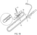
- FIG. 1 Aschematically depicts an illumination system of the present invention that includes a tube in the form of a gastrointestinal feeding device that is coupled to an optical fiber.
- FIG. 1 Eschematically depicts that in some embodiments the optical fiber can be disposable.
- FIG. 6schematically depicts a tube of a gastrointestinal feeding device according to an embodiment having an optical fiber with a bent light-emitting distal end that is optically coupled to an opening disposed in a side wall of the tube.
- FIG. 7 Bschematically depicts a tube having a plurality of openings and an optical fiber disposed in the tube and having a plurality of light-emitting segments, each of which is in optical coupling with one of the openings disposed in the tube.
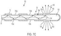
- FIG. 7 Cschematically depicts an embodiment of the illumination system of the present invention having two windows through which the light emitted by an optical fiber disposed in the tube can exit the tube to transilluminate at least a portion of the surrounding tissue and further having a plurality of openings.
- FIG. 8schematically depicts an embodiment of the illumination system of the present invention where the tube includes a lens disposed at a distal end thereof for receiving light from an optical fiber positioned in the tube.
- FIG. 9schematically depicts an embodiment of the illumination system of the present invention where a light source (e.g., an LED) disposed in proximity of an opening provided in the tube to transilluminate a patient's tissue to allow safe positioning of the device in the patient's gastrointestinal tract.
- a light sourcee.g., an LED
- FIG. 10schematically depicts an embodiment of the illumination system of the present invention where the tube is configured for receiving at a proximal end thereof light from one or more light sources.
- FIG. 11is a schematic depiction of the illumination system of the present invention where the tube is configured as a catheter for mounting within a lumen, such as a vein, of the patient during a cardiac procedure.
- FIG. 12is a schematic depiction of the illumination system of the present invention according to an embodiment for performing angioplasty.
- the term “lumen”is intended to include any internal passage or opening within the human body, and can include nasal passages, gastric passages and chambers, intestinal tracts and openings, esophageal passages, cardiac passages, venous, capillary and aortic passages, bronchial passages, uterine tracts and openings, and the like. According to one embodiment of the present invention, the invention allows positioning a gastrointestinal tube or a cardiac tube via transillumination.
- the illumination subsystemcan include an optical fiber that is positioned within the tube to transmit light received from a remote light source to the opening (and/or window) disposed in the distal region of the tube.
- a light sourcecan be positioned within the tube to deliver light to the opening (and/or window).
- a lenscan be coupled to the distal end of the tube to receive light from an optical fiber positioned within the tube.
- the lenscan be a divergent lens that causes the divergence of the light incident thereon such that at least a portion of the light would exit a portion of the surrounding tissue to be detected externally.
- a nasogastric device according to the present teachingscan be used for a variety of different purposes.
- the nasogastric devicecan be configured for administering medicine and/or nourishment to a patient.
- a nasogastric devicecan be used for decompressing the stomach for surgery and/or to prevent nausea/vomiting. While in some embodiments discussed below, a nasogastric device according to the present teachings is configured as a nasogastric feeding device for administering nourishment and/or medicine to a patient, it should be understood that the teachings of the present invention are equally applicable to other types of nasogastric devices, e.g., those that are configured for decompressing a patient's stomach.
- light and radiationare used herein interchangeably to refer not only to visible radiation but also to radiation in other regions of the electromagnetic spectrum, such as near-infrared.
- fiber opticand “optical fiber” are used herein interchangeably to refer to a waveguide through which electromagnetic radiation can be transmitted.
- visible lightrefers to radiation wavelengths in a range of about 400 nm to about 700 nm
- near-infrared radiationrefers to radiation having wavelengths in a range of about 750 nm to about 2500 nm.
- transmissionilluminationrefers to the passage of light through a body portion, e.g., to allow guiding a tube through a body lumen.
- FIGS. 1 A through 1 Eschematically depict an illumination system that can deliver light to a specific location or site within a lumen of the human body.
- the illumination systemcan be configured as a nasogastric system 10 that includes a tube 12 configured for placement in a lumen of a patient, such as for example in a gastrointestinal tract for administration of enteral nutrition or compression of the stomach.
- the tube 12has a proximal end 12 a and a distal end 12 b .
- the tube 12terminates in an outlet port 18 .
- An inlet port 14is fluidly coupled to the proximal end of the tube 12 via a tube section 16 .
- the inlet port 14can be configured as any suitable port, such as a sump port.
- the outlet port 18can be used for introducing such nourishment and/or medicine to the patient's gastrointestinal tract.
- the outlet port 18can be used to connect the tube to a pump, e.g., to remove air from the patient's stomach, so as to enhance visibility of any light emitted from the tube 12 .
- the tube 12can include a plurality of openings 30 a , 30 b , 30 c , and 30 d (herein collectively referred to as openings 30 ) disposed in the distal end 12 b of the tube 12 .
- At least one of the openings 30can allow for the passage of light emitted from an optical fiber incorporated into an internal chamber 12 d of the tube so as to allow tracking of the tube 12 , such as for example by visualization or by detection via a detector, as the tube is being inserted and guided within a lumen, such as the gastrointestinal tract of the patient.
- the nasogastric system 10includes an optical fiber 20 that can be attached to an inner wall 12 c of the tube 12 and can extend from the proximal end 12 a of the tube 12 to the distal end 12 b .
- the optical fiber 20can be attached to the inner wall 12 c of the tube in a variety of different ways.
- the optical fiber 20can be glued to an inner wall 12 c of the tube 12 .
- the optical fiber 20can be disposed in the tube 12 such that the optical fiber 20 can be inserted or extracted after the tube 12 is placed in the patient's gastrointestinal tract, e.g., after the distal region 12 b of the tube 12 is placed within the patient's stomach and/or duodenum.
- the optical fiber 20can be inserted in the tube 12 without gluing or otherwise affixing the optical fiber to the tube.
- the illustrated optical fiber 20has a proximal end 20 a and a distal end 20 b .
- the proximal end 20 a of the optical fiber 20is optically coupled to a light source 22 .
- the light source 22can have any selected size, shape or configuration, and can employ any suitable type of radiation or light element for producing the light and can be coupled to any suitable type of power source.
- the light source 22can be configured as a handheld battery-operated light source that is capable of generating light.
- a variety of light sources emitting light in the visible and/or infrared region of the electromagnetic spectrumcan be employed.
- the handheld light source 22includes a light emitting diode (LED).
- LEDlight emitting diode
- white light with wavelengths in a range of 400 to 700 nm with a minimum of about 5000 CCT (Correlated Color Temperature) to about 6200 CCTcan be used.
- monochromatic lighte.g., red light
- non-visible lighte.g., with wavelengths greater than 700 nm
- an LED emitting radiation in the infrared portion of the electromagnetic spectrume.g., in a wavelength range of about 600 nm to 2500 nm
- An example of such an LEDis marketed by CREE under the trade designation Photo Red LED (XQEEPR).
- the optical fibercan be composed of any suitable material, such as plastic.
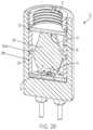
- the light source 22includes a light element, such as the LED 24 that is disposed in an enclosure 26 provided in a housing 28 of the light source.
- a lens 31is also provided in the enclosure 26 and is optically coupled to the LED 24 to receive light therefrom.
- the housingalso mounts the lens 31 , which includes a collar 31 a that can be seated on a shoulder 29 provided within the enclosure 26 to maintain the lens 31 in the enclosure and in optical coupling or communication with the LED 24 .
- a fiber optic adapter 32can be removably and replaceably received in the upper hollow cylindrical portion 34 of the housing 28 to allow coupling the optical fiber 20 to the LED 24 .
- the fiber optic adapter 32can include a plurality of threads 35 that can engage with a plurality of mating threads 37 provided on the inner wall of the upper hollow cylindrical portion 34 .
- the lens 31includes a proximal portion 40 and a distal portion 42 .
- the proximal portion 40 of the lensincludes a recess 33 through which light from the LED 24 can enter the lens.
- the proximal portion 40includes a lateral surface 40 a that is configured to reflect light incident thereon via total internal reflection toward the distal portion. Some of the light entering the lens via the recess 33 passes through the proximal portion of the lens without undergoing reflections at the lateral surface 40 a thereof to reach the distal portion of the lens. The light passes through the distal portion of the lens and exits an output surface 44 of the lens.
- an optical window 50is disposed over the output surface 44 of the lens.
- the optical window 50can protect the output surface of the lens and, in some embodiments, the optical window 50 can adjust one or more characteristics of the light exiting the lens.
- the optical window 50can be selected to function as a filter, e.g., a bandpass filter, to allow passage of certain wavelengths of light exiting the lens while blocking other wavelengths.
- the lens 31can be configured to focus the light received from the LED 24 onto an external focal point in proximity of the input surface of the optical fiber 20 such that the divergence angle of the light propagating from the focal point to the input of the optical fiber substantially matches the numerical aperture of the optical fiber so as to allow efficient coupling of the light into the optical fiber.
- the optical fiber 20can be optically coupled to the light source 22 using other mechanisms.
- the light source 22can be a laser diode 52 having a housing 54 in which an opening 54 a is formed for receiving, e.g., via a friction fit, a fiber optic coupling 53 to which the optical fiber 20 can be coupled so as to receive light from the laser diode.
- a flange(not shown) can be used to ensure that the proximal end of the fiber coupling 53 is securely coupled to the opening in the housing of the light source.
- the optical fiber 20is disposed in the tube 12 such that a light-emitting segment 20 c of the fiber is in substantial register with one or more of the openings 30 (e.g., opening 30 a ) in the distal portion 12 b of the tube 12 .
- the tube 12can include a single opening 30 that is configured to receive light from the optical fiber.
- the optical fiber 20is a side-emitting fiber in which its light-emitting segment is angled at about 45 degrees relative to the axis of the optical fiber so as to direct the emitted light toward the opening 30 a in the tube. At least a portion of the light emitted through the opening 30 a passes through a portion of the surrounding tissue and can be monitored (e.g., visually and/or via an appropriate detector) to guide the nasogastric tube through the gastrointestinal tract.
- the light emitted via the optical fiber 20 that passes through surrounding tissuecan be externally detected and monitored, visually or via an appropriate detector.
- a camera 60can be employed to obtain an image of the distal portion 12 b of the tube 12 to discern the position of the tube within the gastrointestinal tract.
- FIG. 1 Dshows three different types of optical fibers 70 , 72 , and 74 suitable for use in various embodiments of the present invention.
- the optical fiber 70has a distal end 70 a and light rays 70 b passing through an inner chamber 70 c are emitted an end region formed at the distal end 70 a .
- the lightis emitted at a 45-degree angle relative to a longitudinal axis of the fiber since the opening is slanted or formed at an angle.
- the optical fiber 72has a rounded distal light-emitting end 72 a , and the light rays 72 b passing through an inner chamber 72 c are emitted at the distal end region 72 a in a more dispersed pattern.
- the optical fiber 74has a substantially flat distal light-emitting end 74 a and light rays 74 b passing through an inner chamber 74 c are emitted at the distal end 70 a in a relatively parallel manner.
- optical fiber configurationscan also be used, such as for example fibers that have multiple light-emitting segments that are distributed along their length, where each of the light-emitting segments can be positioned in substantial registration with one of a plurality of openings disposed in the distal region of the tube, as discussed in more detail below.
- the optical fiber 20can be disposable and hence can be removed, after use, from the light source 22 . The tube can be discarded as well.
- the illumination systemcan be configured as a nasogastric system that employs the tube 12 and the associated optical fiber 20 .
- the distal end 12 b of the tube 12can be positioned in the esophagus of the patient and can be guided to reach the patient's stomach.
- the optical fiber 20is coupled to the light source 22 and hence light is conveyed from the light source 22 through the fiber to the distal end of the optical fiber and hence tube.
- a portion of the light emitted via the optical fibercan transilluminate at least a portion of the tissue surrounding the nasogastric tube 12 , thus revealing the position of the nasogastric tube, thereby allowing a user to monitor (visually or via a detector) the tube and hence to be able to safely guide the tube 12 to the patient's stomach.
- the optical fiber 20can be configured to emit radiation axially at the distal end 20 b , or the optical fiber 20 can include multiple light-emitting segments 20 c each of which is placed in substantial registration with one of a plurality of openings 30 in the tube 12 so as to emit light along a plurality of different directions for external detection.
- the optical fiber 20 used for guiding the tube 12 into positioncan be safely and easily removed and the tube 12 can be used for its intended purpose, e.g., to administer nourishment and/or medicine to the patient or the compress the stomach, or any other purpose.
- FIG. 5 Aschematically depicts a partial view of an embodiment of a nasogastric system 100 according to the teachings of the present invention where the tube 12 includes an opening 102 a at a distal end 12 b , and an optical fiber 20 is disposed in the tube 12 so as to emit light 106 through the opening 102 a .
- the optical fiber 20includes a substantially flat light-emitting segment 20 c at the distal end 20 b , through which light is emitted from the optical fiber 20 and which is substantially aligned with the opening 102 a to allow the passage of the emitted light 106 through the opening 102 a for external detection.
- the divergence of the light 106 exiting the opening 102 aensures that at least a portion of the light exiting the opening 102 a can transilluminate at least a portion of the surrounding tissue in a manner that allows monitoring the tube 12 as it is being deployed and guided within the patient's gastrointestinal tract.
- 5 Bschematically depicts another embodiment 110 in which the tube 12 seats or mounts an optical fiber 20 having a distal end 20 b that has a rounded light emitting segment 20 c that is disposed within the tube 12 such that the distal end 20 b of the optical fiber is substantially aligned with the opening 102 a to allow light 106 that is emitted from the opening 102 a to transillumination the surrounding or adjacent tissue, thereby allowing tracking the gastrointestinal tube 12 within the patient's gastrointestinal tract.
- FIG. 6schematically depicts another embodiment of a nasogastric system 120 according to the teachings of the present invention.
- the systemincludes a tube 12 (e.g., a feeding tube) in which an optical fiber 20 is disposed.
- the tube 12includes a side opening 30 , 122 at a distal end 12 b thereof and the optical fiber 20 includes a light-emitting segment 20 c at a distal end 20 b through which light 106 is emitted from the optical fiber.
- the distal end 20 b of the optical fiber 20is angled or bent so as to dispose the distal light-emitting segment 20 c in substantial registration with the opening 30 , 122 in the tube.
- FIG. 7 Adepicts yet another embodiment of a nasogastric system 130 that includes a tube 12 , which functions as a nasogastric feeding apparatus, having multiple openings 30 formed therein.
- the openings 30include openings 132 a , 132 b , and 132 c .
- the systemalso includes an optical fiber 20 that is mounted within the internal chamber 12 d of the tube 12 and has s single light emitting segment 20 c .
- the optical fiber 20 that is disposed in the tube 12emits light 106 at a distal end 20 b such that the emitted light 106 exits the tube 12 through the openings 132 c so as to transilluminate at least a portion of the surrounding tissue and allows the nasogastric system and specifically the tube 12 to be externally monitored either visually or via a light-detecting device.
- the other openings 132 a , 132 bcan be used, for example, for administering nourishment and/or medicine to the patient, or to apply suction to the stomach.
- FIG. 7 Bdepicts still another nasogastric system 140 having a tube 12 , such as a feeding tube, having a plurality of openings 30 formed therein.
- the openingsinclude openings 142 a , 142 b , and 142 c .
- the optical fiber 20includes a plurality of light-emitting segments 144 a , 144 b , and 144 c , each of which is in substantial register with one of the openings 142 a , 142 b , 142 c . Similar to the previous embodiment, the light-emitting segment 144 c is disposed at the distal end 20 b of the optical fiber.
- the light-emitting segments 144 a and 144 bare disposed along the length of the optical fiber by removing a portion of the fiber's cladding.
- the light-emitting segments 144 a , 144 bare in the form of circular bands of illumination, although in other embodiments other patterns of illumination can also be employ.
- the light emitting segmentsemit the light rays 106 that pass through the openings 30 .
- FIG. 7 Cschematically depicts yet still another embodiment of a nasogastric system 150 according to the teachings of the present invention.
- the illustrated system 150includes a tube 12 that includes a plurality of openings 30 formed therein.
- the openingsinclude openings 152 a , 152 b , and 152 c .
- the tube 12seats or mounts an optical fiber 20 in the tube chamber 12 d .
- the optical fiberhas a distal end 20 b that includes a light emitting segment 154 .
- the optical fiber 20is positioned within the tube 12 such that the light-emitting segment 154 is disposed in proximity of the openings 152 c that are formed in the distal portion 12 b of the tube 12 .
- the openings 152 chave mounted therein a window element 156 that can be formed of a material that is substantially transparent to the wavelength(s) of radiation emitted by the optical fiber.
- the window element 156can be formed of transparent silicone rubber.
- at least one of the window elements 156can function as a color filter to preferentially allow certain radiation wavelengths to pass therethrough.
- the windowcan be formed from transparent silicone rubber impregnated with appropriate dye(s) to function as a color filter.
- the openings 152 a and 152 b formed in the distal region of the tubecan be employed to administer medicine and/or nourishment to a patient. In other embodiments, the openings can be employed to apply suction to the patient's stomach, e.g., to compress the stomach.
- FIG. 7 Dschematically depicts still another embodiment of a nasogastric system 160 , which includes a tube 12 and an optical fiber 20 disposed in the tube 12 .
- the tube 12has a plurality of openings 30 formed therein.
- the openingsinclude openings 162 a , 162 b , and 162 c .
- the tube 12also includes a plurality of window elements 166 a , 166 b , 166 c .
- the optical fiber 20has formed at a distal end 20 b a plurality of light-emitting segments 3002 a , 3002 b , and 3002 c , where the light-emitting segment 164 a illuminates the window element 166 a , the light-emitting segment 164 b illuminates the window element 166 b , and the light-emitting segment 164 c illuminates the window element 166 c .
- the light 106 passing through the windowscan transilluminate at least a portion of the lumen and surrounding tissue of the patient so as to be monitored externally (e.g., via visualization and/or detection).
- the window elements 166 a , 166 b , 166 ccan function as color filters.
- FIG. 9is a partial schematic view of another embodiment of a nasogastric system 180 , e.g., a nasogastric feeding device, that includes a tube 12 , e.g., a feeding tube.
- the tube 12includes an opening 182 disposed in a distal region thereof.
- FIG. 10schematically depicts another embodiment of a nasogastric system 190 according to the present invention.
- the system 190includes a tube 12 , e.g., a feeding tube, having an annular shape and a plurality of light sources 196 (e.g., a plurality of LEDs) formed in the housing of the tube (as shown), and are positioned circumferentially about the tube housing.
- the light sourcescan be optically coupled to the annulus portion of the feeding tube at a proximal end thereof.
- the light sources 196can generate radiation in the visible, near-infrared or infrared portions of the electromagnetic spectrum.
- a nasogastric deviceprovides a number of advantages. In particular, it allows safe placement of a nasogastric tube in a patient's gastrointestinal tract without the need to expose the patient to potentially harmful radiation. This can be particularly advantageous for pediatric patients. Further, a nasogastric feeding device according to the present teachings is easy to use.
Landscapes
- Health & Medical Sciences (AREA)
- Life Sciences & Earth Sciences (AREA)
- Engineering & Computer Science (AREA)
- Physics & Mathematics (AREA)
- Animal Behavior & Ethology (AREA)
- Veterinary Medicine (AREA)
- Public Health (AREA)
- General Health & Medical Sciences (AREA)
- Biomedical Technology (AREA)
- Surgery (AREA)
- Heart & Thoracic Surgery (AREA)
- Biophysics (AREA)
- Medical Informatics (AREA)
- Molecular Biology (AREA)
- Pathology (AREA)
- Optics & Photonics (AREA)
- Pulmonology (AREA)
- Human Computer Interaction (AREA)
- Otolaryngology (AREA)
- General Engineering & Computer Science (AREA)
- General Physics & Mathematics (AREA)
- Anesthesiology (AREA)
- Hematology (AREA)
- Astronomy & Astrophysics (AREA)
- Nuclear Medicine, Radiotherapy & Molecular Imaging (AREA)
- Radiology & Medical Imaging (AREA)
- Medical Preparation Storing Or Oral Administration Devices (AREA)
- Endoscopes (AREA)
- Laser Surgery Devices (AREA)
Abstract
Description
Claims (21)
Priority Applications (1)
| Application Number | Priority Date | Filing Date | Title |
|---|---|---|---|
| US16/731,852US12023005B2 (en) | 2019-01-02 | 2019-12-31 | Positioning a tube in a lumen via transillumination |
Applications Claiming Priority (2)
| Application Number | Priority Date | Filing Date | Title |
|---|---|---|---|
| US201962787688P | 2019-01-02 | 2019-01-02 | |
| US16/731,852US12023005B2 (en) | 2019-01-02 | 2019-12-31 | Positioning a tube in a lumen via transillumination |
Publications (2)
| Publication Number | Publication Date |
|---|---|
| US20200205640A1 US20200205640A1 (en) | 2020-07-02 |
| US12023005B2true US12023005B2 (en) | 2024-07-02 |
Family
ID=69374403
Family Applications (1)
| Application Number | Title | Priority Date | Filing Date |
|---|---|---|---|
| US16/731,852Active2041-07-26US12023005B2 (en) | 2019-01-02 | 2019-12-31 | Positioning a tube in a lumen via transillumination |
Country Status (5)
| Country | Link |
|---|---|
| US (1) | US12023005B2 (en) |
| EP (1) | EP3905944B1 (en) |
| JP (1) | JP7633164B2 (en) |
| CA (1) | CA3125671A1 (en) |
| WO (1) | WO2020142518A1 (en) |
Families Citing this family (6)
| Publication number | Priority date | Publication date | Assignee | Title |
|---|---|---|---|---|
| WO2017075378A1 (en) | 2015-10-28 | 2017-05-04 | Acera LLC | Elliptical optical lens for high output led |
| US12023005B2 (en) | 2019-01-02 | 2024-07-02 | Fraen Corporation | Positioning a tube in a lumen via transillumination |
| US20230338706A1 (en)* | 2020-09-09 | 2023-10-26 | Neuroceuticals Inc. | Medical tube and medical tube position detection system |
| CN113786168A (en)* | 2021-09-10 | 2021-12-14 | 复旦大学附属中山医院 | Light source system capable of distinguishing blood vessels in adipose tissues during operation |
| JP7730503B2 (en)* | 2021-11-16 | 2025-08-28 | スタンレー電気株式会社 | Imaging device |
| CN116250940A (en)* | 2021-12-10 | 2023-06-13 | 广州迪克医疗器械有限公司 | Optical fiber mechanism for medical optical tracing and medical optical tracing system |
Citations (115)
| Publication number | Priority date | Publication date | Assignee | Title |
|---|---|---|---|---|
| US2908197A (en) | 1954-01-29 | 1959-10-13 | Westinghouse Air Brake Co | Wide angle lenses |
| US3285242A (en) | 1963-07-01 | 1966-11-15 | American Cystoscope Makers Inc | Surgical headlight and light source |
| US3592199A (en) | 1970-02-09 | 1971-07-13 | Medical Products Corp | Autoclavable surgical instrument illumination |
| JPS5659005A (en) | 1979-10-22 | 1981-05-22 | Kobe Steel Ltd | Controller for hydraulic circuit including plural variable-capacity pumps in parallel |
| US4414608A (en) | 1980-08-07 | 1983-11-08 | Olympus Optical Co., Ltd. | Endoscope with adapter |
| US4726074A (en) | 1985-03-15 | 1988-02-23 | Paul Baclit | Detachable visor |
| JPH04288960A (en) | 1991-03-08 | 1992-10-14 | Fuji Densen Denki Kk | Soldering device for electronic parts and exiting lens fitted to this soldering device |
| USD331634S (en) | 1991-04-19 | 1992-12-08 | Stewart R. Browne Mfg. Co., Inc. | Portable trouble lamp |
| US5353208A (en) | 1992-12-29 | 1994-10-04 | Larry Moore | High intensity compact flashlight |
| JPH0751282A (en) | 1993-08-09 | 1995-02-28 | Olympus Optical Co Ltd | Laser medical treatment device |
| JPH0810220A (en) | 1994-07-04 | 1996-01-16 | Asahi Optical Co Ltd | Simple endoscope device |
| US5609561A (en) | 1992-06-09 | 1997-03-11 | Olympus Optical Co., Ltd | Electronic type endoscope in which image pickup unit is dismounted to execute disinfection/sterilization processing |
| US5682199A (en) | 1996-03-28 | 1997-10-28 | Jedmed Instrument Company | Video endoscope with interchangeable endoscope heads |
| US5702349A (en) | 1994-07-07 | 1997-12-30 | Fuji Photo Optical Co., Ltd. | Endoscope with acutely angled handle and associated focus adjustment mechanism |
| US5743848A (en) | 1995-08-31 | 1998-04-28 | Asahi Kogaku Kogyo Kabushiki Kaisha | Portable endoscope system |
| US5765223A (en) | 1996-06-04 | 1998-06-16 | Mccausland; Mary L. | Face shield |
| US6007485A (en) | 1997-09-11 | 1999-12-28 | Asahi Kogaku Kogyo Kabushiki Kaisha | Portable endoscope |
| JP2000171725A (en) | 1998-12-03 | 2000-06-23 | Olympus Optical Co Ltd | Endoscopic device |
| US6099147A (en) | 1998-11-19 | 2000-08-08 | Streamlight, Inc. | Flashlight lamp shock absorber |
| US6135947A (en) | 1997-09-18 | 2000-10-24 | Olympus Optical Co., Ltd. | Endoscope apparatus having light source movable between on and off positions |
| JP3148028B2 (en) | 1992-12-09 | 2001-03-19 | 新日本製鐵株式会社 | Black silicon nitride sintered body and method for producing the same |
| US6257741B1 (en) | 1997-01-03 | 2001-07-10 | Ronald R. Williams | Lamp assembly for a light source |
| JP2002040299A (en) | 2000-07-21 | 2002-02-06 | Sunx Ltd | Optical coupling device |
| JP2002345748A (en) | 2001-03-22 | 2002-12-03 | Olympus Optical Co Ltd | Battery light source for endoscope and endoscope |
| US20030009084A1 (en) | 2000-03-16 | 2003-01-09 | Medivision, Inc. | Endoscope and camera mount |
| US6540389B1 (en) | 1998-03-10 | 2003-04-01 | Storz Endoskop Gmbh | Lighting system for illumination of an observation space |
| US20030074708A1 (en) | 2001-10-18 | 2003-04-24 | Hogg John Joseph | Face protector |
| US20030091820A1 (en) | 2001-11-13 | 2003-05-15 | Robbins Paul E. | Fiber optic LED light |
| US20030158503A1 (en) | 2002-01-18 | 2003-08-21 | Shinya Matsumoto | Capsule endoscope and observation system that uses it |
| US20040213001A1 (en) | 2003-04-25 | 2004-10-28 | Visteon Global Technologies, Inc. | Projector optic assembly |
| US20040218858A1 (en) | 2003-05-02 | 2004-11-04 | Guy James Kevan | Optical coupling apparatus and method |
| US6819505B1 (en) | 2003-09-08 | 2004-11-16 | William James Cassarly | Internally reflective ellipsoidal collector with projection lens |
| US20040246744A1 (en) | 2003-03-26 | 2004-12-09 | Krupa Robert J. | Compact, high-efficiency, high-power solid state light source using a single solid state light-emitting device |
| JP2004536639A (en) | 2001-06-19 | 2004-12-09 | ザ・トラステイーズ・オブ・ザ・ユニバーシテイ・オブ・ペンシルベニア | Optical guidance system for placement of invasive catheters |
| US20050162848A1 (en) | 2002-03-01 | 2005-07-28 | Dalton David R. | Rechargable flashlight |
| US20050201100A1 (en) | 2003-09-08 | 2005-09-15 | Cassarly William J. | Led lighting assembly |
| US6991603B2 (en) | 2002-05-17 | 2006-01-31 | Optim, Inc. | Insertion tube device |
| US20060183977A1 (en) | 2003-10-06 | 2006-08-17 | Olympus Corporation | Endoscope |
| US7115091B2 (en) | 2002-03-18 | 2006-10-03 | Optim, Inc. | Reusable endoscopic device and related systems and methods |
| USD533939S1 (en) | 2005-02-23 | 2006-12-19 | Optim, Inc. | Control handle with a display for an endoscopic device |
| JP2007059073A (en) | 2005-08-22 | 2007-03-08 | Toshiba Lighting & Technology Corp | Lens and lighting device |
| US7198397B2 (en) | 2004-09-17 | 2007-04-03 | Optim, Inc. | LED endoscope illuminator and methods of mounting within an endoscope |
| JP2007091119A (en) | 2005-09-29 | 2007-04-12 | Harison Toshiba Lighting Corp | Lighting device |
| US20070104664A1 (en) | 2005-10-26 | 2007-05-10 | California Institute Of Technology | Treatment of toenail fungus |
| US20070173695A1 (en) | 2004-06-28 | 2007-07-26 | Yasuo Hirata | Endoscope device |
| USD551762S1 (en) | 2005-02-23 | 2007-09-25 | Optim, Inc. | Control handle for an endoscope device |
| US20070253188A1 (en) | 2006-01-26 | 2007-11-01 | Brasscorp Limited | LED Spotlight |
| USD561336S1 (en) | 2005-04-18 | 2008-02-05 | Optim, Inc. | Control handle for a portable endoscopic device |
| WO2008016895A2 (en) | 2006-07-31 | 2008-02-07 | 3M Innovative Properties Company | Integrating light source module |
| US20080039715A1 (en)* | 2004-11-04 | 2008-02-14 | Wilson David F | Three-dimensional optical guidance for catheter placement |
| WO2008017718A1 (en) | 2006-08-10 | 2008-02-14 | Upstream Engineering Oy | Illuminator method and device |
| US20080091064A1 (en) | 2006-10-17 | 2008-04-17 | Vadim Laser | Portable endoscope for intubation |
| US20080174996A1 (en) | 2007-01-18 | 2008-07-24 | Hong Kong Applied Science And Technology Research Institute Co., Ltd. | Light-emitting devices and lens therefor |
| US20080194973A1 (en)* | 2005-09-13 | 2008-08-14 | Imam Farhad B | Light-guided transluminal catheter |
| JP2008539479A (en) | 2005-04-26 | 2008-11-13 | コダック グラフィック コミュニケーションズ カナダ カンパニー | Comparing documents with graphic elements |
| USD581052S1 (en) | 2007-09-14 | 2008-11-18 | Optim, Incorporated | Control handle for an endoscopic device |
| JP2009056290A (en) | 2007-06-28 | 2009-03-19 | Biosense Webster Inc | Optical pyrometric catheter for tissue temperature monitoring during cardiac ablation |
| US20090185392A1 (en) | 2003-03-26 | 2009-07-23 | Optim, Inc. | Detachable illumination system |
| US20090287197A1 (en) | 2008-05-19 | 2009-11-19 | Hanley Brian M | Side-firing laser fiber with internal bent fiber and related methods |
| WO2010091097A1 (en) | 2009-02-03 | 2010-08-12 | Fraen Corporation | Light mixing optics and systems |
| USD623786S1 (en) | 2009-12-24 | 2010-09-14 | Wessel Elmer A | Convertible work light |
| US7798692B2 (en) | 2003-03-26 | 2010-09-21 | Optim, Inc. | Illumination device |
| US20100277894A1 (en) | 2009-05-01 | 2010-11-04 | Kim Paul Y | Lighting device with removable cradle |
| USD629537S1 (en) | 2010-02-05 | 2010-12-21 | Everlight Electronics Co., Ltd. | LED lamp |
| CN201680208U (en) | 2010-05-27 | 2010-12-22 | 中国科学院西安光学精密机械研究所 | Lighting system applied in liquid oxygen environment |
| USD631567S1 (en) | 2008-01-11 | 2011-01-25 | Pervaiz Lodhie | LED bulb |
| US20110194295A1 (en) | 2010-02-10 | 2011-08-11 | Fraen Corporation | Light repositioning optics |
| US8152715B2 (en) | 2007-09-14 | 2012-04-10 | Optim, Incorporated | Endoscope with internal light source and power supply |
| USD662231S1 (en) | 2010-05-24 | 2012-06-19 | S. K. G. Co., Ltd. | LED light bulb |
| USD663445S1 (en) | 2010-02-23 | 2012-07-10 | S. K. G. Co., Ltd. | LED light bulb |
| USD663464S1 (en) | 2011-01-26 | 2012-07-10 | Edison Opto Corporation | LED lamp |
| US20120184924A1 (en) | 2011-01-14 | 2012-07-19 | Loma Linda University | Self-illuminating endogastric tubes and method of placing endogastric tubes |
| USD666340S1 (en) | 2010-04-23 | 2012-08-28 | S. K. G. Co., Ltd. | LED light bulb |
| USD669200S1 (en) | 2011-12-26 | 2012-10-16 | Power Digital Delight Co., Ltd. | LED light bulb |
| USD671241S1 (en) | 2010-02-23 | 2012-11-20 | S. K. G. Co., Ltd. | LED light bulb |
| USD675349S1 (en) | 2011-01-10 | 2013-01-29 | Rambus International Ltd. | Light conductor and light emitter for a LED light source |
| JP2013025924A (en) | 2011-07-19 | 2013-02-04 | Iwasaki Electric Co Ltd | Lamp |
| US20130046172A1 (en)* | 2007-03-14 | 2013-02-21 | Kathryn A. McKenzie Waitzman | Methods and systems for locating a feeding tube inside of a person |
| JP2013123477A (en) | 2011-12-13 | 2013-06-24 | Olympus Corp | Radiation module having plurality of light guide members |
| USD685506S1 (en) | 2011-07-26 | 2013-07-02 | Cree, Inc. | Lamp |
| JP2013533049A (en) | 2010-07-30 | 2013-08-22 | エレメント シックス ナムローゼ フェンノートシャップ | Diamond window components for laser tools |
| US8534890B2 (en) | 2008-10-09 | 2013-09-17 | Tyco Electronics Canada Ulc | Light pipe assembly having optical concentrator |
| USD690383S1 (en) | 2013-02-25 | 2013-09-24 | Yasar Sheikh | Combination stun gun and flashlight with a cap |
| JP2013198644A (en) | 2012-03-26 | 2013-10-03 | Panasonic Corp | Tube distal end position confirmation device |
| US20140148653A1 (en) | 2005-04-01 | 2014-05-29 | Welch Allyn, Inc. | Vaginal speculum apparatus |
| US20140275986A1 (en)* | 2013-03-15 | 2014-09-18 | LX Medical, Inc. | Tissue imaging and image guidance in luminal anatomic structures and body cavities |
| USD715463S1 (en) | 2013-06-04 | 2014-10-14 | Component Hardware Group, Inc. | LED bulb |
| WO2015038971A1 (en) | 2013-09-12 | 2015-03-19 | Quarkstar Llc | Light-emitting device with total internal reflection (tir) extractor |
| JP2015056137A (en) | 2013-09-13 | 2015-03-23 | 株式会社リコー | System and information processing method |
| JP2015077336A (en) | 2013-10-18 | 2015-04-23 | ジーニアルライト株式会社 | Biological monitoring device |
| US9055863B2 (en) | 2006-11-14 | 2015-06-16 | Optim, Inc. | Portable endoscope |
| US20150219313A1 (en) | 2014-01-31 | 2015-08-06 | Eveready Battery Company, Inc. | Near-field lens with convex hyperbolic surface |
| USD739586S1 (en) | 2012-08-15 | 2015-09-22 | Heshan Gmy Lighting And Electrical Co., Ltd. | Ultraviolet light sterilizer |
| USD744674S1 (en) | 2014-03-13 | 2015-12-01 | Lumenmax Optoelectronics Co., Ltd. | Fluorescent lamp |
| US20160050990A1 (en) | 2014-08-25 | 2016-02-25 | Arthur Hayes | Face shield attachment for a hat brim |
| CN205079073U (en) | 2015-09-11 | 2016-03-09 | 陈贵生 | Through rotatory LED highlight flashlight of adjusting luminance |
| USD753322S1 (en) | 2015-02-27 | 2016-04-05 | Tadd, LLC | LED lamp |
| JP2016087091A (en) | 2014-11-05 | 2016-05-23 | ウシオ電機株式会社 | Catheter device and catheter position confirmation method |
| USD760928S1 (en) | 2015-03-27 | 2016-07-05 | Yuyao Yuchang Electrical Appliance Co., Ltd. | Working lamp |
| USD768321S1 (en) | 2015-07-08 | 2016-10-04 | Mathew Inskeep | Work light |
| USD775752S1 (en) | 2012-12-07 | 2017-01-03 | The Noco Company | Rechargeable device with flashlight and electronic device charger |
| USD778473S1 (en) | 2013-08-27 | 2017-02-07 | Wilmar Corporation | Light tool |
| US20170123131A1 (en) | 2015-10-28 | 2017-05-04 | Acera LLC | Handheld Mobile Light Source |
| US20170197002A1 (en) | 2014-10-28 | 2017-07-13 | Sensor Electronic Technology, Inc. | Flexible Article for UV Disinfection |
| USD793595S1 (en) | 2016-01-05 | 2017-08-01 | Nite Ize, Inc. | Glowstick |
| US20170274184A1 (en)* | 2016-03-28 | 2017-09-28 | Becton, Dickinson And Company | Cannula with light-emitting optical fiber |
| USD804064S1 (en) | 2016-09-27 | 2017-11-28 | Tadd, LLC | LED bulb |
| USD810325S1 (en) | 2017-01-16 | 2018-02-13 | Shenzhen Snc Opto Electronic Co., Ltd. | Dustproof corn light |
| USD813424S1 (en) | 2014-06-02 | 2018-03-20 | Soraa, Inc. | LED lamp |
| WO2018207753A1 (en) | 2017-05-11 | 2018-11-15 | アルプス電気株式会社 | Catheter device, connector device, and catheter system |
| USD836227S1 (en) | 2015-10-28 | 2018-12-18 | Acera, Llc | Handheld mobile light source |
| KR20190067110A (en) | 2017-12-06 | 2019-06-14 | 서울바이오시스 주식회사 | Light treatment device |
| US20200205640A1 (en) | 2019-01-02 | 2020-07-02 | Acera LLC | Positioning a tube in a lumen via transillumination |
| US20210299298A1 (en) | 2020-03-25 | 2021-09-30 | Acera LLC | Portable sterilization device |
| US20210307421A1 (en) | 2020-04-02 | 2021-10-07 | Acera LLC | Headgear shield |
Family Cites Families (1)
| Publication number | Priority date | Publication date | Assignee | Title |
|---|---|---|---|---|
| JP2008508034A (en) | 2004-07-27 | 2008-03-21 | バイオレーズ テクノロジー インコーポレイテッド | Contra-angle rotating handpiece with tactile feedback tip ferrule |
- 2019
- 2019-12-31USUS16/731,852patent/US12023005B2/enactiveActive
- 2019-12-31JPJP2021538760Apatent/JP7633164B2/enactiveActive
- 2019-12-31WOPCT/US2019/069111patent/WO2020142518A1/ennot_activeCeased
- 2019-12-31CACA3125671Apatent/CA3125671A1/enactivePending
- 2019-12-31EPEP19845684.0Apatent/EP3905944B1/enactiveActive
Patent Citations (137)
| Publication number | Priority date | Publication date | Assignee | Title |
|---|---|---|---|---|
| US2908197A (en) | 1954-01-29 | 1959-10-13 | Westinghouse Air Brake Co | Wide angle lenses |
| US3285242A (en) | 1963-07-01 | 1966-11-15 | American Cystoscope Makers Inc | Surgical headlight and light source |
| US3592199A (en) | 1970-02-09 | 1971-07-13 | Medical Products Corp | Autoclavable surgical instrument illumination |
| JPS5659005A (en) | 1979-10-22 | 1981-05-22 | Kobe Steel Ltd | Controller for hydraulic circuit including plural variable-capacity pumps in parallel |
| US4414608A (en) | 1980-08-07 | 1983-11-08 | Olympus Optical Co., Ltd. | Endoscope with adapter |
| US4726074A (en) | 1985-03-15 | 1988-02-23 | Paul Baclit | Detachable visor |
| JPH04288960A (en) | 1991-03-08 | 1992-10-14 | Fuji Densen Denki Kk | Soldering device for electronic parts and exiting lens fitted to this soldering device |
| USD331634S (en) | 1991-04-19 | 1992-12-08 | Stewart R. Browne Mfg. Co., Inc. | Portable trouble lamp |
| US5609561A (en) | 1992-06-09 | 1997-03-11 | Olympus Optical Co., Ltd | Electronic type endoscope in which image pickup unit is dismounted to execute disinfection/sterilization processing |
| JP3148028B2 (en) | 1992-12-09 | 2001-03-19 | 新日本製鐵株式会社 | Black silicon nitride sintered body and method for producing the same |
| US5353208A (en) | 1992-12-29 | 1994-10-04 | Larry Moore | High intensity compact flashlight |
| JPH0751282A (en) | 1993-08-09 | 1995-02-28 | Olympus Optical Co Ltd | Laser medical treatment device |
| JPH0810220A (en) | 1994-07-04 | 1996-01-16 | Asahi Optical Co Ltd | Simple endoscope device |
| US5702349A (en) | 1994-07-07 | 1997-12-30 | Fuji Photo Optical Co., Ltd. | Endoscope with acutely angled handle and associated focus adjustment mechanism |
| US5743848A (en) | 1995-08-31 | 1998-04-28 | Asahi Kogaku Kogyo Kabushiki Kaisha | Portable endoscope system |
| US5682199A (en) | 1996-03-28 | 1997-10-28 | Jedmed Instrument Company | Video endoscope with interchangeable endoscope heads |
| US5765223A (en) | 1996-06-04 | 1998-06-16 | Mccausland; Mary L. | Face shield |
| US6257741B1 (en) | 1997-01-03 | 2001-07-10 | Ronald R. Williams | Lamp assembly for a light source |
| US6007485A (en) | 1997-09-11 | 1999-12-28 | Asahi Kogaku Kogyo Kabushiki Kaisha | Portable endoscope |
| US6135947A (en) | 1997-09-18 | 2000-10-24 | Olympus Optical Co., Ltd. | Endoscope apparatus having light source movable between on and off positions |
| US6540389B1 (en) | 1998-03-10 | 2003-04-01 | Storz Endoskop Gmbh | Lighting system for illumination of an observation space |
| US6099147A (en) | 1998-11-19 | 2000-08-08 | Streamlight, Inc. | Flashlight lamp shock absorber |
| JP2000171725A (en) | 1998-12-03 | 2000-06-23 | Olympus Optical Co Ltd | Endoscopic device |
| US20030009084A1 (en) | 2000-03-16 | 2003-01-09 | Medivision, Inc. | Endoscope and camera mount |
| JP2002040299A (en) | 2000-07-21 | 2002-02-06 | Sunx Ltd | Optical coupling device |
| JP2002345748A (en) | 2001-03-22 | 2002-12-03 | Olympus Optical Co Ltd | Battery light source for endoscope and endoscope |
| US20080027408A1 (en) | 2001-06-19 | 2008-01-31 | The Trustees Of The University Of Pennsylvania | Method for catheter placement |
| JP2004536639A (en) | 2001-06-19 | 2004-12-09 | ザ・トラステイーズ・オブ・ザ・ユニバーシテイ・オブ・ペンシルベニア | Optical guidance system for placement of invasive catheters |
| US20030074708A1 (en) | 2001-10-18 | 2003-04-24 | Hogg John Joseph | Face protector |
| US20030091820A1 (en) | 2001-11-13 | 2003-05-15 | Robbins Paul E. | Fiber optic LED light |
| US20030158503A1 (en) | 2002-01-18 | 2003-08-21 | Shinya Matsumoto | Capsule endoscope and observation system that uses it |
| US20050162848A1 (en) | 2002-03-01 | 2005-07-28 | Dalton David R. | Rechargable flashlight |
| US7193519B2 (en) | 2002-03-18 | 2007-03-20 | Optim, Inc. | Reusable instruments and related systems and methods |
| US7115091B2 (en) | 2002-03-18 | 2006-10-03 | Optim, Inc. | Reusable endoscopic device and related systems and methods |
| US6991603B2 (en) | 2002-05-17 | 2006-01-31 | Optim, Inc. | Insertion tube device |
| US20040246744A1 (en) | 2003-03-26 | 2004-12-09 | Krupa Robert J. | Compact, high-efficiency, high-power solid state light source using a single solid state light-emitting device |
| US20090040783A1 (en) | 2003-03-26 | 2009-02-12 | Optim, Inc. | Compact, high efficiency, high power solid state light source using a single solid state light-emitting device |
| US9022628B2 (en) | 2003-03-26 | 2015-05-05 | Optim, Inc. | Compact, high efficiency, high power solid state light source using a single solid state light-emitting device |
| US7229201B2 (en) | 2003-03-26 | 2007-06-12 | Optim Inc. | Compact, high-efficiency, high-power solid state light source using a single solid state light-emitting device |
| US7798692B2 (en) | 2003-03-26 | 2010-09-21 | Optim, Inc. | Illumination device |
| US8033704B2 (en) | 2003-03-26 | 2011-10-11 | Optim, Inc. | Compact, high efficiency, high power solid state light source using a solid state light-emitting device |
| US20090185392A1 (en) | 2003-03-26 | 2009-07-23 | Optim, Inc. | Detachable illumination system |
| US8801253B2 (en) | 2003-03-26 | 2014-08-12 | Optim Llc | Illumination device |
| US20040213001A1 (en) | 2003-04-25 | 2004-10-28 | Visteon Global Technologies, Inc. | Projector optic assembly |
| US20040218858A1 (en) | 2003-05-02 | 2004-11-04 | Guy James Kevan | Optical coupling apparatus and method |
| US6937791B2 (en) | 2003-05-02 | 2005-08-30 | The Boeing Company | Optical coupling apparatus and method |
| US20050201100A1 (en) | 2003-09-08 | 2005-09-15 | Cassarly William J. | Led lighting assembly |
| US6819505B1 (en) | 2003-09-08 | 2004-11-16 | William James Cassarly | Internally reflective ellipsoidal collector with projection lens |
| US20060183977A1 (en) | 2003-10-06 | 2006-08-17 | Olympus Corporation | Endoscope |
| US20070173695A1 (en) | 2004-06-28 | 2007-07-26 | Yasuo Hirata | Endoscope device |
| US7198397B2 (en) | 2004-09-17 | 2007-04-03 | Optim, Inc. | LED endoscope illuminator and methods of mounting within an endoscope |
| US20080039715A1 (en)* | 2004-11-04 | 2008-02-14 | Wilson David F | Three-dimensional optical guidance for catheter placement |
| USD533939S1 (en) | 2005-02-23 | 2006-12-19 | Optim, Inc. | Control handle with a display for an endoscopic device |
| USD551762S1 (en) | 2005-02-23 | 2007-09-25 | Optim, Inc. | Control handle for an endoscope device |
| US20140148653A1 (en) | 2005-04-01 | 2014-05-29 | Welch Allyn, Inc. | Vaginal speculum apparatus |
| USD561336S1 (en) | 2005-04-18 | 2008-02-05 | Optim, Inc. | Control handle for a portable endoscopic device |
| JP2008539479A (en) | 2005-04-26 | 2008-11-13 | コダック グラフィック コミュニケーションズ カナダ カンパニー | Comparing documents with graphic elements |
| JP2007059073A (en) | 2005-08-22 | 2007-03-08 | Toshiba Lighting & Technology Corp | Lens and lighting device |
| US20080194973A1 (en)* | 2005-09-13 | 2008-08-14 | Imam Farhad B | Light-guided transluminal catheter |
| JP2007091119A (en) | 2005-09-29 | 2007-04-12 | Harison Toshiba Lighting Corp | Lighting device |
| US20070104664A1 (en) | 2005-10-26 | 2007-05-10 | California Institute Of Technology | Treatment of toenail fungus |
| US20070253188A1 (en) | 2006-01-26 | 2007-11-01 | Brasscorp Limited | LED Spotlight |
| WO2008016895A2 (en) | 2006-07-31 | 2008-02-07 | 3M Innovative Properties Company | Integrating light source module |
| WO2008017718A1 (en) | 2006-08-10 | 2008-02-14 | Upstream Engineering Oy | Illuminator method and device |
| US20080091064A1 (en) | 2006-10-17 | 2008-04-17 | Vadim Laser | Portable endoscope for intubation |
| US9055863B2 (en) | 2006-11-14 | 2015-06-16 | Optim, Inc. | Portable endoscope |
| US20080174996A1 (en) | 2007-01-18 | 2008-07-24 | Hong Kong Applied Science And Technology Research Institute Co., Ltd. | Light-emitting devices and lens therefor |
| US20130046172A1 (en)* | 2007-03-14 | 2013-02-21 | Kathryn A. McKenzie Waitzman | Methods and systems for locating a feeding tube inside of a person |
| JP2010528818A (en) | 2007-06-11 | 2010-08-26 | ザ・トラステイーズ・オブ・ザ・ユニバーシテイ・オブ・ペンシルベニア | Three-dimensional light guidance for catheter placement |
| JP2009056290A (en) | 2007-06-28 | 2009-03-19 | Biosense Webster Inc | Optical pyrometric catheter for tissue temperature monitoring during cardiac ablation |
| US8152715B2 (en) | 2007-09-14 | 2012-04-10 | Optim, Incorporated | Endoscope with internal light source and power supply |
| USD581052S1 (en) | 2007-09-14 | 2008-11-18 | Optim, Incorporated | Control handle for an endoscopic device |
| USD631567S1 (en) | 2008-01-11 | 2011-01-25 | Pervaiz Lodhie | LED bulb |
| US20090287197A1 (en) | 2008-05-19 | 2009-11-19 | Hanley Brian M | Side-firing laser fiber with internal bent fiber and related methods |
| US8534890B2 (en) | 2008-10-09 | 2013-09-17 | Tyco Electronics Canada Ulc | Light pipe assembly having optical concentrator |
| US20100226127A1 (en) | 2009-02-03 | 2010-09-09 | Fraen Corporation | Light mixing optics and systems |
| WO2010091097A1 (en) | 2009-02-03 | 2010-08-12 | Fraen Corporation | Light mixing optics and systems |
| EP2846179A2 (en) | 2009-02-03 | 2015-03-11 | Fraen Corporation | Light mixing optics and systems |
| US20100277894A1 (en) | 2009-05-01 | 2010-11-04 | Kim Paul Y | Lighting device with removable cradle |
| USD623786S1 (en) | 2009-12-24 | 2010-09-14 | Wessel Elmer A | Convertible work light |
| USD629537S1 (en) | 2010-02-05 | 2010-12-21 | Everlight Electronics Co., Ltd. | LED lamp |
| US20110194295A1 (en) | 2010-02-10 | 2011-08-11 | Fraen Corporation | Light repositioning optics |
| USD663445S1 (en) | 2010-02-23 | 2012-07-10 | S. K. G. Co., Ltd. | LED light bulb |
| USD671241S1 (en) | 2010-02-23 | 2012-11-20 | S. K. G. Co., Ltd. | LED light bulb |
| USD671242S1 (en) | 2010-04-23 | 2012-11-20 | S. K. G. Co., Ltd. | LED light bulb |
| USD666340S1 (en) | 2010-04-23 | 2012-08-28 | S. K. G. Co., Ltd. | LED light bulb |
| USD671243S1 (en) | 2010-05-24 | 2012-11-20 | S. K. G. Co., Ltd. | LED light bulb |
| USD662231S1 (en) | 2010-05-24 | 2012-06-19 | S. K. G. Co., Ltd. | LED light bulb |
| CN201680208U (en) | 2010-05-27 | 2010-12-22 | 中国科学院西安光学精密机械研究所 | Lighting system applied in liquid oxygen environment |
| JP2013533049A (en) | 2010-07-30 | 2013-08-22 | エレメント シックス ナムローゼ フェンノートシャップ | Diamond window components for laser tools |
| USD675349S1 (en) | 2011-01-10 | 2013-01-29 | Rambus International Ltd. | Light conductor and light emitter for a LED light source |
| US20120184924A1 (en) | 2011-01-14 | 2012-07-19 | Loma Linda University | Self-illuminating endogastric tubes and method of placing endogastric tubes |
| USD663464S1 (en) | 2011-01-26 | 2012-07-10 | Edison Opto Corporation | LED lamp |
| JP2013025924A (en) | 2011-07-19 | 2013-02-04 | Iwasaki Electric Co Ltd | Lamp |
| USD685506S1 (en) | 2011-07-26 | 2013-07-02 | Cree, Inc. | Lamp |
| JP2013123477A (en) | 2011-12-13 | 2013-06-24 | Olympus Corp | Radiation module having plurality of light guide members |
| USD669200S1 (en) | 2011-12-26 | 2012-10-16 | Power Digital Delight Co., Ltd. | LED light bulb |
| JP2013198644A (en) | 2012-03-26 | 2013-10-03 | Panasonic Corp | Tube distal end position confirmation device |
| USD739586S1 (en) | 2012-08-15 | 2015-09-22 | Heshan Gmy Lighting And Electrical Co., Ltd. | Ultraviolet light sterilizer |
| USD775752S1 (en) | 2012-12-07 | 2017-01-03 | The Noco Company | Rechargeable device with flashlight and electronic device charger |
| USD690383S1 (en) | 2013-02-25 | 2013-09-24 | Yasar Sheikh | Combination stun gun and flashlight with a cap |
| US20140275986A1 (en)* | 2013-03-15 | 2014-09-18 | LX Medical, Inc. | Tissue imaging and image guidance in luminal anatomic structures and body cavities |
| USD715463S1 (en) | 2013-06-04 | 2014-10-14 | Component Hardware Group, Inc. | LED bulb |
| USD778473S1 (en) | 2013-08-27 | 2017-02-07 | Wilmar Corporation | Light tool |
| WO2015038971A1 (en) | 2013-09-12 | 2015-03-19 | Quarkstar Llc | Light-emitting device with total internal reflection (tir) extractor |
| JP2015056137A (en) | 2013-09-13 | 2015-03-23 | 株式会社リコー | System and information processing method |
| JP2015077336A (en) | 2013-10-18 | 2015-04-23 | ジーニアルライト株式会社 | Biological monitoring device |
| US20150219313A1 (en) | 2014-01-31 | 2015-08-06 | Eveready Battery Company, Inc. | Near-field lens with convex hyperbolic surface |
| USD744674S1 (en) | 2014-03-13 | 2015-12-01 | Lumenmax Optoelectronics Co., Ltd. | Fluorescent lamp |
| USD813424S1 (en) | 2014-06-02 | 2018-03-20 | Soraa, Inc. | LED lamp |
| US20160050990A1 (en) | 2014-08-25 | 2016-02-25 | Arthur Hayes | Face shield attachment for a hat brim |
| US20170197002A1 (en) | 2014-10-28 | 2017-07-13 | Sensor Electronic Technology, Inc. | Flexible Article for UV Disinfection |
| JP2016087091A (en) | 2014-11-05 | 2016-05-23 | ウシオ電機株式会社 | Catheter device and catheter position confirmation method |
| USD753322S1 (en) | 2015-02-27 | 2016-04-05 | Tadd, LLC | LED lamp |
| USD760928S1 (en) | 2015-03-27 | 2016-07-05 | Yuyao Yuchang Electrical Appliance Co., Ltd. | Working lamp |
| USD768321S1 (en) | 2015-07-08 | 2016-10-04 | Mathew Inskeep | Work light |
| CN205079073U (en) | 2015-09-11 | 2016-03-09 | 陈贵生 | Through rotatory LED highlight flashlight of adjusting luminance |
| US20170123199A1 (en) | 2015-10-28 | 2017-05-04 | Acera LLC | Elliptical Optical Lens For High Output LED |
| US20170122525A1 (en) | 2015-10-28 | 2017-05-04 | Acera LLC | Embeddable Module For High Output LED |
| US20200081241A1 (en) | 2015-10-28 | 2020-03-12 | Acera LLC | Embeddable module for high output led |
| US20210278657A1 (en) | 2015-10-28 | 2021-09-09 | Acera LLC | Handheld mobile light source |
| US11016282B2 (en) | 2015-10-28 | 2021-05-25 | Acera LLC | Handheld mobile light source |
| US20170123131A1 (en) | 2015-10-28 | 2017-05-04 | Acera LLC | Handheld Mobile Light Source |
| US10782518B2 (en) | 2015-10-28 | 2020-09-22 | Acera LLC | Embeddable module for high output LED |
| USD836227S1 (en) | 2015-10-28 | 2018-12-18 | Acera, Llc | Handheld mobile light source |
| US10281709B2 (en) | 2015-10-28 | 2019-05-07 | Acera, Llc | Handheld mobile light source |
| US10768407B2 (en) | 2015-10-28 | 2020-09-08 | Acera, Llc | Embeddable module for high output LED |
| US20190361217A1 (en) | 2015-10-28 | 2019-11-28 | Acera LLC | Handheld mobile light source |
| USD793595S1 (en) | 2016-01-05 | 2017-08-01 | Nite Ize, Inc. | Glowstick |
| US20170274184A1 (en)* | 2016-03-28 | 2017-09-28 | Becton, Dickinson And Company | Cannula with light-emitting optical fiber |
| USD804064S1 (en) | 2016-09-27 | 2017-11-28 | Tadd, LLC | LED bulb |
| USD810325S1 (en) | 2017-01-16 | 2018-02-13 | Shenzhen Snc Opto Electronic Co., Ltd. | Dustproof corn light |
| WO2018207753A1 (en) | 2017-05-11 | 2018-11-15 | アルプス電気株式会社 | Catheter device, connector device, and catheter system |
| KR20190067110A (en) | 2017-12-06 | 2019-06-14 | 서울바이오시스 주식회사 | Light treatment device |
| US20200205640A1 (en) | 2019-01-02 | 2020-07-02 | Acera LLC | Positioning a tube in a lumen via transillumination |
| US20210299298A1 (en) | 2020-03-25 | 2021-09-30 | Acera LLC | Portable sterilization device |
| US20210307421A1 (en) | 2020-04-02 | 2021-10-07 | Acera LLC | Headgear shield |
Non-Patent Citations (26)
| Title |
|---|
| Canadian Office Action for Canadian Patent Application No. 3,125,671 dated Dec. 20, 2023. |
| European Examination Report, 16794169.9, dated Nov. 17, 2021, 10 pages. |
| European Examination Report, 16798028.3, dated Jul. 1, 2021, 4 pages. |
| European Extended Search Report, 21164168.3, dated Apr. 23, 2021, 7 pages. |
| European Office Action (Communication Pursuant to Article 94(3) EPC) for European Patent Application No. 19845684.0 dated Dec. 20, 2023. |
| European Search Report, 16794163.2, dated Jan. 7, 2020, 7 pages. |
| International Invitation to Pay Additional fees and Partial Search Report, PCT/US2021/022948, dated Jun. 29, 2021, 13 pages. |
| International Preliminary Report on Patentability for corresponding PCT Application No. PCT/US2016/059361, dated May 11, 2018, 10 pages. |
| International Preliminary Report on Patentability, PCT/US2019/069111, dated Jul. 15, 2021, 7 pages. |
| International Preliminary Report on Patentability, PCT/US2019/069111, dated Jun. 16, 2021, 6 pages. |
| International Search Report and Written Opinion, PCT/US2019/069111, dated Mar. 25, 2020, 24 pages. |
| International Search Report and Written Opinion, PCT/US2021/022948, dated Aug. 19, 2021, 21 pages. |
| International Search Report and Written Opinion, PCT/US2021/025050, dated Jul. 6, 2021, 13 pages. |
| International Search Report/Written Opinion for corresponding PCT Application No. PCT/US2016/059361, dated Apr. 4, 2017, 16 pages. |
| International Search Report/Written Opinion for corresponding PCT Application No. PCT/US2016/059406, dated Apr. 7, 2017, 9 pages. |
| International Search Report/Written Opinion for corresponding PCT/US2016/059451, dated Jun. 19, 2017; 15 pages. |
| Invitation to Pay Additional Fees and, Where Applicable, Protest Fee, for PCT/US2016/059451, dated Mar. 16, 2017; 6 pages. |
| Invitation to Pay Additional Fees for corresponding PCT Application No. PCT/US2016/059361, dated Feb. 3, 2017, 6 pages. |
| Japanese Office Action, JP2018-542988, dated Oct. 21, 2020, 10 pages. |
| Japanese Office Action, JP2018-542988, dated Sep. 1, 2021, 4 pages. |
| Japanese Office Action, JP2018-542993, dated May 12, 2021, 15 pages. |
| Japanese Office Action, JP2018-542993, dated Oct. 14, 2020, 14 pages. |
| Merriam-Webster, https://www.merriam-webster.com/dictionary/periphery, Oct. 20, 2020, 8 pages. |
| Office Action (Notice of Reasons for Refusal) dated Oct. 3, 2023 for Japanese Patent Application No. 2021-538760. |
| Oxford English Dictionary, https://www.oed.com/view/Entry/141021#eid30851400, Oct. 20, 2020, 2 pages. |
| United States Examiner's Answer to Appeal Brief, U.S. Appl. No. 15/337,922, dated Oct. 23, 2020, 10 pages. |
Also Published As
| Publication number | Publication date |
|---|---|
| WO2020142518A1 (en) | 2020-07-09 |
| US20200205640A1 (en) | 2020-07-02 |
| EP3905944A1 (en) | 2021-11-10 |
| EP3905944B1 (en) | 2025-06-04 |
| JP7633164B2 (en) | 2025-02-19 |
| CA3125671A1 (en) | 2020-07-09 |
| JP2022516171A (en) | 2022-02-24 |
Similar Documents
| Publication | Publication Date | Title |
|---|---|---|
| US12023005B2 (en) | Positioning a tube in a lumen via transillumination | |
| JP4842509B2 (en) | Optical guidance system for placement of invasive catheters | |
| US8078261B2 (en) | Light-guided transluminal catheter | |
| US8954134B2 (en) | Light-guided transluminal catheter | |
| US7992573B2 (en) | Optically guided system for precise placement of a medical catheter in a patient | |
| EP2739208B1 (en) | A system for locating a catheter in a vessel | |
| US20130211246A1 (en) | METHODS AND DEVICES FOR GASTROINTESTINAL SURGICAL PROCEDURES USING NEAR INFRARED (nIR) IMAGING TECHNIQUES | |
| US20080132990A1 (en) | Stent delivery system with imaging capability | |
| JP2010528818A (en) | Three-dimensional light guidance for catheter placement | |
| US12251528B2 (en) | Cannula with light-emitting optical fiber | |
| CN103249359A (en) | Medical tool that emits near infrared fluorescence and medical tool position-confirming system | |
| CN109069222B (en) | Intubation tube positioning device | |
| CN101128151A (en) | Optical guidance system for precise placement of medical catheters in patients | |
| JP4886698B2 (en) | Optically guided system for precise patient placement of medical catheters | |
| CN120456951A (en) | Vascular puncturing device and vascular puncturing system |
Legal Events
| Date | Code | Title | Description |
|---|---|---|---|
| AS | Assignment | Owner name:FRAEN CORPORATION, MASSACHUSETTS Free format text:ASSIGNMENT OF ASSIGNORS INTEREST;ASSIGNOR:JONES, CARLTON;REEL/FRAME:051402/0560 Effective date:20191203 Owner name:NEUROCEUTICALS INC., JAPAN Free format text:ASSIGNMENT OF ASSIGNORS INTEREST;ASSIGNOR:MIIKE, SHINYA;REEL/FRAME:051460/0205 Effective date:20191228 | |
| AS | Assignment | Owner name:ACERA LLC, MASSACHUSETTS Free format text:ASSIGNMENT OF ASSIGNORS INTEREST;ASSIGNORS:EPSTEIN, MICHAEL;COOK, MICHAEL;ROOT, THOMAS;REEL/FRAME:051407/0234 Effective date:20191231 | |
| STPP | Information on status: patent application and granting procedure in general | Free format text:APPLICATION DISPATCHED FROM PREEXAM, NOT YET DOCKETED | |
| STPP | Information on status: patent application and granting procedure in general | Free format text:DOCKETED NEW CASE - READY FOR EXAMINATION | |
| STPP | Information on status: patent application and granting procedure in general | Free format text:NON FINAL ACTION MAILED | |
| STPP | Information on status: patent application and granting procedure in general | Free format text:RESPONSE TO NON-FINAL OFFICE ACTION ENTERED AND FORWARDED TO EXAMINER | |
| STPP | Information on status: patent application and granting procedure in general | Free format text:FINAL REJECTION MAILED | |
| STPP | Information on status: patent application and granting procedure in general | Free format text:DOCKETED NEW CASE - READY FOR EXAMINATION | |
| STPP | Information on status: patent application and granting procedure in general | Free format text:NON FINAL ACTION MAILED | |
| STPP | Information on status: patent application and granting procedure in general | Free format text:RESPONSE TO NON-FINAL OFFICE ACTION ENTERED AND FORWARDED TO EXAMINER | |
| STPP | Information on status: patent application and granting procedure in general | Free format text:AWAITING TC RESP., ISSUE FEE NOT PAID | |
| STPP | Information on status: patent application and granting procedure in general | Free format text:NOTICE OF ALLOWANCE MAILED -- APPLICATION RECEIVED IN OFFICE OF PUBLICATIONS | |
| STPP | Information on status: patent application and granting procedure in general | Free format text:PUBLICATIONS -- ISSUE FEE PAYMENT VERIFIED | |
| STCF | Information on status: patent grant | Free format text:PATENTED CASE |