US12016777B2 - Medical device including attachable components - Google Patents
Medical device including attachable componentsDownload PDFInfo
- Publication number
- US12016777B2 US12016777B2US17/583,466US202217583466AUS12016777B2US 12016777 B2US12016777 B2US 12016777B2US 202217583466 AUS202217583466 AUS 202217583466AUS 12016777 B2US12016777 B2US 12016777B2
- Authority
- US
- United States
- Prior art keywords
- end region
- coupling member
- stem
- projection
- locking
- Prior art date
- Legal status (The legal status is an assumption and is not a legal conclusion. Google has not performed a legal analysis and makes no representation as to the accuracy of the status listed.)
- Active, expires
Links
Images


Classifications
- A—HUMAN NECESSITIES
- A61—MEDICAL OR VETERINARY SCIENCE; HYGIENE
- A61F—FILTERS IMPLANTABLE INTO BLOOD VESSELS; PROSTHESES; DEVICES PROVIDING PATENCY TO, OR PREVENTING COLLAPSING OF, TUBULAR STRUCTURES OF THE BODY, e.g. STENTS; ORTHOPAEDIC, NURSING OR CONTRACEPTIVE DEVICES; FOMENTATION; TREATMENT OR PROTECTION OF EYES OR EARS; BANDAGES, DRESSINGS OR ABSORBENT PADS; FIRST-AID KITS
- A61F2/00—Filters implantable into blood vessels; Prostheses, i.e. artificial substitutes or replacements for parts of the body; Appliances for connecting them with the body; Devices providing patency to, or preventing collapsing of, tubular structures of the body, e.g. stents
- A61F2/02—Prostheses implantable into the body
- A61F2/24—Heart valves ; Vascular valves, e.g. venous valves; Heart implants, e.g. passive devices for improving the function of the native valve or the heart muscle; Transmyocardial revascularisation [TMR] devices; Valves implantable in the body
- A61F2/2427—Devices for manipulating or deploying heart valves during implantation
- A61F2/2436—Deployment by retracting a sheath
- A—HUMAN NECESSITIES
- A61—MEDICAL OR VETERINARY SCIENCE; HYGIENE
- A61F—FILTERS IMPLANTABLE INTO BLOOD VESSELS; PROSTHESES; DEVICES PROVIDING PATENCY TO, OR PREVENTING COLLAPSING OF, TUBULAR STRUCTURES OF THE BODY, e.g. STENTS; ORTHOPAEDIC, NURSING OR CONTRACEPTIVE DEVICES; FOMENTATION; TREATMENT OR PROTECTION OF EYES OR EARS; BANDAGES, DRESSINGS OR ABSORBENT PADS; FIRST-AID KITS
- A61F2/00—Filters implantable into blood vessels; Prostheses, i.e. artificial substitutes or replacements for parts of the body; Appliances for connecting them with the body; Devices providing patency to, or preventing collapsing of, tubular structures of the body, e.g. stents
- A61F2/02—Prostheses implantable into the body
- A61F2/24—Heart valves ; Vascular valves, e.g. venous valves; Heart implants, e.g. passive devices for improving the function of the native valve or the heart muscle; Transmyocardial revascularisation [TMR] devices; Valves implantable in the body
- A61F2/2442—Annuloplasty rings or inserts for correcting the valve shape; Implants for improving the function of a native heart valve
- A61F2/2466—Delivery devices therefor
- A—HUMAN NECESSITIES
- A61—MEDICAL OR VETERINARY SCIENCE; HYGIENE
- A61F—FILTERS IMPLANTABLE INTO BLOOD VESSELS; PROSTHESES; DEVICES PROVIDING PATENCY TO, OR PREVENTING COLLAPSING OF, TUBULAR STRUCTURES OF THE BODY, e.g. STENTS; ORTHOPAEDIC, NURSING OR CONTRACEPTIVE DEVICES; FOMENTATION; TREATMENT OR PROTECTION OF EYES OR EARS; BANDAGES, DRESSINGS OR ABSORBENT PADS; FIRST-AID KITS
- A61F2/00—Filters implantable into blood vessels; Prostheses, i.e. artificial substitutes or replacements for parts of the body; Appliances for connecting them with the body; Devices providing patency to, or preventing collapsing of, tubular structures of the body, e.g. stents
- A61F2/02—Prostheses implantable into the body
- A61F2/24—Heart valves ; Vascular valves, e.g. venous valves; Heart implants, e.g. passive devices for improving the function of the native valve or the heart muscle; Transmyocardial revascularisation [TMR] devices; Valves implantable in the body
- A61F2/2427—Devices for manipulating or deploying heart valves during implantation
- A61F2/2439—Expansion controlled by filaments
- A—HUMAN NECESSITIES
- A61—MEDICAL OR VETERINARY SCIENCE; HYGIENE
- A61F—FILTERS IMPLANTABLE INTO BLOOD VESSELS; PROSTHESES; DEVICES PROVIDING PATENCY TO, OR PREVENTING COLLAPSING OF, TUBULAR STRUCTURES OF THE BODY, e.g. STENTS; ORTHOPAEDIC, NURSING OR CONTRACEPTIVE DEVICES; FOMENTATION; TREATMENT OR PROTECTION OF EYES OR EARS; BANDAGES, DRESSINGS OR ABSORBENT PADS; FIRST-AID KITS
- A61F2220/00—Fixations or connections for prostheses classified in groups A61F2/00 - A61F2/26 or A61F2/82 or A61F9/00 or A61F11/00 or subgroups thereof
- A61F2220/0025—Connections or couplings between prosthetic parts, e.g. between modular parts; Connecting elements
- A61F2220/0091—Connections or couplings between prosthetic parts, e.g. between modular parts; Connecting elements connected by a hinged linkage mechanism, e.g. of the single-bar or multi-bar linkage type
Definitions
- the present disclosurepertains to medical devices, and methods for manufacturing medical devices. More particularly, the present disclosure pertains to medical devices including an attachable inner member and attachable outer member.
- intracorporeal medical deviceshave been developed for medical use, for example, intravascular use. Some of these devices include heart valves, catheters, and the like. These devices are manufactured by any one of a variety of different manufacturing methods and may be used according to any one of a variety of methods. Of the known medical devices and methods, each has certain advantages and disadvantages. There is an ongoing need to provide alternative medical devices as well as alternative methods for manufacturing and using medical devices.
- An example system for delivering an implantable heart valveincludes an inner shaft having a proximal end region, a distal end region and a first coupling member disposed along a portion of the distal end region, wherein the first coupling member includes a first aperture.
- the systemalso includes a support shaft having a proximal end region, a distal end region and a second coupling member disposed along a portion of the proximal end region, wherein the second coupling member includes a stem, wherein the stem includes a groove extending circumferentially around the stem.
- the systemalso includes a locking clip coupled to the inner shaft, wherein coupling the inner shaft to the support shaft includes extending at least a portion of the locking clip through the first aperture and into at least a portion of the groove.
- the locking clipincludes a first locking tab having an inner surface, a first end region and a second end region opposite the first end region, and wherein the first end region includes a first projection extending radially inward from the inner surface of the first locking tab.
- the first projectionis designed to extend through the first aperture and nest within the groove of the stem.
- the first projectionhas a first engagement surface, the first engagement surface having radius of curvature, and wherein stem includes a second radius of curvature which substantially matches the first radius of curvature of the first engagement surface.
- the locking clipincludes a second locking tab having an inner surface, a first end region and a second end region opposite the first end region, and wherein the first end region includes a second projection extending radially inward from an inner surface of the second locking tab.
- the first coupling memberincludes a second aperture
- the second projectionis designed to extend through the second aperture and nest within the groove of the stem.
- the locking clipfurther includes a first connector and a second connector, and wherein each of the first connector and the second connector extends between the first locking tab and the second locking tab.
- first connector and the second connectorare configured to bias the first locking tab toward the second locking tab.
- first projection and the second projectionare configured to slide within the groove of the stem.
- first coupling memberis configured to rotate relative to the second coupling member when the first projection and the second projection are positioned within the groove of the stem.
- Another system for delivering an implantable heart valveincludes a tip assembly having a distal end region and a proximal end region, a guidewire shaft coupled to the distal end region of the tip assembly and an inner shaft having a proximal end region, a distal end region and a first coupling member disposed along a portion of the distal end region, wherein the first coupling member includes a first aperture.
- the systemalso includes a support shaft having a proximal end region, a distal end region and a second coupling member disposed along a portion of the proximal end region, wherein the second coupling member includes a stem, wherein the stem includes a groove extending circumferentially around the stem.
- the systemalso includes a locking clip coupled to the inner shaft, wherein coupling the inner shaft to the support shaft includes extending at least a portion of the locking clip through the first aperture and into at least a portion of the groove.
- the locking clipincludes a first locking tab having an inner surface, a first end region and a second end region opposite the first end region, and wherein the first end region includes a first projection extending radially inward from the inner surface of the first locking tab.
- the first projectionis designed to extend through the first aperture and nest within the groove of the stem.
- the locking clipincludes a second locking tab having an inner surface, a first end region and a second end region opposite the first end region, and wherein the first end region includes a second projection extending radially inward from the inner surface of the second locking tab.
- the first coupling memberhas a second aperture
- the second projectionis designed to extend through the second aperture and nest within the groove of the stem.
- the locking clipfurther includes a first connector and a second connector, and wherein each of the first connector and the second connector extends between the first locking tab and the second locking tab.
- first connector and the second connectorare configured to bias the first locking tab toward the second locking tab.
- first coupling memberis configured to swivel relative to the second coupling member when the first projection and the second projection are positioned within the groove of the stem.
- An example method for delivering an implantable heart valveincludes attaching a first coupling member of an actuation shaft to a second coupling member of a support shaft using a locking clip of a medical device delivery system, the medical device delivery system including the implantable heart valve. Further, attaching the first coupling member of the actuation shaft to the second coupling member of the support shaft includes positioning a first projection of the locking clip through a first aperture of the first coupling member into a groove of the second coupling member. Additionally, the method also includes advancing the medical device delivery system to a target site adjacent the heart and deploying the implantable heart valve at the target site.
- FIG. 1is a side view of an example medical device system
- FIG. 2is a side view of the tip assembly and valve assembly spaced away from the inner shaft and exoskeleton of the medical device of FIG. 1 ;
- FIG. 3is a perspective view of a connection assembly of the medical device of FIG. 1 ;
- FIG. 4is an exploded view of the connection assembly shown in FIG. 3 ;
- FIG. 5is a perspective view of an example component of the connection assembly shown in FIGS. 3 - 4 ;
- FIG. 6is a perspective view showing multiple translation members and a securement collar of the connection assembly shown in FIGS. 3 - 4 ;
- FIG. 7is a cross-sectional view of the connection assembly shown in FIG. 3 .
- references in the specification to “an embodiment”, “some embodiments”, “other embodiments”, etc.indicate that the embodiment described may include one or more particular features, structures, and/or characteristics. However, such recitations do not necessarily mean that all embodiments include the particular features, structures, and/or characteristics. Additionally, when particular features, structures, and/or characteristics are described in connection with one embodiment, it should be understood that such features, structures, and/or characteristics may also be used connection with other embodiments whether or not explicitly described unless clearly stated to the contrary.
- Some relatively common medical conditionsmay include or be the result of inefficiency, ineffectiveness, or complete failure of one or more of the valves within the heart.
- failure of the aortic valve or the mitral valvecan have a serious effect on a human and could lead to serious health condition and/or death if not dealt with properly.
- Treatment of defective heart valvesposes other challenges in that the treatment often requires the repair or outright replacement of the defective valve.
- Such therapiesmay be highly invasive to the patient.
- medical devicesthat may be used for delivering a medical device to a portion of the cardiovascular system in order to diagnose, treat, and/or repair the system.
- At least some of the medical devices disclosed hereinmay be used to deliver and implant a replacement heart valve (e.g., a replacement aortic valve, replacement mitral valve, etc.).
- a replacement heart valvee.g., a replacement aortic valve, replacement mitral valve, etc.
- the devices disclosed hereinmay deliver the replacement heart valve percutaneously and, thus, may be much less invasive to the patient.
- the devices disclosed hereinmay also provide a number of additional desirable features and benefits as described in more detail below.
- a medical device system 10may be used to deliver and/or deploy a variety of medical devices to a number of locations within the anatomy.
- the medical device system 10may include a replacement heart valve delivery system (e.g., a replacement aortic valve delivery system) that can be used for percutaneous delivery of a medical implant 16 (shown in the detailed view of FIG.
- the medical device system 10may also be used for other interventions including valve repair, valvuloplasty, delivery of an implantable medical device (e.g., such as a stent, graft, etc.), and the like, or other similar interventions.
- an implantable medical devicee.g., such as a stent, graft, etc.
- the medical device system 10may generally be described as a catheter system that includes an outer shaft 12 , an exoskeleton 14 extending at least partially through a lumen of the outer shaft 12 , and a medical implant 16 (e.g., a replacement heart valve implant) which may be coupled to the exoskeleton 14 and disposed within a lumen of the outer shaft 12 during delivery of the medical implant 16 .
- a medical device handle 18may be disposed at a proximal end of the outer shaft 12 and/or the exoskeleton 14 and may include one or more actuation mechanisms associated therewith.
- one or more tubular membersmay extend distally from the medical device handle 18 .
- the medical device handle 18may be designed to manipulate the position of the outer shaft 12 relative to the exoskeleton 14 and/or facilitate the deployment of the medical implant 16 .
- the medical device system 10may be advanced percutaneously through the vasculature to a position adjacent to an area of interest and/or a treatment location.
- the medical device system 10may be advanced through the vasculature to a position adjacent to a defective native valve (e.g., aortic valve, mitral valve, etc.).
- a defective native valvee.g., aortic valve, mitral valve, etc.
- Alternative approaches to treat a defective aortic valve and/or other heart valve(s)are also contemplated with the medical device system 10 .
- the medical implant 16may be generally disposed in an elongated and low profile “delivery” configuration within the lumen and/or a distal end of the outer shaft 12 , as seen schematically in FIG. 1 , for example.
- the outer shaft 12may be retracted relative to the medical implant 16 and/or the exoskeleton 14 to expose the medical implant 16 .
- the medical implant 16may be self-expanding such that exposure of the medical implant 16 may deploy the medical implant 16 .
- the medical implant 16may be expanded/deployed using the medical device handle 18 in order to translate the medical implant 16 into a generally shortened and larger profile “deployed” configuration suitable for implantation within the anatomy.
- the medical device system 10may be disconnected, detached, and/or released from the medical implant 16 and the medical device system 10 can be removed from the vasculature, leaving the medical implant 16 in place in a “released” configuration.
- an implantable medical devicee.g., the medical implant 16
- portions of the medical device systeme.g., the medical device system 10
- components and design medical delivery systemse.g., such as the medical device system 10 and/or other medical devices
- reduce the profile of portions of the medical devicewhile maintaining sufficient strength (compressive, torsional, etc.) and flexibility of the system as a whole.
- the medical device system 10it may be desirable to design the medical device system 10 such that one or more device components may be disconnected from the medical device handle 18 when initially packaged (e.g., unattached to the exoskeleton 14 , other inner shafts, etc.) whereby the one or more components may be subsequently coupled to the handle 18 after the packaging containing the medical device system 10 has been opened (and prior to a clinician utilizing the medical device system 10 in a medical procedure).
- the medical implant 16e.g., heart valve, heart valve frame, the heart valve support structure, etc.
- packaging the medical implant 16e.g., heart valve, heart valve frame, the heart valve support structure, etc. separately may permit the medical implant 16 (including the heart valve, heart valve frame, the heart valve support structure, etc.) to be sterilized according to a different process, or kept at different temperatures, for example, than the remaining separately-packaged components of the medical device system 10 .
- FIG. 2shows an illustration of the medical device system 10 whereby the medical implant 16 , the medical implant support structure 26 (coupled to the medical implant 16 ) and the tip assembly 24 are uncoupled from the handle 18 (it is noted that, for simplicity, the handle 18 is not shown in FIG. 2 ). It can be appreciated from FIG. 2 that any one of the medical implant 16 , the medical implant support structure 26 and/or the tip assembly 24 may be packaged separately from the remaining components (e.g., handle 18 , outer shaft 12 , exoskeleton 14 , guidewire shaft 36 , etc.) of the medical device system 10 , as described above.
- the remaining componentse.g., handle 18 , outer shaft 12 , exoskeleton 14 , guidewire shaft 36 , etc.
- FIG. 2illustrates that the tip assembly 24 is uncoupled (e.g., unattached) from the medical implant 16 , the medical implant support structure 26 and the remainder of the medical device delivery system 10 .
- the tip assemblymay be packaged separately from the remainder of the medical device system 10 .
- FIG. 2further illustrates that the tip assembly 24 may eventually be coupled to the handle member 18 (and remainder of the medical device system 10 ) via a tubular guidewire member 36 (as illustrated by the dotted line 45 ).
- the tubular guidewire member 36may extend proximally within the lumen of an exoskeleton 14 and couple to the handle member 18 (it is noted that the exoskeleton 14 will be discussed in greater detail below). Additionally, the tubular guidewire member 36 may include a lumen which permits a guidewire to extend and translate therein. In other words, when fully assembled, the medical device system 10 may be advanced to a target site within a body over a guidewire extending within the lumen of the tubular guidewire member 36 . Further, as discussed above, the tubular guidewire member 36 may extend from the handle member 18 , through the lumen of the exoskeleton 14 , through the implant medical and terminate at the tip assembly 24 .
- the tubular guidewire member 36may be advanced through the medical implant support structure 26 and the medical implant 16 . Further, the tip assembly 24 and the tubular guidewire member 36 may be designed such that they “quick connect” (e.g., snap, attach, engage, etc.) together. Examples of attaching the tip assembly to a tubular guidewire member 36 are disclosed in U.S. Patent Application No. 62/887,088, the entirety of which is incorporated by reference.
- FIG. 2further illustrates the medical implant 16 (e.g., a heart valve) coupled to a medical implant support structure 26 .
- FIG. 2illustrates that the medical implant 16 and the medical implant support structure 26 are uncoupled (e.g., unattached) from the remainder of the medical device delivery system 10 .
- the medical implant support structure 26may include one or more components and/or features which are designed to maintain the medical implant 16 in a pre-delivery configuration prior to attaching the medical implant 16 and medical implant support structure 26 to the remainder of the medical device system 10 .
- FIG. 2illustrates the medical implant 16 and the medical implant support structure 26 unattached to the remainder of the medical device system 10
- the medical implant 16 and the medical implant support structure 26may be coupled to the remainder of the medical device system 10 (e.g., handle 18 ) via one or more shaft members and/or coupling members (as illustrated by the dotted line 49 ).
- the coupling of the medical implant 16 and the medical implant support structure 26 to the medical device system 10will be described below.
- FIG. 2illustrates that the medical device system 10 may include an exoskeleton 14 extending within the outer shaft 12 .
- the exoskeleton 14may include one more lumens extending therein.
- One or more inner shaftsmay extend through the exoskeleton 14 .
- the exoskeleton 14may include a lumen through which an actuation shaft 17 may extend (the actuation shaft 17 will be described in greater detail below).
- the exoskeleton 14may include a plurality of discrete members or articulating links.
- the exoskeleton 14may include a plurality of bead members 41 and a plurality of barrel members 43 .
- Other discrete membersare contemplated that may have differing shapes and/or configurations.
- the discrete memberse.g., the bead members 41 and the barrel members 43
- the discrete membersare engaged with one another and are designed to increase the compression resistance, the tension resistance, or both of the exoskeleton 14 while also affording a desirable amount of flexibility and kink resistance such that the one or more inner shafts extending through the exoskeleton can be navigated through the anatomy.
- the bead members 41 and the barrel members 43may be arranged in a number of different configurations. In at least some instances, the bead members 41 and the barrel members 43 alternate along the exoskeleton 14 . Other arrangements and/or patterns are contemplated.
- Example exoskeletonsare disclosed in U.S. Patent Publication No. US20180140323, the entirety of which is incorporated by reference.
- FIG. 2illustrates that, in some examples, the distal end of the exoskeleton 14 may include a first exoskeleton coupling member 30 .
- the first exoskeleton coupling member 30may include one or more features which are designed to attach to a second exoskeleton coupling member 28 .
- the second exoskeleton coupling member 28may be attached to the proximal end of one or more components of the medical implant support structure 26 . Therefore, it can be appreciated that coupling the first exoskeleton coupling member 30 to the second exoskeleton coupling member 28 may connect the exoskeleton 14 to the medical implant 16 via the medical implant support structure 26 .
- FIG. 2illustrates that the medical device system 10 may include an exoskeleton locking collar 34 .
- the exoskeleton locking collar 34may be disposed along an outer surface of the exoskeleton 14 .
- the exoskeleton locking collar 34may be utilized to couple (e.g., attach, lock, engage, etc.) the first exoskeleton coupling member 30 to the second exoskeleton coupling member 28 .
- FIG. 2illustrates the outer shaft 12 of the medical device system 10 having been retracted in a proximal direction to a position proximal of both the first exoskeleton coupling member 30 , the exoskeleton locking collar 34 , a portion of the actuation shaft 17 and a portion of the tubular guidewire member 36 .
- the outer shaft 12may be advanced distally such that it covers the medical implant 16 , the medical implant support structure 26 and a portion of the tip assembly 24 .
- FIG. 2illustrates that the medical device system 10 may include an actuation shaft 17 extending within a portion of the exoskeleton 14 .
- FIG. 2further illustrates that, in some examples, the distal end of the actuation shaft 17 may include a first actuation shaft coupling member 19 .
- the first actuation shaft coupling member 19may include one or more features which are designed to attach to a second actuation shaft coupling member 20 .
- the second actuation coupling member 20may be attached to the proximal end of one or more translation members 22 (e.g., push-pull members). Therefore, it can be appreciated that coupling the first actuation shaft coupling member 18 to the second actuation coupling member 20 may connect the actuation shaft 17 to the medical implant 16 via the one or more translation members 22 (as illustrated by the dotted line 47 ).
- an operatormay be able to manipulate the translation members 22 via the handle 18 (which is coupled to the translation members 22 via the actuation shaft 17 , first actuation coupling member 19 and second actuation coupling member 20 ).
- the handle 18may be designed to control the translation of the translation members 22 .
- actuation of the translation members 22may help deploy the medical implant 16 at a target site adjacent the heart.
- Example translation membersare disclosed in U.S. patent application Ser. No. 16/396,089, the entirety of which is incorporated by reference.
- FIG. 2illustrates that the medical device system 10 may include an actuation shaft locking clip 32 .
- the actuation shaft locking clip 32may be disposed along an outer surface of the actuation shaft 17 .
- the actuation shaft locking clip 32may be attached to the first actuation coupling member 19 .
- the actuation shaft locking clip 32may be free from the first actuation coupling member 19 .
- the actuation shaft locking clip 32may be utilized to couple (e.g., attach, lock, engage, etc.) the first actuation shaft coupling member 19 to the second actuation coupling member 20 .
- the order of connecting separately packaged componentsmay include first advancing the guidewire shaft 36 through the medical implant.
- the first actuation coupling member 19may be attached to the second actuation coupling member 20 .
- the actuation shaft 17may be retracted such that the first exoskeleton coupling member 30 may be attached to the implant support structure 26 via the second exoskeleton coupling member 28 .
- the nosecone 24may be attached to the distal end region of the guidewire shaft 36 .
- FIG. 3is a perspective view showing a connection assembly 15 .
- FIG. 3illustrates the first actuation coupling member 19 coupled to the second actuation coupling member 20 .
- the proximal end of the first actuation coupling member 19may be attached to the distal end of the actuation shaft 17 .
- the first actuation coupling member 19may include a lumen (not visible in FIG. 3 , but shown in FIG. 4 ) extending therein.
- the distal end region of the second actuation coupling member 20may include a stem (not visible in FIG. 3 , but shown in FIG. 4 ) which is configured to be inserted into the lumen of the first actuation coupling member 19 .
- a more detailed description of the first actuation coupling member 19 coupled to the second actuation coupling member 20is provided below.
- FIG. 3illustrates the actuation shaft locking clip 32 disposed along the outer surface of the first actuation coupling member 19 .
- the actuation shaft locking clip 32may be designed such that both the actuation shaft 17 and the proximal end region of the first actuation coupling member 19 may extend through a portion of the actuation shaft locking clip 32 (e.g., a portion of the actuation shaft locking clip 32 may extend circumferentially around the outer surface of the first actuation coupling member 19 ).
- the actuation shaft locking clip 32may include two locking tabs designed to extend through an aperture of the first actuation coupling member 19 and engage a portion of the stem of the second actuation member coupling member 20 . Further details of the actuation locking clip 32 and its engagement with both the first actuation coupling member 19 and the second actuation coupling member 20 are discussed below.
- FIG. 3further illustrates that the proximal end of the second actuation coupling member 20 may be attached to the distal ends of each of the translation members 22 described above.
- the proximal end of the second actuation coupling member 20may include a lumen (not visible in FIG. 3 ) within which the distal end region of each of the translation members 22 may be inserted. Additional details of the engagement of the second actuation coupling member 20 with the translation members 22 is described below.
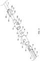
- FIG. 4illustrates an exploded view of the connection assembly 15 shown in FIG. 3 .
- FIG. 4illustrates the translation members 22 (coupled to one another via a securement collar 54 ) aligned with the second actuation coupling member 20 , the second actuation coupling member 20 aligned with the first actuation coupling member 19 , and the actuation shaft locking clip 32 positioned proximal of the first actuation coupling member 19 and disposed along the actuation shaft 17 .
- FIG. 4illustrates the translation members 22 aligned with the lumen 48 of the second actuation coupling member 20 . It is noted that FIG. 4 illustrates three translation members 22 positioned adjacent to one another (however, one of the translation members 22 is partially obstructed from view as it is positioned behind two other translation members 22 in the illustration). FIG. 4 further illustrates that the translation members 22 may be secured to one another via a securement collar 54 .
- the securement collar 54may extend around all or a portion of the outer surface of the translation members 22 . Details of the engagement of the securement collar 54 and the translation members 22 is discussed with respect to FIG. 7 below.
- FIG. 4further illustrates the second actuation coupling member 20 having a proximal end region 51 and a distal end region 44 .
- the second actuation coupling member 20may include a lumen 48 extending within a portion of the proximal end region 51 .
- the lumen 48 of the second actuation coupling member 20may be sized to permit the distal end regions (including the securement collar 54 ) of the translation members 22 to be inserted therein. It can be further appreciated from FIG.
- distal ends of the translation members 22may include a tapered (e.g., chamfered, beveled, angled, etc.) distal end which may permit easier insertion of the distal ends of the translation members 22 into the lumen 48 of the second actuation coupling member 20 .
- the translation members 22may be secured to the second actuation coupling member 20 via welding the securement collar 54 directly to the second actuation coupling member 20 .
- the aperture 50may be utilized during the welding process to assure that the securement collar 54 is properly aligned with the second actuation coupling member 20 .
- FIG. 4illustrates that the distal end region 44 of the second actuation coupling member 20 may be referred to as a stem extending away from the proximal end region 51 .
- the stem 44may include an outer diameter which is less than the diameter of the lumen 48 of the proximal end region 51 .
- the second actuation coupling member 20may include a tapered lip 55 which is positioned between the proximal end region 51 and the stem 44 .
- FIG. 4further illustrates that the stem 44 may include a channel 46 (e.g., groove) which extends circumferentially around the circumference of the stem 44 .
- the channel 46may be described as a portion of the stem 44 which extends radially inward from an outer surface of the stem 44 .
- FIG. 4illustrates that the channel 46 may be positioned along the stem 44 such that it is positioned approximately midway along the length of the stem 44 . However, this is not intended to be limiting.
- the channel 46may be positioned along any portion of the stem 44 . Additionally, FIG.
- the stem 44may include a tapered (e.g., chamfered, beveled, angled, etc.) distal end 53 which may permit easier insertion of the distal end of the stem 44 into the lumen 52 of the first actuation coupling member 19 .
- a taperede.g., chamfered, beveled, angled, etc.
- FIG. 4further illustrates the first actuation coupling member 19 aligned with the second actuation coupling member 20 .
- the first actuation coupling member 19may include a lumen 52 which may be configured to accept the stem 44 of the second actuation coupling member 20 therein.
- the lumen 52may include a diameter which is sized to the permit the outer diameter of the stem 44 be inserted therein.
- FIG. 4further illustrates that the first actuation coupling member 19 may include a first aperture 42 a which extends from the outer surface of the first actuation coupling member 19 , through the wall of the first actuation coupling member 19 to an inner surface of the first actuation coupling member 19 .
- the first aperture 42 aextends from the outer surface of the first actuation coupling member 19 and opens into the lumen 52 of the first actuation coupling member 19 .
- the first actuation coupling member 19may include a second aperture 42 b (not visible in FIG. 4 ) positioned approximately 180 degrees from the first aperture 42 a .
- the first aperture 42 amay be both longitudinally and transversely aligned with the second aperture 42 b.
- FIG. 4further illustrates that the first actuation coupling member 19 may include a first face 56 a .
- the first face 56 amay be longitudinally aligned with the first aperture 42 a of the first actuation coupling member 19 .
- the first face 56 amay include a first end which begins at the first aperture 42 a and extends away from the first aperture 42 a . Therefore, a portion of the first face 56 a may form a portion of a first channel 57 a which extends through a portion of the wall of the first actuation coupling member 19 .
- FIG. 4shows the first channel 57 a
- the first actuation coupling member 19may include a second channel 57 b (not visible in FIG. 4 ) positioned approximately 180 degrees from the first channel 57 a .
- the second channel 57 bmay be longitudinally aligned with the second aperture 42 b (not visible in FIG. 4 ).
- FIG. 4further illustrates the actuation shaft locking clip 32 disposed along the actuation shaft 17 .
- the actuation shaft locking clip 32may include a first locking tab 38 a and a second locking tab 38 b .
- the first locking tab 38 amay be positioned approximately 180 degrees from the second locking tab 38 b .
- the distal end of the first locking tab 38 amay include a first locking projection 40 a which extends radially inward from an outer surface of the first locking tab 38 a .
- the distal end of the second locking tab 38 bmay include a second locking projection 40 b which extends radially inward from an outer surface of the first locking tab 38 a .
- each of the first locking projection 40 a and the second locking projection 40 bmay be configured to extend through the first aperture 42 a and the second aperture 42 b , respectively, of the first actuation coupling member 19 . Further, as will be discussed in greater detail below, each of the first locking projection 40 a and the second locking projection 40 b may engage the channel 46 of the stem 44 of the second actuation coupling member 20 .
- FIG. 5illustrates a detailed view of the actuation shaft locking clip 32 .
- the actuation shaft locking clip 32may include a first locking tab 38 a and a second locking tab 38 b .
- a first end 65 of the first locking tab 38 amay include a first locking projection 40 a .
- the first locking projection 40 amay include a curved inner surface 62 a extending across the width of the first locking projection 40 a .
- a first end 67 of the second locking tab 38 bmay include a second locking projection 40 b .
- the second locking projection 40 amay include a curved inner surface 62 b extending across the width of the second locking projection 40 b .
- each of the first curved inner surface 62 a and the second curved inner surface 62 bmay match the radius of curvature of the stem 44 of the second actuation coupling member 20 .
- first and second locking projections 40 a / 40 bmay extend thought first and second apertures 42 a / 42 b and engage the channel 46 of the stem 44 of the second actuation locking member 20 . This engagement may couple the actuation shaft 17 (and the first actuation coupling member 19 ) to the second actuation locking member 20 while also permitting the actuation shaft 17 to rotate with respect to the second actuation locking member 20 .
- FIG. 5further illustrates that first locking tab 38 a and the second locking tab 38 b may extend longitudinally along the longitudinal axis 70 to second end 68 .
- the second end 68 of the actuation locking clip 32may include a first curved portion 64 a and a second curved portion 64 b .
- Each of the first curved portion 64 a and the second curved portion 64 bmay extend along the longitudinal axis 70 of the actuation locking clip 32 .
- the first curved portion 64 a and the second curved portion 64 b of the locking clip 32may provide a radially-inward force which biases the first locking tab 38 a and second locking tab 38 b (and hence, the first locking projection 40 a and the second locking projection 40 b ) toward the channel 46 , thereby preventing the first locking tab 38 a and second locking tab 38 b (and hence, the first locking projection 40 a and the second locking projection 40 b ) from flexing radially away from the channel 46 .
- FIG. 5illustrates that the second end 68 may be sized and shaped to permit the proximal end region of the first actuation coupling member 20 to extend therethrough.
- the second end 68 of the actuation shaft locking clip 32may extend around the circumference of the first actuation coupling member 19 (e.g., the second end 68 of the locking clip 32 may extend around the outer surface of the first actuation coupling member 19 ).
- the actuation shaft locking clip 32may include a first inner surface 66 a and a second inner surface 66 b .
- the first inner surface 66 amay face the second inner surface 66 b .
- the first inner surface 66 amay be designed to extend along the first face 56 a of the first actuation coupling member 20 while the second inner surface 66 b may be designed to extend along the second face 56 b of the first actuation coupling member 20 .
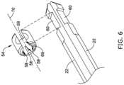
- FIG. 6illustrates a partial exploded view of the securement collar 54 spaced away from the distal end regions of the translation members 22 .
- the distal end region of each of the translation members 22may include a notched portion 60 .
- each of the notched portions 60may be circumferentially offset from one another approximately 120 degrees.
- the securement collar 54may include an inner surface 59 .
- the inner surface 59may include multiple flat surfaces 58 , each of which may be offset 120 degrees from one another. It can be further appreciated that when the securement collar 54 is coupled to the translation members 22 , each of the flat surfaces 58 may mate with each of the notched portion 60 , respectively, of the securement collar 54 .
- the securement collar 54may include a gap 69 which prevents the securement collar 54 from extending continuously around its longitudinal axis 70 (it is noted that the securement collar 54 shares the same longitudinal axis 70 as the locking clip 32 described above). Therefore, the securement collar 54 may be designed to flex such that it may flex around and onto (e.g., it may snap onto) the translation members 22 (collectively) whereby each of the flat surfaces 58 engage each of the notched regions 60 , respectively.
- FIG. 7illustrates a cross-section of the connection assembly 15 shown in FIG. 3 above.
- FIG. 7illustrates two translation members 22 (it can be appreciated that the third translation member 22 is hidden behind the two visible translation members 22 shown in FIG. 7 ) inserted into the lumen 48 of the proximal end region 51 of the second actuation coupling member 20 .
- FIG. 7illustrates the securement collar 54 positioned within the notched portions 60 of the translation members 22 . As discussed above, the securement collar 54 may be welded directly to the second actuation coupling member 20 .
- FIG. 7further illustrates the stem 44 of the second actuation coupling member 20 positioned within the lumen 52 of the first actuation coupling member 19 .
- FIG. 7further illustrates the first locking projection 40 a extending through the first aperture 42 a of the first actuation coupling member 19 .
- FIG. 7also illustrate the second locking projection 40 b extending through the second aperture 42 b of the first actuation coupling member 19 .
- FIG. 7further illustrates that the first aperture 40 a may be rotated approximately 180 degrees from the second aperture 40 b along the circumference of the outer surface of the first actuation coupling member 19 . In other words, the first aperture 40 a may be directly aligned with and (positioned directly across from) the second aperture 40 b.
- FIG. 7shows the first locking projection 40 a of the actuation shaft locking clip 32 extending through the first aperture 40 a and resting within the channel 46 of the stem 44 of the second actuation coupling member 20 .
- FIG. 7illustrates the second locking projection 40 b of the actuation shaft locking clip 32 extending through the second aperture 40 b and engaging the channel 46 of the stem 44 of the second actuation coupling member 20 .
- first locking projection 40 a and the second locking projection 40 bmay each resemble a finger which passes through the wall (via the first aperture 40 a and the second aperture 40 b , respectively) of the first actuation coupling member 19 and nests within the channel 46 of the stem 44 of the second actuation coupling member 20 .
- first locking projection 40 a and the second locking projection 40 bare positioned within the channel 46 , the locking clip 32 is prevented from moving distally relative to the first actuation coupling member 19 .
- first locking projection 40 a and the second locking projection 40 bmay abut the wall defining the first aperture 40 a and the second aperture 40 b , respectively, and are thereby prevented from moving in a distal direction (e.g., a direction toward the second actuation coupling member 20 ).
- first locking projection 40 a and the second locking projection 40 b within the channel 46may prevent the second actuation coupling member 20 from being pulled away from the second actuation coupling member 20 .
- the first curved portion 64 a and the second curved portion 64 b of the locking clip 32may provide a radially-inward force which biases the first locking tab 38 a and second locking tab 38 b (and hence, the first locking projection 40 a and the second locking projection 40 b ) toward the channel 46 , thereby preventing the first locking tab 38 a and second locking tab 38 b (and hence, the first locking projection 40 a and the second locking projection 40 b ) from flexing radially away from the channel 46 .
- first curved portion 64 a and the second curved portion of the locking clip 32provide a force toward the longitudinal axis of the first actuation locking member 19 which is designed to maintain the first locking projection 40 a and the second locking projection 40 b within the channel 46 and thereby prevent the stem 44 from being pulled out of the lumen 52 of the first actuation coupling member 19 .
- the second actuation coupling member 20may be permitted to swivel (e.g., spin along its longitudinal axis) relative to both the first locking actuation member 19 and the actuation shaft locking clip 32 . Because the first locking projection 40 a and the second locking projection 40 b extend through the first aperture 40 a and the second aperture 40 b , respectively, the first actuation coupling member 20 and the locking clip 32 may rotate together around the stem 44 of the second actuation coupling member 20 , while the first locking projection 40 a and the second locking projection 40 b remain engaged within the channel and slide within the channel 46 .
- swivele.g., spin along its longitudinal axis
- medical device system 10 and components thereofmay be made from a metal, metal alloy, polymer (some examples of which are disclosed below), a metal-polymer composite, ceramics, combinations thereof, and the like, or other suitable material.
- suitable polymersmay include polytetrafluoroethylene (PTFE), ethylene tetrafluoroethylene (ETFE), fluorinated ethylene propylene (FEP), polyoxymethylene (POM, for example, DELRIN® available from DuPont), polyether block ester, polyurethane (for example, Polyurethane 85A), polypropylene (PP), polyvinylchloride (PVC), polyether-ester (for example, ARNITEL® available from DSM Engineering Plastics), ether or ester based copolymers (for example, butylene/poly(alkylene ether) phthalate and/or other polyester elastomers such as HYTREL® available from DuPont), polyamide (for example, DURETHAN® available from Bayer or C
- suitable metals and metal alloysinclude stainless steel, such as 304V, 304L, and 316LV stainless steel; mild steel; nickel-titanium alloy such as linear-elastic and/or super-elastic nitinol; other nickel alloys such as nickel-chromium-molybdenum alloys (e.g., UNS: N06625 such as INCONEL® 625, UNS: N06022 such as HASTELLOY® C-22®, UNS: N10276 such as HASTELLOY® C276®, other HASTELLOY® alloys, and the like), nickel-copper alloys (e.g., UNS: N04400 such as MONEL® 400, NICKELVAC® 400, NICORROS® 400, and the like), nickel-cobalt-chromium-molybdenum alloys (e.g., UNS: R30035 such as MP35-NR and the like), nickel-molybdenum alloys (e.g., UN
- portions or all of the medical device system 10 and components thereofmay also be doped with, made of, or otherwise include a radiopaque material.
- Radiopaque materialsare understood to be materials capable of producing a relatively bright image on a fluoroscopy screen or another imaging technique during a medical procedure. This relatively bright image aids the user of the shaft in determining its location.
- Some examples of radiopaque materialscan include, but are not limited to, gold, platinum, palladium, tantalum, tungsten alloy, polymer material loaded with a radiopaque filler, and the like. Additionally, other radiopaque marker bands and/or coils may also be incorporated into the design of the medical device system 10 and components thereof to achieve the same result.
- a degree of Magnetic Resonance Imaging (MRI) compatibilityis imparted into the shaft.
- the medical device system 10 and components thereofmay include a material that does not substantially distort the image and create substantial artifacts (e.g., gaps in the image). Certain ferromagnetic materials, for example, may not be suitable because they may create artifacts in an MRI image.
- the medical device system 10 and components thereofmay also be made from a material that the MRI machine can image.
- Some materials that exhibit these characteristicsinclude, for example, tungsten, cobalt-chromium-molybdenum alloys (e.g., UNS: R30003 such as ELGILOY®, PHYNOX®, and the like), nickel-cobalt-chromium-molybdenum alloys (e.g., UNS: R30035 such as MP35-NR and the like), nitinol, and the like, and others.
- cobalt-chromium-molybdenum alloyse.g., UNS: R30003 such as ELGILOY®, PHYNOX®, and the like
- nickel-cobalt-chromium-molybdenum alloyse.g., UNS: R30035 such as MP35-NR and the like
- nitinoland the like, and others.
Landscapes
- Health & Medical Sciences (AREA)
- Cardiology (AREA)
- Oral & Maxillofacial Surgery (AREA)
- Transplantation (AREA)
- Engineering & Computer Science (AREA)
- Biomedical Technology (AREA)
- Heart & Thoracic Surgery (AREA)
- Vascular Medicine (AREA)
- Life Sciences & Earth Sciences (AREA)
- Animal Behavior & Ethology (AREA)
- General Health & Medical Sciences (AREA)
- Public Health (AREA)
- Veterinary Medicine (AREA)
- Prostheses (AREA)
Abstract
Description
Claims (20)
Priority Applications (1)
| Application Number | Priority Date | Filing Date | Title |
|---|---|---|---|
| US17/583,466US12016777B2 (en) | 2021-01-26 | 2022-01-25 | Medical device including attachable components |
Applications Claiming Priority (2)
| Application Number | Priority Date | Filing Date | Title |
|---|---|---|---|
| US202163141777P | 2021-01-26 | 2021-01-26 | |
| US17/583,466US12016777B2 (en) | 2021-01-26 | 2022-01-25 | Medical device including attachable components |
Publications (2)
| Publication Number | Publication Date |
|---|---|
| US20220233313A1 US20220233313A1 (en) | 2022-07-28 |
| US12016777B2true US12016777B2 (en) | 2024-06-25 |
Family
ID=82495228
Family Applications (1)
| Application Number | Title | Priority Date | Filing Date |
|---|---|---|---|
| US17/583,466Active2042-06-27US12016777B2 (en) | 2021-01-26 | 2022-01-25 | Medical device including attachable components |
Country Status (1)
| Country | Link |
|---|---|
| US (1) | US12016777B2 (en) |
Cited By (1)
| Publication number | Priority date | Publication date | Assignee | Title |
|---|---|---|---|---|
| US20220233314A1 (en)* | 2021-01-26 | 2022-07-28 | Boston Scientific Scimed, Inc. | Medical device including attachable components |
Citations (151)
| Publication number | Priority date | Publication date | Assignee | Title |
|---|---|---|---|---|
| US3674014A (en) | 1969-10-28 | 1972-07-04 | Astra Meditec Ab | Magnetically guidable catheter-tip and method |
| US4798598A (en) | 1986-05-23 | 1989-01-17 | Sarcem S.A. | Guide for a catheter |
| US4955384A (en) | 1989-05-11 | 1990-09-11 | Advanced Cardiovascular Systems, Inc. | Guiding member for vascular catheters with a flexible link distal section |
| US4985022A (en) | 1988-11-23 | 1991-01-15 | Med Institute, Inc. | Catheter having durable and flexible segments |
| US4998923A (en) | 1988-08-11 | 1991-03-12 | Advanced Cardiovascular Systems, Inc. | Steerable dilatation catheter |
| US5003989A (en) | 1989-05-11 | 1991-04-02 | Advanced Cardiovascular Systems, Inc. | Steerable dilation catheter |
| US5035706A (en) | 1989-10-17 | 1991-07-30 | Cook Incorporated | Percutaneous stent and method for retrieval thereof |
| US5095915A (en) | 1990-03-19 | 1992-03-17 | Target Therapeutics | Guidewire with flexible distal tip |
| US5315996A (en) | 1991-02-15 | 1994-05-31 | Lundquist Ingemar H | Torquable catheter and method |
| US5406960A (en) | 1994-04-13 | 1995-04-18 | Cordis Corporation | Guidewire with integral core and marker bands |
| US5437288A (en) | 1992-09-04 | 1995-08-01 | Mayo Foundation For Medical Education And Research | Flexible catheter guidewire |
| US5570701A (en) | 1992-08-12 | 1996-11-05 | Scimed Life Systems, Inc. | Shaft movement control apparatus and method |
| EP0778040A2 (en) | 1995-12-07 | 1997-06-11 | Sarcos, Inc. | Hollow guide wire apparatus for catheters |
| US5665115A (en) | 1992-02-21 | 1997-09-09 | Boston Scientific Technology, Inc. | Intraluminal stent |
| US5746701A (en) | 1995-09-14 | 1998-05-05 | Medtronic, Inc. | Guidewire with non-tapered tip |
| US5749837A (en) | 1993-05-11 | 1998-05-12 | Target Therapeutics, Inc. | Enhanced lubricity guidewire |
| WO1998020811A1 (en) | 1996-11-15 | 1998-05-22 | C.R. Bard, Inc. | Endoprosthesis delivery catheter with sequential stage control |
| US5769796A (en) | 1993-05-11 | 1998-06-23 | Target Therapeutics, Inc. | Super-elastic composite guidewire |
| US5772609A (en) | 1993-05-11 | 1998-06-30 | Target Therapeutics, Inc. | Guidewire with variable flexibility due to polymeric coatings |
| US5776080A (en) | 1992-08-12 | 1998-07-07 | Scimed Life Systems, Inc. | Shaft movement control apparatus |
| US5800456A (en) | 1992-01-15 | 1998-09-01 | Cook Incorporated | Spiral stent |
| US5902254A (en) | 1996-07-29 | 1999-05-11 | The Nemours Foundation | Cathether guidewire |
| WO1999025280A1 (en) | 1997-11-14 | 1999-05-27 | Boston Scientific Limited | Multi-sheath delivery catheter |
| US5931830A (en) | 1995-12-07 | 1999-08-03 | Sarcos L.C. | Hollow coil guide wire apparatus for catheters |
| US5951494A (en) | 1995-02-28 | 1999-09-14 | Boston Scientific Corporation | Polymeric implements for torque transmission |
| US6001068A (en) | 1996-10-22 | 1999-12-14 | Terumo Kabushiki Kaisha | Guide wire having tubular connector with helical slits |
| US6017319A (en) | 1996-05-24 | 2000-01-25 | Precision Vascular Systems, Inc. | Hybrid tubular guide wire for catheters |
| US6139510A (en) | 1994-05-11 | 2000-10-31 | Target Therapeutics Inc. | Super elastic alloy guidewire |
| US6221096B1 (en) | 1997-06-09 | 2001-04-24 | Kanto Special Steel Works, Ltd. | Intravascular stent |
| US6254628B1 (en) | 1996-12-09 | 2001-07-03 | Micro Therapeutics, Inc. | Intracranial stent |
| US6273876B1 (en) | 1997-12-05 | 2001-08-14 | Intratherapeutics, Inc. | Catheter segments having circumferential supports with axial projection |
| EP1168986A1 (en) | 1999-04-09 | 2002-01-09 | Endotex Interventional Systems, Inc. | Stent delivery handle |
| US6398776B1 (en) | 1996-06-03 | 2002-06-04 | Terumo Kabushiki Kaisha | Tubular medical device |
| US20030069521A1 (en) | 2001-10-05 | 2003-04-10 | Brian Reynolds | Composite guidewire |
| US6565597B1 (en) | 1999-07-16 | 2003-05-20 | Med Institute, Inc. | Stent adapted for tangle-free deployment |
| US6606921B2 (en) | 1995-09-19 | 2003-08-19 | Nobert Noetzold | Pull cable system |
| US20040064179A1 (en) | 2001-11-09 | 2004-04-01 | Rubicon Medical, Inc. | Stent delivery device with embolic protection |
| US6739787B1 (en) | 1999-04-30 | 2004-05-25 | Bystroem Johan Adolf | Joint device |
| US6764503B1 (en) | 1998-07-10 | 2004-07-20 | Shin Ishimaru | Stent (or stent graft) locating device |
| US20040193244A1 (en) | 2002-12-04 | 2004-09-30 | Cook Incorporated | Device and method for treating thoracic aorta |
| US20040220499A1 (en) | 2003-05-01 | 2004-11-04 | Scimed Life Systems, Inc. | Medical instrument with controlled torque transmission |
| US20040243143A1 (en) | 2003-05-27 | 2004-12-02 | Corcoran Michael P. | Flexible delivery device |
| US20050080400A1 (en) | 2003-05-27 | 2005-04-14 | Cardia, Inc. | Flexible medical device |
| US20050090848A1 (en) | 2003-10-22 | 2005-04-28 | Adams Kenneth M. | Angled tissue cutting instruments and method of fabricating angled tissue cutting instruments having flexible inner tubular members of tube and sleeve construction |
| US20050267444A1 (en) | 2003-03-27 | 2005-12-01 | Stephen Griffin | Medical device |
| WO2006041612A2 (en) | 2004-10-08 | 2006-04-20 | Cardia, Inc. | Flexible center connection for occlusion device |
| US20060111615A1 (en) | 2004-11-23 | 2006-05-25 | Novare Surgical Systems, Inc. | Articulating sheath for flexible instruments |
| US7055656B2 (en) | 2003-04-25 | 2006-06-06 | Delta Cycle Corporation | Apparatus for restraining cable curvature |
| US20060122537A1 (en) | 2001-10-05 | 2006-06-08 | Brian Reynolds | Composite guidewire |
| WO2006073581A2 (en) | 2004-11-23 | 2006-07-13 | Novare Surgical Systems, Inc. | Articulating mechanisms and link systems with torque transmission in remote manipulation of instruments and tools |
| US20060179966A1 (en) | 2005-02-03 | 2006-08-17 | Kuo Yung-Pin | Flexible sheath for cables |
| US20060189896A1 (en) | 1995-12-07 | 2006-08-24 | Davis Clark C | Medical device with collapse-resistant liner and mehtod of making same |
| US20070066900A1 (en) | 2005-09-22 | 2007-03-22 | Boston Scientific Scimed, Inc. | Intravascular ultrasound catheter |
| US20070083132A1 (en) | 2005-10-11 | 2007-04-12 | Sharrow James S | Medical device coil |
| US20070100285A1 (en) | 2005-10-27 | 2007-05-03 | Boston Scientific Scimed, Inc. | Elongate medical device with continuous reinforcement member |
| US20070114211A1 (en) | 2003-02-26 | 2007-05-24 | Boston Scientific Scimed, Inc. | Elongated medical device with distal cap |
| US20070233043A1 (en) | 2006-03-31 | 2007-10-04 | Boston Scientific Scimed, Inc. | Flexible device shaft with angled spiral wrap |
| US20070265637A1 (en) | 2006-04-21 | 2007-11-15 | Xtent, Inc. | Devices and methods for controlling and counting interventional elements |
| US20080009829A1 (en) | 2006-07-07 | 2008-01-10 | Abbott Cardiovascular Systems Inc. | Balloon catheter having a branched distal section with secured branches |
| US20080064989A1 (en) | 2006-09-13 | 2008-03-13 | Boston Scientific Scimed, Inc. | Crossing guidewire |
| US20080077119A1 (en) | 2001-07-05 | 2008-03-27 | Precision Vascular Systems, Inc. | Torqueable soft tip medical device and method of usage |
| US20080194994A1 (en) | 2007-02-08 | 2008-08-14 | C.R. Bard, Inc. | Shape memory medical device and methods of use |
| US20080205980A1 (en) | 2007-02-27 | 2008-08-28 | Carnegie Mellon University | System for releasably attaching a disposable device to a durable device |
| US20080255655A1 (en) | 2007-04-09 | 2008-10-16 | Ev3 Peripheral, Inc. | Stretchable stent and delivery system |
| US20080262474A1 (en) | 2007-04-20 | 2008-10-23 | Boston Scientific Scimed, Inc. | Medical device |
| US20090036833A1 (en) | 2007-08-02 | 2009-02-05 | Boston Scientific Scimed, Inc. | Composite elongate medical device including distal tubular member |
| US20090043228A1 (en) | 2007-08-06 | 2009-02-12 | Boston Scientific Scimed, Inc. | Laser shock peening of medical devices |
| US20090043283A1 (en) | 2007-08-07 | 2009-02-12 | Boston Scientific Scimed, Inc. | Microfabricated catheter with improved bonding structure |
| US7533906B2 (en) | 2003-10-14 | 2009-05-19 | Water Pik, Inc. | Rotatable and pivotable connector |
| US20090143768A1 (en) | 2007-04-23 | 2009-06-04 | Interventional & Surgical Innovations, Llc | Guidewire with adjustable stiffness |
| US20090156999A1 (en) | 2007-12-13 | 2009-06-18 | Boston Scientific Scimed, Inc. | Coil member for a medical device |
| US20090171151A1 (en) | 2004-06-25 | 2009-07-02 | Choset Howard M | Steerable, follow the leader device |
| US20090319037A1 (en) | 2008-06-20 | 2009-12-24 | Edwards Lifesciences Corporation | Retaining mechanisms for prosthetic valves |
| WO2010027485A1 (en) | 2008-09-05 | 2010-03-11 | Med Institute, Inc. | Apparatus and methods for improve stent deployment |
| US20100063480A1 (en) | 2008-09-10 | 2010-03-11 | Boston Scientific Scimed, Inc. | Medical devices and tapered tubular members for use in medical devices |
| US20100076266A1 (en) | 2003-04-01 | 2010-03-25 | Boston Scientific Scimed, Inc | Articulation joint for video endoscope |
| US20100080892A1 (en) | 2008-09-30 | 2010-04-01 | O'brien Michael J | Varnish compositions for electrical insulation and method of using the same |
| JP2010088545A (en) | 2008-10-06 | 2010-04-22 | Goodman Co Ltd | Catheter |
| US20100145308A1 (en) | 2008-12-10 | 2010-06-10 | Boston Scientific Scimed, Inc. | Medical devices with a slotted tubular member having improved stress distribution |
| US7784376B2 (en) | 2007-09-14 | 2010-08-31 | Chun-Te Wen | Bicycle cable assembly |
| US20100234933A1 (en) | 2009-03-10 | 2010-09-16 | Medtronic Vascular, Inc. | Prosthesis Delivery Apparatus and Methods |
| US20100249655A1 (en) | 2009-03-30 | 2010-09-30 | C. R. Bard, Inc. | Tip-Shapeable Guidewire |
| US20100274187A1 (en) | 2009-04-23 | 2010-10-28 | Medtronic Vascular, Inc. | Centering for a TAA |
| US7824345B2 (en) | 2003-12-22 | 2010-11-02 | Boston Scientific Scimed, Inc. | Medical device with push force limiter |
| US20100286566A1 (en) | 2003-05-27 | 2010-11-11 | Boston Scientific Scimed, Inc. | Medical device having segmented construction |
| US20100294071A1 (en) | 2006-10-24 | 2010-11-25 | Carnegie Mellon University | Steerable multi-linked device having a modular link assembly |
| US7841994B2 (en) | 2007-11-02 | 2010-11-30 | Boston Scientific Scimed, Inc. | Medical device for crossing an occlusion in a vessel |
| US20100305475A1 (en) | 2007-04-23 | 2010-12-02 | Hinchliffe Peter W J | Guidewire with adjustable stiffness |
| US7914467B2 (en) | 2002-07-25 | 2011-03-29 | Boston Scientific Scimed, Inc. | Tubular member having tapered transition for use in a medical device |
| JP2011087947A (en) | 2003-10-16 | 2011-05-06 | Trivascular Inc | Delivery system and method for bifurcated graft |
| US20110152613A1 (en) | 2008-04-14 | 2011-06-23 | Carnegie Mellon University | Articulated device with visualization system |
| US20110184241A1 (en) | 2008-06-05 | 2011-07-28 | Cardiorobotics, Inc. | Extendable articulated probe device |
| WO2011094527A1 (en) | 2010-01-29 | 2011-08-04 | Cook Medical Technologies Llc | Mechanically expandable delivery and dilation systems |
| US20110218620A1 (en) | 2010-03-05 | 2011-09-08 | Edwards Lifesciences Corporation | Retaining Mechanisms for Prosthetic Valves |
| US20110257478A1 (en) | 2010-04-20 | 2011-10-20 | Spinewindow Llc | Method and apparatus for performing retro peritoneal dissection |
| US20110264191A1 (en) | 2010-04-23 | 2011-10-27 | Medtronic, Inc. | Delivery Systems and Methods of Implantation for Prosthetic Heart Valves |
| WO2011133486A1 (en) | 2010-04-19 | 2011-10-27 | Micrus Endovascular Llc | Low profile guiding catheter for neurovascular applications |
| US8048004B2 (en) | 2002-07-25 | 2011-11-01 | Precision Vascular Systems, Inc. | Medical device for navigation through anatomy and method of making same |
| US8047236B2 (en) | 2008-09-12 | 2011-11-01 | Boston Scientific Scimed, Inc. | Flexible conduit with locking element |
| US8080053B2 (en) | 2006-08-01 | 2011-12-20 | Merit Medical Systems, Inc. | Stent, stent removal and repositioning device, and associated methods |
| US8105246B2 (en) | 2007-08-03 | 2012-01-31 | Boston Scientific Scimed, Inc. | Elongate medical device having enhanced torque and methods thereof |
| US8137293B2 (en) | 2009-11-17 | 2012-03-20 | Boston Scientific Scimed, Inc. | Guidewires including a porous nickel-titanium alloy |
| US8147534B2 (en) | 2005-05-25 | 2012-04-03 | Tyco Healthcare Group Lp | System and method for delivering and deploying an occluding device within a vessel |
| EP2455128A2 (en) | 2010-11-18 | 2012-05-23 | Cook Medical Technologies LLC | Introducer assembly and sheath therefor |
| US8192422B2 (en) | 2006-08-14 | 2012-06-05 | Medrobotics Corporation | Steerable multi linked device having multiple working ports |
| US8197419B2 (en) | 2008-05-30 | 2012-06-12 | Inrad, Inc. | Biopsy device having specimen length adjustment |
| US20120160537A1 (en) | 2010-12-28 | 2012-06-28 | Wen Yuan-Hung | Cable sheath |
| WO2012116368A2 (en) | 2011-02-25 | 2012-08-30 | Edwards Lifesciences Corporation | Prosthetic heart valve delivery apparatus |
| US20120265134A1 (en) | 2011-04-15 | 2012-10-18 | Micrus Endovascular Llc | Noncircular inner lumen guiding catheter with assisted variable support |
| US8328868B2 (en) | 2004-11-05 | 2012-12-11 | Sadra Medical, Inc. | Medical devices and delivery systems for delivering medical devices |
| US8376865B2 (en) | 2006-06-20 | 2013-02-19 | Cardiacmd, Inc. | Torque shaft and torque shaft drive |
| US8376961B2 (en) | 2008-04-07 | 2013-02-19 | Boston Scientific Scimed, Inc. | Micromachined composite guidewire structure with anisotropic bending properties |
| US8377035B2 (en) | 2003-01-17 | 2013-02-19 | Boston Scientific Scimed, Inc. | Unbalanced reinforcement members for medical device |
| US20130085562A1 (en) | 2010-06-24 | 2013-04-04 | Cordis Corporation | Apparatus for and method of pulling a tensile member from a medical device |
| US20130123796A1 (en) | 2011-11-15 | 2013-05-16 | Boston Scientific Scimed, Inc. | Medical device with keyed locking structures |
| US20130123912A1 (en)* | 2011-11-15 | 2013-05-16 | Boston Scientific Scimed, Inc. | Medical device with nosecone and nosecone tube extension |
| US20130131775A1 (en) | 2011-11-22 | 2013-05-23 | Cook Medical Technologies Llc | Endoluminal prosthesis introducer |
| US20130144276A1 (en) | 2011-12-03 | 2013-06-06 | Boston Scientific Scimed, Inc. | Medical device handle |
| US8475366B2 (en) | 2003-04-01 | 2013-07-02 | Boston Scientific Scimed, Inc. | Articulation joint for a medical device |
| US8535219B2 (en) | 2003-04-01 | 2013-09-17 | Boston Scientific Scimed, Inc. | Fluid manifold for endoscope system |
| US8551021B2 (en) | 2010-03-31 | 2013-10-08 | Boston Scientific Scimed, Inc. | Guidewire with an improved flexural rigidity profile |
| US8556914B2 (en) | 2006-12-15 | 2013-10-15 | Boston Scientific Scimed, Inc. | Medical device including structure for crossing an occlusion in a vessel |
| US8608648B2 (en) | 2003-04-01 | 2013-12-17 | Boston Scientific Scimed, Inc. | Articulation joint |
| US8622894B2 (en) | 2003-04-01 | 2014-01-07 | Boston Scientific Scimed, Inc. | Articulation joint |
| JP2014508568A (en) | 2011-01-14 | 2014-04-10 | アイデブ テクノロジーズ インコーポレイテッド | Stent delivery system with pusher assembly |
| US8795202B2 (en) | 2011-02-04 | 2014-08-05 | Boston Scientific Scimed, Inc. | Guidewires and methods for making and using the same |
| US20140235361A1 (en) | 2013-02-15 | 2014-08-21 | Cardiacmd, Inc. | Torque Shaft and Torque Shaft Drive |
| US8821477B2 (en) | 2007-08-06 | 2014-09-02 | Boston Scientific Scimed, Inc. | Alternative micromachined structures |
| US9072874B2 (en) | 2011-05-13 | 2015-07-07 | Boston Scientific Scimed, Inc. | Medical devices with a heat transfer region and a heat sink region and methods for manufacturing medical devices |
| US20150250481A1 (en) | 2014-03-10 | 2015-09-10 | Trivascular, Inc. | Inflatable occlusion wire-balloon for aortic applications |
| US20160100941A1 (en) | 2014-10-13 | 2016-04-14 | Hlt, Inc. | Inversion Delivery Device And Method For A Prosthesis |
| JP2016067915A (en) | 2014-09-24 | 2016-05-09 | コヴィディエン リミテッド パートナーシップ | Endoscopic ultrasound-guided biliary access system |
| US9370432B2 (en) | 2010-12-10 | 2016-06-21 | Globus Medical, Inc. | Spine stabilization device and methods |
| US20160184117A1 (en) | 2014-12-29 | 2016-06-30 | Cook Medical Technologies Llc | Deployment handle for a delivery device with mechanism for quick release of a prosthesis and re-sheathing of device tip |
| US9402682B2 (en) | 2010-09-24 | 2016-08-02 | Ethicon Endo-Surgery, Llc | Articulation joint features for articulating surgical device |
| US20160256304A1 (en) | 2015-03-05 | 2016-09-08 | Cook Medical Technologies Llc | Stent graft delivery device pre-loaded with a single wire for device tracking and cannulation |
| US20160302921A1 (en) | 2015-04-15 | 2016-10-20 | Medtronic, Inc. | Transcatheter prosthetic heart valve delivery system and method |
| US20160317301A1 (en) | 2015-04-30 | 2016-11-03 | Edwards Lifesciences Cardiaq Llc | Replacement mitral valve, delivery system for replacement mitral valve and methods of use |
| WO2016196933A1 (en) | 2015-06-05 | 2016-12-08 | Tendyne Holdings, Inc. | Apical control of transvascular delivery of prosthetic mitral valve |
| US20180140323A1 (en)* | 2016-11-22 | 2018-05-24 | Boston Scientific Scimed, Inc. | Medical device shaft resistant to compression and/or tension |
| US9993360B2 (en) | 2013-01-08 | 2018-06-12 | Endospan Ltd. | Minimization of stent-graft migration during implantation |
| US20180263771A1 (en)* | 2017-03-14 | 2018-09-20 | Boston Scientific Scimed, Inc. | Medical device shaft including a liner |
| US20180263773A1 (en)* | 2017-03-14 | 2018-09-20 | Boston Scientific Scimed, Inc. | Medical device with inner assembly |
| US10092426B2 (en) | 2011-05-31 | 2018-10-09 | Cook Medical Technologies Llc | Non-foreshortening, axial tension constrainable stent |
| WO2018204558A1 (en) | 2017-05-03 | 2018-11-08 | Boston Scientific Scimed, Inc. | Medical device with sealing assembly |
| US20190038408A1 (en)* | 2017-08-01 | 2019-02-07 | Boston Scientific Scimed, Inc. | Medical implant locking mechanism |
| US20190070001A1 (en)* | 2017-09-05 | 2019-03-07 | Boston Scientific Scimed, Inc. | Medical device with tip member |
| US10258465B2 (en) | 2003-12-23 | 2019-04-16 | Boston Scientific Scimed Inc. | Methods and apparatus for endovascular heart valve replacement comprising tissue grasping elements |
| US20190328523A1 (en)* | 2018-04-26 | 2019-10-31 | Boston Scientific Scimed, Inc. | Medical device with coupling member |
| US10646365B2 (en) | 2003-09-03 | 2020-05-12 | Bolton Medical, Inc. | Delivery system and method for self-centering a proximal end of a stent graft |
| US11266518B2 (en) | 2018-04-26 | 2022-03-08 | Boston Scientific Scimed, Inc. | Medical device with telescoping sealing assembly |
- 2022
- 2022-01-25USUS17/583,466patent/US12016777B2/enactiveActive
Patent Citations (235)
| Publication number | Priority date | Publication date | Assignee | Title |
|---|---|---|---|---|
| US3674014A (en) | 1969-10-28 | 1972-07-04 | Astra Meditec Ab | Magnetically guidable catheter-tip and method |
| US4798598A (en) | 1986-05-23 | 1989-01-17 | Sarcem S.A. | Guide for a catheter |
| US4998923A (en) | 1988-08-11 | 1991-03-12 | Advanced Cardiovascular Systems, Inc. | Steerable dilatation catheter |
| US4985022A (en) | 1988-11-23 | 1991-01-15 | Med Institute, Inc. | Catheter having durable and flexible segments |
| US4955384A (en) | 1989-05-11 | 1990-09-11 | Advanced Cardiovascular Systems, Inc. | Guiding member for vascular catheters with a flexible link distal section |
| US5003989A (en) | 1989-05-11 | 1991-04-02 | Advanced Cardiovascular Systems, Inc. | Steerable dilation catheter |
| US5035706A (en) | 1989-10-17 | 1991-07-30 | Cook Incorporated | Percutaneous stent and method for retrieval thereof |
| US5095915A (en) | 1990-03-19 | 1992-03-17 | Target Therapeutics | Guidewire with flexible distal tip |
| US5599492A (en) | 1990-03-19 | 1997-02-04 | Target Therapeutics, Inc. | Method for making a guidewire with a flexible distal tip |
| US5315996A (en) | 1991-02-15 | 1994-05-31 | Lundquist Ingemar H | Torquable catheter and method |
| US5800456A (en) | 1992-01-15 | 1998-09-01 | Cook Incorporated | Spiral stent |
| US5665115A (en) | 1992-02-21 | 1997-09-09 | Boston Scientific Technology, Inc. | Intraluminal stent |
| US5776080A (en) | 1992-08-12 | 1998-07-07 | Scimed Life Systems, Inc. | Shaft movement control apparatus |
| US5570701A (en) | 1992-08-12 | 1996-11-05 | Scimed Life Systems, Inc. | Shaft movement control apparatus and method |
| US5437288A (en) | 1992-09-04 | 1995-08-01 | Mayo Foundation For Medical Education And Research | Flexible catheter guidewire |
| US5749837A (en) | 1993-05-11 | 1998-05-12 | Target Therapeutics, Inc. | Enhanced lubricity guidewire |
| US5769796A (en) | 1993-05-11 | 1998-06-23 | Target Therapeutics, Inc. | Super-elastic composite guidewire |
| US5772609A (en) | 1993-05-11 | 1998-06-30 | Target Therapeutics, Inc. | Guidewire with variable flexibility due to polymeric coatings |
| US5406960A (en) | 1994-04-13 | 1995-04-18 | Cordis Corporation | Guidewire with integral core and marker bands |
| US6139510A (en) | 1994-05-11 | 2000-10-31 | Target Therapeutics Inc. | Super elastic alloy guidewire |
| US5951494A (en) | 1995-02-28 | 1999-09-14 | Boston Scientific Corporation | Polymeric implements for torque transmission |
| US5746701A (en) | 1995-09-14 | 1998-05-05 | Medtronic, Inc. | Guidewire with non-tapered tip |
| US6606921B2 (en) | 1995-09-19 | 2003-08-19 | Nobert Noetzold | Pull cable system |
| US5833632A (en) | 1995-12-07 | 1998-11-10 | Sarcos, Inc. | Hollow guide wire apparatus catheters |
| US5931830A (en) | 1995-12-07 | 1999-08-03 | Sarcos L.C. | Hollow coil guide wire apparatus for catheters |
| US20060189896A1 (en) | 1995-12-07 | 2006-08-24 | Davis Clark C | Medical device with collapse-resistant liner and mehtod of making same |
| EP0778040A2 (en) | 1995-12-07 | 1997-06-11 | Sarcos, Inc. | Hollow guide wire apparatus for catheters |
| US7914466B2 (en) | 1995-12-07 | 2011-03-29 | Precision Vascular Systems, Inc. | Medical device with collapse-resistant liner and method of making same |
| US6017319A (en) | 1996-05-24 | 2000-01-25 | Precision Vascular Systems, Inc. | Hybrid tubular guide wire for catheters |
| US6398776B1 (en) | 1996-06-03 | 2002-06-04 | Terumo Kabushiki Kaisha | Tubular medical device |
| US5902254A (en) | 1996-07-29 | 1999-05-11 | The Nemours Foundation | Cathether guidewire |
| US6001068A (en) | 1996-10-22 | 1999-12-14 | Terumo Kabushiki Kaisha | Guide wire having tubular connector with helical slits |
| WO1998020811A1 (en) | 1996-11-15 | 1998-05-22 | C.R. Bard, Inc. | Endoprosthesis delivery catheter with sequential stage control |
| JP2001504016A (en) | 1996-11-15 | 2001-03-27 | シー・アール・バード・インク | Sequential step-controllable endoprosthesis delivery catheter |
| US6254628B1 (en) | 1996-12-09 | 2001-07-03 | Micro Therapeutics, Inc. | Intracranial stent |
| US6221096B1 (en) | 1997-06-09 | 2001-04-24 | Kanto Special Steel Works, Ltd. | Intravascular stent |
| US20010037141A1 (en) | 1997-11-14 | 2001-11-01 | Yee Carl E. | Multi-sheath delivery catheter |
| JP2001522694A (en) | 1997-11-14 | 2001-11-20 | ボストン サイエンティフィック リミテッド | Multi-sheath delivery catheter |
| WO1999025280A1 (en) | 1997-11-14 | 1999-05-27 | Boston Scientific Limited | Multi-sheath delivery catheter |
| US6273876B1 (en) | 1997-12-05 | 2001-08-14 | Intratherapeutics, Inc. | Catheter segments having circumferential supports with axial projection |
| US6764503B1 (en) | 1998-07-10 | 2004-07-20 | Shin Ishimaru | Stent (or stent graft) locating device |
| EP1168986A1 (en) | 1999-04-09 | 2002-01-09 | Endotex Interventional Systems, Inc. | Stent delivery handle |
| US6739787B1 (en) | 1999-04-30 | 2004-05-25 | Bystroem Johan Adolf | Joint device |
| US6565597B1 (en) | 1999-07-16 | 2003-05-20 | Med Institute, Inc. | Stent adapted for tangle-free deployment |
| US8449526B2 (en) | 2001-07-05 | 2013-05-28 | Boston Scientific Scimed, Inc. | Torqueable soft tip medical device and method of usage |
| US20080077119A1 (en) | 2001-07-05 | 2008-03-27 | Precision Vascular Systems, Inc. | Torqueable soft tip medical device and method of usage |
| US7074197B2 (en) | 2001-10-05 | 2006-07-11 | Scimed Life Systems, Inc. | Composite guidewire |
| US20070244414A1 (en) | 2001-10-05 | 2007-10-18 | Boston Scientific Scimed, Inc. | Composite guidewire |
| US20030069521A1 (en) | 2001-10-05 | 2003-04-10 | Brian Reynolds | Composite guidewire |
| US20030069520A1 (en) | 2001-10-05 | 2003-04-10 | Scimed Life Systems, Inc. | Guidewire with stiffness blending connection |
| US6918882B2 (en) | 2001-10-05 | 2005-07-19 | Scimed Life Systems, Inc. | Guidewire with stiffness blending connection |
| US7993286B2 (en) | 2001-10-05 | 2011-08-09 | Boston Scientific Scimed, Inc. | Composite guidewire |
| US20070135734A1 (en) | 2001-10-05 | 2007-06-14 | Boston Scientific Scimed, Inc. | Composite guidewire |
| US7618379B2 (en) | 2001-10-05 | 2009-11-17 | Boston Scientific Scimed, Inc. | Composite guidewire |
| US8414506B2 (en) | 2001-10-05 | 2013-04-09 | Boston Scientific Scimed, Inc. | Composite guidewire |
| US20060122537A1 (en) | 2001-10-05 | 2006-06-08 | Brian Reynolds | Composite guidewire |
| US20040064179A1 (en) | 2001-11-09 | 2004-04-01 | Rubicon Medical, Inc. | Stent delivery device with embolic protection |
| US7914467B2 (en) | 2002-07-25 | 2011-03-29 | Boston Scientific Scimed, Inc. | Tubular member having tapered transition for use in a medical device |
| US8257279B2 (en) | 2002-07-25 | 2012-09-04 | Boston Scientific Scimed, Inc. | Medical device for navigation through anatomy and method of making same |
| US8870790B2 (en) | 2002-07-25 | 2014-10-28 | Boston Scientific Scimed, Inc. | Medical device for navigation through anatomy and method of making same |
| US8900163B2 (en) | 2002-07-25 | 2014-12-02 | Precision Vascular Systems, Inc. | Medical device for navigation through anatomy and method of making same |
| US8915865B2 (en) | 2002-07-25 | 2014-12-23 | Precision Vascular Systems, Inc. | Medical device for navigation through anatomy and method of making same |
| US8932235B2 (en) | 2002-07-25 | 2015-01-13 | Precision Vascular Systems, Inc. | Medical device for navigation through anatomy and method of making same |
| US8936558B2 (en) | 2002-07-25 | 2015-01-20 | Precision Vascular Systems, Inc. | Medical device for navigation through anatomy and method of making same |
| US8939916B2 (en) | 2002-07-25 | 2015-01-27 | Precision Vascular Systems, Inc. | Medical device for navigation through anatomy and method of making same |
| US8048004B2 (en) | 2002-07-25 | 2011-11-01 | Precision Vascular Systems, Inc. | Medical device for navigation through anatomy and method of making same |
| US20040193244A1 (en) | 2002-12-04 | 2004-09-30 | Cook Incorporated | Device and method for treating thoracic aorta |
| US8377035B2 (en) | 2003-01-17 | 2013-02-19 | Boston Scientific Scimed, Inc. | Unbalanced reinforcement members for medical device |
| US8022331B2 (en) | 2003-02-26 | 2011-09-20 | Boston Scientific Scimed, Inc. | Method of making elongated medical devices |
| US20070114211A1 (en) | 2003-02-26 | 2007-05-24 | Boston Scientific Scimed, Inc. | Elongated medical device with distal cap |
| US20070049902A1 (en) | 2003-03-27 | 2007-03-01 | Stephen Griffin | Medical device |
| US9023011B2 (en) | 2003-03-27 | 2015-05-05 | Boston Scientific Scimed, Inc. | Medical device |
| US20050267444A1 (en) | 2003-03-27 | 2005-12-01 | Stephen Griffin | Medical device |
| US8048060B2 (en) | 2003-03-27 | 2011-11-01 | Boston Scientific Scimed, Inc. | Medical device |
| US8182465B2 (en) | 2003-03-27 | 2012-05-22 | Boston Scientific Scimed, Inc. | Medical device |
| US7540865B2 (en) | 2003-03-27 | 2009-06-02 | Boston Scientific Scimed, Inc. | Medical device |
| US8636716B2 (en) | 2003-03-27 | 2014-01-28 | Boston Scientific Scimed, Inc. | Medical device |
| US8425408B2 (en) | 2003-04-01 | 2013-04-23 | Boston Scientific Scimed, Inc. | Articulation joint for video endoscope |
| US20100076266A1 (en) | 2003-04-01 | 2010-03-25 | Boston Scientific Scimed, Inc | Articulation joint for video endoscope |
| US8622894B2 (en) | 2003-04-01 | 2014-01-07 | Boston Scientific Scimed, Inc. | Articulation joint |
| US8475366B2 (en) | 2003-04-01 | 2013-07-02 | Boston Scientific Scimed, Inc. | Articulation joint for a medical device |
| US8608648B2 (en) | 2003-04-01 | 2013-12-17 | Boston Scientific Scimed, Inc. | Articulation joint |
| US8535219B2 (en) | 2003-04-01 | 2013-09-17 | Boston Scientific Scimed, Inc. | Fluid manifold for endoscope system |
| US7055656B2 (en) | 2003-04-25 | 2006-06-06 | Delta Cycle Corporation | Apparatus for restraining cable curvature |
| US20040220499A1 (en) | 2003-05-01 | 2004-11-04 | Scimed Life Systems, Inc. | Medical instrument with controlled torque transmission |
| US8845552B2 (en) | 2003-05-01 | 2014-09-30 | Boston Scientific Scimed, Inc. | Medical instrument with controlled torque transmission |
| US8292829B2 (en) | 2003-05-01 | 2012-10-23 | Boston Scientific Scimed, Inc. | Medical instrument with controlled torque transmission |
| US7780611B2 (en) | 2003-05-01 | 2010-08-24 | Boston Scientific Scimed, Inc. | Medical instrument with controlled torque transmission |
| US7625364B2 (en) | 2003-05-27 | 2009-12-01 | Cardia, Inc. | Flexible center connection for occlusion device |
| US20050080400A1 (en) | 2003-05-27 | 2005-04-14 | Cardia, Inc. | Flexible medical device |
| US8485992B2 (en) | 2003-05-27 | 2013-07-16 | Boston Scientific Scimed, Inc. | Medical device having segmented construction |
| US6921397B2 (en) | 2003-05-27 | 2005-07-26 | Cardia, Inc. | Flexible delivery device |
| US20040243143A1 (en) | 2003-05-27 | 2004-12-02 | Corcoran Michael P. | Flexible delivery device |
| US20100286566A1 (en) | 2003-05-27 | 2010-11-11 | Boston Scientific Scimed, Inc. | Medical device having segmented construction |
| US7413563B2 (en) | 2003-05-27 | 2008-08-19 | Cardia, Inc. | Flexible medical device |
| US10646365B2 (en) | 2003-09-03 | 2020-05-12 | Bolton Medical, Inc. | Delivery system and method for self-centering a proximal end of a stent graft |
| US7533906B2 (en) | 2003-10-14 | 2009-05-19 | Water Pik, Inc. | Rotatable and pivotable connector |
| JP2011087947A (en) | 2003-10-16 | 2011-05-06 | Trivascular Inc | Delivery system and method for bifurcated graft |
| US20050090848A1 (en) | 2003-10-22 | 2005-04-28 | Adams Kenneth M. | Angled tissue cutting instruments and method of fabricating angled tissue cutting instruments having flexible inner tubular members of tube and sleeve construction |
| US7338495B2 (en) | 2003-10-22 | 2008-03-04 | Medtronic Xomed, Inc. | Angled tissue cutting instruments having flexible inner tubular members of tube and sleeve construction |
| US7824345B2 (en) | 2003-12-22 | 2010-11-02 | Boston Scientific Scimed, Inc. | Medical device with push force limiter |
| US10258465B2 (en) | 2003-12-23 | 2019-04-16 | Boston Scientific Scimed Inc. | Methods and apparatus for endovascular heart valve replacement comprising tissue grasping elements |
| US9011318B2 (en) | 2004-06-25 | 2015-04-21 | Carnegie Mellon University and University of Pittsburg—Of the Commonwealth System of Higher Education | Steerable, follow the leader device |
| US20090171151A1 (en) | 2004-06-25 | 2009-07-02 | Choset Howard M | Steerable, follow the leader device |
| WO2006041612A2 (en) | 2004-10-08 | 2006-04-20 | Cardia, Inc. | Flexible center connection for occlusion device |
| US8328868B2 (en) | 2004-11-05 | 2012-12-11 | Sadra Medical, Inc. | Medical devices and delivery systems for delivering medical devices |
| WO2006073581A2 (en) | 2004-11-23 | 2006-07-13 | Novare Surgical Systems, Inc. | Articulating mechanisms and link systems with torque transmission in remote manipulation of instruments and tools |
| US20060111615A1 (en) | 2004-11-23 | 2006-05-25 | Novare Surgical Systems, Inc. | Articulating sheath for flexible instruments |
| US20060179966A1 (en) | 2005-02-03 | 2006-08-17 | Kuo Yung-Pin | Flexible sheath for cables |
| US8147534B2 (en) | 2005-05-25 | 2012-04-03 | Tyco Healthcare Group Lp | System and method for delivering and deploying an occluding device within a vessel |
| US20070066900A1 (en) | 2005-09-22 | 2007-03-22 | Boston Scientific Scimed, Inc. | Intravascular ultrasound catheter |
| US20070083132A1 (en) | 2005-10-11 | 2007-04-12 | Sharrow James S | Medical device coil |
| US20110082443A1 (en) | 2005-10-27 | 2011-04-07 | Boston Scientific Scimed, Inc. | Elongate Medical Device with Continuous Reinforcement Member |
| US7850623B2 (en) | 2005-10-27 | 2010-12-14 | Boston Scientific Scimed, Inc. | Elongate medical device with continuous reinforcement member |
| US20070100285A1 (en) | 2005-10-27 | 2007-05-03 | Boston Scientific Scimed, Inc. | Elongate medical device with continuous reinforcement member |
| US8231551B2 (en) | 2005-10-27 | 2012-07-31 | Boston Scientific Scimed, Inc. | Elongate medical device with continuous reinforcement member |
| US20090312606A1 (en) | 2006-03-31 | 2009-12-17 | Boston Scientific Scimed, Inc. | Flexible device shaft with angled spiral wrap |
| US7579550B2 (en) | 2006-03-31 | 2009-08-25 | Boston Scientific Scimed, Inc. | Flexible device shaft with angled spiral wrap |
| US20070233043A1 (en) | 2006-03-31 | 2007-10-04 | Boston Scientific Scimed, Inc. | Flexible device shaft with angled spiral wrap |
| US8677602B2 (en) | 2006-03-31 | 2014-03-25 | Boston Scientific Scimed, Inc. | Method of making a flexible device shaft with angled spiral wrap |
| US8124876B2 (en) | 2006-03-31 | 2012-02-28 | Boston Scientific Scimed, Inc. | Flexible device shaft with angled spiral wrap |
| US20070265637A1 (en) | 2006-04-21 | 2007-11-15 | Xtent, Inc. | Devices and methods for controlling and counting interventional elements |
| US8376865B2 (en) | 2006-06-20 | 2013-02-19 | Cardiacmd, Inc. | Torque shaft and torque shaft drive |
| US20080009829A1 (en) | 2006-07-07 | 2008-01-10 | Abbott Cardiovascular Systems Inc. | Balloon catheter having a branched distal section with secured branches |
| US8080053B2 (en) | 2006-08-01 | 2011-12-20 | Merit Medical Systems, Inc. | Stent, stent removal and repositioning device, and associated methods |
| US8317777B2 (en) | 2006-08-14 | 2012-11-27 | Medrobotics Corporation | Steerable multi-linked device having multiple working ports |
| US9386911B2 (en) | 2006-08-14 | 2016-07-12 | Carnegie Mellon University | Steerable multi-linked device having multiple working ports |
| JP5575840B2 (en) | 2006-08-14 | 2014-08-20 | メドロボティクス コーポレーション | Operatable articulated device having a plurality of work ports |
| US8192422B2 (en) | 2006-08-14 | 2012-06-05 | Medrobotics Corporation | Steerable multi linked device having multiple working ports |
| US8551020B2 (en) | 2006-09-13 | 2013-10-08 | Boston Scientific Scimed, Inc. | Crossing guidewire |
| US20080064989A1 (en) | 2006-09-13 | 2008-03-13 | Boston Scientific Scimed, Inc. | Crossing guidewire |
| US8397481B2 (en) | 2006-10-24 | 2013-03-19 | Carnegie Mellon University | Steerable multi-linked device having a modular link assembly |
| US8656697B2 (en) | 2006-10-24 | 2014-02-25 | Carnegie Mellon University | Steerable multi-linked device having a modular link assembly |
| US20100294071A1 (en) | 2006-10-24 | 2010-11-25 | Carnegie Mellon University | Steerable multi-linked device having a modular link assembly |
| US7918080B2 (en) | 2006-10-24 | 2011-04-05 | Carnegie Mellon University | Steerable multi-linked device having a modular link assembly |
| US20110056320A1 (en) | 2006-10-24 | 2011-03-10 | Carnegie Mellon University | Steerable multi-linked device having a modular link assembly |
| US7854109B2 (en) | 2006-10-24 | 2010-12-21 | Carnegie Mellon University | Steerable multi-linked device having a modular link assembly |
| US8099939B2 (en) | 2006-10-24 | 2012-01-24 | Carnegie Mellon University | Steerable multi-linked device having a modular link assembly |
| US8556914B2 (en) | 2006-12-15 | 2013-10-15 | Boston Scientific Scimed, Inc. | Medical device including structure for crossing an occlusion in a vessel |
| US9375234B2 (en) | 2006-12-15 | 2016-06-28 | Boston Scientific Scimed, Inc. | Medical device including structure for crossing an occlusion in a vessel |
| US8758268B2 (en) | 2007-02-08 | 2014-06-24 | C. R. Bard, Inc. | Shape memory medical device and methods of use |
| US20080194994A1 (en) | 2007-02-08 | 2008-08-14 | C.R. Bard, Inc. | Shape memory medical device and methods of use |
| US8100031B2 (en) | 2007-02-27 | 2012-01-24 | Carnegie Mellon University | Multi-linked device having a reinforcing member |
| US8443692B2 (en) | 2007-02-27 | 2013-05-21 | Carnegie Mellon University | Multi-linked device having a reinforcing member |
| US8833197B2 (en) | 2007-02-27 | 2014-09-16 | Carnegie Mellon University | Multi-linked device having a reinforcing member |
| US20080245173A1 (en) | 2007-02-27 | 2008-10-09 | Carnegie Mellon University | System for controlling the movement of a multi-linked device |
| US20080205980A1 (en) | 2007-02-27 | 2008-08-28 | Carnegie Mellon University | System for releasably attaching a disposable device to a durable device |
| US8459138B2 (en) | 2007-02-27 | 2013-06-11 | Carnegie Mellon University | System for releasably attaching a disposable device to a durable device |
| US20080255655A1 (en) | 2007-04-09 | 2008-10-16 | Ev3 Peripheral, Inc. | Stretchable stent and delivery system |
| US20080262474A1 (en) | 2007-04-20 | 2008-10-23 | Boston Scientific Scimed, Inc. | Medical device |
| US9387309B2 (en) | 2007-04-23 | 2016-07-12 | Cardioguidance Biomedical, Llc | Guidewire with adjustable stiffness |
| US9387308B2 (en) | 2007-04-23 | 2016-07-12 | Cardioguidance Biomedical, Llc | Guidewire with adjustable stiffness |
| US20100305475A1 (en) | 2007-04-23 | 2010-12-02 | Hinchliffe Peter W J | Guidewire with adjustable stiffness |
| US20090143768A1 (en) | 2007-04-23 | 2009-06-04 | Interventional & Surgical Innovations, Llc | Guidewire with adjustable stiffness |
| US8409114B2 (en) | 2007-08-02 | 2013-04-02 | Boston Scientific Scimed, Inc. | Composite elongate medical device including distal tubular member |
| US20090036833A1 (en) | 2007-08-02 | 2009-02-05 | Boston Scientific Scimed, Inc. | Composite elongate medical device including distal tubular member |
| US8105246B2 (en) | 2007-08-03 | 2012-01-31 | Boston Scientific Scimed, Inc. | Elongate medical device having enhanced torque and methods thereof |
| US20090043228A1 (en) | 2007-08-06 | 2009-02-12 | Boston Scientific Scimed, Inc. | Laser shock peening of medical devices |
| US8821477B2 (en) | 2007-08-06 | 2014-09-02 | Boston Scientific Scimed, Inc. | Alternative micromachined structures |
| US20090043283A1 (en) | 2007-08-07 | 2009-02-12 | Boston Scientific Scimed, Inc. | Microfabricated catheter with improved bonding structure |
| US7784376B2 (en) | 2007-09-14 | 2010-08-31 | Chun-Te Wen | Bicycle cable assembly |
| US7841994B2 (en) | 2007-11-02 | 2010-11-30 | Boston Scientific Scimed, Inc. | Medical device for crossing an occlusion in a vessel |
| US8157751B2 (en) | 2007-12-13 | 2012-04-17 | Boston Scientific Scimed, Inc. | Coil member for a medical device |
| US20090156999A1 (en) | 2007-12-13 | 2009-06-18 | Boston Scientific Scimed, Inc. | Coil member for a medical device |
| US8376961B2 (en) | 2008-04-07 | 2013-02-19 | Boston Scientific Scimed, Inc. | Micromachined composite guidewire structure with anisotropic bending properties |
| US9005114B2 (en) | 2008-04-14 | 2015-04-14 | Carnegie Mellon University | Articulated device with visualization system |
| US20110152613A1 (en) | 2008-04-14 | 2011-06-23 | Carnegie Mellon University | Articulated device with visualization system |
| US8197419B2 (en) | 2008-05-30 | 2012-06-12 | Inrad, Inc. | Biopsy device having specimen length adjustment |
| US8945096B2 (en) | 2008-06-05 | 2015-02-03 | Carnegie Mellon University | Extendable articulated probe device |
| US20110184241A1 (en) | 2008-06-05 | 2011-07-28 | Cardiorobotics, Inc. | Extendable articulated probe device |
| US20090319037A1 (en) | 2008-06-20 | 2009-12-24 | Edwards Lifesciences Corporation | Retaining mechanisms for prosthetic valves |
| US20110178588A1 (en) | 2008-09-05 | 2011-07-21 | Kenneth Haselby | Apparatus and methods for improved stent deployment |
| WO2010027485A1 (en) | 2008-09-05 | 2010-03-11 | Med Institute, Inc. | Apparatus and methods for improve stent deployment |
| JP2012501725A (en) | 2008-09-05 | 2012-01-26 | エム イー ディ インスチィチュート インク | Apparatus and method for improved stent deployment |
| US20100063480A1 (en) | 2008-09-10 | 2010-03-11 | Boston Scientific Scimed, Inc. | Medical devices and tapered tubular members for use in medical devices |
| US8535243B2 (en) | 2008-09-10 | 2013-09-17 | Boston Scientific Scimed, Inc. | Medical devices and tapered tubular members for use in medical devices |
| US8047236B2 (en) | 2008-09-12 | 2011-11-01 | Boston Scientific Scimed, Inc. | Flexible conduit with locking element |
| US20100080892A1 (en) | 2008-09-30 | 2010-04-01 | O'brien Michael J | Varnish compositions for electrical insulation and method of using the same |
| JP2010088545A (en) | 2008-10-06 | 2010-04-22 | Goodman Co Ltd | Catheter |
| US20100145308A1 (en) | 2008-12-10 | 2010-06-10 | Boston Scientific Scimed, Inc. | Medical devices with a slotted tubular member having improved stress distribution |
| US8795254B2 (en) | 2008-12-10 | 2014-08-05 | Boston Scientific Scimed, Inc. | Medical devices with a slotted tubular member having improved stress distribution |
| US20100234933A1 (en) | 2009-03-10 | 2010-09-16 | Medtronic Vascular, Inc. | Prosthesis Delivery Apparatus and Methods |
| US20100249655A1 (en) | 2009-03-30 | 2010-09-30 | C. R. Bard, Inc. | Tip-Shapeable Guidewire |
| US20100274187A1 (en) | 2009-04-23 | 2010-10-28 | Medtronic Vascular, Inc. | Centering for a TAA |
| US8137293B2 (en) | 2009-11-17 | 2012-03-20 | Boston Scientific Scimed, Inc. | Guidewires including a porous nickel-titanium alloy |
| WO2011094527A1 (en) | 2010-01-29 | 2011-08-04 | Cook Medical Technologies Llc | Mechanically expandable delivery and dilation systems |
| JP2013517910A (en) | 2010-01-29 | 2013-05-20 | クック メディカル テクノロジーズ エルエルシー | Mechanically expandable feeding device and expansion device |
| US20110218620A1 (en) | 2010-03-05 | 2011-09-08 | Edwards Lifesciences Corporation | Retaining Mechanisms for Prosthetic Valves |
| US8551021B2 (en) | 2010-03-31 | 2013-10-08 | Boston Scientific Scimed, Inc. | Guidewire with an improved flexural rigidity profile |
| US8784337B2 (en) | 2010-03-31 | 2014-07-22 | Boston Scientific Scimed, Inc. | Catheter with an improved flexural rigidity profile |
| US20120041411A1 (en) | 2010-04-19 | 2012-02-16 | Micrus Endovascular Llc | Low profile guiding catheter for neurovascular applications |
| WO2011133486A1 (en) | 2010-04-19 | 2011-10-27 | Micrus Endovascular Llc | Low profile guiding catheter for neurovascular applications |
| JP2013524943A (en) | 2010-04-19 | 2013-06-20 | ミクラス・エンドバスキュラー・エルエルシー | Thin guide catheter for neurovascular applications |
| US20110257478A1 (en) | 2010-04-20 | 2011-10-20 | Spinewindow Llc | Method and apparatus for performing retro peritoneal dissection |
| US8864654B2 (en) | 2010-04-20 | 2014-10-21 | Jeffrey B. Kleiner | Method and apparatus for performing retro peritoneal dissection |
| US20110264191A1 (en) | 2010-04-23 | 2011-10-27 | Medtronic, Inc. | Delivery Systems and Methods of Implantation for Prosthetic Heart Valves |
| US20130085562A1 (en) | 2010-06-24 | 2013-04-04 | Cordis Corporation | Apparatus for and method of pulling a tensile member from a medical device |
| US9402682B2 (en) | 2010-09-24 | 2016-08-02 | Ethicon Endo-Surgery, Llc | Articulation joint features for articulating surgical device |
| EP2455128A2 (en) | 2010-11-18 | 2012-05-23 | Cook Medical Technologies LLC | Introducer assembly and sheath therefor |
| US9370432B2 (en) | 2010-12-10 | 2016-06-21 | Globus Medical, Inc. | Spine stabilization device and methods |
| US20120160537A1 (en) | 2010-12-28 | 2012-06-28 | Wen Yuan-Hung | Cable sheath |
| JP2014508568A (en) | 2011-01-14 | 2014-04-10 | アイデブ テクノロジーズ インコーポレイテッド | Stent delivery system with pusher assembly |
| US8795202B2 (en) | 2011-02-04 | 2014-08-05 | Boston Scientific Scimed, Inc. | Guidewires and methods for making and using the same |
| JP2014513585A (en) | 2011-02-25 | 2014-06-05 | エドワーズ ライフサイエンシーズ コーポレイション | Prosthetic heart valve delivery device |
| WO2012116368A2 (en) | 2011-02-25 | 2012-08-30 | Edwards Lifesciences Corporation | Prosthetic heart valve delivery apparatus |
| JP2012223578A (en) | 2011-04-15 | 2012-11-15 | Micrus Endovascular Llc | Noncircular inner lumen guiding catheter with assisted variable support |
| US20120265134A1 (en) | 2011-04-15 | 2012-10-18 | Micrus Endovascular Llc | Noncircular inner lumen guiding catheter with assisted variable support |
| US9072874B2 (en) | 2011-05-13 | 2015-07-07 | Boston Scientific Scimed, Inc. | Medical devices with a heat transfer region and a heat sink region and methods for manufacturing medical devices |
| US10092426B2 (en) | 2011-05-31 | 2018-10-09 | Cook Medical Technologies Llc | Non-foreshortening, axial tension constrainable stent |
| US20130123912A1 (en)* | 2011-11-15 | 2013-05-16 | Boston Scientific Scimed, Inc. | Medical device with nosecone and nosecone tube extension |
| US20130123796A1 (en) | 2011-11-15 | 2013-05-16 | Boston Scientific Scimed, Inc. | Medical device with keyed locking structures |
| JP2015501680A (en) | 2011-11-15 | 2015-01-19 | ボストン サイエンティフィック サイムド,インコーポレイテッドBoston Scientific Scimed,Inc. | Medical device with a locking structure fixed with a key |
| US20130131775A1 (en) | 2011-11-22 | 2013-05-23 | Cook Medical Technologies Llc | Endoluminal prosthesis introducer |
| JP2015500063A (en) | 2011-12-03 | 2015-01-05 | ボストン サイエンティフィック サイムド,インコーポレイテッドBoston Scientific Scimed,Inc. | Medical device handle |
| US20130144276A1 (en) | 2011-12-03 | 2013-06-06 | Boston Scientific Scimed, Inc. | Medical device handle |
| US9993360B2 (en) | 2013-01-08 | 2018-06-12 | Endospan Ltd. | Minimization of stent-graft migration during implantation |
| US20140235361A1 (en) | 2013-02-15 | 2014-08-21 | Cardiacmd, Inc. | Torque Shaft and Torque Shaft Drive |
| US20150250481A1 (en) | 2014-03-10 | 2015-09-10 | Trivascular, Inc. | Inflatable occlusion wire-balloon for aortic applications |
| JP2017507744A (en) | 2014-03-10 | 2017-03-23 | トリバスキュラー インコーポレイテッド | Inflatable occlusion wire balloon for aortic applications |
| JP2016067915A (en) | 2014-09-24 | 2016-05-09 | コヴィディエン リミテッド パートナーシップ | Endoscopic ultrasound-guided biliary access system |
| US20160100941A1 (en) | 2014-10-13 | 2016-04-14 | Hlt, Inc. | Inversion Delivery Device And Method For A Prosthesis |
| US20160184117A1 (en) | 2014-12-29 | 2016-06-30 | Cook Medical Technologies Llc | Deployment handle for a delivery device with mechanism for quick release of a prosthesis and re-sheathing of device tip |
| US20160256304A1 (en) | 2015-03-05 | 2016-09-08 | Cook Medical Technologies Llc | Stent graft delivery device pre-loaded with a single wire for device tracking and cannulation |
| US20160302921A1 (en) | 2015-04-15 | 2016-10-20 | Medtronic, Inc. | Transcatheter prosthetic heart valve delivery system and method |
| US20160317301A1 (en) | 2015-04-30 | 2016-11-03 | Edwards Lifesciences Cardiaq Llc | Replacement mitral valve, delivery system for replacement mitral valve and methods of use |
| WO2016196933A1 (en) | 2015-06-05 | 2016-12-08 | Tendyne Holdings, Inc. | Apical control of transvascular delivery of prosthetic mitral valve |
| US20180140323A1 (en)* | 2016-11-22 | 2018-05-24 | Boston Scientific Scimed, Inc. | Medical device shaft resistant to compression and/or tension |
| US20180263771A1 (en)* | 2017-03-14 | 2018-09-20 | Boston Scientific Scimed, Inc. | Medical device shaft including a liner |
| US20180263773A1 (en)* | 2017-03-14 | 2018-09-20 | Boston Scientific Scimed, Inc. | Medical device with inner assembly |
| WO2018170092A1 (en) | 2017-03-14 | 2018-09-20 | Boston Scientific Scimed, Inc. | Medical device with inner assembly |
| WO2018204558A1 (en) | 2017-05-03 | 2018-11-08 | Boston Scientific Scimed, Inc. | Medical device with sealing assembly |
| US20190038408A1 (en)* | 2017-08-01 | 2019-02-07 | Boston Scientific Scimed, Inc. | Medical implant locking mechanism |
| US20190070001A1 (en)* | 2017-09-05 | 2019-03-07 | Boston Scientific Scimed, Inc. | Medical device with tip member |
| US20190328523A1 (en)* | 2018-04-26 | 2019-10-31 | Boston Scientific Scimed, Inc. | Medical device with coupling member |
| US11266518B2 (en) | 2018-04-26 | 2022-03-08 | Boston Scientific Scimed, Inc. | Medical device with telescoping sealing assembly |
Non-Patent Citations (7)
| Title |
|---|
| International Search Report and Written Opinion dated Aug. 16, 2019 for International Application No. PCT/US2019/029345. |
| International Search Report and Written Opinion dated Aug. 31, 2018 for International Application No. PCT/US2018/030751. |
| International Search Report and Written Opinion dated Jun. 15, 2018 for International Application No. PCT/US2018/022377. |
| International Search Report and Written Opinion dated Jun. 27, 2019 for International Application No. PCT/US2019/029336. |
| International Search Report and Written Opinion dated Mar. 2, 2018 for International Application No. PCT/US2017/062113. |
| International Search Report and Written Opinion dated May 25, 2018 for International Application No. PCT/US2018/022371. |
| Notice of Reasons for Refusal dated Dec. 14, 2021 for Japanese Patent Application No. 2020-0559546. |
Cited By (2)
| Publication number | Priority date | Publication date | Assignee | Title |
|---|---|---|---|---|
| US20220233314A1 (en)* | 2021-01-26 | 2022-07-28 | Boston Scientific Scimed, Inc. | Medical device including attachable components |
| US12396852B2 (en)* | 2021-01-26 | 2025-08-26 | Boston Scientific Scimed, Inc. | Medical device including attachable components |
Also Published As
| Publication number | Publication date |
|---|---|
| US20220233313A1 (en) | 2022-07-28 |
Similar Documents
| Publication | Publication Date | Title |
|---|---|---|
| US11026716B2 (en) | Medical device shaft resistant to compression and/or tension | |
| US10869762B2 (en) | Medical device with inner assembly | |
| EP3595595B1 (en) | Medical device shaft including a liner | |
| US11013889B2 (en) | Medical device with sealing assembly | |
| US11241312B2 (en) | Medical device delivery system including a resistance member | |
| US11266518B2 (en) | Medical device with telescoping sealing assembly | |
| US11419721B2 (en) | Medical device with coupling member | |
| US12016777B2 (en) | Medical device including attachable components | |
| US20190070001A1 (en) | Medical device with tip member | |
| US11723767B2 (en) | Medical device including attachable tip member | |
| US20210145575A1 (en) | Medical device including attachable components | |
| US12396852B2 (en) | Medical device including attachable components | |
| US11633569B2 (en) | Motorized telescoping medical device delivery system |
Legal Events
| Date | Code | Title | Description |
|---|---|---|---|
| AS | Assignment | Owner name:BOSTON SCIENTIFIC SCIMED, INC., MINNESOTA Free format text:ASSIGNMENT OF ASSIGNORS INTEREST;ASSIGNORS:FOSTER, DANIEL J.;SCHEFF, CHRISTOPHER JAY;SWEHLA, BRADLEY S.;SIGNING DATES FROM 20220126 TO 20220127;REEL/FRAME:058803/0315 | |
| STPP | Information on status: patent application and granting procedure in general | Free format text:DOCKETED NEW CASE - READY FOR EXAMINATION | |
| STPP | Information on status: patent application and granting procedure in general | Free format text:EX PARTE QUAYLE ACTION MAILED | |
| STPP | Information on status: patent application and granting procedure in general | Free format text:RESPONSE TO EX PARTE QUAYLE ACTION ENTERED AND FORWARDED TO EXAMINER | |
| STPP | Information on status: patent application and granting procedure in general | Free format text:NOTICE OF ALLOWANCE MAILED -- APPLICATION RECEIVED IN OFFICE OF PUBLICATIONS | |
| ZAAB | Notice of allowance mailed | Free format text:ORIGINAL CODE: MN/=. | |
| STPP | Information on status: patent application and granting procedure in general | Free format text:AWAITING TC RESP., ISSUE FEE NOT PAID | |
| STPP | Information on status: patent application and granting procedure in general | Free format text:AWAITING TC RESP., ISSUE FEE NOT PAID | |
| STPP | Information on status: patent application and granting procedure in general | Free format text:NOTICE OF ALLOWANCE MAILED -- APPLICATION RECEIVED IN OFFICE OF PUBLICATIONS | |
| STPP | Information on status: patent application and granting procedure in general | Free format text:PUBLICATIONS -- ISSUE FEE PAYMENT RECEIVED | |
| STPP | Information on status: patent application and granting procedure in general | Free format text:PUBLICATIONS -- ISSUE FEE PAYMENT VERIFIED | |
| STPP | Information on status: patent application and granting procedure in general | Free format text:AWAITING TC RESP, ISSUE FEE PAYMENT VERIFIED | |
| STCF | Information on status: patent grant | Free format text:PATENTED CASE |