US12015261B2 - Intelligent circuit breakers with solid-state bidirectional switches - Google Patents
Intelligent circuit breakers with solid-state bidirectional switchesDownload PDFInfo
- Publication number
- US12015261B2 US12015261B2US18/094,738US202318094738AUS12015261B2US 12015261 B2US12015261 B2US 12015261B2US 202318094738 AUS202318094738 AUS 202318094738AUS 12015261 B2US12015261 B2US 12015261B2
- Authority
- US
- United States
- Prior art keywords
- switch
- state
- circuit breaker
- current
- voltage
- Prior art date
- Legal status (The legal status is an assumption and is not a legal conclusion. Google has not performed a legal analysis and makes no representation as to the accuracy of the status listed.)
- Active
Links
Images


Classifications
- H—ELECTRICITY
- H02—GENERATION; CONVERSION OR DISTRIBUTION OF ELECTRIC POWER
- H02H—EMERGENCY PROTECTIVE CIRCUIT ARRANGEMENTS
- H02H3/00—Emergency protective circuit arrangements for automatic disconnection directly responsive to an undesired change from normal electric working condition with or without subsequent reconnection ; integrated protection
- H02H3/02—Details
- G—PHYSICS
- G01—MEASURING; TESTING
- G01R—MEASURING ELECTRIC VARIABLES; MEASURING MAGNETIC VARIABLES
- G01R15/00—Details of measuring arrangements of the types provided for in groups G01R17/00 - G01R29/00, G01R33/00 - G01R33/26 or G01R35/00
- G01R15/14—Adaptations providing voltage or current isolation, e.g. for high-voltage or high-current networks
- G01R15/20—Adaptations providing voltage or current isolation, e.g. for high-voltage or high-current networks using galvano-magnetic devices, e.g. Hall-effect devices, i.e. measuring a magnetic field via the interaction between a current and a magnetic field, e.g. magneto resistive or Hall effect devices
- G01R15/202—Adaptations providing voltage or current isolation, e.g. for high-voltage or high-current networks using galvano-magnetic devices, e.g. Hall-effect devices, i.e. measuring a magnetic field via the interaction between a current and a magnetic field, e.g. magneto resistive or Hall effect devices using Hall-effect devices
- G—PHYSICS
- G01—MEASURING; TESTING
- G01R—MEASURING ELECTRIC VARIABLES; MEASURING MAGNETIC VARIABLES
- G01R19/00—Arrangements for measuring currents or voltages or for indicating presence or sign thereof
- G01R19/175—Indicating the instants of passage of current or voltage through a given value, e.g. passage through zero
- G—PHYSICS
- G01—MEASURING; TESTING
- G01R—MEASURING ELECTRIC VARIABLES; MEASURING MAGNETIC VARIABLES
- G01R19/00—Arrangements for measuring currents or voltages or for indicating presence or sign thereof
- G01R19/25—Arrangements for measuring currents or voltages or for indicating presence or sign thereof using digital measurement techniques
- G01R19/2513—Arrangements for monitoring electric power systems, e.g. power lines or loads; Logging
- G—PHYSICS
- G01—MEASURING; TESTING
- G01R—MEASURING ELECTRIC VARIABLES; MEASURING MAGNETIC VARIABLES
- G01R31/00—Arrangements for testing electric properties; Arrangements for locating electric faults; Arrangements for electrical testing characterised by what is being tested not provided for elsewhere
- G01R31/50—Testing of electric apparatus, lines, cables or components for short-circuits, continuity, leakage current or incorrect line connections
- G01R31/52—Testing for short-circuits, leakage current or ground faults
- H—ELECTRICITY
- H01—ELECTRIC ELEMENTS
- H01H—ELECTRIC SWITCHES; RELAYS; SELECTORS; EMERGENCY PROTECTIVE DEVICES
- H01H33/00—High-tension or heavy-current switches with arc-extinguishing or arc-preventing means
- H01H33/02—Details
- H01H33/59—Circuit arrangements not adapted to a particular application of the switch and not otherwise provided for, e.g. for ensuring operation of the switch at a predetermined point in the AC cycle
- H01H33/593—Circuit arrangements not adapted to a particular application of the switch and not otherwise provided for, e.g. for ensuring operation of the switch at a predetermined point in the AC cycle for ensuring operation of the switch at a predetermined point of the AC cycle
- H—ELECTRICITY
- H01—ELECTRIC ELEMENTS
- H01H—ELECTRIC SWITCHES; RELAYS; SELECTORS; EMERGENCY PROTECTIVE DEVICES
- H01H71/00—Details of the protective switches or relays covered by groups H01H73/00 - H01H83/00
- H01H71/04—Means for indicating condition of the switching device
- H—ELECTRICITY
- H01—ELECTRIC ELEMENTS
- H01H—ELECTRIC SWITCHES; RELAYS; SELECTORS; EMERGENCY PROTECTIVE DEVICES
- H01H71/00—Details of the protective switches or relays covered by groups H01H73/00 - H01H83/00
- H01H71/10—Operating or release mechanisms
- H01H71/12—Automatic release mechanisms with or without manual release
- H01H71/128—Manual release or trip mechanisms, e.g. for test purposes
- H—ELECTRICITY
- H01—ELECTRIC ELEMENTS
- H01H—ELECTRIC SWITCHES; RELAYS; SELECTORS; EMERGENCY PROTECTIVE DEVICES
- H01H71/00—Details of the protective switches or relays covered by groups H01H73/00 - H01H83/00
- H01H71/10—Operating or release mechanisms
- H01H71/12—Automatic release mechanisms with or without manual release
- H01H71/24—Electromagnetic mechanisms
- H—ELECTRICITY
- H01—ELECTRIC ELEMENTS
- H01H—ELECTRIC SWITCHES; RELAYS; SELECTORS; EMERGENCY PROTECTIVE DEVICES
- H01H9/00—Details of switching devices, not covered by groups H01H1/00 - H01H7/00
- H01H9/54—Circuit arrangements not adapted to a particular application of the switching device and for which no provision exists elsewhere
- H01H9/541—Contacts shunted by semiconductor devices
- H01H9/542—Contacts shunted by static switch means
- H—ELECTRICITY
- H01—ELECTRIC ELEMENTS
- H01H—ELECTRIC SWITCHES; RELAYS; SELECTORS; EMERGENCY PROTECTIVE DEVICES
- H01H9/00—Details of switching devices, not covered by groups H01H1/00 - H01H7/00
- H01H9/54—Circuit arrangements not adapted to a particular application of the switching device and for which no provision exists elsewhere
- H01H9/548—Electromechanical and static switch connected in series
- H—ELECTRICITY
- H01—ELECTRIC ELEMENTS
- H01H—ELECTRIC SWITCHES; RELAYS; SELECTORS; EMERGENCY PROTECTIVE DEVICES
- H01H9/00—Details of switching devices, not covered by groups H01H1/00 - H01H7/00
- H01H9/54—Circuit arrangements not adapted to a particular application of the switching device and for which no provision exists elsewhere
- H01H9/56—Circuit arrangements not adapted to a particular application of the switching device and for which no provision exists elsewhere for ensuring operation of the switch at a predetermined point in the AC cycle
- H01H9/563—Circuit arrangements not adapted to a particular application of the switching device and for which no provision exists elsewhere for ensuring operation of the switch at a predetermined point in the AC cycle for multipolar switches, e.g. different timing for different phases, selecting phase with first zero-crossing
- H—ELECTRICITY
- H02—GENERATION; CONVERSION OR DISTRIBUTION OF ELECTRIC POWER
- H02H—EMERGENCY PROTECTIVE CIRCUIT ARRANGEMENTS
- H02H1/00—Details of emergency protective circuit arrangements
- H02H1/0007—Details of emergency protective circuit arrangements concerning the detecting means
- H—ELECTRICITY
- H02—GENERATION; CONVERSION OR DISTRIBUTION OF ELECTRIC POWER
- H02H—EMERGENCY PROTECTIVE CIRCUIT ARRANGEMENTS
- H02H1/00—Details of emergency protective circuit arrangements
- H02H1/0092—Details of emergency protective circuit arrangements concerning the data processing means, e.g. expert systems, neural networks
- H—ELECTRICITY
- H02—GENERATION; CONVERSION OR DISTRIBUTION OF ELECTRIC POWER
- H02H—EMERGENCY PROTECTIVE CIRCUIT ARRANGEMENTS
- H02H3/00—Emergency protective circuit arrangements for automatic disconnection directly responsive to an undesired change from normal electric working condition with or without subsequent reconnection ; integrated protection
- H02H3/02—Details
- H02H3/021—Details concerning the disconnection itself, e.g. at a particular instant, particularly at zero value of current, disconnection in a predetermined order
- H02H3/023—Details concerning the disconnection itself, e.g. at a particular instant, particularly at zero value of current, disconnection in a predetermined order by short-circuiting
- H—ELECTRICITY
- H02—GENERATION; CONVERSION OR DISTRIBUTION OF ELECTRIC POWER
- H02H—EMERGENCY PROTECTIVE CIRCUIT ARRANGEMENTS
- H02H3/00—Emergency protective circuit arrangements for automatic disconnection directly responsive to an undesired change from normal electric working condition with or without subsequent reconnection ; integrated protection
- H02H3/02—Details
- H02H3/04—Details with warning or supervision in addition to disconnection, e.g. for indicating that protective apparatus has functioned
- H02H3/042—Details with warning or supervision in addition to disconnection, e.g. for indicating that protective apparatus has functioned combined with means for locating the fault
- H—ELECTRICITY
- H02—GENERATION; CONVERSION OR DISTRIBUTION OF ELECTRIC POWER
- H02H—EMERGENCY PROTECTIVE CIRCUIT ARRANGEMENTS
- H02H3/00—Emergency protective circuit arrangements for automatic disconnection directly responsive to an undesired change from normal electric working condition with or without subsequent reconnection ; integrated protection
- H02H3/02—Details
- H02H3/04—Details with warning or supervision in addition to disconnection, e.g. for indicating that protective apparatus has functioned
- H02H3/044—Checking correct functioning of protective arrangements, e.g. by simulating a fault
- H—ELECTRICITY
- H02—GENERATION; CONVERSION OR DISTRIBUTION OF ELECTRIC POWER
- H02H—EMERGENCY PROTECTIVE CIRCUIT ARRANGEMENTS
- H02H3/00—Emergency protective circuit arrangements for automatic disconnection directly responsive to an undesired change from normal electric working condition with or without subsequent reconnection ; integrated protection
- H02H3/08—Emergency protective circuit arrangements for automatic disconnection directly responsive to an undesired change from normal electric working condition with or without subsequent reconnection ; integrated protection responsive to excess current
- H02H3/10—Emergency protective circuit arrangements for automatic disconnection directly responsive to an undesired change from normal electric working condition with or without subsequent reconnection ; integrated protection responsive to excess current additionally responsive to some other abnormal electrical conditions
- H—ELECTRICITY
- H02—GENERATION; CONVERSION OR DISTRIBUTION OF ELECTRIC POWER
- H02H—EMERGENCY PROTECTIVE CIRCUIT ARRANGEMENTS
- H02H3/00—Emergency protective circuit arrangements for automatic disconnection directly responsive to an undesired change from normal electric working condition with or without subsequent reconnection ; integrated protection
- H02H3/20—Emergency protective circuit arrangements for automatic disconnection directly responsive to an undesired change from normal electric working condition with or without subsequent reconnection ; integrated protection responsive to excess voltage
- H—ELECTRICITY
- H02—GENERATION; CONVERSION OR DISTRIBUTION OF ELECTRIC POWER
- H02H—EMERGENCY PROTECTIVE CIRCUIT ARRANGEMENTS
- H02H3/00—Emergency protective circuit arrangements for automatic disconnection directly responsive to an undesired change from normal electric working condition with or without subsequent reconnection ; integrated protection
- H02H3/26—Emergency protective circuit arrangements for automatic disconnection directly responsive to an undesired change from normal electric working condition with or without subsequent reconnection ; integrated protection responsive to difference between voltages or between currents; responsive to phase angle between voltages or between currents
- H02H3/32—Emergency protective circuit arrangements for automatic disconnection directly responsive to an undesired change from normal electric working condition with or without subsequent reconnection ; integrated protection responsive to difference between voltages or between currents; responsive to phase angle between voltages or between currents involving comparison of the voltage or current values at corresponding points in different conductors of a single system, e.g. of currents in go and return conductors
- H02H3/33—Emergency protective circuit arrangements for automatic disconnection directly responsive to an undesired change from normal electric working condition with or without subsequent reconnection ; integrated protection responsive to difference between voltages or between currents; responsive to phase angle between voltages or between currents involving comparison of the voltage or current values at corresponding points in different conductors of a single system, e.g. of currents in go and return conductors using summation current transformers
- H—ELECTRICITY
- H02—GENERATION; CONVERSION OR DISTRIBUTION OF ELECTRIC POWER
- H02H—EMERGENCY PROTECTIVE CIRCUIT ARRANGEMENTS
- H02H5/00—Emergency protective circuit arrangements for automatic disconnection directly responsive to an undesired change from normal non-electric working conditions with or without subsequent reconnection
- H02H5/04—Emergency protective circuit arrangements for automatic disconnection directly responsive to an undesired change from normal non-electric working conditions with or without subsequent reconnection responsive to abnormal temperature
- H—ELECTRICITY
- H02—GENERATION; CONVERSION OR DISTRIBUTION OF ELECTRIC POWER
- H02H—EMERGENCY PROTECTIVE CIRCUIT ARRANGEMENTS
- H02H5/00—Emergency protective circuit arrangements for automatic disconnection directly responsive to an undesired change from normal non-electric working conditions with or without subsequent reconnection
- H02H5/08—Emergency protective circuit arrangements for automatic disconnection directly responsive to an undesired change from normal non-electric working conditions with or without subsequent reconnection responsive to abnormal fluid pressure, liquid level or liquid displacement, e.g. Buchholz relays
- H—ELECTRICITY
- H02—GENERATION; CONVERSION OR DISTRIBUTION OF ELECTRIC POWER
- H02J—CIRCUIT ARRANGEMENTS OR SYSTEMS FOR SUPPLYING OR DISTRIBUTING ELECTRIC POWER; SYSTEMS FOR STORING ELECTRIC ENERGY
- H02J13/00—Circuit arrangements for providing remote indication of network conditions, e.g. an instantaneous record of the open or closed condition of each circuitbreaker in the network; Circuit arrangements for providing remote control of switching means in a power distribution network, e.g. switching in and out of current consumers by using a pulse code signal carried by the network
- H02J13/00006—Circuit arrangements for providing remote indication of network conditions, e.g. an instantaneous record of the open or closed condition of each circuitbreaker in the network; Circuit arrangements for providing remote control of switching means in a power distribution network, e.g. switching in and out of current consumers by using a pulse code signal carried by the network characterised by information or instructions transport means between the monitoring, controlling or managing units and monitored, controlled or operated power network element or electrical equipment
- H02J13/00022—Circuit arrangements for providing remote indication of network conditions, e.g. an instantaneous record of the open or closed condition of each circuitbreaker in the network; Circuit arrangements for providing remote control of switching means in a power distribution network, e.g. switching in and out of current consumers by using a pulse code signal carried by the network characterised by information or instructions transport means between the monitoring, controlling or managing units and monitored, controlled or operated power network element or electrical equipment using wireless data transmission
- H—ELECTRICITY
- H02—GENERATION; CONVERSION OR DISTRIBUTION OF ELECTRIC POWER
- H02M—APPARATUS FOR CONVERSION BETWEEN AC AND AC, BETWEEN AC AND DC, OR BETWEEN DC AND DC, AND FOR USE WITH MAINS OR SIMILAR POWER SUPPLY SYSTEMS; CONVERSION OF DC OR AC INPUT POWER INTO SURGE OUTPUT POWER; CONTROL OR REGULATION THEREOF
- H02M1/00—Details of apparatus for conversion
- H02M1/0003—Details of control, feedback or regulation circuits
- H02M1/0009—Devices or circuits for detecting current in a converter
- H—ELECTRICITY
- H02—GENERATION; CONVERSION OR DISTRIBUTION OF ELECTRIC POWER
- H02M—APPARATUS FOR CONVERSION BETWEEN AC AND AC, BETWEEN AC AND DC, OR BETWEEN DC AND DC, AND FOR USE WITH MAINS OR SIMILAR POWER SUPPLY SYSTEMS; CONVERSION OF DC OR AC INPUT POWER INTO SURGE OUTPUT POWER; CONTROL OR REGULATION THEREOF
- H02M1/00—Details of apparatus for conversion
- H02M1/0064—Magnetic structures combining different functions, e.g. storage, filtering or transformation
- H—ELECTRICITY
- H02—GENERATION; CONVERSION OR DISTRIBUTION OF ELECTRIC POWER
- H02M—APPARATUS FOR CONVERSION BETWEEN AC AND AC, BETWEEN AC AND DC, OR BETWEEN DC AND DC, AND FOR USE WITH MAINS OR SIMILAR POWER SUPPLY SYSTEMS; CONVERSION OF DC OR AC INPUT POWER INTO SURGE OUTPUT POWER; CONTROL OR REGULATION THEREOF
- H02M1/00—Details of apparatus for conversion
- H02M1/08—Circuits specially adapted for the generation of control voltages for semiconductor devices incorporated in static converters
- H02M1/083—Circuits specially adapted for the generation of control voltages for semiconductor devices incorporated in static converters for the ignition at the zero crossing of the voltage or the current
- H—ELECTRICITY
- H02—GENERATION; CONVERSION OR DISTRIBUTION OF ELECTRIC POWER
- H02M—APPARATUS FOR CONVERSION BETWEEN AC AND AC, BETWEEN AC AND DC, OR BETWEEN DC AND DC, AND FOR USE WITH MAINS OR SIMILAR POWER SUPPLY SYSTEMS; CONVERSION OF DC OR AC INPUT POWER INTO SURGE OUTPUT POWER; CONTROL OR REGULATION THEREOF
- H02M1/00—Details of apparatus for conversion
- H02M1/08—Circuits specially adapted for the generation of control voltages for semiconductor devices incorporated in static converters
- H02M1/088—Circuits specially adapted for the generation of control voltages for semiconductor devices incorporated in static converters for the simultaneous control of series or parallel connected semiconductor devices
- H02M1/096—Circuits specially adapted for the generation of control voltages for semiconductor devices incorporated in static converters for the simultaneous control of series or parallel connected semiconductor devices the power supply of the control circuit being connected in parallel to the main switching element
- H—ELECTRICITY
- H02—GENERATION; CONVERSION OR DISTRIBUTION OF ELECTRIC POWER
- H02M—APPARATUS FOR CONVERSION BETWEEN AC AND AC, BETWEEN AC AND DC, OR BETWEEN DC AND DC, AND FOR USE WITH MAINS OR SIMILAR POWER SUPPLY SYSTEMS; CONVERSION OF DC OR AC INPUT POWER INTO SURGE OUTPUT POWER; CONTROL OR REGULATION THEREOF
- H02M1/00—Details of apparatus for conversion
- H02M1/32—Means for protecting converters other than automatic disconnection
- H—ELECTRICITY
- H02—GENERATION; CONVERSION OR DISTRIBUTION OF ELECTRIC POWER
- H02M—APPARATUS FOR CONVERSION BETWEEN AC AND AC, BETWEEN AC AND DC, OR BETWEEN DC AND DC, AND FOR USE WITH MAINS OR SIMILAR POWER SUPPLY SYSTEMS; CONVERSION OF DC OR AC INPUT POWER INTO SURGE OUTPUT POWER; CONTROL OR REGULATION THEREOF
- H02M7/00—Conversion of AC power input into DC power output; Conversion of DC power input into AC power output
- H02M7/02—Conversion of AC power input into DC power output without possibility of reversal
- H02M7/04—Conversion of AC power input into DC power output without possibility of reversal by static converters
- H02M7/12—Conversion of AC power input into DC power output without possibility of reversal by static converters using discharge tubes with control electrode or semiconductor devices with control electrode
- H02M7/21—Conversion of AC power input into DC power output without possibility of reversal by static converters using discharge tubes with control electrode or semiconductor devices with control electrode using devices of a triode or transistor type requiring continuous application of a control signal
- H02M7/217—Conversion of AC power input into DC power output without possibility of reversal by static converters using discharge tubes with control electrode or semiconductor devices with control electrode using devices of a triode or transistor type requiring continuous application of a control signal using semiconductor devices only
- H—ELECTRICITY
- H03—ELECTRONIC CIRCUITRY
- H03K—PULSE TECHNIQUE
- H03K17/00—Electronic switching or gating, i.e. not by contact-making and –breaking
- H03K17/51—Electronic switching or gating, i.e. not by contact-making and –breaking characterised by the components used
- H03K17/90—Electronic switching or gating, i.e. not by contact-making and –breaking characterised by the components used by the use, as active elements, of galvano-magnetic devices, e.g. Hall-effect devices
- H—ELECTRICITY
- H01—ELECTRIC ELEMENTS
- H01H—ELECTRIC SWITCHES; RELAYS; SELECTORS; EMERGENCY PROTECTIVE DEVICES
- H01H9/00—Details of switching devices, not covered by groups H01H1/00 - H01H7/00
- H01H9/54—Circuit arrangements not adapted to a particular application of the switching device and for which no provision exists elsewhere
- H01H9/541—Contacts shunted by semiconductor devices
- H01H9/542—Contacts shunted by static switch means
- H01H2009/543—Contacts shunted by static switch means third parallel branch comprising an energy absorber, e.g. MOV, PTC, Zener
- H—ELECTRICITY
- H01—ELECTRIC ELEMENTS
- H01H—ELECTRIC SWITCHES; RELAYS; SELECTORS; EMERGENCY PROTECTIVE DEVICES
- H01H9/00—Details of switching devices, not covered by groups H01H1/00 - H01H7/00
- H01H9/54—Circuit arrangements not adapted to a particular application of the switching device and for which no provision exists elsewhere
- H01H9/541—Contacts shunted by semiconductor devices
- H01H9/542—Contacts shunted by static switch means
- H01H2009/546—Contacts shunted by static switch means the static switching means being triggered by the voltage over the mechanical switch contacts
- H—ELECTRICITY
- H01—ELECTRIC ELEMENTS
- H01H—ELECTRIC SWITCHES; RELAYS; SELECTORS; EMERGENCY PROTECTIVE DEVICES
- H01H2300/00—Orthogonal indexing scheme relating to electric switches, relays, selectors or emergency protective devices covered by H01H
- H01H2300/03—Application domotique, e.g. for house automation, bus connected switches, sensors, loads or intelligent wiring
- H—ELECTRICITY
- H01—ELECTRIC ELEMENTS
- H01H—ELECTRIC SWITCHES; RELAYS; SELECTORS; EMERGENCY PROTECTIVE DEVICES
- H01H9/00—Details of switching devices, not covered by groups H01H1/00 - H01H7/00
- H01H9/54—Circuit arrangements not adapted to a particular application of the switching device and for which no provision exists elsewhere
- H—ELECTRICITY
- H02—GENERATION; CONVERSION OR DISTRIBUTION OF ELECTRIC POWER
- H02H—EMERGENCY PROTECTIVE CIRCUIT ARRANGEMENTS
- H02H3/00—Emergency protective circuit arrangements for automatic disconnection directly responsive to an undesired change from normal electric working condition with or without subsequent reconnection ; integrated protection
- H02H3/08—Emergency protective circuit arrangements for automatic disconnection directly responsive to an undesired change from normal electric working condition with or without subsequent reconnection ; integrated protection responsive to excess current
- H02H3/085—Emergency protective circuit arrangements for automatic disconnection directly responsive to an undesired change from normal electric working condition with or without subsequent reconnection ; integrated protection responsive to excess current making use of a thermal sensor, e.g. thermistor, heated by the excess current
- H—ELECTRICITY
- H02—GENERATION; CONVERSION OR DISTRIBUTION OF ELECTRIC POWER
- H02M—APPARATUS FOR CONVERSION BETWEEN AC AND AC, BETWEEN AC AND DC, OR BETWEEN DC AND DC, AND FOR USE WITH MAINS OR SIMILAR POWER SUPPLY SYSTEMS; CONVERSION OF DC OR AC INPUT POWER INTO SURGE OUTPUT POWER; CONTROL OR REGULATION THEREOF
- H02M7/00—Conversion of AC power input into DC power output; Conversion of DC power input into AC power output
- H02M7/02—Conversion of AC power input into DC power output without possibility of reversal
- H02M7/04—Conversion of AC power input into DC power output without possibility of reversal by static converters
- H02M7/06—Conversion of AC power input into DC power output without possibility of reversal by static converters using discharge tubes without control electrode or semiconductor devices without control electrode
- Y—GENERAL TAGGING OF NEW TECHNOLOGICAL DEVELOPMENTS; GENERAL TAGGING OF CROSS-SECTIONAL TECHNOLOGIES SPANNING OVER SEVERAL SECTIONS OF THE IPC; TECHNICAL SUBJECTS COVERED BY FORMER USPC CROSS-REFERENCE ART COLLECTIONS [XRACs] AND DIGESTS
- Y02—TECHNOLOGIES OR APPLICATIONS FOR MITIGATION OR ADAPTATION AGAINST CLIMATE CHANGE
- Y02E—REDUCTION OF GREENHOUSE GAS [GHG] EMISSIONS, RELATED TO ENERGY GENERATION, TRANSMISSION OR DISTRIBUTION
- Y02E60/00—Enabling technologies; Technologies with a potential or indirect contribution to GHG emissions mitigation
Definitions
- This disclosurerelates generally to power control systems and devices and, in particular, to circuit breaker devices and systems for protecting branch circuits from damage due to fault conditions.
- circuit breakersare essential components in electrical distribution systems.
- circuit breakersare disposed in a power distribution panel (e.g., circuit breaker panel) which divides a high-current power supply feed of a utility power supply system into a plurality of downstream branch circuits within a given building or home structure.
- a power distribution panele.g., circuit breaker panel
- Each circuit breakeris connected between the incoming high-current power supply feed and a corresponding one of the branch circuits to protect the branch circuit conductors and electrical loads on the branch circuit from being exposed to over-current conditions.
- over-current conditionsincluding overload conditions and fault conditions.
- An overload conditionis defined as operation of equipment in excess of its normal, full-load rating, or a branch circuit in excess of its ampacity which, when the overload persists for a sufficient period of time, would cause damage or dangerous over-heating.
- Fault conditionscomprise unintended or accidental load conditions that typically produce much higher over-current conditions than do overloads, depending on the impedance of the fault.
- a fault producing the maximum over-current conditionis referred to as a short-circuit or a “bolted fault.”
- circuit breakersare electromechanical in nature and have electrical contacts that are physically separated by either manual intervention of an operator lever or automatically upon the occurrence of a fault condition or prolonged over-current condition, in which cases the circuit breaker is deemed to be “tripped.”
- the separation of the electrical contacts of a circuit breakercan be performed electromagnetically or electromechanically, or by combination of both.
- a significant problem with conventional circuit breakersis that they are slow to react to fault conditions due to their electromechanical construction.
- Conventional circuit breakerstypically require at least several milliseconds to isolate a fault condition.
- the slow reaction timeis undesirable since it raises the risk of hazardous fire, damage to electrical equipment, and arc-flashes, which can occur at the short-circuit location when a bolted fault is not isolated quickly enough.
- An arc-flashis an electrical explosion of the electrical conductors that create the short-circuit condition.
- the energy release in an arc-flashcan produce temperatures exceeding 35,000° F. at the terminals, resulting in rapidly vaporizing metal conductors, blasting molten metal, as well as expanding plasma that is ejected outwards with extreme force. Therefore, arc-flashes are extremely hazardous to life, property and electrical equipment, particularly in industrial and residential environments where the risk of a gas leak is significant.
- circuit breakersIn addition to being slow at isolating faults, conventional circuit breakers exhibit large variations in both the time to trip and the current trip limit in response to a fault or prolonged over-current conditions. This variation is predominately due to the limitations of the electromechanical design of the circuit breaker device and the influence of physical factors such as mounting stresses and temperature variation. The variations in the time to trip and the current trip limit can themselves vary from device to device even when the devices are of the same type, have the same rating, and are from the same manufacturer.
- circuit breakersprovide high isolation capability once they have been tripped.
- their slow reaction times, lack of precision and high degree of variabilityare all very undesirable characteristics. Not only do the slow reaction times result in inadequate protection against the possibilities of arc-flashes, but the high degree of variability and lack of precision make coordination between multiple circuit breakers in a complex system almost impossible.
- the Ampere Interrupting Capacity (AIC) rating of a circuit breakerindicates the maximum fault current (in amperes) that the circuit breaker device will safely clear when a fault is applied at the load side of the circuit breaker device.
- the AIC rating of a circuit breaker devicedenotes the maximum fault current that can be interrupted by the circuit breaker device without failure of the circuit breaker device.
- the AIC ratingdemands an extremely high level of short-circuit protection and domestic circuit breakers are often rated at an AIC of 10,000 amperes or more.
- circuit breakersdo not implement functionality based on smart decision making for breaking or isolating utility power from a load, or otherwise monitoring or measuring power components such as voltage and/or current, and making intelligent decisions based on measurements and computations of the voltage and/or current.
- conventional circuit breakersoperate to protect against excessive load power demand (e.g., current overload, short-circuits) based on electromechanical components in which circuit breakers are tripped by magnetic forces or mechanical forces that are generated by expansion of a bi-metal element having metals with disparate thermal expansion parameters.
- the lack of intelligent tripping operations and the dependency on the brutal forces created in power distribution environmentcan result in excessive power conditions such as excessive arcing, slow trip response times, and dangerously high internal operational temperature.
- Embodiments of the disclosureinclude intelligent circuit breakers and systems and methods for implementing intelligent circuit breakers.
- a circuit breakercomprises a solid-state bidirectional switch, a first switch control circuit, a current sensor, a voltage sensor, and a processor.
- the solid-state bidirectional switchis serially connected between a line input terminal and a load output terminal of the circuit breaker, and configured to be placed in one of (i) a switched-on state and (ii) a switched-off state.
- the first switch control circuitis configured to generate control signals to control operation of the solid-state bidirectional switch.
- the current sensoris configured to sense a magnitude of current flowing in an electrical path between the line input terminal and the load output terminal and generate a current sense signal.
- the voltage sensoris configured to sense a magnitude of voltage at a point on the electrical path between the line input terminal and the load output terminal and generate a voltage sense signal.
- the processoris configured to receive and process the current sense signals and voltage sense signals to determine operational status information of the circuit breaker, to determine a fault event, and to determine power usage information of a load connected to the load output terminal.
- Another embodimentincludes a method which comprises: connecting a circuit breaker between a utility power source and a branch circuit comprising a load, wherein the circuit breaker comprises a solid-state bidirectional switch which is configured to be placed in one of (i) a switched-on state to connect the utility power source to the branch circuit and (ii) a switched-off state to disconnect the utility power source from the branch circuit; sensing current flow through the circuit breaker and generating a current sense signal that is indicative of a magnitude of the sensed current flow through the circuit breaker; sensing a voltage at a point on an electrical path through the circuit breaker and generating a voltage sense signal that is indicative of a magnitude of the sensed voltage; generating a control signal to place the solid-state bidirectional switch into a switched-off state in response to detection of a fault event based on at least one of the current sense signal and the voltage sense signal; and processing the current sense signal and the voltage sense signal to determine operational status information of the circuit breaker and determine power usage information of the load.
- the circuit breaker distribution panelcomprises a bus bar coupled to a utility power source.
- the circuit breakercomprises a line input terminal coupled to the bus bar, a load output terminal connected to a branch circuit, a solid-state bidirectional switch, a first switch control circuit, a current sensor, a voltage sensor, and a processor.
- the solid-state bidirectional switchis serially connected between the line input terminal and the load output terminal of the circuit breaker, and configured to be placed in one of (i) a switched-on state and (ii) a switched-off state.
- the first switch control circuitis configured to generate control signals to control operation of the solid-state bidirectional switch.
- the current sensoris configured to sense a magnitude of current flowing in an electrical path between the line input terminal and the load output terminal and generate a current sense signal.
- the voltage sensoris configured to sense a magnitude of voltage at a point on the electrical path between the line input terminal and the load output terminal and generate a voltage sense signal.
- the processoris configured to receive and process the current sense signals and voltage sense signals to determine operational status information of the circuit breaker, to determine a fault event, and to determine power usage information of a load connected to the load output terminal.
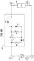
- FIG. 1 Ais a schematic circuit diagram of a conventional thermal-magnetic circuit breaker.
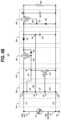
- FIG. 1 Bis a perspective view of a housing of the conventional circuit breaker of FIG. 1 A .
- FIG. 2 Ais a schematic block diagram of an intelligent circuit breaker comprising an electromechanical switch, according to an embodiment of the disclosure.
- FIG. 2 Bis a schematic block diagram of an intelligent circuit breaker comprising an electromechanical switch, according to another embodiment of the disclosure.
- FIG. 3 Ais a schematic block diagram of an intelligent circuit breaker comprising a solid-state bidirectional switch, according to an embodiment of the disclosure.
- FIG. 3 Bis a schematic block diagram of an intelligent circuit breaker comprising a solid-state bidirectional switch, according to another embodiment of the disclosure.
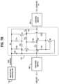
- FIG. 4 Ais a schematic block diagram of an alternating current-to-direct current (AC-to-DC) converter circuit which can implemented in an intelligent circuit breaker, according to an embodiment of the disclosure.
- AC-to-DCalternating current-to-direct current
- FIG. 4 Bis a schematic circuit diagram of the AC-to-DC converter circuit of FIG. 4 A , according to an embodiment of the disclosure.
- FIG. 5is a schematic circuit diagram of an AC-to-DC circuit which can be implemented in an intelligent circuit breaker, according to another embodiment of the disclosure.
- FIG. 6 Ais a schematic circuit diagram of a solid-state bidirectional switch that can be implemented in an intelligent circuit breaker, according to an embodiment of the disclosure.
- FIG. 6 Billustrates active elements of the solid-state bidirectional switch of FIG. 6 A during a positive half cycle of an AC mains supply voltage applied to the solid-state bidirectional switch.
- FIG. 6 Cis a schematic circuit diagram of a solid-state bidirectional switch that can be implemented in an intelligent circuit breaker, according to another embodiment of the disclosure.
- FIG. 6 Dis a schematic circuit diagram of a solid-state bidirectional switch that can be implemented in an intelligent circuit breaker, according to another embodiment of the disclosure.
- FIG. 6 Eis a schematic circuit diagram of a solid-state bidirectional switch that can be implemented in an intelligent circuit breaker, according to another embodiment of the disclosure.
- FIG. 6 Fis a schematic circuit diagram of a solid-state bidirectional switch that can be implemented in an intelligent circuit breaker, according to another embodiment of the disclosure.
- FIG. 6 Gis a schematic circuit diagram of a solid-state bidirectional switch that can be implemented in an intelligent circuit breaker, according to another embodiment of the disclosure.
- FIG. 6 His a schematic circuit diagram of a solid-state bidirectional switch that can be implemented in an intelligent circuit breaker, according to another embodiment of the disclosure.
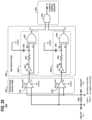
- FIGS. 7 A and 7 Bschematically illustrate switch control circuitry for controlling a solid-state bidirectional switch, according to an embodiment of the disclosure, wherein:
- FIG. 7 Ais a schematic block diagram of control circuitry that can be implemented in an intelligent circuit breaker for controlling a solid-state bidirectional switch, according to embodiment of the disclosure.
- FIG. 7 Bis a schematic circuit diagram of the control circuitry of FIG. 7 A , according to embodiment of the disclosure.
- FIG. 8 Ais a high-level schematic illustration of an intelligent circuit breaker according to another embodiment of the disclosure.
- FIG. 8 Bis a high-level schematic illustration of an intelligent circuit breaker which comprises isolation circuitry that is configured to galvanically isolate the intelligent circuit breaker from a load, according to an embodiment of the disclosure.
- FIGS. 9 A, 9 B, and 9 Cschematically illustrate an integrated current sensor and energy metering circuit that can be implemented in an intelligent circuit breaker, according to an embodiment of the disclosure, wherein:
- FIG. 9 Ais a schematic diagram of a power supply block and a current sensor block of the current sensor and energy metering circuit
- FIG. 9 Bis a schematic diagram of an over-current detection block of the current sensor and energy metering circuit.
- FIG. 9 Cis a schematic diagram of an energy metering block of the current sensor and energy metering circuit.
- FIG. 10is a flow diagram of a method for controlling switches of an intelligent circuit breaker in response to detection of fault conditions, according to an embodiment of the disclosure.
- FIG. 11is a state diagram that illustrates a control process which is implemented by an intelligent circuit breaker to detect and protect against fault conditions, according to an embodiment of the disclosure.
- FIG. 12schematically illustrates an intelligent power distribution and monitoring system which utilizes intelligent circuit breakers according to an embodiment of the disclosure.
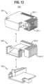
- FIG. 13is an exploded view of a housing structure which can be utilized to house switches and intelligent circuitry of an intelligent circuit breaker, according to an embodiment of the disclosure.
- FIG. 14is a flow diagram of a process which is implemented by an intelligent circuit breaker to monitor energy usage on a branch circuit and protect against fault conditions on the branch circuit, according to an embodiment of the disclosure.
- FIG. 15is a flow diagram of a process which is implemented by an intelligent circuit breaker to monitor energy usage on a branch circuit and protect against fault conditions on the branch circuit, according to an embodiment of the disclosure.
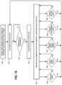
- FIG. 16is a schematic block diagram of an intelligent circuit breaker which is configured to identify a type of load connected to the circuit breaker and to control the load on the basis of the identified load type, according to an embodiment of the disclosure.
- FIG. 17is a flow diagram of a method of a load identifying and control process which is implemented by an intelligent circuit breaker, according to an embodiment of the disclosure.
- FIG. 18 Ais a schematic block diagram of an intelligent circuit breaker which is configured to monitor for ground-fault and arc-fault conditions and provide circuit interruption in response to detected fault conditions, according to an embodiment of the disclosure.
- FIG. 18 Bis a schematic circuit diagram of the intelligent circuit breaker of FIG. 18 A , according to an embodiment of the disclosure.
- FIG. 19is a schematic block diagram of a fault detection processor which can be implemented in the intelligent circuit breaker of FIG. 18 B , according to an embodiment of the disclosure.
- FIG. 20schematically illustrates a current zero-crossing detector circuit according to an embodiment of the disclosure.
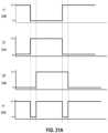
- FIGS. 21 A and 21 Bdepict various waveforms that illustrate operating modes of the current zero-crossing detection circuit of FIG. 20 , according to an embodiment of the disclosure, wherein:
- FIG. 21 Adepicts waveforms that illustrate a mode of operation of the edge detection stage of FIG. 20 ;
- FIG. 21 Billustrates simulated signal waveforms that illustrate an operating mode of the current zero-crossing detection circuit of FIG. 20 , according to an embodiment of the disclosure.
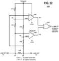
- FIG. 22schematically illustrates a short-circuit detection circuit according to an embodiment of the disclosure.
- FIG. 23illustrates simulated signal waveforms that illustrate a mode of operation of the short-circuit detection circuit of FIG. 22 , according to an embodiment of the disclosure.
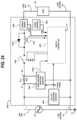
- FIG. 24schematically illustrates an intelligent circuit breaker according to another embodiment of the disclosure.
- FIG. 25 Aillustrates a power supply voltage waveform that is input to a line side of the intelligent circuit breaker of FIG. 24 .
- FIG. 25 Billustrates an output voltage waveform on a load side of the intelligent circuit breaker of FIG. 24 , when a solid-state switch of the intelligent circuit breaker is in a switched-off state and an air-gap electromagnetic switch of the intelligent circuit breaker is in a switched-closed state.
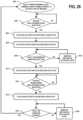
- FIG. 26is a flow diagram of a switch control process which is implemented by a switch controller of the intelligent circuit breaker of FIG. 24 , according to an embodiment of the disclosure.
- FIG. 27schematically illustrates an intelligent circuit breaker according to another embodiment of the disclosure.
- FIGS. 28 A, 28 B, 28 C, 28 D, and 28 Eare perspective and schematic views of an intelligent circuit breaker which comprises multiple visual indictors that are configured to indicate operational states of the intelligent circuit breaker, according to another embodiment of the disclosure.
- FIG. 29schematically illustrates an intelligent circuit breaker according to another embodiment of the disclosure.
- FIGS. 1 A and 1 Bschematically illustrate a conventional thermal-magnetic circuit breaker 100
- FIG. 1 Ais a schematic circuit diagram of the thermal-magnetic circuit breaker 100
- FIG. 1 Bis a perspective view of a housing 101 of the thermal-magnetic circuit breaker 100
- FIG. 1 Aillustrates the thermal-magnetic circuit breaker 100 connected between a utility power supply 110 (referred to herein as AC mains 110 ) and a load 120 which is connected to a branch circuit that is protected by the circuit breaker 100 .
- AC mains 110referred to herein as AC mains 110
- the circuit breaker 100is typically connected between a hot phase 111 (referred to as “line hot”) of the AC mains 110 and a load hot line 121 of the load 120 , while a neutral phase 112 (referred to as “line neutral”) of the AC mains 110 is directly connected to a load neutral line 122 of the load 120 .
- the circuit breaker 100comprises an electromechanical switch 102 that is manually opened and closed by means of a manual switch mechanism (not shown).
- the electromechanical switch 102is mechanically coupled 104 to a thermal-magnetic actuator comprising a solenoid 106 connected in series with the switch 102 and a bimetallic element 108 (which is heated by a resistive element) also connected in series with the switch 102 .
- the mechanical coupling 104is configured such that an instantaneous current flowing from the hot phase 111 which exceeds a first threshold value (e.g., beyond the current rating of the circuit breaker 100 ) causes the solenoid 106 to separate the contacts of the switch 102 , thereby opening the circuit and “tripping” the circuit breaker 100 .
- the solenoid 106(e.g., electromagnet) asserts a pulling force which increases with the current.
- the circuit breaker contactsare held closed by a latch.
- the solenoid's pullreleases the latch, which causes the contacts to open by spring action.
- the mechanical coupling 104is configured such that a prolonged excess current at a second, lower threshold value causes the bimetallic element 108 to separate the contacts of the switch 102 and thereby trip the circuit breaker 100 .
- the bimetallic element 108is responsive to less extreme but longer-term over-current conditions.
- the thermal mechanism of the circuit breaker 100provides a time response feature, that trips the circuit breaker 100 sooner for larger over-currents but allows smaller overloads to persist for a longer time. This allows short current spikes such as are produced when a motor or other non-resistive load is switched on.
- the solenoid 106(electromagnet mechanism) responds instantaneously to large surges in current (short-circuits) and the bimetallic element 108 responds to less extreme but longer-term over-current conditions. Once tripped, the circuit breaker 100 must be manually reset using the manual switch mechanism.
- the line neutral 112is typically bonded to earth ground 114 (GND) in a circuit breaker distribution panel, and an earth ground connection 116 is made from ground bar in the circuit breaker distribution panel to a ground connection of the load 120 .
- the earth ground connection 116provides an alternative low-resistance path for ground-fault return current to flow in the event of a ground-fault event at the load 120 .
- the earth ground connection 116is useful for other circuit breaker or receptacle designs which provide protections such as arc-fault sensing and arc-fault circuit interruption (AFCI), and ground-fault sensing and ground-fault circuit interruption (GFCI).
- AFCIarc-fault sensing and arc-fault circuit interruption
- GFCIground-fault sensing and ground-fault circuit interruption
- a line neutral wire(not shown in FIG. 1 A or FIG. 1 B ) would be included in the circuit breaker 100 that is designed to provide AFCI and GFCI protection.
- FIG. 1 Billustrates a conventional housing 101 for a residential circuit breaker which is usually manufactured using molded plastic components.
- intelligent circuit breakersare implemented using standard housings for residential and/or commercial applications to allow the intelligent circuit breakers to be backward compatible with existing housings and retrofitted into existing distribution panels.
- circuits, algorithms, heat exchangers, and other aspects of the disclosed technologiescan be adjusted to various form factors required in other locations or countries. It is contemplated herein that present approach does not require using traditional style breaker elements, for example, particularly without using traditional breaker housing.
- intelligent circuit breakersare designed to provide high isolation capability, while having relatively fast reaction times to isolate short-circuit conditions, over-current conditions, and other types of faults, more rapidly than conventional circuit breakers.
- Intelligent circuit breakersare designed with time-current characteristics that can be programmable in real time, and which are more precise with less variability as compared to conventional circuit breakers.
- intelligent circuit breakersimplement low-power solid-state bidirectional switches that enable fast reaction time to isolate faults on high-energy branch circuits.
- Intelligent breakersare designed to communicate with smart devices connected to provide support for multiple points of failure, independent from the location of the circuit breaker installation, thereby allowing for a reduction in the impedance of short-circuited conductors.
- Intelligent circuit breakersprovide added safety, expanded convenience, added energy awareness, control, energy savings, and improved situational awareness, as compared to conventional circuit breakers.
- intelligent circuit breakersimplement various functionalities and control circuits to implement intelligent processing, including AC mains switching techniques, AC-to-DC conversion techniques, internal short-circuit trip techniques, techniques to communicate status and sensor data wirelessly to enable a variety of innovative use-cases, algorithms for detecting faults, techniques for detecting and protection from internal device failures, techniques for handling new types of loads through over-the-air updates, techniques for exchanging thermal energy, techniques for cloud services support for remote notifications, control, monitoring and big data collection even during collapsing utility events, circuit techniques for shunt-resistor current sensing, energy metering, and over-current detection, techniques for avoiding fault conditions.
- FIG. 2 Ais a schematic block diagram of an intelligent circuit breaker according to an embodiment of the disclosure.
- FIG. 2 Aschematically illustrates an intelligent circuit breaker 200 connected between an AC mains 110 and a load 120 .
- the intelligent circuit breaker 200comprises an electromechanical AC switch 202 , a current sensor 204 , a first voltage sensor 206 , a second voltage sensor 208 , AC-to-DC converter circuitry 210 , a processor 220 , a processor reset switch 222 , and a radio frequency (RF) transceiver 230 with an associated antenna 232 .
- RFradio frequency
- the electromechanical AC switch 202is serially connected between a line input terminal and a load output terminal of the circuit breaker 200 , wherein the line hot 111 of the AC mains 110 is connected to the line input terminal and the load hot 121 of the load 120 is connected to the load output terminal.
- the line hot 111 of the AC mains 110is connected to the load hot 121 when the electromechanical AC switch 202 is in a switched-closed state.
- the line neutral 112(which, for example, is bonded to the earth ground 114 in the breaker distribution panel) serves as a low-side voltage reference (e.g., ground) for the electronic circuitry of the intelligent circuit breaker 200 .
- the electromechanical AC switch 202comprises a thermal-magnetic trip and switch mechanism which is the same or similar to the thermal-magnetic circuit breaker 100 discussed above in conjunction with FIG. 1 A , wherein the electromechanical AC switch 202 comprises a thermal switching mechanism (e.g., bimetal switch) and an electromagnetic switching mechanism (e.g., solenoid).
- the electromechanical AC switch 202is configured to provide an “open” circuit when either an operator manually disables the hot path using the manual switch (or actuator lever) or automatically when a fault condition (e.g., short-circuit conditions, over-current conditions, etc.) is detected by the electromechanical AC switch 202 .
- the processor 220operates in conjunction with the current sensor 204 and the first and second voltage sensors 206 and 208 to perform functions such as monitoring energy utilization and detecting fault conditions.
- the processor 220is configured (via software and/or hardware) to detect the presence of a fault condition in the load 120 (e.g., short-circuit condition, over-current condition, over-voltage condition, etc.), or an internal fault condition within the intelligent circuit breaker 200 , and generate a control signal on a control line 202 - 1 to cause electrical contacts of an electromagnetic component (e.g., solenoid) to open and thereby disconnect the line hot 111 from the load hot 121 .
- the intelligent circuit breaker 200comprises additional sensor circuitry and/or processing functionality to support arc-fault circuit interruption and/or ground-fault circuit interruption functions using, for example, techniques as discussed herein.
- the processor 220can be implemented using one or more processing architectures.
- the processor 220may comprise a central processing unit, a microprocessor, a microcontroller, an application-specific integrated circuit (ASIC), a field programmable gate array (FPGA), a system-on-chip (SOC) and other types of processors, as well as portions or combinations of such processors, which can perform processing functions based on software, hardware, firmware, etc.
- the solid-state circuitry of the various components (e.g., 204 , 206 , 208 , 210 , 220 , and/or 230 ) of the intelligent circuit breaker 200can be implemented on a single die as a system-on-chip.
- the solid-state circuitry of the various components (e.g., 204 , 206 , 208 , 210 , 220 , and/or 230 ) of the intelligent circuit breaker 200can be implemented on one or more separate dies that are integrally packaged as a multi-chip module (e.g., system-in-package) providing a high-density heterogeneous integrated solution.
- a multi-chip modulee.g., system-in-package
- the processor 220utilizes the RF transceiver 230 to wirelessly communicate with a remote node, device, system, etc., to support remote monitoring of energy utilization and detection of fault conditions.
- the processor reset switch 222is utilized to reset the status of the processor 220 under certain conditions, e.g., when there is a loss of DC power to the processor 220 , etc.
- the processor reset switch 222comprises a manual result switch that is mechanically coupled to the manual switch lever mechanism (e.g., actuator lever) of the electromechanical AC switch 202 so that a manual reset of the switch lever following a trip event also causes mechanical activation of the processor reset switch 222 .
- the current sensor 204 and the voltage sensors 206 and 208are configured to sense and detect conditions that are indicative of open circuits or damaged or failed internal components of the intelligent circuit breaker 200 and to provide timing for the safe opening and closing of circuits.
- the current sensor 204is configured to detect a magnitude of current being drawn by the load 120 in the hot line path through the intelligent circuit breaker 200 .
- the current sensor 204can be implemented using any suitable type of current sensing circuit including, but not limited to, a current-sensing resistor, a current amplifier, a Hall Effect current sensor, etc.
- the current sensor 204is coupled to the processor 220 by one or more data acquisition and control lines 204 - 1 .
- the first and second voltage sensors 206 and 208are configured to monitor the voltage at different points along the hot line path through the circuit breaker 200 .
- the first voltage sensor 206is coupled to the hot line path upstream of the electromechanical AC switch 202 to monitor the AC supply voltage of the AC mains 110
- the second voltage sensor 208is coupled to the hot line path downstream of the electromechanical AC switch 202 to monitor the load voltage on the branch circuit which is connected to, and protected by, the intelligent circuit breaker 200 .
- the voltage sensors 206 and 208are coupled to the processor 220 by one or more data acquisition and control lines 206 - 1 and 208 - 1 , respectively.
- the voltage sensors 206 and 208can be implemented using any suitable type of voltage sensing circuitry including, but not limited to, zero-crossing detector circuits.
- a zero-crossing detectoris configured to receive as input an AC waveform, compare the input AC waveform to a zero reference voltage (e.g., line neutral voltage), and detect the AC waveform transition from positive and negative, which coincides when the AC waveform crosses the zero reference voltage.
- the zero-crossing detector circuitryis configured to generate a square wave output which transitions between a logic “1” and logic “0” output upon each zero-crossing detection of the AC voltage waveform.
- the zero-crossing detector circuitryis configured to generate a short-lived pulse ( ⁇ 3 us) having an RC-adjustable duration.
- the AC-to-DC converter circuitry 210is configured to provide DC supply power to various circuitry and elements of the intelligent circuit breaker 200 including the current sensor 204 , the voltage sensors 206 and 208 , the processor 220 and the RF transceiver 230 .
- the AC-to-DC converter circuitry 210remains powered during faults when the electromechanical AC switch 202 is in an open state.
- the AC-to-DC converter circuitry 210comprises sufficient storage capacitance to power the DC subsystems immediately following a utility outage such that relevant power outage or short-circuit information may be obtained and stored by the processor 220 as the utility power collapses, and then wirelessly transmitted to a remote node, device, or system using the RF transceiver 230 .
- the AC-to-DC converter circuitry 210may also include sufficient capacitance to power the DC subsystem during a load short-circuit event without being pulled-down by the collapsing voltage of the hot line and load, such that the load can be intentionally disconnected to prevent damage during out-of-range voltage events.
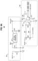
- FIG. 2 Bis a schematic block diagram of an intelligent circuit breaker according to another embodiment of the disclosure.
- FIG. 2 Bschematically illustrates an intelligent circuit breaker 201 connected between an AC mains 110 and a load 120 .
- the intelligent circuit breaker 201is similar to the intelligent circuit breaker 200 of FIG. 2 A , except that the intelligent circuit breaker 201 comprises current sensor and energy metering circuitry 240 , a fuse 250 , and an internal short-circuit switch 260 .
- the current sensor and energy metering circuitry 240is configured to detect a magnitude of current being drawn by the load 120 in the hot line path through the circuit breaker 201 as well as implement a programmable over-current detection system and intelligent energy metering circuitry.
- An exemplary embodiment of the current sensor and energy metering circuitry 240will be discussed below in conjunction with FIGS. 9 A, 9 B and 9 C .
- the fuse 250is implemented to protect the circuit breaker 201 from internal failure or to provide a simple end-of-life disablement mechanism, such as in the event of a device failure.
- the internal short-circuit switch 260is connected between the AC hot line path of the circuit breaker 201 and the line neutral 112 , wherein the internal short-circuit switch 260 is connected to the AC hot line path at some point between the fuse 250 and the electromechanical AC switch 202 .
- the internal short-circuit switch 260is responsive to control signals generated by the processor 220 and applied to the short-circuit switch 260 over a switch control line 220 - 1 .
- the processor 220can implement an end-of-life disablement mechanism, such as in the event of a device failure, wherein the processor 220 outputs a control signal on the control line 220 - 1 to activate the internal short-circuit switch 260 and blow the fuse 250 to disable the intelligent circuit breaker 201 .
- an end-of-life disablement mechanismcan be implemented by configuring the processor 220 to generate a control signal which, e.g., keeps the electromechanical AC switch 202 from being placed in a switched-closed state at any time after a device failure has been detected, or which immediately causes the electromechanical AC switch 202 to trip (and be placed in a switched-open state) any time an individual attempts to turn on the breaker (via activation of the manual switch) after a device failure has been detected.
- an internal short-circuit switchcan be implemented in an intelligent circuit breaker as a mechanism to internally trigger a fault to trip the electromechanical AC switch 202 .
- an internal short-circuit switchcan be connected between the AC hot line path and the line neutral 112 on the load side of the electromechanical AC switch 202 .
- the processor 220can be configured to generate a switch control signal to activate the internal short-circuit switch and generate a short-circuit fault condition at the load side of the electromechanical AC switch 202 and thereby trip the electromechanical AC switch 202 .
- the processor 220can detect the existence of an unsafe condition or internal circuit breaker failure based on sensor data generated by the current and/or voltage sensors 240 , 206 , and 208 , and then generate a control signal to activate the internal short-circuit switch 260 and thereby trip the electromechanical AC switch 202 .
- an internal short-circuit trigger eventcan be triggered in response to the processor 220 receiving a remote command to disconnect or in response to the detection of an unsafe local condition such as over-heating, excessive moisture, or a device failure, etc.
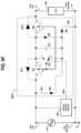
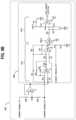
- FIG. 3 Ais a schematic block diagram of an intelligent circuit breaker according to another embodiment of the disclosure.
- FIG. 3 Aschematically illustrates an intelligent circuit breaker 300 connected between an AC mains 110 and a load 120 .
- the intelligent circuit breaker 300comprises an air-gap electromagnetic switch 302 , a solid-state bidirectional switch 304 , switch control circuitry 306 that is configured to control operation of the air-gap electromagnetic switch 302 , a manual switch 307 that allows a user to manually open and close the air-gap electromagnetic switch 302 , and switch control circuitry 308 that is configured to control operation of the solid-state bidirectional switch 304 .
- 3 Acomprises a current sensor 204 , a first voltage sensor 206 , a second voltage sensor 208 , AC-to-DC converter circuitry 210 , a processor 220 , a processor reset switch 222 , and a RF transceiver 230 and associated antenna 232 , which are configured to perform functions which are the same or similar to the functions as discussed above.
- an external DC power supplycan be implemented to provide DC power to the solid-state circuitry and components of the intelligent circuit breaker 300 .
- the air-gap electromagnetic switch 302comprises any suitable type of electromagnetic trip and mechanical switch mechanism, which is configured to physically open and close a set of electrical contacts, wherein an air gap is created between the electrical contacts when the air-gap electromagnetic switch 302 is in a switched-open state.
- the air-gap electromagnetic switch 302may comprise a latching solenoid or relay element that is responsive to control signals from the switch control circuitry 306 to automatically open or close the electrical contacts of the air-gap electromagnetic switch 302 .
- the switch control circuitry 306 and the air-gap electromagnetic switch 302are configured such that the electrical contacts of the air-gap electromagnetic switch 302 can be automatically opened by the switch control circuitry 306 , but not automatically closed by operation of the switch control circuitry 306 . In this instance, the electrical contacts of the air-gap electromagnetic switch 302 are manually closed by operation of the manual switch 307 .
- the switch control circuitry 308is responsive to control signals from one or more of the sensors (e.g., current sensor 204 , voltage sensors 206 and 208 etc.) to determine when to open the air-gap electromagnetic switch 302 in response to fault conditions detected by the sensors.
- the switch control circuitry 306is responsive to control signals received from the processor 220 (over a control line 306 - 1 ) to control the opening of the air-gap electromagnetic switch 302 in response to fault conditions such as short-circuit faults, over-current faults, and other faults that are detected by the processor 220 as a result of the processor 220 analyzing sensor data obtained from the current sensor 204 and the voltage sensor 206 and 208 .
- the air-gap electromagnetic switch 302comprises a manual switch 307 that enables a person to manually open or close the electrical contacts of the air-gap electromagnetic switch 302 and thereby manually place the air-gap electromagnetic switch 302 into a switched-open or switched-closed state.
- the state of the manual switch 307(activated or deactivated) can be detected by the processor 220 based on an electrical signal that is present on a sense line 307 - 1 connected between the manual switch 307 and the processor 220 .
- the creation of the air gap in the line path between the line hot 111 and load hot 121provides complete isolation of the AC mains 110 from the load 120 , and prevents the flow of current from the line hot 111 to the load 120 (and also prevents flow of leakage current that can be generated by the solid-state bidirectional switch 304 when the solid-state bidirectional switch 304 is in a switched-off state).
- the air-gap electromagnetic switch 302is connected in series with the solid-state bidirectional switch 304 between the line input terminal and the load output terminal of the intelligent circuit breaker 300 .
- the air-gap electromagnetic switch 302may be disposed on either the line side (as shown in FIG. 3 A ) of the solid-state bidirectional switch 304 or on the load side of the solid-state bidirectional switch 304 .
- the solid-state bidirectional switch 304comprises electrically controlled solid-state switching devices such as power MOSFET (metal-oxide semiconductor field effect transistor) devices and associated biasing circuitry. Exemplary embodiments of the solid-state bidirectional switch 304 will be discussed in further detail below in conjunction with FIGS. 6 A through 6 H .
- the semiconductor MOSFET devicescan be silicon-based solid-state devices or silicon carbide (SiC) or gallium arsenide (GaN) based solid-state devices.
- the solid-state bidirectional switch 304is controlled by the switch control circuitry 308 to place the solid-state bidirectional switch 304 into a switched-on state or a switched-off state in response to gate control signals generated by the switch control circuitry 308 .
- the switch control circuitry 308is responsive to control signals received from the processor 220 (over a control line 308 - 1 ) to switch off the solid-state bidirectional switch 304 in response to fault conditions such as short-circuit faults, over-current faults, and other faults that are detected by the processor 220 as a result of the processor 220 analyzing sensor data obtained from the current sensor 204 and the voltage sensor 206 and 208 .
- the switch control circuitry 308comprises control circuitry that is responsive to control signals generated by the current sensor 204 (and other sensors, e.g., voltage sensors 206 and 208 ) in response to detection of fault conditions, and transmitted on a control line 204 - 1 to the switch control circuitry 308 .
- the switch control circuitry 308is responsive to such control signals to generate gating control signals to control activation and deactivation of the solid-state bidirectional switch 304 .
- the switch control circuitry 308comprises short-circuit detection circuitry which is configured to detect a load-side short-circuit fault, and automatically deactivate the solid-state bidirectional switch 304 in response to the detected short-circuit fault.
- switch control circuitry 308comprising short-circuit detection circuitry will be discussed in further detail below in conjunction with FIGS. 7 A and 7 B .
- the switch control circuitry 308is configured to control the drive voltage of the solid-state bidirectional switch 304 for the purpose of controlling and minimizing leakage of the solid-state bidirectional switch 304 when the switch 304 is in a switched-off state.
- the implementation of the solid-state bidirectional switch 304allows the intelligent circuit breaker 300 to rapidly respond to imminent fault conditions such as over-current fault conditions, load-side short-circuit fault conditions, internal fault conditions, over-voltage conditions, etc., by rapid deactivation of the solid-state bidirectional switch 304 .
- the response time for deactivating the solid-state bidirectional switch 304 to isolate a fault conditioncan be on the order of 1000 times faster than the response time associated with the automatic tripping of an electromechanical AC switch to isolate the fault condition (e.g., on the order of several milliseconds), as the solid-state state bidirectional switch 304 can transition from a switched-on state to a switched-off state on the order of microseconds or nanoseconds.
- the solid-state bidirectional switch 304has a time-current characteristic profile that is more precise and repeatable as compared to a conventional electromechanical circuit breaker. This allows the current which is conducted by the solid-state bidirectional switch 304 to be more precisely controlled, as compared to conventional electromechanical circuit breakers which have time-current characteristics that vary over their life-time.
- control logic implemented by the processor 220 of the intelligent circuit breaker 300is configured to issue switch control signals to the switch control circuitry 306 so that the air-gap electromagnetic switch 302 is placed in a switched-open state in response to the solid-state bidirectional switch 304 being placed into a switched-off state.
- control logic implemented by the processor 220is configured to issue switch control signals to the switch control circuitry 306 so that the air-gap electromagnetic switch 302 is placed in a switched-closed state prior to placing the solid-state bidirectional switch 304 into a switched-on state.
- the processor 220is configured to monitor and detect for a manual switch opening event wherein the manual switch 307 of the air-gap electromagnetic switch 302 is actuated to manually open the electrical contacts of the air-gap electromagnetic switch 302 .
- the processor 220will generate and output a control signal to the switch control circuitry 308 to place the solid-state bidirectional switch 304 into a switched-off state.
- the switch timing control scheme as outlined aboveprevents or minimizes the generation of electrical arcs between the electrical contacts of the air-gap electromagnetic switch 302 by ensuring that (i) the air-gap electromagnetic switch 302 is placed in a switched-closed state prior to placing the solid-state bidirectional switch 304 into a switched-on state, and that (ii) the solid-state bidirectional switch 304 is automatically placed in a switched-off state in response to detection of a manual operator disconnect of the air-gap electromagnetic switch 302 and thereby deactivate the solid-state bidirectional switch 304 prior to the opening of the electrical contacts of the air-gap electromagnetic switch 302 .
- the switch control schemeis configured to operate the intelligent circuit breaker 300 in a “standby” state, wherein the solid-state bidirectional switch 304 is in a switched-off state, and the air-gap electromagnetic switch 304 in a switched-closed state.
- the electrical contacts of the air-gap electromagnetic switch 302are configured to support high energy flow in a switched-closed state, but may be designed for movement only during low-current flow conditions to prevent or minimize arcing between the electrical contacts.
- a switch control schemecan be implemented in which the air-gap electromagnetic switch 302 is actuated when the magnitude of the current on the hot line path is less than a pre-selected value. The prevention of arcing within the air-gap electromagnetic switch 302 enables miniaturization of the air-gap electromagnetic switch 302 .
- the implementation of the air-gap electromagnetic switch 302provides additional safety features for the intelligent circuit breaker 301 .
- the air-gap electromagnetic switch 302provides a fail-safe mechanism for fault isolation in the event that the solid-state bidirectional switch 304 fails.
- the processor 220can be configured to detect a failure state of the solid-state bidirectional switch 304 or otherwise detect potential over-current or short-circuit fault conditions. In such instance, the processor 220 can generate and output a control signal to the switch control circuitry 306 to place the air-gap electromagnetic switch 302 into a switched-open state.
- the current sensor 204comprises a sense resistor that is connected in series in the hot line path.
- the sense resistoris configured to generate a burden voltage or sense voltage as a result of load current flowing through the sense resistor, wherein the burden voltage or sense voltage is measured and processed by one or more detection circuits (e.g., current sensor circuit, short-circuit detection circuit, energy metering circuit, etc.) to detect fault conditions and to control the solid-state switch directly without the assistance of the processor. This allows for faster reaction time by avoiding the indeterminate time of the processor or CPU response.
- detection circuitse.g., current sensor circuit, short-circuit detection circuit, energy metering circuit, etc.
- the air-gap switch 302provides galvanic isolation between the AC mains 110 and the load 120 when the air-gap switch 302 is placed in a switched-open state. With the air gap formed, no current can flow from the AC mains 110 to the load 120 . Such galvanic isolation guards against the unwanted flow of current due to leakage current of the solid-state bidirectional switch 304 when the solid-state bidirectional switch 304 is in a switched-off state.
- the processor 220can be implemented using one or more processing architectures (e.g., CPU, microprocessor, a microcontroller, ASIC, etc.).
- the solid-state circuitry of the various componentse.g., 204 , 206 , 208 , 210 , 220 , 230 , 306 , and/or 308 ) of the intelligent circuit breaker 300 can be implemented on a single die as a system-on-chip.
- the solid-state circuitry of the various components (e.g., 204 , 206 , 208 , 210 , 220 , 230 , 306 , and/or 308 ) of the intelligent circuit breaker 230can be implemented on one or more separate dies that are integrally packaged as a multi-chip module (e.g., system-in-package) providing a high-density heterogeneous integrated solution.
- a multi-chip modulee.g., system-in-package
- FIG. 3 Bis a schematic block diagram of an intelligent circuit breaker according to another embodiment of the disclosure.
- FIG. 3 Bschematically illustrates an intelligent circuit breaker 301 connected between an AC mains 110 and a load 120 .
- the intelligent circuit breaker 301comprises a combination of components of the intelligent circuit breakers 201 and 300 ( FIGS. 2 B and 3 A ) and thus, a detailed description of the various components and associated functionalities will not be repeated.
- the intelligent circuit breaker 301comprises a snubber 310 that is connected between the hot line path and neutral line path to protect the internal components from damage due to energy kick-back from inductive loads.
- the snubber 310may be disposed on the line and/or load side of the switches 302 and 304 .
- a snubber located on the line side of the switches 302 and 304allows the snubber to only protect the internal circuits when the switches 302 and 304 are in switched-open and switched-on states, respectively.
- the snubber 310 located on the load side of the switches 302 and 304 as shown in FIG. 3 Bhelps to eliminate the possibility of an arc occurring within the air-gap electromagnetic switch 302 during an inductive load kick-back event. It is to be understood that a snubber can be implemented in the intelligent circuit breaker embodiments of FIGS. 2 A, 2 B, and 3 A .
- an external DC power supplycan be implemented to provide DC power to the solid-state circuitry and components of the intelligent circuit breakers 200 , 201 , 300 , and 301 of FIGS. 2 A, 2 B, 3 A and 3 B (as well as other embodiments of circuit breakers discussed below).
- a distribution panel in which an intelligent circuit breaker is mountedcan have a DC battery and a DC power bus that is configured to distribute DC power to the intelligent circuit breakers within the distribution panel.
- the DC batterycan be coupled to an AC-to-DC converter that is configured to convert the AC power of the AC mains 110 to DC power that charges the DC battery.
- FIGS. 2 A, 2 B, 3 A and 3 Billustrate a processor reset switch 222 for resetting the processor 220
- the processor reset switch 222is an optional feature, and that other mechanisms can be implemented for effecting a processor reset.
- the processor 220comprises an internal reset circuit that is configured to reset the processor 220 under certain circumstances such as when there is a loss of DC power to the processor 220 or when there is an internal fault condition of the processor 200 .
- the processoris configured to generate a “CPU_OK” signal which is output on the control lines 306 - 1 and 308 - 1 to the switch control circuitry 306 and 308 .
- the CPU_OK signalprovides an indication of whether or not the processor 220 and associated software is operating normally.
- the switch control circuitry 306 and 308will automatically place the solid-state bidirectional switch 304 into a switched-off state and then place the air-gap electromagnetic switch 302 into a switched-open state (to create the air-gap for galvanic isolation). This provides a hardware fail-safe mechanism to ensure that the intelligent circuit breaker is not servicing a load under conditions where the processor 220 or a subsystem thereof is not operating correctly.
- the internal reset circuit of the processor 220comprises a Watchdog timer and suitable architected software that is configured to service the Watchdog timer (e.g., reset the Watchdog timer) when all subsystems within the firmware of the processor 220 are determined to be operating correctly.
- the Watchdog timercomprises a resistor/capacitor network which implements a unique clock. When the Watchdog timer is enabled, the timer counts from an initial value to final count value. If the Watchdog timer is not initialized to the initial count value before reaching the final count value, the processor 220 will be reset. The processor 220 will be reset because of a loss of AC (thus DC) power, or an internal fault condition that causes the Watchdog timer to reach the final count value in which case a control signal is generated which causes the processor 220 to be reset.
- the internal reset circuit of the processor 220operates as follows. When DC power is first applied to the processor 220 , the processor will perform a self-check and initialization routine. If the self-check and initialization routine are successfully completed, the processor 220 will output a logic “1” CPU_OK control signal to indicate that the processor 220 and embedded software are operating correctly. The logic “1” CPU_OK control signal is input to the switch control circuitry 306 and 308 to indicate that the switches 302 and 304 can be safely activated to service the load 120 .
- a logic “0” CPU_OK control signalindicates to the switch control circuitry 306 and 306 that the switches 320 and 304 should be deactivated or should not be activated (if deactivated at the time that CPU_OK is asserted to a logic “0” level).
- the control signal CPU_OKis held at a logic “0” level until the processor 220 is reset and determined to be fully functional and operating as expected.
- the software of the processor 220continuously monitors several points in the firmware to ensure that all subsystems of the processor 220 are properly operating as excepted. If all monitored points are determined to be operating correctly, then the Watchdog timer is serviced (e.g., counter is reset to the initial value). If any one of the monitored points is determined to be nonfunctional or operating incorrectly, the Watchdog timer will not be serviced, and the Watchdog timer will eventually reach its maximum count value. In some embodiments, the Watchdog timer has a count sequence with defines approximately 1 second of time.
- the Watchdog timerwill “fire” after ⁇ 1 second and reset the processor 220 , which causes the CPU_OK control signal to transition to a logic “0” level.
- the transition of the CPU_OK signal from logic “1” to logic “0”triggers the switch control circuitry 306 and 308 to place the solid-state bidirectional switch 304 into a switched-off state, and place the air-gap electromagnetic switch 302 into a switched-open state.
- a hardware indication(designed into the processor 220 ) which indicates whether the processor reset was caused by a Watchdog timer reset or a power-on-reset. If the processor reset is caused by a power-on-reset, the firmware of the processor 220 will proceed with a normal startup initialization process. On the other hand, if the processor reset is triggered by the Watchdog timer, the firmware of the processor 220 will proceed with a “Recover from a Watchdog timer reset” initialization path instead of the normal startup initialization. To the user, a Watchdog timer reset appears like a normal over-current “Trip” condition (with communication to the cloud or a remote computing device that the processor reset was caused by an internal Watchdog timer reset).
- the firmwarewill determine whether the number of consecutive Watchdog timer resets has exceeded a predefined threshold number (e.g., 5). If the number of consecutive Watchdog timer resets is determined to exceed the predefined threshold number, an internal failure or internal fault condition will be declared and the intelligent circuit breaker will be disabled until it is serviced and the counter is reset. In this instance, the processor firmware will declare an internal failure and report the error via cloud notification, status LEDs, and other available user interfaces, and not allow the intelligent circuit breaker to be manually turned ON until it is serviced. On the other hand, the intelligent circuit breaker can be manually reset following a Watchdog timer reset if the number of consecutive Watchdog timer resets has not exceeded the predetermined threshold number.
- a predefined threshold numbere.g., 5
- a Watchdog timer reset eventappears like a “normal over-current trip” by design and is the result of the processor firmware which executes immediately following a reset.
- the processor firmwarewill determine if the processor reset was caused by the Watchdog timer, and if so, recovery is performed by emulating a “trip” event, with communication to the cloud indicating the Watchdog timer reset event, and allowing normal operation to continue once the air-gap switch 302 is placed into a switched-closed state either manually or automatically via a controls signal, if so provisioned.
- the processor 220is no longer functional once the Watchdog timer fires (or when power is (re)applied), the unit will be totally non-functional, with the AC to the load guaranteed to be OFF by design. In a rare case where the processor 220 becomes non-functional immediately following a Watchdog timer reset, there will be no communication of the event to the cloud, because the communication to the cloud is part of the “recovery” path during the initialization.
- the exemplary embodiments of the intelligent circuit breakers of FIGS. 2 A, 2 B, 3 A and 3 Bprovide various advantages over conventional circuit breaker designs.
- the implementation of voltage and current sensors, processors, and a wireless communications subsystemprovide the ability of the intelligent circuit breaker to sense operating conditions of circuit breaker and load and wirelessly communicate which breaker has tripped making it far easier to identify within the circuit breaker panel. This may be extended with the addition of an LED signal at the front-panel controlled by a processor.
- the featureis enabled with the addition of the AC-to-DC converter circuit which remains powered during fault events.
- intelligent circuit breakersare capable of saving time in life-safety applications such as when circuits are, or are nearly, over-loaded in hospitals and similar applications such as military command and control facilities.
- Maintenance technicians or electricians in such an environmentcan be wirelessly notified of an impending or existing fault with information to direct them to offending load without the local affected personnel having to reach out to maintenance for support.
- the speed at which the load is analyzed and cleared and the breaker re-energized, or prevented from opening,may be critical to the successful treatment of patients or the continuation of critical job functions.
- wireless communication with an intelligent circuit breakerallows a technician or electrician to remotely re-energize the load using predetermined commands to remotely control the intelligent circuit breaker.
- the solid-state switch technologythat is implemented in the intelligent circuit breakers of FIGS. 3 A and 3 B , for example, is capable of disconnecting a fault roughly 1000 times faster than the electro-mechanical equivalent in FIG. 1 A , and with added reliability due to the arc-free non-moving nature of solid-state electronics. The added speed further reduces the likelihood of damage to a circuit, an electrical device, a load, fire, and personal harm.
- the solid-state switchis opened in less than one cycle during the collapse of AC power that occurs during a short-circuit current at the load.
- FIG. 4 Ais a schematic block diagram of an AC-to-DC converter circuit 400 which can be implemented in an intelligent circuit breaker, according to an embodiment of the disclosure.
- the AC-to-DC converter circuit 400comprises an architecture which does not require a rectifier to generate DC voltage.
- the AC-to-DC converter circuit 400comprises an inrush protection circuit 410 , a sampling circuit 420 , a switch driver circuit 430 , a control switch and clamp circuit 440 , a storage circuit 450 , a voltage regulator circuit 460 , and a galvanic isolation circuit 470 .
- the AC-to-DC converter circuit 400generates a DC supply voltage that is applied to load circuitry 402 .
- the inrush protection circuit 410is configured to limit the magnitude of input current to the AC-to-DC converter circuit 400 .
- the sampling circuit 420is configured to sample the AC supply voltage waveform of AC mains 110 .
- the sampling circuit 420outputs sampled voltages to the switch driver circuit 430 .
- the switch driver circuit 430is configured to apply a control voltage to a control switch of the control switch and clamp circuit 440 .
- the control switch and clamp circuit 440is configured to supply power to the storage circuit 450 in response to the control voltage applied by the switch driver circuit 430 .
- the storage circuit 450comprises a voltage storage element (e.g., capacitor) that is configured to store a DC voltage that is applied to the voltage regulator circuit 460 .
- the voltage regulator circuit 460is configured to generate a regulated DC supply voltage to the load circuitry 402 .
- the switch driver circuit 430receives a feedback voltage 480 from the storage circuit 450 and generates the control voltage that is applied to the control switch and clamp circuit 440 based, at least in part, on the feedback voltage 480 .
- the feedback voltage 480can be eliminated, and the AC-to-DC converter circuit 400 operates as a feed forward converter in which the storage element of the storage circuit 450 is controlled from the forward side elements 420 , 430 and 440 .
- the AC-to-DC converter circuitry 400implements a feedback control circuit 490 from the load circuitry 402 to the switch driver circuit 430 to support both feed forward and feedback control.
- the balance of feed forward and feedback controlis determined by the feedback voltage 480 and the selection of components in the sampling circuitry 420 .
- a balance between feedforward and feedback controlis configured according to resistor elements in the sampling circuitry 420 and the feedback voltage 480 .
- variable elementsare utilized to enable adjustment of the feedforward and feedback control.
- the feedback circuit 490would comprise galvanic isolation between the switch driver circuit 430 and the load circuitry 402 .
- FIG. 4 Bis a schematic circuit diagram of the AC-to-DC converter circuit of FIG. 4 A , according to an embodiment of the disclosure.
- the inrush protection circuitry 410comprises a first input resistor 411 connected to the line hot 111 of the AC mains 110 and a second input resistor 412 connected to the line neutral 112 of the AC mains 110 .
- the inrush protection circuitry 410comprises switch elements that are configured to allow current to flow through the resistors 411 and 412 at startup, and then bypass the resistors 411 and 412 once steady state operation is reached.
- the inrush protection circuitry 410comprises first and second inductor elements in place of the first and second resistors 411 and 412 .
- the sampling circuitry 420comprises a plurality of resistors 421 , 422 , 423 , and 424 which are connected to various nodes N 1 , N 2 , N 3 , and N 4 as shown.
- the resistors 421 , 422 , and 423form a voltage divider network for sampling the input AC waveform, wherein the voltage divider network comprises a feedback node N 2 and an output node N 3 .
- the resistor 424is connected between the feedback node N 2 and an output node N 4 of the storage circuitry 450 to provide a feedback voltage from the storage capacitor 452 .
- the switch driver circuitry 430comprises a resistor 431 connected between nodes N 1 and N 5 , and a switch element 432 .
- the control switch and clamp circuitry 440comprises a control switch element 441 , a resistor 442 , and a Zener diode 443 .
- the storage circuitry 450comprises a diode 451 and a storage capacitor 452 .
- the voltage regulator circuitry 460comprises a switch element 461 , a resistor 462 , a Zener diode 463 , and a capacitor 464 .
- the switch elements 432 , 441 and 461comprise n-type enhancement MOSFET devices with gate G, drain D and source S terminals as shown in FIG. 4 B .
- the switch elements 432 , 441 and 461may be implemented using bipolar transistors or microelectromechanical switches.
- the switch element 443comprises a gate terminal G connected to the output node N 3 of the voltage divider network of the sampling circuitry 420 , a drain terminal D connected to an output node N 5 of the switch driver circuitry 430 , and a source terminal S connected to an output node N 3 of the inrush protection circuitry 410 .
- the drain terminal D of the switch element 432is coupled to the output node N 1 of the inrush protection circuitry 410 through the resistor 431 .
- the control switch 441comprises a drain terminal D connected to the output node N 1 of the inrush circuitry 410 , a gate terminal G connected to the output node N 5 of the switch driver circuitry, and a source terminal S connected to an input (i.e., anode of diode 451 ) of the storage circuitry 450 .
- the Zener diode 443is connected between the gate terminal G and source terminal S of the control switch 441 , with a cathode of the Zener diode 443 connected to the gate terminal G of the control switch 441 and an anode of the Zener diode 443 connected to the source terminal S of the control switch 441 .
- the switch element 461 of the voltage regulator circuitry 460comprises a drain terminal D connected to the output node N 4 of the storage circuitry 450 , a gate terminal G connected to a node N 7 between the resistor 462 and the Zener diode 463 , and a source terminal S connected to an output node N 8 of the voltage regulator circuitry 460 .
- the capacitor 464is connected between the output node N 8 of the voltage regulator circuitry 460 and the output node N 6 of the inrush protection circuitry 410 .
- the resistor 424(or sense resistor) is connected between the output node N 4 of the storage circuitry 450 to provide a feedback voltage that is applied to the feedback node N 2 of the sampling circuitry 420 through the resistor 424 .
- the feedback path provided by the connection of the resistor 424 between nodes N 4 and N 2provides an exemplary embodiment of the feedback voltage 480 as shown in FIG. 4 A , wherein the charge of the storage capacitor 452 is utilized, in part, to generate a control voltage at the output node N 3 of the sampling circuitry 420 connected to the gate terminal G of the switch element 432 of the switch driver circuitry 430 .
- the switch element 432is driven by a gate control voltage generated at the output node N 3 of the voltage divider network of the sampling circuitry 420 .
- the gating of the switch element 432controls operation of the control switch 441 of the switch driver circuitry 430 .
- the resistance values of the resistors 421 , 422 , 423 , and 424are selected such that the voltage on node N 3 of the voltage divider network, which is applied to the gate terminal G of the switch element 432 in the switch driver circuitry 430 , will turn the switch element 432 ON and OFF and thereby synchronously turn the control switch element 441 OFF and ON.
- the control switch element 441is thereby driven to output a preselected timed output pulse to charge the storage capacitor 452 .
- the peak output current of the control switch 441is clamped to a preselected value based on a preselected value of the Zener voltage (i.e., reverse breakdown voltage) of the Zener diode 443 , wherein the maximum gate-to-source voltage (V GS ) is limited by the Zener voltage of the Zener diode 443 .
- the pulsed output from the control switch 441operates to turn on the diode 451 and supply charge to the node N 4 to charge the storage capacitor 452 .
- the feedback provided by the resistor 424 connected between the output node N 4 of the storage circuitry 450 and the feedback node N 2 of the sampling circuitry 420serves to drive the switch driver circuit 430 to maintain the storage capacitor 452 to a constant charge.
- the switch element 432 and control switch 441are activated, either opened or closed, in synch with the AC voltage input.
- the AC-to-DC converter circuit 400provides a low voltage output with pulse modulation at the frequency of the incoming AC source.
- the switches 432 and 441are activated, either opened or closed, at voltages that are near, within the threshold voltages for the switches 432 and 441 , of the zero crossing of the AC source.
- the output node N 4 of the storage circuitry 450is applied to an input of the voltage regulator circuitry 460 and then the load circuit 402 .
- the capacitor 464provides storage capacity to buffer and thereby smooth the output from the AC-to-DC converter 400 to the load circuitry 402 .
- the exemplary AC-to-DC converter circuits 400 as shown in FIGS. 4 A and 4 Bcomprise the inrush protection circuit 410 , the voltage sampling circuit 420 , the switch driver circuit 430 , the control switch and clamp circuit 440 , the storage circuit 450 , and the voltage regulator circuit 460 .
- the selection of components in the voltage sampling circuit 420determine the timing of the switch driver 430 .
- the selection of components of the control switch and clamping circuit 440determine a peak voltage and current for out pulses. Power output is controlled by selection of both the peak current and the pulse timing. Feedback from the storage element 452 through the voltage sampling circuit 420 is utilized to select the pulse timing.
- the AC-to-DC converter circuit 400operates in sync with the AC voltage waveform of the AC mains 110 .
- the AC-to-DC converter circuitry shown in FIGS. 2 A, 2 B, 3 A, and 3 Bcan be implemented using the same or similar DC power conversion techniques as disclosed in the following co-pending applications: (1) U.S. patent application Ser. No. 16/092,263, filed on Oct. 9, 2018 (Pub. No.: US 2019/0165691), entitled High Efficiency AC to DC Converter and Methods; and (2) U.S. patent application Ser. No. 16/340,672, filed on Apr. 9, 2019 (Pub. No.: US 2019/0238060), entitled High-Efficiency AC Direct to DC Extraction Converter and Methods, the disclosures of which are all fully incorporated herein by reference.
- FIG. 5is a schematic circuit diagram of an AC-to-DC converter circuit 500 which can be implemented in an intelligent circuit breaker, according to another embodiment of the disclosure.
- FIG. 5schematically illustrates an exemplary embodiment of a sample and hold AC-to-DC converter circuit 500 which can be implemented using techniques as disclosed in U.S. patent application Ser. No. 16/029,546, filed on Jul. 7, 2018, entitled Method and Apparatus for Signal Extraction with Sample and Hold and Release, the disclosure of which is fully incorporated herein by reference.
- the AC-to-DC converter circuit 500is configured to generate a DC supply voltage from an AC voltage waveform of the AC mains 110 .
- the AC-to-DC converter circuit 500comprises first and second resistors 501 and 502 , a first switch 510 , a second switch 512 , a controller 520 , a diode 530 , a storage capacitor 540 , a voltage regulator 550 , and an output capacitor 560 .
- the first and second switches 510 and 512comprise N-type enhancement MOSFETS having gate terminals G, drain terminals D, and source terminals S as shown.
- the resistors 501 and 502form a voltage divider circuit having an output node N 1 that drives the gate terminal G of the first switch 510 .
- the source terminal S of the first switch 510is connected to neutral/ground 114
- the drain terminal D of the first switch 510is connected to the gate terminal G of the second switch 512 and to the controller 520 .
- the drain terminal D of the second switch 512is connected to the line hot 111
- the source terminal S of the second switch 512is connected to an input of the controller 520 .
- the controller 520has an output that is connected to an anode of the diode 530 .
- the diode 530 and the storage capacitor 540form a storage circuit similar to that shown in FIG. 4 B .
- the voltage regulator 550 and the output capacitor 560form a voltage regulator circuit similar to that shown in FIG. 4 B .
- FIG. 6 Ais a schematic circuit diagram of a solid-state bidirectional switch 600 - 1 that can be implemented in an intelligent circuit breaker, according to an embodiment of the disclosure.
- FIG. 6 Aillustrates an exemplary embodiment of the solid-state bidirectional switch 304 shown in FIGS. 3 A and 3 B for controlling AC power delivered from the AC mains 110 to the load 120 .
- the solid-state bidirectional switch 600 - 1is configured to allow a bidirectional flow of current between the AC mains 110 and load 120 (i.e., conduct positive current or negative current) when the solid-state bidirectional switch 600 - 1 is in switched-on state, and block positive or negative current flow between the AC mains 110 and the load 120 when the solid-state bidirectional switch 600 - 1 is in a switched-off state.
- the solid-state bidirectional switch 600 - 1comprises a first MOSFET switch 601 and a second MOSFET switch 602 which are connected back-to-back in series along the hot line path between the line hot 111 and the load hot 121 .
- the first and second MOSFET switches 601 and 602comprise power MOSFET devices and, in particular, N-type enhancement MOSFET devices, having gate terminal (G), drain terminals (D), and source terminals (S) as shown.
- the solid-state bidirectional switch 600 - 1is implemented using two N-channel MOSFET switches 601 and 602 with commonly connected source terminals.
- the first and second MOSFET switches 601 and 602comprises intrinsic body diodes 601 - 1 and 602 - 1 , respectively, which represent the P-N junctions between the P-type substrate body to N-doped drain regions of the MOSFET devices.
- the body diodes 601 - 1 and 602 - 1are intrinsic elements of the MOSFET switches 601 and 602 (i.e., not discrete elements) and, thus, are shown with dashed-line connections. It is to be noted that the intrinsic body-to-source diodes of the MOSFET switches 601 and 602 are not shown as they are shorted out by the connections between the source regions and the substrate bodies (e.g., N+ source and P body junction are shorted through source metallization).
- the solid-state bidirectional switch 600 - 1further comprises first and second resistors 603 and 604 , first and second rectifier diodes 605 and 606 , a Zener diode 608 , and a single pole, single throw (SPST) switch element 607 .
- the first resistor 603 and the first rectifier diode 605are serially connected between the drain terminal (D) and the gate terminal (G) of the first MOSFET switch 601 .
- the second resistor 604 and the second rectifier diode 606are serially connected between the drain terminal (D) and gate terminal (G) of the second MOSFET switch 602 .
- the switch 607 and the Zener diode 608are connected in parallel between the commonly connected source terminals (S) and the commonly connected gate terminals (G) of the first and second MOSFET switches 601 and 602 , wherein an anode of the Zener diode 608 is connected to the source terminals, and a cathode of the Zener diode 608 is connected to the gate terminals.
- the Zener diode 608comprises a reverse breakdown voltage (referred to as “Zener voltage” VZ) which is greater than a threshold voltage, VT, of the power MOSFET switches 601 and 602 .
- VZreverse breakdown voltage
- VTthreshold voltage
- the Zener diode 608is “reversed” biased through a first bias branch circuit comprising the serially-connected first resistor 603 and first rectifier diode 605 or through a second bias branch circuit comprising the serially-connected second resistor 604 and second rectifier diode 606 .
- the first and second rectifier diodes 605 and 606are coupled to the drain terminals D of the power MOSFET switches 601 and 602 , respectively, and protected by the first and second resistors 603 and 604 which serve to limit an amount of current that flows through the first and second rectifier diodes 605 and 606 , respectively.
- the solid-state bidirectional switch 600 - 1generally operates as follows. When the switch 607 is in an “open” state as shown in FIG. 6 A , the first bias branch ( 603 - 605 ) and the second bias branch ( 604 - 606 ) provide “reverse bias” for the Zener diode 608 when either drain terminal D exceeds the Zener voltage, thereby placing the power MOSFET switches 601 and 602 in an “on” state.
- the switch 607When the switch 607 is in a “closed” state, the switch 607 shunts the bias current from the first and second bias branches ( 603 - 605 ) and 604 - 608 to the source S terminals of the power MOSFET switches 601 and 602 , which causes the MOSFET switches 601 and 602 to be placed in an “off” state.
- a “turn-on” time constantis dictated by the value of the current limiting resistors 603 and 604 and the gate-to-source capacitance of the power MOSFET switches 601 and 602
- a “turn-off” time constantis dictated by the intrinsic capacitances of the MOSFET switches 601 and 602 and the on-resistance of switch 607 .
- the “turn-on” and “turn-off” time constantscan be designed to be much shorter than the period of the AC mains 110 , which allows the solid-state bidirectional switch 600 - 1 to operate in both an on-off and a phase-control mode.
- the Zener diode 608may never reach its Zener voltage, and the gate-source voltage of the MOSFET switches 601 and 602 will rarely exceed the threshold voltage, VT. Thus, neither MOSFET switch 601 and 602 may be fully “on” resulting in excess power dissipation in the units and reduced current supplied to the load 120 .
- FIG. 6 Billustrates active elements of the solid-state bidirectional switch 600 - 1 of FIG. 6 A during a positive half cycle of the supply voltage waveform of the AC mains 110 applied to the solid-state bidirectional switch 600 - 1 .
- the switch 607is in an open state to allow the first MOSFET switch 601 to turn on
- the gate voltage of the first MOSFET switch 601begins to follow the positive excursion of the supply voltage waveform of the AC mains 110 when the supply voltage increases from zero volts.
- the gate voltagereaches the threshold voltage of first MOSFET switch 601 , current begins to flow to the load 120 and the body diode 602 - 1 of the second MOSFET switch 602 is forward biased.
- first MOSFET switch 601“follows” the increasing gate voltage, but lagging behind by the value of the threshold voltage plus an additional bias to account for the current supplied to the load 120 . This condition is maintained until the voltage waveform of AC mains 110 becomes negative. Consequently, the drain-to-source voltage of first MOSFET switch 601 never falls below the threshold voltage, regardless of the drain-to-source resistance of the first MOSFET switch 601 , such that the power dissipated in the first MOSFET switch 601 is (I D ⁇ V T ), where I D is the drain current.
- the dissipated poweris given by (I D 2 ⁇ r ds ), where r ds is the “on” resistance of the first MOSFET switch 601 , wherein the value of (I D 2 ⁇ r ds ) can be significantly smaller than the value of (I D ⁇ V T ).
- the active components of the solid-state bidirectional switch 600 - 1include the body diode 601 - 1 of the first MOSFET switch 601 , the Zener diode 608 , the second MOSFET switch 602 , and the second branch elements 604 and 606 .
- the gate voltage of the second MOSFET switch 602starts at 0V and begins to follow the source voltage negative once the source voltage drops to the negative threshold voltage ( ⁇ V T ) wherein current begins to flow through the load 120 and the body diode 601 - 1 of the first MOSFET switch 601 is forward biased.
- the drain voltage of the second MOSFET switch 602is effectively clamped to the gate voltage, so that the drain-to-source voltage V DS remains at ⁇ V T until the supply voltage waveform of the AC mains 110 becomes positive. Consequently, V DS of the second MOSFET switch 602 never falls below the threshold voltage except around the zero-crossing of the power supply voltage waveform of the AC mains 110 , regardless of the drain-to-source resistance of the second MOSFET switch 602 , and the power dissipated is (I D ⁇ V T ) in the negative half-cycle.
- FIG. 6 Cis a schematic circuit diagram of a solid-state bidirectional switch 600 - 2 that can be implemented in an intelligent circuit breaker, according to another embodiment of the disclosure.
- the solid-state bidirectional switch 600 - 2is similar in circuit configuration to the solid-state bidirectional switch 600 - 1 of FIG. 6 A , except that the solid-state bidirectional switch 600 - 2 implements a single pole, double-throw (SPDT) switch element 612 in place of the SPST switch 607 , and further comprises a capacitor 613 that is connected in parallel with the Zener diode 608 .
- the double pole switch 612is controlled by a switch control circuit 610 which is coupled to the double pole switch 612 by a control line 610 - 1 .
- the switch control circuit 610comprises an embodiment of the switch control circuitry 308 shown in FIGS. 3 A and 3 B .
- the switch control circuit 610operates the double pole switch 612 to selectively connect the gate G terminals of the first and second MOSFET switches 601 and 602 to (i) the source S terminals of the first and second MOSFET switches 601 and 602 (“position 1”) or to (ii) bias circuitry comprising the first and second resistors 603 and 604 , the first and second rectifier diodes 605 and 606 , and the capacitor 613 (“position 2”).
- the switch control circuit 610is configured to maintain the switch 612 in position 1 until the supply voltage waveform of the AC mains 110 exceeds a pre-established trigger level, V TRIG , whereupon the switch 612 is set to position 2.
- the switch control circuit 610operates the switch 612 to maintain the first and second MOSFET switches 601 and 602 in an “off” state until the AC supply voltage waveform reaches V TRIG , which allows the bias circuitry 603 , 605 , 613 to charge to V TRIG while the source S terminal of the first MOSFET switch 601 remains at 0 volts.
- the bias voltage, V TRIGis applied to the gate terminal of the first MOSFET switch 601 , whereby the bias voltage value can be much larger than the threshold voltage, V T .
- the source terminal of first MOSFET switch 601begins charging towards V TRIG ⁇ V T , and part of this voltage step is coupled to the gate terminal of the first MOSFET switch 601 through the capacitor 613 .
- the first MOSFET switch 601reaches a state where the drain-to-source voltage is nearly zero, while the gate-to-source voltage is larger than V TRIG . In this state, the first MOSFET switch 601 exhibits its minimum channel resistance, R DS , and maximum voltage appears across load 120 .
- FIG. 6 Dis a schematic circuit diagram of a solid-state bidirectional switch 600 - 3 that can be implemented in an intelligent circuit breaker, according to another embodiment of the disclosure.
- the solid-state bidirectional switch 600 - 3is similar in circuit configuration to the solid-state bidirectional switch 600 - 2 of FIG. 6 C , wherein the double pole switch 612 is implemented using first and second control switches 621 and 622 that are controlled by a switch control circuit 620 .
- the switch control circuit 620comprises a first control line 620 - 1 that is coupled to the first control switch 621 , and a second control line 620 - 2 that is coupled to the second control switch 622 .
- the first and second control switches 621 and 622comprise phototransistors (e.g., optical bipolar junction transistors).
- the switch control circuit 620monitors the voltage level of the supply voltage waveform on the line hot path 111 . While the voltage level remains below the predetermined trigger level trigger level, V TRIG , the switch control circuit 620 outputs an optical control signal on the control line 620 - 1 to drive the first control switch 621 (i.e., maintain switch 621 in an “on” state), while the second control switch 622 is maintained in an off state.
- the switch control circuit 620when the voltage level exceeds the predetermined trigger level trigger level, V TRIG , the switch control circuit 620 outputs an optical control signal on the control line 620 - 2 to drive the second control switch 622 (i.e., maintain the second control switch 622 in an “on” state), while the first control switch 621 is maintained in an off state.
- the switch control circuit 620is configured such that the optical drive control signal outputs 620 - 1 and 620 - 2 do not overlap, thereby providing a “break before make” switch characteristic, which avoids discharging the capacitor 613 prematurely.
- FIG. 6 Eis a schematic circuit diagram of a solid-state bidirectional switch 600 - 4 that can be implemented in an intelligent circuit breaker, according to another embodiment of the disclosure.
- the solid-state bidirectional switch 600 - 4is similar in circuit configuration to the solid-state bidirectional switch 600 - 1 of FIG. 6 A , except that the solid-state bidirectional switch 600 - 4 comprises a capacitor 613 that is connected in parallel with the Zener diode 608 , and wherein the second biasing branch comprising the second resistor 604 and the second rectifier diode 606 is connected to the line neural 112 of the AC mains 110 , as opposed to being connected to the drain terminal D of the second MOSFET switch 602 .
- the configuration of the solid-state bidirectional switch 600 - 4avoids the clamping action that occurs for the configuration of FIG. 6 A and allows the Zener diode 608 to reach its Zener voltage, V Z , when the source terminal S of the second MOSFET switch 602 falls to ⁇ V Z .
- the boosted gate-to-source biasis stored on the intrinsic gate-to-source capacitances of the MOSFET switches 601 and 602 and the capacitor 613 , and is maintained during the subsequent positive half-cycle of the supply voltage waveform of the AC mains 110 .
- both MOSFET switches 601 and 602remain in minimum R DS configurations until the switch 607 is closed.
- the first resistor 603 and the first rectifier diode 605are maintained to improve the initial turn-on characteristics during a positive half-cycle, and the additional capacitor 613 in parallel with the intrinsic gate-to-source capacitances of MOSFET switches 601 and 602 allows the storage of the boosted gate-to-source bias voltage to be more robust.
- the switch 607is closed for a predetermined period during each cycle of the supply voltage waveform of the AC mains 110 . Since the capacitor 613 is discharged through the switch 607 while the switch 607 is closed, the gate-to-source bias required to turn on the MOSFET switches 601 and 602 must be re-established during each cycle. This results in the first MOSFET switch 601 operating in a suboptimal mode if the switch 607 opens during the positive half cycle of the voltage waveform of the AC mains 110 since the boost provided during the negative half cycle is reset when the switch 607 is closed.
- FIG. 6 Fis a schematic circuit diagram of a solid-state bidirectional switch 600 - 5 that can be implemented in an intelligent circuit breaker, according to another embodiment of the disclosure.
- the solid-state bidirectional switch 600 - 5is similar in circuit configuration to the solid-state bidirectional switch 600 - 4 of FIG. 6 E , except that the solid-state bidirectional switch 600 - 5 implements a SPDT switch 632 in place of the SPST switch 607 , and wherein the gate terminals of the first and second MOSFET switches 601 and 602 are directly connected to the input of the SPDT switch 632 .
- the SPDT switch 632is controlled by a switch control circuit 630 which is coupled to the SPDT switch 632 by a control line 630 - 1 .
- the switch control circuit 630comprises an embodiment of the switch control circuitry 308 shown in FIGS. 3 A and 3 B .
- the switch control circuit 630operates the SPDT switch 632 to selectively connect the gate terminals of the MOSFET switches 601 and 602 to either (i) the commonly connected source terminals S of the MOSFET switches 601 and 602 (“position 1”) or (ii) to the Zener diode bias circuit comprising the resistors 603 and 604 , the rectifier diodes 605 and 606 , and the capacitor 613 (“position 2”).
- activating the switch 632 into position 1causes the MOSFET switches 601 and 602 to turn “off” by disconnecting the gate terminals of the MOSFET switches 601 and 602 from the Zener diode bias circuit and shorting out V GS of the first and second MOSFET switches 601 and 602
- the capacitor 613once charged, the capacitor 613 will never fully discharge no matter the phase or the position of the switch 632 as long as the values of the resistors 603 and 604 and the capacitor 613 are selected properly, until AC power is removed.
- FIG. 6 Gis a schematic circuit diagram of a solid-state bidirectional switch 600 - 6 that can be implemented in an intelligent circuit breaker, according to another embodiment of the disclosure.
- the solid-state bidirectional switch 600 - 6is similar in circuit configuration to the solid-state bidirectional switch 600 - 5 of FIG. 6 F , wherein the SPDT switch 632 (in FIG. 6 F ) is implemented using first and second control switches 641 and 642 that are controlled by a switch control circuit 640 .
- the switch control circuit 640comprises a first control line 640 - 1 that is coupled to the first control switch 641 , and a second control line 640 - 2 that is coupled to the second control switch 642 .
- the first and second control switches 641 and 642comprise phototransistors (e.g., optical bipolar junction transistors).
- the switch control circuit 640is configured to synchronize the optical control signal outputs 640 - 1 and 640 - 2 to the supply voltage waveform of the AC mains 110 .
- the switch control circuit 640monitors the voltage level of the supply voltage waveform on the line hot path 111 . While the voltage level remains below a predetermined trigger level trigger level, V TRIG , the switch control circuit 640 outputs an optical control signal on the control line 640 - 1 to drive the first control switch 641 (i.e., maintain switch 641 in an “on” state), while the second control switch 642 is maintained in an off state.
- the switch control circuit 640when the voltage level exceeds the predetermined trigger level trigger level, V TRIG , the switch control circuit 640 outputs an optical control signal on the control line 640 - 2 to drive the second control switch 642 (i.e., maintain the second control switch 642 in an “on” state), while the first control switch 641 is maintained in an off state.
- the switch control circuit 640is configured such that the optical drive control signal outputs 640 - 1 and 640 - 2 do not overlap, thereby providing a “break before make” switch characteristic, which avoids discharging the capacitor 613 prematurely.
- the time constant for the switch controlallows for the rapid switching of the optical drive signal outputs 640 - 1 and 640 - 2 in synchronism with the supply voltage waveform of the AC mains 110 through external control circuitry (not shown) to provide phase control of the applied AC waveform, as is used in dimmer applications.
- FIG. 6 His a schematic circuit diagram of a solid-state bidirectional switch 600 - 7 that can be implemented in an intelligent circuit breaker, according to another embodiment of the disclosure.
- the solid-state bidirectional switch 600 - 7is similar in circuit configuration to the solid-state bidirectional switch 600 - 6 of FIG. 6 G , except that the solid-state bidirectional switch 600 - 7 comprises a current sensor circuit 650 and a current sensing element 652 .
- the current sensor circuit 650employs the current sensing element 652 to sense AC current that is delivered by the AC mains 110 to the load 120 .
- FIG. 6 His a schematic circuit diagram of a solid-state bidirectional switch 600 - 7 that can be implemented in an intelligent circuit breaker, according to another embodiment of the disclosure.
- the solid-state bidirectional switch 600 - 7is similar in circuit configuration to the solid-state bidirectional switch 600 - 6 of FIG. 6 G , except that the solid-state bidirectional switch 600 - 7 comprises a current sensor circuit 650 and a current sens
- the current sensing element 652is coupled to a node between the serially connected first and second MOSFET switches 601 and 602 (e.g., coupled to the node of the commonly connected source terminals S of the MOSFET switches 601 and 602 ).
- the current sensing element 652comprises a current transformer or a Hall-Effect sensing element.
- the current sensor circuit 650is configured to generate and output a control signal to the switch control circuit 640 to selectively control the activation and deactivation of the control switches 641 and 642 . For example, when the current sensor circuit 650 determines that there is no current flow or excessive current flow in the hot line path between the line hot 111 and load hot 121 , the current sensor circuit 650 will output a control signal to the switch control circuit 640 which causes the switch control circuit 640 to (i) turn off the control switch 642 to thereby disconnect the first and second MOSFET switches 601 and 602 from the bias circuitry, and (ii) turn on the control switch 641 to thereby deactivate the first and second MOSFET switches 601 and 602 and place the solid-state bidirectional switch 600 - 7 into a switched-off state.
- an intelligent circuit breakercan implement the same or similar solid-state AC switching circuitry and techniques as disclosed in any one of the following co-pending applications and issued patents: (1) U.S. patent application Ser. No. 16/093,044, filed Oct. 11, 2018 (Pub. No.: US 2019/0207375), entitled Solid-State Line Disturbance Circuit Interrupter; (2) U.S. Pat. No. 10,469,077, issued on Nov. 5, 2019, entitled Electronic Switch and Dimmer; (3) International Patent Application No. PCT/US2018/059564, filed Nov. 7, 2018 (WO 2019/133110), entitled Electronic Switch and Dimmer; (4) U.S. patent application Ser. No. 16/029,549, filed on Jul.
- FIGS. 7 A and 7 Bschematically illustrate a switch control circuit for controlling a solid-state bidirectional switch, according to an embodiment of the disclosure.
- FIG. 7 Ais a schematic block diagram of a switch control circuit that can be implemented in an intelligent circuit breaker for controlling a solid-state bidirectional switch, according to embodiment of the disclosure
- FIG. 7 Bis a schematic circuit diagram of the switch control circuit of FIG. 7 A , according to embodiment of the disclosure.
- FIGS. 7 A and 7 Billustrate an exemplary embodiment of the switch control circuitry 308 for controlling the solid-state bidirectional switch 304 in the exemplary embodiments of FIGS. 3 A and 3 B .
- FIG. 7 Aillustrates a solid-state bidirectional switch 700 comprising first and second MOSFET switches 601 and 602 and respective body diodes 601 - 1 and 602 - 1 .
- the solid-state bidirectional switchis coupled to a control circuit 710 comprising a sense resistor 716 , a short-circuit detection and protection circuit 712 , and a switch VGS controller 714 .
- the sense resistor 716is connected between the source terminals S (e.g., nodes N 1 and N 2 ) of the first and second MOSFET switches 601 and 602 .
- the short-circuit detection and protection circuit 712is configured to detect a load-side short-circuit fault condition and operate in conjunction with the switch VGS controller 714 to provide a fast disconnect of the solid-state bidirectional switch in response to the detection of the short-circuit fault condition.
- the short-circuit detection and protection circuit 712is coupled to nodes N 1 and N 2 and is configured to measure a burden voltage across the sensor resistor 716 and determine when the burden voltage exceeds a pre-set value which is indicative of a short-circuit fault condition.
- the short-circuit detection and protection circuit 712cooperates with the switch VGS controller 714 to rapidly shut-off the first and second MOSFET switches 601 and 602 when the burden voltage across the sense resistor 716 exceeds the pre-set value.
- the short-circuit detection and protection circuit 712is configured to provide notification of the fault to a processor (e.g., processor 220 , FIGS. 3 A and 3 B ).
- the switch VGS controller 714is coupled to the gate terminals (e.g., node N 3 ) of the first and second MOSFET switches 601 and 602 .
- the switch VGS controller 714is configured to control the activation and deactivation of the first and second MOSFET switches 601 and 602 during normal operation of the bidirectional switch (e.g., ON-state), and to deactivate both MOSFET switches 601 and 602 in response to fault conditions.
- the switch VGS controller 714is configured to minimize leakage of the first and second MOSFET devices 601 and 602 during on OFF state of the solid-state bidirectional switch.
- the switch VGS controller 714is configured to receive control signals (e.g., switch control signal, leakage control signal) from a control processor (e.g., processor 220 , FIGS. 3 A and 3 B ) to implement the switch VGS control functionality.
- control signalse.g., switch control signal, leakage control signal
- a control processore.g., processor 220 , FIGS. 3 A and 3 B
- FIG. 7 Aillustrates an exemplary embodiment in which the sense resistor 716 is connected between the source terminals S of the first and second MOSFET switches 601 and 602 , it is to be understood that the sense resistor 716 can be connected at other positions along a hot line path between the line hot 111 and the load hot 121 .
- the sense resistor 716may also be utilized as an energy sensing element of current sensor and energy metering circuitry 240 of FIG. 3 B such that the burden voltage across the sense resistor 716 is utilized by the different sensing and control circuitry to implement the respective functions.
- FIG. 7 Bschematically illustrates a circuit diagram of the short-circuit detection and protection circuit 712 according to an embodiment of the disclosure.
- the sense resistor 716is connected between nodes N 1 and N 2 , wherein node N 1 is coupled to the source terminal of the first MOSFET switch 601 (denoted high-side switch) and wherein node N 2 is coupled to the source terminal of the second MOSFET switch 602 (denoted low-side switch), such as shown in FIG. 7 A .
- the switch VGS controller 714is connected to a node N 4 of the short-circuit detection and protection circuit 712 .
- the short-circuit detection and protection circuit 712comprises a plurality of bipolar junction transistors 720 , 721 , and 722 , a N-type MOSFET 724 , a plurality of resistors 730 , 731 , 732 , 733 , 734 , 735 , and 736 , and a capacitor 740 , all arranged and connected as shown in FIG. 7 B .
- the transistors 720 , 721 , and 722are arranged to comprise a phase discriminator featuring a fundamentally bidirectional support for AC current.
- the short-circuit detection circuit 712monitors the burden voltage across the sense resistor 716 (i.e., across nodes N 1 and N 2 ) and trips the VGS Control to the switches 601 and 602 when the burden voltage exceeds 0.7 Volts. More specifically, in this embodiment, the resistance value of the sense resistor 716 is chosen to generate a base-to-emitter (V BE ) which is sufficient to turn-on the bipolar junction transistors 720 and 722 when the current flow through the sense resistor 716 meets or exceeds a predetermined maximum current value (e.g., trip current threshold). For higher trip currents, the resistance value of the sense resistor 716 decreases, whereas for lower trip currents, the resistance value of the sense resistor 716 increases. For example, for a trip current of about 200 amperes, the sense resistor 716 would have a resistance value of about 30 milli-ohms.
- the short-circuit trip currentis adjustable by either changing the resistance value of the sensor resistor 716 , or by adjusting its ability to influence the 0.7 Volt bias point with voltage dividers.
- an additional mechanismsuch as a digital-to-analog converter (DAC) may be utilized to influence and adjust the short-circuit current threshold in real-time, thereby allowing the system to be programmable with regard to the short-circuit current level. This programmability is particularly useful in extending the performance of the system to improve reaction times and reduce nuisance trips.
- DACdigital-to-analog converter
- FIG. 8 Ais a high-level schematic illustration of an intelligent circuit breaker according to another embodiment of the disclosure.
- FIG. 8 Aillustrates an intelligent circuit breaker 800 which comprises a solid-state bidirectional switch 801 and a load isolation switch 802 .
- the solid-state bidirectional switch 801is serially connected in the electrical path between a line input terminal (connected to the line hot 111 ) and a loud output terminal (connected to the load hot 121 ) of the intelligent circuit breaker 800 .
- the load isolation switch 802is connected across the load hot 121 and the load neutral 122 .
- various components of the intelligent circuit breaker 800e.g., processor, switch controllers, current sensors, voltage sensors, AC-to-DC converter circuitry, etc.
- FIG. 8 Avarious components of the intelligent circuit breaker 800 (e.g., processor, switch controllers, current sensors, voltage sensors, AC-to-DC converter circuitry, etc.) are not illustrated in FIG. 8 A .
- the intelligent circuit breaker 800implements a control scheme to activate the load isolation switch 802 to bypass the load 120 and thereby isolate (e.g., galvanically isolate) the load 120 from the intelligent circuit breaker 800 when the solid-state bidirectional switch 801 is in a switched-off state. This allows any leakage current from the deactivated solid-state bidirectional switch 801 to flow through the isolation switch 802 to ground, and prevent such leakage current from flowing to the load 120 .
- the load isolation switch 802is deactivated when the solid-state bidirectional switch 801 is in a switched-on state with the intelligent circuit breaker 800 supplying power to the load 120 .
- FIG. 8 Bis a high-level schematic illustration of an intelligent circuit breaker which comprises isolation circuitry that is configured to isolate the intelligent circuit breaker from a load, according to an embodiment of the disclosure. More specifically, FIG. 8 B illustrates an exemplary embodiment of the intelligent circuit breaker 800 of FIG. 8 A , wherein the isolation switch 802 is implemented as part of an isolation circuit 810 that is configured to isolate (e.g., dielectric isolation) the intelligent circuit breaker 800 from the load 120 when the solid-state bidirectional switch 801 is in a switched-off state. As noted above, when the solid-state bidirectional switch 801 is in a switched-off state, the solid-state bidirectional switch can generate a small amount of leakage current.
- a small amount of leakage currentcan flow through the solid-state switch 801 and generate a sizable voltage drop across the load 120 when the load 120 comprises a high impedance load.
- the isolation circuit 810serves to shunt the unwanted leakage current from the load 120 when the solid-state bidirectional switch 801 is deactivated.
- the isolation circuit 810comprises a controller 820 , MOSFET devices 830 and 840 and associated body diodes 830 - 1 and 840 - 1 .
- the isolation switch 802 of FIG. 8 Ais implemented as a solid-state bidirectional switch comprising the MOSFET devices 830 and 840 .
- the controller 820commands the MOSFET switches 830 and 840 to turn on, which prevents any leakage current from the deactivated solid-state bidirectional switch 801 from flowing to the load 120 .
- the isolation circuit 810provides dielectric isolation and serves as a pseudo air-gap. It is to be appreciated that the isolation circuit 810 can be implemented in other exemplary embodiments of intelligent circuit breakers as discussed herein.
- FIGS. 9 A, 9 B and 9 Cschematically illustrate an integrated current sensor and energy metering circuit 900 that can be implemented in an intelligent circuit breaker, according to an embodiment of the disclosure.
- FIGS. 9 A, 9 B, and 9 Cillustrate an exemplary embodiment of the current sensor and energy metering circuit 240 shown in FIGS. 2 B and 3 B .
- FIGS. 9 A, 9 B, and 9 Cillustrate different circuit blocks of the current sensor and energy metering circuit 900 , wherein FIG. 9 A is a schematic diagram of a power supply block 910 and current sensor block 920 , FIG. 9 B is a schematic diagram of an over-current detection block 930 , and FIG. 9 C is a schematic diagram of an energy metering block 980 .
- the power supply block 910comprises an isolation DC-to-DC converter 911 , a ferrite bead 912 , capacitors 914 and 916 , and a virtual ground (HGND) 918 , all arranged and connected as shown.
- the isolation DC-to-DC converter 911is configured to convert a first DC supply voltage VDC-A to a second DC supply voltage VDC-on-Hot and provide isolation between the first and second DC supply voltages.
- the ferrite bead 912is connected between the line hot 111 and a virtual ground (HGND) 918 .
- the capacitor 914serves as a bypass capacitor that is connected across the input terminals of the isolation DC-to-DC converter 911 and, thus, connected between a VDC-A voltage rail and neutral ground (GND) 114 .
- the capacitor 916serves as bypass capacitor that is connected across the output terminals of the isolation DC-to-DC converter 911 and, thus, connected across a VDC-on-Hot voltage rail and the virtual ground HGND 918 .
- the ferrite bead 912 and capacitors 914 and 916serve to filter high frequency noise from the supply voltage rails.
- a first DC supply voltage VDC-A on the VDC-A voltage railcomprises a DC supply voltage (e.g., 5V) generated by the AC-to-DC converter circuitry 210 (see FIGS. 2 B and 3 B ), and the isolation DC-to-DC converter 911 provides a 1:1 conversion to generate a second VDC-on-Hot supply voltage (e.g., 5V) which is applied to VDC-on-Hot voltage rail, which is connected to the line hot 111 .
- a DC supply voltagee.g., 5V
- the isolation DC-to-DC converter 911generates the second VDC-on-Hot voltage (e.g., 5V) that is applied to the hot line path to provide a 5V DC offset on the hot line path, which is measured relative to the virtual ground HGND 918 , while the first DC supply voltage VDC-A is measured relative to the neutral ground GND 114 .
- the second VDC-on-Hot voltagee.g., 5V
- the current sensor block 920comprises an isolation amplifier 921 comprising a first block 921 - 1 and a second block 921 - 2 , which are galvanically isolated from each other using, e.g., optical coupling techniques, capacitive coupling techniques, etc.
- the first block 921 - 1is powered by the VDC-on-Hot supply voltage generated by the power supply block 910
- the second block 921 - 2is powered by the VDC-A supply voltage.
- the current sensor block 920further comprises a current sense resistor 922 and a low pass filter formed by resistors 923 and 924 and capacitor 925 at the input of the isolation amplifier 921 .
- a bypass capacitor 926is connected between the power supply rail VDC-A and ground 114 .
- the sense resistor 922is serially connected in the electrical path between the line hot 111 and an AC switch.
- the sense resistor 922generates an AC voltage (referred to herein as burden voltage (V B ) or sense voltage (V Sense ) across a first node N 1 (referred to as line side node) and a second node N 2 (referred to as load side node) based on an AC load current that flows through the sense resistor 922 in the hot line path.
- the sense resistor 922comprises a high-power resistor that has a relatively low resistance value which can generate a sufficient sense voltage across the sense resistor 922 for purposes of measurement, while not consuming a large amount of energy.
- the sense resistor 922comprises a resistance value of about 1 milli-Ohm.
- the current sense resistor 922generates a burden voltage V B in proportion to the load current flowing on the hot line path.
- the first block 921 - 1 of the isolation amplifier 921amplifies and samples the voltage level of the burden voltage V B across the sense resistor 922 , and transmits (e.g., optically, capacitively, etc.) the sampled voltage information to the second block 921 - 2 through the isolation barrier.
- the biasing of the first block 921 - 1 of the isolation amplifier 921 using VDC-on-Hot and the virtual HGND 918allows the first block 921 - 1 of the isolation amplifier 921 to measure the voltage across the sense resistor 922 (which is serially connected in the hot line path) relative to the virtual ground HGND 918 .
- the isolation between the first and second blocks 921 - 1 and 921 - 2 of the isolation amplifier 921allows the second block 921 - 2 and the downstream circuit components to be biased using VDC-A and the neutral ground GND 114 .
- the second block 921 - 2 of the isolation amplifier 921utilizes the sampled voltage information provided from the first block 921 - 1 to generate and output a differential signal comprising first and second current sense control signals (denoted Current Sense(+) and Current_Sense( ⁇ )) with respect the neutral ground GND 114 .
- the differential output of the isolation amplifier 921is implemented as a differential signal having a DC offset (e.g., 1.3 V offset) and a desired gain (e.g., gain of 8).
- the first and second current sense control signals (Current_Sense(+) and Current_Sense( ⁇ ))are input to the over-current detection block 930 ( FIG. 9 B ) and the energy metering block 980 ( FIG. 9 C ).
- the isolation amplifier 921is configured to have an adjustable gain that can be controlled by a processor or controller of the intelligent circuit breaker.
- the second block 921 - 2 of the isolation amplifier 921comprises a Gain_Adjust control input that allows the processor or controller to adjust the gain of the isolation amplifier 921 and thereby adjust the level of the over-current condition at which the intelligent circuit breaker will trip.
- the isolation amplifier 921provides an element of gain to amplify a relatively small sense voltage that is generated across the sense resistor 922 (i.e., across node N 1 and N 2 ) as a result of current flow on the hot line path between the line hot 111 and the load hot 121 .
- the sense resistor 922can have a relatively small resistance value (e.g., 1 milliohm) which generates a relatively small sense voltage and minimizes power dissipation for normal circuit operation, but which is amplified by the isolation amplifier 921 to enable over-current detection using the small sense voltage.
- the resistance value of the sense resistor 922can remain fixed (e.g., 1 milliohm) while the gain of the isolation amplifier 921 is adjusted as desired to adjust the level of over-current detection.
- the processor or controllercan be configured to adjust the gain of the amplifier 912 based on the temperature of the intelligent circuit breaker, as determined by a temperature sensor that is integrated with or otherwise coupled to the intelligent circuit breaker. For example, in instances where the temperature of the intelligent circuit breaker increases to a relatively high level (e.g., 115 degrees Celsius and above), the gain of the isolation amplifier 921 can be adjusted (e.g., increased) to reduce the level of the over-current at which the intelligent circuit breaker trips.
- a relatively high levele.g., 115 degrees Celsius and above
- the over-current detection block 930comprises a unity-gain amplifier 931 , and a two-stage detection circuit 935 comprising an RMS stage 935 - 1 and a comparator stage 935 - 2 .
- the unity-gain amplifier 931has a non-inverting input connected to node N 3 between resistors 932 and 933 .
- the resistors 932 and 933are serially connected between the differential outputs of the isolation amplifier 921 of the current sensor block 920 ( FIG. 9 A ).
- the unity-gain amplifier 931 and resistors 932 and 933serve as a level-shift input stage for the over-current detection block 930 , wherein the resistors 932 and 933 are selected to have the same resistance value to address the DC offset (e.g., 1.3 V offset) of the differential output of the isolation amplifier 921 .
- the output of the unity-gain amplifier 931is input to the RMS stage 935 - 1 .
- the RMS stage 935 - 1comprises an active peak detection circuit which is configured to generate an output signal that represent an RMS (root mean square) value of Vin_OCD.
- the RMS stage 935 - 1comprises a first amplifier 940 and a second amplifier 950 .
- the first and second amplifiers 940 and 950comprise respective non-inverting inputs that are coupled to the output of the unity-gain amplifier 931 through resistors 941 and 951 , respectively.
- the first and second amplifiers 940 and 950comprise respective inverting inputs that are coupled to the Current_Sense( ⁇ ) output of the current sensor block 920 through resistors 942 and 943 , respectively.
- the output of the first amplifier 940is coupled to an inverting input of the second amplifier 950 through a rectifier diode 946 and a resistor 952 .
- the first amplifier 940comprises a first negative feedback loop comprising a rectifier diode 945 and a second negative feedback loop comprising a resistor 944 .
- the second amplifier 950comprises a negative feedback look comprising a parallel connected resistor 953 and capacitor 954 .
- the RMS voltageis generated at the output of the second amplifier 950 , which is coupled to the input of the second (comparator) stage 935 - 2 .
- the comparator stage 935 - 2comprises a comparator 960 having an inverting input coupled to the output of the amplifier 950 to receive the RMS voltage V RMS , and a non-inverting input which receives as input a Current Threshold control signal.
- the Current Threshold control signalcomprises a current that is generated by a current DAC (digital-to-analog converter) in a control processor (e.g., processor 220 , FIGS. 2 B and 3 B ).
- the Current Threshold control signalgenerates a current threshold voltage, V CT , across a resistor 961 which is connected to the non-inverting input of the comparator 960 .
- a resolution of the DACis 2.4 ⁇ A/bit and the resistor 961 has a resistance value of 4320 ⁇ . This results in the current threshold voltage V CT having a resolution of 10.368 mV/bit at the non-inverting input of the comparator 960 .
- the comparator stage 935 - 2is implemented as a two-stage comparator comprising the first comparator 960 and a second comparator 970 .
- the comparator 960compares V CT with V RMS . If the V CT with V RMS signals are close to one another, the output of the first comparator 960 will dither with a duty cycle in relation to how much over or under current V RMS represents.
- the first comparator 960has an output that is coupled to a non-inverting input of the second comparator 960 through a low pass filter formed by resistor 962 and capacitor 963 .
- the second comparator 970comprises an inverting input that is connected to a voltage divider network comprising first and second resistors 971 and 972 that are serially connected between the supply voltage VDC-A and ground GND 114 .
- the voltage divider networkgenerates a reference voltage V REF that is applied to the inverting input of the second comparator 970 .
- the second comparator 970generates an Over_Current_Detection signal when the duty cycle of the first comparator 960 is greater than 50%.
- the Over_Current_Detection signalis input to control circuitry to deactivate an AC switch of the circuit breaker to protect against the over-current fault condition.
- An exemplary control processwhich can be implemented by a processor of an intelligent circuit breaker in conjunction with the current sensor circuitry 900 of FIGS. 9 A and 9 B for monitoring and detecting over-current fault conditions will be explained in further detail below with reference to FIG. 11 .
- the energy metering block 980comprises an energy metering circuit 981 and a passive bandpass filter comprising resistors 982 , 983 and 984 and capacitors 985 , 986 , and 987 .
- the energy metering circuit 981comprises a differential input that is coupled to the differential output, Current_Sense(+) and Current_Sense( ⁇ ), of the isolation amplifier 921 of the current sensor block 920 ( FIG. 9 A ) through the passive bandpass filter.
- V CM(Aa ⁇ I L ⁇ R S )/A N (where A N denotes an attenuation of the bandpass filter), since the bandpass filter removes the DC offset (e.g., 1.3 V offset), attenuates the Current_Sense(+) and Current_Sense( ⁇ ) signals, and highly attenuates unwanted high frequencies.
- FIGS. 9 A, 9 B, and 9 Ccan vary depending on the application.
- the following non-limiting examples of resistance and capacitance valuescan be implemented in the circuitry of FIGS. 9 A, 9 B, and 9 C .
- the values of the resistors 922 , 923 and 924 and the capacitor 925are selected to provide desired input signal filtering.
- the resistance values and capacitor values in FIG. 9 Bare as follows.
- the resistors 932 and 933have a resistance value of 5.9K.
- the resistor 941has a resistance value of 4.7K.
- the resistors 942 , 943 and 944have a resistance value of 10K.
- the resistor 951has a resistance value of 2.7K.
- the resistor 952has a resistance value of 4.99K.
- the resistor 953has a resistance value of 11K.
- the capacitor 954has a capacitance value of 2.2 uF.
- the resistor 961has a resistance value of 4.3K.
- the resistor 962has a resistance value of 22K.
- the capacitor 963has a capacitance value of 0.47 uF.
- the resistors 971 and 972have a resistance value of 22K.
- the resistance values and capacitor values in FIG. 9 Care as follows.
- the resistors 982 and 983have a resistance value of 4.7K.
- the resistor 984has a resistance value of 470 Ohms.
- the capacitors 985 and 986have capacitance values of 10 uF.
- the capacitor 987has a capacitance value of 10 nF.
- the energy metering circuit 981comprises an application-specific integrated circuit (ASIC) which is specifically designed to measure power and energy in a power line system and process instantaneous voltage and current waveforms to compute RMS values of voltage and currents, active, reactive and apparent power and energies.
- the energy metering circuit 981comprises an “off-the-shelf” application-specific standard product (ASSP) chip that implements the desired energy metering functionalities.
- ASSPapplication-specific standard product
- the energy metering circuit 981generates and outputs energy metering data to the processor 220 of the intelligent circuit breaker (e.g., FIGS. 2 B and 3 B ), and the processor 220 stores and analyzes the energy metering data to determine energy usage of the load on a branch circuit that is protected by the intelligent circuit breaker.
- the processor 220can provide energy usage information to a remote computing node or device via a wireless or wired network connection. This configuration allows remote energy monitoring and notification of energy usage and thereby improves energy awareness for various applications.
- a plurality of energy-aware intelligent circuit breakerscan be configured to report real-time and accumulated energy usage from a plurality of branch circuits within a given residence or building.
- the energy-aware intelligent circuit breakers within the given residence or buildingcan provide accumulated energy usage information which a property owner can utilize to validate or otherwise correlate the energy usage of the given residence or building as reported by a utility company.
- the intelligent energy metering using energy-aware intelligent circuit breakersallows a property owner to individually bill tenants without the need for multiple utility meters.
- intelligent energy metering by intelligent circuit breakersis also useful with renters or Airbnb rentals to prevent or report unnecessary waste of energy such as a renter sleeping with the window open on a cold night with an electric heater continuously operating at full power, or an AC unit on a maximum cooling setting while the renter sleeps beneath heavy covers on a warm night.
- intelligent energy metering by intelligent circuit breakersprovides a way of determining possible energy theft or unusual and unexpected energy consumption and can also reveal defective or malfunctioning utility meters.
- intelligent energy-aware circuit breakersare also capable of sending alerts/notifications when electrical usage exceeds a settable “normal level” for devices on a branch or an aggregation of devices and branches.
- intelligent energy-aware circuit breakersare also useful to utility companies as they search for loads that can be disabled or power-reduced during peak load periods.
- an intelligent circuit breakercan implement the load profiling techniques as disclosed in U.S.
- FIG. 10is a flow diagram of a method for controlling a switch of an intelligent circuit breaker in response to detection of fault conditions, according to an embodiment of the disclosure.
- the exemplary process flow of FIG. 10will be discussed in the context of controlling a solid-state bidirectional switch of an intelligent circuit breaker, although the same or similar process flow may be implemented to control an electromagnetic switch (e.g., switch 302 , FIGS. 3 A and 3 B ) of an intelligent circuit breaker.
- control logic of the intelligent circuit breakerassumes control of a solid-state bidirectional switch (block 1000 ).
- control logicwill place the solid-state bidirectional switch into an open state (or switched-off state) (block 1001 ), and proceed to determine when it is appropriate to place the solid-state bidirectional switch into a closed state (or switched-on state) (block 1002 ).
- control logicmay determine that is appropriate to close the solid-state bidirectional switch based on (i) the manual circuit breaker switch position (e.g., manual switched is closed), (ii) the switch condition at the time of loss of utility power (e.g., switch was closed at time of loss of power), (iii) commands received from a local processor or commands received wirelessly from a remote node, (iv) end-of-life disablement conditions, etc.
- the control logicwill proceed to monitor for the occurrence of an event that is deemed to require placing the solid-state bidirectional switch into an open state, i.e., switched-off state (block 1004 ).
- a current overload eventcan be determined by a processor analyzing real-time current sensor data obtained using a current sensor configured to detect line current.
- the intelligent circuit breakercomprises a current sensor that comprises current overload detection circuitry (e.g., FIGS. 9 A and 9 B ) which is configured to detect a current overload event, and to generate a current overload detection signal that triggers the opening of the solid-state bidirectional switch.
- detecting the opening of the manual circuit breaker switchis deemed an event that would trigger the opening of the solid-state bidirectional switch (block 1007 ).
- the opening of the solid-state bidirectional switch before or concurrently with the manual switch opening eventwould serve to eliminate or minimize the occurrence of electrical arcing between the contacts of the electromechanical or electromagnetic switch of the intelligent circuit breaker.
- the occurrence of arcingcauses degradation of the metal contacts of a circuit breaker and is a safety hazard in situations where flammable gasses may be present.
- the ability to eliminate arcs during fault events or manual lever actionare examples of how intelligent circuit breakers disclosed herein extending the safety of circuit breakers beyond simply protecting the downstream circuit wiring from thermal damage.
- the implementation of a solid-state bidirectional switch with a fast disconnect response timeprevents the flow of dangerous current levels that could cause arcing in downstream wiring and loads.
- a remote switch open command eventwould trigger the opening of the solid-state bidirectional switch (block 1008 ).
- the implementation of wireless transceiver within an intelligent circuit breakerenables wireless communication to remotely disconnect a branch circuit and load(s) protected by the intelligent circuit breaker.
- the remote switch open command capabilityallows emergency service personnel to power-down part or all of a structure during a reported gas leak or flood event.
- the implementation of the wireless transceiver through a secure Internet Protocol (IP) address and IP networkallows a remote command to be issued to the control logic of the intelligent circuit breaker to switch off the solid-state bidirectional switch and, in effect, trip the intelligent circuit breaker.
- IPInternet Protocol
- a sensor data trip eventwould trigger the opening of the solid-state bidirectional switch (block 1009 ).
- the implementation of various sensors and a processor with control logicenables tripping of an intelligent circuit breaker in response to various sensed conditions.
- an intelligent circuit breakercan include other types of sensors such as temperature sensors, humidity sensors, etc.
- the ability to acquire sensor data combined with the implementation of control algorithms that are able to process the acquired sensor data and to predict for dangerous and problematic events and issue wireless alerts/notificationsextends the safety capabilities of intelligent circuit breakers as disclosed herein.
- an intelligent circuit breakercan be configured to initiate the opening of the solid-state switch just prior to a potential fault condition of a load by predicting an imminent failure of the load such as a spa pump, heater, or a compressor of a central air conditioning system, etc.
- an intelligent circuit breakercan implement the predictive analytic techniques as disclosed in U.S. patent application Ser. No. 15/980,311, filed May 15, 2018, and entitled Predictive Analytics System, the disclosure of which is incorporated by reference herein in its entirety.
- the ability of an intelligent circuit breaker to identifying a load typee.g., a spa pump
- an intelligent circuit breakercan implement the circuit load characterization techniques as disclosed in U.S. patent application Ser. No. 16/340,474, filed on Apr. 9, 2019 (Pub. No.: US 2019/0245457), entitled Load Identifying AC Power Supply with Controls and Methods, the disclosure of which is incorporated by reference herein in its entirety.
- the wireless communications ability of an intelligent circuit breakerallows enhanced support for new types of load profiles, such as a new type of refrigeration motor, and unusual alternative energy feeds through automatic software, firmware, and algorithm updates from a remote site.
- the sensorswhen intelligently connected to downstream electrical devices, can detect unsafe conditions at specific receptacles or loads.
- a 20 Amp circuit breakertypically feeds numerous downstream receptacles. Each of these receptacles may be 15 Amp rated devices with the assumption that a 20 Amp load is shared across multiple receptacles. Sensors in the circuit breaker may alert a particular smart receptacle, smart load, or property owner to an unsafe condition, such as overloaded and daisy-chained power strips, or too many strings of holiday lights on a single receptacle.
- an intelligent circuit breakercould issue a wireless alert/notification, or direct the receptacle to disconnect, or simply trip the breaker itself until the situation is rectified and reset.
- an intelligent circuit breakerin another embodiment, allows the intelligent circuit breaker to detect or otherwise monitor for potential degradation in the performance of a given load type. This is particularly useful, for example, in providing information for preventative maintenance on a refrigeration unit prior to failure and any resulting spoilage and numerous other types of appliances or loads.
- an intelligent circuit breakercan be configured to identify and profile many types of loads and compare the real-time operating profile of a given load with a nominal operation profile of the given load. Appliance manufacturers will benefit greatly from the big data gathering associated with energy usage profiling, communication, and analysis.
- an intelligent circuit breakercan be paired with a smart receptacle to detect an overload condition of the smart receptacle with an ability to wirelessly communicate before re-supplying power to its load, may trip a branch circuit given a dangerous fault condition, and re-apply power automatically by wirelessly directing the offending smart receptacle to remain in a load-disconnected state after power is reapplied to the branch circuit by the intelligent circuit breaker.
- Thisenables the intelligent circuit breaker to re-energize and continue servicing power to all the other loads on the given branch, details of which will be discussed below in conjunction with the flow diagram of FIG. 15 .
- an intelligent circuit breakerwhen paired with smart receptacles with more than one individual branch feed or phase and a mechanism to switch between them, is able to direct smart receptacles to switch branch circuits in an effort to balance the load and more economically make use of phase balancing.
- an intelligent circuit breakermay comprise, or otherwise be connected to remote sensors, such as temperature, humidity, gas, smoke/fire, and water sensors.
- the intelligent circuit breakercan monitor environmental conditions using such sensors and react to unsafe conditions by disconnecting power from branch circuits in conditions where unsafe water levels may lead to electrocution or fire, or unsafe temperatures may lead to device failures within the circuit breaker panel.
- a humidity sensorcan be disposed within an intelligent circuit breaker, or within a breaker distribution panel, or within a wall, and be used to detect a roof or plumbing leak that may adversely impact the safety of the entire electrical system.
- the intelligent circuit breakersare also able to issue wireless alerts/notifications prior to or immediately after a fault event. Each of these examples may also include a wireless notification to local emergency services and, or, the local utility companies.
- intelligent circuit breakerscomprising arc-fault and/or ground-fault sensors are also able to safely shut down branch circuits in unsafe conditions.
- the intelligent circuit breakerscan issue wireless alerts/notifications prior to or immediately after such arc-fault or ground-fault events.
- Each of these examplesmay also include a wireless notification to local emergency services and, or, the local utility companies.
- additional information derived from external sensors or data available through wireless communicationsmay also be utilized to cause a notification/alert or a trip event.
- FIG. 11is a state diagram that illustrates a control process which is implemented by an intelligent circuit breaker to detect and protect against fault conditions, according to an embodiment of the disclosure.
- FIG. 11illustrates a fault detection state graph that illustrates a state machine which is implemented by a processor of an intelligent circuit breaker (e.g., processor 220 of intelligent circuit breakers 2 B and 3 B) to detect over-current fault conditions.
- the processor 220comprises a current digital to analog converter (current DAC) to generate programmable reference current (e.g., Current Threshold, FIG.
- current DACcurrent digital to analog converter
- a current sensore.g., Over_Current_Detection signal generated by the over-voltage comparator 935 - 2 of the over-current detection block 930 of the current sensor 900 , FIG. 9 B ).
- a current sensore.g., Over_Current_Detection signal generated by the over-voltage comparator 935 - 2 of the over-current detection block 930 of the current sensor 900 , FIG. 9 B ).
- the processor 220implements a 1 KHz state machine to detect over-current fault conditions, wherein the state machine comprises the following states: (i) Stopped; (ii) Reset; (iii) Over-Current Detection (S0); (iv) Slow Blow Ramp (S1); (v) Tail Detection (S2); and (vi) Tripped.
- the state machineimplements the following programmable parameters: (i) OCT, which denotes an Over-Current Threshold (output during S0 and S2); (ii) ITT, which denotes an Instantaneous Trip Threshold (the start of the S1 Ramp); (iii) SBRT, which denotes a Slow Blow Ramp Time (the duration of S2); and (iv) TT, which denotes a Tail Time (S2 Duration).
- OCTwhich denotes an Over-Current Threshold (output during S0 and S2)
- ITTwhich denotes an Instantaneous Trip Threshold (the start of the S1 Ramp)
- SBRTwhich denotes a Slow Blow Ramp Time (the duration of S2)
- TTwhich denotes a Tail Time (S2 Duration).
- the statesare defined as follows.
- the Stopped stateis used when a trip or fault condition has been detected to stop the current detection until set to the Reset state by a command.
- the Reset stateis the initial state used to start the state machine, it initializes the DAC output to the over-current threshold detection circuitry and sets the state machine to the S0 state.
- the current DACis programmed to output the voltage that represents the desired over-current threshold (OCT) that is input into the comparator stage of the over-current detection block 930 of the current sensor 900 , FIG. 9 B .
- the DACis programmed to the instantaneous trip threshold and will setup the ramp duration and the length and duration of each step needed for the state S1, and the state machine transitions to the S1 state.
- the S1 stateanytime the comparator output transitions to logic “1” is considered a trip condition and the state machine will immediately move to the Tripped state.
- the Slow Blow Rampwill be executed, with the DAC being adjusted in steps as time elapses from the Instantaneous Trip Threshold back to the Over-Current Threshold. If the ramp completes without the comparator indicating a trip condition, then the state machine will be moved to the S2 state. While the ramp does not have to be linear as shown in FIG. 11 , the ramp can be weighted or non-linear in any way desired to achieve the desired effect, e.g., the heating characteristics of the wiring being protected. In some embodiments, the S1 ramp could be perturbed (via software control) to compensate for an increased temperature of the intelligent circuit breaker.
- the state machineDuring the S2 state, anytime the comparator output transitions to logic “1” will be considered a trip condition and the state machine will immediately move to the Tripped state.
- the DACwill output the over-current threshold (the same as in state S0) for the programmed period of time, giving the state machine an opportunity to detect a condition where the current is steady and exactly at the over-current threshold reference level, instead of continuously cycling through the over-current states without actually declaring the trip condition.
- the state machineAt the end of the S2 period, the state machine is set to the Reset state (which sets the DAC output to the over-current threshold and sets the state to S0).
- a “wire heating” processis implemented by varying the S0 output current based on how many times high current trips have occurred without exceeding the over-current detection.
- the processcould implement a secondary state machine that is configured to vary (in durations of seconds or minutes) the S0 level, the instantaneous trip levels, and the slope of the slow blow ramp accordingly.
- FIG. 12schematically illustrates an intelligent power distribution and monitoring system 1200 which utilizes intelligent circuit breakers according to an embodiment of the disclosure.
- the system 1200comprises a circuit breaker distribution panel 1210 , a wired and/or wireless communications network 1220 , one or more intelligent load devices 1230 , one or more user computing devices 1240 , and an Internet of Things (IoT) computing platform 1250 .
- the circuit breaker distribution panel 1210comprises a front panel 1211 and cover 1212 which is opened to access a main circuit breaker 1213 and a plurality of branch circuit breakers 1214 that protect branch circuits in a given dwelling or building, and a breaker and load status display module 1215 .
- the configuration of the circuit breaker distribution panel 1210will vary depending on the type of electrical service that is provided.
- residential electric service in the United States120/240 VAC
- residential electric service in the United Statescomprises a single-phase service comprising two hot voltage lines and one neutral line, wherein both line voltages are derived from a single phase of a distribution transformer with a center tapped neutral and are 180° out of phase with each other.
- two hot line service wires that feed the circuit breaker panel 1210are connected to the main circuit breaker 1213 , and the main circuit breaker 1213 is connected to two hot bus bars within the circuit breaker panel 1210 .
- an incoming neutral line service wireis connected to a neutral bus bar in the circuit breaker panel 1210 , and the neutral bus bar is coupled to a separate grounding bus bar in the circuit breaker panel 1210 .
- the two hot line service wires feeding the main circuit breaker 1213each provide 120V from, e.g., an electric meter, and feed the two hot bus bars in the circuit breaker panel 1210 through the main circuit breaker 1213 (when the main circuit breaker 1213 is switched on).
- the branch circuit breakers 1214have line input terminals that connect to one or both of the hot bus bars to provide power to the circuits (e.g., a single-pole circuit breaker has one input line terminal which connects to one hot bus bar to provide 120V to a branch circuit, while a double-pole circuit breaker comprises two input line terminals which connect to both hot bus bars to provides 240V to a branch circuit).
- some or all of the main circuit breaker 1213 and the branch circuit breakers 1214comprise intelligent circuit breakers that are implemented using intelligent circuitry and functionalities as discussed herein.
- the intelligent circuit breakers 1213 and 1214would have a connection to the neutral line, e.g., a wire that connects the ground plane for the solid-state circuitry to the neutral bus bar in the circuit breaker panel 1210 .
- the intelligent load devices 1230may comprise various types of intelligent devices such as intelligent electrical receptacles or intelligent energy consuming load devices, including, but not limited to, switches, power outlets, light bulbs, appliances, heating systems, ventilation systems, air conditioning systems, appliances, communication systems, entertainment systems, home security devices, etc., and other types of smart electrical and electronic devices and systems that are utilized in residential, commercial or industrial buildings.
- intelligent devicessuch as intelligent electrical receptacles or intelligent energy consuming load devices, including, but not limited to, switches, power outlets, light bulbs, appliances, heating systems, ventilation systems, air conditioning systems, appliances, communication systems, entertainment systems, home security devices, etc., and other types of smart electrical and electronic devices and systems that are utilized in residential, commercial or industrial buildings.
- the intelligent circuit breakers 1213 and 1214 and the intelligent load devices 1230comprise smart IoT devices that operate and communicate within a IoT device network and are configured to support an IoT applications for a given application domain.
- the IoT devices(e.g., 1213 , 1214 and 1230 ) generate data which is uploaded to the IoT cloud computing platform 1250 over the communications network 1220 for data processing, data storage and data management by the cloud computing platform 1220 .
- the IoT devicescan access and download data from the IoT cloud computing platform 1250 over the communications network 1220 .
- the IoT devicesare configured for peer-to-peer communication within the IoT device network.
- the IoT devicesare configured to form a network (e.g., mesh network) through self-organization using known methods.
- the user computing devices 1240comprise one of various types of computing devices such as a desktop computer, a laptop computer, a server, a smart phone, an electronic tablet, etc., which allows a user or administrator to access the IoT cloud computing platform 1250 and the intelligent devices 1213 , 1214 , and 1230 over the communications network 1220 .
- the user computing devices 1240can host a client-side IoT application that is utilized to configure and manage the network intelligent devices 1213 , 1214 , and 1230 , either directly or through the IoT cloud computing platform 1250 .
- the communications network 1220may comprise any combination of known wired and/or wireless communication networks such as, a global computer network (e.g., the Internet), a wide area network (WAN), a local area network (LAN), a satellite network, a telephone or cable network, a cellular network, a wireless network such as Wi-Fi or WiMAX, Bluetooth, or various portions or combinations of these and other types of networks.
- a global computer networke.g., the Internet
- WANwide area network
- LANlocal area network
- satellite networke.g., a satellite network
- telephone or cable networke.g., a cellular network
- wireless networksuch as Wi-Fi or WiMAX, Bluetooth, or various portions or combinations of these and other types of networks.
- the term “communications network”is broadly construed so as to encompass a wide variety of different network arrangements, including combinations of multiple networks possibly of different types.
- the communications network 1220comprises combinations of multiple different types of communications networks each comprising network devices configured to communicate using Internet Protocol (IP) or other related communication protocols.
- IPInternet Protocol
- the communications network 1120comprises intermediate points (such as routers, switches, etc.) and other elements (e.g., gateways) that form a network backbone to establish communication paths and enable communication between network endpoints.
- the communications network 1220comprises an IoT device network, wherein the intelligent circuit breakers 1213 and 1214 and the intelligent load devices 1230 (and other wireless/wired sensors such as humidity sensors, temperature sensors, etc.) comprise smart IoT devices that operate and communicate within the IoT device network and are configured to support an IoT application for a given application domain (e.g., controlling and managing intelligent circuit breakers and smart electrical devices within a given dwelling or building, collecting and analyzing energy usage information for the given dwelling or building, etc.).
- the intelligent circuit breakers 1213 and 1214 and the intelligent load devices 1230comprise smart IoT devices that operate and communicate within the IoT device network and are configured to support an IoT application for a given application domain (e.g., controlling and managing intelligent circuit breakers and smart electrical devices within a given dwelling or building, collecting and analyzing energy usage information for the given dwelling or building, etc.).
- the IoT devices(e.g., 1213 , 1214 and 1230 ) generate data which is uploaded to the IoT cloud computing platform 1250 over the communications network 1220 for data processing, data storage and data management by the cloud computing platform 1220 .
- the IoT devicescan access and download data from the IoT cloud computing platform 1250 over the communications network 1220 .
- the IoT cloud computing platform 1250manages and processes IoT data received from the various IoT devices 1213 , 1214 , and 1230 .
- the IoT cloud computing platform 1250performs data processing, data storage, and data management functions and support one or more IoT network applications and/or other types of high performance computing applications such as deep learning applications, machine learning, big data analytics, or other types of high performance computing applications that are useful for supporting a home or building automation system which comprises network of smart electrical devices that can be monitored and controlled using techniques as disclosed herein.
- the IoT devicesare configured for peer-to-peer communication within the IoT device network.
- the IoT devicesare configured to form a network (e.g., mesh network) through self-organization using known methods.
- wireless communication between the IoT devices (e.g., 1213 , 1214 and 1230 ) and wireless communication between the user computing devices 1240 and the IoT devices (e.g., 1213 , 1214 , and 1230 )can be implemented through radio frequency communication protocols and systems such as Bluetooth®, near-field communication, Wi-Fi devices, Zigbee®, and other proprietary and non-proprietary protocols.
- radio frequency communication protocols and systemssuch as Bluetooth®, near-field communication, Wi-Fi devices, Zigbee®, and other proprietary and non-proprietary protocols.
- various sensorssuch as temperature, humidity, motion and sound sensors may be included as part of the IoT device network to provide environmental information that is used by the intelligent circuit breakers 1213 and 1214 to protect against potential electrical hazards that may result from adverse environmental conditions.
- the breaker and load status display module 1215comprises a master processor that communicates with the processors of the intelligent circuit breakers 1213 and 1214 and the intelligent load devices 1230 to obtain, process, and display operating status data of such devices.
- the master processoris configured to display analog or digital data received from various intelligent devices and sensors and provide status of the breakers (e.g., tripped, overload, etc.) and activate alarms/notifications when sensor readings are outside of pre-selected limits.
- the alarmsinclude a visual display on the user interface of the faceplate, an audible sound from the audio output device, a communication signal sent through the electronic communication module and signal sent to a light or audio alarm.
- the user computing devices 1240can access the breaker/load status display module 1215 to obtain status information regarding the IoT devices and issue commands to perform certain functions (e.g., trip an intelligent breaker, reset and intelligent breaker, etc.).
- the system 1200 of FIG. 12implements home/building automation and controls systems and methods as disclosed in International Application No. PCT/US2017/057309, filed on Oct. 19, 2017 (published as WO 2018/075726), entitled Building Automation System, the disclosure of which is fully incorporated herein by reference.
- This applicationdiscloses techniques for implementing intelligent electrical receptacles which can be extended using intelligent circuit breakers as discussed herein for enhanced safety and security, power metering, power control, and home diagnostics.
- the master processoris configured to control and manage the IoT communication for all intelligent circuit breakers and components within the distribution panel, and communicate to the individual intelligent circuit breakers within the distribution panel using wire communications (e.g., Controller Area Network (CAN) bus) or bus) or using wireless communication to individual intelligent breakers within the distribution panel using a local Bluetooth Low-Energy (BLE) mesh network, with the master processor implementing or otherwise utilizing any suitable broadband communications technology to communicate to remote IoT devices, systems, etc.
- wire communicationse.g., Controller Area Network (CAN) bus
- BLEBluetooth Low-Energy
- FIG. 13is an exploded view of a circuit breaker housing structure 1300 which can be utilized to house switches, circuitry, sensors, and other components of an intelligent circuit breaker, according to an embodiment of the disclosure.
- the housing structure 1300comprises a first housing member 1301 , a heat sink element 1302 , and a second housing member 1303 .
- the heat sink element 1302is disposed within the housing structure 1300 formed by the coupling of the first and second housing members 1301 and 1303 .
- the first and second housing members 1301 and 1303comprise molded plastic enclosures for the heat sink element 1302 and other components of the circuit breaker.
- the heat sink element 1302is formed of a metallic material such as aluminum, or other suitable materials or alloys that would have sufficient thermal conductivity for the given application.
- the first housing member 1301comprises a plurality of open slots 1301 - 1
- the heat sink element 1302comprises a plurality of cooling fins 1302 - 1 .
- the cooling fins 1302 - 1 of the heat sink element 1302are aligned with corresponding slots 1301 - 1 of the first housing member 1301 to enable an air-cooled heat sink mechanism.
- the various integrated circuit chip componentse.g., processor, solid-state bidirectional switch, etc.
- the integrated heat sink coolingallows for enhanced thermal exchange and a relaxation in the total ON resistance of the solid-state bidirectional switch during heavy circuit breaker load conditions.
- a line neutral wire(not shown) is added in the traditional industry-standard approach used for AFCI and GFCI products and for intelligent circuit breakers.
- a line neutral wire(not shown) is added in the traditional industry-standard approach used for AFCI and GFCI products and for intelligent circuit breakers.
- One skilled in the artwill recognize that the various circuits, algorithms, heat exchangers, and other aspects of the disclosed configuration of intelligent circuit breakers can be adjusted to various form factors required in other locations or countries.
- FIG. 14is a flow diagram of a process which is implemented by an intelligent circuit breaker to monitor energy usage on a branch circuit and protect against fault conditions on the branch circuit, according to an embodiment of the disclosure.
- FIG. 14illustrates an automated process that is implemented by the intelligent power distribution and monitoring system 1200 of FIG. 12 when the utility supply power is in a normal state (e.g., no power outage) (block 1400 ).
- the intelligent circuit breakerswill utilize intelligent energy metering methods as discussed herein to monitor energy usage profiles of the circuit breakers and intelligent receptacles or electrical devices (block 1401 ).
- an intelligent circuit breakerdetermines that a given load has an imminent fault condition (affirmative determination in block 1402 )
- the intelligent circuit breakerwill communicate with the intelligent receptacle or device to automatically disable power delivery to the given load (block 1403 ).
- an “imminent fault”comprises a user/machine programmable threshold (e.g., determined using artificial intelligence techniques based on historical information).
- the intelligent circuit breakerwould compare the monitored energy usage to a programmed threshold setting (or “Imminent Fault Threshold”) that is held in the device being monitored.
- the intelligent circuit breakers(or master processor) will send an alert signal or notification of the automated action to one or more user computing devices to notify users of the action taken (block 1404 ).
- an intelligent circuit breaker or sensorwhich is intelligently connected to downstream electrical devices, detects an unsafe condition at a specific receptacle or load.
- a 20 Amp circuit breakertypically feeds numerous downstream receptacles. Each of these receptacles may be 15 Amp rated devices with the assumption that a 20 Amp load is shared across multiple receptacles.
- Sensors in the intelligent circuit breakermay alert a particular smart receptacle, smart load, or property owner to an unsafe condition, such as overloaded and daisy-chained power strips, or too many strings of holiday lights on a single receptacle.
- the intelligent circuit breakercould issue a wireless alert/notification, or direct the receptacle to disconnect, or simply trip the breaker itself until the situation is rectified and reset.
- FIG. 15is a flow diagram of a process which is implemented by an intelligent circuit breaker to monitor energy usage on a branch circuit and protect against fault conditions on the branch circuit, according to an embodiment of the disclosure.
- FIG. 15illustrates an automated process that is implemented by the intelligent power distribution and monitoring system 1200 of FIG. 12 when the utility supply power is in a normal state (e.g., no power outage) (block 1500 ).
- the intelligent circuit breakerswill utilize intelligent energy metering methods as discussed herein to monitor energy usage profiles of the circuit breakers and intelligent receptacles or electrical devices (block 1501 ).
- the intelligent circuit breaker that protects the given branch circuitwill communicate with the intelligent devices (e.g., intelligent receptacles and load devices) on the given branch circuit and command such intelligent devices to disable power to the load devices (block 1502 ).
- the intelligent devicese.g., intelligent receptacles and load devices
- the intelligent circuit breakerwill wait for a predetermined amount of time following the fault event (block 1503 ) and then automatically re-energize the branch circuit (block 1504 ). After power up of the branch circuit, the intelligent circuit breaker will proceed to determine or otherwise identify which receptacle or load was the source of the fault event (block 1505 ). The intelligent circuit breaker will communicate with the other non-offending receptacles or loads to re-apply power (block 1506 ).
- an intelligent circuit breakerwhen paired with an overloaded intelligent receptacle with an ability to wirelessly communicate before re-supplying power to its load, may trip a branch circuit given a dangerous fault condition, and re-apply power automatically by wirelessly directing the offending smart receptacle to remain in a load-disconnected state after power-on. This enables the intelligent circuit breaker to re-energize to continue servicing power to all the other loads on the branch, while still isolating the fault.
- the intelligent circuit breakerwhen an intelligent circuit breaker is paired with intelligent receptacles with more than one individual branch feed or phase and a mechanism to switch between them, the intelligent circuit breaker can direct an intelligent receptacle to switch branch circuits in an effort to balance the load and more economically make use of phase balancing.
- an intelligent circuit breakercan be configured to identify a type of load that is connected to the circuit breaker and the control the identified load using predefined control rules that are based on the identified load type, using control circuitry and control processes as disclosed in U.S. patent application Ser. No. 16/340,474 filed on Apr. 9, 2019, entitled “Load Identifying AC Power Supply With Control and Methods,” the disclosure of which is fully incorporated herein by reference.
- FIG. 16is a schematic block diagram of an intelligent circuit breaker 1600 which is configured to identify a type of load connected to the circuit breaker and to control the load on the basis of the identified load type, according to an embodiment of the disclosure.
- FIG. 16is a schematic block diagram of an intelligent circuit breaker 1600 which is configured to identify a type of load connected to the circuit breaker and to control the load on the basis of the identified load type, according to an embodiment of the disclosure.
- FIG. 16is a schematic block diagram of an intelligent circuit breaker 1600 which is configured to identify a type of load connected to the circuit breaker and
- the intelligent circuit breaker 1600comprises a processor 1602 , a first switch 1604 , a second switch 1606 , switch control circuitry 1608 , AC-to-DC converter circuitry 1610 , a first voltage sensor 1620 , a second voltage sensor 1622 , a first current sensor 1630 , a second current sensor 1632 , a third current sensor 1634 , and a fourth current sensor 1636 .
- the first switch 1604is serially connected in a hot line path between a line input terminal and a load output terminal of the circuit breaker 1600 , wherein the line hot 111 of the AC mains 110 is connected the line input terminal and the load hot 121 of the load 120 is connected to the load output terminal.
- the second switch 1606is serially connected in a neutral line path between the line neutral 112 and the load neutral 122 .
- the line hot 111 of the AC mains 110is connected to the load hot 121 when the first switch 1604 is in a switched-on state and the line neutral 112 is connected to the load neutral 122 when the second switch 1606 is in a switched-on state.
- the line neutral 112(which, for example, is bonded to the earth ground 114 in the breaker distribution panel) serves as a low-side voltage reference (e.g., ground) for the electronic circuitry of the intelligent circuit breaker 1600 .
- the first and second switches 1604 and 1606comprise solid-state bidirectional switches that may be configured using one of the exemplary switching circuits as discussed above in conjunction with FIGS. 6 A- 6 H .
- the switch control circuitry 1608is configured to control operation of the first and second switches 1604 and 1606 using switch control circuitry and techniques as discussed herein.
- the load identifying AC power supplyincludes an AC-to-DC converter 1610 that supplies power to the current sensors 1630 , 1632 , 1634 , and 1636 and to the voltage sensors 1620 and 1622 , which acquire the AC mains data and the load data.
- the AC-to-DC converter circuitry 1610is configured to provide DC supply power to various circuitry and elements of the intelligent circuit breaker 1600 including the processor 1602 , the voltage sensors 1620 and 1622 , the current sensors 1630 , 1632 , 1634 , and 1636 , and the switch control circuitry 1608 .
- the AC-to-DC converter circuitry 1610can be implemented using the exemplary frameworks as discussed above in conjunction with FIGS. 4 A, 4 B, and 5 .
- the first and second voltage sensors 1620 and 1622are configured to monitor the voltage at different points along the hot line path through the circuit breaker 1600 .
- the first voltage sensor 1620is coupled to the hot line path upstream of the first switch 1604 to monitor the AC supply voltage of the AC mains 110
- the second voltage sensor 1622is coupled to the hot line path downstream of the first switch 1604 to monitor the load voltage on the branch circuit which is connected to, and protected by, the intelligent circuit breaker 1600 .
- the voltage sensors 1620 and 1622are each coupled to the processor 1602 by one or more data acquisition and control lines 1620 - 1 and 1622 - 1 , respectively.
- the voltage sensors 1620 and 1622can be implemented using any suitable type of voltage sensing circuitry including, but not limited to, zero crossing detector circuits, resistive voltage dividers, etc.
- the current sensors 1630 , 1632 , 1634 , and 1636are configured to monitor the current at different points along the hot line path and neutral line path through the circuit breaker 1600 .
- the first current sensor 1630is coupled to the hot line path upstream of the first switch 1604 to monitor the line side supply current
- the second current sensor 1632is coupled to the hot line path downstream of the first switch 1604 to monitor the load side supply current.
- the third current sensor 1634is coupled to the neutral line path upstream of the second switch 1606 to monitor the line side return current
- the fourth current sensor 1636is coupled to the neutral line path downstream of the second switch 1606 to monitor the load side return current.
- the current sensors 1630 , 1632 , 1634 , and 1636are each coupled to the processor 1602 by one or more data acquisition and control lines 1630 - 1 , 1632 - 1 , 1634 - 1 , and 1636 - 1 , respectively.
- the current sensors 1630 , 1632 , 1634 , and 1636can be implemented using any suitable type of current sensing circuit including, but not limited to, a current-sensing resistor, a current amplifier, a Hall Effect current sensor, etc.
- the processor 1602operates in conjunction with the voltage sensors 1620 and 1622 and current sensors 1630 , 1632 , 1634 , and 1636 to sample the analog supply voltage and current waveforms of the AC mains 110 and the voltage and current waveforms across and through the load 120 .
- the processor 1602is configured to sample the sensed current and voltage waveforms at a sampling frequency that is significantly greater than the cycle time of a single period of the power supply voltage of the AC mains 110 .
- the sampling frequency of the voltage and current waveformsare selected as required to distinguish load types.
- the sampling frequencyis in the kilohertz range. In other embodiments, the sampling frequency is in the megahertz range.
- a programmed variation of the power (or power modulation)is applied to the load 120 so as to optimize differentiation in the acquired waveforms between anticipated load types.
- the processor 1602comprises circuitry to capture, process and record the current and voltage samples, wherein the circuitry comprises comparators, analog-to-digital converters, etc., as well as data storage elements such as random-access memory (RAM), read only memory (ROM) and other types of solid-state memory and non-solid-state memory devices as are known in the art.
- the processor 1602comprises control logic and associated computing resources to analyze the recorded current and voltage samples (e.g., neural network analysis and classification of the load data) to identify a load type of the load 120 .
- analysis of the sampled current and voltage waveformsincludes matching patterns in the high frequency components of the voltage and current waveforms from the load 120 .
- the analysis of the waveformsincludes determining a delay in timing of the load drawing power after power is first applied to the load.
- analysiscomprises classifying the acquired waveforms, including high frequency components thereof, into groups that are indicative of different load types.
- groupsinclude waveforms indicative of a primarily resistive load, a capacitive load, an inductive load, loads that include power factor correction and loads that include power control such that there is a delay in the power to the load at initial application of power form the source.
- the processor 1602can access and utilized a remote server for analyzing the recorded current and voltage waveform samples. In this instance, the processor 1602 would transmit the recorded samples (via wired or wireless communication links through an IP (internet protocol) network) to a remote server for processing, and then receive the process results from the remote server. In some embodiments, the processor 1602 is configured to execute a process flow as illustrated in FIG. 17 .
- FIG. 17is a flow diagram of a method of a load identifying and control process which is implemented by an intelligent circuit breaker, according to an embodiment of the disclosure.
- An intelligent circuit breaker having a load type identifying and load control capabilityis installed at a target location between the AC mains and a load (block 1700 ).
- FIG. 17will be described in the context of the intelligent circuit breaker 1600 of FIG. 16 .
- the intelligent circuit breaker 1600is installed in a circuit breaker distribution panel.
- the intelligent circuit breaker 1600comprises a device that is installed in a separate junction box between the AC mains and the load.
- the intelligent circuit breaker 1600is a component of an electrical receptacle.
- the intelligent circuit breaker 1600is a component of an electronic supply strip or smart extension cord.
- the intelligent circuit breaker 1600will proceed to monitor the connection of a load (block 1701 ). In response to detecting a load (affirmative determination in block 1701 ), the intelligent circuit breaker 1600 will activate the switches 1604 and 1606 to connect the power supply voltage of the AC mains to the load (block 1702 ). The intelligent circuit breaker 1600 then proceeds to acquire and store various types of data for subsequent analysis (block 1703 ). The acquired data is stored in a data storage device 1710 .
- data acquisitioncomprises recording timing information with regard to the time that the load is connected to the AC mains power supply, the time that power is applied to the load, and the time that power is used by the load.
- data acquisitioncomprises acquiring waveform data. Any data acquired once a load is detected that is specific to a load is termed “load data.” Load data includes the turn on timing of the load as well as waveform data. Waveform data includes acquiring values of the AC main voltage, the load voltage the load current and the power consumed by the load as a function of time.
- the datais acquired at a frequency which is optimized for detection of the type of load.
- datais acquired at a frequency that is a multiple higher than the frequency of the AC mains source.
- data for a 50 to 60 cycle AC source datais acquired at a kilohertz rate.
- the datais acquired at a megahertz rate.
- the acquired datais stored in a RAM of the processor 1602 for real-time or near real-time processing.
- the acquired datais stored in persistent memory or storage for subsequent access and analysis, e.g., pattern matching, to identify the identical or similar loads based upon matching of the waveform patterns obtained at the first connection of the load (block 1701 ) with connection of the same or different loads at later times.
- the data storage 1710is accessible by a plurality of intelligent circuit breaker devices with load identifying and load control capabilities. Such storage is accessible by devices that are wired or wirelessly connected to the intelligent circuit breaker 1600 or by transfer of the stored load data from an intelligent circuit breaker 1600 to another device such as an intelligent circuit breaker device.
- the intelligent circuit breaker 1600can modulate the power that is supplied to the load (block 1704 ).
- power modulationcomprises controlling one or more of the switches 1604 and 1606 to vary the power that is delivered to the load.
- Additional load datais acquired and stored both during and after the power modulation (block 1705 ).
- the intelligent circuit breaker 1600proceeds to perform a load identification process to identify the load type of the connected load based on the acquired load data which is captured, before, during and after the power modulation (block 1706 ).
- the load identification processis performed by comparing the waveforms of the load data with previous acquired waveforms in load data of known load devices. In other embodiments, the load identification process is based on both the timing around the turn on of the power to the load, as already discussed, and matching of the wave form data. In other embodiments, a neural network analysis is used to classify the load data into a category of load types by comparison with a library of prior load data.
- the load identification processcan implement any suitable classification process using a trained model to classify the connected load into a particular category of load based upon the phase relationship between the load voltage and current wave forms and the AC mains voltage wave form both before, during and after modulation of the power to the connected load using the switches 1604 and/or 1606 .
- a load type of a given loadcan be classified as one of:
- the load identification process (block 1706 )further comprises determining a confidence level for the identification.
- the confidence levelis determined by the goodness of fit of a match of the load data obtained during the data acquisition steps 1703 and 1705 with data obtained previously on known loads and stored in data storage 1701 .
- a determinationis made as to whether the load-type of the connected load has been properly identified with a given level of confidence and whether there are control rules associated with the identified type of load (block 1707 ). In some embodiments, such determination (block 1707 ) is done by comparing a confidence level in the identification with a pre-selected confidence level defined as positive identification.
- the intelligent circuit breaker 1600can control power to the connected load according to one or more of the associated control rules (block 1708 ). For example, power to the connected load is controlled by controlling the switches 1604 and/or 1606 in series with the load.
- pre-selected control rulesinclude:
- a pure resistive loadsuch as a light bulb is dimmed to reduce power usage, especially during peak demand
- the loads identified as having an included power factor correction, that is constant power loadsare not turned off by the controller, while power to pure resistive loads is turned off during pre-selected periods of time, and power to pure reactive loads is reduced during pre-selected periods of time.
- the intelligent circuit breakerwill simply maintain the connection of the power supply and load (block 1709 ), and disconnect in response to fault conditions as discussed herein.
- an intelligent circuit breakercan be configured to include fault detection sensors and circuitry to support arc-fault circuit interrupt (AFCI) and/or ground-fault circuit interrupt (GFCI) functions using control circuitry and methods as disclosed in U.S. patent application Ser. No. 16/093,044, filed on Oct. 11, 2018, entitled “Solid-State Line Disturbance Circuit Interrupter,” the disclosure of which is fully incorporated herein by reference.
- An intelligent AFCI circuit breaker according to an embodiment of the disclosureis configured to provide protection against parallel arcing (line to neutral), series arcing (a loose, broken, or otherwise high resistance segment in a given line, and ground arcing (from line, or neutral, to ground).
- An intelligent GFCI circuit breakeris configured to provide protection against ground-faults which occur when electrical current in given device or appliance leaks from the normal path from line to neutral an appliance.
- a GFCI circuit breakermonitors the difference in current between the hot and neutral lines, and when the current input to a given load on the hot line is greater that the return current from the load on the neutral line by a predefined amount (e.g., 5 mA), the GFCI breaker will trip to stop of flow of current.
- FIG. 18 Ais a schematic block diagram of an intelligent circuit breaker 1800 which is configured to monitor for ground-fault and arc-fault conditions and provide circuit interruption in response to detected fault conditions, according to an embodiment of the disclosure.
- the intelligent circuit breaker 1800comprises a low voltage DC power supply 1804 , voltage and current sensing circuitry 1820 , a control processor 1830 , and electronic switch and switch control circuitry 1840 .
- the low voltage DC power supply 1810efficiently provides DC power for the voltage and current sensing circuitry 1820 , and the control processor 1830 .
- Sense inputs 1820 - 1 and 1820 - 2 to the control processor 1830are provided from the voltage and current sensing circuitry 1820 .
- the voltage and current sensing circuitry 1820comprises sensors that sense the waveforms of the voltage and current applied to the load circuit, and, develop proportional analog waveforms.
- the control processor 1830processes the proportional analog waveforms and upon detection of either a ground-fault or an arc-fault generates a fault output on control line 1840 - 1 , which is coupled to switch control circuitry 1840 .
- a fault output signal applied on control line 1840 - 1is latched and fed to a CONTROL input of the switch control circuitry and causes the electronic switch to disconnect the load 120 from the AC mains 110 until a reset 1850 is applied to the fault detection control processor 1830 .
- an output voltage of the electronic switch 1840can be varied through the switch control circuitry. For example, upon detection of an arc-fault, the output voltage can be reduced to a value that is less than a threshold for arcing yet greater than zero. Such an embodiment allows the load circuit to continue operation at a reduced voltage while reducing the chance for a damaging arc. The operation at reduced voltage also allows for continued characterization of the load and mains supply circuit to determine the location of an arc-fault for subsequent replacement or repair.
- FIG. 18 Bis a schematic circuit diagram of the intelligent circuit breaker 1800 of FIG. 18 A , according to an embodiment of the disclosure.
- the voltage and current sensing circuitry( 1820 , FIG. 18 A ) comprises a first current sensor 1821 , a second current sensor 1822 , a full-wave rectifier 1823 , and sense resistors 1824 and 1825 .
- the electronic switch and control circuitry( 1840 , FIG. 18 A ) comprises solid-state switch circuitry 1842 (e.g., solid-state bidirectional switch) to connect the AC mains 110 to the load 120 , and switch control circuit 1844 that controls the solid-state switch circuitry 1842 via an optical signal interface 1844 - 1 .
- the low voltage AC-to-DC power supply 1810provides DC supply power for the current sensors 1821 and 1822 , the fault detection processor 1830 , and the switch control circuitry 1844 .
- the fault detection processor 1830comprises current sense inputs for each of the current sensors 1821 and 1822 and voltage sense inputs that sense voltage across the sense resistors 1824 and 1825 .
- the first and second current sensors 1821 and 1822comprise solid-state Hall Effect sensors which generate an output voltage proportional to the current flowing in the line hot 111 and line neutral 112 paths.
- the voltages generated by the Hall Effect sensor outputsare fed to the current sense inputs of the fault detection processor 1830 .
- the voltage sensorcomprises a full-wave rectifier bridge 1823 which is configured to convert both half cycles of the AC supply voltage waveform of the AC mains 110 into a pulsating DC voltage.
- the full-wave rectified waveformis attenuated using a resistive divider network comprising resistors 1824 and 1825 and applied to the voltage sense inputs of the fault detection processor 1830 .
- the full-wave rectifier bridge 1823can be eliminated and the full-wave rectified waveform obtained directly from the output of the AC-DC converter circuit 1810 .
- a fault output of the fault detection processor 1830is latched and fed to a control input of the switch control circuitry 1844 , which then generates an optical control signal 1844 - 1 to the solid-state bidirectional switch circuitry 1842 to disconnect the load 120 from the AC mains 110 until a reset switch 1850 is activated to reset the fault detection processor 1830 .
- the output voltage of the solid-state switch circuitry 1842is varied through the switch control circuitry 1844 such that upon detection of an arc-fault, the output voltage is reduced to a value that is less than a threshold for arcing yet greater than zero. This allows the load 120 to continue operation at a reduced voltage while reducing the chance for a damaging arc. The operation at reduced voltage also allows for continued characterization of the load and mains supply circuit to determine the location of an arc-fault for subsequent replacement or repair.
- FIG. 19is a schematic block diagram of a fault detection processor 1900 which can be implemented in the intelligent circuit breaker of FIG. 18 B , according to an embodiment of the disclosure.
- the fault detection processor 1900comprises input resistors 1902 and 1904 , amplifiers 1910 , 1912 , and 1914 , A/D converters 1920 , 1922 , and 1924 , a voltage anomaly detection module 1930 , a current anomaly detection module 1932 , a threshold detection module 1934 , an AND gate 1940 , an OR gate 1950 , and a latch circuit 1960 .
- the voltage sense signalsare applied to the inverting and non-inverting input terminals of the amplifier 1910 .
- the amplifier 1910is configured as a differential amplifier which generates a difference signal AV that is input to the A/D converter 1920 .
- the current sense inputsare applied to the non-inverting input of the amplifier 1912 through the resistors 1902 and 1904 .
- the sense inputsare summed by the input circuit ( 1902 , 1904 ) and the operational amplifier 1912 outputs a signal that is proportional to the sum of the currents in the line and neutral legs of the AC mains 110 .
- the signalis also applied to the input of the A/D converter 1922 .
- the digitized AV signalis processed by the voltage anomaly detection module 1930 (e.g., subprogram) that is executed by the fault detection processor 1900 to detect anomalies in the voltage waveform over several cycles that indicate the presence of an arc-fault.
- the voltage anomaly detection module 1930e.g., subprogram
- the fault detection processor 1900executes the fault detection processor 1900 to detect anomalies in the voltage waveform over several cycles that indicate the presence of an arc-fault.
- One non-limiting example of such a voltage anomalyis the presence of excess high frequency energy impressed upon the normally low frequency AC mains voltage waveform.
- the digitized signalis processed by the current anomaly detection module 1932 (subprogram) that is executed by the fault detection processor 1900 to detect anomalies in the current waveforms over several cycles that indicate the presence of an arc-fault.
- a current anomalyis the occurrence of “shoulders” (flat spots) in the current waveform that occur near zero-crossings of the current waveform.
- the outputs of the detection modules 1930 and 1932are input to the AND gate 1940 , wherein a combined appearance of a voltage waveform anomaly and a current waveform anomaly is one indicator of an arc-fault.
- the current sense signalsare also applied to the inputs of the amplifier 1914 which forms a difference signal AI proportional to the difference between the currents in the line and neutral legs.
- the AI signalis digitized by the A/D converter 1924 and processed by the threshold detection module 1934 which generates a threshold detection signal which indicates a ground-fault.
- the arc-fault signal at the output of the AND gate 1940 and the ground-fault signal at the output of the threshold detection module 1934are logically OR'ed via the OR gate 1950 , and the output of the OR gate 1950 is input to the latch circuit 1960 .
- the latch circuit 1960outputs a fault detection signal and stores the fault condition until cleared by an external reset signal.
- FIG. 20schematically illustrates a current zero-crossing detector circuit according to an embodiment of the disclosure.
- FIG. 20schematically illustrates a current zero-crossing detector circuit 2000 comprising a polarity change detection stage 2010 , an edge detection stage 2020 , an output stage 2030 , and a sense resistor 2040 .
- the sense resistor 2040is connected in series in an electrical path between the line hot 111 and the load hot 121 .
- the polarity change detection stage 2010comprises a first comparator 2011 and a second comparator 2012 .
- the edge detection stage 2020comprises a first edge detection circuit 2020 - 1 connected to an output of the first comparator 2011 , and a second edge detection circuit 2020 - 2 connected to an output of the second comparator 2012 .
- the first and second edge detection circuits 2020 - 1 and 2020 - 2comprise respective inverters 2021 and 2022 , respective resistors 2023 and 2034 , respective capacitors 2025 and 2026 , and respective exclusive-OR (XOR) gates 2027 and 2028 .
- the output stage 2030comprises an AND gate 2032 having inputs connected to the outputs of the XOR gates 2027 and 2028 of the edge detection stage 2020 .
- the sense resistor 2040generates an AC voltage (referred to as sense voltage, V Sense ) across a first node N 1 (line side node) and a second node N 2 (load side node) based on an AC load current that flows through the sense resistor 2040 in the electrical path between the line hot 111 and the load hot 121 .
- the sense resistor 2040comprises a high-power resistor that has a relatively low resistance value which can generate a sufficient sense voltage across the sense resistor 2040 for purposes of measurement, while not consuming a large amount of energy.
- the sense resistor 2040comprises a resistance value of about 1 milli-Ohm.
- the sense resistor 2040 shown in FIG. 20is the same sense resistor 922 shown in FIG. 9 A , wherein multiple detection circuits of an intelligent circuit breaker are tapped off the same sense resistor to provide various functionalities.
- the polarity change detection stage 2010is configured to detect a polarity change of the sense voltage V Sense that is generated across the sense resistor 2040 as a result of AC current flow through the sense resistor 2040 .
- the first and second comparators 2011 and 2012are each configured as a voltage comparator which compares a reference voltage applied to an inverting input ( ⁇ ) of the comparator with an input voltage applied to a non-inverting input (+) of the comparator, and generates a logic “1” output when the input voltage is greater than the reference voltage, and generates a logic “0” output when the input voltage is less than the reference voltage. More specifically, in the exemplary embodiment of FIG.
- the first comparator 2011comprises a non-inverting input (+) connected to a load side (node N 2 ) of the sense resistor 2040 and an inverting input ( ⁇ ) connected to a line side (node N 1 ) of the sense resistor 2040 .
- the second comparator 2012comprises a non-inverting input (+) connected to the line side (node N 1 ) of the sense resistor 2040 and an inverting input ( ⁇ ) connected to the load side (node N 2 ) of the sense resistor 2040 .
- the transitions (or edges) of the compare signals C 1 and C 2are detected by the respective edge detection circuits 2020 - 1 and 2020 - 2 of the edge detection stage 2020 . More specifically, in the first edge detection circuit 2020 - 1 , the XOR gate 2027 has a first input terminal which receives the compare signal C 1 , and a second input terminal which receives a delayed complementary compare signal C 1 ′ .
- the delayed complementary compare signal C 1 ′is generated by the inverter 2021 and a delay circuit implemented by the resistor 2023 and the capacitor 2025 , wherein the inverter 2021 is configured to generate and output an inverted (complementary) compare signal C 1 , and wherein the resistor 2023 and the capacitor 2025 are configured to apply an RC delay to the complementary compare signal C 1 and thereby generate the delayed complementary compare signal C 1 ′ .
- the resistor 2023has a resistance of 1 kilo-ohm
- the capacitor 2025has a capacitance of 3.3 nano-farads.
- the XOR gate 2027generates a short logic 0 edge pulse signal E 1 during a period of time when the input signals C 1 and C 1 ′ have the same logic level (e.g., both logic 0 or both or logic 1).
- the XOR gate 2028has a first input terminal which receives the compare signal C 2 , and a second input terminal which receives a delayed complementary compare signal C 2 ′ .
- the delayed complementary compare signal C 2 ′is generated by the inverter 2022 and a delay circuit implemented by the resistor 2024 and the capacitor 2026 , wherein the inverter 2022 is configured to generate and output an inverted (complementary) compare signal C 2 , and wherein the resistor 2024 and the capacitor 2026 are configured to apply an RC delay to the complementary compare signal C 2 and thereby generate the delayed complementary compare signal C 2 ′ .
- the resistor 2024has a resistance of 1 kilo-ohm
- the capacitor 2026has a capacitance of 3.3 nano-farads.
- the XOR gate 2028generates a short logic 0 edge pulse signal E 2 during a period of time when the input signals C 2 and C 2 ′ have the same logic level (e.g., both are logic 0 or both are logic 1).
- the XOR gates 2027 and 2028generate the respective edge pulse signals E 1 and E 2 just prior to the current zero-crossing and just after the zero-current crossing.
- the AND gate 2032has first and second input terminals connected to the respective outputs of the XOR gates 2027 and 2028 .
- the AND gate 2032generates and outputs a current zero-crossing detection signal Zi based on a logical ANDing of the output signals E 1 and E 2 .
- the current zero-crossing detection signal Ziis applied to switch control circuitry which controls one or more switches (e.g., solid-state bi-directional switch and/or a solenoid of an electromechanical switch) of the intelligent circuit breaker.
- switchese.g., solid-state bi-directional switch and/or a solenoid of an electromechanical switch
- the AND gate 2032outputs two zero-going pulses, one before and one after current zero-crossing.
- the two pulsesare closer together with increasing sense current. At large currents (e.g., 100 amps), the two pulses are essentially one pulse.
- the AND gate 2032 in this configurationfunctions as “ground-true” OR gate because anytime a logic “0” is on one of the inputs of the AND gate 2032 , the output of the AND gate 2032 will be logic “0.”
- FIGS. 21 A and 21 Bdepict various waveforms that illustrate operating modes of the current zero-crossing detection circuit of FIG. 20 , according to an embodiment of the disclosure.
- FIG. 21 Adepicts waveforms that illustrate a mode of operation of the edge detection stage 2020 of FIG. 20 , in particular, an operating mode of the first edge detection circuit 2020 - 1 .
- FIG. 21 Adepicts waveforms that illustrate a mode of operation of the edge detection stage 2020 of FIG. 20 , in particular, an operating mode of the first edge detection circuit 2020 - 1 .
- FIG. 21 Adepicts waveforms that illustrate a mode of operation of the edge detection stage 2020 of FIG. 20 , in particular, an operating mode of the first edge detection circuit 2020 - 1 .
- waveform 21 Aillustrates a timing diagram for plurality of signal waveforms 2100 , 2110 , 2120 , and 2130 , wherein waveform 2100 represents an exemplary compare signal C 1 which is generated by the first comparator 2011 , wherein waveform 2110 represents an exemplary complementary compare signal C 1 which output from the inverter 2021 , wherein waveform 2120 represents an exemplary delayed complementary compare signal C 1 ′ which is generated as a result of the RC delay circuit at the output of the inverter 2021 , and wherein waveform 2130 represents an exemplary edge detection signal E 1 that is generated by the XOR gate 2027 in response to the waveforms 2100 and 2120 applied to the inputs of the XOR gate 2027 .
- waveform 2100represents an exemplary compare signal C 1 which is generated by the first comparator 2011
- waveform 2110represents an exemplary complementary compare signal C 1 which output from the inverter 2021
- waveform 2120represents an exemplary delayed complementary compare signal C 1 ′ which is generated as a
- the waveform 2130 of the edge detection signal E 1generates a zero-going pulse in response to each logic transition of the waveform 2100 of the compare signal C 1 output from the first comparator 2011 .
- the edge detection circuit 2020 - 2operates in a similar manner to the edge detection circuit 2020 - 1 , as depicted in the timing diagram of FIG. 21 A .
- the waveforms 2100 , 2110 , 2120 , and 2130can represent, respectively, the compare signal C 2 generated by the second comparator 2012 , the complementary compare signal C 2 generated by the inverter 2022 , the delayed complementary compare signal C 2 ′ generated by the RC delay circuit (resistor 2024 , and capacitor 2026 ), and the edge detection signal E 2 output from the XOR gate 2028 in response to the waveforms C 2 and C 2 ′ applied to the inputs of the XOR gate 2028 .
- the waveforms 2100 , 2110 , 2120 , and 2130are generically depicted in FIG. 21 A and do not take into account, e.g., slew rates (of rising and falling edges) of the signals, propagation delays through the logic gates, etc.
- FIG. 21 Billustrates simulated signal waveforms that illustrate an operating mode of the current zero-crossing detection circuit 2000 of FIG. 20 , according to an embodiment of the disclosure.
- FIG. 21 Billustrates a timing diagram for plurality of simulated signal waveforms 2140 , 2150 , 2160 , 2170 , 2180 , and 2190 .
- the waveform 2140represents an exemplary current waveform of load current that flows through the sense resistor 2040 .
- the waveform 2150represents an exemplary compare signal C 1 which is generated by the first comparator 2011 .
- the waveform 2160represents an exemplary compare signal C 2 which is generated by the second comparator 2012 .
- the waveform 2170represents an exemplary edge detection signal E 1 generated by the first edge detection circuit 2020 - 1 .
- the waveform 2180represents an exemplary edge detection signal E 2 generated by the second edge detection circuit 2020 - 2 .
- the waveform 2190represents a current zero-crossing detection signal Zi which is generated by the AND gate 2032 in response to the waveforms (D) and (E).
- FIG. 21 Bdepicts a Z-REF dashed line, which represents a time of a current zero crossing of the current waveform 2140 .
- the waveform 2140 of the load currentis shown to rise from negative to positive, which indicates a transitioning of the AC current waveform through the sense resistor 2040 from a negative half-cycle to a positive half-cycle.
- the sense voltage, V Sensetransitions from negative ( ⁇ V Sense ) to positive (+V Sense ).
- the zero cross of the load current through the sense resistor 2040does not necessarily coincide with the zero cross of the voltage, as there can be a phase difference between the voltage and current due to, e.g., an inductive load (current phase trails voltage phase) or other instances when the power factor is less than 1 resulting in a phase difference between the load current and voltage waveforms.
- the waveform 2150illustrates the first compare signal C 1 transitioning from logic “1” to logic “0” in response to a transitioning of the sense voltage V Sense from negative to positive
- the waveform 2160illustrates the second compare signal C 2 transitioning from logic “0” to logic “1” in response to the transitioning of the sense voltage V Sense from negative to positive
- the waveform 2170illustrates that the first edge detection signal E 1 output from the XOR gate 2027 comprises a short zero-going edge detection pulse 2171 which corresponds to the edge transition of the first compare signal C 1 of waveform 2150
- the waveform 2180illustrates that the second edge detection signal E 2 output from the XOR gate 2028 comprises a short zero-going edge detection pulse 2182 which corresponds to the edge transition of the second compare signal C 2 of waveform 2160 .
- first compare signal C 1 waveform 2150precedes the zero current cross Z-REF and that the rising edge of the second compare signal C 2 of waveform 2160 follows the zero current cross Z-REF.
- the load current 2140(not specifically shown), the roles reverse.
- the falling edge of the second compare signal C 2will precede the zero crossing of the load current, and the rising edge of first compare signal C 1 will follow the zero crossing of the load current. This is due to asymmetry in the rising edge and falling edge propagation delay of the comparator circuitry in the polarity change detection stage 2010 , and is a reason for the dual circuit configuration.
- the waveform 2190 of the zero-crossing detection signal Zicomprises a first zero-crossing detection pulse 2191 (zero-going pulse) and a second zero-crossing detection pulse 2192 (zero-going pulse) which are generated just before and just after the actual zero-crossing of the load current waveform 2140 .
- the waveform 2190 of the zero-crossing detection signal Ziis generated by logically ANDing the waveforms 2170 and 2180 of the edge detection signals E 1 and E 2 , wherein the first zero-crossing detection pulse 2191 corresponds to the first edge detection pulse 2171 in the E 1 waveform 2170 , and wherein the second zero-crossing detection pulse 2192 corresponds to the second edge detection pulse 2182 in the E 2 waveform 2180 .
- the AND gate 2032outputs two zero-going pulses 2191 and 2192 , one before and one after the current zero-crossing.
- the zero-crossing detection pulsesmove closer together with increasing load current through the sense resistor 2040 .
- the two zero-crossing detection pulsesare essentially one pulse, and are generated at essentially the same time as the actual current zero-crossing, where the load current through the sense resistor 2040 is substantially or actually zero.
- the slope of the load currentdv/dt
- a benefit of the current zero-crossing detector circuit 2000 of FIG. 20is that as the load current increases, the dual negative going pulses of Zi move closer in time towards one another and towards the point in time of the current zero crossing.
- an intelligent circuit breakerin which the current zero-crossing detector circuit 2000 is integrated
- another benefitis that the pulses of Zi are closest to the current zero crossing when it is most important, at high current loads. At the highest loads (e.g., greater than 100 A) the dual pulses of Zi move so close together that they essentially merge into one pulse that is nearly coincident with current zero crossing.
- FIG. 22schematically illustrates a short-circuit detection circuit according to an embodiment of the disclosure.
- FIG. 22schematically illustrates a short-circuit detection circuit 2200 comprising a first comparator 2202 , a second comparator 2204 , a NOR gate 2210 , a plurality of resistors 2212 , 2213 , 2213 , and 2215 , and a sense resistor 2040 .
- the sense resistor 2040is connected in series between nodes N 1 and N 2 in the electrical path between the line hot 111 and the load hot 121 .
- the sense resistor 2040is the same sense resistor 2040 that is utilized for the current zero-crossing detector circuit 2000 of FIG. 20 .
- the first comparator 2202comprises a non-inverting input (+) connected to a load side (node N 2 ) of the sense resistor 2040 and an inverting input ( ⁇ ) connected to a node N 3 between the resistors 2212 and 2213 .
- the second comparator 2204comprises a non-inverting input (+) connected to the line side (node N 1 ) of the sense resistor 2040 and an inverting input ( ⁇ ) connected to a node N 4 between the resistors 2214 and 2215 .
- the resistors 2212 and 2213implement a first voltage divider circuit (connected across VDC on Hot and node N 1 ) which is configured to generate a first reference voltage VREF 1 at node N 3 which is applied to the inverting input ( ⁇ ) of the first comparator 2202 .
- the resistors 2214 and 2215implement a second voltage divider network (connected across VDC on Hot and node N 2 ) which is configured to generate a second reference voltage VREF 2 at node N 4 which is applied to the inverting input ( ⁇ ) of the second comparator 2204 .
- the first and second comparators 2202 and 2204have output terminals connected to input terminals of the NOR gate 2210 .
- the first comparator 2202compares the sense voltage V Sense at node N 2 with the first reference voltage VREF 1 and generates and outputs a first compare signal HC 1 .
- the second comparator 2204compares the sense voltage V Sense at node N 1 with the second reference voltage VREF 2 and generates and outputs a second compare signal HC 2 .
- the NOR gate 2210logically NOR's the first and second compare signals HC 1 and HC 2 to generate and output a high-current detection signal HC which is applied to switch control circuitry which controls one or more switches (e.g., solid-state bi-directional switch and/or a solenoid of an electromechanical switch) of the intelligent circuit breaker.
- the first comparator 2202generates and outputs a logic “1” signal (HC 1 ) when the sense voltage V Sense at node N 2 exceeds the first reference voltage VREF 1
- the second comparator 2204generates and outputs a logic 1 signal (HC 2 ) when the sense voltage V Sense at node N 1 exceeds the second reference voltage VREF 2 .
- HC 1logic “1” signal
- HC 2logic 1 signal
- the first comparator 2202is configured to detect an extreme over-current condition of the load (i.e., short-circuit) during negative half-cycles of the AC supply voltage waveform
- the second comparator 2204is configured to detect an extreme over-current condition of the load (i.e., short-circuit) during positive half-cycles of the AC supply voltage waveform.
- the NOR gate 2210will output a logic “0” signal (HC) when either of the half-cycles is detected to have an extreme over-current condition (e.g., when either HC 1 or HC 2 is logic “1”).
- the resistance values of the resistors 2212 , 2213 , 2214 and 2215are selected to generate reference voltages VREF 1 and VREF 2 which allow the short-circuit detection circuit 2200 to detect over-current conditions that exceed a target over-current threshold level.
- the short-circuit detection circuit 2220can be configured to detect short-circuit conditions in which the load current is 200 A or more.
- the ratio of the resistance values of resistors 2212 and 2213is selected to achieve a desired value of the first reference voltage VREF 1
- the ratio of the resistance values of resistors 2214 and 2215is selected to achieve a desired value of the second reference voltage VREF 2 .
- the resistance value of the resistor 2215is selected to be substantially equal to a resistance value of the resistors 2212 and 2213 in parallel, which effectively compensates for the voltage drop across the sense resistor 2040 .
- FIG. 23illustrates simulated signal waveforms that illustrate a mode of operation of the short-circuit detection circuit 2200 of FIG. 22 , according to an embodiment of the disclosure.
- FIG. 23illustrates a timing diagram for plurality of signal waveforms 2300 , 2310 , 2320 , and 2330 .
- the waveform 2300represents an exemplary first compare signal HC 1 which is generated by the first comparator 2202 .
- the waveform 2310represents an exemplary second compare signal HC 2 which is generated by the second comparator 2204 .
- the waveform 2320represents an exemplary high-current detection signal HC which is generated by the NOR gate 2210 .
- the waveform 2330represents a simulated AC current waveform of load current that flows through the sense resistor 2040 .
- the short-circuit detection circuit 2200is configured to detect over-current conditions when the load current waveform 2330 reaches or exceed 200 A or more in either half-cycle.
- the waveform 2300illustrates that the first compare signal HC 1 is set to a logic “1” level during a period of time in each negative half-cycle in which the load current waveform 2330 reaches or exceeds 200 A.
- the waveform 2310illustrates that the second compare signal HC 2 is set to a logic “1” during a period of time in each positive half-cycle in which the load current waveform 2330 reaches or exceeds 200 A.
- the waveform 2320illustrates the high-current detection signal HC which is generated by logically NOR'ing the waveforms 2300 and 2310 .
- the waveform 2320illustrates that the NOR gate 2210 generates a logic “0” pulse for each period of time in which the load current waveform 2330 reaches and exceeds 200 A in either half-cycle of the load current.
- the hardware detection circuits of FIGS. 20 and 22allow for fast and efficient detection of current zero-crossing events, and fast and efficient detection and response to extreme over-current and short-circuit conditions. While such detection can be implemented using software that is executed by a processor, the use of the hardware detection enables fast detection and response times and, as compared to the delay in the detection and response that may occur as a result of the indeterministic processing time that a processor might impose by analyzing sensor data using software.
- the current zero-crossing detection circuit 2000 of FIG. 20allows an intelligent circuit breaker to place a solid-state switch in a switched-off state at a time when the load current is at a near zero.
- the solid-state switchcan be switched-off when the load current is at a near zero to avoid kick-back from inductive loads, wherein high-voltage kick-back spikes can damage the MOSFETS of the solid-state switch or the MOSFETS of a leakage clamp (e.g., isolation circuitry 810 , FIG. 8 B ).
- the hardware detection circuits of FIGS. 20 and 22are powered by a DC supply (e.g., VDC-on-Hot) that is referenced from the line hot 110 . This provides the advantage of avoiding the delay that comes with opto-isolators or other circuits that would be required if these circuits were powered from a neutral-referenced DC power supply.
- FIG. 24schematically illustrates an intelligent circuit breaker according to another embodiment of the disclosure.
- FIG. 24schematically illustrates an intelligent circuit breaker 2400 connected between an AC mains 110 and a load 120 , wherein the intelligent circuit breaker 2400 comprises a single pole hybrid solid-state and mechanical circuit breaker architecture.
- the intelligent circuit breaker 2400comprises a solid-state switch 2410 and an air-gap electromagnetic switch 2420 connected in series in an electrical path between the line hot 111 of the AC mains 110 and the load hot 121 of the load 120 (e.g., the air-gap electromagnetic switch 2420 and the solid-state switch 2410 are connected in series between a line input terminal and a load output terminal of the intelligent circuit breaker 2400 ).
- the intelligent circuit breaker 2400further comprises an AC-to-DC converter circuit 2430 , a zero-crossing detection circuitry 2440 , a sense resistor 2442 , a current sensor 2450 , other types of sensors 2460 (e.g., environmental sensors, light sensors, etc.), and a switch controller 2470 .
- the solid-state switch 2410comprises a power MOSFET switch 2410 (e.g., N-type enhancement MOSFET device) having gate terminals (G), drain terminals (D), and source terminals (S) as shown, and an intrinsic body diode 2410 - 1 .
- the air-gap electromagnetic switch 2420comprises any suitable type of electromagnetic switch mechanism which is configured to physically open and close a set of electrical contacts, wherein an air gap is created between the electrical contacts when the air-gap electromagnetic switch 2420 is in a switched-open state.
- the air-gap electromagnetic switch 2420may comprise a latching solenoid or relay contact element that is responsive to control signals from the switch controller 2470 to automatically open or close the electrical contacts of the air-gap electromagnetic switch 2420 .
- the creation of an air gap in the line path between the line hot 111 and load hot 121provides complete isolation of the AC mains 110 from the load 120 , as it prevents the flow of current from the line hot 111 to the load hot 121 .
- the air-gap electromagnetic switch 2420may be disposed on either the line side (as shown in FIG. 24 ) of the solid-state switch 2410 or on the load side of the solid-state switch 2410 .
- the intelligent circuit breaker 2400provides a cost-effective solution which allows one solid-state switch to be utilized (as compared to several solid-state switches in the exemplary embodiments described above) in an instance where electrical codes require the implementation of an air-gap in the circuit breaker for complete isolation.
- the AC-to-DC converter circuitry 2430is configured to provide DC supply power to various circuitry and elements of the intelligent circuit breaker 2400 including the zero-crossing detection circuitry 2440 , the switch controller 2470 , and optionally the current sensor 2450 and other sensors 2460 (depending on the configuration of such sensors 2450 and 2460 ).
- the AC-to-DC converter circuitry 2430is configured to remain powered during faults when the solid-state switch 2410 is in a switched-off state or when the electromagnetic switch 2420 is in a switched-open state.
- the AC-to-DC converter circuitry 2430comprises sufficient storage capacitance to power the DC subsystems immediately following a utility outage such that relevant power outage or short-circuit information may be obtained and stored by the switch controller 2470 as the utility power collapses, and then wirelessly transmitted to a remote node, device, or system using a radio frequency transceiver (not shown) which is either coupled to the switch controller 2470 or integrated with the switch controller 2470 .
- the zero-crossing detection circuitry 2440is configured to monitor the voltage and/or current at a target point along the hot line electrical path of the intelligent circuit breaker 2400 and detect zero current and/or zero voltage crossings of the AC waveform on the hot line electrical path.
- the zero-crossing detection circuitry 2440is coupled to the hot line electrical path upstream of the switches 2420 and 2410 to detect instances of zero current and/or zero voltage crossings of the AC power waveform on the line side of the intelligent circuit breaker 2400 .
- the zero-crossing detection circuitry 2440is coupled to the switch controller 2470 by one or more data acquisition and control lines 2440 - 1 .
- the zero-crossing detection circuitry 2440can be implemented using any suitable type of voltage zero-crossing and/or current zero-crossing detection circuitry that is configured to sense zero crossings of current and/or voltage of the AC power supply waveform and generate a detection signal which indicates a zero-crossing event and an associated transition direction of the zero-crossing event of the current or voltage waveform (e.g., the AC waveform transitioning from negative to positive (referred to as “positive transition direction”), or the AC waveform transitioning from positive to negative (referred to as a “negative transition direction”)).
- positive transition directionthe AC waveform transitioning from negative to positive
- negative transition directionthe AC waveform transitioning from positive to negative
- the zero-crossing detection circuitry 2440is configured to receive as input a sampling of the AC waveform on the hot line path (on the line side of the switches 2420 and 2410 ), compare the AC waveform sample to a zero reference voltage (e.g., line neutral voltage) to determine the polarity of the AC waveform on the hot line path, and detect a zero-crossing event and the associated transition direction of the zero-crossing of the AC waveform.
- a zero reference voltagee.g., line neutral voltage
- the comparingis performed using a voltage comparator which has a non-inverting input connected to the hot line path, and an inverting input that receives a reference voltage.
- the output of the voltage comparatorswitches (i) from logic 1 to logic 0 when the input voltage transitions from positive to negative and (ii) from logic 0 to logic 1 when the input voltage transitions from negative to positive.
- the output of the zero-crossing detection circuitry 2440will transition between a logic “1” and logic “0” output upon each detected zero crossing of the AC voltage waveform.
- the zero-crossing detection circuitry 2420implements the current zero-crossing detection circuit 2000 of FIG. 20 .
- the sense resistor 2442 in FIG. 24is utilized in a manner similar to the sense resistor 2040 shown in FIG. 20 .
- the current zero-crossing detection circuitryis utilized instead of, or in addition to, a voltage zero-crossing detection circuitry to determine when the AC current waveform (i.e., AC load current) on the hot line is zero and the transition direction of the AC current waveform. This is desired in instances, for example, when there is an inductive load which causes the voltage and current waveforms on the hot line path to be out of phase.
- the current sensor 2450is configured to detect a magnitude of current being drawn by the load 120 in the hot line path through the intelligent circuit breaker 2400 .
- the current sensor 2450can be implemented using any suitable type of current sensing circuit including, but not limited to, a current-sensing resistor, a current amplifier, a Hall Effect current sensor, etc.
- the current sensor 2450is coupled to the switch controller 2470 by one or more data acquisition and control lines 2450 - 1 .
- the current sensor 2450implements the short-circuit detection circuit 2200 of FIG. 22 , wherein the current sensor 2450 comprises a sense resistor that is serially connected between the load side of the solid-state switch 2410 and the load hot 121 .
- the current sensor 2450utilizes the same sense resistor 2442 as the zero-crossing detection circuitry 2440 , wherein the current sensor 2450 would have inputs connected to nodes N 1 and N 2 to sample the sense voltage V Sense .
- the sensors 2460include one or more optional sensors that are configured to sense environmental conditions (e.g., chemical, gas, humidity, water, temperature, light, etc.) and generate sensor data that is indicative of potentially hazardous environmental conditions.
- the sensors 2460are coupled to the switch controller 2470 by one or more data acquisition and control lines 2460 - 1 .
- the sensors 2460can include one or more of (i) a chemical sensitive detector that is configured to detect the presence of hazardous chemicals, (ii) a gas sensitive detector that is configured to detect the presence of hazardous gases, (iii) a temperature sensor that is configured to detect high temperatures indicative of, e.g., a fire; a (iv) a piezoelectric detector that is configured to detect large vibrations associated with, e.g., explosions, earthquakes, etc., (v) a humidity sensor or water sensor that is configured to detect floods or damp conditions, and other types of sensors that are configured to detect for the presence or occurrence of hazardous environmental conditions that would warrant circuit interruption.
- a chemical sensitive detectorthat is configured to detect the presence of hazardous chemicals
- a gas sensitive detectorthat is configured to detect the presence of hazardous gases
- a temperature sensorthat is configured to detect high temperatures indicative of, e.g., a fire
- a piezoelectric detectorthat is configured to detect large vibrations associated with, e.g., explosions, earthquakes
- the switch controller 2470operates in conjunction with the zero-crossing detection circuitry 2440 , the current sensor 2450 and the sensors 2460 to perform functions such as detecting fault conditions (e.g., short-circuit faults, over-current faults, arc-faults, ground-faults, etc.), detecting hazardous environmental conditions (e.g., gas leaks, chemical spills, fire, floods, etc.), and to provide timing control for the opening and closing of the switches 2410 and 2420 in response to detected fault conditions or hazardous environmental conditions, to thereby avoid creating electrical arcs in the air-gap electromagnetic switch 2420 .
- fault conditionse.g., short-circuit faults, over-current faults, arc-faults, ground-faults, etc.
- hazardous environmental conditionse.g., gas leaks, chemical spills, fire, floods, etc.
- the switch controller 2470generates gate control signals that are applied to the gate terminal (G) of the solid-state switch 2410 to place the solid-state switch 2410 into a switched-on or a switched-off state.
- the switch controller 2470generates a gate control signal to place the solid-state switch 2410 into a switched-off state in response to fault conditions such as short-circuit faults, over-current faults, over-voltage conditions, and other faults or hazards that are detected by the switch controller 2470 as a result of analyzing sensor data obtained from the current sensor 2450 and/or the other sensors 2460 .
- the switch controller 2470can be implemented using a processor that is configured to process sensor data and implement switch control timing protocols as discussed herein for controlling the switches 2410 and 2420 .
- the switch controller 2470can implement circuitry for converting the sensor data into proper formats that are suitable for processing by the processor.
- the switch control 2470implements hardware-based switch control circuitry (as in the exemplary embodiments discussed above) to enable hardware-based control, as opposed to software-based control.
- the switch controller 2470can include an RF transceiver to wirelessly communicate with a remote node, device, system, etc., to support remote monitoring and detection of fault conditions and to receive remote commands for controlling the intelligent circuit breaker 2400 .
- the processormay comprise a central processing unit, a microprocessor, a microcontroller, an application-specific integrated circuit (ASIC), a field programmable gate array (FPGA), and other types of processors, as well as portions or combinations of such processors, which can perform processing functions based on software, hardware, firmware, etc.
- the solid-state circuitry of the various components (e.g., 2430 , 2440 , and 2470 ) of the intelligent circuit breaker 2400can be implemented on a single die as a system-on-chip.
- the switch controller 2470is configured to place the solid-state switch 2410 into a switched-off state before placing the air-gap electromagnetic switch 2420 into a switched-open or switched-closed state.
- the body diode 2410 - 1 of the solid-state switch 2410will allow negative current to conduct from the load 120 to the AC mains 110 when the AC power supply waveform of the AC mains 110 is in a negative half-cycle.
- the air-gap electromagnetic switch 2420is opened during the negative half cycle of the AC power supply waveform, the flow of negative current would generate electrical arcs between the electrical contacts of the air-gap electromagnetic switch 2420 .
- the switch controller 2470is configured to place the solid-state switch 2410 in a switched-off state in response to detecting a fault or hazardous condition, and process the sensor data obtained from the zero-crossing detection circuitry 2440 to determine a zero-crossing event of the AC voltage and/or current on the line side (e.g., line hot 111 ) of the intelligent circuit breaker 2400 and associated transition direction of the zero-crossing event, and the open the air-gap electromagnetic switch 2420 in response to the detected zero-crossing event if the polarity of the AC voltage and/or current on the line side is determined to be transitioning to a positive half cycle.
- the line sidee.g., line hot 111
- the switch controller 2470determines, at a given time, that the associated transition direction of the zero-crossing event is a negative transition where the polarity of the AC voltage and/or current on the line side is transitioning to a negative half cycle, the switch controller 2470 will not open the air-gap electromagnetic switch 2420 , but rather defer opening the air-gap electromagnetic switch 2420 until the next instance of a zero-crossing event with a positive transition as detected by the zero-crossing detection circuitry 2440 . In this instance, the air-gap electromagnetic switch 2420 would be opened during the half-cycle in which the solid-state switch 2410 is preventing all current flow (less any leakage). This switch control protocol enables a significant down-sizing of the size and strength requirements of the electro-mechanical mechanism for opening the air-gap electromagnetic switch 2420 .
- FIG. 25 Aillustrates a power supply voltage waveform that is input to a line side of the intelligent circuit breaker 2400 of FIG. 24 .
- FIG. 25 Aillustrates an input voltage waveform 2500 which represents a power supply voltage waveform of the AC mains 110 .
- the input voltage waveform 2500comprises positive half cycles 2502 , negative half cycles 2504 , and zero voltage crossings 2510 at times T 0 , T 1 , T 2 , T 3 , and T 4 .
- the input voltage waveform 2500is applied to the load hot line 121 of the load 120 .
- the switch controller 2470determines that power should be disconnected from the load 120 , the switch controller 2470 will generate a gate control signal that is applied to the gate terminal G of the solid-state switch 2410 to place the solid-state switch 2410 into a switched-off state.
- FIG. 25 Billustrates an output voltage waveform 2520 on a load side of the intelligent circuit breaker 2400 of FIG. 24 when the solid-state switch 2410 is in a switched-off state and the air-gap electromagnetic switch 2420 is in a switched-closed state.
- the body diode 2410 - 1 of the solid-state switch 2410is forward biased during the negative half cycles 2504 of the input voltage waveform 2500 , which rectifies the input voltage waveform 2500 and results in the output voltage waveform 2520 shown in FIG.
- portions 2522 of the output voltage waveform 2520 which correspond to the positive half cycles 2502 of the input waveform 2500are at 0V
- portions 2524 of the output voltage waveform 2520track the voltage of the negative half cycles 2504 of the input waveform 2500 .
- negative currentwould flow from the load 120 to the AC mains 110 during each negative half cycle 2524 until the air-gap electromagnetic switch 2420 was opened.
- the switch controller 2470will process the sensor data obtained from the zero-crossing detection circuitry 2440 to determine a zero-crossing event of the AC voltage waveform (and/or an AC current waveform) on the hot line path of the intelligent circuit breaker 2400 and the transition direction of the zero-crossing event.
- the switch controller 2470will generate a control signal to open the air-gap electromagnetic switch 2420 in response to the detected zero-crossing event if the AC voltage waveform is transitioning to a positive half-cycle. For instance, while FIG.
- 25 Ashows zero-crossing events 2510 of the AC waveform 2500 at times T 0 , T 1 , T 2 , T 3 and T 4 , only the zero-crossing events 2510 at times T 0 , T 2 and T 4 have positive transition direction where the AC waveform 2500 transitions to a positive half-cycle.
- the switch controller 2470will generate a control signal to open the air-gap electromagnetic switch 2420 to fully disconnect power to the load 120 , in response to a zero-crossing event at times T 0 , T 2 or T 4 .
- the switch controller 2470in response to detecting a positive transitioning zero-crossing event (e.g., at times T 0 or T 2 ), the switch controller 2470 will wait for a short time delay T S (e.g., about 10 ⁇ s) before generating a switch control signal to open the air-gap electromagnetic switch 2420 .
- T Se.g., about 10 ⁇ s
- This brief delay time T Sensures that the AC waveform is slightly positive and that no current is flowing in the hot line path, thereby preventing possible electrical arc formation in the air-gap electromagnetic switch 2420 and allowing the air-gap electromagnetic switch 2420 to easily open without jitter due small current flow.
- the switch controller 2470would determine that a next zero-crossing event 2510 of the AC waveform 2500 at time T 1 is a negative transitioning zero-crossing event. In this instance, the switch controller 2470 would wait for the next positive transitioning zero-crossing event 2510 at time T 2 before generating a control signal (at a delayed time T S after detecting the zero-crossing event at time T 2 ) to open the air-gap electromagnetic switch 2420 .
- the exemplary voltage waveforms 25 A and 25 Brepresent a load 120 having a power factor of about one (1) where it is assumed that AC voltage waveform and the current drawn by the load 120 are in phase. In such instance, the zero voltage crossings are assumed to be zero current crossings. However, in instances where the load 120 has a power factor that is less than 1 (e.g., capacitive or inductive load), the voltage waveform and current drawn by the load 120 will be out of phase.
- the zero-crossing detection circuitry 2440can include a current zero-crossing detector to determine zero current crossings, or positive transitioning zero current crossings, of a current waveform on the line side of the switches 2420 and 2410 to ensure that no positive current is flowing in the line hot path before opening the air-gap electromagnetic switch 2420 .
- the zero-crossing detection circuitry 2420implements the current zero-crossing detection circuit 2000 of FIG. 20 .
- FIG. 26is a flow diagram of a switch control process which is implemented by the switch controller 2470 of the intelligent circuit breaker 2400 of FIG. 24 , according to an embodiment of the disclosure.
- the switch control process of FIG. 26represents a non-limiting exemplary embodiment for recovery of utility power or a manual, automatic, or remote activation control to activate the intelligent circuit breaker 2400 (block 2600 ).
- the solid-state switch 2410is in a switched-off state
- the air-gap electromagnetic switch 2420is in a switched-closed state.
- the switch controller 2470waits to detect a proper zero crossing (block 2602 ) before closing the air-gap electromagnetic switch 2420 (block 2604 ). While it is ideal to wait for a voltage and/or current zero cross event prior to closing the air-gap electromagnetic switch 2420 , one of ordinary skill in the art will understand that this is not a mandatory condition for closure.
- the zero-crossing eventcan be a positive transitioning zero-crossing event or a negative transitioning zero-crossing event.
- the air-gap electromagnetic switch 2420it is preferable to close the air-gap electromagnetic switch 2420 at the zero-crossing of an upcoming half cycle in which the body diode (e.g., diode 2410 - 1 ) of the solid-state switch (e.g., switch 2410 ) is not forward biased and conducting.
- the body diode 2410 - 1 of the solid-state switch 2410is reversed biased and non-conducting during positive half cycles of the supply voltage waveform of the AC mains 110 .
- the solid-state switch 2410 in FIG. 24is implemented as a P-type enhancement MOSFET with a drain terminal coupled line side to the air-gap switch 2420 and a source terminal coupled load side
- the body diode of the P-type MOSFETwould have its anode connected line side and its cathode disposed load side.
- the body diode of the P-type solid-state switchwould be reversed biased and non-conducting during negative half cycles of the supply voltage waveform of the AC mains 110 .
- the P-type solid-state switchwhen it is in a switched-off state, it would be ideal to close the air-gap electromagnetic switch 2420 upon detecting a negative transitioning (current or voltage) zero-crossing event.
- the samewould apply for a circuit configuration in which the N-type solid-state switch 2410 as shown in FIG. 24 is reversed with the source terminal connected line side and the drain terminal connected load side.
- the switch controller 2470When the air-gap electromagnetic switch 2420 is closed, the switch controller 2470 will proceed to generate a gate control signal to place the solid-state switch 2410 into a switched-on state (block 2606 ).
- the solid-state switch 2410may be switched-on at any time after the air-gap electromagnetic switch 2420 is closed.
- the intelligent circuit breaker 2400may operate in a “stand-by” mode where the air-gap electromagnetic switch 2420 is maintained in switched-closed state, and the switch controller 2470 waits for the occurrence of some triggering event (e.g., remote command) to proceed with activating the solid-state switch 2410 .
- some triggering evente.g., remote command
- the switch controller 2470When both switches 2410 and 2420 are activated, the switch controller 2470 will enter a waiting state for some event or command to interrupt the circuit connection between power and load (block 2608 ). During the waiting period, the solid-state switch 2410 and the air-gap electromagnetic switch 2420 will be maintained in an activated state (block 2610 ).
- the eventcan be the detection of a given fault condition or hazardous condition as determined by the switch controller 2470 processing sensor data received from the various sensors 2450 and 2460 .
- the commandcan be a manual command or automated command to interrupt the circuit connection.
- the switch controller 2470Upon detecting a fault or hazardous condition (affirmative determination in block 2608 ) or in response to a manual or automated command to trip the circuit breaker, the switch controller 2470 will generate a gate control signal to place the solid-state switch 2410 into a switched-off state (block 2612 ).
- the switch controller 2470will then proceed to process data from the zero-crossing detection circuitry 2440 to detect a target zero-crossing event (e.g., a positive transitioning zero-crossing event) on the line hot path (block 2614 ), and in response to detecting the target zero-crossing event (affirmative determination in block 2614 ), the switch controller 2470 will generate a switch control signal to place the air-gap electromagnetic switch 2420 into a switched-open state (block 2616 ).
- a target zero-crossing evente.g., a positive transitioning zero-crossing event
- the switch controller 2470will enter a wait state (block 2618 ) to wait for the fault event or hazardous condition to be cleared, and maintain the solid-state and air-gap electromagnetic switches in a deactivate state (block 2620 ).
- a wait stateblock 2618
- the switch controller 2470When the fault event or hazardous condition is cleared (affirmative determination in block 2618 ), or when the switch controller 2470 otherwise receives a manual or remote command indicating to reconnect power to the load, the control process returns to block 2600 , wherein the switch controller 2470 proceeds to reactivate the air-gap and solid-state switches and, thereby reconnect the power supply to the load.
- the switching on and off of the solid-state switch 2410may be timed with either a voltage or current zero-crossing event, as desired.
- FIG. 27schematically illustrates an intelligent circuit breaker according to another embodiment of the disclosure.
- FIG. 27schematically illustrates an intelligent circuit breaker 2700 connected between an AC mains 110 and a load 120 .
- the intelligent circuit breaker 2700is similar to the intelligent circuit breaker 2400 of FIG. 24 , except that the intelligent circuit breaker 2700 of FIG. 27 implements a thermal electromechanical circuit breaker switch 2710 (in place of the air-gap electromagnetic switch 2420 in FIG. 24 ), an internal switch 2720 , and a shunt resistor 2730 .
- the thermal electromechanical circuit breaker switch 2710comprises a conventional circuit breaker architecture, such as discussed above in conjunction with FIG. 1 A .
- the internal switch 2720 and the shunt resistor 2730are serially connected between a node N 3 and ground (neutral) 114 , wherein the node N 3 comprises a connection point between the thermal electromechanical circuit breaker switch 2710 and the solid-state switch 2410 .
- the internal switch 2720comprises a solid-state bidirectional switch comprising a first MOSFET switch 2721 and a second MOSFET switch 2722 (e.g., N-channel MOSFET switches) which are serially connected back-to-back with commonly connected source terminals and commonly connected gate terminals.
- the commonly connected gate terminals of the first and second MOSFET switches 2721 and 2722are connected to a control output port of the switch controller 2470 .
- the first and second MOSFET switches 2721 and 2722have intrinsic body diodes (not specifically shown in FIG. 27 ).
- the switch controller 2470operates in conjunction with the zero-crossing detection circuitry 2440 , the current sensor 2450 and the other sensors 2460 to perform functions such as detecting fault conditions (e.g., short-circuit conditions, over-current conditions, over-voltage conditions, arc-faults, ground-faults, etc.), and detecting hazardous environmental conditions (e.g., gas leaks, chemical spills, fire, floods, etc.).
- the switch controller 2470is configured to apply a control signal to the gate terminal (G) of the solid-state switch 2410 to control the activation (switched-on) and deactivation (switched-off) of the solid-state switch 2410 .
- the switch controller 2470is configured to generate a control signal to control the activation and deactivation of the internal switch 2720 .
- the switch controller 2470implements a timing control protocol that is configured to control the timing of the activation/deactivation of solid-state switch 2410 and the internal switch 2720 under different operating conditions of the intelligent circuit breaker 2700 .
- the switch controller 2470generates a gate control signal to place the solid-state switch 2410 into a switched-off state in response to detected fault conditions such as short-circuit faults, over-current faults, over-voltage conditions, and other faults or hazards which are detected by the switch controller 2470 as a result of analyzing sensor data obtained from the current sensor 2450 and/or the other sensors 2460 .
- the switch controller 2470after the solid-state switch 2410 is switched-off, the switch controller 2470 generates a control signal to activate the internal switch 2720 and thereby generate an internal short-circuit between the node N 3 and ground 114 .
- the internal short-circuit between the node N 3 and ground 114causes over-current to flow through the thermal electromechanical circuit breaker switch 2710 and thereby trip the thermal electromechanical circuit breaker switch 2710 and create an air-gap in the electrical path between the line hot 110 and the load hot 121 .
- the switch controller 2470does not generate a control signal which is applied directly to the thermal electromechanical circuit breaker switch 2710 to trip the thermal electromechanical circuit breaker switch 2710 . Instead, the switch controller 2470 applies a gate control signal to the commonly connected gate terminals of the first and second MOSFET switches 2721 and 2722 to turn on the first and second MOSFET switches 2721 and 2722 . This creates an internal short-circuit between the node N 3 and ground 114 with current flowing through the shunt resistor 2730 , which causes the thermal electromechanical circuit breaker switch 2710 to trip.
- the internal switch 2720is deactivated (e.g., the first and second MOSFET switches 2721 and 2722 are switched-off) at some point in time after the thermal electromechanical circuit breaker switch 2710 is tripped and before the intelligent circuit breaker 2700 is reset for normal operation.
- the resistance of the shunt resistor 2730is selected so that the short-circuit current flow from the node N 3 to ground 114 is in range of about 2 ⁇ to 3 ⁇ the current rating of the thermal electromechanical circuit breaker switch 2710 .
- the resistance of the shunt resistor 2730is selected so that a maximum of approximately 40 to 60 amperes of current flows through the thermal electromechanical circuit breaker switch 2710 and through the short-circuit branch between the node N 3 and ground 114 to cause the thermal electromechanical circuit breaker switch 2710 to trip and generate an air-gap in the electrical path between the line hot 110 and the load hot 121 .
- the switch controller 2470is configured to utilize zero-crossing detection signals output from the zero-crossing detection circuit 2440 to determine when to activate the internal switch 2720 and thereby create the short-circuit between the node N 3 and ground 114 , which causes the thermal electromechanical circuit breaker switch 2710 to trip.
- the switch controller 2470is configured to utilize zero-crossing detection signals output from the zero-crossing detection circuit 2440 to determine when to activate the internal switch 2720 and thereby create the short-circuit between the node N 3 and ground 114 , which causes the thermal electromechanical circuit breaker switch 2710 to trip.
- the switch controller 2470when the zero-crossing detection circuit 2440 is configured to detect a direction of polarity transitioning between opposing half cycles of the AC voltage waveform or the AC current waveform on the line side of the thermal electromechanical circuit breaker switch 2710 , the switch controller 2470 is configured to activate the internal switch 2720 at a time when the polarity transitioning causes the body diode 2410 - 1 of the deactivated solid-state switch 2410 to be reversed-biased.
- the body diode 2410 - 1 of the solid-state switch 2410is reversed-biased during positive half cycles of the AC voltage waveform or the AC current waveform on the line side of the thermal electromechanical circuit breaker switch 2710 .
- the body diode 2410 - 1 of the solid-state switch 2410will be forward-biased and allow negative current to conduct from the load 120 to the AC mains 110 through the thermal electromechanical circuit breaker switch 2710 when, e.g., the AC power supply waveform of the AC mains 110 is in a negative half-cycle.
- the current flow through the thermal electromechanical circuit breaker switch 2710would be a combination of (i) the negative current flow from the load 120 to the AC mains 110 and (ii) the current flow that is generated in the short-circuit path from the ground 114 to the node N 3 , thereby providing an increased current flow through the thermal electromechanical circuit breaker switch 2710 to trip the thermal electromechanical circuit breaker switch 2710 .
- Thiscan result in the generation of high-energy electrical arcs between the electrical contacts of the thermal electromechanical circuit breaker switch 2710 when tripped.
- the amount of current flow through the thermal electromechanical circuit breaker switch 2710is at least initially limited to the current that is generated in the short-circuit path between the node N 3 and ground 114 based on the resistance value of the shunt resistor 2730 .
- the amount of short-circuit current that is generated to trip the thermal electromechanical circuit breaker switch 2710can be controlled/limited by the shunt resistor 2730 and thus limit the amount of electrical arcing that is generated between the electrical contacts of the thermal electromechanical circuit breaker switch 2710 when tripped.
- the intelligent circuit breaker 2700avoids using the actual short-circuit load current to trip the conventional thermal electromechanical circuit breaker switch 2710 , and instead, utilizes the limited/controlled internal short-circuit current (which is generated by activation of the internal switch 2720 ) to trip the circuit breaker switch 2710 .
- an intelligent circuit breakeris designed to include one or more visual indicators that allow an individual to determine an operational state of the intelligent circuit breaker.
- FIGS. 28 A, 28 B, 28 C, 28 D and 28 Eare perspective and schematic views of an intelligent circuit breaker 2800 which comprises multiple visual indictors that are configured to indicate operational states of the intelligent circuit breaker 2800 .
- FIGS. 28 A and 28 Bare perspective views of the intelligent circuit breaker 2800 which comprises a circuit breaker housing 2810 (or enclosure), a manual rocker switch 2820 , a first visual indicator 2830 , and a second visual indicator 2840 .
- the manual rocker switch 2820comprises an OFF position and an ON position which allows an individual to manually trip and reset the intelligent circuit breaker 2800 .
- the first and second visual indictors 2830 and 2840are configured to provide a visual status of the operational state(s) of the intelligent circuit breaker 2800 .
- FIGS. 28 C, 28 D, and 28 Eschematically illustrate various components within the circuit breaker housing 2810 of the intelligent circuit breaker 2800 .
- the componentsinclude an actuator mechanism 2850 , a solenoid 2860 , and an air-gap switch 2870 .
- the air-gap switch 2870comprises a first fixed contact 2871 and a second movable contact 2872 which is connected to the actuator mechanism 2850 .
- the manual rocker switch 2820 and solenoid 2860are connected to the actuator mechanism 2850 .
- the actuator mechanism 2850is configured to control the position of the movable contact 2872 in relation to the fixed contact 2871 in response to (i) a manual actuation of the rocker switch 2820 and (ii) a magnetic actuation of the solenoid 2860 .
- the solenoid 2850is configured to be magnetically actuated in response to high over-currents, wherein magnetic actuation of the solenoid 2860 results in a mechanical actuation of the actuator mechanism 2850 to cause the movable contact 2872 to separate from the fixed contact 2871 of the air-gap switch 2870 .
- FIGS. 28 C, 28 D, and 28 Edo not illustrate the circuit board(s) and associated solid-state circuitry which is used to implement the various intelligent functionalities of the intelligent circuit breaker 2800 , as discussed above.
- FIGS. 28 C, 28 D, and 28 Eillustrate different operational states of the intelligent circuit breaker 2800 .
- FIG. 28 Cillustrates an operational state in which the air-gap switch 2870 is “Open” with the first and second contacts 2871 and 2872 separated to form an air-gap 2873 .
- the manual rocker switch 2820is in an “OFF” position.
- the air-gap switch 2870is manually opened by moving the rocker switch 2820 from the ON position to the OFF position, wherein the actuation of the rocker switch 2820 in this instance causes the actuator mechanism 2850 to move the movable contact 2872 away from the fixed contact 2871 .
- FIG. 28 Dillustrates an operational state in which the air-gap switch 2870 is “Closed” with the first and second contacts 2871 and 2872 making electrical contact with the air-gap 2873 closed.
- the manual rocker switch 2820is in an “ON” position, and the solenoid 2860 is in a closed position.
- the air-gap switch 2870is manually closed by moving the rocker switch 2820 from the OFF position to the ON position, wherein the actuation of the rocker switch 2820 in this instance causes the actuator mechanism 2850 to move the movable contact 2872 against the fixed contact 2871 .
- FIG. 28 Dillustrates a normal operating state of the intelligent circuit breaker 2800 .
- FIG. 28 Eillustrates an operational state in which the air-gap switch 2870 is “Open” with the first and second contacts 2871 and 2872 separated to form an air-gap 2873 .
- the manual rocker switch 2820is in an “ON” position
- the intelligent circuit breaker 2800is in a “tripped” state as a result of the magnetic actuation of the solenoid 2860 (e.g., solenoid 2860 in an open position) causing the actuator mechanism 2850 to move the movable contact 2872 away from the fixed contact 2871 and thereby open the air-gap switch 2870 to form the air-gap 2873 .
- the intelligent circuit breaker 2800is tripped electromechanically, and the intelligent circuit breaker 2800 is reset by moving the manual rocker switch 2820 from the ON position, to the OFF position, and then back to the ON position.
- the first visual indicator 2830comprises a window 2832 (e.g., glass or plastic window) that is formed as part of the circuit breaker housing 2810 and a status LED 2834 which is disposed within the circuit breaker housing 2810 behind the window 2832 .
- the status LED 2834is illuminated to indicate a status (e.g., On, Off, Standby, wireless status, provisioning, etc.) of the intelligent circuit breaker 2800 .
- the status LED 2834can emit different colors (e.g., red, green, etc.) and/or have different illumination patterns (e.g., continuous, blinking, etc.) to represent different operational states. In some embodiments, the status LED 2834 is only operational when utility power is present.
- FIG. 28 Aillustrates an exemplary embodiment in which the status LED 2834 of the first visual indicator 2830 is illuminated with a first color (e.g., red) when the intelligent circuit breaker 2800 is in a “tripped” state in which the manual rocker switch 2820 is in an ON position but the air-gap switch is in an Open state.
- the status LED 2834 of the first visual indicator 2830can be illuminated with another color (e.g., green) when the intelligent circuit breaker 2800 is operating normally (e.g., non-tripped state) with the manual rocker switch 2820 in the ON position.
- FIG. 28 Billustrates an exemplary embodiment in which the status LED 2834 of the first visual indicator 2830 is not illuminated when the intelligent circuit breaker 2800 is in an Off state (e.g., not connected to utility power, or connected to utility power but the manual rocker switch 2820 is in the OFF position).
- the viewing window 2832can have a translucent colored coating with a color that is the same or similar to the color of the circuit breaker housing 2810 .
- the second visual indicator 2840comprises a window 2842 (e.g., glass or plastic window) that is formed as part of the circuit breaker housing 2810 , and a first colored element 2844 (or more generally, a first indicator element), and a second colored element 2846 (or more generally, a second indicator element) which are disposed within the circuit breaker housing 2810 and selectively positioned behind the window 2832 to show different operational states of the intelligent circuit breaker. More specifically, in some embodiments, the second visual indicator 2840 is configured to provide a status of the air-gap switch 2870 (Open or Closed).
- a status of the air-gap switch 2870Open or Closed
- the first and second colored elements 2844 and 2846comprise colored pieces of plastic that are bonded to portions of the actuator mechanism 2850 or otherwise comprise painted surfaces on portion of the actuator mechanism 2850 .
- the first and second colored elements 2844 and 2846are selectively disposed behind the viewing window 2842 to allow an individual to view the color and thereby determine the status of the air-gap switch 2870 based on the color seen through the viewing window 2842 .
- the second colored element 2846can be a red color which indicates that the air-gap is in an “Open” state
- the first colored element 2844can be a non-red color (e.g., black) which indicates that the air-gap is in a “Closed” state.
- the first and second indicator elements 2844 and 2846can implement other means of indicating the status of the air-gap switch 2870 , such as words, patterns, etc., in addition to and/or in place of the different colors.
- FIGS. 28 C and 28 Eschematically illustrate a state in which the air-gap switch 2870 is in an “Open” state by virtue of the manual actuation of the rocker switch 2820 to the OFF position ( FIG. 28 C ) or by virtue of the magnetic actuation of the solenoid 2860 which causes the air-gap switch 2870 to open and trip the intelligent circuit breaker 2800 .
- the second colored element 2846is positioned behind the viewing window 2842 by the movement of actuator mechanism 2850 to open the air-gap switch 2870 , while the first colored element 2844 is positioned away from the viewing window 2842 .
- FIG. 28 Dschematically illustrates a state in which the air-gap switch 2870 is in a “Closed” state by virtue of the manual actuation of the rocker switch 2820 which causes the air-gap switch 2870 to close.
- the first colored element 2844is positioned behind the viewing window 2842 by the movement of actuator mechanism 2850 to close the air-gap switch 2870
- the second colored element 2846is positioned away from the viewing window 2842 .
- the second the second visual indicator 2840is fully-functional even when utility power is absent, and provides an “air-gap open” indicator for safety.
- FIG. 29schematically illustrates an intelligent circuit breaker 2900 according to another embodiment of the disclosure.
- the intelligent circuit breaker 2900is similar to the intelligent circuit breaker 2800 of FIGS. 28 A- 28 E , except that the intelligent circuit breaker 2900 comprises a secondary internal sensing switch 2910 (e.g., electromechanical detector) which is coupled to the manual rocker switch 2820 .
- the sensing switch 2910is configured to detect an anticipated manual state change of the rocker switch 2820 from, e.g., an ON position (air-gap switch 2870 closed) to an OFF (air-gap switch 2870 open).
- the sensing switch 2910triggers the electronics (e.g., solid-state switch control circuitry) of the intelligent circuit breaker 2900 to activate or deactivate the solid-state switch (e.g., bidirectional solid-state switch) before the air-gap switch 2870 finishes its motion of opening or closing, which takes a moment of time, e.g., an order of magnitude or two longer than it takes to open/close the solid-state switch.
- the internal sensing switch 2910ensures that, e.g., air-gap switch 2870 is not opened under high load current, or that the air-gap switch 2870 is closed before the solid-state switch is activated.
- the intelligent circuit breakerscan be configured for use with DC supply power.
- DC supply powerinstead of AC supply power.
- the AC power delivered/provided by a utility companycan be converted on site to DC supply power (using an AC-to-DC power conversion system), wherein the DC supply power is then fed to one or more DC distribution panels with DC circuit breakers that feed downstream branch circuits and loads.
- the exemplary intelligent circuit breakers as discussed hereincan be configured to operate in either an “AC protection mode” or a “DC protection mode” depending on whether AC power or DC power is applied to the line input terminal of the intelligent circuit breaker.
- the solid-state circuitrye.g., sensors, processor, etc.
- the intelligent circuit breakercan be configured to detect whether AC power or DC power is applied to the line input terminal of the intelligent circuit breaker, and then automatically configure the intelligent circuit breaker to operate in either the AC protection mode or the DC protection mode, depending on the detected input power.
- a voltage sensor or zero-crossing detectorcoupled to the line side of the switches of the intelligent breaker can monitor the voltage waveform and send sensor data to the processor.
- the processor of the intelligent circuit breakercan analyze the sensor data to determine whether the input power is AC or DC. For example, the processor can determine that DC power is applied to the line input terminal when the voltage sensor data indicates that a magnitude of the input voltage remains at a constant level for a predetermined period of time, and/or when the zero-crossing detection circuitry does not output a zero-crossing event signal within the predetermined period of time.
- the processorcan determine that AC power is applied to the line input terminal when the voltage sensor data indicates that the magnitude of the input voltage is varying and/or when the zero-crossing detection circuitry outputs multiple zero-crossing event signals within the predetermined period of time.
- the processore.g., microprocessor, controllers, etc.
- the processorcan be configured to process different embedded software programs (e.g., different state machines) for the different protection modes.
- the embedded software programs for the different protection modescomprise different program instructions and utilize different pre-defined parameters or register values to enable the processor to make intelligent control decisions in response to detecting and responding to fault conditions (e.g., short-circuit, over-current, over-voltage, etc.) depending on the detected supply power (AC or DC power).
- fault conditionse.g., short-circuit, over-current, over-voltage, etc.
- AC or DC powerdetected supply power
- different threshold values and timing considerations for identifying and protecting against over-current or over-voltage conditionswill vary depending on whether the intelligent circuit breaker is operating in a DC protection mode of an AC protection mode.
- the switch control protocols for controlling the activation and deactivation of the switches (e.g., solid-state bidirectional switches) of the intelligent circuit breakerwill vary depending on whether the intelligent circuit breaker is operating in a DC or an AC protection mode. For example, in a DC protection mode, the gate-to-source voltage of both MOSFET devices of a solid-state bidirectional switch is controlled so that both MOSFET devices are switched-on during normal operation, and both are switched-off in response to detection of fault condition. Moreover, to conserve power, some hardware circuitry of the intelligent circuit breaker can be disabled depending on the whether the intelligent circuit breaker is operating in a DC or AC protection mode.
- a zero-crossing detection circuit of the intelligent circuit breakercan be disabled when the intelligent circuit breaker is operating in in a DC protection mode.
- an AC-to-DC converter of the intelligent circuit breakercan be disabled, and a DC-to-DC converter of the intelligent circuit breaker can be selectively enabled to convert the DC supply voltage (applied to the line input terminal of the intelligent breaker) to a lower DC voltage to power the solid-state circuitry of the intelligent circuit breaker.
- intelligent circuit breakersas discussed herein and illustrated through the drawings comprise various features, functions, components, etc., that can be utilized to implement different types of intelligent circuit breakers for different applications. It is to be understood that an intelligent circuit breaker illustrated in one figure can incorporate or more additional features illustrated in one or more other figures to implement another architecture of an intelligent circuit breaker. For example, all exemplary embodiments of intelligent circuit breakers as illustrated through the figures can be configured to include arc-fault and/or ground-fault sensing and protection capabilities.
Landscapes
- Engineering & Computer Science (AREA)
- Power Engineering (AREA)
- Physics & Mathematics (AREA)
- General Physics & Mathematics (AREA)
- Electromagnetism (AREA)
- Computer Networks & Wireless Communication (AREA)
- Artificial Intelligence (AREA)
- Evolutionary Computation (AREA)
- Fluid Mechanics (AREA)
- Emergency Protection Circuit Devices (AREA)
- Breakers (AREA)
- Remote Monitoring And Control Of Power-Distribution Networks (AREA)
Abstract
Description
- (1) Pure Resistive Load: Voltage and current zero crossing and peak synchronously both before during and after modulation of the supply voltage. Power is reduced when voltage is reduced, power returns to pre-modulation level when modulation of supply voltage is stopped and supply voltage returns to full voltage;
- (2) Constant power Resistive load with power correction. Voltage and current peak synchronously before modulation, power is constant before, during and after modulation;
- (3) Pure Reactive (capacitive or inductive) load. Voltage and current are out of phase before, during and after modulation, power is reduced during modulation of the supply voltage, Power returns to pre-modulation level when modulation of supply voltage ends and returns to full voltage.
- (4) Constant Power Reactive load. Voltage and current are out of phase before, during and after modulation, power is constant before, during and after modulation of the supply voltage.
Claims (20)
Priority Applications (2)
| Application Number | Priority Date | Filing Date | Title |
|---|---|---|---|
| US18/094,738US12015261B2 (en) | 2019-05-18 | 2023-01-09 | Intelligent circuit breakers with solid-state bidirectional switches |
| US18/745,276US20240339825A1 (en) | 2019-05-18 | 2024-06-17 | Intelligent circuit breakers with solid-state bidirectional switches |
Applications Claiming Priority (3)
| Application Number | Priority Date | Filing Date | Title |
|---|---|---|---|
| US201962849847P | 2019-05-18 | 2019-05-18 | |
| US16/720,506US11551899B2 (en) | 2019-05-18 | 2019-12-19 | Intelligent circuit breakers with solid-state bidirectional switches |
| US18/094,738US12015261B2 (en) | 2019-05-18 | 2023-01-09 | Intelligent circuit breakers with solid-state bidirectional switches |
Related Parent Applications (1)
| Application Number | Title | Priority Date | Filing Date |
|---|---|---|---|
| US16/720,506ContinuationUS11551899B2 (en) | 2019-05-18 | 2019-12-19 | Intelligent circuit breakers with solid-state bidirectional switches |
Related Child Applications (1)
| Application Number | Title | Priority Date | Filing Date |
|---|---|---|---|
| US18/745,276ContinuationUS20240339825A1 (en) | 2019-05-18 | 2024-06-17 | Intelligent circuit breakers with solid-state bidirectional switches |
Publications (2)
| Publication Number | Publication Date |
|---|---|
| US20230162937A1 US20230162937A1 (en) | 2023-05-25 |
| US12015261B2true US12015261B2 (en) | 2024-06-18 |
Family
ID=73228389
Family Applications (8)
| Application Number | Title | Priority Date | Filing Date |
|---|---|---|---|
| US16/720,506Active2041-02-03US11551899B2 (en) | 2019-05-18 | 2019-12-19 | Intelligent circuit breakers with solid-state bidirectional switches |
| US16/720,583Active2040-10-23US11342151B2 (en) | 2019-05-18 | 2019-12-19 | Intelligent circuit breakers with visual indicators to provide operational status |
| US16/720,533ActiveUS11170964B2 (en) | 2019-05-18 | 2019-12-19 | Intelligent circuit breakers with detection circuitry configured to detect fault conditions |
| US16/720,446Active2040-09-24US11373831B2 (en) | 2019-05-18 | 2019-12-19 | Intelligent circuit breakers |
| US16/720,485Active2040-10-08US11348752B2 (en) | 2019-05-18 | 2019-12-19 | Intelligent circuit breakers with air-gap and solid-state switches |
| US17/047,613Active2041-01-16US11682891B2 (en) | 2019-05-18 | 2020-05-18 | Intelligent circuit breakers with internal short circuit control system |
| US18/094,738ActiveUS12015261B2 (en) | 2019-05-18 | 2023-01-09 | Intelligent circuit breakers with solid-state bidirectional switches |
| US18/745,276PendingUS20240339825A1 (en) | 2019-05-18 | 2024-06-17 | Intelligent circuit breakers with solid-state bidirectional switches |
Family Applications Before (6)
| Application Number | Title | Priority Date | Filing Date |
|---|---|---|---|
| US16/720,506Active2041-02-03US11551899B2 (en) | 2019-05-18 | 2019-12-19 | Intelligent circuit breakers with solid-state bidirectional switches |
| US16/720,583Active2040-10-23US11342151B2 (en) | 2019-05-18 | 2019-12-19 | Intelligent circuit breakers with visual indicators to provide operational status |
| US16/720,533ActiveUS11170964B2 (en) | 2019-05-18 | 2019-12-19 | Intelligent circuit breakers with detection circuitry configured to detect fault conditions |
| US16/720,446Active2040-09-24US11373831B2 (en) | 2019-05-18 | 2019-12-19 | Intelligent circuit breakers |
| US16/720,485Active2040-10-08US11348752B2 (en) | 2019-05-18 | 2019-12-19 | Intelligent circuit breakers with air-gap and solid-state switches |
| US17/047,613Active2041-01-16US11682891B2 (en) | 2019-05-18 | 2020-05-18 | Intelligent circuit breakers with internal short circuit control system |
Family Applications After (1)
| Application Number | Title | Priority Date | Filing Date |
|---|---|---|---|
| US18/745,276PendingUS20240339825A1 (en) | 2019-05-18 | 2024-06-17 | Intelligent circuit breakers with solid-state bidirectional switches |
Country Status (6)
| Country | Link |
|---|---|
| US (8) | US11551899B2 (en) |
| EP (1) | EP3970173A4 (en) |
| JP (2) | JP7546830B2 (en) |
| KR (1) | KR102865796B1 (en) |
| CN (2) | CN114503233B (en) |
| WO (1) | WO2020236726A1 (en) |
Cited By (1)
| Publication number | Priority date | Publication date | Assignee | Title |
|---|---|---|---|---|
| US12400808B2 (en)* | 2021-05-10 | 2025-08-26 | Università degli Studi di Roma “La Sapienza” | Mechatronic control device |
Families Citing this family (198)
| Publication number | Priority date | Publication date | Assignee | Title |
|---|---|---|---|---|
| DE102017201893A1 (en)* | 2017-01-12 | 2018-07-12 | Continental Teves Ag & Co. Ohg | Electronic circuit for securing a power supply of a receiving device |
| US11152780B2 (en)* | 2017-08-31 | 2021-10-19 | Eaton Intelligent Power Limited | Adjustable speed drive with integrated solid-state circuit breaker and method of operation thereof |
| US12238103B2 (en) | 2017-12-05 | 2025-02-25 | Goldilock Secure Limited | Air gap-based network isolation device |
| US11616781B2 (en)* | 2017-12-05 | 2023-03-28 | Goldilock Secure s.r.o. | Air gap-based network isolation device |
| US11128214B2 (en)* | 2017-12-27 | 2021-09-21 | Nicslab Pty Ltd. | Multi-channel power controller |
| US11088496B2 (en)* | 2018-03-28 | 2021-08-10 | Stephen R Tarte | Male to male adapter |
| JP7006476B2 (en)* | 2018-04-17 | 2022-01-24 | 株式会社デンソー | Semiconductor integrated circuit equipment |
| US11037749B2 (en) | 2018-05-04 | 2021-06-15 | Atom Power, Inc. | Selective coordination of solid-state circuit breakers and mechanical circuit breakers in electrical distribution systems |
| US11671029B2 (en) | 2018-07-07 | 2023-06-06 | Intelesol, Llc | AC to DC converters |
| US11056981B2 (en) | 2018-07-07 | 2021-07-06 | Intelesol, Llc | Method and apparatus for signal extraction with sample and hold and release |
| US11581725B2 (en) | 2018-07-07 | 2023-02-14 | Intelesol, Llc | Solid-state power interrupters |
| US11645029B2 (en) | 2018-07-12 | 2023-05-09 | Manufacturing Resources International, Inc. | Systems and methods for remotely monitoring electronic displays |
| US11334388B2 (en) | 2018-09-27 | 2022-05-17 | Amber Solutions, Inc. | Infrastructure support to enhance resource-constrained device capabilities |
| US11349296B2 (en) | 2018-10-01 | 2022-05-31 | Intelesol, Llc | Solid-state circuit interrupters |
| US10834792B2 (en) | 2018-12-17 | 2020-11-10 | Intelesol, Llc | AC-driven light-emitting diode systems |
| US11456142B2 (en) | 2018-12-26 | 2022-09-27 | Eaton Intelligent Power Limited | Hazardous location compliant circuit protection devices, systems and methods with safety lockout/tagout components |
| US11539201B2 (en)* | 2019-03-04 | 2022-12-27 | Portwell Inc. | Reverse polarity protection device |
| US20220181985A1 (en)* | 2019-03-20 | 2022-06-09 | Panasonic Intellectual Property Management Co., Ltd. | Power conversion system, and diagnosis method and program for power conversion circuit |
| JP2020160245A (en)* | 2019-03-26 | 2020-10-01 | キヤノン株式会社 | Power control device and image formation apparatus |
| US11132890B2 (en) | 2019-05-15 | 2021-09-28 | Johnson Controls Fire Protection LP | Fault isolation locality |
| US11108223B2 (en)* | 2019-05-15 | 2021-08-31 | Johnson Controls Fire Protection LP | Abnormal impedance fault isolation |
| CN119485842A (en)* | 2019-05-17 | 2025-02-18 | 路创技术有限责任公司 | Load control device with closed loop gate drive circuit |
| US11551899B2 (en) | 2019-05-18 | 2023-01-10 | Amber Semiconductor, Inc. | Intelligent circuit breakers with solid-state bidirectional switches |
| EP3742295A1 (en)* | 2019-05-23 | 2020-11-25 | NXP USA, Inc. | Automatic firmware rollback |
| WO2020240576A1 (en)* | 2019-05-28 | 2020-12-03 | Jhaveri Tejas Kamlesh | Device and method for detecting faulty electrical circuits with fault identification and alert system |
| EP3984108A4 (en) | 2019-06-13 | 2023-10-11 | Atom Power, Inc. | DISTRIBUTION BOARD FOR SMART-CONTROLLED SEMICONDUCTOR CIRCUIT BREAKERS |
| WO2020252561A1 (en)* | 2019-06-17 | 2020-12-24 | Smartd Technologies Inc. | Dynamic balancing of transistors |
| US11664741B2 (en)* | 2019-07-25 | 2023-05-30 | Susan Rhodes | System and method for AC power control |
| US11437211B2 (en) | 2019-09-03 | 2022-09-06 | Atom Power, Inc. | Solid-state circuit breaker with self-diagnostic, self-maintenance, and self-protection capabilities |
| US11791620B2 (en) | 2019-09-03 | 2023-10-17 | Atom Power, Inc. | Solid-state circuit breaker with self-diagnostic, self-maintenance, and self-protection capabilities |
| JP7148469B2 (en)* | 2019-09-12 | 2022-10-05 | 株式会社東芝 | Semiconductor circuits and semiconductor systems |
| US12141176B2 (en)* | 2019-10-07 | 2024-11-12 | Panasonic Intellectual Property Management Co., Ltd. | Classification system and classification method |
| US11071225B2 (en)* | 2019-10-17 | 2021-07-20 | GM Global Technology Operations LLC | Smart high-voltage relay |
| US11742653B2 (en)* | 2019-11-04 | 2023-08-29 | Semiconductor Components Industries, Llc | Integrated circuit module for circuit breakers, relays and contactors |
| EP3822936B1 (en)* | 2019-11-13 | 2023-09-13 | Carrier Corporation | Short-circuit isolator |
| US11176806B1 (en) | 2019-12-06 | 2021-11-16 | Johnson Controls Fire Protection LP | Erratic short-circuit detection |
| US11150300B2 (en)* | 2019-12-16 | 2021-10-19 | Analog Devices International Unlimited Company | Adaptive blanking of over current fault detection circuits in power conversion gate drivers |
| KR102620032B1 (en)* | 2019-12-26 | 2023-12-29 | 도시바 미쓰비시덴키 산교시스템 가부시키가이샤 | power supply |
| US11928955B2 (en)* | 2020-01-06 | 2024-03-12 | Brilliant Home Technology, Inc. | Safety disconnect mechanism with integrated illumination for electronic devices |
| US20210278809A1 (en)* | 2020-01-11 | 2021-09-09 | Ashok K. Prajapati | AI-enabled Self-Learning Circuit Breaker |
| US11368010B2 (en)* | 2020-01-17 | 2022-06-21 | Eaton Intelligent Power Limited | Solid state circuit interrupter with solid state interlocking mechanism |
| EP4088125A4 (en) | 2020-01-21 | 2024-03-06 | Amber Semiconductor, Inc. | INTELLIGENT CIRCUIT INTERRUPTION |
| US11158477B2 (en) | 2020-02-21 | 2021-10-26 | Rockwell Automation Technologies, Inc. | Motor control center with enhanced circuit disconnect |
| CN115245050B (en)* | 2020-03-09 | 2025-07-29 | 因特莱索有限责任公司 | AC-DC converter |
| WO2021188735A1 (en)* | 2020-03-17 | 2021-09-23 | Heartland Ag Tech, Inc. | Systems and methods for predictive irrigation system maintenance |
| US11445585B2 (en)* | 2020-03-20 | 2022-09-13 | Leviton Manufacturing Company, Inc. | Non-neutral-based, illuminated electrical load controls |
| CN214122391U (en)* | 2020-04-30 | 2021-09-03 | 神亚科技股份有限公司 | Measuring circuit for measuring passive element |
| US11190014B1 (en)* | 2020-05-14 | 2021-11-30 | GoPlug, LLC | Power line monitor |
| GB2595855A (en)* | 2020-06-08 | 2021-12-15 | Eaton Intelligent Power Ltd | DC-overcurrent detector |
| CN114079296B (en)* | 2020-07-31 | 2024-04-12 | 华为数字能源技术有限公司 | Voltage conversion circuit, control method, DC/DC converter and device |
| US11362507B2 (en)* | 2020-08-06 | 2022-06-14 | Abb Schweiz Ag | Ground fault protection in a high resistance grounding system |
| EP4197086A4 (en) | 2020-08-11 | 2024-09-04 | Amber Semiconductor, Inc. | INTELLIGENT ENERGY SOURCE MONITORING AND SELECTION CONTROL SYSTEM |
| CN111999581B (en)* | 2020-08-14 | 2021-04-30 | 燕山大学 | Device and method for testing electromagnetic characteristics of small-flow electromagnetic switch valve |
| US11726130B2 (en)* | 2020-08-26 | 2023-08-15 | Eaton Intelligent Power Limited | Hybrid switch for substation and other applications and methods of operating same |
| US11362650B2 (en)* | 2020-09-11 | 2022-06-14 | Littelfuse, Inc. | Overcurrent protection by depletion mode MOSFET and bi-metallic temperature sensing switch |
| US11637423B2 (en) | 2020-09-11 | 2023-04-25 | Littelfuse, Inc. | Overcurrent protection by depletion mode MOSFET or JFET and bi-metallic temperature sensing switch in mini circuit breaker |
| KR102699856B1 (en)* | 2020-11-10 | 2024-08-27 | 가부시키가이샤 티마이크 | Power supply |
| CN114450865A (en)* | 2020-11-13 | 2022-05-06 | 华为数字能源技术有限公司 | Anti-power reverse connection circuit, power distribution device and power supply and distribution system |
| CN112398175A (en)* | 2020-12-07 | 2021-02-23 | 阳光电源股份有限公司 | Medium-voltage photovoltaic grid-connected inverter system and photovoltaic power generation system |
| US12377751B2 (en)* | 2020-12-08 | 2025-08-05 | Atom Power, Inc. | Electric vehicle supply equipment unit configured in an EV charging system |
| CN112729381B (en)* | 2020-12-11 | 2023-05-02 | 广州致新电力科技有限公司 | Fault diagnosis method of high-voltage circuit breaker based on neural network |
| EP4016574B1 (en)* | 2020-12-15 | 2023-06-28 | ABB Schweiz AG | A hybrid switching apparatus for electric grids |
| EP4233084A1 (en)* | 2020-12-21 | 2023-08-30 | Siemens Aktiengesellschaft | Protective switching device and method |
| DE102020216397B3 (en)* | 2020-12-21 | 2022-05-12 | Siemens Aktiengesellschaft | Protective switching device and method |
| DE102020216416A1 (en)* | 2020-12-21 | 2022-06-23 | Siemens Aktiengesellschaft | Protective switching device and method |
| US20240047962A1 (en)* | 2020-12-21 | 2024-02-08 | Siemens Aktiengesellschaft | Circuit-breaker device and method |
| US20240047958A1 (en)* | 2020-12-21 | 2024-02-08 | Siemens Aktiengesellschaft | Circuit breaker device and method |
| US12354825B2 (en)* | 2020-12-21 | 2025-07-08 | Siemens Aktiengesellschaft | Circuit breaker device and method |
| EP4229667A1 (en)* | 2020-12-21 | 2023-08-23 | Siemens Aktiengesellschaft | Circuit breaker device and method |
| DE102020216409B4 (en) | 2020-12-21 | 2022-08-25 | Siemens Aktiengesellschaft | Protective switching device and method |
| US11676788B2 (en)* | 2020-12-22 | 2023-06-13 | Schneider Electric USA, Inc. | Circuit breaker handle indication using opto-mechanical design |
| BR112023013868A2 (en)* | 2021-01-11 | 2023-10-17 | Samsung Electronics Co Ltd | ELECTRONIC DEVICE AND METHOD FOR CONTROLLING ELECTRONIC DEVICE |
| CN113782396B (en)* | 2021-01-11 | 2023-09-12 | 嘉兴京硅智能技术有限公司 | circuit breaker system |
| CN113054542B (en)* | 2021-01-27 | 2022-05-27 | 东莞市纳百川电子科技有限公司 | Intelligent hot-line plug fast access box and circuit structure thereof |
| US11498499B2 (en)* | 2021-02-03 | 2022-11-15 | Ford Global Technologies, Llc | Automatic and user initiated isolation testing for automotive alternating current power systems |
| DE102021102714B3 (en)* | 2021-02-05 | 2022-07-07 | Tdk Electronics Ag | Condition detection circuit and remote controllable switch |
| US12424937B2 (en)* | 2021-02-12 | 2025-09-23 | Eaton Intelligent Power Limited | System, method, and apparatus for bi-directional DC short-circuit protection |
| NO346637B1 (en)* | 2021-02-22 | 2022-11-07 | Eqon As | Heating system comprising a resistive heat element, controller for such heating system, and method of controlling a load current through such resistive heat element |
| KR102656808B1 (en)* | 2021-03-29 | 2024-04-12 | 엘에스일렉트릭(주) | Solid state circuit breaker(sscb) |
| KR20220145764A (en)* | 2021-04-22 | 2022-10-31 | 리텔퓨즈 인코퍼레이티드 | Overcurrent Protection by Depletion Mode MOSFET or JFET and Bi-Metallic Temperature Sensing Switch in Mini Circuit Breaker |
| US11398724B1 (en)* | 2021-04-28 | 2022-07-26 | Siemens Industry, Inc. | Solid-state circuit breaker configured to discharge and dissipate recovery voltage |
| CN113189513B (en)* | 2021-04-29 | 2022-10-21 | 电子科技大学 | Ripple-based redundant power supply current sharing state identification method |
| US12130647B2 (en)* | 2021-05-05 | 2024-10-29 | Cirrus Logic Inc. | Circuitry for driving a load |
| CN115943539A (en)* | 2021-05-14 | 2023-04-07 | 东芝三菱电机产业系统株式会社 | power supply unit |
| FR3123164A1 (en)* | 2021-05-20 | 2022-11-25 | Schneider Electric Industries Sas | Electrical switching device, switching system and associated method |
| CN115472365B (en)* | 2021-06-11 | 2025-02-25 | 东莞令特电子有限公司 | A device for remote monitoring and indication of TMOV |
| WO2022265794A1 (en)* | 2021-06-15 | 2022-12-22 | Leviton Manufacturing Co., Inc. | Arc fault detection using machine learning |
| WO2023274581A1 (en)* | 2021-06-29 | 2023-01-05 | Eaton Intelligent Power Limited | Multiparameter noninvasive arching discharge anomaly monitoring device and method |
| CN117677801A (en)* | 2021-07-16 | 2024-03-08 | 美国西门子医学诊断股份有限公司 | Detection of abnormal heat exchanger operating conditions |
| CN113485200A (en)* | 2021-07-30 | 2021-10-08 | 蔚来汽车科技(安徽)有限公司 | Control apparatus, method, mobile equipment and storage medium for electronic device |
| EP4124541A1 (en)* | 2021-07-30 | 2023-02-01 | Televic Rail NV | Emulated voltage-free safety contact |
| WO2023023072A1 (en)* | 2021-08-17 | 2023-02-23 | Roman Potapov | Air-gapped remote controller system |
| US11522465B1 (en)* | 2021-08-18 | 2022-12-06 | Aes Global Holdings Pte Ltd. | High precision power controller |
| US20250119414A1 (en)* | 2021-09-03 | 2025-04-10 | Goldilock Secure Limited | Air gap-based network isolation device circuit board |
| EP4377982A1 (en)* | 2021-09-28 | 2024-06-05 | Siemens Aktiengesellschaft | Circuit breaker and method |
| DE102021210816A1 (en)* | 2021-09-28 | 2023-03-30 | Siemens Aktiengesellschaft | protective switching device |
| DE102021210829A1 (en)* | 2021-09-28 | 2023-03-30 | Siemens Aktiengesellschaft | protective switching device |
| DE102021210833A1 (en)* | 2021-09-28 | 2023-03-30 | Siemens Aktiengesellschaft | Protective switching device and method |
| CN118020124A (en)* | 2021-09-28 | 2024-05-10 | 西门子股份公司 | Protection switch device and method |
| DE102021210819A1 (en)* | 2021-09-28 | 2023-03-30 | Siemens Aktiengesellschaft | protective switching device |
| DE102021210828A1 (en)* | 2021-09-28 | 2023-03-30 | Siemens Aktiengesellschaft | Protective switching device and method |
| DE102021210818A1 (en)* | 2021-09-28 | 2023-03-30 | Siemens Aktiengesellschaft | protective switching device |
| DE102021210824A1 (en)* | 2021-09-28 | 2023-03-30 | Siemens Aktiengesellschaft | Protective switching device and method |
| DE102021210812A1 (en)* | 2021-09-28 | 2023-03-30 | Siemens Aktiengesellschaft | Protective switching device and method |
| DE102021210831B4 (en)* | 2021-09-28 | 2025-09-11 | Siemens Aktiengesellschaft | Protective switching device and procedure |
| DE102021210815A1 (en)* | 2021-09-28 | 2023-03-30 | Siemens Aktiengesellschaft | protective switching device |
| DE102021210834A1 (en)* | 2021-09-28 | 2023-03-30 | Siemens Aktiengesellschaft | Protective switching device and method |
| DE102021210820A1 (en)* | 2021-09-28 | 2023-03-30 | Siemens Aktiengesellschaft | protective switching device |
| DE102021210810A1 (en)* | 2021-09-28 | 2023-03-30 | Siemens Aktiengesellschaft | Protective switching device and method |
| DE102021210814A1 (en)* | 2021-09-28 | 2023-03-30 | Siemens Aktiengesellschaft | protective switching device |
| JPWO2023054511A1 (en)* | 2021-09-30 | 2023-04-06 | ||
| US12113525B2 (en) | 2021-09-30 | 2024-10-08 | Amber Semiconductor, Inc. | Intelligent electrical switches |
| IT202100025889A1 (en)* | 2021-10-08 | 2023-04-08 | Sempreanorma S R L | SYSTEM FOR THE MANAGEMENT OF AT LEAST ONE CORRESPONDING OPERATIONAL COMPONENT |
| CN115967064A (en)* | 2021-10-09 | 2023-04-14 | 施耐德电器工业公司 | Solid state circuit breaker and control method thereof |
| US12348028B2 (en) | 2021-10-22 | 2025-07-01 | Amber Semiconductor, Inc. | Multi-output programmable power manager |
| CN114301438B (en)* | 2021-11-17 | 2025-08-22 | 深圳市联洲国际技术有限公司 | Circuit and device for isolating driving and detecting bidirectional switches |
| CN114414875A (en)* | 2021-12-09 | 2022-04-29 | 深圳市联洲国际技术有限公司 | Detection circuit and detection equipment |
| KR102466194B1 (en)* | 2022-01-07 | 2022-11-14 | 주식회사 엑시피온 | Apparatus for diagnosing LED lamp and System having the same |
| US12362646B2 (en) | 2022-01-26 | 2025-07-15 | Amber Semiconductor, Inc. | Controlling AC power to inductive loads |
| CN114400612A (en)* | 2022-01-27 | 2022-04-26 | 华斗数字科技(上海)有限公司 | Microsecond-level rapid overcurrent protection charging pile |
| CN114720836B (en)* | 2022-03-07 | 2024-09-10 | 三峡大学 | Monitoring circuit and method for heat dissipation performance degradation of GaN module |
| KR102797038B1 (en)* | 2022-03-11 | 2025-04-21 | 동아전기공업 주식회사 | Earth leakage breaker with built-in trip module type circuit breaker |
| CN114594351A (en)* | 2022-03-18 | 2022-06-07 | 国网浙江省电力有限公司电力科学研究院 | Transformer bushing partial discharge monitoring chip device and method |
| US20230314497A1 (en)* | 2022-03-31 | 2023-10-05 | Siemens Industry, Inc. | Methods and systems for source identification of a fault such as arc fault or ground fault event in a communicating panel |
| US20230344212A1 (en)* | 2022-04-22 | 2023-10-26 | Eaton Intelligent Power Limited | Hybrid miniature circuit breaker |
| WO2023205464A1 (en)* | 2022-04-22 | 2023-10-26 | Aclara Technologies Llc | Series arc detection firmware |
| EP4519949A4 (en)* | 2022-05-02 | 2025-05-21 | Leach International Corporation | System and method for distinguishing short-circuit events in circuits with high inrush current |
| US11722130B1 (en) | 2022-05-02 | 2023-08-08 | Leach International Corporation | System and method for distinguishing short-circuit events in high inrush current systems |
| US20230361560A1 (en)* | 2022-05-06 | 2023-11-09 | Siemens Industry, Inc. | Electronic circuit breaker configured to provide a fail-safe mode |
| CN114977492B (en)* | 2022-05-11 | 2024-05-17 | 中海油能源发展装备技术有限公司 | Power supply monitoring and diagnosing method for offshore platform central control system |
| CN117096821A (en)* | 2022-05-12 | 2023-11-21 | Abb瑞士股份有限公司 | Protection unit, ADC module and system |
| EP4533644A1 (en)* | 2022-05-26 | 2025-04-09 | Power Integrations, Inc. | Ac switch with supply regulation |
| EP4287564A1 (en)* | 2022-06-02 | 2023-12-06 | Hamilton Sundstrand Corporation | Can interface termination control |
| WO2023237232A1 (en)* | 2022-06-08 | 2023-12-14 | Eaton Intelligent Power Limited | Solid-state circuit breaker |
| US12438353B2 (en)* | 2022-06-17 | 2025-10-07 | Eaton Intelligent Power Limited | Fault logic based operating system for one or more disconnects in a circuit breaker, with provision of limited automatic self-reset and/or reset by software application |
| CN117375594A (en)* | 2022-06-30 | 2024-01-09 | 施耐德电器工业公司 | Solid state switching device and method of operation for the solid state switching device |
| DE102022208317A1 (en) | 2022-08-10 | 2024-02-15 | Siemens Aktiengesellschaft | Switching device |
| US20240097409A1 (en)* | 2022-08-12 | 2024-03-21 | Savant Systems, Inc. | Energy management module |
| WO2024044272A1 (en)* | 2022-08-23 | 2024-02-29 | Bruiner Jack | Systems and methods for seamlessly transfering a load between two ac sources of ac electrical power |
| US12148590B2 (en)* | 2022-08-24 | 2024-11-19 | Abb Schweiz Ag | Fault current detection for solid-state circuit breakers and method of operating solid-state circuit breakers |
| US12213287B2 (en)* | 2022-08-25 | 2025-01-28 | Siemens Industry, Inc. | Heat sink for a solid-state circuit breakerin an electrical panel |
| WO2024049836A2 (en)* | 2022-08-29 | 2024-03-07 | Amber Semiconductor, Inc. | Thermal-mechanical framework for solid-state circuit breakers |
| DE102022209033A1 (en)* | 2022-08-31 | 2024-02-29 | Siemens Aktiengesellschaft | Circuit breaker and method |
| CN115276245B (en)* | 2022-09-27 | 2022-12-30 | 北京合纵科技股份有限公司 | Column switch with automatic performance detection function |
| JP2025532378A (en)* | 2022-10-06 | 2025-09-29 | ランディス・ギア・テクノロジー・インコーポレイテッド | Electricity meter that detects grid-side voltage |
| KR102684535B1 (en)* | 2022-10-13 | 2024-07-11 | 한국전기연구원 | Inrush Current Blocking Smart Transformer |
| GB2625200A (en)* | 2022-10-28 | 2024-06-12 | Honeywell Int Inc | System and method for maintaining a measure of accumulated energy delivered to an appliance by a first smart socket followed by a second replacement |
| WO2024102324A1 (en)* | 2022-11-11 | 2024-05-16 | Enphase Energy, Inc. | Arc-free hybrid relay |
| TWI871543B (en)* | 2022-11-18 | 2025-02-01 | 思達科技股份有限公司 | Switch protection system and switch protection method |
| CN115833587B (en)* | 2022-11-26 | 2025-08-08 | 国网湖北省电力有限公司电力科学研究院 | A control system and method for a high-power bidirectional DC/DC conversion circuit |
| US20240195166A1 (en)* | 2022-12-13 | 2024-06-13 | Battelle Memorial Institute | Circuit Breakers and Circuit Breaker Operational Methods |
| CZ310213B8 (en)* | 2023-01-31 | 2025-02-05 | Západočeská Univerzita V Plzni | Power module for solid-state circuit breaker |
| DE102023201778A1 (en)* | 2023-02-27 | 2024-08-29 | Siemens Aktiengesellschaft | Protective switching device and procedure |
| DE102023201781A1 (en)* | 2023-02-27 | 2024-08-29 | Siemens Aktiengesellschaft | Protective switching device and procedure |
| DE102023201777A1 (en)* | 2023-02-27 | 2024-08-29 | Siemens Aktiengesellschaft | Protective switching device and procedure |
| DE102023201774A1 (en)* | 2023-02-27 | 2024-08-29 | Siemens Aktiengesellschaft | Protective switching device and procedure |
| US20240305086A1 (en)* | 2023-03-07 | 2024-09-12 | Siemens Industry, Inc. | Dc solid-state circuit breaker with a solid-state aided airgap that provides a fail-safe mechanism |
| CN116455044A (en)* | 2023-03-08 | 2023-07-18 | 科舸物联科技有限公司 | Intelligent miniature circuit breaker power-off information loss prevention system and method |
| US20240305109A1 (en)* | 2023-03-09 | 2024-09-12 | Huawei Digital Power Technologies Co., Ltd. | Power converter and protection method for short circuit to ground on direct current side thereof |
| EP4435991A1 (en)* | 2023-03-21 | 2024-09-25 | Aptiv Technologies AG | Electrical power supply |
| US20240321540A1 (en)* | 2023-03-21 | 2024-09-26 | Siemens Industry, Inc. | Dc solid-state circuit breaker with fail-safe redundancy via double power electronics and overvoltage protection |
| CN118867961A (en)* | 2023-04-14 | 2024-10-29 | 施耐德电气工业公司 | breaker |
| US20240355717A1 (en)* | 2023-04-18 | 2024-10-24 | Navitas Semiconductor Limited | Integrated bidirectional four quadrant switches with drivers and input/output circuits |
| US20240356425A1 (en)* | 2023-04-21 | 2024-10-24 | Advanced Energy Industries, Inc. | System and method of determining a load voltage in a power converter |
| WO2024227025A1 (en)* | 2023-04-27 | 2024-10-31 | Amber Semiconductor, Inc. | Ac-to-dc converter with intelligent capacitive energy storage regulator |
| WO2024243207A1 (en)* | 2023-05-22 | 2024-11-28 | Ge Intellectual Property Licensing, Llc | Safety mechanism in a power receiver |
| US20240396324A1 (en)* | 2023-05-23 | 2024-11-28 | Atomic Machines, Inc. | Hybrid digitally controlled circuit breaker utilizing mems relay |
| WO2024254167A1 (en)* | 2023-06-06 | 2024-12-12 | Lifesafety Power, Llc | Power management system for device-specific optimization |
| US20240421632A1 (en)* | 2023-06-13 | 2024-12-19 | Siemens Industry, Inc. | System for identification of loads in a residential branch of electrical circuit |
| US12218580B2 (en)* | 2023-06-28 | 2025-02-04 | Hamilton Sundstrand Corporation | Surge protection and failsafe circuit for DC-DC converter |
| EP4489049A1 (en)* | 2023-07-05 | 2025-01-08 | Murrelektronik GmbH | Electronic circuit breaker and circuit arrangement comprising an electronic circuit breaker |
| CN220383043U (en) | 2023-07-24 | 2024-01-23 | 施耐德电气(中国)有限公司 | Orderly action device and solid-state starter and solid-state breaker comprising same |
| US20250052833A1 (en)* | 2023-08-11 | 2025-02-13 | Siemens Industry, Inc. | Active detection of an arc fault |
| CN119496491A (en)* | 2023-08-18 | 2025-02-21 | 台达电子工业股份有限公司 | Switch trigger that suppresses inrush current |
| TWI860817B (en)* | 2023-08-18 | 2024-11-01 | 台達電子工業股份有限公司 | Switch trigger for suppressing inrush current |
| US20250069837A1 (en)* | 2023-08-24 | 2025-02-27 | Siemens Industry, Inc. | End of life monitoring for a solid-state circuit breaker |
| CN116819151B (en)* | 2023-08-28 | 2024-01-23 | 北京智芯微电子科技有限公司 | Low-voltage distribution switch and power supply equipment |
| US20250087974A1 (en)* | 2023-09-11 | 2025-03-13 | Span.IO, Inc. | Modular architecture for managing site-level electrical power distribution |
| US12399197B2 (en)* | 2023-09-12 | 2025-08-26 | Stmicroelectronics International N.V. | Closed loop, high accuracy hall effect sensor AFE with autozeroed switched-capacitor analog accumulator |
| WO2025059661A1 (en)* | 2023-09-14 | 2025-03-20 | Microchip Technology Incorporated | Method and apparatus for sensing current in a back-to-back configuration |
| CN220822615U (en)* | 2023-09-22 | 2024-04-19 | 施耐德电气(中国)有限公司 | Solid-state circuit breakers |
| US20250260313A1 (en)* | 2023-10-10 | 2025-08-14 | Digiq Power Ltd. | System and methods for using a mems switch as an ideal diode |
| CN117082108B (en)* | 2023-10-16 | 2023-12-26 | 中盛新源智能电网科技有限公司 | Internet of things communication method for intelligent low-voltage circuit breaker |
| CN119965794A (en)* | 2023-11-07 | 2025-05-09 | 施耐德电气(中国)有限公司 | Power distribution protection system and method |
| US20250147091A1 (en)* | 2023-11-08 | 2025-05-08 | Acleap Power Inc. | Systems and methods for electrical power delivery with fault management |
| CN120089570A (en)* | 2023-12-01 | 2025-06-03 | 施耐德电气(中国)有限公司 | A mechanical breakpoint module and solid-state circuit breaker |
| JP7641688B1 (en)* | 2023-12-21 | 2025-03-07 | 株式会社 テクノミライ | Digital emergency electric safety control system |
| TWI870175B (en)* | 2023-12-22 | 2025-01-11 | 尼克森微電子股份有限公司 | Semiconductor switch controller and digital device having the same |
| CN118213937B (en)* | 2024-03-29 | 2024-11-22 | 杭州驭电微电子有限公司 | A magnetic latching relay driver chip |
| CN117977491B (en)* | 2024-03-29 | 2024-06-14 | 辰芯半导体(深圳)有限公司 | Load detection protection circuit and device |
| WO2025212305A1 (en) | 2024-04-04 | 2025-10-09 | Manufacturing Resources International, Inc. | Display assembly using air characteristic data to verify display assembly operating conditions, systems and methods for the same |
| CN118040682B (en)* | 2024-04-12 | 2024-06-25 | 江苏正泰泰杰赛智能科技有限公司 | Power supply control system and method based on voltage state feedback |
| CN118331204B (en)* | 2024-04-22 | 2024-08-30 | 金捷利科技(北京)有限公司 | Safety state monitoring method and system for industrial automation control equipment |
| CN118604419B (en)* | 2024-05-22 | 2024-11-22 | 广州市稳健教育科技有限公司 | NBioT intelligent electric appliance charging control system |
| CN118214169B (en)* | 2024-05-22 | 2024-08-13 | 上海红檀智能科技有限公司 | AC/DC universal IoT circuit breaker and operating status classification method |
| CN118367528B (en)* | 2024-06-19 | 2024-08-23 | 华邦创科(惠州市)智能科技有限公司 | IGBT or IGBT when high current is short-circuited MOSFET protection method and device |
| CN118432006B (en)* | 2024-07-05 | 2024-10-29 | 江苏电子信息职业学院 | Circuit protection device and method for Internet of things |
| CN119483192A (en)* | 2024-10-09 | 2025-02-18 | 华为数字能源技术有限公司 | A power converter and a control method thereof |
Citations (383)
| Publication number | Priority date | Publication date | Assignee | Title |
|---|---|---|---|---|
| US3638102A (en) | 1966-10-20 | 1972-01-25 | Siemens Ag | Overload protection circuit |
| GB1302357A (en) | 1969-05-29 | 1973-01-10 | ||
| US3777253A (en) | 1972-10-24 | 1973-12-04 | Allen Bradley Co | Low power loss voltage supply circuit |
| US4074345A (en) | 1976-11-02 | 1978-02-14 | Ackermann Walter J | Electronic power supply |
| US4127895A (en) | 1977-08-19 | 1978-11-28 | Krueger Paul J | Charge-transfer voltage converter |
| EP0016646A1 (en) | 1979-03-23 | 1980-10-01 | Westinghouse Electric Corporation | AC Solid-state circuit breaker |
| US4245148A (en) | 1979-09-14 | 1981-01-13 | Wisco Industries, Inc. | Optically sensitive control circuit for a food browning device |
| US4245185A (en) | 1979-03-23 | 1981-01-13 | Westinghouse Electric Corp. | Solid state circuit breaker with three phase capability |
| US4245184A (en) | 1979-03-23 | 1981-01-13 | Westinghouse Electric Corp. | AC Solid-state circuit breaker |
| US4257081A (en) | 1977-10-24 | 1981-03-17 | Matsushita Electric Works Ltd. | Circuit arrangement for the control of a bistable relay |
| US4466071A (en) | 1981-09-28 | 1984-08-14 | Texas A&M University System | High impedance fault detection apparatus and method |
| US4487458A (en) | 1982-09-28 | 1984-12-11 | Eaton Corporation | Bidirectional source to source stacked FET gating circuit |
| US4581540A (en) | 1984-03-16 | 1986-04-08 | Teledyne Industries, Inc. | Current overload protected solid state relay |
| US4631625A (en) | 1984-09-27 | 1986-12-23 | Siemens Energy & Automation, Inc. | Microprocessor controlled circuit breaker trip unit |
| US4636907A (en) | 1985-07-11 | 1987-01-13 | General Electric Company | Arcless circuit interrupter |
| US4641233A (en) | 1985-05-03 | 1987-02-03 | Eaton Corporation | AC to DC converter with voltage regulation |
| US4649302A (en) | 1984-07-30 | 1987-03-10 | Eaton Corporation | DC or AC solid state switch with improved line-derived control circuit power supply |
| US4653084A (en) | 1984-07-20 | 1987-03-24 | Om Ahuja | Remote actuated switch |
| US4682061A (en) | 1986-05-01 | 1987-07-21 | Honeywell Inc. | MOSFET transistor switch control |
| US4685046A (en) | 1985-10-03 | 1987-08-04 | The Scott & Fetzer Company | Low voltage direct current power supply |
| US4709296A (en) | 1985-06-18 | 1987-11-24 | Northern Telecom Limited | Protection arrangement for a telephone subscriber line interface circuit |
| US4760293A (en) | 1982-11-04 | 1988-07-26 | Siemens Aktiengesellschaft | Combined bipolar and MOSFET switch |
| US4766281A (en) | 1986-11-17 | 1988-08-23 | Ag Fur Industrielle Elektronik Agie Losone Bei Locarno | Pulse generator spark-erosive metal working |
| US4812995A (en) | 1987-05-19 | 1989-03-14 | Girgis Adly A | Adaptive Kalman Filtering in fault classification |
| US4888504A (en) | 1988-10-07 | 1989-12-19 | International Rectifier Corporation | Bidirectional MOSFET switching circuit with single gate bias |
| US4945345A (en) | 1989-08-08 | 1990-07-31 | Ross Proctor | Circuit breaker signal |
| EP0398026A2 (en) | 1989-04-24 | 1990-11-22 | Motorola, Inc. | Semiconductor AC switch |
| US5121282A (en) | 1990-03-30 | 1992-06-09 | White Orval C | Arcing fault detector |
| US5276737A (en) | 1992-04-20 | 1994-01-04 | Silvio Micali | Fair cryptosystems and methods of use |
| JPH0653779A (en) | 1992-07-30 | 1994-02-25 | Hioki Ee Corp | Method for extracting DC signal from AC signal and method for removing DC signal |
| US5307257A (en) | 1991-02-22 | 1994-04-26 | Matsushita Electric Industrial Co., Ltd. | Transformerless power-supply unit for supplying a low DC voltage |
| US5371646A (en) | 1991-01-16 | 1994-12-06 | Felten & Guilleaume Austria Ag | Ground fault circuit interrupter |
| US5410745A (en) | 1993-05-20 | 1995-04-25 | Motorola, Inc. | Detector and video amplifier |
| US5559656A (en) | 1993-04-01 | 1996-09-24 | International Rectifier Corporation | IGBT switching voltage transient protection circuit |
| US5646514A (en) | 1993-11-01 | 1997-07-08 | Kabushiki Kaisha Toshiba | AC/DC converter using a non-latch type switching device |
| US5654880A (en) | 1996-01-16 | 1997-08-05 | California Institute Of Technology | Single-stage AC-to-DC full-bridge converter with magnetic amplifiers for input current shaping independent of output voltage regulation |
| US5731732A (en) | 1993-11-30 | 1998-03-24 | Siliconix Incorporated | Gate drive technique for a bidirectional blocking lateral MOSFET |
| WO1998029928A2 (en) | 1996-12-17 | 1998-07-09 | Asea Brown Boveri Ab | Switching device including spark gap for switching electrical power, a method for protection of an electrical object and its use |
| US5793596A (en) | 1994-04-22 | 1998-08-11 | Unitrode Corp | Floating positive circuit breaker |
| US5796274A (en) | 1996-10-16 | 1998-08-18 | Lockheed Martin Corporation | Fault tolerant MOSFET driver |
| DE19712261A1 (en) | 1997-03-24 | 1998-10-08 | Siemens Ag | Electronic security |
| US5844759A (en) | 1995-05-26 | 1998-12-01 | David C. Nemir | Electrical fault interrupter |
| US5859756A (en) | 1994-02-10 | 1999-01-12 | Pressman; Stanton L. | Automatic power line monitor and controller system |
| US5870009A (en) | 1996-11-07 | 1999-02-09 | Schneider Electronic Sa | Adjustable electromagnetic trip device and a circuit breaker comprising such a trip device |
| US5933305A (en) | 1998-06-02 | 1999-08-03 | Eaton Corporation | Arc fault detector comparing integrated interval to interval filtered load current and circuit breaker incorporating same |
| US6081123A (en) | 1996-11-18 | 2000-06-27 | Schneider Electric Sa | Device for preventive detection of faults with identification of the type of load |
| US6111494A (en) | 1996-08-03 | 2000-08-29 | Robert Bosch Gmbh | Adjustable voltage divider produced by hybrid technology |
| US6115267A (en) | 1998-06-09 | 2000-09-05 | Herbert; Edward | AC-DC converter with no input rectifiers and power factor correction |
| US6141197A (en) | 1998-03-10 | 2000-10-31 | General Electric Company | Smart residential circuit breaker |
| US6160689A (en) | 1997-10-09 | 2000-12-12 | Jay Stolzenberg | Two wire solid state AC/DC circuit breaker |
| US6167329A (en) | 1998-04-06 | 2000-12-26 | Eaton Corporation | Dual microprocessor electronic trip unit for a circuit interrupter |
| US6169391B1 (en) | 1999-07-12 | 2001-01-02 | Supertex, Inc. | Device for converting high voltage alternating current to low voltage direct current |
| US6188203B1 (en) | 1996-11-01 | 2001-02-13 | Lucas Aerospace Power Equipment Corporation | Ground fault detection circuit |
| US6300748B1 (en) | 2000-07-13 | 2001-10-09 | Tyco Electronics Corporation | Transformerless power supply circuit with a switchable capacitive element |
| US6369554B1 (en) | 2000-09-01 | 2002-04-09 | Marvell International, Ltd. | Linear regulator which provides stabilized current flow |
| US20020109487A1 (en) | 2001-01-10 | 2002-08-15 | Iwatt | Phase-controlled AC-DC power converter |
| US6483290B1 (en) | 1992-02-21 | 2002-11-19 | Abb Automation Inc. | Apparatus for metering electrical power that determines energy usage data based on downloaded information |
| US6515434B1 (en) | 1999-10-18 | 2003-02-04 | Patent-Treuhand-Gesellschaft Fuer Elektrische Gluehlampen Mbh | Control circuit for LED and corresponding operating method |
| US20030052544A1 (en) | 2000-03-08 | 2003-03-20 | Eiji Yamamoto | Pwm cycloconverter and power fault detector |
| US6538906B1 (en) | 2002-02-11 | 2003-03-25 | Delta Electronics, Inc. | Energy storage circuit for DC-DC converter |
| US20030063420A1 (en) | 2001-09-28 | 2003-04-03 | Eaton Corporation | Method and apparatus for detecting and suppressing a parallel ARC fault |
| US20030151865A1 (en) | 2002-02-14 | 2003-08-14 | Hitachi, Ltd. | Electrostatic discharge protection circuit |
| US20040032756A1 (en) | 2002-03-12 | 2004-02-19 | Stmicroelectronics N.V. | Transformerless AC/DC converter |
| US6756998B1 (en) | 2000-10-19 | 2004-06-29 | Destiny Networks, Inc. | User interface and method for home automation system |
| GB2396982A (en) | 2002-12-30 | 2004-07-07 | Lear Corp | Active safety circuit operated by temperature of solid state relay with crowbar circuit. |
| US6788512B2 (en) | 2002-04-16 | 2004-09-07 | General Electric Company | Electronic trip unit capable of analog and digital setting of circuit breaker setpoints |
| US6807035B1 (en) | 2000-11-28 | 2004-10-19 | Hubbell Incorporated | Fault interrupter using microcontroller for fault sensing and automatic self-testing |
| US6813720B2 (en) | 1999-12-14 | 2004-11-02 | Legrand | Method of and device for supplying electrical power to a load using a power modulation system including at least one controlled switch and overvoltage counting apparatus |
| US20040251884A1 (en) | 2003-06-10 | 2004-12-16 | Lutron Electronics Co., Ltd. | High efficiency off-line linear power supply |
| US6839208B2 (en) | 2000-02-17 | 2005-01-04 | Pass & Seymour, Inc | Arc fault circuit interrupter recognizing arc noise burst patterns |
| US6843680B2 (en) | 2002-05-23 | 2005-01-18 | Protectconnect | Electrical distribution terminal guard |
| US6906476B1 (en) | 2003-07-25 | 2005-06-14 | Asp Corporation | Power control system for reducing power to lighting systems |
| US20050128657A1 (en) | 2003-12-16 | 2005-06-16 | Covault Jack L. | Apparatus and method for limiting application of electrical power to a load |
| US20050162139A1 (en) | 2004-01-23 | 2005-07-28 | Mark Hirst | Alternating current switching circuit |
| US20050185353A1 (en) | 2003-06-06 | 2005-08-25 | Electronic Theatre Controls, Inc. | Overcurrent protection for solid state switching system |
| US20050286184A1 (en) | 2004-06-22 | 2005-12-29 | Steve Campolo | Electrical power outlet strip |
| US6984988B2 (en) | 2002-10-16 | 2006-01-10 | Yazaki Corporation | Ground-fault detecting device and insulation resistance measuring device |
| US7045723B1 (en) | 2005-09-27 | 2006-05-16 | Joti Projkovski | Fail safe electrical receptacle |
| US7053626B2 (en) | 2001-08-14 | 2006-05-30 | Robert Bosch Gmbh | Device and method for monitoring the connection of an electrical supply unit |
| US7110225B1 (en) | 2005-03-31 | 2006-09-19 | Leviton Manufacturing Co., Inc. | Arc-limiting switching circuit |
| US20060227469A1 (en) | 2005-04-11 | 2006-10-12 | Eaton Corporation | Arc fault circuit interrupter for a compressor load |
| US20060285366A1 (en) | 2005-05-23 | 2006-12-21 | Matthias Radecker | Control circuit for a switch unit of a clocked power supply circuit, and resonance converter |
| US20070008747A1 (en) | 2005-07-11 | 2007-01-11 | International Rectifier Corporation | Bridgeless bi-directional forward type converter |
| US7164238B2 (en) | 2001-11-14 | 2007-01-16 | Astral Communications, Inc. | Energy savings device and method for a resistive and/or an inductive load and/or a capacitive load |
| US20070018506A1 (en) | 2005-07-22 | 2007-01-25 | American Power Conversion Corporation | Apparatus and method for preventing an electrical backfeed |
| US20070143826A1 (en) | 2005-12-21 | 2007-06-21 | Sastry Manoj R | Method, apparatus and system for providing stronger authentication by extending physical presence to a remote entity |
| US20070159745A1 (en) | 2004-05-24 | 2007-07-12 | Sven Berberich | Circuit Element and Method for Protecting a Load Circuit |
| US20070188025A1 (en) | 2005-06-06 | 2007-08-16 | Keagy Jon M | Dimmer switch for use with lighting circuits having three-way switches |
| US20070217237A1 (en) | 2006-03-17 | 2007-09-20 | Lutron Electronics Co., Inc. | Dimmer for preventing asymmetric current flow through an unloaded magnetic low-voltage transformer |
| US20070236152A1 (en) | 2006-04-10 | 2007-10-11 | Lutron Electronics Co., Inc. | Load control device having a variable drive circuit |
| US7292419B1 (en) | 2001-09-09 | 2007-11-06 | Nemir David C | Fault interrupter with interchangeable line load connections |
| US7297603B2 (en) | 2005-03-31 | 2007-11-20 | Semiconductor Components Industries, L.L.C. | Bi-directional transistor and method therefor |
| US7304828B1 (en)* | 2004-09-22 | 2007-12-04 | Shvartsman Vladimir A | Intelligent solid state relay/breaker |
| USD558683S1 (en) | 2006-01-20 | 2008-01-01 | Watlow Electric Manufacturing Company | Power controller base housing |
| US20080006607A1 (en) | 2006-07-04 | 2008-01-10 | Franz Boeder | Electrical circuit breaker |
| US7319574B2 (en) | 2005-05-23 | 2008-01-15 | Eaton Corporation | Arc fault detection apparatus, method and system for an underground electrical conductor |
| US7367121B1 (en) | 2000-01-05 | 2008-05-06 | Protectconnect | Electrical wiring method |
| USD568253S1 (en) | 2004-12-08 | 2008-05-06 | Protectconnect, Inc. | Electrical module |
| US20080136581A1 (en) | 2005-06-09 | 2008-06-12 | Whirlpool Corporation | smart current attenuator for energy conservation in appliances |
| US20080151444A1 (en) | 2006-12-20 | 2008-06-26 | John D Upton | Method and apparatus for protection against current overloads |
| US20080174922A1 (en) | 2007-01-19 | 2008-07-24 | Tellabs Bedford, Inc. | Method and apparatus for detecting ground fault current on a power line |
| US20080180866A1 (en) | 2007-01-29 | 2008-07-31 | Honor Tone, Ltd. | Combined arc fault circuit interrupter and leakage current detector interrupter |
| US20080197699A1 (en) | 2005-06-30 | 2008-08-21 | Honeywell International Inc. | Leakage current shunt in an electrical power distribution system utilizing solid state relays |
| US20080204950A1 (en) | 2007-02-27 | 2008-08-28 | Xin Zhou | Arc fault circuit interrupter and series arc fault detection method using plural high frequency bands |
| US20080234879A1 (en) | 2007-03-21 | 2008-09-25 | Fuller Randy J | Ground fault interruption using dsp based sspc module |
| US20080246451A1 (en) | 2005-06-06 | 2008-10-09 | Lutron Electronics Co., Inc. | Power supply for a load control |
| US20080253153A1 (en) | 2007-04-13 | 2008-10-16 | Wu Chin-Chang | Active Power Conditioner |
| US20080281472A1 (en) | 2007-03-01 | 2008-11-13 | Syracuse University | Open Web Services-Based Indoor Climate Control System |
| US20090034139A1 (en) | 2007-08-03 | 2009-02-05 | Linear Technology Corporation | Over-voltage protection circuit |
| US20090067201A1 (en) | 2007-09-06 | 2009-03-12 | Jun Cai | Isolated Switched-mode Power Supply With Output Regulation From Primary Side |
| US20090168273A1 (en) | 2008-01-02 | 2009-07-02 | Wenjiang Yu | Hybrid high voltage dc contactor with arc energy diversion |
| US20090195349A1 (en) | 2008-02-01 | 2009-08-06 | Energyhub | System and method for home energy monitor and control |
| US20090203355A1 (en) | 2008-02-07 | 2009-08-13 | Garrett Clark | Mobile electronic security apparatus and method |
| US20090213629A1 (en) | 2008-02-22 | 2009-08-27 | Macroblock, Inc. | Powering circuit of ac-dc converter |
| US7586285B2 (en) | 2006-03-09 | 2009-09-08 | Omron Corporation | Ground fault detection device for motor driving circuit |
| US7595680B2 (en) | 2007-01-25 | 2009-09-29 | Panasonic Corporation | Bidirectional switch and method for driving the same |
| GB2458699A (en) | 2008-03-28 | 2009-09-30 | Deepstream Technologies Ltd | Linear regulator with zero crossing coordination |
| US7610616B2 (en) | 2003-10-17 | 2009-10-27 | Fujitsu Limited | Pervasive security mechanism by combinations of network and physical interfaces |
| US20090284385A1 (en) | 2008-05-15 | 2009-11-19 | Lex Products Corp. | Apparatus and method of illuminating indicator lights |
| US7643256B2 (en) | 2006-12-06 | 2010-01-05 | General Electric Company | Electromechanical switching circuitry in parallel with solid state switching circuitry selectively switchable to carry a load appropriate to such circuitry |
| US7693670B2 (en) | 2007-08-14 | 2010-04-06 | General Electric Company | Cognitive electric power meter |
| US20100091418A1 (en) | 2008-10-15 | 2010-04-15 | Jian Xu | Solid state circuit protection system that works with arc fault circuit interrupter |
| US7729147B1 (en) | 2007-09-13 | 2010-06-01 | Henry Wong | Integrated circuit device using substrate-on-insulator for driving a load and method for fabricating the same |
| US7731403B2 (en) | 2001-01-23 | 2010-06-08 | Donnelly Corpoation | Lighting system for a vehicle, with high-intensity power LED |
| US20100145542A1 (en) | 2007-03-14 | 2010-06-10 | Zonit Structured Solutions, Llc | Smart electrical outlets and associated networks |
| US20100145479A1 (en) | 2008-10-09 | 2010-06-10 | G2 Software Systems, Inc. | Wireless Portable Sensor Monitoring System |
| US20100156369A1 (en) | 2008-12-18 | 2010-06-24 | Kularatna Nihal | High current voltage regulator |
| US7746677B2 (en) | 2006-03-09 | 2010-06-29 | Avago Technologies Wireless Ip (Singapore) Pte. Ltd. | AC-DC converter circuit and power supply |
| US20100191487A1 (en) | 2009-01-26 | 2010-07-29 | Geneva Clean Tech Inc. | Energy usage monitoring with remote display and automatic detection of appliance including graphical user interface |
| US20100188054A1 (en) | 2007-07-26 | 2010-07-29 | Jun Asakura | Battery internal short-circuit detecting device and method, battery pack, and electronic device system |
| US20100231135A1 (en) | 2009-07-17 | 2010-09-16 | Bridgelux,Inc. | Reconfigurable LED Array and Use in Lighting System |
| US20100231373A1 (en) | 2009-03-13 | 2010-09-16 | Greg Romp | Intelligent Vehicular Speed Control System |
| WO2010110951A1 (en) | 2009-03-25 | 2010-09-30 | General Electric Company | Dimming interface for power line |
| US20100261373A1 (en) | 2009-04-11 | 2010-10-14 | Roneker Michael D | Switched receptacle device with led indication |
| US7821023B2 (en) | 2005-01-10 | 2010-10-26 | Cree, Inc. | Solid state lighting component |
| US20100284207A1 (en) | 2009-05-08 | 2010-11-11 | Sony Corporation | AC line signal detection device and method and power supply device |
| US20100296207A1 (en) | 2007-11-16 | 2010-11-25 | Eaton Industries Gmbh | Short-circuit limiting apparatus in a low-voltage installation |
| US20100320840A1 (en) | 2009-06-18 | 2010-12-23 | Adsp Consulting, Llc | Method and Apparatus for Driving Low-Power Loads from AC Sources |
| US20110062936A1 (en) | 2009-09-01 | 2011-03-17 | Vetco Gray Controls Limited | Ac power switching module |
| USD638355S1 (en) | 2010-09-09 | 2011-05-24 | Cheng Uei Precision Industry Co., Ltd. | Power adapter |
| US20110121752A1 (en) | 2009-11-25 | 2011-05-26 | Lutron Electronics Co., Inc. | Two-wire dimmer switch for low-power loads |
| US20110127922A1 (en) | 2008-07-29 | 2011-06-02 | Koninklijke Philips Electronics N.V. | llumination device comprising multiple LEDs |
| US20110156610A1 (en) | 2009-12-30 | 2011-06-30 | Leviton Manufacturing Co., Inc. | Phase control with adaptive parameters |
| CN102165555A (en) | 2008-09-25 | 2011-08-24 | 松下电工株式会社 | Hybrid relay and control terminal apparatus |
| US20110227615A1 (en) | 2010-03-17 | 2011-09-22 | Texas Instruments Incorporated | Pll with continuous and bang-bang feedback controls |
| US20110273103A1 (en) | 2010-05-06 | 2011-11-10 | Tli Inc. | Led lamp with adjustable illumination intensity based on ac voltage amplitude |
| US20110292703A1 (en) | 2010-05-29 | 2011-12-01 | Cuks, Llc | Single-stage AC-to-DC converter with isolation and power factor correction |
| US20110301894A1 (en) | 2010-06-04 | 2011-12-08 | Sensus Usa Inc. | Method and System for Non-Intrusive Load Monitoring and Processing |
| US20110299547A1 (en) | 2010-06-04 | 2011-12-08 | Wael William Diab | Method and system for managing energy costs utilizing a broadband gateway |
| US20110307447A1 (en) | 2010-06-09 | 2011-12-15 | Brocade Communications Systems, Inc. | Inline Wire Speed Deduplication System |
| US20110305054A1 (en) | 2010-06-15 | 2011-12-15 | Yamagiwa Hiroto | Bi-directional switch, alternating-current two-wire switch, switching power source circuit, and method of driving bi-directional switch |
| US20120026632A1 (en) | 2010-07-28 | 2012-02-02 | General Electric Company | Systems, Methods, and Apparatus for Limiting Voltage Across a Switch |
| US8124888B2 (en) | 2008-06-25 | 2012-02-28 | Wire Wrangler, LLC | Concealed and flush dual phone and power outlet |
| US20120075897A1 (en) | 2010-09-27 | 2012-03-29 | Semiconductor Energy Laboratory Co., Ltd. | Rectifier circuit and semiconductor device using the same |
| US20120080942A1 (en) | 2010-10-04 | 2012-04-05 | Carralero Michael A | Smart microgrid |
| US20120089266A1 (en) | 2009-12-18 | 2012-04-12 | Tomimbang Wendell E | System and integrated method for a parallel and series arc fault circuit interrupter |
| US20120095605A1 (en) | 2011-09-17 | 2012-04-19 | Tran Bao Q | Smart building systems and methods |
| US20120120700A1 (en) | 2010-11-12 | 2012-05-17 | David Elberbaum | Method and Apparatus for Regulating AC-DC Adaptor for Low Current Drain |
| US20120133289A1 (en) | 2011-04-11 | 2012-05-31 | David Hum | AC LED Light Source with Reduced Flicker |
| US8256675B2 (en) | 2007-11-21 | 2012-09-04 | Infineon Technologies Ag | Voltage converter, usage of a voltage converter, method for converting an AC voltage into a DC voltage, and contactless chip card |
| US8295950B1 (en) | 2008-07-02 | 2012-10-23 | Jerry Lee Wordsworth | Intelligent power management system |
| US20120275076A1 (en) | 2011-04-28 | 2012-11-01 | Fujitsu Semiconductor Limited | Bidirectional switch and charge/discharge protection device using same |
| US20120311035A1 (en) | 2011-06-06 | 2012-12-06 | Microsoft Corporation | Privacy-preserving matching service |
| JP2012244716A (en) | 2011-05-18 | 2012-12-10 | Sony Corp | Protection circuit and electronic apparatus |
| US20120323510A1 (en) | 2011-06-15 | 2012-12-20 | General Electric Company | Systems, methods, and apparatus for evaluating load power consumption utilizing a power meter |
| US20130021708A1 (en) | 2010-03-26 | 2013-01-24 | Georgios Demetriades | Hybrid Circuit Breaker |
| US20130026925A1 (en) | 2011-07-28 | 2013-01-31 | Ven Antony P Van De | Solid State Lighting Apparatus and Methods Using Integrated Driver Circuitry |
| EP2560063A1 (en) | 2011-08-15 | 2013-02-20 | Nxp B.V. | Voltage regulator circuit and method |
| US20130051102A1 (en) | 2011-08-25 | 2013-02-28 | North Carolina State University | Isolated soft-switch single-stage ac-dc converter |
| US20130057247A1 (en) | 2011-08-29 | 2013-03-07 | Control4 Corporation | Wall box device for managing energy |
| US20130063851A1 (en) | 2011-09-12 | 2013-03-14 | Honeywell International Inc. | Appartus and method for protecting signal and communication lines from very high voltage and transient pulses |
| US20130066478A1 (en) | 2011-09-08 | 2013-03-14 | Schneider Electric USA, Inc. | Optimized protection coordination of electronic-trip circuit breaker by short circuit current availability monitoring |
| US20130088160A1 (en) | 2011-10-05 | 2013-04-11 | Yan Chai | Reconfigurable Multi-LED Light Source |
| US20130119958A1 (en) | 2011-11-16 | 2013-05-16 | Michael Gasperi | Wide Input Voltage Range Power Supply Circuit |
| US20130128396A1 (en) | 2011-11-23 | 2013-05-23 | Metroic Limited | Current measurement |
| US8463453B2 (en) | 2009-11-13 | 2013-06-11 | Leviton Manufacturing Co., Inc. | Intelligent metering demand response |
| US20130174211A1 (en) | 2011-12-30 | 2013-07-04 | Nokia Corporation | Method And Apparatus Providing Privacy Setting And Monitoring User Interface |
| US20130170261A1 (en) | 2011-12-28 | 2013-07-04 | Richtek Technology Corporation | Self-discharge control for an emi filter capacitor |
| US8482885B2 (en) | 2009-09-14 | 2013-07-09 | Electronic Systems Protection, Inc. | Hybrid switch circuit |
| US20130187631A1 (en) | 2012-01-25 | 2013-07-25 | Control4 Corporation | Device for detecting a load type |
| US20130245841A1 (en) | 2010-06-26 | 2013-09-19 | Junho AHN | Method for controlling component for network system |
| US20130253898A1 (en) | 2012-03-23 | 2013-09-26 | Power Analytics Corporation | Systems and methods for model-driven demand response |
| US20130261821A1 (en) | 2011-10-04 | 2013-10-03 | Advanergy, Inc. | Power distribution system and method |
| US20130265041A1 (en) | 2012-04-04 | 2013-10-10 | Allegro Microsystems, Inc. | High accuracy differential current sensor for applications like ground fault interrupters |
| US8560134B1 (en) | 2010-09-10 | 2013-10-15 | Kwangduk Douglas Lee | System and method for electric load recognition from centrally monitored power signal and its application to home energy management |
| JP2013230034A (en) | 2012-04-26 | 2013-11-07 | Diamond Electric Mfg Co Ltd | Input voltage data formation device, and ac/dc converter including the same |
| US20130300534A1 (en) | 2006-06-08 | 2013-11-14 | Innohome Oy (Leitzinger Oy) | Automated control system for multi-level authority to operate electronic and electrical devices |
| US20130329331A1 (en) | 2012-06-11 | 2013-12-12 | Schneider Electric USA, Inc. | Wireless Branch Circuit Energy Monitoring System |
| US20140043732A1 (en) | 2012-07-20 | 2014-02-13 | Assembled Products, A Unit Of Jason Incorporated | Plug and Play Control Panel Module with Integrally Socketed Circuit Board |
| JP2014030355A (en) | 2013-10-28 | 2014-02-13 | Chuo Seisakusho Ltd | Dc power-supply device |
| US8664886B2 (en) | 2011-12-22 | 2014-03-04 | Leviton Manufacturing Company, Inc. | Timer-based switching circuit synchronization in an electrical dimmer |
| US20140067137A1 (en) | 2012-08-21 | 2014-03-06 | N2 Global Solutions Incorporated | System and apparatus for providing and managing electricity. |
| US20140074730A1 (en) | 2012-02-28 | 2014-03-13 | Emerson Climate Technologies, Inc. | Hvac system remote monitoring and diagnosis |
| US20140085940A1 (en) | 2012-09-24 | 2014-03-27 | Iwatt Inc. | Power System Switch Protection Using Output Driver Regulation |
| US20140096272A1 (en) | 2012-10-02 | 2014-04-03 | Disney Enterprises, Inc. | System and method for validating input by detecting and recognizing human presence |
| US20140097809A1 (en) | 2012-10-05 | 2014-04-10 | Schneider Electric Industries Sas | Reactive power compensator |
| US8717720B2 (en) | 2010-07-20 | 2014-05-06 | Siemens Industry, Inc. | Systems and methods for providing arc fault and/or ground fault protection for distributed generation sources |
| US20140159593A1 (en) | 2012-12-07 | 2014-06-12 | Vastview Technology Inc. | Apparatus having universal structure for driving a plurality of led strings |
| US20140164294A1 (en) | 2001-09-10 | 2014-06-12 | Strategic Design Federation W, Inc. | Energy Monitoring System and Method |
| US8781637B2 (en) | 2009-10-27 | 2014-07-15 | Voltserver Inc. | Safe exposed conductor power distribution system |
| US20140203718A1 (en) | 2013-01-11 | 2014-07-24 | Posco Led Company Ltd. | Ac led lighting apparatus using voltage edge detector |
| US8817441B2 (en) | 2010-08-04 | 2014-08-26 | Cree, Inc. | Circuit breaker |
| US20140246926A1 (en) | 2009-12-01 | 2014-09-04 | International Electrical Savings & Development, LLC | Systems and devices for reducing phantom load |
| US20140276753A1 (en) | 2013-03-14 | 2014-09-18 | Covidien Lp | Systems and methods for arc detection and drag adjustment |
| US20140268935A1 (en) | 2013-03-18 | 2014-09-18 | Power Forest Technology Corporation | Ac/dc converting circuit and starting method thereof |
| US20140266698A1 (en) | 2013-03-13 | 2014-09-18 | Qualcomm Incorporated | Systems and methods for monitoring a proximity of a personal item and automatically assigning safe and unsafe zones |
| WO2014152794A1 (en) | 2013-03-14 | 2014-09-25 | Weiss Controls, Inc. | Bi-polar triac short detection and safety circuit and method |
| US8890371B2 (en) | 2009-06-17 | 2014-11-18 | Panasonic Corporation | Alternating current/direct current two-way switch |
| US20140365490A1 (en) | 2013-06-07 | 2014-12-11 | Eaton Corporation | Method and system employing graphical electric load categorization to identify one of a plurality of different electric load types |
| USD720295S1 (en) | 2013-12-06 | 2014-12-30 | Cooper Technologies Company | Multi-port USB device |
| US8947838B2 (en) | 2010-08-31 | 2015-02-03 | Hitachi Automotive Systems, Ltd. | Overcurrent fault detection device for electrical drive control system |
| US20150042274A1 (en) | 2013-08-09 | 2015-02-12 | Samsung Electronics Co., Ltd. | Apparatus and method for wireless power reception |
| US20150055261A1 (en) | 2013-08-22 | 2015-02-26 | Varian Semiconductor Equipment Associates, Inc. | System and method of providing isolated power to gate driving circuits in solid state fault current limiters |
| US20150097430A1 (en) | 2011-06-20 | 2015-04-09 | BAE Systems Infornation and Electronic Systems Integration Inc. | Apparatus For Bi-Directional Power Switching In Low Voltage Vehicle Power Distribution Systems |
| US20150116886A1 (en) | 2013-10-25 | 2015-04-30 | Abb Technology Ag | Multiphase circuit breaker system having a short-circuit link |
| US20150155789A1 (en) | 2013-02-08 | 2015-06-04 | Advanced Charging Technologies, LLC | Power device |
| US20150154404A1 (en) | 2012-06-04 | 2015-06-04 | Koninklijke Philips N.V. | Method for providing privacy protection in networked lighting control systems |
| US9054587B2 (en) | 2012-08-08 | 2015-06-09 | Ixys Corporation | Non-isolated AC-to-DC converter having a low charging current initial power up mode |
| US9055641B2 (en) | 2009-06-04 | 2015-06-09 | Point Somee Limited Liability Company | Apparatus, method and system for providing AC line power to lighting devices |
| US20150180469A1 (en) | 2013-12-19 | 2015-06-25 | Nxp B.V. | Circuit and method for body biasing |
| US20150185262A1 (en) | 2013-12-28 | 2015-07-02 | James Y. Song | Electrical load identification during an on event using a support vector machine classifier |
| US20150216006A1 (en) | 2014-01-29 | 2015-07-30 | American Bright Lighting, Inc. | Multi-stage led lighting systems |
| US20150236587A1 (en) | 2014-02-20 | 2015-08-20 | Samsung Electro-Mechanics Co., Ltd. | Power supply apparatus |
| US20150253364A1 (en) | 2012-09-27 | 2015-09-10 | Nitto Denko Corporation | Electric household appliance remote monitoring system |
| US20150256355A1 (en) | 2014-03-07 | 2015-09-10 | Robert J. Pera | Wall-mounted interactive sensing and audio-visual node devices for networked living and work spaces |
| US20150282223A1 (en) | 2014-03-27 | 2015-10-01 | Gemtek Technology Co., Ltd. | Method and system for binding mobile device with intelligent apparatus |
| US20150309521A1 (en) | 2014-04-29 | 2015-10-29 | Yang Pan | Cloud Based Power Management System |
| US20150317326A1 (en) | 2014-05-02 | 2015-11-05 | Vmware, Inc. | Inline garbage collection for log-structured file systems |
| US20150355649A1 (en) | 2014-06-05 | 2015-12-10 | Wise Spaces Ltd. | Home automation control system |
| US20150362927A1 (en) | 2014-06-17 | 2015-12-17 | Magnum Energy Solutions, LLC | Thermostat and messaging device and methods thereof |
| US20160012699A1 (en) | 2012-05-24 | 2016-01-14 | Douglas H. Lundy | Threat detection system and method |
| US20160018800A1 (en) | 2014-07-15 | 2016-01-21 | Leeo, Inc. | Selective electrical coupling based on environmental conditions |
| WO2016010529A1 (en) | 2014-07-15 | 2016-01-21 | Leeo, Inc. | Selective electrical coupling based on environmental conditions |
| US20160035159A1 (en) | 2014-07-29 | 2016-02-04 | Aruba Networks, Inc. | Method for using mobile devices with validated user network identity as physical identity proof |
| US20160057841A1 (en) | 2014-08-22 | 2016-02-25 | Lutron Electronics Co., Inc. | Three-way switching circuit having delay for inrush current protection |
| US20160069933A1 (en) | 2012-12-31 | 2016-03-10 | Veris Industries, Llc | Power meter with automatic configuration |
| US9287792B2 (en) | 2012-08-13 | 2016-03-15 | Flextronics Ap, Llc | Control method to reduce switching loss on MOSFET |
| US20160077746A1 (en) | 2014-09-12 | 2016-03-17 | Netapp, Inc. | Optimized segment cleaning technique |
| US20160081143A1 (en) | 2014-09-15 | 2016-03-17 | Analog Integrations Corporation | AC LED LAMPS and control methods thereof |
| US20160110154A1 (en) | 2014-10-15 | 2016-04-21 | Umbrela Smart Inc. | Wall-Mounted Smart Switches and Outlets for Use in Building Wiring for Load Control, Home Automation, and/or Security Purposes |
| US20160117917A1 (en) | 2014-10-27 | 2016-04-28 | Honeywell International Inc. | Physical and Logical Threat Analysis in Access Control Systems Using BIM |
| US20160126031A1 (en) | 2014-11-04 | 2016-05-05 | Matthew Wootton | Intelligent Electrical Switch |
| US9366702B2 (en) | 2013-08-23 | 2016-06-14 | Green Edge Technologies, Inc. | Devices and methods for determining whether an electrical device or component can sustain variations in voltage |
| US20160178691A1 (en) | 2014-12-19 | 2016-06-23 | Hubbell Incorporated | Gfci self test software for autonomous monitoring and fail safe power denial |
| US20160181941A1 (en) | 2014-12-19 | 2016-06-23 | Distech Controls Inc. | Common zero volt reference ac / dc power supply with positive and negative rectification and method of operation thereof |
| WO2016105505A1 (en) | 2014-12-23 | 2016-06-30 | Revive Electronics, LLC | Apparatuses and methods for controlling power to electronic devices |
| US20160195864A1 (en) | 2014-12-04 | 2016-07-07 | Belkin International, Inc. | Autonomous, distributed, rule-based intelligence |
| WO2016110833A2 (en) | 2015-01-06 | 2016-07-14 | Cmoo Systems Itd. | A method and apparatus for power extraction in a pre-existing ac wiring infrastructure |
| US20160247799A1 (en) | 2015-02-23 | 2016-08-25 | Freescale Semiconductor, Inc. | Transistor body control circuit and an integrated circuit |
| US9439318B2 (en) | 2015-01-23 | 2016-09-06 | Liang Light Chen | Electrical receptacle controller |
| US20160260135A1 (en) | 2015-03-04 | 2016-09-08 | Google Inc. | Privacy-aware personalized content for the smart home |
| US20160259308A1 (en) | 2015-03-05 | 2016-09-08 | Google Inc. | Smart-home automation system that suggests or autmatically implements selected household policies based on sensed observations |
| US20160277528A1 (en) | 2015-03-16 | 2016-09-22 | Invensense, Inc. | Method and system for generating exchangeable user profiles |
| US20160294179A1 (en) | 2015-04-06 | 2016-10-06 | Atom Power, LLC | Dynamic coordination of protection devices in electrical distribution systems |
| US20160322807A1 (en) | 2015-04-29 | 2016-11-03 | Hamilton Sundstrand Corporation | Built-in test circuits for transient voltage protection devices |
| US9502832B1 (en) | 2015-12-07 | 2016-11-22 | Mustafa Majeed Ullahkhan | Duplex receptacle having a plurality of LEDs to illuminate the sockets |
| US20160343083A1 (en) | 2015-05-18 | 2016-11-24 | Lookout, Inc. | Systems and methods for computing device protection |
| US9509083B2 (en) | 2013-12-11 | 2016-11-29 | Jiaming YANG | Waterproof socket having a waterproofing inner core movable between usage and non-usage positions |
| US9515560B1 (en) | 2014-08-08 | 2016-12-06 | Flextronics Ap, Llc | Current controlled resonant tank circuit |
| US20160360586A1 (en) | 2013-08-23 | 2016-12-08 | Sichuan Sunfor Light Co., Ltd. | Led ac drive circuit |
| US20160374134A1 (en) | 2015-06-22 | 2016-12-22 | Samsung Electronics Co., Ltd. | Method and apparatus for subscribing electronic device in mobile communication system |
| US20170004948A1 (en) | 2013-03-13 | 2017-01-05 | Google Inc. | Electrical circuit protector |
| US20170019969A1 (en) | 2015-07-17 | 2017-01-19 | EPtronics, Inc. | Ac led light engine |
| US20170026194A1 (en) | 2015-04-17 | 2017-01-26 | Facebook, Inc. | Home automation device |
| US20170033942A1 (en) | 2015-07-27 | 2017-02-02 | International Business Machines Corporation | Methods and systems for mindful home automation |
| US9577420B2 (en) | 2011-07-29 | 2017-02-21 | Leviton Manufacturing Company, Inc. | Arc fault circuit interrupter |
| US20170063225A1 (en) | 2015-08-27 | 2017-03-02 | Fairchild Semiconductor Corporation | Input ac line control for ac-dc converters |
| US20170067961A1 (en) | 2015-09-04 | 2017-03-09 | NewAE Technology Inc. | Method and Apparatus for Detection of Counterfeit, Defective or Damaged Devices |
| US20170099647A1 (en) | 2015-10-05 | 2017-04-06 | Nebulae LLC | Systems and Methods for Registering Devices in a Wireless Network |
| US9621053B1 (en) | 2014-08-05 | 2017-04-11 | Flextronics Ap, Llc | Peak power control technique for primary side controller operation in continuous conduction mode |
| US20170104325A1 (en) | 2015-09-24 | 2017-04-13 | Brainwave Research Corporation | Electrical receptacle fault protection |
| US20170171802A1 (en) | 2015-12-14 | 2017-06-15 | Xiaomi Inc. | Device binding methods and apparatuses |
| US20170168516A1 (en) | 2015-12-09 | 2017-06-15 | King Electric Vehicles Inc. | Renewable energy system with integrated home power supply system |
| US20170170730A1 (en) | 2015-12-11 | 2017-06-15 | Sii Semiconductor Corporation | Amplifier circuit and voltage regulator |
| US20170179946A1 (en) | 2015-12-22 | 2017-06-22 | Rolls-Royce Plc | Solid state power control |
| US20170195130A1 (en) | 2015-12-30 | 2017-07-06 | Echostar Technologies L.L.C. | Personalized home automation control based on individualized profiling |
| US20170212653A1 (en) | 2016-01-27 | 2017-07-27 | Starry, Inc. | Premises Networking Device with Interactive Display and Method of Operation |
| US20170214967A1 (en) | 2011-02-22 | 2017-07-27 | Asoka Usa Corporation | Set-top-box having a built-in master node that provides an external interface for communication and control in a power-line-based residential communication system |
| US20170230193A1 (en) | 2012-07-17 | 2017-08-10 | The Procter & Gamble Company | Home network of connected consumer devices |
| US20170244241A1 (en) | 2016-02-19 | 2017-08-24 | Varian Semiconductor Equipment Associates, Inc. | Fault current limiter having self-checking power electronics and triggering circuit |
| US9755630B2 (en) | 2009-04-30 | 2017-09-05 | The United States of America as represented by the Secretary of the Government | Solid-state circuit breakers and related circuits |
| US20170256934A1 (en) | 2016-03-01 | 2017-09-07 | Atom Power, Inc. | Hybrid air-gap / solid-state circuit breaker |
| US20170256941A1 (en) | 2016-03-01 | 2017-09-07 | International Business Machines Corporation | Analytic-based energy consumption control |
| US20170256956A1 (en) | 2016-03-04 | 2017-09-07 | Qualcomm Incorporated | Multi-impedance rectification for wireless power transfer |
| US9774182B2 (en) | 2015-06-09 | 2017-09-26 | The United States Of America As Represented By Secretary Of The Navy | Intelligent solid-state integrated crowbar/circuit breaker |
| US20170277709A1 (en) | 2016-03-25 | 2017-09-28 | Amazon Technologies, Inc. | Block allocation for low latency file systems |
| US20170314743A1 (en) | 2014-12-24 | 2017-11-02 | Bridgelux, Inc. | Serial and Parallel LED Configurations for Linear Lighting Modules |
| US20170322258A1 (en) | 2014-11-10 | 2017-11-09 | Eaton Corporation | Circuit interrupter and system for testing the same |
| US20170322049A1 (en) | 2016-05-03 | 2017-11-09 | Ivani, LLC | Electrical monitoring and network enabled electrical faceplate |
| WO2017196572A1 (en) | 2016-05-12 | 2017-11-16 | Mark Telefus | Electronic switch and dimmer |
| WO2017196571A1 (en) | 2016-05-07 | 2017-11-16 | Mark Telefus | High efficiency ac to dc converter and methods |
| WO2017196649A1 (en) | 2016-05-07 | 2017-11-16 | Mark Telefus | Solid-state line disturbance circuit interrupter |
| US20170338809A1 (en) | 2016-05-23 | 2017-11-23 | Nxp Usa, Inc. | Circuit arrangement for fast turn-off of bi-directional switching device |
| US20170347415A1 (en) | 2016-05-24 | 2017-11-30 | Nam Chin Cho | Switch Based Lighting Control |
| US9836243B1 (en) | 2016-03-31 | 2017-12-05 | EMC IP Holding Company LLC | Cache management techniques |
| US20170366950A1 (en) | 2016-06-16 | 2017-12-21 | Aol Inc. | Mobile content delivery optimization |
| US20180026534A1 (en) | 2016-07-19 | 2018-01-25 | Microchip Technology Incorporated | Controlled Adaptive Power Limiter |
| US9883554B2 (en) | 2015-09-29 | 2018-01-30 | Microchip Technology Inc. | Commutation circuit for sequential linear LED drivers |
| US20180054862A1 (en) | 2015-03-20 | 2018-02-22 | Rohm Co., Ltd. | Switch driving device, light-emitting device, and vehicle |
| US20180061158A1 (en) | 2016-08-24 | 2018-03-01 | Echostar Technologies L.L.C. | Trusted user identification and management for home automation systems |
| USD814424S1 (en) | 2016-11-10 | 2018-04-03 | Thomas DeCosta | Duplex receptacle housing |
| WO2018075726A1 (en) | 2016-10-20 | 2018-04-26 | Intelesol, Llc | Building automation system |
| WO2018080614A1 (en) | 2016-10-28 | 2018-05-03 | Mark Telefus | Load identifying ac power supply with control and methods |
| WO2018080604A1 (en) | 2016-10-28 | 2018-05-03 | Mark Telefus | High efficiency ac direct to dc extraction converter and methods |
| US9965007B2 (en) | 2013-08-21 | 2018-05-08 | N2 Global Solutions Incorporated | System and apparatus for providing and managing electricity |
| US20180130618A1 (en) | 2016-11-07 | 2018-05-10 | Landis+Gyr, Inc. | Method and arrangement for electrical service disconnect |
| GB2556081A (en) | 2016-11-18 | 2018-05-23 | Ge Aviat Systems Ltd | System and method for protecting a solid state power controller |
| US20180146369A1 (en) | 2016-11-18 | 2018-05-24 | Siemens Industry, Inc. | Secure access authorization method |
| US9991633B2 (en) | 2014-12-09 | 2018-06-05 | Legrand Snc | Electrical socket device including at least one locking and unlocking element |
| US9990786B1 (en) | 2014-01-17 | 2018-06-05 | Microstrategy Incorporated | Visitor credentials |
| US20180174076A1 (en) | 2016-12-21 | 2018-06-21 | Shuji Fukami | Automated Property Management, Authorized Entry, and Reservation System Platform |
| US20180196094A1 (en) | 2014-11-26 | 2018-07-12 | Sense Labs, Inc. | Identifying and categorizing power consumption with disaggregation |
| US20180201302A1 (en) | 2015-09-18 | 2018-07-19 | Mitsubishi Electric Corporation | Integrated electric power steering apparatus |
| US20180254959A1 (en) | 2015-09-04 | 2018-09-06 | Pcms Holdings, Inc. | User interface method and apparatus for networked devices |
| WO2018159914A1 (en) | 2017-03-02 | 2018-09-07 | 주식회사 웰림 | Complex multifunctional relay system and control method therefor |
| US10076006B2 (en) | 2014-10-21 | 2018-09-11 | Philips Lighting Holding B.V. | Segmental driving of light emitting circuits |
| US20180287802A1 (en) | 2017-03-31 | 2018-10-04 | Intel Corporation | Using A Trusted Execution Environment As A Trusted Third Party Providing Privacy For Attestation |
| US20180285198A1 (en) | 2017-03-30 | 2018-10-04 | Pavilion Data Systems, Inc. | Recovery mechanism for low latency metadata log |
| US20180301006A1 (en) | 2015-10-20 | 2018-10-18 | Vivint, Inc. | System and methods for correlating sound events to security and/or automation system operations |
| US20180307609A1 (en) | 2017-04-25 | 2018-10-25 | Seagate Technology, Llc | Latency sensitive metadata object persistence operation for storage device |
| US20180342329A1 (en) | 2017-05-24 | 2018-11-29 | Happie Home, Inc. | Happie home system |
| US20180351342A1 (en)* | 2017-05-30 | 2018-12-06 | Eaton Corporation | Grounded neutral detection circuit and circuit interrupter including the same |
| US20180359039A1 (en) | 2015-11-18 | 2018-12-13 | PB, Inc | Radiobeacon Data Sharing by Forwarding Low Energy Transmissions to a Cloud Host |
| US20180359223A1 (en) | 2017-06-08 | 2018-12-13 | Microsoft Technology Licensing, Llc | Privacy as a service by offloading user identification and network protection to a third party |
| US20190020477A1 (en) | 2017-07-12 | 2019-01-17 | International Business Machines Corporation | Anonymous encrypted data |
| US10187944B2 (en) | 2015-09-04 | 2019-01-22 | Lutron Electronics Co., Inc. | Load control device for high-efficiency loads |
| US20190028869A1 (en) | 2016-01-08 | 2019-01-24 | Deutsche Telekom Ag | Enhanced machine type communication between mobile communication network and group of machine type communication devices |
| US20190036928A1 (en) | 2015-08-21 | 2019-01-31 | Arm Ip Limited | Data access and ownership management |
| US20190050903A1 (en) | 2015-05-21 | 2019-02-14 | Cloudtraq Llc | Identification, location, and authentication systems and methods |
| US20190052174A1 (en) | 2017-08-09 | 2019-02-14 | Infineon Technologies Austria Ag | Method and Apparatus for Measuring at least One of Output Current and Output Power for Isolated Power Converters |
| US20190068716A1 (en) | 2016-04-04 | 2019-02-28 | Gogo Llc | Presence-based network authentication |
| US20190086979A1 (en) | 2017-09-18 | 2019-03-21 | Lite-On Electronics (Guangzhou) Limited | Monitoring apparatus, monitoring system and monitoring method |
| US20190087835A1 (en) | 2017-09-15 | 2019-03-21 | Sap Se | Secure data analysis in multitenant applications |
| US20190103742A1 (en) | 2017-10-03 | 2019-04-04 | Atom Power, Inc. | Solid-state circuit interrupter and arc inhibitor |
| US20190104138A1 (en) | 2017-10-04 | 2019-04-04 | New Context Services, Inc. | Autonomous edge device for monitoring and threat detection |
| US20190122834A1 (en) | 2014-11-04 | 2019-04-25 | Ivani, LLC | Intelligent electrical switch |
| US20190148931A1 (en) | 2016-07-19 | 2019-05-16 | Abb Schweiz Ag | Ideal diode with active reverse voltage protection |
| US20190181679A1 (en) | 2017-12-08 | 2019-06-13 | Briggs & Stratton Corporation | Smart switching panel for secondary power supply |
| US20190207375A1 (en) | 2016-05-12 | 2019-07-04 | Intelesol, Llc | Solid-state line disturbance circuit interrupter |
| WO2019133110A1 (en) | 2017-12-28 | 2019-07-04 | Intelesol, Llc | Electronic switch and dimmer |
| US20190222058A1 (en) | 2018-01-12 | 2019-07-18 | Katerra Inc. | Supplying electrical power to multiple loads from more than one power source |
| US20190253243A1 (en) | 2018-02-12 | 2019-08-15 | Afero, Inc. | System and method for securely configuring a new device with network credentials |
| US20190268176A1 (en) | 2016-07-22 | 2019-08-29 | Overkiz | Method for configuring, monitoring or supervising a home automation installation |
| US20190280887A1 (en) | 2018-02-15 | 2019-09-12 | Intelesol, Llc | Multifunctional system integrator |
| US20190306953A1 (en) | 2012-08-27 | 2019-10-03 | The Watt Stopper, Inc. | Method and Apparatus for Controlling Light Levels to Save Energy |
| US20190334999A1 (en) | 2014-03-06 | 2019-10-31 | Verizon Patent And Licensing Inc. | Application environment for sensory networks |
| US20190355014A1 (en) | 2018-05-15 | 2019-11-21 | Amber Solutions, Inc. | Predictive analytics system |
| US20190372331A1 (en) | 2018-06-05 | 2019-12-05 | X2 Power Technologies Limited | Overvoltage Protection Device and Method Thereof |
| US20200014301A1 (en) | 2018-07-07 | 2020-01-09 | Intelesol, Llc | Method and Apparatus for Signal Extraction with Sample and Hold and Release |
| US20200014379A1 (en) | 2018-07-07 | 2020-01-09 | Intelesol, Llc | Solid State Power Interrupter |
| US10548188B2 (en) | 2018-04-18 | 2020-01-28 | Diodes Incorporated | Constant current linear driver with high power factor |
| US20200053100A1 (en) | 2018-08-08 | 2020-02-13 | Amber Solutions, Inc. | Managing access rights of transferable sensor systems |
| USD879056S1 (en) | 2018-05-10 | 2020-03-24 | Mark Telefus | Electrical outlet dongle |
| US20200106637A1 (en) | 2018-09-27 | 2020-04-02 | Amber Solutions, Inc. | Methods and apparatus for determining preferences and events and generating associated outreach therefrom |
| US20200106260A1 (en) | 2018-10-01 | 2020-04-02 | Intelesol Llc | Solid-state circuit interrupters |
| US20200106259A1 (en) | 2018-10-01 | 2020-04-02 | Intelesol, Llc | Circuit interrupter with optical connection |
| USD881144S1 (en) | 2018-05-10 | 2020-04-14 | Mark Telefus | Electrical outlet dongle |
| US20200120202A1 (en) | 2018-10-10 | 2020-04-16 | Amber Solutions, Inc. | Configuration and management of smart nodes with limited user interfaces |
| US10645536B1 (en) | 2019-05-29 | 2020-05-05 | Royal Caribbean Cruises Ltd. | Object location and tracking |
| US20200145247A1 (en) | 2018-11-07 | 2020-05-07 | Amber Solutions, Inc. | Third party application enablement for node networks deployed in residential and commercial settings |
| US20200153245A1 (en) | 2018-11-13 | 2020-05-14 | Amber Solutions, Inc. | Managing power for residential and commercial networks |
| US20200159960A1 (en) | 2018-09-27 | 2020-05-21 | Amber Solutions, Inc. | Privacy enhancement using derived data disclosure |
| US20200193785A1 (en) | 2018-12-14 | 2020-06-18 | Invue Security Products Inc. | Wireless tracking system for merchandise security |
| US20200196110A1 (en) | 2018-09-27 | 2020-06-18 | Amber Solutions, Inc. | Methods and apparatus for device location services |
| US20200196412A1 (en) | 2018-12-17 | 2020-06-18 | Intelesol, Llc | Ac-driven light-emitting diode systems |
| US20200260287A1 (en) | 2017-10-27 | 2020-08-13 | Guy Hendel | Real-time monitored mobile device security |
| US10756662B2 (en) | 2017-06-09 | 2020-08-25 | Lutron Technology Company Llc | Motor control device |
| US20200275266A1 (en) | 2018-09-27 | 2020-08-27 | Amber Solutions, Inc. | Privacy control and enhancements for distributed networks |
| US20200314233A1 (en) | 2016-06-20 | 2020-10-01 | Telefonaktiebolaget Lm Ericsson (Publ) | Monitoring objects capable of wireless communications |
| US20200328694A1 (en) | 2019-04-09 | 2020-10-15 | Intelesol, Llc | Load identifying ac power supply with control and methods |
| US20200344596A1 (en) | 2017-12-05 | 2020-10-29 | Signify Holding B.V. | A method of and a system and node device for locating information available at a node device in a network of communicatively interconnected node devices |
| US20200365356A1 (en) | 2019-05-18 | 2020-11-19 | Amber Solutions, Inc. | Intelligent circuit breakers with visual indicators to provide operational status |
| US20200394332A1 (en) | 2018-09-27 | 2020-12-17 | Amber Solutions, Inc. | Privacy and the management of permissions |
| US20210119528A1 (en) | 2018-07-07 | 2021-04-22 | Intelesol, Llc | Solid-state power interrupters |
| WO2021112870A1 (en) | 2019-12-06 | 2021-06-10 | Amber Solutions, Inc. | Solid-state ground-fault circuit interrupter |
| US20210173364A1 (en) | 2019-04-08 | 2021-06-10 | Intelesol, Llc | Building automation system |
| US20210182111A1 (en) | 2018-09-27 | 2021-06-17 | Amber Solutions, Inc. | Infrastructure support to enhance resource-constrained device capabilities |
| US20210226441A1 (en) | 2020-01-21 | 2021-07-22 | Amber Solutions, Inc. | Intelligent circuit interruption |
| US20210234356A1 (en) | 2018-10-11 | 2021-07-29 | Intelesol, Llc | Solid-state line disturbance circuit interrupter |
| WO2021183172A1 (en) | 2020-03-09 | 2021-09-16 | Intelesol, Llc | Ac to dc converter |
| US20210336555A1 (en) | 2018-07-07 | 2021-10-28 | Intelesol, Llc | Ac to dc converters |
| WO2022031276A1 (en) | 2020-08-05 | 2022-02-10 | Amber Solutions, Inc. | Two-wire electronic switch and dimmer |
| WO2022036016A1 (en) | 2020-08-11 | 2022-02-17 | Amber Solutions, Inc. | Intelligent energy source monitoring and selection control system |
Family Cites Families (13)
| Publication number | Priority date | Publication date | Assignee | Title |
|---|---|---|---|---|
| JP3248962B2 (en)* | 1991-12-27 | 2002-01-21 | 株式会社竹中工務店 | How to protect the inverter distribution system |
| JPH11234894A (en)* | 1998-02-12 | 1999-08-27 | Hitachi Ltd | Semiconductor element combined circuit breaker |
| JP3743479B2 (en)* | 1999-01-20 | 2006-02-08 | 三菱電機株式会社 | Circuit breaker switching control device |
| JP2006014479A (en)* | 2004-06-25 | 2006-01-12 | Matsushita Electric Works Ltd | Circuit protection device |
| JP2007110844A (en)* | 2005-10-14 | 2007-04-26 | C Tekku:Kk | DC power shut-off device |
| JP4666367B2 (en)* | 2005-10-31 | 2011-04-06 | 三菱電機株式会社 | Power switching control device |
| US8072723B2 (en)* | 2007-06-19 | 2011-12-06 | General Electric Company | Resettable MEMS micro-switch array based on current limiting apparatus |
| JP5358348B2 (en)* | 2008-09-25 | 2013-12-04 | パナソニック株式会社 | Hybrid relay |
| US20120271576A1 (en)* | 2011-04-22 | 2012-10-25 | Expanergy, Llc | Systems and methods for analyzing energy usage |
| US11245285B2 (en)* | 2014-01-27 | 2022-02-08 | Ivani, LLC | Faceplate switch |
| JP2016092881A (en)* | 2014-10-30 | 2016-05-23 | 有限会社バベッジ | Breaker and breaker device control |
| US9742185B2 (en)* | 2015-04-28 | 2017-08-22 | General Electric Company | DC circuit breaker and method of use |
| JP2017208938A (en)* | 2016-05-18 | 2017-11-24 | 河村電器産業株式会社 | Distribution board with seismic shutdown function |
- 2019
- 2019-12-19USUS16/720,506patent/US11551899B2/enactiveActive
- 2019-12-19USUS16/720,583patent/US11342151B2/enactiveActive
- 2019-12-19USUS16/720,533patent/US11170964B2/enactiveActive
- 2019-12-19USUS16/720,446patent/US11373831B2/enactiveActive
- 2019-12-19USUS16/720,485patent/US11348752B2/enactiveActive
- 2020
- 2020-05-18CNCN202080051430.XApatent/CN114503233B/enactiveActive
- 2020-05-18WOPCT/US2020/033421patent/WO2020236726A1/ennot_activeCeased
- 2020-05-18JPJP2021569078Apatent/JP7546830B2/enactiveActive
- 2020-05-18EPEP20809502.6Apatent/EP3970173A4/enactivePending
- 2020-05-18KRKR1020217041449Apatent/KR102865796B1/enactiveActive
- 2020-05-18USUS17/047,613patent/US11682891B2/enactiveActive
- 2020-05-18CNCN202411119321.3Apatent/CN119093267A/enactivePending
- 2023
- 2023-01-09USUS18/094,738patent/US12015261B2/enactiveActive
- 2024
- 2024-06-17USUS18/745,276patent/US20240339825A1/enactivePending
- 2024-08-01JPJP2024126082Apatent/JP2024149640A/enactivePending
Patent Citations (470)
| Publication number | Priority date | Publication date | Assignee | Title |
|---|---|---|---|---|
| US3638102A (en) | 1966-10-20 | 1972-01-25 | Siemens Ag | Overload protection circuit |
| GB1302357A (en) | 1969-05-29 | 1973-01-10 | ||
| US3777253A (en) | 1972-10-24 | 1973-12-04 | Allen Bradley Co | Low power loss voltage supply circuit |
| US4074345A (en) | 1976-11-02 | 1978-02-14 | Ackermann Walter J | Electronic power supply |
| US4127895A (en) | 1977-08-19 | 1978-11-28 | Krueger Paul J | Charge-transfer voltage converter |
| US4257081A (en) | 1977-10-24 | 1981-03-17 | Matsushita Electric Works Ltd. | Circuit arrangement for the control of a bistable relay |
| EP0016646A1 (en) | 1979-03-23 | 1980-10-01 | Westinghouse Electric Corporation | AC Solid-state circuit breaker |
| US4245185A (en) | 1979-03-23 | 1981-01-13 | Westinghouse Electric Corp. | Solid state circuit breaker with three phase capability |
| US4245184A (en) | 1979-03-23 | 1981-01-13 | Westinghouse Electric Corp. | AC Solid-state circuit breaker |
| US4245148A (en) | 1979-09-14 | 1981-01-13 | Wisco Industries, Inc. | Optically sensitive control circuit for a food browning device |
| US4466071A (en) | 1981-09-28 | 1984-08-14 | Texas A&M University System | High impedance fault detection apparatus and method |
| US4487458A (en) | 1982-09-28 | 1984-12-11 | Eaton Corporation | Bidirectional source to source stacked FET gating circuit |
| US4760293A (en) | 1982-11-04 | 1988-07-26 | Siemens Aktiengesellschaft | Combined bipolar and MOSFET switch |
| US4581540A (en) | 1984-03-16 | 1986-04-08 | Teledyne Industries, Inc. | Current overload protected solid state relay |
| US4653084A (en) | 1984-07-20 | 1987-03-24 | Om Ahuja | Remote actuated switch |
| US4649302A (en) | 1984-07-30 | 1987-03-10 | Eaton Corporation | DC or AC solid state switch with improved line-derived control circuit power supply |
| US4631625A (en) | 1984-09-27 | 1986-12-23 | Siemens Energy & Automation, Inc. | Microprocessor controlled circuit breaker trip unit |
| US4641233A (en) | 1985-05-03 | 1987-02-03 | Eaton Corporation | AC to DC converter with voltage regulation |
| US4709296A (en) | 1985-06-18 | 1987-11-24 | Northern Telecom Limited | Protection arrangement for a telephone subscriber line interface circuit |
| US4636907A (en) | 1985-07-11 | 1987-01-13 | General Electric Company | Arcless circuit interrupter |
| US4685046A (en) | 1985-10-03 | 1987-08-04 | The Scott & Fetzer Company | Low voltage direct current power supply |
| US4682061A (en) | 1986-05-01 | 1987-07-21 | Honeywell Inc. | MOSFET transistor switch control |
| US4766281A (en) | 1986-11-17 | 1988-08-23 | Ag Fur Industrielle Elektronik Agie Losone Bei Locarno | Pulse generator spark-erosive metal working |
| US4812995A (en) | 1987-05-19 | 1989-03-14 | Girgis Adly A | Adaptive Kalman Filtering in fault classification |
| US4888504A (en) | 1988-10-07 | 1989-12-19 | International Rectifier Corporation | Bidirectional MOSFET switching circuit with single gate bias |
| EP0398026A2 (en) | 1989-04-24 | 1990-11-22 | Motorola, Inc. | Semiconductor AC switch |
| US4945345A (en) | 1989-08-08 | 1990-07-31 | Ross Proctor | Circuit breaker signal |
| US5121282A (en) | 1990-03-30 | 1992-06-09 | White Orval C | Arcing fault detector |
| US5371646A (en) | 1991-01-16 | 1994-12-06 | Felten & Guilleaume Austria Ag | Ground fault circuit interrupter |
| US5307257A (en) | 1991-02-22 | 1994-04-26 | Matsushita Electric Industrial Co., Ltd. | Transformerless power-supply unit for supplying a low DC voltage |
| US6483290B1 (en) | 1992-02-21 | 2002-11-19 | Abb Automation Inc. | Apparatus for metering electrical power that determines energy usage data based on downloaded information |
| US5276737B1 (en) | 1992-04-20 | 1995-09-12 | Silvio Micali | Fair cryptosystems and methods of use |
| US5276737A (en) | 1992-04-20 | 1994-01-04 | Silvio Micali | Fair cryptosystems and methods of use |
| JPH0653779A (en) | 1992-07-30 | 1994-02-25 | Hioki Ee Corp | Method for extracting DC signal from AC signal and method for removing DC signal |
| US5559656A (en) | 1993-04-01 | 1996-09-24 | International Rectifier Corporation | IGBT switching voltage transient protection circuit |
| US5410745A (en) | 1993-05-20 | 1995-04-25 | Motorola, Inc. | Detector and video amplifier |
| US5646514A (en) | 1993-11-01 | 1997-07-08 | Kabushiki Kaisha Toshiba | AC/DC converter using a non-latch type switching device |
| US5731732A (en) | 1993-11-30 | 1998-03-24 | Siliconix Incorporated | Gate drive technique for a bidirectional blocking lateral MOSFET |
| US5859756A (en) | 1994-02-10 | 1999-01-12 | Pressman; Stanton L. | Automatic power line monitor and controller system |
| US5793596A (en) | 1994-04-22 | 1998-08-11 | Unitrode Corp | Floating positive circuit breaker |
| US5844759A (en) | 1995-05-26 | 1998-12-01 | David C. Nemir | Electrical fault interrupter |
| US5654880A (en) | 1996-01-16 | 1997-08-05 | California Institute Of Technology | Single-stage AC-to-DC full-bridge converter with magnetic amplifiers for input current shaping independent of output voltage regulation |
| US6111494A (en) | 1996-08-03 | 2000-08-29 | Robert Bosch Gmbh | Adjustable voltage divider produced by hybrid technology |
| US5796274A (en) | 1996-10-16 | 1998-08-18 | Lockheed Martin Corporation | Fault tolerant MOSFET driver |
| US6188203B1 (en) | 1996-11-01 | 2001-02-13 | Lucas Aerospace Power Equipment Corporation | Ground fault detection circuit |
| US5870009A (en) | 1996-11-07 | 1999-02-09 | Schneider Electronic Sa | Adjustable electromagnetic trip device and a circuit breaker comprising such a trip device |
| US6081123A (en) | 1996-11-18 | 2000-06-27 | Schneider Electric Sa | Device for preventive detection of faults with identification of the type of load |
| WO1998029928A2 (en) | 1996-12-17 | 1998-07-09 | Asea Brown Boveri Ab | Switching device including spark gap for switching electrical power, a method for protection of an electrical object and its use |
| CN1246208A (en) | 1996-12-17 | 2000-03-01 | 瑞典通用电器勃朗勃威力公司 | Switching device including spark gap for switching electrical power |
| WO1998029931A2 (en) | 1996-12-17 | 1998-07-09 | Asea Brown Boveri Ab | A device and a method for protecting an object against fault related over-currents, and its use |
| WO1998029930A2 (en) | 1996-12-17 | 1998-07-09 | Asea Brown Boveri Ab | A device and a method for protecting an object against fault-related over-currents |
| WO1998029927A2 (en) | 1996-12-17 | 1998-07-09 | Asea Brown Boveri Ab | Switching device including spark gap for switching electrical power, a method for protection of an electric object and its use |
| DE19712261A1 (en) | 1997-03-24 | 1998-10-08 | Siemens Ag | Electronic security |
| US6160689A (en) | 1997-10-09 | 2000-12-12 | Jay Stolzenberg | Two wire solid state AC/DC circuit breaker |
| US6141197A (en) | 1998-03-10 | 2000-10-31 | General Electric Company | Smart residential circuit breaker |
| US6167329A (en) | 1998-04-06 | 2000-12-26 | Eaton Corporation | Dual microprocessor electronic trip unit for a circuit interrupter |
| US5933305A (en) | 1998-06-02 | 1999-08-03 | Eaton Corporation | Arc fault detector comparing integrated interval to interval filtered load current and circuit breaker incorporating same |
| US6115267A (en) | 1998-06-09 | 2000-09-05 | Herbert; Edward | AC-DC converter with no input rectifiers and power factor correction |
| US6169391B1 (en) | 1999-07-12 | 2001-01-02 | Supertex, Inc. | Device for converting high voltage alternating current to low voltage direct current |
| US6515434B1 (en) | 1999-10-18 | 2003-02-04 | Patent-Treuhand-Gesellschaft Fuer Elektrische Gluehlampen Mbh | Control circuit for LED and corresponding operating method |
| US6813720B2 (en) | 1999-12-14 | 2004-11-02 | Legrand | Method of and device for supplying electrical power to a load using a power modulation system including at least one controlled switch and overvoltage counting apparatus |
| US7367121B1 (en) | 2000-01-05 | 2008-05-06 | Protectconnect | Electrical wiring method |
| US6839208B2 (en) | 2000-02-17 | 2005-01-04 | Pass & Seymour, Inc | Arc fault circuit interrupter recognizing arc noise burst patterns |
| US20030052544A1 (en) | 2000-03-08 | 2003-03-20 | Eiji Yamamoto | Pwm cycloconverter and power fault detector |
| US6300748B1 (en) | 2000-07-13 | 2001-10-09 | Tyco Electronics Corporation | Transformerless power supply circuit with a switchable capacitive element |
| US6369554B1 (en) | 2000-09-01 | 2002-04-09 | Marvell International, Ltd. | Linear regulator which provides stabilized current flow |
| US6756998B1 (en) | 2000-10-19 | 2004-06-29 | Destiny Networks, Inc. | User interface and method for home automation system |
| US6807035B1 (en) | 2000-11-28 | 2004-10-19 | Hubbell Incorporated | Fault interrupter using microcontroller for fault sensing and automatic self-testing |
| US20020109487A1 (en) | 2001-01-10 | 2002-08-15 | Iwatt | Phase-controlled AC-DC power converter |
| US7731403B2 (en) | 2001-01-23 | 2010-06-08 | Donnelly Corpoation | Lighting system for a vehicle, with high-intensity power LED |
| US7053626B2 (en) | 2001-08-14 | 2006-05-30 | Robert Bosch Gmbh | Device and method for monitoring the connection of an electrical supply unit |
| US7292419B1 (en) | 2001-09-09 | 2007-11-06 | Nemir David C | Fault interrupter with interchangeable line load connections |
| US20140164294A1 (en) | 2001-09-10 | 2014-06-12 | Strategic Design Federation W, Inc. | Energy Monitoring System and Method |
| US20030063420A1 (en) | 2001-09-28 | 2003-04-03 | Eaton Corporation | Method and apparatus for detecting and suppressing a parallel ARC fault |
| US7164238B2 (en) | 2001-11-14 | 2007-01-16 | Astral Communications, Inc. | Energy savings device and method for a resistive and/or an inductive load and/or a capacitive load |
| US6538906B1 (en) | 2002-02-11 | 2003-03-25 | Delta Electronics, Inc. | Energy storage circuit for DC-DC converter |
| US20030151865A1 (en) | 2002-02-14 | 2003-08-14 | Hitachi, Ltd. | Electrostatic discharge protection circuit |
| US20040032756A1 (en) | 2002-03-12 | 2004-02-19 | Stmicroelectronics N.V. | Transformerless AC/DC converter |
| US6788512B2 (en) | 2002-04-16 | 2004-09-07 | General Electric Company | Electronic trip unit capable of analog and digital setting of circuit breaker setpoints |
| US6843680B2 (en) | 2002-05-23 | 2005-01-18 | Protectconnect | Electrical distribution terminal guard |
| US6984988B2 (en) | 2002-10-16 | 2006-01-10 | Yazaki Corporation | Ground-fault detecting device and insulation resistance measuring device |
| GB2396982A (en) | 2002-12-30 | 2004-07-07 | Lear Corp | Active safety circuit operated by temperature of solid state relay with crowbar circuit. |
| US20050185353A1 (en) | 2003-06-06 | 2005-08-25 | Electronic Theatre Controls, Inc. | Overcurrent protection for solid state switching system |
| US20040251884A1 (en) | 2003-06-10 | 2004-12-16 | Lutron Electronics Co., Ltd. | High efficiency off-line linear power supply |
| US6906476B1 (en) | 2003-07-25 | 2005-06-14 | Asp Corporation | Power control system for reducing power to lighting systems |
| US7610616B2 (en) | 2003-10-17 | 2009-10-27 | Fujitsu Limited | Pervasive security mechanism by combinations of network and physical interfaces |
| US20050128657A1 (en) | 2003-12-16 | 2005-06-16 | Covault Jack L. | Apparatus and method for limiting application of electrical power to a load |
| US20050162139A1 (en) | 2004-01-23 | 2005-07-28 | Mark Hirst | Alternating current switching circuit |
| US20070159745A1 (en) | 2004-05-24 | 2007-07-12 | Sven Berberich | Circuit Element and Method for Protecting a Load Circuit |
| US20050286184A1 (en) | 2004-06-22 | 2005-12-29 | Steve Campolo | Electrical power outlet strip |
| US7304828B1 (en)* | 2004-09-22 | 2007-12-04 | Shvartsman Vladimir A | Intelligent solid state relay/breaker |
| USD568253S1 (en) | 2004-12-08 | 2008-05-06 | Protectconnect, Inc. | Electrical module |
| US7821023B2 (en) | 2005-01-10 | 2010-10-26 | Cree, Inc. | Solid state lighting component |
| US7110225B1 (en) | 2005-03-31 | 2006-09-19 | Leviton Manufacturing Co., Inc. | Arc-limiting switching circuit |
| US7297603B2 (en) | 2005-03-31 | 2007-11-20 | Semiconductor Components Industries, L.L.C. | Bi-directional transistor and method therefor |
| US20060227469A1 (en) | 2005-04-11 | 2006-10-12 | Eaton Corporation | Arc fault circuit interrupter for a compressor load |
| US20060285366A1 (en) | 2005-05-23 | 2006-12-21 | Matthias Radecker | Control circuit for a switch unit of a clocked power supply circuit, and resonance converter |
| US7319574B2 (en) | 2005-05-23 | 2008-01-15 | Eaton Corporation | Arc fault detection apparatus, method and system for an underground electrical conductor |
| US20070188025A1 (en) | 2005-06-06 | 2007-08-16 | Keagy Jon M | Dimmer switch for use with lighting circuits having three-way switches |
| US20080246451A1 (en) | 2005-06-06 | 2008-10-09 | Lutron Electronics Co., Inc. | Power supply for a load control |
| US20080136581A1 (en) | 2005-06-09 | 2008-06-12 | Whirlpool Corporation | smart current attenuator for energy conservation in appliances |
| US20080197699A1 (en) | 2005-06-30 | 2008-08-21 | Honeywell International Inc. | Leakage current shunt in an electrical power distribution system utilizing solid state relays |
| US20070008747A1 (en) | 2005-07-11 | 2007-01-11 | International Rectifier Corporation | Bridgeless bi-directional forward type converter |
| US20070018506A1 (en) | 2005-07-22 | 2007-01-25 | American Power Conversion Corporation | Apparatus and method for preventing an electrical backfeed |
| US7045723B1 (en) | 2005-09-27 | 2006-05-16 | Joti Projkovski | Fail safe electrical receptacle |
| US20070143826A1 (en) | 2005-12-21 | 2007-06-21 | Sastry Manoj R | Method, apparatus and system for providing stronger authentication by extending physical presence to a remote entity |
| USD558683S1 (en) | 2006-01-20 | 2008-01-01 | Watlow Electric Manufacturing Company | Power controller base housing |
| US7586285B2 (en) | 2006-03-09 | 2009-09-08 | Omron Corporation | Ground fault detection device for motor driving circuit |
| US7746677B2 (en) | 2006-03-09 | 2010-06-29 | Avago Technologies Wireless Ip (Singapore) Pte. Ltd. | AC-DC converter circuit and power supply |
| US20070217237A1 (en) | 2006-03-17 | 2007-09-20 | Lutron Electronics Co., Inc. | Dimmer for preventing asymmetric current flow through an unloaded magnetic low-voltage transformer |
| US20070236152A1 (en) | 2006-04-10 | 2007-10-11 | Lutron Electronics Co., Inc. | Load control device having a variable drive circuit |
| US20130300534A1 (en) | 2006-06-08 | 2013-11-14 | Innohome Oy (Leitzinger Oy) | Automated control system for multi-level authority to operate electronic and electrical devices |
| US20080006607A1 (en) | 2006-07-04 | 2008-01-10 | Franz Boeder | Electrical circuit breaker |
| US7643256B2 (en) | 2006-12-06 | 2010-01-05 | General Electric Company | Electromechanical switching circuitry in parallel with solid state switching circuitry selectively switchable to carry a load appropriate to such circuitry |
| US20080151444A1 (en) | 2006-12-20 | 2008-06-26 | John D Upton | Method and apparatus for protection against current overloads |
| US20080174922A1 (en) | 2007-01-19 | 2008-07-24 | Tellabs Bedford, Inc. | Method and apparatus for detecting ground fault current on a power line |
| US7595680B2 (en) | 2007-01-25 | 2009-09-29 | Panasonic Corporation | Bidirectional switch and method for driving the same |
| US20080180866A1 (en) | 2007-01-29 | 2008-07-31 | Honor Tone, Ltd. | Combined arc fault circuit interrupter and leakage current detector interrupter |
| US7633727B2 (en) | 2007-02-27 | 2009-12-15 | Eaton Corporation | Arc fault circuit interrupter and series arc fault detection method using plural high frequency bands |
| US20080204950A1 (en) | 2007-02-27 | 2008-08-28 | Xin Zhou | Arc fault circuit interrupter and series arc fault detection method using plural high frequency bands |
| US20080281472A1 (en) | 2007-03-01 | 2008-11-13 | Syracuse University | Open Web Services-Based Indoor Climate Control System |
| US20100145542A1 (en) | 2007-03-14 | 2010-06-10 | Zonit Structured Solutions, Llc | Smart electrical outlets and associated networks |
| US8374729B2 (en) | 2007-03-14 | 2013-02-12 | Zonit Structured Solutions, Llc | Smart electrical outlets and associated networks |
| US20080234879A1 (en) | 2007-03-21 | 2008-09-25 | Fuller Randy J | Ground fault interruption using dsp based sspc module |
| US20080253153A1 (en) | 2007-04-13 | 2008-10-16 | Wu Chin-Chang | Active Power Conditioner |
| US20100188054A1 (en) | 2007-07-26 | 2010-07-29 | Jun Asakura | Battery internal short-circuit detecting device and method, battery pack, and electronic device system |
| US20090034139A1 (en) | 2007-08-03 | 2009-02-05 | Linear Technology Corporation | Over-voltage protection circuit |
| US7693670B2 (en) | 2007-08-14 | 2010-04-06 | General Electric Company | Cognitive electric power meter |
| US20090067201A1 (en) | 2007-09-06 | 2009-03-12 | Jun Cai | Isolated Switched-mode Power Supply With Output Regulation From Primary Side |
| US7729147B1 (en) | 2007-09-13 | 2010-06-01 | Henry Wong | Integrated circuit device using substrate-on-insulator for driving a load and method for fabricating the same |
| US20100296207A1 (en) | 2007-11-16 | 2010-11-25 | Eaton Industries Gmbh | Short-circuit limiting apparatus in a low-voltage installation |
| US8256675B2 (en) | 2007-11-21 | 2012-09-04 | Infineon Technologies Ag | Voltage converter, usage of a voltage converter, method for converting an AC voltage into a DC voltage, and contactless chip card |
| US20090168273A1 (en) | 2008-01-02 | 2009-07-02 | Wenjiang Yu | Hybrid high voltage dc contactor with arc energy diversion |
| US20150185261A1 (en) | 2008-02-01 | 2015-07-02 | Energyhub | System and method for home energy monitor and control |
| US20090195349A1 (en) | 2008-02-01 | 2009-08-06 | Energyhub | System and method for home energy monitor and control |
| US20090203355A1 (en) | 2008-02-07 | 2009-08-13 | Garrett Clark | Mobile electronic security apparatus and method |
| US20090213629A1 (en) | 2008-02-22 | 2009-08-27 | Macroblock, Inc. | Powering circuit of ac-dc converter |
| US7715216B2 (en) | 2008-02-22 | 2010-05-11 | Macroblock, Inc. | Powering circuit of AC-DC converter |
| GB2458699A (en) | 2008-03-28 | 2009-09-30 | Deepstream Technologies Ltd | Linear regulator with zero crossing coordination |
| US20090284385A1 (en) | 2008-05-15 | 2009-11-19 | Lex Products Corp. | Apparatus and method of illuminating indicator lights |
| US7936279B2 (en) | 2008-05-15 | 2011-05-03 | Lex Products Corp. | Apparatus and method of illuminating indicator lights |
| US8124888B2 (en) | 2008-06-25 | 2012-02-28 | Wire Wrangler, LLC | Concealed and flush dual phone and power outlet |
| US8295950B1 (en) | 2008-07-02 | 2012-10-23 | Jerry Lee Wordsworth | Intelligent power management system |
| US20110127922A1 (en) | 2008-07-29 | 2011-06-02 | Koninklijke Philips Electronics N.V. | llumination device comprising multiple LEDs |
| CN102165555A (en) | 2008-09-25 | 2011-08-24 | 松下电工株式会社 | Hybrid relay and control terminal apparatus |
| US20100145479A1 (en) | 2008-10-09 | 2010-06-10 | G2 Software Systems, Inc. | Wireless Portable Sensor Monitoring System |
| US20100091418A1 (en) | 2008-10-15 | 2010-04-15 | Jian Xu | Solid state circuit protection system that works with arc fault circuit interrupter |
| US7948719B2 (en) | 2008-10-15 | 2011-05-24 | Masco Corporation | Solid state circuit protection system that works with arc fault circuit interrupter |
| US20100156369A1 (en) | 2008-12-18 | 2010-06-24 | Kularatna Nihal | High current voltage regulator |
| US20100191487A1 (en) | 2009-01-26 | 2010-07-29 | Geneva Clean Tech Inc. | Energy usage monitoring with remote display and automatic detection of appliance including graphical user interface |
| US20100231373A1 (en) | 2009-03-13 | 2010-09-16 | Greg Romp | Intelligent Vehicular Speed Control System |
| WO2010110951A1 (en) | 2009-03-25 | 2010-09-30 | General Electric Company | Dimming interface for power line |
| US20100244730A1 (en) | 2009-03-25 | 2010-09-30 | General Electric Company | Dimming interface for power line |
| US20100261373A1 (en) | 2009-04-11 | 2010-10-14 | Roneker Michael D | Switched receptacle device with led indication |
| US9755630B2 (en) | 2009-04-30 | 2017-09-05 | The United States of America as represented by the Secretary of the Government | Solid-state circuit breakers and related circuits |
| US20100284207A1 (en) | 2009-05-08 | 2010-11-11 | Sony Corporation | AC line signal detection device and method and power supply device |
| US9055641B2 (en) | 2009-06-04 | 2015-06-09 | Point Somee Limited Liability Company | Apparatus, method and system for providing AC line power to lighting devices |
| US8890371B2 (en) | 2009-06-17 | 2014-11-18 | Panasonic Corporation | Alternating current/direct current two-way switch |
| US20100320840A1 (en) | 2009-06-18 | 2010-12-23 | Adsp Consulting, Llc | Method and Apparatus for Driving Low-Power Loads from AC Sources |
| US20100231135A1 (en) | 2009-07-17 | 2010-09-16 | Bridgelux,Inc. | Reconfigurable LED Array and Use in Lighting System |
| US20110062936A1 (en) | 2009-09-01 | 2011-03-17 | Vetco Gray Controls Limited | Ac power switching module |
| US8482885B2 (en) | 2009-09-14 | 2013-07-09 | Electronic Systems Protection, Inc. | Hybrid switch circuit |
| US8781637B2 (en) | 2009-10-27 | 2014-07-15 | Voltserver Inc. | Safe exposed conductor power distribution system |
| US8463453B2 (en) | 2009-11-13 | 2013-06-11 | Leviton Manufacturing Co., Inc. | Intelligent metering demand response |
| US20110121752A1 (en) | 2009-11-25 | 2011-05-26 | Lutron Electronics Co., Inc. | Two-wire dimmer switch for low-power loads |
| US20140246926A1 (en) | 2009-12-01 | 2014-09-04 | International Electrical Savings & Development, LLC | Systems and devices for reducing phantom load |
| US20120089266A1 (en) | 2009-12-18 | 2012-04-12 | Tomimbang Wendell E | System and integrated method for a parallel and series arc fault circuit interrupter |
| US20110156610A1 (en) | 2009-12-30 | 2011-06-30 | Leviton Manufacturing Co., Inc. | Phase control with adaptive parameters |
| US20110227615A1 (en) | 2010-03-17 | 2011-09-22 | Texas Instruments Incorporated | Pll with continuous and bang-bang feedback controls |
| US20130021708A1 (en) | 2010-03-26 | 2013-01-24 | Georgios Demetriades | Hybrid Circuit Breaker |
| US20110273103A1 (en) | 2010-05-06 | 2011-11-10 | Tli Inc. | Led lamp with adjustable illumination intensity based on ac voltage amplitude |
| US20110292703A1 (en) | 2010-05-29 | 2011-12-01 | Cuks, Llc | Single-stage AC-to-DC converter with isolation and power factor correction |
| US20110301894A1 (en) | 2010-06-04 | 2011-12-08 | Sensus Usa Inc. | Method and System for Non-Intrusive Load Monitoring and Processing |
| US20110299547A1 (en) | 2010-06-04 | 2011-12-08 | Wael William Diab | Method and system for managing energy costs utilizing a broadband gateway |
| US20110307447A1 (en) | 2010-06-09 | 2011-12-15 | Brocade Communications Systems, Inc. | Inline Wire Speed Deduplication System |
| US20110305054A1 (en) | 2010-06-15 | 2011-12-15 | Yamagiwa Hiroto | Bi-directional switch, alternating-current two-wire switch, switching power source circuit, and method of driving bi-directional switch |
| US20130245841A1 (en) | 2010-06-26 | 2013-09-19 | Junho AHN | Method for controlling component for network system |
| US8717720B2 (en) | 2010-07-20 | 2014-05-06 | Siemens Industry, Inc. | Systems and methods for providing arc fault and/or ground fault protection for distributed generation sources |
| US20120026632A1 (en) | 2010-07-28 | 2012-02-02 | General Electric Company | Systems, Methods, and Apparatus for Limiting Voltage Across a Switch |
| US8817441B2 (en) | 2010-08-04 | 2014-08-26 | Cree, Inc. | Circuit breaker |
| US8947838B2 (en) | 2010-08-31 | 2015-02-03 | Hitachi Automotive Systems, Ltd. | Overcurrent fault detection device for electrical drive control system |
| USD638355S1 (en) | 2010-09-09 | 2011-05-24 | Cheng Uei Precision Industry Co., Ltd. | Power adapter |
| US8560134B1 (en) | 2010-09-10 | 2013-10-15 | Kwangduk Douglas Lee | System and method for electric load recognition from centrally monitored power signal and its application to home energy management |
| US20120075897A1 (en) | 2010-09-27 | 2012-03-29 | Semiconductor Energy Laboratory Co., Ltd. | Rectifier circuit and semiconductor device using the same |
| US20120080942A1 (en) | 2010-10-04 | 2012-04-05 | Carralero Michael A | Smart microgrid |
| US20120120700A1 (en) | 2010-11-12 | 2012-05-17 | David Elberbaum | Method and Apparatus for Regulating AC-DC Adaptor for Low Current Drain |
| US20170214967A1 (en) | 2011-02-22 | 2017-07-27 | Asoka Usa Corporation | Set-top-box having a built-in master node that provides an external interface for communication and control in a power-line-based residential communication system |
| US20120133289A1 (en) | 2011-04-11 | 2012-05-31 | David Hum | AC LED Light Source with Reduced Flicker |
| US20120275076A1 (en) | 2011-04-28 | 2012-11-01 | Fujitsu Semiconductor Limited | Bidirectional switch and charge/discharge protection device using same |
| JP2012244716A (en) | 2011-05-18 | 2012-12-10 | Sony Corp | Protection circuit and electronic apparatus |
| US20120311035A1 (en) | 2011-06-06 | 2012-12-06 | Microsoft Corporation | Privacy-preserving matching service |
| US20120323510A1 (en) | 2011-06-15 | 2012-12-20 | General Electric Company | Systems, methods, and apparatus for evaluating load power consumption utilizing a power meter |
| US20150097430A1 (en) | 2011-06-20 | 2015-04-09 | BAE Systems Infornation and Electronic Systems Integration Inc. | Apparatus For Bi-Directional Power Switching In Low Voltage Vehicle Power Distribution Systems |
| US20130026925A1 (en) | 2011-07-28 | 2013-01-31 | Ven Antony P Van De | Solid State Lighting Apparatus and Methods Using Integrated Driver Circuitry |
| US9577420B2 (en) | 2011-07-29 | 2017-02-21 | Leviton Manufacturing Company, Inc. | Arc fault circuit interrupter |
| EP2560063A1 (en) | 2011-08-15 | 2013-02-20 | Nxp B.V. | Voltage regulator circuit and method |
| US20130051102A1 (en) | 2011-08-25 | 2013-02-28 | North Carolina State University | Isolated soft-switch single-stage ac-dc converter |
| US20130057247A1 (en) | 2011-08-29 | 2013-03-07 | Control4 Corporation | Wall box device for managing energy |
| US8718830B2 (en) | 2011-09-08 | 2014-05-06 | Schneider Electric USA, Inc. | Optimized protection coordination of electronic-trip circuit breaker by short circuit current availability monitoring |
| US20130066478A1 (en) | 2011-09-08 | 2013-03-14 | Schneider Electric USA, Inc. | Optimized protection coordination of electronic-trip circuit breaker by short circuit current availability monitoring |
| US20130063851A1 (en) | 2011-09-12 | 2013-03-14 | Honeywell International Inc. | Appartus and method for protecting signal and communication lines from very high voltage and transient pulses |
| US20120095605A1 (en) | 2011-09-17 | 2012-04-19 | Tran Bao Q | Smart building systems and methods |
| US8649883B2 (en) | 2011-10-04 | 2014-02-11 | Advanergy, Inc. | Power distribution system and method |
| US20130261821A1 (en) | 2011-10-04 | 2013-10-03 | Advanergy, Inc. | Power distribution system and method |
| US20130088160A1 (en) | 2011-10-05 | 2013-04-11 | Yan Chai | Reconfigurable Multi-LED Light Source |
| US20130119958A1 (en) | 2011-11-16 | 2013-05-16 | Michael Gasperi | Wide Input Voltage Range Power Supply Circuit |
| US20130128396A1 (en) | 2011-11-23 | 2013-05-23 | Metroic Limited | Current measurement |
| US8664886B2 (en) | 2011-12-22 | 2014-03-04 | Leviton Manufacturing Company, Inc. | Timer-based switching circuit synchronization in an electrical dimmer |
| US20130170261A1 (en) | 2011-12-28 | 2013-07-04 | Richtek Technology Corporation | Self-discharge control for an emi filter capacitor |
| US20130174211A1 (en) | 2011-12-30 | 2013-07-04 | Nokia Corporation | Method And Apparatus Providing Privacy Setting And Monitoring User Interface |
| US20130187631A1 (en) | 2012-01-25 | 2013-07-25 | Control4 Corporation | Device for detecting a load type |
| US20140074730A1 (en) | 2012-02-28 | 2014-03-13 | Emerson Climate Technologies, Inc. | Hvac system remote monitoring and diagnosis |
| US20130253898A1 (en) | 2012-03-23 | 2013-09-26 | Power Analytics Corporation | Systems and methods for model-driven demand response |
| US20130265041A1 (en) | 2012-04-04 | 2013-10-10 | Allegro Microsystems, Inc. | High accuracy differential current sensor for applications like ground fault interrupters |
| JP2013230034A (en) | 2012-04-26 | 2013-11-07 | Diamond Electric Mfg Co Ltd | Input voltage data formation device, and ac/dc converter including the same |
| US20160012699A1 (en) | 2012-05-24 | 2016-01-14 | Douglas H. Lundy | Threat detection system and method |
| US20150154404A1 (en) | 2012-06-04 | 2015-06-04 | Koninklijke Philips N.V. | Method for providing privacy protection in networked lighting control systems |
| US20130329331A1 (en) | 2012-06-11 | 2013-12-12 | Schneider Electric USA, Inc. | Wireless Branch Circuit Energy Monitoring System |
| US20170230193A1 (en) | 2012-07-17 | 2017-08-10 | The Procter & Gamble Company | Home network of connected consumer devices |
| US20140043732A1 (en) | 2012-07-20 | 2014-02-13 | Assembled Products, A Unit Of Jason Incorporated | Plug and Play Control Panel Module with Integrally Socketed Circuit Board |
| US9054587B2 (en) | 2012-08-08 | 2015-06-09 | Ixys Corporation | Non-isolated AC-to-DC converter having a low charging current initial power up mode |
| US9287792B2 (en) | 2012-08-13 | 2016-03-15 | Flextronics Ap, Llc | Control method to reduce switching loss on MOSFET |
| US20140067137A1 (en) | 2012-08-21 | 2014-03-06 | N2 Global Solutions Incorporated | System and apparatus for providing and managing electricity. |
| US20190306953A1 (en) | 2012-08-27 | 2019-10-03 | The Watt Stopper, Inc. | Method and Apparatus for Controlling Light Levels to Save Energy |
| US20140085940A1 (en) | 2012-09-24 | 2014-03-27 | Iwatt Inc. | Power System Switch Protection Using Output Driver Regulation |
| US20150253364A1 (en) | 2012-09-27 | 2015-09-10 | Nitto Denko Corporation | Electric household appliance remote monitoring system |
| US20140096272A1 (en) | 2012-10-02 | 2014-04-03 | Disney Enterprises, Inc. | System and method for validating input by detecting and recognizing human presence |
| US20140097809A1 (en) | 2012-10-05 | 2014-04-10 | Schneider Electric Industries Sas | Reactive power compensator |
| US20140159593A1 (en) | 2012-12-07 | 2014-06-12 | Vastview Technology Inc. | Apparatus having universal structure for driving a plurality of led strings |
| US20160069933A1 (en) | 2012-12-31 | 2016-03-10 | Veris Industries, Llc | Power meter with automatic configuration |
| US20140203718A1 (en) | 2013-01-11 | 2014-07-24 | Posco Led Company Ltd. | Ac led lighting apparatus using voltage edge detector |
| US20150155789A1 (en) | 2013-02-08 | 2015-06-04 | Advanced Charging Technologies, LLC | Power device |
| US20170004948A1 (en) | 2013-03-13 | 2017-01-05 | Google Inc. | Electrical circuit protector |
| US20140266698A1 (en) | 2013-03-13 | 2014-09-18 | Qualcomm Incorporated | Systems and methods for monitoring a proximity of a personal item and automatically assigning safe and unsafe zones |
| WO2014152794A1 (en) | 2013-03-14 | 2014-09-25 | Weiss Controls, Inc. | Bi-polar triac short detection and safety circuit and method |
| US20140276753A1 (en) | 2013-03-14 | 2014-09-18 | Covidien Lp | Systems and methods for arc detection and drag adjustment |
| US20140268935A1 (en) | 2013-03-18 | 2014-09-18 | Power Forest Technology Corporation | Ac/dc converting circuit and starting method thereof |
| US20140365490A1 (en) | 2013-06-07 | 2014-12-11 | Eaton Corporation | Method and system employing graphical electric load categorization to identify one of a plurality of different electric load types |
| US20150042274A1 (en) | 2013-08-09 | 2015-02-12 | Samsung Electronics Co., Ltd. | Apparatus and method for wireless power reception |
| US9965007B2 (en) | 2013-08-21 | 2018-05-08 | N2 Global Solutions Incorporated | System and apparatus for providing and managing electricity |
| US20150055261A1 (en) | 2013-08-22 | 2015-02-26 | Varian Semiconductor Equipment Associates, Inc. | System and method of providing isolated power to gate driving circuits in solid state fault current limiters |
| US20160360586A1 (en) | 2013-08-23 | 2016-12-08 | Sichuan Sunfor Light Co., Ltd. | Led ac drive circuit |
| US9366702B2 (en) | 2013-08-23 | 2016-06-14 | Green Edge Technologies, Inc. | Devices and methods for determining whether an electrical device or component can sustain variations in voltage |
| US20150116886A1 (en) | 2013-10-25 | 2015-04-30 | Abb Technology Ag | Multiphase circuit breaker system having a short-circuit link |
| JP2014030355A (en) | 2013-10-28 | 2014-02-13 | Chuo Seisakusho Ltd | Dc power-supply device |
| USD720295S1 (en) | 2013-12-06 | 2014-12-30 | Cooper Technologies Company | Multi-port USB device |
| US9509083B2 (en) | 2013-12-11 | 2016-11-29 | Jiaming YANG | Waterproof socket having a waterproofing inner core movable between usage and non-usage positions |
| US20150180469A1 (en) | 2013-12-19 | 2015-06-25 | Nxp B.V. | Circuit and method for body biasing |
| US20150185262A1 (en) | 2013-12-28 | 2015-07-02 | James Y. Song | Electrical load identification during an on event using a support vector machine classifier |
| US9990786B1 (en) | 2014-01-17 | 2018-06-05 | Microstrategy Incorporated | Visitor credentials |
| US20150216006A1 (en) | 2014-01-29 | 2015-07-30 | American Bright Lighting, Inc. | Multi-stage led lighting systems |
| US20150236587A1 (en) | 2014-02-20 | 2015-08-20 | Samsung Electro-Mechanics Co., Ltd. | Power supply apparatus |
| US20190334999A1 (en) | 2014-03-06 | 2019-10-31 | Verizon Patent And Licensing Inc. | Application environment for sensory networks |
| US9325516B2 (en) | 2014-03-07 | 2016-04-26 | Ubiquiti Networks, Inc. | Power receptacle wireless access point devices for networked living and work spaces |
| US20150256665A1 (en) | 2014-03-07 | 2015-09-10 | Robert J. Pera | Power receptacle wireless access point devices for networked living and work spaces |
| US20150256355A1 (en) | 2014-03-07 | 2015-09-10 | Robert J. Pera | Wall-mounted interactive sensing and audio-visual node devices for networked living and work spaces |
| US20150282223A1 (en) | 2014-03-27 | 2015-10-01 | Gemtek Technology Co., Ltd. | Method and system for binding mobile device with intelligent apparatus |
| US20150309521A1 (en) | 2014-04-29 | 2015-10-29 | Yang Pan | Cloud Based Power Management System |
| US20150317326A1 (en) | 2014-05-02 | 2015-11-05 | Vmware, Inc. | Inline garbage collection for log-structured file systems |
| US20150355649A1 (en) | 2014-06-05 | 2015-12-10 | Wise Spaces Ltd. | Home automation control system |
| US20150362927A1 (en) | 2014-06-17 | 2015-12-17 | Magnum Energy Solutions, LLC | Thermostat and messaging device and methods thereof |
| US20160018800A1 (en) | 2014-07-15 | 2016-01-21 | Leeo, Inc. | Selective electrical coupling based on environmental conditions |
| WO2016010529A1 (en) | 2014-07-15 | 2016-01-21 | Leeo, Inc. | Selective electrical coupling based on environmental conditions |
| US20160035159A1 (en) | 2014-07-29 | 2016-02-04 | Aruba Networks, Inc. | Method for using mobile devices with validated user network identity as physical identity proof |
| US9621053B1 (en) | 2014-08-05 | 2017-04-11 | Flextronics Ap, Llc | Peak power control technique for primary side controller operation in continuous conduction mode |
| US9515560B1 (en) | 2014-08-08 | 2016-12-06 | Flextronics Ap, Llc | Current controlled resonant tank circuit |
| US20160057841A1 (en) | 2014-08-22 | 2016-02-25 | Lutron Electronics Co., Inc. | Three-way switching circuit having delay for inrush current protection |
| US20160077746A1 (en) | 2014-09-12 | 2016-03-17 | Netapp, Inc. | Optimized segment cleaning technique |
| US20160081143A1 (en) | 2014-09-15 | 2016-03-17 | Analog Integrations Corporation | AC LED LAMPS and control methods thereof |
| US20160110154A1 (en) | 2014-10-15 | 2016-04-21 | Umbrela Smart Inc. | Wall-Mounted Smart Switches and Outlets for Use in Building Wiring for Load Control, Home Automation, and/or Security Purposes |
| US10076006B2 (en) | 2014-10-21 | 2018-09-11 | Philips Lighting Holding B.V. | Segmental driving of light emitting circuits |
| US20160117917A1 (en) | 2014-10-27 | 2016-04-28 | Honeywell International Inc. | Physical and Logical Threat Analysis in Access Control Systems Using BIM |
| US20190122834A1 (en) | 2014-11-04 | 2019-04-25 | Ivani, LLC | Intelligent electrical switch |
| US20160126031A1 (en) | 2014-11-04 | 2016-05-05 | Matthew Wootton | Intelligent Electrical Switch |
| US20170322258A1 (en) | 2014-11-10 | 2017-11-09 | Eaton Corporation | Circuit interrupter and system for testing the same |
| US20180196094A1 (en) | 2014-11-26 | 2018-07-12 | Sense Labs, Inc. | Identifying and categorizing power consumption with disaggregation |
| US20160195864A1 (en) | 2014-12-04 | 2016-07-07 | Belkin International, Inc. | Autonomous, distributed, rule-based intelligence |
| US10101716B2 (en) | 2014-12-04 | 2018-10-16 | Belkin International, Inc. | Autonomous, distributed, rule-based intelligence |
| US9991633B2 (en) | 2014-12-09 | 2018-06-05 | Legrand Snc | Electrical socket device including at least one locking and unlocking element |
| US20160178691A1 (en) | 2014-12-19 | 2016-06-23 | Hubbell Incorporated | Gfci self test software for autonomous monitoring and fail safe power denial |
| US20160181941A1 (en) | 2014-12-19 | 2016-06-23 | Distech Controls Inc. | Common zero volt reference ac / dc power supply with positive and negative rectification and method of operation thereof |
| WO2016105505A1 (en) | 2014-12-23 | 2016-06-30 | Revive Electronics, LLC | Apparatuses and methods for controlling power to electronic devices |
| US20170314743A1 (en) | 2014-12-24 | 2017-11-02 | Bridgelux, Inc. | Serial and Parallel LED Configurations for Linear Lighting Modules |
| US20170086281A1 (en) | 2015-01-06 | 2017-03-23 | Cmoo Systems Ltd. | Method and Apparatus for Power Extraction in a Pre-Existing AC Wiring Infrastructure |
| WO2016110833A2 (en) | 2015-01-06 | 2016-07-14 | Cmoo Systems Itd. | A method and apparatus for power extraction in a pre-existing ac wiring infrastructure |
| US9439318B2 (en) | 2015-01-23 | 2016-09-06 | Liang Light Chen | Electrical receptacle controller |
| US9443845B1 (en) | 2015-02-23 | 2016-09-13 | Freescale Semiconductor, Inc. | Transistor body control circuit and an integrated circuit |
| US20160247799A1 (en) | 2015-02-23 | 2016-08-25 | Freescale Semiconductor, Inc. | Transistor body control circuit and an integrated circuit |
| US20160260135A1 (en) | 2015-03-04 | 2016-09-08 | Google Inc. | Privacy-aware personalized content for the smart home |
| US20160259308A1 (en) | 2015-03-05 | 2016-09-08 | Google Inc. | Smart-home automation system that suggests or autmatically implements selected household policies based on sensed observations |
| US20160277528A1 (en) | 2015-03-16 | 2016-09-22 | Invensense, Inc. | Method and system for generating exchangeable user profiles |
| US20180054862A1 (en) | 2015-03-20 | 2018-02-22 | Rohm Co., Ltd. | Switch driving device, light-emitting device, and vehicle |
| US20160294179A1 (en) | 2015-04-06 | 2016-10-06 | Atom Power, LLC | Dynamic coordination of protection devices in electrical distribution systems |
| US20170026194A1 (en) | 2015-04-17 | 2017-01-26 | Facebook, Inc. | Home automation device |
| US20160322807A1 (en) | 2015-04-29 | 2016-11-03 | Hamilton Sundstrand Corporation | Built-in test circuits for transient voltage protection devices |
| US20160343083A1 (en) | 2015-05-18 | 2016-11-24 | Lookout, Inc. | Systems and methods for computing device protection |
| US20190050903A1 (en) | 2015-05-21 | 2019-02-14 | Cloudtraq Llc | Identification, location, and authentication systems and methods |
| US9774182B2 (en) | 2015-06-09 | 2017-09-26 | The United States Of America As Represented By Secretary Of The Navy | Intelligent solid-state integrated crowbar/circuit breaker |
| US20160374134A1 (en) | 2015-06-22 | 2016-12-22 | Samsung Electronics Co., Ltd. | Method and apparatus for subscribing electronic device in mobile communication system |
| US20170019969A1 (en) | 2015-07-17 | 2017-01-19 | EPtronics, Inc. | Ac led light engine |
| US20170033942A1 (en) | 2015-07-27 | 2017-02-02 | International Business Machines Corporation | Methods and systems for mindful home automation |
| US20190036928A1 (en) | 2015-08-21 | 2019-01-31 | Arm Ip Limited | Data access and ownership management |
| US20170063225A1 (en) | 2015-08-27 | 2017-03-02 | Fairchild Semiconductor Corporation | Input ac line control for ac-dc converters |
| US10187944B2 (en) | 2015-09-04 | 2019-01-22 | Lutron Electronics Co., Inc. | Load control device for high-efficiency loads |
| US20170067961A1 (en) | 2015-09-04 | 2017-03-09 | NewAE Technology Inc. | Method and Apparatus for Detection of Counterfeit, Defective or Damaged Devices |
| US20180254959A1 (en) | 2015-09-04 | 2018-09-06 | Pcms Holdings, Inc. | User interface method and apparatus for networked devices |
| US20180201302A1 (en) | 2015-09-18 | 2018-07-19 | Mitsubishi Electric Corporation | Integrated electric power steering apparatus |
| US20170104325A1 (en) | 2015-09-24 | 2017-04-13 | Brainwave Research Corporation | Electrical receptacle fault protection |
| US9883554B2 (en) | 2015-09-29 | 2018-01-30 | Microchip Technology Inc. | Commutation circuit for sequential linear LED drivers |
| US20170099647A1 (en) | 2015-10-05 | 2017-04-06 | Nebulae LLC | Systems and Methods for Registering Devices in a Wireless Network |
| US20180301006A1 (en) | 2015-10-20 | 2018-10-18 | Vivint, Inc. | System and methods for correlating sound events to security and/or automation system operations |
| US20180359039A1 (en) | 2015-11-18 | 2018-12-13 | PB, Inc | Radiobeacon Data Sharing by Forwarding Low Energy Transmissions to a Cloud Host |
| US9502832B1 (en) | 2015-12-07 | 2016-11-22 | Mustafa Majeed Ullahkhan | Duplex receptacle having a plurality of LEDs to illuminate the sockets |
| US20170168516A1 (en) | 2015-12-09 | 2017-06-15 | King Electric Vehicles Inc. | Renewable energy system with integrated home power supply system |
| US20170170730A1 (en) | 2015-12-11 | 2017-06-15 | Sii Semiconductor Corporation | Amplifier circuit and voltage regulator |
| US20170171802A1 (en) | 2015-12-14 | 2017-06-15 | Xiaomi Inc. | Device binding methods and apparatuses |
| US20170179946A1 (en) | 2015-12-22 | 2017-06-22 | Rolls-Royce Plc | Solid state power control |
| US20170195130A1 (en) | 2015-12-30 | 2017-07-06 | Echostar Technologies L.L.C. | Personalized home automation control based on individualized profiling |
| US20190028869A1 (en) | 2016-01-08 | 2019-01-24 | Deutsche Telekom Ag | Enhanced machine type communication between mobile communication network and group of machine type communication devices |
| US20170212653A1 (en) | 2016-01-27 | 2017-07-27 | Starry, Inc. | Premises Networking Device with Interactive Display and Method of Operation |
| US20170244241A1 (en) | 2016-02-19 | 2017-08-24 | Varian Semiconductor Equipment Associates, Inc. | Fault current limiter having self-checking power electronics and triggering circuit |
| US20170256934A1 (en) | 2016-03-01 | 2017-09-07 | Atom Power, Inc. | Hybrid air-gap / solid-state circuit breaker |
| US20170256941A1 (en) | 2016-03-01 | 2017-09-07 | International Business Machines Corporation | Analytic-based energy consumption control |
| US20170256956A1 (en) | 2016-03-04 | 2017-09-07 | Qualcomm Incorporated | Multi-impedance rectification for wireless power transfer |
| US20170277709A1 (en) | 2016-03-25 | 2017-09-28 | Amazon Technologies, Inc. | Block allocation for low latency file systems |
| US9836243B1 (en) | 2016-03-31 | 2017-12-05 | EMC IP Holding Company LLC | Cache management techniques |
| US20190068716A1 (en) | 2016-04-04 | 2019-02-28 | Gogo Llc | Presence-based network authentication |
| US20170322049A1 (en) | 2016-05-03 | 2017-11-09 | Ivani, LLC | Electrical monitoring and network enabled electrical faceplate |
| US10072942B2 (en) | 2016-05-03 | 2018-09-11 | Ivani, LLC | Electrical monitoring and network enabled electrical faceplate |
| US20190003855A1 (en) | 2016-05-03 | 2019-01-03 | Ivani, LLC | Electrical monitoring and network enabled electrical faceplate |
| US20190165691A1 (en) | 2016-05-07 | 2019-05-30 | Intelesol, Llc | High efficiency ac to dc converter and methods |
| JP2019515639A (en) | 2016-05-07 | 2019-06-06 | インテレソル,エルエルシー | Solid State Bad Wiring Circuit Breaker |
| CN109075551B (en) | 2016-05-07 | 2021-01-15 | 因特莱索有限责任公司 | Solid state line jamming circuit interrupter |
| CN109075551A (en) | 2016-05-07 | 2018-12-21 | 因特莱索有限责任公司 | Solid State Line Interrupter Circuit Interrupters |
| WO2017196571A1 (en) | 2016-05-07 | 2017-11-16 | Mark Telefus | High efficiency ac to dc converter and methods |
| US10615713B2 (en) | 2016-05-07 | 2020-04-07 | Intelesol, Llc | High efficiency AC to DC converter and methods |
| WO2017196649A1 (en) | 2016-05-07 | 2017-11-16 | Mark Telefus | Solid-state line disturbance circuit interrupter |
| US20190140640A1 (en) | 2016-05-12 | 2019-05-09 | Intelesol, Llc | Electronic switch and dimmer |
| US10469077B2 (en) | 2016-05-12 | 2019-11-05 | Intelesol, Llc | Electronic switch and dimmer |
| US20190207375A1 (en) | 2016-05-12 | 2019-07-04 | Intelesol, Llc | Solid-state line disturbance circuit interrupter |
| JP6997105B2 (en) | 2016-05-12 | 2022-01-17 | インテレソル,エルエルシー | Electronic switch and dimmer |
| US10812072B2 (en) | 2016-05-12 | 2020-10-20 | Intelesol, Llc | Bidirectional electronic switch and dimmer comprising a light emitting device to illuminate a photo-activated electronic device |
| US20200007126A1 (en) | 2016-05-12 | 2020-01-02 | Intelesol, Llc | Electronic switch and dimmer |
| WO2017196572A1 (en) | 2016-05-12 | 2017-11-16 | Mark Telefus | Electronic switch and dimmer |
| US11050236B2 (en) | 2016-05-12 | 2021-06-29 | Intelesol, Llc | Solid-state line disturbance circuit interrupter |
| US20170338809A1 (en) | 2016-05-23 | 2017-11-23 | Nxp Usa, Inc. | Circuit arrangement for fast turn-off of bi-directional switching device |
| US20170347415A1 (en) | 2016-05-24 | 2017-11-30 | Nam Chin Cho | Switch Based Lighting Control |
| US20170366950A1 (en) | 2016-06-16 | 2017-12-21 | Aol Inc. | Mobile content delivery optimization |
| US20200314233A1 (en) | 2016-06-20 | 2020-10-01 | Telefonaktiebolaget Lm Ericsson (Publ) | Monitoring objects capable of wireless communications |
| US20190148931A1 (en) | 2016-07-19 | 2019-05-16 | Abb Schweiz Ag | Ideal diode with active reverse voltage protection |
| US20180026534A1 (en) | 2016-07-19 | 2018-01-25 | Microchip Technology Incorporated | Controlled Adaptive Power Limiter |
| US20190268176A1 (en) | 2016-07-22 | 2019-08-29 | Overkiz | Method for configuring, monitoring or supervising a home automation installation |
| US20180061158A1 (en) | 2016-08-24 | 2018-03-01 | Echostar Technologies L.L.C. | Trusted user identification and management for home automation systems |
| WO2018075726A1 (en) | 2016-10-20 | 2018-04-26 | Intelesol, Llc | Building automation system |
| US20200044883A1 (en) | 2016-10-20 | 2020-02-06 | Intelesol, Llc | Building automation system |
| US10931473B2 (en) | 2016-10-20 | 2021-02-23 | Intelesol, Llc | Building automation system |
| WO2018081619A2 (en) | 2016-10-28 | 2018-05-03 | Intelesol, Llc | Electronic switch and dimmer |
| US11114947B2 (en) | 2016-10-28 | 2021-09-07 | Intelesol, Llc | Load identifying AC power supply with control and methods |
| WO2018080614A1 (en) | 2016-10-28 | 2018-05-03 | Mark Telefus | Load identifying ac power supply with control and methods |
| US20190245457A1 (en) | 2016-10-28 | 2019-08-08 | Intelesol, Llc | Load identifying ac power supply with control and methods |
| US10992236B2 (en) | 2016-10-28 | 2021-04-27 | Intelesol, Llc | High efficiency AC direct to DC extraction converter and methods |
| US20200052607A1 (en) | 2016-10-28 | 2020-02-13 | Intelesol, Llc | Electronic Switch and Dimmer |
| WO2018080604A1 (en) | 2016-10-28 | 2018-05-03 | Mark Telefus | High efficiency ac direct to dc extraction converter and methods |
| WO2018081619A3 (en) | 2016-10-28 | 2019-06-06 | Intelesol, Llc | Electronic switch and dimmer |
| US11245339B2 (en) | 2016-10-28 | 2022-02-08 | Intelesol, Llc | Electronic switch and dimmer |
| US20190238060A1 (en) | 2016-10-28 | 2019-08-01 | Intelesol, Llc | High efficiency ac direct to dc extraction converter and methods |
| US20180130618A1 (en) | 2016-11-07 | 2018-05-10 | Landis+Gyr, Inc. | Method and arrangement for electrical service disconnect |
| USD814424S1 (en) | 2016-11-10 | 2018-04-03 | Thomas DeCosta | Duplex receptacle housing |
| US20180146369A1 (en) | 2016-11-18 | 2018-05-24 | Siemens Industry, Inc. | Secure access authorization method |
| GB2556081A (en) | 2016-11-18 | 2018-05-23 | Ge Aviat Systems Ltd | System and method for protecting a solid state power controller |
| CN108075449A (en) | 2016-11-18 | 2018-05-25 | 通用电气航空系统有限公司 | For protecting the system and method for solid-state power controller |
| US20180174076A1 (en) | 2016-12-21 | 2018-06-21 | Shuji Fukami | Automated Property Management, Authorized Entry, and Reservation System Platform |
| WO2018159914A1 (en) | 2017-03-02 | 2018-09-07 | 주식회사 웰림 | Complex multifunctional relay system and control method therefor |
| US20180285198A1 (en) | 2017-03-30 | 2018-10-04 | Pavilion Data Systems, Inc. | Recovery mechanism for low latency metadata log |
| US20180287802A1 (en) | 2017-03-31 | 2018-10-04 | Intel Corporation | Using A Trusted Execution Environment As A Trusted Third Party Providing Privacy For Attestation |
| US20180307609A1 (en) | 2017-04-25 | 2018-10-25 | Seagate Technology, Llc | Latency sensitive metadata object persistence operation for storage device |
| US20180342329A1 (en) | 2017-05-24 | 2018-11-29 | Happie Home, Inc. | Happie home system |
| US20180351342A1 (en)* | 2017-05-30 | 2018-12-06 | Eaton Corporation | Grounded neutral detection circuit and circuit interrupter including the same |
| US20180359223A1 (en) | 2017-06-08 | 2018-12-13 | Microsoft Technology Licensing, Llc | Privacy as a service by offloading user identification and network protection to a third party |
| US10756662B2 (en) | 2017-06-09 | 2020-08-25 | Lutron Technology Company Llc | Motor control device |
| US20190020477A1 (en) | 2017-07-12 | 2019-01-17 | International Business Machines Corporation | Anonymous encrypted data |
| US20190052174A1 (en) | 2017-08-09 | 2019-02-14 | Infineon Technologies Austria Ag | Method and Apparatus for Measuring at least One of Output Current and Output Power for Isolated Power Converters |
| US20190087835A1 (en) | 2017-09-15 | 2019-03-21 | Sap Se | Secure data analysis in multitenant applications |
| US20190086979A1 (en) | 2017-09-18 | 2019-03-21 | Lite-On Electronics (Guangzhou) Limited | Monitoring apparatus, monitoring system and monitoring method |
| US20190103742A1 (en) | 2017-10-03 | 2019-04-04 | Atom Power, Inc. | Solid-state circuit interrupter and arc inhibitor |
| US20190104138A1 (en) | 2017-10-04 | 2019-04-04 | New Context Services, Inc. | Autonomous edge device for monitoring and threat detection |
| US20200260287A1 (en) | 2017-10-27 | 2020-08-13 | Guy Hendel | Real-time monitored mobile device security |
| US20200344596A1 (en) | 2017-12-05 | 2020-10-29 | Signify Holding B.V. | A method of and a system and node device for locating information available at a node device in a network of communicatively interconnected node devices |
| US20190181679A1 (en) | 2017-12-08 | 2019-06-13 | Briggs & Stratton Corporation | Smart switching panel for secondary power supply |
| US20200287537A1 (en) | 2017-12-28 | 2020-09-10 | Intelesol, Llc | Electronic switch and dimmer |
| US10819336B2 (en) | 2017-12-28 | 2020-10-27 | Intelesol, Llc | Electronic switch and dimmer |
| WO2019133110A1 (en) | 2017-12-28 | 2019-07-04 | Intelesol, Llc | Electronic switch and dimmer |
| US20190222058A1 (en) | 2018-01-12 | 2019-07-18 | Katerra Inc. | Supplying electrical power to multiple loads from more than one power source |
| US20190253243A1 (en) | 2018-02-12 | 2019-08-15 | Afero, Inc. | System and method for securely configuring a new device with network credentials |
| US10812282B2 (en) | 2018-02-15 | 2020-10-20 | Intelesol, Llc | Multifunctional system integrator |
| US20190280887A1 (en) | 2018-02-15 | 2019-09-12 | Intelesol, Llc | Multifunctional system integrator |
| US10548188B2 (en) | 2018-04-18 | 2020-01-28 | Diodes Incorporated | Constant current linear driver with high power factor |
| USD881144S1 (en) | 2018-05-10 | 2020-04-14 | Mark Telefus | Electrical outlet dongle |
| USD879056S1 (en) | 2018-05-10 | 2020-03-24 | Mark Telefus | Electrical outlet dongle |
| US20190355014A1 (en) | 2018-05-15 | 2019-11-21 | Amber Solutions, Inc. | Predictive analytics system |
| US20190372331A1 (en) | 2018-06-05 | 2019-12-05 | X2 Power Technologies Limited | Overvoltage Protection Device and Method Thereof |
| US20200014379A1 (en) | 2018-07-07 | 2020-01-09 | Intelesol, Llc | Solid State Power Interrupter |
| US20210119528A1 (en) | 2018-07-07 | 2021-04-22 | Intelesol, Llc | Solid-state power interrupters |
| US11056981B2 (en) | 2018-07-07 | 2021-07-06 | Intelesol, Llc | Method and apparatus for signal extraction with sample and hold and release |
| US20210336555A1 (en) | 2018-07-07 | 2021-10-28 | Intelesol, Llc | Ac to dc converters |
| WO2020014161A1 (en) | 2018-07-07 | 2020-01-16 | Intelesol, Llc | Solid state power interrupter |
| WO2020014158A1 (en) | 2018-07-07 | 2020-01-16 | Intelesol, Llc | Method and apparatus for signal extraction with sample and hold and release |
| US20200014301A1 (en) | 2018-07-07 | 2020-01-09 | Intelesol, Llc | Method and Apparatus for Signal Extraction with Sample and Hold and Release |
| US20200053100A1 (en) | 2018-08-08 | 2020-02-13 | Amber Solutions, Inc. | Managing access rights of transferable sensor systems |
| US11477209B2 (en) | 2018-08-08 | 2022-10-18 | Amber Semiconductor, Inc. | Managing access rights of transferable sensor systems |
| US10951435B2 (en) | 2018-09-27 | 2021-03-16 | Amber Solutions, Inc. | Methods and apparatus for determining preferences and events and generating associated outreach therefrom |
| US20200196110A1 (en) | 2018-09-27 | 2020-06-18 | Amber Solutions, Inc. | Methods and apparatus for device location services |
| US20200275266A1 (en) | 2018-09-27 | 2020-08-27 | Amber Solutions, Inc. | Privacy control and enhancements for distributed networks |
| US11205011B2 (en) | 2018-09-27 | 2021-12-21 | Amber Solutions, Inc. | Privacy and the management of permissions |
| US20210182111A1 (en) | 2018-09-27 | 2021-06-17 | Amber Solutions, Inc. | Infrastructure support to enhance resource-constrained device capabilities |
| US20200106637A1 (en) | 2018-09-27 | 2020-04-02 | Amber Solutions, Inc. | Methods and apparatus for determining preferences and events and generating associated outreach therefrom |
| US10993082B2 (en) | 2018-09-27 | 2021-04-27 | Amber Solutions, Inc. | Methods and apparatus for device location services |
| US11334388B2 (en) | 2018-09-27 | 2022-05-17 | Amber Solutions, Inc. | Infrastructure support to enhance resource-constrained device capabilities |
| US20200159960A1 (en) | 2018-09-27 | 2020-05-21 | Amber Solutions, Inc. | Privacy enhancement using derived data disclosure |
| US11197153B2 (en) | 2018-09-27 | 2021-12-07 | Amber Solutions, Inc. | Privacy control and enhancements for distributed networks |
| US10936749B2 (en) | 2018-09-27 | 2021-03-02 | Amber Solutions, Inc. | Privacy enhancement using derived data disclosure |
| US20200394332A1 (en) | 2018-09-27 | 2020-12-17 | Amber Solutions, Inc. | Privacy and the management of permissions |
| US20200106259A1 (en) | 2018-10-01 | 2020-04-02 | Intelesol, Llc | Circuit interrupter with optical connection |
| US20220255310A1 (en) | 2018-10-01 | 2022-08-11 | Intelesol, Llc | Solid-state circuit interrupters |
| WO2020072516A1 (en) | 2018-10-01 | 2020-04-09 | Intelesol Llc | Solid-state circuit interrupters |
| US20200106260A1 (en) | 2018-10-01 | 2020-04-02 | Intelesol Llc | Solid-state circuit interrupters |
| US11349296B2 (en) | 2018-10-01 | 2022-05-31 | Intelesol, Llc | Solid-state circuit interrupters |
| US10985548B2 (en) | 2018-10-01 | 2021-04-20 | Intelesol, Llc | Circuit interrupter with optical connection |
| US20200120202A1 (en) | 2018-10-10 | 2020-04-16 | Amber Solutions, Inc. | Configuration and management of smart nodes with limited user interfaces |
| US10887447B2 (en) | 2018-10-10 | 2021-01-05 | Amber Solutions, Inc. | Configuration and management of smart nodes with limited user interfaces |
| US11342735B2 (en) | 2018-10-11 | 2022-05-24 | Intelesol, Llc | Solid-state line disturbance circuit interrupter |
| US20210234356A1 (en) | 2018-10-11 | 2021-07-29 | Intelesol, Llc | Solid-state line disturbance circuit interrupter |
| US11463274B2 (en) | 2018-11-07 | 2022-10-04 | Amber Semiconductor, Inc. | Third party application enablement for node networks deployed in residential and commercial settings |
| US20200145247A1 (en) | 2018-11-07 | 2020-05-07 | Amber Solutions, Inc. | Third party application enablement for node networks deployed in residential and commercial settings |
| US20200153245A1 (en) | 2018-11-13 | 2020-05-14 | Amber Solutions, Inc. | Managing power for residential and commercial networks |
| US11336096B2 (en) | 2018-11-13 | 2022-05-17 | Amber Solutions, Inc. | Managing power for residential and commercial networks |
| US20200193785A1 (en) | 2018-12-14 | 2020-06-18 | Invue Security Products Inc. | Wireless tracking system for merchandise security |
| US11064586B2 (en) | 2018-12-17 | 2021-07-13 | Intelesol, Llc | AC-driven light-emitting diode systems |
| US20200196412A1 (en) | 2018-12-17 | 2020-06-18 | Intelesol, Llc | Ac-driven light-emitting diode systems |
| US20210014947A1 (en) | 2018-12-17 | 2021-01-14 | Intelesol, Llc | Ac-driven light-emitting diode systems |
| US11363690B2 (en) | 2018-12-17 | 2022-06-14 | Intelesol, Llc | AC-driven light-emitting diode systems |
| US10834792B2 (en) | 2018-12-17 | 2020-11-10 | Intelesol, Llc | AC-driven light-emitting diode systems |
| US20210345462A1 (en) | 2018-12-17 | 2021-11-04 | Intelesol, Llc | Ac-driven light-emitting diode systems |
| WO2020131977A1 (en) | 2018-12-17 | 2020-06-25 | Intelesol, Llc | Ac-driven light-emitting diode systems |
| US20210173364A1 (en) | 2019-04-08 | 2021-06-10 | Intelesol, Llc | Building automation system |
| US11422520B2 (en) | 2019-04-08 | 2022-08-23 | Intelesol, Llc | Building automation system |
| US11336199B2 (en) | 2019-04-09 | 2022-05-17 | Intelesol, Llc | Load identifying AC power supply with control and methods |
| US20200328694A1 (en) | 2019-04-09 | 2020-10-15 | Intelesol, Llc | Load identifying ac power supply with control and methods |
| US20220189721A1 (en) | 2019-05-18 | 2022-06-16 | Amber Solutions, Inc. | Intelligent circuit breakers |
| US20200365345A1 (en) | 2019-05-18 | 2020-11-19 | Amber Solutions, Inc. | Intelligent circuit breakers with air-gap and solid-state switches |
| US11551899B2 (en)* | 2019-05-18 | 2023-01-10 | Amber Semiconductor, Inc. | Intelligent circuit breakers with solid-state bidirectional switches |
| US20200365356A1 (en) | 2019-05-18 | 2020-11-19 | Amber Solutions, Inc. | Intelligent circuit breakers with visual indicators to provide operational status |
| US20200365346A1 (en) | 2019-05-18 | 2020-11-19 | Amber Solutions, Inc. | Intelligent circuit breakers with solid-state bidirectional switches |
| US20200366078A1 (en) | 2019-05-18 | 2020-11-19 | Amber Solutions, Inc. | Intelligent circuit breakers |
| US11373831B2 (en) | 2019-05-18 | 2022-06-28 | Amber Solutions, Inc. | Intelligent circuit breakers |
| US11170964B2 (en) | 2019-05-18 | 2021-11-09 | Amber Solutions, Inc. | Intelligent circuit breakers with detection circuitry configured to detect fault conditions |
| US20200366079A1 (en) | 2019-05-18 | 2020-11-19 | Amber Solutions, Inc. | Intelligent circuit breakers with detection circuitry configured to detect fault conditions |
| WO2020236726A1 (en) | 2019-05-18 | 2020-11-26 | Amber Solutions, Inc. | Intelligent circuit breakers |
| US11342151B2 (en) | 2019-05-18 | 2022-05-24 | Amber Solutions, Inc. | Intelligent circuit breakers with visual indicators to provide operational status |
| US11348752B2 (en) | 2019-05-18 | 2022-05-31 | Amber Solutions, Inc. | Intelligent circuit breakers with air-gap and solid-state switches |
| US10645536B1 (en) | 2019-05-29 | 2020-05-05 | Royal Caribbean Cruises Ltd. | Object location and tracking |
| WO2021112870A1 (en) | 2019-12-06 | 2021-06-10 | Amber Solutions, Inc. | Solid-state ground-fault circuit interrupter |
| WO2021150684A1 (en) | 2020-01-21 | 2021-07-29 | Amber Solutions, Inc. | Intelligent circuit interruption |
| US11349297B2 (en) | 2020-01-21 | 2022-05-31 | Amber Solutions, Inc. | Intelligent circuit interruption |
| US20210226441A1 (en) | 2020-01-21 | 2021-07-22 | Amber Solutions, Inc. | Intelligent circuit interruption |
| WO2021183172A1 (en) | 2020-03-09 | 2021-09-16 | Intelesol, Llc | Ac to dc converter |
| US20220311350A1 (en) | 2020-04-28 | 2022-09-29 | Amber Solutions, Inc | TWO-WIRE Electronic switch and Dimmer |
| WO2022031276A1 (en) | 2020-08-05 | 2022-02-10 | Amber Solutions, Inc. | Two-wire electronic switch and dimmer |
| US20220052533A1 (en) | 2020-08-11 | 2022-02-17 | Amber Solutions, Inc. | Intelligent energy source monitoring and selection control system |
| WO2022036016A1 (en) | 2020-08-11 | 2022-02-17 | Amber Solutions, Inc. | Intelligent energy source monitoring and selection control system |
Non-Patent Citations (54)
| Title |
|---|
| A. Adams et al., "Users are Not the Enemy," Communications of the ACM, Dec. 1999, 6 pages. |
| A. Ayari et al., "Active Power Measurement Comparison Between Analog and Digital Methods," International Conference on Electrical Engineering and Software Applications, 2013, 6 pages. |
| A. Morton et al., "Privacy is a Process, Not a Pet: a Theory for Effective Privacy Practice," Proceedings of the 2012 New Security Paradigms Workshop, Sep. 2012, 18 pages. |
| A. Narayanan et al., "Robust De-anonymization of Large Sparse Datasets," IEEE Symposium on Security and Privacy, May 2008, 15 pages. |
| A. P. Felt et al., "Android Permissions: User Attention, Comprehension, and Behavior," Symposium on Usable Privacy and Security, Jul. 11-13, 2012, 14 pages. |
| B. Mrazovac et al., "Towards Ubiquitous Smart Outlets for Safety and Energetic Efficiency of Home Electric Appliances," 2011 IEEE International Conference on Consumer Electronics, Berlin, German, Sep. 6-8, 2011, 5 pages. |
| C. Dwork et al., "Differential Privacy and Robust Statistics," 41st ACM Symposium on Theory of Computing, 2009, 10 pages. |
| C. Dwork, "Differential Privacy," Encyclopedia of Cryptography and Security, 2011, 12 pages. |
| C. Restrepo, "Arc Fault Detection and Discrimination Methods," 2007 Proceedings of the 53rd IEEE Holm Conference on Electrical Contacts, IEEE Explore Sep. 24, 2007, 8 pages. |
| D. Irwin et al., "Exploiting Home Automation Protocols for Load Monitoring in Smart Buildings," BuildSys '11: Proceedings of the Third ACM Workshop on Embedded Sensing Systems for Energy-Efficiency in Buildings, Nov. 2011, 6 pages. |
| D. L. Chaum, "Untraceable Electronic Mail, Return Addresses, and Digital Pseudonyms," Communications of the ACM, vol. 24, No. 2, Feb. 1981, pp. 84-88. |
| E. Carvou et al., "Electrical Arc Characterization for Ac-Arc Fault Applications," 2009 Proceedings of the 55th IEEE Holm Conference on Electrical Contacts, IEEE Explore Oct. 9, 2009, 6 pages. |
| European Search Report of Application 20809502.6 dated Jun. 15, 2023, 9 pages. |
| F. Stajano et al., "The Resurrecting Duckling: Security Issues for Ad-hoc Wireless Networks," International Workshop on Security Protocols, 1999, 11 pages. |
| G. D. Abowd et al., "Charting Past, Present And Future Research In Ubiquitous Computing," ACM Transactions on Computer—Human Interaction, vol. 7, No. 1, Mar. 2000, pp. 29-58. |
| G. D. Gregory et al., "The Arc-Fault Circuit Interrupter, an Emerging Product," IEEE, 1998, 8 pages. |
| G. M. Gray et al., "Dealing with the Dangers of Fear: The Role of Risk Communication," Health Affairs, Nov. 2002, 11 pages. |
| H. Siadati et al., "Mind your SMSes: Mitigating Social Engineering in Second Factor Authentication," Computers & Security, vol. 65, Mar. 2017, 12 pages. |
| H.-H. Chang et al., "Load Recognition for Different Loads with the Same Real Power and Reactive Power in a Non-intrusive Load-monitoring System," 2008 12th International Conference on Computer Supported Cooperative Work in Design, Apr. 16-18, 2008, 6 pages. |
| I. Clarke et al., "Freenet: A Distributed Anonymous Information Storage And Retrieval System," International Workshop on Designing Privacy Enhanching Technologies: Design Issues in Anonymity and Unobservability, 2001, 21 pages. |
| J. Camenisch et al., "An Efficient System For Nontransferable Anonymous Credentials With Optional Anonymity Revocation," International Conference on the Theory and Application of Cryptographic Techniques, May 6-10, 2001, 30 pages. |
| J. Camenisch et al., "Compact E-Cash," Eurocrypt, vol. 3494, 2005, pp. 302-321. |
| J. Camenisch et al., "Digital Payment Systems with Passive Anonymity-Revoking Trustees," Journal of Computer Security, vol. 5, No. 1, 1997, 11 pages. |
| J. Hollan et al., "Distributed Cognition: Toward a New Foundation for Human-Computer Interaction Research," ACM Transactions on Computer-Human Interaction, vol. 7, No. 2, Jun. 2000, pp. 174-196. |
| J. K. Becker et al., "Tracking Anonymized Bluetooth Devices," Proceedings on Privacy Enhancing Technologies, vol. 3, 2019, pp. 50-65. |
| J.-E. Park et al., "Design on Topologies for High Efficiency Two-Stage AC-DC Converter," 2012 IEEE 7th International Power Electronics and Motion Control Conference—ECCE Asia, Jun. 2-5, 2012, China, 6 pages. |
| K. Eguchi et al., "Design of a Charge-Pump Type AC-DC Converter for RF-ID Tags," 2006 International Symposium on Communications and Information Technologies, F4D-3, IEEE, 2006, 4 pages. |
| K. Mowery et al., "Pixel Perfect: Fingerprinting Canvas in HTML5," Proceedings of W2SP, 2012, 12 pages. |
| K. Yang et al. "Series Arc Fault Detection Algorithm Based on Autoregressive Bispecturm Analysis," Algorithms, vol. 8, Oct. 16, 2015, pp. 929-950. |
| L. Coney et al., "Towards a Privacy Measurement Criterion for Voting Systems," Proceedings of the 2005 National Conference On Digital Government Research, 2005, 2 pages. |
| L. Shengyuan et al., "Instantaneous Value Sampling AC-DC Converter and its Application in Power Quantity Detection," 2011 Third International Conference on Measuring Technology and Mechatronics Automation, Jan. 6-7, 2011, 4 pages. |
| L. Sweeney, "k-anonymity: A Model for Protecting Privacy," International Journal of Uncertainty, Fuzziness and Knowledge-Based Systems, vol. 1, No. 5, 2002, 14 pages. |
| L. Sweeney, "Simple Demographics Often Identify People Uniquely," Carnegie Mellon University, Data Privacy Working Paper, Mar. 2000, 34 pages. |
| M. Alahmad et al., "Non-Intrusive Electrical Load Monitoring and Profiling Methods for Applications in Energy Management Systems," IEEE Long Island Systems, Applications and Technology Conference, 2011, 7 pages. |
| M. K. Franklin et al., "Fair Exchange with a Semi-Trusted Third Party," Association for Computing Machinery, 1997, 6 pages. |
| M. K. Reiter et al., "Crowds: Anonymity For Web Transactions," ACM Transactions on Information and System Security, vol. 1, 1997, 23 pages. |
| M. Rubio, "Rubio Introduces Privacy Bill To Protect Consumers While Promoting Innovation," https://www.rubio.senate.gov/public/index.cfm/2019/1/rubio-introduces-privacy-bill-to-protect-consumers-while-promoting-innovation#:%7E:text=Washingt%E2%80%A6, Jan. 16, 2019, 2 pages. |
| P. Golle et al., "Universal Re-encryption for Mixnets," Lecture Notes in Computer Science, Feb. 2004, 15 pages. |
| R. Wyden, "Wyden Releases Discussion Draft Of Legislation To Provide Real Protections For Americans' Privacy," https://www.wyden.senate.gov/news/press-releases/wyden-releases-discussion-draft-of-legislation-to-provide-real-protections-for-americans-privacy, Nov. 1, 2018, 3 pages. |
| S. Cuk, "98% Efficient Single-Stage AC/DC Converter Topologies," Power Electronics Europe, Issue 4, 2011, 6 pages. |
| S. Jerde, "The New York Times Can Now Predict Your Emotions and Motivations After Reading a Story," https://www.adweek.com/tv-video/the-new-york-times-can-now-predict-your-emotions-and-motivations-after-reading-a-story/, Apr. 29, 2019, 3 pages. |
| S. Kamkar, "Evercookie," https://samy.pl/evercookie/, Oct. 11, 2010, 5 pages. |
| S. Von Solms et al., "On Blind Signatures and Perfect Crimes," Computers & Security, vol. 11, No. 6, 1992, 3 pages. |
| U.S. Appl. No. 17/904,437 filed in the name of Mark Telefus, filed Aug. 17, 2022, and entitled "AC to DC Converter." |
| U.S. Appl. No. 17/958,319 filed in the name of Damon Matthew Baker, filed Sep. 30, 2022, and entitled "Intelligent Electrical Switches." |
| U.S. Appl. No. 17/972,589 filed in the name of Mark Telefus et al., filed Oct. 25, 2022, and entitled "Multi-Output Programmable Power Manager." |
| U.S. Appl. No. 18/090,709 filed in the name of Mark Telefus, filed Dec. 29, 2022, and entitled "Solid-State Power Interrupters." |
| U.S. Appl. No. 63/303,492 filed in the name of Damon Matthew Baker et al., filed Jan. 26, 2022, and entitled "Zero-Current Crossing Detection In Inductive Loads." |
| U.S. Appl. No. 63/356,317 filed in the name of Mark Telefus et al., filed Jun. 28, 2022, and entitled "FET-Based AC-to-DC Converter with Negative Cycle Gate Pre-Charge." |
| U.S. Appl. No. 63/402,058 filed in the name of Mark Telefus et al., filed Aug. 29, 2022, and entitled "Thermal-Mechanical Framework For Solid-State Circuit Breaker." |
| U.S. Appl. No. 63/428,465 filed in the name of Mark Telefus et al., filed Nov. 29, 2022, and entitled "Ground Fault Detection in AC Systems Using Digital Synthesizing Techniques." |
| U.S. Appl. No. 63/436,344 filed in the name of Mark Telefus, filed Dec. 30, 2022, and entitled "Bidirectional Switch Device Implemented Using Bridge Rectifier." |
| W. Mason et al., "Conducting Behavioral Research on Amazon's Mechanical Turk," Behavior Research Methods, Jun. 2011, 23 pages. |
| Y. Lindell et al., "Multiparty Computation For Privacy Preserving Data Mining," Journal of Privacy and Confidentiality, May 6, 2008, 39 pages. |
Cited By (1)
| Publication number | Priority date | Publication date | Assignee | Title |
|---|---|---|---|---|
| US12400808B2 (en)* | 2021-05-10 | 2025-08-26 | Università degli Studi di Roma “La Sapienza” | Mechatronic control device |
Also Published As
| Publication number | Publication date |
|---|---|
| US11682891B2 (en) | 2023-06-20 |
| US20230162937A1 (en) | 2023-05-25 |
| US20200366078A1 (en) | 2020-11-19 |
| CN114503233B (en) | 2024-09-10 |
| JP2022533840A (en) | 2022-07-26 |
| EP3970173A4 (en) | 2023-07-19 |
| US11342151B2 (en) | 2022-05-24 |
| US11348752B2 (en) | 2022-05-31 |
| US20220189721A1 (en) | 2022-06-16 |
| KR102865796B1 (en) | 2025-09-29 |
| US20200365356A1 (en) | 2020-11-19 |
| WO2020236726A1 (en) | 2020-11-26 |
| US20200366079A1 (en) | 2020-11-19 |
| US11170964B2 (en) | 2021-11-09 |
| CN114503233A (en) | 2022-05-13 |
| EP3970173A1 (en) | 2022-03-23 |
| JP7546830B2 (en) | 2024-09-09 |
| KR20220038599A (en) | 2022-03-29 |
| US20200365346A1 (en) | 2020-11-19 |
| US20240339825A1 (en) | 2024-10-10 |
| US20200365345A1 (en) | 2020-11-19 |
| US11373831B2 (en) | 2022-06-28 |
| US11551899B2 (en) | 2023-01-10 |
| CN119093267A (en) | 2024-12-06 |
| JP2024149640A (en) | 2024-10-18 |
Similar Documents
| Publication | Publication Date | Title |
|---|---|---|
| US12015261B2 (en) | Intelligent circuit breakers with solid-state bidirectional switches | |
| US11791616B2 (en) | Solid-state circuit interrupters | |
| US10374410B2 (en) | Automatic reclosing alternating current circuit breaker | |
| US11721508B2 (en) | Solid-state ground-fault circuit interrupter | |
| CN112366104B (en) | Hybrid air gap and solid state circuit breaker | |
| US10224155B1 (en) | Circuit breakers with integrated safety, control, monitoring, and protection features | |
| CN106663937B (en) | Selective breaker | |
| CA3115120A1 (en) | Solid-state circuit interrupters | |
| CN115461629A (en) | Intelligent Circuit Interruption | |
| US9966206B1 (en) | Circuit breakers with integrated safety, control, monitoring, and protection features | |
| Solangi et al. | Selective coordination of GaN-based solid state circuit breakers | |
| KR20250143362A (en) | Intelligent circuit breakers | |
| Bukur | Design, Simulation, and Hardware Construction of A 600 W Solid State Dc Circuit Breaker for the Dc House Project |
Legal Events
| Date | Code | Title | Description |
|---|---|---|---|
| AS | Assignment | Owner name:AMBER SEMICONDUCTOR, INC., CALIFORNIA Free format text:CHANGE OF NAME;ASSIGNOR:AMBER SOLUTIONS, INC.;REEL/FRAME:062336/0780 Effective date:20220419 Owner name:AMBER SOLUTIONS, INC., CALIFORNIA Free format text:ASSIGNMENT OF ASSIGNORS INTEREST;ASSIGNORS:TELEFUS, MARK;GERBER, STEPHEN C.;BAKER, DAMON M.;AND OTHERS;REEL/FRAME:062316/0545 Effective date:20191218 | |
| FEPP | Fee payment procedure | Free format text:ENTITY STATUS SET TO UNDISCOUNTED (ORIGINAL EVENT CODE: BIG.); ENTITY STATUS OF PATENT OWNER: SMALL ENTITY | |
| FEPP | Fee payment procedure | Free format text:ENTITY STATUS SET TO SMALL (ORIGINAL EVENT CODE: SMAL); ENTITY STATUS OF PATENT OWNER: SMALL ENTITY | |
| STPP | Information on status: patent application and granting procedure in general | Free format text:DOCKETED NEW CASE - READY FOR EXAMINATION | |
| STPP | Information on status: patent application and granting procedure in general | Free format text:NON FINAL ACTION MAILED | |
| STPP | Information on status: patent application and granting procedure in general | Free format text:RESPONSE TO NON-FINAL OFFICE ACTION ENTERED AND FORWARDED TO EXAMINER | |
| STPP | Information on status: patent application and granting procedure in general | Free format text:NOTICE OF ALLOWANCE MAILED -- APPLICATION RECEIVED IN OFFICE OF PUBLICATIONS | |
| ZAAB | Notice of allowance mailed | Free format text:ORIGINAL CODE: MN/=. | |
| STPP | Information on status: patent application and granting procedure in general | Free format text:AWAITING TC RESP., ISSUE FEE NOT PAID | |
| STPP | Information on status: patent application and granting procedure in general | Free format text:NOTICE OF ALLOWANCE MAILED -- APPLICATION RECEIVED IN OFFICE OF PUBLICATIONS | |
| STPP | Information on status: patent application and granting procedure in general | Free format text:AWAITING TC RESP, ISSUE FEE PAYMENT VERIFIED | |
| STPP | Information on status: patent application and granting procedure in general | Free format text:PUBLICATIONS -- ISSUE FEE PAYMENT VERIFIED | |
| STCF | Information on status: patent grant | Free format text:PATENTED CASE |