US12013694B2 - Operation-security system for an automated vehicle - Google Patents
Operation-security system for an automated vehicleDownload PDFInfo
- Publication number
- US12013694B2 US12013694B2US17/541,774US202117541774AUS12013694B2US 12013694 B2US12013694 B2US 12013694B2US 202117541774 AUS202117541774 AUS 202117541774AUS 12013694 B2US12013694 B2US 12013694B2
- Authority
- US
- United States
- Prior art keywords
- location
- vehicle
- host
- vector
- time
- Prior art date
- Legal status (The legal status is an assumption and is not a legal conclusion. Google has not performed a legal analysis and makes no representation as to the accuracy of the status listed.)
- Active, expires
Links
- 238000000034methodMethods0.000claimsdescription8
- 238000012544monitoring processMethods0.000claimsdescription4
- 238000001514detection methodMethods0.000claims6
- 238000004891communicationMethods0.000abstractdescription20
- 238000012935AveragingMethods0.000description1
- 238000010586diagramMethods0.000description1
- 239000013307optical fiberSubstances0.000description1
- 238000012545processingMethods0.000description1
Images


Classifications
- G—PHYSICS
- G05—CONTROLLING; REGULATING
- G05D—SYSTEMS FOR CONTROLLING OR REGULATING NON-ELECTRIC VARIABLES
- G05D1/00—Control of position, course, altitude or attitude of land, water, air or space vehicles, e.g. using automatic pilots
- G05D1/0055—Control of position, course, altitude or attitude of land, water, air or space vehicles, e.g. using automatic pilots with safety arrangements
- G05D1/0077—Control of position, course, altitude or attitude of land, water, air or space vehicles, e.g. using automatic pilots with safety arrangements using redundant signals or controls
- G—PHYSICS
- G01—MEASURING; TESTING
- G01S—RADIO DIRECTION-FINDING; RADIO NAVIGATION; DETERMINING DISTANCE OR VELOCITY BY USE OF RADIO WAVES; LOCATING OR PRESENCE-DETECTING BY USE OF THE REFLECTION OR RERADIATION OF RADIO WAVES; ANALOGOUS ARRANGEMENTS USING OTHER WAVES
- G01S17/00—Systems using the reflection or reradiation of electromagnetic waves other than radio waves, e.g. lidar systems
- G01S17/86—Combinations of lidar systems with systems other than lidar, radar or sonar, e.g. with direction finders
- G—PHYSICS
- G01—MEASURING; TESTING
- G01S—RADIO DIRECTION-FINDING; RADIO NAVIGATION; DETERMINING DISTANCE OR VELOCITY BY USE OF RADIO WAVES; LOCATING OR PRESENCE-DETECTING BY USE OF THE REFLECTION OR RERADIATION OF RADIO WAVES; ANALOGOUS ARRANGEMENTS USING OTHER WAVES
- G01S13/00—Systems using the reflection or reradiation of radio waves, e.g. radar systems; Analogous systems using reflection or reradiation of waves whose nature or wavelength is irrelevant or unspecified
- G01S13/86—Combinations of radar systems with non-radar systems, e.g. sonar, direction finder
- G01S13/865—Combination of radar systems with lidar systems
- G—PHYSICS
- G01—MEASURING; TESTING
- G01S—RADIO DIRECTION-FINDING; RADIO NAVIGATION; DETERMINING DISTANCE OR VELOCITY BY USE OF RADIO WAVES; LOCATING OR PRESENCE-DETECTING BY USE OF THE REFLECTION OR RERADIATION OF RADIO WAVES; ANALOGOUS ARRANGEMENTS USING OTHER WAVES
- G01S13/00—Systems using the reflection or reradiation of radio waves, e.g. radar systems; Analogous systems using reflection or reradiation of waves whose nature or wavelength is irrelevant or unspecified
- G01S13/86—Combinations of radar systems with non-radar systems, e.g. sonar, direction finder
- G01S13/867—Combination of radar systems with cameras
- G—PHYSICS
- G01—MEASURING; TESTING
- G01S—RADIO DIRECTION-FINDING; RADIO NAVIGATION; DETERMINING DISTANCE OR VELOCITY BY USE OF RADIO WAVES; LOCATING OR PRESENCE-DETECTING BY USE OF THE REFLECTION OR RERADIATION OF RADIO WAVES; ANALOGOUS ARRANGEMENTS USING OTHER WAVES
- G01S13/00—Systems using the reflection or reradiation of radio waves, e.g. radar systems; Analogous systems using reflection or reradiation of waves whose nature or wavelength is irrelevant or unspecified
- G01S13/88—Radar or analogous systems specially adapted for specific applications
- G01S13/93—Radar or analogous systems specially adapted for specific applications for anti-collision purposes
- G01S13/931—Radar or analogous systems specially adapted for specific applications for anti-collision purposes of land vehicles
- G—PHYSICS
- G05—CONTROLLING; REGULATING
- G05D—SYSTEMS FOR CONTROLLING OR REGULATING NON-ELECTRIC VARIABLES
- G05D1/00—Control of position, course, altitude or attitude of land, water, air or space vehicles, e.g. using automatic pilots
- G05D1/0088—Control of position, course, altitude or attitude of land, water, air or space vehicles, e.g. using automatic pilots characterized by the autonomous decision making process, e.g. artificial intelligence, predefined behaviours
- G—PHYSICS
- G05—CONTROLLING; REGULATING
- G05D—SYSTEMS FOR CONTROLLING OR REGULATING NON-ELECTRIC VARIABLES
- G05D1/00—Control of position, course, altitude or attitude of land, water, air or space vehicles, e.g. using automatic pilots
- G05D1/02—Control of position or course in two dimensions
- G05D1/021—Control of position or course in two dimensions specially adapted to land vehicles
- G05D1/0231—Control of position or course in two dimensions specially adapted to land vehicles using optical position detecting means
- G05D1/0246—Control of position or course in two dimensions specially adapted to land vehicles using optical position detecting means using a video camera in combination with image processing means
- G05D1/0248—Control of position or course in two dimensions specially adapted to land vehicles using optical position detecting means using a video camera in combination with image processing means in combination with a laser
- G—PHYSICS
- G05—CONTROLLING; REGULATING
- G05D—SYSTEMS FOR CONTROLLING OR REGULATING NON-ELECTRIC VARIABLES
- G05D1/00—Control of position, course, altitude or attitude of land, water, air or space vehicles, e.g. using automatic pilots
- G05D1/02—Control of position or course in two dimensions
- G05D1/021—Control of position or course in two dimensions specially adapted to land vehicles
- G05D1/0257—Control of position or course in two dimensions specially adapted to land vehicles using a radar
- G—PHYSICS
- G05—CONTROLLING; REGULATING
- G05D—SYSTEMS FOR CONTROLLING OR REGULATING NON-ELECTRIC VARIABLES
- G05D1/00—Control of position, course, altitude or attitude of land, water, air or space vehicles, e.g. using automatic pilots
- G05D1/20—Control system inputs
- G05D1/24—Arrangements for determining position or orientation
- G05D1/247—Arrangements for determining position or orientation using signals provided by artificial sources external to the vehicle, e.g. navigation beacons
- G—PHYSICS
- G05—CONTROLLING; REGULATING
- G05D—SYSTEMS FOR CONTROLLING OR REGULATING NON-ELECTRIC VARIABLES
- G05D1/00—Control of position, course, altitude or attitude of land, water, air or space vehicles, e.g. using automatic pilots
- G05D1/80—Arrangements for reacting to or preventing system or operator failure
- G05D1/81—Handing over between on-board automatic and on-board manual control
- G—PHYSICS
- G05—CONTROLLING; REGULATING
- G05D—SYSTEMS FOR CONTROLLING OR REGULATING NON-ELECTRIC VARIABLES
- G05D1/00—Control of position, course, altitude or attitude of land, water, air or space vehicles, e.g. using automatic pilots
- G05D1/80—Arrangements for reacting to or preventing system or operator failure
- G05D1/87—Arrangements for reacting to or preventing system or operator failure using redundant control arrangements
- G—PHYSICS
- G08—SIGNALLING
- G08G—TRAFFIC CONTROL SYSTEMS
- G08G1/00—Traffic control systems for road vehicles
- G08G1/16—Anti-collision systems
- G08G1/161—Decentralised systems, e.g. inter-vehicle communication
- G08G1/163—Decentralised systems, e.g. inter-vehicle communication involving continuous checking
- G—PHYSICS
- G08—SIGNALLING
- G08G—TRAFFIC CONTROL SYSTEMS
- G08G1/00—Traffic control systems for road vehicles
- G08G1/16—Anti-collision systems
- G08G1/166—Anti-collision systems for active traffic, e.g. moving vehicles, pedestrians, bikes
- G—PHYSICS
- G01—MEASURING; TESTING
- G01S—RADIO DIRECTION-FINDING; RADIO NAVIGATION; DETERMINING DISTANCE OR VELOCITY BY USE OF RADIO WAVES; LOCATING OR PRESENCE-DETECTING BY USE OF THE REFLECTION OR RERADIATION OF RADIO WAVES; ANALOGOUS ARRANGEMENTS USING OTHER WAVES
- G01S13/00—Systems using the reflection or reradiation of radio waves, e.g. radar systems; Analogous systems using reflection or reradiation of waves whose nature or wavelength is irrelevant or unspecified
- G01S13/88—Radar or analogous systems specially adapted for specific applications
- G01S13/93—Radar or analogous systems specially adapted for specific applications for anti-collision purposes
- G01S13/931—Radar or analogous systems specially adapted for specific applications for anti-collision purposes of land vehicles
- G01S2013/9316—Radar or analogous systems specially adapted for specific applications for anti-collision purposes of land vehicles combined with communication equipment with other vehicles or with base stations
- G—PHYSICS
- G01—MEASURING; TESTING
- G01S—RADIO DIRECTION-FINDING; RADIO NAVIGATION; DETERMINING DISTANCE OR VELOCITY BY USE OF RADIO WAVES; LOCATING OR PRESENCE-DETECTING BY USE OF THE REFLECTION OR RERADIATION OF RADIO WAVES; ANALOGOUS ARRANGEMENTS USING OTHER WAVES
- G01S13/00—Systems using the reflection or reradiation of radio waves, e.g. radar systems; Analogous systems using reflection or reradiation of waves whose nature or wavelength is irrelevant or unspecified
- G01S13/88—Radar or analogous systems specially adapted for specific applications
- G01S13/93—Radar or analogous systems specially adapted for specific applications for anti-collision purposes
- G01S13/931—Radar or analogous systems specially adapted for specific applications for anti-collision purposes of land vehicles
- G01S2013/9318—Controlling the steering
- G—PHYSICS
- G01—MEASURING; TESTING
- G01S—RADIO DIRECTION-FINDING; RADIO NAVIGATION; DETERMINING DISTANCE OR VELOCITY BY USE OF RADIO WAVES; LOCATING OR PRESENCE-DETECTING BY USE OF THE REFLECTION OR RERADIATION OF RADIO WAVES; ANALOGOUS ARRANGEMENTS USING OTHER WAVES
- G01S13/00—Systems using the reflection or reradiation of radio waves, e.g. radar systems; Analogous systems using reflection or reradiation of waves whose nature or wavelength is irrelevant or unspecified
- G01S13/88—Radar or analogous systems specially adapted for specific applications
- G01S13/93—Radar or analogous systems specially adapted for specific applications for anti-collision purposes
- G01S13/931—Radar or analogous systems specially adapted for specific applications for anti-collision purposes of land vehicles
- G01S2013/93185—Controlling the brakes
- G—PHYSICS
- G01—MEASURING; TESTING
- G01S—RADIO DIRECTION-FINDING; RADIO NAVIGATION; DETERMINING DISTANCE OR VELOCITY BY USE OF RADIO WAVES; LOCATING OR PRESENCE-DETECTING BY USE OF THE REFLECTION OR RERADIATION OF RADIO WAVES; ANALOGOUS ARRANGEMENTS USING OTHER WAVES
- G01S13/00—Systems using the reflection or reradiation of radio waves, e.g. radar systems; Analogous systems using reflection or reradiation of waves whose nature or wavelength is irrelevant or unspecified
- G01S13/88—Radar or analogous systems specially adapted for specific applications
- G01S13/93—Radar or analogous systems specially adapted for specific applications for anti-collision purposes
- G01S13/931—Radar or analogous systems specially adapted for specific applications for anti-collision purposes of land vehicles
- G01S2013/9319—Controlling the accelerator
- G05D2201/0212—
- G05D2201/0213—
Definitions
- This disclosuregenerally relates to a an operation-security system for an automated vehicle, and more particularly relates to selecting a sensor to ignore if there is an indication that a location of an object indicated by the sensor is in error due to the system being hacked or the sensor being spoofed.
- on-vehicle and/or remote sensorse.g. camera, radar, lidar
- on-vehicle and/or remote sensorse.g. camera, radar, lidar
- vehicle control software and remote sensing systemsbeing infiltrated or maliciously hacked to cause the automated vehicle to possibly operate in an erratic manner.
- an operation-security system for an automated vehicleincludes an object-detector and a controller.
- the object-detectorincludes at least three sensors. Each sensor is one of a camera used to determine an image-location of an object proximate to a host-vehicle, a lidar-unit used to determine a lidar-location of the object proximate to the host-vehicle, and a radar-unit used to determine a radar-location of the object proximate to the host-vehicle.
- the controlleris in communication with the at least three sensors.
- the controlleris configured to determine a composite-location based on a comparison of locations indicated by the at least three sensors. Information from one sensor is ignored when a respective location indicated by the one sensor differs from the composite-location by greater than an error-threshold.
- an operation-security system for an automated vehicleincludes a camera, a lidar-unit, a radar-unit, and a controller.
- the camerais used to determine an image-location of an object proximate to a host-vehicle.
- the lidar-unitis used to determine a lidar-location of the object proximate to the host-vehicle.
- the radar-unitis used to determine a radar-location of the object proximate to the host-vehicle.
- the controlleris in communication with the camera, the radar-unit, and the lidar-unit.
- the controlleris configured to determine a composite-location based on a comparison of the imager-location, the radar-location, and the lidar-location. Information from one of the camera, the radar-unit, and the lidar-unit is ignored when one of the imager-location, the radar-location, and the lidar-location differs from the composite-location by greater than an error-threshold.
- an operation-security system for an automated vehicleincludes an object-detector and a controller.
- the object-detectoris used to determine a first-location of an object proximate to a host-vehicle at a first-time, and a second-location of the object at a second-time characterized as a sampling-interval after the first-time.
- the controlleris in communication with the object-detector.
- the controlleris configured to determine a motion-vector of the host-vehicle, and estimate an expected-location of the object at the second-time based on the motion-vector, the first-location, and the sampling-interval. Information from the object-detector at the second-time is ignored when the expected-location differs from the second-location by greater than an error-threshold.
- an operation-security system for an automated vehicleincludes an object-detector, a transceiver, and a controller.
- the object-detectorincludes an on-vehicle sensor mounted on a host-vehicle.
- the on-vehicle sensoris used to determine a detected-location of an object proximate to the host-vehicle.
- the transceiveris used to receive a reported-location of the object determined by a remote sensor not mounted on the host-vehicle.
- the controlleris in communication with the on-vehicle sensor and the transceiver, said controller configured to compare the detected-location and the reported-location, and ignore information from the transceiver when the detected-location differs from the reported-location by greater than an error-threshold.
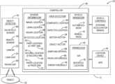
- FIG. 1is a diagram of a operation-security system in accordance with one embodiment
- FIG. 2is a traffic-scenario encountered by the system of FIG. 1 in accordance with one embodiment.
- FIG. 1illustrates a non-limiting example of a sensor-control system 10 , hereafter referred to as the system 10 , which is suitable for use by an automated vehicle, for example a host-vehicle 12 .
- the examples presented hereinare generally directed to instances when the host-vehicle 12 is being operated in an automated-mode 14 , i.e. a fully autonomous mode, where a human operator (not shown) of the host-vehicle 12 does little more than designate a destination to operate the host-vehicle 12 .
- the teachings presented hereinare useful when the host-vehicle 12 is operated in a manual-mode 16 where the degree or level of automation may be little more than providing steering advice to the human operator who is generally in control of the steering, accelerator, and brakes of the host-vehicle 12 , i.e. the system 10 assists the human operator as needed to reach the destination and/or avoid a collision with, for example an object 18 such as an other-vehicle.
- the system 10includes an object-detector 20 that includes at least three sensors, which may be any combination of, but are not limited to a camera 22 , a lidar-unit 24 , and a radar-unit 26 . That is, each sensor may be one of the options, but it is not a requirement that each sensor be a different option.
- the example embodiments of the system 10 described hereingenerally suggest that all three sensors are mounted on the host-vehicle, and one of each kind of sensor is used, e.g. one each of the camera 22 , the lidar-unit 24 , and the radar-unit 26 is mounted on the host-vehicle 12 . While the non-limiting example shown in FIG.
- FIG. 2shows all of the sensors as part of the host-vehicle, i.e. mounted on the host-vehicle, alternative embodiments are contemplated where one or more of the sensors is not mounted on the host-vehicle 12 , i.e. is remote rather than on-vehicle, and where duplicates of the types of sensor are used.
- an alternative configurationmay have a camera and a lidar mounted on the host-vehicle 12 , and a second camera or a second lidar located at a remote-position 28 ( FIG. 2 ) selected so the sensor can be used to observe an intersection approached by the host-vehicle 12 .
- the remote instance of the sensor(a remote sensor 78 ) may be mounted on another vehicle (not shown, a vehicle other than the other-vehicle is shown as the object 18 in FIG. 2 ).
- FIG. 2illustrates a non-limiting example of a traffic-scenario 30 where the various sensors are used to determine a location of the object 18 , preferably a readily identifiable point on the object 18 .
- the objectis an other-vehicle, and the point is the center of the front edge or front bumper of the other-vehicle.
- the camera 22is used to determine an image-location 32 of the object 18
- the lidar-unit 24is used to determine a lidar-location 34 of the object 18
- the radar-unit 26is used to determine a radar-location 36 of the object 18 .
- the various locationsmay be specified in terms of range or distance and direction (e.g.
- the various locationsmay be specified in world coordinates, e.g. latitude, longitude, and elevation. Using world coordinates may be preferable if one or more of the sensors is located remote from the host-vehicle 12 rather than mounted on the host-vehicle.
- the radar-location 36is shown as apparently being in error (i.e. well-spaced apart from the object 18 and corresponding instances of the image-location 32 and the lidar-location 34 ) is done to illustrate the improvement provided by the system 10 described herein.
- instanceshave been reported of vehicle control software and remote sensing systems being infiltrated or maliciously hacked to cause the host-vehicle 12 to possibly operate in an erratic manner.
- the radar-location 36is so different or distant from the image-location 32 and the lidar-location 34 suggests that the system 10 may have been hacked, or the radar-signal used to determine the radar-location 36 may have been jammed or spoofed to cause the error.
- the radar-unit 26may have been tampered with or the communication between the radar-unit 26 and the host-vehicle may have been hacked or spoofed.
- the system 10is configured to detect or determine when the system 10 has been hacked or is being spoofed, and take action to avoid erratic operation of the host-vehicle 12 .
- the system 10includes a controller 40 in communication with the (at least) three sensors, whatever combination of sensors that may be.
- the communicationmay be by way of, but not limited to, wires, wireless-communication, or optical-fiber as will be recognized by those in the art.
- the sensoris a remote sensor 78 , i.e. not on-vehicle, communications may be by way of vehicle-to-infrastructure (V2I) communications, vehicle-to-vehicle (V2V) communications, and/or vehicle-to-pedestrian (V2P) communications, which may be generically labeled as V2X communications.
- V2Ivehicle-to-infrastructure
- V2Vvehicle-to-vehicle
- V2Pvehicle-to-pedestrian
- the system 10may include a transceiver 42 to enable such communications.
- the controller 40may include a processor (not specifically shown) such as a microprocessor or other control circuitry such as analog and/or digital control circuitry including an application specific integrated circuit (ASIC) for processing data as should be evident to those in the art.
- the controller 40may include memory (not specifically shown), including non-volatile memory, such as electrically erasable programmable read-only memory (EEPROM) for storing one or more routines, thresholds, and captured data.
- the one or more routinesmay be executed by the processor to perform steps for determining if any of the locations indicated by the various sensors suggest that the system 10 has been hacked or is being spoofed.
- the system 10may include a location-device 44 such as a global-position-system (GPS) receiver, whereby a map-location on a digital-map may be determined.
- a location-device 44such as a global-position-system (GPS) receiver
- GPSglobal-position-system
- the map-location of the host-vehicle 12may be determined based on the location of the host-vehicle 12 relative to various permanent objects such as road-signs, buildings, etc., as will be recognized by those in the art.
- the controller 40configured to determine a composite-location 46 based on a comparison of locations, e.g.—the image-location 32 , the lidar-location 34 , and the radar-location 36 , indicated by the at least three sensors, e.g. the camera 22 , the lidar-unit 24 , and the radar-unit 26 .
- the composite-location 46may be determined by calculating an average range or distance and an average azimuth angle from the host-vehicle 12 to each of the locations ( 32 , 34 , and 36 ).
- the composite-location 46may be determined based on an average of the latitudes and longitudes of each location if the locations are expressed in world coordinates.
- the averagingmay be un-weighted, or may be weighted to, for example, give the two locations that are closest to each other more emphasis or weight relative to the outlier e.g. the radar-location 36 in FIG. 2 .
- the controller 40may be further configured to ignore location information from the one sensor that appear to be the most erroneous (the radar-unit 26 in this example) when a respective location (the radar-location 36 in this example) of the one sensor differs from the composite-location 46 by greater than an error-threshold 48 , e.g. a half-meter (0.5m) for example. In other words, if the distance between the composite-location 46 and any of the locations is greater than the error-threshold 48 , that erroneous location may be ignored and presumed to be in error due to, for example, hacking or spoofing.
- an error-threshold 48e.g. a half-meter (0.5m) for example.
- a sensormay become out-of-specification or otherwise damaged, which could also be the reason that a location reported by a sensor appears to be so at odds with locations reported by other sensors. Nevertheless, it is likely preferable that the location information from the sensor in question be ignored.
- the composite-location 46maybe recalculated to improve the overall accuracy of determining the actual locations of the object 18 relative to the host-vehicle 12 .
- the description of the system 10 provided abovegenerally evaluates location information from multiple sensors taken or gathered at about the same instant in time, for example within one-tenth second (0.1s) of each other. However, it is contemplated that hacking, spoofing, or a sudden failure of a sensor could also be detected by monitoring the location information over time and looking for sudden, unusual, or unexpected changes in the location information.
- the object-detector 20may be used to determine a first-location 50 of the object 18 that is proximate to a host-vehicle at a first-time 52 , and a second-location 54 of the object 18 a second-time 56 a sampling-interval 68 after or later than the first-time 52 , where a suitable value for the sampling-interval 68 is two-tenths of a second (0.2s).
- the first-location 50 and the second-location 54may be based on location information from a single sensor, i.e. information from individual sensors is being monitored over a period of time.
- the composite-location 46 at the first-time 52may be used as the first-location 50
- the composite-location 46 at the second-time 56may be as the second-location 54 , and analyzed to detect sudden or unexpected changes in the location information.
- FIG. 2suggests that the host-vehicle 12 is moving or traveling toward an intersection 60 while the other-vehicle that is the object 18 waits to enter the intersection 60 .
- the controller 40which is in communication with the object-detector 20 , may be further configured to determine a motion-vector 58 of the host-vehicle 12 .
- the motion-vector 58may be an actual vector based on, for example, an indicated speed, and yaw-rate from the host-vehicle 12 . Alternatively, the motion-vector 58 may be based on speed and a direction or heading determined from the location-device 44 .
- the controller 40may be further configured to estimate an expected-location 62 of the object 18 at the second-time 56 based on the motion-vector 58 , the first-location 50 , and the sampling-interval 68 . That is, as the host-vehicle 12 travels toward the object 18 , it is expected that the location of the object 18 relative to the host-vehicle 12 will change because the host-vehicle 12 is moving, but the change can be predicted based on the motion-vector 58 . However, if the expected-location 62 does not correspond well with the second-location 54 indicated by the object-detector 20 at the second-time 56 , then that may be an indication that the system 10 has been hacked or is being spoofed.
- information from the object-detector 20 at the second-timemay be ignored when expected-location 62 differs from the second-location 54 by greater than an error-threshold 48 .
- error-threshold 48the second-time 56 there was no hacking or spoofing of the system 10 .
- FIG. 2may be interpreted to suggest that the other-vehicle indicated as the object 18 is not moving because of the stop sign at the intersection 60 .
- the controller 40may be further configured to determine an object-vector 64 based on a prior-difference 66 between the first-location 50 and a prior-location 70 of the object 18 proximate to the host-vehicle at a prior-time 72 prior to the first-time 52 .
- the expected-location 62may also be determined based on the object-vector. That is, both the motion-vector 58 of the host-vehicle 12 and the object-vector 64 of the object 18 may be used to determine the expected-location 62 of the object 18 to cover instances when the object 18 is moving rather than stationary.
- the systemmay include the transceiver 42 to support V2X communications from sensors that are remote, i.e. not mounted on the host-vehicle 12 .
- the locations provided by one or more instances of an on-vehicle sensor 80 that make up the object-detector 20 that are mounted on a host-vehicle 12may be used to determine a detected-location 74 of an object proximate to the host-vehicle 12 .
- the composite-location 46 mentioned abovemay include locations that are not strictly determined by the on-vehicle sensor 80 mounted on the host-vehicle 12 , while the determination of the detected-location 74 is limited to using only the one or more instances of on-vehicle sensor 80 that are actually mounted on the host-vehicle 12 .
- the transceiver 42may be used to receive a reported-location 76 of the object 18 determined by a remote sensor 78 not mounted on the host-vehicle 12 .
- the controller 40which is in communication with one or more instances of the on-vehicle sensor 80 of the object-detector 20 and the transceiver 42 , may be further configured to compare the detected-location 74 and the reported-location 76 , and ignore information from the transceiver 42 when the detected-location 74 differs from the reported-location 76 by greater than the error-threshold 48 . There is a presumption that the host-vehicle 12 , or more specifically the controller 40 , has not been hacked.
- an operation-security system(the system 10 ), a controller 40 for the system 10 , and a method of operating the system 10 is provided.
Landscapes
- Engineering & Computer Science (AREA)
- Radar, Positioning & Navigation (AREA)
- Remote Sensing (AREA)
- Physics & Mathematics (AREA)
- General Physics & Mathematics (AREA)
- Aviation & Aerospace Engineering (AREA)
- Automation & Control Theory (AREA)
- Computer Networks & Wireless Communication (AREA)
- Electromagnetism (AREA)
- Business, Economics & Management (AREA)
- Health & Medical Sciences (AREA)
- Artificial Intelligence (AREA)
- Evolutionary Computation (AREA)
- Game Theory and Decision Science (AREA)
- Medical Informatics (AREA)
- Optics & Photonics (AREA)
- Computer Vision & Pattern Recognition (AREA)
- Multimedia (AREA)
- Traffic Control Systems (AREA)
Abstract
Description
Claims (20)
Priority Applications (1)
| Application Number | Priority Date | Filing Date | Title |
|---|---|---|---|
| US17/541,774US12013694B2 (en) | 2016-08-05 | 2021-12-03 | Operation-security system for an automated vehicle |
Applications Claiming Priority (3)
| Application Number | Priority Date | Filing Date | Title |
|---|---|---|---|
| US15/230,019US10571913B2 (en) | 2016-08-05 | 2016-08-05 | Operation-security system for an automated vehicle |
| US16/797,862US11194328B2 (en) | 2016-08-05 | 2020-02-21 | Operation-security system for an automated vehicle |
| US17/541,774US12013694B2 (en) | 2016-08-05 | 2021-12-03 | Operation-security system for an automated vehicle |
Related Parent Applications (1)
| Application Number | Title | Priority Date | Filing Date |
|---|---|---|---|
| US16/797,862ContinuationUS11194328B2 (en) | 2016-08-05 | 2020-02-21 | Operation-security system for an automated vehicle |
Publications (2)
| Publication Number | Publication Date |
|---|---|
| US20220163964A1 US20220163964A1 (en) | 2022-05-26 |
| US12013694B2true US12013694B2 (en) | 2024-06-18 |
Family
ID=61069598
Family Applications (3)
| Application Number | Title | Priority Date | Filing Date |
|---|---|---|---|
| US15/230,019Active2037-08-26US10571913B2 (en) | 2016-08-05 | 2016-08-05 | Operation-security system for an automated vehicle |
| US16/797,862ActiveUS11194328B2 (en) | 2016-08-05 | 2020-02-21 | Operation-security system for an automated vehicle |
| US17/541,774Active2036-09-03US12013694B2 (en) | 2016-08-05 | 2021-12-03 | Operation-security system for an automated vehicle |
Family Applications Before (2)
| Application Number | Title | Priority Date | Filing Date |
|---|---|---|---|
| US15/230,019Active2037-08-26US10571913B2 (en) | 2016-08-05 | 2016-08-05 | Operation-security system for an automated vehicle |
| US16/797,862ActiveUS11194328B2 (en) | 2016-08-05 | 2020-02-21 | Operation-security system for an automated vehicle |
Country Status (4)
| Country | Link |
|---|---|
| US (3) | US10571913B2 (en) |
| EP (1) | EP3494444A4 (en) |
| CN (2) | CN109937389B (en) |
| WO (1) | WO2018026486A1 (en) |
Families Citing this family (26)
| Publication number | Priority date | Publication date | Assignee | Title |
|---|---|---|---|---|
| US11482100B2 (en)* | 2015-03-28 | 2022-10-25 | Intel Corporation | Technologies for detection of anomalies in vehicle traffic patterns |
| US11092446B2 (en) | 2016-06-14 | 2021-08-17 | Motional Ad Llc | Route planning for an autonomous vehicle |
| US10126136B2 (en) | 2016-06-14 | 2018-11-13 | nuTonomy Inc. | Route planning for an autonomous vehicle |
| US10309792B2 (en) | 2016-06-14 | 2019-06-04 | nuTonomy Inc. | Route planning for an autonomous vehicle |
| US10571913B2 (en) | 2016-08-05 | 2020-02-25 | Aptiv Technologies Limited | Operation-security system for an automated vehicle |
| US10473470B2 (en) | 2016-10-20 | 2019-11-12 | nuTonomy Inc. | Identifying a stopping place for an autonomous vehicle |
| US10681513B2 (en) | 2016-10-20 | 2020-06-09 | nuTonomy Inc. | Identifying a stopping place for an autonomous vehicle |
| US10331129B2 (en) | 2016-10-20 | 2019-06-25 | nuTonomy Inc. | Identifying a stopping place for an autonomous vehicle |
| US10857994B2 (en) | 2016-10-20 | 2020-12-08 | Motional Ad Llc | Identifying a stopping place for an autonomous vehicle |
| CN109101011A (en)* | 2017-06-20 | 2018-12-28 | 百度在线网络技术(北京)有限公司 | Sensor monitoring method, device, equipment and the storage medium of automatic driving vehicle |
| US10613547B2 (en)* | 2017-08-14 | 2020-04-07 | GM Global Technology Operations LLC | System and method for improved obstacle awareness in using a V2X communications system |
| CN108375982A (en)* | 2018-03-16 | 2018-08-07 | 姜鹏飞 | A kind of method and system judging automatic driving vehicle safety |
| CN108762245B (en) | 2018-03-20 | 2022-03-25 | 华为技术有限公司 | Data fusion method and related equipment |
| US11142205B2 (en)* | 2018-04-25 | 2021-10-12 | Aptiv Technologies Limited | System and method to notify operator of host-vehicle of takeover-event in another-vehicle |
| US10909866B2 (en)* | 2018-07-20 | 2021-02-02 | Cybernet Systems Corp. | Autonomous transportation system and methods |
| KR102769264B1 (en)* | 2018-10-10 | 2025-02-20 | 주식회사 에이치엘클레무브 | Apparatus and Method for Complementing Automotive Radar |
| EP3724031A4 (en)* | 2019-02-28 | 2020-11-18 | SZ DJI Technology Co., Ltd. | DEVICE AND METHOD FOR TRANSMISSION OF VEHICLE INFORMATION |
| EP3736597B1 (en)* | 2019-05-06 | 2025-02-12 | Easymile | Method and system for modifying the speed of a vehicle depending on the validation of its calculated localization field |
| DE102019132024A1 (en)* | 2019-11-26 | 2021-05-27 | Sick Ag | security system |
| KR102662730B1 (en)* | 2020-03-04 | 2024-05-02 | 주식회사 에이치엘클레무브 | Driver assistance apparatus and method thereof |
| JP7463146B2 (en)* | 2020-03-17 | 2024-04-08 | 本田技研工業株式会社 | MOBILE OBJECT MONITORING SYSTEM AND MOBILE OBJECT MONITORING METHOD |
| US11551456B2 (en) | 2020-06-17 | 2023-01-10 | Ford Global Technologies, Llc | Enhanced infrastructure |
| EP4218315A1 (en)* | 2020-09-22 | 2023-08-02 | Qualcomm Incorporated | Positioning reference signal configuration and management |
| KR20220068710A (en) | 2020-11-19 | 2022-05-26 | 삼성전자주식회사 | Method and apparatus for vehicle localization |
| JP7571716B2 (en)* | 2021-12-07 | 2024-10-23 | トヨタ自動車株式会社 | OBJECT DETERMINATION DEVICE, OBJECT DETERMINATION COMPUTER PROGRAM, AND OBJECT DETERMINATION METHOD |
| US12391215B2 (en)* | 2023-07-19 | 2025-08-19 | GM Global Technology Operations LLC | Systems and methods for detecting vehicle controller spoofing |
Citations (46)
| Publication number | Priority date | Publication date | Assignee | Title |
|---|---|---|---|---|
| US20050206142A1 (en) | 2004-03-05 | 2005-09-22 | Prakah-Asante Kwaku O | Method and control system for predictive deployment of side-impact restraints |
| US20060021361A1 (en) | 2003-04-11 | 2006-02-02 | Bayerische Motoren Werke | Fault detection system and method for detecting a faulty temperature sensor in motor vehicles |
| US20060287806A1 (en) | 2005-06-16 | 2006-12-21 | Hitachi, Ltd. | Fault diagnosis apparatus for sensors used in a system |
| US20060293853A1 (en) | 2005-06-23 | 2006-12-28 | Raytheon Company | Aided INS/GPS/SAR navigation with other platforms |
| US20090058881A1 (en) | 2007-04-03 | 2009-03-05 | Ottney Joseph C | Fusion night vision system with parallax correction |
| US7512516B1 (en) | 2007-11-02 | 2009-03-31 | Delphi Technologies, Inc. | Collision avoidance and warning system and method |
| CN101512347A (en) | 2006-08-29 | 2009-08-19 | 大陆汽车有限责任公司 | Speed detection for a tachograph system |
| CN101526552A (en) | 2008-02-08 | 2009-09-09 | 凯尔西-海耶斯公司 | Failure-safe test of a motion sensor |
| US20090244263A1 (en) | 2007-10-29 | 2009-10-01 | Toru Saito | Object Detecting System |
| JP2010061484A (en) | 2008-09-05 | 2010-03-18 | Hitachi Industrial Equipment Systems Co Ltd | Mobile object and recovery method from position prediction error state of mobile object |
| US20100100324A1 (en) | 2008-10-22 | 2010-04-22 | Toyota Motor Engineering & Manufacturing North America, Inc. | Communication based vehicle-pedestrian collision warning system |
| US20100198442A1 (en) | 2005-06-19 | 2010-08-05 | Dina Appelman | Method and system for automatically guiding an unmanned vechile |
| US20100228419A1 (en) | 2009-03-09 | 2010-09-09 | Gm Global Technology Operations, Inc. | method to assess risk associated with operating an autonomic vehicle control system |
| US20100253489A1 (en) | 2009-04-02 | 2010-10-07 | Gm Global Technology Operations, Inc. | Distortion and perspective correction of vector projection display |
| US20100253493A1 (en) | 2009-04-02 | 2010-10-07 | Gm Global Technology Operations, Inc. | Recommended following distance on full-windshield head-up display |
| CN202022205U (en) | 2011-03-17 | 2011-11-02 | 交通运输部公路科学研究所 | Multisource information fusion device for safe driving assistance |
| CN102753395A (en) | 2010-02-11 | 2012-10-24 | 大陆-特韦斯贸易合伙股份公司及两合公司 | Vehicle sensor node |
| DE102011017593A1 (en) | 2011-04-27 | 2012-10-31 | Robert Bosch Gmbh | Device for detecting errors of environment sensor of vehicle, has evaluation unit for comparing two informations such that fault is detected, when former information deviates over predetermined amount of latter information |
| US20130099911A1 (en) | 2011-10-20 | 2013-04-25 | GM Global Technology Operations LLC | Highway Merge Assistant and Control |
| CN103347757A (en) | 2010-07-21 | 2013-10-09 | 伊顿公司 | System and method for optimizing fuel economy using predictive environment and driver behavior information |
| CN103370249A (en) | 2010-10-05 | 2013-10-23 | 谷歌公司 | System and method for predicting behaviors of detected objects |
| US20130325311A1 (en) | 2012-05-31 | 2013-12-05 | Hyundai Motor Company | Apparatus and method for detecting moving-object around vehicle |
| CN103439973A (en) | 2013-08-12 | 2013-12-11 | 桂林电子科技大学 | Household cleaning robot capable of establishing map by self and cleaning method |
| US20130335569A1 (en) | 2012-03-14 | 2013-12-19 | Honda Motor Co., Ltd. | Vehicle with improved traffic-object position detection |
| CN103823208A (en) | 2012-11-16 | 2014-05-28 | 通用汽车环球科技运作有限责任公司 | Method and apparatus for state of health estimation of object sensing fusion system |
| CN103868201A (en) | 2014-03-21 | 2014-06-18 | 长春轨道客车股份有限公司 | High-speed motor train unit air conditioner control method suitable for high-cold environment |
| US20140168377A1 (en) | 2012-12-13 | 2014-06-19 | Delphi Technologies, Inc. | Stereoscopic camera object detection system and method of aligning the same |
| US20150025771A1 (en) | 2013-07-19 | 2015-01-22 | Hyundai Mobis Co., Ltd. | Apparatus and method for correcting offset of yaw rate sensor and system for controlling speed of vehicle with the said apparatus |
| US20150032290A1 (en) | 2009-02-27 | 2015-01-29 | Toyota Jidosha Kabushiki Kaisha | Movement trajectory generator |
| US20150123816A1 (en) | 2000-10-04 | 2015-05-07 | Intelligent Technologies International, Inc. | Animal detecting and notification method and system |
| CN104704424A (en) | 2012-08-21 | 2015-06-10 | 视觉智能有限合伙公司 | Infrastructure mapping system and method |
| US20150208207A1 (en) | 2014-01-22 | 2015-07-23 | Lear Corporation | Wireless device localization |
| CN104850119A (en) | 2014-02-14 | 2015-08-19 | 丰田自动车株式会社 | Autonomous vehicle and its failure determination method |
| CN104870260A (en) | 2012-12-20 | 2015-08-26 | 大陆-特韦斯贸易合伙股份公司及两合公司 | Device for outputting a measurement signal indicating a physical measurement variable |
| US20150260498A1 (en) | 2014-03-13 | 2015-09-17 | The Boeing Company | Calibration of sensor arrays |
| US20150294422A1 (en) | 2014-04-15 | 2015-10-15 | Maris, Ltd. | Assessing asynchronous authenticated data sources for use in driver risk management |
| US9274525B1 (en) | 2012-09-28 | 2016-03-01 | Google Inc. | Detecting sensor degradation by actively controlling an autonomous vehicle |
| CN105515739A (en) | 2014-10-14 | 2016-04-20 | 罗伯特·博世有限公司 | Fail-safe E/E architecture for automated driving |
| CN105571585A (en) | 2014-10-20 | 2016-05-11 | 霍尼韦尔国际公司 | System and method for isolating attitude failures in aircraft |
| US20160161950A1 (en) | 2013-03-19 | 2016-06-09 | Massive Analytic Ltd. | Apparatus for controlling a land vehicle which is self-driving or partially self-driving |
| CN105700533A (en) | 2016-04-22 | 2016-06-22 | 扬州大学 | Agricultural machinery automatic driving control system based on Beidou navigation and method thereof |
| US20160209236A1 (en) | 2013-11-20 | 2016-07-21 | Continental Teves Ag & Co. Ohg | Method, fusion filter, and system for fusing sensor signals with different temporal signal output delays into a fusion data set |
| US20170166205A1 (en) | 2015-12-14 | 2017-06-15 | Honda Motor Co., Ltd. | Method and system for lane detection and validation |
| US20170294124A1 (en) | 2014-09-24 | 2017-10-12 | Denso Corporation | Object detection apparatus |
| US20180039269A1 (en) | 2016-08-05 | 2018-02-08 | Delphi Technologies, Inc. | Operation-security system for an automated vehicle |
| US20190061746A1 (en)* | 2016-04-12 | 2019-02-28 | Bayerische Motoren Werke Aktiengesellschaft | Method, System, and Vehicle Comprising the System for Automatic Initiation of a Vehicle Function of a Vehicle |
- 2016
- 2016-08-05USUS15/230,019patent/US10571913B2/enactiveActive
- 2017
- 2017-07-13CNCN201780062022.2Apatent/CN109937389B/enactiveActive
- 2017-07-13CNCN202310348227.4Apatent/CN116520346A/enactivePending
- 2017-07-13WOPCT/US2017/041831patent/WO2018026486A1/ennot_activeCeased
- 2017-07-13EPEP17837376.7Apatent/EP3494444A4/enactivePending
- 2020
- 2020-02-21USUS16/797,862patent/US11194328B2/enactiveActive
- 2021
- 2021-12-03USUS17/541,774patent/US12013694B2/enactiveActive
Patent Citations (49)
| Publication number | Priority date | Publication date | Assignee | Title |
|---|---|---|---|---|
| US20150123816A1 (en) | 2000-10-04 | 2015-05-07 | Intelligent Technologies International, Inc. | Animal detecting and notification method and system |
| US20060021361A1 (en) | 2003-04-11 | 2006-02-02 | Bayerische Motoren Werke | Fault detection system and method for detecting a faulty temperature sensor in motor vehicles |
| US20050206142A1 (en) | 2004-03-05 | 2005-09-22 | Prakah-Asante Kwaku O | Method and control system for predictive deployment of side-impact restraints |
| US20060287806A1 (en) | 2005-06-16 | 2006-12-21 | Hitachi, Ltd. | Fault diagnosis apparatus for sensors used in a system |
| US20100198442A1 (en) | 2005-06-19 | 2010-08-05 | Dina Appelman | Method and system for automatically guiding an unmanned vechile |
| US20060293853A1 (en) | 2005-06-23 | 2006-12-28 | Raytheon Company | Aided INS/GPS/SAR navigation with other platforms |
| CN101512347A (en) | 2006-08-29 | 2009-08-19 | 大陆汽车有限责任公司 | Speed detection for a tachograph system |
| US20090058881A1 (en) | 2007-04-03 | 2009-03-05 | Ottney Joseph C | Fusion night vision system with parallax correction |
| US20090244263A1 (en) | 2007-10-29 | 2009-10-01 | Toru Saito | Object Detecting System |
| US7512516B1 (en) | 2007-11-02 | 2009-03-31 | Delphi Technologies, Inc. | Collision avoidance and warning system and method |
| CN101526552A (en) | 2008-02-08 | 2009-09-09 | 凯尔西-海耶斯公司 | Failure-safe test of a motion sensor |
| JP2010061484A (en) | 2008-09-05 | 2010-03-18 | Hitachi Industrial Equipment Systems Co Ltd | Mobile object and recovery method from position prediction error state of mobile object |
| US20100100324A1 (en) | 2008-10-22 | 2010-04-22 | Toyota Motor Engineering & Manufacturing North America, Inc. | Communication based vehicle-pedestrian collision warning system |
| US20150032290A1 (en) | 2009-02-27 | 2015-01-29 | Toyota Jidosha Kabushiki Kaisha | Movement trajectory generator |
| US20100228419A1 (en) | 2009-03-09 | 2010-09-09 | Gm Global Technology Operations, Inc. | method to assess risk associated with operating an autonomic vehicle control system |
| US20100253493A1 (en) | 2009-04-02 | 2010-10-07 | Gm Global Technology Operations, Inc. | Recommended following distance on full-windshield head-up display |
| US20100253489A1 (en) | 2009-04-02 | 2010-10-07 | Gm Global Technology Operations, Inc. | Distortion and perspective correction of vector projection display |
| CN102753395A (en) | 2010-02-11 | 2012-10-24 | 大陆-特韦斯贸易合伙股份公司及两合公司 | Vehicle sensor node |
| CN103347757A (en) | 2010-07-21 | 2013-10-09 | 伊顿公司 | System and method for optimizing fuel economy using predictive environment and driver behavior information |
| CN103370249A (en) | 2010-10-05 | 2013-10-23 | 谷歌公司 | System and method for predicting behaviors of detected objects |
| CN202022205U (en) | 2011-03-17 | 2011-11-02 | 交通运输部公路科学研究所 | Multisource information fusion device for safe driving assistance |
| DE102011017593A1 (en) | 2011-04-27 | 2012-10-31 | Robert Bosch Gmbh | Device for detecting errors of environment sensor of vehicle, has evaluation unit for comparing two informations such that fault is detected, when former information deviates over predetermined amount of latter information |
| US20130099911A1 (en) | 2011-10-20 | 2013-04-25 | GM Global Technology Operations LLC | Highway Merge Assistant and Control |
| US20130335569A1 (en) | 2012-03-14 | 2013-12-19 | Honda Motor Co., Ltd. | Vehicle with improved traffic-object position detection |
| US20130325311A1 (en) | 2012-05-31 | 2013-12-05 | Hyundai Motor Company | Apparatus and method for detecting moving-object around vehicle |
| CN104704424A (en) | 2012-08-21 | 2015-06-10 | 视觉智能有限合伙公司 | Infrastructure mapping system and method |
| US9274525B1 (en) | 2012-09-28 | 2016-03-01 | Google Inc. | Detecting sensor degradation by actively controlling an autonomous vehicle |
| CN103823208A (en) | 2012-11-16 | 2014-05-28 | 通用汽车环球科技运作有限责任公司 | Method and apparatus for state of health estimation of object sensing fusion system |
| US20140168377A1 (en) | 2012-12-13 | 2014-06-19 | Delphi Technologies, Inc. | Stereoscopic camera object detection system and method of aligning the same |
| CN104870260A (en) | 2012-12-20 | 2015-08-26 | 大陆-特韦斯贸易合伙股份公司及两合公司 | Device for outputting a measurement signal indicating a physical measurement variable |
| US20160161950A1 (en) | 2013-03-19 | 2016-06-09 | Massive Analytic Ltd. | Apparatus for controlling a land vehicle which is self-driving or partially self-driving |
| US20150025771A1 (en) | 2013-07-19 | 2015-01-22 | Hyundai Mobis Co., Ltd. | Apparatus and method for correcting offset of yaw rate sensor and system for controlling speed of vehicle with the said apparatus |
| CN103439973A (en) | 2013-08-12 | 2013-12-11 | 桂林电子科技大学 | Household cleaning robot capable of establishing map by self and cleaning method |
| US20160209236A1 (en) | 2013-11-20 | 2016-07-21 | Continental Teves Ag & Co. Ohg | Method, fusion filter, and system for fusing sensor signals with different temporal signal output delays into a fusion data set |
| US20150208207A1 (en) | 2014-01-22 | 2015-07-23 | Lear Corporation | Wireless device localization |
| CN104850119A (en) | 2014-02-14 | 2015-08-19 | 丰田自动车株式会社 | Autonomous vehicle and its failure determination method |
| US20150260498A1 (en) | 2014-03-13 | 2015-09-17 | The Boeing Company | Calibration of sensor arrays |
| CN103868201A (en) | 2014-03-21 | 2014-06-18 | 长春轨道客车股份有限公司 | High-speed motor train unit air conditioner control method suitable for high-cold environment |
| US20150294422A1 (en) | 2014-04-15 | 2015-10-15 | Maris, Ltd. | Assessing asynchronous authenticated data sources for use in driver risk management |
| US20170294124A1 (en) | 2014-09-24 | 2017-10-12 | Denso Corporation | Object detection apparatus |
| CN105515739A (en) | 2014-10-14 | 2016-04-20 | 罗伯特·博世有限公司 | Fail-safe E/E architecture for automated driving |
| CN105571585A (en) | 2014-10-20 | 2016-05-11 | 霍尼韦尔国际公司 | System and method for isolating attitude failures in aircraft |
| US20170166205A1 (en) | 2015-12-14 | 2017-06-15 | Honda Motor Co., Ltd. | Method and system for lane detection and validation |
| US20190061746A1 (en)* | 2016-04-12 | 2019-02-28 | Bayerische Motoren Werke Aktiengesellschaft | Method, System, and Vehicle Comprising the System for Automatic Initiation of a Vehicle Function of a Vehicle |
| CN105700533A (en) | 2016-04-22 | 2016-06-22 | 扬州大学 | Agricultural machinery automatic driving control system based on Beidou navigation and method thereof |
| US20180039269A1 (en) | 2016-08-05 | 2018-02-08 | Delphi Technologies, Inc. | Operation-security system for an automated vehicle |
| US10571913B2 (en) | 2016-08-05 | 2020-02-25 | Aptiv Technologies Limited | Operation-security system for an automated vehicle |
| US20200192361A1 (en) | 2016-08-05 | 2020-06-18 | Aptiv Technologies Limited | Operation-Security System for an Automated Vehicle |
| US11194328B2 (en) | 2016-08-05 | 2021-12-07 | Motional Ad Llc | Operation-security system for an automated vehicle |
Non-Patent Citations (3)
| Title |
|---|
| EP Extended Search Report in European Application No. 17837376, dated Aug. 5, 2019, 8 pages. |
| PCT International Preliminary Report on Patentability in International Application No. PCT/US2017/041831, dated Feb. 14, 2019, 9 pages. |
| PCT International Search Report and Written Opinion in International Application No. PCT/US2017/041831, dated Oct. 24, 2017, 16 pages. |
Also Published As
| Publication number | Publication date |
|---|---|
| CN109937389B (en) | 2023-04-28 |
| US20220163964A1 (en) | 2022-05-26 |
| WO2018026486A1 (en) | 2018-02-08 |
| US11194328B2 (en) | 2021-12-07 |
| US10571913B2 (en) | 2020-02-25 |
| CN109937389A (en) | 2019-06-25 |
| EP3494444A4 (en) | 2019-09-04 |
| US20180039269A1 (en) | 2018-02-08 |
| CN116520346A (en) | 2023-08-01 |
| US20200192361A1 (en) | 2020-06-18 |
| EP3494444A1 (en) | 2019-06-12 |
Similar Documents
| Publication | Publication Date | Title |
|---|---|---|
| US12013694B2 (en) | Operation-security system for an automated vehicle | |
| US11772489B2 (en) | Visually obstructed object detection for automated vehicle using V2V/V2I communications | |
| CN115214661B (en) | Cooperative adaptive cruise control system based on target vehicle's driving style | |
| US9165198B2 (en) | Method for identifying a vehicle during vehicle-to-vehicle communication | |
| US20180154901A1 (en) | Method and system for localizing a vehicle | |
| CN109219536B (en) | V2X object location verification system for automated vehicles | |
| EP2637149B1 (en) | Onboard device and control method | |
| US20190114493A1 (en) | Method and device for traffic sign recognition | |
| US10369993B2 (en) | Method and device for monitoring a setpoint trajectory to be traveled by a vehicle for being collision free | |
| US20140297063A1 (en) | Vehicle specifying apparatus | |
| US10094933B1 (en) | Automated vehicle GPS accuracy improvement using V2V communications | |
| JP2019532292A (en) | Autonomous vehicle with vehicle location | |
| US20190179323A1 (en) | Method for providing an information item regarding a pedestrian in an environment of a vehicle and method for controlling a vehicle | |
| JPWO2013027803A1 (en) | Autonomous driving control system for vehicles | |
| US11292481B2 (en) | Method and apparatus for multi vehicle sensor suite diagnosis | |
| EP3501932B1 (en) | Automated vehicle system and method for changing from automated-mode to manual-mode near a construction-zone | |
| EP3620818B1 (en) | Annotation of radar-profiles of objects | |
| US11142196B2 (en) | Lane detection method and system for a vehicle | |
| US20210206392A1 (en) | Method and device for operating an automated vehicle | |
| WO2016126318A1 (en) | Method of automatically controlling an autonomous vehicle based on cellular telephone location information | |
| US11340357B2 (en) | Method and apparatus for detecting a position of a vehicle having a high level of automation | |
| US9395448B2 (en) | Information indication apparatus | |
| US11577753B2 (en) | Safety architecture for control of autonomous vehicle | |
| KR102665894B1 (en) | Systems and methods for estimating the direction of traffic participants | |
| WO2024051934A1 (en) | A method for determining whether a vehicle is driving in, or towards a target area |
Legal Events
| Date | Code | Title | Description |
|---|---|---|---|
| FEPP | Fee payment procedure | Free format text:ENTITY STATUS SET TO UNDISCOUNTED (ORIGINAL EVENT CODE: BIG.); ENTITY STATUS OF PATENT OWNER: LARGE ENTITY | |
| AS | Assignment | Owner name:APTIV TECHNOLOGIES LIMITED, BARBADOS Free format text:ASSIGNMENT OF ASSIGNORS INTEREST;ASSIGNOR:DELPHI TECHNOLOGIES, INC.;REEL/FRAME:058305/0154 Effective date:20180101 Owner name:MOTIONAL AD LLC, MASSACHUSETTS Free format text:ASSIGNMENT OF ASSIGNORS INTEREST;ASSIGNOR:APTIV TECHNOLOGIES LIMITED;REEL/FRAME:058305/0288 Effective date:20200917 Owner name:DELPHI TECHNOLOGIES, INC., MICHIGAN Free format text:ASSIGNMENT OF ASSIGNORS INTEREST;ASSIGNORS:LAMBERMONT, SERGE;KIM, JUNSUNG;WEI, JUNQING;AND OTHERS;SIGNING DATES FROM 20160630 TO 20160715;REEL/FRAME:058312/0511 | |
| STPP | Information on status: patent application and granting procedure in general | Free format text:DOCKETED NEW CASE - READY FOR EXAMINATION | |
| STPP | Information on status: patent application and granting procedure in general | Free format text:NON FINAL ACTION MAILED | |
| STPP | Information on status: patent application and granting procedure in general | Free format text:RESPONSE TO NON-FINAL OFFICE ACTION ENTERED AND FORWARDED TO EXAMINER | |
| STPP | Information on status: patent application and granting procedure in general | Free format text:NOTICE OF ALLOWANCE MAILED -- APPLICATION RECEIVED IN OFFICE OF PUBLICATIONS | |
| STPP | Information on status: patent application and granting procedure in general | Free format text:PUBLICATIONS -- ISSUE FEE PAYMENT VERIFIED | |
| STCF | Information on status: patent grant | Free format text:PATENTED CASE |