US12011968B2 - Interface system for connecting a vehicle and a transport climate control system - Google Patents
Interface system for connecting a vehicle and a transport climate control systemDownload PDFInfo
- Publication number
- US12011968B2 US12011968B2US17/820,114US202217820114AUS12011968B2US 12011968 B2US12011968 B2US 12011968B2US 202217820114 AUS202217820114 AUS 202217820114AUS 12011968 B2US12011968 B2US 12011968B2
- Authority
- US
- United States
- Prior art keywords
- tccs
- ves
- power
- controller
- vehicle
- Prior art date
- Legal status (The legal status is an assumption and is not a legal conclusion. Google has not performed a legal analysis and makes no representation as to the accuracy of the status listed.)
- Active
Links
Images


Classifications
- B—PERFORMING OPERATIONS; TRANSPORTING
- B60—VEHICLES IN GENERAL
- B60H—ARRANGEMENTS OF HEATING, COOLING, VENTILATING OR OTHER AIR-TREATING DEVICES SPECIALLY ADAPTED FOR PASSENGER OR GOODS SPACES OF VEHICLES
- B60H1/00—Heating, cooling or ventilating [HVAC] devices
- B60H1/00421—Driving arrangements for parts of a vehicle air-conditioning
- B60H1/00428—Driving arrangements for parts of a vehicle air-conditioning electric
- H—ELECTRICITY
- H02—GENERATION; CONVERSION OR DISTRIBUTION OF ELECTRIC POWER
- H02J—CIRCUIT ARRANGEMENTS OR SYSTEMS FOR SUPPLYING OR DISTRIBUTING ELECTRIC POWER; SYSTEMS FOR STORING ELECTRIC ENERGY
- H02J7/00—Circuit arrangements for charging or depolarising batteries or for supplying loads from batteries
- H02J7/00032—Circuit arrangements for charging or depolarising batteries or for supplying loads from batteries characterised by data exchange
- B—PERFORMING OPERATIONS; TRANSPORTING
- B60—VEHICLES IN GENERAL
- B60P—VEHICLES ADAPTED FOR LOAD TRANSPORTATION OR TO TRANSPORT, TO CARRY, OR TO COMPRISE SPECIAL LOADS OR OBJECTS
- B60P3/00—Vehicles adapted to transport, to carry or to comprise special loads or objects
- B—PERFORMING OPERATIONS; TRANSPORTING
- B60—VEHICLES IN GENERAL
- B60H—ARRANGEMENTS OF HEATING, COOLING, VENTILATING OR OTHER AIR-TREATING DEVICES SPECIALLY ADAPTED FOR PASSENGER OR GOODS SPACES OF VEHICLES
- B60H1/00—Heating, cooling or ventilating [HVAC] devices
- B60H1/00007—Combined heating, ventilating, or cooling devices
- B60H1/00014—Combined heating, ventilating, or cooling devices for load cargos on load transporting vehicles
- B—PERFORMING OPERATIONS; TRANSPORTING
- B60—VEHICLES IN GENERAL
- B60H—ARRANGEMENTS OF HEATING, COOLING, VENTILATING OR OTHER AIR-TREATING DEVICES SPECIALLY ADAPTED FOR PASSENGER OR GOODS SPACES OF VEHICLES
- B60H1/00—Heating, cooling or ventilating [HVAC] devices
- B60H1/00507—Details, e.g. mounting arrangements, desaeration devices
- B60H1/00585—Means for monitoring, testing or servicing the air-conditioning
- B—PERFORMING OPERATIONS; TRANSPORTING
- B60—VEHICLES IN GENERAL
- B60H—ARRANGEMENTS OF HEATING, COOLING, VENTILATING OR OTHER AIR-TREATING DEVICES SPECIALLY ADAPTED FOR PASSENGER OR GOODS SPACES OF VEHICLES
- B60H1/00—Heating, cooling or ventilating [HVAC] devices
- B60H1/00642—Control systems or circuits; Control members or indication devices for heating, cooling or ventilating devices
- B60H1/00985—Control systems or circuits characterised by display or indicating devices, e.g. voice simulators
- B—PERFORMING OPERATIONS; TRANSPORTING
- B60—VEHICLES IN GENERAL
- B60H—ARRANGEMENTS OF HEATING, COOLING, VENTILATING OR OTHER AIR-TREATING DEVICES SPECIALLY ADAPTED FOR PASSENGER OR GOODS SPACES OF VEHICLES
- B60H1/00—Heating, cooling or ventilating [HVAC] devices
- B60H1/32—Cooling devices
- B60H1/3204—Cooling devices using compression
- B60H1/3205—Control means therefor
- B60H1/3208—Vehicle drive related control of the compressor drive means, e.g. for fuel saving purposes
- B—PERFORMING OPERATIONS; TRANSPORTING
- B60—VEHICLES IN GENERAL
- B60H—ARRANGEMENTS OF HEATING, COOLING, VENTILATING OR OTHER AIR-TREATING DEVICES SPECIALLY ADAPTED FOR PASSENGER OR GOODS SPACES OF VEHICLES
- B60H1/00—Heating, cooling or ventilating [HVAC] devices
- B60H1/32—Cooling devices
- B60H1/3204—Cooling devices using compression
- B60H1/3222—Cooling devices using compression characterised by the compressor driving arrangements, e.g. clutches, transmissions or multiple drives
- B—PERFORMING OPERATIONS; TRANSPORTING
- B60—VEHICLES IN GENERAL
- B60H—ARRANGEMENTS OF HEATING, COOLING, VENTILATING OR OTHER AIR-TREATING DEVICES SPECIALLY ADAPTED FOR PASSENGER OR GOODS SPACES OF VEHICLES
- B60H1/00—Heating, cooling or ventilating [HVAC] devices
- B60H1/32—Cooling devices
- B60H1/3204—Cooling devices using compression
- B60H1/3232—Cooling devices using compression particularly adapted for load transporting vehicles
- B—PERFORMING OPERATIONS; TRANSPORTING
- B60—VEHICLES IN GENERAL
- B60R—VEHICLES, VEHICLE FITTINGS, OR VEHICLE PARTS, NOT OTHERWISE PROVIDED FOR
- B60R16/00—Electric or fluid circuits specially adapted for vehicles and not otherwise provided for; Arrangement of elements of electric or fluid circuits specially adapted for vehicles and not otherwise provided for
- B60R16/02—Electric or fluid circuits specially adapted for vehicles and not otherwise provided for; Arrangement of elements of electric or fluid circuits specially adapted for vehicles and not otherwise provided for electric constitutive elements
- B60R16/023—Electric or fluid circuits specially adapted for vehicles and not otherwise provided for; Arrangement of elements of electric or fluid circuits specially adapted for vehicles and not otherwise provided for electric constitutive elements for transmission of signals between vehicle parts or subsystems
- B60R16/0231—Circuits relating to the driving or the functioning of the vehicle
- B—PERFORMING OPERATIONS; TRANSPORTING
- B60—VEHICLES IN GENERAL
- B60R—VEHICLES, VEHICLE FITTINGS, OR VEHICLE PARTS, NOT OTHERWISE PROVIDED FOR
- B60R16/00—Electric or fluid circuits specially adapted for vehicles and not otherwise provided for; Arrangement of elements of electric or fluid circuits specially adapted for vehicles and not otherwise provided for
- B60R16/02—Electric or fluid circuits specially adapted for vehicles and not otherwise provided for; Arrangement of elements of electric or fluid circuits specially adapted for vehicles and not otherwise provided for electric constitutive elements
- B60R16/03—Electric or fluid circuits specially adapted for vehicles and not otherwise provided for; Arrangement of elements of electric or fluid circuits specially adapted for vehicles and not otherwise provided for electric constitutive elements for supply of electrical power to vehicle subsystems or for
- B60R16/033—Electric or fluid circuits specially adapted for vehicles and not otherwise provided for; Arrangement of elements of electric or fluid circuits specially adapted for vehicles and not otherwise provided for electric constitutive elements for supply of electrical power to vehicle subsystems or for characterised by the use of electrical cells or batteries
- H—ELECTRICITY
- H02—GENERATION; CONVERSION OR DISTRIBUTION OF ELECTRIC POWER
- H02J—CIRCUIT ARRANGEMENTS OR SYSTEMS FOR SUPPLYING OR DISTRIBUTING ELECTRIC POWER; SYSTEMS FOR STORING ELECTRIC ENERGY
- H02J1/00—Circuit arrangements for DC mains or DC distribution networks
- H02J1/08—Three-wire systems; Systems having more than three wires
- H—ELECTRICITY
- H04—ELECTRIC COMMUNICATION TECHNIQUE
- H04L—TRANSMISSION OF DIGITAL INFORMATION, e.g. TELEGRAPHIC COMMUNICATION
- H04L67/00—Network arrangements or protocols for supporting network services or applications
- H04L67/01—Protocols
- H04L67/12—Protocols specially adapted for proprietary or special-purpose networking environments, e.g. medical networks, sensor networks, networks in vehicles or remote metering networks
- H—ELECTRICITY
- H02—GENERATION; CONVERSION OR DISTRIBUTION OF ELECTRIC POWER
- H02J—CIRCUIT ARRANGEMENTS OR SYSTEMS FOR SUPPLYING OR DISTRIBUTING ELECTRIC POWER; SYSTEMS FOR STORING ELECTRIC ENERGY
- H02J2310/00—The network for supplying or distributing electric power characterised by its spatial reach or by the load
- H02J2310/40—The network being an on-board power network, i.e. within a vehicle
- Y—GENERAL TAGGING OF NEW TECHNOLOGICAL DEVELOPMENTS; GENERAL TAGGING OF CROSS-SECTIONAL TECHNOLOGIES SPANNING OVER SEVERAL SECTIONS OF THE IPC; TECHNICAL SUBJECTS COVERED BY FORMER USPC CROSS-REFERENCE ART COLLECTIONS [XRACs] AND DIGESTS
- Y02—TECHNOLOGIES OR APPLICATIONS FOR MITIGATION OR ADAPTATION AGAINST CLIMATE CHANGE
- Y02T—CLIMATE CHANGE MITIGATION TECHNOLOGIES RELATED TO TRANSPORTATION
- Y02T10/00—Road transport of goods or passengers
- Y02T10/80—Technologies aiming to reduce greenhouse gasses emissions common to all road transportation technologies
- Y02T10/88—Optimized components or subsystems, e.g. lighting, actively controlled glasses
Definitions
- This disclosurerelates generally to an electrically powered accessory configured to be used with at least one of a vehicle, trailer, and a transport container. More specifically, the disclosure relates to a two-way interface system for connecting a vehicle and an electrically powered accessory that provides climate control within an internal space moved by the vehicle.
- a transport climate control systemis generally used to control environmental condition(s) (e.g., temperature, humidity, air quality, and the like) within a climate controlled space of a transport unit (e.g., a truck, a container (such as a container on a flat car, an intermodal container, etc.), a box car, a semi-tractor, a bus, or other similar transport unit).
- the transport climate control systemcan include, for example, a transport refrigeration system (TRS) and/or a heating, ventilation and air conditioning (HVAC) system.
- TRStransport refrigeration system
- HVACheating, ventilation and air conditioning
- the TRScan control environmental condition(s) within the climate controlled space to maintain cargo (e.g., produce, frozen foods, pharmaceuticals, etc.).
- the HVAC systemcan control environmental conditions(s) within the climate controlled space to provide passenger comfort for passengers travelling in the transport unit.
- the transport climate control systemcan be installed externally (e.g., on a rooftop of the transport unit, on a front wall of the transport unit, etc.).
- This disclosurerelates generally to an electrically powered accessory configured to be used with at least one of a vehicle, trailer, and a transport container. More specifically, the disclosure relates to a two-way interface system for connecting a vehicle and an electrically powered accessory.
- the electrically powered accessorycan be a transport climate control system that provides climate control within an internal space moved by the vehicle.
- an interface system for communicating with a vehicle and a transport climate control system (TCCS) that provides climate control within an internal space moved by the vehicleis disclosed.
- the interface systemincludes a two-way communication interface that interfaces with a vehicle electrical system (VES) controller of a VES of the vehicle and a TCCS controller of the TCCS.
- VESvehicle electrical system
- TCCS controller of the TCCSTCCS controller of the TCCS.
- the interface systemalso includes a power interface that interfaces with a vehicle energy source of the VES to the TCCS.
- the two-way communication interfaceis configured to distribute a TCCS status from the TCCS controller to the VES controller, and is configured to distribute a VES status from the VES controller to the TCCS controller.
- the power interfaceis configured to distribute power from the vehicle energy source of the VES to the TCCS when a VES instruction, that is based on the TCCS status, is received from the VES controller.
- a method for interfacing between a vehicle and a transport climate control system (TCCS) that provides climate control within an internal space moved by the vehicleincludes a two-way communication interface communicating with a vehicle electrical system (VES) controller of a VES of the vehicle.
- the methodalso includes the two-way communication interface communicating with a TCCS controller of the TCCS.
- the methodfurther includes a power interface interfacing with a vehicle energy source of the VES.
- the methodincludes the two-way communication interface distributing a TCCS status from the TCCS controller to the VES controller and/or distributing a VES status from the VES controller to the TCCS controller.
- the methodalso includes the power interface distributing power from the vehicle energy source to the TCCS when a VES instruction, that is based on the TCCS status, is received from the VES controller.
- an interface system for communicating with a vehicle and an electrically powered accessoryis disclosed.
- the EPAis configured to be used with at least one of the vehicle, a trailer, and a transportation container.
- the interface systemincludes a two-way communication interface that interfaces with a vehicle electrical system (VES) controller of a VES of the vehicle and an EPA controller of the EPA.
- the interface systemalso includes a power interface that interfaces with a vehicle energy source of the VES to the EPA.
- the two-way communication interfaceis configured to distribute an EPA status from the EPA controller to the VES controller, and is configured to distribute a VES status from the VES controller to the EPA controller.
- the power interfaceis configured to distribute power from the vehicle energy source of the VES to the EPA when a VES instruction, that is based on the EPA status, is received from the VES controller.
- a method for interfacing between a vehicle and an electrically powered accessoryis disclosed.
- the EPAis configured to be used with at least one of the vehicle, a trailer, and a transportation container.
- the methodincludes a two-way communication interface communicating with a vehicle electrical system (VES) controller of a VES of the vehicle.
- the methodalso includes the two-way communication interface communicating with an EPA controller of the EPA.
- the methodfurther includes a power interface interfacing with a vehicle energy source of the VES.
- the methodincludes the two-way communication interface distributing an EPA status from the EPA controller to the VES controller and/or distributing a VES status from the VES controller to the EPA controller.
- the methodalso includes the power interface distributing power from the vehicle energy source to the EPA when a VES instruction, that is based on the EPA status, is received from the VES controller.
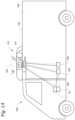
- FIG. 1 Aillustrates a side view of a van with a transport climate control system, according to one embodiment.
- FIG. 1 Billustrates a side view of a truck with a transport climate control system, according to one embodiment.
- FIG. 1 Cillustrates a perspective view of a climate controlled transport unit, with a transport climate control system, attached to a tractor, according to one embodiment.
- FIG. 1 Dillustrates a side view of a climate controlled transport unit with a multi-zone transport climate control system, according to one embodiment.
- FIG. 1 Eillustrates a perspective view of a mass transit vehicle including a transport climate control system, according to one embodiment.
- FIG. 2is a schematic illustration of an interface system between an accessory power distribution unit (PDU), power sources, a vehicle and an electrically powered accessory configured to be used with at least one of a vehicle, trailer, and a transport container, according to one embodiment.
- PDUaccessory power distribution unit
- FIG. 3 Ais a schematic illustration of an interface system between an electrical supply equipment, an accessory PDU, a vehicle, and an electrically powered accessory configured to be used with at least one of a vehicle, a trailer, and a transport container, according to a first embodiment.
- FIG. 3 Bis a schematic illustration of an interface system between an electrical supply equipment(s), an accessory PDU, a vehicle, and an electrically powered accessory configured to be used with at least one of a vehicle, a trailer, and a transport container, according to a second embodiment.
- FIGS. 4 A- 4 Care flow charts illustrating a method for interfacing between a VES of a vehicle and an electrically powered accessory that provides climate control within an internal space moved by the vehicle, according to one embodiment.
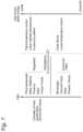
- FIG. 5is a chart illustrating different priority levels for negotiable tasks/operations/loads, according to one embodiment.
- This disclosurerelates generally to an electrically powered accessory configured to be used with at least one of a vehicle, trailer, and a transport container. More specifically, the disclosure relates to a two-way interface system for connecting a vehicle and an electrically powered accessory that provides climate control within an internal space moved by the vehicle.
- 16/565,252“DEMAND-SIDE POWER DISTRIBUTION MANAGEMENT FOR A PLURALITY OF TRANSPORT CLIMATE CONTROL SYSTEMS”; and U.S. application Ser. No. 16/565,282, “OPTIMIZED POWER CORD FOR TRANSFERRING POWER TO A TRANSPORT CLIMATE CONTROL SYSTEM”; all filed concurrently herewith on Sep. 9, 2019, and the contents of which are incorporated herein by reference.
- the electrically powered accessoryis not limited to the transport climate control system or a climate control unit (CCU) of the transport climate control system.
- a CCUcan be e.g., a transport refrigeration unit (TRU).
- the electrically powered accessorycan be, for example, a crane attached to a vehicle, a cement mixer attached to a truck, one or more food appliances of a food truck, a boom arm attached to a vehicle, a concrete pumping truck, a refuse truck, a fire truck (with a power driven ladder, pumps, lights, etc.), etc.
- the electrically powered accessorymay require continuous operation even when the vehicle's ignition is turned off and/or the vehicle is parked and/or idling and/or charging.
- the electrically powered accessorycan require substantial power to operate and/or continuous and/or autonomous operation (e.g., controlling temperature/humidity/airflow of a climate controlled space) on an as needed basis, independent of the vehicle's operational mode.
- the electrically powered accessorymay require continuous operation even when the vehicle's system enabling signal is turned off and/or the vehicle is in e.g., a park mode, a standby mode, and/or a charging mode.
- the system enabling signalis configured to enable the high voltage (HV) system of the VES. When the vehicle's system enabling signal is on, HV system of the VES is enabled.
- HVhigh voltage
- “low voltage”refers to Class A of the ISO 6469-3 in the automotive environment, in particular, a maximum working voltage of between 0V and 60V DC or between 0V and 30V AC.
- high voltagerefers to Class B of the ISO 6469-3 in the automotive environment, in particular, a maximum working voltage of between 60V and 1500V DC or between 30V and 1000V AC.
- the electrically powered accessorycan require substantial power to operate and/or continuous and/or autonomous operation (e.g., controlling temperature/humidity/airflow of a climate controlled space) on an as needed basis, independent of the vehicle's operational mode.
- the vehiclemay limit/disable power output to an ePTO or to auxiliary applications.
- an electrically powered accessorye.g., a climate control unit requiring substantial power to operate
- a load losse.g., produce, frozen foods, pharmaceuticals, etc. may not be safe or fresh
- running/operatinge.g., keeping the required temperature, humidity, airflow, etc.
- Embodiments disclosed hereincan help to address e.g., load loss issues.
- embodiments disclosed hereincan help to enable prioritizing the electrically powered accessory over the charging of the vehicle if the user so desires.
- Embodiments disclosed hereincan help e.g., to enable electrically powered accessory use in e.g., a bus, when charging the bus, and can help to give priority for running HVAC, onboard power sockets for vacuums, lights, etc. when cleaning the bus.
- FIG. 1 Adepicts a climate-controlled van 100 that includes a climate controlled space 105 for carrying cargo and a transport climate control system 110 for providing climate control within the climate controlled space 105 .
- the transport climate control system 110includes a climate control unit (CCU) 115 that is mounted to a rooftop 120 of the van 100 .
- the transport climate control system 110can include, amongst other components, a climate control circuit (not shown) that connects, for example, a compressor, a condenser, an evaporator and an expansion device to provide climate control within the climate controlled space 105 .
- climate-controlled vanscan apply to any type of transport unit (e.g., a truck, a container (such as a container on a flat car, an intermodal container, a marine container, etc.), a box car, a semi-tractor, a bus, or other similar transport unit), etc.
- transport unite.g., a truck, a container (such as a container on a flat car, an intermodal container, a marine container, etc.), a box car, a semi-tractor, a bus, or other similar transport unit), etc.
- the transport climate control system 110also includes a programmable climate controller 125 and one or more sensors (not shown) that are configured to measure one or more parameters of the transport climate control system 110 (e.g., an ambient temperature outside of the van 100 , an ambient humidity outside of the van 100 , a compressor suction pressure, a compressor discharge pressure, a supply air temperature of air supplied by the CCU 115 into the climate controlled space 105 , a return air temperature of air returned from the climate controlled space 105 back to the CCU 115 , a humidity within the climate controlled space 105 , etc.) and communicate parameter data to the climate controller 125 .
- the climate controller 125is configured to control operation of the transport climate control system 110 including the components of the climate control circuit.
- the climate controller unit 115may comprise a single integrated control unit 126 or may comprise a distributed network of climate controller elements 126 , 127 . The number of distributed control elements in a given network can depend upon the particular application of the principles described herein.
- the climate-controlled van 100can also include a vehicle PDU 101 , a VES 102 , a standard charging port 103 , and/or an enhanced charging port 104 (see FIGS. 3 A and 3 B for the detailed description about the standard charging port and the enhanced charging port).
- the VES 102can include a controller (not shown).
- the vehicle PDU 101can include a controller (not shown).
- the vehicle PDU controllercan be a part of the VES controller or vice versa.
- powercan be distributed from e.g., an EVSE (not shown), via the standard charging port 103 , to the vehicle PDU 101 .
- Powercan also be distributed from the vehicle PDU 101 to an electrical supply equipment (ESE, not shown) and/or to the CCU 115 (see solid lines for power lines and dotted lines for communication lines).
- ESEelectrical supply equipment
- powercan be distributed from e.g., an EVSE (not shown), via the enhanced charging port 104 , to an ESE (not shown) and/or to the CCU 115 .
- the ESEcan then distribute power to the vehicle PDU 101 via the standard charging port 103 . See FIGS. 2 , 3 A, and 3 B for a more detailed discussion of the ESE.
- FIG. 1 Bdepicts a climate-controlled straight truck 130 that includes a climate controlled space 131 for carrying cargo and a transport climate control system 132 .
- the transport climate control system 132includes a CCU 133 that is mounted to a front wall 134 of the climate controlled space 131 .
- the CCU 133can include, amongst other components, a climate control circuit (not shown) that connects, for example, a compressor, a condenser, an evaporator and an expansion device to provide climate control within the climate controlled space 131 .
- the transport climate control system 132also includes a programmable climate controller 135 and one or more sensors (not shown) that are configured to measure one or more parameters of the transport climate control system 132 (e.g., an ambient temperature outside of the truck 130 , an ambient humidity outside of the truck 130 , a compressor suction pressure, a compressor discharge pressure, a supply air temperature of air supplied by the CCU 133 into the climate controlled space 131 , a return air temperature of air returned from the climate controlled space 131 back to the CCU 133 , a humidity within the climate controlled space 131 , etc.) and communicate parameter data to the climate controller 135 .
- the climate controller 135is configured to control operation of the transport climate control system 132 including components of the climate control circuit.
- the climate controller 135may comprise a single integrated control unit 136 or may comprise a distributed network of climate controller elements 136 , 137 . The number of distributed control elements in a given network can depend upon the particular application of the principles described herein.
- the climate-controlled straight truck 130 of FIG. 1 Bcan also include a vehicle PDU (such as the vehicle PDU 101 shown in FIG. 1 A ), a VES (such as the VES 102 shown in FIG. 1 A ), a standard charging port (such as the standard charging port 103 shown in FIG. 1 A ), and/or an enhanced charging port (e.g., the enhanced charging port 104 shown in FIG. 1 A ), communicating with and distribute power from/to the corresponding ESE and/or the CCU 133 .
- a vehicle PDUsuch as the vehicle PDU 101 shown in FIG. 1 A
- VESsuch as the VES 102 shown in FIG. 1 A
- a standard charging portsuch as the standard charging port 103 shown in FIG. 1 A
- an enhanced charging porte.g., the enhanced charging port 104 shown in FIG. 1 A
- FIG. 1 Cillustrates one embodiment of a climate controlled transport unit 140 attached to a tractor 142 .
- the climate controlled transport unit 140includes a transport climate control system 145 for a transport unit 150 .
- the tractor 142is attached to and is configured to tow the transport unit 150 .
- the transport unit 150 shown in FIG. 1 Cis a trailer.
- the transport climate control system 145includes a CCU 152 that provides environmental control (e.g. temperature, humidity, air quality, etc.) within a climate controlled space 154 of the transport unit 150 .
- the CCU 152is disposed on a front wall 157 of the transport unit 150 . In other embodiments, it will be appreciated that the CCU 152 can be disposed, for example, on a rooftop or another wall of the transport unit 150 .
- the CCU 152includes a climate control circuit (not shown) that connects, for example, a compressor, a condenser, an evaporator and an expansion device to provide conditioned air within the climate controlled space 154 .
- the transport climate control system 145also includes a programmable climate controller 156 and one or more sensors (not shown) that are configured to measure one or more parameters of the transport climate control system 145 (e.g., an ambient temperature outside of the transport unit 150 , an ambient humidity outside of the transport unit 150 , a compressor suction pressure, a compressor discharge pressure, a supply air temperature of air supplied by the CCU 152 into the climate controlled space 154 , a return air temperature of air returned from the climate controlled space 154 back to the CCU 152 , a humidity within the climate controlled space 154 , etc.) and communicate parameter data to the climate controller 156 .
- the climate controller 156is configured to control operation of the transport climate control system 145 including components of the climate control circuit.
- the climate controller 156may comprise a single integrated control unit 158 or may comprise a distributed network of climate controller elements 158 , 159 . The number of distributed control elements in a given network can depend upon the particular application of the principles described herein.
- the tractor 142can include an optional APU 108 .
- the optional APU 108can be an electric auxiliary power unit (eAPU).
- the tractor 142can also include a vehicle PDU 101 and a VES 102 (not shown).
- the APU 108can provide power to the vehicle PDU 101 for distribution. It will be appreciated that for the connections, solid lines represent power lines and dotted lines represent communication lines.
- the climate controlled transport unit 140can include a PDU 121 connecting to power sources (including, for example, an optional solar power source 109 ; an optional power source 122 such as Genset, fuel cell, undermount power unit, auxiliary battery pack, etc.; and/or an optional liftgate battery 107 , etc.) of the climate controlled transport unit 140 .
- the PDU 121can include a PDU controller (not shown).
- the PDU controllercan be a part of the climate controller 156 .
- the PDU 121can distribute power from the power sources of the climate controlled transport unit 140 to e.g., the transport climate control system 145 .
- the climate controlled transport unit 140can also include an optional liftgate 106 .
- the optional liftgate battery 107can provide power to open and/or close the liftgate 106 .
- the climate controlled transport unit 140 attached to the tractor 142 of FIG. 1 Ccan also include a VES (such as the VES 102 shown in FIG. 1 A ), a standard charging port (such as the standard charging port 103 shown in FIG. 1 A ), and/or an enhanced charging port (such as the enhanced charging port 104 shown in FIG. 1 A ), communicating with and distribute power from/to a corresponding ESE and/or the CCU 152 .
- the charging port(s) 103 and/orcan be on either the tractor 142 or the trailer.
- the standard charging port 103is on the tractor 142 and the enhanced charging port 104 is on the trailer.
- FIG. 1 Dillustrates another embodiment of a climate controlled transport unit 160 .
- the climate controlled transport unit 160includes a multi-zone transport climate control system (MTCS) 162 for a transport unit 164 that can be towed, for example, by a tractor (not shown).
- MTCSmulti-zone transport climate control system
- the MTCS 162includes a CCU 166 and a plurality of remote units 168 that provide environmental control (e.g. temperature, humidity, air quality, etc.) within a climate controlled space 170 of the transport unit 164 .
- the climate controlled space 170can be divided into a plurality of zones 172 .
- the term “zone”means a part of an area of the climate controlled space 170 separated by walls 174 .
- the CCU 166can operate as a host unit and provide climate control within a first zone 172 a of the climate controlled space 166 .
- the remote unit 168 acan provide climate control within a second zone 172 b of the climate controlled space 170 .
- the remote unit 168 bcan provide climate control within a third zone 172 c of the climate controlled space 170 . Accordingly, the MTCS 162 can be used to separately and independently control environmental condition(s) within each of the multiple zones 172 of the climate controlled space 162 .
- the CCU 166is disposed on a front wall 167 of the transport unit 160 . In other embodiments, it will be appreciated that the CCU 166 can be disposed, for example, on a rooftop or another wall of the transport unit 160 .
- the CCU 166includes a climate control circuit (not shown) that connects, for example, a compressor, a condenser, an evaporator and an expansion device to provide conditioned air within the climate controlled space 170 .
- the remote unit 168 ais disposed on a ceiling 179 within the second zone 172 b and the remote unit 168 b is disposed on the ceiling 179 within the third zone 172 c .
- Each of the remote units 168 a,binclude an evaporator (not shown) that connects to the rest of the climate control circuit provided in the CCU 166 .
- the MTCS 162also includes a programmable climate controller 180 and one or more sensors (not shown) that are configured to measure one or more parameters of the MTCS 162 (e.g., an ambient temperature outside of the transport unit 164 , an ambient humidity outside of the transport unit 164 , a compressor suction pressure, a compressor discharge pressure, supply air temperatures of air supplied by the CCU 166 and the remote units 168 into each of the zones 172 , return air temperatures of air returned from each of the zones 172 back to the respective CCU 166 or remote unit 168 a or 168 b , a humidity within each of the zones 118 , etc.) and communicate parameter data to a climate controller 180 .
- a climate controller 180e.g., a climate controller 180 .
- the climate controller 180is configured to control operation of the MTCS 162 including components of the climate control circuit.
- the climate controller 180may comprise a single integrated control unit 181 or may comprise a distributed network of climate controller elements 181 , 182 .
- the number of distributed control elements in a given networkcan depend upon the particular application of the principles described herein.
- the climate controlled transport unit 160 of FIG. 1 Dcan also include a vehicle PDU (such as the vehicle PDU 101 shown in FIG. 1 A ), a VES (such as the VES 102 shown in FIG. 1 A ), a standard charging port (such as the standard charging port 103 shown in FIG. 1 A ), and/or an enhanced charging port (e.g., the enhanced charging port 104 shown in FIG. 1 A ), communicating with and distribute power from/to the corresponding ESE and/or the CCU 166 .
- a vehicle PDUsuch as the vehicle PDU 101 shown in FIG. 1 A
- VESsuch as the VES 102 shown in FIG. 1 A
- a standard charging portsuch as the standard charging port 103 shown in FIG. 1 A
- an enhanced charging porte.g., the enhanced charging port 104 shown in FIG. 1 A
- FIG. 1 Eis a perspective view of a vehicle 185 including a transport climate control system 187 , according to one embodiment.
- the vehicle 185is a mass-transit bus that can carry passenger(s) (not shown) to one or more destinations. In other embodiments, the vehicle 185 can be a school bus, railway vehicle, subway car, or other commercial vehicle that carries passengers.
- the vehicle 185includes a climate controlled space (e.g., passenger compartment) 189 supported that can accommodate a plurality of passengers.
- the vehicle 185includes doors 190 that are positioned on a side of the vehicle 185 . In the embodiment shown in FIG.
- a first door 190is located adjacent to a forward end of the vehicle 185 , and a second door 190 is positioned towards a rearward end of the vehicle 185 .
- Each door 190is movable between an open position and a closed position to selectively allow access to the climate controlled space 189 .
- the transport climate control system 187includes a CCU 192 attached to a roof 194 of the vehicle 185 .
- the CCU 192includes a climate control circuit (not shown) that connects, for example, a compressor, a condenser, an evaporator and an expansion device to provide conditioned air within the climate controlled space 189 .
- the transport climate control system 187also includes a programmable climate controller 195 and one or more sensors (not shown) that are configured to measure one or more parameters of the transport climate control system 187 (e.g., an ambient temperature outside of the vehicle 185 , a space temperature within the climate controlled space 189 , an ambient humidity outside of the vehicle 185 , a space humidity within the climate controlled space 189 , etc.) and communicate parameter data to the climate controller 195 .
- parameters of the transport climate control system 187e.g., an ambient temperature outside of the vehicle 185 , a space temperature within the climate controlled space 189 , an ambient humidity outside of the vehicle 185 , a space humidity within the climate controlled space 189 , etc.
- the climate controller 195is configured to control operation of the transport climate control system 187 including components of the climate control circuit.
- the climate controller 195may comprise a single integrated control unit 196 or may comprise a distributed network of climate controller elements 196 , 197 .
- the number of distributed control elements in a given networkcan depend upon the particular application of the principles described herein.
- the vehicle 185 including a transport climate control system 187 of FIG. 1 Ecan also include a vehicle PDU (such as the vehicle PDU 101 shown in FIG. 1 A ), a VES (such as the VES 102 shown in FIG. 1 A ), a standard charging port (such as the standard charging port 103 shown in FIG. 1 A ), and/or an enhanced charging port (e.g., the enhanced charging port 104 shown in FIG. 1 A ), communicating with and distribute power from/to the corresponding ESE and/or the CCU 192 .
- a vehicle PDUsuch as the vehicle PDU 101 shown in FIG. 1 A
- VESsuch as the VES 102 shown in FIG. 1 A
- a standard charging portsuch as the standard charging port 103 shown in FIG. 1 A
- an enhanced charging porte.g., the enhanced charging port 104 shown in FIG. 1 A
- FIG. 2is a schematic illustration of an interface system 200 between an accessory power distribution unit (PDU), power sources, a vehicle and an electrically powered accessory configured to be used with at least one of a vehicle, trailer, and a transport container, according to one embodiment.
- PDUaccessory power distribution unit
- the power sources described in FIG. 2can be connected to and/or communicated with the electrically powered accessory without the accessory PDU.
- a PDUcan be a component (e.g., a relay and/or a contactor, etc.) that can be configured to control and/or distribute power flow.
- the interface system 200includes an accessory PDU 210 .
- the accessory PDU 210includes a controller 215 .
- the accessory PDU 210can connect to and/or communicate with an electrical supply equipment (ESE) 220 .
- ESE 220can be an EVSE, an EV charging station, a vehicle charger system, etc.
- the accessory PDU 210can also connect to and/or communicate with a vehicle 230 and/or an electrically powered accessory 240 configured to be used with at least one of the vehicle 230 , a trailer, and a transport container.
- the accessory PDU 210can enable fault monitoring and system protection, which can be used for protecting the interface system 200 and can enable analytics and features which allow for the electrically powered accessory 240 use to not void a manufacturer warranty of the vehicle 230 .
- the accessory PDU 210can control the ESE 220 (or other power sources such as the utility power, etc.) to distribute electrical power received from the ESE 220 (or other power sources such as the utility power, etc.) to a vehicle 230 through a standard charging port, to the electrically powered accessory 240 , and/or to the accessory RESS (Rechargeable Energy Storage System) 241 .
- the accessory PDU 210can also control power sources (including power from ePTO, utility power, a second ESE, etc.) to distribute electrical power received from the power sources to the electrically powered accessory 240 , and/or to the accessory RESS 241 .
- the ESE 220includes an off-board charger 225 .
- the off-board charger 225can be a direct current (DC) charger for fast charging.
- DCdirect current
- the vehicle 230includes a vehicle electrical system having an on-board charger 231 and a RESS 232 . See, for example, U.S. Pat. No. 8,441,228 (which is incorporated by reference in its entirety) for a description of a vehicle electrical system.
- the vehicle electrical systemcan provide electrical power to the electrical loads of the vehicle, and/or to charge or discharge the energy storage of the vehicle.
- the vehicle 230can be, for example, the climate-controlled van 100 , the climate-controlled straight truck 130 , the tractor 142 with a climate controlled transport unit 140 attached to, the climate controlled transport unit 160 , and/or the vehicle 185 of FIGS. 1 A- 1 E and/or a recreational vehicle (RV).
- the vehicle electrical systemalso includes a power distribution unit (PDU) 235 .
- the PDU 235can include a controller (not shown) configured to distribute electric power of the vehicle electrical system to loads of the vehicle electrical system.
- Electrical loads (to be powered) of the interface system 200can include low voltage (LV) DC loads such as solenoids, fans, compressor motors, controllers, battery chargers, etc. Electrical loads (to be powered) of the interface system 200 can also include high voltage (HV) DC loads such as fan motor, compressor motor, battery chargers, batteries, etc. Electrical loads (to be powered) of the interface system 200 can further include HV AC loads such as fan motor, compressor motor, battery chargers, On-Board Charger (OBC, which can be used as an accessory inverter such as a bi-directional inverter, etc.), AC Power Module (ACPM), etc.
- LVlow voltage
- HVhigh voltage
- HV AC loadssuch as fan motor, compressor motor, battery chargers
- OBCOn-Board Charger
- ACPMAC Power Module
- Electrical loads (to be powered) of the interface system 200can include motors having power converters which can include DC/DC converters and/or motor control inverters.
- ACPMcan be a power converter used to take input of single-phase or three-phase AC power and create a DC power to feed the DC link.
- the ACPMcan be contained within the electrically powered accessory 240 or the accessory PDU 210 .
- ACPMcan also be a vehicle OBC for charging the vehicle RESS 232 .
- the electrically powered accessory 240can include an accessory RESS 241 .
- the electrically powered accessory 240can be, for example, the transport climate control system 110 , 132 , 145 , 162 , and/or 187 of FIGS. 1 A- 1 E .
- the accessory RESS 241can provide power to operate the electrically powered accessory 240 .
- the electrically powered accessory 240can include HV and/or LV loads including AC (single-phase and/or three-phase) and/or DC loads.
- AC power from the ESE 220can be converted to DC voltage via the accessory PDU 210 , and then converted to AC voltage via the accessory PDU 210 to supply power to e.g., a three-phase AC driven CCU.
- the accessory PDU 210can also connect to and/or communicate with a power source 250 , a utility power source 260 , a marine and/or ferry power source 270 , a power source 280 , and/or an auxiliary RESS 243 .
- the power source 250can be a solar power source, an auxiliary energy source (e.g., battery pack), an electric APU auxiliary energy storage, a fuel cell power source, and/or a liftgate energy storage, etc.
- the power source 250can connect to a converter 251 , which in turn can connect to the accessory PDU 210 . It will be appreciated that the converter 251 can be a part of the accessory PDU 210 .
- the converter 251can be a bidirectional power converter.
- the converter 251can be a DC to DC boost or buck converter. In some embodiments, the converter 251 can also be a DC to AC inverter.
- the utility power source 260can provide single-phase alternating current (AC) and/or three-phase AC power.
- the marine and/or ferry power source 270can, for e.g., convert energy carried by ocean waves, tides, salinity, and/or ocean temperature differences to generate electrical power.
- the power source 280can be a generator set (Genset) power source.
- the power source 280can also be a CCU power source engine (e.g., engine with electric generator and/or inverter and/or converter).
- the power source 280can further be a micro-turbine with generator to provide electrical power.
- the power source 280can be a combination of e.g., an electrical generator and an engine mounted together to form a single piece of equipment that produces electrical power.
- the auxiliary RESS 243can be an electric auxiliary power unit (eAPU).
- the electrical power supplied from the marine and/or ferry power source 270 , the power source 280 , and/or the auxiliary RESS 243can be AC and/or DC power.
- the power source 280can connect to an AC to DC converter (not shown) before connecting to the accessory PDU 210 .
- the AC to DC convertercan be a rectifier.
- the AC to DC convertercan be an ACPM active rectifier, with boost power factor correction/controller (PFC).
- the AC to DC convertercan be bidirectional.
- FIG. 2shows power lines (solid lines) between/among the components and communication lines (dotted lines) between controller 215 and the components (e.g., controllers of the components). It will be appreciated that the communication(s) between/among the components of FIG. 2 can be accomplished wirelessly or through wire connection(s), through any suitable communication media and/or using any suitable communication protocol(s).
- energycan be a finite resource, especially the energy available in the RESS.
- an ESEsuch as an EVSE
- optimizing the power in the systeme.g., optimizing discharging or charging, optimizing operations of various components
- available energycan be forecasted/predicted/estimated, even when the TCCS/VES is connected to ESE.
- the ESE supplyhas a limited power given by the ESE equipment, and the charging duration can be forecasted based on the anticipated charging time.
- the anticipated charging timecan be based on e.g., route data or determined by the user (e.g., driver, operator) by specifying a predetermined time/duration for charging.
- Available energy (e.g., for the TCCS and/or VES) from the ESEcan be based on how much supply power from the ESE over time. Charging can help in the optimization of energy since energy is added to the system.
- the accessorycan dominate over vehicle charging (e.g., ESE provides power to the accessory, which has a higher priority level than charging the vehicle).
- ESEprovides power to the accessory, which has a higher priority level than charging the vehicle.
- the priority level for the power to be supplied to the accessorycan be decreased to allow the vehicle to charge better.
- the ESE 220can be configured to supply electrical power (or energy) for powering and/or charging the vehicle 230 (e.g., the vehicle electrical system of the vehicle 230 ) and/or the electrically powered accessory 240 , e.g. through the accessory PDU 210 , via connectors (e.g., charging port, not shown).
- the electric power supplied from the ESE 220 (and/or other power sources)can include alternating current (AC) and/or direct current (DC) power.
- the AC powercan be single-phase AC or three phase AC power.
- the DC powercan be Low Voltage (LV) DC power (e.g., Class A) and/or High Voltage (HV) DC power (e.g., Class B).
- LVLow Voltage
- HVHigh Voltage
- the connectorscan be any suitable connectors that support e.g., Combined Charging System (CCS, guided by e.g., CharIN), CHAdeMO, Guobiao recommended-standard 20234, Tesla Supercharger, and/or other EVSE standards.
- CCSCombined Charging System
- CHAdeMOCHAdeMO
- Guobiao recommended-standard 20234Guobiao recommended-standard 20234
- Tesla Superchargere.g., EVSE 220
- Embodiments disclosed hereincan enable supplying both the AC power and the DC power for fast charging from the ESE 220 , via e.g., the accessory PDU 210 , to e.g., supply power to the vehicle 230 and/or charge the vehicle RESS 232 with the DC power and to operate the electrically powered accessory 240 with AC power.
- controller 215 of the accessory PDU 210can be a part of the controller of the electrical accessory 240 .
- the controller 215can communicate with the vehicle 230 , the vehicle RESS 232 , the OBC 231 , the accessory RESS 241 , the auxiliary RESS 243 , intelligent power sources 280 such as a Genset, and/or the converter 251 .
- the controller 215is configured to manage power inputs from e.g., the ESE 220 and/or other power sources such as a utility power source, etc., and to prioritize and control power flows to the vehicle 230 and/or the electrically powered accessory 240 , etc.
- the controller 215can communicate with the ESE 220 using e.g., powerline communications, Pulse Width Modulation (PWM) communications, Local Interconnect Network (LIN) communications, Controller Area Network (CAN) communications, and/or Pilot signal analog feedback, etc. to support e.g., CCS, CHAdeMO, Guobiao recommended-standard 20234, Tesla Supercharger, and/or other EVSE standards.
- PWMPulse Width Modulation
- LINLocal Interconnect Network
- CANController Area Network
- Pilot signal analog feedbacketc.
- the communications between the controller 215 and the ESE 220include e.g., a Control Pilot (CP) line and a Proximity Pilot (PP) line.
- the PP lineis also known as Plug Present for determining status and capability of the charging port.
- the CP linecan be used e.g., by the controller 215 to indicate e.g., the charging level(s) of e.g., the vehicle 230 and/or the electrically powered accessory 240 , to initiate charging, and/or to communicate other information to the ESE 220 .
- the ESE 220can use the CP line to detect e.g., the presence of the vehicle 230 and/or the electrically powered accessory 240 e.g.
- the accessory PDU 210to communicate e.g., the maximum and/or minimum allowable charging current and/or voltage to the controller 215 , and/or to control e.g., the charging current and/or voltage, and/or to control the beginning and/or ending of charging.
- the PWM duty cyclecan set the current limit for power delivery.
- the PP linecan be used to prevent movement of the vehicle 230 and/or the electrically powered accessory 240 and to indicate e.g., the latch release button to the vehicle 230 and/or the electrically powered accessory 240 , e.g. via the accessory PDU 210 .
- the interface system 200can include a user interface device (not shown).
- the user interface devicecan be a mobile device (e.g., phone, computer, etc.) or a server.
- the user interface devicecan connect to and/or communicate with the ESE 220 and the accessory PDU 210 . It will be appreciated that the communications from the ESE 220 to the accessory PDU 210 can be sent to the user interface device.
- a usercan review the information from the ESE 220 and send request(s) and/or confirmation(s) to the ESE 220 and/or the controller 215 , to make adjustment(s) and/or request(s) accordingly, via the user interface device.
- the user interface devicecan be used to view charging rate (of the electric power), perform payment authorization, etc., and/or can track how much electrical power goes to the vehicle 230 and/or to the electrically powered accessory 240 , and/or split payment billing, etc.
- the controller 215can communicate with a controller (not shown, e.g., the controller 125 , 135 , 156 , 180 , and/or 195 of FIGS. 1 A- 1 E ) of the electrically powered accessory 240 .
- the controller 215can be integrated with the controller (e.g., the controller 125 , 135 , 156 , 180 , and/or 195 of FIGS. 1 A- 1 E ) of the electrically powered accessory 240 .
- the electrically powered accessory 240can include sensors (e.g., temperature, pressure, voltage, current, battery status, and/or battery charging level sensor, etc.).
- the electrically powered accessory 240can communicate the status (e.g., status of the sensors and/or charge status) to the controller 215 .
- the controller 215can include sensors (e.g., temperature, pressure, voltage, current, battery status, and/or battery charging level sensor, etc.).
- the controller 215can communicate and request the status (e.g., status of the sensors and/or charge status) to the electrically powered accessory 240 .
- the controller 215can e.g., control the accessory PDU 210 to distribute power (AC and/or DC) received from the ESE 220 (and/or other power sources) to the electrically powered accessory 240 .
- the controller 215can communicate with a PDU 235 of the vehicle 230 .
- the PDU 235can include a controller (not shown).
- the vehicle 230can include sensors (e.g., temperature, location, pressure, voltage, current, battery status, and/or battery charging level sensor, etc.).
- the sensorscan sense e.g., an ambient temperature, a temperature of a user's (e.g., a driver's) space/seat, a temperature of the vehicle RESS 232 , a location of the vehicle, an ambient pressure, voltage/current of a VES circuit, a charging level of the vehicle RESS, etc.
- the vehicle 230can communicate the status (e.g., status of the sensors and/or charge status) to the controller 215 .
- the controller 215can include sensors (e.g., temperature, location, pressure, voltage, current, battery status, and/or battery charging level sensor, etc.).
- the sensorscan sense e.g., an ambient temperature, a temperature of a climate controlled space of the electrically powered accessory, a temperature of the accessory RESS, a location of the electrically powered accessory, an ambient pressure, discharge/suction pressure of a compressor of the electrically powered accessory, voltage/current of an electrically powered accessory circuit, a charging level of the accessory RESS, etc.
- the controller 215can communicate the status (e.g., status of the sensors and/or charge status) to the vehicle 230 .
- the controller 215can communicate messages to the vehicle 230 for the vehicle 230 to operate in a proper system operational mode. The status can be modified. For example, when the vehicle 230 is fully charged and ready to drive, but the controller 215 determines that the electrical accessory 240 still requires attention, the controller 215 can prevent the vehicle 230 from disconnecting and driving away. If the vehicle 230 indicates that electric power is needed to charge the vehicle 230 , the controller 215 can control the accessory PDU 210 to distribute power (AC and/or DC) received from the ESE 220 (and/or other power sources) to the vehicle 230 to provide power to the on-board charger 231 and/or to charge the RESS 232 .
- powerAC and/or DC
- the controller 215can communicate the information received from the ESE 220 (and/or other power sources) to the vehicle 230 (e.g., the PDU 235 ).
- the vehicle 230can initiate/request charging from the ESE 220 , e.g., via the controller 215 and the CP line.
- the controller 215can obtain sensed data (via the sensors) for the power inputs, monitor power usage, and communicate with all energy sources to balance power (e.g., to balance charging level between vehicle RESS and accessory RESS, etc.).
- the controller 215can have telematics capability. Data can be shared over telematics to coordinate and perform data analytics on the power usage of the systems (and/or enable a priority mode to supply power to power demands with a higher priority level).
- the controller 215can drive the door interlock (to prevent the vehicle and/or the electrically powered accessory from moving, for example, when the door is open), status lights for charging, and/or the lock on the connector.
- power demand/request from the electrically powered accessory 240can have a higher priority level (e.g., the cargo is regulated by government bodies or of high economic value) than power demand/request from the vehicle 230 (e.g., for charging the vehicle 230 ). See FIG. 5 for examples of different priority levels.
- the electrical accessorycan obtain energy from a source such as the vehicle and/or the accessory auxiliary RESS.
- the controller 215can control the accessory PDU 210 to distribute power (AC and/or DC) received from the ESE 220 (and/or other power sources) to the electrically powered accessory 240 first, and then to the vehicle 230 if the higher priority power demand from the electrically powered accessory 240 is satisfied.
- powerAC and/or DC
- satisfying the higher priority power demand (e.g., for high value cargo) from the electrically powered accessory 240may cause the vehicle to be operate in a “reduced operation mode” (e.g., a “limp home” mode where the vehicle is commanded to reduce maximum speed) when e.g., the total energy available is not sufficient to satisfy both the higher priority power demand from the electrically powered accessory 240 and the power demand from the vehicle (e.g., for driving at a full/maximum speed).
- lowering/reducing the amount of power over timee.g., in the “reduced operation mode” can help to optimize the usage of the finite energy source.
- power demand/request from the vehicle 230can have a higher priority level than power demand/request from the power demand/request from the electrically powered accessory 240 .
- the controller 215can control the accessory PDU 210 to distribute power (AC and/or DC) received from the ESE 220 (and/or other power sources) to the vehicle 230 first, and then to the electrically powered accessory 240 if the higher priority power demand from the vehicle 230 is satisfied.
- the controller 215can control the accessory PDU 210 to distribute power (AC and/or DC) received from the ESE 220 (and/or other power sources) to the vehicle 230 and to the electrically powered accessory 240 simultaneously (e.g., AC power (or one power input) to the electrically powered accessory 240 and DC power (or another power input) to the vehicle 230 , or vice versa, if one type of power (AC or DC) and/or one power input (e.g., ESE, utility power, etc.) is sufficient to satisfy the higher priority power demand).
- the priority level of the power demandcan be predetermined or determined by a user and communicated to the controller 215 .
- the priority levelcan be overridden by e.g., feedback from a human machine interface (HMI) to force certain operational modes.
- HMIhuman machine interface
- the controller 215can communicate with the converter 251 to exchange operational information regarding e.g., power performance, for example, voltages and/or currents and/or operational levels such as the speed setpoint of the compressor converter drive.
- operational informatione.g., power performance, for example, voltages and/or currents and/or operational levels such as the speed setpoint of the compressor converter drive.
- the controller 215can communicate with the power source 280 (e.g., Genset) to communicate power performance and operation, for example, the maximum power capability of the Genset (which can change depending on operational area, such as operational speed limitations in particular areas) and/or power supplied including voltage, current, and/or frequency.
- the controller 215can command the Genset on and the power level the Genset can operate at.
- the controller 215can communicate with the Auxiliary RESS 243 to communicate power capability (e.g., available voltage and/or current), state/status of charge, and/or priority level of charging the Auxiliary RESS 243 .
- power capabilitye.g., available voltage and/or current
- state/status of charge of the Auxiliary RESS 243can be used by the controller 215 to prevent overcharge (e.g., to run TRU if needed since overcharging can cause damages, and if necessary the Auxiliary RESS 243 can be used to cross charge the vehicle to prevent possible battery damages) and/or prevent undercharge of the Auxiliary RESS 243 .
- the communicationcan be conducted via e.g., powerline communications, Pulse Width Modulation (PWM) communications, Local Interconnect Network (LIN) communications, Controller Area Network (CAN) communications, and/or any other suitable communications.
- PWMPulse Width Modulation
- LINLocal Interconnect Network
- CANController Area Network
- FIG. 3 Ais a schematic illustration of an interface system 300 between an electrical supply equipment, an accessory PDU 310 , a vehicle, and an electrically powered accessory 340 configured to be used with at least one of a vehicle, a trailer, and a transport container, according to a first embodiment.
- FIG. 3 Bis a schematic illustration of an interface system 301 between electrical supply equipment(s) 320 , 395 , an accessory PDU 310 , a vehicle, and an electrically powered accessory 340 configured to be used with at least one of a vehicle, a trailer, and a transport container, according to a second embodiment.
- the interface systems 300 and 301can be between the vehicle and the electrical accessory without the accessory PDU.
- the accessory PDU 310can connect to and/or communicate with an ESE (not shown), through an enhanced charging port 311 .
- the enhanced charging port 311can be any suitable charging port in compliance with one or more of the CCS, CHAdeMO, Guobiao recommended-standard 20234, Tesla Supercharger, and/or other EVSE standards, with portions or all of the communication/control pins and/or AC and/or DC power supply pins (from one of more of the different EVSE standards) populated/enabled.
- the accessory PDU 310can be e.g., the accessory PDU 210 of FIG. 2 .
- the ESEcan be the ESE 220 of FIG. 2 .
- the accessory PDU 310can connect to and/or communicate with an AC power source 312 .
- the AC power source 312can be the power source 250 , the utility power source 260 , the marine and/or ferry power source 270 , the power source 280 , and/or the auxiliary RESS 243 of FIG. 2 or any other suitable power source.
- the accessory PDU 310can control the ESE to distribute electrical power received from the ESE to a vehicle (not shown, e.g., the vehicle 230 of FIG. 2 ) through a standard charging port 313 , to the electrically powered accessory 340 , and/or to the accessory RESS 341 .
- the standard charging port 313can be any suitable charging port in compliance with CCS, CHAdeMO, Guobiao recommended-standard 20234, Tesla Supercharger, and/or other EVSE standards.
- the electrically powered accessory 340can be the electrically powered accessory 240 of FIG. 2 .
- the accessory RESS 341can be the accessory RESS 241 of FIG. 2 .
- the accessory PDU 310can also control the AC power source 312 to distribute electrical power received from the AC power source 312 to the vehicle through the standard charging port 313 , to the electrically powered accessory 340 , and/or to the accessory RESS 341 .
- the accessory RESS 341can be controlled (e.g., by the controller of the accessory PDU 310 ) to supply electrical power to the electrically powered accessory 340 .
- the ESEcan be configured to lock and monitor (e.g., prevent movement of) the vehicle and/or the electrically powered accessory 340 via the accessory PDU 310 through e.g., the PP line of the enhanced charging port 311 .
- the accessory PDU 310can monitor the maximum and/or minimum allowable charging current and/or voltage from the ESE and/or the AC power source 312 , to distribute power from the ESE and/or the AC power source 312 to the vehicle, the electrically powered accessory 340 , and/or the accessory RESS 341 , based on the priority level of the power demand/request from the vehicle (and/or from a user), the electrically powered accessory 340 , and/or the accessory RESS 341 .
- the accessory PDU 310can include a parameter that sets the maximum allowable charging current.
- the electrically powered accessory 340(when having a higher priority power demand) can obtain power supply from e.g., the accessory PDU 310 when the vehicle is using power sources for operation (e.g., charging, driving, etc.).
- the controller of the accessory PDU 310can be the main/master controller (for the ESE 320 ) of the interface system 300 .
- FIG. 3 Ait is the accessory PDU 310 that controls the ESE to distribute power to the vehicle and/or to the electrically powered accessory 340 , based on e.g., a priority level of the power demand from the vehicle and/or a priority level of the power demand from the electrically powered accessory 340 .
- FIG. 3 Bit is the vehicle (e.g., PDU of the vehicle) that controls the ESE to charge the vehicle and/or to distribute power to the electrically powered accessory via e.g., ePTO.
- the vehiclenot shown, e.g., the vehicle 230 of FIG.
- the ESE 320can be the ESE 220 of FIG. 2 .
- the vehicle PDU 335can be the vehicle PDU 235 of FIG. 2 .
- the ESE 320can be configured to supply electrical power (or energy) for charging the vehicle (e.g., a vehicle electrical system of the vehicle) via the standard charging port 313 .
- the electric power supplied from the ESE 320can include alternating current (AC) and/or direct current (DC) power.
- the AC powercan be single-phase AC or three phase AC power.
- the DC powercan be Low Voltage (LV) DC power (e.g., Class A) and/or High Voltage (HV) DC power (e.g., Class B).
- LVLow Voltage
- HVHigh Voltage
- the PDU 335can communicate with the ESE 320 using e.g., powerline communications, Pulse Width Modulation (PWM) communications, Local Interconnect Network (LIN) communications, Controller Area Network (CAN) communications, and/or Pilot signal analog feedback, etc. to support e.g., CCS, CHAdeMO, Guobiao recommended-standard 20234, Tesla Supercharger, and/or other EVSE standards.
- PWMPulse Width Modulation
- LINLocal Interconnect Network
- CANController Area Network
- Pilot signal analog feedbacketc.
- the communications between the PDU 335 and the ESE 320include e.g., a CP line and a PP line.
- the CP linecan be used e.g., by the PDU 335 to indicate e.g., the charging level(s) of e.g., the vehicle, to initiate charging, and/or to communicate other information to the ESE 320 .
- the ESE 320can use the CP line to detect e.g., the presence of the vehicle, to communicate e.g., the maximum and/or minimum allowable charging current and/or voltage to the PDU 335 , and/or to control e.g., the charging current and/or voltage, and/or to control the beginning and/or ending of charging.
- the PP linecan be used (e.g., between the ESE 320 and a vehicle controller) to prevent movement of the vehicle and to indicate e.g., the latch release button to the vehicle.
- the vehicle PDU 335can communicate with a controller (not shown, e.g., the controller 215 of FIG. 2 ) of the accessory PDU 310 .
- the controller of the accessory PDU 310can determine the status (e.g., status of the sensors (e.g., temperature, location, pressure, voltage, current, battery status, and/or battery charging level sensor, etc.) and/or charge status) of the electrically powered accessory 340 and/or the accessory RESS 341 .
- the sensorscan sense e.g., an ambient temperature outside the vehicle, a temperature of a climate controlled space of the electrically powered accessory, a temperature of the accessory RESS, a location of the electrically powered accessory, an ambient pressure outside the vehicle, discharge/suction pressure of a compressor of the electrically powered accessory, voltage/current of an electrically powered accessory circuit, a charging level of the accessory RESS, etc.
- power demand/request from the electrically powered accessory 340 and/or the accessory RESS 341can have a higher priority level than the power demand/request from the vehicle (e.g., for charging the vehicle).
- controller of the accessory PDU 310can request an electric power take-off (ePTO) to be enabled by the vehicle PDU 335 , based on the priority level of the power demand/request from the electrically powered accessory 340 and/or the accessory RESS 341 (e.g., when such priority level is higher than the priority level of the power demand from the vehicle).
- ePTOelectric power take-off
- ePTOcan be defined as e.g., taking electrical power from a power source and transmitting the electrical power to an application such as an attached implement or separate machines, via electric mechanisms.
- the electrically powered accessory 340 and/or the accessory RESS 341can have a lower priority level than the power demand/request from the vehicle (e.g., for charging the vehicle).
- the priority level between the electrically powered accessory 340 and/or the accessory RESS 341 at one end and the power demand/request from the vehicle at the other endcan vary based on a variety of factors including, for example, cargo being stored.
- the controller of the PDU 335can be the main/master controller (for the ESE 320 ) of the interface system 301 . If ePTO is enabled, when for e.g., the vehicle is charging by the ESE 320 via the standard charging port 313 , the power (a portion or all) from the ESE 320 can be taken and transmitted to the electrically powered accessory 340 and/or the accessory RESS 341 , via the accessory PDU 310 .
- the ePTOcan be disabled by the PDU 335 if there is no power demand/request from the electrically powered accessory 340 and/or the accessory RESS 341 , and/or the priority level of the power demand/request from the electrically powered accessory 340 and/or the accessory RESS 341 is not higher than the priority level of the power demand from the vehicle.
- the accessory PDU 310can connect to and/or communicate with an AC power source 360 .
- the AC power source 360can be the power source 250 , the utility power source 260 , the marine and/or ferry power source 270 , the power source 280 , and/or the auxiliary RESS 243 of FIG. 2 or any other suitable power source.
- the accessory PDU 310can connect to and/or communicate with another ESE 395 .
- the ESE 395can be the ESE 220 of FIG. 2 .
- the accessory PDU 310can control the ESE 395 and/or the AC power source 360 to distribute electrical power received from the ESE 395 and/or the AC power source 312 to the electrically powered accessory 340 and/or to the accessory RESS 341 .
- the accessory PDU 310can also control the electrically powered accessory 340 to distribute electrical power to the accessory RESS 341 (e.g., charging the accessory RESS 341 ), and/or control the accessory RESS 341 to distribute electrical power to the electrically powered accessory 340 (e.g., operating/running the electrically powered accessory 340 ).
- FIGS. 4 A- 4 Care flow charts illustrating a method for interfacing between a VES of a vehicle and an electrically powered accessory that provides climate control within an internal space moved by the vehicle, according to one embodiment.
- the electrically powered accessoryis not limited to a climate control unit (CCU) of a transport climate control system.
- the electrically powered accessorycan be, for example, a crane attached to a vehicle, a cement mixer attached to a truck, one or more food appliances of a food truck, etc. It will be appreciated that in the embodiments disclosed herein, when a TCCS is referred to, it can also refer to an electrically powered accessory.
- interfacingcan be achieved by, e.g., an interface system for connecting the vehicle and the electrically powered accessory (e.g., the TCCS).
- the interface systemcan include a two-way (bi-directional, from the vehicle to the TCCS and/or from the TCCS to the vehicle) communication interface (CI) that connects a VES controller of the VES of the vehicle and a TCCS controller of the TCCS.
- the VES controllercan be, e.g., a controller of the PDU 235 and/or a controller of the vehicle 230 of FIG. 2 and/or a battery management system (BMS) controller.
- BMSbattery management system
- the TCCS controllercan be, e.g., the controller 215 and/or a controller of the electrical accessary 240 of FIG. 2 .
- the two-way communication interfacecan be configured to distribute a TCCS status from the TCCS controller to the VES controller, and can be configured to distribute a VES status from the VES controller to the TCCS controller.
- the two-way communication interfacecan utilize any suitable communications including powerline communications, Pulse Width Modulation (PWM) communications, Local Interconnect Network (LIN) communications, Controller Area Network (CAN) communications, and/or Pilot signal analog feedback, etc.
- PWMPulse Width Modulation
- LINLocal Interconnect Network
- CANController Area Network
- Pilot signal analog feedbacketc.
- the two-way communication interfacecan utilize any suitable communications including wired and/or wireless, analog and/or digital communications.
- the two-way communication interfacecan include communications over telematics.
- the TCCScan include sensors (e.g., temperature, pressure, voltage, current, battery status, and/or battery charging level sensor, etc.).
- the TCCScan communicate the status (e.g., status of the sensors and/or charge status) to the TCCS controller so that the TCCS controller can determine a TCCS status (e.g., power demand/request for an operation of the TCCS, power availability of the TCCS, charging level of the TCCS energy storage, etc.).
- the VEScan include sensors (e.g., temperature, pressure, voltage, current, battery status, and/or battery charging level sensor, etc.).
- the VEScan communicate the status (e.g., status of the sensors and/or charge status) to the VES controller so that the VES controller can determine a VES status (e.g., power demand/request for an operation of the VES, power availability of the VES, charging level of the VES energy storage, etc.).
- a VES statuse.g., power demand/request for an operation of the VES, power availability of the VES, charging level of the VES energy storage, etc.
- the CIcan include the VES controller, the vehicle PDU controller, the TCCS controller, the BMS controller, the accessory PDU controller, the components (e.g., vehicle sensors, TCCS sensors, etc.) that communicate with the controller(s), and/or the communication lines, etc.
- power sourcese.g., rechargeable power sources
- power sourceshave electrical energy, and can provide electrical power (energy over time) to run electrical components.
- Energy needed for a TCCS operationcan be predicted based on forecasted power requirements.
- a TCCS operationcan be maintaining the temperature of a cargo to be at or below a setpoint temperature for a determined period of time (e.g., from the start of the delivery of the cargo to the end of the delivery or to the next nearest charging station).
- Power requirements for such operationcan be predicted based on, e.g., the TCCS operational parameters, temperature control settings (e.g., tight temperature control, lower setpoint temperature, loose temperature control, etc.), road/route conditions (e.g., uphill, downhill, altitude, elevation, traffic information, etc.), and/or ambient temperature, etc.
- the amount of power/energy provided by the power sources of the TCCSmay or may not be sufficient to satisfy the power demand of the TCCS operation.
- energy needed for a VES operationcan be predicted based on forecasted power requirements. For example, a VES operation can be driving the vehicle at/above/below a certain speed to pass a predetermined distance (e.g., railroad track, a high speed highway, etc.).
- Power requirements for such operationcan be predicted based on, e.g., the road/route conditions (e.g., uphill, downhill, altitude, elevation, traffic information, etc.), the speed requirement, the weight of the vehicle and/or the cargo, etc.
- the amount of power/energy provided by the power sources of the VESmay or may not be sufficient to satisfy the power demand of the VES operation.
- the TCCS statuscan include one or more of power demand (how much power is needed) for an operation of the TCCS, power availability of the power sources of the TCCS, charging level of the TCCS rechargeable energy storage, priority level of the TCCS operation, route/road information, TCCS sensor sensed data, allocation of power, etc.
- the VES statuscan include one or more of power demand (how much power is needed) for an operation of the VES, power availability of the power sources of the VES, charging level of the VES rechargeable energy storage, priority level of the VES operation, route/road information, VES sensor sensed data, allocation of power, etc.
- the TCCS status and/or the VES statuscan be communicated to a user interface (wirelessly or via wire) to inform a user (driver, operator, etc.).
- the user interfacecan display TCCS run-time remaining (based on the available power from the power sources of the TCCS and/or the TCCS operational parameters) and/or the vehicle run-time remaining to the user as e.g., X hours Y minutes.
- the interface systemcan include a power interface (PI) that connects a vehicle energy source of the VES to the TCCS and connects a TCCS energy source of the TCCS to the VES.
- the power interfacecan be two-way power interface.
- the power interfacecan be configured to distribute power from the vehicle energy source of the VES to the TCCS when a VES instruction (e.g., indicating providing power to the TCCS, etc.), that is based on the TCCS status (the amount of power needed (which can be determined by the TCCS controller based on e.g., the TCCS operational parameters, temperature control settings, etc.), the priority level of the TCCS operation, etc.
- a VES instructione.g., indicating providing power to the TCCS, etc.
- the amount of power neededwhich can be determined by the TCCS controller based on e.g., the TCCS operational parameters, temperature control settings, etc.
- the priority level of the TCCS operationetc.
- determining whether the VES has enough power and whether the TCCS or the VES operation has a higher priority level, etc.is received from the VES controller, and can be configured to distribute power from the TCCS energy source to the VES when a TCCS instruction (e.g., indicating providing power to the VES, etc.), that is based on the VES status (the amount of power needed, the priority level of the VES operation, etc. for e.g., determining whether the TCCS has enough power and whether the TCCS or the VES operation has a higher priority level, etc.), is received from the TCCS controller.
- a TCCS instructione.g., indicating providing power to the VES, etc.
- the VES statusthe amount of power needed, the priority level of the VES operation, etc. for e.g., determining whether the TCCS has enough power and whether the TCCS or the VES operation has a higher priority level, etc.
- PIcan include the VES power sources, the TCCS power sources, the vehicle PDU, the accessory PDU, the components (e.g., compressor, fan(s), RESS, etc.) that powered by the power source(s), and/or the power lines, etc.
- the VES controlleris configured to update the VES status (e.g., the status about “charge time remaining” during charging the vehicle, and/or “power available from the VES”, etc.)
- the method 400begins at 403 where the TCCS controller is configured to determine whether the TCCS needs power.
- the TCCS controllercan obtain sensed data from TCCS sensors, and determine whether the TCCS needs power for e.g., an operation such as running or operating the TCCS to e.g., control the temperature/humidity/airflow (air quality) of the climate controlled space, based on the sensed data. Determining whether the TCCS needs power includes determining a TCCS power consumption forecast for a TCCS operation and determining the required energy for the TCCS operation.
- the TCCS controllerdetermines that the TCCS energy source can provide sufficient (greater than or equal to) power (e.g., based on the charging level of the TCCS energy storage and/or the available power from other TCCS energy sources, etc.) to satisfy the power demand/request of the TCCS operation (e.g., based on the setpoints of temperature and/or humidity and/or airflow, the currently sensed temperature and/or humidity and/or airflow of the climate controlled space, and/or the TCCS system output and/or capacity), the TCCS controller determines that the TCCS does not need power, and the method 400 then proceeds to 404 . If the TCCS controller determines that the TCCS energy source cannot provide sufficient power to satisfy the power demand of the TCCS operation, the TCCS controller determines that the TCCS needs power, and the method 400 then proceeds to A.
- the TCCS controllerdetermines that the TCCS energy source cannot provide sufficient power to satisfy the power demand of the TCCS operation, the TCCS
- TCCS energy sourcecan include one or more of an auxiliary energy source (e.g., battery pack), a transport refrigerant unit (TRU) power source engine, an electric auxiliary power unit (APU) auxiliary energy storage, a solar power source, a Genset power source, a fuel cell power source (which can provide, e.g., DC power), a micro-turbine with a generator (to provide electrical power), and/or a liftgate energy storage (to provide power for opening/closing liftgate).
- auxiliary energy sourcee.g., battery pack
- TRUtransport refrigerant unit
- APUelectric auxiliary power unit
- Genset power sourcee.g., a fuel cell power source
- micro-turbine with a generatorto provide electrical power
- liftgate energy storageto provide power for opening/closing liftgate
- the auxiliary energy sourcecan be used to provide power to the TCCS.
- the auxiliary energy sourcecan be the power source of the TCCS if e.g., no engine exists.
- the TRU power source enginecan be engine with electric generator and/or inverter and/or converter.
- the TRU power source enginecan be used to power e.g., HVACR system and/or to export power (e.g., AC or DC power via the inverter and/or converter).
- the Genset power sourcecan be e.g., under-mounted on trailer.
- the VES controlleris configured to determine whether the VES needs power.
- the VES controllercan obtain sensed data from the vehicle sensors, and determine whether the VES needs power for e.g., an operation such as driving and/or charging the vehicle, based on the sensed data. If the VES controller determines that the VES energy source can provide sufficient (greater than or equal to) power (e.g., based on the charging level of the VES energy storage) to satisfy the power demand/request of the VES operation (e.g., based on the distance of driving, and/or the VES system output and/or capacity), the VES controller determines that the VES does not need power, and the method 400 then proceeds to 403 . If the VES controller determines that the VES energy source cannot provide sufficient power to satisfy the power demand of the VES operation, the VES controller determines that the VES needs power, and the method 400 then proceeds to B.
- the VES energy sourcecan include one or more of a (main) vehicle RESS, a hybrid generator (e.g., range extender), charging via DC fast charge or an OBC, and/or an alternator, etc.
- a hybrid generatore.g., range extender
- the VES controllercan determine whether the VES needs power at 404 concurrently or before the TCCS controller determines that the TCCS needs power at 403 . It will also be appreciated that method 400 can proceed from C (see FIG. 4 B ) to 403 and/or from D (see FIG. 4 C ) to 404 .
- the method 401begins at A. It will be appreciated that method 401 can be a part of method 400 or an independent method. When method 401 is an independent method, the method 401 begins at A and then proceeds to 405 , where the TCCS controller is configured to determine whether the TCCS needs power. The TCCS controller can obtain sensed data from the sensors, and determine whether the TCCS needs power for e.g., an operation such as running or operating the TCCS to e.g., control the temperature/humidity/airflow (air quality) of the climate controlled space, based on the sensed data of the TCCS.
- an operationsuch as running or operating the TCCS to e.g., control the temperature/humidity/airflow (air quality) of the climate controlled space, based on the sensed data of the TCCS.
- the TCCS controllerdetermines that the TCCS energy source can provide sufficient (greater than or equal to) power (e.g., based on the charging level of the TCCS energy storage and/or the available power from other TCCS energy sources, etc.) to satisfy the power demand/request of the TCCS operation (e.g., based on the setpoints of temperature and/or humidity and/or airflow, the currently sensed temperature and/or humidity and/or airflow of the climate controlled space, and/or the TCCS system output and/or capacity), the TCCS controller determines that the TCCS does not need power, and the method 401 then proceeds to 410 . If the TCCS controller determines that the TCCS energy source cannot provide sufficient power to satisfy the power demand of the TCCS operation, the TCCS controller determines that the TCCS needs power, and the method 401 then proceeds to 415 .
- the TCCS controllerdetermines that the TCCS energy source cannot provide sufficient power to satisfy the power demand of the TCCS operation,
- the two-way communication interfacecan optionally distribute the TCCS status (e.g., status indicating that TCCS does not need power, a request to disable or turn off ePTO, etc.) from the TCCS controller to the VES controller.
- the method 401then proceeds back to 405 .
- method 401then proceeds to C instead of 405 .
- the method 401begins at A and then proceeds to 415 .
- the two-way communication interfacecan distribute the TCCS status (e.g., TCCS needs power, the amount of power needed for an operation of the TCCS, the priority level of the operation, a request to enable or turn on the ePTO, etc.) from the TCCS controller to the VES controller.
- the method 401then proceeds to 420 .
- the VESdetermines whether the VES energy source can provide sufficient (greater than or equal to) power (e.g., based on the charging level of the VES energy storage) to satisfy the power demand/request of the TCCS operation. if the VES controller determines that the VES energy source can provide sufficient power to satisfy the power demand/request of the TCCS operation, the VES controller determines that VES has power available for the power demand/request of the TCCS operation, and the method 401 proceeds to 445 .
- the VES controllerdetermines that the VES energy source cannot provide sufficient power to satisfy the power demand/request of the TCCS operation, the VES controller determines that VES does not have power available for the power demand/request of the TCCS operation, and the method 401 proceeds to 425 . It will be appreciated that 425 can be optional, and in such embodiments, the method 401 proceeds to 430 instead of 425 .
- the two-way communication interfacecan distribute the VES status (e.g., the VES does not have power available for the power demand of the TCCS operation, etc.) from the VES controller to the TCCS controller.
- the method 401then proceeds to 430 .
- the VES controllervalidates whether the ePTO can be safely enabled. For example, when the vehicle's operation is at a non-negotiable priority level (e.g., the vehicle is passing train tracks, performing priority movement, and/or in a limp-home mode), the ePTO cannot be safely enabled. If the ePTO can be safely enabled, the method 401 then proceeds to 440 . If the ePTO cannot be safely enabled, the method 401 then proceeds to 435 .
- a non-negotiable priority levele.g., the vehicle is passing train tracks, performing priority movement, and/or in a limp-home mode
- the VES controllerenables (or turns on) the ePTO. It will be appreciated that the vehicle system enabling signal can be either on or off when the ePTO is enabled.
- the power interfacecan be configured to distribute power from the VES to the TCCS (for the TCCS operation) via ePTO.
- the method 401then proceeds to C (if the method 401 is a part of the method 400 ) or 405 .
- the two-way communication interfacecan distribute information such as an error code (e.g., indicating that the power demand of the TCCS operation cannot be satisfied, etc.) from the VES controller to the TCCS controller.
- the two-way communication interfacecan distribute the error code from the VES controller to a user interface.
- the user interfacecan be local to the vehicle or TCCS, or remote from the vehicle or TCCS.
- the usercan be a driver, a fleet manager, a service person, etc.
- the error codecan be communicated e.g., over telematics.
- a user interventionmay be needed to exit from 435 to C or 405 (paths not shown), via e.g., the user interface.
- the VES controllerdetermines whether the VES energy source can provide sufficient (greater than or equal to) power (e.g., based on the charging level of the VES energy storage) to satisfy both the power demand/request of the TCCS operation and the power demand/request of the VES operation (e.g., driving the vehicle). If the VES controller determines that the VES energy source can provide sufficient power to satisfy both the power demand/request of the TCCS operation and the power demand/request of the VES operation, the VES controller determines that VES has enough power for both the power demands, and the method 401 then proceeds to 450 .
- the VES controllerdetermines that the VES energy source cannot provide sufficient power to satisfy both the power demand/request of the TCCS operation and the power demand/request of the VES operation, the VES controller determines that VES does not have enough power for both the power demands, and the method 401 then proceeds to 455 .
- the controllercan be configured to determine the power requirements (demand/request) of an operation (e.g., TCCS and/or VES operation).
- the power requirements of an operationcan be forecasted energy demands determined by analyzing power demands and their current and future durations (of the operation) and a number of events (that can contribute to the power demands of the operation).
- the controllercan be configured to determine an energy gap (if any), based on the forecasted power requirements for the operation and a determination of the reserved energy available for the operation.
- priority analysiscan then be done to reduce the overall energy needed by e.g., reducing the power of the demand and/or the duration of the power demands of an operation (e.g., lower priority operation).
- the power interfacecan be configured to distribute power from the VES energy source to the TCCS (for the TCCS operation). The method 401 then proceeds to C or 405 .
- the VES controllerdetermines whether the TCCS operation has a higher priority level than the VES operation. If the VES controller determines that the TCCS operation has a higher priority level than the VES operation, the method 401 then proceeds to 460 . If the VES controller determines that the TCCS operation does not have a higher priority level than the VES operation, the method 401 then proceeds to 435 .
- the priority level of a TCCS operation and/or the priority level of a VES operationcan be predetermined and saved in e.g., a memory of the VES controller and/or the TCCS controller.
- the priority level of a TCCS operation and/or the priority level of a VES operationcan be determined by the VES controller and/or the TCCS controller, by using the sensed VES data (e.g., the location (including elevation, altitude, grade/terrain of the route, etc.) of the vehicle (e.g., whether the vehicle is passing a railroad track, etc.), the ambient temperature, etc.) and/or TCCS data (the setpoints of temperature/humidity/airflow and the currently sensed temperature/humidity/airflow of the climate controlled space), and/or by using an input from a user (driver, operator, etc.) via the user interface (and communicated to the VES controller and/or the TCCS controller).
- the controllercan be appreciated that in some embodiments, the
- Each TCCS operation and VES operationcan have a priority level.
- Each priority levelcan be represented by a unique number indicating an order of the priority level. For example, a smaller number can indicate a higher priority level, or a bigger number can indicate a higher priority level.
- non-negotiable priority levelcan include, for example, operations that are related to a user's (driver, operator, etc.) safety. For example, when the vehicle is passing a railroad track, completing the passing is a non-negotiable priority task/operation. Other examples include when a vehicle is on a high speed highway with minimum speed limit, driving at a speed exceed the minimum speed limit is a non-negotiable priority task/operation.
- telematicse.g., GPS
- informationsuch as sensing train tracks, detecting high speed highways, etc.
- negotiable priority leveli.e., those tasks/operations that can postpone receiving power to higher priority level tasks/operations.
- power demand/request from the TCCS to keep the cargo (e.g., produce, frozen foods, pharmaceuticals, etc.) safe and/or freshcan have different negotiable priorities (e.g., the cargo can be regulated by government bodies or of high economic value).
- the regulated loads/cargocan include pharmaceuticals, meat, seafood, produce, diary, and/or frozen foods, etc. (listed in a decreased order of priority).
- Loads/cargo having high economical valuecan include beverages, canned foods, paint, flowers, and/or plants, etc. (listed in decreased order of priority).
- the regulated loads/cargohave higher priority than loads/cargo having high economical value.
- a power demand/request from the VES to operate the vehiclecan have different negotiable priorities (e.g., charging, driving with a restricted speed, etc. (listed in an increased order of priority)).
- a user interfacecan be used to intervene/take control/override the priority level of a particular operation. For example, the user can escalate an operation to a higher priority level (or deescalate an operation to a lower priority level), and the two-way communication interface can distribute the updated priority level from the user interface to the VES and/or TCCS controllers.
- the user interfacecan be implemented via, e.g., an HMI, an infotainment system (e.g., for the driver), a smartphone app (e.g., text/status message, etc.), a web page (e.g., for remote users), etc.
- the usercan provide input (regarding the priority level of the particular operation) via the user interface.
- the usercan indicate “safe” (for the vehicle and/or the user) via the user interface to indicate that the vehicle is parked in an off roadway lot, even when the controller determines that the operation of the vehicle has a non-negotiable priority level.
- the priority level of the operation of the vehiclecan be deescalated from the non-negotiable priority level to a level that is lower than the priority level of a TCCS operation (e.g., to maintain the temperature of the cargo at/below the setpoint to save the load).
- the usercan also indicate “save load” via the user interface (to escalate the priority level of the TCCS operation to be higher than the priority level of the vehicle operation such as driving) so that in addition to dedicating the vehicle energy to the TCCS, the vehicle can be prevented from moving to conserve energy and the user can be notified to call a recharging/tow truck.
- the power interfacecan be configured to distribute power from the VES energy source to the TCCS (for the TCCS operation) and instruct the vehicle to reduce power consumption.
- the VEScan be configured to operate in an energy saving mode (because the VES does not have enough power for both the TCCS and the VES power demands), until e.g., power can be added to the vehicle (e.g., through charging, etc.).
- the two-way communication interfacecan distribute a warning/notification (e.g., the vehicle needs to be charged in a predetermined period of time, the vehicle has to be stayed on flat ground, etc.) to the user via e.g., the user interface (e.g., an HMI, an infotainment system (e.g., for the driver), a smartphone app (e.g., text/status message, etc.), a web page (e.g., for remote users), etc.).
- the VEScan be configured to restricted peak acceleration of the vehicle.
- the VEScan be configured to operate the vehicle with a restricted speed, in a “limp home” mode, etc.
- the method 401then proceeds to C or 405 .
- Embodiments disclosed hereincan e.g., allow power transfer from the VES to the TCCS for autonomous and continuous TCCS operation or battery charging, especially in a vehicle charging scenario where the power availability to ePTO and/or accessory loads (e.g., the TCCS) can be limited or unavailable during certain use conditions.
- Embodiments disclosed hereincan help to prevent a load loss condition due to e.g., insufficient power to operate the TCCS.
- Embodiments disclosed hereincan help to ensure the power path to the TCCS remains active, even if there is no charge demand from the VES.
- Embodiments disclosed hereincan help to mitigate the risk and preserve critical loads/cargo.
- Embodiments disclosed hereindo not require additional charge/interface hardware at a customer depot (e.g., a charging station) to support the TCCS other than the standard vehicle charge interface/port. It will be appreciated that in some embodiments, additional hardware (e.g., different charging port, etc.) can be used for providing power to the VES and to the TCCS directly, or providing separate plugs/charging ports for TCCS utility power supply and for the vehicle charging (2-plug solution), which can require additional infrastructure at the customer site (e.g., the charging station).
- a customer depote.g., a charging station
- additional hardwaree.g., different charging port, etc.
- Embodiments disclosed hereincan help to notify a user when e.g., the power of the VES and/or TCCS is running low.
- Embodiments disclosed hereincan help with communicating power/charging needs (of the VES and/or TCCS) to other vehicles (e.g., adjacent vehicles, via telematics) for charging optimization and/or power demands.
- an adjacent vehiclecan serve as a charging vehicle when a power demand (from the VES of the vehicle and/or the TCCS) is sent to the adjacent vehicle.
- the method 402begins at B. It will be appreciated that method 402 can be a part of method 400 or an independent method. When method 402 is an independent method, the method 402 begins at B and then proceeds to 465 , where the VES controller is configured to determine whether the VES needs power. The VES controller can obtain sensed data from the sensors, and determine whether the VES needs power for e.g., an operation such as driving or charging the vehicle, based on the sensed data.
- the VES controllerdetermines that the VES energy source can provide sufficient (greater than or equal to) power (e.g., based on the charging level of the VES energy sources, etc.) to satisfy the power demand/request of the VES operation (e.g., based on the distance of driving, and/or the VES system output and/or capacity), the VES controller determines that the VES does not need power, and the method 402 then proceeds to 470 . If the VES controller determines that the VES energy source cannot provide sufficient power to satisfy the power demand of the VES operation, the VES controller determines that the VES needs power, and the method 402 then proceeds to 475 .
- the two-way communication interfacecan optionally distribute the VES status (e.g., VES does not need power, etc.) from the VES controller to the TCCS controller.
- the method 402then proceeds back to 465 .
- method 402then proceeds to D instead of 465 .
- the method 402begins at A and then proceeds to 475 .
- the two-way communication interfacecan distribute the VES status (e.g., VES needs power, the amount of power needed for an operation of the VES, the priority level of the operation, etc.) from the VES controller to the TCCS controller.
- the method 402then proceeds to 480 .
- the TCCS controllerdetermines whether the TCCS energy source can provide sufficient (greater than or equal to) power (e.g., based on the charging level of the TCCS energy storage and/or the available power from other TCCS energy sources, etc.) to satisfy both the power demand/request of the VES operation (e.g., driving or charging the vehicle) and the power demand/request of the TCCS operation (e.g., based on the setpoints of temperature and/or humidity and/or airflow, the currently sensed temperature and/or humidity and/or airflow of the climate controlled space, and/or the TCCS system output and/or capacity).
- the VES operatione.g., driving or charging the vehicle
- the power demand/request of the TCCS operatione.g., based on the setpoints of temperature and/or humidity and/or airflow, the currently sensed temperature and/or humidity and/or airflow of the climate controlled space, and/or the TCCS system output and/or capacity.
- the TCCS controllerdetermines that the TCCS energy source can provide sufficient power to satisfy both the power demand/request of the VES operation and the power demand/request of the TCCS operation, the TCCS controller determines that TCCS has enough power for both the power demands, and the method 402 then proceeds to 495 . If the TCCS controller determines that the TCCS energy source cannot provide sufficient power to satisfy both the power demand/request of the VES operation and the power demand/request of the TCCS operation, the TCCS controller determines that TCCS does not have enough power for both the power demands, and the method 402 then proceeds to 485 .
- the power interfacecan be configured to distribute power from the TCCS energy source to the VES (for the VES operation).
- the method 402then proceeds to D or 465 .
- the TCCS controllerdetermines whether the VES operation has a higher priority level than the TCCS operation. If the TCCS controller determines that the VES operation has a higher priority level than the TCCS operation, the method 402 then proceeds to 496 . If the TCCS controller determines that the VES operation does not have a higher priority level than the TCCS operation, the method 402 then proceeds to 490 . See step 455 of FIG. 4 B for description of operation priority levels.
- the two-way communication interfacecan distribute information such as an error code (e.g., indicating that the power demand of the VES operation cannot be satisfied, etc.) from the TCCS controller to the VES controller.
- the two-way communication interfacecan distribute the error code from the TCCS controller to a user interface.
- the user interfacecan be local to the vehicle or TCCS, or remote from the vehicle or TCCS.
- the usercan be a driver, a fleet manager, a service person, etc.
- the error codecan be communicated e.g., over telematics.
- a user interventionmay be needed to exit from 490 to D or 465 (paths not shown), via e.g., the user interface.
- the power interfacecan be configured to distribute power from the TCCS energy source to the VES (for the VES operation).
- the TCCScan be configured to operate in an energy saving mode (or “reduced power operational mode”, because the TCCS does not have enough power for both the TCCS and the VES power demands).
- the TCCS energy sourcecan include an auxiliary energy source (e.g., a battery pack), a TRU power source engine, an electric auxiliary power unit (APU) auxiliary energy storage, a solar power, a Genset, a fuel cell, a micro-turbine with a generator, and/or a liftgate energy storage, etc, each having a priority level associated with a unique number.
- auxiliary energy sourcee.g., a battery pack
- APUelectric auxiliary power unit
- the power(to be distributed to the VES) can be first distributed from the TCCS energy source having a lowest priority level to the VES.
- the liftgate energy storage(for operating the liftgate of the cargo space) can have the lowest priority level over the VES operation and/or other TCCS operations, and can be used up first to provide power to the VES.
- the Gensetis available and not powering the TRU, which typically indicating the Genset is redundant power source (e.g., as a backup power source for TCCS climate control) and can be used up to provide power to the VES.
- the TRU power sourcee.g., engine driven generator, fuel cell power source, auxiliary battery pack, etc.
- the TRU power sourcecan be used to provide power to the VES.
- all available TCCS powercan be used to provide power to the VES, including allowing the TCCS to lose climate control over the cargo.
- the vehiclecan work in an e.g., “limp home” mode (e.g., with restricted speed, etc.). It will be appreciated that running in a reduced operation mode (e.g., “limp home” mode) can lower the power demand over time and thus the energy required for the operation.
- the method 402then proceeds to D or 465 .
- the power interfacecan include an inductive charging type of link through e.g., the fifth wheel hitch, hardwired and rigid or stinger flexible cable, a 7-way trailer power connector (e.g., multi-pole, JS60 connector), a separate high voltage DC link, a separate high voltage AC link, etc.
- an inductive charging type of linkthrough e.g., the fifth wheel hitch, hardwired and rigid or stinger flexible cable, a 7-way trailer power connector (e.g., multi-pole, JS60 connector), a separate high voltage DC link, a separate high voltage AC link, etc.
- the power interfacedistributes power from the TCCS energy source to the VES
- considerationcan be taken when the VES and/or TCCS controller obtains information (e.g., about the closest charging station) via, e.g., telematics communication link.
- the energy from the TCCScan be available to get the vehicle to the charging station in time before all TCCS and/or VES energy sources are sufficiently discharged. It will be appreciated that future charging needs can be based on energy calculation.
- the power interfacedistributes power from the TCCS energy source to the VES
- considerationcan be taken when the VES and/or TCCS controller determines that the vehicle can e.g., move to a safe location and use available engine (e.g., in TRU/Genset) and/or solar power source to charge the vehicle.
- the trip of the vehiclecan be recalculated (e.g., using telematics in concert with e.g., the fleet management, etc.), and the vehicle can be charged to support the newly calculated trip.
- Embodiments disclosed hereincan help to operate the vehicle when the vehicle lacks power due to e.g., discharging and/or failure of the onboard rechargeable energy storage system, especially when the vehicle is stranded in a location where the vehicle must move from to e.g., wait for recovery.
- FIG. 5is a chart illustrating different priority levels for negotiable tasks/operations/loads, according to one embodiment.
- operations that have a non-negotiable priority levelcan include, for example, operations that are related to a user's (driver, operator, etc.) safety. For example, when the vehicle is passing a railroad track, completing the passing is a non-negotiable priority task/operation. Another example is when a vehicle is on a high speed highway with minimum speed limit, driving at a speed exceed the minimum speed limit is a non-negotiable priority task/operation. Other examples include the vehicle is performing priority movement and/or in a limp-home mode, battery pack is in unsafe mode (overcharge, over-discharge), etc.
- TCCScan prevent the cargo from being damaged by, e.g., maintaining the temperature of the cargo at or below a setpoint temperature.
- Cargocan include regulated cargo (pharmaceuticals, meat, seafood, produce, diary, and/or frozen foods, etc., listed in a decreased order of the priority level) and/or cargo having economical value (beverages, canned foods, paint, flowers, and/or plants, etc., listed in a decreased order of the priority level).
- regulated cargopharmaceuticals, meat, seafood, produce, diary, and/or frozen foods, etc., listed in a decreased order of the priority level
- cargo having economical valuebeverages, canned foods, paint, flowers, and/or plants, etc., listed in a decreased order of the priority level.
- the regulated cargohas a higher priority level than the cargo having economical value.
- TCCSTCCS operational parameters
- pharmaceuticalscan require a different operational mode (tight temperature control) which can be more energy intensive than other cargo.
- Produce such as berriescan require constant airflow which can require additional energy compared to cargo with discontinuous airflow.
- the priority level of the regulated cargo and/or of cargo having economical valuecan be translated to different operational control: tight temperature control, lower setpoint temperature, continuous airflow, cycle sentry, and/or loose temperature control, etc., listed in a decreased order of power requirement.
- vehicle operationse.g., uphill, downhill, etc. listed in a decreased order of power requirement.
- Such predetermined customer preferencescan be included as a factor to determine operational parameters.
- the usere.g., driver, operator, etc.
- the usercan provide input (regarding the priority level of the particular operation) via the user interface (at any time).
- the priority level of the operationcan be escalated or deescalated (override the priority level of an operation).
Landscapes
- Engineering & Computer Science (AREA)
- Mechanical Engineering (AREA)
- Thermal Sciences (AREA)
- Physics & Mathematics (AREA)
- Health & Medical Sciences (AREA)
- Power Engineering (AREA)
- Computing Systems (AREA)
- General Health & Medical Sciences (AREA)
- Medical Informatics (AREA)
- Computer Networks & Wireless Communication (AREA)
- Signal Processing (AREA)
- Transportation (AREA)
- Public Health (AREA)
- Automation & Control Theory (AREA)
- Charge And Discharge Circuits For Batteries Or The Like (AREA)
- Devices That Are Associated With Refrigeration Equipment (AREA)
- Electric Propulsion And Braking For Vehicles (AREA)
Abstract
Description
- a two-way communication interface that interfaces with a vehicle electrical system (VES) controller of a VES of the vehicle and a TCCS controller of the TCCS, and
- a power interface that interfaces with a vehicle energy source of the VES to the TCCS,
- wherein the two-way communication interface is configured to distribute a TCCS status from the TCCS controller to the VES controller, and is configured to distribute a VES status from the VES controller to the TCCS controller, and
- wherein the power interface is configured to distribute power from the vehicle energy source of the VES to the TCCS when a VES instruction, that is based on the TCCS status, is received from the VES controller.
Aspect 2. The interface system of aspect 1, wherein the power interface interfaces with a TCCS energy source of the TCCS to the VES, and - the power interface is configured to distribute power from the TCCS energy source to the VES when a TCCS instruction, that is based on the VES status, is received from the TCCS controller.
Aspect 3. The interface system of aspect 2, wherein when the vehicle energy source of the VES is not sufficient to satisfy a power demand for an operation of the VES, the two-way communication interface is configured to distribute the VES status from the VES controller to the TCCS controller.
Aspect 4. The interface system of aspect 3, wherein when the TCCS energy source is sufficient to satisfy a power demand for an operation of the TCCS, or a priority level of the operation of the VES is higher than a priority level of the operation of the TCCS, the two-way communication interface is configured to receive the TCCS instruction from the TCCS controller.
Aspect 5. The interface system of aspect 4, wherein the priority level of the operation of the TCCS is determined by a criticality of preservation of a load, the load includes regulated loads and/or loads having economical value.
Aspect 6. The interface system of aspect 5, wherein the regulated loads include pharmaceuticals, meat, seafood, produce, diary, and/or frozen foods, - wherein the loads having economical value include beverages, canned foods, paint, flowers, and/or plants.
Aspect 7. The interface system of any one of aspects 2-6, wherein when the TCCS energy source is not sufficient to satisfy a power demand for an operation of the TCCS, the two-way communication interface is configured to distribute the TCCS status from the TCCS controller to the VES controller.
Aspect 8. The interface system of aspect 7, wherein when the vehicle energy source of the VES is sufficient to satisfy a power demand for an operation of the VES, or a priority level of the operation of the TCCS is higher than a priority level of the operation of the VES, the two-way communication interface is configured to receive the VES instruction from the VES controller.
Aspect 9. The interface system of any one of aspects 1-8, wherein when the power interface distributes power from the vehicle energy source of the VES to the TCCS, the power interface distributes power to the TCCS via electric power take off (ePTO).
Aspect 10. The interface system of any one of aspects 2-9, wherein the TCCS energy source includes an auxiliary battery pack, a transport refrigerant unit (TRU) power source engine, an electric auxiliary power unit (APU) auxiliary energy storage, a solar power, a Genset, a fuel cell, a micro-turbine with a generator, and/or a liftgate energy storage.
Aspect 11. The interface system of any one of aspects 1-10, wherein the two-way communication interface includes a Controller Area Network (CAN).
Aspect 12. The interface system of any one of aspects 1-11, wherein the two-way communication interface includes telematics.
Aspect 13. The interface system of any one of aspects 1-12, wherein when the power interface is configured to distribute power from the vehicle energy source of the VES to the TCCS, the power is determined based on current and forecasted power demands of the TCCS that form an energy requirement.
Aspect 14. The interface system of any one of aspects 1-13, wherein the TCCS controller and/or the VES controller are configured to determine a combination of available vehicle energy and available TCCS energy.
Aspect 15. A method for interfacing between a vehicle and a transport climate control system (TCCS) that provides climate control within an internal space moved by the vehicle, the method comprising: - a two-way communication interface communicating with a vehicle electrical system (VES) controller of a VES of the vehicle;
- the two-way communication interface communicating with a TCCS controller of the TCCS;
- a power interface interfacing with a vehicle energy source of the VES;
- the two-way communication interface distributing a TCCS status from the TCCS controller to the VES controller and/or distributing a VES status from the VES controller to the TCCS controller; and
- the power interface distributing power from the vehicle energy source to the TCCS when a VES instruction, that is based on the TCCS status, is received from the VES controller.
Aspect 16. The method of aspect 15, further comprising: - the power interface interfacing with a TCCS energy source of the TCCS; and
- the power interface distributing power from the TCCS energy source to the VES when a TCCS instruction, that is based on the VES status, is received from the TCCS controller.
Aspect 17. The method of aspect 16, further comprising: - when the vehicle energy source of the VES is not sufficient to satisfy a power demand for an operation of the VES, the two-way communication interface distributing the VES status from the VES controller to the TCCS controller.
Aspect 18. The method of aspect 17, further comprising: - when the TCCS energy source is sufficient to satisfy a power demand for an operation of the TCCS, or a priority level of the operation of the VES is higher than a priority level of the operation of the TCCS, the two-way communication interface receiving the TCCS instruction from the TCCS controller.
Aspect 19. The method of any one of aspects 16-18, further comprising: - when the TCCS energy source is not sufficient to satisfy a power demand for an operation of the TCCS, the two-way communication interface distributing the TCCS status from the TCCS controller to the VES controller.
Aspect 20. The method of aspect 19, further comprising: - when the vehicle energy source of the VES is sufficient to satisfy a power demand for an operation of the VES, or a priority level of the operation of the TCCS is higher than a priority level of the operation of the VES, the two-way communication interface receiving the VES instruction from the VES controller.
Aspect 21. An interface system for communicating with a vehicle and an electrically powered accessory (EPA), the EPA configured to be used with at least one of the vehicle, a trailer, and a transportation container, the interface system comprising: - a two-way communication interface that interfaces with a vehicle electrical system (VES) controller of a VES of the vehicle and an EPA controller of the EPA, and
- a power interface that interfaces with a vehicle energy source of the VES to the EPA,
- wherein the two-way communication interface is configured to distribute an EPA status from the EPA controller to the VES controller, and is configured to distribute a VES status from the VES controller to the EPA controller, and
- wherein the power interface is configured to distribute power from the vehicle energy source of the VES to the EPA when a VES instruction, that is based on the EPA status, is received from the VES controller.
Aspect 22. The interface system of aspect 21, wherein the power interface interfaces with an EPA energy source of the EPA to the VES, and - the power interface is configured to distribute power from the EPA energy source to the VES when an EPA instruction, that is based on the VES status, is received from the EPA controller.
Aspect 23. The interface system of aspect 22, wherein when the vehicle energy source of the VES is not sufficient to satisfy a power demand for an operation of the VES, the two-way communication interface is configured to distribute the VES status from the VES controller to the EPA controller.
Aspect 24. The interface system of aspect 23, wherein when the EPA energy source is sufficient to satisfy a power demand for an operation of the EPA, or a priority level of the operation of the VES is higher than a priority level of the operation of the EPA, the two-way communication interface is configured to receive the EPA instruction from the EPA controller.
Aspect 25. The interface system of aspect 24, wherein the priority level of the operation of the EPA is determined by a criticality of preservation of a load, the load includes regulated loads and/or loads having economical value.
Aspect 26. The interface system of aspect 25, wherein the regulated loads include pharmaceuticals, meat, seafood, produce, diary, and/or frozen foods, - wherein the loads having economical value include beverages, canned foods, paint, flowers, and/or plants.
Aspect 27. The interface system of any one of aspects 22-26, wherein when the EPA energy source is not sufficient to satisfy a power demand for an operation of the EPA, the two-way communication interface is configured to distribute the EPA status from the EPA controller to the VES controller.
Aspect 28. The interface system of aspect 27, wherein when the vehicle energy source of the VES is sufficient to satisfy a power demand for an operation of the VES, or a priority level of the operation of the EPA is higher than a priority level of the operation of the VES, the two-way communication interface is configured to receive the VES instruction from the VES controller.
Aspect 29. The interface system of any one of aspects 21-28, wherein when the power interface distributes power from the vehicle energy source of the VES to the EPA, the power interface distributes power to the EPA via electric power take off (ePTO).
Aspect 30. The interface system of any one of aspects 22-29, wherein the EPA energy source includes an auxiliary battery pack, a transport refrigerant unit (TRU) power source engine, an electric auxiliary power unit (APU) auxiliary energy storage, a solar power, a Genset, a fuel cell, a micro-turbine with a generator, and/or a liftgate energy storage.
Aspect 31. The interface system of any one of aspects 21-30, wherein the two-way communication interface includes a Controller Area Network (CAN).
Aspect 32. The interface system of any one of aspects 21-31, wherein the two-way communication interface includes telematics.
Aspect 33. A method for interfacing between a vehicle and an electrically powered accessory (EPA), the EPA configured to be used with at least one of the vehicle, a trailer, and a transportation container, the method comprising: - a two-way communication interface communicating with a vehicle electrical system (VES) controller of a VES of the vehicle;
- the two-way communication interface communicating with an EPA controller of the EPA;
- a power interface interfacing with a vehicle energy source of the VES;
- the two-way communication interface distributing an EPA status from the EPA controller to the VES controller and/or distributing a VES status from the VES controller to the EPA controller; and
- the power interface distributing power from the vehicle energy source to the EPA when a VES instruction, that is based on the EPA status, is received from the VES controller.
Aspect 34. The method of aspect 33, further comprising: - the power interface interfacing with an EPA energy source of the EPA; and
- the power interface distributing power from the EPA energy source to the VES when an EPA instruction, that is based on the VES status, is received from the EPA controller.
Aspect 35. The method of aspect 34, further comprising: - when the vehicle energy source of the VES is not sufficient to satisfy a power demand for an operation of the VES, the two-way communication interface distributing the VES status from the VES controller to the EPA controller.
Aspect 36. The method of aspect 35, further comprising: - when the EPA energy source is sufficient to satisfy a power demand for an operation of the EPA, or a priority level of the operation of the VES is higher than a priority level of the operation of the EPA, the two-way communication interface receiving the EPA instruction from the EPA controller.
Aspect 37. The method of any one of aspects 34-36, further comprising: - when the EPA energy source is not sufficient to satisfy a power demand for an operation of the EPA, the two-way communication interface distributing the EPA status from the EPA controller to the VES controller.
Aspect 38. The method of aspect 37, further comprising: - when the vehicle energy source of the VES is sufficient to satisfy a power demand for an operation of the VES, or a priority level of the operation of the EPA is higher than a priority level of the operation of the VES, the two-way communication interface receiving the VES instruction from the VES controller.
Claims (20)
Priority Applications (1)
| Application Number | Priority Date | Filing Date | Title |
|---|---|---|---|
| US17/820,114US12011968B2 (en) | 2019-09-09 | 2022-08-16 | Interface system for connecting a vehicle and a transport climate control system |
Applications Claiming Priority (2)
| Application Number | Priority Date | Filing Date | Title |
|---|---|---|---|
| US16/565,235US11420495B2 (en) | 2019-09-09 | 2019-09-09 | Interface system for connecting a vehicle and a transport climate control system |
| US17/820,114US12011968B2 (en) | 2019-09-09 | 2022-08-16 | Interface system for connecting a vehicle and a transport climate control system |
Related Parent Applications (1)
| Application Number | Title | Priority Date | Filing Date |
|---|---|---|---|
| US16/565,235ContinuationUS11420495B2 (en) | 2019-09-09 | 2019-09-09 | Interface system for connecting a vehicle and a transport climate control system |
Publications (2)
| Publication Number | Publication Date |
|---|---|
| US20220388369A1 US20220388369A1 (en) | 2022-12-08 |
| US12011968B2true US12011968B2 (en) | 2024-06-18 |
Family
ID=72432821
Family Applications (2)
| Application Number | Title | Priority Date | Filing Date |
|---|---|---|---|
| US16/565,235Active2040-05-13US11420495B2 (en) | 2019-09-09 | 2019-09-09 | Interface system for connecting a vehicle and a transport climate control system |
| US17/820,114ActiveUS12011968B2 (en) | 2019-09-09 | 2022-08-16 | Interface system for connecting a vehicle and a transport climate control system |
Family Applications Before (1)
| Application Number | Title | Priority Date | Filing Date |
|---|---|---|---|
| US16/565,235Active2040-05-13US11420495B2 (en) | 2019-09-09 | 2019-09-09 | Interface system for connecting a vehicle and a transport climate control system |
Country Status (3)
| Country | Link |
|---|---|
| US (2) | US11420495B2 (en) |
| EP (1) | EP3790144A1 (en) |
| CN (1) | CN112455314B (en) |
Families Citing this family (7)
| Publication number | Priority date | Publication date | Assignee | Title |
|---|---|---|---|---|
| GB2585679B (en)* | 2019-07-10 | 2024-04-10 | Maersk Line As | Power control for a container vessel |
| US12067528B1 (en)* | 2021-05-28 | 2024-08-20 | Wonder Group, Inc. | Apparatus and method for managing perishable food items |
| WO2023086408A1 (en)* | 2021-11-09 | 2023-05-19 | Outrider Technologies, Inc. | Autonomous trailer connectivity |
| EP4266628A3 (en)* | 2022-04-18 | 2023-11-01 | Carrier Corporation | Obfuscating data in controller area network messages for transport refrigeration units |
| EP4321355A1 (en)* | 2022-08-08 | 2024-02-14 | Thermo King LLC | An apparatus comprising a photovoltaic system |
| US20240181916A1 (en)* | 2022-12-02 | 2024-06-06 | Carrier Corporation | METHOD AND SYSTEM FOR MANAGING POWER SUPPLY DURING CHARGINGOPERATION OF BEVs |
| CN116775665B (en)* | 2023-08-24 | 2023-10-27 | 云南省交通投资建设集团有限公司 | Full-automatic task release system based on daily operation and maintenance management of expressway |
Citations (275)
| Publication number | Priority date | Publication date | Assignee | Title |
|---|---|---|---|---|
| US3875483A (en) | 1972-01-03 | 1975-04-01 | Tecumseh Products Co | Power supply for refrigeration units |
| EP0282051A2 (en) | 1987-03-12 | 1988-09-14 | Alex Müller | Tractor or trailer for transporting loads with an installation for cooling the load compartment by air circulation |
| DE3817365A1 (en) | 1988-05-20 | 1989-11-30 | Mueller Alex | Lorry or trailer with a loading area or refrigeration chamber cooled by a refrigeration unit at the front end by means of air circulation |
| US5104037A (en) | 1990-10-26 | 1992-04-14 | Aeg Westinghouse Transportation Systems, Inc. | Microprocessor controlled climate control device for a plurality of mass transit vehicles |
| EP0536552A1 (en) | 1991-09-12 | 1993-04-14 | Jacobs Japan, Inc. | A non-handle type tool chuck |
| US5231849A (en) | 1992-09-15 | 1993-08-03 | Rosenblatt Joel H | Dual-temperature vehicular absorption refrigeration system |
| DE29715576U1 (en) | 1997-09-01 | 1997-12-04 | Zeeuw, Hans de, 47228 Duisburg | Air distributor for cold rooms |
| JP2000158930A (en) | 1998-11-28 | 2000-06-13 | Hino Auto Body Ltd | Method and device for supplying air conditioning air for vehicle |
| US6280320B1 (en) | 1999-07-13 | 2001-08-28 | Rite-Hite Holding Corporation | Frame to support a deflated fabric air duct |
| CN2456117Y (en) | 2000-12-28 | 2001-10-24 | 上海纽福克斯汽车配件有限公司 | Universal electric refrigerator |
| US20020113576A1 (en) | 2001-02-21 | 2002-08-22 | Mitsuyo Oomura | Charging control system for air conditioner and battery |
| US6487869B1 (en) | 2001-11-06 | 2002-12-03 | Themo King Corporation | Compressor capacity control system |
| DE10138750A1 (en) | 2001-07-30 | 2003-02-27 | Caa Ag | Vehicle computer system for determining and displaying load power consumption has energy detection device that provides consumption data to evaluation device driving display |
| US20030043607A1 (en) | 2001-08-31 | 2003-03-06 | Patrizio Vinciarelli | Passive control of harmonic current drawn from an AC input by rectification circuitry |
| WO2003038988A1 (en) | 2001-10-02 | 2003-05-08 | Arthur Naiman | Speed and direction control for capacitor motors |
| US6560980B2 (en) | 2000-04-10 | 2003-05-13 | Thermo King Corporation | Method and apparatus for controlling evaporator and condenser fans in a refrigeration system |
| US20030106332A1 (en)* | 2000-06-28 | 2003-06-12 | Hiroshi Okamoto | Refrigerating apparatus for use in vehicles, using an engine as power source |
| US6600237B1 (en) | 1999-11-18 | 2003-07-29 | Vb Autobatterie Gmbh | Method for controlling a plurality of electrical loads operated at the same time by a current source |
| US6631080B2 (en) | 2001-06-06 | 2003-10-07 | Hybrid Power Generation Systems Llc | Systems and methods for boosting DC link voltage in turbine generators |
| US20030200017A1 (en) | 2002-04-23 | 2003-10-23 | Capps Rick W. | Method and handling apparatus for a vehicular electrical system |
| US20030201097A1 (en) | 2002-04-29 | 2003-10-30 | Bergstrom, Inc. | Vehicle air conditioning and heating system providing engine on and engine off operation |
| DE10200637C1 (en) | 2002-01-10 | 2003-10-30 | Guenter Grams | Control method for automobile climate-control device, provides stepped switching in of individual climate-control elements for limiting switching in current |
| US6652330B1 (en) | 2002-08-06 | 2003-11-25 | Brunswick Corporation | Storage battery monitoring system with automatic electrical load shedding |
| US6700214B2 (en)* | 2000-02-14 | 2004-03-02 | Aura Systems, Inc. | Mobile power generation system |
| US6753692B2 (en) | 2000-03-29 | 2004-06-22 | Canon Kabushiki Kaisha | Method and apparatus for testing solar panel, manufacturing method for manufacturing the solar panel, method and apparatus for inspecting solar panel generating system, insulation resistance measuring apparatus, and withstand voltage tester |
| US20040168455A1 (en)* | 2002-11-05 | 2004-09-02 | Hiroki Nakamura | Vehicle air conditioner with regenerative electric power |
| US20050057210A1 (en) | 2003-09-09 | 2005-03-17 | Mitsuo Ueda | Converter circuit and motor driving apparatus |
| US20050065684A1 (en)* | 2003-09-10 | 2005-03-24 | Larson Gerald L. | Modularized power take-off systems for vehicles |
| US6925826B2 (en) | 2003-05-05 | 2005-08-09 | Carrier Corporation | Modular bus air conditioning system |
| US7011902B2 (en) | 2003-03-12 | 2006-03-14 | Ballard Power Systems Inc. | Black start method and apparatus for a fuel cell power plant, and fuel cell power plant with black start capability |
| US7120539B2 (en) | 2001-12-21 | 2006-10-10 | Garmin Ltd. | Navigation system, method and device with detour algorithm |
| US7122923B2 (en) | 2003-07-10 | 2006-10-17 | Magnetic Applications Inc. | Compact high power alternator |
| US7151326B2 (en) | 2003-09-23 | 2006-12-19 | Idle Free Systems, L.L.C. | System and method for safely and efficiently capturing power currently produced by already available power supplies to power electrical devices in a truck while its engine is turned off |
| US20060284601A1 (en) | 2004-07-02 | 2006-12-21 | Lembit Salasoo | High temperature battery system for hybrid locomotive and offhighway vehicles |
| CN1885660A (en) | 2006-06-16 | 2006-12-27 | 太原钢铁(集团)有限公司 | High power motor over-voltage protection device |
| US7176658B2 (en) | 2003-06-02 | 2007-02-13 | Magnetic Applications Inc. | Controller for permanent magnet alternator |
| US20070052241A1 (en) | 2005-08-31 | 2007-03-08 | Pacy David H | Auxiliary power device for refrigerated trucks |
| US7206692B2 (en) | 2001-12-11 | 2007-04-17 | Garmin Ltd. | System and method for estimating impedance time through a road network |
| CN2912069Y (en) | 2006-06-16 | 2007-06-13 | 太原钢铁(集团)有限公司 | Over-voltage protector of large power dynamo |
| US20070192116A1 (en) | 2006-02-10 | 2007-08-16 | Garmin Ltd., A Cayman Islands Corporation | Position-sensitive events |
| JP2007320352A (en) | 2006-05-30 | 2007-12-13 | Toyota Motor Corp | In-vehicle device control system |
| US7327123B2 (en) | 2005-02-02 | 2008-02-05 | Magnetic Applications, Inc. | Controller for AC generator |
| US20080147270A1 (en)* | 2006-12-15 | 2008-06-19 | Denso Corporation | Vehicle interior environment control system |
| EP1935712A1 (en) | 2006-12-22 | 2008-06-25 | Nederlandse Organisatie voor Toegepast-Natuuurwetenschappelijk Onderzoek TNO | Vehicle system and method |
| US20080177678A1 (en) | 2007-01-24 | 2008-07-24 | Paul Di Martini | Method of communicating between a utility and its customer locations |
| US7424343B2 (en) | 2004-08-11 | 2008-09-09 | Lawrence Kates | Method and apparatus for load reduction in an electric power system |
| US7449798B2 (en) | 2002-08-01 | 2008-11-11 | I-Hits Laboratory | Co-generated power supply system |
| US20080281473A1 (en) | 2007-05-08 | 2008-11-13 | Pitt Ronald L | Electric energy bill reduction in dynamic pricing environments |
| WO2008153518A1 (en) | 2007-06-07 | 2008-12-18 | Carrier Corporation | Transport refrigeration unit auxiliary power |
| US7532960B2 (en) | 2001-03-27 | 2009-05-12 | General Electric Company | Hybrid energy off highway vehicle electric power management system and method |
| US20090121798A1 (en) | 2007-08-10 | 2009-05-14 | Melvin Leroy Levinson | High power microwave waste management |
| US20090122901A1 (en) | 2007-11-09 | 2009-05-14 | Lg Electronics Inc. | Method for configurating basic signal allocation unit and method for transmitting signals using the same |
| US20090126901A1 (en)* | 2007-11-20 | 2009-05-21 | Thermo King Corporation | External noise reduction of hvac system for a vehicle |
| US20090178424A1 (en) | 2007-12-21 | 2009-07-16 | Lg Electronics Inc. | Air conditioner |
| US20090195349A1 (en) | 2008-02-01 | 2009-08-06 | Energyhub | System and method for home energy monitor and control |
| US20090228155A1 (en) | 2007-11-23 | 2009-09-10 | Slifkin Timothy P | Display and management of events in transport refrigeration units |
| JP2009243780A (en) | 2008-03-31 | 2009-10-22 | Panasonic Corp | Air duct for painting work and air supply device for painting work |
| US20090314019A1 (en) | 2007-01-26 | 2009-12-24 | Yuji Fujimoto | Refrigeration unit for refrigerated vehicle |
| WO2009155941A1 (en) | 2008-06-24 | 2009-12-30 | Carrier Corporation | Method of controlling an air cooled heat exchanger |
| US20090320515A1 (en) | 2006-08-29 | 2009-12-31 | BSH Bosch und Siemens Hausgeräte GmbH | Refrigerating device comprising a pressure compensation opening |
| US20100045105A1 (en) | 2007-01-31 | 2010-02-25 | Carrier Corporation | Integrated multiple power conversion system for transport refrigeration units |
| CN101713577A (en) | 2009-09-21 | 2010-05-26 | 浙江大学 | Wind-driven thermoacoustic vehicle air conditioning |
| US7728546B2 (en) | 2006-03-20 | 2010-06-01 | Denso Corporation | Multiple power supply apparatus with improved installability |
| US7730981B2 (en) | 2005-10-19 | 2010-06-08 | The Raymond Corporation | Lift truck with hybrid power source |
| WO2010065476A2 (en) | 2008-12-01 | 2010-06-10 | Odyne Systems, Llc | Hybrid drive for medium and heavy duty trucks |
| US7745953B2 (en) | 2005-05-02 | 2010-06-29 | Magneti Marelli Powertrain S.P.A. | Energy storage system for powering vehicle electric user devices |
| US20100230224A1 (en) | 2009-03-13 | 2010-09-16 | Donald Hindman | Cargo carrying vehicle with safety system for shore power connection |
| US7806796B2 (en) | 2006-03-14 | 2010-10-05 | Raphael Zhu | Power set for vehicles |
| US7830117B2 (en) | 2005-01-10 | 2010-11-09 | Odyne Systems, Llc | Vehicle charging, monitoring and control systems for electric and hybrid electric vehicles |
| US20100312425A1 (en) | 2009-06-05 | 2010-12-09 | Denso Corporation | Apparatus for managing energy supplied to functional device units realizing a specific function |
| US20100320018A1 (en) | 2009-06-18 | 2010-12-23 | Ford Global Technologies, Llc | Method And System To Prevent Vehicle Driveaway During Battery Charging |
| US20110000244A1 (en) | 2007-07-06 | 2011-01-06 | Carrier Corporation | Transport Refrigeration Series Hybrid Power Supply |
| US7898111B1 (en) | 2008-06-10 | 2011-03-01 | Network Engines, Inc. | Power supply methods and systems |
| US20110118916A1 (en) | 2009-11-17 | 2011-05-19 | Eric Gullichsen | Discrete Voltage Level Controller |
| US20110114398A1 (en) | 2009-11-17 | 2011-05-19 | Bianco James S | Battery Power System for Plug In Hybrid Tractor Trailers |
| WO2011066468A1 (en) | 2009-11-24 | 2011-06-03 | Telogis, Inc. | Vehicle route selection based on energy usage |
| US20110162395A1 (en)* | 2008-09-17 | 2011-07-07 | Bruno Chakiachvili | Electrically powered transport refrigeration units |
| WO2011094099A1 (en) | 2010-01-29 | 2011-08-04 | Carrier Corporation | Solar power assisted transport refrigeration systems, transport refigeration units and methods for same |
| US20110208378A1 (en) | 2010-02-24 | 2011-08-25 | Gm Global Technology Operations, Inc. | Method for operating a hybrid vehicle |
| US20110224841A1 (en) | 2011-01-06 | 2011-09-15 | Ford Global Technologies, Llc | Methods and systems for monitoring a vehicle's energy source |
| US8020651B2 (en) | 2004-11-16 | 2011-09-20 | Volkswagen Aktiengesellschaft | Hybrid motor vehicle and method for controlling operation of a hybrid motor vehicle |
| US8030880B2 (en) | 2006-11-15 | 2011-10-04 | Glacier Bay, Inc. | Power generation and battery management systems |
| US20110241420A1 (en) | 2010-03-31 | 2011-10-06 | Zf Friedrichshafen Ag | Power supply device and unit |
| CN202038315U (en) | 2011-03-31 | 2011-11-16 | 青岛理工大学 | An externally connected variable cross-section uniform air supply system for high-speed trains |
| US20110290893A1 (en) | 2010-05-26 | 2011-12-01 | John Douglas Steinberg | System and method for using a mobile electronic device to optimize an energy management system |
| US20120000212A1 (en) | 2010-06-30 | 2012-01-05 | Thermo King Corporation | Transport refrigeration system with predictive refrigeration |
| US8134339B2 (en) | 2007-02-28 | 2012-03-13 | Stmicroelectronics, Inc. | Integrated circuit and method for preserving vehicle's battery charge and protecting trailer load |
| US8170886B2 (en) | 2008-03-28 | 2012-05-01 | The Nielsen Company (U.S.), Llc | Systems, methods, and apparatus to generate an energy consumption index |
| US20120116931A1 (en) | 2010-11-08 | 2012-05-10 | System Planning Corporation | Method for establishing an impromtu geofenced area to organize and analyze shipments |
| US20120153722A1 (en) | 2010-12-16 | 2012-06-21 | Ashot Nazarian | Method and apparatus for integrated electric power generation, storage and supply distributed and networked at the same time |
| US8214141B2 (en) | 2005-08-10 | 2012-07-03 | Rm Acquisition, Llc | Route evaluation system |
| US20120167605A1 (en)* | 2009-09-16 | 2012-07-05 | Makoto Ikemiya | Container refrigeration system |
| US20120198866A1 (en) | 2009-10-23 | 2012-08-09 | Carrier Corporation | Spatial control of conditioned gas delivery for transport refrigeration system to include cargo spatial temperature distribution, and methods for same |
| KR20120092834A (en) | 2011-02-14 | 2012-08-22 | (주)정은테크 | Device for increasing ride comfort of train |
| WO2012138500A1 (en) | 2011-04-04 | 2012-10-11 | Carrier Corporation | Transport refrigeration system and method for operating |
| WO2012138497A1 (en) | 2011-04-04 | 2012-10-11 | Carrier Corporation | Semi-electric mobile refrigerated system |
| US8295950B1 (en)* | 2008-07-02 | 2012-10-23 | Jerry Lee Wordsworth | Intelligent power management system |
| DE102011050719A1 (en) | 2011-05-30 | 2012-12-06 | Lti Drives Gmbh | Emergency operative driving circuit for three-phase motor in pitch drives for e.g. wind power plant, has inverter unit supplied by intermediate circuit and another inverter unit supplied by storage device, so that motor is energized |
| US20120310416A1 (en) | 2011-06-03 | 2012-12-06 | Energyhub | Realization of energy savings potential through feedback |
| US20120310376A1 (en) | 2011-06-02 | 2012-12-06 | Microsoft Corporation | Occupancy prediction using historical occupancy patterns |
| US8381540B2 (en) | 2006-11-15 | 2013-02-26 | Crosspoint Solutions, Llc | Installable HVAC systems for vehicles |
| US20130073094A1 (en) | 2010-03-30 | 2013-03-21 | Telepure Limited | Building occupancy dependent control system |
| US20130088900A1 (en) | 2011-10-10 | 2013-04-11 | Jong-Ho Park | Energy storage system and controlling method of the same |
| US8441228B2 (en) | 2009-07-31 | 2013-05-14 | Thermo King Corporation | Bi-directional battery voltage converter |
| US20130158828A1 (en) | 2011-08-12 | 2013-06-20 | Mcalister Technologies, Llc | Reducing and/or harvesting drag energy from transport vehicles, including for chemical reactors, and associated systems and methods |
| WO2013096084A1 (en) | 2011-12-19 | 2013-06-27 | Carrier Corporation | Transport refrigeration system with regenerative elements |
| US8476872B2 (en) | 2009-08-12 | 2013-07-02 | Thermo King Corporation | Systems and methods of reducing a load on an engine |
| US8487458B2 (en) | 2008-01-17 | 2013-07-16 | Carrier Corporation | Two speed control for mobile refrigeration generators |
| US20130231808A1 (en) | 2012-01-30 | 2013-09-05 | Jeffrey C. Flath | Method and apparatus for vehicular energy management |
| CN103287279A (en) | 2012-02-24 | 2013-09-11 | 福特全球技术公司 | Vehicle system |
| US8602141B2 (en) | 2010-04-05 | 2013-12-10 | Daimler Trucks North America Llc | Vehicle power system with fuel cell auxiliary power unit (APU) |
| WO2014002244A1 (en) | 2012-06-29 | 2014-01-03 | 本田技研工業株式会社 | Vehicle equipped with electrical storage device and air conditioner |
| US8626419B2 (en) | 2012-04-27 | 2014-01-07 | Fleetmatics Irl Limited | System and method for automated identification of frequent stop locations for vehicle fleets |
| US20140018969A1 (en) | 2012-07-14 | 2014-01-16 | Joseph W. Forbes, Jr. | Method and Apparatus for Actively Managing Electric Power Supply for an Electric Power Grid |
| EP2689944A2 (en) | 2012-07-24 | 2014-01-29 | Mitsubishi Heavy Industries, Ltd. | Refrigeration system for transportation |
| US8643216B2 (en) | 2009-07-31 | 2014-02-04 | Thermo King Corporation | Electrical storage element control system for a vehicle |
| US8643217B2 (en) | 2007-12-26 | 2014-02-04 | Carrier Corporation | Apparatus and method for boosting output of a generator set |
| US20140060097A1 (en) | 2012-08-31 | 2014-03-06 | Philip PERREAULT | Refrigerated truck battery back-up system and related methods |
| US8670225B2 (en) | 2008-09-22 | 2014-03-11 | Carrier Corporation | Data logging device for supply chain management |
| EP2717016A1 (en) | 2012-10-05 | 2014-04-09 | Hitachi, Ltd. | Method and system for providing route assistance for electric vehicles |
| WO2014058610A1 (en) | 2012-10-08 | 2014-04-17 | Thermo King Corporation | Systems and methods for powering a transport refrigeration system |
| US8723344B1 (en) | 2010-06-24 | 2014-05-13 | James Dierickx | Energy harvesting system |
| US20140137590A1 (en) | 2011-07-07 | 2014-05-22 | Carrier Corporation | Integrated Transport Refrigeration Unit |
| US8742620B1 (en) | 2012-07-10 | 2014-06-03 | Geneva Holdings, LLC | Electrical cogeneration system and method |
| WO2014085672A1 (en) | 2012-11-28 | 2014-06-05 | Thermo King Corporation | Methods and systems to control an engine of a transport refrigeration unit |
| US8760115B2 (en) | 2009-08-20 | 2014-06-24 | GM Global Technology Operations LLC | Method for charging a plug-in electric vehicle |
| US8764469B2 (en) | 2012-09-28 | 2014-07-01 | Atlantic Great Dane, Inc. | Power supply system including panel with safety release |
| US8767379B2 (en) | 2013-02-11 | 2014-07-01 | Connecticut Electric, Inc. | Recreational vehicle user interface system and method |
| WO2014106068A1 (en) | 2012-12-27 | 2014-07-03 | Thermo King Corporation | Systems and methods for engine power control for transport refrigeration system |
| WO2014106060A1 (en) | 2012-12-27 | 2014-07-03 | Thermo King Corporation | Geographic specific controlling of a transport refrigeration system |
| US20140230470A1 (en) | 2013-02-15 | 2014-08-21 | City of Tallahassee | Vehicle Idle Time Reduction System and Method |
| US8818588B2 (en) | 2007-07-12 | 2014-08-26 | Odyne Systems, Llc | Parallel hybrid drive system utilizing power take off connection as transfer for a secondary energy source |
| US20140265560A1 (en) | 2013-03-15 | 2014-09-18 | Levant Power Corporation | System and method for using voltage bus levels to signal system conditions |
| US20140283533A1 (en)* | 2013-03-22 | 2014-09-25 | Aura Systems, Inc. | Apparatus and Method for Electrical Transport Refrigeration in a Tractor-Trailer System |
| US8862356B2 (en) | 2010-03-02 | 2014-10-14 | International Truck Intellectual Property Company, Llc | Regenerative brake system reset feature and adaptive calibration for hybrid and electric vehicles |
| US8912683B2 (en) | 2008-09-22 | 2014-12-16 | Open Energi Limited | Smart responsive electrical load |
| US8924057B2 (en) | 2010-03-19 | 2014-12-30 | GM Global Technology Operations LLC | Method for starting a hybrid vehicle |
| US20150019132A1 (en) | 2013-07-10 | 2015-01-15 | Ford Global Technologies, Llc | System and method for vehicle routing using stochastic optimization |
| US8978798B2 (en) | 2007-10-12 | 2015-03-17 | Odyne Systems, Llc | Hybrid vehicle drive system and method and idle reduction system and method |
| US20150081212A1 (en) | 2013-09-16 | 2015-03-19 | Fleetmatics Irl Limited | System and method for automated correction of geofences |
| CN104539184A (en) | 2014-12-12 | 2015-04-22 | 贵州永红航空机械有限责任公司 | Efficient transport refrigeration machine |
| US20150121923A1 (en) | 2012-05-01 | 2015-05-07 | Carrier Corporation | Transport refrigeration system having electric fans |
| US9030336B2 (en) | 2006-08-02 | 2015-05-12 | Omnitracs, Llc | Method and apparatus for obtaining weather information from road-going vehicles |
| US20150168032A1 (en) | 2011-12-19 | 2015-06-18 | Carrier Corporation | Power Supply System For Transport Refrigeration System |
| US9061680B2 (en) | 2007-07-12 | 2015-06-23 | Odyne Systems, Llc | Hybrid vehicle drive system and method for fuel reduction during idle |
| CN104734178A (en) | 2013-12-24 | 2015-06-24 | 珠海格力电器股份有限公司 | Solar air conditioning system and control method thereof |
| US20150188360A1 (en) | 2014-01-02 | 2015-07-02 | Robert W. Doane | Solar charging of multiple battery banks |
| US9093788B2 (en) | 2012-09-28 | 2015-07-28 | Atlantic Great Dane, Inc. | Power supply system including panel with safety release |
| US20150246593A1 (en)* | 2014-02-28 | 2015-09-03 | Enow | Tractor trailer refrigeration unit |
| US9147335B2 (en) | 2011-12-22 | 2015-09-29 | Omnitracs, Llc | System and method for generating real-time alert notifications in an asset tracking system |
| US20150306937A1 (en) | 2013-01-17 | 2015-10-29 | Mitsubishi Electric Corporation | Vehicle air conditioning control device |
| US20150316301A1 (en) | 2014-05-02 | 2015-11-05 | Thermo King Corporation | Method and system for charging a transport refrigeration system |
| EP2942216A1 (en) | 2014-05-07 | 2015-11-11 | MAN Truck & Bus AG | Operating method for at least one air conditioning system of a vehicle |
| US20150345958A1 (en)* | 2014-05-27 | 2015-12-03 | Atieva, Inc. | Method of Controlling an Auxiliary Vehicle System |
| US20150355288A1 (en) | 2013-02-19 | 2015-12-10 | Furukawa Electric Co., Ltd. | Secondary battery degradation determination method and secondary battery degradation determination device |
| US20150360568A1 (en) | 2014-06-12 | 2015-12-17 | Hollywood Trucks, LLC | Solar-thermal powered recreational vehicle |
| US20160011001A1 (en) | 2014-07-08 | 2016-01-14 | Omnitracs, Llc | Integration of hours of service and navigation |
| US20160035152A1 (en) | 2013-12-31 | 2016-02-04 | Agnik, Llc | Vehicle data mining based on vehicle onboard analysis and cloud-based distributed data stream mining algorithm |
| WO2016038838A1 (en) | 2014-09-09 | 2016-03-17 | 株式会社デンソー | Refrigerating device and container refrigerating system |
| US20160089994A1 (en) | 2014-09-29 | 2016-03-31 | Daimler Ag | Battery management system for a motor vehicle |
| US9313616B2 (en) | 2013-09-16 | 2016-04-12 | Fleetmatics Development Limited | System and method for automated identification of location types for geofences |
| US20160144764A1 (en) | 2013-06-18 | 2016-05-26 | Thermo King Corporation | Control method for a hybrid refrigeration system |
| CN105711376A (en) | 2008-09-17 | 2016-06-29 | 开利公司 | Electric transport refrigeration unit |
| US20160252289A1 (en) | 2013-10-17 | 2016-09-01 | Carrier Corporation | Motor and drive arrangement for refrigeration system |
| US9436853B1 (en) | 2011-03-01 | 2016-09-06 | Globaltrak, Llc | Methods and apparatus for combining temperature data from separate segments of handling |
| US9440507B2 (en) | 2013-03-15 | 2016-09-13 | Levant Power Corporation | Context aware active suspension control system |
| WO2016145107A2 (en) | 2015-03-09 | 2016-09-15 | Bergstrom, Inc. | System and method for remotely managing climate control systems of a fleet of vehicles |
| US20160285416A1 (en) | 2015-03-24 | 2016-09-29 | Carrier Corporation | System and method for energy harvesting system planning and performance |
| US20160291622A1 (en) | 2015-03-31 | 2016-10-06 | Enernoc, Inc. | System for weather induced facility energy consumption characterization |
| US9463681B2 (en) | 2012-04-30 | 2016-10-11 | Thermo King Corporation | Real-time engine load control for electronically controlled engines |
| US20160327921A1 (en) | 2015-05-04 | 2016-11-10 | Johnson Controls Technology Company | Multi-function home control system with control system hub and remote sensors |
| CN106184252A (en) | 2016-07-28 | 2016-12-07 | 中车建设工程有限公司 | Train air-conditioning duty control method based on passenger's weighing system and confirmation method |
| US20160377309A1 (en) | 2015-06-24 | 2016-12-29 | Emerson Electric Co. | HVAC Performance And Energy Usage Monitoring And Reporting System |
| US9557100B2 (en) | 2009-10-27 | 2017-01-31 | Carrier Corporation | Hybrid refrigeration system for a mobile unit and method of operation |
| US20170030728A1 (en) | 2014-04-04 | 2017-02-02 | Tesla Motors, Inc. | Trip planning with energy constraint |
| US9562715B2 (en) | 2012-03-21 | 2017-02-07 | Thermo King Corporation | Power regulation system for a mobile environment-controlled unit and method of controlling the same |
| US20170063248A1 (en) | 2015-08-27 | 2017-03-02 | Lg Electronics Inc. | Power conversion apparatus and air conditioner including the same |
| US20170057323A1 (en) | 2015-08-31 | 2017-03-02 | Thermo King Corporation | Methods and systems to control engine loading on a transport refrigeration system |
| WO2017058660A1 (en) | 2015-09-28 | 2017-04-06 | Carrier Corporation | A vehicle comprising a wheel driven generator for charging a battery |
| US20170098954A1 (en) | 2015-10-02 | 2017-04-06 | Carrier Corporation | Inductive charging for a vehicle |
| WO2017083333A1 (en) | 2015-11-09 | 2017-05-18 | Carrier Corporation | Parallel loop intermodal container |
| WO2017083336A1 (en) | 2015-11-09 | 2017-05-18 | Carrier Corporation | Refrigerated transport system with refrigerant dilution |
| CN106766419A (en) | 2016-11-11 | 2017-05-31 | 江苏大学 | The refrigerator car mixed refrigeration systems and its changing method under different operating modes of a kind of utilization photovoltaic energy storage |
| CN106774131A (en) | 2017-01-05 | 2017-05-31 | 河南机电职业学院 | A kind of urban track traffic energy consumption measurement control system and evaluation method |
| US9738160B2 (en) | 2012-12-31 | 2017-08-22 | Hyundai Motor Company | Fail-safe method and apparatus for high voltage parts in a hybrid vehicle |
| WO2017151698A1 (en) | 2016-03-01 | 2017-09-08 | Carrier Corporation | Cargo transport system for perishable products |
| US9758013B2 (en) | 2011-12-20 | 2017-09-12 | Carrier Corporation | Transport refrigeration system with engine shaft horsepower augmentation |
| US20170259764A1 (en) | 2014-11-25 | 2017-09-14 | Universidade Do Porto | Energy harvesting device for a transport vehicle |
| WO2017172855A1 (en) | 2016-03-30 | 2017-10-05 | Carrier Corporation | Transport refrigeration unit |
| WO2017172484A1 (en) | 2016-03-28 | 2017-10-05 | Carrier Corporation | Cold chain overall cost and quality software as a service module |
| US20170282711A1 (en) | 2010-10-01 | 2017-10-05 | Emerald Technology Partners, Llc | Kinetic Energy Converter System |
| US9784780B2 (en) | 2014-03-24 | 2017-10-10 | Ford Global Technologies, Llc | Battery simulator with variable current capacity |
| WO2017176682A1 (en) | 2016-04-04 | 2017-10-12 | Carrier Corporation | Power management system for a transport refrigeration unit |
| WO2017176729A1 (en) | 2016-04-05 | 2017-10-12 | Carrier Corporation | Transport refrigeration unit with battery boost |
| WO2017176725A1 (en) | 2016-04-05 | 2017-10-12 | Carrier Corporation | Engineless transport refrigeration unit |
| US20170302200A1 (en)* | 2016-04-15 | 2017-10-19 | Emerson Climate Technologies, Inc. | Buck-converter-based drive circuits for driving motors of compressors and condenser fans |
| WO2017189485A1 (en) | 2016-04-27 | 2017-11-02 | Carrier Corporation | A perishable product condition system including an ad-hoc wireless mesh network of detectors |
| US9825549B2 (en) | 2015-04-09 | 2017-11-21 | Lsis Co., Ltd. | Multi-level inverter |
| CN107415642A (en) | 2016-05-24 | 2017-12-01 | 财团法人工业技术研究院 | Pre-cooling system and method for cargo compartment of logistics vehicle |
| US20170349078A1 (en) | 2016-06-01 | 2017-12-07 | Cummins Inc. | Hybrid reefer systems |
| US9846086B1 (en) | 2012-11-09 | 2017-12-19 | Startrak Systems Llc | System and method for time-temperature monitoring of transportable goods |
| WO2017218910A2 (en) | 2016-06-17 | 2017-12-21 | Carrier Corporation | Battery system for refrigerated transport container |
| WO2017218912A1 (en) | 2016-06-17 | 2017-12-21 | Carrier Corporation | Battery for temporary cooling of a transport refrigeration system |
| WO2017218909A1 (en) | 2016-06-17 | 2017-12-21 | Carrier Corporation | Mechanical subcooler with battery supplement |
| GB2551999A (en) | 2016-07-06 | 2018-01-10 | Ford Global Tech Llc | Climate control method and system |
| WO2018009646A1 (en) | 2016-07-07 | 2018-01-11 | Carrier Corporation | Perishable product information coordination system for a cargo transport system |
| WO2018009798A1 (en) | 2016-07-08 | 2018-01-11 | Carrier Corporation | High voltage system for a transport refrigeration unit |
| WO2018017450A1 (en) | 2016-07-18 | 2018-01-25 | Carrier Corporation | Cold chain in-transit exchange of perishable goods |
| WO2018017818A1 (en) | 2016-07-22 | 2018-01-25 | Carrier Corporation | Cold chain transportation route modeling system |
| US20180029488A1 (en) | 2015-02-18 | 2018-02-01 | Scania Cv Ab | Method and control system for charging a vehicle |
| US20180029436A1 (en)* | 2016-07-28 | 2018-02-01 | Volta Air Technology Inc. | Mobile Hybrid Electric Refrigeration System |
| US9893545B2 (en) | 2015-08-26 | 2018-02-13 | Phillips Connect Technologies Llc | Vehicle charging system for charging an auxiliary battery from a plurality of power sources |
| WO2018029502A1 (en) | 2016-08-11 | 2018-02-15 | Carrier Corporation | Energy harvesting system |
| US20180087813A1 (en) | 2015-03-20 | 2018-03-29 | Carrier Corporation | Transportation refrigeration unit with multiple compressors |
| US9931960B2 (en) | 2015-09-11 | 2018-04-03 | Ford Global Technologies, Llc | Electric or hybrid vehicle battery pack voltage measurement functional assessment and redundancy |
| US20180111441A1 (en) | 2015-03-19 | 2018-04-26 | Carrier Corporation | All electric architecture truck unit |
| US9975446B2 (en) | 2016-02-25 | 2018-05-22 | Ford Global Technologies, Llc | Vehicle charge system |
| CN108074466A (en) | 2018-01-12 | 2018-05-25 | 北京车和家信息技术有限公司 | The emulation mode of new energy vehicle heat management system |
| US20180154723A1 (en) | 2013-03-15 | 2018-06-07 | ClearMotion, Inc. | Self-driving vehicle with integrated active suspension |
| US10000122B2 (en) | 2014-03-31 | 2018-06-19 | Siemens Aktiengesellschaft | Method for operating parallel auxiliary converters in a rail vehicle |
| EP3343728A1 (en) | 2016-12-30 | 2018-07-04 | Thermo King Corporation | Load management in a transport unit of a self-contained climate controlled storage unit |
| US20180201092A1 (en) | 2017-01-17 | 2018-07-19 | International Business Machines Corporation | Pre-Cooling and Pre-Heating Transportation Vehicles Using Predictive Crowd Estimation Techniques |
| US20180203443A1 (en) | 2017-01-16 | 2018-07-19 | Nio Usa, Inc. | Method and system for using weather information in operation of autonomous vehicles |
| US20180306533A1 (en) | 2015-10-23 | 2018-10-25 | Carrier Corporation | Hydrophobic heat exchangers |
| US20180334012A1 (en)* | 2017-05-16 | 2018-11-22 | Toyota Motor Engineering & Manufacturing North America, Inc. | Efficient hvac operation by predictive control |
| US20180342877A1 (en) | 2017-05-24 | 2018-11-29 | Lg Fuel Cell Systems, Inc. | Ac coupled power electronics system for a fuel cell power system |
| US20180342876A1 (en) | 2017-05-24 | 2018-11-29 | Lg Fuel Cell Systems, Inc. | Dc coupled power electronics system for a fuel cell power system |
| US10148212B2 (en) | 2017-01-06 | 2018-12-04 | Thermo King Corporation | DC to DC converter sourcing variable DC link voltage |
| CN108931006A (en) | 2018-07-01 | 2018-12-04 | 王子韩 | One kind being based on the auxiliary hot direct current air register of composite graphite alkene film and manufacturing method |
| WO2018226986A1 (en) | 2017-06-08 | 2018-12-13 | Carrier Corporation | Method of control for economizer of transport refrigeration units |
| WO2018226906A1 (en) | 2017-06-07 | 2018-12-13 | Carrier Corporation | Transport refrigeration unit |
| WO2018226389A1 (en) | 2017-06-07 | 2018-12-13 | Carrier Corporation | Hybrid power conversion system for a refrigerated transport vehicle and method |
| US20180356870A1 (en) | 2015-12-18 | 2018-12-13 | Carrier Corporation | Methods and systems for monitoring power supply for a container |
| WO2018226981A1 (en) | 2017-06-07 | 2018-12-13 | Carrier Corporation | Energy control for a transport refrigeration unit with an energy storage device |
| WO2018226862A1 (en) | 2017-06-07 | 2018-12-13 | Carrier Corporation | Transport refrigeration unit with an energy storage device |
| WO2018226649A1 (en) | 2017-06-06 | 2018-12-13 | Carrier Corporation | Transport refrigeration system |
| WO2018226848A1 (en) | 2017-06-07 | 2018-12-13 | Carrier Corporation | Transport refrigeration unit architecture and controls for smart grid optimization and integration |
| WO2018226857A1 (en) | 2017-06-07 | 2018-12-13 | Carrier Corporation | Transport refrigeration unit control with an energy storage device |
| CN208306320U (en) | 2018-05-21 | 2019-01-01 | 安徽华菱汽车有限公司 | A kind of air-conditioner control system |
| US20190047496A1 (en) | 2016-09-30 | 2019-02-14 | Faraday&Future Inc. | External power supply for an electric vehicle |
| WO2019051086A1 (en) | 2017-09-06 | 2019-03-14 | Carrier Corporation | Transport refrigeration unit with a renewable wind-energy source |
| US10240847B1 (en)* | 2018-01-03 | 2019-03-26 | Robert P Thomas, Jr. | Efficient electric trailer refrigeration system |
| CN208650989U (en) | 2018-06-05 | 2019-03-26 | 重庆天人自控设备有限公司 | A kind of fixed device of microcomputer governor |
| US20190092122A1 (en)* | 2017-09-22 | 2019-03-28 | Thermo King Corporation | Methods and systems for determining unit shutdown based on system operational parameters |
| US20190123544A1 (en) | 2017-10-20 | 2019-04-25 | Illinois Tool Works Inc. | Method and apparatus for adaptive ac/dc surge protection |
| US20190184838A1 (en) | 2017-12-20 | 2019-06-20 | Hyundai Motor Company | Method and system for controlling vehicle during charging |
| WO2019151947A1 (en) | 2018-02-05 | 2019-08-08 | H3 Dynamics Holdings Pte. Ltd. | Landing platform with improved charging for unmanned vehicles |
| US20190255914A1 (en) | 2018-02-19 | 2019-08-22 | Toyota Jidosha Kabushiki Kaisha | Cooling device for vehicle |
| JP2019145521A (en) | 2019-04-29 | 2019-08-29 | 株式会社半導体エネルギー研究所 | Electronic apparatus |
| EP3540340A1 (en) | 2018-03-14 | 2019-09-18 | Carrier Corporation | Load management for refrigerated truck unit |
| US20190283541A1 (en) | 2018-03-19 | 2019-09-19 | Carrier Corporation | Load management for refrigerated truck unit |
| US10428844B1 (en)* | 2018-06-08 | 2019-10-01 | Eugene Holt | Method and system for generating electrical power from a wheeled engine-driven vehicle for powering a transport refrigeration unit |
| US20190308487A1 (en) | 2018-04-05 | 2019-10-10 | Ford Global Technologies, Llc | Auto-isolate vehicular climate system |
| US20200050753A1 (en) | 2016-10-12 | 2020-02-13 | Kortek Industries Pty Ltd | Configurable Wireless Power Control and Management |
| US20200076029A1 (en) | 2018-08-30 | 2020-03-05 | Ford Global Technologies, Llc | Method for the climate control of a battery electric vehicle |
| US20200086744A1 (en) | 2018-09-19 | 2020-03-19 | Thermo King Corporation | Methods and systems for energy management of a transport climate control system |
| WO2020068646A1 (en) | 2018-09-28 | 2020-04-02 | Carrier Corporation | Transportation refrigeration unit with external ac generator power source |
| WO2020068502A1 (en) | 2018-09-28 | 2020-04-02 | Carrier Corporation | Transportation refrigeration unit with external dc generator power source |
| US20200101820A1 (en) | 2018-09-29 | 2020-04-02 | Thermo King Corporation | Methods and systems for monitoring and displaying energy use and energy cost of a transport vehicle climate control system or a fleet of transport vehicle climate control systems |
| WO2020068446A1 (en) | 2018-09-28 | 2020-04-02 | Carrier Corporation | Transportation refrigeration unit with cold climate battery heating |
| WO2020069107A1 (en) | 2018-09-28 | 2020-04-02 | Carrier Corporation | Integrated charging port for refrigerated electrical or hybrid electrical truck |
| WO2020068556A1 (en) | 2018-09-28 | 2020-04-02 | Carrier Corporation | Electrical architecture for powering transportation refrigeration unit |
| WO2020068450A1 (en) | 2018-09-28 | 2020-04-02 | Carrier Corporation | Transportation refrigeration unit with dc generator charging of prime mover energy storage device |
| WO2020068641A1 (en) | 2018-09-28 | 2020-04-02 | Carrier Corporation | Simultaneous charge/discharge of battery for transportation refrigeration usage |
| WO2020068469A1 (en) | 2018-09-28 | 2020-04-02 | Carrier Corporation | Transportation refrigeration unit with ac generator charging of prime mover energy storage device |
| WO2020068475A1 (en) | 2018-09-28 | 2020-04-02 | Carrier Corporation | Transportation refrigeration unit with energy storage system and external dc power source |
| US20200130471A1 (en) | 2018-10-31 | 2020-04-30 | Thermo King Corporation | Methods and systems for augmenting a vehicle powered transport climate control system |
| US20200136504A1 (en) | 2018-10-31 | 2020-04-30 | Thermo King Corporation | Reconfigurable utility power input with passive voltage booster |
| US20200130473A1 (en) | 2018-10-31 | 2020-04-30 | Thermo King Corporation | Methods and systems for controlling a mild hybrid system that powers a transport climate control system |
| US20200207184A1 (en) | 2018-12-28 | 2020-07-02 | Thermo King Corporation | Methods and systems for preserving autonomous operation of a transport climate control system |
| US20200217577A1 (en)* | 2019-01-08 | 2020-07-09 | Carrier Corporation | Transport refrigeration monitoring and control |
| US10875497B2 (en)* | 2018-10-31 | 2020-12-29 | Thermo King Corporation | Drive off protection system and method for preventing drive off |
| US20210061156A1 (en)* | 2017-09-11 | 2021-03-04 | Carrier Corporation | A trailer transport refrigeration unit assisted by a tractor auxiliary power unit |
| US20210061105A1 (en) | 2018-01-17 | 2021-03-04 | Redarc Technologies Pty Ltd. | A power distribution system and method |
| US10995760B1 (en)* | 2019-10-31 | 2021-05-04 | Commercial Energy Solutions, LLC | Computer-controlled power takeoff driven motorized pump system |
Family Cites Families (3)
| Publication number | Priority date | Publication date | Assignee | Title |
|---|---|---|---|---|
| CA2236920C (en)* | 1995-11-09 | 2005-12-27 | Vehicle Enhancement Systems, Inc. | Systems and methods for monitoring and controlling vehicle systems |
| US7653186B2 (en)* | 2006-05-26 | 2010-01-26 | Aeris Communications, Inc. | System and method for event communication correlation |
| DE102016010644A1 (en)* | 2016-09-02 | 2018-03-08 | Wabco Gmbh | Method for setting up a wireless vehicle network |
- 2019
- 2019-09-09USUS16/565,235patent/US11420495B2/enactiveActive
- 2020
- 2020-09-09EPEP20195231.4Apatent/EP3790144A1/enactivePending
- 2020-09-09CNCN202010950091.0Apatent/CN112455314B/enactiveActive
- 2022
- 2022-08-16USUS17/820,114patent/US12011968B2/enactiveActive
Patent Citations (300)
| Publication number | Priority date | Publication date | Assignee | Title |
|---|---|---|---|---|
| US3875483A (en) | 1972-01-03 | 1975-04-01 | Tecumseh Products Co | Power supply for refrigeration units |
| EP0282051A2 (en) | 1987-03-12 | 1988-09-14 | Alex Müller | Tractor or trailer for transporting loads with an installation for cooling the load compartment by air circulation |
| DE3817365A1 (en) | 1988-05-20 | 1989-11-30 | Mueller Alex | Lorry or trailer with a loading area or refrigeration chamber cooled by a refrigeration unit at the front end by means of air circulation |
| US5104037A (en) | 1990-10-26 | 1992-04-14 | Aeg Westinghouse Transportation Systems, Inc. | Microprocessor controlled climate control device for a plurality of mass transit vehicles |
| EP0536552A1 (en) | 1991-09-12 | 1993-04-14 | Jacobs Japan, Inc. | A non-handle type tool chuck |
| US5231849A (en) | 1992-09-15 | 1993-08-03 | Rosenblatt Joel H | Dual-temperature vehicular absorption refrigeration system |
| DE29715576U1 (en) | 1997-09-01 | 1997-12-04 | Zeeuw, Hans de, 47228 Duisburg | Air distributor for cold rooms |
| JP2000158930A (en) | 1998-11-28 | 2000-06-13 | Hino Auto Body Ltd | Method and device for supplying air conditioning air for vehicle |
| US6280320B1 (en) | 1999-07-13 | 2001-08-28 | Rite-Hite Holding Corporation | Frame to support a deflated fabric air duct |
| US6600237B1 (en) | 1999-11-18 | 2003-07-29 | Vb Autobatterie Gmbh | Method for controlling a plurality of electrical loads operated at the same time by a current source |
| US6700214B2 (en)* | 2000-02-14 | 2004-03-02 | Aura Systems, Inc. | Mobile power generation system |
| US6753692B2 (en) | 2000-03-29 | 2004-06-22 | Canon Kabushiki Kaisha | Method and apparatus for testing solar panel, manufacturing method for manufacturing the solar panel, method and apparatus for inspecting solar panel generating system, insulation resistance measuring apparatus, and withstand voltage tester |
| US6560980B2 (en) | 2000-04-10 | 2003-05-13 | Thermo King Corporation | Method and apparatus for controlling evaporator and condenser fans in a refrigeration system |
| US6688125B2 (en) | 2000-06-28 | 2004-02-10 | Toshiba Carrier Corporation | Refrigerating apparatus for use in vehicles, using an engine as power source |
| US20030106332A1 (en)* | 2000-06-28 | 2003-06-12 | Hiroshi Okamoto | Refrigerating apparatus for use in vehicles, using an engine as power source |
| CN2456117Y (en) | 2000-12-28 | 2001-10-24 | 上海纽福克斯汽车配件有限公司 | Universal electric refrigerator |
| US6518727B2 (en) | 2001-02-21 | 2003-02-11 | Denso Corporation | Charging control system for air conditioner and battery |
| US20020113576A1 (en) | 2001-02-21 | 2002-08-22 | Mitsuyo Oomura | Charging control system for air conditioner and battery |
| US7532960B2 (en) | 2001-03-27 | 2009-05-12 | General Electric Company | Hybrid energy off highway vehicle electric power management system and method |
| US6631080B2 (en) | 2001-06-06 | 2003-10-07 | Hybrid Power Generation Systems Llc | Systems and methods for boosting DC link voltage in turbine generators |
| DE10138750A1 (en) | 2001-07-30 | 2003-02-27 | Caa Ag | Vehicle computer system for determining and displaying load power consumption has energy detection device that provides consumption data to evaluation device driving display |
| US20030043607A1 (en) | 2001-08-31 | 2003-03-06 | Patrizio Vinciarelli | Passive control of harmonic current drawn from an AC input by rectification circuitry |
| WO2003038988A1 (en) | 2001-10-02 | 2003-05-08 | Arthur Naiman | Speed and direction control for capacitor motors |
| US6487869B1 (en) | 2001-11-06 | 2002-12-03 | Themo King Corporation | Compressor capacity control system |
| US7206692B2 (en) | 2001-12-11 | 2007-04-17 | Garmin Ltd. | System and method for estimating impedance time through a road network |
| US7120539B2 (en) | 2001-12-21 | 2006-10-10 | Garmin Ltd. | Navigation system, method and device with detour algorithm |
| DE10200637C1 (en) | 2002-01-10 | 2003-10-30 | Guenter Grams | Control method for automobile climate-control device, provides stepped switching in of individual climate-control elements for limiting switching in current |
| US20030200017A1 (en) | 2002-04-23 | 2003-10-23 | Capps Rick W. | Method and handling apparatus for a vehicular electrical system |
| US20030201097A1 (en) | 2002-04-29 | 2003-10-30 | Bergstrom, Inc. | Vehicle air conditioning and heating system providing engine on and engine off operation |
| US7449798B2 (en) | 2002-08-01 | 2008-11-11 | I-Hits Laboratory | Co-generated power supply system |
| US6652330B1 (en) | 2002-08-06 | 2003-11-25 | Brunswick Corporation | Storage battery monitoring system with automatic electrical load shedding |
| US20040168455A1 (en)* | 2002-11-05 | 2004-09-02 | Hiroki Nakamura | Vehicle air conditioner with regenerative electric power |
| US7011902B2 (en) | 2003-03-12 | 2006-03-14 | Ballard Power Systems Inc. | Black start method and apparatus for a fuel cell power plant, and fuel cell power plant with black start capability |
| US6925826B2 (en) | 2003-05-05 | 2005-08-09 | Carrier Corporation | Modular bus air conditioning system |
| US7176658B2 (en) | 2003-06-02 | 2007-02-13 | Magnetic Applications Inc. | Controller for permanent magnet alternator |
| US7122923B2 (en) | 2003-07-10 | 2006-10-17 | Magnetic Applications Inc. | Compact high power alternator |
| US20050057210A1 (en) | 2003-09-09 | 2005-03-17 | Mitsuo Ueda | Converter circuit and motor driving apparatus |
| US20050065684A1 (en)* | 2003-09-10 | 2005-03-24 | Larson Gerald L. | Modularized power take-off systems for vehicles |
| US7151326B2 (en) | 2003-09-23 | 2006-12-19 | Idle Free Systems, L.L.C. | System and method for safely and efficiently capturing power currently produced by already available power supplies to power electrical devices in a truck while its engine is turned off |
| US20060284601A1 (en) | 2004-07-02 | 2006-12-21 | Lembit Salasoo | High temperature battery system for hybrid locomotive and offhighway vehicles |
| US7424343B2 (en) | 2004-08-11 | 2008-09-09 | Lawrence Kates | Method and apparatus for load reduction in an electric power system |
| US8020651B2 (en) | 2004-11-16 | 2011-09-20 | Volkswagen Aktiengesellschaft | Hybrid motor vehicle and method for controlling operation of a hybrid motor vehicle |
| US7830117B2 (en) | 2005-01-10 | 2010-11-09 | Odyne Systems, Llc | Vehicle charging, monitoring and control systems for electric and hybrid electric vehicles |
| US7327123B2 (en) | 2005-02-02 | 2008-02-05 | Magnetic Applications, Inc. | Controller for AC generator |
| US7745953B2 (en) | 2005-05-02 | 2010-06-29 | Magneti Marelli Powertrain S.P.A. | Energy storage system for powering vehicle electric user devices |
| US8214141B2 (en) | 2005-08-10 | 2012-07-03 | Rm Acquisition, Llc | Route evaluation system |
| US20070052241A1 (en) | 2005-08-31 | 2007-03-08 | Pacy David H | Auxiliary power device for refrigerated trucks |
| US7730981B2 (en) | 2005-10-19 | 2010-06-08 | The Raymond Corporation | Lift truck with hybrid power source |
| US20070192116A1 (en) | 2006-02-10 | 2007-08-16 | Garmin Ltd., A Cayman Islands Corporation | Position-sensitive events |
| US7806796B2 (en) | 2006-03-14 | 2010-10-05 | Raphael Zhu | Power set for vehicles |
| US7728546B2 (en) | 2006-03-20 | 2010-06-01 | Denso Corporation | Multiple power supply apparatus with improved installability |
| JP2007320352A (en) | 2006-05-30 | 2007-12-13 | Toyota Motor Corp | In-vehicle device control system |
| CN1885660A (en) | 2006-06-16 | 2006-12-27 | 太原钢铁(集团)有限公司 | High power motor over-voltage protection device |
| CN2912069Y (en) | 2006-06-16 | 2007-06-13 | 太原钢铁(集团)有限公司 | Over-voltage protector of large power dynamo |
| US9030336B2 (en) | 2006-08-02 | 2015-05-12 | Omnitracs, Llc | Method and apparatus for obtaining weather information from road-going vehicles |
| US20090320515A1 (en) | 2006-08-29 | 2009-12-31 | BSH Bosch und Siemens Hausgeräte GmbH | Refrigerating device comprising a pressure compensation opening |
| US8030880B2 (en) | 2006-11-15 | 2011-10-04 | Glacier Bay, Inc. | Power generation and battery management systems |
| US8381540B2 (en) | 2006-11-15 | 2013-02-26 | Crosspoint Solutions, Llc | Installable HVAC systems for vehicles |
| US20080147270A1 (en)* | 2006-12-15 | 2008-06-19 | Denso Corporation | Vehicle interior environment control system |
| EP1935712A1 (en) | 2006-12-22 | 2008-06-25 | Nederlandse Organisatie voor Toegepast-Natuuurwetenschappelijk Onderzoek TNO | Vehicle system and method |
| US20080177678A1 (en) | 2007-01-24 | 2008-07-24 | Paul Di Martini | Method of communicating between a utility and its customer locations |
| US20090314019A1 (en) | 2007-01-26 | 2009-12-24 | Yuji Fujimoto | Refrigeration unit for refrigerated vehicle |
| US20100045105A1 (en) | 2007-01-31 | 2010-02-25 | Carrier Corporation | Integrated multiple power conversion system for transport refrigeration units |
| US8134339B2 (en) | 2007-02-28 | 2012-03-13 | Stmicroelectronics, Inc. | Integrated circuit and method for preserving vehicle's battery charge and protecting trailer load |
| US20080281473A1 (en) | 2007-05-08 | 2008-11-13 | Pitt Ronald L | Electric energy bill reduction in dynamic pricing environments |
| WO2008153518A1 (en) | 2007-06-07 | 2008-12-18 | Carrier Corporation | Transport refrigeration unit auxiliary power |
| US20110000244A1 (en) | 2007-07-06 | 2011-01-06 | Carrier Corporation | Transport Refrigeration Series Hybrid Power Supply |
| US9061680B2 (en) | 2007-07-12 | 2015-06-23 | Odyne Systems, Llc | Hybrid vehicle drive system and method for fuel reduction during idle |
| US8818588B2 (en) | 2007-07-12 | 2014-08-26 | Odyne Systems, Llc | Parallel hybrid drive system utilizing power take off connection as transfer for a secondary energy source |
| US20090121798A1 (en) | 2007-08-10 | 2009-05-14 | Melvin Leroy Levinson | High power microwave waste management |
| US8978798B2 (en) | 2007-10-12 | 2015-03-17 | Odyne Systems, Llc | Hybrid vehicle drive system and method and idle reduction system and method |
| US20090122901A1 (en) | 2007-11-09 | 2009-05-14 | Lg Electronics Inc. | Method for configurating basic signal allocation unit and method for transmitting signals using the same |
| US7900462B2 (en) | 2007-11-20 | 2011-03-08 | Thermo King Corporation | External noise reduction of HVAC system for a vehicle |
| US20090126901A1 (en)* | 2007-11-20 | 2009-05-21 | Thermo King Corporation | External noise reduction of hvac system for a vehicle |
| US20090228155A1 (en) | 2007-11-23 | 2009-09-10 | Slifkin Timothy P | Display and management of events in transport refrigeration units |
| US20090178424A1 (en) | 2007-12-21 | 2009-07-16 | Lg Electronics Inc. | Air conditioner |
| US8643217B2 (en) | 2007-12-26 | 2014-02-04 | Carrier Corporation | Apparatus and method for boosting output of a generator set |
| US8487458B2 (en) | 2008-01-17 | 2013-07-16 | Carrier Corporation | Two speed control for mobile refrigeration generators |
| US20090195349A1 (en) | 2008-02-01 | 2009-08-06 | Energyhub | System and method for home energy monitor and control |
| US8170886B2 (en) | 2008-03-28 | 2012-05-01 | The Nielsen Company (U.S.), Llc | Systems, methods, and apparatus to generate an energy consumption index |
| JP2009243780A (en) | 2008-03-31 | 2009-10-22 | Panasonic Corp | Air duct for painting work and air supply device for painting work |
| US7898111B1 (en) | 2008-06-10 | 2011-03-01 | Network Engines, Inc. | Power supply methods and systems |
| WO2009155941A1 (en) | 2008-06-24 | 2009-12-30 | Carrier Corporation | Method of controlling an air cooled heat exchanger |
| US8295950B1 (en)* | 2008-07-02 | 2012-10-23 | Jerry Lee Wordsworth | Intelligent power management system |
| US20110162395A1 (en)* | 2008-09-17 | 2011-07-07 | Bruno Chakiachvili | Electrically powered transport refrigeration units |
| CN105711376A (en) | 2008-09-17 | 2016-06-29 | 开利公司 | Electric transport refrigeration unit |
| US8670225B2 (en) | 2008-09-22 | 2014-03-11 | Carrier Corporation | Data logging device for supply chain management |
| US8912683B2 (en) | 2008-09-22 | 2014-12-16 | Open Energi Limited | Smart responsive electrical load |
| EP2365915A2 (en) | 2008-12-01 | 2011-09-21 | Odyne Systems, LLC | Hybrid drive for medium and heavy duty trucks |
| WO2010065476A2 (en) | 2008-12-01 | 2010-06-10 | Odyne Systems, Llc | Hybrid drive for medium and heavy duty trucks |
| US20100230224A1 (en) | 2009-03-13 | 2010-09-16 | Donald Hindman | Cargo carrying vehicle with safety system for shore power connection |
| US20100312425A1 (en) | 2009-06-05 | 2010-12-09 | Denso Corporation | Apparatus for managing energy supplied to functional device units realizing a specific function |
| US20100320018A1 (en) | 2009-06-18 | 2010-12-23 | Ford Global Technologies, Llc | Method And System To Prevent Vehicle Driveaway During Battery Charging |
| US9102241B2 (en) | 2009-07-31 | 2015-08-11 | Thermo King Corporation | Bi-directional battery voltage converter |
| US9694697B2 (en) | 2009-07-31 | 2017-07-04 | Thermo King Corporation | Bi-directional battery voltage converter |
| US8643216B2 (en) | 2009-07-31 | 2014-02-04 | Thermo King Corporation | Electrical storage element control system for a vehicle |
| US8541905B2 (en) | 2009-07-31 | 2013-09-24 | Thermo King Corporation | Bi-directional battery voltage converter |
| US9199543B2 (en) | 2009-07-31 | 2015-12-01 | Thermo King Corporation | Bi-directional battery voltage converter |
| US8441228B2 (en) | 2009-07-31 | 2013-05-14 | Thermo King Corporation | Bi-directional battery voltage converter |
| US8476872B2 (en) | 2009-08-12 | 2013-07-02 | Thermo King Corporation | Systems and methods of reducing a load on an engine |
| US8760115B2 (en) | 2009-08-20 | 2014-06-24 | GM Global Technology Operations LLC | Method for charging a plug-in electric vehicle |
| US20120167605A1 (en)* | 2009-09-16 | 2012-07-05 | Makoto Ikemiya | Container refrigeration system |
| CN101713577A (en) | 2009-09-21 | 2010-05-26 | 浙江大学 | Wind-driven thermoacoustic vehicle air conditioning |
| US20120198866A1 (en) | 2009-10-23 | 2012-08-09 | Carrier Corporation | Spatial control of conditioned gas delivery for transport refrigeration system to include cargo spatial temperature distribution, and methods for same |
| US9557100B2 (en) | 2009-10-27 | 2017-01-31 | Carrier Corporation | Hybrid refrigeration system for a mobile unit and method of operation |
| US20110118916A1 (en) | 2009-11-17 | 2011-05-19 | Eric Gullichsen | Discrete Voltage Level Controller |
| US20110114398A1 (en) | 2009-11-17 | 2011-05-19 | Bianco James S | Battery Power System for Plug In Hybrid Tractor Trailers |
| WO2011066468A1 (en) | 2009-11-24 | 2011-06-03 | Telogis, Inc. | Vehicle route selection based on energy usage |
| WO2011094099A1 (en) | 2010-01-29 | 2011-08-04 | Carrier Corporation | Solar power assisted transport refrigeration systems, transport refigeration units and methods for same |
| US20130000342A1 (en) | 2010-01-29 | 2013-01-03 | Carrier Corporation | Solar power assisted transport refrigeration systems, transport refrigeration units and methods for same |
| US20110208378A1 (en) | 2010-02-24 | 2011-08-25 | Gm Global Technology Operations, Inc. | Method for operating a hybrid vehicle |
| US8626367B2 (en) | 2010-02-24 | 2014-01-07 | GM Global Technology Operations LLC | Method for operating a hybrid vehicle |
| US8862356B2 (en) | 2010-03-02 | 2014-10-14 | International Truck Intellectual Property Company, Llc | Regenerative brake system reset feature and adaptive calibration for hybrid and electric vehicles |
| US8924057B2 (en) | 2010-03-19 | 2014-12-30 | GM Global Technology Operations LLC | Method for starting a hybrid vehicle |
| US20130073094A1 (en) | 2010-03-30 | 2013-03-21 | Telepure Limited | Building occupancy dependent control system |
| US20110241420A1 (en) | 2010-03-31 | 2011-10-06 | Zf Friedrichshafen Ag | Power supply device and unit |
| US8602141B2 (en) | 2010-04-05 | 2013-12-10 | Daimler Trucks North America Llc | Vehicle power system with fuel cell auxiliary power unit (APU) |
| US20110290893A1 (en) | 2010-05-26 | 2011-12-01 | John Douglas Steinberg | System and method for using a mobile electronic device to optimize an energy management system |
| US8723344B1 (en) | 2010-06-24 | 2014-05-13 | James Dierickx | Energy harvesting system |
| US20120000212A1 (en) | 2010-06-30 | 2012-01-05 | Thermo King Corporation | Transport refrigeration system with predictive refrigeration |
| US20170282711A1 (en) | 2010-10-01 | 2017-10-05 | Emerald Technology Partners, Llc | Kinetic Energy Converter System |
| US20120116931A1 (en) | 2010-11-08 | 2012-05-10 | System Planning Corporation | Method for establishing an impromtu geofenced area to organize and analyze shipments |
| US20120153722A1 (en) | 2010-12-16 | 2012-06-21 | Ashot Nazarian | Method and apparatus for integrated electric power generation, storage and supply distributed and networked at the same time |
| US20110224841A1 (en) | 2011-01-06 | 2011-09-15 | Ford Global Technologies, Llc | Methods and systems for monitoring a vehicle's energy source |
| KR20120092834A (en) | 2011-02-14 | 2012-08-22 | (주)정은테크 | Device for increasing ride comfort of train |
| US9436853B1 (en) | 2011-03-01 | 2016-09-06 | Globaltrak, Llc | Methods and apparatus for combining temperature data from separate segments of handling |
| CN202038315U (en) | 2011-03-31 | 2011-11-16 | 青岛理工大学 | An externally connected variable cross-section uniform air supply system for high-speed trains |
| WO2012138500A1 (en) | 2011-04-04 | 2012-10-11 | Carrier Corporation | Transport refrigeration system and method for operating |
| US20140020414A1 (en) | 2011-04-04 | 2014-01-23 | Carrier Corporation | Semi-Electric Mobile Refrigerated System |
| US9464839B2 (en) | 2011-04-04 | 2016-10-11 | Carrier Corporation | Semi-electric mobile refrigerated system |
| US9975403B2 (en) | 2011-04-04 | 2018-05-22 | Carrier Corporation | Transport refrigeration system and method for operating |
| US20140026599A1 (en) | 2011-04-04 | 2014-01-30 | Carrier Corporation | Transport Refrigeration System And Method For Operating |
| WO2012138497A1 (en) | 2011-04-04 | 2012-10-11 | Carrier Corporation | Semi-electric mobile refrigerated system |
| DE102011050719A1 (en) | 2011-05-30 | 2012-12-06 | Lti Drives Gmbh | Emergency operative driving circuit for three-phase motor in pitch drives for e.g. wind power plant, has inverter unit supplied by intermediate circuit and another inverter unit supplied by storage device, so that motor is energized |
| US20120310376A1 (en) | 2011-06-02 | 2012-12-06 | Microsoft Corporation | Occupancy prediction using historical occupancy patterns |
| US20120310416A1 (en) | 2011-06-03 | 2012-12-06 | Energyhub | Realization of energy savings potential through feedback |
| US20140137590A1 (en) | 2011-07-07 | 2014-05-22 | Carrier Corporation | Integrated Transport Refrigeration Unit |
| US20130158828A1 (en) | 2011-08-12 | 2013-06-20 | Mcalister Technologies, Llc | Reducing and/or harvesting drag energy from transport vehicles, including for chemical reactors, and associated systems and methods |
| US20130088900A1 (en) | 2011-10-10 | 2013-04-11 | Jong-Ho Park | Energy storage system and controlling method of the same |
| US20150168032A1 (en) | 2011-12-19 | 2015-06-18 | Carrier Corporation | Power Supply System For Transport Refrigeration System |
| WO2013096084A1 (en) | 2011-12-19 | 2013-06-27 | Carrier Corporation | Transport refrigeration system with regenerative elements |
| US9758013B2 (en) | 2011-12-20 | 2017-09-12 | Carrier Corporation | Transport refrigeration system with engine shaft horsepower augmentation |
| US9147335B2 (en) | 2011-12-22 | 2015-09-29 | Omnitracs, Llc | System and method for generating real-time alert notifications in an asset tracking system |
| US20130231808A1 (en) | 2012-01-30 | 2013-09-05 | Jeffrey C. Flath | Method and apparatus for vehicular energy management |
| CN103287279A (en) | 2012-02-24 | 2013-09-11 | 福特全球技术公司 | Vehicle system |
| US9562715B2 (en) | 2012-03-21 | 2017-02-07 | Thermo King Corporation | Power regulation system for a mobile environment-controlled unit and method of controlling the same |
| US8626419B2 (en) | 2012-04-27 | 2014-01-07 | Fleetmatics Irl Limited | System and method for automated identification of frequent stop locations for vehicle fleets |
| US9463681B2 (en) | 2012-04-30 | 2016-10-11 | Thermo King Corporation | Real-time engine load control for electronically controlled engines |
| US20150121923A1 (en) | 2012-05-01 | 2015-05-07 | Carrier Corporation | Transport refrigeration system having electric fans |
| WO2014002244A1 (en) | 2012-06-29 | 2014-01-03 | 本田技研工業株式会社 | Vehicle equipped with electrical storage device and air conditioner |
| US8742620B1 (en) | 2012-07-10 | 2014-06-03 | Geneva Holdings, LLC | Electrical cogeneration system and method |
| US20140018969A1 (en) | 2012-07-14 | 2014-01-16 | Joseph W. Forbes, Jr. | Method and Apparatus for Actively Managing Electric Power Supply for an Electric Power Grid |
| EP2689944A2 (en) | 2012-07-24 | 2014-01-29 | Mitsubishi Heavy Industries, Ltd. | Refrigeration system for transportation |
| US20140060097A1 (en) | 2012-08-31 | 2014-03-06 | Philip PERREAULT | Refrigerated truck battery back-up system and related methods |
| US8764469B2 (en) | 2012-09-28 | 2014-07-01 | Atlantic Great Dane, Inc. | Power supply system including panel with safety release |
| US9093788B2 (en) | 2012-09-28 | 2015-07-28 | Atlantic Great Dane, Inc. | Power supply system including panel with safety release |
| EP2717016A1 (en) | 2012-10-05 | 2014-04-09 | Hitachi, Ltd. | Method and system for providing route assistance for electric vehicles |
| WO2014058610A1 (en) | 2012-10-08 | 2014-04-17 | Thermo King Corporation | Systems and methods for powering a transport refrigeration system |
| US20150231948A1 (en)* | 2012-10-08 | 2015-08-20 | Thermo King Corporation | Systems and methods for powering a transport refrigeration system |
| US9987906B2 (en)* | 2012-10-08 | 2018-06-05 | Thermo King Corporation | Systems and methods for powering a transport refrigeration system |
| US9846086B1 (en) | 2012-11-09 | 2017-12-19 | Startrak Systems Llc | System and method for time-temperature monitoring of transportable goods |
| WO2014085672A1 (en) | 2012-11-28 | 2014-06-05 | Thermo King Corporation | Methods and systems to control an engine of a transport refrigeration unit |
| WO2014106068A1 (en) | 2012-12-27 | 2014-07-03 | Thermo King Corporation | Systems and methods for engine power control for transport refrigeration system |
| WO2014106060A1 (en) | 2012-12-27 | 2014-07-03 | Thermo King Corporation | Geographic specific controlling of a transport refrigeration system |
| US9738160B2 (en) | 2012-12-31 | 2017-08-22 | Hyundai Motor Company | Fail-safe method and apparatus for high voltage parts in a hybrid vehicle |
| US20150306937A1 (en) | 2013-01-17 | 2015-10-29 | Mitsubishi Electric Corporation | Vehicle air conditioning control device |
| US8767379B2 (en) | 2013-02-11 | 2014-07-01 | Connecticut Electric, Inc. | Recreational vehicle user interface system and method |
| US20140230470A1 (en) | 2013-02-15 | 2014-08-21 | City of Tallahassee | Vehicle Idle Time Reduction System and Method |
| US20150355288A1 (en) | 2013-02-19 | 2015-12-10 | Furukawa Electric Co., Ltd. | Secondary battery degradation determination method and secondary battery degradation determination device |
| US20180154723A1 (en) | 2013-03-15 | 2018-06-07 | ClearMotion, Inc. | Self-driving vehicle with integrated active suspension |
| US9440507B2 (en) | 2013-03-15 | 2016-09-13 | Levant Power Corporation | Context aware active suspension control system |
| US20140265560A1 (en) | 2013-03-15 | 2014-09-18 | Levant Power Corporation | System and method for using voltage bus levels to signal system conditions |
| US20140283533A1 (en)* | 2013-03-22 | 2014-09-25 | Aura Systems, Inc. | Apparatus and Method for Electrical Transport Refrigeration in a Tractor-Trailer System |
| US20160144764A1 (en) | 2013-06-18 | 2016-05-26 | Thermo King Corporation | Control method for a hybrid refrigeration system |
| US20150019132A1 (en) | 2013-07-10 | 2015-01-15 | Ford Global Technologies, Llc | System and method for vehicle routing using stochastic optimization |
| US9313616B2 (en) | 2013-09-16 | 2016-04-12 | Fleetmatics Development Limited | System and method for automated identification of location types for geofences |
| US20150081212A1 (en) | 2013-09-16 | 2015-03-19 | Fleetmatics Irl Limited | System and method for automated correction of geofences |
| US20160252289A1 (en) | 2013-10-17 | 2016-09-01 | Carrier Corporation | Motor and drive arrangement for refrigeration system |
| CN104734178A (en) | 2013-12-24 | 2015-06-24 | 珠海格力电器股份有限公司 | Solar air conditioning system and control method thereof |
| US20160035152A1 (en) | 2013-12-31 | 2016-02-04 | Agnik, Llc | Vehicle data mining based on vehicle onboard analysis and cloud-based distributed data stream mining algorithm |
| US20150188360A1 (en) | 2014-01-02 | 2015-07-02 | Robert W. Doane | Solar charging of multiple battery banks |
| US20170217280A1 (en) | 2014-02-28 | 2017-08-03 | Enow, Inc. | Tractor trailer refrigeration unit |
| US20150246593A1 (en)* | 2014-02-28 | 2015-09-03 | Enow | Tractor trailer refrigeration unit |
| US9784780B2 (en) | 2014-03-24 | 2017-10-10 | Ford Global Technologies, Llc | Battery simulator with variable current capacity |
| US10000122B2 (en) | 2014-03-31 | 2018-06-19 | Siemens Aktiengesellschaft | Method for operating parallel auxiliary converters in a rail vehicle |
| US20170030728A1 (en) | 2014-04-04 | 2017-02-02 | Tesla Motors, Inc. | Trip planning with energy constraint |
| US20150316301A1 (en) | 2014-05-02 | 2015-11-05 | Thermo King Corporation | Method and system for charging a transport refrigeration system |
| EP2942216A1 (en) | 2014-05-07 | 2015-11-11 | MAN Truck & Bus AG | Operating method for at least one air conditioning system of a vehicle |
| US20150345958A1 (en)* | 2014-05-27 | 2015-12-03 | Atieva, Inc. | Method of Controlling an Auxiliary Vehicle System |
| US20150360568A1 (en) | 2014-06-12 | 2015-12-17 | Hollywood Trucks, LLC | Solar-thermal powered recreational vehicle |
| US20160011001A1 (en) | 2014-07-08 | 2016-01-14 | Omnitracs, Llc | Integration of hours of service and navigation |
| US20180222278A1 (en) | 2014-09-09 | 2018-08-09 | Denso Corporation | Refrigeration device and container refrigeration system |
| WO2016038838A1 (en) | 2014-09-09 | 2016-03-17 | 株式会社デンソー | Refrigerating device and container refrigerating system |
| US20160089994A1 (en) | 2014-09-29 | 2016-03-31 | Daimler Ag | Battery management system for a motor vehicle |
| US20170259764A1 (en) | 2014-11-25 | 2017-09-14 | Universidade Do Porto | Energy harvesting device for a transport vehicle |
| CN104539184A (en) | 2014-12-12 | 2015-04-22 | 贵州永红航空机械有限责任公司 | Efficient transport refrigeration machine |
| US20180029488A1 (en) | 2015-02-18 | 2018-02-01 | Scania Cv Ab | Method and control system for charging a vehicle |
| WO2016145107A2 (en) | 2015-03-09 | 2016-09-15 | Bergstrom, Inc. | System and method for remotely managing climate control systems of a fleet of vehicles |
| US20160280040A1 (en) | 2015-03-09 | 2016-09-29 | Bergstrom, Inc. | System and Method for Remotely Managing Climate Control Systems of a Fleet of Vehicles |
| US20180022187A1 (en) | 2015-03-09 | 2018-01-25 | Bergstrom, Inc. | System and Method for Remotely Managing Climate Control Systems of a Fleet of Vehicles |
| US9783024B2 (en) | 2015-03-09 | 2017-10-10 | Bergstrom Inc. | System and method for remotely managing climate control systems of a fleet of vehicles |
| US20180111441A1 (en) | 2015-03-19 | 2018-04-26 | Carrier Corporation | All electric architecture truck unit |
| US20180087813A1 (en) | 2015-03-20 | 2018-03-29 | Carrier Corporation | Transportation refrigeration unit with multiple compressors |
| US20160285416A1 (en) | 2015-03-24 | 2016-09-29 | Carrier Corporation | System and method for energy harvesting system planning and performance |
| US20160291622A1 (en) | 2015-03-31 | 2016-10-06 | Enernoc, Inc. | System for weather induced facility energy consumption characterization |
| US9825549B2 (en) | 2015-04-09 | 2017-11-21 | Lsis Co., Ltd. | Multi-level inverter |
| US20160327921A1 (en) | 2015-05-04 | 2016-11-10 | Johnson Controls Technology Company | Multi-function home control system with control system hub and remote sensors |
| US20160377309A1 (en) | 2015-06-24 | 2016-12-29 | Emerson Electric Co. | HVAC Performance And Energy Usage Monitoring And Reporting System |
| US9893545B2 (en) | 2015-08-26 | 2018-02-13 | Phillips Connect Technologies Llc | Vehicle charging system for charging an auxiliary battery from a plurality of power sources |
| US20170063248A1 (en) | 2015-08-27 | 2017-03-02 | Lg Electronics Inc. | Power conversion apparatus and air conditioner including the same |
| US20170057323A1 (en) | 2015-08-31 | 2017-03-02 | Thermo King Corporation | Methods and systems to control engine loading on a transport refrigeration system |
| US9931960B2 (en) | 2015-09-11 | 2018-04-03 | Ford Global Technologies, Llc | Electric or hybrid vehicle battery pack voltage measurement functional assessment and redundancy |
| WO2017058660A1 (en) | 2015-09-28 | 2017-04-06 | Carrier Corporation | A vehicle comprising a wheel driven generator for charging a battery |
| US20170098954A1 (en) | 2015-10-02 | 2017-04-06 | Carrier Corporation | Inductive charging for a vehicle |
| US20180306533A1 (en) | 2015-10-23 | 2018-10-25 | Carrier Corporation | Hydrophobic heat exchangers |
| WO2017083333A1 (en) | 2015-11-09 | 2017-05-18 | Carrier Corporation | Parallel loop intermodal container |
| WO2017083336A1 (en) | 2015-11-09 | 2017-05-18 | Carrier Corporation | Refrigerated transport system with refrigerant dilution |
| US20180356870A1 (en) | 2015-12-18 | 2018-12-13 | Carrier Corporation | Methods and systems for monitoring power supply for a container |
| US9975446B2 (en) | 2016-02-25 | 2018-05-22 | Ford Global Technologies, Llc | Vehicle charge system |
| WO2017151698A1 (en) | 2016-03-01 | 2017-09-08 | Carrier Corporation | Cargo transport system for perishable products |
| WO2017172484A1 (en) | 2016-03-28 | 2017-10-05 | Carrier Corporation | Cold chain overall cost and quality software as a service module |
| WO2017172855A1 (en) | 2016-03-30 | 2017-10-05 | Carrier Corporation | Transport refrigeration unit |
| WO2017176682A1 (en) | 2016-04-04 | 2017-10-12 | Carrier Corporation | Power management system for a transport refrigeration unit |
| US20190086138A1 (en) | 2016-04-05 | 2019-03-21 | Carrier Corporation | Engineless transport refrigeration unit |
| WO2017176725A1 (en) | 2016-04-05 | 2017-10-12 | Carrier Corporation | Engineless transport refrigeration unit |
| WO2017176729A1 (en) | 2016-04-05 | 2017-10-12 | Carrier Corporation | Transport refrigeration unit with battery boost |
| US20170302200A1 (en)* | 2016-04-15 | 2017-10-19 | Emerson Climate Technologies, Inc. | Buck-converter-based drive circuits for driving motors of compressors and condenser fans |
| WO2017189485A1 (en) | 2016-04-27 | 2017-11-02 | Carrier Corporation | A perishable product condition system including an ad-hoc wireless mesh network of detectors |
| CN107415642A (en) | 2016-05-24 | 2017-12-01 | 财团法人工业技术研究院 | Pre-cooling system and method for cargo compartment of logistics vehicle |
| US20170349078A1 (en) | 2016-06-01 | 2017-12-07 | Cummins Inc. | Hybrid reefer systems |
| WO2017218910A2 (en) | 2016-06-17 | 2017-12-21 | Carrier Corporation | Battery system for refrigerated transport container |
| WO2017218912A1 (en) | 2016-06-17 | 2017-12-21 | Carrier Corporation | Battery for temporary cooling of a transport refrigeration system |
| WO2017218909A1 (en) | 2016-06-17 | 2017-12-21 | Carrier Corporation | Mechanical subcooler with battery supplement |
| GB2551999A (en) | 2016-07-06 | 2018-01-10 | Ford Global Tech Llc | Climate control method and system |
| WO2018009646A1 (en) | 2016-07-07 | 2018-01-11 | Carrier Corporation | Perishable product information coordination system for a cargo transport system |
| WO2018009798A1 (en) | 2016-07-08 | 2018-01-11 | Carrier Corporation | High voltage system for a transport refrigeration unit |
| WO2018017450A1 (en) | 2016-07-18 | 2018-01-25 | Carrier Corporation | Cold chain in-transit exchange of perishable goods |
| WO2018017818A1 (en) | 2016-07-22 | 2018-01-25 | Carrier Corporation | Cold chain transportation route modeling system |
| US20180029436A1 (en)* | 2016-07-28 | 2018-02-01 | Volta Air Technology Inc. | Mobile Hybrid Electric Refrigeration System |
| CN106184252A (en) | 2016-07-28 | 2016-12-07 | 中车建设工程有限公司 | Train air-conditioning duty control method based on passenger's weighing system and confirmation method |
| WO2018029502A1 (en) | 2016-08-11 | 2018-02-15 | Carrier Corporation | Energy harvesting system |
| US20190047496A1 (en) | 2016-09-30 | 2019-02-14 | Faraday&Future Inc. | External power supply for an electric vehicle |
| US20200050753A1 (en) | 2016-10-12 | 2020-02-13 | Kortek Industries Pty Ltd | Configurable Wireless Power Control and Management |
| CN106766419A (en) | 2016-11-11 | 2017-05-31 | 江苏大学 | The refrigerator car mixed refrigeration systems and its changing method under different operating modes of a kind of utilization photovoltaic energy storage |
| EP3343728A1 (en) | 2016-12-30 | 2018-07-04 | Thermo King Corporation | Load management in a transport unit of a self-contained climate controlled storage unit |
| US20180186317A1 (en) | 2016-12-30 | 2018-07-05 | Thermo King Corporation | Load management in a transport unit of a self-contained climate controlled storage unit |
| CN106774131A (en) | 2017-01-05 | 2017-05-31 | 河南机电职业学院 | A kind of urban track traffic energy consumption measurement control system and evaluation method |
| US10148212B2 (en) | 2017-01-06 | 2018-12-04 | Thermo King Corporation | DC to DC converter sourcing variable DC link voltage |
| US20180203443A1 (en) | 2017-01-16 | 2018-07-19 | Nio Usa, Inc. | Method and system for using weather information in operation of autonomous vehicles |
| US20180201092A1 (en) | 2017-01-17 | 2018-07-19 | International Business Machines Corporation | Pre-Cooling and Pre-Heating Transportation Vehicles Using Predictive Crowd Estimation Techniques |
| US20180334012A1 (en)* | 2017-05-16 | 2018-11-22 | Toyota Motor Engineering & Manufacturing North America, Inc. | Efficient hvac operation by predictive control |
| US20180342877A1 (en) | 2017-05-24 | 2018-11-29 | Lg Fuel Cell Systems, Inc. | Ac coupled power electronics system for a fuel cell power system |
| US20180342876A1 (en) | 2017-05-24 | 2018-11-29 | Lg Fuel Cell Systems, Inc. | Dc coupled power electronics system for a fuel cell power system |
| WO2018226649A1 (en) | 2017-06-06 | 2018-12-13 | Carrier Corporation | Transport refrigeration system |
| WO2018226389A1 (en) | 2017-06-07 | 2018-12-13 | Carrier Corporation | Hybrid power conversion system for a refrigerated transport vehicle and method |
| WO2018226981A1 (en) | 2017-06-07 | 2018-12-13 | Carrier Corporation | Energy control for a transport refrigeration unit with an energy storage device |
| WO2018226862A1 (en) | 2017-06-07 | 2018-12-13 | Carrier Corporation | Transport refrigeration unit with an energy storage device |
| WO2018226848A1 (en) | 2017-06-07 | 2018-12-13 | Carrier Corporation | Transport refrigeration unit architecture and controls for smart grid optimization and integration |
| WO2018226857A1 (en) | 2017-06-07 | 2018-12-13 | Carrier Corporation | Transport refrigeration unit control with an energy storage device |
| US20200106271A1 (en)* | 2017-06-07 | 2020-04-02 | Carrier Corporation | Transport refrigeration unit architecture and controls for smart grid optimization and integration |
| WO2018226906A1 (en) | 2017-06-07 | 2018-12-13 | Carrier Corporation | Transport refrigeration unit |
| WO2018226986A1 (en) | 2017-06-08 | 2018-12-13 | Carrier Corporation | Method of control for economizer of transport refrigeration units |
| WO2019051086A1 (en) | 2017-09-06 | 2019-03-14 | Carrier Corporation | Transport refrigeration unit with a renewable wind-energy source |
| US20210061156A1 (en)* | 2017-09-11 | 2021-03-04 | Carrier Corporation | A trailer transport refrigeration unit assisted by a tractor auxiliary power unit |
| US20190092122A1 (en)* | 2017-09-22 | 2019-03-28 | Thermo King Corporation | Methods and systems for determining unit shutdown based on system operational parameters |
| US20190123544A1 (en) | 2017-10-20 | 2019-04-25 | Illinois Tool Works Inc. | Method and apparatus for adaptive ac/dc surge protection |
| US20190184838A1 (en) | 2017-12-20 | 2019-06-20 | Hyundai Motor Company | Method and system for controlling vehicle during charging |
| US10240847B1 (en)* | 2018-01-03 | 2019-03-26 | Robert P Thomas, Jr. | Efficient electric trailer refrigeration system |
| CN108074466A (en) | 2018-01-12 | 2018-05-25 | 北京车和家信息技术有限公司 | The emulation mode of new energy vehicle heat management system |
| US20210061105A1 (en) | 2018-01-17 | 2021-03-04 | Redarc Technologies Pty Ltd. | A power distribution system and method |
| WO2019151947A1 (en) | 2018-02-05 | 2019-08-08 | H3 Dynamics Holdings Pte. Ltd. | Landing platform with improved charging for unmanned vehicles |
| US20190255914A1 (en) | 2018-02-19 | 2019-08-22 | Toyota Jidosha Kabushiki Kaisha | Cooling device for vehicle |
| EP3540340A1 (en) | 2018-03-14 | 2019-09-18 | Carrier Corporation | Load management for refrigerated truck unit |
| US20190283541A1 (en) | 2018-03-19 | 2019-09-19 | Carrier Corporation | Load management for refrigerated truck unit |
| US20190308487A1 (en) | 2018-04-05 | 2019-10-10 | Ford Global Technologies, Llc | Auto-isolate vehicular climate system |
| CN208306320U (en) | 2018-05-21 | 2019-01-01 | 安徽华菱汽车有限公司 | A kind of air-conditioner control system |
| CN208650989U (en) | 2018-06-05 | 2019-03-26 | 重庆天人自控设备有限公司 | A kind of fixed device of microcomputer governor |
| US10428844B1 (en)* | 2018-06-08 | 2019-10-01 | Eugene Holt | Method and system for generating electrical power from a wheeled engine-driven vehicle for powering a transport refrigeration unit |
| CN108931006A (en) | 2018-07-01 | 2018-12-04 | 王子韩 | One kind being based on the auxiliary hot direct current air register of composite graphite alkene film and manufacturing method |
| US20200076029A1 (en) | 2018-08-30 | 2020-03-05 | Ford Global Technologies, Llc | Method for the climate control of a battery electric vehicle |
| US20200086744A1 (en) | 2018-09-19 | 2020-03-19 | Thermo King Corporation | Methods and systems for energy management of a transport climate control system |
| WO2020068446A1 (en) | 2018-09-28 | 2020-04-02 | Carrier Corporation | Transportation refrigeration unit with cold climate battery heating |
| WO2020068646A1 (en) | 2018-09-28 | 2020-04-02 | Carrier Corporation | Transportation refrigeration unit with external ac generator power source |
| WO2020068502A1 (en) | 2018-09-28 | 2020-04-02 | Carrier Corporation | Transportation refrigeration unit with external dc generator power source |
| WO2020069107A1 (en) | 2018-09-28 | 2020-04-02 | Carrier Corporation | Integrated charging port for refrigerated electrical or hybrid electrical truck |
| WO2020068556A1 (en) | 2018-09-28 | 2020-04-02 | Carrier Corporation | Electrical architecture for powering transportation refrigeration unit |
| WO2020068450A1 (en) | 2018-09-28 | 2020-04-02 | Carrier Corporation | Transportation refrigeration unit with dc generator charging of prime mover energy storage device |
| WO2020068641A1 (en) | 2018-09-28 | 2020-04-02 | Carrier Corporation | Simultaneous charge/discharge of battery for transportation refrigeration usage |
| WO2020068469A1 (en) | 2018-09-28 | 2020-04-02 | Carrier Corporation | Transportation refrigeration unit with ac generator charging of prime mover energy storage device |
| WO2020068475A1 (en) | 2018-09-28 | 2020-04-02 | Carrier Corporation | Transportation refrigeration unit with energy storage system and external dc power source |
| US20200101820A1 (en) | 2018-09-29 | 2020-04-02 | Thermo King Corporation | Methods and systems for monitoring and displaying energy use and energy cost of a transport vehicle climate control system or a fleet of transport vehicle climate control systems |
| US11034213B2 (en)* | 2018-09-29 | 2021-06-15 | Thermo King Corporation | Methods and systems for monitoring and displaying energy use and energy cost of a transport vehicle climate control system or a fleet of transport vehicle climate control systems |
| US20200130471A1 (en) | 2018-10-31 | 2020-04-30 | Thermo King Corporation | Methods and systems for augmenting a vehicle powered transport climate control system |
| US10875497B2 (en)* | 2018-10-31 | 2020-12-29 | Thermo King Corporation | Drive off protection system and method for preventing drive off |
| US20200130473A1 (en) | 2018-10-31 | 2020-04-30 | Thermo King Corporation | Methods and systems for controlling a mild hybrid system that powers a transport climate control system |
| US20200136504A1 (en) | 2018-10-31 | 2020-04-30 | Thermo King Corporation | Reconfigurable utility power input with passive voltage booster |
| US20200207184A1 (en) | 2018-12-28 | 2020-07-02 | Thermo King Corporation | Methods and systems for preserving autonomous operation of a transport climate control system |
| US20200217577A1 (en)* | 2019-01-08 | 2020-07-09 | Carrier Corporation | Transport refrigeration monitoring and control |
| JP2019145521A (en) | 2019-04-29 | 2019-08-29 | 株式会社半導体エネルギー研究所 | Electronic apparatus |
| US10995760B1 (en)* | 2019-10-31 | 2021-05-04 | Commercial Energy Solutions, LLC | Computer-controlled power takeoff driven motorized pump system |
Non-Patent Citations (33)
Also Published As
| Publication number | Publication date |
|---|---|
| EP3790144A1 (en) | 2021-03-10 |
| US11420495B2 (en) | 2022-08-23 |
| CN112455314A (en) | 2021-03-09 |
| US20220388369A1 (en) | 2022-12-08 |
| CN112455314B (en) | 2024-09-27 |
| US20210070139A1 (en) | 2021-03-11 |
Similar Documents
| Publication | Publication Date | Title |
|---|---|---|
| US12011968B2 (en) | Interface system for connecting a vehicle and a transport climate control system | |
| US11827106B2 (en) | Transport climate control system with an accessory power distribution unit for managing transport climate control loads | |
| US11027624B2 (en) | Electric vehicle charging by adjusting charger current based on battery chemistry | |
| US12233683B2 (en) | Optimized power distribution to transport climate control systems amongst one or more electric supply equipment stations | |
| EP3626489A1 (en) | Methods and systems for energy management of a transport climate control system | |
| EP3626490A1 (en) | Methods and systems for power and load management of a transport climate control system | |
| EP3789221B1 (en) | Prioritized power delivery for facilitating transport climate control | |
| CN105270197A (en) | Vehicle system with battery boost and bypass control | |
| WO2015106336A1 (en) | Electric vehicle generator opportunity charging control system | |
| US20210138874A1 (en) | Electrical power supply management for climate-controlled system associated with automotive application | |
| EP3820018A1 (en) | Adaptive control of transport climate control system based on available energy | |
| US12237627B2 (en) | Optimized power cord for transferring power to a transport climate control system | |
| US20250323505A1 (en) | Prioritized power delivery for facilitating transport climate control | |
| US11214118B2 (en) | Demand-side power distribution management for a plurality of transport climate control systems |
Legal Events
| Date | Code | Title | Description |
|---|---|---|---|
| FEPP | Fee payment procedure | Free format text:ENTITY STATUS SET TO UNDISCOUNTED (ORIGINAL EVENT CODE: BIG.); ENTITY STATUS OF PATENT OWNER: LARGE ENTITY | |
| STPP | Information on status: patent application and granting procedure in general | Free format text:DOCKETED NEW CASE - READY FOR EXAMINATION | |
| AS | Assignment | Owner name:THERMO KING LLC, MINNESOTA Free format text:CHANGE OF NAME;ASSIGNOR:THERMO KING CORPORATION;REEL/FRAME:061956/0252 Effective date:20221001 | |
| STPP | Information on status: patent application and granting procedure in general | Free format text:NON FINAL ACTION MAILED | |
| STPP | Information on status: patent application and granting procedure in general | Free format text:RESPONSE TO NON-FINAL OFFICE ACTION ENTERED AND FORWARDED TO EXAMINER | |
| STPP | Information on status: patent application and granting procedure in general | Free format text:NOTICE OF ALLOWANCE MAILED -- APPLICATION RECEIVED IN OFFICE OF PUBLICATIONS | |
| ZAAB | Notice of allowance mailed | Free format text:ORIGINAL CODE: MN/=. | |
| STPP | Information on status: patent application and granting procedure in general | Free format text:PUBLICATIONS -- ISSUE FEE PAYMENT VERIFIED | |
| STCF | Information on status: patent grant | Free format text:PATENTED CASE | |
| STPP | Information on status: patent application and granting procedure in general | Free format text:AWAITING TC RESP., ISSUE FEE NOT PAID | |
| STPP | Information on status: patent application and granting procedure in general | Free format text:NOTICE OF ALLOWANCE MAILED -- APPLICATION RECEIVED IN OFFICE OF PUBLICATIONS | |
| STCF | Information on status: patent grant | Free format text:PATENTED CASE |