US12011355B2 - Laser-produced porous surface - Google Patents
Laser-produced porous surfaceDownload PDFInfo
- Publication number
- US12011355B2 US12011355B2US18/420,381US202418420381AUS12011355B2US 12011355 B2US12011355 B2US 12011355B2US 202418420381 AUS202418420381 AUS 202418420381AUS 12011355 B2US12011355 B2US 12011355B2
- Authority
- US
- United States
- Prior art keywords
- implant
- solid section
- porous
- laser
- porous portion
- Prior art date
- Legal status (The legal status is an assumption and is not a legal conclusion. Google has not performed a legal analysis and makes no representation as to the accuracy of the status listed.)
- Active
Links
- 238000000034methodMethods0.000claimsabstractdescription93
- 239000007943implantSubstances0.000claimsabstractdescription33
- 239000000758substrateSubstances0.000claimsabstractdescription14
- 238000000151depositionMethods0.000claimsabstractdescription13
- 239000000463materialSubstances0.000claimsdescription42
- 239000007787solidSubstances0.000claimsdescription36
- 239000011148porous materialSubstances0.000claimsdescription31
- 238000004519manufacturing processMethods0.000claimsdescription17
- 238000002844meltingMethods0.000claimsdescription13
- 230000008018meltingEffects0.000claimsdescription13
- 239000000843powderSubstances0.000abstractdescription69
- 229910052751metalInorganic materials0.000abstractdescription66
- 239000002184metalSubstances0.000abstractdescription66
- 239000010410layerSubstances0.000description79
- 210000000988bone and boneAnatomy0.000description58
- 229920000642polymerPolymers0.000description29
- 230000008569processEffects0.000description29
- 229910003460diamondInorganic materials0.000description13
- 239000010432diamondSubstances0.000description13
- 210000000845cartilageAnatomy0.000description10
- 230000009969flowable effectEffects0.000description10
- 238000013461designMethods0.000description8
- 238000001746injection mouldingMethods0.000description8
- 239000002639bone cementSubstances0.000description7
- 238000005516engineering processMethods0.000description7
- 238000010309melting processMethods0.000description7
- 210000004417patellaAnatomy0.000description7
- 229910000684Cobalt-chromeInorganic materials0.000description6
- 229910045601alloyInorganic materials0.000description6
- 239000000956alloySubstances0.000description6
- 230000004888barrier functionEffects0.000description6
- 239000010952cobalt-chromeSubstances0.000description6
- 238000001816coolingMethods0.000description6
- 238000009826distributionMethods0.000description6
- 238000003754machiningMethods0.000description6
- 238000004364calculation methodMethods0.000description5
- 238000010438heat treatmentMethods0.000description5
- 229920002635polyurethanePolymers0.000description5
- 239000004814polyurethaneSubstances0.000description5
- XKRFYHLGVUSROY-UHFFFAOYSA-NArgonChemical compound[Ar]XKRFYHLGVUSROY-UHFFFAOYSA-N0.000description4
- 239000004699Ultra-high molecular weight polyethyleneSubstances0.000description4
- 238000000576coating methodMethods0.000description4
- 230000000694effectsEffects0.000description4
- 239000002245particleSubstances0.000description4
- 239000002861polymer materialSubstances0.000description4
- 239000000243solutionSubstances0.000description4
- 239000010935stainless steelSubstances0.000description4
- 229910001220stainless steelInorganic materials0.000description4
- 238000001356surgical procedureMethods0.000description4
- 210000001519tissueAnatomy0.000description4
- 239000010936titaniumSubstances0.000description4
- 229910052719titaniumInorganic materials0.000description4
- 229920000785ultra high molecular weight polyethylenePolymers0.000description4
- 241000545744HirudineaSpecies0.000description3
- RTAQQCXQSZGOHL-UHFFFAOYSA-NTitaniumChemical compound[Ti]RTAQQCXQSZGOHL-UHFFFAOYSA-N0.000description3
- 230000015572biosynthetic processEffects0.000description3
- 238000005266castingMethods0.000description3
- 239000011248coating agentSubstances0.000description3
- 238000000748compression mouldingMethods0.000description3
- 230000001419dependent effectEffects0.000description3
- 238000002474experimental methodMethods0.000description3
- 230000004927fusionEffects0.000description3
- 239000007789gasSubstances0.000description3
- 230000001788irregularEffects0.000description3
- 238000005259measurementMethods0.000description3
- 238000012986modificationMethods0.000description3
- 230000004048modificationEffects0.000description3
- 210000004197pelvisAnatomy0.000description3
- 210000004872soft tissueAnatomy0.000description3
- IJGRMHOSHXDMSA-UHFFFAOYSA-NAtomic nitrogenChemical compoundN#NIJGRMHOSHXDMSA-UHFFFAOYSA-N0.000description2
- 238000004873anchoringMethods0.000description2
- 229910052786argonInorganic materials0.000description2
- QVGXLLKOCUKJST-UHFFFAOYSA-Natomic oxygenChemical compound[O]QVGXLLKOCUKJST-UHFFFAOYSA-N0.000description2
- 125000004432carbon atomChemical groupC*0.000description2
- 230000008859changeEffects0.000description2
- 238000004590computer programMethods0.000description2
- 238000005094computer simulationMethods0.000description2
- 230000007423decreaseEffects0.000description2
- ILYCWAKSDCYMBB-OPCMSESCSA-NdihydrotachysterolChemical compoundC1(/[C@@H]2CC[C@@H]([C@]2(CCC1)C)[C@H](C)/C=C/[C@H](C)C(C)C)=C\C=C1/C[C@@H](O)CC[C@@H]1CILYCWAKSDCYMBB-OPCMSESCSA-N0.000description2
- 238000011049fillingMethods0.000description2
- 210000001624hipAnatomy0.000description2
- 238000002347injectionMethods0.000description2
- 239000007924injectionSubstances0.000description2
- 239000007769metal materialSubstances0.000description2
- 150000002739metalsChemical class0.000description2
- 239000000203mixtureSubstances0.000description2
- 229910052758niobiumInorganic materials0.000description2
- 239000010955niobiumSubstances0.000description2
- GUCVJGMIXFAOAE-UHFFFAOYSA-Nniobium atomChemical compound[Nb]GUCVJGMIXFAOAE-UHFFFAOYSA-N0.000description2
- 230000000399orthopedic effectEffects0.000description2
- 239000001301oxygenSubstances0.000description2
- 229910052760oxygenInorganic materials0.000description2
- 238000012545processingMethods0.000description2
- 238000000110selective laser sinteringMethods0.000description2
- 238000000926separation methodMethods0.000description2
- 238000005245sinteringMethods0.000description2
- 229910000679solderInorganic materials0.000description2
- 238000007711solidificationMethods0.000description2
- 230000008023solidificationEffects0.000description2
- 229910052715tantalumInorganic materials0.000description2
- GUVRBAGPIYLISA-UHFFFAOYSA-Ntantalum atomChemical compound[Ta]GUVRBAGPIYLISA-UHFFFAOYSA-N0.000description2
- 210000000689upper legAnatomy0.000description2
- 241001653121GlenoidesSpecies0.000description1
- 229910001069Ti alloyInorganic materials0.000description1
- ATJFFYVFTNAWJD-UHFFFAOYSA-NTinChemical compound[Sn]ATJFFYVFTNAWJD-UHFFFAOYSA-N0.000description1
- 210000000588acetabulumAnatomy0.000description1
- 239000002253acidSubstances0.000description1
- 238000004458analytical methodMethods0.000description1
- 125000004429atomChemical group0.000description1
- 239000010953base metalSubstances0.000description1
- 239000011324beadSubstances0.000description1
- 230000002902bimodal effectEffects0.000description1
- 239000011230binding agentSubstances0.000description1
- 230000008468bone growthEffects0.000description1
- 229910052799carbonInorganic materials0.000description1
- 230000001413cellular effectEffects0.000description1
- 229910010293ceramic materialInorganic materials0.000description1
- 239000000788chromium alloySubstances0.000description1
- 238000004140cleaningMethods0.000description1
- 238000002591computed tomographyMethods0.000description1
- 239000012141concentrateSubstances0.000description1
- 230000003247decreasing effectEffects0.000description1
- 230000002950deficientEffects0.000description1
- -1e.g.Substances0.000description1
- 239000003623enhancerSubstances0.000description1
- 238000005530etchingMethods0.000description1
- 239000000835fiberSubstances0.000description1
- 238000010100freeform fabricationMethods0.000description1
- 229910052588hydroxylapatiteInorganic materials0.000description1
- 238000002513implantationMethods0.000description1
- 238000010348incorporationMethods0.000description1
- 238000001764infiltrationMethods0.000description1
- 230000008595infiltrationEffects0.000description1
- 238000007689inspectionMethods0.000description1
- 239000007788liquidSubstances0.000description1
- 229910001092metal group alloyInorganic materials0.000description1
- 238000001000micrographMethods0.000description1
- 230000003278mimic effectEffects0.000description1
- 230000000921morphogenic effectEffects0.000description1
- PXHVJJICTQNCMI-UHFFFAOYSA-NnickelSubstances[Ni]PXHVJJICTQNCMI-UHFFFAOYSA-N0.000description1
- 229910052759nickelInorganic materials0.000description1
- 229910052757nitrogenInorganic materials0.000description1
- 230000003287optical effectEffects0.000description1
- 230000003647oxidationEffects0.000description1
- 238000007254oxidation reactionMethods0.000description1
- 230000001590oxidative effectEffects0.000description1
- XYJRXVWERLGGKC-UHFFFAOYSA-Dpentacalcium;hydroxide;triphosphateChemical compound[OH-].[Ca+2].[Ca+2].[Ca+2].[Ca+2].[Ca+2].[O-]P([O-])([O-])=O.[O-]P([O-])([O-])=O.[O-]P([O-])([O-])=OXYJRXVWERLGGKC-UHFFFAOYSA-D0.000description1
- 229920002530polyetherether ketonePolymers0.000description1
- 238000003825pressingMethods0.000description1
- 102000004169proteins and genesHuman genes0.000description1
- 108090000623proteins and genesProteins0.000description1
- 239000002994raw materialSubstances0.000description1
- 238000009877renderingMethods0.000description1
- 238000002791soakingMethods0.000description1
- 239000002344surface layerSubstances0.000description1
- 230000003746surface roughnessEffects0.000description1
- 238000012360testing methodMethods0.000description1
- 238000005382thermal cyclingMethods0.000description1
- 238000011541total hip replacementMethods0.000description1
- 238000012546transferMethods0.000description1
Images


Classifications
- A—HUMAN NECESSITIES
- A61—MEDICAL OR VETERINARY SCIENCE; HYGIENE
- A61F—FILTERS IMPLANTABLE INTO BLOOD VESSELS; PROSTHESES; DEVICES PROVIDING PATENCY TO, OR PREVENTING COLLAPSING OF, TUBULAR STRUCTURES OF THE BODY, e.g. STENTS; ORTHOPAEDIC, NURSING OR CONTRACEPTIVE DEVICES; FOMENTATION; TREATMENT OR PROTECTION OF EYES OR EARS; BANDAGES, DRESSINGS OR ABSORBENT PADS; FIRST-AID KITS
- A61F2/00—Filters implantable into blood vessels; Prostheses, i.e. artificial substitutes or replacements for parts of the body; Appliances for connecting them with the body; Devices providing patency to, or preventing collapsing of, tubular structures of the body, e.g. stents
- A61F2/02—Prostheses implantable into the body
- A61F2/30—Joints
- A61F2/30767—Special external or bone-contacting surface, e.g. coating for improving bone ingrowth
- A61F2/30907—Nets or sleeves applied to surface of prostheses or in cement
- A—HUMAN NECESSITIES
- A61—MEDICAL OR VETERINARY SCIENCE; HYGIENE
- A61F—FILTERS IMPLANTABLE INTO BLOOD VESSELS; PROSTHESES; DEVICES PROVIDING PATENCY TO, OR PREVENTING COLLAPSING OF, TUBULAR STRUCTURES OF THE BODY, e.g. STENTS; ORTHOPAEDIC, NURSING OR CONTRACEPTIVE DEVICES; FOMENTATION; TREATMENT OR PROTECTION OF EYES OR EARS; BANDAGES, DRESSINGS OR ABSORBENT PADS; FIRST-AID KITS
- A61F2/00—Filters implantable into blood vessels; Prostheses, i.e. artificial substitutes or replacements for parts of the body; Appliances for connecting them with the body; Devices providing patency to, or preventing collapsing of, tubular structures of the body, e.g. stents
- A61F2/02—Prostheses implantable into the body
- A61F2/30—Joints
- A—HUMAN NECESSITIES
- A61—MEDICAL OR VETERINARY SCIENCE; HYGIENE
- A61L—METHODS OR APPARATUS FOR STERILISING MATERIALS OR OBJECTS IN GENERAL; DISINFECTION, STERILISATION OR DEODORISATION OF AIR; CHEMICAL ASPECTS OF BANDAGES, DRESSINGS, ABSORBENT PADS OR SURGICAL ARTICLES; MATERIALS FOR BANDAGES, DRESSINGS, ABSORBENT PADS OR SURGICAL ARTICLES
- A61L27/00—Materials for grafts or prostheses or for coating grafts or prostheses
- A61L27/28—Materials for coating prostheses
- A61L27/30—Inorganic materials
- A61L27/306—Other specific inorganic materials not covered by A61L27/303 - A61L27/32
- A—HUMAN NECESSITIES
- A61—MEDICAL OR VETERINARY SCIENCE; HYGIENE
- A61L—METHODS OR APPARATUS FOR STERILISING MATERIALS OR OBJECTS IN GENERAL; DISINFECTION, STERILISATION OR DEODORISATION OF AIR; CHEMICAL ASPECTS OF BANDAGES, DRESSINGS, ABSORBENT PADS OR SURGICAL ARTICLES; MATERIALS FOR BANDAGES, DRESSINGS, ABSORBENT PADS OR SURGICAL ARTICLES
- A61L27/00—Materials for grafts or prostheses or for coating grafts or prostheses
- A61L27/50—Materials characterised by their function or physical properties, e.g. injectable or lubricating compositions, shape-memory materials, surface modified materials
- A61L27/56—Porous materials, e.g. foams or sponges
- B—PERFORMING OPERATIONS; TRANSPORTING
- B22—CASTING; POWDER METALLURGY
- B22F—WORKING METALLIC POWDER; MANUFACTURE OF ARTICLES FROM METALLIC POWDER; MAKING METALLIC POWDER; APPARATUS OR DEVICES SPECIALLY ADAPTED FOR METALLIC POWDER
- B22F10/00—Additive manufacturing of workpieces or articles from metallic powder
- B22F10/20—Direct sintering or melting
- B22F10/28—Powder bed fusion, e.g. selective laser melting [SLM] or electron beam melting [EBM]
- B—PERFORMING OPERATIONS; TRANSPORTING
- B22—CASTING; POWDER METALLURGY
- B22F—WORKING METALLIC POWDER; MANUFACTURE OF ARTICLES FROM METALLIC POWDER; MAKING METALLIC POWDER; APPARATUS OR DEVICES SPECIALLY ADAPTED FOR METALLIC POWDER
- B22F10/00—Additive manufacturing of workpieces or articles from metallic powder
- B22F10/30—Process control
- B22F10/38—Process control to achieve specific product aspects, e.g. surface smoothness, density, porosity or hollow structures
- B—PERFORMING OPERATIONS; TRANSPORTING
- B22—CASTING; POWDER METALLURGY
- B22F—WORKING METALLIC POWDER; MANUFACTURE OF ARTICLES FROM METALLIC POWDER; MAKING METALLIC POWDER; APPARATUS OR DEVICES SPECIALLY ADAPTED FOR METALLIC POWDER
- B22F3/00—Manufacture of workpieces or articles from metallic powder characterised by the manner of compacting or sintering; Apparatus specially adapted therefor ; Presses and furnaces
- B22F3/10—Sintering only
- B22F3/11—Making porous workpieces or articles
- B22F3/1103—Making porous workpieces or articles with particular physical characteristics
- B22F3/1109—Inhomogenous pore distribution
- B—PERFORMING OPERATIONS; TRANSPORTING
- B22—CASTING; POWDER METALLURGY
- B22F—WORKING METALLIC POWDER; MANUFACTURE OF ARTICLES FROM METALLIC POWDER; MAKING METALLIC POWDER; APPARATUS OR DEVICES SPECIALLY ADAPTED FOR METALLIC POWDER
- B22F5/00—Manufacture of workpieces or articles from metallic powder characterised by the special shape of the product
- B22F5/10—Manufacture of workpieces or articles from metallic powder characterised by the special shape of the product of articles with cavities or holes, not otherwise provided for in the preceding subgroups
- B—PERFORMING OPERATIONS; TRANSPORTING
- B23—MACHINE TOOLS; METAL-WORKING NOT OTHERWISE PROVIDED FOR
- B23K—SOLDERING OR UNSOLDERING; WELDING; CLADDING OR PLATING BY SOLDERING OR WELDING; CUTTING BY APPLYING HEAT LOCALLY, e.g. FLAME CUTTING; WORKING BY LASER BEAM
- B23K26/00—Working by laser beam, e.g. welding, cutting or boring
- B23K26/36—Removing material
- B23K26/38—Removing material by boring or cutting
- B23K26/382—Removing material by boring or cutting by boring
- B—PERFORMING OPERATIONS; TRANSPORTING
- B29—WORKING OF PLASTICS; WORKING OF SUBSTANCES IN A PLASTIC STATE IN GENERAL
- B29C—SHAPING OR JOINING OF PLASTICS; SHAPING OF MATERIAL IN A PLASTIC STATE, NOT OTHERWISE PROVIDED FOR; AFTER-TREATMENT OF THE SHAPED PRODUCTS, e.g. REPAIRING
- B29C37/00—Component parts, details, accessories or auxiliary operations, not covered by group B29C33/00 or B29C35/00
- B29C37/0078—Measures or configurations for obtaining anchoring effects in the contact areas between layers
- B29C37/0082—Mechanical anchoring
- B—PERFORMING OPERATIONS; TRANSPORTING
- B29—WORKING OF PLASTICS; WORKING OF SUBSTANCES IN A PLASTIC STATE IN GENERAL
- B29C—SHAPING OR JOINING OF PLASTICS; SHAPING OF MATERIAL IN A PLASTIC STATE, NOT OTHERWISE PROVIDED FOR; AFTER-TREATMENT OF THE SHAPED PRODUCTS, e.g. REPAIRING
- B29C45/00—Injection moulding, i.e. forcing the required volume of moulding material through a nozzle into a closed mould; Apparatus therefor
- B29C45/14—Injection moulding, i.e. forcing the required volume of moulding material through a nozzle into a closed mould; Apparatus therefor incorporating preformed parts or layers, e.g. injection moulding around inserts or for coating articles
- B29C45/14311—Injection moulding, i.e. forcing the required volume of moulding material through a nozzle into a closed mould; Apparatus therefor incorporating preformed parts or layers, e.g. injection moulding around inserts or for coating articles using means for bonding the coating to the articles
- B—PERFORMING OPERATIONS; TRANSPORTING
- B33—ADDITIVE MANUFACTURING TECHNOLOGY
- B33Y—ADDITIVE MANUFACTURING, i.e. MANUFACTURING OF THREE-DIMENSIONAL [3-D] OBJECTS BY ADDITIVE DEPOSITION, ADDITIVE AGGLOMERATION OR ADDITIVE LAYERING, e.g. BY 3-D PRINTING, STEREOLITHOGRAPHY OR SELECTIVE LASER SINTERING
- B33Y70/00—Materials specially adapted for additive manufacturing
- B—PERFORMING OPERATIONS; TRANSPORTING
- B33—ADDITIVE MANUFACTURING TECHNOLOGY
- B33Y—ADDITIVE MANUFACTURING, i.e. MANUFACTURING OF THREE-DIMENSIONAL [3-D] OBJECTS BY ADDITIVE DEPOSITION, ADDITIVE AGGLOMERATION OR ADDITIVE LAYERING, e.g. BY 3-D PRINTING, STEREOLITHOGRAPHY OR SELECTIVE LASER SINTERING
- B33Y80/00—Products made by additive manufacturing
- C—CHEMISTRY; METALLURGY
- C23—COATING METALLIC MATERIAL; COATING MATERIAL WITH METALLIC MATERIAL; CHEMICAL SURFACE TREATMENT; DIFFUSION TREATMENT OF METALLIC MATERIAL; COATING BY VACUUM EVAPORATION, BY SPUTTERING, BY ION IMPLANTATION OR BY CHEMICAL VAPOUR DEPOSITION, IN GENERAL; INHIBITING CORROSION OF METALLIC MATERIAL OR INCRUSTATION IN GENERAL
- C23C—COATING METALLIC MATERIAL; COATING MATERIAL WITH METALLIC MATERIAL; SURFACE TREATMENT OF METALLIC MATERIAL BY DIFFUSION INTO THE SURFACE, BY CHEMICAL CONVERSION OR SUBSTITUTION; COATING BY VACUUM EVAPORATION, BY SPUTTERING, BY ION IMPLANTATION OR BY CHEMICAL VAPOUR DEPOSITION, IN GENERAL
- C23C24/00—Coating starting from inorganic powder
- C23C24/08—Coating starting from inorganic powder by application of heat or pressure and heat
- C23C24/10—Coating starting from inorganic powder by application of heat or pressure and heat with intermediate formation of a liquid phase in the layer
- C—CHEMISTRY; METALLURGY
- C23—COATING METALLIC MATERIAL; COATING MATERIAL WITH METALLIC MATERIAL; CHEMICAL SURFACE TREATMENT; DIFFUSION TREATMENT OF METALLIC MATERIAL; COATING BY VACUUM EVAPORATION, BY SPUTTERING, BY ION IMPLANTATION OR BY CHEMICAL VAPOUR DEPOSITION, IN GENERAL; INHIBITING CORROSION OF METALLIC MATERIAL OR INCRUSTATION IN GENERAL
- C23C—COATING METALLIC MATERIAL; COATING MATERIAL WITH METALLIC MATERIAL; SURFACE TREATMENT OF METALLIC MATERIAL BY DIFFUSION INTO THE SURFACE, BY CHEMICAL CONVERSION OR SUBSTITUTION; COATING BY VACUUM EVAPORATION, BY SPUTTERING, BY ION IMPLANTATION OR BY CHEMICAL VAPOUR DEPOSITION, IN GENERAL
- C23C26/00—Coating not provided for in groups C23C2/00 - C23C24/00
- C23C26/02—Coating not provided for in groups C23C2/00 - C23C24/00 applying molten material to the substrate
- C—CHEMISTRY; METALLURGY
- C23—COATING METALLIC MATERIAL; COATING MATERIAL WITH METALLIC MATERIAL; CHEMICAL SURFACE TREATMENT; DIFFUSION TREATMENT OF METALLIC MATERIAL; COATING BY VACUUM EVAPORATION, BY SPUTTERING, BY ION IMPLANTATION OR BY CHEMICAL VAPOUR DEPOSITION, IN GENERAL; INHIBITING CORROSION OF METALLIC MATERIAL OR INCRUSTATION IN GENERAL
- C23C—COATING METALLIC MATERIAL; COATING MATERIAL WITH METALLIC MATERIAL; SURFACE TREATMENT OF METALLIC MATERIAL BY DIFFUSION INTO THE SURFACE, BY CHEMICAL CONVERSION OR SUBSTITUTION; COATING BY VACUUM EVAPORATION, BY SPUTTERING, BY ION IMPLANTATION OR BY CHEMICAL VAPOUR DEPOSITION, IN GENERAL
- C23C4/00—Coating by spraying the coating material in the molten state, e.g. by flame, plasma or electric discharge
- C23C4/02—Pretreatment of the material to be coated, e.g. for coating on selected surface areas
- C—CHEMISTRY; METALLURGY
- C23—COATING METALLIC MATERIAL; COATING MATERIAL WITH METALLIC MATERIAL; CHEMICAL SURFACE TREATMENT; DIFFUSION TREATMENT OF METALLIC MATERIAL; COATING BY VACUUM EVAPORATION, BY SPUTTERING, BY ION IMPLANTATION OR BY CHEMICAL VAPOUR DEPOSITION, IN GENERAL; INHIBITING CORROSION OF METALLIC MATERIAL OR INCRUSTATION IN GENERAL
- C23C—COATING METALLIC MATERIAL; COATING MATERIAL WITH METALLIC MATERIAL; SURFACE TREATMENT OF METALLIC MATERIAL BY DIFFUSION INTO THE SURFACE, BY CHEMICAL CONVERSION OR SUBSTITUTION; COATING BY VACUUM EVAPORATION, BY SPUTTERING, BY ION IMPLANTATION OR BY CHEMICAL VAPOUR DEPOSITION, IN GENERAL
- C23C4/00—Coating by spraying the coating material in the molten state, e.g. by flame, plasma or electric discharge
- C23C4/18—After-treatment
- A—HUMAN NECESSITIES
- A61—MEDICAL OR VETERINARY SCIENCE; HYGIENE
- A61F—FILTERS IMPLANTABLE INTO BLOOD VESSELS; PROSTHESES; DEVICES PROVIDING PATENCY TO, OR PREVENTING COLLAPSING OF, TUBULAR STRUCTURES OF THE BODY, e.g. STENTS; ORTHOPAEDIC, NURSING OR CONTRACEPTIVE DEVICES; FOMENTATION; TREATMENT OR PROTECTION OF EYES OR EARS; BANDAGES, DRESSINGS OR ABSORBENT PADS; FIRST-AID KITS
- A61F2/00—Filters implantable into blood vessels; Prostheses, i.e. artificial substitutes or replacements for parts of the body; Appliances for connecting them with the body; Devices providing patency to, or preventing collapsing of, tubular structures of the body, e.g. stents
- A61F2/02—Prostheses implantable into the body
- A61F2/30—Joints
- A61F2/30756—Cartilage endoprostheses
- A—HUMAN NECESSITIES
- A61—MEDICAL OR VETERINARY SCIENCE; HYGIENE
- A61F—FILTERS IMPLANTABLE INTO BLOOD VESSELS; PROSTHESES; DEVICES PROVIDING PATENCY TO, OR PREVENTING COLLAPSING OF, TUBULAR STRUCTURES OF THE BODY, e.g. STENTS; ORTHOPAEDIC, NURSING OR CONTRACEPTIVE DEVICES; FOMENTATION; TREATMENT OR PROTECTION OF EYES OR EARS; BANDAGES, DRESSINGS OR ABSORBENT PADS; FIRST-AID KITS
- A61F2/00—Filters implantable into blood vessels; Prostheses, i.e. artificial substitutes or replacements for parts of the body; Appliances for connecting them with the body; Devices providing patency to, or preventing collapsing of, tubular structures of the body, e.g. stents
- A61F2/02—Prostheses implantable into the body
- A61F2/30—Joints
- A61F2/30767—Special external or bone-contacting surface, e.g. coating for improving bone ingrowth
- A—HUMAN NECESSITIES
- A61—MEDICAL OR VETERINARY SCIENCE; HYGIENE
- A61F—FILTERS IMPLANTABLE INTO BLOOD VESSELS; PROSTHESES; DEVICES PROVIDING PATENCY TO, OR PREVENTING COLLAPSING OF, TUBULAR STRUCTURES OF THE BODY, e.g. STENTS; ORTHOPAEDIC, NURSING OR CONTRACEPTIVE DEVICES; FOMENTATION; TREATMENT OR PROTECTION OF EYES OR EARS; BANDAGES, DRESSINGS OR ABSORBENT PADS; FIRST-AID KITS
- A61F2/00—Filters implantable into blood vessels; Prostheses, i.e. artificial substitutes or replacements for parts of the body; Appliances for connecting them with the body; Devices providing patency to, or preventing collapsing of, tubular structures of the body, e.g. stents
- A61F2/02—Prostheses implantable into the body
- A61F2/30—Joints
- A61F2/3094—Designing or manufacturing processes
- A61F2/30965—Reinforcing the prosthesis by embedding particles or fibres during moulding or dipping
- A—HUMAN NECESSITIES
- A61—MEDICAL OR VETERINARY SCIENCE; HYGIENE
- A61F—FILTERS IMPLANTABLE INTO BLOOD VESSELS; PROSTHESES; DEVICES PROVIDING PATENCY TO, OR PREVENTING COLLAPSING OF, TUBULAR STRUCTURES OF THE BODY, e.g. STENTS; ORTHOPAEDIC, NURSING OR CONTRACEPTIVE DEVICES; FOMENTATION; TREATMENT OR PROTECTION OF EYES OR EARS; BANDAGES, DRESSINGS OR ABSORBENT PADS; FIRST-AID KITS
- A61F2/00—Filters implantable into blood vessels; Prostheses, i.e. artificial substitutes or replacements for parts of the body; Appliances for connecting them with the body; Devices providing patency to, or preventing collapsing of, tubular structures of the body, e.g. stents
- A61F2/02—Prostheses implantable into the body
- A61F2/30—Joints
- A61F2/32—Joints for the hip
- A61F2/36—Femoral heads ; Femoral endoprostheses
- A—HUMAN NECESSITIES
- A61—MEDICAL OR VETERINARY SCIENCE; HYGIENE
- A61F—FILTERS IMPLANTABLE INTO BLOOD VESSELS; PROSTHESES; DEVICES PROVIDING PATENCY TO, OR PREVENTING COLLAPSING OF, TUBULAR STRUCTURES OF THE BODY, e.g. STENTS; ORTHOPAEDIC, NURSING OR CONTRACEPTIVE DEVICES; FOMENTATION; TREATMENT OR PROTECTION OF EYES OR EARS; BANDAGES, DRESSINGS OR ABSORBENT PADS; FIRST-AID KITS
- A61F2/00—Filters implantable into blood vessels; Prostheses, i.e. artificial substitutes or replacements for parts of the body; Appliances for connecting them with the body; Devices providing patency to, or preventing collapsing of, tubular structures of the body, e.g. stents
- A61F2/02—Prostheses implantable into the body
- A61F2/30—Joints
- A61F2/38—Joints for elbows or knees
- A61F2/3877—Patellae or trochleae
- A—HUMAN NECESSITIES
- A61—MEDICAL OR VETERINARY SCIENCE; HYGIENE
- A61F—FILTERS IMPLANTABLE INTO BLOOD VESSELS; PROSTHESES; DEVICES PROVIDING PATENCY TO, OR PREVENTING COLLAPSING OF, TUBULAR STRUCTURES OF THE BODY, e.g. STENTS; ORTHOPAEDIC, NURSING OR CONTRACEPTIVE DEVICES; FOMENTATION; TREATMENT OR PROTECTION OF EYES OR EARS; BANDAGES, DRESSINGS OR ABSORBENT PADS; FIRST-AID KITS
- A61F2/00—Filters implantable into blood vessels; Prostheses, i.e. artificial substitutes or replacements for parts of the body; Appliances for connecting them with the body; Devices providing patency to, or preventing collapsing of, tubular structures of the body, e.g. stents
- A61F2/02—Prostheses implantable into the body
- A61F2/30—Joints
- A61F2002/30001—Additional features of subject-matter classified in A61F2/28, A61F2/30 and subgroups thereof
- A61F2002/30003—Material related properties of the prosthesis or of a coating on the prosthesis
- A61F2002/30004—Material related properties of the prosthesis or of a coating on the prosthesis the prosthesis being made from materials having different values of a given property at different locations within the same prosthesis
- A61F2002/30011—Material related properties of the prosthesis or of a coating on the prosthesis the prosthesis being made from materials having different values of a given property at different locations within the same prosthesis differing in porosity
- A—HUMAN NECESSITIES
- A61—MEDICAL OR VETERINARY SCIENCE; HYGIENE
- A61F—FILTERS IMPLANTABLE INTO BLOOD VESSELS; PROSTHESES; DEVICES PROVIDING PATENCY TO, OR PREVENTING COLLAPSING OF, TUBULAR STRUCTURES OF THE BODY, e.g. STENTS; ORTHOPAEDIC, NURSING OR CONTRACEPTIVE DEVICES; FOMENTATION; TREATMENT OR PROTECTION OF EYES OR EARS; BANDAGES, DRESSINGS OR ABSORBENT PADS; FIRST-AID KITS
- A61F2/00—Filters implantable into blood vessels; Prostheses, i.e. artificial substitutes or replacements for parts of the body; Appliances for connecting them with the body; Devices providing patency to, or preventing collapsing of, tubular structures of the body, e.g. stents
- A61F2/02—Prostheses implantable into the body
- A61F2/30—Joints
- A61F2002/30001—Additional features of subject-matter classified in A61F2/28, A61F2/30 and subgroups thereof
- A61F2002/30108—Shapes
- A61F2002/30199—Three-dimensional shapes
- A61F2002/30242—Three-dimensional shapes spherical
- A61F2002/30243—Three-dimensional shapes spherical the overall spherical surface being composed of a plurality of adjacent circular or polygonal segments, e.g. football-like shaped
- A—HUMAN NECESSITIES
- A61—MEDICAL OR VETERINARY SCIENCE; HYGIENE
- A61F—FILTERS IMPLANTABLE INTO BLOOD VESSELS; PROSTHESES; DEVICES PROVIDING PATENCY TO, OR PREVENTING COLLAPSING OF, TUBULAR STRUCTURES OF THE BODY, e.g. STENTS; ORTHOPAEDIC, NURSING OR CONTRACEPTIVE DEVICES; FOMENTATION; TREATMENT OR PROTECTION OF EYES OR EARS; BANDAGES, DRESSINGS OR ABSORBENT PADS; FIRST-AID KITS
- A61F2/00—Filters implantable into blood vessels; Prostheses, i.e. artificial substitutes or replacements for parts of the body; Appliances for connecting them with the body; Devices providing patency to, or preventing collapsing of, tubular structures of the body, e.g. stents
- A61F2/02—Prostheses implantable into the body
- A61F2/30—Joints
- A61F2002/30001—Additional features of subject-matter classified in A61F2/28, A61F2/30 and subgroups thereof
- A61F2002/30108—Shapes
- A61F2002/30199—Three-dimensional shapes
- A61F2002/30261—Three-dimensional shapes parallelepipedal
- A—HUMAN NECESSITIES
- A61—MEDICAL OR VETERINARY SCIENCE; HYGIENE
- A61F—FILTERS IMPLANTABLE INTO BLOOD VESSELS; PROSTHESES; DEVICES PROVIDING PATENCY TO, OR PREVENTING COLLAPSING OF, TUBULAR STRUCTURES OF THE BODY, e.g. STENTS; ORTHOPAEDIC, NURSING OR CONTRACEPTIVE DEVICES; FOMENTATION; TREATMENT OR PROTECTION OF EYES OR EARS; BANDAGES, DRESSINGS OR ABSORBENT PADS; FIRST-AID KITS
- A61F2/00—Filters implantable into blood vessels; Prostheses, i.e. artificial substitutes or replacements for parts of the body; Appliances for connecting them with the body; Devices providing patency to, or preventing collapsing of, tubular structures of the body, e.g. stents
- A61F2/02—Prostheses implantable into the body
- A61F2/30—Joints
- A61F2002/30001—Additional features of subject-matter classified in A61F2/28, A61F2/30 and subgroups thereof
- A61F2002/30108—Shapes
- A61F2002/30199—Three-dimensional shapes
- A61F2002/3028—Three-dimensional shapes polyhedral different from parallelepipedal and pyramidal
- A—HUMAN NECESSITIES
- A61—MEDICAL OR VETERINARY SCIENCE; HYGIENE
- A61F—FILTERS IMPLANTABLE INTO BLOOD VESSELS; PROSTHESES; DEVICES PROVIDING PATENCY TO, OR PREVENTING COLLAPSING OF, TUBULAR STRUCTURES OF THE BODY, e.g. STENTS; ORTHOPAEDIC, NURSING OR CONTRACEPTIVE DEVICES; FOMENTATION; TREATMENT OR PROTECTION OF EYES OR EARS; BANDAGES, DRESSINGS OR ABSORBENT PADS; FIRST-AID KITS
- A61F2/00—Filters implantable into blood vessels; Prostheses, i.e. artificial substitutes or replacements for parts of the body; Appliances for connecting them with the body; Devices providing patency to, or preventing collapsing of, tubular structures of the body, e.g. stents
- A61F2/02—Prostheses implantable into the body
- A61F2/30—Joints
- A61F2002/30001—Additional features of subject-matter classified in A61F2/28, A61F2/30 and subgroups thereof
- A61F2002/30316—The prosthesis having different structural features at different locations within the same prosthesis; Connections between prosthetic parts; Special structural features of bone or joint prostheses not otherwise provided for
- A61F2002/30329—Connections or couplings between prosthetic parts, e.g. between modular parts; Connecting elements
- A—HUMAN NECESSITIES
- A61—MEDICAL OR VETERINARY SCIENCE; HYGIENE
- A61F—FILTERS IMPLANTABLE INTO BLOOD VESSELS; PROSTHESES; DEVICES PROVIDING PATENCY TO, OR PREVENTING COLLAPSING OF, TUBULAR STRUCTURES OF THE BODY, e.g. STENTS; ORTHOPAEDIC, NURSING OR CONTRACEPTIVE DEVICES; FOMENTATION; TREATMENT OR PROTECTION OF EYES OR EARS; BANDAGES, DRESSINGS OR ABSORBENT PADS; FIRST-AID KITS
- A61F2/00—Filters implantable into blood vessels; Prostheses, i.e. artificial substitutes or replacements for parts of the body; Appliances for connecting them with the body; Devices providing patency to, or preventing collapsing of, tubular structures of the body, e.g. stents
- A61F2/02—Prostheses implantable into the body
- A61F2/30—Joints
- A61F2002/30001—Additional features of subject-matter classified in A61F2/28, A61F2/30 and subgroups thereof
- A61F2002/30316—The prosthesis having different structural features at different locations within the same prosthesis; Connections between prosthetic parts; Special structural features of bone or joint prostheses not otherwise provided for
- A61F2002/30535—Special structural features of bone or joint prostheses not otherwise provided for
- A61F2002/30593—Special structural features of bone or joint prostheses not otherwise provided for hollow
- A—HUMAN NECESSITIES
- A61—MEDICAL OR VETERINARY SCIENCE; HYGIENE
- A61F—FILTERS IMPLANTABLE INTO BLOOD VESSELS; PROSTHESES; DEVICES PROVIDING PATENCY TO, OR PREVENTING COLLAPSING OF, TUBULAR STRUCTURES OF THE BODY, e.g. STENTS; ORTHOPAEDIC, NURSING OR CONTRACEPTIVE DEVICES; FOMENTATION; TREATMENT OR PROTECTION OF EYES OR EARS; BANDAGES, DRESSINGS OR ABSORBENT PADS; FIRST-AID KITS
- A61F2/00—Filters implantable into blood vessels; Prostheses, i.e. artificial substitutes or replacements for parts of the body; Appliances for connecting them with the body; Devices providing patency to, or preventing collapsing of, tubular structures of the body, e.g. stents
- A61F2/02—Prostheses implantable into the body
- A61F2/30—Joints
- A61F2002/30001—Additional features of subject-matter classified in A61F2/28, A61F2/30 and subgroups thereof
- A61F2002/30316—The prosthesis having different structural features at different locations within the same prosthesis; Connections between prosthetic parts; Special structural features of bone or joint prostheses not otherwise provided for
- A61F2002/30535—Special structural features of bone or joint prostheses not otherwise provided for
- A61F2002/30594—Special structural features of bone or joint prostheses not otherwise provided for slotted, e.g. radial or meridian slot ending in a polar aperture, non-polar slots, horizontal or arcuate slots
- A—HUMAN NECESSITIES
- A61—MEDICAL OR VETERINARY SCIENCE; HYGIENE
- A61F—FILTERS IMPLANTABLE INTO BLOOD VESSELS; PROSTHESES; DEVICES PROVIDING PATENCY TO, OR PREVENTING COLLAPSING OF, TUBULAR STRUCTURES OF THE BODY, e.g. STENTS; ORTHOPAEDIC, NURSING OR CONTRACEPTIVE DEVICES; FOMENTATION; TREATMENT OR PROTECTION OF EYES OR EARS; BANDAGES, DRESSINGS OR ABSORBENT PADS; FIRST-AID KITS
- A61F2/00—Filters implantable into blood vessels; Prostheses, i.e. artificial substitutes or replacements for parts of the body; Appliances for connecting them with the body; Devices providing patency to, or preventing collapsing of, tubular structures of the body, e.g. stents
- A61F2/02—Prostheses implantable into the body
- A61F2/30—Joints
- A61F2/30767—Special external or bone-contacting surface, e.g. coating for improving bone ingrowth
- A61F2/30907—Nets or sleeves applied to surface of prostheses or in cement
- A61F2002/30909—Nets
- A61F2002/30915—Nets made of a stack of bonded perforated sheets, grids or wire meshes
- A—HUMAN NECESSITIES
- A61—MEDICAL OR VETERINARY SCIENCE; HYGIENE
- A61F—FILTERS IMPLANTABLE INTO BLOOD VESSELS; PROSTHESES; DEVICES PROVIDING PATENCY TO, OR PREVENTING COLLAPSING OF, TUBULAR STRUCTURES OF THE BODY, e.g. STENTS; ORTHOPAEDIC, NURSING OR CONTRACEPTIVE DEVICES; FOMENTATION; TREATMENT OR PROTECTION OF EYES OR EARS; BANDAGES, DRESSINGS OR ABSORBENT PADS; FIRST-AID KITS
- A61F2/00—Filters implantable into blood vessels; Prostheses, i.e. artificial substitutes or replacements for parts of the body; Appliances for connecting them with the body; Devices providing patency to, or preventing collapsing of, tubular structures of the body, e.g. stents
- A61F2/02—Prostheses implantable into the body
- A61F2/30—Joints
- A61F2/30767—Special external or bone-contacting surface, e.g. coating for improving bone ingrowth
- A61F2002/3092—Special external or bone-contacting surface, e.g. coating for improving bone ingrowth having an open-celled or open-pored structure
- A—HUMAN NECESSITIES
- A61—MEDICAL OR VETERINARY SCIENCE; HYGIENE
- A61F—FILTERS IMPLANTABLE INTO BLOOD VESSELS; PROSTHESES; DEVICES PROVIDING PATENCY TO, OR PREVENTING COLLAPSING OF, TUBULAR STRUCTURES OF THE BODY, e.g. STENTS; ORTHOPAEDIC, NURSING OR CONTRACEPTIVE DEVICES; FOMENTATION; TREATMENT OR PROTECTION OF EYES OR EARS; BANDAGES, DRESSINGS OR ABSORBENT PADS; FIRST-AID KITS
- A61F2/00—Filters implantable into blood vessels; Prostheses, i.e. artificial substitutes or replacements for parts of the body; Appliances for connecting them with the body; Devices providing patency to, or preventing collapsing of, tubular structures of the body, e.g. stents
- A61F2/02—Prostheses implantable into the body
- A61F2/30—Joints
- A61F2/3094—Designing or manufacturing processes
- A61F2002/30968—Sintering
- A—HUMAN NECESSITIES
- A61—MEDICAL OR VETERINARY SCIENCE; HYGIENE
- A61F—FILTERS IMPLANTABLE INTO BLOOD VESSELS; PROSTHESES; DEVICES PROVIDING PATENCY TO, OR PREVENTING COLLAPSING OF, TUBULAR STRUCTURES OF THE BODY, e.g. STENTS; ORTHOPAEDIC, NURSING OR CONTRACEPTIVE DEVICES; FOMENTATION; TREATMENT OR PROTECTION OF EYES OR EARS; BANDAGES, DRESSINGS OR ABSORBENT PADS; FIRST-AID KITS
- A61F2/00—Filters implantable into blood vessels; Prostheses, i.e. artificial substitutes or replacements for parts of the body; Appliances for connecting them with the body; Devices providing patency to, or preventing collapsing of, tubular structures of the body, e.g. stents
- A61F2/02—Prostheses implantable into the body
- A61F2/30—Joints
- A61F2/3094—Designing or manufacturing processes
- A61F2002/3097—Designing or manufacturing processes using laser
- A—HUMAN NECESSITIES
- A61—MEDICAL OR VETERINARY SCIENCE; HYGIENE
- A61F—FILTERS IMPLANTABLE INTO BLOOD VESSELS; PROSTHESES; DEVICES PROVIDING PATENCY TO, OR PREVENTING COLLAPSING OF, TUBULAR STRUCTURES OF THE BODY, e.g. STENTS; ORTHOPAEDIC, NURSING OR CONTRACEPTIVE DEVICES; FOMENTATION; TREATMENT OR PROTECTION OF EYES OR EARS; BANDAGES, DRESSINGS OR ABSORBENT PADS; FIRST-AID KITS
- A61F2/00—Filters implantable into blood vessels; Prostheses, i.e. artificial substitutes or replacements for parts of the body; Appliances for connecting them with the body; Devices providing patency to, or preventing collapsing of, tubular structures of the body, e.g. stents
- A61F2/02—Prostheses implantable into the body
- A61F2/30—Joints
- A61F2/3094—Designing or manufacturing processes
- A61F2002/30971—Laminates, i.e. layered products
- A—HUMAN NECESSITIES
- A61—MEDICAL OR VETERINARY SCIENCE; HYGIENE
- A61F—FILTERS IMPLANTABLE INTO BLOOD VESSELS; PROSTHESES; DEVICES PROVIDING PATENCY TO, OR PREVENTING COLLAPSING OF, TUBULAR STRUCTURES OF THE BODY, e.g. STENTS; ORTHOPAEDIC, NURSING OR CONTRACEPTIVE DEVICES; FOMENTATION; TREATMENT OR PROTECTION OF EYES OR EARS; BANDAGES, DRESSINGS OR ABSORBENT PADS; FIRST-AID KITS
- A61F2/00—Filters implantable into blood vessels; Prostheses, i.e. artificial substitutes or replacements for parts of the body; Appliances for connecting them with the body; Devices providing patency to, or preventing collapsing of, tubular structures of the body, e.g. stents
- A61F2/02—Prostheses implantable into the body
- A61F2/30—Joints
- A61F2/32—Joints for the hip
- A61F2/34—Acetabular cups
- A61F2002/3401—Acetabular cups with radial apertures, e.g. radial bores for receiving fixation screws
- A—HUMAN NECESSITIES
- A61—MEDICAL OR VETERINARY SCIENCE; HYGIENE
- A61F—FILTERS IMPLANTABLE INTO BLOOD VESSELS; PROSTHESES; DEVICES PROVIDING PATENCY TO, OR PREVENTING COLLAPSING OF, TUBULAR STRUCTURES OF THE BODY, e.g. STENTS; ORTHOPAEDIC, NURSING OR CONTRACEPTIVE DEVICES; FOMENTATION; TREATMENT OR PROTECTION OF EYES OR EARS; BANDAGES, DRESSINGS OR ABSORBENT PADS; FIRST-AID KITS
- A61F2/00—Filters implantable into blood vessels; Prostheses, i.e. artificial substitutes or replacements for parts of the body; Appliances for connecting them with the body; Devices providing patency to, or preventing collapsing of, tubular structures of the body, e.g. stents
- A61F2/02—Prostheses implantable into the body
- A61F2/30—Joints
- A61F2/32—Joints for the hip
- A61F2/34—Acetabular cups
- A61F2002/3412—Acetabular cups with pins or protrusions, e.g. non-sharp pins or protrusions projecting from a shell surface
- A61F2002/3425—Acetabular cups with pins or protrusions, e.g. non-sharp pins or protrusions projecting from a shell surface the outer shell having non-meridian protrusions, e.g. fins or wings, located in planes inclined or perpendicular with respect to the equatorial plane
- A—HUMAN NECESSITIES
- A61—MEDICAL OR VETERINARY SCIENCE; HYGIENE
- A61F—FILTERS IMPLANTABLE INTO BLOOD VESSELS; PROSTHESES; DEVICES PROVIDING PATENCY TO, OR PREVENTING COLLAPSING OF, TUBULAR STRUCTURES OF THE BODY, e.g. STENTS; ORTHOPAEDIC, NURSING OR CONTRACEPTIVE DEVICES; FOMENTATION; TREATMENT OR PROTECTION OF EYES OR EARS; BANDAGES, DRESSINGS OR ABSORBENT PADS; FIRST-AID KITS
- A61F2220/00—Fixations or connections for prostheses classified in groups A61F2/00 - A61F2/26 or A61F2/82 or A61F9/00 or A61F11/00 or subgroups thereof
- A61F2220/0025—Connections or couplings between prosthetic parts, e.g. between modular parts; Connecting elements
- A—HUMAN NECESSITIES
- A61—MEDICAL OR VETERINARY SCIENCE; HYGIENE
- A61F—FILTERS IMPLANTABLE INTO BLOOD VESSELS; PROSTHESES; DEVICES PROVIDING PATENCY TO, OR PREVENTING COLLAPSING OF, TUBULAR STRUCTURES OF THE BODY, e.g. STENTS; ORTHOPAEDIC, NURSING OR CONTRACEPTIVE DEVICES; FOMENTATION; TREATMENT OR PROTECTION OF EYES OR EARS; BANDAGES, DRESSINGS OR ABSORBENT PADS; FIRST-AID KITS
- A61F2230/00—Geometry of prostheses classified in groups A61F2/00 - A61F2/26 or A61F2/82 or A61F9/00 or A61F11/00 or subgroups thereof
- A61F2230/0063—Three-dimensional shapes
- A61F2230/0071—Three-dimensional shapes spherical
- A—HUMAN NECESSITIES
- A61—MEDICAL OR VETERINARY SCIENCE; HYGIENE
- A61F—FILTERS IMPLANTABLE INTO BLOOD VESSELS; PROSTHESES; DEVICES PROVIDING PATENCY TO, OR PREVENTING COLLAPSING OF, TUBULAR STRUCTURES OF THE BODY, e.g. STENTS; ORTHOPAEDIC, NURSING OR CONTRACEPTIVE DEVICES; FOMENTATION; TREATMENT OR PROTECTION OF EYES OR EARS; BANDAGES, DRESSINGS OR ABSORBENT PADS; FIRST-AID KITS
- A61F2230/00—Geometry of prostheses classified in groups A61F2/00 - A61F2/26 or A61F2/82 or A61F9/00 or A61F11/00 or subgroups thereof
- A61F2230/0063—Three-dimensional shapes
- A61F2230/0082—Three-dimensional shapes parallelepipedal
- A—HUMAN NECESSITIES
- A61—MEDICAL OR VETERINARY SCIENCE; HYGIENE
- A61F—FILTERS IMPLANTABLE INTO BLOOD VESSELS; PROSTHESES; DEVICES PROVIDING PATENCY TO, OR PREVENTING COLLAPSING OF, TUBULAR STRUCTURES OF THE BODY, e.g. STENTS; ORTHOPAEDIC, NURSING OR CONTRACEPTIVE DEVICES; FOMENTATION; TREATMENT OR PROTECTION OF EYES OR EARS; BANDAGES, DRESSINGS OR ABSORBENT PADS; FIRST-AID KITS
- A61F2250/00—Special features of prostheses classified in groups A61F2/00 - A61F2/26 or A61F2/82 or A61F9/00 or A61F11/00 or subgroups thereof
- A61F2250/0014—Special features of prostheses classified in groups A61F2/00 - A61F2/26 or A61F2/82 or A61F9/00 or A61F11/00 or subgroups thereof having different values of a given property or geometrical feature, e.g. mechanical property or material property, at different locations within the same prosthesis
- A61F2250/0023—Special features of prostheses classified in groups A61F2/00 - A61F2/26 or A61F2/82 or A61F9/00 or A61F11/00 or subgroups thereof having different values of a given property or geometrical feature, e.g. mechanical property or material property, at different locations within the same prosthesis differing in porosity
- B—PERFORMING OPERATIONS; TRANSPORTING
- B22—CASTING; POWDER METALLURGY
- B22F—WORKING METALLIC POWDER; MANUFACTURE OF ARTICLES FROM METALLIC POWDER; MAKING METALLIC POWDER; APPARATUS OR DEVICES SPECIALLY ADAPTED FOR METALLIC POWDER
- B22F10/00—Additive manufacturing of workpieces or articles from metallic powder
- B22F10/30—Process control
- B22F10/32—Process control of the atmosphere, e.g. composition or pressure in a building chamber
- B—PERFORMING OPERATIONS; TRANSPORTING
- B22—CASTING; POWDER METALLURGY
- B22F—WORKING METALLIC POWDER; MANUFACTURE OF ARTICLES FROM METALLIC POWDER; MAKING METALLIC POWDER; APPARATUS OR DEVICES SPECIALLY ADAPTED FOR METALLIC POWDER
- B22F10/00—Additive manufacturing of workpieces or articles from metallic powder
- B22F10/30—Process control
- B22F10/36—Process control of energy beam parameters
- B22F10/366—Scanning parameters, e.g. hatch distance or scanning strategy
- B—PERFORMING OPERATIONS; TRANSPORTING
- B22—CASTING; POWDER METALLURGY
- B22F—WORKING METALLIC POWDER; MANUFACTURE OF ARTICLES FROM METALLIC POWDER; MAKING METALLIC POWDER; APPARATUS OR DEVICES SPECIALLY ADAPTED FOR METALLIC POWDER
- B22F10/00—Additive manufacturing of workpieces or articles from metallic powder
- B22F10/60—Treatment of workpieces or articles after build-up
- B22F10/62—Treatment of workpieces or articles after build-up by chemical means
- B—PERFORMING OPERATIONS; TRANSPORTING
- B22—CASTING; POWDER METALLURGY
- B22F—WORKING METALLIC POWDER; MANUFACTURE OF ARTICLES FROM METALLIC POWDER; MAKING METALLIC POWDER; APPARATUS OR DEVICES SPECIALLY ADAPTED FOR METALLIC POWDER
- B22F10/00—Additive manufacturing of workpieces or articles from metallic powder
- B22F10/60—Treatment of workpieces or articles after build-up
- B22F10/64—Treatment of workpieces or articles after build-up by thermal means
- B—PERFORMING OPERATIONS; TRANSPORTING
- B22—CASTING; POWDER METALLURGY
- B22F—WORKING METALLIC POWDER; MANUFACTURE OF ARTICLES FROM METALLIC POWDER; MAKING METALLIC POWDER; APPARATUS OR DEVICES SPECIALLY ADAPTED FOR METALLIC POWDER
- B22F12/00—Apparatus or devices specially adapted for additive manufacturing; Auxiliary means for additive manufacturing; Combinations of additive manufacturing apparatus or devices with other processing apparatus or devices
- B22F12/40—Radiation means
- B22F12/41—Radiation means characterised by the type, e.g. laser or electron beam
- B—PERFORMING OPERATIONS; TRANSPORTING
- B22—CASTING; POWDER METALLURGY
- B22F—WORKING METALLIC POWDER; MANUFACTURE OF ARTICLES FROM METALLIC POWDER; MAKING METALLIC POWDER; APPARATUS OR DEVICES SPECIALLY ADAPTED FOR METALLIC POWDER
- B22F2999/00—Aspects linked to processes or compositions used in powder metallurgy
- B—PERFORMING OPERATIONS; TRANSPORTING
- B29—WORKING OF PLASTICS; WORKING OF SUBSTANCES IN A PLASTIC STATE IN GENERAL
- B29C—SHAPING OR JOINING OF PLASTICS; SHAPING OF MATERIAL IN A PLASTIC STATE, NOT OTHERWISE PROVIDED FOR; AFTER-TREATMENT OF THE SHAPED PRODUCTS, e.g. REPAIRING
- B29C45/00—Injection moulding, i.e. forcing the required volume of moulding material through a nozzle into a closed mould; Apparatus therefor
- B29C45/14—Injection moulding, i.e. forcing the required volume of moulding material through a nozzle into a closed mould; Apparatus therefor incorporating preformed parts or layers, e.g. injection moulding around inserts or for coating articles
- B29C45/14311—Injection moulding, i.e. forcing the required volume of moulding material through a nozzle into a closed mould; Apparatus therefor incorporating preformed parts or layers, e.g. injection moulding around inserts or for coating articles using means for bonding the coating to the articles
- B29C2045/14327—Injection moulding, i.e. forcing the required volume of moulding material through a nozzle into a closed mould; Apparatus therefor incorporating preformed parts or layers, e.g. injection moulding around inserts or for coating articles using means for bonding the coating to the articles anchoring by forcing the material to pass through a hole in the article
- B—PERFORMING OPERATIONS; TRANSPORTING
- B29—WORKING OF PLASTICS; WORKING OF SUBSTANCES IN A PLASTIC STATE IN GENERAL
- B29L—INDEXING SCHEME ASSOCIATED WITH SUBCLASS B29C, RELATING TO PARTICULAR ARTICLES
- B29L2031/00—Other particular articles
- B29L2031/753—Medical equipment; Accessories therefor
- B29L2031/7532—Artificial members, protheses
- B—PERFORMING OPERATIONS; TRANSPORTING
- B33—ADDITIVE MANUFACTURING TECHNOLOGY
- B33Y—ADDITIVE MANUFACTURING, i.e. MANUFACTURING OF THREE-DIMENSIONAL [3-D] OBJECTS BY ADDITIVE DEPOSITION, ADDITIVE AGGLOMERATION OR ADDITIVE LAYERING, e.g. BY 3-D PRINTING, STEREOLITHOGRAPHY OR SELECTIVE LASER SINTERING
- B33Y10/00—Processes of additive manufacturing
- Y—GENERAL TAGGING OF NEW TECHNOLOGICAL DEVELOPMENTS; GENERAL TAGGING OF CROSS-SECTIONAL TECHNOLOGIES SPANNING OVER SEVERAL SECTIONS OF THE IPC; TECHNICAL SUBJECTS COVERED BY FORMER USPC CROSS-REFERENCE ART COLLECTIONS [XRACs] AND DIGESTS
- Y02—TECHNOLOGIES OR APPLICATIONS FOR MITIGATION OR ADAPTATION AGAINST CLIMATE CHANGE
- Y02P—CLIMATE CHANGE MITIGATION TECHNOLOGIES IN THE PRODUCTION OR PROCESSING OF GOODS
- Y02P10/00—Technologies related to metal processing
- Y02P10/25—Process efficiency
Definitions
- the present inventionrelates to a device having a porous surface attached directly or indirectly to a bearing surface and a method for forming the same.
- this inventionrelates to a computer-aided laser apparatus or other suited high energy beam, which sequentially remelts a plurality of powder layers to build a porous layer in a layer-by-layer fashion.
- the present inventionalso includes a method of attaching or connecting a bearing surface directly or indirectly preferably formed from a polymer to the sequentially-built porous part.
- the present applicationis particularly directed toward a method of forming a porous and partially-porous metallic structure having a bearing surface.
- the powderis fused, remelted or sintered, by the application of laser energy that is directed in raster-scan fashion to portions of the powder layer corresponding to a cross-section of the article. After fusing of the powder on one particular layer, an additional layer of powder is dispensed, and the process repeated with fusion taking place between the current layer and the previously laid layers, until the article is complete.
- the metal articles formed in these wayshave been quite dense, for example, having densities of up to 70% to 80% of full density (prior to any infiltration). Prior applications of this technology have strived to increase the density of the metal structure formed by the melting or sintering process.
- the field of rapid prototyping of partshas focused on providing high strength, high density parts for use and design in production of many useful articles, including metal parts.
- a structuremay have a first surface which needs to be porous for tissue in-growth and a second surface which should be adapted to be a bearing surface.
- the first surface or portionmay include different layers having different gradients of porosity.
- the first surfacemay include an outer region having a porosity of approximately 80%. As you move normal with regard to the first surface the porosity may alter such that the porosity is increased or in a preferred embodiment, the porosity decreases even until the porosity is almost zero.
- the present inventioncontemplates a situation where the porosity alters from position to position depending on the requirements of the device.
- the present inventionrelates to a method of forming an implant having a porous tissue ingrowth structure and a bearing support structure.
- the methodmay include depositing a first layer of a metal powder onto a substrate.
- a laser beamscans over the powder so as to sinter the metal powder at predetermined locations.
- At least one layer of the metal powdermay be deposited onto said first layer while repeating the laser scanning step for each successive layer until a predetermined structure having a first surface and a second surface is constructed.
- a flowable polymeris placed into contact with the second surface of said predetermined structure.
- the polymeris cooled such that the flowable polymer adheres to the second surface of the structure.
- the laser scanning stepmay include scanning the laser beam onto the metal powder to form a portion of a plurality of predetermined unit cells within the metal powder.
- the methodmay include placing the predetermined structure into a cavity of a die and depositing a polymer onto the second surface of the predetermined structure within the cavity of the die.
- the step of placing a flowable polymer in contact with the second surface of the predetermined structuremay include applying pressure and heat to the polymer in the cavity of the die.
- the step of placing the flowable polymer in contact with the second surface of the predetermined structuremay include transferring the flowable polymer onto the second surface.
- the step of placing the flowable polymer in contact with the second surface of the predetermined structuremay include placing the second surface of the predetermined structure adjacent a polymer structure, applying heat to the polymer structure and allowing the polymer structure to engage the predetermined structure.
- the predetermined structuremay include an outer layer, an intermediate layer and an inner layer, the outer layer and the inner layer being relatively porous and the intermediate layer being relatively dense such that the flowable polymer cannot substantially leech through the intermediate layer from the inner layer to the outer layer.
- the outer layerhas a porosity approximately between 60% to 80% and the inner layer has a porosity approximately higher than 80%.
- the outer layermay have a pore size distribution in the range of 80 ⁇ m to 800 ⁇ m and the inner layer may have a pore size distribution higher than approximately 800 ⁇ m.
- the predetermined structuremay have a gradient porosity.
- the gradient porosity of the predetermined structuremay include a first layer that is substantially porous, a second layer that is substantially non-porous, a third layer that is substantially porous such that the flowable polymer cannot substantially leech through the second layer from the third layer to the first layer when the flowable liquid polymer is placed in contact with the third layer.
- the present inventionalso includes a medical implant including a metal insert having a bone ingrowth structure, an intermediate structure and a bearing support structure, the bone ingrowth structure having a porosity sufficient to promote bone ingrowth.
- the implantalso includes a bearing surface formed from a polymer material, the bearing surface being attached to the bearing support structure.
- the intermediate structurehas a porosity sufficient to inhibit the polymer material from translating through the bearing support structure to the bone ingrowth structure.
- the intermediate structuremay be designed to facilitate a specific stiffness characteristic to an overall construct and/or include two barrier layers and a bridging section.
- FIG. 1 Ais one embodiment of a metal insert of an acetabular cup constructed according to the present invention
- FIG. 1 Billustrates a cut out portion of the metal insert of FIG. 1 A ;
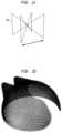
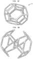
- FIG. 1 Cis a unit cell used to construct a portion of the metal insert of FIG. 1 A ;
- FIG. 1 Dis a computer model of a portion of an acetabular cup constructed using the unit cell of FIG. 1 C ;
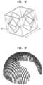
- FIG. 1 Eis a unit cell used to construct a portion of the metal insert of FIG. 1 A ;
- FIG. 1 Fis a computer model of a portion of an acetabular cup constructed using the unit cell of FIG. 1 E ;
- FIG. 1 Gis a computer rendering of an acetabular cup including the portions illustrated in FIGS. 1 D and 1 F ;
- FIG. 2is a schematic drawing of a pelvis region
- FIG. 3is a schematic drawing of an acetabular cup and a femoral stem implanted into the pelvic region;
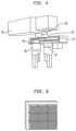
- FIG. 4is an illustration of an apparatus used in conjunction with the present invention.
- FIG. 5illustrates an alternate apparatus for employing methods of the present invention
- FIG. 6is a sample of constructed coupons using a method according to the present invention.
- FIG. 7is a table showing a series of parameters used for making samples according to the present invention.
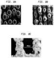
- FIGS. 8 A- 8 Care scanning electro-microscopic images of the surface structure of various samples made by a method according to the present invention.
- FIG. 9 A- 9 Dare illustrations of different embodiments of unit cells according to the present invention.
- FIG. 10illustrates a lattice structure using a plurality of unit cells according to FIG. 8 A ;
- FIG. 11illustrates a lattice structure with and without laser beam compensation using the unit cells illustrated in FIG. 1 ;
- FIG. 12illustrates a lattice structure using a plurality of unit cells illustrated in FIG. 8 B ;
- FIG. 13illustrates a lattice structure with and without laser beam compensation using the unit cell of FIG. 8 B ;
- FIG. 14illustrates a lattice structure using a plurality of unit cells illustrated in FIG. 8 C ;
- FIGS. 15 A and 15 Billustrate lattice structures created using unit cells illustrated in FIGS. 9 D and 8 A with varying exposure time, respectively;
- FIG. 15 Cillustrates a side view of the embodiment of FIG. 15 A ;
- FIG. 15 Dillustrates a side view of the lattice structure illustrated in FIG. 15 B ;
- FIG. 16is a representation of a lattice structure created using a plurality of unit cells illustrated in FIG. 8 D with random perturbation;
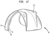
- FIG. 17is an illustration of an acetabular cup built using the methods of the present invention.
- FIG. 18is an illustration of an alternate embodiment of an acetabular cup built using the methods of the present invention.
- FIG. 19is an illustration of an alternate embodiment of an acetabular cup built using the methods of the present invention.
- FIGS. 20 and 21are representations of a patella component built using one embodiment of the present invention.
- FIG. 22is a side view of a cartilage plug built according to one embodiment of the present invention.
- FIG. 23is a front view of the cartilage plug of FIG. 22 ;
- FIG. 24is an illustration of an alternate embodiment of an acetabular cup.
- the present inventionrelates to a method of forming a porous or partially porous metallic structure having a bearing surface attached directly or indirectly thereto.
- the structuresare particularly but not exclusively applicable for use in the art of soft tissue interlock structures for medical implants and prosthesis.
- the methodmakes use of laser technology or any other high energy beam by employing a variety of scanning strategies.
- Typical metal and metal alloys employedinclude stainless steel, cobalt chromium alloys, titanium and its alloys, tantalum and niobium, all of which have been used in medical device applications.
- the present inventioncan be used for such medical device applications where bone and/or soft tissue interlock with the component is required, or where a controlled structure is required to more closely match mechanical properties of the device with surrounding tissue.
- the present inventionmay be employed to enhance the biocompatibility of a porous structure with human tissue while also providing a bearing surface that is resistant to wear.
- a structuremay be created using specific dimensions required to accommodate a particular patient.
- the porous and partially porous metallic structuresmay be attached or incorporated to a surface, which will be used as a bearing surface, as is described below.
- the orthopedic implantcan provide a structure for permitting bone and soft tissue interlock in combination with a bearing surface that enables the implant to rotate, articulate or pivot relative to an additional bearing surface.
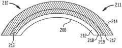
- the device for implantation into the bodymay be in the form of an acetabular cup 10 .
- the acetabular cup 10preferably includes a metal insert 11 comprised of a bearing support structure 12 , a bone ingrowth structure 14 and an intermediate structure 16 .
- the acetabular cup 10can be used in a total hip replacement surgery.
- acetabular cupsuch as acetabular cup 10
- a first end 15 of a femoral stem FSis positioned within the femur F
- a second end 17is positioned adjacent the bearing support structure 12 of the acetabular cup 10
- the second end 17 of the femoral stem FSis rotatably moveable relative to the acetabular cup 10 .
- the bone ingrowth structure 14may be constructed using a direct laser remelt process as, for example, described in U.S. patent application Ser. No. 10/704,270, filed Nov. 7, 2003 entitled “Laser-Produced Porous Surface,” and U.S. patent application Ser. No. 11/027,421, filed Dec. 30, 2004, entitled “Laser-Produced Porous Structure,” the disclosures of which are hereby incorporated herein by reference.
- the bone ingrowth structure 14is approximately 1.1 mm thick and has a porosity of approximately between the range of 70% to 80%.
- the intermediate structure 16is approximately 0.1 mm thick and is substantially fully dense.
- the bearing support structure 12is approximately 0.8 mm thick and is adapted for being secured within a polymer layer to form a bearing surface 8 , as will be described below.
- the incorporation of the polymer, as described below,desirably results in an acetabular cup with a thickness of less than 4 mm, which is considered to be preferentially for resurfacing cups.
- the measurementsare simply illustration and should not be considered a limitation since various thicknesses may be used when building the part.
- the bone ingrowth structure 14may be prepared by populating the volume of the structure with a single unit repeating cell using propriety software.
- a single unit cell 110 and the corresponding porous layerare shown in FIGS. 1 C and 1 D .
- the single cell 110 usedis a unit cell octahedron structure having a length of 800 ⁇ m with vertical pillars on each corner. When tessellated, these cells produce porous structures having a porosity of approximately 80% with full interconnected porosity and mean pore sizes between 100 ⁇ m and 400 ⁇ m.
- the intermediate structure 16is designed to facilitate the bonding of the bearing support structure 12 to the bone ingrowth structure 12 , as well as isolate the bone ingrowth structure from a polymeric material, as will be described below.
- the bearing support structure 12may be designed by populating the volume of the structure with a single repeating unit cell 112 , as shown in FIGS. 1 E and 1 F . This produces a structure that is between 90% to 95% porous with fully interconnected porosity with pore sizes between 1.25 mm and 2 mm diameter.
- the dimension of the unit cell 112may be altered or even a difference unit cell employed, such that the porosity of the structure may be customized based on desirability.
- the porosity of each structuremay be altered but in a preferred embodiment the porosity of each structure is dependent on that structures function.
- the resultant porosity of the bone ingrowth structure 14should be within a range that promotes bone ingrowth.
- the porosity of the bearing support structure 12should be in a range that easily allows for a polymeric material or other material to adhere to the structure as will be described below.
- the porosity of the intermediate layershould be in a range that prohibits or at least reduces the ability of a polymeric material to leech from the bearing support structure 12 to the bone ingrowth structure 14 , as will be described below.
- the files describing the bone ingrowth structure 14 , solid intermediate structure 16 and the bearing support structure 12may all be loaded into the operating software for a MCP realizer, FUSCO.
- the three structuresare then reassembled and manufactured as one part.
- a schematic of the manufactured part and a photo of the final componentare shown in FIG. 1 G .
- the acetabular cuphas a total thickness of 3 mm and an internal diameter of 46 mm.
- a powder of titanium, titanium alloys, stainless steel, cobalt chrome alloys, tantalum or niobiumis disposed onto a substrate.
- the laser melting processincludes scanning a laser beam onto the powder and in parallel scan lines with a beam overlap, e.g., scan spacing, followed by similar additional scans or subsequent scans at 90 degrees, as way of example.
- the type of scan chosenmay depend on the initial layer thickness as well as the web height required.
- the web heightrefers to the height of a single stage of the metal structure 11 .
- the web heightmay be increased by depositing additional layers of powder of a structure and scanning the laser at the same angle of the previous scan.
- the additional scan linesmay be at any angle to the first scan, to form a structure with the formation of a defined porosity, which may be regular or random.
- the scanned devicemay be programmed to proceed in a random generated manner to produce an irregular porous construct but with a defined level of porosity.
- the scancan be preprogrammed using digitized images of various structures, such as the acetabular cup 10 , shown in FIGS. 1 A and 1 B , to produce a similar structure.
- the scanmay also be customized to a particular patient. In this process, a CT scan of for instance, a person's acetabullum is taken and inputted into a computer program.
- the resultant filemay be sliced, digitized or manipulated by methods known to those in the art as well as described herein. Based on these files and tailored measurements, a customized implant may be fabricated for a particular individual.
- the nature of the material formed as a result of laser melting of powder beadsis principally dependent upon the thermal profile involved (heating rate, soaking time, cooling rate); the condition of the raw material (size and size distribution of powder particles); atmospheric conditions (reducing, inert or oxidizing chamber gas); and accurate control of the deposited layer thickness.
- the most optimum porous structure for maximization of bone in-growth on a prosthesishas generally been found to be between approximately 60% to 80%.
- the preferred pore structureis irregular and interconnected, with a minimum pore size between about 80 ⁇ m and 100 ⁇ m and a maximum pore size between 80 ⁇ m and 800 ⁇ m.
- the bone ingrowth structure 14 , the bearing support structure 12 and the intermediate structure 16 of the acetabular cup 10may be constructed using the apparatus shown in FIG. 4 of 5 .
- the apparatus of FIG. 4may include an Nd; YAG industrial laser 30 , integrated to an RSG 1014 analog galvo-scanning head 32 for providing a maximum scan speed of 500 mm per second.
- the laser beam 34is directed into an atmospherically-controlled chamber 36 , which consists of two computer-controlled platforms with powder delivery and part building.
- the powderis delivered from a variable capacity chamber 38 into the chamber 36 and is transported by a roller 40 to a build platform 42 above a variable capacity build chamber 44 .
- the build and delivery system parametersare optimized for an even 100 ⁇ m coating of powder to be deposited for every build layer.
- the metals chosen as surface materialsare all difficult to process due to their affinity for oxygen. Titanium and other alloys are easily oxidized when processed by laser in oxygen-containing atmosphere, their oxide products have high melting points and poor flowability. For this reason, and to prevent the formation of other undesirable phases, the methods may be carried out under an Argon inert atmosphere in chamber 36 . Pressure may remain at or below atmospheric pressure during the entire application.
- a cobalt chrome alloymay be configured into square structures, called coupons. As shown in FIG.
- an array of cobalt chrome couponsmay be built onto a stainless steel substrate.
- the couponswere built as test subjects.
- the cobalt chrome alloymay have a particle size distribution of 90 less than 22 ⁇ m, i.e., 90% of the particles are less than 22 ⁇ m, the composition of which is shown in the table below.
- An array of nine sample couponswere produced as shown in FIG. 6 , with the process of Table 2, using a maximum laser power of 78 watts (W) and laser scanning speed for each coupon varying between 100-260 mms-1.
- Wwatts
- a simple linear x-direction scanwas used on each of the coupons. This allowed the processing parameter, beam overlap, to be used to control the space between successive scan lines. That is, with a 100 ⁇ m laser spot size, an overlap of ⁇ 200% produces a 100 ⁇ m gap between scans.
- the acceptable range for the beam overlapis given at +50% to ⁇ 1200% it should be duly noted that the negative number only refers to the fact the there is a gap as opposed to a beam overlap between successive scans. For instance a beam overlap of zero refers to the fact that successive scans on the same layer of powder border each other.
- a positive beam overlapproduces more solid components in contrast to a more negative beam overlap, which produces a more porous structure. The less the beam overlap the more solid the resultant structure will be.
- a larger beam overlapmay be used to create the attachment structure or bearing support structure 12 , as compared to the intermediate structure 16 . If the beam overlap was 5%, then 5% of the first scan is overlapped by the second scan. When computing the Andrew number the absolute value of the beam overlap is used. The complete set of process parameters used is shown in Table 2 below.
- the key laser parameters varied for forming the three-dimensional metallic porous structuresare: (a) Laser scanning speed (v.) in (mms-1), which controls the rate at which the laser traverses the powder bed; (b) Laser power, P(W), which in conjunction with the laser spot size controls the intensity of the laser beam. The spot size was kept constant throughout the experiment; (c) Frequency, (Hz) or pulse repetition rate. This variable controls the number of laser pulses per second. A lower frequency delivers a higher peak power and vice versa.
- the line widthcan be related to the laser scanning speed and the laser power to provide a measure of specific density, known as the “Andrew Number”, where:
- AnP bxv ⁇ ( J / mm _ ⁇ 2 )
- Pdenotes the power of the laser
- vis the laser scanning speed
- bdenotes beam width of the laser.
- the Andrew numberis the basis for the calculation of the present invention.
- the Andrew numbermay also be calculated by substituting the line separation (d) for beam width (b).
- the two methods of calculating the Andrew numberwill result in different values being obtained.
- line separation (d)only one track of fused powder is considered, whereas when using the beam width (b) as a factor, two tracks of fused powder are considered as well as the relative influence of one track to the next. For this reason we have chosen to concern our with the Andrew number using scan spacing as a calculating factor. It can thus be appreciated, that the closer these tracks are together the greater the influence they have on one another.
- the laser powermay be varied between 5 W and 1000 W. Utilizing lower power may be necessary for small and intricate parts but would be economically inefficient for such coatings and structures described herein. It should be noted that the upper limit of laser power is restricted because of the availability of current laser technology. However, if a laser was produced having a power in excess of 1000 W, the scanning speed of the laser could be increased in order that an acceptable Andrew number is achieved. A spot size having a range between 5 ⁇ m to 500 ⁇ m is also possible. For the spot size to increase while still maintaining an acceptable Andrew number, either the laser power must be increased or the scanning speed decreased.
- the above formulagives an indication of how the physical parameters can vary the quantity of energy absorbed by the powder bed. That is, if the melted powder has limited cohesion, e.g. insufficient melting, the parameters can be varied to concentrate the energy supply to the powder.
- High Andrew numbersresult in reduced pore coverage and an increase in pore size due to the effects of increased melt volume and flow.
- Low Andrew numbersresult in low melt volume, high pore density and small pores.
- Current satisfactory Andrew numbersare approximately 0.3 J/mm-2 to 8 J/mm-2 and are applicable to many alternative laser sources. It is possible to use a higher powered laser with increased scanning speed and obtain an Andrew number within the working range stated above.
- FIGS. 8 A to 8 Care scanning election microscope images of the surface structure of CoCr on stainless steel produced with a laser power of 82 W cw.
- FIG. 8 Awas produced with a laser scanning speed of 105 mms ⁇ 1
- FIG. 8 Bwas produced with a laser scanning speed of 135 mms ⁇ 1.
- FIG. 8 Cis an image of the same structure in FIG. 8 B , in section. There is a significant self-ordering within the overall structure.
- Increased fusionmay, if required, be obtained by heating the substrate, powder or both prior to scanning.
- Such heating sourcesare commonly included in standard selective laser sintering/melting/remelting machines to permit this operation.
- the processcan be carried out on flat baseplates that provide for easy powder delivery in successive layers of around 100 ⁇ m thickness. Control of powder layer thickness is very important if consistent surface properties are required.
- the application of this technologycan also be applied to curved surfaces such as those found in modern prosthetic devices such as acetabular cup 10 , with refinements being made to the powder layer technique.
- the structuresmay receive ultrasonic and aqueous cleaning.
- the resultant porous surfaces produced by the Direct Laser Remelting processexhibit small particulates that are scattered throughout the structure. It is unclear at this stage whether these particulates are bonded to the surface or loosely attached but there are means to remove or consolidate the particulates if required, by for example acid etching, heat treatment, a combination of the two, or the like.
- the Direct Laser Remelting processhas the ability to produce porous structures that are suitable for bone in-growth applications.
- the powdered surfaceshave undergone considerable thermal cycling culminating in rapid cooling rates that have produced very fine dendritic structures.
- the Direct Laser Remelting processcan produce effective bone in-growth surfaces and the manufacturing costs are reasonable.
- the objecthas been to provide a metal insert having a porosity on a base but the present invention can also be used to provide a non-porous structure on such a base to form a three-dimensional structure.
- the same techniquescan be utilized for the materials concerned but the laser processing parameters can be appropriately selected so that a substantially solid non-porous structure is achieved.
- a techniquecan be used to deposit the powder onto a suitable carrier, for example a mold, and to carry out the process without the use of a base so that a three-dimensional structure is achieved which can be either porous, as described above, or non-porous if required.
- this methodcan, therefore, be used to produce article from the metals referred to which can be created to a desired shape and which may or may not require subsequent machining. Yet again, such an article can be produced so that it has a graded porosity of, e.g., non-porous through various degrees of porosity to the outer surface layer.
- Such articlescould be surgical prostheses, parts or any other article to which this method of production would be advantageous.
- each layer or portion of a layermay be scanned to create a portion of a plurality of predetermined unit cells. As successive layers of powder are deposited onto previous layers, the scanning and depositing of such layers continues the building process of a predetermined unit cell.
- the preferred embodimentincludes employing a pulse high energy beam to form “spots” on the deposited powder layer. At least some of the “spots” are joined to produce struts or portions of struts, which constitute a portion of a predetermined unit cell. The spots may be created at random, in a continuous manner or a combination of the two.
- FIGS. 9 A- 9 DExamples of some possible geometric shapes of a unit cell are shown in FIGS. 9 A- 9 D .
- by continuing the building processrefers not only to a continuation of a unit cell from a previous layer but also a beginning of a new unit cell as well as the completion of a unit cell.
- the inventioncan include a laser melting process that precludes the requirement for subsequent heat treatment of the structure, thereby preserving the initial mechanical properties of the core or base metal.
- the equipment used for the manufacture of such a devicecould be one of many currently available including the MCP Realiszer, the EOS M270, Trumpf Trumaform 250, the Arcam EBM S12 and the like.
- the lasermay also be a custom produced laboratory device.
- one apparatus for constructing a structure comprised of predetermined unit cellsmay include a chamber 50 filled with an inactive gas such as argon and nitrogen. By using an inactive gas you can avoid oxidation of the metal powder 52 .
- the three-dimensional model, such as metal insert 11may be built on a base plate 51 . The model is built in a layer by layer fashion.
- the laser head 53projects a beam of energy 54 onto locations of the powder to thereby form a spot or portion of a strut of a predetermined unit cell.
- the laserscans the powder bed and projects the energy beam based on the slice data of the model contained in the computer program.
- successive layer of metal powdermay be deposited onto the previous layer by the use of a powder feeder 55 .
- the powder feeder 55may work in conjunction with a piston 56 that is lowered prior to the depositing of the additional layer of metal powder.
- the piston 56is desirably positioned under the substrate on which the metal structure is built. As each layer is processed, the piston 56 may be lowered and an additional layer of metal powder deposited onto the previous layer. In this manner, each layer of unprocessed powder is positioned at the same distance from the laser head 53 .
- the laser beamis capable of being directed along a X, Y coordinate system such that the desired location of the layer of metal powder can be engaged by the beam of energy 54 .
- the guiding of the laser beamis dependent on the manufacturing system used. For example, if an E-beam system is employed the movement of the E-beam is controlled by deployment of the magnetic fields. If a laser beam apparatus is employed, the movement or guidance of the laser beam is controlled by a galvanometer.
- the pore density, pore size and pore size distributioncan be controlled from one location on the structure to another. It is important to note that successive powder layers can differ in porosity by varying factors used for laser scanning powder layers. Additionally, the porosity of successive layers of powder can be varied by either creating a specific type of predetermined unit cell or manipulating various dimensions of a given predetermined unit cell.
- such unit cells designscan be a tetrahedron 60 ( FIG. 9 A ), dodecahedron 62 ( FIG. 9 B ), octahedron 64 ( FIG. 9 C ), diamond, as well as many other various shapes.
- various strutsmay be removed from a unit cell to create an additional structure such as that shown in FIG. 9 D .
- the unit cells of the present inventionmay be configured to have irregular shapes where various sides and dimensions have little if any repeating sequences.
- the unit cellscan be configured to build constructs that closely mimic the structure of trabecular bone for instance.
- Unit cellscan be space filling, all the space within a three-dimensional object is filled with cells, or interconnected where there may be some space left between cells but the cells are connected together by their edges.
- the unit cellscan also be constructed in a form of a lattice. Additionally, adjacent lattices may be isolated from one another or only partially attached.
- the cellscan be distributed within the construct a number of ways. Firstly, they may be made into a block within a computer added design (“CAD”) system where the dimensions correspond to the extent of the solid geometry. This block can then be intersected with the geometry representing the component to produce a porous cellular representation of the geometry. Secondly, the cells may be deformed so as to drape over an object thus allowing the cells to follow the surface of the geometry. Thirdly, the cells can be populated through the geometry following the contours of any selected surface.
- CADcomputer added design
- the unit cellcan be open or complete at the surface of the construct to produce a desired effect.
- open cells with truncated lattice strutsproduce a surface with a porosity and impart the surface with some degree of barb
- closed cellscan be “peaky” so as to increase surface roughness.
- Modifying the lattice strut dimensionscan control the mechanical strength of the unit cell. This modification can be in a number of key areas.
- the lattice strutcan be adjusted by careful selection of build parameters or specifically by changing the design of the cross-section of each strut.
- the density of the latticecan similarly be adjusted by modification of the density of the unit cells as can the extent and shape of porosity or a combination thereof.
- the overall design of the unit cellwill also have a significant effect of the structural performance of the lattice. For instance, dodecahedral unit cells have a different mechanical performance when compared to a tetrahedral (diamond) structure.
- each point 70 , 72 , 74 , and 76is the same distance from the neighboring point.
- This structureis analogous to the arrangements of carbon atoms in diamond.
- Each carbon atom in the diamond structureis surrounded by four nearest neighbors. They are connected together by bonds that separate them by a distance of 1.5445 angstroms. The angles between these bonds are 109.5 degrees. As a result, the central atom and its neighbors form a tetrahedron. This geometry as in the case discussed herein may then be scaled to appropriate value for the pore construct required.
- the two key parameters used to define the relations regarding height, surface area, space height, volume of tetrahedron, and the dihedral angle of a tetrahedronare the strand length of the tetrahedron and, i.e., the diameter or height and width, cross section area of the strand i.e., strut. These two parameters control the pore size and porosity of the structure.
- the parameter editor and relation editor within a typical CAD systemcan be used to control these parameters. Hence, by changing the parameters one can change the fundamental properties of the porous structure.
- the diamond structuremay have a circular cross-section strands or square cross-section strands. Although only two strand cross-sections are discussed herein, strands having various cross-sections are possible. Further, this is true with most of the designs for the unit cell.
- FIG. 11illustrates a view of a diamond lattice structure with and without laser beam compensation.
- Laser beam compensationessentially allows the diameter of the beam to be taken into account. Without it the constructed geometry is one beam diameter too wide as the beam traces out the contour of the particular section being grown. When laser beam compensation is utilized, the contour is offset half a beam diameter all around the constructed geometry which is represented in the CAD file.
- the parameters employed to create the lattices of FIG. 11include a laser power of 90.5 watts with an exposure time of 1,000 ⁇ sec from a point distance of 90 ⁇ m. Table 3 illustrates various other examples of parameters that may be used to create various unit cells.
- the porous structurecan also be created using a unit cell in the shape of a dodecahedron.
- the regular dodecahedronis a platonic solid composed of 20 polyhydron vertices, 30 polyhydron edges, and 12 pentagonal faces.
- This polyhydronis one of an order of five regular polyhedra, that is, they each represent the regular division of 3-dimensional space, equilaterally and equiangularly.
- This basic unit cell for a decahedron meshcan be built up in a CAD package using the following calculations and procedure.
- the dodecahedronhas twelve regular pentagonal faces, twenty vertices, and thirty edges. These faces meet at each vertex.
- the calculations for a side length of a dodecahedronare given by simple trigonometry calculations and are known by those in the art.
- a sweep featureis first used to model the dodecahedron structure by driving a profile along a trajectory curve.
- the trajectory curvesare constructed from datum points corresponding to the vertices of the dodecahedron connected by datum curves.
- the type of profileremains constant along the sweep producing the model shown in FIG. 9 B .
- the size and shape of the profilecan be designed to suit the particular application and the required strut diameter.
- the cellcan be instanced to produce a regular lattice as shown in FIG. 12 .
- meshesare produced by simple offsetting of the unit cell and allowing some of the struts to overlap. This method of overlapping may be used with the alternate shapes of the unit cell.
- FIG. 13shows a view of a dodecahedron (with and without laser beam compensation, from left to right) structure using selective laser melting process parameters.
- the lattices of FIG. 13were created using the following parameters; a laser power of 90.5 watts, exposure of the powder for 1,000 usec and a point distance of 90 ⁇ m.
- the unit cell of the present inventionmay also be constructed in the shape of a truncated octahedron.
- a truncated octahedronhas eight regular hexagonal faces, six regular square faces, twenty-four vertices, and thirty-six edges. A square and two hexagons meet at each vertex.
- the octahedronWhen the octahedron is truncated, it creates a square face replacing the vertex, and changes the triangular face to a hexagonal face.
- This solidcontains six square faces and eight hexagonal faces. The square faces replace the vertices and thus this leads to the formation of the hexagonal faces.
- various dimensionssuch as the octahedron height, octahedron volume, octahedron surface area, octahedron dihydral angle, and truncated octahedron volume, truncated octahedron height, truncated octahedron area, truncated octahedron volume, truncated octahedron dihydral angle can be determined by simple trigonometry and are known by those skilled in the art.
- a CAD model of the truncated octahedronis constructed using the sweep feature and calculations and dimensions are incorporated using basic trigonometry.
- the unit cellis first reoriented to enable casy tessellation and to reduce the number of horizontal struts in the model.
- the modelcan be modified to remove all of the horizontal struts as shown in FIG. 9 D .
- the modified structureis reproduced in order to save file size in the Steriolithography (“STL”) format of the program.
- STLSteriolithography
- the parameter chosenincludes a laser power of 90.5 watts, an exposure of 1000 ⁇ sec with a point distance of 90 ⁇ m.
- FIG. 8 Billustrates a lattice structure formed using a plurality of individual truncated octahedron. As discussed earlier, the removal of various struts can create a barb effect on the exterior surface of the lattice structure.
- FIGS. 15 A-Dit is possible to reduce the size of the unit cell geometry. Also as shown, it is possible to manufacture open cell structures with unit cell sizes below 1 millimeter.
- FIG. 15 Aillustrates truncated octahedron structures manufactured using the laser melting process. All the structures were created using a laser power of 90.5 W, and a point distance of 90 ⁇ m; however, from left to right, the exposure time was varied from 500 usec and 100 ⁇ sec.
- FIG. 15illustrates similar structures and parameters as used with FIG. 15 A , however, the unit cell used to create the lattice is diamond.
- FIGS. 9 C and 9 Dillustrate a side view of the truncated octahedron structure of FIG. 15 A and the diamond structure of FIG. 15 B , respectively. Table 4 includes various manufacturing parameters used to construct various unit cell structure.
- the average pore size of the bone ingrowth structure 14falls within 280 ⁇ m to 480 ⁇ m, as measured using conventional linear intercept methods.
- a bimodal pore size distributionmay be present as, for example, small pores within a 250 ⁇ m to 450 ⁇ m range and larger pores within a 600 ⁇ m to 800 ⁇ m range.
- the metal insert 11i.e., the bone ingrowth structure 14 , the bearing support structure and the intermediate structure 14 may be isotropic as, for example, without directionality with regard to the structure, and mechanical properties.
- the average pore sizes of the porous layer 14 for interconnecting poresexceeds 250 ⁇ m with at least 99% and the pore volume therefore within between 65% to 75% of interconnecting pores exceeding 180 ⁇ m.
- the general thickness of the porous layergenerally lies within the range of between 1 mm to 2 mm but may be larger or smaller if so required.
- porous structure 14bearing support structure 12 and the intermediate structure 16 may be formed simultaneously using any of the processes described herein or a combination of the processes.
- a polymeric materialmay be connected to the bearing support structure 12 to enable the acetabular cup 10 to bear against an articulating surface of an additional element.
- the polymeric materialwill comprise the bearing surface 8 of the acetabular cup 10
- the polymeric materialcan be integrated with the bearing support structure 12 , by compression molding, injection molding or heat forming. It may also be possible to cast certain types of materials from solution as, for example, polyurethane.
- the metallic inserti.e., the bone ingrowth structure 14 , the bearing support structure 12 and the intermediate structure 16 , but specifically the bearing support structure 12
- UHMWPEultra-high molecular weight polyethylene
- the metallic inserti.e., the bone ingrowth structure 14 , the bearing support structure 12 and the intermediate structure 16 , but specifically the bearing support structure 12
- the metal insert 11is placed into a cavity part of a metal die.
- the polymer powdermay then be added to the cavity of the metal die and desirably is dispersed against the bearing support structure 12 .
- the cavity of the metal dieis sealed and the metal die is then heated to a required temperature.
- the polymer powderbegins to soften or melt so as to be flowable.
- Increased pressure onto the polymer powdermay also aid in the melting process. Fusion of the polymer powder and attachment to the bearing support structure 12 is achieved when the acquired application of heat and pressure is reached. Subsequent cooling under pressure allows solidification of the polymer powder, which thus forms the bearing surface 8 that is securely attached to the bearing support structure 12 . A final machining operation may be required to complete the construct of the bearing surface 8 .
- the metal insert 11is situated in the metal die with the bone ingrowth structure 14 bounded within the cavity of the metal die such that the polymer material cannot come in contact with the bone ingrowth structure.
- the intermediate structure 16is preferably substantially solid, the intermediate structure prohibits or at least, reduces the ability of the polymeric material to come in contact with the bone ingrowth structure as the polymeric material attaches to the bearing support structure 12 to form a bearing surface 8 . By keeping the pores of the bone ingrowth structure unencumbered with polymer material, the ability of the bone ingrowth structure to promote bone ingrowth is not altered.
- an injection molding processmay be carried out in order to fuse the bearing surface 8 to the bearing support structure 12 .
- An injection molding processmay be preferred when the material used to create the bearing surface 8 is a polyurethane or chopped-fiber-reinforced poly (ETHERETHERKETONE) (“CFRPEEK”). Similar to the compression molding process, in the injection molding process, the metal insert 11 is secured into a cavity of an injection molding machine and the mold closed. As with the previous embodiment, the bone ingrowth structure 14 may be isolated from the polyurethane or additional polymer used. The selected material, e.g., polyurethane or CFRPEEK is heated in a barrel of the injection molding machine.
- the pressuremay be applied to the selected material to urge the heated selected material from the barrel into the mold cavity and onto a surface of the bearing support structure 12 .
- the selected materialis fused to the bearing support structure 12 so as to form the bearing surface 8 upon which the acetabular cup 10 may move relative to an additional element, i.e., the femoral stem FS.
- the completed partmay be removed from the injection mold and machined if so required.
- the mold cavitycan be configured such that particular features, designs and contours of the bearing surface 8 may be formed.
- the bearing surface 8may be formed using a heat forming process.
- materialssuch as UHMWPE are supplied as fabricated rod stock suitable for machining. Profiles can be produced by machining the fabricated rod stock to represent a near net shape of the intended article such as the bearing surface 8 of the acetabular cup 10 .
- both the metal insert 11 and the shape polymer machine partare placed into a mold and heated to the required temperature.
- the softened polymeris forced into and against the metal insert 11 , specifically the bearing support structure 12 .
- solidificationtakes place and the polymer is secured to the metal insert 11 and specifically the bearing support structure 12 . Further machining may be required if necessary once the part has been allowed to cool and is removed from the mold.
- the bone ingrowth structure 14may be isolated from any polymeric material so that the polymeric material cannot affect the ability of the structure to promote bone ingrowth.
- the bearing surface 8may be constructed using a solution casting method.
- a materialsuch as a polyurethane material, can be formed by casting solvent-dissolved solutions in the mold.
- the bearing surface 8out of additional material such as a metallic material or ceramic material.
- additional materialsuch as a metallic material or ceramic material.
- the selective laser melting processdescribed herein, as well as in U.S. patent application Ser. Nos. 10/704,270, and 11/027,421 (described above) may be utilized.
- a CAD file of an acetabular cup componentis loaded into the Magics software package as a single part, as shown in FIG. 17 .
- the filemay then be divided into three separate solid volumes having a 1.1 mm thick outer layer—this layer will be used to create the 80% porous bone ingrowth surface; 0.1 mm thick intermediate layer—this layer will be a fully dense layer that supports the bone ingrowth surface; and 0.8 mm thick inner layer—this will be used to create an interlock surface for a polymer injection molding.
- the three layers, when completed,will comprise the metal insert 11 of the acetabular cup 10 .
- a completed acetabular cup 10is shown is shown in FIG. 17 and includes a bearing surface 8 , an intermediate structure 16 and a bone ingrowth structure 12 .
- the bone ingrowth structure 14may include fins or protrusions 13 for anchoring into bone.
- the acetabular cupmay be constructed with a two tier structure.
- the two tier structureincludes a metal insert 111 having a bone ingrowth structure 114 and a bearing support structure 112 .
- the bearing surface 108is attached to the bearing support structure 112 are connected directly to one another.
- each structureis adapted for its own purpose, i.e., the bone ingrowth structure 14 has a porosity adapted for bone ingrowth and the bearing support structure 12 has a porosity suited for anchoring a polymeric material or additional material as discussed herein.
- the figureillustrates a demarcation between the two structures, highlighting the difference in porosity between the two, the actual metal insert 111 may have a graded porosity which increases, decreases or some combination of the two along an axis 119 passing through the center of the acetabular cup 110 .
- the acetabular cup 210may have a plurality of structures comprising a metal insert 211 .
- the metal insert 211may include a bone ingrowth structure 214 , an intermediate structure 216 and a bearing support structure 212 .
- the intermediate structure 216may include a first barrier 217 , a second barrier 218 and a bridging structure 219 .
- the first barrier 217 and second barrier 218may be substantially solid while the bridging structure 219 , positioned between the two barriers has a particular porosity.
- the particular porositymay be specifically designed to transfer mechanical loads through the overall construct to a bone to which the acetabular cup is attached to.
- a patella component 300as shown in FIGS. 20 and 21 , includes a baseplate 302 and a bearing surface 304 .
- the patella bearing surface 304may be attached to the baseplate 302 using the processes discussed herein.
- the patellais shaved on a posterior side to a desired depth and some of the cartilage surrounding the area is removed.
- the baseplate 302 of the patella componentpreferably includes a plurality of pegs 306 that engage the remaining bone of the patella.
- the pegs 306are designed for bone ingrowth as discussed in here. With the pegs 306 attached to the posterior of the patella, the bearing surface 304 may replace and perform the function of any cartilage removed from the area.
- the present inventioncan be used to construct a cartilage plug 400 .
- the cartilage plug 400desirably includes a metal insert 401 having a bone ingrowth structure 402 , an intermediate structure 403 and a bearing support structure 404 .
- the metal insert 401may be constructed using methods discussed herein. Once the metal insert 401 is completed, the bearing surface 408 may be attached to the bearing support structure 404 as discussed herein.
- the bearing support structure 404is comprised of two independent lattices 406 and 407 .
- the lattices 406 and 407are independent from one another and may be constructed differently from each other.
- the bearing support structure 404may be constructed similar to the bearing support structure 12 of the metal insert 11 , discussed herein.
- the cartilage plug 400may be employed as for example when only a portion of a tibial plateau must be replaced. A bore is created in the tibial plateau removing the defective portion and than filled with the cartilage plug 400 .
- the bone ingrowth structure 514 of the cartilage plug 400is positioned within the bone while the bearing surface 408 faces outward to replace any cartilage removed from the area.
- the intermediate structure of an implantmay be constructed using a die cast or any method known to those in the art.
- the resultant intermediate structuremay then be placed onto the base plate of an apparatus similar to that shown in FIG. 4 or 5 .
- a bone ingrowth structure and bearing support structuremay be built onto the intermediate structure.
- a bearing surfacemay be attached to an implant or metal insert indirectly.
- a metal insert 511may be constructed similar to metal insert 11 in the shape of an acetabular cup 510 , and include a bone ingrowth structure 514 , an intermediate structure 516 and a bearing support structure 512 .
- a bone cement 506may be deposited and attached to the bearing support structure 512 , in methods known to those in the art.
- a UHMWPE liner 509is positioned adjacent the bone cement and is subsequently attached thereto as the bone cement polymerizes.
- the liner 509preferably includes an exterior 502 and an interior 503 .
- the exterior 502 of the liner 509preferably includes a plurality of attachment sites such as radial grooves or as shown in the figure, circumferential grooves 504 . As the liner 509 is forced against the bone cement the bone cement engages the grooves. As the bone cement 506 polymerizes, the liner 509 is mechanically interlocked to the bone cement.
- the interior 503 of the liner 509is suitable to act as a bearing surface of the completed acetabular cup 510 .
- the metal insert 511 and liner 509are prepackaged and available to a surgeon in a plurality of sizes such that during surgery the surgeon only has to remove the desired liner and insert once the specific measurements and requirements have been decided upon.
- the present inventionmay be in the shape of a glenoid or any other component where bone ingrowth is desired in combination with a bearing surface.
- a coating of a bone growth enhanceras, for example, hydroxyapatite, bone morphogenic protein such as OP-1 (Stryker), to the surface intended to be in direct contact with bone.
Landscapes
- Chemical & Material Sciences (AREA)
- Engineering & Computer Science (AREA)
- Health & Medical Sciences (AREA)
- Mechanical Engineering (AREA)
- Materials Engineering (AREA)
- Manufacturing & Machinery (AREA)
- Organic Chemistry (AREA)
- Metallurgy (AREA)
- Chemical Kinetics & Catalysis (AREA)
- Plasma & Fusion (AREA)
- Physics & Mathematics (AREA)
- Public Health (AREA)
- Transplantation (AREA)
- Life Sciences & Earth Sciences (AREA)
- Animal Behavior & Ethology (AREA)
- General Health & Medical Sciences (AREA)
- Oral & Maxillofacial Surgery (AREA)
- Veterinary Medicine (AREA)
- Medicinal Chemistry (AREA)
- Dermatology (AREA)
- Epidemiology (AREA)
- Orthopedic Medicine & Surgery (AREA)
- Biomedical Technology (AREA)
- Cardiology (AREA)
- Vascular Medicine (AREA)
- Heart & Thoracic Surgery (AREA)
- Optics & Photonics (AREA)
- Inorganic Chemistry (AREA)
- Dispersion Chemistry (AREA)
- Automation & Control Theory (AREA)
- Prostheses (AREA)
- Powder Metallurgy (AREA)
Abstract
Description
The present application is a continuation of U.S. patent application Ser. No. 18/411,633, filed on Jan. 12, 2024 which is a continuation of U.S. patent application Ser. No. 16/900,219, filed Jun. 12, 2020 which is a continuation of U.S. patent application Ser. No. 15/788,304 filed Oct. 19, 2017, which is a continuation of U.S. patent application Ser. No. 14/276,483 filed May 13, 2014, now U.S. Pat. No. 10,398,559, which is a continuation of U.S. patent application Ser. No. 11/295,008 filed Dec. 6, 2005, now U.S. Pat. No. 8,728,387, the disclosures of which are hereby incorporated herein by reference.
The present invention relates to a device having a porous surface attached directly or indirectly to a bearing surface and a method for forming the same.
In particular, this invention relates to a computer-aided laser apparatus or other suited high energy beam, which sequentially remelts a plurality of powder layers to build a porous layer in a layer-by-layer fashion.
The present invention also includes a method of attaching or connecting a bearing surface directly or indirectly preferably formed from a polymer to the sequentially-built porous part.
The present application is particularly directed toward a method of forming a porous and partially-porous metallic structure having a bearing surface.
The field of free-form fabrication has seen many important recent advances in the fabrication of articles directly from computer-controlled databases. These advances, many of which are in the field of rapid prototyping of articles such as prototype parts and mold dies, have greatly reduced the time and expense required to fabricate articles, particularly in contrast to conventional machining processes in which a block of material, such as a metal, is machined according to the engineering drawings. One example of a modern rapid prototyping technology is the selective laser sintering process practiced by systems available from 3D Systems, Valencia, California. According to this technology, articles are produced in a layer-wise fashion, from a laser-fusible powder that is dispensed one layer at a time. The powder is fused, remelted or sintered, by the application of laser energy that is directed in raster-scan fashion to portions of the powder layer corresponding to a cross-section of the article. After fusing of the powder on one particular layer, an additional layer of powder is dispensed, and the process repeated with fusion taking place between the current layer and the previously laid layers, until the article is complete.
The field of rapid prototyping of parts has, in recent years, made large improvements in broadening high strain, high density parts for use in the design and pilot production of many useful articles including metal parts. These advances have permitted the selective laser remelting and sintering process to now also be used in fabricating prototype tooling for injection molding, with expected tool life in excess of 10,000 mold cycles. The technologies have also been applied to the direct fabrication of articles, such as molds from metal powders without a binder. Examples of metal powder reportedly used in such direct fabrication include two-phase metal powders of the copper-tins, copper-solder (the solder being 70% lead and 30% tin), and bronze-nickel systems. The metal articles formed in these ways have been quite dense, for example, having densities of up to 70% to 80% of full density (prior to any infiltration). Prior applications of this technology have strived to increase the density of the metal structure formed by the melting or sintering process. The field of rapid prototyping of parts has focused on providing high strength, high density parts for use and design in production of many useful articles, including metal parts.
But while the field of rapid prototyping has focused on increasing density of such three-dimensional structures, the field has not focused its attention on reducing the density of three-dimensional structures. Consequently, applications where porous and partially-porous metallic structures, and more particularly metal porous structures with interconnective porosity, are advantageous for use, have been largely ignored.
In addition, many structures, especially in the medical arts, require two different surfaces, each adapted for their own purposes. Along this line, a structure may have a first surface which needs to be porous for tissue in-growth and a second surface which should be adapted to be a bearing surface. Further, the first surface or portion may include different layers having different gradients of porosity. For example, the first surface may include an outer region having a porosity of approximately 80%. As you move normal with regard to the first surface the porosity may alter such that the porosity is increased or in a preferred embodiment, the porosity decreases even until the porosity is almost zero. Of course, the present invention contemplates a situation where the porosity alters from position to position depending on the requirements of the device.
Although different techniques have tried to provide such a method and apparatus, still greater techniques are needed in this area.
In one embodiment, the present invention relates to a method of forming an implant having a porous tissue ingrowth structure and a bearing support structure. The method may include depositing a first layer of a metal powder onto a substrate. Next, a laser beam scans over the powder so as to sinter the metal powder at predetermined locations. At least one layer of the metal powder may be deposited onto said first layer while repeating the laser scanning step for each successive layer until a predetermined structure having a first surface and a second surface is constructed. A flowable polymer is placed into contact with the second surface of said predetermined structure. The polymer is cooled such that the flowable polymer adheres to the second surface of the structure. The laser scanning step may include scanning the laser beam onto the metal powder to form a portion of a plurality of predetermined unit cells within the metal powder.
The method may include placing the predetermined structure into a cavity of a die and depositing a polymer onto the second surface of the predetermined structure within the cavity of the die. The step of placing a flowable polymer in contact with the second surface of the predetermined structure may include applying pressure and heat to the polymer in the cavity of the die. The step of placing the flowable polymer in contact with the second surface of the predetermined structure may include transferring the flowable polymer onto the second surface. The step of placing the flowable polymer in contact with the second surface of the predetermined structure may include placing the second surface of the predetermined structure adjacent a polymer structure, applying heat to the polymer structure and allowing the polymer structure to engage the predetermined structure. The predetermined structure may include an outer layer, an intermediate layer and an inner layer, the outer layer and the inner layer being relatively porous and the intermediate layer being relatively dense such that the flowable polymer cannot substantially leech through the intermediate layer from the inner layer to the outer layer. The outer layer has a porosity approximately between 60% to 80% and the inner layer has a porosity approximately higher than 80%. The outer layer may have a pore size distribution in the range of 80 μm to 800 μm and the inner layer may have a pore size distribution higher than approximately 800 μm.
The predetermined structure may have a gradient porosity. The gradient porosity of the predetermined structure may include a first layer that is substantially porous, a second layer that is substantially non-porous, a third layer that is substantially porous such that the flowable polymer cannot substantially leech through the second layer from the third layer to the first layer when the flowable liquid polymer is placed in contact with the third layer.
The present invention also includes a medical implant including a metal insert having a bone ingrowth structure, an intermediate structure and a bearing support structure, the bone ingrowth structure having a porosity sufficient to promote bone ingrowth. The implant also includes a bearing surface formed from a polymer material, the bearing surface being attached to the bearing support structure. The intermediate structure has a porosity sufficient to inhibit the polymer material from translating through the bearing support structure to the bone ingrowth structure. The intermediate structure may be designed to facilitate a specific stiffness characteristic to an overall construct and/or include two barrier layers and a bridging section.
The present invention relates to a method of forming a porous or partially porous metallic structure having a bearing surface attached directly or indirectly thereto. The structures are particularly but not exclusively applicable for use in the art of soft tissue interlock structures for medical implants and prosthesis.
The method makes use of laser technology or any other high energy beam by employing a variety of scanning strategies.
Typical metal and metal alloys employed include stainless steel, cobalt chromium alloys, titanium and its alloys, tantalum and niobium, all of which have been used in medical device applications. The present invention can be used for such medical device applications where bone and/or soft tissue interlock with the component is required, or where a controlled structure is required to more closely match mechanical properties of the device with surrounding tissue.
Additionally, the present invention may be employed to enhance the biocompatibility of a porous structure with human tissue while also providing a bearing surface that is resistant to wear. With these advantages in mind, a structure may be created using specific dimensions required to accommodate a particular patient.
The porous and partially porous metallic structures may be attached or incorporated to a surface, which will be used as a bearing surface, as is described below. By interconnecting or having an implant with a porous structure adjacent a bearing surface, the orthopedic implant can provide a structure for permitting bone and soft tissue interlock in combination with a bearing surface that enables the implant to rotate, articulate or pivot relative to an additional bearing surface.
As shown inFIGS.1A and1B , the device for implantation into the body may be in the form of anacetabular cup 10. Theacetabular cup 10 preferably includes ametal insert 11 comprised of a bearingsupport structure 12, abone ingrowth structure 14 and anintermediate structure 16. Theacetabular cup 10 can be used in a total hip replacement surgery.
During the surgery, the joint of the hip, as shown inFIGS.2 and3 , the hip socket20 (acetabulum) and theball 18 or head of the femur F are removed. An acetabular cup, such asacetabular cup 10, is positioned within the pelvis P. Afirst end 15 of a femoral stem FS is positioned within the femur F, while asecond end 17, including a “ball” is positioned adjacent the bearingsupport structure 12 of theacetabular cup 10. Desirably, thesecond end 17 of the femoral stem FS is rotatably moveable relative to theacetabular cup 10.
Thebone ingrowth structure 14, as well as the bearingsupport structure 12 andintermediate structure 16 of theacetabular cup 10 may be constructed using a direct laser remelt process as, for example, described in U.S. patent application Ser. No. 10/704,270, filed Nov. 7, 2003 entitled “Laser-Produced Porous Surface,” and U.S. patent application Ser. No. 11/027,421, filed Dec. 30, 2004, entitled “Laser-Produced Porous Structure,” the disclosures of which are hereby incorporated herein by reference.
As shown inFIG.1A , in one preferred embodiment of the present invention, thebone ingrowth structure 14 is approximately 1.1 mm thick and has a porosity of approximately between the range of 70% to 80%. Theintermediate structure 16 is approximately 0.1 mm thick and is substantially fully dense. The bearingsupport structure 12 is approximately 0.8 mm thick and is adapted for being secured within a polymer layer to form abearing surface 8, as will be described below. The incorporation of the polymer, as described below, desirably results in an acetabular cup with a thickness of less than 4 mm, which is considered to be preferentially for resurfacing cups. The measurements are simply illustration and should not be considered a limitation since various thicknesses may be used when building the part.
Thebone ingrowth structure 14 may be prepared by populating the volume of the structure with a single unit repeating cell using propriety software. Asingle unit cell 110 and the corresponding porous layer are shown inFIGS.1C and1D . Thesingle cell 110 used is a unit cell octahedron structure having a length of 800 μm with vertical pillars on each corner. When tessellated, these cells produce porous structures having a porosity of approximately 80% with full interconnected porosity and mean pore sizes between 100 μm and 400 μm.
Theintermediate structure 16 is designed to facilitate the bonding of the bearingsupport structure 12 to thebone ingrowth structure 12, as well as isolate the bone ingrowth structure from a polymeric material, as will be described below.
The bearingsupport structure 12 may be designed by populating the volume of the structure with a single repeatingunit cell 112, as shown inFIGS.1E and1F . This produces a structure that is between 90% to 95% porous with fully interconnected porosity with pore sizes between 1.25 mm and 2 mm diameter. Of course, the dimension of theunit cell 112 may be altered or even a difference unit cell employed, such that the porosity of the structure may be customized based on desirability.
The porosity of each structure may be altered but in a preferred embodiment the porosity of each structure is dependent on that structures function. Thus the resultant porosity of thebone ingrowth structure 14 should be within a range that promotes bone ingrowth. The porosity of the bearingsupport structure 12 should be in a range that easily allows for a polymeric material or other material to adhere to the structure as will be described below. And the porosity of the intermediate layer should be in a range that prohibits or at least reduces the ability of a polymeric material to leech from the bearingsupport structure 12 to thebone ingrowth structure 14, as will be described below.
The files describing thebone ingrowth structure 14, solidintermediate structure 16 and the bearingsupport structure 12 may all be loaded into the operating software for a MCP realizer, FUSCO. The three structures are then reassembled and manufactured as one part. A schematic of the manufactured part and a photo of the final component are shown inFIG.1G .
In one specific embodiment, the acetabular cup has a total thickness of 3 mm and an internal diameter of 46 mm.
According to one method of forming a porous three-dimensional structure by laser melting, a powder of titanium, titanium alloys, stainless steel, cobalt chrome alloys, tantalum or niobium is disposed onto a substrate. The laser melting process includes scanning a laser beam onto the powder and in parallel scan lines with a beam overlap, e.g., scan spacing, followed by similar additional scans or subsequent scans at 90 degrees, as way of example. The type of scan chosen may depend on the initial layer thickness as well as the web height required. The web height refers to the height of a single stage of themetal structure 11. The web height may be increased by depositing additional layers of powder of a structure and scanning the laser at the same angle of the previous scan. Further, the additional scan lines may be at any angle to the first scan, to form a structure with the formation of a defined porosity, which may be regular or random. The scanned device may be programmed to proceed in a random generated manner to produce an irregular porous construct but with a defined level of porosity. Furthermore, the scan can be preprogrammed using digitized images of various structures, such as theacetabular cup 10, shown inFIGS.1A and1B , to produce a similar structure. The scan may also be customized to a particular patient. In this process, a CT scan of for instance, a person's acetabullum is taken and inputted into a computer program. The resultant file may be sliced, digitized or manipulated by methods known to those in the art as well as described herein. Based on these files and tailored measurements, a customized implant may be fabricated for a particular individual.
To produce a bone ingrowth structure, such as thebone ingrowth structure 14 of theacetabular cup 10, the nature of the material formed as a result of laser melting of powder beads is principally dependent upon the thermal profile involved (heating rate, soaking time, cooling rate); the condition of the raw material (size and size distribution of powder particles); atmospheric conditions (reducing, inert or oxidizing chamber gas); and accurate control of the deposited layer thickness.
The most optimum porous structure for maximization of bone in-growth on a prosthesis has generally been found to be between approximately 60% to 80%. The preferred pore structure is irregular and interconnected, with a minimum pore size between about 80 μm and 100 μm and a maximum pore size between 80 μm and 800 μm.
Thebone ingrowth structure 14, the bearingsupport structure 12 and theintermediate structure 16 of theacetabular cup 10 may be constructed using the apparatus shown inFIG.4 of5. The apparatus ofFIG.4 may include an Nd; YAGindustrial laser 30, integrated to an RSG 1014 analog galvo-scanninghead 32 for providing a maximum scan speed of 500 mm per second. Thelaser beam 34 is directed into an atmospherically-controlledchamber 36, which consists of two computer-controlled platforms with powder delivery and part building. The powder is delivered from avariable capacity chamber 38 into thechamber 36 and is transported by aroller 40 to abuild platform 42 above a variablecapacity build chamber 44.
In one embodiment as shown inFIG.4 , the build and delivery system parameters are optimized for an even 100 μm coating of powder to be deposited for every build layer. For implant manufacture, the metals chosen as surface materials are all difficult to process due to their affinity for oxygen. Titanium and other alloys are easily oxidized when processed by laser in oxygen-containing atmosphere, their oxide products have high melting points and poor flowability. For this reason, and to prevent the formation of other undesirable phases, the methods may be carried out under an Argon inert atmosphere inchamber 36. Pressure may remain at or below atmospheric pressure during the entire application. In another example of forming a porous structure, a cobalt chrome alloy may be configured into square structures, called coupons. As shown inFIG.6 , an array of cobalt chrome coupons may be built onto a stainless steel substrate. The coupons were built as test subjects. The cobalt chrome alloy may have a particle size distribution of 90 less than 22 μm, i.e., 90% of the particles are less than 22 μm, the composition of which is shown in the table below.
| TABLE 1 |
| Composition of Co212-e CoCr alloy |
| Element |
| Cr | Mo | Si | Fe | Mn | Ni | N | C | Co | |
| Wt % | 27.1 | 5.9 | 0.84 | 0.55 | 0.21 | 0.20 | 0.16 | 0.050 | Balance |
An array of nine sample coupons were produced as shown inFIG.6 , with the process of Table 2, using a maximum laser power of 78 watts (W) and laser scanning speed for each coupon varying between 100-260 mms-1. Of course a higher laser power may be employed; however, a higher laser power would also necessitate increasing the speed of the laser scan speed in order to produce the desired melting of the powder layer. A simple linear x-direction scan was used on each of the coupons. This allowed the processing parameter, beam overlap, to be used to control the space between successive scan lines. That is, with a 100 μm laser spot size, an overlap of −200% produces a 100 μm gap between scans. Although the acceptable range for the beam overlap is given at +50% to −1200% it should be duly noted that the negative number only refers to the fact the there is a gap as opposed to a beam overlap between successive scans. For instance a beam overlap of zero refers to the fact that successive scans on the same layer of powder border each other. A positive beam overlap produces more solid components in contrast to a more negative beam overlap, which produces a more porous structure. The less the beam overlap the more solid the resultant structure will be. In addition, a larger beam overlap may be used to create the attachment structure or bearingsupport structure 12, as compared to theintermediate structure 16. If the beam overlap was 5%, then 5% of the first scan is overlapped by the second scan. When computing the Andrew number the absolute value of the beam overlap is used. The complete set of process parameters used is shown in Table 2 below.
| TABLE 2 |
| Process parameters |
| Power | Layer | Beam | Scanning | Overlap | ||
| Watts | Thickness | Diameter | Speed | Atmo- | No. of | (% of |
| (W) | (μm) | (μm) | (mms−1) | sphere | Layers | line width) |
| 78 | 100 | 100 | 100-260 | 16 | 25, 50, | |
| −500 | ||||||
The incremental changes in scanning speed and the size of the speed range were modified as the experiments progressed. To begin with, a large range of speeds was used to provide an initial indication of the material's performance and the propensity to melt. As the experiments progressed, the range was reduced to more closely define the process window. Speed and beam overlap variations were used to modify the specific energy density being applied to the powder bed and change the characteristics of the final structure. The complete series of parameters are given inFIG.7 , the parameters sets used for the definitive samples are shaded in gray.
The key laser parameters varied for forming the three-dimensional metallic porous structures are: (a) Laser scanning speed (v.) in (mms-1), which controls the rate at which the laser traverses the powder bed; (b) Laser power, P(W), which in conjunction with the laser spot size controls the intensity of the laser beam. The spot size was kept constant throughout the experiment; (c) Frequency, (Hz) or pulse repetition rate. This variable controls the number of laser pulses per second. A lower frequency delivers a higher peak power and vice versa.
The line width can be related to the laser scanning speed and the laser power to provide a measure of specific density, known as the “Andrew Number”, where:
Where P denotes the power of the laser, v is the laser scanning speed and b denotes beam width of the laser. The Andrew number is the basis for the calculation of the present invention. The Andrew number may also be calculated by substituting the line separation (d) for beam width (b). The two methods of calculating the Andrew number will result in different values being obtained. When using line separation (d) as a factor only one track of fused powder is considered, whereas when using the beam width (b) as a factor, two tracks of fused powder are considered as well as the relative influence of one track to the next. For this reason we have chosen to concern ourselves with the Andrew number using scan spacing as a calculating factor. It can thus be appreciated, that the closer these tracks are together the greater the influence they have on one another.
Additionally, the laser power may be varied between 5 W and 1000 W. Utilizing lower power may be necessary for small and intricate parts but would be economically inefficient for such coatings and structures described herein. It should be noted that the upper limit of laser power is restricted because of the availability of current laser technology. However, if a laser was produced having a power in excess of 1000 W, the scanning speed of the laser could be increased in order that an acceptable Andrew number is achieved. A spot size having a range between 5 μm to 500 μm is also possible. For the spot size to increase while still maintaining an acceptable Andrew number, either the laser power must be increased or the scanning speed decreased.
The above formula gives an indication of how the physical parameters can vary the quantity of energy absorbed by the powder bed. That is, if the melted powder has limited cohesion, e.g. insufficient melting, the parameters can be varied to concentrate the energy supply to the powder. High Andrew numbers result in reduced pore coverage and an increase in pore size due to the effects of increased melt volume and flow. Low Andrew numbers result in low melt volume, high pore density and small pores. Current satisfactory Andrew numbers are approximately 0.3 J/mm-2 to 8 J/mm-2 and are applicable to many alternative laser sources. It is possible to use a higher powered laser with increased scanning speed and obtain an Andrew number within the working range stated above.
Line spacing or beam overlap can also be varied to allow for a gap between successive scan lines. It is, therefore, possible to heat selected areas. This gap would allow for a smaller or larger pore size to result. The best illustration of this is shown inFIGS.8A to8C where a −500% beam overlap has been applied.FIGS.8A to8C are scanning election microscope images of the surface structure of CoCr on stainless steel produced with a laser power of 82 W cw.FIG.8A was produced with a laser scanning speed of 105 mms−1 andFIG.8B was produced with a laser scanning speed of 135 mms−1.FIG.8C is an image of the same structure inFIG.8B , in section. There is a significant self-ordering within the overall structure. Larger columnar structures are selectively built leaving large regions of unmelted powder. It is worth noting that these pillars are around 300 μm wide, over 1.6 mm tall and fuse well with the substrate, as seen inFIG.8C . Further analysis shows that the use of a hatched scanning format allows porosity to be more sufficiently controlled to allow the pore size to be directly controlled by the beam overlap.
The use of an optical inspection method to determine this approximate porosity is appropriate given the sample size. This method, although not accurate due to the filter selection process, can, if used carefully, provide an indication of porosity. This porosity level falls within the range of the desired porosity for bone ingrowth structures. The mechanical characteristics of the porous structures are determined by the extent of porosity and the interconnecting webs. A balance of these variables is necessary to achieve the mechanical properties required by the intended application.
Increased fusion may, if required, be obtained by heating the substrate, powder or both prior to scanning. Such heating sources are commonly included in standard selective laser sintering/melting/remelting machines to permit this operation.
As described above, the process can be carried out on flat baseplates that provide for easy powder delivery in successive layers of around 100 μm thickness. Control of powder layer thickness is very important if consistent surface properties are required. The application of this technology can also be applied to curved surfaces such as those found in modern prosthetic devices such asacetabular cup 10, with refinements being made to the powder layer technique.
The structures may receive ultrasonic and aqueous cleaning. On close examination, the resultant porous surfaces produced by the Direct Laser Remelting process exhibit small particulates that are scattered throughout the structure. It is unclear at this stage whether these particulates are bonded to the surface or loosely attached but there are means to remove or consolidate the particulates if required, by for example acid etching, heat treatment, a combination of the two, or the like.
The Direct Laser Remelting process has the ability to produce porous structures that are suitable for bone in-growth applications. The powdered surfaces have undergone considerable thermal cycling culminating in rapid cooling rates that have produced very fine dendritic structures.
The Direct Laser Remelting process can produce effective bone in-growth surfaces and the manufacturing costs are reasonable.
In the preceding examples, the object has been to provide a metal insert having a porosity on a base but the present invention can also be used to provide a non-porous structure on such a base to form a three-dimensional structure. The same techniques can be utilized for the materials concerned but the laser processing parameters can be appropriately selected so that a substantially solid non-porous structure is achieved.
Again, a technique can be used to deposit the powder onto a suitable carrier, for example a mold, and to carry out the process without the use of a base so that a three-dimensional structure is achieved which can be either porous, as described above, or non-porous if required.
It will be appreciated that this method can, therefore, be used to produce article from the metals referred to which can be created to a desired shape and which may or may not require subsequent machining. Yet again, such an article can be produced so that it has a graded porosity of, e.g., non-porous through various degrees of porosity to the outer surface layer. Such articles could be surgical prostheses, parts or any other article to which this method of production would be advantageous.
Although the porous structure has been discussed with regard to randomly depositing powder onto a substrate and selectively laser melting the powder while repeating layer after layer, in contrast, each layer or portion of a layer, may be scanned to create a portion of a plurality of predetermined unit cells. As successive layers of powder are deposited onto previous layers, the scanning and depositing of such layers continues the building process of a predetermined unit cell. When constructing the predetermined unit cells, the preferred embodiment includes employing a pulse high energy beam to form “spots” on the deposited powder layer. At least some of the “spots” are joined to produce struts or portions of struts, which constitute a portion of a predetermined unit cell. The spots may be created at random, in a continuous manner or a combination of the two. Examples of some possible geometric shapes of a unit cell are shown inFIGS.9A-9D . As disclosed herein, by continuing the building process refers not only to a continuation of a unit cell from a previous layer but also a beginning of a new unit cell as well as the completion of a unit cell.
The invention can include a laser melting process that precludes the requirement for subsequent heat treatment of the structure, thereby preserving the initial mechanical properties of the core or base metal. The equipment used for the manufacture of such a device could be one of many currently available including the MCP Realiszer, the EOS M270,Trumpf Trumaform 250, the Arcam EBM S12 and the like. The laser may also be a custom produced laboratory device.
As shown inFIG.5 , one apparatus for constructing a structure comprised of predetermined unit cells may include achamber 50 filled with an inactive gas such as argon and nitrogen. By using an inactive gas you can avoid oxidation of themetal powder 52. The three-dimensional model, such asmetal insert 11 may be built on abase plate 51. The model is built in a layer by layer fashion.
As successive layers of metal powder are deposited onto previous layers, thelaser head 53 projects a beam ofenergy 54 onto locations of the powder to thereby form a spot or portion of a strut of a predetermined unit cell. The laser scans the powder bed and projects the energy beam based on the slice data of the model contained in the computer program.
After a layer has been completed, successive layer of metal powder may be deposited onto the previous layer by the use of apowder feeder 55. Thepowder feeder 55 may work in conjunction with apiston 56 that is lowered prior to the depositing of the additional layer of metal powder. Thepiston 56 is desirably positioned under the substrate on which the metal structure is built. As each layer is processed, thepiston 56 may be lowered and an additional layer of metal powder deposited onto the previous layer. In this manner, each layer of unprocessed powder is positioned at the same distance from thelaser head 53. The laser beam is capable of being directed along a X, Y coordinate system such that the desired location of the layer of metal powder can be engaged by the beam ofenergy 54. The guiding of the laser beam is dependent on the manufacturing system used. For example, if an E-beam system is employed the movement of the E-beam is controlled by deployment of the magnetic fields. If a laser beam apparatus is employed, the movement or guidance of the laser beam is controlled by a galvanometer.
The pore density, pore size and pore size distribution can be controlled from one location on the structure to another. It is important to note that successive powder layers can differ in porosity by varying factors used for laser scanning powder layers. Additionally, the porosity of successive layers of powder can be varied by either creating a specific type of predetermined unit cell or manipulating various dimensions of a given predetermined unit cell.
As described in U.S. patent application Ser. No. 11/027,421, the disclosure of which is incorporated by reference herein, such unit cells designs can be a tetrahedron60 (FIG.9A ), dodecahedron62 (FIG.9B ), octahedron64 (FIG.9C ), diamond, as well as many other various shapes. In addition, various struts may be removed from a unit cell to create an additional structure such as that shown inFIG.9D . Besides regular geometric shapes as discussed above, the unit cells of the present invention may be configured to have irregular shapes where various sides and dimensions have little if any repeating sequences. The unit cells can be configured to build constructs that closely mimic the structure of trabecular bone for instance. Unit cells can be space filling, all the space within a three-dimensional object is filled with cells, or interconnected where there may be some space left between cells but the cells are connected together by their edges. The unit cells can also be constructed in a form of a lattice. Additionally, adjacent lattices may be isolated from one another or only partially attached.
The cells can be distributed within the construct a number of ways. Firstly, they may be made into a block within a computer added design (“CAD”) system where the dimensions correspond to the extent of the solid geometry. This block can then be intersected with the geometry representing the component to produce a porous cellular representation of the geometry. Secondly, the cells may be deformed so as to drape over an object thus allowing the cells to follow the surface of the geometry. Thirdly, the cells can be populated through the geometry following the contours of any selected surface.
The unit cell can be open or complete at the surface of the construct to produce a desired effect. For instance, open cells with truncated lattice struts produce a surface with a porosity and impart the surface with some degree of barb, whereas closed cells can be “peaky” so as to increase surface roughness.
Modifying the lattice strut dimensions can control the mechanical strength of the unit cell. This modification can be in a number of key areas. The lattice strut can be adjusted by careful selection of build parameters or specifically by changing the design of the cross-section of each strut. The density of the lattice can similarly be adjusted by modification of the density of the unit cells as can the extent and shape of porosity or a combination thereof. Clearly the overall design of the unit cell will also have a significant effect of the structural performance of the lattice. For instance, dodecahedral unit cells have a different mechanical performance when compared to a tetrahedral (diamond) structure.
As shown inFIG.9A , in atetrahedron 60, eachpoint
Each carbon atom in the diamond structure is surrounded by four nearest neighbors. They are connected together by bonds that separate them by a distance of 1.5445 angstroms. The angles between these bonds are 109.5 degrees. As a result, the central atom and its neighbors form a tetrahedron. This geometry as in the case discussed herein may then be scaled to appropriate value for the pore construct required.
The two key parameters used to define the relations regarding height, surface area, space height, volume of tetrahedron, and the dihedral angle of a tetrahedron are the strand length of the tetrahedron and, i.e., the diameter or height and width, cross section area of the strand i.e., strut. These two parameters control the pore size and porosity of the structure. The parameter editor and relation editor within a typical CAD system can be used to control these parameters. Hence, by changing the parameters one can change the fundamental properties of the porous structure. As shown inFIG.9A , the diamond structure may have a circular cross-section strands or square cross-section strands. Although only two strand cross-sections are discussed herein, strands having various cross-sections are possible. Further, this is true with most of the designs for the unit cell.
To create the mesh as shown inFIG.10 , the unit cell can be instanced across the 3-D space to produce the required lattice.FIG.11 illustrates a view of a diamond lattice structure with and without laser beam compensation. Laser beam compensation essentially allows the diameter of the beam to be taken into account. Without it the constructed geometry is one beam diameter too wide as the beam traces out the contour of the particular section being grown. When laser beam compensation is utilized, the contour is offset half a beam diameter all around the constructed geometry which is represented in the CAD file. Although various parameters may be used, the parameters employed to create the lattices ofFIG.11 include a laser power of 90.5 watts with an exposure time of 1,000 μsec from a point distance of 90 μm. Table 3 illustrates various other examples of parameters that may be used to create various unit cells.
| TABLE 3 | |||||
| edge | laser | point | |||
| length | diameter | power | exposure | distance | |
| Part build on SLM | μm | μm | Watts | μsec | μm |
| Diamond Structure | 2000 | 200 | 90.5 | 1000 | 90 |
| Diamond Structure with | 2000 | 200 | 90.5 | 1000 | 90 |
| compensation | |||||
| Dodecahedron Structure | 1500 | 200 | 68.3 | 1000 | 90 |
| Dodecahedron Structure | 1500 | 200 | 68.3 | 1000 | 90 |
| with compensation | |||||
| Modified Truncated | 1500 | 200 | 90.5 | 1000 | 90 |
| Octahedron | |||||
As shown inFIGS.9B and12 , the porous structure can also be created using a unit cell in the shape of a dodecahedron. The regular dodecahedron is a platonic solid composed of 20 polyhydron vertices, 30 polyhydron edges, and 12 pentagonal faces. This polyhydron is one of an order of five regular polyhedra, that is, they each represent the regular division of 3-dimensional space, equilaterally and equiangularly. This basic unit cell for a decahedron mesh can be built up in a CAD package using the following calculations and procedure. The dodecahedron has twelve regular pentagonal faces, twenty vertices, and thirty edges. These faces meet at each vertex. The calculations for a side length of a dodecahedron are given by simple trigonometry calculations and are known by those in the art.
In a method of use, a sweep feature is first used to model the dodecahedron structure by driving a profile along a trajectory curve. The trajectory curves are constructed from datum points corresponding to the vertices of the dodecahedron connected by datum curves. The type of profile remains constant along the sweep producing the model shown inFIG.9B . The size and shape of the profile can be designed to suit the particular application and the required strut diameter. Once a particular unit cell has been designed, the cell can be instanced to produce a regular lattice as shown inFIG.12 . As a dodecahedron is not spaced filling, meshes are produced by simple offsetting of the unit cell and allowing some of the struts to overlap. This method of overlapping may be used with the alternate shapes of the unit cell.
As shown inFIGS.9C and14 , the unit cell of the present invention may also be constructed in the shape of a truncated octahedron. A truncated octahedron has eight regular hexagonal faces, six regular square faces, twenty-four vertices, and thirty-six edges. A square and two hexagons meet at each vertex. When the octahedron is truncated, it creates a square face replacing the vertex, and changes the triangular face to a hexagonal face. This solid contains six square faces and eight hexagonal faces. The square faces replace the vertices and thus this leads to the formation of the hexagonal faces. It should be noted here that these truncations are not regular polydra, but rather square-based prisms. All edges of an archamedian solid have the same length, since the features are regular polygons and the edges of a regular polygon have the same length. The neighbors of a polygon must have the same edge length, therefore also the neighbors and so on. As with previous unit cells, various dimensions such as the octahedron height, octahedron volume, octahedron surface area, octahedron dihydral angle, and truncated octahedron volume, truncated octahedron height, truncated octahedron area, truncated octahedron volume, truncated octahedron dihydral angle can be determined by simple trigonometry and are known by those skilled in the art.
In a method of use, a CAD model of the truncated octahedron is constructed using the sweep feature and calculations and dimensions are incorporated using basic trigonometry. To tessellate the unit cell, the unit cell is first reoriented to enable casy tessellation and to reduce the number of horizontal struts in the model. Further, the model can be modified to remove all of the horizontal struts as shown inFIG.9D . The modified structure is reproduced in order to save file size in the Steriolithography (“STL”) format of the program. Next, in order to create the unit cells, the method of using a laser melting process is performed. In one preferred embodiment, the parameter chosen includes a laser power of 90.5 watts, an exposure of 1000 μsec with a point distance of 90 μm.FIG.8B illustrates a lattice structure formed using a plurality of individual truncated octahedron. As discussed earlier, the removal of various struts can create a barb effect on the exterior surface of the lattice structure.
As shown inFIGS.15A-D , it is possible to reduce the size of the unit cell geometry. Also as shown, it is possible to manufacture open cell structures with unit cell sizes below 1 millimeter.FIG.15A illustrates truncated octahedron structures manufactured using the laser melting process. All the structures were created using a laser power of 90.5 W, and a point distance of 90 μm; however, from left to right, the exposure time was varied from 500 usec and 100 μsec.FIG.15 illustrates similar structures and parameters as used withFIG.15A , however, the unit cell used to create the lattice is diamond.FIGS.9C and9D illustrate a side view of the truncated octahedron structure ofFIG.15A and the diamond structure ofFIG.15B , respectively. Table 4 includes various manufacturing parameters used to construct various unit cell structure.
| TABLE 4 | ||||||
| Strand | Length of | Width of | Laser | Point | ||
| Part build on | length | strand c/s | strand c/s | Power | Exposure | distance |
| SLM | μm | μm | μm | Watts | μsec | μm |
| Truncated | 3000 | 50 | 50 | 90.5 | 500 | 90 |
| Octahedron | ||||||
| Truncated | 3000 | 50 | 50 | 90.5 | 300 | 90 |
| Octahedron | ||||||
| Truncated | 3000 | 50 | 50 | 90.5 | 100 | 90 |
| Octahedron | ||||||
| Truncated | 1000 | 50 | 50 | 90.5 | 500 | 90 |
| Octahedron | ||||||
| Truncated | 1000 | 50 | 50 | 90.5 | 300 | 90 |
| Octahedron | ||||||
| Truncated | 1000 | 50 | 50 | 90.5 | 100 | 90 |
| Octahedron | ||||||
| Diamond | 700 | 50 | 50 | 90.5 | 500 | 90 |
| Structure | ||||||
| Diamond | 700 | 50 | 50 | 90.5 | 300 | 90 |
| Structure | ||||||
| Diamond | 700 | 50 | 50 | 90.5 | 100 | 90 |
| Structure | ||||||
Pseudorandom representative geometries may be made from the current regular unit cells by applying a random X, Y, Z perturbation to the vertices of the unit cells. One such example can be seen in
Various other methods may also be utilized to produce thebone ingrowth structure 14, bearingsupport structure 12 and/or theintermediate structure 16 of theacetabular cup 10 in methods known to those in the art.
In one preferred embodiment, the average pore size of thebone ingrowth structure 14 falls within 280 μm to 480 μm, as measured using conventional linear intercept methods. A bimodal pore size distribution may be present as, for example, small pores within a 250 μm to 450 μm range and larger pores within a 600 μm to 800 μm range. Themetal insert 11, i.e., thebone ingrowth structure 14, the bearing support structure and theintermediate structure 14 may be isotropic as, for example, without directionality with regard to the structure, and mechanical properties.
In one preferred embodiment, the average pore sizes of theporous layer 14 for interconnecting pores exceeds 250 μm with at least 99% and the pore volume therefore within between 65% to 75% of interconnecting pores exceeding 180 μm.
The general thickness of the porous layer generally lies within the range of between 1 mm to 2 mm but may be larger or smaller if so required.
Theporous structure 14, bearingsupport structure 12 and theintermediate structure 16 may be formed simultaneously using any of the processes described herein or a combination of the processes.
Once the metallic structure has been formed, e.g., the bone ingrowth, bearing and intermediate structures, a polymeric material may be connected to the bearingsupport structure 12 to enable theacetabular cup 10 to bear against an articulating surface of an additional element. The polymeric material will comprise thebearing surface 8 of theacetabular cup 10
Depending on the material used to create thebearing surface 8, the polymeric material can be integrated with the bearingsupport structure 12, by compression molding, injection molding or heat forming. It may also be possible to cast certain types of materials from solution as, for example, polyurethane.
If the polymeric material used to form thebearing surface 8 is an ultra-high molecular weight polyethylene (“UHMWPE”) material or the like, the metallic insert, i.e., thebone ingrowth structure 14, the bearingsupport structure 12 and theintermediate structure 16, but specifically the bearingsupport structure 12, may be joined to thebearing surface 8 by a compression molding process using a matched metal die. Themetal insert 11 is placed into a cavity part of a metal die. The polymer powder may then be added to the cavity of the metal die and desirably is dispersed against the bearingsupport structure 12. The cavity of the metal die is sealed and the metal die is then heated to a required temperature. As the temperature of the polymer powder is increased, the polymer powder begins to soften or melt so as to be flowable. Increased pressure onto the polymer powder may also aid in the melting process. Fusion of the polymer powder and attachment to the bearingsupport structure 12 is achieved when the acquired application of heat and pressure is reached. Subsequent cooling under pressure allows solidification of the polymer powder, which thus forms the bearingsurface 8 that is securely attached to the bearingsupport structure 12. A final machining operation may be required to complete the construct of the bearingsurface 8.
In one preferred embodiment, themetal insert 11 is situated in the metal die with thebone ingrowth structure 14 bounded within the cavity of the metal die such that the polymer material cannot come in contact with the bone ingrowth structure. And since theintermediate structure 16 is preferably substantially solid, the intermediate structure prohibits or at least, reduces the ability of the polymeric material to come in contact with the bone ingrowth structure as the polymeric material attaches to the bearingsupport structure 12 to form abearing surface 8. By keeping the pores of the bone ingrowth structure unencumbered with polymer material, the ability of the bone ingrowth structure to promote bone ingrowth is not altered.
In an alternate embodiment, an injection molding process may be carried out in order to fuse thebearing surface 8 to the bearingsupport structure 12. An injection molding process may be preferred when the material used to create thebearing surface 8 is a polyurethane or chopped-fiber-reinforced poly (ETHERETHERKETONE) (“CFRPEEK”). Similar to the compression molding process, in the injection molding process, themetal insert 11 is secured into a cavity of an injection molding machine and the mold closed. As with the previous embodiment, thebone ingrowth structure 14 may be isolated from the polyurethane or additional polymer used. The selected material, e.g., polyurethane or CFRPEEK is heated in a barrel of the injection molding machine. Once the selected material is heated in the barrel of the injection mold, the pressure may be applied to the selected material to urge the heated selected material from the barrel into the mold cavity and onto a surface of the bearingsupport structure 12. Upon cooling, the selected material is fused to the bearingsupport structure 12 so as to form thebearing surface 8 upon which theacetabular cup 10 may move relative to an additional element, i.e., the femoral stem FS. Upon cooling, the completed part may be removed from the injection mold and machined if so required. The mold cavity can be configured such that particular features, designs and contours of the bearingsurface 8 may be formed.
In still yet another alternate embodiment, the bearingsurface 8 may be formed using a heat forming process. In a heat-forming process, materials such as UHMWPE are supplied as fabricated rod stock suitable for machining. Profiles can be produced by machining the fabricated rod stock to represent a near net shape of the intended article such as the bearingsurface 8 of theacetabular cup 10. Once the article has been produced, both themetal insert 11 and the shape polymer machine part are placed into a mold and heated to the required temperature. Upon the application of heat and pressure, the softened polymer is forced into and against themetal insert 11, specifically the bearingsupport structure 12. Upon cooling, solidification takes place and the polymer is secured to themetal insert 11 and specifically the bearingsupport structure 12. Further machining may be required if necessary once the part has been allowed to cool and is removed from the mold.
As with previous embodiments, in combination with theintermediate structure 16 and additional elements, thebone ingrowth structure 14 may be isolated from any polymeric material so that the polymeric material cannot affect the ability of the structure to promote bone ingrowth.
In yet still another alternate embodiment, the bearingsurface 8 may be constructed using a solution casting method. In a solution casting method, a material, such as a polyurethane material, can be formed by casting solvent-dissolved solutions in the mold.
In addition to the method as described above, it is also possible to make thebearing surface 8 out of additional material such as a metallic material or ceramic material. As such, when forming thebearing surface 8 from a metallic material, the selective laser melting process, described herein, as well as in U.S. patent application Ser. Nos. 10/704,270, and 11/027,421 (described above) may be utilized.
An example of a process for forming theacetabular cup 10 is discussed herein, although various methods may be employed. In a preferred method, software and equipment, as shown in Table 6 below, may be employed to build a finished product.
| TABLE 6 | |
| Equipment/Software | Description |
| MCP realiser | SLM machine using 100 w fibre laser |
| Magics V8.05 (Materialise) | CAD software package used for |
| manipulating STL files and preparing | |
| builds for Rapid Manufacture (RM) | |
| Manipulator 3.4.1 | Propriety program for populating a |
| solid STL file with porous surface | |
| coating. Outputs a sliced F&S file | |
| ready for manufacture | |
| Fusco | MCP realiser operating software |
| Gas atomized co - titanium | Metal powder with a mean particle |
| powder | size of approximately 40 μm |
In a first step of such process, a CAD file of an acetabular cup component is loaded into the Magics software package as a single part, as shown inFIG.17 . The file may then be divided into three separate solid volumes having a 1.1 mm thick outer layer—this layer will be used to create the 80% porous bone ingrowth surface; 0.1 mm thick intermediate layer—this layer will be a fully dense layer that supports the bone ingrowth surface; and 0.8 mm thick inner layer—this will be used to create an interlock surface for a polymer injection molding. The three layers, when completed, will comprise themetal insert 11 of theacetabular cup 10.
A completedacetabular cup 10 is shown is shown inFIG.17 and includes abearing surface 8, anintermediate structure 16 and abone ingrowth structure 12. Thebone ingrowth structure 14 may include fins orprotrusions 13 for anchoring into bone.
In an alternate embodiment of the present invention, the acetabular cup may be constructed with a two tier structure. As shown inFIG.18 , which is a cross section of anacetabular cup 110, the two tier structure includes ametal insert 111 having abone ingrowth structure 114 and abearing support structure 112. The bearingsurface 108 is attached to the bearingsupport structure 112 are connected directly to one another. But each structure is adapted for its own purpose, i.e., thebone ingrowth structure 14 has a porosity adapted for bone ingrowth and the bearingsupport structure 12 has a porosity suited for anchoring a polymeric material or additional material as discussed herein.
Although, the figure illustrates a demarcation between the two structures, highlighting the difference in porosity between the two, theactual metal insert 111 may have a graded porosity which increases, decreases or some combination of the two along anaxis 119 passing through the center of theacetabular cup 110.
In yet another alternate embodiment, as shown inFIG.19 , theacetabular cup 210 may have a plurality of structures comprising ametal insert 211. Themetal insert 211 may include abone ingrowth structure 214, anintermediate structure 216 and abearing support structure 212. Theintermediate structure 216 may include afirst barrier 217, asecond barrier 218 and abridging structure 219. Thefirst barrier 217 andsecond barrier 218 may be substantially solid while the bridgingstructure 219, positioned between the two barriers has a particular porosity. The particular porosity may be specifically designed to transfer mechanical loads through the overall construct to a bone to which the acetabular cup is attached to. Once themetal insert 211 is designed, the bearingsurface 208 may be coupled thereto as described herein.
Although the present invention has been discussed with regard to constructing an acetabular cup, various other orthopedic implants, tools, apparatus, and structures may also be built using the same process. For instance, apatella component 300, as shown inFIGS.20 and21 , includes abaseplate 302 and abearing surface 304.
As with the acetabular cup discussed herein, once thebaseplate 302 had been constructed, thepatella bearing surface 304 may be attached to thebaseplate 302 using the processes discussed herein.
In a method of assembly, the patella is shaved on a posterior side to a desired depth and some of the cartilage surrounding the area is removed. Thebaseplate 302 of the patella component preferably includes a plurality ofpegs 306 that engage the remaining bone of the patella. Thepegs 306 are designed for bone ingrowth as discussed in here. With thepegs 306 attached to the posterior of the patella, the bearingsurface 304 may replace and perform the function of any cartilage removed from the area.
In yet another alternate embodiment, as shown inFIGS.22 and23 , the present invention can be used to construct acartilage plug 400. Thecartilage plug 400 desirably includes ametal insert 401 having abone ingrowth structure 402, anintermediate structure 403 and abearing support structure 404. Themetal insert 401 may be constructed using methods discussed herein. Once themetal insert 401 is completed, the bearingsurface 408 may be attached to the bearingsupport structure 404 as discussed herein.
For illustration purposes, the bearingsupport structure 404 is comprised of twoindependent lattices lattices support structure 404 may be constructed similar to the bearingsupport structure 12 of themetal insert 11, discussed herein.
Thecartilage plug 400 may be employed as for example when only a portion of a tibial plateau must be replaced. A bore is created in the tibial plateau removing the defective portion and than filled with thecartilage plug 400. Thebone ingrowth structure 514 of thecartilage plug 400 is positioned within the bone while the bearingsurface 408 faces outward to replace any cartilage removed from the area.
In yet another alternate embodiment not shown in the figures, the intermediate structure of an implant may be constructed using a die cast or any method known to those in the art. The resultant intermediate structure may then be placed onto the base plate of an apparatus similar to that shown inFIG.4 or5 . Once in place, a bone ingrowth structure and bearing support structure may be built onto the intermediate structure.
As previously discussed, a bearing surface may be attached to an implant or metal insert indirectly. For example, as shown inFIG.24 , ametal insert 511 may be constructed similar tometal insert 11 in the shape of anacetabular cup 510, and include abone ingrowth structure 514, anintermediate structure 516 and abearing support structure 512. Abone cement 506 may be deposited and attached to the bearingsupport structure 512, in methods known to those in the art. AUHMWPE liner 509 is positioned adjacent the bone cement and is subsequently attached thereto as the bone cement polymerizes. Theliner 509 preferably includes an exterior502 and an interior503. Theexterior 502 of theliner 509 preferably includes a plurality of attachment sites such as radial grooves or as shown in the figure,circumferential grooves 504. As theliner 509 is forced against the bone cement the bone cement engages the grooves. As thebone cement 506 polymerizes, theliner 509 is mechanically interlocked to the bone cement.
Theinterior 503 of theliner 509 is suitable to act as a bearing surface of the completedacetabular cup 510. Preferably, themetal insert 511 andliner 509 are prepackaged and available to a surgeon in a plurality of sizes such that during surgery the surgeon only has to remove the desired liner and insert once the specific measurements and requirements have been decided upon.
Systems incorporating the used of a liner cemented to a porous metal insert are normally used when the acetabullum has been severely damaged or in some cases of revision surgery.
Although not shown in the figures, the present invention may be in the shape of a glenoid or any other component where bone ingrowth is desired in combination with a bearing surface.
As with all of the embodiments herein, it is possible to apply a coating of a bone growth enhancer as, for example, hydroxyapatite, bone morphogenic protein such as OP-1 (Stryker), to the surface intended to be in direct contact with bone.
Although the invention herein has been described with reference to particular embodiments, it is to be understood that these embodiments are merely illustrative of the principles and applications of the present invention. It is therefore to be understood that numerous modifications may be made to the illustrative embodiments and that other arrangements may be devised without departing from the spirit and scope of the present invention as defined by the appended claims.
Claims (20)
1. A method of fabricating a medical implant comprising the steps of:
successively depositing layers of a material and at least partially melting at least a portion of each deposited layer of the material at predetermined locations to form a first porous portion of the implant surrounding perimeters of both a first solid section of the implant and a second solid section of the implant spaced from the first solid section.
2. The method ofclaim 1 , wherein the implant is porous between the first solid section and the second solid section.
3. The method ofclaim 1 , wherein the steps of successively depositing layers of a material and at least partially melting at least a portion of each deposited layer of the material at predetermined locations further forms a second porous portion of the implant between the first solid section and the second solid section.
4. The method ofclaim 1 , wherein the first porous portion includes irregularly shaped pores.
5. The method ofclaim 4 , wherein the irregularly shaped pores are defined by struts.
6. The method ofclaim 1 , wherein the second solid section extends from a substrate.
7. The method ofclaim 6 , wherein the substrate is a further porous portion of the implant.
8. The method ofclaim 1 , wherein the first porous portion is defined by struts.
9. The method ofclaim 1 , wherein the first porous portion is defined by tessellated cells, each cell being formed of struts including a first plurality of struts defining a first plane and a second plurality of struts sharing a strut with the first plurality of struts and defining a second plane transverse to the first plane.
10. The method ofclaim 1 , wherein the first porous portion of the implant is formed surrounding a structure having a circular cross-section.
11. The method ofclaim 1 , wherein the first solid section has a circular cross-section circumferentially surrounded by the first porous portion.
12. The method ofclaim 11 , wherein the second solid section has a circular cross-section circumferentially surrounded by the first porous portion.
13. A method of fabricating a medical implant comprising the steps of:
successively depositing layers of a material and at least partially melting at least a portion of each deposited layer of the material at predetermined locations to form a first porous portion of the implant surrounding perimeters of both a first solid section of the implant and a second solid section of the implant spaced from the first solid section,
wherein the implant is porous between the first solid section and the second solid section, and
wherein the first porous portion includes irregularly shaped pores.
14. The method ofclaim 13 , wherein the second solid section extends from a substrate.
15. The method ofclaim 14 , wherein the substrate is a further porous portion of the implant.
16. The method ofclaim 13 , wherein the first solid section has a circular cross-section circumferentially surrounded by the first porous portion.
17. The method ofclaim 16 , wherein the second solid section has a circular cross-section circumferentially surrounded by the first porous portion.
18. A method of fabricating a medical implant comprising the steps of:
successively depositing layers of a material and at least partially melting at least a portion of each deposited layer of the material at predetermined locations to form a first porous portion of the implant surrounding perimeters of both a first solid section of the implant and a second solid section of the implant spaced from the first solid section,
wherein the steps of successively depositing layers of a material and at least partially melting at least a portion of each deposited layer of the material at predetermined locations further forms a second porous portion of the implant between the first solid section and the second solid section,
wherein the first porous portion includes irregularly shaped pores.
19. The method ofclaim 18 , wherein the second solid section extends from a substrate.
20. The method ofclaim 19 , wherein the substrate is a further porous portion of the implant.
Priority Applications (1)
| Application Number | Priority Date | Filing Date | Title |
|---|---|---|---|
| US18/420,381US12011355B2 (en) | 2005-12-06 | 2024-01-23 | Laser-produced porous surface |
Applications Claiming Priority (5)
| Application Number | Priority Date | Filing Date | Title |
|---|---|---|---|
| US11/295,008US8728387B2 (en) | 2005-12-06 | 2005-12-06 | Laser-produced porous surface |
| US14/276,483US10398559B2 (en) | 2005-12-06 | 2014-05-13 | Laser-produced porous surface |
| US15/788,304US10716673B2 (en) | 2005-12-06 | 2017-10-19 | Laser-produced porous surface |
| US16/900,219US11918474B2 (en) | 2005-12-06 | 2020-06-12 | Laser-produced porous surface |
| US18/420,381US12011355B2 (en) | 2005-12-06 | 2024-01-23 | Laser-produced porous surface |
Related Parent Applications (1)
| Application Number | Title | Priority Date | Filing Date |
|---|---|---|---|
| US16/900,219ContinuationUS11918474B2 (en) | 2005-12-06 | 2020-06-12 | Laser-produced porous surface |
Publications (2)
| Publication Number | Publication Date |
|---|---|
| US20240156605A1 US20240156605A1 (en) | 2024-05-16 |
| US12011355B2true US12011355B2 (en) | 2024-06-18 |
Family
ID=38016494
Family Applications (6)
| Application Number | Title | Priority Date | Filing Date |
|---|---|---|---|
| US11/295,008Active2028-07-11US8728387B2 (en) | 2005-12-06 | 2005-12-06 | Laser-produced porous surface |
| US12/562,298Active2025-12-30US8556981B2 (en) | 2005-12-06 | 2009-09-18 | Laser-produced porous surface |
| US14/276,483Active2027-06-05US10398559B2 (en) | 2005-12-06 | 2014-05-13 | Laser-produced porous surface |
| US15/788,304Active2026-01-23US10716673B2 (en) | 2005-12-06 | 2017-10-19 | Laser-produced porous surface |
| US16/900,219Active2028-01-20US11918474B2 (en) | 2005-12-06 | 2020-06-12 | Laser-produced porous surface |
| US18/420,381ActiveUS12011355B2 (en) | 2005-12-06 | 2024-01-23 | Laser-produced porous surface |
Family Applications Before (5)
| Application Number | Title | Priority Date | Filing Date |
|---|---|---|---|
| US11/295,008Active2028-07-11US8728387B2 (en) | 2005-12-06 | 2005-12-06 | Laser-produced porous surface |
| US12/562,298Active2025-12-30US8556981B2 (en) | 2005-12-06 | 2009-09-18 | Laser-produced porous surface |
| US14/276,483Active2027-06-05US10398559B2 (en) | 2005-12-06 | 2014-05-13 | Laser-produced porous surface |
| US15/788,304Active2026-01-23US10716673B2 (en) | 2005-12-06 | 2017-10-19 | Laser-produced porous surface |
| US16/900,219Active2028-01-20US11918474B2 (en) | 2005-12-06 | 2020-06-12 | Laser-produced porous surface |
Country Status (7)
| Country | Link |
|---|---|
| US (6) | US8728387B2 (en) |
| EP (2) | EP1800700B2 (en) |
| JP (1) | JP5452840B2 (en) |
| AT (1) | ATE480264T1 (en) |
| AU (1) | AU2006241341B2 (en) |
| CA (1) | CA2569773C (en) |
| DE (1) | DE602006016717D1 (en) |
Families Citing this family (356)
| Publication number | Priority date | Publication date | Assignee | Title |
|---|---|---|---|---|
| US8617242B2 (en) | 2001-05-25 | 2013-12-31 | Conformis, Inc. | Implant device and method for manufacture |
| US8556983B2 (en) | 2001-05-25 | 2013-10-15 | Conformis, Inc. | Patient-adapted and improved orthopedic implants, designs and related tools |
| US8735773B2 (en) | 2007-02-14 | 2014-05-27 | Conformis, Inc. | Implant device and method for manufacture |
| US8439926B2 (en) | 2001-05-25 | 2013-05-14 | Conformis, Inc. | Patient selectable joint arthroplasty devices and surgical tools |
| AU2003261497B2 (en) | 2002-11-08 | 2009-02-26 | Howmedica Osteonics Corp. | Laser-produced porous surface |
| US20060147332A1 (en) | 2004-12-30 | 2006-07-06 | Howmedica Osteonics Corp. | Laser-produced porous structure |
| FR2884406B1 (en) | 2005-04-14 | 2008-10-17 | Memometal Technologies Soc Par | INTRAMEDULAR OSTEOSYNTHESIS DEVICE OF TWO BONE PARTS, IN PARTICULAR HAND AND / OR FOOT |
| JP5144270B2 (en)* | 2005-10-11 | 2013-02-13 | 独立行政法人科学技術振興機構 | Co-base alloy functional member and method for manufacturing the same |
| US8728387B2 (en) | 2005-12-06 | 2014-05-20 | Howmedica Osteonics Corp. | Laser-produced porous surface |
| US8377066B2 (en) | 2006-02-27 | 2013-02-19 | Biomet Manufacturing Corp. | Patient-specific elbow guides and associated methods |
| US9345548B2 (en) | 2006-02-27 | 2016-05-24 | Biomet Manufacturing, Llc | Patient-specific pre-operative planning |
| US8608749B2 (en) | 2006-02-27 | 2013-12-17 | Biomet Manufacturing, Llc | Patient-specific acetabular guides and associated instruments |
| US8603180B2 (en) | 2006-02-27 | 2013-12-10 | Biomet Manufacturing, Llc | Patient-specific acetabular alignment guides |
| US7967868B2 (en) | 2007-04-17 | 2011-06-28 | Biomet Manufacturing Corp. | Patient-modified implant and associated method |
| US8568487B2 (en) | 2006-02-27 | 2013-10-29 | Biomet Manufacturing, Llc | Patient-specific hip joint devices |
| US8092465B2 (en) | 2006-06-09 | 2012-01-10 | Biomet Manufacturing Corp. | Patient specific knee alignment guide and associated method |
| US9339278B2 (en) | 2006-02-27 | 2016-05-17 | Biomet Manufacturing, Llc | Patient-specific acetabular guides and associated instruments |
| US20150335438A1 (en) | 2006-02-27 | 2015-11-26 | Biomet Manufacturing, Llc. | Patient-specific augments |
| US10278711B2 (en) | 2006-02-27 | 2019-05-07 | Biomet Manufacturing, Llc | Patient-specific femoral guide |
| US9173661B2 (en) | 2006-02-27 | 2015-11-03 | Biomet Manufacturing, Llc | Patient specific alignment guide with cutting surface and laser indicator |
| US9907659B2 (en) | 2007-04-17 | 2018-03-06 | Biomet Manufacturing, Llc | Method and apparatus for manufacturing an implant |
| US8591516B2 (en) | 2006-02-27 | 2013-11-26 | Biomet Manufacturing, Llc | Patient-specific orthopedic instruments |
| US8608748B2 (en) | 2006-02-27 | 2013-12-17 | Biomet Manufacturing, Llc | Patient specific guides |
| US9113971B2 (en) | 2006-02-27 | 2015-08-25 | Biomet Manufacturing, Llc | Femoral acetabular impingement guide |
| US8535387B2 (en) | 2006-02-27 | 2013-09-17 | Biomet Manufacturing, Llc | Patient-specific tools and implants |
| US8407067B2 (en) | 2007-04-17 | 2013-03-26 | Biomet Manufacturing Corp. | Method and apparatus for manufacturing an implant |
| US9289253B2 (en) | 2006-02-27 | 2016-03-22 | Biomet Manufacturing, Llc | Patient-specific shoulder guide |
| US9918740B2 (en) | 2006-02-27 | 2018-03-20 | Biomet Manufacturing, Llc | Backup surgical instrument system and method |
| US8425614B2 (en)* | 2006-03-20 | 2013-04-23 | Biomet Manufacturing Corp. | Modular center pegged glenoid |
| US9795399B2 (en) | 2006-06-09 | 2017-10-24 | Biomet Manufacturing, Llc | Patient-specific knee alignment guide and associated method |
| US8147861B2 (en) | 2006-08-15 | 2012-04-03 | Howmedica Osteonics Corp. | Antimicrobial implant |
| GB2442441B (en)* | 2006-10-03 | 2011-11-09 | Biomet Uk Ltd | Surgical instrument |
| ITUD20070092A1 (en) | 2007-05-29 | 2008-11-30 | Lima Lto S P A | PROSTHETIC ELEMENT AND RELATIVE PROCEDURE FOR IMPLEMENTATION |
| WO2009014718A1 (en) | 2007-07-24 | 2009-01-29 | Porex Corporation | Porous laser sintered articles |
| WO2009022911A2 (en)* | 2007-08-16 | 2009-02-19 | Cam Implants B.V. | Prosthesis comprising an anti-micromotion bone-interfacing surface and method for the manufacture thereof |
| ITMO20070280A1 (en)* | 2007-09-12 | 2009-03-13 | Eurocoating S P A | METHOD FOR COATING ELEMENTS FOR PROSTHESIS AND ELEMENTS OBTAINED BY PROCEDURE |
| US8979938B2 (en)* | 2007-11-08 | 2015-03-17 | Linares Medical Devices, Llc | Artificial knee implant including liquid ballast supporting / rotating surfaces and incorporating flexible multi-material and natural lubricant retaining matrix applied to a joint surface |
| CN101254138B (en)* | 2008-03-28 | 2010-06-02 | 西北有色金属研究院 | A Microporous Treatment Method for Rough Surface of Bone Prosthesis |
| CN100581708C (en)* | 2008-04-25 | 2010-01-20 | 河北工业大学 | Application of femtosecond laser in titanium or titanium alloy implantation material surface treatment |
| GB0809721D0 (en)* | 2008-05-28 | 2008-07-02 | Univ Bath | Improvements in or relating to joints and/or implants |
| US20120209396A1 (en)* | 2008-07-07 | 2012-08-16 | David Myung | Orthopedic implants having gradient polymer alloys |
| US20100042226A1 (en)* | 2008-08-13 | 2010-02-18 | Nebosky Paul S | Orthopaedic implant with spatially varying porosity |
| DE102008045020A1 (en)* | 2008-08-29 | 2010-03-04 | Tutech Innovation Gmbh | Medical implant and method for its production |
| FR2935601B1 (en) | 2008-09-09 | 2010-10-01 | Memometal Technologies | INTRAMEDULLARY IMPLANT RESORBABLE BETWEEN TWO BONE OR TWO BONE FRAGMENTS |
| GB0821927D0 (en)* | 2008-12-01 | 2009-01-07 | Ucl Business Plc | Article and method of surface treatment of an article |
| NO331237B1 (en)* | 2008-12-19 | 2011-11-07 | Om Be Plast As | Process for manufacturing products |
| US8349015B2 (en) | 2009-02-11 | 2013-01-08 | Howmedica Osteonics Corp. | Intervertebral implant with integrated fixation |
| US20100217270A1 (en)* | 2009-02-25 | 2010-08-26 | Conformis, Inc. | Integrated Production of Patient-Specific Implants and Instrumentation |
| US9220547B2 (en) | 2009-03-27 | 2015-12-29 | Spinal Elements, Inc. | Flanged interbody fusion device |
| ES2663554T5 (en) | 2009-04-28 | 2022-05-06 | Bae Systems Plc | Layered additive manufacturing method |
| WO2010125381A1 (en) | 2009-04-28 | 2010-11-04 | Bae Systems Plc | Additive layer fabrication method |
| WO2010124398A1 (en)* | 2009-04-29 | 2010-11-04 | Maetta Sciences Inc. | A method for co-processing components in a metal injection molding process, and components made via the same |
| EP2253291B1 (en) | 2009-05-19 | 2016-03-16 | National University of Ireland, Galway | A bone implant with a surface anchoring structure |
| US9330406B2 (en)* | 2009-05-19 | 2016-05-03 | Cobra Golf Incorporated | Method and system for sales of golf equipment |
| CA2706233C (en) | 2009-06-04 | 2015-05-05 | Howmedica Osteonics Corp. | Orthopedic peek-on-polymer bearings |
| GB0910447D0 (en)* | 2009-06-17 | 2009-07-29 | Ulive Entpr Ltd | Dental implant |
| EP2451988A1 (en)* | 2009-07-07 | 2012-05-16 | Eurocoating S.p.A. | Laser process for producing metallic objects, and object obtained therefrom |
| DE102009028503B4 (en) | 2009-08-13 | 2013-11-14 | Biomet Manufacturing Corp. | Resection template for the resection of bones, method for producing such a resection template and operation set for performing knee joint surgery |
| AU2010284207B2 (en) | 2009-08-19 | 2016-01-28 | Smith & Nephew, Inc. | Porous implant structures |
| WO2011056422A1 (en)* | 2009-11-03 | 2011-05-12 | Howmedica Osteonics Corp | Platform for soft tissue attachment |
| KR101869106B1 (en)* | 2009-11-12 | 2018-06-19 | 스미스 앤드 네퓨, 인크. | Controlled randomized porous structures and methods for making same |
| ITVR20090190A1 (en) | 2009-11-13 | 2011-05-14 | Eurocoating S P A | PROCESS TO CONNECT A POLYMER COMPONENT TO A METALLIC COMPONENT CONSTITUTING PART OF OR A MEDICAL PROSTHESIS |
| FR2955247B1 (en) | 2010-01-21 | 2013-04-26 | Tornier Sa | GLENOIDAL COMPONENT OF SHOULDER PROSTHESIS |
| EP2338530B1 (en)* | 2009-12-22 | 2015-04-22 | Arthrex, Inc. | Hybrid polymer/metal plug for treating chondral defects |
| EP2345390A1 (en)* | 2010-01-14 | 2011-07-20 | Socinser 21, S.A. | Procedure for the manufacture and implant of sponge material of governable density |
| IT1398443B1 (en)* | 2010-02-26 | 2013-02-22 | Lima Lto S P A Ora Limacorporate Spa | INTEGRATED PROSTHETIC ELEMENT |
| US8632547B2 (en) | 2010-02-26 | 2014-01-21 | Biomet Sports Medicine, Llc | Patient-specific osteotomy devices and methods |
| JP5137993B2 (en)* | 2010-04-14 | 2013-02-06 | 株式会社松浦機械製作所 | Artificial bone manufacturing method and artificial bone manufactured by the method |
| US20110313532A1 (en)* | 2010-06-18 | 2011-12-22 | Jessee Hunt | Bone implant interface system and method |
| EP2402096A1 (en)* | 2010-07-01 | 2012-01-04 | Siemens Aktiengesellschaft | Porous beam structure |
| US9271744B2 (en) | 2010-09-29 | 2016-03-01 | Biomet Manufacturing, Llc | Patient-specific guide for partial acetabular socket replacement |
| US8535386B2 (en) | 2010-10-21 | 2013-09-17 | Howmedica Osteonics Corp. | Stem with pressfit porous element |
| US9248020B2 (en)* | 2010-11-17 | 2016-02-02 | Zimmer, Inc. | Ceramic monoblock implants with osseointegration fixation surfaces |
| US9968376B2 (en) | 2010-11-29 | 2018-05-15 | Biomet Manufacturing, Llc | Patient-specific orthopedic instruments |
| KR101109086B1 (en)* | 2011-01-04 | 2012-01-31 | 주식회사 코렌텍 | Implants for Bioinsertion with Porous Coating Layers |
| US9895229B2 (en)* | 2011-01-04 | 2018-02-20 | Corentec Co., Ltd. | Method for manufacturing implant having porous layer on surface thereof |
| FR2971144A1 (en) | 2011-02-08 | 2012-08-10 | Tornier Sa | GLENOIDAL IMPLANT FOR SHOULDER PROSTHESIS AND SURGICAL KIT |
| US9241745B2 (en) | 2011-03-07 | 2016-01-26 | Biomet Manufacturing, Llc | Patient-specific femoral version guide |
| US8715289B2 (en) | 2011-04-15 | 2014-05-06 | Biomet Manufacturing, Llc | Patient-specific numerically controlled instrument |
| US8956364B2 (en) | 2011-04-29 | 2015-02-17 | Biomet Manufacturing, Llc | Patient-specific partial knee guides and other instruments |
| US8668700B2 (en) | 2011-04-29 | 2014-03-11 | Biomet Manufacturing, Llc | Patient-specific convertible guides |
| ITMO20110115A1 (en)* | 2011-05-16 | 2012-11-17 | Caselli Stefano | OSTEOINDUCTIVE SUPPORT |
| US8532807B2 (en) | 2011-06-06 | 2013-09-10 | Biomet Manufacturing, Llc | Pre-operative planning and manufacturing method for orthopedic procedure |
| US9084618B2 (en) | 2011-06-13 | 2015-07-21 | Biomet Manufacturing, Llc | Drill guides for confirming alignment of patient-specific alignment guides |
| US20130001121A1 (en) | 2011-07-01 | 2013-01-03 | Biomet Manufacturing Corp. | Backup kit for a patient-specific arthroplasty kit assembly |
| US8764760B2 (en) | 2011-07-01 | 2014-07-01 | Biomet Manufacturing, Llc | Patient-specific bone-cutting guidance instruments and methods |
| US8506638B2 (en) | 2011-07-13 | 2013-08-13 | Biomets Manufacturing, LLC | Shoulder prosthesis |
| US20130018476A1 (en) | 2011-07-13 | 2013-01-17 | Biomet Manufacturing Corp. | Shoulder prosthesis |
| US8597365B2 (en) | 2011-08-04 | 2013-12-03 | Biomet Manufacturing, Llc | Patient-specific pelvic implants for acetabular reconstruction |
| US9066734B2 (en) | 2011-08-31 | 2015-06-30 | Biomet Manufacturing, Llc | Patient-specific sacroiliac guides and associated methods |
| US9295497B2 (en) | 2011-08-31 | 2016-03-29 | Biomet Manufacturing, Llc | Patient-specific sacroiliac and pedicle guides |
| US9386993B2 (en) | 2011-09-29 | 2016-07-12 | Biomet Manufacturing, Llc | Patient-specific femoroacetabular impingement instruments and methods |
| KR20140115294A (en) | 2011-10-03 | 2014-09-30 | 바이오미메디카, 인코포레이티드 | Polymeric adhesive for anchoring compliant materials to another surface |
| WO2013062848A1 (en) | 2011-10-27 | 2013-05-02 | Biomet Manufacturing Corporation | Patient-specific glenoid guides |
| US9301812B2 (en) | 2011-10-27 | 2016-04-05 | Biomet Manufacturing, Llc | Methods for patient-specific shoulder arthroplasty |
| US9554910B2 (en) | 2011-10-27 | 2017-01-31 | Biomet Manufacturing, Llc | Patient-specific glenoid guide and implants |
| US9451973B2 (en) | 2011-10-27 | 2016-09-27 | Biomet Manufacturing, Llc | Patient specific glenoid guide |
| KR20130046337A (en) | 2011-10-27 | 2013-05-07 | 삼성전자주식회사 | Multi-view device and contol method thereof, display apparatus and contol method thereof, and display system |
| CN102335742B (en)* | 2011-11-04 | 2013-01-30 | 北京科技大学 | A preparation method of biomedical porous titanium-molybdenum alloy implant with complex shape |
| EP2787901B1 (en) | 2011-12-09 | 2017-06-07 | Howmedica Osteonics Corp. | Surgical reaming instrument for shaping a bone cavity |
| CA2860013C (en) | 2011-12-23 | 2020-09-22 | The Royal Institution For The Advancement Of Learning/Mcgill University | Bone replacement implants with mechanically biocompatible cellular material |
| WO2013102089A1 (en) | 2011-12-30 | 2013-07-04 | Howmedica Osteonics Corp. | Systems for preparing bone voids to receive a prosthesis |
| US9408686B1 (en) | 2012-01-20 | 2016-08-09 | Conformis, Inc. | Devices, systems and methods for manufacturing orthopedic implants |
| WO2013112586A1 (en)* | 2012-01-24 | 2013-08-01 | Smith & Nephew, Inc. | Porous structure and methods of making same |
| US9237950B2 (en) | 2012-02-02 | 2016-01-19 | Biomet Manufacturing, Llc | Implant with patient-specific porous structure |
| US9364896B2 (en) | 2012-02-07 | 2016-06-14 | Medical Modeling Inc. | Fabrication of hybrid solid-porous medical implantable devices with electron beam melting technology |
| FR2986962B1 (en)* | 2012-02-20 | 2014-02-14 | Pierre-Etienne Moreau | ORTHOPEDIC IMPLANT CUP, ORTHOPEDIC IMPLANT COMPRISING SUCH A CUPULE AND METHOD FOR PRODUCING SUCH A CUPULE |
| JP6933879B2 (en) | 2012-02-20 | 2021-09-08 | スミス アンド ネフュー インコーポレイテッド | Porous structure and its manufacturing method |
| CN103302292B (en)* | 2012-03-12 | 2015-08-12 | 中国科学院沈阳自动化研究所 | A kind of Laser Direct Deposition titanium alloy component process |
| US9498334B2 (en)* | 2012-03-27 | 2016-11-22 | DePuy Synthes Products, Inc. | Glenoid defect-filling component |
| US9180010B2 (en) | 2012-04-06 | 2015-11-10 | Howmedica Osteonics Corp. | Surface modified unit cell lattice structures for optimized secure freeform fabrication |
| US9135374B2 (en) | 2012-04-06 | 2015-09-15 | Howmedica Osteonics Corp. | Surface modified unit cell lattice structures for optimized secure freeform fabrication |
| ITUD20120059A1 (en)* | 2012-04-06 | 2013-10-07 | Limacorporate Spa | PROSTHETIC ELEMENT FOR BONE ENDS WHAT FINGERS OR TEETH AND ITS RELATION PROCEDURE |
| EP2836168B1 (en)* | 2012-04-13 | 2016-09-28 | ConforMIS, Inc. | Methods for additive manufacturing of implant components |
| US8900303B2 (en) | 2012-07-09 | 2014-12-02 | Howmedica Osteonics Corp. | Porous bone reinforcements |
| EP2872189A4 (en) | 2012-07-11 | 2016-03-16 | Osiris Therapeutics Inc | CARTILAGE PRODUCTS HAVING PORES |
| US8843229B2 (en) | 2012-07-20 | 2014-09-23 | Biomet Manufacturing, Llc | Metallic structures having porous regions from imaged bone at pre-defined anatomic locations |
| US9415137B2 (en)* | 2012-08-22 | 2016-08-16 | Biomet Manufacturing, Llc. | Directional porous coating |
| US9636229B2 (en) | 2012-09-20 | 2017-05-02 | Conformis, Inc. | Solid freeform fabrication of implant components |
| JP2015532858A (en) | 2012-09-21 | 2015-11-16 | コンフォーミス・インコーポレイテッドConforMIS, Inc. | Method and system for optimizing the design and manufacture of implant components using solid freeform manufacturing |
| ITUD20120179A1 (en)* | 2012-10-24 | 2014-04-25 | Limacorporate Spa | ACETABULAR PROSTHESIS AND ITS PROCESS OF MANUFACTURING AND ASSEMBLY |
| US9060788B2 (en) | 2012-12-11 | 2015-06-23 | Biomet Manufacturing, Llc | Patient-specific acetabular guide for anterior approach |
| US9204977B2 (en) | 2012-12-11 | 2015-12-08 | Biomet Manufacturing, Llc | Patient-specific acetabular guide for anterior approach |
| US9907654B2 (en)* | 2012-12-11 | 2018-03-06 | Dr. H.C. Robert Mathys Stiftung | Bone substitute and method for producing the same |
| US9949837B2 (en) | 2013-03-07 | 2018-04-24 | Howmedica Osteonics Corp. | Partially porous bone implant keel |
| US9839438B2 (en) | 2013-03-11 | 2017-12-12 | Biomet Manufacturing, Llc | Patient-specific glenoid guide with a reusable guide holder |
| US9579107B2 (en) | 2013-03-12 | 2017-02-28 | Biomet Manufacturing, Llc | Multi-point fit for patient specific guide |
| US9498233B2 (en) | 2013-03-13 | 2016-11-22 | Biomet Manufacturing, Llc. | Universal acetabular guide and associated hardware |
| US9526513B2 (en) | 2013-03-13 | 2016-12-27 | Howmedica Osteonics Corp. | Void filling joint prosthesis and associated instruments |
| US9826981B2 (en) | 2013-03-13 | 2017-11-28 | Biomet Manufacturing, Llc | Tangential fit of patient-specific guides |
| US9480570B2 (en)* | 2013-03-13 | 2016-11-01 | Biomet Manufacturing, Llc | Porous metal glenoid and associated method for molding the same |
| US9517145B2 (en) | 2013-03-15 | 2016-12-13 | Biomet Manufacturing, Llc | Guide alignment system and method |
| CN105392450B (en) | 2013-03-15 | 2017-09-29 | 马科外科公司 | Tibial knee list condyle implant |
| JP6419181B2 (en)* | 2013-07-24 | 2018-11-07 | レノビス サージカル テクノロジーズ,インコーポレイテッド | Surgical implant device incorporating a porous surface |
| US10016811B2 (en)* | 2013-08-09 | 2018-07-10 | David J. Neal | Orthopedic implants and methods of manufacturing orthopedic implants |
| US20150112349A1 (en) | 2013-10-21 | 2015-04-23 | Biomet Manufacturing, Llc | Ligament Guide Registration |
| DE102013227136B4 (en)* | 2013-12-23 | 2020-12-31 | Mathys Ag Bettlach | Coated hemiprosthetic implant |
| WO2015103090A1 (en) | 2014-01-03 | 2015-07-09 | Tornier, Inc. | Reverse shoulder systems |
| CN106456331A (en)* | 2014-03-04 | 2017-02-22 | 皇家墨尔本理工大学 | Method for producing custom orthopedic implants |
| US10282488B2 (en) | 2014-04-25 | 2019-05-07 | Biomet Manufacturing, Llc | HTO guide with optional guided ACL/PCL tunnels |
| CA3195066A1 (en) | 2014-05-02 | 2015-11-05 | The Royal Institution For The Advancement Of Learning/Mcgill University | Structural porous biomaterial and implant formed of same |
| JP6464470B2 (en)* | 2014-05-07 | 2019-02-06 | 帝人ナカシマメディカル株式会社 | Implant and manufacturing method thereof |
| US9408616B2 (en) | 2014-05-12 | 2016-08-09 | Biomet Manufacturing, Llc | Humeral cut guide |
| US10069271B2 (en) | 2014-06-02 | 2018-09-04 | Nlight, Inc. | Scalable high power fiber laser |
| US9839436B2 (en) | 2014-06-03 | 2017-12-12 | Biomet Manufacturing, Llc | Patient-specific glenoid depth control |
| US9561040B2 (en) | 2014-06-03 | 2017-02-07 | Biomet Manufacturing, Llc | Patient-specific glenoid depth control |
| US9486878B2 (en) | 2014-06-20 | 2016-11-08 | Velo3D, Inc. | Apparatuses, systems and methods for three-dimensional printing |
| EP3193785B1 (en) | 2014-07-17 | 2018-09-26 | Poriferous, LLC | Orbital floor sheet |
| US9782270B2 (en)* | 2014-08-08 | 2017-10-10 | Warsaw Orthopedic, Inc. | Spinal implant system and method |
| CN104207867B (en)* | 2014-08-13 | 2017-02-22 | 中国科学院福建物质结构研究所 | Low-modulus medical implant porous scaffold structure |
| EP2990013B1 (en) | 2014-09-01 | 2017-06-21 | Jossi Holding AG | Artificial articulated shell |
| US9833245B2 (en) | 2014-09-29 | 2017-12-05 | Biomet Sports Medicine, Llc | Tibial tubercule osteotomy |
| US9826994B2 (en) | 2014-09-29 | 2017-11-28 | Biomet Manufacturing, Llc | Adjustable glenoid pin insertion guide |
| WO2016061148A1 (en)* | 2014-10-16 | 2016-04-21 | Additive Innovations, Llc | Additive manufactured titanium bone device |
| US20160143663A1 (en) | 2014-11-24 | 2016-05-26 | Stryker European Holdings I, Llc | Strut plate and cabling system |
| KR101707589B1 (en)* | 2014-12-24 | 2017-02-17 | 주식회사 코렌텍 | Method for Producing Customized Tibial Baseplate with Hybrid Material |
| US10149763B2 (en) | 2015-01-12 | 2018-12-11 | Howmedica Osteonics Corp. | Multipurpose void filling prosthesis |
| AU2016200179B2 (en) | 2015-01-14 | 2020-09-17 | Stryker European Operations Holdings Llc | Spinal implant with porous and solid surfaces |
| AU2016200195B2 (en) | 2015-01-14 | 2020-07-02 | Vb Spine Us Opco Llc | Spinal implant with fluid delivery capabilities |
| US9837783B2 (en) | 2015-01-26 | 2017-12-05 | Nlight, Inc. | High-power, single-mode fiber sources |
| US10098746B1 (en) | 2015-02-13 | 2018-10-16 | Nextstep Arthropedix, LLC | Medical implants having desired surface features and methods of manufacturing |
| US9757168B2 (en) | 2015-03-03 | 2017-09-12 | Howmedica Osteonics Corp. | Orthopedic implant and methods of implanting and removing same |
| DE102015204630A1 (en)* | 2015-03-13 | 2016-09-15 | Eos Gmbh Electro Optical Systems | Method and device for producing a three-dimensional object with improved surface quality |
| US10050404B2 (en) | 2015-03-26 | 2018-08-14 | Nlight, Inc. | Fiber source with cascaded gain stages and/or multimode delivery fiber with low splice loss |
| US9820868B2 (en) | 2015-03-30 | 2017-11-21 | Biomet Manufacturing, Llc | Method and apparatus for a pin apparatus |
| WO2016166641A1 (en)* | 2015-04-13 | 2016-10-20 | Marco Lanzetta | Prosthesis for the trapeze-metacarpal joint of the thumb |
| ITMI20150565A1 (en)* | 2015-04-20 | 2016-10-20 | Adler Ortho S R L | PERFECTED COTYLOID PROSTHESIS FOR HIP ARTHROPROTHESIS. |
| US10722374B2 (en) | 2015-05-05 | 2020-07-28 | Tornier, Inc. | Convertible glenoid implant |
| CA2930123A1 (en) | 2015-05-18 | 2016-11-18 | Stryker European Holdings I, Llc | Partially resorbable implants and methods |
| FR3036945B1 (en)* | 2015-06-02 | 2021-12-03 | Abdelmadjid Djemai | SET CONSISTS OF A DENTAL IMPLANT AND A SELF-LOCKING FIXING ELEMENT WITH HETEROGENOUS POROUS STRUCTURES AND ITS MANUFACTURING PROCESS |
| US10226262B2 (en) | 2015-06-25 | 2019-03-12 | Biomet Manufacturing, Llc | Patient-specific humeral guide designs |
| US10568647B2 (en) | 2015-06-25 | 2020-02-25 | Biomet Manufacturing, Llc | Patient-specific humeral guide designs |
| US10520671B2 (en) | 2015-07-08 | 2019-12-31 | Nlight, Inc. | Fiber with depressed central index for increased beam parameter product |
| WO2017005514A1 (en) | 2015-07-09 | 2017-01-12 | Waldemar Link Gmbh & Co. Kg | Porous structure for bone implants |
| CN105105883A (en)* | 2015-07-27 | 2015-12-02 | 深圳市义和平有限公司 | Improved artificial knee joint femoral prosthesis with porous film and preparation method thereof |
| CN105105882A (en)* | 2015-07-27 | 2015-12-02 | 深圳市义和平有限公司 | Improved artificial knee joint femoral prosthesis with rough film and preparation method thereof |
| CN105105886A (en)* | 2015-07-29 | 2015-12-02 | 深圳市义和平有限公司 | Improved artificial knee joint tibial tray with porous film and preparation method thereof |
| FR3039440B1 (en)* | 2015-07-30 | 2017-08-11 | Soc D'etudes De Rech Et De Fabrication (Serf) | PROCESS FOR PRODUCING A CUPULE |
| US11077228B2 (en) | 2015-08-10 | 2021-08-03 | Hyalex Orthopaedics, Inc. | Interpenetrating polymer networks |
| KR101603903B1 (en)* | 2015-08-11 | 2016-03-17 | 한국생산기술연구원 | Method for modifying surface property of metal implant manufactured by 3D printing |
| US11331191B2 (en) | 2015-08-12 | 2022-05-17 | Howmedica Osteonics Corp. | Bioactive soft tissue implant and methods of manufacture and use thereof |
| US20170057134A1 (en)* | 2015-09-01 | 2017-03-02 | Proradiant Opto. Co., Ltd. | Method for manufacturing an optical element |
| FR3042726B1 (en) | 2015-10-23 | 2021-04-16 | Applications Additives Avancees 3A | LAY-BY-LAYER ADDITIVE MANUFACTURING PROCESS OF A THREE-DIMENSIONAL OBJECT |
| EP4049772A1 (en)* | 2015-10-30 | 2022-08-31 | Seurat Technologies, Inc. | Chamber systems for additive manufacturing |
| US10065270B2 (en) | 2015-11-06 | 2018-09-04 | Velo3D, Inc. | Three-dimensional printing in real time |
| US11179807B2 (en) | 2015-11-23 | 2021-11-23 | Nlight, Inc. | Fine-scale temporal control for laser material processing |
| WO2017091505A1 (en) | 2015-11-23 | 2017-06-01 | Nlight, Inc. | Fine-scale temporal control for laser material processing |
| US10286603B2 (en) | 2015-12-10 | 2019-05-14 | Velo3D, Inc. | Skillful three-dimensional printing |
| US10596660B2 (en)* | 2015-12-15 | 2020-03-24 | Howmedica Osteonics Corp. | Porous structures produced by additive layer manufacturing |
| US20170239726A1 (en)* | 2015-12-30 | 2017-08-24 | Mott Corporation | Porous devices made by laser additive manufacturing |
| US20170239719A1 (en) | 2016-02-18 | 2017-08-24 | Velo3D, Inc. | Accurate three-dimensional printing |
| CN105809506A (en)* | 2016-02-29 | 2016-07-27 | 浪潮软件集团有限公司 | A method and device for pushing information |
| CN105664244B (en)* | 2016-03-01 | 2019-03-29 | 湘潭大学 | A method of preparing porous cartilage frame |
| US10548738B2 (en) | 2016-04-07 | 2020-02-04 | Howmedica Osteonics Corp. | Expandable interbody implant |
| US10383740B2 (en) | 2016-04-29 | 2019-08-20 | Vivex Biomedical, Inc. | Bone growth enhancing implant |
| AU2017203369B2 (en) | 2016-05-20 | 2022-04-28 | Vb Spine Us Opco Llc | Expandable interbody implant with lordosis correction |
| CN105817635A (en)* | 2016-05-25 | 2016-08-03 | 安徽省春谷3D打印智能装备产业技术研究院有限公司 | Medical cobalt, tantalum and molybdenum alloy 3D printing metal powder with biocompatibility and preparation method of medical 3D printing metal powder |
| US10959850B2 (en)* | 2016-06-01 | 2021-03-30 | Corentec Co., Ltd. | Implant having porous layer and molding method thereof |
| EP3251621B1 (en) | 2016-06-03 | 2021-01-20 | Stryker European Holdings I, LLC | Intramedullary implant |
| US20200000595A1 (en) | 2016-06-07 | 2020-01-02 | HD LifeSciences LLC | High X-Ray Lucency Lattice Structures |
| US11691343B2 (en) | 2016-06-29 | 2023-07-04 | Velo3D, Inc. | Three-dimensional printing and three-dimensional printers |
| EP3492244A1 (en) | 2016-06-29 | 2019-06-05 | VELO3D, Inc. | Three-dimensional printing system and method for three-dimensional printing |
| US10456262B2 (en) | 2016-08-02 | 2019-10-29 | Howmedica Osteonics Corp. | Patient-specific implant flanges with bone side porous ridges |
| US10639160B2 (en) | 2016-08-24 | 2020-05-05 | Howmedica Osteonics Corp. | Peek femoral component with segmented TI foam in-growth |
| US10441684B2 (en) | 2016-09-09 | 2019-10-15 | Zimmer, Inc. | Monolithic composite orthopedic implants and associated methods |
| US10673197B2 (en) | 2016-09-29 | 2020-06-02 | Nlight, Inc. | Fiber-based optical modulator |
| US10730785B2 (en) | 2016-09-29 | 2020-08-04 | Nlight, Inc. | Optical fiber bending mechanisms |
| US10661391B2 (en) | 2016-09-29 | 2020-05-26 | Nlight, Inc. | Method of forming pores in three-dimensional objects |
| CN109791252B (en)* | 2016-09-29 | 2021-06-29 | 恩耐公司 | Adjustable beam characteristics |
| US10673198B2 (en) | 2016-09-29 | 2020-06-02 | Nlight, Inc. | Fiber-coupled laser with time varying beam characteristics |
| US10673199B2 (en) | 2016-09-29 | 2020-06-02 | Nlight, Inc. | Fiber-based saturable absorber |
| US20180093418A1 (en) | 2016-09-30 | 2018-04-05 | Velo3D, Inc. | Three-dimensional objects and their formation |
| US11051967B2 (en) | 2016-10-07 | 2021-07-06 | Df2, Llc | Functional fracture brace for femur fractures |
| US20180126460A1 (en) | 2016-11-07 | 2018-05-10 | Velo3D, Inc. | Gas flow in three-dimensional printing |
| CA3044517C (en)* | 2016-11-22 | 2021-07-27 | Osaka Yakin Kogyo Co., Ltd. | Method for metal powder injection molding |
| TWI617533B (en) | 2016-12-09 | 2018-03-11 | 財團法人工業技術研究院 | Surface-treated ceramic powder and applications thereof |
| US20180186082A1 (en) | 2017-01-05 | 2018-07-05 | Velo3D, Inc. | Optics in three-dimensional printing |
| DE102017201035A1 (en) | 2017-01-23 | 2018-07-26 | Bruker Eas Gmbh | Method for producing an at least two-part structure, in particular a semifinished product for a superconducting wire |
| CA3061043A1 (en) | 2017-02-14 | 2018-08-23 | HD LifeSciences LLC | High x-ray lucency lattice structures and variably x-ray lucent markers |
| US11039938B2 (en) | 2017-07-26 | 2021-06-22 | Optimotion Implants LLC | Modular knee prothesis |
| US11406502B2 (en) | 2017-03-02 | 2022-08-09 | Optimotion Implants LLC | Orthopedic implants and methods |
| US10905436B2 (en) | 2017-03-02 | 2021-02-02 | Optimotion Implants, Llc | Knee arthroplasty systems and methods |
| US12083027B2 (en) | 2017-03-02 | 2024-09-10 | Optimotion Implants LLC | Universal femoral trial system and methods |
| US10315252B2 (en) | 2017-03-02 | 2019-06-11 | Velo3D, Inc. | Three-dimensional printing of three-dimensional objects |
| CN107029296B (en)* | 2017-03-03 | 2020-09-29 | 北京博辉瑞进生物科技有限公司 | Periosteum repairing piece for guiding bone regeneration, preparation method and application |
| CN106984822A (en)* | 2017-03-08 | 2017-07-28 | 窦鹤鸿 | 3D printing alloy material honeycomb lamination engraved structure and the car component using its manufacture |
| US10722310B2 (en) | 2017-03-13 | 2020-07-28 | Zimmer Biomet CMF and Thoracic, LLC | Virtual surgery planning system and method |
| US10449696B2 (en) | 2017-03-28 | 2019-10-22 | Velo3D, Inc. | Material manipulation in three-dimensional printing |
| EP3606473A4 (en) | 2017-04-01 | 2020-12-30 | HD Lifesciences LLC | FLUID INTERFACE SYSTEM FOR IMPLANTS |
| CA3058365A1 (en) | 2017-04-01 | 2018-10-04 | HD LifeSciences LLC | Three-dimensional lattice structures for implants |
| US11298747B2 (en) | 2017-05-18 | 2022-04-12 | Howmedica Osteonics Corp. | High fatigue strength porous structure |
| CN107190190B (en)* | 2017-05-19 | 2019-02-15 | 东莞颠覆产品设计有限公司 | Gradient porous magnesium alloy material for bone defect repair |
| US10940666B2 (en) | 2017-05-26 | 2021-03-09 | Howmedica Osteonics Corp. | Packaging structures and additive manufacturing thereof |
| US10646345B2 (en) | 2017-06-02 | 2020-05-12 | Howmedica Osteonics Corp. | Implant with hole having porous structure for soft tissue fixation |
| US11224915B2 (en) | 2017-06-05 | 2022-01-18 | General Electric Company | Method of repairing a component using an additive manufacture replacement coupon, and alloy for additive manufacturing |
| EP3412252B1 (en) | 2017-06-09 | 2020-02-12 | Howmedica Osteonics Corp. | Polymer interlock support structure |
| US11628517B2 (en) | 2017-06-15 | 2023-04-18 | Howmedica Osteonics Corp. | Porous structures produced by additive layer manufacturing |
| US11006981B2 (en) | 2017-07-07 | 2021-05-18 | K2M, Inc. | Surgical implant and methods of additive manufacturing |
| US10665504B2 (en) | 2017-07-28 | 2020-05-26 | Veeco Instruments Inc. | Laser-based systems and methods for melt-processing of metal layers in semiconductor manufacturing |
| DE102017213378A1 (en)* | 2017-08-02 | 2019-02-07 | Siemens Aktiengesellschaft | Method for forming a defined surface roughness |
| DE102017119728A1 (en)* | 2017-08-29 | 2019-02-28 | Renk Aktiengesellschaft | Plain bearing and method for producing the same |
| EP3459502B1 (en) | 2017-09-20 | 2024-05-22 | Stryker European Operations Holdings LLC | Spinal implants |
| US10828077B2 (en) | 2017-09-22 | 2020-11-10 | Howmedica Osteonics Corp. | Distal radius wedge screw |
| US11737880B2 (en) | 2017-10-03 | 2023-08-29 | Howmedica Osteonics Corp. | Integrated spring for soft tissue attachment |
| WO2019079104A2 (en) | 2017-10-16 | 2019-04-25 | Imascap Sas | Shoulder implants and methods of use and assembly |
| BR112020007853A2 (en)* | 2017-10-20 | 2020-10-13 | Centinel Spine, Llc | porous implantable interbody devices |
| EP3479798B1 (en) | 2017-11-03 | 2023-06-21 | Howmedica Osteonics Corp. | Flexible construct for femoral reconstruction |
| US20190167433A1 (en)* | 2017-12-04 | 2019-06-06 | Duke University | Orthopedic implant for sustained drug release |
| EP3501432A1 (en) | 2017-12-20 | 2019-06-26 | Stryker European Holdings I, LLC | Joint instrumentation |
| CN108125735A (en)* | 2017-12-25 | 2018-06-08 | 北京爱康宜诚医疗器材有限公司 | Type femoral bone end prosthesis |
| US10272525B1 (en) | 2017-12-27 | 2019-04-30 | Velo3D, Inc. | Three-dimensional printing systems and methods of their use |
| US10512495B2 (en) | 2017-12-28 | 2019-12-24 | Industrial Technology Research Institute | Method for fabricating medical device and applications thereof |
| CN108372302A (en)* | 2018-01-07 | 2018-08-07 | 北京工业大学 | A method of preparing high specific strength using 3D printing, high resiliency deforms lattice structure copper alloy |
| US10144176B1 (en) | 2018-01-15 | 2018-12-04 | Velo3D, Inc. | Three-dimensional printing systems and methods of their use |
| EP3593745B1 (en) | 2018-02-02 | 2024-10-09 | Stryker European Operations Holdings LLC | Orthopedic screw and porous structures thereof |
| US10864602B2 (en)* | 2018-02-06 | 2020-12-15 | Warsaw Orthopedic, Inc. | System and method of manufacture for spinal implant |
| WO2019186405A1 (en)* | 2018-03-26 | 2019-10-03 | DePuy Synthes Products, Inc. | Three-dimensional porous structures for bone ingrowth and methods for producing |
| EP4112011B1 (en) | 2018-03-30 | 2024-09-11 | DePuy Synthes Products, Inc. | Hybrid fixation features for three-dimensional porous structures for bone ingrowth and methods for producing |
| JP7566632B2 (en) | 2018-03-30 | 2024-10-15 | デピュイ・シンセス・プロダクツ・インコーポレイテッド | Surface texture and method of fabrication of three-dimensional porous structures for bone ingrowth - Patents.com |
| US11744695B2 (en) | 2018-04-06 | 2023-09-05 | Howmedica Osteonics Corp. | Soft tissue attachment device |
| US10531962B2 (en) | 2018-05-08 | 2020-01-14 | Globus Medical, Inc. | Intervertebral spinal implant |
| US10744003B2 (en) | 2018-05-08 | 2020-08-18 | Globus Medical, Inc. | Intervertebral spinal implant |
| US10682238B2 (en) | 2018-05-08 | 2020-06-16 | Globus Medical, Inc. | Intervertebral spinal implant |
| AU2019203404B2 (en) | 2018-05-15 | 2024-11-07 | Howmedica Osteonics Corp. | Fabrication of components using shaped energy beam profiles |
| AU2019203591B2 (en) | 2018-05-25 | 2024-11-14 | Howmedica Osteonics Corp. | Variable thickness femoral augments |
| KR102115229B1 (en)* | 2018-06-20 | 2020-05-27 | 한국생산기술연구원 | One-step manufacturing method of laminated molding porous component which has curved surface |
| KR102128777B1 (en)* | 2018-06-20 | 2020-07-02 | 한국생산기술연구원 | Laminated molding method for metallic materials with controlling the microstructure |
| US10869950B2 (en) | 2018-07-17 | 2020-12-22 | Hyalex Orthopaedics, Inc. | Ionic polymer compositions |
| EP3826582A4 (en) | 2018-07-26 | 2022-05-25 | Nanohive Medical LLC | DYNAMIC IMPLANT FIXATION PLATE |
| US11065126B2 (en) | 2018-08-09 | 2021-07-20 | Stryker European Operations Holdings Llc | Interbody implants and optimization features thereof |
| US11426818B2 (en) | 2018-08-10 | 2022-08-30 | The Research Foundation for the State University | Additive manufacturing processes and additively manufactured products |
| GB2576706A (en)* | 2018-08-20 | 2020-03-04 | Bri Tech | Magnesium alloy based implant and method of preparing an implant |
| AU2019342137A1 (en) | 2018-09-20 | 2021-03-25 | Spinal Elements, Inc. | Spinal implant device |
| WO2020072469A1 (en) | 2018-10-01 | 2020-04-09 | K2M, Inc. | Graft scaffold |
| CN109481092B (en)* | 2018-12-04 | 2024-06-04 | 北京市春立正达医疗器械股份有限公司 | Bone trabecular structure and prosthesis using the same |
| CA3064394A1 (en)* | 2018-12-07 | 2020-06-07 | Smed-Ta/Td, Llc | Patellofemoral implant with porous ingrowth material and method of manufacturing the same |
| CN109501249B (en)* | 2018-12-11 | 2024-02-23 | 西安国宏天易智能科技有限公司 | Variable-section open-pore grid supporting structure and generation method thereof |
| EP3666228A1 (en) | 2018-12-14 | 2020-06-17 | Howmedica Osteonics Corp. | Augmented, just-in-time, patient-specific implant manufacture |
| GB2609310B (en) | 2018-12-21 | 2023-08-09 | Biosapien Inc | Drug-eluting surgical articles and related methods |
| US20200215610A1 (en) | 2019-01-07 | 2020-07-09 | Howmedica Osteonics Corp. | Support Frame |
| US11497617B2 (en) | 2019-01-16 | 2022-11-15 | Nanohive Medical Llc | Variable depth implants |
| US11298244B2 (en) | 2019-01-31 | 2022-04-12 | K2M, Inc. | Interbody implants and instrumentation |
| US11039931B2 (en) | 2019-02-01 | 2021-06-22 | Globus Medical, Inc. | Intervertebral spinal implant |
| US12059354B2 (en) | 2019-02-15 | 2024-08-13 | Howmedica Osteonics Corp. | Robotic acetabulum preparation for acceptance of acetabular cup with engagement features |
| JP7193377B2 (en)* | 2019-02-25 | 2022-12-20 | 三菱重工業株式会社 | Joining material |
| US20200281736A1 (en) | 2019-03-04 | 2020-09-10 | K2M, Inc. | Intervertebral Implant Assembly and Instruments Therefor |
| US11213403B2 (en) | 2019-03-14 | 2022-01-04 | Medos International Sarl | Devices and methods for optimized spinal fixation |
| US12220863B2 (en)* | 2019-04-11 | 2025-02-11 | Smith & Nephew, Inc. | Medical devices and methods for forming medical devices containing a build plate |
| CN110014153A (en)* | 2019-04-24 | 2019-07-16 | 同济大学 | A method for preparing periodic aluminum alloy lattice structures by 3D printing |
| JP7257546B2 (en) | 2019-05-13 | 2023-04-13 | ハウメディカ オステオニクス コーポレイション | Glenoid baseplate and implant assembly |
| CN110063818A (en)* | 2019-05-27 | 2019-07-30 | 北京大学第三医院 | Porous metals prosthese |
| CA3148849A1 (en) | 2019-07-26 | 2021-02-04 | Velo3D, Inc. | Quality assurance in formation of three-dimensional objects |
| EP3771509A1 (en) | 2019-08-01 | 2021-02-03 | Howmedica Osteonics Corp. | Multi-stage additive manufacturing process with inserts |
| EP3982848A1 (en) | 2019-08-09 | 2022-04-20 | Howmedica Osteonics Corp. | Apparatuses and methods for implanting glenoid prostheses |
| WO2021034664A1 (en) | 2019-08-14 | 2021-02-25 | K2M, Inc. | Pedicle fixation system |
| CN110385436B (en)* | 2019-08-26 | 2020-11-17 | 厦门大学 | Metal liquid absorption core with multi-aperture structure characteristic and manufacturing method thereof |
| US11534307B2 (en) | 2019-09-16 | 2022-12-27 | K2M, Inc. | 3D printed cervical standalone implant |
| US11517438B2 (en) | 2019-09-25 | 2022-12-06 | Depuy Ireland Unlimited Company | Three-dimensional porous structures for bone ingrowth and methods for producing |
| CN112355277B (en)* | 2019-10-29 | 2022-02-08 | 沈阳铸造研究所有限公司 | High-melting-point Kelvin structure lattice metal and preparation method and application thereof |
| WO2021081857A1 (en)* | 2019-10-31 | 2021-05-06 | 北京爱康宜诚医疗器材有限公司 | Metal and ceramic composite joint prosthesis, and application thereof and manufacturing method therefor |
| CN110625274B (en)* | 2019-11-05 | 2021-12-21 | 南京先进激光技术研究院 | Laser precision machining method for dense holes |
| WO2021113797A1 (en)* | 2019-12-06 | 2021-06-10 | Formae, Inc. | Medical implant and anchoring system for a medical implant |
| US12171666B2 (en)* | 2019-12-10 | 2024-12-24 | Depuy Ireland Unlimited Company | Metal reinforced acetabular shell liner |
| US11291549B2 (en) | 2019-12-11 | 2022-04-05 | Depuy Ireland Unlimited Company | Ceramic acetabular shell liners with augments |
| US11686344B2 (en) | 2019-12-13 | 2023-06-27 | Roller Bearing Company Of America, Inc. | Bearing component with core and surface lattice structures |
| CN111036902B (en)* | 2019-12-13 | 2021-09-03 | 同济大学 | Porous forming method for selective laser additive manufacturing |
| KR20210084756A (en)* | 2019-12-27 | 2021-07-08 | 한국재료연구원 | Metal mold comprising porosites and preparation method thereof |
| US11707361B2 (en) | 2020-02-05 | 2023-07-25 | K2M, Inc. | Flexible interbody implant |
| KR102149329B1 (en)* | 2020-02-26 | 2020-08-31 | 알앤엑스(주) | Method for forming a porous coating layer on the surface of the implant inserted body |
| CN111360392A (en)* | 2020-03-04 | 2020-07-03 | 北京航空航天大学合肥创新研究院 | Femtosecond laser processing method for surface of ceramic implant |
| WO2021214958A1 (en)* | 2020-04-24 | 2021-10-28 | ヤマハ発動機株式会社 | Molding powder and molding wire comprising stainless steel |
| AU2021202801A1 (en) | 2020-05-07 | 2021-11-25 | Howmedica Osteonics Corp. | Stemless metaphyseal humeral implant |
| AU2021202888B2 (en) | 2020-05-26 | 2025-09-11 | Howmedica Osteonics Corp. | Medial trochanteric plate fixation |
| EP3932369B1 (en) | 2020-06-03 | 2025-06-04 | Howmedica Osteonics Corp. | Intercalary endoprosthesis |
| US12415229B2 (en) | 2020-07-29 | 2025-09-16 | Blue Origin Manufacturing, LLC | Friction stir welding systems and methods |
| US11730603B2 (en) | 2020-09-03 | 2023-08-22 | Globus Medical, Inc. | Systems and methods for knee arthroplasty |
| US11844697B2 (en) | 2020-09-03 | 2023-12-19 | Globus Medical, Inc. | Systems and methods for knee arthroplasty |
| US11426904B2 (en) | 2020-09-11 | 2022-08-30 | Happe Spine Llc | Implantable medical device with varied composition and porosity, and method for forming same |
| RU202646U1 (en)* | 2020-10-20 | 2021-03-01 | федеральное государственное бюджетное учреждение "Национальный медицинский исследовательский центр травматологии и ортопедии имени академика Г.А. Илизарова" Министерства здравоохранения Российской Федерации | Endoprosthesis of the hip joint with a honeycomb structure and a bioactive coating |
| US11911284B2 (en) | 2020-11-19 | 2024-02-27 | Spinal Elements, Inc. | Curved expandable interbody devices and deployment tools |
| WO2022133456A1 (en) | 2020-12-17 | 2022-06-23 | Spinal Elements, Inc. | Spinal implant device |
| EP4015106A1 (en)* | 2020-12-18 | 2022-06-22 | Siemens Energy Global GmbH & Co. KG | Porous component structure made using additive manufacturing and means for producing the same |
| SE545838C2 (en)* | 2021-01-18 | 2024-02-20 | Valmet Oy | Vibration polshing of a product comprising a porous metallic material |
| US12145081B1 (en) | 2021-01-26 | 2024-11-19 | National Technology & Engineering Solutions Of Sandia, Llc | Fluid flow control device with different permeabilities |
| US12162072B2 (en) | 2021-06-29 | 2024-12-10 | Howmedica Osteonics Corp. | Supports for cantilevered elements during additive manufacturing and methods of forming such supports |
| RU210802U1 (en)* | 2021-10-28 | 2022-05-05 | Федеральное государственное бюджетное образовательное учреждение высшего образования "Саратовский государственный технический университет имени Гагарина Ю.А." (СГТУ имени Гагарина Ю.А.) | Endoprosthesis of the acetabular component of the hip joint |
| RU210808U1 (en)* | 2021-10-28 | 2022-05-05 | Федеральное государственное бюджетное образовательное учреждение высшего образования "Саратовский государственный технический университет имени Гагарина Ю.А." (СГТУ имени Гагарина Ю.А.) | Endoprosthesis of the acetabular component of the hip joint |
| RU210804U1 (en)* | 2021-10-28 | 2022-05-05 | Федеральное государственное бюджетное образовательное учреждение высшего образования "Саратовский государственный технический университет имени Гагарина Ю.А." (СГТУ имени Гагарина Ю.А.) | Endoprosthesis of the acetabular component of the hip joint |
| RU210809U1 (en)* | 2021-10-28 | 2022-05-05 | Федеральное государственное бюджетное образовательное учреждение высшего образования "Саратовский государственный технический университет имени Гагарина Ю.А." (СГТУ имени Гагарина Ю.А.) | Endoprosthesis of the acetabular component of the hip joint |
| RU210800U1 (en)* | 2021-11-08 | 2022-05-05 | Федеральное государственное бюджетное образовательное учреждение высшего образования "Саратовский государственный технический университет имени Гагарина Ю.А." (СГТУ имени Гагарина Ю.А.) | ENDOPROSTHESIS OF THE ACETABULAR COMPONENT OF THE HIP JOINT |
| RU210803U1 (en)* | 2021-11-08 | 2022-05-05 | Федеральное государственное бюджетное образовательное учреждение высшего образования "Саратовский государственный технический университет имени Гагарина Ю.А." (СГТУ имени Гагарина Ю.А.) | ENDOPROSTHESIS OF THE ACETABULAR COMPONENT OF THE HIP JOINT |
| RU210801U1 (en)* | 2021-11-08 | 2022-05-05 | Федеральное государственное бюджетное образовательное учреждение высшего образования "Саратовский государственный технический университет имени Гагарина Ю.А." (СГТУ имени Гагарина Ю.А.) | ENDOPROSTHESIS OF THE ACETABULAR COMPONENT OF THE HIP JOINT |
| CN114260463B (en)* | 2021-11-17 | 2022-05-27 | 哈尔滨工业大学(威海) | A kind of laser selective melting discharge compound technology and equipment |
| USD1086459S1 (en) | 2021-11-23 | 2025-07-29 | Howmedica Osteonics Corp. | Femoral hip broach |
| FR3129859B1 (en)* | 2021-12-08 | 2024-11-29 | Commissariat Energie Atomique | Part comprising a porous structure and its manufacturing process |
| EP4241739B1 (en) | 2022-03-07 | 2024-07-10 | Howmedica Osteonics Corporation | Hybrid knee prosthesis |
| EP4245242A1 (en) | 2022-03-18 | 2023-09-20 | Stryker Australia PTY LTD | Bone resection scoring and planning |
| WO2023208388A1 (en)* | 2022-04-29 | 2023-11-02 | Depuy Ireland Unlimited Company | Three-dimensional porous structures for bone ingrowth and methods for producing |
| CN115026307A (en)* | 2022-06-22 | 2022-09-09 | 华南理工大学 | High-corrosion-resistance stainless steel additive manufacturing process |
| US11771528B1 (en) | 2022-09-12 | 2023-10-03 | Spectrum Spine Ip Holdings, Llc | Implant with enhanced osteoinductivity |
| CN115671386B (en)* | 2022-10-27 | 2024-03-19 | 华中科技大学 | Polyether-ether-ketone bracket for integrally repairing cartilage and lower bone and manufacturing method thereof |
| US20240299178A1 (en) | 2023-03-06 | 2024-09-12 | Howmedica Osteonics Corp. | Universal Insert-Baseplate Interface And Insert For Tibiofemoral Articular Congruency |
| US12172229B2 (en) | 2023-03-30 | 2024-12-24 | Blue Origin, Llc | Friction stir additive manufacturing devices and methods for forming in-situ rivets |
| US12140109B2 (en) | 2023-03-30 | 2024-11-12 | Blue Origin, Llc | Transpiration-cooled systems having permeable and non-permeable portions |
| US12246392B2 (en) | 2023-03-30 | 2025-03-11 | Blue Origin Manufacturing, LLC | Deposition head for friction stir additive manufacturing devices and methods |
| AU2024202154A1 (en) | 2023-04-07 | 2024-10-24 | Howmedica Osteonics Corp. | Bone implant shell with mulitple fixation options |
| US20240342800A1 (en) | 2023-04-12 | 2024-10-17 | Howmedica Osteonics Corp. | Implant Support Structure And Method Of Fabrication Of Implant Using The Same |
| EP4458492A1 (en) | 2023-04-24 | 2024-11-06 | Howmedica Osteonics Corporation | Breakaway covers for use in processing build structures with porous regions |
| CN116442476A (en)* | 2023-05-04 | 2023-07-18 | 西安康拓医疗技术股份有限公司 | Manufacturing method of porous structure skull prosthesis based on 3D printing and injection molding technology |
| US12303994B2 (en) | 2023-08-03 | 2025-05-20 | Blue Origin Manufacturing, LLC | Friction stir additive manufacturing formed parts and structures with integrated passages |
| US12383975B2 (en) | 2023-08-03 | 2025-08-12 | Blue Origin Manufacturing, LLC | Friction stir additive manufacturing formed parts and structures with integrated passages |
| AU2024220142A1 (en) | 2023-09-29 | 2025-04-17 | Howmedica Osteonics Corp. | Offset resurfacing head for ball and socket joint |
| WO2025083516A1 (en)* | 2023-10-18 | 2025-04-24 | Warsaw Orthopedic, Inc. | Polymer interbody device with metal endcaps and endplate grooves and manufacturing method thereof |
| WO2025083466A1 (en) | 2023-10-20 | 2025-04-24 | Stryker European Operations Limited | Orbital implant |
| AU2024227340A1 (en) | 2023-10-24 | 2025-05-08 | Howmedica Osteonics Corp. | Modular instrument and methods of using and manufacturing the modular instrument |
| EP4555977A1 (en) | 2023-11-14 | 2025-05-21 | Howmedica Osteonics Corp. | Modular femoral knee implant |
Citations (448)
| Publication number | Priority date | Publication date | Assignee | Title |
|---|---|---|---|---|
| US14403A (en) | 1856-03-11 | Improved spirit blow-pipe | ||
| US222687A (en) | 1879-12-16 | Improvement in combined pencil and line-measurer | ||
| US2373769A (en) | 1942-08-17 | 1945-04-17 | Claude W Macy | Tire repairing device |
| US3520099A (en) | 1968-09-16 | 1970-07-14 | Mastic Corp | Interlocking building siding unit |
| US3556918A (en) | 1968-12-03 | 1971-01-19 | Jerome H Lemelson | Composite reinforced plastic foam sheet |
| US3605123A (en) | 1969-04-29 | 1971-09-20 | Melpar Inc | Bone implant |
| US3806961A (en) | 1972-02-16 | 1974-04-30 | Sulzer Ag | Phosthetic patella implant |
| US3816855A (en) | 1971-06-01 | 1974-06-18 | Nat Res Dev | Knee joint prosthesis |
| US3826054A (en) | 1972-05-15 | 1974-07-30 | B Culpepper | Building insulation and sheathing |
| US3852045A (en)* | 1972-08-14 | 1974-12-03 | Battelle Memorial Institute | Void metal composite material and method |
| US3855638A (en)* | 1970-06-04 | 1974-12-24 | Ontario Research Foundation | Surgical prosthetic device with porous metal coating |
| US3890107A (en)* | 1972-09-25 | 1975-06-17 | Research Corp | Materials useful for prosthetic devices and the like |
| US3906550A (en) | 1973-12-27 | 1975-09-23 | William Rostoker | Prosthetic device having a porous fiber metal structure |
| US4047349A (en) | 1976-05-14 | 1977-09-13 | Johns-Manville Corporation | Sheet material attaching device and wall arrangement using this device |
| US4073999A (en)* | 1975-05-09 | 1978-02-14 | Minnesota Mining And Manufacturing Company | Porous ceramic or metallic coatings and articles |
| US4085466A (en) | 1974-11-18 | 1978-04-25 | National Research Development Corporation | Prosthetic joint device |
| US4117302A (en) | 1974-03-04 | 1978-09-26 | Caterpillar Tractor Co. | Method for fusibly bonding a coating material to a metal article |
| US4154040A (en) | 1978-02-24 | 1979-05-15 | Pace Thomas G | Building siding and beveled backer panel assembly and method |
| US4164794A (en)* | 1977-04-14 | 1979-08-21 | Union Carbide Corporation | Prosthetic devices having coatings of selected porous bioengineering thermoplastics |
| US4179485A (en)* | 1973-01-18 | 1979-12-18 | Ceraver | Bone prosthesis and method of manufacture thereof |
| US4202055A (en) | 1976-05-12 | 1980-05-13 | Battelle-Institut E.V. | Anchorage for highly stressed endoprostheses |
| US4218494A (en)* | 1978-07-04 | 1980-08-19 | Centro Richerche Fiat S.P.A. | Process for coating a metallic surface with a wear-resistant material |
| US4247508A (en) | 1979-12-03 | 1981-01-27 | Hico Western Products Co. | Molding process |
| US4259072A (en) | 1977-04-04 | 1981-03-31 | Kyoto Ceramic Co., Ltd. | Ceramic endosseous implant |
| US4305340A (en) | 1978-02-24 | 1981-12-15 | Yuwa Sangyo Kabushiki Kaisha | Method of forming a box-shaped structure from a foldable metal sheet |
| US4344193A (en) | 1980-11-28 | 1982-08-17 | Kenny Charles H | Meniscus prosthesis |
| US4385404A (en) | 1980-02-21 | 1983-05-31 | J. & P. Coats, Limited | Device and method for use in the treatment of damaged articular surfaces of human joints |
| US4444818A (en) | 1982-01-30 | 1984-04-24 | Nitto Electric Industrial Co., Ltd. | Reinforcing adhesive sheets |
| US4474861A (en) | 1983-03-09 | 1984-10-02 | Smith International, Inc. | Composite bearing structure of alternating hard and soft metal, and process for making the same |
| US4479271A (en) | 1981-10-26 | 1984-10-30 | Zimmer, Inc. | Prosthetic device adapted to promote bone/tissue ingrowth |
| US4502161A (en) | 1981-09-21 | 1985-03-05 | Wall W H | Prosthetic meniscus for the repair of joints |
| US4513045A (en) | 1984-04-02 | 1985-04-23 | Gaf Corporation | Sheet type felt |
| US4543158A (en) | 1984-04-02 | 1985-09-24 | Gaf Corporation | Sheet type felt |
| US4542539A (en) | 1982-03-12 | 1985-09-24 | Artech Corp. | Surgical implant having a graded porous coating |
| US4550448A (en) | 1982-02-18 | 1985-11-05 | Pfizer Hospital Products Group, Inc. | Bone prosthesis with porous coating |
| EP0178650A2 (en) | 1984-10-17 | 1986-04-23 | Paul Ducheyne | Porous flexible metal fiber material for surgical implantation |
| US4636219A (en) | 1985-12-05 | 1987-01-13 | Techmedica, Inc. | Prosthesis device fabrication |
| US4644942A (en) | 1981-07-27 | 1987-02-24 | Battelle Development Corporation | Production of porous coating on a prosthesis |
| US4659331A (en) | 1983-11-28 | 1987-04-21 | Regents Of University Of Michigan | Prosthesis interface surface and method of implanting |
| US4673409A (en) | 1984-04-25 | 1987-06-16 | Minnesota Mining And Manufacturing Company | Implant with attachment surface |
| US4673408A (en) | 1983-08-24 | 1987-06-16 | Arthroplasty Research & Development (Pty) Ltd. | Knee prosthesis |
| US4714474A (en) | 1986-05-12 | 1987-12-22 | Dow Corning Wright Corporation | Tibial knee joint prosthesis with removable articulating surface insert |
| US4714473A (en) | 1985-07-25 | 1987-12-22 | Harrington Arthritis Research Center | Knee prosthesis |
| US4719908A (en) | 1986-08-15 | 1988-01-19 | Osteonics Corp. | Method and apparatus for implanting a prosthetic device |
| US4766029A (en) | 1987-01-23 | 1988-08-23 | Kimberly-Clark Corporation | Semi-permeable nonwoven laminate |
| EP0295038A2 (en) | 1987-06-08 | 1988-12-14 | Minnesota Mining And Manufacturing Company | Nonwoven thermal insulating batts |
| US4863538A (en) | 1986-10-17 | 1989-09-05 | Board Of Regents, The University Of Texas System | Method and apparatus for producing parts by selective sintering |
| US4944817A (en) | 1986-10-17 | 1990-07-31 | Board Of Regents, The University Of Texas System | Multiple material systems for selective beam sintering |
| US4944756A (en) | 1988-02-03 | 1990-07-31 | Pfizer Hospital Products Group | Prosthetic knee joint with improved patellar component tracking |
| US4957819A (en) | 1988-06-10 | 1990-09-18 | Haruyuki Kawahara | Frameless and coreless porous endosseous implant |
| US4961154A (en) | 1986-06-03 | 1990-10-02 | Scitex Corporation Ltd. | Three dimensional modelling apparatus |
| JPH02255329A (en) | 1989-03-29 | 1990-10-16 | Toray Ind Inc | Metallic roof sheet lined with heat insulator of glass fiber mat |
| US4969910A (en) | 1987-11-11 | 1990-11-13 | Sulzer Brothers Limited | Acetabular cup prosthesis |
| US4969302A (en) | 1985-01-15 | 1990-11-13 | Abitibi-Price Corporation | Siding panels |
| US4969907A (en) | 1985-01-08 | 1990-11-13 | Sulzer Brothers Limited | Metal bone implant |
| US4976738A (en) | 1985-01-09 | 1990-12-11 | Sulzer Brothers Limited | Porous metal overlay for an implant surface |
| US4978355A (en) | 1985-01-25 | 1990-12-18 | Sulzer Brothers Limited | Plastic bone implant having a reinforced contact surface |
| US4990163A (en) | 1989-02-06 | 1991-02-05 | Trustees Of The University Of Pennsylvania | Method of depositing calcium phosphate cermamics for bone tissue calcification enhancement |
| US4997445A (en) | 1989-12-08 | 1991-03-05 | Zimmer, Inc. | Metal-backed prosthetic implant with enhanced bonding of polyethylene portion to metal base |
| US5002572A (en) | 1986-09-11 | 1991-03-26 | Picha George J | Biological implant with textured surface |
| US5004476A (en) | 1989-10-31 | 1991-04-02 | Tulane University | Porous coated total hip replacement system |
| US5017753A (en) | 1986-10-17 | 1991-05-21 | Board Of Regents, The University Of Texas System | Method and apparatus for producing parts by selective sintering |
| US5024670A (en) | 1989-10-02 | 1991-06-18 | Depuy, Division Of Boehringer Mannheim Corporation | Polymeric bearing component |
| US5031120A (en) | 1987-12-23 | 1991-07-09 | Itzchak Pomerantz | Three dimensional modelling apparatus |
| US5034186A (en) | 1985-11-20 | 1991-07-23 | Permelec Electrode Ltd. | Process for providing titanium composite having a porous surface |
| US5053090A (en) | 1989-09-05 | 1991-10-01 | Board Of Regents, The University Of Texas System | Selective laser sintering with assisted powder handling |
| US5067964A (en) | 1989-12-13 | 1991-11-26 | Stryker Corporation | Articular surface repair |
| US5076869A (en) | 1986-10-17 | 1991-12-31 | Board Of Regents, The University Of Texas System | Multiple material systems for selective beam sintering |
| US5080674A (en) | 1988-09-08 | 1992-01-14 | Zimmer, Inc. | Attachment mechanism for securing an additional portion to an implant |
| JPH0441794A (en) | 1990-06-01 | 1992-02-12 | Mitsubishi Paper Mills Ltd | Fiber sheet and its complex sheet |
| US5090174A (en) | 1990-09-26 | 1992-02-25 | Fragale Anthony J | Siding system including siding trim pieces and method of siding a structure using same |
| US5108432A (en) | 1990-06-24 | 1992-04-28 | Pfizer Hospital Products Group, Inc. | Porous fixation surface |
| US5108441A (en) | 1990-07-17 | 1992-04-28 | Mcdowell Charles L | Method of regenerating joint articular cartilage |
| US5147402A (en) | 1990-12-05 | 1992-09-15 | Sulzer Brothers Limited | Implant for ingrowth of osseous tissue |
| US5150304A (en) | 1989-10-28 | 1992-09-22 | Metalpraecis Berchem+Schaberg Gesellschaft Fur Metallformgebung Mbh | Method of making an implantable joint prosthesis |
| US5155324A (en) | 1986-10-17 | 1992-10-13 | Deckard Carl R | Method for selective laser sintering with layerwise cross-scanning |
| US5158574A (en) | 1987-07-20 | 1992-10-27 | Regen Corporation | Prosthetic meniscus |
| US5171282A (en) | 1990-01-12 | 1992-12-15 | Societe Civile D'innovations Technologique | Femoral member for knee prosthesis |
| US5176710A (en) | 1991-01-23 | 1993-01-05 | Orthopaedic Research Institute | Prosthesis with low stiffness factor |
| EP0528800A1 (en) | 1990-04-24 | 1993-03-03 | Science Inc | CLOSED DRUG DELIVERY SYSTEM. |
| US5192328A (en) | 1989-09-29 | 1993-03-09 | Winters Thomas F | Knee joint replacement apparatus |
| US5219362A (en) | 1991-02-07 | 1993-06-15 | Finsbury (Instruments) Limited | Knee prosthesis |
| US5274565A (en) | 1990-10-03 | 1993-12-28 | Board Of Regents, The University Of Texas System | Process for making custom joint replacements |
| US5282861A (en)* | 1992-03-11 | 1994-02-01 | Ultramet | Open cell tantalum structures for cancellous bone implants and cell and tissue receptors |
| US5282870A (en) | 1992-01-14 | 1994-02-01 | Sulzer Medizinaltechnik Ag | Artificial knee joint |
| US5287435A (en) | 1987-06-02 | 1994-02-15 | Cubital Ltd. | Three dimensional modeling |
| US5298115A (en) | 1989-11-09 | 1994-03-29 | Ian Leonard | Producing prostheses |
| US5314478A (en)* | 1991-03-29 | 1994-05-24 | Kyocera Corporation | Artificial bone connection prosthesis |
| US5323954A (en) | 1990-12-21 | 1994-06-28 | Zimmer, Inc. | Method of bonding titanium to a cobalt-based alloy substrate in an orthophedic implant device |
| US5336518A (en) | 1992-12-11 | 1994-08-09 | Cordis Corporation | Treatment of metallic surfaces using radiofrequency plasma deposition and chemical attachment of bioactive agents |
| US5352405A (en) | 1992-12-18 | 1994-10-04 | Dtm Corporation | Thermal control of selective laser sintering via control of the laser scan |
| US5356433A (en) | 1991-08-13 | 1994-10-18 | Cordis Corporation | Biocompatible metal surfaces |
| US5358529A (en) | 1993-03-05 | 1994-10-25 | Smith & Nephew Richards Inc. | Plastic knee femoral implants |
| US5368602A (en) | 1993-02-11 | 1994-11-29 | De La Torre; Roger A. | Surgical mesh with semi-rigid border members |
| US5370692A (en) | 1992-08-14 | 1994-12-06 | Guild Associates, Inc. | Rapid, customized bone prosthesis |
| US5380328A (en)* | 1993-08-09 | 1995-01-10 | Timesh, Inc. | Composite perforated implant structures |
| US5386500A (en) | 1987-06-02 | 1995-01-31 | Cubital Ltd. | Three dimensional modeling apparatus |
| US5398193A (en) | 1993-08-20 | 1995-03-14 | Deangelis; Alfredo O. | Method of three-dimensional rapid prototyping through controlled layerwise deposition/extraction and apparatus therefor |
| US5397359A (en) | 1991-08-07 | 1995-03-14 | Oscobal Ag | Metal wire structure for endoprosthetics |
| US5425210A (en) | 1992-08-07 | 1995-06-20 | Zafir; George | Insulated panel |
| US5443518A (en) | 1993-07-20 | 1995-08-22 | Zimmer, Inc. | Knee position indicator |
| US5443510A (en)* | 1993-04-06 | 1995-08-22 | Zimmer, Inc. | Porous coated implant and method of making same |
| US5461839A (en) | 1993-12-22 | 1995-10-31 | Certainteed Corporation | Reinforced exterior siding |
| US5486599A (en) | 1989-03-29 | 1996-01-23 | The Board Of Trustees Of The Leland Stanford Junior University | Construction and use of synthetic constructs encoding syndecan |
| US5489306A (en) | 1995-01-03 | 1996-02-06 | Gorski; Jerrold M. | Graduated porosity implant for fibro-osseous integration |
| US5490962A (en) | 1993-10-18 | 1996-02-13 | Massachusetts Institute Of Technology | Preparation of medical devices by solid free-form fabrication methods |
| US5496372A (en) | 1992-04-17 | 1996-03-05 | Kyocera Corporation | Hard tissue prosthesis including porous thin metal sheets |
| WO1996006881A2 (en) | 1994-08-30 | 1996-03-07 | Dtm Corporation | Sinterable semi-crystalline powder and article formed therewith |
| DE19502733A1 (en) | 1994-09-20 | 1996-03-21 | Gefinex Jackon Gmbh | Tiling panel for interiors |
| US5504300A (en)* | 1994-04-18 | 1996-04-02 | Zimmer, Inc. | Orthopaedic implant and method of making same |
| US5507815A (en) | 1991-06-17 | 1996-04-16 | Cycam, Inc. | Random surface protrusions on an implantable device |
| US5510066A (en) | 1992-08-14 | 1996-04-23 | Guild Associates, Inc. | Method for free-formation of a free-standing, three-dimensional body |
| US5514183A (en) | 1994-12-20 | 1996-05-07 | Epstein; Norman | Reduced friction prosthetic knee joint utilizing replaceable roller bearings |
| US5518680A (en)* | 1993-10-18 | 1996-05-21 | Massachusetts Institute Of Technology | Tissue regeneration matrices by solid free form fabrication techniques |
| US5549700A (en) | 1993-09-07 | 1996-08-27 | Ortho Development Corporation | Segmented prosthetic articulation |
| US5549123A (en)* | 1993-12-29 | 1996-08-27 | Ngk Spark Plug Co., Ltd. | Process for producing biocompatible implant material by firing a mixture of a granulated powder and a combustible substance |
| US5571185A (en) | 1991-10-12 | 1996-11-05 | Eska Implants Gmbh | Process for the production of a bone implant and a bone implant produced thereby |
| US5571196A (en) | 1994-10-24 | 1996-11-05 | Stein; Daniel | Patello-femoral joint replacement device and method |
| US5580353A (en) | 1994-04-19 | 1996-12-03 | Mendes; David | Prosthetic patella implant of the knee joint |
| US5609646A (en) | 1992-01-23 | 1997-03-11 | Howmedica International | Acetabular cup for a total hip prosthesis |
| EP0761242A1 (en) | 1995-08-21 | 1997-03-12 | Bristol-Myers Squibb Company | Orthopaedic implant with bearing surface |
| US5616294A (en) | 1986-10-17 | 1997-04-01 | Board Of Regents, The University Of Texas System | Method for producing parts by infiltration of porous intermediate parts |
| US5624463A (en) | 1987-07-20 | 1997-04-29 | Regen Biologics, Inc. | Prosthetic articular cartilage |
| US5632745A (en) | 1995-02-07 | 1997-05-27 | R&D Biologicals, Inc. | Surgical implantation of cartilage repair unit |
| US5640667A (en) | 1995-11-27 | 1997-06-17 | Board Of Regents, The University Of Texas System | Laser-directed fabrication of full-density metal articles using hot isostatic processing |
| US5648450A (en) | 1992-11-23 | 1997-07-15 | Dtm Corporation | Sinterable semi-crystalline powder and near-fully dense article formed therein |
| US5665118A (en) | 1994-02-18 | 1997-09-09 | Johnson & Johnson Professional, Inc. | Bone prostheses with direct cast macrotextured surface regions and method for manufacturing the same |
| US5681354A (en) | 1996-02-20 | 1997-10-28 | Board Of Regents, University Of Colorado | Asymmetrical femoral component for knee prosthesis |
| US5702448A (en) | 1990-09-17 | 1997-12-30 | Buechel; Frederick F. | Prosthesis with biologically inert wear resistant surface |
| US5714103A (en) | 1992-02-27 | 1998-02-03 | Merck Patent Gesellschaft Mit Beschrankter Haftung | Process for the production of shaped articles having a predetermined pore structure |
| US5716358A (en) | 1994-12-02 | 1998-02-10 | Johnson & Johnson Professional, Inc. | Directional bone fixation device |
| US5728162A (en) | 1993-01-28 | 1998-03-17 | Board Of Regents Of University Of Colorado | Asymmetric condylar and trochlear femoral knee component |
| US5729946A (en) | 1994-05-13 | 1998-03-24 | Certainteed Corporation | Apparatus and method of applying building panels to surfaces |
| US5735903A (en) | 1987-07-20 | 1998-04-07 | Li; Shu-Tung | Meniscal augmentation device |
| US5749874A (en) | 1995-02-07 | 1998-05-12 | Matrix Biotechnologies, Inc. | Cartilage repair unit and method of assembling same |
| WO1998024574A1 (en) | 1996-12-02 | 1998-06-11 | Fraunhofer-Gesellschaft zur Förderung der angewandten Forschung e.V. | Selective laser sintering at melting temperature |
| US5768134A (en) | 1994-04-19 | 1998-06-16 | Materialise, Naamloze Vennootschap | Method for making a perfected medical model on the basis of digital image information of a part of the body |
| US5769899A (en) | 1994-08-12 | 1998-06-23 | Matrix Biotechnologies, Inc. | Cartilage repair unit |
| US5769092A (en) | 1996-02-22 | 1998-06-23 | Integrated Surgical Systems, Inc. | Computer-aided system for revision total hip replacement surgery |
| US5773789A (en) | 1994-04-18 | 1998-06-30 | Bristol-Myers Squibb Company | Method of making an orthopaedic implant having a porous metal pad |
| US5776201A (en) | 1995-10-02 | 1998-07-07 | Johnson & Johnson Professional, Inc. | Modular femoral trial system |
| US5782908A (en) | 1995-08-22 | 1998-07-21 | Medtronic, Inc. | Biocompatible medical article and method |
| US5795353A (en) | 1994-05-06 | 1998-08-18 | Advanced Bio Surfaces, Inc. | Joint resurfacing system |
| US5798924A (en) | 1993-12-04 | 1998-08-25 | Eufinger; Harald | Process for producing endoprostheses |
| US5824098A (en) | 1994-10-24 | 1998-10-20 | Stein; Daniel | Patello-femoral joint replacement device and method |
| US5824102A (en) | 1992-06-19 | 1998-10-20 | Buscayret; Christian | Total knee prosthesis |
| US5857303A (en) | 1994-05-13 | 1999-01-12 | Certainteed Corporation | Apparatus and method of applying building panels to surfaces |
| US5866113A (en)* | 1996-05-31 | 1999-02-02 | Medtronic, Inc. | Medical device with biomolecule-coated surface graft matrix |
| US5879398A (en) | 1995-02-14 | 1999-03-09 | Zimmer, Inc. | Acetabular cup |
| US5879387A (en) | 1994-08-25 | 1999-03-09 | Howmedica International Inc. | Prosthetic bearing element and method of manufacture |
| WO1999033641A1 (en) | 1997-12-24 | 1999-07-08 | Molecular Geodesics, Inc. | Foam scaffold materials |
| US5928285A (en) | 1997-05-30 | 1999-07-27 | Bristol-Myers Squibb Co. | Orthopaedic implant having an articulating surface with a conforming and translational surface |
| JPH11287020A (en) | 1998-04-03 | 1999-10-19 | Ig Tech Res Inc | Soundproof exterior finish material |
| US5973222A (en) | 1994-04-18 | 1999-10-26 | Bristol-Myers Squibb Co. | Orthopedic implant having a porous metal pad |
| US5989472A (en) | 1994-10-05 | 1999-11-23 | Howmedica International, Inc. | Method for making a reinforced orthopedic implant |
| JPH11348045A (en) | 1998-06-10 | 1999-12-21 | Matsushita Electric Ind Co Ltd | Metal mold |
| US6013855A (en) | 1996-08-06 | 2000-01-11 | United States Surgical | Grafting of biocompatible hydrophilic polymers onto inorganic and metal surfaces |
| US6042774A (en) | 1995-03-30 | 2000-03-28 | Eos Gmbh Electro Optical Systems | Method for producing a three-dimensional object |
| US6046426A (en) | 1996-07-08 | 2000-04-04 | Sandia Corporation | Method and system for producing complex-shape objects |
| US6045581A (en) | 1997-12-12 | 2000-04-04 | Sulzer Orthopedics Inc. | Implantable prosthesis having textured bearing surfaces |
| US6049054A (en) | 1994-04-18 | 2000-04-11 | Bristol-Myers Squibb Company | Method of making an orthopaedic implant having a porous metal pad |
| US6077989A (en) | 1996-05-28 | 2000-06-20 | Kandel; Rita | Resorbable implant biomaterial made of condensed calcium phosphate particles |
| US6087553A (en) | 1996-02-26 | 2000-07-11 | Implex Corporation | Implantable metallic open-celled lattice/polyethylene composite material and devices |
| CA2295896A1 (en) | 1999-01-19 | 2000-07-19 | Bego Bremer Goldschlagerei Wilh. Herbst Gmbh & Co. | Method for producing tooth replacements and auxiliary dental parts |
| US6096043A (en) | 1998-12-18 | 2000-08-01 | Depuy Orthopaedics, Inc. | Epicondylar axis alignment-femoral positioning drill guide |
| US6112109A (en) | 1993-09-10 | 2000-08-29 | The University Of Queensland | Constructive modelling of articles |
| US6128866A (en) | 1996-11-08 | 2000-10-10 | Wearne; John R. | Identifying prefabricated exterior siding and related trim items |
| US6132468A (en) | 1998-09-10 | 2000-10-17 | Mansmann; Kevin A. | Arthroscopic replacement of cartilage using flexible inflatable envelopes |
| US6139585A (en) | 1998-03-11 | 2000-10-31 | Depuy Orthopaedics, Inc. | Bioactive ceramic coating and method |
| US6149689A (en) | 1995-11-22 | 2000-11-21 | Eska Implants Gmbh & Co. | Implant as bone replacement |
| US6149688A (en) | 1995-06-07 | 2000-11-21 | Surgical Dynamics, Inc. | Artificial bone graft implant |
| US6171340B1 (en) | 1998-02-27 | 2001-01-09 | Mcdowell Charles L. | Method and device for regenerating cartilage in articulating joints |
| US6190407B1 (en) | 1997-11-20 | 2001-02-20 | St. Jude Medical, Inc. | Medical article with adhered antimicrobial metal |
| US6206927B1 (en) | 1999-04-02 | 2001-03-27 | Barry M. Fell | Surgically implantable knee prothesis |
| US6206924B1 (en)* | 1999-10-20 | 2001-03-27 | Interpore Cross Internat | Three-dimensional geometric bio-compatible porous engineered structure for use as a bone mass replacement or fusion augmentation device |
| US6209621B1 (en) | 1995-07-07 | 2001-04-03 | Depuy Orthopaedics, Inc. | Implantable prostheses with metallic porous bead preforms applied during casting and method of forming the same |
| US6217615B1 (en) | 1995-01-20 | 2001-04-17 | Spire Corporation | Arthroplasty process for securely anchoring prostheses to bone, and arthroplasty products therefor |
| US6248131B1 (en) | 1994-05-06 | 2001-06-19 | Advanced Bio Surfaces, Inc. | Articulating joint repair |
| US6251143B1 (en) | 1999-06-04 | 2001-06-26 | Depuy Orthopaedics, Inc. | Cartilage repair unit |
| US6254639B1 (en) | 1996-09-25 | 2001-07-03 | Ninian Peckitt | Prosthetic implants |
| US6261493B1 (en) | 1997-03-20 | 2001-07-17 | Therics, Inc. | Fabrication of tissue products with additives by casting or molding using a mold formed by solid free-form methods |
| US6261322B1 (en)* | 1998-05-14 | 2001-07-17 | Hayes Medical, Inc. | Implant with composite coating |
| US20010014403A1 (en) | 1997-08-12 | 2001-08-16 | Lawrence Evans Brown | Method and apparatus for making components by direct laser processing |
| US6280478B1 (en) | 1997-03-04 | 2001-08-28 | Implico B.V. | Artefact suitable for use as a bone implant |
| US6283997B1 (en) | 1998-11-13 | 2001-09-04 | The Trustees Of Princeton University | Controlled architecture ceramic composites by stereolithography |
| US6290726B1 (en) | 2000-01-30 | 2001-09-18 | Diamicron, Inc. | Prosthetic hip joint having sintered polycrystalline diamond compact articulation surfaces |
| US6299645B1 (en) | 1999-07-23 | 2001-10-09 | William S. Ogden | Dove tail total knee replacement unicompartmental |
| JP2001303751A (en) | 2000-04-25 | 2001-10-31 | Nitto Boseki Co Ltd | Siding panel and outer wall panel using the same |
| US20020007294A1 (en) | 2000-04-05 | 2002-01-17 | Bradbury Thomas J. | System and method for rapidly customizing a design and remotely manufacturing biomedical devices using a computer system |
| US20020010512A1 (en) | 2000-07-19 | 2002-01-24 | Tsunenori Takei | Artificial knee joint |
| US6344061B1 (en) | 1996-05-10 | 2002-02-05 | Isotis N.V. | Device for incorporation and release of biologically active agents |
| US20020015654A1 (en) | 2000-06-01 | 2002-02-07 | Suman Das | Direct selective laser sintering of metals |
| US6350284B1 (en) | 1998-09-14 | 2002-02-26 | Bionx Implants, Oy | Bioabsorbable, layered composite material for guided bone tissue regeneration |
| US6370382B1 (en) | 1999-04-27 | 2002-04-09 | Qualcomm Incorporated | System and method for reducing wireless telecommunications network resources required to successfully route calls to a wireline network |
| US6368354B2 (en) | 1999-10-07 | 2002-04-09 | Exactech, Inc. | Acetabular bearing assembly for total hip joints |
| US6371958B1 (en) | 2000-03-02 | 2002-04-16 | Ethicon, Inc. | Scaffold fixation device for use in articular cartilage repair |
| US6379816B1 (en) | 1997-06-30 | 2002-04-30 | N.V. Bekaert S.A. | Laminated metal structure |
| US6385585B1 (en) | 1997-12-15 | 2002-05-07 | Telefonaktiebolaget Lm Ericsson (Publ) | Embedded data in a coded voice channel |
| US20020062154A1 (en) | 2000-09-22 | 2002-05-23 | Ayers Reed A. | Non-uniform porosity tissue implant |
| US6395327B1 (en)* | 1999-03-12 | 2002-05-28 | Zimmer, Inc. | Enhanced fatigue strength orthopaedic implant with porous coating and method of making same |
| US6415574B2 (en) | 1993-12-22 | 2002-07-09 | Certainteed Corp. | Reinforced exterior siding |
| US20020102674A1 (en) | 1987-05-20 | 2002-08-01 | David M Anderson | Stabilized microporous materials |
| US20020128714A1 (en)* | 1999-06-04 | 2002-09-12 | Mark Manasas | Orthopedic implant and method of making metal articles |
| US20020130112A1 (en) | 2000-06-05 | 2002-09-19 | Mark Manasas | Orthopedic implant and method of making metal articles |
| US6454811B1 (en) | 1998-10-12 | 2002-09-24 | Massachusetts Institute Of Technology | Composites for tissue regeneration and methods of manufacture thereof |
| US20020138143A1 (en)* | 1997-08-27 | 2002-09-26 | Grooms Jamie M. | Cortical bone cervical Smith-Robinson fusion implant |
| EP1247537A1 (en) | 2001-04-04 | 2002-10-09 | Isotis B.V. | Coating for medical devices |
| WO2002085246A2 (en) | 2001-04-19 | 2002-10-31 | Case Western Reserve University | Fabrication of a polymeric prosthetic implant |
| US6476343B2 (en) | 1996-07-08 | 2002-11-05 | Sandia Corporation | Energy-beam-driven rapid fabrication system |
| US6482209B1 (en) | 2001-06-14 | 2002-11-19 | Gerard A. Engh | Apparatus and method for sculpting the surface of a joint |
| US20020173855A1 (en) | 2001-02-05 | 2002-11-21 | Mansmann Kevin A. | Cartilage repair implant with soft bearing surface and flexible anchoring device |
| US20020187458A1 (en) | 1999-01-19 | 2002-12-12 | Bego Bremer Goldschlagerei Wilh. Herbst Gmbh & Co. | Method for producing tooth replacements and auxiliary dental parts |
| US6494914B2 (en) | 2000-12-05 | 2002-12-17 | Biomet, Inc. | Unicondylar femoral prosthesis and instruments |
| US6497728B2 (en) | 2000-02-16 | 2002-12-24 | Korea Advanced Institute Of Science And Technology | Metal jacket for a cementless artificial joint stem and artificial joint having the jacket |
| US20030012805A1 (en) | 2001-07-04 | 2003-01-16 | Chen Guoping | Implant for cartilage tissue regeneration |
| US20030032351A1 (en) | 1998-09-08 | 2003-02-13 | Horner Charles J. | Foamed facer and insulation boards made therefrom |
| US20030033018A1 (en) | 2001-08-07 | 2003-02-13 | Merchant Alan C. | Patello-femoral joint arthroplasty |
| US6520996B1 (en) | 1999-06-04 | 2003-02-18 | Depuy Acromed, Incorporated | Orthopedic implant |
| US20030039676A1 (en)* | 1999-02-23 | 2003-02-27 | Boyce Todd M. | Shaped load-bearing osteoimplant and methods of making same |
| US20030045941A1 (en) | 2001-08-27 | 2003-03-06 | Lewallen David G. | Coated prosthetic implant |
| US6530951B1 (en) | 1996-10-24 | 2003-03-11 | Cook Incorporated | Silver implantable medical device |
| US20030055501A1 (en) | 1999-05-10 | 2003-03-20 | Fell Barry M. | Surgically implantable knee prosthesis having different tibial and femoral surface profiles |
| US20030055500A1 (en) | 1999-05-10 | 2003-03-20 | Fell Barry M. | Surgically implantable knee prosthesis having two-piece keyed components |
| US20030060888A1 (en) | 1999-05-10 | 2003-03-27 | Fell Barry M. | Proportioned surgically implantable knee prosthesis |
| US20030060884A1 (en) | 1999-05-10 | 2003-03-27 | Fell Barry M. | Surgically implantable knee prosthesis having keels |
| US20030060883A1 (en) | 1999-05-10 | 2003-03-27 | Fell Barry M. | Surgically implantable knee prosthesis having attachment apertures |
| US20030060882A1 (en) | 1999-05-10 | 2003-03-27 | Fell Barry M. | Surgically implantable knee prosthesis having medially shifted tibial surface |
| US20030060885A1 (en) | 1999-05-10 | 2003-03-27 | Fell Barry M. | Surgically implantable knee prosthesis having enlarged femoral surface |
| US20030065400A1 (en) | 2001-04-12 | 2003-04-03 | Beam Heather Ann | Method and apparatus for engineered regenrative biostructures such as hydroxyapatite substrates for bone healing applications |
| EP1300511A2 (en) | 2001-09-20 | 2003-04-09 | Armstrong World Industries, Inc. | Thermo formable acoustical panel |
| US20030069638A1 (en) | 1994-08-08 | 2003-04-10 | Barlow Joel W. | Method and system for fabricating artificial bone implants |
| US20030069718A1 (en) | 2001-06-22 | 2003-04-10 | Hollister Scott J. | Design methodology for tissue engineering scaffolds and biomaterial implants |
| US6551608B2 (en) | 2000-03-06 | 2003-04-22 | Porex Technologies Corporation | Porous plastic media with antiviral or antimicrobial properties and processes for making the same |
| US6558421B1 (en) | 2000-09-19 | 2003-05-06 | Barry M. Fell | Surgically implantable knee prosthesis |
| US6582715B1 (en) | 1999-04-27 | 2003-06-24 | Agion Technologies, Inc. | Antimicrobial orthopedic implants |
| US6589283B1 (en) | 2001-05-15 | 2003-07-08 | Biomet, Inc. | Elongated femoral component |
| US6592598B2 (en) | 1996-08-30 | 2003-07-15 | Verigen Transplantation Service International (Vtsi) | Method, instruments, and kit for autologous transplantation |
| US6599322B1 (en) | 2001-01-25 | 2003-07-29 | Tecomet, Inc. | Method for producing undercut micro recesses in a surface, a surgical implant made thereby, and method for fixing an implant to bone |
| US6599323B2 (en)* | 2000-12-21 | 2003-07-29 | Ethicon, Inc. | Reinforced tissue implants and methods of manufacture and use |
| US20030153981A1 (en)* | 2002-02-08 | 2003-08-14 | Wang Kathy K. | Porous metallic scaffold for tissue ingrowth |
| US20030153977A1 (en) | 2002-02-13 | 2003-08-14 | Nakashima Propeller Co., Ltd. | Artificial knee joint |
| US20030155686A1 (en) | 2002-02-20 | 2003-08-21 | Michael Hawkins | Method of making an orthopaedic implant having a porous metal surface |
| US20030158606A1 (en) | 2002-02-20 | 2003-08-21 | Coon Thomas M. | Knee arthroplasty prosthesis and method |
| US6610067B2 (en) | 2000-05-01 | 2003-08-26 | Arthrosurface, Incorporated | System and method for joint resurface repair |
| US20030180171A1 (en)* | 2001-03-07 | 2003-09-25 | Advanced Ceramics Research, Inc. | Method for preparation of metallic and ceramic foam products and products made |
| US6626945B2 (en) | 2000-03-14 | 2003-09-30 | Chondrosite, Llc | Cartilage repair plug |
| US6632246B1 (en) | 2000-03-14 | 2003-10-14 | Chondrosite, Llc | Cartilage repair plug |
| JP2003293012A (en) | 2003-03-31 | 2003-10-15 | Matsushita Electric Works Ltd | Method for surface-finishing metal powder sintered parts |
| US20030206820A1 (en) | 1999-07-07 | 2003-11-06 | Keicher David M. | Forming structures from CAD solid models |
| US20030209305A1 (en) | 1998-05-23 | 2003-11-13 | Smith Ralph Berryman | Underlayment mat employed with a single-ply roofing system |
| US6652246B1 (en) | 2000-04-24 | 2003-11-25 | Delta Electronics, Inc. | Centrifugal fan having upside-down mounted structure |
| US6652587B2 (en) | 2000-08-28 | 2003-11-25 | Advanced Bio Surfaces, Inc. | Method and system for mammalian joint resurfacing |
| US20030220696A1 (en) | 2002-05-23 | 2003-11-27 | Levine David Jerome | Implantable porous metal |
| RU2218242C2 (en) | 1999-02-11 | 2003-12-10 | Физический институт им. П.Н. Лебедева РАН | Method for making medical implants from biologically compatible materials |
| US20040006393A1 (en) | 2002-07-03 | 2004-01-08 | Brian Burkinshaw | Implantable prosthetic knee for lateral compartment |
| US20040009228A1 (en) | 1999-11-30 | 2004-01-15 | Pertti Tormala | Bioabsorbable drug delivery system for local treatment and prevention of infections |
| US6679917B2 (en) | 2000-05-01 | 2004-01-20 | Arthrosurface, Incorporated | System and method for joint resurface repair |
| US6682567B1 (en)* | 2001-09-19 | 2004-01-27 | Biomet, Inc. | Method and apparatus for providing a shell component incorporating a porous ingrowth material and liner |
| US6686437B2 (en) | 2001-10-23 | 2004-02-03 | M.M.A. Tech Ltd. | Medical implants made of wear-resistant, high-performance polyimides, process of making same and medical use of same |
| US20040023586A1 (en) | 2002-08-02 | 2004-02-05 | Tilton Jeffrey A. | Low porosity facings for acoustic applications |
| US6699252B2 (en) | 2001-04-17 | 2004-03-02 | Regeneration Technologies, Inc. | Methods and instruments for improved meniscus transplantation |
| US20040044414A1 (en) | 2000-11-21 | 2004-03-04 | Andrej Nowakowski | Knee joint endoprosthesis system |
| US6702848B1 (en)* | 1999-07-20 | 2004-03-09 | Peter Paul Zilla | Foam-type vascular prosthesis with well-defined anclio-permissive open porosity |
| US20040054416A1 (en) | 2002-09-12 | 2004-03-18 | Joe Wyss | Posterior stabilized knee with varus-valgus constraint |
| US6709462B2 (en)* | 2002-01-11 | 2004-03-23 | Mayo Foundation For Medical Education And Research | Acetabular shell with screw access channels |
| US20040059356A1 (en) | 2002-07-17 | 2004-03-25 | Peter Gingras | Soft tissue implants and methods for making same |
| US6712822B2 (en) | 2001-10-01 | 2004-03-30 | Scandius Biomedical, Inc. | Apparatus and method for the repair of articular cartilage defects |
| US6712856B1 (en) | 2000-03-17 | 2004-03-30 | Kinamed, Inc. | Custom replacement device for resurfacing a femur and method of making the same |
| US6716957B2 (en) | 1999-03-05 | 2004-04-06 | Stryker Technologies Corporation | Bioabsorbable materials and medical devices made therefrom |
| CA2448592A1 (en) | 2002-11-08 | 2004-05-08 | Howmedica Osteonics Corp. | Laser-produced porous surface |
| US20040098132A1 (en) | 2002-11-19 | 2004-05-20 | Thomas Andriacchi | Femoral prosthesis |
| US6743232B2 (en) | 2001-02-26 | 2004-06-01 | David W. Overaker | Tissue scaffold anchor for cartilage repair |
| EP1426013A1 (en) | 2002-12-03 | 2004-06-09 | ArthroSurface, Inc. | Tibial resurfacing system |
| US20040121110A1 (en) | 2002-12-20 | 2004-06-24 | Kimberly-Clark Worldwide, Inc. | Encased insulation article |
| US20040143339A1 (en) | 2003-01-21 | 2004-07-22 | Axelson Stuart L. | Emulating natural knee kinematics in a knee prosthesis |
| US20040143341A1 (en) | 2001-01-25 | 2004-07-22 | Mclean Terry | Containment system for constraining a prosthetic component |
| US20040148030A1 (en) | 2000-05-01 | 2004-07-29 | Ek Steven W. | System and method for joint resurface repair |
| US6772026B2 (en) | 2000-04-05 | 2004-08-03 | Therics, Inc. | System and method for rapidly customizing design, manufacture and/or selection of biomedical devices |
| US20040153163A1 (en) | 2003-01-31 | 2004-08-05 | Howmedica Osteonics Corp. | Meniscal and tibial implants |
| US20040167633A1 (en) | 2003-02-24 | 2004-08-26 | Depuy Products, Inc. | Metallic implants having roughened surfaces and methods for producing the same |
| EP1455666A1 (en) | 2000-05-01 | 2004-09-15 | Arthrosurface Incorporated | System and method for joint resurface repair |
| US20040199249A1 (en) | 1999-05-10 | 2004-10-07 | Fell Barry M. | Surgically implantable knee prosthesis |
| US20040199250A1 (en) | 1999-05-10 | 2004-10-07 | Fell Barry M. | Surgically implantable knee prosthesis |
| US6802864B2 (en) | 2001-10-30 | 2004-10-12 | Toriner Sa | Patellar implant and knee prosthesis incorporating such an implant |
| US20040204766A1 (en) | 2003-04-08 | 2004-10-14 | Thomas Siebel | Anatomical knee prosthesis |
| US6811569B1 (en)* | 1999-11-19 | 2004-11-02 | Proconcept Sa | Expansible acetabular prosthesis with double mobility |
| US20040230315A1 (en) | 2000-05-01 | 2004-11-18 | Ek Steven W. | Articular surface implant |
| US20040243237A1 (en) | 2001-08-11 | 2004-12-02 | Paul Unwin | Surgical implant |
| US20040267363A1 (en) | 1999-05-10 | 2004-12-30 | Fell Barry M | Surgically implantable knee prosthesis |
| EP1493455A2 (en) | 2003-06-30 | 2005-01-05 | Depuy Products, Inc. | Crosslinked polymeric composite for orthopaedic implants |
| US6843807B1 (en)* | 1998-02-06 | 2005-01-18 | Osteotech Inc. | Osteoimplant |
| US6846329B2 (en) | 2002-02-26 | 2005-01-25 | Mcminn Derek James Wallace | Knee prosthesis |
| US6850125B2 (en) | 2001-08-15 | 2005-02-01 | Gallitzin Allegheny Llc | Systems and methods for self-calibration |
| US20050033424A1 (en) | 1999-05-10 | 2005-02-10 | Fell Barry M. | Surgically implantable knee prosthesis |
| US20050043816A1 (en) | 2003-05-15 | 2005-02-24 | Arindam Datta | Reticulated elastomeric matrices, their manufacture and use in implantable devices |
| US20050049715A1 (en)* | 2001-10-21 | 2005-03-03 | Atsuo Ito | Porous article of sintered calclium phosphate, process for producing the same and artificial bone and histomorphological scaffold using the same |
| US20050048193A1 (en) | 2001-02-19 | 2005-03-03 | Isotis N.V. | Porous metals and metal coatings for implants |
| US6863689B2 (en) | 2001-07-16 | 2005-03-08 | Spinecore, Inc. | Intervertebral spacer having a flexible wire mesh vertebral body contact element |
| US20050070989A1 (en) | 2002-11-13 | 2005-03-31 | Whye-Kei Lye | Medical devices having porous layers and methods for making the same |
| US20050079200A1 (en) | 2003-05-16 | 2005-04-14 | Jorg Rathenow | Biocompatibly coated medical implants |
| US20050085922A1 (en) | 2003-10-17 | 2005-04-21 | Shappley Ben R. | Shaped filler for implantation into a bone void and methods of manufacture and use thereof |
| US20050085918A1 (en) | 2000-04-07 | 2005-04-21 | Tecres S.P.A. | Disposable articulated spacing device for surgical treatment of joints of the human body |
| US20050100578A1 (en)* | 2003-11-06 | 2005-05-12 | Schmid Steven R. | Bone and tissue scaffolding and method for producing same |
| US20050103765A1 (en) | 2002-07-31 | 2005-05-19 | Akira Kawasaki | Method and device for forming a body having a three-dimensional structure |
| US20050112397A1 (en) | 2003-07-24 | 2005-05-26 | Rolfe Jonathan L. | Assembled non-random foams |
| US20050123672A1 (en) | 2003-12-03 | 2005-06-09 | Justin Daniel F. | Laser based metal deposition of implant structures |
| US6916341B2 (en) | 2003-02-20 | 2005-07-12 | Lindsey R. Rolston | Device and method for bicompartmental arthroplasty |
| US20050154471A1 (en) | 2004-01-12 | 2005-07-14 | Luke Aram | Systems and methods for compartmental replacement in a knee |
| US6921264B2 (en) | 2002-08-23 | 2005-07-26 | Woodwelding Ag | Implant to be implanted in bone tissue or in bone tissue supplemented with bone substitute material |
| US20050171604A1 (en) | 2004-01-20 | 2005-08-04 | Alexander Michalow | Unicondylar knee implant |
| US20050169893A1 (en) | 2004-02-03 | 2005-08-04 | Antony Koblish | Bone restorative carrier mediums |
| US20050170159A1 (en) | 2003-11-04 | 2005-08-04 | Ramsey Thomas H. | Composite porous materials and methods of making and using the same |
| US20050177169A1 (en) | 2004-02-06 | 2005-08-11 | Synvasive Technology, Inc. | Dynamic knee balancer |
| US6932610B2 (en) | 2002-12-02 | 2005-08-23 | Ono & Co., Ltd. | Process for producing an artificial bone model and an artificial bone model produced by the process |
| WO2005080029A1 (en) | 2004-02-25 | 2005-09-01 | Bego Medical Gmbh | Method and device used to produce a set of control data for producing products by free-form sintering and/or melting, in addition to a device for the production thereof |
| US20050203630A1 (en) | 2000-01-30 | 2005-09-15 | Pope Bill J. | Prosthetic knee joint having at least one diamond articulation surface |
| WO2005087982A1 (en) | 2004-03-13 | 2005-09-22 | Accentus Plc | Metal implants |
| US6966932B1 (en) | 2002-02-05 | 2005-11-22 | Biomet, Inc. | Composite acetabular component |
| US20060015187A1 (en) | 2004-07-19 | 2006-01-19 | Smith & Nephew Inc. | Pulsed current sintering for surfaces of medical implants |
| US6993406B1 (en) | 2003-04-24 | 2006-01-31 | Sandia Corporation | Method for making a bio-compatible scaffold |
| US20060036251A1 (en) | 2004-08-09 | 2006-02-16 | Reiley Mark A | Systems and methods for the fixation or fusion of bone |
| US20060036331A1 (en) | 2004-03-05 | 2006-02-16 | Lu Helen H | Polymer-ceramic-hydrogel composite scaffold for osteochondral repair |
| US20060045903A1 (en) | 2004-09-01 | 2006-03-02 | Sudhakar Kadiyala | Musculo-skeletal implant having a bioactive gradient |
| US20060058888A1 (en)* | 2004-09-16 | 2006-03-16 | Gordon Hunter | Method of surface oxidizing zirconium and zirconium alloys and resulting product |
| US20060106419A1 (en) | 2002-08-23 | 2006-05-18 | Peter Gingras | Three dimensional implant |
| US7051417B2 (en) | 1999-12-08 | 2006-05-30 | Sdgi Holdings, Inc. | Method for forming an orthopedic implant surface configuration |
| US20060116774A1 (en) | 2004-10-12 | 2006-06-01 | Benoist Girard Sas | Prosthetic acetabular cup and method of manufacture |
| US20060147332A1 (en)* | 2004-12-30 | 2006-07-06 | Howmedica Osteonics Corp. | Laser-produced porous structure |
| US20060241776A1 (en) | 2005-04-21 | 2006-10-26 | Biomet Manufacturing Corp. | Method and apparatus for use of porous implants |
| US20060241781A1 (en) | 2005-04-21 | 2006-10-26 | Biomet Manufacturing Corp. | Method and apparatus for use of porous implants |
| US20060254200A1 (en) | 2004-11-19 | 2006-11-16 | The Trustees Of Columbia University In The City Of New York | Systems and methods for construction of space-truss structures |
| US7168283B2 (en) | 2004-02-09 | 2007-01-30 | Ast Acquisitions, Llc | Cobalt chrome forging of femoral knee implants and other components |
| US20070071733A1 (en) | 1999-10-15 | 2007-03-29 | Mount Sinai Hospital | Synthetic substrate for tissue formation |
| WO2007058160A1 (en) | 2005-11-15 | 2007-05-24 | Matsushita Electric Works, Ltd. | Process for producing three-dimensionally shaped object |
| US20070135528A1 (en)* | 2003-08-04 | 2007-06-14 | The University Of Liverpool | Porous material and method of production thereof |
| US20070142914A1 (en)* | 2005-12-06 | 2007-06-21 | Eric Jones | Laser-produced porous surface |
| US20070150068A1 (en)* | 2005-12-23 | 2007-06-28 | Howmedica Osteonics Corp. | Gradient porous implant |
| US20070156249A1 (en) | 2006-01-05 | 2007-07-05 | Howmedica Osteonics Corp. | High velocity spray technique for medical implant components |
| US20070158446A1 (en)* | 2006-01-05 | 2007-07-12 | Howmedica Osteonics Corp. | Method for fabricating a medical implant component and such component |
| US20070173948A1 (en) | 2005-04-21 | 2007-07-26 | Biomet Manufacturing Corp. | Porous metal cup with cobalt bearing surface |
| US20070203584A1 (en) | 2006-02-14 | 2007-08-30 | Amit Bandyopadhyay | Bone replacement materials |
| US20070225390A1 (en) | 2004-06-07 | 2007-09-27 | Ticona Llc | Polyethylene Molding Powder and Porous Articles Made Therefrom |
| US7294149B2 (en) | 2003-12-05 | 2007-11-13 | Howmedica Osteonics Corp. | Orthopedic implant with angled pegs |
| US20080004709A1 (en) | 2005-12-30 | 2008-01-03 | Howmedica Osteonics Corp. | Laser-produced implants |
| US20080013170A1 (en)* | 2006-07-14 | 2008-01-17 | Semiconductor Energy Laboratory Co., Ltd. | Laser irradiation apparatus and laser irradiation method |
| US7332537B2 (en) | 1996-09-04 | 2008-02-19 | Z Corporation | Three dimensional printing material system and method |
| US20080050412A1 (en) | 2006-08-15 | 2008-02-28 | Howmedica Osteonics Corp. | Antimicrobial implant |
| US20080071381A1 (en) | 2004-07-16 | 2008-03-20 | Robin Buscher | Implant |
| US7388972B2 (en) | 2002-09-26 | 2008-06-17 | Meridian Technique Limited | Orthopaedic surgery planning |
| US20080161927A1 (en) | 2006-10-18 | 2008-07-03 | Warsaw Orthopedic, Inc. | Intervertebral Implant with Porous Portions |
| US20080206862A1 (en) | 2007-02-28 | 2008-08-28 | Cinvention Ag | High surface cultivation system bag |
| CN101301230A (en) | 2008-06-26 | 2008-11-12 | 上海交通大学 | Preparation method of artificial joint prosthesis with locally controllable porous structure |
| US20080288083A1 (en)* | 2005-10-26 | 2008-11-20 | Robert Axelsson | Osseointegration Implant |
| US7465318B2 (en) | 2004-04-15 | 2008-12-16 | Soteira, Inc. | Cement-directing orthopedic implants |
| US20090037148A1 (en)* | 2003-12-05 | 2009-02-05 | The Regents Of The University Of Michigan | Biodegradable/bioresorbable tissue augmentation/reconstruction device |
| US7494507B2 (en) | 2000-01-30 | 2009-02-24 | Diamicron, Inc. | Articulating diamond-surfaced spinal implants |
| US7497876B2 (en) | 2003-11-03 | 2009-03-03 | Finsbury (Development) Limited | Prosthetic implant |
| US20090068245A1 (en) | 2007-07-24 | 2009-03-12 | Noble Aaron M | Porous Laser Sintered Articles |
| US7521017B2 (en) | 1999-11-16 | 2009-04-21 | Triton Systems, Inc. | Laser fabrication of discontinuously reinforced metal matrix composites |
| US20090105772A1 (en) | 2005-11-09 | 2009-04-23 | Zimmer Gmbh | Implant |
| US20090112315A1 (en) | 2007-10-29 | 2009-04-30 | Zimmer, Inc. | Medical implants and methods for delivering biologically active agents |
| US7563284B2 (en) | 2002-08-15 | 2009-07-21 | Synthes Usa, Llc | Intervertebral disc implant |
| WO2009116950A1 (en) | 2008-03-17 | 2009-09-24 | Nanyang Polytechnic | Mould for casting tissue engineering scaffolds and process for generating the same |
| US7637942B2 (en) | 2002-11-05 | 2009-12-29 | Merit Medical Systems, Inc. | Coated stent with geometry determinated functionality and method of making the same |
| US20090326671A1 (en)* | 2006-10-13 | 2009-12-31 | Symmetry Medical Inc. | Medical devices |
| US7655047B2 (en)* | 2003-04-16 | 2010-02-02 | Porex Surgical, Inc. | Craniofacial implant |
| US20100057211A1 (en) | 2008-09-03 | 2010-03-04 | Biomet Manufacturing Corp. | Revision patella prosthesis |
| US7718109B2 (en) | 2005-02-14 | 2010-05-18 | Mayo Foundation For Medical Education And Research | Tissue support structure |
| US20100137990A1 (en) | 2007-02-20 | 2010-06-03 | National University Of Ireland, Galway | Porous Substrates for Implantation |
| US20100161061A1 (en)* | 2008-12-18 | 2010-06-24 | Jessee Hunt | Truss implant |
| US7747305B2 (en) | 2003-06-11 | 2010-06-29 | Case Western Reserve University | Computer-aided-design of skeletal implants |
| US20100168856A1 (en)* | 2008-12-31 | 2010-07-01 | Howmedica Osteonics Corp. | Multiple piece tissue void filler |
| US20100174377A1 (en) | 2007-06-07 | 2010-07-08 | Smith & Nephew, Inc. | Reticulated particle porous coating for medical implant use |
| US7779890B2 (en) | 1998-11-20 | 2010-08-24 | Rolls-Royce Corporation | Method and apparatus for production of a cast component |
| US20100256758A1 (en) | 2009-04-02 | 2010-10-07 | Synvasive Technology, Inc. | Monolithic orthopedic implant with an articular finished surface |
| US20100268337A1 (en) | 2009-04-02 | 2010-10-21 | Synvasive Technology, Inc. | Monolithic orthopedic implant with an articular finished surface |
| US20100298950A1 (en) | 2009-05-19 | 2010-11-25 | National University Of Ireland, Galway, Established By Charter Dated 1908 | Bone Implant with a Surface Anchoring Structure |
| WO2011002765A2 (en) | 2009-07-01 | 2011-01-06 | Services Petroliers Schlumberger | Method to build 3d digital models of porous media using transmitted laser scanning confocal microscopy and multi-point statistics |
| US7875083B2 (en) | 2004-09-08 | 2011-01-25 | Einar Sudmann | Prosthetic element |
| US7879275B2 (en) | 2004-12-30 | 2011-02-01 | Depuy Products, Inc. | Orthopaedic bearing and method for making the same |
| US20110076316A1 (en) | 2007-10-08 | 2011-03-31 | Sureshan Sivananthan | Scalable matrix for the in vivo cultivation of bone and cartilage |
| US7931931B2 (en)* | 1997-04-15 | 2011-04-26 | Advanced Cardiovascular Systems, Inc. | Medicated porous metal prosthesis and a method of making the same |
| CN102087676A (en) | 2010-12-13 | 2011-06-08 | 上海大学 | Pore network model (PNM)-based bionic bone scaffold designing method |
| US20110200478A1 (en)* | 2010-02-14 | 2011-08-18 | Romain Louis Billiet | Inorganic structures with controlled open cell porosity and articles made therefrom |
| US8029575B2 (en) | 2005-10-25 | 2011-10-04 | Globus Medical, Inc. | Porous and nonporous materials for tissue grafting and repair |
| US20110245930A1 (en) | 2008-10-29 | 2011-10-06 | Smith & Nephew, Inc. | Porous surface layers with increased surface roughness and implants incorporating the same |
| US20110257753A1 (en)* | 2009-04-02 | 2011-10-20 | Synvasive Technology, Inc. | Implant having a convex surface surrounding a concave articular surface |
| US8066770B2 (en) | 2007-05-31 | 2011-11-29 | Depuy Products, Inc. | Sintered coatings for implantable prostheses |
| US20110313532A1 (en) | 2010-06-18 | 2011-12-22 | Jessee Hunt | Bone implant interface system and method |
| US8090540B2 (en) | 2004-12-10 | 2012-01-03 | Nanyang Polytechnic | Method for designing 3-dimensional porous tissue engineering scaffold |
| US20120022662A1 (en) | 2010-06-08 | 2012-01-26 | Smith & Nephew, Inc. | Implant components and methods |
| US20120067853A1 (en)* | 2010-09-16 | 2012-03-22 | Howmedica Osteonics Corp. | Methods for manufacturing porous orthopaedic implants |
| US8247333B2 (en) | 2000-05-26 | 2012-08-21 | University Of Virginia Patent Foundation | Multifunctional periodic cellular solids and the method of making thereof |
| US20120215310A1 (en) | 2009-08-19 | 2012-08-23 | Smith & Nephew, Inc. | Porous implant structures |
| US20120253474A1 (en) | 2009-11-03 | 2012-10-04 | Howmedica Osteonics Corp. | Platform for soft tissue attachment |
| WO2013006778A2 (en) | 2011-07-07 | 2013-01-10 | 4-Web, Inc. | Foot and ankle implant system and method |
| US20130018483A1 (en)* | 2011-07-13 | 2013-01-17 | Zimmer, Inc. | Rapid manufacturing of porous metal prostheses |
| US20130030529A1 (en) | 2011-07-29 | 2013-01-31 | Jessee Hunt | Implant interface system and method |
| US8414648B2 (en) | 2004-08-09 | 2013-04-09 | Si-Bone Inc. | Apparatus, systems, and methods for achieving trans-iliac lumbar fusion |
| US20130123935A1 (en) | 2011-11-03 | 2013-05-16 | Jessee Hunt | Method of length preservation during bone repair |
| US8454705B2 (en) | 2007-05-29 | 2013-06-04 | Limacorporate Spa | Prosthetic element and relative method to make it |
| US8475503B2 (en)* | 2007-01-19 | 2013-07-02 | Mimedx Group, Inc. | Methods for forming implants with selectively exposed mesh for fixation and related implants |
| US20130199748A1 (en)* | 2012-02-07 | 2013-08-08 | Medical Modeling Inc. | Fabrication of hybrid solid-porous medical implantable devices with electron beam melting technology |
| US20130218282A1 (en) | 2012-02-08 | 2013-08-22 | Jessee Hunt | Prosthetic implant for ball and socket joints and method of use |
| US8551173B2 (en) | 2008-01-17 | 2013-10-08 | DePuy Synthes Products, LLC | Expandable intervertebral implant and associated method of manufacturing the same |
| US20130268085A1 (en) | 2012-04-06 | 2013-10-10 | The University Of Liverpool | Surface modified unit cell lattice structures for optimized secure freeform fabrication |
| US20140058526A1 (en) | 2012-08-22 | 2014-02-27 | Biomet Manufacturing Corporation | Directional porous coating |
| US20140121776A1 (en) | 2012-09-25 | 2014-05-01 | 4Web, Inc. | Programmable implants and methods of using programmable implants to repair bone structures |
| US8734462B2 (en) | 2004-08-09 | 2014-05-27 | Si-Bone Inc. | Systems and methods for the fixation or fusion of bone using compressive implants |
| US8796015B2 (en) | 2004-11-09 | 2014-08-05 | Proxy Biomedical Limited | Tissue scaffold |
| US20140228969A1 (en) | 2013-02-12 | 2014-08-14 | Ossdsign Ab | Mosaic Implants, Kits and Methods for Correcting Bone Defects |
| US8828311B2 (en)* | 2009-05-15 | 2014-09-09 | Board Of Regents, The University Of Texas System | Reticulated mesh arrays and dissimilar array monoliths by additive layered manufacturing using electron and laser beam melting |
| US20140262006A1 (en) | 2013-03-15 | 2014-09-18 | Board Of Trustees Of The University Of Arkansas | Biodegradable polymeric nanocomposite materials and applications of the same |
| US20140277548A1 (en) | 2013-03-15 | 2014-09-18 | Mako Surgical Corp. | Unicondylar tibial knee implant |
| US8843229B2 (en)* | 2012-07-20 | 2014-09-23 | Biomet Manufacturing, Llc | Metallic structures having porous regions from imaged bone at pre-defined anatomic locations |
| US20140288650A1 (en) | 2013-03-15 | 2014-09-25 | 4Web, Inc. | Motion preservation implant and methods |
| US20140288649A1 (en) | 2013-03-15 | 2014-09-25 | 4Web, Inc. | Traumatic bone fracture repair systems and methods |
| US8864826B2 (en) | 2010-02-26 | 2014-10-21 | Limacorporate Spa | Integrated prosthetic element |
| US20150045903A1 (en)* | 2013-08-09 | 2015-02-12 | David J. Neal | Orthopedic implants and methods of manufacturing orthopedic implants |
| US8983646B1 (en) | 2013-10-10 | 2015-03-17 | Barbara Hanna | Interactive digital drawing and physical realization |
| US8979938B2 (en)* | 2007-11-08 | 2015-03-17 | Linares Medical Devices, Llc | Artificial knee implant including liquid ballast supporting / rotating surfaces and incorporating flexible multi-material and natural lubricant retaining matrix applied to a joint surface |
| US8985430B2 (en) | 2002-06-18 | 2015-03-24 | Zimmer, Inc. | Method for attaching a porous metal layer to a metal substrate |
| US20150374882A1 (en) | 2014-06-20 | 2015-12-31 | Robert Anthony McDemus | Porous material |
| US9370426B2 (en) | 2008-05-28 | 2016-06-21 | Renishaw Plc | Relating to joints and/or implants |
| US20170095337A1 (en) | 2014-05-02 | 2017-04-06 | The Royal Institution For The Advancement Of Learning/Mcgill University | Structural porous biomaterial and implant formed of same |
| US9801974B2 (en) | 2010-08-13 | 2017-10-31 | Smith & Nephew, Inc. | Patellar implants |
| US20180055643A1 (en) | 2016-08-07 | 2018-03-01 | Nanochon, Llc | Three-dimensionally printed tissue engineering scaffolds for tissue regeneration |
| US9949843B2 (en) | 2004-08-09 | 2018-04-24 | Si-Bone Inc. | Apparatus, systems, and methods for the fixation or fusion of bone |
| US10045854B2 (en) | 2015-05-22 | 2018-08-14 | Ebm Fusion Solutions, Llc | Joint or segmental bone implant for deformity correction |
| US20180228613A1 (en) | 2017-02-14 | 2018-08-16 | HD LifeSciences LLC | Methods of Designing High X-Ray Lucency Lattice Structures |
| US20180280140A1 (en) | 2017-04-01 | 2018-10-04 | HD LifeSciences LLC | Anisotropic Biocompatible Lattice Structure |
| US20180361510A1 (en)* | 2017-06-15 | 2018-12-20 | Howmedica Osteonics Corp. | Porous structures produced by additive layer manufacturing |
| US20190133770A1 (en) | 2017-11-09 | 2019-05-09 | DePuy Synthes Products, Inc. | Orthopaedic prosthesis for an interphalangeal joint and associated method |
| US20190290441A1 (en)* | 2018-03-26 | 2019-09-26 | DePuy Synthes Products, Inc. | Three-dimensional porous structures for bone ingrowth and methods for producing |
| US20200179570A1 (en) | 2016-06-30 | 2020-06-11 | Matricel Gmbh | Biomaterial |
| US10744426B2 (en) | 2015-12-31 | 2020-08-18 | Crystaphase Products, Inc. | Structured elements and methods of use |
| US20200281724A1 (en) | 2017-09-20 | 2020-09-10 | Universität Zürich | Microarchitecture of osteoconductive bone substitute |
| US20200315662A1 (en) | 2017-12-20 | 2020-10-08 | Materialise N.V. | Flexible porous implant fixation system |
| US10806557B1 (en) | 2016-07-11 | 2020-10-20 | Microfabrica Inc. | Tissue scaffolding devices, methods of using, and methods of making |
| US20200330235A1 (en) | 2017-10-11 | 2020-10-22 | Waldemar Link Gmbh & Co. Kg | Implantable drug eluting device comprising a microporous structure |
| US20210106426A1 (en) | 2019-10-15 | 2021-04-15 | b-ONE Medical (Suzhou) Co., Ltd. | Implant and a method of making the implant and a method of calculating porosity of a porous material |
| US20210282930A1 (en)* | 2018-12-04 | 2021-09-16 | Beijing Chunlizhengda Medical Instruments Co., Ltd | Bone trabecula structure and prosthesis using same and manufacturing method therefor |
| US20220117753A1 (en) | 2020-10-16 | 2022-04-21 | KYOCERA Medical Technologies, Inc. | Surgical implant device incorporating a lattice volume and associated method of manufacture |
| US11318558B2 (en)* | 2018-05-15 | 2022-05-03 | The Chancellor, Masters And Scholars Of The University Of Cambridge | Fabrication of components using shaped energy beam profiles |
| US20220142783A1 (en)* | 2018-10-25 | 2022-05-12 | AM Solution Holding B.V. | Implants, assemblies and methods of manufacturing such implants or assemblies |
| US11351021B2 (en)* | 2008-06-10 | 2022-06-07 | Cook Biotech Incorporated | Quilted implantable graft |
| US11517438B2 (en)* | 2019-09-25 | 2022-12-06 | Depuy Ireland Unlimited Company | Three-dimensional porous structures for bone ingrowth and methods for producing |
| US11534961B2 (en)* | 2018-11-09 | 2022-12-27 | General Electric Company | Melt pool monitoring system and method for detecting errors in a multi-laser additive manufacturing process |
Family Cites Families (6)
| Publication number | Priority date | Publication date | Assignee | Title |
|---|---|---|---|---|
| US2742104A (en) | 1953-12-17 | 1956-04-17 | Research Corp | Automatic voltage control of electrostatic precipitator with saturable reactor |
| US5263987A (en)* | 1989-08-25 | 1993-11-23 | Shah Mrugesh K | Method and apparatus for arthroscopically replacing a bone joint |
| JPH041794A (en) | 1990-04-19 | 1992-01-07 | Sakurai Kk | Adhesive sheet for display |
| CH685369A5 (en)* | 1991-07-05 | 1995-06-30 | Sulzer Ag | Patella prosthesis. |
| US6315789B1 (en)* | 1999-02-08 | 2001-11-13 | Andrew H. Cragg | Medical device anchoring system and method |
| CA2555026A1 (en)* | 2004-01-30 | 2005-08-18 | Osteotech, Inc. | Stacking implants for spinal fusion |
- 2005
- 2005-12-06USUS11/295,008patent/US8728387B2/enactiveActive
- 2006
- 2006-11-23AUAU2006241341Apatent/AU2006241341B2/enactiveActive
- 2006-12-01CACA2569773Apatent/CA2569773C/enactiveActive
- 2006-12-05ATAT06125422Tpatent/ATE480264T1/ennot_activeIP Right Cessation
- 2006-12-05DEDE602006016717Tpatent/DE602006016717D1/enactiveActive
- 2006-12-05EPEP06125422.3Apatent/EP1800700B2/enactiveActive
- 2006-12-05EPEP10162970.7Apatent/EP2210623B1/enactiveActive
- 2006-12-06JPJP2006329177Apatent/JP5452840B2/enactiveActive
- 2009
- 2009-09-18USUS12/562,298patent/US8556981B2/enactiveActive
- 2014
- 2014-05-13USUS14/276,483patent/US10398559B2/enactiveActive
- 2017
- 2017-10-19USUS15/788,304patent/US10716673B2/enactiveActive
- 2020
- 2020-06-12USUS16/900,219patent/US11918474B2/enactiveActive
- 2024
- 2024-01-23USUS18/420,381patent/US12011355B2/enactiveActive
Patent Citations (513)
| Publication number | Priority date | Publication date | Assignee | Title |
|---|---|---|---|---|
| US222687A (en) | 1879-12-16 | Improvement in combined pencil and line-measurer | ||
| US14403A (en) | 1856-03-11 | Improved spirit blow-pipe | ||
| US2373769A (en) | 1942-08-17 | 1945-04-17 | Claude W Macy | Tire repairing device |
| US3520099A (en) | 1968-09-16 | 1970-07-14 | Mastic Corp | Interlocking building siding unit |
| US3556918A (en) | 1968-12-03 | 1971-01-19 | Jerome H Lemelson | Composite reinforced plastic foam sheet |
| US3605123A (en) | 1969-04-29 | 1971-09-20 | Melpar Inc | Bone implant |
| US3855638A (en)* | 1970-06-04 | 1974-12-24 | Ontario Research Foundation | Surgical prosthetic device with porous metal coating |
| US3816855A (en) | 1971-06-01 | 1974-06-18 | Nat Res Dev | Knee joint prosthesis |
| US3806961A (en) | 1972-02-16 | 1974-04-30 | Sulzer Ag | Phosthetic patella implant |
| US3826054A (en) | 1972-05-15 | 1974-07-30 | B Culpepper | Building insulation and sheathing |
| US3852045A (en)* | 1972-08-14 | 1974-12-03 | Battelle Memorial Institute | Void metal composite material and method |
| US3890107A (en)* | 1972-09-25 | 1975-06-17 | Research Corp | Materials useful for prosthetic devices and the like |
| US4179485A (en)* | 1973-01-18 | 1979-12-18 | Ceraver | Bone prosthesis and method of manufacture thereof |
| US3906550A (en) | 1973-12-27 | 1975-09-23 | William Rostoker | Prosthetic device having a porous fiber metal structure |
| US4117302A (en) | 1974-03-04 | 1978-09-26 | Caterpillar Tractor Co. | Method for fusibly bonding a coating material to a metal article |
| US4085466A (en) | 1974-11-18 | 1978-04-25 | National Research Development Corporation | Prosthetic joint device |
| US4073999A (en)* | 1975-05-09 | 1978-02-14 | Minnesota Mining And Manufacturing Company | Porous ceramic or metallic coatings and articles |
| US4202055A (en) | 1976-05-12 | 1980-05-13 | Battelle-Institut E.V. | Anchorage for highly stressed endoprostheses |
| US4047349A (en) | 1976-05-14 | 1977-09-13 | Johns-Manville Corporation | Sheet material attaching device and wall arrangement using this device |
| US4259072A (en) | 1977-04-04 | 1981-03-31 | Kyoto Ceramic Co., Ltd. | Ceramic endosseous implant |
| US4164794A (en)* | 1977-04-14 | 1979-08-21 | Union Carbide Corporation | Prosthetic devices having coatings of selected porous bioengineering thermoplastics |
| US4154040A (en) | 1978-02-24 | 1979-05-15 | Pace Thomas G | Building siding and beveled backer panel assembly and method |
| US4305340A (en) | 1978-02-24 | 1981-12-15 | Yuwa Sangyo Kabushiki Kaisha | Method of forming a box-shaped structure from a foldable metal sheet |
| US4218494A (en)* | 1978-07-04 | 1980-08-19 | Centro Richerche Fiat S.P.A. | Process for coating a metallic surface with a wear-resistant material |
| US4247508B1 (en) | 1979-12-03 | 1996-10-01 | Dtm Corp | Molding process |
| US4247508A (en) | 1979-12-03 | 1981-01-27 | Hico Western Products Co. | Molding process |
| US4385404A (en) | 1980-02-21 | 1983-05-31 | J. & P. Coats, Limited | Device and method for use in the treatment of damaged articular surfaces of human joints |
| US4344193A (en) | 1980-11-28 | 1982-08-17 | Kenny Charles H | Meniscus prosthesis |
| US4644942A (en) | 1981-07-27 | 1987-02-24 | Battelle Development Corporation | Production of porous coating on a prosthesis |
| US4502161A (en) | 1981-09-21 | 1985-03-05 | Wall W H | Prosthetic meniscus for the repair of joints |
| US4502161B1 (en) | 1981-09-21 | 1989-07-25 | ||
| US4479271A (en) | 1981-10-26 | 1984-10-30 | Zimmer, Inc. | Prosthetic device adapted to promote bone/tissue ingrowth |
| US4444818A (en) | 1982-01-30 | 1984-04-24 | Nitto Electric Industrial Co., Ltd. | Reinforcing adhesive sheets |
| US4550448A (en) | 1982-02-18 | 1985-11-05 | Pfizer Hospital Products Group, Inc. | Bone prosthesis with porous coating |
| US4542539A (en) | 1982-03-12 | 1985-09-24 | Artech Corp. | Surgical implant having a graded porous coating |
| US4474861A (en) | 1983-03-09 | 1984-10-02 | Smith International, Inc. | Composite bearing structure of alternating hard and soft metal, and process for making the same |
| US4673408A (en) | 1983-08-24 | 1987-06-16 | Arthroplasty Research & Development (Pty) Ltd. | Knee prosthesis |
| US4659331A (en) | 1983-11-28 | 1987-04-21 | Regents Of University Of Michigan | Prosthesis interface surface and method of implanting |
| US4543158A (en) | 1984-04-02 | 1985-09-24 | Gaf Corporation | Sheet type felt |
| US4513045A (en) | 1984-04-02 | 1985-04-23 | Gaf Corporation | Sheet type felt |
| US4673409A (en) | 1984-04-25 | 1987-06-16 | Minnesota Mining And Manufacturing Company | Implant with attachment surface |
| EP0178650A2 (en) | 1984-10-17 | 1986-04-23 | Paul Ducheyne | Porous flexible metal fiber material for surgical implantation |
| US4969907A (en) | 1985-01-08 | 1990-11-13 | Sulzer Brothers Limited | Metal bone implant |
| US4976738A (en) | 1985-01-09 | 1990-12-11 | Sulzer Brothers Limited | Porous metal overlay for an implant surface |
| US4969302A (en) | 1985-01-15 | 1990-11-13 | Abitibi-Price Corporation | Siding panels |
| US4978355A (en) | 1985-01-25 | 1990-12-18 | Sulzer Brothers Limited | Plastic bone implant having a reinforced contact surface |
| US4714473A (en) | 1985-07-25 | 1987-12-22 | Harrington Arthritis Research Center | Knee prosthesis |
| US5034186A (en) | 1985-11-20 | 1991-07-23 | Permelec Electrode Ltd. | Process for providing titanium composite having a porous surface |
| US4636219A (en) | 1985-12-05 | 1987-01-13 | Techmedica, Inc. | Prosthesis device fabrication |
| US4714474A (en) | 1986-05-12 | 1987-12-22 | Dow Corning Wright Corporation | Tibial knee joint prosthesis with removable articulating surface insert |
| US4961154A (en) | 1986-06-03 | 1990-10-02 | Scitex Corporation Ltd. | Three dimensional modelling apparatus |
| US4719908A (en) | 1986-08-15 | 1988-01-19 | Osteonics Corp. | Method and apparatus for implanting a prosthetic device |
| US5002572A (en) | 1986-09-11 | 1991-03-26 | Picha George J | Biological implant with textured surface |
| US5616294A (en) | 1986-10-17 | 1997-04-01 | Board Of Regents, The University Of Texas System | Method for producing parts by infiltration of porous intermediate parts |
| US4863538A (en) | 1986-10-17 | 1989-09-05 | Board Of Regents, The University Of Texas System | Method and apparatus for producing parts by selective sintering |
| US5076869A (en) | 1986-10-17 | 1991-12-31 | Board Of Regents, The University Of Texas System | Multiple material systems for selective beam sintering |
| US5155324A (en) | 1986-10-17 | 1992-10-13 | Deckard Carl R | Method for selective laser sintering with layerwise cross-scanning |
| US4944817A (en) | 1986-10-17 | 1990-07-31 | Board Of Regents, The University Of Texas System | Multiple material systems for selective beam sintering |
| US5017753A (en) | 1986-10-17 | 1991-05-21 | Board Of Regents, The University Of Texas System | Method and apparatus for producing parts by selective sintering |
| US4766029A (en) | 1987-01-23 | 1988-08-23 | Kimberly-Clark Corporation | Semi-permeable nonwoven laminate |
| US20020102674A1 (en) | 1987-05-20 | 2002-08-01 | David M Anderson | Stabilized microporous materials |
| US5287435A (en) | 1987-06-02 | 1994-02-15 | Cubital Ltd. | Three dimensional modeling |
| US5386500A (en) | 1987-06-02 | 1995-01-31 | Cubital Ltd. | Three dimensional modeling apparatus |
| EP0295038A2 (en) | 1987-06-08 | 1988-12-14 | Minnesota Mining And Manufacturing Company | Nonwoven thermal insulating batts |
| US5735903A (en) | 1987-07-20 | 1998-04-07 | Li; Shu-Tung | Meniscal augmentation device |
| US5624463A (en) | 1987-07-20 | 1997-04-29 | Regen Biologics, Inc. | Prosthetic articular cartilage |
| US5158574A (en) | 1987-07-20 | 1992-10-27 | Regen Corporation | Prosthetic meniscus |
| US4969910A (en) | 1987-11-11 | 1990-11-13 | Sulzer Brothers Limited | Acetabular cup prosthesis |
| US5031120A (en) | 1987-12-23 | 1991-07-09 | Itzchak Pomerantz | Three dimensional modelling apparatus |
| US4944756A (en) | 1988-02-03 | 1990-07-31 | Pfizer Hospital Products Group | Prosthetic knee joint with improved patellar component tracking |
| US4957819A (en) | 1988-06-10 | 1990-09-18 | Haruyuki Kawahara | Frameless and coreless porous endosseous implant |
| US5080674A (en) | 1988-09-08 | 1992-01-14 | Zimmer, Inc. | Attachment mechanism for securing an additional portion to an implant |
| US4990163A (en) | 1989-02-06 | 1991-02-05 | Trustees Of The University Of Pennsylvania | Method of depositing calcium phosphate cermamics for bone tissue calcification enhancement |
| US5486599A (en) | 1989-03-29 | 1996-01-23 | The Board Of Trustees Of The Leland Stanford Junior University | Construction and use of synthetic constructs encoding syndecan |
| JPH02255329A (en) | 1989-03-29 | 1990-10-16 | Toray Ind Inc | Metallic roof sheet lined with heat insulator of glass fiber mat |
| US5053090A (en) | 1989-09-05 | 1991-10-01 | Board Of Regents, The University Of Texas System | Selective laser sintering with assisted powder handling |
| US5192328A (en) | 1989-09-29 | 1993-03-09 | Winters Thomas F | Knee joint replacement apparatus |
| US5024670A (en) | 1989-10-02 | 1991-06-18 | Depuy, Division Of Boehringer Mannheim Corporation | Polymeric bearing component |
| US5150304A (en) | 1989-10-28 | 1992-09-22 | Metalpraecis Berchem+Schaberg Gesellschaft Fur Metallformgebung Mbh | Method of making an implantable joint prosthesis |
| US5004476A (en) | 1989-10-31 | 1991-04-02 | Tulane University | Porous coated total hip replacement system |
| US5298115A (en) | 1989-11-09 | 1994-03-29 | Ian Leonard | Producing prostheses |
| US4997445A (en) | 1989-12-08 | 1991-03-05 | Zimmer, Inc. | Metal-backed prosthetic implant with enhanced bonding of polyethylene portion to metal base |
| US5067964A (en) | 1989-12-13 | 1991-11-26 | Stryker Corporation | Articular surface repair |
| US5171282A (en) | 1990-01-12 | 1992-12-15 | Societe Civile D'innovations Technologique | Femoral member for knee prosthesis |
| EP0528800A1 (en) | 1990-04-24 | 1993-03-03 | Science Inc | CLOSED DRUG DELIVERY SYSTEM. |
| JPH0441794A (en) | 1990-06-01 | 1992-02-12 | Mitsubishi Paper Mills Ltd | Fiber sheet and its complex sheet |
| US5108432A (en) | 1990-06-24 | 1992-04-28 | Pfizer Hospital Products Group, Inc. | Porous fixation surface |
| US5108441A (en) | 1990-07-17 | 1992-04-28 | Mcdowell Charles L | Method of regenerating joint articular cartilage |
| US5702448A (en) | 1990-09-17 | 1997-12-30 | Buechel; Frederick F. | Prosthesis with biologically inert wear resistant surface |
| US5090174A (en) | 1990-09-26 | 1992-02-25 | Fragale Anthony J | Siding system including siding trim pieces and method of siding a structure using same |
| US5274565A (en) | 1990-10-03 | 1993-12-28 | Board Of Regents, The University Of Texas System | Process for making custom joint replacements |
| US5147402A (en) | 1990-12-05 | 1992-09-15 | Sulzer Brothers Limited | Implant for ingrowth of osseous tissue |
| US5323954A (en) | 1990-12-21 | 1994-06-28 | Zimmer, Inc. | Method of bonding titanium to a cobalt-based alloy substrate in an orthophedic implant device |
| US5176710A (en) | 1991-01-23 | 1993-01-05 | Orthopaedic Research Institute | Prosthesis with low stiffness factor |
| US5219362A (en) | 1991-02-07 | 1993-06-15 | Finsbury (Instruments) Limited | Knee prosthesis |
| US5314478A (en)* | 1991-03-29 | 1994-05-24 | Kyocera Corporation | Artificial bone connection prosthesis |
| US5507815A (en) | 1991-06-17 | 1996-04-16 | Cycam, Inc. | Random surface protrusions on an implantable device |
| US5397359A (en) | 1991-08-07 | 1995-03-14 | Oscobal Ag | Metal wire structure for endoprosthetics |
| US5356433A (en) | 1991-08-13 | 1994-10-18 | Cordis Corporation | Biocompatible metal surfaces |
| US5571185A (en) | 1991-10-12 | 1996-11-05 | Eska Implants Gmbh | Process for the production of a bone implant and a bone implant produced thereby |
| US5282870A (en) | 1992-01-14 | 1994-02-01 | Sulzer Medizinaltechnik Ag | Artificial knee joint |
| US5609646A (en) | 1992-01-23 | 1997-03-11 | Howmedica International | Acetabular cup for a total hip prosthesis |
| US5714103A (en) | 1992-02-27 | 1998-02-03 | Merck Patent Gesellschaft Mit Beschrankter Haftung | Process for the production of shaped articles having a predetermined pore structure |
| US5282861A (en)* | 1992-03-11 | 1994-02-01 | Ultramet | Open cell tantalum structures for cancellous bone implants and cell and tissue receptors |
| US5496372A (en) | 1992-04-17 | 1996-03-05 | Kyocera Corporation | Hard tissue prosthesis including porous thin metal sheets |
| US5824102A (en) | 1992-06-19 | 1998-10-20 | Buscayret; Christian | Total knee prosthesis |
| US5425210A (en) | 1992-08-07 | 1995-06-20 | Zafir; George | Insulated panel |
| US5510066A (en) | 1992-08-14 | 1996-04-23 | Guild Associates, Inc. | Method for free-formation of a free-standing, three-dimensional body |
| US5370692A (en) | 1992-08-14 | 1994-12-06 | Guild Associates, Inc. | Rapid, customized bone prosthesis |
| US5648450A (en) | 1992-11-23 | 1997-07-15 | Dtm Corporation | Sinterable semi-crystalline powder and near-fully dense article formed therein |
| US5336518A (en) | 1992-12-11 | 1994-08-09 | Cordis Corporation | Treatment of metallic surfaces using radiofrequency plasma deposition and chemical attachment of bioactive agents |
| US5352405A (en) | 1992-12-18 | 1994-10-04 | Dtm Corporation | Thermal control of selective laser sintering via control of the laser scan |
| US5728162A (en) | 1993-01-28 | 1998-03-17 | Board Of Regents Of University Of Colorado | Asymmetric condylar and trochlear femoral knee component |
| US5368602A (en) | 1993-02-11 | 1994-11-29 | De La Torre; Roger A. | Surgical mesh with semi-rigid border members |
| US5358529A (en) | 1993-03-05 | 1994-10-25 | Smith & Nephew Richards Inc. | Plastic knee femoral implants |
| US5443510A (en)* | 1993-04-06 | 1995-08-22 | Zimmer, Inc. | Porous coated implant and method of making same |
| US5443518A (en) | 1993-07-20 | 1995-08-22 | Zimmer, Inc. | Knee position indicator |
| US5380328A (en)* | 1993-08-09 | 1995-01-10 | Timesh, Inc. | Composite perforated implant structures |
| US5398193B1 (en) | 1993-08-20 | 1997-09-16 | Alfredo O Deangelis | Method of three-dimensional rapid prototyping through controlled layerwise deposition/extraction and apparatus therefor |
| US5398193A (en) | 1993-08-20 | 1995-03-14 | Deangelis; Alfredo O. | Method of three-dimensional rapid prototyping through controlled layerwise deposition/extraction and apparatus therefor |
| US5549700A (en) | 1993-09-07 | 1996-08-27 | Ortho Development Corporation | Segmented prosthetic articulation |
| US6112109A (en) | 1993-09-10 | 2000-08-29 | The University Of Queensland | Constructive modelling of articles |
| US5518680A (en)* | 1993-10-18 | 1996-05-21 | Massachusetts Institute Of Technology | Tissue regeneration matrices by solid free form fabrication techniques |
| US5490962A (en) | 1993-10-18 | 1996-02-13 | Massachusetts Institute Of Technology | Preparation of medical devices by solid free-form fabrication methods |
| US5798924A (en) | 1993-12-04 | 1998-08-25 | Eufinger; Harald | Process for producing endoprostheses |
| US6164032A (en) | 1993-12-22 | 2000-12-26 | Certainteed Corporation | Reinforced exterior siding |
| US5839247A (en) | 1993-12-22 | 1998-11-24 | Beck; David H. | Reinforced exterior siding |
| US5987838A (en) | 1993-12-22 | 1999-11-23 | Certainteed | Reinforced exterior siding |
| US5526627A (en) | 1993-12-22 | 1996-06-18 | Certainteed Corporation | Reinforced exterior siding |
| US5461839A (en) | 1993-12-22 | 1995-10-31 | Certainteed Corporation | Reinforced exterior siding |
| US6415574B2 (en) | 1993-12-22 | 2002-07-09 | Certainteed Corp. | Reinforced exterior siding |
| US5549123A (en)* | 1993-12-29 | 1996-08-27 | Ngk Spark Plug Co., Ltd. | Process for producing biocompatible implant material by firing a mixture of a granulated powder and a combustible substance |
| US5665118A (en) | 1994-02-18 | 1997-09-09 | Johnson & Johnson Professional, Inc. | Bone prostheses with direct cast macrotextured surface regions and method for manufacturing the same |
| US5973222A (en) | 1994-04-18 | 1999-10-26 | Bristol-Myers Squibb Co. | Orthopedic implant having a porous metal pad |
| US5504300A (en)* | 1994-04-18 | 1996-04-02 | Zimmer, Inc. | Orthopaedic implant and method of making same |
| US5773789A (en) | 1994-04-18 | 1998-06-30 | Bristol-Myers Squibb Company | Method of making an orthopaedic implant having a porous metal pad |
| US6049054A (en) | 1994-04-18 | 2000-04-11 | Bristol-Myers Squibb Company | Method of making an orthopaedic implant having a porous metal pad |
| US5768134A (en) | 1994-04-19 | 1998-06-16 | Materialise, Naamloze Vennootschap | Method for making a perfected medical model on the basis of digital image information of a part of the body |
| US5580353A (en) | 1994-04-19 | 1996-12-03 | Mendes; David | Prosthetic patella implant of the knee joint |
| US5795353A (en) | 1994-05-06 | 1998-08-18 | Advanced Bio Surfaces, Inc. | Joint resurfacing system |
| US6248131B1 (en) | 1994-05-06 | 2001-06-19 | Advanced Bio Surfaces, Inc. | Articulating joint repair |
| US5729946A (en) | 1994-05-13 | 1998-03-24 | Certainteed Corporation | Apparatus and method of applying building panels to surfaces |
| US5857303A (en) | 1994-05-13 | 1999-01-12 | Certainteed Corporation | Apparatus and method of applying building panels to surfaces |
| US20030069638A1 (en) | 1994-08-08 | 2003-04-10 | Barlow Joel W. | Method and system for fabricating artificial bone implants |
| US5769899A (en) | 1994-08-12 | 1998-06-23 | Matrix Biotechnologies, Inc. | Cartilage repair unit |
| US5879387A (en) | 1994-08-25 | 1999-03-09 | Howmedica International Inc. | Prosthetic bearing element and method of manufacture |
| WO1996006881A2 (en) | 1994-08-30 | 1996-03-07 | Dtm Corporation | Sinterable semi-crystalline powder and article formed therewith |
| DE19502733A1 (en) | 1994-09-20 | 1996-03-21 | Gefinex Jackon Gmbh | Tiling panel for interiors |
| US5989472A (en) | 1994-10-05 | 1999-11-23 | Howmedica International, Inc. | Method for making a reinforced orthopedic implant |
| US5824098A (en) | 1994-10-24 | 1998-10-20 | Stein; Daniel | Patello-femoral joint replacement device and method |
| US5571196A (en) | 1994-10-24 | 1996-11-05 | Stein; Daniel | Patello-femoral joint replacement device and method |
| US5716358A (en) | 1994-12-02 | 1998-02-10 | Johnson & Johnson Professional, Inc. | Directional bone fixation device |
| US5514183A (en) | 1994-12-20 | 1996-05-07 | Epstein; Norman | Reduced friction prosthetic knee joint utilizing replaceable roller bearings |
| US5489306A (en) | 1995-01-03 | 1996-02-06 | Gorski; Jerrold M. | Graduated porosity implant for fibro-osseous integration |
| US6217615B1 (en) | 1995-01-20 | 2001-04-17 | Spire Corporation | Arthroplasty process for securely anchoring prostheses to bone, and arthroplasty products therefor |
| US5632745A (en) | 1995-02-07 | 1997-05-27 | R&D Biologicals, Inc. | Surgical implantation of cartilage repair unit |
| US5749874A (en) | 1995-02-07 | 1998-05-12 | Matrix Biotechnologies, Inc. | Cartilage repair unit and method of assembling same |
| US5879398A (en) | 1995-02-14 | 1999-03-09 | Zimmer, Inc. | Acetabular cup |
| US6042774A (en) | 1995-03-30 | 2000-03-28 | Eos Gmbh Electro Optical Systems | Method for producing a three-dimensional object |
| US6149688A (en) | 1995-06-07 | 2000-11-21 | Surgical Dynamics, Inc. | Artificial bone graft implant |
| US6209621B1 (en) | 1995-07-07 | 2001-04-03 | Depuy Orthopaedics, Inc. | Implantable prostheses with metallic porous bead preforms applied during casting and method of forming the same |
| EP0761242A1 (en) | 1995-08-21 | 1997-03-12 | Bristol-Myers Squibb Company | Orthopaedic implant with bearing surface |
| US5782908A (en) | 1995-08-22 | 1998-07-21 | Medtronic, Inc. | Biocompatible medical article and method |
| US5776201A (en) | 1995-10-02 | 1998-07-07 | Johnson & Johnson Professional, Inc. | Modular femoral trial system |
| US6149689A (en) | 1995-11-22 | 2000-11-21 | Eska Implants Gmbh & Co. | Implant as bone replacement |
| US5640667A (en) | 1995-11-27 | 1997-06-17 | Board Of Regents, The University Of Texas System | Laser-directed fabrication of full-density metal articles using hot isostatic processing |
| US5681354A (en) | 1996-02-20 | 1997-10-28 | Board Of Regents, University Of Colorado | Asymmetrical femoral component for knee prosthesis |
| US5769092A (en) | 1996-02-22 | 1998-06-23 | Integrated Surgical Systems, Inc. | Computer-aided system for revision total hip replacement surgery |
| US6087553A (en) | 1996-02-26 | 2000-07-11 | Implex Corporation | Implantable metallic open-celled lattice/polyethylene composite material and devices |
| US6344061B1 (en) | 1996-05-10 | 2002-02-05 | Isotis N.V. | Device for incorporation and release of biologically active agents |
| US6077989A (en) | 1996-05-28 | 2000-06-20 | Kandel; Rita | Resorbable implant biomaterial made of condensed calcium phosphate particles |
| US5866113A (en)* | 1996-05-31 | 1999-02-02 | Medtronic, Inc. | Medical device with biomolecule-coated surface graft matrix |
| US6046426A (en) | 1996-07-08 | 2000-04-04 | Sandia Corporation | Method and system for producing complex-shape objects |
| US6476343B2 (en) | 1996-07-08 | 2002-11-05 | Sandia Corporation | Energy-beam-driven rapid fabrication system |
| US6013855A (en) | 1996-08-06 | 2000-01-11 | United States Surgical | Grafting of biocompatible hydrophilic polymers onto inorganic and metal surfaces |
| US6599301B2 (en) | 1996-08-30 | 2003-07-29 | Verrgen Transplantation Service International (Vtsi) | Method, instruments, and kit for autologous transplantation |
| US6592598B2 (en) | 1996-08-30 | 2003-07-15 | Verigen Transplantation Service International (Vtsi) | Method, instruments, and kit for autologous transplantation |
| US7332537B2 (en) | 1996-09-04 | 2008-02-19 | Z Corporation | Three dimensional printing material system and method |
| US6254639B1 (en) | 1996-09-25 | 2001-07-03 | Ninian Peckitt | Prosthetic implants |
| US6530951B1 (en) | 1996-10-24 | 2003-03-11 | Cook Incorporated | Silver implantable medical device |
| US6128866A (en) | 1996-11-08 | 2000-10-10 | Wearne; John R. | Identifying prefabricated exterior siding and related trim items |
| US6215093B1 (en) | 1996-12-02 | 2001-04-10 | Fraunhofer-Gesellschaft Zur Foerderung Der Angewandten Forschung E.V. | Selective laser sintering at melting temperature |
| WO1998024574A1 (en) | 1996-12-02 | 1998-06-11 | Fraunhofer-Gesellschaft zur Förderung der angewandten Forschung e.V. | Selective laser sintering at melting temperature |
| US6280478B1 (en) | 1997-03-04 | 2001-08-28 | Implico B.V. | Artefact suitable for use as a bone implant |
| US6261493B1 (en) | 1997-03-20 | 2001-07-17 | Therics, Inc. | Fabrication of tissue products with additives by casting or molding using a mold formed by solid free-form methods |
| US7931931B2 (en)* | 1997-04-15 | 2011-04-26 | Advanced Cardiovascular Systems, Inc. | Medicated porous metal prosthesis and a method of making the same |
| US5928285A (en) | 1997-05-30 | 1999-07-27 | Bristol-Myers Squibb Co. | Orthopaedic implant having an articulating surface with a conforming and translational surface |
| US6379816B1 (en) | 1997-06-30 | 2002-04-30 | N.V. Bekaert S.A. | Laminated metal structure |
| US20010014403A1 (en) | 1997-08-12 | 2001-08-16 | Lawrence Evans Brown | Method and apparatus for making components by direct laser processing |
| US6355086B2 (en) | 1997-08-12 | 2002-03-12 | Rolls-Royce Corporation | Method and apparatus for making components by direct laser processing |
| US20020138143A1 (en)* | 1997-08-27 | 2002-09-26 | Grooms Jamie M. | Cortical bone cervical Smith-Robinson fusion implant |
| US6190407B1 (en) | 1997-11-20 | 2001-02-20 | St. Jude Medical, Inc. | Medical article with adhered antimicrobial metal |
| US6045581A (en) | 1997-12-12 | 2000-04-04 | Sulzer Orthopedics Inc. | Implantable prosthesis having textured bearing surfaces |
| US6385585B1 (en) | 1997-12-15 | 2002-05-07 | Telefonaktiebolaget Lm Ericsson (Publ) | Embedded data in a coded voice channel |
| WO1999033641A1 (en) | 1997-12-24 | 1999-07-08 | Molecular Geodesics, Inc. | Foam scaffold materials |
| US6843807B1 (en)* | 1998-02-06 | 2005-01-18 | Osteotech Inc. | Osteoimplant |
| US6171340B1 (en) | 1998-02-27 | 2001-01-09 | Mcdowell Charles L. | Method and device for regenerating cartilage in articulating joints |
| US6139585A (en) | 1998-03-11 | 2000-10-31 | Depuy Orthopaedics, Inc. | Bioactive ceramic coating and method |
| JPH11287020A (en) | 1998-04-03 | 1999-10-19 | Ig Tech Res Inc | Soundproof exterior finish material |
| US6261322B1 (en)* | 1998-05-14 | 2001-07-17 | Hayes Medical, Inc. | Implant with composite coating |
| US20020016635A1 (en) | 1998-05-14 | 2002-02-07 | Hayes Medical, Inc. | Implant with composite coating |
| US20030209305A1 (en) | 1998-05-23 | 2003-11-13 | Smith Ralph Berryman | Underlayment mat employed with a single-ply roofing system |
| JPH11348045A (en) | 1998-06-10 | 1999-12-21 | Matsushita Electric Ind Co Ltd | Metal mold |
| US20030032351A1 (en) | 1998-09-08 | 2003-02-13 | Horner Charles J. | Foamed facer and insulation boards made therefrom |
| US6132468A (en) | 1998-09-10 | 2000-10-17 | Mansmann; Kevin A. | Arthroscopic replacement of cartilage using flexible inflatable envelopes |
| US6350284B1 (en) | 1998-09-14 | 2002-02-26 | Bionx Implants, Oy | Bioabsorbable, layered composite material for guided bone tissue regeneration |
| US6454811B1 (en) | 1998-10-12 | 2002-09-24 | Massachusetts Institute Of Technology | Composites for tissue regeneration and methods of manufacture thereof |
| US6283997B1 (en) | 1998-11-13 | 2001-09-04 | The Trustees Of Princeton University | Controlled architecture ceramic composites by stereolithography |
| US7779890B2 (en) | 1998-11-20 | 2010-08-24 | Rolls-Royce Corporation | Method and apparatus for production of a cast component |
| US6096043A (en) | 1998-12-18 | 2000-08-01 | Depuy Orthopaedics, Inc. | Epicondylar axis alignment-femoral positioning drill guide |
| CA2295896A1 (en) | 1999-01-19 | 2000-07-19 | Bego Bremer Goldschlagerei Wilh. Herbst Gmbh & Co. | Method for producing tooth replacements and auxiliary dental parts |
| US20020187458A1 (en) | 1999-01-19 | 2002-12-12 | Bego Bremer Goldschlagerei Wilh. Herbst Gmbh & Co. | Method for producing tooth replacements and auxiliary dental parts |
| US20120148987A1 (en) | 1999-01-19 | 2012-06-14 | Bego Bremer Goldschlagerei Wilh. Herbst Gmbh & Co. Kg | Method For Producing Tooth Replacements And Auxiliary Dental Parts |
| RU2218242C2 (en) | 1999-02-11 | 2003-12-10 | Физический институт им. П.Н. Лебедева РАН | Method for making medical implants from biologically compatible materials |
| US20030039676A1 (en)* | 1999-02-23 | 2003-02-27 | Boyce Todd M. | Shaped load-bearing osteoimplant and methods of making same |
| US6716957B2 (en) | 1999-03-05 | 2004-04-06 | Stryker Technologies Corporation | Bioabsorbable materials and medical devices made therefrom |
| US20020151983A1 (en) | 1999-03-12 | 2002-10-17 | Shetty H. Ravindranath | Enhanced fatigue strength orthopaedic implant with porous coating and method of making same |
| US20020127328A1 (en) | 1999-03-12 | 2002-09-12 | H. Ravindranath Shetty | Enhanced fatigue strength orthopaedic implant with porous coating and method of making same |
| US6395327B1 (en)* | 1999-03-12 | 2002-05-28 | Zimmer, Inc. | Enhanced fatigue strength orthopaedic implant with porous coating and method of making same |
| US6206927B1 (en) | 1999-04-02 | 2001-03-27 | Barry M. Fell | Surgically implantable knee prothesis |
| US6370382B1 (en) | 1999-04-27 | 2002-04-09 | Qualcomm Incorporated | System and method for reducing wireless telecommunications network resources required to successfully route calls to a wireline network |
| US6582715B1 (en) | 1999-04-27 | 2003-06-24 | Agion Technologies, Inc. | Antimicrobial orthopedic implants |
| US20030055501A1 (en) | 1999-05-10 | 2003-03-20 | Fell Barry M. | Surgically implantable knee prosthesis having different tibial and femoral surface profiles |
| US20030060884A1 (en) | 1999-05-10 | 2003-03-27 | Fell Barry M. | Surgically implantable knee prosthesis having keels |
| US6893463B2 (en) | 1999-05-10 | 2005-05-17 | Barry M. Fell | Surgically implantable knee prosthesis having two-piece keyed components |
| US6911044B2 (en) | 1999-05-10 | 2005-06-28 | Barry M. Fell | Surgically implantable knee prosthesis having medially shifted tibial surface |
| US6923831B2 (en) | 1999-05-10 | 2005-08-02 | Barry M. Fell | Surgically implantable knee prosthesis having attachment apertures |
| US6855165B2 (en) | 1999-05-10 | 2005-02-15 | Barry M. Fell | Surgically implantable knee prosthesis having enlarged femoral surface |
| US20040199249A1 (en) | 1999-05-10 | 2004-10-07 | Fell Barry M. | Surgically implantable knee prosthesis |
| US20040267363A1 (en) | 1999-05-10 | 2004-12-30 | Fell Barry M | Surgically implantable knee prosthesis |
| US20030060885A1 (en) | 1999-05-10 | 2003-03-27 | Fell Barry M. | Surgically implantable knee prosthesis having enlarged femoral surface |
| US20030060882A1 (en) | 1999-05-10 | 2003-03-27 | Fell Barry M. | Surgically implantable knee prosthesis having medially shifted tibial surface |
| US20050033424A1 (en) | 1999-05-10 | 2005-02-10 | Fell Barry M. | Surgically implantable knee prosthesis |
| US20030060883A1 (en) | 1999-05-10 | 2003-03-27 | Fell Barry M. | Surgically implantable knee prosthesis having attachment apertures |
| US6866684B2 (en) | 1999-05-10 | 2005-03-15 | Barry M. Fell | Surgically implantable knee prosthesis having different tibial and femoral surface profiles |
| US20040199250A1 (en) | 1999-05-10 | 2004-10-07 | Fell Barry M. | Surgically implantable knee prosthesis |
| US20030055500A1 (en) | 1999-05-10 | 2003-03-20 | Fell Barry M. | Surgically implantable knee prosthesis having two-piece keyed components |
| US20030060888A1 (en) | 1999-05-10 | 2003-03-27 | Fell Barry M. | Proportioned surgically implantable knee prosthesis |
| US20020128714A1 (en)* | 1999-06-04 | 2002-09-12 | Mark Manasas | Orthopedic implant and method of making metal articles |
| US6520996B1 (en) | 1999-06-04 | 2003-02-18 | Depuy Acromed, Incorporated | Orthopedic implant |
| US6251143B1 (en) | 1999-06-04 | 2001-06-26 | Depuy Orthopaedics, Inc. | Cartilage repair unit |
| US20030206820A1 (en) | 1999-07-07 | 2003-11-06 | Keicher David M. | Forming structures from CAD solid models |
| US6702848B1 (en)* | 1999-07-20 | 2004-03-09 | Peter Paul Zilla | Foam-type vascular prosthesis with well-defined anclio-permissive open porosity |
| US6299645B1 (en) | 1999-07-23 | 2001-10-09 | William S. Ogden | Dove tail total knee replacement unicompartmental |
| US6368354B2 (en) | 1999-10-07 | 2002-04-09 | Exactech, Inc. | Acetabular bearing assembly for total hip joints |
| US20070071733A1 (en) | 1999-10-15 | 2007-03-29 | Mount Sinai Hospital | Synthetic substrate for tissue formation |
| US6206924B1 (en)* | 1999-10-20 | 2001-03-27 | Interpore Cross Internat | Three-dimensional geometric bio-compatible porous engineered structure for use as a bone mass replacement or fusion augmentation device |
| US7521017B2 (en) | 1999-11-16 | 2009-04-21 | Triton Systems, Inc. | Laser fabrication of discontinuously reinforced metal matrix composites |
| US6811569B1 (en)* | 1999-11-19 | 2004-11-02 | Proconcept Sa | Expansible acetabular prosthesis with double mobility |
| US20040009228A1 (en) | 1999-11-30 | 2004-01-15 | Pertti Tormala | Bioabsorbable drug delivery system for local treatment and prevention of infections |
| US7051417B2 (en) | 1999-12-08 | 2006-05-30 | Sdgi Holdings, Inc. | Method for forming an orthopedic implant surface configuration |
| US20050203630A1 (en) | 2000-01-30 | 2005-09-15 | Pope Bill J. | Prosthetic knee joint having at least one diamond articulation surface |
| US7494507B2 (en) | 2000-01-30 | 2009-02-24 | Diamicron, Inc. | Articulating diamond-surfaced spinal implants |
| US6290726B1 (en) | 2000-01-30 | 2001-09-18 | Diamicron, Inc. | Prosthetic hip joint having sintered polycrystalline diamond compact articulation surfaces |
| US6497728B2 (en) | 2000-02-16 | 2002-12-24 | Korea Advanced Institute Of Science And Technology | Metal jacket for a cementless artificial joint stem and artificial joint having the jacket |
| US6371958B1 (en) | 2000-03-02 | 2002-04-16 | Ethicon, Inc. | Scaffold fixation device for use in articular cartilage repair |
| US6551608B2 (en) | 2000-03-06 | 2003-04-22 | Porex Technologies Corporation | Porous plastic media with antiviral or antimicrobial properties and processes for making the same |
| US6632246B1 (en) | 2000-03-14 | 2003-10-14 | Chondrosite, Llc | Cartilage repair plug |
| US6852125B2 (en) | 2000-03-14 | 2005-02-08 | Chondrosite, Inc. | Cartilage repair plug |
| US6626945B2 (en) | 2000-03-14 | 2003-09-30 | Chondrosite, Llc | Cartilage repair plug |
| US20040162622A1 (en) | 2000-03-14 | 2004-08-19 | Chondosite, Llc | Cartilage repair plug |
| US6712856B1 (en) | 2000-03-17 | 2004-03-30 | Kinamed, Inc. | Custom replacement device for resurfacing a femur and method of making the same |
| US20020007294A1 (en) | 2000-04-05 | 2002-01-17 | Bradbury Thomas J. | System and method for rapidly customizing a design and remotely manufacturing biomedical devices using a computer system |
| US6772026B2 (en) | 2000-04-05 | 2004-08-03 | Therics, Inc. | System and method for rapidly customizing design, manufacture and/or selection of biomedical devices |
| US20050085918A1 (en) | 2000-04-07 | 2005-04-21 | Tecres S.P.A. | Disposable articulated spacing device for surgical treatment of joints of the human body |
| US6652246B1 (en) | 2000-04-24 | 2003-11-25 | Delta Electronics, Inc. | Centrifugal fan having upside-down mounted structure |
| JP2001303751A (en) | 2000-04-25 | 2001-10-31 | Nitto Boseki Co Ltd | Siding panel and outer wall panel using the same |
| EP1455666A1 (en) | 2000-05-01 | 2004-09-15 | Arthrosurface Incorporated | System and method for joint resurface repair |
| US6679917B2 (en) | 2000-05-01 | 2004-01-20 | Arthrosurface, Incorporated | System and method for joint resurface repair |
| US20040015170A1 (en) | 2000-05-01 | 2004-01-22 | Tallarida Steven J. | System and method for joint resurface repair |
| US20040230315A1 (en) | 2000-05-01 | 2004-11-18 | Ek Steven W. | Articular surface implant |
| US6610067B2 (en) | 2000-05-01 | 2003-08-26 | Arthrosurface, Incorporated | System and method for joint resurface repair |
| US20040148030A1 (en) | 2000-05-01 | 2004-07-29 | Ek Steven W. | System and method for joint resurface repair |
| US8247333B2 (en) | 2000-05-26 | 2012-08-21 | University Of Virginia Patent Foundation | Multifunctional periodic cellular solids and the method of making thereof |
| US6676892B2 (en) | 2000-06-01 | 2004-01-13 | Board Of Regents, University Texas System | Direct selective laser sintering of metals |
| US20020015654A1 (en) | 2000-06-01 | 2002-02-07 | Suman Das | Direct selective laser sintering of metals |
| US20020130112A1 (en) | 2000-06-05 | 2002-09-19 | Mark Manasas | Orthopedic implant and method of making metal articles |
| US20020010512A1 (en) | 2000-07-19 | 2002-01-24 | Tsunenori Takei | Artificial knee joint |
| US6406497B2 (en) | 2000-07-19 | 2002-06-18 | Tsunenori Takei | Artificial knee joint |
| US6652587B2 (en) | 2000-08-28 | 2003-11-25 | Advanced Bio Surfaces, Inc. | Method and system for mammalian joint resurfacing |
| US6558421B1 (en) | 2000-09-19 | 2003-05-06 | Barry M. Fell | Surgically implantable knee prosthesis |
| US20020062154A1 (en) | 2000-09-22 | 2002-05-23 | Ayers Reed A. | Non-uniform porosity tissue implant |
| US20040044414A1 (en) | 2000-11-21 | 2004-03-04 | Andrej Nowakowski | Knee joint endoprosthesis system |
| US6494914B2 (en) | 2000-12-05 | 2002-12-17 | Biomet, Inc. | Unicondylar femoral prosthesis and instruments |
| US6599323B2 (en)* | 2000-12-21 | 2003-07-29 | Ethicon, Inc. | Reinforced tissue implants and methods of manufacture and use |
| US20040143341A1 (en) | 2001-01-25 | 2004-07-22 | Mclean Terry | Containment system for constraining a prosthetic component |
| US6599322B1 (en) | 2001-01-25 | 2003-07-29 | Tecomet, Inc. | Method for producing undercut micro recesses in a surface, a surgical implant made thereby, and method for fixing an implant to bone |
| US20020173855A1 (en) | 2001-02-05 | 2002-11-21 | Mansmann Kevin A. | Cartilage repair implant with soft bearing surface and flexible anchoring device |
| US20050048193A1 (en) | 2001-02-19 | 2005-03-03 | Isotis N.V. | Porous metals and metal coatings for implants |
| US6743232B2 (en) | 2001-02-26 | 2004-06-01 | David W. Overaker | Tissue scaffold anchor for cartilage repair |
| US20030180171A1 (en)* | 2001-03-07 | 2003-09-25 | Advanced Ceramics Research, Inc. | Method for preparation of metallic and ceramic foam products and products made |
| EP1247537A1 (en) | 2001-04-04 | 2002-10-09 | Isotis B.V. | Coating for medical devices |
| US20030065400A1 (en) | 2001-04-12 | 2003-04-03 | Beam Heather Ann | Method and apparatus for engineered regenrative biostructures such as hydroxyapatite substrates for bone healing applications |
| US6699252B2 (en) | 2001-04-17 | 2004-03-02 | Regeneration Technologies, Inc. | Methods and instruments for improved meniscus transplantation |
| WO2002085246A2 (en) | 2001-04-19 | 2002-10-31 | Case Western Reserve University | Fabrication of a polymeric prosthetic implant |
| US6589283B1 (en) | 2001-05-15 | 2003-07-08 | Biomet, Inc. | Elongated femoral component |
| US6482209B1 (en) | 2001-06-14 | 2002-11-19 | Gerard A. Engh | Apparatus and method for sculpting the surface of a joint |
| US20020198528A1 (en) | 2001-06-14 | 2002-12-26 | Engh Gerard A. | Apparatus and method for sculpting the surface of a joint |
| US20030069718A1 (en) | 2001-06-22 | 2003-04-10 | Hollister Scott J. | Design methodology for tissue engineering scaffolds and biomaterial implants |
| US20030012805A1 (en) | 2001-07-04 | 2003-01-16 | Chen Guoping | Implant for cartilage tissue regeneration |
| US6863689B2 (en) | 2001-07-16 | 2005-03-08 | Spinecore, Inc. | Intervertebral spacer having a flexible wire mesh vertebral body contact element |
| US20030033018A1 (en) | 2001-08-07 | 2003-02-13 | Merchant Alan C. | Patello-femoral joint arthroplasty |
| US20040243237A1 (en) | 2001-08-11 | 2004-12-02 | Paul Unwin | Surgical implant |
| US6850125B2 (en) | 2001-08-15 | 2005-02-01 | Gallitzin Allegheny Llc | Systems and methods for self-calibration |
| US20030045941A1 (en) | 2001-08-27 | 2003-03-06 | Lewallen David G. | Coated prosthetic implant |
| US6682567B1 (en)* | 2001-09-19 | 2004-01-27 | Biomet, Inc. | Method and apparatus for providing a shell component incorporating a porous ingrowth material and liner |
| EP1300511A2 (en) | 2001-09-20 | 2003-04-09 | Armstrong World Industries, Inc. | Thermo formable acoustical panel |
| US6712822B2 (en) | 2001-10-01 | 2004-03-30 | Scandius Biomedical, Inc. | Apparatus and method for the repair of articular cartilage defects |
| US20050049715A1 (en)* | 2001-10-21 | 2005-03-03 | Atsuo Ito | Porous article of sintered calclium phosphate, process for producing the same and artificial bone and histomorphological scaffold using the same |
| US6686437B2 (en) | 2001-10-23 | 2004-02-03 | M.M.A. Tech Ltd. | Medical implants made of wear-resistant, high-performance polyimides, process of making same and medical use of same |
| US6802864B2 (en) | 2001-10-30 | 2004-10-12 | Toriner Sa | Patellar implant and knee prosthesis incorporating such an implant |
| US6709462B2 (en)* | 2002-01-11 | 2004-03-23 | Mayo Foundation For Medical Education And Research | Acetabular shell with screw access channels |
| US6966932B1 (en) | 2002-02-05 | 2005-11-22 | Biomet, Inc. | Composite acetabular component |
| US20060003179A1 (en)* | 2002-02-08 | 2006-01-05 | Howmedica Osteonics Corp. | Porous metallic scaffold for tissue ingrowth |
| US20030153981A1 (en)* | 2002-02-08 | 2003-08-14 | Wang Kathy K. | Porous metallic scaffold for tissue ingrowth |
| US20030153977A1 (en) | 2002-02-13 | 2003-08-14 | Nakashima Propeller Co., Ltd. | Artificial knee joint |
| US20030155686A1 (en) | 2002-02-20 | 2003-08-21 | Michael Hawkins | Method of making an orthopaedic implant having a porous metal surface |
| US20030158606A1 (en) | 2002-02-20 | 2003-08-21 | Coon Thomas M. | Knee arthroplasty prosthesis and method |
| US6846329B2 (en) | 2002-02-26 | 2005-01-25 | Mcminn Derek James Wallace | Knee prosthesis |
| US20030220696A1 (en) | 2002-05-23 | 2003-11-27 | Levine David Jerome | Implantable porous metal |
| US8985430B2 (en) | 2002-06-18 | 2015-03-24 | Zimmer, Inc. | Method for attaching a porous metal layer to a metal substrate |
| US20040006393A1 (en) | 2002-07-03 | 2004-01-08 | Brian Burkinshaw | Implantable prosthetic knee for lateral compartment |
| US20040059356A1 (en) | 2002-07-17 | 2004-03-25 | Peter Gingras | Soft tissue implants and methods for making same |
| US20050103765A1 (en) | 2002-07-31 | 2005-05-19 | Akira Kawasaki | Method and device for forming a body having a three-dimensional structure |
| US20040023586A1 (en) | 2002-08-02 | 2004-02-05 | Tilton Jeffrey A. | Low porosity facings for acoustic applications |
| US7563284B2 (en) | 2002-08-15 | 2009-07-21 | Synthes Usa, Llc | Intervertebral disc implant |
| US6921264B2 (en) | 2002-08-23 | 2005-07-26 | Woodwelding Ag | Implant to be implanted in bone tissue or in bone tissue supplemented with bone substitute material |
| US20060106419A1 (en) | 2002-08-23 | 2006-05-18 | Peter Gingras | Three dimensional implant |
| US20040054416A1 (en) | 2002-09-12 | 2004-03-18 | Joe Wyss | Posterior stabilized knee with varus-valgus constraint |
| US20050192672A1 (en) | 2002-09-12 | 2005-09-01 | Joe Wyss | Posterior stabilized knee with varus-valgus constraint |
| US7388972B2 (en) | 2002-09-26 | 2008-06-17 | Meridian Technique Limited | Orthopaedic surgery planning |
| US7637942B2 (en) | 2002-11-05 | 2009-12-29 | Merit Medical Systems, Inc. | Coated stent with geometry determinated functionality and method of making the same |
| US11155073B2 (en) | 2002-11-08 | 2021-10-26 | Howmedica Osteonics Corp. | Laser-produced porous surface |
| US20130056912A1 (en) | 2002-11-08 | 2013-03-07 | Howmedica Osteonics Corp. | Laser-produced porous surface |
| US8992703B2 (en) | 2002-11-08 | 2015-03-31 | Howmedica Osteonics Corp. | Laser-produced porous surface |
| US20150258735A1 (en) | 2002-11-08 | 2015-09-17 | Howmedica Osteonics Corp. | Laser-produced porous surface |
| EP1418013A1 (en) | 2002-11-08 | 2004-05-12 | Howmedica Osteonics Corp. | Laser-produced porous surface |
| US20200086625A1 (en)* | 2002-11-08 | 2020-03-19 | The University Of Liverpool | Laser-Produced Porous Surface |
| US20040191106A1 (en)* | 2002-11-08 | 2004-09-30 | Howmedica Osteonics Corp. | Laser-produced porous surface |
| US20210162731A1 (en) | 2002-11-08 | 2021-06-03 | Howmedica Osteonics Corp. | Laser-Produced Porous Surface |
| US11186077B2 (en) | 2002-11-08 | 2021-11-30 | Howmedica Osteonics Corp. | Laser-produced porous surface |
| CA2448592A1 (en) | 2002-11-08 | 2004-05-08 | Howmedica Osteonics Corp. | Laser-produced porous surface |
| US11510783B2 (en) | 2002-11-08 | 2022-11-29 | Howmedica Osteonics Corp. | Laser-produced porous surface |
| US20050070989A1 (en) | 2002-11-13 | 2005-03-31 | Whye-Kei Lye | Medical devices having porous layers and methods for making the same |
| US20040098132A1 (en) | 2002-11-19 | 2004-05-20 | Thomas Andriacchi | Femoral prosthesis |
| US6770099B2 (en) | 2002-11-19 | 2004-08-03 | Zimmer Technology, Inc. | Femoral prosthesis |
| US6932610B2 (en) | 2002-12-02 | 2005-08-23 | Ono & Co., Ltd. | Process for producing an artificial bone model and an artificial bone model produced by the process |
| EP1426013A1 (en) | 2002-12-03 | 2004-06-09 | ArthroSurface, Inc. | Tibial resurfacing system |
| US20040121110A1 (en) | 2002-12-20 | 2004-06-24 | Kimberly-Clark Worldwide, Inc. | Encased insulation article |
| US20040143339A1 (en) | 2003-01-21 | 2004-07-22 | Axelson Stuart L. | Emulating natural knee kinematics in a knee prosthesis |
| US20040153163A1 (en) | 2003-01-31 | 2004-08-05 | Howmedica Osteonics Corp. | Meniscal and tibial implants |
| US6916341B2 (en) | 2003-02-20 | 2005-07-12 | Lindsey R. Rolston | Device and method for bicompartmental arthroplasty |
| US20040167633A1 (en) | 2003-02-24 | 2004-08-26 | Depuy Products, Inc. | Metallic implants having roughened surfaces and methods for producing the same |
| JP2003293012A (en) | 2003-03-31 | 2003-10-15 | Matsushita Electric Works Ltd | Method for surface-finishing metal powder sintered parts |
| US20040204766A1 (en) | 2003-04-08 | 2004-10-14 | Thomas Siebel | Anatomical knee prosthesis |
| US7655047B2 (en)* | 2003-04-16 | 2010-02-02 | Porex Surgical, Inc. | Craniofacial implant |
| US6993406B1 (en) | 2003-04-24 | 2006-01-31 | Sandia Corporation | Method for making a bio-compatible scaffold |
| US20050043816A1 (en) | 2003-05-15 | 2005-02-24 | Arindam Datta | Reticulated elastomeric matrices, their manufacture and use in implantable devices |
| US20050079200A1 (en) | 2003-05-16 | 2005-04-14 | Jorg Rathenow | Biocompatibly coated medical implants |
| US7747305B2 (en) | 2003-06-11 | 2010-06-29 | Case Western Reserve University | Computer-aided-design of skeletal implants |
| EP1493455A2 (en) | 2003-06-30 | 2005-01-05 | Depuy Products, Inc. | Crosslinked polymeric composite for orthopaedic implants |
| US20050112397A1 (en) | 2003-07-24 | 2005-05-26 | Rolfe Jonathan L. | Assembled non-random foams |
| US20070135528A1 (en)* | 2003-08-04 | 2007-06-14 | The University Of Liverpool | Porous material and method of production thereof |
| US20050085922A1 (en) | 2003-10-17 | 2005-04-21 | Shappley Ben R. | Shaped filler for implantation into a bone void and methods of manufacture and use thereof |
| US7497876B2 (en) | 2003-11-03 | 2009-03-03 | Finsbury (Development) Limited | Prosthetic implant |
| US7674517B2 (en) | 2003-11-04 | 2010-03-09 | Porex Corporation | Composite porous materials and methods of making and using the same |
| US20050170159A1 (en) | 2003-11-04 | 2005-08-04 | Ramsey Thomas H. | Composite porous materials and methods of making and using the same |
| US20090087605A1 (en) | 2003-11-04 | 2009-04-02 | Porex Corporation, Inc. | Composite Porous Materials and Methods of Making and Using the Same |
| US20050100578A1 (en)* | 2003-11-06 | 2005-05-12 | Schmid Steven R. | Bone and tissue scaffolding and method for producing same |
| US7632575B2 (en)* | 2003-12-03 | 2009-12-15 | IMDS, Inc. | Laser based metal deposition (LBMD) of implant structures |
| US20050123672A1 (en) | 2003-12-03 | 2005-06-09 | Justin Daniel F. | Laser based metal deposition of implant structures |
| US20090037148A1 (en)* | 2003-12-05 | 2009-02-05 | The Regents Of The University Of Michigan | Biodegradable/bioresorbable tissue augmentation/reconstruction device |
| US7294149B2 (en) | 2003-12-05 | 2007-11-13 | Howmedica Osteonics Corp. | Orthopedic implant with angled pegs |
| US20050154471A1 (en) | 2004-01-12 | 2005-07-14 | Luke Aram | Systems and methods for compartmental replacement in a knee |
| US20050171604A1 (en) | 2004-01-20 | 2005-08-04 | Alexander Michalow | Unicondylar knee implant |
| US20050169893A1 (en) | 2004-02-03 | 2005-08-04 | Antony Koblish | Bone restorative carrier mediums |
| US20050177169A1 (en) | 2004-02-06 | 2005-08-11 | Synvasive Technology, Inc. | Dynamic knee balancer |
| US7168283B2 (en) | 2004-02-09 | 2007-01-30 | Ast Acquisitions, Llc | Cobalt chrome forging of femoral knee implants and other components |
| WO2005080029A1 (en) | 2004-02-25 | 2005-09-01 | Bego Medical Gmbh | Method and device used to produce a set of control data for producing products by free-form sintering and/or melting, in addition to a device for the production thereof |
| WO2005084216A2 (en) | 2004-02-27 | 2005-09-15 | Arthrosurface, Inc. | Articular surface implant |
| US20060036331A1 (en) | 2004-03-05 | 2006-02-16 | Lu Helen H | Polymer-ceramic-hydrogel composite scaffold for osteochondral repair |
| WO2005087982A1 (en) | 2004-03-13 | 2005-09-22 | Accentus Plc | Metal implants |
| US7465318B2 (en) | 2004-04-15 | 2008-12-16 | Soteira, Inc. | Cement-directing orthopedic implants |
| US20070225390A1 (en) | 2004-06-07 | 2007-09-27 | Ticona Llc | Polyethylene Molding Powder and Porous Articles Made Therefrom |
| US20080071381A1 (en) | 2004-07-16 | 2008-03-20 | Robin Buscher | Implant |
| US20060015187A1 (en) | 2004-07-19 | 2006-01-19 | Smith & Nephew Inc. | Pulsed current sintering for surfaces of medical implants |
| US20120245697A1 (en) | 2004-07-19 | 2012-09-27 | Smith & Nephew Inc. | Pulsed current sintering for surfaces of medical implants |
| US8414648B2 (en) | 2004-08-09 | 2013-04-09 | Si-Bone Inc. | Apparatus, systems, and methods for achieving trans-iliac lumbar fusion |
| US8734462B2 (en) | 2004-08-09 | 2014-05-27 | Si-Bone Inc. | Systems and methods for the fixation or fusion of bone using compressive implants |
| US7922765B2 (en) | 2004-08-09 | 2011-04-12 | Si-Bone, Inc. | Systems and methods for the fixation or fusion of bone |
| US20060036251A1 (en) | 2004-08-09 | 2006-02-16 | Reiley Mark A | Systems and methods for the fixation or fusion of bone |
| US9375323B2 (en) | 2004-08-09 | 2016-06-28 | Si-Bone Inc. | Apparatus, systems, and methods for achieving trans-iliac lumbar fusion |
| US9949843B2 (en) | 2004-08-09 | 2018-04-24 | Si-Bone Inc. | Apparatus, systems, and methods for the fixation or fusion of bone |
| US9486264B2 (en) | 2004-08-09 | 2016-11-08 | Si-Bone Inc. | Systems and methods for the fixation or fusion of bone using compressive implants |
| US20060045903A1 (en) | 2004-09-01 | 2006-03-02 | Sudhakar Kadiyala | Musculo-skeletal implant having a bioactive gradient |
| US7875083B2 (en) | 2004-09-08 | 2011-01-25 | Einar Sudmann | Prosthetic element |
| US20060058888A1 (en)* | 2004-09-16 | 2006-03-16 | Gordon Hunter | Method of surface oxidizing zirconium and zirconium alloys and resulting product |
| JP2006158953A (en) | 2004-10-12 | 2006-06-22 | Benoist Girard Sas | Artificial acetabular cup |
| US20060116774A1 (en) | 2004-10-12 | 2006-06-01 | Benoist Girard Sas | Prosthetic acetabular cup and method of manufacture |
| US8796015B2 (en) | 2004-11-09 | 2014-08-05 | Proxy Biomedical Limited | Tissue scaffold |
| US20060254200A1 (en) | 2004-11-19 | 2006-11-16 | The Trustees Of Columbia University In The City Of New York | Systems and methods for construction of space-truss structures |
| US8090540B2 (en) | 2004-12-10 | 2012-01-03 | Nanyang Polytechnic | Method for designing 3-dimensional porous tissue engineering scaffold |
| US20110014081A1 (en)* | 2004-12-30 | 2011-01-20 | Howmedica Osteonics Corp. | Laser-produced porous structure |
| US20060147332A1 (en)* | 2004-12-30 | 2006-07-06 | Howmedica Osteonics Corp. | Laser-produced porous structure |
| EP1683593A2 (en) | 2004-12-30 | 2006-07-26 | Howmedica Osteonics Corp. | Laser produced porous structure |
| US7879275B2 (en) | 2004-12-30 | 2011-02-01 | Depuy Products, Inc. | Orthopaedic bearing and method for making the same |
| US7718109B2 (en) | 2005-02-14 | 2010-05-18 | Mayo Foundation For Medical Education And Research | Tissue support structure |
| US7597715B2 (en) | 2005-04-21 | 2009-10-06 | Biomet Manufacturing Corp. | Method and apparatus for use of porous implants |
| US20060241776A1 (en) | 2005-04-21 | 2006-10-26 | Biomet Manufacturing Corp. | Method and apparatus for use of porous implants |
| US20060241781A1 (en) | 2005-04-21 | 2006-10-26 | Biomet Manufacturing Corp. | Method and apparatus for use of porous implants |
| US20070173948A1 (en) | 2005-04-21 | 2007-07-26 | Biomet Manufacturing Corp. | Porous metal cup with cobalt bearing surface |
| US8292967B2 (en) | 2005-04-21 | 2012-10-23 | Biomet Manufacturing Corp. | Method and apparatus for use of porous implants |
| US8029575B2 (en) | 2005-10-25 | 2011-10-04 | Globus Medical, Inc. | Porous and nonporous materials for tissue grafting and repair |
| US20080288083A1 (en)* | 2005-10-26 | 2008-11-20 | Robert Axelsson | Osseointegration Implant |
| US8308807B2 (en) | 2005-11-09 | 2012-11-13 | Zimmer, Gmbh | Implant with differential anchoring |
| US20090105772A1 (en) | 2005-11-09 | 2009-04-23 | Zimmer Gmbh | Implant |
| WO2007058160A1 (en) | 2005-11-15 | 2007-05-24 | Matsushita Electric Works, Ltd. | Process for producing three-dimensionally shaped object |
| EP1949989A1 (en) | 2005-11-15 | 2008-07-30 | Matsushita Electric Works, Ltd. | Process for producing three-dimensionally shaped object |
| EP1800700A2 (en) | 2005-12-06 | 2007-06-27 | Howmedica Osteonics Corp. | Implant with laser-produced porous surface |
| US11918474B2 (en)* | 2005-12-06 | 2024-03-05 | The University Of Liverpool | Laser-produced porous surface |
| US20180055641A1 (en)* | 2005-12-06 | 2018-03-01 | Howmedica Osteonics Corp. | Laser-produced porous surface |
| US20070142914A1 (en)* | 2005-12-06 | 2007-06-21 | Eric Jones | Laser-produced porous surface |
| US20100010638A1 (en)* | 2005-12-06 | 2010-01-14 | Howmedica Osteonics Corp. | Laser-Produced Porous Surface |
| US10398559B2 (en) | 2005-12-06 | 2019-09-03 | Howmedica Osteonics Corp. | Laser-produced porous surface |
| US20070150068A1 (en)* | 2005-12-23 | 2007-06-28 | Howmedica Osteonics Corp. | Gradient porous implant |
| US8350186B2 (en) | 2005-12-30 | 2013-01-08 | Howmedica Osteonics Corp. | Laser-produced implants |
| US20080004709A1 (en) | 2005-12-30 | 2008-01-03 | Howmedica Osteonics Corp. | Laser-produced implants |
| US20070156249A1 (en) | 2006-01-05 | 2007-07-05 | Howmedica Osteonics Corp. | High velocity spray technique for medical implant components |
| EP1806154A1 (en) | 2006-01-05 | 2007-07-11 | Howmedica Osteonics Corp. | High velocity spray technique for medical implant components |
| US20070158446A1 (en)* | 2006-01-05 | 2007-07-12 | Howmedica Osteonics Corp. | Method for fabricating a medical implant component and such component |
| US20070203584A1 (en) | 2006-02-14 | 2007-08-30 | Amit Bandyopadhyay | Bone replacement materials |
| US20080013170A1 (en)* | 2006-07-14 | 2008-01-17 | Semiconductor Energy Laboratory Co., Ltd. | Laser irradiation apparatus and laser irradiation method |
| US20080050412A1 (en) | 2006-08-15 | 2008-02-28 | Howmedica Osteonics Corp. | Antimicrobial implant |
| US20090326671A1 (en)* | 2006-10-13 | 2009-12-31 | Symmetry Medical Inc. | Medical devices |
| US20080161927A1 (en) | 2006-10-18 | 2008-07-03 | Warsaw Orthopedic, Inc. | Intervertebral Implant with Porous Portions |
| US8475503B2 (en)* | 2007-01-19 | 2013-07-02 | Mimedx Group, Inc. | Methods for forming implants with selectively exposed mesh for fixation and related implants |
| US20100137990A1 (en) | 2007-02-20 | 2010-06-03 | National University Of Ireland, Galway | Porous Substrates for Implantation |
| US20080206862A1 (en) | 2007-02-28 | 2008-08-28 | Cinvention Ag | High surface cultivation system bag |
| US8454705B2 (en) | 2007-05-29 | 2013-06-04 | Limacorporate Spa | Prosthetic element and relative method to make it |
| US8066770B2 (en) | 2007-05-31 | 2011-11-29 | Depuy Products, Inc. | Sintered coatings for implantable prostheses |
| US20100174377A1 (en) | 2007-06-07 | 2010-07-08 | Smith & Nephew, Inc. | Reticulated particle porous coating for medical implant use |
| US20090068245A1 (en) | 2007-07-24 | 2009-03-12 | Noble Aaron M | Porous Laser Sintered Articles |
| US20110076316A1 (en) | 2007-10-08 | 2011-03-31 | Sureshan Sivananthan | Scalable matrix for the in vivo cultivation of bone and cartilage |
| US20090112315A1 (en) | 2007-10-29 | 2009-04-30 | Zimmer, Inc. | Medical implants and methods for delivering biologically active agents |
| US8979938B2 (en)* | 2007-11-08 | 2015-03-17 | Linares Medical Devices, Llc | Artificial knee implant including liquid ballast supporting / rotating surfaces and incorporating flexible multi-material and natural lubricant retaining matrix applied to a joint surface |
| US8551173B2 (en) | 2008-01-17 | 2013-10-08 | DePuy Synthes Products, LLC | Expandable intervertebral implant and associated method of manufacturing the same |
| WO2009116950A1 (en) | 2008-03-17 | 2009-09-24 | Nanyang Polytechnic | Mould for casting tissue engineering scaffolds and process for generating the same |
| US9370426B2 (en) | 2008-05-28 | 2016-06-21 | Renishaw Plc | Relating to joints and/or implants |
| US11351021B2 (en)* | 2008-06-10 | 2022-06-07 | Cook Biotech Incorporated | Quilted implantable graft |
| CN101301230A (en) | 2008-06-26 | 2008-11-12 | 上海交通大学 | Preparation method of artificial joint prosthesis with locally controllable porous structure |
| US20100057211A1 (en) | 2008-09-03 | 2010-03-04 | Biomet Manufacturing Corp. | Revision patella prosthesis |
| US20110245930A1 (en) | 2008-10-29 | 2011-10-06 | Smith & Nephew, Inc. | Porous surface layers with increased surface roughness and implants incorporating the same |
| US20100161061A1 (en)* | 2008-12-18 | 2010-06-24 | Jessee Hunt | Truss implant |
| US8430930B2 (en) | 2008-12-18 | 2013-04-30 | 4-Web, Inc. | Truss implant |
| US20100168856A1 (en)* | 2008-12-31 | 2010-07-01 | Howmedica Osteonics Corp. | Multiple piece tissue void filler |
| US20100268337A1 (en) | 2009-04-02 | 2010-10-21 | Synvasive Technology, Inc. | Monolithic orthopedic implant with an articular finished surface |
| US20110257753A1 (en)* | 2009-04-02 | 2011-10-20 | Synvasive Technology, Inc. | Implant having a convex surface surrounding a concave articular surface |
| US20100256758A1 (en) | 2009-04-02 | 2010-10-07 | Synvasive Technology, Inc. | Monolithic orthopedic implant with an articular finished surface |
| US8828311B2 (en)* | 2009-05-15 | 2014-09-09 | Board Of Regents, The University Of Texas System | Reticulated mesh arrays and dissimilar array monoliths by additive layered manufacturing using electron and laser beam melting |
| US20100298950A1 (en) | 2009-05-19 | 2010-11-25 | National University Of Ireland, Galway, Established By Charter Dated 1908 | Bone Implant with a Surface Anchoring Structure |
| US8888862B2 (en) | 2009-05-19 | 2014-11-18 | Patrick McDonnell | Bone implant with a surface anchoring structure |
| WO2011002765A2 (en) | 2009-07-01 | 2011-01-06 | Services Petroliers Schlumberger | Method to build 3d digital models of porous media using transmitted laser scanning confocal microscopy and multi-point statistics |
| US20120215310A1 (en) | 2009-08-19 | 2012-08-23 | Smith & Nephew, Inc. | Porous implant structures |
| US20120253474A1 (en) | 2009-11-03 | 2012-10-04 | Howmedica Osteonics Corp. | Platform for soft tissue attachment |
| US20110200478A1 (en)* | 2010-02-14 | 2011-08-18 | Romain Louis Billiet | Inorganic structures with controlled open cell porosity and articles made therefrom |
| US8864826B2 (en) | 2010-02-26 | 2014-10-21 | Limacorporate Spa | Integrated prosthetic element |
| US20120022662A1 (en) | 2010-06-08 | 2012-01-26 | Smith & Nephew, Inc. | Implant components and methods |
| US20110313532A1 (en) | 2010-06-18 | 2011-12-22 | Jessee Hunt | Bone implant interface system and method |
| US20130158672A1 (en) | 2010-06-18 | 2013-06-20 | 4-Web, Inc. | Bone implant interface system and method |
| US9801974B2 (en) | 2010-08-13 | 2017-10-31 | Smith & Nephew, Inc. | Patellar implants |
| US20120067853A1 (en)* | 2010-09-16 | 2012-03-22 | Howmedica Osteonics Corp. | Methods for manufacturing porous orthopaedic implants |
| CN102087676A (en) | 2010-12-13 | 2011-06-08 | 上海大学 | Pore network model (PNM)-based bionic bone scaffold designing method |
| WO2013006778A2 (en) | 2011-07-07 | 2013-01-10 | 4-Web, Inc. | Foot and ankle implant system and method |
| US20130018483A1 (en)* | 2011-07-13 | 2013-01-17 | Zimmer, Inc. | Rapid manufacturing of porous metal prostheses |
| US20130030529A1 (en) | 2011-07-29 | 2013-01-31 | Jessee Hunt | Implant interface system and method |
| US20130123935A1 (en) | 2011-11-03 | 2013-05-16 | Jessee Hunt | Method of length preservation during bone repair |
| US20130199748A1 (en)* | 2012-02-07 | 2013-08-08 | Medical Modeling Inc. | Fabrication of hybrid solid-porous medical implantable devices with electron beam melting technology |
| US20130218282A1 (en) | 2012-02-08 | 2013-08-22 | Jessee Hunt | Prosthetic implant for ball and socket joints and method of use |
| US20130268085A1 (en) | 2012-04-06 | 2013-10-10 | The University Of Liverpool | Surface modified unit cell lattice structures for optimized secure freeform fabrication |
| US8843229B2 (en)* | 2012-07-20 | 2014-09-23 | Biomet Manufacturing, Llc | Metallic structures having porous regions from imaged bone at pre-defined anatomic locations |
| US20140058526A1 (en) | 2012-08-22 | 2014-02-27 | Biomet Manufacturing Corporation | Directional porous coating |
| US20140121776A1 (en) | 2012-09-25 | 2014-05-01 | 4Web, Inc. | Programmable implants and methods of using programmable implants to repair bone structures |
| US20140228969A1 (en) | 2013-02-12 | 2014-08-14 | Ossdsign Ab | Mosaic Implants, Kits and Methods for Correcting Bone Defects |
| US20140343681A1 (en) | 2013-03-15 | 2014-11-20 | Mako Surgical Corp. | Unicondylar tibial knee implant |
| US20140288649A1 (en) | 2013-03-15 | 2014-09-25 | 4Web, Inc. | Traumatic bone fracture repair systems and methods |
| US20140288650A1 (en) | 2013-03-15 | 2014-09-25 | 4Web, Inc. | Motion preservation implant and methods |
| US20140277548A1 (en) | 2013-03-15 | 2014-09-18 | Mako Surgical Corp. | Unicondylar tibial knee implant |
| US20140262006A1 (en) | 2013-03-15 | 2014-09-18 | Board Of Trustees Of The University Of Arkansas | Biodegradable polymeric nanocomposite materials and applications of the same |
| US20150045903A1 (en)* | 2013-08-09 | 2015-02-12 | David J. Neal | Orthopedic implants and methods of manufacturing orthopedic implants |
| US8983646B1 (en) | 2013-10-10 | 2015-03-17 | Barbara Hanna | Interactive digital drawing and physical realization |
| US20170095337A1 (en) | 2014-05-02 | 2017-04-06 | The Royal Institution For The Advancement Of Learning/Mcgill University | Structural porous biomaterial and implant formed of same |
| US20150374882A1 (en) | 2014-06-20 | 2015-12-31 | Robert Anthony McDemus | Porous material |
| US10045854B2 (en) | 2015-05-22 | 2018-08-14 | Ebm Fusion Solutions, Llc | Joint or segmental bone implant for deformity correction |
| US10744426B2 (en) | 2015-12-31 | 2020-08-18 | Crystaphase Products, Inc. | Structured elements and methods of use |
| US20200179570A1 (en) | 2016-06-30 | 2020-06-11 | Matricel Gmbh | Biomaterial |
| US10806557B1 (en) | 2016-07-11 | 2020-10-20 | Microfabrica Inc. | Tissue scaffolding devices, methods of using, and methods of making |
| US20180055643A1 (en) | 2016-08-07 | 2018-03-01 | Nanochon, Llc | Three-dimensionally printed tissue engineering scaffolds for tissue regeneration |
| US20180228613A1 (en) | 2017-02-14 | 2018-08-16 | HD LifeSciences LLC | Methods of Designing High X-Ray Lucency Lattice Structures |
| US20180280140A1 (en) | 2017-04-01 | 2018-10-04 | HD LifeSciences LLC | Anisotropic Biocompatible Lattice Structure |
| US20180280145A1 (en) | 2017-04-01 | 2018-10-04 | HD LifeSciences LLC | Three-Dimensional Lattice Structures for Implants |
| US20180361510A1 (en)* | 2017-06-15 | 2018-12-20 | Howmedica Osteonics Corp. | Porous structures produced by additive layer manufacturing |
| US20200281724A1 (en) | 2017-09-20 | 2020-09-10 | Universität Zürich | Microarchitecture of osteoconductive bone substitute |
| US20200330235A1 (en) | 2017-10-11 | 2020-10-22 | Waldemar Link Gmbh & Co. Kg | Implantable drug eluting device comprising a microporous structure |
| US20190133770A1 (en) | 2017-11-09 | 2019-05-09 | DePuy Synthes Products, Inc. | Orthopaedic prosthesis for an interphalangeal joint and associated method |
| US20200315662A1 (en) | 2017-12-20 | 2020-10-08 | Materialise N.V. | Flexible porous implant fixation system |
| US20190290441A1 (en)* | 2018-03-26 | 2019-09-26 | DePuy Synthes Products, Inc. | Three-dimensional porous structures for bone ingrowth and methods for producing |
| US11318558B2 (en)* | 2018-05-15 | 2022-05-03 | The Chancellor, Masters And Scholars Of The University Of Cambridge | Fabrication of components using shaped energy beam profiles |
| US20220142783A1 (en)* | 2018-10-25 | 2022-05-12 | AM Solution Holding B.V. | Implants, assemblies and methods of manufacturing such implants or assemblies |
| US11534961B2 (en)* | 2018-11-09 | 2022-12-27 | General Electric Company | Melt pool monitoring system and method for detecting errors in a multi-laser additive manufacturing process |
| US20210282930A1 (en)* | 2018-12-04 | 2021-09-16 | Beijing Chunlizhengda Medical Instruments Co., Ltd | Bone trabecula structure and prosthesis using same and manufacturing method therefor |
| US11517438B2 (en)* | 2019-09-25 | 2022-12-06 | Depuy Ireland Unlimited Company | Three-dimensional porous structures for bone ingrowth and methods for producing |
| US20210106426A1 (en) | 2019-10-15 | 2021-04-15 | b-ONE Medical (Suzhou) Co., Ltd. | Implant and a method of making the implant and a method of calculating porosity of a porous material |
| US20220117753A1 (en) | 2020-10-16 | 2022-04-21 | KYOCERA Medical Technologies, Inc. | Surgical implant device incorporating a lattice volume and associated method of manufacture |
Non-Patent Citations (54)
| Title |
|---|
| "Solid Freeform Fabrication", IEEE Spectrum, Feb. 1999, pp. 34-43. |
| Akamaru et al., "Healing of Autologous Bone in a Titanium Mesh Case Used in Anterior Column Reconstruction After Total Spondylectomy", SPINE vol. 27, No. 13, 2002, pp. E329-E333. |
| Australian Examination Report for Application No. 2013202075 dated Feb. 13, 2015. |
| Australian Examination Report for Application No. 2013202686 date Aug. 7, 2014. |
| Bobyn et al., "The optimum pore size for the fixation of porous-surfaced metal implants by the ingrowth of bone", Clinical Orthopaedics and Related Research, 150; 263-270 (1980). |
| Canadian Office Action and Examination Search Report for Appln. No. 2,860, 188 dated Jun. 4, 2015. |
| Canadian Office Action for Application No. 2,529,884 dated Mar. 27, 2013. |
| Cheah et al., Automatic Algorithm for Generating Complex Polyhedral Scaffold Structures for Tissue Engineering, Tissue Engineering, vol. 10, No. 3/4, pp. 595-610, Mar. 2004. |
| Chen, "3D Texture Mapping for Rapid Manufacturing", Computer-Aided Design and Applications, University of Southern California, vol. 4, No. 6, pp. 761-771, Jan. 1, 2007. |
| Cheung et al., "Spinal Instrumentation Overview in Lumbar Degenerative Disorders: Cages", Chapter 26 / Spinal-Instrumentation Overview, Section IV/Surgery, Lumbar Spine: Official Publication of the International Society for the Study of the Lumbar Spine (3), 2004, pp. 286-291. |
| Chua, C.K. et al., Development of a Tissue Engineering Scaffold Structure Library for Rapid Prototyping. Parts 1 and 2, International Journal of Advanced Manufacturing Technology, Feb. 2003, vol. 21, pp. 291-312. |
| Created and Designed by Shaman Gaspar, Maintained by Peter Fox, "Direct Laser Remelting", "Project Web Site", Using Lasers to Grow 3D object on Stainless Steel; The University of Liverpool 2002; http://mserc.liv.ac.uk/research/dlr/dlr_html. |
| Cunningham et al., "Design of Interbody Fusion Cages: Historical Considerations and Current Perspectives in Cage Technology", Surgical Techniques; Spinal Implants; Chapter 29-31, 2006, pp. 421-465. |
| Custom Design and Manufacturing of Canine Knee Implants, <http://www.lib.ncsu.edu/resolver/1840.16/670>, Issued Dec. 2, 2003. |
| Dr. Kerron Harvey, producer, Research Intelligence, The University of Liverpool, Issue 13, Jun. 2002. |
| EBI Learning Center Cafe flyer, EBI Spine EBI & Interpore Cross, NASS Booth 801, prior to Sep. 27, 2005, Philadelphia, PA. |
| Engelbrecht et al., Cellular Structures for Optimal Performance, Georgia Institute of Technology & Paramount Industries, Inc., 2009. |
| European Examination Report for Application No. 10162970.7 dated Feb. 9, 2016. |
| European Examination Report for Application No. EP10162970.7 dated Aug. 4, 2017. |
| European Examination Report for Application No. EP10162970.7 dated Dec. 3, 2013. |
| European Search Report and Written Opinion, EP05028133, dated May 11, 2010. |
| European Search Report and Written Opinion, EP06127218, dated May 6, 2010. |
| European Search Report and Written Opinion, EP10162970, dated Jun. 17, 2010. |
| Filiz et al., Int. Journal of Machine Tools & Manufacture, 48, 459-472, 2008. |
| H.J. Niu and I.T.H. Chang, "Selective Laser Sintering of Gas and Water Atomized High Speed Steel Powders," Scripta Materialia vol. 41, No. 1, (1999), pp. 25-30. |
| Hawley's Condensed Chemical Dictionary, 14th edition. John Wiley & Sons, 2002. Definition: sintering. |
| Heinl et al., Cellular Ti—6Al—4V structures with interconnected macro porosity for bone implants fabricated by selective electron beam melting, Acta Biomaterialia, vol. 4, Issue 5, pp. 1536-1544, Sep. 2008. |
| Hollander et al., Structural mechanical and in vitro characterization of individually structured Ti-A1-4V produces by direct layer forming, Biomaterials, pp. 1-9, 2005. |
| Inter Fix Threaded Fusion Device, Important Medical Information, 14 pages. |
| Interlocutory Decision for Application No. EP 06125422.3 dated Nov. 14, 2012. |
| Kim et al., "Spinal Instrumentation Surgical Techniques", Thieme Medical Publishers, Inc., New York, NY, Copyright 2005, 41 pages. |
| Lin et al., "Interbody Fusion Cage Design Using Integrated Global Layout and Local Microstructure Topology Optimization", SPINE vol. 29, No. 16, pp. 1747-1754, Aug. 2004. |
| Lin et al., "Structural and mechanical evaluations of a topology optimized titanium interbody fusion cage fabricated by selective laser melting process", revised Aug. 25, 2006, accepted Dec. 2006, Published online Apr. 5, 2007 in Wiley Interscience (www.interscience.wiley.com). DOI: 10.1002/jbm.a.31231. 8 pages. |
| Mcafee et al., "Current Concepts Review: Interbody Fusion Cages in Reconstructive Operations on the Spine", The Journal of Bone and Joint Surgery, vol. 81, Issue 6, Jun. 1999, pp. 859-880. |
| Meiners et al., "Direct Generation of Metal Parts and Tools by Selective Laser Powder Remelting (SLPR)", W. Meiners, C. Over, K. Wissenbach, R. Poprawe, pp. 655-661 Austin, Texas, Aug. 9-11, 1999. |
| N.K. Vail, L.D. Swain, W.C. fox, T.B. Aufdlemorte, G. Lee, J.W. Barlow, "Materials for biomedical applications," Materials and Design, 20, 1999, pp. 123-132. |
| Notice of Opposition for EP Application No. 06125422.3 dated Jul. 4, 2011. |
| Patello-femoral Arthroplasty X-ray Results, Stryker Howmedica Osteonics, published on or before Apr. 5, 2011. |
| PCT/US2008/008955 International Preliminary Report on Patentability mailed Feb. 4, 2010. |
| PCT/US2008/008955 International Search Report and Written Opinion mailed Dec. 2, 2008. |
| Protek Cementless Replacement of the Acetabulum by E. Morscher, published on or before Apr. 5, 2011. |
| R. Morgan, C.J. Sutcliffe, W. O'Neill, "Experimental investigatoin of nanosecond pulsed Nd:YAG laser re-melted pre-placed powder beds," Rapid Prototyping Journal, vol. 7, No. 3, 2001, pp. 159-172. |
| R.H. Morgan, A.J. Papworth, C. Sutcliffe, P. Fox, W. O'Neill, "High density net shape components by direct laser re-melting of single phase powders," Journal of Materials Science, 37, 2002, pp. 3093-3100. |
| Stephen D. Kuslich, MD, "Lumbar Interbody Cage Fusion for Back Pain: An Update on the Bak (Bagby and Kuslich) System", SPINE: State of the art reviews—vol. 13, No. 2, May 1999, pp. 295-311. |
| The Metals Handbook, Desk Edition, 2nd Edition, ASM International, 1998, p. 29. |
| Third Party Observation for EP05028133.6 dated Mar. 25, 2019, 3 pages. |
| Third Party Observation for EP05028133.6 dated May 18, 2020, 3 pages. |
| Tuan et al., "Application of Micro CT and Computation Modeling in Bone Tissue Engineering", Computer-Aided Design, vol. 37, No. 11, Sep. 2005, pp. 1151-1161. |
| Vureal et al., Plasma-sprayed oxide ceramics on steel substrates, Surface Coatings and Technology, 97 (1997) 347-354. |
| Wang et al., "A Hybrid Geometric Modeling Method for Large Scale Conformal Cellular Structures," ASME Design Engineering Technical Conferences, Sep. 2005, 7 pages. |
| Wang, Computer-Aided Design Methods for Additive Fabrication of Truss Structures, Georgia Institute of Technology, 2002. |
| Williams et al., "CT evaluation of lumbar interbody fusion: Current concepts", AJNR Am J Neuroradiol 26:2057-2066, Sep. 2005. |
| Williams, et al., "Advances in Modeling the Effects of Selected Parameters on the SLS Process," Rapid Prototyping Journal, Jun. 1, 1998, pp. 90-100, vol. 4, No. 2. |
| Zdeblick et al., "LT-CAGE—Lumbar Tapered Fusion Device—Surgical Technique", Medtronic Sofamor Danek, 25 pages, Copyright 2000. |
Also Published As
| Publication number | Publication date |
|---|---|
| JP5452840B2 (en) | 2014-03-26 |
| US20200306048A1 (en) | 2020-10-01 |
| AU2006241341A1 (en) | 2007-06-21 |
| DE602006016717D1 (en) | 2010-10-21 |
| US10398559B2 (en) | 2019-09-03 |
| EP2210623A1 (en) | 2010-07-28 |
| CA2569773A1 (en) | 2007-06-06 |
| US20180055641A1 (en) | 2018-03-01 |
| ATE480264T1 (en) | 2010-09-15 |
| US10716673B2 (en) | 2020-07-21 |
| US8728387B2 (en) | 2014-05-20 |
| AU2006241341B2 (en) | 2012-06-07 |
| US20100010638A1 (en) | 2010-01-14 |
| US20140249643A1 (en) | 2014-09-04 |
| US20070142914A1 (en) | 2007-06-21 |
| EP2210623B1 (en) | 2019-07-10 |
| US8556981B2 (en) | 2013-10-15 |
| EP1800700B1 (en) | 2010-09-08 |
| EP1800700B2 (en) | 2018-03-21 |
| CA2569773C (en) | 2013-04-02 |
| JP2007262568A (en) | 2007-10-11 |
| US11918474B2 (en) | 2024-03-05 |
| EP1800700A2 (en) | 2007-06-27 |
| EP1800700A3 (en) | 2007-10-10 |
| US20240156605A1 (en) | 2024-05-16 |
Similar Documents
| Publication | Publication Date | Title |
|---|---|---|
| US12011355B2 (en) | Laser-produced porous surface | |
| US11510783B2 (en) | Laser-produced porous surface | |
| AU2006252296B2 (en) | Laser-produced implants | |
| US12263271B2 (en) | Polymer interlock support structure and method of manufacture thereof | |
| AU2012216789B2 (en) | Laser-produced porous surface |
Legal Events
| Date | Code | Title | Description |
|---|---|---|---|
| FEPP | Fee payment procedure | Free format text:ENTITY STATUS SET TO UNDISCOUNTED (ORIGINAL EVENT CODE: BIG.); ENTITY STATUS OF PATENT OWNER: LARGE ENTITY | |
| AS | Assignment | Owner name:THE UNIVERSITY OF LIVERPOOL, UNITED KINGDOM Free format text:CONFIRMATORY ASSIGNMENT;ASSIGNOR:HOWMEDICA OSTEONICS CORP.;REEL/FRAME:066990/0602 Effective date:20130924 Owner name:HOWMEDICA OSTEONICS CORP., NEW JERSEY Free format text:ASSIGNMENT OF ASSIGNORS INTEREST;ASSIGNORS:JONES, ERIC;SUTCLIFFE, CHRISTOPHER J.;STAMP, ROBIN;SIGNING DATES FROM 20060301 TO 20060303;REEL/FRAME:066989/0961 | |
| STPP | Information on status: patent application and granting procedure in general | Free format text:PUBLICATIONS -- ISSUE FEE PAYMENT VERIFIED | |
| STCF | Information on status: patent grant | Free format text:PATENTED CASE |