US12011210B2 - Electrosurgical device having a distal aperture - Google Patents
Electrosurgical device having a distal apertureDownload PDFInfo
- Publication number
- US12011210B2 US12011210B2US16/423,092US201916423092AUS12011210B2US 12011210 B2US12011210 B2US 12011210B2US 201916423092 AUS201916423092 AUS 201916423092AUS 12011210 B2US12011210 B2US 12011210B2
- Authority
- US
- United States
- Prior art keywords
- electrosurgical device
- cutting portion
- distal
- tissue
- elongate member
- Prior art date
- Legal status (The legal status is an assumption and is not a legal conclusion. Google has not performed a legal analysis and makes no representation as to the accuracy of the status listed.)
- Active, expires
Links
- 239000012530fluidSubstances0.000claimsabstractdescription34
- 230000007423decreaseEffects0.000claimsabstract3
- 239000012777electrically insulating materialSubstances0.000claimsdescription34
- 239000004020conductorSubstances0.000claimsdescription6
- 238000000034methodMethods0.000abstractdescription15
- 210000001519tissueAnatomy0.000description93
- 239000010410layerSubstances0.000description28
- 238000000576coating methodMethods0.000description13
- 229920000642polymerPolymers0.000description13
- 239000011248coating agentSubstances0.000description11
- 239000000463materialSubstances0.000description11
- 238000010292electrical insulationMethods0.000description8
- 239000011810insulating materialSubstances0.000description8
- 229910052751metalInorganic materials0.000description8
- 239000002184metalSubstances0.000description8
- 239000003550markerSubstances0.000description7
- 239000012811non-conductive materialSubstances0.000description7
- 238000004891communicationMethods0.000description5
- 230000010339dilationEffects0.000description5
- 238000009413insulationMethods0.000description5
- 239000011800void materialSubstances0.000description5
- 230000000916dilatatory effectEffects0.000description4
- 230000001965increasing effectEffects0.000description4
- VYPSYNLAJGMNEJ-UHFFFAOYSA-NSilicium dioxideChemical compoundO=[Si]=OVYPSYNLAJGMNEJ-UHFFFAOYSA-N0.000description3
- 230000015572biosynthetic processEffects0.000description3
- 239000000919ceramicSubstances0.000description3
- 239000012212insulatorSubstances0.000description3
- 238000012544monitoring processMethods0.000description3
- 238000007674radiofrequency ablationMethods0.000description3
- 210000003157atrial septumAnatomy0.000description2
- 210000004027cellAnatomy0.000description2
- 230000006037cell lysisEffects0.000description2
- 229910003460diamondInorganic materials0.000description2
- 239000010432diamondSubstances0.000description2
- 230000005611electricityEffects0.000description2
- 238000003384imaging methodMethods0.000description2
- 230000000873masking effectEffects0.000description2
- 238000012986modificationMethods0.000description2
- 230000004048modificationEffects0.000description2
- -1oxidesSubstances0.000description2
- 239000004033plasticSubstances0.000description2
- 229910001220stainless steelInorganic materials0.000description2
- 239000010935stainless steelSubstances0.000description2
- 239000010409thin filmSubstances0.000description2
- 239000004812Fluorinated ethylene propyleneSubstances0.000description1
- 230000015556catabolic processEffects0.000description1
- 238000003486chemical etchingMethods0.000description1
- 238000005229chemical vapour depositionMethods0.000description1
- 238000010276constructionMethods0.000description1
- 238000000151depositionMethods0.000description1
- 230000008021depositionEffects0.000description1
- 238000005137deposition processMethods0.000description1
- 238000002059diagnostic imagingMethods0.000description1
- 230000000694effectsEffects0.000description1
- 230000005684electric fieldEffects0.000description1
- HQQADJVZYDDRJT-UHFFFAOYSA-Nethene;prop-1-eneChemical groupC=C.CC=CHQQADJVZYDDRJT-UHFFFAOYSA-N0.000description1
- 230000008020evaporationEffects0.000description1
- 238000001704evaporationMethods0.000description1
- 238000011010flushing procedureMethods0.000description1
- 238000010438heat treatmentMethods0.000description1
- 230000000004hemodynamic effectEffects0.000description1
- 208000011316hemodynamic instabilityDiseases0.000description1
- 230000001939inductive effectEffects0.000description1
- 239000003978infusion fluidSubstances0.000description1
- 210000002977intracellular fluidAnatomy0.000description1
- 230000000302ischemic effectEffects0.000description1
- 238000000608laser ablationMethods0.000description1
- 230000003902lesionEffects0.000description1
- 229910044991metal oxideInorganic materials0.000description1
- 150000004706metal oxidesChemical class0.000description1
- 150000002739metalsChemical class0.000description1
- 150000004767nitridesChemical class0.000description1
- 230000000149penetrating effectEffects0.000description1
- 229920009441perflouroethylene propylenePolymers0.000description1
- 230000002093peripheral effectEffects0.000description1
- 238000001020plasma etchingMethods0.000description1
- 239000013047polymeric layerSubstances0.000description1
- 235000012239silicon dioxideNutrition0.000description1
- 239000000377silicon dioxideSubstances0.000description1
- 229910052814silicon oxideInorganic materials0.000description1
- 239000007787solidSubstances0.000description1
- 238000005507sprayingMethods0.000description1
- 238000004544sputter depositionMethods0.000description1
- 230000000087stabilizing effectEffects0.000description1
- 238000010186stainingMethods0.000description1
- 238000012360testing methodMethods0.000description1
- 238000007740vapor depositionMethods0.000description1
Images


Classifications
- A—HUMAN NECESSITIES
- A61—MEDICAL OR VETERINARY SCIENCE; HYGIENE
- A61B—DIAGNOSIS; SURGERY; IDENTIFICATION
- A61B18/00—Surgical instruments, devices or methods for transferring non-mechanical forms of energy to or from the body
- A61B18/04—Surgical instruments, devices or methods for transferring non-mechanical forms of energy to or from the body by heating
- A61B18/12—Surgical instruments, devices or methods for transferring non-mechanical forms of energy to or from the body by heating by passing a current through the tissue to be heated, e.g. high-frequency current
- A61B18/14—Probes or electrodes therefor
- A61B18/1477—Needle-like probes
- A—HUMAN NECESSITIES
- A61—MEDICAL OR VETERINARY SCIENCE; HYGIENE
- A61B—DIAGNOSIS; SURGERY; IDENTIFICATION
- A61B18/00—Surgical instruments, devices or methods for transferring non-mechanical forms of energy to or from the body
- A61B18/04—Surgical instruments, devices or methods for transferring non-mechanical forms of energy to or from the body by heating
- A61B18/12—Surgical instruments, devices or methods for transferring non-mechanical forms of energy to or from the body by heating by passing a current through the tissue to be heated, e.g. high-frequency current
- A61B18/1206—Generators therefor
- A—HUMAN NECESSITIES
- A61—MEDICAL OR VETERINARY SCIENCE; HYGIENE
- A61B—DIAGNOSIS; SURGERY; IDENTIFICATION
- A61B18/00—Surgical instruments, devices or methods for transferring non-mechanical forms of energy to or from the body
- A61B2018/00053—Mechanical features of the instrument of device
- A61B2018/00059—Material properties
- A61B2018/00071—Electrical conductivity
- A61B2018/00077—Electrical conductivity high, i.e. electrically conducting
- A—HUMAN NECESSITIES
- A61—MEDICAL OR VETERINARY SCIENCE; HYGIENE
- A61B—DIAGNOSIS; SURGERY; IDENTIFICATION
- A61B18/00—Surgical instruments, devices or methods for transferring non-mechanical forms of energy to or from the body
- A61B2018/00053—Mechanical features of the instrument of device
- A61B2018/00059—Material properties
- A61B2018/00071—Electrical conductivity
- A61B2018/00083—Electrical conductivity low, i.e. electrically insulating
- A—HUMAN NECESSITIES
- A61—MEDICAL OR VETERINARY SCIENCE; HYGIENE
- A61B—DIAGNOSIS; SURGERY; IDENTIFICATION
- A61B18/00—Surgical instruments, devices or methods for transferring non-mechanical forms of energy to or from the body
- A61B2018/00053—Mechanical features of the instrument of device
- A61B2018/00297—Means for providing haptic feedback
- A—HUMAN NECESSITIES
- A61—MEDICAL OR VETERINARY SCIENCE; HYGIENE
- A61B—DIAGNOSIS; SURGERY; IDENTIFICATION
- A61B18/00—Surgical instruments, devices or methods for transferring non-mechanical forms of energy to or from the body
- A61B2018/00315—Surgical instruments, devices or methods for transferring non-mechanical forms of energy to or from the body for treatment of particular body parts
- A61B2018/00345—Vascular system
- A61B2018/00351—Heart
- A—HUMAN NECESSITIES
- A61—MEDICAL OR VETERINARY SCIENCE; HYGIENE
- A61B—DIAGNOSIS; SURGERY; IDENTIFICATION
- A61B18/00—Surgical instruments, devices or methods for transferring non-mechanical forms of energy to or from the body
- A61B2018/00571—Surgical instruments, devices or methods for transferring non-mechanical forms of energy to or from the body for achieving a particular surgical effect
- A61B2018/00601—Cutting
- A—HUMAN NECESSITIES
- A61—MEDICAL OR VETERINARY SCIENCE; HYGIENE
- A61B—DIAGNOSIS; SURGERY; IDENTIFICATION
- A61B18/00—Surgical instruments, devices or methods for transferring non-mechanical forms of energy to or from the body
- A61B18/04—Surgical instruments, devices or methods for transferring non-mechanical forms of energy to or from the body by heating
- A61B18/12—Surgical instruments, devices or methods for transferring non-mechanical forms of energy to or from the body by heating by passing a current through the tissue to be heated, e.g. high-frequency current
- A61B18/14—Probes or electrodes therefor
- A61B2018/1405—Electrodes having a specific shape
- A61B2018/1412—Blade
- A—HUMAN NECESSITIES
- A61—MEDICAL OR VETERINARY SCIENCE; HYGIENE
- A61B—DIAGNOSIS; SURGERY; IDENTIFICATION
- A61B18/00—Surgical instruments, devices or methods for transferring non-mechanical forms of energy to or from the body
- A61B18/04—Surgical instruments, devices or methods for transferring non-mechanical forms of energy to or from the body by heating
- A61B18/12—Surgical instruments, devices or methods for transferring non-mechanical forms of energy to or from the body by heating by passing a current through the tissue to be heated, e.g. high-frequency current
- A61B18/14—Probes or electrodes therefor
- A61B2018/1405—Electrodes having a specific shape
- A61B2018/1425—Needle
- A61B2018/1427—Needle with a beveled end
- A—HUMAN NECESSITIES
- A61—MEDICAL OR VETERINARY SCIENCE; HYGIENE
- A61B—DIAGNOSIS; SURGERY; IDENTIFICATION
- A61B18/00—Surgical instruments, devices or methods for transferring non-mechanical forms of energy to or from the body
- A61B18/04—Surgical instruments, devices or methods for transferring non-mechanical forms of energy to or from the body by heating
- A61B18/12—Surgical instruments, devices or methods for transferring non-mechanical forms of energy to or from the body by heating by passing a current through the tissue to be heated, e.g. high-frequency current
- A61B18/14—Probes or electrodes therefor
- A61B2018/1467—Probes or electrodes therefor using more than two electrodes on a single probe
- A—HUMAN NECESSITIES
- A61—MEDICAL OR VETERINARY SCIENCE; HYGIENE
- A61B—DIAGNOSIS; SURGERY; IDENTIFICATION
- A61B18/00—Surgical instruments, devices or methods for transferring non-mechanical forms of energy to or from the body
- A61B18/04—Surgical instruments, devices or methods for transferring non-mechanical forms of energy to or from the body by heating
- A61B18/12—Surgical instruments, devices or methods for transferring non-mechanical forms of energy to or from the body by heating by passing a current through the tissue to be heated, e.g. high-frequency current
- A61B18/14—Probes or electrodes therefor
- A61B2018/1497—Electrodes covering only part of the probe circumference
- A—HUMAN NECESSITIES
- A61—MEDICAL OR VETERINARY SCIENCE; HYGIENE
- A61B—DIAGNOSIS; SURGERY; IDENTIFICATION
- A61B90/00—Instruments, implements or accessories specially adapted for surgery or diagnosis and not covered by any of the groups A61B1/00 - A61B50/00, e.g. for luxation treatment or for protecting wound edges
- A61B90/39—Markers, e.g. radio-opaque or breast lesions markers
- A61B2090/392—Radioactive markers
- A—HUMAN NECESSITIES
- A61—MEDICAL OR VETERINARY SCIENCE; HYGIENE
- A61B—DIAGNOSIS; SURGERY; IDENTIFICATION
- A61B90/00—Instruments, implements or accessories specially adapted for surgery or diagnosis and not covered by any of the groups A61B1/00 - A61B50/00, e.g. for luxation treatment or for protecting wound edges
- A61B90/39—Markers, e.g. radio-opaque or breast lesions markers
- A61B2090/3966—Radiopaque markers visible in an X-ray image
- A—HUMAN NECESSITIES
- A61—MEDICAL OR VETERINARY SCIENCE; HYGIENE
- A61B—DIAGNOSIS; SURGERY; IDENTIFICATION
- A61B2218/00—Details of surgical instruments, devices or methods for transferring non-mechanical forms of energy to or from the body
- A61B2218/001—Details of surgical instruments, devices or methods for transferring non-mechanical forms of energy to or from the body having means for irrigation and/or aspiration of substances to and/or from the surgical site
- A61B2218/002—Irrigation
Definitions
- the disclosurerelates to methods and devices usable to deliver energy within the body of a patient. More specifically, the present invention is concerned with an electrosurgical perforation apparatus.
- a surgical deviceproviding an elongate (non-circular) puncture, dilation, and forward fluid delivery, while avoiding coring; the device generally comprises a distal face defining an opening, the distal face of the device including at least one elongate cutting portion and at least one non-cutting portion.
- embodiments of the present inventioninclude an electrosurgical device for puncturing tissue comprising an elongate member defining a lumen for receiving a fluid; a distal face defining at least one aperture; and the distal face including at least one cutting portion and at least one non-cutting portion cooperating to produce an elongated cut in a tissue when electrical energy is delivered to the distal face while avoiding coring of the tissue.
- some embodimentsinclude the at least one cutting portion is substantially arcuate and is located along an inner surface of the elongate member.
- some embodimentsinclude a distal end the elongate member being asymmetrically truncated to define a stepped distal face having a leading portion and a recessed portion, the leading portion comprising the at least one cutting portion, and the recessed portion comprising the at least one non-cutting portion.
- some embodimentsfurther comprise a protruding electrode defining a leading surface distal of the elongate member, the leading surface including the at least one cutting portion.
- some embodimentsinclude the at least one cutting portion being arcuate and partially surrounding the aperture, the at least one cutting portion comprising at least one active electrode and at least one return electrode being operable for bi-polar energy delivery.
- some embodimentsinclude the at least one cutting portion comprising an active electrode and a return electrode parallel to one another and substantially extending across the aperture, the active electrode and the return electrode being operable for bi-polar energy delivery.
- some embodimentsinclude the elongate member comprising an electrically conductive tubular member at least partially covered by electrically insulating material, wherein the at least one non-cutting portion of the distal face comprises a layer of electrical insulation.
- some embodimentsinclude the elongate member comprising an electrically conductive tubular member at least partially covered by electrically insulating material, the electrically conductive tubular member having a cut away portion proximal of the distal face, and the electrosurgical device further comprising an electrically insulating insert located in the cut away portion, wherein the distal face of the electrosurgical device comprises a distal surface of the tubular member defining the at least one cutting portion and a distal surface of the electrically insulating insert defining at least a portion of the at least one non-cutting portion.
- embodiments of the present inventioninclude an electrosurgical device for puncturing tissue comprising an elongate member comprising an electrically non-conductive material and defining a lumen for receiving a fluid; a distal face defining an aperture; and the distal face including at least one cutting portion and at least one non-cutting portion configured for cooperating to produce an elongated cut in a tissue when electrical energy is delivered to the distal face, while avoiding coring of the tissue.
- embodiments of the present inventioninclude an electrosurgical device for puncturing tissue comprising an elongate member defining a lumen for receiving a fluid; and a distal surface of the elongate member defining an aperture and an electrically conductive portion at least partially surrounding the aperture, the electrically conductive portion defining a biased electrode configured to produce a non-coring cut in tissue when energy is delivered to the distal surface.
- FIG. 1is an illustration of an embodiment of a device including a handle and shaft;
- FIGS. 2 a - care illustrations of an embodiment of a device with an electrically conductive tubular member and insulation
- FIGS. 3 a - dare illustrations of embodiments of a device with electrically non-conductive coatings on its distal face
- FIGS. 4 a - gare illustrations of embodiments of a device with an off center lumen
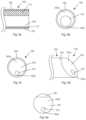
- FIGS. 5 a to 5 care illustrations of an embodiment in which an electrically conductive tubular member receives an electrically insulating insert
- FIGS. 6 a and 6 bare illustrations of embodiment of a device wherein the distal portion is partially recessed or cut away;
- FIGS. 7 a - care illustrations of embodiments of a device with an off-center elongate curved electrode
- FIG. 8is an illustration of an embodiment of a surgical device with a non-conductive elongate member
- FIGS. 9 a and 9 billustrate an embodiment with a rectangular-shaped protruding electrode
- FIGS. 10 a and 10 billustrate an embodiment with a star-shaped (or pie cutter-shaped) protruding electrode
- FIG. 11illustrates a bi-polar embodiment with peripheral cutting electrodes
- FIG. 12illustrates a bi-polar embodiment with central transverse cutting
- FIGS. 13 a and 13 billustrate an embodiment of a method of puncturing tissue within a heart
- FIG. 14illustrates an embodiment with a protruding electrode and a support ring
- FIG. 15illustrates an embodiment with a protruding electrode and optional support members
- FIG. 16illustrates an embodiment with a protruding electrode having a widened portion.
- Devices used for puncturing tissueare typically either mechanical or electrosurgical in nature.
- Some electrosurgical devicesincorporate side-ports and do not have a forward facing lumen aperture, and consequently lack the ability, for example, to effectively inject fluid or monitor fluid pressure when confined inside of a close-fitting dilator lumen.
- a guide-wireWhile it is possible in some cases for a guide-wire to be passed through or to be received by a side-port, in general, devices lacking a forward facing aperture do not facilitate the use of a guide-wire with the device.
- devices with a forward facing apertureare typically more effective in injecting fluid, monitoring pressure, and typically better facilitate usage of a guide-wire than a side-port device.
- a conventional Brockenbrough transseptal needle with a sharp beveled tiphas a forward facing aperture that may be used for injecting fluid or monitoring pressure.
- conventional transseptal needlestypically utilize mechanical force to puncture tissue, which is not effective at puncturing tissue under certain circumstances.
- an electrocautery generator or the liketo electrify the mechanical needle and to thereby produce an ad hoc electrosurgical device with a forward facing aperture.
- One drawback to electrifying a Brockenbrough needleis the risk of tissue coring.
- a core (or plug) of tissueis typically cut from surrounding tissue upon delivery of energy and is subsequently captured in the lumen of the electrosurgical device upon advancement of the needle through tissue.
- the tissue coremay be released from the lumen by flushing, potentially leading to emboli and increasing the risk of a stroke or some other ischemic event. Furthermore, a non-insulated and electrified Brockenbrough needle bears an additional increased risk of burns to the patient and physician.
- This disclosureincludes different embodiments of an electrosurgical device that has a distal face for creating an elongate initial puncture that is configured to be dilated when the device is advanced while reducing the risks of tissue coring and emboli formation.
- Embodiments of the devicealso have a forward facing lumen aperture to provide for pressure monitoring, forward fluid delivery, and to facilitate being used with a guide-wire.
- the distal surface of an electrodedefines at least one elongate portion (when seen from the end view), whereby the device creates a puncture corresponding with the at least one elongate portion thereby defining one or more flaps of tissue which the distal face of the device may push aside when the device is advanced.
- elongate electrodeis used to describe electrodes that are non-circular and that may be described as being longer in one dimension than in another.
- the distal surface of the electrodedefines an elongate shape which is generally C-shaped, U-shaped, semicircular-shaped, shaped like a segment of a circle, shaped like an arc of a circle, arcuate, crescent-shaped, rectangular-shaped, generally straight, or star-shaped (i.e. having segments radiating from a central point).
- Some embodimentshave a pair of generally parallel electrodes which are generally straight (or rectangular-shaped) and operable for bi-polar delivery of energy. While this disclosure describes electrosurgical devices that are generally circular in cross-section, the concepts and claims of this disclosure also apply to non-circular devices e.g. square-shaped, elliptical-shaped. Furthermore, some embodiments are configured such that an electrode used for puncturing tissue does not completely encircle or enclose a forward facing lumen aperture, thereby avoiding having a ring-shaped electrode that may possibly core tissue.
- the present inventorshave conceived and reduced to practice a surgical device for puncturing tissue, such as an atrial septum of a heart, wherein the surgical device allows for forward fluid delivery for staining the septum and has less risk of coring tissue relative to an electrified Brockenbrough needle or similar device.
- the devicecomprises a distal face defining at least one aperture, with the distal face including at least one cutting portion and at least one non-cutting portion cooperating to produce an elongated cut in a tissue when electrical energy is delivered to the distal face, while avoiding coring of the tissue.
- Typical embodimentscan be advanced over a guide-wire to a treatment site.
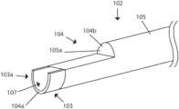
- FIG. 1is an illustration of an embodiment of a device including a handle and shaft.
- Electrosurgical device 120 of FIG. 1is comprised of elongate member 102 , electrically insulating material 105 and distal portion 110 .
- the handle 101is mechanically coupled to the proximal end of the elongate member 102 .
- Elongate member 102defines a lumen ( FIG. 4 a ).
- Distal portion 110includes electrode 103 and distal face 104 (further described herein below) which defines an aperture.
- the embodimentis operable to direct a fluid forward, as represented by fluid flow lines 140 .
- the forward facing aperturefacilitates the device being used with a guide-wire.
- electrosurgical device 120include electrically insulating material 105 covering portions of the shaft of elongate member 102 and/or distal face 104 of the device.
- the insulating materialis understood by one skilled in the art to be an effective insulator, which may be a 100 percent insulating material or a partially insulating material.
- the partially insulating materialfunctions as an effective insulator, when the device is used, by only allowing limited electrical energy flow through the partially insulating material, such that there is insufficient electrical energy to heat adjacent tissue to create a void in the tissue for advancing the electrosurgical device through.
- distal faceis with reference to the entire electrosurgical device and used to refer to the end surfaces of the device seen from the distal end view (not interior or side surfaces).
- distal surfaceis used to refer to the end surfaces seen from the distal end for a particular part of the device.
- distal surface of elongate member 102 and the distal face 104refer to the same surface, for example, the embodiment of FIG. 3 a.
- an electrosurgical device 120 for puncturing tissuecomprising: an elongate member 102 defining a lumen 109 for receiving a fluid; with distal face 104 of the electrosurgical device defining at least one aperture 107 ; and the distal face 104 including at least one cutting portion 103 a and at least one non-cutting portion 105 a cooperating to produce an elongated cut in a tissue when electrical energy is delivered to the distal face 104 while avoiding coring of the tissue.
- Some embodimentsonly have one distal aperture, while other embodiments have more than one aperture.
- the devicecan be described as having an aperture that is divided into more than one portion.
- Various embodiments of this disclosurefurther include at least one cutting portion 103 a being configured to create an initial partial puncture upon energy delivery, the initial partial puncture substantially corresponding to the at least one cutting portion.
- the “initial partial puncture”is a puncture created by energy delivery before the tissue is dilated or pushed aside when the electrosurgical device is advanced after energy delivery; the initial partial puncture is too small to receive the device without dilating or pushing aside tissue.
- distal face 104is configured for advancing while avoiding coring tissue during advancement of elongate member 102 .
- the initial punctureis dilated by distal face 104 of electrosurgical device 120 as the device is advanced; if the shaft of the elongate member is tapered there is typically further dilation by the shaft during advancement.
- elongate member 102has a length of about 30 cm to about 100 cm to facilitate the puncture of a septum of a heart. In some embodiments, the elongate member has an outer diameter of about 0.40 mm to about 1.5 mm to minimize hemodynamic stability, for example, by ensuring that the perforation will not cause hemodynamic instability once electrosurgical device 120 is removed. In some embodiments, the electrosurgical device 120 is a stiff elongate needle.
- electrosurgical device 120include an elongate member 102 having flexural rigidity of at least about 0.016 Nm 2 , for example a flexural rigidity of about 0.017 Nm 2 , to provide tactile feedback for a user of the device.
- Some embodiments of the devicehave markers for highlighting the location of important landmarks on electrosurgical device 120 .
- Such landmarksmay include the location where the elongated member 102 begins to curve, the location of the electrode 103 , or the location of the proximal edge of a beveled distal face.
- the markeris radiopaque.
- Imaging markersmay be different shapes including, but not limited to, a ring-shaped hollow band or a coil. Alternative embodiments include imaging markers that are disc-shaped, rectangular, and elongate, that define other geometric shapes, or that define symbols.
- An elongate member 102which can be comprised of one or more layers/components of plastic, other polymers, metal, or other materials, may have a marker embedded in its sidewall which may be either all metal or substantially (mostly) metal.
- the marker receiving sidewallcan be covered with a relatively thin layer of polymer, such as the sidewall being covered with a layer of electrical insulation.
- a radiopaque markershould be more radiopaque than the metal comprising the elongate member to function properly.
- the radiopaque markermay be comprised of a material that is more radiopaque than whatever material elongate member 102 is comprised of.
- the elongate membercomprises a curved section.
- the curved sectionhas a curve length of from about 10 to about 25 cm and traverses from about 20° to about 40° of a circle. In some other examples, the curved section has a curve length of from about 4 to about 7 cm and traverses from about 70 degrees to about 110 degrees of a circle.
- handle 101comprises a connector for receiving an electrical plug or other electrical connector, and a fluid port for receiving a second connector, for example, a luer lock.
- Electrical energymay be delivered from an energy source, through the connector and, typically, a wire (not shown in the drawing) located within handle 101 . The electrical energy is then conveyed to the elongate member 102 and electrode 103 .
- Some embodiments of the handle 101include a relatively large graspable surface having ridges so that tactile feedback can be transmitted relatively efficiently, for example by transmitting vibrations.
- one end of a tubingis operatively coupled to a source of fluid (not shown in drawing), for example a syringe, pump, intravenous fluid bag, etc.
- a source of fluidfor example a syringe, pump, intravenous fluid bag, etc.
- the other end of the tubingis operatively coupled with a connector to a fluid port of handle 101 which is in fluid communication with lumen 109 of elongate member 102 via a conduit in the handle (not shown), whereby the tubing and lumen 109 are in fluid communication with one another, thus allowing for a flow of fluid between an external device and lumen 109 .
- aperture 107 and the lumen 109together provide a pressure transmitting lumen which is coupled to the external tubing by a connector, and the tubing is in fluid communication with a pressure sensing device, for example, a pressure transducer.
- FIGS. 2 a to 2 cillustrate the distal portion of an embodiment of an electrosurgical device 120 in which elongate member 102 is an electrically conductive tubular member.
- Elongate member 102defines a lumen 109 for receiving a fluid.
- the fluid within the lumenmay be injected, withdrawn, or may remain substantially stationary.
- the electrically conductive tubular memberis comprised of stainless steel.
- the electrically conductive tubular memberis at least partially covered by electrically insulating material 105 with a distal portion of the electrically conductive tubular member uncovered (i.e. electrically exposed) to define electrode 103 .
- the non-cutting portion 105 a of the distal facecomprises a layer of electrical insulation, which in some embodiments (e.g. FIGS. 2 a to c ), is the same as the electrically insulating material 105 covering the shaft of the tubular member, which includes both the electrically insulating material 105 covering the shaft of the tubular member extending over the distal face 104 and the electrical insulation covering the distal face 104 being the same type of material applied separately.
- the layer of electrical insulation covering distal face 104is a different type of insulation.
- Distal face 104 of the electrosurgical devicedefines an aperture 107 which is in communication with lumen 109 .
- the layer of electrical insulation(non-cutting portion 105 a ) has the shape of a segment of a circle whereby the electrically conductive tubular member (cutting portion 103 a of FIG. 2 b ) and the layer of electrical insulation define aperture 107 .
- distal face 104is beveled and is comprised of an electrically exposed and conductive cutting portion 103 a and an electrically insulated non-cutting portion 105 a .
- the distal surface of electrode 103forms cutting portion 103 a which, in this embodiment, is generally C-shaped or arcuate shaped when viewing the distal face 104 from a distal end-view.
- Cutting portion 103 ais elongate i.e. it is non-circular and has a length greater than its width. Furthermore, cutting portion 103 a does not completely encircle, circumscribe or enclose aperture 107 but rather partially surrounds the aperture.
- the proximal portion 143 of distal face 104( FIG. 2 c ) is comprised of non-cutting portion 105 a .
- Electrically insulated portion 105 aextends from a periphery 145 of distal face 104 to partially cover the end surface of the tubular member.
- non-cutting portion 105 ais comprised of polymer insulation, which may be a heat shrink, a spray coating, or a material selectively coated by vapor deposition.
- non-cutting portion 105 acomprises a ceramic.
- the distal face of the electrically conductive tubular memberhas a step recess wherein a layer of insulation is received to thereby provide for a planar distal face 104 (i.e. to avoid having a stepped surface).
- the cutting portion 103 ais configured such that, when the electrosurgical device is advanced into a tissue, energy delivered by the electrically exposed cutting portion 103 a punctures the tissue without the tissue substantially occluding lumen 109 .
- itis the leading surface of electrode 103 that defines the cutting surface of the electrode (i.e. cutting portion 103 a ) which actually cuts into tissue when the energy delivery device is advanced while delivering energy.
- the outer perimeter of the distal surface of electrode 103defines a portion (but not all) of the perimeter of distal face 104 ( FIG.
- the devicecreates a puncture corresponding with a portion (but not all) of the perimeter of the distal face 104 , such that the puncture defines a flap of tissue which the beveled distal face pushes aside as the device is advanced.
- the embodiment of electrosurgical device 120 of FIG. 2 cincludes a distal tip 146 which is substantially rounded or atraumatic, as it is not necessary to have a sharp tip on the device for puncturing.
- the rounded tipreduces the risk of accidental tissue puncture and skiving of supporting dilators.
- the distal portion 142 of the distal faceis substantially rounded.
- the tip of the deviceis sharp.
- the planar surface of distal face 104is substantially atraumatic.
- the distal faceis beveled, in some alternative embodiments the distal face comprises a flat tip. In such embodiments, the configuration of the distal face allows electrosurgical device 120 to be operable to electrically puncture and push aside tissue without coring, as the device is advanced.
- FIGS. 3 a to dillustrate embodiments of electrosurgical device 120 wherein an electrically conductive material forms cutting portion 103 a and non-cutting portion 105 a comprises an electrically insulative coating 106 on the distal face of the device.
- the distal surface of elongate member 102includes one cutting portion 103 a and one non-cutting portion 105 a .
- Alternative embodimentscontain more than one cutting portion 103 a and/or more than one non-cutting portion 105 a .
- the electrically insulative coating 106comprises a non-polymeric layer of a material selected from the group including oxides, nitrides and ceramics. More specific examples include the layer of material being a metal oxide, silicon oxide, silicon dioxide, or diamond thin film.
- the electrically insulative coating 106may be any solid state insulating material.
- elongate member 102comprises an electrically conductive tubular member (e.g. stainless steel), and the at least one non-cutting portion 105 a comprises the electrically insulating material positioned along a portion of a distal surface of the elongate member 102 , and furthermore an electrically exposed portion of the distal surface of the elongate member 102 forms the at least one cutting portion 103 a .
- Such embodimentsmay be produced by a layer of electrically insulative oxide being deposited upon an electrically conductive metal tube by methods including (but not limited to) evaporation, chemical vapor deposition, or sputtering. This layer can be deposited on only the distal surface of the tube or it can also be deposited on the side of the tube.
- a portion, or portions, of the electrically insulative coating 106is removed by methods including (but not limited to) laser ablation, chemical etching or plasma etching to form the at least one cutting portion 103 a .
- maskingcan be used to cover the at least one cutting portion 103 a during the deposition process and the masking removed after deposition to expose the electrode, while the rest of the distal surface is covered with insulative material to form at least one non-cutting portion 105 a.
- FIGS. 3 a and 3 bare side and front perspective views, respectively, of an electrosurgical device 120 wherein the distal face 104 comprises a beveled surface.
- Non-cutting portion 105 a and electrical insulation 105 (on the shaft of elongate member 102 )are both comprised of the electrically insulative coating 106 .
- Cutting portion 103 ais comprised of the distal surface of electrode 103 .
- the distal portion of the electrically insulating material 105 on the shaft of elongate member 102is comprised of the electrically insulative coating 106 (described above) and the proximal portion is comprised of polymer 105 b .
- the distal face 104 of the devicecomprises a substantially flat tip.
- the at least one cutting portionis located on the distal face 104 along an inner surface of the elongate member 102 i.e. the cutting portion 103 a is adjacent aperture 107 while not extending to the outer periphery of the distal face 104 .
- Non-polymeric coatings disclosed abovecan function as effective insulators in thinner layers than typical polymers.
- the electrically insulative coatingcomprises a layer less than about 1 micron thick.
- the electrically insulative coatingcomprises a layer from about 100 nanometers to about 1 micron thick.
- the electrically insulative coatingcomprises a layer about 1 micron to about 50 microns thick.
- the electrically insulative coatingcomprises a layer about 1 micron to about 25 microns thick, and some more specific examples, the electrically insulative coating comprises a layer about 1 micron to about 10 microns thick.
- the at least one non-cutting portion of the distal faceis comprised of a partially electrically insulating layer.
- FIGS. 4 a to gare for an electrosurgical device 120 for puncturing tissue comprising an elongate member 102 defining a lumen 109 ( FIG. 4 a ) for receiving a fluid.
- a distal surface of the elongate member 102defines an aperture 107 and an electrically conductive portion (the distal surface of electrode 103 ) at least partially surrounding the aperture.
- the electrically conductive portiondefines a biased electrode 103 structured to produce a non-coring cut in tissue when energy is delivered to the distal surface.
- the distal surfaceincludes a non-cutting portion 105 a and a cutting portion 103 a , as to be explained below.
- the distal surface of the elongate member 102is configured for advancing while avoiding coring during advancement of the elongate member.
- FIGS. 4 a to dshow embodiments having an electrically conductive elongate member 102 having a layer of electrically insulating material 105 covering the shaft of the elongate member.
- the distal surface of elongate member 102is indicated by electrode 103 (which is also the electrically conductive portion), and the distal face 104 of electrosurgical device 120 includes electrically insulating material 105 .
- the embodiment of FIG. 4 eincludes a distal face 104 wherein the electrically insulating material 105 extends over a portion of the electrode 103 .
- the electrically conductive portiondefines an outer perimeter
- a narrow region of the electrically conductive portionincludes the part of the outer perimeter which is closest to the aperture (e.g. the bottom of electrode 103 in FIG. 4 c ) and a wide region of the electrically conductive portion includes the part of the outer perimeter which is furthest from the aperture (e.g. the top of electrode 103 in FIG. 4 c ), to thereby define, respectively, a narrow conductive region and a wide conductive region.
- the voltageis the same for the narrow and wide conductive regions, while the electrical field strength and electrical flow is more concentrated through the narrow conductive region into adjacent tissue than through the wide conductive region, whereby tissue adjacent the narrow conductive region heats to a higher temperature than tissue adjacent the wide conductive region.
- tissue adjacent the wide conductive regionheats to 50 degrees Celsius, which does not electrically perforate tissue, while the tissue adjacent at least a portion of narrow conductive region heats to 300 degrees Celsius, which does electrically perforate tissue.
- having the electrically conductive portion configured to provide a greater concentration of electrical flow through the narrow conductive region than through the wide conductive regiondefines a biased electrode wherein the narrow conductive region includes at least some of the cutting portion 103 a and the wide conductive region includes at least some of the non-cutting portion 105 a.
- Electrode 103has the general configuration of a plate and is comprised of an electrically conductive material, for example, metal. It has no sharp corners or edges to prevent the formation of hot spots caused by discontinuities. In the embodiment of FIGS. 4 f and g , electrode 103 covers the end surface of the electrically insulating material 105 such that the distal surface of electrode 103 forms the distal face 104 of electrosurgical device 120 .
- Some embodimentsinclude at least a part of the narrow conductive region is arcuate-shaped.
- the part of the narrow conductive region which is arcuate-shapedincludes a portion having a substantially constant radial width or thickness.
- FIG. 4 dhas a distal face 104 which is beveled, while the embodiment of FIGS. 4 a and f each have a distal face 104 comprising a substantially flat surfaced tip.
- FIGS. 5 a to 5 cillustrate another embodiment of electrosurgical device 120 wherein the elongate member 102 comprises an electrically conductive tubular member 112 at least partially covered by electrically insulating material 105 , the electrically conductive tubular member 112 having a cut away portion proximal of the distal face 104 (of electrosurgical device 120 ), and the electrosurgical device 120 further comprising an electrically insulating insert 144 located in the cut away portion.
- the distal face 104 of the electrosurgical devicecomprises a distal surface of the electrically conductive tubular member defining the at least one cutting portion 103 a and a distal surface of the electrically insulating insert 144 defining at least a portion of the at least one non-cutting portion 105 a .
- the distal face 104 of electrosurgical device 120is beveled. In some alternative embodiments, distal face 104 defines a flat tip.
- electrically insulating insert 144is a polymer. In some embodiments, electrically insulating insert 144 is a stiff plastic, and in some particular embodiments is re-flowed FEP (Fluorinated ethylene propylene).
- FIG. 5 cwhich is a rotated side-view, illustrates the device with electrically insulating material 105 partially cut away and shows how electrically conductive tubular member 112 receives electrically insulating insert 144 .
- FIG. 5 bis a cut-away side-view illustrating that electrode 103 extends from electrically conductive tubular member 112 .
- the side-view of FIG. 5 a and FIG. 5 bshow that electrode 103 is an electrically exposed portion of tubular member 112 (i.e. the electrode is continuous with conductive tubular member 112 ) and is not covered by electrically insulating material 105 .
- FIG. 5 ashows the electrically insulating insert 144 located between a layer of electrically insulating material 105 and electrode 103 .
- FIGS. 5 b and 5 cshow how electrically insulating insert 144 fits into the cut away portion in electrically conductive tubular member 112 , and that insulating material 105 encloses both conductive insert 44 and electrically conductive tubular member 112 .
- the electrically insulated portion 105 a of distal face 104is comprised of the end surfaces of both electrically insulating material 105 and electrically insulating insert 144 .
- Electrically exposed conductive portion 103 ais comprised of the distal surface of electrode 103 .
- the end views of FIG. 5show that electrically exposed conductive portion 103 a has a shape of a segment of a circle and that electrically insulated portion 105 a extends radially from aperture 107 to the periphery 145 of the distal face 104 .
- the electrically insulating insert 144defines aperture 107 . Electrically exposed conductive portion 103 a does not fully or partially encircle aperture 107 , but instead is lateral to aperture 107 , and consequently does not form a ring-shaped electrode capable of coring out tissue.
- FIGS. 6 a and billustrate embodiments of electrosurgical device 120 wherein a distal end of the elongate member 102 is asymmetrically truncated to define a stepped distal face 104 (of electrosurgical device 120 ) having a leading portion 104 a and a recessed portion 104 b .
- the leading portion 104 aincludes the cutting portion 103 a
- the recessed portion 104 bincludes the non-cutting portion 105 a .
- the leading portion 104 ais arcuate-shaped.
- the elongate member 102comprises an electrically conductive tubular member at least partially covered by electrically insulating material 105 .
- non-cutting portion 105 acomprises an electrically insulating polymer layer.
- recessed portion 104 bdefines a substantially flat surface comprising non-cutting portion 105 a and leading portion 104 a defines a flat tip.
- leading portion 104 adefines beveled corners 147 and recessed portion 104 b defines a sloped surface at least partially defining the at least one non-cutting portion.
- leading portion 104 ais beveled.
- FIGS. 7 a to cillustrate examples of electrosurgical device 120 wherein the at least one cutting portion cutting portion 103 a is substantially arcuate and is located along an inner surface of elongate member 102 .
- the at least one cutting portion 103 acomprises an electrically conductive material
- the at least one non-cutting portion 105 acomprises an electrically insulating layer and is positioned along a distal surface of the elongate member.
- cutting portion 103 ais crescent-shaped.
- FIG. 7 cillustrates an embodiment wherein distal face 104 is beveled. All of the examples of FIG. 7 have a forward facing aperture 107 .
- Some alternative embodimentsinclude a cutting portion 103 a which is embedded in a wall of elongate member 102 .
- Some other alternative embodimentsinclude elongate member 102 comprising an electrically conductive tubular member at least partially covered by an electrically insulating material 105 , and the at least one non-cutting portion 105 a comprises the electrically insulating material positioned along a portion of a distal surface of the elongate member 102 , and wherein an electrically exposed portion of the distal surface of the elongate member 102 forms the at least one cutting portion 103 a with the at least one cutting portion being located on the distal face 104 along an inner surface of the elongate member 102 i.e. the cutting portion 103 a is adjacent aperture 107 while not extending to the outer periphery of the distal face 104 .
- elongate member 102is comprised of a non-conductive material (e.g. polymer), with the at least one cutting portion 103 a being an electrode which is substantially arcuate and located along an inner surface of elongate member 102 , and an electrically conductive wire extending to the electrode for supplying electrical power thereto.
- a non-conductive materiale.g. polymer
- FIG. 8is for an electrosurgical device 120 comprising: an elongate member 102 comprising an electrically non-conductive material and defining a lumen 109 for receiving a fluid; a distal face 104 defining an aperture; and the distal face 104 including at least one cutting portion 103 a and at least one non-cutting portion 105 a configured for cooperating to produce an elongated cut in a tissue when electrical energy is delivered to distal face 104 , while avoiding coring of the tissue.
- a distal end surface of elongate member 102defines aperture 107 .
- elongate member 102is comprised of polymer. In the embodiment of FIG.
- a distal end surface of electrode 103is located at a distal end of elongate member 102 and includes the at least one cutting portion 103 a .
- the illustrated embodimenthas a beveled distal face 104 .
- the distal end surface of electrode 103is crescent shaped, while in some other embodiments, the distal end surface has the shape of a segment of a circle.
- wire 111is embedded in a sidewall of elongate member 102 and is connected to electrode 103 for delivering energy thereto.
- wire 111is contained in a lumen of appropriate size.
- non-cutting portion 105 ais located at a proximal portion of distal face 104 and is comprised of the distal surface of elongate member 102 .
- non-cutting portion 105 ais comprised of polymer.
- non-cutting portion 105 aencircles aperture 107
- cutting portion 103 adoes not encircle aperture 107 , but instead is lateral to aperture 107 , and consequently does not form a ring-shaped electrode capable of coring tissue.
- FIGS. 9 and 10are for an electrosurgical device 120 comprising a protruding electrode 103 defining a leading surface 104 c ( FIGS. 9 a and 10 b ) distal of the elongate member 102 , with the leading surface 104 c including the at least one cutting portion 103 a .
- Distal face 104comprises a trailing surface 104 d ( FIGS. 9 a and 10 b ) defined by a distal end surface of the elongate member 102 .
- Trailing surface 104 dcomprises an electrically insulating material 105 to form non-cutting portion 105 a .
- leading surface 104 cis substantially flat.
- protruding electrode 103is connected to a rotary mechanism such that the leading surface 104 c may be rotated when energy is delivered.
- Distal face 104 of the electrosurgical deviceincludes leading surface 104 c and trailing surface 104 d.
- protruding electrode 103substantially bisects the aperture 107 into two parts.
- the protruding electrode 103when seen in end view, is substantially rectangular-shaped.
- the leading surface 104 cis substantially rectangular-shaped.
- electrosurgical device 120include the protruding electrode 103 comprising at least three elongate portions radiating from a center point 103 b . Some such devices include the protruding electrode 103 substantially dividing the aperture 107 into at least three pie slice shaped wedges. Some embodiments include protruding electrode 103 defining leading surface 104 c as having at least three elongate portions radiating from a center point 103 b . The example of FIG. 10 has six elongate portions of electrodes 103 radiating from a center point 103 b to divide aperture 107 into to six wedge-shaped segments. Some embodiments further include the at least three elongate portions of the leading surface 104 c sloping proximally as they radiate from the center point 103 b.
- FIGS. 9 and 10include an elongate member 102 comprising an electrically conductive tubular member with an electrically insulating material 105 on the tubular member's distal surface to form non-cutting portion 105 a .
- Some alternative embodimentsinclude elongate member 102 comprising a non-conductive material, for example, polymer.
- FIGS. 14 , 15 and 16are for an electrosurgical device 120 comprising a protruding electrode 103 defining a leading surface 104 c distal of the elongate member 102 , with the leading surface 104 c including the at least one cutting portion 103 a .
- Distal face 104comprises a trailing surface 104 d defined by a distal end surface of the elongate member 102 .
- Trailing surface 104 dcomprises an electrically insulating material 105 to form non-cutting portion 105 a.
- protruding electrode 103when seen in end view, is located within aperture 107 , leaving the rest of the aperture open.
- the protruding electrode 103when seen in end view, may be non-elongated and may have some other configuration, such as, for example, having a circular, square, or rectangular shape.
- leading surface 104 cwhen seen in end view, may be non-elongated and may have some other configuration.
- leading surface 104 cis rounded or domed, while in some alternative embodiments, it is substantially flat.
- FIGS. 14 , 15 and 16include an elongate member 102 comprising an electrically conductive tubular member with an electrically insulating material 105 on the tubular member's distal surface to form non-cutting portion 105 a .
- Some alternative embodimentsinclude elongate member 102 comprising a non-conductive material, for example, polymer.
- FIG. 14includes a support ring 153 for retaining and supporting electrode 103 .
- support ringhas a limited thickness while in alternative embodiments it persists or extends into the lumen.
- support ring 153is comprised of a non-conductive material and an electrically conductive wire connects electrode 103 to an electrically conductive tubular member.
- support ring 153is comprised of an electrically conductive material, such as metal, with insulation thereupon, with support ring 153 being in electrical communication with an electrically conductive tubular member.
- the generally J-shaped electrode 103is connected to an electrically conductive tubular member at point of attachment 152 .
- the electrodehas some type of stabilizing means, such as, for example, support members 150 .
- the embodiment of FIG. 16includes an electrode 103 having a widened portion which is attached to the inner surface of the electrically conductive tubular member along two longitudinal portions of the tube.
- the widened portionhas a rectangular shape when seen from an end view or a side view.
- the widened portionis attached proximal of the distal face of the device.
- the widened portionis attached adjacent the distal face of the device, whereby the portion of the electrode which increases in width will facilitate dilation of tissue as the device is advanced therethrough.
- FIGS. 14 , 15 and 16provide puncturing, dilation, and forward fluid delivery, while avoiding coring.
- the puncture shapewill correspond with the configuration of the electrode's cutting portion 103 a and be non-elongate (e.g. circular or square shaped).
- these embodimentsinclude an electrosurgical device for puncturing tissue comprising an elongate member 102 defining a lumen 109 for receiving a fluid; a distal face defining at least one aperture 107 ; and the distal face including at least one cutting portion 103 a and at least one non-cutting portion 105 a cooperating to produce a cut in a tissue, which may be non-elongate, when electrical energy is delivered to the distal face, while avoiding coring of the tissue.
- the devicecreates a puncture corresponding with the leading surface 104 c with the puncture being surrounded by tissue which the distal face of the device may push aside when the device is advanced.
- the embodiment of the electrosurgical device of FIG. 11includes the at least one cutting portion 103 a being arcuate-shaped and partially surrounding aperture 107 , with the at least one cutting portion 103 a comprising at least one active electrode 103 (indicated by “A” in FIG. 11 ) and at least one return electrode 103 (indicated by “R” in FIG. 11 ) being operable for bi-polar energy delivery.
- the at least one cutting portion 103 acomprising at least one active electrode 103 (indicated by “A” in FIG. 11 ) and at least one return electrode 103 (indicated by “R” in FIG. 11 ) being operable for bi-polar energy delivery.
- embodimentshave pairs of electrodes, one active and one return, whereby typical embodiments have 2, 4, 8, 10 or more electrodes.
- cutting portion 103 acomprises a 180 degree arc of a circle.
- Cutting portion 103 a of FIG. 11includes four active electrodes and four return electrodes arranged in an alternating pattern.
- non-cutting portion 105 acomprises an electrically insulating material 105 .
- the example illustrated in FIG. 12is for another bi-polar device.
- the electrosurgical device of FIG. 12includes the at least one cutting portion 103 a comprising an active electrode 103 (indicated by “A” in FIG. 12 ) and a return electrode 103 (indicated by “B” in FIG. 12 ) parallel to one another and substantially extending across the aperture 107 , the active electrode and the return electrode being operable for bi-polar energy delivery.
- the aperture 107is between the active electrode and the return electrode, as shown in the drawing.
- the portion of the distal face 104 between the active electrode and the elongate member 102 , and the portion of the distal face between the return electrode and the elongate member 102are both comprised of electrically insulating material 105 .
- the distal face 104 of the electrosurgical deviceincludes the above described cutting portion 103 a and non-cutting portion 105 a.
- FIGS. 13 a and 13 billustrate an embodiment of a method of puncturing tissue.
- the methodcomprises the steps of (a) delivering energy through electrically exposed conductive portion 103 a of electrosurgical device 120 to tissue 141 at a target site for creating a puncture substantially corresponding to an elongate cutting portion of the distal face of the electrosurgical device; and (b) dilating or widening the puncture primarily by advancing a flat-tipped or angled distal surface of the electrosurgical device, without coring the tissue.
- the step of delivering energycomprises creating a flap in the tissue and the step of dilating or widening is completed without further delivery of energy.
- the target siteis a tissue within a heart, and in some particular embodiments the tissue is an atrial septum 132 .
- the methoduses a sheath, for example, sheath 130 of FIG. 7 a .
- the term dilateis used herein to mean “to make wider, larger, or more open”.
- An alternative embodiment of a method of puncturing tissuecomprises the steps of (a) delivering energy through a cutting portion a distal face of an electrosurgical device to tissue at a target site to create an elongate puncture through the tissue, while preventing delivery of energy from a non-cutting portion of the distal face; and (b) advancing the electrosurgical device through the tissue by pushing aside a flap of tissue defined by the puncture.
- the step of delivering energycomprises creating a slit or slits (e.g. using the FIG. 10 embodiment) in the tissue.
- Dilating the puncturetypically includes displacing the tissue.
- dilationincludes wedging apart and thereby outwardly compressing surrounding portions of the tissue.
- Some embodiments of the methodinclude using a medical imaging modality to guide the electrosurgical device 120 to the target site. Some embodiments comprise measuring pressure for positioning electrosurgical device 120 at the target site. In some embodiments, the method includes using a radiopaque marker 160 for positioning electrosurgical device 120 . Some embodiments include advancing the electrosurgical device to the target site over a guide-wire.
- the methodincludes advancing electrosurgical device 120 to the target site through a dilator 128 ; positioning electrosurgical device 120 such that cutting portion 103 a is aligned with or protruding slightly from a distal end of the dilator 128 ; and delivering fluid through an aperture 107 (e.g. FIG. 3 ) at a distal end of electrosurgical device 120 to stain the tissue.
- the fluidis typically delivered longitudinally forward through the electrosurgical device.
- Some embodimentsfurther comprise a step of withdrawing a fluid via an open distal face of the electrosurgical device.
- the distal surface of the electrically exposed conductive portion 103 ais generally C-shaped and step (b) includes creating a generally C-shaped puncture. In some other embodiments, the distal surface of the electrically exposed conductive portion is generally crescent-shaped and step (b) includes creating a generally crescent-shaped puncture. In yet other embodiments, the distal surface of the electrically exposed conductive portion is generally arcuate-shaped and step (b) includes creating a generally arcuate-shaped puncture.
- the aperture 107 and the lumen 109together comprise a pressure transmitting lumen, and the method further comprises measuring a fluid pressure of the pressure transmitting lumen using a pressure sensing mechanism.
- RF perforation or puncturing procedureunlike RF ablation, energy is applied to rapidly increase tissue temperature to the extent that the intracellular fluid becomes converted to steam, inducing cell lysis as a result of elevated pressure within the cell. Upon the occurrence of cell lysis and rupture, a void is created, allowing the tip of the catheter to penetrate the tissue.
- RF perforation devicesmust apply a high voltage to the tissue region over a short period of time.
- the tip of the device being usedshould be relatively small, in order to increase the impedance of the device. This is in contrast to RF ablation, whereby a larger-tipped device is utilized to deliver a low impedance and high power signal to the region involved.
- perforationis defined as the creation of a void within a material.
- Embodiments of the present inventionare operable to create such punctures or voids without substantially removing a plug or core of material from the tissue at the target site, since the puncture resulting from devices as described hereinabove are typically slit-like, C-shaped, or similar configurations substantially corresponding to the shape(s) of the cutting portion of the distal face of the electrosurgical device.
- Electrosurgical device 120may be used in conjunction with a source of radiofrequency energy suitable for perforating material within a patient's body.
- the source of energymay be a radiofrequency (RF) electrical generator, operable in the range of about 100 kHz to about 1000 kHz, and designed to generate a high voltage over a short period of time. More specifically, in some embodiments, the voltage generated by the generator increases from about 0 V (peak-to-peak) to greater than about 75 V (peak-to-peak) in less than about 0.6 seconds.
- the maximum voltage generated by generatormay be between about 180V peak-to-peak and about 3000V peak-to-peak.
- the waveform generatedmay vary, and may include, for example, a sine-wave, a rectangular-wave, or a pulsed rectangular wave, amongst others.
- the impedance loadmay increase due to tissue lesioning near the target-site, or the formation of a vapor layer following cell rupture, for example.
- the generatormay be operable to continue to increase the voltage, even as the impedance load increases.
- energymay be delivered to a tissue within a body at a voltage that rapidly increases from about 0 V (RMS) to about 220 V (RMS) for a period of between about 0.5 seconds and about 5 seconds.
- dielectric breakdown and arcingmay occur upon the delivery of radiofrequency energy, whereby polar molecules may be pulled apart.
- the combination of these factorsmay result in the creation of an insulative vapor layer around the electrode, therein resulting in an increase in impedance, for example the impedance may increase to greater than 4000 ⁇ .
- the voltagecontinues to increase. Further increasing the voltage increases the intensity of fulguration, which may be desirable as it allows for an increased perforation rate and puncture creation.
- An example of an appropriate generator for this applicationis the BMC RF Perforation Generator (model number RFP-100A, Baylis Medical Company, Montreal, Canada) This generator delivers continuous RF energy at about 460 kHz.
- a grounding pad or dispersive electrodemay be electrically coupled to the generator for contacting or attaching to the body of the patient to provide a return path for the RF energy when the generator is operated in a monopolar mode.
- an electrosurgical devicecomprising a distal face defining at least one aperture, and the distal face including at least one cutting portion and at least one non-cutting portion cooperating to produce an elongated cut in a tissue when electrical energy is delivered to the distal face, while avoiding coring of the tissue.
- FIG. 2 embodimentsCut C-shaped punctures that correspond to the shape of the electrode when viewed from the end, resulting in a flap of skin that is displaced sideways by the proximal portion of distal face 104 when electrosurgical device 120 is advanced, whereby the C-shaped puncture is dilated.
Landscapes
- Health & Medical Sciences (AREA)
- Surgery (AREA)
- Engineering & Computer Science (AREA)
- Life Sciences & Earth Sciences (AREA)
- Biomedical Technology (AREA)
- Otolaryngology (AREA)
- Nuclear Medicine, Radiotherapy & Molecular Imaging (AREA)
- Plasma & Fusion (AREA)
- Physics & Mathematics (AREA)
- Heart & Thoracic Surgery (AREA)
- Medical Informatics (AREA)
- Molecular Biology (AREA)
- Animal Behavior & Ethology (AREA)
- General Health & Medical Sciences (AREA)
- Public Health (AREA)
- Veterinary Medicine (AREA)
- Surgical Instruments (AREA)
Abstract
Description
Claims (13)
Priority Applications (2)
| Application Number | Priority Date | Filing Date | Title |
|---|---|---|---|
| US16/423,092US12011210B2 (en) | 2013-03-15 | 2019-05-27 | Electrosurgical device having a distal aperture |
| US18/526,904US20240090939A1 (en) | 2013-03-15 | 2023-12-01 | Electrosurgical device having a distal aperture |
Applications Claiming Priority (6)
| Application Number | Priority Date | Filing Date | Title |
|---|---|---|---|
| US201361787617P | 2013-03-15 | 2013-03-15 | |
| PCT/IB2014/059641WO2014141077A1 (en) | 2013-03-15 | 2014-03-11 | Electrosurgical device having a distal aperture |
| PCT/IB2014/064600WO2015136338A1 (en) | 2013-03-15 | 2014-09-17 | Electrosurgical device having a distal aperture |
| US14/850,545US10751115B2 (en) | 2013-03-15 | 2015-09-10 | Electrosurgical device having a distal aperture |
| US15/262,715US11020173B2 (en) | 2013-03-15 | 2016-09-12 | Electrosurgical device having a distal aperture |
| US16/423,092US12011210B2 (en) | 2013-03-15 | 2019-05-27 | Electrosurgical device having a distal aperture |
Related Parent Applications (1)
| Application Number | Title | Priority Date | Filing Date |
|---|---|---|---|
| US15/262,715ContinuationUS11020173B2 (en) | 2013-03-15 | 2016-09-12 | Electrosurgical device having a distal aperture |
Related Child Applications (1)
| Application Number | Title | Priority Date | Filing Date |
|---|---|---|---|
| US18/526,904ContinuationUS20240090939A1 (en) | 2013-03-15 | 2023-12-01 | Electrosurgical device having a distal aperture |
Publications (2)
| Publication Number | Publication Date |
|---|---|
| US20190274754A1 US20190274754A1 (en) | 2019-09-12 |
| US12011210B2true US12011210B2 (en) | 2024-06-18 |
Family
ID=57754856
Family Applications (3)
| Application Number | Title | Priority Date | Filing Date |
|---|---|---|---|
| US15/262,715Active2034-10-29US11020173B2 (en) | 2013-03-15 | 2016-09-12 | Electrosurgical device having a distal aperture |
| US16/423,092Active2034-05-03US12011210B2 (en) | 2013-03-15 | 2019-05-27 | Electrosurgical device having a distal aperture |
| US18/526,904PendingUS20240090939A1 (en) | 2013-03-15 | 2023-12-01 | Electrosurgical device having a distal aperture |
Family Applications Before (1)
| Application Number | Title | Priority Date | Filing Date |
|---|---|---|---|
| US15/262,715Active2034-10-29US11020173B2 (en) | 2013-03-15 | 2016-09-12 | Electrosurgical device having a distal aperture |
Family Applications After (1)
| Application Number | Title | Priority Date | Filing Date |
|---|---|---|---|
| US18/526,904PendingUS20240090939A1 (en) | 2013-03-15 | 2023-12-01 | Electrosurgical device having a distal aperture |
Country Status (2)
| Country | Link |
|---|---|
| US (3) | US11020173B2 (en) |
| CA (1) | CA3220441A1 (en) |
Families Citing this family (12)
| Publication number | Priority date | Publication date | Assignee | Title |
|---|---|---|---|---|
| JP6526640B2 (en)* | 2013-10-01 | 2019-06-05 | マフィン・インコーポレイテッドMuffin Incorporated | Wire extrapolation ultrasound system |
| WO2018062387A1 (en)* | 2016-09-30 | 2018-04-05 | テルモ株式会社 | Medical device and treatment method |
| CA3099451A1 (en)* | 2018-05-08 | 2019-11-14 | Baylis Medical Company Inc. | Methods and devices for puncturing tissue |
| EP3628255A1 (en)* | 2018-09-26 | 2020-04-01 | Erbe Elektromedizin GmbH | Hf surgical preparation instrument with fluid channel |
| US11090080B2 (en)* | 2019-05-15 | 2021-08-17 | Indian Wells Medical, Inc. | Steerable endoluminal punch with introducer |
| CA3167407A1 (en)* | 2020-02-11 | 2021-08-19 | John Paul Urbanski | Medical dilator |
| AU2021238998A1 (en)* | 2020-03-20 | 2022-09-22 | Boston Scientific Medical Device Limited | Needle assembly for forming hole through biological wall |
| US20210353356A1 (en)* | 2020-05-14 | 2021-11-18 | Singlepass Transsepat, Inc. | Tubular large bore transseptal crossing sheath |
| US20230380891A1 (en)* | 2022-05-26 | 2023-11-30 | Biosense Webster (Israel) Ltd. | Port and depth stop and tip features for transseptal puncture apparatus |
| US20240206944A1 (en)* | 2022-12-22 | 2024-06-27 | Boston Scientific Medical Device Limited | Open lumen radiofrequency needle |
| CN120676915A (en) | 2022-12-28 | 2025-09-19 | 阿特拉弗斯医疗股份有限公司 | Methods, systems and devices for perforating tissue structures |
| WO2025132257A1 (en)* | 2023-12-18 | 2025-06-26 | Boston Scientific Medical Device Limited | Open-tipped radiofrequency perforation device |
Citations (316)
| Publication number | Priority date | Publication date | Assignee | Title |
|---|---|---|---|---|
| US175254A (en) | 1876-03-28 | Improvement in game apparatus | ||
| US827626A (en) | 1905-02-15 | 1906-07-31 | Alexis F Gillet | Game apparatus. |
| US848711A (en) | 1906-06-28 | 1907-04-02 | Daniel Weaver | Game apparatus. |
| US1072954A (en) | 1913-03-29 | 1913-09-09 | Frank B Junn | Game apparatus. |
| US1279654A (en) | 1916-04-14 | 1918-09-24 | Horace M Charlesworth | Game apparatus. |
| US1918094A (en) | 1931-04-04 | 1933-07-11 | Demetrius G Geekas | Game device |
| US1996986A (en) | 1932-05-13 | 1935-04-09 | Weinberg Alexander | Game apparatus |
| US2021989A (en) | 1931-12-08 | 1935-11-26 | Master Matthew J De | Ball tossing game |
| US2146636A (en) | 1937-01-09 | 1939-02-07 | Walter F Lipchow | Baseball game |
| US3429574A (en) | 1965-08-12 | 1969-02-25 | Charles L Williams | Game with ball-receiving spaced divider members |
| US3448739A (en) | 1966-08-22 | 1969-06-10 | Edwards Lab Inc | Double lumen diagnostic balloon catheter |
| US3575415A (en) | 1968-05-17 | 1971-04-20 | Franklin G Fulp | Pocketed ball-receiving target |
| US3595239A (en) | 1969-04-04 | 1971-07-27 | Roy A Petersen | Catheter with electrical cutting means |
| US4129129A (en) | 1977-03-18 | 1978-12-12 | Sarns, Inc. | Venous return catheter and a method of using the same |
| US4244362A (en) | 1978-11-29 | 1981-01-13 | Anderson Charles C | Endotracheal tube control device |
| US4401124A (en) | 1981-08-13 | 1983-08-30 | Technicare Corporation | Reflection enhancement of a biopsy needle |
| US4639252A (en) | 1985-04-05 | 1987-01-27 | Research Medical, Inc. | Venous return catheter |
| US4641649A (en) | 1985-10-30 | 1987-02-10 | Rca Corporation | Method and apparatus for high frequency catheter ablation |
| US4669467A (en) | 1985-03-22 | 1987-06-02 | Massachusetts Institute Of Technology | Mode mixer for a laser catheter |
| US4674499A (en)* | 1980-12-08 | 1987-06-23 | Pao David S C | Coaxial bipolar probe |
| US4682596A (en)* | 1984-05-22 | 1987-07-28 | Cordis Corporation | Electrosurgical catheter and method for vascular applications |
| US4790311A (en) | 1986-06-03 | 1988-12-13 | Ruiz Oscar F | Radio frequency angioplasty catheter system |
| US4790809A (en) | 1985-08-29 | 1988-12-13 | Medical Engineering Corporation | Ureteral stent |
| US4793350A (en) | 1987-01-06 | 1988-12-27 | Advanced Cardiovascular Systems, Inc. | Liquid filled low profile dilatation catheter |
| US4807620A (en) | 1987-05-22 | 1989-02-28 | Advanced Interventional Systems, Inc. | Apparatus for thermal angioplasty |
| US4832048A (en) | 1987-10-29 | 1989-05-23 | Cordis Corporation | Suction ablation catheter |
| US4840622A (en) | 1987-10-06 | 1989-06-20 | Menlo Care, Inc. | Kink resistant catheter |
| US4863441A (en) | 1987-07-17 | 1989-09-05 | Minnesota Mining And Manufacturing Company | Venous return catheter |
| US4884567A (en) | 1987-12-03 | 1989-12-05 | Dimed Inc. | Method for transvenous implantation of objects into the pericardial space of patients |
| US4892104A (en) | 1988-09-02 | 1990-01-09 | Nihon Kohden Corp. | Apparatus for inspecting an electrically stimulated heart |
| US4896671A (en) | 1988-08-01 | 1990-01-30 | C. R. Bard, Inc. | Catheter with contoured ablation electrode |
| US4928693A (en) | 1989-03-13 | 1990-05-29 | Schneider (Usa), Inc. | Pressure monitor catheter |
| US4936281A (en) | 1989-04-13 | 1990-06-26 | Everest Medical Corporation | Ultrasonically enhanced RF ablation catheter |
| US4960410A (en) | 1989-03-31 | 1990-10-02 | Cordis Corporation | Flexible tubular member for catheter construction |
| US4977897A (en) | 1988-08-17 | 1990-12-18 | Robert Hurwitz | Amniocentesis needle with improved sonographic visibility |
| US4998933A (en) | 1988-06-10 | 1991-03-12 | Advanced Angioplasty Products, Inc. | Thermal angioplasty catheter and method |
| US5006119A (en) | 1989-05-25 | 1991-04-09 | Engineering & Research Associates, Inc. | Hollow core coaxial catheter |
| US5019076A (en) | 1986-09-12 | 1991-05-28 | Yamanashi William S | Radio frequency surgical tool and method |
| US5047026A (en) | 1989-09-29 | 1991-09-10 | Everest Medical Corporation | Electrosurgical implement for tunneling through tissue |
| US5081997A (en) | 1989-03-09 | 1992-01-21 | Vance Products Incorporated | Echogenic devices, material and method |
| US5098431A (en) | 1989-04-13 | 1992-03-24 | Everest Medical Corporation | RF ablation catheter |
| US5112048A (en) | 1990-11-05 | 1992-05-12 | Kienle Robert N | Garage roof party game |
| US5154724A (en) | 1990-05-14 | 1992-10-13 | Andrews Winston A | Atherectomy catheter |
| US5201756A (en) | 1990-06-20 | 1993-04-13 | Danforth Biomedical, Inc. | Radially-expandable tubular elements for use in the construction of medical devices |
| US5209741A (en) | 1991-07-08 | 1993-05-11 | Endomedix Corporation | Surgical access device having variable post-insertion cross-sectional geometry |
| US5211183A (en) | 1987-05-13 | 1993-05-18 | Wilson Bruce C | Steerable memory alloy guide wires |
| US5221256A (en) | 1992-02-10 | 1993-06-22 | Mahurkar Sakharam D | Multiple-lumen catheter |
| US5221281A (en) | 1992-06-30 | 1993-06-22 | Valleylab Inc. | Electrosurgical tubular trocar |
| US5230349A (en) | 1988-11-25 | 1993-07-27 | Sensor Electronics, Inc. | Electrical heating catheter |
| US5281216A (en) | 1992-03-31 | 1994-01-25 | Valleylab, Inc. | Electrosurgical bipolar treating apparatus |
| US5300069A (en) | 1992-08-12 | 1994-04-05 | Daniel Hunsberger | Electrosurgical apparatus for laparoscopic procedures and method of use |
| US5300068A (en) | 1992-04-21 | 1994-04-05 | St. Jude Medical, Inc. | Electrosurgical apparatus |
| US5314418A (en) | 1990-09-21 | 1994-05-24 | Toyo Boseki Kabushiki Kaisha | Cannula |
| US5318525A (en) | 1992-04-10 | 1994-06-07 | Medtronic Cardiorhythm | Steerable electrode catheter |
| US5327905A (en) | 1992-02-14 | 1994-07-12 | Boaz Avitall | Biplanar deflectable catheter for arrhythmogenic tissue ablation |
| US5364393A (en) | 1990-07-02 | 1994-11-15 | Heart Technology, Inc. | Tissue dissipative recanalization catheter |
| US5372596A (en) | 1993-07-27 | 1994-12-13 | Valleylab Inc. | Apparatus for leakage control and method for its use |
| US5380304A (en) | 1991-08-07 | 1995-01-10 | Cook Incorporated | Flexible, kink-resistant, introducer sheath and method of manufacture |
| US5397304A (en) | 1992-04-10 | 1995-03-14 | Medtronic Cardiorhythm | Shapable handle for steerable electrode catheter |
| US5403338A (en) | 1992-01-21 | 1995-04-04 | Scanlan International, Inc. | Punch for opening passages between two compartments |
| EP0651974A2 (en) | 1993-11-10 | 1995-05-10 | Mentor O & O Inc. | Bipolar electrosurgical instrument and method for making the instrument |
| US5423809A (en) | 1992-01-21 | 1995-06-13 | Valleylab Inc. | Electrosurgical control for a trocar |
| US5425382A (en) | 1993-09-14 | 1995-06-20 | University Of Washington | Apparatus and method for locating a medical tube in the body of a patient |
| US5490859A (en) | 1992-11-13 | 1996-02-13 | Scimed Life Systems, Inc. | Expandable intravascular occlusion material removal devices and methods of use |
| US5497774A (en) | 1993-11-03 | 1996-03-12 | Daig Corporation | Guiding introducer for left atrium |
| US5507751A (en) | 1988-11-09 | 1996-04-16 | Cook Pacemaker Corporation | Locally flexible dilator sheath |
| US5509411A (en) | 1993-01-29 | 1996-04-23 | Cardima, Inc. | Intravascular sensing device |
| US5520685A (en)* | 1994-08-04 | 1996-05-28 | Alto Development Corporation | Thermally-insulated anti-clog tip for electrocautery suction tubes |
| US5530685A (en) | 1993-11-05 | 1996-06-25 | Sharp Kabushiki Kaisha | Magneto-optical recording apparatus having paired devices for applying external magnetic fields |
| US5540681A (en) | 1992-04-10 | 1996-07-30 | Medtronic Cardiorhythm | Method and system for radiofrequency ablation of tissue |
| US5545200A (en) | 1993-07-20 | 1996-08-13 | Medtronic Cardiorhythm | Steerable electrophysiology catheter |
| US5555618A (en) | 1993-10-12 | 1996-09-17 | Arrow International Investment Corp. | Method of making electrode-carrying catheter |
| US5571088A (en) | 1993-07-01 | 1996-11-05 | Boston Scientific Corporation | Ablation catheters |
| US5575766A (en) | 1993-11-03 | 1996-11-19 | Daig Corporation | Process for the nonsurgical mapping and treatment of atrial arrhythmia using catheters guided by shaped guiding introducers |
| US5599347A (en) | 1991-02-13 | 1997-02-04 | Applied Medical Resources Corporation | Surgical trocar with cutoff circuit |
| US5605162A (en) | 1991-10-15 | 1997-02-25 | Advanced Cardiovascular Systems, Inc. | Method for using a variable stiffness guidewire |
| US5617878A (en) | 1996-05-31 | 1997-04-08 | Taheri; Syde A. | Stent and method for treatment of aortic occlusive disease |
| US5624430A (en) | 1994-11-28 | 1997-04-29 | Eton; Darwin | Magnetic device to assist transcorporeal guidewire placement |
| US5667488A (en) | 1992-08-12 | 1997-09-16 | Vidamed, Inc. | Transurethral needle ablation device and method for the treatment of the prostate |
| US5673695A (en) | 1995-08-02 | 1997-10-07 | Ep Technologies, Inc. | Methods for locating and ablating accessory pathways in the heart |
| US5674208A (en) | 1993-08-18 | 1997-10-07 | Scimed Life Systems, Inc. | Thin-walled catheter |
| US5683366A (en) | 1992-01-07 | 1997-11-04 | Arthrocare Corporation | System and method for electrosurgical tissue canalization |
| US5720744A (en) | 1995-06-06 | 1998-02-24 | Valleylab Inc | Control system for neurosurgery |
| US5741249A (en) | 1996-10-16 | 1998-04-21 | Fidus Medical Technology Corporation | Anchoring tip assembly for microwave ablation catheter |
| US5766135A (en) | 1995-03-08 | 1998-06-16 | Terwilliger; Richard A. | Echogenic needle tip |
| US5779688A (en) | 1994-10-28 | 1998-07-14 | Intella Interventional Systems, Inc. | Low profile balloon-on-a-wire catheter with shapeable and/or deflectable tip and method |
| US5830214A (en) | 1994-11-08 | 1998-11-03 | Heartport, Inc. | Fluid-evacuating electrosurgical device |
| US5836875A (en) | 1995-10-06 | 1998-11-17 | Cordis Webster, Inc. | Split tip electrode catheter |
| US5849011A (en) | 1995-06-19 | 1998-12-15 | Vidamed, Inc. | Medical device with trigger actuation assembly |
| US5851210A (en) | 1997-03-21 | 1998-12-22 | Torossian; Richard | Stent delivery system and method |
| US5885227A (en) | 1997-03-25 | 1999-03-23 | Radius Medical Technologies, Inc. | Flexible guidewire with radiopaque plastic tip |
| US5888201A (en) | 1996-02-08 | 1999-03-30 | Schneider (Usa) Inc | Titanium alloy self-expanding stent |
| US5893848A (en) | 1996-10-24 | 1999-04-13 | Plc Medical Systems, Inc. | Gauging system for monitoring channel depth in percutaneous endocardial revascularization |
| US5893885A (en) | 1996-11-01 | 1999-04-13 | Cordis Webster, Inc. | Multi-electrode ablation catheter |
| US5904679A (en) | 1989-01-18 | 1999-05-18 | Applied Medical Resources Corporation | Catheter with electrosurgical cutter |
| US5916210A (en) | 1990-01-26 | 1999-06-29 | Intraluminal Therapeutics, Inc. | Catheter for laser treatment of atherosclerotic plaque and other tissue abnormalities |
| US5921957A (en) | 1994-07-12 | 1999-07-13 | Scimed Life Systems, Inc. | Intravascular dilation catheter |
| US5931818A (en) | 1997-08-29 | 1999-08-03 | Stereotaxis, Inc. | Method of and apparatus for intraparenchymal positioning of medical devices |
| US5944023A (en) | 1995-12-07 | 1999-08-31 | Sims Deltec, Inc. | Systems and methods for determining the location of an implanted device including a magnet |
| US5951482A (en) | 1997-10-03 | 1999-09-14 | Intraluminal Therapeutics, Inc. | Assemblies and methods for advancing a guide wire through body tissue |
| US5957842A (en) | 1994-01-27 | 1999-09-28 | Cardima, Inc. | High resolution intravascular signal detection |
| US5964757A (en) | 1997-09-05 | 1999-10-12 | Cordis Webster, Inc. | Steerable direct myocardial revascularization catheter |
| US5967976A (en) | 1994-08-19 | 1999-10-19 | Novoste Corporation | Apparatus and methods for procedures related to the electrophysiology of the heart |
| US5968042A (en) | 1997-06-17 | 1999-10-19 | Ernster; Joel A. | Monopolar suction coagulator |
| US5989276A (en) | 1996-11-08 | 1999-11-23 | Advanced Bypass Technologies, Inc. | Percutaneous bypass graft and securing system |
| US6007555A (en) | 1997-04-25 | 1999-12-28 | Surgical Design Corp | Ultrasonic needle for surgical emulsification |
| US6009877A (en) | 1994-06-24 | 2000-01-04 | Edwards; Stuart D. | Method for treating a sphincter |
| US6013072A (en) | 1997-07-09 | 2000-01-11 | Intraluminal Therapeutics, Inc. | Systems and methods for steering a catheter through body tissue |
| US6017340A (en) | 1994-10-03 | 2000-01-25 | Wiltek Medical Inc. | Pre-curved wire guided papillotome having a shape memory tip for controlled bending and orientation |
| US6018676A (en) | 1993-08-31 | 2000-01-25 | Medtronic, Inc. | Ultrasound biopsy needle |
| US6030380A (en) | 1996-12-09 | 2000-02-29 | Bsc Northwest Technology Center, Inc. | Radio frequency transmyocardial revascularization |
| US6048349A (en) | 1997-07-09 | 2000-04-11 | Intraluminal Therapeutics, Inc. | Systems and methods for guiding a medical instrument through a body |
| US6053904A (en) | 1996-04-05 | 2000-04-25 | Robert M. Scribner | Thin wall catheter introducer system |
| US6053870A (en) | 1997-11-08 | 2000-04-25 | Angiodynamics, Inc. | Ultrasonic visible surgical needle |
| US6056747A (en) | 1997-08-04 | 2000-05-02 | Gynecare, Inc. | Apparatus and method for treatment of body tissues |
| US6093185A (en) | 1998-03-05 | 2000-07-25 | Scimed Life Systems, Inc. | Expandable PMR device and method |
| US6106515A (en) | 1998-08-13 | 2000-08-22 | Intraluminal Therapeutics, Inc. | Expandable laser catheter |
| US6106520A (en) | 1997-09-30 | 2000-08-22 | Hearten Medical, Inc. | Endocardial device for producing reversible damage to heart tissue |
| US6117131A (en) | 1995-06-09 | 2000-09-12 | Engineering & Research Associates, Inc. | Multi-electrode probe for thermal ablation |
| US6142992A (en) | 1993-05-10 | 2000-11-07 | Arthrocare Corporation | Power supply for limiting power in electrosurgery |
| US6142996A (en)* | 1996-11-07 | 2000-11-07 | Optex Ophthalmologics, Inc. | Methods useable for forming small openings in the lens capsules of mammalian eyes |
| US6146380A (en) | 1998-01-09 | 2000-11-14 | Radionics, Inc. | Bent tip electrical surgical probe |
| US6155264A (en) | 1997-03-06 | 2000-12-05 | Scimed Life Systems, Inc. | Percutaneous bypass by tunneling through vessel wall |
| US6156031A (en) | 1995-08-09 | 2000-12-05 | Eclipse Surgical Technologies | Transmyocardial revascularization using radiofrequency energy |
| US6171305B1 (en) | 1998-05-05 | 2001-01-09 | Cardiac Pacemakers, Inc. | RF ablation apparatus and method having high output impedance drivers |
| US6179824B1 (en) | 1993-05-10 | 2001-01-30 | Arthrocare Corporation | System and methods for electrosurgical restenosis of body lumens |
| US6193715B1 (en) | 1999-03-19 | 2001-02-27 | Medical Scientific, Inc. | Device for converting a mechanical cutting device to an electrosurgical cutting device |
| US6193676B1 (en) | 1997-10-03 | 2001-02-27 | Intraluminal Therapeutics, Inc. | Guide wire assembly |
| US6210408B1 (en) | 1999-02-24 | 2001-04-03 | Scimed Life Systems, Inc. | Guide wire system for RF recanalization of vascular blockages |
| WO2001024720A1 (en) | 1999-10-05 | 2001-04-12 | Oratec Interventions, Inc. | Surgical instrument for ablation and aspiration |
| US6217575B1 (en) | 1999-02-24 | 2001-04-17 | Scimed Life Systems, Inc. | PMR catheter |
| US6221061B1 (en) | 1993-05-12 | 2001-04-24 | Target Therapeutics, Inc. | Lubricious catheters |
| US6228076B1 (en) | 1999-01-09 | 2001-05-08 | Intraluminal Therapeutics, Inc. | System and method for controlling tissue ablation |
| US6245054B1 (en) | 1998-11-09 | 2001-06-12 | Kristine B. Fuimaono | Guiding sheath exchange system |
| US6267758B1 (en) | 1994-01-18 | 2001-07-31 | Esc Medical Systems Ltd. | Apparatus for in situ saphenous vein bypass and less-invasive varicose vein treatment |
| US6283983B1 (en) | 1995-10-13 | 2001-09-04 | Transvascular, Inc. | Percutaneous in-situ coronary bypass method and apparatus |
| US20010021867A1 (en) | 1993-03-16 | 2001-09-13 | Kordis Thomas F. | Cardiac mapping and ablation systems |
| US6292678B1 (en) | 1999-05-13 | 2001-09-18 | Stereotaxis, Inc. | Method of magnetically navigating medical devices with magnetic fields and gradients, and medical devices adapted therefor |
| US6293945B1 (en) | 2000-03-06 | 2001-09-25 | Everest Medical Corporation | Electrosurgical instrument with suction capability |
| US6296615B1 (en) | 1999-03-05 | 2001-10-02 | Data Sciences International, Inc. | Catheter with physiological sensor |
| US6304769B1 (en) | 1997-10-16 | 2001-10-16 | The Regents Of The University Of California | Magnetically directable remote guidance systems, and methods of use thereof |
| US6302898B1 (en) | 1994-06-24 | 2001-10-16 | Advanced Closure Systems, Inc. | Devices for sealing punctures in body vessels |
| US6315777B1 (en) | 1998-07-07 | 2001-11-13 | Medtronic, Inc. | Method and apparatus for creating a virtual electrode used for the ablation of tissue |
| US6328699B1 (en) | 2000-01-11 | 2001-12-11 | Cedars-Sinai Medical Center | Permanently implantable system and method for detecting, diagnosing and treating congestive heart failure |
| US20020019644A1 (en) | 1999-07-12 | 2002-02-14 | Hastings Roger N. | Magnetically guided atherectomy |
| US20020022781A1 (en) | 1998-11-06 | 2002-02-21 | Gregory Mclntire | Products and methods for brachytherapy |
| US20020022836A1 (en) | 1999-03-05 | 2002-02-21 | Gyrus Medical Limited | Electrosurgery system |
| US20020035361A1 (en) | 1999-06-25 | 2002-03-21 | Houser Russell A. | Apparatus and methods for treating tissue |
| US6364877B1 (en) | 1995-06-23 | 2002-04-02 | Gyrus Medical Limited | Electrosurgical generator and system |
| US6385472B1 (en) | 1999-09-10 | 2002-05-07 | Stereotaxis, Inc. | Magnetically navigable telescoping catheter and method of navigating telescoping catheter |
| US6395002B1 (en) | 2000-01-18 | 2002-05-28 | Alan G. Ellman | Electrosurgical instrument for ear surgery |
| US6394976B1 (en) | 2000-01-31 | 2002-05-28 | Intraluminal Therapeutics, Inc. | Catheter for controlling the advancement of a guide wire |
| US20020087153A1 (en) | 1999-08-05 | 2002-07-04 | Broncus Technologies, Inc. | Devices for creating collateral channels |
| US20020087156A1 (en) | 1997-07-08 | 2002-07-04 | Maguire Mark A. | Medical device with sensor cooperating with expandable member |
| US6419674B1 (en) | 1996-11-27 | 2002-07-16 | Cook Vascular Incorporated | Radio frequency dilator sheath |
| WO2002056805A2 (en) | 2001-01-18 | 2002-07-25 | The Regents Of The University Of California | Minimally invasive glaucoma surgical instrument and method |
| US6428551B1 (en) | 1999-03-30 | 2002-08-06 | Stereotaxis, Inc. | Magnetically navigable and/or controllable device for removing material from body lumens and cavities |
| US20020111618A1 (en) | 1999-04-05 | 2002-08-15 | Stewart Mark T. | Ablation catheter assembly with radially decreasing helix and method of use |
| US20020123749A1 (en) | 2001-03-01 | 2002-09-05 | Jain Mudit K. | Ablation catheter with transducer for providing one or more of pressure, temperature and fluid flow data for use in controlling ablation therapy |
| US6450989B2 (en) | 1998-04-27 | 2002-09-17 | Artemis Medical, Inc. | Dilating and support apparatus with disease inhibitors and methods for use |
| US20020147485A1 (en) | 2000-11-15 | 2002-10-10 | George Mamo | Minimally invasive apparatus for implanting a sacral stimulation lead |
| US6475214B1 (en) | 2000-05-01 | 2002-11-05 | Biosense Webster, Inc. | Catheter with enhanced ablation electrode |
| US20020169377A1 (en) | 2000-04-13 | 2002-11-14 | Khairkhahan Alexander K. | Method and apparatus for accessing the left atrial appendage |
| US6482202B1 (en) | 1996-06-20 | 2002-11-19 | Gyrus Medical Limited | Under water treatment |
| US20020188302A1 (en) | 1998-11-06 | 2002-12-12 | St. Jude Medical Atg, Inc. | Minimally invasive revascularization apparatus and methods |
| US20020198521A1 (en) | 1997-07-08 | 2002-12-26 | Maguire Mark A. | Circumferential ablation device assembly and methods of use and manufacture providing an ablative circumferential band along an expandable member |
| US6508754B1 (en) | 1997-09-23 | 2003-01-21 | Interventional Therapies | Source wire for radiation treatment |
| US20030032929A1 (en) | 1998-12-09 | 2003-02-13 | Mcguckin James F. | Hollow curved superelastic medical needle and method |
| US6524303B1 (en) | 2000-09-08 | 2003-02-25 | Stereotaxis, Inc. | Variable stiffness magnetic catheter |
| US20030040742A1 (en) | 1998-02-20 | 2003-02-27 | Arthrocare Corporation | Systems and methods for electrosurgical spine surgery |
| US6530923B1 (en) | 1998-02-10 | 2003-03-11 | Artemis Medical, Inc. | Tissue removal methods and apparatus |
| US6554827B2 (en) | 2000-12-11 | 2003-04-29 | Scimed Life Systems, Inc. | Radio frequency ablation system |
| US6562049B1 (en) | 2000-03-01 | 2003-05-13 | Cook Vascular Incorporated | Medical introducer apparatus |
| US6565562B1 (en) | 1997-06-27 | 2003-05-20 | Baylis Medical Company Inc. | Method for the radio frequency perforation and the enlargement of a body tissue |
| US6589240B2 (en) | 2001-08-28 | 2003-07-08 | Rex Medical, L.P. | Tissue biopsy apparatus with collapsible cutter |
| US20030144658A1 (en) | 2002-01-31 | 2003-07-31 | Yitzhack Schwartz | Radio frequency pulmonary vein isolation |
| US6607529B1 (en) | 1995-06-19 | 2003-08-19 | Medtronic Vidamed, Inc. | Electrosurgical device |
| US20030158480A1 (en) | 2000-05-15 | 2003-08-21 | Audun Tornes | Grooved medical devices with enhanced ultrasound visibility |
| US20030163153A1 (en) | 2002-02-28 | 2003-08-28 | Scheib Mark S. | Retractable dilator needle |
| US6632222B1 (en) | 1993-11-08 | 2003-10-14 | Rita Medical Systems, Inc. | Tissue ablation apparatus |
| US6639999B1 (en) | 1999-11-04 | 2003-10-28 | Eastman Kodak Company | Apparatus for assessing overall quality of hardcopy images |
| US6650923B1 (en) | 2000-04-13 | 2003-11-18 | Ev3 Sunnyvale, Inc. | Method for accessing the left atrium of the heart by locating the fossa ovalis |
| US6651672B2 (en) | 1993-02-22 | 2003-11-25 | Heartport, Inc. | Devices for less-invasive intracardiac interventions |
| US20030225392A1 (en) | 2002-05-31 | 2003-12-04 | Kimberly-Clark Worldwide, Inc. | Low profile transpyloric jejunostomy system and method to enable |
| US6662034B2 (en) | 2000-11-15 | 2003-12-09 | Stereotaxis, Inc. | Magnetically guidable electrophysiology catheter |
| US20040015162A1 (en) | 2002-07-22 | 2004-01-22 | Medtronic Vidamed, Inc. | Method for treating tissue with a wet electrode and apparatus for using same |
| US20040024396A1 (en) | 1999-12-27 | 2004-02-05 | Eggers Philip E. | Electrosurgical accessing of tissue with controlled collateral thermal phenomena |
| US20040030328A1 (en) | 2001-07-12 | 2004-02-12 | Eggers Philip E. | Electrosurgical generator |
| US20040044350A1 (en) | 1999-04-09 | 2004-03-04 | Evalve, Inc. | Steerable access sheath and methods of use |
| US6709444B1 (en) | 1996-02-02 | 2004-03-23 | Transvascular, Inc. | Methods for bypassing total or near-total obstructions in arteries or other anatomical conduits |
| US20040073243A1 (en) | 2000-06-29 | 2004-04-15 | Concentric Medical, Inc., A Delaware Corporation | Systems, methods and devices for removing obstructions from a blood vessel |
| US6723052B2 (en) | 2001-06-07 | 2004-04-20 | Stanley L. Mills | Echogenic medical device |
| US20040077948A1 (en) | 1996-11-06 | 2004-04-22 | Sts Biopolymers, Inc. | Echogenic coatings with overcoat |
| US6733511B2 (en) | 1998-10-02 | 2004-05-11 | Stereotaxis, Inc. | Magnetically navigable and/or controllable device for removing material from body lumens and cavities |
| US20040116851A1 (en) | 2002-12-16 | 2004-06-17 | Intraluminal Therapeutics, Inc. | Deflecting catheter |
| US6752800B1 (en) | 2000-02-18 | 2004-06-22 | Intraluminal Therapeutics Inc. | Catheter handle for controlling the advancement of a guide wire |
| US6755816B2 (en) | 1999-10-04 | 2004-06-29 | Stereotaxis, Inc. | Method for safely and efficiently navigating magnetic devices in the body |
| US20040127963A1 (en) | 1999-01-25 | 2004-07-01 | Uchida Andy H. | Intervertebral decompression |
| US20040133130A1 (en) | 2003-01-06 | 2004-07-08 | Ferry Steven J. | Magnetically navigable medical guidewire |
| US20040133113A1 (en) | 2002-08-24 | 2004-07-08 | Krishnan Subramaniam C. | Method and apparatus for locating the fossa ovalis and performing transseptal puncture |
| US20040143256A1 (en) | 2003-01-21 | 2004-07-22 | Bednarek Michael C. | Ablation catheter and electrode |
| US20040147950A1 (en) | 2003-01-24 | 2004-07-29 | Mueller Richard L. | Atraumatic dilator for human mammary duct |
| US20040181213A1 (en) | 2003-03-11 | 2004-09-16 | Masakatsu Gondo | Electrode rod for treating biological tissue |
| US6811544B2 (en) | 1999-05-11 | 2004-11-02 | Alan K. Schaer | Catheter positioning system |
| US20040230188A1 (en) | 2003-05-12 | 2004-11-18 | Iulian Cioanta | Treatment catheters with thermally insulated regions |
| US6820614B2 (en) | 2000-12-02 | 2004-11-23 | The Bonutti 2003 Trust -A | Tracheal intubination |
| US6834201B2 (en) | 2001-01-29 | 2004-12-21 | Stereotaxis, Inc. | Catheter navigation within an MR imaging device |
| US6842639B1 (en) | 1997-10-03 | 2005-01-11 | Intraluminal Therapeutics, Inc. | Method and apparatus for determining neovascular flow through tissue in a vessel |
| US20050010208A1 (en) | 2002-06-11 | 2005-01-13 | Winston Thomas R. | Radio frequency guide wire assembly with optical coherence reflectometry guidance |
| US6855143B2 (en) | 1997-06-13 | 2005-02-15 | Arthrocare Corporation | Electrosurgical systems and methods for recanalization of occluded body lumens |
| US6860856B2 (en) | 2002-01-11 | 2005-03-01 | Scimed Life Systems, Inc. | Echogenic surface for enhanced ultasonic visibility |
| US20050049628A1 (en) | 2002-08-29 | 2005-03-03 | Medical Components, Inc. | Releasably locking dilator and sheath assembly |
| US20050059966A1 (en) | 2002-02-12 | 2005-03-17 | Mcclurken Michael E. | Fluid-assisted medical devices, systems and methods |
| US20050065507A1 (en) | 2003-09-19 | 2005-03-24 | Baylis Medical Company Inc. | Surgical perforation device with curve |
| US20050085806A1 (en) | 2002-06-06 | 2005-04-21 | Map Technologies, Llc | Methods and devices for electrosurgery |
| US20050096529A1 (en) | 1999-08-05 | 2005-05-05 | Broncus Technologies, Inc. | Methods for treating chronic obstructive pulmonary disease |
| US20050101984A1 (en) | 2003-11-06 | 2005-05-12 | Nmt Medical, Inc. | Transseptal puncture apparatus |
| WO2005046739A2 (en) | 2003-11-10 | 2005-05-26 | Team Medical, Llc. | Electrosurgical instrument |
| US20050137527A1 (en) | 2003-12-23 | 2005-06-23 | Medical Components, Inc. | Graduated sheath and dilator assembly |
| US20050149012A1 (en) | 2000-02-22 | 2005-07-07 | Gyrus Medical Limited | Tissue resurfacing |
| US20050203504A1 (en) | 1998-10-23 | 2005-09-15 | Wham Robert H. | Method and system for controlling output of RF medical generator |
| US20050203507A1 (en) | 2004-03-12 | 2005-09-15 | Surgrx, Inc. | Electrosurgical instrument and method of use |
| US6951555B1 (en) | 1998-03-16 | 2005-10-04 | Chase Medical, L.P. | Catheter having integral expandable/collapsible lumen |
| US20050261607A1 (en) | 2003-04-10 | 2005-11-24 | Intraluminal Therapeutics, Inc. | Shapeable intraluminal device and method therefor |
| US6980843B2 (en) | 2003-05-21 | 2005-12-27 | Stereotaxis, Inc. | Electrophysiology catheter |
| US20050288631A1 (en) | 1998-02-03 | 2005-12-29 | Lewis Brian D | Methods and systems for treating ischemia |
| US20060041253A1 (en) | 2004-08-17 | 2006-02-23 | Newton David W | System and method for performing an electrosurgical procedure |
| US20060074398A1 (en) | 2004-09-30 | 2006-04-06 | Whiting James S | Transmembrane access systems and methods |
| US20060079884A1 (en) | 2004-10-08 | 2006-04-13 | Intuitive Surgical Inc. | Robotic tool with wristed monopolar electrosurgical end effectors |
| US20060079787A1 (en) | 2004-09-30 | 2006-04-13 | Whiting James S | Transmembrane access systems and methods |
| US7029470B2 (en) | 2001-04-26 | 2006-04-18 | Medtronic, Inc. | Ablation system and method of use |
| US20060085054A1 (en) | 2004-09-09 | 2006-04-20 | Zikorus Arthur W | Methods and apparatus for treatment of hollow anatomical structures |
| US20060089638A1 (en) | 2004-10-27 | 2006-04-27 | Yuval Carmel | Radio-frequency device for passivation of vascular plaque and method of using same |
| US20060106375A1 (en) | 2004-11-15 | 2006-05-18 | Werneth Randell L | Ablation system with feedback |
| US20060135962A1 (en) | 2004-09-09 | 2006-06-22 | Kick George F | Expandable trans-septal sheath |
| US20060142756A1 (en) | 2003-01-21 | 2006-06-29 | Baylis Medical Company Inc. | Method of surgical perforation via the delivery of energy |
| US7083566B2 (en) | 2000-05-15 | 2006-08-01 | Ge Healthcare Limited | Grooved brachytherapy sources |
| US20060178646A1 (en) | 2005-02-04 | 2006-08-10 | Chad Harris | Non-coring needles and methods of manufacturing same |
| US20060178666A1 (en) | 2001-08-03 | 2006-08-10 | Cosman Eric R | Over-the-wire high frequency electrode |
| US20060189972A1 (en) | 2005-02-02 | 2006-08-24 | Gynesonics, Inc. | Method and device for uterine fibroid treatment |
| US20060189979A1 (en) | 2005-02-23 | 2006-08-24 | Esch Brady D | Methods and apparatus for coagulating and/or constricting hollow anatomical structures |
| US7112197B2 (en) | 2003-01-21 | 2006-09-26 | Baylis Medical Company Inc. | Surgical device with pressure monitoring ability |
| US20060224156A1 (en) | 2005-03-31 | 2006-10-05 | Sherwood Services Ag | Electrosurgical cannulas, systems and methods |
| US20060241586A1 (en) | 2005-04-22 | 2006-10-26 | Wilk Patent, Llc | Intra-abdominal medical device and associated method |
| US20060247672A1 (en) | 2005-04-27 | 2006-11-02 | Vidlund Robert M | Devices and methods for pericardial access |
| US20060264927A1 (en) | 2005-03-04 | 2006-11-23 | Gyrus Ent, L.L.C. | Surgical instrument and method |
| US20060276710A1 (en) | 2005-03-03 | 2006-12-07 | Krishnan Subramaniam C | Method and apparatus for locating the fossa ovalis, creating a virtual fossa ovalis and performing transseptal puncture |
| US20070005053A1 (en) | 2005-06-30 | 2007-01-04 | Dando Jeremy D | Ablation catheter with contoured openings in insulated electrodes |
| US7169148B2 (en) | 2002-09-10 | 2007-01-30 | O'halloran Laurence R | Beveled tonsil suction cautery dissector |
| US20070060879A1 (en) | 2001-02-15 | 2007-03-15 | Hansen Medical, Inc. | Coaxial catheter system |
| US20070066975A1 (en) | 2003-01-21 | 2007-03-22 | Christine Wong | Method for creating a channel through an occlusion and apparatus therefor |
| US20070118099A1 (en) | 2005-08-15 | 2007-05-24 | Trout Hugh H Iii | Method and apparatus for endovascular graft cutting |
| US20070123964A1 (en) | 2003-01-21 | 2007-05-31 | Baylis Medical Company | Magnetically guidable energy delivery apparatus and method of using same |
| US20070167775A1 (en) | 2005-12-15 | 2007-07-19 | Galil Medical Ltd. | Method and apparatus for protecting the rectal wall during cryoablation |
| US20070208256A1 (en) | 2006-03-03 | 2007-09-06 | Medtronic Vascular, Inc. | Multiple Branch Tubular Prosthesis and Methods |
| US20070225681A1 (en) | 2006-03-21 | 2007-09-27 | Medtronic Vascular | Catheter Having a Selectively Formable Distal Section |
| US20070270791A1 (en) | 2006-05-16 | 2007-11-22 | Huisun Wang | Ablation electrode assembly and methods for improved control of temperature and minimization of coagulation and tissue damage |
| US20080039865A1 (en) | 2006-08-08 | 2008-02-14 | Maasal Shaher | Maasal cervical dilator |
| US20080042360A1 (en) | 2006-08-15 | 2008-02-21 | Veikley Aaron M | Hybrid bag toss and card game |
| US7335197B2 (en) | 2004-10-13 | 2008-02-26 | Medtronic, Inc. | Transurethral needle ablation system with flexible catheter tip |
| US20080086121A1 (en) | 2006-10-06 | 2008-04-10 | Sensenbrenner Alexander G | Surgical instrument for coagulation and suction |
| US20080086120A1 (en) | 2006-09-29 | 2008-04-10 | Mahmood Mirza | Radiofrequency perforation apparatus |
| US20080097213A1 (en) | 2004-10-14 | 2008-04-24 | Cook Incorporated | Echogenic Medical Device and Method of Forming Echogenic Surface |
| US20080108987A1 (en) | 2006-11-07 | 2008-05-08 | Medtronic Vascular, Inc. | Cutting Radio Frequency Catheter for Creating Fenestrations in Graft Cloth |
| US20080146918A1 (en) | 2005-02-08 | 2008-06-19 | Magnin Paul A | Apparatus and methods for low-cost intravascular ultrasound imaging and for crossing severe vascular occlusions |
| US20080171934A1 (en) | 2007-01-12 | 2008-07-17 | Medtronic Vascular, Inc. | Vessel Position and Configuration Imaging Apparatus and Methods |
| US20080208121A1 (en) | 2006-09-29 | 2008-08-28 | Biadillah Youssef | Method for creating a channel through a foreign material |
| US20080221567A1 (en) | 1997-09-30 | 2008-09-11 | Boston Scientific Scimed, Inc. | Electrosurgical tissue removal with a selectively insulated electrode |
| US20080275439A1 (en) | 2002-01-25 | 2008-11-06 | David Francischelli | Cardiac ablation and electrical interface system and instrument |
| US20090105742A1 (en) | 2007-10-19 | 2009-04-23 | Pressure Products Medical Supplies Inc. | Transseptal guidewire |
| US20090138009A1 (en) | 2007-11-05 | 2009-05-28 | Viswanathan Raju R | Magnetically guided energy delivery apparatus |
| JP2009131565A (en) | 2007-12-03 | 2009-06-18 | Hoya Corp | High-frequency treatment instrument for endoscope |
| US20090163850A1 (en) | 2006-05-23 | 2009-06-25 | Vertech, Inc. | Radiofrequency Catheter without Needle for Effectuating RF Treatment |
| US20090177114A1 (en) | 2007-12-13 | 2009-07-09 | Yem Chin | Echogenic needle aspiration device |
| US20090264977A1 (en) | 2008-04-21 | 2009-10-22 | Medtronic Vascular, Inc. | Family of Electrodes for Use in Performing in Situ Fenestration Using a Plasma RF Catheter |
| US7651492B2 (en) | 2006-04-24 | 2010-01-26 | Covidien Ag | Arc based adaptive control system for an electrosurgical unit |
| US20100057074A1 (en) | 2008-09-02 | 2010-03-04 | Roman Ricardo D | Irrigated Ablation Catheter System and Methods |
| US7678081B2 (en) | 2004-07-12 | 2010-03-16 | Pacesetter, Inc. | Methods and devices for transseptal access |
| US7682360B2 (en) | 2006-12-07 | 2010-03-23 | Tyco Healthcare Group Lp | Bipolar tissue debrider and method |
| US20100087789A1 (en) | 2008-08-29 | 2010-04-08 | AUST Development, LLC | Apparatus and methods for making coated liners and tubular devices including such liners |
| US20100125282A1 (en) | 2008-11-14 | 2010-05-20 | Medtronic Vascular, Inc. | Robotically Steered RF Catheter |
| US20100168684A1 (en) | 2008-12-30 | 2010-07-01 | Shawn Ryan | Echogenic Enhancement for a Needle |
| US20100179632A1 (en) | 2009-01-12 | 2010-07-15 | Medtronic Vascular, Inc. | Robotic Fenestration Device Having Impedance Measurement |
| US20100191142A1 (en) | 2008-12-29 | 2010-07-29 | Saurav Paul | Anatomical thermal sensing device and method |
| US20100194047A1 (en) | 2009-02-05 | 2010-08-05 | Sauerwine Dean N | Weighted bag toss game |
| WO2010135793A1 (en)* | 2009-05-29 | 2010-12-02 | Eduardo Sisterolli Alencar | Devices and methods for conducting radiofrequency microsclerosis, optionally associated with chemical sclerosis in the treatment of spider veins and small varicose veins |
| US20110028970A1 (en) | 1995-11-22 | 2011-02-03 | Jean Woloszko | Electrosurgical systems and methods for removing and modifying tissue |
| US7883515B2 (en) | 2002-07-25 | 2011-02-08 | Boston Scientific Scimed, Inc. | Medical device |
| US20110046619A1 (en) | 2009-08-19 | 2011-02-24 | Wilson-Cook Medical Inc. | Echogenic Electrosurgical Device |
| US7900928B2 (en) | 2007-01-29 | 2011-03-08 | Sapo U.S.A. Corp. | Target game |
| US20110152716A1 (en) | 2009-12-23 | 2011-06-23 | Rafal Chudzik | Biopsy probe mechanism having multiple echogenic features |
| US20110160592A1 (en) | 2008-07-29 | 2011-06-30 | Coco Research PTY Ltd. | Echogenic medical needle |
| US20110190763A1 (en) | 2010-01-29 | 2011-08-04 | Medtronic, Inc. | Needle Design for Recording Monophasic Action Potential and Delivery of Therapy |
| US20110202056A1 (en) | 2005-12-12 | 2011-08-18 | Covidien Ag | Laparoscopic Apparatus for Performing Electrosurgical Procedures |
| WO2011146243A1 (en) | 2010-05-21 | 2011-11-24 | Nimbus Concepts, Llc | Systems and methods for tissue ablation |
| US8182480B2 (en) | 2008-08-19 | 2012-05-22 | Tyco Healthcare Group Lp | Insulated tube for suction coagulator |
| US20120172857A1 (en) | 2010-12-30 | 2012-07-05 | Kimberly-Clark, Inc. | Electrosurgical Apparatus Having a Sensor |
| US8257323B2 (en) | 2005-08-03 | 2012-09-04 | Medtronic, Inc. | Cannula system and method |
| US20120265055A1 (en) | 2011-04-15 | 2012-10-18 | Melsheimer Jeffry S | Tubular feeding device having shapeable distal end |
| US20120271334A1 (en) | 1998-09-21 | 2012-10-25 | Benjamin Pless | Apparatus and Method for Ablating Tissue |
| US20120330156A1 (en) | 2010-12-31 | 2012-12-27 | Volcano Corporation | Pulmonary Embolism Therapeutic Methods Using Therapeutic Ablation Devices and Systems |
| US20130046305A1 (en) | 2007-01-02 | 2013-02-21 | Baylis Medical Company | Cardiac Electrosurgery |
| US20130184735A1 (en) | 2012-01-12 | 2013-07-18 | Fischell Innovations Llc | Carotid sheath with entry and tracking rapid exchange dilators and method of use |
| US20130184551A1 (en) | 2012-01-13 | 2013-07-18 | Jude V. Paganelli | Neuromonitoring dilator |
| US8500697B2 (en) | 2007-10-19 | 2013-08-06 | Pressure Products Medical Supplies, Inc. | Transseptal guidewire |
| US20130282084A1 (en) | 2004-09-10 | 2013-10-24 | Vessix Vascular, Inc. | Apparatus and Method for Treatment of In-Stent Restenosis |
| US20130304051A1 (en) | 2012-05-08 | 2013-11-14 | Greatbatch Ltd. | Transseptal needle apparatus |
| US20130303997A1 (en) | 2012-05-08 | 2013-11-14 | Greatbatch Ltd. | Transseptal needle apparatus |
| US20130304036A1 (en) | 2012-05-08 | 2013-11-14 | Greatbatch Ltd. | Transseptal needle apparatus |
| US20140012228A1 (en) | 2010-03-04 | 2014-01-09 | ProMed, Inc. | Methods, devices and systems for accessing a hollow organ |
| US20140206987A1 (en) | 2003-01-21 | 2014-07-24 | Baylis Medical Company Inc. | Medical apparatus for fluid communication |
| US20140296769A1 (en) | 2013-03-28 | 2014-10-02 | Silk Road Medical, Inc. | Methods and Systems for Establishing Retrograde Carotid Arterial Blood Flow |
| US20160220741A1 (en) | 2014-03-21 | 2016-08-04 | Route 92 Medical, Inc. | Rapid aspiration thrombectomy system and method |
| US20190021763A1 (en) | 2017-07-20 | 2019-01-24 | Terumo Kabushiki Kaisha | Introducer sheath and introducer |
| US20190247035A1 (en) | 2016-10-25 | 2019-08-15 | Muffin Incorporated | Vascular anchoring introducer sheath |
| US11339579B1 (en) | 2017-05-17 | 2022-05-24 | Kenneth W Stearns | Electrically powered pool vacuum cleaner |
- 2014
- 2014-09-17CACA3220441Apatent/CA3220441A1/enactivePending
- 2016
- 2016-09-12USUS15/262,715patent/US11020173B2/enactiveActive
- 2019
- 2019-05-27USUS16/423,092patent/US12011210B2/enactiveActive
- 2023
- 2023-12-01USUS18/526,904patent/US20240090939A1/enactivePending
Patent Citations (356)
| Publication number | Priority date | Publication date | Assignee | Title |
|---|---|---|---|---|
| US175254A (en) | 1876-03-28 | Improvement in game apparatus | ||
| US827626A (en) | 1905-02-15 | 1906-07-31 | Alexis F Gillet | Game apparatus. |
| US848711A (en) | 1906-06-28 | 1907-04-02 | Daniel Weaver | Game apparatus. |
| US1072954A (en) | 1913-03-29 | 1913-09-09 | Frank B Junn | Game apparatus. |
| US1279654A (en) | 1916-04-14 | 1918-09-24 | Horace M Charlesworth | Game apparatus. |
| US1918094A (en) | 1931-04-04 | 1933-07-11 | Demetrius G Geekas | Game device |
| US2021989A (en) | 1931-12-08 | 1935-11-26 | Master Matthew J De | Ball tossing game |
| US1996986A (en) | 1932-05-13 | 1935-04-09 | Weinberg Alexander | Game apparatus |
| US2146636A (en) | 1937-01-09 | 1939-02-07 | Walter F Lipchow | Baseball game |
| US3429574A (en) | 1965-08-12 | 1969-02-25 | Charles L Williams | Game with ball-receiving spaced divider members |
| US3448739A (en) | 1966-08-22 | 1969-06-10 | Edwards Lab Inc | Double lumen diagnostic balloon catheter |
| US3575415A (en) | 1968-05-17 | 1971-04-20 | Franklin G Fulp | Pocketed ball-receiving target |
| US3595239A (en) | 1969-04-04 | 1971-07-27 | Roy A Petersen | Catheter with electrical cutting means |
| US4129129A (en) | 1977-03-18 | 1978-12-12 | Sarns, Inc. | Venous return catheter and a method of using the same |
| US4244362A (en) | 1978-11-29 | 1981-01-13 | Anderson Charles C | Endotracheal tube control device |
| US4674499A (en)* | 1980-12-08 | 1987-06-23 | Pao David S C | Coaxial bipolar probe |
| US4401124A (en) | 1981-08-13 | 1983-08-30 | Technicare Corporation | Reflection enhancement of a biopsy needle |
| US4682596A (en)* | 1984-05-22 | 1987-07-28 | Cordis Corporation | Electrosurgical catheter and method for vascular applications |
| US4669467A (en) | 1985-03-22 | 1987-06-02 | Massachusetts Institute Of Technology | Mode mixer for a laser catheter |
| US4639252A (en) | 1985-04-05 | 1987-01-27 | Research Medical, Inc. | Venous return catheter |
| US4790809A (en) | 1985-08-29 | 1988-12-13 | Medical Engineering Corporation | Ureteral stent |
| US4641649A (en) | 1985-10-30 | 1987-02-10 | Rca Corporation | Method and apparatus for high frequency catheter ablation |
| US4790311A (en) | 1986-06-03 | 1988-12-13 | Ruiz Oscar F | Radio frequency angioplasty catheter system |
| US5019076A (en) | 1986-09-12 | 1991-05-28 | Yamanashi William S | Radio frequency surgical tool and method |
| US4793350A (en) | 1987-01-06 | 1988-12-27 | Advanced Cardiovascular Systems, Inc. | Liquid filled low profile dilatation catheter |
| US5211183A (en) | 1987-05-13 | 1993-05-18 | Wilson Bruce C | Steerable memory alloy guide wires |
| US4807620A (en) | 1987-05-22 | 1989-02-28 | Advanced Interventional Systems, Inc. | Apparatus for thermal angioplasty |
| US4863441A (en) | 1987-07-17 | 1989-09-05 | Minnesota Mining And Manufacturing Company | Venous return catheter |
| US4840622A (en) | 1987-10-06 | 1989-06-20 | Menlo Care, Inc. | Kink resistant catheter |
| US4832048A (en) | 1987-10-29 | 1989-05-23 | Cordis Corporation | Suction ablation catheter |
| US4884567A (en) | 1987-12-03 | 1989-12-05 | Dimed Inc. | Method for transvenous implantation of objects into the pericardial space of patients |
| US4998933A (en) | 1988-06-10 | 1991-03-12 | Advanced Angioplasty Products, Inc. | Thermal angioplasty catheter and method |
| US4896671A (en) | 1988-08-01 | 1990-01-30 | C. R. Bard, Inc. | Catheter with contoured ablation electrode |
| US4977897A (en) | 1988-08-17 | 1990-12-18 | Robert Hurwitz | Amniocentesis needle with improved sonographic visibility |
| US4892104A (en) | 1988-09-02 | 1990-01-09 | Nihon Kohden Corp. | Apparatus for inspecting an electrically stimulated heart |
| US5507751A (en) | 1988-11-09 | 1996-04-16 | Cook Pacemaker Corporation | Locally flexible dilator sheath |
| US5230349A (en) | 1988-11-25 | 1993-07-27 | Sensor Electronics, Inc. | Electrical heating catheter |
| US5904679A (en) | 1989-01-18 | 1999-05-18 | Applied Medical Resources Corporation | Catheter with electrosurgical cutter |
| US5081997A (en) | 1989-03-09 | 1992-01-21 | Vance Products Incorporated | Echogenic devices, material and method |
| US4928693A (en) | 1989-03-13 | 1990-05-29 | Schneider (Usa), Inc. | Pressure monitor catheter |
| US4960410A (en) | 1989-03-31 | 1990-10-02 | Cordis Corporation | Flexible tubular member for catheter construction |
| US5098431A (en) | 1989-04-13 | 1992-03-24 | Everest Medical Corporation | RF ablation catheter |
| US4936281A (en) | 1989-04-13 | 1990-06-26 | Everest Medical Corporation | Ultrasonically enhanced RF ablation catheter |
| US5006119A (en) | 1989-05-25 | 1991-04-09 | Engineering & Research Associates, Inc. | Hollow core coaxial catheter |
| US5047026A (en) | 1989-09-29 | 1991-09-10 | Everest Medical Corporation | Electrosurgical implement for tunneling through tissue |
| US5916210A (en) | 1990-01-26 | 1999-06-29 | Intraluminal Therapeutics, Inc. | Catheter for laser treatment of atherosclerotic plaque and other tissue abnormalities |
| US5154724A (en) | 1990-05-14 | 1992-10-13 | Andrews Winston A | Atherectomy catheter |
| US5201756A (en) | 1990-06-20 | 1993-04-13 | Danforth Biomedical, Inc. | Radially-expandable tubular elements for use in the construction of medical devices |
| US5364393A (en) | 1990-07-02 | 1994-11-15 | Heart Technology, Inc. | Tissue dissipative recanalization catheter |
| US5314418A (en) | 1990-09-21 | 1994-05-24 | Toyo Boseki Kabushiki Kaisha | Cannula |
| US5112048A (en) | 1990-11-05 | 1992-05-12 | Kienle Robert N | Garage roof party game |
| US5599347A (en) | 1991-02-13 | 1997-02-04 | Applied Medical Resources Corporation | Surgical trocar with cutoff circuit |
| US5209741A (en) | 1991-07-08 | 1993-05-11 | Endomedix Corporation | Surgical access device having variable post-insertion cross-sectional geometry |
| US5380304A (en) | 1991-08-07 | 1995-01-10 | Cook Incorporated | Flexible, kink-resistant, introducer sheath and method of manufacture |
| US5605162A (en) | 1991-10-15 | 1997-02-25 | Advanced Cardiovascular Systems, Inc. | Method for using a variable stiffness guidewire |
| US5810764A (en) | 1992-01-07 | 1998-09-22 | Arthrocare Corporation | Resecting loop electrode and method for electrosurgical cutting and ablation |
| US6032674A (en) | 1992-01-07 | 2000-03-07 | Arthrocare Corporation | Systems and methods for myocardial revascularization |
| US5683366A (en) | 1992-01-07 | 1997-11-04 | Arthrocare Corporation | System and method for electrosurgical tissue canalization |
| US5423809A (en) | 1992-01-21 | 1995-06-13 | Valleylab Inc. | Electrosurgical control for a trocar |
| US5403338A (en) | 1992-01-21 | 1995-04-04 | Scanlan International, Inc. | Punch for opening passages between two compartments |
| US5221256A (en) | 1992-02-10 | 1993-06-22 | Mahurkar Sakharam D | Multiple-lumen catheter |
| US5327905A (en) | 1992-02-14 | 1994-07-12 | Boaz Avitall | Biplanar deflectable catheter for arrhythmogenic tissue ablation |
| US5281216A (en) | 1992-03-31 | 1994-01-25 | Valleylab, Inc. | Electrosurgical bipolar treating apparatus |
| US5318525A (en) | 1992-04-10 | 1994-06-07 | Medtronic Cardiorhythm | Steerable electrode catheter |
| US5397304A (en) | 1992-04-10 | 1995-03-14 | Medtronic Cardiorhythm | Shapable handle for steerable electrode catheter |
| US5540681A (en) | 1992-04-10 | 1996-07-30 | Medtronic Cardiorhythm | Method and system for radiofrequency ablation of tissue |
| US5300068A (en) | 1992-04-21 | 1994-04-05 | St. Jude Medical, Inc. | Electrosurgical apparatus |
| JPH07504594A (en) | 1992-06-30 | 1995-05-25 | ヴァリーラブ・インコーポレーテッド | electrosurgical tubular trocar |
| US5221281A (en) | 1992-06-30 | 1993-06-22 | Valleylab Inc. | Electrosurgical tubular trocar |
| US5667488A (en) | 1992-08-12 | 1997-09-16 | Vidamed, Inc. | Transurethral needle ablation device and method for the treatment of the prostate |
| US5300069A (en) | 1992-08-12 | 1994-04-05 | Daniel Hunsberger | Electrosurgical apparatus for laparoscopic procedures and method of use |
| US5490859A (en) | 1992-11-13 | 1996-02-13 | Scimed Life Systems, Inc. | Expandable intravascular occlusion material removal devices and methods of use |
| US5509411A (en) | 1993-01-29 | 1996-04-23 | Cardima, Inc. | Intravascular sensing device |
| US6651672B2 (en) | 1993-02-22 | 2003-11-25 | Heartport, Inc. | Devices for less-invasive intracardiac interventions |
| US20010021867A1 (en) | 1993-03-16 | 2001-09-13 | Kordis Thomas F. | Cardiac mapping and ablation systems |
| US6360128B2 (en) | 1993-03-16 | 2002-03-19 | Ep Technologies, Inc. | Cardiac mapping and ablation systems |
| US6142992A (en) | 1993-05-10 | 2000-11-07 | Arthrocare Corporation | Power supply for limiting power in electrosurgery |
| US6179824B1 (en) | 1993-05-10 | 2001-01-30 | Arthrocare Corporation | System and methods for electrosurgical restenosis of body lumens |
| US6221061B1 (en) | 1993-05-12 | 2001-04-24 | Target Therapeutics, Inc. | Lubricious catheters |
| US5575772A (en) | 1993-07-01 | 1996-11-19 | Boston Scientific Corporation | Albation catheters |
| US5571088A (en) | 1993-07-01 | 1996-11-05 | Boston Scientific Corporation | Ablation catheters |
| US5545200A (en) | 1993-07-20 | 1996-08-13 | Medtronic Cardiorhythm | Steerable electrophysiology catheter |
| US5372596A (en) | 1993-07-27 | 1994-12-13 | Valleylab Inc. | Apparatus for leakage control and method for its use |
| US5674208A (en) | 1993-08-18 | 1997-10-07 | Scimed Life Systems, Inc. | Thin-walled catheter |
| US6018676A (en) | 1993-08-31 | 2000-01-25 | Medtronic, Inc. | Ultrasound biopsy needle |
| US5622169A (en) | 1993-09-14 | 1997-04-22 | University Of Washington | Apparatus and method for locating a medical tube in the body of a patient |
| US5425382A (en) | 1993-09-14 | 1995-06-20 | University Of Washington | Apparatus and method for locating a medical tube in the body of a patient |
| US5555618A (en) | 1993-10-12 | 1996-09-17 | Arrow International Investment Corp. | Method of making electrode-carrying catheter |
| US5814028A (en) | 1993-11-03 | 1998-09-29 | Daig Corporation | Curved guiding introducers for cardiac access |
| US5575766A (en) | 1993-11-03 | 1996-11-19 | Daig Corporation | Process for the nonsurgical mapping and treatment of atrial arrhythmia using catheters guided by shaped guiding introducers |
| US5497774A (en) | 1993-11-03 | 1996-03-12 | Daig Corporation | Guiding introducer for left atrium |
| US5530685A (en) | 1993-11-05 | 1996-06-25 | Sharp Kabushiki Kaisha | Magneto-optical recording apparatus having paired devices for applying external magnetic fields |
| US6632222B1 (en) | 1993-11-08 | 2003-10-14 | Rita Medical Systems, Inc. | Tissue ablation apparatus |
| US5925045A (en) | 1993-11-10 | 1999-07-20 | Mentor Corporation | Bipolar electrosurgical instrument |
| US5972416A (en) | 1993-11-10 | 1999-10-26 | Mentor Corporation | Bipolar electrosurgical instrument and method for making the instrument |
| EP0651974A2 (en) | 1993-11-10 | 1995-05-10 | Mentor O & O Inc. | Bipolar electrosurgical instrument and method for making the instrument |
| US6267758B1 (en) | 1994-01-18 | 2001-07-31 | Esc Medical Systems Ltd. | Apparatus for in situ saphenous vein bypass and less-invasive varicose vein treatment |
| US5957842A (en) | 1994-01-27 | 1999-09-28 | Cardima, Inc. | High resolution intravascular signal detection |
| US6296636B1 (en) | 1994-05-10 | 2001-10-02 | Arthrocare Corporation | Power supply and methods for limiting power in electrosurgery |
| US6009877A (en) | 1994-06-24 | 2000-01-04 | Edwards; Stuart D. | Method for treating a sphincter |
| US6302898B1 (en) | 1994-06-24 | 2001-10-16 | Advanced Closure Systems, Inc. | Devices for sealing punctures in body vessels |
| US5921957A (en) | 1994-07-12 | 1999-07-13 | Scimed Life Systems, Inc. | Intravascular dilation catheter |
| US5520685A (en)* | 1994-08-04 | 1996-05-28 | Alto Development Corporation | Thermally-insulated anti-clog tip for electrocautery suction tubes |
| US5967976A (en) | 1994-08-19 | 1999-10-19 | Novoste Corporation | Apparatus and methods for procedures related to the electrophysiology of the heart |
| US6017340A (en) | 1994-10-03 | 2000-01-25 | Wiltek Medical Inc. | Pre-curved wire guided papillotome having a shape memory tip for controlled bending and orientation |
| US5779688A (en) | 1994-10-28 | 1998-07-14 | Intella Interventional Systems, Inc. | Low profile balloon-on-a-wire catheter with shapeable and/or deflectable tip and method |
| US5830214A (en) | 1994-11-08 | 1998-11-03 | Heartport, Inc. | Fluid-evacuating electrosurgical device |
| US5624430A (en) | 1994-11-28 | 1997-04-29 | Eton; Darwin | Magnetic device to assist transcorporeal guidewire placement |
| US5766135A (en) | 1995-03-08 | 1998-06-16 | Terwilliger; Richard A. | Echogenic needle tip |
| US5720744A (en) | 1995-06-06 | 1998-02-24 | Valleylab Inc | Control system for neurosurgery |
| US6117131A (en) | 1995-06-09 | 2000-09-12 | Engineering & Research Associates, Inc. | Multi-electrode probe for thermal ablation |
| US6607529B1 (en) | 1995-06-19 | 2003-08-19 | Medtronic Vidamed, Inc. | Electrosurgical device |
| US5849011A (en) | 1995-06-19 | 1998-12-15 | Vidamed, Inc. | Medical device with trigger actuation assembly |
| US6364877B1 (en) | 1995-06-23 | 2002-04-02 | Gyrus Medical Limited | Electrosurgical generator and system |
| US5673695A (en) | 1995-08-02 | 1997-10-07 | Ep Technologies, Inc. | Methods for locating and ablating accessory pathways in the heart |
| US6156031A (en) | 1995-08-09 | 2000-12-05 | Eclipse Surgical Technologies | Transmyocardial revascularization using radiofrequency energy |
| US5836875A (en) | 1995-10-06 | 1998-11-17 | Cordis Webster, Inc. | Split tip electrode catheter |
| US6283983B1 (en) | 1995-10-13 | 2001-09-04 | Transvascular, Inc. | Percutaneous in-situ coronary bypass method and apparatus |
| US20110028970A1 (en) | 1995-11-22 | 2011-02-03 | Jean Woloszko | Electrosurgical systems and methods for removing and modifying tissue |
| US5944023A (en) | 1995-12-07 | 1999-08-31 | Sims Deltec, Inc. | Systems and methods for determining the location of an implanted device including a magnet |
| US6709444B1 (en) | 1996-02-02 | 2004-03-23 | Transvascular, Inc. | Methods for bypassing total or near-total obstructions in arteries or other anatomical conduits |
| US5888201A (en) | 1996-02-08 | 1999-03-30 | Schneider (Usa) Inc | Titanium alloy self-expanding stent |
| US6053904A (en) | 1996-04-05 | 2000-04-25 | Robert M. Scribner | Thin wall catheter introducer system |
| US5617878A (en) | 1996-05-31 | 1997-04-08 | Taheri; Syde A. | Stent and method for treatment of aortic occlusive disease |
| US6482202B1 (en) | 1996-06-20 | 2002-11-19 | Gyrus Medical Limited | Under water treatment |
| US5741249A (en) | 1996-10-16 | 1998-04-21 | Fidus Medical Technology Corporation | Anchoring tip assembly for microwave ablation catheter |
| US5893848A (en) | 1996-10-24 | 1999-04-13 | Plc Medical Systems, Inc. | Gauging system for monitoring channel depth in percutaneous endocardial revascularization |
| US5893885A (en) | 1996-11-01 | 1999-04-13 | Cordis Webster, Inc. | Multi-electrode ablation catheter |
| US20040077948A1 (en) | 1996-11-06 | 2004-04-22 | Sts Biopolymers, Inc. | Echogenic coatings with overcoat |
| US6142996A (en)* | 1996-11-07 | 2000-11-07 | Optex Ophthalmologics, Inc. | Methods useable for forming small openings in the lens capsules of mammalian eyes |
| US5989276A (en) | 1996-11-08 | 1999-11-23 | Advanced Bypass Technologies, Inc. | Percutaneous bypass graft and securing system |
| US6419674B1 (en) | 1996-11-27 | 2002-07-16 | Cook Vascular Incorporated | Radio frequency dilator sheath |
| US6030380A (en) | 1996-12-09 | 2000-02-29 | Bsc Northwest Technology Center, Inc. | Radio frequency transmyocardial revascularization |
| US6155264A (en) | 1997-03-06 | 2000-12-05 | Scimed Life Systems, Inc. | Percutaneous bypass by tunneling through vessel wall |
| US5851210A (en) | 1997-03-21 | 1998-12-22 | Torossian; Richard | Stent delivery system and method |
| US5885227A (en) | 1997-03-25 | 1999-03-23 | Radius Medical Technologies, Inc. | Flexible guidewire with radiopaque plastic tip |
| US6007555A (en) | 1997-04-25 | 1999-12-28 | Surgical Design Corp | Ultrasonic needle for surgical emulsification |
| US6855143B2 (en) | 1997-06-13 | 2005-02-15 | Arthrocare Corporation | Electrosurgical systems and methods for recanalization of occluded body lumens |
| US5968042A (en) | 1997-06-17 | 1999-10-19 | Ernster; Joel A. | Monopolar suction coagulator |
| US6565562B1 (en) | 1997-06-27 | 2003-05-20 | Baylis Medical Company Inc. | Method for the radio frequency perforation and the enlargement of a body tissue |
| US20020198521A1 (en) | 1997-07-08 | 2002-12-26 | Maguire Mark A. | Circumferential ablation device assembly and methods of use and manufacture providing an ablative circumferential band along an expandable member |
| US20020087156A1 (en) | 1997-07-08 | 2002-07-04 | Maguire Mark A. | Medical device with sensor cooperating with expandable member |
| US6869431B2 (en) | 1997-07-08 | 2005-03-22 | Atrionix, Inc. | Medical device with sensor cooperating with expandable member |
| US6013072A (en) | 1997-07-09 | 2000-01-11 | Intraluminal Therapeutics, Inc. | Systems and methods for steering a catheter through body tissue |
| US6063093A (en) | 1997-07-09 | 2000-05-16 | Intraluminal Therapeutics, Inc. | Systems and methods for guiding a medical instrument through a body |
| US6970732B2 (en) | 1997-07-09 | 2005-11-29 | Intraluminal Therapeutics, Inc. | Method for guiding a medical instrument through a body |
| US6048349A (en) | 1997-07-09 | 2000-04-11 | Intraluminal Therapeutics, Inc. | Systems and methods for guiding a medical instrument through a body |
| US6663621B1 (en) | 1997-07-09 | 2003-12-16 | Intraluminal Therapeutics, Inc. | Systems and methods for steering a catheter through body tissue |
| US6056747A (en) | 1997-08-04 | 2000-05-02 | Gynecare, Inc. | Apparatus and method for treatment of body tissues |
| US5931818A (en) | 1997-08-29 | 1999-08-03 | Stereotaxis, Inc. | Method of and apparatus for intraparenchymal positioning of medical devices |
| US5964757A (en) | 1997-09-05 | 1999-10-12 | Cordis Webster, Inc. | Steerable direct myocardial revascularization catheter |
| US6508754B1 (en) | 1997-09-23 | 2003-01-21 | Interventional Therapies | Source wire for radiation treatment |
| US20080221567A1 (en) | 1997-09-30 | 2008-09-11 | Boston Scientific Scimed, Inc. | Electrosurgical tissue removal with a selectively insulated electrode |
| US6106520A (en) | 1997-09-30 | 2000-08-22 | Hearten Medical, Inc. | Endocardial device for producing reversible damage to heart tissue |
| US6193676B1 (en) | 1997-10-03 | 2001-02-27 | Intraluminal Therapeutics, Inc. | Guide wire assembly |
| US5951482A (en) | 1997-10-03 | 1999-09-14 | Intraluminal Therapeutics, Inc. | Assemblies and methods for advancing a guide wire through body tissue |
| US6842639B1 (en) | 1997-10-03 | 2005-01-11 | Intraluminal Therapeutics, Inc. | Method and apparatus for determining neovascular flow through tissue in a vessel |
| US6304769B1 (en) | 1997-10-16 | 2001-10-16 | The Regents Of The University Of California | Magnetically directable remote guidance systems, and methods of use thereof |
| US6053870A (en) | 1997-11-08 | 2000-04-25 | Angiodynamics, Inc. | Ultrasonic visible surgical needle |
| US6146380A (en) | 1998-01-09 | 2000-11-14 | Radionics, Inc. | Bent tip electrical surgical probe |
| US20050288631A1 (en) | 1998-02-03 | 2005-12-29 | Lewis Brian D | Methods and systems for treating ischemia |
| US6530923B1 (en) | 1998-02-10 | 2003-03-11 | Artemis Medical, Inc. | Tissue removal methods and apparatus |
| US20030040742A1 (en) | 1998-02-20 | 2003-02-27 | Arthrocare Corporation | Systems and methods for electrosurgical spine surgery |
| US6093185A (en) | 1998-03-05 | 2000-07-25 | Scimed Life Systems, Inc. | Expandable PMR device and method |
| US6951555B1 (en) | 1998-03-16 | 2005-10-04 | Chase Medical, L.P. | Catheter having integral expandable/collapsible lumen |
| US6450989B2 (en) | 1998-04-27 | 2002-09-17 | Artemis Medical, Inc. | Dilating and support apparatus with disease inhibitors and methods for use |
| US6171305B1 (en) | 1998-05-05 | 2001-01-09 | Cardiac Pacemakers, Inc. | RF ablation apparatus and method having high output impedance drivers |
| US6315777B1 (en) | 1998-07-07 | 2001-11-13 | Medtronic, Inc. | Method and apparatus for creating a virtual electrode used for the ablation of tissue |
| US6485485B1 (en) | 1998-08-13 | 2002-11-26 | Intraluminal Therapeutics, Inc. | Expandable laser catheter |
| US6106515A (en) | 1998-08-13 | 2000-08-22 | Intraluminal Therapeutics, Inc. | Expandable laser catheter |
| US20120271334A1 (en) | 1998-09-21 | 2012-10-25 | Benjamin Pless | Apparatus and Method for Ablating Tissue |
| US6733511B2 (en) | 1998-10-02 | 2004-05-11 | Stereotaxis, Inc. | Magnetically navigable and/or controllable device for removing material from body lumens and cavities |
| US6740103B2 (en) | 1998-10-02 | 2004-05-25 | Stereotaxis, Inc. | Magnetically navigable and/or controllable device for removing material from body lumens and cavities |
| US20050004585A1 (en) | 1998-10-02 | 2005-01-06 | Hall Andrew F. | Magnetically navigable and/or controllable device for removing material from body lumens and cavities |
| US20050203504A1 (en) | 1998-10-23 | 2005-09-15 | Wham Robert H. | Method and system for controlling output of RF medical generator |
| US20020022781A1 (en) | 1998-11-06 | 2002-02-21 | Gregory Mclntire | Products and methods for brachytherapy |
| US20020188302A1 (en) | 1998-11-06 | 2002-12-12 | St. Jude Medical Atg, Inc. | Minimally invasive revascularization apparatus and methods |
| US6245054B1 (en) | 1998-11-09 | 2001-06-12 | Kristine B. Fuimaono | Guiding sheath exchange system |
| US20030032929A1 (en) | 1998-12-09 | 2003-02-13 | Mcguckin James F. | Hollow curved superelastic medical needle and method |
| US6228076B1 (en) | 1999-01-09 | 2001-05-08 | Intraluminal Therapeutics, Inc. | System and method for controlling tissue ablation |
| US20040127963A1 (en) | 1999-01-25 | 2004-07-01 | Uchida Andy H. | Intervertebral decompression |
| US6210408B1 (en) | 1999-02-24 | 2001-04-03 | Scimed Life Systems, Inc. | Guide wire system for RF recanalization of vascular blockages |
| US20010012934A1 (en) | 1999-02-24 | 2001-08-09 | Scimed Life Systems, Inc. | Guide wire system for RF recanalization of vascular blockages |
| US6217575B1 (en) | 1999-02-24 | 2001-04-17 | Scimed Life Systems, Inc. | PMR catheter |
| US6562031B2 (en) | 1999-02-24 | 2003-05-13 | Scime Life Systems, Inc. | Guide wire system for RF recanalization of vascular blockages |
| US20020022836A1 (en) | 1999-03-05 | 2002-02-21 | Gyrus Medical Limited | Electrosurgery system |
| US6296615B1 (en) | 1999-03-05 | 2001-10-02 | Data Sciences International, Inc. | Catheter with physiological sensor |
| US6193715B1 (en) | 1999-03-19 | 2001-02-27 | Medical Scientific, Inc. | Device for converting a mechanical cutting device to an electrosurgical cutting device |
| US6428551B1 (en) | 1999-03-30 | 2002-08-06 | Stereotaxis, Inc. | Magnetically navigable and/or controllable device for removing material from body lumens and cavities |
| US20020111618A1 (en) | 1999-04-05 | 2002-08-15 | Stewart Mark T. | Ablation catheter assembly with radially decreasing helix and method of use |
| US6702811B2 (en) | 1999-04-05 | 2004-03-09 | Medtronic, Inc. | Ablation catheter assembly with radially decreasing helix and method of use |
| US20040044350A1 (en) | 1999-04-09 | 2004-03-04 | Evalve, Inc. | Steerable access sheath and methods of use |
| US6811544B2 (en) | 1999-05-11 | 2004-11-02 | Alan K. Schaer | Catheter positioning system |
| US6292678B1 (en) | 1999-05-13 | 2001-09-18 | Stereotaxis, Inc. | Method of magnetically navigating medical devices with magnetic fields and gradients, and medical devices adapted therefor |
| US20020035361A1 (en) | 1999-06-25 | 2002-03-21 | Houser Russell A. | Apparatus and methods for treating tissue |
| US20020019644A1 (en) | 1999-07-12 | 2002-02-14 | Hastings Roger N. | Magnetically guided atherectomy |
| US6911026B1 (en) | 1999-07-12 | 2005-06-28 | Stereotaxis, Inc. | Magnetically guided atherectomy |
| US20020087153A1 (en) | 1999-08-05 | 2002-07-04 | Broncus Technologies, Inc. | Devices for creating collateral channels |
| US20050096529A1 (en) | 1999-08-05 | 2005-05-05 | Broncus Technologies, Inc. | Methods for treating chronic obstructive pulmonary disease |
| US6385472B1 (en) | 1999-09-10 | 2002-05-07 | Stereotaxis, Inc. | Magnetically navigable telescoping catheter and method of navigating telescoping catheter |
| US6755816B2 (en) | 1999-10-04 | 2004-06-29 | Stereotaxis, Inc. | Method for safely and efficiently navigating magnetic devices in the body |
| WO2001024720A1 (en) | 1999-10-05 | 2001-04-12 | Oratec Interventions, Inc. | Surgical instrument for ablation and aspiration |
| US6379350B1 (en)* | 1999-10-05 | 2002-04-30 | Oratec Interventions, Inc. | Surgical instrument for ablation and aspiration |
| US20020049438A1 (en) | 1999-10-05 | 2002-04-25 | Oratec Interventions, Inc. | Surgical instrument having distal face with first and second electrodes |
| US6639999B1 (en) | 1999-11-04 | 2003-10-28 | Eastman Kodak Company | Apparatus for assessing overall quality of hardcopy images |
| US20040024396A1 (en) | 1999-12-27 | 2004-02-05 | Eggers Philip E. | Electrosurgical accessing of tissue with controlled collateral thermal phenomena |
| US6328699B1 (en) | 2000-01-11 | 2001-12-11 | Cedars-Sinai Medical Center | Permanently implantable system and method for detecting, diagnosing and treating congestive heart failure |
| US6395002B1 (en) | 2000-01-18 | 2002-05-28 | Alan G. Ellman | Electrosurgical instrument for ear surgery |
| US6394976B1 (en) | 2000-01-31 | 2002-05-28 | Intraluminal Therapeutics, Inc. | Catheter for controlling the advancement of a guide wire |
| US6752800B1 (en) | 2000-02-18 | 2004-06-22 | Intraluminal Therapeutics Inc. | Catheter handle for controlling the advancement of a guide wire |
| US20050149012A1 (en) | 2000-02-22 | 2005-07-07 | Gyrus Medical Limited | Tissue resurfacing |
| US6562049B1 (en) | 2000-03-01 | 2003-05-13 | Cook Vascular Incorporated | Medical introducer apparatus |
| US6293945B1 (en) | 2000-03-06 | 2001-09-25 | Everest Medical Corporation | Electrosurgical instrument with suction capability |
| US20020169377A1 (en) | 2000-04-13 | 2002-11-14 | Khairkhahan Alexander K. | Method and apparatus for accessing the left atrial appendage |
| US7056294B2 (en) | 2000-04-13 | 2006-06-06 | Ev3 Sunnyvale, Inc | Method and apparatus for accessing the left atrial appendage |
| US6650923B1 (en) | 2000-04-13 | 2003-11-18 | Ev3 Sunnyvale, Inc. | Method for accessing the left atrium of the heart by locating the fossa ovalis |
| US6475214B1 (en) | 2000-05-01 | 2002-11-05 | Biosense Webster, Inc. | Catheter with enhanced ablation electrode |
| US20030158480A1 (en) | 2000-05-15 | 2003-08-21 | Audun Tornes | Grooved medical devices with enhanced ultrasound visibility |
| US7083566B2 (en) | 2000-05-15 | 2006-08-01 | Ge Healthcare Limited | Grooved brachytherapy sources |
| US20040073243A1 (en) | 2000-06-29 | 2004-04-15 | Concentric Medical, Inc., A Delaware Corporation | Systems, methods and devices for removing obstructions from a blood vessel |
| US6524303B1 (en) | 2000-09-08 | 2003-02-25 | Stereotaxis, Inc. | Variable stiffness magnetic catheter |
| US20020147485A1 (en) | 2000-11-15 | 2002-10-10 | George Mamo | Minimally invasive apparatus for implanting a sacral stimulation lead |
| US6662034B2 (en) | 2000-11-15 | 2003-12-09 | Stereotaxis, Inc. | Magnetically guidable electrophysiology catheter |
| US6820614B2 (en) | 2000-12-02 | 2004-11-23 | The Bonutti 2003 Trust -A | Tracheal intubination |
| US6554827B2 (en) | 2000-12-11 | 2003-04-29 | Scimed Life Systems, Inc. | Radio frequency ablation system |
| WO2002056805A2 (en) | 2001-01-18 | 2002-07-25 | The Regents Of The University Of California | Minimally invasive glaucoma surgical instrument and method |
| US20020111608A1 (en) | 2001-01-18 | 2002-08-15 | George Baerveldt | Minimally invasive glaucoma surgical instrument and method |
| US20050119556A1 (en) | 2001-01-29 | 2005-06-02 | Gillies George T. | Catheter navigation within an MR imaging device |
| US6834201B2 (en) | 2001-01-29 | 2004-12-21 | Stereotaxis, Inc. | Catheter navigation within an MR imaging device |
| US20070060879A1 (en) | 2001-02-15 | 2007-03-15 | Hansen Medical, Inc. | Coaxial catheter system |
| US6955675B2 (en) | 2001-03-01 | 2005-10-18 | Cardiac Pacemakers, Inc. | Ablation catheter with transducer for providing one or more of pressure, temperature and fluid flow data for use in controlling ablation therapy |
| US20020123749A1 (en) | 2001-03-01 | 2002-09-05 | Jain Mudit K. | Ablation catheter with transducer for providing one or more of pressure, temperature and fluid flow data for use in controlling ablation therapy |
| US7029470B2 (en) | 2001-04-26 | 2006-04-18 | Medtronic, Inc. | Ablation system and method of use |
| US6723052B2 (en) | 2001-06-07 | 2004-04-20 | Stanley L. Mills | Echogenic medical device |
| US20040030328A1 (en) | 2001-07-12 | 2004-02-12 | Eggers Philip E. | Electrosurgical generator |
| US20060178666A1 (en) | 2001-08-03 | 2006-08-10 | Cosman Eric R | Over-the-wire high frequency electrode |
| US6589240B2 (en) | 2001-08-28 | 2003-07-08 | Rex Medical, L.P. | Tissue biopsy apparatus with collapsible cutter |
| US6860856B2 (en) | 2002-01-11 | 2005-03-01 | Scimed Life Systems, Inc. | Echogenic surface for enhanced ultasonic visibility |
| US20080275439A1 (en) | 2002-01-25 | 2008-11-06 | David Francischelli | Cardiac ablation and electrical interface system and instrument |
| US20030144658A1 (en) | 2002-01-31 | 2003-07-31 | Yitzhack Schwartz | Radio frequency pulmonary vein isolation |
| US6814733B2 (en) | 2002-01-31 | 2004-11-09 | Biosense, Inc. | Radio frequency pulmonary vein isolation |
| US20050059966A1 (en) | 2002-02-12 | 2005-03-17 | Mcclurken Michael E. | Fluid-assisted medical devices, systems and methods |
| US20030163153A1 (en) | 2002-02-28 | 2003-08-28 | Scheib Mark S. | Retractable dilator needle |
| US7618430B2 (en) | 2002-02-28 | 2009-11-17 | Biosense Webster, Inc. | Retractable dilator needle |
| US20030225392A1 (en) | 2002-05-31 | 2003-12-04 | Kimberly-Clark Worldwide, Inc. | Low profile transpyloric jejunostomy system and method to enable |
| US20050085806A1 (en) | 2002-06-06 | 2005-04-21 | Map Technologies, Llc | Methods and devices for electrosurgery |
| US20050010208A1 (en) | 2002-06-11 | 2005-01-13 | Winston Thomas R. | Radio frequency guide wire assembly with optical coherence reflectometry guidance |
| US6852109B2 (en) | 2002-06-11 | 2005-02-08 | Intraluminal Therapeutics, Inc. | Radio frequency guide wire assembly with optical coherence reflectometry guidance |
| US20040015162A1 (en) | 2002-07-22 | 2004-01-22 | Medtronic Vidamed, Inc. | Method for treating tissue with a wet electrode and apparatus for using same |
| US7883515B2 (en) | 2002-07-25 | 2011-02-08 | Boston Scientific Scimed, Inc. | Medical device |
| US20040133113A1 (en) | 2002-08-24 | 2004-07-08 | Krishnan Subramaniam C. | Method and apparatus for locating the fossa ovalis and performing transseptal puncture |
| US20050049628A1 (en) | 2002-08-29 | 2005-03-03 | Medical Components, Inc. | Releasably locking dilator and sheath assembly |
| US7169148B2 (en) | 2002-09-10 | 2007-01-30 | O'halloran Laurence R | Beveled tonsil suction cautery dissector |
| US6951554B2 (en) | 2002-12-16 | 2005-10-04 | Intraluminal Therapeutics Inc. | Deflecting catheter |
| US20040116851A1 (en) | 2002-12-16 | 2004-06-17 | Intraluminal Therapeutics, Inc. | Deflecting catheter |
| US20040133130A1 (en) | 2003-01-06 | 2004-07-08 | Ferry Steven J. | Magnetically navigable medical guidewire |
| US20040143256A1 (en) | 2003-01-21 | 2004-07-22 | Bednarek Michael C. | Ablation catheter and electrode |
| US20070066975A1 (en) | 2003-01-21 | 2007-03-22 | Christine Wong | Method for creating a channel through an occlusion and apparatus therefor |
| US20070123964A1 (en) | 2003-01-21 | 2007-05-31 | Baylis Medical Company | Magnetically guidable energy delivery apparatus and method of using same |
| US7112197B2 (en) | 2003-01-21 | 2006-09-26 | Baylis Medical Company Inc. | Surgical device with pressure monitoring ability |
| US20140206987A1 (en) | 2003-01-21 | 2014-07-24 | Baylis Medical Company Inc. | Medical apparatus for fluid communication |
| US7828796B2 (en) | 2003-01-21 | 2010-11-09 | Baylis Medical Company Inc. | Method for creating a channel through an occlusion and apparatus therefor |
| US20060142756A1 (en) | 2003-01-21 | 2006-06-29 | Baylis Medical Company Inc. | Method of surgical perforation via the delivery of energy |
| US20040147950A1 (en) | 2003-01-24 | 2004-07-29 | Mueller Richard L. | Atraumatic dilator for human mammary duct |
| US20040181213A1 (en) | 2003-03-11 | 2004-09-16 | Masakatsu Gondo | Electrode rod for treating biological tissue |
| US20050261607A1 (en) | 2003-04-10 | 2005-11-24 | Intraluminal Therapeutics, Inc. | Shapeable intraluminal device and method therefor |
| US20040230188A1 (en) | 2003-05-12 | 2004-11-18 | Iulian Cioanta | Treatment catheters with thermally insulated regions |
| US6980843B2 (en) | 2003-05-21 | 2005-12-27 | Stereotaxis, Inc. | Electrophysiology catheter |
| US20050065507A1 (en) | 2003-09-19 | 2005-03-24 | Baylis Medical Company Inc. | Surgical perforation device with curve |
| US7666203B2 (en) | 2003-11-06 | 2010-02-23 | Nmt Medical, Inc. | Transseptal puncture apparatus |
| US20050101984A1 (en) | 2003-11-06 | 2005-05-12 | Nmt Medical, Inc. | Transseptal puncture apparatus |
| WO2005046739A2 (en) | 2003-11-10 | 2005-05-26 | Team Medical, Llc. | Electrosurgical instrument |
| US20050137527A1 (en) | 2003-12-23 | 2005-06-23 | Medical Components, Inc. | Graduated sheath and dilator assembly |
| US20050203507A1 (en) | 2004-03-12 | 2005-09-15 | Surgrx, Inc. | Electrosurgical instrument and method of use |
| US7678081B2 (en) | 2004-07-12 | 2010-03-16 | Pacesetter, Inc. | Methods and devices for transseptal access |
| US20060041253A1 (en) | 2004-08-17 | 2006-02-23 | Newton David W | System and method for performing an electrosurgical procedure |
| US20060085054A1 (en) | 2004-09-09 | 2006-04-20 | Zikorus Arthur W | Methods and apparatus for treatment of hollow anatomical structures |
| US20060135962A1 (en) | 2004-09-09 | 2006-06-22 | Kick George F | Expandable trans-septal sheath |
| US20130282084A1 (en) | 2004-09-10 | 2013-10-24 | Vessix Vascular, Inc. | Apparatus and Method for Treatment of In-Stent Restenosis |
| US20060079769A1 (en) | 2004-09-30 | 2006-04-13 | Whiting James S | Transmembrane access systems and methods |
| US20060074398A1 (en) | 2004-09-30 | 2006-04-06 | Whiting James S | Transmembrane access systems and methods |
| US20060079787A1 (en) | 2004-09-30 | 2006-04-13 | Whiting James S | Transmembrane access systems and methods |
| US20060079884A1 (en) | 2004-10-08 | 2006-04-13 | Intuitive Surgical Inc. | Robotic tool with wristed monopolar electrosurgical end effectors |
| US7335197B2 (en) | 2004-10-13 | 2008-02-26 | Medtronic, Inc. | Transurethral needle ablation system with flexible catheter tip |
| US20080097213A1 (en) | 2004-10-14 | 2008-04-24 | Cook Incorporated | Echogenic Medical Device and Method of Forming Echogenic Surface |
| US20060089638A1 (en) | 2004-10-27 | 2006-04-27 | Yuval Carmel | Radio-frequency device for passivation of vascular plaque and method of using same |
| US20060106375A1 (en) | 2004-11-15 | 2006-05-18 | Werneth Randell L | Ablation system with feedback |
| US20060189972A1 (en) | 2005-02-02 | 2006-08-24 | Gynesonics, Inc. | Method and device for uterine fibroid treatment |
| US7651482B2 (en)* | 2005-02-04 | 2010-01-26 | Boston Scientific Scimed, Inc. | Non-coring needles and methods of manufacturing same |
| US20060178646A1 (en) | 2005-02-04 | 2006-08-10 | Chad Harris | Non-coring needles and methods of manufacturing same |
| US20080146918A1 (en) | 2005-02-08 | 2008-06-19 | Magnin Paul A | Apparatus and methods for low-cost intravascular ultrasound imaging and for crossing severe vascular occlusions |
| US20060189979A1 (en) | 2005-02-23 | 2006-08-24 | Esch Brady D | Methods and apparatus for coagulating and/or constricting hollow anatomical structures |
| US20060276710A1 (en) | 2005-03-03 | 2006-12-07 | Krishnan Subramaniam C | Method and apparatus for locating the fossa ovalis, creating a virtual fossa ovalis and performing transseptal puncture |
| US20060264927A1 (en) | 2005-03-04 | 2006-11-23 | Gyrus Ent, L.L.C. | Surgical instrument and method |
| US20060224156A1 (en) | 2005-03-31 | 2006-10-05 | Sherwood Services Ag | Electrosurgical cannulas, systems and methods |
| US20060241586A1 (en) | 2005-04-22 | 2006-10-26 | Wilk Patent, Llc | Intra-abdominal medical device and associated method |
| US20060247672A1 (en) | 2005-04-27 | 2006-11-02 | Vidlund Robert M | Devices and methods for pericardial access |
| US20070005053A1 (en) | 2005-06-30 | 2007-01-04 | Dando Jeremy D | Ablation catheter with contoured openings in insulated electrodes |
| US8257323B2 (en) | 2005-08-03 | 2012-09-04 | Medtronic, Inc. | Cannula system and method |
| US20070118099A1 (en) | 2005-08-15 | 2007-05-24 | Trout Hugh H Iii | Method and apparatus for endovascular graft cutting |
| US20110202056A1 (en) | 2005-12-12 | 2011-08-18 | Covidien Ag | Laparoscopic Apparatus for Performing Electrosurgical Procedures |
| JP2012090999A (en) | 2005-12-12 | 2012-05-17 | Covidien Ag | Laparoscopic apparatus for performing electrosurgical procedure |
| US20070167775A1 (en) | 2005-12-15 | 2007-07-19 | Galil Medical Ltd. | Method and apparatus for protecting the rectal wall during cryoablation |
| US20070208256A1 (en) | 2006-03-03 | 2007-09-06 | Medtronic Vascular, Inc. | Multiple Branch Tubular Prosthesis and Methods |
| US20070225681A1 (en) | 2006-03-21 | 2007-09-27 | Medtronic Vascular | Catheter Having a Selectively Formable Distal Section |
| US7651492B2 (en) | 2006-04-24 | 2010-01-26 | Covidien Ag | Arc based adaptive control system for an electrosurgical unit |
| US20070270791A1 (en) | 2006-05-16 | 2007-11-22 | Huisun Wang | Ablation electrode assembly and methods for improved control of temperature and minimization of coagulation and tissue damage |
| US20090163850A1 (en) | 2006-05-23 | 2009-06-25 | Vertech, Inc. | Radiofrequency Catheter without Needle for Effectuating RF Treatment |
| US20080039865A1 (en) | 2006-08-08 | 2008-02-14 | Maasal Shaher | Maasal cervical dilator |
| US20080042360A1 (en) | 2006-08-15 | 2008-02-21 | Veikley Aaron M | Hybrid bag toss and card game |
| US8192425B2 (en) | 2006-09-29 | 2012-06-05 | Baylis Medical Company Inc. | Radiofrequency perforation apparatus |
| US20080086120A1 (en) | 2006-09-29 | 2008-04-10 | Mahmood Mirza | Radiofrequency perforation apparatus |
| US20120232546A1 (en) | 2006-09-29 | 2012-09-13 | Baylis Medical Company | Radiofrequency Perforation Apparatus |
| US20080208121A1 (en) | 2006-09-29 | 2008-08-28 | Biadillah Youssef | Method for creating a channel through a foreign material |
| US20080086121A1 (en) | 2006-10-06 | 2008-04-10 | Sensenbrenner Alexander G | Surgical instrument for coagulation and suction |
| US8187272B2 (en) | 2006-10-06 | 2012-05-29 | Biomedcraft Designs, Inc. | Surgical instrument for coagulation and suction |
| US20080108987A1 (en) | 2006-11-07 | 2008-05-08 | Medtronic Vascular, Inc. | Cutting Radio Frequency Catheter for Creating Fenestrations in Graft Cloth |
| US7682360B2 (en) | 2006-12-07 | 2010-03-23 | Tyco Healthcare Group Lp | Bipolar tissue debrider and method |
| US20130046305A1 (en) | 2007-01-02 | 2013-02-21 | Baylis Medical Company | Cardiac Electrosurgery |
| US20080171934A1 (en) | 2007-01-12 | 2008-07-17 | Medtronic Vascular, Inc. | Vessel Position and Configuration Imaging Apparatus and Methods |
| US7900928B2 (en) | 2007-01-29 | 2011-03-08 | Sapo U.S.A. Corp. | Target game |
| US8500697B2 (en) | 2007-10-19 | 2013-08-06 | Pressure Products Medical Supplies, Inc. | Transseptal guidewire |
| US20090105742A1 (en) | 2007-10-19 | 2009-04-23 | Pressure Products Medical Supplies Inc. | Transseptal guidewire |
| US20090138009A1 (en) | 2007-11-05 | 2009-05-28 | Viswanathan Raju R | Magnetically guided energy delivery apparatus |
| JP2009131565A (en) | 2007-12-03 | 2009-06-18 | Hoya Corp | High-frequency treatment instrument for endoscope |
| US20090177114A1 (en) | 2007-12-13 | 2009-07-09 | Yem Chin | Echogenic needle aspiration device |
| US20090264977A1 (en) | 2008-04-21 | 2009-10-22 | Medtronic Vascular, Inc. | Family of Electrodes for Use in Performing in Situ Fenestration Using a Plasma RF Catheter |
| US20110160592A1 (en) | 2008-07-29 | 2011-06-30 | Coco Research PTY Ltd. | Echogenic medical needle |
| US8182480B2 (en) | 2008-08-19 | 2012-05-22 | Tyco Healthcare Group Lp | Insulated tube for suction coagulator |
| US20100087789A1 (en) | 2008-08-29 | 2010-04-08 | AUST Development, LLC | Apparatus and methods for making coated liners and tubular devices including such liners |
| US20100057074A1 (en) | 2008-09-02 | 2010-03-04 | Roman Ricardo D | Irrigated Ablation Catheter System and Methods |
| US20100125282A1 (en) | 2008-11-14 | 2010-05-20 | Medtronic Vascular, Inc. | Robotically Steered RF Catheter |
| US8388549B2 (en) | 2008-12-29 | 2013-03-05 | St. Jude Medical, Atrial Fibrillation Division, Inc. | Anatomical thermal sensing device and method |
| US20100191142A1 (en) | 2008-12-29 | 2010-07-29 | Saurav Paul | Anatomical thermal sensing device and method |
| US20100168684A1 (en) | 2008-12-30 | 2010-07-01 | Shawn Ryan | Echogenic Enhancement for a Needle |
| US20100179632A1 (en) | 2009-01-12 | 2010-07-15 | Medtronic Vascular, Inc. | Robotic Fenestration Device Having Impedance Measurement |
| US20100194047A1 (en) | 2009-02-05 | 2010-08-05 | Sauerwine Dean N | Weighted bag toss game |
| WO2010135793A1 (en)* | 2009-05-29 | 2010-12-02 | Eduardo Sisterolli Alencar | Devices and methods for conducting radiofrequency microsclerosis, optionally associated with chemical sclerosis in the treatment of spider veins and small varicose veins |
| US20110046619A1 (en) | 2009-08-19 | 2011-02-24 | Wilson-Cook Medical Inc. | Echogenic Electrosurgical Device |
| US20110152716A1 (en) | 2009-12-23 | 2011-06-23 | Rafal Chudzik | Biopsy probe mechanism having multiple echogenic features |
| US20110190763A1 (en) | 2010-01-29 | 2011-08-04 | Medtronic, Inc. | Needle Design for Recording Monophasic Action Potential and Delivery of Therapy |
| US20140012228A1 (en) | 2010-03-04 | 2014-01-09 | ProMed, Inc. | Methods, devices and systems for accessing a hollow organ |
| WO2011146243A1 (en) | 2010-05-21 | 2011-11-24 | Nimbus Concepts, Llc | Systems and methods for tissue ablation |
| US20120172857A1 (en) | 2010-12-30 | 2012-07-05 | Kimberly-Clark, Inc. | Electrosurgical Apparatus Having a Sensor |
| US20120330156A1 (en) | 2010-12-31 | 2012-12-27 | Volcano Corporation | Pulmonary Embolism Therapeutic Methods Using Therapeutic Ablation Devices and Systems |
| US20120265055A1 (en) | 2011-04-15 | 2012-10-18 | Melsheimer Jeffry S | Tubular feeding device having shapeable distal end |
| US20130184735A1 (en) | 2012-01-12 | 2013-07-18 | Fischell Innovations Llc | Carotid sheath with entry and tracking rapid exchange dilators and method of use |
| US20130184551A1 (en) | 2012-01-13 | 2013-07-18 | Jude V. Paganelli | Neuromonitoring dilator |
| US20130304051A1 (en) | 2012-05-08 | 2013-11-14 | Greatbatch Ltd. | Transseptal needle apparatus |
| US20130304036A1 (en) | 2012-05-08 | 2013-11-14 | Greatbatch Ltd. | Transseptal needle apparatus |
| US20130303997A1 (en) | 2012-05-08 | 2013-11-14 | Greatbatch Ltd. | Transseptal needle apparatus |
| US20140296769A1 (en) | 2013-03-28 | 2014-10-02 | Silk Road Medical, Inc. | Methods and Systems for Establishing Retrograde Carotid Arterial Blood Flow |
| US20160220741A1 (en) | 2014-03-21 | 2016-08-04 | Route 92 Medical, Inc. | Rapid aspiration thrombectomy system and method |
| US20190247035A1 (en) | 2016-10-25 | 2019-08-15 | Muffin Incorporated | Vascular anchoring introducer sheath |
| US11339579B1 (en) | 2017-05-17 | 2022-05-24 | Kenneth W Stearns | Electrically powered pool vacuum cleaner |
| US20190021763A1 (en) | 2017-07-20 | 2019-01-24 | Terumo Kabushiki Kaisha | Introducer sheath and introducer |
Non-Patent Citations (7)
| Title |
|---|
| International Search Report and Written Opinion received for PCT Patent Application No. PCT/IB2014/064600, dated Dec. 31, 2014, 17 pages. |
| International Search Report for International Application No. PCT/IB2014/059641 with International Filing Date Mar. 11, 2014 dated Jun. 27, 2014. |
| Japanese Search Report for counterpart to parent Japanese Application No. 2015-562485, dated Jan. 26, 2018. |
| Patent Cooperation Treaty, International Preliminary Report on Patentability, International Application No. PCT/IB2014/059641, dated Sep. 15, 2015. |
| Patent Cooperation Treaty, International Preliminary Report on Patentability, International Application No. PCT/IB2014/064600, dated Sep. 13, 2016. |
| Supplementary European Search Report for European Application No. 14763885.2, dated Sep. 28, 2016. |
| Supplementary European Search Report for European Application No. 14885380.7, dated Oct. 18, 2017. |
Also Published As
| Publication number | Publication date |
|---|---|
| US11020173B2 (en) | 2021-06-01 |
| US20190274754A1 (en) | 2019-09-12 |
| US20160374751A1 (en) | 2016-12-29 |
| CA3220441A1 (en) | 2015-09-17 |
| US20240090939A1 (en) | 2024-03-21 |
Similar Documents
| Publication | Publication Date | Title |
|---|---|---|
| US20240090939A1 (en) | Electrosurgical device having a distal aperture | |
| EP4122412B1 (en) | Electrosurgical device having a distal aperture | |
| US8192425B2 (en) | Radiofrequency perforation apparatus | |
| CA2943463A1 (en) | Medical apparatus for fluid communication | |
| EP3806767B1 (en) | Bipolar irrigated radiofrequency ablation tined probe | |
| RU2770455C1 (en) | Electrosurgical instrument | |
| US20240206944A1 (en) | Open lumen radiofrequency needle |
Legal Events
| Date | Code | Title | Description |
|---|---|---|---|
| FEPP | Fee payment procedure | Free format text:ENTITY STATUS SET TO UNDISCOUNTED (ORIGINAL EVENT CODE: BIG.); ENTITY STATUS OF PATENT OWNER: LARGE ENTITY | |
| STPP | Information on status: patent application and granting procedure in general | Free format text:DOCKETED NEW CASE - READY FOR EXAMINATION | |
| STPP | Information on status: patent application and granting procedure in general | Free format text:NON FINAL ACTION MAILED | |
| STPP | Information on status: patent application and granting procedure in general | Free format text:RESPONSE TO NON-FINAL OFFICE ACTION ENTERED AND FORWARDED TO EXAMINER | |
| STPP | Information on status: patent application and granting procedure in general | Free format text:FINAL REJECTION MAILED | |
| AS | Assignment | Owner name:BAYLIS MEDICAL COMPANY INC., CANADA Free format text:ASSIGNMENT OF ASSIGNORS INTEREST;ASSIGNORS:DAVIES, GARETH;URBANSKI, JOHN PAUL;HARFIELD, ELLEN;AND OTHERS;SIGNING DATES FROM 20160901 TO 20160912;REEL/FRAME:057432/0335 | |
| STPP | Information on status: patent application and granting procedure in general | Free format text:DOCKETED NEW CASE - READY FOR EXAMINATION | |
| STPP | Information on status: patent application and granting procedure in general | Free format text:NON FINAL ACTION MAILED | |
| STPP | Information on status: patent application and granting procedure in general | Free format text:RESPONSE TO NON-FINAL OFFICE ACTION ENTERED AND FORWARDED TO EXAMINER | |
| STPP | Information on status: patent application and granting procedure in general | Free format text:FINAL REJECTION MAILED | |
| AS | Assignment | Owner name:BOSTON SCIENTIFIC MEDICAL DEVICE LIMITED, IRELAND Free format text:ASSIGNMENT OF ASSIGNORS INTEREST;ASSIGNOR:BAYLIS MEDICAL COMPANY INC.;REEL/FRAME:060938/0731 Effective date:20220601 | |
| STPP | Information on status: patent application and granting procedure in general | Free format text:ADVISORY ACTION MAILED | |
| STPP | Information on status: patent application and granting procedure in general | Free format text:DOCKETED NEW CASE - READY FOR EXAMINATION | |
| STPP | Information on status: patent application and granting procedure in general | Free format text:NON FINAL ACTION MAILED | |
| STPP | Information on status: patent application and granting procedure in general | Free format text:RESPONSE AFTER FINAL ACTION FORWARDED TO EXAMINER | |
| STPP | Information on status: patent application and granting procedure in general | Free format text:ADVISORY ACTION MAILED | |
| STPP | Information on status: patent application and granting procedure in general | Free format text:NOTICE OF ALLOWANCE MAILED -- APPLICATION RECEIVED IN OFFICE OF PUBLICATIONS | |
| STPP | Information on status: patent application and granting procedure in general | Free format text:PUBLICATIONS -- ISSUE FEE PAYMENT VERIFIED | |
| STPP | Information on status: patent application and granting procedure in general | Free format text:WITHDRAW FROM ISSUE AWAITING ACTION | |
| STPP | Information on status: patent application and granting procedure in general | Free format text:DOCKETED NEW CASE - READY FOR EXAMINATION | |
| STPP | Information on status: patent application and granting procedure in general | Free format text:NOTICE OF ALLOWANCE MAILED -- APPLICATION RECEIVED IN OFFICE OF PUBLICATIONS | |
| FEPP | Fee payment procedure | Free format text:PETITION RELATED TO MAINTENANCE FEES GRANTED (ORIGINAL EVENT CODE: PTGR); ENTITY STATUS OF PATENT OWNER: LARGE ENTITY | |
| STCF | Information on status: patent grant | Free format text:PATENTED CASE |