US12011150B2 - Radiolucent retractor - Google Patents
Radiolucent retractorDownload PDFInfo
- Publication number
- US12011150B2 US12011150B2US16/906,338US202016906338AUS12011150B2US 12011150 B2US12011150 B2US 12011150B2US 202016906338 AUS202016906338 AUS 202016906338AUS 12011150 B2US12011150 B2US 12011150B2
- Authority
- US
- United States
- Prior art keywords
- retractor
- hinge
- elongated curved
- distal ends
- elongated
- Prior art date
- Legal status (The legal status is an assumption and is not a legal conclusion. Google has not performed a legal analysis and makes no representation as to the accuracy of the status listed.)
- Active, expires
Links
- 239000000463materialSubstances0.000claimsabstractdescription3
- 238000000034methodMethods0.000claimsdescription11
- 238000003384imaging methodMethods0.000claimsdescription3
- 229920005992thermoplastic resinPolymers0.000claimsdescription3
- IAYPIBMASNFSPL-UHFFFAOYSA-NEthylene oxideChemical compoundC1CO1IAYPIBMASNFSPL-UHFFFAOYSA-N0.000claimsdescription2
- 230000000249desinfective effectEffects0.000claims1
- 239000002184metalSubstances0.000description3
- 238000012986modificationMethods0.000description3
- 230000004048modificationEffects0.000description3
- 239000004033plasticSubstances0.000description3
- 238000001356surgical procedureMethods0.000description3
- 238000013156embolectomyMethods0.000description2
- 238000002513implantationMethods0.000description2
- 238000013151thrombectomyMethods0.000description2
- 239000004743PolypropyleneSubstances0.000description1
- 230000004075alterationEffects0.000description1
- 238000002224dissectionMethods0.000description1
- 230000006870functionEffects0.000description1
- 238000002682general surgeryMethods0.000description1
- 230000023597hemostasisEffects0.000description1
- 238000007654immersionMethods0.000description1
- 238000003780insertionMethods0.000description1
- 230000037431insertionEffects0.000description1
- 239000002906medical wasteSubstances0.000description1
- 230000000149penetrating effectEffects0.000description1
- -1polypropylenePolymers0.000description1
- 229920001155polypropylenePolymers0.000description1
- 230000001737promoting effectEffects0.000description1
- 230000000284resting effectEffects0.000description1
Images


Classifications
- A—HUMAN NECESSITIES
- A61—MEDICAL OR VETERINARY SCIENCE; HYGIENE
- A61B—DIAGNOSIS; SURGERY; IDENTIFICATION
- A61B17/00—Surgical instruments, devices or methods
- A61B17/02—Surgical instruments, devices or methods for holding wounds open, e.g. retractors; Tractors
- A61B17/0206—Surgical instruments, devices or methods for holding wounds open, e.g. retractors; Tractors with antagonistic arms as supports for retractor elements
- A—HUMAN NECESSITIES
- A61—MEDICAL OR VETERINARY SCIENCE; HYGIENE
- A61L—METHODS OR APPARATUS FOR STERILISING MATERIALS OR OBJECTS IN GENERAL; DISINFECTION, STERILISATION OR DEODORISATION OF AIR; CHEMICAL ASPECTS OF BANDAGES, DRESSINGS, ABSORBENT PADS OR SURGICAL ARTICLES; MATERIALS FOR BANDAGES, DRESSINGS, ABSORBENT PADS OR SURGICAL ARTICLES
- A61L2/00—Methods or apparatus for disinfecting or sterilising materials or objects other than foodstuffs or contact lenses; Accessories therefor
- A61L2/16—Methods or apparatus for disinfecting or sterilising materials or objects other than foodstuffs or contact lenses; Accessories therefor using chemical substances
- A61L2/20—Gaseous substances, e.g. vapours
- A61L2/206—Ethylene oxide
- A—HUMAN NECESSITIES
- A61—MEDICAL OR VETERINARY SCIENCE; HYGIENE
- A61B—DIAGNOSIS; SURGERY; IDENTIFICATION
- A61B17/00—Surgical instruments, devices or methods
- A61B2017/0023—Surgical instruments, devices or methods disposable
- A—HUMAN NECESSITIES
- A61—MEDICAL OR VETERINARY SCIENCE; HYGIENE
- A61B—DIAGNOSIS; SURGERY; IDENTIFICATION
- A61B17/00—Surgical instruments, devices or methods
- A61B2017/00681—Aspects not otherwise provided for
- A61B2017/00738—Aspects not otherwise provided for part of the tool being offset with respect to a main axis, e.g. for better view for the surgeon
- A—HUMAN NECESSITIES
- A61—MEDICAL OR VETERINARY SCIENCE; HYGIENE
- A61B—DIAGNOSIS; SURGERY; IDENTIFICATION
- A61B17/00—Surgical instruments, devices or methods
- A61B2017/00831—Material properties
- A61B2017/00889—Material properties antimicrobial, disinfectant
- A—HUMAN NECESSITIES
- A61—MEDICAL OR VETERINARY SCIENCE; HYGIENE
- A61B—DIAGNOSIS; SURGERY; IDENTIFICATION
- A61B17/00—Surgical instruments, devices or methods
- A61B2017/00831—Material properties
- A61B2017/00902—Material properties transparent or translucent
- A61B2017/00915—Material properties transparent or translucent for radioactive radiation
- A61B2017/0092—Material properties transparent or translucent for radioactive radiation for X-rays
- A—HUMAN NECESSITIES
- A61—MEDICAL OR VETERINARY SCIENCE; HYGIENE
- A61B—DIAGNOSIS; SURGERY; IDENTIFICATION
- A61B17/00—Surgical instruments, devices or methods
- A61B2017/00831—Material properties
- A61B2017/00929—Material properties isolating electrical current
- A—HUMAN NECESSITIES
- A61—MEDICAL OR VETERINARY SCIENCE; HYGIENE
- A61B—DIAGNOSIS; SURGERY; IDENTIFICATION
- A61B17/00—Surgical instruments, devices or methods
- A61B2017/00831—Material properties
- A61B2017/00955—Material properties thermoplastic
- A—HUMAN NECESSITIES
- A61—MEDICAL OR VETERINARY SCIENCE; HYGIENE
- A61B—DIAGNOSIS; SURGERY; IDENTIFICATION
- A61B17/00—Surgical instruments, devices or methods
- A61B17/28—Surgical forceps
- A61B17/2812—Surgical forceps with a single pivotal connection
- A61B17/2833—Locking means
- A61B2017/2837—Locking means with a locking ratchet
- A—HUMAN NECESSITIES
- A61—MEDICAL OR VETERINARY SCIENCE; HYGIENE
- A61L—METHODS OR APPARATUS FOR STERILISING MATERIALS OR OBJECTS IN GENERAL; DISINFECTION, STERILISATION OR DEODORISATION OF AIR; CHEMICAL ASPECTS OF BANDAGES, DRESSINGS, ABSORBENT PADS OR SURGICAL ARTICLES; MATERIALS FOR BANDAGES, DRESSINGS, ABSORBENT PADS OR SURGICAL ARTICLES
- A61L2101/00—Chemical composition of materials used in disinfecting, sterilising or deodorising
- A61L2101/32—Organic compounds
- A61L2101/44—Heterocyclic compounds
- A—HUMAN NECESSITIES
- A61—MEDICAL OR VETERINARY SCIENCE; HYGIENE
- A61L—METHODS OR APPARATUS FOR STERILISING MATERIALS OR OBJECTS IN GENERAL; DISINFECTION, STERILISATION OR DEODORISATION OF AIR; CHEMICAL ASPECTS OF BANDAGES, DRESSINGS, ABSORBENT PADS OR SURGICAL ARTICLES; MATERIALS FOR BANDAGES, DRESSINGS, ABSORBENT PADS OR SURGICAL ARTICLES
- A61L2202/00—Aspects relating to methods or apparatus for disinfecting or sterilising materials or objects
- A61L2202/20—Targets to be treated
- A61L2202/24—Medical instruments, e.g. endoscopes, catheters, sharps
Definitions
- Retractorsare devices commonly used to pull tissue away from the operative area to allow the surgeon room and visibility. Retractor devices allow access to otherwise concealed tissues and surrounding areas, and are useful in both general surgery as well as microsurgical procedures.
- FIG. 1is a first perspective view of a retractor device according to a first embodiment of the novel technology.
- FIG. 2is a second perspective view of the embodiment of FIG. 1 .
- FIG. 3is a third perspective side view of the embodiment of FIG. 1 .
- FIG. 4is a fourth perspective view of the embodiment of FIG. 1 and including a locking device.
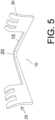
- FIG. 5is a perspective view of the embodiment of FIG. 1 but with curved fingers.
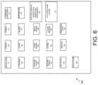
- FIG. 6is a top plan view of a second embodiment of the present novel technology, a surgical kit including the retractor embodiment of FIG. 1 .
- FIG. 7is perspective view of a third embodiment retractor of the present novel technology.
- FIG. 8is a partial perspective view of an alternate hinge assembly for use in FIG. 7 .
- FIG. 9is a side elevation view of FIG. 7 .
- FIG. 10 Ais a perspective view of a center retractor member attachment for the embodiment of FIG. 7 .
- FIG. 10 Bis a side elevation view of a hinge pin for use with the embodiment of FIG. 7 .
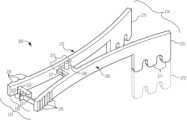
- the present novel technologyrelates to a single use or ‘disposable’ device 10 for holding tissues away from a field of operation, such as by pushing open the edges of a wound to allow access thereinto.
- the device 10is electrically insulating, non-magnetic, and radiotransparent, and is typically a unitary, homogeneous body molded or printed from a (typically) medical grade thermoplastic resin or like material, and is typically nonporous.
- the deviceincludes a pair of elongated legs 15 extending from a transverse portion 20 to define a generally wishbone-shaped retractor 10 .
- a tissue-engaging plate portion 25is typically positioned at the terminal end (opposite the transverse portion 20 ) of each leg 15 for engaging and urging tissue away from a wound or incision.
- the plate 25may further include a plurality of tissue-gripping fingers 30 extending away from the leg 15 .
- the fingers 30may be straight or curved to better engage the tissue. Curved fingers 30 typically curve away from the retractor 10 . In some embodiments, the fingers 30 may curl into hooks to even better grip tissue.
- each legis about 8 cm. in length and has a generally square cross section of 8 mm. on a side.
- the transverse portionis about 1.5 cm. long.
- the legs 15are not parallel, and typically each leg 15 extends away from the other leg 15 with the plates 25 being spaced about 6 cm. away from one another, thus defining an angle between fifteen and sixty degrees, more typically between thirty and forty-five degrees, and still more typically about thirty-five degrees.
- each leg 15extends away from a major axis 35 , defined as bisecting the transverse portion 20 and lying in the same plane as the legs 15 , at an angle of about seventeen and a half degrees.
- the legs 15When pressed together, the legs 15 typically exert a force of about between about twenty-five and about fifty Newtons, more typically about thirty-five Newtons, away from one another, with each leg typically exerting a force of about between about ten and twenty Newtons, more typically about fifteen Newtons, against the edge of the wound or incision.
- the device 10thus is described by a spring constant ‘k’ of between about 400 and about 850 N/m, more typically about 600 N/m.
- the retractor 10functions as an elongated transverse leaf spring, insofar as the legs 15 , when pushed together, exert an urging force to return them to their original resting orientation.
- the force exerted by the legs 15may be varied by varying the thickness of the legs 15 and transverse piece 20 , the length of the legs 15 , the thickness of the legs 15 , the angle defined by the legs 15 , and/or the composition of the retractor 10 .
- each retractor 10Prior to use, each retractor 10 is typically sterilized, such as via immersion in an ethylene oxide bath.
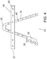
- the legs 15each include a locking device 37 for preventing the legs 15 from moving relative to one another.
- One exemplary locking device 37includes a plurality of spaced raised nubs or bullets 40 positioned on each leg 15 , that cooperate with an elongated locking strip or latch 45 having a plurality of spaced apertures formed therethrough 50 , each aperture 50 sized to snugly engage a bullet 40 .
- the locking strip 45may be engaged to a bullet 40 extending from each leg 15 to secure the retractor 10 once it is engaged with a patient to prevent unwanted expansion or constriction of the retractor legs 15 to control and maintain the dimensions of an incision opening.
- kit 100typically includes at least one or more (typically a plurality) of each of the following: retractors 10 , drapes 105 , towels 110 , contrast containers 115 , syringes 120 , and loops 125 .
- kit 100may also include one or more of the following: blade (typically no.
- the legs 15are first pressed together and are inserted far enough into the wound or incision such that the plates 25 and/or fingers 30 engage tissue on either side of the wound.
- the pressure holding the legs 15 togetheris then released to allow the legs 15 to exert a spring force against the tissue, urging the wound open.
- the retractor 10may then be left in place to hold the wound open, and may optionally be locked by engaging the strip 45 with bullets 40 on either leg 15 .
- the legs 15are once again urged toward one another and the retractor 10 is removed from the wound.
- X-rays made during the procedurewill not be impeded or obstructed by the plastic retractor, making the retractor attractive for procedures on the carotid, thrombectomies, embolectomies, pacemaker implantation, and the like.
- the retractor 200includes a first prong 205 and a second prong 210 that are pivotably interconnected by a hinge assembly 215 .
- Prongs 205 , 210are elongated members that are curved so as to provide an urging force.
- the prongs 205 , 210are coupled together and oriented to curve away from each other so as to provide an urging force away from one another 205 , 210 when engaged to hold a wound or incision open.
- This embodiment retractor 200also includes an elongated center retractor member 211 which may be connected to the retractor 200 and engaged to pull the patient's flesh in a direction typically orthogonal to the force exerted by the prongs 205 , 210 .
- the first prong 205 and second prong 210can be moved freely and independently without a requirement to move the respective prong.
- Each prong 205 , 210contains a respective proximal end 213 and distal end 214 .
- a hinge assembly 215located about midway between the ends 231 , 214 pivotably connects the prongs 205 , 210 .
- the distance between the ends 213 , 214 , of the prongs 205 , 210can be locked or defined by engaging a multi-position locking mechanism 220 .
- the multi-position locking mechanism 220has two parts, a locking ratchet 221 connected to the proximal end 213 of one respective prong 205 , 210 and a receiving portion 225 connected to the proximal end 213 of the other respective prong 210 , 205 .
- the locking ratchet 221is typically unitary with the first prong 205 and the receiving portion is typically unitary with the second prong 210 .
- Pressurecan be applied to a tab 223 extending from the locking ratchet 221 for quick release of the locking mechanism 220 (disengaging the portions 221 , 225 ) so that the distance between the prongs 205 , 210 can be adjusted.
- the locking ratchet 221is securely placed in the grooves or teeth of the receiving portion 225 of the locking mechanism 220 . Locking the first prong 205 and the second prong 210 together at the proximal end 213 minimizes unnecessary and unwanted relative movement of the prongs 205 , 210 relative one another.
- the proximal end 213 of each respective prong 205 , 210is typically knurled 235 for ease of gripping.
- the hinge assembly 215may be unitarily formed with the prongs 205 , 210 as a single unitary piece having an aperture 237 through which a pin 240 may be inserted, or a first apertured hinge portion 250 A may extend from one prong 205 , 210 and a second hinge portion 250 B may extend from the opposite prong 210 , 205 with a in 240 extending therefrom for engaging the aperture 237 .
- the placement of the center retractor 211is adjustable by inserting a hinge pin 240 into one of the plurality of insertion holes 212 typically located along the centerline of the center retractor 211 . Engaging the hinge pin 240 locks the center retractor 211 in place relative to the retractor 200 .
- Blades 270typically extend from the respective distal end 214 of the three prongs 205 , 210 , 211 . These blades 270 are typically about one centimeter in length; however, in one embodiment the blades can be extended to four centimeters or longer. The extra length of the extendable blades 270 provides the surgeon with greater control over surgery. Blades 270 typically include a plurality of serrations or fingers 271 extending therefrom, which may curve away from the retractor 200 .
- the retractortypically includes a titled handle 230 that tilts at approximately 15 from the hinge 215 relative the remainder of the retractor 200 degrees to provide for maximum comfort and ease of use.
- retractor 200is typically formed from radiolucent medical grade plastic.
- the distal ends 214 of prongs 205 , 210are first pressed together and are inserted far enough into the wound or incision such that the blades 270 engage tissue on either side of the wound.
- the pressure holding the prongs 205 , 210 togetheris then released to allow the prongs 205 , 210 to exert a spring force against the tissue, urging the wound open.
- the locking ratchet 220is engaged to maintain the urging force.
- the retractor 200may then be left in place to hold the wound open.
- Center retractor 211may be engaged to further open the wound or incision, and lockingly engaged to center pin 240 of retractor 200 .
- the center retractor 211may be disengaged, the locking ratchet disengaged, and the prongs removed from the wound/incision, typically by urging prongs 205 , 210 toward one another, and the retractor 200 is removed from the wound.
- the retractor 200is then disposed of as medical waste, although the retractor 200 may be sterilized and reused if so desired. X-rays made during the procedure will not be impeded or obstructed by the plastic retractor, making the retractor 200 attractive for procedures on the carotid, thrombectomies, embolectomies, pacemaker implantation, and the like.
Landscapes
- Health & Medical Sciences (AREA)
- Life Sciences & Earth Sciences (AREA)
- Surgery (AREA)
- Animal Behavior & Ethology (AREA)
- Veterinary Medicine (AREA)
- Public Health (AREA)
- General Health & Medical Sciences (AREA)
- Engineering & Computer Science (AREA)
- Molecular Biology (AREA)
- Medical Informatics (AREA)
- Heart & Thoracic Surgery (AREA)
- Biomedical Technology (AREA)
- Nuclear Medicine, Radiotherapy & Molecular Imaging (AREA)
- Chemical & Material Sciences (AREA)
- Chemical Kinetics & Catalysis (AREA)
- General Chemical & Material Sciences (AREA)
- Epidemiology (AREA)
- Surgical Instruments (AREA)
Abstract
Description
Claims (12)
Priority Applications (2)
| Application Number | Priority Date | Filing Date | Title |
|---|---|---|---|
| US16/906,338US12011150B2 (en) | 2018-09-10 | 2020-06-19 | Radiolucent retractor |
| US18/744,848US20240407775A1 (en) | 2018-09-10 | 2024-06-17 | Radiolucent retractors |
Applications Claiming Priority (2)
| Application Number | Priority Date | Filing Date | Title |
|---|---|---|---|
| US16/126,177US20200077997A1 (en) | 2018-09-10 | 2018-09-10 | Radiolucent retractor |
| US16/906,338US12011150B2 (en) | 2018-09-10 | 2020-06-19 | Radiolucent retractor |
Related Parent Applications (1)
| Application Number | Title | Priority Date | Filing Date |
|---|---|---|---|
| US16/126,177Continuation-In-PartUS20200077997A1 (en) | 2018-09-10 | 2018-09-10 | Radiolucent retractor |
Related Child Applications (1)
| Application Number | Title | Priority Date | Filing Date |
|---|---|---|---|
| US18/744,848Continuation-In-PartUS20240407775A1 (en) | 2018-09-10 | 2024-06-17 | Radiolucent retractors |
Publications (2)
| Publication Number | Publication Date |
|---|---|
| US20210068800A1 US20210068800A1 (en) | 2021-03-11 |
| US12011150B2true US12011150B2 (en) | 2024-06-18 |
Family
ID=74849801
Family Applications (1)
| Application Number | Title | Priority Date | Filing Date |
|---|---|---|---|
| US16/906,338Active2041-06-03US12011150B2 (en) | 2018-09-10 | 2020-06-19 | Radiolucent retractor |
Country Status (1)
| Country | Link |
|---|---|
| US (1) | US12011150B2 (en) |
Families Citing this family (2)
| Publication number | Priority date | Publication date | Assignee | Title |
|---|---|---|---|---|
| US20220330964A1 (en)* | 2021-03-29 | 2022-10-20 | ECA Medical Instruments, Inc. | Locking forceps device |
| WO2023137209A2 (en)* | 2022-01-14 | 2023-07-20 | Chip Shot Partners Llc | External fixator apparatus & method |
Citations (24)
| Publication number | Priority date | Publication date | Assignee | Title |
|---|---|---|---|---|
| US1194319A (en)* | 1916-08-08 | Vaginal | ||
| US3038467A (en)* | 1960-08-29 | 1962-06-12 | Sklar Mfg Co J | Surgical instrument |
| US3840014A (en) | 1971-09-24 | 1974-10-08 | Nat Res Dev | Retractor for hip joint surgery |
| US5174278A (en)* | 1990-11-26 | 1992-12-29 | Beth Babkow | Downward rotating speculum with conical shaped blades |
| US5299563A (en)* | 1992-07-31 | 1994-04-05 | Seton Joseph Z | Method of using a surgical retractor |
| US6102852A (en) | 1999-06-18 | 2000-08-15 | Liu; Yen-Huang | Disposable nasal speculum |
| US6196969B1 (en)* | 1999-05-21 | 2001-03-06 | Lab Engineering & Manufacturing, Inc. | Tissue retractor adapted for the attachment of an auxiliary element |
| US20030055320A1 (en)* | 2001-09-18 | 2003-03-20 | Mcbride G. Grady | Tissue retractor |
| US6544169B2 (en) | 2001-01-29 | 2003-04-08 | Barzell Whitmore Maroon Bells, Inc. | Eyelid retraction device |
| US20050027170A1 (en) | 2003-07-10 | 2005-02-03 | Showa Ika Kohgyo Co., Ltd. | Surgical retractors |
| US20050080320A1 (en)* | 2003-08-14 | 2005-04-14 | Lee Andrew Max | Multiple-blade retractor |
| US20050215865A1 (en) | 2002-07-18 | 2005-09-29 | Minnesota Scientific, Inc. | Method and apparatus for surgical retraction |
| US20110046450A1 (en) | 2009-08-24 | 2011-02-24 | Blaine Theodore A | Visiblade - a transparent disposable surgical retractor based on fis ("form in situ") technology |
| US20110060194A1 (en) | 2004-12-29 | 2011-03-10 | Olof Risto | Retractor |
| US20110105849A1 (en) | 2009-07-21 | 2011-05-05 | Covello Leonard V | Devices and Methods for Minimally Invasive Access to Sinuses and Treatment of Sinusitis |
| US20120130180A1 (en) | 2009-04-13 | 2012-05-24 | Physcient, Inc. | Methods and devices to decrease tissue trauma during surgery |
| US8257256B1 (en) | 2009-10-22 | 2012-09-04 | Krolman Arthur M M | Retractor device |
| US8376939B1 (en) | 2009-08-19 | 2013-02-19 | Alberto David Leyva | Coronary artery retraction and CO2 dispensing device |
| US8899809B2 (en) | 2012-01-30 | 2014-12-02 | Invuity, Inc. | Illuminated clip and methods of use |
| US20150209022A1 (en) | 2014-01-24 | 2015-07-30 | Contour Surgical, Inc. | Retraction devices and methods of its use and manufacture |
| US9468405B2 (en)* | 2003-02-27 | 2016-10-18 | Nuvasive, Inc. | Surgical access system and related methods |
| US20170311942A1 (en)* | 2016-04-29 | 2017-11-02 | Scanlan International, Inc. | Spinal retractor with releasable arms |
| US20170333023A1 (en)* | 2016-05-20 | 2017-11-23 | Choicespine, Lp | Access Instruments To Extend A Surgical Working Channel |
| US20180353164A1 (en)* | 2017-06-12 | 2018-12-13 | Globus Medical, Inc. | Surgical retractor |
- 2020
- 2020-06-19USUS16/906,338patent/US12011150B2/enactiveActive
Patent Citations (24)
| Publication number | Priority date | Publication date | Assignee | Title |
|---|---|---|---|---|
| US1194319A (en)* | 1916-08-08 | Vaginal | ||
| US3038467A (en)* | 1960-08-29 | 1962-06-12 | Sklar Mfg Co J | Surgical instrument |
| US3840014A (en) | 1971-09-24 | 1974-10-08 | Nat Res Dev | Retractor for hip joint surgery |
| US5174278A (en)* | 1990-11-26 | 1992-12-29 | Beth Babkow | Downward rotating speculum with conical shaped blades |
| US5299563A (en)* | 1992-07-31 | 1994-04-05 | Seton Joseph Z | Method of using a surgical retractor |
| US6196969B1 (en)* | 1999-05-21 | 2001-03-06 | Lab Engineering & Manufacturing, Inc. | Tissue retractor adapted for the attachment of an auxiliary element |
| US6102852A (en) | 1999-06-18 | 2000-08-15 | Liu; Yen-Huang | Disposable nasal speculum |
| US6544169B2 (en) | 2001-01-29 | 2003-04-08 | Barzell Whitmore Maroon Bells, Inc. | Eyelid retraction device |
| US20030055320A1 (en)* | 2001-09-18 | 2003-03-20 | Mcbride G. Grady | Tissue retractor |
| US20050215865A1 (en) | 2002-07-18 | 2005-09-29 | Minnesota Scientific, Inc. | Method and apparatus for surgical retraction |
| US9468405B2 (en)* | 2003-02-27 | 2016-10-18 | Nuvasive, Inc. | Surgical access system and related methods |
| US20050027170A1 (en) | 2003-07-10 | 2005-02-03 | Showa Ika Kohgyo Co., Ltd. | Surgical retractors |
| US20050080320A1 (en)* | 2003-08-14 | 2005-04-14 | Lee Andrew Max | Multiple-blade retractor |
| US20110060194A1 (en) | 2004-12-29 | 2011-03-10 | Olof Risto | Retractor |
| US20120130180A1 (en) | 2009-04-13 | 2012-05-24 | Physcient, Inc. | Methods and devices to decrease tissue trauma during surgery |
| US20110105849A1 (en) | 2009-07-21 | 2011-05-05 | Covello Leonard V | Devices and Methods for Minimally Invasive Access to Sinuses and Treatment of Sinusitis |
| US8376939B1 (en) | 2009-08-19 | 2013-02-19 | Alberto David Leyva | Coronary artery retraction and CO2 dispensing device |
| US20110046450A1 (en) | 2009-08-24 | 2011-02-24 | Blaine Theodore A | Visiblade - a transparent disposable surgical retractor based on fis ("form in situ") technology |
| US8257256B1 (en) | 2009-10-22 | 2012-09-04 | Krolman Arthur M M | Retractor device |
| US8899809B2 (en) | 2012-01-30 | 2014-12-02 | Invuity, Inc. | Illuminated clip and methods of use |
| US20150209022A1 (en) | 2014-01-24 | 2015-07-30 | Contour Surgical, Inc. | Retraction devices and methods of its use and manufacture |
| US20170311942A1 (en)* | 2016-04-29 | 2017-11-02 | Scanlan International, Inc. | Spinal retractor with releasable arms |
| US20170333023A1 (en)* | 2016-05-20 | 2017-11-23 | Choicespine, Lp | Access Instruments To Extend A Surgical Working Channel |
| US20180353164A1 (en)* | 2017-06-12 | 2018-12-13 | Globus Medical, Inc. | Surgical retractor |
Also Published As
| Publication number | Publication date |
|---|---|
| US20210068800A1 (en) | 2021-03-11 |
Similar Documents
| Publication | Publication Date | Title |
|---|---|---|
| US5919202A (en) | Surgical instrument with jaws and movable internal needle and method for use thereof | |
| US5922001A (en) | Surgical instrument with jaws and a movable internal blade member and method for use thereof | |
| US5893863A (en) | Surgical instrument with jaws and movable internal hook member for use thereof | |
| US5922002A (en) | Surgical instrument with jaws and movable internal biopsy device and method for use thereof | |
| US5984938A (en) | Surgical instrument with jaws and movable internal scissors and method for use thereof | |
| US6099550A (en) | Surgical instrument having jaws and an operating channel and method for use thereof | |
| US5797927A (en) | Combined tissue clamping and suturing instrument | |
| US5993385A (en) | Self-aligning side-loading surgical retractor | |
| US5031634A (en) | Adjustable biopsy needle-guide device | |
| US5759188A (en) | Suturing instrument with rotatably mounted needle driver and catcher | |
| US5409499A (en) | Biocompatible suture knot clip | |
| US5788716A (en) | Surgical instrument and method for fallopian tube ligation and biopsy | |
| EP1706042B1 (en) | Tissue fastening and cutting tool, | |
| US8888795B2 (en) | Suture passer | |
| US5468251A (en) | Surgical suturing device | |
| US4527562A (en) | Non-metallic, bio-compatible hemostatic clips | |
| EP0122046A1 (en) | Absorbable fastening device with internal locking means | |
| US7028878B2 (en) | Stapling device for closure of deep tissue | |
| US20100145381A1 (en) | Multi-ringed separator for tubular organs | |
| EP0634142B1 (en) | Biocompatible suture knot clip | |
| US12011150B2 (en) | Radiolucent retractor | |
| JPS61259652A (en) | Bonding clip and clip adapting instrument | |
| US6702739B2 (en) | Holder | |
| WO2006041317A1 (en) | Multipurpose surgical tool | |
| US10973510B2 (en) | Needle loading unit for surgical suturing apparatus |
Legal Events
| Date | Code | Title | Description |
|---|---|---|---|
| FEPP | Fee payment procedure | Free format text:ENTITY STATUS SET TO UNDISCOUNTED (ORIGINAL EVENT CODE: BIG.); ENTITY STATUS OF PATENT OWNER: MICROENTITY | |
| FEPP | Fee payment procedure | Free format text:ENTITY STATUS SET TO MICRO (ORIGINAL EVENT CODE: MICR); ENTITY STATUS OF PATENT OWNER: MICROENTITY | |
| STPP | Information on status: patent application and granting procedure in general | Free format text:APPLICATION DISPATCHED FROM PREEXAM, NOT YET DOCKETED | |
| STPP | Information on status: patent application and granting procedure in general | Free format text:DOCKETED NEW CASE - READY FOR EXAMINATION | |
| STPP | Information on status: patent application and granting procedure in general | Free format text:NON FINAL ACTION MAILED | |
| STPP | Information on status: patent application and granting procedure in general | Free format text:RESPONSE TO NON-FINAL OFFICE ACTION ENTERED AND FORWARDED TO EXAMINER | |
| STPP | Information on status: patent application and granting procedure in general | Free format text:FINAL REJECTION MAILED | |
| STPP | Information on status: patent application and granting procedure in general | Free format text:RESPONSE AFTER FINAL ACTION FORWARDED TO EXAMINER | |
| STPP | Information on status: patent application and granting procedure in general | Free format text:ADVISORY ACTION MAILED | |
| STPP | Information on status: patent application and granting procedure in general | Free format text:NOTICE OF ALLOWANCE MAILED -- APPLICATION RECEIVED IN OFFICE OF PUBLICATIONS | |
| ZAAB | Notice of allowance mailed | Free format text:ORIGINAL CODE: MN/=. | |
| STPP | Information on status: patent application and granting procedure in general | Free format text:PUBLICATIONS -- ISSUE FEE PAYMENT RECEIVED | |
| STPP | Information on status: patent application and granting procedure in general | Free format text:PUBLICATIONS -- ISSUE FEE PAYMENT VERIFIED | |
| STCF | Information on status: patent grant | Free format text:PATENTED CASE | |
| AS | Assignment | Owner name:RADIOLUCENT SURGICAL INSTRUMENTS LLC, INDIANA Free format text:ASSIGNMENT OF ASSIGNORS INTEREST;ASSIGNORS:MCCORMICK, ERIC;MAVES, STEVEN S.;REEL/FRAME:068153/0104 Effective date:20240801 | |
| CC | Certificate of correction |