US12007476B2 - Method for detecting objects via a vehicular sensing system - Google Patents
Method for detecting objects via a vehicular sensing systemDownload PDFInfo
- Publication number
- US12007476B2 US12007476B2US17/930,785US202217930785AUS12007476B2US 12007476 B2US12007476 B2US 12007476B2US 202217930785 AUS202217930785 AUS 202217930785AUS 12007476 B2US12007476 B2US 12007476B2
- Authority
- US
- United States
- Prior art keywords
- sensors
- vehicle
- sensor
- sensing
- sensing system
- Prior art date
- Legal status (The legal status is an assumption and is not a legal conclusion. Google has not performed a legal analysis and makes no representation as to the accuracy of the status listed.)
- Active, expires
Links
- 238000000034methodMethods0.000titledescription3
- 238000012545processingMethods0.000claimsabstractdescription14
- 238000013459approachMethods0.000description2
- 238000004891communicationMethods0.000description2
- 238000001514detection methodMethods0.000description1
- 210000003195fasciaAnatomy0.000description1
- 238000012986modificationMethods0.000description1
- 230000004048modificationEffects0.000description1
- 238000012552reviewMethods0.000description1
- 230000026676system processEffects0.000description1
- 238000012546transferMethods0.000description1
Images


Classifications
- G—PHYSICS
- G01—MEASURING; TESTING
- G01S—RADIO DIRECTION-FINDING; RADIO NAVIGATION; DETERMINING DISTANCE OR VELOCITY BY USE OF RADIO WAVES; LOCATING OR PRESENCE-DETECTING BY USE OF THE REFLECTION OR RERADIATION OF RADIO WAVES; ANALOGOUS ARRANGEMENTS USING OTHER WAVES
- G01S15/00—Systems using the reflection or reradiation of acoustic waves, e.g. sonar systems
- G01S15/02—Systems using the reflection or reradiation of acoustic waves, e.g. sonar systems using reflection of acoustic waves
- G01S15/06—Systems determining the position data of a target
- G01S15/42—Simultaneous measurement of distance and other co-ordinates
- G—PHYSICS
- G01—MEASURING; TESTING
- G01S—RADIO DIRECTION-FINDING; RADIO NAVIGATION; DETERMINING DISTANCE OR VELOCITY BY USE OF RADIO WAVES; LOCATING OR PRESENCE-DETECTING BY USE OF THE REFLECTION OR RERADIATION OF RADIO WAVES; ANALOGOUS ARRANGEMENTS USING OTHER WAVES
- G01S15/00—Systems using the reflection or reradiation of acoustic waves, e.g. sonar systems
- G01S15/88—Sonar systems specially adapted for specific applications
- G01S15/93—Sonar systems specially adapted for specific applications for anti-collision purposes
- G01S15/931—Sonar systems specially adapted for specific applications for anti-collision purposes of land vehicles
- G01S2015/937—Sonar systems specially adapted for specific applications for anti-collision purposes of land vehicles sensor installation details
- G01S2015/938—Sonar systems specially adapted for specific applications for anti-collision purposes of land vehicles sensor installation details in the bumper area
- G—PHYSICS
- G01—MEASURING; TESTING
- G01S—RADIO DIRECTION-FINDING; RADIO NAVIGATION; DETERMINING DISTANCE OR VELOCITY BY USE OF RADIO WAVES; LOCATING OR PRESENCE-DETECTING BY USE OF THE REFLECTION OR RERADIATION OF RADIO WAVES; ANALOGOUS ARRANGEMENTS USING OTHER WAVES
- G01S15/00—Systems using the reflection or reradiation of acoustic waves, e.g. sonar systems
- G01S15/88—Sonar systems specially adapted for specific applications
- G01S15/93—Sonar systems specially adapted for specific applications for anti-collision purposes
- G01S15/931—Sonar systems specially adapted for specific applications for anti-collision purposes of land vehicles
- G01S2015/937—Sonar systems specially adapted for specific applications for anti-collision purposes of land vehicles sensor installation details
- G01S2015/939—Sonar systems specially adapted for specific applications for anti-collision purposes of land vehicles sensor installation details vertical stacking of sensors, e.g. to enable obstacle height determination
Definitions
- the present inventionrelates generally to a vehicle sensing system for a vehicle and, more particularly, to a vehicle sensing system that utilizes one or more sensors at a vehicle to provide a field of sensing around the vehicle.
- a vehicular sensing systemutilizes one or more sensors (e.g., ultrasonic sensors) to capture sensor data exterior of a vehicle.
- the systemincludes a first set of sensors disposed at a first rear portion of a vehicle equipped with the vehicular sensing system.
- the first set of sensorsincludes a plurality of first sensors and each first sensor of the first set of sensors has a respective first field of sensing that extends exterior and at least rearward of the vehicle.
- the systemincludes a second set of sensors disposed at a second rear portion of the vehicle that is above the first rear portion of the vehicle.
- the second set of sensorsincludes a plurality of second sensors and each second sensor of the second set of sensors has a respective second field of sensing that extends exterior and at least rearward of the vehicle.
- the respective first field of sensing of at least one first sensor of the plurality of first sensorsat least partially overlaps the respective second field of sensing of at least one second sensor of the plurality of second sensors.
- the systemincludes an electronic control unit (ECU) with electronic circuitry and associated software.
- the electronic circuitry of the ECUincludes a data processor for (i) processing sensor data captured by first sensors of the first set of sensors and (ii) processing sensor data captured by second sensors of the second set of sensors to detect presence of objects exterior and at least rearward of the vehicle.
- the vehicular sensing systemresponsive at least in part to processing at the ECU of sensor data captured by the first sensors of the first set of sensors and by the second sensors of the second set of sensors, detects objects that are located within the at least partially overlapping fields of sensing of the at least one first sensor and the at least one second sensor.
- the vehicular sensing systemresponsive to detecting the objects that are located within the at least partially overlapping fields of sensing, determines three-dimensional locations of the detected objects relative to the vehicle.
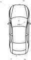
- FIG. 1is a plan view of a vehicle with a sensing system that incorporates sensors
- FIGS. 2 and 3are plan views of conventional sensor placements at a rear of a vehicle
- FIG. 4is a plan view of a rear of a vehicle with multiple sensors distributed around a rear of the vehicle;
- FIG. 5is a plan view of a top of the vehicle with fields of sensing of a portion of the sensors of FIG. 4 ;
- FIG. 6is a plan view of the of the vehicle with fields of sensing of a different portion of the sensors of FIG. 4 ;
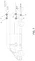
- FIG. 7is a plan view of a side of the vehicle with fields of sensing of a portion of the sensors of FIG. 4 ;
- FIG. 8is a plan view of the side of the vehicle with fields of sensing of a different portion of the sensors of FIG. 4 .
- a vehicle sensing systemoperates to capture sensing data exterior of the vehicle and may process the captured data to detect objects at or near the vehicle (e.g., to the rear of the vehicle), such as to assist a driver of the vehicle in maneuvering the vehicle or to assist the driver in parking the vehicle in a parking space.
- the systemincludes a processor that is operable to receive sensing data from multiple sensors and to provide an output to a control that, responsive to the output, generates an alert or controls an accessory or system of the vehicle, or highlights or overlays an alert on a display screen (that may be displaying video images captured by a single rearward viewing camera or multiple cameras providing forward, side or 360 degree surround views of the area surrounding the vehicle during a reversing or low speed maneuver of the vehicle).
- a vehicle 10includes a sensing system 12 that includes at least one exterior sensing sensor, such as an ultrasonic sensor 14 a (and the system may optionally include multiple exterior sensing sensors, such as a forward sensing sensor 14 b at the front of the vehicle), which senses objects exterior of the vehicle ( FIG. 1 ).
- the sensing system 12includes a control or electronic control unit (ECU) 18 having electronic circuitry and associated software, with the electronic circuitry including a data processor or image processor that is operable to process image data captured by the sensor(s), whereby the ECU may detect or determine presence of objects or the like.
- the data transfer or signal communication from the sensor to the ECUmay comprise any suitable data or communication link, such as a vehicle network bus or the like of the equipped vehicle.
- known sensor systems for vehiclesprovide near field coverage in two dimensions (2D) for the side of vehicle.
- these systemsfocus on sensor coverage of a particular side of the vehicle (e.g., a side of the vehicle or a rear of the vehicle).
- some systemsinclude four to six ultrasonic sensors (or other types of sensors, such as radar sensors or lidar sensors or cameras) that are installed at the rear of the vehicle (e.g., at the bumper and/or fascia of the vehicle) to sense a distance to objects directly behind the vehicle.
- ultrasonic sensorsor other types of sensors, such as radar sensors or lidar sensors or cameras
- These sensorsare typically limited to detecting or sensing objects low to the ground, such as objects that may collide with the bumper of the vehicle when the vehicle is reversing.
- a rear of a vehicle 10may be equipped with multiple sensors 12 (e.g., ultrasonic sensors, radar sensors, etc.).
- sensors 12e.g., ultrasonic sensors, radar sensors, etc.
- Conventional sensor systemsmay come equipped with the sensors at the locations labeled ‘A’, ‘B’, ‘C’, and ‘D’ (i.e., the sensors located along the bumper of the vehicle).
- using only these sensorslimits the sensing system to detection of only objects in two dimensions and near to the ground.
- Implementations hereininclude additional sensors, such as sensors 12 labeled ‘1’, ‘2’, ‘3’, and ‘4’ linearly arranged higher (i.e., further from the ground) than the sensors linearly arranged closer to the ground (e.g., along the bumper).
- the sensorsare disposed along a rear roofline of the vehicle.
- the systemincludes rear body side sensors 12 (i.e., the sensors labeled ‘5’ and ‘6’ here).
- the rear body side sensorsmay be disposed above the sensors A-D (e.g., at the bumper) and below the sensors 1-4 (e.g., at the rear roofline) such as approximately half-way up the vehicle or at or near the same height as the side mirrors.
- Each sensor 12may have a field of sensing that intersects or at least partially overlaps with the field of sensing of one or more other sensors such that reflections of sensing energy transmitted by a single sensor are received by multiple other sensors. Due to the placement of the sensors (e.g., sensors placed along both horizontal and vertical dimensions instead of just a horizontal dimension), the system processes these multiple reflections to localize objects behind the vehicle in three dimensions (3D) (i.e., localize an object relative to an X, Y, and Z axis).
- 3Dthree dimensions
- the field of sensing of the sensors 12may have different angles relative to the vehicle 10 (e.g., relative to a surface of the vehicle).
- the outer sensors 12 disposed at or near lateral edges of the rear of the vehiclee.g., the sensors ‘1’ and ‘4’ and/or sensors ‘5’ and/or ‘6’ and/or sensors ‘A’ and ‘D’ of FIG. 4
- the sensors ‘1’ and ‘4’ and/or sensors ‘5’ and/or ‘6’ and/or sensors ‘A’ and ‘D’ of FIG. 4 )may be angled inward (i.e., have a field of sensing that is angled toward a midline 14 extending from the center of the vehicle) to intersect or approach an intersection with the rear contour of the vehicle.
- these sensorsmay have a field of sensing with a principal axis that extends from the rear of the vehicle with an angle less than 90 degrees and greater than 0 degrees relative to the rear surface or plane of the vehicle.
- the inner sensors 12 disposed away from the lateral edges of the vehicle and at or near the midline of the vehiclee.g., sensors ‘2’ and ‘3’ and/or ‘B’ and ‘C’ of FIG. 4 ) may be oriented to have a larger field of sensing in the vertical axis (i.e., a first dimension) and a smaller field of sensing horizontally (i.e., a second dimension) relative to the ground. That is, the field of sensing for the inner sensors may extend vertically (relative to the ground) more than horizontally (i.e., be taller than wide).
- the optional mid side or outer sensorsmay be angled inward to approach intersection with the rear contour of the vehicle.
- these sensors 12have a larger field of sensing in the vertical dimension (i.e., perpendicular to the ground) than the horizontal dimension.
- the sensors 12are calibrated so that the field of sensing has an angle ⁇ that minimizes the field of sensing of the sensor outside of the vehicle bodyline. That is, the mid outer sensors may be angled “inward” toward the midline of the vehicle such that the little, if any, of the field of sensing captured by the sensors is outside of lines 16 extending rearward from the rear sides of the vehicle.
- the inner sensorse.g., sensors ‘2’ and ‘3’ and/or ‘B’ and ‘C’ of FIG. 4
- the inner sensorsmay be oriented with the larger field of sensing along the vertical axis. That is, the field of sensing is larger in the dimension perpendicular to the ground than the dimension parallel to the ground.
- the position of the sensorsmay be selected or calibrated to maximize the coverage behind the vehicle with a preference to include coverage in close proximity to the vehicle.
- the outer sensors 12e.g., sensors ‘1’ and ‘4’ and/or sensors ‘5’ and ‘6’ and/or sensors ‘A’ and ‘D’ of FIG.
- each of the sensorsmay have a field of sensing that at least partially overlaps the field of sensing of a different sensor.
- a sensor disposed at the rooflinemay have a field of sensing that at least partially overlaps the field of sensing of a sensor disposed at the bumper.
- two sensors disposed at the rooflineeach have a field of sensing that at least partially overlaps the other sensor and two sensors disposed at or near the bumper may each have a field of sensing that at least partially overlaps the other sensor.
- the sensing systemmay utilize aspects of the systems described in U.S. Pat. Nos. 11,275,175 and/or 10,768,298, and/or U.S. Publication No. US-2022-0227366, which are hereby incorporated herein by reference in their entireties.
- the sensing system described hereinincludes a plurality of sensors (e.g., ultrasonic sensors) disposed at a rear of a vehicle.
- a first set of sensorsincludes at least one sensor disposed at or near a bumper of the vehicle (e.g., four sensors disposed linearly along the bumper).
- the first set of sensorsmay be approximately linearly arranged along a horizontal line parallel to the ground. That is, each sensor of the first set of sensors may be approximately the same height from the ground.
- the systemincludes a second set of sensors (including at least one sensor) disposed at or near a rear roofline of the vehicle (e.g., four sensors disposed linearly along the roofline).
- the second set of sensorsmay be approximately linearly arranged along another horizontal line parallel to the ground.
- each sensor of the second set of sensorsmay be approximately the same height from the ground.
- additional sensorsmay be disposed along the rear sides of the vehicle (e.g., above the sensors disposed at the bumper and below the sensors disposed at the roofline).
- Each sensorhas a field of sensing that overlaps with the field of sensing of at least one other sensor.
- One or more sensorsmay have a field of sensing that at least partially overlaps two other sensors. Based on the overlapping fields of sensing (e.g., using triangulation), the system detects the presence of objects rear of the vehicle in three dimensions (i.e., relative to an X axis, a Y axis, and a Z axis of the vehicle).
- Each sensordepending on its respective location at the vehicle, may have a respective field of sensing with a vertical component that is larger than a horizontal component or vice versa.
- the sensing systemmay utilize aspects of the systems described in U.S. Pat. Nos. 10,866,306; 9,954,955; 9,869,762; 9,753,121; 9,689,967; 9,599,702; 9,575,160; 9,146,898; 9,036,026; 8,027,029; 8,013,780; 7,408,627; 7,405,812; 7,379,163; 7,379,100; 7,375,803; 7,352,454; 7,340,077; 7,321,111; 7,310,431; 7,283,213; 7,212,663; 7,203,356; 7,176,438; 7,157,685; 7,053,357; 6,919,549; 6,906,793; 6,876,775; 6,710,770; 6,690,354; 6,678,039; 6,674,895 and/or 6,587,186, and/or U.S.
Landscapes
- Engineering & Computer Science (AREA)
- Radar, Positioning & Navigation (AREA)
- Remote Sensing (AREA)
- Physics & Mathematics (AREA)
- Acoustics & Sound (AREA)
- Computer Networks & Wireless Communication (AREA)
- General Physics & Mathematics (AREA)
- Measurement Of Velocity Or Position Using Acoustic Or Ultrasonic Waves (AREA)
Abstract
Description
The present application claims the filing benefits of U.S. provisional application Ser. No. 63/261,111, filed Sep. 13, 2021, which is hereby incorporated herein by reference in its entirety.
The present invention relates generally to a vehicle sensing system for a vehicle and, more particularly, to a vehicle sensing system that utilizes one or more sensors at a vehicle to provide a field of sensing around the vehicle.
It is known to provide sensors, such as ultrasonic sensors, at a rear bumper of a vehicle for sensing objects at the ground behind the vehicle.
A vehicular sensing system utilizes one or more sensors (e.g., ultrasonic sensors) to capture sensor data exterior of a vehicle. The system includes a first set of sensors disposed at a first rear portion of a vehicle equipped with the vehicular sensing system. The first set of sensors includes a plurality of first sensors and each first sensor of the first set of sensors has a respective first field of sensing that extends exterior and at least rearward of the vehicle. The system includes a second set of sensors disposed at a second rear portion of the vehicle that is above the first rear portion of the vehicle. The second set of sensors includes a plurality of second sensors and each second sensor of the second set of sensors has a respective second field of sensing that extends exterior and at least rearward of the vehicle. The respective first field of sensing of at least one first sensor of the plurality of first sensors at least partially overlaps the respective second field of sensing of at least one second sensor of the plurality of second sensors. The system includes an electronic control unit (ECU) with electronic circuitry and associated software. The electronic circuitry of the ECU includes a data processor for (i) processing sensor data captured by first sensors of the first set of sensors and (ii) processing sensor data captured by second sensors of the second set of sensors to detect presence of objects exterior and at least rearward of the vehicle. The vehicular sensing system, responsive at least in part to processing at the ECU of sensor data captured by the first sensors of the first set of sensors and by the second sensors of the second set of sensors, detects objects that are located within the at least partially overlapping fields of sensing of the at least one first sensor and the at least one second sensor. The vehicular sensing system, responsive to detecting the objects that are located within the at least partially overlapping fields of sensing, determines three-dimensional locations of the detected objects relative to the vehicle.
These and other objects, advantages, purposes and features of the present invention will become apparent upon review of the following specification in conjunction with the drawings.
A vehicle sensing system operates to capture sensing data exterior of the vehicle and may process the captured data to detect objects at or near the vehicle (e.g., to the rear of the vehicle), such as to assist a driver of the vehicle in maneuvering the vehicle or to assist the driver in parking the vehicle in a parking space. The system includes a processor that is operable to receive sensing data from multiple sensors and to provide an output to a control that, responsive to the output, generates an alert or controls an accessory or system of the vehicle, or highlights or overlays an alert on a display screen (that may be displaying video images captured by a single rearward viewing camera or multiple cameras providing forward, side or 360 degree surround views of the area surrounding the vehicle during a reversing or low speed maneuver of the vehicle).
Referring now to the drawings and the illustrative embodiments depicted therein, avehicle 10 includes asensing system 12 that includes at least one exterior sensing sensor, such as anultrasonic sensor 14a(and the system may optionally include multiple exterior sensing sensors, such as aforward sensing sensor 14bat the front of the vehicle), which senses objects exterior of the vehicle (FIG.1 ). Thesensing system 12 includes a control or electronic control unit (ECU)18 having electronic circuitry and associated software, with the electronic circuitry including a data processor or image processor that is operable to process image data captured by the sensor(s), whereby the ECU may detect or determine presence of objects or the like. The data transfer or signal communication from the sensor to the ECU may comprise any suitable data or communication link, such as a vehicle network bus or the like of the equipped vehicle.
Referring now toFIGS.2 and3 , known sensor systems for vehicles provide near field coverage in two dimensions (2D) for the side of vehicle. Typically, these systems focus on sensor coverage of a particular side of the vehicle (e.g., a side of the vehicle or a rear of the vehicle). For example, some systems include four to six ultrasonic sensors (or other types of sensors, such as radar sensors or lidar sensors or cameras) that are installed at the rear of the vehicle (e.g., at the bumper and/or fascia of the vehicle) to sense a distance to objects directly behind the vehicle. These sensors are typically limited to detecting or sensing objects low to the ground, such as objects that may collide with the bumper of the vehicle when the vehicle is reversing.
Referring now toFIG.4 , a rear of avehicle 10 may be equipped with multiple sensors12 (e.g., ultrasonic sensors, radar sensors, etc.). Conventional sensor systems may come equipped with the sensors at the locations labeled ‘A’, ‘B’, ‘C’, and ‘D’ (i.e., the sensors located along the bumper of the vehicle). However, using only these sensors limits the sensing system to detection of only objects in two dimensions and near to the ground. Implementations herein include additional sensors, such assensors 12 labeled ‘1’, ‘2’, ‘3’, and ‘4’ linearly arranged higher (i.e., further from the ground) than the sensors linearly arranged closer to the ground (e.g., along the bumper). Here, the sensors are disposed along a rear roofline of the vehicle. Optionally, the system includes rear body side sensors12 (i.e., the sensors labeled ‘5’ and ‘6’ here). The rear body side sensors may be disposed above the sensors A-D (e.g., at the bumper) and below the sensors 1-4 (e.g., at the rear roofline) such as approximately half-way up the vehicle or at or near the same height as the side mirrors.
Eachsensor 12 may have a field of sensing that intersects or at least partially overlaps with the field of sensing of one or more other sensors such that reflections of sensing energy transmitted by a single sensor are received by multiple other sensors. Due to the placement of the sensors (e.g., sensors placed along both horizontal and vertical dimensions instead of just a horizontal dimension), the system processes these multiple reflections to localize objects behind the vehicle in three dimensions (3D) (i.e., localize an object relative to an X, Y, and Z axis).
Referring now toFIG.5 , the field of sensing of thesensors 12 may have different angles relative to the vehicle10 (e.g., relative to a surface of the vehicle). For example, theouter sensors 12 disposed at or near lateral edges of the rear of the vehicle (e.g., the sensors ‘1’ and ‘4’ and/or sensors ‘5’ and/or ‘6’ and/or sensors ‘A’ and ‘D’ ofFIG.4 ) may be angled inward (i.e., have a field of sensing that is angled toward amidline 14 extending from the center of the vehicle) to intersect or approach an intersection with the rear contour of the vehicle. That is, these sensors may have a field of sensing with a principal axis that extends from the rear of the vehicle with an angle less than 90 degrees and greater than 0 degrees relative to the rear surface or plane of the vehicle. Theinner sensors 12 disposed away from the lateral edges of the vehicle and at or near the midline of the vehicle (e.g., sensors ‘2’ and ‘3’ and/or ‘B’ and ‘C’ ofFIG.4 ) may be oriented to have a larger field of sensing in the vertical axis (i.e., a first dimension) and a smaller field of sensing horizontally (i.e., a second dimension) relative to the ground. That is, the field of sensing for the inner sensors may extend vertically (relative to the ground) more than horizontally (i.e., be taller than wide).
As shown inFIG.6 , the optional mid side or outer sensors (e.g., the sensors ‘5’ and ‘6’ ofFIG.4 ) may be angled inward to approach intersection with the rear contour of the vehicle. Optionally, thesesensors 12 have a larger field of sensing in the vertical dimension (i.e., perpendicular to the ground) than the horizontal dimension. Optionally, thesensors 12 are calibrated so that the field of sensing has an angle α that minimizes the field of sensing of the sensor outside of the vehicle bodyline. That is, the mid outer sensors may be angled “inward” toward the midline of the vehicle such that the little, if any, of the field of sensing captured by the sensors is outside oflines 16 extending rearward from the rear sides of the vehicle.
Referring now toFIG.7 , the inner sensors (e.g., sensors ‘2’ and ‘3’ and/or ‘B’ and ‘C’ ofFIG.4 ) may be oriented with the larger field of sensing along the vertical axis. That is, the field of sensing is larger in the dimension perpendicular to the ground than the dimension parallel to the ground. The position of the sensors may be selected or calibrated to maximize the coverage behind the vehicle with a preference to include coverage in close proximity to the vehicle. As shown inFIG.8 , the outer sensors12 (e.g., sensors ‘1’ and ‘4’ and/or sensors ‘5’ and ‘6’ and/or sensors ‘A’ and ‘D’ ofFIG.4 ) may be angled downward (i.e., at angle β) and inward (i.e., toward a centerline or midline of the vehicle). The sensors ‘A’ through ‘D’ and the sensors ‘1’ through ‘6’ may have intersecting or overlapping fields of sensing with one or more other sensors. That is, each of the sensors may have a field of sensing that at least partially overlaps the field of sensing of a different sensor. For example, a sensor disposed at the roofline may have a field of sensing that at least partially overlaps the field of sensing of a sensor disposed at the bumper. Likewise, two sensors disposed at the roofline each have a field of sensing that at least partially overlaps the other sensor and two sensors disposed at or near the bumper may each have a field of sensing that at least partially overlaps the other sensor. The sensing system may utilize aspects of the systems described in U.S. Pat. Nos. 11,275,175 and/or 10,768,298, and/or U.S. Publication No. US-2022-0227366, which are hereby incorporated herein by reference in their entireties.
Thus, the sensing system described herein includes a plurality of sensors (e.g., ultrasonic sensors) disposed at a rear of a vehicle. A first set of sensors includes at least one sensor disposed at or near a bumper of the vehicle (e.g., four sensors disposed linearly along the bumper). The first set of sensors may be approximately linearly arranged along a horizontal line parallel to the ground. That is, each sensor of the first set of sensors may be approximately the same height from the ground. The system includes a second set of sensors (including at least one sensor) disposed at or near a rear roofline of the vehicle (e.g., four sensors disposed linearly along the roofline). The second set of sensors may be approximately linearly arranged along another horizontal line parallel to the ground. That is, each sensor of the second set of sensors may be approximately the same height from the ground. Optionally, additional sensors may be disposed along the rear sides of the vehicle (e.g., above the sensors disposed at the bumper and below the sensors disposed at the roofline). Each sensor has a field of sensing that overlaps with the field of sensing of at least one other sensor. One or more sensors may have a field of sensing that at least partially overlaps two other sensors. Based on the overlapping fields of sensing (e.g., using triangulation), the system detects the presence of objects rear of the vehicle in three dimensions (i.e., relative to an X axis, a Y axis, and a Z axis of the vehicle). Each sensor, depending on its respective location at the vehicle, may have a respective field of sensing with a vertical component that is larger than a horizontal component or vice versa.
The sensing system may utilize aspects of the systems described in U.S. Pat. Nos. 10,866,306; 9,954,955; 9,869,762; 9,753,121; 9,689,967; 9,599,702; 9,575,160; 9,146,898; 9,036,026; 8,027,029; 8,013,780; 7,408,627; 7,405,812; 7,379,163; 7,379,100; 7,375,803; 7,352,454; 7,340,077; 7,321,111; 7,310,431; 7,283,213; 7,212,663; 7,203,356; 7,176,438; 7,157,685; 7,053,357; 6,919,549; 6,906,793; 6,876,775; 6,710,770; 6,690,354; 6,678,039; 6,674,895 and/or 6,587,186, and/or U.S. Publication Nos. US-2019-0339382; US-2018-0231635; US-2018-0045812; US-2018-0015875; US-2017-0356994; US-2017-0315231; US-2017-0276788; US-2017-0254873; US-2017-0222311 and/or US-2010-0245066, which are hereby incorporated herein by reference in their entireties.
Changes and modifications in the specifically described embodiments can be carried out without departing from the principles of the invention, which is intended to be limited only by the scope of the appended claims, as interpreted according to the principles of patent law including the doctrine of equivalents.
Claims (23)
1. A vehicular sensing system, the vehicular sensing system comprising:
a first set of sensors disposed at a first rear portion of a vehicle equipped with the vehicular sensing system, wherein the first set of sensors comprises a plurality of first sensors, and wherein each first sensor of the first set of sensors has a respective first field of sensing that extends exterior and at least rearward of the vehicle;
a second set of sensors disposed at a second rear portion of the vehicle that is above the first rear portion of the vehicle, wherein the second set of sensors comprises a plurality of second sensors, and wherein each second sensor of the second set of sensors has a respective second field of sensing that extends exterior and at least rearward of the vehicle;
wherein the respective first field of sensing of at least one first sensor of the plurality of first sensors at least partially overlaps the respective second field of sensing of at least one second sensor of the plurality of second sensors;
an electronic control unit (ECU) comprising electronic circuitry and associated software;
wherein the electronic circuitry of the ECU comprises a data processor for (i) processing sensor data captured by first sensors of the first set of sensors and (ii) processing sensor data captured by second sensors of the second set of sensors to detect presence of objects exterior and at least rearward of the vehicle;
wherein the vehicular sensing system, responsive at least in part to processing at the ECU of sensor data captured by the first sensors of the first set of sensors and by the second sensors of the second set of sensors, detects the objects that are located within the at least partially overlapping fields of sensing of the at least one first sensor and the at least one second sensor; and
wherein the vehicular sensing system, responsive to detecting the objects that are located within the at least partially overlapping fields of sensing, determines three-dimensional locations of the detected objects relative to the vehicle.
2. The vehicular sensing system ofclaim 1 , wherein each first sensor of the first set of sensors comprises an ultrasonic sensor.
3. The vehicular sensing system ofclaim 2 , wherein the first set of sensors comprises at least four first sensors arranged along the first rear portion of the vehicle horizontally relative to the ground.
4. The vehicular sensing system ofclaim 1 , wherein each second sensor of the second set of sensors comprises an ultrasonic sensor.
5. The vehicular sensing system ofclaim 4 , wherein the second set of sensors comprises at least four second sensors arranged along the second rear portion of the vehicle horizontally relative to the ground.
6. The vehicular sensing system ofclaim 1 , further comprising a third set of sensors disposed at rear side regions of the vehicle, wherein the third set of sensors comprises a plurality of third sensors, and wherein each third sensor of the third set of sensors is disposed at a height above the first set of sensors and below the second set of sensors.
7. The vehicular sensing system ofclaim 6 , wherein the third set of sensors comprises a right-side third sensor disposed at a right-side rear region of the vehicle, and wherein the third set of sensors comprises a left-side third sensor disposed at a left-side rear region of the vehicle, and wherein a field of sensing of the right-side third sensor at least partially overlaps with a field of sensing of the left-side third sensor.
8. The vehicular sensing system ofclaim 1 , wherein the vehicular sensing system detects the objects using triangulation based on the at least partially overlapping fields of sensing.
9. The vehicular sensing system ofclaim 1 , wherein one or more second sensors of the second set of sensors has a field of sensing that has a principal axis extending rearward from the vehicle at an angle less than 90 degrees and at an angle greater than 0 degrees relative to a rear surface of the vehicle.
10. The vehicular sensing system ofclaim 1 , wherein one or more second sensors of the second set of sensors has a field of sensing that has a vertical dimension perpendicular to the ground and a horizontal dimension parallel to the ground, and wherein the vertical dimension is greater than the horizontal dimension.
11. The vehicular sensing system ofclaim 10 , wherein the second set of sensors comprises at least three second sensors disposed along the second rear portion of the vehicle.
12. The vehicular sensing system ofclaim 1 , wherein one or more first sensors of the first set of sensors has a field of sensing that has a vertical dimension perpendicular to the ground and a horizontal dimension parallel to the ground, and wherein the vertical dimension is greater than the horizontal dimension.
13. The vehicular sensing system ofclaim 12 , wherein the first set of sensors comprises at least three first sensors disposed along the second rear portion of the vehicle.
14. The vehicular sensing system ofclaim 1 , wherein the first rear portion of the vehicle comprises a rear bumper of the vehicle.
15. The vehicular sensing system ofclaim 1 , wherein the second rear portion of the vehicle comprises a rear roofline of the vehicle.
16. A vehicular sensing system, the vehicular sensing system comprising:
a first set of sensors disposed at a rear bumper of a vehicle equipped with the vehicular sensing system, wherein the first set of sensors comprises a plurality of first sensors, and wherein each first sensor of the first set of sensors has a respective first field of sensing that extends exterior and at least rearward of the vehicle;
a second set of sensors disposed at a roofline of the vehicle above the rear bumper of the vehicle, wherein the second set of sensors comprises a plurality of second sensors, and wherein each second sensor of the second set of sensors has a respective second field of sensing that extends exterior and at least rearward of the vehicle;
wherein the respective first field of sensing of at least one first sensor of the plurality of first sensors at least partially overlaps the respective second field of sensing of at least one second sensor of the plurality of second sensors;
an electronic control unit (ECU) comprising electronic circuitry and associated software;
wherein the electronic circuitry of the ECU comprises a data processor for (i) processing sensor data captured by first sensors of the first set of sensors and (ii) processing sensor data captured by second sensors of the second set of sensors to detect presence of objects exterior and at least rearward of the vehicle;
wherein the vehicular sensing system, responsive at least in part to processing at the ECU of sensor data captured by the first sensors of the first set of sensors and by the second sensors of the second set of sensors, detects objects that are located within the at least partially overlapping fields of sensing of the at least one first sensor and the at least one second sensor; and
wherein the vehicular sensing system, responsive to detecting the objects that are located within the at least partially overlapping fields of sensing, determines three-dimensional locations of the detected objects relative to the vehicle.
17. The vehicular sensing system ofclaim 16 , wherein each first sensor of the first set of sensors comprises an ultrasonic sensor.
18. The vehicular sensing system ofclaim 17 , wherein the first set of sensors comprises at least four first sensors arranged along the rear bumper of the vehicle horizontally relative to the ground.
19. The vehicular sensing system ofclaim 16 , wherein each second sensor of the second set of sensors comprises an ultrasonic sensor.
20. The vehicular sensing system ofclaim 19 , wherein the second set of sensors comprises at least four second sensors arranged along the roofline of the vehicle horizontally relative to the ground.
21. A vehicular sensing system, the vehicular sensing system comprising:
a first set of ultrasonic sensors disposed at a first rear portion of a vehicle equipped with the vehicular sensing system, wherein the first set of ultrasonic sensors comprises a plurality of first sensors, and wherein each first sensor of the first set of ultrasonic sensors has a respective first field of sensing that extends exterior and at least rearward of the vehicle;
a second set of ultrasonic sensors disposed at a second rear portion of the vehicle that is above the first rear portion of the vehicle, wherein the second set of ultrasonic sensors comprises a plurality of second sensors, and wherein each second sensor of the second set of ultrasonic sensors has a respective second field of sensing that extends exterior and at least rearward of the vehicle;
a third set of ultrasonic sensors disposed at rear side regions of the vehicle, wherein the third set of ultrasonic sensors comprises a plurality of third sensors, and wherein each third sensor of the third set of ultrasonic sensors is disposed at a height above the first set of ultrasonic sensors and below the second set of ultrasonic sensors, and wherein each third sensor of the third set of ultrasonic sensors has a respective third field of sensing that extends exterior and at least rearward of the vehicle;
wherein the respective first field of sensing of at least one first sensor of the plurality of first sensors at least partially overlaps the respective second field of sensing of at least one second sensor of the plurality of second sensors, and wherein the respective first field of sensing of the at least one first sensor of the plurality of first sensors at least partially overlaps the respective third field of sensing of at least one third sensor of the plurality of third sensors;
an electronic control unit (ECU) comprising electronic circuitry and associated software;
wherein the electronic circuitry of the ECU comprises a data processor for (i) processing sensor data captured by first sensors of the first set of ultrasonic sensors, (ii) processing sensor data captured by second sensors of the second set of ultrasonic sensors, and (iii) processing sensor data captured by third sensors of the third set of ultrasonic sensors to detect presence of objects exterior and at least rearward of the vehicle;
wherein the vehicular sensing system, responsive at least in part to processing at the ECU of sensor data captured by the first sensors of the first set of ultrasonic sensors, by the second sensors of the second set of ultrasonic sensors, and by the third sensors of the third set of ultrasonic sensors, detects objects that are located within the at least partially overlapping fields of sensing of the at least one first sensor, the at least one second sensor, and the at least one third sensor; and
wherein the vehicular sensing system, responsive to detecting the objects that are located within the at least partially overlapping fields of sensing, determines three-dimensional locations of the detected objects relative to the vehicle.
22. The vehicular sensing system ofclaim 21 , wherein the third set of sensors comprises a right-side third sensor disposed at a right-side rear region of the vehicle, and wherein the third set of sensors comprises a left-side third sensor disposed at a left-side rear region of the vehicle, and wherein a field of sensing of the right-side third sensor at least partially overlaps with a field of sensing of the left-side third sensor.
23. The vehicular sensing system ofclaim 21 , wherein the vehicular sensing system detects the objects using triangulation based on the at least partially overlapping fields of sensing.
Priority Applications (1)
| Application Number | Priority Date | Filing Date | Title |
|---|---|---|---|
| US17/930,785US12007476B2 (en) | 2021-09-13 | 2022-09-09 | Method for detecting objects via a vehicular sensing system |
Applications Claiming Priority (2)
| Application Number | Priority Date | Filing Date | Title |
|---|---|---|---|
| US202163261111P | 2021-09-13 | 2021-09-13 | |
| US17/930,785US12007476B2 (en) | 2021-09-13 | 2022-09-09 | Method for detecting objects via a vehicular sensing system |
Publications (2)
| Publication Number | Publication Date |
|---|---|
| US20230080530A1 US20230080530A1 (en) | 2023-03-16 |
| US12007476B2true US12007476B2 (en) | 2024-06-11 |
Family
ID=85479203
Family Applications (1)
| Application Number | Title | Priority Date | Filing Date |
|---|---|---|---|
| US17/930,785Active2042-12-14US12007476B2 (en) | 2021-09-13 | 2022-09-09 | Method for detecting objects via a vehicular sensing system |
Country Status (1)
| Country | Link |
|---|---|
| US (1) | US12007476B2 (en) |
Citations (99)
| Publication number | Priority date | Publication date | Assignee | Title |
|---|---|---|---|---|
| US5767793A (en) | 1995-04-21 | 1998-06-16 | Trw Inc. | Compact vehicle based rear and side obstacle detection system including multiple antennae |
| US5949331A (en) | 1993-02-26 | 1999-09-07 | Donnelly Corporation | Display enhancements for vehicle vision system |
| US20030034883A1 (en) | 2001-08-14 | 2003-02-20 | Yoshihisa Sato | Obstacle detecting apparatus and related communication apparatus |
| US6587186B2 (en) | 2000-06-06 | 2003-07-01 | Canesta, Inc. | CMOS-compatible three-dimensional image sensing using reduced peak energy |
| US6674895B2 (en) | 1999-09-22 | 2004-01-06 | Canesta, Inc. | Methods for enhancing performance and data acquired from three-dimensional image systems |
| US6678039B2 (en) | 2001-05-23 | 2004-01-13 | Canesta, Inc. | Method and system to enhance dynamic range conversion useable with CMOS three-dimensional imaging |
| US6690354B2 (en) | 2000-11-19 | 2004-02-10 | Canesta, Inc. | Method for enhancing performance in a system utilizing an array of sensors that sense at least two-dimensions |
| US6690268B2 (en) | 2000-03-02 | 2004-02-10 | Donnelly Corporation | Video mirror systems incorporating an accessory module |
| US6693517B2 (en) | 2000-04-21 | 2004-02-17 | Donnelly Corporation | Vehicle mirror assembly communicating wirelessly with vehicle accessories and occupants |
| US6710770B2 (en) | 2000-02-11 | 2004-03-23 | Canesta, Inc. | Quasi-three-dimensional method and apparatus to detect and localize interaction of user-object and virtual transfer device |
| US6825455B1 (en) | 1996-09-05 | 2004-11-30 | Rudolf Schwarte | Method and apparatus for photomixing |
| US20040239509A1 (en)* | 2003-06-02 | 2004-12-02 | Branislav Kisacanin | Target awareness determination system and method |
| US6876775B2 (en) | 2001-02-16 | 2005-04-05 | Canesta, Inc. | Technique for removing blurring from a captured image |
| US6906793B2 (en) | 2000-12-11 | 2005-06-14 | Canesta, Inc. | Methods and devices for charge management for three-dimensional sensing |
| US6919549B2 (en) | 2003-04-11 | 2005-07-19 | Canesta, Inc. | Method and system to differentially enhance sensor dynamic range |
| US20060139181A1 (en) | 2002-12-11 | 2006-06-29 | Christian Danz | Parking aid |
| US20060206243A1 (en) | 2002-05-03 | 2006-09-14 | Donnelly Corporation, A Corporation Of The State Michigan | Object detection system for vehicle |
| US7157685B2 (en) | 2004-04-12 | 2007-01-02 | Canesta, Inc. | Method and system to enhance differential dynamic range and signal/noise in CMOS range finding systems using differential sensors |
| US7176438B2 (en) | 2003-04-11 | 2007-02-13 | Canesta, Inc. | Method and system to differentially enhance sensor dynamic range using enhanced common mode reset |
| US7203356B2 (en) | 2002-04-11 | 2007-04-10 | Canesta, Inc. | Subject segmentation and tracking using 3D sensing technology for video compression in multimedia applications |
| US7212663B2 (en) | 2002-06-19 | 2007-05-01 | Canesta, Inc. | Coded-array technique for obtaining depth and other position information of an observed object |
| US7283213B2 (en) | 2005-02-08 | 2007-10-16 | Canesta, Inc. | Method and system to correct motion blur and reduce signal transients in time-of-flight sensor systems |
| US7310431B2 (en) | 2002-04-10 | 2007-12-18 | Canesta, Inc. | Optical methods for remotely measuring objects |
| US7321111B2 (en) | 2004-04-12 | 2008-01-22 | Canesta, Inc. | Method and system to enhance differential dynamic range and signal/noise in CMOS range finding systems using differential sensors |
| US7340077B2 (en) | 2002-02-15 | 2008-03-04 | Canesta, Inc. | Gesture recognition system using depth perceptive sensors |
| US7352454B2 (en) | 2000-11-09 | 2008-04-01 | Canesta, Inc. | Methods and devices for improved charge management for three-dimensional and color sensing |
| US7375803B1 (en) | 2006-05-18 | 2008-05-20 | Canesta, Inc. | RGBZ (red, green, blue, z-depth) filter system usable with sensor systems, including sensor systems with synthetic mirror enhanced three-dimensional imaging |
| US7379100B2 (en) | 2004-02-12 | 2008-05-27 | Canesta, Inc. | Method and system to increase dynamic range of time-of-flight (TOF) and/or imaging sensors |
| US7379163B2 (en) | 2005-02-08 | 2008-05-27 | Canesta, Inc. | Method and system for automatic gain control of sensors in time-of-flight systems |
| US7405812B1 (en) | 2006-05-18 | 2008-07-29 | Canesta, Inc. | Method and system to avoid inter-system interference for phase-based time-of-flight systems |
| US7408627B2 (en) | 2005-02-08 | 2008-08-05 | Canesta, Inc. | Methods and system to quantify depth data accuracy in three-dimensional sensors using single frame capture |
| US20080211708A1 (en) | 2005-11-29 | 2008-09-04 | Valeo Schalter Und Sensoren Gmbh | Method for the operation of a radar system |
| US7580795B2 (en) | 1999-11-24 | 2009-08-25 | Donnelly Corporation | Vehicular navigation system |
| US20090242310A1 (en) | 2008-03-27 | 2009-10-01 | Aisin Seiki Kabushiki Kaisha | Object detecting apparatus, opening and closing control system for vehicle using object detecting apparatus, and method of detecting upstroke of envelope |
| US20100001897A1 (en) | 2007-01-25 | 2010-01-07 | Lyman Niall R | Radar Sensing System for Vehicle |
| US20100245066A1 (en) | 2007-10-23 | 2010-09-30 | Sarioglu Guner R | Automotive Ultrasonic Sensor System with Independent Wire Harness |
| US20110103650A1 (en) | 2009-11-02 | 2011-05-05 | Industrial Technology Research Institute | Method and system for assisting driver |
| WO2011090484A1 (en) | 2010-01-22 | 2011-07-28 | Massa Products Corporation | Hidden ultrasonic transducer |
| US8027029B2 (en) | 2007-11-07 | 2011-09-27 | Magna Electronics Inc. | Object detection and tracking system |
| US20120062743A1 (en) | 2009-02-27 | 2012-03-15 | Magna Electronics Inc. | Alert system for vehicle |
| US20120218412A1 (en) | 2009-06-12 | 2012-08-30 | Magna Electronics Inc. | Scalable integrated electronic control unit for vehicle |
| US20130093613A1 (en) | 2010-06-30 | 2013-04-18 | Fujitsu Ten Limited | Signal processing device, radar device, vehicle control system, and signal processing method |
| US20130215271A1 (en) | 2012-02-22 | 2013-08-22 | Magna Electronics, Inc. | Indicia and camera assembly for a vehicle |
| US20130222592A1 (en) | 2012-02-24 | 2013-08-29 | Magna Electronics Inc. | Vehicle top clearance alert system |
| US8698894B2 (en) | 2006-02-07 | 2014-04-15 | Magna Electronics Inc. | Camera mounted at rear of vehicle |
| US20140219506A1 (en) | 2011-03-31 | 2014-08-07 | Johannes Foltin | Method and control unit for transmitting data on a current vehicle environment to an headlight control unit of a vehicle |
| US20140218529A1 (en) | 2013-02-04 | 2014-08-07 | Magna Electronics Inc. | Vehicle data recording system |
| US20140375476A1 (en) | 2013-06-24 | 2014-12-25 | Magna Electronics Inc. | Vehicle alert system |
| US20150124096A1 (en) | 2013-10-25 | 2015-05-07 | Magna Electronics Inc. | Vehicle vision system utilizing communication system |
| US20150138011A1 (en) | 2012-07-18 | 2015-05-21 | Aisin Seiki Kabushiki Kaisha | Parking assisting device |
| US20150158499A1 (en) | 2013-12-05 | 2015-06-11 | Magna Electronics Inc. | Vehicle monitoring system |
| US20150185319A1 (en) | 2012-07-06 | 2015-07-02 | Denso Corporation | Adjacent vehicle detection device |
| US20150251599A1 (en) | 2014-03-04 | 2015-09-10 | Magna Electronics Inc. | Vehicle alert system utilizing communication system |
| US9146898B2 (en) | 2011-10-27 | 2015-09-29 | Magna Electronics Inc. | Driver assist system with algorithm switching |
| US9193321B2 (en) | 2013-06-21 | 2015-11-24 | Continental Automotive Systems, Inc. | Multi-axis vehicle sensor mounting |
| US20150352953A1 (en) | 2014-06-04 | 2015-12-10 | Magna Electronics Inc. | Vehicle control system with mobile device interface |
| US20160036917A1 (en) | 2014-08-01 | 2016-02-04 | Magna Electronics Inc. | Smart road system for vehicles |
| US20160098612A1 (en) | 2012-06-14 | 2016-04-07 | Insitu, Inc. | Statistical approach to identifying and tracking targets within captured image data |
| US20160200240A1 (en) | 2015-01-09 | 2016-07-14 | J.W. Speaker, Corporation | Tracking and lighting systems and methods for a vehicle |
| US20160210853A1 (en) | 2015-01-15 | 2016-07-21 | Magna Electronics Inc. | Vehicle vision system with traffic monitoring and alert |
| US9524597B2 (en) | 2012-03-14 | 2016-12-20 | Autoconnect Holdings Llc | Radar sensing and emergency response vehicle detection |
| US9575160B1 (en) | 2016-04-25 | 2017-02-21 | Uhnder, Inc. | Vehicular radar sensing system utilizing high rate true random number generator |
| US9586138B2 (en) | 2014-05-06 | 2017-03-07 | SZ DJI Technology Co., Ltd. | Apparatus, systems, and methods for detecting projectile hits on a surface |
| US9599702B1 (en) | 2016-04-25 | 2017-03-21 | Uhnder, Inc. | On-demand multi-scan micro doppler for vehicle |
| US9689967B1 (en) | 2016-04-07 | 2017-06-27 | Uhnder, Inc. | Adaptive transmission and interference cancellation for MIMO radar |
| US20170205506A1 (en) | 2014-07-25 | 2017-07-20 | Robert Bosch Gmbh | Method for migrating radar sensor limitations with video camera input for active braking for pedestrians |
| US20170212231A1 (en) | 2015-06-01 | 2017-07-27 | Panasonic Intellectual Property Management Co., Ltd. | Radar device |
| US20170222311A1 (en) | 2016-02-01 | 2017-08-03 | Magna Electronics Inc. | Vehicle sensing system with radar antenna radome |
| US9753121B1 (en) | 2016-06-20 | 2017-09-05 | Uhnder, Inc. | Power control for improved near-far performance of radar systems |
| US20170254873A1 (en) | 2016-03-04 | 2017-09-07 | Magna Electronics Inc. | Vehicle trailer angle detection system using short range communication devices |
| US20170276788A1 (en) | 2016-03-25 | 2017-09-28 | Magna Electronics Inc. | Vehicle short range sensing system using rf sensors |
| US20170285161A1 (en) | 2016-03-30 | 2017-10-05 | Delphi Technologies, Inc. | Object Detection Using Radar And Vision Defined Image Detection Zone |
| US20170315231A1 (en) | 2016-05-02 | 2017-11-02 | Magna Electronics Inc. | Mounting system for vehicle short range sensors |
| US20170356994A1 (en) | 2016-06-14 | 2017-12-14 | Magna Electronics Inc. | Vehicle sensing system with 360 degree near range sensing |
| US9869762B1 (en) | 2016-09-16 | 2018-01-16 | Uhnder, Inc. | Virtual radar configuration for 2D array |
| US20180015875A1 (en) | 2016-07-13 | 2018-01-18 | Magna Electronics Inc. | Vehicle sensing system using daisy chain of sensors |
| US20180045812A1 (en) | 2016-08-15 | 2018-02-15 | Magna Electronics Inc. | Vehicle radar system with shaped radar antennas |
| US20180059236A1 (en) | 2016-08-24 | 2018-03-01 | Magna Electronics Inc. | Vehicle sensor with integrated radar and image sensors |
| US20180067194A1 (en) | 2016-09-06 | 2018-03-08 | Magna Electronics Inc. | Vehicle sensing system for classification of vehicle model |
| US20180065623A1 (en) | 2016-09-06 | 2018-03-08 | Magna Electronics Inc. | Vehicle sensing system with enhanced detection of vehicle angle |
| US20180074191A1 (en) | 2014-07-03 | 2018-03-15 | GM Global Technology Operations LLC | Centralized vehicle radar methods and systems |
| US9954955B2 (en) | 2016-04-25 | 2018-04-24 | Uhnder, Inc. | Vehicle radar system with a shared radar and communication system |
| US9977593B2 (en) | 2011-11-16 | 2018-05-22 | Autoconnect Holdings Llc | Gesture recognition for on-board display |
| US10004458B2 (en) | 2013-03-27 | 2018-06-26 | Autonomix Medical, Inc. | Systems and methods for neurological traffic and/or receptor functional evaluation and/or modification |
| US20180231657A1 (en) | 2017-02-16 | 2018-08-16 | Magna Electronics Inc. | Vehicle radar system with radar embedded into radome |
| US20180231635A1 (en) | 2017-02-16 | 2018-08-16 | Magna Electronics Inc. | Vehicle radar system with copper pcb |
| US20180299533A1 (en) | 2017-04-17 | 2018-10-18 | Magna Electronics Inc. | Calibration system for vehicle radar system |
| US20190072667A1 (en) | 2017-09-07 | 2019-03-07 | Magna Electronics Inc. | Vehicle radar sensing system with enhanced accuracy using interferometry techniques |
| US20190072669A1 (en) | 2017-09-07 | 2019-03-07 | Magna Electronics Inc. | Vehicle radar sensing system with surface segmentation using interferometric statistical analysis |
| US20190072666A1 (en) | 2017-09-07 | 2019-03-07 | Magna Electronics Inc. | Vehicle radar sensing system with surface modeling |
| US20190072668A1 (en) | 2017-09-07 | 2019-03-07 | Magna Electronics Inc. | Vehicle radar sensing system with enhanced angle resolution using synthesized aperture |
| US20190120951A1 (en) | 2017-09-28 | 2019-04-25 | Delphi Technologies, Llc | Radar system of a vehicle and method for detecting an object in standstill situation |
| US20190154823A1 (en)* | 2017-11-17 | 2019-05-23 | Valeo Radar Systems, Inc. | Method for detecting pedestrians using 24 gigahertz radar |
| US20190339382A1 (en) | 2016-07-08 | 2019-11-07 | Magna Electronics Inc. | 2d mimo radar system for vehicle |
| US20200200898A1 (en)* | 2018-12-19 | 2020-06-25 | Semiconductor Components Industries, Llc | Acoustic distance measuring circuit and method for low frequency modulated (lfm) chirp signals |
| US10866306B2 (en) | 2017-02-10 | 2020-12-15 | Uhnder, Inc. | Increasing performance of a receive pipeline of a radar with memory optimization |
| US20210405156A1 (en)* | 2020-06-30 | 2021-12-30 | Aurora Innovation, Inc. | Systems and methods for pulsed-wave lidar |
| US20220227366A1 (en) | 2021-01-19 | 2022-07-21 | Magna Electronics Inc. | Vehicular sensing system with upper and lower sensors and with reconfigurable alert triggers |
| US11520027B2 (en)* | 2020-02-14 | 2022-12-06 | Semiconductor Components Industries, Llc | Devices, systems and processes for ultra-short range detection of obstacles |
- 2022
- 2022-09-09USUS17/930,785patent/US12007476B2/enactiveActive
Patent Citations (113)
| Publication number | Priority date | Publication date | Assignee | Title |
|---|---|---|---|---|
| US5949331A (en) | 1993-02-26 | 1999-09-07 | Donnelly Corporation | Display enhancements for vehicle vision system |
| US5767793A (en) | 1995-04-21 | 1998-06-16 | Trw Inc. | Compact vehicle based rear and side obstacle detection system including multiple antennae |
| US7053357B2 (en) | 1996-09-05 | 2006-05-30 | Rudolf Schwarte | Method and apparatus for determining the phase and/or amplitude information of an electromagnetic wave for photomixing |
| US6825455B1 (en) | 1996-09-05 | 2004-11-30 | Rudolf Schwarte | Method and apparatus for photomixing |
| US6674895B2 (en) | 1999-09-22 | 2004-01-06 | Canesta, Inc. | Methods for enhancing performance and data acquired from three-dimensional image systems |
| US7580795B2 (en) | 1999-11-24 | 2009-08-25 | Donnelly Corporation | Vehicular navigation system |
| US6710770B2 (en) | 2000-02-11 | 2004-03-23 | Canesta, Inc. | Quasi-three-dimensional method and apparatus to detect and localize interaction of user-object and virtual transfer device |
| US6690268B2 (en) | 2000-03-02 | 2004-02-10 | Donnelly Corporation | Video mirror systems incorporating an accessory module |
| US6693517B2 (en) | 2000-04-21 | 2004-02-17 | Donnelly Corporation | Vehicle mirror assembly communicating wirelessly with vehicle accessories and occupants |
| US6587186B2 (en) | 2000-06-06 | 2003-07-01 | Canesta, Inc. | CMOS-compatible three-dimensional image sensing using reduced peak energy |
| US7352454B2 (en) | 2000-11-09 | 2008-04-01 | Canesta, Inc. | Methods and devices for improved charge management for three-dimensional and color sensing |
| US6690354B2 (en) | 2000-11-19 | 2004-02-10 | Canesta, Inc. | Method for enhancing performance in a system utilizing an array of sensors that sense at least two-dimensions |
| US6906793B2 (en) | 2000-12-11 | 2005-06-14 | Canesta, Inc. | Methods and devices for charge management for three-dimensional sensing |
| US6876775B2 (en) | 2001-02-16 | 2005-04-05 | Canesta, Inc. | Technique for removing blurring from a captured image |
| US6678039B2 (en) | 2001-05-23 | 2004-01-13 | Canesta, Inc. | Method and system to enhance dynamic range conversion useable with CMOS three-dimensional imaging |
| US20030034883A1 (en) | 2001-08-14 | 2003-02-20 | Yoshihisa Sato | Obstacle detecting apparatus and related communication apparatus |
| US7340077B2 (en) | 2002-02-15 | 2008-03-04 | Canesta, Inc. | Gesture recognition system using depth perceptive sensors |
| US7310431B2 (en) | 2002-04-10 | 2007-12-18 | Canesta, Inc. | Optical methods for remotely measuring objects |
| US7203356B2 (en) | 2002-04-11 | 2007-04-10 | Canesta, Inc. | Subject segmentation and tracking using 3D sensing technology for video compression in multimedia applications |
| US20090147083A1 (en) | 2002-05-03 | 2009-06-11 | Donnelly Corporation | Object detection system for vehicle |
| US8665079B2 (en) | 2002-05-03 | 2014-03-04 | Magna Electronics Inc. | Vision system for vehicle |
| US20170129489A1 (en) | 2002-05-03 | 2017-05-11 | Magna Electronics Inc. | Vehicular control system using cameras and radar sensor |
| US20130063600A1 (en) | 2002-05-03 | 2013-03-14 | Donnelly Corporation | Vision system for vehicle |
| US20190061760A1 (en) | 2002-05-03 | 2019-02-28 | Magna Electronics Inc. | Vehicular control system using cameras and radar sensor |
| US20060206243A1 (en) | 2002-05-03 | 2006-09-14 | Donnelly Corporation, A Corporation Of The State Michigan | Object detection system for vehicle |
| US20100002081A1 (en) | 2002-05-03 | 2010-01-07 | Donnelly Corporation | Object detection system for vehicle |
| US20180105176A1 (en) | 2002-05-03 | 2018-04-19 | Magna Electronics Inc. | Vehicular control system using cameras and radar sensor |
| US7212663B2 (en) | 2002-06-19 | 2007-05-01 | Canesta, Inc. | Coded-array technique for obtaining depth and other position information of an observed object |
| US20060139181A1 (en) | 2002-12-11 | 2006-06-29 | Christian Danz | Parking aid |
| US7176438B2 (en) | 2003-04-11 | 2007-02-13 | Canesta, Inc. | Method and system to differentially enhance sensor dynamic range using enhanced common mode reset |
| US6919549B2 (en) | 2003-04-11 | 2005-07-19 | Canesta, Inc. | Method and system to differentially enhance sensor dynamic range |
| US20040239509A1 (en)* | 2003-06-02 | 2004-12-02 | Branislav Kisacanin | Target awareness determination system and method |
| US7379100B2 (en) | 2004-02-12 | 2008-05-27 | Canesta, Inc. | Method and system to increase dynamic range of time-of-flight (TOF) and/or imaging sensors |
| US7321111B2 (en) | 2004-04-12 | 2008-01-22 | Canesta, Inc. | Method and system to enhance differential dynamic range and signal/noise in CMOS range finding systems using differential sensors |
| US7157685B2 (en) | 2004-04-12 | 2007-01-02 | Canesta, Inc. | Method and system to enhance differential dynamic range and signal/noise in CMOS range finding systems using differential sensors |
| US7408627B2 (en) | 2005-02-08 | 2008-08-05 | Canesta, Inc. | Methods and system to quantify depth data accuracy in three-dimensional sensors using single frame capture |
| US7283213B2 (en) | 2005-02-08 | 2007-10-16 | Canesta, Inc. | Method and system to correct motion blur and reduce signal transients in time-of-flight sensor systems |
| US7379163B2 (en) | 2005-02-08 | 2008-05-27 | Canesta, Inc. | Method and system for automatic gain control of sensors in time-of-flight systems |
| US20080211708A1 (en) | 2005-11-29 | 2008-09-04 | Valeo Schalter Und Sensoren Gmbh | Method for the operation of a radar system |
| US8698894B2 (en) | 2006-02-07 | 2014-04-15 | Magna Electronics Inc. | Camera mounted at rear of vehicle |
| US7375803B1 (en) | 2006-05-18 | 2008-05-20 | Canesta, Inc. | RGBZ (red, green, blue, z-depth) filter system usable with sensor systems, including sensor systems with synthetic mirror enhanced three-dimensional imaging |
| US7405812B1 (en) | 2006-05-18 | 2008-07-29 | Canesta, Inc. | Method and system to avoid inter-system interference for phase-based time-of-flight systems |
| US20100001897A1 (en) | 2007-01-25 | 2010-01-07 | Lyman Niall R | Radar Sensing System for Vehicle |
| US8013780B2 (en) | 2007-01-25 | 2011-09-06 | Magna Electronics Inc. | Radar sensing system for vehicle |
| US20100245066A1 (en) | 2007-10-23 | 2010-09-30 | Sarioglu Guner R | Automotive Ultrasonic Sensor System with Independent Wire Harness |
| US8027029B2 (en) | 2007-11-07 | 2011-09-27 | Magna Electronics Inc. | Object detection and tracking system |
| US20090242310A1 (en) | 2008-03-27 | 2009-10-01 | Aisin Seiki Kabushiki Kaisha | Object detecting apparatus, opening and closing control system for vehicle using object detecting apparatus, and method of detecting upstroke of envelope |
| US20120062743A1 (en) | 2009-02-27 | 2012-03-15 | Magna Electronics Inc. | Alert system for vehicle |
| US9036026B2 (en) | 2009-06-12 | 2015-05-19 | Magna Electronics | Scalable integrated electronic control unit for vehicle |
| US20120218412A1 (en) | 2009-06-12 | 2012-08-30 | Magna Electronics Inc. | Scalable integrated electronic control unit for vehicle |
| US20110103650A1 (en) | 2009-11-02 | 2011-05-05 | Industrial Technology Research Institute | Method and system for assisting driver |
| WO2011090484A1 (en) | 2010-01-22 | 2011-07-28 | Massa Products Corporation | Hidden ultrasonic transducer |
| US20130093613A1 (en) | 2010-06-30 | 2013-04-18 | Fujitsu Ten Limited | Signal processing device, radar device, vehicle control system, and signal processing method |
| US20140219506A1 (en) | 2011-03-31 | 2014-08-07 | Johannes Foltin | Method and control unit for transmitting data on a current vehicle environment to an headlight control unit of a vehicle |
| US9146898B2 (en) | 2011-10-27 | 2015-09-29 | Magna Electronics Inc. | Driver assist system with algorithm switching |
| US9977593B2 (en) | 2011-11-16 | 2018-05-22 | Autoconnect Holdings Llc | Gesture recognition for on-board display |
| US20130215271A1 (en) | 2012-02-22 | 2013-08-22 | Magna Electronics, Inc. | Indicia and camera assembly for a vehicle |
| US20130222592A1 (en) | 2012-02-24 | 2013-08-29 | Magna Electronics Inc. | Vehicle top clearance alert system |
| US9524597B2 (en) | 2012-03-14 | 2016-12-20 | Autoconnect Holdings Llc | Radar sensing and emergency response vehicle detection |
| US20160098612A1 (en) | 2012-06-14 | 2016-04-07 | Insitu, Inc. | Statistical approach to identifying and tracking targets within captured image data |
| US20150185319A1 (en) | 2012-07-06 | 2015-07-02 | Denso Corporation | Adjacent vehicle detection device |
| US20150138011A1 (en) | 2012-07-18 | 2015-05-21 | Aisin Seiki Kabushiki Kaisha | Parking assisting device |
| US20140218529A1 (en) | 2013-02-04 | 2014-08-07 | Magna Electronics Inc. | Vehicle data recording system |
| US10004458B2 (en) | 2013-03-27 | 2018-06-26 | Autonomix Medical, Inc. | Systems and methods for neurological traffic and/or receptor functional evaluation and/or modification |
| US9193321B2 (en) | 2013-06-21 | 2015-11-24 | Continental Automotive Systems, Inc. | Multi-axis vehicle sensor mounting |
| US20140375476A1 (en) | 2013-06-24 | 2014-12-25 | Magna Electronics Inc. | Vehicle alert system |
| US20150124096A1 (en) | 2013-10-25 | 2015-05-07 | Magna Electronics Inc. | Vehicle vision system utilizing communication system |
| US20150158499A1 (en) | 2013-12-05 | 2015-06-11 | Magna Electronics Inc. | Vehicle monitoring system |
| US20150251599A1 (en) | 2014-03-04 | 2015-09-10 | Magna Electronics Inc. | Vehicle alert system utilizing communication system |
| US9586138B2 (en) | 2014-05-06 | 2017-03-07 | SZ DJI Technology Co., Ltd. | Apparatus, systems, and methods for detecting projectile hits on a surface |
| US20150352953A1 (en) | 2014-06-04 | 2015-12-10 | Magna Electronics Inc. | Vehicle control system with mobile device interface |
| US20180074191A1 (en) | 2014-07-03 | 2018-03-15 | GM Global Technology Operations LLC | Centralized vehicle radar methods and systems |
| US20170205506A1 (en) | 2014-07-25 | 2017-07-20 | Robert Bosch Gmbh | Method for migrating radar sensor limitations with video camera input for active braking for pedestrians |
| US20160036917A1 (en) | 2014-08-01 | 2016-02-04 | Magna Electronics Inc. | Smart road system for vehicles |
| US20160200240A1 (en) | 2015-01-09 | 2016-07-14 | J.W. Speaker, Corporation | Tracking and lighting systems and methods for a vehicle |
| US20160210853A1 (en) | 2015-01-15 | 2016-07-21 | Magna Electronics Inc. | Vehicle vision system with traffic monitoring and alert |
| US20170212231A1 (en) | 2015-06-01 | 2017-07-27 | Panasonic Intellectual Property Management Co., Ltd. | Radar device |
| US20170222311A1 (en) | 2016-02-01 | 2017-08-03 | Magna Electronics Inc. | Vehicle sensing system with radar antenna radome |
| US20170254873A1 (en) | 2016-03-04 | 2017-09-07 | Magna Electronics Inc. | Vehicle trailer angle detection system using short range communication devices |
| US20170276788A1 (en) | 2016-03-25 | 2017-09-28 | Magna Electronics Inc. | Vehicle short range sensing system using rf sensors |
| US20170285161A1 (en) | 2016-03-30 | 2017-10-05 | Delphi Technologies, Inc. | Object Detection Using Radar And Vision Defined Image Detection Zone |
| US9689967B1 (en) | 2016-04-07 | 2017-06-27 | Uhnder, Inc. | Adaptive transmission and interference cancellation for MIMO radar |
| US9599702B1 (en) | 2016-04-25 | 2017-03-21 | Uhnder, Inc. | On-demand multi-scan micro doppler for vehicle |
| US9575160B1 (en) | 2016-04-25 | 2017-02-21 | Uhnder, Inc. | Vehicular radar sensing system utilizing high rate true random number generator |
| US9954955B2 (en) | 2016-04-25 | 2018-04-24 | Uhnder, Inc. | Vehicle radar system with a shared radar and communication system |
| US20170315231A1 (en) | 2016-05-02 | 2017-11-02 | Magna Electronics Inc. | Mounting system for vehicle short range sensors |
| US20170356994A1 (en) | 2016-06-14 | 2017-12-14 | Magna Electronics Inc. | Vehicle sensing system with 360 degree near range sensing |
| US10768298B2 (en) | 2016-06-14 | 2020-09-08 | Magna Electronics Inc. | Vehicle sensing system with 360 degree near range sensing |
| US11275175B2 (en) | 2016-06-14 | 2022-03-15 | Magna Electronics Inc. | Method for detecting objects via a vehicular sensing system |
| US9753121B1 (en) | 2016-06-20 | 2017-09-05 | Uhnder, Inc. | Power control for improved near-far performance of radar systems |
| US11454719B2 (en) | 2016-07-08 | 2022-09-27 | Magna Electronics Inc. | 2D MIMO radar system for vehicle |
| US20190339382A1 (en) | 2016-07-08 | 2019-11-07 | Magna Electronics Inc. | 2d mimo radar system for vehicle |
| US20180015875A1 (en) | 2016-07-13 | 2018-01-18 | Magna Electronics Inc. | Vehicle sensing system using daisy chain of sensors |
| US20190217775A1 (en) | 2016-07-13 | 2019-07-18 | Magna Electronics Inc. | Vehicle sensing system using chain of sensors |
| US20180045812A1 (en) | 2016-08-15 | 2018-02-15 | Magna Electronics Inc. | Vehicle radar system with shaped radar antennas |
| US20180059236A1 (en) | 2016-08-24 | 2018-03-01 | Magna Electronics Inc. | Vehicle sensor with integrated radar and image sensors |
| US20180067194A1 (en) | 2016-09-06 | 2018-03-08 | Magna Electronics Inc. | Vehicle sensing system for classification of vehicle model |
| US20180065623A1 (en) | 2016-09-06 | 2018-03-08 | Magna Electronics Inc. | Vehicle sensing system with enhanced detection of vehicle angle |
| US9869762B1 (en) | 2016-09-16 | 2018-01-16 | Uhnder, Inc. | Virtual radar configuration for 2D array |
| US10866306B2 (en) | 2017-02-10 | 2020-12-15 | Uhnder, Inc. | Increasing performance of a receive pipeline of a radar with memory optimization |
| US20180231635A1 (en) | 2017-02-16 | 2018-08-16 | Magna Electronics Inc. | Vehicle radar system with copper pcb |
| US20180231657A1 (en) | 2017-02-16 | 2018-08-16 | Magna Electronics Inc. | Vehicle radar system with radar embedded into radome |
| US20180299533A1 (en) | 2017-04-17 | 2018-10-18 | Magna Electronics Inc. | Calibration system for vehicle radar system |
| US20190072669A1 (en) | 2017-09-07 | 2019-03-07 | Magna Electronics Inc. | Vehicle radar sensing system with surface segmentation using interferometric statistical analysis |
| US20190072666A1 (en) | 2017-09-07 | 2019-03-07 | Magna Electronics Inc. | Vehicle radar sensing system with surface modeling |
| US20190072668A1 (en) | 2017-09-07 | 2019-03-07 | Magna Electronics Inc. | Vehicle radar sensing system with enhanced angle resolution using synthesized aperture |
| US20190072667A1 (en) | 2017-09-07 | 2019-03-07 | Magna Electronics Inc. | Vehicle radar sensing system with enhanced accuracy using interferometry techniques |
| US20190120951A1 (en) | 2017-09-28 | 2019-04-25 | Delphi Technologies, Llc | Radar system of a vehicle and method for detecting an object in standstill situation |
| US20190154823A1 (en)* | 2017-11-17 | 2019-05-23 | Valeo Radar Systems, Inc. | Method for detecting pedestrians using 24 gigahertz radar |
| US20200200898A1 (en)* | 2018-12-19 | 2020-06-25 | Semiconductor Components Industries, Llc | Acoustic distance measuring circuit and method for low frequency modulated (lfm) chirp signals |
| US11520027B2 (en)* | 2020-02-14 | 2022-12-06 | Semiconductor Components Industries, Llc | Devices, systems and processes for ultra-short range detection of obstacles |
| US20210405156A1 (en)* | 2020-06-30 | 2021-12-30 | Aurora Innovation, Inc. | Systems and methods for pulsed-wave lidar |
| US20220227366A1 (en) | 2021-01-19 | 2022-07-21 | Magna Electronics Inc. | Vehicular sensing system with upper and lower sensors and with reconfigurable alert triggers |
Also Published As
| Publication number | Publication date |
|---|---|
| US20230080530A1 (en) | 2023-03-16 |
Similar Documents
| Publication | Publication Date | Title |
|---|---|---|
| US11971475B2 (en) | 2D MIMO vehicular radar sensing system | |
| US11719808B2 (en) | Vehicle sensor with integrated radar and image sensors | |
| US11447070B2 (en) | Method for determining misalignment of a vehicular camera | |
| US10866310B2 (en) | Vehicle sensing system for classification of vehicle model | |
| US11597378B2 (en) | Vehicular sensing system for anticipating cut-in by other vehicle | |
| US20210026009A1 (en) | Method for detecting objects via a vehicular sensing system | |
| US20210325897A1 (en) | Sensor array for an autonomously operated utility vehicle and method for surround-view image acquisition | |
| US11391826B2 (en) | Vehicle LIDAR sensor calibration system | |
| US11648877B2 (en) | Method for detecting an object via a vehicular vision system | |
| US20190072669A1 (en) | Vehicle radar sensing system with surface segmentation using interferometric statistical analysis | |
| US8988525B2 (en) | System and method for providing guidance information to a driver of a vehicle | |
| US20040051659A1 (en) | Vehicular situational awareness system | |
| US12194923B2 (en) | Vehicular trailer hitching assist system with hitch ball location estimation | |
| JPH05242391A (en) | Vehicle obstacle detection device | |
| US12007484B2 (en) | Vehicular driving assist system with lidar sensors that emit light at different pulse rates | |
| US20190128047A1 (en) | Apparatus and method for controlling vehicle | |
| US12240386B2 (en) | Vehicle sensing system with enhanced obstacle detection forward and sideward of the vehicle | |
| US12007476B2 (en) | Method for detecting objects via a vehicular sensing system | |
| EP4453607A1 (en) | Camera monitor system including integrated range sensor | |
| EP4299418A1 (en) | Sensor system and method for determining an articulation angle of a vehicle with a trailer | |
| US20250085390A1 (en) | Surroundings monitoring apparatus and program product |
Legal Events
| Date | Code | Title | Description |
|---|---|---|---|
| FEPP | Fee payment procedure | Free format text:ENTITY STATUS SET TO UNDISCOUNTED (ORIGINAL EVENT CODE: BIG.); ENTITY STATUS OF PATENT OWNER: LARGE ENTITY | |
| STPP | Information on status: patent application and granting procedure in general | Free format text:DOCKETED NEW CASE - READY FOR EXAMINATION | |
| STPP | Information on status: patent application and granting procedure in general | Free format text:NOTICE OF ALLOWANCE MAILED -- APPLICATION RECEIVED IN OFFICE OF PUBLICATIONS | |
| STPP | Information on status: patent application and granting procedure in general | Free format text:PUBLICATIONS -- ISSUE FEE PAYMENT RECEIVED | |
| STPP | Information on status: patent application and granting procedure in general | Free format text:PUBLICATIONS -- ISSUE FEE PAYMENT VERIFIED | |
| STCF | Information on status: patent grant | Free format text:PATENTED CASE | |
| CC | Certificate of correction |