US12004712B2 - Medical device kit with endoscope accessory - Google Patents
Medical device kit with endoscope accessoryDownload PDFInfo
- Publication number
- US12004712B2 US12004712B2US16/717,702US201916717702AUS12004712B2US 12004712 B2US12004712 B2US 12004712B2US 201916717702 AUS201916717702 AUS 201916717702AUS 12004712 B2US12004712 B2US 12004712B2
- Authority
- US
- United States
- Prior art keywords
- endoscope
- working channel
- kit
- coupler
- coupler device
- Prior art date
- Legal status (The legal status is an assumption and is not a legal conclusion. Google has not performed a legal analysis and makes no representation as to the accuracy of the status listed.)
- Active, expires
Links
Images


Classifications
- A—HUMAN NECESSITIES
- A61—MEDICAL OR VETERINARY SCIENCE; HYGIENE
- A61B—DIAGNOSIS; SURGERY; IDENTIFICATION
- A61B1/00—Instruments for performing medical examinations of the interior of cavities or tubes of the body by visual or photographical inspection, e.g. endoscopes; Illuminating arrangements therefor
- A61B1/012—Instruments for performing medical examinations of the interior of cavities or tubes of the body by visual or photographical inspection, e.g. endoscopes; Illuminating arrangements therefor characterised by internal passages or accessories therefor
- A—HUMAN NECESSITIES
- A61—MEDICAL OR VETERINARY SCIENCE; HYGIENE
- A61B—DIAGNOSIS; SURGERY; IDENTIFICATION
- A61B1/00—Instruments for performing medical examinations of the interior of cavities or tubes of the body by visual or photographical inspection, e.g. endoscopes; Illuminating arrangements therefor
- A61B1/00142—Instruments for performing medical examinations of the interior of cavities or tubes of the body by visual or photographical inspection, e.g. endoscopes; Illuminating arrangements therefor with means for preventing contamination, e.g. by using a sanitary sheath
- A—HUMAN NECESSITIES
- A61—MEDICAL OR VETERINARY SCIENCE; HYGIENE
- A61B—DIAGNOSIS; SURGERY; IDENTIFICATION
- A61B1/00—Instruments for performing medical examinations of the interior of cavities or tubes of the body by visual or photographical inspection, e.g. endoscopes; Illuminating arrangements therefor
- A61B1/00064—Constructional details of the endoscope body
- A61B1/00071—Insertion part of the endoscope body
- A61B1/0008—Insertion part of the endoscope body characterised by distal tip features
- A61B1/00096—Optical elements
- A—HUMAN NECESSITIES
- A61—MEDICAL OR VETERINARY SCIENCE; HYGIENE
- A61B—DIAGNOSIS; SURGERY; IDENTIFICATION
- A61B1/00—Instruments for performing medical examinations of the interior of cavities or tubes of the body by visual or photographical inspection, e.g. endoscopes; Illuminating arrangements therefor
- A61B1/00064—Constructional details of the endoscope body
- A61B1/00071—Insertion part of the endoscope body
- A61B1/0008—Insertion part of the endoscope body characterised by distal tip features
- A61B1/00098—Deflecting means for inserted tools
- A—HUMAN NECESSITIES
- A61—MEDICAL OR VETERINARY SCIENCE; HYGIENE
- A61B—DIAGNOSIS; SURGERY; IDENTIFICATION
- A61B1/00—Instruments for performing medical examinations of the interior of cavities or tubes of the body by visual or photographical inspection, e.g. endoscopes; Illuminating arrangements therefor
- A61B1/00064—Constructional details of the endoscope body
- A61B1/00071—Insertion part of the endoscope body
- A61B1/0008—Insertion part of the endoscope body characterised by distal tip features
- A61B1/00101—Insertion part of the endoscope body characterised by distal tip features the distal tip features being detachable
- A—HUMAN NECESSITIES
- A61—MEDICAL OR VETERINARY SCIENCE; HYGIENE
- A61B—DIAGNOSIS; SURGERY; IDENTIFICATION
- A61B1/00—Instruments for performing medical examinations of the interior of cavities or tubes of the body by visual or photographical inspection, e.g. endoscopes; Illuminating arrangements therefor
- A61B1/00064—Constructional details of the endoscope body
- A61B1/00105—Constructional details of the endoscope body characterised by modular construction
- A—HUMAN NECESSITIES
- A61—MEDICAL OR VETERINARY SCIENCE; HYGIENE
- A61B—DIAGNOSIS; SURGERY; IDENTIFICATION
- A61B1/00—Instruments for performing medical examinations of the interior of cavities or tubes of the body by visual or photographical inspection, e.g. endoscopes; Illuminating arrangements therefor
- A61B1/00112—Connection or coupling means
- A61B1/00119—Tubes or pipes in or with an endoscope
- A—HUMAN NECESSITIES
- A61—MEDICAL OR VETERINARY SCIENCE; HYGIENE
- A61B—DIAGNOSIS; SURGERY; IDENTIFICATION
- A61B1/00—Instruments for performing medical examinations of the interior of cavities or tubes of the body by visual or photographical inspection, e.g. endoscopes; Illuminating arrangements therefor
- A61B1/00112—Connection or coupling means
- A61B1/00121—Connectors, fasteners and adapters, e.g. on the endoscope handle
- A61B1/00128—Connectors, fasteners and adapters, e.g. on the endoscope handle mechanical, e.g. for tubes or pipes
- A—HUMAN NECESSITIES
- A61—MEDICAL OR VETERINARY SCIENCE; HYGIENE
- A61B—DIAGNOSIS; SURGERY; IDENTIFICATION
- A61B1/00—Instruments for performing medical examinations of the interior of cavities or tubes of the body by visual or photographical inspection, e.g. endoscopes; Illuminating arrangements therefor
- A61B1/00131—Accessories for endoscopes
- A61B1/00133—Drive units for endoscopic tools inserted through or with the endoscope
- A—HUMAN NECESSITIES
- A61—MEDICAL OR VETERINARY SCIENCE; HYGIENE
- A61B—DIAGNOSIS; SURGERY; IDENTIFICATION
- A61B1/00—Instruments for performing medical examinations of the interior of cavities or tubes of the body by visual or photographical inspection, e.g. endoscopes; Illuminating arrangements therefor
- A61B1/00131—Accessories for endoscopes
- A61B1/00137—End pieces at either end of the endoscope, e.g. caps, seals or forceps plugs
- A—HUMAN NECESSITIES
- A61—MEDICAL OR VETERINARY SCIENCE; HYGIENE
- A61B—DIAGNOSIS; SURGERY; IDENTIFICATION
- A61B1/00—Instruments for performing medical examinations of the interior of cavities or tubes of the body by visual or photographical inspection, e.g. endoscopes; Illuminating arrangements therefor
- A61B1/00163—Optical arrangements
- A61B1/00174—Optical arrangements characterised by the viewing angles
- A61B1/00177—Optical arrangements characterised by the viewing angles for 90 degrees side-viewing
- A—HUMAN NECESSITIES
- A61—MEDICAL OR VETERINARY SCIENCE; HYGIENE
- A61B—DIAGNOSIS; SURGERY; IDENTIFICATION
- A61B1/00—Instruments for performing medical examinations of the interior of cavities or tubes of the body by visual or photographical inspection, e.g. endoscopes; Illuminating arrangements therefor
- A61B1/005—Flexible endoscopes
- A61B1/01—Guiding arrangements therefore
- A—HUMAN NECESSITIES
- A61—MEDICAL OR VETERINARY SCIENCE; HYGIENE
- A61B—DIAGNOSIS; SURGERY; IDENTIFICATION
- A61B1/00—Instruments for performing medical examinations of the interior of cavities or tubes of the body by visual or photographical inspection, e.g. endoscopes; Illuminating arrangements therefor
- A61B1/012—Instruments for performing medical examinations of the interior of cavities or tubes of the body by visual or photographical inspection, e.g. endoscopes; Illuminating arrangements therefor characterised by internal passages or accessories therefor
- A61B1/015—Control of fluid supply or evacuation
- A—HUMAN NECESSITIES
- A61—MEDICAL OR VETERINARY SCIENCE; HYGIENE
- A61B—DIAGNOSIS; SURGERY; IDENTIFICATION
- A61B1/00—Instruments for performing medical examinations of the interior of cavities or tubes of the body by visual or photographical inspection, e.g. endoscopes; Illuminating arrangements therefor
- A61B1/012—Instruments for performing medical examinations of the interior of cavities or tubes of the body by visual or photographical inspection, e.g. endoscopes; Illuminating arrangements therefor characterised by internal passages or accessories therefor
- A61B1/018—Instruments for performing medical examinations of the interior of cavities or tubes of the body by visual or photographical inspection, e.g. endoscopes; Illuminating arrangements therefor characterised by internal passages or accessories therefor for receiving instruments
- A—HUMAN NECESSITIES
- A61—MEDICAL OR VETERINARY SCIENCE; HYGIENE
- A61B—DIAGNOSIS; SURGERY; IDENTIFICATION
- A61B1/00—Instruments for performing medical examinations of the interior of cavities or tubes of the body by visual or photographical inspection, e.g. endoscopes; Illuminating arrangements therefor
- A61B1/06—Instruments for performing medical examinations of the interior of cavities or tubes of the body by visual or photographical inspection, e.g. endoscopes; Illuminating arrangements therefor with illuminating arrangements
- A61B1/0661—Endoscope light sources
- A61B1/0676—Endoscope light sources at distal tip of an endoscope
- A—HUMAN NECESSITIES
- A61—MEDICAL OR VETERINARY SCIENCE; HYGIENE
- A61B—DIAGNOSIS; SURGERY; IDENTIFICATION
- A61B1/00—Instruments for performing medical examinations of the interior of cavities or tubes of the body by visual or photographical inspection, e.g. endoscopes; Illuminating arrangements therefor
- A61B1/12—Instruments for performing medical examinations of the interior of cavities or tubes of the body by visual or photographical inspection, e.g. endoscopes; Illuminating arrangements therefor with cooling or rinsing arrangements
- A61B1/126—Instruments for performing medical examinations of the interior of cavities or tubes of the body by visual or photographical inspection, e.g. endoscopes; Illuminating arrangements therefor with cooling or rinsing arrangements provided with means for cleaning in-use
- A—HUMAN NECESSITIES
- A61—MEDICAL OR VETERINARY SCIENCE; HYGIENE
- A61B—DIAGNOSIS; SURGERY; IDENTIFICATION
- A61B1/00—Instruments for performing medical examinations of the interior of cavities or tubes of the body by visual or photographical inspection, e.g. endoscopes; Illuminating arrangements therefor
- A61B1/273—Instruments for performing medical examinations of the interior of cavities or tubes of the body by visual or photographical inspection, e.g. endoscopes; Illuminating arrangements therefor for the upper alimentary canal, e.g. oesophagoscopes, gastroscopes
- A61B1/2736—Gastroscopes
- A—HUMAN NECESSITIES
- A61—MEDICAL OR VETERINARY SCIENCE; HYGIENE
- A61B—DIAGNOSIS; SURGERY; IDENTIFICATION
- A61B1/00—Instruments for performing medical examinations of the interior of cavities or tubes of the body by visual or photographical inspection, e.g. endoscopes; Illuminating arrangements therefor
- A61B1/31—Instruments for performing medical examinations of the interior of cavities or tubes of the body by visual or photographical inspection, e.g. endoscopes; Illuminating arrangements therefor for the rectum, e.g. proctoscopes, sigmoidoscopes, colonoscopes
- A—HUMAN NECESSITIES
- A61—MEDICAL OR VETERINARY SCIENCE; HYGIENE
- A61B—DIAGNOSIS; SURGERY; IDENTIFICATION
- A61B1/00—Instruments for performing medical examinations of the interior of cavities or tubes of the body by visual or photographical inspection, e.g. endoscopes; Illuminating arrangements therefor
- A61B1/00064—Constructional details of the endoscope body
- A61B1/00071—Insertion part of the endoscope body
- A61B1/0008—Insertion part of the endoscope body characterised by distal tip features
- A61B1/00089—Hoods
- A—HUMAN NECESSITIES
- A61—MEDICAL OR VETERINARY SCIENCE; HYGIENE
- A61B—DIAGNOSIS; SURGERY; IDENTIFICATION
- A61B1/00—Instruments for performing medical examinations of the interior of cavities or tubes of the body by visual or photographical inspection, e.g. endoscopes; Illuminating arrangements therefor
- A61B1/00064—Constructional details of the endoscope body
- A61B1/00103—Constructional details of the endoscope body designed for single use
- A—HUMAN NECESSITIES
- A61—MEDICAL OR VETERINARY SCIENCE; HYGIENE
- A61B—DIAGNOSIS; SURGERY; IDENTIFICATION
- A61B1/00—Instruments for performing medical examinations of the interior of cavities or tubes of the body by visual or photographical inspection, e.g. endoscopes; Illuminating arrangements therefor
- A61B1/00163—Optical arrangements
- A61B1/00165—Optical arrangements with light-conductive means, e.g. fibre optics
- A—HUMAN NECESSITIES
- A61—MEDICAL OR VETERINARY SCIENCE; HYGIENE
- A61B—DIAGNOSIS; SURGERY; IDENTIFICATION
- A61B1/00—Instruments for performing medical examinations of the interior of cavities or tubes of the body by visual or photographical inspection, e.g. endoscopes; Illuminating arrangements therefor
- A61B1/00163—Optical arrangements
- A61B1/00174—Optical arrangements characterised by the viewing angles
- A61B1/00181—Optical arrangements characterised by the viewing angles for multiple fixed viewing angles
Definitions
- the present disclosurerelates to a kit for use in an endoscopic procedure on a patient, and more particularly to a kit including a coupling device for covering, at least partially sealing and extending a working end portion of an optical imaging endoscope and a mechanism for articulating instruments exiting the working channel of the endoscope.
- Endoscopyis a procedure in which a lighted visualization device called an endoscope is inserted into the patient's body to look inside a body cavity, lumen, organ or in combination, for the purpose of examination, diagnosis or treatment.
- the endoscopemay be inserted through a small incision or through a natural opening of the patient. In a bronchoscopy, the endoscope is inserted through the mouth, while in a sigmoidoscopy, the endoscope is inserted through the rectum. Unlike most other medical imaging devices, endoscopes are inserted directly into the organ, body cavity or lumen.
- endoscopesare reused. This means that, after an endoscopy, the endoscope goes through a cleaning, disinfecting or sterilizing, and reprocessing procedure to be introduced back into the field for use in another endoscopy on another patient. In some cases, the endoscope is reused several times a day on several different patients.
- Endoscopes used in the gastrointestinal tractsuch as endoscopic ultrasound scopes (EUS) and duodenoscopes with side-viewing capability, have an added complexity in that they are in a bacteria rich environment.
- Typical duodenoscopes and EUS scopeshave internal moving components like an elevator with hinges attached to a cable for actuation.
- the elevatoris used to deflect and therefore change the direction of instruments passed down the scope's working channel.
- This elevatoris beneficial in that it can allow the user to change the direction of a wire or a catheter to direct the wire or catheter into a specific opening, so that one or more instruments can be turned to enter a particular body lumen or to penetrate or sample tissue.
- the elevatorcreates cleaning issues, including the risk that bacteria finds its way into the elevator's hinges and other hard to clean locations on the scope. This provides an opportunity for bacteria to colonize and become drug resistant, creating the risk of significant illness and even death for a patient. This infection risk is also present in the cable mechanisms that are used to move the elevator mechanism back and forth and in other aspects of current scope designs. Moreover, in addition to the health risks posed by bacterial contamination, the accumulation of fluid, debris, bacteria, particulates, and other unwanted matter in these hard to clean areas of the scope also impact performance, shortening the useful life of these reusable scopes.
- the present disclosureprovides a kit for use in an endoscopic procedure on a patient.
- the kitincludes one or more devices for use in an endoscopic procedure, a coupler device for covering and at least partially sealing a portion of the working end of an endoscope, and a mechanism for articulating an instrument passing through the working channel of the endoscope.
- the coupler deviceprotects the scope and its components, particularly the scope elevator, to reduce the risk of debris, fluid and other matter ending up in the elevator and behind the elevator and the working or biopsy channel, potentially causing infection risk.
- the coupler deviceincludes an open area, cavity or channel that allows the instrument to pass through the coupler device to the surgical site.
- the instrument(s)may be articulated by a variety of suitable means, such as cables, elevators, piezo electric materials, micro motors, organic semiconductors, electrically activated polymers or other sources of energy or power, that are either disposed within the coupler device, on or within the endoscope, or external to both and suitably coupled to the instrument(s).
- the coupler deviceincludes a flexible working channel extension that extends the working or biopsy channel of the scope and can be angularly adjustable.
- the flexible working channel extensionmay be adjustable by an elevator or cable passing through the endoscope.
- the coupler devicemay include its own actuator, such as an elevator, cable, or similar actuation means, for adjusting the working channel extension and thereby articulating instruments passing through the endoscope.
- the actuatormay be powered by any suitable source of energy, such as a motor or the like.
- the source of energymay be coupled to the actuator either directly through the scope, or indirectly through magnetic, electric, or some other source of energy.
- the source of energymay be disposed within the coupler device, or it may be external to the coupler device (i.e., either disposed on the proximal end of the scope or external to the patient).
- the kitfurther includes an endoscope, preferably a side-viewing scope such as a duodenum scope, endoscopic ultrasound scope (EUS) or the like.
- the side-viewing scopeincludes a working channel, a light source and a camera.
- the scopemay further comprise an actuator for adjusting the angle of the working channel extension of the optical coupler.
- the actuatorcomprises an elevator disposed within a distal end portion of the scope.
- the actuatorcomprises a cable extending through the scope
- the coupler deviceis configured to cooperate with the scope's actuator or cable to articulate instruments through the coupler device.
- the coupler deviceincludes its own actuator for articulating instruments, eliminating the need to have a scope with an elevator or cable actuator.
- the kitcomprises a positioning system configured for facilitating the advancement of the endoscope through one or more internal body lumens, such as the small or large intestines.
- the positioning systempreferably includes an over tube configured to slide over substantially the entire length of the endoscope and one or more inflatable balloon(s) configured for attachment to a portion of the outer surface of the endoscope or to the inner or outer surfaces of the over tube.
- the balloon(s)comprises an interior fluidly coupled to an internal lumen that extends through the over tube or the endoscope.
- the internal lumenis suitably coupled to a fluid delivery system external to the patient for inflation and deflation of balloon. Inflation of the balloon(s) facilitates advancement of the endoscope through the patient's intestines or other body lumens.
- the kitmay include an inflatable balloon coupled to the endoscope and/or the coupler device.
- the inflatable balloonis removably coupled to the coupler device and includes a fluid delivery tube extending through, for example, the endoscope to allow for inflation or deflation of the balloon.
- the ballooncan be used to facilitate advancement of the coupler device and the distal end portion of the endoscope through one or more internal body lumens, such as the pancreaticobiliary tract, the intestines, the patient's vasculature and the like.
- the kitcomprises a guidewire for use with the endoscope and the coupler device.
- the guidewirepreferably comprises an elongate shaft sized for advancement through a working channel of the endoscope and the working channel extension or other articulating element of the coupler device.
- the guidewirecomprises a distal tip sized to advance into a relatively narrow body lumen of the patient, such as pancreaticobiliary tract or other body lumen.
- the orientation of the guidewiremay be adjusted by actuating the working channel extension or other articulating element of the coupler device relative to the endoscope shaft.
- the guidewiremay be adjusted through a separate actuator on the proximal end of the guidewire, on or within the endoscope, the coupler device or external to both.
- the kitcomprises an access device configured for providing access to an interior of the patient's body through a natural orifice, such as a bite block, port, trocar or other similar device for assisting with the entry of the scope into the natural orifice, or a cannula, trocar or similar port that provides percutaneous access through the patient's skin into a body cavity.
- the devicemay include a cannula for providing access to a patient's gallbladder, biliary system, pancreas and/or liver in, for example, an endoscopic retrograde cholangiopancreatography procedure (ERCP), wherein the access device provides access through one of the major or minor papillas.
- ERCPendoscopic retrograde cholangiopancreatography procedure
- the access devicemay be configured to provide access to the patient's vasculature (i.e., blood vessel) or another body lumen in the patient, such as the intestines.
- the endoscopic devicemay be configured to create a penetration, incision or other port on or within the patient's body (e.g., a trocar, papillotome, sphincterotome or the like).
- the endoscopic devicemay be configured to maintain patency of an already-created penetration or port in the patient's body (e.g., cannula).
- the kitcomprises an endoscopic device configured for advancement through an opening into the patient.
- an openingmeans natural orifice openings through any pre-existing, natural opening into the patient, such as the mouth, sinus, ear, urethra, vagina or anus, or any access port provided through a patient's skin into a body cavity, internal lumen (i.e., blood vessel), etc. or through incisions, and port-based openings in the patient's skin, cavity, skull, joint, or other medically indicated points of entry.
- the endoscopic devicemay also be configured to pass through a working or biopsy channel within the endoscope (i.e., through the same access port as the endoscope) and further through the working channel extension or other passageway, including an alternative articulating element, of the coupler device.
- the endoscopic devicemay be configured to pass through an opening that is separate from the endoscope access point.
- the kitcomprises a tissue or other matter collection device, such as a retrieval device configured for retrieving tissue from a patient's body, such as a polypectomy snare, tissue or polyp collection basket, retrieval basket or balloon for collecting stones, or other type or of tissue or other matter collection device.
- a tissue or other matter collection devicesuch as a retrieval device configured for retrieving tissue from a patient's body, such as a polypectomy snare, tissue or polyp collection basket, retrieval basket or balloon for collecting stones, or other type or of tissue or other matter collection device.
- the tissue collection devicemay also comprise biopsy forceps, suture removal forceps, needles or cytology brushes, including ultrasound guided or guided versions of collection devices.
- the tissue collection deviceis preferably configured to advance through the working channel of the endoscope and the working channel extension or other passageway of the coupler device
- the kitcomprises a dilatation device configured for dilating a body tissue or lumen, a partially obstructed vessel or the like.
- the dilatation devicemay comprise a catheter, such as angiographic catheter, arterial catheter, Foley catheter, (stent (metal, plastic or bioabsorbable), a balloon, or the like, comprising an elongate flexible shaft for advancing through the patient's vasculature or other body lumen, and an inflatable device, such as a balloon, coupled to the distal end of the shaft.
- the dilatation deviceis preferably configured to advance through the working channel of the endoscope and the working channel extension or other passageway of the coupler device.
- the kitcomprises a disposable endoscope for viewing within the body, including, without limitation, during any procedure using remote visualization, such as merely for example ERCP, colonoscopy, bronchoscopy, arthroscopy, ENT, OB/GEN or laparoscopy.
- the disposable endoscopecomprises a choledocoscope configured for viewing into a very narrow channel, such as the central bile duct.
- the disposable endoscopeis configured for advancing through the working channel of the end viewing endoscope and the working channel extension of the coupler device.
- the coupler device of the present inventionmay be adapted for covering and sealing a portion of the working end of the choledocoscope.
- the kitcomprises an instrument having an elongate shaft with a distal end portion configured for advancement through the natural orifice or access opening in the patient.
- the instrumentmay include an endoscopic mucosal resection instrument, needle injector, Foley catheter, bipolar or monopolar electrosurgical or ultrasonic devices, snares, endoscopic staplers and other clamping or sealing instruments, arterial lines, drainage catheters, peripherally inserted central catheters, and other devices that penetrate and/or navigate in the body.
- the instrumentmay be configured to advance through the working channel of the endoscope and the working channel extension or other passageway of the coupler device.
- the kitcomprises an implantable device configured to reside or in-dwell within the patient's body for a temporary or permanent period of time.
- the implantable devicemay include, for example, electrical nerve stimulators, defibrillators, drug delivery ports, endotracheal tubes, stents, pacemakers, joint implants, internal fixation devices, spinal implants and the like.
- the implantable devicecomprises a tubular support device for maintaining patency of a body lumen.
- the tubular support devicemay be, for example, a stent or similar device placed temporarily inside a blood vessel, canal, or duct to aid healing or relieve an obstruction, such as a plastic stent, self-expanding metallic stent (e.g., via temperature change in the patient's body), bioabsorbable stent, ultrasound-guided stent or the like.
- the tubular support deviceis preferably configured to advance through the working channel or other passageway of the endoscope and the working channel extension of the coupler device.
- a kit for use in an endoscopic procedure on a patientincludes an external accessory device for use with an endoscope and a coupler device for the endoscope.
- the coupler deviceincludes a main body comprising a proximal end configured to attach to a distal end portion of the endoscope, a flexible working channel extension having a proximal end configured for attachment to a working channel of the endoscope or other element for articulating an instrument and an open distal end and a flexible membrane coupled to the open distal end of the working channel extension.
- the working channel extensionis configured for angular adjustment by actuation of the endoscope.
- the kitfurther includes an endoscope, which may comprise a side-viewing scope such as a duodenoscope or endoscopic ultrasound scope.
- the external accessory devicemay include a disposable tube having a distal end configured for attachment to a proximal end portion of the endoscope and a proximal end configured for attachment to a fluid delivery system.
- the disposable tubemay include one or more tubes configured to provide suction, irrigation and/or air insufflation through internal lumens within the endoscope to the surgical site.
- the tubepreferably attaches to a pump or other suitable fluid delivery system.
- the external accessory devicecomprises one or more disposable valve(s) configured for attachment to a lumen in the endoscope for opening and closing access to the lumen.
- the disposable valvesallow the operator to open and close biopsy, irrigation, suction and/or air insufflation tubes coupled to the endoscope.
- the external accessory devicecomprises a bite block for use with an endoscope.
- the bite blockcomprises a front flange to overlap a patient's mouth and an opening configured to be received between the patient's lower and upper jaw and sized to provide access to the patient's oral cavity for an endoscope or the like.
- the bite blockserves to protect the patient's mouth from the endoscope and the endoscope from the patient's mouth (i.e., biting down during the procedure).
- the kitmay include a procedure preparation device, such as a table drape, throat analgesic or the like.
- the kitmay include materials used post-procedure, such as cleaning brushes, swabs, sponges, tubing for irrigating and/or flushing the endoscope after the procedure, other cleaning and sterilization materials or devices, such as enzymatic cleaners, disinfectants, sterilizers, test trips or other sensors for determining the effectiveness of the cleaning procedure, contamination bags, scope transportation housings and the like.
- the coupler devicemay be provided as a single-use disposable accessory to an endoscope that provides the user with the ability to change the angle of exit of a device being advanced out of the working channel of an endoscope, without exposing the distal end of the scope to bacteria, debris, fluid and particulate matter.
- the deviceattaches to the end of the endoscope and covers the working channel of the endoscope with a working channel extension in the coupler device, allowing an instrument to be passed down the working channel of the endoscope and into the working channel extension of the coupler device.
- the working channel extensioncan provide a seal against the scope working channel, so instruments can be passed back and forth through the scope working channel and out the working channel extension of the coupler device without fluid and bacteria entering areas outside of the scope working channel.
- This sealis accomplished, in some embodiments, through an extension of the device working channel into the scope working channel, through a gasket on the end of the working channel extension, by way of a temporary glue, through pressure and the seal of the overall device against the distal end of the scope, through the selection of elastic and elastomeric materials, and other suitable and alternative means.
- the working channel extension of the coupler devicecan be made of one or more materials with elastic properties.
- the materialscan include biocompatible material(s) when the device is intended for medical applications, which may include, without limitation, elastic and elastomeric materials, as well as combinations of rigid and flexible materials, including silicone joined to polycarbonate and other materials joined to a biocompatible metal.
- the working channel extension of the coupler devicemay include an elastic biocompatible material that reduces the friction involving in passing devices through the working channel extension, which is joined to a biocompatible metal, such as a coil spring, hypotube, or braid, an additional elastic material that is joined to the biocompatible metal, to improve flexibility, reduce kinking and aid in sealing the working channel of the device against the endoscope's working channel.
- a biocompatible metalsuch as a coil spring, hypotube, or braid
- the deviceallows the user to articulate the working channel of the device in the direction preferred by the user of the endoscope, so that a wire, catheter or other instrument being advanced down the working channel of the endoscope can direct the wire or catheter or other instrument in a preferred direction different than the angle at which the instrument would exit the endoscope if the coupler device was not in place or if an elevator in the scope is not used.
- This redirection of an instrumenthas the benefit of assisting with the navigation of the device, while not allowing fluid, debris, particulate matter, bacteria and other unwanted elements to enter hard to clean areas of the endoscope, especially at the distal end of the endoscope.
- the benefits of the inventioninclude allowing the physician to change the angle of exit, so that one or more devices can be turned to enter a particular body lumen, such as a biliary duct or pancreatic duct, or other hard to reach area, including in non-medical procedures, while sealing the distal end of the scope to prevent infection and the intrusion of debris and particulate matter into interior elements of the scope that are hard to reach to effectively clean.
- a particular body lumensuch as a biliary duct or pancreatic duct, or other hard to reach area
- the devicemay be formed of an optically clear material that covers the end of the endoscope and seals the end of the endoscope, allowing visualization of the endoscope's camera without obscuring the view by the device.
- the optically clear materialmay also cover the endoscope's light guide to allow the light projected by the endoscope to illuminate the field of view of the endoscope.
- the optically clear materialmay include navigation markers to orient the user when visualizing tissue, such as markers to identify the relative position of the scope as the user visualizes the tissue through the optically clear material.
- the optically clear materialmay also include other markers to guide the user with confirmation of the accurate placement of the optically clear material over the endoscope's camera and, if applicable, over the endoscope's light guide.
- the devicemay articulate instruments through the device through a cable in a sealed sheath that is attached to the flexible working channel extension in the coupler device, allowing the user to advance and retract the cable to move the working channel extension or other articulating element backward and forward to change the angle of exit from the flexible working channel in order to direct an instrument to a desired direction.
- the devicemay have multiple cables so the angle of exit can be articulated in multiple directions, including in different quadrants, unlike with the current endoscope elevators, which can only deflect and therefore redirect an instrument in a single axis due to the limited travel of endoscope elevators, which can only be raised or lowered, but not moved from side to side or articulated into other quadrants.
- the cable(s)may be attached directly to the working channel extension or to other devices that can be articulated and cause the working channel extension to change its angle of exit, including, for example, a dowel underneath the working channel extension, but encased in the device that can be advanced forward and backward to move the working channel extension as the cable is advanced and retracted.
- the articulation ability of the coupler devicemay be created with an elevator embedded in the coupler device, which is disposable and therefore thrown away after the procedure.
- the articulation ability of the coupler devicemay also take place with elements that do not involve cables, including for example, piezo electric materials, micro motors, organic semiconductors, and electrically activated polymers.
- the articulation ability of the coupler devicemay also take place with the transfer of force to the working channel extension or an embedded elevator through interlocking connectors that transfer force, wires that twist, slidable sheaths, and memory metals that change shape through the transfer of temperature.
- the deviceincludes a power connector or motors to deliver energy, including electromagnetic energy, to the device to cause a transfer in force to change the angle of exit from the coupler device as an instrument is passed through the device, or in advance of passing an instrument through the device.
- This transfer of forcecan include causing the device to rotate as it exits the working channel extension.
- the devicemay be navigated and articulated by the user directly, or as part of a robotic system in which the users input is translated through the system through various means, including cables, power connectors, motors, electromagnetic energy, slidable sheaths, haptics, computer-guided and directed input, and other means to direct and guide the device to its intended location, including to specific diagnosis and treatment objectives in a patient, or in non-medical applications, to a desired remote location.
- the devicemay be integrated into a scope and configured to be detachable and reusable for separate cleaning, including manual cleaning, in an autoclave, an ETO sterilizer, gamma sterilizer, and other sterilization methods.
- the articulation aspect of the coupler devicemay include a locking feature or capability to affix the angle of exit in the working channel extension at a specific angle.
- the specific angle of exitmay be aimed at a specific point in the gastrointestinal tract, such as a biliary or pancreatic duct, or the angle of exit may be affixed so that a wire or other instrument inside the working channel temporarily cannot be advanced, locking the instrument in position temporarily to aid in the exchange of instruments or to improve navigation of the instrument temporarily.
- the devicemay include a disposable or reusable control mechanism that attaches to the endoscope to articulate the distal end of the coupler device to change the angle of exit from the working channel extension of the coupler device.
- this control mechanismmay also lock the angle of exit of the working channel extension or the working channel extension may be locked through elements in the endoscope itself, such as the elements that articulate the endoscope's elevator.
- the coupler devicemay cover the entire distal end of the endoscope, or may just cover hard to clean areas. In some embodiments, the coupler device may cover the distal end of the endoscope, or a portion thereof, or it may include a sheath attached to the coupler device which covers the entirety of the scope that is exposed to fluid, debris, particulate matter, bacteria and other unwanted elements.
- the deviceincludes an anti-infective material.
- the deviceincludes an anti-infective coating.
- the deviceincludes a coating that is hydrophobic.
- the deviceis superhydrophobic.
- the deviceis anti-infective and hydrophobic.
- the deviceis anti-infective and superhydrophobic.
- anti-inflammatory coatingsare incorporated into the device.
- the devicemay include a silver ion coating and a silver hydrogel applied, infused or made part of the device in the area that covers or goes around the scope elevators.
- the devicemay also include a valve or other element at the distal end of the catheter channel and may in embodiments have a valve in the working channel extension to prevent having fluid and debris traveling from the lumen back into the scope working channel.
- the devicemay include an electrical wire or other power transmission point to enable the creation of an electrical field across a silver ion coating to improve the activity of the silver ion coating or other coating to prevent infection.
- FIG. 1is a partial cross-sectional view of the proximal portion of a representative endoscope according to the present disclosure
- FIG. 2is a perspective view of the distal end portion of a side-viewing endoscope according to the present disclosure
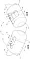
- FIGS. 3 A and 3 Bare isometric views of an exemplary embodiment of the coupler device of the present disclosure in use with a duodenum scope.
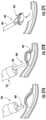
- FIGS. 4 A and 4 Bshow partial cutaway views of the coupler device and a duodenum scope of FIGS. 3 A and 3 B , respectively.
- FIG. 6shows still another cutaway view of the coupler device and a duodenum scope of FIGS. 3 A and 3 B .
- FIG. 7is a cutaway side view of the coupler device and a duodenum scope of FIGS. 3 A and 3 B in a first position.
- FIG. 8is a cutaway side view of the coupler device and a duodenum scope of FIGS. 3 A and 3 B in a second position.
- FIG. 9is a cutaway side view of the coupler device and a duodenum scope of FIGS. 3 A and 3 B in a third position.
- FIG. 10is an enlarged side view of the working channel extension with membrane of the coupler device of FIGS. 3 A and 3 B .
- FIG. 11is a top-down view of the coupler device of FIGS. 3 A and 3 B .
- FIG. 12is a cutaway view of another exemplary embodiment of a coupler device of the present disclosure.
- FIG. 13is a cutaway side view of the coupler device of FIG. 12 .
- FIG. 14is a cutaway side view of the coupler device of FIG. 12 in use with a duodenum scope.
- FIG. 15is an enlarged side view of an exemplary embodiment of a working channel extension of the present disclosure.
- FIG. 16is another enlarged side view of the working channel extension of FIG. 15 .
- FIG. 17 Ais a perspective view of the working channel extension of FIG. 15 .
- FIG. 17 Bshows the working channel extension of FIG. 17 A in use with an instrument.
- FIG. 18is a perspective top-down view of the coupler device of FIG. 3 with a locking feature.
- FIG. 19is a perspective view of another exemplary embodiment of a working channel extension of the present disclosure.
- FIG. 20is a perspective view of a positioning system for use with an endoscope and an optical coupler in a kit according to the present disclosure.
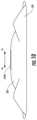
- FIG. 21is a partial cutaway view of a biliary guidewire for use with an endoscope and the optical coupler of the present disclosure.
- FIGS. 22 A- 22 Cillustrate a kit according to the present disclosure including, the optical coupler, an endoscope and a dilatation catheter.
- FIG. 23is a perspective view of a cannula system for use in an ERCP procedure as part of a kit according to the present disclosure.
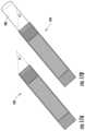
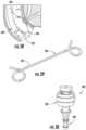
- FIG. 24is a perspective view of a sphincterotome for use in an endoscopic kit according to the present disclosure
- FIG. 25is a perspective view of a choledoscope for use in an endoscopic kit according to the present disclosure.
- FIG. 26is a perspective view of an extraction device for kidney stones for use in a kit according to the present disclosure.
- FIGS. 27 A- 27 Care schematic view of instruments for use in a mucosal resection procedure according to the present disclosure.
- FIG. 28is a schematic view of polypectomy snare instrument and an endoscope as part of a kit according to the present disclosure.
- FIG. 29is a perspective view of a biliary stent for use in with an endoscope and the optical coupler according to the present disclosure.
- FIG. 30is a perspective view of a disposable valve for use with an endoscope and coupler device according to the present disclosure.
- FIG. 31is a perspective view of disposable tubing for use with an endoscope and the coupler device of the present disclosure.
- FIG. 32is a perspective view of a bite block for use with an endoscope and the optical coupler of the present disclosure.
- FIG. 33is a schematic view of a compression device for an endoscopic procedure.
- kitfor use in an endoscopic procedure including a coupler device for an optical image endoscope
- the features of the presently described kitmay be readily adapted for use with a variety of reusable or disposable endoscopic scopes, instruments and devices.
- endoscoperefers generally to any scope used on or in a medical application, which includes a body (human or otherwise) and includes, for example, a laparoscope, duodenoscope, endoscopic ultrasound scope, arthroscope, colonoscope, bronchoscopes, enteroscope, cystoscope, laparoscope, laryngoscope, sigmoidoscope, thoracoscope, cardioscope, and saphenous vein harvester with a scope, whether robotic or non-robotic.
- scopesWhen engaged in remote visualization inside the patient's body, a variety of scopes are used. The scope used depends on the degree to which the physician needs to navigate into the body, the type of surgical instruments used in the procedure and the level of invasiveness that is appropriate for the type of procedure. For example, visualization inside the gastrointestinal tract may involve the use of endoscopy in the form of flexible gastroscopes and colonoscopes, endoscopic ultrasound scopes (EUS) and specialty duodenum scopes with lengths that can run many feet and diameters that can exceed 1 centimeter. These scopes can be turned and articulated or steered by the physician as the scope is navigated through the patient.
- EUSendoscopic ultrasound scopes
- scopesinclude one or more working channels for passing and supporting instruments, fluid channels and washing channels for irrigating the tissue and washing the scope, insufflation channels for insufflating to improve navigation and visualization and one or more light guides for illuminating the field of view of the scope.
- Smaller and less flexible or rigid scopes, or scopes with a combination of flexibility and rigidityare also used in medical applications.
- a smaller, narrower and much shorter scopeis used when inspecting a joint and performing arthroscopic surgery, such as surgery on the shoulder or knee.
- a shorter, more rigid scopeis usually inserted through a small incision on one side of the knee to visualize the injury, while instruments are passed through incisions on the opposite side of the knee. The instruments can irrigate the scope inside the knee to maintain visualization and to manipulate the tissue to complete the repair
- scopesmay be used for diagnosis and treatment using less invasive endoscopic procedures, including, by way of example, but not limitation, the use of scopes to inspect and treat conditions in the lung (bronchoscopes), mouth (enteroscope), urethra (cystoscope), abdomen and peritoneal cavity (laparoscope), nose and sinus (laryngoscope), anus (sigmoidoscope), chest and thoracic cavity (thoracoscope), and the heart (cardioscope).
- bronchoscopesto inspect and treat conditions in the lung
- enteroscopeto inspect and treat conditions in the mouth
- cystoscopecystoscope
- laparoscopeto inspect and treat conditions in the abdomen and peritoneal cavity
- laparoscopeto inspect and treat conditions in the abdomen and peritoneal cavity
- laparoscopeto inspect and treat conditions in the abdomen and peritoneal cavity
- laparoscopeto inspect and treat conditions in the abdomen and peritoneal cavity
- laparoscopeto inspect and treat conditions in the abdomen and peritoneal
- scopesmay be inserted through natural orifices (such as the mouth, sinus, ear, urethra, anus and vagina) and through incisions and port-based openings in the patient's skin, cavity, skull, joint, or other medically indicated points of entry.
- diagnostic use of endoscopy with visualization using these medical scopesincludes investigating the symptoms of disease, such as maladies of the digestive system (for example, nausea, vomiting, abdominal pain, gastrointestinal bleeding), or confirming a diagnosis, (for example by performing a biopsy for anemia, bleeding, inflammation, and cancer) or surgical treatment of the disease (such as removal of a ruptured appendix or cautery of an endogastric bleed).
- the kit of the present disclosuremay include an optical viewing endoscope of the type described above.
- a representative endoscope 100 for use with the present disclosureincludes a proximal handle 112 adapted for manipulation by the surgeon or clinician coupled to an elongate shaft 114 adapted for insertion through a natural orifice or an endoscopic or percutaneous penetration into a body cavity of a patient.
- Endoscope 100further includes a fluid delivery system 116 coupled to handle 112 via a universal cord 115 .
- Fluid delivery system 116may include a number of different tubes coupled to internal lumens within shaft 114 for delivery of fluid(s), such as water and air, suction, and other features that may be desired by the clinician to displace fluid, blood, debris and particulate matter from the field of view. This provides a better view of the underlying tissue or matter for assessment and therapy.
- fluid delivery system 116includes a water-jet connector 118 , water bottle connector 120 , a suction connector 122 and an air pipe 124 .
- Water-jet connector 118is coupled to an internal water-jet lumen 126 that extends through handle 112 and elongate shaft 114 to the distal end of endoscope 100 .
- water jet connector 118water bottle connector 120 , suction connector 122 and air pipe 124 are each connected to internal lumens 128 , 130 , 132 , 134 respectively, that pass through shaft 114 to the distal end of endoscope 100 .
- Endoscope 100may further include a working channel (not shown) for passing instruments therethrough.
- the working channelpermits passage of instruments down the shaft 114 of endoscope 100 for assessment and treatment of tissue and other matter.
- Such instrumentsmay include cannula, catheters, stents and stent delivery systems, papillotomes, wires, other imaging devices including mini-scopes, baskets, snares and other devices for use with a scope in a lumen.
- Proximal handle 112may include a variety of controls for the surgeon or clinician to operate fluid delivery system 116 .
- handle 112include a suction valve 135 , and air/water valve 136 and a biopsy valve 138 for extracting tissue samples from the patient.
- Handle 112will also include an eyepiece (not shown) coupled to an image capture device (not shown), such as a lens and a light transmitting system.
- image capture deviceas used herein also need not refer to devices that only have lenses or other light directing structure.
- the image capture devicecould be any device that can capture and relay an image, including (i) relay lenses between the objective lens at the distal end of the scope and an eyepiece, (ii) fiber optics, (iii) charge coupled devices (CCD), (iv) complementary metal oxide semiconductor (CMOS) sensors.
- An image capture devicemay also be merely a chip for sensing light and generating electrical signals for communication corresponding to the sensed light or other technology for transmitting an image.
- the image capture devicemay have a viewing end—where the light is captured.
- the image capture devicecan be any device that can view objects, capture images and/or capture video.
- endoscope 100includes some form of positioning assembly (e.g., hand controls) attached to a proximal end of the shaft to allow the operator to steer the scope.
- the scopeis part of a robotic element that provides for steerability and positioning of the scope relative to the desired point to investigate and focus the scope.
- scope 150includes an elongate flexible shaft 151 with distal end portion 152 having a viewing region 154 and an instrument region 156 , both of which face laterally or to the side of the longitudinal axis of shaft 151 .
- Viewing region 154includes an air nozzle port 158 , a camera lens 160 and a light source 162 for providing a view of the surgical site in the patient.
- Instrument region 156includes an opening 164 coupled to a working channel (not shown) within shaft 151 of scope 150 .
- Opening 164is configured to allow passage of instruments from the working channel of scope 150 to the surgical site.
- Scope 150also preferably includes an articulation mechanism for adjusting the angle that the instruments pass through opening 164 .
- the articulation mechanismcomprises an elevator 166 , although it will be recognized by those skilled in the art that the articulation mechanism may include a variety of other components designed to articulate the instrument angle, such as a cable extending through shaft 151 or the like.
- FIGS. 3 A and 3 Billustrate an exemplary embodiment of a coupler device 10 of the present disclosure.
- the coupler device 10serves as an accessory component for currently existing endoscopes.
- the deviceseals and covers infection prone areas of the scope to prevent ingress of debris, fluid, or other unwanted matter that could lead to bacterial contamination and decreased performance of the scope.
- the coupler device 10provides a flexible working channel for instruments to be inserted into the scope.
- the flexible working channelcan be angularly adjustable with ease.
- the coupler device 10may be used with a duodenum scope 40 or other side-viewing scope instrument. It is understood, of course, that the coupler device 10 may be adapted for use with end viewing scopes as well.
- the coupler device 10 of the present disclosurecan be used with all types of scopes for different medical applications.
- the duodenum scope 40 shown hereis merely for illustrative purposes.
- the instruments passing through the scopemay be articulated by a variety of different mechanism.
- the devicemay have multiple cables so the angle of exit can be articulated in multiple directions, including in different quadrants, unlike with the current endoscope elevators, which can only deflect and therefore redirect an instrument in a single axis due to the limited travel of endoscope elevators, which can only be raised or lowered, but not moved from side to side or articulated into other quadrants.
- the cable(s)may be attached directly to the working channel extension or to other devices that can be articulated and cause the working channel extension to change its angle of exit, including, for example, a dowel underneath the working channel extension, but encased in the device that can be advanced forward and backward to move the working channel extension as the cable is advanced and retracted.
- the articulation ability of the coupler devicemay be created with an elevator embedded in the coupler device, which is disposable and therefore thrown away after the procedure.
- the articulation ability of the coupler devicemay also take place with elements that do not involve cables, including for example, piezo electric materials, micro motors, organic semiconductors, and electrically activated polymers.
- the articulation ability of the coupler devicemay also take place with the transfer of force to the working channel extension or an embedded elevator through interlocking connectors that transfer force, wires that twist, slidable sheaths, and memory metals that change shape through the transfer of temperature.
- the deviceincludes a power connector or motors to deliver energy, including electromagnetic energy, to the device to cause a transfer in force to change the angle of exit from the coupler device as an instrument is passed through the device, or in advance of passing an instrument through the device.
- This transfer of forcecan include causing the device to rotate as it exits the working channel extension.
- the devicemay be navigated and articulated by the user directly, or as part of a robotic system in which the users input is translated through the system through various means, including cables, power connectors, motors, electromagnetic energy, slidable sheaths, haptics, computer-guided and directed input, and other means to direct and guide the device to its intended location, including to specific diagnosis and treatment objectives in a patient, or in non-medical applications, to a desired remote location.
- the coupler device 10may comprise a main body 12 , proximal end 14 and distal end 16 , lower surface 18 and upper surface 20 .
- the proximal end 14attaches onto a working end of a duodenum scope 40 , extending the working end portion of the scope 40 .
- the upper surface 20may include a lens and light guide 24 and a scope washer opening 28 , which is used to push fluid across the scope camera to wash debris off the camera and is also used to push air across the camera to dry the camera and insufflate the patient's gastrointestinal tract.
- Upper surface 20may further include an open area over lens and light guide 24 and scope washer opening 28 to facilitate viewing the surgical site and to allow egress of fluid from scope washer opening 28 into the surgical site (and/or egress of air that may be passed over light guide 24 to dry the camera or that may be passed into the surgical site to insufflate a portion of the site).
- the upper surface 20includes a flexible working channel region 30 that includes a flexible working channel extension 34 that is surrounded by a flexible membrane 38 .
- This flexible membrane 138serves as a protective hood or covering for the working end of the coupler device 10 , providing for flexible articulation while sealing out debris, fluid, bacteria or other unwanted matter.
- the duodenum scope 40may comprise a light guide 44 , lens 46 and washer opening 48 .
- the coupler device 10cooperates with each of these components of the scope 40 to provide a fully functioning scope.
- the coupler device 10does not interfere with the scope's ability to emit a clear image, but instead reduces the risk of contamination with each use. This benefit is achieved by providing a coupler device 10 which attaches to the working end components of the scope 40 , and seals around the working end.
- the coupler device 10provides an extension of the scope's working channel 42 .
- the working channel extension 34 of the coupler device 10 in FIG. 3is flexible and may contact the scope's working channel 42 by a sealed connection, as shown in FIG. 6 , at the proximal end 34 a of the working channel extension.
- the distal end 34 b of the working channel extension 34serves as an exit portal for instruments to pass through the scope 40 to reach different areas of the body.
- the coupler device 10provides a further seal around the elevator 50 of the scope. Because the coupler device 10 seals the elevator 40 , risk of debris influx, fluids, bacteria and other matter build up behind the elevator and working channel is reduced significantly. This influx of debris, bacteria and other matter is believed to be the reason for drug resistant infections with current scopes today. While preventing influx, the coupler device 10 advantageously maintains flexibility to move the working channel extension 34 .
- the scope's working channel extension 34permits passage of instruments down the scope working channel 42 and through and out the working channel extension 34 of the device 40 for assessment and treatment of tissue and other matter.
- Such instrumentsmay include cannula, catheters, stents and stent delivery systems, papillotomes, wires, other imaging devices including mini-scopes, baskets, snares and other devices for use with a scope in a lumen.
- This working channel extension 34is flexible enough that the elevator 50 of the scope 40 can raise and lower the working channel extension 34 so that instruments can be advanced down and out of the working channel extension distal end (or exit portal) 34 b of the scope 40 at various angles, or be raised and lowered by a cable or other means to articulate the working channel extension 34 .
- FIGS. 7 to 9illustrate, in use when the elevator 50 of the scope 40 is actuated, the flexible working channel extension 34 of the coupler device moves or adjusts to this actuation, along the direction A-A.
- the elevator 50is raised slightly, creating a hinged ramp or shoulder that pushes the working channel extension 34 a corresponding angle and shifts the exit portal or distal end 34 b of the working channel extension to the left.
- the elevatoris raised higher than in FIG. 7 , such that the distal end 34 b of working channel extension 34 is likewise shifted further to the left in comparison to FIG. 7
- FIG. 9shows the elevator 50 raised even higher and the distal end 34 b of working channel extension 34 moved to the left even further in comparison to FIGS. 7 and 8 .
- the ability of the distal end 34 b of working channel extension 34 to shift along the width of the working channel region 30 of the coupler device 10is in part due to the fact that the distal end 34 b is itself attached to a flexible membrane 38 .
- This flexible membrane 38comprises a plurality of loose folds or creases, allowing the excess material to stretch and bend as the elevator actuation forces the working channel extension to bend and shift in response.
- the flexible membrane 38acts as a protective cover or hood for the working channel region 38 , preventing the ingress of fluids, debris, or other unwanted matter from getting inside the scope 40 and causing a bacterial contamination or the infusion of other unwanted fluid, debris or particulate matter.
- the coupler device 10 of the present disclosuremay be configured for single, disposable use, or it may be configured for reuse.
- the coupler device 10may be made of any biocompatible material, such as for example, silicone or another elastic or polymeric material.
- the materialmay be transparent.
- the coupler device 10may be formed of a transparent material to provide a transparent covering of the scope camera and light source, thereby allowing unhindered performance of the scope 40 .
- FIGS. 12 to 14show another exemplary embodiment of a coupler device 10 of the present disclosure.
- the coupler device 10is adapted for use with scopes that are actuated by cable and eliminates the need for the elevator component.
- the coupler device 10maintains the same structural features as previously described, but now includes a further disposable external sheath 60 that can receive an interior actuating cable 54 of the scope.
- This cable 54can be detached from the elevator and reattached to the flexible working channel extension 34 of the coupler device 10 .
- the elevatoris no longer needed in this embodiment, as actuation of the cable effects movement of the working channel extension 34 .
- the external sheath 60may be configured to attach directly to the scope 40 , such as by winding around the outside of the scope or by a friction fit connection.
- multiple cablesmay be included in one or more sheaths to provide for articulation in other quadrants than the single axis articulation with elevators in current duodenoscopes.
- the coupler device 10may also include a closable port (i.e., self-sealing) that allows for the injection of anti-adhesion, anti-bacterial, anti-inflammatory or other drug or infusible matter that prevents the adherence or colonization of bacteria on the scope.
- a closable porti.e., self-sealing
- An applicatormay be provided that is integrated into the coupler device 10 with a port for delivery of the infusible matter. Alternatively, the applicator may be separate from the coupler device 10 and applied to the distal end of the scope 40 .
- the infusible mattermay include forms of silver, including in a gel or other solution, platinum, copper, other anti-adhesion, anti-bacterial, anti-inflammatory or other drug or infusible matter that is compatible with the scope and coupler device materials and biocompatible for patient use.
- the deviceincludes an anti-infective material. In another exemplary embodiment, the device includes an anti-infective coating. In still another embodiment, the device includes a coating that is hydrophobic. In yet another embodiment, the device is superhydrophobic. In even still another embodiment, the device is anti-infective and hydrophobic. Further yet in another embodiment, the device is anti-infective and superhydrophobic. In further still another exemplary embodiment, anti-inflammatory coatings are incorporated into the device. In other embodiments, the anti-inflammatory coating may be hydrophilic.
- the device 10may include a silver ion coating.
- the device 10may have a silver hydrogel applied, infused, or made part of the device 10 in the area that covers or goes around the scope elevators.
- silvercan also conduct electricity.
- the device 10may include an electrical wire or other power transmission point to enable the creation of an electric field across the silver ion coating to improve the ability of the silver ion coating to prevent infection.
- the electrical wire or other power transmission pointmay also apply to other antimicrobial and conductive materials, including platinum and copper.
- FIGS. 15 and 16show another embodiment of the working channel extension 234 of the present disclosure.
- the working channel extensionsmay comprise a combination of different materials.
- the working channel extension 234may be formed of multiple elastic materials joined to a biocompatible metal.
- one of the elastic materialsmay be PTFE and another elastic material may be a biocompatible elastic material that covers the biocompatible metal.
- the working channel extension 234may comprise an inner elastic material 210 and an outer elastic material.
- the outside of the working channel extension 234may include a biocompatible metal 230 , which may take the form of a coil or winding 232 .
- the biocompatible metalmay be encapsulated by one or more of the elastic materials.
- the outer biocompatible elastic material 220is formed to create a gasket 222 to seal the proximal end of the working channel extension against 234 the working channel of an endoscope, creating a seal to prevent the intrusion of unwanted bacteria, biomatter and other material into this sealed area.
- a working channel extension 234is shown with an adjustable angle of exit ⁇ for locking an instrument 200 in place.
- the angle of exit ⁇when adjusted, it creates compressive force in the working channel 234 , locking an instrument 200 in place, as shown in FIG. 17 B .
- Thiscan be used to fixate an instrument while a wire is advanced through the instrument, or to fixate a wire, while a second instrument is exchanged over the wire.
- FIG. 18an alternative embodiment is shown for locking an instrument 200 in place.
- the working channel extension 234is raised to a point in which the instrument 200 in the working channel extension 234 is compressed against a lock 180 on the device 100 , causing a change in the angle of exit of the working channel extension 234 and locking the instrument 200 in a fixated place in the working channel extension 234 .
- FIG. 19an alternative embodiment of the working channel extension 234 is shown with a flange 268 for attaching the working channel extension to the membrane material 38 that is part of the device 10 .
- FIG. 20illustrates a positioning system 330 for use in a kit including coupler device 10 (not shown in FIG. 20 ) and an endoscope 332 according to the present disclosure.
- endoscope 332is shown as an end viewing scope, it will be understood that positioning system 330 can be used with any known scope, including side viewing scopes similar to those discussed above.
- positioning system 330includes an overtube 334 designed to slide over the entire length of endoscope 332
- An inflatable balloon 336is configured for attachment to a portion of the outer surface of endoscope 332 or to the inner or outer surfaces of overtube 334 .
- Balloon 336comprises an interior fluidly coupled to an internal lumen that extends through overtube 334 or endoscope 332 .
- the internal lumenis suitably coupled to a fluid delivery system external to the patient for inflation and deflation of balloon 336 .
- inflation of balloon 336serves to anchor overtube 334 within the patient's intestine. While the over tube 334 is anchored, the endoscope 332 can be advanced further into the small intestine. By withdrawing the overtube 334 , the small intestine can be shortened and straightened to facilitate the passage of the inner endoscope 332 through the patient's intestines. The balloon 336 may then be deflated so that overtube 334 can be inserted further into the intestines.
- endoscope 332preferably includes the coupler device 10 , as described above.
- the positioning systemmay comprise an inflatable balloon (not shown) configured for removable attachment to the distal end portions of either the endoscope 332 or coupler device 10 .
- balloon 336is fluidly coupled via an internal lumen within the endoscope and/or coupler device 10 to a suitable fluid delivery system for inflation and deflation of the balloon.
- the kitmay include an inflatable balloon coupled to the endoscope and/or the coupler device.
- the inflatable balloonis removably coupled to the coupler device and includes a fluid delivery tube extending through, for example, the endoscope to allow for inflation or deflation of the balloon.
- the ballooncan be used to facilitate advancement of the coupler device and the distal end portion of the endoscope through one or more internal body lumens, such as the pancreaticobiliary tract, the intestines, the patient's vasculature and the like.
- FIG. 21illustrates a kit including a biliary guidewire 340 , an endoscope 342 and coupler device 10 according to the present disclosure.
- guidewire 340comprises an elongate shaft 344 sized for advancement through a working channel (not shown) in endoscope 342 .
- Guidewire 340comprises a distal tip 344 sized to advance into, for example, the pancreaticobiliary tract 346 of a patient.
- Guidewire 340may also be used in combination with coupler device 10 by passing through guidewire 340 working channel extension 34 of coupler device 10 .
- the orientation of guidewire 340may be adjusted by adjusting an elevator or cable in scope 342 , which moves working channel extension 34 of coupler device 10 in an axial direction relative to the endoscope shaft, as described above.
- Coupler device 10protects the scope and its components, particularly the scope elevator 50 , to reduce the risk of debris, fluid and other matter ending up in the elevator and behind the elevator and the working channel, potentially causing infection risk.
- FIGS. 22 A- 22 Cillustrates a kit including a dilatation catheter 350 , an endoscope 352 and the coupler device (not shown) according to the present disclosure.
- endoscope 352is shown as an end viewing scope, it will be understood that dilatation catheter 350 can be used with any known scope, including side viewing scopes similar to those discussed above.
- catheter 350includes an elongate flexible shaft 354 with an inflatable balloon 356 at its distal end. Balloon 356 is coupled to a fluid lumen (not shown) within shaft 354 that is suitably coupled to a fluid delivery system for delivering air or other fluid into balloon 356 to inflate the balloon.
- Catheter 350may be used in combination with the scope and coupler device of the present disclosure to create or enlarge a passageway in the patient's body.
- catheter 350may be used with the scope and the coupler device for diagnosing and/or treating disorders in the liver, pancreas, gallbladder, spleen, duodenum, kidney and the like.
- FIGS. 22 A- 22 Cillustrate one example of dilatation catheter 350 used with an endoscope 352 and the coupler device (not shown in these figures) according to the present invention.
- catheter 350is advanced through the working channel of endoscope 352 and through working channel extension 34 of coupler 10 until balloon 356 is distal of endoscope 352 and coupler device 10 .
- Balloon 354may then be advanced to a narrowed or stenosed region 358 of the body passage and inflated to enlarge the passageway (see FIGS. 22 B and 22 C ). The entire procedure can be viewed by the camera and light in endoscope 352 through the open area in coupler device 10 .
- a cannula 360 for use in a kit according to the present inventionis used in combination with coupler device 10 and the endoscopes of the present disclosure for gaining access to certain areas of the surgical site, such as the patient's gallbladder, biliary system, pancreas and/or liver.
- cannula 360is configured for access through the major or minor papillas in, for example, an endoscopic retrograde cholangiopancreatography procedure (ERCP).
- Cannula 360may be a single-lumen catheter for advancement of a guide wire 362 , or it may have multiple lumens, for injection of contrast material or other fluids.
- cannula 360may include a proximal adaptor 364 , such as a Tuohy-Borst adaptor, that may function as a common port for both guidewire and contrast injection.
- FIG. 24illustrates another endoscopic instrument 370 for use with the coupler device and endoscope of the present disclosure.
- instrument 370includes an elongate flexible shaft 372 with a distal tip 374 and a cutting wire 376 extending to the region of distal tip 374 .
- Cutting wire 376has a proximal end coupled to a suitable electrosurgical power source for delivering electrosurgical energy to the surgical site.
- Instrument 370may be configured as a sphincterotome, a papillotome or other suitable known electrosurgical catheter for use in endoscopic procedures.
- activation of the power sourcecauses electrical current to pass along an insulated portion of cutting wire 376 within the catheter to the exposed cutting wire 376 .
- a retractable plunger on the control handle or other control mechanismpermits flexing of the catheter tip upward by pulling on cutting wire 376 . This flexing assists with aligning the tip of the catheter with the proper orientation to the papilla and aligning the cutting wire 376 and maintaining contact of the wire with the papilla while the catheter is pulled back, incising the major or minor papilla.
- instrument 370is configured for passing through a working channel in an endoscope and through working channel extension 34 of coupler device 10 .
- the angle of distal tip 374can be adjusted, for example, with an elevator or cable in the endoscope which adjusts the working channel extension 34 within coupler device 10 , as described above.
- FIG. 25illustrates another embodiment of an endoscope 380 for use in a kit according to the present disclosure.
- Coupler device 10may be configured for use with endoscope 380 as discussed above.
- endoscope 380may be used together with the coupler device 10 and endoscope 100 in an endoscopic procedure, such as procedure designed to diagnose or treat disorders of the bile duct, pancreas, liver duodenum or spleen.
- endoscope 380comprises a smaller disposable scope configured for advancement through the working channel of an end or side viewing scope such as the one described above in FIGS. 1 and 2 .
- Disposable scope 380is also configured for advancement through working channel extension 34 of coupler device 10 and can be articulated in any of the manners described above.
- endoscope 380is a choledochoscope for use in examining and diagnosing the common bile duct of a patient.
- scope 380includes a proximal handle 382 coupled to an elongate flexible shaft 384 sized for advancing into the common bile duct.
- Scope 380further includes a thin fiberoptic cable for transmitting light to the surgical site, and a camera with a lens for viewing the site.
- choledochoscope 380may be used in combination with coupler device 10 to, for example, remove biliary tract stones from the common bile duct.
- choledochoscope 380may be passed directly into the bile duct such that a thorough exploration of the proximal and distal duct may be performed. Stones may be flushed out of the bile duct, removed directly with atraumatic graspers, forceps, or the like, or extracted using a snare, basket or other suitable device that is passed through choledochoscope 380 or a side viewing endoscope 100 .
- FIG. 26illustrates a stone entrapment and extraction device 390 for use with choledochoscope 380 , coupler device 10 and/or endoscope 100 .
- Extraction device 390comprises an elongate shaft 392 and a capture basket 394 that may be advanced through the lumen of a suitable endoscope and through working channel extension 34 of coupler device 10 . Once capture basket 394 has passed through the distal opening of working channel extension and delivered where clinically intended, it is expanded into the configuration shown in FIG. 26 .
- device 390may include components other than a basket for retrieving stones, such as a wire arrangement, a balloon or the like.
- any suitable grasping or biopsy forcepscan be used with coupler device 10 and endoscope 100 to remove stones from the patient.
- FIGS. 27 A- 27 Cillustrate a polyp or tissue removal device 400 for use with an endoscope 100 and the coupler device of the present invention.
- tissue removal device 400may be used with one of the side viewing scopes described above.
- Coupler device 10(not shown in FIGS. 27 A- 287 C ) can be used to cover the tip of the endoscope such that tissue removal device 400 passes through working channel extension 34 , as described above.
- Tissue removal device 400can be, for example, a snare type device that includes a wire snare 402 at the distal end of an elongate shaft. The snare is configured for grasping and extracting tissue and/or polyps from the surgical site.
- tissue removal device 400may comprise other suitable tissue removal components, such as baskets, balloons, forceps and the like.
- FIG. 28illustrates a polypectomy snare 420 for use with endoscope 100 and the coupler device (not shown) of the present invention.
- a polypectomy snare 420comprises an elongate shaft 422 designed to advance through the working channel of the endoscope and working channel extension 134 of coupler device.
- Snare 420includes a wire loop 424 at its distal tip configured for passing over a polyp or other tissue matter.
- the wire loop 424is coupled to an actuator at proximal end of the endoscope for actuating the loop and closing it onto the polp, resulting in cutting the polyp away from the patient's tissue.
- Wire loop 424may be coupled to a power source external to the patient for passing electric current through loop to assist with the cutting procedure and to cauterize the tissue while removing the polyp.
- FIG. 29illustrates a biliary stent 430 for use with an endoscope and the coupler device 10 in a kit according to the present invention.
- Stent 430comprises a flexible metallic tube 432 configured to hold open a bile duct during or after an endoscopic procedure.
- Stent 430may be placed within the bile duct and expanded therein to maintain patency of the bile duct such that fluids, such as bile (bilirubin) are able to flow into the duodenum to aid in digestion.
- Stent 430is configured to advance through the working channel of the endoscope (typically with a guidewire) and through working channel extension 34 of coupler device 10 .
- Stent 430Once stent 430 has been passed through the distal open end of working channel extension 34 , it can be put into position with bile duct and expanded so as to expand the bile duct channel.
- Stent 430may be expanded through any suitable means knows in the art, such as body temperature (e.g., nitinol material) or actuating mechanisms.
- Stent 430may comprise any suitable material, such as plastic, temperature-based self-expanding materials (e.g. nitinol), bioabsorbable materials or the like.
- FIG. 30illustrates a disposable valve 300 for use in a kit including the endoscope 100 and coupler device 10 of the present disclosure.
- Disposable valve 300is configured for attachment to a valve in endoscope 100 for opening and closing access to an internal lumen within the endoscope.
- disposable valve 300comprises a stem 302 for sealing a lumen in an endoscope valve, maintain a suction force and preventing fluid from passing through the lumen, and an adjustable valve 304 for opening the lumen such that fluids may pass therethrough.
- Valve 300may be configured for opening and closing biopsy, irrigation, suction and/or air insufflation valves coupled to the endoscope.
- Valve 300is disposable and intended for single-use on one surgical procedure or patient.
- FIG. 31illustrates disposable tubing 310 for use in a kit including the coupler device 10 and an endoscope according to the present disclosure.
- tubing 310comprises an elongate flexible tube 312 with an internal lumen for passing fluid therethrough, and a distal fitting 314 configured for attachment to an endoscope valve or a disposable valve, such as the one described above in reference to FIG. 20 .
- Tubing 310further comprising a proximal end 316 for attachment to a suitable fluid delivery system, such as a sterile water bottle, irrigation pump, suction device, air or CO2 pump or the like.
- Tubing 310is designed as a single-use disposable device and may include multiple tubes.
- FIG. 32illustrates a bite block 320 for use in a kit including coupler device 10 and an endoscope according to the present disclosure.
- bite block 320includes a front flange 322 to overlap a patient's mouth and an opening 324 configured to be received between the patient's lower and upper jaw and sized to provide access to the patient's oral cavity for an endoscope or the like.
- Bite block 320may further include a strap 326 or other suitable device for wrapping around the patient's head to secure front flange 322 in place.
- Bite block 320serves to protect the patient's mouth from the endoscope and the endoscope from the patient's mouth (i.e., biting down during the procedure).
- FIG. 33illustrates an external anatomic support band 440 for use with the endoscope 100 and coupler device 10 in a kit according to the present invention.
- Support band 440is an abdominal compression device configured for wear by patients undergoing endoscopic procedures, such as colonoscopy.
- support band 440is configured to provide sustained, adjustable pressure to splint the patient's sigmoid and transverse colon 442 , which allows for faster and easier endoscope advancement.
- colonoscopylooping is a frequent challenge. It occurs as the endoscope is advanced forward, which causes stretching and distension of the colon in response to the physician's efforts to advance the scope forward through the colon.
- the kitmay include other devices for use with the endoscope and coupler device of the present disclosure, such as cytology brushes, biopsy forceps or needles, needle injectors, or the like.
- a needle biopsyis a procedure to obtain a sample of cells from your body for laboratory testing. Common needle biopsy procedures include fine-needle aspiration and core needle biopsy.
- an ultrasound-guided biopsy devicecan be used with the endoscope(s) and coupler device 10 of the present disclosure.
- the kitincludes an ultrasound, x-ray or other lithotripter device configured for transmitting sounds waves (e.g., shock waves) through a patient's outer skin surface to a target site within the body.
- sounds wavese.g., shock waves
- the lithotriptermay focus shock waves onto stones to break up the stones into smaller fragments that can be retrieved by one of the devices or methods discussed above, or naturally passed out of the body through urine.
- the lithotriptermay be used in conjunction with the endoscope and optical coupler of the present disclosure for treating stones and/or or disorders of the GI tract.
- the kit of the present disclosuremay also include a variety of devices used to prepare for an endoscopic procedure with the endoscope and coupler device of the present disclosure, such as instrument table covers, table drapes, throat analgesics, tissue/polyp collection baskets and the like.
- the kit of the present disclosuremay also include a variety of other devices used after an endoscopic procedures, such as cleaning brushes, swabs and/or sponges, disposable tubing for irrigating and flushing an endoscope, enzymatic cleaners, disinfectants, and other devices and agents for sterilizing and/or disinfecting medical devices, test strips or other sensors for determining the effectiveness of such cleaning devices (i.e., detecting the presence of proteins, biomatter, bacteria, fungi, viruses or other pathogens), scope housings for transporting scopes to and from, for example a reprocessing location, contamination bags and the like.
- cleaning brushes, swabs and/or spongesdisposable tubing for irrigating and flushing an endoscope, enzymatic cleaners, disinfectants, and other devices and agents for sterilizing and/or disinfecting medical devices, test strips or other sensors for determining the effectiveness of such cleaning devices (i.e., detecting the presence of proteins, biomatter, bacteria, fungi, viruses or other pathogens), scope housings
- Suitable sensors for use with the present inventionmay include PCT and microarray based sensors, optical sensors (e.g., bioluminescence and fluorescence), piezoelectric, potentiometric, amperometric, conductometric, nanosensors or the like.
- the kitfurther include an indicator, such as a display, coupled to the sensor(s) and configured to indicator the presence of pathogens, liquids or other particulars detected by the sensor.
- the indicatormay be any suitable chemical indicator validated for sterilization procedures that undergoes a physical or chemical change visible to the human eye after exposure to certain parameters.
- the indicator and sensormay be part of the same device, or separate from each other.
Landscapes
- Health & Medical Sciences (AREA)
- Life Sciences & Earth Sciences (AREA)
- Surgery (AREA)
- Engineering & Computer Science (AREA)
- Physics & Mathematics (AREA)
- Optics & Photonics (AREA)
- Biomedical Technology (AREA)
- General Health & Medical Sciences (AREA)
- Pathology (AREA)
- Nuclear Medicine, Radiotherapy & Molecular Imaging (AREA)
- Biophysics (AREA)
- Heart & Thoracic Surgery (AREA)
- Medical Informatics (AREA)
- Molecular Biology (AREA)
- Animal Behavior & Ethology (AREA)
- Radiology & Medical Imaging (AREA)
- Public Health (AREA)
- Veterinary Medicine (AREA)
- Gastroenterology & Hepatology (AREA)
- Mechanical Engineering (AREA)
- Endoscopes (AREA)
- Surgical Instruments (AREA)
- Instruments For Viewing The Inside Of Hollow Bodies (AREA)
Abstract
Description
Claims (17)
Priority Applications (3)
| Application Number | Priority Date | Filing Date | Title |
|---|---|---|---|
| US16/717,702US12004712B2 (en) | 2015-07-21 | 2019-12-17 | Medical device kit with endoscope accessory |
| PCT/US2020/065427WO2021127054A1 (en) | 2015-07-21 | 2020-12-16 | Medical device kit with endoscope accessory |
| US18/654,453US20240277213A1 (en) | 2015-07-21 | 2024-05-03 | Medical device kit with endoscope accessory |
Applications Claiming Priority (3)
| Application Number | Priority Date | Filing Date | Title |
|---|---|---|---|
| US201562195291P | 2015-07-21 | 2015-07-21 | |
| PCT/US2016/043371WO2017015480A1 (en) | 2015-07-21 | 2016-07-21 | Endoscope accessory with angularly adjustable exit portal |
| US16/717,702US12004712B2 (en) | 2015-07-21 | 2019-12-17 | Medical device kit with endoscope accessory |
Related Parent Applications (1)
| Application Number | Title | Priority Date | Filing Date |
|---|---|---|---|
| PCT/US2016/043371Continuation-In-PartWO2017015480A1 (en) | 2015-07-21 | 2016-07-21 | Endoscope accessory with angularly adjustable exit portal |
Related Child Applications (1)
| Application Number | Title | Priority Date | Filing Date |
|---|---|---|---|
| US18/654,453ContinuationUS20240277213A1 (en) | 2015-07-21 | 2024-05-03 | Medical device kit with endoscope accessory |
Publications (2)
| Publication Number | Publication Date |
|---|---|
| US20200178773A1 US20200178773A1 (en) | 2020-06-11 |
| US12004712B2true US12004712B2 (en) | 2024-06-11 |
Family
ID=57834632
Family Applications (10)
| Application Number | Title | Priority Date | Filing Date |
|---|---|---|---|
| US15/746,196Active2037-04-14US10856724B2 (en) | 2015-07-21 | 2016-07-21 | Endoscope accessory with angularly adjustable exit portal |
| US15/906,557Active2038-02-21US11019984B2 (en) | 2015-07-21 | 2018-02-27 | Endoscope accessory with angularly adjustable exit portal |
| US16/717,702Active2036-08-10US12004712B2 (en) | 2015-07-21 | 2019-12-17 | Medical device kit with endoscope accessory |
| US16/717,804Active2036-07-31US12256893B2 (en) | 2015-07-21 | 2019-12-17 | Endoscope accessory and medical device kit |
| US16/897,098ActiveUS11253137B2 (en) | 2015-07-21 | 2020-06-09 | Endoscope accessory with locking elements |
| US17/572,852ActiveUS11882999B2 (en) | 2015-07-21 | 2022-01-11 | Coupler device for an endoscope |
| US17/572,850ActiveUS11910999B2 (en) | 2015-07-21 | 2022-01-11 | Endoscope accessory with locking elements |
| US18/422,229ActiveUS12414677B2 (en) | 2015-07-21 | 2024-01-25 | Endoscope accessory with locking elements |
| US18/654,453PendingUS20240277213A1 (en) | 2015-07-21 | 2024-05-03 | Medical device kit with endoscope accessory |
| US19/058,555PendingUS20250185890A1 (en) | 2015-07-21 | 2025-02-20 | Endoscope accessory and medical device kit |
Family Applications Before (2)
| Application Number | Title | Priority Date | Filing Date |
|---|---|---|---|
| US15/746,196Active2037-04-14US10856724B2 (en) | 2015-07-21 | 2016-07-21 | Endoscope accessory with angularly adjustable exit portal |
| US15/906,557Active2038-02-21US11019984B2 (en) | 2015-07-21 | 2018-02-27 | Endoscope accessory with angularly adjustable exit portal |
Family Applications After (7)
| Application Number | Title | Priority Date | Filing Date |
|---|---|---|---|
| US16/717,804Active2036-07-31US12256893B2 (en) | 2015-07-21 | 2019-12-17 | Endoscope accessory and medical device kit |
| US16/897,098ActiveUS11253137B2 (en) | 2015-07-21 | 2020-06-09 | Endoscope accessory with locking elements |
| US17/572,852ActiveUS11882999B2 (en) | 2015-07-21 | 2022-01-11 | Coupler device for an endoscope |
| US17/572,850ActiveUS11910999B2 (en) | 2015-07-21 | 2022-01-11 | Endoscope accessory with locking elements |
| US18/422,229ActiveUS12414677B2 (en) | 2015-07-21 | 2024-01-25 | Endoscope accessory with locking elements |
| US18/654,453PendingUS20240277213A1 (en) | 2015-07-21 | 2024-05-03 | Medical device kit with endoscope accessory |
| US19/058,555PendingUS20250185890A1 (en) | 2015-07-21 | 2025-02-20 | Endoscope accessory and medical device kit |
Country Status (8)
| Country | Link |
|---|---|
| US (10) | US10856724B2 (en) |
| EP (2) | EP3324820A4 (en) |
| JP (5) | JP6935100B2 (en) |
| KR (2) | KR20240151282A (en) |
| CN (2) | CN113143174B (en) |
| AU (4) | AU2016297077B2 (en) |
| CA (1) | CA2992739A1 (en) |
| WO (3) | WO2017015480A1 (en) |
Families Citing this family (70)
| Publication number | Priority date | Publication date | Assignee | Title |
|---|---|---|---|---|
| DE10154163A1 (en) | 2001-11-03 | 2003-05-22 | Advanced Med Tech | Device for straightening and stabilizing the spine |
| US8979931B2 (en) | 2006-12-08 | 2015-03-17 | DePuy Synthes Products, LLC | Nucleus replacement device and method |
| US20090088789A1 (en) | 2007-09-28 | 2009-04-02 | O'neil Michael J | Balloon With Shape Control For Spinal Procedures |
| BRPI0818608A2 (en) | 2007-10-05 | 2015-04-22 | Synthes Gmbh | Sequential directional dilatation system for dilating from a nerve of a patient's anatomy, and method for forming an access opening through a psoas muscle to a patient's spine using a dilatation system |
| US9622779B2 (en) | 2011-10-27 | 2017-04-18 | DePuy Synthes Products, Inc. | Method and devices for a sub-splenius / supra-levator scapulae surgical access technique |
| US9808232B2 (en) | 2011-11-01 | 2017-11-07 | DePuy Synthes Products, Inc. | Dilation system |
| US9265490B2 (en) | 2012-04-16 | 2016-02-23 | DePuy Synthes Products, Inc. | Detachable dilator blade |
| US9480855B2 (en) | 2012-09-26 | 2016-11-01 | DePuy Synthes Products, Inc. | NIR/red light for lateral neuroprotection |
| US9980737B2 (en) | 2014-08-04 | 2018-05-29 | Medos International Sarl | Flexible transport auger |
| US10111712B2 (en) | 2014-09-09 | 2018-10-30 | Medos International Sarl | Proximal-end securement of a minimally invasive working channel |
| US10264959B2 (en) | 2014-09-09 | 2019-04-23 | Medos International Sarl | Proximal-end securement of a minimally invasive working channel |
| US9924979B2 (en) | 2014-09-09 | 2018-03-27 | Medos International Sarl | Proximal-end securement of a minimally invasive working channel |
| US10786264B2 (en) | 2015-03-31 | 2020-09-29 | Medos International Sarl | Percutaneous disc clearing device |
| US10548467B2 (en) | 2015-06-02 | 2020-02-04 | GI Scientific, LLC | Conductive optical element |
| WO2017015480A1 (en)* | 2015-07-21 | 2017-01-26 | GI Scientific, LLC | Endoscope accessory with angularly adjustable exit portal |
| CN105455772B (en)* | 2015-07-31 | 2017-06-27 | 沈阳沈大内窥镜有限公司 | The ERCP protected with medical disposable material |
| US11439380B2 (en) | 2015-09-04 | 2022-09-13 | Medos International Sarl | Surgical instrument connectors and related methods |
| US10987129B2 (en) | 2015-09-04 | 2021-04-27 | Medos International Sarl | Multi-shield spinal access system |
| US12150636B2 (en) | 2015-09-04 | 2024-11-26 | Medos International Sárl | Surgical instrument connectors and related methods |
| US11744447B2 (en) | 2015-09-04 | 2023-09-05 | Medos International | Surgical visualization systems and related methods |
| CN113143355A (en) | 2015-09-04 | 2021-07-23 | 美多斯国际有限公司 | Multi-shield spinal access system |
| US11672562B2 (en) | 2015-09-04 | 2023-06-13 | Medos International Sarl | Multi-shield spinal access system |
| EP3383246A4 (en)* | 2015-12-05 | 2019-08-07 | The Regents of the University of Colorado, a body corporate | NOVEL ENDOSCOPIC DEVICES AND METHODS OF USE |
| US10299838B2 (en) | 2016-02-05 | 2019-05-28 | Medos International Sarl | Method and instruments for interbody fusion and posterior fixation through a single incision |
| CN109475287B (en)* | 2016-07-19 | 2021-09-21 | 奥林巴斯株式会社 | Tip attachment for endoscope |
| DE102016114881A1 (en)* | 2016-08-11 | 2018-02-15 | Digital Endoscopy Gmbh | Endoscope head, endoscope and albarrane lever holding element |
| CN109757097B (en)* | 2016-10-14 | 2022-02-18 | Hoya株式会社 | Stand and endoscope |
| DE102016122477A1 (en)* | 2016-11-22 | 2018-05-24 | Digital Endoscopy Gmbh | ENDOSCOPIC HEAD AND ENDOSCOPE WITH THIS |
| WO2018098465A1 (en) | 2016-11-28 | 2018-05-31 | Inventio, Inc. | Endoscope with separable, disposable shaft |
| JP2018149269A (en)* | 2017-01-18 | 2018-09-27 | マッカイ メディカル ファンデーション ザ プレスビュテロス チャーチ イン タイワン マッカイ メモリアル ホスピタル | Endoluminal treatment system for gastrointestinal infections |
| RU2661124C1 (en)* | 2017-04-20 | 2018-07-11 | Общество с ограниченной ответственностью "Волоконно-оптическая техника" (ООО "ВОТ") | Transparent bactericidal oxide coating and fibre-optic element with transparent bactericidal coating |
| CN111093463A (en) | 2017-09-28 | 2020-05-01 | 安布股份有限公司 | endoscope |
| WO2019070696A1 (en)* | 2017-10-02 | 2019-04-11 | The Regents Of The University Of California | Steerable catheter flexible robotic system for use with endoscopes |
| CN118177700A (en)* | 2018-01-05 | 2024-06-14 | 波士顿科学国际有限公司 | Fluorophore imaging device, system and method for endoscopic surgery |
| KR102732789B1 (en) | 2018-01-08 | 2024-11-22 | 지아이 사이언티픽, 엘엘씨 | Device delivery tools and systems |
| WO2019163401A1 (en)* | 2018-02-23 | 2019-08-29 | 富士フイルム株式会社 | Endoscope |
| CN108261174B (en)* | 2018-03-13 | 2024-06-07 | 南微医学科技股份有限公司 | Endoscope end cap |
| WO2019210227A1 (en)* | 2018-04-26 | 2019-10-31 | Deka Products Limited Partnership | Endoscope with rotatable camera and related methods |
| CN108937859A (en)* | 2018-06-06 | 2018-12-07 | 河南科技大学第附属医院 | One kind is for fibroid detector under laparoscope |
| US11013530B2 (en) | 2019-03-08 | 2021-05-25 | Medos International Sarl | Surface features for device retention |
| US11241252B2 (en) | 2019-03-22 | 2022-02-08 | Medos International Sarl | Skin foundation access portal |
| US11129727B2 (en) | 2019-03-29 | 2021-09-28 | Medos International Sari | Inflatable non-distracting intervertebral implants and related methods |
| US11813026B2 (en) | 2019-04-05 | 2023-11-14 | Medos International Sarl | Systems, devices, and methods for providing surgical trajectory guidance |
| WO2020246532A1 (en)* | 2019-06-07 | 2020-12-10 | Hoya株式会社 | Raising base attachment and endoscope |
| US20220322914A1 (en)* | 2019-09-19 | 2022-10-13 | Abhijit Chandra | An external endoluminal fixator device |
| US20230016459A1 (en)* | 2019-12-17 | 2023-01-19 | GI Scientific, LLC | Optical components for endoscope companion devices |
| USD1018844S1 (en) | 2020-01-09 | 2024-03-19 | Adaptivendo Llc | Endoscope handle |
| FR3106268B1 (en)* | 2020-01-17 | 2022-04-22 | Axess Vision Tech | Distal endoscope head with enlarged working channel |
| JP7432405B2 (en)* | 2020-03-13 | 2024-02-16 | ソニー・オリンパスメディカルソリューションズ株式会社 | Mounting member and endoscope device |
| US20230172435A1 (en)* | 2020-04-09 | 2023-06-08 | GI Scientific, LLC | Endoscope companion devices with locking elements |
| CN115397300A (en)* | 2020-04-10 | 2022-11-25 | 波士顿科学国际有限公司 | Distal tip for medical device |
| US11457990B2 (en)* | 2020-04-11 | 2022-10-04 | Ellen Hsu | Devices and methods to entrap aerosols and droplets |
| US20230329528A1 (en)* | 2020-07-27 | 2023-10-19 | 270 Surgical Ltd. | Mitigating smudging of an endoscope window elements during a medical procedure |
| USD1051380S1 (en) | 2020-11-17 | 2024-11-12 | Adaptivendo Llc | Endoscope handle |
| US11771517B2 (en) | 2021-03-12 | 2023-10-03 | Medos International Sarl | Camera position indication systems and methods |
| DE102021107191A1 (en) | 2021-03-23 | 2022-09-29 | Hoya Corporation | Distal end with free space between camera and working channel |
| USD1031035S1 (en) | 2021-04-29 | 2024-06-11 | Adaptivendo Llc | Endoscope handle |
| USD1070082S1 (en) | 2021-04-29 | 2025-04-08 | Adaptivendo Llc | Endoscope handle |
| USD1066659S1 (en) | 2021-09-24 | 2025-03-11 | Adaptivendo Llc | Endoscope handle |
| USD1048571S1 (en) | 2021-10-07 | 2024-10-22 | Masimo Corporation | Bite block |
| US12061590B2 (en) | 2021-11-18 | 2024-08-13 | Olympus Corporation | Information processing system and processing method |
| JP7529746B2 (en)* | 2021-11-18 | 2024-08-06 | オリンパス株式会社 | Medical system and method for controlling medical system |
| US12329396B2 (en) | 2022-03-02 | 2025-06-17 | Calyxo, Inc. | Kidney stone treatment system |
| US20230413827A1 (en)* | 2022-06-22 | 2023-12-28 | Hoya Corporation | Silver-ion-impregnated channel for endoscope, endoscope including silver-ion-impregnated channel, and methods of cleaning and reprocessing such endoscope |
| US12426772B2 (en) | 2022-09-09 | 2025-09-30 | Auris Health, Inc. | Articulating introducer cannula for surgical scope in robotic system |
| KR102790962B1 (en)* | 2022-09-14 | 2025-04-04 | 주식회사 엔도로보틱스 | Auxiliary cap for endoscope |
| US20240108412A1 (en) | 2022-09-29 | 2024-04-04 | Calyxo, Inc. | Tool guiding device for kidney stone treatment apparatus |
| KR102850428B1 (en)* | 2023-03-15 | 2025-08-26 | 주식회사 로엔서지컬 | Endoscopic surgical instrument transfer apparatus |
| WO2025064305A1 (en)* | 2023-09-18 | 2025-03-27 | Boehringer Technologies, Lp | Systems, devices and methods for cleaning laparoscopes |
| CN119818005B (en)* | 2025-03-18 | 2025-06-24 | 湖南省华芯医疗器械有限公司 | Front end assembly, insertion portion and endoscope |
Citations (206)
| Publication number | Priority date | Publication date | Assignee | Title |
|---|---|---|---|---|
| US3774614A (en) | 1971-06-29 | 1973-11-27 | G Cook | Surgical hemostatic light |
| US3858577A (en) | 1974-04-05 | 1975-01-07 | Univ Southern California | Fiber optic laser light delivery system |
| US4090501A (en) | 1976-06-24 | 1978-05-23 | Horace Chaitin | Skin lesion analyzer |
| US4201199A (en) | 1978-01-13 | 1980-05-06 | Smith Donald C | Endoscope attachment to a viewing instrument for insertion into the uterine cavity |
| US4207872A (en) | 1977-12-16 | 1980-06-17 | Northwestern University | Device and method for advancing an endoscope through a body passage |
| US4340811A (en) | 1979-06-12 | 1982-07-20 | Olympus Optical Co., Ltd. | Focusing method and apparatus for use in an optical system |
| DE3532609A1 (en) | 1985-09-12 | 1987-03-19 | Josef Dagn | Sealing apparatus for container openings, pipes and the like |
| US4681093A (en) | 1982-12-13 | 1987-07-21 | Sumitomo Electric Industries, Ltd. | Endoscope |
| US4696544A (en) | 1985-11-18 | 1987-09-29 | Olympus Corporation | Fiberscopic device for inspection of internal sections of construction, and method for using same |
| US4744620A (en) | 1984-10-30 | 1988-05-17 | Nippon Sheet Glass Co., Ltd. | Optical coupler |
| US4779611A (en) | 1987-02-24 | 1988-10-25 | Grooters Ronald K | Disposable surgical scope guide |
| US4805598A (en) | 1986-09-26 | 1989-02-21 | Olympus Optical Co., Ltd. | Endoscope having optical elements that are resistant to condensation |
| US4878725A (en) | 1987-05-25 | 1989-11-07 | Messerschmitt-Bolkow-Blohm Gmbh | Apparatus for the circumferential irradiation of objects |
| US4881810A (en) | 1986-11-10 | 1989-11-21 | Olympus Optical Co., Ltd. | Endoscope with a removable cover member |
| US4888243A (en) | 1987-08-01 | 1989-12-19 | Bayer Aktiengesellschaft | Process for antistatic treatment of plastic mouldings |
| US4967732A (en) | 1989-05-01 | 1990-11-06 | Kabushiki Kaisha Machida Seisakusho | Endoscope |
| JPH0373168A (en) | 1989-08-14 | 1991-03-28 | Olympus Optical Co Ltd | Plug body for medical treatment implement |
| US5040715A (en) | 1989-05-26 | 1991-08-20 | United States Surgical Corporation | Apparatus and method for placing staples in laparoscopic or endoscopic procedures |
| US5050585A (en) | 1988-03-28 | 1991-09-24 | Asahi Kogaku Kogyo Kabushiki Kaisha | Sheathed endoscope |
| US5080660A (en) | 1990-05-11 | 1992-01-14 | Applied Urology, Inc. | Electrosurgical electrode |
| US5104025A (en) | 1990-09-28 | 1992-04-14 | Ethicon, Inc. | Intraluminal anastomotic surgical stapler with detached anvil |
| US5137198A (en) | 1991-05-16 | 1992-08-11 | Ethicon, Inc. | Fast closure device for linear surgical stapling instrument |
| US5201900A (en) | 1992-02-27 | 1993-04-13 | Medical Scientific, Inc. | Bipolar surgical clip |
| US5205459A (en) | 1991-08-23 | 1993-04-27 | Ethicon, Inc. | Surgical anastomosis stapling instrument |
| JPH05123288A (en) | 1991-11-06 | 1993-05-21 | Asahi Optical Co Ltd | Treater erecting device of endoscope |
| US5237984A (en) | 1991-06-24 | 1993-08-24 | Xomed-Treace Inc. | Sheath for endoscope |
| US5271379A (en) | 1991-07-26 | 1993-12-21 | The Regents Of The University Of California | Endoscopic device actuator and method |
| US5326013A (en) | 1991-10-18 | 1994-07-05 | United States Surgical Corporation | Self contained gas powered surgical apparatus |
| US5329935A (en) | 1989-12-25 | 1994-07-19 | Asahi Kogaku Kabushiki Kaisha | Sheathed endoscope and sheath therefor |
| US5337734A (en) | 1992-10-29 | 1994-08-16 | Advanced Polymers, Incorporated | Disposable sheath with optically transparent window formed continuously integral therewith |
| US5342388A (en) | 1993-03-25 | 1994-08-30 | Sonia Toller | Method and apparatus for sealing luminal tissue |
| US5413268A (en) | 1989-05-26 | 1995-05-09 | United States Surgical Corporation | Apparatus and method for placing stables in laparoscopic or endoscopic procedures |
| US5413052A (en) | 1991-08-05 | 1995-05-09 | Trienda Corporation | Plastic pallet with two decks |
| JPH07178094A (en) | 1993-12-22 | 1995-07-18 | Fuji Photo Optical Co Ltd | Ultrasonic probe of treatment tool inserting channel type |
| US5448990A (en) | 1994-02-15 | 1995-09-12 | Very Inventive Physicians, Inc. | Endoscope viewing cannula and surgical techniques |
| US5460168A (en)* | 1992-12-25 | 1995-10-24 | Olympus Optical Co., Ltd. | Endoscope cover assembly and cover-system endoscope |
| US5536236A (en) | 1993-02-12 | 1996-07-16 | Olympus Optical Co., Ltd. | Covered endoscope system |
| US5555129A (en) | 1993-04-27 | 1996-09-10 | Olympus Optical Co., Ltd. | Optical low pass filter |
| US5569157A (en) | 1993-05-07 | 1996-10-29 | Olympus Optical Co., Ltd. | Endoscope |
| US5575291A (en) | 1993-11-17 | 1996-11-19 | Fujitsu Ltd. | Ultrasonic coupler |
| US5605532A (en) | 1995-10-20 | 1997-02-25 | Vista Medical Technologies, Inc. | Fog-free endoscope |
| US5632717A (en) | 1994-10-07 | 1997-05-27 | Yoon; Inbae | Penetrating endoscope |
| US5657921A (en) | 1994-08-05 | 1997-08-19 | United States Surgical Corporation | Apparatus for applying surgical fasteners |
| US5662258A (en) | 1994-02-03 | 1997-09-02 | Ethicon Endo-Surgery, Inc. | Surgical stapler instrument |
| JPH09238893A (en) | 1996-03-04 | 1997-09-16 | Olympus Optical Co Ltd | Endoscope |
| US5674181A (en) | 1994-12-27 | 1997-10-07 | Olympus Optical Co., Ltd. | Endoscope with a detachable tip cover |
| US5707342A (en) | 1995-11-24 | 1998-01-13 | Fuji Photo Optical Co., Ltd. | Protector girdle for endoscopic insertion instrument |
| US5725474A (en) | 1993-11-26 | 1998-03-10 | Asahi Kogaku Kogyo Kabushiki Kaisha | Front end structure of endoscope |
| US5725475A (en) | 1994-03-15 | 1998-03-10 | Asahi Kogaku Kogyo Kabushiki Kaisha | Front end structure of endoscope |
| US5738629A (en) | 1991-05-29 | 1998-04-14 | Origin Medsystems, Inc. | Self-retracting endoscope |
| US5743851A (en) | 1991-05-29 | 1998-04-28 | Origin Medsystems, Inc. | Retraction apparatus and methods for endoscopic surgery |
| US5771327A (en) | 1996-11-18 | 1998-06-23 | Optical Biopsy | Optical fiber probe protector |
| US5788628A (en) | 1994-05-26 | 1998-08-04 | Asahi Kogaku Kogyo Kabushiki Kaisha | Endoscope |
| US5808813A (en) | 1996-10-30 | 1998-09-15 | Smith & Nephew, Inc. | Optical coupler |
| US5840014A (en) | 1997-01-14 | 1998-11-24 | Fuji Photo Optical Co., Ltd. | Endoscope |
| US5860913A (en) | 1996-05-16 | 1999-01-19 | Olympus Optical Co., Ltd. | Endoscope whose distal cover can be freely detachably attached to main distal part thereof with high positioning precision |
| US5897487A (en) | 1997-04-15 | 1999-04-27 | Asahi Kogaku Kogyo Kabushiki Kaisha | Front end hood for endoscope |
| WO1999029362A1 (en) | 1997-12-12 | 1999-06-17 | Wilson-Cook Medical, Inc. | Medical device having different bidirectional coefficients of surface friction |
| US5916148A (en) | 1995-06-29 | 1999-06-29 | Olympus Optical Co., Ltd. | Objective optical system for endoscopes |
| US6059719A (en) | 1997-08-06 | 2000-05-09 | Olympus Optical Co., Ltd. | Endoscope system |
| US6131789A (en) | 1990-11-30 | 2000-10-17 | Ethicon, Inc. | Surgical stapler |
| JP2000300570A (en) | 1999-04-23 | 2000-10-31 | Sumitomo Bakelite Co Ltd | Puncture aid |
| US6217509B1 (en) | 1996-03-22 | 2001-04-17 | Sdgi Holdings, Inc. | Devices and methods for percutaneous surgery |
| US6250532B1 (en) | 1991-10-18 | 2001-06-26 | United States Surgical Corporation | Surgical stapling apparatus |
| US6277065B1 (en) | 1998-03-20 | 2001-08-21 | Boston Scientific Corporation | Anchoring and positioning device and method for an endoscope |
| US6283951B1 (en) | 1996-10-11 | 2001-09-04 | Transvascular, Inc. | Systems and methods for delivering drugs to selected locations within the body |
| US6293907B1 (en) | 1996-05-23 | 2001-09-25 | Anthony Thomas Roger Axon | Endoscope cover having protrusions |
| US6306081B1 (en) | 1998-04-21 | 2001-10-23 | Olympus Optical Co., Ltd. | Hood for an endoscope |
| WO2001085319A1 (en) | 2000-05-09 | 2001-11-15 | Centre National De La Recherche Scientifique (Cnrs) | Method for preparing a monodispersed double emulsion |
| JP2002017655A (en) | 2000-07-07 | 2002-01-22 | Asahi Optical Co Ltd | Endoscope tip |
| US6352503B1 (en)* | 1998-07-17 | 2002-03-05 | Olympus Optical Co., Ltd. | Endoscopic surgery apparatus |
| US20020035311A1 (en) | 2000-09-18 | 2002-03-21 | Asahi Kogaku Kogyo Kabushiki Kaisha | Tip portion of an endoscope |
| US20020065515A1 (en) | 1998-11-23 | 2002-05-30 | C. R. Bard, Inc. | Intracardiac grasp catheter |
| US6409725B1 (en) | 2000-02-01 | 2002-06-25 | Triad Surgical Technologies, Inc. | Electrosurgical knife |
| US6416462B1 (en) | 1999-01-19 | 2002-07-09 | Tyco Healthcare Group Lp | Sheath and applicator for surgical instrument |
| JP2002233491A (en) | 2001-02-08 | 2002-08-20 | Asahi Optical Co Ltd | Endoscope endoscope with tip cap |
| US20020133148A1 (en) | 2001-01-11 | 2002-09-19 | Daniel Steven A. | Bone-treatment instrument and method |
| JP2003033319A (en) | 2001-07-19 | 2003-02-04 | Olympus Optical Co Ltd | Endoscope insertion aid |
| US20030040657A1 (en) | 2001-07-23 | 2003-02-27 | Olympus Optical Co., Ltd. | Endoscope |
| US20030181900A1 (en) | 2002-03-25 | 2003-09-25 | Long Gary L. | Endoscopic ablation system with a plurality of electrodes |
| JP2003339631A (en) | 2002-05-23 | 2003-12-02 | Olympus Optical Co Ltd | Endoscope insertion assisting tool |
| US6673091B1 (en) | 1996-05-24 | 2004-01-06 | Terry Shaffer | Accessing and deaccessing tools and methods |
| US6689130B2 (en) | 2001-06-04 | 2004-02-10 | Olympus Corporation | Treatment apparatus for endoscope |
| US6699180B2 (en) | 2000-10-11 | 2004-03-02 | Olympus Corporation | Endoscopic hood |
| US6712524B2 (en) | 2000-09-11 | 2004-03-30 | Corning Cable Systems Llc | Translucent dust cap and associated method for testing the continuity of an optical fiber jumper |
| US6723350B2 (en) | 2001-04-23 | 2004-04-20 | Nucryst Pharmaceuticals Corp. | Lubricious coatings for substrates |
| US20040077927A1 (en)* | 2002-10-10 | 2004-04-22 | Pentax Corporation | Outer sheathed endoscope |
| US6733440B2 (en) | 1999-01-21 | 2004-05-11 | Vision Sciences, Inc. | Apparatus and method for forming thin-walled elastic components from an elastomeric material |
| US6770069B1 (en) | 2001-06-22 | 2004-08-03 | Sciton, Inc. | Laser applicator |
| US6792837B2 (en) | 2002-10-17 | 2004-09-21 | Stride Tool, Inc. | Universal retaining ring plier tool |
| US20040249246A1 (en) | 2003-04-22 | 2004-12-09 | Campos Jorge A. | System, apparatus, and method for viewing a visually obscured portion of a cavity |
| US20040267092A1 (en) | 2002-02-25 | 2004-12-30 | Olympus Corporation | Distal hood component |
| US20040263613A1 (en) | 2003-04-09 | 2004-12-30 | Kazuo Morita | Stereo-observation system |
| US6855108B2 (en) | 2001-09-25 | 2005-02-15 | Olympus Corporation | Endoscope hood member and endoscope system |
| US20050043589A1 (en) | 2003-06-05 | 2005-02-24 | Hydrocision, Inc. | Disposable endoscope and method of making a disposable endoscope |
| US6866627B2 (en) | 2002-10-11 | 2005-03-15 | Olympus Corporation | Endoscope distal hood component |
| JP2005066139A (en) | 2003-08-27 | 2005-03-17 | Pentax Corp | Endoscopic high-frequency incision tool |
| US20050080411A1 (en) | 2003-10-08 | 2005-04-14 | Pentax Corporation | Endoscope for high-frequency treatment |
| US20050131279A1 (en) | 2003-04-01 | 2005-06-16 | Boston Scientific Scimed, Inc. | Articulation joint for video endoscope |
| US6934093B2 (en) | 1999-06-15 | 2005-08-23 | Given Imaging Ltd | Optical system |
| US20050197530A1 (en)* | 2003-09-25 | 2005-09-08 | Wallace Daniel T. | Balloon visualization for traversing a tissue wall |
| CN1692872A (en) | 2004-12-14 | 2005-11-09 | 姜克让 | Endoscopic system with disposable sheath and method of use |
| US6981628B2 (en) | 2003-07-09 | 2006-01-03 | Ethicon Endo-Surgery, Inc. | Surgical instrument with a lateral-moving articulation control |
| US6988650B2 (en) | 2003-12-30 | 2006-01-24 | Ethicon Endo-Surgery, Inc. | Retaining pin lever advancement mechanism for a curved cutter stapler |
| JP2006026344A (en) | 2004-07-12 | 2006-02-02 | Toshifumi Hayakawa | Stretching leg type movable sheath for insertion of large intestine endoscope |
| US20060030844A1 (en) | 2004-08-04 | 2006-02-09 | Knight Bradley P | Transparent electrode for the radiofrequency ablation of tissue |
| US20060084839A1 (en) | 2002-05-30 | 2006-04-20 | Mourlas Nicholas J | Apparatus and methods for coronary sinus access |
| US7046439B2 (en) | 2003-05-22 | 2006-05-16 | Eastman Kodak Company | Optical element with nanoparticles |
| US20060173241A1 (en) | 2005-01-14 | 2006-08-03 | Pentax Corporation | Front end structure of endoscope |
| US7087012B2 (en) | 2002-02-28 | 2006-08-08 | Olympus Corporation | Endoscope hood |
| US20060200176A1 (en) | 2003-11-05 | 2006-09-07 | Olympus Corporation | Endoscopic ligation tool and endoscope |
| US7112195B2 (en) | 2003-04-21 | 2006-09-26 | Cynosure, Inc. | Esophageal lesion treatment method |
| US20060229662A1 (en) | 2005-03-29 | 2006-10-12 | Marine Polymer Technologies, Inc. | Methods and apparatus for a manual vascular compression device |
| US20060235271A1 (en)* | 2005-04-15 | 2006-10-19 | Wilson-Cook Medical Inc. | Endoscopic apparatus having an improved elevator |
| US20060270978A1 (en) | 2005-04-08 | 2006-11-30 | Ken Binmoeller | Expandable esophageal access device |
| US20060270900A1 (en) | 2005-05-26 | 2006-11-30 | Chin Albert K | Apparatus and methods for performing ablation |
| WO2006138409A2 (en) | 2005-06-15 | 2006-12-28 | Usgi Medical Inc. | Apparatus and methods for endoluminal advancement |
| US20070038043A1 (en) | 2003-04-17 | 2007-02-15 | Gelikonov Valentin M | Protector for a fibre-optic catheter |
| WO2007029814A1 (en) | 2005-09-09 | 2007-03-15 | Olympus Corporation | Optical window member for capsule type endoscope |
| WO2007029230A2 (en) | 2005-09-06 | 2007-03-15 | Stryker Gi Ltd. | Disposable cap for endoscope |
| US20070066869A1 (en) | 2005-09-21 | 2007-03-22 | David Hoffman | Endoscopic assembly including cap and sheath |
| US20070066870A1 (en) | 2005-09-22 | 2007-03-22 | Katsuaki Ohashi | Hood for endoscope |
| US20070073108A1 (en) | 2005-09-28 | 2007-03-29 | Fujinon Corporation | Electronic endoscope |
| US7205339B2 (en) | 2000-12-12 | 2007-04-17 | Massachusetts General Hospital | Selective controlled manipulation of polymers |
| US20070099500A1 (en)* | 2005-08-31 | 2007-05-03 | Tonis Pilvisto | Endoscope |
| US7235592B2 (en) | 2004-10-12 | 2007-06-26 | Zimmer Gmbh | PVA hydrogel |
| US7238153B2 (en) | 2002-04-08 | 2007-07-03 | Olympus Corporation | Endoscope hood |
| US7245813B2 (en) | 2005-06-20 | 2007-07-17 | Us Conec, Ltd. | Dust cap for an optical ferrule |
| US20070208219A1 (en) | 2006-03-03 | 2007-09-06 | Wilson-Cook Medical Inc. | Endoscopic elevator apparatus |
| US20070239620A1 (en) | 1997-09-22 | 2007-10-11 | Schwartz Robert G | Technique for effectively generating multi-dimensional symbols representing postal information |
| US20070260117A1 (en) | 2006-05-08 | 2007-11-08 | Ethicon Endo-Surgery, Inc. | Endoscopic Translumenal Surgical Systems |
| US20070270897A1 (en) | 2006-05-16 | 2007-11-22 | Wilson-Cook Medical Inc. | Balloon cuff |
| US20070282256A1 (en) | 2006-06-05 | 2007-12-06 | Cryocath Technologies Inc. | Service loop |
| US20070287885A1 (en)* | 2006-06-09 | 2007-12-13 | Wilson-Cook Medical Inc. | Endoscopic apparatus having an expandable balloon delivery system |
| US20070293888A1 (en) | 2004-10-20 | 2007-12-20 | Ernst-Diethelm Harren | Self-Closing External Vascular Closure |
| WO2007147060A2 (en) | 2006-06-14 | 2007-12-21 | Voyage Medical, Inc. | Visualization apparatus and methods for transseptal access |
| US20080021268A1 (en) | 2006-07-21 | 2008-01-24 | Olympus Medical Systems Corp. | Endoscope |
| US20080021269A1 (en)* | 2006-07-24 | 2008-01-24 | Brian Tinkham | Positioning System for Manipulating a Treatment Instrument at the End of a Medical Device |
| US20080033246A1 (en) | 2006-08-01 | 2008-02-07 | Raifu Matsui | Endoscopic insertion aid, endoscopic system, and method of inserting insertion portion of endoscope into body cavity by use of endoscopic insertion aid |
| JP2008029384A (en) | 2006-07-26 | 2008-02-14 | Pentax Corp | Ultrasound endoscope |
| US20080139885A1 (en) | 2006-11-16 | 2008-06-12 | Jamie Knapp | Autoclavable antireflective coatings for endoscopy windows and related methods |
| US20080188874A1 (en) | 2005-09-09 | 2008-08-07 | University Of South Florida | Laparoscopic hernia mesh spreader |
| US20080262295A1 (en) | 2007-03-22 | 2008-10-23 | Amar Kendale | Methods and devices for viewing anatomic structure |
| US20080306335A1 (en) | 2006-06-01 | 2008-12-11 | Origin Medsystems, Inc. | Endoscopic vessel harvesting system components |
| US7464847B2 (en) | 2005-06-03 | 2008-12-16 | Tyco Healthcare Group Lp | Surgical stapler with timer and feedback display |
| US20090048486A1 (en)* | 2007-08-08 | 2009-02-19 | Wilson-Cook Medical Inc. | Distal Tip for an Endoscope |
| US20090048483A1 (en) | 2007-08-16 | 2009-02-19 | Fujifilm Corporation | Device for insertion guide and endoscope having the same |
| US20090062790A1 (en) | 2007-08-31 | 2009-03-05 | Voyage Medical, Inc. | Direct visualization bipolar ablation systems |
| US20090098409A1 (en) | 2007-10-15 | 2009-04-16 | Hoya Corporation | Method for forming optical coating and optical element having such coating |
| US20090124858A1 (en) | 2007-11-14 | 2009-05-14 | Oskin Christopher | Introducer device with locking adaptor |
| US7537561B2 (en) | 2002-11-27 | 2009-05-26 | Olympus Corporation | Endoscope apparatus |
| US20090143643A1 (en)* | 2007-10-05 | 2009-06-04 | Weitzner Barry D | Transluminal endoscopic surgery kit |
| US20090156898A1 (en) | 2006-08-30 | 2009-06-18 | Hironobu Ichimura | Distal end hood for endoscope and endoscope with hood |
| US7554743B2 (en) | 2006-05-30 | 2009-06-30 | Wisconsin Alumni Research Foundation | Variable-focus lens assembly |
| US7553278B2 (en) | 2005-06-01 | 2009-06-30 | Cannuflow, Inc. | Protective cap for arthroscopic instruments |
| US7566993B2 (en) | 2002-11-29 | 2009-07-28 | Freescale Semiconductor, Inc. | Battery optimized circuit and system on a chip |
| US20090254164A1 (en) | 2008-03-27 | 2009-10-08 | Johnson Kristin D | Energized stents and methods of using the same |
| JP2009261830A (en) | 2008-04-30 | 2009-11-12 | Fujifilm Corp | Endoscope system |
| US7621868B2 (en) | 2004-01-14 | 2009-11-24 | Precision Optics Corporation | Convergence optics for stereoscopic imaging systems |
| US20090299135A1 (en)* | 2008-05-30 | 2009-12-03 | Ethicon Endo-Surgery, Inc. | Surgical device and endoscope including same |
| WO2009149042A2 (en) | 2008-06-03 | 2009-12-10 | Eilaz Babaev | Ultrasonic endometrial cryoablation device |
| US20090315989A1 (en) | 2008-06-19 | 2009-12-24 | Adelson Edward H | Tactile sensor using elastomeric imaging |
| US20100017414A1 (en) | 2008-07-18 | 2010-01-21 | Leeds Douglas D | Search activity eraser |
| US20100026940A1 (en) | 2008-08-04 | 2010-02-04 | Fujifilm Corporation | Method for producing optical film, optical film, polarizer, optical compensatory film, antireflection film and liquid crystal display device |
| JP2010063721A (en) | 2008-09-11 | 2010-03-25 | Hoya Corp | Hood for endoscope |
| US20100121442A1 (en) | 2008-11-06 | 2010-05-13 | Clarity Medical Systems, Inc. | Optical coupling gel for eye imaging |
| US20100203454A1 (en) | 2009-02-10 | 2010-08-12 | Mark Brongersma | Enhanced transparent conductive oxides |
| US20100268027A1 (en) | 2008-10-24 | 2010-10-21 | Susumu Aono | Endoscope insertion portion |
| US7819872B2 (en) | 2005-09-30 | 2010-10-26 | Covidien Ag | Flexible endoscopic catheter with ligasure |
| US20100286475A1 (en) | 2009-05-08 | 2010-11-11 | Boston Scientific Scimed, Inc. | Endoscope with distal tip having encased optical components and display orientation capabilities |
| US20110124960A1 (en) | 2009-10-07 | 2011-05-26 | St Onge Andre D | Devices for introducing multiple instruments and methods of use |
| US20110152618A1 (en) | 2009-12-18 | 2011-06-23 | Cook Medical Technologies Llc | Endoscope cap with ramp |
| US7977255B1 (en) | 2010-09-10 | 2011-07-12 | Applied Materials, Inc. | Method and system for depositing a thin-film transistor |
| WO2011085319A1 (en) | 2010-01-09 | 2011-07-14 | Spirus Medical, Inc. | Rotate-to-advance catheterization system |
| WO2011099329A1 (en) | 2010-02-12 | 2011-08-18 | コニカミノルタオプト株式会社 | Objective lens of optical pickup device and optical pickup device |
| US20110241460A1 (en) | 2008-07-16 | 2011-10-06 | Cummins Generator Technologies Limited | Axial flux machine |
| WO2011148172A2 (en) | 2010-05-25 | 2011-12-01 | Arc Medical Design Limited | Covering for a medical scoping device |
| US20120022330A1 (en)* | 2010-07-26 | 2012-01-26 | Meichner Robert H | Tactile indicator for endoscopic instruments |
| US20120034573A1 (en) | 2009-03-17 | 2012-02-09 | Kaltenbach & Voigt Gmbh | Medical, in Particular Dental, Diagnostic Device Having Image Capture Means |
| US8180423B2 (en) | 2003-09-30 | 2012-05-15 | Roche Diagnostics Operations, Inc. | Sensor with increased biocompatibility |
| US20120209090A1 (en) | 2011-02-14 | 2012-08-16 | Searete Llc, A Limited Liability Corporation Of The Sate Of Delaware | Systems, devices, and methods including implantable devices with anti-microbial properties |
| US20120209074A1 (en) | 2011-02-16 | 2012-08-16 | James Sidney Titus | Optical coupler for an endoscope |
| US20120232342A1 (en) | 2009-10-15 | 2012-09-13 | Boris Reydel | Disposable and reusable comlex shaped see-through endoscope |
| US20130040516A1 (en) | 2010-02-19 | 2013-02-14 | Valerio Pruneri | Transparent electrode based on combination of transparent conductive oxides, metals and oxides |
| US20130144287A1 (en) | 1998-10-05 | 2013-06-06 | Boston Scientific Scimed, Inc. | Large area thermal ablation |
| US20130190562A1 (en) | 2012-01-25 | 2013-07-25 | Paul Smith | Endoscopic instrument having movable distal tool |
| US20130237998A1 (en) | 2010-06-10 | 2013-09-12 | C.R. Bard Inc | Suturing devices and methods with absorbable or non-absorbable material inserts |
| US20140027578A1 (en) | 2011-03-09 | 2014-01-30 | Astrium Sas | Method and device for the successive launching of two satellites |
| WO2014123563A1 (en) | 2013-02-07 | 2014-08-14 | Endoaid Ltd. | Endoscopic sleeve |
| US20140358089A1 (en)* | 2013-06-04 | 2014-12-04 | Boston Scientific Scimed, Inc. | Vacuum-assisted pancreaticobiliary cannulation |
| US8915931B2 (en) | 2005-11-23 | 2014-12-23 | Ethicon Endo-Surgery, Inc. | Surgical clip and applier device and method of use |
| US20150073214A1 (en) | 2013-09-06 | 2015-03-12 | Fujifilm Corporation | Endoscope system having connector |
| US20150119640A1 (en)* | 2011-04-05 | 2015-04-30 | Visualization Balloons, Llc | Balloon access device with features for engaging an endoscope |
| US20160051135A1 (en) | 2012-09-13 | 2016-02-25 | Emmy Medical, Llc. | 4-way cystoscopy catheter |
| US20160270636A1 (en) | 2015-03-20 | 2016-09-22 | Fujifilm Corporation | Endoscope |
| US9459442B2 (en) | 2014-09-23 | 2016-10-04 | Scott Miller | Optical coupler for optical imaging visualization device |
| WO2017011535A1 (en) | 2015-07-16 | 2017-01-19 | Cogentix Medical, Inc. | Endoscope sheath assembly including an integrated elevator mechanism |
| WO2017015480A1 (en)* | 2015-07-21 | 2017-01-26 | GI Scientific, LLC | Endoscope accessory with angularly adjustable exit portal |
| US20170066111A1 (en) | 2014-05-26 | 2017-03-09 | Hangzhou Great Star Industrial Co., Ltd | Wrench with translational wrench jaw |
| US20170251910A1 (en) | 2016-03-01 | 2017-09-07 | Cook Medical Technologies Llc | Flexible Endoscopic Support System |
| US20170311789A1 (en) | 2016-04-27 | 2017-11-02 | Csa Medical, Inc. | Vision preservation system for medical devices |
| US20170311974A1 (en) | 2016-05-02 | 2017-11-02 | Covidien Lp | Devices, systems, and methods for establishing electrical and fluid connections to surgical instruments |
| US20180160886A1 (en) | 2015-07-20 | 2018-06-14 | The Regents Of The University Of Michigan | Spray cap for chromoendoscopy |
| US20190009963A1 (en) | 2015-12-30 | 2019-01-10 | Giesecke+Devrient Currency Technology Gmbh | Molded plastic film article, manufacturing method, and blister |
| US20190070998A1 (en) | 2017-09-01 | 2019-03-07 | Never Second Llc | Vehicle lighting systems and methods |
| US20200100655A1 (en) | 2017-06-01 | 2020-04-02 | Hoya Corporation | Single use endoscope device |
Family Cites Families (46)
| Publication number | Priority date | Publication date | Assignee | Title |
|---|---|---|---|---|
| US1010157A (en) | 1910-12-15 | 1911-11-28 | Bliss E W Co | Feed mechanism for perforating-machines. |
| US4245624A (en)* | 1977-01-20 | 1981-01-20 | Olympus Optical Co., Ltd. | Endoscope with flexible tip control |
| US4436087A (en)* | 1977-12-11 | 1984-03-13 | Kabushiki Kaisha Medos Kenkyusho | Bioptic instrument |
| DE3621509A1 (en)* | 1986-06-27 | 1988-03-03 | Wolf Gmbh Richard | SIDE VIEW ENDOSCOPE |
| JP3124083B2 (en)* | 1991-11-29 | 2001-01-15 | 旭光学工業株式会社 | Endoscope treatment instrument raising device |
| JP3273071B2 (en)* | 1992-12-25 | 2002-04-08 | オリンパス光学工業株式会社 | Endoscope |
| JPH0666609U (en)* | 1993-03-04 | 1994-09-20 | オリンパス光学工業株式会社 | Endoscope cover with channel |
| US5562602A (en)* | 1993-03-15 | 1996-10-08 | Olympus Optical Co., Ltd. | Insert cover portion of endoscope cover, insert cover portion having channels of endoscope cover, endoscope-cover-type endoscope, endoscope-cover-system endoscope and endoscope apparatus |
| JPH07184848A (en)* | 1993-12-27 | 1995-07-25 | Olympus Optical Co Ltd | Endoscope |
| CA2136455C (en)* | 1993-11-18 | 1999-06-29 | Robert Edward Burrell | Process for producing anti-microbial effect with complex silver ions |
| JP3300146B2 (en)* | 1993-12-29 | 2002-07-08 | オリンパス光学工業株式会社 | Endoscope treatment instrument raising device |
| JP3679674B2 (en)* | 2000-02-03 | 2005-08-03 | オリンパス株式会社 | Endoscope |
| JP2002204774A (en)* | 2001-01-10 | 2002-07-23 | Asahi Optical Co Ltd | Tip of side-viewing type endoscope |
| JP3766617B2 (en)* | 2001-08-07 | 2006-04-12 | オリンパス株式会社 | Endoscope |
| JP3951770B2 (en)* | 2002-03-28 | 2007-08-01 | フジノン株式会社 | Covered endoscope |
| US7226410B2 (en)* | 2002-12-05 | 2007-06-05 | Ethicon-Endo Surgery, Inc. | Locally-propelled, intraluminal device with cable loop track and method of use |
| DE10334100A1 (en)* | 2003-07-25 | 2005-03-03 | Viktor Josef Wimmer | Flexible endoscope with longitudinal axial channels |
| WO2006033671A2 (en)* | 2004-04-15 | 2006-03-30 | Wilson-Cook Medical Inc. | Endoscopic surgical access devices and methods of articulating an external accessory channel |
| JP4025755B2 (en)* | 2004-07-02 | 2007-12-26 | オリンパス株式会社 | Endoscope |
| JP5143332B2 (en)* | 2004-07-05 | 2013-02-13 | オリンパス株式会社 | Imaging device, fixing member for imaging device, and method of repairing imaging device |
| US7955255B2 (en)* | 2006-04-20 | 2011-06-07 | Boston Scientific Scimed, Inc. | Imaging assembly with transparent distal cap |
| US20070265494A1 (en)* | 2006-05-10 | 2007-11-15 | Boston Scientific Scimed Inc. | Flexible and retractable endoscope elevator |
| JP4847354B2 (en)* | 2007-01-22 | 2011-12-28 | オリンパスメディカルシステムズ株式会社 | Endoscopic treatment tool |
| JP4980777B2 (en)* | 2007-04-06 | 2012-07-18 | オリンパスメディカルシステムズ株式会社 | Endoscopic treatment tool |
| US8636686B2 (en)* | 2008-04-28 | 2014-01-28 | Ethicon Endo-Surgery, Inc. | Surgical access device |
| DE202008007774U1 (en)* | 2008-06-11 | 2008-08-14 | Ovesco Endoscopy Gmbh | endoscope cap |
| US8241204B2 (en)* | 2008-08-29 | 2012-08-14 | Ethicon Endo-Surgery, Inc. | Articulating end cap |
| DE102009041510A1 (en)* | 2009-09-14 | 2011-03-31 | Richard Wolf Gmbh | Endoscopic instrument |
| CN102038479B (en)* | 2009-10-23 | 2012-05-23 | 姜克让 | Disposable protecting jacket for endoscope |
| US20110152610A1 (en)* | 2009-12-17 | 2011-06-23 | Ethicon Endo-Surgery, Inc. | Intralumenal accessory tip for endoscopic sheath arrangements |
| CN101810464B (en)* | 2010-04-12 | 2011-12-28 | 飞秒光电科技(西安)有限公司 | Antifogging and disinfection-free portable endoscope for examining nose and throat |
| WO2012096816A1 (en)* | 2011-01-10 | 2012-07-19 | Spotlight Technology Partners Llc | Apparatus and methods for accessing and treating a body cavity, lumen, or ostium |
| EP2596741B1 (en)* | 2011-02-16 | 2015-06-10 | Olympus Medical Systems Corp. | Endoscope, and treatment instrument for endoscope |
| EP2744386B1 (en) | 2011-08-19 | 2018-12-19 | Cook Medical Technologies LLC | Cap for attachment to an endoscope |
| US20130131447A1 (en)* | 2011-11-21 | 2013-05-23 | Christopher A. Benning | Endoscopic system for optimized visualization |
| US9724225B2 (en)* | 2012-01-06 | 2017-08-08 | Colowrap, Llc | Method and apparatus for tensile colonoscopy compression |
| JP5670002B1 (en)* | 2013-02-27 | 2015-02-18 | オリンパスメディカルシステムズ株式会社 | Advancing / retreating aid for endoscopic treatment tools |
| EP2996540A4 (en)* | 2013-05-17 | 2018-01-24 | Avantis Medical Systems, Inc. | Secondary imaging endoscopic device |
| EP3009086B1 (en)* | 2013-06-11 | 2018-07-04 | Olympus Corporation | Treatment tool for endoscope |
| DE102014201208A1 (en)* | 2014-01-23 | 2015-07-23 | Digital Endoscopy Gmbh | FLUID BLOCK FOR AN ENDOSCOPE PART AND ENDOSCOPE |
| US10206686B2 (en)* | 2014-06-10 | 2019-02-19 | Ethicon Llc | Bronchus sealants and methods of sealing bronchial tubes |
| CN106793922B (en)* | 2015-01-15 | 2018-10-30 | 奥林巴斯株式会社 | Outer casing |
| DE102015100922A1 (en)* | 2015-01-22 | 2016-07-28 | Newfrey Llc | Interchangeable die, joining tool and joining method |
| CN105455772B (en)* | 2015-07-31 | 2017-06-27 | 沈阳沈大内窥镜有限公司 | The ERCP protected with medical disposable material |
| WO2017151559A1 (en)* | 2016-03-01 | 2017-09-08 | Cook Medical Technologies Llc | Deflecting endoscope accessory channels |
| CN114449938B (en)* | 2019-07-15 | 2025-09-02 | 波士顿科学国际有限公司 | Endoscopic tool stabilization and related usage methods |
- 2016
- 2016-07-21WOPCT/US2016/043371patent/WO2017015480A1/ennot_activeCeased
- 2016-07-21KRKR1020247033751Apatent/KR20240151282A/enactivePending
- 2016-07-21USUS15/746,196patent/US10856724B2/enactiveActive
- 2016-07-21CACA2992739Apatent/CA2992739A1/enactivePending
- 2016-07-21EPEP16828548.4Apatent/EP3324820A4/enactivePending
- 2016-07-21KRKR1020187004979Apatent/KR102717618B1/enactiveActive
- 2016-07-21AUAU2016297077Apatent/AU2016297077B2/enactiveActive
- 2016-07-21CNCN202110244632.2Apatent/CN113143174B/enactiveActive
- 2016-07-21EPEP18174913.6Apatent/EP3539453A1/enactivePending
- 2016-07-21CNCN201680054885.0Apatent/CN108289595B/enactiveActive
- 2016-07-21JPJP2018502721Apatent/JP6935100B2/enactiveActive
- 2018
- 2018-02-27USUS15/906,557patent/US11019984B2/enactiveActive
- 2018-03-20JPJP2018052885Apatent/JP2018122121A/enactivePending
- 2019
- 2019-12-17USUS16/717,702patent/US12004712B2/enactiveActive
- 2019-12-17USUS16/717,804patent/US12256893B2/enactiveActive
- 2020
- 2020-06-09USUS16/897,098patent/US11253137B2/enactiveActive
- 2020-12-16WOPCT/US2020/065427patent/WO2021127054A1/ennot_activeCeased
- 2020-12-16WOPCT/US2020/065429patent/WO2021127055A1/ennot_activeCeased
- 2020-12-21AUAU2020289889Apatent/AU2020289889B2/enactiveActive
- 2021
- 2021-08-18JPJP2021133407Apatent/JP7411249B2/enactiveActive
- 2022
- 2022-01-11USUS17/572,852patent/US11882999B2/enactiveActive
- 2022-01-11USUS17/572,850patent/US11910999B2/enactiveActive
- 2023
- 2023-01-10JPJP2023001580Apatent/JP2023029527A/enactivePending
- 2023-02-28AUAU2023201209Apatent/AU2023201209B2/enactiveActive
- 2024
- 2024-01-25USUS18/422,229patent/US12414677B2/enactiveActive
- 2024-05-03USUS18/654,453patent/US20240277213A1/enactivePending
- 2024-06-26JPJP2024102901Apatent/JP2024114839A/enactivePending
- 2025
- 2025-02-20USUS19/058,555patent/US20250185890A1/enactivePending
- 2025-06-05AUAU2025204207Apatent/AU2025204207A1/enactivePending
Patent Citations (220)
| Publication number | Priority date | Publication date | Assignee | Title |
|---|---|---|---|---|
| US3774614A (en) | 1971-06-29 | 1973-11-27 | G Cook | Surgical hemostatic light |
| US3858577A (en) | 1974-04-05 | 1975-01-07 | Univ Southern California | Fiber optic laser light delivery system |
| US4090501A (en) | 1976-06-24 | 1978-05-23 | Horace Chaitin | Skin lesion analyzer |
| US4207872A (en) | 1977-12-16 | 1980-06-17 | Northwestern University | Device and method for advancing an endoscope through a body passage |
| US4201199A (en) | 1978-01-13 | 1980-05-06 | Smith Donald C | Endoscope attachment to a viewing instrument for insertion into the uterine cavity |
| US4340811A (en) | 1979-06-12 | 1982-07-20 | Olympus Optical Co., Ltd. | Focusing method and apparatus for use in an optical system |
| US4681093A (en) | 1982-12-13 | 1987-07-21 | Sumitomo Electric Industries, Ltd. | Endoscope |
| US4744620A (en) | 1984-10-30 | 1988-05-17 | Nippon Sheet Glass Co., Ltd. | Optical coupler |
| DE3532609A1 (en) | 1985-09-12 | 1987-03-19 | Josef Dagn | Sealing apparatus for container openings, pipes and the like |
| US4696544A (en) | 1985-11-18 | 1987-09-29 | Olympus Corporation | Fiberscopic device for inspection of internal sections of construction, and method for using same |
| US4805598A (en) | 1986-09-26 | 1989-02-21 | Olympus Optical Co., Ltd. | Endoscope having optical elements that are resistant to condensation |
| US4881810A (en) | 1986-11-10 | 1989-11-21 | Olympus Optical Co., Ltd. | Endoscope with a removable cover member |
| US4779611A (en) | 1987-02-24 | 1988-10-25 | Grooters Ronald K | Disposable surgical scope guide |
| US4878725A (en) | 1987-05-25 | 1989-11-07 | Messerschmitt-Bolkow-Blohm Gmbh | Apparatus for the circumferential irradiation of objects |
| US4888243A (en) | 1987-08-01 | 1989-12-19 | Bayer Aktiengesellschaft | Process for antistatic treatment of plastic mouldings |
| US5050585A (en) | 1988-03-28 | 1991-09-24 | Asahi Kogaku Kogyo Kabushiki Kaisha | Sheathed endoscope |
| US4967732A (en) | 1989-05-01 | 1990-11-06 | Kabushiki Kaisha Machida Seisakusho | Endoscope |
| US5476206A (en) | 1989-05-26 | 1995-12-19 | United States Surgical Corporation | Apparatus and method for placing staples in laparoscopic or endoscopic procedures |
| US5040715A (en) | 1989-05-26 | 1991-08-20 | United States Surgical Corporation | Apparatus and method for placing staples in laparoscopic or endoscopic procedures |
| US5413268A (en) | 1989-05-26 | 1995-05-09 | United States Surgical Corporation | Apparatus and method for placing stables in laparoscopic or endoscopic procedures |
| US5040715B1 (en) | 1989-05-26 | 1994-04-05 | United States Surgical Corp | Apparatus and method for placing staples in laparoscopic or endoscopic procedures |
| JPH0373168A (en) | 1989-08-14 | 1991-03-28 | Olympus Optical Co Ltd | Plug body for medical treatment implement |
| US5329935A (en) | 1989-12-25 | 1994-07-19 | Asahi Kogaku Kabushiki Kaisha | Sheathed endoscope and sheath therefor |
| US5080660A (en) | 1990-05-11 | 1992-01-14 | Applied Urology, Inc. | Electrosurgical electrode |
| US5104025A (en) | 1990-09-28 | 1992-04-14 | Ethicon, Inc. | Intraluminal anastomotic surgical stapler with detached anvil |
| US6131789A (en) | 1990-11-30 | 2000-10-17 | Ethicon, Inc. | Surgical stapler |
| US5137198A (en) | 1991-05-16 | 1992-08-11 | Ethicon, Inc. | Fast closure device for linear surgical stapling instrument |
| US5738629A (en) | 1991-05-29 | 1998-04-14 | Origin Medsystems, Inc. | Self-retracting endoscope |
| US5743851A (en) | 1991-05-29 | 1998-04-28 | Origin Medsystems, Inc. | Retraction apparatus and methods for endoscopic surgery |
| US5237984A (en) | 1991-06-24 | 1993-08-24 | Xomed-Treace Inc. | Sheath for endoscope |
| US5271379A (en) | 1991-07-26 | 1993-12-21 | The Regents Of The University Of California | Endoscopic device actuator and method |
| US5413052A (en) | 1991-08-05 | 1995-05-09 | Trienda Corporation | Plastic pallet with two decks |
| US5205459A (en) | 1991-08-23 | 1993-04-27 | Ethicon, Inc. | Surgical anastomosis stapling instrument |
| US5326013A (en) | 1991-10-18 | 1994-07-05 | United States Surgical Corporation | Self contained gas powered surgical apparatus |
| US6250532B1 (en) | 1991-10-18 | 2001-06-26 | United States Surgical Corporation | Surgical stapling apparatus |
| JPH05123288A (en) | 1991-11-06 | 1993-05-21 | Asahi Optical Co Ltd | Treater erecting device of endoscope |
| JP3124079B2 (en) | 1991-11-06 | 2001-01-15 | 旭光学工業株式会社 | Endoscope treatment instrument raising device |
| US5201900A (en) | 1992-02-27 | 1993-04-13 | Medical Scientific, Inc. | Bipolar surgical clip |
| US5337734A (en) | 1992-10-29 | 1994-08-16 | Advanced Polymers, Incorporated | Disposable sheath with optically transparent window formed continuously integral therewith |
| US5443781A (en) | 1992-10-29 | 1995-08-22 | Saab; Mark A. | Method of preparing disposable sheath with optically transparent windows formed continuously integral therewith |
| US5460168A (en)* | 1992-12-25 | 1995-10-24 | Olympus Optical Co., Ltd. | Endoscope cover assembly and cover-system endoscope |
| US5536236A (en) | 1993-02-12 | 1996-07-16 | Olympus Optical Co., Ltd. | Covered endoscope system |
| US5342388A (en) | 1993-03-25 | 1994-08-30 | Sonia Toller | Method and apparatus for sealing luminal tissue |
| US5555129A (en) | 1993-04-27 | 1996-09-10 | Olympus Optical Co., Ltd. | Optical low pass filter |
| US5569157A (en) | 1993-05-07 | 1996-10-29 | Olympus Optical Co., Ltd. | Endoscope |
| US5575291A (en) | 1993-11-17 | 1996-11-19 | Fujitsu Ltd. | Ultrasonic coupler |
| US5725474A (en) | 1993-11-26 | 1998-03-10 | Asahi Kogaku Kogyo Kabushiki Kaisha | Front end structure of endoscope |
| JPH07178094A (en) | 1993-12-22 | 1995-07-18 | Fuji Photo Optical Co Ltd | Ultrasonic probe of treatment tool inserting channel type |
| US5662258A (en) | 1994-02-03 | 1997-09-02 | Ethicon Endo-Surgery, Inc. | Surgical stapler instrument |
| US5448990A (en) | 1994-02-15 | 1995-09-12 | Very Inventive Physicians, Inc. | Endoscope viewing cannula and surgical techniques |
| US5725475A (en) | 1994-03-15 | 1998-03-10 | Asahi Kogaku Kogyo Kabushiki Kaisha | Front end structure of endoscope |
| US5788628A (en) | 1994-05-26 | 1998-08-04 | Asahi Kogaku Kogyo Kabushiki Kaisha | Endoscope |
| US5657921A (en) | 1994-08-05 | 1997-08-19 | United States Surgical Corporation | Apparatus for applying surgical fasteners |
| US5632717A (en) | 1994-10-07 | 1997-05-27 | Yoon; Inbae | Penetrating endoscope |
| US5674181A (en) | 1994-12-27 | 1997-10-07 | Olympus Optical Co., Ltd. | Endoscope with a detachable tip cover |
| US5916148A (en) | 1995-06-29 | 1999-06-29 | Olympus Optical Co., Ltd. | Objective optical system for endoscopes |
| US5605532A (en) | 1995-10-20 | 1997-02-25 | Vista Medical Technologies, Inc. | Fog-free endoscope |
| US5707342A (en) | 1995-11-24 | 1998-01-13 | Fuji Photo Optical Co., Ltd. | Protector girdle for endoscopic insertion instrument |
| JPH09238893A (en) | 1996-03-04 | 1997-09-16 | Olympus Optical Co Ltd | Endoscope |
| US6217509B1 (en) | 1996-03-22 | 2001-04-17 | Sdgi Holdings, Inc. | Devices and methods for percutaneous surgery |
| US5860913A (en) | 1996-05-16 | 1999-01-19 | Olympus Optical Co., Ltd. | Endoscope whose distal cover can be freely detachably attached to main distal part thereof with high positioning precision |
| US6293907B1 (en) | 1996-05-23 | 2001-09-25 | Anthony Thomas Roger Axon | Endoscope cover having protrusions |
| US6673091B1 (en) | 1996-05-24 | 2004-01-06 | Terry Shaffer | Accessing and deaccessing tools and methods |
| US6283951B1 (en) | 1996-10-11 | 2001-09-04 | Transvascular, Inc. | Systems and methods for delivering drugs to selected locations within the body |
| US5808813A (en) | 1996-10-30 | 1998-09-15 | Smith & Nephew, Inc. | Optical coupler |
| US5771327A (en) | 1996-11-18 | 1998-06-23 | Optical Biopsy | Optical fiber probe protector |
| US5840014A (en) | 1997-01-14 | 1998-11-24 | Fuji Photo Optical Co., Ltd. | Endoscope |
| US5897487A (en) | 1997-04-15 | 1999-04-27 | Asahi Kogaku Kogyo Kabushiki Kaisha | Front end hood for endoscope |
| US6059719A (en) | 1997-08-06 | 2000-05-09 | Olympus Optical Co., Ltd. | Endoscope system |
| US20070239620A1 (en) | 1997-09-22 | 2007-10-11 | Schwartz Robert G | Technique for effectively generating multi-dimensional symbols representing postal information |
| WO1999029362A1 (en) | 1997-12-12 | 1999-06-17 | Wilson-Cook Medical, Inc. | Medical device having different bidirectional coefficients of surface friction |
| US6277065B1 (en) | 1998-03-20 | 2001-08-21 | Boston Scientific Corporation | Anchoring and positioning device and method for an endoscope |
| US6306081B1 (en) | 1998-04-21 | 2001-10-23 | Olympus Optical Co., Ltd. | Hood for an endoscope |
| US6352503B1 (en)* | 1998-07-17 | 2002-03-05 | Olympus Optical Co., Ltd. | Endoscopic surgery apparatus |
| US20130144287A1 (en) | 1998-10-05 | 2013-06-06 | Boston Scientific Scimed, Inc. | Large area thermal ablation |
| US20020065515A1 (en) | 1998-11-23 | 2002-05-30 | C. R. Bard, Inc. | Intracardiac grasp catheter |
| US6416462B1 (en) | 1999-01-19 | 2002-07-09 | Tyco Healthcare Group Lp | Sheath and applicator for surgical instrument |
| US6733440B2 (en) | 1999-01-21 | 2004-05-11 | Vision Sciences, Inc. | Apparatus and method for forming thin-walled elastic components from an elastomeric material |
| JP2000300570A (en) | 1999-04-23 | 2000-10-31 | Sumitomo Bakelite Co Ltd | Puncture aid |
| US6934093B2 (en) | 1999-06-15 | 2005-08-23 | Given Imaging Ltd | Optical system |
| US6409725B1 (en) | 2000-02-01 | 2002-06-25 | Triad Surgical Technologies, Inc. | Electrosurgical knife |
| WO2001085319A1 (en) | 2000-05-09 | 2001-11-15 | Centre National De La Recherche Scientifique (Cnrs) | Method for preparing a monodispersed double emulsion |
| JP2002017655A (en) | 2000-07-07 | 2002-01-22 | Asahi Optical Co Ltd | Endoscope tip |
| US6712524B2 (en) | 2000-09-11 | 2004-03-30 | Corning Cable Systems Llc | Translucent dust cap and associated method for testing the continuity of an optical fiber jumper |
| US20020035311A1 (en) | 2000-09-18 | 2002-03-21 | Asahi Kogaku Kogyo Kabushiki Kaisha | Tip portion of an endoscope |
| US6699180B2 (en) | 2000-10-11 | 2004-03-02 | Olympus Corporation | Endoscopic hood |
| US7205339B2 (en) | 2000-12-12 | 2007-04-17 | Massachusetts General Hospital | Selective controlled manipulation of polymers |
| US20020133148A1 (en) | 2001-01-11 | 2002-09-19 | Daniel Steven A. | Bone-treatment instrument and method |
| JP2002233491A (en) | 2001-02-08 | 2002-08-20 | Asahi Optical Co Ltd | Endoscope endoscope with tip cap |
| US6723350B2 (en) | 2001-04-23 | 2004-04-20 | Nucryst Pharmaceuticals Corp. | Lubricious coatings for substrates |
| US20040157073A1 (en) | 2001-04-23 | 2004-08-12 | Nucryst Pharmaceuticals Corp., A Alberta, Canada Corporation | Lubricious coatings for substrates |
| US6689130B2 (en) | 2001-06-04 | 2004-02-10 | Olympus Corporation | Treatment apparatus for endoscope |
| US6770069B1 (en) | 2001-06-22 | 2004-08-03 | Sciton, Inc. | Laser applicator |
| JP2003033319A (en) | 2001-07-19 | 2003-02-04 | Olympus Optical Co Ltd | Endoscope insertion aid |
| US20030040657A1 (en) | 2001-07-23 | 2003-02-27 | Olympus Optical Co., Ltd. | Endoscope |
| US6855108B2 (en) | 2001-09-25 | 2005-02-15 | Olympus Corporation | Endoscope hood member and endoscope system |
| US20040267092A1 (en) | 2002-02-25 | 2004-12-30 | Olympus Corporation | Distal hood component |
| US7087012B2 (en) | 2002-02-28 | 2006-08-08 | Olympus Corporation | Endoscope hood |
| US20030181900A1 (en) | 2002-03-25 | 2003-09-25 | Long Gary L. | Endoscopic ablation system with a plurality of electrodes |
| US7238153B2 (en) | 2002-04-08 | 2007-07-03 | Olympus Corporation | Endoscope hood |
| JP2003339631A (en) | 2002-05-23 | 2003-12-02 | Olympus Optical Co Ltd | Endoscope insertion assisting tool |
| US20060084839A1 (en) | 2002-05-30 | 2006-04-20 | Mourlas Nicholas J | Apparatus and methods for coronary sinus access |
| EP1870018A2 (en) | 2002-05-30 | 2007-12-26 | The Board of Trustees of The Leland Stanford Junior University | Apparatus and methods for coronary sinus access |
| US20040077927A1 (en)* | 2002-10-10 | 2004-04-22 | Pentax Corporation | Outer sheathed endoscope |
| US6866627B2 (en) | 2002-10-11 | 2005-03-15 | Olympus Corporation | Endoscope distal hood component |
| US6792837B2 (en) | 2002-10-17 | 2004-09-21 | Stride Tool, Inc. | Universal retaining ring plier tool |
| US7537561B2 (en) | 2002-11-27 | 2009-05-26 | Olympus Corporation | Endoscope apparatus |
| US7566993B2 (en) | 2002-11-29 | 2009-07-28 | Freescale Semiconductor, Inc. | Battery optimized circuit and system on a chip |
| US20050131279A1 (en) | 2003-04-01 | 2005-06-16 | Boston Scientific Scimed, Inc. | Articulation joint for video endoscope |
| US20040263613A1 (en) | 2003-04-09 | 2004-12-30 | Kazuo Morita | Stereo-observation system |
| US20070038043A1 (en) | 2003-04-17 | 2007-02-15 | Gelikonov Valentin M | Protector for a fibre-optic catheter |
| US7112195B2 (en) | 2003-04-21 | 2006-09-26 | Cynosure, Inc. | Esophageal lesion treatment method |
| US20040249246A1 (en) | 2003-04-22 | 2004-12-09 | Campos Jorge A. | System, apparatus, and method for viewing a visually obscured portion of a cavity |
| US7046439B2 (en) | 2003-05-22 | 2006-05-16 | Eastman Kodak Company | Optical element with nanoparticles |
| US7033317B2 (en) | 2003-06-05 | 2006-04-25 | Hydrocision, Inc. | Disposable endoscope and method of making a disposable endoscope |
| US20050043589A1 (en) | 2003-06-05 | 2005-02-24 | Hydrocision, Inc. | Disposable endoscope and method of making a disposable endoscope |
| US6981628B2 (en) | 2003-07-09 | 2006-01-03 | Ethicon Endo-Surgery, Inc. | Surgical instrument with a lateral-moving articulation control |
| JP2005066139A (en) | 2003-08-27 | 2005-03-17 | Pentax Corp | Endoscopic high-frequency incision tool |
| US20050197530A1 (en)* | 2003-09-25 | 2005-09-08 | Wallace Daniel T. | Balloon visualization for traversing a tissue wall |
| US8180423B2 (en) | 2003-09-30 | 2012-05-15 | Roche Diagnostics Operations, Inc. | Sensor with increased biocompatibility |
| US20050080411A1 (en) | 2003-10-08 | 2005-04-14 | Pentax Corporation | Endoscope for high-frequency treatment |
| US20060200176A1 (en) | 2003-11-05 | 2006-09-07 | Olympus Corporation | Endoscopic ligation tool and endoscope |
| US6988650B2 (en) | 2003-12-30 | 2006-01-24 | Ethicon Endo-Surgery, Inc. | Retaining pin lever advancement mechanism for a curved cutter stapler |
| US7621868B2 (en) | 2004-01-14 | 2009-11-24 | Precision Optics Corporation | Convergence optics for stereoscopic imaging systems |
| JP2006026344A (en) | 2004-07-12 | 2006-02-02 | Toshifumi Hayakawa | Stretching leg type movable sheath for insertion of large intestine endoscope |
| US20060030844A1 (en) | 2004-08-04 | 2006-02-09 | Knight Bradley P | Transparent electrode for the radiofrequency ablation of tissue |
| US7235592B2 (en) | 2004-10-12 | 2007-06-26 | Zimmer Gmbh | PVA hydrogel |
| US20070293888A1 (en) | 2004-10-20 | 2007-12-20 | Ernst-Diethelm Harren | Self-Closing External Vascular Closure |
| CN1692872A (en) | 2004-12-14 | 2005-11-09 | 姜克让 | Endoscopic system with disposable sheath and method of use |
| US20060173241A1 (en) | 2005-01-14 | 2006-08-03 | Pentax Corporation | Front end structure of endoscope |
| US20060229662A1 (en) | 2005-03-29 | 2006-10-12 | Marine Polymer Technologies, Inc. | Methods and apparatus for a manual vascular compression device |
| US20060270978A1 (en) | 2005-04-08 | 2006-11-30 | Ken Binmoeller | Expandable esophageal access device |
| US20060235271A1 (en)* | 2005-04-15 | 2006-10-19 | Wilson-Cook Medical Inc. | Endoscopic apparatus having an improved elevator |
| US20060270900A1 (en) | 2005-05-26 | 2006-11-30 | Chin Albert K | Apparatus and methods for performing ablation |
| US20090326328A1 (en) | 2005-06-01 | 2009-12-31 | Cannuflow Incorporated | Protective Cap for Arthroscopic Instruments |
| US7553278B2 (en) | 2005-06-01 | 2009-06-30 | Cannuflow, Inc. | Protective cap for arthroscopic instruments |
| US7464847B2 (en) | 2005-06-03 | 2008-12-16 | Tyco Healthcare Group Lp | Surgical stapler with timer and feedback display |
| WO2006138409A2 (en) | 2005-06-15 | 2006-12-28 | Usgi Medical Inc. | Apparatus and methods for endoluminal advancement |
| US7245813B2 (en) | 2005-06-20 | 2007-07-17 | Us Conec, Ltd. | Dust cap for an optical ferrule |
| US20070099500A1 (en)* | 2005-08-31 | 2007-05-03 | Tonis Pilvisto | Endoscope |
| WO2007029230A2 (en) | 2005-09-06 | 2007-03-15 | Stryker Gi Ltd. | Disposable cap for endoscope |
| WO2007029814A1 (en) | 2005-09-09 | 2007-03-15 | Olympus Corporation | Optical window member for capsule type endoscope |
| US20080188874A1 (en) | 2005-09-09 | 2008-08-07 | University Of South Florida | Laparoscopic hernia mesh spreader |
| US20070066869A1 (en) | 2005-09-21 | 2007-03-22 | David Hoffman | Endoscopic assembly including cap and sheath |
| US20070066870A1 (en) | 2005-09-22 | 2007-03-22 | Katsuaki Ohashi | Hood for endoscope |
| US20070073108A1 (en) | 2005-09-28 | 2007-03-29 | Fujinon Corporation | Electronic endoscope |
| US7819872B2 (en) | 2005-09-30 | 2010-10-26 | Covidien Ag | Flexible endoscopic catheter with ligasure |
| US8915931B2 (en) | 2005-11-23 | 2014-12-23 | Ethicon Endo-Surgery, Inc. | Surgical clip and applier device and method of use |
| US20070208219A1 (en) | 2006-03-03 | 2007-09-06 | Wilson-Cook Medical Inc. | Endoscopic elevator apparatus |
| US20070260117A1 (en) | 2006-05-08 | 2007-11-08 | Ethicon Endo-Surgery, Inc. | Endoscopic Translumenal Surgical Systems |
| US20070270897A1 (en) | 2006-05-16 | 2007-11-22 | Wilson-Cook Medical Inc. | Balloon cuff |
| US7554743B2 (en) | 2006-05-30 | 2009-06-30 | Wisconsin Alumni Research Foundation | Variable-focus lens assembly |
| US20080306335A1 (en) | 2006-06-01 | 2008-12-11 | Origin Medsystems, Inc. | Endoscopic vessel harvesting system components |
| US20070282256A1 (en) | 2006-06-05 | 2007-12-06 | Cryocath Technologies Inc. | Service loop |
| US20070287885A1 (en)* | 2006-06-09 | 2007-12-13 | Wilson-Cook Medical Inc. | Endoscopic apparatus having an expandable balloon delivery system |
| WO2007147060A2 (en) | 2006-06-14 | 2007-12-21 | Voyage Medical, Inc. | Visualization apparatus and methods for transseptal access |
| US20080021268A1 (en) | 2006-07-21 | 2008-01-24 | Olympus Medical Systems Corp. | Endoscope |
| US20080021269A1 (en)* | 2006-07-24 | 2008-01-24 | Brian Tinkham | Positioning System for Manipulating a Treatment Instrument at the End of a Medical Device |
| JP2008029384A (en) | 2006-07-26 | 2008-02-14 | Pentax Corp | Ultrasound endoscope |
| US20080033246A1 (en) | 2006-08-01 | 2008-02-07 | Raifu Matsui | Endoscopic insertion aid, endoscopic system, and method of inserting insertion portion of endoscope into body cavity by use of endoscopic insertion aid |
| US20090156898A1 (en) | 2006-08-30 | 2009-06-18 | Hironobu Ichimura | Distal end hood for endoscope and endoscope with hood |
| US20080139885A1 (en) | 2006-11-16 | 2008-06-12 | Jamie Knapp | Autoclavable antireflective coatings for endoscopy windows and related methods |
| US20080262295A1 (en) | 2007-03-22 | 2008-10-23 | Amar Kendale | Methods and devices for viewing anatomic structure |
| US20090048486A1 (en)* | 2007-08-08 | 2009-02-19 | Wilson-Cook Medical Inc. | Distal Tip for an Endoscope |
| US20090048483A1 (en) | 2007-08-16 | 2009-02-19 | Fujifilm Corporation | Device for insertion guide and endoscope having the same |
| US20090062790A1 (en) | 2007-08-31 | 2009-03-05 | Voyage Medical, Inc. | Direct visualization bipolar ablation systems |
| US20090143643A1 (en)* | 2007-10-05 | 2009-06-04 | Weitzner Barry D | Transluminal endoscopic surgery kit |
| US20090098409A1 (en) | 2007-10-15 | 2009-04-16 | Hoya Corporation | Method for forming optical coating and optical element having such coating |
| US20090124858A1 (en) | 2007-11-14 | 2009-05-14 | Oskin Christopher | Introducer device with locking adaptor |
| US20090254164A1 (en) | 2008-03-27 | 2009-10-08 | Johnson Kristin D | Energized stents and methods of using the same |
| JP2009261830A (en) | 2008-04-30 | 2009-11-12 | Fujifilm Corp | Endoscope system |
| US20090299135A1 (en)* | 2008-05-30 | 2009-12-03 | Ethicon Endo-Surgery, Inc. | Surgical device and endoscope including same |
| WO2009149042A2 (en) | 2008-06-03 | 2009-12-10 | Eilaz Babaev | Ultrasonic endometrial cryoablation device |
| US20090315989A1 (en) | 2008-06-19 | 2009-12-24 | Adelson Edward H | Tactile sensor using elastomeric imaging |
| US20110241460A1 (en) | 2008-07-16 | 2011-10-06 | Cummins Generator Technologies Limited | Axial flux machine |
| US20100017414A1 (en) | 2008-07-18 | 2010-01-21 | Leeds Douglas D | Search activity eraser |
| US20100026940A1 (en) | 2008-08-04 | 2010-02-04 | Fujifilm Corporation | Method for producing optical film, optical film, polarizer, optical compensatory film, antireflection film and liquid crystal display device |
| JP2010063721A (en) | 2008-09-11 | 2010-03-25 | Hoya Corp | Hood for endoscope |
| US20100268027A1 (en) | 2008-10-24 | 2010-10-21 | Susumu Aono | Endoscope insertion portion |
| US20100121442A1 (en) | 2008-11-06 | 2010-05-13 | Clarity Medical Systems, Inc. | Optical coupling gel for eye imaging |
| US20100203454A1 (en) | 2009-02-10 | 2010-08-12 | Mark Brongersma | Enhanced transparent conductive oxides |
| US20120034573A1 (en) | 2009-03-17 | 2012-02-09 | Kaltenbach & Voigt Gmbh | Medical, in Particular Dental, Diagnostic Device Having Image Capture Means |
| US20100286475A1 (en) | 2009-05-08 | 2010-11-11 | Boston Scientific Scimed, Inc. | Endoscope with distal tip having encased optical components and display orientation capabilities |
| US20110124960A1 (en) | 2009-10-07 | 2011-05-26 | St Onge Andre D | Devices for introducing multiple instruments and methods of use |
| US20120232342A1 (en) | 2009-10-15 | 2012-09-13 | Boris Reydel | Disposable and reusable comlex shaped see-through endoscope |
| US20110152618A1 (en) | 2009-12-18 | 2011-06-23 | Cook Medical Technologies Llc | Endoscope cap with ramp |
| WO2011085319A1 (en) | 2010-01-09 | 2011-07-14 | Spirus Medical, Inc. | Rotate-to-advance catheterization system |
| WO2011099329A1 (en) | 2010-02-12 | 2011-08-18 | コニカミノルタオプト株式会社 | Objective lens of optical pickup device and optical pickup device |
| US20130040516A1 (en) | 2010-02-19 | 2013-02-14 | Valerio Pruneri | Transparent electrode based on combination of transparent conductive oxides, metals and oxides |
| WO2011148172A2 (en) | 2010-05-25 | 2011-12-01 | Arc Medical Design Limited | Covering for a medical scoping device |
| US20130090527A1 (en) | 2010-05-25 | 2013-04-11 | Arc Medical Design Limited | Covering for a medical scoping device |
| US20130237998A1 (en) | 2010-06-10 | 2013-09-12 | C.R. Bard Inc | Suturing devices and methods with absorbable or non-absorbable material inserts |
| US20120022330A1 (en)* | 2010-07-26 | 2012-01-26 | Meichner Robert H | Tactile indicator for endoscopic instruments |
| US7977255B1 (en) | 2010-09-10 | 2011-07-12 | Applied Materials, Inc. | Method and system for depositing a thin-film transistor |
| US20120209090A1 (en) | 2011-02-14 | 2012-08-16 | Searete Llc, A Limited Liability Corporation Of The Sate Of Delaware | Systems, devices, and methods including implantable devices with anti-microbial properties |
| US20120209074A1 (en) | 2011-02-16 | 2012-08-16 | James Sidney Titus | Optical coupler for an endoscope |
| US8905921B2 (en) | 2011-02-16 | 2014-12-09 | The General Hospital Corporation | Optical coupler for an endoscope |
| US20150065795A1 (en) | 2011-02-16 | 2015-03-05 | The General Hospital Corporation | Optical Coupler for an Endoscope |
| US20140027578A1 (en) | 2011-03-09 | 2014-01-30 | Astrium Sas | Method and device for the successive launching of two satellites |
| US20150119640A1 (en)* | 2011-04-05 | 2015-04-30 | Visualization Balloons, Llc | Balloon access device with features for engaging an endoscope |
| US20130190562A1 (en) | 2012-01-25 | 2013-07-25 | Paul Smith | Endoscopic instrument having movable distal tool |
| US20160051135A1 (en) | 2012-09-13 | 2016-02-25 | Emmy Medical, Llc. | 4-way cystoscopy catheter |
| WO2014123563A1 (en) | 2013-02-07 | 2014-08-14 | Endoaid Ltd. | Endoscopic sleeve |
| US20140358089A1 (en)* | 2013-06-04 | 2014-12-04 | Boston Scientific Scimed, Inc. | Vacuum-assisted pancreaticobiliary cannulation |
| US20150073214A1 (en) | 2013-09-06 | 2015-03-12 | Fujifilm Corporation | Endoscope system having connector |
| US20170066111A1 (en) | 2014-05-26 | 2017-03-09 | Hangzhou Great Star Industrial Co., Ltd | Wrench with translational wrench jaw |
| US9459442B2 (en) | 2014-09-23 | 2016-10-04 | Scott Miller | Optical coupler for optical imaging visualization device |
| US10101574B2 (en) | 2014-09-23 | 2018-10-16 | Scott Miller | Optical coupler for optical imaging visualization device |
| US9709795B2 (en) | 2014-09-23 | 2017-07-18 | Scott Miller | Optical coupler for optical imaging visualization device |
| US20160270636A1 (en) | 2015-03-20 | 2016-09-22 | Fujifilm Corporation | Endoscope |
| WO2017011535A1 (en) | 2015-07-16 | 2017-01-19 | Cogentix Medical, Inc. | Endoscope sheath assembly including an integrated elevator mechanism |
| US20180160886A1 (en) | 2015-07-20 | 2018-06-14 | The Regents Of The University Of Michigan | Spray cap for chromoendoscopy |
| US20180206708A1 (en) | 2015-07-21 | 2018-07-26 | GI Scientific, LLC | Endoscope accessory with angularly adjustable exit portal |
| WO2017015480A1 (en)* | 2015-07-21 | 2017-01-26 | GI Scientific, LLC | Endoscope accessory with angularly adjustable exit portal |
| US20190009963A1 (en) | 2015-12-30 | 2019-01-10 | Giesecke+Devrient Currency Technology Gmbh | Molded plastic film article, manufacturing method, and blister |
| US20170251910A1 (en) | 2016-03-01 | 2017-09-07 | Cook Medical Technologies Llc | Flexible Endoscopic Support System |
| US20170311789A1 (en) | 2016-04-27 | 2017-11-02 | Csa Medical, Inc. | Vision preservation system for medical devices |
| US20170311974A1 (en) | 2016-05-02 | 2017-11-02 | Covidien Lp | Devices, systems, and methods for establishing electrical and fluid connections to surgical instruments |
| US20200100655A1 (en) | 2017-06-01 | 2020-04-02 | Hoya Corporation | Single use endoscope device |
| US20190070998A1 (en) | 2017-09-01 | 2019-03-07 | Never Second Llc | Vehicle lighting systems and methods |
Non-Patent Citations (46)
| Title |
|---|
| Beneq Biocompatible Coatings Webpage. |
| Cargille Laboratories, Inc. Material Safety Data Sheet—Cargille Optical Gel Code 0607, Jun. 3, 2005. |
| Chinese Office Action and Search Report for CN Appl. No. 201280014363, dated Mar. 23, 2015. |
| Chinese Office Action for CN Appl. No. 201280014363, dated Jan. 5, 2016. |
| Chinese Office Action for CN Appl. No. 201680045602.6 dated Jun. 5, 2019. |
| Depth of Field, OPMI Application Tip #2, Informed for Medical Professionals in Neuro, ENT and Spine, 2nd Issue, Oct. 2006, Published by Carl Zeiss Surgical GmbH, Germany. |
| European Examination Report for EP Appl. No. 15843356.5 dated May 20, 2019, 7 pages. |
| Extended European Search Report and Written Opinion for EP Appl. No. 16804462-6 dated Dec. 10, 2018. |
| Extended European Search Report for EP Appl. No. 12747511.9 dated Jan. 3, 2018. |
| Extended European Search Report for EP Appl. No. 16804476.6 dated Dec. 5, 2018. |
| Extended European Search Report for EP Appl. No. 16828548.4 dated Feb. 28, 2019. |
| Extended European Search Report for EP Appl. No. 18174913.6 dated Aug. 16, 2019. |
| First Examination Report for Indian Appl. No. 6566/CHENP/2013 dated Aug. 29, 2019. |
| International Preliminary Report on Patentability issued in PCT/US2015/051662 dated Apr. 6, 2017. |
| International Preliminary Report On Patentability; PCT/US2021/026528; GI Scientific, LLC; dated Oct. 20, 2022. |
| International Search Report and Written Opinion dated Dec. 16, 2020 for PCT Appl. No. PCT/US2020/65424. |
| International Search Report and Written Opinion dated Dec. 16, 2020 for PCT Appl. No. PCT/US2020/65427. |
| International Search Report and Written Opinion dated Dec. 16, 2020 for PCT Appl. No. PCT/US2020/65429. |
| International Search Report and Written Opinion dated Oct. 26, 2016 for PCT Application No. PCT/US2016/043371, filed Jul. 21, 2016. |
| International Search Report and Written Opinion dated Sep. 21, 2012 for PCT Appl. No. PCT/US2012/025404. |
| International Search Report and Written Opinion for PCT Appl. No. PCT/US2019/012448 dated Apr. 16, 2019. |
| International Search Report issued in corresponding International Application No. PCT/US2015/051662 dated Dec. 14, 2015. |
| Japanese Patent Office, Notification of Reasons for Refusal, JP Appl. No. 2013-554596, dated Dec. 8, 2015. |
| Kopp, et al., Chapter 9, Optical Principles of the Endoscope, Hysteroscopy: Visual Perspectives of Uterine Anatomy, Physiology & Pathology, 3rd Edition, Lippincott Williams & Wilkins, 2007, 19 pages. |
| Maquet Training Manual, Vasoview 6 Endoscopic Vessel Harvesting System, Cardiovascular, Copyright Maquet Cardiovascular LLC, Oct. 2008. |
| Oil Immersion, From Wikipedia, http://en.wikipedia.org/wiki/Oil.sub.--immerson, Printed Sep. 7, 2010. |
| Olympus Colonoscopes Outpatient Doctor Surgery Center, http://outpatientsurgicare.com/index.PHP?Facilities: Technologies:Olympus.sub.--Colonoscopes&print, Printed Oct. 26, 2010. |
| Olympus Disposal Distal Attachment Product Data Sheet. |
| Olympus Evis Exera Colonovideoscope/Sigmoidovideoscope, Olympus CF Type Q1601JUS, Today's Most Versatile Choice for Colonoscopy, Product Data Sheet. |
| Olympus NA-11J-KB Product Data Sheet. |
| Olympus Technologies Evis Exera II, Learn About Wide--Angle, http://www.olympusamerica.com/msg.sub.--section/ msg.sub.--endoscopy.sub.---technology.asp, Copyright 2010 Olympus America Inc. |
| Optical Gels for Fiber-Optic Connectors and Splices--A Tutorial, Nye Optical Products, 6 pages. |
| Paxton, et al., An Experimental Investigation on the Development of Hydrogels for Optical Applications, Polymer Testing, 2003, 22(4):371-374, English Abstract. |
| Republic of China Patent Office; Office Action; Chinese Patent Application No. 201680054885.0; dated Jun. 3, 2020. |
| Sigma-Aldrich Methacrylic acid Product Data Sheet, http://www.sigmaaldrich.com/catalog/Product Detail, Printed Sep. 3, 2010. |
| Sigma-Aldrich Poly(2-hydroxyethyl methacrylate) Product Data Sheet, http://www.sigmaaldrich.com/catalog/Product Detail, Copyright 2010 Sigma-Aldrich Co. |
| Sigma-Aldrich Poly(ethylene glycol) Product Data Sheet, http://www.sigmaaldrich.com/catalog/Product Detail, Copyright 2010 Sigma-Aldrich Co. |
| Sigma-Aldrich Poly(vinyl alcohol) Product Data Sheet, http://www.sigmaaldrich.com/catalog/Product Detail, Copyright 2010 Sigma-Aldrich Co. |
| SmartGel Nye Nyogel OCK-451LPH Product Data Sheet, Nye Optical Products. |
| Smeds, et al., Photocrosslinkable Polysaccharides for in situ Hydrogel Formation, Journal of Biomedical Materials Research, 2001, 54:115-121. |
| Stadler, Transparent conducting oxides—An up-to-date overview, Materials 5.4:661-683, 2012. |
| The Basics of Silicon Chemistry, Basic Silicon Production and Siloxane Polymerization, http://www.dowcorning.com/ content/sitech/sitechbasics/siloxane.sub.--poly-merization.asp, Copyright 2000-2010 Dow Corning Corporation. |
| Uw Eye Research Institute, Newsletter, Point of View, Summer 2009, http://vision.wisc.edu/news.sub.-- sum09.html, Printed Feb. 5, 2010. |
| Vinyl Sustainability Forum 2014, Title: Benefits of PVC, Date retrieved: Mar. 7, 2014 from website: http://www.pvc.org/ en/p/benefits-of-pvc, pp. 1-4. |
| Zeng, et al., An Endoscope Utilizing Tunable-Focus Microlenses Actuated through Infrared Light, Solid-State Sensors, Actuators and Microsystems Conference, 2009, Transducers 2009, International, Issue 21-25, pp. 1214-1217, Abstract Only. |
| Zeng, et al., Tunable Liquid Microlens Actuated by Infrared Light-Responsive Hydrogel, Applied Physics Letters, 2008, 93:151101-1-151101-3. |
Also Published As
Similar Documents
| Publication | Publication Date | Title |
|---|---|---|
| US12004712B2 (en) | Medical device kit with endoscope accessory | |
| US20060149129A1 (en) | Catheter with multiple visual elements | |
| JP5388371B2 (en) | Endoscopic device having an external rail | |
| US20150080764A1 (en) | Disposable instrument including working channels for endoscopy | |
| US20230172435A1 (en) | Endoscope companion devices with locking elements | |
| US11779200B2 (en) | Variable pressure cleaning device and method | |
| US20190357762A1 (en) | Modular wireless large bore vacuum universal endoscope and vacuumscope | |
| WO2013134600A1 (en) | Devices, systems, and methods for visualizing and manipulating tissue | |
| US20230016459A1 (en) | Optical components for endoscope companion devices | |
| JP2024008900A (en) | elongated endoscope cover |
Legal Events
| Date | Code | Title | Description |
|---|---|---|---|
| FEPP | Fee payment procedure | Free format text:ENTITY STATUS SET TO UNDISCOUNTED (ORIGINAL EVENT CODE: BIG.); ENTITY STATUS OF PATENT OWNER: SMALL ENTITY | |
| FEPP | Fee payment procedure | Free format text:ENTITY STATUS SET TO SMALL (ORIGINAL EVENT CODE: SMAL); ENTITY STATUS OF PATENT OWNER: SMALL ENTITY | |
| STPP | Information on status: patent application and granting procedure in general | Free format text:APPLICATION DISPATCHED FROM PREEXAM, NOT YET DOCKETED | |
| STPP | Information on status: patent application and granting procedure in general | Free format text:DOCKETED NEW CASE - READY FOR EXAMINATION | |
| STPP | Information on status: patent application and granting procedure in general | Free format text:NON FINAL ACTION MAILED | |
| STPP | Information on status: patent application and granting procedure in general | Free format text:RESPONSE TO NON-FINAL OFFICE ACTION ENTERED AND FORWARDED TO EXAMINER | |
| STPP | Information on status: patent application and granting procedure in general | Free format text:FINAL REJECTION MAILED | |
| STPP | Information on status: patent application and granting procedure in general | Free format text:ADVISORY ACTION MAILED | |
| STPP | Information on status: patent application and granting procedure in general | Free format text:DOCKETED NEW CASE - READY FOR EXAMINATION | |
| STPP | Information on status: patent application and granting procedure in general | Free format text:NON FINAL ACTION MAILED | |
| STPP | Information on status: patent application and granting procedure in general | Free format text:RESPONSE TO NON-FINAL OFFICE ACTION ENTERED AND FORWARDED TO EXAMINER | |
| STPP | Information on status: patent application and granting procedure in general | Free format text:FINAL REJECTION MAILED | |
| STPP | Information on status: patent application and granting procedure in general | Free format text:RESPONSE AFTER FINAL ACTION FORWARDED TO EXAMINER | |
| STPP | Information on status: patent application and granting procedure in general | Free format text:NOTICE OF ALLOWANCE MAILED -- APPLICATION RECEIVED IN OFFICE OF PUBLICATIONS | |
| ZAAB | Notice of allowance mailed | Free format text:ORIGINAL CODE: MN/=. | |
| STCB | Information on status: application discontinuation | Free format text:ABANDONED -- FAILURE TO PAY ISSUE FEE | |
| STPP | Information on status: patent application and granting procedure in general | Free format text:NOTICE OF ALLOWANCE MAILED -- APPLICATION RECEIVED IN OFFICE OF PUBLICATIONS | |
| STPP | Information on status: patent application and granting procedure in general | Free format text:PUBLICATIONS -- ISSUE FEE PAYMENT VERIFIED | |
| STCF | Information on status: patent grant | Free format text:PATENTED CASE | |
| AS | Assignment | Owner name:GI SCIENTIFIC, LLC, VIRGINIA Free format text:ASSIGNMENT OF ASSIGNORS INTEREST;ASSIGNOR:MILLER, SCOTT;REEL/FRAME:070270/0277 Effective date:20250217 |