US12004700B2 - Cyclonic surface cleaning apparatus - Google Patents
Cyclonic surface cleaning apparatusDownload PDFInfo
- Publication number
- US12004700B2 US12004700B2US17/549,211US202117549211AUS12004700B2US 12004700 B2US12004700 B2US 12004700B2US 202117549211 AUS202117549211 AUS 202117549211AUS 12004700 B2US12004700 B2US 12004700B2
- Authority
- US
- United States
- Prior art keywords
- cyclone
- stage
- cyclonic
- dirt collection
- collection chamber
- Prior art date
- Legal status (The legal status is an assumption and is not a legal conclusion. Google has not performed a legal analysis and makes no representation as to the accuracy of the status listed.)
- Active, expires
Links
- 238000004140cleaningMethods0.000titleclaimsdescription48
- JTJMJGYZQZDUJJ-UHFFFAOYSA-NphencyclidineChemical classC1CCCCN1C1(C=2C=CC=CC=2)CCCCC1JTJMJGYZQZDUJJ-UHFFFAOYSA-N0.000claimsabstractdescription13
- 238000011144upstream manufacturingMethods0.000claimsdescription6
- 238000001914filtrationMethods0.000description32
- 239000000463materialSubstances0.000description11
- 238000004891communicationMethods0.000description9
- 239000013618particulate matterSubstances0.000description9
- 238000013461designMethods0.000description7
- 239000012530fluidSubstances0.000description7
- 230000008901benefitEffects0.000description6
- 239000002245particleSubstances0.000description6
- 238000007789sealingMethods0.000description4
- 238000010276constructionMethods0.000description3
- 239000006260foamSubstances0.000description3
- 238000012216screeningMethods0.000description3
- 238000000926separation methodMethods0.000description3
- 238000012986modificationMethods0.000description2
- 230000004048modificationEffects0.000description2
- 238000013459approachMethods0.000description1
- 239000000835fiberSubstances0.000description1
- 239000011148porous materialSubstances0.000description1
- 230000000717retained effectEffects0.000description1
Images


Classifications
- A—HUMAN NECESSITIES
- A47—FURNITURE; DOMESTIC ARTICLES OR APPLIANCES; COFFEE MILLS; SPICE MILLS; SUCTION CLEANERS IN GENERAL
- A47L—DOMESTIC WASHING OR CLEANING; SUCTION CLEANERS IN GENERAL
- A47L5/00—Structural features of suction cleaners
- A47L5/12—Structural features of suction cleaners with power-driven air-pumps or air-compressors, e.g. driven by motor vehicle engine vacuum
- A47L5/22—Structural features of suction cleaners with power-driven air-pumps or air-compressors, e.g. driven by motor vehicle engine vacuum with rotary fans
- A47L5/24—Hand-supported suction cleaners
- A—HUMAN NECESSITIES
- A47—FURNITURE; DOMESTIC ARTICLES OR APPLIANCES; COFFEE MILLS; SPICE MILLS; SUCTION CLEANERS IN GENERAL
- A47L—DOMESTIC WASHING OR CLEANING; SUCTION CLEANERS IN GENERAL
- A47L9/00—Details or accessories of suction cleaners, e.g. mechanical means for controlling the suction or for effecting pulsating action; Storing devices specially adapted to suction cleaners or parts thereof; Carrying-vehicles specially adapted for suction cleaners
- A47L9/10—Filters; Dust separators; Dust removal; Automatic exchange of filters
- A47L9/106—Dust removal
- A—HUMAN NECESSITIES
- A47—FURNITURE; DOMESTIC ARTICLES OR APPLIANCES; COFFEE MILLS; SPICE MILLS; SUCTION CLEANERS IN GENERAL
- A47L—DOMESTIC WASHING OR CLEANING; SUCTION CLEANERS IN GENERAL
- A47L9/00—Details or accessories of suction cleaners, e.g. mechanical means for controlling the suction or for effecting pulsating action; Storing devices specially adapted to suction cleaners or parts thereof; Carrying-vehicles specially adapted for suction cleaners
- A47L9/10—Filters; Dust separators; Dust removal; Automatic exchange of filters
- A47L9/16—Arrangement or disposition of cyclones or other devices with centrifugal action
- A47L9/1608—Cyclonic chamber constructions
- A—HUMAN NECESSITIES
- A47—FURNITURE; DOMESTIC ARTICLES OR APPLIANCES; COFFEE MILLS; SPICE MILLS; SUCTION CLEANERS IN GENERAL
- A47L—DOMESTIC WASHING OR CLEANING; SUCTION CLEANERS IN GENERAL
- A47L9/00—Details or accessories of suction cleaners, e.g. mechanical means for controlling the suction or for effecting pulsating action; Storing devices specially adapted to suction cleaners or parts thereof; Carrying-vehicles specially adapted for suction cleaners
- A47L9/10—Filters; Dust separators; Dust removal; Automatic exchange of filters
- A47L9/16—Arrangement or disposition of cyclones or other devices with centrifugal action
- A47L9/1616—Multiple arrangement thereof
- A47L9/1625—Multiple arrangement thereof for series flow
- A—HUMAN NECESSITIES
- A47—FURNITURE; DOMESTIC ARTICLES OR APPLIANCES; COFFEE MILLS; SPICE MILLS; SUCTION CLEANERS IN GENERAL
- A47L—DOMESTIC WASHING OR CLEANING; SUCTION CLEANERS IN GENERAL
- A47L9/00—Details or accessories of suction cleaners, e.g. mechanical means for controlling the suction or for effecting pulsating action; Storing devices specially adapted to suction cleaners or parts thereof; Carrying-vehicles specially adapted for suction cleaners
- A47L9/10—Filters; Dust separators; Dust removal; Automatic exchange of filters
- A47L9/16—Arrangement or disposition of cyclones or other devices with centrifugal action
- A47L9/1616—Multiple arrangement thereof
- A47L9/1641—Multiple arrangement thereof for parallel flow
- A—HUMAN NECESSITIES
- A47—FURNITURE; DOMESTIC ARTICLES OR APPLIANCES; COFFEE MILLS; SPICE MILLS; SUCTION CLEANERS IN GENERAL
- A47L—DOMESTIC WASHING OR CLEANING; SUCTION CLEANERS IN GENERAL
- A47L9/00—Details or accessories of suction cleaners, e.g. mechanical means for controlling the suction or for effecting pulsating action; Storing devices specially adapted to suction cleaners or parts thereof; Carrying-vehicles specially adapted for suction cleaners
- A47L9/10—Filters; Dust separators; Dust removal; Automatic exchange of filters
- A47L9/16—Arrangement or disposition of cyclones or other devices with centrifugal action
- A47L9/165—Construction of inlets
- A—HUMAN NECESSITIES
- A47—FURNITURE; DOMESTIC ARTICLES OR APPLIANCES; COFFEE MILLS; SPICE MILLS; SUCTION CLEANERS IN GENERAL
- A47L—DOMESTIC WASHING OR CLEANING; SUCTION CLEANERS IN GENERAL
- A47L9/00—Details or accessories of suction cleaners, e.g. mechanical means for controlling the suction or for effecting pulsating action; Storing devices specially adapted to suction cleaners or parts thereof; Carrying-vehicles specially adapted for suction cleaners
- A47L9/10—Filters; Dust separators; Dust removal; Automatic exchange of filters
- A47L9/16—Arrangement or disposition of cyclones or other devices with centrifugal action
- A47L9/1658—Construction of outlets
- A47L9/1666—Construction of outlets with filtering means
- A—HUMAN NECESSITIES
- A47—FURNITURE; DOMESTIC ARTICLES OR APPLIANCES; COFFEE MILLS; SPICE MILLS; SUCTION CLEANERS IN GENERAL
- A47L—DOMESTIC WASHING OR CLEANING; SUCTION CLEANERS IN GENERAL
- A47L9/00—Details or accessories of suction cleaners, e.g. mechanical means for controlling the suction or for effecting pulsating action; Storing devices specially adapted to suction cleaners or parts thereof; Carrying-vehicles specially adapted for suction cleaners
- A47L9/10—Filters; Dust separators; Dust removal; Automatic exchange of filters
- A47L9/16—Arrangement or disposition of cyclones or other devices with centrifugal action
- A47L9/1683—Dust collecting chambers; Dust collecting receptacles
Definitions
- This applicationrelates to surface cleaning apparatus, such as vacuum cleaners.
- a cycloneor multiple cyclones connected in parallel or series, is known to be advantageous in the separation of particulate matter from a fluid stream.
- vacuum cleanerswhich are sold for residential applications, utilize at least one cyclone as part of the air filtration mechanism.
- U.S. Pat. No. 4,826,515discloses a cyclonic vacuum cleaner having two cyclonic stages, namely a first stage for separating larger particulate matter from an air stream and a second stage for separating finer particulate matter from the same air stream.
- Each cyclonic stagecomprised a single cyclone wherein separated particulate matter was collected in the bottom of the cyclones.
- a difficulty experienced with cyclonic separatorsis the re-entrainment of the separated particulate matter back into the outgoing fluid flow. Deposited particles exposed to a high-speed cyclonic flow have a tendency to be re-entrained.
- One approach to resolve this issueis to use a plate positioned in a cyclone container to divide the cyclone container into an upper cyclone chamber, which is positioned above the plate, and a lower dirt collection chamber, which is positioned below the plate. See for example Conrad (U.S. Pat. No. 6,221,134). Accordingly, the portion of the cyclone casing below the plate functions as a dirt collection chamber wherein re-entrainment of separated particulate matter is impeded.
- a filtration apparatus for a surface cleaning apparatuscomprises a cyclone and a dirt collection chamber for the cyclone that is separate from the cyclone, and preferably external to the cyclone chamber.
- the dirt collection chamberis openable and, when opened, material collected therein may be removed.
- the cycloneis openable. When opened, the cyclone chamber has an absence of any member having a larger diameter than the vortex finder. Therefore, when the cyclone is opened, material collected therein may be also removed.
- a vortex finder with a large diameter shroud, or a deflector disc positioned around a vortex finder or air outletare not located in the cyclone when it is opened and therefore do not create an impediment to dirt falling out of the cyclone when a cyclone is opened and positioned with the opening over a garbage can.
- both the cyclone and the dirt collection chamberare openable at the same time.
- the vortex finderis also removed from the cyclone chamber when the cyclone is opened.
- the cyclonemay be configured such that heavier material is collected in the cyclone itself.
- the cyclonemay be inverted and have an upper dirt outlet. Material that is too heavy to be entrained in an air stream and carried upwardly through the cyclone and through the dirt outlet will accumulate in the cyclone. Accordingly, the interior of the cyclone could be used as a dirt collection chamber.
- the dirt collection chamber associated with the cycloneis not the bottom of the cyclone casing, but a separate chamber, then by opening the cyclone, material that collects in the cyclone may be removed, e.g., the opened portion of the cyclone may be held over a garbage can and the accumulated material in the cyclone may be poured out.
- cycloneshave an efficiency to separate particulate matter having a targeted size range.
- the cyclonemay be designed to separate particulate matter having a smaller targeted size range.
- the material that is disentrained from the airflow by the cyclone and which exits the cyclone dirt outletmay accumulate in a separate dirt collection chamber in flow communication with the cyclone dirt outlet.
- the cyclone or the cyclonic cleaning stages combinedmay achieve a separation efficiency for IEC dirt as specified as IEC 60312, which is representative of household dirt, of 98% of particles that are from 3 to 5 microns and at least 96.5% of particles that are from 1-2 microns.
- IEC 60312is representative of household dirt
- a surface cleaning apparatusmay include an inverted cyclone having a floor and an upper dirt outlet.
- a lower air inletis provided and an air outlet is provided through the floor or a sidewall of the cyclone.
- airwill enter through the air inlet and cyclone upwardly. Some of the dirt will exit upwardly through the dirt outlet. The air will then travel downwardly and exit the cyclone through the cyclone outlet (e.g., a vortex finder). Some of the dirt will accumulate on the floor of the cyclone.
- the dirt collection chambermay surround at least a portion of the cyclone and, preferably, all of the cyclone.
- the dirt collection chamberhas a floor on which dirt entering the dirt collection chamber will accumulate.
- the floor of the cyclone and the floor of the dirt collection chambermay concurrently open so that the dirt collected in the cyclone and the dirt collected in the dirt collection chamber are emptied concurrently.
- a vortex findermay be provided on the portion of the cyclone that opens. For example, if the cyclone is inverted, the vortex finder may be positioned on the bottom opening floor of the cyclone. Accordingly, when the cyclone is opened, the vortex finder is removed from the cyclone leaving an open cyclone chamber.
- the cyclonemay have an interior shroud or screen that may need cleaning from time to time. Accordingly a consumer may use a single step to open the cyclone to access a shroud, filter or screen that requires cleaning or replacement and, at the same time, have access to the dirt collection chamber so as to empty the dirt collection chamber.
- a surface cleaning apparatuscomprising:
- the end portionmay be pivotally openable.
- the end portionmay comprise a dirt collection surface.
- the end portionmay be at an end of the dirt collection chamber distal to the dirt outlet.
- the end portionmay further comprise the vortex finder.
- the end portionmay face the dirt outlet.
- the cyclonemay have an openable portion and the end portion of the dirt collection chamber may be openable concurrently with the openable portion of the cyclone.
- the openable portion of the cyclonemay comprise a cyclone dirt collection surface
- the dirt collection chambermay have a moveable dirt collection chamber surface
- the dirt collection chamber surfacemay be moveable concurrently with the cyclone dirt collection surface
- the end portionmay comprise a dirt collection surface
- the cyclonemay have a moveable cyclone dirt collection surface
- the moveable cyclone dirt collection surfacemay be a floor of the cyclone
- the dirt collection surfacemay be a floor of the dirt collection chamber.
- the dirt collection surface and the cyclone dirt collection surfacecomprise a pivoting bottom of the filtration apparatus.
- the vortex finderis mounted to the cyclone floor.
- the vortex findermay have an upstream end in the cyclone chamber and an absence of any filtration member in covering relationship thereto.
- the dirt collection chambermay be positioned around at least a portion of the cyclone and preferably surrounds the cyclone.
- the filtration apparatusmay comprise a plurality of cyclonic cleaning stages and the cyclone comprises a portion of one such stage.
- the cyclonemay comprise a first cyclonic cleaning stage and the filtration apparatus may comprise a second cyclonic cleaning stage comprising a plurality of cyclones in parallel.
- the cycloneis inverted and the dirt outlet is in an upper portion of the cyclone.
- the cyclonepreferably has a lower air inlet and a lower air outlet.
- the cyclonemay have an air inlet at one end of the cyclone and the dirt outlet is provided in a sidewall of the cyclone spaced from the air inlet, the cyclone has an cyclone dirt collection surface that is openable concurrently with the end portion.
- the cyclonepreferably has as an upper air inlet and an upper air outlet.
- a filtration membermay be positioned downstream from, e.g., beneath, the vortex finder. More preferably, the end of the vortex finder in the cyclone is unobstructed, e.g., there is no screen, shroud or filter overlying or surrounding the inlet to the vortex finder.
- any of these alternate embodimentsmay be used individually or in combination in a single surface cleaning apparatus, as exemplified in a preferred embodiment described herein, or in any particular sub-combination. Accordingly, any two or more alternate embodiments may be used in a single surface cleaning apparatus.
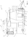
- FIG. 1is a side elevational view of a preferred embodiment of a vacuum cleaner in accordance with this design wherein the outer casing surrounding the cyclone and forming an outer wall of a dirt collection chamber is optionally transparent;
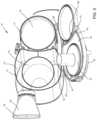
- FIG. 2is a perspective view from the front and the right side of the vacuum cleaner of FIG. 1 ;
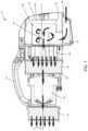
- FIG. 3is a cross-section along the line 3 - 3 in FIG. 2 ;
- FIG. 4is a schematic drawing of the vacuum cleaner of FIG. 1 showing the airflow passage therethrough;
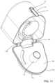
- FIG. 5is a perspective view from the bottom of the vacuum cleaner of FIG. 1 wherein the bottom of the first and second housings is open;
- FIG. 6is a perspective view of the bottom of the vacuum cleaner of FIG. 1 wherein the first and second housings are closed but an access door is open;
- FIG. 7is a longitudinal section through an alternate embodiment of a vacuum cleaner in accordance with this disclosure.
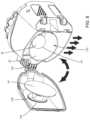
- FIG. 8is a perspective end view of the vacuum cleaner of FIG. 8 wherein the dirt collection chamber and the cyclone are open;
- FIG. 9is a perspective cross-section view of a further alternate embodiment of a cyclone and dirt collection chamber in accordance with this disclosure.
- FIG. 10is an exploded perspective view of the alternate embodiment shown in FIG. 9 ;
- FIG. 11is a perspective view from the bottom of the cyclone and dirt collection chamber shown in FIG. 9 wherein the bottom panel is open;
- FIG. 12is a cross-section through a further alternate embodiment of a cyclone and dirt collection chamber in accordance with this disclosure.
- FIG. 13is a cross-section through the alternate embodiment shown in FIG. 12 wherein the cyclone floor and dirt collection chamber floor are open;
- a surface cleaning apparatuscomprises a vacuum cleaner 10 having at least one cyclone and a dirt collection chamber in communication with the cyclone dirt outlet.
- the filtration apparatusmay be of any design or configuration.
- surface cleaning apparatus 10has a first housing 12 and a second housing 14 .
- First housing 12comprises at least one cyclone 16 and a dirt collection chamber 18 and second housing 14 houses the filtration members and the suction motor.
- a surface cleaning apparatus 10has a first cyclonic cleaning stage comprising a single cyclone 150 having a dirt collection chamber 152 and a second cyclonic cleaning stage comprising a plurality of second stage cyclones 154 in parallel.
- vacuum cleaner 10comprises a hand held vacuum cleaner. Accordingly, vacuum cleaner 10 may be provided with handle 54 , which is affixed to lid 32 and lid 58 of second housing 14 . Handle 54 may alternately be affixed to any other portion or portions of vacuum cleaner 10 as is known in the art.
- on/off switch 56may be provided on handle 54 . On/off switch 56 may alternately be provided on any other portion of vacuum cleaner 10 .
- suction motor 26is positioned in second housing 14 , preferably with a suction fan provided below the electric motor.
- Clean air outlet 60is provided downstream from suction motor 26 .
- An optional post-motor filtermay be provided downstream from suction motor 26 , such as in post-motor filter housing 62 , which may be accessible via post motor filter housing door 64 , which could be pivotally mounted to second housing 14 .
- surface cleaning apparatusmay be a vacuum cleaner, a carpet extractor, a bare floor cleaner or the like. As exemplified, the surface cleaning apparatus is hand held.
- the surface cleaning apparatusmay be configured as an upright vacuum cleaner, a stick vacuum cleaner, a canister vacuum cleaner, a backpack or shoulder strap vacuum cleaner or other configuration known in the art.
- the surface cleaning apparatusmay have a single cyclonic cleaning stage, which may be of any construction known in the art, or a plurality of cyclonic cleaning stages, each of which may be of any construction known in the art, e.g. they may comprise a single cyclone or a plurality of cyclones in parallel.
- an openable dirt collection chamber 18is provided that is in communication with the dirt outlet 28 .
- Dirt collection chamber 18has an openable end portion that comprises a wall that is intersected by the longitudinally extending axis of the cyclone.
- the openable end portionmay be floor 44 of cyclone 16 as exemplified in FIGS. 1 - 6 , impingement member 30 and the floor of dirt collection chamber 18 to which impingement member 30 may be mounted as exemplified in FIGS. 7 - 8 or opposed wall 164 of dirt collection chamber 18 of FIGS. 12 - 13 or bottom 66 comprising cyclone floor 42 and dirt collection chamber floor 44 of FIGS. 9 - 11 .
- the cyclone chamberWhen the end portion is in an open position as exemplified in FIGS. 5 , 8 and 11 and 13 , the cyclone chamber has an absence of any member having a larger diameter than the vortex finder whereby dirt collection chamber 18 and the cyclone 16 may be concurrently emptyable with dirt collection chamber 18 .
- FIGS. 1 - 6A first embodiment of this disclosure is shown in FIGS. 1 - 6 , which exemplifies the use of an inverted cyclone.
- the cyclone 16may be of any configuration and orientation and need not be inverted (e.g., cyclone 16 may be a horizontally mounted cyclone or a vertically mounted upright cyclone with an upper air inlet, an upper air out and a lower dirt outlet). Accordingly, the reference to “upper” and “lower” and “floor” are for convenience in the following discussion and relate to a preferred embodiment.
- cyclone 16has a dirt outlet 28 and an impingement surface 30 in dirt collection chamber 18 spaced from and facing dirt outlet 28 .
- optional impingement surface 30is preferably spaced a distance D from outlet 28 wherein distance D may be up to 50 mm, preferably from 8 to 30 millimeters and, and more preferably from 12 to 25 millimeters.
- impingement member 30may be mounted to lid 32 of dirt collection chamber 18 as exemplified. Alternately, impingement member may be mounted to a sidewall of dirt collection chamber 18 and/or cyclone 16 . It will be appreciated that cyclone 16 may be in any particular orientation and/or any particular configuration.
- cyclone 150may have a longitudinally extending axis A that extends generally horizontally when the surface cleaning apparatus is in use.
- impingement surface 30may be positioned facing dirt outlet 28 and accordingly, in use, extends generally vertically, (i.e. transverse to longitudinal axis A).
- an impingement surfacemay not be provided.
- cyclone 16is an inverted cyclone. Accordingly, cyclone 16 has a lower air inlet 34 and a lower air outlet 36 . Air inlet 34 is positioned downstream from dirty air inlet 38 of surface cleaning nozzle 40 .
- Surface cleaning nozzle 40may be any surface cleaning nozzle known in the art. Air inlet 34 of cyclone 16 may be in airflow communication with surface cleaning nozzle 40 in any manner known in the art. The exact structure of surface cleaning nozzle 40 and the communication passage between surface cleaning nozzle 40 and air inlet 34 will vary depending if the surface cleaning apparatus is an upright vacuum cleaner, canister vacuum cleaner or, as exemplified, a portable hand held vacuum cleaner.
- airwill enter cyclone 16 through inlet 34 and travel upwardly, as exemplified in FIG. 4 .
- the airwill then travel downwardly to exit cyclone 16 via outlet 36 .
- dirtwill exit upwardly through outlet 28 and deposit on dirt collection chamber floor 42 .
- some of the heavier particulate mattermay not be entrained in the air stream and may be deposited on cyclone floor 44 .
- cyclone 16has a longitudinally extending axis that extends through the centre of cyclone 16 .
- the longitudinal axisis aligned with, and extends through, air outlet 36 and accordingly intersects floor 44 and door 82 .
- cyclone 16need not be inverted but may be of any configuration or orientation.
- cyclones 150 , 154may be oriented such that longitudinal axis A of the cyclones extends horizontally when the surface cleaning apparatus is in use.
- cyclone 150has an impingement member 30 that is generally vertical and faces dirt outlet 28 and is intersected by longitudinal axis A.
- the cyclonemay be an upright cyclone (see for example FIGS. 12 to 13 ) or a cyclone having a single direction of travel of the air.
- cyclone 16has a longitudinal axis that intersects dirt collection chamber floor 42 and cyclone floor 44 .
- cyclone 16has a longitudinal axis that intersects cyclone floor 44 .
- cyclone 16is a frustoconical cyclone having cylindrical portion 46 and frustoconical portion 48 .
- cyclone 16may be cylindrical, entirely frustoconical or any other shape known in the art.
- cyclone 16may be closed, i.e. have a portion that closes the dirt outlet end of the cyclone chamber, and is provided with at least one dirt outlet 28 .
- the dirt exit endmay be bowl shaped, e.g., rounded.
- outlet 36 of cyclone 16comprises a vortex finder that extends inwardly into the cyclone chamber defined by cyclone 16 .
- Outlet 36preferably comprises a generally cylindrical passage having an inlet 50 and an outlet 52 . It will be appreciated that, in an alternate embodiment any outlet or vortex finder known in the art for cyclones may be utilized.
- inlet 50may be covered by a screen, shroud or filter as is known in the art. However, it is preferred that vortex finder 36 is unobstructed, i.e., no screen, shroud or filter is provided on inlet 50 .
- vortex finder 36is not surrounded by a screen, shroud or filter and no physical separation member is positioned in the cyclone chamber of cyclone 16 . Accordingly, no filtration or screen member interior of cyclone 16 requires cleaning. Elongate material such as hair or fibre can become adhered to a shroud, requiring the shroud to be manually cleaned.
- a screenis positioned downstream from cyclone 16 and upstream from the pre-motor filter.
- a screen 78is preferably provided (see for example FIG. 3 ). The material that would otherwise clog a screen or shroud that surrounds inlet 50 may be retained by optional screen 78 which may be larger than a screen in a cyclone chamber.
- an impingement membermay not be provided.
- an impingement membermay not be provided in the example of FIGS. 1 - 6 . See also FIGS. 9 - 13 wherein an impingement member is not provided.
- dirt collection chamber 18surrounds at least a portion of and, as exemplified, preferably all of cyclone 16 and is preferably external to the cyclone chamber defined by cyclone 16 . Accordingly, cyclone 16 may be positioned in dirt collection chamber 18 and, preferably, generally centrally therein.
- An advantage of this designis that the bottom of cyclone 16 (e.g., floor 44 ) may be continuous with the bottom of dirt collection chamber 18 (e.g., floor 44 ) so that a simplified construction is provided that permits both cyclone 16 and dirt collection chamber 18 to be opened at the same time.
- the openable end of the dirt collection camberis the dirt collection surface (floor 42 ).
- the openable portionneed not be the dirt collection surface.
- the openable portionmay be opposed wall 164 of dirt collection chamber 18 facing dirt outlet 28 to which impingement member 30 is attached. In such a case, the dirt collection surface will be a sidewall of dirt collection chamber 18 .
- vacuum cleaner 10is preferably configured such that floor 44 forms an openable end portion of cyclone 16 and floor 42 forms an openable end portion of dirt collection chamber 18 .
- Floor 44is a moveable cyclone dirt collection surface and floor 42 is a moveable dirt collection chamber surface.
- the openable portion of cyclone 16is accordingly opened when the openable portion of dirt collection chamber 18 is opened. Accordingly, dirt collected on floor 44 of cyclone 16 is emptied at the same time as dirt collected on floor 42 of dirt collection chamber 18 .
- floor 42 and floor 44are both moveable and connected to each other whereby both floor 42 and 44 are concurrently moveable such that dirt collection chamber 18 and cyclone 16 are concurrently emptied.
- floors 42 and 44comprise a wall intersecting the longitudinally extending axis of the dirt collection chamber 18 and cyclone 16 .
- Floors 42 and 44may comprise a pivoting bottom or end portion of first housing 12 and, alternately, of the filtration apparatus (e.g. housings 12 and 14 of this embodiment).
- floors 42 and 44may be otherwise openable and may be removably mounted. For example, they may be slidably, translatably or removably mounted (e.g., by a screw mount, a bayonet mount or a snap fit) to cyclone 16 and dirt collection chamber 18 .
- outlet 36is in some embodiments preferably provided as part of floor 42 , and is preferably integrally molded therewith. Accordingly, when floors 42 and 44 are in the open position, vortex finder 36 , and any shroud or the like mounted thereon, is removed from cyclone 16 . Accordingly, the cyclone chamber has an absence of any member having a larger diameter than the vortex finder therein. Accordingly, the dirt will fall out of collection chamber 16 and cyclone 16 and will fall downwardly off of floors 42 and 44 .
- both cyclone 16 and dirt collection chamber 18are openable and may be emptied concurrently when floors 42 and 44 are in the open position by holding vacuum cleaner 10 in the upright position (as shown in FIG. 1 ).
- dirt collection chamber 18may be spaced from cyclone 16 provided dirt outlet 28 is in communication with dirt collection chamber 18 so that dirt which is disentrained from the fluid flow in cyclone 16 is conveyed to dirt collection chamber 18 .
- floor 42may open separately from floor 44 , such that cyclone 16 and dirt collection chamber 18 may be individually opened.
- housings 12 and 14may have a pivoting bottom 66 , which is secured to each of housings 12 and 14 by a pivot 68 .
- pivoting bottom 66In the closed position exemplified in FIGS. 1 and 4 , pivoting bottom 66 is secured in position by latch 70 .
- Latch 70may have a button 72 which, when pressed, causes arm 74 to move outwardly thereby disengaging a flange provided on the bottom end of arm 74 from flange 76 provided on pivoting bottom 66 .
- a gasket or other sealing membermay be provided at the interface of housings 12 and 14 and pivoting bottom 66 to provide an air tight or fluid tight seal.
- bottom 66may be moveable in any other direction by any other means known in the art and may optionally be removable from housings 12 , 14 . Further, bottom 66 may be moveably secured in position by any other means known in the art and need not be connected to surface cleaning apparatus 10 for relative motion thereto.
- FIGS. 1 - 6it will be appreciated that only floors 42 and 44 may be pivotally mounted to housing 12 . In such an embodiment, foam filter 20 may remain sealed when cyclone 16 and dirt collection chamber 18 are emptied. In an alternate embodiment, a side-by-side housing design as exemplified in FIG. 1 need not be utilized. In such a case, floor 42 and floor 44 may comprise the entire floor of the filtration assembly, see for example, FIGS. 9 - 11 .
- bottom 66opens both housings 12 and 14 , then it will be appreciated that dirt positioned on the upstream surface of filter 20 will be emptied when bottom 66 is opened.
- impingement member 30is removed from the vicinity of dirt outlet 28 when opposed wall is opened, e.g., by pivoting about pivot pin 66 .
- impingement member 30is mounted to support 166 that is preferably mounted to opposed wall 164 . It will be appreciated that impingement member 30 may be otherwise moveably mounted.
- the cyclone chamberis opened and both cyclone 150 and dirt collection chamber 152 may be concurrently emptied. In this embodiment, vortex finder 36 remains in position in the cyclone chamber.
- a screenmay be positioned to overlie inlet end 50 of vortex finder 36 , it will be appreciated that a member having a diameter larger than vortex finder 36 is absent from the interior of cyclone 150 thereby permitting dirt to be unimpeded when cyclone 150 is held open over a garbage can.
- cyclone 16has a closed end and is opened at the closed dirt outlet end for emptying.
- cyclone 16has tangential passage 172 that is in airflow communication with a surface cleaning nozzle (not shown). Tangential passage 172 is connected to air inlet 34 of cyclone 16 .
- Cyclone 16has a clean air outlet 36 in floor 44 , similar to the embodiment of FIGS. 1 - 6 .
- Cyclone 16has a closed end wall 174 with at least one dirt outlet 28 in a side wall thereof. Dirt outlet 28 opens to dirt collection chamber 18 .
- the outer walls of dirt collection chamber 18are formed from sidewall 186 and end wall 188 .
- Bottom wall 182comprises floors 44 and 42 .
- a gasket 180may be provided at the interface of dirt collection chamber 18 , cyclone 16 and bottom panel 182 to provide an air tight or fluid tight seal.
- dirty airenters cyclone 16 tangentially via air inlet 34 and swirls upwardly. Heavier dirt particles fall out of the air stream and are deposited on floor 44 of bottom panel 182 . Some dirt particles will exit cyclone 16 via dirt outlet 28 , fall downwardly in dirt collection chamber 18 and deposit on floor 42 of bottom panel 182 .
- bottom panel 182comprises a wall intersecting the longitudinally extending axis A of dirt collection chamber 18 and cyclone 16 . Accordingly, bottom panel 182 forms the end portion of dirt collection chamber 18 and cyclone 16 .
- Bottom panel 182may have a flange 184 connected to a flange 190 on sidewall 186 . Accordingly, bottom panel 182 is rotatably moveable such that cyclone 16 and dirt collection chamber 18 may be opened to empty deposited dirt particles.
- the cyclone chamberhas an absence of any member having a larger diameter than the vortex finder.
- floors 42 and 44comprise the openable end portion.
- Cyclone floor 44is mounted to dirt collection chamber 18 , such as by support 176 . Accordingly, when dirt collection chamber 18 is opened, such as by rotating about pivot 170 , cyclone 16 is also opened.
- a filtration membermay be provided adjacent outlet 36 and, preferably, in sealing engagement with outlet 52 .
- filtration member 78may be positioned on rear surface 84 of floor 44 and overlies outlet 52 . Accordingly, air that exits outlet 36 travels through filtration member 78 . The air then travels through filtration chamber 80 and travels laterally to outlet 86 , which is in air flow communication with headspace 88 below filter 20 .
- An advantage of such an embodimentis that a screen, shroud or filter need not be provided inside cyclone 16 overlying inlet 52 of vortex finder 36 .
- filtration member 78preferably comprises a screen, such as an open mesh screen, e.g., a wire mesh screen or, alternately, a plastic mesh screen.
- a screensuch as an open mesh screen, e.g., a wire mesh screen or, alternately, a plastic mesh screen.
- Access door 82may be provided to permit access to filtration member 78 such that filtration member 78 may be cleaned.
- Access doormay be any door that is movably mounted in overlying relationship to filtration chamber 80 .
- access door 82is pivotally mounted by pivot 90 to pivoting bottom 66 , and is secured in position by a latch 120 .
- Latch 120may have a button 122 which, when pressed, causes arm 124 to move outwardly thereby disengaging a flange on the bottom end of arm 124 from flange 92 provided on the front end of access door 82 .
- a sealing gasket or other sealing member known in the artmay be utilized to provide an air tight or fluid tight seal for filtration chamber 80 . Any other securing member known in the art may be used.
- door 82may be removable and need not be connected to surface cleaning apparatus 10 for relative motion thereto.
- filtration member 78is mounted and, more preferably, movably mounted and, most preferably, removably mounted to access door 82 .
- filtration member 78is pivotally mounted to the inner surface of access door 82 . Accordingly, when a user desires to clean filtration member 78 , it may be pivoted in the direction shown by arrow A in FIG. 6 to an open or cleaning position. It will be noticed that access door 82 may be opened independently of pivoting bottom 66 . In an alternate embodiment, it will be appreciated that a pivoting bottom 66 need not be provided.
- At least a portion of and, more preferably, all of access door 82is transparent. Accordingly, a user may lift the vacuum cleaner, invert the vacuum cleaner or tilt the vacuum cleaner on its side to view filtration member 78 and determine whether filtration 78 requires cleaning or, alternately, replacement.
- a series of screening and filtration membersmay be used in series downstream from the cyclone chamber of cyclone 16 .
- the screening and filtration memberscomprise a screen 78 , which is preferably positioned adjacent outlet 36 , a foam filter 22 downstream from screen 78 , a felt filter 22 downstream from foam 20 and a HEPA filter 24 downstream from felt filter 22 .
- all of these filtersare positioned upstream from suction motor 26 .
- one or more of these filtersmay be positioned downstream from suction motor 26 .
- HEPA filter 24may be downstream from suction motor 26 .
- a plurality of screening and filtration memberseach of which have a finer filtration capacity (e.g. smaller pores) are provided in series in the downstream direction.
- a shroude.g. a perforated or apertured plastic cover
- inlet 50 of outlet 36may be provided surrounding or overlying inlet 50 of outlet 36 .
- the end portionmay be openable by any means known in the art.
- itmay be translatable, slidable or removably mounted, such as by a screw or bayonet mount or a snap fit.
- itis not removably mounted, but remains affixed to the filtration housing when opened, such as by being pivotally mounted as exemplified.
- the end portionmay be oriented such that it is the lower portion of the dirt collection chamber 18 (e.g. FIGS. 1 - 6 and 9 - 13 ) and accordingly comprises a dirt collection surface. However, it need not be, provided that it intersects the longitudinal axis of the cyclone (e.g. FIGS. 7 - 8 ).
- end portionmay be distal to dirt outlet 28 (e.g., FIGS. 1 - 6 and 9 - 11 ) or may face dirt outlet 28 (e.g., FIGS. 7 - 10 ).
Landscapes
- Engineering & Computer Science (AREA)
- Mechanical Engineering (AREA)
- Filters For Electric Vacuum Cleaners (AREA)
- Cyclones (AREA)
Abstract
Description
- (a) a dirty air inlet;
- (b) a filtration apparatus comprising a cyclone downstream from the dirty air inlet, the cyclone having a cyclone chamber, a vortex finder, a dirt outlet and a longitudinally extending axis;
- (c) an openable dirt collection chamber in communication with the dirt outlet, the dirt collection chamber having an openable end portion that comprises a wall that is intersected by the longitudinally extending axis, and when the end portion is in an open position, the cyclone chamber has an absence of any member having a larger diameter than the vortex finder whereby the dirt collection chamber and the cyclone are concurrently emptyable when the dirt collection chamber is opened;
- (d) a suction motor; and,
- (e) a clean air outlet downstream from the suction motor.
Claims (8)
Priority Applications (2)
| Application Number | Priority Date | Filing Date | Title |
|---|---|---|---|
| US17/549,211US12004700B2 (en) | 2007-08-29 | 2021-12-13 | Cyclonic surface cleaning apparatus |
| US18/657,434US20240366046A1 (en) | 2007-08-29 | 2024-05-07 | Cyclonic surface cleaning apparatus |
Applications Claiming Priority (6)
| Application Number | Priority Date | Filing Date | Title |
|---|---|---|---|
| CA2599303 | 2007-08-29 | ||
| CA002599303ACA2599303A1 (en) | 2007-08-29 | 2007-08-29 | Surface cleaning apparatus |
| PCT/CA2008/001530WO2009026709A1 (en) | 2007-08-29 | 2008-08-28 | Cyclonic surface cleaning apparatus with externally positioned dirt chamber |
| US67554010A | 2010-02-26 | 2010-02-26 | |
| US14/683,026US11229335B2 (en) | 2007-08-29 | 2015-04-09 | Cyclonic surface cleaning apparatus |
| US17/549,211US12004700B2 (en) | 2007-08-29 | 2021-12-13 | Cyclonic surface cleaning apparatus |
Related Parent Applications (1)
| Application Number | Title | Priority Date | Filing Date |
|---|---|---|---|
| US14/683,026ContinuationUS11229335B2 (en) | 2007-08-29 | 2015-04-09 | Cyclonic surface cleaning apparatus |
Related Child Applications (1)
| Application Number | Title | Priority Date | Filing Date |
|---|---|---|---|
| US18/657,434ContinuationUS20240366046A1 (en) | 2007-08-29 | 2024-05-07 | Cyclonic surface cleaning apparatus |
Publications (2)
| Publication Number | Publication Date |
|---|---|
| US20220142423A1 US20220142423A1 (en) | 2022-05-12 |
| US12004700B2true US12004700B2 (en) | 2024-06-11 |
Family
ID=81455408
Family Applications (2)
| Application Number | Title | Priority Date | Filing Date |
|---|---|---|---|
| US17/549,211Active2028-09-12US12004700B2 (en) | 2007-08-29 | 2021-12-13 | Cyclonic surface cleaning apparatus |
| US18/657,434PendingUS20240366046A1 (en) | 2007-08-29 | 2024-05-07 | Cyclonic surface cleaning apparatus |
Family Applications After (1)
| Application Number | Title | Priority Date | Filing Date |
|---|---|---|---|
| US18/657,434PendingUS20240366046A1 (en) | 2007-08-29 | 2024-05-07 | Cyclonic surface cleaning apparatus |
Country Status (1)
| Country | Link |
|---|---|
| US (2) | US12004700B2 (en) |
Citations (122)
| Publication number | Priority date | Publication date | Assignee | Title |
|---|---|---|---|---|
| US1940609A (en)* | 1928-09-17 | 1933-12-19 | Arthur Koenreich | Vacuum cleaner |
| US2071975A (en) | 1937-02-23 | Separator | ||
| US2309583A (en) | 1941-02-20 | 1943-01-26 | Apex Electrical Mfg Co | Suction cleaner |
| US3320727A (en) | 1965-08-02 | 1967-05-23 | Mitchell Co John E | Portable vacuum cleaning machine |
| US3477087A (en)* | 1967-06-19 | 1969-11-11 | Bon Aire Ind Inc | Vacuum cleaner |
| US3582616A (en) | 1968-10-29 | 1971-06-01 | Watlow Electric Mfg Co | Electrical heaters |
| US4373228A (en) | 1979-04-19 | 1983-02-15 | James Dyson | Vacuum cleaning appliances |
| GB2163703A (en) | 1984-08-07 | 1986-03-05 | Bondico Inc | Method and device for heat sealing thermoplastic materials |
| US4821366A (en)* | 1988-05-03 | 1989-04-18 | Cic Int'l. Corp. | Wet-dry vacuum cleaner |
| US4826515A (en) | 1980-06-19 | 1989-05-02 | Prototypes, Ltd. | Vacuum cleaning apparatus |
| DE3734355C2 (en) | 1986-10-14 | 1989-06-29 | Alfred Kaercher Gmbh & Co, 7057 Winnenden, De | |
| US5230722A (en) | 1988-11-29 | 1993-07-27 | Amway Corporation | Vacuum filter |
| US5309601A (en) | 1992-10-16 | 1994-05-10 | White Consolidated Industries, Inc. | Vacuum cleaner with improved assembly |
| US5858038A (en) | 1994-12-21 | 1999-01-12 | Notetry Limited | Dust separation apparatus |
| JP2000140533A (en) | 1998-11-10 | 2000-05-23 | Shintoo Fine Kk | Filter for capturing/separating fine dust and capturing/ separating of fine dust using this filter |
| US6146434A (en)* | 1999-02-24 | 2000-11-14 | The Hoover Company | Cyclonic dirt cup assembly |
| WO2000078546A1 (en) | 1999-06-22 | 2000-12-28 | Miraglia Philip J | Method and apparatus for sealing |
| US6210469B1 (en) | 1999-02-26 | 2001-04-03 | Donaldson Company, Inc. | Air filter arrangement having first and second filter media dividing a housing and methods |
| US6221134B1 (en) | 1999-07-27 | 2001-04-24 | G.B.D. Corp. | Apparatus and method for separating particles from a cyclonic fluid flow |
| WO2001082767A1 (en) | 2000-05-04 | 2001-11-08 | AEG Hausgeräte GmbH | Dust box provided with a cyclone and usable in conventional vacuum cleaners |
| CN1336154A (en) | 2000-08-07 | 2002-02-20 | 三星光州电子株式会社 | Suction cleaner with vortex type dust collector |
| CN2524655Y (en) | 2001-12-13 | 2002-12-11 | 泰怡凯电器(苏州)有限公司 | Dust storage device on vacuum cleaner |
| US6532620B2 (en) | 2000-10-19 | 2003-03-18 | Samsung Kwangju Electronics Co., Ltd. | Cyclone dust collecting chamber for a vacuum cleaner |
| US6553612B1 (en) | 1998-12-18 | 2003-04-29 | Dyson Limited | Vacuum cleaner |
| US6560818B1 (en) | 1999-10-08 | 2003-05-13 | Production Metal Forming, Inc. | Carpet cleaning wand boot |
| US6581239B1 (en) | 1998-12-18 | 2003-06-24 | Dyson Limited | Cleaner head for a vacuum cleaner |
| DE10110581C2 (en) | 2000-05-16 | 2003-11-13 | Samsung Kwangju Electronics Co | Vertical vacuum cleaner with a cyclone type dust collector |
| US20030226232A1 (en) | 2002-06-11 | 2003-12-11 | Shoji Hayashi | Electric vacuum cleaner |
| JP2004121722A (en) | 2002-10-07 | 2004-04-22 | Sanyo Electric Co Ltd | Dust collector and vacuum cleaner using the same |
| US20040112022A1 (en) | 2001-02-24 | 2004-06-17 | Vuijk Remco Douwinus | Collecting chamber for a vacuum cleaner |
| US6782585B1 (en)* | 1999-01-08 | 2004-08-31 | Fantom Technologies Inc. | Upright vacuum cleaner with cyclonic air flow |
| KR20050013696A (en) | 2003-07-29 | 2005-02-05 | 엘지전자 주식회사 | Dust removing unit in vacuum cleaner |
| JP3656835B2 (en) | 2001-07-09 | 2005-06-08 | 東芝テック株式会社 | Electric vacuum cleaner |
| KR20050054551A (en) | 2003-12-05 | 2005-06-10 | 엘지전자 주식회사 | Dust removing unit in vacuum cleaner |
| KR20050091833A (en) | 2004-03-11 | 2005-09-15 | 엘지전자 주식회사 | A dust collector for vacuum clearner |
| KR20050091838A (en) | 2004-03-11 | 2005-09-15 | 엘지전자 주식회사 | A vacuum clearner |
| KR20050091824A (en) | 2004-03-11 | 2005-09-15 | 엘지전자 주식회사 | A dust collector for vacuum clearner |
| KR20050091829A (en) | 2004-03-11 | 2005-09-15 | 엘지전자 주식회사 | A vacuum clearner |
| KR20050091826A (en) | 2004-03-11 | 2005-09-15 | 엘지전자 주식회사 | A dust collector for vacuum clearner |
| US20050198771A1 (en) | 2004-03-11 | 2005-09-15 | Lg Electronics Inc. | Vacuum cleaner |
| KR20050091835A (en) | 2004-03-11 | 2005-09-15 | 엘지전자 주식회사 | A vacuum clearner |
| KR20050091821A (en) | 2004-03-11 | 2005-09-15 | 엘지전자 주식회사 | A dust collector for vacuum clearner |
| KR20050091837A (en) | 2004-03-11 | 2005-09-15 | 엘지전자 주식회사 | A vacuum clearner |
| KR20050091834A (en) | 2004-03-11 | 2005-09-15 | 엘지전자 주식회사 | A vacuum clearner |
| KR20050091830A (en) | 2004-03-11 | 2005-09-15 | 엘지전자 주식회사 | A vacuum clearner |
| KR20050091836A (en) | 2004-03-11 | 2005-09-15 | 엘지전자 주식회사 | A vacuum clearner |
| KR20050103343A (en) | 2004-04-26 | 2005-10-31 | 엘지전자 주식회사 | A dust collector for vacuum cleaner |
| KR20050104613A (en) | 2004-04-29 | 2005-11-03 | 엘지전자 주식회사 | A dust collector for vacuum cleaner |
| KR20050104614A (en) | 2004-04-29 | 2005-11-03 | 엘지전자 주식회사 | A dust collector for vacuum cleaner |
| KR20060008365A (en) | 2004-07-22 | 2006-01-26 | 엘지전자 주식회사 | Dust collection assembly of vacuum cleaner |
| KR20060018004A (en) | 2004-08-23 | 2006-02-28 | 엘지전자 주식회사 | Dust collection assembly of vacuum cleaner |
| US20060042038A1 (en) | 2004-08-26 | 2006-03-02 | Adrian Christopher Arnold | Compact cyclonic separation device |
| DE60201666T2 (en) | 2001-02-24 | 2006-06-01 | Dyson Technology Ltd., Malmesbury | COLLECTION CHAMBER FOR A VACUUM CLEANER |
| US20060117519A1 (en) | 2002-10-15 | 2006-06-08 | Armin Bock | Removable dust collector |
| US20060137307A1 (en) | 2004-12-27 | 2006-06-29 | Lg Electronics, Inc. | Dust collection unit of vacuum cleaner |
| US20060137304A1 (en) | 2004-12-29 | 2006-06-29 | Lg Electronics, Inc. | Dust collection assembly of vacuum cleaner |
| US20060137305A1 (en) | 2004-12-27 | 2006-06-29 | Lg Electronics, Inc. | Dust collection unit for vacuum cleaner |
| US7073226B1 (en) | 2001-11-30 | 2006-07-11 | Bissell Homecare, Inc. | Portable extraction cleaner |
| US20060156508A1 (en) | 2005-01-14 | 2006-07-20 | Royal Appliance Mfg. Co. | Vacuum cleaner with cyclonic separating dirt cup and dirt cup door |
| KR20060119587A (en) | 2005-05-20 | 2006-11-24 | 엘지전자 주식회사 | Vacuum cleaner |
| KR20060125954A (en) | 2005-06-01 | 2006-12-07 | 엘지전자 주식회사 | Dust collection unit |
| KR20060125952A (en) | 2005-06-01 | 2006-12-07 | 엘지전자 주식회사 | Dust collection unit |
| CN1911151A (en) | 2005-08-11 | 2007-02-14 | 百得有限公司 | Hand-holdable vacuum cleaners |
| US20070067945A1 (en) | 2005-09-23 | 2007-03-29 | Bissell Homecare, Inc. | Vacuum cleaner with two stage filtration |
| US20070079586A1 (en) | 2005-10-11 | 2007-04-12 | Samsung Gwangju Electronics Co., Ltd. | Multi-cyclone dust collector for vacuum cleaner |
| US7222393B2 (en) | 2003-02-20 | 2007-05-29 | Wessel-Werk Gmbh & Co. Kg | Vacuum cleaner nozzle for floors and carpets |
| CN1969739A (en) | 2006-11-30 | 2007-05-30 | 苏州宜洁电器有限公司 | Dust separation device of vacuum cleaner |
| US20070130895A1 (en) | 2003-04-24 | 2007-06-14 | Bsh Bosch Und Siemens Hausgerate Gmbh | Removable dust collecting receptacle |
| WO2007084699A2 (en) | 2006-01-19 | 2007-07-26 | Electrolux Home Care Products,Inc | Vacuum cleaner dustcup and conduit construction |
| CN101015436A (en) | 2007-01-24 | 2007-08-15 | 泰怡凯电器(苏州)有限公司 | Multi-stage whirlwind separating device of vacuum cleaner |
| DE102007011457A1 (en) | 2006-03-10 | 2007-10-25 | Royal Appliance International Gmbh | cyclone vacuum cleaner |
| US20070289264A1 (en) | 2006-06-16 | 2007-12-20 | Samsung Gwangju Electronics Co., Ltd. | Dust collecting apparatus for vacuum cleaner |
| CN101108110A (en) | 2006-07-19 | 2008-01-23 | 乐金电子(天津)电器有限公司 | Dust collecting unit of vacuum cleaner |
| CN101108106A (en) | 2006-07-19 | 2008-01-23 | 乐金电子(天津)电器有限公司 | Dust collecting unit of vacuum cleaner |
| WO2008035032A2 (en) | 2006-09-20 | 2008-03-27 | Dyson Technology Limited | A support device |
| WO2008034325A1 (en) | 2006-09-21 | 2008-03-27 | Suzhou Kingclean Floorcare Co., Ltd. | A dust collector |
| KR20080029824A (en) | 2006-09-29 | 2008-04-03 | 백스 리미티드 | Dust collector of vacuum cleaner |
| US20080104793A1 (en) | 2006-11-03 | 2008-05-08 | Daewoo Electronics Corporation | Hand-held vacuum cleaner |
| US20080134460A1 (en) | 2006-12-12 | 2008-06-12 | Gbd Corporation | Surface cleaning apparatus |
| US7386916B2 (en) | 2003-08-05 | 2008-06-17 | Black & Decker Inc. | Self-cleaning vacuum cleaner and receptacle therefor |
| US20080172992A1 (en) | 2006-12-15 | 2008-07-24 | G.B.D. Corp. | Vacuum cleaner with openable lid |
| US20080178416A1 (en) | 2006-12-12 | 2008-07-31 | G.B.D. Corp. | Surface cleaning apparatus with shoulder strap reel |
| US20080250601A1 (en)* | 2007-04-04 | 2008-10-16 | Eric Coburn | Filter cleaning mechanisms |
| CN101288572A (en) | 2007-04-18 | 2008-10-22 | 百得有限公司 | Motor, fan and filter device for vacuum cleaner |
| WO2008135708A1 (en) | 2007-05-03 | 2008-11-13 | Dyson Technology Limited | A collecting chamber for a cleaning appliance |
| DE112006003479T5 (en) | 2005-12-22 | 2008-12-18 | Royal Appliance Mfg. Co., Glenwillow | Dual stage cyclone vacuum cleaner |
| US7485164B2 (en) | 2004-12-27 | 2009-02-03 | Lg Electronics, Inc. | Dust collection unit for vacuum cleaner |
| WO2009026709A1 (en) | 2007-08-29 | 2009-03-05 | Gbd Corp. | Cyclonic surface cleaning apparatus with externally positioned dirt chamber |
| DE112007001314T5 (en) | 2006-06-16 | 2009-04-23 | Royal Appliance Mfg. Co., Glenwillow | Separately opening dust container of a cyclone-type household vacuum cleaner |
| US20090113663A1 (en) | 2007-11-01 | 2009-05-07 | Dyson Technology Limited | Cyclonic separating apparatus |
| CN101489453A (en) | 2006-07-18 | 2009-07-22 | 戴森技术有限公司 | A cleaning appliance with filter status identification means |
| CN101489461A (en) | 2006-07-18 | 2009-07-22 | 戴森技术有限公司 | Cyclonic separating apparatus |
| CN101489457A (en) | 2006-07-18 | 2009-07-22 | 戴森技术有限公司 | A cleaning appliance |
| US7597730B2 (en) | 2005-07-12 | 2009-10-06 | Samsung Gwangju Electronics Co., Ltd. | Dust collection apparatus for vacuum cleaner |
| DE112007003039T5 (en) | 2006-12-12 | 2009-10-29 | GBD Corp., Nassau | Surface cleaning device |
| JP2009261501A (en) | 2008-04-23 | 2009-11-12 | Yamada Electric Ind Co Ltd | Stick vacuum cleaner |
| CN101657133A (en) | 2006-12-12 | 2010-02-24 | Gbd公司 | Surface cleaning apparatus |
| US20100045215A1 (en) | 2006-09-20 | 2010-02-25 | Syson Technology Limited | Motor driving apparatus |
| US20100115727A1 (en) | 2008-11-07 | 2010-05-13 | Jang-Keun Oh | Dust-collecting apparatus and cleaner having the same |
| US20100139033A1 (en) | 2007-12-06 | 2010-06-10 | Sergey Makarov | Dual Stage Cyclonic Dust Collector |
| US20100224073A1 (en) | 2006-05-03 | 2010-09-09 | Samsung Gwangju Electronics Co., Ltd. | Dual Cyclone Dust-Collecting Apparatus Vacuum Cleaner |
| US20100229322A1 (en) | 2009-03-11 | 2010-09-16 | G.B.D. Corp. | Nozzle construction for a cleaning head |
| WO2010102396A1 (en) | 2009-03-13 | 2010-09-16 | G.B.D. Corp. | Surface cleaning apparatus |
| JP2010227287A (en) | 2009-03-27 | 2010-10-14 | Hitachi Appliances Inc | Electric vacuum cleaner |
| KR20100121886A (en) | 2009-05-11 | 2010-11-19 | 삼성광주전자 주식회사 | Vacuum cleaner with dust removing apparatus |
| DE202011003563U1 (en) | 2010-03-19 | 2011-05-19 | SEB S.A. - Les 4 M -, 69134 | Vacuum cleaner with cyclone separation of waste |
| US20110219570A1 (en) | 2010-03-12 | 2011-09-15 | G.B.D. Corp. | Surface cleaning apparatus |
| CN102188208A (en) | 2010-03-12 | 2011-09-21 | G·B·D·有限公司 | Compact surface cleaning apparatus |
| US8062398B2 (en) | 2008-12-19 | 2011-11-22 | Bissell Homecare, Inc. | Vacuum cleaner and cyclone module therefor |
| US8100999B2 (en) | 2008-11-28 | 2012-01-24 | Dyson Technology Limited | Separating apparatus for a cleaning appliance |
| US20120036675A1 (en)* | 2006-03-10 | 2012-02-16 | Conrad Wayne E | Vacuum Cleaner with a Removable Screen |
| CN202173358U (en) | 2011-08-17 | 2012-03-28 | 苏州市伊塔电器科技有限公司 | Handheld dust collector |
| CN202277306U (en) | 2011-10-18 | 2012-06-20 | 广东新宝电器股份有限公司 | Cyclone dust collector |
| CN103040413A (en) | 2011-10-12 | 2013-04-17 | 百得有限公司 | Cyclonic separation apparatus |
| CN103040412A (en) | 2011-10-12 | 2013-04-17 | 百得有限公司 | Structure for motor, fan and cyclonic separation apparatus |
| US20130091812A1 (en) | 2011-10-12 | 2013-04-18 | Black & Decker Inc. | Motor, fan and cyclonic separation apparatus arrangement |
| US20130091813A1 (en) | 2011-10-12 | 2013-04-18 | Black & Decker Inc. | Motor, fan and cyclonic separation apparatus arrangement for a vacuum cleaner |
| US20130091660A1 (en) | 2011-10-12 | 2013-04-18 | Black & Decker Inc. | Cyclonic separation apparatus |
| US8424154B2 (en)* | 2006-04-10 | 2013-04-23 | Ab Electrolux | Vacuum cleaner with filter cleaning means |
| CN103169420A (en) | 2011-12-22 | 2013-06-26 | 戴森技术有限公司 | vacuum cleaner |
| US20140237768A1 (en) | 2013-02-28 | 2014-08-28 | G.B.D. Corp. | Surface cleaning apparatus |
| US20160367094A1 (en) | 2010-03-12 | 2016-12-22 | Omachron Intellectual Property Inc. | Surface cleaning apparatus |
- 2021
- 2021-12-13USUS17/549,211patent/US12004700B2/enactiveActive
- 2024
- 2024-05-07USUS18/657,434patent/US20240366046A1/enactivePending
Patent Citations (137)
| Publication number | Priority date | Publication date | Assignee | Title |
|---|---|---|---|---|
| US2071975A (en) | 1937-02-23 | Separator | ||
| US1940609A (en)* | 1928-09-17 | 1933-12-19 | Arthur Koenreich | Vacuum cleaner |
| US2309583A (en) | 1941-02-20 | 1943-01-26 | Apex Electrical Mfg Co | Suction cleaner |
| US3320727A (en) | 1965-08-02 | 1967-05-23 | Mitchell Co John E | Portable vacuum cleaning machine |
| US3477087A (en)* | 1967-06-19 | 1969-11-11 | Bon Aire Ind Inc | Vacuum cleaner |
| US3582616A (en) | 1968-10-29 | 1971-06-01 | Watlow Electric Mfg Co | Electrical heaters |
| US4373228A (en) | 1979-04-19 | 1983-02-15 | James Dyson | Vacuum cleaning appliances |
| US4826515A (en) | 1980-06-19 | 1989-05-02 | Prototypes, Ltd. | Vacuum cleaning apparatus |
| GB2163703A (en) | 1984-08-07 | 1986-03-05 | Bondico Inc | Method and device for heat sealing thermoplastic materials |
| DE3734355C2 (en) | 1986-10-14 | 1989-06-29 | Alfred Kaercher Gmbh & Co, 7057 Winnenden, De | |
| US4821366A (en)* | 1988-05-03 | 1989-04-18 | Cic Int'l. Corp. | Wet-dry vacuum cleaner |
| US5230722A (en) | 1988-11-29 | 1993-07-27 | Amway Corporation | Vacuum filter |
| US5309601A (en) | 1992-10-16 | 1994-05-10 | White Consolidated Industries, Inc. | Vacuum cleaner with improved assembly |
| US5858038A (en) | 1994-12-21 | 1999-01-12 | Notetry Limited | Dust separation apparatus |
| JP2000140533A (en) | 1998-11-10 | 2000-05-23 | Shintoo Fine Kk | Filter for capturing/separating fine dust and capturing/ separating of fine dust using this filter |
| US6581239B1 (en) | 1998-12-18 | 2003-06-24 | Dyson Limited | Cleaner head for a vacuum cleaner |
| US6553612B1 (en) | 1998-12-18 | 2003-04-29 | Dyson Limited | Vacuum cleaner |
| US6782585B1 (en)* | 1999-01-08 | 2004-08-31 | Fantom Technologies Inc. | Upright vacuum cleaner with cyclonic air flow |
| US6146434A (en)* | 1999-02-24 | 2000-11-14 | The Hoover Company | Cyclonic dirt cup assembly |
| US6210469B1 (en) | 1999-02-26 | 2001-04-03 | Donaldson Company, Inc. | Air filter arrangement having first and second filter media dividing a housing and methods |
| WO2000078546A1 (en) | 1999-06-22 | 2000-12-28 | Miraglia Philip J | Method and apparatus for sealing |
| US6221134B1 (en) | 1999-07-27 | 2001-04-24 | G.B.D. Corp. | Apparatus and method for separating particles from a cyclonic fluid flow |
| US6560818B1 (en) | 1999-10-08 | 2003-05-13 | Production Metal Forming, Inc. | Carpet cleaning wand boot |
| WO2001082767A1 (en) | 2000-05-04 | 2001-11-08 | AEG Hausgeräte GmbH | Dust box provided with a cyclone and usable in conventional vacuum cleaners |
| DE10110581C2 (en) | 2000-05-16 | 2003-11-13 | Samsung Kwangju Electronics Co | Vertical vacuum cleaner with a cyclone type dust collector |
| US6406505B1 (en) | 2000-08-07 | 2002-06-18 | Samsung Kwangju Electronics Co., Ltd. | Vacuum cleaner having a cyclone type dust collecting apparatus |
| DE10056935C2 (en) | 2000-08-07 | 2003-01-16 | Samsung Kwangju Electronics Co | Vacuum cleaner with cyclone dust collector |
| CN1336154A (en) | 2000-08-07 | 2002-02-20 | 三星光州电子株式会社 | Suction cleaner with vortex type dust collector |
| US6532620B2 (en) | 2000-10-19 | 2003-03-18 | Samsung Kwangju Electronics Co., Ltd. | Cyclone dust collecting chamber for a vacuum cleaner |
| DE60201666T2 (en) | 2001-02-24 | 2006-06-01 | Dyson Technology Ltd., Malmesbury | COLLECTION CHAMBER FOR A VACUUM CLEANER |
| US20040112022A1 (en) | 2001-02-24 | 2004-06-17 | Vuijk Remco Douwinus | Collecting chamber for a vacuum cleaner |
| JP3656835B2 (en) | 2001-07-09 | 2005-06-08 | 東芝テック株式会社 | Electric vacuum cleaner |
| US7073226B1 (en) | 2001-11-30 | 2006-07-11 | Bissell Homecare, Inc. | Portable extraction cleaner |
| CN2524655Y (en) | 2001-12-13 | 2002-12-11 | 泰怡凯电器(苏州)有限公司 | Dust storage device on vacuum cleaner |
| US20030226232A1 (en) | 2002-06-11 | 2003-12-11 | Shoji Hayashi | Electric vacuum cleaner |
| JP2004121722A (en) | 2002-10-07 | 2004-04-22 | Sanyo Electric Co Ltd | Dust collector and vacuum cleaner using the same |
| US20060117519A1 (en) | 2002-10-15 | 2006-06-08 | Armin Bock | Removable dust collector |
| US7222393B2 (en) | 2003-02-20 | 2007-05-29 | Wessel-Werk Gmbh & Co. Kg | Vacuum cleaner nozzle for floors and carpets |
| US20070130895A1 (en) | 2003-04-24 | 2007-06-14 | Bsh Bosch Und Siemens Hausgerate Gmbh | Removable dust collecting receptacle |
| KR20050013696A (en) | 2003-07-29 | 2005-02-05 | 엘지전자 주식회사 | Dust removing unit in vacuum cleaner |
| US7386916B2 (en) | 2003-08-05 | 2008-06-17 | Black & Decker Inc. | Self-cleaning vacuum cleaner and receptacle therefor |
| KR20050054551A (en) | 2003-12-05 | 2005-06-10 | 엘지전자 주식회사 | Dust removing unit in vacuum cleaner |
| KR20050091829A (en) | 2004-03-11 | 2005-09-15 | 엘지전자 주식회사 | A vacuum clearner |
| KR20050091824A (en) | 2004-03-11 | 2005-09-15 | 엘지전자 주식회사 | A dust collector for vacuum clearner |
| KR20050091837A (en) | 2004-03-11 | 2005-09-15 | 엘지전자 주식회사 | A vacuum clearner |
| KR20050091834A (en) | 2004-03-11 | 2005-09-15 | 엘지전자 주식회사 | A vacuum clearner |
| KR20050091830A (en) | 2004-03-11 | 2005-09-15 | 엘지전자 주식회사 | A vacuum clearner |
| KR20050091836A (en) | 2004-03-11 | 2005-09-15 | 엘지전자 주식회사 | A vacuum clearner |
| US20050198771A1 (en) | 2004-03-11 | 2005-09-15 | Lg Electronics Inc. | Vacuum cleaner |
| KR20050091835A (en) | 2004-03-11 | 2005-09-15 | 엘지전자 주식회사 | A vacuum clearner |
| KR20050091821A (en) | 2004-03-11 | 2005-09-15 | 엘지전자 주식회사 | A dust collector for vacuum clearner |
| KR20050091838A (en) | 2004-03-11 | 2005-09-15 | 엘지전자 주식회사 | A vacuum clearner |
| KR20050091826A (en) | 2004-03-11 | 2005-09-15 | 엘지전자 주식회사 | A dust collector for vacuum clearner |
| KR20050091833A (en) | 2004-03-11 | 2005-09-15 | 엘지전자 주식회사 | A dust collector for vacuum clearner |
| KR20050103343A (en) | 2004-04-26 | 2005-10-31 | 엘지전자 주식회사 | A dust collector for vacuum cleaner |
| KR20050104614A (en) | 2004-04-29 | 2005-11-03 | 엘지전자 주식회사 | A dust collector for vacuum cleaner |
| KR20050104613A (en) | 2004-04-29 | 2005-11-03 | 엘지전자 주식회사 | A dust collector for vacuum cleaner |
| KR20060008365A (en) | 2004-07-22 | 2006-01-26 | 엘지전자 주식회사 | Dust collection assembly of vacuum cleaner |
| KR20060018004A (en) | 2004-08-23 | 2006-02-28 | 엘지전자 주식회사 | Dust collection assembly of vacuum cleaner |
| US20060042038A1 (en) | 2004-08-26 | 2006-03-02 | Adrian Christopher Arnold | Compact cyclonic separation device |
| US20060137307A1 (en) | 2004-12-27 | 2006-06-29 | Lg Electronics, Inc. | Dust collection unit of vacuum cleaner |
| US20060137305A1 (en) | 2004-12-27 | 2006-06-29 | Lg Electronics, Inc. | Dust collection unit for vacuum cleaner |
| US7485164B2 (en) | 2004-12-27 | 2009-02-03 | Lg Electronics, Inc. | Dust collection unit for vacuum cleaner |
| US20060137304A1 (en) | 2004-12-29 | 2006-06-29 | Lg Electronics, Inc. | Dust collection assembly of vacuum cleaner |
| US7488362B2 (en) | 2004-12-29 | 2009-02-10 | Lg Electronics Inc. | Dust collection assembly of vacuum cleaner |
| US20060156508A1 (en) | 2005-01-14 | 2006-07-20 | Royal Appliance Mfg. Co. | Vacuum cleaner with cyclonic separating dirt cup and dirt cup door |
| KR20060119587A (en) | 2005-05-20 | 2006-11-24 | 엘지전자 주식회사 | Vacuum cleaner |
| KR20060125952A (en) | 2005-06-01 | 2006-12-07 | 엘지전자 주식회사 | Dust collection unit |
| KR20060125954A (en) | 2005-06-01 | 2006-12-07 | 엘지전자 주식회사 | Dust collection unit |
| US7597730B2 (en) | 2005-07-12 | 2009-10-06 | Samsung Gwangju Electronics Co., Ltd. | Dust collection apparatus for vacuum cleaner |
| CN1911151A (en) | 2005-08-11 | 2007-02-14 | 百得有限公司 | Hand-holdable vacuum cleaners |
| US20070067945A1 (en) | 2005-09-23 | 2007-03-29 | Bissell Homecare, Inc. | Vacuum cleaner with two stage filtration |
| US20070079586A1 (en) | 2005-10-11 | 2007-04-12 | Samsung Gwangju Electronics Co., Ltd. | Multi-cyclone dust collector for vacuum cleaner |
| DE112006003479T5 (en) | 2005-12-22 | 2008-12-18 | Royal Appliance Mfg. Co., Glenwillow | Dual stage cyclone vacuum cleaner |
| WO2007084699A2 (en) | 2006-01-19 | 2007-07-26 | Electrolux Home Care Products,Inc | Vacuum cleaner dustcup and conduit construction |
| DE102007011457A1 (en) | 2006-03-10 | 2007-10-25 | Royal Appliance International Gmbh | cyclone vacuum cleaner |
| US20120036675A1 (en)* | 2006-03-10 | 2012-02-16 | Conrad Wayne E | Vacuum Cleaner with a Removable Screen |
| US7887612B2 (en) | 2006-03-10 | 2011-02-15 | G.B.D. Corp. | Vacuum cleaner with a plurality of cyclonic cleaning stages |
| US8424154B2 (en)* | 2006-04-10 | 2013-04-23 | Ab Electrolux | Vacuum cleaner with filter cleaning means |
| US20100224073A1 (en) | 2006-05-03 | 2010-09-09 | Samsung Gwangju Electronics Co., Ltd. | Dual Cyclone Dust-Collecting Apparatus Vacuum Cleaner |
| US20070289264A1 (en) | 2006-06-16 | 2007-12-20 | Samsung Gwangju Electronics Co., Ltd. | Dust collecting apparatus for vacuum cleaner |
| DE112007001314T5 (en) | 2006-06-16 | 2009-04-23 | Royal Appliance Mfg. Co., Glenwillow | Separately opening dust container of a cyclone-type household vacuum cleaner |
| US7381234B2 (en) | 2006-06-16 | 2008-06-03 | Samsung Gwangju Electronics Co., Ltd. | Dust collecting apparatus for vacuum cleaner |
| US8444731B2 (en) | 2006-07-18 | 2013-05-21 | Dyson Technology Limited | Handheld cleaning appliance |
| US20090307864A1 (en) | 2006-07-18 | 2009-12-17 | Dyson Technology Limited | Handheld cleaning appliance |
| US20090282639A1 (en) | 2006-07-18 | 2009-11-19 | James Dyson | Cleaning appliance |
| CN101489455A (en) | 2006-07-18 | 2009-07-22 | 戴森技术有限公司 | A handheld cleaning appliance with a cyclone and a pre-motor filter |
| CN101489457A (en) | 2006-07-18 | 2009-07-22 | 戴森技术有限公司 | A cleaning appliance |
| CN101489461A (en) | 2006-07-18 | 2009-07-22 | 戴森技术有限公司 | Cyclonic separating apparatus |
| CN101489453A (en) | 2006-07-18 | 2009-07-22 | 戴森技术有限公司 | A cleaning appliance with filter status identification means |
| CN101108106A (en) | 2006-07-19 | 2008-01-23 | 乐金电子(天津)电器有限公司 | Dust collecting unit of vacuum cleaner |
| CN101108110A (en) | 2006-07-19 | 2008-01-23 | 乐金电子(天津)电器有限公司 | Dust collecting unit of vacuum cleaner |
| US20100045215A1 (en) | 2006-09-20 | 2010-02-25 | Syson Technology Limited | Motor driving apparatus |
| WO2008035032A2 (en) | 2006-09-20 | 2008-03-27 | Dyson Technology Limited | A support device |
| WO2008034325A1 (en) | 2006-09-21 | 2008-03-27 | Suzhou Kingclean Floorcare Co., Ltd. | A dust collector |
| US7740676B2 (en) | 2006-09-29 | 2010-06-22 | Vax Limited | Dust collection in vacuum cleaners |
| KR20080029824A (en) | 2006-09-29 | 2008-04-03 | 백스 리미티드 | Dust collector of vacuum cleaner |
| US20080104793A1 (en) | 2006-11-03 | 2008-05-08 | Daewoo Electronics Corporation | Hand-held vacuum cleaner |
| CN1969739A (en) | 2006-11-30 | 2007-05-30 | 苏州宜洁电器有限公司 | Dust separation device of vacuum cleaner |
| WO2008065168A1 (en) | 2006-11-30 | 2008-06-05 | Bob-Home Gmbh | Dust filter apparatus for vacuum cleaners |
| US20080178416A1 (en) | 2006-12-12 | 2008-07-31 | G.B.D. Corp. | Surface cleaning apparatus with shoulder strap reel |
| US20080134460A1 (en) | 2006-12-12 | 2008-06-12 | Gbd Corporation | Surface cleaning apparatus |
| DE112007003039T5 (en) | 2006-12-12 | 2009-10-29 | GBD Corp., Nassau | Surface cleaning device |
| CN101657133A (en) | 2006-12-12 | 2010-02-24 | Gbd公司 | Surface cleaning apparatus |
| US20080172992A1 (en) | 2006-12-15 | 2008-07-24 | G.B.D. Corp. | Vacuum cleaner with openable lid |
| DE112007003052T5 (en) | 2006-12-15 | 2010-01-14 | GBD Corp., Nassau | Vacuum cleaner with lid to open |
| CN101015436A (en) | 2007-01-24 | 2007-08-15 | 泰怡凯电器(苏州)有限公司 | Multi-stage whirlwind separating device of vacuum cleaner |
| US20080250601A1 (en)* | 2007-04-04 | 2008-10-16 | Eric Coburn | Filter cleaning mechanisms |
| CN101288572A (en) | 2007-04-18 | 2008-10-22 | 百得有限公司 | Motor, fan and filter device for vacuum cleaner |
| US20080256744A1 (en) | 2007-04-18 | 2008-10-23 | David Rowntreer | Motor, fan and filter arrangement for a vacuum cleaner |
| WO2008135708A1 (en) | 2007-05-03 | 2008-11-13 | Dyson Technology Limited | A collecting chamber for a cleaning appliance |
| WO2009026714A1 (en) | 2007-08-29 | 2009-03-05 | Gbd Corp. | Filtration chamber construction for a cyclonic surface cleaning apparatus |
| WO2009026709A1 (en) | 2007-08-29 | 2009-03-05 | Gbd Corp. | Cyclonic surface cleaning apparatus with externally positioned dirt chamber |
| US20090113663A1 (en) | 2007-11-01 | 2009-05-07 | Dyson Technology Limited | Cyclonic separating apparatus |
| US20100139033A1 (en) | 2007-12-06 | 2010-06-10 | Sergey Makarov | Dual Stage Cyclonic Dust Collector |
| JP2009261501A (en) | 2008-04-23 | 2009-11-12 | Yamada Electric Ind Co Ltd | Stick vacuum cleaner |
| US20100115727A1 (en) | 2008-11-07 | 2010-05-13 | Jang-Keun Oh | Dust-collecting apparatus and cleaner having the same |
| US8100999B2 (en) | 2008-11-28 | 2012-01-24 | Dyson Technology Limited | Separating apparatus for a cleaning appliance |
| US8062398B2 (en) | 2008-12-19 | 2011-11-22 | Bissell Homecare, Inc. | Vacuum cleaner and cyclone module therefor |
| US20100229322A1 (en) | 2009-03-11 | 2010-09-16 | G.B.D. Corp. | Nozzle construction for a cleaning head |
| WO2010102396A1 (en) | 2009-03-13 | 2010-09-16 | G.B.D. Corp. | Surface cleaning apparatus |
| JP2010227287A (en) | 2009-03-27 | 2010-10-14 | Hitachi Appliances Inc | Electric vacuum cleaner |
| KR20100121886A (en) | 2009-05-11 | 2010-11-19 | 삼성광주전자 주식회사 | Vacuum cleaner with dust removing apparatus |
| US20110219570A1 (en) | 2010-03-12 | 2011-09-15 | G.B.D. Corp. | Surface cleaning apparatus |
| US20160367094A1 (en) | 2010-03-12 | 2016-12-22 | Omachron Intellectual Property Inc. | Surface cleaning apparatus |
| CN102188208A (en) | 2010-03-12 | 2011-09-21 | G·B·D·有限公司 | Compact surface cleaning apparatus |
| DE202011003563U1 (en) | 2010-03-19 | 2011-05-19 | SEB S.A. - Les 4 M -, 69134 | Vacuum cleaner with cyclone separation of waste |
| CN202173358U (en) | 2011-08-17 | 2012-03-28 | 苏州市伊塔电器科技有限公司 | Handheld dust collector |
| CN103040413A (en) | 2011-10-12 | 2013-04-17 | 百得有限公司 | Cyclonic separation apparatus |
| US20130091813A1 (en) | 2011-10-12 | 2013-04-18 | Black & Decker Inc. | Motor, fan and cyclonic separation apparatus arrangement for a vacuum cleaner |
| US20130091661A1 (en) | 2011-10-12 | 2013-04-18 | Black & Decker Inc. | Cyclonic separation apparatus |
| US20130091660A1 (en) | 2011-10-12 | 2013-04-18 | Black & Decker Inc. | Cyclonic separation apparatus |
| US20130091812A1 (en) | 2011-10-12 | 2013-04-18 | Black & Decker Inc. | Motor, fan and cyclonic separation apparatus arrangement |
| CN103040412A (en) | 2011-10-12 | 2013-04-17 | 百得有限公司 | Structure for motor, fan and cyclonic separation apparatus |
| CN202277306U (en) | 2011-10-18 | 2012-06-20 | 广东新宝电器股份有限公司 | Cyclone dust collector |
| CN103169420A (en) | 2011-12-22 | 2013-06-26 | 戴森技术有限公司 | vacuum cleaner |
| US20140237768A1 (en) | 2013-02-28 | 2014-08-28 | G.B.D. Corp. | Surface cleaning apparatus |
Non-Patent Citations (56)
| Title |
|---|
| English machine translation of CN101015436A, published on Aug. 15, 2007. |
| English machine translation of CN101108106A , published on Jan. 23, 2008. |
| English machine translation of CN101108110A, published on Jan. 23, 2008. |
| English machine translation of CN101288572A, published on Oct. 22, 2008. |
| English machine translation of CN101489453A, published on Jul. 22, 2009. |
| English machine translation of CN101489455A, published on Jul. 22, 2009. |
| English machine translation of CN101489457A, published on Jul. 22, 2009. |
| English machine translation of CN101489461A, published on Jul. 22, 2009. |
| English machine translation of CN101657133A, published on Jul. 22, 2009. |
| English machine translation of CN102188208A, published on Sep. 21, 2011. |
| English machine translation of CN103040412A, published on Apr. 17, 2013. |
| English machine translation of CN103040413A, published on Apr. 17, 2013. |
| English machine translation of CN103169420A, published on Jun. 26, 2013. |
| English machine translation of CN1336154A, published on Feb. 20, 2002. |
| English machine translation of CN1911151A, published on Feb. 14, 2007. |
| English machine translation of CN1969739A, published on May 30, 2007. |
| English machine translation of CN202173358U, published on Mar. 28, 2012. |
| English machine translation of CN202277306U, published on Jun. 20, 2012. |
| English machine translation of DE10056935C2, published on Jan. 16, 2013. |
| English machine translation of DE10110581C2, published on Nov. 13, 2003. |
| English machine translation of DE102007011457A1, published on Oct. 25, 2007. |
| English machine translation of DE112006003479T5, published on Dec. 18, 2008. |
| English machine translation of DE112007001314T5, published on Apr. 23, 2009. |
| English machine translation of DE112007003039T5, published on Oct. 29, 2009. |
| English machine translation of DE112007003052T5, published on Jan. 14, 2010. |
| English machine translation of DE202011003563U1, published on May 19, 2011. |
| English machine translation of DE60201666T2, published on Jun. 1, 2006. |
| English machine translation of JP2004121722A, published on Apr. 22, 2004. |
| English machine translation of JP2009261501, published on Nov. 12, 2009. |
| English machine translation of JP2010227287A, published on Oct. 14, 2010. |
| English machine translation of JP3656835B2, published on Mar. 18, 2005. |
| English machine translation of KR1020050013696, published on Feb. 5, 2005. |
| English machine translation of KR1020050054551, published on Jun. 10, 2005. |
| English machine translation of KR1020050091821, published on Sep. 15, 2005. |
| English machine translation of KR1020050091824, published on Sep. 15, 2005. |
| English machine translation of KR1020050091826, published on Sep. 15, 2005. |
| English machine translation of KR1020050091829, published on Sep. 15, 2005. |
| English machine translation of KR1020050091830, published on Sep. 15, 2005. |
| English machine translation of KR1020050091833, published on Sep. 15, 2005. |
| English machine translation of KR1020050091834, published on Sep. 15, 2005. |
| English machine translation of KR1020050091835, published on Sep. 15, 2005. |
| English machine translation of KR1020050091836, published on Sep. 17, 2005. |
| English machine translation of KR1020050091837, published on Sep. 18, 2005. |
| English machine translation of KR1020050091838, published on Sep. 19, 2005. |
| English machine translation of KR1020050103343, published on Oct. 31, 2005. |
| English machine translation of KR1020050104613, published on Nov. 3, 2005. |
| English machine translation of KR1020050104614, published on Nov. 3, 2005. |
| English machine translation of KR1020060008365, published on Jan. 26, 2006. |
| English machine translation of KR1020060018004, published on Feb. 28, 2006. |
| English machine translation of KR1020060119587, published on Nov. 24, 2006. |
| English machine translation of KR1020060125952, published on Dec. 7, 2006. |
| English machine translation of KR1020060125954, published on Dec. 7, 2006. |
| English machine translation of KR1020080029824, published on Apr. 3, 2008. |
| English machine translation of KR1020100121886, published on Nov. 19, 2010. |
| English machine translation of the Abstract of DE3734355C2, published on Jun. 29, 1989. |
| English machine translation of WO200865168A1, published on Jun. 5, 2008. |
Also Published As
| Publication number | Publication date |
|---|---|
| US20220142423A1 (en) | 2022-05-12 |
| US20240366046A1 (en) | 2024-11-07 |
Similar Documents
| Publication | Publication Date | Title |
|---|---|---|
| US11229335B2 (en) | Cyclonic surface cleaning apparatus | |
| US7604675B2 (en) | Separately opening dust containers | |
| US8209815B2 (en) | Dual stage cyclonic dust collector | |
| US8726461B2 (en) | Dual stage cyclonic vacuum cleaner | |
| US5935279A (en) | Removable cyclone separator for a vacuum cleaner | |
| US20100229325A1 (en) | Surface cleaning apparatus | |
| KR101248722B1 (en) | Dust Collector and Vacuum Cleaner Having the Same | |
| US20050160554A1 (en) | Electric vacuum cleaner and dust collecting unit for use therein | |
| CA2658019A1 (en) | Configuration of a hand vacuum cleaner | |
| CA2658022A1 (en) | Configuration of an openable dirt bin | |
| EP2231303A1 (en) | Dual stage cyclonic dust collector | |
| US12004700B2 (en) | Cyclonic surface cleaning apparatus |
Legal Events
| Date | Code | Title | Description |
|---|---|---|---|
| FEPP | Fee payment procedure | Free format text:ENTITY STATUS SET TO UNDISCOUNTED (ORIGINAL EVENT CODE: BIG.); ENTITY STATUS OF PATENT OWNER: LARGE ENTITY | |
| STPP | Information on status: patent application and granting procedure in general | Free format text:DOCKETED NEW CASE - READY FOR EXAMINATION | |
| AS | Assignment | Owner name:G.B.D. CORP., BAHAMAS Free format text:ASSIGNMENT OF ASSIGNORS INTEREST;ASSIGNOR:CONRAD, WAYNE ERNEST;REEL/FRAME:059503/0055 Effective date:20100225 Owner name:CONRAD IN TRUST, WAYNE, CANADA Free format text:ASSIGNMENT OF ASSIGNORS INTEREST;ASSIGNOR:G.B.D. CORP.;REEL/FRAME:059503/0005 Effective date:20150622 Owner name:OMACHRON INTELLECTUAL PROPERTY INC., CANADA Free format text:ASSIGNMENT OF ASSIGNORS INTEREST;ASSIGNOR:CONRAD IN TRUST, WAYNE;REEL/FRAME:059503/0071 Effective date:20150622 | |
| STPP | Information on status: patent application and granting procedure in general | Free format text:NON FINAL ACTION MAILED | |
| STPP | Information on status: patent application and granting procedure in general | Free format text:RESPONSE TO NON-FINAL OFFICE ACTION ENTERED AND FORWARDED TO EXAMINER | |
| STPP | Information on status: patent application and granting procedure in general | Free format text:FINAL REJECTION MAILED | |
| STPP | Information on status: patent application and granting procedure in general | Free format text:RESPONSE AFTER FINAL ACTION FORWARDED TO EXAMINER | |
| STPP | Information on status: patent application and granting procedure in general | Free format text:ADVISORY ACTION MAILED | |
| STPP | Information on status: patent application and granting procedure in general | Free format text:DOCKETED NEW CASE - READY FOR EXAMINATION | |
| STPP | Information on status: patent application and granting procedure in general | Free format text:NOTICE OF ALLOWANCE MAILED -- APPLICATION RECEIVED IN OFFICE OF PUBLICATIONS | |
| STPP | Information on status: patent application and granting procedure in general | Free format text:PUBLICATIONS -- ISSUE FEE PAYMENT VERIFIED | |
| STCF | Information on status: patent grant | Free format text:PATENTED CASE |