US12000914B2 - Resistive electromagnet systems and methods - Google Patents
Resistive electromagnet systems and methodsDownload PDFInfo
- Publication number
- US12000914B2 US12000914B2US17/559,957US202117559957AUS12000914B2US 12000914 B2US12000914 B2US 12000914B2US 202117559957 AUS202117559957 AUS 202117559957AUS 12000914 B2US12000914 B2US 12000914B2
- Authority
- US
- United States
- Prior art keywords
- electromagnet
- conductors
- layers
- magnet
- mri
- Prior art date
- Legal status (The legal status is an assumption and is not a legal conclusion. Google has not performed a legal analysis and makes no representation as to the accuracy of the status listed.)
- Active, expires
Links
Images


Classifications
- G—PHYSICS
- G01—MEASURING; TESTING
- G01R—MEASURING ELECTRIC VARIABLES; MEASURING MAGNETIC VARIABLES
- G01R33/00—Arrangements or instruments for measuring magnetic variables
- G01R33/20—Arrangements or instruments for measuring magnetic variables involving magnetic resonance
- G01R33/28—Details of apparatus provided for in groups G01R33/44 - G01R33/64
- G01R33/38—Systems for generation, homogenisation or stabilisation of the main or gradient magnetic field
- G01R33/387—Compensation of inhomogeneities
- G01R33/3873—Compensation of inhomogeneities using ferromagnetic bodies ; Passive shimming
- A—HUMAN NECESSITIES
- A61—MEDICAL OR VETERINARY SCIENCE; HYGIENE
- A61B—DIAGNOSIS; SURGERY; IDENTIFICATION
- A61B5/00—Measuring for diagnostic purposes; Identification of persons
- A61B5/05—Detecting, measuring or recording for diagnosis by means of electric currents or magnetic fields; Measuring using microwaves or radio waves
- A61B5/055—Detecting, measuring or recording for diagnosis by means of electric currents or magnetic fields; Measuring using microwaves or radio waves involving electronic [EMR] or nuclear [NMR] magnetic resonance, e.g. magnetic resonance imaging
- A—HUMAN NECESSITIES
- A61—MEDICAL OR VETERINARY SCIENCE; HYGIENE
- A61N—ELECTROTHERAPY; MAGNETOTHERAPY; RADIATION THERAPY; ULTRASOUND THERAPY
- A61N5/00—Radiation therapy
- A61N5/10—X-ray therapy; Gamma-ray therapy; Particle-irradiation therapy
- G—PHYSICS
- G01—MEASURING; TESTING
- G01R—MEASURING ELECTRIC VARIABLES; MEASURING MAGNETIC VARIABLES
- G01R33/00—Arrangements or instruments for measuring magnetic variables
- G01R33/20—Arrangements or instruments for measuring magnetic variables involving magnetic resonance
- G01R33/28—Details of apparatus provided for in groups G01R33/44 - G01R33/64
- G01R33/32—Excitation or detection systems, e.g. using radio frequency signals
- G01R33/34—Constructional details, e.g. resonators, specially adapted to MR
- G01R33/34046—Volume type coils, e.g. bird-cage coils; Quadrature bird-cage coils; Circularly polarised coils
- G01R33/34053—Solenoid coils; Toroidal coils
- G—PHYSICS
- G01—MEASURING; TESTING
- G01R—MEASURING ELECTRIC VARIABLES; MEASURING MAGNETIC VARIABLES
- G01R33/00—Arrangements or instruments for measuring magnetic variables
- G01R33/20—Arrangements or instruments for measuring magnetic variables involving magnetic resonance
- G01R33/28—Details of apparatus provided for in groups G01R33/44 - G01R33/64
- G01R33/38—Systems for generation, homogenisation or stabilisation of the main or gradient magnetic field
- G01R33/3802—Manufacture or installation of magnet assemblies; Additional hardware for transportation or installation of the magnet assembly or for providing mechanical support to components of the magnet assembly
- G—PHYSICS
- G01—MEASURING; TESTING
- G01R—MEASURING ELECTRIC VARIABLES; MEASURING MAGNETIC VARIABLES
- G01R33/00—Arrangements or instruments for measuring magnetic variables
- G01R33/20—Arrangements or instruments for measuring magnetic variables involving magnetic resonance
- G01R33/28—Details of apparatus provided for in groups G01R33/44 - G01R33/64
- G01R33/38—Systems for generation, homogenisation or stabilisation of the main or gradient magnetic field
- G01R33/3804—Additional hardware for cooling or heating of the magnet assembly, for housing a cooled or heated part of the magnet assembly or for temperature control of the magnet assembly
- G—PHYSICS
- G01—MEASURING; TESTING
- G01R—MEASURING ELECTRIC VARIABLES; MEASURING MAGNETIC VARIABLES
- G01R33/00—Arrangements or instruments for measuring magnetic variables
- G01R33/20—Arrangements or instruments for measuring magnetic variables involving magnetic resonance
- G01R33/28—Details of apparatus provided for in groups G01R33/44 - G01R33/64
- G01R33/38—Systems for generation, homogenisation or stabilisation of the main or gradient magnetic field
- G01R33/3806—Open magnet assemblies for improved access to the sample, e.g. C-type or U-type magnets
- G—PHYSICS
- G01—MEASURING; TESTING
- G01R—MEASURING ELECTRIC VARIABLES; MEASURING MAGNETIC VARIABLES
- G01R33/00—Arrangements or instruments for measuring magnetic variables
- G01R33/20—Arrangements or instruments for measuring magnetic variables involving magnetic resonance
- G01R33/28—Details of apparatus provided for in groups G01R33/44 - G01R33/64
- G01R33/38—Systems for generation, homogenisation or stabilisation of the main or gradient magnetic field
- G01R33/381—Systems for generation, homogenisation or stabilisation of the main or gradient magnetic field using electromagnets
- G—PHYSICS
- G01—MEASURING; TESTING
- G01R—MEASURING ELECTRIC VARIABLES; MEASURING MAGNETIC VARIABLES
- G01R33/00—Arrangements or instruments for measuring magnetic variables
- G01R33/20—Arrangements or instruments for measuring magnetic variables involving magnetic resonance
- G01R33/28—Details of apparatus provided for in groups G01R33/44 - G01R33/64
- G01R33/38—Systems for generation, homogenisation or stabilisation of the main or gradient magnetic field
- G01R33/389—Field stabilisation, e.g. by field measurements and control means or indirectly by current stabilisation
- G—PHYSICS
- G01—MEASURING; TESTING
- G01R—MEASURING ELECTRIC VARIABLES; MEASURING MAGNETIC VARIABLES
- G01R33/00—Arrangements or instruments for measuring magnetic variables
- G01R33/20—Arrangements or instruments for measuring magnetic variables involving magnetic resonance
- G01R33/44—Arrangements or instruments for measuring magnetic variables involving magnetic resonance using nuclear magnetic resonance [NMR]
- G01R33/48—NMR imaging systems
- A—HUMAN NECESSITIES
- A61—MEDICAL OR VETERINARY SCIENCE; HYGIENE
- A61N—ELECTROTHERAPY; MAGNETOTHERAPY; RADIATION THERAPY; ULTRASOUND THERAPY
- A61N5/00—Radiation therapy
- A61N5/10—X-ray therapy; Gamma-ray therapy; Particle-irradiation therapy
- A61N5/1048—Monitoring, verifying, controlling systems and methods
- A61N5/1049—Monitoring, verifying, controlling systems and methods for verifying the position of the patient with respect to the radiation beam
- A61N2005/1055—Monitoring, verifying, controlling systems and methods for verifying the position of the patient with respect to the radiation beam using magnetic resonance imaging [MRI]
- A—HUMAN NECESSITIES
- A61—MEDICAL OR VETERINARY SCIENCE; HYGIENE
- A61N—ELECTROTHERAPY; MAGNETOTHERAPY; RADIATION THERAPY; ULTRASOUND THERAPY
- A61N5/00—Radiation therapy
- A61N5/10—X-ray therapy; Gamma-ray therapy; Particle-irradiation therapy
- A61N5/1048—Monitoring, verifying, controlling systems and methods
- A61N5/1049—Monitoring, verifying, controlling systems and methods for verifying the position of the patient with respect to the radiation beam
- G—PHYSICS
- G01—MEASURING; TESTING
- G01R—MEASURING ELECTRIC VARIABLES; MEASURING MAGNETIC VARIABLES
- G01R33/00—Arrangements or instruments for measuring magnetic variables
- G01R33/20—Arrangements or instruments for measuring magnetic variables involving magnetic resonance
- G01R33/44—Arrangements or instruments for measuring magnetic variables involving magnetic resonance using nuclear magnetic resonance [NMR]
- G01R33/48—NMR imaging systems
- G01R33/4808—Multimodal MR, e.g. MR combined with positron emission tomography [PET], MR combined with ultrasound or MR combined with computed tomography [CT]
Definitions
- Magnetic resonance imagingis a noninvasive imaging technique that uses the interaction between radio frequency pulses, a strong magnetic field (modified with weak gradient fields applied across it to localize and encode or decode phases and frequencies) and body tissue to obtain projections, spectral signals, and images of planes or volumes from within a patient's body. Magnetic resonance imaging is particularly helpful in the imaging of soft tissues and may be used for the diagnosis of disease.
- Real-time or cine MRImay be used for the diagnosis of medical conditions requiring the imaging of moving structures within a patient.
- Real-time MRImay also be used in conjunction with interventional procedures, such as radiation therapy or image guided surgery, and also in planning for such procedures.
- Electromagnet designsare disclosed that may be utilized in magnetic resonance imaging systems. Certain embodiments may comprise a resistive, solenoidal electromagnet for whole-body MRI including conductors and ferromagnetic material within an envelope of the electromagnet.
- the electromagnetmay be gapped and the ferromagnetic material may be steel.
- the electromagnetmay be configured for current flow in only one circumferential direction within the electromagnet.
- the electromagnetmay be configured as resistive, solenoidal electromagnet for whole-body MRI having a field strength of at least 0.05 Tesla comprising conductors for creating a main electromagnetic field of the electromagnet, where the main electromagnetic field is not generated by bundles of conductors.
- the main electromagnetic fieldmay be generated by layers of conductors (for example, less than 10 layers).
- Electromagnet designs disclosed hereinmay utilize non-metallic formers for supporting conductors such as fiberglass formers.
- the layers of conductors and the non-metallic formerscan be constructed to form a rigid object by fixing them together with an epoxy.
- the electromagnetcan have two halves and the two halves can be held apart by a fixation structure, which may be made from carbon fiber.
- conductorsmay be utilized that have a cross-sectional area greater than 0.5 centimeters squared.
- the magnetic resonance imaging systemmay include a resistive, solenoidal electromagnet for whole-body MRI having a field strength of at least 0.05 Tesla with conductors for creating a main electromagnetic field of the electromagnet that cover at least 50% of the envelope of the electromagnet.
- the power supply for powering the resistive electromagnetcan have more than one part per ten thousand current fluctuation at frequencies of 180 Hz or above and may not include a current filter separate from filtering provided by the resistive electromagnet itself.
- the power supplymay also be a single channel power supply and may not include active current controls.
- the systemcan include a battery, where the resistive electromagnet can be connected to the battery and the system can be configured so that the battery can be charged by the power supply.
- the systemcan also include a fuel cell, where the system can be configured so that the fuel cell is located between the power supply and the resistive electromagnet.
- Implementations of the current subject mattercan include, but are not limited to, methods consistent with the descriptions provided herein as well as articles that comprise a tangibly embodied machine-readable medium operable to cause one or more machines (e.g., computers, etc.) to result in operations implementing one or more of the described features.
- machinese.g., computers, etc.
- computer systemsare also contemplated that may include one or more processors and one or more memories coupled to the one or more processors.
- a memorywhich can include a computer-readable storage medium, may include, encode, store, or the like, one or more programs that cause one or more processors to perform one or more of the operations described herein.
- Computer implemented methods consistent with one or more implementations of the current subject mattercan be implemented by one or more data processors residing in a single computing system or across multiple computing systems. Such multiple computing systems can be connected and can exchange data and/or commands or other instructions or the like via one or more connections, including but not limited to a connection over a network (e.g., the internet, a wireless wide area network, a local area network, a wide area network, a wired network, or the like), via a direct connection between one or more of the multiple computing systems, etc.
- a networke.g., the internet, a wireless wide area network, a local area network, a wide area network, a wired network, or the like
- FIG. 1is a diagram illustrating a simplified perspective view of an exemplary magnetic resonance imaging system in accordance with certain aspects of the present disclosure.
- FIG. 2is a diagram illustrating a simplified sectional view of an exemplary electromagnet for generating the main magnetic field for a gapped solenoidal magnet, as shown in FIG. 1 .
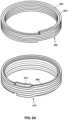
- FIG. 3is a diagram illustrating a simplified sectional view and a simplified perspective view of layers of an electromagnet in accordance with certain aspects of the present disclosure.
- FIG. 4is a diagram illustrating a simplified sectional view of an electromagnet that includes additional ferromagnetic material for reducing fringe fields in accordance with certain aspects of the present disclosure.
- FIG. 5is a diagram illustrating a simplified perspective view of an exemplary magnetic resonance imaging system incorporating an exemplary interventional device for radiation therapy in accordance with certain aspects of the present disclosure.
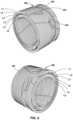
- FIG. 6is a diagram illustrating a simplified perspective view of the conductors of two exemplary halves of a gapped solenoidal electromagnet in accordance with certain aspects of the present disclosure.
- FIG. 7 Ais a diagram illustrating a simplified exemplary construction of a portion of an electromagnet in accordance with certain aspects of the present disclosure.
- FIG. 7 Bis a diagram illustrating a simplified perspective view of one half of an electromagnet with an indirect cooling system that includes serpentine channels in accordance with certain aspects of the present disclosure.
- FIG. 7 Cis a diagram illustrating a simplified perspective view of an indirect cooling system including serpentine channels between electromagnet layers in accordance with certain aspects of the present disclosure.
- FIG. 8 Ais a diagram illustrating two exemplary arrangements for conductors in adjacent levels within an electromagnet in accordance with certain aspects of the present disclosure.
- FIG. 8 Bis a diagram illustrating a simplified exemplary construction of a portion of an electromagnet with radial S-bends in accordance with certain aspects of the present disclosure.
- FIG. 8 Cis a diagram illustrating a simplified exemplary configuration of an electromagnet in accordance with certain aspects of the present disclosure.
- FIG. 9is a diagram illustrating a simplified exemplary alternative construction of a portion of an electromagnet in accordance with certain aspects of the present disclosure.
- FIG. 10is a simplified circuit diagram illustrating an exemplary electromagnet and associated power supply with filtering in accordance with certain aspects of the present disclosure.
- FIG. 11is a diagram illustrating a simplified implementation for using multiple batteries in conjunction with powering an electromagnet in accordance with certain aspects of the present disclosure.
- FIG. 12is a diagram illustrating a simplified implementation of a fuel-cell between a power supply and an electromagnet in accordance with certain aspects of the present disclosure.
- the present disclosurerelates to technologies that may be utilized in various systems, devices, methods and computer software used with electromagnets. Certain embodiments of the technologies described herein may be beneficially employed in conjunction with magnets used for magnetic resonance imaging (MRI), although it is contemplated that these technologies may also be implemented in electromagnets for other applications.
- MRImagnetic resonance imaging
- MRI magnetOne particular type of MRI magnet discussed herein as benefiting from these technologies is a solenoidal (i.e., cylindrical), resistive electromagnet (to be distinguished from, e.g., permanent magnets, superconducting electromagnets and non-solenoidal electromagnets such as dipolar electromagnets).
- solenoid or solenoidalis used herein to describe a magnet, such refers merely to the so-named configuration of certain MRIs (i.e., cylindrical); it is not by any means limited to magnet configurations that might typically be described as a perfect solenoid (e.g., a single helically wound conductor).
- the main implementations discussed hereinrelate to magnets for whole-body MRI systems.
- whole-bodyrefers to typical size magnetic resonance imaging systems (e.g., the Siemens Healthineers Magnetom Aera and the GE Signa), instead of small MRIs for imaging particular body parts (such as the Esaote O-Scan), or those for veterinary applications, research, etc.
- the technologies of the present disclosurecan be used in traditional solenoidal MRI systems used for diagnostic purposes, but can be particularly beneficial in gapped solenoidal systems, such as the system depicted in FIG. 1 .
- the present disclosurerefers to “gapped” magnets, such is intended to include solenoidal electromagnets having a gap (as in FIG. 1 ), as opposed to dipolar magnet arrangements, often referred to as “open” MRI systems.
- Gapped systemssuch as those discussed herein, may be useful for interventional applications such as MRI-guided radiotherapy, MRI-guided surgery, and the like.
- FIG. 5An example of such a radiotherapy system is depicted in FIG. 5 , which shows a gantry in the gap having magnetic shielding structures mounted thereon that contain components of a linear accelerator.
- magnet systemscan include those used in research, industry, or practical applications such as magnetic switching, motors, power generators, relays, speakers, magnetic separation equipment, etc.
- FIG. 1illustrates one implementation of a magnetic resonance imaging system (MRI) 100 consistent with certain aspects of the present disclosure.
- the MRI 100includes a main electromagnet 102 , a gradient coil assembly 104 and an RF coil system 106 .
- MRI 100Within MRI 100 is a patient couch 108 on which a human patient 110 may lie.
- the main electromagnet 102 of MRI 100may be a gapped solenoidal electromagnet separated by buttresses 114 with a gap 116 as shown in FIG. 1 .
- Gradient coil assembly 104contains the coils necessary to add small varying magnetic fields on top of the field of main electromagnet 102 to allow for spatial encoding of the imaging data.
- Gradient coil assembly 104may be a continuous cylindrical assembly, a split gradient coil assembly as shown in FIG. 1 , or other designs as may be necessary for the particular MRI configuration utilized.
- RF coil system 106is responsible for exciting the spins of hydrogen protons within patient 110 and for receiving subsequent signals emitted from patient 110 .
- RF coil system 106thus includes an RF transmitter portion and an RF receive portion.
- the implementation in FIG. 1includes a singular body coil performing both the RF transmit and RF functionalities.
- RF coil system 106may alternatively divide transmit and receive functionalities between a body coil and a surface coil, or may provide both transmit and receive functionalities within a surface coil.
- Magnetic resonance imaging systemsinclude control systems configured for the acquisition and processing of magnetic resonance imaging data from patient 110 , including image reconstruction.
- control systemsmay contain numerous subsystems, for example, those which control operation of the gradient coil assembly 104 , the RF coil system 106 , portions of those systems themselves, and those that process data received from RF coil system 106 and perform image reconstruction. Additional control system functionality can be included, for example, when an interventional device (such as a radiation therapy device) is integrated with MRI 100 .
- an interventional devicesuch as a radiation therapy device
- FIG. 2illustrates a simplified cross-section of the main electromagnet 102 shown in FIG. 1 , including a gap 116 .
- Gradient coil 104 and RF coil 106are not depicted in this figure. All four visible cross sections of main electromagnet 102 are shown in FIG. 2 , surrounding the MRI 100 's bore 200 and the imaging area or Field Of View 202 .
- FIG. 2illustrates an important concept that will be referred to throughout this disclosure, specifically, a “magnet envelope.”
- the concept of a magnet envelopemay be demonstrated by reference to the letters A, B, C and D in FIG. 2 .
- the termrefers to the outer boundaries of conductors used to generate the electromagnet's main magnetic field.
- the magnet envelopeis understood to mean the smallest rectangle (or tightly fitting convex polygon, for irregular shapes) that can be used to encompass the conductors.
- the magnet enveloperather than following the exact boundary of the conductors, extends all the way to corner “C” to form a rectangle. While the magnet envelope is depicted in the figures in two-dimensional cross-section, it is understood that the magnet envelope actually encompasses the entire three-dimensional volume corresponding to the cross-section(s) (i.e., generally, the volumetric area defined by sweeping the cross-section around the solenoidal magnet's Z-axis at a constant radius).
- “within the magnet envelope”means within the magnet envelope created by the conductors in both halves of the magnet.
- the magnet envelopeis understood to encompass the area bounded by points A, B, C, D and also the area bounded by points E, G, F, H, but it does not include the area within magnet gap 116 . If the electromagnet of FIG. 2 was a non-gapped design, the magnet envelope would be defined by the letters E, B, F, and D.
- FIG. 3focuses in on the right half of electromagnet 102 that is shown in FIGS. 1 and 2 , and specifically the upper right quadrant of FIG. 2 .
- This figureadds dimensions to the exemplary implementation to show, on the x-axis, distances from the central field of view along the magnet's Z-axis and, on the Y-axis, radial distances from the solenoidal magnet's Z-axis.
- conductors 302are represented by cross-hatched areas, ferromagnetic material 304 is represented by solid black areas, and the absence of conductors or ferromagnetic material is designated by whitespace 306 .
- Electromagnetsare, of course, made with conductors, for example, loops of copper wire.
- the term “conductors”refers to any conductive loops, coils or other structures that are used to generate the main magnetic field of an electromagnet.
- plural form of the wordis used herein, it is intended to cover not only a plurality of conductors (e.g., separate coils or bundles of wire), but plural “conductors” may also refer to structures that are technically one continuous conductor but may comprise, for example, multiple conductive loops, turns or other structures.
- ferromagnetic material 304may include materials such as iron, steel alloys and even a martensitic stainless steel (but not a lower-permeability austenitic stainless steel).
- ferromagnetic materials with initial relative permeabilities above 20can be used.
- ferromagnetic materials with low initial relative permeabilitiessuch as martensitic and ferritic stainless steel are acceptable, it is preferable to utilize materials with higher initial relative permeabilities, such as non-stainless steels (e.g., SAE1006 steel).
- FIG. 3illustrates one particular implementation that includes ferromagnetic material within an envelope of an electromagnet.
- This particular magnet configurationincludes six layers, which are labeled on the top and bottom of FIG. 3 as L 1 , L 2 , L 3 , L 4 , L 5 and L 6 .
- Layerscan be understood to mean sections of the electromagnet that are located at a given radial distance from the magnet axis. In the example of FIG. 3 , layers L 1 through L 6 have each been designed to be 4 cm tall.
- This examplethus includes 4 cm ⁇ 4 cm conductors wrapped in a generally cylindrical shape at layers L 1 , L 2 , L 4 , L 5 and L 6 , and a generally cylindrical piece of 4 cm thick ferromagnetic material (e.g., steel) at L 4 (the ferromagnetic material is not depicted in the bottom half of FIG. 3 ).
- ferromagnetic materiale.g., steel
- FIG. 3utilizes relatively large and evenly spread out conductors
- the beneficial technologies described hereincan also be utilized in electromagnet designs that include “bundles” of conductors.
- ferromagnetic material within the envelopecan be beneficial for an electromagnet designed with, for example, 10 bundles of smaller conductors wrapped together and placed at particular locations within the magnet to generate the desired magnetic field.
- the present disclosurecontemplates that the layers of an electromagnet design similar to that of FIG. 3 do not need to all be the same height, and the height of a ferromagnetic material layer does not need to be the same height as any of the conductor layers.
- the conductor layersare 4 cm tall, while the ferromagnetic layer is only 2 cm tall.
- electromagnetsmay similarly be designed with more than one layer of ferromagnetic material, or partial layer(s) of ferromagnetic material. While the examples discussed thus far contemplate cylindrically-shaped ferromagnetic material layers, it is contemplated that ferromagnetic materials within the electromagnet envelope need not be cylindrical in shape.
- the present disclosurespecifically contemplates its technologies being utilized in magnet designs that have no yoke and magnet designs that have no flux return.
- the “ferromagnetic material within the electromagnet envelope” magnet designs discussed hereinare distinguishable from flux returns and yokes. For example, for a solenoidal magnet (as illustrated in FIG. 2 ), a flux return or yoke would be positioned within the bore 200 of the magnet, rather than “within the envelope” of the magnet (as delineated by the letters A, B, C, D, E, F, G, H described previously).
- dipole magnet designs that commonly utilize flux returns or yokesare likewise distinguishable from the designs of the present disclosure.
- the present disclosurealso specifically distinguishes magnets where the main magnetic field is generated primarily by a permanent magnet or magnets. While such systems may seem to include ferromagnetic material within their magnet's envelope, they are distinct from the technologies disclosed herein, which relate to electromagnets and define “within the envelope” as within the envelope of conductors used to generate the electromagnet's main magnetic field.
- the amount of ferromagnetic materialis approximately one sixth the volume of the overall electromagnet or approximately one fifth the volume of the conductors.
- the height of the ferromagnetic layermay be cut in half, and the overall volume of ferromagnetic material decreased to only about one tenth the volume of the conductors.
- the volume of the ferromagnetic materialmay be as small as one twentieth the volume of the conductors.
- the volume and configuration of ferromagnetic materialscan vary greatly, and can be determined through modeling particular magnet designs with software such as Comsol MultiPhysics or Faraday (by Integrated Engineering Solutions, Inc.) to arrive at configurations resulting in magnetization currents within the ferromagnetic materials sufficient to improve the main magnetic field homogeneity without requiring additional power (for example, to drive negative current loops).
- softwaresuch as Comsol MultiPhysics or Faraday (by Integrated Engineering Solutions, Inc.) to arrive at configurations resulting in magnetization currents within the ferromagnetic materials sufficient to improve the main magnetic field homogeneity without requiring additional power (for example, to drive negative current loops).
- the electromagnet designs contemplated hereinmay include additional ferromagnetic materials outside the envelope of the electromagnet, which are configured to reduce the fringe field of the electromagnet.
- An example of such fringe field reducing material 402is illustrated in FIG. 4 .
- this additional ferromagnetic material 402may be designed as an L-shaped cross-section steel structure that is 1-2 cm thick.
- FIG. 5depicts such an interventional application, specifically, an MRI-guided radiation therapy system.
- FIG. 5depicts a gantry 502 on which magnetic shielding shells 504 are mounted in order to protect portions of a linear accelerator 508 from the electromagnet's main magnetic field.
- the linear accelerator portions 508may be connected utilizing RF waveguides 506 .
- the magnetic shielding shells 504include large amounts of ferromagnetic material that should also be taken into account when designing the electromagnet, along with the conductors and the ferromagnetic materials included within the envelope of the electromagnet.
- One embodiment of the present disclosuremade thus be a magnetic resonance imaging (MRI) system including a resistive, solenoidal electromagnet for whole-body MRI including conductors and ferromagnetic material within an envelope of the electromagnet.
- the electromagnetmay be gapped and the ferromagnetic material may comprise steel.
- the volume of ferromagnetic materialmay be at least one sixth the volume of the conductors or at least one twentieth the volume of the conductors.
- the electromagnetmay comprise a plurality of cylindrical layers and the ferromagnetic material may comprise a layer of the plurality of cylindrical layers.
- the ferromagnetic materialmay comprise a portion of a layer of the plurality of cylindrical layers.
- the ferromagnetic materialmay comprise a plurality of layers or a plurality of portions of layers of the plurality of cylindrical layers.
- a “positive” current flowis a flow direction that contributes positively to a magnet's main magnetic field Bo (see, e.g., positive flow direction 118 and main magnetic field 122 in FIG. 1 ).
- a “negative” current flowopposes the magnet's main magnetic field Bo (see, e.g., negative flow direction 120 in FIG. 1 ).
- magnet designs including ferromagnetic material within the magnet envelopeallows for magnet designs containing only positive current flows to produce satisfactorily homogeneous fields, even in gapped magnet configurations.
- a magnetic resonance imaging systemmay thus comprise a resistive, solenoidal electromagnet for whole-body MRI including conductors and ferromagnetic material within an envelope of the electromagnet where the system may be gapped and the electromagnet may be configured for current flow in only one circumferential direction within the magnet.
- each of the bundles driving the main magnetic fieldmay have a positive current direction, or, in the case of a non-bundled design, each of the conductors (e.g., as depicted in the bottom of FIG. 3 ) is configured, bent or formed to provide for positive flow currents only.
- the electromagnetmay be configured for less than 5% negative current flow or less than 10% negative current flow.
- less than 5% or 10% of the conductorsmay be configured or formed in a manner to result in negative current flows.
- less than 5% or 10% of the current loopsare configured for negative flows (e.g., a loop representing a single turn around the magnet's circumference).
- Certain implementations herein of a magnetic resonance imaging systemcan include a resistive, solenoidal electromagnet for whole-body MRI including conductors and ferromagnetic material within an envelope of a gapped electromagnet where the conductors are made of copper.
- Certain of such implementationswhere the conductors are directly cooled, (e.g., coolant is flowed through the center of the conductor) can be configured for a field strength of at least 0.12 Tesla and a power supply of less than 30 kW or less than 45 kW, while others may be configured for a field strength of at least 0.2 Tesla and a power supply of less than 100 kW or less than 145 kW, and yet others may be configured for a field strength of at least 0.3 Tesla and a power supply of less than 210 kW or less than 300 kW.
- such electromagnetsmay be configured for a field strength of at least 0.12 Tesla and a power supply of less than 35 kW or less than 50 kW, while others may be configured for a field strength of at least 0.2 Tesla and a power supply of less than 105 kW or less than 150 kW, and yet others may be configured for a field strength of at least 0.3 Tesla and a power supply of less than 230 kW or less than 330 kW.
- implementations herein of a magnetic resonance imaging systemcan include a resistive, solenoidal electromagnet for whole-body MRI including conductors and ferromagnetic material within an envelope of a gapped electromagnet where the conductors are made of aluminum.
- Certain of such implementations where the conductors are directly coolede.g., coolant is flowed through the center of the conductor
- othersmay be configured for a field strength of at least 0.2 Tesla and a power supply of less than 155 kW or less than 220 kW
- yet othersmay be configured for a field strength of at least 0.3 Tesla and a power supply of less than 335 kW or less than 480 kW.
- such electromagnetsmay be configured for a field strength of at least 0.12 Tesla and a power supply of less than 50 kW or less than 70 kW, while others may be configured for a field strength of at least 0.2 Tesla and a power supply of less than 170 kW or less than 245 kW, and yet others may be configured for a field strength of at least 0.3 Tesla and a power supply of less than 365 kW or less than 520 kW.
- gapped solenoidal electromagnetscan reduce power requirements and can result in reduced forces between the two halves of a gapped solenoidal electromagnet.
- gapped solenoidal electromagnetsrequire substantial fixation structures in order to keep apart the two halves of the magnet, which are attracted to one another with considerable force. This must be done in a way that avoids any relative movement that could affect field homogeneity.
- FIG. 1Examples of substantial fixation structures are depicted in FIG. 1 as buttresses 114 .
- Buttresses of this typewould normally need to be made from a strong and typically metallic material such as steel or aluminum.
- the technologies of the present disclosureenable implementations of a magnetic resonance imaging system including a resistive, solenoidal electromagnet for whole-body MRI including conductors and ferromagnetic material within an envelope of a gapped electromagnet where the two halves of the electromagnet are held apart by a fixation structure where, in some implementations, the fixation structure may be substantially nonmetallic.
- “Substantially” nonmetallicis understood to describe a fixation structure that relies primarily on nonmetallic materials to brace against the force exerted by the two magnet halves. To the extent metallic materials are included in such a structure but are not primarily responsible for bearing the load, such a structure is intended to fall within the term “substantially nonmetallic.”
- fixation structures contemplated hereinmay comprise carbon fiber or zero CTE carbon fiber.
- the combined systemmay be configured such that the radiation therapy device is directed to treat through the fixation structure.
- the fixation structuremay be a 0.5 cm thick uniform carbon fiber cylinder between the magnet halves, with a coefficient of thermal expansion that is substantially zero and which provides minimal and uniform attenuation of a radiation therapy beam.
- the fixation structuremay be a single cylinder or continuous former that extends not just between the two magnet halves, but also into the electromagnet assembly itself (e.g., as a former between layers of conductors).
- a magnetic resonance imaging system having a resistive, solenoidal electromagnet for whole-body MRI with a field strength of at least 0.05 Teslamay include conductors for creating a main magnetic field of the electromagnet where the main magnetic field is not generated by bundles of conductors but instead may be generated by layers of conductors.
- An example of such a layered conductor arrangementis depicted in FIG. 3 , and the details of such designs will be discussed further below. Because such layered arrangements can produce highly homogeneous fields and can facilitate beneficial new fabrication methods, they can provide an alternative to generating main magnetic fields using bundles of conductors.
- the present disclosurerefers to designs where “the main magnetic field is not generated by bundles of conductors,” such means that the main magnetic field is entirely or primarily created by more distributed conductor configurations (e.g., similar to those described with respect to FIG. 3 ).
- main magnetic fieldis not generated by bundles” herein contemplates some minimal use of bundles, for example, where bundles are used, but contribute no more than 10% to the production of the main magnetic field.
- FIG. 3illustrates one example of a layered design for a gapped solenoidal magnet where layers of conductors extend or traverse approximately one meter across the magnet's Z axis—from about 0.2 m away from the center of the imaging field to about 1.2 m away from the center of the imaging field.
- a main magnetic fieldcan be generated by multiple layers of conductors, as depicted in FIG. 3 , and electromagnets with this design may include ferromagnetic material within the magnet envelope, as also depicted in FIG. 3 and as discussed above.
- FIG. 6depicts the exemplary design of FIG. 3 along with an additional view of the design from the opposite perspective.
- FIG. 6illustrates five separate layers of conductors for generating a main magnetic field, with level L 3 being reserved for the insertion of a ferromagnetic cylinder.
- the present disclosurecontemplates various numbers of layers being used, the number of which, for example, may depend on the particular conductor size chosen. In the implementation of FIG. 6 , relatively large conductors are used (e.g., 4 cm by 4 cm, with an open core for direct cooling).
- 2 cm by 2 cm conductorsmay be utilized.
- the main magnetic fieldis generated by layers of conductors where the conductors have a cross-sectional area greater than 0.50 cm 2 or greater than 0.75 cm 2 .
- a portion of the conductorscan have a smaller cross-sectional area than the cross-sectional area for other conductors.
- a layer of smaller conductorsmay have approximately half the cross-sectional size of a layer of larger conductors (e.g., one layer's conductors may have a cross section of 40 mm ⁇ 40 mm, and another layer may have conductors with a cross-section of 20 mm ⁇ 20 mm).
- a layer or layers of smaller conductorsmay be implemented at or near the outer radial layer, or near or adjacent the ferromagnetic layer (e.g., L 3 as shown in FIG. 6 ).
- the conductors of the designs contemplated hereinmay be supported by lower strength materials such as fiberglass or plastic cylindrical formers.
- the layers of conductorsmay be supported by 1 mm thick cylindrical fiberglass formers in-between layers, and the conductor layers and formers may be combined into a single rigid object through the use of an epoxy or other insulating material.
- FIG. 7 Aillustrates a cross-section of one particular implementation where conductor layers L 1 , L 2 , L 4 , L 5 , L 6 and ferromagnetic material layer L 3 are separated by formers 702 that may be comprised of a nonmetallic material such as a glass reinforced polymer.
- FIG. 7 Aillustrates an implementation where the electromagnet may also include a side cheek 704 that can be made from a similar nonmetallic material, and an external former 706 , which may optionally be made from a stronger, metallic material such as aluminum.
- a resistive, solenoidal electromagnet for whole-body MRIhaving a field strength of at least 0.05 Tesla
- One implementationincludes at least two solenoidal layers of conductors separated by a nonmetallic former. Another implementation may include less than 10 layers of conductors.
- the layers of conductors and non-metallic formersmay be constructed to form a rigid object, for example, by fixing them together with an epoxy.
- the rigid objectcan further include at least a portion of a gradient coil. For example, just the slice select coil may be incorporated or, alternatively, the entire gradient coil may be epoxied together with the main magnet into a single rigid object.
- FIG. 7 Aillustrates an example of a conductor 708 having a generally square cross-section with a cylindrical, hollowed-out core 710 that can be used for direct cooling (e.g., the flowing of water or coolant through core 710 ).
- FIG. 7 Billustrates an example of an electromagnet with an indirect cooling system provided by serpentine coolant channels.
- the indirect cooling systemcan provide sufficient cooling for the electromagnet such that some or all of the conductors in the electromagnet may be solid conductors, rather than having a hollow core 710 as shown in the direct cooling example in FIG. 7 A .
- a serpentine channel 720can include one or more linear sections 722 and one or more curved sections 724 , which can combine to form an “S-shaped” or “serpentine” channel 720 .
- a serpentine channel 720can be adjacent (or wrapped around) one or more of the conductors or ferromagnetic layers to provide indirect cooling.
- FIG. 7 Cillustrates an exemplary indirect cooling system, such as depicted in FIG. 7 B , with its serpentine channels interspersed between layers of conductors and/or ferromagnetic material.
- a serpentine channel 720will include an inlet and outlet (e.g., 726 ) for flowing coolant through the channel.
- the inlets and/or outletscan be located at a particular end 730 of the electromagnet that may be more accessible for establishing cooling connections.
- inlets and outletsmay be located at a patient end or a service end of the electromagnet.
- a solenoidal electromagnetWhen the present disclosure refers to a solenoidal electromagnet or refers to a solenoidal layer of conductors within an electromagnet, it is contemplated that the conductors may deviate somewhat from a perfect solenoid (i.e., a uniform, helically wound coil).
- a layer of conductorsmay include S-bends (illustrated as element 602 in FIG. 6 ).
- S-bend configurationsare an alternative to helical configurations. In addition to having a different manufacturing process, they can be modeled more effectively during magnet design if the software used for modeling simplifies current loops as pure “rings” of current (in which case, S-bend designs will more closely match the model than helical designs).
- an “S-bend”may take the form of a stretched-out letter S, as shown in the figures, but the term is intended to cover any gradual or sharp transition (even a 90 degree turn) to a subsequent loop that results in current flow in the subsequent loop continuing in the same circumferential direction.
- S-bendsare distinguished from helical arrangements and also from U-bends, which result in current flow of the subsequent loop going in the opposite direction.
- certain electromagnet designsmay include negative currents therein (i.e., those which create a magnetic field counteracting the direction of the main magnetic field). If such negative currents are required, they can be implemented in the coils of the present disclosure utilizing U-bends. As noted, however, negative currents may be avoided using the technologies of the present disclosure, including the inclusion of ferromagnetic material within the envelope of the electromagnet.
- conductorsmay also be arranged so that a conductor traverses a layer in a direction parallel to the axis of the solenoidal electromagnet.
- Such an arrangementis depicted as 604 in FIG. 6 and can be utilized when magnet modeling and design indicates that a current loop is not required at a specific axial location within that layer. For further illustration, such a location is depicted in the exemplary design of FIG. 3 as element 306 .
- a resistive, solenoidal electromagnet for whole-body MRI having a field strength of at least 0.05 Teslacan include conductors for creating a main magnetic field of the electromagnet, where the main magnetic field is generated by layers of conductors and where the layers of conductors include at least one layer including a section where a conductor traverses in a direction parallel to an axis of the solenoidal electromagnet and where the conductor may have a cross-sectional area greater than 0.50 cm 2 or greater than 0.75 cm 2 .
- the layers of conductorsmay include a first layer that is a helically wrapped conductor having a first helical tilt and a second layer, adjacent to the first layer, comprising a helically wrapped conductor having a second helical tilt, where the second helical tilt is opposite to the first helical tilt.
- certain implementationsmay have a layer that is a helically wound conductor tilting to the right and the layer just inside or outside of that layer (i.e., the layer adjacent at the immediately smaller or larger radius) is a helically wound conductor tilting to the left.
- the layers of conductorsmay include a first layer of wrapped conductor having first S-bends bending in a first direction and a second layer, adjacent to the first layer, comprising a wrapped conductor having second S-bends bending in a second direction where the first S-bends and the second S-bends overlap and where the second direction is opposite to the first direction.
- An example of such a configurationis depicted at the bottom of FIG. 8 A where the outer layer 808 has S-bends in one direction and the adjacent layer 810 has S-bends bending in the opposite direction and where the S-bends of each layer overlap at location 812 .
- An alternative arrangement
- FIG. 8 Bis a diagram illustrating a simplified exemplary construction of a portion of an electromagnet with radial S-bends in accordance with certain aspects of the present disclosure.
- adjacent layers of conductorscan be connected (e.g., in a generally radial direction) by one or more S-bends 826 .
- An example of such a configurationis illustrated in FIG. 8 B showing two adjacent layers of conductors where a first layer 820 of wrapped conductor is connected to a second layer 822 of wrapped conductor by an S-bend 826 .
- An expanded view 824 of the S-bend connectionis also shown.
- either or both of the adjacent layerscan be helical (e.g., not including S-bends in the axial direction) or they may include S-bends in the axial direction instead of having a helical pitch).
- FIG. 8 Cis a diagram illustrating a simplified exemplary configuration of an electromagnet in accordance with certain aspects of the present disclosure.
- This exemplary configurationincludes a gapped electromagnet design and happens to depict cylinders arranged in the gap that may be used in a radiotherapy application to shield components of a linear accelerator.
- the magnet halves ( 830 , 832 )can be “rotated” such that their radial connections 834 (e.g., S-bends) between adjacent layers of conductors are not at the same azimuthal angle. This can have the beneficial effect of reducing remnant tesseral harmonics that may be generated by the radial S-bend connections. As shown in the example illustrated in FIG.
- the magnet halvescan be rotated approximately 180 degrees relative to each other, though other rotation angles could be implemented, for example, 30°, 45°, 60°, 90°, 135°, 150°, 165°, etc.
- One of the magnet halvesmay be designated the “patient end” (where the patient enters bore 200 of the MRI system) and the other magnet half can be designated the “service end.”
- the patient-end radial connections 834can be on the bottom (i.e., at the lowest point of patient-end magnet half 830 ), and service-end radial connections 836 can be on the top (i.e., at the highest point of service-end magnet half 832 ).
- the angle of the magnet halvescan be different (e.g., having an overall rotation of 30°, 45°, 60°, 90°, 135°, 150°, 165° relative to the vertical, such that the radial connections are not at the top and bottom), while still maintaining an approximately 180 degree separation between the radial connections of the two magnet halves.
- multiple layers of conductorscan be connected (for example, L 1 , L 2 , L 4 , L 5 and L 6 of FIG. 3 ) so that they essentially form a single current path.
- the electromagnetmay be configured to operate with a single supplied current.
- the layer to layer connectionscan be made so that the current flow will be positive in each layer and therefore each layer will positively contribute to creation of the main magnetic field.
- the magnet halvesmay be connected in series and therefore still run on a single supplied current (or they may run in parallel circuits, but on the same amperage).
- Such beneficial configurationscan utilize simplified power supplies, in contrast to typical bundled magnet designs that often require different amperages for different bundles (and often require a negative current in one or more bundles).
- FIG. 9depicts an alternative electromagnet design that is not based on layers of conductors, but that similarly has a more distributed conductor arrangement for the creation of the main magnetic field.
- Exemplary embodiments of such designsinclude conductors covering, for example, at least 40%, 50%, 60% or 70% of the magnet envelope.
- the particular exemplary implementation depicted in FIG. 9has conductors covering more than 50% of the magnet envelope and utilizes conductor bundles 902 in creating the main magnetic field. While many electromagnet designs that utilize bundles to generate their main magnetic field can utilize very small conductors, the present disclosure also contemplates the utilization of larger conductors in bundles.
- individual conductors 904have a cross-section of 1 cm ⁇ 1 cm.
- Implementations of this type of designmay also include ferromagnetic material within the magnet envelope, as previously discussed.
- ferromagnetic material 906 in FIG. 9can enable the electromagnet to be configured for current flow in only one circumferential direction within the magnet.
- each of the bundles driving the main magnetic fieldmay have a positive current direction.
- the electromagnetmay be configured for less than 5% negative current flow or less than 10% negative current flow.
- bundlesmay be connected by conductors traversing in a direction parallel to the axis of the electromagnet to essentially form a single current path and to allow the electromagnet to be powered with a single supplied current.
- Electromagnetscan be required to produce highly homogeneous and stable magnetic fields. Such stability is commonly facilitated by the use of sophisticated DC power supplies that maintain highly stable voltage and current outputs (for example, on the order of only parts per million fluctuation).
- the technologies of the present disclosurecan provide for homogeneous and stable magnetic fields without the need for such complex power supply designs. These technologies are applicable to different magnet configurations such as traditional solenoidal (ungapped) magnets, gapped solenoidal systems, dipolar magnets, etc.
- While power supplies for MRI systemsare typically designed to provide DC current with fluctuations on the order of only parts per million, the technologies of the present disclosure can provide the requisite field homogeneity and stability with a power supply having, e.g., only part per ten thousand stability.
- this stability metriccan relate to the DC current ripple that exists, after rectification, at the original AC frequency and harmonics thereof.
- implementations of the present disclosuremay utilize a power supply having at least one part per ten thousand current fluctuation at frequencies of 180 Hz or above, or at frequencies of 600 Hz or above.
- Other implementationsmay even utilize power supplies having at least one part per thousand current fluctuation at frequencies of 180 Hz or above, or at frequencies of 600 Hz or above.
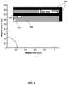
- an exemplary electromagnetcan filter current fluctuations of 15 parts per ten thousand over 600 Hz down to a level of ⁇ 90 dB.
- Implementations of the present disclosurecan thus include magnetic resonance imaging systems that do not include a current filter separate from the filtering provided by the resistive electromagnet itself. Stated another way, such a system does not include an additional element added for the purpose of reducing current fluctuation (e.g., the addition of an inductor).
- Alternative implementationsmay include a current filter but can limit such filters to having less than, for example, 5 mH, 2 mH or 1 mH inductance.
- a magnetic resonance imaging systemcan thus include a resistive electromagnet for whole-body MRI having a field strength of at least 0.05 Tesla and a power supply for powering the resistive electromagnet having at least one part per ten thousand current fluctuation at frequencies of 180 Hz or above and either no current filter separate from the filtering provided by the resistive electromagnet itself, or a current filter of less than 2 mH inductance.
- Certain implementations of the technologies described hereinalso enable the use of single-channel power supplies.
- certain electromagnet designs described herein as having ferromagnetic material within their magnet envelopecan be supplied with a single current.
- these magnet designscan be optimized, for example, to avoid a need for negative currents and/or bundles of conductors that must be supplied with differing amounts of current.
- simplified, single-channel power suppliescan be used that do not require complex control systems to keep multiple power channels in sync with one another.
- low-frequency current fluctuations from a single-channel power supplycan be more easily handled by MRI control systems accounting for such variations than fluctuations from multichannel power supplies.
- an MRI's spectrometermay be utilized to compensate for low-frequency drifts in current or voltage through main magnetic field strength corrections.
- these power suppliescan be used with the exemplary gapped solenoidal magnet designs discussed above.
- the power supplycan be designed to provide a power of only 45 kW, or even less.
- a power supply of 155 kW or lessmay be used for such a design and a field strength of at least 0.2 Tesla.
- Other configurations as taught or specifically discussed hereinare contemplated.
- Implementations of the present disclosurecontemplate the addition of a simple filter to control voltage fluctuations, for example, an LC filter.
- a solenoidal electromagnethaving a gap of 28 cm configured for whole body MRI with a field strength of at least 0.12 Tesla is considered, and is made with ferromagnetic material within the magnet envelope and directly cooled aluminum conductors.
- An exemplary filter for such a designis depicted in FIG. 10 .
- FIG. 10depicts this exemplary electromagnet having a resistance of 40 m ⁇ and an inductance of 40 mH.
- the power supply utilizedcan be configured to provide 1000 A at 40 V and can have a ripple of 1760 ppm at 600 Hz and 57.6 kHz.
- Such filter characteristicsmay be determined with the assistance of the following equations:
- a battery or multiple batteriesmay be utilized in the system to at least partially limit the power supply fluctuations. Such may be utilized in addition to or instead of the filters discussed above.
- the electromagnetmay be connected to and essentially powered by the battery and the system can be configured so that the battery can be charged by the power supply.
- Power fluctuations at the electromagnet that may be caused by the power supply charging the batterycan be avoided by other implementations utilizing multiple batteries (e.g., two or more).
- the battery responsible for powering the electromagnetcan avoid being charged while it is powering the magnet and then, when the battery powering the electromagnet needs to be charged, the power source for the electromagnet can be switched to a different battery that has already been charged.
- the systemmay be configured such that the resistive electromagnet can be connected to one of a plurality of batteries while another of the plurality of batteries can be charged by the power supply.
- FIG. 11Another example of a multi-battery embodiment is depicted in FIG. 11 and utilizes at least three batteries.
- switchesmay be opened and closed so that a single battery is powering the electromagnet (but not being charged at the same time), while the other batteries can be charged.
- the switch positionsmay be changed in a manner that allows the electromagnet to be switched to being powered by another battery that has already been cut off from the power supply.
- the switch connecting the second battery for chargingcan be opened prior to the switch between the second battery and the electromagnet being closed for powering the magnet.
- Such a system having three or more batteriescan thus be configured to facilitate a smooth transition between two batteries that are not being charged and not being affected by the fluctuations of the power supply.
- the systemmay include at least three batteries and may be configured such that the resistive electromagnet can be connected to a first battery while a second battery is being charged and the system can be further configured for the resistive electromagnet connection to be switched to a third battery that is not being charged when the connection is switched.
- all of the batteriesmay be charging and connected to the electromagnet to keep it warm when the electromagnet is not in use (e.g., when MRI imaging is not occurring, such as between patients).
- the present disclosurealso contemplates the use of a fuel-cell in a similar manner.
- the systemmay be configured so that a fuel cell is located between the power supply and the resistive electromagnet to essentially filter out voltage fluctuations seen at the power supply.
- One or more aspects or features of the subject matter described hereincan be realized in digital electronic circuitry, integrated circuitry, specially designed application specific integrated circuits (ASICs), field programmable gate arrays (FPGAs) computer hardware, firmware, software, and/or combinations thereof.
- ASICsapplication specific integrated circuits
- FPGAsfield programmable gate arrays
- These various aspects or featurescan include implementation in one or more computer programs that are executable and/or interpretable on a programmable system including at least one programmable processor, which can be special or general purpose, coupled to receive data and instructions from, and to transmit data and instructions to, a storage system, at least one input device, and at least one output device.
- the programmable system or computing systemmay include clients and servers.
- a client and serverare generally remote from each other and typically interact through a communication network. The relationship of client and server arises by virtue of computer programs running on the respective computers and having a client-server relationship to each other.
- machine-readable signalrefers to any signal used to provide machine instructions and/or data to a programmable processor.
- the machine-readable mediumcan be a non-transitory, machine-readable medium that can store such machine instructions non-transitorily, such as for example as would a non-transient solid-state memory or a magnetic hard drive or any equivalent storage medium.
- the machine-readable mediumcan alternatively or additionally store such machine instructions in a transient manner, such as for example as would a processor cache or other random access memory associated with one or more physical processor cores.
- one or more aspects or features of the subject matter described hereincan be implemented on a computer having a display device, such as for example a cathode ray tube (CRT) or a liquid crystal display (LCD) or a light emitting diode (LED) monitor for displaying information to the user and a keyboard and a pointing device, such as for example a mouse or a trackball, by which the user may provide input to the computer.
- a display devicesuch as for example a cathode ray tube (CRT) or a liquid crystal display (LCD) or a light emitting diode (LED) monitor for displaying information to the user
- LCDliquid crystal display
- LEDlight emitting diode
- a keyboard and a pointing devicesuch as for example a mouse or a trackball
- feedback provided to the usercan be any form of sensory feedback, such as for example visual feedback, auditory feedback, or tactile feedback; and input from the user may be received in any form, including, but not limited to, acoustic, speech, or tactile input.
- Other possible input devicesinclude, but are not limited to, touch screens or other touch-sensitive devices such as single or multi-point resistive or capacitive trackpads, voice recognition hardware and software, optical scanners, optical pointers, digital image capture devices and associated interpretation software, and the like.
- phrases such as “at least one of” or “one or more of”may occur followed by a conjunctive list of elements or features.
- the term “and/or”may also occur in a list of two or more elements or features. Unless otherwise implicitly or explicitly contradicted by the context in which it used, such a phrase is intended to mean any of the listed elements or features individually or any of the recited elements or features in combination with any of the other recited elements or features.
- the phrases “at least one of A and B;” “one or more of A and B;” and “A and/or B”are each intended to mean “A alone, B alone, or A and B together.”
- a similar interpretationis also intended for lists including three or more items.
- the phrases “at least one of A, B, and C;” “one or more of A, B, and C;” and “A, B, and/or C”are each intended to mean “A alone, B alone, C alone, A and B together, A and C together, B and C together, or A and B and C together.”
- Use of the term “based on,” above and in the claimsis intended to mean, “based at least in part on,” such that an unrecited feature or element is also permissible.
Landscapes
- Physics & Mathematics (AREA)
- Health & Medical Sciences (AREA)
- Condensed Matter Physics & Semiconductors (AREA)
- General Physics & Mathematics (AREA)
- Life Sciences & Earth Sciences (AREA)
- Nuclear Medicine, Radiotherapy & Molecular Imaging (AREA)
- Engineering & Computer Science (AREA)
- Biomedical Technology (AREA)
- High Energy & Nuclear Physics (AREA)
- Pathology (AREA)
- Veterinary Medicine (AREA)
- Animal Behavior & Ethology (AREA)
- General Health & Medical Sciences (AREA)
- Public Health (AREA)
- Radiology & Medical Imaging (AREA)
- Medical Informatics (AREA)
- Heart & Thoracic Surgery (AREA)
- Biophysics (AREA)
- Molecular Biology (AREA)
- Surgery (AREA)
- Electromagnetism (AREA)
- Magnetic Resonance Imaging Apparatus (AREA)
- Radiation-Therapy Devices (AREA)
Abstract
Description
Claims (25)
Priority Applications (2)
| Application Number | Priority Date | Filing Date | Title |
|---|---|---|---|
| US17/559,957US12000914B2 (en) | 2018-05-16 | 2021-12-22 | Resistive electromagnet systems and methods |
| US18/731,981US20250012879A1 (en) | 2018-05-16 | 2024-06-03 | Resistive electromagnet systems and methods |
Applications Claiming Priority (4)
| Application Number | Priority Date | Filing Date | Title |
|---|---|---|---|
| US201862672525P | 2018-05-16 | 2018-05-16 | |
| US201862677546P | 2018-05-29 | 2018-05-29 | |
| US16/179,764US11209509B2 (en) | 2018-05-16 | 2018-11-02 | Resistive electromagnet systems and methods |
| US17/559,957US12000914B2 (en) | 2018-05-16 | 2021-12-22 | Resistive electromagnet systems and methods |
Related Parent Applications (1)
| Application Number | Title | Priority Date | Filing Date |
|---|---|---|---|
| US16/179,764ContinuationUS11209509B2 (en) | 2018-05-16 | 2018-11-02 | Resistive electromagnet systems and methods |
Related Child Applications (1)
| Application Number | Title | Priority Date | Filing Date |
|---|---|---|---|
| US18/731,981ContinuationUS20250012879A1 (en) | 2018-05-16 | 2024-06-03 | Resistive electromagnet systems and methods |
Publications (2)
| Publication Number | Publication Date |
|---|---|
| US20220113360A1 US20220113360A1 (en) | 2022-04-14 |
| US12000914B2true US12000914B2 (en) | 2024-06-04 |
Family
ID=64362764
Family Applications (3)
| Application Number | Title | Priority Date | Filing Date |
|---|---|---|---|
| US16/179,764ActiveUS11209509B2 (en) | 2018-05-16 | 2018-11-02 | Resistive electromagnet systems and methods |
| US17/559,957Active2038-12-31US12000914B2 (en) | 2018-05-16 | 2021-12-22 | Resistive electromagnet systems and methods |
| US18/731,981PendingUS20250012879A1 (en) | 2018-05-16 | 2024-06-03 | Resistive electromagnet systems and methods |
Family Applications Before (1)
| Application Number | Title | Priority Date | Filing Date |
|---|---|---|---|
| US16/179,764ActiveUS11209509B2 (en) | 2018-05-16 | 2018-11-02 | Resistive electromagnet systems and methods |
Family Applications After (1)
| Application Number | Title | Priority Date | Filing Date |
|---|---|---|---|
| US18/731,981PendingUS20250012879A1 (en) | 2018-05-16 | 2024-06-03 | Resistive electromagnet systems and methods |
Country Status (5)
| Country | Link |
|---|---|
| US (3) | US11209509B2 (en) |
| EP (1) | EP3794363A1 (en) |
| JP (2) | JP7383643B2 (en) |
| CN (2) | CN112424625B (en) |
| WO (1) | WO2019221781A1 (en) |
Families Citing this family (9)
| Publication number | Priority date | Publication date | Assignee | Title |
|---|---|---|---|---|
| ATE503419T1 (en) | 2004-02-20 | 2011-04-15 | Univ Florida | SYSTEM FOR ADMINISTERING CONFORMAL RADIATION THERAPY WHILE IMAGING SOFT TISSUE |
| CA3198109A1 (en) | 2009-07-15 | 2011-01-20 | Viewray Technologies, Inc. | Method and apparatus for shielding a linear accelerator and a magnetic resonance imaging device from each other |
| EP3628370A1 (en) | 2012-10-26 | 2020-04-01 | ViewRay Technologies, Inc. | Assessment and improvement of treatment using imaging of physiological responses to radiation therapy |
| US9446263B2 (en)* | 2013-03-15 | 2016-09-20 | Viewray Technologies, Inc. | Systems and methods for linear accelerator radiotherapy with magnetic resonance imaging |
| CN109310879A (en) | 2016-03-02 | 2019-02-05 | 优瑞技术公司 | Particle Therapy Using Magnetic Resonance Imaging |
| CA3028716C (en) | 2016-06-22 | 2024-02-13 | Viewray Technologies, Inc. | Magnetic resonance imaging at low field strength |
| US11033758B2 (en) | 2017-12-06 | 2021-06-15 | Viewray Technologies, Inc. | Radiotherapy systems, methods and software |
| US11209509B2 (en)* | 2018-05-16 | 2021-12-28 | Viewray Technologies, Inc. | Resistive electromagnet systems and methods |
| CN113648550A (en)* | 2021-09-15 | 2021-11-16 | 上海翰斯泰医疗科技有限公司 | Magnetic resonance radiotherapy integrated equipment and radiotherapy method thereof |
Citations (390)
| Publication number | Priority date | Publication date | Assignee | Title |
|---|---|---|---|---|
| US3428307A (en) | 1964-11-06 | 1969-02-18 | Philips Corp | Adjustable couches |
| US4019059A (en) | 1974-11-22 | 1977-04-19 | Siemens Aktiengesellschaft | Patient's support arrangement for an X-ray apparatus |
| US4233662A (en) | 1973-04-25 | 1980-11-11 | Emi Limited | Radiography |
| US4481657A (en) | 1981-06-01 | 1984-11-06 | Siemens Aktiengesellschaft | Patient support apparatus comprising a rotatable support |
| US4589126A (en) | 1984-01-26 | 1986-05-13 | Augustsson Nils E | Radiotherapy treatment table |
| US4612596A (en) | 1985-03-18 | 1986-09-16 | Kabushiki Kaisha Toshiba | Circuit for stabilizing electromagnet coil current of a magnetic resonance imaging device |
| US4694837A (en) | 1985-08-09 | 1987-09-22 | Picker International, Inc. | Cardiac and respiratory gated magnetic resonance imaging |
| JPS62281934A (en) | 1986-05-30 | 1987-12-07 | 横河メディカルシステム株式会社 | Static magnetic field magnet |
| US4766378A (en) | 1986-11-28 | 1988-08-23 | Fonar Corporation | Nuclear magnetic resonance scanners |
| US4771785A (en) | 1986-07-25 | 1988-09-20 | Resonex, Inc. | Magnetic resonance imaging apparatus and three-axis patient positioning assembly for use therewith |
| JPS63294839A (en) | 1987-05-27 | 1988-12-01 | Nec Corp | Ct simulator for radiotherapy |
| DE3828639A1 (en) | 1987-08-24 | 1989-03-16 | Mitsubishi Electric Corp | THERAPY DEVICE |
| US4851778A (en) | 1988-12-15 | 1989-07-25 | The Regents Of The University Of California | Enhanced S/N MRI for short TR nutation sequences |
| GB2219406A (en) | 1988-04-08 | 1989-12-06 | Magnex Scient Limited | Electromagnets |
| US4987309A (en) | 1988-11-29 | 1991-01-22 | Varian Associates, Inc. | Radiation therapy unit |
| US5023554A (en)* | 1989-05-22 | 1991-06-11 | The Reagents Of The University Of California | Fringe field MRI |
| US5027818A (en) | 1987-12-03 | 1991-07-02 | University Of Florida | Dosimetric technique for stereotactic radiosurgery same |
| US5094837A (en) | 1990-01-22 | 1992-03-10 | Wayne State University | Method for use of magnetic resonance imaging to image pancreas using secretin |
| US5117829A (en) | 1989-03-31 | 1992-06-02 | Loma Linda University Medical Center | Patient alignment system and procedure for radiation treatment |
| US5216255A (en) | 1992-03-31 | 1993-06-01 | Siemens Medical Laboratories | Beam profile generator for photon radiation |
| JPH0654916A (en) | 1992-08-06 | 1994-03-01 | Mitsubishi Electric Corp | Respiration monitoring/treating system |
| US5291169A (en) | 1992-11-02 | 1994-03-01 | General Electric Company | Open architecture magnetic resonance imaging superconducting magnet assembly |
| US5317616A (en) | 1992-03-19 | 1994-05-31 | Wisconsin Alumni Research Foundation | Method and apparatus for radiation therapy |
| US5327884A (en) | 1993-03-26 | 1994-07-12 | General Electric Company | Heat surgery system monitored by real-time magnetic resonance temperature profiling |
| US5328681A (en) | 1991-01-19 | 1994-07-12 | Meito Sangyo Kabushiki Kaisha | Composition comprising magnetic metal oxide ultrafine particles and derivatized polysaccharides |
| US5332908A (en) | 1992-03-31 | 1994-07-26 | Siemens Medical Laboratories, Inc. | Method for dynamic beam profile generation |
| US5351280A (en) | 1992-03-19 | 1994-09-27 | Wisconsin Alumni Research Foundation | Multi-leaf radiation attenuator for radiation therapy |
| US5363077A (en) | 1994-01-31 | 1994-11-08 | General Electric Company | MRI magnet having a vibration-isolated cryocooler |
| US5365927A (en) | 1993-11-02 | 1994-11-22 | General Electric Company | Magnetic resonance imaging system with pointing device |
| US5373844A (en) | 1993-06-14 | 1994-12-20 | The Regents Of The University Of California | Inverse treatment planning method and apparatus for stereotactic radiosurgery |
| US5377678A (en) | 1991-09-03 | 1995-01-03 | General Electric Company | Tracking system to follow the position and orientation of a device with radiofrequency fields |
| US5378989A (en) | 1993-11-02 | 1995-01-03 | General Electric Company | Open gradient coils for magnetic resonance imaging |
| US5391139A (en) | 1992-09-03 | 1995-02-21 | William Beaumont Hospital | Real time radiation treatment planning system |
| US5402094A (en)* | 1994-08-15 | 1995-03-28 | Enge; Harald A. | MRI mammography magnet |
| US5412363A (en) | 1991-12-20 | 1995-05-02 | Applied Superconetics, Inc. | Open access superconducting MRI magnet |
| US5412823A (en) | 1993-02-26 | 1995-05-09 | C.A.T. Di Corsini Guiseppe & C. S.P.A. | Patient's examination table for carrying out medical examinations |
| US5443068A (en) | 1994-09-26 | 1995-08-22 | General Electric Company | Mechanical positioner for magnetic resonance guided ultrasound therapy |
| US5458125A (en) | 1994-01-28 | 1995-10-17 | Board Of Directors Of The Leland Standford Jr. University | Treatment planning method and apparatus for radiosurgery and radiation therapy |
| US5511549A (en) | 1995-02-13 | 1996-04-30 | Loma Linda Medical Center | Normalizing and calibrating therapeutic radiation delivery systems |
| US5513238A (en) | 1994-10-11 | 1996-04-30 | Radionics, Inc. | Automatic planning for radiation dosimetry |
| US5537452A (en) | 1994-05-10 | 1996-07-16 | Shepherd; Joseph S. | Radiation therapy and radiation surgery treatment system and methods of use of same |
| US5538494A (en) | 1994-03-17 | 1996-07-23 | Hitachi, Ltd. | Radioactive beam irradiation method and apparatus taking movement of the irradiation area into consideration |
| US5547454A (en) | 1993-11-02 | 1996-08-20 | Sandia Corporation | Ion-induced nuclear radiotherapy |
| US5555283A (en) | 1995-06-07 | 1996-09-10 | Board Of Regents Of The University Of Texas System | Computer-controlled miniature multileaf collimator |
| US5570022A (en) | 1993-08-20 | 1996-10-29 | Picker Nordstar Inc. | Power supply for MRI magnets |
| US5585724A (en) | 1995-06-12 | 1996-12-17 | Picker International, Inc. | Magnetic resonance gradient coils with interstitial gap |
| US5596619A (en) | 1992-08-21 | 1997-01-21 | Nomos Corporation | Method and apparatus for conformal radiation therapy |
| US5602892A (en) | 1996-03-21 | 1997-02-11 | Llacer; Jorge | Method for optimization of radiation therapy planning |
| US5602982A (en) | 1994-09-23 | 1997-02-11 | Kelly Properties, Inc. | Universal automated training and testing software system |
| US5647361A (en) | 1992-09-28 | 1997-07-15 | Fonar Corporation | Magnetic resonance imaging method and apparatus for guiding invasive therapy |
| US5659281A (en) | 1992-04-15 | 1997-08-19 | Houston Advanced Research Center | Structured coil electromagnets for magnetic resonance imaging |
| US5708362A (en) | 1995-11-16 | 1998-01-13 | Siemens Aktiengesellschaft | Magnet arrangement for a diagnostic magnetic resonance apparatus |
| US5724400A (en) | 1992-03-19 | 1998-03-03 | Wisconsin Alumni Research Foundation | Radiation therapy system with constrained rotational freedom |
| US5722411A (en) | 1993-03-12 | 1998-03-03 | Kabushiki Kaisha Toshiba | Ultrasound medical treatment apparatus with reduction of noise due to treatment ultrasound irradiation at ultrasound imaging device |
| US5734384A (en) | 1991-11-29 | 1998-03-31 | Picker International, Inc. | Cross-referenced sectioning and reprojection of diagnostic image volumes |
| US5740225A (en) | 1995-12-07 | 1998-04-14 | Kabushiki Kaisha Toshiba | Radiation therapy planning method and its system and apparatus |
| US5751781A (en) | 1995-10-07 | 1998-05-12 | Elekta Ab | Apparatus for treating a patient |
| US5757881A (en) | 1997-01-06 | 1998-05-26 | Siemens Business Communication Systems, Inc. | Redundant field-defining arrays for a radiation system |
| US5790996A (en) | 1996-09-27 | 1998-08-11 | Siemens-Elma Ab | Examination table for supporting and positioning a patient in a medical examination apparatus |
| US5851182A (en) | 1996-09-11 | 1998-12-22 | Sahadevan; Velayudhan | Megavoltage radiation therapy machine combined to diagnostic imaging devices for cost efficient conventional and 3D conformal radiation therapy with on-line Isodose port and diagnostic radiology |
| WO1999032189A1 (en) | 1997-12-19 | 1999-07-01 | Varian Associates, Inc. | Radiotherapy machine including magnetic resonance imaging system |
| US5936502A (en) | 1997-12-05 | 1999-08-10 | Picker Nordstar Inc. | Magnet coils for MRI |
| US5952830A (en) | 1997-12-22 | 1999-09-14 | Picker International, Inc. | Octapole magnetic resonance gradient coil system with elongate azimuthal gap |
| US5993373A (en) | 1997-08-08 | 1999-11-30 | Sumitomo Heavy Industries, Ltd. | Rotating radiation chamber for radiation therapy |
| US6005916A (en) | 1992-10-14 | 1999-12-21 | Techniscan, Inc. | Apparatus and method for imaging with wavefields using inverse scattering techniques |
| US6011393A (en) | 1997-06-26 | 2000-01-04 | Toshiba America Mri, Inc. | Self-supporting RF coil for MRI |
| US6038283A (en) | 1996-10-24 | 2000-03-14 | Nomos Corporation | Planning method and apparatus for radiation dosimetry |
| US6052430A (en) | 1997-09-25 | 2000-04-18 | Siemens Medical Systems, Inc. | Dynamic sub-space intensity modulation |
| WO2000025864A1 (en) | 1998-11-03 | 2000-05-11 | Stereotaxis, Inc. | Open field system for magnetic surgery |
| US6094760A (en) | 1997-08-04 | 2000-08-01 | Sumitomo Heavy Industries, Ltd. | Bed system for radiation therapy |
| US6112112A (en) | 1998-09-18 | 2000-08-29 | Arch Development Corporation | Method and system for the assessment of tumor extent in magnetic resonance images |
| US6125335A (en) | 1998-04-10 | 2000-09-26 | Sun Nuclear Corporation | Wide field calibration of a multi-sensor array |
| US6144875A (en) | 1999-03-16 | 2000-11-07 | Accuray Incorporated | Apparatus and method for compensating for respiratory and patient motion during treatment |
| US6175761B1 (en) | 1998-04-21 | 2001-01-16 | Bechtel Bwxt Idaho, Llc | Methods and computer executable instructions for rapidly calculating simulated particle transport through geometrically modeled treatment volumes having uniform volume elements for use in radiotherapy |
| US6207952B1 (en) | 1997-08-11 | 2001-03-27 | Sumitomo Heavy Industries, Ltd. | Water phantom type dose distribution determining apparatus |
| US6223067B1 (en) | 1997-04-11 | 2001-04-24 | Brainlab Med. Computersysteme Gmbh | Referencing device including mouthpiece |
| US6240162B1 (en) | 1998-01-15 | 2001-05-29 | Siemens Medical Systems, Inc. | Precision dosimetry in an intensity modulated radiation treatment system |
| US6260005B1 (en) | 1996-03-05 | 2001-07-10 | The Regents Of The University Of California | Falcon: automated optimization method for arbitrary assessment criteria |
| US6273858B1 (en) | 1998-02-10 | 2001-08-14 | Emory University | Systems and methods for providing radiation therapy and catheter guides |
| US6278891B1 (en) | 1999-08-25 | 2001-08-21 | Echo Medical Systems, Llc | Nuclear magnetic resonance method and apparatus for bone analysis and imaging |
| US6311389B1 (en) | 1998-07-01 | 2001-11-06 | Kabushiki Kaisha Toshiba | Gradient magnetic coil apparatus and method of manufacturing the same |
| US6314159B1 (en) | 1999-12-08 | 2001-11-06 | Siemens Medical Systems, Inc. | System and method for optimizing radiation treatment with an intensity modulating multi-leaf collimator |
| US6320377B1 (en) | 1997-03-28 | 2001-11-20 | Kabushiki Kaisha Toshiba | MR imaging with pre-sequence including plural saturation pulses |
| US20010049475A1 (en) | 2000-01-31 | 2001-12-06 | Bucholz Richard D. | System combining proton beam irradiation and magnetic resonance imaging |
| US6330300B1 (en) | 2000-08-23 | 2001-12-11 | Siemens Medical Solutions Usa, Inc. | High definition intensity modulating radiation therapy system and method |
| US6349129B1 (en) | 1999-12-08 | 2002-02-19 | Siemens Medical Solutions Usa, Inc. | System and method for defining radiation treatment intensity maps |
| JP2002102198A (en) | 2000-09-22 | 2002-04-09 | Ge Medical Systems Global Technology Co Llc | Mr apparatus |
| US6373250B1 (en) | 2000-05-19 | 2002-04-16 | Ramot University Authority For Applied Research And Industrial Development Ltd. | Method of magnetic resonance imaging |
| US20020046010A1 (en) | 1998-04-21 | 2002-04-18 | Bechtel Bwxt Idaho, Llc | Methods and computer readable medium for improved radiotherapy dosimetry planning |
| US6381486B1 (en) | 1999-01-08 | 2002-04-30 | Wisconsin Alumni Research Foundation | Magnetic resonance angiography with vessel segmentation |
| US6385286B1 (en) | 1998-08-06 | 2002-05-07 | Wisconsin Alumni Research Foundation | Delivery modification system for radiation therapy |
| US6385477B1 (en) | 1997-06-19 | 2002-05-07 | Elektra Ab | Method for automatized dose planning |
| US6393096B1 (en) | 1998-05-27 | 2002-05-21 | Nomos Corporation | Planning method and apparatus for radiation dosimetry |
| US6405072B1 (en) | 1991-01-28 | 2002-06-11 | Sherwood Services Ag | Apparatus and method for determining a location of an anatomical target with reference to a medical apparatus |
| US6411675B1 (en) | 2000-11-13 | 2002-06-25 | Jorge Llacer | Stochastic method for optimization of radiation therapy planning |
| US6414490B1 (en) | 1992-12-18 | 2002-07-02 | Fonar Corporation | MRI magnet with enhanced patient entry and positioning |
| US6414487B1 (en) | 2000-11-22 | 2002-07-02 | Philips Medical Systems (Cleveland), Inc. | Time and memory optimized method of acquiring and reconstructing multi-shot 3D MRI data |
| JP2002186676A (en) | 2000-12-22 | 2002-07-02 | Hitachi Medical Corp | Collimator and radiotherapy device using the same |
| US20020091315A1 (en) | 1998-02-27 | 2002-07-11 | Varian Medical Systems, Inc. | Brachytherapy system for prostate cancer treatment with computer implemented systems and processes to facilitate pre-implantation planning and post-implantation evaluations with storage of multiple plan variations for a single patient |
| US6424856B1 (en) | 1998-06-30 | 2002-07-23 | Brainlab Ag | Method for the localization of targeted treatment areas in soft body parts |
| WO2002072190A2 (en) | 2001-03-09 | 2002-09-19 | Tomotherapy, Inc. | Fluence adjustment for improving delivery to voxels without reoptimization |
| US20020131556A1 (en) | 2001-03-15 | 2002-09-19 | Siemens Medical Systems, Inc. | Rotatable multi-element beam shaping device |
| US6456076B1 (en) | 2001-01-31 | 2002-09-24 | The Trustees Of The University Of Pennsylvania | Z gradient shielding coil for canceling eddy currents |
| US6459769B1 (en) | 1999-05-03 | 2002-10-01 | Sherwood Services Ag | Movable miniature multi-leaf collimator |
| US6466813B1 (en) | 2000-07-22 | 2002-10-15 | Koninklijke Philips Electronics N.V. | Method and apparatus for MR-based volumetric frameless 3-D interactive localization, virtual simulation, and dosimetric radiation therapy planning |
| US20020151786A1 (en) | 2001-04-12 | 2002-10-17 | Marconi Medical Systems, Inc. | MR-based real-time radiation therapy oncology simulator |
| US6487435B2 (en) | 1998-04-10 | 2002-11-26 | Wisconsin Alumni Research Foundation | Magnetic resonance angiography using undersampled 3D projection imaging |
| US20020193685A1 (en) | 2001-06-08 | 2002-12-19 | Calypso Medical, Inc. | Guided Radiation Therapy System |
| US6504899B2 (en) | 2000-09-25 | 2003-01-07 | The Board Of Trustees Of The Leland Stanford Junior University | Method for selecting beam orientations in intensity modulated radiation therapy |
| US20030011451A1 (en) | 2000-08-22 | 2003-01-16 | Ehud Katznelson | Permanent magnet assemblies for use in medical applications |
| US6512813B1 (en) | 1999-05-03 | 2003-01-28 | Franz Krispel | Rotating stereotactic treatment system |
| US6512942B1 (en) | 1997-11-24 | 2003-01-28 | Computerized Medical Systems, Inc. | Radiation therapy and real time imaging of a patient treatment region |
| WO2003008986A2 (en) | 2001-07-20 | 2003-01-30 | Elekta Ab (Publ) | Mri in guided radiotherapy and position verification |
| US6516046B1 (en) | 1999-11-04 | 2003-02-04 | Brainlab Ag | Exact patient positioning by compairing reconstructed x-ray images and linac x-ray images |
| US6526123B2 (en) | 1997-09-29 | 2003-02-25 | Moshe Ein-Gal | Multiple layer multileaf collimator |
| US6527443B1 (en) | 1999-04-20 | 2003-03-04 | Brainlab Ag | Process and apparatus for image guided treatment with an integration of X-ray detection and navigation system |
| US20030057947A1 (en) | 2001-09-26 | 2003-03-27 | Qingwen Ni | Nuclear magnetic resonance technology for non-invasive characterization of bone porosity and pore size distributions |
| US6542767B1 (en) | 1999-11-09 | 2003-04-01 | Biotex, Inc. | Method and system for controlling heat delivery to a target |
| US6546073B1 (en) | 1999-11-05 | 2003-04-08 | Georgia Tech Research Corporation | Systems and methods for global optimization of treatment planning for external beam radiation therapy |
| US20030068097A1 (en) | 2001-06-15 | 2003-04-10 | Massachusetts Institute Of Technology | Adaptive mean estimation and normalization of data |
| US20030083901A1 (en) | 2001-06-22 | 2003-05-01 | Bosch Juan P. | Process for providing dialysis and other treatments |
| US6560311B1 (en) | 1998-08-06 | 2003-05-06 | Wisconsin Alumni Research Foundation | Method for preparing a radiation therapy plan |
| US20030086526A1 (en) | 2001-11-02 | 2003-05-08 | Siemens Medical Solutions Usa, Inc. | System and method for positioning an electronic portal imaging device |
| US6564084B2 (en) | 2001-03-02 | 2003-05-13 | Draeger Medical, Inc. | Magnetic field shielding and detecting device and method thereof |
| US6570475B1 (en) | 2000-11-20 | 2003-05-27 | Intermagnetics General Corp. | Split type magnetic resonance imaging magnet |
| US20030112922A1 (en) | 2001-11-05 | 2003-06-19 | Computerized Medical Systems, Inc. | Apparatus and method for registration, guidance and targeting of external beam radiation therapy |
| US6584174B2 (en) | 2001-05-22 | 2003-06-24 | Brainlab Ag | Registering image information |
| US6591127B1 (en) | 1999-03-15 | 2003-07-08 | General Electric Company | Integrated multi-modality imaging system and method |
| US6594516B1 (en) | 2000-07-18 | 2003-07-15 | Koninklijke Philips Electronics, N.V. | External patient contouring |
| US6600810B1 (en) | 1998-08-10 | 2003-07-29 | Siemens Medical Solutions Usa, Inc. | Multiple layer multileaf collimator design to improve resolution and reduce leakage |
| US6609022B2 (en) | 2000-01-12 | 2003-08-19 | Brainlab Ag | Intraoperative navigation updating |
| US20030155530A1 (en) | 2000-01-14 | 2003-08-21 | Nabil Adnani | Linac neutron therapy and imaging |
| US6611700B1 (en) | 1999-12-30 | 2003-08-26 | Brainlab Ag | Method and apparatus for positioning a body for radiation using a position sensor |
| US6618467B1 (en) | 1999-04-02 | 2003-09-09 | Wisconsin Alumni Research Foundation | Megavoltage computed tomography during radiotherapy |
| US20030181804A1 (en) | 2002-03-20 | 2003-09-25 | Koninklijke Philips Electronics N.V. | Distributed diagnostic imaging systems |
| US6636645B1 (en) | 2000-06-29 | 2003-10-21 | Eastman Kodak Company | Image processing method for reducing noise and blocking artifact in a digital image |
| US20030197507A1 (en) | 2002-04-22 | 2003-10-23 | Qin Liu | Gradient coil set capable of producing a variable field of view |
| US20030219098A1 (en) | 2002-05-23 | 2003-11-27 | Koninklijke Philips Electronics N.V. | Inverse planning for intensity-modulated radiotherapy |
| FR2839894A1 (en) | 2002-05-21 | 2003-11-28 | Chabunda Christophe Mwanza | Integrated radiotherapy equipment for obtaining instant diagnostic images, comprises five sources of photon beams on rotating frames and six sources of photon beams on fixed porticos |
| US6657391B2 (en) | 2002-02-07 | 2003-12-02 | Siemens Medical Solutions Usa, Inc. | Apparatus and method for establishing a Q-factor of a cavity for an accelerator |
| US20040030240A1 (en) | 2002-05-13 | 2004-02-12 | Tokunori Kimura | MRI apparatus, flow quantification apparatus, and flow quantification method for ASL imaging |
| US20040054248A1 (en) | 2000-08-21 | 2004-03-18 | Yoav Kimchy | Radioactive emission detector equipped with a position tracking system |
| GB2393373A (en) | 2002-09-13 | 2004-03-24 | Elekta Ab | MRI in guided radiotherapy and position verification |
| US6719683B2 (en) | 2000-09-30 | 2004-04-13 | Brainlab Ag | Radiotherapy treatment planning with multiple inverse planning results |
| US6724922B1 (en) | 1998-10-22 | 2004-04-20 | Brainlab Ag | Verification of positions in camera images |
| US6728336B2 (en) | 2002-07-12 | 2004-04-27 | General Hospital Corporation | Arrangements and methods for treating a subject |
| US6731970B2 (en) | 2000-07-07 | 2004-05-04 | Brainlab Ag | Method for breath compensation in radiation therapy |
| US20040106869A1 (en) | 2002-11-29 | 2004-06-03 | Ron-Tech Medical Ltd. | Ultrasound tracking device, system and method for intrabody guiding procedures |
| US6757355B1 (en) | 2000-08-17 | 2004-06-29 | Siemens Medical Solutions Usa, Inc. | High definition radiation treatment with an intensity modulating multi-leaf collimator |
| US6772002B2 (en) | 2000-11-24 | 2004-08-03 | Brainlab Ag | Device and method for navigation |
| US6778850B1 (en) | 1999-03-16 | 2004-08-17 | Accuray, Inc. | Frameless radiosurgery treatment system and method |
| US6792074B2 (en) | 2001-03-05 | 2004-09-14 | Brainlab Ag | Method for producing or updating radiotherapy plan |
| US20040222795A1 (en) | 2003-02-12 | 2004-11-11 | Peter Dietz | Magnetic resonance apparatus with eddy current compensation |
| US20040239327A1 (en) | 2003-03-25 | 2004-12-02 | Oliver Heid | Time-variable magnetic fields generator for a magnetic resonance apparatus |
| US20040254773A1 (en) | 2003-06-13 | 2004-12-16 | Tiezhi Zhang | Apparatus and method using synchronized breathing to treat tissue subject to respiratory motion |
| US20040254448A1 (en) | 2003-03-24 | 2004-12-16 | Amies Christopher Jude | Active therapy redefinition |
| US20050020917A1 (en) | 2002-10-07 | 2005-01-27 | Scherch John David | Method and apparatus for target position verification |
| US6849129B2 (en) | 2002-03-13 | 2005-02-01 | Lactec Gmbh | Paint-spraying apparatus for applying liquid coating material to workpieces |
| US6853704B2 (en) | 2002-09-23 | 2005-02-08 | Siemens Medical Solutions Usa, Inc. | System providing multiple focused radiation beams |
| US20050030028A1 (en) | 2003-08-07 | 2005-02-10 | Neil Clarke | Apparatus for active cooling of an mri patient bore in cylindrical mri systems |
| US6859660B2 (en) | 1995-09-28 | 2005-02-22 | Brainlab Ag | Neuro-navigation system |
| US6865411B2 (en) | 2001-03-05 | 2005-03-08 | Brainlab Ag | Patient positioning system for radiotherapy |
| US6865253B2 (en) | 2000-10-17 | 2005-03-08 | Brainlab Ag | Method and device for accurately positioning a patient in radiotherapy and/or radiosurgery |
| US20050053267A1 (en) | 2003-09-05 | 2005-03-10 | Varian Medical Systems Technologies, Inc. | Systems and methods for tracking moving targets and monitoring object positions |
| US20050054916A1 (en) | 2003-09-05 | 2005-03-10 | Varian Medical Systems Technologies, Inc. | Systems and methods for gating medical procedures |
| US20050065431A1 (en) | 2003-09-23 | 2005-03-24 | Arcady Reiderman | Magnetic resonance imaging method and apparatus for body composition analysis |
| US6879714B2 (en) | 2000-09-01 | 2005-04-12 | Brainlab Ag | System and method for analysing and displaying two- or three-dimensional sets of data |
| JP2005103295A (en) | 2003-10-01 | 2005-04-21 | Ge Medical Systems Global Technology Co Llc | Integrated electronic rf shielding apparatus for mri magnet |
| US6885886B2 (en) | 2000-09-11 | 2005-04-26 | Brainlab Ag | Method and system for visualizing a body volume and computer program product |
| US6891924B1 (en) | 1999-05-13 | 2005-05-10 | Mitsubishi Denki Kabushiki Kaisha | Control apparatus for controlling radiotherapy irradiation system |
| US6891375B2 (en) | 2001-07-04 | 2005-05-10 | Ge Medical Systems Global Technology Company, Llc | Static field controlling method and MRI apparatus |
| US6898456B2 (en) | 2000-11-22 | 2005-05-24 | Brainlab Ag | Method for determining a current lung filling extent and method for assisting radiation therapy during respiratory shifting of the radiation target |
| US20050143965A1 (en) | 2003-03-14 | 2005-06-30 | Failla Gregory A. | Deterministic computation of radiation doses delivered to tissues and organs of a living organism |
| US6915005B1 (en) | 2001-03-09 | 2005-07-05 | Tomo Therapy Incorporated | Method for reconstruction of limited data images using fusion-aligned reprojection and normal-error-aligned reprojection |
| US6937696B1 (en) | 1998-10-23 | 2005-08-30 | Varian Medical Systems Technologies, Inc. | Method and system for predictive physiological gating |
| US6940281B2 (en) | 2003-12-22 | 2005-09-06 | Ge Medical Systems Global Technology Company Llc | Gradient coil apparatus and method of assembly thereof |
| US20050197564A1 (en) | 2004-02-20 | 2005-09-08 | University Of Florida Research Foundation, Inc. | System for delivering conformal radiation therapy while simultaneously imaging soft tissue |
| US20050201516A1 (en) | 2002-03-06 | 2005-09-15 | Ruchala Kenneth J. | Method for modification of radiotherapy treatment delivery |
| US6947582B1 (en) | 1999-09-16 | 2005-09-20 | Brainlab Ag | Three-dimensional shape detection by means of camera images |
| CN1669599A (en) | 2004-03-16 | 2005-09-21 | 上海英迈吉东影图像设备有限公司 | Dose planning method for three-dimensional shape adapting radiation therapy |
| US20050207531A1 (en) | 2004-01-20 | 2005-09-22 | University Of Florida Research Foundation, Inc. | Radiation therapy system using interior-point methods and convex models for intensity modulated fluence map optimization |
| US20050254623A1 (en) | 2004-04-08 | 2005-11-17 | Srijit Kamath | Field splitting for intensity modulated fields of large size |
| US6980679B2 (en) | 1998-10-23 | 2005-12-27 | Varian Medical System Technologies, Inc. | Method and system for monitoring breathing activity of a subject |
| WO2006007277A2 (en) | 2004-06-17 | 2006-01-19 | Accsys Technology, Inc. | Mobile/transportable pet radioisotope system with omnidirectional self-shielding |
| US6999555B2 (en) | 2003-09-15 | 2006-02-14 | Varian Medical Systems Imaging Laboratory Gmbh | Systems and methods for processing data |
| US20060033496A1 (en) | 2002-11-20 | 2006-02-16 | Shvartsman Shmaryu M | Self-shielded gradient field coil for magnetic resonance imaging |
| US7012385B1 (en) | 2004-09-24 | 2006-03-14 | Viara Research, Llc | Multi-channel induction accelerator with external channels |
| US20060058636A1 (en) | 2004-09-13 | 2006-03-16 | Wemple Charles A | Method for tracking the movement of a particle through a geometric model for use in radiotherapy |
| US20060074292A1 (en) | 2004-09-30 | 2006-04-06 | Accuray, Inc. | Dynamic tracking of moving targets |
| US7046765B2 (en) | 2004-03-31 | 2006-05-16 | Accuray, Inc. | Radiosurgery x-ray system with collision avoidance subsystem |
| US7046762B2 (en) | 1999-11-05 | 2006-05-16 | Georgia Tech Research Corporation | Systems and methods for global optimization of treatment planning for external beam radiation therapy |
| US7050845B2 (en) | 2001-12-18 | 2006-05-23 | Brainlab Ag | Projecting patient image data from radioscopic imaging methods and/or tomographic imaging methods onto video images |
| US20060120583A1 (en) | 2004-11-10 | 2006-06-08 | Agfa-Gevaert | Method of performing measurements on digital images |
| JP2006149560A (en) | 2004-11-26 | 2006-06-15 | Hitachi Medical Corp | Nuclear magnetic resonance imaging apparatus |
| US20060170679A1 (en) | 2005-02-01 | 2006-08-03 | Hongwu Wang | Representing a volume of interest as boolean combinations of multiple simple contour sets |
| US7092573B2 (en) | 2001-12-10 | 2006-08-15 | Eastman Kodak Company | Method and system for selectively applying enhancement to an image |
| US7096055B1 (en) | 1998-06-24 | 2006-08-22 | Achim Schweikard | Method to control delivery of radiation therapy |
| US7095823B2 (en) | 2003-07-08 | 2006-08-22 | Elekta Ab (Publ) | Multi-leaf collimator |
| US20060193441A1 (en) | 2005-02-28 | 2006-08-31 | Cadman Patrick F | Method and apparatus for modulating a radiation beam |
| WO2006097274A1 (en) | 2005-03-17 | 2006-09-21 | Elekta Ab (Publ) | Radiotherapeutic apparatus with integrated magnetic resonance imaging apparatus |
| US7130372B2 (en) | 2004-06-08 | 2006-10-31 | Siemens Medical Solutions Usa, Inc. | Linear accelerator with X-ray imaging elements mounted on curved support |
| US20060280287A1 (en) | 2005-06-13 | 2006-12-14 | Esham Matthew P | Beam therapy treatment user interface monitoring and recording system |
| US7154991B2 (en) | 2003-10-17 | 2006-12-26 | Accuray, Inc. | Patient positioning assembly for therapeutic radiation system |
| US20060291621A1 (en) | 2005-06-22 | 2006-12-28 | Yulong Yan | Dynamic radiation therapy simulation system |
| US20070003021A1 (en) | 2005-04-29 | 2007-01-04 | Varian Medical Systems Technologies, Inc. | Patient support systems |
| US7162005B2 (en) | 2002-07-19 | 2007-01-09 | Varian Medical Systems Technologies, Inc. | Radiation sources and compact radiation scanning systems |
| US20070016014A1 (en) | 2005-06-15 | 2007-01-18 | Kenji Hara | Radio therapy apparatus and operating method of the same |
| WO2007007276A2 (en) | 2005-07-14 | 2007-01-18 | Koninklijke Philips Electronics | Method of accounting for tumor motion in radiotherapy treatment |
| US7166852B2 (en) | 2004-04-06 | 2007-01-23 | Accuray, Inc. | Treatment target positioning system |
| US7171257B2 (en) | 2003-06-11 | 2007-01-30 | Accuray Incorporated | Apparatus and method for radiosurgery |
| WO2007014105A2 (en) | 2005-07-22 | 2007-02-01 | Tomotherapy Incorporated | Method and system for adapting a radiation therapy treatment plan based on a biological model |
| US20070038058A1 (en) | 2005-08-11 | 2007-02-15 | West Jay B | Patient tracking using a virtual image |
| US7180366B2 (en) | 2003-10-15 | 2007-02-20 | Varian Medical Systems Technologies, Inc. | Data signal amplifier and processor with multiple signal gains for increased dynamic signal range |
| US7191100B2 (en) | 1998-10-23 | 2007-03-13 | Varian Medical Systems Technologies, Inc. | Method and system for predictive physiological gating of radiation therapy |
| EP1761794A2 (en) | 2004-06-17 | 2007-03-14 | Koninklijke Philips Electronics N.V. | Magnetic resonance imaging system with iron-assisted magnetic field gradient system |
| US7202663B2 (en) | 2003-11-12 | 2007-04-10 | Iovivo Corporation | Method for generating fast magnetic resonance images |
| US20070083114A1 (en) | 2005-08-26 | 2007-04-12 | The University Of Connecticut | Systems and methods for image resolution enhancement |
| US7204640B2 (en) | 2003-08-29 | 2007-04-17 | Accuray, Inc. | Apparatus and method for registering 2D radiographic images with images reconstructed from 3D scan data |
| US20070086569A1 (en) | 2005-10-13 | 2007-04-19 | Johnsen Stanley W | Radiation therapy system and method of using the same |
| WO2007045076A1 (en) | 2005-10-17 | 2007-04-26 | Alberta Cancer Board | Integrated external beam radiotherapy and mri system |
| US7221733B1 (en) | 2002-01-02 | 2007-05-22 | Varian Medical Systems Technologies, Inc. | Method and apparatus for irradiating a target |
| US7227925B1 (en) | 2002-10-02 | 2007-06-05 | Varian Medical Systems Technologies, Inc. | Gantry mounted stereoscopic imaging system |
| US7231076B2 (en) | 2004-06-30 | 2007-06-12 | Accuray, Inc. | ROI selection in image registration |
| US7231075B2 (en) | 2000-12-20 | 2007-06-12 | Brainlab Ag | Method for dynamic characterization of density fields in a compound structure |
| US7230429B1 (en) | 2004-01-23 | 2007-06-12 | Invivo Corporation | Method for applying an in-painting technique to correct images in parallel imaging |
| CN101000689A (en) | 2006-12-29 | 2007-07-18 | 四川大学 | Contour projection method of tumour 3D anatomy structure in radiotherapy plan system |
| US7260426B2 (en) | 2002-11-12 | 2007-08-21 | Accuray Incorporated | Method and apparatus for tracking an internal target region without an implanted fiducial |
| US20070197908A1 (en) | 2003-10-29 | 2007-08-23 | Ruchala Kenneth J | System and method for calibrating and positioning a radiation therapy treatment table |
| US7265545B2 (en) | 2004-12-21 | 2007-09-04 | Siemens Aktiengesellschaft | Method and apparatus for accelerated spiral-coded imaging in magnetic resonance tomography |
| US7266176B2 (en) | 2005-09-28 | 2007-09-04 | Accuray Incorporated | Workspace optimization for radiation treatment delivery system |
| US7266175B1 (en) | 2003-07-11 | 2007-09-04 | Nomos Corporation | Planning method for radiation therapy |
| US20070230770A1 (en) | 2005-11-18 | 2007-10-04 | Ashok Kulkarni | Methods and systems for determining a position of inspection data in design data space |
| US20070244386A1 (en) | 2003-09-30 | 2007-10-18 | Steckner Michael C | Target Tracking Method and Apparatus for Radiation Treatment Planning and Delivery |
| US7289599B2 (en) | 2002-10-04 | 2007-10-30 | Varian Medical Systems Technologies, Inc. | Radiation process and apparatus |
| WO2007126842A2 (en) | 2006-03-30 | 2007-11-08 | Accuray Incorporated | Delineation on three-dimensional medical image |
| US7298819B2 (en) | 2004-09-30 | 2007-11-20 | Accuray Incorporated | Flexible treatment planning |
| US7302038B2 (en) | 2004-09-24 | 2007-11-27 | Wisconsin Alumni Research Foundation | Correction of patient rotation errors in radiotherapy using couch translation |
| US7308298B2 (en) | 2000-12-22 | 2007-12-11 | Kabushiki Kaisha Toshiba | Magnetic resonance imaging using MT pulse of which duration is shorter |
| US7315636B2 (en) | 2003-09-18 | 2008-01-01 | Accuray, Inc. | Generation of reconstructed images |
| US7317782B2 (en) | 2003-01-31 | 2008-01-08 | Varian Medical Systems Technologies, Inc. | Radiation scanning of cargo conveyances at seaports and the like |
| US7318805B2 (en) | 1999-03-16 | 2008-01-15 | Accuray Incorporated | Apparatus and method for compensating for respiratory and patient motion during treatment |
| US7324626B2 (en) | 2004-08-06 | 2008-01-29 | Brainlab Ag | Volumetric imaging on a radiotherapy apparatus |
| WO2008013598A2 (en) | 2006-05-25 | 2008-01-31 | William Beaumont Hospital | Real-time, on-line and offline treatment dose tracking and feedback process for volumetric image guided adaptive radiotherapy |
| US7327865B2 (en) | 2004-06-30 | 2008-02-05 | Accuray, Inc. | Fiducial-less tracking with non-rigid image registration |
| US20080033287A1 (en) | 2006-07-25 | 2008-02-07 | Ast Gmbh | Shock Wave Imaging System |
| US20080049897A1 (en) | 2004-05-24 | 2008-02-28 | Molloy Janelle A | System and Method for Temporally Precise Intensity Modulated Radiation Therapy (Imrt) |
| US20080049896A1 (en) | 2006-08-25 | 2008-02-28 | Kuduvalli Gopinath R | Determining a target-to-surface distance and using it for real time absorbed dose calculation and compensation |
| US20080093567A1 (en) | 2005-11-18 | 2008-04-24 | Kenneth Gall | Charged particle radiation therapy |
| US7366278B2 (en) | 2004-06-30 | 2008-04-29 | Accuray, Inc. | DRR generation using a non-linear attenuation model |
| US20080108894A1 (en) | 2004-11-15 | 2008-05-08 | Elgavish Gabriel A | Methods and Systems of Analyzing Clinical Parameters and Methods of Producing Visual Images |
| US20080123927A1 (en) | 2006-11-16 | 2008-05-29 | Vanderbilt University | Apparatus and methods of compensating for organ deformation, registration of internal structures to images, and applications of same |
| JP2008130947A (en) | 2006-11-24 | 2008-06-05 | Hitachi Ltd | Superconducting magnet apparatus and magnetic resonance imaging apparatus using the same |
| US7394081B2 (en) | 2004-03-26 | 2008-07-01 | Hitachi, Ltd. | Radioisotope production apparatus and radiopharmaceutical production apparatus |
| US20080177138A1 (en) | 2007-01-19 | 2008-07-24 | Brian Courtney | Scanning mechanisms for imaging probe |
| US7412029B2 (en) | 2003-06-25 | 2008-08-12 | Varian Medical Systems Technologies, Inc. | Treatment planning, simulation, and verification system |
| US7415095B2 (en) | 2004-10-01 | 2008-08-19 | Siemens Aktiengesellschaft | System and method utilizing adaptive radiation therapy framework |
| US20080197842A1 (en) | 2007-02-13 | 2008-08-21 | The Board Of Trustees Of The Leland Stanford Junior University | K-t sparse: high frame-rate dynamic magnetic resonance imaging exploiting spatio-temporal sparsity |
| US20080208036A1 (en) | 2007-02-28 | 2008-08-28 | Christopher Jude Amies | Combined radiation therapy and magnetic resonance unit |
| US7423273B2 (en) | 2004-03-01 | 2008-09-09 | Varian Medical Systems Technologies, Inc. | Object examination by delayed neutrons |
| US7426318B2 (en) | 2004-06-30 | 2008-09-16 | Accuray, Inc. | Motion field generation for non-rigid image registration |
| CN101268474A (en) | 2005-07-22 | 2008-09-17 | 断层放疗公司 | Method and system for estimating delivered dose |
| US20080235052A1 (en) | 2007-03-19 | 2008-09-25 | General Electric Company | System and method for sharing medical information between image-guided surgery systems |
| WO2008122899A1 (en) | 2007-04-04 | 2008-10-16 | Koninklijke Philips Electronics N.V. | Split gradient coil and pet/mri hybrid system using the same |
| US20080259560A1 (en) | 2007-04-23 | 2008-10-23 | General Electric Company | System and apparatus for direct cooling of gradient coils |
| US7444178B2 (en) | 2004-10-05 | 2008-10-28 | Brainlab Ag | Positional marker system with point light sources |
| US7463823B2 (en) | 2003-07-24 | 2008-12-09 | Brainlab Ag | Stereoscopic visualization device for patient image data and video images |
| US20080303457A1 (en) | 2007-06-06 | 2008-12-11 | Siemens Medical Solutions Usa, Inc. | Modular linac and systems to support same |
| US7471813B2 (en) | 2004-10-01 | 2008-12-30 | Varian Medical Systems International Ag | Systems and methods for correction of scatter in images |
| WO2009004521A2 (en) | 2007-07-02 | 2009-01-08 | Koninklijke Philips Electronics N.V. | Thermally stabilized pet detector for hybrid pet-mr system |
| US7477776B2 (en) | 2004-03-01 | 2009-01-13 | Brainlab Ag | Method and apparatus for determining a plane of symmetry of a three-dimensional object |
| US20090039886A1 (en) | 2005-11-16 | 2009-02-12 | Briggs, Macfarlane And Zaremba | Apparatus and method for tracking movement of a target |
| US20090060130A1 (en) | 2006-02-09 | 2009-03-05 | Deutsches Krebsforschungszentrum Stiftung Des Offentlichen Rechts | Inverse Treatment Planning Method |
| US7505037B2 (en) | 2004-10-02 | 2009-03-17 | Accuray, Inc. | Direct volume rendering of 4D deformable volume images |
| US7522779B2 (en) | 2004-06-30 | 2009-04-21 | Accuray, Inc. | Image enhancement method and system for fiducial-less tracking of treatment targets |
| US7532705B2 (en) | 2006-04-10 | 2009-05-12 | Duke University | Systems and methods for localizing a target for radiotherapy based on digital tomosynthesis |
| US20090129659A1 (en) | 2007-10-18 | 2009-05-21 | Heinz Deutschmann | Methods for improving image quality of image detectors, and systems therefor |
| US7542622B1 (en) | 2003-06-02 | 2009-06-02 | The Trustees Of Columbia University In The City Of New York | Spatio-temporal treatment of noisy images using brushlets |
| US20090161826A1 (en) | 2007-12-23 | 2009-06-25 | Oraya Therapeutics, Inc. | Methods and devices for orthovoltage ocular radiotherapy and treatment planning |
| US20090171184A1 (en) | 2007-09-24 | 2009-07-02 | Surgi-Vision | Mri surgical systems for real-time visualizations using mri image data and predefined data of surgical tools |
| US20090175418A1 (en) | 2008-01-09 | 2009-07-09 | Yasuo Sakurai | Radiotherapy support apparatus |
| JP2009160309A (en) | 2008-01-09 | 2009-07-23 | Toshiba Corp | Radiotherapy system, radiotherapy support apparatus, and radiotherapy support program |
| US7570987B2 (en) | 2003-04-04 | 2009-08-04 | Brainlab Ag | Perspective registration and visualization of internal areas of the body |
| WO2009099001A1 (en) | 2008-02-05 | 2009-08-13 | Hitachi Medical Corporation | Inclined magnetic field coil device and magnetic resonance imaging device |
| US7577474B2 (en) | 2000-04-05 | 2009-08-18 | Brainlab Ag | Referencing or registering a patient or a patient body part in a medical navigation system by means of irradiation of light points |
| WO2009107005A2 (en) | 2008-02-25 | 2009-09-03 | Koninklijke Philips Electronics N.V. | Iso-plane backbone for radiation detectors |
| US7589326B2 (en) | 2003-10-15 | 2009-09-15 | Varian Medical Systems Technologies, Inc. | Systems and methods for image acquisition |
| US7602190B2 (en)* | 2007-09-24 | 2009-10-13 | Surgivision, Inc. | External MRI imaging coil assemblies and MRI-guided interventional systems utilizing same |
| US20090264768A1 (en) | 2007-01-19 | 2009-10-22 | Brian Courtney | Scanning mechanisms for imaging probe |
| US20090299170A1 (en) | 2008-05-29 | 2009-12-03 | Siemens Aktiengesellschaft | Magnetic resonance scanner with PET unit |
| US7634122B2 (en) | 2004-08-25 | 2009-12-15 | Brainlab Ag | Registering intraoperative scans |
| US7638752B2 (en) | 2002-10-16 | 2009-12-29 | Varian Medical Systems, Inc. | Method and apparatus for correcting excess signals in an imaging system |
| WO2009156896A1 (en) | 2008-06-25 | 2009-12-30 | Koninklijke Philips Electronics N.V. | Radiation therapy system with real time magnetic resonance monitoring |
| WO2009155700A1 (en) | 2008-06-24 | 2009-12-30 | Marco Carlone | Radiation therapy system |
| US7657304B2 (en) | 2002-10-05 | 2010-02-02 | Varian Medical Systems, Inc. | Imaging device for radiation treatment applications |
| US7659718B1 (en) | 2008-07-31 | 2010-02-09 | The Board Of Trustees Of The Leland Stanford Junior University | Blip design for random sampling compressed sensing of flyback 3D-MRSI |
| US20100056900A1 (en) | 2006-03-14 | 2010-03-04 | The John Hopkins University | Apparatus for insertion of a medical device within a body during a medical imaging process and devices and methods related thereto |
| US7688998B2 (en) | 2004-02-11 | 2010-03-30 | Brainlab Ag | Adjustable marker arrangement |
| US20100119032A1 (en) | 2006-05-25 | 2010-05-13 | Di Yan | Portal and real time imaging for treatment verification |
| US7741624B1 (en) | 2008-05-03 | 2010-06-22 | Velayudhan Sahadevan | Single session interactive ultra-short duration super-high biological dose rate radiation therapy and radiosurgery |
| US20100174172A1 (en) | 2009-01-07 | 2010-07-08 | Moshe Ein-Gal | Mri system for upright radiotherapy |
| US7785358B2 (en) | 2000-11-03 | 2010-08-31 | Eleme Medical, Inc. | System and method for tissue treatment |
| US7791338B2 (en) | 2007-09-07 | 2010-09-07 | The Board Of Trustees Of The Leland Stanford Junior University | MRI method of determining time-optimal gradient waveforms with gradient amplitude as a function of arc-length in k-space |
| WO2010103644A1 (en) | 2009-03-12 | 2010-09-16 | 独立行政法人放射線医学総合研究所 | Open pet-mri complex machine |
| US20100239066A1 (en) | 2009-03-13 | 2010-09-23 | Rebecca Fahrig | Configurations for integrated MRI-linear accelerators |
| WO2010113050A2 (en) | 2009-04-02 | 2010-10-07 | Koninklijke Philips Electronics N.V. | Automated anatomy delineation for image guided therapy planning |
| US7840045B2 (en) | 2006-04-21 | 2010-11-23 | The University Of Utah Research Foundation | Method and system for parallel reconstruction in the K-space domain for application in imaging systems |
| JP2010269067A (en) | 2009-05-25 | 2010-12-02 | Hitachi Medical Corp | Treatment support device |
| US20100304976A1 (en) | 2007-12-21 | 2010-12-02 | Koninklijke Philips Electronics N.V. | Electromagnet with laminated ferromagnetic core and superconducting film for suppressing eddy magnetic field |
| US20100312100A1 (en) | 2005-03-31 | 2010-12-09 | Michael Zarkh | Method and apparatus for guiding a device in a totally occluded or partly occluded tubular organ |
| US20100312095A1 (en) | 2009-06-08 | 2010-12-09 | Jenkins Kimble L | Mri-guided surgical systems with proximity alerts |
| US20100322497A1 (en) | 2009-06-19 | 2010-12-23 | Viewray, Incorporated | System and method for performing tomographic image acquisition and reconstruction |
| US20110012593A1 (en) | 2009-07-15 | 2011-01-20 | Viewray Incorporated | Method and apparatus for shielding a linear accelerator and a magnetic resonance imaging device from each other |
| US20110051893A1 (en) | 2008-05-08 | 2011-03-03 | The Johns Hopkins University | Real-time dose computation for radiation therapy using graphics processing unit acceleration of the convolution/superposition dose computation method |
| US7901357B2 (en) | 2003-07-21 | 2011-03-08 | The John Hopkins University | Robotic 5-dimensional ultrasound |
| US7902530B1 (en) | 2006-04-06 | 2011-03-08 | Velayudhan Sahadevan | Multiple medical accelerators and a kV-CT incorporated radiation therapy device and semi-automated custom reshapeable blocks for all field synchronous image guided 3-D-conformal-intensity modulated radiation therapy |
| US20110118588A1 (en) | 2008-03-12 | 2011-05-19 | Giora Komblau | Combination MRI and Radiotherapy Systems and Methods of Use |
| US20110121832A1 (en) | 2009-11-20 | 2011-05-26 | Viewray Incorporated | Self-shielded gradient coil |
| US20110142887A1 (en) | 2009-12-15 | 2011-06-16 | Immunovative Therapies Ltd. | Methods and compositions for liquidation of tumors |
| US20110150180A1 (en) | 2008-05-22 | 2011-06-23 | Vladimir Yegorovich Balakin | X-ray method and apparatus used in conjunction with a charged particle cancer therapy system |
| US20110156703A1 (en) | 2009-12-31 | 2011-06-30 | O'connor John P | System For Combining Magnetic Resonance Imaging With Particle-Based Radiation Systems for Image Guided Radiation Therapy |
| EP2359905A1 (en) | 2010-02-12 | 2011-08-24 | Elekta AB (PUBL) | Radiotherapy and imaging apparatus |
| US8013697B2 (en)* | 2006-04-13 | 2011-09-06 | Siemens Plc | Solenoidal superconducting magnet structure |
| US20110237859A1 (en) | 2008-12-12 | 2011-09-29 | Koninklijke Philips Electronics N.V. | Therapeutic apparatus |
| US20110241684A1 (en) | 2010-02-24 | 2011-10-06 | Viewray Incorporated | Split magnetic resonance imaging system |
| US20110284757A1 (en) | 2010-05-11 | 2011-11-24 | Hampton University | Apparatus, method and system for measuring prompt gamma and other beam-induced radiation during hadron therapy treatments for dose and range verification purposes using ionization radiation detection |
| US20120043482A1 (en) | 2010-08-23 | 2012-02-23 | Varian Medical Systems, Inc. | Multi level multileaf collimators |
| US8139714B1 (en) | 2009-06-25 | 2012-03-20 | Velayudhan Sahadevan | Few seconds beam on time, breathing synchronized image guided all fields simultaneous radiation therapy combined with hyperthermia |
| US20120070056A1 (en) | 2009-04-28 | 2012-03-22 | Koninklijke Philips Electronics N.V. | Interventional mr imaging with motion compensation |
| US8155417B2 (en) | 2007-03-27 | 2012-04-10 | Hologic, Inc. | Post-acquisition adaptive reconstruction of MRI data |
| WO2012045153A1 (en) | 2010-10-05 | 2012-04-12 | Satyapal Rathee | Image guided radiation therapy system and shielded radiofrequency detector coil for use therein |
| US8173983B1 (en) | 2010-01-07 | 2012-05-08 | Velayudhan Sahadevan | All field simultaneous radiation therapy |
| US20120157402A1 (en) | 2009-05-27 | 2012-06-21 | Liangxian Cao | Methods for treating brain tumors |
| US20120165652A1 (en) | 2010-12-22 | 2012-06-28 | Viewray Incorporated | System and method for image guidance during medical procedures |
| US20120245453A1 (en) | 2011-03-23 | 2012-09-27 | Erik John Tryggestad | Respiratory interval-based correlation and processing of dynamic imaging data |
| US20120253172A1 (en) | 2011-03-31 | 2012-10-04 | Wilfried Loeffler | Radiation therapy system with high frequency shielding |
| US8310233B2 (en) | 2009-02-18 | 2012-11-13 | Mayo Foundation For Medical Education And Research | Method for image reconstruction from undersampled medical imaging data |
| WO2012164527A1 (en) | 2011-05-31 | 2012-12-06 | Koninklijke Philips Electronics N.V. | Correcting the static magnetic field of an mri radiotherapy apparatus |
| US20130066135A1 (en) | 2011-08-29 | 2013-03-14 | Louis Rosa | Neutron irradiation therapy device |
| US8405395B2 (en) | 2010-04-15 | 2013-03-26 | The General Hospital Corporation | Method for simultaneous multi-slice magnetic resonance imaging |
| US20130086163A1 (en) | 2011-10-04 | 2013-04-04 | Siemens Medical Solutions Usa, Inc. | Healthcare Information System Interface Supporting Social Media and Related Applications |
| US20130090549A1 (en) | 2010-06-11 | 2013-04-11 | Koninklijke Philips Electronics N.V. | Simultaneous multi-modality inverse optimization for radiotherapy treatment planning |
| US20130141094A1 (en) | 2010-11-15 | 2013-06-06 | Toshiba Medical Systems Corporation | Magnetic resonance imaging apparatus and magnetic resonance imaging method |
| US20130147476A1 (en) | 2011-12-13 | 2013-06-13 | Viewray Incorporated | Active resistive shimming for mri devices |
| US20130261429A1 (en) | 2012-03-30 | 2013-10-03 | Chi-Yin Lee | Magnetic Resonance and Ultrasound Parametric Image Fusion |
| US20130261430A1 (en) | 2010-12-13 | 2013-10-03 | Koninklijke Philips Electronics N.V. | Therapeutic apparatus comprising a radiotherapy apparatus, a mechanical positioning system, and a magnetic resonance imaging system |
| US20130296687A1 (en) | 2012-05-02 | 2013-11-07 | Viewray Incorporated | Videographic display of real-time medical treatment |
| US20130345545A1 (en) | 2012-06-21 | 2013-12-26 | Siemens Medical Solutions Usa, Inc. | Ultrasound Enhanced Magnetic Resonance Imaging |
| US20140003023A1 (en) | 2012-06-26 | 2014-01-02 | Ets-Lindgren, Inc. | Movable emf shield, method for facilitating rapid imaging and treatment of patient |
| US20140121495A1 (en) | 2012-10-26 | 2014-05-01 | Viewray Incorporated | Assessment and improvement of treatment using imaging of physiological responses to radiation therapy |
| US20140128719A1 (en) | 2012-11-06 | 2014-05-08 | Siemens Plc | Mri magnet for radiation and particle therapy |
| US8723521B2 (en) | 2007-01-11 | 2014-05-13 | Koninklijke Philips N.V. | PET/MR scanners for simultaneous PET and MR imaging |
| US20140135615A1 (en) | 2012-11-12 | 2014-05-15 | Marcel Kruip | Combined mri and radiation therapy system |
| US20140266206A1 (en) | 2013-03-12 | 2014-09-18 | Viewray, Incorporated | Radio Frequency Transmit Coil For Magnetic Resonance Imaging System |
| US20140263990A1 (en) | 2013-03-13 | 2014-09-18 | Viewray Incorporated | Systems and methods for improved radioisotopic dose calculation and delivery |
| US20140266208A1 (en) | 2013-03-15 | 2014-09-18 | Viewray, Incorporated | Systems And Methods For Linear Accelerator Radiotherapy With Magnetic Resonance Imaging |
| US20140275963A1 (en) | 2013-03-13 | 2014-09-18 | Viewray, Incorporated | Systems and methods for radiotherapy with magnetic resonance imaging |
| US20140336442A1 (en) | 2006-03-28 | 2014-11-13 | Hampton University | Hadron treatment planning with adequate biological weighting |
| US20150095044A1 (en) | 2013-09-27 | 2015-04-02 | Varian Medical Systems International Ag | Decision support tool for choosing treatment plans |
| US20150126850A1 (en) | 2013-11-07 | 2015-05-07 | Siemens Aktiengesellschaft | Magnetic Resonance Imaging with Asymmetric Radial Sampling and Compressed-Sensing Reconstruction |
| US20150154756A1 (en) | 2013-12-03 | 2015-06-04 | Viewray Incorporated | Single- And Multi-Modality Alignment Of Medical Images In The Presence Of Non-Rigid Deformations Using Phase Correlation |
| US20150165233A1 (en) | 2013-03-14 | 2015-06-18 | Viewray Incorporated | Systems And Methods For Isotopic Source External Beam Radiotherapy |
| WO2015138945A1 (en) | 2014-03-14 | 2015-09-17 | The General Hospital Corporation | System and method for free radical imaging |
| US20150273239A1 (en) | 2014-03-25 | 2015-10-01 | Varian Medical Systems, Inc. | Multi level multileaf collimator leaf tip shape effects and penumbra optimization |
| US20150346304A1 (en) | 2012-11-02 | 2015-12-03 | The Regents Of The University Of California | Cardiac late gadolinium enhancement mri for patients with implanted cardiac devices |
| US20160146911A1 (en) | 2014-11-26 | 2016-05-26 | Viewray Incorporated | Magnetic resonance imaging receive coil assembly |
| US20160232690A1 (en) | 2015-02-05 | 2016-08-11 | Ohio State Innovation Foundation | Low field magnetic resonance imaging (mri) scanner for cardiac imaging |
| US20160252596A1 (en) | 2013-10-08 | 2016-09-01 | Koninklijke Philips N.V. | Corrected multiple-slice magnetic resonance imaging |
| US20160256712A1 (en) | 2013-10-17 | 2016-09-08 | Koninklijke Philips . N.V. | Medical apparatus with a radiation therapy device and a radiation detection system |
| US20160334479A1 (en) | 2015-05-12 | 2016-11-17 | Hyperfine Research, Inc. | Radio frequency coil methods and apparatus |
| US20170021198A1 (en) | 2015-07-22 | 2017-01-26 | Viewray Technologies, Inc. | Ion chamber for radiation measurement |
| US9638773B2 (en) | 2014-09-05 | 2017-05-02 | Hyperfine Research, Inc. | Ferromagnetic augmentation for magnetic resonance imaging |
| US20170148536A1 (en) | 2015-11-24 | 2017-05-25 | ViewRay Techonologies, Inc. | Radiation beam collimating systems and methods |
| US20170231583A1 (en) | 2014-08-25 | 2017-08-17 | Panacea Medical Technologies Pvt. Ltd | Radiotherapy apparatus with on-board stereotactic imaging system |
| US20170252577A1 (en) | 2016-03-02 | 2017-09-07 | Viewray Technologies, Inc. | Particle therapy with magnetic resonance imaging |
| US20170371001A1 (en) | 2016-06-22 | 2017-12-28 | Viewray Technologies, Inc. | Magnetic resonance imaging |
| US20180021595A1 (en) | 2016-03-21 | 2018-01-25 | Varian Medical Systems International Ag | Systems and methods for generating beam-specific planning target volume design outputs |
| US20180078792A1 (en) | 2016-09-22 | 2018-03-22 | Varian Medical Systems International Ag | Controlling and shaping the dose distribution outside treatment targets in external-beam radiation treatments |
| US20180078785A1 (en) | 2016-09-19 | 2018-03-22 | Varian Medical Systems International Ag | Optimization of radiation treatment plans for optimal treatment time in external-beam radiation treatments |
| US20180143274A1 (en) | 2016-11-22 | 2018-05-24 | Hyperfine Research, Inc. | Low-field magnetic resonance imaging methods and apparatus |
| US20180185669A1 (en) | 2016-12-30 | 2018-07-05 | Varian Medical Systems International Ag | Interactive dose manipulation using prioritized constraints |
| US20180243584A1 (en) | 2017-02-24 | 2018-08-30 | Varian Medical Systems International Ag | Radiation treatment planning and delivery using collision free regions |
| US20190083814A1 (en) | 2017-09-21 | 2019-03-21 | Varian Medical Systems International Ag | Vmat treatment planning using multicriteria optimization and a progressive optimization scheme |
| US20190168028A1 (en) | 2017-12-06 | 2019-06-06 | Viewray Technologies, Inc. | Radiotherapy systems, methods and software |
| US20190353725A1 (en) | 2018-05-16 | 2019-11-21 | Viewray Technologies, Inc. | Resistive electromagnet systems and methods |
| US20190353724A1 (en) | 2016-12-15 | 2019-11-21 | Koninklijke Philips N.V. | Magnetic resonance antenna compatible with charged particle accelerator systems |
| US20200086143A1 (en) | 2015-12-31 | 2020-03-19 | Shanghai United Imaging Healthcare Co., Ltd. | Radiation therapy system |
| US10613171B2 (en) | 2017-03-14 | 2020-04-07 | Siemens Healthcare Gmbh | Multi-banded RF-pulse enhanced magnetization imaging |
| US20200147412A1 (en) | 2018-11-14 | 2020-05-14 | Shanghai United Imaging Healthcare Co., Ltd. | Radiation therapy system and method |
| US20200246637A1 (en) | 2019-02-02 | 2020-08-06 | Shanghai United Imaging Healthcare Co., Ltd. | Radiation therapy system and method |
| US11675036B2 (en)* | 2021-03-17 | 2023-06-13 | Shanghai United Imaging Healthcare Co., Ltd. | Shimming device for a magnetic resonance imaging system |
Family Cites Families (3)
| Publication number | Priority date | Publication date | Assignee | Title |
|---|---|---|---|---|
| JP5246649B2 (en) | 2008-01-31 | 2013-07-24 | 独立行政法人理化学研究所 | Magnetic field stabilization mechanism, magnetic resonance apparatus, and electron spin resonance apparatus |
| DE102014219779B4 (en) | 2014-09-30 | 2016-06-02 | Siemens Aktiengesellschaft | Operation of an imaging medical examination device with a plurality of subsystems |
| AT521173B1 (en) | 2018-06-27 | 2019-11-15 | Trumpf Maschinen Austria Gmbh & Co Kg | Bending tool with spacer element |
- 2018
- 2018-11-02USUS16/179,764patent/US11209509B2/enactiveActive
- 2018-11-05CNCN201880095675.5Apatent/CN112424625B/enactiveActive
- 2018-11-05EPEP18804890.4Apatent/EP3794363A1/enactivePending
- 2018-11-05JPJP2020563985Apatent/JP7383643B2/enactiveActive
- 2018-11-05WOPCT/US2018/059245patent/WO2019221781A1/ennot_activeCeased
- 2018-11-05CNCN202411380563.8Apatent/CN119270168A/enactivePending
- 2021
- 2021-12-22USUS17/559,957patent/US12000914B2/enactiveActive
- 2023
- 2023-11-08JPJP2023190726Apatent/JP7620068B2/enactiveActive
- 2024
- 2024-06-03USUS18/731,981patent/US20250012879A1/enactivePending
Patent Citations (496)
| Publication number | Priority date | Publication date | Assignee | Title |
|---|---|---|---|---|
| US3428307A (en) | 1964-11-06 | 1969-02-18 | Philips Corp | Adjustable couches |
| US4233662A (en) | 1973-04-25 | 1980-11-11 | Emi Limited | Radiography |
| US4019059A (en) | 1974-11-22 | 1977-04-19 | Siemens Aktiengesellschaft | Patient's support arrangement for an X-ray apparatus |
| US4481657A (en) | 1981-06-01 | 1984-11-06 | Siemens Aktiengesellschaft | Patient support apparatus comprising a rotatable support |
| US4589126A (en) | 1984-01-26 | 1986-05-13 | Augustsson Nils E | Radiotherapy treatment table |
| US4612596A (en) | 1985-03-18 | 1986-09-16 | Kabushiki Kaisha Toshiba | Circuit for stabilizing electromagnet coil current of a magnetic resonance imaging device |
| US4694837A (en) | 1985-08-09 | 1987-09-22 | Picker International, Inc. | Cardiac and respiratory gated magnetic resonance imaging |
| JPS62281934A (en) | 1986-05-30 | 1987-12-07 | 横河メディカルシステム株式会社 | Static magnetic field magnet |
| US4771785A (en) | 1986-07-25 | 1988-09-20 | Resonex, Inc. | Magnetic resonance imaging apparatus and three-axis patient positioning assembly for use therewith |
| US4766378A (en) | 1986-11-28 | 1988-08-23 | Fonar Corporation | Nuclear magnetic resonance scanners |
| JPS63294839A (en) | 1987-05-27 | 1988-12-01 | Nec Corp | Ct simulator for radiotherapy |
| DE3828639A1 (en) | 1987-08-24 | 1989-03-16 | Mitsubishi Electric Corp | THERAPY DEVICE |
| US5039867A (en) | 1987-08-24 | 1991-08-13 | Mitsubishi Denki Kabushiki Kaisha | Therapeutic apparatus |
| US5027818A (en) | 1987-12-03 | 1991-07-02 | University Of Florida | Dosimetric technique for stereotactic radiosurgery same |
| GB2219406A (en) | 1988-04-08 | 1989-12-06 | Magnex Scient Limited | Electromagnets |
| US4987309A (en) | 1988-11-29 | 1991-01-22 | Varian Associates, Inc. | Radiation therapy unit |
| US4851778A (en) | 1988-12-15 | 1989-07-25 | The Regents Of The University Of California | Enhanced S/N MRI for short TR nutation sequences |
| US5117829A (en) | 1989-03-31 | 1992-06-02 | Loma Linda University Medical Center | Patient alignment system and procedure for radiation treatment |
| US5023554A (en)* | 1989-05-22 | 1991-06-11 | The Reagents Of The University Of California | Fringe field MRI |
| US5094837A (en) | 1990-01-22 | 1992-03-10 | Wayne State University | Method for use of magnetic resonance imaging to image pancreas using secretin |
| US5328681A (en) | 1991-01-19 | 1994-07-12 | Meito Sangyo Kabushiki Kaisha | Composition comprising magnetic metal oxide ultrafine particles and derivatized polysaccharides |
| US6405072B1 (en) | 1991-01-28 | 2002-06-11 | Sherwood Services Ag | Apparatus and method for determining a location of an anatomical target with reference to a medical apparatus |
| US5377678A (en) | 1991-09-03 | 1995-01-03 | General Electric Company | Tracking system to follow the position and orientation of a device with radiofrequency fields |
| US5734384A (en) | 1991-11-29 | 1998-03-31 | Picker International, Inc. | Cross-referenced sectioning and reprojection of diagnostic image volumes |
| US5412363A (en) | 1991-12-20 | 1995-05-02 | Applied Superconetics, Inc. | Open access superconducting MRI magnet |
| US5351280A (en) | 1992-03-19 | 1994-09-27 | Wisconsin Alumni Research Foundation | Multi-leaf radiation attenuator for radiation therapy |
| US5724400A (en) | 1992-03-19 | 1998-03-03 | Wisconsin Alumni Research Foundation | Radiation therapy system with constrained rotational freedom |
| US5317616A (en) | 1992-03-19 | 1994-05-31 | Wisconsin Alumni Research Foundation | Method and apparatus for radiation therapy |
| US5442675A (en) | 1992-03-19 | 1995-08-15 | Wisconsin Alumni Research Foundation | Dynamic collimator for radiation therapy |
| US5216255A (en) | 1992-03-31 | 1993-06-01 | Siemens Medical Laboratories | Beam profile generator for photon radiation |
| US5332908A (en) | 1992-03-31 | 1994-07-26 | Siemens Medical Laboratories, Inc. | Method for dynamic beam profile generation |
| US5659281A (en) | 1992-04-15 | 1997-08-19 | Houston Advanced Research Center | Structured coil electromagnets for magnetic resonance imaging |
| JPH0654916A (en) | 1992-08-06 | 1994-03-01 | Mitsubishi Electric Corp | Respiration monitoring/treating system |
| US5596619A (en) | 1992-08-21 | 1997-01-21 | Nomos Corporation | Method and apparatus for conformal radiation therapy |
| US5391139A (en) | 1992-09-03 | 1995-02-21 | William Beaumont Hospital | Real time radiation treatment planning system |
| US5647361A (en) | 1992-09-28 | 1997-07-15 | Fonar Corporation | Magnetic resonance imaging method and apparatus for guiding invasive therapy |
| US6005916A (en) | 1992-10-14 | 1999-12-21 | Techniscan, Inc. | Apparatus and method for imaging with wavefields using inverse scattering techniques |
| US5291169A (en) | 1992-11-02 | 1994-03-01 | General Electric Company | Open architecture magnetic resonance imaging superconducting magnet assembly |
| US6414490B1 (en) | 1992-12-18 | 2002-07-02 | Fonar Corporation | MRI magnet with enhanced patient entry and positioning |
| US5412823A (en) | 1993-02-26 | 1995-05-09 | C.A.T. Di Corsini Guiseppe & C. S.P.A. | Patient's examination table for carrying out medical examinations |
| US5722411A (en) | 1993-03-12 | 1998-03-03 | Kabushiki Kaisha Toshiba | Ultrasound medical treatment apparatus with reduction of noise due to treatment ultrasound irradiation at ultrasound imaging device |
| US5327884A (en) | 1993-03-26 | 1994-07-12 | General Electric Company | Heat surgery system monitored by real-time magnetic resonance temperature profiling |
| US5373844A (en) | 1993-06-14 | 1994-12-20 | The Regents Of The University Of California | Inverse treatment planning method and apparatus for stereotactic radiosurgery |
| US5570022A (en) | 1993-08-20 | 1996-10-29 | Picker Nordstar Inc. | Power supply for MRI magnets |
| US5547454A (en) | 1993-11-02 | 1996-08-20 | Sandia Corporation | Ion-induced nuclear radiotherapy |
| JPH07213507A (en) | 1993-11-02 | 1995-08-15 | General Electric Co <Ge> | Open type magnetic resonance imaging system |
| US5365927A (en) | 1993-11-02 | 1994-11-22 | General Electric Company | Magnetic resonance imaging system with pointing device |
| US5378989A (en) | 1993-11-02 | 1995-01-03 | General Electric Company | Open gradient coils for magnetic resonance imaging |
| US5458125A (en) | 1994-01-28 | 1995-10-17 | Board Of Directors Of The Leland Standford Jr. University | Treatment planning method and apparatus for radiosurgery and radiation therapy |
| US5363077A (en) | 1994-01-31 | 1994-11-08 | General Electric Company | MRI magnet having a vibration-isolated cryocooler |
| US5538494A (en) | 1994-03-17 | 1996-07-23 | Hitachi, Ltd. | Radioactive beam irradiation method and apparatus taking movement of the irradiation area into consideration |
| US6422748B1 (en) | 1994-05-10 | 2002-07-23 | Joseph S. Shepherd | Radiation therapy and radiation surgery treatment system and methods of use of same |
| US5894503A (en) | 1994-05-10 | 1999-04-13 | Shepherd; Joseph S. | Radiation therapy and radiation surgery treatment system and methods of use of same |
| US6104779A (en) | 1994-05-10 | 2000-08-15 | Shepherd; Joseph S. | Radiation therapy and radiation surgery treatment system and methods of use of same |
| US5815547A (en) | 1994-05-10 | 1998-09-29 | Shepherd; Joseph S. | Radiation therapy and radiation surgery treatment system and methods of use of same |
| US5748700A (en) | 1994-05-10 | 1998-05-05 | Shepherd; Joseph S. | Radiation therapy and radiation surgery treatment system and methods of use of same |
| US5537452A (en) | 1994-05-10 | 1996-07-16 | Shepherd; Joseph S. | Radiation therapy and radiation surgery treatment system and methods of use of same |
| US5802136A (en) | 1994-05-17 | 1998-09-01 | Nomos Corporation | Method and apparatus for conformal radiation therapy |
| US5402094A (en)* | 1994-08-15 | 1995-03-28 | Enge; Harald A. | MRI mammography magnet |
| US5602982A (en) | 1994-09-23 | 1997-02-11 | Kelly Properties, Inc. | Universal automated training and testing software system |
| US5443068A (en) | 1994-09-26 | 1995-08-22 | General Electric Company | Mechanical positioner for magnetic resonance guided ultrasound therapy |
| US5513238A (en) | 1994-10-11 | 1996-04-30 | Radionics, Inc. | Automatic planning for radiation dosimetry |
| US5511549A (en) | 1995-02-13 | 1996-04-30 | Loma Linda Medical Center | Normalizing and calibrating therapeutic radiation delivery systems |
| US5555283A (en) | 1995-06-07 | 1996-09-10 | Board Of Regents Of The University Of Texas System | Computer-controlled miniature multileaf collimator |
| US5585724A (en) | 1995-06-12 | 1996-12-17 | Picker International, Inc. | Magnetic resonance gradient coils with interstitial gap |
| US7558617B2 (en) | 1995-09-28 | 2009-07-07 | Brainlab Ag | Neuro-navigation system |
| US6859660B2 (en) | 1995-09-28 | 2005-02-22 | Brainlab Ag | Neuro-navigation system |
| US5751781A (en) | 1995-10-07 | 1998-05-12 | Elekta Ab | Apparatus for treating a patient |
| US5708362A (en) | 1995-11-16 | 1998-01-13 | Siemens Aktiengesellschaft | Magnet arrangement for a diagnostic magnetic resonance apparatus |
| US5740225A (en) | 1995-12-07 | 1998-04-14 | Kabushiki Kaisha Toshiba | Radiation therapy planning method and its system and apparatus |
| US6260005B1 (en) | 1996-03-05 | 2001-07-10 | The Regents Of The University Of California | Falcon: automated optimization method for arbitrary assessment criteria |
| US5602892A (en) | 1996-03-21 | 1997-02-11 | Llacer; Jorge | Method for optimization of radiation therapy planning |
| US5851182A (en) | 1996-09-11 | 1998-12-22 | Sahadevan; Velayudhan | Megavoltage radiation therapy machine combined to diagnostic imaging devices for cost efficient conventional and 3D conformal radiation therapy with on-line Isodose port and diagnostic radiology |
| US5790996A (en) | 1996-09-27 | 1998-08-11 | Siemens-Elma Ab | Examination table for supporting and positioning a patient in a medical examination apparatus |
| US6038283A (en) | 1996-10-24 | 2000-03-14 | Nomos Corporation | Planning method and apparatus for radiation dosimetry |
| US5757881A (en) | 1997-01-06 | 1998-05-26 | Siemens Business Communication Systems, Inc. | Redundant field-defining arrays for a radiation system |
| US6320377B1 (en) | 1997-03-28 | 2001-11-20 | Kabushiki Kaisha Toshiba | MR imaging with pre-sequence including plural saturation pulses |
| US6223067B1 (en) | 1997-04-11 | 2001-04-24 | Brainlab Med. Computersysteme Gmbh | Referencing device including mouthpiece |
| US6385477B1 (en) | 1997-06-19 | 2002-05-07 | Elektra Ab | Method for automatized dose planning |
| US6011393A (en) | 1997-06-26 | 2000-01-04 | Toshiba America Mri, Inc. | Self-supporting RF coil for MRI |
| US6094760A (en) | 1997-08-04 | 2000-08-01 | Sumitomo Heavy Industries, Ltd. | Bed system for radiation therapy |
| US5993373A (en) | 1997-08-08 | 1999-11-30 | Sumitomo Heavy Industries, Ltd. | Rotating radiation chamber for radiation therapy |
| US6207952B1 (en) | 1997-08-11 | 2001-03-27 | Sumitomo Heavy Industries, Ltd. | Water phantom type dose distribution determining apparatus |
| US6052430A (en) | 1997-09-25 | 2000-04-18 | Siemens Medical Systems, Inc. | Dynamic sub-space intensity modulation |
| US6526123B2 (en) | 1997-09-29 | 2003-02-25 | Moshe Ein-Gal | Multiple layer multileaf collimator |
| US6512942B1 (en) | 1997-11-24 | 2003-01-28 | Computerized Medical Systems, Inc. | Radiation therapy and real time imaging of a patient treatment region |
| US5936502A (en) | 1997-12-05 | 1999-08-10 | Picker Nordstar Inc. | Magnet coils for MRI |
| WO1999032189A1 (en) | 1997-12-19 | 1999-07-01 | Varian Associates, Inc. | Radiotherapy machine including magnetic resonance imaging system |
| US20010001807A1 (en) | 1997-12-19 | 2001-05-24 | Varian, Inc. | Radiotherapy machine including magnetic resonance imaging system |
| US6198957B1 (en) | 1997-12-19 | 2001-03-06 | Varian, Inc. | Radiotherapy machine including magnetic resonance imaging system |
| JP2001517132A (en) | 1997-12-19 | 2001-10-02 | バリアン・アソシエイツ・インコーポレイテッド | Radiotherapy equipment including magnetic resonance imaging system |
| US6366798B2 (en) | 1997-12-19 | 2002-04-02 | Varian, Inc. | Radiotherapy machine including magnetic resonance imaging system |
| US5952830A (en) | 1997-12-22 | 1999-09-14 | Picker International, Inc. | Octapole magnetic resonance gradient coil system with elongate azimuthal gap |
| US6240162B1 (en) | 1998-01-15 | 2001-05-29 | Siemens Medical Systems, Inc. | Precision dosimetry in an intensity modulated radiation treatment system |
| US6273858B1 (en) | 1998-02-10 | 2001-08-14 | Emory University | Systems and methods for providing radiation therapy and catheter guides |
| US20020091315A1 (en) | 1998-02-27 | 2002-07-11 | Varian Medical Systems, Inc. | Brachytherapy system for prostate cancer treatment with computer implemented systems and processes to facilitate pre-implantation planning and post-implantation evaluations with storage of multiple plan variations for a single patient |
| US6487435B2 (en) | 1998-04-10 | 2002-11-26 | Wisconsin Alumni Research Foundation | Magnetic resonance angiography using undersampled 3D projection imaging |
| US6125335A (en) | 1998-04-10 | 2000-09-26 | Sun Nuclear Corporation | Wide field calibration of a multi-sensor array |
| US6965847B2 (en) | 1998-04-21 | 2005-11-15 | Battelle Energy Alliance, Llc | Methods and computer readable medium for improved radiotherapy dosimetry planning |
| US20020046010A1 (en) | 1998-04-21 | 2002-04-18 | Bechtel Bwxt Idaho, Llc | Methods and computer readable medium for improved radiotherapy dosimetry planning |
| US6175761B1 (en) | 1998-04-21 | 2001-01-16 | Bechtel Bwxt Idaho, Llc | Methods and computer executable instructions for rapidly calculating simulated particle transport through geometrically modeled treatment volumes having uniform volume elements for use in radiotherapy |
| US6393096B1 (en) | 1998-05-27 | 2002-05-21 | Nomos Corporation | Planning method and apparatus for radiation dosimetry |
| US7096055B1 (en) | 1998-06-24 | 2006-08-22 | Achim Schweikard | Method to control delivery of radiation therapy |
| US6424856B1 (en) | 1998-06-30 | 2002-07-23 | Brainlab Ag | Method for the localization of targeted treatment areas in soft body parts |
| JP2009112870A (en) | 1998-07-01 | 2009-05-28 | Toshiba Corp | Coil device and manufacturing method thereof |
| US6311389B1 (en) | 1998-07-01 | 2001-11-06 | Kabushiki Kaisha Toshiba | Gradient magnetic coil apparatus and method of manufacturing the same |
| US6385286B1 (en) | 1998-08-06 | 2002-05-07 | Wisconsin Alumni Research Foundation | Delivery modification system for radiation therapy |
| US6560311B1 (en) | 1998-08-06 | 2003-05-06 | Wisconsin Alumni Research Foundation | Method for preparing a radiation therapy plan |
| JP2002522129A (en) | 1998-08-06 | 2002-07-23 | ウイスコンシン アラムナイ リサーチ フオンデーシヨン | Delivery modification system for radiation therapy |
| US6600810B1 (en) | 1998-08-10 | 2003-07-29 | Siemens Medical Solutions Usa, Inc. | Multiple layer multileaf collimator design to improve resolution and reduce leakage |
| US6112112A (en) | 1998-09-18 | 2000-08-29 | Arch Development Corporation | Method and system for the assessment of tumor extent in magnetic resonance images |
| US6724922B1 (en) | 1998-10-22 | 2004-04-20 | Brainlab Ag | Verification of positions in camera images |
| US6937696B1 (en) | 1998-10-23 | 2005-08-30 | Varian Medical Systems Technologies, Inc. | Method and system for predictive physiological gating |
| US7123758B2 (en) | 1998-10-23 | 2006-10-17 | Varian Medical Systems Technologies, Inc. | Method and system for monitoring breathing activity of a subject |
| US7403638B2 (en) | 1998-10-23 | 2008-07-22 | Varian Medical Systems Technologies, Inc. | Method and system for monitoring breathing activity of a subject |
| US7191100B2 (en) | 1998-10-23 | 2007-03-13 | Varian Medical Systems Technologies, Inc. | Method and system for predictive physiological gating of radiation therapy |
| US6980679B2 (en) | 1998-10-23 | 2005-12-27 | Varian Medical System Technologies, Inc. | Method and system for monitoring breathing activity of a subject |
| WO2000025864A1 (en) | 1998-11-03 | 2000-05-11 | Stereotaxis, Inc. | Open field system for magnetic surgery |
| US6381486B1 (en) | 1999-01-08 | 2002-04-30 | Wisconsin Alumni Research Foundation | Magnetic resonance angiography with vessel segmentation |
| US6591127B1 (en) | 1999-03-15 | 2003-07-08 | General Electric Company | Integrated multi-modality imaging system and method |
| US7318805B2 (en) | 1999-03-16 | 2008-01-15 | Accuray Incorporated | Apparatus and method for compensating for respiratory and patient motion during treatment |
| US6144875A (en) | 1999-03-16 | 2000-11-07 | Accuray Incorporated | Apparatus and method for compensating for respiratory and patient motion during treatment |
| US20090129545A1 (en) | 1999-03-16 | 2009-05-21 | Accuray, Inc. | Frameless radiosurgery treatment system and method |
| US6778850B1 (en) | 1999-03-16 | 2004-08-17 | Accuray, Inc. | Frameless radiosurgery treatment system and method |
| US6618467B1 (en) | 1999-04-02 | 2003-09-09 | Wisconsin Alumni Research Foundation | Megavoltage computed tomography during radiotherapy |
| US6527443B1 (en) | 1999-04-20 | 2003-03-04 | Brainlab Ag | Process and apparatus for image guided treatment with an integration of X-ray detection and navigation system |
| US6512813B1 (en) | 1999-05-03 | 2003-01-28 | Franz Krispel | Rotating stereotactic treatment system |
| US6459769B1 (en) | 1999-05-03 | 2002-10-01 | Sherwood Services Ag | Movable miniature multi-leaf collimator |
| US6891924B1 (en) | 1999-05-13 | 2005-05-10 | Mitsubishi Denki Kabushiki Kaisha | Control apparatus for controlling radiotherapy irradiation system |
| US6278891B1 (en) | 1999-08-25 | 2001-08-21 | Echo Medical Systems, Llc | Nuclear magnetic resonance method and apparatus for bone analysis and imaging |
| US6947582B1 (en) | 1999-09-16 | 2005-09-20 | Brainlab Ag | Three-dimensional shape detection by means of camera images |
| US6516046B1 (en) | 1999-11-04 | 2003-02-04 | Brainlab Ag | Exact patient positioning by compairing reconstructed x-ray images and linac x-ray images |
| US7046762B2 (en) | 1999-11-05 | 2006-05-16 | Georgia Tech Research Corporation | Systems and methods for global optimization of treatment planning for external beam radiation therapy |
| US6546073B1 (en) | 1999-11-05 | 2003-04-08 | Georgia Tech Research Corporation | Systems and methods for global optimization of treatment planning for external beam radiation therapy |
| US6542767B1 (en) | 1999-11-09 | 2003-04-01 | Biotex, Inc. | Method and system for controlling heat delivery to a target |
| US6349129B1 (en) | 1999-12-08 | 2002-02-19 | Siemens Medical Solutions Usa, Inc. | System and method for defining radiation treatment intensity maps |
| US6314159B1 (en) | 1999-12-08 | 2001-11-06 | Siemens Medical Systems, Inc. | System and method for optimizing radiation treatment with an intensity modulating multi-leaf collimator |
| US6611700B1 (en) | 1999-12-30 | 2003-08-26 | Brainlab Ag | Method and apparatus for positioning a body for radiation using a position sensor |
| US6609022B2 (en) | 2000-01-12 | 2003-08-19 | Brainlab Ag | Intraoperative navigation updating |
| US20030155530A1 (en) | 2000-01-14 | 2003-08-21 | Nabil Adnani | Linac neutron therapy and imaging |
| US6862469B2 (en) | 2000-01-31 | 2005-03-01 | St. Louis University | Method for combining proton beam irradiation and magnetic resonance imaging |
| US20010049475A1 (en) | 2000-01-31 | 2001-12-06 | Bucholz Richard D. | System combining proton beam irradiation and magnetic resonance imaging |
| US7577474B2 (en) | 2000-04-05 | 2009-08-18 | Brainlab Ag | Referencing or registering a patient or a patient body part in a medical navigation system by means of irradiation of light points |
| US6373250B1 (en) | 2000-05-19 | 2002-04-16 | Ramot University Authority For Applied Research And Industrial Development Ltd. | Method of magnetic resonance imaging |
| US6636645B1 (en) | 2000-06-29 | 2003-10-21 | Eastman Kodak Company | Image processing method for reducing noise and blocking artifact in a digital image |
| US6731970B2 (en) | 2000-07-07 | 2004-05-04 | Brainlab Ag | Method for breath compensation in radiation therapy |
| US6594516B1 (en) | 2000-07-18 | 2003-07-15 | Koninklijke Philips Electronics, N.V. | External patient contouring |
| US6466813B1 (en) | 2000-07-22 | 2002-10-15 | Koninklijke Philips Electronics N.V. | Method and apparatus for MR-based volumetric frameless 3-D interactive localization, virtual simulation, and dosimetric radiation therapy planning |
| US6757355B1 (en) | 2000-08-17 | 2004-06-29 | Siemens Medical Solutions Usa, Inc. | High definition radiation treatment with an intensity modulating multi-leaf collimator |
| US20040054248A1 (en) | 2000-08-21 | 2004-03-18 | Yoav Kimchy | Radioactive emission detector equipped with a position tracking system |
| US20030011451A1 (en) | 2000-08-22 | 2003-01-16 | Ehud Katznelson | Permanent magnet assemblies for use in medical applications |
| US6330300B1 (en) | 2000-08-23 | 2001-12-11 | Siemens Medical Solutions Usa, Inc. | High definition intensity modulating radiation therapy system and method |
| US6879714B2 (en) | 2000-09-01 | 2005-04-12 | Brainlab Ag | System and method for analysing and displaying two- or three-dimensional sets of data |
| US6885886B2 (en) | 2000-09-11 | 2005-04-26 | Brainlab Ag | Method and system for visualizing a body volume and computer program product |
| JP2002102198A (en) | 2000-09-22 | 2002-04-09 | Ge Medical Systems Global Technology Co Llc | Mr apparatus |
| US6504899B2 (en) | 2000-09-25 | 2003-01-07 | The Board Of Trustees Of The Leland Stanford Junior University | Method for selecting beam orientations in intensity modulated radiation therapy |
| US6719683B2 (en) | 2000-09-30 | 2004-04-13 | Brainlab Ag | Radiotherapy treatment planning with multiple inverse planning results |
| US6865253B2 (en) | 2000-10-17 | 2005-03-08 | Brainlab Ag | Method and device for accurately positioning a patient in radiotherapy and/or radiosurgery |
| US7785358B2 (en) | 2000-11-03 | 2010-08-31 | Eleme Medical, Inc. | System and method for tissue treatment |
| US6411675B1 (en) | 2000-11-13 | 2002-06-25 | Jorge Llacer | Stochastic method for optimization of radiation therapy planning |
| US6570475B1 (en) | 2000-11-20 | 2003-05-27 | Intermagnetics General Corp. | Split type magnetic resonance imaging magnet |
| US6898456B2 (en) | 2000-11-22 | 2005-05-24 | Brainlab Ag | Method for determining a current lung filling extent and method for assisting radiation therapy during respiratory shifting of the radiation target |
| US6414487B1 (en) | 2000-11-22 | 2002-07-02 | Philips Medical Systems (Cleveland), Inc. | Time and memory optimized method of acquiring and reconstructing multi-shot 3D MRI data |
| US6772002B2 (en) | 2000-11-24 | 2004-08-03 | Brainlab Ag | Device and method for navigation |
| US7231075B2 (en) | 2000-12-20 | 2007-06-12 | Brainlab Ag | Method for dynamic characterization of density fields in a compound structure |
| JP2002186676A (en) | 2000-12-22 | 2002-07-02 | Hitachi Medical Corp | Collimator and radiotherapy device using the same |
| US7308298B2 (en) | 2000-12-22 | 2007-12-11 | Kabushiki Kaisha Toshiba | Magnetic resonance imaging using MT pulse of which duration is shorter |
| US6456076B1 (en) | 2001-01-31 | 2002-09-24 | The Trustees Of The University Of Pennsylvania | Z gradient shielding coil for canceling eddy currents |
| US6564084B2 (en) | 2001-03-02 | 2003-05-13 | Draeger Medical, Inc. | Magnetic field shielding and detecting device and method thereof |
| US6865411B2 (en) | 2001-03-05 | 2005-03-08 | Brainlab Ag | Patient positioning system for radiotherapy |
| US6792074B2 (en) | 2001-03-05 | 2004-09-14 | Brainlab Ag | Method for producing or updating radiotherapy plan |
| US20020150207A1 (en) | 2001-03-09 | 2002-10-17 | Kapatoes Jeffrey M. | Fluence adjustment for improving delivery to voxels without reoptimization |
| US6661870B2 (en) | 2001-03-09 | 2003-12-09 | Tomotherapy Incorporated | Fluence adjustment for improving delivery to voxels without reoptimization |
| US6915005B1 (en) | 2001-03-09 | 2005-07-05 | Tomo Therapy Incorporated | Method for reconstruction of limited data images using fusion-aligned reprojection and normal-error-aligned reprojection |
| WO2002072190A2 (en) | 2001-03-09 | 2002-09-19 | Tomotherapy, Inc. | Fluence adjustment for improving delivery to voxels without reoptimization |
| US7046831B2 (en) | 2001-03-09 | 2006-05-16 | Tomotherapy Incorporated | System and method for fusion-aligned reprojection of incomplete data |
| US20020131556A1 (en) | 2001-03-15 | 2002-09-19 | Siemens Medical Systems, Inc. | Rotatable multi-element beam shaping device |
| US20020151786A1 (en) | 2001-04-12 | 2002-10-17 | Marconi Medical Systems, Inc. | MR-based real-time radiation therapy oncology simulator |
| US6708054B2 (en) | 2001-04-12 | 2004-03-16 | Koninklijke Philips Electronics, N.V. | MR-based real-time radiation therapy oncology simulator |
| US6584174B2 (en) | 2001-05-22 | 2003-06-24 | Brainlab Ag | Registering image information |
| US20020193685A1 (en) | 2001-06-08 | 2002-12-19 | Calypso Medical, Inc. | Guided Radiation Therapy System |
| US20030068097A1 (en) | 2001-06-15 | 2003-04-10 | Massachusetts Institute Of Technology | Adaptive mean estimation and normalization of data |
| US20030083901A1 (en) | 2001-06-22 | 2003-05-01 | Bosch Juan P. | Process for providing dialysis and other treatments |
| US6891375B2 (en) | 2001-07-04 | 2005-05-10 | Ge Medical Systems Global Technology Company, Llc | Static field controlling method and MRI apparatus |
| WO2003008986A2 (en) | 2001-07-20 | 2003-01-30 | Elekta Ab (Publ) | Mri in guided radiotherapy and position verification |
| US20030057947A1 (en) | 2001-09-26 | 2003-03-27 | Qingwen Ni | Nuclear magnetic resonance technology for non-invasive characterization of bone porosity and pore size distributions |
| US20030086526A1 (en) | 2001-11-02 | 2003-05-08 | Siemens Medical Solutions Usa, Inc. | System and method for positioning an electronic portal imaging device |
| CN1612713A (en) | 2001-11-05 | 2005-05-04 | 计算机化医学体系股份有限公司 | Apparatus and method for registration, guidance, and targeting of external beam radiation therapy |
| US20030112922A1 (en) | 2001-11-05 | 2003-06-19 | Computerized Medical Systems, Inc. | Apparatus and method for registration, guidance and targeting of external beam radiation therapy |
| US7092573B2 (en) | 2001-12-10 | 2006-08-15 | Eastman Kodak Company | Method and system for selectively applying enhancement to an image |
| US7050845B2 (en) | 2001-12-18 | 2006-05-23 | Brainlab Ag | Projecting patient image data from radioscopic imaging methods and/or tomographic imaging methods onto video images |
| US7221733B1 (en) | 2002-01-02 | 2007-05-22 | Varian Medical Systems Technologies, Inc. | Method and apparatus for irradiating a target |
| US6657391B2 (en) | 2002-02-07 | 2003-12-02 | Siemens Medical Solutions Usa, Inc. | Apparatus and method for establishing a Q-factor of a cavity for an accelerator |
| US20050201516A1 (en) | 2002-03-06 | 2005-09-15 | Ruchala Kenneth J. | Method for modification of radiotherapy treatment delivery |
| US6849129B2 (en) | 2002-03-13 | 2005-02-01 | Lactec Gmbh | Paint-spraying apparatus for applying liquid coating material to workpieces |
| US20030181804A1 (en) | 2002-03-20 | 2003-09-25 | Koninklijke Philips Electronics N.V. | Distributed diagnostic imaging systems |
| US20030197507A1 (en) | 2002-04-22 | 2003-10-23 | Qin Liu | Gradient coil set capable of producing a variable field of view |
| US20040030240A1 (en) | 2002-05-13 | 2004-02-12 | Tokunori Kimura | MRI apparatus, flow quantification apparatus, and flow quantification method for ASL imaging |
| FR2839894A1 (en) | 2002-05-21 | 2003-11-28 | Chabunda Christophe Mwanza | Integrated radiotherapy equipment for obtaining instant diagnostic images, comprises five sources of photon beams on rotating frames and six sources of photon beams on fixed porticos |
| US20030219098A1 (en) | 2002-05-23 | 2003-11-27 | Koninklijke Philips Electronics N.V. | Inverse planning for intensity-modulated radiotherapy |
| US6735277B2 (en) | 2002-05-23 | 2004-05-11 | Koninklijke Philips Electronics N.V. | Inverse planning for intensity-modulated radiotherapy |
| US6728336B2 (en) | 2002-07-12 | 2004-04-27 | General Hospital Corporation | Arrangements and methods for treating a subject |
| US7162005B2 (en) | 2002-07-19 | 2007-01-09 | Varian Medical Systems Technologies, Inc. | Radiation sources and compact radiation scanning systems |
| WO2004024235A1 (en) | 2002-09-13 | 2004-03-25 | Elekta Ab (Publ) | Mri in guided radiotherapy apparatus with beam heterogeneity compensators |
| GB2393373A (en) | 2002-09-13 | 2004-03-24 | Elekta Ab | MRI in guided radiotherapy and position verification |
| US6853704B2 (en) | 2002-09-23 | 2005-02-08 | Siemens Medical Solutions Usa, Inc. | System providing multiple focused radiation beams |
| US7227925B1 (en) | 2002-10-02 | 2007-06-05 | Varian Medical Systems Technologies, Inc. | Gantry mounted stereoscopic imaging system |
| US7289599B2 (en) | 2002-10-04 | 2007-10-30 | Varian Medical Systems Technologies, Inc. | Radiation process and apparatus |
| US7657304B2 (en) | 2002-10-05 | 2010-02-02 | Varian Medical Systems, Inc. | Imaging device for radiation treatment applications |
| US20050020917A1 (en) | 2002-10-07 | 2005-01-27 | Scherch John David | Method and apparatus for target position verification |
| US7638752B2 (en) | 2002-10-16 | 2009-12-29 | Varian Medical Systems, Inc. | Method and apparatus for correcting excess signals in an imaging system |
| US7260426B2 (en) | 2002-11-12 | 2007-08-21 | Accuray Incorporated | Method and apparatus for tracking an internal target region without an implanted fiducial |
| US20060033496A1 (en) | 2002-11-20 | 2006-02-16 | Shvartsman Shmaryu M | Self-shielded gradient field coil for magnetic resonance imaging |
| US20040106869A1 (en) | 2002-11-29 | 2004-06-03 | Ron-Tech Medical Ltd. | Ultrasound tracking device, system and method for intrabody guiding procedures |
| US7317782B2 (en) | 2003-01-31 | 2008-01-08 | Varian Medical Systems Technologies, Inc. | Radiation scanning of cargo conveyances at seaports and the like |
| US20040222795A1 (en) | 2003-02-12 | 2004-11-11 | Peter Dietz | Magnetic resonance apparatus with eddy current compensation |
| US20050143965A1 (en) | 2003-03-14 | 2005-06-30 | Failla Gregory A. | Deterministic computation of radiation doses delivered to tissues and organs of a living organism |
| US20040254448A1 (en) | 2003-03-24 | 2004-12-16 | Amies Christopher Jude | Active therapy redefinition |
| US20040239327A1 (en) | 2003-03-25 | 2004-12-02 | Oliver Heid | Time-variable magnetic fields generator for a magnetic resonance apparatus |
| US7570987B2 (en) | 2003-04-04 | 2009-08-04 | Brainlab Ag | Perspective registration and visualization of internal areas of the body |
| US7542622B1 (en) | 2003-06-02 | 2009-06-02 | The Trustees Of Columbia University In The City Of New York | Spatio-temporal treatment of noisy images using brushlets |
| US7171257B2 (en) | 2003-06-11 | 2007-01-30 | Accuray Incorporated | Apparatus and method for radiosurgery |
| US20040254773A1 (en) | 2003-06-13 | 2004-12-16 | Tiezhi Zhang | Apparatus and method using synchronized breathing to treat tissue subject to respiratory motion |
| US7412029B2 (en) | 2003-06-25 | 2008-08-12 | Varian Medical Systems Technologies, Inc. | Treatment planning, simulation, and verification system |
| US7095823B2 (en) | 2003-07-08 | 2006-08-22 | Elekta Ab (Publ) | Multi-leaf collimator |
| US7266175B1 (en) | 2003-07-11 | 2007-09-04 | Nomos Corporation | Planning method for radiation therapy |
| US7901357B2 (en) | 2003-07-21 | 2011-03-08 | The John Hopkins University | Robotic 5-dimensional ultrasound |
| US7463823B2 (en) | 2003-07-24 | 2008-12-09 | Brainlab Ag | Stereoscopic visualization device for patient image data and video images |
| US20050030028A1 (en) | 2003-08-07 | 2005-02-10 | Neil Clarke | Apparatus for active cooling of an mri patient bore in cylindrical mri systems |
| US7204640B2 (en) | 2003-08-29 | 2007-04-17 | Accuray, Inc. | Apparatus and method for registering 2D radiographic images with images reconstructed from 3D scan data |
| US7480399B2 (en) | 2003-08-29 | 2009-01-20 | Accuray, Inc. | Apparatus and method for determining measure of similarity between images |
| US20050054916A1 (en) | 2003-09-05 | 2005-03-10 | Varian Medical Systems Technologies, Inc. | Systems and methods for gating medical procedures |
| US20050053267A1 (en) | 2003-09-05 | 2005-03-10 | Varian Medical Systems Technologies, Inc. | Systems and methods for tracking moving targets and monitoring object positions |
| US6999555B2 (en) | 2003-09-15 | 2006-02-14 | Varian Medical Systems Imaging Laboratory Gmbh | Systems and methods for processing data |
| US7315636B2 (en) | 2003-09-18 | 2008-01-01 | Accuray, Inc. | Generation of reconstructed images |
| US20050065431A1 (en) | 2003-09-23 | 2005-03-24 | Arcady Reiderman | Magnetic resonance imaging method and apparatus for body composition analysis |
| US20070244386A1 (en) | 2003-09-30 | 2007-10-18 | Steckner Michael C | Target Tracking Method and Apparatus for Radiation Treatment Planning and Delivery |
| JP2005103295A (en) | 2003-10-01 | 2005-04-21 | Ge Medical Systems Global Technology Co Llc | Integrated electronic rf shielding apparatus for mri magnet |
| US7589326B2 (en) | 2003-10-15 | 2009-09-15 | Varian Medical Systems Technologies, Inc. | Systems and methods for image acquisition |
| US7180366B2 (en) | 2003-10-15 | 2007-02-20 | Varian Medical Systems Technologies, Inc. | Data signal amplifier and processor with multiple signal gains for increased dynamic signal range |
| US7154991B2 (en) | 2003-10-17 | 2006-12-26 | Accuray, Inc. | Patient positioning assembly for therapeutic radiation system |
| US20070197908A1 (en) | 2003-10-29 | 2007-08-23 | Ruchala Kenneth J | System and method for calibrating and positioning a radiation therapy treatment table |
| US7202663B2 (en) | 2003-11-12 | 2007-04-10 | Iovivo Corporation | Method for generating fast magnetic resonance images |
| US6940281B2 (en) | 2003-12-22 | 2005-09-06 | Ge Medical Systems Global Technology Company Llc | Gradient coil apparatus and method of assembly thereof |
| US20050207531A1 (en) | 2004-01-20 | 2005-09-22 | University Of Florida Research Foundation, Inc. | Radiation therapy system using interior-point methods and convex models for intensity modulated fluence map optimization |
| US7230429B1 (en) | 2004-01-23 | 2007-06-12 | Invivo Corporation | Method for applying an in-painting technique to correct images in parallel imaging |
| US7688998B2 (en) | 2004-02-11 | 2010-03-30 | Brainlab Ag | Adjustable marker arrangement |
| US20130245425A1 (en) | 2004-02-20 | 2013-09-19 | University Of Florida Research Foundation, Inc. | System for Delivering Conformal Radiation Therapy While Simultaneously Imaging Soft Tissue |
| CN102641561A (en) | 2004-02-20 | 2012-08-22 | 佛罗里达大学研究基金会公司 | System for delivering conformal radiation therapy while simultaneously imaging soft tissue |
| CN1946339A (en) | 2004-02-20 | 2007-04-11 | 佛罗里达大学研究基金会公司 | System for delivering conformal radiation therapy while imaging soft tissue |
| US9114253B2 (en) | 2004-02-20 | 2015-08-25 | University Of Florida Research Foundation, Inc. | System for delivering conformal radiation therapy while simultaneously imaging soft tissue |
| US7907987B2 (en) | 2004-02-20 | 2011-03-15 | University Of Florida Research Foundation, Inc. | System for delivering conformal radiation therapy while simultaneously imaging soft tissue |
| US8190233B2 (en) | 2004-02-20 | 2012-05-29 | University Of Florida Research Foundation, Inc. | System for delivering conformal radiation therapy while simultaneously imaging soft tissue |
| US20120022363A1 (en) | 2004-02-20 | 2012-01-26 | University Of Florida Research Foundation, Inc. | System for delivering conformal radiation therapy while simultaneously imaging soft tissue |
| WO2005081842A2 (en) | 2004-02-20 | 2005-09-09 | University Of Florida Research Foundation, Inc. | System for delivering conformal radiation therapy while simultaneously imaging soft tissue |
| US20170203126A1 (en) | 2004-02-20 | 2017-07-20 | University Of Florida Research Foundation, Inc. | System for delivering conformal radiation therapy while simultaneously imaging soft tissue |
| US20160184609A1 (en) | 2004-02-20 | 2016-06-30 | University Of Florida Research Foundation, Inc. | System For Delivering Conformal Radiation Therapy While Simultaneously Imaging Soft Tissue |
| US20050197564A1 (en) | 2004-02-20 | 2005-09-08 | University Of Florida Research Foundation, Inc. | System for delivering conformal radiation therapy while simultaneously imaging soft tissue |
| JP2007526036A (en) | 2004-02-20 | 2007-09-13 | ユニバーシティ オブ フロリダ リサーチ ファウンデーション,インコーポレイティド | System for delivering conformal radiation therapy while simultaneously imaging soft tissue |
| US20100113911A1 (en) | 2004-02-20 | 2010-05-06 | University Of Florida Research Foundation, Inc. | System for Delivering Conformal Radiation Therapy While Simultaneously Imaging Soft Tissue |
| US7477776B2 (en) | 2004-03-01 | 2009-01-13 | Brainlab Ag | Method and apparatus for determining a plane of symmetry of a three-dimensional object |
| US7423273B2 (en) | 2004-03-01 | 2008-09-09 | Varian Medical Systems Technologies, Inc. | Object examination by delayed neutrons |
| US7636417B2 (en) | 2004-03-01 | 2009-12-22 | Varian Medical Systems, Inc. | Dual energy radiation scanning of contents of an object |
| CN1669599A (en) | 2004-03-16 | 2005-09-21 | 上海英迈吉东影图像设备有限公司 | Dose planning method for three-dimensional shape adapting radiation therapy |
| US7394081B2 (en) | 2004-03-26 | 2008-07-01 | Hitachi, Ltd. | Radioisotope production apparatus and radiopharmaceutical production apparatus |
| US7046765B2 (en) | 2004-03-31 | 2006-05-16 | Accuray, Inc. | Radiosurgery x-ray system with collision avoidance subsystem |
| US7166852B2 (en) | 2004-04-06 | 2007-01-23 | Accuray, Inc. | Treatment target positioning system |
| US20050254623A1 (en) | 2004-04-08 | 2005-11-17 | Srijit Kamath | Field splitting for intensity modulated fields of large size |
| US20080049897A1 (en) | 2004-05-24 | 2008-02-28 | Molloy Janelle A | System and Method for Temporally Precise Intensity Modulated Radiation Therapy (Imrt) |
| US7130372B2 (en) | 2004-06-08 | 2006-10-31 | Siemens Medical Solutions Usa, Inc. | Linear accelerator with X-ray imaging elements mounted on curved support |
| WO2006007277A2 (en) | 2004-06-17 | 2006-01-19 | Accsys Technology, Inc. | Mobile/transportable pet radioisotope system with omnidirectional self-shielding |
| EP1761794A2 (en) | 2004-06-17 | 2007-03-14 | Koninklijke Philips Electronics N.V. | Magnetic resonance imaging system with iron-assisted magnetic field gradient system |
| US7417434B2 (en) | 2004-06-17 | 2008-08-26 | Koninklijke Philips Electronics N.V. | Magnetic resonance imaging system with iron-assisted magnetic field gradient system |
| US20070216409A1 (en) | 2004-06-17 | 2007-09-20 | Koninklijke Philips Electronics N.V. | Magnetic Resonance Imaging System With Iron-Assisted Magnetic Field Gradient System |
| US7231076B2 (en) | 2004-06-30 | 2007-06-12 | Accuray, Inc. | ROI selection in image registration |
| US7327865B2 (en) | 2004-06-30 | 2008-02-05 | Accuray, Inc. | Fiducial-less tracking with non-rigid image registration |
| US7426318B2 (en) | 2004-06-30 | 2008-09-16 | Accuray, Inc. | Motion field generation for non-rigid image registration |
| US7505617B2 (en) | 2004-06-30 | 2009-03-17 | Accuray, Inc. | Fiducial-less tracking with non-rigid image registration |
| US7366278B2 (en) | 2004-06-30 | 2008-04-29 | Accuray, Inc. | DRR generation using a non-linear attenuation model |
| US7522779B2 (en) | 2004-06-30 | 2009-04-21 | Accuray, Inc. | Image enhancement method and system for fiducial-less tracking of treatment targets |
| US7324626B2 (en) | 2004-08-06 | 2008-01-29 | Brainlab Ag | Volumetric imaging on a radiotherapy apparatus |
| US7634122B2 (en) | 2004-08-25 | 2009-12-15 | Brainlab Ag | Registering intraoperative scans |
| US20060058636A1 (en) | 2004-09-13 | 2006-03-16 | Wemple Charles A | Method for tracking the movement of a particle through a geometric model for use in radiotherapy |
| US7012385B1 (en) | 2004-09-24 | 2006-03-14 | Viara Research, Llc | Multi-channel induction accelerator with external channels |
| US7302038B2 (en) | 2004-09-24 | 2007-11-27 | Wisconsin Alumni Research Foundation | Correction of patient rotation errors in radiotherapy using couch translation |
| US20060074292A1 (en) | 2004-09-30 | 2006-04-06 | Accuray, Inc. | Dynamic tracking of moving targets |
| US7298819B2 (en) | 2004-09-30 | 2007-11-20 | Accuray Incorporated | Flexible treatment planning |
| US7471813B2 (en) | 2004-10-01 | 2008-12-30 | Varian Medical Systems International Ag | Systems and methods for correction of scatter in images |
| US7415095B2 (en) | 2004-10-01 | 2008-08-19 | Siemens Aktiengesellschaft | System and method utilizing adaptive radiation therapy framework |
| US7505037B2 (en) | 2004-10-02 | 2009-03-17 | Accuray, Inc. | Direct volume rendering of 4D deformable volume images |
| US7444178B2 (en) | 2004-10-05 | 2008-10-28 | Brainlab Ag | Positional marker system with point light sources |
| US20060120583A1 (en) | 2004-11-10 | 2006-06-08 | Agfa-Gevaert | Method of performing measurements on digital images |
| US20080108894A1 (en) | 2004-11-15 | 2008-05-08 | Elgavish Gabriel A | Methods and Systems of Analyzing Clinical Parameters and Methods of Producing Visual Images |
| JP2006149560A (en) | 2004-11-26 | 2006-06-15 | Hitachi Medical Corp | Nuclear magnetic resonance imaging apparatus |
| US7265545B2 (en) | 2004-12-21 | 2007-09-04 | Siemens Aktiengesellschaft | Method and apparatus for accelerated spiral-coded imaging in magnetic resonance tomography |
| US20060170679A1 (en) | 2005-02-01 | 2006-08-03 | Hongwu Wang | Representing a volume of interest as boolean combinations of multiple simple contour sets |
| US20060193441A1 (en) | 2005-02-28 | 2006-08-31 | Cadman Patrick F | Method and apparatus for modulating a radiation beam |
| US7957507B2 (en) | 2005-02-28 | 2011-06-07 | Cadman Patrick F | Method and apparatus for modulating a radiation beam |
| WO2006097274A1 (en) | 2005-03-17 | 2006-09-21 | Elekta Ab (Publ) | Radiotherapeutic apparatus with integrated magnetic resonance imaging apparatus |
| US20100312100A1 (en) | 2005-03-31 | 2010-12-09 | Michael Zarkh | Method and apparatus for guiding a device in a totally occluded or partly occluded tubular organ |
| US20070003021A1 (en) | 2005-04-29 | 2007-01-04 | Varian Medical Systems Technologies, Inc. | Patient support systems |
| US20060280287A1 (en) | 2005-06-13 | 2006-12-14 | Esham Matthew P | Beam therapy treatment user interface monitoring and recording system |
| US20070016014A1 (en) | 2005-06-15 | 2007-01-18 | Kenji Hara | Radio therapy apparatus and operating method of the same |
| US20060291621A1 (en) | 2005-06-22 | 2006-12-28 | Yulong Yan | Dynamic radiation therapy simulation system |
| WO2007007276A2 (en) | 2005-07-14 | 2007-01-18 | Koninklijke Philips Electronics | Method of accounting for tumor motion in radiotherapy treatment |
| JP2009501043A (en) | 2005-07-14 | 2009-01-15 | コーニンクレッカ フィリップス エレクトロニクス エヌ ヴィ | How to respond to tumor movements in radiation therapy treatment |
| WO2007014105A2 (en) | 2005-07-22 | 2007-02-01 | Tomotherapy Incorporated | Method and system for adapting a radiation therapy treatment plan based on a biological model |
| CN101268474A (en) | 2005-07-22 | 2008-09-17 | 断层放疗公司 | Method and system for estimating delivered dose |
| CN101267858A (en) | 2005-07-22 | 2008-09-17 | 断层放疗公司 | Method and system for adapting a radiation therapy treatment plan based on a biological model |
| US20070043286A1 (en) | 2005-07-22 | 2007-02-22 | Weiguo Lu | Method and system for adapting a radiation therapy treatment plan based on a biological model |
| CN101278361A (en) | 2005-08-11 | 2008-10-01 | 艾可瑞公司 | Method and apparatus for targeting a tumor during radiotherapy using a virtual image |
| US20070038058A1 (en) | 2005-08-11 | 2007-02-15 | West Jay B | Patient tracking using a virtual image |
| US20070083114A1 (en) | 2005-08-26 | 2007-04-12 | The University Of Connecticut | Systems and methods for image resolution enhancement |
| US7266176B2 (en) | 2005-09-28 | 2007-09-04 | Accuray Incorporated | Workspace optimization for radiation treatment delivery system |
| US20070086569A1 (en) | 2005-10-13 | 2007-04-19 | Johnsen Stanley W | Radiation therapy system and method of using the same |
| JP2009511222A (en) | 2005-10-17 | 2009-03-19 | アルバータ キャンサー ボード | Integrated system of external beam radiation therapy and MRI |
| WO2007045076A1 (en) | 2005-10-17 | 2007-04-26 | Alberta Cancer Board | Integrated external beam radiotherapy and mri system |
| US20090149735A1 (en) | 2005-10-17 | 2009-06-11 | Fallone B Gino | Integrated external beam radiotherapy and mri system |
| US20090039886A1 (en) | 2005-11-16 | 2009-02-12 | Briggs, Macfarlane And Zaremba | Apparatus and method for tracking movement of a target |
| US20070230770A1 (en) | 2005-11-18 | 2007-10-04 | Ashok Kulkarni | Methods and systems for determining a position of inspection data in design data space |
| US7728311B2 (en) | 2005-11-18 | 2010-06-01 | Still River Systems Incorporated | Charged particle radiation therapy |
| US20080093567A1 (en) | 2005-11-18 | 2008-04-24 | Kenneth Gall | Charged particle radiation therapy |
| US20090060130A1 (en) | 2006-02-09 | 2009-03-05 | Deutsches Krebsforschungszentrum Stiftung Des Offentlichen Rechts | Inverse Treatment Planning Method |
| US20100056900A1 (en) | 2006-03-14 | 2010-03-04 | The John Hopkins University | Apparatus for insertion of a medical device within a body during a medical imaging process and devices and methods related thereto |
| US20140336442A1 (en) | 2006-03-28 | 2014-11-13 | Hampton University | Hadron treatment planning with adequate biological weighting |
| CN101443819A (en) | 2006-03-30 | 2009-05-27 | 艾可瑞公司 | Delineation on three-dimensional medical image |
| WO2007126842A2 (en) | 2006-03-30 | 2007-11-08 | Accuray Incorporated | Delineation on three-dimensional medical image |
| US7902530B1 (en) | 2006-04-06 | 2011-03-08 | Velayudhan Sahadevan | Multiple medical accelerators and a kV-CT incorporated radiation therapy device and semi-automated custom reshapeable blocks for all field synchronous image guided 3-D-conformal-intensity modulated radiation therapy |
| US7532705B2 (en) | 2006-04-10 | 2009-05-12 | Duke University | Systems and methods for localizing a target for radiotherapy based on digital tomosynthesis |
| US8013697B2 (en)* | 2006-04-13 | 2011-09-06 | Siemens Plc | Solenoidal superconducting magnet structure |
| US7840045B2 (en) | 2006-04-21 | 2010-11-23 | The University Of Utah Research Foundation | Method and system for parallel reconstruction in the K-space domain for application in imaging systems |
| JP2009538195A (en) | 2006-05-25 | 2009-11-05 | ウィリアム・ボーモント・ホスピタル | Real-time on-line and off-line treatment dose tracking and feedback process for 3D image-guided adaptive radiotherapy |
| WO2008013598A2 (en) | 2006-05-25 | 2008-01-31 | William Beaumont Hospital | Real-time, on-line and offline treatment dose tracking and feedback process for volumetric image guided adaptive radiotherapy |
| US20100119032A1 (en) | 2006-05-25 | 2010-05-13 | Di Yan | Portal and real time imaging for treatment verification |
| US20080033287A1 (en) | 2006-07-25 | 2008-02-07 | Ast Gmbh | Shock Wave Imaging System |
| US20080049896A1 (en) | 2006-08-25 | 2008-02-28 | Kuduvalli Gopinath R | Determining a target-to-surface distance and using it for real time absorbed dose calculation and compensation |
| US20080123927A1 (en) | 2006-11-16 | 2008-05-29 | Vanderbilt University | Apparatus and methods of compensating for organ deformation, registration of internal structures to images, and applications of same |
| JP2008130947A (en) | 2006-11-24 | 2008-06-05 | Hitachi Ltd | Superconducting magnet apparatus and magnetic resonance imaging apparatus using the same |
| CN101000689A (en) | 2006-12-29 | 2007-07-18 | 四川大学 | Contour projection method of tumour 3D anatomy structure in radiotherapy plan system |
| US8723521B2 (en) | 2007-01-11 | 2014-05-13 | Koninklijke Philips N.V. | PET/MR scanners for simultaneous PET and MR imaging |
| US20090264768A1 (en) | 2007-01-19 | 2009-10-22 | Brian Courtney | Scanning mechanisms for imaging probe |
| US8214010B2 (en) | 2007-01-19 | 2012-07-03 | Sunnybrook Health Sciences Centre | Scanning mechanisms for imaging probe |
| US20080177138A1 (en) | 2007-01-19 | 2008-07-24 | Brian Courtney | Scanning mechanisms for imaging probe |
| US20130345556A1 (en) | 2007-01-19 | 2013-12-26 | Sunnybrook Health Sciences Centre | Scanning mechanisms for imaging probe |
| US8460195B2 (en) | 2007-01-19 | 2013-06-11 | Sunnybrook Health Sciences Centre | Scanning mechanisms for imaging probe |
| US20080197842A1 (en) | 2007-02-13 | 2008-08-21 | The Board Of Trustees Of The Leland Stanford Junior University | K-t sparse: high frame-rate dynamic magnetic resonance imaging exploiting spatio-temporal sparsity |
| US20080208036A1 (en) | 2007-02-28 | 2008-08-28 | Christopher Jude Amies | Combined radiation therapy and magnetic resonance unit |
| US20080235052A1 (en) | 2007-03-19 | 2008-09-25 | General Electric Company | System and method for sharing medical information between image-guided surgery systems |
| US8155417B2 (en) | 2007-03-27 | 2012-04-10 | Hologic, Inc. | Post-acquisition adaptive reconstruction of MRI data |
| WO2008122899A1 (en) | 2007-04-04 | 2008-10-16 | Koninklijke Philips Electronics N.V. | Split gradient coil and pet/mri hybrid system using the same |
| US8334697B2 (en) | 2007-04-04 | 2012-12-18 | Koninklijke Philips Electronics N.V. | Split gradient coil and PET/MRI hybrid system using the same |
| US8604795B2 (en) | 2007-04-04 | 2013-12-10 | Koninklijke Philips N.V. | Split gradient coil and PET/MTI hybrid system using the same |
| US20100033186A1 (en) | 2007-04-04 | 2010-02-11 | Koninklijke Philips Electronics N.V. | Split gradient coil and pet/mti hybrid system using the same |
| US20080259560A1 (en) | 2007-04-23 | 2008-10-23 | General Electric Company | System and apparatus for direct cooling of gradient coils |
| US7489131B2 (en) | 2007-04-23 | 2009-02-10 | General Electric Co. | System and apparatus for direct cooling of gradient coils |
| US20080303457A1 (en) | 2007-06-06 | 2008-12-11 | Siemens Medical Solutions Usa, Inc. | Modular linac and systems to support same |
| WO2009004521A2 (en) | 2007-07-02 | 2009-01-08 | Koninklijke Philips Electronics N.V. | Thermally stabilized pet detector for hybrid pet-mr system |
| US20100188082A1 (en) | 2007-07-02 | 2010-07-29 | Koninklijke Philips Electronics N.V. | Thermally stabilized pet detector for hybrid pet-mr system |
| US8378677B2 (en) | 2007-07-02 | 2013-02-19 | Koninklijke Philips Electronics N.V. | Thermally stabilized pet detector for hybrid PET-MR system |
| US7791338B2 (en) | 2007-09-07 | 2010-09-07 | The Board Of Trustees Of The Leland Stanford Junior University | MRI method of determining time-optimal gradient waveforms with gradient amplitude as a function of arc-length in k-space |
| US7602190B2 (en)* | 2007-09-24 | 2009-10-13 | Surgivision, Inc. | External MRI imaging coil assemblies and MRI-guided interventional systems utilizing same |
| US20090171184A1 (en) | 2007-09-24 | 2009-07-02 | Surgi-Vision | Mri surgical systems for real-time visualizations using mri image data and predefined data of surgical tools |
| US20090129659A1 (en) | 2007-10-18 | 2009-05-21 | Heinz Deutschmann | Methods for improving image quality of image detectors, and systems therefor |
| US20100304976A1 (en) | 2007-12-21 | 2010-12-02 | Koninklijke Philips Electronics N.V. | Electromagnet with laminated ferromagnetic core and superconducting film for suppressing eddy magnetic field |
| US20090161826A1 (en) | 2007-12-23 | 2009-06-25 | Oraya Therapeutics, Inc. | Methods and devices for orthovoltage ocular radiotherapy and treatment planning |
| US20090175418A1 (en) | 2008-01-09 | 2009-07-09 | Yasuo Sakurai | Radiotherapy support apparatus |
| JP2009160309A (en) | 2008-01-09 | 2009-07-23 | Toshiba Corp | Radiotherapy system, radiotherapy support apparatus, and radiotherapy support program |
| WO2009099001A1 (en) | 2008-02-05 | 2009-08-13 | Hitachi Medical Corporation | Inclined magnetic field coil device and magnetic resonance imaging device |
| US20100321019A1 (en) | 2008-02-05 | 2010-12-23 | Hitachi Medical Corporation | Gradient magnetic field coil device and magnetic resonance imaging apparatus |
| US20110018541A1 (en) | 2008-02-25 | 2011-01-27 | Koninklijke Philips Electronics N.V. | Iso-plane backbone for radiation detectors |
| WO2009107005A2 (en) | 2008-02-25 | 2009-09-03 | Koninklijke Philips Electronics N.V. | Iso-plane backbone for radiation detectors |
| US20110118588A1 (en) | 2008-03-12 | 2011-05-19 | Giora Komblau | Combination MRI and Radiotherapy Systems and Methods of Use |
| US7741624B1 (en) | 2008-05-03 | 2010-06-22 | Velayudhan Sahadevan | Single session interactive ultra-short duration super-high biological dose rate radiation therapy and radiosurgery |
| US20110051893A1 (en) | 2008-05-08 | 2011-03-03 | The Johns Hopkins University | Real-time dose computation for radiation therapy using graphics processing unit acceleration of the convolution/superposition dose computation method |
| US20110150180A1 (en) | 2008-05-22 | 2011-06-23 | Vladimir Yegorovich Balakin | X-ray method and apparatus used in conjunction with a charged particle cancer therapy system |
| US20090299170A1 (en) | 2008-05-29 | 2009-12-03 | Siemens Aktiengesellschaft | Magnetic resonance scanner with PET unit |
| US8983573B2 (en) | 2008-06-24 | 2015-03-17 | Alberta Health Services | Radiation therapy system |
| US20110218420A1 (en) | 2008-06-24 | 2011-09-08 | Marco Carlone | Radiation therapy system |
| WO2009155700A1 (en) | 2008-06-24 | 2009-12-30 | Marco Carlone | Radiation therapy system |
| WO2009156896A1 (en) | 2008-06-25 | 2009-12-30 | Koninklijke Philips Electronics N.V. | Radiation therapy system with real time magnetic resonance monitoring |
| US20110087090A1 (en) | 2008-06-25 | 2011-04-14 | Koninklijke Philips Electronics N.V. | Radiation therapy system with real time magnetic resonance monitoring |
| US7659718B1 (en) | 2008-07-31 | 2010-02-09 | The Board Of Trustees Of The Leland Stanford Junior University | Blip design for random sampling compressed sensing of flyback 3D-MRSI |
| US20110237859A1 (en) | 2008-12-12 | 2011-09-29 | Koninklijke Philips Electronics N.V. | Therapeutic apparatus |
| US20100174172A1 (en) | 2009-01-07 | 2010-07-08 | Moshe Ein-Gal | Mri system for upright radiotherapy |
| US8310233B2 (en) | 2009-02-18 | 2012-11-13 | Mayo Foundation For Medical Education And Research | Method for image reconstruction from undersampled medical imaging data |
| WO2010103644A1 (en) | 2009-03-12 | 2010-09-16 | 独立行政法人放射線医学総合研究所 | Open pet-mri complex machine |
| US20120150017A1 (en) | 2009-03-12 | 2012-06-14 | National Institute Of Radiological Sciences | Open pet/mri hybrid machine |
| US20100239066A1 (en) | 2009-03-13 | 2010-09-23 | Rebecca Fahrig | Configurations for integrated MRI-linear accelerators |
| US8331531B2 (en) | 2009-03-13 | 2012-12-11 | The Board Of Trustees Of The Leland Stanford Junior University | Configurations for integrated MRI-linear accelerators |
| WO2010113050A2 (en) | 2009-04-02 | 2010-10-07 | Koninklijke Philips Electronics N.V. | Automated anatomy delineation for image guided therapy planning |
| CN102369529A (en) | 2009-04-02 | 2012-03-07 | 皇家飞利浦电子股份有限公司 | Automated anatomy delineation for image-guided treatment planning |
| US20120070056A1 (en) | 2009-04-28 | 2012-03-22 | Koninklijke Philips Electronics N.V. | Interventional mr imaging with motion compensation |
| EP2424430B1 (en) | 2009-04-28 | 2013-01-30 | Koninklijke Philips Electronics N.V. | Interventional mr imaging with motion compensation |
| JP2010269067A (en) | 2009-05-25 | 2010-12-02 | Hitachi Medical Corp | Treatment support device |
| US20120157402A1 (en) | 2009-05-27 | 2012-06-21 | Liangxian Cao | Methods for treating brain tumors |
| US20100312095A1 (en) | 2009-06-08 | 2010-12-09 | Jenkins Kimble L | Mri-guided surgical systems with proximity alerts |
| US20100322497A1 (en) | 2009-06-19 | 2010-12-23 | Viewray, Incorporated | System and method for performing tomographic image acquisition and reconstruction |
| US9472000B2 (en) | 2009-06-19 | 2016-10-18 | Viewray Technologies, Inc. | System and method for performing tomographic image acquisition and reconstruction |
| US8139714B1 (en) | 2009-06-25 | 2012-03-20 | Velayudhan Sahadevan | Few seconds beam on time, breathing synchronized image guided all fields simultaneous radiation therapy combined with hyperthermia |
| US8836332B2 (en) | 2009-07-15 | 2014-09-16 | Viewray Incorporated | Method and apparatus for shielding a linear accelerator and a magnetic resonance imaging device from each other |
| US9421398B2 (en) | 2009-07-15 | 2016-08-23 | Viewray Technologies, Inc. | Method and apparatus for shielding a linear accelerator and a magnetic resonance imaging device from each other |
| CN102472830A (en) | 2009-07-15 | 2012-05-23 | 微雷公司 | Method and apparatus for shielding a linac and a magnetic resonance imaging apparatus from each other |
| US20190217126A1 (en) | 2009-07-15 | 2019-07-18 | Viewray Technologies, Inc. | Method and apparatus for shielding a linear accelerator and a magnetic resonance imaging device from each other |
| US20150065860A1 (en) | 2009-07-15 | 2015-03-05 | Viewray Incorporated | Method And Apparatus For Shielding A Linear Accelerator And A Magnetic Resonance Imaging Device From Each Other |
| US20110012593A1 (en) | 2009-07-15 | 2011-01-20 | Viewray Incorporated | Method and apparatus for shielding a linear accelerator and a magnetic resonance imaging device from each other |
| US20170014644A1 (en) | 2009-07-15 | 2017-01-19 | Viewray Technologies, Inc. | Method and appratus for shielding a linear accelerator and a magnetic resonance imaging device from each other |
| WO2011008969A1 (en) | 2009-07-15 | 2011-01-20 | Viewray Incorporated | Method and apparatus for shielding a linear accelerator and a magnetic resonance imaging device from each other |
| US20150077118A1 (en) | 2009-11-20 | 2015-03-19 | Viewray Incorporated | Self-Shielded Split Gradient Coil |
| US8896308B2 (en) | 2009-11-20 | 2014-11-25 | Viewray Incorporated | Self-shielded gradient coil |
| US20110121832A1 (en) | 2009-11-20 | 2011-05-26 | Viewray Incorporated | Self-shielded gradient coil |
| US10132888B2 (en) | 2009-11-20 | 2018-11-20 | Viewray Technologies, Inc. | Self-shielded split gradient coil |
| US20110142887A1 (en) | 2009-12-15 | 2011-06-16 | Immunovative Therapies Ltd. | Methods and compositions for liquidation of tumors |
| US20110156703A1 (en) | 2009-12-31 | 2011-06-30 | O'connor John P | System For Combining Magnetic Resonance Imaging With Particle-Based Radiation Systems for Image Guided Radiation Therapy |
| US8173983B1 (en) | 2010-01-07 | 2012-05-08 | Velayudhan Sahadevan | All field simultaneous radiation therapy |
| EP2359905A1 (en) | 2010-02-12 | 2011-08-24 | Elekta AB (PUBL) | Radiotherapy and imaging apparatus |
| US20110241684A1 (en) | 2010-02-24 | 2011-10-06 | Viewray Incorporated | Split magnetic resonance imaging system |
| US20140347053A1 (en) | 2010-02-24 | 2014-11-27 | Viewray Incorporated | Split Magnetic Resonance Imaging System |
| US9423477B2 (en) | 2010-02-24 | 2016-08-23 | Viewray Technologies, Inc. | Split magnetic resonance imaging system |
| US8803524B2 (en) | 2010-02-24 | 2014-08-12 | Viewray Incorporated | Split magnetic resonance imaging system |
| US20160356869A1 (en) | 2010-02-24 | 2016-12-08 | Viewray Technologies, Inc. | Split magnetic resonance imaging system |
| US8405395B2 (en) | 2010-04-15 | 2013-03-26 | The General Hospital Corporation | Method for simultaneous multi-slice magnetic resonance imaging |
| US20110284757A1 (en) | 2010-05-11 | 2011-11-24 | Hampton University | Apparatus, method and system for measuring prompt gamma and other beam-induced radiation during hadron therapy treatments for dose and range verification purposes using ionization radiation detection |
| US20130090549A1 (en) | 2010-06-11 | 2013-04-11 | Koninklijke Philips Electronics N.V. | Simultaneous multi-modality inverse optimization for radiotherapy treatment planning |
| US20140112453A1 (en) | 2010-08-23 | 2014-04-24 | Varian Medical Systems, Inc. | Multi level multileaf collimators |
| US9082520B2 (en) | 2010-08-23 | 2015-07-14 | Varian Medical Systems, Inc. | Multi level multileaf collimators |
| US20120043482A1 (en) | 2010-08-23 | 2012-02-23 | Varian Medical Systems, Inc. | Multi level multileaf collimators |
| US8637841B2 (en) | 2010-08-23 | 2014-01-28 | Varian Medical Systems, Inc. | Multi level multileaf collimators |
| WO2012045153A1 (en) | 2010-10-05 | 2012-04-12 | Satyapal Rathee | Image guided radiation therapy system and shielded radiofrequency detector coil for use therein |
| US20130141094A1 (en) | 2010-11-15 | 2013-06-06 | Toshiba Medical Systems Corporation | Magnetic resonance imaging apparatus and magnetic resonance imaging method |
| US20130261430A1 (en) | 2010-12-13 | 2013-10-03 | Koninklijke Philips Electronics N.V. | Therapeutic apparatus comprising a radiotherapy apparatus, a mechanical positioning system, and a magnetic resonance imaging system |
| US20140330108A1 (en) | 2010-12-22 | 2014-11-06 | Viewray Incorporated | System and Method for Image Guidance During Medical Procedures |
| JP2014502541A (en) | 2010-12-22 | 2014-02-03 | ビューレイ・インコーポレイテッド | System and method for image guidance during medical procedures |
| US20120165652A1 (en) | 2010-12-22 | 2012-06-28 | Viewray Incorporated | System and method for image guidance during medical procedures |
| US8812077B2 (en) | 2010-12-22 | 2014-08-19 | Viewray Incorporated | System and method for image guidance during medical procedures |
| US20120245453A1 (en) | 2011-03-23 | 2012-09-27 | Erik John Tryggestad | Respiratory interval-based correlation and processing of dynamic imaging data |
| US20120253172A1 (en) | 2011-03-31 | 2012-10-04 | Wilfried Loeffler | Radiation therapy system with high frequency shielding |
| WO2012164527A1 (en) | 2011-05-31 | 2012-12-06 | Koninklijke Philips Electronics N.V. | Correcting the static magnetic field of an mri radiotherapy apparatus |
| JP2014519382A (en) | 2011-05-31 | 2014-08-14 | コーニンクレッカ フィリップス エヌ ヴェ | Static magnetic field correction of MRI radiation therapy equipment |
| US20140084926A1 (en) | 2011-05-31 | 2014-03-27 | Koninklijke Philips N.V. | Correcting the static magnetic field of an mri radiotherapy apparatus |
| US20130066135A1 (en) | 2011-08-29 | 2013-03-14 | Louis Rosa | Neutron irradiation therapy device |
| US20130086163A1 (en) | 2011-10-04 | 2013-04-04 | Siemens Medical Solutions Usa, Inc. | Healthcare Information System Interface Supporting Social Media and Related Applications |
| US20150185300A1 (en) | 2011-12-13 | 2015-07-02 | Viewray Incorporated | Active Resistive Shimming for MRI Devices |
| US20130147476A1 (en) | 2011-12-13 | 2013-06-13 | Viewray Incorporated | Active resistive shimming for mri devices |
| US20130261429A1 (en) | 2012-03-30 | 2013-10-03 | Chi-Yin Lee | Magnetic Resonance and Ultrasound Parametric Image Fusion |
| US20130296687A1 (en) | 2012-05-02 | 2013-11-07 | Viewray Incorporated | Videographic display of real-time medical treatment |
| JP2015520631A (en) | 2012-05-02 | 2015-07-23 | ビューレイ・インコーポレイテッドViewRay Incorporated | Real-time medical treatment video graphic display |
| US20130345545A1 (en) | 2012-06-21 | 2013-12-26 | Siemens Medical Solutions Usa, Inc. | Ultrasound Enhanced Magnetic Resonance Imaging |
| US20140003023A1 (en) | 2012-06-26 | 2014-01-02 | Ets-Lindgren, Inc. | Movable emf shield, method for facilitating rapid imaging and treatment of patient |
| US20180133511A1 (en) | 2012-10-26 | 2018-05-17 | Viewray Technologies, Inc. | Assessment and improvement of treatment using imaging of physiological responses to radiation therapy |
| US20140121495A1 (en) | 2012-10-26 | 2014-05-01 | Viewray Incorporated | Assessment and improvement of treatment using imaging of physiological responses to radiation therapy |
| US20150346304A1 (en) | 2012-11-02 | 2015-12-03 | The Regents Of The University Of California | Cardiac late gadolinium enhancement mri for patients with implanted cardiac devices |
| US20140128719A1 (en) | 2012-11-06 | 2014-05-08 | Siemens Plc | Mri magnet for radiation and particle therapy |
| US9526918B2 (en) | 2012-11-12 | 2016-12-27 | Siemens Plc | Combined MRI and radiation therapy system |
| US20140135615A1 (en) | 2012-11-12 | 2014-05-15 | Marcel Kruip | Combined mri and radiation therapy system |
| US20140266206A1 (en) | 2013-03-12 | 2014-09-18 | Viewray, Incorporated | Radio Frequency Transmit Coil For Magnetic Resonance Imaging System |
| US20140263990A1 (en) | 2013-03-13 | 2014-09-18 | Viewray Incorporated | Systems and methods for improved radioisotopic dose calculation and delivery |
| US20140275963A1 (en) | 2013-03-13 | 2014-09-18 | Viewray, Incorporated | Systems and methods for radiotherapy with magnetic resonance imaging |
| US9289626B2 (en) | 2013-03-13 | 2016-03-22 | Viewray Incorporated | Systems and methods for improved radioisotopic dose calculation and delivery |
| US20150165233A1 (en) | 2013-03-14 | 2015-06-18 | Viewray Incorporated | Systems And Methods For Isotopic Source External Beam Radiotherapy |
| US20170001039A1 (en) | 2013-03-15 | 2017-01-05 | Viewray Technologies, Inc. | Systems and methods for linear accelerator radiotherapy with magnetic resonance imaging |
| JP2016513560A (en) | 2013-03-15 | 2016-05-16 | ビューレイ・インコーポレイテッドViewRay Incorporated | System and method for linear accelerator radiation therapy using magnetic resonance imaging |
| US20140266208A1 (en) | 2013-03-15 | 2014-09-18 | Viewray, Incorporated | Systems And Methods For Linear Accelerator Radiotherapy With Magnetic Resonance Imaging |
| US9446263B2 (en) | 2013-03-15 | 2016-09-20 | Viewray Technologies, Inc. | Systems and methods for linear accelerator radiotherapy with magnetic resonance imaging |
| US20150095044A1 (en) | 2013-09-27 | 2015-04-02 | Varian Medical Systems International Ag | Decision support tool for choosing treatment plans |
| US20160252596A1 (en) | 2013-10-08 | 2016-09-01 | Koninklijke Philips N.V. | Corrected multiple-slice magnetic resonance imaging |
| US20160256712A1 (en) | 2013-10-17 | 2016-09-08 | Koninklijke Philips . N.V. | Medical apparatus with a radiation therapy device and a radiation detection system |
| US20150126850A1 (en) | 2013-11-07 | 2015-05-07 | Siemens Aktiengesellschaft | Magnetic Resonance Imaging with Asymmetric Radial Sampling and Compressed-Sensing Reconstruction |
| US20150154756A1 (en) | 2013-12-03 | 2015-06-04 | Viewray Incorporated | Single- And Multi-Modality Alignment Of Medical Images In The Presence Of Non-Rigid Deformations Using Phase Correlation |
| WO2015138945A1 (en) | 2014-03-14 | 2015-09-17 | The General Hospital Corporation | System and method for free radical imaging |
| US20150273239A1 (en) | 2014-03-25 | 2015-10-01 | Varian Medical Systems, Inc. | Multi level multileaf collimator leaf tip shape effects and penumbra optimization |
| US20170231583A1 (en) | 2014-08-25 | 2017-08-17 | Panacea Medical Technologies Pvt. Ltd | Radiotherapy apparatus with on-board stereotactic imaging system |
| US9638773B2 (en) | 2014-09-05 | 2017-05-02 | Hyperfine Research, Inc. | Ferromagnetic augmentation for magnetic resonance imaging |
| US20160146911A1 (en) | 2014-11-26 | 2016-05-26 | Viewray Incorporated | Magnetic resonance imaging receive coil assembly |
| US20160232690A1 (en) | 2015-02-05 | 2016-08-11 | Ohio State Innovation Foundation | Low field magnetic resonance imaging (mri) scanner for cardiac imaging |
| US20160334479A1 (en) | 2015-05-12 | 2016-11-17 | Hyperfine Research, Inc. | Radio frequency coil methods and apparatus |
| US20170021198A1 (en) | 2015-07-22 | 2017-01-26 | Viewray Technologies, Inc. | Ion chamber for radiation measurement |
| US20170148536A1 (en) | 2015-11-24 | 2017-05-25 | ViewRay Techonologies, Inc. | Radiation beam collimating systems and methods |
| US20200086143A1 (en) | 2015-12-31 | 2020-03-19 | Shanghai United Imaging Healthcare Co., Ltd. | Radiation therapy system |
| US20170252577A1 (en) | 2016-03-02 | 2017-09-07 | Viewray Technologies, Inc. | Particle therapy with magnetic resonance imaging |
| US20180021595A1 (en) | 2016-03-21 | 2018-01-25 | Varian Medical Systems International Ag | Systems and methods for generating beam-specific planning target volume design outputs |
| US20170371001A1 (en) | 2016-06-22 | 2017-12-28 | Viewray Technologies, Inc. | Magnetic resonance imaging |
| US11378629B2 (en) | 2016-06-22 | 2022-07-05 | Viewray Technologies, Inc. | Magnetic resonance imaging |
| US20180078785A1 (en) | 2016-09-19 | 2018-03-22 | Varian Medical Systems International Ag | Optimization of radiation treatment plans for optimal treatment time in external-beam radiation treatments |
| US20180078792A1 (en) | 2016-09-22 | 2018-03-22 | Varian Medical Systems International Ag | Controlling and shaping the dose distribution outside treatment targets in external-beam radiation treatments |
| US20180143274A1 (en) | 2016-11-22 | 2018-05-24 | Hyperfine Research, Inc. | Low-field magnetic resonance imaging methods and apparatus |
| US20190353724A1 (en) | 2016-12-15 | 2019-11-21 | Koninklijke Philips N.V. | Magnetic resonance antenna compatible with charged particle accelerator systems |
| US20180185669A1 (en) | 2016-12-30 | 2018-07-05 | Varian Medical Systems International Ag | Interactive dose manipulation using prioritized constraints |
| US20180243584A1 (en) | 2017-02-24 | 2018-08-30 | Varian Medical Systems International Ag | Radiation treatment planning and delivery using collision free regions |
| US10613171B2 (en) | 2017-03-14 | 2020-04-07 | Siemens Healthcare Gmbh | Multi-banded RF-pulse enhanced magnetization imaging |
| US20190083814A1 (en) | 2017-09-21 | 2019-03-21 | Varian Medical Systems International Ag | Vmat treatment planning using multicriteria optimization and a progressive optimization scheme |
| US20190168028A1 (en) | 2017-12-06 | 2019-06-06 | Viewray Technologies, Inc. | Radiotherapy systems, methods and software |
| US20190353725A1 (en) | 2018-05-16 | 2019-11-21 | Viewray Technologies, Inc. | Resistive electromagnet systems and methods |
| US11209509B2 (en)* | 2018-05-16 | 2021-12-28 | Viewray Technologies, Inc. | Resistive electromagnet systems and methods |
| US20200147412A1 (en) | 2018-11-14 | 2020-05-14 | Shanghai United Imaging Healthcare Co., Ltd. | Radiation therapy system and method |
| US20200246637A1 (en) | 2019-02-02 | 2020-08-06 | Shanghai United Imaging Healthcare Co., Ltd. | Radiation therapy system and method |
| US11675036B2 (en)* | 2021-03-17 | 2023-06-13 | Shanghai United Imaging Healthcare Co., Ltd. | Shimming device for a magnetic resonance imaging system |
Non-Patent Citations (135)
| Title |
|---|
| Anixter Inc. World Headquarters; "Wire Wisdom"; 2014 NEC 310.106 (B); 1 Page; 2016. |
| AU Search Report dated Dec. 11, 2017. |
| Aytekin Oto, Md, et al., Multidetector Row CT of the Liver; (2005) 43 ERDCNA 5 827-848. |
| B W Raaymakers et al.; "Integrating a 1.5 T MRI Scanner with a 6 MV Accelerator: Proof of Concepts," Physics in Medicine and Biology. vol. 54, No. 12, May 19, 2009, pp. N229-N237, XP055395399, Bristol GB ISSN: 0031-9155. 9 pages. |
| Balter, James M., et al. ‘Accuracy of a Wireless Localization System for Radiotherapy’ Int. J. Radiation Oncology Biol. Phys., vol. 61, No. 3. pp. 933-937, Nov. 1, 2004, Elsevier Inc., USA. |
| Baro, J et al. ‘Penelope: An algorithm for Monte Carlo simulation of the penetration and energy loss of electrons and positrons in matter’ Nuclear Instruments and Methods in Physics Research B 100 (1995) 31-46, received Sep. 30, 1994, Elsevier Science B.V. |
| Barth, et al. "Simultaneous Multislice (SMS) Imaging Techniques." Magnetic Resonance in Medicine; vol. 75; pp. 63-81; 2016. |
| Bemier, Jacques et al. ‘Radiation oncology: a century of achievements’ Nature Reviews—Cancer, vol. 4, Sep. 2004. pp. 737-747. |
| Bilgin, A. et al. ‘Randomly Perturbed Radial Trajectories for Compressed Sensing MRI.’ Proceedings of International Society for Magnetic Resonance in Medicine 16 (2008):p. 3152. |
| Blaimer, et al. ‘Smash, Sense, Pills, Grappa, How to Choose the Optimal Method’. Top Magan Reson Imaging, vol. 15, No. 4, Aug. 2004, pp. 223-236. |
| Buchanan, Roger ‘Cobalt on the way out’ British Medical Journal, vol. 292, Feb. 1, 1986. p. 290. |
| Candes, et al. ‘Robust Uncertainty Principles: Exact Signal Reconstruction from Highly Incomplete Frequency Information.’ IEEE Transactions on Information Theory, vol. 52, No. 2, Feb. 2006, pp. 489-509. |
| Candes, et al. ‘Sparsity and Incoherence in Compressive Sampling’. Electrical and Computer Engineering, Georgia Tech, Atlanta, GA, 90332. Nov. 2006, pp. 1-20. |
| Chng, N. et al. ‘Development of inverse planning and limited angle CT reconstruction for cobalt-60 tomotherapy’ Proceedings of 51st Annual Meeting of Canadian Organization of Medical Physicists and the Canadian College of Physicists in Medicine, 2005, McMaster University, Hamilton Ontario. Medical Physics, 2005, p. 2426. (4 pages). |
| CIPRA ‘L1-magic’ from SIAM News, vol. 39, No. 9, Nov. 2006. (3 pages). |
| Cosmus, Thomas C. et al.; "Advances in Whole-Body MRI Magnets"; IEEE/CSC & ESAS European Superconductivity New Forum (ESNF), No. 14; Oct. 2010; 6 Pages; The published version of this manuscript appeared in IEEE Transactions on Applied Superconductivity 21, Issue 3; pp. 2104-2109 (2011). |
| De Poorter J. et al. ‘Noninvasive MRI Thermometry with the Proton Resonance Frequencey (PRF) Method: In Vivo Results in Human Muscle,’ Magnetic Resonance in Medicine, Academic Press, Duluth, vol. 33, No. 1, Jan. 1995 pp. 74-81 XP000482971. |
| Donoho, David L., ‘Compressed Sensing’. Department of Statistics, Stanford University. Sep. 14, 2004. (34 pages). |
| EP App. No. 10195476.6; Extended EP Search Report dated Jul. 4, 2011; 11 pages. |
| EP App. No. 10800553.9; Extended EP Search Report dated Oct. 17, 2013; 10 pages. |
| EP App. No. 17000760.3; Extended EP Search Report dated Nov. 9, 2017; 7 pages. |
| EU Office Action in app. 17734947.9, dated Oct. 14, 2021. |
| Extended European Search Report and supplementary European Search Opinion of European Patent application No. EP 10822326.2-1560, dated Aug. 2, 2013, 11 pages. |
| Extended European Search Report in European Patent Application No. EP11850577, dated Jul. 9, 2014. 8 pages. |
| Fofanov, Dr. Denis et al.; "Magentic Properties of Stainless Steels: Applications, Opportunities and New Developments"; https://steelmehdipour.net/wp-content/uploads/2017/02/Magnetic-properties-of-stainless-steels.pdf ; Webpage retrieved Feb. 2017; 13 Pages. |
| Foroosh, Hassan, et.al. ‘Extension of Phase Correlation to Subpixel Registration.’ IEEE Transactions on Image Processing, vol. 11, No. 3, 2002, pp. 188-200. |
| Gerganov G et al, ‘Portal image registration using the phase correlation method’, 2013 IEEE Nuclear Science Symposium and Medical Imaging Conference (2013 NSS/MIC), IEEE, (Oct. 27, 2013), doi:10.1109/NSSMIC.2013.6829306, pp. 1-3, XP032601397. |
| Goitein, Michael. ‘Organ and Tumor Motion: An Overview.’ Seminars in Radiation Oncology. vol. 14, No. 1 Jan. 2004: pp. 2-9. |
| Goldberg, S. Nahum; G. Scott Gazelle, and Peter R. Mueller. ‘Thermal Ablation Therapy for Focal Malignancy: A Unified Approach to Underlying Principles, Techniques, and Diagnostic Imaging Guidance.’ Amer. J. of Roentgenology, vol. 174, Feb. 2000 pp. 323-331 XP002431995. |
| Golen et al., "A comparison of two scoring systems for late radiation toxicity in patients after radiotherapy for head and neck cancer," Rep Pract Oncol Radiother, 2005; 10(4): 179-192. |
| Green et al. ‘Split cylindrical gradient coil for combined PET-MR system.’ Proc. Intl. Soc. Mag. Reson. Med. 16 (2008):352. |
| Haacke, Mark E. et al. ‘Constrained reconstruction: A superresolution, optimal signal-to-noise alternative to the Fourier transform in magnetic resonance imaging.’ Medical Physics, AIP, Melville, NY, US, vol. 16, No. 3, May 1, 1989 (May 1, 1989), pp. 388-397, XP000034068, ISSN: 0094-2405, DDI: 10.1118/1.596427. |
| Hajdok, George. ‘An Investigation of Megavoltage Computed Tomography Using a Radioactive Cobalt-60 Gamma Ray Source for Radiation Therapy Treatment Verification.’ Thesis. May 2002. 150 pages. |
| Hernando, D. et al. ‘Interventional MRI with sparse sampling: an application of compressed sensing.’ Proceedings of International Society for Magnetic Resonance in Medicine. 16 (2008):p. 1482. |
| Hicks, et al., ‘Early FDG-PET imaging after radical radiotherapy for non-small-cell lung cancer: Inflammatory changes in normal tissues correlate with tumor response and do not confound therapeutic response evaluation’, International Journal of Radiation: Oncology Biology Physics; [Publication // Division of Scientific and Technical Information, International Atomic Energy Agency, ISSN 0074-1876 ; 1196], Pergamon Press, USA, (Oct. 1, 2004), vol. 60, No. 2, doi: 10.1016/J.IJROBP.2004.03.036, ISSN 0360-3016, ISBN 978-92-0-107304-4, pp. 412-418, XP004582712. |
| Hong J et al, ‘Interventional navigation for abdominal therapy based on simultaneous use of MRI and ultrasound’, Medical and Biological Engineering and Computing, Springer, Heildelberg, DE, vol. 44, No. 12, doi:10.1007/S11517-006-0133-2, ISSN 0140-0118, (Nov. 11, 2006), pp. 1127-1134, (Nov. 11, 2006), XP001551805. |
| Hong Pan, et al., Review; New and Emerging Techniques for Mapping Brain Circuitry; (2011) 67 ESBRR 1-2 226-251. |
| International Preliminary Report on Patentability, International Applicaiton No. PCT/US2018/059245, International Filing Date Nov. 5, 2018, dated Nov. 26, 2020, 24 pages. |
| International Search Report and Written Opinion dated Apr. 13, 2012, for corresponding international application No. PCT/US2011/066605; 9 pages. |
| International Search Report of PCT/US2010/057650 dated Feb. 2, 2011, 2 pages. |
| International Search Report of the International Searching Authority issued in International Application No. PCT/US2014/028792, dated Jul. 2, 2014. 3 pages. |
| Irarrazabal, Pablo, and Dwight G. Nishimura. ‘Fast Three Dimensional Magnetic Resonance Imaging.’ Magnetic Resonance in Medicine, vol. 33, No. 5, 1995, pp. 656-662. |
| Jaffray, David A., et al. ‘Flat-Panel Cone Beam Computed Tomography for Image-Guided Radiation Therapy’ Int. J. Radiation Oncology Biol. Phys., vol. 53, No. 5, pp. 1337-1349, Apr. 3, 2002, Elsevier Science Inc., USA. |
| Jan J. W. Lagendijk et al.; "MR Guidance in Radiotherapy", Physics in Medicine and Biology, Institute of Physics Publishing, Bristol GB, vol. 59, No. 21, Oct. 16, 2014, pp. R349-R369, XP020272054, ISSN: 0031-9155. |
| JP Office Action dated Jan. 11, 2022, Japanese Patent Application No. 2018-567083. |
| Jursinic, Paul et al. ‘Characteristics of secondary electrons produced by 6, 10 and 24 MV x-ray beams’ Phys. Med. Biol. 41 (1996) 1499-1509, United Kingdom. |
| Khan, Faiz M., ‘The Physics of Radiation Therapy (second edition)’, Lippincott Williams & Wilkins. Chapter 13. 1985. pp. 323-332. |
| Kwan-Jin Jung, et al., "Parallel Imaging with Asymmetric Acceleration to Reduce Gibbs Artifacts and to Increase Signal-To-Noise Ratio of the Gradient Echo Echo-Planar Imaging Sequence for Functional MRI," Magnetic Resonance in Medicine 67:419-427 (2012). |
| Lagendijk et al, ‘MRI/linac integration’, Radiotherapy and Oncology, Elsevier, Ireland, (Nov. 26, 2007), vol. 86, No. 1, doi:10.1016/J.RADONC.2007.10.034, ISSN 0167-8140, pp. 25-29, XP022423061. |
| Lagendijk JJ W et al.: "MRI Guided Radiotherapy: A MRI based linear Accelerator", Radiotherapy and Oncology, vol. 56, No. 01, Sep. 21, 2000 (Sep. 21, 2000), pp. S60-S61. |
| Langen, K.M. et al. ‘Organ Motion and its Management.’ Int J. Radiation Oncology Biol. Phys., vol. 50, No. 1, pp. 265-278. 2001. Elsevier Science Inc., USA. |
| Law, C. , and Glover, G. ‘Deconvolving Haemodynamic Response Function in fMRI under high noise by Compressive Sampling.’ Proceedings of International Society for Magnetic Resonance in Medicine. 17 (2009):p. 1712. Stanford University, Stanford, CA, United States. |
| Li, Kang and Kanadae, Takeo. ‘Nonnegative Mixed-Norm Preconditioning for Microscopy Image Segmentation.’ Information Processing in Medical Imaging. Springer Berlin Heidelberg. vol. 5636. (2009):362-373. |
| Liang, J. and D. Yan. ‘Reducing Uncertainties in Volumetric Image Based Deformable Organ Registration.’ Medical Physics, vol. 30, No. 8, 2003, pp. 2116-2122. |
| Lopez, Hector Sanchez et al.; "Designing an Efficient Resistive Magnet for Magnetic Resonance Imaging"; IEEE Transactions on Magnetics, vol. 40, No. 5; Sep. 2004; pp. 3378-3381. |
| Lopez, Mike R. et al. ‘Relativistic Magnetron Driven by a Microsecond E-Beam Accelerator with a Ceramic Insulator’ IEEE Transactions on Plasma Science vol. 32, No. 3, Jun. 2004. pp. 1171-1180. |
| Lucas et al. ‘Simultaneous PET-MR: toward a combined microPET.RTM.-MR system.’ Proc. Intl. Soc. Mag. Reson. Med. 15(2007):922. |
| Lurie, D.J., PhD. ‘Free radical imaging’ The British Journal of Radiology. 74 (2001). pp. 782-784. |
| Lustig, et al. ‘L1 SPIR-IT: Autocalibrating Parallel Imaging Compressed Sensing.’ Electrical Engineering, Stanford University, Stanford, CA, United States. Radiology, Stanford University. Statistics, Stanford University (p. 334). |
| Lustig, M, et al. ‘Faster Imaging with Randomly Perturbed, Undersampled Spirals and |L|_1 Reconstruction.’ In: Proceedings of the 13th Annual Meeting of ISMRM, Miami Beach, 2005. (1 page). |
| Macura, Katarzyna J., Md, PhD. ‘Advancements in Magnetic Resonance-Guided Robotic Interventions in the Prostate’. Top Magn Reson Imaging. vol. 19, No. 6. Dec. 2008. pp. 297-304. |
| Mah et al., "Measurement of intrafractional prostate motion using magnetic resonance imaging," Int. J. Radiation Oncology Boil. Phys. vol. 54, No. 2, pp. 568-575, 2002. |
| Mathieu Sarracanie et al: "Low Cost High Performance MRI", Proceedings of the International Society for Magnetic Resonance in Medicine, vol. 23, 702, May 15, 2015. |
| May et al., Abnormal Signal Intensity in Skeletal Muscle at MR Imaging: Patterns, Pearls, and Pitfalls, RadioGraphics 2000; 20: S295-S315. |
| McMahon et al., "Muscle Edema", AJR: 194, Apr. 2010, W284-W292. |
| Medtronic, Inc.. ‘Image-Guided Surgery Overview’. 2010. 2 pages. |
| Meulenbroeks, David; "Aluminum versus Copper Conductors—Application of Aluminum Conductors in Bus Way Systems for more Sustainable Data Centers" ; Siemens Center of Competence Data Centers , The Netherlands; www.siemens.com/datacenter; White Paper Oct. 2014; 9 Pages. |
| Meyer, et al. "Fast Spiral Coronary Artery Imaging", Magnetic Resonance in Medicine 28, pp. 202-213 (1992). |
| Momy, A. et al.; "Low-Leakage Wide-Access Magnet for MRI"; IEEE Transactions on Magnetics, vol. 33, No. 6; Nov. 1997; pp. 4572-4574. |
| Morgan, Patrick N. et al.; "Resistive Homogeneous MRI Magnet Design by Matrix Subset Selection"; Magnetic Resonance in Medicine 41:1221-1229; Wiley-Liss, Inc. (1999). |
| Mozer, Pierre C, Md, PhD. ‘Robotic Image-Guided Needle Interventions of the Prostate’. Reviews in Urology. vol. 11, No. 1. 2009. pp. 7-15. |
| Muntener, Michael, MD et al. ‘Transperineal Prostate Intervention: Robot for fully Automated MR Imaging-System Description and Proof of Principle in a Canine Model’. Radiology. vol. 247, No. 2. May 2008. pp. 543-549. |
| Mutic Sasa et al: "The ViewRay System: Magnetic Resonance-Guided and Controlled Radiotherapy", Seminars in Radiation Oncology, vol. 24, No. 3, Jun. 12, 2014 (Jun. 12, 2014), pp. 196-199. |
| Noel C et al: "TU-G-217A-09: Feasibility of Bowel Tracking Using Onboard Cine MRI for Gated Radiotherapy", Medical Physics, Jun. 28, 2012 (Jun. 28, 2012), pp. 1-2, XP55832625, Retrieved from the Internet: URL:https://aapm.onlinelibrary.wiley.com/doi/abs/10.1118/1. |
| Nomayr A et al.; ‘MRI appearance of radiation-induced changes of normal cervical tissues’, Eur Radiol., (2001), vol. 11, No. 9, doi:doi:10.1007/s003300000728, pp. 1807-1817, XP055095676. |
| Notice of Allowance dated Apr. 7, 2021 for U.S. Appl. No. 16/598,564 (pp. 1-5). |
| Notice of Allowance dated Aug. 27, 2020 for U.S. Appl. No. 16/116,187 (pp. 1-8). |
| Notice of Allowance dated Aug. 28, 2020 for U.S. Appl. No. 15/851,543 (pp. 1-7). |
| Notice of Allowance dated Feb. 26, 2020, for U.S. Appl. No. 15/436,620 (pp. 1-9). |
| Notice of Allowance dated Jul. 13, 2018 for U.S. Appl. No. 14/550,464 (pp. 1-11). |
| Office Action (Notice of Allowance and Fees Due (PTOL-85)) dated Aug. 25, 2021 for U.S. Appl. No. 16/179,764 (pp. 1-8). |
| Office Action dated Apr. 1, 2021 for U.S. Appl. No. 15/630,890 (pp. 1-19). |
| Office Action dated Feb. 18, 2020 for U.S. Appl. No. 16/179,764 (pp. 1-10). |
| Office Action dated Jan. 5, 2018 for U.S. Appl. No. 14/550,464 (pp. 1-21). |
| Office Action dated Jul. 17, 2020 for U.S. Appl. No. 15/851,543 (pp. 1-7). |
| Office Action dated Jul. 17, 2020 for U.S. Appl. No. 16/116,187 (pp. 1-7). |
| Office Action dated Jul. 24, 2020 for U.S. Appl. No. 15/630,890 (pp. 1-10). |
| Office Action dated Jun. 11, 2020 for U.S. Appl. No. 16/195,673 (pp. 1-14). |
| Office Action dated Mar. 20, 2020, for U.S. Appl. No. 16/195,673 (pp. 1-12). |
| Office Action dated Mar. 22, 2018 for U.S. Appl. No. 14/550,464 (pp. 1-22). |
| Office Action dated Mar. 9, 2020 for U.S. Appl. No. 16/204,838 (pp. 1-13). |
| Office Action dated May 14, 2021 for U.S. Appl. No. 16/179,764 (pp. 1-9). |
| Office Action dated Nov. 13, 2020 for U.S. Appl. No. 16/598,564 (pp. 1-9). |
| Office Action dated Nov. 4, 2020 for U.S. Appl. No. 16/179,764 (pp. 1-8). |
| Office Action dated Sep. 8, 2020 for U.S. Appl. No. 16/204,838 (pp. 1-17). |
| Overweg et al. ‘System for MRI guided Radiotherapy.’ Proc. Intl. Soc. Mag. Reson. Med. 17(2009):594. |
| Overweg, Johan; "MRI Main Field Magnets"; Philips Research; Hamburg, Germany; 7 Pages. |
| Partial International Search Report Issued in International Application No. PCT/US2013/039009, dated Oct. 18, 2013. 2 pages. |
| Pasternak et al., Free Water Elimination and Mapping from Diffusion, Magnetic Resonance in Medicine 62:717-730, 2009. |
| Patriciu, Alexandru, et al., ‘Automatic Brachytherapy Seed Placement Under MRI Guidance’. IEEE Transactions on Biomedical Engineering. vol. 54, No. 8. Aug. 2007. pp. 1-8. |
| PCT App. No. PCT/US2010/039036; International Search Report dated Aug. 11, 2010; (pp. 1-2). |
| PCT App. No. PCT/US2010/042156; International Search Report and Written Opinion dated Sep. 10, 2010 ; 15 pages. |
| PCT App. No. PCT/US2016/063416; International Preliminary Report on Patentability and International Search Report with Written Option dated Jun. 7, 2018; 9 pages. |
| PCT App. No. PCT/US2017/020015; International Search Report and Written Opinion dated Jul. 26, 2017; 18 pages. |
| PCT App. No. PCT/US2017/038867; International Search Report and Written Opinion dated Nov. 8, 2017; (pp. 1-12). |
| Pryor, Larry et a.: "A Comparison of Aluminum vs. Copper Used in Electrical Equipment"; 7 Pages. |
| Raaijmakers, A.J.E et al. ‘Integrating a MRI scanner with a 6 MV radiotherapy accelerator: dose increase at tissue-air interfaces in a lateral magnetic field due to returning electrons.’ Phys. Med. Biol. 50 (2005) pp. 1363-1376. |
| Raaymakers, B.W et al. ‘Integrating a MRI scanner with a 6 MV radiotherapy accelerator: dose deposition in a transverse magnetic field’, Phys. Med. Biol. 49 (2004) 4109-4118. |
| Rancati et al., NTCP Modeling of Subacute/Late Laryngeal Edema Scored by Fiberoptic Examination, Int. J. Radiation Oncology Biol. Rhys., vol. 75, No. 3, pp. 915-923, 2009. |
| Reddy, B. Srinivasa, and B. N. Chatterji. ‘An FFT-Based Technique for Translation, Rotation, and Scale-Invariant Image Registration.’ IEEE Transactions on Image Processing, vol. 5, No. 8, Aug. 1996, pp. 1266-1271. |
| Riek, et al. "Flow Compensation in MRI Using a Phase-Corrected Real Reconstruction", Magnetic Resonance in Medicine 30, pp. 724-731, 1993. |
| Roullot Elodie et al. ‘Regularized reconstruction of 3D high-resolution magnetic resonance images from acquisitions of anisotropically degraded resolutions.’ Pattern Recognition, 2000. Proceedings. 15th International Conference on Sep. 3-7, 2000; [Proceedings of the International Conference on Pattern Recognition. (ICPR)], Los Alamitos, CA, USA, IEEE Comput. Soc, US, vol. 3, Sep. 3, 2000 (Sep. 3, 2000), pp. 346-349. |
| Sanchez, H et al.; "Approach to Design an Efficient Resistive Magnet for MRI"; Proc. Intl. Soc. Mag, Reson. Med. 11 (2003); p. 2409. |
| Sanguineti et al., Dosimetric Predictors of Laryngeal Edema, Int. J. Radiation Oncology Biol. Phys., vol. 68, No. 3, pp. 741-749, 2007. |
| Schreiner, John; Kerr, Andrew; Salomons, Greg; Dyck, Christine, and Hajdok, George, ‘The Potential for Image Guided Radiation Therapy with Cobalt-60 Tomotherapy’, MICCAI 2003, LNCS 2879, pp. 449-456, 2003. |
| Schreiner, L. John, et al. ‘The role of Cobalt-60 in modern radiation therapy: Dose delivery and image guidance’. Journal of Medical Physics, vol. 34, No. 3, 2009, 133-136. |
| Sempau, Josep et al. ‘DPM, a fast, accurate Monte Carlo code optimized for photon and electron radiotherapy treatment planning dose calculations.’ Phys. Med. Biol. 45 (2000) pp. 2263-2291, Received Feb. 29, 2000. Printed in the UK. |
| Sherouse, George W. et al. ‘Virtual Simulation in the Clinical Setting: Some Practical Considerations’, Int. J. Radiation Oncology Biol. Phys. vol. 19, pp. 1059-1065, Apr. 26, 1990, Pergamon Press, USA. |
| Shvartsman et al. ‘Gradient Coil Induced Eddy Current Computation Using the Boundary Elements Method.’ Proc. Intl. Soc. Mag. Reson. Med. 17(2009):3055. |
| St. Aubin et al.,, ‘Magnetic decoupling on the linac in a low field biplanar linac-MR system’, Med. Phys, 37 (9), Sep. 2010, pp. 4755-4761. |
| Stoianovici, Dan, et al. MRI Stealth Robot for Prostate Interventions. Minimally Invasive Therapy. 2007. pp. 241-248. |
| Tamada and Kose. ‘Two-Dimensional Compressed Sensing Using the Cross-sampling Approach for Low-Field MRI Systems.’ IEEE Transactions on Medical Imaging. vol. 33, No. 9. Sep. 2014. pp. 1905-1912. |
| Tokuda, J. et al. ‘Real-Time Organ Motion Tracking and Fast Image Registration System for MRI-Guided Surgery.’ Systems and Computers in Japan Scripta Technica USA. vol. 37, No. 1. Jan. 2006: 83-92. Database Inspec [Online]. The Institution of Electrical Engineers, Stevenage, GB; Jan. 2006. |
| Tokuda, Junichi; Morikawa, Shigehiro; Dohi, Takeyoshi; Hata, Nobuhiko; Motion Tracking in MR-Guided Liver Therapy by Using Navigator Echoes and Projection Profile Matching, 2004. vol. 11. No. 1. pp. 111-120. |
| Trzasko et al. ‘Highly Undersampled Magnetic Resonance Image Reconstruction via Homotopic L0—Minimization’ IEEE Transactions on Medical Imaging. vol 28. No. 1. Jan. 31. 2009, pp. 106-121. |
| Wang et al., Evolution of Radiation-Induced Brain Injury: MRI Imaging—Based Study, Radiology: vol. 254: No. 1; Jan. 2010. |
| Warrington, Jim et al. ‘Cobalt 60 Teletherapy for Cancer: A Revived Treatment Modality for the 21st Century’, 2002 The Institution of Electrical Engineers, pp. 19-1-19/19. |
| Wazer, David E. et al. ‘Principles and Practice of Radiation Oncology (fifth edition).’, Wolters Kluwer/ Lippincott Williams & Wilkins. 2008. 2 pages. |
| Weaver, John B.; "Simultaneous Multislice Acquisition of MR Images", Magnetic Resonance in Medicine, John Wiley & Sons, Inc., vol. 8, No. 3, Nov. 1, 1988, pp. 275-284, XP000003030, ISSN: 0740-3194. |
| Webb, S. ‘The physical basis of IMRT and inverse planning’ The British Journal of Radiology, 76 (2003), 678-689, 2003 The British Institute of Radiology. |
| Webb, Steve, ‘Intensity-modulated radiation therapy using only jaws and a mask: II. A simplified concept of relocatable single-bixel attenuators’, published May 22, 2002, Institute of Physics Publishing, Physics in Medicine and Biology, Phys. Med. Biol. 47 (2002) 1869-1879. |
| Webb, Steve. "Historical Perspective on IMRT." Institute of Cancer Research and Royal Marsden NHS Trust. 2002. (23 pages). |
| Yang, Junfeng, et al. ‘A Fast TVL1-L2 Minimization Algorithm for Signal Reconstruction from Rartial Fourier Data.’ Technical Report, TR08-27, CAAM, Rice University Houston, TX, 2008. pp. 1-10. |
| Zaitsev M et al.: "Shared k-space Echo Planar Imaging with Keyhole," Magnetic Resonance in Medicine, John Wiley & Sons, Inc. US, vol. 45, Jan. 1, 2001, pp. 109-117, XP002311925, ISSN: 0740-3194. |
| Zitova B et al, ‘Image Registration Methods: a Survey’, Image and Vision Computing, Elsevier, Guildford, GB, (Oct. 1, 2003), vol. 21, No. 11, doi:10.1016/ S0262-8856(03)00137-9, ISSN 0262-8856, pp. 977-1000, XP001189327. |
Also Published As
| Publication number | Publication date |
|---|---|
| US20250012879A1 (en) | 2025-01-09 |
| US11209509B2 (en) | 2021-12-28 |
| JP2021527459A (en) | 2021-10-14 |
| CN119270168A (en) | 2025-01-07 |
| WO2019221781A1 (en) | 2019-11-21 |
| CN112424625A (en) | 2021-02-26 |
| US20190353725A1 (en) | 2019-11-21 |
| CN112424625B (en) | 2024-10-15 |
| EP3794363A1 (en) | 2021-03-24 |
| JP2024020318A (en) | 2024-02-14 |
| JP7620068B2 (en) | 2025-01-22 |
| JP7383643B2 (en) | 2023-11-20 |
| US20220113360A1 (en) | 2022-04-14 |
Similar Documents
| Publication | Publication Date | Title |
|---|---|---|
| US12000914B2 (en) | Resistive electromagnet systems and methods | |
| US5382904A (en) | Structured coil electromagnets for magnetic resonance imaging and method for fabricating the same | |
| CN112098912B (en) | Ferromagnetic enhancement system for magnetic resonance imaging and method of providing the same | |
| US5359310A (en) | Ultrashort cylindrical shielded electromagnet for magnetic resonance imaging | |
| EP1893290B1 (en) | Particle radiation therapy equipment comprising magnetic resonance imaging means | |
| JP5497785B2 (en) | Gradient magnetic field coil and nuclear magnetic resonance imaging apparatus | |
| JPH07503580A (en) | Small superconducting magnets for magnetic resonance imaging | |
| JPH021238A (en) | Magnetic field gradient coil device and magnetic resonance imaging system using it | |
| EP1725886A1 (en) | Asymmetric ultra-short gradient coil for magnetic resonance imaging system | |
| US7786730B2 (en) | NMR machine comprising solenoid gradient coils which are incorporated into tubes | |
| US9435869B2 (en) | Magnetic resonance imaging system with satellite gradient coils | |
| EP0927890A2 (en) | Shielded gradient coil assembly for magnetic resonance imaging system | |
| US20240219494A1 (en) | Magnetic resonance imaging systems and components thereof | |
| US10006977B2 (en) | Open magnetic resonance imaging | |
| US20190339346A1 (en) | Magnetic Coil With Incomplete Geometric Configuration | |
| Sattarov et al. | High-field open MRI for breast cancer screening | |
| EP2568475A1 (en) | Magnet and method for designing a magnet | |
| Lillaney et al. | Magnetostatic focal spot correction for x‐ray tubes operating in strong magnetic fields using iterative optimization | |
| WO2019046894A1 (en) | Open bore magnet for mri guided radiotherapy system | |
| RU2782979C2 (en) | Shielding coil of gradient magnetic field with meander winding for magnetic resonance imaging device | |
| CN112041696A (en) | Gradient shielded coils for MRI devices | |
| WO2009001084A1 (en) | Magnet system for use in magnetic resonance imaging | |
| JP2019118781A (en) | Magnetic resonance imaging device | |
| GB2422672A (en) | A solenoidal magnet structure for a magnetic resonance imaging system | |
| JP2016202791A (en) | Superconductive magnet and magnet device |
Legal Events
| Date | Code | Title | Description |
|---|---|---|---|
| AS | Assignment | Owner name:VIEWRAY TECHNOLOGIES, INC., OHIO Free format text:ASSIGNMENT OF ASSIGNORS INTEREST;ASSIGNORS:DEMPSEY, JAMES F.;DAL FORNO, MASSIMO;SHVARTSMAN, SHMARYU M.;AND OTHERS;SIGNING DATES FROM 20181106 TO 20190215;REEL/FRAME:058465/0521 | |
| FEPP | Fee payment procedure | Free format text:ENTITY STATUS SET TO UNDISCOUNTED (ORIGINAL EVENT CODE: BIG.); ENTITY STATUS OF PATENT OWNER: LARGE ENTITY | |
| STPP | Information on status: patent application and granting procedure in general | Free format text:DOCKETED NEW CASE - READY FOR EXAMINATION | |
| AS | Assignment | Owner name:MIDCAP FUNDING IV TRUST, MARYLAND Free format text:SECURITY INTEREST;ASSIGNORS:VIEWRAY TECHNOLOGIES, INC.;VIEWRAY, INC.;REEL/FRAME:063157/0703 Effective date:20230322 | |
| STPP | Information on status: patent application and granting procedure in general | Free format text:NON FINAL ACTION MAILED | |
| STPP | Information on status: patent application and granting procedure in general | Free format text:RESPONSE TO NON-FINAL OFFICE ACTION ENTERED AND FORWARDED TO EXAMINER | |
| STPP | Information on status: patent application and granting procedure in general | Free format text:NOTICE OF ALLOWANCE MAILED -- APPLICATION RECEIVED IN OFFICE OF PUBLICATIONS | |
| AS | Assignment | Owner name:VIEWRAY SYSTEMS, INC., COLORADO Free format text:ASSIGNMENT OF ASSIGNORS INTEREST;ASSIGNORS:VIEWRAY, INC.;VIEWRAY TECHNOLOGIES, INC.;REEL/FRAME:067096/0625 Effective date:20240206 | |
| STPP | Information on status: patent application and granting procedure in general | Free format text:PUBLICATIONS -- ISSUE FEE PAYMENT RECEIVED | |
| STPP | Information on status: patent application and granting procedure in general | Free format text:PUBLICATIONS -- ISSUE FEE PAYMENT VERIFIED | |
| STCF | Information on status: patent grant | Free format text:PATENTED CASE |