US12000137B2 - Structural attachment sealing system - Google Patents
Structural attachment sealing systemDownload PDFInfo
- Publication number
- US12000137B2 US12000137B2US17/977,943US202217977943AUS12000137B2US 12000137 B2US12000137 B2US 12000137B2US 202217977943 AUS202217977943 AUS 202217977943AUS 12000137 B2US12000137 B2US 12000137B2
- Authority
- US
- United States
- Prior art keywords
- base
- roof
- mounting device
- mount
- sealant
- Prior art date
- Legal status (The legal status is an assumption and is not a legal conclusion. Google has not performed a legal analysis and makes no representation as to the accuracy of the status listed.)
- Active
Links
Images


Classifications
- E—FIXED CONSTRUCTIONS
- E04—BUILDING
- E04B—GENERAL BUILDING CONSTRUCTIONS; WALLS, e.g. PARTITIONS; ROOFS; FLOORS; CEILINGS; INSULATION OR OTHER PROTECTION OF BUILDINGS
- E04B1/00—Constructions in general; Structures which are not restricted either to walls, e.g. partitions, or floors or ceilings or roofs
- E04B1/62—Insulation or other protection; Elements or use of specified material therefor
- E04B1/66—Sealings
- E04B1/68—Sealings of joints, e.g. expansion joints
- E04B1/6801—Fillings therefor
- E—FIXED CONSTRUCTIONS
- E04—BUILDING
- E04D—ROOF COVERINGS; SKY-LIGHTS; GUTTERS; ROOF-WORKING TOOLS
- E04D13/00—Special arrangements or devices in connection with roof coverings; Protection against birds; Roof drainage ; Sky-lights
- E04D13/14—Junctions of roof sheathings to chimneys or other parts extending above the roof
- E04D13/143—Junctions of roof sheathings to chimneys or other parts extending above the roof with ventilating means in junctions of roof sheathings to parts extending above the roof
- F—MECHANICAL ENGINEERING; LIGHTING; HEATING; WEAPONS; BLASTING
- F16—ENGINEERING ELEMENTS AND UNITS; GENERAL MEASURES FOR PRODUCING AND MAINTAINING EFFECTIVE FUNCTIONING OF MACHINES OR INSTALLATIONS; THERMAL INSULATION IN GENERAL
- F16B—DEVICES FOR FASTENING OR SECURING CONSTRUCTIONAL ELEMENTS OR MACHINE PARTS TOGETHER, e.g. NAILS, BOLTS, CIRCLIPS, CLAMPS, CLIPS OR WEDGES; JOINTS OR JOINTING
- F16B33/00—Features common to bolt and nut
- F16B33/004—Sealing; Insulation
- F—MECHANICAL ENGINEERING; LIGHTING; HEATING; WEAPONS; BLASTING
- F16—ENGINEERING ELEMENTS AND UNITS; GENERAL MEASURES FOR PRODUCING AND MAINTAINING EFFECTIVE FUNCTIONING OF MACHINES OR INSTALLATIONS; THERMAL INSULATION IN GENERAL
- F16B—DEVICES FOR FASTENING OR SECURING CONSTRUCTIONAL ELEMENTS OR MACHINE PARTS TOGETHER, e.g. NAILS, BOLTS, CIRCLIPS, CLAMPS, CLIPS OR WEDGES; JOINTS OR JOINTING
- F16B43/00—Washers or equivalent devices; Other devices for supporting bolt-heads or nuts
- F16B43/001—Washers or equivalent devices; Other devices for supporting bolt-heads or nuts for sealing or insulation
- F—MECHANICAL ENGINEERING; LIGHTING; HEATING; WEAPONS; BLASTING
- F16—ENGINEERING ELEMENTS AND UNITS; GENERAL MEASURES FOR PRODUCING AND MAINTAINING EFFECTIVE FUNCTIONING OF MACHINES OR INSTALLATIONS; THERMAL INSULATION IN GENERAL
- F16B—DEVICES FOR FASTENING OR SECURING CONSTRUCTIONAL ELEMENTS OR MACHINE PARTS TOGETHER, e.g. NAILS, BOLTS, CIRCLIPS, CLAMPS, CLIPS OR WEDGES; JOINTS OR JOINTING
- F16B9/00—Connections of rods or tubular parts to flat surfaces at an angle
- F16B9/05—Connections of rods or tubular parts to flat surfaces at an angle by way of an intermediate member
- F—MECHANICAL ENGINEERING; LIGHTING; HEATING; WEAPONS; BLASTING
- F24—HEATING; RANGES; VENTILATING
- F24S—SOLAR HEAT COLLECTORS; SOLAR HEAT SYSTEMS
- F24S10/00—Solar heat collectors using working fluids
- H—ELECTRICITY
- H02—GENERATION; CONVERSION OR DISTRIBUTION OF ELECTRIC POWER
- H02S—GENERATION OF ELECTRIC POWER BY CONVERSION OF INFRARED RADIATION, VISIBLE LIGHT OR ULTRAVIOLET LIGHT, e.g. USING PHOTOVOLTAIC [PV] MODULES
- H02S20/00—Supporting structures for PV modules
- H02S20/20—Supporting structures directly fixed to an immovable object
- H02S20/22—Supporting structures directly fixed to an immovable object specially adapted for buildings
- H02S20/23—Supporting structures directly fixed to an immovable object specially adapted for buildings specially adapted for roof structures
- Y—GENERAL TAGGING OF NEW TECHNOLOGICAL DEVELOPMENTS; GENERAL TAGGING OF CROSS-SECTIONAL TECHNOLOGIES SPANNING OVER SEVERAL SECTIONS OF THE IPC; TECHNICAL SUBJECTS COVERED BY FORMER USPC CROSS-REFERENCE ART COLLECTIONS [XRACs] AND DIGESTS
- Y02—TECHNOLOGIES OR APPLICATIONS FOR MITIGATION OR ADAPTATION AGAINST CLIMATE CHANGE
- Y02B—CLIMATE CHANGE MITIGATION TECHNOLOGIES RELATED TO BUILDINGS, e.g. HOUSING, HOUSE APPLIANCES OR RELATED END-USER APPLICATIONS
- Y02B10/00—Integration of renewable energy sources in buildings
- Y02B10/10—Photovoltaic [PV]
- Y—GENERAL TAGGING OF NEW TECHNOLOGICAL DEVELOPMENTS; GENERAL TAGGING OF CROSS-SECTIONAL TECHNOLOGIES SPANNING OVER SEVERAL SECTIONS OF THE IPC; TECHNICAL SUBJECTS COVERED BY FORMER USPC CROSS-REFERENCE ART COLLECTIONS [XRACs] AND DIGESTS
- Y02—TECHNOLOGIES OR APPLICATIONS FOR MITIGATION OR ADAPTATION AGAINST CLIMATE CHANGE
- Y02B—CLIMATE CHANGE MITIGATION TECHNOLOGIES RELATED TO BUILDINGS, e.g. HOUSING, HOUSE APPLIANCES OR RELATED END-USER APPLICATIONS
- Y02B10/00—Integration of renewable energy sources in buildings
- Y02B10/20—Solar thermal
- Y—GENERAL TAGGING OF NEW TECHNOLOGICAL DEVELOPMENTS; GENERAL TAGGING OF CROSS-SECTIONAL TECHNOLOGIES SPANNING OVER SEVERAL SECTIONS OF THE IPC; TECHNICAL SUBJECTS COVERED BY FORMER USPC CROSS-REFERENCE ART COLLECTIONS [XRACs] AND DIGESTS
- Y02—TECHNOLOGIES OR APPLICATIONS FOR MITIGATION OR ADAPTATION AGAINST CLIMATE CHANGE
- Y02E—REDUCTION OF GREENHOUSE GAS [GHG] EMISSIONS, RELATED TO ENERGY GENERATION, TRANSMISSION OR DISTRIBUTION
- Y02E10/00—Energy generation through renewable energy sources
- Y02E10/40—Solar thermal energy, e.g. solar towers
- Y02E10/44—Heat exchange systems
- Y—GENERAL TAGGING OF NEW TECHNOLOGICAL DEVELOPMENTS; GENERAL TAGGING OF CROSS-SECTIONAL TECHNOLOGIES SPANNING OVER SEVERAL SECTIONS OF THE IPC; TECHNICAL SUBJECTS COVERED BY FORMER USPC CROSS-REFERENCE ART COLLECTIONS [XRACs] AND DIGESTS
- Y02—TECHNOLOGIES OR APPLICATIONS FOR MITIGATION OR ADAPTATION AGAINST CLIMATE CHANGE
- Y02E—REDUCTION OF GREENHOUSE GAS [GHG] EMISSIONS, RELATED TO ENERGY GENERATION, TRANSMISSION OR DISTRIBUTION
- Y02E10/00—Energy generation through renewable energy sources
- Y02E10/40—Solar thermal energy, e.g. solar towers
- Y02E10/47—Mountings or tracking
- Y—GENERAL TAGGING OF NEW TECHNOLOGICAL DEVELOPMENTS; GENERAL TAGGING OF CROSS-SECTIONAL TECHNOLOGIES SPANNING OVER SEVERAL SECTIONS OF THE IPC; TECHNICAL SUBJECTS COVERED BY FORMER USPC CROSS-REFERENCE ART COLLECTIONS [XRACs] AND DIGESTS
- Y02—TECHNOLOGIES OR APPLICATIONS FOR MITIGATION OR ADAPTATION AGAINST CLIMATE CHANGE
- Y02E—REDUCTION OF GREENHOUSE GAS [GHG] EMISSIONS, RELATED TO ENERGY GENERATION, TRANSMISSION OR DISTRIBUTION
- Y02E10/00—Energy generation through renewable energy sources
- Y02E10/50—Photovoltaic [PV] energy
Definitions
- the disclosurerelates to providing the system for sealing structural attachments for solar panel mounts for rail guides.
- the systemutilizes an adhesive sealant to create a permanent watertight seal at any surface penetration.
- the systemmay be used for any structural attachment, fastener, mount, or other penetration that requires sealing.
- Typical building applicationsinclude roof penetrations and wall penetrations for cases such as roof vents, structural attachment, conduit or pipe penetrations, or electrical mounts to name a few.
- the systemallows the user to fasten or place any attachment over the penetration point.
- Sealantis then injected under pressure using, by way of example, a sealant dispenser gun, into an enclosed cavity around the penetration.
- the force from the sealant dispenser gunincreases the pressure inside the enclosed cavity and forces all the air out through a vent hole. This ensures that the sealant completely fills all the voids and removes the air inside the enclosed cavity around the penetration. Variations of the preferred embodiment are also provided.
- the systemcreates a permanent airtight and watertight seal that does more than just shed water around the attachment.
- the systemalso eliminates the need for standard flashing and assemblies, which may reduce installation costs.
- the systemalso eliminates the need to break the manufacturer's seal on the leading edge of roof shingles and eliminates the risk of removing nails on upper courses of shingles, which creates additional penetrations in the roof thereby making the structure more vulnerable to leaks.
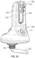
- FIG. 1illustrates a front perspective view of an exemplary attachment mount
- FIG. 2illustrates a rear perspective view of the attachment mount of FIG. 1 ;
- FIG. 3illustrates a cross-sectional view of the front perspective view of FIG. 1 ;
- FIG. 4illustrates a top view of a standard shingle roof
- FIG. 5illustrates an exploded view of the attachment mount secured to the roof of FIG. 4 ;
- FIG. 6illustrates a perspective view of a standard sealant gun applying sealant into a port hole on the attachment mount
- FIG. 7illustrates a perspective view of an alternate embodiment of the attachment mount of FIG. 1 in the form of a standoff-type attachment
- FIG. 8illustrates an exploded perspective view of the standoff-type attachment mount being secured to the roof of FIG. 4 ;
- FIG. 9illustrates a cross-sectional perspective view of the standoff-type attachment mount
- FIG. 10illustrates a perspective view of the sealant gun applying sealant to a port hole in the standoff-type attachment mount
- FIG. 11illustrates an exploded view of a mount with the standoff-type attachment mount
- FIG. 12illustrates a front perspective view of an exemplary tile-hook attachment mount
- FIG. 13illustrates a cross-sectional view of the rear of the tile-hook attachment mount
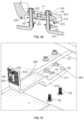
- FIG. 14illustrates a front perspective view of an exemplary flush mount attachment
- FIG. 15illustrates an exploded front perspective view of the flush mount attachment
- FIG. 16illustrates a cross-sectional view of the flush mount attachment
- FIG. 17illustrates an exploded perspective view of the flush mount attachment being secured to the roof of FIG. 4 ;
- FIG. 18illustrates a perspective view of the sealant gun applying sealant into a port hole on the flush mount attachment
- FIG. 19illustrates a front perspective view of an exemplary universal base mount
- FIG. 20illustrates a perspective cross-sectional view of the universal base mount
- FIG. 21illustrates an exploded perspective view of the universal base mount being secured to the roof of FIG. 4 ;
- FIG. 22illustrates a perspective view of the sealant gun applying sealant into a port hole on the universal base mount
- FIG. 23illustrates a front perspective view of an exemplary conduit mount
- FIG. 24illustrates an exploded perspective view of the conduit mount
- FIG. 25illustrates a cross-sectional view of the conduit mount
- FIG. 26illustrates a front perspective exploded view of the conduit mount being secured to the roof of FIG. 4 ;
- FIG. 27illustrates a perspective view of the sealant gun applying sealant into a port hole of the conduit mount
- FIG. 28illustrates a perspective view of the conduit mount with a conduit being assembled to the roof of FIG. 4 ;
- FIG. 29illustrates a front perspective view of an exemplary conduit riser
- FIG. 30illustrates a front perspective view of the conduit riser with the conduit
- FIG. 31illustrates a front perspective cross-sectional view of the conduit riser with the conduit
- FIG. 32illustrates a top view of the roof of FIG. 4 with an opening for the conduit
- FIG. 33illustrates a front perspective exploded view of the conduit riser secured to the roof of FIG. 32 ;
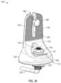
- FIG. 34illustrates a front perspective view of an alternate embodiment of the mount shown in FIGS. 1 - 6 that utilizes an anchor bolt for securing the mount to a roof;
- FIG. 35illustrates a rear perspective view of the embodiment in FIG. 34 ;
- FIG. 36illustrates a side cross-sectional view of the embodiment in FIG. 35 ;
- FIG. 37illustrates a rear cross-sectional view of the embodiment in FIG. 35 ;
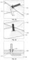
- FIG. 38illustrates a front perspective view of the anchor bolt used to secure the embodiment in FIG. 34 prior to insertion into a pilot hole of a roof;
- FIG. 39illustrates a front perspective view of the anchor bolt used to secure the embodiment in FIG. 34 after being installed into a pilot hole of the roof;
- FIG. 40illustrates a side cross-sectional view of the installed anchor bolt in FIG. 39 ;
- FIG. 41illustrates an exploded view of an installed version of the embodiment in FIG. 34 ;
- FIG. 42illustrates a side cross-sectional view of an installed version of the embodiment in FIG. 34 ;
- FIG. 43illustrates a front perspective view of an alternate embodiment of the mount shown in FIG. 34 that utilizes multiple angled screws to secure the mount to a roof;
- FIG. 44illustrates a rear perspective view of the embodiment shown in FIG. 43 ;
- FIG. 45illustrates a cross-sectional perspective view of the embodiment shown in FIG. 43 ;
- FIG. 46illustrates a perspective view of a low-slope universal attachment mount
- FIG. 47illustrates a cross-sectional perspective view of the embodiment shown in FIG. 46 ;
- FIG. 48illustrates an exploded view of the embodiment shown in FIG. 46 ;
- FIG. 49illustrates a front perspective view of an alternate embodiment of the mount shown in FIGS. 12 and 13 that utilizes anchor bolts to secure the mount to a roof;
- FIG. 50illustrates a cross-sectional perspective view of the embodiment shown in FIG. 49 ;
- FIG. 51illustrates an exploded perspective view of the embodiment shown in FIG. 49 ;
- FIG. 52illustrates a perspective view of the sealant gun applying sealant into a port hole of the embodiment shown in FIG. 49 ;
- FIG. 53illustrates a perspective view of an alternate embodiment of a solar panel rail guide
- FIG. 54illustrates a cross-sectional perspective view of the solar panel rail guide of FIG. 53 .
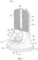
- FIG. 1illustrates the front side of the flush-type mount 100 includes a lower portion 120 that includes a base 110 that is typically mounted and conforms to a top surface of a structure such as a roof 200 shown in FIG. 4 .
- the term “roof”can also mean “structure.”
- the base 110is rounded in this embodiment, but as with other alternate exemplary embodiments shown below, the shape of the base 110 can be any suitable form.
- the front side of the lower portion 120tapers upward and forms a generally first concave section 132 and as shown in FIG.
- the rear sidetapers upward and forms a generally second concave section 136 .
- Each of these concave sections 132 and 136define the bottom of an upper portion of the mount 100 , and are contiguous with a generally convex section 133 .
- These concave and convex sectionsenable the apparatus to dispel water away from the base and create a volume to form the internal cavity.
- the first concave section 132also forms an external cavity 134 , which includes a base or seat 137 and an opening 125 through the seat 137 for receiving a bolt 130 .
- the bolt 130typically comprises a nut or head 131 for tightening the bolt 130 to secure the flush-type mount 100 to the roof 200 by penetrating a shaft 135 into an opening or pilot hole 210 on the roof 200 so that the head of the bolt resides on the seat 137 .
- a generally U-shaped guide 140which includes a pair of vertical members 141 and 142 that are contiguous with the internal cavity, extends upward contiguously from the concave sections 132 and 136 and the convex section 133 of the lower portion 120 .
- the lower portion 120tapers upward and forms this U-shaped guide 140 , and the vertical members 141 and 142 form an aperture 160 .
- Each of the members 141 and 142 on the guide 140also includes a ridged surface 150 .
- the aperture 160is configured to receive a bolt that in turn is used to secure a mounting rail (not shown) to the ridged surface 150 , which provides friction to assist the connection.
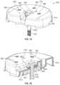
- FIG. 2illustrates the rear side of the flush-type mount 100 .
- the lower portion 120includes a port 170 and a vent 180 . It is understood that the port 170 and the vent 180 can be located anywhere on the lower portion 120 .
- FIG. 3which illustrates a cross-sectional view of the flush mount 100 , shows that the port hole 170 and the vent 180 provide access to a cavity 127 .
- the cavity 127provides a reservoir for sealant 175 that is injected into the port 170 by way, for example, of a sealant gun 300 as shown in FIG. 6 .
- An optional seal 115is provided along the perimeter of the base 110 , and the bottom of the cavity 127 typically should cover the entire surface area within the base 110 and the optional seal 115 .
- the vent 180enables excess air inside the cavity 127 to be released as sealant 175 is injected into the cavity 127 so that the sealant 175 can cover the full surface area along the base 110 and seal the flush-type mount 100 to the surface of the roof 200 to prevent any liquid from leaking into the roof 200 where the flush-type mount 100 is secured.
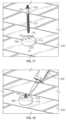
- FIGS. 4 - 6illustrate the steps of installing the flush-type mount 100 to the roof 200 .
- FIG. 4shows a top view of the roof 200 .
- the first step in installing the systemis to bore a pilot hole 210 , typically with a drill, into a roof shingle on the roof 200 and fill it with sealant 175 .
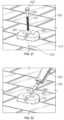
- FIG. 5shows an exploded view of the flush-type mount 100 being installed.
- the next stepis to place the mount 100 over the pilot hole 210 and secure the mount 100 by inserting the bolt 130 into the opening 125 and tightening it by rotating the nut 131 until the shaft 135 is fully inserted into the pilot hole 210 . Once secured, as shown in FIG.
- the sealant gun 300is used to inject sealant 175 into the port hole 170 .
- the cavity 127is filled with sealant 175 until the sealant 175 begins to escape out of the vent 180 on the mount 100 .
- the sealant 175begins to escape, it provides visual notice that the cavity 127 has been filled with sealant 175 , thereby sealing the mount 100 to the roof 200 .
- the standoff-type 400includes a base 410 and a pair of openings 425 (shown in FIG. 8 ) on opposite sides of the base 410 for bolts 430 to secure the standoff-type mount 400 to the roof 200 .
- Each bolt 430also has a shaft 435 extending downward and a threaded portion 437 on the shaft 435 .
- the standoff-type mount 400includes a support 440 with a port hole 470 and outer threads 442 that are used to receive an attachment 500 as shown in FIG. 11 .
- the support 440 and base 410form a hollow cavity 427 that is accessible by the port hole 470 .
- An optional thread patch 450is also included that assists in restricting the movement of the attachment 500 when it is rotated onto the support 440 .
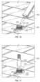
- FIGS. 8 - 11illustrate the steps of installing the standoff-type mount 400 to the roof 200 .
- the first step in installing the systemis to bore pilot holes 210 , typically with a drill, into a roof shingle on the roof 200 and fill it with sealant 175 .
- FIG. 8shows an exploded view of the standoff-type mount 400 being installed.
- the next stepis to place the mount 400 over the pilot holes 210 and secure the mount 400 by inserting the bolts 430 into the openings 425 and tightening each bolt 430 by rotating the nut 431 until the shaft 435 is fully inserted into the pilot hole 210 .
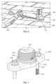
- FIG. 9illustrates further details of the standoff-type mount 400 .
- An optional sealing lip 455that surrounds the inner surface of the cavity 427 is shown.
- the sealant gun 300is used to inject sealant 175 into the port hole 470 .
- the port hole 470can act both as a port hole 470 and a vent.
- the cavity 427is filled with sealant 175 until the sealant 175 begins to escape out of the port hole 470 on the mount 400 .
- the sealant 175begins to escape, it provides visual notice that the cavity 427 has been filled with sealant 175 , thereby sealing the mount 400 to the roof 200 .
- the attachment 500can be coupled to the support 440 , typically by rotating it along the threaded portion 437 until it is fully tightened.
- FIGS. 12 and 13Another exemplary embodiment is a tile-hook attachment/mount 600 as shown in FIGS. 12 and 13 .
- the tile-hook mount 600includes a base 610 and a pair of openings 625 (shown in FIG. 13 ) on opposite sides of the base 610 for bolts 630 to secure the tile-hook mount 600 to the roof 200 .
- Each bolt 630also has a shaft 635 extending downward and a threaded portion 637 on the shaft 635 .
- the tile-hook mount 600includes an attachment mount 620 with a lower portion that extends from the base 610 in a general L-shape.
- the upper portion of the attachment mount 620forms an apparatus similar to that shown in the flush-type mount 100 with a generally U-shaped guide 640 that comprises a pair of members 641 and 642 extending from opposing sides of the upper portion of the attachment mount 620 , which in turn forms an aperture 660 .
- Each of the members 641 and 642 on the guide 640also include a ridged surface 650 .
- the aperture 660is configured to receive a bolt that in turn is used to secure a mounting rail (not shown) to the ridged surface 650 , which provides friction to assist the connection.
- the base 610also includes a port hole 670 . As shown in FIG. 13 , the base 610 comprises a hollow cavity 627 that is accessible by the port hole 670 . Once secured, as shown in FIG. 13 , the steps of use are similar to the previously discussed mounts. Pilot holes 210 are bored, typically with a drill, into the roof 200 and the holes 210 are filled with sealant 175 . The sealant gun 300 is used to inject sealant 175 into the port hole 670 . In this embodiment, the port hole 670 can act both as a porthole 670 and a vent. The cavity 627 is filled with sealant 175 until the sealant 175 begins to escape out of the port hole 670 from the base 610 on the mount 600 . When the sealant 175 begins to escape, it provides visual notice that the cavity 627 has been filled with sealant 175 , thereby sealing the mount 600 to the roof 200 .
- the universal flush mount 700includes a base 710 and an opening 725 (shown in FIG. 16 ) in the middle of the mount 700 for a hanger bolt 730 that is used to secure the universal flush mount 700 to the roof 200 .
- the hanger bolt 730also has a shaft 735 extending downward and a threaded portion 737 on the shaft 735 .
- the universal flush mount 700includes an optional seal 715 that extends around the perimeter of the base 710 .
- a washer 760may be coupled between the top end of the hanger bolt 730 and the top surface of the base 710 to provide a tighter seal.
- the base 710also includes a port hole 770 on its top surface. As shown in FIG. 16 , the base 710 comprises a hollow cavity 727 that is accessible by the port hole 770 and a vent 780 that are both typically on the top surface of the base 710 .
- the port hole 770is typically larger than the vent 780 , although the port hole 770 —like the other port holes as discussed herein, should be capable of fitting a sealant injection device like the sealant gun 300 as shown herein.
- a pilot hole 210is drilled into the roof 200 and the hole 210 is filled with sealant 175 .
- the hanger bolt 730is then inserted through the opening 725 and is tightened until the mount 700 is secured to the roof 200 .
- the steps of useare similar to the previously discussed mounts.
- the sealant gun 300is used to inject sealant 175 into the port hole 770 .
- the cavity 727is then filled with sealant 175 until the sealant 175 begins to escape through the port hole 780 from the base 710 .
- the sealant 175begins to escape, it provides visual notice that the cavity 727 has been filled with sealant 175 , thereby sealing the mount 700 to the roof 200 .
- the universal base mount 800includes a base 810 and an opening 825 (shown in FIG. 20 ) in the middle of the mount 800 for a bolt 830 that is used to secure the universal base mount 800 to the roof 200 .
- the bolt 830also has a shaft 835 extending downward and a threaded portion 837 on the shaft 835 .
- the universal base mount 800also includes a plurality of internally threaded apertures 890 that are used to secure a mount (not shown) to the universal base mount 800 .
- the mount 800also includes an optional seal 815 that extends around the perimeter of a cavity 827 within the base 810 .
- a washer 860may be coupled between the top end of the bolt 830 and the top surface of the base 810 to provide a tighter seal.
- the base 810also includes a port hole 870 on its top surface. As shown in FIG. 20 , the base 810 comprises the hollow cavity 827 that is accessible by the port hole 870 and a vent 880 that are both typically on the top surface of the base 810 .
- the port hole 870is typically larger than the vent 880 , although the port hole 870 —like the other port holes as discussed herein, should be capable of fitting a sealant injection device like the sealant gun 300 as shown herein and are typically positioned on opposite sides of the base 810 . As shown in FIG. 21 , a pilot hole 210 is bored, typically with a drill, into the roof 200 and the hole 210 is filled with sealant 175 .
- the bolt 830is then inserted through the opening 825 and is tightened until the mount 800 is secured to the roof 200 .
- the steps of useare similar to the previously discussed mounts.
- the sealant gun 300is used to inject sealant 175 into the port hole 870 .
- the cavity 827is then filled with sealant 175 until the sealant 175 begins to escape through the port hole 880 from the base 810 .
- the sealant 175begins to escape, it provides visual notice that the cavity 827 has been filled with sealant 175 , thereby sealing the mount 800 to the roof 200 .
- FIGS. 23 - 25Another exemplary embodiment is a conduit mount 900 as shown in FIGS. 23 - 25 .
- the conduit mount 900typically supports a conduit 1000 , which can be of any suitable shape such as a cylindrical pipe as shown in FIG. 28 .
- the conduit mount 900includes a base 910 and an opening 925 (shown in FIG. 24 ) in the middle of the mount 900 for receiving a bolt 930 that is used to secure the conduit mount 900 to the roof 200 .
- the bolt 930also has a shaft 935 extending downward and a threaded portion 937 on the shaft 935 .
- the base 910typically tapers upward and forms a generally U-shaped guide that comprises a pair of members 945 and 946 extending from opposing sides of the base 910 , which in turn forms an opening 920 configured to receive the conduit 1000 .
- Each of the members 945 and 946also includes a threaded aperture 940 and 941 respectively.
- the apertures 945 and 946are configured to receive a securing bolt 950 that is threaded 955 .
- the base 910also includes a port hole 970 on its outer surface. As shown in FIG. 25 , the base 910 comprises the hollow cavity 927 that is accessible by the port hole 970 and a vent 980 that are both typically on the outer surface of the base 910 .
- the port hole 970is typically larger than the vent 980 , although the port hole 970 —like the other port holes as discussed herein, should be capable of fitting a sealant injection device like the sealant gun 300 as shown herein and are typically positioned on opposite sides of the base 910 .
- the bolt 930is inserted through the opening 925 and is tightened until the mount 900 is secured to the roof 200 . Once secured, as shown in FIGS.
- the sealant gun 300is used to inject sealant 175 into the port hole 970 .
- the cavity 927is then filled with sealant 175 until the sealant 175 begins to escape through the port hole 980 from the base 910 .
- the sealant 175begins to escape, it provides visual notice that the cavity 927 has been filled with sealant 175 , thereby sealing the mount 900 to the roof 200 .
- the conduit 1000can be inserted through the opening 920 and secured to the mount 900 by using the second bolt 950 and tightening it through the apertures 940 and 941 using the threaded portion 955 of the second bolt 950 .
- FIGS. 29 - 31Another exemplary embodiment is a conduit riser attachment 1100 as shown in FIGS. 29 - 31 .
- the conduit riser 1100typically fits over a conduit that rises through the roof 200 through a conduit hole 240 as shown in FIG. 33 .
- the conduit riser 1100includes a base 1110 , that extends upward to a top end with a conduit gasket 1120 on the top end that surrounds an opening 1115 that is configured to receive a conduit 1200 as shown in FIG. 30 .
- the base 1110also includes a port hole 1170 on its outer surface. As shown in FIGS. 29 - 31 , the base 1110 comprises the hollow cavity 1125 for holding sealant 175 and is accessible by the port hole 1170 and a vent 1180 that are both typically on the outer surface of the base 1110 .
- the port hole 1170is typically larger than the vent 1180 , although the port hole 1170 —like the other port holes as discussed herein, should be capable of fitting a sealant injection device like the sealant gun 300 as shown herein and are typically positioned on opposite sides of the base 1110 .
- the conduit hole 240is bored into the roof 200 .
- the conduit 1200is then attached to a rafter in an attic (not shown) below the roof 200 .
- the conduit riser 1100is then placed over the conduit 1200 as shown in FIG. 33 until fully seated on the roof 200 .
- the sealant gun 300is used to inject sealant 175 into the port hole 1170 .
- the cavity 1127is then filled with sealant 175 until the sealant 175 begins to escape through the port hole 1180 from the base 1110 .
- the sealant 175begins to escape, it provides visual notice that the cavity 1127 has been filled with sealant 175 , thereby sealing the conduit riser 1100 to the roof 200 .
- FIGS. 34 - 42Another exemplary embodiment is shown in FIGS. 34 - 42 and is a variation of the flush-type mount 100 shown in FIGS. 1 - 6 .
- This embodimentprovides two different features.
- the mountinstead of securing the mount 100 to roof 200 by using bolt 130 , the mount is secured by utilizing an anchor bolt 162 in combination with a grommet 163 .
- the anchor bolt 162includes two legs that are bent so that they are generally at a right angle to each other. At least one of the legs includes external threads 166 that are configured to receive a threaded bolt 164 .
- the grommet 163is inserted into the pilot hole 210 so that the external threads on the grommet 163 fit snuggly into the pilot hole 210 and the grommet 163 is near the bend in the anchor bolt 162 as shown in FIG. 38 . It is understood that the grommet 163 can include internal threads that allow it to be rotated along the threaded portion 166 of one of the legs of the anchor bolt 162 until the grommet 163 resides near the bend of the anchor bolt 162 as well.
- the anchor bolt 162is installed by inserting the second leg of the anchor bolt 162 into the pilot hole 210 so that the inserted leg is positioned generally parallel to, and beneath the roof 200 with the grommet 163 being firmly secured within the pilot hole 210 as shown in FIGS.
- the threaded leg of the anchor bolt 162is exposed and firmly positioned to receive the mount 100 through opening 125 .
- the mount 100is secured by affixing a nut 164 on the threaded leg of the anchor bolt 162 over an optional washer 165 .
- a standard bolt 166is typically inserted into the aperture 160 and can secure other objects to the rear side of the mount 100 with a standard nut 167 and washer 168 combination.
- the cross-sectional views in FIGS. 36 and 42illustrate the final installation in more detail.
- the mount 100includes a modified sealant port hole 171 that typically is comprised of a flexible material such as rubber and provides for easy insertion of the sealant gun 300 and provides for improved delivery of sealant into the cavity 127 .
- An additional vent 180 that is coupled to the cavity 127is also included.
- the cavity 127further comprises a pair of sealant guides 128 .
- Each sealant guide 128is a vertical barrier that extends downward from the upper wall of the cavity 127 and ends slightly above the bottom of the mount 100 .
- Each of the guides 128form a channel 132 and two outer chambers 133 that are interconnected with each other within the cavity 127 .
- the outer chambers 133are coupled to each of the vent holes 180 respectively and are designed to provide amore uniform distribution of sealant as it is inserted from the sealant gun 300 into the port hole 171 .
- the channel 132is coupled to the sealant port hole 171 and is configured to directly receive sealant from the sealant gun 300 .
- the guides 128serve to uniformly direct the sealant into each of the outer chambers 133 .
- the sealantwill begin to evacuate from the vent holes 180 and give visual notice that the entire cavity 127 is filled.
- An optional seal 129is also included.
- the seal 129includes a plurality of ribs 129 A that provide added sealing capability to prevent sealant leaks under pressure.
- the ribs 129 Acan be solid or flexible depending on the needs of the installer.
- FIGS. 43 - 45Another exemplary embodiment is shown in FIGS. 43 - 45 and is a variation of the flush-type mount 100 shown in FIGS. 34 - 42 .
- the mount 100is secured by utilizing four screws 1385 as shown.
- Each of the screws 1385is threaded and inserted through corresponding apertures 1360 that are positioned on the opposite ends of the front and rear sides of the mount 100 and are slightly angled inward toward the center of the mount 100 .
- the mountis installed by placing the mount 100 at the desired location on the roof 200 and inserting each of the screws 1385 into the apertures 1360 and drilling them into the roof 200 . It is understood by one of ordinary skill in the art that although the angles of the apertures 1360 are directed inward, the particular angles are not determinative in securing the mount 100 to the roof 200 . It is also understood that although four screws 1385 are preferred, the number of screws and apertures 1385 used can vary as long as they secure and seal the mount 100 to thereof 200 .
- FIGS. 46 - 48Another exemplary embodiment of a mount with similar features as the prior mounts is shown in FIGS. 46 - 48 .
- a low-slope universal attachment mount 1400is shown.
- the mount 1400comprises a base 1493 that includes an outer shell 1492 with a flanged sealing lip 1429 comprising a plurality of ribs 1429 A extending from the sealing lip's 1429 lower surface. It is understood that the ribs 1429 A can be flexible or rigid.
- the base 1493has a top support surface 1497 that is generally round and tapers downward toward the outer shell 1492 that forms a cavity 1427 .
- the top support surface 1497further comprises a port hole 1471 and vent hole 1480 .
- the port hole 1471 and vent hole 1480operate in the same fashion as port holes and vent holes in earlier-described embodiments wherein sealant from the sealant gun 300 is inserted into the cavity 1427 through the port hole 1471 until it begins to evacuate from the vent hole 1480 . Even though it is desired to locate the port hole 1471 and vent hole 1480 on opposite sides of the top support surface 1497 to maximize the amount of sealant that is inserted into the port hole 1471 before it begins to evacuate from the vent hole 1480 , the specific location of these holes can be indifferent locations on the top support surface 1497 .
- the base 1493is secured to the roof 200 by inserting a plurality of threaded screws 1485 into corresponding apertures 1460 that are positioned at different locations around the perimeter of the top support surface 1497 as shown in FIG. 48 .
- Each screw 1485is drilled into the roof 200 .
- a pilot hole corresponding to each screw 1485can be created and filled with sealant prior to installation to provide further protection against leaks.
- At the center of the top support surface 1497is an opening 1425 .
- the opening 1425is configured to receive attachment bolt 1495 from beneath the top support surface 1497 .
- the attachment bolt 1495includes outer threads and a head that rests within seat 1498 .
- An attachment nut 1496is typically used to tighten the attachment bolt 1497 into the seat 1498 so that the threaded portion of the attachment bolt 1495 is exposed above the top support surface 1497 and can then be used to secure a bracket (not shown) onto the top support surface 1497 .
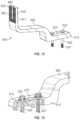
- FIGS. 49 - 52Another exemplary embodiment is shown in FIGS. 49 - 52 and is a variation on the tile hook attachment mount embodiment shown in FIGS. 12 and 13 and utilizes the same securing structure as the mount described in FIGS. 34 - 42 .
- the embodimentemploys a pair of anchor bolts 162 with grommets 163 .
- the anchor bolt 162is installed by inserting the second leg of the anchor bolts 162 into a pair of pilot holes 210 on the roof 200 so that the inserted legs are positioned generally parallel to, and beneath the roof 200 with the grommets 163 being firmly secured within the pilot holes 210 as shown in FIGS. 50 and 51 .
- the threaded legs of the anchor bolts 162are exposed and firmly positioned to receive base 610 of the mount 600 through openings 666 .
- the mount 600is secured by affixing nuts 164 on the threaded legs of the anchor bolts 162 over optional washers 165 .
- the base 610also includes the modified port hole 171 and vent hole 680 that are both coupled to cavity 627 .
- the cavity 627also includes further comprises a pair of sealant guides 628 .
- Each sealant guide 628is a vertical barrier that extends downward from the upper wall of the cavity 627 and ends slightly above the bottom of the mount 600 .
- Each of the guides 628form a channel 632 and two outer chambers 633 that are interconnected with each other within the cavity 627 .
- the outer chambers 633are coupled to the vent hole 680 respectively and are designed to provide a more uniform distribution of sealant as it is inserted from the sealant gun 300 into the port hole 171 .
- the channel 632is coupled to the sealant port hole 171 and is configured to directly receive sealant from the sealant gun 300 .
- the guides 628serve to uniformly direct the sealant into each of the outer chambers 633 .
- the sealantwill begin to evacuate from the vent hole 180 and give visual notice that the entire cavity 627 is filled.
- An optional seal 627is also included.
- the seal 629includes a plurality of ribs 629 A that provide added sealing capability to prevent sealant leaks under pressure.
- the ribs 629 Acan be solid or flexible depending on the needs of the installer.
- a standard bolt 661is typically inserted into the aperture 660 and can secure other objects to the of the U-shaped guide 640 with a standard nut 167 and washer 168 combination.
- the cross-sectional view in FIG. 50illustrates the final installation in more detail.
- the rail guide mount 1500includes a base 1510 that conforms to the shape of the roof 200 , is rectangularly shaped, and includes a pair of guides 1512 on opposing sides of the length of the base 1510 .
- These guides 1512include grooves 1513 that conform to the shape of an end of a bracket (not shown) that can be coupled with the grooves 1513 and support a solar panel bracket (also not shown).
- the base 1510also comprises an opening 1525 for receiving a bolt 1513 .
- the bolt 1531includes a shaft 1532 and a shaft 1532 has a threaded portion 1537 that secures the mount 1500 to a roof 200 .
- the bolt 1531also includes a washer 1530 to provide a sealing mechanism over the opening 1525 .
- the bolt 1531passes through cavity 1527 , which encompasses the inner volume of the base 1510 .
- a port hole 1571 and a vent hole 1580are located on the top side of the base 1510 and are coupled to the cavity 1527 .
- the port hole 1571 and vent 1580are generally located on opposite sides of the base 1510 .
- the portions of the cavity 1571 that are coupled to the port hole 1571 and vent 1580are separated by a pair of sealant guides 1528 .
- the sealant guidesenable sealant to enter the port hole 1571 when inserted with the sealant gun 300 and distribute the sealant in a more evenly fashion by filling the chamber of the cavity 1527 nearer to the port hole 1571 first, and then progressively filling the chamber beneath and within the portion 1528 A of the cavity 1527 beneath the sealant guides 1528 , and then moving toward the chamber near the vent 1580 before it begins to escape through the vent 1580 .
- the perimeter of the base 1510includes an optional seal 1529 .
- the sealincludes a plurality of ribs 1529 A that provide added sealing capability to prevent sealant leaks under pressure.
- the ribs 1529 Acan be solid or flexible depending on the needs of the installer.
Landscapes
- Engineering & Computer Science (AREA)
- General Engineering & Computer Science (AREA)
- Architecture (AREA)
- Mechanical Engineering (AREA)
- Structural Engineering (AREA)
- Civil Engineering (AREA)
- Physics & Mathematics (AREA)
- Thermal Sciences (AREA)
- Chemical & Material Sciences (AREA)
- Combustion & Propulsion (AREA)
- Sustainable Energy (AREA)
- Sustainable Development (AREA)
- Life Sciences & Earth Sciences (AREA)
- Electromagnetism (AREA)
- Roof Covering Using Slabs Or Stiff Sheets (AREA)
- Insertion Pins And Rivets (AREA)
- Fittings On The Vehicle Exterior For Carrying Loads, And Devices For Holding Or Mounting Articles (AREA)
Abstract
Description
Claims (18)
Priority Applications (4)
| Application Number | Priority Date | Filing Date | Title |
|---|---|---|---|
| US17/977,943US12000137B2 (en) | 2016-12-14 | 2022-10-31 | Structural attachment sealing system |
| US18/134,962US12018476B2 (en) | 2016-12-14 | 2023-04-14 | Structural attachment sealing system |
| US18/441,928US20240254756A1 (en) | 2016-12-14 | 2024-02-14 | Structural Attachment Sealing System |
| US18/962,774US20250122719A1 (en) | 2016-12-14 | 2024-11-27 | Structural attachment sealing system |
Applications Claiming Priority (6)
| Application Number | Priority Date | Filing Date | Title |
|---|---|---|---|
| US201662433953P | 2016-12-14 | 2016-12-14 | |
| US15/840,430US10171026B2 (en) | 2016-12-14 | 2017-12-13 | Structural attachment sealing system |
| US16/204,334US10781587B2 (en) | 2016-12-14 | 2018-11-29 | Structural attachment sealing system |
| US16/994,582US10982430B2 (en) | 2016-12-14 | 2020-08-15 | Structural attachment sealing system |
| US17/220,730US11486134B2 (en) | 2016-12-14 | 2021-04-01 | Structural attachment sealing system |
| US17/977,943US12000137B2 (en) | 2016-12-14 | 2022-10-31 | Structural attachment sealing system |
Related Parent Applications (1)
| Application Number | Title | Priority Date | Filing Date |
|---|---|---|---|
| US17/220,730ContinuationUS11486134B2 (en) | 2016-12-14 | 2021-04-01 | Structural attachment sealing system |
Related Child Applications (1)
| Application Number | Title | Priority Date | Filing Date |
|---|---|---|---|
| US18/134,962ContinuationUS12018476B2 (en) | 2016-12-14 | 2023-04-14 | Structural attachment sealing system |
Publications (2)
| Publication Number | Publication Date |
|---|---|
| US20230137985A1 US20230137985A1 (en) | 2023-05-04 |
| US12000137B2true US12000137B2 (en) | 2024-06-04 |
Family
ID=65808708
Family Applications (10)
| Application Number | Title | Priority Date | Filing Date |
|---|---|---|---|
| US16/204,334Active2037-12-14US10781587B2 (en) | 2016-12-14 | 2018-11-29 | Structural attachment sealing system |
| US16/994,582ActiveUS10982430B2 (en) | 2016-12-14 | 2020-08-15 | Structural attachment sealing system |
| US17/203,662ActiveUS11486133B2 (en) | 2016-12-14 | 2021-03-16 | Structural attachment sealing system |
| US17/220,730ActiveUS11486134B2 (en) | 2016-12-14 | 2021-04-01 | Structural attachment sealing system |
| US17/315,215ActiveUS11572690B2 (en) | 2016-12-14 | 2021-05-07 | Structural attachment sealing system |
| US17/977,865ActiveUS12024880B2 (en) | 2016-12-14 | 2022-10-31 | Structural attachment sealing system |
| US17/977,943ActiveUS12000137B2 (en) | 2016-12-14 | 2022-10-31 | Structural attachment sealing system |
| US18/134,962ActiveUS12018476B2 (en) | 2016-12-14 | 2023-04-14 | Structural attachment sealing system |
| US18/441,928AbandonedUS20240254756A1 (en) | 2016-12-14 | 2024-02-14 | Structural Attachment Sealing System |
| US18/962,774PendingUS20250122719A1 (en) | 2016-12-14 | 2024-11-27 | Structural attachment sealing system |
Family Applications Before (6)
| Application Number | Title | Priority Date | Filing Date |
|---|---|---|---|
| US16/204,334Active2037-12-14US10781587B2 (en) | 2016-12-14 | 2018-11-29 | Structural attachment sealing system |
| US16/994,582ActiveUS10982430B2 (en) | 2016-12-14 | 2020-08-15 | Structural attachment sealing system |
| US17/203,662ActiveUS11486133B2 (en) | 2016-12-14 | 2021-03-16 | Structural attachment sealing system |
| US17/220,730ActiveUS11486134B2 (en) | 2016-12-14 | 2021-04-01 | Structural attachment sealing system |
| US17/315,215ActiveUS11572690B2 (en) | 2016-12-14 | 2021-05-07 | Structural attachment sealing system |
| US17/977,865ActiveUS12024880B2 (en) | 2016-12-14 | 2022-10-31 | Structural attachment sealing system |
Family Applications After (3)
| Application Number | Title | Priority Date | Filing Date |
|---|---|---|---|
| US18/134,962ActiveUS12018476B2 (en) | 2016-12-14 | 2023-04-14 | Structural attachment sealing system |
| US18/441,928AbandonedUS20240254756A1 (en) | 2016-12-14 | 2024-02-14 | Structural Attachment Sealing System |
| US18/962,774PendingUS20250122719A1 (en) | 2016-12-14 | 2024-11-27 | Structural attachment sealing system |
Country Status (1)
| Country | Link |
|---|---|
| US (10) | US10781587B2 (en) |
Families Citing this family (34)
| Publication number | Priority date | Publication date | Assignee | Title |
|---|---|---|---|---|
| US10359069B2 (en) | 2015-07-29 | 2019-07-23 | Ironridge, Inc. | Bracket mount for securing solar panel rail guides on shingle roofs |
| US10781587B2 (en) | 2016-12-14 | 2020-09-22 | Solsera, Inc. | Structural attachment sealing system |
| US10767684B1 (en) | 2019-04-26 | 2020-09-08 | Solsera, Inc. | Flat roof mounting device |
| US11746821B2 (en) | 2019-04-26 | 2023-09-05 | Solsera, Inc. | Flat roof mounting device |
| AU2020387552B2 (en) | 2019-11-18 | 2025-04-03 | Ironridge, Inc. | Flashing and bracket mount assembly for securing solar panel rail guides on shingle roofs |
| US12292075B2 (en) | 2019-11-25 | 2025-05-06 | Pegasus Solar Inc | Twist-lock solar module clamp |
| US11377840B2 (en) | 2019-11-26 | 2022-07-05 | Pegasus Solar Inc. | One-piece bonding splice for rails |
| US11085190B1 (en)* | 2020-02-10 | 2021-08-10 | Jamahl Farrington | Roof pipe securing apparatus |
| US11152889B1 (en)* | 2020-03-12 | 2021-10-19 | Sunrun Inc. | Mount assemblies with chemical flashings |
| US11515831B2 (en)* | 2020-03-12 | 2022-11-29 | Sunrun Inc. | Mount assemblies with chemical flashings |
| US11962137B2 (en) | 2020-04-21 | 2024-04-16 | Unirac Inc. | Electric junction box mount apparatus |
| WO2022169989A1 (en)* | 2021-02-03 | 2022-08-11 | Unirac Inc. | Roof interface with sealant injection ports |
| US12163546B2 (en) | 2021-02-03 | 2024-12-10 | Unirac, Inc. | Sealing fasteners |
| US20240297609A1 (en)* | 2021-02-03 | 2024-09-05 | Unirac Inc. | Roof interface with sealant injection ports |
| US11990862B2 (en) | 2021-02-18 | 2024-05-21 | Pegasus Solar Inc. | Rail accessory mount |
| CA3210732A1 (en)* | 2021-03-17 | 2022-09-22 | Unirac Inc. | Mounting system for mounting solar panel modules |
| US12068715B2 (en) | 2021-04-28 | 2024-08-20 | Unirac Inc. | Sealable mounting system with a slidable component mount |
| USD987412S1 (en)* | 2021-04-28 | 2023-05-30 | Unirac Inc. | Panel mount assembly |
| US11808042B2 (en) | 2021-05-21 | 2023-11-07 | Unirac Inc. | Attachment bracket apparatus |
| USD988853S1 (en)* | 2021-05-21 | 2023-06-13 | Unirac Inc. | Bracket |
| US12281750B2 (en) | 2022-01-14 | 2025-04-22 | Pegasus Solar Inc | Grip rail clamp |
| US12140175B2 (en)* | 2022-01-27 | 2024-11-12 | Ford Global Technologies, Llc | Fastener with alignment bushing |
| US20240060598A1 (en)* | 2022-08-19 | 2024-02-22 | Pegasus Solar, Inc. | Roof attachment with integrated sealant |
| USD984872S1 (en) | 2022-12-30 | 2023-05-02 | Sunmodo Corporation | Roof mount bracket for mounting solar panels |
| USD983017S1 (en) | 2022-12-30 | 2023-04-11 | Sunmodo Corporation | Roof mount bracket for mounting solar panels |
| USD983015S1 (en) | 2022-12-30 | 2023-04-11 | Sunmodo Corporation | Roof mount bracket for mounting solar panels |
| USD983016S1 (en) | 2022-12-30 | 2023-04-11 | Sunmodo Corporation | Roof mount bracket for mounting solar panels |
| USD983019S1 (en) | 2022-12-30 | 2023-04-11 | Sunmodo Corporation | Roof mount bracket for mounting solar panels |
| USD983018S1 (en) | 2022-12-30 | 2023-04-11 | Sunmodo Corporation | Roof mount bracket for mounting solar panels |
| US11750143B1 (en) | 2023-01-24 | 2023-09-05 | Sunmodo Corporation | Bracket and devices for mounting solar panels to roofs |
| US12009774B1 (en)* | 2023-12-29 | 2024-06-11 | Sunmodo Corporation | L-foot adapter for rail-based solar panel racking systems |
| US12149200B1 (en) | 2024-07-03 | 2024-11-19 | Sunmodo Corporation | Railless mounting system and devices for attaching solar modules to roofs |
| US12231076B1 (en) | 2024-09-04 | 2025-02-18 | Sunmodo Corporation | Rail-less mounting system and devices for attaching solar modules to roofs |
| US12286994B1 (en) | 2024-09-09 | 2025-04-29 | Sunmodo Corporation | Railless mounting devices for securing solar modules to roofs |
Citations (144)
| Publication number | Priority date | Publication date | Assignee | Title |
|---|---|---|---|---|
| US4025183A (en) | 1974-03-15 | 1977-05-24 | Xerox Corporation | Camera/processor/projector and sub-systems |
| US4112693A (en) | 1976-09-30 | 1978-09-12 | Kaiser Steel Corporation | Mine roof support plate |
| USD263678S (en) | 1979-11-07 | 1982-04-06 | Illinois Tool Works Inc. | Roof insulation washer |
| USD263928S (en) | 1979-11-07 | 1982-04-20 | Illinois Tool Works Inc. | Roof insulation washer |
| USD263927S (en) | 1979-11-07 | 1982-04-20 | Illinois Tool Works Inc. | Roof insulation washer |
| US4351997A (en) | 1979-08-27 | 1982-09-28 | Societe d'Assistance Technique pour Porduits Nestle S.A. | Food package |
| US4371293A (en) | 1978-09-25 | 1983-02-01 | Wilcox Raymond J | Mine roof bearing plate |
| US4455804A (en) | 1982-02-19 | 1984-06-26 | Single-Ply Institute Of America, Inc. | Membrane anchor |
| US4476660A (en) | 1982-09-09 | 1984-10-16 | Francovitch Thomas F | Membrane anchor with flexure resisting regions |
| US4502256A (en) | 1981-01-23 | 1985-03-05 | Veith Pirelli, A.G. | Arrangement for securing a flexible web to a walling means |
| US4520606A (en) | 1983-01-27 | 1985-06-04 | Francovitch Thomas F | Roof membrane anchoring systems using dual anchor plates |
| US4574551A (en) | 1984-05-23 | 1986-03-11 | Giannuzzi Louis | Load-bearing plate |
| US4619094A (en) | 1985-12-11 | 1986-10-28 | The Firestone Tire & Rubber Company | Non-penetrating mechanical fastener for roofing membrane and method of applying same |
| US4620402A (en) | 1985-01-22 | 1986-11-04 | The Firestone Tire & Rubber Company | Penetrating roofing fastening and sealing system |
| US4624092A (en) | 1984-10-22 | 1986-11-25 | Illinois Tool Works Inc. | Roofing membrane fastener |
| US4630422A (en) | 1985-01-22 | 1986-12-23 | The Firestone Tire & Rubber Company | Penetrating roofing mechanical fastening sealing system and method |
| US4631433A (en) | 1985-05-06 | 1986-12-23 | General Electric Company | Plastic end shield with thermal barrier for dynamoelectric machines |
| US4631887A (en) | 1986-01-31 | 1986-12-30 | Francovitch Thomas F | Non-penetrating roof membrane anchoring system |
| US4658558A (en) | 1986-05-22 | 1987-04-21 | North American Roofing Company, Inc. | Apparatus for attaching roofing membrane to a structure |
| US4686808A (en) | 1983-03-14 | 1987-08-18 | John D. Gray | Roofing system, method and holddown apparatus |
| US4715756A (en) | 1984-07-30 | 1987-12-29 | Trw Inc. | Nut and washer assembly |
| US4726164A (en) | 1987-03-16 | 1988-02-23 | Elco Industries, Inc. | Fastener assembly for a roof membrane |
| US4727699A (en) | 1987-04-07 | 1988-03-01 | Sargent Richard G | Roofing membrane securement system |
| US4744187A (en) | 1987-01-27 | 1988-05-17 | The Firestone Tire & Rubber Company | Mechanical roof fastener |
| US4757662A (en) | 1987-02-09 | 1988-07-19 | G.B.R. Enterprises | Membrane roofing fastener |
| US4763456A (en) | 1987-08-03 | 1988-08-16 | Giannuzzi Louis | Roof anchor and stress plate assembly |
| US4787188A (en) | 1986-01-02 | 1988-11-29 | Engineered Construction Components | Stress plate and method of using same for securing a roof membrane to a roof deck |
| US4788807A (en) | 1986-05-01 | 1988-12-06 | Whitman Robert E | Fastening plate for facilitating installation of rubber roof covering |
| US4799845A (en) | 1986-05-16 | 1989-01-24 | Dunlop Construction Products Inc. | Means for attaching sheet material to a substrate |
| US4860513A (en) | 1988-01-25 | 1989-08-29 | Whitman Robert E | Roofing fastener |
| US4860514A (en) | 1986-10-22 | 1989-08-29 | Kelly Thomas L | Single ply roof membrane securing system and method of making and using same |
| US4890968A (en) | 1989-02-15 | 1990-01-02 | Illinois Tool Works Inc. | Stackable roofing washer |
| US4943100A (en) | 1988-01-14 | 1990-07-24 | Enpoco Limited | Drain suited for installation in wooden floors |
| US4945699A (en) | 1986-01-02 | 1990-08-07 | Engineered Construction Components (America) | Stress plate |
| US4959938A (en) | 1989-08-28 | 1990-10-02 | Caro Charles J De | Non-seating plate/fastener assembly |
| US4989911A (en) | 1989-08-16 | 1991-02-05 | Prince Corporation | Snap-in visor mount |
| US4999963A (en) | 1986-05-22 | 1991-03-19 | North American Roofing Company, Inc. | Apparatus for attaching roofing membrane to a structure |
| US5018748A (en) | 1988-05-27 | 1991-05-28 | Aquarius Rubber (Aust.) Pty. Ltd. | Seal device |
| US5018329A (en) | 1989-10-05 | 1991-05-28 | Illinois Tool Works Inc. | Attachment of roofing washer with heat-sealed screw-washer assemblage |
| US5056853A (en) | 1989-08-16 | 1991-10-15 | Prince Corporation | Snap-in visor mount |
| US5069589A (en) | 1988-08-25 | 1991-12-03 | Lemke Stuart H | Stress plate for roof membrane fastener assembly |
| US5094056A (en) | 1989-12-01 | 1992-03-10 | Peters William H | Roofing attachment plate |
| US5100274A (en) | 1990-10-29 | 1992-03-31 | Illinois Tool Works Inc. | Roofing fastener and improved screw therefor |
| US5139379A (en) | 1990-10-29 | 1992-08-18 | Illinois Tool Works Inc. | Roofing fastener, improved screw therefor, and improved washer therefor |
| US5217339A (en) | 1992-06-30 | 1993-06-08 | Performance Building Products, Inc. | Non-seating plate/fastener assembly |
| US5407313A (en) | 1991-07-29 | 1995-04-18 | National Nail Corp. | Roofing nail pressure plate |
| US5419666A (en) | 1993-09-27 | 1995-05-30 | Best; Don A. | Protective waterproof cover assembly for covering a fastener |
| DE4416884A1 (en) | 1994-05-13 | 1995-11-23 | Daimler Benz Aerospace Ag | Solar generator panel mechanical attachment appts. |
| US5557897A (en) | 1992-02-20 | 1996-09-24 | Braas Gmbh | Fastening device for a roof sealing strip or the like |
| US5562380A (en) | 1994-09-28 | 1996-10-08 | Illinois Tool Works Inc. | Protective seam plate |
| US5628587A (en) | 1994-08-02 | 1997-05-13 | Tru-Di Tool Manufacturing Co., Pty. Ltd. | Bearer plate |
| US5797232A (en) | 1996-08-15 | 1998-08-25 | Illinois Tool Works Inc. | Gripping plate for attaching roofing membrane |
| US5803693A (en) | 1997-04-17 | 1998-09-08 | Olympic Manufacturing Group, Inc. | Swiveling roofing washer |
| US5908278A (en) | 1997-08-07 | 1999-06-01 | Illinois Tool Works Inc. | Stress plate with depending sleeve |
| US5915903A (en) | 1993-12-10 | 1999-06-29 | Sfs Industrie Holding Ag | Large-area washer having friction increasing elements on the underside thereof |
| US5930969A (en) | 1996-08-27 | 1999-08-03 | Mayle; Robert L. | Roof membrane attachment system |
| US5934855A (en) | 1993-12-10 | 1999-08-10 | Sfs Industrie Holding Ag | Large-area washer |
| US6007353A (en) | 1998-04-22 | 1999-12-28 | Webster; Stephen L. | Electrical connector enclosure |
| US6035595A (en) | 1998-10-29 | 2000-03-14 | Anderson; Kirk D. | Self-sealing fastener |
| US6205730B1 (en) | 1999-01-13 | 2001-03-27 | Illinois Tool Works Inc | Roofing plate for securing roofing membrane |
| US6233889B1 (en) | 2000-04-14 | 2001-05-22 | Construction Fasteners, Inc. | Ventilated roof membrane plate and method of installing membrane roof utilizing same |
| US6250034B1 (en) | 1999-11-09 | 2001-06-26 | Construction Fasteners, Inc. | Membrane plate |
| USD446319S1 (en) | 2000-03-09 | 2001-08-07 | Sarnafil, Inc. | Roof membrane stress plate |
| US6282857B1 (en) | 2000-03-09 | 2001-09-04 | Sarnafil, Inc. | Articulating plate assembly for retaining sheets of roofing material on a roof surface |
| US20020066235A1 (en) | 2000-07-03 | 2002-06-06 | Stearns Brian C. | Roof mount |
| US20020108315A1 (en) | 2001-02-14 | 2002-08-15 | Bridgestone/Firestone, Inc | Vented roofing anchor plate |
| US20030033783A1 (en) | 2001-08-20 | 2003-02-20 | Kobetsky Robert G. | Seam plate for retaining roof decking membrane |
| US20030033780A1 (en) | 2001-08-20 | 2003-02-20 | Riaz Hasan | Seam plate for retaining roof decking membrane |
| US6536729B1 (en) | 1999-05-17 | 2003-03-25 | Robert M. M. Haddock | Bracket assembly including a reservoir |
| US20040040243A1 (en) | 2002-09-04 | 2004-03-04 | Pinconning Metals, Inc. | Attachment plate |
| US20040115010A1 (en) | 2000-09-01 | 2004-06-17 | Robertson Roy Lee | Apparatus for providing secondary mine roof support |
| US20040148888A1 (en) | 2003-02-03 | 2004-08-05 | Kuhn William P. | Double barbed plate with fastener |
| US20040170489A1 (en) | 2003-02-27 | 2004-09-02 | Building Materials Investment Corporation | Plastic/metal composite stress plate and method of using same for securing a thermoplastic roof membrane to a roof deck |
| US20050121902A1 (en) | 2003-12-05 | 2005-06-09 | Hull Eric G. | Fitting for ENT tubing |
| US20050166503A1 (en) | 2004-01-09 | 2005-08-04 | Illinois Tool Works Inc. | Insulation plate for retaining roof decking membranes and for removing the adhesive release film or release sheet |
| US20050183261A1 (en) | 2002-12-05 | 2005-08-25 | Building Materials Investment Corporation | Method of securing a membrane to a deck |
| US6938385B2 (en) | 2000-05-13 | 2005-09-06 | Fischerwerke Artur Fischer Gmbh & Co. Kg | Fixing element for laminated glass and an assembly comprising a fixing element that is anchored in a plate-type multi-layer body |
| US6979777B2 (en) | 2003-10-15 | 2005-12-27 | Cooper Wiring Devices, Inc. | Weatherproof electrical enclosure having an adjustable-position cover |
| US20060185289A1 (en) | 2005-02-23 | 2006-08-24 | Illinois Tool Works Inc. | Seam plate, for retaining roof decking membranes, having means for preventing interlocking of adjacent plates |
| US20070137126A1 (en) | 2005-12-21 | 2007-06-21 | Per Sommerhein | Multi-purpose roof outlet |
| US7265292B2 (en) | 2005-04-18 | 2007-09-04 | Peter Greenfield | Weatherproof while-in-use electrical receptacle cover assembly |
| US20080047730A1 (en) | 2006-08-24 | 2008-02-28 | Hubbell Incorporated | Weatherproof cover assembly |
| US20080178556A1 (en) | 2007-01-29 | 2008-07-31 | Dennis Meeks | Foundation anchor bolt positioning and restraining device |
| EP2006465A2 (en) | 2007-06-22 | 2008-12-24 | fischerwerke GmbH & Co. KG | Multi-layer body, fixing arrangement, procedure to manufacturer the fixing arrangement and fixing element |
| US20090173028A1 (en) | 2008-01-09 | 2009-07-09 | Talan Products, Inc. | Roofing Membrane Retainer |
| US7645937B2 (en) | 2007-12-04 | 2010-01-12 | Pass & Seymour, Inc. | Recessed while-in-use electrical box |
| US7709735B2 (en) | 2008-04-11 | 2010-05-04 | Hubbell Incorporated | Lift cover and gasket assembly |
| US20100132305A1 (en) | 2009-10-06 | 2010-06-03 | Steve Heckeroth | Method and system for providing and installing photovoltaic material |
| US20100326006A1 (en) | 2009-06-26 | 2010-12-30 | Richard Yaros | Attachment plate |
| US7866099B2 (en) | 2005-04-07 | 2011-01-11 | Sharp Kabushiki Kaisha | Mounting structure of solar cell module |
| US20110094652A1 (en) | 2008-05-19 | 2011-04-28 | Kedge Holding B.V. | Finish element, construction and method for a liquid-tight sealing of a surface |
| US7943850B2 (en) | 2008-09-30 | 2011-05-17 | Cooper Technologies Company | Environmentally sealed wiring device with removable weather-resistant cover |
| US8013245B2 (en) | 2008-10-31 | 2011-09-06 | Hubbell Incorporated | Weatherproof cover assembly for an electrical box having a water intrusion barrier |
| US20110227298A1 (en) | 2010-03-19 | 2011-09-22 | Teng Chung-Hsien | Water leakage-proof apparatus |
| US20110240088A1 (en) | 2010-03-31 | 2011-10-06 | Ats Automation Tooling Systems Inc. | One-piece junction box |
| US8136311B2 (en) | 2011-04-01 | 2012-03-20 | Jun Liu | Solar panel and equipment mounting apparatus for roofs |
| US20120073220A1 (en) | 2009-05-11 | 2012-03-29 | Yanegijutsukenkyujo Co., Ltd. | Securing configuration of solar cell module |
| US20120228863A1 (en) | 2011-03-11 | 2012-09-13 | Matthew Coleman | Roof Flashing with a Detachable Component |
| US20120233958A1 (en) | 2011-03-15 | 2012-09-20 | Brian Cecil Stearns | Roof mount assembly |
| US8302363B1 (en) | 2009-05-12 | 2012-11-06 | Ebert Composites Corporation | Composite interlocking structure |
| US8341895B2 (en) | 2008-08-13 | 2013-01-01 | Solon Se | Mounting device for solar modules having a large aspect ratio |
| US20130009025A1 (en) | 2011-07-08 | 2013-01-10 | Brian Cecil Stearns | Roof mount having built-in failure |
| US8389858B2 (en) | 2010-08-24 | 2013-03-05 | Thomas & Betts International, Inc. | While-in-use electrical box cover |
| US20130074441A1 (en) | 2011-09-23 | 2013-03-28 | Vermont Slate & Copper Services, Inc. | Roof mount assembly and method of mounting same |
| US8448407B1 (en) | 2011-03-30 | 2013-05-28 | Gregory M. Wiener | Roof mounting assembly |
| US8536453B2 (en) | 2011-04-14 | 2013-09-17 | Hong Fu Jin Precision Industry (Shenzhen) Co., Ltd. | Waterproof device |
| US20130298494A1 (en) | 2012-05-10 | 2013-11-14 | Peter A. CORSI | Non-invasive roof mounting adaptor and method for installing same |
| US8640400B2 (en) | 2003-02-26 | 2014-02-04 | Unirac, Inc. | Low profile mounting system |
| KR20140013849A (en) | 2012-07-27 | 2014-02-05 | 삼성전기주식회사 | Method for power management in beacon-enabled wireless network |
| US8796548B2 (en) | 2012-06-04 | 2014-08-05 | Seahorse Industries Ltd. | Underground utility box assembly |
| US8875455B1 (en) | 2014-05-28 | 2014-11-04 | Zep Solar, Llc | Ramp mounting system for a flat roof solar array |
| US20140331594A1 (en) | 2011-09-23 | 2014-11-13 | Vermont Slate & Copper Services, Inc. | Power grip button |
| US8938932B1 (en) | 2013-12-13 | 2015-01-27 | Quality Product Llc | Rail-less roof mounting system |
| US20150176434A1 (en) | 2013-12-18 | 2015-06-25 | Rolls-Royce Deutschland Ltd & Co Kg | Washer of a combustion chamber tile of a gas turbine |
| US9080792B2 (en) | 2013-07-31 | 2015-07-14 | Ironridge, Inc. | Method and apparatus for mounting solar panels |
| US9134044B2 (en) | 2010-01-25 | 2015-09-15 | Vermont Slate & Copper Services, Inc. | Roof mount assembly |
| US20160134230A1 (en) | 2014-11-06 | 2016-05-12 | Ironridge, Inc. | Roof Attachment Flashing Assembly |
| US20160248369A1 (en) | 2015-02-25 | 2016-08-25 | Solarcity Corporation | Photovoltaic mounting system with chemical flashing |
| US20160248367A1 (en) | 2015-02-25 | 2016-08-25 | Solarcity Corporation | Photovoltaic mounting system with chemical flashing |
| US20160268957A1 (en) | 2013-11-01 | 2016-09-15 | Omg, Inc. | Roof Attachment System |
| US9447988B2 (en) | 2010-01-25 | 2016-09-20 | Rillito Rive Solar, LLC | Roof mount assembly |
| US9496820B2 (en) | 2015-02-25 | 2016-11-15 | Solarcity Corporation | Photovoltaic mounting system and devices |
| WO2017019999A1 (en) | 2015-07-29 | 2017-02-02 | Ironridge, Inc. | Bracket mount for securing solar panel rail guides on a roof |
| US9577571B2 (en) | 2015-04-17 | 2017-02-21 | Moti Atia | Solar panel mounting apparatus with enhanced strength |
| US20170063300A1 (en) | 2015-08-31 | 2017-03-02 | Ironridge, Inc. | Apparatus for Securing a Solar Panel Rail Guide to a Support Bracket |
| US20170108165A1 (en) | 2015-10-14 | 2017-04-20 | Building Materials Investment Corporation | Self-Sealing Mounting Bracket for Roof Mounted Structures |
| US9680409B2 (en) | 2014-01-29 | 2017-06-13 | D Three Enterprises, Llc | Adjustable combined flashing and mounting apparatus and method of mounting to be used therewith |
| US20170279403A1 (en) | 2016-03-23 | 2017-09-28 | Solarcity Corporation | Photovoltaic mounting system with sealant injector inlet |
| US20170302222A1 (en) | 2016-04-14 | 2017-10-19 | Shahriar Shamloo Aliabadi | Racking system for installing solar panels |
| US9825581B2 (en) | 2013-11-14 | 2017-11-21 | Ecolibrium Solar, Inc. | Modular sloped roof solar mounting system |
| US9874021B2 (en) | 2015-08-28 | 2018-01-23 | Solarcity Corporation | Tile and slate roof flashing systems |
| US20180062571A1 (en) | 2015-08-31 | 2018-03-01 | Ironridge, Inc. | Apparatus for Securing a Solar Panel Rail Guide to a Support Bracket |
| US20180062560A1 (en) | 2016-08-23 | 2018-03-01 | Pegasus Solar Inc. | Solar mounting assemblies |
| US20180167022A1 (en) | 2016-12-14 | 2018-06-14 | Solsera, Inc. | Structural Attachment Sealing System |
| US10079481B2 (en) | 2015-08-13 | 2018-09-18 | Hubbell Incorporated | Weatherproof electrical box assembly |
| US20190093340A1 (en) | 2016-12-14 | 2019-03-28 | Solsera, Inc. | Structural Attachment Sealing System |
| US20190145453A1 (en) | 2016-01-04 | 2019-05-16 | Celcore Incorporated | Roof cover fastener |
| US10767684B1 (en) | 2019-04-26 | 2020-09-08 | Solsera, Inc. | Flat roof mounting device |
| US10777981B1 (en) | 2015-09-14 | 2020-09-15 | Jeffrey P. Baldwin | Configurable electrical outlet cover enclosure |
| US10916926B2 (en) | 2018-03-01 | 2021-02-09 | Warren W. Jones | Fireproof airtight electrical box |
| US11313591B1 (en) | 2017-09-11 | 2022-04-26 | Moti Atia | Universal clamp apparatus to accommodate solar panel frames with different thicknesses |
| US11424604B1 (en) | 2021-10-04 | 2022-08-23 | George Emmanuel Mon | Flush wallplate electrical box assembly |
| WO2022226160A1 (en) | 2020-04-21 | 2022-10-27 | Unirac Inc. | Electric junction box mount apparatus |
| USD987412S1 (en) | 2021-04-28 | 2023-05-30 | Unirac Inc. | Panel mount assembly |
Family Cites Families (4)
| Publication number | Priority date | Publication date | Assignee | Title |
|---|---|---|---|---|
| US4026183A (en) | 1976-05-17 | 1977-05-31 | Illinois Tool Works Inc. | Sealing washer |
| US4361997A (en) | 1980-02-25 | 1982-12-07 | Textron Inc. | Fastener plate and assembly |
| US8424821B2 (en)* | 2010-05-07 | 2013-04-23 | Sunmodo Corporation | Bracket assembly for mounting rooftop objects |
| US10601360B2 (en)* | 2017-09-08 | 2020-03-24 | Unirac Inc. | Replacement tile mount for mounting solar panels on tile roofs |
- 2018
- 2018-11-29USUS16/204,334patent/US10781587B2/enactiveActive
- 2020
- 2020-08-15USUS16/994,582patent/US10982430B2/enactiveActive
- 2021
- 2021-03-16USUS17/203,662patent/US11486133B2/enactiveActive
- 2021-04-01USUS17/220,730patent/US11486134B2/enactiveActive
- 2021-05-07USUS17/315,215patent/US11572690B2/enactiveActive
- 2022
- 2022-10-31USUS17/977,865patent/US12024880B2/enactiveActive
- 2022-10-31USUS17/977,943patent/US12000137B2/enactiveActive
- 2023
- 2023-04-14USUS18/134,962patent/US12018476B2/enactiveActive
- 2024
- 2024-02-14USUS18/441,928patent/US20240254756A1/ennot_activeAbandoned
- 2024-11-27USUS18/962,774patent/US20250122719A1/enactivePending
Patent Citations (171)
| Publication number | Priority date | Publication date | Assignee | Title |
|---|---|---|---|---|
| US4025183A (en) | 1974-03-15 | 1977-05-24 | Xerox Corporation | Camera/processor/projector and sub-systems |
| US4112693A (en) | 1976-09-30 | 1978-09-12 | Kaiser Steel Corporation | Mine roof support plate |
| US4371293A (en) | 1978-09-25 | 1983-02-01 | Wilcox Raymond J | Mine roof bearing plate |
| US4351997A (en) | 1979-08-27 | 1982-09-28 | Societe d'Assistance Technique pour Porduits Nestle S.A. | Food package |
| USD263928S (en) | 1979-11-07 | 1982-04-20 | Illinois Tool Works Inc. | Roof insulation washer |
| USD263927S (en) | 1979-11-07 | 1982-04-20 | Illinois Tool Works Inc. | Roof insulation washer |
| USD263678S (en) | 1979-11-07 | 1982-04-06 | Illinois Tool Works Inc. | Roof insulation washer |
| US4502256A (en) | 1981-01-23 | 1985-03-05 | Veith Pirelli, A.G. | Arrangement for securing a flexible web to a walling means |
| US4455804A (en) | 1982-02-19 | 1984-06-26 | Single-Ply Institute Of America, Inc. | Membrane anchor |
| US4476660A (en) | 1982-09-09 | 1984-10-16 | Francovitch Thomas F | Membrane anchor with flexure resisting regions |
| US4520606A (en) | 1983-01-27 | 1985-06-04 | Francovitch Thomas F | Roof membrane anchoring systems using dual anchor plates |
| US4686808A (en) | 1983-03-14 | 1987-08-18 | John D. Gray | Roofing system, method and holddown apparatus |
| US4574551A (en) | 1984-05-23 | 1986-03-11 | Giannuzzi Louis | Load-bearing plate |
| US4715756A (en) | 1984-07-30 | 1987-12-29 | Trw Inc. | Nut and washer assembly |
| US4624092A (en) | 1984-10-22 | 1986-11-25 | Illinois Tool Works Inc. | Roofing membrane fastener |
| US4630422A (en) | 1985-01-22 | 1986-12-23 | The Firestone Tire & Rubber Company | Penetrating roofing mechanical fastening sealing system and method |
| US4620402A (en) | 1985-01-22 | 1986-11-04 | The Firestone Tire & Rubber Company | Penetrating roofing fastening and sealing system |
| US4631433A (en) | 1985-05-06 | 1986-12-23 | General Electric Company | Plastic end shield with thermal barrier for dynamoelectric machines |
| US4619094A (en) | 1985-12-11 | 1986-10-28 | The Firestone Tire & Rubber Company | Non-penetrating mechanical fastener for roofing membrane and method of applying same |
| US4787188A (en) | 1986-01-02 | 1988-11-29 | Engineered Construction Components | Stress plate and method of using same for securing a roof membrane to a roof deck |
| US4945699A (en) | 1986-01-02 | 1990-08-07 | Engineered Construction Components (America) | Stress plate |
| US4631887A (en) | 1986-01-31 | 1986-12-30 | Francovitch Thomas F | Non-penetrating roof membrane anchoring system |
| US4788807A (en) | 1986-05-01 | 1988-12-06 | Whitman Robert E | Fastening plate for facilitating installation of rubber roof covering |
| US4799845A (en) | 1986-05-16 | 1989-01-24 | Dunlop Construction Products Inc. | Means for attaching sheet material to a substrate |
| US4999963A (en) | 1986-05-22 | 1991-03-19 | North American Roofing Company, Inc. | Apparatus for attaching roofing membrane to a structure |
| US4658558A (en) | 1986-05-22 | 1987-04-21 | North American Roofing Company, Inc. | Apparatus for attaching roofing membrane to a structure |
| US4860514A (en) | 1986-10-22 | 1989-08-29 | Kelly Thomas L | Single ply roof membrane securing system and method of making and using same |
| US4744187A (en) | 1987-01-27 | 1988-05-17 | The Firestone Tire & Rubber Company | Mechanical roof fastener |
| US4757662A (en) | 1987-02-09 | 1988-07-19 | G.B.R. Enterprises | Membrane roofing fastener |
| US4726164A (en) | 1987-03-16 | 1988-02-23 | Elco Industries, Inc. | Fastener assembly for a roof membrane |
| US4727699A (en) | 1987-04-07 | 1988-03-01 | Sargent Richard G | Roofing membrane securement system |
| US4763456A (en) | 1987-08-03 | 1988-08-16 | Giannuzzi Louis | Roof anchor and stress plate assembly |
| US4943100A (en) | 1988-01-14 | 1990-07-24 | Enpoco Limited | Drain suited for installation in wooden floors |
| US4860513A (en) | 1988-01-25 | 1989-08-29 | Whitman Robert E | Roofing fastener |
| US5018748A (en) | 1988-05-27 | 1991-05-28 | Aquarius Rubber (Aust.) Pty. Ltd. | Seal device |
| US5069589A (en) | 1988-08-25 | 1991-12-03 | Lemke Stuart H | Stress plate for roof membrane fastener assembly |
| US4890968A (en) | 1989-02-15 | 1990-01-02 | Illinois Tool Works Inc. | Stackable roofing washer |
| US4989911A (en) | 1989-08-16 | 1991-02-05 | Prince Corporation | Snap-in visor mount |
| US5056853A (en) | 1989-08-16 | 1991-10-15 | Prince Corporation | Snap-in visor mount |
| US4959938A (en) | 1989-08-28 | 1990-10-02 | Caro Charles J De | Non-seating plate/fastener assembly |
| US5018329A (en) | 1989-10-05 | 1991-05-28 | Illinois Tool Works Inc. | Attachment of roofing washer with heat-sealed screw-washer assemblage |
| US5094056A (en) | 1989-12-01 | 1992-03-10 | Peters William H | Roofing attachment plate |
| US5100274A (en) | 1990-10-29 | 1992-03-31 | Illinois Tool Works Inc. | Roofing fastener and improved screw therefor |
| US5139379A (en) | 1990-10-29 | 1992-08-18 | Illinois Tool Works Inc. | Roofing fastener, improved screw therefor, and improved washer therefor |
| US5407313A (en) | 1991-07-29 | 1995-04-18 | National Nail Corp. | Roofing nail pressure plate |
| US5557897A (en) | 1992-02-20 | 1996-09-24 | Braas Gmbh | Fastening device for a roof sealing strip or the like |
| US5217339A (en) | 1992-06-30 | 1993-06-08 | Performance Building Products, Inc. | Non-seating plate/fastener assembly |
| US5419666A (en) | 1993-09-27 | 1995-05-30 | Best; Don A. | Protective waterproof cover assembly for covering a fastener |
| US5915903A (en) | 1993-12-10 | 1999-06-29 | Sfs Industrie Holding Ag | Large-area washer having friction increasing elements on the underside thereof |
| US5934855A (en) | 1993-12-10 | 1999-08-10 | Sfs Industrie Holding Ag | Large-area washer |
| DE4416884A1 (en) | 1994-05-13 | 1995-11-23 | Daimler Benz Aerospace Ag | Solar generator panel mechanical attachment appts. |
| US5628587A (en) | 1994-08-02 | 1997-05-13 | Tru-Di Tool Manufacturing Co., Pty. Ltd. | Bearer plate |
| US5562380A (en) | 1994-09-28 | 1996-10-08 | Illinois Tool Works Inc. | Protective seam plate |
| US5797232A (en) | 1996-08-15 | 1998-08-25 | Illinois Tool Works Inc. | Gripping plate for attaching roofing membrane |
| US5930969A (en) | 1996-08-27 | 1999-08-03 | Mayle; Robert L. | Roof membrane attachment system |
| US5803693A (en) | 1997-04-17 | 1998-09-08 | Olympic Manufacturing Group, Inc. | Swiveling roofing washer |
| US5908278A (en) | 1997-08-07 | 1999-06-01 | Illinois Tool Works Inc. | Stress plate with depending sleeve |
| US6007353A (en) | 1998-04-22 | 1999-12-28 | Webster; Stephen L. | Electrical connector enclosure |
| US6035595A (en) | 1998-10-29 | 2000-03-14 | Anderson; Kirk D. | Self-sealing fastener |
| US6205730B1 (en) | 1999-01-13 | 2001-03-27 | Illinois Tool Works Inc | Roofing plate for securing roofing membrane |
| US6536729B1 (en) | 1999-05-17 | 2003-03-25 | Robert M. M. Haddock | Bracket assembly including a reservoir |
| US6250034B1 (en) | 1999-11-09 | 2001-06-26 | Construction Fasteners, Inc. | Membrane plate |
| US6282857B1 (en) | 2000-03-09 | 2001-09-04 | Sarnafil, Inc. | Articulating plate assembly for retaining sheets of roofing material on a roof surface |
| USD446319S1 (en) | 2000-03-09 | 2001-08-07 | Sarnafil, Inc. | Roof membrane stress plate |
| US6233889B1 (en) | 2000-04-14 | 2001-05-22 | Construction Fasteners, Inc. | Ventilated roof membrane plate and method of installing membrane roof utilizing same |
| US6938385B2 (en) | 2000-05-13 | 2005-09-06 | Fischerwerke Artur Fischer Gmbh & Co. Kg | Fixing element for laminated glass and an assembly comprising a fixing element that is anchored in a plate-type multi-layer body |
| US20020066235A1 (en) | 2000-07-03 | 2002-06-06 | Stearns Brian C. | Roof mount |
| US20040115010A1 (en) | 2000-09-01 | 2004-06-17 | Robertson Roy Lee | Apparatus for providing secondary mine roof support |
| US20020108315A1 (en) | 2001-02-14 | 2002-08-15 | Bridgestone/Firestone, Inc | Vented roofing anchor plate |
| US20030033783A1 (en) | 2001-08-20 | 2003-02-20 | Kobetsky Robert G. | Seam plate for retaining roof decking membrane |
| US20030033780A1 (en) | 2001-08-20 | 2003-02-20 | Riaz Hasan | Seam plate for retaining roof decking membrane |
| US20040040243A1 (en) | 2002-09-04 | 2004-03-04 | Pinconning Metals, Inc. | Attachment plate |
| US20050183261A1 (en) | 2002-12-05 | 2005-08-25 | Building Materials Investment Corporation | Method of securing a membrane to a deck |
| US20040148888A1 (en) | 2003-02-03 | 2004-08-05 | Kuhn William P. | Double barbed plate with fastener |
| US8640400B2 (en) | 2003-02-26 | 2014-02-04 | Unirac, Inc. | Low profile mounting system |
| US20040170489A1 (en) | 2003-02-27 | 2004-09-02 | Building Materials Investment Corporation | Plastic/metal composite stress plate and method of using same for securing a thermoplastic roof membrane to a roof deck |
| US6979777B2 (en) | 2003-10-15 | 2005-12-27 | Cooper Wiring Devices, Inc. | Weatherproof electrical enclosure having an adjustable-position cover |
| US20050121902A1 (en) | 2003-12-05 | 2005-06-09 | Hull Eric G. | Fitting for ENT tubing |
| US20050166503A1 (en) | 2004-01-09 | 2005-08-04 | Illinois Tool Works Inc. | Insulation plate for retaining roof decking membranes and for removing the adhesive release film or release sheet |
| US20060185289A1 (en) | 2005-02-23 | 2006-08-24 | Illinois Tool Works Inc. | Seam plate, for retaining roof decking membranes, having means for preventing interlocking of adjacent plates |
| US7866099B2 (en) | 2005-04-07 | 2011-01-11 | Sharp Kabushiki Kaisha | Mounting structure of solar cell module |
| US7265292B2 (en) | 2005-04-18 | 2007-09-04 | Peter Greenfield | Weatherproof while-in-use electrical receptacle cover assembly |
| US20070137126A1 (en) | 2005-12-21 | 2007-06-21 | Per Sommerhein | Multi-purpose roof outlet |
| US20080047730A1 (en) | 2006-08-24 | 2008-02-28 | Hubbell Incorporated | Weatherproof cover assembly |
| US20080178556A1 (en) | 2007-01-29 | 2008-07-31 | Dennis Meeks | Foundation anchor bolt positioning and restraining device |
| EP2006465A2 (en) | 2007-06-22 | 2008-12-24 | fischerwerke GmbH & Co. KG | Multi-layer body, fixing arrangement, procedure to manufacturer the fixing arrangement and fixing element |
| US7645937B2 (en) | 2007-12-04 | 2010-01-12 | Pass & Seymour, Inc. | Recessed while-in-use electrical box |
| US20090173028A1 (en) | 2008-01-09 | 2009-07-09 | Talan Products, Inc. | Roofing Membrane Retainer |
| US7709735B2 (en) | 2008-04-11 | 2010-05-04 | Hubbell Incorporated | Lift cover and gasket assembly |
| US20110094652A1 (en) | 2008-05-19 | 2011-04-28 | Kedge Holding B.V. | Finish element, construction and method for a liquid-tight sealing of a surface |
| US8341895B2 (en) | 2008-08-13 | 2013-01-01 | Solon Se | Mounting device for solar modules having a large aspect ratio |
| US7943850B2 (en) | 2008-09-30 | 2011-05-17 | Cooper Technologies Company | Environmentally sealed wiring device with removable weather-resistant cover |
| US8013245B2 (en) | 2008-10-31 | 2011-09-06 | Hubbell Incorporated | Weatherproof cover assembly for an electrical box having a water intrusion barrier |
| US20120073220A1 (en) | 2009-05-11 | 2012-03-29 | Yanegijutsukenkyujo Co., Ltd. | Securing configuration of solar cell module |
| US8302363B1 (en) | 2009-05-12 | 2012-11-06 | Ebert Composites Corporation | Composite interlocking structure |
| US20100326006A1 (en) | 2009-06-26 | 2010-12-30 | Richard Yaros | Attachment plate |
| US20100132305A1 (en) | 2009-10-06 | 2010-06-03 | Steve Heckeroth | Method and system for providing and installing photovoltaic material |
| US9134044B2 (en) | 2010-01-25 | 2015-09-15 | Vermont Slate & Copper Services, Inc. | Roof mount assembly |
| US9447988B2 (en) | 2010-01-25 | 2016-09-20 | Rillito Rive Solar, LLC | Roof mount assembly |
| US8282108B2 (en) | 2010-03-19 | 2012-10-09 | Unisaf Enterprise Company Limited | Water leakage-proof apparatus |
| US20110227298A1 (en) | 2010-03-19 | 2011-09-22 | Teng Chung-Hsien | Water leakage-proof apparatus |
| US20110240088A1 (en) | 2010-03-31 | 2011-10-06 | Ats Automation Tooling Systems Inc. | One-piece junction box |
| US8389858B2 (en) | 2010-08-24 | 2013-03-05 | Thomas & Betts International, Inc. | While-in-use electrical box cover |
| US20120228863A1 (en) | 2011-03-11 | 2012-09-13 | Matthew Coleman | Roof Flashing with a Detachable Component |
| US20120233958A1 (en) | 2011-03-15 | 2012-09-20 | Brian Cecil Stearns | Roof mount assembly |
| US8448407B1 (en) | 2011-03-30 | 2013-05-28 | Gregory M. Wiener | Roof mounting assembly |
| US8136311B2 (en) | 2011-04-01 | 2012-03-20 | Jun Liu | Solar panel and equipment mounting apparatus for roofs |
| US8536453B2 (en) | 2011-04-14 | 2013-09-17 | Hong Fu Jin Precision Industry (Shenzhen) Co., Ltd. | Waterproof device |
| US20130009025A1 (en) | 2011-07-08 | 2013-01-10 | Brian Cecil Stearns | Roof mount having built-in failure |
| US20140331594A1 (en) | 2011-09-23 | 2014-11-13 | Vermont Slate & Copper Services, Inc. | Power grip button |
| US20130074441A1 (en) | 2011-09-23 | 2013-03-28 | Vermont Slate & Copper Services, Inc. | Roof mount assembly and method of mounting same |
| US20130298494A1 (en) | 2012-05-10 | 2013-11-14 | Peter A. CORSI | Non-invasive roof mounting adaptor and method for installing same |
| US8796548B2 (en) | 2012-06-04 | 2014-08-05 | Seahorse Industries Ltd. | Underground utility box assembly |
| KR20140013849A (en) | 2012-07-27 | 2014-02-05 | 삼성전기주식회사 | Method for power management in beacon-enabled wireless network |
| US9080792B2 (en) | 2013-07-31 | 2015-07-14 | Ironridge, Inc. | Method and apparatus for mounting solar panels |
| US20150244308A1 (en) | 2013-07-31 | 2015-08-27 | Ironridge, Inc. | Lateral Movement Solar Panel Mounting System |
| US20160268957A1 (en) | 2013-11-01 | 2016-09-15 | Omg, Inc. | Roof Attachment System |
| US9825581B2 (en) | 2013-11-14 | 2017-11-21 | Ecolibrium Solar, Inc. | Modular sloped roof solar mounting system |
| US8938932B1 (en) | 2013-12-13 | 2015-01-27 | Quality Product Llc | Rail-less roof mounting system |
| US20150176434A1 (en) | 2013-12-18 | 2015-06-25 | Rolls-Royce Deutschland Ltd & Co Kg | Washer of a combustion chamber tile of a gas turbine |
| US9680409B2 (en) | 2014-01-29 | 2017-06-13 | D Three Enterprises, Llc | Adjustable combined flashing and mounting apparatus and method of mounting to be used therewith |
| US8984819B1 (en) | 2014-05-28 | 2015-03-24 | Zep Solar, Llc | Ramp mounting system for a flat roof solar array |
| US8875455B1 (en) | 2014-05-28 | 2014-11-04 | Zep Solar, Llc | Ramp mounting system for a flat roof solar array |
| US20160134230A1 (en) | 2014-11-06 | 2016-05-12 | Ironridge, Inc. | Roof Attachment Flashing Assembly |
| US20160248367A1 (en) | 2015-02-25 | 2016-08-25 | Solarcity Corporation | Photovoltaic mounting system with chemical flashing |
| US9496820B2 (en) | 2015-02-25 | 2016-11-15 | Solarcity Corporation | Photovoltaic mounting system and devices |
| US20160248369A1 (en) | 2015-02-25 | 2016-08-25 | Solarcity Corporation | Photovoltaic mounting system with chemical flashing |
| US9577571B2 (en) | 2015-04-17 | 2017-02-21 | Moti Atia | Solar panel mounting apparatus with enhanced strength |
| US20230358268A1 (en) | 2015-07-29 | 2023-11-09 | Ironridge, Inc. | Bracket Mount for Securing Solar Panel Rail Guides on a Roof |
| US20220178586A1 (en) | 2015-07-29 | 2022-06-09 | Ironridge, Inc. | Bracket Mount for Securing Solar Panel Rail Guides on a Roof |
| WO2017019999A1 (en) | 2015-07-29 | 2017-02-02 | Ironridge, Inc. | Bracket mount for securing solar panel rail guides on a roof |
| US11746820B2 (en) | 2015-07-29 | 2023-09-05 | Ironridge, Inc. | Bracket mount for securing solar panel rail guides on a roof |
| US10359069B2 (en) | 2015-07-29 | 2019-07-23 | Ironridge, Inc. | Bracket mount for securing solar panel rail guides on shingle roofs |
| US20190345971A1 (en) | 2015-07-29 | 2019-11-14 | Ironridge, Inc. | Bracket Mount for Securing Solar Panel Rail Guides on a Roof |
| US10851826B2 (en) | 2015-07-29 | 2020-12-01 | Ironridge, Inc. | Bracket mount for securing solar panel rail guides on a roof |
| US20210079947A1 (en) | 2015-07-29 | 2021-03-18 | Ironridge, Inc. | Bracket Mount for Securing Solar Panel Rail Guides on a Roof |
| US20180106289A1 (en) | 2015-07-29 | 2018-04-19 | Ironridge, Inc. | Bracket Mount for Securing Solar Panel Rail Guides on Shingle Roofs |
| US11255369B2 (en) | 2015-07-29 | 2022-02-22 | Ironridge, Inc. | Bracket mount for securing solar panel rail guides on a roof |
| US10079481B2 (en) | 2015-08-13 | 2018-09-18 | Hubbell Incorporated | Weatherproof electrical box assembly |
| US9874021B2 (en) | 2015-08-28 | 2018-01-23 | Solarcity Corporation | Tile and slate roof flashing systems |
| US20170063300A1 (en) | 2015-08-31 | 2017-03-02 | Ironridge, Inc. | Apparatus for Securing a Solar Panel Rail Guide to a Support Bracket |
| US20180062571A1 (en) | 2015-08-31 | 2018-03-01 | Ironridge, Inc. | Apparatus for Securing a Solar Panel Rail Guide to a Support Bracket |
| US10777981B1 (en) | 2015-09-14 | 2020-09-15 | Jeffrey P. Baldwin | Configurable electrical outlet cover enclosure |
| US20170108165A1 (en) | 2015-10-14 | 2017-04-20 | Building Materials Investment Corporation | Self-Sealing Mounting Bracket for Roof Mounted Structures |
| US20190145453A1 (en) | 2016-01-04 | 2019-05-16 | Celcore Incorporated | Roof cover fastener |
| US20170279403A1 (en) | 2016-03-23 | 2017-09-28 | Solarcity Corporation | Photovoltaic mounting system with sealant injector inlet |
| US20170302222A1 (en) | 2016-04-14 | 2017-10-19 | Shahriar Shamloo Aliabadi | Racking system for installing solar panels |
| US20180062560A1 (en) | 2016-08-23 | 2018-03-01 | Pegasus Solar Inc. | Solar mounting assemblies |
| US20210262222A1 (en) | 2016-12-14 | 2021-08-26 | Solsera, Inc. | Structural Attachment Sealing System |
| US10171026B2 (en) | 2016-12-14 | 2019-01-01 | Solsera, Inc. | Structural attachment sealing system |
| US20200378110A1 (en) | 2016-12-14 | 2020-12-03 | Solsera, Inc. | Structural Attachment Sealing System |
| US20190093340A1 (en) | 2016-12-14 | 2019-03-28 | Solsera, Inc. | Structural Attachment Sealing System |
| US20180167023A1 (en) | 2016-12-14 | 2018-06-14 | Solsera, Inc. | Structural Attachment Sealing System |
| US10982430B2 (en) | 2016-12-14 | 2021-04-20 | Solsera, Inc. | Structural attachment sealing system |
| US20210222421A1 (en) | 2016-12-14 | 2021-07-22 | Solsera, Inc. | Structural Attachment Sealing System |
| US20210230861A1 (en) | 2016-12-14 | 2021-07-29 | Solsera, Inc. | Structural Attachment Sealing System |
| US10781587B2 (en) | 2016-12-14 | 2020-09-22 | Solsera, Inc. | Structural attachment sealing system |
| US20180167022A1 (en) | 2016-12-14 | 2018-06-14 | Solsera, Inc. | Structural Attachment Sealing System |
| US20230250629A1 (en) | 2016-12-14 | 2023-08-10 | Unirac Inc. | Structural Attachment Sealing System |
| US10148217B2 (en) | 2016-12-14 | 2018-12-04 | Solsera, Inc. | Structural attachment sealing system |
| US20230137985A1 (en) | 2016-12-14 | 2023-05-04 | Unirac Inc. | Structural Attachment Sealing System |
| US20230128923A1 (en) | 2016-12-14 | 2023-04-27 | Unirac Inc. | Structural Attachment Sealing System |
| US11486133B2 (en)* | 2016-12-14 | 2022-11-01 | Unirac Inc. | Structural attachment sealing system |
| US11486134B2 (en)* | 2016-12-14 | 2022-11-01 | Unirac Inc. | Structural attachment sealing system |
| US11572690B2 (en) | 2016-12-14 | 2023-02-07 | Unirac Inc. | Structural attachment sealing system |
| US11313591B1 (en) | 2017-09-11 | 2022-04-26 | Moti Atia | Universal clamp apparatus to accommodate solar panel frames with different thicknesses |
| US10916926B2 (en) | 2018-03-01 | 2021-02-09 | Warren W. Jones | Fireproof airtight electrical box |
| US10767684B1 (en) | 2019-04-26 | 2020-09-08 | Solsera, Inc. | Flat roof mounting device |
| WO2022226160A1 (en) | 2020-04-21 | 2022-10-27 | Unirac Inc. | Electric junction box mount apparatus |
| USD987412S1 (en) | 2021-04-28 | 2023-05-30 | Unirac Inc. | Panel mount assembly |
| US11424604B1 (en) | 2021-10-04 | 2022-08-23 | George Emmanuel Mon | Flush wallplate electrical box assembly |
Non-Patent Citations (15)
| Title |
|---|
| Appelrubber, "Seal and Gasket Cross Sections", retrieved from <https://www.applerubber.com/hot-topics-for-engineers/seal-and-gasket-cross-sections>, Feb. 21, 2013, 2 pages. |
| Barkaszi et al., ""Discussion of Strategies for Mounting Photovoltaic Arrays on Rooftops,"" Florida Solar Energy Center/University of Central Florida, publication No. FSEC-PF-419-98, Apr. 2001, 7 pages.Mounting Photovoltaic Arrayson Rooftops. |
| Canadian Application No. 3216025, corresponds to U.S. Appl. No. 17/236,376 and International Application No. PCT/US2022/025710. |
| Hi-tech Seals INC, "U-CUPS", retrieved from <https://we.archive.org/web/20200811093253/https://www.hitechseals.com/products/u-cups.asp>, Aug. 11, 2020, 4 pages. |
| Mexican Application No. MX/a/2023/012438, corresponds to U.S. Appl. No. 17/236,376 and International Application No. PCT/US2022/025710. |
| Office Action for U.S. Appl. No. 15/840,430, dated Aug. 14, 2018, Shawn Meine, "Structural Attachment Sealing System", 8 pages. |
| Office Action for U.S. Appl. No. 15/875,021 dated Apr. 4, 2018, Shawn Meine, Structural Attachment Sealing System:, 7 pages. |
| Office Action for U.S. Appl. No. 16/204,334 dated Jan. 31, 2020, Shawn Meine, "Structural Attachment Sealing System", 8 pages. |
| Office Action for U.S. Appl. No. 16/994,582 dated Dec. 4, 2020, Shawn Meine, "Structural Attachment Sealing System", 14 pages. |
| Office Action for U.S. Appl. No. 17/220,730, dated May 13, 2022, Shawn Meine, "Structural Attachment Sealing System", 8 pages. |
| Office Action for U.S. Appl. No. 17/236,376, dated May 11, 2023, Meine, "Electric Junction Box Mount Apparatus", 11 Pages. |
| Office Action for U.S. Appl. No. 17/315,215, dated Jun. 2, 2022, Shawn Meine, "Structural Attachment Sealing System", 14 pages. |
| Office Action for U.S. Appl. No. 17/315,215, dated Sep. 21, 2022, Shawn Meine, "Structural Attachment Sealing System", 7 pages. |
| Office Action for U.S. Appl. No. 17/977,865, dated Mar. 30, 2023, Meine, "Structural Attachment Sealing System", 24 Pages. |
| PCT Search Report and Written Opinion dated Aug. 15, 2022 for PCT Application No. PCT/US22/25710, 8 pages. |
Also Published As
| Publication number | Publication date |
|---|---|
| US20230128923A1 (en) | 2023-04-27 |
| US20210262222A1 (en) | 2021-08-26 |
| US20230250629A1 (en) | 2023-08-10 |
| US11486133B2 (en) | 2022-11-01 |
| US20200378110A1 (en) | 2020-12-03 |
| US20240254756A1 (en) | 2024-08-01 |
| US11486134B2 (en) | 2022-11-01 |
| US20190093340A1 (en) | 2019-03-28 |
| US11572690B2 (en) | 2023-02-07 |
| US10982430B2 (en) | 2021-04-20 |
| US20250122719A1 (en) | 2025-04-17 |
| US20210222421A1 (en) | 2021-07-22 |
| US20230137985A1 (en) | 2023-05-04 |
| US10781587B2 (en) | 2020-09-22 |
| US20210230861A1 (en) | 2021-07-29 |
| US12024880B2 (en) | 2024-07-02 |
| US12018476B2 (en) | 2024-06-25 |
Similar Documents
| Publication | Publication Date | Title |
|---|---|---|
| US12000137B2 (en) | Structural attachment sealing system | |
| US10148217B2 (en) | Structural attachment sealing system | |
| US20220372762A1 (en) | Attachment bracket apparatus | |
| US6536729B1 (en) | Bracket assembly including a reservoir | |
| US6526701B2 (en) | Roof mount | |
| US20160248368A1 (en) | Photovoltaic mounting system and devices | |
| KR101738662B1 (en) | Fixing apparatus of out wall Panels for bullding | |
| JP2014043729A (en) | Mounting structure for installation object, and mounting method | |
| US10233959B2 (en) | Anchor for accepting a screw or fastener and a method of using the same | |
| CA2714945A1 (en) | Grouting apparatus | |
| JP7752551B2 (en) | Waterproof frame | |
| KR102438111B1 (en) | Rainwater inflow protection device | |
| KR102073582B1 (en) | A Membrane Structure Retaining System for Preventing Indoor Air Sealers and Rainwater Penetration | |
| JP5878443B2 (en) | Anchor pipe installation method | |
| CN209211480U (en) | A kind of power transmission tower frame basis suitable for rock geology | |
| EP4384722A1 (en) | Fixing and sealing plug | |
| KR200479152Y1 (en) | Apparatus for installing window frame | |
| JP3053221U (en) | Separator device applied to the construction of a waterproof underground wall | |
| JP2014163123A (en) | Apparatus loading device on roof |
Legal Events
| Date | Code | Title | Description |
|---|---|---|---|
| FEPP | Fee payment procedure | Free format text:ENTITY STATUS SET TO UNDISCOUNTED (ORIGINAL EVENT CODE: BIG.); ENTITY STATUS OF PATENT OWNER: LARGE ENTITY | |
| FEPP | Fee payment procedure | Free format text:ENTITY STATUS SET TO SMALL (ORIGINAL EVENT CODE: SMAL); ENTITY STATUS OF PATENT OWNER: LARGE ENTITY | |
| STPP | Information on status: patent application and granting procedure in general | Free format text:NON FINAL ACTION MAILED | |
| AS | Assignment | Owner name:UNIRAC INC., NEW MEXICO Free format text:ASSIGNMENT OF ASSIGNORS INTEREST;ASSIGNOR:SOLSERA, INC.;REEL/FRAME:063755/0975 Effective date:20210922 Owner name:SOLSERA, INC., ARIZONA Free format text:ASSIGNMENT OF ASSIGNORS INTEREST;ASSIGNOR:MEINE, SHAWN;REEL/FRAME:063755/0959 Effective date:20210506 | |
| STPP | Information on status: patent application and granting procedure in general | Free format text:RESPONSE TO NON-FINAL OFFICE ACTION ENTERED AND FORWARDED TO EXAMINER | |
| STPP | Information on status: patent application and granting procedure in general | Free format text:FINAL REJECTION MAILED | |
| FEPP | Fee payment procedure | Free format text:ENTITY STATUS SET TO UNDISCOUNTED (ORIGINAL EVENT CODE: BIG.); ENTITY STATUS OF PATENT OWNER: LARGE ENTITY | |
| STPP | Information on status: patent application and granting procedure in general | Free format text:DOCKETED NEW CASE - READY FOR EXAMINATION | |
| STPP | Information on status: patent application and granting procedure in general | Free format text:AWAITING TC RESP., ISSUE FEE NOT PAID | |
| STPP | Information on status: patent application and granting procedure in general | Free format text:NOTICE OF ALLOWANCE MAILED -- APPLICATION RECEIVED IN OFFICE OF PUBLICATIONS | |
| STPP | Information on status: patent application and granting procedure in general | Free format text:PUBLICATIONS -- ISSUE FEE PAYMENT VERIFIED | |
| STCF | Information on status: patent grant | Free format text:PATENTED CASE |