US11998457B2 - Implant trial with radiographically visible indicium - Google Patents
Implant trial with radiographically visible indiciumDownload PDFInfo
- Publication number
- US11998457B2 US11998457B2US17/308,725US202117308725AUS11998457B2US 11998457 B2US11998457 B2US 11998457B2US 202117308725 AUS202117308725 AUS 202117308725AUS 11998457 B2US11998457 B2US 11998457B2
- Authority
- US
- United States
- Prior art keywords
- spacer
- trial
- depth
- spacer body
- indicium
- Prior art date
- Legal status (The legal status is an assumption and is not a legal conclusion. Google has not performed a legal analysis and makes no representation as to the accuracy of the status listed.)
- Active, expires
Links
- 239000007943implantSubstances0.000titleabstractdescription22
- 125000006850spacer groupChemical group0.000claimsabstractdescription57
- 238000004513sizingMethods0.000claimsdescription10
- 238000003384imaging methodMethods0.000claimsdescription9
- 238000000034methodMethods0.000claimsdescription7
- 238000004519manufacturing processMethods0.000claimsdescription6
- 238000003780insertionMethods0.000claimsdescription4
- 230000037431insertionEffects0.000claimsdescription4
- 239000000654additiveSubstances0.000claimsdescription3
- 230000000996additive effectEffects0.000claimsdescription3
- 239000000463materialSubstances0.000description11
- 230000005855radiationEffects0.000description4
- 238000001356surgical procedureMethods0.000description4
- 239000003550markerSubstances0.000description3
- 229910000831SteelInorganic materials0.000description2
- 238000002591computed tomographyMethods0.000description2
- 230000004927fusionEffects0.000description2
- 238000001727in vivoMethods0.000description2
- 238000002601radiographyMethods0.000description2
- 239000010959steelSubstances0.000description2
- 2380000101463D printingMethods0.000description1
- RTAQQCXQSZGOHL-UHFFFAOYSA-NTitaniumChemical compound[Ti]RTAQQCXQSZGOHL-UHFFFAOYSA-N0.000description1
- 229910052782aluminiumInorganic materials0.000description1
- XAGFODPZIPBFFR-UHFFFAOYSA-NaluminiumChemical compound[Al]XAGFODPZIPBFFR-UHFFFAOYSA-N0.000description1
- 238000000149argon plasma sinteringMethods0.000description1
- 238000011109contaminationMethods0.000description1
- 238000002594fluoroscopyMethods0.000description1
- 238000002513implantationMethods0.000description1
- 229910052751metalInorganic materials0.000description1
- 239000002184metalSubstances0.000description1
- 238000012986modificationMethods0.000description1
- 230000004048modificationEffects0.000description1
- 230000000399orthopedic effectEffects0.000description1
- 230000000135prohibitive effectEffects0.000description1
- 238000009545projectional radiographyMethods0.000description1
- 238000011084recoveryMethods0.000description1
- 239000010936titaniumSubstances0.000description1
- 229910052719titaniumInorganic materials0.000description1
- 230000000007visual effectEffects0.000description1
Images


Classifications
- A—HUMAN NECESSITIES
- A61—MEDICAL OR VETERINARY SCIENCE; HYGIENE
- A61F—FILTERS IMPLANTABLE INTO BLOOD VESSELS; PROSTHESES; DEVICES PROVIDING PATENCY TO, OR PREVENTING COLLAPSING OF, TUBULAR STRUCTURES OF THE BODY, e.g. STENTS; ORTHOPAEDIC, NURSING OR CONTRACEPTIVE DEVICES; FOMENTATION; TREATMENT OR PROTECTION OF EYES OR EARS; BANDAGES, DRESSINGS OR ABSORBENT PADS; FIRST-AID KITS
- A61F2/00—Filters implantable into blood vessels; Prostheses, i.e. artificial substitutes or replacements for parts of the body; Appliances for connecting them with the body; Devices providing patency to, or preventing collapsing of, tubular structures of the body, e.g. stents
- A61F2/02—Prostheses implantable into the body
- A61F2/30—Joints
- A61F2/46—Special tools for implanting artificial joints
- A61F2/4684—Trial or dummy prostheses
- A—HUMAN NECESSITIES
- A61—MEDICAL OR VETERINARY SCIENCE; HYGIENE
- A61F—FILTERS IMPLANTABLE INTO BLOOD VESSELS; PROSTHESES; DEVICES PROVIDING PATENCY TO, OR PREVENTING COLLAPSING OF, TUBULAR STRUCTURES OF THE BODY, e.g. STENTS; ORTHOPAEDIC, NURSING OR CONTRACEPTIVE DEVICES; FOMENTATION; TREATMENT OR PROTECTION OF EYES OR EARS; BANDAGES, DRESSINGS OR ABSORBENT PADS; FIRST-AID KITS
- A61F2/00—Filters implantable into blood vessels; Prostheses, i.e. artificial substitutes or replacements for parts of the body; Appliances for connecting them with the body; Devices providing patency to, or preventing collapsing of, tubular structures of the body, e.g. stents
- A61F2/02—Prostheses implantable into the body
- A61F2/30—Joints
- A61F2/44—Joints for the spine, e.g. vertebrae, spinal discs
- A61F2/442—Intervertebral or spinal discs, e.g. resilient
- A—HUMAN NECESSITIES
- A61—MEDICAL OR VETERINARY SCIENCE; HYGIENE
- A61F—FILTERS IMPLANTABLE INTO BLOOD VESSELS; PROSTHESES; DEVICES PROVIDING PATENCY TO, OR PREVENTING COLLAPSING OF, TUBULAR STRUCTURES OF THE BODY, e.g. STENTS; ORTHOPAEDIC, NURSING OR CONTRACEPTIVE DEVICES; FOMENTATION; TREATMENT OR PROTECTION OF EYES OR EARS; BANDAGES, DRESSINGS OR ABSORBENT PADS; FIRST-AID KITS
- A61F2/00—Filters implantable into blood vessels; Prostheses, i.e. artificial substitutes or replacements for parts of the body; Appliances for connecting them with the body; Devices providing patency to, or preventing collapsing of, tubular structures of the body, e.g. stents
- A61F2/02—Prostheses implantable into the body
- A61F2/30—Joints
- A61F2/44—Joints for the spine, e.g. vertebrae, spinal discs
- A61F2/4455—Joints for the spine, e.g. vertebrae, spinal discs for the fusion of spinal bodies, e.g. intervertebral fusion of adjacent spinal bodies, e.g. fusion cages
- A61F2/447—Joints for the spine, e.g. vertebrae, spinal discs for the fusion of spinal bodies, e.g. intervertebral fusion of adjacent spinal bodies, e.g. fusion cages substantially parallelepipedal, e.g. having a rectangular or trapezoidal cross-section
- A—HUMAN NECESSITIES
- A61—MEDICAL OR VETERINARY SCIENCE; HYGIENE
- A61F—FILTERS IMPLANTABLE INTO BLOOD VESSELS; PROSTHESES; DEVICES PROVIDING PATENCY TO, OR PREVENTING COLLAPSING OF, TUBULAR STRUCTURES OF THE BODY, e.g. STENTS; ORTHOPAEDIC, NURSING OR CONTRACEPTIVE DEVICES; FOMENTATION; TREATMENT OR PROTECTION OF EYES OR EARS; BANDAGES, DRESSINGS OR ABSORBENT PADS; FIRST-AID KITS
- A61F2/00—Filters implantable into blood vessels; Prostheses, i.e. artificial substitutes or replacements for parts of the body; Appliances for connecting them with the body; Devices providing patency to, or preventing collapsing of, tubular structures of the body, e.g. stents
- A61F2/02—Prostheses implantable into the body
- A61F2/30—Joints
- A61F2002/30001—Additional features of subject-matter classified in A61F2/28, A61F2/30 and subgroups thereof
- A61F2002/30003—Material related properties of the prosthesis or of a coating on the prosthesis
- A61F2002/3006—Properties of materials and coating materials
- A61F2002/3008—Properties of materials and coating materials radio-opaque, e.g. radio-opaque markers
- A—HUMAN NECESSITIES
- A61—MEDICAL OR VETERINARY SCIENCE; HYGIENE
- A61F—FILTERS IMPLANTABLE INTO BLOOD VESSELS; PROSTHESES; DEVICES PROVIDING PATENCY TO, OR PREVENTING COLLAPSING OF, TUBULAR STRUCTURES OF THE BODY, e.g. STENTS; ORTHOPAEDIC, NURSING OR CONTRACEPTIVE DEVICES; FOMENTATION; TREATMENT OR PROTECTION OF EYES OR EARS; BANDAGES, DRESSINGS OR ABSORBENT PADS; FIRST-AID KITS
- A61F2/00—Filters implantable into blood vessels; Prostheses, i.e. artificial substitutes or replacements for parts of the body; Appliances for connecting them with the body; Devices providing patency to, or preventing collapsing of, tubular structures of the body, e.g. stents
- A61F2/02—Prostheses implantable into the body
- A61F2/30—Joints
- A61F2002/30001—Additional features of subject-matter classified in A61F2/28, A61F2/30 and subgroups thereof
- A61F2002/30316—The prosthesis having different structural features at different locations within the same prosthesis; Connections between prosthetic parts; Special structural features of bone or joint prostheses not otherwise provided for
- A61F2002/30535—Special structural features of bone or joint prostheses not otherwise provided for
- A61F2002/30593—Special structural features of bone or joint prostheses not otherwise provided for hollow
- A—HUMAN NECESSITIES
- A61—MEDICAL OR VETERINARY SCIENCE; HYGIENE
- A61F—FILTERS IMPLANTABLE INTO BLOOD VESSELS; PROSTHESES; DEVICES PROVIDING PATENCY TO, OR PREVENTING COLLAPSING OF, TUBULAR STRUCTURES OF THE BODY, e.g. STENTS; ORTHOPAEDIC, NURSING OR CONTRACEPTIVE DEVICES; FOMENTATION; TREATMENT OR PROTECTION OF EYES OR EARS; BANDAGES, DRESSINGS OR ABSORBENT PADS; FIRST-AID KITS
- A61F2/00—Filters implantable into blood vessels; Prostheses, i.e. artificial substitutes or replacements for parts of the body; Appliances for connecting them with the body; Devices providing patency to, or preventing collapsing of, tubular structures of the body, e.g. stents
- A61F2/02—Prostheses implantable into the body
- A61F2/30—Joints
- A61F2002/30001—Additional features of subject-matter classified in A61F2/28, A61F2/30 and subgroups thereof
- A61F2002/30316—The prosthesis having different structural features at different locations within the same prosthesis; Connections between prosthetic parts; Special structural features of bone or joint prostheses not otherwise provided for
- A61F2002/30535—Special structural features of bone or joint prostheses not otherwise provided for
- A61F2002/30617—Visible markings for adjusting, locating or measuring
- A—HUMAN NECESSITIES
- A61—MEDICAL OR VETERINARY SCIENCE; HYGIENE
- A61F—FILTERS IMPLANTABLE INTO BLOOD VESSELS; PROSTHESES; DEVICES PROVIDING PATENCY TO, OR PREVENTING COLLAPSING OF, TUBULAR STRUCTURES OF THE BODY, e.g. STENTS; ORTHOPAEDIC, NURSING OR CONTRACEPTIVE DEVICES; FOMENTATION; TREATMENT OR PROTECTION OF EYES OR EARS; BANDAGES, DRESSINGS OR ABSORBENT PADS; FIRST-AID KITS
- A61F2/00—Filters implantable into blood vessels; Prostheses, i.e. artificial substitutes or replacements for parts of the body; Appliances for connecting them with the body; Devices providing patency to, or preventing collapsing of, tubular structures of the body, e.g. stents
- A61F2/02—Prostheses implantable into the body
- A61F2/30—Joints
- A61F2/3094—Designing or manufacturing processes
- A61F2/30942—Designing or manufacturing processes for designing or making customized prostheses, e.g. using templates, CT or NMR scans, finite-element analysis or CAD-CAM techniques
- A61F2002/30962—Designing or manufacturing processes for designing or making customized prostheses, e.g. using templates, CT or NMR scans, finite-element analysis or CAD-CAM techniques using stereolithography
- A—HUMAN NECESSITIES
- A61—MEDICAL OR VETERINARY SCIENCE; HYGIENE
- A61F—FILTERS IMPLANTABLE INTO BLOOD VESSELS; PROSTHESES; DEVICES PROVIDING PATENCY TO, OR PREVENTING COLLAPSING OF, TUBULAR STRUCTURES OF THE BODY, e.g. STENTS; ORTHOPAEDIC, NURSING OR CONTRACEPTIVE DEVICES; FOMENTATION; TREATMENT OR PROTECTION OF EYES OR EARS; BANDAGES, DRESSINGS OR ABSORBENT PADS; FIRST-AID KITS
- A61F2/00—Filters implantable into blood vessels; Prostheses, i.e. artificial substitutes or replacements for parts of the body; Appliances for connecting them with the body; Devices providing patency to, or preventing collapsing of, tubular structures of the body, e.g. stents
- A61F2/02—Prostheses implantable into the body
- A61F2/30—Joints
- A61F2/3094—Designing or manufacturing processes
- A61F2002/30985—Designing or manufacturing processes using three dimensional printing [3DP]
Definitions
- the present disclosurerelates to an implant trial with radiographically visible indicium.
- Trial spacerscan be used to measure the appropriate size of implant needed in orthopedic surgery. It is critical to the success of any surgical procedure and subsequent patient recovery that an appropriately sized device is selected for implantation. However, currently there is no identifier to see the value of depth markers intraoperatively. Depth markers are typically laser marked or inscribed on the top and bottom of the trial spacer but cannot be seen when the trial spacer is in use in vivo. Often, selection of the correct implant size is based on relative position of a reference feature or other fiducial marker, since radiographic techniques are prone to scale or image distortion errors.
- FIG. 1is a front elevational view of a trial spacer.
- FIG. 2is a rear elevational view of the trial spacer.
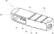
- FIG. 3is a perspective view of the trial spacer.
- FIG. 4is a top plan view of the trial spacer.
- FIG. 7is a perspective view of the trial spacer in combination with an insertion tool.
- the portion of the implant trial body having the X-ray visible indiciummay be sealed from any biological contamination, maintaining optimal surgical function without changing any cleanability or other use criteria.
- additive manufacturingmay be used to make the X-ray visible indicium and other portions of the implant trial, including the entire implant trial.
- materials of two different radiographic densitycould be molded.
- the implant trialcan be used in any application where it is desirable to view the implant trial under radiography, such as fluoroscopy, computed tomography (CT scan), and/or projectional radiography.
- the implant trialis a trial spacer used in spinal surgery, such as but not limited to lumbar interbody fusions and other spinal fusions procedures.
- the trial spacer(broadly, an implant trial) is generally indicated by reference numeral 10 .
- the trial spacer 10generally comprises a main body 12 having an inferior wall 14 and a superior wall 16 . It will be understood by the skilled person that the terms “superior,” “inferior,” and other or any other term referencing the relative locations of components and structures of the spacer trial are described in relation to the orientation of the trial spacer as inserted in the body of the patient.
- the main body 12generally comprises a first or distal portion 18 and a second or proximal portion 20 .
- the first portion 18comprises a visible height marking 22 (e.g., a number).
- the height marking 22is indicium and generally indicates the height of the device from the inferior wall 14 to the superior wall 16 .
- the height marking 22can comprise any signifier of the height of the device, for example, letters, numbers, or any other indicia.
- the height marking 22is disposed in a window extending through anterior and posterior sides of the trial spacer 10 .
- the second portion 20comprises depth indicia 24 (e.g., numbers).
- the depth indicia 24are associated with respective depth markers 26 on the exterior of the body 12 (see FIG. 5 ).
- the depth markers 26comprise triangle cutouts or notches but can comprise any marking that are visible in radiographic imaging, such as in an X-ray image.
- the depth indicia 24generally indicate the length or depth from a nose 30 or distal end of the body 10 to the corresponding depth marker 26 .
- the depth indicia 24are located within the main body 12 and therefore may not be visible from the outside of trial spacer 10 .
- the depth indicia 24can comprise any signifier of the length from the nose 30 to the particular depth marker 26 , for example, letters, numbers, or any other indicia.
- Anterior and posterior wallsare provided on the corresponding sides of the second portion 20 of the body 10 . Together, the superior wall 16 , the inferior wall 14 , the anterior wall, and posterior wall define an internal chamber in which the depth indicia 24 are received.
- the anterior and posterior wallsare more radiotranslucent than the depth indicia 24 , which may be substantially radiopaque, so that the depth indicia are visible during radiography, such as shown in FIG. 8 .
- the anterior and posterior wallsare suitably thin to allow X-ray (or other radiation for radiographic imaging) to pass through with little interference
- the depth indicia 24are made of much thicker material (such as steel) that will absorb the radiation from the X-ray (or other radiographic imaging) and make them visible on the radiographic image itself.
- the depth indicia 26may be disposed on or adjacent to the anterior wall, as shown in FIG. 6 .
- the trial spacer 10can be made by additive manufacturing, such as by using a direct metal laser sintering (DMLS) printer.
- DMLSdirect metal laser sintering
- the depth indiciaare designed to be visible when using X-ray in an anterior-posterior (AP) view (X-ray passing from posterior to anterior). Space is left above, below, and to the sides of the depth indicia 24 to allow them to be visible when viewing the depth indicia 24 from a few degrees from normal to the depth indicia 24 .
- APanterior-posterior
- the depth indicia 24can be suspended in a material that is more radiolucent than material of the depth indicia.
- the depth indicia 24can be printed in steel or any other material that is visible on the desired radiographic imaging radiation (e.g., X-ray) and the remainder of the device can be printed in titanium, aluminum, or any other material through which the particular radiographic imaging radiation can pass more easily so that the depth indicia 24 is more visible than the other material on the image.
- the depth indicia 24may be made from material having a greater density than the surrounding material. The skilled person will understand that different methods of manufacture are possible to achieve the same result.
- Opening 32is sized and shaped to receive an inserter tool 40 to allow for insertion of trial spacer 10 into the vertebral space of the patient (see FIG. 7 ). As shown in FIG. 6 , opening 32 can be disposed at an angle toward the anterior wall in order to provide ease of insertion for the user.
- the height markingis clearly indicated as 10 and the depth indicia are visible whereas the surrounding material is semi-translucent. The user will be able to determine whether the correct height of spacer was chosen based on the height marking and also the depth needed by use of the depth indicia.
- the trial spacer of the present disclosureis typically manufactured using 3D printing techniques to create features that may not otherwise be technically manufacturable or are otherwise cost prohibitive.
- the trial spacercould designed hollow, to further attach to another surgical instrument such as a shaft, or could be produced as one-piece.
- a shaftmay be welded or threaded in place to completely seal off the internal chamber to prevent the need for the internal chamber to be cleaned between uses.
Landscapes
- Health & Medical Sciences (AREA)
- Orthopedic Medicine & Surgery (AREA)
- Engineering & Computer Science (AREA)
- Biomedical Technology (AREA)
- Transplantation (AREA)
- Heart & Thoracic Surgery (AREA)
- Oral & Maxillofacial Surgery (AREA)
- Cardiology (AREA)
- Vascular Medicine (AREA)
- Life Sciences & Earth Sciences (AREA)
- Animal Behavior & Ethology (AREA)
- General Health & Medical Sciences (AREA)
- Public Health (AREA)
- Veterinary Medicine (AREA)
- Neurology (AREA)
- Physical Education & Sports Medicine (AREA)
- Prostheses (AREA)
- Apparatus For Radiation Diagnosis (AREA)
Abstract
Description
Claims (11)
Priority Applications (2)
| Application Number | Priority Date | Filing Date | Title |
|---|---|---|---|
| US17/308,725US11998457B2 (en) | 2020-05-05 | 2021-05-05 | Implant trial with radiographically visible indicium |
| US18/732,165US12414865B2 (en) | 2020-05-05 | 2024-06-03 | Implant trial with radiographically visible indicium |
Applications Claiming Priority (2)
| Application Number | Priority Date | Filing Date | Title |
|---|---|---|---|
| US202063020126P | 2020-05-05 | 2020-05-05 | |
| US17/308,725US11998457B2 (en) | 2020-05-05 | 2021-05-05 | Implant trial with radiographically visible indicium |
Related Child Applications (1)
| Application Number | Title | Priority Date | Filing Date |
|---|---|---|---|
| US18/732,165ContinuationUS12414865B2 (en) | 2020-05-05 | 2024-06-03 | Implant trial with radiographically visible indicium |
Publications (2)
| Publication Number | Publication Date |
|---|---|
| US20210346176A1 US20210346176A1 (en) | 2021-11-11 |
| US11998457B2true US11998457B2 (en) | 2024-06-04 |
Family
ID=78411873
Family Applications (2)
| Application Number | Title | Priority Date | Filing Date |
|---|---|---|---|
| US17/308,725Active2041-05-25US11998457B2 (en) | 2020-05-05 | 2021-05-05 | Implant trial with radiographically visible indicium |
| US18/732,165ActiveUS12414865B2 (en) | 2020-05-05 | 2024-06-03 | Implant trial with radiographically visible indicium |
Family Applications After (1)
| Application Number | Title | Priority Date | Filing Date |
|---|---|---|---|
| US18/732,165ActiveUS12414865B2 (en) | 2020-05-05 | 2024-06-03 | Implant trial with radiographically visible indicium |
Country Status (1)
| Country | Link |
|---|---|
| US (2) | US11998457B2 (en) |
Cited By (1)
| Publication number | Priority date | Publication date | Assignee | Title |
|---|---|---|---|---|
| US12307918B2 (en) | 2021-03-23 | 2025-05-20 | Tactile Robotics Ltd. | Automated measurement apparatus and method for quantifying dimensions of dental preparation |
Citations (22)
| Publication number | Priority date | Publication date | Assignee | Title |
|---|---|---|---|---|
| US6113639A (en)* | 1999-03-23 | 2000-09-05 | Raymedica, Inc. | Trial implant and trial implant kit for evaluating an intradiscal space |
| US20030135275A1 (en)* | 2001-11-09 | 2003-07-17 | Javier Garcia | Instruments and methods for inserting a spinal implant |
| US20030139813A1 (en)* | 2001-05-03 | 2003-07-24 | Dominique Messerli | Intervertebral implant for transforaminal posterior lumbar interbody fusion procedure |
| US6641582B1 (en)* | 2000-07-06 | 2003-11-04 | Sulzer Spine-Tech Inc. | Bone preparation instruments and methods |
| US20030233145A1 (en)* | 2002-03-11 | 2003-12-18 | Landry Michael E. | Instrumentation and procedure for implanting spinal implant devices |
| EP1384455A1 (en)* | 2002-07-23 | 2004-01-28 | DePuy AcroMed, Inc. | Surgical trial implant |
| US20040052333A1 (en)* | 2002-09-13 | 2004-03-18 | James Sayre | Device and method for margin marking of radiography specimens |
| US20040059337A1 (en)* | 2000-07-06 | 2004-03-25 | Sulzer Spine-Tech Inc. | Bone preparation instruments and methods |
| WO2005072659A2 (en)* | 2004-01-28 | 2005-08-11 | Sdgi Holdings, Inc. | Systems and techniques for restoring and maintaining intervertebral anatomy |
| US20060129238A1 (en)* | 2004-10-26 | 2006-06-15 | Adam Paltzer | Spinal stabilization device and methods |
| US20070093825A1 (en)* | 2005-09-28 | 2007-04-26 | Nuvasive Inc. | Methods and apparatus for treating spinal stenosis |
| US20070237307A1 (en)* | 2006-03-03 | 2007-10-11 | Loubert Suddaby | Radiographic spine marker |
| US20080287959A1 (en)* | 2005-09-26 | 2008-11-20 | Archus Orthopedics, Inc. | Measurement and trialing system and methods for orthopedic device component selection |
| US20130331850A1 (en)* | 2012-06-11 | 2013-12-12 | Conformis, Inc. | Devices, techniques and methods for assessing joint spacing, balancing soft tissues and obtaining desired kinematics for joint implant components |
| US20140114415A1 (en)* | 2012-10-19 | 2014-04-24 | Jeffrey Tyber | Orthopedic Systems for Spine and Tracking Control |
| US20140243982A1 (en)* | 2013-02-28 | 2014-08-28 | William Miller | Expandable Intervertebral Implant, System, Kit and Method |
| WO2014151172A1 (en)* | 2013-03-15 | 2014-09-25 | Globus Medical, Inc. | Expandable intervertebral implant |
| US20150328005A1 (en)* | 2014-05-15 | 2015-11-19 | Globus Medical, Inc | Standalone Interbody Implants |
| US20150342757A1 (en)* | 2014-06-03 | 2015-12-03 | DePuy Synthes Products, LLC | Optical trial device |
| US9801732B2 (en)* | 2009-10-30 | 2017-10-31 | Spinefrontier, Inc | System and method for an intervertebral implant assembly |
| US20190298546A1 (en)* | 2018-03-30 | 2019-10-03 | Warsaw Orthopedic, Inc. | Radiolucent trial |
| US20210290410A1 (en)* | 2017-03-03 | 2021-09-23 | Engage Uni Llc | Unicompartmental knee arthroplasty |
Family Cites Families (2)
| Publication number | Priority date | Publication date | Assignee | Title |
|---|---|---|---|---|
| US6086595A (en)* | 1997-08-29 | 2000-07-11 | Sulzer Spine-Tech Inc. | Apparatus and method for spinal stabilization |
| US20150223899A1 (en)* | 2014-02-11 | 2015-08-13 | Brian Kieser | Method of manufacturing a structurally encoded implantable device |
- 2021
- 2021-05-05USUS17/308,725patent/US11998457B2/enactiveActive
- 2024
- 2024-06-03USUS18/732,165patent/US12414865B2/enactiveActive
Patent Citations (23)
| Publication number | Priority date | Publication date | Assignee | Title |
|---|---|---|---|---|
| US6113639A (en)* | 1999-03-23 | 2000-09-05 | Raymedica, Inc. | Trial implant and trial implant kit for evaluating an intradiscal space |
| US6641582B1 (en)* | 2000-07-06 | 2003-11-04 | Sulzer Spine-Tech Inc. | Bone preparation instruments and methods |
| US20040059337A1 (en)* | 2000-07-06 | 2004-03-25 | Sulzer Spine-Tech Inc. | Bone preparation instruments and methods |
| US20030139813A1 (en)* | 2001-05-03 | 2003-07-24 | Dominique Messerli | Intervertebral implant for transforaminal posterior lumbar interbody fusion procedure |
| US20030135275A1 (en)* | 2001-11-09 | 2003-07-17 | Javier Garcia | Instruments and methods for inserting a spinal implant |
| US20030233145A1 (en)* | 2002-03-11 | 2003-12-18 | Landry Michael E. | Instrumentation and procedure for implanting spinal implant devices |
| EP1384455A1 (en)* | 2002-07-23 | 2004-01-28 | DePuy AcroMed, Inc. | Surgical trial implant |
| US20040019356A1 (en)* | 2002-07-23 | 2004-01-29 | Robert Fraser | Surgical trial implant |
| US20040052333A1 (en)* | 2002-09-13 | 2004-03-18 | James Sayre | Device and method for margin marking of radiography specimens |
| WO2005072659A2 (en)* | 2004-01-28 | 2005-08-11 | Sdgi Holdings, Inc. | Systems and techniques for restoring and maintaining intervertebral anatomy |
| US20060129238A1 (en)* | 2004-10-26 | 2006-06-15 | Adam Paltzer | Spinal stabilization device and methods |
| US20080287959A1 (en)* | 2005-09-26 | 2008-11-20 | Archus Orthopedics, Inc. | Measurement and trialing system and methods for orthopedic device component selection |
| US20070093825A1 (en)* | 2005-09-28 | 2007-04-26 | Nuvasive Inc. | Methods and apparatus for treating spinal stenosis |
| US20070237307A1 (en)* | 2006-03-03 | 2007-10-11 | Loubert Suddaby | Radiographic spine marker |
| US9801732B2 (en)* | 2009-10-30 | 2017-10-31 | Spinefrontier, Inc | System and method for an intervertebral implant assembly |
| US20130331850A1 (en)* | 2012-06-11 | 2013-12-12 | Conformis, Inc. | Devices, techniques and methods for assessing joint spacing, balancing soft tissues and obtaining desired kinematics for joint implant components |
| US20140114415A1 (en)* | 2012-10-19 | 2014-04-24 | Jeffrey Tyber | Orthopedic Systems for Spine and Tracking Control |
| US20140243982A1 (en)* | 2013-02-28 | 2014-08-28 | William Miller | Expandable Intervertebral Implant, System, Kit and Method |
| WO2014151172A1 (en)* | 2013-03-15 | 2014-09-25 | Globus Medical, Inc. | Expandable intervertebral implant |
| US20150328005A1 (en)* | 2014-05-15 | 2015-11-19 | Globus Medical, Inc | Standalone Interbody Implants |
| US20150342757A1 (en)* | 2014-06-03 | 2015-12-03 | DePuy Synthes Products, LLC | Optical trial device |
| US20210290410A1 (en)* | 2017-03-03 | 2021-09-23 | Engage Uni Llc | Unicompartmental knee arthroplasty |
| US20190298546A1 (en)* | 2018-03-30 | 2019-10-03 | Warsaw Orthopedic, Inc. | Radiolucent trial |
Cited By (1)
| Publication number | Priority date | Publication date | Assignee | Title |
|---|---|---|---|---|
| US12307918B2 (en) | 2021-03-23 | 2025-05-20 | Tactile Robotics Ltd. | Automated measurement apparatus and method for quantifying dimensions of dental preparation |
Also Published As
| Publication number | Publication date |
|---|---|
| US20210346176A1 (en) | 2021-11-11 |
| US20250073048A1 (en) | 2025-03-06 |
| US12414865B2 (en) | 2025-09-16 |
Similar Documents
| Publication | Publication Date | Title |
|---|---|---|
| EP1587437B1 (en) | Spinal midline indicator | |
| US11185423B2 (en) | Highly radiographically opaque metal based interbody | |
| EP3011933B1 (en) | Spinal fusion implant | |
| US6723097B2 (en) | Surgical trial implant | |
| US7303583B1 (en) | Intervertebral implant | |
| US20080287959A1 (en) | Measurement and trialing system and methods for orthopedic device component selection | |
| US12414865B2 (en) | Implant trial with radiographically visible indicium | |
| CN111902104B (en) | Radiolucent test device | |
| CA2556102A1 (en) | Method for improving pedicle screw placement in spinal surgery | |
| Littleton et al. | Temporal bone: comparison of pluridirectional tomography and high resolution computed tomography | |
| US11666459B2 (en) | Radiolucent trial | |
| US20070237307A1 (en) | Radiographic spine marker | |
| Todd et al. | Interobserver agreement of coiling of Med-El cochlear implant: plain x-ray studies | |
| DE202009013604U1 (en) | System for the intraoperative positioning of artificial acetabular cups | |
| US11096802B2 (en) | Intervertebral trial with marker | |
| HK1134001B (en) | Templating and placing artificial discs in spine | |
| HK1134001A1 (en) | Templating and placing artificial discs in spine |
Legal Events
| Date | Code | Title | Description |
|---|---|---|---|
| FEPP | Fee payment procedure | Free format text:ENTITY STATUS SET TO UNDISCOUNTED (ORIGINAL EVENT CODE: BIG.); ENTITY STATUS OF PATENT OWNER: SMALL ENTITY | |
| FEPP | Fee payment procedure | Free format text:ENTITY STATUS SET TO SMALL (ORIGINAL EVENT CODE: SMAL); ENTITY STATUS OF PATENT OWNER: SMALL ENTITY | |
| STPP | Information on status: patent application and granting procedure in general | Free format text:DOCKETED NEW CASE - READY FOR EXAMINATION | |
| AS | Assignment | Owner name:CORELINK, LLC, MISSOURI Free format text:ASSIGNMENT OF ASSIGNORS INTEREST;ASSIGNORS:MACMILLAN, ADAM;SUPPIGER, GERHART;SMITH, BRETT;SIGNING DATES FROM 20220202 TO 20220204;REEL/FRAME:058975/0232 | |
| STPP | Information on status: patent application and granting procedure in general | Free format text:NON FINAL ACTION MAILED | |
| STPP | Information on status: patent application and granting procedure in general | Free format text:FINAL REJECTION MAILED | |
| STPP | Information on status: patent application and granting procedure in general | Free format text:DOCKETED NEW CASE - READY FOR EXAMINATION | |
| STPP | Information on status: patent application and granting procedure in general | Free format text:NON FINAL ACTION MAILED | |
| STPP | Information on status: patent application and granting procedure in general | Free format text:RESPONSE TO NON-FINAL OFFICE ACTION ENTERED AND FORWARDED TO EXAMINER | |
| STPP | Information on status: patent application and granting procedure in general | Free format text:NOTICE OF ALLOWANCE MAILED -- APPLICATION RECEIVED IN OFFICE OF PUBLICATIONS | |
| STPP | Information on status: patent application and granting procedure in general | Free format text:PUBLICATIONS -- ISSUE FEE PAYMENT RECEIVED | |
| STPP | Information on status: patent application and granting procedure in general | Free format text:PUBLICATIONS -- ISSUE FEE PAYMENT VERIFIED | |
| STCF | Information on status: patent grant | Free format text:PATENTED CASE | |
| AS | Assignment | Owner name:VARAGON CAPITAL PARTNERS AGENT, LLC, AS ADMINISTRATIVE AGENT, ILLINOIS Free format text:SECURITY INTEREST;ASSIGNOR:CORELINK, LLC;REEL/FRAME:067820/0916 Effective date:20230730 | |
| AS | Assignment | Owner name:VARAGON CAPITAL PARTNERS AGENT, LLC, AS ADMINISTRATIVE AGENT, ILLINOIS Free format text:SECURITY INTEREST;ASSIGNOR:CORELINK, LLC;REEL/FRAME:068045/0638 Effective date:20240722 |