US11998329B2 - Membrane for continuous analyte sensors - Google Patents
Membrane for continuous analyte sensorsDownload PDFInfo
- Publication number
- US11998329B2 US11998329B2US16/532,235US201916532235AUS11998329B2US 11998329 B2US11998329 B2US 11998329B2US 201916532235 AUS201916532235 AUS 201916532235AUS 11998329 B2US11998329 B2US 11998329B2
- Authority
- US
- United States
- Prior art keywords
- patent publication
- domain
- enzyme
- sensor
- glucose
- Prior art date
- Legal status (The legal status is an assumption and is not a legal conclusion. Google has not performed a legal analysis and makes no representation as to the accuracy of the status listed.)
- Active, expires
Links
- 239000012528membraneSubstances0.000titleclaimsabstractdescription146
- 239000012491analyteSubstances0.000titleclaimsabstractdescription116
- 102000004190EnzymesHuman genes0.000claimsabstractdescription204
- 108090000790EnzymesProteins0.000claimsabstractdescription204
- 229920005601base polymerPolymers0.000claimsabstractdescription36
- 229920001477hydrophilic polymerPolymers0.000claimsabstractdescription36
- 238000005259measurementMethods0.000claimsabstractdescription35
- 229940088598enzymeDrugs0.000claimsdescription201
- 239000008103glucoseSubstances0.000claimsdescription130
- WQZGKKKJIJFFOK-GASJEMHNSA-NGlucoseNatural productsOC[C@H]1OC(O)[C@H](O)[C@@H](O)[C@@H]1OWQZGKKKJIJFFOK-GASJEMHNSA-N0.000claimsdescription126
- WQZGKKKJIJFFOK-VFUOTHLCSA-Nbeta-D-glucoseChemical compoundOC[C@H]1O[C@@H](O)[C@H](O)[C@@H](O)[C@@H]1OWQZGKKKJIJFFOK-VFUOTHLCSA-N0.000claimsdescription123
- 229920000642polymerPolymers0.000claimsdescription109
- 229920002635polyurethanePolymers0.000claimsdescription69
- 239000004814polyurethaneSubstances0.000claimsdescription69
- -1poly(sulfobetaine)Polymers0.000claimsdescription66
- 238000009792diffusion processMethods0.000claimsdescription38
- KWIUHFFTVRNATP-UHFFFAOYSA-Nglycine betaineChemical compoundC[N+](C)(C)CC([O-])=OKWIUHFFTVRNATP-UHFFFAOYSA-N0.000claimsdescription33
- 239000003795chemical substances by applicationSubstances0.000claimsdescription32
- 229920001296polysiloxanePolymers0.000claimsdescription30
- 239000003431cross linking reagentSubstances0.000claimsdescription28
- 239000000203mixtureSubstances0.000claimsdescription28
- 229960003237betaineDrugs0.000claimsdescription24
- 238000001727in vivoMethods0.000claimsdescription18
- 235000019420glucose oxidaseNutrition0.000claimsdescription15
- 108010015776Glucose oxidaseProteins0.000claimsdescription14
- 239000004366Glucose oxidaseSubstances0.000claimsdescription14
- 229920003171Poly (ethylene oxide)Polymers0.000claimsdescription14
- 229920001577copolymerPolymers0.000claimsdescription14
- 229940116332glucose oxidaseDrugs0.000claimsdescription14
- 239000002243precursorSubstances0.000claimsdescription13
- 229920001223polyethylene glycolPolymers0.000claimsdescription12
- 230000000087stabilizing effectEffects0.000claimsdescription11
- 239000003153chemical reaction reagentSubstances0.000claimsdescription10
- UWFRVQVNYNPBEF-UHFFFAOYSA-N1-(2,4-dimethylphenyl)propan-1-oneChemical compoundCCC(=O)C1=CC=C(C)C=C1CUWFRVQVNYNPBEF-UHFFFAOYSA-N0.000claimsdescription8
- XMNIXWIUMCBBBL-UHFFFAOYSA-N2-(2-phenylpropan-2-ylperoxy)propan-2-ylbenzeneChemical compoundC=1C=CC=CC=1C(C)(C)OOC(C)(C)C1=CC=CC=C1XMNIXWIUMCBBBL-UHFFFAOYSA-N0.000claimsdescription8
- 239000004593EpoxySubstances0.000claimsdescription8
- 230000004907fluxEffects0.000claimsdescription8
- 229920000120polyethyl acrylatePolymers0.000claimsdescription8
- 229920000191poly(N-vinyl pyrrolidone)Polymers0.000claimsdescription7
- 229920000728polyesterPolymers0.000claimsdescription7
- 229920000570polyetherPolymers0.000claimsdescription7
- 150000001299aldehydesChemical class0.000claimsdescription6
- 150000001413amino acidsChemical class0.000claimsdescription6
- 150000001718carbodiimidesChemical class0.000claimsdescription6
- 125000002091cationic groupChemical group0.000claimsdescription6
- 125000002791glucosyl groupChemical groupC1([C@H](O)[C@@H](O)[C@H](O)[C@H](O1)CO)*0.000claimsdescription6
- 229920003229poly(methyl methacrylate)Polymers0.000claimsdescription6
- SXRSQZLOMIGNAQ-UHFFFAOYSA-NGlutaraldehydeChemical compoundO=CCCCC=OSXRSQZLOMIGNAQ-UHFFFAOYSA-N0.000claimsdescription5
- WHNWPMSKXPGLAX-UHFFFAOYSA-NN-Vinyl-2-pyrrolidoneChemical compoundC=CN1CCCC1=OWHNWPMSKXPGLAX-UHFFFAOYSA-N0.000claimsdescription5
- 150000001242acetic acid derivativesChemical class0.000claimsdescription5
- 229920002401polyacrylamidePolymers0.000claimsdescription5
- 229920000098polyolefinPolymers0.000claimsdescription5
- 239000011118polyvinyl acetateSubstances0.000claimsdescription5
- LJCNDNBULVLKSG-UHFFFAOYSA-N2-aminoacetic acid;butaneChemical compoundCCCC.CCCC.NCC(O)=OLJCNDNBULVLKSG-UHFFFAOYSA-N0.000claimsdescription4
- 108010025188Alcohol oxidaseProteins0.000claimsdescription4
- 108010089254Cholesterol oxidaseProteins0.000claimsdescription4
- 108010015133Galactose oxidaseProteins0.000claimsdescription4
- 108010073450Lactate 2-monooxygenaseProteins0.000claimsdescription4
- 108010092464Urate OxidaseProteins0.000claimsdescription4
- 150000001252acrylic acid derivativesChemical class0.000claimsdescription4
- 229920006397acrylic thermoplasticPolymers0.000claimsdescription4
- 150000004649carbonic acid derivativesChemical class0.000claimsdescription4
- GYZLOYUZLJXAJU-UHFFFAOYSA-Ndiglycidyl etherChemical compoundC1OC1COCC1CO1GYZLOYUZLJXAJU-UHFFFAOYSA-N0.000claimsdescription4
- 125000003700epoxy groupChemical group0.000claimsdescription4
- 239000012948isocyanateSubstances0.000claimsdescription4
- 150000002513isocyanatesChemical class0.000claimsdescription4
- 229920000647polyepoxidePolymers0.000claimsdescription4
- 229920002689polyvinyl acetatePolymers0.000claimsdescription4
- ISXSCDLOGDJUNJ-UHFFFAOYSA-Ntert-butyl prop-2-enoateChemical compoundCC(C)(C)OC(=O)C=CISXSCDLOGDJUNJ-UHFFFAOYSA-N0.000claimsdescription4
- 108010050375Glucose 1-DehydrogenaseProteins0.000claimsdescription3
- 239000004372Polyvinyl alcoholSubstances0.000claimsdescription3
- 229940088644n,n-dimethylacrylamideDrugs0.000claimsdescription3
- YLGYACDQVQQZSW-UHFFFAOYSA-Nn,n-dimethylprop-2-enamideChemical compoundCN(C)C(=O)C=CYLGYACDQVQQZSW-UHFFFAOYSA-N0.000claimsdescription3
- 229920002451polyvinyl alcoholPolymers0.000claimsdescription3
- YPUUGRMTUUCONZ-UHFFFAOYSA-N2-[dimethyl(octyl)azaniumyl]acetateChemical compoundCCCCCCCC[N+](C)(C)CC([O-])=OYPUUGRMTUUCONZ-UHFFFAOYSA-N0.000claimsdescription2
- ZKWJQNCOTNUNMF-QXMHVHEDSA-N2-[dimethyl-[3-[[(z)-octadec-9-enoyl]amino]propyl]azaniumyl]acetateChemical compoundCCCCCCCC\C=C/CCCCCCCC(=O)NCCC[N+](C)(C)CC([O-])=OZKWJQNCOTNUNMF-QXMHVHEDSA-N0.000claimsdescription2
- BHATUINFZWUDIX-UHFFFAOYSA-NZwittergent 3-14Chemical compoundCCCCCCCCCCCCCC[N+](C)(C)CCCS([O-])(=O)=OBHATUINFZWUDIX-UHFFFAOYSA-N0.000claimsdescription2
- MRUAUOIMASANKQ-UHFFFAOYSA-Ncocamidopropyl betaineChemical compoundCCCCCCCCCCCC(=O)NCCC[N+](C)(C)CC([O-])=OMRUAUOIMASANKQ-UHFFFAOYSA-N0.000claimsdescription2
- 229940073507cocamidopropyl betaineDrugs0.000claimsdescription2
- 150000002148estersChemical class0.000claimsdescription2
- IZWSFJTYBVKZNK-UHFFFAOYSA-Nlauryl sulfobetaineChemical compoundCCCCCCCCCCCC[N+](C)(C)CCCS([O-])(=O)=OIZWSFJTYBVKZNK-UHFFFAOYSA-N0.000claimsdescription2
- WTJKGGKOPKCXLL-RRHRGVEJSA-NphosphatidylcholineChemical compoundCCCCCCCCCCCCCCCC(=O)OC[C@H](COP([O-])(=O)OCC[N+](C)(C)C)OC(=O)CCCCCCCC=CCCCCCCCCWTJKGGKOPKCXLL-RRHRGVEJSA-N0.000claimsdescription2
- 238000000034methodMethods0.000description79
- QVGXLLKOCUKJST-UHFFFAOYSA-Natomic oxygenChemical compound[O]QVGXLLKOCUKJST-UHFFFAOYSA-N0.000description74
- 239000001301oxygenSubstances0.000description74
- 229910052760oxygenInorganic materials0.000description74
- 230000000513bioprotective effectEffects0.000description69
- 239000012867bioactive agentSubstances0.000description66
- 229920000036polyvinylpyrrolidonePolymers0.000description52
- 239000001267polyvinylpyrrolidoneSubstances0.000description52
- 235000013855polyvinylpyrrolidoneNutrition0.000description52
- 239000000463materialSubstances0.000description46
- 239000003381stabilizerSubstances0.000description29
- 241000894007speciesSpecies0.000description28
- 150000001875compoundsChemical class0.000description26
- 239000011162core materialSubstances0.000description24
- 230000000694effectsEffects0.000description23
- 230000035945sensitivityEffects0.000description20
- 239000000126substanceSubstances0.000description20
- MHAJPDPJQMAIIY-UHFFFAOYSA-NHydrogen peroxideChemical compoundOOMHAJPDPJQMAIIY-UHFFFAOYSA-N0.000description19
- 238000000576coating methodMethods0.000description19
- 238000004519manufacturing processMethods0.000description19
- 230000008569processEffects0.000description18
- 230000004044responseEffects0.000description18
- 238000012545processingMethods0.000description17
- 230000002255enzymatic effectEffects0.000description16
- 230000001965increasing effectEffects0.000description16
- 239000011159matrix materialSubstances0.000description16
- 239000000243solutionSubstances0.000description16
- 239000011248coating agentSubstances0.000description15
- 239000004020conductorSubstances0.000description15
- 238000001723curingMethods0.000description15
- 229910021607Silver chlorideInorganic materials0.000description14
- HKZLPVFGJNLROG-UHFFFAOYSA-Msilver monochlorideChemical compound[Cl-].[Ag+]HKZLPVFGJNLROG-UHFFFAOYSA-M0.000description14
- 230000035699permeabilityEffects0.000description13
- HTTJABKRGRZYRN-UHFFFAOYSA-NHeparinChemical compoundOC1C(NC(=O)C)C(O)OC(COS(O)(=O)=O)C1OC1C(OS(O)(=O)=O)C(O)C(OC2C(C(OS(O)(=O)=O)C(OC3C(C(O)C(O)C(O3)C(O)=O)OS(O)(=O)=O)C(CO)O2)NS(O)(=O)=O)C(C(O)=O)O1HTTJABKRGRZYRN-UHFFFAOYSA-N0.000description12
- 230000015572biosynthetic processEffects0.000description12
- 210000004369bloodAnatomy0.000description12
- 239000008280bloodSubstances0.000description12
- 238000006243chemical reactionMethods0.000description12
- 230000007246mechanismEffects0.000description12
- 238000004132cross linkingMethods0.000description11
- 238000002513implantationMethods0.000description10
- 230000001976improved effectEffects0.000description10
- 238000011068loading methodMethods0.000description10
- 238000012544monitoring processMethods0.000description10
- BASFCYQUMIYNBI-UHFFFAOYSA-NplatinumChemical compound[Pt]BASFCYQUMIYNBI-UHFFFAOYSA-N0.000description10
- 229910052709silverInorganic materials0.000description10
- BQCADISMDOOEFD-UHFFFAOYSA-NSilverChemical compound[Ag]BQCADISMDOOEFD-UHFFFAOYSA-N0.000description9
- 210000004027cellAnatomy0.000description9
- 229920001940conductive polymerPolymers0.000description9
- 239000010408filmSubstances0.000description9
- 230000006870functionEffects0.000description9
- 229920000669heparinPolymers0.000description9
- 238000003780insertionMethods0.000description9
- 230000037431insertionEffects0.000description9
- 230000000670limiting effectEffects0.000description9
- 239000002245particleSubstances0.000description9
- 239000004332silverSubstances0.000description9
- 238000012360testing methodMethods0.000description9
- 230000002452interceptive effectEffects0.000description8
- 239000004005microsphereSubstances0.000description8
- 229920005597polymer membranePolymers0.000description8
- 102000004169proteins and genesHuman genes0.000description8
- 108090000623proteins and genesProteins0.000description8
- XLYOFNOQVPJJNP-UHFFFAOYSA-NwaterSubstancesOXLYOFNOQVPJJNP-UHFFFAOYSA-N0.000description8
- 239000004599antimicrobialSubstances0.000description7
- 239000013060biological fluidSubstances0.000description7
- 230000015556catabolic processEffects0.000description7
- 230000008859changeEffects0.000description7
- 238000006731degradation reactionMethods0.000description7
- 238000000151depositionMethods0.000description7
- 239000003814drugSubstances0.000description7
- 229920002959polymer blendPolymers0.000description7
- 210000001519tissueAnatomy0.000description7
- RZVAJINKPMORJF-UHFFFAOYSA-NAcetaminophenChemical compoundCC(=O)NC1=CC=C(O)C=C1RZVAJINKPMORJF-UHFFFAOYSA-N0.000description6
- ULGZDMOVFRHVEP-RWJQBGPGSA-NErythromycinChemical compoundO([C@@H]1[C@@H](C)C(=O)O[C@@H]([C@@]([C@H](O)[C@@H](C)C(=O)[C@H](C)C[C@@](C)(O)[C@H](O[C@H]2[C@@H]([C@H](C[C@@H](C)O2)N(C)C)O)[C@H]1C)(C)O)CC)[C@H]1C[C@@](C)(OC)[C@@H](O)[C@H](C)O1ULGZDMOVFRHVEP-RWJQBGPGSA-N0.000description6
- LFQSCWFLJHTTHZ-UHFFFAOYSA-NEthanolChemical compoundCCOLFQSCWFLJHTTHZ-UHFFFAOYSA-N0.000description6
- 230000002491angiogenic effectEffects0.000description6
- 239000003242anti bacterial agentSubstances0.000description6
- 230000005540biological transmissionEffects0.000description6
- 229920002301cellulose acetatePolymers0.000description6
- HVYWMOMLDIMFJA-DPAQBDIFSA-NcholesterolChemical compoundC1C=C2C[C@@H](O)CC[C@]2(C)[C@@H]2[C@@H]1[C@@H]1CC[C@H]([C@H](C)CCCC(C)C)[C@@]1(C)CC2HVYWMOMLDIMFJA-DPAQBDIFSA-N0.000description6
- MYSWGUAQZAJSOK-UHFFFAOYSA-NciprofloxacinChemical compoundC12=CC(N3CCNCC3)=C(F)C=C2C(=O)C(C(=O)O)=CN1C1CC1MYSWGUAQZAJSOK-UHFFFAOYSA-N0.000description6
- 239000008199coating compositionSubstances0.000description6
- 230000007423decreaseEffects0.000description6
- 238000003618dip coatingMethods0.000description6
- 229940079593drugDrugs0.000description6
- 239000012212insulatorSubstances0.000description6
- NOESYZHRGYRDHS-UHFFFAOYSA-NinsulinChemical compoundN1C(=O)C(NC(=O)C(CCC(N)=O)NC(=O)C(CCC(O)=O)NC(=O)C(C(C)C)NC(=O)C(NC(=O)CN)C(C)CC)CSSCC(C(NC(CO)C(=O)NC(CC(C)C)C(=O)NC(CC=2C=CC(O)=CC=2)C(=O)NC(CCC(N)=O)C(=O)NC(CC(C)C)C(=O)NC(CCC(O)=O)C(=O)NC(CC(N)=O)C(=O)NC(CC=2C=CC(O)=CC=2)C(=O)NC(CSSCC(NC(=O)C(C(C)C)NC(=O)C(CC(C)C)NC(=O)C(CC=2C=CC(O)=CC=2)NC(=O)C(CC(C)C)NC(=O)C(C)NC(=O)C(CCC(O)=O)NC(=O)C(C(C)C)NC(=O)C(CC(C)C)NC(=O)C(CC=2NC=NC=2)NC(=O)C(CO)NC(=O)CNC2=O)C(=O)NCC(=O)NC(CCC(O)=O)C(=O)NC(CCCNC(N)=N)C(=O)NCC(=O)NC(CC=3C=CC=CC=3)C(=O)NC(CC=3C=CC=CC=3)C(=O)NC(CC=3C=CC(O)=CC=3)C(=O)NC(C(C)O)C(=O)N3C(CCC3)C(=O)NC(CCCCN)C(=O)NC(C)C(O)=O)C(=O)NC(CC(N)=O)C(O)=O)=O)NC(=O)C(C(C)CC)NC(=O)C(CO)NC(=O)C(C(C)O)NC(=O)C1CSSCC2NC(=O)C(CC(C)C)NC(=O)C(NC(=O)C(CCC(N)=O)NC(=O)C(CC(N)=O)NC(=O)C(NC(=O)C(N)CC=1C=CC=CC=1)C(C)C)CC1=CN=CN1NOESYZHRGYRDHS-UHFFFAOYSA-N0.000description6
- 238000002156mixingMethods0.000description6
- 238000012986modificationMethods0.000description6
- 230000002829reductive effectEffects0.000description6
- OKTJSMMVPCPJKN-UHFFFAOYSA-NCarbonChemical compound[C]OKTJSMMVPCPJKN-UHFFFAOYSA-N0.000description5
- 206010029113NeovascularisationDiseases0.000description5
- 239000004642PolyimideSubstances0.000description5
- 229940088710antibiotic agentDrugs0.000description5
- 239000003146anticoagulant agentSubstances0.000description5
- 229940127219anticoagulant drugDrugs0.000description5
- 239000003054catalystSubstances0.000description5
- 230000001413cellular effectEffects0.000description5
- 229920006217cellulose acetate butyratePolymers0.000description5
- ZPUCINDJVBIVPJ-LJISPDSOSA-NcocaineChemical compoundO([C@H]1C[C@@H]2CC[C@@H](N2C)[C@H]1C(=O)OC)C(=O)C1=CC=CC=C1ZPUCINDJVBIVPJ-LJISPDSOSA-N0.000description5
- 238000001514detection methodMethods0.000description5
- 206010012601diabetes mellitusDiseases0.000description5
- 238000007598dipping methodMethods0.000description5
- 239000006185dispersionSubstances0.000description5
- 238000003487electrochemical reactionMethods0.000description5
- 239000003792electrolyteSubstances0.000description5
- 235000019441ethanolNutrition0.000description5
- 229960002897heparinDrugs0.000description5
- 230000002209hydrophobic effectEffects0.000description5
- 239000003112inhibitorSubstances0.000description5
- 230000004048modificationEffects0.000description5
- 229910052697platinumInorganic materials0.000description5
- 229920001692polycarbonate urethanePolymers0.000description5
- 229920001721polyimidePolymers0.000description5
- 239000000047productSubstances0.000description5
- 239000002904solventSubstances0.000description5
- 238000005507sprayingMethods0.000description5
- CFFZDZCDUFSOFZ-UHFFFAOYSA-N3,4-Dihydroxy-phenylacetic acidChemical compoundOC(=O)CC1=CC=C(O)C(O)=C1CFFZDZCDUFSOFZ-UHFFFAOYSA-N0.000description4
- YCKRFDGAMUMZLT-UHFFFAOYSA-NFluorine atomChemical compound[F]YCKRFDGAMUMZLT-UHFFFAOYSA-N0.000description4
- CEAZRRDELHUEMR-URQXQFDESA-NGentamicinChemical compoundO1[C@H](C(C)NC)CC[C@@H](N)[C@H]1O[C@H]1[C@H](O)[C@@H](O[C@@H]2[C@@H]([C@@H](NC)[C@@](C)(O)CO2)O)[C@H](N)C[C@@H]1NCEAZRRDELHUEMR-URQXQFDESA-N0.000description4
- 229930182566GentamicinNatural products0.000description4
- KDLHZDBZIXYQEI-UHFFFAOYSA-NPalladiumChemical compound[Pd]KDLHZDBZIXYQEI-UHFFFAOYSA-N0.000description4
- 239000004098TetracyclineSubstances0.000description4
- 208000007536ThrombosisDiseases0.000description4
- RTAQQCXQSZGOHL-UHFFFAOYSA-NTitaniumChemical compound[Ti]RTAQQCXQSZGOHL-UHFFFAOYSA-N0.000description4
- XSQUKJJJFZCRTK-UHFFFAOYSA-NUreaChemical compoundNC(N)=OXSQUKJJJFZCRTK-UHFFFAOYSA-N0.000description4
- 125000000129anionic groupChemical group0.000description4
- 210000002457barrier cellAnatomy0.000description4
- 230000000903blocking effectEffects0.000description4
- 229910052799carbonInorganic materials0.000description4
- DDRJAANPRJIHGJ-UHFFFAOYSA-NcreatinineChemical compoundCN1CC(=O)NC1=NDDRJAANPRJIHGJ-UHFFFAOYSA-N0.000description4
- 125000005442diisocyanate groupChemical group0.000description4
- VYFYYTLLBUKUHU-UHFFFAOYSA-NdopamineChemical compoundNCCC1=CC=C(O)C(O)=C1VYFYYTLLBUKUHU-UHFFFAOYSA-N0.000description4
- 210000003743erythrocyteAnatomy0.000description4
- 238000005530etchingMethods0.000description4
- 238000001914filtrationMethods0.000description4
- 239000011737fluorineSubstances0.000description4
- 229910052731fluorineInorganic materials0.000description4
- 125000001153fluoro groupChemical groupF*0.000description4
- 239000000499gelSubstances0.000description4
- 229960002518gentamicinDrugs0.000description4
- 230000012010growthEffects0.000description4
- QRMZSPFSDQBLIX-UHFFFAOYSA-Nhomovanillic acidChemical compoundCOC1=CC(CC(O)=O)=CC=C1OQRMZSPFSDQBLIX-UHFFFAOYSA-N0.000description4
- JYGXADMDTFJGBT-VWUMJDOOSA-NhydrocortisoneChemical compoundO=C1CC[C@]2(C)[C@H]3[C@@H](O)C[C@](C)([C@@](CC4)(O)C(=O)CO)[C@@H]4[C@@H]3CCC2=C1JYGXADMDTFJGBT-VWUMJDOOSA-N0.000description4
- 239000011810insulating materialSubstances0.000description4
- 238000000608laser ablationMethods0.000description4
- 230000007774longtermEffects0.000description4
- 230000007935neutral effectEffects0.000description4
- 238000002360preparation methodMethods0.000description4
- 230000000770proinflammatory effectEffects0.000description4
- QZAYGJVTTNCVMB-UHFFFAOYSA-NserotoninChemical compoundC1=C(O)C=C2C(CCN)=CNC2=C1QZAYGJVTTNCVMB-UHFFFAOYSA-N0.000description4
- 239000007787solidSubstances0.000description4
- 229910001220stainless steelInorganic materials0.000description4
- 239000010935stainless steelSubstances0.000description4
- 238000007920subcutaneous administrationMethods0.000description4
- BDHFUVZGWQCTTF-UHFFFAOYSA-MsulfonateChemical compound[O-]S(=O)=OBDHFUVZGWQCTTF-UHFFFAOYSA-M0.000description4
- 229910052715tantalumInorganic materials0.000description4
- GUVRBAGPIYLISA-UHFFFAOYSA-Ntantalum atomChemical compound[Ta]GUVRBAGPIYLISA-UHFFFAOYSA-N0.000description4
- 235000019364tetracyclineNutrition0.000description4
- 150000003522tetracyclinesChemical class0.000description4
- 229910052719titaniumInorganic materials0.000description4
- 239000010936titaniumSubstances0.000description4
- 238000011282treatmentMethods0.000description4
- 230000029663wound healingEffects0.000description4
- FFTVPQUHLQBXQZ-KVUCHLLUSA-N(4s,4as,5ar,12ar)-4,7-bis(dimethylamino)-1,10,11,12a-tetrahydroxy-3,12-dioxo-4a,5,5a,6-tetrahydro-4h-tetracene-2-carboxamideChemical compoundC1C2=C(N(C)C)C=CC(O)=C2C(O)=C2[C@@H]1C[C@H]1[C@H](N(C)C)C(=O)C(C(N)=O)=C(O)[C@@]1(O)C2=OFFTVPQUHLQBXQZ-KVUCHLLUSA-N0.000description3
- QTBSBXVTEAMEQO-UHFFFAOYSA-NAcetic acidChemical compoundCC(O)=OQTBSBXVTEAMEQO-UHFFFAOYSA-N0.000description3
- CSCPPACGZOOCGX-UHFFFAOYSA-NAcetoneChemical compoundCC(C)=OCSCPPACGZOOCGX-UHFFFAOYSA-N0.000description3
- WEVYAHXRMPXWCK-UHFFFAOYSA-NAcetonitrileChemical compoundCC#NWEVYAHXRMPXWCK-UHFFFAOYSA-N0.000description3
- APKFDSVGJQXUKY-KKGHZKTASA-NAmphotericin-BNatural productsO[C@H]1[C@@H](N)[C@H](O)[C@@H](C)O[C@H]1O[C@H]1C=CC=CC=CC=CC=CC=CC=C[C@H](C)[C@@H](O)[C@@H](C)[C@H](C)OC(=O)C[C@H](O)C[C@H](O)CC[C@@H](O)[C@H](O)C[C@H](O)C[C@](O)(C[C@H](O)[C@H]2C(O)=O)O[C@H]2C1APKFDSVGJQXUKY-KKGHZKTASA-N0.000description3
- CIWBSHSKHKDKBQ-JLAZNSOCSA-NAscorbic acidNatural productsOC[C@H](O)[C@H]1OC(=O)C(O)=C1OCIWBSHSKHKDKBQ-JLAZNSOCSA-N0.000description3
- BSYNRYMUTXBXSQ-UHFFFAOYSA-NAspirinChemical compoundCC(=O)OC1=CC=CC=C1C(O)=OBSYNRYMUTXBXSQ-UHFFFAOYSA-N0.000description3
- XUIIKFGFIJCVMT-GFCCVEGCSA-ND-thyroxineChemical compoundIC1=CC(C[C@@H](N)C(O)=O)=CC(I)=C1OC1=CC(I)=C(O)C(I)=C1XUIIKFGFIJCVMT-GFCCVEGCSA-N0.000description3
- YMWUJEATGCHHMB-UHFFFAOYSA-NDichloromethaneChemical compoundClCClYMWUJEATGCHHMB-UHFFFAOYSA-N0.000description3
- WSFSSNUMVMOOMR-UHFFFAOYSA-NFormaldehydeChemical compoundO=CWSFSSNUMVMOOMR-UHFFFAOYSA-N0.000description3
- 241000700721Hepatitis B virusSpecies0.000description3
- 241000282412HomoSpecies0.000description3
- 241000713772Human immunodeficiency virus 1Species0.000description3
- 102000004877InsulinHuman genes0.000description3
- 108090001061InsulinProteins0.000description3
- JVTAAEKCZFNVCJ-UHFFFAOYSA-MLactateChemical compoundCC(O)C([O-])=OJVTAAEKCZFNVCJ-UHFFFAOYSA-M0.000description3
- SUHOOTKUPISOBE-UHFFFAOYSA-NO-phosphoethanolamineChemical compoundNCCOP(O)(O)=OSUHOOTKUPISOBE-UHFFFAOYSA-N0.000description3
- 229930012538PaclitaxelNatural products0.000description3
- 239000004952PolyamideSubstances0.000description3
- 108010059993VancomycinProteins0.000description3
- 108010073929Vascular Endothelial Growth Factor AProteins0.000description3
- 108010019530Vascular Endothelial Growth FactorsProteins0.000description3
- 102000005789Vascular Endothelial Growth FactorsHuman genes0.000description3
- XTXRWKRVRITETP-UHFFFAOYSA-NVinyl acetateChemical compoundCC(=O)OC=CXTXRWKRVRITETP-UHFFFAOYSA-N0.000description3
- 206010052428WoundDiseases0.000description3
- 208000027418Wounds and injuryDiseases0.000description3
- 238000010521absorption reactionMethods0.000description3
- 229960001138acetylsalicylic acidDrugs0.000description3
- 230000009471actionEffects0.000description3
- 150000001412aminesChemical class0.000description3
- APKFDSVGJQXUKY-INPOYWNPSA-Namphotericin BChemical compoundO[C@H]1[C@@H](N)[C@H](O)[C@@H](C)O[C@H]1O[C@H]1/C=C/C=C/C=C/C=C/C=C/C=C/C=C/[C@H](C)[C@@H](O)[C@@H](C)[C@H](C)OC(=O)C[C@H](O)C[C@H](O)CC[C@@H](O)[C@H](O)C[C@H](O)C[C@](O)(C[C@H](O)[C@H]2C(O)=O)O[C@H]2C1APKFDSVGJQXUKY-INPOYWNPSA-N0.000description3
- 229960003942amphotericin bDrugs0.000description3
- 230000000692anti-sense effectEffects0.000description3
- 229960005475antiinfective agentDrugs0.000description3
- 235000010323ascorbic acidNutrition0.000description3
- 229960005070ascorbic acidDrugs0.000description3
- 239000011668ascorbic acidSubstances0.000description3
- 238000005422blastingMethods0.000description3
- 210000004204blood vesselAnatomy0.000description3
- 150000007942carboxylatesChemical group0.000description3
- 238000005266castingMethods0.000description3
- 229960001139cefazolinDrugs0.000description3
- MLYYVTUWGNIJIB-BXKDBHETSA-NcefazolinChemical compoundS1C(C)=NN=C1SCC1=C(C(O)=O)N2C(=O)[C@@H](NC(=O)CN3N=NN=C3)[C@H]2SC1MLYYVTUWGNIJIB-BXKDBHETSA-N0.000description3
- 238000003486chemical etchingMethods0.000description3
- 235000012000cholesterolNutrition0.000description3
- 229940107161cholesterolDrugs0.000description3
- 208000037976chronic inflammationDiseases0.000description3
- 230000006020chronic inflammationEffects0.000description3
- 229960003405ciprofloxacinDrugs0.000description3
- 229960002227clindamycinDrugs0.000description3
- KDLRVYVGXIQJDK-AWPVFWJPSA-NclindamycinChemical compoundCN1C[C@H](CCC)C[C@H]1C(=O)N[C@H]([C@H](C)Cl)[C@@H]1[C@H](O)[C@H](O)[C@@H](O)[C@@H](SC)O1KDLRVYVGXIQJDK-AWPVFWJPSA-N0.000description3
- 238000004891communicationMethods0.000description3
- 230000000052comparative effectEffects0.000description3
- 239000002131composite materialSubstances0.000description3
- 230000008021depositionEffects0.000description3
- 229960003276erythromycinDrugs0.000description3
- 210000003722extracellular fluidAnatomy0.000description3
- 229960004884fluconazoleDrugs0.000description3
- RFHAOTPXVQNOHP-UHFFFAOYSA-NfluconazoleChemical compoundC1=NC=NN1CC(C=1C(=CC(F)=CC=1)F)(O)CN1C=NC=N1RFHAOTPXVQNOHP-UHFFFAOYSA-N0.000description3
- 239000012530fluidSubstances0.000description3
- BTCSSZJGUNDROE-UHFFFAOYSA-Ngamma-aminobutyric acidChemical compoundNCCCC(O)=OBTCSSZJGUNDROE-UHFFFAOYSA-N0.000description3
- RWSXRVCMGQZWBV-WDSKDSINSA-NglutathioneChemical compoundOC(=O)[C@@H](N)CCC(=O)N[C@@H](CS)C(=O)NCC(O)=ORWSXRVCMGQZWBV-WDSKDSINSA-N0.000description3
- 229920001519homopolymerPolymers0.000description3
- 229940088597hormoneDrugs0.000description3
- 239000005556hormoneSubstances0.000description3
- 239000000017hydrogelSubstances0.000description3
- 239000004615ingredientSubstances0.000description3
- 229940125396insulinDrugs0.000description3
- 229910052741iridiumInorganic materials0.000description3
- GKOZUEZYRPOHIO-UHFFFAOYSA-Niridium atomChemical compound[Ir]GKOZUEZYRPOHIO-UHFFFAOYSA-N0.000description3
- TYQCGQRIZGCHNB-JLAZNSOCSA-Nl-ascorbic acidChemical compoundOC[C@H](O)[C@H]1OC(O)=C(O)C1=OTYQCGQRIZGCHNB-JLAZNSOCSA-N0.000description3
- 238000012417linear regressionMethods0.000description3
- 210000002540macrophageAnatomy0.000description3
- 230000002503metabolic effectEffects0.000description3
- 229960000282metronidazoleDrugs0.000description3
- VAOCPAMSLUNLGC-UHFFFAOYSA-NmetronidazoleChemical compoundCC1=NC=C([N+]([O-])=O)N1CCOVAOCPAMSLUNLGC-UHFFFAOYSA-N0.000description3
- 229960004023minocyclineDrugs0.000description3
- 239000012811non-conductive materialSubstances0.000description3
- 229960001592paclitaxelDrugs0.000description3
- 229960005489paracetamolDrugs0.000description3
- 230000037361pathwayEffects0.000description3
- HWLDNSXPUQTBOD-UHFFFAOYSA-Nplatinum-iridium alloyChemical compound[Ir].[Pt]HWLDNSXPUQTBOD-UHFFFAOYSA-N0.000description3
- 229920002647polyamidePolymers0.000description3
- 238000005070samplingMethods0.000description3
- 238000000807solvent castingMethods0.000description3
- 230000006641stabilisationEffects0.000description3
- 238000011105stabilizationMethods0.000description3
- 230000004936stimulating effectEffects0.000description3
- 239000000758substrateSubstances0.000description3
- 230000002459sustained effectEffects0.000description3
- RCINICONZNJXQF-MZXODVADSA-NtaxolChemical compoundO([C@@H]1[C@@]2(C[C@@H](C(C)=C(C2(C)C)[C@H](C([C@]2(C)[C@@H](O)C[C@H]3OC[C@]3([C@H]21)OC(C)=O)=O)OC(=O)C)OC(=O)[C@H](O)[C@@H](NC(=O)C=1C=CC=CC=1)C=1C=CC=CC=1)O)C(=O)C1=CC=CC=C1RCINICONZNJXQF-MZXODVADSA-N0.000description3
- XUIIKFGFIJCVMT-UHFFFAOYSA-Nthyroxine-binding globulinNatural productsIC1=CC(CC([NH3+])C([O-])=O)=CC(I)=C1OC1=CC(I)=C(O)C(I)=C1XUIIKFGFIJCVMT-UHFFFAOYSA-N0.000description3
- 229960003165vancomycinDrugs0.000description3
- MYPYJXKWCTUITO-LYRMYLQWSA-NvancomycinChemical compoundO([C@@H]1[C@@H](O)[C@H](O)[C@@H](CO)O[C@H]1OC1=C2C=C3C=C1OC1=CC=C(C=C1Cl)[C@@H](O)[C@H](C(N[C@@H](CC(N)=O)C(=O)N[C@H]3C(=O)N[C@H]1C(=O)N[C@H](C(N[C@@H](C3=CC(O)=CC(O)=C3C=3C(O)=CC=C1C=3)C(O)=O)=O)[C@H](O)C1=CC=C(C(=C1)Cl)O2)=O)NC(=O)[C@@H](CC(C)C)NC)[C@H]1C[C@](C)(N)[C@H](O)[C@H](C)O1MYPYJXKWCTUITO-LYRMYLQWSA-N0.000description3
- MYPYJXKWCTUITO-UHFFFAOYSA-NvancomycinNatural productsO1C(C(=C2)Cl)=CC=C2C(O)C(C(NC(C2=CC(O)=CC(O)=C2C=2C(O)=CC=C3C=2)C(O)=O)=O)NC(=O)C3NC(=O)C2NC(=O)C(CC(N)=O)NC(=O)C(NC(=O)C(CC(C)C)NC)C(O)C(C=C3Cl)=CC=C3OC3=CC2=CC1=C3OC1OC(CO)C(O)C(O)C1OC1CC(C)(N)C(O)C(C)O1MYPYJXKWCTUITO-UHFFFAOYSA-N0.000description3
- SNICXCGAKADSCV-JTQLQIEISA-N(-)-NicotineChemical compoundCN1CCC[C@H]1C1=CC=CN=C1SNICXCGAKADSCV-JTQLQIEISA-N0.000description2
- KWGRBVOPPLSCSI-WPRPVWTQSA-N(-)-ephedrineChemical compoundCN[C@@H](C)[C@H](O)C1=CC=CC=C1KWGRBVOPPLSCSI-WPRPVWTQSA-N0.000description2
- XMAYWYJOQHXEEK-OZXSUGGESA-N(2R,4S)-ketoconazoleChemical compoundC1CN(C(=O)C)CCN1C(C=C1)=CC=C1OC[C@@H]1O[C@@](CN2C=NC=C2)(C=2C(=CC(Cl)=CC=2)Cl)OC1XMAYWYJOQHXEEK-OZXSUGGESA-N0.000description2
- NMWKYTGJWUAZPZ-WWHBDHEGSA-N(4S)-4-[[(4R,7S,10S,16S,19S,25S,28S,31R)-31-[[(2S)-2-[[(1R,6R,9S,12S,18S,21S,24S,27S,30S,33S,36S,39S,42R,47R,53S,56S,59S,62S,65S,68S,71S,76S,79S,85S)-47-[[(2S)-2-[[(2S)-4-amino-2-[[(2S)-2-[[(2S)-2-[[(2S)-2-[[(2S)-2-[[(2S)-2-amino-3-methylbutanoyl]amino]-3-methylbutanoyl]amino]-3-hydroxypropanoyl]amino]-3-(1H-imidazol-4-yl)propanoyl]amino]-3-phenylpropanoyl]amino]-4-oxobutanoyl]amino]-3-carboxypropanoyl]amino]-18-(4-aminobutyl)-27,68-bis(3-amino-3-oxopropyl)-36,71,76-tribenzyl-39-(3-carbamimidamidopropyl)-24-(2-carboxyethyl)-21,56-bis(carboxymethyl)-65,85-bis[(1R)-1-hydroxyethyl]-59-(hydroxymethyl)-62,79-bis(1H-imidazol-4-ylmethyl)-9-methyl-33-(2-methylpropyl)-8,11,17,20,23,26,29,32,35,38,41,48,54,57,60,63,66,69,72,74,77,80,83,86-tetracosaoxo-30-propan-2-yl-3,4,44,45-tetrathia-7,10,16,19,22,25,28,31,34,37,40,49,55,58,61,64,67,70,73,75,78,81,84,87-tetracosazatetracyclo[40.31.14.012,16.049,53]heptaoctacontane-6-carbonyl]amino]-3-methylbutanoyl]amino]-7-(3-carbamimidamidopropyl)-25-(hydroxymethyl)-19-[(4-hydroxyphenyl)methyl]-28-(1H-imidazol-4-ylmethyl)-10-methyl-6,9,12,15,18,21,24,27,30-nonaoxo-16-propan-2-yl-1,2-dithia-5,8,11,14,17,20,23,26,29-nonazacyclodotriacontane-4-carbonyl]amino]-5-[[(2S)-1-[[(2S)-1-[[(2S)-3-carboxy-1-[[(2S)-1-[[(2S)-1-[[(1S)-1-carboxyethyl]amino]-4-methyl-1-oxopentan-2-yl]amino]-4-methyl-1-oxopentan-2-yl]amino]-1-oxopropan-2-yl]amino]-1-oxopropan-2-yl]amino]-3-(1H-imidazol-4-yl)-1-oxopropan-2-yl]amino]-5-oxopentanoic acidChemical compoundCC(C)C[C@H](NC(=O)[C@H](CC(C)C)NC(=O)[C@H](CC(O)=O)NC(=O)[C@H](C)NC(=O)[C@H](Cc1c[nH]cn1)NC(=O)[C@H](CCC(O)=O)NC(=O)[C@@H]1CSSC[C@H](NC(=O)[C@@H](NC(=O)[C@@H]2CSSC[C@@H]3NC(=O)[C@H](Cc4ccccc4)NC(=O)[C@H](CCC(N)=O)NC(=O)[C@@H](NC(=O)[C@H](Cc4c[nH]cn4)NC(=O)[C@H](CO)NC(=O)[C@H](CC(O)=O)NC(=O)[C@@H]4CCCN4C(=O)[C@H](CSSC[C@H](NC(=O)[C@@H](NC(=O)CNC(=O)[C@H](Cc4c[nH]cn4)NC(=O)[C@H](Cc4ccccc4)NC3=O)[C@@H](C)O)C(=O)N[C@@H](CCCNC(N)=N)C(=O)N[C@@H](Cc3ccccc3)C(=O)N[C@@H](CC(C)C)C(=O)N[C@@H](C(C)C)C(=O)N[C@@H](CCC(N)=O)C(=O)N[C@@H](CCC(O)=O)C(=O)N[C@@H](CC(O)=O)C(=O)N[C@@H](CCCCN)C(=O)N3CCC[C@H]3C(=O)N[C@@H](C)C(=O)N2)NC(=O)[C@H](CC(O)=O)NC(=O)[C@H](CC(N)=O)NC(=O)[C@H](Cc2ccccc2)NC(=O)[C@H](Cc2c[nH]cn2)NC(=O)[C@H](CO)NC(=O)[C@@H](NC(=O)[C@@H](N)C(C)C)C(C)C)[C@@H](C)O)C(C)C)C(=O)N[C@@H](Cc2c[nH]cn2)C(=O)N[C@@H](CO)C(=O)NCC(=O)N[C@@H](Cc2ccc(O)cc2)C(=O)N[C@@H](C(C)C)C(=O)NCC(=O)N[C@@H](C)C(=O)N[C@@H](CCCNC(N)=N)C(=O)N1)C(=O)N[C@@H](C)C(O)=ONMWKYTGJWUAZPZ-WWHBDHEGSA-N0.000description2
- MINDHVHHQZYEEK-UHFFFAOYSA-N(E)-(2S,3R,4R,5S)-5-[(2S,3S,4S,5S)-2,3-epoxy-5-hydroxy-4-methylhexyl]tetrahydro-3,4-dihydroxy-(beta)-methyl-2H-pyran-2-crotonic acid ester with 9-hydroxynonanoic acidNatural productsCC(O)C(C)C1OC1CC1C(O)C(O)C(CC(C)=CC(=O)OCCCCCCCCC(O)=O)OC1MINDHVHHQZYEEK-UHFFFAOYSA-N0.000description2
- LMDZBCPBFSXMTL-UHFFFAOYSA-N1-Ethyl-3-(3-dimethylaminopropyl)carbodiimideSubstancesCCN=C=NCCCN(C)CLMDZBCPBFSXMTL-UHFFFAOYSA-N0.000description2
- VHVPQPYKVGDNFY-DFMJLFEVSA-N2-[(2r)-butan-2-yl]-4-[4-[4-[4-[[(2r,4s)-2-(2,4-dichlorophenyl)-2-(1,2,4-triazol-1-ylmethyl)-1,3-dioxolan-4-yl]methoxy]phenyl]piperazin-1-yl]phenyl]-1,2,4-triazol-3-oneChemical compoundO=C1N([C@H](C)CC)N=CN1C1=CC=C(N2CCN(CC2)C=2C=CC(OC[C@@H]3O[C@](CN4N=CN=C4)(OC3)C=3C(=CC(Cl)=CC=3)Cl)=CC=2)C=C1VHVPQPYKVGDNFY-DFMJLFEVSA-N0.000description2
- WZPBZJONDBGPKJ-VEHQQRBSSA-L2-[(z)-[1-(2-amino-1,3-thiazol-4-yl)-2-[[(2s,3s)-2-methyl-4-oxo-1-sulfonatoazetidin-3-yl]amino]-2-oxoethylidene]amino]oxy-2-methylpropanoateChemical compoundO=C1N(S([O-])(=O)=O)[C@@H](C)[C@@H]1NC(=O)C(=N/OC(C)(C)C([O-])=O)\C1=CSC(N)=N1WZPBZJONDBGPKJ-VEHQQRBSSA-L0.000description2
- HZCBWYNLGPIQRK-LBPRGKRZSA-N3,3',5'-triiodo-L-thyronineChemical compoundIC1=CC(C[C@H]([NH3+])C([O-])=O)=CC=C1OC1=CC(I)=C(O)C(I)=C1HZCBWYNLGPIQRK-LBPRGKRZSA-N0.000description2
- FPQQSJJWHUJYPU-UHFFFAOYSA-N3-(dimethylamino)propyliminomethylidene-ethylazanium;chlorideChemical compoundCl.CCN=C=NCCCN(C)CFPQQSJJWHUJYPU-UHFFFAOYSA-N0.000description2
- DIVQKHQLANKJQO-UHFFFAOYSA-N3-methoxytyramineChemical compoundCOC1=CC(CCN)=CC=C1ODIVQKHQLANKJQO-UHFFFAOYSA-N0.000description2
- DUUGKQCEGZLZNO-UHFFFAOYSA-N5-hydroxyindoleacetic acidChemical compoundC1=C(O)C=C2C(CC(=O)O)=CNC2=C1DUUGKQCEGZLZNO-UHFFFAOYSA-N0.000description2
- 1080100297316-phosphogluconolactonaseProteins0.000description2
- 1021000311266-phosphogluconolactonaseHuman genes0.000description2
- WZPBZJONDBGPKJ-UHFFFAOYSA-NAntibiotic SQ 26917Natural productsO=C1N(S(O)(=O)=O)C(C)C1NC(=O)C(=NOC(C)(C)C(O)=O)C1=CSC(N)=N1WZPBZJONDBGPKJ-UHFFFAOYSA-N0.000description2
- 102000004452ArginaseHuman genes0.000description2
- 108700024123ArginasesProteins0.000description2
- IJGRMHOSHXDMSA-UHFFFAOYSA-NAtomic nitrogenChemical compoundN#NIJGRMHOSHXDMSA-UHFFFAOYSA-N0.000description2
- BPYKTIZUTYGOLE-IFADSCNNSA-NBilirubinChemical compoundN1C(=O)C(C)=C(C=C)\C1=C\C1=C(C)C(CCC(O)=O)=C(CC2=C(C(C)=C(\C=C/3C(=C(C=C)C(=O)N\3)C)N2)CCC(O)=O)N1BPYKTIZUTYGOLE-IFADSCNNSA-N0.000description2
- 102000007350Bone Morphogenetic ProteinsHuman genes0.000description2
- 108010007726Bone Morphogenetic ProteinsProteins0.000description2
- 244000025254Cannabis sativaSpecies0.000description2
- 235000012766Cannabis sativa ssp. sativa var. sativaNutrition0.000description2
- 235000012765Cannabis sativa ssp. sativa var. spontaneaNutrition0.000description2
- 229930186147CephalosporinNatural products0.000description2
- HEDRZPFGACZZDS-UHFFFAOYSA-NChloroformChemical compoundClC(Cl)ClHEDRZPFGACZZDS-UHFFFAOYSA-N0.000description2
- 206010053567CoagulopathiesDiseases0.000description2
- 102000008186CollagenHuman genes0.000description2
- 108010035532CollagenProteins0.000description2
- 102000004420Creatine KinaseHuman genes0.000description2
- 108010042126Creatine kinaseProteins0.000description2
- PMATZTZNYRCHOR-CGLBZJNRSA-NCyclosporin AChemical compoundCC[C@@H]1NC(=O)[C@H]([C@H](O)[C@H](C)C\C=C\C)N(C)C(=O)[C@H](C(C)C)N(C)C(=O)[C@H](CC(C)C)N(C)C(=O)[C@H](CC(C)C)N(C)C(=O)[C@@H](C)NC(=O)[C@H](C)NC(=O)[C@H](CC(C)C)N(C)C(=O)[C@H](C(C)C)NC(=O)[C@H](CC(C)C)N(C)C(=O)CN(C)C1=OPMATZTZNYRCHOR-CGLBZJNRSA-N0.000description2
- 108010036949CyclosporineProteins0.000description2
- 108010092160DactinomycinProteins0.000description2
- MYMOFIZGZYHOMD-UHFFFAOYSA-NDioxygenChemical compoundO=OMYMOFIZGZYHOMD-UHFFFAOYSA-N0.000description2
- 206010013801Duchenne Muscular DystrophyDiseases0.000description2
- JOYRKODLDBILNP-UHFFFAOYSA-NEthyl urethaneChemical compoundCCOC(N)=OJOYRKODLDBILNP-UHFFFAOYSA-N0.000description2
- 108090000386Fibroblast Growth Factor 1Proteins0.000description2
- 102000003971Fibroblast Growth Factor 1Human genes0.000description2
- 102000003974Fibroblast growth factor 2Human genes0.000description2
- 108090000379Fibroblast growth factor 2Proteins0.000description2
- UUOUOERPONYGOS-CLCRDYEYSA-NFluocinoloneChemical compoundO=C1C=C[C@]2(C)[C@@]3(F)[C@@H](O)C[C@](C)([C@@]([C@H](O)C4)(O)C(=O)CO)[C@@H]4[C@@H]3C[C@H](F)C2=C1UUOUOERPONYGOS-CLCRDYEYSA-N0.000description2
- YLQBMQCUIZJEEH-UHFFFAOYSA-NFuranChemical compoundC=1C=COC=1YLQBMQCUIZJEEH-UHFFFAOYSA-N0.000description2
- 108010018962Glucosephosphate DehydrogenaseProteins0.000description2
- 229940121710HMGCoA reductase inhibitorDrugs0.000description2
- 101000595923Homo sapiens Placenta growth factorProteins0.000description2
- 229920002153Hydroxypropyl cellulosePolymers0.000description2
- HEFNNWSXXWATRW-UHFFFAOYSA-NIbuprofenChemical compoundCC(C)CC1=CC=C(C(C)C(O)=O)C=C1HEFNNWSXXWATRW-UHFFFAOYSA-N0.000description2
- 108010093096Immobilized EnzymesProteins0.000description2
- 102100026236Interleukin-8Human genes0.000description2
- 108090001007Interleukin-8Proteins0.000description2
- 102000015696InterleukinsHuman genes0.000description2
- 108010063738InterleukinsProteins0.000description2
- XADCESSVHJOZHK-UHFFFAOYSA-NMeperidineChemical compoundC=1C=CC=CC=1C1(C(=O)OCC)CCN(C)CC1XADCESSVHJOZHK-UHFFFAOYSA-N0.000description2
- NPPQSCRMBWNHMW-UHFFFAOYSA-NMeprobamateChemical compoundNC(=O)OCC(C)(CCC)COC(N)=ONPPQSCRMBWNHMW-UHFFFAOYSA-N0.000description2
- 241001465754MetazoaSpecies0.000description2
- NWIBSHFKIJFRCO-WUDYKRTCSA-NMytomycinChemical compoundC1N2C(C(C(C)=C(N)C3=O)=O)=C3[C@@H](COC(N)=O)[C@@]2(OC)[C@@H]2[C@H]1N2NWIBSHFKIJFRCO-WUDYKRTCSA-N0.000description2
- SECXISVLQFMRJM-UHFFFAOYSA-NN-MethylpyrrolidoneChemical compoundCN1CCCC1=OSECXISVLQFMRJM-UHFFFAOYSA-N0.000description2
- GQPLMRYTRLFLPF-UHFFFAOYSA-NNitrous OxideChemical compound[O-][N+]#NGQPLMRYTRLFLPF-UHFFFAOYSA-N0.000description2
- BRUQQQPBMZOVGD-XFKAJCMBSA-NOxycodoneChemical compoundO=C([C@@H]1O2)CC[C@@]3(O)[C@H]4CC5=CC=C(OC)C2=C5[C@@]13CCN4CBRUQQQPBMZOVGD-XFKAJCMBSA-N0.000description2
- 239000002033PVDF binderSubstances0.000description2
- 229930182555PenicillinNatural products0.000description2
- 102100035194Placenta growth factorHuman genes0.000description2
- 239000004696Poly ether ether ketoneSubstances0.000description2
- 239000004721Polyphenylene oxideSubstances0.000description2
- 239000004743PolypropyleneSubstances0.000description2
- RJKFOVLPORLFTN-LEKSSAKUSA-NProgesteroneChemical compoundC1CC2=CC(=O)CC[C@]2(C)[C@@H]2[C@@H]1[C@@H]1CC[C@H](C(=O)C)[C@@]1(C)CC2RJKFOVLPORLFTN-LEKSSAKUSA-N0.000description2
- LOUPRKONTZGTKE-WZBLMQSHSA-NQuinineChemical compoundC([C@H]([C@H](C1)C=C)C2)C[N@@]1[C@@H]2[C@H](O)C1=CC=NC2=CC=C(OC)C=C21LOUPRKONTZGTKE-WZBLMQSHSA-N0.000description2
- YASAKCUCGLMORW-UHFFFAOYSA-NRosiglitazoneChemical compoundC=1C=CC=NC=1N(C)CCOC(C=C1)=CC=C1CC1SC(=O)NC1=OYASAKCUCGLMORW-UHFFFAOYSA-N0.000description2
- QJJXYPPXXYFBGM-LFZNUXCKSA-NTacrolimusChemical compoundC1C[C@@H](O)[C@H](OC)C[C@@H]1\C=C(/C)[C@@H]1[C@H](C)[C@@H](O)CC(=O)[C@H](CC=C)/C=C(C)/C[C@H](C)C[C@H](OC)[C@H]([C@H](C[C@H]2C)OC)O[C@@]2(O)C(=O)C(=O)N2CCCC[C@H]2C(=O)O1QJJXYPPXXYFBGM-LFZNUXCKSA-N0.000description2
- WKDDRNSBRWANNC-UHFFFAOYSA-NThienamycinNatural productsC1C(SCCN)=C(C(O)=O)N2C(=O)C(C(O)C)C21WKDDRNSBRWANNC-UHFFFAOYSA-N0.000description2
- 102000004887Transforming Growth Factor betaHuman genes0.000description2
- 108090001012Transforming Growth Factor betaProteins0.000description2
- 102400001320Transforming growth factor alphaHuman genes0.000description2
- 101800004564Transforming growth factor alphaProteins0.000description2
- 108060008682Tumor Necrosis FactorProteins0.000description2
- 102000000852Tumor Necrosis Factor-alphaHuman genes0.000description2
- LEHOTFFKMJEONL-UHFFFAOYSA-NUric AcidChemical compoundN1C(=O)NC(=O)C2=C1NC(=O)N2LEHOTFFKMJEONL-UHFFFAOYSA-N0.000description2
- TVWHNULVHGKJHS-UHFFFAOYSA-NUric acidNatural productsN1C(=O)NC(=O)C2NC(=O)NC21TVWHNULVHGKJHS-UHFFFAOYSA-N0.000description2
- 241000700605VirusesSpecies0.000description2
- MCMNRKCIXSYSNV-UHFFFAOYSA-NZirconium dioxideChemical compoundO=[Zr]=OMCMNRKCIXSYSNV-UHFFFAOYSA-N0.000description2
- 229930183665actinomycinNatural products0.000description2
- 208000038016acute inflammationDiseases0.000description2
- 230000006022acute inflammationEffects0.000description2
- 239000000654additiveSubstances0.000description2
- 150000001298alcoholsChemical class0.000description2
- 239000000956alloySubstances0.000description2
- 229910045601alloyInorganic materials0.000description2
- WQZGKKKJIJFFOK-PHYPRBDBSA-Nalpha-D-galactoseChemical compoundOC[C@H]1O[C@H](O)[C@H](O)[C@@H](O)[C@H]1OWQZGKKKJIJFFOK-PHYPRBDBSA-N0.000description2
- 238000004458analytical methodMethods0.000description2
- 230000033115angiogenesisEffects0.000description2
- 229940121363anti-inflammatory agentDrugs0.000description2
- 239000002260anti-inflammatory agentSubstances0.000description2
- 230000002421anti-septic effectEffects0.000description2
- 239000000427antigenSubstances0.000description2
- 102000036639antigensHuman genes0.000description2
- 108091007433antigensProteins0.000description2
- 229940127218antiplatelet drugDrugs0.000description2
- 229960003093antiseptics and disinfectantsDrugs0.000description2
- 229960004099azithromycinDrugs0.000description2
- MQTOSJVFKKJCRP-BICOPXKESA-NazithromycinChemical compoundO([C@@H]1[C@@H](C)C(=O)O[C@@H]([C@@]([C@H](O)[C@@H](C)N(C)C[C@H](C)C[C@@](C)(O)[C@H](O[C@H]2[C@@H]([C@H](C[C@@H](C)O2)N(C)C)O)[C@H]1C)(C)O)CC)[C@H]1C[C@@](C)(OC)[C@@H](O)[C@H](C)O1MQTOSJVFKKJCRP-BICOPXKESA-N0.000description2
- 229960003644aztreonamDrugs0.000description2
- 238000005452bendingMethods0.000description2
- 230000008901benefitEffects0.000description2
- 239000003782beta lactam antibiotic agentSubstances0.000description2
- 239000011230binding agentSubstances0.000description2
- 230000000975bioactive effectEffects0.000description2
- 229920001400block copolymerPolymers0.000description2
- 230000017531blood circulationEffects0.000description2
- 229940112869bone morphogenetic proteinDrugs0.000description2
- 239000006227byproductSubstances0.000description2
- 238000004364calculation methodMethods0.000description2
- 239000004202carbamideSubstances0.000description2
- 125000003178carboxy groupChemical group[H]OC(*)=O0.000description2
- 239000000969carrierSubstances0.000description2
- 229940124587cephalosporinDrugs0.000description2
- 150000001780cephalosporinsChemical class0.000description2
- JQXXHWHPUNPDRT-BQVAUQFYSA-Nchembl1523493Chemical compoundO([C@](C1=O)(C)O\C=C/[C@@H]([C@H]([C@@H](OC(C)=O)[C@H](C)[C@H](O)[C@H](C)[C@@H](O)[C@@H](C)/C=C\C=C(C)/C(=O)NC=2C(O)=C3C(O)=C4C)C)OC)C4=C1C3=C(O)C=2C=NN1CCN(C)CC1JQXXHWHPUNPDRT-BQVAUQFYSA-N0.000description2
- 239000007795chemical reaction productSubstances0.000description2
- 229960005091chloramphenicolDrugs0.000description2
- WIIZWVCIJKGZOK-RKDXNWHRSA-NchloramphenicolChemical compoundClC(Cl)C(=O)N[C@H](CO)[C@H](O)C1=CC=C([N+]([O-])=O)C=C1WIIZWVCIJKGZOK-RKDXNWHRSA-N0.000description2
- 229960001265ciclosporinDrugs0.000description2
- 229960002626clarithromycinDrugs0.000description2
- AGOYDEPGAOXOCK-KCBOHYOISA-NclarithromycinChemical compoundO([C@@H]1[C@@H](C)C(=O)O[C@@H]([C@@]([C@H](O)[C@@H](C)C(=O)[C@H](C)C[C@](C)([C@H](O[C@H]2[C@@H]([C@H](C[C@@H](C)O2)N(C)C)O)[C@H]1C)OC)(C)O)CC)[C@H]1C[C@@](C)(OC)[C@@H](O)[C@H](C)O1AGOYDEPGAOXOCK-KCBOHYOISA-N0.000description2
- 230000035602clottingEffects0.000description2
- 230000015271coagulationEffects0.000description2
- 238000005345coagulationMethods0.000description2
- AGVAZMGAQJOSFJ-WZHZPDAFSA-Mcobalt(2+);[(2r,3s,4r,5s)-5-(5,6-dimethylbenzimidazol-1-yl)-4-hydroxy-2-(hydroxymethyl)oxolan-3-yl] [(2r)-1-[3-[(1r,2r,3r,4z,7s,9z,12s,13s,14z,17s,18s,19r)-2,13,18-tris(2-amino-2-oxoethyl)-7,12,17-tris(3-amino-3-oxopropyl)-3,5,8,8,13,15,18,19-octamethyl-2Chemical compound[Co+2].N#[C-].[N-]([C@@H]1[C@H](CC(N)=O)[C@@]2(C)CCC(=O)NC[C@@H](C)OP(O)(=O)O[C@H]3[C@H]([C@H](O[C@@H]3CO)N3C4=CC(C)=C(C)C=C4N=C3)O)\C2=C(C)/C([C@H](C\2(C)C)CCC(N)=O)=N/C/2=C\C([C@H]([C@@]/2(CC(N)=O)C)CCC(N)=O)=N\C\2=C(C)/C2=N[C@]1(C)[C@@](C)(CC(N)=O)[C@@H]2CCC(N)=OAGVAZMGAQJOSFJ-WZHZPDAFSA-M0.000description2
- 229960003920cocaineDrugs0.000description2
- OROGSEYTTFOCAN-DNJOTXNNSA-NcodeineChemical compoundC([C@H]1[C@H](N(CC[C@@]112)C)C3)=C[C@H](O)[C@@H]1OC1=C2C3=CC=C1OCOROGSEYTTFOCAN-DNJOTXNNSA-N0.000description2
- 229920001436collagenPolymers0.000description2
- 238000006482condensation reactionMethods0.000description2
- 238000012937correctionMethods0.000description2
- 229940109239creatinineDrugs0.000description2
- SDZRWUKZFQQKKV-JHADDHBZSA-Ncytochalasin DChemical compoundC([C@H]1[C@@H]2[C@@H](C([C@@H](O)[C@H]\3[C@]2([C@@H](/C=C/[C@@](C)(O)C(=O)[C@@H](C)C/C=C/3)OC(C)=O)C(=O)N1)=C)C)C1=CC=CC=C1SDZRWUKZFQQKKV-JHADDHBZSA-N0.000description2
- 239000000645desinfectantSubstances0.000description2
- 229960003957dexamethasoneDrugs0.000description2
- UREBDLICKHMUKA-CXSFZGCWSA-NdexamethasoneChemical compoundC1CC2=CC(=O)C=C[C@]2(C)[C@]2(F)[C@@H]1[C@@H]1C[C@@H](C)[C@@](C(=O)CO)(O)[C@@]1(C)C[C@@H]2OUREBDLICKHMUKA-CXSFZGCWSA-N0.000description2
- 229960001912dicoumarolDrugs0.000description2
- DOBMPNYZJYQDGZ-UHFFFAOYSA-NdicoumarolChemical compoundC1=CC=CC2=C1OC(=O)C(CC=1C(OC3=CC=CC=C3C=1O)=O)=C2ODOBMPNYZJYQDGZ-UHFFFAOYSA-N0.000description2
- 229960003638dopamineDrugs0.000description2
- 239000002158endotoxinSubstances0.000description2
- 150000002118epoxidesChemical class0.000description2
- 229960002428fentanylDrugs0.000description2
- IVLVTNPOHDFFCJ-UHFFFAOYSA-Nfentanyl citrateChemical compoundOC(=O)CC(O)(C(O)=O)CC(O)=O.C=1C=CC=CC=1N(C(=O)CC)C(CC1)CCN1CCC1=CC=CC=C1IVLVTNPOHDFFCJ-UHFFFAOYSA-N0.000description2
- 229940043075fluocinoloneDrugs0.000description2
- IVJISJACKSSFGE-UHFFFAOYSA-Nformaldehyde;1,3,5-triazine-2,4,6-triamineChemical compoundO=C.NC1=NC(N)=NC(N)=N1IVJISJACKSSFGE-UHFFFAOYSA-N0.000description2
- 229930182830galactoseNatural products0.000description2
- 230000002641glycemic effectEffects0.000description2
- PCHJSUWPFVWCPO-UHFFFAOYSA-NgoldChemical compound[Au]PCHJSUWPFVWCPO-UHFFFAOYSA-N0.000description2
- 229910052737goldInorganic materials0.000description2
- 239000010931goldSubstances0.000description2
- 229910002804graphiteInorganic materials0.000description2
- 239000010439graphiteSubstances0.000description2
- 230000035876healingEffects0.000description2
- 230000007412host metabolismEffects0.000description2
- 229960000890hydrocortisoneDrugs0.000description2
- 229920001600hydrophobic polymerPolymers0.000description2
- 239000002471hydroxymethylglutaryl coenzyme A reductase inhibitorSubstances0.000description2
- 239000001863hydroxypropyl celluloseSubstances0.000description2
- 235000010977hydroxypropyl celluloseNutrition0.000description2
- 239000001866hydroxypropyl methyl celluloseSubstances0.000description2
- 229920003088hydroxypropyl methyl cellulosePolymers0.000description2
- UFVKGYZPFZQRLF-UHFFFAOYSA-Nhydroxypropyl methyl celluloseChemical compoundOC1C(O)C(OC)OC(CO)C1OC1C(O)C(O)C(OC2C(C(O)C(OC3C(C(O)C(O)C(CO)O3)O)C(CO)O2)O)C(CO)O1UFVKGYZPFZQRLF-UHFFFAOYSA-N0.000description2
- 235000010979hydroxypropyl methyl celluloseNutrition0.000description2
- WQYVRQLZKVEZGA-UHFFFAOYSA-NhypochloriteChemical compoundCl[O-]WQYVRQLZKVEZGA-UHFFFAOYSA-N0.000description2
- 229960001680ibuprofenDrugs0.000description2
- 229960002182imipenemDrugs0.000description2
- ZSKVGTPCRGIANV-ZXFLCMHBSA-NimipenemChemical compoundC1C(SCC\N=C\N)=C(C(O)=O)N2C(=O)[C@H]([C@H](O)C)[C@H]21ZSKVGTPCRGIANV-ZXFLCMHBSA-N0.000description2
- 230000002519immonomodulatory effectEffects0.000description2
- 230000028993immune responseEffects0.000description2
- 230000001506immunosuppresive effectEffects0.000description2
- 239000007943implantSubstances0.000description2
- 230000006872improvementEffects0.000description2
- 238000010348incorporationMethods0.000description2
- CGIGDMFJXJATDK-UHFFFAOYSA-NindomethacinChemical compoundCC1=C(CC(O)=O)C2=CC(OC)=CC=C2N1C(=O)C1=CC=C(Cl)C=C1CGIGDMFJXJATDK-UHFFFAOYSA-N0.000description2
- 239000012678infectious agentSubstances0.000description2
- 230000028709inflammatory responseEffects0.000description2
- 229940096397interleukin-8Drugs0.000description2
- XKTZWUACRZHVAN-VADRZIEHSA-Ninterleukin-8Chemical compoundC([C@H](NC(=O)[C@H](CC(O)=O)NC(=O)[C@H](CC=1C2=CC=CC=C2NC=1)NC(=O)[C@@H](NC(C)=O)CCSC)C(=O)N[C@@H](CC(O)=O)C(=O)N[C@@H](CC(O)=O)C(=O)N[C@@H](CC(C)C)C(=O)N[C@@H](CC(N)=O)C(=O)N[C@@H](CC=1C=CC=CC=1)C(=O)N[C@@H]([C@@H](C)O)C(=O)NCC(=O)N[C@@H](CCSC)C(=O)N1[C@H](CCC1)C(=O)N1[C@H](CCC1)C(=O)N[C@@H](C)C(=O)N[C@H](CC(O)=O)C(=O)N[C@H](CCC(O)=O)C(=O)N[C@H](CC(O)=O)C(=O)N[C@H](CC=1C=CC(O)=CC=1)C(=O)N[C@H](CO)C(=O)N1[C@H](CCC1)C(N)=O)C1=CC=CC=C1XKTZWUACRZHVAN-VADRZIEHSA-N0.000description2
- 229960004130itraconazoleDrugs0.000description2
- 229960004125ketoconazoleDrugs0.000description2
- JVTAAEKCZFNVCJ-UHFFFAOYSA-Nlactic acidChemical compoundCC(O)C(O)=OJVTAAEKCZFNVCJ-UHFFFAOYSA-N0.000description2
- 229920006008lipopolysaccharidePolymers0.000description2
- 239000007788liquidSubstances0.000description2
- 239000003120macrolide antibiotic agentSubstances0.000description2
- 229940041033macrolidesDrugs0.000description2
- 230000001404mediated effectEffects0.000description2
- RHCSKNNOAZULRK-UHFFFAOYSA-NmescalineChemical compoundCOC1=CC(CCN)=CC(OC)=C1OCRHCSKNNOAZULRK-UHFFFAOYSA-N0.000description2
- HPNSFSBZBAHARI-UHFFFAOYSA-Nmicophenolic acidNatural productsOC1=C(CC=C(C)CCC(O)=O)C(OC)=C(C)C2=C1C(=O)OC2HPNSFSBZBAHARI-UHFFFAOYSA-N0.000description2
- BQJCRHHNABKAKU-KBQPJGBKSA-NmorphineChemical compoundO([C@H]1[C@H](C=C[C@H]23)O)C4=C5[C@@]12CCN(C)[C@@H]3CC5=CC=C4OBQJCRHHNABKAKU-KBQPJGBKSA-N0.000description2
- 229960003128mupirocinDrugs0.000description2
- 229930187697mupirocinNatural products0.000description2
- DDHVILIIHBIMQU-YJGQQKNPSA-Lmupirocin calcium hydrateChemical compoundO.O.[Ca+2].C[C@H](O)[C@H](C)[C@@H]1O[C@H]1C[C@@H]1[C@@H](O)[C@@H](O)[C@H](C\C(C)=C\C(=O)OCCCCCCCCC([O-])=O)OC1.C[C@H](O)[C@H](C)[C@@H]1O[C@H]1C[C@@H]1[C@@H](O)[C@@H](O)[C@H](C\C(C)=C\C(=O)OCCCCCCCCC([O-])=O)OC1DDHVILIIHBIMQU-YJGQQKNPSA-L0.000description2
- 229960000951mycophenolic acidDrugs0.000description2
- HPNSFSBZBAHARI-RUDMXATFSA-Nmycophenolic acidChemical compoundOC1=C(C\C=C(/C)CCC(O)=O)C(OC)=C(C)C2=C1C(=O)OC2HPNSFSBZBAHARI-RUDMXATFSA-N0.000description2
- 229960000515nafcillinDrugs0.000description2
- GPXLMGHLHQJAGZ-JTDSTZFVSA-NnafcillinChemical compoundC1=CC=CC2=C(C(=O)N[C@@H]3C(N4[C@H](C(C)(C)S[C@@H]43)C(O)=O)=O)C(OCC)=CC=C21GPXLMGHLHQJAGZ-JTDSTZFVSA-N0.000description2
- 229920005615natural polymerPolymers0.000description2
- 229960002715nicotineDrugs0.000description2
- SNICXCGAKADSCV-UHFFFAOYSA-NnicotineNatural productsCN1CCCC1C1=CC=CN=C1SNICXCGAKADSCV-UHFFFAOYSA-N0.000description2
- 229940021182non-steroidal anti-inflammatory drugDrugs0.000description2
- 229960000988nystatinDrugs0.000description2
- VQOXZBDYSJBXMA-NQTDYLQESA-Nnystatin A1Chemical compoundO[C@H]1[C@@H](N)[C@H](O)[C@@H](C)O[C@H]1O[C@H]1/C=C/C=C/C=C/C=C/CC/C=C/C=C/[C@H](C)[C@@H](O)[C@@H](C)[C@H](C)OC(=O)C[C@H](O)C[C@H](O)C[C@H](O)CC[C@@H](O)[C@H](O)C[C@](O)(C[C@H](O)[C@H]2C(O)=O)O[C@H]2C1VQOXZBDYSJBXMA-NQTDYLQESA-N0.000description2
- 239000003960organic solventSubstances0.000description2
- 230000003204osmotic effectEffects0.000description2
- 230000003647oxidationEffects0.000description2
- 238000007254oxidation reactionMethods0.000description2
- 230000001590oxidative effectEffects0.000description2
- 229910052763palladiumInorganic materials0.000description2
- 150000002960penicillinsChemical class0.000description2
- 229960000482pethidineDrugs0.000description2
- 239000008194pharmaceutical compositionSubstances0.000description2
- JTJMJGYZQZDUJJ-UHFFFAOYSA-NphencyclidineChemical compoundC1CCCCN1C1(C=2C=CC=CC=2)CCCCC1JTJMJGYZQZDUJJ-UHFFFAOYSA-N0.000description2
- 229950010883phencyclidineDrugs0.000description2
- ZJAOAACCNHFJAH-UHFFFAOYSA-Nphosphonoformic acidChemical compoundOC(=O)P(O)(O)=OZJAOAACCNHFJAH-UHFFFAOYSA-N0.000description2
- HYAFETHFCAUJAY-UHFFFAOYSA-NpioglitazoneChemical compoundN1=CC(CC)=CC=C1CCOC(C=C1)=CC=C1CC1C(=O)NC(=O)S1HYAFETHFCAUJAY-UHFFFAOYSA-N0.000description2
- 239000000106platelet aggregation inhibitorSubstances0.000description2
- 229920001707polybutylene terephthalatePolymers0.000description2
- 229920002530polyetherether ketonePolymers0.000description2
- 239000004926polymethyl methacrylateSubstances0.000description2
- 229920001155polypropylenePolymers0.000description2
- 229920001343polytetrafluoroethylenePolymers0.000description2
- 239000004810polytetrafluoroethyleneSubstances0.000description2
- 229920002981polyvinylidene fluoridePolymers0.000description2
- 239000011148porous materialSubstances0.000description2
- 230000003389potentiating effectEffects0.000description2
- 238000007639printingMethods0.000description2
- PAHGJZDQXIOYTH-UHFFFAOYSA-Npristanic acidChemical compoundCC(C)CCCC(C)CCCC(C)CCCC(C)C(O)=OPAHGJZDQXIOYTH-UHFFFAOYSA-N0.000description2
- QVDSEJDULKLHCG-UHFFFAOYSA-NpsilocybinChemical compoundC1=CC(OP(O)(O)=O)=C2C(CCN(C)C)=CNC2=C1QVDSEJDULKLHCG-UHFFFAOYSA-N0.000description2
- 150000007660quinolonesChemical class0.000description2
- 230000005855radiationEffects0.000description2
- ZAHRKKWIAAJSAO-UHFFFAOYSA-NrapamycinNatural productsCOCC(O)C(=C/C(C)C(=O)CC(OC(=O)C1CCCCN1C(=O)C(=O)C2(O)OC(CC(OC)C(=CC=CC=CC(C)CC(C)C(=O)C)C)CCC2C)C(C)CC3CCC(O)C(C3)OC)CZAHRKKWIAAJSAO-UHFFFAOYSA-N0.000description2
- 230000009467reductionEffects0.000description2
- 229920005989resinPolymers0.000description2
- 239000011347resinSubstances0.000description2
- 229960001225rifampicinDrugs0.000description2
- 238000005096rolling processMethods0.000description2
- WVYADZUPLLSGPU-UHFFFAOYSA-NsalsalateChemical compoundOC(=O)C1=CC=CC=C1OC(=O)C1=CC=CC=C1OWVYADZUPLLSGPU-UHFFFAOYSA-N0.000description2
- 150000003839saltsChemical class0.000description2
- 229960002930sirolimusDrugs0.000description2
- QFJCIRLUMZQUOT-HPLJOQBZSA-NsirolimusChemical compoundC1C[C@@H](O)[C@H](OC)C[C@@H]1C[C@@H](C)[C@H]1OC(=O)[C@@H]2CCCCN2C(=O)C(=O)[C@](O)(O2)[C@H](C)CC[C@H]2C[C@H](OC)/C(C)=C/C=C/C=C/[C@@H](C)C[C@@H](C)C(=O)[C@H](OC)[C@H](O)/C(C)=C/[C@@H](C)C(=O)C1QFJCIRLUMZQUOT-HPLJOQBZSA-N0.000description2
- 238000001179sorption measurementMethods0.000description2
- DUYSYHSSBDVJSM-KRWOKUGFSA-Nsphingosine 1-phosphateChemical compoundCCCCCCCCCCCCC\C=C\[C@@H](O)[C@@H](N)COP(O)(O)=ODUYSYHSSBDVJSM-KRWOKUGFSA-N0.000description2
- 238000003860storageMethods0.000description2
- FKENQMMABCRJMK-RITPCOANSA-NsulbactamChemical compoundO=S1(=O)C(C)(C)[C@H](C(O)=O)N2C(=O)C[C@H]21FKENQMMABCRJMK-RITPCOANSA-N0.000description2
- 229960005256sulbactamDrugs0.000description2
- 229960005404sulfamethoxazoleDrugs0.000description2
- 229940124530sulfonamideDrugs0.000description2
- 150000003456sulfonamidesChemical class0.000description2
- JLKIGFTWXXRPMT-UHFFFAOYSA-NsulphamethoxazoleChemical compoundO1C(C)=CC(NS(=O)(=O)C=2C=CC(N)=CC=2)=N1JLKIGFTWXXRPMT-UHFFFAOYSA-N0.000description2
- 238000003786synthesis reactionMethods0.000description2
- 229920001059synthetic polymerPolymers0.000description2
- 229960001967tacrolimusDrugs0.000description2
- QJJXYPPXXYFBGM-SHYZHZOCSA-NtacrolimusNatural productsCO[C@H]1C[C@H](CC[C@@H]1O)C=C(C)[C@H]2OC(=O)[C@H]3CCCCN3C(=O)C(=O)[C@@]4(O)O[C@@H]([C@H](C[C@H]4C)OC)[C@@H](C[C@H](C)CC(=C[C@@H](CC=C)C(=O)C[C@H](O)[C@H]2C)C)OCQJJXYPPXXYFBGM-SHYZHZOCSA-N0.000description2
- 229960002180tetracyclineDrugs0.000description2
- 229930101283tetracyclineNatural products0.000description2
- 229940040944tetracyclinesDrugs0.000description2
- ZRKFYGHZFMAOKI-QMGMOQQFSA-NtgfbetaChemical compoundC([C@H](NC(=O)[C@H](C(C)C)NC(=O)CNC(=O)[C@H](CCC(O)=O)NC(=O)[C@H](CCCNC(N)=N)NC(=O)[C@H](CC(N)=O)NC(=O)[C@H](CC(C)C)NC(=O)[C@H]([C@@H](C)O)NC(=O)[C@H](CCC(O)=O)NC(=O)[C@H]([C@@H](C)O)NC(=O)[C@H](CC(C)C)NC(=O)CNC(=O)[C@H](C)NC(=O)[C@H](CO)NC(=O)[C@H](CCC(N)=O)NC(=O)[C@@H](NC(=O)[C@H](C)NC(=O)[C@H](C)NC(=O)[C@@H](NC(=O)[C@H](CC(C)C)NC(=O)[C@@H](N)CCSC)C(C)C)[C@@H](C)CC)C(=O)N[C@@H]([C@@H](C)O)C(=O)N[C@@H](C(C)C)C(=O)N[C@@H](CC=1C=CC=CC=1)C(=O)N[C@@H](C)C(=O)N1[C@@H](CCC1)C(=O)N[C@@H]([C@@H](C)O)C(=O)N[C@@H](CC(N)=O)C(=O)N[C@@H](CCC(O)=O)C(=O)N[C@@H](C)C(=O)N[C@@H](CC=1C=CC=CC=1)C(=O)N[C@@H](CCCNC(N)=N)C(=O)N[C@@H](C)C(=O)N[C@@H](CC(C)C)C(=O)N1[C@@H](CCC1)C(=O)N1[C@@H](CCC1)C(=O)N[C@@H](CCCNC(N)=N)C(=O)N[C@@H](CCC(O)=O)C(=O)N[C@@H](CCCNC(N)=N)C(=O)N[C@@H](CO)C(=O)N[C@@H](CCCNC(N)=N)C(=O)N[C@@H](CC(C)C)C(=O)N[C@@H](CC(C)C)C(O)=O)C1=CC=C(O)C=C1ZRKFYGHZFMAOKI-QMGMOQQFSA-N0.000description2
- ZFXYFBGIUFBOJW-UHFFFAOYSA-NtheophyllineChemical compoundO=C1N(C)C(=O)N(C)C2=C1NC=N2ZFXYFBGIUFBOJW-UHFFFAOYSA-N0.000description2
- 229940034208thyroxineDrugs0.000description2
- 229960005342tranilastDrugs0.000description2
- NZHGWWWHIYHZNX-CSKARUKUSA-NtranilastChemical compoundC1=C(OC)C(OC)=CC=C1\C=C\C(=O)NC1=CC=CC=C1C(O)=ONZHGWWWHIYHZNX-CSKARUKUSA-N0.000description2
- 229960002117triamcinolone acetonideDrugs0.000description2
- YNDXUCZADRHECN-JNQJZLCISA-Ntriamcinolone acetonideChemical compoundC1CC2=CC(=O)C=C[C@]2(C)[C@]2(F)[C@@H]1[C@@H]1C[C@H]3OC(C)(C)O[C@@]3(C(=O)CO)[C@@]1(C)C[C@@H]2OYNDXUCZADRHECN-JNQJZLCISA-N0.000description2
- 230000001960triggered effectEffects0.000description2
- IEDVJHCEMCRBQM-UHFFFAOYSA-NtrimethoprimChemical compoundCOC1=C(OC)C(OC)=CC(CC=2C(=NC(N)=NC=2)N)=C1IEDVJHCEMCRBQM-UHFFFAOYSA-N0.000description2
- 229960001082trimethoprimDrugs0.000description2
- 229940116269uric acidDrugs0.000description2
- 229920002554vinyl polymerPolymers0.000description2
- 239000002132β-lactam antibioticSubstances0.000description2
- 229940124586β-lactam antibioticsDrugs0.000description2
- XEEQGYMUWCZPDN-DOMZBBRYSA-N(-)-(11S,2'R)-erythro-mefloquineChemical compoundC([C@@H]1[C@@H](O)C=2C3=CC=CC(=C3N=C(C=2)C(F)(F)F)C(F)(F)F)CCCN1XEEQGYMUWCZPDN-DOMZBBRYSA-N0.000description1
- SFLSHLFXELFNJZ-QMMMGPOBSA-N(-)-norepinephrineChemical compoundNC[C@H](O)C1=CC=C(O)C(O)=C1SFLSHLFXELFNJZ-QMMMGPOBSA-N0.000description1
- GRYSXUXXBDSYRT-WOUKDFQISA-N(2r,3r,4r,5r)-2-(hydroxymethyl)-4-methoxy-5-[6-(methylamino)purin-9-yl]oxolan-3-olChemical compoundC1=NC=2C(NC)=NC=NC=2N1[C@@H]1O[C@H](CO)[C@@H](O)[C@H]1OCGRYSXUXXBDSYRT-WOUKDFQISA-N0.000description1
- CIKNYWFPGZCHDL-ZHFUJENKSA-N(2r,3r,4r,5r)-2-[(1s,2s,3r,4s,6r)-4,6-diamino-3-[[(2s,3r)-3-amino-6-(aminomethyl)-3,4-dihydro-2h-pyran-2-yl]oxy]-2-hydroxycyclohexyl]oxy-5-methyl-4-(methylamino)oxane-3,5-diol;sulfuric acidChemical compoundOS(O)(=O)=O.OS(O)(=O)=O.OS(O)(=O)=O.OS(O)(=O)=O.OS(O)(=O)=O.O1C[C@@](O)(C)[C@H](NC)[C@@H](O)[C@H]1O[C@@H]1[C@@H](O)[C@H](O[C@@H]2[C@@H](CC=C(CN)O2)N)[C@@H](N)C[C@H]1N.O1C[C@@](O)(C)[C@H](NC)[C@@H](O)[C@H]1O[C@@H]1[C@@H](O)[C@H](O[C@@H]2[C@@H](CC=C(CN)O2)N)[C@@H](N)C[C@H]1NCIKNYWFPGZCHDL-ZHFUJENKSA-N0.000description1
- RDJGLLICXDHJDY-NSHDSACASA-N(2s)-2-(3-phenoxyphenyl)propanoic acidChemical compoundOC(=O)[C@@H](C)C1=CC=CC(OC=2C=CC=CC=2)=C1RDJGLLICXDHJDY-NSHDSACASA-N0.000description1
- YKFCISHFRZHKHY-NGQGLHOPSA-N(2s)-2-amino-3-(3,4-dihydroxyphenyl)-2-methylpropanoic acid;trihydrateChemical compoundO.O.O.OC(=O)[C@](N)(C)CC1=CC=C(O)C(O)=C1.OC(=O)[C@](N)(C)CC1=CC=C(O)C(O)=C1YKFCISHFRZHKHY-NGQGLHOPSA-N0.000description1
- RLCKHJSFHOZMDR-UHFFFAOYSA-N(3R, 7R, 11R)-1-Phytanoid acidNatural productsCC(C)CCCC(C)CCCC(C)CCCC(C)CC(O)=ORLCKHJSFHOZMDR-UHFFFAOYSA-N0.000description1
- RUDATBOHQWOJDD-UHFFFAOYSA-N(3beta,5beta,7alpha)-3,7-Dihydroxycholan-24-oic acidNatural productsOC1CC2CC(O)CCC2(C)C2C1C1CCC(C(CCC(O)=O)C)C1(C)CC2RUDATBOHQWOJDD-UHFFFAOYSA-N0.000description1
- UUEZOEBHFHYMGR-RNWHKREASA-N(4r,4ar,7ar,12bs)-9-methoxy-3-methyl-1,2,4,4a,5,6,7a,13-octahydro-4,12-methanobenzofuro[3,2-e]isoquinoline-7-one;3-(4-chlorophenyl)-n,n-dimethyl-3-pyridin-2-ylpropan-1-amineChemical compoundC=1C=CC=NC=1C(CCN(C)C)C1=CC=C(Cl)C=C1.C([C@H]1[C@H](N(CC[C@@]112)C)C3)CC(=O)[C@@H]1OC1=C2C3=CC=C1OCUUEZOEBHFHYMGR-RNWHKREASA-N0.000description1
- PUDHBTGHUJUUFI-SCTWWAJVSA-N(4r,7s,10s,13r,16s,19r)-10-(4-aminobutyl)-n-[(2s,3r)-1-amino-3-hydroxy-1-oxobutan-2-yl]-19-[[(2r)-2-amino-3-naphthalen-2-ylpropanoyl]amino]-16-[(4-hydroxyphenyl)methyl]-13-(1h-indol-3-ylmethyl)-6,9,12,15,18-pentaoxo-7-propan-2-yl-1,2-dithia-5,8,11,14,17-pChemical compoundC([C@H]1C(=O)N[C@H](CC=2C3=CC=CC=C3NC=2)C(=O)N[C@@H](CCCCN)C(=O)N[C@H](C(N[C@@H](CSSC[C@@H](C(=O)N1)NC(=O)[C@H](N)CC=1C=C2C=CC=CC2=CC=1)C(=O)N[C@@H]([C@@H](C)O)C(N)=O)=O)C(C)C)C1=CC=C(O)C=C1PUDHBTGHUJUUFI-SCTWWAJVSA-N0.000description1
- SGKRLCUYIXIAHR-AKNGSSGZSA-N(4s,4ar,5s,5ar,6r,12ar)-4-(dimethylamino)-1,5,10,11,12a-pentahydroxy-6-methyl-3,12-dioxo-4a,5,5a,6-tetrahydro-4h-tetracene-2-carboxamideChemical compoundC1=CC=C2[C@H](C)[C@@H]([C@H](O)[C@@H]3[C@](C(O)=C(C(N)=O)C(=O)[C@H]3N(C)C)(O)C3=O)C3=C(O)C2=C1OSGKRLCUYIXIAHR-AKNGSSGZSA-N0.000description1
- PHIQHXFUZVPYII-ZCFIWIBFSA-N(R)-carnitineChemical compoundC[N+](C)(C)C[C@H](O)CC([O-])=OPHIQHXFUZVPYII-ZCFIWIBFSA-N0.000description1
- QKDHBVNJCZBTMR-LLVKDONJSA-N(R)-temafloxacinChemical compoundC1CN[C@H](C)CN1C(C(=C1)F)=CC2=C1C(=O)C(C(O)=O)=CN2C1=CC=C(F)C=C1FQKDHBVNJCZBTMR-LLVKDONJSA-N0.000description1
- WHTVZRBIWZFKQO-AWEZNQCLSA-N(S)-chloroquineChemical compoundClC1=CC=C2C(N[C@@H](C)CCCN(CC)CC)=CC=NC2=C1WHTVZRBIWZFKQO-AWEZNQCLSA-N0.000description1
- XUBOMFCQGDBHNK-JTQLQIEISA-N(S)-gatifloxacinChemical compoundFC1=CC(C(C(C(O)=O)=CN2C3CC3)=O)=C2C(OC)=C1N1CCN[C@@H](C)C1XUBOMFCQGDBHNK-JTQLQIEISA-N0.000description1
- 108091032973(ribonucleotides)n+mProteins0.000description1
- TZCPCKNHXULUIY-RGULYWFUSA-N1,2-distearoyl-sn-glycero-3-phosphoserineChemical compoundCCCCCCCCCCCCCCCCCC(=O)OC[C@H](COP(O)(=O)OC[C@H](N)C(O)=O)OC(=O)CCCCCCCCCCCCCCCCCTZCPCKNHXULUIY-RGULYWFUSA-N0.000description1
- QNJJECIHYZJXRL-UHFFFAOYSA-N1-(2-chlorophenyl)-2-methylpropan-2-amine;hydrochlorideChemical compoundCl.CC(C)(N)CC1=CC=CC=C1ClQNJJECIHYZJXRL-UHFFFAOYSA-N0.000description1
- PBGPBHYPCGDFEZ-UHFFFAOYSA-N1-ethenylpiperidin-2-oneChemical compoundC=CN1CCCCC1=OPBGPBHYPCGDFEZ-UHFFFAOYSA-N0.000description1
- CPKVUHPKYQGHMW-UHFFFAOYSA-N1-ethenylpyrrolidin-2-one;molecular iodineChemical compoundII.C=CN1CCCC1=OCPKVUHPKYQGHMW-UHFFFAOYSA-N0.000description1
- FUFLCEKSBBHCMO-UHFFFAOYSA-N11-dehydrocorticosteroneNatural productsO=C1CCC2(C)C3C(=O)CC(C)(C(CC4)C(=O)CO)C4C3CCC2=C1FUFLCEKSBBHCMO-UHFFFAOYSA-N0.000description1
- FPIPGXGPPPQFEQ-UHFFFAOYSA-N13-cis retinolNatural productsOCC=C(C)C=CC=C(C)C=CC1=C(C)CCCC1(C)CFPIPGXGPPPQFEQ-UHFFFAOYSA-N0.000description1
- QNLDTXPVZPRSAM-UHFFFAOYSA-N17146-95-1Chemical compoundCC(O)C(O)=O.C1C2=CC=C(O)C=C2C2(C)C(C)C1N(CC=C(C)C)CC2QNLDTXPVZPRSAM-UHFFFAOYSA-N0.000description1
- DBPWSSGDRRHUNT-UHFFFAOYSA-N17alpha-hydroxy progesteroneNatural productsC1CC2=CC(=O)CCC2(C)C2C1C1CCC(C(=O)C)(O)C1(C)CC2DBPWSSGDRRHUNT-UHFFFAOYSA-N0.000description1
- DBPWSSGDRRHUNT-CEGNMAFCSA-N17α-hydroxyprogesteroneChemical compoundC1CC2=CC(=O)CC[C@]2(C)[C@@H]2[C@@H]1[C@@H]1CC[C@@](C(=O)C)(O)[C@@]1(C)CC2DBPWSSGDRRHUNT-CEGNMAFCSA-N0.000description1
- VOXZDWNPVJITMN-ZBRFXRBCSA-N17β-estradiolChemical compoundOC1=CC=C2[C@H]3CC[C@](C)([C@H](CC4)O)[C@@H]4[C@@H]3CCC2=C1VOXZDWNPVJITMN-ZBRFXRBCSA-N0.000description1
- UYVVLXVBEQAATF-WAIVXGPNSA-N1b-Hydroxycholic acidChemical compoundC([C@H]1C[C@H]2O)[C@H](O)C[C@@H](O)[C@]1(C)[C@@H]1[C@@H]2[C@@H]2CC[C@H]([C@@H](CCC(O)=O)C)[C@@]2(C)[C@@H](O)C1UYVVLXVBEQAATF-WAIVXGPNSA-N0.000description1
- VEPOHXYIFQMVHW-XOZOLZJESA-N2,3-dihydroxybutanedioic acid (2S,3S)-3,4-dimethyl-2-phenylmorpholineChemical compoundOC(C(O)C(O)=O)C(O)=O.C[C@H]1[C@@H](OCCN1C)c1ccccc1VEPOHXYIFQMVHW-XOZOLZJESA-N0.000description1
- ZWEHNKRNPOVVGH-UHFFFAOYSA-N2-ButanoneChemical compoundCCC(C)=OZWEHNKRNPOVVGH-UHFFFAOYSA-N0.000description1
- RMWVZGDJPAKBDE-UHFFFAOYSA-N2-acetyloxy-4-(trifluoromethyl)benzoic acidChemical compoundCC(=O)OC1=CC(C(F)(F)F)=CC=C1C(O)=ORMWVZGDJPAKBDE-UHFFFAOYSA-N0.000description1
- NYEZZYQZRQDLEH-UHFFFAOYSA-N2-ethyl-4,5-dihydro-1,3-oxazoleChemical compoundCCC1=NCCO1NYEZZYQZRQDLEH-UHFFFAOYSA-N0.000description1
- LCZBQMKVFQNSJR-UJPCIWJBSA-N21-deoxycortisolChemical compoundC1CC2=CC(=O)CC[C@]2(C)[C@@H]2[C@@H]1[C@@H]1CC[C@@](C(=O)C)(O)[C@@]1(C)C[C@@H]2OLCZBQMKVFQNSJR-UJPCIWJBSA-N0.000description1
- SHXWCVYOXRDMCX-UHFFFAOYSA-N3,4-methylenedioxymethamphetamineChemical compoundCNC(C)CC1=CC=C2OCOC2=C1SHXWCVYOXRDMCX-UHFFFAOYSA-N0.000description1
- RLCKHJSFHOZMDR-PWCSWUJKSA-N3,7R,11R,15-tetramethyl-hexadecanoic acidChemical compoundCC(C)CCC[C@@H](C)CCC[C@@H](C)CCCC(C)CC(O)=ORLCKHJSFHOZMDR-PWCSWUJKSA-N0.000description1
- GAVHQOUUSHBDAA-UHFFFAOYSA-N3-butyl-1-ethenylaziridin-2-oneChemical compoundCCCCC1N(C=C)C1=OGAVHQOUUSHBDAA-UHFFFAOYSA-N0.000description1
- WYEPBHZLDUPIOD-UHFFFAOYSA-N4,6-dioxoheptanoic acidChemical compoundCC(=O)CC(=O)CCC(O)=OWYEPBHZLDUPIOD-UHFFFAOYSA-N0.000description1
- WZRJTRPJURQBRM-UHFFFAOYSA-N4-amino-n-(5-methyl-1,2-oxazol-3-yl)benzenesulfonamide;5-[(3,4,5-trimethoxyphenyl)methyl]pyrimidine-2,4-diamineChemical compoundO1C(C)=CC(NS(=O)(=O)C=2C=CC(N)=CC=2)=N1.COC1=C(OC)C(OC)=CC(CC=2C(=NC(N)=NC=2)N)=C1WZRJTRPJURQBRM-UHFFFAOYSA-N0.000description1
- WUBBRNOQWQTFEX-UHFFFAOYSA-N4-aminosalicylic acidChemical compoundNC1=CC=C(C(O)=O)C(O)=C1WUBBRNOQWQTFEX-UHFFFAOYSA-N0.000description1
- OSDLLIBGSJNGJE-UHFFFAOYSA-N4-chloro-3,5-dimethylphenolChemical compoundCC1=CC(O)=CC(C)=C1ClOSDLLIBGSJNGJE-UHFFFAOYSA-N0.000description1
- KYWCWBXGRWWINE-UHFFFAOYSA-N4-methoxy-N1,N3-bis(3-pyridinylmethyl)benzene-1,3-dicarboxamideChemical compoundCOC1=CC=C(C(=O)NCC=2C=NC=CC=2)C=C1C(=O)NCC1=CC=CN=C1KYWCWBXGRWWINE-UHFFFAOYSA-N0.000description1
- 1017101693365'-deoxyadenosine deaminaseProteins0.000description1
- CWSZBVAUYPTXTG-UHFFFAOYSA-N5-[6-[[3,4-dihydroxy-6-(hydroxymethyl)-5-methoxyoxan-2-yl]oxymethyl]-3,4-dihydroxy-5-[4-hydroxy-3-(2-hydroxyethoxy)-6-(hydroxymethyl)-5-methoxyoxan-2-yl]oxyoxan-2-yl]oxy-6-(hydroxymethyl)-2-methyloxane-3,4-diolChemical compoundO1C(CO)C(OC)C(O)C(O)C1OCC1C(OC2C(C(O)C(OC)C(CO)O2)OCCO)C(O)C(O)C(OC2C(OC(C)C(O)C2O)CO)O1CWSZBVAUYPTXTG-UHFFFAOYSA-N0.000description1
- KIIBBJKLKFTNQO-WHFBIAKZSA-N5-hydroxyectoineChemical compoundCC1=N[C@H](C(O)=O)[C@@H](O)CN1KIIBBJKLKFTNQO-WHFBIAKZSA-N0.000description1
- RVWZUOPFHTYIEO-UHFFFAOYSA-N5-hydroxyindoleacetic acidNatural productsC1=C(O)C=C2C(C(=O)O)=CNC2=C1RVWZUOPFHTYIEO-UHFFFAOYSA-N0.000description1
- 2390000033105-hydroxyindoleacetic acidSubstances0.000description1
- VHRSUDSXCMQTMA-PJHHCJLFSA-N6alpha-methylprednisoloneChemical compoundC([C@@]12C)=CC(=O)C=C1[C@@H](C)C[C@@H]1[C@@H]2[C@@H](O)C[C@]2(C)[C@@](O)(C(=O)CO)CC[C@H]21VHRSUDSXCMQTMA-PJHHCJLFSA-N0.000description1
- WUWFMDMBOJLQIV-UHFFFAOYSA-N7-(3-aminopyrrolidin-1-yl)-1-(2,4-difluorophenyl)-6-fluoro-4-oxo-1,4-dihydro-1,8-naphthyridine-3-carboxylic acidChemical compoundC1C(N)CCN1C(C(=C1)F)=NC2=C1C(=O)C(C(O)=O)=CN2C1=CC=C(F)C=C1FWUWFMDMBOJLQIV-UHFFFAOYSA-N0.000description1
- ZCYVEMRRCGMTRW-UHFFFAOYSA-N7553-56-2Chemical compound[I]ZCYVEMRRCGMTRW-UHFFFAOYSA-N0.000description1
- GSDSWSVVBLHKDQ-UHFFFAOYSA-N9-fluoro-3-methyl-10-(4-methylpiperazin-1-yl)-7-oxo-2,3-dihydro-7H-[1,4]oxazino[2,3,4-ij]quinoline-6-carboxylic acidChemical compoundFC1=CC(C(C(C(O)=O)=C2)=O)=C3N2C(C)COC3=C1N1CCN(C)CC1GSDSWSVVBLHKDQ-UHFFFAOYSA-N0.000description1
- 108010024223Adenine phosphoribosyltransferaseProteins0.000description1
- 102100029457Adenine phosphoribosyltransferaseHuman genes0.000description1
- 102100036664Adenosine deaminaseHuman genes0.000description1
- 108010088751AlbuminsProteins0.000description1
- 102000009027AlbuminsHuman genes0.000description1
- 102000007698Alcohol dehydrogenaseHuman genes0.000description1
- 108010021809Alcohol dehydrogenaseProteins0.000description1
- RUXPNBWPIRDVTH-UHFFFAOYSA-NAmifloxacinChemical compoundC1=C2N(NC)C=C(C(O)=O)C(=O)C2=CC(F)=C1N1CCN(C)CC1RUXPNBWPIRDVTH-UHFFFAOYSA-N0.000description1
- RLFWWDJHLFCNIJ-UHFFFAOYSA-NAminoantipyrineNatural productsCN1C(C)=C(N)C(=O)N1C1=CC=CC=C1RLFWWDJHLFCNIJ-UHFFFAOYSA-N0.000description1
- 108010001779AncrodProteins0.000description1
- 102100022987AngiogeninHuman genes0.000description1
- 108010048154Angiopoietin-1Proteins0.000description1
- 102100034594Angiopoietin-1Human genes0.000description1
- 108010058207AnistreplaseProteins0.000description1
- 102000004411Antithrombin IIIHuman genes0.000description1
- 108090000935Antithrombin IIIProteins0.000description1
- 239000004475ArginineSubstances0.000description1
- 208000012657Atopic diseaseDiseases0.000description1
- 239000005552B01AC04 - ClopidogrelSubstances0.000description1
- 239000005528B01AC05 - TiclopidineSubstances0.000description1
- 108010001478BacitracinProteins0.000description1
- 201000006935Becker muscular dystrophyDiseases0.000description1
- KUVIULQEHSCUHY-XYWKZLDCSA-NBeclometasoneChemical compoundC1CC2=CC(=O)C=C[C@]2(C)[C@]2(Cl)[C@@H]1[C@@H]1C[C@H](C)[C@@](C(=O)COC(=O)CC)(OC(=O)CC)[C@@]1(C)C[C@@H]2OKUVIULQEHSCUHY-XYWKZLDCSA-N0.000description1
- KZFBHCCLJSAHBQ-UHFFFAOYSA-NBenzoylecgonineNatural productsCN1C2CCC1C(C(C2)OC(=C)c3ccccc3)C(=O)OKZFBHCCLJSAHBQ-UHFFFAOYSA-N0.000description1
- 108010039206BiotinidaseProteins0.000description1
- 102100026044BiotinidaseHuman genes0.000description1
- 241000283690Bos taurusSpecies0.000description1
- 108010073975BrinolaseProteins0.000description1
- VOVIALXJUBGFJZ-KWVAZRHASA-NBudesonideChemical compoundC1CC2=CC(=O)C=C[C@]2(C)[C@@H]2[C@@H]1[C@@H]1C[C@H]3OC(CCC)O[C@@]3(C(=O)CO)[C@@]1(C)C[C@@H]2OVOVIALXJUBGFJZ-KWVAZRHASA-N0.000description1
- JQJPBYFTQAANLE-UHFFFAOYSA-NButyl nitriteChemical compoundCCCCON=OJQJPBYFTQAANLE-UHFFFAOYSA-N0.000description1
- 108010074051C-Reactive ProteinProteins0.000description1
- 102100032752C-reactive proteinHuman genes0.000description1
- KSFOVUSSGSKXFI-GAQDCDSVSA-NCC1=C/2NC(\C=C3/N=C(/C=C4\N\C(=C/C5=N/C(=C\2)/C(C=C)=C5C)C(C=C)=C4C)C(C)=C3CCC(O)=O)=C1CCC(O)=OChemical compoundCC1=C/2NC(\C=C3/N=C(/C=C4\N\C(=C/C5=N/C(=C\2)/C(C=C)=C5C)C(C=C)=C4C)C(C)=C3CCC(O)=O)=C1CCC(O)=OKSFOVUSSGSKXFI-GAQDCDSVSA-N0.000description1
- 229940124638COX inhibitorDrugs0.000description1
- QAGYKUNXZHXKMR-UHFFFAOYSA-NCPD000469186Natural productsCC1=C(O)C=CC=C1C(=O)NC(C(O)CN1C(CC2CCCCC2C1)C(=O)NC(C)(C)C)CSC1=CC=CC=C1QAGYKUNXZHXKMR-UHFFFAOYSA-N0.000description1
- 241000222120Candida <Saccharomycetales>Species0.000description1
- 108010033547Carbonic Anhydrase IProteins0.000description1
- 102100025518Carbonic anhydrase 1Human genes0.000description1
- 108090000994Catalytic RNAProteins0.000description1
- 102000053642Catalytic RNAHuman genes0.000description1
- 229940123587Cell cycle inhibitorDrugs0.000description1
- 229920000623Cellulose acetate phthalatePolymers0.000description1
- 229920008347Cellulose acetate propionatePolymers0.000description1
- 108010075016CeruloplasminProteins0.000description1
- 102100023321CeruloplasminHuman genes0.000description1
- GHXZTYHSJHQHIJ-UHFFFAOYSA-NChlorhexidineChemical compoundC=1C=C(Cl)C=CC=1NC(N)=NC(N)=NCCCCCCN=C(N)N=C(N)NC1=CC=C(Cl)C=C1GHXZTYHSJHQHIJ-UHFFFAOYSA-N0.000description1
- 102000003914CholinesterasesHuman genes0.000description1
- 108090000322CholinesterasesProteins0.000description1
- 235000001258Cinchona calisayaNutrition0.000description1
- PTOAARAWEBMLNO-KVQBGUIXSA-NCladribineChemical compoundC1=NC=2C(N)=NC(Cl)=NC=2N1[C@H]1C[C@H](O)[C@@H](CO)O1PTOAARAWEBMLNO-KVQBGUIXSA-N0.000description1
- HZZVJAQRINQKSD-UHFFFAOYSA-NClavulanic acidNatural productsOC(=O)C1C(=CCO)OC2CC(=O)N21HZZVJAQRINQKSD-UHFFFAOYSA-N0.000description1
- MFYSYFVPBJMHGN-ZPOLXVRWSA-NCortisoneChemical compoundO=C1CC[C@]2(C)[C@H]3C(=O)C[C@](C)([C@@](CC4)(O)C(=O)CO)[C@@H]4[C@@H]3CCC2=C1MFYSYFVPBJMHGN-ZPOLXVRWSA-N0.000description1
- MFYSYFVPBJMHGN-UHFFFAOYSA-NCortisoneNatural productsO=C1CCC2(C)C3C(=O)CC(C)(C(CC4)(O)C(=O)CO)C4C3CCC2=C1MFYSYFVPBJMHGN-UHFFFAOYSA-N0.000description1
- 239000004971Cross linkerSubstances0.000description1
- 108050006400CyclinProteins0.000description1
- 229930105110Cyclosporin ANatural products0.000description1
- 201000003808Cystic echinococcosisDiseases0.000description1
- 201000003883Cystic fibrosisDiseases0.000description1
- 108010071840Cytosol nonspecific dipeptidaseProteins0.000description1
- HEBKCHPVOIAQTA-QWWZWVQMSA-ND-arabinitolChemical classOC[C@@H](O)C(O)[C@H](O)COHEBKCHPVOIAQTA-QWWZWVQMSA-N0.000description1
- LHQIJBMDNUYRAM-AWFVSMACSA-ND-erythro-biopterinChemical compoundN1=C(N)NC(=O)C2=NC([C@H](O)[C@H](O)C)=CN=C21LHQIJBMDNUYRAM-AWFVSMACSA-N0.000description1
- VVNCNSJFMMFHPL-VKHMYHEASA-ND-penicillamineChemical compoundCC(C)(S)[C@@H](N)C(O)=OVVNCNSJFMMFHPL-VKHMYHEASA-N0.000description1
- 108020004414DNAProteins0.000description1
- MQJKPEGWNLWLTK-UHFFFAOYSA-NDapsoneChemical compoundC1=CC(N)=CC=C1S(=O)(=O)C1=CC=C(N)C=C1MQJKPEGWNLWLTK-UHFFFAOYSA-N0.000description1
- 102000004237DecorinHuman genes0.000description1
- 108090000738DecorinProteins0.000description1
- 241000725619Dengue virusSpecies0.000description1
- 229920000045Dermatan sulfatePolymers0.000description1
- BXZVVICBKDXVGW-NKWVEPMBSA-NDidanosineChemical compoundO1[C@H](CO)CC[C@@H]1N1C(NC=NC2=O)=C2N=C1BXZVVICBKDXVGW-NKWVEPMBSA-N0.000description1
- IIUZTXTZRGLYTI-UHFFFAOYSA-NDihydrogriseofulvinNatural productsCOC1CC(=O)CC(C)C11C(=O)C(C(OC)=CC(OC)=C2Cl)=C2O1IIUZTXTZRGLYTI-UHFFFAOYSA-N0.000description1
- 108010028196Dihydropteridine ReductaseProteins0.000description1
- 102100022317Dihydropteridine reductaseHuman genes0.000description1
- JYGLAHSAISAEAL-UHFFFAOYSA-NDiphenadioneChemical compoundO=C1C2=CC=CC=C2C(=O)C1C(=O)C(C=1C=CC=CC=1)C1=CC=CC=C1JYGLAHSAISAEAL-UHFFFAOYSA-N0.000description1
- 229940123900Direct thrombin inhibitorDrugs0.000description1
- 241001319090Dracunculus medinensisSpecies0.000description1
- 241000244170Echinococcus granulosusSpecies0.000description1
- WQXNXVUDBPYKBA-UHFFFAOYSA-NEctoineNatural productsCC1=NCCC(C(O)=O)N1WQXNXVUDBPYKBA-UHFFFAOYSA-N0.000description1
- XPOQHMRABVBWPR-UHFFFAOYSA-NEfavirenzNatural productsO1C(=O)NC2=CC=C(Cl)C=C2C1(C(F)(F)F)C#CC1CC1XPOQHMRABVBWPR-UHFFFAOYSA-N0.000description1
- 241000196324EmbryophytaSpecies0.000description1
- 108050009340EndothelinProteins0.000description1
- 102000002045EndothelinHuman genes0.000description1
- 241000224432Entamoeba histolyticaSpecies0.000description1
- 101710146739EnterotoxinProteins0.000description1
- 241000709661EnterovirusSpecies0.000description1
- 241000991587Enterovirus CSpecies0.000description1
- LMHIPJMTZHDKEW-XQYLJSSYSA-MEpoprostenol sodiumChemical compound[Na+].O1\C(=C/CCCC([O-])=O)C[C@@H]2[C@@H](/C=C/[C@@H](O)CCCCC)[C@H](O)C[C@@H]21LMHIPJMTZHDKEW-XQYLJSSYSA-M0.000description1
- 108010056764EptifibatideProteins0.000description1
- 241000588724Escherichia coliSpecies0.000description1
- HKVAMNSJSFKALM-GKUWKFKPSA-NEverolimusChemical compoundC1C[C@@H](OCCO)[C@H](OC)C[C@@H]1C[C@@H](C)[C@H]1OC(=O)[C@@H]2CCCCN2C(=O)C(=O)[C@](O)(O2)[C@H](C)CC[C@H]2C[C@H](OC)/C(C)=C/C=C/C=C/[C@@H](C)C[C@@H](C)C(=O)[C@H](OC)[C@H](O)/C(C)=C/[C@@H](C)C(=O)C1HKVAMNSJSFKALM-GKUWKFKPSA-N0.000description1
- 108010088842FibrinolysinProteins0.000description1
- 102000018233Fibroblast Growth FactorHuman genes0.000description1
- 108050007372Fibroblast Growth FactorProteins0.000description1
- 241000192125FirmicutesSpecies0.000description1
- WJOHZNCJWYWUJD-IUGZLZTKSA-NFluocinonideChemical compoundC1([C@@H](F)C2)=CC(=O)C=C[C@]1(C)[C@]1(F)[C@@H]2[C@@H]2C[C@H]3OC(C)(C)O[C@@]3(C(=O)COC(=O)C)[C@@]2(C)C[C@@H]1OWJOHZNCJWYWUJD-IUGZLZTKSA-N0.000description1
- 102100029115FumarylacetoacetaseHuman genes0.000description1
- IECPWNUMDGFDKC-UHFFFAOYSA-NFusicsaeureNatural productsC12C(O)CC3C(=C(CCC=C(C)C)C(O)=O)C(OC(C)=O)CC3(C)C1(C)CCC1C2(C)CCC(O)C1CIECPWNUMDGFDKC-UHFFFAOYSA-N0.000description1
- 241000224466GiardiaSpecies0.000description1
- 108010024636GlutathioneProteins0.000description1
- 102000017011Glycated Hemoglobin AHuman genes0.000description1
- 108010014663Glycated Hemoglobin AProteins0.000description1
- JZNWSCPGTDBMEW-UHFFFAOYSA-NGlycerophosphorylethanolaminNatural productsNCCOP(O)(=O)OCC(O)COJZNWSCPGTDBMEW-UHFFFAOYSA-N0.000description1
- ZWZWYGMENQVNFU-UHFFFAOYSA-NGlycerophosphorylserinNatural productsOC(=O)C(N)COP(O)(=O)OCC(O)COZWZWYGMENQVNFU-UHFFFAOYSA-N0.000description1
- 108010007979Glycocholic AcidProteins0.000description1
- 108010015899GlycopeptidesProteins0.000description1
- 102000002068GlycopeptidesHuman genes0.000description1
- UXWOXTQWVMFRSE-UHFFFAOYSA-NGriseoviridinNatural productsO=C1OC(C)CC=C(C(NCC=CC=CC(O)CC(O)C2)=O)SCC1NC(=O)C1=COC2=N1UXWOXTQWVMFRSE-UHFFFAOYSA-N0.000description1
- 108010051696Growth HormoneProteins0.000description1
- FOHHNHSLJDZUGQ-VWLOTQADSA-NHalofantrineChemical compoundFC(F)(F)C1=CC=C2C([C@@H](O)CCN(CCCC)CCCC)=CC3=C(Cl)C=C(Cl)C=C3C2=C1FOHHNHSLJDZUGQ-VWLOTQADSA-N0.000description1
- 239000004866HashishSubstances0.000description1
- 241000590002Helicobacter pyloriSpecies0.000description1
- 108010085682Hemoglobin AProteins0.000description1
- 102000007513Hemoglobin AHuman genes0.000description1
- 108010085686Hemoglobin CProteins0.000description1
- 108010068323Hemoglobin EProteins0.000description1
- 108091005880Hemoglobin FProteins0.000description1
- 108010054147HemoglobinsProteins0.000description1
- 102000001554HemoglobinsHuman genes0.000description1
- 108090000100Hepatocyte Growth FactorProteins0.000description1
- 102000003745Hepatocyte Growth FactorHuman genes0.000description1
- 208000032087Hereditary Leber Optic AtrophyDiseases0.000description1
- GVGLGOZIDCSQPN-PVHGPHFFSA-NHeroinChemical compoundO([C@H]1[C@H](C=C[C@H]23)OC(C)=O)C4=C5[C@@]12CCN(C)[C@@H]3CC5=CC=C4OC(C)=OGVGLGOZIDCSQPN-PVHGPHFFSA-N0.000description1
- 102000016871Hexosaminidase AHuman genes0.000description1
- 108010053317Hexosaminidase AProteins0.000description1
- 241000714260Human T-lymphotropic virus 1Species0.000description1
- 241000701024Human betaherpesvirus 5Species0.000description1
- 108010056651Hydroxymethylbilane synthaseProteins0.000description1
- 208000013016HypoglycemiaDiseases0.000description1
- 108010091358Hypoxanthine PhosphoribosyltransferaseProteins0.000description1
- 102000018251Hypoxanthine PhosphoribosyltransferaseHuman genes0.000description1
- 206010021143HypoxiaDiseases0.000description1
- 206010061218InflammationDiseases0.000description1
- 108090000723Insulin-Like Growth Factor IProteins0.000description1
- 102100037852Insulin-like growth factor IHuman genes0.000description1
- 102000014150InterferonsHuman genes0.000description1
- 108010050904InterferonsProteins0.000description1
- 108090001005Interleukin-6Proteins0.000description1
- 108010044467IsoenzymesProteins0.000description1
- ZAGRKAFMISFKIO-UHFFFAOYSA-NIsolysergic acidNatural productsC1=CC(C2=CC(CN(C2C2)C)C(O)=O)=C3C2=CNC3=C1ZAGRKAFMISFKIO-UHFFFAOYSA-N0.000description1
- WTDRDQBEARUVNC-LURJTMIESA-NL-DOPAChemical compoundOC(=O)[C@@H](N)CC1=CC=C(O)C(O)=C1WTDRDQBEARUVNC-LURJTMIESA-N0.000description1
- WTDRDQBEARUVNC-UHFFFAOYSA-NL-DopaNatural productsOC(=O)C(N)CC1=CC=C(O)C(O)=C1WTDRDQBEARUVNC-UHFFFAOYSA-N0.000description1
- LHQIJBMDNUYRAM-UHFFFAOYSA-NL-erythro-BiopterinNatural productsN1=C(N)NC(=O)C2=NC(C(O)C(O)C)=CN=C21LHQIJBMDNUYRAM-UHFFFAOYSA-N0.000description1
- FFFHZYDWPBMWHY-VKHMYHEASA-NL-homocysteineChemical compoundOC(=O)[C@@H](N)CCSFFFHZYDWPBMWHY-VKHMYHEASA-N0.000description1
- COLNVLDHVKWLRT-QMMMGPOBSA-NL-phenylalanineChemical compoundOC(=O)[C@@H](N)CC1=CC=CC=C1COLNVLDHVKWLRT-QMMMGPOBSA-N0.000description1
- QIVBCDIJIAJPQS-VIFPVBQESA-NL-tryptophaneChemical compoundC1=CC=C2C(C[C@H](N)C(O)=O)=CNC2=C1QIVBCDIJIAJPQS-VIFPVBQESA-N0.000description1
- OUYCCCASQSFEME-QMMMGPOBSA-NL-tyrosineChemical compoundOC(=O)[C@@H](N)CC1=CC=C(O)C=C1OUYCCCASQSFEME-QMMMGPOBSA-N0.000description1
- 201000000639Leber hereditary optic neuropathyDiseases0.000description1
- 241000222727Leishmania donovaniSpecies0.000description1
- 241000589902LeptospiraSpecies0.000description1
- GSDSWSVVBLHKDQ-JTQLQIEISA-NLevofloxacinChemical compoundC([C@@H](N1C2=C(C(C(C(O)=O)=C1)=O)C=C1F)C)OC2=C1N1CCN(C)CC1GSDSWSVVBLHKDQ-JTQLQIEISA-N0.000description1
- 102000004895LipoproteinsHuman genes0.000description1
- 108090001030LipoproteinsProteins0.000description1
- 241000883511Lophophora williamsiiSpecies0.000description1
- 102000009571Macrophage Inflammatory ProteinsHuman genes0.000description1
- 108010009474Macrophage Inflammatory ProteinsProteins0.000description1
- 201000005505MeaslesDiseases0.000description1
- CERQOIWHTDAKMF-UHFFFAOYSA-NMethacrylic acidChemical compoundCC(=C)C(O)=OCERQOIWHTDAKMF-UHFFFAOYSA-N0.000description1
- JEYCTXHKTXCGPB-UHFFFAOYSA-NMethaqualoneChemical compoundCC1=CC=CC=C1N1C(=O)C2=CC=CC=C2N=C1CJEYCTXHKTXCGPB-UHFFFAOYSA-N0.000description1
- BYBLEWFAAKGYCD-UHFFFAOYSA-NMiconazoleChemical compoundClC1=CC(Cl)=CC=C1COC(C=1C(=CC(Cl)=CC=1)Cl)CN1C=NC=C1BYBLEWFAAKGYCD-UHFFFAOYSA-N0.000description1
- 229930192392MitomycinNatural products0.000description1
- HZQDCMWJEBCWBR-UUOKFMHZSA-NMizoribineChemical compoundOC1=C(C(=O)N)N=CN1[C@H]1[C@H](O)[C@H](O)[C@@H](CO)O1HZQDCMWJEBCWBR-UUOKFMHZSA-N0.000description1
- 208000005647MumpsDiseases0.000description1
- 102000016943MuramidaseHuman genes0.000description1
- 108010014251MuramidaseProteins0.000description1
- MSFSPUZXLOGKHJ-UHFFFAOYSA-NMuraminsaeureNatural productsOC(=O)C(C)OC1C(N)C(O)OC(CO)C1OMSFSPUZXLOGKHJ-UHFFFAOYSA-N0.000description1
- 241000186362Mycobacterium lepraeSpecies0.000description1
- 241000202934Mycoplasma pneumoniaeSpecies0.000description1
- 102100030856MyoglobinHuman genes0.000description1
- 108010062374MyoglobinProteins0.000description1
- KCWZGJVSDFYRIX-YFKPBYRVSA-NN(gamma)-nitro-L-arginine methyl esterChemical compoundCOC(=O)[C@@H](N)CCCN=C(N)N[N+]([O-])=OKCWZGJVSDFYRIX-YFKPBYRVSA-N0.000description1
- 108010062010N-Acetylmuramoyl-L-alanine AmidaseProteins0.000description1
- SBKRTALNRRAOJP-BWSIXKJUSA-NN-[(2S)-4-amino-1-[[(2S,3R)-1-[[(2S)-4-amino-1-oxo-1-[[(3S,6S,9S,12S,15R,18R,21S)-6,9,18-tris(2-aminoethyl)-15-benzyl-3-[(1R)-1-hydroxyethyl]-12-(2-methylpropyl)-2,5,8,11,14,17,20-heptaoxo-1,4,7,10,13,16,19-heptazacyclotricos-21-yl]amino]butan-2-yl]amino]-3-hydroxy-1-oxobutan-2-yl]amino]-1-oxobutan-2-yl]-6-methylheptanamide (6S)-N-[(2S)-4-amino-1-[[(2S,3R)-1-[[(2S)-4-amino-1-oxo-1-[[(3S,6S,9S,12S,15R,18R,21S)-6,9,18-tris(2-aminoethyl)-15-benzyl-3-[(1R)-1-hydroxyethyl]-12-(2-methylpropyl)-2,5,8,11,14,17,20-heptaoxo-1,4,7,10,13,16,19-heptazacyclotricos-21-yl]amino]butan-2-yl]amino]-3-hydroxy-1-oxobutan-2-yl]amino]-1-oxobutan-2-yl]-6-methyloctanamide sulfuric acidPolymersOS(O)(=O)=O.CC(C)CCCCC(=O)N[C@@H](CCN)C(=O)N[C@@H]([C@@H](C)O)C(=O)N[C@@H](CCN)C(=O)N[C@H]1CCNC(=O)[C@@H](NC(=O)[C@H](CCN)NC(=O)[C@H](CCN)NC(=O)[C@H](CC(C)C)NC(=O)[C@@H](Cc2ccccc2)NC(=O)[C@@H](CCN)NC1=O)[C@@H](C)O.CC[C@H](C)CCCCC(=O)N[C@@H](CCN)C(=O)N[C@@H]([C@@H](C)O)C(=O)N[C@@H](CCN)C(=O)N[C@H]1CCNC(=O)[C@@H](NC(=O)[C@H](CCN)NC(=O)[C@H](CCN)NC(=O)[C@H](CC(C)C)NC(=O)[C@@H](Cc2ccccc2)NC(=O)[C@@H](CCN)NC1=O)[C@@H](C)OSBKRTALNRRAOJP-BWSIXKJUSA-N0.000description1
- RFDAIACWWDREDC-UHFFFAOYSA-NNa salt-Glycocholic acidNatural productsOC1CC2CC(O)CCC2(C)C2C1C1CCC(C(CCC(=O)NCC(O)=O)C)C1(C)C(O)C2RFDAIACWWDREDC-UHFFFAOYSA-N0.000description1
- BLXXJMDCKKHMKV-UHFFFAOYSA-NNabumetoneChemical compoundC1=C(CCC(C)=O)C=CC2=CC(OC)=CC=C21BLXXJMDCKKHMKV-UHFFFAOYSA-N0.000description1
- CMWTZPSULFXXJA-UHFFFAOYSA-NNaproxenNatural productsC1=C(C(C)C(O)=O)C=CC2=CC(OC)=CC=C21CMWTZPSULFXXJA-UHFFFAOYSA-N0.000description1
- DDUHZTYCFQRHIY-UHFFFAOYSA-NNegwer: 6874Natural productsCOC1=CC(=O)CC(C)C11C(=O)C(C(OC)=CC(OC)=C2Cl)=C2O1DDUHZTYCFQRHIY-UHFFFAOYSA-N0.000description1
- 229930193140NeomycinNatural products0.000description1
- 102100029438Nitric oxide synthase, inducibleHuman genes0.000description1
- 101710089543Nitric oxide synthase, inducibleProteins0.000description1
- 239000004677NylonSubstances0.000description1
- MHABMANUFPZXEB-UHFFFAOYSA-NO-demethyl-aloesaponarin INatural productsO=C1C2=CC=CC(O)=C2C(=O)C2=C1C=C(O)C(C(O)=O)=C2CMHABMANUFPZXEB-UHFFFAOYSA-N0.000description1
- 241000243985Onchocerca volvulusSpecies0.000description1
- 239000008896OpiumSubstances0.000description1
- 108090000854OxidoreductasesProteins0.000description1
- 102000004316OxidoreductasesHuman genes0.000description1
- 229910019142PO4Inorganic materials0.000description1
- 108010016731PPAR gammaProteins0.000description1
- 102000019280Pancreatic lipasesHuman genes0.000description1
- 108050006759Pancreatic lipasesProteins0.000description1
- 208000002606Paramyxoviridae InfectionsDiseases0.000description1
- 108010013639PeptidoglycanProteins0.000description1
- 102000003992PeroxidasesHuman genes0.000description1
- 102100038825Peroxisome proliferator-activated receptor gammaHuman genes0.000description1
- 241000223960Plasmodium falciparumSpecies0.000description1
- 241000223810Plasmodium vivaxSpecies0.000description1
- 108010093965Polymyxin BProteins0.000description1
- 229920002396PolyureaPolymers0.000description1
- 102100034391Porphobilinogen deaminaseHuman genes0.000description1
- 229920003082Povidone K 90Polymers0.000description1
- 229920000153Povidone-iodinePolymers0.000description1
- CZWCKYRVOZZJNM-UHFFFAOYSA-NPrasterone sodium sulfateNatural productsC1C(OS(O)(=O)=O)CCC2(C)C3CCC(C)(C(CC4)=O)C4C3CC=C21CZWCKYRVOZZJNM-UHFFFAOYSA-N0.000description1
- 101710101148Probable 6-oxopurine nucleoside phosphorylaseProteins0.000description1
- 102000003946ProlactinHuman genes0.000description1
- 108010057464ProlactinProteins0.000description1
- 102100036691Proliferating cell nuclear antigenHuman genes0.000description1
- 108010043005Prolyl HydroxylasesProteins0.000description1
- 102000004079Prolyl HydroxylasesHuman genes0.000description1
- 101800004937Protein CProteins0.000description1
- 102000017975Protein CHuman genes0.000description1
- 108010094028ProthrombinProteins0.000description1
- 241000589517Pseudomonas aeruginosaSpecies0.000description1
- 102000030764Purine-nucleoside phosphorylaseHuman genes0.000description1
- 241000725643Respiratory syncytial virusSpecies0.000description1
- 241000606701RickettsiaSpecies0.000description1
- 229930189077RifamycinNatural products0.000description1
- NCDNCNXCDXHOMX-UHFFFAOYSA-NRitonavirNatural productsC=1C=CC=CC=1CC(NC(=O)OCC=1SC=NC=1)C(O)CC(CC=1C=CC=CC=1)NC(=O)C(C(C)C)NC(=O)N(C)CC1=CSC(C(C)C)=N1NCDNCNXCDXHOMX-UHFFFAOYSA-N0.000description1
- MEFKEPWMEQBLKI-AIRLBKTGSA-OS-adenosyl-L-methionineChemical compoundO[C@@H]1[C@H](O)[C@@H](C[S+](CC[C@H]([NH3+])C([O-])=O)C)O[C@H]1N1C2=NC=NC(N)=C2N=C1MEFKEPWMEQBLKI-AIRLBKTGSA-O0.000description1
- 101800001700Saposin-DProteins0.000description1
- 241000242680Schistosoma mansoniSpecies0.000description1
- BUGBHKTXTAQXES-UHFFFAOYSA-NSeleniumChemical compound[Se]BUGBHKTXTAQXES-UHFFFAOYSA-N0.000description1
- 108010016797Sickle HemoglobinProteins0.000description1
- FAPWRFPIFSIZLT-UHFFFAOYSA-MSodium chlorideChemical compound[Na+].[Cl-]FAPWRFPIFSIZLT-UHFFFAOYSA-M0.000description1
- 229920002125Sokalan®Polymers0.000description1
- 102100038803SomatotropinHuman genes0.000description1
- 241000295644StaphylococcaceaeSpecies0.000description1
- XNKLLVCARDGLGL-JGVFFNPUSA-NStavudineChemical compoundO=C1NC(=O)C(C)=CN1[C@H]1C=C[C@@H](CO)O1XNKLLVCARDGLGL-JGVFFNPUSA-N0.000description1
- 108010023197StreptokinaseProteins0.000description1
- 241000701093Suid alphaherpesvirus 1Species0.000description1
- NHUHCSRWZMLRLA-UHFFFAOYSA-NSulfisoxazoleChemical compoundCC1=NOC(NS(=O)(=O)C=2C=CC(N)=CC=2)=C1CNHUHCSRWZMLRLA-UHFFFAOYSA-N0.000description1
- 229920000439SulodexidePolymers0.000description1
- PJSFRIWCGOHTNF-UHFFFAOYSA-NSulphormetoxinChemical compoundCOC1=NC=NC(NS(=O)(=O)C=2C=CC(N)=CC=2)=C1OCPJSFRIWCGOHTNF-UHFFFAOYSA-N0.000description1
- CYQFCXCEBYINGO-UHFFFAOYSA-NTHCNatural productsC1=C(C)CCC2C(C)(C)OC3=CC(CCCCC)=CC(O)=C3C21CYQFCXCEBYINGO-UHFFFAOYSA-N0.000description1
- 108010053950TeicoplaninProteins0.000description1
- 108010039185TenecteplaseProteins0.000description1
- 108060008245ThrombospondinProteins0.000description1
- 102000002938ThrombospondinHuman genes0.000description1
- 102100029529Thrombospondin-2Human genes0.000description1
- 102100031372Thymidine phosphorylaseHuman genes0.000description1
- 108700023160Thymidine phosphorylasesProteins0.000description1
- AUYYCJSJGJYCDS-LBPRGKRZSA-NThyrolarChemical compoundIC1=CC(C[C@H](N)C(O)=O)=CC(I)=C1OC1=CC=C(O)C(I)=C1AUYYCJSJGJYCDS-LBPRGKRZSA-N0.000description1
- 102000011923ThyrotropinHuman genes0.000description1
- 108010061174ThyrotropinProteins0.000description1
- 102000002248Thyroxine-Binding GlobulinHuman genes0.000description1
- 108010000259Thyroxine-Binding GlobulinProteins0.000description1
- 108090000373Tissue Plasminogen ActivatorProteins0.000description1
- 102000003978Tissue Plasminogen ActivatorHuman genes0.000description1
- GWEVSGVZZGPLCZ-UHFFFAOYSA-NTitan oxideChemical compoundO=[Ti]=OGWEVSGVZZGPLCZ-UHFFFAOYSA-N0.000description1
- JLRGJRBPOGGCBT-UHFFFAOYSA-NTolbutamideChemical compoundCCCCNC(=O)NS(=O)(=O)C1=CC=C(C)C=C1JLRGJRBPOGGCBT-UHFFFAOYSA-N0.000description1
- 241000223997Toxoplasma gondiiSpecies0.000description1
- 102000004338TransferrinHuman genes0.000description1
- 108090000901TransferrinProteins0.000description1
- XEFQLINVKFYRCS-UHFFFAOYSA-NTriclosanChemical compoundOC1=CC(Cl)=CC=C1OC1=CC=C(Cl)C=C1ClXEFQLINVKFYRCS-UHFFFAOYSA-N0.000description1
- 241000223109Trypanosoma cruziSpecies0.000description1
- 241000223097Trypanosoma rangeliSpecies0.000description1
- 108090000631TrypsinProteins0.000description1
- 102000004142TrypsinHuman genes0.000description1
- QIVBCDIJIAJPQS-UHFFFAOYSA-NTryptophanNatural productsC1=CC=C2C(CC(N)C(O)=O)=CNC2=C1QIVBCDIJIAJPQS-UHFFFAOYSA-N0.000description1
- 102100021436UDP-glucose 4-epimeraseHuman genes0.000description1
- 108010075202UDP-glucose 4-epimeraseProteins0.000description1
- 108010058532UTP-hexose-1-phosphate uridylyltransferaseProteins0.000description1
- 102000006321UTP-hexose-1-phosphate uridylyltransferaseHuman genes0.000description1
- 108090000435Urokinase-type plasminogen activatorProteins0.000description1
- 102000003990Urokinase-type plasminogen activatorHuman genes0.000description1
- HDOVUKNUBWVHOX-QMMMGPOBSA-NValacyclovirChemical compoundN1C(N)=NC(=O)C2=C1N(COCCOC(=O)[C@@H](N)C(C)C)C=N2HDOVUKNUBWVHOX-QMMMGPOBSA-N0.000description1
- WPVFJKSGQUFQAP-GKAPJAKFSA-NValcyteChemical compoundN1C(N)=NC(=O)C2=C1N(COC(CO)COC(=O)[C@@H](N)C(C)C)C=N2WPVFJKSGQUFQAP-GKAPJAKFSA-N0.000description1
- 102000013127VimentinHuman genes0.000description1
- 108010065472VimentinProteins0.000description1
- FPIPGXGPPPQFEQ-BOOMUCAASA-NVitamin ANatural productsOC/C=C(/C)\C=C\C=C(\C)/C=C/C1=C(C)CCCC1(C)CFPIPGXGPPPQFEQ-BOOMUCAASA-N0.000description1
- 241000244005Wuchereria bancroftiSpecies0.000description1
- 102100039662Xaa-Pro dipeptidaseHuman genes0.000description1
- 241000710772Yellow fever virusSpecies0.000description1
- JNWFIPVDEINBAI-UHFFFAOYSA-N[5-hydroxy-4-[4-(1-methylindol-5-yl)-5-oxo-1H-1,2,4-triazol-3-yl]-2-propan-2-ylphenyl] dihydrogen phosphateChemical compoundC1=C(OP(O)(O)=O)C(C(C)C)=CC(C=2N(C(=O)NN=2)C=2C=C3C=CN(C)C3=CC=2)=C1OJNWFIPVDEINBAI-UHFFFAOYSA-N0.000description1
- 229960000446abciximabDrugs0.000description1
- 108010063628acarboxyprothrombinProteins0.000description1
- 230000001133accelerationEffects0.000description1
- 229960002054acenocoumarolDrugs0.000description1
- VABCILAOYCMVPS-UHFFFAOYSA-NacenocoumarolChemical compoundOC=1C2=CC=CC=C2OC(=O)C=1C(CC(=O)C)C1=CC=C([N+]([O-])=O)C=C1VABCILAOYCMVPS-UHFFFAOYSA-N0.000description1
- 229960004150aciclovirDrugs0.000description1
- MKUXAQIIEYXACX-UHFFFAOYSA-NaciclovirChemical compoundN1C(N)=NC(=O)C2=C1N(COCCO)C=N2MKUXAQIIEYXACX-UHFFFAOYSA-N0.000description1
- 239000002253acidSubstances0.000description1
- 230000000996additive effectEffects0.000description1
- 239000000853adhesiveSubstances0.000description1
- 230000001070adhesive effectEffects0.000description1
- 210000001789adipocyteAnatomy0.000description1
- 230000002776aggregationEffects0.000description1
- 238000004220aggregationMethods0.000description1
- 125000000217alkyl groupChemical group0.000description1
- FPIPGXGPPPQFEQ-OVSJKPMPSA-Nall-trans-retinolChemical compoundOC\C=C(/C)\C=C\C=C(/C)\C=C\C1=C(C)CCCC1(C)CFPIPGXGPPPQFEQ-OVSJKPMPSA-N0.000description1
- 229960004685aloxiprinDrugs0.000description1
- MANKSFVECICGLK-UHFFFAOYSA-KaloxiprinChemical compound[OH-].[Al+3].CC(=O)OC1=CC=CC=C1C([O-])=O.CC(=O)OC1=CC=CC=C1C([O-])=OMANKSFVECICGLK-UHFFFAOYSA-K0.000description1
- 108010050122alpha 1-AntitrypsinProteins0.000description1
- 102000015395alpha 1-AntitrypsinHuman genes0.000description1
- 229940024142alpha 1-antitrypsinDrugs0.000description1
- 108010026331alpha-FetoproteinsProteins0.000description1
- 102000013529alpha-FetoproteinsHuman genes0.000description1
- 229960003318alteplaseDrugs0.000description1
- 229920005603alternating copolymerPolymers0.000description1
- PNEYBMLMFCGWSK-UHFFFAOYSA-Naluminium oxideInorganic materials[O-2].[O-2].[O-2].[Al+3].[Al+3]PNEYBMLMFCGWSK-UHFFFAOYSA-N0.000description1
- DKNWSYNQZKUICI-UHFFFAOYSA-NamantadineChemical compoundC1C(C2)CC3CC2CC1(N)C3DKNWSYNQZKUICI-UHFFFAOYSA-N0.000description1
- 229960003805amantadineDrugs0.000description1
- 229960002414ambrisentanDrugs0.000description1
- OUJTZYPIHDYQMC-LJQANCHMSA-NambrisentanChemical compoundO([C@@H](C(OC)(C=1C=CC=CC=1)C=1C=CC=CC=1)C(O)=O)C1=NC(C)=CC(C)=N1OUJTZYPIHDYQMC-LJQANCHMSA-N0.000description1
- 229950009484amifloxacinDrugs0.000description1
- 235000001014amino acidNutrition0.000description1
- 229940126575aminoglycosideDrugs0.000description1
- 229960004909aminosalicylic acidDrugs0.000description1
- 229960003022amoxicillinDrugs0.000description1
- LSQZJLSUYDQPKJ-NJBDSQKTSA-NamoxicillinChemical compoundC1([C@@H](N)C(=O)N[C@H]2[C@H]3SC([C@@H](N3C2=O)C(O)=O)(C)C)=CC=C(O)C=C1LSQZJLSUYDQPKJ-NJBDSQKTSA-N0.000description1
- 229960000723ampicillinDrugs0.000description1
- AVKUERGKIZMTKX-NJBDSQKTSA-NampicillinChemical compoundC1([C@@H](N)C(=O)N[C@H]2[C@H]3SC([C@@H](N3C2=O)C(O)=O)(C)C)=CC=CC=C1AVKUERGKIZMTKX-NJBDSQKTSA-N0.000description1
- 229960003116amyl nitriteDrugs0.000description1
- 239000003263anabolic agentSubstances0.000description1
- 229940070021anabolic steroidsDrugs0.000description1
- 229960004233ancrodDrugs0.000description1
- 108010072788angiogeninProteins0.000description1
- 229940044094angiotensin-converting-enzyme inhibitorDrugs0.000description1
- 229960000983anistreplaseDrugs0.000description1
- 230000000507anthelmentic effectEffects0.000description1
- 229940124339anthelmintic agentDrugs0.000description1
- 239000000921anthelmintic agentSubstances0.000description1
- 230000000843anti-fungal effectEffects0.000description1
- 230000000947anti-immunosuppressive effectEffects0.000description1
- 230000003110anti-inflammatory effectEffects0.000description1
- 230000000845anti-microbial effectEffects0.000description1
- 230000003460anti-nuclearEffects0.000description1
- 230000001028anti-proliverative effectEffects0.000description1
- 230000002785anti-thrombosisEffects0.000description1
- 229940019748antifibrinolytic proteinase inhibitorsDrugs0.000description1
- 229940121375antifungal agentDrugs0.000description1
- 239000003963antioxidant agentSubstances0.000description1
- 235000006708antioxidantsNutrition0.000description1
- VEQOALNAAJBPNY-UHFFFAOYSA-NantipyrineChemical compoundCN1C(C)=CC(=O)N1C1=CC=CC=C1VEQOALNAAJBPNY-UHFFFAOYSA-N0.000description1
- 229940064004antiseptic throat preparationsDrugs0.000description1
- 229960005348antithrombin iiiDrugs0.000description1
- 229960004676antithrombotic agentDrugs0.000description1
- 239000003443antiviral agentSubstances0.000description1
- 229940121357antiviralsDrugs0.000description1
- 238000013459approachMethods0.000description1
- KXNPVXPOPUZYGB-XYVMCAHJSA-NargatrobanChemical compoundOC(=O)[C@H]1C[C@H](C)CCN1C(=O)[C@H](CCCN=C(N)N)NS(=O)(=O)C1=CC=CC2=C1NC[C@H](C)C2KXNPVXPOPUZYGB-XYVMCAHJSA-N0.000description1
- 229960003856argatrobanDrugs0.000description1
- ODKSFYDXXFIFQN-UHFFFAOYSA-NarginineNatural productsOC(=O)C(N)CCCNC(N)=NODKSFYDXXFIFQN-UHFFFAOYSA-N0.000description1
- 150000004982aromatic aminesChemical class0.000description1
- 210000001367arteryAnatomy0.000description1
- 125000003118aryl groupChemical group0.000description1
- 150000003851azolesChemical class0.000description1
- 229960003071bacitracinDrugs0.000description1
- 229930184125bacitracinNatural products0.000description1
- CLKOFPXJLQSYAH-ABRJDSQDSA-Nbacitracin AChemical compoundC1SC([C@@H](N)[C@@H](C)CC)=N[C@@H]1C(=O)N[C@@H](CC(C)C)C(=O)N[C@H](CCC(O)=O)C(=O)N[C@@H]([C@@H](C)CC)C(=O)N[C@@H]1C(=O)N[C@H](CCCN)C(=O)N[C@@H]([C@@H](C)CC)C(=O)N[C@H](CC=2C=CC=CC=2)C(=O)N[C@@H](CC=2N=CNC=2)C(=O)N[C@H](CC(O)=O)C(=O)N[C@@H](CC(N)=O)C(=O)NCCCC1CLKOFPXJLQSYAH-ABRJDSQDSA-N0.000description1
- 230000001580bacterial effectEffects0.000description1
- 244000052616bacterial pathogenSpecies0.000description1
- 230000004888barrier functionEffects0.000description1
- 229950000210beclometasone dipropionateDrugs0.000description1
- 229960003616bemiparinDrugs0.000description1
- ANFSNXAXVLRZCG-RSAXXLAASA-Nbenzphetamine hydrochlorideChemical compound[Cl-].C([C@H](C)[NH+](C)CC=1C=CC=CC=1)C1=CC=CC=C1ANFSNXAXVLRZCG-RSAXXLAASA-N0.000description1
- FCPVYOBCFFNJFS-LQDWTQKMSA-Mbenzylpenicillin sodiumChemical compound[Na+].N([C@H]1[C@H]2SC([C@@H](N2C1=O)C([O-])=O)(C)C)C(=O)CC1=CC=CC=C1FCPVYOBCFFNJFS-LQDWTQKMSA-M0.000description1
- 229960002890beraprostDrugs0.000description1
- CTPOHARTNNSRSR-APJZLKAGSA-NberaprostChemical compoundO([C@H]1C[C@@H](O)[C@@H]([C@@H]21)/C=C/[C@@H](O)C(C)CC#CC)C1=C2C=CC=C1CCCC(O)=OCTPOHARTNNSRSR-APJZLKAGSA-N0.000description1
- 208000005980beta thalassemiaDiseases0.000description1
- 229960002537betamethasoneDrugs0.000description1
- UREBDLICKHMUKA-DVTGEIKXSA-NbetamethasoneChemical compoundC1CC2=CC(=O)C=C[C@]2(C)[C@]2(F)[C@@H]1[C@@H]1C[C@H](C)[C@@](C(=O)CO)(O)[C@@]1(C)C[C@@H]2OUREBDLICKHMUKA-DVTGEIKXSA-N0.000description1
- 229960001102betamethasone dipropionateDrugs0.000description1
- CIWBQSYVNNPZIQ-XYWKZLDCSA-Nbetamethasone dipropionateChemical compoundC1CC2=CC(=O)C=C[C@]2(C)[C@]2(F)[C@@H]1[C@@H]1C[C@H](C)[C@@](C(=O)COC(=O)CC)(OC(=O)CC)[C@@]1(C)C[C@@H]2OCIWBQSYVNNPZIQ-XYWKZLDCSA-N0.000description1
- 229960004311betamethasone valerateDrugs0.000description1
- SNHRLVCMMWUAJD-SUYDQAKGSA-Nbetamethasone valerateChemical compoundC1CC2=CC(=O)C=C[C@]2(C)[C@]2(F)[C@@H]1[C@@H]1C[C@H](C)[C@@](C(=O)CO)(OC(=O)CCCC)[C@@]1(C)C[C@@H]2OSNHRLVCMMWUAJD-SUYDQAKGSA-N0.000description1
- 230000003115biocidal effectEffects0.000description1
- 229920002988biodegradable polymerPolymers0.000description1
- 239000004621biodegradable polymerSubstances0.000description1
- 238000006065biodegradation reactionMethods0.000description1
- 230000004071biological effectEffects0.000description1
- 239000012620biological materialSubstances0.000description1
- 108010055460bivalirudinProteins0.000description1
- 229960001500bivalirudinDrugs0.000description1
- OIRCOABEOLEUMC-GEJPAHFPSA-NbivalirudinChemical compoundC([C@@H](C(=O)N[C@@H](CCC(O)=O)C(=O)N[C@@H](CCC(O)=O)C(=O)N[C@@H]([C@@H](C)CC)C(=O)N1[C@@H](CCC1)C(=O)N[C@@H](CCC(O)=O)C(=O)N[C@@H](CCC(O)=O)C(=O)N[C@@H](CC=1C=CC(O)=CC=1)C(=O)N[C@@H](CC(C)C)C(O)=O)NC(=O)[C@H](CC(O)=O)NC(=O)CNC(=O)[C@H](CC(N)=O)NC(=O)CNC(=O)CNC(=O)CNC(=O)CNC(=O)[C@H]1N(CCC1)C(=O)[C@H](CCCNC(N)=N)NC(=O)[C@H]1N(CCC1)C(=O)[C@H](N)CC=1C=CC=CC=1)C1=CC=CC=C1OIRCOABEOLEUMC-GEJPAHFPSA-N0.000description1
- 210000000601blood cellAnatomy0.000description1
- 210000000988bone and boneAnatomy0.000description1
- GJPICJJJRGTNOD-UHFFFAOYSA-NbosentanChemical compoundCOC1=CC=CC=C1OC(C(=NC(=N1)C=2N=CC=CN=2)OCCO)=C1NS(=O)(=O)C1=CC=C(C(C)(C)C)C=C1GJPICJJJRGTNOD-UHFFFAOYSA-N0.000description1
- 229960003065bosentanDrugs0.000description1
- 229960002473brinaseDrugs0.000description1
- 229960004436budesonideDrugs0.000description1
- 239000007853buffer solutionSubstances0.000description1
- 239000006172buffering agentSubstances0.000description1
- 239000002775capsuleSubstances0.000description1
- 229960004105carbasalate calciumDrugs0.000description1
- VYMUGTALCSPLDM-UHFFFAOYSA-Lcarbasalate calciumChemical compound[Ca+2].NC(N)=O.CC(=O)OC1=CC=CC=C1C([O-])=O.CC(=O)OC1=CC=CC=C1C([O-])=OVYMUGTALCSPLDM-UHFFFAOYSA-L0.000description1
- 229960004203carnitineDrugs0.000description1
- 238000006555catalytic reactionMethods0.000description1
- 229960005361cefaclorDrugs0.000description1
- QYIYFLOTGYLRGG-GPCCPHFNSA-NcefaclorChemical compoundC1([C@H](C(=O)N[C@@H]2C(N3C(=C(Cl)CS[C@@H]32)C(O)=O)=O)N)=CC=CC=C1QYIYFLOTGYLRGG-GPCCPHFNSA-N0.000description1
- 229960004261cefotaximeDrugs0.000description1
- AZZMGZXNTDTSME-JUZDKLSSSA-Mcefotaxime sodiumChemical compound[Na+].N([C@@H]1C(N2C(=C(COC(C)=O)CS[C@@H]21)C([O-])=O)=O)C(=O)\C(=N/OC)C1=CSC(N)=N1AZZMGZXNTDTSME-JUZDKLSSSA-M0.000description1
- SRZNHPXWXCNNDU-RHBCBLIFSA-NcefotetanChemical compoundN([C@]1(OC)C(N2C(=C(CSC=3N(N=NN=3)C)CS[C@@H]21)C(O)=O)=O)C(=O)C1SC(=C(C(N)=O)C(O)=O)S1SRZNHPXWXCNNDU-RHBCBLIFSA-N0.000description1
- 229960005495cefotetanDrugs0.000description1
- 229960000484ceftazidimeDrugs0.000description1
- ORFOPKXBNMVMKC-DWVKKRMSSA-NceftazidimeChemical compoundS([C@@H]1[C@@H](C(N1C=1C([O-])=O)=O)NC(=O)\C(=N/OC(C)(C)C(O)=O)C=2N=C(N)SC=2)CC=1C[N+]1=CC=CC=C1ORFOPKXBNMVMKC-DWVKKRMSSA-N0.000description1
- 229960004755ceftriaxoneDrugs0.000description1
- VAAUVRVFOQPIGI-SPQHTLEESA-NceftriaxoneChemical compoundS([C@@H]1[C@@H](C(N1C=1C(O)=O)=O)NC(=O)\C(=N/OC)C=2N=C(N)SC=2)CC=1CSC1=NC(=O)C(=O)NN1CVAAUVRVFOQPIGI-SPQHTLEESA-N0.000description1
- 229960001668cefuroximeDrugs0.000description1
- JFPVXVDWJQMJEE-IZRZKJBUSA-NcefuroximeChemical compoundN([C@@H]1C(N2C(=C(COC(N)=O)CS[C@@H]21)C(O)=O)=O)C(=O)\C(=N/OC)C1=CC=CO1JFPVXVDWJQMJEE-IZRZKJBUSA-N0.000description1
- RZEKVGVHFLEQIL-UHFFFAOYSA-NcelecoxibChemical compoundC1=CC(C)=CC=C1C1=CC(C(F)(F)F)=NN1C1=CC=C(S(N)(=O)=O)C=C1RZEKVGVHFLEQIL-UHFFFAOYSA-N0.000description1
- 229960000590celecoxibDrugs0.000description1
- 229940081734cellulose acetate phthalateDrugs0.000description1
- 229940083181centrally acting adntiadrenergic agent methyldopaDrugs0.000description1
- 229940106164cephalexinDrugs0.000description1
- ZAIPMKNFIOOWCQ-UEKVPHQBSA-NcephalexinChemical compoundC1([C@@H](N)C(=O)N[C@H]2[C@@H]3N(C2=O)C(=C(CS3)C)C(O)=O)=CC=CC=C1ZAIPMKNFIOOWCQ-UEKVPHQBSA-N0.000description1
- 210000001175cerebrospinal fluidAnatomy0.000description1
- DDTDNCYHLGRFBM-YZEKDTGTSA-Nchembl2367892Chemical compoundCC(=O)N[C@H]1[C@@H](O)[C@H](O)[C@H](CO)O[C@H]1O[C@@H]([C@H]1C(N[C@@H](C2=CC(O)=CC(O[C@@H]3[C@H]([C@H](O)[C@H](O)[C@@H](CO)O3)O)=C2C=2C(O)=CC=C(C=2)[C@@H](NC(=O)[C@@H]2NC(=O)[C@@H]3C=4C=C(O)C=C(C=4)OC=4C(O)=CC=C(C=4)[C@@H](N)C(=O)N[C@H](CC=4C=C(Cl)C(O5)=CC=4)C(=O)N3)C(=O)N1)C(O)=O)=O)C(C=C1Cl)=CC=C1OC1=C(O[C@H]3[C@H]([C@@H](O)[C@H](O)[C@H](CO)O3)NC(C)=O)C5=CC2=C1DDTDNCYHLGRFBM-YZEKDTGTSA-N0.000description1
- 239000013043chemical agentSubstances0.000description1
- 238000002144chemical decomposition reactionMethods0.000description1
- 239000013626chemical specieSubstances0.000description1
- RUDATBOHQWOJDD-BSWAIDMHSA-Nchenodeoxycholic acidChemical compoundC([C@H]1C[C@H]2O)[C@H](O)CC[C@]1(C)[C@@H]1[C@@H]2[C@@H]2CC[C@H]([C@@H](CCC(O)=O)C)[C@@]2(C)CC1RUDATBOHQWOJDD-BSWAIDMHSA-N0.000description1
- 229960001091chenodeoxycholic acidDrugs0.000description1
- ANTSCNMPPGJYLG-UHFFFAOYSA-NchlordiazepoxideChemical compoundO=N=1CC(NC)=NC2=CC=C(Cl)C=C2C=1C1=CC=CC=C1ANTSCNMPPGJYLG-UHFFFAOYSA-N0.000description1
- 229960003260chlorhexidineDrugs0.000description1
- 150000003841chloride saltsChemical class0.000description1
- 229960003677chloroquineDrugs0.000description1
- WHTVZRBIWZFKQO-UHFFFAOYSA-NchloroquineNatural productsClC1=CC=C2C(NC(C)CCCN(CC)CC)=CC=NC2=C1WHTVZRBIWZFKQO-UHFFFAOYSA-N0.000description1
- 229940048961cholinesteraseDrugs0.000description1
- 230000001684chronic effectEffects0.000description1
- LOUPRKONTZGTKE-UHFFFAOYSA-NcinchonineNatural productsC1C(C(C2)C=C)CCN2C1C(O)C1=CC=NC2=CC=C(OC)C=C21LOUPRKONTZGTKE-UHFFFAOYSA-N0.000description1
- 230000004087circulationEffects0.000description1
- 229960003324clavulanic acidDrugs0.000description1
- HZZVJAQRINQKSD-PBFISZAISA-Nclavulanic acidChemical compoundOC(=O)[C@H]1C(=C/CO)/O[C@@H]2CC(=O)N21HZZVJAQRINQKSD-PBFISZAISA-N0.000description1
- QGPKADBNRMWEQR-UHFFFAOYSA-NclinafloxacinChemical compoundC1C(N)CCN1C1=C(F)C=C2C(=O)C(C(O)=O)=CN(C3CC3)C2=C1ClQGPKADBNRMWEQR-UHFFFAOYSA-N0.000description1
- 229950001320clinafloxacinDrugs0.000description1
- 229960004703clobetasol propionateDrugs0.000description1
- CBGUOGMQLZIXBE-XGQKBEPLSA-Nclobetasol propionateChemical compoundC1CC2=CC(=O)C=C[C@]2(C)[C@]2(F)[C@@H]1[C@@H]1C[C@H](C)[C@@](C(=O)CCl)(OC(=O)CC)[C@@]1(C)C[C@@H]2OCBGUOGMQLZIXBE-XGQKBEPLSA-N0.000description1
- 229960003009clopidogrelDrugs0.000description1
- GKTWGGQPFAXNFI-HNNXBMFYSA-NclopidogrelChemical compoundC1([C@H](N2CC=3C=CSC=3CC2)C(=O)OC)=CC=CC=C1ClGKTWGGQPFAXNFI-HNNXBMFYSA-N0.000description1
- 229960002571cloricromenDrugs0.000description1
- GYNNRVJJLAVVTQ-UHFFFAOYSA-NcloricromenChemical compoundCC1=C(CCN(CC)CC)C(=O)OC2=C(Cl)C(OCC(=O)OCC)=CC=C21GYNNRVJJLAVVTQ-UHFFFAOYSA-N0.000description1
- 229960001307clorindioneDrugs0.000description1
- NJDUWAXIURWWLN-UHFFFAOYSA-NclorindioneChemical compoundC1=CC(Cl)=CC=C1C1C(=O)C2=CC=CC=C2C1=ONJDUWAXIURWWLN-UHFFFAOYSA-N0.000description1
- 229940047766co-trimoxazoleDrugs0.000description1
- 229960004126codeineDrugs0.000description1
- 229960004531colistimethate sodiumDrugs0.000description1
- IQWHCHZFYPIVRV-VLLYEMIKSA-Icolistin A sodium methanesulfonateChemical compound[Na+].[Na+].[Na+].[Na+].[Na+].CC[C@@H](C)CCCCC(=O)N[C@@H](CCNCS([O-])(=O)=O)C(=O)N[C@@H]([C@@H](C)O)C(=O)N[C@@H](CCNCS([O-])(=O)=O)C(=O)N[C@H]1CCNC(=O)[C@H]([C@@H](C)O)NC(=O)[C@H](CCNCS([O-])(=O)=O)NC(=O)[C@H](CCNCS([O-])(=O)=O)NC(=O)[C@H](CC(C)C)NC(=O)[C@@H](CC(C)C)NC(=O)[C@H](CCNCS([O-])(=O)=O)NC1=OIQWHCHZFYPIVRV-VLLYEMIKSA-I0.000description1
- 108700028201colistinmethanesulfonic acidProteins0.000description1
- 239000000470constituentSubstances0.000description1
- 238000011109contaminationMethods0.000description1
- 230000008094contradictory effectEffects0.000description1
- 239000002872contrast mediaSubstances0.000description1
- 238000013270controlled releaseMethods0.000description1
- ARUVKPQLZAKDPS-UHFFFAOYSA-Lcopper(II) sulfateChemical compound[Cu+2].[O-][S+2]([O-])([O-])[O-]ARUVKPQLZAKDPS-UHFFFAOYSA-L0.000description1
- 239000003246corticosteroidSubstances0.000description1
- 229960001334corticosteroidsDrugs0.000description1
- 229960004544cortisoneDrugs0.000description1
- 239000006184cosolventSubstances0.000description1
- 125000004122cyclic groupChemical group0.000description1
- 229930182912cyclosporinNatural products0.000description1
- KWGRBVOPPLSCSI-UHFFFAOYSA-Nd-ephedrineNatural productsCNC(C)C(O)C1=CC=CC=C1KWGRBVOPPLSCSI-UHFFFAOYSA-N0.000description1
- 229960003850dabigatranDrugs0.000description1
- YBSJFWOBGCMAKL-UHFFFAOYSA-NdabigatranChemical compoundN=1C2=CC(C(=O)N(CCC(O)=O)C=3N=CC=CC=3)=CC=C2N(C)C=1CNC1=CC=C(C(N)=N)C=C1YBSJFWOBGCMAKL-UHFFFAOYSA-N0.000description1
- 229960004969dalteparinDrugs0.000description1
- 229960003828danaparoidDrugs0.000description1
- 229960000860dapsoneDrugs0.000description1
- 230000003247decreasing effectEffects0.000description1
- 230000007547defectEffects0.000description1
- 229960004120defibrotideDrugs0.000description1
- 230000002950deficientEffects0.000description1
- 230000006735deficitEffects0.000description1
- CZWCKYRVOZZJNM-USOAJAOKSA-Ndehydroepiandrosterone sulfateChemical compoundC1[C@@H](OS(O)(=O)=O)CC[C@]2(C)[C@H]3CC[C@](C)(C(CC4)=O)[C@@H]4[C@@H]3CC=C21CZWCKYRVOZZJNM-USOAJAOKSA-N0.000description1
- CYQFCXCEBYINGO-IAGOWNOFSA-Ndelta1-THCChemical compoundC1=C(C)CC[C@H]2C(C)(C)OC3=CC(CCCCC)=CC(O)=C3[C@@H]21CYQFCXCEBYINGO-IAGOWNOFSA-N0.000description1
- AVJBPWGFOQAPRH-FWMKGIEWSA-Ldermatan sulfateChemical compoundCC(=O)N[C@H]1[C@H](O)O[C@H](CO)[C@H](OS([O-])(=O)=O)[C@@H]1O[C@H]1[C@H](O)[C@@H](O)[C@H](O)[C@H](C([O-])=O)O1AVJBPWGFOQAPRH-FWMKGIEWSA-L0.000description1
- 229940051593dermatan sulfateDrugs0.000description1
- 239000000747designer drugSubstances0.000description1
- XYWBJDRHGNULKG-OUMQNGNKSA-NdesirudinChemical compoundC([C@@H](C(=O)N[C@@H](CCC(O)=O)C(=O)N[C@@H](CCC(O)=O)C(=O)N[C@@H]([C@@H](C)CC)C(=O)N1[C@@H](CCC1)C(=O)N[C@@H](CCC(O)=O)C(=O)N[C@@H](CCC(O)=O)C(=O)N[C@@H](CC=1C=CC(O)=CC=1)C(=O)N[C@@H](CC(C)C)C(=O)N[C@@H](CCC(N)=O)C(O)=O)NC(=O)[C@H](CC(O)=O)NC(=O)CNC(=O)[C@H](CC(O)=O)NC(=O)[C@H](CC(N)=O)NC(=O)[C@H](CC=1NC=NC=1)NC(=O)[C@H](CO)NC(=O)[C@H](CCC(N)=O)NC(=O)[C@H]1N(CCC1)C(=O)[C@H](CCCCN)NC(=O)[C@H]1N(CCC1)C(=O)[C@@H](NC(=O)CNC(=O)[C@H](CCC(O)=O)NC(=O)CNC(=O)[C@@H](NC(=O)[C@@H](NC(=O)[C@H]1NC(=O)[C@H](CCC(N)=O)NC(=O)[C@H](CC(N)=O)NC(=O)[C@H](CCCCN)NC(=O)[C@H](CCC(O)=O)NC(=O)CNC(=O)[C@H](CC(O)=O)NC(=O)[C@H](CO)NC(=O)CNC(=O)[C@H](CC(C)C)NC(=O)[C@H]([C@@H](C)CC)NC(=O)[C@@H]2CSSC[C@@H](C(=O)N[C@@H](CCC(O)=O)C(=O)NCC(=O)N[C@@H](CO)C(=O)N[C@@H](CC(N)=O)C(=O)N[C@H](C(=O)N[C@H](C(NCC(=O)N[C@@H](CCC(N)=O)C(=O)NCC(=O)N[C@@H](CC(N)=O)C(=O)N[C@@H](CCCCN)C(=O)N2)=O)CSSC1)C(C)C)NC(=O)[C@H](CC(C)C)NC(=O)[C@H]1NC(=O)[C@H](CC(C)C)NC(=O)[C@H](CC(N)=O)NC(=O)[C@H](CCC(N)=O)NC(=O)CNC(=O)[C@H](CO)NC(=O)[C@H](CCC(O)=O)NC(=O)[C@H]([C@@H](C)O)NC(=O)[C@@H](NC(=O)[C@H](CC(O)=O)NC(=O)[C@@H](NC(=O)[C@H](CC=2C=CC(O)=CC=2)NC(=O)[C@@H](NC(=O)[C@@H](N)C(C)C)C(C)C)[C@@H](C)O)CSSC1)C(C)C)[C@@H](C)O)[C@@H](C)O)C1=CC=CC=C1XYWBJDRHGNULKG-OUMQNGNKSA-N0.000description1
- 108010073652desirudinProteins0.000description1
- 229960000296desirudinDrugs0.000description1
- 229960003662desonideDrugs0.000description1
- WBGKWQHBNHJJPZ-LECWWXJVSA-NdesonideChemical compoundC1CC2=CC(=O)C=C[C@]2(C)[C@@H]2[C@@H]1[C@@H]1C[C@H]3OC(C)(C)O[C@@]3(C(=O)CO)[C@@]1(C)C[C@@H]2OWBGKWQHBNHJJPZ-LECWWXJVSA-N0.000description1
- 229960002593desoximetasoneDrugs0.000description1
- VWVSBHGCDBMOOT-IIEHVVJPSA-NdesoximetasoneChemical compoundC1CC2=CC(=O)C=C[C@]2(C)[C@]2(F)[C@@H]1[C@@H]1C[C@@H](C)[C@H](C(=O)CO)[C@@]1(C)C[C@@H]2OVWVSBHGCDBMOOT-IIEHVVJPSA-N0.000description1
- 239000003599detergentSubstances0.000description1
- 238000011161developmentMethods0.000description1
- 229960002344dexamethasone sodium phosphateDrugs0.000description1
- PLCQGRYPOISRTQ-FCJDYXGNSA-Ldexamethasone sodium phosphateChemical compound[Na+].[Na+].C1CC2=CC(=O)C=C[C@]2(C)[C@]2(F)[C@@H]1[C@@H]1C[C@@H](C)[C@@](C(=O)COP([O-])([O-])=O)(O)[C@@]1(C)C[C@@H]2OPLCQGRYPOISRTQ-FCJDYXGNSA-L0.000description1
- QMQBBUPJKANITL-MYXGOWFTSA-Ndextropropoxyphene hydrochlorideChemical compound[H+].[Cl-].C([C@](OC(=O)CC)([C@H](C)CN(C)C)C=1C=CC=CC=1)C1=CC=CC=C1QMQBBUPJKANITL-MYXGOWFTSA-N0.000description1
- 238000000502dialysisMethods0.000description1
- 229960002069diamorphineDrugs0.000description1
- AAOVKJBEBIDNHE-UHFFFAOYSA-NdiazepamChemical compoundN=1CC(=O)N(C)C2=CC=C(Cl)C=C2C=1C1=CC=CC=C1AAOVKJBEBIDNHE-UHFFFAOYSA-N0.000description1
- KXZOIWWTXOCYKR-UHFFFAOYSA-Mdiclofenac potassiumChemical compound[K+].[O-]C(=O)CC1=CC=CC=C1NC1=C(Cl)C=CC=C1ClKXZOIWWTXOCYKR-UHFFFAOYSA-M0.000description1
- 229960004515diclofenac potassiumDrugs0.000description1
- 229960001193diclofenac sodiumDrugs0.000description1
- 229960001585dicloxacillinDrugs0.000description1
- YFAGHNZHGGCZAX-JKIFEVAISA-NdicloxacillinChemical compoundN([C@@H]1C(N2[C@H](C(C)(C)S[C@@H]21)C(O)=O)=O)C(=O)C1=C(C)ON=C1C1=C(Cl)C=CC=C1ClYFAGHNZHGGCZAX-JKIFEVAISA-N0.000description1
- HIZKPJUTKKJDGA-UHFFFAOYSA-NdicumarolNatural productsO=C1OC2=CC=CC=C2C(=O)C1CC1C(=O)C2=CC=CC=C2OC1=OHIZKPJUTKKJDGA-UHFFFAOYSA-N0.000description1
- 229960002656didanosineDrugs0.000description1
- 229940120144didrexDrugs0.000description1
- 235000014113dietary fatty acidsNutrition0.000description1
- ZBCBWPMODOFKDW-UHFFFAOYSA-NdiethanolamineChemical compoundOCCNCCOZBCBWPMODOFKDW-UHFFFAOYSA-N0.000description1
- 230000004069differentiationEffects0.000description1
- HUPFGZXOMWLGNK-UHFFFAOYSA-NdiflunisalChemical compoundC1=C(O)C(C(=O)O)=CC(C=2C(=CC(F)=CC=2)F)=C1HUPFGZXOMWLGNK-UHFFFAOYSA-N0.000description1
- 229960000616diflunisalDrugs0.000description1
- 239000004205dimethyl polysiloxaneSubstances0.000description1
- 235000013870dimethyl polysiloxaneNutrition0.000description1
- 229960000267diphenadioneDrugs0.000description1
- HYPPXZBJBPSRLK-UHFFFAOYSA-NdiphenoxylateChemical compoundC1CC(C(=O)OCC)(C=2C=CC=CC=2)CCN1CCC(C#N)(C=1C=CC=CC=1)C1=CC=CC=C1HYPPXZBJBPSRLK-UHFFFAOYSA-N0.000description1
- QCHSEDTUUKDTIG-UHFFFAOYSA-Ldipotassium clorazepateChemical compound[OH-].[K+].[K+].C12=CC(Cl)=CC=C2NC(=O)C(C(=O)[O-])N=C1C1=CC=CC=C1QCHSEDTUUKDTIG-UHFFFAOYSA-L0.000description1
- 229960002768dipyridamoleDrugs0.000description1
- IZEKFCXSFNUWAM-UHFFFAOYSA-NdipyridamoleChemical compoundC=12N=C(N(CCO)CCO)N=C(N3CCCCC3)C2=NC(N(CCO)CCO)=NC=1N1CCCCC1IZEKFCXSFNUWAM-UHFFFAOYSA-N0.000description1
- 238000004090dissolutionMethods0.000description1
- 229960005067ditazoleDrugs0.000description1
- UUCMDZWCRNZCOY-UHFFFAOYSA-NditazoleChemical compoundO1C(N(CCO)CCO)=NC(C=2C=CC=CC=2)=C1C1=CC=CC=C1UUCMDZWCRNZCOY-UHFFFAOYSA-N0.000description1
- 239000002552dosage formSubstances0.000description1
- 229960003722doxycyclineDrugs0.000description1
- 229960004242dronabinolDrugs0.000description1
- 229940056176drotrecogin alfaDrugs0.000description1
- 238000012377drug deliveryMethods0.000description1
- 238000001035dryingMethods0.000description1
- 230000009977dual effectEffects0.000description1
- GVGYEFKIHJTNQZ-RFQIPJPRSA-Necgonine benzoateChemical compoundO([C@@H]1[C@@H]([C@H]2CC[C@@H](C1)N2C)C(O)=O)C(=O)C1=CC=CC=C1GVGYEFKIHJTNQZ-RFQIPJPRSA-N0.000description1
- WQXNXVUDBPYKBA-YFKPBYRVSA-NectoineChemical compoundCC1=[NH+][C@H](C([O-])=O)CCN1WQXNXVUDBPYKBA-YFKPBYRVSA-N0.000description1
- XPOQHMRABVBWPR-ZDUSSCGKSA-NefavirenzChemical compoundC([C@]1(C2=CC(Cl)=CC=C2NC(=O)O1)C(F)(F)F)#CC1CC1XPOQHMRABVBWPR-ZDUSSCGKSA-N0.000description1
- 229960003804efavirenzDrugs0.000description1
- 239000007772electrode materialSubstances0.000description1
- 239000008151electrolyte solutionSubstances0.000description1
- 238000001523electrospinningMethods0.000description1
- 239000003995emulsifying agentSubstances0.000description1
- 239000000839emulsionSubstances0.000description1
- 238000005538encapsulationMethods0.000description1
- 210000002889endothelial cellAnatomy0.000description1
- ZUBDGKVDJUIMQQ-UBFCDGJISA-Nendothelin-1Chemical compoundC([C@@H](C(=O)N[C@@H](CC(C)C)C(=O)N[C@@H](CC(O)=O)C(=O)N[C@@H]([C@@H](C)CC)C(=O)N[C@@H]([C@@H](C)CC)C(=O)N[C@@H](CC=1C2=CC=CC=C2NC=1)C(O)=O)NC(=O)[C@H]1NC(=O)[C@H](CC=2C=CC=CC=2)NC(=O)[C@@H](CC=2C=CC(O)=CC=2)NC(=O)[C@H](C(C)C)NC(=O)[C@H]2CSSC[C@@H](C(N[C@H](CO)C(=O)N[C@@H](CO)C(=O)N[C@H](CC(C)C)C(=O)N[C@@H](CCSC)C(=O)N[C@H](CC(O)=O)C(=O)N[C@@H](CCCCN)C(=O)N[C@@H](CCC(O)=O)C(=O)N2)=O)NC(=O)[C@@H](CO)NC(=O)[C@H](N)CSSC1)C1=CNC=N1ZUBDGKVDJUIMQQ-UBFCDGJISA-N0.000description1
- 238000005516engineering processMethods0.000description1
- 239000003623enhancerSubstances0.000description1
- 230000002708enhancing effectEffects0.000description1
- 229960002549enoxacinDrugs0.000description1
- IDYZIJYBMGIQMJ-UHFFFAOYSA-NenoxacinChemical compoundN1=C2N(CC)C=C(C(O)=O)C(=O)C2=CC(F)=C1N1CCNCC1IDYZIJYBMGIQMJ-UHFFFAOYSA-N0.000description1
- 229960000610enoxaparinDrugs0.000description1
- 229940007078entamoeba histolyticaDrugs0.000description1
- 239000000147enterotoxinSubstances0.000description1
- 231100000655enterotoxinToxicity0.000description1
- 230000007613environmental effectEffects0.000description1
- 229960002179ephedrineDrugs0.000description1
- 229960001123epoprostenolDrugs0.000description1
- 229960004468eptifibatideDrugs0.000description1
- GLGOPUHVAZCPRB-LROMGURASA-NeptifibatideChemical compoundN1C(=O)[C@H](CC(O)=O)NC(=O)CNC(=O)[C@H](CCCCNC(=N)N)NC(=O)CCSSC[C@@H](C(N)=O)NC(=O)[C@@H]2CCCN2C(=O)[C@@H]1CC1=CN=C2[C]1C=CC=C2GLGOPUHVAZCPRB-LROMGURASA-N0.000description1
- 229930182833estradiolNatural products0.000description1
- 229960005309estradiolDrugs0.000description1
- 150000002159estradiolsChemical class0.000description1
- KXVGTQFNYXBBHD-UHFFFAOYSA-Nethenyl acetate;pyrrolidin-2-oneChemical compoundCC(=O)OC=C.O=C1CCCN1KXVGTQFNYXBBHD-UHFFFAOYSA-N0.000description1
- 150000002170ethersChemical class0.000description1
- SUPCQIBBMFXVTL-UHFFFAOYSA-Nethyl 2-methylprop-2-enoateChemical compoundCCOC(=O)C(C)=CSUPCQIBBMFXVTL-UHFFFAOYSA-N0.000description1
- 229960002822ethyl biscoumacetateDrugs0.000description1
- SEGSDVUVOWIWFX-UHFFFAOYSA-Nethyl biscoumacetateChemical compoundC1=CC=C2C(=O)C(C(C=3C(C4=CC=CC=C4OC=3O)=O)C(=O)OCC)=C(O)OC2=C1SEGSDVUVOWIWFX-UHFFFAOYSA-N0.000description1
- OYQYHJRSHHYEIG-UHFFFAOYSA-Nethyl carbamate;ureaChemical compoundNC(N)=O.CCOC(N)=OOYQYHJRSHHYEIG-UHFFFAOYSA-N0.000description1
- 229960005293etodolacDrugs0.000description1
- XFBVBWWRPKNWHW-UHFFFAOYSA-NetodolacChemical compoundC1COC(CC)(CC(O)=O)C2=N[C]3C(CC)=CC=CC3=C21XFBVBWWRPKNWHW-UHFFFAOYSA-N0.000description1
- 230000001610euglycemic effectEffects0.000description1
- 238000001704evaporationMethods0.000description1
- 230000008020evaporationEffects0.000description1
- 229960005167everolimusDrugs0.000description1
- 230000001747exhibiting effectEffects0.000description1
- 238000002474experimental methodMethods0.000description1
- 239000003925fatSubstances0.000description1
- 229930195729fatty acidNatural products0.000description1
- 239000000194fatty acidSubstances0.000description1
- 150000004665fatty acidsChemical class0.000description1
- 229960001419fenoprofenDrugs0.000description1
- 229940001501fibrinolysinDrugs0.000description1
- 210000002950fibroblastAnatomy0.000description1
- 229940126864fibroblast growth factorDrugs0.000description1
- 230000003176fibrotic effectEffects0.000description1
- 238000011049fillingMethods0.000description1
- XBJBPGROQZJDOJ-UHFFFAOYSA-NfleroxacinChemical compoundC1CN(C)CCN1C1=C(F)C=C2C(=O)C(C(O)=O)=CN(CCF)C2=C1FXBJBPGROQZJDOJ-UHFFFAOYSA-N0.000description1
- 229960003306fleroxacinDrugs0.000description1
- 229960000676flunisolideDrugs0.000description1
- 229960000785fluocinonideDrugs0.000description1
- NBVXSUQYWXRMNV-UHFFFAOYSA-NfluoromethaneChemical compoundFCNBVXSUQYWXRMNV-UHFFFAOYSA-N0.000description1
- 229960002390flurbiprofenDrugs0.000description1
- SYTBZMRGLBWNTM-UHFFFAOYSA-NflurbiprofenChemical compoundFC1=CC(C(C(O)=O)C)=CC=C1C1=CC=CC=C1SYTBZMRGLBWNTM-UHFFFAOYSA-N0.000description1
- 229960000289fluticasone propionateDrugs0.000description1
- WMWTYOKRWGGJOA-CENSZEJFSA-Nfluticasone propionateChemical compoundC1([C@@H](F)C2)=CC(=O)C=C[C@]1(C)[C@]1(F)[C@@H]2[C@@H]2C[C@@H](C)[C@@](C(=O)SCF)(OC(=O)CC)[C@@]2(C)C[C@@H]1OWMWTYOKRWGGJOA-CENSZEJFSA-N0.000description1
- KANJSNBRCNMZMV-ABRZTLGGSA-NfondaparinuxChemical compoundO[C@@H]1[C@@H](NS(O)(=O)=O)[C@@H](OC)O[C@H](COS(O)(=O)=O)[C@H]1O[C@H]1[C@H](OS(O)(=O)=O)[C@@H](O)[C@H](O[C@@H]2[C@@H]([C@@H](OS(O)(=O)=O)[C@H](O[C@H]3[C@@H]([C@@H](O)[C@H](O[C@@H]4[C@@H]([C@@H](O)[C@H](O)[C@@H](COS(O)(=O)=O)O4)NS(O)(=O)=O)[C@H](O3)C(O)=O)O)[C@@H](COS(O)(=O)=O)O2)NS(O)(=O)=O)[C@H](C(O)=O)O1KANJSNBRCNMZMV-ABRZTLGGSA-N0.000description1
- 229960001318fondaparinuxDrugs0.000description1
- 230000037406food intakeEffects0.000description1
- 229960005102foscarnetDrugs0.000description1
- 230000037433frameshiftEffects0.000description1
- 108010022687fumarylacetoacetaseProteins0.000description1
- 230000002538fungal effectEffects0.000description1
- 229960001625furazolidoneDrugs0.000description1
- PLHJDBGFXBMTGZ-WEVVVXLNSA-NfurazolidoneChemical compoundO1C([N+](=O)[O-])=CC=C1\C=N\N1C(=O)OCC1PLHJDBGFXBMTGZ-WEVVVXLNSA-N0.000description1
- 229960004675fusidic acidDrugs0.000description1
- IECPWNUMDGFDKC-MZJAQBGESA-Nfusidic acidChemical compoundO[C@@H]([C@@H]12)C[C@H]3\C(=C(/CCC=C(C)C)C(O)=O)[C@@H](OC(C)=O)C[C@]3(C)[C@@]2(C)CC[C@@H]2[C@]1(C)CC[C@@H](O)[C@H]2CIECPWNUMDGFDKC-MZJAQBGESA-N0.000description1
- 229960002963ganciclovirDrugs0.000description1
- IRSCQMHQWWYFCW-UHFFFAOYSA-NganciclovirChemical compoundO=C1NC(N)=NC2=C1N=CN2COC(CO)COIRSCQMHQWWYFCW-UHFFFAOYSA-N0.000description1
- 229960003923gatifloxacinDrugs0.000description1
- 229960003180glutathioneDrugs0.000description1
- 150000004676glycansChemical class0.000description1
- RFDAIACWWDREDC-FRVQLJSFSA-Nglycocholic acidChemical compoundC([C@H]1C[C@H]2O)[C@H](O)CC[C@]1(C)[C@@H]1[C@@H]2[C@@H]2CC[C@H]([C@@H](CCC(=O)NCC(O)=O)C)[C@@]2(C)[C@@H](O)C1RFDAIACWWDREDC-FRVQLJSFSA-N0.000description1
- 229940099347glycocholic acidDrugs0.000description1
- 229920000578graft copolymerPolymers0.000description1
- 238000005469granulationMethods0.000description1
- 230000003179granulationEffects0.000description1
- DDUHZTYCFQRHIY-RBHXEPJQSA-NgriseofulvinChemical compoundCOC1=CC(=O)C[C@@H](C)[C@@]11C(=O)C(C(OC)=CC(OC)=C2Cl)=C2O1DDUHZTYCFQRHIY-RBHXEPJQSA-N0.000description1
- 229960002867griseofulvinDrugs0.000description1
- 238000009499grossingMethods0.000description1
- 239000000122growth hormoneSubstances0.000description1
- 239000000380hallucinogenSubstances0.000description1
- 229960003242halofantrineDrugs0.000description1
- LVASCWIMLIKXLA-LSDHHAIUSA-NhalofuginoneChemical compoundO[C@@H]1CCCN[C@H]1CC(=O)CN1C(=O)C2=CC(Cl)=C(Br)C=C2N=C1LVASCWIMLIKXLA-LSDHHAIUSA-N0.000description1
- 229950010152halofuginoneDrugs0.000description1
- 238000013007heat curingMethods0.000description1
- 229940037467helicobacter pyloriDrugs0.000description1
- 108010047389hemoglobin DProteins0.000description1
- 229940019334heparin group antithrombotic drugDrugs0.000description1
- 229960004068hexachloropheneDrugs0.000description1
- ACGUYXCXAPNIKK-UHFFFAOYSA-NhexachloropheneChemical compoundOC1=C(Cl)C=C(Cl)C(Cl)=C1CC1=C(O)C(Cl)=CC(Cl)=C1ClACGUYXCXAPNIKK-UHFFFAOYSA-N0.000description1
- 235000010299hexamethylene tetramineNutrition0.000description1
- VKYKSIONXSXAKP-UHFFFAOYSA-NhexamethylenetetramineChemical compoundC1N(C2)CN3CN1CN2C3VKYKSIONXSXAKP-UHFFFAOYSA-N0.000description1
- HNDVDQJCIGZPNO-UHFFFAOYSA-NhistidineNatural productsOC(=O)C(N)CC1=CN=CN1HNDVDQJCIGZPNO-UHFFFAOYSA-N0.000description1
- 229940084986human chorionic gonadotropinDrugs0.000description1
- 229930195733hydrocarbonNatural products0.000description1
- 150000002430hydrocarbonsChemical class0.000description1
- 125000001183hydrocarbyl groupChemical group0.000description1
- OROGSEYTTFOCAN-UHFFFAOYSA-NhydrocodoneNatural productsC1C(N(CCC234)C)C2C=CC(O)C3OC2=C4C1=CC=C2OCOROGSEYTTFOCAN-UHFFFAOYSA-N0.000description1
- 230000007062hydrolysisEffects0.000description1
- 238000006460hydrolysis reactionMethods0.000description1
- 230000003301hydrolyzing effectEffects0.000description1
- JUMYIBMBTDDLNG-OJERSXHUSA-Nhydron;methyl (2r)-2-phenyl-2-[(2r)-piperidin-2-yl]acetate;chlorideChemical compoundCl.C([C@@H]1[C@H](C(=O)OC)C=2C=CC=CC=2)CCCN1JUMYIBMBTDDLNG-OJERSXHUSA-N0.000description1
- 229920001480hydrophilic copolymerPolymers0.000description1
- 229920013746hydrophilic polyethylene oxidePolymers0.000description1
- 125000002887hydroxy groupChemical group[H]O*0.000description1
- 235000019447hydroxyethyl celluloseNutrition0.000description1
- 229950000801hydroxyprogesterone caproateDrugs0.000description1
- 230000003345hyperglycaemic effectEffects0.000description1
- 230000002218hypoglycaemic effectEffects0.000description1
- 230000007954hypoxiaEffects0.000description1
- 229960002240iloprostDrugs0.000description1
- HIFJCPQKFCZDDL-ACWOEMLNSA-NiloprostChemical compoundC1\C(=C/CCCC(O)=O)C[C@@H]2[C@@H](/C=C/[C@@H](O)C(C)CC#CC)[C@H](O)C[C@@H]21HIFJCPQKFCZDDL-ACWOEMLNSA-N0.000description1
- 238000003384imaging methodMethods0.000description1
- 230000000984immunochemical effectEffects0.000description1
- 229960001438immunostimulant agentDrugs0.000description1
- 239000003022immunostimulating agentSubstances0.000description1
- 230000003308immunostimulating effectEffects0.000description1
- 229960001936indinavirDrugs0.000description1
- CBVCZFGXHXORBI-PXQQMZJSSA-NindinavirChemical compoundC([C@H](N(CC1)C[C@@H](O)C[C@@H](CC=2C=CC=CC=2)C(=O)N[C@H]2C3=CC=CC=C3C[C@H]2O)C(=O)NC(C)(C)C)N1CC1=CC=CN=C1CBVCZFGXHXORBI-PXQQMZJSSA-N0.000description1
- 229960003422indobufenDrugs0.000description1
- AYDXAULLCROVIT-UHFFFAOYSA-NindobufenChemical compoundC1=CC(C(C(O)=O)CC)=CC=C1N1C(=O)C2=CC=CC=C2C1AYDXAULLCROVIT-UHFFFAOYSA-N0.000description1
- 229960000905indomethacinDrugs0.000description1
- 230000001939inductive effectEffects0.000description1
- 208000015181infectious diseaseDiseases0.000description1
- 210000004969inflammatory cellAnatomy0.000description1
- 230000002757inflammatory effectEffects0.000description1
- 230000004054inflammatory processEffects0.000description1
- 238000001802infusionMethods0.000description1
- 239000003978infusion fluidSubstances0.000description1
- 230000002401inhibitory effectEffects0.000description1
- 239000000976inkSubstances0.000description1
- 229920000592inorganic polymerPolymers0.000description1
- 229940079322interferonDrugs0.000description1
- 230000009545invasionEffects0.000description1
- 239000011630iodineSubstances0.000description1
- 229910052740iodineInorganic materials0.000description1
- 125000003010ionic groupChemical group0.000description1
- 239000002563ionic surfactantSubstances0.000description1
- 230000001788irregularEffects0.000description1
- 239000002085irritantSubstances0.000description1
- 231100000021irritantToxicity0.000description1
- 208000028867ischemiaDiseases0.000description1
- 238000002955isolationMethods0.000description1
- NZLHIVUUYZXTDR-OFSAWIQQSA-Niu18ho8u80Chemical compoundO([C@H]1[C@@H]2[C@]3(OC(C)=O)CO[C@@H]3C[C@@H]([C@]2(C(=O)[C@H](OC(C)=O)C2=C(C)[C@@H](OC(=O)[C@H](O)[C@@H](NC(=O)C=3C=CC=CC=3)C=3C=CC=CC=3)C[C@]1(O)C2(C)C)C)OC(=O)CCCCC)C(=O)C1=CC=CC=C1NZLHIVUUYZXTDR-OFSAWIQQSA-N0.000description1
- 150000002576ketonesChemical class0.000description1
- DKYWVDODHFEZIM-UHFFFAOYSA-NketoprofenChemical compoundOC(=O)C(C)C1=CC=CC(C(=O)C=2C=CC=CC=2)=C1DKYWVDODHFEZIM-UHFFFAOYSA-N0.000description1
- 229960000991ketoprofenDrugs0.000description1
- OZWKMVRBQXNZKK-UHFFFAOYSA-NketorolacChemical compoundOC(=O)C1CCN2C1=CC=C2C(=O)C1=CC=CC=C1OZWKMVRBQXNZKK-UHFFFAOYSA-N0.000description1
- 229960004752ketorolacDrugs0.000description1
- 230000002147killing effectEffects0.000description1
- 239000004310lactic acidSubstances0.000description1
- 235000014655lactic acidNutrition0.000description1
- JTEGQNOMFQHVDC-NKWVEPMBSA-NlamivudineChemical compoundO=C1N=C(N)C=CN1[C@H]1O[C@@H](CO)SC1JTEGQNOMFQHVDC-NKWVEPMBSA-N0.000description1
- 229960001627lamivudineDrugs0.000description1
- 108010021336lanreotideProteins0.000description1
- 229960002437lanreotideDrugs0.000description1
- VHOGYURTWQBHIL-UHFFFAOYSA-NleflunomideChemical compoundO1N=CC(C(=O)NC=2C=CC(=CC=2)C(F)(F)F)=C1CVHOGYURTWQBHIL-UHFFFAOYSA-N0.000description1
- 229960000681leflunomideDrugs0.000description1
- OTQCKZUSUGYWBD-BRHMIFOHSA-NlepirudinChemical compoundC([C@@H](C(=O)N[C@H](C(=O)N[C@@H](CC(O)=O)C(=O)N[C@@H](CS)C(=O)N[C@H](C(=O)N[C@@H](CCC(O)=O)C(=O)N[C@@H](CO)C(=O)NCC(=O)N[C@@H](CCC(N)=O)C(=O)N[C@@H](CC(N)=O)C(=O)N[C@@H](CC(C)C)C(=O)N[C@@H](CS)C(=O)N[C@@H](CC(C)C)C(=O)N[C@@H](CS)C(=O)N[C@@H](CCC(O)=O)C(=O)NCC(=O)N[C@@H](CO)C(=O)N[C@@H](CC(N)=O)C(=O)N[C@H](C(=O)N[C@@H](CS)C(=O)NCC(=O)N[C@@H](CCC(N)=O)C(=O)NCC(=O)N[C@@H](CC(N)=O)C(=O)N[C@@H](CCCCN)C(=O)N[C@@H](CS)C(=O)N[C@@H]([C@@H](C)CC)C(=O)N[C@@H](CC(C)C)C(=O)NCC(=O)N[C@@H](CO)C(=O)N[C@@H](CC(O)=O)C(=O)NCC(=O)N[C@@H](CCC(O)=O)C(=O)N[C@@H](CCCCN)C(=O)N[C@@H](CC(N)=O)C(=O)N[C@@H](CCC(N)=O)C(=O)N[C@@H](CS)C(=O)N[C@@H](C(C)C)C(=O)N[C@@H]([C@@H](C)O)C(=O)NCC(=O)N[C@@H](CCC(O)=O)C(=O)NCC(=O)N[C@@H]([C@@H](C)O)C(=O)N1[C@@H](CCC1)C(=O)N[C@@H](CCCCN)C(=O)N1[C@@H](CCC1)C(=O)N[C@@H](CCC(N)=O)C(=O)N[C@@H](CO)C(=O)N[C@@H](CC=1NC=NC=1)C(=O)N[C@@H](CC(N)=O)C(=O)N[C@@H](CC(O)=O)C(=O)NCC(=O)N[C@@H](CC(O)=O)C(=O)N[C@@H](CC=1C=CC=CC=1)C(=O)N[C@@H](CCC(O)=O)C(=O)N[C@@H](CCC(O)=O)C(=O)N[C@@H]([C@@H](C)CC)C(=O)N1[C@@H](CCC1)C(=O)N[C@@H](CCC(O)=O)C(=O)N[C@@H](CCC(O)=O)C(=O)N[C@@H](CC=1C=CC(O)=CC=1)C(=O)N[C@@H](CC(C)C)C(=O)N[C@@H](CCC(N)=O)C(O)=O)C(C)C)[C@@H](C)O)[C@@H](C)O)NC(=O)[C@@H](NC(=O)[C@@H](N)CC(C)C)[C@@H](C)O)C1=CC=C(O)C=C1OTQCKZUSUGYWBD-BRHMIFOHSA-N0.000description1
- 229960004408lepirudinDrugs0.000description1
- 210000000265leukocyteAnatomy0.000description1
- 229960003376levofloxacinDrugs0.000description1
- 239000003446ligandSubstances0.000description1
- 239000012035limiting reagentSubstances0.000description1
- 150000002632lipidsChemical class0.000description1
- ZEKZLJVOYLTDKK-UHFFFAOYSA-NlomefloxacinChemical compoundFC1=C2N(CC)C=C(C(O)=O)C(=O)C2=CC(F)=C1N1CCNC(C)C1ZEKZLJVOYLTDKK-UHFFFAOYSA-N0.000description1
- 229960002422lomefloxacinDrugs0.000description1
- 229940087973lomotilDrugs0.000description1
- 239000013627low molecular weight specieSubstances0.000description1
- 210000004880lymph fluidAnatomy0.000description1
- ZAGRKAFMISFKIO-QMTHXVAHSA-Nlysergic acidChemical compoundC1=CC(C2=C[C@H](CN([C@@H]2C2)C)C(O)=O)=C3C2=CNC3=C1ZAGRKAFMISFKIO-QMTHXVAHSA-N0.000description1
- 239000004325lysozymeSubstances0.000description1
- 229960000274lysozymeDrugs0.000description1
- 235000010335lysozymeNutrition0.000description1
- 240000004308marijuanaSpecies0.000description1
- 230000035800maturationEffects0.000description1
- BAXLBXFAUKGCDY-UHFFFAOYSA-NmebendazoleChemical compound[CH]1C2=NC(NC(=O)OC)=NC2=CC=C1C(=O)C1=CC=CC=C1BAXLBXFAUKGCDY-UHFFFAOYSA-N0.000description1
- 229960003439mebendazoleDrugs0.000description1
- 229960001962mefloquineDrugs0.000description1
- DKWNMCUOEDMMIN-PKOBYXMFSA-NmelagatranChemical compoundC1=CC(C(=N)N)=CC=C1CNC(=O)[C@H]1N(C(=O)[C@H](NCC(O)=O)C2CCCCC2)CC1DKWNMCUOEDMMIN-PKOBYXMFSA-N0.000description1
- 229960002137melagatranDrugs0.000description1
- 230000005055memory storageEffects0.000description1
- 230000005499meniscusEffects0.000description1
- 229960002260meropenemDrugs0.000description1
- DMJNNHOOLUXYBV-PQTSNVLCSA-NmeropenemChemical compoundC=1([C@H](C)[C@@H]2[C@H](C(N2C=1C(O)=O)=O)[C@H](O)C)S[C@@H]1CN[C@H](C(=O)N(C)C)C1DMJNNHOOLUXYBV-PQTSNVLCSA-N0.000description1
- 230000004060metabolic processEffects0.000description1
- 239000002207metaboliteSubstances0.000description1
- 229910052751metalInorganic materials0.000description1
- 239000002184metalSubstances0.000description1
- 229960002803methaqualoneDrugs0.000description1
- 229960004011methenamineDrugs0.000description1
- 125000000325methylidene groupChemical group[H]C([H])=*0.000description1
- 229960004584methylprednisoloneDrugs0.000description1
- 229940101563micatinDrugs0.000description1
- 239000000693micelleSubstances0.000description1
- 239000003094microcapsuleSubstances0.000description1
- 239000011859microparticleSubstances0.000description1
- 230000005012migrationEffects0.000description1
- 238000013508migrationMethods0.000description1
- 229960004857mitomycinDrugs0.000description1
- 229950000844mizoribineDrugs0.000description1
- 238000012806monitoring deviceMethods0.000description1
- RIEABXYBQSLTFR-UHFFFAOYSA-NmonobutyrinChemical compoundCCCC(=O)OCC(O)CORIEABXYBQSLTFR-UHFFFAOYSA-N0.000description1
- 239000000178monomerSubstances0.000description1
- 229960005181morphineDrugs0.000description1
- 238000000465mouldingMethods0.000description1
- 208000010805mumps infectious diseaseDiseases0.000description1
- FYHCHSNOXWVJJT-UHFFFAOYSA-Nn-debutylhalofantrineChemical compoundFC(F)(F)C1=CC=C2C(C(O)CCNCCCC)=CC3=C(Cl)C=C(Cl)C=C3C2=C1FYHCHSNOXWVJJT-UHFFFAOYSA-N0.000description1
- CSDTZUBPSYWZDX-UHFFFAOYSA-Nn-pentyl nitriteChemical compoundCCCCCON=OCSDTZUBPSYWZDX-UHFFFAOYSA-N0.000description1
- 229960004270nabumetoneDrugs0.000description1
- 229960000899nadroparinDrugs0.000description1
- 229960000210nalidixic acidDrugs0.000description1
- MHWLWQUZZRMNGJ-UHFFFAOYSA-Nnalidixic acidChemical compoundC1=C(C)N=C2N(CC)C=C(C(O)=O)C(=O)C2=C1MHWLWQUZZRMNGJ-UHFFFAOYSA-N0.000description1
- 229960002009naproxenDrugs0.000description1
- 229960003940naproxen sodiumDrugs0.000description1
- CDBRNDSHEYLDJV-FVGYRXGTSA-Mnaproxen sodiumChemical compound[Na+].C1=C([C@H](C)C([O-])=O)C=CC2=CC(OC)=CC=C21CDBRNDSHEYLDJV-FVGYRXGTSA-M0.000description1
- CMWTZPSULFXXJA-VIFPVBQESA-Mnaproxen(1-)Chemical compoundC1=C([C@H](C)C([O-])=O)C=CC2=CC(OC)=CC=C21CMWTZPSULFXXJA-VIFPVBQESA-M0.000description1
- 239000004081narcotic agentSubstances0.000description1
- QAGYKUNXZHXKMR-HKWSIXNMSA-NnelfinavirChemical compoundCC1=C(O)C=CC=C1C(=O)N[C@H]([C@H](O)CN1[C@@H](C[C@@H]2CCCC[C@@H]2C1)C(=O)NC(C)(C)C)CSC1=CC=CC=C1QAGYKUNXZHXKMR-HKWSIXNMSA-N0.000description1
- 229960000884nelfinavirDrugs0.000description1
- 229960004927neomycinDrugs0.000description1
- 229960000808netilmicinDrugs0.000description1
- ZBGPYVZLYBDXKO-HILBYHGXSA-NnetilmycinChemical compoundO([C@@H]1[C@@H](N)C[C@H]([C@@H]([C@H]1O)O[C@@H]1[C@]([C@H](NC)[C@@H](O)CO1)(C)O)NCC)[C@H]1OC(CN)=CC[C@H]1NZBGPYVZLYBDXKO-HILBYHGXSA-N0.000description1
- 230000001722neurochemical effectEffects0.000description1
- IAIWVQXQOWNYOU-FPYGCLRLSA-NnitrofuralChemical compoundNC(=O)N\N=C\C1=CC=C([N+]([O-])=O)O1IAIWVQXQOWNYOU-FPYGCLRLSA-N0.000description1
- 229960000564nitrofurantoinDrugs0.000description1
- NXFQHRVNIOXGAQ-YCRREMRBSA-NnitrofurantoinChemical compoundO1C([N+](=O)[O-])=CC=C1\C=N\N1C(=O)NC(=O)C1NXFQHRVNIOXGAQ-YCRREMRBSA-N0.000description1
- 229960001907nitrofurazoneDrugs0.000description1
- 229910052757nitrogenInorganic materials0.000description1
- 239000001272nitrous oxideSubstances0.000description1
- 239000002736nonionic surfactantSubstances0.000description1
- 229960002748norepinephrineDrugs0.000description1
- SFLSHLFXELFNJZ-UHFFFAOYSA-NnorepinephrineNatural productsNCC(O)C1=CC=C(O)C(O)=C1SFLSHLFXELFNJZ-UHFFFAOYSA-N0.000description1
- OGJPXUAPXNRGGI-UHFFFAOYSA-NnorfloxacinChemical compoundC1=C2N(CC)C=C(C(O)=O)C(=O)C2=CC(F)=C1N1CCNCC1OGJPXUAPXNRGGI-UHFFFAOYSA-N0.000description1
- 229960001180norfloxacinDrugs0.000description1
- 229920001778nylonPolymers0.000description1
- CXQXSVUQTKDNFP-UHFFFAOYSA-NoctamethyltrisiloxaneChemical compoundC[Si](C)(C)O[Si](C)(C)O[Si](C)(C)CCXQXSVUQTKDNFP-UHFFFAOYSA-N0.000description1
- 229960001699ofloxacinDrugs0.000description1
- 229960001027opiumDrugs0.000description1
- 238000013450outlier detectionMethods0.000description1
- 229960002739oxaprozinDrugs0.000description1
- OFPXSFXSNFPTHF-UHFFFAOYSA-NoxaprozinChemical compoundO1C(CCC(=O)O)=NC(C=2C=CC=CC=2)=C1C1=CC=CC=C1OFPXSFXSNFPTHF-UHFFFAOYSA-N0.000description1
- ADIMAYPTOBDMTL-UHFFFAOYSA-NoxazepamChemical compoundC12=CC(Cl)=CC=C2NC(=O)C(O)N=C1C1=CC=CC=C1ADIMAYPTOBDMTL-UHFFFAOYSA-N0.000description1
- 238000006213oxygenation reactionMethods0.000description1
- 229940094443oxytocics prostaglandinsDrugs0.000description1
- LSQZJLSUYDQPKJ-UHFFFAOYSA-Np-HydroxyampicillinNatural productsO=C1N2C(C(O)=O)C(C)(C)SC2C1NC(=O)C(N)C1=CC=C(O)C=C1LSQZJLSUYDQPKJ-UHFFFAOYSA-N0.000description1
- 239000003973paintSubstances0.000description1
- 238000010422paintingMethods0.000description1
- 229940116369pancreatic lipaseDrugs0.000description1
- 206010033675panniculitisDiseases0.000description1
- 229960004762parnaparinDrugs0.000description1
- FHFYDNQZQSQIAI-UHFFFAOYSA-NpefloxacinChemical compoundC1=C2N(CC)C=C(C(O)=O)C(=O)C2=CC(F)=C1N1CCN(C)CC1FHFYDNQZQSQIAI-UHFFFAOYSA-N0.000description1
- 229960004236pefloxacinDrugs0.000description1
- NRNCYVBFPDDJNE-UHFFFAOYSA-NpemolineChemical compoundO1C(N)=NC(=O)C1C1=CC=CC=C1NRNCYVBFPDDJNE-UHFFFAOYSA-N0.000description1
- 229960001639penicillamineDrugs0.000description1
- 229960004448pentamidineDrugs0.000description1
- XDRYMKDFEDOLFX-UHFFFAOYSA-NpentamidineChemical compoundC1=CC(C(=N)N)=CC=C1OCCCCCOC1=CC=C(C(N)=N)C=C1XDRYMKDFEDOLFX-UHFFFAOYSA-N0.000description1
- 239000000137peptide hydrolase inhibitorSubstances0.000description1
- 229940011043percocetDrugs0.000description1
- 230000002093peripheral effectEffects0.000description1
- 239000012466permeateSubstances0.000description1
- 108040007629peroxidase activity proteinsProteins0.000description1
- 239000000546pharmaceutical excipientSubstances0.000description1
- 229960005222phenazoneDrugs0.000description1
- 229960000280phenindioneDrugs0.000description1
- NFBAXHOPROOJAW-UHFFFAOYSA-NphenindioneChemical compoundO=C1C2=CC=CC=C2C(=O)C1C1=CC=CC=C1NFBAXHOPROOJAW-UHFFFAOYSA-N0.000description1
- OOBHFESNSZDWIU-UHFFFAOYSA-NphenmetrazineChemical compoundCC1NCCOC1C1=CC=CC=C1OOBHFESNSZDWIU-UHFFFAOYSA-N0.000description1
- DDBREPKUVSBGFI-UHFFFAOYSA-NphenobarbitalChemical compoundC=1C=CC=CC=1C1(CC)C(=O)NC(=O)NC1=ODDBREPKUVSBGFI-UHFFFAOYSA-N0.000description1
- 229960002695phenobarbitalDrugs0.000description1
- 229960004923phenprocoumonDrugs0.000description1
- DQDAYGNAKTZFIW-UHFFFAOYSA-NphenprocoumonChemical compoundOC=1C2=CC=CC=C2OC(=O)C=1C(CC)C1=CC=CC=C1DQDAYGNAKTZFIW-UHFFFAOYSA-N0.000description1
- COLNVLDHVKWLRT-UHFFFAOYSA-NphenylalanineNatural productsOC(=O)C(N)CC1=CC=CC=C1COLNVLDHVKWLRT-UHFFFAOYSA-N0.000description1
- 239000010452phosphateSubstances0.000description1
- 150000008104phosphatidylethanolaminesChemical class0.000description1
- 150000003904phospholipidsChemical class0.000description1
- 229950004354phosphorylcholineDrugs0.000description1
- PYJNAPOPMIJKJZ-UHFFFAOYSA-Nphosphorylcholine chlorideChemical compound[Cl-].C[N+](C)(C)CCOP(O)(O)=OPYJNAPOPMIJKJZ-UHFFFAOYSA-N0.000description1
- 229960001006picotamideDrugs0.000description1
- 229960005095pioglitazoneDrugs0.000description1
- 229960002292piperacillinDrugs0.000description1
- WCMIIGXFCMNQDS-IDYPWDAWSA-Mpiperacillin sodiumChemical compound[Na+].O=C1C(=O)N(CC)CCN1C(=O)N[C@H](C=1C=CC=CC=1)C(=O)N[C@@H]1C(=O)N2[C@@H](C([O-])=O)C(C)(C)S[C@@H]21WCMIIGXFCMNQDS-IDYPWDAWSA-M0.000description1
- 229960002702piroxicamDrugs0.000description1
- QYSPLQLAKJAUJT-UHFFFAOYSA-NpiroxicamChemical compoundOC=1C2=CC=CC=C2S(=O)(=O)N(C)C=1C(=O)NC1=CC=CC=N1QYSPLQLAKJAUJT-UHFFFAOYSA-N0.000description1
- 238000004987plasma desorption mass spectroscopyMethods0.000description1
- 229920002006poly(N-vinylimidazole) polymerPolymers0.000description1
- 229920000435poly(dimethylsiloxane)Polymers0.000description1
- 229920000052poly(p-xylylene)Polymers0.000description1
- 229920002492poly(sulfone)Polymers0.000description1
- 239000004584polyacrylic acidSubstances0.000description1
- 229920000515polycarbonatePolymers0.000description1
- 239000004417polycarbonateSubstances0.000description1
- 150000004291polyenesChemical class0.000description1
- 229920001228polyisocyanatePolymers0.000description1
- 239000005056polyisocyanateSubstances0.000description1
- 229960003548polymyxin b sulfateDrugs0.000description1
- 229920005862polyolPolymers0.000description1
- 229920001451polypropylene glycolPolymers0.000description1
- 229920001282polysaccharidePolymers0.000description1
- 239000005017polysaccharideSubstances0.000description1
- 239000004800polyvinyl chlorideSubstances0.000description1
- 150000004032porphyrinsChemical class0.000description1
- 229960001621povidone-iodineDrugs0.000description1
- 229950009829prasterone sulfateDrugs0.000description1
- 229960005205prednisoloneDrugs0.000description1
- OIGNJSKKLXVSLS-VWUMJDOOSA-NprednisoloneChemical compoundO=C1C=C[C@]2(C)[C@H]3[C@@H](O)C[C@](C)([C@@](CC4)(O)C(=O)CO)[C@@H]4[C@@H]3CCC2=C1OIGNJSKKLXVSLS-VWUMJDOOSA-N0.000description1
- 229960004618prednisoneDrugs0.000description1
- XOFYZVNMUHMLCC-ZPOLXVRWSA-NprednisoneChemical compoundO=C1C=C[C@]2(C)[C@H]3C(=O)C[C@](C)([C@@](CC4)(O)C(=O)CO)[C@@H]4[C@@H]3CCC2=C1XOFYZVNMUHMLCC-ZPOLXVRWSA-N0.000description1
- 239000003755preservative agentSubstances0.000description1
- 230000002265preventionEffects0.000description1
- FYPMFJGVHOHGLL-UHFFFAOYSA-NprobucolChemical compoundC=1C(C(C)(C)C)=C(O)C(C(C)(C)C)=CC=1SC(C)(C)SC1=CC(C(C)(C)C)=C(O)C(C(C)(C)C)=C1FYPMFJGVHOHGLL-UHFFFAOYSA-N0.000description1
- 229960003912probucolDrugs0.000description1
- 108090000765processed proteins & peptidesProteins0.000description1
- 239000000186progesteroneSubstances0.000description1
- 229960003387progesteroneDrugs0.000description1
- 229940097325prolactinDrugs0.000description1
- 108010066823proline dipeptidaseProteins0.000description1
- 150000003180prostaglandinsChemical class0.000description1
- 229960000856protein cDrugs0.000description1
- 229950003776protoporphyrinDrugs0.000description1
- MIXMJCQRHVAJIO-TZHJZOAOSA-Nqk4dys664xChemical compoundO.C1([C@@H](F)C2)=CC(=O)C=C[C@]1(C)[C@@H]1[C@@H]2[C@@H]2C[C@H]3OC(C)(C)O[C@@]3(C(=O)CO)[C@@]2(C)C[C@@H]1O.C1([C@@H](F)C2)=CC(=O)C=C[C@]1(C)[C@@H]1[C@@H]2[C@@H]2C[C@H]3OC(C)(C)O[C@@]3(C(=O)CO)[C@@]2(C)C[C@@H]1OMIXMJCQRHVAJIO-TZHJZOAOSA-N0.000description1
- FLSLEGPOVLMJMN-YSSFQJQWSA-NquinaprilatChemical compoundC([C@H](N[C@@H](C)C(=O)N1[C@@H](CC2=CC=CC=C2C1)C(O)=O)C(O)=O)CC1=CC=CC=C1FLSLEGPOVLMJMN-YSSFQJQWSA-N0.000description1
- 229960001007quinaprilatDrugs0.000description1
- 229960000948quinineDrugs0.000description1
- 229920005604random copolymerPolymers0.000description1
- 239000000376reactantSubstances0.000description1
- 238000009877renderingMethods0.000description1
- 229960002917reteplaseDrugs0.000description1
- 108010051412reteplaseProteins0.000description1
- 230000002441reversible effectEffects0.000description1
- 229960005496reviparinDrugs0.000description1
- 108091092562ribozymeProteins0.000description1
- BTVYFIMKUHNOBZ-QXMMDKDBSA-Nrifamycin sChemical classO=C1C(C(O)=C2C)=C3C(=O)C=C1NC(=O)\C(C)=C/C=C\C(C)C(O)C(C)C(O)C(C)C(OC(C)=O)C(C)C(OC)\C=C/OC1(C)OC2=C3C1=OBTVYFIMKUHNOBZ-QXMMDKDBSA-N0.000description1
- 229940081192rifamycinsDrugs0.000description1
- 229940099204ritalinDrugs0.000description1
- 229960000311ritonavirDrugs0.000description1
- NCDNCNXCDXHOMX-XGKFQTDJSA-NritonavirChemical compoundN([C@@H](C(C)C)C(=O)N[C@H](C[C@H](O)[C@H](CC=1C=CC=CC=1)NC(=O)OCC=1SC=NC=1)CC=1C=CC=CC=1)C(=O)N(C)CC1=CSC(C(C)C)=N1NCDNCNXCDXHOMX-XGKFQTDJSA-N0.000description1
- 229960001148rivaroxabanDrugs0.000description1
- KGFYHTZWPPHNLQ-AWEZNQCLSA-NrivaroxabanChemical compoundS1C(Cl)=CC=C1C(=O)NC[C@@H]1OC(=O)N(C=2C=CC(=CC=2)N2C(COCC2)=O)C1KGFYHTZWPPHNLQ-AWEZNQCLSA-N0.000description1
- 229960000371rofecoxibDrugs0.000description1
- RZJQGNCSTQAWON-UHFFFAOYSA-NrofecoxibChemical compoundC1=CC(S(=O)(=O)C)=CC=C1C1=C(C=2C=CC=CC=2)C(=O)OC1RZJQGNCSTQAWON-UHFFFAOYSA-N0.000description1
- 229960004586rosiglitazoneDrugs0.000description1
- 201000005404rubellaDiseases0.000description1
- 108010093322s-formylglutathione hydrolaseProteins0.000description1
- 102000028528s-formylglutathione hydrolaseHuman genes0.000description1
- 229960001860salicylateDrugs0.000description1
- YGSDEFSMJLZEOE-UHFFFAOYSA-MsalicylateChemical compoundOC1=CC=CC=C1C([O-])=OYGSDEFSMJLZEOE-UHFFFAOYSA-M0.000description1
- 210000003296salivaAnatomy0.000description1
- 229960000953salsalateDrugs0.000description1
- 229960001852saquinavirDrugs0.000description1
- QWAXKHKRTORLEM-UGJKXSETSA-NsaquinavirChemical compoundC([C@@H]([C@H](O)CN1C[C@H]2CCCC[C@H]2C[C@H]1C(=O)NC(C)(C)C)NC(=O)[C@H](CC(N)=O)NC(=O)C=1N=C2C=CC=CC2=CC=1)C1=CC=CC=C1QWAXKHKRTORLEM-UGJKXSETSA-N0.000description1
- 229960002055saruplaseDrugs0.000description1
- 108010073863saruplaseProteins0.000description1
- 206010039766scrub typhusDiseases0.000description1
- 230000000276sedentary effectEffects0.000description1
- 229910052711seleniumInorganic materials0.000description1
- 239000011669seleniumSubstances0.000description1
- 210000002966serumAnatomy0.000description1
- 230000001568sexual effectEffects0.000description1
- 230000008054signal transmissionEffects0.000description1
- 229920005573silicon-containing polymerPolymers0.000description1
- 229940009188silverDrugs0.000description1
- 238000002791soakingMethods0.000description1
- JGMJQSFLQWGYMQ-UHFFFAOYSA-Msodium;2,6-dichloro-n-phenylaniline;acetateChemical compound[Na+].CC([O-])=O.ClC1=CC=CC(Cl)=C1NC1=CC=CC=C1JGMJQSFLQWGYMQ-UHFFFAOYSA-M0.000description1
- 229960004954sparfloxacinDrugs0.000description1
- DZZWHBIBMUVIIW-DTORHVGOSA-NsparfloxacinChemical compoundC1[C@@H](C)N[C@@H](C)CN1C1=C(F)C(N)=C2C(=O)C(C(O)=O)=CN(C3CC3)C2=C1FDZZWHBIBMUVIIW-DTORHVGOSA-N0.000description1
- 238000004528spin coatingMethods0.000description1
- 239000007921spraySubstances0.000description1
- 238000010561standard procedureMethods0.000description1
- 230000003068static effectEffects0.000description1
- 229960001203stavudineDrugs0.000description1
- 239000000021stimulantSubstances0.000description1
- 229960005202streptokinaseDrugs0.000description1
- 238000010254subcutaneous injectionMethods0.000description1
- 239000007929subcutaneous injectionSubstances0.000description1
- 210000004304subcutaneous tissueAnatomy0.000description1
- SEEPANYCNGTZFQ-UHFFFAOYSA-NsulfadiazineChemical compoundC1=CC(N)=CC=C1S(=O)(=O)NC1=NC=CC=N1SEEPANYCNGTZFQ-UHFFFAOYSA-N0.000description1
- 229960004306sulfadiazineDrugs0.000description1
- 229960004673sulfadoxineDrugs0.000description1
- 229960000654sulfafurazoleDrugs0.000description1
- FDDDEECHVMSUSB-UHFFFAOYSA-NsulfanilamideChemical compoundNC1=CC=C(S(N)(=O)=O)C=C1FDDDEECHVMSUSB-UHFFFAOYSA-N0.000description1
- 125000000020sulfo groupChemical groupO=S(=O)([*])O[H]0.000description1
- 125000001273sulfonato groupChemical group[O-]S(*)(=O)=O0.000description1
- 150000003457sulfonesChemical class0.000description1
- 229960000894sulindacDrugs0.000description1
- MLKXDPUZXIRXEP-MFOYZWKCSA-NsulindacChemical compoundCC1=C(CC(O)=O)C2=CC(F)=CC=C2\C1=C/C1=CC=C(S(C)=O)C=C1MLKXDPUZXIRXEP-MFOYZWKCSA-N0.000description1
- 229960003491sulodexideDrugs0.000description1
- 230000008093supporting effectEffects0.000description1
- 238000004381surface treatmentMethods0.000description1
- 238000001356surgical procedureMethods0.000description1
- 238000013268sustained releaseMethods0.000description1
- 239000012730sustained-release formSubstances0.000description1
- 210000004243sweatAnatomy0.000description1
- 230000002194synthesizing effectEffects0.000description1
- 229940066690talwinDrugs0.000description1
- 229960001608teicoplaninDrugs0.000description1
- 229960004576temafloxacinDrugs0.000description1
- 229960000216tenecteplaseDrugs0.000description1
- 229920001897terpolymerPolymers0.000description1
- 229960005367tetanus antitoxinDrugs0.000description1
- 229960000278theophyllineDrugs0.000description1
- 230000001225therapeutic effectEffects0.000description1
- 239000010409thin filmSubstances0.000description1
- 239000003868thrombin inhibitorSubstances0.000description1
- 238000007395thrombosis prophylaxisMethods0.000description1
- 108010060887thrombospondin 2Proteins0.000description1
- 229960000874thyrotropinDrugs0.000description1
- 230000001748thyrotropinEffects0.000description1
- 229960004659ticarcillinDrugs0.000description1
- OHKOGUYZJXTSFX-KZFFXBSXSA-NticarcillinChemical compoundC=1([C@@H](C(O)=O)C(=O)N[C@H]2[C@H]3SC([C@@H](N3C2=O)C(O)=O)(C)C)C=CSC=1OHKOGUYZJXTSFX-KZFFXBSXSA-N0.000description1
- 229960005001ticlopidineDrugs0.000description1
- PHWBOXQYWZNQIN-UHFFFAOYSA-NticlopidineChemical compoundClC1=CC=CC=C1CN1CC(C=CS2)=C2CC1PHWBOXQYWZNQIN-UHFFFAOYSA-N0.000description1
- 229960005062tinzaparinDrugs0.000description1
- 229960001060tioclomarolDrugs0.000description1
- WRGOVNKNTPWHLZ-UHFFFAOYSA-NtioclomarolChemical compoundC=1C=C(Cl)C=CC=1C(O)CC(C=1C(OC2=CC=CC=C2C=1O)=O)C1=CC=C(Cl)S1WRGOVNKNTPWHLZ-UHFFFAOYSA-N0.000description1
- 229960003425tirofibanDrugs0.000description1
- COKMIXFXJJXBQG-NRFANRHFSA-NtirofibanChemical compoundC1=CC(C[C@H](NS(=O)(=O)CCCC)C(O)=O)=CC=C1OCCCCC1CCNCC1COKMIXFXJJXBQG-NRFANRHFSA-N0.000description1
- OGIDPMRJRNCKJF-UHFFFAOYSA-Ntitanium oxideInorganic materials[Ti]=OOGIDPMRJRNCKJF-UHFFFAOYSA-N0.000description1
- 229960000707tobramycinDrugs0.000description1
- NLVFBUXFDBBNBW-PBSUHMDJSA-NtobramycinChemical compoundN[C@@H]1C[C@H](O)[C@@H](CN)O[C@@H]1O[C@H]1[C@H](O)[C@@H](O[C@@H]2[C@@H]([C@@H](N)[C@H](O)[C@@H](CO)O2)O)[C@H](N)C[C@@H]1NNLVFBUXFDBBNBW-PBSUHMDJSA-N0.000description1
- 229960002277tolazamideDrugs0.000description1
- OUDSBRTVNLOZBN-UHFFFAOYSA-NtolazamideChemical compoundC1=CC(C)=CC=C1S(=O)(=O)NC(=O)NN1CCCCCC1OUDSBRTVNLOZBN-UHFFFAOYSA-N0.000description1
- 229960005371tolbutamideDrugs0.000description1
- 229960001017tolmetinDrugs0.000description1
- UPSPUYADGBWSHF-UHFFFAOYSA-NtolmetinChemical compoundC1=CC(C)=CC=C1C(=O)C1=CC=C(CC(O)=O)N1CUPSPUYADGBWSHF-UHFFFAOYSA-N0.000description1
- FUSNMLFNXJSCDI-UHFFFAOYSA-NtolnaftateChemical compoundC=1C=C2C=CC=CC2=CC=1OC(=S)N(C)C1=CC=CC(C)=C1FUSNMLFNXJSCDI-UHFFFAOYSA-N0.000description1
- 229960004880tolnaftateDrugs0.000description1
- 229950008187tosufloxacinDrugs0.000description1
- 239000011573trace mineralSubstances0.000description1
- 235000013619trace mineralNutrition0.000description1
- 239000003204tranquilizing agentSubstances0.000description1
- 230000002936tranquilizing effectEffects0.000description1
- LOIYMIARKYCTBW-OWOJBTEDSA-Ntrans-urocanic acidChemical compoundOC(=O)\C=C\C1=CNC=N1LOIYMIARKYCTBW-OWOJBTEDSA-N0.000description1
- LOIYMIARKYCTBW-UHFFFAOYSA-Ntrans-urocanic acidNatural productsOC(=O)C=CC1=CNC=N1LOIYMIARKYCTBW-UHFFFAOYSA-N0.000description1
- 239000012581transferrinSubstances0.000description1
- 230000001052transient effectEffects0.000description1
- 230000007704transitionEffects0.000description1
- 238000002054transplantationMethods0.000description1
- 229940063648tranxeneDrugs0.000description1
- 229960005032treprostinilDrugs0.000description1
- PAJMKGZZBBTTOY-ZFORQUDYSA-NtreprostinilChemical compoundC1=CC=C(OCC(O)=O)C2=C1C[C@@H]1[C@@H](CC[C@@H](O)CCCCC)[C@H](O)C[C@@H]1C2PAJMKGZZBBTTOY-ZFORQUDYSA-N0.000description1
- 150000003626triacylglycerolsChemical class0.000description1
- 229960005294triamcinoloneDrugs0.000description1
- GFNANZIMVAIWHM-OBYCQNJPSA-NtriamcinoloneChemical compoundO=C1C=C[C@]2(C)[C@@]3(F)[C@@H](O)C[C@](C)([C@@]([C@H](O)C4)(O)C(=O)CO)[C@@H]4[C@@H]3CCC2=C1GFNANZIMVAIWHM-OBYCQNJPSA-N0.000description1
- 230000004102tricarboxylic acid cycleEffects0.000description1
- 229960003500triclosanDrugs0.000description1
- 229960002268triflusalDrugs0.000description1
- 229940035722triiodothyronineDrugs0.000description1
- 125000005591trimellitate groupChemical group0.000description1
- FQCQGOZEWWPOKI-UHFFFAOYSA-Ktrisalicylate-cholineChemical compound[Mg+2].C[N+](C)(C)CCO.OC1=CC=CC=C1C([O-])=O.OC1=CC=CC=C1C([O-])=O.OC1=CC=CC=C1C([O-])=OFQCQGOZEWWPOKI-UHFFFAOYSA-K0.000description1
- GXPHKUHSUJUWKP-UHFFFAOYSA-NtroglitazoneChemical compoundC1CC=2C(C)=C(O)C(C)=C(C)C=2OC1(C)COC(C=C1)=CC=C1CC1SC(=O)NC1=OGXPHKUHSUJUWKP-UHFFFAOYSA-N0.000description1
- 229960001641troglitazoneDrugs0.000description1
- GXPHKUHSUJUWKP-NTKDMRAZSA-NtroglitazoneNatural productsC([C@@]1(OC=2C(C)=C(C(=C(C)C=2CC1)O)C)C)OC(C=C1)=CC=C1C[C@H]1SC(=O)NC1=OGXPHKUHSUJUWKP-NTKDMRAZSA-N0.000description1
- 239000012588trypsinSubstances0.000description1
- 229940071950tussionexDrugs0.000description1
- OUYCCCASQSFEME-UHFFFAOYSA-NtyrosineNatural productsOC(=O)C(N)CC1=CC=C(O)C=C1OUYCCCASQSFEME-UHFFFAOYSA-N0.000description1
- 241000701161unidentified adenovirusSpecies0.000description1
- 241001529453unidentified herpesvirusSpecies0.000description1
- 241000712461unidentified influenza virusSpecies0.000description1
- 210000002700urineAnatomy0.000description1
- 229960005356urokinaseDrugs0.000description1
- 229940093257valacyclovirDrugs0.000description1
- 229960002149valganciclovirDrugs0.000description1
- 229940072690valiumDrugs0.000description1
- 238000007740vapor depositionMethods0.000description1
- 229940124549vasodilatorDrugs0.000description1
- 239000003071vasodilator agentSubstances0.000description1
- 210000003462veinAnatomy0.000description1
- 210000005048vimentinAnatomy0.000description1
- 239000011782vitaminSubstances0.000description1
- 229940088594vitaminDrugs0.000description1
- 229930003231vitaminNatural products0.000description1
- 235000013343vitaminNutrition0.000description1
- 235000019155vitamin ANutrition0.000description1
- 239000011719vitamin ASubstances0.000description1
- 229940045997vitamin aDrugs0.000description1
- 229940019333vitamin k antagonistsDrugs0.000description1
- 229960005080warfarinDrugs0.000description1
- PJVWKTKQMONHTI-UHFFFAOYSA-NwarfarinChemical compoundOC=1C2=CC=CC=C2OC(=O)C=1C(CC(=O)C)C1=CC=CC=C1PJVWKTKQMONHTI-UHFFFAOYSA-N0.000description1
- 229920003169water-soluble polymerPolymers0.000description1
- ZXIBCJHYVWYIKI-PZJWPPBQSA-NximelagatranChemical compoundC1([C@@H](NCC(=O)OCC)C(=O)N2[C@@H](CC2)C(=O)NCC=2C=CC(=CC=2)C(\N)=N\O)CCCCC1ZXIBCJHYVWYIKI-PZJWPPBQSA-N0.000description1
- 229960001522ximelagatranDrugs0.000description1
- 229940051021yellow-fever virusDrugs0.000description1
- HBOMLICNUCNMMY-XLPZGREQSA-NzidovudineChemical compoundO=C1NC(=O)C(C)=CN1[C@@H]1O[C@H](CO)[C@@H](N=[N+]=[N-])C1HBOMLICNUCNMMY-XLPZGREQSA-N0.000description1
- 229960002555zidovudineDrugs0.000description1
- FUTVBRXUIKZACV-UHFFFAOYSA-Jzinc;3-[18-(2-carboxylatoethyl)-8,13-bis(ethenyl)-3,7,12,17-tetramethylporphyrin-21,24-diid-2-yl]propanoateChemical compound[Zn+2].[N-]1C2=C(C)C(CCC([O-])=O)=C1C=C([N-]1)C(CCC([O-])=O)=C(C)C1=CC(C(C)=C1C=C)=NC1=CC(C(C)=C1C=C)=NC1=C2FUTVBRXUIKZACV-UHFFFAOYSA-J0.000description1
- 150000003952β-lactamsChemical class0.000description1
Images

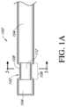
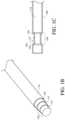


Classifications
- A—HUMAN NECESSITIES
- A61—MEDICAL OR VETERINARY SCIENCE; HYGIENE
- A61B—DIAGNOSIS; SURGERY; IDENTIFICATION
- A61B5/00—Measuring for diagnostic purposes; Identification of persons
- A61B5/145—Measuring characteristics of blood in vivo, e.g. gas concentration or pH-value ; Measuring characteristics of body fluids or tissues, e.g. interstitial fluid or cerebral tissue
- A61B5/1468—Measuring characteristics of blood in vivo, e.g. gas concentration or pH-value ; Measuring characteristics of body fluids or tissues, e.g. interstitial fluid or cerebral tissue using chemical or electrochemical methods, e.g. by polarographic means
- A61B5/1486—Measuring characteristics of blood in vivo, e.g. gas concentration or pH-value ; Measuring characteristics of body fluids or tissues, e.g. interstitial fluid or cerebral tissue using chemical or electrochemical methods, e.g. by polarographic means using enzyme electrodes, e.g. with immobilised oxidase
- A61B5/14865—Measuring characteristics of blood in vivo, e.g. gas concentration or pH-value ; Measuring characteristics of body fluids or tissues, e.g. interstitial fluid or cerebral tissue using chemical or electrochemical methods, e.g. by polarographic means using enzyme electrodes, e.g. with immobilised oxidase invasive, e.g. introduced into the body by a catheter or needle or using implanted sensors
- A—HUMAN NECESSITIES
- A61—MEDICAL OR VETERINARY SCIENCE; HYGIENE
- A61B—DIAGNOSIS; SURGERY; IDENTIFICATION
- A61B5/00—Measuring for diagnostic purposes; Identification of persons
- A61B5/145—Measuring characteristics of blood in vivo, e.g. gas concentration or pH-value ; Measuring characteristics of body fluids or tissues, e.g. interstitial fluid or cerebral tissue
- A61B5/14532—Measuring characteristics of blood in vivo, e.g. gas concentration or pH-value ; Measuring characteristics of body fluids or tissues, e.g. interstitial fluid or cerebral tissue for measuring glucose, e.g. by tissue impedance measurement
- A—HUMAN NECESSITIES
- A61—MEDICAL OR VETERINARY SCIENCE; HYGIENE
- A61B—DIAGNOSIS; SURGERY; IDENTIFICATION
- A61B5/00—Measuring for diagnostic purposes; Identification of persons
- A61B5/145—Measuring characteristics of blood in vivo, e.g. gas concentration or pH-value ; Measuring characteristics of body fluids or tissues, e.g. interstitial fluid or cerebral tissue
- A61B5/14546—Measuring characteristics of blood in vivo, e.g. gas concentration or pH-value ; Measuring characteristics of body fluids or tissues, e.g. interstitial fluid or cerebral tissue for measuring analytes not otherwise provided for, e.g. ions, cytochromes
Definitions
- the devicescomprise: a sensor configured to generate a signal indicative of a concentration of an analyte; and a sensing membrane located over the sensor.
- the sensing membranecomprises an enzyme domain comprising an enzyme, a base polymer, and a hydrophilic polymer which makes up from about 5 wt. % to about 30 wt. % of the enzyme domain.
- Electrochemical sensorsare useful in chemistry and medicine to determine the presence or concentration of a biological analyte. Such sensors are useful, for example, to monitor glucose in diabetic patients and lactate during critical care events.
- a variety of intravascular, transcutaneous and implantable sensorshave been developed for continuously detecting and quantifying blood analytes, such as blood glucose levels.
- the enzymes used in enzymatic glucose sensorsare sensitive to temperature and pH degradation.
- the processes for manufacturing enzymatic glucose sensorsare required to be conducted under pH and temperature conditions which preserve enzymatic activity.
- polymer membrane curing that occurs after application of an enzyme layeris limited to temperatures at which the enzyme does not degrade, which are typically well below preferred curing temperatures for the polymer. Curing polymer membranes at these restricted temperatures extends curing time, increasing cost and limiting throughput. Accordingly, there is a desire for enzyme stabilization in enzymatic glucose sensors so as to provide enhancement in the tolerable pH range and increased thermal stability in order to decrease manufacturing time and cost.
- a devicefor measurement of an analyte concentration, the device comprising: a sensor configured to generate a signal indicative of a concentration of an analyte; and a sensing membrane located over the sensor, the sensing membrane comprising an enzyme domain comprising an enzyme, a base polymer, and a hydrophilic polymer.
- the hydrophilic polymercomprises from about 5 wt. % to about 30 wt. % of the enzyme domain, such as about 10 wt. % to about 25 wt. % of the enzyme domain, such as from about 15 wt. % to about 20 wt. % of the enzyme domain.
- the hydrophilic polymeris selected from the group consisting of poly-N-vinylpyrrolidone (PVP), poly(ethylene glycol) (PEG), polyacrylamide, acetates, polyethylene oxide (PEO), polyethylacrylate (PEA), poly-N-vinyl-3-ethyl-2-pyrrolidone, poly-N-vinyl-4,5-dimethyl-2-pyrrolidone, poly-N,N-dimethylacrylamide, polyvinyl alcohol, polyvinyl acetate, polymers with pendent ionizable groups and copolymers or blends thereof.
- the hydrophilic polymercomprises poly-N-vinylpyrrolidone (PVP).
- the enzymeis selected from the group consisting of glucose oxidase, glucose dehydrogenase, galactose oxidase, cholesterol oxidase, amino acid oxidase, alcohol oxidase, lactate oxidase, and uricase. In some embodiments, the enzyme is glucose oxidase.
- the base polymercomprises at least one polymer selected from the group consisting of epoxies, polyolefins, polysiloxanes, polyethers, acrylics, polyesters, carbonates, and polyurethanes.
- the polyurethanescomprise a polyurethane copolymer.
- the base polymercomprises polyurethane.
- the enzyme domainfurther comprises a cross-linking agent in an amount sufficient to induce cross-linking between polymer molecules.
- the cross-linking agentcomprises a cross-linking agent selected from the group consisting of isocyanate, carbodiimide, gluteraldehyde or other aldehydes, epoxy, acrylates, free-radical based agents, ethylene glycol diglycidyl ether (EGDE), poly(ethylene glycol) diglycidyl ether (PEGDE), and dicumyl peroxide (DCP).
- the cross-linking agentcomprises from about 0.1 wt. % to about 15 wt. % of the total dry weight of the enzyme, cross-linking agent, and polymers.
- the thickness of the enzyme domainis from about 0.05 micron to about 100 microns.
- the senorcomprises an electrode.
- the sensing membranefurther comprises a resistance domain configured to control a flux of said analyte therethrough.
- the sensing membranefurther comprises an interference domain located more proximal to the sensor than the enzyme domain, wherein the interference domain comprises at least about 25% silicone by weight.
- the deviceis configured for continuous measurement of an analyte concentration. In some embodiments, the device is configured for in vivo intermittent or continuous measurement of an analyte concentration.
- the deviceis configured for glucose measurement, including continuous glucose measurement. In some embodiments, the device is configured for in vivo intermittent or continuous glucose measurement.
- a devicefor measurement of an analyte concentration, the device comprising: a sensor configured to generate a signal indicative of a concentration of an analyte; and a sensing membrane located over the sensor, the sensing membrane comprising an enzyme domain comprising an enzyme, a base polymer, and a dipolar enzyme stabilizing agent.
- the enzyme stabilizing agentreduces thermal enzyme degradation, pH-related enzyme degradation, or both.
- the dipolar enzyme stabilizing agentcomprises a zwitterionic enzyme stabilizing agent.
- the zwitterionic enzyme stabilizing agentcomprises a zwitterionic compound, precursor, or derivative thereof.
- the zwitterionic enzyme stabilizing agentcomprises a betaine compound or derivative thereof, such as a carboxyl, sulfo, or phosphor betaine compound, precursor, or derivative thereof.
- the zwitterionic enzyme stabilizing agentcomprises one or more selected from the group consisting of cocamidopropyl betaine, oleamidopropyl betaine, lauryl sulfobetaine, myristyl sulfobetaine, betaine (trimethylglycine), octyl betaine, phosphatidylcholine, glycine betaine, poly(carboxybetaine) (pCB), poly(sulfobetaine) (pSB), and precursors or derivatives thereof.
- the one or more the zwitterionic compounds or derivatives thereofcomprise one or more selected from the group consisting of poly(carboxybetaine) (pCB), poly(sulfobetaine) (pSB), and precursors or derivatives thereof.
- the zwitterionic enzyme stabilizing agentcomprises a betaine or derivative thereof, such as glycine betaine.
- the betaine or derivative thereofis a hydrolyzable cationic betaine ester.
- the hydrolyzable cationic betaine esteris a cationic poly(carboxybetaine) (pCB) ester.
- zwitterionic compoundsare by no means complete, and is not intended to be limiting. It is intended that other suitable zwitterionic compounds may be recognized by those of skill in the art.
- additional zwitterionic compounds, precursors, or derivatives thereofmay include one or more selected from the group consisting of phosphorylcholine, phosphoryl ethanolamine, phosphatidyl ethanolamine, phosphoethanolamine, phosphatidyl serine, and precursors or derivatives thereof.
- the dipolar enzyme stabilizing agentcomprises a non-zwitterionic enzyme stabilizing agent. In some related embodiments, the dipolar enzyme stabilizing agent comprises an amine oxide.
- the dipolar enzyme stabilizing agentis coated on the surface of said enzyme domain. In some embodiments, the dipolar enzyme stabilizing agent is dispersed throughout the enzyme domain. In some embodiments, the amount of dipolar enzyme stabilizing agent is less than or equal to about the dry weight of enzyme used in the enzyme domain, such as less than or equal 90%, 80%, 70%, 60%, 50%, 40%, 30%, 25%, 20%, 15%, 10%, 5%, 2%, or 1%, of the dry weight of enzyme used in the enzyme domain.
- the enzymeis selected from the group consisting of glucose oxidase, glucose dehydrogenase, galactose oxidase, cholesterol oxidase, amino acid oxidase, alcohol oxidase, lactate oxidase, and uricase. In some embodiments, the enzyme is glucose oxidase.
- the base polymercomprises at least one polymer selected from the group consisting of epoxies, polyolefins, polysiloxanes, polyethers, acrylics, polyesters, carbonates, and polyurethanes.
- the polyurethanescomprise a polyurethane copolymer.
- the base polymercomprises a polyurethane.
- the enzyme domainfurther comprises a cross-linking agent in an amount sufficient to induce cross-linking between polymer molecules.
- the cross-linking agentcomprises a cross-linking agent selected from the group consisting of isocyanate, carbodiimide, gluteraldehyde or other aldehydes, epoxy, acrylates, free-radical based agents, ethylene glycol diglycidyl ether (EGDE), poly(ethylene glycol) diglycidyl ether (PEGDE), and dicumyl peroxide (DCP).
- the cross-linking agentcomprises from about 0.1 wt. % to about 15 wt. % of the total dry weight of the enzyme, cross-linking agent, and polymers.
- the thickness of the enzyme domainis from about 0.05 micron to about 100 microns.
- the senorcomprises an electrode.
- the sensing membranefurther comprises a resistance domain configured to control a flux of said analyte therethrough.
- the sensing membranefurther comprises an interference domain located more proximal to the sensor than the enzyme domain, wherein the interference domain comprises at least about 25% silicone by weight.
- the deviceis configured for continuous measurement of an analyte concentration. In some embodiments, the device is configured for in vivo intermittent or continuous measurement of an analyte concentration.
- the deviceis configured for glucose measurement, including continuous glucose measurement. In some embodiments, the device is configured for in vivo intermittent or continuous glucose measurement.
- FIG. 1 Ais a side-view schematic illustrating an in vivo portion of an analyte sensor, in one embodiment.
- FIG. 1 Bis a perspective-view schematic illustrating an in vivo portion of an analyte sensor, in one embodiment.
- FIG. 1 Cis a side-view schematic illustrating an in vivo portion of an analyte sensor, in another embodiment.
- FIGS. 2 A- 2 Care cross-sectional views through the sensor of FIG. 1 on line 2 - 2 , illustrating various embodiments of the membrane system.
- FIG. 3is a graph illustrating the components of a signal measured by a glucose sensor (after sensor break-in was complete), in a non-diabetic volunteer host.
- FIG. 4shows comparative data demonstrating the relative difference in signal in two specific embodiments of the instant invention as compared to a prior art device in low oxygen (i.e., at 0.25 mg/L oxygen) and ambient oxygen environments at different glucose sensitivities. Details are provided in Example 2.
- FIG. 5shows comparative data demonstrating the effect of incremental increase of PVP content in the enzyme domain of a glucose sensor of one embodiment on the signal difference from the sensor in a low oxygen environment (i.e., at 0.25 mg/L oxygen) relative to ambient oxygen conditions.
- FIG. 6shows comparative data demonstrating the effect of increasing PVP content in the enzyme domain of a glucose sensor of one embodiment on the signal difference from the sensor in a low oxygen environment (i.e., at 0.25 mg/L oxygen) relative to ambient oxygen conditions. Details are provided in Example 3.
- analyteas used herein is a broad term, and is to be given its ordinary and customary meaning to a person of ordinary skill in the art (and is not to be limited to a special or customized meaning), and refers without limitation to a substance or chemical constituent in a biological fluid (for example, blood, interstitial fluid, cerebral spinal fluid, lymph fluid, urine, sweat, saliva, etc.) that can be analyzed. Analytes can include naturally occurring substances, artificial substances, metabolites, or reaction products. In some embodiments, the analyte for measurement by the sensing regions, devices, and methods is glucose.
- acarboxyprothrombinacylcarnitine
- adenine phosphoribosyl transferaseadenosine deaminase
- albuminalpha-fetoprotein
- amino acid profilesarginine (Krebs cycle), histidine/urocanic acid, homocysteine, phenylalanine/tyrosine, tryptophan); andrenostenedione
- antipyrinearabinitol enantiomers
- arginasebenzoylecgonine (cocaine); biotinidase; biopterin; c-reactive protein; carnitine; carnosinase; CD4; ceruloplasmin; chenodeoxycholic acid; chloroquine; cholesterol; cholinesterase; conjugated 1- ⁇ hydroxy-cholic acid; cortisol; creatine kinase; creatine kinas
- Salts, sugar, protein, fat, vitamins, and hormones naturally occurring in blood or interstitial fluidscan also constitute analytes in certain embodiments.
- the analytecan be naturally present in the biological fluid or endogenous, for example, a metabolic product, a hormone, an antigen, an antibody, and the like.
- the analytecan be introduced into the body or exogenous, for example, a contrast agent for imaging, a radioisotope, a chemical agent, a fluorocarbon-based synthetic blood, or a drug or pharmaceutical composition, including but not limited to: insulin; ethanol; cannabis (marijuana, tetrahydrocannabinol, hashish); inhalants (nitrous oxide, amyl nitrite, butyl nitrite, chlorohydrocarbons, hydrocarbons); cocaine (crack cocaine); stimulants (amphetamines, methamphetamines, Ritalin, Cylert, Preludin, Didrex, PreState, Voranil, Sandrex, Plegine); depressants (barbituates, methaqualone, tranquilizers such as Valium, Librium, Miltown, Serax, Equanil, Tranxene); hallucinogens (phencyclidine, lysergic acid, mescaline, peyo
- Analytessuch as neurochemicals and other chemicals generated within the body can also be analyzed, such as, for example, ascorbic acid, uric acid, dopamine, noradrenaline, 3-methoxytyramine (3MT), 3,4-dihydroxyphenylacetic acid (DOPAC), homovanillic acid (HVA), 5-hydroxytryptamine (5HT), and 5-hydroxyindoleacetic acid (FHIAA).
- continuous (or continual) analyte sensingis a broad term, and is to be given its ordinary and customary meaning to a person of ordinary skill in the art (and is not to be limited to a special or customized meaning), and refers without limitation to the period in which monitoring of analyte concentration is continuously, continually, and or intermittently (but regularly) performed, for example, about every 5 to 10 minutes.
- operable connectionis broad terms, and are to be given their ordinary and customary meaning to a person of ordinary skill in the art (and are not to be limited to a special or customized meaning), and refer without limitation to one or more components linked to another component(s) in a manner that allows transmission of signals between the components.
- one or more electrodescan be used to detect the amount of analyte in a sample and convert that information into a signal; the signal can then be transmitted to a circuit.
- the electrodeis ‘operably linked’ to the electronic circuitry.
- hostas used herein is a broad term, and is to be given its ordinary and customary meaning to a person of ordinary skill in the art (and is not to be limited to a special or customized meaning), and refers without limitation to animals (e.g. humans) and plants.
- electrochemically reactive surfaceand ‘electroactive surface’ as used herein are broad terms, and are to be given their ordinary and customary meaning to a person of ordinary skill in the art (and are not to be limited to a special or customized meaning), and refer without limitation to the surface of an electrode where an electrochemical reaction takes place.
- H 2 O 2hydrogen peroxide
- glucose oxidaseproduces H 2 O 2 as a byproduct.
- the H 2 O 2reacts with the surface of the working electrode to produce two protons (2H + ), two electrons (2e ⁇ ), and one molecule of oxygen (O 2 ), which produces the electric current being detected.
- a reducible speciesfor example, O 2 is reduced at the electrode surface in order to balance the current being generated by the working electrode.
- sensing region‘sensor,’ and ‘sensing mechanism’ as used herein are broad terms, and are to be given their ordinary and customary meaning to a person of ordinary skill in the art (and are not to be limited to a special or customized meaning), and refer without limitation to the region or mechanism of a monitoring device responsible for the detection of a particular analyte.
- raw data streamand ‘data stream’ as used herein are broad terms, and are to be given their ordinary and customary meaning to a person of ordinary skill in the art (and are not to be limited to a special or customized meaning), and refer without limitation to an analog or digital signal directly related to the measured glucose concentration from the glucose sensor.
- the raw data streamis digital data in ‘counts’ converted by an A/D converter from an analog signal (for example, voltage or amps) representative of a glucose concentration.
- the termsbroadly encompass a plurality of time spaced data points from a substantially continuous glucose sensor, which comprises individual measurements taken at time intervals ranging from fractions of a second up to, for example, 1, 2, or 5 minutes or longer.
- countsis a broad term, and is to be given its ordinary and customary meaning to a person of ordinary skill in the art (and is not to be limited to a special or customized meaning), and refers without limitation to a unit of measurement of a digital signal.
- a raw data stream measured in countsis directly related to a voltage (for example, converted by an A/D converter), which is directly related to current from the working electrode.
- counter electrode voltage measured in countsis directly related to a voltage.
- electrical potentialis a broad term, and is to be given its ordinary and customary meaning to a person of ordinary skill in the art (and is not to be limited to a special or customized meaning), and refers without limitation to the electrical potential difference between two points in a circuit which is the cause of the flow of a current.
- a sensorincludes a membrane system having a bioprotective domain and an enzyme domain. If the sensor is deemed to be the point of reference and the bioprotective domain is positioned farther from the sensor than the enzyme domain, then the bioprotective domain is more distal to the sensor than the enzyme domain.
- proximal tois a broad term, and is to be given its ordinary and customary meaning to a person of ordinary skill in the art (and is not to be limited to a special or customized meaning), and refers without limitation to the spatial relationship between various elements in comparison to a particular point of reference.
- some embodiments of a deviceinclude a membrane system having a bioprotective domain and an enzyme domain. If the sensor is deemed to be the point of reference and the enzyme domain is positioned nearer to the sensor than the bioprotective domain, then the enzyme domain is more proximal to the sensor than the bioprotective domain.
- interferentsand ‘interfering species’ as used herein are broad terms, and are to be given their ordinary and customary meaning to a person of ordinary skill in the art (and are not to be limited to a special or customized meaning), and refer without limitation to effects or species that interfere with the measurement of an analyte of interest in a sensor to produce a signal that does not accurately represent the analyte measurement.
- interfering speciescan include compounds with an oxidation potential that overlaps with that of the analyte to be measured.
- domainis a broad term, and is to be given its ordinary and customary meaning to a person of ordinary skill in the art (and is not to be limited to a special or customized meaning), and refers without limitation to regions of a membrane that can be layers, uniform or non-uniform gradients (i.e., anisotropic) or provided as portions of the membrane.
- sensing membraneand ‘membrane system’ as used herein are broad terms, and are to be given their ordinary and customary meaning to a person of ordinary skill in the art (and are not to be limited to a special or customized meaning), and refers without limitation to a permeable or semi-permeable membrane that can comprise one or more domains and constructed of materials of a few microns thickness or more, which are permeable to oxygen and may or may not be permeable to an analyte of interest.
- the sensing membrane or membrane systemmay comprise an immobilized glucose oxidase enzyme, which enables an electrochemical reaction to occur to measure a concentration of glucose.
- baselineis a broad term, and is to be given its ordinary and customary meaning to a person of ordinary skill in the art (and is not to be limited to a special or customized meaning), and refers without limitation to the component of an analyte sensor signal that is not related to the analyte concentration.
- the baselineis composed substantially of signal contribution due to factors other than glucose (for example, interfering species, non-reaction-related hydrogen peroxide, or other electroactive species with an oxidation potential that overlaps with hydrogen peroxide).
- sensitivityis a broad term, and is to be given its ordinary and customary meaning to a person of ordinary skill in the art (and is not to be limited to a special or customized meaning), and refers without limitation to an amount of electrical current produced by a predetermined amount (unit) of the measured analyte.
- a sensorhas a sensitivity (or slope) of from about 1 to about 100 picoAmps of current for every 1 mg/dL of glucose analyte.
- hydrophilic polymeras used herein is a broad term, and is to be given its ordinary and customary meaning to a person of ordinary skill in the art (and is not to be limited to a special or customize meaning), and refer without limitation to polymers which will absorb in atmospheric conditions more than about 30% of its weight in water under common hydrophilicity test conditions.
- a common measure of hydrophilicity of polymersis water absorption by the bulk polymer within 24 hours or at equilibrium, as detailed in ASTM D570 (standard method to measure water absorption by polymers).
- dipoleor ‘dipolar compound’ as used herein is a broad term, and is to be given its ordinary and customary meaning to a person of ordinary skill in the art (and is not to be limited to a special or customized meaning), and refer without limitation to compounds in which a neutral molecule of the compound has a positive and negative electrical charge at different locations within the molecule.
- the positive and negative electrical charges within the moleculecan be any non-zero charges up to and including full unit charges.
- zwitterionand ‘zwitterionic compound’ as used herein are broad terms, and are to be given their ordinary and customary meaning to a person of ordinary skill in the art (and is not to be limited to a special or customized meaning), and refer without limitation to compounds in which a neutral molecule of the compound has a unit positive and unit negative electrical charge at different locations within the molecule. Such compounds are a type of dipolar compounds, and are also sometimes known as ‘inner salts’.
- a ‘zwitterion precursor’ or ‘zwitterionic compound precursor’is any compound that is not itself a zwitterion, but may become a zwitterion in a final or transition state through chemical reaction.
- devicescomprise zwitterion precursors that may be converted to zwitterions prior to in vivo implantation of the device.
- devicescomprise zwitterion precursors that may be converted to zwitterions by some chemical reaction that occurs after in vivo implantation of the device.
- a ‘zwitterion derivative’ or ‘zwitterionic compound derivative’is any compound that is not itself a zwitterion, but rather is the product of a chemical reaction where a zwitterion is converted to a non-zwitterion. Such reactions may be reversible, such that under certain conditions zwitterion derivatives may act as zwitterion precursors.
- hydrolyzable betaine esters formed from zwitterionic betainesare cationic zwitterion derivatives that under the appropriate conditions are capable of undergoing hydrolysis to revert to zwitterionic betaines.
- non-zwitterionic dipoleand ‘non-zwitterionic dipolar compound’ as used herein are broad terms, and are to be given their ordinary and customary meaning to a person of ordinary skill in the art (and is not to be limited to a special or customized meaning), and refer without limitation to compounds in which a neutral molecule of the compound have a positive and negative electrical charge at different locations within the molecule.
- the positive and negative electrical charges within the moleculecan be any non-zero, but less than full unit, charges.
- polyampholytic polymeras used herein is a broad term, and is to be given its ordinary and customary meaning to a person of ordinary skill in the art (and is not to be limited to a special or customized meaning), and refers without limitation to polymers comprising both cationic and anionic end groups.
- Such polymersmay be prepared to have about equal numbers of positive and negative charges, and thus the surface of such polymers may be about net neutrally charged.
- such polymersmay be prepared to have an excess of either positive or negative charges, and thus the surface of such polymers may be net positively or negatively charged, respectively.
- Eq and Eqs(equivalents); mEq (milliequivalents); M (molar); mM (millimolar) ⁇ M (micromolar); N (Normal); mol (moles); mmol (millimoles); ⁇ mol (micromoles); nmol (nanomoles); g (grams); mg (milligrams); ⁇ g (micrograms); Kg (kilograms); L (liters); mL (milliliters); dL (deciliters); ⁇ L (microliters); cm (centimeters); mm (millimeters); ⁇ m (micrometers); nm (nanometers); h and hr (hours); min. (minutes); s and sec (seconds); ° C. (degrees Centigrade).
- Membrane systems of the various embodimentsare suitable for use with implantable devices in contact with a biological fluid.
- the membrane systemscan be utilized with implantable devices, such as devices for monitoring and determining analyte levels in a biological fluid, for example, devices for monitoring glucose levels for individuals having diabetes.
- the analyte-measuring deviceis a continuous device.
- the analyte-measuring devicecan employ any suitable sensing element to provide the raw signal, including but not limited to those involving enzymatic, chemical, physical, electrochemical, spectrophotometric, polarimetric, calorimetric, radiometric, immunochemical, or like elements.
- membrane systemsare not limited to use in devices that measure or monitor glucose.
- membrane systemsare suitable for use in any of a variety of devices, including, for example, devices that detect and quantify other analytes present in biological fluids (e.g., cholesterol, amino acids, alcohol, galactose, and lactate), cell transplantation devices (see, for example, U.S. Pat. Nos. 6,015,572, 5,964,745, and 6,083,523), drug delivery devices (see, for example, U.S. Pat. Nos. 5,458,631, 5,820,589, and 5,972,369), and the like.
- biological fluidse.g., cholesterol, amino acids, alcohol, galactose, and lactate
- cell transplantation devicessee, for example, U.S. Pat. Nos. 6,015,572, 5,964,745, and 6,083,523
- drug delivery devicessee, for example, U.S. Pat. Nos. 5,458,631, 5,820,589, and 5,972,369), and
- the analyte sensoris an implantable glucose sensor, such as described with reference to U.S. Pat. No. 6,001,067 and U.S. Patent Publication No. US-2005-0027463-A1.
- the analyte sensoris a glucose sensor, such as described with reference to U.S. Patent Publication No. US-2006-0020187-A1.
- the sensoris configured to be implanted in a host vessel or extra-corporeally, such as is described in U.S. Patent Publication No. US-2007-0027385-A1, U.S. Patent Publication No. US-2008-0119703-A1, U.S. Patent Publication No. US-2008-0108942-A1, and U.S.
- the sensoris configured as a dual-electrode sensor, such as described in U.S. Patent Publication No. US-2005-0143635-A1, U.S. Patent Publication No. US-2007-0027385-A1, U.S. Patent Publication No. US-2007-0213611-A1, and U.S. Patent Publication No. US-2008-0083617-A1.
- the continuous glucose sensorcomprises a sensor such as described in U.S. Pat. No. 6,565,509 to Say et al., for example.
- the continuous glucose sensorcomprises a subcutaneous sensor such as described with reference to U.S. Pat. No.
- the continuous glucose sensorcomprises a refillable subcutaneous sensor such as described with reference to U.S. Pat. No. 6,512,939 to Colvin et al., for example.
- the continuous glucose sensorcomprises an intravascular sensor such as described with reference to U.S. Pat. No. 6,477,395 to Schulman et al., for example.
- the continuous glucose sensorcomprises an intravascular sensor such as described with reference to U.S. Pat. No. 6,424,847 to Mastrototaro et al.
- the electrode systemcan be used with any of a variety of known in vivo analyte sensors or monitors, such as U.S. Pat. No. 7,157,528 to Ward; U.S. Pat. No. 6,212,416 to Ward et al.; U.S. Pat. No. 6,119,028 to Schulman et al.; U.S. Pat. No. 6,400,974 to Lesho; U.S. Pat. No. 6,595,919 to Berner et al.; U.S. Pat. No. 6,141,573 to Kurnik et al.; U.S. Pat. No.
- a long term sensore.g., wholly implantable or intravascular
- a time periodof from about 30 days or less to about one year or more (e.g., a sensor session).
- a short term sensor(e.g., one that is transcutaneous or intravascular) is configured and arranged to function for a time period of from about a few hours to about 30 days, including a time period of about 1, 2, 3, 4, 5, 6, 7, 8, 9, 10, 11, 12, 13, 14, 15, 16, 17, 18, 19, 20, 21, 22, 23, 24, 25, 26, 27, 28 or 29 days (e.g., a sensor session).
- the term ‘sensor session’is a broad term and refers without limitation to the period of time the sensor is applied to (e.g., implanted in) the host or is being used to obtain sensor values.
- a sensor sessionextends from the time of sensor implantation (e.g., including insertion of the sensor into subcutaneous tissue and placing the sensor into fluid communication with a host's circulatory system) to the time when the sensor is removed.
- FIGS. 1 A- 1 Cillustrate one exemplary embodiment of a continuous analyte sensor 100 , which includes an elongated conductive body 102 .
- the elongated conductive body 102includes a core 110 (see FIG. 1 B ) and a first layer 112 at least partially surrounding the core.
- the first layerincludes a working electrode (e.g., located in window 106 ) and a membrane 108 located over the working electrode configured and arranged for multi-axis bending.
- the core and first layercan be of a single material (e.g., platinum).
- the elongated conductive bodyis a composite of at least two materials, such as a composite of two conductive materials, or a composite of at least one conductive material and at least one non-conductive material.
- the elongated conductive bodycomprises a plurality of layers.
- additional layerscan be included in some embodiments.
- the layersare coaxial.
- the elongated conductive bodymay be long and thin, yet flexible and strong.
- the smallest dimension of the elongated conductive bodyis less than about 0.1 inches, 0.075 inches, 0.05 inches, 0.025 inches, 0.01 inches, 0.004 inches, or 0.002 inches.
- the cross-section of the elongated conductive bodycan be ovoid, rectangular, triangular, polyhedral, star-shaped, C-shaped, T-shaped, X-shaped, Y-Shaped, irregular, or the like.
- a conductive wire electrodeis employed as a core.
- the conductive layerscan be comprised of any suitable material.
- the materials used to form the elongated conductive bodycan be strong and hard, and therefore are resistant to breakage.
- the ultimate tensile strength of the elongated conductive bodyis from about 80 kPsi to about 500 kPsi.
- the Young's modulus of the elongated conductive bodyis from about 160 GPa to about 220 GPa.
- the yield strength of the elongated conductive bodyis from about 60 kPsi to about 2200 MPa.
- the sensor's small diameterprovides (e.g., imparts, enables) flexibility to these materials, and therefore to the sensor as a whole.
- the sensorcan withstand repeated forces applied to it by surrounding tissue.
- One measurement of the sensor's ability to withstand the implantation environmentis fatigue life, which is described in greater detail in the section entitled “Multi-Axis Bending.”
- the fatigue life of the sensoris at least 1,000 cycles of flexing of from about 28° to about 110° at a bend radius of about 0.125-inches.
- the core 110(or a component thereof) provides electrical conduction for an electrical signal from the working electrode to sensor electronics (not shown), which are described elsewhere herein.
- the core 110comprises a conductive material, such as stainless steel, titanium, tantalum, a conductive polymer, and/or the like.
- the coreis formed from a non-conductive material, such as a non-conductive polymer.
- the corecomprises a plurality of layers of materials.
- the coreincludes an inner core and an outer core.
- the inner coreis formed of a first conductive material and the outer core is formed of a second conductive material.
- the first conductive materialis stainless steel, titanium, tantalum, a conductive polymer, an alloy, and/or the like
- the second conductive materialis conductive material selected to provide electrical conduction between the core and the first layer, and/or to attach the first layer to the core (e.g., if the first layer is formed of a material that does not attach well to the core material).
- the coreis formed of a non-conductive material (e.g., a non-conductive metal and/or a non-conductive polymer) and the first layer is a conductive material, such as stainless steel, titanium, tantalum, a conductive polymer, and/or the like.
- the core and the first layercan be of a single (or same) material, e.g., platinum.
- the first layer 112is formed of a conductive material.
- the working electrodeis an exposed portion of the surface of the first layer.
- the first layeris formed of a material configured to provide a suitable electroactive surface for the working electrode, a material such as but not limited to platinum, platinum-iridium, gold, palladium, iridium, graphite, carbon, a conductive polymer, an alloy and/or the like.
- a second layer 104surrounds a least a portion of the first layer 112 , thereby defining the boundaries of the working electrode.
- the second layer 104serves as an insulator and is formed of an insulating material, such as polyimide, polyurethane, parylene, or any other known insulating materials.
- the second layeris disposed on the first layer and configured such that the working electrode is exposed via window 106 .
- an elongated conductive bodyincluding the core, the first layer and the second layer, is provided, and the working electrode is exposed (i.e., formed) by removing a portion of the second layer, thereby forming the window 106 through which the electroactive surface of the working electrode (e.g., the exposed surface of the first layer) is exposed.
- the working electrodeis exposed by (e.g., window 106 is formed by) removing a portion of the second and (optionally) third layers.
- Removal of coating materials from one or more layers of elongated conductive bodycan be performed by hand, excimer lasing, chemical etching, laser ablation, grit-blasting, or the like.
- the senorfurther comprises a third layer 114 comprising a conductive material.
- the third layermay comprise a reference electrode, which may be formed of a silver-containing material that is applied onto the second layer (e.g., an insulator).
- the silver-containing materialmay include any of a variety of materials and be in various forms, such as, Ag/AgCl-polymer pastes, paints, polymer-based conducting mixture, and/or inks that are commercially available, for example.
- the third layercan be processed using a pasting/dipping/coating step, for example, using a die-metered dip coating process.
- an Ag/AgCl polymer pasteis applied to an elongated body by dip-coating the body (e.g., using a meniscus coating technique) and then drawing the body through a die to meter the coating to a precise thickness. In some embodiments, multiple coating steps are used to build up the coating to a predetermined thickness. Such a drawing method can be utilized for forming one or more of the electrodes in the device depicted in FIG. 1 B .
- the silver grain in the Ag/AgCl solution or pastecan have an average particle size corresponding to a maximum particle dimension that is less than about 100 microns, or less than about 50 microns, or less than about 30 microns, or less than about 20 microns, or less than about 10 microns, or less than about 5 microns.
- the silver chloride grain in the Ag/AgCl solution or pastecan have an average particle size corresponding to a maximum particle dimension that is less than about 100 microns, or less than about 80 microns, or less than about 60 microns, or less than about 50 microns, or less than about 20 microns, or less than about 10 microns.
- the silver grain and the silver chloride grainmay be incorporated at a ratio of the silver chloride grain:silver grain of from about 0.01:1 to 2:1 by weight, or from about 0.1:1 to 1:1.
- the silver grains and the silver chloride grainsare then mixed with a carrier (e.g., a polyurethane) to form a solution or paste.
- a carriere.g., a polyurethane
- the Ag/AgCl componentform from about 10% to about 65% by weight of the total Ag/AgCl solution or paste, or from about 20% to about 50%, or from about 23% to about 37%.
- the Ag/AgCl solution or pastehas a viscosity (under ambient conditions) that is from about 1 to about 500 centipoise, or from about 10 to about 300 centipoise, of from about 50 to about 150 centipoise.
- Ag/AgCl particlesare mixed into a polymer, such as polyurethane, polyimide, or the like, to form the silver-containing material for the reference electrode.
- the third layeris cured, for example, by using an oven or other curing process.
- a covering of fluid-permeable polymer with conductive particles (e.g., carbon particles) thereinis applied over the reference electrode and/or third layer.
- a layer of insulating materialis located over a portion of the silver-containing material, in some embodiments.
- the elongated conductive bodyfurther comprises one or more intermediate layers located between the core and the first layer.
- the intermediate layeris an insulator, a conductor, a polymer, and/or an adhesive.
- the ratio between the thickness of the Ag/AgCl layer and the thickness of an insulator (e.g., polyurethane or polyimide) layercan be controlled, so as to allow for a certain error margin (e.g., an error margin resulting from the etching process) that would not result in a defective sensor (e.g., due to a defect resulting from an etching process that cuts into a depth more than intended, thereby unintentionally exposing an electroactive surface).
- This ratiomay be different depending on the type of etching process used, whether it is laser ablation, grit blasting, chemical etching, or some other etching method.
- the ratio of the thickness of the Ag/AgCl layer and the thickness of the polyurethane layercan be from about 1:5 to about 1:1, or from about 1:3 to about 1:2.
- the corecomprises a non-conductive polymer and the first layer comprises a conductive material.
- a sensor configurationcan sometimes provide reduced material costs, in that it replaces a typically expensive material with an inexpensive material.
- the coreis formed of a non-conductive polymer, such as, a nylon or polyester filament, string or cord, which can be coated and/or plated with a conductive material, such as platinum, platinum-iridium, gold, palladium, iridium, graphite, carbon, a conductive polymer, and allows or combinations thereof.
- the senoralso includes a membrane 108 covering at least a portion of the working electrode.
- Membranesare discussed in detail in greater detail elsewhere herein, for example, with reference to FIGS. 2 A- 2 C .
- a portion of the coated assembly structurecan be stripped or otherwise removed, for example, by hand, excimer lasing, chemical etching, laser ablation, grit-blasting, or the like, to expose the electroactive surfaces.
- a portion of the electrodecan be masked prior to depositing the insulator in order to maintain an exposed electroactive surface area.
- a radial windowis formed through the insulating material to expose a circumferential electroactive surface of the working electrode.
- sections of electroactive surface of the reference electrodeare exposed.
- the sections of electroactive surfacecan be masked during deposition of an outer insulating layer or etched after deposition of an outer insulating layer.
- cellular attack or migration of cells to the sensorcan cause reduced sensitivity or function of the device, particularly after the first day of implantation.
- the exposed electroactive surfaceis distributed circumferentially about the sensor (e.g. as in a radial window)
- the available surface area for reactioncan be sufficiently distributed so as to minimize the effect of local cellular invasion of the sensor on the sensor signal.
- a tangential exposed electroactive windowcan be formed, for example, by stripping only one side of the coated assembly structure.
- the windowcan be provided at the tip of the coated assembly structure such that the electroactive surfaces are exposed at the tip of the sensor.
- Other methods and configurations for exposing electroactive surfacescan also be employed.
- additional electrodescan be included within the assembly, for example, a three-electrode system (working, reference, and counter electrodes) and an additional working electrode (e.g. an electrode which can be used to generate oxygen, which is configured as a baseline subtracting electrode, or which is configured for measuring additional analytes).
- a three-electrode systemworking, reference, and counter electrodes
- an additional working electrodee.g. an electrode which can be used to generate oxygen, which is configured as a baseline subtracting electrode, or which is configured for measuring additional analytes.
- U.S. Pat. No. 7,081,195, U.S. Patent Publication No. US-2005-0143635-A1 and U.S. Patent Publication No. US-2007-0027385-A1each of which are incorporated herein by reference, describe some systems and methods for implementing and using additional working, counter, and reference electrodes.
- the two working electrodesare juxtapositioned, around which the reference electrode is disposed (e.g. helically wound).
- the working electrodescan be formed in a double-, triple-, quad-, etc. helix configuration along the length of the sensor (for example, surrounding a reference electrode, insulated rod, or other support structure).
- the resulting electrode systemcan be configured with an appropriate membrane system, wherein the first working electrode is configured to measure a first signal comprising glucose and baseline signals, and the additional working electrode is configured to measure a baseline signal consisting of the baseline signal only.
- the second working electrodemay be configured to be substantially similar to the first working electrode, but without an enzyme disposed thereon.
- the baseline signalcan be determined and subtracted from the first signal to generate a difference signal, i.e., a glucose-only signal that is substantially not subject to fluctuations in the baseline or interfering species on the signal, such as described in U.S. Patent Publication No. US-2005-0143635-A1, U.S. Patent Publication No. US-2007-0027385-A1, and U.S. Patent Publication No. US-2007-0213611-A1, and U.S. Patent Publication No. US-2008-0083617-A1, which are incorporated herein by reference in their entirety.
- the working electrodesmay sometimes be slightly different from each other.
- two working electrodeseven when manufactured from a single facility may slightly differ in thickness or permeability because of the electrodes' high sensitivity to environmental conditions (e.g. temperature, humidity) during fabrication.
- the working electrodes of a dual-electrode systemmay sometimes have varying diffusion, membrane thickness, and diffusion characteristics.
- the above-described difference signali.e., a glucose-only signal, generated from subtracting the baseline signal from the first signal
- both working electrodesmay be fabricated with one or more membranes that each includes a bioprotective layer, which is described in more detail elsewhere herein.
- the sensing regionmay include any of a variety of electrode configurations.
- the sensing regionin addition to one or more glucose-measuring working electrodes, may also include a reference electrode or other electrodes associated with the working electrode.
- the sensing regionmay also include a separate reference or counter electrode associated with one or more optional auxiliary working electrodes.
- the sensing regionmay include a glucose-measuring working electrode, an auxiliary working electrode, two counter electrodes (one for each working electrode), and one shared reference electrode.
- the sensing regionmay include a glucose-measuring working electrode, an auxiliary working electrode, two reference electrodes, and one shared counter electrode.
- U.S. Patent Publication No. US-2008-0119703-A1 and U.S. Patent Publication No. US-2005-0245799-A1describe additional configurations for using the continuous sensor in different body locations.
- the sensoris configured for transcutaneous implantation in the host.
- the sensoris configured for insertion into the circulatory system, such as a peripheral vein or artery.
- the sensoris configured for insertion into the central circulatory system, such as but not limited to the vena cava.
- the senorcan be placed in an extracorporeal circulation system, such as but not limited to an intravascular access device providing extracorporeal access to a blood vessel, an intravenous fluid infusion system, an extracorporeal blood chemistry analysis device, a dialysis machine, a heart-lung machine (i.e., a device used to provide blood circulation and oxygenation while the heart is stopped during heart surgery), etc.
- the sensorcan be configured to be wholly implantable, as described in U.S. Pat. No. 6,001,067.
- FIG. 2 Ais a cross-sectional view through the sensor of FIG. 1 A on line 2 - 2 , illustrating one embodiment of the membrane system 208 .
- the membrane systemincludes an interference domain 242 , an enzyme domain 244 , and a diffusion resistance domain 246 located around the working electrode 238 , all of which are described in more detail elsewhere herein.
- the membrane systemmay include a bioprotective domain 248 , also referred to as a cell-impermeable domain or biointerface domain, comprising a surface-modified base polymer as described in more detail elsewhere herein.
- a unitary diffusion resistance domain and bioprotective domainmay be included in the membrane system (e.g., wherein the functionality of both domains is incorporated into one domain, i.e., the bioprotective domain).
- the sensoris configured for short-term implantation (e.g., from about 1 to 30 days).
- the membrane system 208can be modified for use in other devices, for example, by including only one or more of the domains, or additional domains.
- the membrane systemmay include an electrode domain 236 .
- the electrode domain 236is provided to ensure that an electrochemical reaction occurs between the electroactive surfaces of the working electrode and the reference electrode, and thus the electrode domain may be situated more proximal to the electroactive surfaces than the interference and/or enzyme domain.
- the electrode domainmay include a coating that maintains a layer of water at the electrochemically reactive surfaces of the sensor. In other words, the electrode domain may be present to provide an environment between the surfaces of the working electrode and the reference electrode, which facilitates an electrochemical reaction between the electrodes.
- any of the domains illustrated in FIGS. 2 A- 2 Cmay be omitted, altered, substituted for, and/or incorporated together without departing from the spirit of the preferred embodiments.
- sensing membranes modified for other sensorsmay include fewer or additional layers.
- the membrane systemmay comprise one electrode layer, one enzyme layer, and two bioprotective layers, but in other embodiments, the membrane system may comprise one electrode layer, two enzyme layers, and one bioprotective layer.
- the bioprotective layermay be configured to function as the diffusion resistance domain and control the flux of the analyte (e.g., glucose) to the underlying membrane layers.
- one or more domains of the sensing membranesmay be formed from materials such as silicone, polytetrafluoroethylene, polyethylene-co-tetrafluoroethylene, polyolefin, polyester, polycarbonate, biostable polytetrafluoroethylene, homopolymers, copolymers, terpolymers of polyurethanes, polypropylene (PP), polyvinylchloride (PVC), polyvinylidene fluoride (PVDF), polybutylene terephthalate (PBT), polymethylmethacrylate (PMMA), polyether ether ketone (PEEK), polyurethanes, cellulosic polymers, poly(ethylene oxide), poly(propylene oxide) and copolymers and blends thereof, polysulfones and block copolymers thereof including, for example, di-block, tri-block, alternating, random and graft copolymers.
- siliconepolytetrafluoroethylene
- the sensing membranecan be deposited on the electroactive surfaces of the electrode material using known thin or thick film techniques (for example, spraying, electro-depositing, dipping, or the like). It should be appreciated that the sensing membrane located over the working electrode does not have to have the same structure as the sensing membrane located over the reference electrode; for example, the enzyme domain deposited over the working electrode does not necessarily need to be deposited over the reference or counter electrodes.
- FIGS. 2 A- 2 Cinvolve circumferentially extending membrane systems
- the membranes described hereinmay be applied to any planar or non-planar surface, for example, the substrate-based sensor structure of U.S. Pat. No. 6,565,509 to Say et al.
- analyte sensor systemshave electronics associated therewith, also referred to as a ‘computer system’ that can include hardware, firmware, or software that enable measurement and processing of data indicative of analyte levels in the host.
- the electronicsinclude a potentiostat, a power source for providing power to the sensor, and other components useful for signal processing.
- some or all of the electronicscan be in wired or wireless communication with the sensor or other portions of the electronics.
- a potentiostat disposed on the devicecan be wired to the remaining electronics (e.g. a processor, a recorder, a transmitter, a receiver, etc.), which reside on the bedside.
- some portion of the electronicsis wirelessly connected to another portion of the electronics (e.g., a receiver), such as by infrared (IR) or RF.
- IRinfrared
- RFradio frequency
- a potentiostatis operably connected to the electrode(s) (such as described elsewhere herein), which biases the sensor to enable measurement of a current signal indicative of the analyte concentration in the host (also referred to as the analog portion).
- the potentiostatincludes a resistor that translates the current into voltage.
- a current to frequency converteris provided that is configured to continuously integrate the measured current, for example, using a charge counting device.
- the electronicsinclude an A/D converter that digitizes the analog signal into a digital signal, also referred to as ‘counts’ for processing. Accordingly, the resulting raw data stream in counts, also referred to as raw sensor data, is directly related to the current measured by the potentiostat.
- the electronicsinclude a processor module that includes the central control unit that controls the processing of the sensor system.
- the processor moduleincludes a microprocessor, however a computer system other than a microprocessor can be used to process data as described herein, for example an ASIC can be used for some or all of the sensor's central processing.
- the processortypically provides semi-permanent storage of data, for example, storing data such as sensor identifier (ID) and programming to process data streams (for example, programming for data smoothing or replacement of signal artifacts such as is described in U.S. Patent Publication No. US-2005-0043598-A1).
- the processoradditionally can be used for the system's cache memory, for example for temporarily storing recent sensor data.
- the processor modulecomprises memory storage components such as ROM, RAM, dynamic-RAM, static-RAM, non-static RAM, EEPROM, rewritable ROMs, flash memory, and the like.
- the processor modulecomprises a digital filter, for example, an infinite impulse response (IIR) or finite impulse response (FIR) filter, configured to smooth the raw data stream.
- digital filtersare programmed to filter data sampled at a predetermined time interval (also referred to as a sample rate).
- time intervalsalso referred to as a sample rate.
- the processor modulecan be programmed to request a digital value from the A/D converter at a predetermined time interval, also referred to as the acquisition time.
- the values obtained by the processorare advantageously averaged over the acquisition time due the continuity of the current measurement. Accordingly, the acquisition time determines the sample rate of the digital filter.
- the processor moduleis configured to build the data packet for transmission to an outside source, for example, an RF transmission to a receiver.
- the data packetcomprises a plurality of bits that can include a preamble, a unique identifier identifying the electronics unit, the receiver, or both, (e.g. sensor ID code), data (e.g. raw data, filtered data, or an integrated value) or error detection or correction.
- the data (transmission) packethas a length of from about 8 bits to about 128 bits, preferably about 48 bits; however, larger or smaller packets can be desirable in certain embodiments.
- the processor modulecan be configured to transmit any combination of raw or filtered data.
- the transmission packetcontains a fixed preamble, a unique ID of the electronics unit, a single five-minute average (e.g. integrated) sensor data value, and a cyclic redundancy code (CRC).
- CRCcyclic redundancy code
- the processorfurther performs the processing, such as storing data, analyzing data streams, calibrating analyte sensor data, estimating analyte values, comparing estimated analyte values with time corresponding measured analyte values, analyzing a variation of estimated analyte values, downloading data, and controlling the user interface by providing analyte values, prompts, messages, warnings, alarms, and the like.
- the processorincludes hardware and software that performs the processing described herein, for example flash memory provides permanent or semi-permanent storage of data, storing data such as sensor ID, receiver ID, and programming to process data streams (for example, programming for performing estimation and other algorithms described elsewhere herein) and random access memory (RAM) stores the system's cache memory and is helpful in data processing.
- flash memoryprovides permanent or semi-permanent storage of data, storing data such as sensor ID, receiver ID, and programming to process data streams (for example, programming for performing estimation and other algorithms described elsewhere herein) and random access memory (RAM) stores the system's cache memory and is helpful in data processing.
- RAMrandom access memory
- some portion of the data processingcan be accomplished at another (e.g. remote) processor and can be configured to be in wired or wireless connection therewith.
- an output modulewhich is integral with or operatively connected with the processor, includes programming for generating output based on the data stream received from the sensor system and it's processing incurred in the processor. In some embodiments, output is generated via a user interface.
- implantable sensorsmeasure a signal related to an analyte of interest in a host.
- an electrochemical sensorcan measure glucose, creatinine, or urea in a host, such as an animal (e.g. a human).
- the signalis converted mathematically to a numeric value indicative of analyte status, such as analyte concentration, as described in more detail elsewhere herein.
- the signal generated by conventional analyte sensorscontains some noise. Noise is clinically important because it can induce error and can reduce sensor performance, such as by providing a signal that causes the analyte concentration to appear higher or lower than the actual analyte concentration. For example, upward or high noise (e.g.
- noise that causes the signal to increasecan cause the reading of the host's glucose concentration to appear higher than the actual value, which in turn can lead to improper treatment decisions.
- downward or low noisee.g. noise that causes the signal to decrease
- noise reductionis desirable.
- the signal detected by the sensorcan be broken down into its component parts.
- the total signalcan be divided into an ‘analyte component,’ which is representative of analyte (e.g., glucose) concentration, and a ‘noise component,’ which is caused by non-analyte-related species that have a redox potential that substantially overlaps with the redox potential of the analyte (or measured species, e.g. H 2 O 2 ) at an applied voltage.
- the noise componentcan be further divided into its component parts, e.g. constant and non-constant noise.
- ‘constant noise’(sometimes referred to as constant background or baseline) is caused by non-analyte-related factors that are relatively stable over time, including but not limited to electroactive species that arise from generally constant (e.g. daily) metabolic processes. Constant noise can vary widely between hosts.
- ‘non-constant noise’(sometimes referred to as non-constant background) is generally caused by non-constant, non-analyte-related species (e.g. non-constant noise-causing electroactive species) that may arise during transient events, such as during host metabolic processes (e.g. wound healing or in response to an illness), or due to ingestion of certain compounds (e.g. certain drugs).
- noisecan be caused by a variety of noise-causing electroactive species, which are discussed in detail elsewhere herein.
- FIG. 3is a graph illustrating the components of a signal measured by a transcutaneous glucose sensor (after sensor break-in was complete), in a non-diabetic volunteer host.
- the Y-axisindicates the signal amplitude (in counts) detected by the sensor.
- the total signal collected by the sensoris represented by line 1000 , which includes components related to glucose, constant noise, and non-constant noise, which are described in more detail elsewhere herein.
- the total signalis a raw data stream, which can include an averaged or integrated signal, for example, using a charge-counting device.
- the non-constant noise component of the total signalis represented by line 1010 .
- the non-constant noise component 1010 of the total signal 1000can be obtained by filtering the total signal 1000 to obtain a filtered signal 1020 using any of a variety of known filtering techniques, and then subtracting the filtered signal 1020 from the total signal 1000 .
- the total signalcan be filtered using linear regression analysis of the n (e.g. 10) most recent sampled sensor values.
- the total signalcan be filtered using non-linear regression.
- the total signalcan be filtered using a trimmed regression, which is a linear regression of a trimmed mean (e.g., after rejecting wide excursions of any point from the regression line).
- the sensorcalculates a trimmed mean (e.g., removes highest and lowest measurements from a data set) and then regresses the remaining measurements to estimate the glucose value.
- the total signalcan be filtered using a non-recursive filter, such as a finite impulse response (FIR) filter.
- FIRfinite impulse response
- An FIR filteris a digital signal filter, in which every sample of output is the weighted sum of past and current samples of input, using only some finite number of past samples.
- the total signalcan be filtered using a recursive filter, such as an infinite impulse response (IIR) filter.
- IIRinfinite impulse response
- An IIR filteris a type of digital signal filter, in which every sample of output is the weighted sum of past and current samples of input.
- the total signalcan be filtered using a maximum-average (max-average) filtering algorithm, which smoothes data based on the discovery that the substantial majority of signal artifacts observed after implantation of glucose sensors in humans, for example, is not distributed evenly above and below the actual blood glucose levels. It has been observed that many data sets are actually characterized by extended periods in which the noise appears to trend downwardly from maximum values with occasional high spikes. To overcome these downward trending signal artifacts, the max-average calculation tracks with the highest sensor values, and discards the bulk of the lower values.
- the max-average methodis designed to reduce the contamination of the data with unphysiologically high data from the high spikes.
- the max-average calculationsmoothes data at a sampling interval (e.g. every 30 seconds) for transmission to the receiver at a less frequent transmission interval (e.g. every 5 minutes), to minimize the effects of low non-physiological data.
- the microprocessorfinds and stores a maximum sensor counts value in a first set of sampled data points (e.g. 5 consecutive, accepted, thirty-second data points).
- a frame shift time windowfinds a maximum sensor counts value for each set of sampled data (e.g. each 5-point cycle length) and stores each maximum value.
- the microprocessorthen computes a rolling average (e.g.
- the total signalcan be filtered using a ‘Cone of Possibility Replacement Method,’ which utilizes physiological information along with glucose signal values in order define a ‘cone’ of physiologically feasible glucose signal values within a human.
- physiological informationdepends upon the physiological parameters obtained from continuous studies in the literature as well as our own observations.
- a first physiological parameteruses a maximal sustained rate of change of glucose in humans (e.g.
- a second physiological parameteruses the knowledge that rate of change of glucose is lowest at the maxima and minima, which are the areas of greatest risk in patient treatment.
- a third physiological parameteruses the fact that the best solution for the shape of the curve at any point along the curve over a certain time period (e.g. about 20-25 minutes) is a straight line. It is noted that the maximum rate of change can be narrowed in some instances. Therefore, additional physiological data can be used to modify the limits imposed upon the Cone of Possibility Replacement Method for sensor glucose values.
- the maximum per minute rate of changecan be lower when the subject is lying down or sleeping; on the other hand, the maximum per minute rate change can be higher when the subject is exercising, for example.
- the total signalcan be filtered using reference changes in electrode potential to estimate glucose sensor data during positive detection of signal artifacts from an electrochemical glucose sensor, the method hereinafter referred to as reference drift replacement; in this embodiment, the electrochemical glucose sensor comprises working, counter, and reference electrodes. This method exploits the function of the reference electrode as it drifts to compensate for counter electrode limitations during oxygen deficits, pH changes, or temperature changes. In alternative implementations of the reference drift method, a variety of algorithms can therefore be implemented based on the changes measured in the reference electrode.
- the constant noise signal component 1030can be obtained by calibrating the sensor signal using reference data, such as one or more blood glucose values obtained from a hand-held blood glucose meter, or the like, from which the baseline ‘b’ of a regression can be obtained, representing the constant noise signal component 1030 .
- the analyte signal component 1040can be obtained by subtracting the constant noise signal component 1030 from the filtered signal 1020 .
- non-constant noiseis caused by interfering species (non-constant noise-causing species), which can be compounds, such as drugs that have been administered to the host, or intermittently produced products of various host metabolic processes.
- interfering speciesnon-constant noise-causing species
- interferentsinclude but are not limited to a variety of drugs (e.g. acetaminophen), H 2 O 2 from exterior sources (e.g. produced outside the sensor membrane system), and reactive metabolic species (e.g. reactive oxygen and nitrogen species, some hormones, etc.).
- Some known interfering species for a glucose sensorinclude but are not limited to acetaminophen, ascorbic acid, bilirubin, cholesterol, creatinine, dopamine, ephedrine, ibuprofen, L-dopa, methyldopa, salicylate, tetracycline, tolazamide, tolbutamide, triglycerides, and uric acid. It has also been observed that non-constant noise may increase when a host is intermittently sedentary, such as when sleeping or sitting for extended periods. This noise may dissipate upon renewed activity by the host. Additional description of this effect can be found in U.S. Patent Publication No. US-2009-0247856-A1.
- Interferentsare molecules or other species that may cause a sensor to generate a false positive or negative analyte signal (e.g. a non-analyte-related signal). Some interferents are known to become reduced or oxidized at the electrochemically reactive surfaces of the sensor, while other interferents are known to interfere with the ability of the enzyme (e.g. glucose oxidase) used to react with the analyte being measured. Yet other interferents are known to react with the enzyme (e.g. glucose oxidase) to produce a byproduct that is electrochemically active. Interferents can exaggerate or mask the response signal, thereby leading to false or misleading results.
- a false positive or negative analyte signale.g. a non-analyte-related signal.
- Some interferentsare known to become reduced or oxidized at the electrochemically reactive surfaces of the sensor, while other interferents are known to interfere with the ability of the enzyme (e.g
- a false positive signalmay cause the host's analyte concentration (e.g., glucose concentration) to appear higher than the true analyte concentration.
- False-positive signalsmay pose a clinically significant problem in some conventional sensors. For example in a severe hypoglycemic situation, in which the host has ingested an interferent (e.g. acetaminophen), the resulting artificially high glucose signal can lead the host to believe that he is euglycemic or hyperglycemic. In response, the host may make inappropriate treatment decisions, such as by injecting himself with too much insulin, or by taking no action, when the proper course of action would be to begin eating.
- an interferente.g. acetaminophen
- certain embodiments contemplated hereininclude a membrane system that substantially reduces or eliminates the effects of interferents on analyte measurements.
- These membrane systemsmay include one or more domains capable of blocking or substantially reducing the flow of interferents onto the electroactive surfaces of the electrode may reduce noise and improve sensor accuracy as described in more detail in U.S. Patent Publication No. US-2009-0247856-A1.
- FIG. 4shows increasing signal drift (i.e., a drift toward less signal) with increasing glucose sensitivity in the presence of about 0.25 mg/L oxygen.
- the low sensitivity sensors under the above-described low oxygen conditionshad negative changes in signals (about ⁇ 2.5% to about ⁇ 4.1%) compared to signals under ambient oxygen conditions.
- these negative changes in signal in signal (about ⁇ 2.5% to about ⁇ 4.1%) for the low sensitivity sensorswere less severe than the negative changes in signals (about ⁇ 4.5% to about ⁇ 7.4%) for high sensitivity sensors.
- hydrophilic polymers in the polymer system of the enzyme domainresults in improved sensor performance (i.e., less signal drift) under low oxygen conditions.
- polymers of the preferred embodimentsmay be processed by solution-based techniques, for example, dipping, casting, electrospinning, vapor deposition, spin coating, coating, and the like.
- Water-based polymer emulsionscan be fabricated to form membranes by methods similar to those used for solvent-based materials. In both cases the evaporation of a volatile liquid (e.g. organic solvent or water) leaves behind a film of the polymer.
- Cross-linking of the deposited filmmay be performed through the use of multi-functional reactive ingredients by a number of methods well known to those skilled in the art.
- the liquid systemmay cure by heat, moisture, high-energy radiation, ultraviolet light, or by completing the reaction, which produces the final polymer in a mold or on a substrate to be coated.
- Domains that include at least two surface-active group-containing polymersmay be made using any of the methods of forming polymer blends known in the art.
- a solution of a polyurethane containing silicone end groupsis mixed with a solution of a polyurethane containing fluorine end groups (e.g. wherein the solutions include the polymer dissolved in a suitable solvent such as acetone, ethyl alcohol, DMAC, THF, 2-butanone, and the like).
- the mixturecan then be drawn into a film or applied to a surface using any method known in the art (e.g. spraying, painting, dip coating, vapor depositing, molding, 3-D printing, lithographic techniques (e.g. photolithograph), micro- and nano-pipetting printing techniques, etc.).
- the mixturecan then be cured under high temperature (e.g. 50-150° C.).
- Other suitable curing methodsmay include ultraviolet or gamma radiation, for example.
- cross-linking agentcan also be included in the mixture to induce cross-linking between polymer molecules.
- suitable cross-linking agentsinclude isocyanate, carbodiimide, gluteraldehyde or other aldehydes, epoxy, acrylates, free-radical based agents, ethylene glycol diglycidyl ether (EGDE), poly(ethylene glycol) diglycidyl ether (PEGDE), or dicumyl peroxide (DCP).
- EGDEethylene glycol diglycidyl ether
- PEGDEpoly(ethylene glycol) diglycidyl ether
- DCPdicumyl peroxide
- from about 0.1% to about 15% w/w of cross-linking agentis added relative to the total dry weights of cross-linking agent and polymers added when blending the ingredients (in one example, about 1% to about 10%).
- substantially all of the cross-linking agentis believed to react, leaving substantially no detectable unreacted cross-linking agent in the final film.
- the bioprotective domainis the domain or layer of an implantable device configured to interface with (e.g. contact) a biological fluid when implanted in a host or connected to the host (e.g. via an intravascular access device providing extracorporeal access to a blood vessel).
- a biological fluidwhen implanted in a host or connected to the host (e.g. via an intravascular access device providing extracorporeal access to a blood vessel).
- the noise reducing capacity of certain bioprotective domainsis described in more detail in U.S. Patent Publication No. US-2009-0247856-A1.
- Some embodiments described hereinmay include membranes which comprise a bioprotective domain 248 (see FIG. 2 B ), also referred to as a bioprotective layer, including at least one polymer containing a surface-active group.
- the surface-active group-containing polymeris a surface-active end group-containing polymer.
- the surface-active end group-containing polymeris a polymer having covalently bonded surface-active end groups.
- surface-active group-containing polymersmay also be used and can be formed by modification of fully-reacted base polymers via the grafting of side chain structures, surface treatments or coatings applied after membrane fabrication (e.g., via surface-modifying additives), blending of a surface-modifying additive to a base polymer before membrane fabrication, immobilization of the surface-active-group-containing soft segments by physical entrainment during synthesis, or the like.
- Certain exemplary bioprotective domainswhich may be used in some embodiments as described herein are described in more detail in U.S. Patent Publication No. US-2009-0247856-A1.
- Base polymers useful for certain embodimentsmay include any linear or branched polymer on the backbone structure of the polymer.
- Suitable base polymersmay include, but are not limited to, epoxies, polyolefins, polysiloxanes, polyethers, acrylics, polyesters, carbonates, and polyurethanes, wherein polyurethanes may include polyurethane copolymers such as polyether-urethane-urea, polycarbonate-urethane, polyether-urethane, silicone-polyether-urethane, silicone-polycarbonate-urethane, polyester-urethane, and the like.
- base polymersmay be selected for their bulk properties, such as, but not limited to, tensile strength, flex life, modulus, and the like.
- polyurethanesare known to be relatively strong and to provide numerous reactive pathways, which properties may be advantageous as bulk properties for a membrane domain of the continuous sensor.
- a base polymer synthesized to have hydrophilic segmentsmay be used to form the bioprotective layer.
- a linear base polymer including biocompatible segmented block polyurethane copolymers comprising hard and soft segmentsmay be used.
- the hard segment of the copolymermay have a molecular weight of from about 160 daltons to about 10,000 daltons, and sometimes from about 200 daltons to about 2,000 daltons.
- the molecular weight of the soft segmentmay be from about 200 daltons to about 10,000,000 daltons, and sometimes from about 500 daltons to about 5,000,000 daltons, and sometimes from about 500,00 daltons to about 2,000,000 daltons.
- polyisocyanates used for the preparation of the hard segments of the copolymermay be aromatic or aliphatic diisocyanates.
- the soft segments used in the preparation of the polyurethanemay be a polyfunctional aliphatic polyol, a polyfunctional aliphatic or aromatic amine, or the like that may be useful for creating permeability of the analyte (e.g. glucose) therethrough, and may include, for example, polyvinyl acetate (PVA), poly(ethylene glycol) (PEG), polyacrylamide, acetates, polyethylene oxide (PEO), polyethylacrylate (PEA), polyvinylpyrrolidone (PVP), and variations thereof (e.g. PVP vinyl acetate), and wherein PVP and variations thereof may be preferred for their hydrolytic stability in some embodiments.
- PVApolyvinyl acetate
- PEGpoly(ethylene glycol)
- PEOpolyethylacrylate
- PVPpolyvinylpyrrolidone
- the bioprotective layermay comprise a combination of a base polymer (e.g. polyurethane) and one or more hydrophilic polymers, such as, PVA, PEG, polyacrylamide, acetates, PEO, PEA, PVP, and variations thereof (e.g. PVP vinyl acetate), e.g. as a physical blend or admixture wherein each polymer maintains its unique chemical nature. It is contemplated that any of a variety of combination of polymers may be used to yield a blend with desired glucose, oxygen, and interference permeability properties.
- a base polymere.g. polyurethane
- hydrophilic polymerssuch as, PVA, PEG, polyacrylamide, acetates, PEO, PEA, PVP, and variations thereof (e.g. PVP vinyl acetate), e.g. as a physical blend or admixture wherein each polymer maintains its unique chemical nature. It is contemplated that any of a variety of combination of polymers may be used to
- the bioprotective layermay be formed from a blend of a polycarbonate-urethane base polymer and PVP, but in other embodiments, a blend of a polyurethane, or another base polymer, and one or more hydrophilic polymers may be used instead.
- the PVP portion of the polymer blendmay comprise from about 5% to about 50% by weight of the polymer blend, sometimes from about 15% to 20%, and other times from about 25% to 40%. It is contemplated that PVP of various molecular weights may be used.
- the molecular weight of the PVP usedmay be from about 25,000 daltons to about 5,000,000 daltons, sometimes from about 50,000 daltons to about 2,000,000 daltons, and other times from 6,000,000 daltons to about 10,000,000 daltons.
- surface-active groupand ‘surface-active end group’ as used herein are broad terms and are used in their ordinary sense, including, without limitation, surface-active oligomers or other surface-active moieties having surface-active properties, such as alkyl groups, which preferentially migrate towards a surface of a membrane formed there from. Surface-active groups preferentially migrate toward air (e.g., driven by thermodynamic properties during membrane formation). In some embodiments, the surface-active groups are covalently bonded to the base polymer during synthesis. In some preferred embodiments, surface-active groups may include silicone, sulfonate, fluorine, polyethylene oxide, hydrocarbon groups, and the like.
- the surface activity (e.g., chemistry, properties) of a membrane domain including a surface-active group-containing polymerreflects the surface activity of the surface-active groups rather than that of the base polymer.
- surface-active groupscontrol the chemistry at the surface (e.g., the biological contacting surface) of the membrane without compromising the bulk properties of the base polymer.
- the surface-active groups of the preferred embodimentsare selected for desirable surface properties, for example, non-constant noise-blocking ability, break-in time (reduced), ability to repel charged species, cationic or anionic blocking, or the like.
- the surface-active groupsare located on one or more ends of the polymer backbone, and referred to as surface-active end groups, wherein the surface-active end groups are believed to more readily migrate to the surface of the bioprotective domain/layer formed from the surface-active group-containing polymer in some circumstances.
- the bioprotective domain 248is formed from a polymer containing silicone as the surface-active group, for example, a polyurethane containing silicone end group(s).
- a polymer containing silicone as the surface-active groupfor example, a polyurethane containing silicone end group(s).
- Some embodimentsinclude a continuous analyte sensor configured for insertion into a host, wherein the sensor has a membrane located over the sensing mechanism, which includes a polyurethane comprising silicone end groups configured to substantially block the effect of non-constant noise-causing species on the sensor signal, as described in more detail elsewhere herein.
- the polymerincludes about 10%, 11%, 12%, 13%, 14%, 15%, 16%, 17%, 18%, 19%, 20%, 21%, 22%, 23%, 24%, 25%, 26%, 27%, 28%, 29%, 30%, to about 31%, 32%, 33%, 34%, 35%, 36%, 37%, 38%, 39%, 40%, 41%, 42%, 43%, 44%, 45%, 46%, 47%, 48%, 49%, 50%, 51%, 52%, 53%, 54% or 55% silicone by weight.
- the siliconee.g.
- a precursor such as PDMShas a molecular weight from about 500 to about 10,000 daltons, preferably at least about 200 daltons.
- the base polymerincludes at least about 10% silicone by weight, and preferably from about 19% to about 40% silicone by weight.
- the bioprotective domainis formed from a polymer containing fluorine as a surface-active group, for example, a polyurethane that contains a fluorine end groups.
- the polymerincludes from about 1% to about 25% fluorine by weight.
- Some embodimentsinclude a continuous analyte sensor configured for insertion into a host, wherein the sensor has a membrane located over the sensing mechanism, wherein the membrane includes a polyurethane containing fluorine surface-active groups, and wherein the membrane is configured and arranged to reduce a break-in time of a sensor as compared to a membrane formed from a similar base polymer without the surface-active group(s).
- a glucose sensor having a bioprotective domain of the preferred embodimentshas a response time (e.g. t.sub.90) of less than 120 seconds, sometimes less than 60 seconds, and sometimes less than about 45, 30, 20, or 10 seconds (across a physiological range of glucose concentration).
- a response timee.g. t.sub.90
- the bioprotective domainmay be formed from a polymer that contains sulfonate as a surface-active group, for example, a polyurethane containing sulfonate end group(s).
- the continuous analyte sensor configured for insertion into a hostmay include a membrane located over the sensing mechanism, wherein the membrane includes a polymer that contains sulfonate as a surface-active group, and is configured to repel charged species, for example, due to the net negative charge of the sulfonated groups.
- a blend of two or more (e.g. two, three, four, five, or more) surface-active group-containing polymersis used to form a bioprotective membrane domain.
- a sensorcan be configured to substantially block non-constant noise-causing species and reduce the sensor's t 90 , as described in more detail elsewhere herein.
- a sensorcan be configured to substantially block non-constant noise-causing species, to reduce the sensor's break-in time and to repel charged species, as described in more detail above.
- blending of two or more surface-active group-containing polymersis used, in other embodiments, a single component polymer can be formed by synthesizing two or more surface-active groups with a base polymer to achieve similarly advantageous surface properties; however, blending may be preferred in some embodiments for ease of manufacture.
- the bioprotective domain 248is positioned most distally to the sensing region such that its outer most domain contacts a biological fluid when inserted in vivo.
- the bioprotective domainis resistant to cellular attachment, impermeable to cells, and may be composed of a biostable material. While not wishing to be bound by theory, it is believed that when the bioprotective domain 248 is resistant to cellular attachment (for example, attachment by inflammatory cells, such as macrophages, which are therefore kept a sufficient distance from other domains, for example, the enzyme domain), hypochlorite and other oxidizing species are short-lived chemical species in vivo and biodegradation does not generally occur.
- the materials preferred for forming the bioprotective domain 248may be resistant to the effects of these oxidative species and have thus been termed biodurable.
- the bioprotective domaincontrols the flux of oxygen and other analytes (for example, glucose) to the underlying enzyme domain (e.g. wherein the functionality of the diffusion resistance domain is built-into the bioprotective domain such that a separate diffusion resistance domain is not required).
- the thickness of the bioprotective domainmay be from about 0.1, 0.5, 1, 2, 4, 6, 8 microns or less to about 10, 15, 20, 30, 40, 50, 75, 100, 125, 150, 175, 200 or 250 microns or more. In some of these embodiments, the thickness of the bioprotective domain may be sometimes from about 1 to about 5 microns, and sometimes from about 2 to about 7 microns. In other embodiments, the bioprotective domain may be from about 20 or 25 microns to about 50, 55, or 60 microns thick.
- the glucose sensormay be configured for transcutaneous or short-term subcutaneous implantation, and may have a thickness from about 0.5 microns to about 8 microns, and sometimes from about 4 microns to about 6 microns. In one glucose sensor configured for fluid communication with a host's circulatory system, the thickness may be from about 1.5 microns to about 25 microns, and sometimes from about 3 to about 15 microns. It is also contemplated that in some embodiments, the bioprotective layer or any other layer of the electrode may have a thickness that is consistent, but in other embodiments, the thickness may vary. For example, in some embodiments, the thickness of the bioprotective layer may vary along the longitudinal axis of the electrode end.
- a diffusion resistance domain 246also referred to as a diffusion resistance layer, may be used and is situated more proximal to the implantable device relative to the bioprotective domain.
- the functionality of the diffusion resistance domainmay be built into the bioprotective domain that comprises the surface-active group-containing base polymer. Accordingly, it is to be noted that the description herein of the diffusion resistance domain may also apply to the bioprotective domain.
- the diffusion resistance domainserves to control the flux of oxygen and other analytes (for example, glucose) to the underlying enzyme domain.
- glucose-monitoring reactionAs described in more detail elsewhere herein, there exists a molar excess of glucose relative to the amount of oxygen in blood, i.e., for every free oxygen molecule in extracellular fluid, there are typically more than 100 glucose molecules present (see Updike et al., Diabetes Care 5:207-21 (1982)).
- an immobilized enzyme-based sensor employing oxygen as cofactoris supplied with oxygen in non-rate-limiting excess in order to respond linearly to changes in glucose concentration, while not responding to changes in oxygen tension. More specifically, when a glucose-monitoring reaction is oxygen-limited, linearity is not achieved above minimal concentrations of glucose.
- a linear response to glucose levelscan be obtained only up to about 40 mg/dL. However, in a clinical setting, a linear response to glucose levels is desirable up to at least about 500 mg/dL.
- the diffusion resistance domain 246includes a semipermeable membrane that controls the flux of oxygen and glucose to the underlying enzyme domain 244 , preferably rendering oxygen in non-rate-limiting excess.
- the diffusion resistance domainexhibits an oxygen-to-glucose permeability ratio of approximately 200:1, but in other embodiments the oxygen-to-glucose permeability ratio may be approximately 100:1, 125:1, 130:1, 135:1, 150:1, 175:1, 225:1, 250:1, 275:1, 300:1, or 500:1.
- one-dimensional reactant diffusionmay provide sufficient excess oxygen at all reasonable glucose and oxygen concentrations found in the subcutaneous matrix (See Rhodes et al., Anal. Chem., 66:1520-1529 (1994)).
- a lower ratio of oxygen-to-glucosecan be sufficient to provide excess oxygen by using a high oxygen soluble domain (for example, a silicone material) to enhance the supply/transport of oxygen to the enzyme membrane or electroactive surfaces.
- a high oxygen soluble domainfor example, a silicone material
- glucose concentrationcan be less of a limiting factor. In other words, if more oxygen is supplied to the enzyme or electroactive surfaces, then more glucose can also be supplied to the enzyme without creating an oxygen rate-limiting excess.
- the diffusion resistance domainis formed of a base polymer synthesized to include a polyurethane membrane with both hydrophilic and hydrophobic regions to control the diffusion of glucose and oxygen to an analyte sensor.
- a suitable hydrophobic polymer componentmay be a polyurethane or polyether urethane urea.
- Polyurethaneis a polymer produced by the condensation reaction of a diisocyanate and a difunctional hydroxyl-containing material.
- a polyureais a polymer produced by the condensation reaction of a diisocyanate and a difunctional amine-containing material.
- Preferred diisocyanatesinclude aliphatic diisocyanates containing from about 4 to about 8 methylene units.
- Diisocyanates containing cycloaliphatic moietiescan also be useful in the preparation of the polymer and copolymer components of the membranes of preferred embodiments.
- the material that forms the basis of the hydrophobic matrix of the diffusion resistance domaincan be any of those known in the art as appropriate for use as membranes in sensor devices and as having sufficient permeability to allow relevant compounds to pass through it, for example, to allow an oxygen molecule to pass through the membrane from the sample under examination in order to reach the active enzyme or electrochemical electrodes.
- non-polyurethane type membranesexamples include vinyl polymers, polyethers, polyesters, polyamides, inorganic polymers such as polysiloxanes and polycarbosiloxanes, natural polymers such as cellulosic and protein based materials, and mixtures or combinations thereof.
- the hydrophilic polymer componentis polyethylene oxide.
- one useful hydrophilic copolymer componentis a polyurethane polymer that includes about 20% hydrophilic polyethylene oxide.
- the polyethylene oxide portions of the copolymerare thermodynamically driven to separate from the hydrophobic portions of the copolymer and the hydrophobic polymer component.
- the 20% polyethylene oxide-based soft segment portion of the copolymer used to form the final blendaffects the water pick-up and subsequent glucose permeability of the membrane.
- the resistance domainmay comprise a combination of a base polymer (e.g. polyurethane) and one or more hydrophilic polymers (e.g. PVA, PEG, polyacrylamide, acetates, PEO, PEA, PVP, and variations thereof). It is contemplated that any of a variety of combination of polymers may be used to yield a blend with desired glucose, oxygen, and interference permeability properties.
- the resistance domainmay be formed from a blend of a silicone polycarbonate-urethane base polymer and a PVP hydrophilic polymer, but in other embodiments, a blend of a polyurethane, or another base polymer, and one or more hydrophilic polymers may be used instead.
- the PVP portion of the polymer blendmay comprise from about 5% to about 50% by weight of the polymer blend, sometimes from about 15% to 20%, and other times from about 25% to 40%. It is contemplated that PVP of various molecular weights may be used. For example, in some embodiments, the molecular weight of the PVP used may be from about 25,000 daltons to about 5,000,000 daltons, sometimes from about 50,000 daltons to about 2,000,000 daltons, and other times from 6,000,000 daltons to about 10,000,000 daltons.
- the diffusion resistance domain 246can be formed as a unitary structure with the bioprotective domain 248 ; that is, the inherent properties of the diffusion resistance domain 246 are incorporated into bioprotective domain 248 such that the bioprotective domain 248 functions as a diffusion resistance domain 246 .
- the thickness of the resistance domainmay be from about 0.05 microns or less to about 200 microns or more. In some of these embodiments, the thickness of the resistance domain may be from about 0.05, 0.1, 0.15, 0.2, 0.25, 0.3, 0.35, 0.4, 0.45, 0.5, 1, 1.5, 2, 2.5, 3, 3.5, 4, 6, 8 microns to about 9, 10, 11, 12, 13, 14, 15, 16, 17, 18, 19, 19.5, 20, 30, 40, 50, 60, 70, 75, 80, 85, 90, 95, or 100 microns.
- the thickness of the resistance domainis from about 2, 2.5 or 3 microns to about 3.5, 4, 4.5, or 5 microns in the case of a transcutaneously implanted sensor or from about 20 or 25 microns to about 40 or 50 microns in the case of a wholly implanted sensor.
- an enzyme domain 244also referred to as the enzyme layer, may be used and is situated less distal from the electrochemically reactive surfaces than the diffusion resistance domain 246 and/or the bioprotective domain 248 .
- the enzyme domaincomprises a catalyst configured to react with an analyte.
- the enzyme domainis an immobilized enzyme domain 244 including glucose oxidase.
- the enzyme domain 244can be impregnated with other oxidases, for example, galactose oxidase, cholesterol oxidase, amino acid oxidase, alcohol oxidase, lactate oxidase, or uricase.
- the sensor's responseshould neither be limited by enzyme activity nor cofactor concentration.
- the catalystcan be impregnated or otherwise immobilized into the bioprotective and/or diffusion resistance domain such that a separate enzyme domain 244 is not required (e.g. wherein a unitary domain is provided including the functionality of the bioprotective domain, diffusion resistance domain, and enzyme domain).
- the enzyme domain 244is formed at least in part from polyurethane, for example, aqueous dispersions of colloidal polyurethane polymers including the enzyme.
- the use of PVP blended with a base polymermay provide the enzyme domain with the capability of substantially improving sensor performance in low oxygen conditions (e.g., such as at oxygen concentration of about 0.25 mg/L or less).
- This increase in sensor performanceallows for the achievement of increased glucose sensitivity (e.g., from 5 to 200 pA/mg/dL) under low oxygen conditions.
- the enzyme domaincomprises a curable mixture of a urethane polymer and a hydrophilic polymer.
- the hydrophilic portion of the polymer blendmay comprise from about 5% to about 50% by weight of the polymer blend, such as from about 5% to 30%, such as from about 10% to 25%, such as from about 15% to 25%, such as about 15%.
- PVPis the hydrophilic polymer
- the molecular weight of the PVP usedmay be from about 25,000 daltons to about 5,000,000 daltons, sometimes from about 50,000 daltons to about 2,000,000 daltons, and other times from 6,000,000 daltons to about 10,000,000 daltons.
- the base polymer and hydrophilic polymer blendmay not be crosslinked, but in other embodiments, crosslinking may be used and achieved by any of a variety of methods, for example, by adding a crosslinking agent.
- a polyurethane polymermay be crosslinked in the presence of PVP by preparing a premix of the polymers and adding a cross-linking agent just prior to the production of the membrane.
- Suitable cross-linking agents contemplatedinclude, but are not limited to, carbodiimides (e.g.
- crosslinkingmay be achieved by irradiation at a wavelength sufficient to promote crosslinking between the hydrophilic polymer molecules, which is believed to create a more tortuous diffusion path through the domain.
- the thickness of the enzyme domainmay be from about 0.01, 0.05, 0.6, 0.7, or 0.8 microns to about 1, 1.2, 1.4, 1.5, 1.6, 1.8, 2, 2.1, 2.2, 2.5, 3, 4, 5, 10, 20, 30 40, 50, 60, 70, 80, 90, or 100 microns.
- the thickness of the enzyme domainis between about 0.05, 0.1, 0.15, 0.2, 0.25, 0.3, 0.35, 0.4, 0.45, 0.5, 1, 1.5, 2, 2.5, 3, 4, or 5 microns and 6, 7, 8, 9, 10, 11, 12, 13, 14, 15, 16, 17, 18, 19, 19.5, 20, 25, or 30 microns.
- the thickness of the enzyme domainis from about 2, 2.5, or 3 microns to about 3.5, 4, 4.5, or 5 microns in the case of a transcutaneously implanted sensor or from about 6, 7, or 8 microns to about 9, 10, 11, or 12 microns in the case of a wholly implanted sensor.
- an enzyme domain 244comprises a catalyst configured to react with an analyte.
- catalysts included in an enzyme domainare susceptible to thermal or pH induced degradation.
- the enzyme domainmay also comprise one or more enzyme stabilizing agents. Such agents improve the enzyme's ability to resist thermal or pH induced denaturing. Inclusion of enzyme stabilizing agents thus facilitates device fabrication by allowing for use of fabrication processes which would otherwise compromise the enzyme's activity. Inclusion of these agents has the added benefits of extending useable and shelf lives of the sensors.
- an enzyme stabilizing agentmay be dipolar. Without wishing to be bound by theory, it is believed that dipolar enzyme stabilizing agents stabilize the enzyme by orienting around the enzyme in such a way as to provide a charged local environment that stabilizes the enzyme's tertiary structure.
- Dipolar enzyme stabilizing agentsmay be zwitterionic or non-zwitterionic. That is, dipolar enzyme stabilizing agents are neutral molecules with a positive and negative electrical charge at different locations.
- the positive and negative electrical chargesare full unit charges (i.e., the molecules are zwitterionic). In other embodiments, the positive and negative charges are less than full unit charges (i.e., the molecules are dipolar, but non-zwitterionic).
- a zwitterionic enzyme stabilizing agentmay be a betaine, such as glycine betaine, poly(carboxybetaine) (pCB), or poly(sulfobetaine) (pSB), or some other zwitterion, such as ectoine or hydroxyectoine.
- the zwitterionic enzyme stabilizing agentis glycine betaine.
- a non-zwitterionic enzyme stabilizing agentmay be an amine oxide.
- the amount of enzyme stabilizing reagent present in the enzyme domainis sufficient to provide an improvement in the thermal and/or pH stability of the enzyme, while not disrupting the permeability characteristics of the enzyme layer so that the sensor retains high glucose sensitivity.
- the identity and amount of enzyme stabilizing reagent used in the enzyme domainmay vary based on the particular enzyme used in the sensor; however, the amount of enzyme stabilizing reagent is generally less than about 50% wt. of the amount of the enzyme in the enzyme domain; such as less than about 25% wt; such as less than about 10 wt. %.
- the enzymeis glucose oxidase and the enzyme stabilizing reagent is a betaine, such as glycine betaine.
- the enzyme and enzyme stabilizing reagentcan be impregnated or otherwise immobilized into the bioprotective or diffusion resistance domain such that a separate enzyme domain 244 is not required (e.g. wherein a unitary domain is provided including the functionality of the bioprotective domain, diffusion resistance domain, and enzyme domain).
- the enzyme domain 244is formed from a polyurethane, for example, aqueous dispersions of colloidal polyurethane polymers including the enzyme and enzyme stabilizing reagent.
- the polymer system of the enzyme domainmay not be crosslinked, but in other embodiments, crosslinking may be used and achieved by any of a variety of methods, for example, by adding a crosslinking agent.
- the thickness of the enzyme domainmay be from about 0.01, 0.05, 0.6, 0.7, or 0.8 microns to about 1, 1.2, 1.4, 1.5, 1.6, 1.8, 2, 2.1, 2.2, 2.5, 3, 4, 5, 10, 20, 30 40, 50, 60, 70, 80, 90, or 100 microns.
- the thickness of the enzyme domainis between about 0.05, 0.1, 0.15, 0.2, 0.25, 0.3, 0.35, 0.4, 0.45, 0.5, 1, 1.5, 2, 2.5, 3, 4, or 5 microns and 6, 7, 8, 9, 10, 11, 12, 13, 14, 15, 16, 17, 18, 19, 19.5, 20, 25, or 30 microns.
- the thickness of the enzyme domainis from about 2, 2.5, or 3 microns to about 3.5, 4, 4.5, or 5 microns in the case of a transcutaneously implanted sensor or from about 6, 7, or 8 microns to about 9, 10, 11, or 12 microns in the case of a wholly implanted sensor.
- enzyme stabilizing agentsmay be included in the enzyme domains with improved low oxygen performance described above.
- the enzyme domaincomprises an enzyme, a base polymer, a hydrophilic polymer, and an enzyme stabilizing agent.
- an optional interference domain 242also referred to as the interference layer, may be provided, in addition to the bioprotective domain and the enzyme domain.
- the interference domain 242may substantially reduce the permeation of one or more interferents into the electrochemically reactive surfaces.
- the interference domain 242 fis configured to be much less permeable to one or more of the interferents than to the measured species. It is also contemplated that in some embodiments, where interferent blocking may be provided by the bioprotective domain (e.g. via a surface-active group-containing polymer of the bioprotective domain), a separate interference domain may not be used.
- the interference domainis formed from a silicone-containing polymer, such as a polyurethane containing silicone, or a silicone polymer. While not wishing to be bound by theory, it is believed that, in order for an enzyme-based glucose sensor to function properly, glucose would not have to permeate the interference layer, where the interference domain is located more proximal to the electroactive surfaces than the enzyme domain. Accordingly, in some embodiments, a silicone-containing interference domain, comprising a greater percentage of silicone by weight than the bioprotective domain, may be used without substantially affecting glucose concentration measurements.
- the silicone-containing interference domainmay comprise a polymer with a high percentage of silicone (e.g. from about 25%, 30%, 35%, 40%, 45%, or 50% to about 60%, 70%, 80%, 90% or 95%).
- the interference domainmay include ionic components incorporated into a polymeric matrix to reduce the permeability of the interference domain to ionic interferents having the same charge as the ionic components.
- the interference domainmay include a catalyst (for example, peroxidase) for catalyzing a reaction that removes interferents.
- a catalystfor example, peroxidase
- the interference domainmay include a thin membrane that is designed to limit diffusion of certain species, for example, those greater than 34 kD in molecular weight.
- the interference domainpermits certain substances (for example, hydrogen peroxide) that are to be measured by the electrodes to pass through, and prevents passage of other substances, such as potentially interfering substances.
- the interference domainis constructed of polyurethane.
- the interference domaincomprises a high oxygen soluble polymer, such as silicone.
- the interference domainis formed from one or more cellulosic derivatives.
- cellulosic derivativesmay include polymers such as cellulose acetate, cellulose acetate butyrate, 2-hydroxyethyl cellulose, cellulose acetate phthalate, cellulose acetate propionate, cellulose acetate trimellitate, or blends and combinations thereof.
- the interference domainincludes a thin, hydrophobic membrane that is non-swellable and restricts diffusion of low molecular weight species.
- the interference domainis permeable to relatively low molecular weight substances, such as hydrogen peroxide, but restricts the passage of higher molecular weight substances, including glucose and ascorbic acid.
- Other systems and methods for reducing or eliminating interference speciesthat can be applied to the membrane system of the preferred embodiments are described in U.S. Pat. No. 7,074,307, U.S. Patent Publication No. US-2005-0176136-A1, U.S. Pat. No. 7,081,195, and U.S. Patent Publication No. US-2005-0143635-A1, each of which is incorporated by reference herein in its entirety.
- the thickness of the interference domainmay be from about 0.01 microns or less to about 20 microns or more. In some of these embodiments, the thickness of the interference domain may be between about 0.01, 0.05, 0.1, 0.15, 0.2, 0.25, 0.3, 0.35, 0.4, 0.45, 0.5, 1, 1.5, 2, 2.5, 3, or 3.5 microns and about 4, 5, 6, 7, 8, 9, 10, 11, 12, 13, 14, 15, 16, 17, 18, 19, or 19.5 microns. In some of these embodiments, the thickness of the interference domain may be from about 0.2, 0.4, 0.5, or 0.6, microns to about 0.8, 0.9, 1, 1.5, 2, 3, or 4 microns.
- the membrane systems described hereinmay be formed or deposited on the exposed electroactive surfaces (e.g., one or more of the working and reference electrodes) using known thin film techniques (for example, casting, spray coating, drawing down, electro-depositing, dip coating, and the like), however casting or other known application techniques can also be utilized.
- the interference domainmay be deposited by spray or dip coating.
- the interference domainis formed by dip coating the sensor into an interference domain solution using an insertion rate of from about 0.5 inch/min to about 60 inches/min, and sometimes about 1 inch/min; a dwell time of from about 0.01 minutes to about 2 minutes, and sometimes about 1 minute; and a withdrawal rate of from about 0.5 inch/minute to about 60 inches/minute, and sometimes about 1 inch/minute; and curing (drying) the domain from about 1 minute to about 14 hours, and sometimes from about 3 minutes to about 15 minutes (and can be accomplished at room temperature or under vacuum (e.g., 20 to 30 mmHg)).
- a 3-minute cure (i.e., dry) timeis used between each layer applied.
- a 15 minute cure timeis used between each layer applied.
- the dip processcan be repeated at least one time and up to 10 times or more. In other embodiments, only one dip is preferred. The preferred number of repeated dip processes may depend upon the cellulosic derivative(s) used, their concentration, conditions during deposition (e.g., dipping) and the desired thickness (e.g., sufficient thickness to provide functional blocking of certain interferents), and the like.
- an interference domainis formed from three layers of cellulose acetate butyrate.
- an interference domainis formed from 10 layers of cellulose acetate.
- an interference domainis formed from 1 layer of a blend of cellulose acetate and cellulose acetate butyrate.
- the interference domaincan be formed using any known method and combination of cellulose acetate and cellulose acetate butyrate, as will be appreciated by one skilled in the art.
- an optional electrode domain 36also referred to as the electrode layer, may be provided, in addition to the bioprotective domain and the enzyme domain; however, in other embodiments, the functionality of the electrode domain may be incorporated into the bioprotective domain so as to provide a unitary domain that includes the functionality of the bioprotective domain, diffusion resistance domain, enzyme domain, and electrode domain.
- the electrode domainis located most proximal to the electrochemically reactive surfaces.
- the electrode domainmay include a semipermeable coating that maintains hydrophilicity at the electrochemically reactive surfaces of the sensor interface.
- the electrode domaincan enhance the stability of an adjacent domain by protecting and supporting the material that makes up the adjacent domain.
- the electrode domainmay also facilitate in stabilizing the operation of the device by overcoming electrode start-up problems and drifting problems caused by inadequate electrolyte.
- the buffered electrolyte solution contained in the electrode domainmay also protect against pH-mediated damage that can result from the formation of a large pH gradient between the substantially hydrophobic interference domain and the electrodes due to the electrochemical activity of the electrodes.
- the electrode domainincludes a flexible, water-swellable, substantially solid gel-like film (e.g. a hydrogel) having a ‘dry film’ thickness of from about 0.05 microns to about 100 microns, and sometimes from about 0.05, 0.1, 0.15, 0.2, 0.25, 0.3, 0.35, 0.4, 0.45, 0.5, 1 microns to about 1.5, 2, 2.5, 3, or 3.5, 4, 4.5, 5, 6, 6.5, 7, 7.5, 8, 8.5, 9, 9.5, 10, 10.5, 11, 11.5, 12, 13, 14, 15, 16, 17, 18, 19, 19.5, 20, 30, 40, 50, 60, 70, 80, 90, or 100 microns.
- a flexible, water-swellable, substantially solid gel-like filme.g. a hydrogel having a ‘dry film’ thickness of from about 0.05 microns to about 100 microns, and sometimes from about 0.05, 0.1, 0.15, 0.2, 0.25, 0.3, 0.35, 0.4, 0.45, 0.5, 1 microns to about 1.5, 2, 2.5
- the thickness of the electrode domainmay be from about 2, 2.5 or 3 microns to about 3.5, 4, 4.5, or 5 microns in the case of a transcutaneously implanted sensor, or from about 6, 7, or 8 microns to about 9, 10, 11, or 12 microns in the case of a wholly implanted sensor.
- dry film thicknessas used herein is a broad term, and is to be given its ordinary and customary meaning to a person of ordinary skill in the art (and is not to be limited to a special or customized meaning), and refers without limitation to the thickness of a cured film cast from a coating formulation onto the surface of the membrane by standard coating techniques.
- the coating formulationmay comprise a premix of film-forming polymers and a crosslinking agent and may be curable upon the application of moderate heat.
- the electrode domainmay be formed of a curable mixture of a urethane polymer and a hydrophilic polymer.
- coatingsare formed of a polyurethane polymer having anionic carboxylate functional groups and non-ionic hydrophilic polyether segments, which are crosslinked in the presence of polyvinylpyrrolidone and cured at a moderate temperature of about 50° C.
- aqueous dispersions of fully-reacted colloidal polyurethane polymers having cross-linkable carboxyl functionalityare supplied in dispersion grades having a polycarbonate-polyurethane backbone containing carboxylate groups identified as XW-121 and XW-123; and a polyester-polyurethane backbone containing carboxylate groups, identified as XW-110-2.
- BAYBOND® 123an aqueous anionic dispersion of an aliphate polycarbonate urethane polymer sold as a 35 weight percent solution in water and co-solvent N-methyl-2-pyrrolidone, may be used.
- the electrode domainis formed from a hydrophilic polymer that renders the electrode domain equally or more hydrophilic than an overlying domain (e.g., interference domain, enzyme domain).
- hydrophilic polymersmay include, a polyamide, a polylactone, a polyimide, a polylactam, a functionalized polyamide, a functionalized polylactone, a functionalized polyimide, a functionalized polylactam or combinations thereof, for example.
- the electrode domainis formed primarily from a hydrophilic polymer, and in some of these embodiments, the electrode domain is formed substantially from PVP.
- PVPis a hydrophilic water-soluble polymer and is available commercially in a range of viscosity grades and average molecular weights ranging from about 18,000 to about 500,000, under the PVP K® homopolymer series by BASF Wyandotte and by GAF Corporation.
- a PVP homopolymer having an average molecular weight of about 360,000 identified as PVP-K90 (BASF Wyandotte)may be used to form the electrode domain.
- hydrophilic, film-forming copolymers of N-vinylpyrrolidonesuch as a copolymer of N-vinylpyrrolidone and vinyl acetate, a copolymer of N-vinylpyrrolidone, ethylmethacrylate and methacrylic acid monomers, and the like.
- the electrode domainis formed entirely from a hydrophilic polymer.
- hydrophilic polymers contemplatedinclude, but are not limited to, poly-N-vinylpyrrolidone, poly-N-vinyl-2-piperidone, poly-N-vinyl-2-caprolactam, poly-N-vinyl-3-methyl-2-caprolactam, poly-N-vinyl-3-methyl-2-piperidone, poly-N-vinyl-4-methyl-2-piperidone, poly-N-vinyl-4-methyl-2-caprolactam, poly-N-vinyl-3-ethyl-2-pyrrolidone, poly-N-vinyl-4,5-dimethyl-2-pyrrolidone, polyvinylimidazole, poly-N,N-dimethylacrylamide, polyvinyl alcohol, polyacrylic acid, polyethylene oxide, poly-2-ethyl-oxazoline, copolymers thereof and mixtures thereof.
- the hydrophilic polymer usedmay not be crosslinked, but in other embodiments, crosslinking may be used and achieved by any of a variety of methods, for example, by adding a crosslinking agent.
- a polyurethane polymermay be crosslinked in the presence of PVP by preparing a premix of the polymers and adding a cross-linking agent just prior to the production of the membrane.
- Suitable cross-linking agents contemplatedinclude, but are not limited to, carbodiimides (e.g.
- crosslinkingmay be achieved by irradiation at a wavelength sufficient to promote crosslinking between the hydrophilic polymer molecules, which is believed to create a more tortuous diffusion path through the domain.
- the flexibility and hardness of the coatingcan be varied as desired by varying the dry weight solids of the components in the coating formulation.
- dry weight solidsas used herein is a broad term, and is to be given its ordinary and customary meaning to a person of ordinary skill in the art (and is not to be limited to a special or customized meaning), and refers without limitation to the dry weight percent based on the total coating composition after the time the crosslinker is included.
- a coating formulationcan contain about 6 to about 20 dry weight percent, preferably about 8 dry weight percent, PVP; about 3 to about 10 dry weight percent, sometimes about 5 dry weight percent cross-linking agent; and about 70 to about 91 weight percent, sometimes about 87 weight percent of a polyurethane polymer, such as a polycarbonate-polyurethane polymer, for example.
- the reaction product of such a coating formulationis referred to herein as a water-swellable cross-linked matrix of polyurethane and PVP.
- an electrolyte phasethat when hydrated is a free-fluid phase including a solution containing at least one compound, typically a soluble chloride salt, which conducts electric current.
- the electrolyte phaseflows over the electrodes and is in contact with the electrode domain. It is contemplated that certain embodiments may use any suitable electrolyte solution, including standard, commercially available solutions.
- the electrolyte phasecan have the same osmotic pressure or a lower osmotic pressure than the sample being analyzed.
- the electrolyte phasecomprises normal saline.
- bioactive agentscan be used with the analyte sensor systems described herein, such as the analyte sensor system shown in FIG. 1 .
- the bioactive agentis an anticoagulant.
- anticoagulantas used herein is a broad term, and is to be given its ordinary and customary meaning to a person of ordinary skill in the art (and is not to be limited to a special or customized meaning), and refers without limitation to a substance the prevents coagulation (e.g. minimizes, reduces, or stops clotting of blood).
- the anticoagulant included in the analyte sensor systemmay prevent coagulation within or on the sensor.
- Suitable anticoagulants for incorporation into the sensor systeminclude, but are not limited to, vitamin K antagonists (e.g. Acenocoumarol, Clorindione, Dicumarol (Dicoumarol), Diphenadione, Ethyl biscoumacetate, Phenprocoumon, Phenindione, Tioclomarol, or Warfarin), heparin group anticoagulants (e.g. Platelet aggregation inhibitors: Antithrombin III, Bemiparin, Dalteparin, Danaparoid, Enoxaparin, Heparin, Nadroparin, Parnaparin, Reviparin, Sulodexide, Tinzaparin), other platelet aggregation inhibitors (e.g.
- vitamin K antagonistse.g. Acenocoumarol, Clorindione, Dicumarol (Dicoumarol), Diphenadione, Ethyl biscoumacetate, Phenprocoumon, Phenindione, Tioclom
- AbciximabAcetylsalicylic acid (Aspirin), Aloxiprin, Beraprost, Ditazole, Carbasalate calcium, Cloricromen, Clopidogrel, Dipyridamole, Epoprostenol, Eptifibatide, Indobufen, Iloprost, Picotamide, Ticlopidine, Tirofiban, Treprostinil, Triflusal), enzymes (e.g., Alteplase, Ancrod, Anistreplase, Brinase, Drotrecogin alfa, Fibrinolysin, Protein C, Reteplase, Saruplase, Streptokinase, Tenecteplase, Urokinase), direct thrombin inhibitors (e.g., Argatroban, Bivalirudin, Desirudin, Lepirudin, Melagatran, Ximelagatran, other antithrombotics (e.g., Dabiga
- heparinis incorporated into the analyte sensor system, for example by dipping or spraying. While not wishing to be bound by theory, it is believed that heparin coated on the catheter or sensor may prevent aggregation and clotting of blood on the analyte sensor system, thereby preventing thromboembolization (e.g., prevention of blood flow by the thrombus or clot) or subsequent complications. In another embodiment, an antimicrobial is coated on the catheter (inner or outer diameter) or sensor.
- an antimicrobial agentmay be incorporated into the analyte sensor system.
- the antimicrobial agents contemplatedmay include, but are not limited to, antibiotics, antiseptics, disinfectants and synthetic moieties, and combinations thereof, and other agents that are soluble in organic solvents such as alcohols, ketones, ethers, aldehydes, acetonitrile, acetic acid, methylene chloride and chloroform.
- the amount of each antimicrobial agent used to impregnate the medical devicevaries to some extent, but is at least of an effective concentration to inhibit the growth of bacterial and fungal organisms, such as staphylococci, gram-positive bacteria, gram-negative bacilli and Candida.
- an antibioticmay be incorporated into the analyte sensor system.
- Classes of antibiotics that can be usedinclude tetracyclines (e.g., minocycline), rifamycins (e.g., rifampin), macrolides (e.g., erythromycin), penicillins (e.g., nafeillin), cephalosporins (e.g., cefazolin), other beta-lactam antibiotics (e.g., imipenem, aztreonam), aminoglycosides (e.g., gentamicin), chloramphenicol, sulfonamides (e.g., sulfamethoxazole), glycopeptides (e.g., vancomycin), quinolones (e.g., ciprofloxacin), fusidic acid, trimethoprim, metronidazole, clindamycin, mupirocin, polyene
- antibioticsexamples include minocycline, rifampin, erythromycin, nafcillin, cefazolin, imipenem, aztreonam, gentamicin, sulfamethoxazole, vancomycin, ciprofloxacin, trimethoprim, metronidazole, clindamycin, teicoplanin, mupirocin, azithromycin, clarithromycin, ofloxacin, lomefloxacin, norfloxacin, nalidixic acid, sparfloxacin, pefloxacin, amifloxacin, enoxacin, fleroxacin, temafloxacin, tosufloxacin, clinafloxacin, sulbactam, clavulanic acid, amphotericin B, fluconazole, itraconazole, ketoconazole, and nystatin.
- an antiseptic or disinfectantmay be incorporated into the analyte sensor system.
- antiseptics and disinfectantsare hexachlorophene, cationic bisiguanides (e.g. chlorhexidine, cyclohexidine) iodine and iodophores (e.g. povidoneiodine), para-chloro-meta-xylenol, triclosan, furan medical preparations (e.g. nitrofurantoin, nitrofurazone), methenamine, aldehydes (glutaraldehyde, formaldehyde) and alcohols.
- cationic bisiguanidese.g. chlorhexidine, cyclohexidine
- iodine and iodophorese.g. povidoneiodine
- para-chloro-meta-xylenole.g. nitrofurazone
- furan medical preparationse.g.
- an anti-barrier cell agentmay be incorporated into the analyte sensor system.
- Anti-barrier cell agentsmay include compounds exhibiting effects on macrophages and foreign body giant cells (FBGCs). It is believed that anti-barrier cell agents prevent closure of the barrier to solute transport presented by macrophages and FBGCs at the device-tissue interface during FBC maturation.
- Anti-barrier cell agentsmay provide anti-inflammatory or immunosuppressive mechanisms that affect the wound healing process, for example, healing of the wound created by the incision into which an implantable device is inserted. Cyclosporine, which stimulates very high levels of neovascularization around biomaterials, can be incorporated into a bioprotective membrane of a preferred embodiment (see U.S. Pat. No.
- Dexamethasonewhich abates the intensity of the FBC response at the tissue-device interface, can be incorporated into a bioprotective membrane of a preferred embodiment.
- Rapamycinwhich is a potent specific inhibitor of some macrophage inflammatory functions, can be incorporated into a bioprotective membrane of a preferred embodiment.
- an, anti-inflammatory agentmay be incorporated into the analyte sensor system to reduce acute or chronic inflammation adjacent to the implant or to decrease the formation of a FBC capsule to reduce or prevent barrier cell layer formation, for example.
- Suitable anti-inflammatory agentsinclude but are not limited to, for example, nonsteroidal anti-inflammatory drugs (NSAIDS) such as acetometaphen, aminosalicylic acid, aspirin, celecoxib, choline magnesium trisalicylate, diclofenac potassium, diclofenac sodium, diflunisal, etodolac, fenoprofen, flurbiprofen, ibuprofen, indomethacin, interleukin (IL)-10, IL-6 mutein, anti-IL-6 iNOS inhibitors (for example, L-NAME or L-NMDA), Interferon, ketoprofen, ketorolac, leflunomide, melenamic acid, mycophenolic acid, mizoribine, na
- an immunosuppressive or immunomodulatory agentmay be incorporated into the analyte sensor system in order to interfere directly with several key mechanisms necessary for involvement of different cellular elements in the inflammatory response.
- Suitable immunosuppressive and immunomodulatory agentsinclude, but are not limited to, anti-proliferative, cell-cycle inhibitors, (for example, paclitaxel, cytochalasin D, infiximab), taxol, actinomycin, mitomycin, thospromote VEGF, estradiols, NO donors, QP-2, tacrolimus, tranilast, actinomycin, everolimus, methothrexate, mycophenolic acid, angiopeptin, vincristing, mitomycine, statins, C MYC antisense, sirolimus (and analogs), RestenASE, 2-chloro-deoxyadenosine, PCNA Ribozyme, batimstat, prolyl hydroxylase inhibitors, PPAR ⁇ lig
- an anti-infective agentmay be incorporated into the analyte sensor system.
- anti-infective agentsare substances capable of acting against infection by inhibiting the spread of an infectious agent or by killing the infectious agent outright, which can serve to reduce an immuno-response without an inflammatory response at the implant site, for example.
- Anti-infective agentsinclude, but are not limited to, anthelmintics (e.g. mebendazole), antibiotics (e.g. aminoclycosides, gentamicin, neomycin, tobramycin), antifungal antibiotics (e.g.
- amphotericin bfluconazole, griseofulvin, itraconazole, ketoconazole, nystatin, micatin, tolnaftate), cephalosporins (e.g. cefaclor, cefazolin, cefotaxime, ceftazidime, ceftriaxone, cefuroxime, cephalexin), beta-lactam antibiotics (e.g. cefotetan, meropenem), chloramphenicol, macrolides (e.g. azithromycin, clarithromycin, erythromycin), penicillins (e.g.
- penicillin G sodium saltamoxicillin, ampicillin, dicloxacillin, nafcillin, piperacillin, ticarcillin
- tetracyclinese.g. doxycycline, minocycline, tetracycline
- bacitracinclindamycin
- colistimethate sodiumpolymyxin b sulfate
- vancomycinantivirals
- acycloviramantadine, didanosine, efavirenz, foscarnet, ganciclovir, indinavir, lamivudine, nelfinavir, ritonavir, saquinavir, silver, stavudine, valacyclovir, valganciclovir, zidovudine), quinolones (e.g. ciprofloxacin, levofloxacin); sulfonamides (e.g. sulfadiazine, sulfisoxazole), sulfones (e.g. dapsone), furazolidone, metronidazole, pentamidine, sulfanilamidum crystallinum, gatifloxacin, and sulfamethoxazole/trimethoprim.
- quinolonese.g. ciprofloxacin, levofloxacin
- a vascularization agentmay be incorporated into the analyte sensor system.
- Vascularization agentsgenerally may include substances with direct or indirect angiogenic properties.
- vascularization agentsmay additionally affect formation of barrier cells in vivo.
- indirect angiogenesisit is meant that the angiogenesis can be mediated through inflammatory or immune stimulatory pathways. It is not fully known how agents that induce local vascularization indirectly inhibit barrier-cell formation; however, while not wishing to be bound by theory, it is believed that some barrier-cell effects can result indirectly from the effects of vascularization agents.
- Vascularization agentsmay provide mechanisms that promote neovascularization and accelerate wound healing around the membrane or minimize periods of ischemia by increasing vascularization close to the tissue-device interface.
- Sphingosine-1-Phosphate (S1P)a phospholipid possessing potent angiogenic activity
- Monobutyrin, a vasodilator and angiogenic lipid product of adipocytesmay also be incorporated into the bioprotective membrane.
- an anti-sense moleculefor example, thrombospondin-2 anti-sense, which may increase vascularization, is incorporated into a bioprotective membrane.
- Vascularization agentsmay provide mechanisms that promote inflammation, which is believed to cause accelerated neovascularization and wound healing in vivo.
- a xenogenic carrierfor example, bovine collagen, which by its foreign nature invokes an immune response, stimulates neovascularization, and is incorporated into a bioprotective membrane of some embodiments.
- Lipopolysaccharide, an immunostimulantmay be incorporated into a bioprotective membrane.
- a proteinfor example, ⁇ bone morphogenetic protein (BMP), which is known to modulate bone healing in tissue, may be incorporated into the bioprotective membrane.
- BMPbone morphogenetic protein
- an angiogenic agentmay be incorporated into the analyte sensor system.
- Angiogenic agentsare substances capable of stimulating neovascularization, which can accelerate and sustain the development of a vascularized tissue bed at the tissue-device interface, for example.
- Angiogenic agentsinclude, but are not limited to, Basic Fibroblast Growth Factor (bFGF), (also known as Heparin Binding Growth Factor-II and Fibroblast Growth Factor II), Acidic Fibroblast Growth Factor (aFGF), (also known as Heparin Binding Growth Factor-I and Fibroblast Growth Factor-I), Vascular Endothelial Growth Factor (VEGF), Platelet Derived Endothelial Cell Growth Factor BB (PDEGF-BB), Angiopoietin-1, Transforming Growth Factor Beta (TGF- ⁇ ), Transforming Growth Factor Alpha (TGF-Alpha), Hepatocyte Growth Factor, Tumor Necrosis Factor-Alpha (TNF ⁇ ), Placental Growth Factor (PLGF), Angiogenin, Interleukin-8 (IL-8), Hypoxia Inducible Factor-I (HIF-1), Angiotensin-Converting Enzyme (ACE) Inhibitor Quinaprilat, Angiotropin, Thro
- a pro-inflammatory agentmay be incorporated into the analyte sensor system.
- Pro-inflammatory agentsare generally substances capable of stimulating an immune response in host tissue, which can accelerate or sustain formation of a mature vascularized tissue bed.
- pro-inflammatory agentsare generally irritants or other substances that induce chronic inflammation and chronic granular response at the wound-site. While not wishing to be bound by theory, it is believed that formation of high tissue granulation induces blood vessels, which supply an adequate or rich supply of analytes to the device-tissue interface.
- Pro-inflammatory agentsinclude, but are not limited to, xenogenic carriers, Lipopolysaccharides, S. aureus peptidoglycan, and proteins.
- bioactive agentscan be used alone or in combination.
- the bioactive agentscan be dispersed throughout the material of the sensor, for example, incorporated into at least a portion of the membrane system, or incorporated into the device (e.g., housing) and adapted to diffuse through the membrane.
- the bioactive agentmay be incorporated into the sensor membrane.
- the bioactive agentmay be incorporated at the time of manufacture of the membrane system.
- the bioactive agentcan be blended prior to curing the membrane system, or subsequent to membrane system manufacture, for example, by coating, imbibing, solvent-casting, or sorption of the bioactive agent into the membrane system.
- the bioactive agentis incorporated into the membrane system, in other embodiments the bioactive agent can be administered concurrently with, prior to, or after insertion of the device in vivo, for example, by oral administration, or locally, by subcutaneous injection near the implantation site.
- a combination of bioactive agent incorporated in the membrane system and bioactive agent administration locally or systemicallycan be preferred in certain embodiments.
- a bioactive agentcan be incorporated into the membrane system, or incorporated into the device and adapted to diffuse therefrom, in order to modify the in vivo response of the host to the membrane.
- the bioactive agentmay be incorporated only into a portion of the membrane system adjacent to the sensing region of the device, over the entire surface of the device except over the sensing region, or any combination thereof, which can be helpful in controlling different mechanisms or stages of in vivo response (e.g., thrombus formation).
- the bioactive agentmay be incorporated into the device proximal to the membrane system, such that the bioactive agent diffuses through the membrane system to the host circulatory system.
- the bioactive agentcan include a carrier matrix, wherein the matrix includes one or more of collagen, a particulate matrix, a resorbable or non-resorbable matrix, a controlled-release matrix, or a gel.
- the carrier matrixincludes a reservoir, wherein a bioactive agent is encapsulated within a microcapsule.
- the carrier matrixcan include a system in which a bioactive agent is physically entrapped within a polymer network.
- the bioactive agentis cross-linked with the membrane system, while in others the bioactive agent is sorbed into the membrane system, for example, by adsorption, absorption, or imbibing.
- the bioactive agentcan be deposited in or on the membrane system, for example, by coating, filling, or solvent casting.
- ionic and nonionic surfactantsionic and nonionic surfactants, detergents, micelles, emulsifiers, demulsifiers, stabilizers, aqueous and oleaginous carriers, solvents, preservatives, antioxidants, or buffering agents are used to incorporate the bioactive agent into the membrane system.
- the bioactive agentcan be incorporated into a polymer using techniques such as described above, and the polymer can be used to form the membrane system, coatings on the membrane system, portions of the membrane system, or any portion of the sensor system.
- the membrane systemcan be manufactured using techniques known in the art.
- the bioactive agentcan be sorbed into the membrane system, for example, by soaking the membrane system for a length of time (for example, from about an hour or less to about a week, or more preferably from about 4, 8, 12, 16, or 20 hours to about 1, 2, 3, 4, 5, or 7 days).
- the bioactive agentcan be blended into uncured polymer prior to forming the membrane system.
- the membrane systemis then cured and the bioactive agent thereby cross-linked or encapsulated within the polymer that forms the membrane system.
- microspheresare used to encapsulate the bioactive agent.
- the microspherescan be formed of biodegradable polymers, most preferably synthetic polymers or natural polymers such as proteins and polysaccharides.
- polymeris used to refer to both to synthetic polymers and proteins.
- bioactive agentscan be incorporated in (1) the polymer matrix forming the microspheres, (2) microparticle(s) surrounded by the polymer which forms the microspheres, (3) a polymer core within a protein microsphere, (4) a polymer coating around a polymer microsphere, (5) mixed in with microspheres aggregated into a larger form, or (6) a combination thereof.
- Bioactive agentscan be incorporated as particulates or by co-dissolving the factors with the polymer.
- Stabilizerscan be incorporated by addition of the stabilizers to the factor solution prior to formation of the microspheres.
- the bioactive agentcan be incorporated into a hydrogel and coated or otherwise deposited in or on the membrane system.
- Some hydrogels suitable for use in the preferred embodimentsinclude cross-linked, hydrophilic, three-dimensional polymer networks that are highly permeable to the bioactive agent and are triggered to release the bioactive agent based on a stimulus.
- the bioactive agentcan be incorporated into the membrane system by solvent casting, wherein a solution including dissolved bioactive agent is disposed on the surface of the membrane system, after which the solvent is removed to form a coating on the membrane surface.
- the bioactive agentcan be compounded into a plug of material, which is placed within the device, such as is described in U.S. Pat. Nos. 4,506,680 and 5,282,844. In some embodiments, it is preferred to dispose the plug beneath a membrane system; in this way, the bioactive agent is controlled by diffusion through the membrane, which provides a mechanism for sustained-release of the bioactive agent in the host.
- bioactive agents of the preferred embodimentscan be optimized for short- or long-term release.
- the bioactive agents of the preferred embodimentsare designed to aid or overcome factors associated with short-term effects (e.g. acute inflammation or thrombosis) of sensor insertion.
- the bioactive agents of the preferred embodimentsare designed to aid or overcome factors associated with long-term effects, for example, chronic inflammation or build-up of fibrotic tissue or plaque material.
- the bioactive agents of the preferred embodimentscombine short- and long-term release to exploit the benefits of both.
- ‘controlled,’ ‘sustained’ or ‘extended’ release of the factorscan be continuous or discontinuous, linear or non-linear. This can be accomplished using one or more types of polymer compositions, drug loadings, selections of excipients or degradation enhancers, or other modifications, administered alone, in combination or sequentially to produce the desired effect.
- Short-term release of the bioactive agent in the preferred embodimentsgenerally refers to release over a period of from about a few minutes or hours to about 2, 3, 4, 5, 6, or 7 days or more.
- the amount of loading of the bioactive agent into the membrane systemcan depend upon several factors.
- the bioactive agent dosage and durationcan vary with the intended use of the membrane system, for example, the intended length of use of the device and the like; differences among patients in the effective dose of bioactive agent; location and methods of loading the bioactive agent; and release rates associated with bioactive agents and optionally their carrier matrix. Therefore, one skilled in the art will appreciate the variability in the levels of loading the bioactive agent, for the reasons described above.
- the preferred level of loading of the bioactive agent into the membrane systemcan vary depending upon the nature of the bioactive agent.
- the level of loading of the bioactive agentis preferably sufficiently high such that a biological effect (e.g., thrombosis prevention) is observed. Above this threshold, the bioactive agent can be loaded into the membrane system so as to imbibe up to 100% of the solid portions, cover all accessible surfaces of the membrane, or fill up to 100% of the accessible cavity space.
- the level of loading(based on the weight of bioactive agent(s), membrane system, and other substances present) is from about 1 ppm or less to about 1000 ppm or more, preferably from about 2, 3, 4, or 5 ppm up to about 10, 25, 50, 75, 100, 200, 300, 400, 500, 600, 700, 800, or 900 ppm.
- the level of loadingcan be 1 wt. % or less up to about 50 wt. % or more, preferably from about 2, 3, 4, 5, 6, 7, 8, 9, 10, 15, or 20 wt. % up to about 25, 30, 35, 40, or 45 wt. %.
- the gel concentrationcan be optimized, for example, loaded with one or more test loadings of the bioactive agent. It is generally preferred that the gel contain from about 0.1 or less to about 50 wt. % or more of the bioactive agent(s), preferably from about 0.2, 0.3, 0.4, 0.5, 0.6, 0.7, 0.8, or 0.9 wt. % to about 6, 7, 8, 9, 10, 15, 20, 25, 30, 35, 40, or 45 wt. % or more bioactive agent(s), more preferably from about 1, 2, or 3 wt. % to about 4 or 5 wt. % of the bioactive agent(s). Substances that are not bioactive can also be incorporated into the matrix.
- the bioactive agentcan be released by diffusion through aqueous filled channels generated in the dosage form by the dissolution of the agent or by voids created by the removal of the polymer solvent or a pore forming agent during the original micro-encapsulation.
- releasecan be enhanced due to the degradation of the encapsulating polymer. With time, the polymer erodes and generates increased porosity and microstructure within the device. This creates additional pathways for release of the bioactive agent.
- the senoris designed to be bioinert, e.g. by the use of bioinert materials.
- Bioinert materialsdo not substantially cause any response from the host. As a result, cells can live adjacent to the material but do not form a bond with it.
- Bioinert materialsinclude but are not limited to alumina, zirconia, titanium oxide or other bioinert materials generally used in the ‘catheter/catheterization’ art. While not wishing to be bound by theory, it is believed that inclusion of a bioinert material in or on the sensor can reduce attachment of blood cells or proteins to the sensor, thrombosis or other host reactions to the sensor.
- Transcutaneous sensorswith electrode, enzyme, and bioprotective/diffusion resistance domains, were built and tested.
- Test sensorswere built as described in the section entitled ‘Exemplary Glucose Sensor Configuration,’ and included an enzyme domain comprising a Hauthane polyurethane from Hauthaway), PVP (about 18% by weight), and glucose oxidase.
- Control sensors with no PVP in the enzyme domainwere also built using Hauthane polyurethane in the enzyme domain.
- the sensors comprising PVP in the enzyme domainwere confirmed to be operable and capable of measuring glucose with a sensitivity of between about 30 and 80 pA/mg/dL.
- Example 1Sensors built as described in Example 1 were further evaluated to determine the effect of PVP in the enzyme domain on the difference in sensor performance in low versus high oxygen conditions.
- the difference in signalwhich is indicative of sensor drift, was determined by measuring the signals produced by control and test sensors under ambient oxygen conditions and under low oxygen conditions (i.e., with oxygen concentrations of 0.25 mg/L). Differences in signal strength relative to glucose sensitivities for the three sensors are seen in FIG. 4 .
- Control sensorsi.e., sensors without PVP in the enzyme domain
- a glucose sensitivityat between about 50-65 pA/mg/dL
- test sensors comprising PVP in the enzyme layersdemonstrated increased signal strength when operating in low oxygen conditions relative to their performance under ambient conditions.
- the test sensorsexhibited up to about 5% signal increase at an even higher glucose sensitivity (about 60-85 pA/mg/dL).
- glucose sensors with enzyme domains comprising polyurethane and PVPdemonstrated improved performance under low oxygen conditions compared to sensors without PVP in the enzyme domain.
- a series of sensors with varying amounts of PVP in the enzyme layer(0, 5, 10, 15, 20, and 25 dry wt. % PVP) were prepared. Measurements were generated with each of these sensors for samples containing about 400 mg/L glucose. The sensors all operated with a sensitivity of about 60 pA/mg/dL, with measurements taken under ambient oxygen conditions (i.e., about 5-10 mg/L oxygen) and under low oxygen conditions (i.e., about 0.25 mg/L). As illustrated in FIG. 5 , all the test sensors with PVP in the enzyme domain showed reduced change in current response/signal. In fact, even the test sensor with 5% PVP showed substantial improvement over the control sensor (with no PVP) with respect to loss of signal attributed to being present in a low oxygen environment.
- control sensor(with 0% PVP in the enzyme layer) exhibited about a 56% decrease in signal in the low oxygen conditions relative to the ambient oxygen conditions.
- all sensors with PVP-containing enzyme layersexhibited greatly improved low oxygen performance.
- Sensorsare built as described in the section entitled ‘Exemplary Glucose Sensor Configuration,’ and included an enzyme domain comprising a polyurethane, glucose oxidase, and glycine betaine at an amount sufficient to provide some degree of enzyme stabilization against thermal, pH, or other chemical degradation.
- polymer-based enzymatic glucose sensorsrequires curing the polymer membrane system at temperatures at or below which enzyme activity is preserved.
- the inclusion of glycine betaine in the enzyme domainenhances the thermal stability of glucose oxidase to allow for curing the polymer membrane system at temperatures that are 5° C., 10° C., 15° C., or even 20° C. or higher than temperatures possible in the absence of glycine betaine. Because of the increased curing temperature, sensors with glycine betaine in the enzyme domain require less curing time, resulting in a faster production rate and decreased cost.
- glycine betaine in the enzyme domainserves to extend the shelf life of enzymatic glucose sensors.
- sensors comprising glycine betaine in the enzyme domainhave a shelf life that is 2 weeks, 1 month, 6 months, or longer than the shelf life of sensors without glycine betaine in the enzyme domain.
- a group of items linked with the conjunction ‘and’should not be read as requiring that each and every one of those items be present in the grouping, but rather should be read as ‘and/or’ unless expressly stated otherwise.
- a group of items linked with the conjunction ‘or’should not be read as requiring mutual exclusivity among that group, but rather should be read as ‘and/or’ unless expressly stated otherwise.
- the articles ‘a’ and ‘an’should be construed as referring to one or more than one (i.e., to at least one) of the grammatical objects of the article.
- ‘an element’means one element or more than one element.
Landscapes
- Health & Medical Sciences (AREA)
- Life Sciences & Earth Sciences (AREA)
- Physics & Mathematics (AREA)
- Biomedical Technology (AREA)
- Medical Informatics (AREA)
- Veterinary Medicine (AREA)
- Public Health (AREA)
- Biophysics (AREA)
- Pathology (AREA)
- Engineering & Computer Science (AREA)
- General Health & Medical Sciences (AREA)
- Heart & Thoracic Surgery (AREA)
- Optics & Photonics (AREA)
- Molecular Biology (AREA)
- Surgery (AREA)
- Animal Behavior & Ethology (AREA)
- Chemical & Material Sciences (AREA)
- Chemical Kinetics & Catalysis (AREA)
- General Chemical & Material Sciences (AREA)
- Emergency Medicine (AREA)
- Measurement Of The Respiration, Hearing Ability, Form, And Blood Characteristics Of Living Organisms (AREA)
Abstract
Description
Claims (21)
Priority Applications (2)
| Application Number | Priority Date | Filing Date | Title |
|---|---|---|---|
| US16/532,235US11998329B2 (en) | 2013-03-15 | 2019-08-05 | Membrane for continuous analyte sensors |
| US18/652,491US20240277268A1 (en) | 2013-03-15 | 2024-05-01 | Membrane for continuous analyte sensors |
Applications Claiming Priority (3)
| Application Number | Priority Date | Filing Date | Title |
|---|---|---|---|
| US13/836,530US9737250B2 (en) | 2013-03-15 | 2013-03-15 | Membrane for continuous analyte sensors |
| US15/652,663US10413227B2 (en) | 2013-03-15 | 2017-07-18 | Membrane for continuous analyte sensors |
| US16/532,235US11998329B2 (en) | 2013-03-15 | 2019-08-05 | Membrane for continuous analyte sensors |
Related Parent Applications (1)
| Application Number | Title | Priority Date | Filing Date |
|---|---|---|---|
| US15/652,663ContinuationUS10413227B2 (en) | 2013-03-15 | 2017-07-18 | Membrane for continuous analyte sensors |
Related Child Applications (1)
| Application Number | Title | Priority Date | Filing Date |
|---|---|---|---|
| US18/652,491ContinuationUS20240277268A1 (en) | 2013-03-15 | 2024-05-01 | Membrane for continuous analyte sensors |
Publications (2)
| Publication Number | Publication Date |
|---|---|
| US20190357826A1 US20190357826A1 (en) | 2019-11-28 |
| US11998329B2true US11998329B2 (en) | 2024-06-04 |
Family
ID=51530362
Family Applications (5)
| Application Number | Title | Priority Date | Filing Date |
|---|---|---|---|
| US13/836,530Active2035-01-28US9737250B2 (en) | 2013-03-15 | 2013-03-15 | Membrane for continuous analyte sensors |
| US14/841,368AbandonedUS20150366494A1 (en) | 2013-03-15 | 2015-08-31 | Membrane for continuous analyte sensors |
| US15/652,663Active2033-04-11US10413227B2 (en) | 2013-03-15 | 2017-07-18 | Membrane for continuous analyte sensors |
| US16/532,235Active2033-05-13US11998329B2 (en) | 2013-03-15 | 2019-08-05 | Membrane for continuous analyte sensors |
| US18/652,491PendingUS20240277268A1 (en) | 2013-03-15 | 2024-05-01 | Membrane for continuous analyte sensors |
Family Applications Before (3)
| Application Number | Title | Priority Date | Filing Date |
|---|---|---|---|
| US13/836,530Active2035-01-28US9737250B2 (en) | 2013-03-15 | 2013-03-15 | Membrane for continuous analyte sensors |
| US14/841,368AbandonedUS20150366494A1 (en) | 2013-03-15 | 2015-08-31 | Membrane for continuous analyte sensors |
| US15/652,663Active2033-04-11US10413227B2 (en) | 2013-03-15 | 2017-07-18 | Membrane for continuous analyte sensors |
Family Applications After (1)
| Application Number | Title | Priority Date | Filing Date |
|---|---|---|---|
| US18/652,491PendingUS20240277268A1 (en) | 2013-03-15 | 2024-05-01 | Membrane for continuous analyte sensors |
Country Status (1)
| Country | Link |
|---|---|
| US (5) | US9737250B2 (en) |
Families Citing this family (11)
| Publication number | Priority date | Publication date | Assignee | Title |
|---|---|---|---|---|
| US10598627B2 (en) | 2012-06-29 | 2020-03-24 | Dexcom, Inc. | Devices, systems, and methods to compensate for effects of temperature on implantable sensors |
| US10881339B2 (en) | 2012-06-29 | 2021-01-05 | Dexcom, Inc. | Use of sensor redundancy to detect sensor failures |
| US9788765B2 (en) | 2012-09-28 | 2017-10-17 | Dexcom, Inc. | Zwitterion surface modifications for continuous sensors |
| US9737250B2 (en) | 2013-03-15 | 2017-08-22 | Dexcom, Inc. | Membrane for continuous analyte sensors |
| EP2927319A1 (en)* | 2014-03-31 | 2015-10-07 | Roche Diagnostics GmbH | High load enzyme immobilization by crosslinking |
| EP3397163B1 (en)* | 2015-12-30 | 2023-09-13 | DexCom, Inc. | Diffusion resistance layer for analyte sensors |
| EP3570749B1 (en) | 2017-01-18 | 2025-06-04 | Dexcom, Inc. | Sensors for continuous analyte monitoring |
| US20200375511A1 (en)* | 2019-05-29 | 2020-12-03 | Senseonics, Incorporated | Tailored drug delivery vehicles for in vivo protection of analyte sensing compounds |
| JP7605819B2 (en)* | 2019-07-16 | 2024-12-24 | デックスコム・インコーポレーテッド | Analyte Sensor Electrode Arrangement |
| EP3798628B1 (en) | 2019-09-27 | 2025-04-16 | Heraeus Medevio GmbH & Co. KG | Method for manufacturing an electrochemical sensor |
| US20250025076A1 (en) | 2022-12-29 | 2025-01-23 | Dexcom, Inc. | Aptamer protective material and biosensor |
Citations (255)
| Publication number | Priority date | Publication date | Assignee | Title |
|---|---|---|---|---|
| US493007A (en) | 1893-03-07 | Secondary-battery electrode | ||
| US4431004A (en) | 1981-10-27 | 1984-02-14 | Bessman Samuel P | Implantable glucose sensor |
| US4506680A (en) | 1983-03-17 | 1985-03-26 | Medtronic, Inc. | Drug dispensing body implantable lead |
| US4703756A (en) | 1986-05-06 | 1987-11-03 | The Regents Of The University Of California | Complete glucose monitoring system with an implantable, telemetered sensor module |
| US4757022A (en) | 1986-04-15 | 1988-07-12 | Markwell Medical Institute, Inc. | Biological fluid measuring device |
| US4861830A (en) | 1980-02-29 | 1989-08-29 | Th. Goldschmidt Ag | Polymer systems suitable for blood-contacting surfaces of a biomedical device, and methods for forming |
| US4939007A (en) | 1988-03-07 | 1990-07-03 | Becton, Dickinson And Company | Article having a hemocompatible surface |
| US4994167A (en) | 1986-04-15 | 1991-02-19 | Markwell Medical Institute, Inc. | Biological fluid measuring device |
| JPH0370751A (en) | 1989-08-03 | 1991-03-26 | Bayer Ag | Stabilizing agent dispersion |
| WO1992013271A1 (en) | 1991-01-25 | 1992-08-06 | Markwell Medical Institute, Inc. | Implantable biological fluid measuring device |
| US5164424A (en) | 1986-12-19 | 1992-11-17 | Deutsche Carbone Ag | Polymer having a betaine structure, solution diffusion membrane, process for producing same and use thereof |
| US5282844A (en) | 1990-06-15 | 1994-02-01 | Medtronic, Inc. | High impedance, low polarization, low threshold miniature steriod eluting pacing lead electrodes |
| US5428123A (en) | 1992-04-24 | 1995-06-27 | The Polymer Technology Group | Copolymers and non-porous, semi-permeable membrane thereof and its use for permeating molecules of predetermined molecular weight range |
| US5458631A (en) | 1989-01-06 | 1995-10-17 | Xavier; Ravi | Implantable catheter with electrical pulse nerve stimulators and drug delivery system |
| US5494562A (en) | 1994-06-27 | 1996-02-27 | Ciba Corning Diagnostics Corp. | Electrochemical sensors |
| US5569462A (en) | 1993-09-24 | 1996-10-29 | Baxter International Inc. | Methods for enhancing vascularization of implant devices |
| US5605152A (en) | 1994-07-18 | 1997-02-25 | Minimed Inc. | Optical glucose sensor |
| US5820589A (en) | 1996-04-30 | 1998-10-13 | Medtronic, Inc. | Implantable non-invasive rate-adjustable pump |
| US5846558A (en) | 1996-03-19 | 1998-12-08 | Minnesota Mining And Manufacturing Company | Ionically conductive adhesives prepared from zwitterionic materials and medical devices using such adhesives |
| US5952267A (en)* | 1994-11-15 | 1999-09-14 | Ab Tall (Holdings) Pty. Ltd. | Betaine osmolyte regulator for cotton |
| US5964745A (en) | 1993-07-02 | 1999-10-12 | Med Usa | Implantable system for cell growth control |
| US5972369A (en) | 1997-03-31 | 1999-10-26 | Alza Corporation | Diffusional implantable delivery system |
| US5976529A (en) | 1990-08-03 | 1999-11-02 | Vertex Pharmaceuticals, Inc. | Methods of enzyme therapy by orally administering crosslinked enzyme crystals |
| US5985129A (en) | 1989-12-14 | 1999-11-16 | The Regents Of The University Of California | Method for increasing the service life of an implantable sensor |
| US6001067A (en) | 1997-03-04 | 1999-12-14 | Shults; Mark C. | Device and method for determining analyte levels |
| US6015572A (en) | 1991-09-20 | 2000-01-18 | Amgen Inc. | Implantable device containing GDNF secreting cells for treating nerve damage and methods of use |
| US6083523A (en) | 1991-04-25 | 2000-07-04 | Brown University Research Foundation | Implantable biocompatable immunoisolatory vehicle for delivery of selected therapeutic products |
| US6119028A (en) | 1997-10-20 | 2000-09-12 | Alfred E. Mann Foundation | Implantable enzyme-based monitoring systems having improved longevity due to improved exterior surfaces |
| US6122536A (en) | 1995-07-06 | 2000-09-19 | Animas Corporation | Implantable sensor and system for measurement and control of blood constituent levels |
| US6120676A (en) | 1997-02-06 | 2000-09-19 | Therasense, Inc. | Method of using a small volume in vitro analyte sensor |
| US6141573A (en) | 1995-09-12 | 2000-10-31 | Cygnus, Inc. | Chemical signal-impermeable mask |
| US6212416B1 (en) | 1995-11-22 | 2001-04-03 | Good Samaritan Hospital And Medical Center | Device for monitoring changes in analyte concentration |
| EP1153571A1 (en) | 2000-05-08 | 2001-11-14 | A. Menarini Industrie Farmaceutiche Riunite S.R.L. | Apparatus for measurement and control of the content of glucose, lactate or other metabolites in biological fluids |
| US20010054319A1 (en) | 2000-05-12 | 2001-12-27 | Therasense, Inc. | Electrodes with multilayer membranes and methods of using and making the electrodes |
| WO2002023851A2 (en) | 2000-09-11 | 2002-03-21 | Vectone Limited | Voice-over internet protocol |
| US6400974B1 (en) | 2000-06-29 | 2002-06-04 | Sensors For Medicine And Science, Inc. | Implanted sensor processing system and method for processing implanted sensor output |
| US6405066B1 (en) | 2000-03-17 | 2002-06-11 | The Regents Of The University Of California | Implantable analyte sensor |
| US20020077134A1 (en) | 2000-12-20 | 2002-06-20 | Nortel Networks Limited World Trade Center Of Montreal | Dual protocol GPRS mobile terminal and method therefor |
| US20020075844A1 (en) | 2000-12-15 | 2002-06-20 | Hagen W. Alexander | Integrating public and private network resources for optimized broadband wireless access and method |
| US20020087634A1 (en) | 1999-08-03 | 2002-07-04 | Ogle David Mark | Technique for enabling wireless messaging systems to use alternative message delivery mechanisms |
| US6424847B1 (en) | 1999-02-25 | 2002-07-23 | Medtronic Minimed, Inc. | Glucose monitor calibration methods |
| US6432362B1 (en) | 1999-10-06 | 2002-08-13 | Iowa State University Research Foundation, Inc. | Chemical sensor and coating for same |
| US20020143968A1 (en) | 2001-03-29 | 2002-10-03 | International Business Machines Corporation | Insuring the proper return of queries requested by world wide web client stations from web sources when dynamic IP addresses are assigned to client stations |
| US6469998B1 (en) | 1998-10-06 | 2002-10-22 | Telefonaktiebolaget Lm Ericsson (Publ) | Method and apparatus for communicating data packets from an external packet network to a mobile radio station |
| US6484046B1 (en) | 1998-03-04 | 2002-11-19 | Therasense, Inc. | Electrochemical analyte sensor |
| US20020181422A1 (en) | 2001-02-09 | 2002-12-05 | Janne Parantainen | Advanced method and arrangement for transferring information in a packet radio service |
| US20030000833A1 (en)* | 2001-05-31 | 2003-01-02 | Sohrab Mansouri | Analytical instruments, biosensors and methods thereof |
| US6512939B1 (en) | 1997-10-20 | 2003-01-28 | Medtronic Minimed, Inc. | Implantable enzyme-based monitoring systems adapted for long term use |
| US6514718B2 (en) | 1991-03-04 | 2003-02-04 | Therasense, Inc. | Subcutaneous glucose electrode |
| US20030032874A1 (en) | 2001-07-27 | 2003-02-13 | Dexcom, Inc. | Sensor head for use with implantable devices |
| US20030042137A1 (en) | 2001-05-15 | 2003-03-06 | Therasense, Inc. | Biosensor membranes composed of polymers containing heterocyclic nitrogens |
| US6542765B1 (en) | 1988-01-29 | 2003-04-01 | The Regent Of The University Of California | Method for the iontophoretic non-invasive determination of the in vivo concentration level of an inorganic or organic substance |
| US20030073449A1 (en) | 2001-09-28 | 2003-04-17 | Ntt Docomo, Inc. | Paging method, mobile communication system, server, base station, mobile station, and paging program |
| US6558321B1 (en) | 1997-03-04 | 2003-05-06 | Dexcom, Inc. | Systems and methods for remote monitoring and modulation of medical devices |
| US6565509B1 (en) | 1998-04-30 | 2003-05-20 | Therasense, Inc. | Analyte monitoring device and methods of use |
| US6579690B1 (en) | 1997-12-05 | 2003-06-17 | Therasense, Inc. | Blood analyte monitoring through subcutaneous measurement |
| US20030135569A1 (en) | 2002-01-15 | 2003-07-17 | Khakoo Shabbir A. | Method and apparatus for delivering messages based on user presence, preference or location |
| US20030134100A1 (en) | 2001-11-21 | 2003-07-17 | Guoqiang Mao | Discrete hydrophilic-hydrophobic porous materials and methods for making the same |
| US6595919B2 (en) | 1998-05-13 | 2003-07-22 | Cygnus, Inc. | Device for signal processing for measurement of physiological analytes |
| US20030187800A1 (en) | 2002-04-02 | 2003-10-02 | Worldcom, Inc. | Billing system for services provided via instant communications |
| WO2003100083A1 (en) | 2002-05-22 | 2003-12-04 | Dexcom, Inc. | Techniques to improve polyurethane membranes for implantable glucose sensors |
| US20030235171A1 (en) | 2002-06-24 | 2003-12-25 | Anders Lundstrom | Applications based radio resource management in a wireless communication network |
| US20040006601A1 (en) | 2002-07-01 | 2004-01-08 | Bernstein David B. | Method and system for optimized persistent messaging |
| US20040025057A1 (en) | 2000-06-15 | 2004-02-05 | Zix Corporation, A Texas Corporation | Secure message forwarding system detecting user's preferences including security preferences |
| US6702857B2 (en) | 2001-07-27 | 2004-03-09 | Dexcom, Inc. | Membrane for use with implantable devices |
| WO2004021877A1 (en) | 2002-09-04 | 2004-03-18 | Pendragon Medical Ltd. | Method and device for measuring glucose |
| US6741877B1 (en) | 1997-03-04 | 2004-05-25 | Dexcom, Inc. | Device and method for determining analyte levels |
| US20040101533A1 (en)* | 2000-12-01 | 2004-05-27 | Rainer Muller | Medicament for preventing or treating tumors caused by human papilloma virus type 18 |
| US20040199649A1 (en) | 2003-03-31 | 2004-10-07 | Teemu Tarnanen | System and method to provide interoperability between session initiation protocol and other messaging services |
| US20050013289A1 (en) | 2003-07-14 | 2005-01-20 | Murata Kikai Kabushiki Kaisha | IP communication device |
| US20050020234A1 (en) | 2001-11-09 | 2005-01-27 | Juha Iivari | Data transmission method to a wireless device which does not have an active data connection to a network |
| US20050026597A1 (en) | 2003-08-01 | 2005-02-03 | Samsung Electronics Co., Ltd. | Method for retransmitting a radio resource control connection request message in mobile communication system capable of providing a multimedia broadcast/multicast service |
| US20050027463A1 (en) | 2003-08-01 | 2005-02-03 | Goode Paul V. | System and methods for processing analyte sensor data |
| US20050033132A1 (en) | 1997-03-04 | 2005-02-10 | Shults Mark C. | Analyte measuring device |
| US20050043598A1 (en) | 2003-08-22 | 2005-02-24 | Dexcom, Inc. | Systems and methods for replacing signal artifacts in a glucose sensor data stream |
| US6862465B2 (en) | 1997-03-04 | 2005-03-01 | Dexcom, Inc. | Device and method for determining analyte levels |
| US20050051427A1 (en) | 2003-07-23 | 2005-03-10 | Brauker James H. | Rolled electrode array and its method for manufacture |
| US20050054909A1 (en) | 2003-07-25 | 2005-03-10 | James Petisce | Oxygen enhancing membrane systems for implantable devices |
| US20050056552A1 (en) | 2003-07-25 | 2005-03-17 | Simpson Peter C. | Increasing bias for oxygen production in an electrode system |
| US20050090607A1 (en) | 2003-10-28 | 2005-04-28 | Dexcom, Inc. | Silicone composition for biocompatible membrane |
| US20050095174A1 (en) | 2003-10-31 | 2005-05-05 | Wolf David E. | Semipermeable sensors for detecting analyte |
| US20050130659A1 (en) | 2003-06-30 | 2005-06-16 | Nokia Corporation | Method for optimizing handover between communication networks |
| US20050143635A1 (en) | 2003-12-05 | 2005-06-30 | Kamath Apurv U. | Calibration techniques for a continuous analyte sensor |
| US20050154271A1 (en) | 2003-11-19 | 2005-07-14 | Andrew Rasdal | Integrated receiver for continuous analyte sensor |
| US20050173245A1 (en) | 2004-02-09 | 2005-08-11 | Benjamin Feldman | Membrane suitable for use in an analyte sensor, analyte sensor, and associated method |
| US20050176136A1 (en) | 2003-11-19 | 2005-08-11 | Dexcom, Inc. | Afinity domain for analyte sensor |
| US20050182451A1 (en) | 2004-01-12 | 2005-08-18 | Adam Griffin | Implantable device with improved radio frequency capabilities |
| US20050192557A1 (en) | 2004-02-26 | 2005-09-01 | Dexcom | Integrated delivery device for continuous glucose sensor |
| US20050203360A1 (en) | 2003-12-09 | 2005-09-15 | Brauker James H. | Signal processing for continuous analyte sensor |
| US20050245795A1 (en) | 2004-05-03 | 2005-11-03 | Dexcom, Inc. | Implantable analyte sensor |
| US20050245799A1 (en) | 2004-05-03 | 2005-11-03 | Dexcom, Inc. | Implantable analyte sensor |
| US20060004272A1 (en) | 2003-11-13 | 2006-01-05 | Rajiv Shah | Long term analyte sensor array |
| US20060015020A1 (en) | 2004-07-06 | 2006-01-19 | Dexcom, Inc. | Systems and methods for manufacture of an analyte-measuring device including a membrane system |
| US20060020187A1 (en) | 2004-07-13 | 2006-01-26 | Dexcom, Inc. | Transcutaneous analyte sensor |
| US20060016700A1 (en) | 2004-07-13 | 2006-01-26 | Dexcom, Inc. | Transcutaneous analyte sensor |
| US7034061B1 (en) | 1996-04-30 | 2006-04-25 | Ajay Kumar Luthra | Non-thrombogenic and anti-thrombogenic polymers |
| US20060142651A1 (en) | 2004-07-13 | 2006-06-29 | Mark Brister | Analyte sensor |
| US7074307B2 (en) | 2003-07-25 | 2006-07-11 | Dexcom, Inc. | Electrode systems for electrochemical sensors |
| US7081195B2 (en) | 2003-12-08 | 2006-07-25 | Dexcom, Inc. | Systems and methods for improving electrochemical analyte sensors |
| US20060198864A1 (en) | 2003-05-21 | 2006-09-07 | Mark Shults | Biointerface membranes incorporating bioactive agents |
| US20060200022A1 (en) | 2003-04-04 | 2006-09-07 | Brauker James H | Optimized sensor geometry for an implantable glucose sensor |
| US7108778B2 (en) | 2003-07-25 | 2006-09-19 | Dexcom, Inc. | Electrochemical sensors including electrode systems with increased oxygen generation |
| US20060222566A1 (en) | 2003-08-01 | 2006-10-05 | Brauker James H | Transcutaneous analyte sensor |
| US20060247855A1 (en) | 2005-04-28 | 2006-11-02 | De Silva Andrew S | Display method and apparatus for navigation system |
| US20060253012A1 (en) | 2005-05-05 | 2006-11-09 | Petisce James R | Cellulosic-based resistance domain for an analyte sensor |
| US20060249381A1 (en) | 2005-05-05 | 2006-11-09 | Petisce James R | Cellulosic-based resistance domain for an analyte sensor |
| US20060257995A1 (en) | 2005-04-15 | 2006-11-16 | Peter Simpson | Analyte sensing biointerface |
| US20060258761A1 (en) | 2002-05-22 | 2006-11-16 | Robert Boock | Silicone based membranes for use in implantable glucose sensors |
| US20060270922A1 (en) | 2004-07-13 | 2006-11-30 | Brauker James H | Analyte sensor |
| US20060275860A1 (en) | 2005-05-17 | 2006-12-07 | Kjaer Thomas | Method of stabilising or reactivating a creatinine sensor with a divalent manganese ion |
| US7157528B2 (en) | 2003-05-21 | 2007-01-02 | The Polymer Technology Group | Permselective structurally robust membrane material |
| US20070016381A1 (en) | 2003-08-22 | 2007-01-18 | Apurv Kamath | Systems and methods for processing analyte sensor data |
| US20070027385A1 (en) | 2003-12-05 | 2007-02-01 | Mark Brister | Dual electrode system for a continuous analyte sensor |
| US20070032706A1 (en) | 2003-08-22 | 2007-02-08 | Apurv Kamath | Systems and methods for replacing signal artifacts in a glucose sensor data stream |
| US20070034512A1 (en) | 2003-10-30 | 2007-02-15 | Arkray, Inc. | Biosensor and method for producing the same |
| US7192450B2 (en) | 2003-05-21 | 2007-03-20 | Dexcom, Inc. | Porous membranes for use with implantable devices |
| US20070173710A1 (en) | 2005-04-08 | 2007-07-26 | Petisce James R | Membranes for an analyte sensor |
| US20070197890A1 (en) | 2003-07-25 | 2007-08-23 | Robert Boock | Analyte sensor |
| US20070203966A1 (en) | 2003-08-01 | 2007-08-30 | Dexcom, Inc. | Transcutaneous analyte sensor |
| US20070208246A1 (en) | 2003-08-01 | 2007-09-06 | Brauker James H | Transcutaneous analyte sensor |
| US20070208245A1 (en) | 2003-08-01 | 2007-09-06 | Brauker James H | Transcutaneous analyte sensor |
| US20070213611A1 (en) | 2003-07-25 | 2007-09-13 | Simpson Peter C | Dual electrode system for a continuous analyte sensor |
| US20070291670A1 (en) | 2004-08-26 | 2007-12-20 | Mattias Pettersson | Method of Activating a Pdp Context |
| WO2007147475A1 (en) | 2006-06-19 | 2007-12-27 | Roche Diagnostics Gmbh | Amperometric sensor and method for its manufacturing |
| US20080033254A1 (en) | 2003-07-25 | 2008-02-07 | Dexcom, Inc. | Systems and methods for replacing signal data artifacts in a glucose sensor data stream |
| US20080034972A1 (en) | 2006-08-10 | 2008-02-14 | The Regents Of The University Of California | Membranes with controlled permeability to polar and apolar molecules in solution and methods of making same |
| US20080083617A1 (en) | 2006-10-04 | 2008-04-10 | Dexcom, Inc. | Dual electrode system for a continuous analyte sensor |
| US20080086044A1 (en) | 2006-10-04 | 2008-04-10 | Dexcom, Inc. | Analyte sensor |
| US7366556B2 (en) | 2003-12-05 | 2008-04-29 | Dexcom, Inc. | Dual electrode system for a continuous analyte sensor |
| US7364592B2 (en) | 2004-02-12 | 2008-04-29 | Dexcom, Inc. | Biointerface membrane with macro-and micro-architecture |
| US20080176271A1 (en) | 2000-05-15 | 2008-07-24 | Silver James H | Sensors for detecting substances indicative of stroke, ischemia, infection or inflammation |
| US20080181861A1 (en) | 2005-08-25 | 2008-07-31 | Washington, University Of | Super-low fouling sulfobetaine and carboxybetaine materials and related methods |
| US20080194938A1 (en) | 2004-07-13 | 2008-08-14 | Dexcom, Inc. | Transcutaneous medical device with variable stiffness |
| US20080200788A1 (en) | 2006-10-04 | 2008-08-21 | Dexcorn, Inc. | Analyte sensor |
| US20080197024A1 (en) | 2003-12-05 | 2008-08-21 | Dexcom, Inc. | Analyte sensor |
| US20080200791A1 (en) | 2006-10-04 | 2008-08-21 | Dexcom, Inc. | Analyte sensor |
| US20080200789A1 (en) | 2006-10-04 | 2008-08-21 | Dexcom, Inc. | Analyte sensor |
| US20080214910A1 (en) | 2007-03-01 | 2008-09-04 | Buck Harvey B | System and method for operating an electrochemical analyte sensor |
| US7424318B2 (en) | 2003-12-05 | 2008-09-09 | Dexcom, Inc. | Dual electrode system for a continuous analyte sensor |
| US20080242961A1 (en) | 2004-07-13 | 2008-10-02 | Dexcom, Inc. | Transcutaneous analyte sensor |
| US20080262469A1 (en) | 2004-02-26 | 2008-10-23 | Dexcom. Inc. | Integrated medicament delivery device for use with continuous analyte sensor |
| US7445792B2 (en) | 2003-03-10 | 2008-11-04 | Abbott Laboratories | Medical device having a hydration inhibitor |
| US20080306434A1 (en) | 2007-06-08 | 2008-12-11 | Dexcom, Inc. | Integrated medicament delivery device for use with continuous analyte sensor |
| US7467003B2 (en) | 2003-12-05 | 2008-12-16 | Dexcom, Inc. | Dual electrode system for a continuous analyte sensor |
| JP2008546442A (en) | 2005-06-17 | 2008-12-25 | イーストマン ケミカル カンパニー | Protein-resistant article containing cyclobutanediol |
| US20090018424A1 (en) | 2006-10-04 | 2009-01-15 | Dexcom, Inc. | Analyte sensor |
| US20090030294A1 (en) | 2004-05-03 | 2009-01-29 | Dexcom, Inc. | Implantable analyte sensor |
| US20090076360A1 (en) | 2007-09-13 | 2009-03-19 | Dexcom, Inc. | Transcutaneous analyte sensor |
| US20090124964A1 (en) | 2003-12-05 | 2009-05-14 | Dexcom, Inc. | Integrated device for continuous in vivo analyte detection and simultaneous control of an infusion device |
| JP2009519106A (en) | 2005-12-13 | 2009-05-14 | メドトロニック ミニメド インコーポレイテッド | Biosensor and method for producing and using the same |
| US20090124879A1 (en) | 2004-07-13 | 2009-05-14 | Dexcom, Inc. | Transcutaneous analyte sensor |
| US20090131777A1 (en) | 2006-10-04 | 2009-05-21 | Dexcom, Inc. | Analyte sensor |
| US20090131769A1 (en) | 2006-10-04 | 2009-05-21 | Dexcom, Inc. | Analyte sensor |
| WO2009067565A2 (en) | 2007-11-19 | 2009-05-28 | University Of Washington | Marine coatings |
| US20090137886A1 (en) | 2006-10-04 | 2009-05-28 | Dexcom, Inc. | Analyte sensor |
| US20090137887A1 (en) | 2006-10-04 | 2009-05-28 | Dexcom, Inc. | Analyte sensor |
| US20090143659A1 (en) | 2003-08-01 | 2009-06-04 | Dexcom, Inc. | Analyte sensor |
| US20090178459A1 (en) | 2003-08-01 | 2009-07-16 | Dexcom, Inc. | Analyte sensor |
| US20090192366A1 (en) | 2007-12-17 | 2009-07-30 | Dexcom, Inc | Systems and methods for processing sensor data |
| US20090192380A1 (en) | 2003-07-25 | 2009-07-30 | Dexcom, Inc. | Systems and methods for processing sensor data |
| US20090192751A1 (en) | 2007-10-25 | 2009-07-30 | Dexcom, Inc. | Systems and methods for processing sensor data |
| US20090192745A1 (en) | 2003-08-01 | 2009-07-30 | Dexcom, Inc. | Systems and methods for processing sensor data |
| US20090192722A1 (en) | 2007-12-17 | 2009-07-30 | Dexcom, Inc. | Systems and methods for processing sensor data |
| US20090216103A1 (en) | 2004-07-13 | 2009-08-27 | Dexcom, Inc. | Transcutaneous analyte sensor |
| US20090240120A1 (en) | 2008-02-21 | 2009-09-24 | Dexcom, Inc. | Systems and methods for processing, transmitting and displaying sensor data |
| US20090247856A1 (en) | 2008-03-28 | 2009-10-01 | Dexcom, Inc. | Polymer membranes for continuous analyte sensors |
| US20090242399A1 (en) | 2008-03-25 | 2009-10-01 | Dexcom, Inc. | Analyte sensor |
| US20090242425A1 (en) | 2008-03-25 | 2009-10-01 | Dexcom, Inc. | Analyte sensor |
| US7613491B2 (en) | 2002-05-22 | 2009-11-03 | Dexcom, Inc. | Silicone based membranes for use in implantable glucose sensors |
| US20090299155A1 (en) | 2008-01-30 | 2009-12-03 | Dexcom, Inc. | Continuous cardiac marker sensor system |
| US20090299156A1 (en) | 2008-02-20 | 2009-12-03 | Dexcom, Inc. | Continuous medicament sensor system for in vivo use |
| US7637868B2 (en) | 2004-01-12 | 2009-12-29 | Dexcom, Inc. | Composite material for implantable device |
| US20100016838A1 (en) | 2004-03-18 | 2010-01-21 | C. R. Bard, Inc. | Catheter connector |
| US7651596B2 (en) | 2005-04-08 | 2010-01-26 | Dexcom, Inc. | Cellulosic-based interference domain for an analyte sensor |
| US20100076283A1 (en) | 2008-09-19 | 2010-03-25 | Dexcom, Inc. | Particle-containing membrane and particulate electrode for analyte sensors |
| US20100099150A1 (en)* | 2007-03-06 | 2010-04-22 | Qiagen Gmbh | Polymerase stabilization by ionic detergents |
| JP2010517054A (en) | 2007-01-31 | 2010-05-20 | アボツト・ダイアベテイス・ケア・インコーポレイテツド | Specimen monitoring device coated with heterocyclic nitrogen-containing polymer and method of use |
| US20100168381A1 (en) | 1999-09-27 | 2010-07-01 | O'mahony Daniel | Conjugates of membrane translocating agents and pharmaceutically active agents |
| US20100168546A1 (en) | 2005-03-10 | 2010-07-01 | Dexcom, Inc. | System and methods for processing analyte sensor data for sensor calibration |
| US20100168540A1 (en) | 2003-08-01 | 2010-07-01 | Dexcom, Inc. | System and methods for processing analyte sensor data |
| US20100179409A1 (en) | 2002-02-12 | 2010-07-15 | Dexcom, Inc. | Systems and methods for replacing signal artifacts in a glucose sensor data stream |
| US20100185071A1 (en) | 2003-12-05 | 2010-07-22 | Dexcom, Inc. | Dual electrode system for a continuous analyte sensor |
| US20100185065A1 (en) | 2003-08-01 | 2010-07-22 | Dexcom, Inc. | System and methods for processing analyte sensor data |
| US7771352B2 (en) | 1997-03-04 | 2010-08-10 | Dexcom, Inc. | Low oxygen in vivo analyte sensor |
| US20100209301A1 (en) | 2003-10-27 | 2010-08-19 | Claire Hartmann-Thompson | Functionalized particles for composite sensors |
| WO2010099335A1 (en) | 2009-02-26 | 2010-09-02 | Abbott Diabetes Care Inc. | Self-powered analyte sensor |
| US20100234793A1 (en) | 2007-08-17 | 2010-09-16 | Searete Llc, A Limited Liability Corporation Of The State Of Delaware | Systems, devices and methods including infection-fighting and monitoring shunts |
| US20100234973A1 (en) | 2009-03-11 | 2010-09-16 | Kenji Konomi | Pattern verifying method, method of manufacturing a semiconductor device and pattern verifying program |
| US20100261987A1 (en) | 2009-03-27 | 2010-10-14 | Dexcom, Inc. | Methods and systems for promoting glucose management |
| US20100274107A1 (en) | 2008-03-28 | 2010-10-28 | Dexcom, Inc. | Polymer membranes for continuous analyte sensors |
| US20100280341A1 (en) | 2008-03-28 | 2010-11-04 | Dexcom, Inc. | Polymer membranes for continuous analyte sensors |
| US7831287B2 (en) | 2006-10-04 | 2010-11-09 | Dexcom, Inc. | Dual electrode system for a continuous analyte sensor |
| US20100331644A1 (en) | 2008-11-07 | 2010-12-30 | Dexcom, Inc. | Housing for an intravascular sensor |
| US20110004085A1 (en) | 2009-04-30 | 2011-01-06 | Dexcom, Inc. | Performance reports associated with continuous sensor data from multiple analysis time periods |
| US20110027453A1 (en) | 2009-07-02 | 2011-02-03 | Dexcom, Inc. | Continuous analyte sensors and methods of making same |
| US20110052788A1 (en) | 2009-08-27 | 2011-03-03 | Northwestern University | Antifouling hydrogels, coatings, and methods of synthesis and use thereof |
| US20110077490A1 (en) | 2009-09-30 | 2011-03-31 | Dexcom, Inc. | Transcutaneous analyte sensor |
| JP2011511665A (en) | 2008-02-04 | 2011-04-14 | バイエル・ヘルスケア・エルエルシー | Analyte sensor and method using semiconductors |
| WO2011057219A2 (en) | 2009-11-06 | 2011-05-12 | University Of Washington Through Its Center For Commercialization | Crosslinked zwitterionic hydrogels |
| US20110144465A1 (en) | 1997-03-04 | 2011-06-16 | Dexcom, Inc. | Low oxygen in vivo analyte sensor |
| US20110180404A1 (en) | 2000-03-29 | 2011-07-28 | Shoji Miyazaki | Biosensor |
| US20110201911A1 (en) | 2010-02-12 | 2011-08-18 | Dexcom, Inc. | Receivers for analyzing and displaying sensor data |
| JP2011162522A (en) | 2010-02-15 | 2011-08-25 | Tokai Univ | Phosphorylcholine group-containing diol compound, and the group-containing polymer |
| JP2011185744A (en) | 2010-03-09 | 2011-09-22 | Toray Ind Inc | Cover film used for biosensor |
| US8060174B2 (en) | 2005-04-15 | 2011-11-15 | Dexcom, Inc. | Analyte sensing biointerface |
| US20110290645A1 (en) | 2004-05-03 | 2011-12-01 | Dexcom, Inc. | Transcutaneous analyte sensor |
| US20110305872A1 (en) | 2010-06-09 | 2011-12-15 | Jun Li | Non-fouling, anti-microbial, anti-thrombogenic graft-from compositons |
| US20110305895A1 (en) | 2010-06-09 | 2011-12-15 | Roth Laurence A | Articles having non-fouling surfaces and processes for preparing the same including pretreatment of articles |
| US20110305898A1 (en) | 2010-06-09 | 2011-12-15 | Zheng Zhang | Non-fouling, anti-microbial, anti-thrombogenic graft compositions |
| US20110320130A1 (en) | 2010-06-25 | 2011-12-29 | Dexcom, Inc. | Systems and methods for communicating sensor data between communication devices |
| US8101156B2 (en) | 2006-11-21 | 2012-01-24 | Abbott Laboratories | Methods of manufacturing copolymers with zwitterionic moieties and dihydroxyphenyl moieties and use of same |
| US8103456B2 (en) | 2009-01-29 | 2012-01-24 | Abbott Diabetes Care Inc. | Method and device for early signal attenuation detection using blood glucose measurements |
| US20120028283A1 (en) | 2010-07-28 | 2012-02-02 | Abott Diabetes Care Inc. | Analyte Sensors Having Temperature Independent Membranes |
| US8133178B2 (en) | 2006-02-22 | 2012-03-13 | Dexcom, Inc. | Analyte sensor |
| US20120071962A1 (en) | 2008-06-12 | 2012-03-22 | Elixir Medical Corporation | Intravascular stent |
| US20120078071A1 (en) | 2010-09-29 | 2012-03-29 | Dexcom, Inc. | Advanced continuous analyte monitoring system |
| US8155722B2 (en) | 2008-06-02 | 2012-04-10 | Abbott Diabetes Care Inc. | Reference electrodes having an extended lifetime for use in long term amperometric sensors |
| US8160669B2 (en) | 2003-08-01 | 2012-04-17 | Dexcom, Inc. | Transcutaneous analyte sensor |
| US20120108934A1 (en) | 2010-10-27 | 2012-05-03 | Dexcom, Inc. | Continuous analyte monitor data recording device operable in a blinded mode |
| US20120179014A1 (en) | 1997-03-04 | 2012-07-12 | Dexcom, Inc. | Device and method for determining analyte levels |
| US8224415B2 (en) | 2009-01-29 | 2012-07-17 | Abbott Diabetes Care Inc. | Method and device for providing offset model based calibration for analyte sensor |
| US20120197576A1 (en) | 2003-10-31 | 2012-08-02 | Abbott Diabetes Care Inc. | Method of Calibrating an Analyte-Measurement Device, and Associated Methods, Devices and Systems |
| US20120215087A1 (en) | 2009-11-02 | 2012-08-23 | Universita Degli Studi Di Padova | Method to recalibrate continuous glucose monitoring data on-line |
| US20120215462A1 (en) | 2003-08-01 | 2012-08-23 | Dexcom, Inc. | System and methods for processing analyte sensor data |
| US8275438B2 (en) | 2006-10-04 | 2012-09-25 | Dexcom, Inc. | Analyte sensor |
| US20120258748A1 (en) | 2011-04-08 | 2012-10-11 | Dexcom, Inc. | Systems and methods for processing and transmitting sensor data |
| US8287453B2 (en) | 2003-12-05 | 2012-10-16 | Dexcom, Inc. | Analyte sensor |
| US20120265036A1 (en) | 2011-04-15 | 2012-10-18 | Dexcom, Inc. | Advanced analyte sensor calibration and error detection |
| US8298142B2 (en) | 2006-10-04 | 2012-10-30 | Dexcom, Inc. | Analyte sensor |
| US20120296186A1 (en) | 2011-05-20 | 2012-11-22 | Tianmei Ouyang | Analyte Sensors Having a Membrane with Low Temperature Sensitivity |
| US8364229B2 (en) | 2003-07-25 | 2013-01-29 | Dexcom, Inc. | Analyte sensors having a signal-to-noise ratio substantially unaffected by non-constant noise |
| JP2013503090A (en) | 2009-08-28 | 2013-01-31 | グラフィック パッケージング インターナショナル インコーポレイテッド | Carton with handle |
| US20130035865A1 (en) | 2011-08-05 | 2013-02-07 | Dexcom, Inc. | Systems and methods for detecting glucose level data patterns |
| US20130053665A1 (en) | 2011-08-26 | 2013-02-28 | Dexcom, Inc. | Polymer membranes for continuous analyte sensors |
| US20130076532A1 (en) | 2011-09-23 | 2013-03-28 | Dexcom, Inc. | Systems and methods for processing and transmitting sensor data |
| US20130098775A1 (en) | 2011-10-20 | 2013-04-25 | Nova Biomedical Corporation | Glucose biosensor with improved shelf life |
| US20130132416A1 (en) | 2011-11-23 | 2013-05-23 | Abbott Diabetes Care Inc. | Compatibility Mechanisms for Devices in a Continuous Analyte Monitoring System and Methods Thereof |
| US20130131478A1 (en) | 2003-07-25 | 2013-05-23 | Dexcom, Inc. | Analyte sensors having a signal-to-noise ratio substantially unaffected by non-constant noise |
| US20130178726A1 (en) | 2012-01-05 | 2013-07-11 | Medtronic Minimed, Inc. | Stabilized polymers for use with analyte sensors and methods for making and using them |
| US20140005508A1 (en) | 2012-06-29 | 2014-01-02 | Dexcom, Inc. | Devices, systems, and methods to compensate for effects of temperature on implantable sensors |
| US20140018653A1 (en) | 2011-03-28 | 2014-01-16 | Roche Diagnostics Operations, Inc. | Diffusion layer for an enzymatic in vivo sensor |
| US20140024060A1 (en) | 2010-12-17 | 2014-01-23 | Achim Müller | Use of hydrogels for biosensors having elevated sensitivity |
| US20140081105A1 (en) | 2011-04-18 | 2014-03-20 | Noviosense B.V. | Biosensor |
| US20140094671A1 (en) | 2012-09-28 | 2014-04-03 | Dexcom, Inc. | Zwitterion surface modifications for continuous sensors |
| US20140118138A1 (en) | 2012-10-30 | 2014-05-01 | Dexcom, Inc. | Systems and methods for providing sensitive and specific alarms |
| US8721870B2 (en) | 2009-03-19 | 2014-05-13 | Edwards Lifesciences Corporation | Membrane system with sufficient buffering capacity |
| US20140188402A1 (en) | 2013-01-03 | 2014-07-03 | Dexcom, Inc. | Outlier detection for analyte sensors |
| US20140278189A1 (en) | 2013-03-14 | 2014-09-18 | Dexcom, Inc. | Advanced calibration for analyte sensors |
| US20140275896A1 (en) | 2013-03-15 | 2014-09-18 | Dexcom, Inc. | Membrane for continuous analyte sensors |
| US20150034230A1 (en) | 2012-04-02 | 2015-02-05 | Compagnie Generale Des Etablissements Michelin | Method for retreading a tyre of which the crown area is provided with a sub-layer comprising a thermoplastic elastomer |
| JP2015508425A (en) | 2011-12-14 | 2015-03-19 | センプラス・バイオサイエンシーズ・コーポレイションSemprus Biosciences Corp. | Surface-modified contact lenses |
| US20150289788A1 (en) | 2014-04-10 | 2015-10-15 | Dexcom, Inc. | Sensors for continuous analyte monitoring, and related methods |
| US20160251470A1 (en) | 2013-10-14 | 2016-09-01 | The University Of Akron | Zwitterionic polysaccharide polymers having antifouling, antimicrobial and optical transparency properties |
| US20170188922A1 (en) | 2015-12-30 | 2017-07-06 | Dexcom, Inc. | Biointerface layer for analyte sensors |
| US10045273B2 (en) | 2005-04-25 | 2018-08-07 | At&T Mobility Ii Llc | Wireless network brokerage |
- 2013
- 2013-03-15USUS13/836,530patent/US9737250B2/enactiveActive
- 2015
- 2015-08-31USUS14/841,368patent/US20150366494A1/ennot_activeAbandoned
- 2017
- 2017-07-18USUS15/652,663patent/US10413227B2/enactiveActive
- 2019
- 2019-08-05USUS16/532,235patent/US11998329B2/enactiveActive
- 2024
- 2024-05-01USUS18/652,491patent/US20240277268A1/enactivePending
Patent Citations (606)
| Publication number | Priority date | Publication date | Assignee | Title |
|---|---|---|---|---|
| US493007A (en) | 1893-03-07 | Secondary-battery electrode | ||
| US4861830A (en) | 1980-02-29 | 1989-08-29 | Th. Goldschmidt Ag | Polymer systems suitable for blood-contacting surfaces of a biomedical device, and methods for forming |
| US4431004A (en) | 1981-10-27 | 1984-02-14 | Bessman Samuel P | Implantable glucose sensor |
| US4506680A (en) | 1983-03-17 | 1985-03-26 | Medtronic, Inc. | Drug dispensing body implantable lead |
| US4994167A (en) | 1986-04-15 | 1991-02-19 | Markwell Medical Institute, Inc. | Biological fluid measuring device |
| US4757022A (en) | 1986-04-15 | 1988-07-12 | Markwell Medical Institute, Inc. | Biological fluid measuring device |
| US4703756A (en) | 1986-05-06 | 1987-11-03 | The Regents Of The University Of California | Complete glucose monitoring system with an implantable, telemetered sensor module |
| US5164424A (en) | 1986-12-19 | 1992-11-17 | Deutsche Carbone Ag | Polymer having a betaine structure, solution diffusion membrane, process for producing same and use thereof |
| US6542765B1 (en) | 1988-01-29 | 2003-04-01 | The Regent Of The University Of California | Method for the iontophoretic non-invasive determination of the in vivo concentration level of an inorganic or organic substance |
| US4939007A (en) | 1988-03-07 | 1990-07-03 | Becton, Dickinson And Company | Article having a hemocompatible surface |
| US5458631A (en) | 1989-01-06 | 1995-10-17 | Xavier; Ravi | Implantable catheter with electrical pulse nerve stimulators and drug delivery system |
| JPH0370751A (en) | 1989-08-03 | 1991-03-26 | Bayer Ag | Stabilizing agent dispersion |
| US5985129A (en) | 1989-12-14 | 1999-11-16 | The Regents Of The University Of California | Method for increasing the service life of an implantable sensor |
| US5282844A (en) | 1990-06-15 | 1994-02-01 | Medtronic, Inc. | High impedance, low polarization, low threshold miniature steriod eluting pacing lead electrodes |
| US5976529A (en) | 1990-08-03 | 1999-11-02 | Vertex Pharmaceuticals, Inc. | Methods of enzyme therapy by orally administering crosslinked enzyme crystals |
| WO1992013271A1 (en) | 1991-01-25 | 1992-08-06 | Markwell Medical Institute, Inc. | Implantable biological fluid measuring device |
| US6514718B2 (en) | 1991-03-04 | 2003-02-04 | Therasense, Inc. | Subcutaneous glucose electrode |
| US6083523A (en) | 1991-04-25 | 2000-07-04 | Brown University Research Foundation | Implantable biocompatable immunoisolatory vehicle for delivery of selected therapeutic products |
| US6015572A (en) | 1991-09-20 | 2000-01-18 | Amgen Inc. | Implantable device containing GDNF secreting cells for treating nerve damage and methods of use |
| US5428123A (en) | 1992-04-24 | 1995-06-27 | The Polymer Technology Group | Copolymers and non-porous, semi-permeable membrane thereof and its use for permeating molecules of predetermined molecular weight range |
| US5964745A (en) | 1993-07-02 | 1999-10-12 | Med Usa | Implantable system for cell growth control |
| US5569462A (en) | 1993-09-24 | 1996-10-29 | Baxter International Inc. | Methods for enhancing vascularization of implant devices |
| US5494562A (en) | 1994-06-27 | 1996-02-27 | Ciba Corning Diagnostics Corp. | Electrochemical sensors |
| US5605152A (en) | 1994-07-18 | 1997-02-25 | Minimed Inc. | Optical glucose sensor |
| US5952267A (en)* | 1994-11-15 | 1999-09-14 | Ab Tall (Holdings) Pty. Ltd. | Betaine osmolyte regulator for cotton |
| US6122536A (en) | 1995-07-06 | 2000-09-19 | Animas Corporation | Implantable sensor and system for measurement and control of blood constituent levels |
| US6141573A (en) | 1995-09-12 | 2000-10-31 | Cygnus, Inc. | Chemical signal-impermeable mask |
| US6212416B1 (en) | 1995-11-22 | 2001-04-03 | Good Samaritan Hospital And Medical Center | Device for monitoring changes in analyte concentration |
| US5846558A (en) | 1996-03-19 | 1998-12-08 | Minnesota Mining And Manufacturing Company | Ionically conductive adhesives prepared from zwitterionic materials and medical devices using such adhesives |
| US7034061B1 (en) | 1996-04-30 | 2006-04-25 | Ajay Kumar Luthra | Non-thrombogenic and anti-thrombogenic polymers |
| US5820589A (en) | 1996-04-30 | 1998-10-13 | Medtronic, Inc. | Implantable non-invasive rate-adjustable pump |
| US6120676A (en) | 1997-02-06 | 2000-09-19 | Therasense, Inc. | Method of using a small volume in vitro analyte sensor |
| US6558321B1 (en) | 1997-03-04 | 2003-05-06 | Dexcom, Inc. | Systems and methods for remote monitoring and modulation of medical devices |
| US7970448B2 (en) | 1997-03-04 | 2011-06-28 | Dexcom, Inc. | Device and method for determining analyte levels |
| US7860545B2 (en) | 1997-03-04 | 2010-12-28 | Dexcom, Inc. | Analyte measuring device |
| US7835777B2 (en) | 1997-03-04 | 2010-11-16 | Dexcom, Inc. | Device and method for determining analyte levels |
| US6862465B2 (en) | 1997-03-04 | 2005-03-01 | Dexcom, Inc. | Device and method for determining analyte levels |
| US20070032718A1 (en) | 1997-03-04 | 2007-02-08 | Shults Mark C | Device and method for determining analyte levels |
| US7792562B2 (en) | 1997-03-04 | 2010-09-07 | Dexcom, Inc. | Device and method for determining analyte levels |
| US7901354B2 (en) | 1997-03-04 | 2011-03-08 | Dexcom, Inc. | Low oxygen in vivo analyte sensor |
| US6741877B1 (en) | 1997-03-04 | 2004-05-25 | Dexcom, Inc. | Device and method for determining analyte levels |
| US7771352B2 (en) | 1997-03-04 | 2010-08-10 | Dexcom, Inc. | Low oxygen in vivo analyte sensor |
| US20080228054A1 (en) | 1997-03-04 | 2008-09-18 | Dexcom, Inc. | Analyte measuring device |
| US20110144465A1 (en) | 1997-03-04 | 2011-06-16 | Dexcom, Inc. | Low oxygen in vivo analyte sensor |
| US7974672B2 (en) | 1997-03-04 | 2011-07-05 | Dexcom, Inc. | Device and method for determining analyte levels |
| US7711402B2 (en) | 1997-03-04 | 2010-05-04 | Dexcom, Inc. | Device and method for determining analyte levels |
| US20120179014A1 (en) | 1997-03-04 | 2012-07-12 | Dexcom, Inc. | Device and method for determining analyte levels |
| US8155723B2 (en) | 1997-03-04 | 2012-04-10 | Dexcom, Inc. | Device and method for determining analyte levels |
| US20110253533A1 (en) | 1997-03-04 | 2011-10-20 | Dexcom, Inc. | Device and method for determining analyte levels |
| US20050033132A1 (en) | 1997-03-04 | 2005-02-10 | Shults Mark C. | Analyte measuring device |
| US7136689B2 (en) | 1997-03-04 | 2006-11-14 | Dexcom, Inc. | Device and method for determining analyte levels |
| US7110803B2 (en) | 1997-03-04 | 2006-09-19 | Dexcom, Inc. | Device and method for determining analyte levels |
| US6001067A (en) | 1997-03-04 | 1999-12-14 | Shults; Mark C. | Device and method for determining analyte levels |
| US5972369A (en) | 1997-03-31 | 1999-10-26 | Alza Corporation | Diffusional implantable delivery system |
| US6512939B1 (en) | 1997-10-20 | 2003-01-28 | Medtronic Minimed, Inc. | Implantable enzyme-based monitoring systems adapted for long term use |
| US6477395B2 (en) | 1997-10-20 | 2002-11-05 | Medtronic Minimed, Inc. | Implantable enzyme-based monitoring systems having improved longevity due to improved exterior surfaces |
| US6119028A (en) | 1997-10-20 | 2000-09-12 | Alfred E. Mann Foundation | Implantable enzyme-based monitoring systems having improved longevity due to improved exterior surfaces |
| US6579690B1 (en) | 1997-12-05 | 2003-06-17 | Therasense, Inc. | Blood analyte monitoring through subcutaneous measurement |
| US6484046B1 (en) | 1998-03-04 | 2002-11-19 | Therasense, Inc. | Electrochemical analyte sensor |
| US6565509B1 (en) | 1998-04-30 | 2003-05-20 | Therasense, Inc. | Analyte monitoring device and methods of use |
| US6595919B2 (en) | 1998-05-13 | 2003-07-22 | Cygnus, Inc. | Device for signal processing for measurement of physiological analytes |
| US6469998B1 (en) | 1998-10-06 | 2002-10-22 | Telefonaktiebolaget Lm Ericsson (Publ) | Method and apparatus for communicating data packets from an external packet network to a mobile radio station |
| US6424847B1 (en) | 1999-02-25 | 2002-07-23 | Medtronic Minimed, Inc. | Glucose monitor calibration methods |
| US20020087634A1 (en) | 1999-08-03 | 2002-07-04 | Ogle David Mark | Technique for enabling wireless messaging systems to use alternative message delivery mechanisms |
| US20100168381A1 (en) | 1999-09-27 | 2010-07-01 | O'mahony Daniel | Conjugates of membrane translocating agents and pharmaceutically active agents |
| US6432362B1 (en) | 1999-10-06 | 2002-08-13 | Iowa State University Research Foundation, Inc. | Chemical sensor and coating for same |
| US6405066B1 (en) | 2000-03-17 | 2002-06-11 | The Regents Of The University Of California | Implantable analyte sensor |
| US20110180404A1 (en) | 2000-03-29 | 2011-07-28 | Shoji Miyazaki | Biosensor |
| EP1153571A1 (en) | 2000-05-08 | 2001-11-14 | A. Menarini Industrie Farmaceutiche Riunite S.R.L. | Apparatus for measurement and control of the content of glucose, lactate or other metabolites in biological fluids |
| US20010054319A1 (en) | 2000-05-12 | 2001-12-27 | Therasense, Inc. | Electrodes with multilayer membranes and methods of using and making the electrodes |
| US20080176271A1 (en) | 2000-05-15 | 2008-07-24 | Silver James H | Sensors for detecting substances indicative of stroke, ischemia, infection or inflammation |
| US20040025057A1 (en) | 2000-06-15 | 2004-02-05 | Zix Corporation, A Texas Corporation | Secure message forwarding system detecting user's preferences including security preferences |
| US6400974B1 (en) | 2000-06-29 | 2002-06-04 | Sensors For Medicine And Science, Inc. | Implanted sensor processing system and method for processing implanted sensor output |
| WO2002023851A2 (en) | 2000-09-11 | 2002-03-21 | Vectone Limited | Voice-over internet protocol |
| US20040101533A1 (en)* | 2000-12-01 | 2004-05-27 | Rainer Muller | Medicament for preventing or treating tumors caused by human papilloma virus type 18 |
| US20020075844A1 (en) | 2000-12-15 | 2002-06-20 | Hagen W. Alexander | Integrating public and private network resources for optimized broadband wireless access and method |
| US20020077134A1 (en) | 2000-12-20 | 2002-06-20 | Nortel Networks Limited World Trade Center Of Montreal | Dual protocol GPRS mobile terminal and method therefor |
| US20020181422A1 (en) | 2001-02-09 | 2002-12-05 | Janne Parantainen | Advanced method and arrangement for transferring information in a packet radio service |
| US20020143968A1 (en) | 2001-03-29 | 2002-10-03 | International Business Machines Corporation | Insuring the proper return of queries requested by world wide web client stations from web sources when dynamic IP addresses are assigned to client stations |
| US6932894B2 (en) | 2001-05-15 | 2005-08-23 | Therasense, Inc. | Biosensor membranes composed of polymers containing heterocyclic nitrogens |
| US20030042137A1 (en) | 2001-05-15 | 2003-03-06 | Therasense, Inc. | Biosensor membranes composed of polymers containing heterocyclic nitrogens |
| WO2003085372A2 (en) | 2001-05-15 | 2003-10-16 | Therasense, Inc. | Biosensor membranes composed of polymers containing heterocyclic nitrogens |
| US8380274B2 (en) | 2001-05-15 | 2013-02-19 | Abbott Diabetes Care Inc. | Biosensor membranes composed of polymers containing heterocyclic nitrogens |
| US7670470B2 (en) | 2001-05-15 | 2010-03-02 | Abbott Diabetes Care Inc. | Biosensor membranes composed of polymers containing heterocyclic nitrogens |
| JP2005520172A (en) | 2001-05-15 | 2005-07-07 | テラセンス,インコーポレイテッド | Biosensor membranes made of polymers containing heterocyclic nitrogen |
| US8147666B2 (en) | 2001-05-15 | 2012-04-03 | Abbott Diabetes Care Inc. | Biosensor membranes composed of polymers containing heterocyclic nitrogens |
| US20030000833A1 (en)* | 2001-05-31 | 2003-01-02 | Sohrab Mansouri | Analytical instruments, biosensors and methods thereof |
| US6702857B2 (en) | 2001-07-27 | 2004-03-09 | Dexcom, Inc. | Membrane for use with implantable devices |
| US7632228B2 (en) | 2001-07-27 | 2009-12-15 | Dexcom, Inc. | Membrane for use with implantable devices |
| US20030032874A1 (en) | 2001-07-27 | 2003-02-13 | Dexcom, Inc. | Sensor head for use with implantable devices |
| US20090045055A1 (en) | 2001-07-27 | 2009-02-19 | Dexcom, Inc. | Sensor head for use with implantable devices |
| US20100087724A1 (en) | 2001-07-27 | 2010-04-08 | Dexcom, Inc. | Membrane for use with implantable devices |
| US7471972B2 (en) | 2001-07-27 | 2008-12-30 | Dexcom, Inc. | Sensor head for use with implantable devices |
| US20030073449A1 (en) | 2001-09-28 | 2003-04-17 | Ntt Docomo, Inc. | Paging method, mobile communication system, server, base station, mobile station, and paging program |
| US20050020234A1 (en) | 2001-11-09 | 2005-01-27 | Juha Iivari | Data transmission method to a wireless device which does not have an active data connection to a network |
| US20030134100A1 (en) | 2001-11-21 | 2003-07-17 | Guoqiang Mao | Discrete hydrophilic-hydrophobic porous materials and methods for making the same |
| US20030135569A1 (en) | 2002-01-15 | 2003-07-17 | Khakoo Shabbir A. | Method and apparatus for delivering messages based on user presence, preference or location |
| US20100179409A1 (en) | 2002-02-12 | 2010-07-15 | Dexcom, Inc. | Systems and methods for replacing signal artifacts in a glucose sensor data stream |
| US20030187800A1 (en) | 2002-04-02 | 2003-10-02 | Worldcom, Inc. | Billing system for services provided via instant communications |
| WO2003100083A1 (en) | 2002-05-22 | 2003-12-04 | Dexcom, Inc. | Techniques to improve polyurethane membranes for implantable glucose sensors |
| US20120040101A1 (en) | 2002-05-22 | 2012-02-16 | Dexcom, Inc. | Techniques to improve polyurethane membranes for implantable glucose sensors |
| US7226978B2 (en) | 2002-05-22 | 2007-06-05 | Dexcom, Inc. | Techniques to improve polyurethane membranes for implantable glucose sensors |
| US20060258761A1 (en) | 2002-05-22 | 2006-11-16 | Robert Boock | Silicone based membranes for use in implantable glucose sensors |
| JP2005531755A (en) | 2002-05-22 | 2005-10-20 | デックスコム・インコーポレーテッド | Improving technology of polyurethane film for implantable glucose sensor |
| US20120035445A1 (en) | 2002-05-22 | 2012-02-09 | Dexcom, Inc. | Silicone based membranes for use in implantable glucose sensors |
| US20130030273A1 (en) | 2002-05-22 | 2013-01-31 | Dexcom, Inc. | Techniques to improve polyurethane membranes for implantable glucose sensors |
| US8064977B2 (en) | 2002-05-22 | 2011-11-22 | Dexcom, Inc. | Silicone based membranes for use in implantable glucose sensors |
| US8053018B2 (en) | 2002-05-22 | 2011-11-08 | Dexcom, Inc. | Techniques to improve polyurethane membranes for implantable glucose sensors |
| US8050731B2 (en) | 2002-05-22 | 2011-11-01 | Dexcom, Inc. | Techniques to improve polyurethane membranes for implantable glucose sensors |
| US20060068208A1 (en) | 2002-05-22 | 2006-03-30 | Tapsak Mark A | Techniques to improve polyurethane membranes for implantable glucose sensors |
| US7613491B2 (en) | 2002-05-22 | 2009-11-03 | Dexcom, Inc. | Silicone based membranes for use in implantable glucose sensors |
| US20030235171A1 (en) | 2002-06-24 | 2003-12-25 | Anders Lundstrom | Applications based radio resource management in a wireless communication network |
| US20040006601A1 (en) | 2002-07-01 | 2004-01-08 | Bernstein David B. | Method and system for optimized persistent messaging |
| WO2004021877A1 (en) | 2002-09-04 | 2004-03-18 | Pendragon Medical Ltd. | Method and device for measuring glucose |
| US7445792B2 (en) | 2003-03-10 | 2008-11-04 | Abbott Laboratories | Medical device having a hydration inhibitor |
| US20040199649A1 (en) | 2003-03-31 | 2004-10-07 | Teemu Tarnanen | System and method to provide interoperability between session initiation protocol and other messaging services |
| US7881763B2 (en) | 2003-04-04 | 2011-02-01 | Dexcom, Inc. | Optimized sensor geometry for an implantable glucose sensor |
| US20060224108A1 (en) | 2003-04-04 | 2006-10-05 | Brauker James H | Optimized sensor geometry for an implantable glucose sensor |
| US20060200022A1 (en) | 2003-04-04 | 2006-09-07 | Brauker James H | Optimized sensor geometry for an implantable glucose sensor |
| US7134999B2 (en) | 2003-04-04 | 2006-11-14 | Dexcom, Inc. | Optimized sensor geometry for an implantable glucose sensor |
| US20110124992A1 (en) | 2003-04-04 | 2011-05-26 | Dexcom, Inc. | Optimized sensor geometry for an implantable glucose sensor |
| US7192450B2 (en) | 2003-05-21 | 2007-03-20 | Dexcom, Inc. | Porous membranes for use with implantable devices |
| US20110313543A1 (en) | 2003-05-21 | 2011-12-22 | Dexcom, Inc. | Porous membranes for use with implantable devices |
| US20060198864A1 (en) | 2003-05-21 | 2006-09-07 | Mark Shults | Biointerface membranes incorporating bioactive agents |
| US7157528B2 (en) | 2003-05-21 | 2007-01-02 | The Polymer Technology Group | Permselective structurally robust membrane material |
| US8118877B2 (en) | 2003-05-21 | 2012-02-21 | Dexcom, Inc. | Porous membranes for use with implantable devices |
| US7875293B2 (en) | 2003-05-21 | 2011-01-25 | Dexcom, Inc. | Biointerface membranes incorporating bioactive agents |
| US20060204536A1 (en) | 2003-05-21 | 2006-09-14 | Mark Shults | Biointerface membranes incorporating bioactive agents |
| US20050130659A1 (en) | 2003-06-30 | 2005-06-16 | Nokia Corporation | Method for optimizing handover between communication networks |
| US20050013289A1 (en) | 2003-07-14 | 2005-01-20 | Murata Kikai Kabushiki Kaisha | IP communication device |
| US20050051427A1 (en) | 2003-07-23 | 2005-03-10 | Brauker James H. | Rolled electrode array and its method for manufacture |
| US7896809B2 (en) | 2003-07-25 | 2011-03-01 | Dexcom, Inc. | Dual electrode system for a continuous analyte sensor |
| US8255030B2 (en) | 2003-07-25 | 2012-08-28 | Dexcom, Inc. | Oxygen enhancing membrane systems for implantable devices |
| US20130131478A1 (en) | 2003-07-25 | 2013-05-23 | Dexcom, Inc. | Analyte sensors having a signal-to-noise ratio substantially unaffected by non-constant noise |
| US20090192380A1 (en) | 2003-07-25 | 2009-07-30 | Dexcom, Inc. | Systems and methods for processing sensor data |
| US7108778B2 (en) | 2003-07-25 | 2006-09-19 | Dexcom, Inc. | Electrochemical sensors including electrode systems with increased oxygen generation |
| US20050056552A1 (en) | 2003-07-25 | 2005-03-17 | Simpson Peter C. | Increasing bias for oxygen production in an electrode system |
| US8364229B2 (en) | 2003-07-25 | 2013-01-29 | Dexcom, Inc. | Analyte sensors having a signal-to-noise ratio substantially unaffected by non-constant noise |
| US20110275919A1 (en) | 2003-07-25 | 2011-11-10 | Dexcom, Inc. | Oxygen enhancing membrane systems for implantable devices |
| US20050054909A1 (en) | 2003-07-25 | 2005-03-10 | James Petisce | Oxygen enhancing membrane systems for implantable devices |
| US20070197890A1 (en) | 2003-07-25 | 2007-08-23 | Robert Boock | Analyte sensor |
| US7379765B2 (en) | 2003-07-25 | 2008-05-27 | Dexcom, Inc. | Oxygen enhancing membrane systems for implantable devices |
| US7761130B2 (en) | 2003-07-25 | 2010-07-20 | Dexcom, Inc. | Dual electrode system for a continuous analyte sensor |
| US20060189856A1 (en) | 2003-07-25 | 2006-08-24 | James Petisce | Oxygen enhancing membrane systems for implantable devices |
| US8255033B2 (en) | 2003-07-25 | 2012-08-28 | Dexcom, Inc. | Oxygen enhancing membrane systems for implantable devices |
| US8255032B2 (en) | 2003-07-25 | 2012-08-28 | Dexcom, Inc. | Oxygen enhancing membrane systems for implantable devices |
| US20080033254A1 (en) | 2003-07-25 | 2008-02-07 | Dexcom, Inc. | Systems and methods for replacing signal data artifacts in a glucose sensor data stream |
| US7828728B2 (en) | 2003-07-25 | 2010-11-09 | Dexcom, Inc. | Analyte sensor |
| US8260393B2 (en) | 2003-07-25 | 2012-09-04 | Dexcom, Inc. | Systems and methods for replacing signal data artifacts in a glucose sensor data stream |
| US7074307B2 (en) | 2003-07-25 | 2006-07-11 | Dexcom, Inc. | Electrode systems for electrochemical sensors |
| US20070213611A1 (en) | 2003-07-25 | 2007-09-13 | Simpson Peter C | Dual electrode system for a continuous analyte sensor |
| US20120228134A1 (en) | 2003-07-25 | 2012-09-13 | Dexcom, Inc. | Electrode systems for electrochemical sensors |
| US20110231141A1 (en) | 2003-08-01 | 2011-09-22 | Dexcom, Inc. | System and methods for processing analyte sensor data |
| US7955261B2 (en) | 2003-08-01 | 2011-06-07 | Dexcom, Inc. | System and methods for processing analyte sensor data |
| US20070208246A1 (en) | 2003-08-01 | 2007-09-06 | Brauker James H | Transcutaneous analyte sensor |
| US20070208245A1 (en) | 2003-08-01 | 2007-09-06 | Brauker James H | Transcutaneous analyte sensor |
| US7826981B2 (en) | 2003-08-01 | 2010-11-02 | Dexcom, Inc. | System and methods for processing analyte sensor data |
| US7276029B2 (en) | 2003-08-01 | 2007-10-02 | Dexcom, Inc. | System and methods for processing analyte sensor data |
| US20050026597A1 (en) | 2003-08-01 | 2005-02-03 | Samsung Electronics Co., Ltd. | Method for retransmitting a radio resource control connection request message in mobile communication system capable of providing a multimedia broadcast/multicast service |
| US8369919B2 (en) | 2003-08-01 | 2013-02-05 | Dexcom, Inc. | Systems and methods for processing sensor data |
| US20110231140A1 (en) | 2003-08-01 | 2011-09-22 | Dexcom, Inc. | System and methods for processing analyte sensor data |
| US20110231142A1 (en) | 2003-08-01 | 2011-09-22 | Dexcom, Inc. | System and methods for processing analyte sensor data |
| US8275437B2 (en) | 2003-08-01 | 2012-09-25 | Dexcom, Inc. | Transcutaneous analyte sensor |
| US20050027463A1 (en) | 2003-08-01 | 2005-02-03 | Goode Paul V. | System and methods for processing analyte sensor data |
| US20060040402A1 (en) | 2003-08-01 | 2006-02-23 | Brauker James H | System and methods for processing analyte sensor data |
| US7599726B2 (en) | 2003-08-01 | 2009-10-06 | Dexcom, Inc. | System and methods for processing analyte sensor data |
| US8332008B2 (en) | 2003-08-01 | 2012-12-11 | Dexcom, Inc. | System and methods for processing analyte sensor data |
| US8052601B2 (en) | 2003-08-01 | 2011-11-08 | Dexcom, Inc. | System and methods for processing analyte sensor data |
| US7797028B2 (en) | 2003-08-01 | 2010-09-14 | Dexcom, Inc. | System and methods for processing analyte sensor data |
| US8321149B2 (en) | 2003-08-01 | 2012-11-27 | Dexcom, Inc. | Transcutaneous analyte sensor |
| US8000901B2 (en) | 2003-08-01 | 2011-08-16 | Dexcom, Inc. | Transcutaneous analyte sensor |
| US20120215462A1 (en) | 2003-08-01 | 2012-08-23 | Dexcom, Inc. | System and methods for processing analyte sensor data |
| US20120215461A1 (en) | 2003-08-01 | 2012-08-23 | Dexcom, Inc. | System and methods for processing analyte sensor data |
| US7583990B2 (en) | 2003-08-01 | 2009-09-01 | Dexcom, Inc. | System and methods for processing analyte sensor data |
| US7914450B2 (en) | 2003-08-01 | 2011-03-29 | Dexcom, Inc. | System and methods for processing analyte sensor data |
| US20080183061A1 (en) | 2003-08-01 | 2008-07-31 | Dexcom, Inc. | System and methods for processing analyte sensor data |
| US20080183399A1 (en) | 2003-08-01 | 2008-07-31 | Dexcom, Inc. | System and methods for processing analyte sensor data |
| US8060173B2 (en) | 2003-08-01 | 2011-11-15 | Dexcom, Inc. | System and methods for processing analyte sensor data |
| US20080189051A1 (en) | 2003-08-01 | 2008-08-07 | Dexcom, Inc. | System and methods for processing analyte sensor data |
| US8394021B2 (en) | 2003-08-01 | 2013-03-12 | Dexcom, Inc. | System and methods for processing analyte sensor data |
| US7925321B2 (en) | 2003-08-01 | 2011-04-12 | Dexcom, Inc. | System and methods for processing analyte sensor data |
| US20100217557A1 (en) | 2003-08-01 | 2010-08-26 | Dexcom, Inc. | System and methods for processing analyte sensor data |
| US20090192745A1 (en) | 2003-08-01 | 2009-07-30 | Dexcom, Inc. | Systems and methods for processing sensor data |
| US20120209098A1 (en) | 2003-08-01 | 2012-08-16 | Dexcom, Inc. | System and methods for processing analyte sensor data |
| US20090192724A1 (en) | 2003-08-01 | 2009-07-30 | Dexcom, Inc. | Transcutaneous analyte sensor |
| US7986986B2 (en) | 2003-08-01 | 2011-07-26 | Dexcom, Inc. | System and methods for processing analyte sensor data |
| US20060222566A1 (en) | 2003-08-01 | 2006-10-05 | Brauker James H | Transcutaneous analyte sensor |
| US7778680B2 (en) | 2003-08-01 | 2010-08-17 | Dexcom, Inc. | System and methods for processing analyte sensor data |
| US20090178459A1 (en) | 2003-08-01 | 2009-07-16 | Dexcom, Inc. | Analyte sensor |
| US7933639B2 (en) | 2003-08-01 | 2011-04-26 | Dexcom, Inc. | System and methods for processing analyte sensor data |
| US7774145B2 (en) | 2003-08-01 | 2010-08-10 | Dexcom, Inc. | Transcutaneous analyte sensor |
| US8285354B2 (en) | 2003-08-01 | 2012-10-09 | Dexcom, Inc. | System and methods for processing analyte sensor data |
| US8311749B2 (en) | 2003-08-01 | 2012-11-13 | Dexcom, Inc. | Transcutaneous analyte sensor |
| US20090143659A1 (en) | 2003-08-01 | 2009-06-04 | Dexcom, Inc. | Analyte sensor |
| US20120283541A1 (en) | 2003-08-01 | 2012-11-08 | Dexcom, Inc. | System and methods for processing analyte sensor data |
| US20080306368A1 (en) | 2003-08-01 | 2008-12-11 | Dexcom, Inc. | System and methods for processing analyte sensor data |
| US20100185065A1 (en) | 2003-08-01 | 2010-07-22 | Dexcom, Inc. | System and methods for processing analyte sensor data |
| US20120283543A1 (en) | 2003-08-01 | 2012-11-08 | Dexcom, Inc | Transcutaneous analyte sensor |
| US7979104B2 (en) | 2003-08-01 | 2011-07-12 | Dexcom, Inc. | System and methods for processing analyte sensor data |
| US6931327B2 (en) | 2003-08-01 | 2005-08-16 | Dexcom, Inc. | System and methods for processing analyte sensor data |
| US20070203966A1 (en) | 2003-08-01 | 2007-08-30 | Dexcom, Inc. | Transcutaneous analyte sensor |
| US20100161269A1 (en) | 2003-08-01 | 2010-06-24 | Dexcom, Inc. | System and methods for processing analyte sensor data |
| US20100168540A1 (en) | 2003-08-01 | 2010-07-01 | Dexcom, Inc. | System and methods for processing analyte sensor data |
| US20100174167A1 (en) | 2003-08-01 | 2010-07-08 | Dexcom, Inc. | System and methods for processing analyte sensor data |
| US20120172691A1 (en) | 2003-08-01 | 2012-07-05 | Dexcom, Inc. | Transcutaneous analyte sensor |
| US8160669B2 (en) | 2003-08-01 | 2012-04-17 | Dexcom, Inc. | Transcutaneous analyte sensor |
| US20100168541A1 (en) | 2003-08-01 | 2010-07-01 | Dexcom, Inc. | System and methods for processing analyte sensor data |
| US7959569B2 (en) | 2003-08-01 | 2011-06-14 | Dexcom, Inc. | System and methods for processing analyte sensor data |
| US20100168657A1 (en) | 2003-08-01 | 2010-07-01 | Dexcom, Inc. | System and methods for processing analyte sensor data |
| US8290562B2 (en) | 2003-08-01 | 2012-10-16 | Dexcom, Inc. | System and methods for processing analyte sensor data |
| US8206297B2 (en) | 2003-08-01 | 2012-06-26 | Dexcom, Inc. | System and methods for processing analyte sensor data |
| US20100168544A1 (en) | 2003-08-01 | 2010-07-01 | Dexcom, Inc. | System and methods for processing analyte sensor data |
| US20100168542A1 (en) | 2003-08-01 | 2010-07-01 | Dexcom, Inc. | System and methods for processing analyte sensor data |
| US20100168543A1 (en) | 2003-08-01 | 2010-07-01 | Dexcom, Inc. | System and methods for processing analyte sensor data |
| US8005525B2 (en) | 2003-08-22 | 2011-08-23 | Dexcom, Inc. | Systems and methods for replacing signal artifacts in a glucose sensor data stream |
| US20100036215A1 (en) | 2003-08-22 | 2010-02-11 | Dexcom, Inc. | Systems and methods for replacing signal artifacts in a glucose sensor data stream |
| US20110218414A1 (en) | 2003-08-22 | 2011-09-08 | Dexcom, Inc. | Systems and methods for processing analyte sensor data |
| US20110130998A1 (en) | 2003-08-22 | 2011-06-02 | Dexcom, Inc. | Systems and methods for replacing signal artifacts in a glucose sensor data stream |
| US20110130970A1 (en) | 2003-08-22 | 2011-06-02 | Dexcom, Inc. | Systems and methods for replacing signal artifacts in a glucose sensor data stream |
| US20090124877A1 (en) | 2003-08-22 | 2009-05-14 | Dexcom, Inc. | Systems and methods for replacing signal artifacts in a glucose sensor data stream |
| US20100240975A1 (en) | 2003-08-22 | 2010-09-23 | Dexcom, Inc. | Systems and methods for replacing signal artifacts in a glucose sensor data stream |
| US20110130971A1 (en) | 2003-08-22 | 2011-06-02 | Dexcom, Inc. | Systems and methods for replacing signal artifacts in a glucose sensor data stream |
| US8229536B2 (en) | 2003-08-22 | 2012-07-24 | Dexcom, Inc. | Systems and methods for replacing signal artifacts in a glucose sensor data stream |
| US8150488B2 (en) | 2003-08-22 | 2012-04-03 | Dexcom, Inc. | Systems and methods for replacing signal artifacts in a glucose sensor data stream |
| US8128562B2 (en) | 2003-08-22 | 2012-03-06 | Dexcom, Inc. | Systems and methods for replacing signal artifacts in a glucose sensor data stream |
| US8292810B2 (en) | 2003-08-22 | 2012-10-23 | Dexcom, Inc. | Systems and methods for replacing signal artifacts in a glucose sensor data stream |
| US20100179408A1 (en) | 2003-08-22 | 2010-07-15 | Dexcom, Inc. | Systems and methods for processing analyte sensor data |
| US20110125410A1 (en) | 2003-08-22 | 2011-05-26 | Dexcom, Inc. | Systems and methods for replacing signal artifacts in a glucose sensor data stream |
| US20110118579A1 (en) | 2003-08-22 | 2011-05-19 | Dexcom, Inc. | Systems and methods for replacing signal artifacts in a glucose sensor data stream |
| US7935057B2 (en) | 2003-08-22 | 2011-05-03 | Dexcom, Inc. | Systems and methods for replacing signal artifacts in a glucose sensor data stream |
| US8073520B2 (en) | 2003-08-22 | 2011-12-06 | Dexcom, Inc. | Systems and methods for replacing signal artifacts in a glucose sensor data stream |
| US20120203467A1 (en) | 2003-08-22 | 2012-08-09 | Dexcom, Inc. | Systems and methods for replacing signal artifacts in a glucose sensor data stream |
| US8073519B2 (en) | 2003-08-22 | 2011-12-06 | Dexcom, Inc. | Systems and methods for replacing signal artifacts in a glucose sensor data stream |
| US8233959B2 (en) | 2003-08-22 | 2012-07-31 | Dexcom, Inc. | Systems and methods for processing analyte sensor data |
| US8195265B2 (en) | 2003-08-22 | 2012-06-05 | Dexcom, Inc. | Systems and methods for replacing signal artifacts in a glucose sensor data stream |
| US8346338B2 (en) | 2003-08-22 | 2013-01-01 | Dexcom, Inc. | System and methods for replacing signal artifacts in a glucose sensor data stream |
| US20070016381A1 (en) | 2003-08-22 | 2007-01-18 | Apurv Kamath | Systems and methods for processing analyte sensor data |
| US20120215496A1 (en) | 2003-08-22 | 2012-08-23 | Dexcom, Inc. | Systems and methods for replacing signal artifacts in a glucose sensor data stream |
| US7998071B2 (en) | 2003-08-22 | 2011-08-16 | Dexcom, Inc. | Systems and methods for replacing signal artifacts in a glucose sensor data stream |
| US20120215086A1 (en) | 2003-08-22 | 2012-08-23 | Dexcom, Inc. | Systems and methods for replacing signal artifacts in a glucose sensor data stream |
| US8010174B2 (en) | 2003-08-22 | 2011-08-30 | Dexcom, Inc. | Systems and methods for replacing signal artifacts in a glucose sensor data stream |
| US20070032706A1 (en) | 2003-08-22 | 2007-02-08 | Apurv Kamath | Systems and methods for replacing signal artifacts in a glucose sensor data stream |
| US20070066873A1 (en) | 2003-08-22 | 2007-03-22 | Apurv Kamath | Systems and methods for processing analyte sensor data |
| US20050043598A1 (en) | 2003-08-22 | 2005-02-24 | Dexcom, Inc. | Systems and methods for replacing signal artifacts in a glucose sensor data stream |
| US8167801B2 (en) | 2003-08-22 | 2012-05-01 | Dexcom, Inc. | Systems and methods for replacing signal artifacts in a glucose sensor data stream |
| US20100240976A1 (en) | 2003-08-22 | 2010-09-23 | Dexcom, Inc. | Systems and methods for replacing signal artifacts in a glucose sensor data stream |
| US20110270062A1 (en) | 2003-08-22 | 2011-11-03 | Dexcom, Inc. | Systems and methods for replacing signal artifacts in a glucose sensor data stream |
| US20100036225A1 (en) | 2003-08-22 | 2010-02-11 | Dexcom, Inc. | Systems and methods for replacing signal artifacts in a glucose sensor data stream |
| US20120245855A1 (en) | 2003-08-22 | 2012-09-27 | Dexcom, Inc. | Systems and methods for replacing signal artifacts in a glucose sensor data stream |
| US20120323100A1 (en) | 2003-08-22 | 2012-12-20 | Dexcom, Inc. | Systems and methods for replacing signal artifacts in a glucose sensor data stream |
| US20100209301A1 (en) | 2003-10-27 | 2010-08-19 | Claire Hartmann-Thompson | Functionalized particles for composite sensors |
| US20080045824A1 (en) | 2003-10-28 | 2008-02-21 | Dexcom, Inc. | Silicone composition for biocompatible membrane |
| US20050090607A1 (en) | 2003-10-28 | 2005-04-28 | Dexcom, Inc. | Silicone composition for biocompatible membrane |
| US20070034512A1 (en) | 2003-10-30 | 2007-02-15 | Arkray, Inc. | Biosensor and method for producing the same |
| US20120197576A1 (en) | 2003-10-31 | 2012-08-02 | Abbott Diabetes Care Inc. | Method of Calibrating an Analyte-Measurement Device, and Associated Methods, Devices and Systems |
| US20050095174A1 (en) | 2003-10-31 | 2005-05-05 | Wolf David E. | Semipermeable sensors for detecting analyte |
| US20060004272A1 (en) | 2003-11-13 | 2006-01-05 | Rajiv Shah | Long term analyte sensor array |
| US8282550B2 (en) | 2003-11-19 | 2012-10-09 | Dexcom, Inc. | Integrated receiver for continuous analyte sensor |
| US20050154271A1 (en) | 2003-11-19 | 2005-07-14 | Andrew Rasdal | Integrated receiver for continuous analyte sensor |
| US7519408B2 (en) | 2003-11-19 | 2009-04-14 | Dexcom, Inc. | Integrated receiver for continuous analyte sensor |
| US20100179401A1 (en) | 2003-11-19 | 2010-07-15 | Dexcom, Inc. | Integrated receiver for continuous analyte sensor |
| US20100016698A1 (en) | 2003-11-19 | 2010-01-21 | Dexcom, Inc. | Integrated receiver for continuous analyte sensor |
| US20050176136A1 (en) | 2003-11-19 | 2005-08-11 | Dexcom, Inc. | Afinity domain for analyte sensor |
| US20080287765A1 (en) | 2003-11-19 | 2008-11-20 | Dexcom, Inc. | Integrated receiver for continuous analyte sensor |
| US20110201910A1 (en) | 2003-11-19 | 2011-08-18 | Dexcorn, Inc. | Integrated receiver for continuous analyte sensor |
| US7927274B2 (en) | 2003-11-19 | 2011-04-19 | Dexcom, Inc. | Integrated receiver for continuous analyte sensor |
| US20100198036A1 (en) | 2003-12-05 | 2010-08-05 | Dexcom, Inc. | Calibration techniques for a continuous analyte sensor |
| US8386004B2 (en) | 2003-12-05 | 2013-02-26 | Dexcom, Inc. | Calibration techniques for a continuous analyte sensor |
| US8249684B2 (en) | 2003-12-05 | 2012-08-21 | Dexcom, Inc. | Calibration techniques for a continuous analyte sensor |
| US20050143635A1 (en) | 2003-12-05 | 2005-06-30 | Kamath Apurv U. | Calibration techniques for a continuous analyte sensor |
| US20080197024A1 (en) | 2003-12-05 | 2008-08-21 | Dexcom, Inc. | Analyte sensor |
| US7424318B2 (en) | 2003-12-05 | 2008-09-09 | Dexcom, Inc. | Dual electrode system for a continuous analyte sensor |
| US20090124964A1 (en) | 2003-12-05 | 2009-05-14 | Dexcom, Inc. | Integrated device for continuous in vivo analyte detection and simultaneous control of an infusion device |
| US20100198035A1 (en) | 2003-12-05 | 2010-08-05 | Dexcom, Inc. | Calibration techniques for a continuous analyte sensor |
| US20090099436A1 (en) | 2003-12-05 | 2009-04-16 | Dexcom, Inc. | Dual electrode system for a continuous analyte sensor |
| US20070027385A1 (en) | 2003-12-05 | 2007-02-01 | Mark Brister | Dual electrode system for a continuous analyte sensor |
| US20110046467A1 (en) | 2003-12-05 | 2011-02-24 | Dexcom, Inc. | Dual electrode system for a continuous analyte sensor |
| US7917186B2 (en) | 2003-12-05 | 2011-03-29 | Dexcom, Inc. | Calibration techniques for a continuous analyte sensor |
| US7460898B2 (en) | 2003-12-05 | 2008-12-02 | Dexcom, Inc. | Dual electrode system for a continuous analyte sensor |
| US20100185070A1 (en) | 2003-12-05 | 2010-07-22 | Dexcom, Inc. | Dual electrode system for a continuous analyte sensor |
| US20100185071A1 (en) | 2003-12-05 | 2010-07-22 | Dexcom, Inc. | Dual electrode system for a continuous analyte sensor |
| US7366556B2 (en) | 2003-12-05 | 2008-04-29 | Dexcom, Inc. | Dual electrode system for a continuous analyte sensor |
| US7715893B2 (en) | 2003-12-05 | 2010-05-11 | Dexcom, Inc. | Calibration techniques for a continuous analyte sensor |
| US20120226121A1 (en) | 2003-12-05 | 2012-09-06 | Dexcom, Inc. | Calibration techniques for a continuous analyte sensor |
| US8287453B2 (en) | 2003-12-05 | 2012-10-16 | Dexcom, Inc. | Analyte sensor |
| US7467003B2 (en) | 2003-12-05 | 2008-12-16 | Dexcom, Inc. | Dual electrode system for a continuous analyte sensor |
| US20100286496A1 (en) | 2003-12-05 | 2010-11-11 | Dexcom, Inc. | Dual electrode system for a continuous analyte sensor |
| US8160671B2 (en) | 2003-12-05 | 2012-04-17 | Dexcom, Inc. | Calibration techniques for a continuous analyte sensor |
| US7081195B2 (en) | 2003-12-08 | 2006-07-25 | Dexcom, Inc. | Systems and methods for improving electrochemical analyte sensors |
| US20090043182A1 (en) | 2003-12-09 | 2009-02-12 | Dexcom, Inc. | Signal processing for continuous analyte sensor |
| US8374667B2 (en) | 2003-12-09 | 2013-02-12 | Dexcom, Inc. | Signal processing for continuous analyte sensor |
| US20100010331A1 (en) | 2003-12-09 | 2010-01-14 | Dexcom, Inc. | Signal processing for continuous analyte sensor |
| US8290561B2 (en) | 2003-12-09 | 2012-10-16 | Dexcom, Inc. | Signal processing for continuous analyte sensor |
| US20090062635A1 (en) | 2003-12-09 | 2009-03-05 | Dexcom, Inc. | Signal processing for continuous analyte sensor |
| US8265725B2 (en) | 2003-12-09 | 2012-09-11 | Dexcom, Inc. | Signal processing for continuous analyte sensor |
| US20090043525A1 (en) | 2003-12-09 | 2009-02-12 | Dexcom, Inc. | Signal processing for continuous analyte sensor |
| US20050203360A1 (en) | 2003-12-09 | 2005-09-15 | Brauker James H. | Signal processing for continuous analyte sensor |
| US20090043181A1 (en) | 2003-12-09 | 2009-02-12 | Dexcom, Inc. | Signal processing for continuous analyte sensor |
| US20100010332A1 (en) | 2003-12-09 | 2010-01-14 | Dexcom, Inc. | Signal processing for continuous analyte sensor |
| US20090036758A1 (en) | 2003-12-09 | 2009-02-05 | Dexcom, Inc. | Signal processing for continuous analyte sensor |
| US8257259B2 (en) | 2003-12-09 | 2012-09-04 | Dexcom, Inc. | Signal processing for continuous analyte sensor |
| US8251906B2 (en) | 2003-12-09 | 2012-08-28 | Dexcom, Inc. | Signal processing for continuous analyte sensor |
| US8216139B2 (en) | 2003-12-09 | 2012-07-10 | Dexcom, Inc. | Signal processing for continuous analyte sensor |
| US20100016687A1 (en) | 2003-12-09 | 2010-01-21 | Dexcom, Inc. | Signal processing for continuous analyte sensor |
| US8282549B2 (en) | 2003-12-09 | 2012-10-09 | Dexcom, Inc. | Signal processing for continuous analyte sensor |
| US20090299162A1 (en) | 2003-12-09 | 2009-12-03 | Dexcom, Inc. | Signal processing for continuous analyte sensor |
| US8005524B2 (en) | 2003-12-09 | 2011-08-23 | Dexcom, Inc. | Signal processing for continuous analyte sensor |
| US20100030484A1 (en) | 2003-12-09 | 2010-02-04 | Dexcom, Inc. | Signal processing for continuous analyte sensor |
| US20110263958A1 (en) | 2003-12-09 | 2011-10-27 | Dexcom, Inc. | Signal processing for continuous analyte sensor |
| US8233958B2 (en) | 2003-12-09 | 2012-07-31 | Dexcom, Inc. | Signal processing for continuous analyte sensor |
| US20090203981A1 (en) | 2003-12-09 | 2009-08-13 | Dexcom, Inc. | Signal processing for continuous analyte sensor |
| US20100045465A1 (en) | 2003-12-09 | 2010-02-25 | Dexcom Inc. | Signal processing for continuous analyte sensor |
| US20050182451A1 (en) | 2004-01-12 | 2005-08-18 | Adam Griffin | Implantable device with improved radio frequency capabilities |
| US7637868B2 (en) | 2004-01-12 | 2009-12-29 | Dexcom, Inc. | Composite material for implantable device |
| US20100049024A1 (en) | 2004-01-12 | 2010-02-25 | Dexcom, Inc. | Composite material for implantable device |
| US20050173245A1 (en) | 2004-02-09 | 2005-08-11 | Benjamin Feldman | Membrane suitable for use in an analyte sensor, analyte sensor, and associated method |
| US7699964B2 (en) | 2004-02-09 | 2010-04-20 | Abbott Diabetes Care Inc. | Membrane suitable for use in an analyte sensor, analyte sensor, and associated method |
| US7364592B2 (en) | 2004-02-12 | 2008-04-29 | Dexcom, Inc. | Biointerface membrane with macro-and micro-architecture |
| US20120186581A1 (en) | 2004-02-26 | 2012-07-26 | DexCom,Inc. | Integrated delivery device for continuous glucose sensor |
| US7976492B2 (en) | 2004-02-26 | 2011-07-12 | Dexcom, Inc. | Integrated delivery device for continuous glucose sensor |
| US20080262469A1 (en) | 2004-02-26 | 2008-10-23 | Dexcom. Inc. | Integrated medicament delivery device for use with continuous analyte sensor |
| US20120238852A1 (en) | 2004-02-26 | 2012-09-20 | Dexcom, Inc. | Integrated delivery device for continuous glucose sensor |
| US20110270158A1 (en) | 2004-02-26 | 2011-11-03 | Dexcom, Inc. | Integrated delivery device for continuous glucose sensor |
| US20120190953A1 (en) | 2004-02-26 | 2012-07-26 | Dexcom, Inc. | Integrated delivery device for continuous glucose sensor |
| US20120215201A1 (en) | 2004-02-26 | 2012-08-23 | Dexcom, Inc. | Integrated delivery device for continuous glucose sensor |
| US7591801B2 (en) | 2004-02-26 | 2009-09-22 | Dexcom, Inc. | Integrated delivery device for continuous glucose sensor |
| US20120220979A1 (en) | 2004-02-26 | 2012-08-30 | Dexcom, Inc. | Integrated delivery device for continuous glucose sensor |
| US20120191063A1 (en) | 2004-02-26 | 2012-07-26 | Dexcom, Inc. | Integrated delivery device for continuous glucose sensor |
| US20050192557A1 (en) | 2004-02-26 | 2005-09-01 | Dexcom | Integrated delivery device for continuous glucose sensor |
| US20120296311A1 (en) | 2004-02-26 | 2012-11-22 | Dexcom, Inc. | Integrated delivery device for continuous glucose sensor |
| US20100016838A1 (en) | 2004-03-18 | 2010-01-21 | C. R. Bard, Inc. | Catheter connector |
| US20050245795A1 (en) | 2004-05-03 | 2005-11-03 | Dexcom, Inc. | Implantable analyte sensor |
| US7657297B2 (en) | 2004-05-03 | 2010-02-02 | Dexcom, Inc. | Implantable analyte sensor |
| US20110290645A1 (en) | 2004-05-03 | 2011-12-01 | Dexcom, Inc. | Transcutaneous analyte sensor |
| US8277713B2 (en) | 2004-05-03 | 2012-10-02 | Dexcom, Inc. | Implantable analyte sensor |
| US20090030294A1 (en) | 2004-05-03 | 2009-01-29 | Dexcom, Inc. | Implantable analyte sensor |
| US20090062633A1 (en) | 2004-05-03 | 2009-03-05 | Dexcorn, Inc. | Implantable analyte sensor |
| US20050245799A1 (en) | 2004-05-03 | 2005-11-03 | Dexcom, Inc. | Implantable analyte sensor |
| US20100041971A1 (en) | 2004-05-03 | 2010-02-18 | Dexcom, Inc. | Implantable analyte sensor |
| US20060015020A1 (en) | 2004-07-06 | 2006-01-19 | Dexcom, Inc. | Systems and methods for manufacture of an analyte-measuring device including a membrane system |
| US20100174157A1 (en) | 2004-07-13 | 2010-07-08 | Dexcom, Inc. | Transcutaneous analyte sensor |
| US20100174164A1 (en) | 2004-07-13 | 2010-07-08 | Dexcom, Inc. | Transcutaneous analyte sensor |
| US20090124879A1 (en) | 2004-07-13 | 2009-05-14 | Dexcom, Inc. | Transcutaneous analyte sensor |
| US20060020187A1 (en) | 2004-07-13 | 2006-01-26 | Dexcom, Inc. | Transcutaneous analyte sensor |
| US20060020188A1 (en) | 2004-07-13 | 2006-01-26 | Dexcom, Inc. | Transcutaneous analyte sensor |
| US20090143660A1 (en) | 2004-07-13 | 2009-06-04 | Dexcom, Inc. | Transcutaneous analyte sensor |
| US20060020192A1 (en) | 2004-07-13 | 2006-01-26 | Dexcom, Inc. | Transcutaneous analyte sensor |
| US20060016700A1 (en) | 2004-07-13 | 2006-01-26 | Dexcom, Inc. | Transcutaneous analyte sensor |
| US20060020190A1 (en) | 2004-07-13 | 2006-01-26 | Dexcom, Inc. | Transcutaneous analyte sensor |
| US7857760B2 (en) | 2004-07-13 | 2010-12-28 | Dexcom, Inc. | Analyte sensor |
| US20060020191A1 (en) | 2004-07-13 | 2006-01-26 | Dexcom, Inc. | Transcutaneous analyte sensor |
| US20060036143A1 (en) | 2004-07-13 | 2006-02-16 | Dexcom, Inc. | Transcutaneous analyte sensor |
| US20060036145A1 (en) | 2004-07-13 | 2006-02-16 | Dexcom, Inc. | Transcutaneous analyte sensor |
| US20130012798A1 (en) | 2004-07-13 | 2013-01-10 | Dexcom, Inc. | Transcutaneous analyte sensor |
| US20060036140A1 (en) | 2004-07-13 | 2006-02-16 | Dexcom, Inc. | Transcutaneous analyte sensor |
| US8170803B2 (en) | 2004-07-13 | 2012-05-01 | Dexcom, Inc. | Transcutaneous analyte sensor |
| US20060142651A1 (en) | 2004-07-13 | 2006-06-29 | Mark Brister | Analyte sensor |
| US7497827B2 (en) | 2004-07-13 | 2009-03-03 | Dexcom, Inc. | Transcutaneous analyte sensor |
| US20100228497A1 (en) | 2004-07-13 | 2010-09-09 | Dexcom, Inc. | Transcutaneous analyte sensor |
| US20060155180A1 (en) | 2004-07-13 | 2006-07-13 | Mark Brister | Analyte sensor |
| US20060200020A1 (en) | 2004-07-13 | 2006-09-07 | Mark Brister | Transcutaneous analyte sensor |
| US20060200970A1 (en) | 2004-07-13 | 2006-09-14 | Mark Brister | Transcutaneous analyte sensor |
| US8313434B2 (en) | 2004-07-13 | 2012-11-20 | Dexcom, Inc. | Analyte sensor inserter system |
| US20060235285A1 (en) | 2004-07-13 | 2006-10-19 | Mark Brister | Transcutaneous analyte sensor |
| US7494465B2 (en) | 2004-07-13 | 2009-02-24 | Dexcom, Inc. | Transcutaneous analyte sensor |
| US20090156919A1 (en) | 2004-07-13 | 2009-06-18 | Dexcom, Inc. | Transcutaneous analyte sensor |
| US7885697B2 (en) | 2004-07-13 | 2011-02-08 | Dexcom, Inc. | Transcutaneous analyte sensor |
| US20100228109A1 (en) | 2004-07-13 | 2010-09-09 | Dexcom, Inc. | Transcutaneous analyte sensor |
| US7899511B2 (en) | 2004-07-13 | 2011-03-01 | Dexcom, Inc. | Low oxygen in vivo analyte sensor |
| US20100223022A1 (en) | 2004-07-13 | 2010-09-02 | Dexcom, Inc. | Transcutaneous analyte sensor |
| US20120277562A1 (en) | 2004-07-13 | 2012-11-01 | Dexcom, Inc. | Transcutaneous analyte sensor |
| US20090036763A1 (en) | 2004-07-13 | 2009-02-05 | Dexcom, Inc. | Analyte sensor |
| US7905833B2 (en) | 2004-07-13 | 2011-03-15 | Dexcom, Inc. | Transcutaneous analyte sensor |
| US20100223023A1 (en) | 2004-07-13 | 2010-09-02 | Dexcom, Inc. | Transcutaneous analyte sensor |
| US20100223013A1 (en) | 2004-07-13 | 2010-09-02 | Dexcom, Inc. | Transcutaneous analyte sensor |
| US8229534B2 (en) | 2004-07-13 | 2012-07-24 | Dexcom, Inc. | Transcutaneous analyte sensor |
| US20080275313A1 (en) | 2004-07-13 | 2008-11-06 | Dexcom, Inc. | Transcutaneous analyte sensor |
| US20100212583A1 (en) | 2004-07-13 | 2010-08-26 | Dexcom, Inc. | Transcutaneous analyte sensor |
| US8231531B2 (en) | 2004-07-13 | 2012-07-31 | Dexcom, Inc. | Analyte sensor |
| US7783333B2 (en) | 2004-07-13 | 2010-08-24 | Dexcom, Inc. | Transcutaneous medical device with variable stiffness |
| US20090163790A1 (en) | 2004-07-13 | 2009-06-25 | Dexcom, Inc. | Transcutaneous analyte sensor |
| US20100191082A1 (en) | 2004-07-13 | 2010-07-29 | Dexcom, Inc. | Transcutaneous analyte sensor |
| US8290560B2 (en) | 2004-07-13 | 2012-10-16 | Dexcom, Inc. | Transcutaneous analyte sensor |
| US20100185069A1 (en) | 2004-07-13 | 2010-07-22 | Dexcom, Inc. | Transcutaneous analyte sensor |
| US7949381B2 (en) | 2004-07-13 | 2011-05-24 | Dexcom, Inc. | Transcutaneous analyte sensor |
| US7946984B2 (en) | 2004-07-13 | 2011-05-24 | Dexcom, Inc. | Transcutaneous analyte sensor |
| US20100185075A1 (en) | 2004-07-13 | 2010-07-22 | Dexcom, Inc. | Transcutaneous analyte sensor |
| US20080242961A1 (en) | 2004-07-13 | 2008-10-02 | Dexcom, Inc. | Transcutaneous analyte sensor |
| US20100179404A1 (en) | 2004-07-13 | 2010-07-15 | Dexcom, Inc. | Transcutaneous analyte sensor |
| US20100174163A1 (en) | 2004-07-13 | 2010-07-08 | Dexcom, Inc. | Transcutaneous analyte sensor |
| US20100174166A1 (en) | 2004-07-13 | 2010-07-08 | Dexcom, Inc. | Transcutaneous analyte sensor |
| US20080214915A1 (en) | 2004-07-13 | 2008-09-04 | Dexcom, Inc. | Transcutaneous analyte sensor |
| US20100174165A1 (en) | 2004-07-13 | 2010-07-08 | Dexcom, Inc. | Transcutaneous analyte sensor |
| US20100174158A1 (en) | 2004-07-13 | 2010-07-08 | Dexcom, Inc. | Transcutaneous analyte sensor |
| US20090216103A1 (en) | 2004-07-13 | 2009-08-27 | Dexcom, Inc. | Transcutaneous analyte sensor |
| US20080194938A1 (en) | 2004-07-13 | 2008-08-14 | Dexcom, Inc. | Transcutaneous medical device with variable stiffness |
| US20080188731A1 (en) | 2004-07-13 | 2008-08-07 | Dexcom, Inc. | Transcutaneous analyte sensor |
| US7310544B2 (en) | 2004-07-13 | 2007-12-18 | Dexcom, Inc. | Methods and systems for inserting a transcutaneous analyte sensor |
| US20110178378A1 (en) | 2004-07-13 | 2011-07-21 | Dexcom, Inc. | Transcutaneous analyte sensor |
| US7713574B2 (en) | 2004-07-13 | 2010-05-11 | Dexcom, Inc. | Transcutaneous analyte sensor |
| US20060270922A1 (en) | 2004-07-13 | 2006-11-30 | Brauker James H | Analyte sensor |
| US20110190614A1 (en) | 2004-07-13 | 2011-08-04 | Dexcom, Inc. | Transcutaneous analyte sensor |
| US20060270923A1 (en) | 2004-07-13 | 2006-11-30 | Brauker James H | Analyte sensor |
| US20100081908A1 (en) | 2004-07-13 | 2010-04-01 | Dexcom, Inc. | Analyte sensor |
| US20070232879A1 (en) | 2004-07-13 | 2007-10-04 | Mark Brister | Transcutaneous analyte sensor |
| US8280475B2 (en) | 2004-07-13 | 2012-10-02 | Dexcom, Inc. | Transcutaneous analyte sensor |
| US20070027370A1 (en) | 2004-07-13 | 2007-02-01 | Brauker James H | Analyte sensor |
| US7654956B2 (en) | 2004-07-13 | 2010-02-02 | Dexcom, Inc. | Transcutaneous analyte sensor |
| US20070045902A1 (en) | 2004-07-13 | 2007-03-01 | Brauker James H | Analyte sensor |
| US20070059196A1 (en) | 2004-07-13 | 2007-03-15 | Mark Brister | Analyte sensor |
| US7640048B2 (en) | 2004-07-13 | 2009-12-29 | Dexcom, Inc. | Analyte sensor |
| US20070291670A1 (en) | 2004-08-26 | 2007-12-20 | Mattias Pettersson | Method of Activating a Pdp Context |
| US20100168546A1 (en) | 2005-03-10 | 2010-07-01 | Dexcom, Inc. | System and methods for processing analyte sensor data for sensor calibration |
| US7920906B2 (en) | 2005-03-10 | 2011-04-05 | Dexcom, Inc. | System and methods for processing analyte sensor data for sensor calibration |
| US20100179402A1 (en) | 2005-03-10 | 2010-07-15 | Dexcom, Inc. | System and methods for processing analyte sensor data for sensor calibration |
| US20130060112A1 (en) | 2005-03-10 | 2013-03-07 | Dexcom, Inc. | System and methods for processing analyte sensor data for sensor calibration |
| US20120277566A1 (en) | 2005-03-10 | 2012-11-01 | Dexcom, Inc. | System and methods for processing analyte sensor data for sensor calibration |
| US20100168545A1 (en) | 2005-03-10 | 2010-07-01 | Dexcom, Inc. | System and methods for processing analyte sensor data for sensor calibration |
| US20070173710A1 (en) | 2005-04-08 | 2007-07-26 | Petisce James R | Membranes for an analyte sensor |
| US20070173709A1 (en) | 2005-04-08 | 2007-07-26 | Petisce James R | Membranes for an analyte sensor |
| US20100121169A1 (en) | 2005-04-08 | 2010-05-13 | Dexcom, Inc. | Cellulosic-based interference domain for an analyte sensor |
| US7651596B2 (en) | 2005-04-08 | 2010-01-26 | Dexcom, Inc. | Cellulosic-based interference domain for an analyte sensor |
| US20120046534A1 (en) | 2005-04-15 | 2012-02-23 | Dexcom, Inc. | Analyte sensing biointerface |
| US8060174B2 (en) | 2005-04-15 | 2011-11-15 | Dexcom, Inc. | Analyte sensing biointerface |
| US20060263763A1 (en) | 2005-04-15 | 2006-11-23 | Simpson Peter C | Analyte sensing biointerface |
| US20060257995A1 (en) | 2005-04-15 | 2006-11-16 | Peter Simpson | Analyte sensing biointerface |
| US10045273B2 (en) | 2005-04-25 | 2018-08-07 | At&T Mobility Ii Llc | Wireless network brokerage |
| US20060247855A1 (en) | 2005-04-28 | 2006-11-02 | De Silva Andrew S | Display method and apparatus for navigation system |
| US20060253012A1 (en) | 2005-05-05 | 2006-11-09 | Petisce James R | Cellulosic-based resistance domain for an analyte sensor |
| US20060252027A1 (en) | 2005-05-05 | 2006-11-09 | Petisce James R | Cellulosic-based resistance domain for an analyte sensor |
| US20060249381A1 (en) | 2005-05-05 | 2006-11-09 | Petisce James R | Cellulosic-based resistance domain for an analyte sensor |
| US20060275860A1 (en) | 2005-05-17 | 2006-12-07 | Kjaer Thomas | Method of stabilising or reactivating a creatinine sensor with a divalent manganese ion |
| JP2008546442A (en) | 2005-06-17 | 2008-12-25 | イーストマン ケミカル カンパニー | Protein-resistant article containing cyclobutanediol |
| US7879444B2 (en) | 2005-08-25 | 2011-02-01 | University Of Washington | Super-low fouling sulfobetaine and carboxybetaine materials and related methods |
| US20080181861A1 (en) | 2005-08-25 | 2008-07-31 | Washington, University Of | Super-low fouling sulfobetaine and carboxybetaine materials and related methods |
| JP2009519106A (en) | 2005-12-13 | 2009-05-14 | メドトロニック ミニメド インコーポレイテッド | Biosensor and method for producing and using the same |
| US20100279377A1 (en) | 2005-12-13 | 2010-11-04 | Medtronic Minimed, Inc. | Biosensors and methods for making and using them |
| US8133178B2 (en) | 2006-02-22 | 2012-03-13 | Dexcom, Inc. | Analyte sensor |
| US20120130214A1 (en) | 2006-02-22 | 2012-05-24 | Dexcom, Inc. | Analyte sensor |
| WO2007147475A1 (en) | 2006-06-19 | 2007-12-27 | Roche Diagnostics Gmbh | Amperometric sensor and method for its manufacturing |
| US20090099433A1 (en) | 2006-06-19 | 2009-04-16 | Arnulf Staib | Amperometric sensor and method for its manufacturing |
| JP2009540889A (en) | 2006-06-19 | 2009-11-26 | エフ ホフマン−ラ ロッシュ アクチェン ゲゼルシャフト | Current measuring sensor and manufacturing method thereof |
| US20080034972A1 (en) | 2006-08-10 | 2008-02-14 | The Regents Of The University Of California | Membranes with controlled permeability to polar and apolar molecules in solution and methods of making same |
| US7871456B2 (en) | 2006-08-10 | 2011-01-18 | The Regents Of The University Of California | Membranes with controlled permeability to polar and apolar molecules in solution and methods of making same |
| US20080200789A1 (en) | 2006-10-04 | 2008-08-21 | Dexcom, Inc. | Analyte sensor |
| US8275438B2 (en) | 2006-10-04 | 2012-09-25 | Dexcom, Inc. | Analyte sensor |
| US7831287B2 (en) | 2006-10-04 | 2010-11-09 | Dexcom, Inc. | Dual electrode system for a continuous analyte sensor |
| US20090131769A1 (en) | 2006-10-04 | 2009-05-21 | Dexcom, Inc. | Analyte sensor |
| US20090131777A1 (en) | 2006-10-04 | 2009-05-21 | Dexcom, Inc. | Analyte sensor |
| US20090287074A1 (en) | 2006-10-04 | 2009-11-19 | Dexcom, Inc. | Analyte sensor |
| US20080083617A1 (en) | 2006-10-04 | 2008-04-10 | Dexcom, Inc. | Dual electrode system for a continuous analyte sensor |
| US20090137886A1 (en) | 2006-10-04 | 2009-05-28 | Dexcom, Inc. | Analyte sensor |
| US20090137887A1 (en) | 2006-10-04 | 2009-05-28 | Dexcom, Inc. | Analyte sensor |
| US20080086044A1 (en) | 2006-10-04 | 2008-04-10 | Dexcom, Inc. | Analyte sensor |
| US20080108942A1 (en) | 2006-10-04 | 2008-05-08 | Dexcom, Inc. | Analyte sensor |
| US20080119703A1 (en) | 2006-10-04 | 2008-05-22 | Mark Brister | Analyte sensor |
| US7775975B2 (en) | 2006-10-04 | 2010-08-17 | Dexcom, Inc. | Analyte sensor |
| US20080119706A1 (en) | 2006-10-04 | 2008-05-22 | Mark Brister | Analyte sensor |
| US20080119704A1 (en) | 2006-10-04 | 2008-05-22 | Mark Brister | Analyte sensor |
| US7615007B2 (en) | 2006-10-04 | 2009-11-10 | Dexcom, Inc. | Analyte sensor |
| US20090018424A1 (en) | 2006-10-04 | 2009-01-15 | Dexcom, Inc. | Analyte sensor |
| US8298142B2 (en) | 2006-10-04 | 2012-10-30 | Dexcom, Inc. | Analyte sensor |
| US20080200788A1 (en) | 2006-10-04 | 2008-08-21 | Dexcorn, Inc. | Analyte sensor |
| US20080200791A1 (en) | 2006-10-04 | 2008-08-21 | Dexcom, Inc. | Analyte sensor |
| US20100298684A1 (en) | 2006-10-04 | 2010-11-25 | Dexcom, Inc. | Analyte sensor |
| US20100081910A1 (en) | 2006-10-04 | 2010-04-01 | Dexcom, Inc. | Analyte sensor |
| US8101156B2 (en) | 2006-11-21 | 2012-01-24 | Abbott Laboratories | Methods of manufacturing copolymers with zwitterionic moieties and dihydroxyphenyl moieties and use of same |
| JP2010517054A (en) | 2007-01-31 | 2010-05-20 | アボツト・ダイアベテイス・ケア・インコーポレイテツド | Specimen monitoring device coated with heterocyclic nitrogen-containing polymer and method of use |
| US20080214910A1 (en) | 2007-03-01 | 2008-09-04 | Buck Harvey B | System and method for operating an electrochemical analyte sensor |
| US20100099150A1 (en)* | 2007-03-06 | 2010-04-22 | Qiagen Gmbh | Polymerase stabilization by ionic detergents |
| US20080306444A1 (en) | 2007-06-08 | 2008-12-11 | Dexcom, Inc. | Integrated medicament delivery device for use with continuous analyte sensor |
| US20080306435A1 (en) | 2007-06-08 | 2008-12-11 | Dexcom, Inc. | Integrated medicament delivery device for use with continuous analyte sensor |
| US20080306434A1 (en) | 2007-06-08 | 2008-12-11 | Dexcom, Inc. | Integrated medicament delivery device for use with continuous analyte sensor |
| US20100234793A1 (en) | 2007-08-17 | 2010-09-16 | Searete Llc, A Limited Liability Corporation Of The State Of Delaware | Systems, devices and methods including infection-fighting and monitoring shunts |
| US20100324403A1 (en) | 2007-09-13 | 2010-12-23 | Dexcom, Inc. | Transcutaneous analyte sensor |
| US20090076360A1 (en) | 2007-09-13 | 2009-03-19 | Dexcom, Inc. | Transcutaneous analyte sensor |
| US20090192751A1 (en) | 2007-10-25 | 2009-07-30 | Dexcom, Inc. | Systems and methods for processing sensor data |
| US20130150692A1 (en) | 2007-10-25 | 2013-06-13 | Dexcom, Inc. | Systems and methods for processing sensor data |
| WO2009067565A2 (en) | 2007-11-19 | 2009-05-28 | University Of Washington | Marine coatings |
| US20120259191A1 (en) | 2007-12-17 | 2012-10-11 | Dexcom, Inc. | Systems and methods for processing sensor data |
| US8290559B2 (en) | 2007-12-17 | 2012-10-16 | Dexcom, Inc. | Systems and methods for processing sensor data |
| US20120245448A1 (en) | 2007-12-17 | 2012-09-27 | Dexcom, Inc. | Systems and methods for processing sensor data |
| US20120302855A1 (en) | 2007-12-17 | 2012-11-29 | Dexcom, Inc. | Systems and methods for processing sensor data |
| US20090192722A1 (en) | 2007-12-17 | 2009-07-30 | Dexcom, Inc. | Systems and methods for processing sensor data |
| US20120302854A1 (en) | 2007-12-17 | 2012-11-29 | Dexcom, Inc. | Systems and methods for processing sensor data |
| US20090192366A1 (en) | 2007-12-17 | 2009-07-30 | Dexcom, Inc | Systems and methods for processing sensor data |
| US20090299155A1 (en) | 2008-01-30 | 2009-12-03 | Dexcom, Inc. | Continuous cardiac marker sensor system |
| JP2011511665A (en) | 2008-02-04 | 2011-04-14 | バイエル・ヘルスケア・エルエルシー | Analyte sensor and method using semiconductors |
| US20090299156A1 (en) | 2008-02-20 | 2009-12-03 | Dexcom, Inc. | Continuous medicament sensor system for in vivo use |
| US20100331656A1 (en) | 2008-02-21 | 2010-12-30 | Dexcom, Inc. | Systems and methods for processing, transmitting and displaying sensor data |
| US20100331657A1 (en) | 2008-02-21 | 2010-12-30 | Dexcom, Inc. | Systems and methods for processing, transmitting and displaying sensor data |
| US20110009727A1 (en) | 2008-02-21 | 2011-01-13 | Dexcom, Inc. | Systems and methods for processing, transmitting and displaying sensor data |
| US8229535B2 (en) | 2008-02-21 | 2012-07-24 | Dexcom, Inc. | Systems and methods for blood glucose monitoring and alert delivery |
| US20090240120A1 (en) | 2008-02-21 | 2009-09-24 | Dexcom, Inc. | Systems and methods for processing, transmitting and displaying sensor data |
| US20090240193A1 (en) | 2008-02-21 | 2009-09-24 | Dexcom, Inc. | Systems and methods for customizing delivery of sensor data |
| US20090242399A1 (en) | 2008-03-25 | 2009-10-01 | Dexcom, Inc. | Analyte sensor |
| US20090242425A1 (en) | 2008-03-25 | 2009-10-01 | Dexcom, Inc. | Analyte sensor |
| US20100274107A1 (en) | 2008-03-28 | 2010-10-28 | Dexcom, Inc. | Polymer membranes for continuous analyte sensors |
| US8682408B2 (en) | 2008-03-28 | 2014-03-25 | Dexcom, Inc. | Polymer membranes for continuous analyte sensors |
| US8583204B2 (en) | 2008-03-28 | 2013-11-12 | Dexcom, Inc. | Polymer membranes for continuous analyte sensors |
| US20100096259A1 (en) | 2008-03-28 | 2010-04-22 | Dexcom, Inc. | Polymer membranes for continuous analyte sensors |
| US20100280341A1 (en) | 2008-03-28 | 2010-11-04 | Dexcom, Inc. | Polymer membranes for continuous analyte sensors |
| US20090247855A1 (en)* | 2008-03-28 | 2009-10-01 | Dexcom, Inc. | Polymer membranes for continuous analyte sensors |
| US20090247856A1 (en) | 2008-03-28 | 2009-10-01 | Dexcom, Inc. | Polymer membranes for continuous analyte sensors |
| US8155722B2 (en) | 2008-06-02 | 2012-04-10 | Abbott Diabetes Care Inc. | Reference electrodes having an extended lifetime for use in long term amperometric sensors |
| US20120071962A1 (en) | 2008-06-12 | 2012-03-22 | Elixir Medical Corporation | Intravascular stent |
| US20100076283A1 (en) | 2008-09-19 | 2010-03-25 | Dexcom, Inc. | Particle-containing membrane and particulate electrode for analyte sensors |
| US20100331644A1 (en) | 2008-11-07 | 2010-12-30 | Dexcom, Inc. | Housing for an intravascular sensor |
| US8224415B2 (en) | 2009-01-29 | 2012-07-17 | Abbott Diabetes Care Inc. | Method and device for providing offset model based calibration for analyte sensor |
| US8103456B2 (en) | 2009-01-29 | 2012-01-24 | Abbott Diabetes Care Inc. | Method and device for early signal attenuation detection using blood glucose measurements |
| WO2010099335A1 (en) | 2009-02-26 | 2010-09-02 | Abbott Diabetes Care Inc. | Self-powered analyte sensor |
| US20100234973A1 (en) | 2009-03-11 | 2010-09-16 | Kenji Konomi | Pattern verifying method, method of manufacturing a semiconductor device and pattern verifying program |
| US8721870B2 (en) | 2009-03-19 | 2014-05-13 | Edwards Lifesciences Corporation | Membrane system with sufficient buffering capacity |
| US20100261987A1 (en) | 2009-03-27 | 2010-10-14 | Dexcom, Inc. | Methods and systems for promoting glucose management |
| US20110004085A1 (en) | 2009-04-30 | 2011-01-06 | Dexcom, Inc. | Performance reports associated with continuous sensor data from multiple analysis time periods |
| US20110024307A1 (en) | 2009-07-02 | 2011-02-03 | Dexcom, Inc. | Analyte sensor |
| US20110027453A1 (en) | 2009-07-02 | 2011-02-03 | Dexcom, Inc. | Continuous analyte sensors and methods of making same |
| US20110028816A1 (en) | 2009-07-02 | 2011-02-03 | Dexcom, Inc. | Analyte sensors and methods of manufacturing same |
| US20110024043A1 (en) | 2009-07-02 | 2011-02-03 | Dexcom, Inc. | Continuous analyte sensors and methods of making same |
| US20110028815A1 (en) | 2009-07-02 | 2011-02-03 | Dexcom, Inc. | Analyte sensors and methods of manufacturing same |
| US20110027127A1 (en) | 2009-07-02 | 2011-02-03 | Dexcom, Inc. | Analyte sensors and methods of manufacturing same |
| US20110027458A1 (en) | 2009-07-02 | 2011-02-03 | Dexcom, Inc. | Continuous analyte sensors and methods of making same |
| US20110052788A1 (en) | 2009-08-27 | 2011-03-03 | Northwestern University | Antifouling hydrogels, coatings, and methods of synthesis and use thereof |
| JP2013503090A (en) | 2009-08-28 | 2013-01-31 | グラフィック パッケージング インターナショナル インコーポレイテッド | Carton with handle |
| US20110077490A1 (en) | 2009-09-30 | 2011-03-31 | Dexcom, Inc. | Transcutaneous analyte sensor |
| US20120215087A1 (en) | 2009-11-02 | 2012-08-23 | Universita Degli Studi Di Padova | Method to recalibrate continuous glucose monitoring data on-line |
| US20150037598A1 (en) | 2009-11-06 | 2015-02-05 | University Of Washington Through Its Center For Commercialization | Crosslinked zwitterionic hydrogels |
| US9394435B2 (en) | 2009-11-06 | 2016-07-19 | University Of Washington Through Its Center For Commercialization | Crosslinked zwitterionic hydrogels |
| WO2011057219A2 (en) | 2009-11-06 | 2011-05-12 | University Of Washington Through Its Center For Commercialization | Crosslinked zwitterionic hydrogels |
| US20110201911A1 (en) | 2010-02-12 | 2011-08-18 | Dexcom, Inc. | Receivers for analyzing and displaying sensor data |
| US20140094673A1 (en) | 2010-02-12 | 2014-04-03 | Dexcom, Inc. | Receivers for analyzing and displaying sensor data |
| JP2011162522A (en) | 2010-02-15 | 2011-08-25 | Tokai Univ | Phosphorylcholine group-containing diol compound, and the group-containing polymer |
| JP2011185744A (en) | 2010-03-09 | 2011-09-22 | Toray Ind Inc | Cover film used for biosensor |
| US8574660B2 (en) | 2010-06-09 | 2013-11-05 | Semprus Biosciences Corporation | Articles having non-fouling surfaces and processes for preparing the same without altering bulk physical properties |
| US20110305909A1 (en) | 2010-06-09 | 2011-12-15 | Weaver Douglas J K | Articles having non-fouling surfaces and processes for preparing the same without altering bulk physical properties |
| US20110305898A1 (en) | 2010-06-09 | 2011-12-15 | Zheng Zhang | Non-fouling, anti-microbial, anti-thrombogenic graft compositions |
| US20110305881A1 (en) | 2010-06-09 | 2011-12-15 | Schultz Karen A | Articles having non-fouling surfaces and processes for preparing the same including applying a primer coat |
| US8632838B2 (en) | 2010-06-09 | 2014-01-21 | Semprus Biosciences Corporation | Articles having non-fouling surfaces and processes for preparing the same including pretreatment of articles |
| US20110305872A1 (en) | 2010-06-09 | 2011-12-15 | Jun Li | Non-fouling, anti-microbial, anti-thrombogenic graft-from compositons |
| US20110305895A1 (en) | 2010-06-09 | 2011-12-15 | Roth Laurence A | Articles having non-fouling surfaces and processes for preparing the same including pretreatment of articles |
| US20110320130A1 (en) | 2010-06-25 | 2011-12-29 | Dexcom, Inc. | Systems and methods for communicating sensor data between communication devices |
| US20120028283A1 (en) | 2010-07-28 | 2012-02-02 | Abott Diabetes Care Inc. | Analyte Sensors Having Temperature Independent Membranes |
| US9085790B2 (en) | 2010-07-28 | 2015-07-21 | Abbott Diabetes Care Inc. | Analyte sensors having temperature independent membranes |
| US20120078071A1 (en) | 2010-09-29 | 2012-03-29 | Dexcom, Inc. | Advanced continuous analyte monitoring system |
| US20120108934A1 (en) | 2010-10-27 | 2012-05-03 | Dexcom, Inc. | Continuous analyte monitor data recording device operable in a blinded mode |
| US9244064B2 (en) | 2010-12-17 | 2016-01-26 | Eyesense Ag | Use of hydrogels for biosensors having elevated sensitivity |
| US20140024060A1 (en) | 2010-12-17 | 2014-01-23 | Achim Müller | Use of hydrogels for biosensors having elevated sensitivity |
| US20150005605A1 (en) | 2011-03-28 | 2015-01-01 | Roche Diagnostics Operations, Inc. | Diffusion barriers and spacer membranes for enzymatic in-vivo sensors |
| US20140018653A1 (en) | 2011-03-28 | 2014-01-16 | Roche Diagnostics Operations, Inc. | Diffusion layer for an enzymatic in vivo sensor |
| US20120255875A1 (en) | 2011-04-08 | 2012-10-11 | Dexcom, Inc. | Systems and methods for processing and transmitting sensor data |
| US20120260323A1 (en) | 2011-04-08 | 2012-10-11 | Dexcom, Inc. | Systems and methods for processing and transmitting sensor data |
| US20120258748A1 (en) | 2011-04-08 | 2012-10-11 | Dexcom, Inc. | Systems and methods for processing and transmitting sensor data |
| US20140114156A1 (en) | 2011-04-15 | 2014-04-24 | Dexcom, Inc. | Advanced analyte sensor calibration and error detection |
| US20120265036A1 (en) | 2011-04-15 | 2012-10-18 | Dexcom, Inc. | Advanced analyte sensor calibration and error detection |
| US20120265037A1 (en) | 2011-04-15 | 2012-10-18 | Dexcom, Inc. | Advanced analyte sensor calibration and error detection |
| US20120262298A1 (en) | 2011-04-15 | 2012-10-18 | Dexcom, Inc. | Advanced analyte sensor calibration and error detection |
| US20120265035A1 (en) | 2011-04-15 | 2012-10-18 | Dexcom, Inc | Advanced analyte sensor calibration and error detection |
| US20140081105A1 (en) | 2011-04-18 | 2014-03-20 | Noviosense B.V. | Biosensor |
| US20120296186A1 (en) | 2011-05-20 | 2012-11-22 | Tianmei Ouyang | Analyte Sensors Having a Membrane with Low Temperature Sensitivity |
| US20130035871A1 (en) | 2011-08-05 | 2013-02-07 | Dexcom, Inc. | Systems and methods for detecting glucose level data patterns |
| US20130035865A1 (en) | 2011-08-05 | 2013-02-07 | Dexcom, Inc. | Systems and methods for detecting glucose level data patterns |
| US20130035575A1 (en) | 2011-08-05 | 2013-02-07 | Dexcom, Inc. | Systems and methods for detecting glucose level data patterns |
| US20130053666A1 (en) | 2011-08-26 | 2013-02-28 | Dexcom, Inc. | Polymer membranes for continuous analyte sensors |
| US20130053665A1 (en) | 2011-08-26 | 2013-02-28 | Dexcom, Inc. | Polymer membranes for continuous analyte sensors |
| US20130076531A1 (en) | 2011-09-23 | 2013-03-28 | Dexcom, Inc. | Systems and methods for processing and transmitting sensor data |
| US20130078912A1 (en) | 2011-09-23 | 2013-03-28 | Dexcom, Inc. | Systems and methods for processing and transmitting sensor data |
| US20130076532A1 (en) | 2011-09-23 | 2013-03-28 | Dexcom, Inc. | Systems and methods for processing and transmitting sensor data |
| US20130098775A1 (en) | 2011-10-20 | 2013-04-25 | Nova Biomedical Corporation | Glucose biosensor with improved shelf life |
| US20130132416A1 (en) | 2011-11-23 | 2013-05-23 | Abbott Diabetes Care Inc. | Compatibility Mechanisms for Devices in a Continuous Analyte Monitoring System and Methods Thereof |
| JP2015508425A (en) | 2011-12-14 | 2015-03-19 | センプラス・バイオサイエンシーズ・コーポレイションSemprus Biosciences Corp. | Surface-modified contact lenses |
| US20130178726A1 (en) | 2012-01-05 | 2013-07-11 | Medtronic Minimed, Inc. | Stabilized polymers for use with analyte sensors and methods for making and using them |
| US20150034230A1 (en) | 2012-04-02 | 2015-02-05 | Compagnie Generale Des Etablissements Michelin | Method for retreading a tyre of which the crown area is provided with a sub-layer comprising a thermoplastic elastomer |
| US20140005508A1 (en) | 2012-06-29 | 2014-01-02 | Dexcom, Inc. | Devices, systems, and methods to compensate for effects of temperature on implantable sensors |
| US20150366491A1 (en) | 2012-09-28 | 2015-12-24 | Dexcom, Inc. | Zwitterion surface modifications for continuous sensors |
| WO2014052080A1 (en) | 2012-09-28 | 2014-04-03 | Dexcom, Inc. | Zwitterion surface modifications for continuous sensors |
| US9936909B2 (en) | 2012-09-28 | 2018-04-10 | Dexcom, Inc. | Zwitterion surface modifications for continuous sensors |
| US20150080691A1 (en) | 2012-09-28 | 2015-03-19 | Dexcom, Inc. | Zwitterion surface modifications for continuous sensors |
| US20140094671A1 (en) | 2012-09-28 | 2014-04-03 | Dexcom, Inc. | Zwitterion surface modifications for continuous sensors |
| US20170181681A1 (en) | 2012-09-28 | 2017-06-29 | Dexcom, Inc. | Zwitterion surface modifications for continuous sensors |
| US10045723B2 (en) | 2012-09-28 | 2018-08-14 | Dexcom, Inc. | Zwitterion surface modifications for continuous sensors |
| JP2015534483A (en) | 2012-09-28 | 2015-12-03 | デックスコム・インコーポレーテッド | Zwitterion surface modification for continuous sensors |
| US9788765B2 (en) | 2012-09-28 | 2017-10-17 | Dexcom, Inc. | Zwitterion surface modifications for continuous sensors |
| US20180220943A1 (en) | 2012-09-28 | 2018-08-09 | Dexcom, Inc. | Zwitterion surface modifications for continuous sensors |
| US20200121232A1 (en) | 2012-09-28 | 2020-04-23 | Dexcom, Inc. | Zwitterion surface modifications for continuous sensors |
| US20140118138A1 (en) | 2012-10-30 | 2014-05-01 | Dexcom, Inc. | Systems and methods for providing sensitive and specific alarms |
| US20140118166A1 (en) | 2012-10-30 | 2014-05-01 | Dexcom, Inc. | Systems and methods for dynamically and intelligently monitoring a host's glycemic condition after an alert is triggered |
| US20140188402A1 (en) | 2013-01-03 | 2014-07-03 | Dexcom, Inc. | Outlier detection for analyte sensors |
| US20140182350A1 (en) | 2013-01-03 | 2014-07-03 | Dexcom, Inc. | End of life detection for analyte sensors |
| US20140278189A1 (en) | 2013-03-14 | 2014-09-18 | Dexcom, Inc. | Advanced calibration for analyte sensors |
| US20150366494A1 (en) | 2013-03-15 | 2015-12-24 | Dexcom, Inc. | Membrane for continuous analyte sensors |
| US9737250B2 (en)* | 2013-03-15 | 2017-08-22 | Dexcom, Inc. | Membrane for continuous analyte sensors |
| US20140275896A1 (en) | 2013-03-15 | 2014-09-18 | Dexcom, Inc. | Membrane for continuous analyte sensors |
| US10413227B2 (en)* | 2013-03-15 | 2019-09-17 | Dexcom, Inc. | Membrane for continuous analyte sensors |
| US20160251470A1 (en) | 2013-10-14 | 2016-09-01 | The University Of Akron | Zwitterionic polysaccharide polymers having antifouling, antimicrobial and optical transparency properties |
| US20150289788A1 (en) | 2014-04-10 | 2015-10-15 | Dexcom, Inc. | Sensors for continuous analyte monitoring, and related methods |
| US20170188905A1 (en) | 2015-12-30 | 2017-07-06 | Dexcom, Inc. | Biointerface layer for analyte sensors |
| US20170188923A1 (en) | 2015-12-30 | 2017-07-06 | Dexcom, Inc. | Diffusion resistance layer for analyte sensors |
| US20170188902A1 (en) | 2015-12-30 | 2017-07-06 | Dexcom, Inc. | Enzyme immobilized adhesive layer for analyte sensors |
| US20170188916A1 (en) | 2015-12-30 | 2017-07-06 | Dexcom, Inc. | Membrane layers for analyte sensors |
| US20170188921A1 (en) | 2015-12-30 | 2017-07-06 | Dexcom, Inc. | Enzyme immobilized adhesive layer for analyte sensors |
| US20170188922A1 (en) | 2015-12-30 | 2017-07-06 | Dexcom, Inc. | Biointerface layer for analyte sensors |
| US20170191955A1 (en) | 2015-12-30 | 2017-07-06 | Dexcom, Inc. | Diffusion resistance layer for analyte sensors |
| CA2998398A1 (en) | 2015-12-30 | 2017-07-06 | Dexcom, Inc. | Biointerface layer for analyte sensors |
| CA3003533A1 (en) | 2015-12-30 | 2017-07-06 | Dexcom, Inc. | Enzyme immobilized adhesive layer for analyte sensors |
| CA3002099A1 (en) | 2015-12-30 | 2017-07-06 | Dexcom, Inc. | Diffusion resistance layer for analyte sensors |
| US11112377B2 (en) | 2015-12-30 | 2021-09-07 | Dexcom, Inc. | Enzyme immobilized adhesive layer for analyte sensors |
Non-Patent Citations (58)
| Title |
|---|
| ASTM International, Inc., "ASTM, Designation: D1708-13, Standard Test Method for Tensile Properties of Plastics by Use of Microtensile Specimens," Sep. 2013, 7 pages. |
| ASTM Intl, Sep. 2012. Designation 03418-12 Standard Test Method for Transition Temperatures and enthalpies of Fusion and Crystallization of polymers by differential scanning calorimetry. |
| Cao J., et al., "Polyurethanes Containing Zwitterionic Sufobetaines and their Molecular Chain Rearrangement in Water," 2013, J Biomed Mater Res A, vol. 101A, pp. 909-918. |
| Carbosil® "Thermoplastic Silicone Polycarbonate Polyurethane (TSPCU)," Retrieved from the internet: :https://www.dsm.com/content/dam/dsm/medical/en_US/documents/carbosil(r)-tspcuproductsheet. pdf?download=Od8ab528-9415-45b9-b7ef-f1422d915fa91558401937562>; first published 2012, 2 pages. |
| Chen et al. 2010. Polymer 51:5283-5293: Surface hydration: Principles and applications toward low-fouling/nonfouling biomaterials. |
| Examination Report No. 1 from Australian Patent Application No. 2020203239, dated Jun. 21, 2021, 3 pages. |
| Extended European Search Report for Application No. 16882711.1 dated May 24, 2019, 13 pages. |
| Extended European Search Report for Application No. 16882712.9 dated May 24, 2019, 10 pages. |
| Extended European Search Report for Application No. 16882715.2 dated Sep. 26, 2019, 12 pages. |
| Extended Search Report for European Application No. 20188139.8, dated Jan. 22, 2021, 10 pages. |
| Fan Q., et al., "Synthesis and Properties of Polyurethane Modified with Aminoethylaminopropyl Poly(Dimethyl Siloxane)," Journal of Applied Polymer Science, Mar. 11, 1999, vol. 74 (10), pp. 2552-2558. |
| Huang J., et al., "Zwitterionic Monomer Graft Copolymerization into Polyurethane Surface Through a PEG Spacer," Applied Surface Science, 2010, vol. 256, pp. 3921-3927. |
| International Preliminary Report on Patentability for Application No. PCT/US2013/059981 dated Apr. 9, 2015, 8 pages. |
| International Preliminary Report on Patentability for Application No. PCT/US2016/069341 dated Jul. 12, 2018, 11 pages. |
| International Preliminary Report on Patentability for Application No. PCT/US2016/069342 dated Jul. 12, 2018, 10 pages. |
| International Preliminary Report on Patentability for Application No. PCT/US2017/69348 dated Jul. 12, 2018, 8 pages. |
| International Search Report and Written Opinion for Application No. PCT/US2013/059981 dated Dec. 3, 2013, 10 pages. |
| International Search Report and Written Opinion for Application No. PCT/US2016/069341 dated Mar. 27, 2017, 11 pages. |
| International Search Report and Written Opinion for Application No. PCT/US2016/069342 dated Mar. 27, 2017, 10 pages. |
| International Search Report and Written Opinion for Application No. PCT/US2016/069348 dated Mar. 27, 2017, 8 pages. |
| Jiang et al., 2010. Adv. Mater. 22:920-932. Ultralow-Fouling, Functionalizable, and Hydrolyzable Zwitterionic Materials and Their Derivatives for Biological Applications. |
| Jiang X., "Electric Field Effects on Alignment of Lamellar Structures in Diblock Copolymer Thin Films Studied by Neutron Scattering," Dissertation, Martin-Luther-University, Halle-Wittenberg, Germany, Dec. 7, 2006, 125 pages. |
| Khurana et al., Detection Mechanism of Metalized Carbon Epoxy Oxidase Enzyme Based Sensors, Electoanalysis 2003, 15(12):1023-1030. |
| Laschewsky A., "Structures and Synthesis of Zwitterionic Polymers," Polymers 2014, doi:10.3390/polym6051544, pp. 1544-1601. |
| Lin et al., 2013. Biosensors & Bioelectronics 47:451-460: Improving biocompatibility by surface modification techniques on implantable bioelectronics. |
| Nakajima S., et al., "Preparation and biocompatibility of poly(urethane-urea) containing phosphorylcholine moiety," 2004, vol. 44, No. 2, 8 pages. |
| Office Action for Japanese Application No. 2018-515505, dated May 24, 2021, 5 pages. |
| Office Action for Japanese Application No. 2018-515505, dated Oct. 5, 2020, 8 pages. |
| Office Action for Japanese Application No. 2018-515510, dated May 24, 2021, 5 pages. |
| Office Action for Japanese Application No. 2018-515510, dated Oct. 5, 2020, 6 pages. |
| Office Action for Japanese Application No. 2018-522996, dated Nov. 30, 2020, 12 pages. |
| Office Action for U.S. Appl. No. 11/113,031, dated Apr. 1, 2008, 14 pages. |
| Office Action for U.S. Appl. No. 11/113,031, dated Dec. 1, 2009, 18 pages. |
| Office Action for U.S. Appl. No. 11/113,031, dated Dec. 14, 2011, 19 pages. |
| Office Action for U.S. Appl. No. 11/113,031, dated Jul. 15, 2010, 32 pages. |
| Office Action for U.S. Appl. No. 11/113,031, dated Mar. 23, 2011, 18 pages. |
| Office Action for U.S. Appl. No. 11/113,031, dated Mar. 31, 2010, 24 pages. |
| Office Action for U.S. Appl. No. 11/113,031, dated May 12, 2009, 14 pages. |
| Office Action for U.S. Appl. No. 11/113,031, dated Oct. 15, 2012, 21 pages. |
| Office Action for U.S. Appl. No. 11/113,031, dated Oct. 9, 2008, 15 pages. |
| Office Action for U.S. Appl. No. 14/037,058, dated Mar. 25, 2015, 15 pages. |
| Office Action from Australian Patent Application No. 2019203174, dated Mar. 17, 2021, 3 pages. |
| Office Action from Australian Patent Application No. 2019253773, dated Apr. 23, 2021, 3 pages. |
| Office Action from Australian Patent Application No. 2019253773, dated Dec. 23, 2020, 6 pages. |
| Office Action from Canadian Patent Application No. 2,998,398, dated Sep. 4, 2020, 4 pages. |
| Office Action from Canadian Patent Application No. 3,003,533, dated Mar. 18, 2021, 4 pages. |
| Office Action from Canadian Patent Application No. 3,003,533, dated Sep. 21, 2021, 6 pages. |
| Office Action from European Patent Application No. 160882711.1 dated Aug. 10, 2020, 141 pages. |
| Office Action from European Patent Application No. 16882715.2, dated Jul. 28, 2020, 5 pages. |
| Office Action from Japanese Patent Application No. 2018-049169, dated Mar. 8, 2021, 2 pages. |
| Office Action from Japanese Patent Application No. 2018-049169, dated Mar. 8, 2021, 4 pages. |
| Schierholz et al., New antiinfectious biomaterials. Ciprofloxacin containing polyurethanesas potential drug delivery systems to prevent foreign-body infections. Arzneimittel-Forschung (1997) 47(1): 70-74 (Abstract only). |
| U.S. Appl. No. 14/841,446, filed Aug. 31, 2015: US PTO Office Action dated Apr. 28, 2017. |
| Wang G., et al., "Development of Robust and Recoverable Ultralow-Fouling Coatings Based on Poly(carboxybetaine) Ester Analogue," ACS Applied Materials & Interfaces Jul. 2015, vol. 7, No. 31; 16938-16945. |
| Yang et al., 2011. Biosensors & Bioelectronics 26(5):2454-2459: Zwitterionic poly(carboxybetaine) hydrogels for glucose biosensors in complex media. |
| Yang W., Zwitterionic Poly(carboxybetaine) Materials for Blood-Contacting Medical Devices and Nanoparticles, PhD thesis, University of Washington, © 2014. |
| Ye, S.-H. et al., "Nonthrombogenic, Biodegradable Elastomeric Polyurethanes with Variable Sulfobetaine Content," ACS Applied Materials & Interfaces 2014, vol. 6, No. 24, 22796-22806. |
| Yuan et al., Reduced Platelet Adhesion on the Surface of Polyurethane Bearing Structure of Sulfobetaine. J Biomater Appl. (2003) 18(2):123-135. |
Also Published As
| Publication number | Publication date |
|---|---|
| US20140275896A1 (en) | 2014-09-18 |
| US20240277268A1 (en) | 2024-08-22 |
| US20150366494A1 (en) | 2015-12-24 |
| US9737250B2 (en) | 2017-08-22 |
| US20190357826A1 (en) | 2019-11-28 |
| US10413227B2 (en) | 2019-09-17 |
| US20170311859A1 (en) | 2017-11-02 |
Similar Documents
| Publication | Publication Date | Title |
|---|---|---|
| US12303266B2 (en) | Zwitterion surface modifications for continuous sensors | |
| US20240277268A1 (en) | Membrane for continuous analyte sensors | |
| EP2257794B1 (en) | Polymer membranes for continuous analyte sensors | |
| US9693721B2 (en) | Polymer membranes for continuous analyte sensors | |
| US9173607B2 (en) | Polymer membranes for continuous analyte sensors |
Legal Events
| Date | Code | Title | Description |
|---|---|---|---|
| FEPP | Fee payment procedure | Free format text:ENTITY STATUS SET TO UNDISCOUNTED (ORIGINAL EVENT CODE: BIG.); ENTITY STATUS OF PATENT OWNER: LARGE ENTITY | |
| STPP | Information on status: patent application and granting procedure in general | Free format text:DOCKETED NEW CASE - READY FOR EXAMINATION | |
| AS | Assignment | Owner name:DEXCOM, INC., CALIFORNIA Free format text:ASSIGNMENT OF ASSIGNORS INTEREST;ASSIGNORS:HUGHES, JONATHAN;BOOCK, ROBERT J.;DRING, CHRIS W.;AND OTHERS;SIGNING DATES FROM 20130516 TO 20130620;REEL/FRAME:052588/0387 | |
| STPP | Information on status: patent application and granting procedure in general | Free format text:NON FINAL ACTION MAILED | |
| STPP | Information on status: patent application and granting procedure in general | Free format text:RESPONSE TO NON-FINAL OFFICE ACTION ENTERED AND FORWARDED TO EXAMINER | |
| STPP | Information on status: patent application and granting procedure in general | Free format text:FINAL REJECTION MAILED | |
| STPP | Information on status: patent application and granting procedure in general | Free format text:RESPONSE AFTER FINAL ACTION FORWARDED TO EXAMINER | |
| STPP | Information on status: patent application and granting procedure in general | Free format text:ADVISORY ACTION MAILED | |
| STPP | Information on status: patent application and granting procedure in general | Free format text:DOCKETED NEW CASE - READY FOR EXAMINATION | |
| STPP | Information on status: patent application and granting procedure in general | Free format text:NON FINAL ACTION MAILED | |
| STPP | Information on status: patent application and granting procedure in general | Free format text:FINAL REJECTION MAILED | |
| STPP | Information on status: patent application and granting procedure in general | Free format text:ADVISORY ACTION MAILED | |
| STPP | Information on status: patent application and granting procedure in general | Free format text:DOCKETED NEW CASE - READY FOR EXAMINATION | |
| STPP | Information on status: patent application and granting procedure in general | Free format text:NON FINAL ACTION MAILED | |
| STPP | Information on status: patent application and granting procedure in general | Free format text:DOCKETED NEW CASE - READY FOR EXAMINATION | |
| STPP | Information on status: patent application and granting procedure in general | Free format text:NON FINAL ACTION MAILED | |
| STPP | Information on status: patent application and granting procedure in general | Free format text:RESPONSE TO NON-FINAL OFFICE ACTION ENTERED AND FORWARDED TO EXAMINER | |
| STPP | Information on status: patent application and granting procedure in general | Free format text:NOTICE OF ALLOWANCE MAILED -- APPLICATION RECEIVED IN OFFICE OF PUBLICATIONS | |
| ZAAB | Notice of allowance mailed | Free format text:ORIGINAL CODE: MN/=. | |
| STPP | Information on status: patent application and granting procedure in general | Free format text:NOTICE OF ALLOWANCE MAILED -- APPLICATION RECEIVED IN OFFICE OF PUBLICATIONS | |
| STPP | Information on status: patent application and granting procedure in general | Free format text:NOTICE OF ALLOWANCE MAILED -- APPLICATION RECEIVED IN OFFICE OF PUBLICATIONS | |
| STPP | Information on status: patent application and granting procedure in general | Free format text:PUBLICATIONS -- ISSUE FEE PAYMENT VERIFIED | |
| STCF | Information on status: patent grant | Free format text:PATENTED CASE |