US11998240B2 - Flexible fastening band connector - Google Patents
Flexible fastening band connectorDownload PDFInfo
- Publication number
- US11998240B2 US11998240B2US17/544,265US202117544265AUS11998240B2US 11998240 B2US11998240 B2US 11998240B2US 202117544265 AUS202117544265 AUS 202117544265AUS 11998240 B2US11998240 B2US 11998240B2
- Authority
- US
- United States
- Prior art keywords
- end portion
- connector
- recess
- elongate body
- flexible elongate
- Prior art date
- Legal status (The legal status is an assumption and is not a legal conclusion. Google has not performed a legal analysis and makes no representation as to the accuracy of the status listed.)
- Active, expires
Links
Images


Classifications
- A—HUMAN NECESSITIES
- A61—MEDICAL OR VETERINARY SCIENCE; HYGIENE
- A61B—DIAGNOSIS; SURGERY; IDENTIFICATION
- A61B17/00—Surgical instruments, devices or methods
- A61B17/56—Surgical instruments or methods for treatment of bones or joints; Devices specially adapted therefor
- A61B17/58—Surgical instruments or methods for treatment of bones or joints; Devices specially adapted therefor for osteosynthesis, e.g. bone plates, screws or setting implements
- A61B17/60—Surgical instruments or methods for treatment of bones or joints; Devices specially adapted therefor for osteosynthesis, e.g. bone plates, screws or setting implements for external osteosynthesis, e.g. distractors, contractors
- A61B17/62—Ring frames, i.e. devices extending around the bones to be positioned
- A—HUMAN NECESSITIES
- A61—MEDICAL OR VETERINARY SCIENCE; HYGIENE
- A61B—DIAGNOSIS; SURGERY; IDENTIFICATION
- A61B17/00—Surgical instruments, devices or methods
- A61B17/56—Surgical instruments or methods for treatment of bones or joints; Devices specially adapted therefor
- A61B17/58—Surgical instruments or methods for treatment of bones or joints; Devices specially adapted therefor for osteosynthesis, e.g. bone plates, screws or setting implements
- A61B17/68—Internal fixation devices, including fasteners and spinal fixators, even if a part thereof projects from the skin
- A61B17/70—Spinal positioners or stabilisers, e.g. stabilisers comprising fluid filler in an implant
- A61B17/7053—Spinal positioners or stabilisers, e.g. stabilisers comprising fluid filler in an implant with parts attached to bones or to each other by flexible wires, straps, sutures or cables
- A—HUMAN NECESSITIES
- A61—MEDICAL OR VETERINARY SCIENCE; HYGIENE
- A61B—DIAGNOSIS; SURGERY; IDENTIFICATION
- A61B17/00—Surgical instruments, devices or methods
- A61B17/56—Surgical instruments or methods for treatment of bones or joints; Devices specially adapted therefor
- A61B17/58—Surgical instruments or methods for treatment of bones or joints; Devices specially adapted therefor for osteosynthesis, e.g. bone plates, screws or setting implements
- A61B17/68—Internal fixation devices, including fasteners and spinal fixators, even if a part thereof projects from the skin
- A61B17/70—Spinal positioners or stabilisers, e.g. stabilisers comprising fluid filler in an implant
- A61B17/7056—Hooks with specially-designed bone-contacting part
- A—HUMAN NECESSITIES
- A61—MEDICAL OR VETERINARY SCIENCE; HYGIENE
- A61B—DIAGNOSIS; SURGERY; IDENTIFICATION
- A61B17/00—Surgical instruments, devices or methods
- A61B17/56—Surgical instruments or methods for treatment of bones or joints; Devices specially adapted therefor
- A61B17/58—Surgical instruments or methods for treatment of bones or joints; Devices specially adapted therefor for osteosynthesis, e.g. bone plates, screws or setting implements
- A61B17/68—Internal fixation devices, including fasteners and spinal fixators, even if a part thereof projects from the skin
- A61B17/70—Spinal positioners or stabilisers, e.g. stabilisers comprising fluid filler in an implant
- A61B17/7062—Devices acting on, attached to, or simulating the effect of, vertebral processes, vertebral facets or ribs ; Tools for such devices
- A61B17/7067—Devices bearing against one or more spinous processes and also attached to another part of the spine; Tools therefor
- A—HUMAN NECESSITIES
- A61—MEDICAL OR VETERINARY SCIENCE; HYGIENE
- A61B—DIAGNOSIS; SURGERY; IDENTIFICATION
- A61B17/00—Surgical instruments, devices or methods
- A61B17/56—Surgical instruments or methods for treatment of bones or joints; Devices specially adapted therefor
- A61B17/58—Surgical instruments or methods for treatment of bones or joints; Devices specially adapted therefor for osteosynthesis, e.g. bone plates, screws or setting implements
- A61B17/68—Internal fixation devices, including fasteners and spinal fixators, even if a part thereof projects from the skin
- A61B17/70—Spinal positioners or stabilisers, e.g. stabilisers comprising fluid filler in an implant
- A61B17/7062—Devices acting on, attached to, or simulating the effect of, vertebral processes, vertebral facets or ribs ; Tools for such devices
- A61B17/707—Devices acting on, or attached to, a transverse process or rib; Tools therefor
- A—HUMAN NECESSITIES
- A61—MEDICAL OR VETERINARY SCIENCE; HYGIENE
- A61B—DIAGNOSIS; SURGERY; IDENTIFICATION
- A61B17/00—Surgical instruments, devices or methods
- A61B17/56—Surgical instruments or methods for treatment of bones or joints; Devices specially adapted therefor
- A61B17/58—Surgical instruments or methods for treatment of bones or joints; Devices specially adapted therefor for osteosynthesis, e.g. bone plates, screws or setting implements
- A61B17/68—Internal fixation devices, including fasteners and spinal fixators, even if a part thereof projects from the skin
- A61B17/82—Internal fixation devices, including fasteners and spinal fixators, even if a part thereof projects from the skin for bone cerclage
- A—HUMAN NECESSITIES
- A61—MEDICAL OR VETERINARY SCIENCE; HYGIENE
- A61B—DIAGNOSIS; SURGERY; IDENTIFICATION
- A61B17/00—Surgical instruments, devices or methods
- A61B17/56—Surgical instruments or methods for treatment of bones or joints; Devices specially adapted therefor
- A61B17/58—Surgical instruments or methods for treatment of bones or joints; Devices specially adapted therefor for osteosynthesis, e.g. bone plates, screws or setting implements
- A61B17/68—Internal fixation devices, including fasteners and spinal fixators, even if a part thereof projects from the skin
- A61B17/84—Fasteners therefor or fasteners being internal fixation devices
- A61B17/842—Flexible wires, bands or straps
Definitions
- the present applicationrelates to surgical methods and apparatuses for stabilizing bone, and more particularly to the flexible fastening band connectors and a method of using the flexible fastening band connectors.
- One source of back and spine painis related to degeneration of the spine or arthritis. Bony contact or grinding of degenerated surfaces can play a role in some pain syndromes.
- Many technological advanceshave focused on the intervertebral disc and artificial replacement or repair of the intervertebral disc.
- the current standard of care to address the degenerative problemsis to fuse the two adjacent vertebrae. By performing this surgical procedure, the relative motion between the two adjacent vertebrae is stopped, thus stopping motion of the vertebra and any potential pain generated as a result thereof. Procedures to fuse two adjacent vertebrae often involve fixation and/or stabilization of the two adjacent vertebrae until the two adjacent vertebrae fuse.
- Injuries and/or surgical procedure on and/or effecting other bonescan also result in the desire to fixate and/or stabilize a bone until the bone, or bone portions, can fuse, for example, to stabilize a sternum after heart surgery, to stabilize a rib after a break, etc.
- Current procedures to fixate and/or stabilize adjacent vertebrae and/or other bonescan be slow and/or complex.
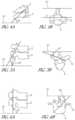
- FIG. 1is a lateral elevational view of a portion of the vertebral column.
- FIG. 2 Ais an example of a superior view of an isolated thoracic vertebra.
- FIG. 2 Bis an example of a side view of an isolated thoracic vertebra.
- FIG. 3 Ais an example of a posterior elevational view of a portion of the vertebral column.
- FIG. 3 Bis an example of a posterior-oblique elevational view of a portion of the vertebral column.
- FIG. 4 Ais an example of a side view of a facet joint in the cervical vertebrae.
- FIG. 4 Bis an example of a superior view of a facet joint in the cervical vertebrae.
- FIG. 5 Ais an example of a side view of a facet joint in the thoracic vertebrae.
- FIG. 5 Bis an example of a superior view of a facet joint in the thoracic vertebrae.
- FIG. 6 Ais an example of a side view of a facet joint in the lumbar vertebrae.
- FIG. 6 Bis an example of a superior view of a facet joint in the lumbar vertebrae.
- FIG. 7is a block diagram of a bone stabilization and distraction apparatus according to an embodiment.
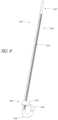
- FIG. 8is a perspective view of a flexible fastening band according to an embodiment.
- FIG. 9is a perspective view of a portion of the flexible fastening band depicted in FIG. 8 .
- FIG. 10is a side view of a flexible fastening band according to an embodiment.
- FIG. 11is a top view the flexible fastening band depicted in FIG. 10 .
- FIG. 12is a side view of a flexible fastening band according to an embodiment.
- FIG. 13is a perspective view of a flexible fastening band according to an embodiment.
- FIG. 14is a cross-sectional side view taken along line 14 - 14 of the flexible fastening band depicted in FIG. 13 .
- FIG. 15is a cross-sectional view taken along line 15 - 15 of the flexible fastening band depicted in FIG. 13 .
- FIG. 16is a cross-sectional top view of the flexible fastening band depicted in FIG. 13 in a first configuration.
- FIG. 17is a cross-sectional top view of the flexible fastening band depicted in FIG. 13 in a second configuration.
- FIGS. 18 A- 18 Care various perspective views of a flexible fastening band according to another embodiment.
- FIG. 19is a perspective view of a flexible fastening band connector according to an embodiment.
- FIG. 20is a cross-sectional view the flexible fastening band connector depicted in FIG. 19 .
- FIG. 21is a perspective view of a flexible fastening band connector according to an embodiment.
- FIG. 22is a cross-sectional view the flexible fastening band connector depicted in FIG. 21 .
- FIG. 23is a perspective view of a flexible fastening band connector according to an embodiment.
- FIG. 24is a cross-sectional view the flexible fastening band connector depicted in FIG. 23 .
- FIG. 25is a perspective view of the portion of the vertebral column including the flexible fastening band connector depicted in FIG. 19 .
- FIG. 26is a perspective view of the portion of the vertebral column including the flexible fastening band connector depicted in FIG. 25 .
- FIG. 27is a perspective view of the portion of the vertebral column including a flexible fastening band connector according to an embodiment.
- FIG. 28is another perspective view of the flexible fastening band connector of FIG. 27 .
- FIG. 29is another perspective view of the flexible fastening band connector of FIG. 27 .
- FIG. 30is a perspective view of the portion of the vertebral column including a flexible fastening band connector according to an embodiment.
- FIG. 31is a perspective view of the portion of the vertebral column including a flexible fastening band connector according to an embodiment.
- FIG. 32is a block diagram of a bone stabilization and distraction system according to an embodiment.
- FIG. 33is a block diagram of a bone stabilization and distraction system according to an embodiment.
- a ratchetis intended to mean a single ratchet or a combination of ratchets.
- a substancecan include any biologic and/or chemical substance, including, but not limited to, medicine, adhesives, etc. While exemplary references are made with respect to vertebra, in some embodiments another bone can be involved. While specific reference may be made to a specific vertebra and/or subset and/or grouping of vertebrae, it is understood that any vertebra and/or subset and/or grouping, or combination of vertebrae can be used.
- substantiallycan mean within plus or minus a few percent (e.g., 1, 2, 3, 4, or 5, etc.) from the given shape or orientation, in other embodiments, within plus or minus 10 degrees from the given orientation, and in other embodiments, within plus or minus 5 degrees from the given orientation.
- the vertebral column 2comprises a series of alternating vertebrae 4 and fibrous discs 6 that provide axial support and movement to the upper portions of the body.
- the vertebral column 2typically comprises thirty-three vertebrae 4 , with seven cervical (C1-C7), twelve thoracic (T1-T12), five lumbar (L1-15), five fused sacral (S1-S5) and four fused coccygeal vertebrae.
- FIGS. 2 A and 2 Bdepict a typical thoracic vertebra.
- Each vertebraincludes an anterior body 8 with a posterior arch 10 .
- the posterior arch 10comprises two pedicles 12 and two laminae 14 that join posteriorly to form a spinous process 16 .
- a transverse 18 , superior 20 and inferior articular process 22Projecting from each side of the posterior arch 10 is a transverse 18 , superior 20 and inferior articular process 22 .
- the facets 24 , 26 of the superior 20 and inferior articular processes 22form facet joints 28 with the articular processes of the adjacent vertebrae (see FIGS. 3 A and 3 B ).
- the facet jointsare true synovial joints with cartilaginous surfaces and a joint capsule.
- the orientation of the facet jointsvary, depending on the level of the vertebral column.
- the facet jointsare parallel to the transverse plane.
- FIGS. 4 A to 6 Bdepict examples of the orientations of the facet joints at different levels of the vertebral column.
- the facetsare oriented at a 45-degree angle to the transverse plane 30 and parallel to the frontal plane 32 , respectively. This orientation allows the facet joints of the cervical vertebrae to flex, extend, lateral flex and rotate.
- FIGS. 5 A and 5 Bdepict examples of the thoracic vertebrae, where the facets are oriented at a 60-degree angle to the transverse plane 30 and a 20-degree angle to the frontal plane 32 , respectively. This orientation is capable of providing lateral flexion and rotation, but only limited flexion and extension.
- FIGS. 6 A and 6 Billustrate examples of the lumbar region, where the facet joints are oriented at 90-degree angles to the transverse plane 30 and a 45-degree angle to the frontal plane 32 , respectively.
- the lumbar vertebraeare capable of flexion, extension and lateral flexion, but little, if any, rotation because of the 90-degree orientation of the facet joints in the transverse plane.
- the actual range of motion along the vertebral columncan vary considerably with each individual vertebra.
- the facet jointsIn addition to guiding movement of the vertebrae, the facet joints also contribute to the load-bearing ability of the vertebral column.
- the facet jointsmay also play a role in resisting shear stresses between the vertebrae. Over time, these forces acting on the facet joints can cause degeneration and arthritis.
- FIGS. 7 - 18 Cillustrates various embodiments of a flexible fastening band (“band”) that can be used to provide fixation in a spinal (or other orthopedic or surgical) procedure. Additional description and embodiments of the flexible fastening band are described in U.S. Pat. No. 8,740,949 (issued on Jun. 3, 2014), U.S. Publication 2012/0221049 (filed Feb. 23, 2012) and Applicant's co-pending patent application Ser. No. 13/804,407 (filed Mar. 14, 2013) and Ser. No. 13/804,521 (filed Mar. 14, 2013), the entirety of these applications being incorporated by reference into this specification. As will be described in detail below, FIGS.
- FIG. 19 - 31illustrate various embodiments of a flexible fastening band connector (“connector”) that can be used in certain arrangements in combination with a band such as the band described herein and/or with other fixation devices.
- a flexible fastening band connector(“connector”) that can be used in certain arrangements in combination with a band such as the band described herein and/or with other fixation devices.
- An advantage of certain embodimentsis that the connector can align portions of the band or other fixation device with each other to ease the fixation process and/or to reduce wear and stress on the band.
- FIG. 7depicts a block diagram of the flexible fastening band (“band”) 140 .
- the band 140includes a flexible elongate body including a proximal end portion 142 , a first portion 144 , a second portion 146 , and a distal end portion 148 that includes a fastening mechanism 150 (alternatively referred to herein as a fastener).
- the band 140can include a third portion (not shown in FIG. 7 ).
- the band 140can include a spacer (not shown in FIG. 7 ).
- the band 140can be configured to anchor to a first vertebra (not shown in FIG. 7 ) and/or a second vertebra (not shown in FIG. 7 ).
- the band 140can be removed from the vertebra, e.g. by cutting, breaking, or otherwise releasing the band 140 . In this manner, should the band 140 fail, a replacement band 140 can be inserted. Similarly, should the band 140 be deemed ineffective for a particular patient, the band 140 can be removed and an alternate treatment can be chosen without incurring permanent fusion of the vertebra. As will be described in more detail herein, the band 140 can be monolithically formed or separately formed.
- the band 140can include any biocompatible material, e.g., stainless steel, titanium, PEEK, nylon, etc.
- a flexible fastening bandcan be used to stabilize and/or fixate a first vertebra to a second vertebra to reduce the pain, to reduce further degradation of a spine, or of a specific vertebra of a spine, and/or until the first vertebra and the second vertebra have fused.
- the band 140can be coupled to a first bone portion and secured to one or more spinal devices, as described herein.
- the band 140can be extended around a bone portion.
- the band 140can be passed through a lumen formed through adjacent vertebra.
- the flexible fastening bandis configured to form a loop either through one or more adjacent bone portions or around one or more bone portions.
- the proximal end portion 142is sized to pass through a fastening mechanism 150 of the distal end portion 148 to form a loop.
- the proximal end portion 142can be shaped to increase the ease of inserting the proximal end portion 142 into the fastening mechanism 150 , e.g., the proximal end portion 142 can be tapered, rounded, and/or angled, etc., to reduce at least a portion of a cross-sectional area of the proximal end portion 142 .
- the first portion 144can extend for a length between the proximal end portion 142 and the second portion 146 , and can have a substantially uniform shape.
- the first portion 144can have, for example, a substantially cuboidal shape, or a substantially cylindrical shape.
- the length of the first portion 144can be more than twice the length of the second portion 146 .
- the cross-sectional area of the first portion 144can be smaller than the cross-sectional area of the second portion 146 .
- the cross-sectional area of the first portion 144can be less than a cross-sectional area of a lumen defined by the fastening mechanism 150 .
- the first portion 144can include a gear rack (not shown in FIG.
- the gear rackcan be configured to allow the first portion 144 to travel through the fastening mechanism 150 in only one direction.
- the first portion 144can be monolithically formed with the second portion 146 . In some other embodiments, the first portion 144 can be separately formed from the second portion 146 .
- the first portion 144can be configured to be slidably disposed in a lumen of the second portion 146 .
- the second portion 146can have a length between the first portion 144 and the distal end portion 148 , and can include a substantially uniform shape. In embodiments including the third portion, the second portion 146 can have a length between the first portion 144 and the third portion.
- the second portion 146can have, for example, a substantially cuboidal shape or a substantially cylindrical shape.
- the first portion 144 and the second portion 146can have the same or different shapes, e.g., the first portion 144 and the second portion 146 can both be substantially cuboidal, the first portion 144 and the second portion 146 can both be substantially cylindrical, the first portion 144 can be substantially cuboidal while the second portion 146 can be substantially cylindrical, or the first portion 144 can be substantially cylindrical while the second portion 146 can be substantially cuboidal.
- the length of the second portion 146can be less than half the length of the first portion 144 .
- the cross-sectional area of the second portion 146can be greater than the cross-sectional area of the first portion 144 .
- the cross-sectional area of the second portion 146can be greater than a cross-sectional area of a lumen defined by the fastening mechanism 150 . In this manner, as a portion of the band 140 is advanced through the fastening mechanism 150 , the cross-sectional area of the second portion 146 can prevent the band 140 from advancing beyond the first portion 144 .
- the second portion 146can include a gear rack (not shown in FIG. 7 ) configured to engage the ratchet of the fastening mechanism 150 .
- the gear rackcan be configured to allow the second portion 146 to travel through the fastening mechanism 150 in only one direction.
- the second portion 146can be monolithically formed with the first portion 144 . In some embodiments, the second portion 146 can be separately formed from the first portion 144 .
- the second portion 146can define a lumen configured to slidably accept the first portion 144 .
- the distal end portion 148includes the fastening mechanism 150 configured to accept at least the portion of proximal end portion 142 , the first portion 144 , and/or the second portion 146 .
- the distal end portion 148 , the second portion 146 , the first portion 144 , and the proximal end portion 142can be monolithically formed.
- the fastening mechanism 150includes a lumen (not shown in FIG. 7 ) configured to accept at least a portion of the proximal end portion 142 , a portion of the first portion 144 , and/or a portion of the second portion 146 .
- the cross-sectional area of the lumen of the fastening mechanism 150is smaller than the cross-sectional area of the second portion 146 . In this manner, the second portion 146 can be prevented from advancing through the fastening mechanism 150 .
- the fastening mechanism 150can include a ratchet (not shown in FIG. 7 ) configured to engage the gear rack of the first portion 144 and/or second portion 146 . In this manner, the fastening mechanism 150 can allow the first portion 144 and/or the second portion 146 to advance through the fastening mechanism 150 in only one direction.
- At least one of the distal end portion 148 , the second portion 146 , the first portion 144 , and the proximal end portion 142can be formed separately from the other(s) of the distal end portion 148 , the second portion 146 , the first portion 144 , and the proximal end portion 142 .
- the distal end portion 148 , the first portion 144 , and the proximal end portion 142can be monolithically formed together, while the second portion 146 can be separately formed.
- the band 140can include an initial second portion 146 configured to be replaced and/or covered with a replacement second portion 146 .
- the initial second portion 146can be monolithically formed with the first portion 144 and the replacement second portion 146 can be slidably disposed over the initial second portion 146 .
- the initial second portion 146can be separately formed from the first portion 144 , can be removed from the band 140 , and the replacement second portion 146 can be slidably disposed over the first portion 144 .
- the initial second portion 146can be separately or monolithically formed from the first portion 144 , and the replacement second portion 146 can be slidably disposed over the first portion 144 and the initial second portion 146 .
- the initial second portion 146 and the replacement second portion 146can have the same shape, e.g., the initial second portion 146 can include a substantially cylindrical shape and the replacement second portion 146 can include a substantially cylindrical shape. In some embodiments, the initial second portion 146 and the replacement second portion 146 can have different shapes, e.g., the initial second portion 146 can include a substantially cuboidal shape and the replacement second portion 146 can include a substantially cylindrical shape.
- the shape of first portion 144 and the shape of second portion 146can be determined based on the shape of an artificial lumen formed through an articular process of a vertebra.
- the shape of the artificial lumenis cuboidal
- the shape of the first portion 144 and the shape of the second portion 146can be cuboidal to allow the first portion 144 and the second portion 146 to slidably advance through the artificial lumen.
- the shape of the artificial lumenis cylindrical
- the shape of the first portion 144 and the shape of the second portion 146can be either cuboidal or cylindrical.
- the shape of the first portion 144can be cuboidal to allow the first portion 144 to advance easily through the artificial lumen, while the shape of the second portion 146 can be cylindrical to allow the second portion 146 to fit more tightly within the artificial lumen as compared to a cuboidal shape.
- the shape of the first portion 144 and the shape of the second portion 146can be determined based on characteristics of the bone or bone portion against which the first portion 144 and the second portion 146 may contact.
- the edges of the first portion 144 and/or the second portion 146can be rounded, partially rounded, and/or otherwise shaped to compliment the shape of a bone or bone portion, and/or to reduce digging or grinding into the bone or bone portion. In this manner, use of the band 140 may cause little or no damage to the bone or bone portions contacted by the band 140 .
- the band 140can include a third portion (not shown in FIG. 7 ).
- the third portioncan have a length between the second portion 146 and the distal end portion 148 , and can have a substantially uniform shape.
- the third portioncan have, for example, a substantially cuboidal shape or a substantially cylindrical shape.
- the length of the third portioncan be less than half the length of first portion 144 .
- the third portioncan be monolithically formed with first portion 144 and/or the second portion 146 . In some other embodiments, the third portion can be separately formed from the second portion 146 and/or the first portion 144 .
- first portion 144 , the second portion 146 , and the third portioncan be a substantially uniform shape
- any one of the first portion 144 , the second portion 146 , and the third portioncan include a transition portion to transition the band 140 from a first substantially uniform shape to a second substantially uniform shape.
- the first portion 144 and the third portioncan be substantially cuboidal and the second portion 146 can be substantially cylindrical.
- the second portion 146can include an angled, conical, or other shaped transition portion.
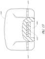
- FIG. 8depicts views of a flexible fastening band (“band”) 440 and FIG. 9 depicts a view of a portion of band 440 .
- the band 440can be similar to the band 140 described above and can include similar components.
- the band 440includes a proximal end portion 442 , a first portion 444 , a second portion 446 , and a distal end portion 448 including a fastening mechanism 450 .
- the band 440includes a cylindrical second portion 446 and a third portion 449 . As depicted in FIGS. 8 - 9 , third portion 449 is substantially the same shape as first portion 442 .
- Second portion 446can be substantially the same diameter as the diameter of the lumen in a first bone portion and/or second bone portion.
- the amount of open space within the lumencan be minimized, the amount of surface area of the second portion 446 of the band 440 in contact with the lumen can increase, and subsequently the movement of bone portions can be reduced or minimized.
- forces acting against the band 440can be more equally distributed throughout the second portion of the band, due at least to the increased surface area of the band 440 in contact with the lumen.
- the band 440includes a gear rack 447 and gears 464 .
- Each of the gears 464can be wedge shaped to allow each of the gears 464 to displace the ratchet of the fastening mechanism 450 in only one direction.
- the gears 464can be other shapes, such as blocks, etc.
- a band according to this embodimentmay be particularly useful in deployments where a single band in used to stabilize adjacent vertebrae.
- the second portion 446can be disposed within the lumen of a first bone portion (e.g., the first articular process of the first vertebra) and a portion of the first portion 444 can be disposed within the lumen of the first bone portion or a second bone portion (e.g., the second articular process of the second vertebra).
- the portion of the band within the first articular process of the first vertebra and the portion of the band within in the second articular process of the second vertebracan both have substantially the same shape as the lumen in the first articular process of the first vertebra and the lumen in the second articular process of the second vertebra.
- FIG. 10is a side view and FIG. 11 is a top view of a flexible fastening band (“band”) 840 according to another embodiment.
- the band 840can be similar to the band 140 and the band 440 described above and can include similar components.
- the band 840includes a proximal end portion 842 , a first portion 844 including a gear rack 847 , a second portion 846 , and a distal end portion 848 including a fastening mechanism 850 and a ratchet 862 .
- a cross sectional area of each gear 864 of gear rack 847is rectangular in shape instead of wedge shaped.
- the first portion 844is cylindrical in shape instead of cuboidal in shape. In this manner, the lumen 866 of the fastening mechanism 850 is cylindrical in shape.
- FIG. 12is a side view a flexible fastening band (“band”) 940 according to an embodiment.
- the band 940can be similar to the band 140 , the band 440 , and the band 840 described above and can include similar components.
- the band 940includes a proximal end portion 942 , a first portion 944 including a gear rack 947 , a second portion 946 , and a distal end portion 948 including a fastening mechanism 950 .
- a cross sectional area of each gear 964 of gear rack 947is rectangular in shape.
- each of the gears 964extend the entire circumference of the first portion 944 instead of only a portion of the circumference of the first portion 944 .
- the first portion 944is cylindrical in shape instead of cuboidal in shape.
- the lumen 966 of the fastening mechanism 950is cylindrical in shape.
- a band according to this embodimentmay be particularly useful in deployments where the movement and repositioning of the band after implantation may be difficult. In this manner, because each of the gears can be the entire circumference of the first portion and/or the second portion, the first portion and/or the second portion can enter the fastening mechanism in any radial orientation and still engage the ratchet.
- FIGS. 13 - 17are views of a flexible fastening band (“band”) 1040 according to another embodiment.
- FIG. 13is a perspective view and FIG. 14 is a cross-sectional side view of the band 1040 .
- FIG. 15is a cross-sectional view of the band 1040 taken along line 15 - 15 .
- FIG. 16is a cross-sectional top view of the band 1040 in a first configuration and
- FIG. 17is a cross-sectional top view of the band 1040 in a second configuration.
- the band 1040can be similar to the band 140 , the band 440 , the band 840 , and/or the band 940 described above and can include similar components.
- the band 1040includes a proximal end portion (not shown), a first portion 1044 including a gear rack 1047 (see FIG. 14 ), a second portion 1046 , and a distal end portion 1048 including a fastening mechanism 1050 , a ratchet 1062 and a lumen 1066 .
- the band 1040includes a reinforcement piece 1072 .
- the reinforcement piece 1072can include any of the materials described above for the band 140 .
- the reinforcement piece 1072can include a material stronger than the second portion 1046 and/or the first portion 1044 , for example, the first portion 1044 and the second portion 1046 can include PEEK and the reinforcement piece 1072 can include titanium.
- the reinforcement piece 1072can be disposed within the band 1040 approximately along the entire length of the second portion 1046 , and a portion of the reinforcement piece 1072 can be disposed within the distal end portion 1048 .
- the reinforcement piececan include a length along at least a portion of the length of the second portion 1046 and/or first portion 1044 but not the distal end portion 1048 .
- the reinforcement piece 1072can be disposed only within the second portion 1046 .
- the reinforcement piece 1072can have a length in first dimension (length), a length in a second dimension (width), and a length in a third dimension (height).
- a reinforcement piececan be different shapes that can include more or fewer dimensions.
- the reinforcement piece 1072can be molded within the band 1040 . Said another way, in embodiments where the first portion, the second portion, and/or the distal end portion are moldable materials, the reinforcement piece 1072 can be placed in the mold and the moldable materials can be injected or otherwise put in the mold around the reinforcement piece. In other embodiments, each portion of the band (for example, the proximal end portion, the first portion, the second portion, the third portion, and/or the distal end portion) around the reinforcement piece can have a top half and a bottom half, and each of the top half and the bottom half can be placed around the reinforcement piece, and sealed. As shown in FIG. 16 , reinforcement piece 1072 includes support members 1074 . While FIG.
- reinforcement piece 1072including four support members 1074 , in some embodiments, more or fewer support members 1074 can be used.
- the support members 1074can maintain the position of the reinforcement piece 1072 during the molding and/or assembly process of the band 1040 . As shown in FIG. 17 , the support members 1074 are removed before the band 1040 is used.
- the reinforcement piece 1072can has a substantially uniform cuboidal shape.
- the reinforcement piece 1072can have other shapes.
- the shape of the reinforcement piececan be selected depending on the desired bending and/or torsion characteristics of the material chosen.
- a substantially planar cuboidal shapecan provide a greater increase in bending strength while providing a lesser increase in torsion strength
- a cylindrical shapecan provide an increase in bending strength while providing very little increase in torsion strength
- a substantially square and/or tubular cuboidal shapecan provide similar bending and torsion increases. Any shape can be selected to achieve the desired bending and torsion strength. Combinations of materials and shapes can also be considered.
- the reinforcement piece 1072can include one or more holes 1076 distributed along the length of the first dimension. While FIGS. 16 and 17 shows the band 1040 including many holes 1076 , in some embodiments, more or fewer holes 1076 can be used. FIGS. 16 and 17 depict the holes 1076 distributed substantially equally along the length of the first dimension, in some embodiments, the holes can be distributed differently or along different dimensions depending on the shape and/or material chosen, and/or whether the reinforcement piece is solid or hollow.
- the holes 1076can be configured to reduce the weight of the reinforcement piece 1072 while still provided the band 1040 additional strength.
- the holes 1076can be round, oval, square, or any other shape.
- FIGS. 18 A- 18 Cillustrate a flexible fastening band 1340 (also referred to herein as “band”) according to an embodiment.
- the band 1340can be similar to the band 140 , the band 440 , the band 840 , the band 940 , and the band 1040 and can include similar components.
- the band 1340includes a distal end portion 1348 , a fastener mechanism 1350 including a ratchet 1362 , a second portion 1346 , a first portion 1344 , and a proximal end portion 1342 . Accordingly, components of the band 1340 that are similar to corresponding components of the band 140 described above with reference to FIG. 7 are not described in further detail herein.
- Each gear 1364 included in the gear rack 1347includes a cross sectional area that is rectangular in shape. Said another way, each gear 1364 can be a rectangular protrusion configured to extend from a surface of the band 1340 (e.g., the first portion 1344 and/or the second portion 1346 ).
- the gear rack 1347is configured to engage the ratchet 1362 of the fastener mechanism 1350 , as further described herein.
- the fastener mechanism 1350defines a lumen 1366 .
- the lumen 1366can be any suitable shape, size, or configuration. For example, as shown in FIG. 18 A the lumen 1366 can have a substantially circular cross-sectional area.
- the ratchet 1362extends from an inner surface of the fastener member 1350 such that the ratchet 1362 substantially reduces the size (e.g., the perimeter, circumference, and/or cross-sectional area) of the lumen 1366 . In this manner, the ratchet 1366 can engage the gear rack 1347 . More specifically, as described in detail with reference to FIG. 7 , the proximal end portion 1342 can be inserted into the lumen 1366 of the fastener mechanism 1350 and advanced in a first direction such that the gear rack 1347 of the first portion 1344 engages the ratchet 1362 . In some embodiments, the proximal end portion 1342 can be inserted into the lumen 1366 of the fastener mechanism 1350 and advanced in a first direction such that the gear rack 1347 of the second portion 1346 engages the ratchet 1362 .
- the proximal end portion 1342can be inserted into the lumen 1366 of the fastener mechanism 1350 and advanced in a
- the proximal end portion 1342can be advanced through the lumen 1366 a sufficient distance such that a portion of the first portion 1344 and/or the second portion 1346 is disposed within the lumen 1366 .
- a portion of the gear rack 1347 disposed on (e.g., included in or defined by) the first portion 1344 and/or the second portion 1346can engage the ratchet 1362 .
- the arrangement of the ratchet 1362 and the gear rack 1347can be such that the proximal end portion 1342 can be moved in the first direction, thereby tightening the band 1340 , and the proximal end portion 1342 can be prevented from moving in a second direction, opposite the first direction, thereby preventing the band 1340 from loosening.
- the band 1340can be monolithically (or unitarily) constructed in an elongate shape and can have a substantially rectangular cross-sectional shape. More specifically, the band 1340 can have a substantially rectangular shape including rounded edges configured to reduce digging or grinding into the bone or portion thereof.
- the fastener mechanism 1350defines a lumen 1366 and includes the ratchet 1362 .
- the first portion 1344 and/or the second portion 1346includes a gear rack 1347 having a set of gears 1364 . In this manner, the proximal end portion 1342 can be inserted into the lumen 1366 of the fastener member 1350 such that the gear rack 1347 engages the ratchet 1362 , as described in detail above.
- the flexible fastening bandcan have alternative configurations than those illustrated above. Examples of alternative flexible fastening bands are shown and described in U.S. patent application Ser. No. 13/804,407; filed Mar. 14, 2013, and titled “Apparatus for Spinal and Methods of Use,” which is incorporated herein by reference in its entirety.
- a connectorcan be used to couple a flexible fastening band to another spinal device, such as a spinal rod.
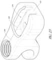
- FIG. 19depicts a connector 300 (also referred to herein as a “flexible fastening band connector”) according to an embodiment.
- FIG. 19is a perspective view and
- FIG. 20is a cross-sectional side view of connector 300 .
- components of band 140are described for use with connector 300 , but any band described herein may be utilized.
- the connector 300can include an elongate body including a first portion 312 for engaging a fixation device and a second portion 318 for engaging a flexible fastening band.
- the first portion 312 and the second portion 318are on opposite ends of the connector 300 .
- the first portion 312 and the second portion 318are on the same end (e.g., both on the proximal end) of the connector 300 .
- the first portion 312is near a proximal end of the connector 300 .
- the first portion 312is near the middle of the connector 300 (not shown).
- the first portion 312is near a distal end of the connector 300 (not shown).
- the second portion 318is near a proximal end of the connector 300 . In some embodiments, the second portion 318 is near the middle of the connector 300 (not shown). In some embodiments, the second portion 318 is near the distal end of the connector 300 (not shown).
- the connector 300can be coupled to the band 140 (or any band described herein) and/or a spinal device, such a support system with a spinal rod. As will be described in more detail herein, the connector 300 can be monolithically formed or formed from a plurality of parts.
- the connector 300can include any biocompatible material, e.g., stainless steel, titanium, PEEK, nylon, etc.
- the connector 300can be coupled to the band 140 and a spinal fixation device or portion thereof such as a spinal rod 240 .
- the spinal rod 240can be received within an opening 322 of the first portion 312 .
- the opening 322can be formed in part by a lip portion 316 .
- the lip portion 316 forming the opening 322has a curvature 324 which can match the curvature of the spinal rod 240 .
- the lip portion 316can be flat, substantially flat, angled, curved, elliptical or any other shape that corresponds to the shape of the spinal rod 240 and/or is otherwise configured to engage the rod and/or spinal fixation device.
- the first portion 312 forming the opening 322can have a curvature 326 which matches the curvature of the spinal rod 240 and/or is otherwise configured to engage the rod and/or spinal fixation device.
- the first portion 312can be flat, substantially flat, angled, curved, elliptical or any other shape that corresponds to the shape of the spinal rod 240 and/or is otherwise configured to engage the rod and/or spinal fixation device.
- the lip portion 316can have a dimension (e.g., length along a longitudinal axis 348 ) equal to or greater than the diameter of the spinal rod 240 to support essentially the entire cross-section of the spinal rod 240 .
- the lip portion 316can have a dimension (e.g., length) less than the diameter of the spinal rod 240 (e.g., greater than 50% of the diameter, 55%, 60%, 65%, 70%, 75%, 80%, 85%, 90%, 95%, 100%, between 50-80%, between 60-90%, between 70-100%, etc.).
- the connector 300can encompass a portion of the circumference of the spinal rod 240 (e.g., greater than 50% of the circumference, 55%, 60%, 65%, 70%, 75%, 80%, 85%, 90%, 95%, 100%, between 50-80%, between 60-90%, between 70-100%, etc.). In some embodiments, the connector 300 can encompass the entire circumference of the spinal rod 240 . In some embodiments, the lip portion 316 can encompass a portion of the circumference of the spinal rod 240 (e.g., greater than 25%, 30%, 40%, 45%, 50%, 55%, 60%, 65%, 70%, 75%, 80%, 85%, 90%, 95%, 100%, between 50-80%, between 60-90%, between 70-100%, etc.).
- the spinal rod 240slides into the opening 322 from the proximal end of the connector 300 toward the middle of the connector 300 . In some embodiments, the spinal rod 240 slides into the opening 322 from the side of the connector 300 toward the middle of the connector 300 (not shown). In some embodiments, the spinal rod 240 is seated adjacent to the lip portion 316 . In the illustrated embodiment, the curvature 324 can include a ridge 328 . The ridge 328 can prevent the spinal rod 240 from becoming disengaged. In some embodiments, the spinal rod 240 is seated adjacent to the first portion 312 .
- the first portion 312can include a threaded bore 330 .
- the threaded bore 330can receive a locking mechanism (not shown in FIG. 19 ) such as, for example, a set screw. Advancing the locking mechanism through the threaded bore 330 can cause the locking mechanism to engage the spinal rod 240 . Further advancement of the locking mechanism can cause the locking mechanism to apply a force to the spinal rod 240 , which will push the spinal rod 240 toward the lip portion 316 .
- the threaded bore 330can be perpendicular or substantially perpendicular to a longitudinal axis of the spinal rod 240 when the spinal rod 240 is received within the opening 322 .
- the locking mechanismcan apply a force to the surface of the spinal rod 240 to push the spinal rod 240 toward the lip portion 316 .
- the locking mechanismcan comprise a clamping member, cam member or other device configured to secure the rod or other fixation device within the opening 322 of the first portion 312 .
- the connector 300is illustrated as connecting a band 140 to a spinal rod 240 .
- the connector 300can be configured with openings, slots, grooves, and/or other structures etc. to engage other fixation devices or spinal fixation devices such as, for example, pedicle screws, trans-facet or trans-pedicle screws, spinous process spacers, plates, intervertebral bodies etc.
- the longitudinal axis 242 of the spinal rod 240(shown in FIG. 26 ) received within the opening 322 forms an angle with the longitudinal axis 348 of the connector 300 (e.g., 0°, 5°, 10°, 15°, 20°, 25°, 30°, 35°, 40°, 45°, 50°, 55°, 60°, 65°, 70°, 75°, 80°, 85°, 90°, 100°, 105°, 110°, 115°, 120°, 125°, 130°, 135°, 140°, 145°, 150°, 155°, 160°, 165°, 170°, 175°, 180°, between 10-40°, between 20-50°, between 30-60°, between 40-70°, between 50-80°, between 60-90°, between 70-100°, between 80-110°, between 90-120°, between 100-130°, between 110-140°, between 120-150°, between 130-160°, between 140-170°, between 150
- the longitudinal axis of the spinal rod 240is perpendicular or substantially perpendicular relative to the longitudinal axis 348 of the connector 300 when the spinal rod 240 is received within the opening 322 .
- the longitudinal axis 352 of the threaded bore 330forms an angle with the longitudinal axis 348 of the connector 300 (e.g., 0°, 5°, 10°, 15°, 20°, 25°, 30°, 35°, 40°, 45°, 50°, 55°, 60°, 65°, 70°, 75°, 80°, 85°, 90°, 90°, 100°, 105°, 110°, 115°, 120°, 125°, 130°, 135°, 140°, 145°, 150°, 155°, 160°, 165°, 170°, 175°, 180°, between 10-40°, between 20-50°, between 30-60°, between 40-70°, between 50-80°, between 60-90°, between 70-100°
- a connecting portion 314can extend for a length between the first portion 312 and the second portion 318 .
- the connecting portion 314has a curved shape between the first portion 312 and the second portion 318 .
- the connecting portion 314has a substantially uniform shape.
- the connecting portion 314can have, for example, a substantially cuboidal shape, or a substantially cylindrical shape.
- the length of connecting portion 314can be more than twice the length of the first portion 312 .
- the cross-sectional area of the connecting portion 314can be smaller than the cross-sectional area of the first portion 312 and the lip portion 316 .
- the cross-sectional area of connecting portion 314can be less than a cross-sectional area of the second portion 318 .
- the connecting portion 314can include one or more engagement features 332 configured to engage a tool (not shown in FIG. 19 ) for placement of the connector 300 .
- the engagement features 332can be a pair of notches disposed on opposite sides of the connecting portion 314 .
- the engagement features 332can be notches, grooves, protrusions and/or other features or combinations thereof configured to facilitate engagement with at tool.
- the connecting portion 314can be monolithically formed with the first portion 312 and/or the second portion 318 .
- the connecting portion 314can be monolithically formed with the lip portion 316 . In some embodiments, the lip portion 316 can be separately formed from the connecting portion 314 .
- the second portion 318can include a recess 334 sized to accept the distal end portion 148 of the band 140 .
- the recess 334can have a bottom surface 336 and a side surface 338 .
- the bottom surface 336is flat or substantially flat to match the surface of the distal end portion 148 .
- the bottom surface 336can be angled, curved, ribbed or any other shape that corresponds to the surface of the distal end portion 148 .
- the side surface 338is curved to match the shape of the distal end portion 148 .
- the side surface 338can be flat angled, ribbed or any other shape that corresponds to the shape of the distal end portion 148 .
- the side surface 338can be shaped to increase the ease of inserting the distal end portion 148 into the recess 334 , e.g., the side surface 338 can be tapered, rounded, and/or angled, etc., to enlarge at least a portion of a cross-sectional area of the recess 334 .
- the recess 334has an opening 342 which causes the side surface 338 to be discontinuous.
- the opening 342is sized to receive the first portion 144 and/or the second portion 146 of the band 140 .
- the opening 342allows the first portion 144 and/or the second portion 146 to extend from the recess 334 when the distal end portion 148 is placed within the recess 334 .
- the opening 342can be on the left side of the second portion 318 .
- the longitudinal axis 346 of the recess 334is angled relative to the longitudinal axis 348 of the connector 300 .
- the longitudinal axis 346 of the recess 334can be at any angle relative to the longitudinal axis 348 of the connector 300 (e.g., 0°, 5°, 10°, 15°, 20°, 25°, 30°, 35°, 40°, 45°, 50°, 55°, 60°, 65°, 70°, 75°, 80°, 85°, 90°, 95°, 100°, 105°, 110°, 115°, 120°, 125°, 130°, 135°, 140°, 145°, 150°, 155°, 160°, 165°, 170°, 175°, 180°, between 10-40°, between 20-50°, between 30-60°, between 40-70°, between 50-80°, between 60-90°, between 70-100°, between 80-110°, between 90-120°, between 100-130°, between 110-140°, between 120-150°, between 130-160°, between 140-170°, between 150-180°, etc.).
- the illustrated embodiment
- the side surface 338 and the opening 342can create a neck which limits the movement of the distal end portion 148 and the fastener 150 in the recess 334 .
- the distal end portion 148is greater in at least one dimension than the first portion 144 and/or the second portion 146 (e.g., length, width, height). In some embodiments, the distal end portion 148 is greater in all three dimensions than the first portion 144 and/or the second portion 146 (e.g., length, width, height).
- the distal end portion 148may not fit through the opening 342 and may abut the side surface 338 .
- the distal end portion 148abuts bottom surface 336 .
- the configuration of the recess 334 including the neck created by the opening 342 and the side surface 338can limit the movement of the band 140 .
- the opening 342 and the side surface 338can match or substantially match the shape of the band 140 .
- there is minimal excess space in the recesse.g., the side surface 338 abuts at least one side wall of the distal end portion 148 ).
- the distal end portion 148can be placed in the recess 334 in only one orientation (e.g., to enable the first portion 144 and/or the second portion 146 to extend outward from the recess).
- This orientationensures that the lumen 166 of the fastener 150 aligns with the lumen 344 of the connector 300 to permit the proximal end portion 142 to traverse there through.
- the configuration of the recess 334 including the neck created by the opening 342 and the side surface 338can align the lumen 166 of the fastener 144 with the lumen 344 of the connector 300 .
- the recess 334extends from the top surface of the connector 300 toward the bottom surface of the connector 300 . In some embodiments, the recess 334 extends from the bottom surface of the connector 300 toward the top surface of the connector 300 . In some embodiments, the recess 334 extends from the left side surface of the connector 300 toward the right side surface of the connector 300 when viewed from the distal end of the connector 300 . In some embodiments, the recess 334 extends from the right side surface of the connector 300 toward the left side surface of the connector 300 when viewed from the distal end of the connector 300 . In the illustrated embodiment, the top surface of the recess 334 is open allowing the distal end portion 148 to be lowered into the recess. In some embodiments, the recess 334 is enclosed such that the distal end portion 148 is enclosed on at least three sides (e.g., four sides, five sides, six sides, etc.).
- the distal end portion 148lies below the surface of the connector 300 when the distal end portion 148 is disposed in the recess 334 .
- the side surface of the recess 338can have a depth equal or greater than the depth of the distal end portion 148 .
- the recess 334can be sized to be greater than the distal end portion 148 in all three dimensions (e.g., length, width, height).
- the distal end portion 148does not protrude from the connector 300 when the distal end portion 148 is disposed in the recess 334 .
- the distal end portion 148lies slightly above the surface of the connector 300 when the distal end portion 148 is disposed in the recess 334 .
- the side surface of the recess 338has a depth less than the depth of the distal end portion 148 .
- the recess 334can be sized to be greater than the distal end portion 148 in two dimensions (e.g., length, width) but not all three dimensions (e.g., length, width, height). In some embodiments, the distal end portion 148 protrudes from the connector 300 when the distal end portion 148 is disposed in the recess 334 .
- the recess 334has a lumen 344 .
- the lumen 344is sized to receive the proximal end portion 142 of the band 140 .
- the lumen 344allows proximal end portion 142 to extend through the fastening mechanism 150 when the distal end portion 148 is placed within the recess 334 .
- the longitudinal axis 354 of the lumen 344forms an angle with the bottom surface 336 .
- the longitudinal axis 354 of the lumen 344can form any angle with the bottom surface 336 (e.g., 0°, 5°, 10°, 15°, 20°, 25°, 30°, 35°, 40°, 45°, 50°, 55°, 60°, 65°, 70°, 75°, 80°, 85°, 90°, 95°, 100°, 105°, 110°, 115°, 120°, 125°, 130°, 135°, 140°, 145°, 150°, 155°, 160°, 165°, 170°, 175°, 180°, between 10-40°, between 20-50°, between 30-60°, between 40-70°, between 50-80°, between 60-90°, between 70-100°, between 80-110°, between 90-120°, between 100-130°, between 110-140°, between 120-150°, between 130-160°, between 140-170°, between 150-180°, etc.).
- the longitudinal axis 354 of the lumen 344is perpendicular or substantially perpendicular relative to the bottom surface 336 .
- the longitudinal axis of the lumen 344forms an angle with the longitudinal axis 348 of the connector 300 (e.g., 0°, 5°, 10°, 15°, 20°, 25°, 30°, 35°, 40°, 45°, 50°, 55°, 60°, 65°, 70°, 75°, 80°, 85°, 90°, 100°, 105°, 110°, 115°, 120°, 125°, 130°, 135°, 140°, 145°, 150°, 155°, 160°, 165°, 170°, 175°, 180°, between 10-40°, between 20-50°, between 30-60°, between 40-70°, between 50-8°, between 60-90°, between 70-100°, between 80-110°, between 90-120°, between 100-130°, between 110-140°,
- the lumen 344extends from the bottom surface of the connector 300 toward the bottom surface 336 of the recess 334 . In some embodiments, the lumen 344 extends from any exterior surface of the connector 300 toward the bottom surface 336 of the recess 334 . In some embodiments, the lumen 344 extends from any exterior surface of the connector 300 toward any interior surface. In some embodiments, the lumen 344 extends from any exterior surface of the connector 300 toward any other exterior surface of the connector 300 .
- the recess 334is formed on a first side of the connector 300 and the lumen 344 formed on a second side of the connector 300 .
- the lumen 344can extend to the recess 334 .
- the first side of the connector 300 and the second side of the connector 300are opposed parallel sides of the connector 300 .
- the first side of the connector 300is the top of the connector 300 and the second side of the connector 300 is the bottom of the connector 300 .
- the longitudinal axis 354 of the lumen 344extends from the top surface to the bottom surface.
- the longitudinal axis 354 of the lumen 344is substantially perpendicular or perpendicular to the longitudinal axis 242 of the spinal rod 240 .
- the first side of the connector 300is a side surface of the connector 300 and the second side of the connector 300 is the opposed side surface.
- the longitudinal axis 354 of the lumen 344can extend from the right side surface to the left side surface.
- the longitudinal axis 354 of the lumen 344is substantially parallel or parallel to the longitudinal axis 242 of the spinal rod 240 .
- the lumen 344can serve as a guide for the proximal end portion 142 of the band 140 .
- the lumen 344can be substantially the same shape as the proximal end portion 142 .
- the lumen 344can be substantially the same diameter as the diameter of the proximal end portion 142 .
- the diameter of the lumen 344is substantially the same diameter as the proximal end portion 142 .
- the amount of open space within the lumen 344can be minimized, the amount of surface area of the proximal end portion 142 of the band 140 in contact with the lumen 344 can increase, and the misalignment of the band 140 can be reduced or minimized.
- forces acting against the band 140can be more equally distributed throughout the proximal end portion 142 , due at least to the increased surface area of the band 140 in contact with the lumen 344 .
- the proximal end portion 142can be passed through the lumen 344 .
- the proximal end portion 142then can pass through the fastening mechanism 150 of the distal end portion 148 received within the recess 334 .
- the proximal end portion 142can be shaped to increase the ease of inserting the proximal end portion 142 into the lumen 344 , e.g., the proximal end portion 142 can be tapered, rounded, and/or angled, etc., to reduce at least a portion of a cross-sectional area of the proximal end portion 142 .
- edges of the lumen 344can be shaped to increase the ease of inserting the proximal end portion 142 into the lumen 344 , e.g., the edges of lumen 344 can be tapered, rounded, and/or angled, etc., to enlarge at least a portion of a cross-sectional area of the lumen 344 .
- the bands disclosed hereinhave gear rack with gears.
- FIGS. 8 - 9One embodiment is shown in FIGS. 8 - 9 , in which the band 440 includes the gear rack 447 and gears 464 .
- Each of gears 464can be wedge shaped to allow each of gears 464 to displace the ratchet of fastening mechanism 450 in only one direction.
- the gears 464can be other shapes, such as rectangular, etc.
- the lumen 344prevents misalignment between the gear rack of the first portion and/or second portion and the ratchet of the fastening mechanism.
- the lumen 344aligns the gear rack in the optimal position to enable engagement of the gears and the ratchet.
- FIG. 9shows one such optimal position, with the connector 300 removed for clarity.
- the gear rack 447can be perpendicular or substantially perpendicular to the fastening mechanism 450 .
- the gear rackis perpendicular or substantially perpendicular to the ratchet.
- Other angles between the gear rack and the ratchetmay cause uneven wear or failure of the gear rack and/or the ratchet. Such failure may cause the band to loosen around the bone portion and/or break.
- FIGS. 21 - 22depict a modified position of recess 334 .
- the opening 342is on the right side of the second portion 318 .
- the opening 342 shown in FIG. 21is approximately 180° relative to opening 342 shown in FIG. 19 .
- the longitudinal axis 346 of the recess 334is angled relative to the longitudinal axis 348 of the connector 300 .
- the recess 334can be at any angle relative to the longitudinal axis.
- the longitudinal axis 346 of the recess 334is perpendicular or substantially perpendicular relative to the longitudinal axis 348 of the connector 300 .
- FIGS. 23 - 24depict another modified position of recess 334 .
- the opening 342is on the front of the second portion 318 .
- the opening 342 shown in FIG. 23is approximately 90° relative to the opening 342 shown in FIG. 19 and approximately 90° relative to the opening 342 shown in FIG. 21 .
- the longitudinal axis 346 of the recess 334 and the longitudinal axis 348 of the connector 300may be substantially coplanar with one another. Indeed in some embodiments, the longitudinal axis 346 of the recess 334 and the longitudinal axis 348 of the connector 300 are substantially parallel to one another.
- the longitudinal axis 346 of the recess 334 and the longitudinal axis 348 of the connector 300may be substantially coaxial with one another.
- the longitudinal axis 346 of the recess 334 and the longitudinal axis 348 of the connector 300are coplanar with, parallel to, or at some pre-determined skew angle with respect to one another.
- the connector 300has more than one recess 334 for receiving the distal end portions 148 of multiple bands 140 .
- the recesses 334can be in the same orientation or can be oriented in different directions.
- the connectorcan have two recesses 334 that are both oriented with the openings 342 facing toward the distal end of the connector 300 .
- a first opening of a first recesscan face to the right and a second opening of a second recess can face to the left, such that the first opening and the second opening are approximately 180° relative to each other.
- Other orientations (e.g., angles) between recessesare also contemplated.
- a plurality of different positions of the recessesare also contemplated, such as a first recess extending into the top surface of the connector and a second recess extending into the bottom surface of the connector.
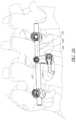
- FIG. 25shows a method of use of the connector 300 of FIG. 19 .
- the band 140 and the spinal rod 240can stabilize a first vertebra and/or a second vertebra, and/or can be configured to define a distraction between the first vertebra and the second vertebra.
- the spinal rod 240can stabilize the first vertebra to a second vertebra (e.g., by securing a pedicle of the first vertebra to a pedicle of a second vertebra) and the band 140 can connect to a transverse process (see, e.g., FIGS. 25 - 26 ).
- the spinal rod 240can stabilize the first vertebra to a second vertebra and the band 140 can connect to a lamina (see, e.g., FIGS. 27 - 29 ). In some uses, the spinal rod 240 can stabilize the first vertebra to a second vertebra and the band 140 can connect to a spinous process (see, e.g., FIGS. 30 - 31 ). In some uses, the spinal rod 240 can stabilize the first vertebra to a second vertebra and the band 140 can be inserted into a lumen through the superior articular process and the inferior articular process (not shown).
- the spinal rod 240is a cylindrically or substantially cylindrical elongate member.
- the cross-sectional of the spinal rod 240can be any appropriate shape, including but not limited to circular, oval, elliptical, rectangular, square, triangular, and polygonal.
- the spinal rod 240is a plate or plate like.
- the spinal rod 240can be part of a larger support member 120 .
- the support member 120can include pedicle screws, as described herein.
- the support membercan be any apparatus configured to be coupled to one or more bone portions. Examples of alternative support members are shown and described in U.S. patent application Ser. No. 13/804,521; filed Mar. 14, 2013, and titled “Apparatus for Bone Stabilization and Distraction and Methods of Use,” which is incorporated herein by reference in its entirety.
- the band 140can be placed into a suitable position.
- FIG. 25shows the band 140 encircling a transverse process.
- the connector 300is similar to the connector shown in FIG. 19 , with the longitudinal axis 346 of the recess 334 perpendicular or substantially perpendicular to the longitudinal axis 348 of the connector 300 .
- the distal end portion 148 of the band 140can be positioned within the connector 300 .
- the distal end portion 148can be inserted into the recess 334 .
- the first portion 144can extend through the opening 342 .
- the first portion 144 and/or the second portion 146can encircle one or more bone portions.
- the band 140can be disposed about a transverse process of a vertebra, as shown in FIGS. 25 - 26 .
- the band 140can be used in any suitable procedure to stabilize and/or fixate a bone portion.
- the band 140can engage a transverse process of a third vertebra, wherein the third vertebra is disposed between the first vertebra and the second vertebra.
- the band 140can be secured.
- the proximal end portion 142can be positioned within the lumen 344 of the connector 300 .
- the connector 300guides the proximal end portion 142 in the correct orientation relative to the distal end portion 148 .
- the proximal end portion 142is perpendicular or substantially perpendicular to the distal end portion 148 during insertion of the proximal end portion 142 in the fastening mechanism 150 .
- the proximal end portion 142can extend through the lumen 166 of the fastener mechanism 150 such that the band 140 forms a loop of suitable tightness about the third bone portion.
- the band 140can be tightened by passing the proximal end portion 142 into the distal end portion 148 and advancing the proximal end portion 142 through the lumen of the fastener member 150 such that the first portion 144 and/or second portion 146 substantially encircles a portion of the vertebra, for instance the transverse process shown in FIGS. 25 - 26 .
- the proximal end portion 142can be inserted in to the lumen of the fastener mechanism 150 such that the band 140 forms a loop about a portion of vertebra.
- the proximal end portion 142 , the first portion 144 and/or the second portion 146can be advanced through the lumen of the fastener mechanism 150 such that the volume disposed within the loop formed by the band 140 is reduced.
- the band 140exerts a compressive force on the bone portion of the vertebra that it encircles.
- the band 140is at least partially tightened or fully tightened around the bone portion prior to placement of the spinal rod 240 .
- the spinal rod 240is secured prior to using the band 140 to encircle a portion of the vertebra.
- a spinal rod 240 of a support member 120can be fixed to one or more bone portions.
- the support member 120is coupled to the pedicles of a first vertebra and a second vertebra.
- the support member 120is coupled to the other portions of the spine (e.g., lamina, transverse processes, spinous processes, facets, vertebral body, etc.).
- the support member 120comprises one or more fasteners 122 .
- the fasteners 122are pedicle screws.
- the fasteners 122may be polyaxial screws.
- the fasteners 122can be coupled to u-shaped yokes 124 .
- the yokes 124can include a slot sized to accept spinal rod 240 .
- the yokes 124can be threaded to receive a locking mechanism 126 .
- the locking mechanism 126applies a force to the spinal rod 240 to seat the spinal rod 240 within the yoke 124 .
- the locking mechanism 126is a set screw, but other locking mechanisms are contemplated.
- fixing the support member 120 to a bone portioncan include advancing a pedicle screw 122 through the yoke 124 and into a first bone portion.
- a first pedicle screw 122can be advanced through a yoke 124 and into a pedicle of a first vertebra.
- a locking mechanism 126can be advanced through a yoke 124 to secure the spinal rod 240 .
- a second pedicle screw 122can be advanced through a yoke 124 and into a pedicle of a second vertebra.
- the spinal rod 240can be placed within the yokes 124 .
- a locking mechanism 126can be advanced through a yoke 124 to secure the spinal rod 240 .
- the first yoke 124 and the second yoke 124can be spaced apart to define a distraction distance between the first bone portion and the second bone portion to define a corresponding distraction distance between a first vertebra and a second vertebra.
- the distance between the first yoke 124 and the second yoke 124e.g., the distance between the first bone portion and the second bone portion, can be increased (or decreased) to increase (or decrease) the distraction between the first vertebra and the second vertebra.
- the locking mechanism 126can be advanced to apply a force on the spinal rod 240 .
- the locking mechanisms 126can maintain the distraction of the first vertebra and the second vertebra.
- the locking mechanisms 126are at least partially tightened or fully tightened onto the spinal rod 240 prior to placement of the spinal rod 240 within the opening 322 of the connector 300 .
- the spinal rod 240is placed within the opening 322 of the connector 300 prior to tightening the one or more locking mechanisms 126 .
- the spinal rod 240can be positioned within the opening 322 of the connector 300 .
- a locking mechanism 244is inserted into the threaded bore 330 .
- the locking mechanism 244is a set screw, but other locking mechanisms are contemplated. Further advancement of the locking mechanism 244 will apply a force to the spinal rod 240 and seat the spinal rod 240 within the connector 300 .
- the locking mechanism 244is at least partially tightened or fully tightened prior to placement of the spinal rod 240 within the yokes 124 .
- locking mechanism 244is at least partially tightened or fully tightened prior to placement of the band 140 within the recess 334 .
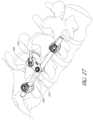
- FIGS. 27 - 29show a method of use of the connector 300 .
- the connector 300is similar to the connector shown in FIG. 19 , with the longitudinal axis 346 of the recess 334 angled relative to the longitudinal axis 348 of the connector 300 .
- the longitudinal axis 346 of the recess 334is angled relative to the longitudinal axis 348 of the connector 300 .
- the longitudinal axis 346 of the recess 334can be at any angle relative to the longitudinal axis 348 of the connector 300 .
- the longitudinal axis 346 of the recess 334is approximately 45° relative to the longitudinal axis 348 of the connector 300 .
- the spinal rod 240can stabilize the first vertebra to a second vertebra by securing a pedicle of the first vertebra to a pedicle of a second vertebra and the band 140 can connect to a lamina (see, e.g., FIGS. 26 - 28 ).
- the distal end portion 148 of the band 140can be positioned within the connector 300 .
- the distal end portion 148can be inserted into the recess 334 .
- the first portion 144can extend through the opening 342 .
- the band 140can be placed into a suitable position.
- the first portion 144 and/or the second portion 146can encircle a bone portion.
- the band 140can be disposed about a lamina of a vertebra, as shown in FIGS. 26 - 28 .
- the band 140can engage a lamina of a third vertebra, wherein the third vertebra is disposed between the first vertebra and the second vertebra.
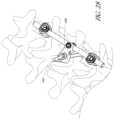
- FIG. 30shows a method of use of the connector 300 .
- the longitudinal axis 346 of the recess 334is parallel or substantially parallel to the longitudinal axis 348 of the connector 300 .
- the recess 334is disposed on the side surface of the connector 300 .
- the distal end portion 148is lowered into the recess 334 from the top surface of the connector 300 toward the bottom surface of the connector 300 in FIGS. 23 - 24 .
- the distal end portion 148is slid into the recess 34 from the side surface of the connector 300 toward the other side surface of the connector 300 .
- the side surfacealso includes the engagement features 332 .
- FIG. 31shows one method of use of the connector 300 .
- the connector 300 of FIG. 31has a L-shaped configuration.
- the recess 334is disposed on the side of the connector 300 .
- the distal end portion 148is lowered into the recess 334 from the top surface of the connector 300 toward the middle of the connector 300 in FIGS. 23 - 24 .
- the distal end portion 148is slid into the recess 334 from the side surface of the connector 300 toward the other side surface of the connector 300 .
- the band 140can be placed into a suitable position.
- FIGS. 30 - 31show the band 140 encircling a spinous process of a vertebra.
- the distal end portion 148 of the band 140can be positioned within the connector 300 .
- the distal end portion 148can be inserted into the recess 334 .
- the first portion 144can extend through the opening 342 .
- the first portion 144 and/or the second portion 146can encircle a bone portion.
- the band 140can be disposed about a spinous process of a vertebra, as shown in FIGS. 30 - 31 .
- the band 140can engage a spinous process of a third vertebra, wherein the third vertebra is disposed between the first vertebra and the second vertebra.
- FIG. 32depicts a block diagram of an embodiment of the flexible fastening band connector (“connector”) 300 and the flexible fastening band (“band”) 140 .
- the connector 300can include a bore 330 in communication with an opening 322 .
- the bore 330is sized to receive a locking mechanism 244 .
- the opening 322is sized to receive a spinal rod 240 .
- the locking mechanism 244extends through the bore 330 into the opening 322 and into contact with the spinal rod 240 disposed within the opening 322 .
- the connector 300can include recess 334 in communication with a lumen 344 .
- the recess 334is sized to receive the distal end portion 148 of a band 140 .
- the lumen 344is sized to receive the proximal end portion 142 of the band 140 .
- the proximal end portion 142 of the band 140extends through the lumen 344 into the recess 334 and into contact with the distal end portion 148 disposed within the recess 334 .
- FIG. 33depicts a block diagram of an embodiment of the flexible fastening band connector (“connector”) 300 and the flexible fastening band (“band”) 140 .
- the connector 300can include the first portion 312 , the connecting portion 314 , and the second portion 318 .
- the first portion 312 , the connecting portion 314 , and the second portion 318can form a unitary structure.
- the first portion 312can include an opening 322 sized to receive a spinal rod 240 .
- the second portion 318can include a recess 334 sized to receive a distal end portion 148 of a band 140 .
- the second portion 318can include a lumen 344 sized to receive a proximal end portion 142 of a band 140 .
- the distal end portion 148 and the proximal end portion 142can form a unitary structure.
- the spinal rod 240can stabilize the first vertebra to a second vertebra and the band 140 can be inserted into lumen between one or more bone portions (e.g., the superior articular process and the inferior articular process).
- the method of forming an artificial lumenis shown and described in U.S. patent application Ser. No. 13/033,791; filed Feb. 24, 2011, and titled “Methods and Apparatus for Stabilizing Bone,” U.S. patent application Ser. No. 13/403,698; filed Feb. 23, 2012, and titled “Vertebral Facet Joint Fusion Implant and Method for Fusion,” which are incorporated herein by reference in their entirety.
- the bandcan include a spacer (not shown).
- the spacercan be similar to, and have similar features to the embodiments of the prosthesis shown and described in U.S. patent application Ser. No. 12/859,009; filed Aug. 18, 2010, and U.S. Provisional Application 61/883,911, filed Sep. 27, 2013, and are incorporated herein by reference in their entirety.
- the spacercan be implanted and deployed to restore the space between facets of a superior articular process of a first vertebra and an inferior articular process of an adjacent vertebra.
- the spacercan be implanted and deployed to help stabilize adjacent vertebrae with adhesives, and/or can be implanted and deployed to deliver a medication.
- the spacercan be at least temporarily maintained in a desired position via an adhesive while the band 140 is positioned relative to the first vertebra and/or second vertebra.
- an adhesivecan be used in conjunction with the band 240 to stabilize and/or fixate the first vertebra to the second vertebra.
- the bandcan be used in combination with a plate (not shown). The plate can be similar to, and have similar features to the embodiments of the plates shown and described in and U.S. Provisional Application 61/883,960, filed Sep. 27, 2013, which is incorporated herein by reference in its entirety.
- the spacercan be, for example, substantially disc shaped. In other embodiments, the spacer can be other shapes, e.g., square, elliptical, or any other shape.
- the spacercan include a first side and a second side. The first side and/or the second side can be, for example, convex, concave, or flat. Said another way, the first side of the spacer can be concave, convex, or flat, and the second side of the spacer can be concave, convex, or flat, for example, the first side can be concave and the second side concave, the first side can be concave and the second side convex, etc.
- the spacercan include the same materials as band 140 .
- the spacercan include substances configured to release medication and/or increase the stability of a vertebra and/or band 140 . As discussed above, the substances can include a medicine(s) and/or an adhesive(s).
- the method of usecan include one or more of the following steps in any order: couple a first fastener to a first bone portion; advance a first fastener through a first yoke and into a first bone portion; advance a first locking mechanism into the first yoke to secure a spinal rod to the first yoke; and/or couple a first bone fastener to a spinal rod.
- the method of usecan include one or more of the following steps in any order: couple a second fastener to a second bone portion; advance a second fastener through a second yoke and into a second bone portion; advance a second locking mechanism into the second yoke to secure a spinal rod to the second yoke; and/or couple a second bone fastener to a spinal rod.
- the method of usecan include one or more of the following steps in any order: distract the first bone portion from the second bone portion; fix a distance between the first bone portion and the second bone portion; move the first bone portion relative to the second bone portion; increase the distraction distance between a first bone portion and a second bone portion and/or decrease the distraction distance between a first bone portion and a second bone portion.
- the method of usecan include one or more of the following steps in any order: insert the spinal rod into a connector; slide a spinal rod from a proximal end toward a distal end of the connector, seat the spinal rod within an opening of the connector; retain the spinal rod within the opening with at least one lip portion; and/or advance a locking mechanism to secure a spinal rod to the connector.
- the method of usecan include one or more of the following steps in any order: insert a flexible fastening band into the connector; lower the flexible fastening band into a recess of the connector; lower the flexible fastening band from a top surface of the connector toward a bottom surface of the connector; slide the flexible fastening band into a recess of the connector; slide the flexible fastening band from a side surface of the connector toward an opposed side surface of the connector; place the distal end portion of the flexible fastening band within a recess of the connector; and/or abut the distal end portion of the flexible fastening band with a surface of the recess of the connector.
- the method of usecan include one or more of the following steps in any order: insert the flexible fastening band into a lumen between two bone portions; insert the flexible fastening band into a lumen between articular processes; and/or insert the flexible fastening band across the facet joint.
- the method of usecan include one or more of the following steps in any order: encircle a bone portion with the flexible fastening band, encircle a bone portion of a first vertebra and a bone portion of a second vertebra with the flexible fastening band; encircle a spinous process with the flexible fastening band; encircle a transverse process with the flexible fastening band; and/or encircle a lamina with the flexible fastening band.
- the method of usecan include one or more of the following steps in any order: insert a flexible fastening band into a lumen of the connector; align the lumen of the connector with the lumen of the fastening mechanism; advance the flexible fastening band through the lumen of the connector; advance the flexible fastening band through the fastening mechanism.
- the method of usecan include one or more of the following steps in any order: insert the gears of the flexible fastening band into a lumen of the connector; align the lumen of the connector with the lumen of the fastening mechanism; advance the gears of the flexible fastening band through the fastening mechanism; advance the gears of the flexible fastening band through the ratchet of the fastening mechanism.
- a systemcomprising:
- Clause 2The system of Clause 1, wherein the first portion of the connector includes an opening configured to accept a spinal rod.
- Clause 3The system of Clause 1, wherein the first side of the connector and the second side of the connector are opposed parallel sides of the connector.
- Clause 4The system of Clause 2, wherein the first portion of the connector includes a locking mechanism configured to apply a force to the spinal rod within the opening.
- Clause 5The system of Clause 1, wherein the first side of the connector is the top of the connector and the second side of the connector is the bottom of the connector.
- Clause 6The system of Clause 1, wherein the first side of the connector is a side surface of the connector and the second side of the connector is the opposed side surface.
- Clause 7The system of Clause 1, wherein a side surface of the recess has a depth equal or greater than a thickness of the distal end portion.
- Clause 8The system of Clause 1, wherein the distal end portion does not protrude from the connector when the distal end portion is disposed in the recess.
- Clause 9The system of Clause 1, wherein the recess is sized to be greater than the distal end portion in all three dimensions.
- Clause 10The system of Clause 1 wherein the recess includes a neck which limits movement of the distal end portion within the recess.
- Clause 12The system of Clause 1, wherein a longitudinal axis of the recess forms an angle with a longitudinal axis of the connector.
- Clause 13The system of Clause 12, wherein the angle is approximately 0°.
- Clause 14The system of Clause 12, wherein the angle is approximately 45°.
- Clause 15The system of Clause 12, wherein the angle is approximately 90°.
- Clause 16The system of Clause 1, wherein a longitudinal axis of the recess forms an angle with a longitudinal axis of the lumen.
- Clause 17The system of Clause 16, wherein the angle is approximately 90°.
- Clause 18The system of Clause 1, further comprising one or more pedicle screws configured to couple to the spinal rod.
- Clause 19The system of Clause 1, further comprising a second flexible elongate body configured to couple to the spinal rod.
- a spinal fixation device connectorcomprising:
- Clause 21The connector of Clause 20, further comprising a locking mechanism in communication with the opening, wherein the locking mechanism is configured to apply a force to the spinal rod within the opening.
- Clause 22The connector of Clause 20, wherein a longitudinal axis of the recess forms an angle with a longitudinal axis of the connector.
- Clause 23The connector of Clause 22, wherein the angle is approximately 0°.
- Clause 24The connector of Clause 22, wherein the angle is approximately 45°.
- Clause 25The connector of Clause 22, wherein the angle is approximately 90°.
- Clause 26The connector of Clause 20, further comprising the flexible elongate body.
- Clause 27The connector of Clause 20, wherein a longitudinal axis of the recess forms an angle with a longitudinal axis of the lumen.
- Clause 28The connector of Clause 27, wherein the angle is approximately 90°.
- Clause 29The connector of Clause 20, wherein a longitudinal axis of the recess is substantially perpendicular to a longitudinal axis of the lumen.
- Clause 30The connector of Clause 20, wherein a longitudinal axis of the recess is perpendicular to a longitudinal axis of the lumen.
- Clause 31The connector of Clause 20, wherein a longitudinal axis of the recess is substantially parallel to a longitudinal axis of the spinal rod received within the opening.
- Clause 32The connector of Clause 20, wherein a longitudinal axis of the recess is parallel to a longitudinal axis of the spinal rod received within the opening.
- Clause 33The connector of Clause 20, wherein a longitudinal axis of the lumen is substantially perpendicular to a longitudinal axis of the spinal rod received within the opening.
- Clause 34The connector of Clause 20, wherein a longitudinal axis of the lumen is perpendicular to a longitudinal axis of the spinal rod received within the opening.
- Clause 35The connector of Clause 20, further comprising a bore in communication with the opening, wherein the bore is configured to receive a locking mechanism for securing the spinal rod to the connector.
- Clause 36The connector of Clause 35, wherein a longitudinal axis of the bore is substantially parallel to a longitudinal axis of the lumen.
- Clause 37The connector of Clause 35, wherein a longitudinal axis of the bore is parallel to a longitudinal axis of the lumen.
- Clause 38The connector of Clause 35, wherein a longitudinal axis of the bore is substantially perpendicular to a longitudinal axis of the spinal rod received within the opening.
- Clause 39The connector of Clause 35, wherein a longitudinal axis of the bore is perpendicular to a longitudinal axis of the spinal rod received within the opening.
- Clause 41The method of Clause 40, wherein disposing a portion of a flexible elongate body into contact with a first bone portion comprises encircling a first bone portion.
- Clause 42The method of Clause 40, wherein disposing a portion of a flexible elongate body into contact with a first bone portion comprises disposing a portion of the flexible elongate body through an artificial lumen of the first bone portion.
- Clause 43The method of Clause 40, wherein disposing a portion of a flexible elongate body into contact with a first bone portion comprises encircling a spinous process.
- Clause 44The method of Clause 40, wherein disposing a portion of a flexible elongate body into contact with a first bone portion comprises encircling a transverse process.
- Clause 45The method of Clause 40, wherein disposing a portion of a flexible elongate body into contact with a first bone portion comprises encircling a lamina.
- Clause 46The method of Clause 40, further comprising disposing a spinal rod in an opening of the connector.
- Clause 47The method of Clause 46, further comprising securing the spinal rod in the opening of the connector with a locking mechanism.
- Clause 48The method of Clause 46, further comprising securing the spinal rod to one or more vertebra with one or more fasteners.
- Clause 49The method of Clause 46, further comprising securing the spinal rod to one or more vertebra with one or more flexible elongate bodies.
Landscapes
- Health & Medical Sciences (AREA)
- Orthopedic Medicine & Surgery (AREA)
- Life Sciences & Earth Sciences (AREA)
- Surgery (AREA)
- Neurology (AREA)
- Heart & Thoracic Surgery (AREA)
- Engineering & Computer Science (AREA)
- Biomedical Technology (AREA)
- Nuclear Medicine, Radiotherapy & Molecular Imaging (AREA)
- Medical Informatics (AREA)
- Molecular Biology (AREA)
- Animal Behavior & Ethology (AREA)
- General Health & Medical Sciences (AREA)
- Public Health (AREA)
- Veterinary Medicine (AREA)
- Surgical Instruments (AREA)
- Prostheses (AREA)
Abstract
Description
- a band comprising a flexible elongate body including a proximal end portion and a distal end portion, the distal end portion including a fastener having an opening that can receive the proximal end portion of the flexible elongate body;
- a connector comprising a first portion for engaging a fixation device, and a second portion with a recess formed on a first side of the connector and a lumen formed on a second side of the connector, the lumen extending to the recess, wherein the recess is configured to receive at least a portion of the fastener of the distal end portion of the flexible elongate body and wherein the lumen is configured to guide the proximal end portion of the flexible elongated body into the opening in the fastener when the fastener is positioned at least partially within the recess.
- a body comprising a first portion and a second portion, the first portion of the body including an opening configured to accept a spinal rod, and the second portion having a first side and a second side, a recess formed in the first side of the body configured to receive a distal end portion of a flexible elongate body, wherein the flexible elongate body comprises a proximal end portion and a distal end portion, wherein the distal end portion of the flexible elongate body comprises a fastener configured to accept the proximal end portion; and
- a lumen formed on the second side of the body, the lumen intersecting the recess and configured to guide a proximal end portion toward a fastener when the distal end portion of the flexible elongate body is received in the recess.
- inserting a distal end portion of a flexible elongate body into a recess of a connector,
- disposing a portion of the flexible elongate body into contact with a first bone portion,
- inserting a proximal end portion of the flexible elongate body into a lumen of the connector, and
- guiding the proximal end portion through the lumen and through a fastener of the distal end portion.
Claims (19)
Priority Applications (2)
| Application Number | Priority Date | Filing Date | Title |
|---|---|---|---|
| US17/544,265US11998240B2 (en) | 2014-09-17 | 2021-12-07 | Flexible fastening band connector |
| US18/649,083US12440242B2 (en) | 2024-04-29 | Flexible fastening band connector |
Applications Claiming Priority (4)
| Application Number | Priority Date | Filing Date | Title |
|---|---|---|---|
| US201462051454P | 2014-09-17 | 2014-09-17 | |
| PCT/US2015/050441WO2016044432A1 (en) | 2014-09-17 | 2015-09-16 | Flexible fastening band connector |
| US201715508365A | 2017-03-02 | 2017-03-02 | |
| US17/544,265US11998240B2 (en) | 2014-09-17 | 2021-12-07 | Flexible fastening band connector |
Related Parent Applications (2)
| Application Number | Title | Priority Date | Filing Date |
|---|---|---|---|
| PCT/US2015/050441DivisionWO2016044432A1 (en) | 2014-09-17 | 2015-09-16 | Flexible fastening band connector |
| US15/508,365DivisionUS11478275B2 (en) | 2014-09-17 | 2015-09-16 | Flexible fastening band connector |
Related Child Applications (1)
| Application Number | Title | Priority Date | Filing Date |
|---|---|---|---|
| US18/649,083ContinuationUS12440242B2 (en) | 2024-04-29 | Flexible fastening band connector |
Publications (2)
| Publication Number | Publication Date |
|---|---|
| US20220151659A1 US20220151659A1 (en) | 2022-05-19 |
| US11998240B2true US11998240B2 (en) | 2024-06-04 |
Family
ID=55533796
Family Applications (2)
| Application Number | Title | Priority Date | Filing Date |
|---|---|---|---|
| US15/508,365Active2036-01-30US11478275B2 (en) | 2014-09-17 | 2015-09-16 | Flexible fastening band connector |
| US17/544,265Active2036-01-14US11998240B2 (en) | 2014-09-17 | 2021-12-07 | Flexible fastening band connector |
Family Applications Before (1)
| Application Number | Title | Priority Date | Filing Date |
|---|---|---|---|
| US15/508,365Active2036-01-30US11478275B2 (en) | 2014-09-17 | 2015-09-16 | Flexible fastening band connector |
Country Status (2)
| Country | Link |
|---|---|
| US (2) | US11478275B2 (en) |
| WO (1) | WO2016044432A1 (en) |
Cited By (4)
| Publication number | Priority date | Publication date | Assignee | Title |
|---|---|---|---|---|
| US12232778B2 (en) | 2020-02-14 | 2025-02-25 | Spinal Elements, Inc. | Bone tie methods |
| US12343048B2 (en) | 2011-02-24 | 2025-07-01 | Spinal Elements, Inc. | Methods and apparatus for stabilizing bone |
| US12369952B2 (en) | 2021-12-10 | 2025-07-29 | Spinal Elements, Inc. | Bone tie and portal |
| US12440242B2 (en) | 2024-04-29 | 2025-10-14 | Spinal Elements, Inc. | Flexible fastening band connector |
Families Citing this family (23)
| Publication number | Priority date | Publication date | Assignee | Title |
|---|---|---|---|---|
| US7846183B2 (en) | 2004-02-06 | 2010-12-07 | Spinal Elements, Inc. | Vertebral facet joint prosthesis and method of fixation |
| US9504583B2 (en) | 2004-06-10 | 2016-11-29 | Spinal Elements, Inc. | Implant and method for facet immobilization |
| EP2813190B1 (en) | 2007-02-22 | 2017-04-26 | Spinal Elements, Inc. | Vertebral facet joint drill |
| US8992533B2 (en) | 2007-02-22 | 2015-03-31 | Spinal Elements, Inc. | Vertebral facet joint drill and method of use |
| US9271765B2 (en) | 2011-02-24 | 2016-03-01 | Spinal Elements, Inc. | Vertebral facet joint fusion implant and method for fusion |
| USD739935S1 (en) | 2011-10-26 | 2015-09-29 | Spinal Elements, Inc. | Interbody bone implant |
| WO2014149244A1 (en) | 2013-02-07 | 2014-09-25 | Houff Louis | Sternum fixation device and method |
| USD765853S1 (en) | 2013-03-14 | 2016-09-06 | Spinal Elements, Inc. | Flexible elongate member with a portion configured to receive a bone anchor |
| US9421044B2 (en) | 2013-03-14 | 2016-08-23 | Spinal Elements, Inc. | Apparatus for bone stabilization and distraction and methods of use |
| US9820784B2 (en) | 2013-03-14 | 2017-11-21 | Spinal Elements, Inc. | Apparatus for spinal fixation and methods of use |
| US9456855B2 (en) | 2013-09-27 | 2016-10-04 | Spinal Elements, Inc. | Method of placing an implant between bone portions |
| US9839450B2 (en) | 2013-09-27 | 2017-12-12 | Spinal Elements, Inc. | Device and method for reinforcement of a facet |
| US11478275B2 (en) | 2014-09-17 | 2022-10-25 | Spinal Elements, Inc. | Flexible fastening band connector |
| AU2016212009C1 (en) | 2015-01-27 | 2021-02-25 | Spinal Elements, Inc. | Facet joint implant |
| US10463403B2 (en) | 2017-07-31 | 2019-11-05 | Medos International Sarl | Systems and methods for reducing the risk of proximal junctional kyphosis using a bone anchor or other attachment point |
| US10456174B2 (en) | 2017-07-31 | 2019-10-29 | Medos International Sarl | Connectors for use in systems and methods for reducing the risk of proximal junctional kyphosis |
| BR112021022695A2 (en) | 2019-05-22 | 2021-12-28 | Spinal Elements Inc | Bone tethering and bone tethering inserter |
| US11457959B2 (en) | 2019-05-22 | 2022-10-04 | Spinal Elements, Inc. | Bone tie and bone tie inserter |
| US11779379B2 (en)* | 2020-06-19 | 2023-10-10 | Circumfix Solutions, Inc. | Sternum fixation devices and methods |
| US12290295B2 (en) | 2020-06-19 | 2025-05-06 | Circumfix Solutions, Inc. | Bone repair devices and methods |
| AU2022266771B2 (en)* | 2021-04-27 | 2025-03-06 | Circumfix Solutions, Inc. | Bone repair devices and methods |
| MX2024001359A (en) | 2021-07-29 | 2024-04-30 | Circumfix Solutions Inc | BONE REPAIR DEVICES AND METHODS. |
| WO2023211983A2 (en)* | 2022-04-26 | 2023-11-02 | Circumfix Solutions, Inc. | Bone repair devices and methods |
Citations (533)
| Publication number | Priority date | Publication date | Assignee | Title |
|---|---|---|---|---|
| US86016A (en) | 1869-01-19 | Silas j | ||
| US1630239A (en) | 1924-05-09 | 1927-05-24 | Roy S Binkley | Antrum burr |
| US1822280A (en) | 1929-06-26 | 1931-09-08 | John F Ervay | Carpenter's hammer |
| US1822330A (en) | 1930-01-13 | 1931-09-08 | Ainslie George | Suturing instrument |
| US2486303A (en) | 1948-04-29 | 1949-10-25 | Harry Herschel Leiter | Surgical appliance for bone fractures |
| US2706023A (en) | 1952-01-02 | 1955-04-12 | Ronald A Merritt | Gripping device for securing guy wires to a mast |
| US2967282A (en) | 1957-09-30 | 1961-01-03 | Gen Electric | High temperature resistor |
| US3111945A (en) | 1961-01-05 | 1963-11-26 | Solbrig Charles R Von | Bone band and process of applying the same |
| US3149808A (en) | 1963-09-25 | 1964-09-22 | Weckesser Co | Wedge-lock band clamp |
| US3570497A (en) | 1969-01-16 | 1971-03-16 | Gerald M Lemole | Suture apparatus and methods |
| US3867728A (en) | 1971-12-30 | 1975-02-25 | Cutter Lab | Prosthesis for spinal repair |
| US3875595A (en) | 1974-04-15 | 1975-04-08 | Edward C Froning | Intervertebral disc prosthesis and instruments for locating same |
| US3879767A (en) | 1972-01-26 | 1975-04-29 | Cutter Lab | Prosthesis for articulating body structures |
| US4001896A (en) | 1975-06-09 | 1977-01-11 | Zimmer, U.S.A. Inc. | Prosthetic joint for total knee replacement |
| US4037603A (en) | 1975-05-13 | 1977-07-26 | Wendorff Erwin R | Metallic surgical suture |
| JPS535889A (en) | 1976-07-06 | 1978-01-19 | Partridge Anthony John | Orthopedic surgical operation band and bone setting method |
| US4085466A (en) | 1974-11-18 | 1978-04-25 | National Research Development Corporation | Prosthetic joint device |
| US4156296A (en) | 1977-04-08 | 1979-05-29 | Bio-Dynamics, Inc. | Great (large) toe prosthesis and method of implanting |
| US4164793A (en) | 1978-04-26 | 1979-08-21 | Swanson Alfred B | Lunate implant |
| US4166292A (en) | 1977-09-08 | 1979-09-04 | Carbomedics, Inc. | Stress reinforced artificial joint prostheses |
| US4231121A (en) | 1979-07-05 | 1980-11-04 | Wright Dow Corning | Metacarpal-phalangeal prosthesis |
| USD261935S (en) | 1978-12-18 | 1981-11-17 | Halloran William X | Slotted intramedullary rod |
| US4312337A (en) | 1980-09-08 | 1982-01-26 | Donohue Brian T | Cannula and drill guide apparatus |
| US4323217A (en) | 1980-01-30 | 1982-04-06 | General Electric Company | Motor mounting assembly including extendable band |
| US4349921A (en) | 1980-06-13 | 1982-09-21 | Kuntz J David | Intervertebral disc prosthesis |
| US4502161A (en) | 1981-09-21 | 1985-03-05 | Wall W H | Prosthetic meniscus for the repair of joints |
| USD279502S (en) | 1982-11-26 | 1985-07-02 | Halloran William X | Intramedullary rod having a s-shaped cross section |
| USD279503S (en) | 1982-11-26 | 1985-07-02 | Halloran William X | Grooved intramedullary rod |
| US4535764A (en) | 1983-04-15 | 1985-08-20 | Tayco Developments, Inc. | Surgical bone tie |
| US4557259A (en) | 1983-08-10 | 1985-12-10 | Henry Ford Hospital | Surgical method and apparatus for inserting wire into the spine |
| US4570618A (en) | 1983-11-23 | 1986-02-18 | Henry Ford Hospital | Intervertebral body wire stabilization |
| US4573458A (en) | 1982-08-17 | 1986-03-04 | Zimmer, Inc. | Bone fixation plate |
| US4573459A (en) | 1983-08-25 | 1986-03-04 | Litton Bruce W | Thumb and finger extension device |
| US4634445A (en) | 1981-01-30 | 1987-01-06 | Oec Europe Limited | Joint prosthesis |
| US4643178A (en) | 1984-04-23 | 1987-02-17 | Fabco Medical Products, Inc. | Surgical wire and method for the use thereof |
| US4662371A (en) | 1983-01-26 | 1987-05-05 | Whipple Terry L | Surgical instrument |
| EP0238219A1 (en) | 1986-03-03 | 1987-09-23 | Pfizer Hospital Products Group, Inc. | A sternum closure device |
| US4706659A (en) | 1984-12-05 | 1987-11-17 | Regents Of The University Of Michigan | Flexible connecting shaft for intramedullary reamer |
| US4714469A (en) | 1987-02-26 | 1987-12-22 | Pfizer Hospital Products Group, Inc. | Spinal implant |
| US4722331A (en) | 1985-09-03 | 1988-02-02 | Fox James M | Orthopaedic tool guide |
| US4759766A (en) | 1984-09-04 | 1988-07-26 | Humboldt-Universitaet Zu Berlin | Intervertebral disc endoprosthesis |
| US4759769A (en) | 1987-02-12 | 1988-07-26 | Health & Research Services Inc. | Artificial spinal disc |
| WO1988006022A1 (en) | 1987-02-20 | 1988-08-25 | Farrell Edward M | Surgical tying devices |
| US4772287A (en) | 1987-08-20 | 1988-09-20 | Cedar Surgical, Inc. | Prosthetic disc and method of implanting |
| US4773402A (en) | 1985-09-13 | 1988-09-27 | Isola Implants, Inc. | Dorsal transacral surgical implant |
| US4834757A (en) | 1987-01-22 | 1989-05-30 | Brantigan John W | Prosthetic implant |
| EP0322334A1 (en) | 1987-12-23 | 1989-06-28 | Cremascoli France | Prosthesis implanted between vertebral spinous processes |
| US4863477A (en) | 1987-05-12 | 1989-09-05 | Monson Gary L | Synthetic intervertebral disc prosthesis |
| US4880429A (en) | 1987-07-20 | 1989-11-14 | Stone Kevin R | Prosthetic meniscus |
| US4907577A (en) | 1989-04-03 | 1990-03-13 | Wu Shing Sheng | Spinal transpedicle drill jig |
| US4911718A (en) | 1988-06-10 | 1990-03-27 | University Of Medicine & Dentistry Of N.J. | Functional and biocompatible intervertebral disc spacer |
| US4919667A (en) | 1988-12-02 | 1990-04-24 | Stryker Corporation | Implant |
| US4923471A (en) | 1989-10-17 | 1990-05-08 | Timesh, Inc. | Bone fracture reduction and fixation devices with identity tags |
| US4936848A (en) | 1989-09-22 | 1990-06-26 | Bagby George W | Implant for vertebrae |
| US4941466A (en) | 1987-04-13 | 1990-07-17 | Romano Jack W | Curved bore drilling method and apparatus |
| US4955913A (en) | 1985-03-28 | 1990-09-11 | Robinson Walter C | Surgical tie |
| US4959065A (en) | 1989-07-14 | 1990-09-25 | Techmedica, Inc. | Bone plate with positioning member |
| EP0392124A1 (en) | 1987-11-16 | 1990-10-17 | Francis Henri Bréard | Surgical implant for limiting the relative movement of vertebrae |
| US4969909A (en) | 1987-10-27 | 1990-11-13 | Barouk Louis S | Articular prosthetic implant with temporary fixing means |
| US5000165A (en) | 1989-05-15 | 1991-03-19 | Watanabe Robert S | Lumbar spine rod fixation system |
| US5002546A (en) | 1987-04-13 | 1991-03-26 | Romano Jack W | Curved bore drilling apparatus |
| JPH03100154A (en) | 1989-09-13 | 1991-04-25 | Kawasaki Steel Corp | Production of alloying hot dip galvanized steel strip |
| US5015255A (en) | 1989-05-10 | 1991-05-14 | Spine-Tech, Inc. | Spinal stabilization method |
| US5047055A (en) | 1990-12-21 | 1991-09-10 | Pfizer Hospital Products Group, Inc. | Hydrogel intervertebral disc nucleus |
| JPH03240660A (en) | 1990-02-02 | 1991-10-28 | Yazaki Corp | Focusing tool |
| US5071437A (en) | 1989-02-15 | 1991-12-10 | Acromed Corporation | Artificial disc |
| US5092868A (en) | 1987-07-17 | 1992-03-03 | Mehdian Seyed M H | Apparatus for use in the treatment of spinal disorders |
| US5092866A (en) | 1989-02-03 | 1992-03-03 | Breard Francis H | Flexible inter-vertebral stabilizer as well as process and apparatus for determining or verifying its tension before installation on the spinal column |
| US5112013A (en) | 1991-02-25 | 1992-05-12 | Chrysler Corporation | Tie strap structure for electric wiring |
| US5112346A (en) | 1989-06-08 | 1992-05-12 | Richard Wolf Gmbh | Retrograde cutting hook punch |
| US5127912A (en) | 1990-10-05 | 1992-07-07 | R. Charles Ray | Sacral implant system |
| US5135188A (en) | 1990-02-06 | 1992-08-04 | Anderson Franklin R | Attachable bundling strap |
| US5147404A (en) | 1987-12-07 | 1992-09-15 | Downey Ernest L | Vertebra prosthesis |
| US5171280A (en) | 1990-04-20 | 1992-12-15 | Sulzer Brothers Limited | Intervertebral prosthesis |
| US5192326A (en) | 1990-12-21 | 1993-03-09 | Pfizer Hospital Products Group, Inc. | Hydrogel bead intervertebral disc nucleus |
| US5192327A (en) | 1991-03-22 | 1993-03-09 | Brantigan John W | Surgical prosthetic implant for vertebrae |
| US5209755A (en) | 1992-06-05 | 1993-05-11 | Stella Abrahan | Dermal exciser |
| DE9304368U1 (en) | 1993-03-18 | 1993-05-13 | AAP GmbH & Co. Betriebs KG, 1000 Berlin | Spinal implant |
| WO1993014721A1 (en) | 1992-01-28 | 1993-08-05 | Salut, Ltd. | Sacral implant system |
| US5258031A (en) | 1992-01-06 | 1993-11-02 | Danek Medical | Intervertebral disk arthroplasty |
| US5282861A (en) | 1992-03-11 | 1994-02-01 | Ultramet | Open cell tantalum structures for cancellous bone implants and cell and tissue receptors |
| US5286249A (en) | 1989-10-31 | 1994-02-15 | Thibodaux Peggy L | Brace for fixation of bone fractures |
| WO1994004088A1 (en) | 1992-08-19 | 1994-03-03 | Surgicraft Limited | Surgical implants, etc |
| US5304178A (en) | 1992-05-29 | 1994-04-19 | Acromed Corporation | Sublaminar wire |
| US5306275A (en) | 1992-12-31 | 1994-04-26 | Bryan Donald W | Lumbar spine fixation apparatus and method |
| US5306309A (en) | 1992-05-04 | 1994-04-26 | Calcitek, Inc. | Spinal disk implant and implantation kit |
| US5306308A (en) | 1989-10-23 | 1994-04-26 | Ulrich Gross | Intervertebral implant |
| US5326364A (en) | 1992-12-16 | 1994-07-05 | Wright Medical Technology, Inc. | Trapezial implant |
| US5330479A (en) | 1993-03-11 | 1994-07-19 | Whitmore Henry B | Reciprocating bone punch |
| EP0610837A1 (en) | 1993-02-09 | 1994-08-17 | Acromed Corporation | Spine disc |
| US5360431A (en) | 1990-04-26 | 1994-11-01 | Cross Medical Products | Transpedicular screw system and method of use |
| FR2704745A1 (en) | 1993-05-07 | 1994-11-10 | Erpios | Device for connecting the ends of a ligament for osteosynthesis, in particular for vertebral osteosynthesis. |
| JPH06319742A (en) | 1993-04-21 | 1994-11-22 | Amei Technol Inc | Fixing system and fixing method for fixing medical cable, medical cable fixing device, and crimping and cutting device |
| US5368596A (en) | 1992-03-18 | 1994-11-29 | Burkhart; Stephen S. | Augmented awl for creating channels in human bone tissue |
| US5370697A (en) | 1992-04-21 | 1994-12-06 | Sulzer Medizinaltechnik Ag | Artificial intervertebral disk member |
| US5372598A (en) | 1987-05-14 | 1994-12-13 | Howmedica Gmbh | Small bone plate for cranial or facial fractures or the like |
| US5401269A (en) | 1992-03-13 | 1995-03-28 | Waldemar Link Gmbh & Co. | Intervertebral disc endoprosthesis |
| US5400784A (en) | 1993-10-15 | 1995-03-28 | Case Western Reserve University | Slowly penetrating inter-fascicular nerve cuff electrode and method of using |
| US5413576A (en) | 1993-02-10 | 1995-05-09 | Rivard; Charles-Hilaire | Apparatus for treating spinal disorder |
| US5415661A (en) | 1993-03-24 | 1995-05-16 | University Of Miami | Implantable spinal assist device |
| US5425773A (en) | 1992-01-06 | 1995-06-20 | Danek Medical, Inc. | Intervertebral disk arthroplasty device |
| US5437672A (en) | 1992-11-12 | 1995-08-01 | Alleyne; Neville | Spinal cord protection device |
| US5445639A (en) | 1989-05-10 | 1995-08-29 | Spine-Tech, Inc. | Intervertebral reamer construction |
| US5458642A (en) | 1994-01-18 | 1995-10-17 | Beer; John C. | Synthetic intervertebral disc |
| US5458643A (en) | 1991-03-29 | 1995-10-17 | Kyocera Corporation | Artificial intervertebral disc |
| US5462542A (en) | 1994-01-24 | 1995-10-31 | United States Surgical Corporation | Sternum buckle with serrated strap |
| US5487756A (en) | 1994-12-23 | 1996-01-30 | Simon Fraser University | Implantable cuff having improved closure |
| FR2722980A1 (en) | 1994-07-26 | 1996-02-02 | Samani Jacques | Spinal implant for securing adjacent pair of vertebrae |
| US5491882A (en) | 1993-12-28 | 1996-02-20 | Walston; D. Kenneth | Method of making joint prosthesis having PTFE cushion |
| US5496142A (en) | 1993-07-20 | 1996-03-05 | Applied Materials, Inc. | Slotted conical spring washer |
| US5496318A (en) | 1993-01-08 | 1996-03-05 | Advanced Spine Fixation Systems, Inc. | Interspinous segmental spine fixation device |
| US5509918A (en) | 1993-05-11 | 1996-04-23 | David Romano | Method and apparatus for drilling a curved bore in an object |
| US5514180A (en) | 1994-01-14 | 1996-05-07 | Heggeness; Michael H. | Prosthetic intervertebral devices |
| US5527312A (en) | 1994-08-19 | 1996-06-18 | Salut, Ltd. | Facet screw anchor |
| US5527314A (en) | 1993-01-04 | 1996-06-18 | Danek Medical, Inc. | Spinal fixation system |
| US5534028A (en) | 1993-04-20 | 1996-07-09 | Howmedica, Inc. | Hydrogel intervertebral disc nucleus with diminished lateral bulging |
| US5540703A (en) | 1993-01-06 | 1996-07-30 | Smith & Nephew Richards Inc. | Knotted cable attachment apparatus formed of braided polymeric fibers |
| US5540706A (en) | 1993-01-25 | 1996-07-30 | Aust; Gilbert M. | Surgical instrument |
| US5545229A (en) | 1988-08-18 | 1996-08-13 | University Of Medicine And Dentistry Of Nj | Functional and biocompatible intervertebral disc spacer containing elastomeric material of varying hardness |
| US5549619A (en) | 1991-06-04 | 1996-08-27 | Clinical Product Development Limited | Medical/surgical devices |
| US5556431A (en) | 1992-03-13 | 1996-09-17 | B+E,Uml U+Ee Ttner-Janz; Karin | Intervertebral disc endoprosthesis |
| US5571189A (en) | 1994-05-20 | 1996-11-05 | Kuslich; Stephen D. | Expandable fabric implant for stabilizing the spinal motion segment |
| US5571105A (en) | 1993-07-06 | 1996-11-05 | Gundolf; Ferdinand | Osteosynthesis apparatus for the fixation of bone fragments |
| US5571131A (en) | 1995-06-07 | 1996-11-05 | Smith & Nephew Endoscopy, Inc. | Back biting punch |
| US5571191A (en) | 1995-03-16 | 1996-11-05 | Fitz; William R. | Artificial facet joint |
| US5577995A (en) | 1991-06-13 | 1996-11-26 | Grace L. Walker | Spinal and soft tissue mobilizer |
| US5586989A (en) | 1995-01-27 | 1996-12-24 | Bray, Jr.; Robert | Microsurgical curette |
| US5591165A (en) | 1992-11-09 | 1997-01-07 | Sofamor, S.N.C. | Apparatus and method for spinal fixation and correction of spinal deformities |
| US5603713A (en) | 1991-09-24 | 1997-02-18 | Aust; Gilbert M. | Anterior lumbar/cervical bicortical compression plate |
| US5609634A (en) | 1992-07-07 | 1997-03-11 | Voydeville; Gilles | Intervertebral prosthesis making possible rotatory stabilization and flexion/extension stabilization |
| US5638700A (en) | 1996-01-11 | 1997-06-17 | Shechter; Jaime | Earring post |
| US5645597A (en) | 1995-12-29 | 1997-07-08 | Krapiva; Pavel I. | Disc replacement method and apparatus |
| US5649947A (en) | 1990-11-09 | 1997-07-22 | Arthrotek, Inc. | Surgical instrument |
| US5653762A (en) | 1994-03-18 | 1997-08-05 | Pisharodi; Madhavan | Method of stabilizing adjacent vertebrae with rotating, lockable, middle-expanded intervertebral disk stabilizer |
| US5674296A (en) | 1994-11-14 | 1997-10-07 | Spinal Dynamics Corporation | Human spinal disc prosthesis |
| US5674295A (en) | 1994-10-17 | 1997-10-07 | Raymedica, Inc. | Prosthetic spinal disc nucleus |
| US5676701A (en) | 1993-01-14 | 1997-10-14 | Smith & Nephew, Inc. | Low wear artificial spinal disc |
| US5683466A (en) | 1996-03-26 | 1997-11-04 | Vitale; Glenn C. | Joint surface replacement system |
| WO1997047246A1 (en) | 1996-06-10 | 1997-12-18 | Influence Medical Technologies Ltd. | Suture insertion device for the treatment of urinary stress incontinence |
| US5702450A (en) | 1993-06-28 | 1997-12-30 | Bisserie; Michel | Intervertebral disk prosthesis |
| US5707373A (en) | 1996-04-26 | 1998-01-13 | Ikonos Corporation | Bone fastener and instrument for insertion thereof |
| US5713542A (en) | 1995-07-11 | 1998-02-03 | Avery Dennison Corporation | Locator tie |
| US5716415A (en) | 1993-10-01 | 1998-02-10 | Acromed Corporation | Spinal implant |
| US5741261A (en) | 1996-06-25 | 1998-04-21 | Sdgi Holdings, Inc. | Minimally invasive spinal surgical methods and instruments |
| US5741260A (en) | 1994-02-24 | 1998-04-21 | Pioneer Laboratories, Inc. | Cable system for bone securance |
| US5766253A (en) | 1996-01-16 | 1998-06-16 | Surgical Dynamics, Inc. | Spinal fusion device |
| USD395138S (en) | 1996-05-20 | 1998-06-16 | Kenji Ohata | Metallic cranial burr hole cover and bone flap fixation plate |
| US5766251A (en) | 1992-03-13 | 1998-06-16 | Tomihisa Koshino | Wedge-shaped spacer for correction of deformed extremities |
| US5772663A (en) | 1994-02-17 | 1998-06-30 | Whiteside; Leo A. | Surgical device for banding bone with cable |
| JPH10179622A (en) | 1996-12-20 | 1998-07-07 | Mizuho Ika Kogyo Kk | Vertebral implant |
| US5797916A (en) | 1996-12-10 | 1998-08-25 | Johnson & Johnson Professional, Inc. | Trochanteric reattachment cerclage device |
| US5810854A (en) | 1997-01-24 | 1998-09-22 | Beach; William R. | Method and apparatus for attaching connective tissue to each other or underlying bone |
| US5824094A (en) | 1997-10-17 | 1998-10-20 | Acromed Corporation | Spinal disc |
| US5824093A (en) | 1994-10-17 | 1998-10-20 | Raymedica, Inc. | Prosthetic spinal disc nucleus |
| WO1998048717A1 (en) | 1997-04-30 | 1998-11-05 | Jean Taylor | Apparatus for interlocking two contiguous, in particular lumbar, vertebrae |
| US5836948A (en) | 1997-01-02 | 1998-11-17 | Saint Francis Medical Technologies, Llc | Spine distraction implant and method |
| US5851208A (en) | 1996-10-15 | 1998-12-22 | Linvatec Corporation | Rotatable surgical burr |
| US5860977A (en) | 1997-01-02 | 1999-01-19 | Saint Francis Medical Technologies, Llc | Spine distraction implant and method |
| US5868745A (en) | 1992-11-12 | 1999-02-09 | Alleyne; Neville | Spinal protection device |
| US5879396A (en) | 1993-12-28 | 1999-03-09 | Walston; D. Kenneth | Joint prosthesis having PTFE cushion |
| US5888203A (en) | 1995-03-09 | 1999-03-30 | Goldberg; Robert | Biaxial ligamentous-restrained prostheses for upper and lower extremity arthroplasties |
| US5893889A (en) | 1997-06-20 | 1999-04-13 | Harrington; Michael | Artificial disc |
| US5895428A (en) | 1996-11-01 | 1999-04-20 | Berry; Don | Load bearing spinal joint implant |
| WO1999023963A1 (en) | 1997-11-10 | 1999-05-20 | Dimso (Distribution Medicale Du Sud-Ouest) | Vertebra implant |
| USRE36221E (en) | 1989-02-03 | 1999-06-01 | Breard; Francis Henri | Flexible inter-vertebral stabilizer as well as process and apparatus for determining or verifying its tension before installation on the spinal column |
| US5918604A (en) | 1997-02-12 | 1999-07-06 | Arthrex, Inc. | Method of loading tendons into the knee |
| EP0928603A1 (en) | 1998-01-12 | 1999-07-14 | Salvatore Sessa | Intervertebral connecting device |
| US5951555A (en) | 1996-03-27 | 1999-09-14 | Rehak; Lubos | Device for the correction of spinal deformities |
| US5964765A (en) | 1998-04-16 | 1999-10-12 | Axya Medical, Inc. | Soft tissue fixation device |
| US5993452A (en) | 1998-08-24 | 1999-11-30 | Biomet Inc. | Cerclage system |
| US5997542A (en) | 1997-11-18 | 1999-12-07 | Biomet, Inc. | Surgical wire assembly and method of use |
| US6014588A (en) | 1998-04-07 | 2000-01-11 | Fitz; William R. | Facet joint pain relief method and apparatus |
| US6019768A (en) | 1997-11-18 | 2000-02-01 | Ethicon, Inc, | Suture anchor retriever and method for retrieving an implanted suture anchor |
| US6019792A (en) | 1998-04-23 | 2000-02-01 | Cauthen Research Group, Inc. | Articulating spinal implant |
| US6019763A (en) | 1996-10-25 | 2000-02-01 | Gunze Limited | Bone joining device |
| US6039763A (en) | 1998-10-27 | 2000-03-21 | Disc Replacement Technologies, Inc. | Articulating spinal disc prosthesis |
| US6048342A (en) | 1997-01-02 | 2000-04-11 | St. Francis Medical Technologies, Inc. | Spine distraction implant |
| US6050998A (en) | 1999-05-21 | 2000-04-18 | Stephen A. Fletcher | Bone fastener |
| US6063121A (en) | 1998-07-29 | 2000-05-16 | Xavier; Ravi | Vertebral body prosthesis |
| US6066325A (en) | 1996-08-27 | 2000-05-23 | Fusion Medical Technologies, Inc. | Fragmented polymeric compositions and methods for their use |
| US6068630A (en) | 1997-01-02 | 2000-05-30 | St. Francis Medical Technologies, Inc. | Spine distraction implant |
| US6080157A (en) | 1995-09-12 | 2000-06-27 | Cg Surgical Limited | Device to stabilize the lamina |
| WO2000038582A1 (en) | 1998-12-23 | 2000-07-06 | Nuvasive, Inc. | Bony tissue resector |
| JP2000201941A (en) | 1999-01-13 | 2000-07-25 | Kyowa Tokei Kogyo Kk | Bone binding band |
| JP2000210297A (en) | 1999-01-26 | 2000-08-02 | Ishibashi Toru | Steel wire |
| US6099531A (en) | 1998-08-20 | 2000-08-08 | Bonutti; Peter M. | Changing relationship between bones |
| US6102347A (en) | 1997-09-03 | 2000-08-15 | Avery Dennison Corporation | Cable tie |
| US6106558A (en) | 1997-09-15 | 2000-08-22 | Applied Medical Research, Inc. | Neuro decompression device |
| US6113637A (en) | 1998-10-22 | 2000-09-05 | Sofamor Danek Holdings, Inc. | Artificial intervertebral joint permitting translational and rotational motion |
| WO2000053126A1 (en) | 1999-03-10 | 2000-09-14 | Aesculap Ag & Co. Kg | Implant for fixing an articulated joint |
| US6132464A (en) | 1994-06-24 | 2000-10-17 | Paulette Fairant | Vertebral joint facets prostheses |
| US6132465A (en) | 1998-06-04 | 2000-10-17 | Raymedica, Inc. | Tapered prosthetic spinal disc nucleus |
| US6146422A (en) | 1999-01-25 | 2000-11-14 | Lawson; Kevin Jon | Prosthetic nucleus replacement for surgical reconstruction of intervertebral discs and treatment method |
| US6179839B1 (en) | 1999-09-20 | 2001-01-30 | Kinetikos Medical Incorporated | Bone fusion apparatus and method |
| US6200322B1 (en) | 1999-08-13 | 2001-03-13 | Sdgi Holdings, Inc. | Minimal exposure posterior spinal interbody instrumentation and technique |
| USD439340S1 (en) | 2000-01-03 | 2001-03-20 | Gary K. Michelson | End cap for a spinal implant |
| WO2001030248A1 (en) | 1999-10-22 | 2001-05-03 | Reiley Mark A | Facet arthroplasty devices and methods |
| US20010018614A1 (en) | 1999-03-16 | 2001-08-30 | Bianchi John R. | Implants for orthopedic applications |
| US6293949B1 (en) | 2000-03-01 | 2001-09-25 | Sdgi Holdings, Inc. | Superelastic spinal stabilization system and method |
| DE20112123U1 (en) | 2001-07-23 | 2001-09-27 | Aesculap AG & Co. KG, 78532 Tuttlingen | Facet joint implant |
| US6325803B1 (en) | 1998-02-18 | 2001-12-04 | Walter Lorenz Surgical, Inc. | Method and apparatus for mandibular osteosynthesis |
| US20020019637A1 (en) | 1999-10-21 | 2002-02-14 | George Frey | Devices and techniques for a posterior lateral disc space approach |
| US20020018799A1 (en) | 2000-06-28 | 2002-02-14 | Myron Spector | Collagen tubes for nerve regeneration |
| US20020029039A1 (en) | 1997-01-02 | 2002-03-07 | Zucherman James F. | Supplemental spine fixation device and methods |
| US20020040227A1 (en) | 1999-06-04 | 2002-04-04 | Boaz Harari | Bone suturing device |
| US6368325B1 (en) | 1998-05-27 | 2002-04-09 | Nuvasive, Inc. | Bone blocks and methods for inserting bone blocks into intervertebral spaces |
| US6368350B1 (en) | 1999-03-11 | 2002-04-09 | Sulzer Spine-Tech Inc. | Intervertebral disc prosthesis and method |
| US6371958B1 (en) | 2000-03-02 | 2002-04-16 | Ethicon, Inc. | Scaffold fixation device for use in articular cartilage repair |
| US6375573B2 (en) | 1997-12-31 | 2002-04-23 | Jack W. Romano | Method and apparatus for transferring drilling energy to a cutting member |
| US6379386B1 (en) | 1997-09-09 | 2002-04-30 | Stryker Technologies Corporation | Anatomic glenoid shoulder prosthesis together with methods and tools for implanting same |
| EP1201202A1 (en) | 1999-07-07 | 2002-05-02 | Tapic International Co., Ltd. | Artificial neural tube |
| EP1201256A2 (en) | 2000-10-28 | 2002-05-02 | DEUTSCHE INSTITUTE FÜR TEXTIL- UND FASERFORSCHUNG STUTTGART Stiftung des öffentlichen Rechts | Bioresorbable nerve guidance channels |
| US20020065557A1 (en) | 2000-11-29 | 2002-05-30 | Goble E. Marlowe | Facet joint replacement |
| US20020072800A1 (en) | 2000-12-13 | 2002-06-13 | Goble E. Marlowe | Multiple facet joint replacement |
| WO2002045765A2 (en) | 2000-12-08 | 2002-06-13 | Osteotech, Inc. | Biocompatible osteogenic band for repair of spinal disorders |
| US20020077700A1 (en) | 2000-06-12 | 2002-06-20 | Ortho Development Corporation | Intervertebral spacer |
| US6409765B1 (en) | 1997-06-03 | 2002-06-25 | Sdgi Holdings, Inc. | Open intervertebral spacer |
| USD460189S1 (en) | 1999-12-09 | 2002-07-09 | Gary K. Michelson | Trailing end of a spinal implant |
| US6419703B1 (en) | 2001-03-01 | 2002-07-16 | T. Wade Fallin | Prosthesis for the replacement of a posterior element of a vertebra |
| US6419678B1 (en) | 2000-11-28 | 2002-07-16 | Wilson T. Asfora | Curved drill guide system |
| US6423071B1 (en) | 2000-07-25 | 2002-07-23 | Kevin Jon Lawson | Surgical tool and method for passing pilot-line sutures through spinal vertebrae |
| US20020099444A1 (en) | 2001-01-22 | 2002-07-25 | Boyd Lawrence M. | Modular interbody fusion implant |
| US6436101B1 (en) | 1999-10-13 | 2002-08-20 | James S. Hamada | Rasp for use in spine surgery |
| US6436099B1 (en) | 1999-04-23 | 2002-08-20 | Sdgi Holdings, Inc. | Adjustable spinal tether |
| US6436146B1 (en) | 1997-12-10 | 2002-08-20 | Bioprofile | Implant for treating ailments of a joint or a bone |
| WO2002065954A1 (en) | 2001-02-16 | 2002-08-29 | Queen's University At Kingston | Method and device for treating scoliosis |
| US20020120335A1 (en) | 2001-02-28 | 2002-08-29 | Angelucci Christopher M. | Laminoplasty implants and methods of use |
| US20020123806A1 (en) | 1999-10-22 | 2002-09-05 | Total Facet Technologies, Inc. | Facet arthroplasty devices and methods |
| US6447544B1 (en) | 1995-06-07 | 2002-09-10 | Gary Karlin Michelson | Lordotic interbody spinal fusion implants |
| US20020138077A1 (en) | 2001-03-26 | 2002-09-26 | Ferree Bret A. | Spinal alignment apparatus and methods |
| US6470207B1 (en) | 1999-03-23 | 2002-10-22 | Surgical Navigation Technologies, Inc. | Navigational guidance via computer-assisted fluoroscopic imaging |
| US6475220B1 (en) | 1999-10-15 | 2002-11-05 | Whiteside Biomechanics, Inc. | Spinal cable system |
| US20020173800A1 (en) | 2001-05-21 | 2002-11-21 | Peter Dreyfuss | Suture passer |
| US20020173813A1 (en) | 2001-04-05 | 2002-11-21 | Peterson Francis C. | Circumferential resecting reamer tool |
| WO2002096300A1 (en) | 2001-05-25 | 2002-12-05 | Hb Medicals Corporation | Nerve anastomosis device |
| US20020198527A1 (en) | 2001-06-21 | 2002-12-26 | Helmut Muckter | Implantable screw for stabilization of a joint or a bone fracture |
| US20030004572A1 (en) | 2001-03-02 | 2003-01-02 | Goble E. Marlowe | Method and apparatus for spine joint replacement |
| US20030028250A1 (en) | 1999-10-22 | 2003-02-06 | Archus Orthopedics, Inc. | Prostheses, systems and methods for replacement of natural facet joints with artifical facet joint surfaces |
| JP2003079649A (en) | 2001-09-12 | 2003-03-18 | Pentax Corp | Atlas fixation spacer |
| JP2003516173A (en) | 1999-10-15 | 2003-05-13 | スパイン・ネクスト | Intervertebral implant |
| US20030093154A1 (en) | 2000-10-25 | 2003-05-15 | Estes Bradley T. | Vertically expanding intervertebral body fusion device |
| US20030093152A1 (en) | 1999-12-17 | 2003-05-15 | Pedersen Walther Batsberg | Prosthetic device |
| US6589244B1 (en) | 1996-02-14 | 2003-07-08 | Walter Lorenz Surgical, Inc. | Bone fastener and instrument for insertion thereof |
| US6600956B2 (en) | 2001-08-21 | 2003-07-29 | Cyberonics, Inc. | Circumneural electrode assembly |
| US6607530B1 (en) | 1999-05-10 | 2003-08-19 | Highgate Orthopedics, Inc. | Systems and methods for spinal fixation |
| USD479331S1 (en) | 2002-11-05 | 2003-09-02 | Zimmer | Orthopedic bone plate |
| US20030176919A1 (en) | 1997-02-12 | 2003-09-18 | Reinhold Schmieding | Transverse fixation technique for ACL reconstruction using bone-tendon-bone graft with loop at end |
| US20030176922A1 (en) | 2002-03-13 | 2003-09-18 | Cross Medical Products, Inc. | Keeled prosthetic nucleus |
| US20030181979A1 (en) | 2002-01-23 | 2003-09-25 | Ferree Bret A. | Bone reinforcers |
| US6626944B1 (en) | 1998-02-20 | 2003-09-30 | Jean Taylor | Interspinous prosthesis |
| US6641614B1 (en) | 1997-05-01 | 2003-11-04 | Spinal Concepts, Inc. | Multi-variable-height fusion device |
| US20030216669A1 (en) | 2001-05-25 | 2003-11-20 | Imaging Therapeutics, Inc. | Methods and compositions for articular repair |
| US6656178B1 (en) | 1999-07-28 | 2003-12-02 | Baat B.V. Engineering | Vertebral-column fusion devices and surgical methods |
| US6656195B2 (en) | 2000-09-22 | 2003-12-02 | Medtronic Xomed, Inc. | Flexible inner tubular members and rotary tissue cutting instruments having flexible inner tubular members |
| US20030233146A1 (en) | 2002-06-18 | 2003-12-18 | Alexander Grinberg | Intervertebral disc |
| US6669729B2 (en) | 2002-03-08 | 2003-12-30 | Kingsley Richard Chin | Apparatus and method for the replacement of posterior vertebral elements |
| US6669697B1 (en) | 1998-09-25 | 2003-12-30 | Perumala Corporation | Self-retaining bolt for internal spinal stabilizers |
| US20040010318A1 (en) | 2002-05-15 | 2004-01-15 | Ferree Bret A. | Conformable endplates for artificial disc replacement (ADR) devices and other applications |
| US6679914B1 (en) | 2000-11-14 | 2004-01-20 | Shlomo Gabbay | Implantable orthopedic support apparatus |
| US20040024462A1 (en) | 2002-04-12 | 2004-02-05 | Ferree Bret A. | Spacerless artificial disc replacements |
| US20040049271A1 (en) | 2001-08-03 | 2004-03-11 | Lutz Biedermann | Spacer having a variable axial length |
| US6706068B2 (en) | 2002-04-23 | 2004-03-16 | Bret A. Ferree | Artificial disc replacements with natural kinematics |
| US20040059429A1 (en) | 2002-09-20 | 2004-03-25 | Uri Amin | Mechanically attached elastomeric cover for prosthesis |
| JP2004508888A (en) | 2000-09-19 | 2004-03-25 | エスディージーアイ・ホールディングス・インコーポレーテッド | Bone formation fusion device |
| US20040087954A1 (en) | 2002-08-28 | 2004-05-06 | Allen C . Wayne | Systems, methods, and apparatuses for clamping and reclamping an orthopedic surgical cable |
| US6743232B2 (en) | 2001-02-26 | 2004-06-01 | David W. Overaker | Tissue scaffold anchor for cartilage repair |
| US20040116927A1 (en) | 2000-12-01 | 2004-06-17 | Henry Graf | Intervertebral stabilizing device |
| US20040127989A1 (en) | 2002-12-31 | 2004-07-01 | Andrew Dooris | Prosthetic facet joint ligament |
| JP2004181236A (en) | 2002-12-03 | 2004-07-02 | Arthrosurface Inc | Drill guide, bone chisel and articular face implant |
| US20040143264A1 (en) | 2002-08-23 | 2004-07-22 | Mcafee Paul C. | Metal-backed UHMWPE rod sleeve system preserving spinal motion |
| WO2004071358A1 (en) | 2003-02-06 | 2004-08-26 | Archus Orthopedics Inc. | Facet arthroplasty devices and methods |
| US6783527B2 (en) | 2001-10-30 | 2004-08-31 | Sdgi Holdings, Inc. | Flexible spinal stabilization system and method |
| US20040172019A1 (en) | 1999-10-08 | 2004-09-02 | Ferree Bret A. | Reinforcers for artificial disc replacement methods and apparatus |
| US20040176844A1 (en) | 2003-03-06 | 2004-09-09 | Rafail Zubok | Cervical disc replacement |
| US6790210B1 (en) | 2000-02-16 | 2004-09-14 | Trans1, Inc. | Methods and apparatus for forming curved axial bores through spinal vertebrae |
| US20040199166A1 (en) | 2003-03-18 | 2004-10-07 | Reinhold Schmieding | ACL reconstruction technique using retrodrill |
| US20040195727A1 (en) | 2002-10-09 | 2004-10-07 | Pragtech, Inc. | Knee Meniscus implant |
| US20040230201A1 (en) | 2003-05-14 | 2004-11-18 | Archus Orthopedics Inc. | Prostheses, tools and methods for replacement of natural facet joints with artifical facet joint surfaces |
| US20040230304A1 (en) | 2003-05-14 | 2004-11-18 | Archus Orthopedics Inc. | Prostheses, tools and methods for replacement of natural facet joints with artifical facet joint surfaces |
| JP2004537354A (en) | 2001-07-20 | 2004-12-16 | スパイナル・コンセプツ・インコーポレーテッド | Spinal stabilization system and method |
| US20050010291A1 (en) | 2003-07-08 | 2005-01-13 | Archus Orthopedics Inc. | Prostheses, tools and methods for replacement of natural facet joints with artificial facet joint surfaces |
| US20050015146A1 (en) | 2001-11-15 | 2005-01-20 | Rene Louis | Posterior vertebral joint prosthesis |
| US20050043797A1 (en) | 2003-07-17 | 2005-02-24 | Lee Casey K. | Facet joint prosthesis |
| US20050049705A1 (en) | 2003-08-29 | 2005-03-03 | Hale Horace Winston | Facet implant |
| US20050055096A1 (en) | 2002-12-31 | 2005-03-10 | Depuy Spine, Inc. | Functional spinal unit prosthetic |
| US20050059972A1 (en) | 2003-09-16 | 2005-03-17 | Spineco, Inc., An Ohio Corporation | Bone anchor prosthesis and system |
| US20050107879A1 (en) | 2002-02-13 | 2005-05-19 | John Christensen | Implant for spine and method for manufacturing same |
| US6902566B2 (en) | 1997-01-02 | 2005-06-07 | St. Francis Medical Technologies, Inc. | Spinal implants, insertion instruments, and methods of use |
| US20050131538A1 (en) | 2003-12-10 | 2005-06-16 | Alan Chervitz | Spinal facet implants with mating articulating bearing surface and methods of use |
| US20050143818A1 (en) | 2003-05-14 | 2005-06-30 | Hansen Yuan | Prostheses, tools and methods for replacement of natural facet joints with artifical facet joint surfaces |
| US20050154463A1 (en) | 2000-08-30 | 2005-07-14 | Trieu Hal H. | Spinal nucleus replacement implants and methods |
| US20050159746A1 (en) | 2004-01-21 | 2005-07-21 | Dieter Grob | Cervical facet resurfacing implant |
| US20050171547A1 (en) | 2004-01-29 | 2005-08-04 | Aram Tony N. | Surgical instrument, and related methods |
| WO2005076974A2 (en) | 2004-02-06 | 2005-08-25 | Quantum Orthopedics | Vertebral facet joint prosthesis and method of fixation |
| US20050197700A1 (en) | 2004-02-18 | 2005-09-08 | Boehm Frank H.Jr. | Facet joint prosthesis and method of replacing a facet joint |
| US20050204515A1 (en) | 2004-03-18 | 2005-09-22 | Hewes David A | Cable tie |
| US20050216017A1 (en) | 2004-03-09 | 2005-09-29 | Louie Fielding | Spinal implant and method for restricting spinal flexion |
| US20050240201A1 (en) | 2001-02-13 | 2005-10-27 | Yeung Jeffrey E | Disc shunt delivery devices |
| US20050256494A1 (en) | 2004-04-29 | 2005-11-17 | Kimberly-Clark Worldwide, Inc. | Easy open diaper |
| US6966930B2 (en) | 2003-10-20 | 2005-11-22 | Impliant Ltd. | Facet prosthesis |
| US6974479B2 (en) | 2002-12-10 | 2005-12-13 | Sdgi Holdings, Inc. | System and method for blocking and/or retaining a prosthetic spinal implant |
| US20060004367A1 (en) | 2004-06-17 | 2006-01-05 | Alamin Todd F | Facet joint fusion devices and methods |
| US20060036323A1 (en) | 2004-08-03 | 2006-02-16 | Carl Alan L | Facet device and method |
| US20060041311A1 (en) | 2004-08-18 | 2006-02-23 | Mcleer Thomas J | Devices and methods for treating facet joints |
| US7004971B2 (en) | 2002-12-31 | 2006-02-28 | Depuy Acromed, Inc. | Annular nucleus pulposus replacement |
| WO2006023980A2 (en) | 2002-12-03 | 2006-03-02 | Arthrosurface, Inc. | System and method for retrograde procedure |
| US7008429B2 (en) | 2004-06-23 | 2006-03-07 | Golobek Donald D | Bio-absorbable bone tie with convex head |
| US7013675B2 (en) | 2003-12-04 | 2006-03-21 | Terri Marquez-Pickering | Smooth backed pierced earring |
| USD517404S1 (en) | 2004-03-19 | 2006-03-21 | Robert Schluter | Anti-tamper fastener |
| US20060085006A1 (en) | 2002-12-03 | 2006-04-20 | Ek Steven W | System and method for retrograde procedure |
| US20060084985A1 (en) | 2004-10-20 | 2006-04-20 | The Board Of Trustees Of The Leland Stanford Junior University | Systems and methods for posterior dynamic stabilization of the spine |
| US20060085072A1 (en) | 2004-04-22 | 2006-04-20 | Archus Orthopedics, Inc. | Implantable orthopedic device component selection instrument and methods |
| US20060106381A1 (en) | 2004-11-18 | 2006-05-18 | Ferree Bret A | Methods and apparatus for treating spinal stenosis |
| US20060111782A1 (en) | 2004-11-22 | 2006-05-25 | Orthopedic Development Corporation | Spinal plug for a minimally invasive facet joint fusion system |
| US7051451B2 (en) | 2004-04-22 | 2006-05-30 | Archus Orthopedics, Inc. | Facet joint prosthesis measurement and implant tools |
| US20060149289A1 (en) | 2004-12-13 | 2006-07-06 | St. Francis Medical Technologies, Inc. | Inter-cervical facet implant and method |
| US20060190081A1 (en) | 2005-02-09 | 2006-08-24 | Gary Kraus | Facet stabilization schemes |
| US7101375B2 (en) | 1997-01-02 | 2006-09-05 | St. Francis Medical Technologies, Inc. | Spine distraction implant |
| JP2006230722A (en) | 2005-02-25 | 2006-09-07 | Takiron Co Ltd | Biomaterial for artificial cartilage |
| WO2006096803A2 (en) | 2005-03-08 | 2006-09-14 | Chester Sutterlin Iii | Facet joint stabilization |
| US20060241597A1 (en) | 2004-12-13 | 2006-10-26 | St. Francis Medical Technologies, Inc. | Inter-cervical facet joint implant with locking screw system |
| US20060241601A1 (en) | 2005-04-08 | 2006-10-26 | Trautwein Frank T | Interspinous vertebral and lumbosacral stabilization devices and methods of use |
| US20060241778A1 (en) | 2003-04-18 | 2006-10-26 | Ascension Orthopedics, Inc. | Interpositional biarticular disk implant |
| US20060241758A1 (en) | 2005-04-20 | 2006-10-26 | Sdgi Holdings, Inc. | Facet spacers |
| JP2006528540A (en) | 2003-05-30 | 2006-12-21 | ウォーソー・オーソペディック・インコーポレーテッド | Spinal graft assembly |
| US20060293691A1 (en) | 2005-06-07 | 2006-12-28 | Avir Mitra | Apparatus and methods for performing cerclage |
| US20070055373A1 (en) | 2005-09-08 | 2007-03-08 | Zimmer Spine, Inc. | Facet replacement/spacing and flexible spinal stabilization |
| US20070055252A1 (en) | 2005-03-17 | 2007-03-08 | Jason Blain | Flanged interbody fusion device with oblong fastener apertures |
| US20070055236A1 (en) | 2005-09-02 | 2007-03-08 | Zimmer Spine, Inc. | Translaminar facet augmentation and flexible spinal stabilization |
| US20070073293A1 (en) | 2003-10-16 | 2007-03-29 | Martz Erik O | System and method for flexible correction of bony motion segment |
| US20070078464A1 (en) | 2005-09-30 | 2007-04-05 | Depuy Products, Inc. | Separator tool for a modular prosthesis |
| US20070100452A1 (en) | 2003-12-02 | 2007-05-03 | Alphatec Spine, Inc. | Vertebral body replacement cage assembly |
| US20070118218A1 (en) | 2005-11-22 | 2007-05-24 | Hooper David M | Facet joint implant and procedure |
| US7223269B2 (en) | 2002-12-02 | 2007-05-29 | Chappuis James L | Facet fusion system |
| JP2007513739A (en) | 2003-12-16 | 2007-05-31 | デピュイ・スパイン・インコーポレイテッド | Method and apparatus for placing a minimally invasive spinal fixation element |
| US20070123863A1 (en) | 2004-12-13 | 2007-05-31 | St. Francis Medical Technologies, Inc. | Inter-cervical facet implant with multiple direction articulation joint and method for implanting |
| US20070135814A1 (en) | 2005-12-12 | 2007-06-14 | Sdgi Holdings, Inc. | Facet spacer |
| JP2007517627A (en) | 2004-01-15 | 2007-07-05 | ウォーソー・オーソペディック・インコーポレーテッド | Spine structure |
| JP2007190389A (en) | 2006-01-17 | 2007-08-02 | Stryker Trauma Gmbh | Medical device, equipment component, and method for spatially adjusting an aiming device relative to a biological implant |
| US20070250166A1 (en) | 2006-04-25 | 2007-10-25 | Sdgi Holdings, Inc. | Facet fusion implants and methods of use |
| US20070255414A1 (en) | 2006-05-01 | 2007-11-01 | Sdgi Holdings, Inc. | Intervertebral implants with one or more covers and methods of use |
| US20070270812A1 (en) | 2006-04-14 | 2007-11-22 | Sdgi Holdings, Inc. | Fixation plate and method of use |
| US20080009866A1 (en) | 2004-03-09 | 2008-01-10 | Todd Alamin | Methods and systems for constraint of spinous processes with attachment |
| WO2008008522A2 (en) | 2006-07-13 | 2008-01-17 | Highgate Orthopedics, Inc. | Devices and methods for stabilizing a spinal region |
| US20080033552A1 (en) | 2004-05-17 | 2008-02-07 | Canon Kasushiki Kaisha | Sensor Device |
| US20080046083A1 (en) | 2006-08-15 | 2008-02-21 | Motionback Llc | Spinal implant |
| JP2008508067A (en) | 2004-08-04 | 2008-03-21 | アエスキュラップ アーゲー ウント ツェーオー カーゲー | Implants for fixing adjacent bone plates |
| USD565180S1 (en) | 2004-07-08 | 2008-03-25 | Jung-Yen Liao | Device for bone grafting |
| US20080082103A1 (en) | 2006-06-16 | 2008-04-03 | Alphatec Spine, Inc. | Systems and methods for manipulating and/or installing a pedicle screw |
| US20080082172A1 (en) | 2006-09-29 | 2008-04-03 | Jackson Roger P | Interspinous process spacer |
| JP2008510526A (en) | 2004-08-20 | 2008-04-10 | アースロサーフィス・インコーポレーテッド | System and method for retrograde treatment |
| JP2008086827A (en) | 1997-02-11 | 2008-04-17 | Warsaw Orthopaedic Inc | Plate |
| US20080114357A1 (en) | 2006-11-15 | 2008-05-15 | Warsaw Orthopedic, Inc. | Inter-transverse process spacer device and method for use in correcting a spinal deformity |
| US20080161853A1 (en) | 2006-12-28 | 2008-07-03 | Depuy Spine, Inc. | Spine stabilization system with dynamic screw |
| JP2008522787A (en) | 2004-12-13 | 2008-07-03 | セント フランシス メディカル テクノロジーズ インコーポレイテッド | Intervertebral implant |
| US20080177326A1 (en) | 2007-01-19 | 2008-07-24 | Matthew Thompson | Orthosis to correct spinal deformities |
| US20080177264A1 (en) | 2006-10-19 | 2008-07-24 | Simpirica Spine, Inc. | Methods and systems for laterally stabilized constraint of spinous processes |
| US20080183209A1 (en) | 2005-09-23 | 2008-07-31 | Spinal Kinetics, Inc. | Spinal Stabilization Device |
| US20080183211A1 (en) | 2007-01-11 | 2008-07-31 | Lanx, Llc | Spinous process implants and associated methods |
| WO2008103843A1 (en) | 2007-02-22 | 2008-08-28 | Spinal Elements, Inc. | Vertebral facet joint drill and method of use |
| US20080228225A1 (en) | 2006-11-30 | 2008-09-18 | Paradigm Spine, Llc | Interlaminar-Interspinous Vertebral Stabilization System |
| US20080255664A1 (en) | 2007-04-10 | 2008-10-16 | Mdesign International | Percutaneously deliverable orthopedic joint device |
| US20080262549A1 (en) | 2006-10-19 | 2008-10-23 | Simpirica Spine, Inc. | Methods and systems for deploying spinous process constraints |
| WO2008146185A1 (en) | 2007-05-27 | 2008-12-04 | Simon Christian Hede | A tightening means for orthopaedic surgery |
| US20090005873A1 (en) | 2007-06-29 | 2009-01-01 | Michael Andrew Slivka | Spinous Process Spacer Hammock |
| US20090005818A1 (en) | 2007-06-27 | 2009-01-01 | Spinefrontier Inc | Dynamic facet replacement system |
| US20090018662A1 (en) | 2005-08-26 | 2009-01-15 | Abbott Laboratories | Intervertebral implant for the lumbosacral joint |
| US20090024165A1 (en) | 2007-07-17 | 2009-01-22 | Ferree Bret A | Methods of annulus and ligament reconstruction using flexible devices |
| US20090024166A1 (en) | 2004-08-03 | 2009-01-22 | Vertech Innovations, Llc. | Facet device and method |
| WO2009015100A2 (en) | 2007-07-20 | 2009-01-29 | Synthes (U.S.A.) | Polyaxial bone fixation element |
| WO2009013397A1 (en) | 2007-07-25 | 2009-01-29 | Ros Guillen, Francisco | Vertebral fastening device for a system for correcting the abnormal curvatures of the rachis |
| US20090036926A1 (en) | 2007-07-31 | 2009-02-05 | Zimmer Spine, Inc. | Method for stabilizing a facet joint |
| WO2009021876A2 (en) | 2007-08-10 | 2009-02-19 | Neos Surgery, S.L. | A fixation device for the fixation of bone fragments |
| US20090072006A1 (en) | 2007-03-08 | 2009-03-19 | Cardica, Inc. | Surgical Stapler With Splaying Mechanism |
| US20090076617A1 (en) | 2006-01-17 | 2009-03-19 | Ralph James D | Craniotomy Closures |
| US7517358B2 (en) | 2004-11-22 | 2009-04-14 | Orthopedic Development Corporation | Implant device used in minimally invasive facet joint hemi-arthroplasty |
| US20090105766A1 (en) | 2007-01-19 | 2009-04-23 | Matthew Thompson | Systems, Devices and Methods for the Correction of Spinal Deformities |
| US20090138048A1 (en) | 2005-09-21 | 2009-05-28 | Abbott Laboratories | Instrument for tensioning a flexible tie |
| US7559940B2 (en) | 2002-12-18 | 2009-07-14 | Smith & Nephew, Inc. | Surgical biting punch |
| US7563286B2 (en) | 2002-08-15 | 2009-07-21 | Synthes Usa, Llc | Controlled artificial intervertebral disc implant |
| US20090198339A1 (en) | 2008-02-06 | 2009-08-06 | Nuvasive, Inc. | Systems and methods for spinal fusion |
| US7585300B2 (en) | 2003-12-19 | 2009-09-08 | Spinascope, Inc. | Dissecting high speed burr for spinal surgery |
| US20090248082A1 (en) | 2008-03-04 | 2009-10-01 | David Crook | Surgical systems and methods for joint fixation |
| US20090248077A1 (en) | 2008-03-31 | 2009-10-01 | Derrick William Johns | Hybrid dynamic stabilization |
| US20090264928A1 (en) | 2004-06-10 | 2009-10-22 | Spinal Elements, Inc. | Implant and method for facet immobilization |
| US20090264929A1 (en) | 2006-10-19 | 2009-10-22 | Simpirica Spine, Inc. | Structures and methods for constraining spinal processes with single connector |
| US20090270929A1 (en) | 2008-04-24 | 2009-10-29 | Loubert Suddaby | Facet joint fixation device |
| US20090270918A1 (en) | 2005-04-08 | 2009-10-29 | David Attia | Surgical Intervertebral Implant Forming a Swivel Joint |
| US20090292317A1 (en) | 2008-05-20 | 2009-11-26 | Zimmer Spine S.A.S. | System for stabilizing at least two vertebrae |
| US20090306716A1 (en) | 2006-12-08 | 2009-12-10 | Aesculap Ag | Implant and implant system |
| EP2138122A1 (en) | 2008-06-25 | 2009-12-30 | Abbott Spine | Stabilization system between a sacrum and a lumbar vertebra |
| US20090326589A1 (en) | 2008-06-26 | 2009-12-31 | Lemoine Jeremy J | Hinged plate for dynamic stabilization |
| US20100004657A1 (en) | 2008-01-18 | 2010-01-07 | Spinecore, Inc. | Instruments and methods for inserting artificial intervertebral implants |
| US20100010548A1 (en) | 2008-07-11 | 2010-01-14 | Elias Humberto Hermida Ochoa | Instruments and Method of Use for Minimally Invasive Spine Surgery in Interspine Space Through Only One Side |
| US20100036442A1 (en) | 2004-11-18 | 2010-02-11 | Depuy Spine, Inc. | Cervical bone preparation tool and implant guide systems |
| US20100063550A1 (en) | 2008-09-11 | 2010-03-11 | Innovasis, Inc, | Radiolucent screw with radiopaque marker |
| US20100076503A1 (en) | 2007-02-07 | 2010-03-25 | N.M.B. Medical Applications Ltd | Bone implant |
| JP2010510852A (en) | 2006-11-29 | 2010-04-08 | サージクラフト リミテッド | Orthopedic implants and prostheses |
| US20100087859A1 (en) | 2008-10-03 | 2010-04-08 | Jackson Jr Darrell | Facet button assembly and related surgical methods |
| US7695472B2 (en) | 2003-03-26 | 2010-04-13 | Swiss Orthopedic Solutions Sa | Locking bone plate |
| US20100106194A1 (en) | 2004-10-26 | 2010-04-29 | P Tech, Llc | Stabilizing a spinal anatomical structure |
| US20100121387A1 (en) | 2008-11-07 | 2010-05-13 | Zimmer Spine | Surgical tool for tensioning a flexible member |
| WO2010060072A1 (en) | 2008-11-24 | 2010-05-27 | Simpirica Spine, Inc. | Methods and devices for restricting flexion and extension of a spinal segment |
| US20100131008A1 (en) | 2008-11-25 | 2010-05-27 | Thomas Overes | Visco-elastic facet joint implant |
| US20100168864A1 (en) | 2008-09-12 | 2010-07-01 | Articulinx, Inc. | Tensioned delivery of orthopedic joint device |
| US20100179553A1 (en) | 2006-01-17 | 2010-07-15 | Ralph James D | Craniotomy Closures and Plugs |
| US20100185241A1 (en) | 2009-01-16 | 2010-07-22 | Malandain Hugues F | Adjustable surgical cables and methods for treating spinal stenosis |
| US20100191286A1 (en) | 2008-10-03 | 2010-07-29 | Butler Jesse P | Facet compression system and related surgical methods |
| JP2010173739A (en) | 2010-03-19 | 2010-08-12 | Mitsubishi Engineering Plastics Corp | Binding band and molded object having hinge structure |
| US20100204732A1 (en) | 2007-09-14 | 2010-08-12 | Felix Aschmann | Interspinous spacer |
| US20100204700A1 (en) | 2009-02-06 | 2010-08-12 | Falahee Mark H | Percutaneous locking bone fixation system |
| US20100234894A1 (en) | 2009-03-10 | 2010-09-16 | Simpirica Spine, Inc. | Surgical tether apparatus and methods of use |
| US7799077B2 (en) | 2002-10-07 | 2010-09-21 | Conformis, Inc. | Minimally invasive joint implant with 3-dimensional geometry matching the articular surfaces |
| US7806895B2 (en) | 2006-05-08 | 2010-10-05 | Device Evolutions Llc | Thoracic closure device and methods |
| US20100256680A1 (en) | 2006-02-28 | 2010-10-07 | Abbott Spine | Intervertebral Implant |
| US20100274289A1 (en)* | 2009-04-24 | 2010-10-28 | Warsaw Orthopedic, Inc. | Medical implant with tie configured to deliver a therapeutic substance |
| WO2010122472A1 (en) | 2009-04-21 | 2010-10-28 | Malan De Villiers | Spinal implant |
| US20100292698A1 (en) | 2009-05-12 | 2010-11-18 | Urs Hulliger | Self-Retaining Cable Tie |
| US20100298829A1 (en) | 2009-05-20 | 2010-11-25 | Konrad Schaller | Peri-Prosthetic Fixation Implant and Method |
| US20100318133A1 (en) | 2009-06-11 | 2010-12-16 | Clariance Sas | Device to protect adjacent stages of a spinal segment |
| US7862590B2 (en) | 2005-04-08 | 2011-01-04 | Warsaw Orthopedic, Inc. | Interspinous process spacer |
| US20110015744A1 (en) | 2009-07-20 | 2011-01-20 | Warsaw Orthopedic, Inc. | Prosthetic spinal disc system |
| WO2011011621A1 (en) | 2009-07-24 | 2011-01-27 | Zyga Technology, Inc. | Systems and methods for facet joint treatment |
| US20110022050A1 (en) | 2009-03-19 | 2011-01-27 | Mcclellan William Thomas | Systems and methods for sternum repair |
| US20110034956A1 (en) | 2002-07-23 | 2011-02-10 | Keyvan Mazda | Vertebral fixing system |
| US20110060366A1 (en) | 2007-06-29 | 2011-03-10 | Stephen Heim | Facet Joint Implant and Related Methods |
| US20110082504A1 (en) | 2008-06-02 | 2011-04-07 | Synthes Usa, Llc | Inflatable interspinous spacer |
| US20110098816A1 (en) | 2009-10-28 | 2011-04-28 | Warsaw Orthopedic, Inc. | Sacro-iliac joint implant system and method |
| US20110106259A1 (en) | 2009-11-05 | 2011-05-05 | Synthes Usa, L.L.C. | Self-Pivoting Spinal Implant and Associated Instrumentation |
| US20110106163A1 (en) | 2006-01-23 | 2011-05-05 | Hochschuler Stephen H | Interlaminar Stabilizing System |
| US20110160772A1 (en) | 2009-12-28 | 2011-06-30 | Arcenio Gregory B | Systems and methods for performing spinal fusion |
| JP2011519303A (en) | 2008-04-30 | 2011-07-07 | モキシメッド インコーポレイテッド | Base component for femur and tibia |
| JP2011522627A (en) | 2008-06-06 | 2011-08-04 | シンピリカ・スパイン・インコーポレーテッド | Method and apparatus for securing a band |
| US7993370B2 (en) | 2003-09-24 | 2011-08-09 | N Spine, Inc. | Method and apparatus for flexible fixation of a spine |
| USD643121S1 (en) | 2010-05-27 | 2011-08-09 | Ebi, Llc | Orthopedic wrist spanning bone plate |
| US20110245875A1 (en) | 2010-04-05 | 2011-10-06 | Neurosurj Research & Development, LLC | Sublaminar wired screwed device for spinal fusion |
| US20110301644A1 (en) | 2010-06-08 | 2011-12-08 | Zimmer Spine | Spinal stabilization system |
| US20110320000A1 (en) | 2010-06-24 | 2011-12-29 | O'neil Michael J | Multi-Segment Lateral Cage Adapted to Flex Substantially in the Coronal Plane |
| WO2012007941A2 (en) | 2010-07-11 | 2012-01-19 | Mininvasive Ltd. | Circular bone tunneling device |
| US20120022591A1 (en) | 2005-09-20 | 2012-01-26 | Christian Baccelli | Vertebral fixing system |
| US20120022649A1 (en) | 2009-09-11 | 2012-01-26 | Articulinx, Inc. | Disc-shaped orthopedic devices |
| US8109971B2 (en) | 2007-10-29 | 2012-02-07 | Horace Winston Hale | Orthopedic fixation mechanism |
| US20120041441A1 (en) | 2010-08-10 | 2012-02-16 | Acute Innovations, Llc. | Cable tie system for stabilizing bone |
| US20120046749A1 (en) | 2009-04-13 | 2012-02-23 | Rlt Healthcare, Llc | Interspinous spacer and facet joint fixation device |
| US8133225B2 (en) | 2006-11-21 | 2012-03-13 | Oliver Pieske | Implant for long bones and treatment method |
| US8163016B2 (en) | 2007-09-17 | 2012-04-24 | Linares Medical Devices, Llc | Artificial ligaments for joint applications and including ligaments crosswise extending ligaments between first and second bones |
| US20120101502A1 (en) | 2007-08-02 | 2012-04-26 | Proactive Orthopedic, Llc | Fixation and alignment device and method used in orthopaedic surgery |
| US8172877B2 (en) | 2004-12-13 | 2012-05-08 | Kyphon Sarl | Inter-cervical facet implant with surface enhancements |
| US8192468B2 (en) | 2005-12-23 | 2012-06-05 | Biedermann Technologies Gmbh & Co. Kg | Dynamic stabilization device for bones or vertebrae |
| US20120150231A1 (en) | 2009-02-02 | 2012-06-14 | Simpirica Spine, Inc. | Sacral tether anchor and methods of use |
| US8231661B2 (en) | 2009-09-30 | 2012-07-31 | Warsaw Orthopedic | Systems and methods for minimally invasive facet fusion |
| US8246655B2 (en) | 2009-01-09 | 2012-08-21 | Pioneer Surgical Technology, Inc. | Intervertebral implant devices and methods for insertion thereof |
| US20120221060A1 (en) | 2011-02-24 | 2012-08-30 | Spinal Elements, Inc. | Methods and apparatus for stabilizing bone |
| WO2012116267A2 (en) | 2011-02-24 | 2012-08-30 | Spinal Elements, Inc. | Vertebral facet joint fusion implant and method for fusion |
| US8267966B2 (en) | 2008-06-06 | 2012-09-18 | Providence Medical Technology, Inc. | Facet joint implants and delivery tools |
| US20120245586A1 (en) | 2011-03-21 | 2012-09-27 | Oulun Yliopisto | Bone Drill |
| US20120271354A1 (en) | 2010-01-06 | 2012-10-25 | Implanet, Societe Anonyme | Vertebral attachment device |
| US20120277801A1 (en) | 2011-04-29 | 2012-11-01 | Warsaw Orthopedic, Inc. | Methods and Instruments for Use in Vertebral Treatment |
| US8306307B2 (en) | 2009-03-25 | 2012-11-06 | Fuji Xerox Co., Ltd. | Component assembly inspection method and component assembly inspection apparatus |
| WO2012154265A1 (en) | 2011-02-22 | 2012-11-15 | Simpirica Spine, Inc. | Spinous process cerclage for bone graft containment |
| US20130023878A1 (en) | 2011-07-21 | 2013-01-24 | Zimmer Spine | Fixing device |
| US20130041410A1 (en) | 2011-08-08 | 2013-02-14 | Zimmer Spine, Inc. | Bone anchoring device |
| US8382801B2 (en) | 2007-01-11 | 2013-02-26 | Lanx, Inc. | Spinous process implants, instruments, and methods |
| US20130072983A1 (en)* | 2011-09-14 | 2013-03-21 | Band-Lok, Llc | Tether clamp and implantation system |
| US20130079778A1 (en) | 2011-09-26 | 2013-03-28 | Atex Technologies, Inc. | Loop |
| US20130123923A1 (en) | 2011-05-10 | 2013-05-16 | Paul Pavlov | Facet interference cage |
| US8486078B2 (en) | 1999-05-10 | 2013-07-16 | Highgate Orthopedics | Systems, devices and apparatuses for bony fixation and disk repair and replacement methods related thereto |
| US20130197643A1 (en) | 2012-01-31 | 2013-08-01 | Blackstone Medical, Inc. | Intervertebral disc prosthesis and method |
| US20130204250A1 (en) | 2012-02-07 | 2013-08-08 | Mnr Device Corporation | Method and apparatus for treating a bone fracture |
| JP2013535247A (en) | 2010-07-12 | 2013-09-12 | デピュイ・スパイン・インコーポレイテッド | Pedicle facet joint fusion screw with plate |
| WO2013138655A1 (en) | 2012-03-14 | 2013-09-19 | Zyga Technology, Inc. | Sacroiliac fusion system |
| US20130253649A1 (en) | 2012-02-17 | 2013-09-26 | Timothy T. DAVIS | Implantable facet fusion devices |
| US20130261625A1 (en) | 2012-03-28 | 2013-10-03 | Rudolf Koch | Bone fixation member systems and methods of use |
| US20140012318A1 (en) | 2011-09-06 | 2014-01-09 | Atul Goel | Devices and method for treatment of spondylotic disease |
| US20140018816A1 (en) | 2012-07-12 | 2014-01-16 | Synthes Usa, Llc | Torque transmitting ball joint driver having a rigid fixation mechanism |
| JP2014504905A (en) | 2010-12-10 | 2014-02-27 | セルゲン アーゲー | Device for bone regeneration and bone extension |
| US20140066758A1 (en) | 2012-08-28 | 2014-03-06 | Warsaw Orthopedic, Inc. | Spinal implant system and methods of use |
| WO2014078541A1 (en) | 2012-11-15 | 2014-05-22 | Zyga Technology, Inc. | Systems and methods for facet joint treatment |
| US8753345B2 (en) | 2008-06-06 | 2014-06-17 | Providence Medical Technology, Inc. | Vertebral joint implants and delivery tools |
| US8784423B2 (en) | 2010-05-17 | 2014-07-22 | Arthrex, Inc. | Tibial cross-pin fixation techniques and instrumentation |
| US20140214084A1 (en) | 2013-01-28 | 2014-07-31 | Roger P. Jackson | Polyaxial bone anchor with receiver with spheric edge for friction fit |
| US20140257397A1 (en)* | 2013-03-11 | 2014-09-11 | K2M, Inc. | Flexible fastening system |
| US20140277149A1 (en) | 2013-03-15 | 2014-09-18 | Warsaw Orthopedic, Inc. | Spinal correction system and method |
| US20140277142A1 (en) | 2013-03-14 | 2014-09-18 | Spinal Elements, Inc. | Apparatus for spinal fixation and methods of use |
| US20140309699A1 (en) | 2013-02-07 | 2014-10-16 | Louis Houff | Sternum fixation device and method |
| US20140336653A1 (en) | 2013-05-13 | 2014-11-13 | Empire Technology Development Llc | Articulated bone drill and tap |
| US20140378976A1 (en) | 2011-06-29 | 2014-12-25 | Biomet Microfixation, Llc | Locking mechanism to secure ends of an implantable fabric |
| JP2015500701A (en) | 2011-12-07 | 2015-01-08 | スミス アンド ネフュー インコーポレーテッド | Orthopedic augmentation with recessed pockets |
| US20150045794A1 (en) | 2013-03-15 | 2015-02-12 | Biomet Microfixation, Llc | Sternal Closure Cerclage, Plate Implant And Instrumentation |
| US8961613B2 (en) | 2009-10-07 | 2015-02-24 | Zyga Technology, Inc. | Low friction resurfacing implant |
| US8974456B2 (en) | 2011-05-19 | 2015-03-10 | Dallen Medical, Inc. | Hybrid medical device implant with migration management |
| USD724733S1 (en) | 2011-02-24 | 2015-03-17 | Spinal Elements, Inc. | Interbody bone implant |
| US8979529B2 (en) | 2007-12-10 | 2015-03-17 | Jeffrey R. Marcus | Intermaxillary fixation device and method of using same |
| US8992533B2 (en) | 2007-02-22 | 2015-03-31 | Spinal Elements, Inc. | Vertebral facet joint drill and method of use |
| US20150094766A1 (en) | 2013-09-27 | 2015-04-02 | Spinal Elements, Inc. | Device and method for reinforcement of a facet |
| US9028522B1 (en) | 2011-11-15 | 2015-05-12 | Seaspine, Inc. | Tissue dilator and retractor system and method of use |
| US20150190149A1 (en) | 2014-01-09 | 2015-07-09 | Zyga Technology, Inc. | Undercutting system for use in conjunction with sacroiliac fusion |
| US20150209096A1 (en) | 2012-11-21 | 2015-07-30 | Pioneer Surgical Technology, Inc. | Tensioning instrument |
| US9101410B1 (en) | 2007-10-24 | 2015-08-11 | Robert E. Urrea | Facet joint fusion device and method for using same |
| USD739935S1 (en) | 2011-10-26 | 2015-09-29 | Spinal Elements, Inc. | Interbody bone implant |
| US20150305792A1 (en) | 2011-02-02 | 2015-10-29 | DePuy Synthes Products, Inc. | Bone fixation assembly |
| US20150313656A1 (en) | 2014-04-30 | 2015-11-05 | DePuy Synthes Products, Inc. | Tensioning instrument and related bone fixation systems and methods |
| US20150342657A1 (en) | 2014-05-30 | 2015-12-03 | DePuy Synthes Products, Inc. | Bone fixation assembly |
| US20150342648A1 (en) | 2014-05-27 | 2015-12-03 | Bruce M. McCormack | Lateral mass fixation implant |
| US9220547B2 (en) | 2009-03-27 | 2015-12-29 | Spinal Elements, Inc. | Flanged interbody fusion device |
| US9233006B2 (en) | 2010-06-15 | 2016-01-12 | Zyga Technology, Inc. | Systems and methods for facet joint treatment |
| WO2016044432A1 (en) | 2014-09-17 | 2016-03-24 | Spinal Elements, Inc. | Flexible fastening band connector |
| JP2016511059A (en) | 2013-03-14 | 2016-04-14 | スパイナル・エレメンツ・インコーポレーテッド | Apparatus and methods of use for bone stabilization and stretching |
| US9314277B2 (en) | 2010-06-15 | 2016-04-19 | Zyga Technology, Inc. | Systems and methods for facet joint treatment |
| US20160113692A1 (en) | 2013-07-11 | 2016-04-28 | Stryker Leibinger Gmbh & Co. Kg | Fixation assembly with a flexible elongated member for securing parts of a sternum |
| US9345488B2 (en) | 2010-01-04 | 2016-05-24 | Zyga Technology, Inc. | Method of cutting tissue |
| US20160213481A1 (en) | 2015-01-27 | 2016-07-28 | Spinal Elements, Inc. | Facet joint implant |
| USD765853S1 (en) | 2013-03-14 | 2016-09-06 | Spinal Elements, Inc. | Flexible elongate member with a portion configured to receive a bone anchor |
| US9456855B2 (en) | 2013-09-27 | 2016-10-04 | Spinal Elements, Inc. | Method of placing an implant between bone portions |
| US9615861B2 (en) | 2010-09-16 | 2017-04-11 | Mi4Spine, Llc | Minimally invasive vertebral laminar reconstructive plate |
| USD784536S1 (en) | 2014-11-06 | 2017-04-18 | Pfm Medical Ag | Medical device |
| USD799037S1 (en) | 2015-10-27 | 2017-10-03 | OrthoGrid Systems, Inc | Grid positioning device |
| US20170296234A1 (en) | 2009-06-15 | 2017-10-19 | Roger P. Jackson | Polyaxial bone anchor with pop-on shank and friction fit retainer with low profile edge lock |
| US20170333091A1 (en) | 2007-01-11 | 2017-11-23 | Zimmer Biomet Spine, Inc. | Spinous process implants and associated methods |
| US20170333205A1 (en) | 2016-05-03 | 2017-11-23 | Ldr Medical | Vertebral System, Implant and Inserts for Vertebral System |
| US20180064461A1 (en) | 2016-09-07 | 2018-03-08 | Vertos Medical, Inc. | Percutaneous lateral recess resection methods and instruments |
| US20180132915A1 (en) | 2016-11-11 | 2018-05-17 | Stryker European Holdings I, Llc | Implant for bone fixation |
| USD848623S1 (en) | 2017-08-10 | 2019-05-14 | Therrex Innovations, Llc | Physical therapy balance board |
| US20190167314A1 (en) | 2017-12-01 | 2019-06-06 | Medicrea International | Method and apparatus for inhibiting proximal junctional failure |
| US20200000608A1 (en) | 2016-05-31 | 2020-01-02 | Absolute Advantage Medical LLC | Systems and methods for adjacent vertebral fixation |
| WO2020030656A1 (en) | 2018-08-08 | 2020-02-13 | Brook Orthopaedics Ltd | A clamp and cable |
| US10610364B2 (en) | 2008-12-04 | 2020-04-07 | Subchondral Solutions, Inc. | Method for ameliorating joint conditions and diseases and preventing bone hypertrophy |
| US20200367945A1 (en) | 2019-05-22 | 2020-11-26 | Spinal Elements, Inc. | Bone tie and bone tie inserter |
| US20210121207A1 (en) | 2019-05-22 | 2021-04-29 | Spinal Elements, Inc. | Bone tie and bone tie inserter |
| WO2021163313A1 (en) | 2020-02-14 | 2021-08-19 | Spinal Elements, Inc. | Bone tie methods |
| US20220273442A1 (en) | 2021-03-01 | 2022-09-01 | Spinal Elements, Inc. | Bone tie methods |
| US20230181226A1 (en) | 2021-12-10 | 2023-06-15 | Spinal Elements, Inc. | Bone tie and portal |
| US20240008903A1 (en) | 2019-05-22 | 2024-01-11 | Spinal Elements, Inc. | Bone tie and bone tie inserter |
- 2015
- 2015-09-16USUS15/508,365patent/US11478275B2/enactiveActive
- 2015-09-16WOPCT/US2015/050441patent/WO2016044432A1/enactiveApplication Filing
- 2021
- 2021-12-07USUS17/544,265patent/US11998240B2/enactiveActive
Patent Citations (733)
| Publication number | Priority date | Publication date | Assignee | Title |
|---|---|---|---|---|
| US86016A (en) | 1869-01-19 | Silas j | ||
| US1630239A (en) | 1924-05-09 | 1927-05-24 | Roy S Binkley | Antrum burr |
| US1822280A (en) | 1929-06-26 | 1931-09-08 | John F Ervay | Carpenter's hammer |
| US1822330A (en) | 1930-01-13 | 1931-09-08 | Ainslie George | Suturing instrument |
| US2486303A (en) | 1948-04-29 | 1949-10-25 | Harry Herschel Leiter | Surgical appliance for bone fractures |
| US2706023A (en) | 1952-01-02 | 1955-04-12 | Ronald A Merritt | Gripping device for securing guy wires to a mast |
| US2967282A (en) | 1957-09-30 | 1961-01-03 | Gen Electric | High temperature resistor |
| US3111945A (en) | 1961-01-05 | 1963-11-26 | Solbrig Charles R Von | Bone band and process of applying the same |
| US3149808A (en) | 1963-09-25 | 1964-09-22 | Weckesser Co | Wedge-lock band clamp |
| US3570497A (en) | 1969-01-16 | 1971-03-16 | Gerald M Lemole | Suture apparatus and methods |
| US3867728A (en) | 1971-12-30 | 1975-02-25 | Cutter Lab | Prosthesis for spinal repair |
| US3879767A (en) | 1972-01-26 | 1975-04-29 | Cutter Lab | Prosthesis for articulating body structures |
| US3875595A (en) | 1974-04-15 | 1975-04-08 | Edward C Froning | Intervertebral disc prosthesis and instruments for locating same |
| US4085466A (en) | 1974-11-18 | 1978-04-25 | National Research Development Corporation | Prosthetic joint device |
| US4037603A (en) | 1975-05-13 | 1977-07-26 | Wendorff Erwin R | Metallic surgical suture |
| US4001896A (en) | 1975-06-09 | 1977-01-11 | Zimmer, U.S.A. Inc. | Prosthetic joint for total knee replacement |
| JPS535889A (en) | 1976-07-06 | 1978-01-19 | Partridge Anthony John | Orthopedic surgical operation band and bone setting method |
| US4119091A (en) | 1976-07-06 | 1978-10-10 | Chichester Partridge Limited | Tie for use in bone fracture surgery |
| US4156296A (en) | 1977-04-08 | 1979-05-29 | Bio-Dynamics, Inc. | Great (large) toe prosthesis and method of implanting |
| US4166292A (en) | 1977-09-08 | 1979-09-04 | Carbomedics, Inc. | Stress reinforced artificial joint prostheses |
| US4164793A (en) | 1978-04-26 | 1979-08-21 | Swanson Alfred B | Lunate implant |
| USD261935S (en) | 1978-12-18 | 1981-11-17 | Halloran William X | Slotted intramedullary rod |
| US4231121A (en) | 1979-07-05 | 1980-11-04 | Wright Dow Corning | Metacarpal-phalangeal prosthesis |
| US4323217A (en) | 1980-01-30 | 1982-04-06 | General Electric Company | Motor mounting assembly including extendable band |
| US4349921A (en) | 1980-06-13 | 1982-09-21 | Kuntz J David | Intervertebral disc prosthesis |
| US4312337A (en) | 1980-09-08 | 1982-01-26 | Donohue Brian T | Cannula and drill guide apparatus |
| US4634445A (en) | 1981-01-30 | 1987-01-06 | Oec Europe Limited | Joint prosthesis |
| US4502161A (en) | 1981-09-21 | 1985-03-05 | Wall W H | Prosthetic meniscus for the repair of joints |
| US4502161B1 (en) | 1981-09-21 | 1989-07-25 | ||
| US4573458A (en) | 1982-08-17 | 1986-03-04 | Zimmer, Inc. | Bone fixation plate |
| USD279503S (en) | 1982-11-26 | 1985-07-02 | Halloran William X | Grooved intramedullary rod |
| USD279502S (en) | 1982-11-26 | 1985-07-02 | Halloran William X | Intramedullary rod having a s-shaped cross section |
| US4662371A (en) | 1983-01-26 | 1987-05-05 | Whipple Terry L | Surgical instrument |
| US4535764A (en) | 1983-04-15 | 1985-08-20 | Tayco Developments, Inc. | Surgical bone tie |
| US4557259A (en) | 1983-08-10 | 1985-12-10 | Henry Ford Hospital | Surgical method and apparatus for inserting wire into the spine |
| US4573459A (en) | 1983-08-25 | 1986-03-04 | Litton Bruce W | Thumb and finger extension device |
| US4570618A (en) | 1983-11-23 | 1986-02-18 | Henry Ford Hospital | Intervertebral body wire stabilization |
| US4643178A (en) | 1984-04-23 | 1987-02-17 | Fabco Medical Products, Inc. | Surgical wire and method for the use thereof |
| US4759766A (en) | 1984-09-04 | 1988-07-26 | Humboldt-Universitaet Zu Berlin | Intervertebral disc endoprosthesis |
| US4706659A (en) | 1984-12-05 | 1987-11-17 | Regents Of The University Of Michigan | Flexible connecting shaft for intramedullary reamer |
| US4955913A (en) | 1985-03-28 | 1990-09-11 | Robinson Walter C | Surgical tie |
| US4722331A (en) | 1985-09-03 | 1988-02-02 | Fox James M | Orthopaedic tool guide |
| US4773402A (en) | 1985-09-13 | 1988-09-27 | Isola Implants, Inc. | Dorsal transacral surgical implant |
| JPS62270147A (en) | 1986-03-03 | 1987-11-24 | デクナテル テクノロジー コーポレイション | sternal closure device |
| EP0238219A1 (en) | 1986-03-03 | 1987-09-23 | Pfizer Hospital Products Group, Inc. | A sternum closure device |
| US4730615A (en) | 1986-03-03 | 1988-03-15 | Pfizer Hospital Products Group, Inc. | Sternum closure device |
| US4834757A (en) | 1987-01-22 | 1989-05-30 | Brantigan John W | Prosthetic implant |
| US4759769A (en) | 1987-02-12 | 1988-07-26 | Health & Research Services Inc. | Artificial spinal disc |
| WO1988006022A1 (en) | 1987-02-20 | 1988-08-25 | Farrell Edward M | Surgical tying devices |
| US4714469A (en) | 1987-02-26 | 1987-12-22 | Pfizer Hospital Products Group, Inc. | Spinal implant |
| US4941466A (en) | 1987-04-13 | 1990-07-17 | Romano Jack W | Curved bore drilling method and apparatus |
| US5002546A (en) | 1987-04-13 | 1991-03-26 | Romano Jack W | Curved bore drilling apparatus |
| US4863477A (en) | 1987-05-12 | 1989-09-05 | Monson Gary L | Synthetic intervertebral disc prosthesis |
| US5372598A (en) | 1987-05-14 | 1994-12-13 | Howmedica Gmbh | Small bone plate for cranial or facial fractures or the like |
| US5092868A (en) | 1987-07-17 | 1992-03-03 | Mehdian Seyed M H | Apparatus for use in the treatment of spinal disorders |
| US4880429A (en) | 1987-07-20 | 1989-11-14 | Stone Kevin R | Prosthetic meniscus |
| US4904260A (en) | 1987-08-20 | 1990-02-27 | Cedar Surgical, Inc. | Prosthetic disc containing therapeutic material |
| US4772287A (en) | 1987-08-20 | 1988-09-20 | Cedar Surgical, Inc. | Prosthetic disc and method of implanting |
| US4969909A (en) | 1987-10-27 | 1990-11-13 | Barouk Louis S | Articular prosthetic implant with temporary fixing means |
| EP0392124A1 (en) | 1987-11-16 | 1990-10-17 | Francis Henri Bréard | Surgical implant for limiting the relative movement of vertebrae |
| US5011484A (en) | 1987-11-16 | 1991-04-30 | Breard Francis H | Surgical implant for restricting the relative movement of vertebrae |
| US5147404A (en) | 1987-12-07 | 1992-09-15 | Downey Ernest L | Vertebra prosthesis |
| EP0322334A1 (en) | 1987-12-23 | 1989-06-28 | Cremascoli France | Prosthesis implanted between vertebral spinous processes |
| US4911718A (en) | 1988-06-10 | 1990-03-27 | University Of Medicine & Dentistry Of N.J. | Functional and biocompatible intervertebral disc spacer |
| US5545229A (en) | 1988-08-18 | 1996-08-13 | University Of Medicine And Dentistry Of Nj | Functional and biocompatible intervertebral disc spacer containing elastomeric material of varying hardness |
| US4919667A (en) | 1988-12-02 | 1990-04-24 | Stryker Corporation | Implant |
| USRE36221E (en) | 1989-02-03 | 1999-06-01 | Breard; Francis Henri | Flexible inter-vertebral stabilizer as well as process and apparatus for determining or verifying its tension before installation on the spinal column |
| US5092866A (en) | 1989-02-03 | 1992-03-03 | Breard Francis H | Flexible inter-vertebral stabilizer as well as process and apparatus for determining or verifying its tension before installation on the spinal column |
| US5071437A (en) | 1989-02-15 | 1991-12-10 | Acromed Corporation | Artificial disc |
| US4907577A (en) | 1989-04-03 | 1990-03-13 | Wu Shing Sheng | Spinal transpedicle drill jig |
| US5015255A (en) | 1989-05-10 | 1991-05-14 | Spine-Tech, Inc. | Spinal stabilization method |
| US5062845A (en) | 1989-05-10 | 1991-11-05 | Spine-Tech, Inc. | Method of making an intervertebral reamer |
| US5445639A (en) | 1989-05-10 | 1995-08-29 | Spine-Tech, Inc. | Intervertebral reamer construction |
| US5000165A (en) | 1989-05-15 | 1991-03-19 | Watanabe Robert S | Lumbar spine rod fixation system |
| US5112346A (en) | 1989-06-08 | 1992-05-12 | Richard Wolf Gmbh | Retrograde cutting hook punch |
| US4959065A (en) | 1989-07-14 | 1990-09-25 | Techmedica, Inc. | Bone plate with positioning member |
| JPH03100154A (en) | 1989-09-13 | 1991-04-25 | Kawasaki Steel Corp | Production of alloying hot dip galvanized steel strip |
| US4936848A (en) | 1989-09-22 | 1990-06-26 | Bagby George W | Implant for vertebrae |
| US4923471A (en) | 1989-10-17 | 1990-05-08 | Timesh, Inc. | Bone fracture reduction and fixation devices with identity tags |
| US5306308A (en) | 1989-10-23 | 1994-04-26 | Ulrich Gross | Intervertebral implant |
| US5286249A (en) | 1989-10-31 | 1994-02-15 | Thibodaux Peggy L | Brace for fixation of bone fractures |
| JPH03240660A (en) | 1990-02-02 | 1991-10-28 | Yazaki Corp | Focusing tool |
| US5135188A (en) | 1990-02-06 | 1992-08-04 | Anderson Franklin R | Attachable bundling strap |
| US5171280A (en) | 1990-04-20 | 1992-12-15 | Sulzer Brothers Limited | Intervertebral prosthesis |
| US5360431A (en) | 1990-04-26 | 1994-11-01 | Cross Medical Products | Transpedicular screw system and method of use |
| US5127912A (en) | 1990-10-05 | 1992-07-07 | R. Charles Ray | Sacral implant system |
| US5300073A (en) | 1990-10-05 | 1994-04-05 | Salut, Ltd. | Sacral implant system |
| US5649947A (en) | 1990-11-09 | 1997-07-22 | Arthrotek, Inc. | Surgical instrument |
| US5192326A (en) | 1990-12-21 | 1993-03-09 | Pfizer Hospital Products Group, Inc. | Hydrogel bead intervertebral disc nucleus |
| US5047055A (en) | 1990-12-21 | 1991-09-10 | Pfizer Hospital Products Group, Inc. | Hydrogel intervertebral disc nucleus |
| US5112013A (en) | 1991-02-25 | 1992-05-12 | Chrysler Corporation | Tie strap structure for electric wiring |
| US5192327A (en) | 1991-03-22 | 1993-03-09 | Brantigan John W | Surgical prosthetic implant for vertebrae |
| US5458643A (en) | 1991-03-29 | 1995-10-17 | Kyocera Corporation | Artificial intervertebral disc |
| US5549619A (en) | 1991-06-04 | 1996-08-27 | Clinical Product Development Limited | Medical/surgical devices |
| US5577995A (en) | 1991-06-13 | 1996-11-26 | Grace L. Walker | Spinal and soft tissue mobilizer |
| US5603713A (en) | 1991-09-24 | 1997-02-18 | Aust; Gilbert M. | Anterior lumbar/cervical bicortical compression plate |
| US5562738A (en) | 1992-01-06 | 1996-10-08 | Danek Medical, Inc. | Intervertebral disk arthroplasty device |
| US5425773A (en) | 1992-01-06 | 1995-06-20 | Danek Medical, Inc. | Intervertebral disk arthroplasty device |
| US5258031A (en) | 1992-01-06 | 1993-11-02 | Danek Medical | Intervertebral disk arthroplasty |
| WO1993014721A1 (en) | 1992-01-28 | 1993-08-05 | Salut, Ltd. | Sacral implant system |
| US5282861A (en) | 1992-03-11 | 1994-02-01 | Ultramet | Open cell tantalum structures for cancellous bone implants and cell and tissue receptors |
| US5556431A (en) | 1992-03-13 | 1996-09-17 | B+E,Uml U+Ee Ttner-Janz; Karin | Intervertebral disc endoprosthesis |
| US5766251A (en) | 1992-03-13 | 1998-06-16 | Tomihisa Koshino | Wedge-shaped spacer for correction of deformed extremities |
| US5401269A (en) | 1992-03-13 | 1995-03-28 | Waldemar Link Gmbh & Co. | Intervertebral disc endoprosthesis |
| US5368596A (en) | 1992-03-18 | 1994-11-29 | Burkhart; Stephen S. | Augmented awl for creating channels in human bone tissue |
| US5370697A (en) | 1992-04-21 | 1994-12-06 | Sulzer Medizinaltechnik Ag | Artificial intervertebral disk member |
| US5306309A (en) | 1992-05-04 | 1994-04-26 | Calcitek, Inc. | Spinal disk implant and implantation kit |
| US5683464A (en) | 1992-05-04 | 1997-11-04 | Sulzer Calcitek Inc. | Spinal disk implantation kit |
| US5304178A (en) | 1992-05-29 | 1994-04-19 | Acromed Corporation | Sublaminar wire |
| US5209755A (en) | 1992-06-05 | 1993-05-11 | Stella Abrahan | Dermal exciser |
| US5609634A (en) | 1992-07-07 | 1997-03-11 | Voydeville; Gilles | Intervertebral prosthesis making possible rotatory stabilization and flexion/extension stabilization |
| US5725582A (en) | 1992-08-19 | 1998-03-10 | Surgicraft Limited | Surgical implants |
| WO1994004088A1 (en) | 1992-08-19 | 1994-03-03 | Surgicraft Limited | Surgical implants, etc |
| US5591165A (en) | 1992-11-09 | 1997-01-07 | Sofamor, S.N.C. | Apparatus and method for spinal fixation and correction of spinal deformities |
| US5437672A (en) | 1992-11-12 | 1995-08-01 | Alleyne; Neville | Spinal cord protection device |
| US5868745A (en) | 1992-11-12 | 1999-02-09 | Alleyne; Neville | Spinal protection device |
| US5326364A (en) | 1992-12-16 | 1994-07-05 | Wright Medical Technology, Inc. | Trapezial implant |
| US5306275A (en) | 1992-12-31 | 1994-04-26 | Bryan Donald W | Lumbar spine fixation apparatus and method |
| US5527314A (en) | 1993-01-04 | 1996-06-18 | Danek Medical, Inc. | Spinal fixation system |
| US5540703A (en) | 1993-01-06 | 1996-07-30 | Smith & Nephew Richards Inc. | Knotted cable attachment apparatus formed of braided polymeric fibers |
| US5496318A (en) | 1993-01-08 | 1996-03-05 | Advanced Spine Fixation Systems, Inc. | Interspinous segmental spine fixation device |
| US5676701A (en) | 1993-01-14 | 1997-10-14 | Smith & Nephew, Inc. | Low wear artificial spinal disc |
| US5540706A (en) | 1993-01-25 | 1996-07-30 | Aust; Gilbert M. | Surgical instrument |
| US5534030A (en) | 1993-02-09 | 1996-07-09 | Acromed Corporation | Spine disc |
| EP0610837A1 (en) | 1993-02-09 | 1994-08-17 | Acromed Corporation | Spine disc |
| US5413576A (en) | 1993-02-10 | 1995-05-09 | Rivard; Charles-Hilaire | Apparatus for treating spinal disorder |
| US5330479A (en) | 1993-03-11 | 1994-07-19 | Whitmore Henry B | Reciprocating bone punch |
| DE9304368U1 (en) | 1993-03-18 | 1993-05-13 | AAP GmbH & Co. Betriebs KG, 1000 Berlin | Spinal implant |
| US5415661A (en) | 1993-03-24 | 1995-05-16 | University Of Miami | Implantable spinal assist device |
| US5534028A (en) | 1993-04-20 | 1996-07-09 | Howmedica, Inc. | Hydrogel intervertebral disc nucleus with diminished lateral bulging |
| US5540698A (en) | 1993-04-21 | 1996-07-30 | Amei Technologies Inc. | System and method for securing a medical cable |
| JPH06319742A (en) | 1993-04-21 | 1994-11-22 | Amei Technol Inc | Fixing system and fixing method for fixing medical cable, medical cable fixing device, and crimping and cutting device |
| FR2704745A1 (en) | 1993-05-07 | 1994-11-10 | Erpios | Device for connecting the ends of a ligament for osteosynthesis, in particular for vertebral osteosynthesis. |
| JPH08509918A (en) | 1993-05-11 | 1996-10-22 | ロマノ、ジャック・ダブリュ | Equipment for drilling curved bores |
| US5700265A (en) | 1993-05-11 | 1997-12-23 | Romano; Jack W. | Method and apparatus for drilling a curved bore in an object |
| US5509918A (en) | 1993-05-11 | 1996-04-23 | David Romano | Method and apparatus for drilling a curved bore in an object |
| US5702450A (en) | 1993-06-28 | 1997-12-30 | Bisserie; Michel | Intervertebral disk prosthesis |
| US5571105A (en) | 1993-07-06 | 1996-11-05 | Gundolf; Ferdinand | Osteosynthesis apparatus for the fixation of bone fragments |
| US5496142A (en) | 1993-07-20 | 1996-03-05 | Applied Materials, Inc. | Slotted conical spring washer |
| US5716415A (en) | 1993-10-01 | 1998-02-10 | Acromed Corporation | Spinal implant |
| US5400784A (en) | 1993-10-15 | 1995-03-28 | Case Western Reserve University | Slowly penetrating inter-fascicular nerve cuff electrode and method of using |
| US5507823A (en) | 1993-12-28 | 1996-04-16 | Walston; D. Kenneth | Joint prosthesis having PTFE cushion |
| US5879396A (en) | 1993-12-28 | 1999-03-09 | Walston; D. Kenneth | Joint prosthesis having PTFE cushion |
| US5491882A (en) | 1993-12-28 | 1996-02-20 | Walston; D. Kenneth | Method of making joint prosthesis having PTFE cushion |
| US5514180A (en) | 1994-01-14 | 1996-05-07 | Heggeness; Michael H. | Prosthetic intervertebral devices |
| US5458642A (en) | 1994-01-18 | 1995-10-17 | Beer; John C. | Synthetic intervertebral disc |
| US5462542A (en) | 1994-01-24 | 1995-10-31 | United States Surgical Corporation | Sternum buckle with serrated strap |
| US5772663A (en) | 1994-02-17 | 1998-06-30 | Whiteside; Leo A. | Surgical device for banding bone with cable |
| US5741260A (en) | 1994-02-24 | 1998-04-21 | Pioneer Laboratories, Inc. | Cable system for bone securance |
| US5653762A (en) | 1994-03-18 | 1997-08-05 | Pisharodi; Madhavan | Method of stabilizing adjacent vertebrae with rotating, lockable, middle-expanded intervertebral disk stabilizer |
| US5571189A (en) | 1994-05-20 | 1996-11-05 | Kuslich; Stephen D. | Expandable fabric implant for stabilizing the spinal motion segment |
| US6132464A (en) | 1994-06-24 | 2000-10-17 | Paulette Fairant | Vertebral joint facets prostheses |
| FR2722980A1 (en) | 1994-07-26 | 1996-02-02 | Samani Jacques | Spinal implant for securing adjacent pair of vertebrae |
| US5645599A (en) | 1994-07-26 | 1997-07-08 | Fixano | Interspinal vertebral implant |
| US5527312A (en) | 1994-08-19 | 1996-06-18 | Salut, Ltd. | Facet screw anchor |
| US5824093A (en) | 1994-10-17 | 1998-10-20 | Raymedica, Inc. | Prosthetic spinal disc nucleus |
| US5674295A (en) | 1994-10-17 | 1997-10-07 | Raymedica, Inc. | Prosthetic spinal disc nucleus |
| US6001130A (en) | 1994-11-14 | 1999-12-14 | Bryan; Vincent | Human spinal disc prosthesis with hinges |
| US5865846A (en) | 1994-11-14 | 1999-02-02 | Bryan; Vincent | Human spinal disc prosthesis |
| US6156067A (en) | 1994-11-14 | 2000-12-05 | Spinal Dynamics Corporation | Human spinal disc prosthesis |
| US5674296A (en) | 1994-11-14 | 1997-10-07 | Spinal Dynamics Corporation | Human spinal disc prosthesis |
| US5487756A (en) | 1994-12-23 | 1996-01-30 | Simon Fraser University | Implantable cuff having improved closure |
| US5586989A (en) | 1995-01-27 | 1996-12-24 | Bray, Jr.; Robert | Microsurgical curette |
| US5888203A (en) | 1995-03-09 | 1999-03-30 | Goldberg; Robert | Biaxial ligamentous-restrained prostheses for upper and lower extremity arthroplasties |
| US5571191A (en) | 1995-03-16 | 1996-11-05 | Fitz; William R. | Artificial facet joint |
| USRE36758E (en) | 1995-03-16 | 2000-06-27 | Fitz; William R. | Artificial facet joint |
| US6447544B1 (en) | 1995-06-07 | 2002-09-10 | Gary Karlin Michelson | Lordotic interbody spinal fusion implants |
| US5571131A (en) | 1995-06-07 | 1996-11-05 | Smith & Nephew Endoscopy, Inc. | Back biting punch |
| US5713542A (en) | 1995-07-11 | 1998-02-03 | Avery Dennison Corporation | Locator tie |
| US6080157A (en) | 1995-09-12 | 2000-06-27 | Cg Surgical Limited | Device to stabilize the lamina |
| US5645597A (en) | 1995-12-29 | 1997-07-08 | Krapiva; Pavel I. | Disc replacement method and apparatus |
| US5638700A (en) | 1996-01-11 | 1997-06-17 | Shechter; Jaime | Earring post |
| US5766253A (en) | 1996-01-16 | 1998-06-16 | Surgical Dynamics, Inc. | Spinal fusion device |
| US6589244B1 (en) | 1996-02-14 | 2003-07-08 | Walter Lorenz Surgical, Inc. | Bone fastener and instrument for insertion thereof |
| US5683466A (en) | 1996-03-26 | 1997-11-04 | Vitale; Glenn C. | Joint surface replacement system |
| US5951555A (en) | 1996-03-27 | 1999-09-14 | Rehak; Lubos | Device for the correction of spinal deformities |
| US5707373A (en) | 1996-04-26 | 1998-01-13 | Ikonos Corporation | Bone fastener and instrument for insertion thereof |
| USD395138S (en) | 1996-05-20 | 1998-06-16 | Kenji Ohata | Metallic cranial burr hole cover and bone flap fixation plate |
| WO1997047246A1 (en) | 1996-06-10 | 1997-12-18 | Influence Medical Technologies Ltd. | Suture insertion device for the treatment of urinary stress incontinence |
| US5741261A (en) | 1996-06-25 | 1998-04-21 | Sdgi Holdings, Inc. | Minimally invasive spinal surgical methods and instruments |
| US6066325A (en) | 1996-08-27 | 2000-05-23 | Fusion Medical Technologies, Inc. | Fragmented polymeric compositions and methods for their use |
| US5851208A (en) | 1996-10-15 | 1998-12-22 | Linvatec Corporation | Rotatable surgical burr |
| US6019763A (en) | 1996-10-25 | 2000-02-01 | Gunze Limited | Bone joining device |
| US5895428A (en) | 1996-11-01 | 1999-04-20 | Berry; Don | Load bearing spinal joint implant |
| US5797916A (en) | 1996-12-10 | 1998-08-25 | Johnson & Johnson Professional, Inc. | Trochanteric reattachment cerclage device |
| JPH10179622A (en) | 1996-12-20 | 1998-07-07 | Mizuho Ika Kogyo Kk | Vertebral implant |
| US6068630A (en) | 1997-01-02 | 2000-05-30 | St. Francis Medical Technologies, Inc. | Spine distraction implant |
| US20020029039A1 (en) | 1997-01-02 | 2002-03-07 | Zucherman James F. | Supplemental spine fixation device and methods |
| US6902566B2 (en) | 1997-01-02 | 2005-06-07 | St. Francis Medical Technologies, Inc. | Spinal implants, insertion instruments, and methods of use |
| US5876404A (en) | 1997-01-02 | 1999-03-02 | St. Francis Medical Technologies, Llc | Spine distraction implant and method |
| US7101375B2 (en) | 1997-01-02 | 2006-09-05 | St. Francis Medical Technologies, Inc. | Spine distraction implant |
| US6048342A (en) | 1997-01-02 | 2000-04-11 | St. Francis Medical Technologies, Inc. | Spine distraction implant |
| US5860977A (en) | 1997-01-02 | 1999-01-19 | Saint Francis Medical Technologies, Llc | Spine distraction implant and method |
| US5836948A (en) | 1997-01-02 | 1998-11-17 | Saint Francis Medical Technologies, Llc | Spine distraction implant and method |
| US5810854A (en) | 1997-01-24 | 1998-09-22 | Beach; William R. | Method and apparatus for attaching connective tissue to each other or underlying bone |
| JP2008086827A (en) | 1997-02-11 | 2008-04-17 | Warsaw Orthopaedic Inc | Plate |
| US5918604A (en) | 1997-02-12 | 1999-07-06 | Arthrex, Inc. | Method of loading tendons into the knee |
| US20090171360A1 (en) | 1997-02-12 | 2009-07-02 | Whelan Jeffery M | Apparatus for loading tendons into the knee |
| US20080058929A1 (en) | 1997-02-12 | 2008-03-06 | Whelan Jeffery M | Method of loading tendons into the knee |
| US20030176919A1 (en) | 1997-02-12 | 2003-09-18 | Reinhold Schmieding | Transverse fixation technique for ACL reconstruction using bone-tendon-bone graft with loop at end |
| US20060116684A1 (en) | 1997-02-12 | 2006-06-01 | Whelan Jeffery M | Method of loading tendons into the knee |
| US20030120343A1 (en) | 1997-02-12 | 2003-06-26 | Whelan Jeffery M. | Method of loading tendons into the knee |
| WO1998048717A1 (en) | 1997-04-30 | 1998-11-05 | Jean Taylor | Apparatus for interlocking two contiguous, in particular lumbar, vertebrae |
| US6641614B1 (en) | 1997-05-01 | 2003-11-04 | Spinal Concepts, Inc. | Multi-variable-height fusion device |
| US6409765B1 (en) | 1997-06-03 | 2002-06-25 | Sdgi Holdings, Inc. | Open intervertebral spacer |
| US5893889A (en) | 1997-06-20 | 1999-04-13 | Harrington; Michael | Artificial disc |
| US6102347A (en) | 1997-09-03 | 2000-08-15 | Avery Dennison Corporation | Cable tie |
| US6379386B1 (en) | 1997-09-09 | 2002-04-30 | Stryker Technologies Corporation | Anatomic glenoid shoulder prosthesis together with methods and tools for implanting same |
| US6106558A (en) | 1997-09-15 | 2000-08-22 | Applied Medical Research, Inc. | Neuro decompression device |
| US5824094A (en) | 1997-10-17 | 1998-10-20 | Acromed Corporation | Spinal disc |
| US6572617B1 (en) | 1997-11-10 | 2003-06-03 | Stryker Spine | Vertebra implant |
| WO1999023963A1 (en) | 1997-11-10 | 1999-05-20 | Dimso (Distribution Medicale Du Sud-Ouest) | Vertebra implant |
| US6019768A (en) | 1997-11-18 | 2000-02-01 | Ethicon, Inc, | Suture anchor retriever and method for retrieving an implanted suture anchor |
| US5997542A (en) | 1997-11-18 | 1999-12-07 | Biomet, Inc. | Surgical wire assembly and method of use |
| US6436146B1 (en) | 1997-12-10 | 2002-08-20 | Bioprofile | Implant for treating ailments of a joint or a bone |
| US6375573B2 (en) | 1997-12-31 | 2002-04-23 | Jack W. Romano | Method and apparatus for transferring drilling energy to a cutting member |
| EP0928603A1 (en) | 1998-01-12 | 1999-07-14 | Salvatore Sessa | Intervertebral connecting device |
| US6325803B1 (en) | 1998-02-18 | 2001-12-04 | Walter Lorenz Surgical, Inc. | Method and apparatus for mandibular osteosynthesis |
| US6626944B1 (en) | 1998-02-20 | 2003-09-30 | Jean Taylor | Interspinous prosthesis |
| US6014588A (en) | 1998-04-07 | 2000-01-11 | Fitz; William R. | Facet joint pain relief method and apparatus |
| US5964765A (en) | 1998-04-16 | 1999-10-12 | Axya Medical, Inc. | Soft tissue fixation device |
| US6019792A (en) | 1998-04-23 | 2000-02-01 | Cauthen Research Group, Inc. | Articulating spinal implant |
| US6368325B1 (en) | 1998-05-27 | 2002-04-09 | Nuvasive, Inc. | Bone blocks and methods for inserting bone blocks into intervertebral spaces |
| US6132465A (en) | 1998-06-04 | 2000-10-17 | Raymedica, Inc. | Tapered prosthetic spinal disc nucleus |
| US6063121A (en) | 1998-07-29 | 2000-05-16 | Xavier; Ravi | Vertebral body prosthesis |
| US6099531A (en) | 1998-08-20 | 2000-08-08 | Bonutti; Peter M. | Changing relationship between bones |
| US5993452A (en) | 1998-08-24 | 1999-11-30 | Biomet Inc. | Cerclage system |
| US6669697B1 (en) | 1998-09-25 | 2003-12-30 | Perumala Corporation | Self-retaining bolt for internal spinal stabilizers |
| US6113637A (en) | 1998-10-22 | 2000-09-05 | Sofamor Danek Holdings, Inc. | Artificial intervertebral joint permitting translational and rotational motion |
| US20030187454A1 (en) | 1998-10-22 | 2003-10-02 | Gill Steven S. | Artificial intervertebral joint permitting translational and rotational motion |
| US6039763A (en) | 1998-10-27 | 2000-03-21 | Disc Replacement Technologies, Inc. | Articulating spinal disc prosthesis |
| WO2000038582A1 (en) | 1998-12-23 | 2000-07-06 | Nuvasive, Inc. | Bony tissue resector |
| JP2000201941A (en) | 1999-01-13 | 2000-07-25 | Kyowa Tokei Kogyo Kk | Bone binding band |
| US6146422A (en) | 1999-01-25 | 2000-11-14 | Lawson; Kevin Jon | Prosthetic nucleus replacement for surgical reconstruction of intervertebral discs and treatment method |
| JP2000210297A (en) | 1999-01-26 | 2000-08-02 | Ishibashi Toru | Steel wire |
| WO2000053126A1 (en) | 1999-03-10 | 2000-09-14 | Aesculap Ag & Co. Kg | Implant for fixing an articulated joint |
| US6368350B1 (en) | 1999-03-11 | 2002-04-09 | Sulzer Spine-Tech Inc. | Intervertebral disc prosthesis and method |
| US20010018614A1 (en) | 1999-03-16 | 2001-08-30 | Bianchi John R. | Implants for orthopedic applications |
| US6470207B1 (en) | 1999-03-23 | 2002-10-22 | Surgical Navigation Technologies, Inc. | Navigational guidance via computer-assisted fluoroscopic imaging |
| US6436099B1 (en) | 1999-04-23 | 2002-08-20 | Sdgi Holdings, Inc. | Adjustable spinal tether |
| US20040059333A1 (en) | 1999-05-10 | 2004-03-25 | Allen Carl | Systems, methods, devices and device kits for fixation of bones and spinal vertebrae |
| US8486078B2 (en) | 1999-05-10 | 2013-07-16 | Highgate Orthopedics | Systems, devices and apparatuses for bony fixation and disk repair and replacement methods related thereto |
| US6607530B1 (en) | 1999-05-10 | 2003-08-19 | Highgate Orthopedics, Inc. | Systems and methods for spinal fixation |
| US6050998A (en) | 1999-05-21 | 2000-04-18 | Stephen A. Fletcher | Bone fastener |
| US20020040227A1 (en) | 1999-06-04 | 2002-04-04 | Boaz Harari | Bone suturing device |
| EP1201202A1 (en) | 1999-07-07 | 2002-05-02 | Tapic International Co., Ltd. | Artificial neural tube |
| US6656178B1 (en) | 1999-07-28 | 2003-12-02 | Baat B.V. Engineering | Vertebral-column fusion devices and surgical methods |
| US6200322B1 (en) | 1999-08-13 | 2001-03-13 | Sdgi Holdings, Inc. | Minimal exposure posterior spinal interbody instrumentation and technique |
| US6179839B1 (en) | 1999-09-20 | 2001-01-30 | Kinetikos Medical Incorporated | Bone fusion apparatus and method |
| US20040172019A1 (en) | 1999-10-08 | 2004-09-02 | Ferree Bret A. | Reinforcers for artificial disc replacement methods and apparatus |
| US6436101B1 (en) | 1999-10-13 | 2002-08-20 | James S. Hamada | Rasp for use in spine surgery |
| JP2003516173A (en) | 1999-10-15 | 2003-05-13 | スパイン・ネクスト | Intervertebral implant |
| US6761720B1 (en) | 1999-10-15 | 2004-07-13 | Spine Next | Intervertebral implant |
| US6475220B1 (en) | 1999-10-15 | 2002-11-05 | Whiteside Biomechanics, Inc. | Spinal cable system |
| US6764491B2 (en) | 1999-10-21 | 2004-07-20 | Sdgi Holdings, Inc. | Devices and techniques for a posterior lateral disc space approach |
| US20020019637A1 (en) | 1999-10-21 | 2002-02-14 | George Frey | Devices and techniques for a posterior lateral disc space approach |
| US6610091B1 (en) | 1999-10-22 | 2003-08-26 | Archus Orthopedics Inc. | Facet arthroplasty devices and methods |
| US20020123806A1 (en) | 1999-10-22 | 2002-09-05 | Total Facet Technologies, Inc. | Facet arthroplasty devices and methods |
| US20050043799A1 (en) | 1999-10-22 | 2005-02-24 | Archus Orthopedics Inc. | Facet arthroplasty devices and methods |
| US20040049278A1 (en) | 1999-10-22 | 2004-03-11 | Archus Orthopedics, Inc. | Facet arthroplasty devices and methods |
| US20040049272A1 (en) | 1999-10-22 | 2004-03-11 | Archus Orthopedics, Inc. | Facet arthroplasty devices and methods |
| US20040049281A1 (en) | 1999-10-22 | 2004-03-11 | Archus Orthopedics, Inc. | Facet arthroplasty devices and methods |
| US20040049274A1 (en) | 1999-10-22 | 2004-03-11 | Archus Orthopedics, Inc. | Facet arthroplasty devices and methods |
| US20040049275A1 (en) | 1999-10-22 | 2004-03-11 | Archus Orthopedics, Inc. | Facet arthroplasty devices and methods |
| US20050251256A1 (en) | 1999-10-22 | 2005-11-10 | Archus Orthopedics, Inc. | Facet arthroplasty devices and methods |
| US6811567B2 (en) | 1999-10-22 | 2004-11-02 | Archus Orthopedics Inc. | Facet arthroplasty devices and methods |
| WO2001030248A1 (en) | 1999-10-22 | 2001-05-03 | Reiley Mark A | Facet arthroplasty devices and methods |
| US20030028250A1 (en) | 1999-10-22 | 2003-02-06 | Archus Orthopedics, Inc. | Prostheses, systems and methods for replacement of natural facet joints with artifical facet joint surfaces |
| US20040049273A1 (en) | 1999-10-22 | 2004-03-11 | Archus Orthopedics, Inc. | Facet Arthroplasty devices and methods |
| US20040006391A1 (en) | 1999-10-22 | 2004-01-08 | Archus Orthopedics Inc. | Facet arthroplasty devices and methods |
| US6974478B2 (en) | 1999-10-22 | 2005-12-13 | Archus Orthopedics, Inc. | Prostheses, systems and methods for replacement of natural facet joints with artificial facet joint surfaces |
| US20040049277A1 (en) | 1999-10-22 | 2004-03-11 | Archus Orthopedics, Inc. | Facet arthroplasty devices and methods |
| US20040049276A1 (en) | 1999-10-22 | 2004-03-11 | Archus Orthopedics, Inc. | Facet arthroplasty devices and methods |
| USD460189S1 (en) | 1999-12-09 | 2002-07-09 | Gary K. Michelson | Trailing end of a spinal implant |
| US20030093152A1 (en) | 1999-12-17 | 2003-05-15 | Pedersen Walther Batsberg | Prosthetic device |
| USD439340S1 (en) | 2000-01-03 | 2001-03-20 | Gary K. Michelson | End cap for a spinal implant |
| USD454953S1 (en) | 2000-01-03 | 2002-03-26 | Gary K. Michelson | End cap for a spinal implant |
| USD463560S1 (en) | 2000-01-03 | 2002-09-24 | Gary K. Michelson | End cap for a spinal implant |
| USD450122S1 (en) | 2000-01-03 | 2001-11-06 | Gary K. Michelson | End cap for a spinal implant |
| USD460188S1 (en) | 2000-01-03 | 2002-07-09 | Gary K. Michelson | End cap for a spinal implant |
| US6790210B1 (en) | 2000-02-16 | 2004-09-14 | Trans1, Inc. | Methods and apparatus for forming curved axial bores through spinal vertebrae |
| US6293949B1 (en) | 2000-03-01 | 2001-09-25 | Sdgi Holdings, Inc. | Superelastic spinal stabilization system and method |
| US6371958B1 (en) | 2000-03-02 | 2002-04-16 | Ethicon, Inc. | Scaffold fixation device for use in articular cartilage repair |
| US20020077700A1 (en) | 2000-06-12 | 2002-06-20 | Ortho Development Corporation | Intervertebral spacer |
| US6579318B2 (en) | 2000-06-12 | 2003-06-17 | Ortho Development Corporation | Intervertebral spacer |
| US20020018799A1 (en) | 2000-06-28 | 2002-02-14 | Myron Spector | Collagen tubes for nerve regeneration |
| GB2366736A (en) | 2000-06-28 | 2002-03-20 | Geistlich Soehne Ag | Collagen tubes |
| US6423071B1 (en) | 2000-07-25 | 2002-07-23 | Kevin Jon Lawson | Surgical tool and method for passing pilot-line sutures through spinal vertebrae |
| US20050154463A1 (en) | 2000-08-30 | 2005-07-14 | Trieu Hal H. | Spinal nucleus replacement implants and methods |
| JP2004508888A (en) | 2000-09-19 | 2004-03-25 | エスディージーアイ・ホールディングス・インコーポレーテッド | Bone formation fusion device |
| US6656195B2 (en) | 2000-09-22 | 2003-12-02 | Medtronic Xomed, Inc. | Flexible inner tubular members and rotary tissue cutting instruments having flexible inner tubular members |
| US20030093154A1 (en) | 2000-10-25 | 2003-05-15 | Estes Bradley T. | Vertically expanding intervertebral body fusion device |
| US20020086047A1 (en) | 2000-10-28 | 2002-07-04 | Erhard Mueller | Bioresorbable nerve guide rail |
| EP1201256A2 (en) | 2000-10-28 | 2002-05-02 | DEUTSCHE INSTITUTE FÜR TEXTIL- UND FASERFORSCHUNG STUTTGART Stiftung des öffentlichen Rechts | Bioresorbable nerve guidance channels |
| US6679914B1 (en) | 2000-11-14 | 2004-01-20 | Shlomo Gabbay | Implantable orthopedic support apparatus |
| US6419678B1 (en) | 2000-11-28 | 2002-07-16 | Wilson T. Asfora | Curved drill guide system |
| US6579319B2 (en) | 2000-11-29 | 2003-06-17 | Medicinelodge, Inc. | Facet joint replacement |
| US20020065557A1 (en) | 2000-11-29 | 2002-05-30 | Goble E. Marlowe | Facet joint replacement |
| US20030191532A1 (en) | 2000-11-29 | 2003-10-09 | Goble E. Marlowe | Facet joint replacement |
| US20040116927A1 (en) | 2000-12-01 | 2004-06-17 | Henry Graf | Intervertebral stabilizing device |
| US20040215341A1 (en) | 2000-12-08 | 2004-10-28 | Sybert Daryl R | Biocompatible osteogenic band for repair of spinal disorders |
| WO2002045765A2 (en) | 2000-12-08 | 2002-06-13 | Osteotech, Inc. | Biocompatible osteogenic band for repair of spinal disorders |
| US20020072800A1 (en) | 2000-12-13 | 2002-06-13 | Goble E. Marlowe | Multiple facet joint replacement |
| US20030204259A1 (en) | 2000-12-13 | 2003-10-30 | Goble E. Marlowe | Multiple facet joint replacement |
| US6565605B2 (en) | 2000-12-13 | 2003-05-20 | Medicinelodge, Inc. | Multiple facet joint replacement |
| US20120035658A1 (en) | 2000-12-13 | 2012-02-09 | Marlowe Goble E | Multiple Facet Joint Replacement |
| US20020099444A1 (en) | 2001-01-22 | 2002-07-25 | Boyd Lawrence M. | Modular interbody fusion implant |
| US20050240201A1 (en) | 2001-02-13 | 2005-10-27 | Yeung Jeffrey E | Disc shunt delivery devices |
| WO2002065954A1 (en) | 2001-02-16 | 2002-08-29 | Queen's University At Kingston | Method and device for treating scoliosis |
| US20020151895A1 (en) | 2001-02-16 | 2002-10-17 | Soboleski Donald A. | Method and device for treating scoliosis |
| CA2437575A1 (en) | 2001-02-16 | 2002-08-29 | Queen's University At Kingston | Method and device for treating abnormal curvature of the spine |
| US7371238B2 (en) | 2001-02-16 | 2008-05-13 | Queen's University At Kingston | Method and device for treating scoliosis |
| US20060200137A1 (en) | 2001-02-16 | 2006-09-07 | St. Francis Medical Technologies, Inc. | Method and device for treating ailments of the spine |
| US20080287996A1 (en) | 2001-02-16 | 2008-11-20 | Soboleski Donald A | Method and device for treating scoliosis |
| US6743232B2 (en) | 2001-02-26 | 2004-06-01 | David W. Overaker | Tissue scaffold anchor for cartilage repair |
| US20020120335A1 (en) | 2001-02-28 | 2002-08-29 | Angelucci Christopher M. | Laminoplasty implants and methods of use |
| US20030040797A1 (en) | 2001-03-01 | 2003-02-27 | Fallin T. Wade | Prosthesis for the replacement of a posterior element of a vertebra |
| US6419703B1 (en) | 2001-03-01 | 2002-07-16 | T. Wade Fallin | Prosthesis for the replacement of a posterior element of a vertebra |
| US20030004572A1 (en) | 2001-03-02 | 2003-01-02 | Goble E. Marlowe | Method and apparatus for spine joint replacement |
| US20020138077A1 (en) | 2001-03-26 | 2002-09-26 | Ferree Bret A. | Spinal alignment apparatus and methods |
| US20020173813A1 (en) | 2001-04-05 | 2002-11-21 | Peterson Francis C. | Circumferential resecting reamer tool |
| US20020173800A1 (en) | 2001-05-21 | 2002-11-21 | Peter Dreyfuss | Suture passer |
| WO2002096300A1 (en) | 2001-05-25 | 2002-12-05 | Hb Medicals Corporation | Nerve anastomosis device |
| US20030216669A1 (en) | 2001-05-25 | 2003-11-20 | Imaging Therapeutics, Inc. | Methods and compositions for articular repair |
| US20020198527A1 (en) | 2001-06-21 | 2002-12-26 | Helmut Muckter | Implantable screw for stabilization of a joint or a bone fracture |
| JP2004537354A (en) | 2001-07-20 | 2004-12-16 | スパイナル・コンセプツ・インコーポレーテッド | Spinal stabilization system and method |
| DE10135771A1 (en) | 2001-07-23 | 2003-02-20 | Aesculap Ag & Co Kg | Vertebral facet joint implant comprises at least one fixing element with surfaces which are in full areal contact with at least one facet |
| DE20112123U1 (en) | 2001-07-23 | 2001-09-27 | Aesculap AG & Co. KG, 78532 Tuttlingen | Facet joint implant |
| US20040049271A1 (en) | 2001-08-03 | 2004-03-11 | Lutz Biedermann | Spacer having a variable axial length |
| US6600956B2 (en) | 2001-08-21 | 2003-07-29 | Cyberonics, Inc. | Circumneural electrode assembly |
| JP2003079649A (en) | 2001-09-12 | 2003-03-18 | Pentax Corp | Atlas fixation spacer |
| US6783527B2 (en) | 2001-10-30 | 2004-08-31 | Sdgi Holdings, Inc. | Flexible spinal stabilization system and method |
| US20050015146A1 (en) | 2001-11-15 | 2005-01-20 | Rene Louis | Posterior vertebral joint prosthesis |
| US20030181979A1 (en) | 2002-01-23 | 2003-09-25 | Ferree Bret A. | Bone reinforcers |
| US20050107879A1 (en) | 2002-02-13 | 2005-05-19 | John Christensen | Implant for spine and method for manufacturing same |
| US6669729B2 (en) | 2002-03-08 | 2003-12-30 | Kingsley Richard Chin | Apparatus and method for the replacement of posterior vertebral elements |
| US6802863B2 (en) | 2002-03-13 | 2004-10-12 | Cross Medical Products, Inc. | Keeled prosthetic nucleus |
| US20030176922A1 (en) | 2002-03-13 | 2003-09-18 | Cross Medical Products, Inc. | Keeled prosthetic nucleus |
| US20040024462A1 (en) | 2002-04-12 | 2004-02-05 | Ferree Bret A. | Spacerless artificial disc replacements |
| US6706068B2 (en) | 2002-04-23 | 2004-03-16 | Bret A. Ferree | Artificial disc replacements with natural kinematics |
| US20040010318A1 (en) | 2002-05-15 | 2004-01-15 | Ferree Bret A. | Conformable endplates for artificial disc replacement (ADR) devices and other applications |
| WO2003101350A1 (en) | 2002-05-30 | 2003-12-11 | Archus Orthopedics Inc. | Prostheses, systems and methods for replacement of natural facet joints with artificial facet joint surfaces |
| US6770095B2 (en) | 2002-06-18 | 2004-08-03 | Depuy Acroned, Inc. | Intervertebral disc |
| US20030233146A1 (en) | 2002-06-18 | 2003-12-18 | Alexander Grinberg | Intervertebral disc |
| US20110034956A1 (en) | 2002-07-23 | 2011-02-10 | Keyvan Mazda | Vertebral fixing system |
| US7563286B2 (en) | 2002-08-15 | 2009-07-21 | Synthes Usa, Llc | Controlled artificial intervertebral disc implant |
| US20040143264A1 (en) | 2002-08-23 | 2004-07-22 | Mcafee Paul C. | Metal-backed UHMWPE rod sleeve system preserving spinal motion |
| US20040087954A1 (en) | 2002-08-28 | 2004-05-06 | Allen C . Wayne | Systems, methods, and apparatuses for clamping and reclamping an orthopedic surgical cable |
| US20040059429A1 (en) | 2002-09-20 | 2004-03-25 | Uri Amin | Mechanically attached elastomeric cover for prosthesis |
| US7799077B2 (en) | 2002-10-07 | 2010-09-21 | Conformis, Inc. | Minimally invasive joint implant with 3-dimensional geometry matching the articular surfaces |
| US20040195727A1 (en) | 2002-10-09 | 2004-10-07 | Pragtech, Inc. | Knee Meniscus implant |
| USD479331S1 (en) | 2002-11-05 | 2003-09-02 | Zimmer | Orthopedic bone plate |
| US7223269B2 (en) | 2002-12-02 | 2007-05-29 | Chappuis James L | Facet fusion system |
| JP2004181236A (en) | 2002-12-03 | 2004-07-02 | Arthrosurface Inc | Drill guide, bone chisel and articular face implant |
| WO2006023980A2 (en) | 2002-12-03 | 2006-03-02 | Arthrosurface, Inc. | System and method for retrograde procedure |
| US20060085006A1 (en) | 2002-12-03 | 2006-04-20 | Ek Steven W | System and method for retrograde procedure |
| US6974479B2 (en) | 2002-12-10 | 2005-12-13 | Sdgi Holdings, Inc. | System and method for blocking and/or retaining a prosthetic spinal implant |
| US7559940B2 (en) | 2002-12-18 | 2009-07-14 | Smith & Nephew, Inc. | Surgical biting punch |
| US20050055096A1 (en) | 2002-12-31 | 2005-03-10 | Depuy Spine, Inc. | Functional spinal unit prosthetic |
| US7004971B2 (en) | 2002-12-31 | 2006-02-28 | Depuy Acromed, Inc. | Annular nucleus pulposus replacement |
| US20040127989A1 (en) | 2002-12-31 | 2004-07-01 | Andrew Dooris | Prosthetic facet joint ligament |
| WO2004071358A1 (en) | 2003-02-06 | 2004-08-26 | Archus Orthopedics Inc. | Facet arthroplasty devices and methods |
| US20040176844A1 (en) | 2003-03-06 | 2004-09-09 | Rafail Zubok | Cervical disc replacement |
| US6908484B2 (en) | 2003-03-06 | 2005-06-21 | Spinecore, Inc. | Cervical disc replacement |
| US20040199166A1 (en) | 2003-03-18 | 2004-10-07 | Reinhold Schmieding | ACL reconstruction technique using retrodrill |
| US7695472B2 (en) | 2003-03-26 | 2010-04-13 | Swiss Orthopedic Solutions Sa | Locking bone plate |
| US20060241778A1 (en) | 2003-04-18 | 2006-10-26 | Ascension Orthopedics, Inc. | Interpositional biarticular disk implant |
| US20050143818A1 (en) | 2003-05-14 | 2005-06-30 | Hansen Yuan | Prostheses, tools and methods for replacement of natural facet joints with artifical facet joint surfaces |
| US20040230201A1 (en) | 2003-05-14 | 2004-11-18 | Archus Orthopedics Inc. | Prostheses, tools and methods for replacement of natural facet joints with artifical facet joint surfaces |
| US20040230304A1 (en) | 2003-05-14 | 2004-11-18 | Archus Orthopedics Inc. | Prostheses, tools and methods for replacement of natural facet joints with artifical facet joint surfaces |
| US20060149375A1 (en) | 2003-05-14 | 2006-07-06 | Yuan Hansen A | Prostheses, Tools And Methods For Replacement Of Natural Facet Joints With Artificial Facet Joint Surfaces |
| US7608104B2 (en) | 2003-05-14 | 2009-10-27 | Archus Orthopedics, Inc. | Prostheses, tools and methods for replacement of natural facet joints with artifical facet joint surfaces |
| JP2006528540A (en) | 2003-05-30 | 2006-12-21 | ウォーソー・オーソペディック・インコーポレーテッド | Spinal graft assembly |
| US7074238B2 (en) | 2003-07-08 | 2006-07-11 | Archus Orthopedics, Inc. | Prostheses, tools and methods for replacement of natural facet joints with artificial facet joint surfaces |
| US20050010291A1 (en) | 2003-07-08 | 2005-01-13 | Archus Orthopedics Inc. | Prostheses, tools and methods for replacement of natural facet joints with artificial facet joint surfaces |
| US20050043797A1 (en) | 2003-07-17 | 2005-02-24 | Lee Casey K. | Facet joint prosthesis |
| US7537611B2 (en) | 2003-07-17 | 2009-05-26 | Lee Casey K | Facet joint prosthesis |
| WO2005020850A2 (en) | 2003-08-29 | 2005-03-10 | Gerraspine A.G. | Facet implant |
| US20050049705A1 (en) | 2003-08-29 | 2005-03-03 | Hale Horace Winston | Facet implant |
| JP2007503884A (en) | 2003-08-29 | 2007-03-01 | ゲラスパイン アー.ゲー. | Small joint surface implant |
| US20070149976A1 (en) | 2003-08-29 | 2007-06-28 | Gerraspine A.G. | Method for resurfacing a lumbar articular facet |
| US20050059972A1 (en) | 2003-09-16 | 2005-03-17 | Spineco, Inc., An Ohio Corporation | Bone anchor prosthesis and system |
| US7993370B2 (en) | 2003-09-24 | 2011-08-09 | N Spine, Inc. | Method and apparatus for flexible fixation of a spine |
| US20070073293A1 (en) | 2003-10-16 | 2007-03-29 | Martz Erik O | System and method for flexible correction of bony motion segment |
| US6966930B2 (en) | 2003-10-20 | 2005-11-22 | Impliant Ltd. | Facet prosthesis |
| US20070100452A1 (en) | 2003-12-02 | 2007-05-03 | Alphatec Spine, Inc. | Vertebral body replacement cage assembly |
| US7013675B2 (en) | 2003-12-04 | 2006-03-21 | Terri Marquez-Pickering | Smooth backed pierced earring |
| US20050131538A1 (en) | 2003-12-10 | 2005-06-16 | Alan Chervitz | Spinal facet implants with mating articulating bearing surface and methods of use |
| US20050131409A1 (en) | 2003-12-10 | 2005-06-16 | Alan Chervitz | Linked bilateral spinal facet implants and methods of use |
| JP2007513739A (en) | 2003-12-16 | 2007-05-31 | デピュイ・スパイン・インコーポレイテッド | Method and apparatus for placing a minimally invasive spinal fixation element |
| US7585300B2 (en) | 2003-12-19 | 2009-09-08 | Spinascope, Inc. | Dissecting high speed burr for spinal surgery |
| JP2007517627A (en) | 2004-01-15 | 2007-07-05 | ウォーソー・オーソペディック・インコーポレーテッド | Spine structure |
| US20050159746A1 (en) | 2004-01-21 | 2005-07-21 | Dieter Grob | Cervical facet resurfacing implant |
| WO2005072661A1 (en) | 2004-01-21 | 2005-08-11 | Gerraspine A.G. | Cervical facet resurfacing implant |
| US20070179619A1 (en) | 2004-01-21 | 2007-08-02 | Gerraspine A.G. | Method for resurfacing a cervical articular facet |
| US20050171547A1 (en) | 2004-01-29 | 2005-08-04 | Aram Tony N. | Surgical instrument, and related methods |
| US8858597B2 (en) | 2004-02-06 | 2014-10-14 | Spinal Elements, Inc. | Vertebral facet joint prosthesis and method of fixation |
| JP2007521881A (en) | 2004-02-06 | 2007-08-09 | スパイナル・エレメンツ・インコーポレーテッド | Vertebral facet prosthesis and its fixation method |
| US7846183B2 (en) | 2004-02-06 | 2010-12-07 | Spinal Elements, Inc. | Vertebral facet joint prosthesis and method of fixation |
| WO2005076974A2 (en) | 2004-02-06 | 2005-08-25 | Quantum Orthopedics | Vertebral facet joint prosthesis and method of fixation |
| US20150196330A1 (en) | 2004-02-06 | 2015-07-16 | Spinal Elements, Inc. | Vertebral facet joint prosthesis and method of fixation |
| US7998172B2 (en) | 2004-02-06 | 2011-08-16 | Spinal Elements, Inc. | Vertebral facet joint prosthesis and method of fixation |
| US8998953B2 (en) | 2004-02-06 | 2015-04-07 | Spinal Elements, Inc. | Vertebral facet joint prosthesis and method of fixation |
| US20150081023A1 (en) | 2004-02-06 | 2015-03-19 | Spinal Elements, Inc. | Vertebral facet joint prosthesis and method of fixation |
| US20170239060A1 (en) | 2004-02-06 | 2017-08-24 | Spinal Elements, Inc. | Vertebral facet joint prosthesis and method of fixation |
| US8740942B2 (en) | 2004-02-06 | 2014-06-03 | Spinal Elements, Inc. | Vertebral facet joint prosthesis and method of fixation |
| US9675387B2 (en) | 2004-02-06 | 2017-06-13 | Spinal Elements, Inc. | Vertebral facet joint prosthesis and method of fixation |
| US10085776B2 (en) | 2004-02-06 | 2018-10-02 | Spinal Elements, Inc. | Vertebral facet joint prosthesis and method of fixation |
| US8882804B2 (en) | 2004-02-06 | 2014-11-11 | Spinal Elements, Inc. | Vertebral facet joint prosthesis and method of fixation |
| US20050197700A1 (en) | 2004-02-18 | 2005-09-08 | Boehm Frank H.Jr. | Facet joint prosthesis and method of replacing a facet joint |
| US20090198282A1 (en) | 2004-03-09 | 2009-08-06 | Louis Fielding | Spinal implant and method for restricting spinal flexion |
| US7458981B2 (en) | 2004-03-09 | 2008-12-02 | The Board Of Trustees Of The Leland Stanford Junior University | Spinal implant and method for restricting spinal flexion |
| US8216275B2 (en) | 2004-03-09 | 2012-07-10 | The Board Of Trustees Of The Leland Stanford Junior University | Spinal implant and method for restricting spinal flexion |
| US20080009866A1 (en) | 2004-03-09 | 2008-01-10 | Todd Alamin | Methods and systems for constraint of spinous processes with attachment |
| US20050216017A1 (en) | 2004-03-09 | 2005-09-29 | Louie Fielding | Spinal implant and method for restricting spinal flexion |
| US20050204515A1 (en) | 2004-03-18 | 2005-09-22 | Hewes David A | Cable tie |
| USD517404S1 (en) | 2004-03-19 | 2006-03-21 | Robert Schluter | Anti-tamper fastener |
| US20060085072A1 (en) | 2004-04-22 | 2006-04-20 | Archus Orthopedics, Inc. | Implantable orthopedic device component selection instrument and methods |
| US7051451B2 (en) | 2004-04-22 | 2006-05-30 | Archus Orthopedics, Inc. | Facet joint prosthesis measurement and implant tools |
| US20050256494A1 (en) | 2004-04-29 | 2005-11-17 | Kimberly-Clark Worldwide, Inc. | Easy open diaper |
| US20080033552A1 (en) | 2004-05-17 | 2008-02-07 | Canon Kasushiki Kaisha | Sensor Device |
| US9931142B2 (en) | 2004-06-10 | 2018-04-03 | Spinal Elements, Inc. | Implant and method for facet immobilization |
| US20090264928A1 (en) | 2004-06-10 | 2009-10-22 | Spinal Elements, Inc. | Implant and method for facet immobilization |
| US20060004367A1 (en) | 2004-06-17 | 2006-01-05 | Alamin Todd F | Facet joint fusion devices and methods |
| US20110172712A1 (en) | 2004-06-17 | 2011-07-14 | Uriel Hiram Chee | Facet joint fusion devices and methods |
| US7935136B2 (en) | 2004-06-17 | 2011-05-03 | Alamin Todd F | Facet joint fusion devices and methods |
| US7008429B2 (en) | 2004-06-23 | 2006-03-07 | Golobek Donald D | Bio-absorbable bone tie with convex head |
| USD565180S1 (en) | 2004-07-08 | 2008-03-25 | Jung-Yen Liao | Device for bone grafting |
| US20090024166A1 (en) | 2004-08-03 | 2009-01-22 | Vertech Innovations, Llc. | Facet device and method |
| US20060036323A1 (en) | 2004-08-03 | 2006-02-16 | Carl Alan L | Facet device and method |
| JP2008508067A (en) | 2004-08-04 | 2008-03-21 | アエスキュラップ アーゲー ウント ツェーオー カーゲー | Implants for fixing adjacent bone plates |
| US20060041311A1 (en) | 2004-08-18 | 2006-02-23 | Mcleer Thomas J | Devices and methods for treating facet joints |
| JP2008510526A (en) | 2004-08-20 | 2008-04-10 | アースロサーフィス・インコーポレーテッド | System and method for retrograde treatment |
| US20060084985A1 (en) | 2004-10-20 | 2006-04-20 | The Board Of Trustees Of The Leland Stanford Junior University | Systems and methods for posterior dynamic stabilization of the spine |
| US20100106194A1 (en) | 2004-10-26 | 2010-04-29 | P Tech, Llc | Stabilizing a spinal anatomical structure |
| US20060106381A1 (en) | 2004-11-18 | 2006-05-18 | Ferree Bret A | Methods and apparatus for treating spinal stenosis |
| US20100036442A1 (en) | 2004-11-18 | 2010-02-11 | Depuy Spine, Inc. | Cervical bone preparation tool and implant guide systems |
| US20060111782A1 (en) | 2004-11-22 | 2006-05-25 | Orthopedic Development Corporation | Spinal plug for a minimally invasive facet joint fusion system |
| US7517358B2 (en) | 2004-11-22 | 2009-04-14 | Orthopedic Development Corporation | Implant device used in minimally invasive facet joint hemi-arthroplasty |
| US8172877B2 (en) | 2004-12-13 | 2012-05-08 | Kyphon Sarl | Inter-cervical facet implant with surface enhancements |
| US20060149289A1 (en) | 2004-12-13 | 2006-07-06 | St. Francis Medical Technologies, Inc. | Inter-cervical facet implant and method |
| US20060247650A1 (en) | 2004-12-13 | 2006-11-02 | St. Francis Medical Technologies, Inc. | Inter-cervical facet joint fusion implant |
| US20070123863A1 (en) | 2004-12-13 | 2007-05-31 | St. Francis Medical Technologies, Inc. | Inter-cervical facet implant with multiple direction articulation joint and method for implanting |
| JP2008522787A (en) | 2004-12-13 | 2008-07-03 | セント フランシス メディカル テクノロジーズ インコーポレイテッド | Intervertebral implant |
| US20060241597A1 (en) | 2004-12-13 | 2006-10-26 | St. Francis Medical Technologies, Inc. | Inter-cervical facet joint implant with locking screw system |
| US20090125066A1 (en) | 2005-02-09 | 2009-05-14 | Gary Kraus | Facet stabilization schemes |
| US20120245637A1 (en) | 2005-02-09 | 2012-09-27 | Gary Kraus | Facet stabilization schemes |
| US20060190081A1 (en) | 2005-02-09 | 2006-08-24 | Gary Kraus | Facet stabilization schemes |
| JP2006230722A (en) | 2005-02-25 | 2006-09-07 | Takiron Co Ltd | Biomaterial for artificial cartilage |
| WO2006096803A2 (en) | 2005-03-08 | 2006-09-14 | Chester Sutterlin Iii | Facet joint stabilization |
| US9936984B2 (en) | 2005-03-17 | 2018-04-10 | Spinal Elements, Inc. | Flanged interbody fusion device with fastener insert and retaining ring |
| US8496691B2 (en) | 2005-03-17 | 2013-07-30 | Spinal Elements, Inc. | Side-biased orthopedic fastener retention |
| JP2008537498A (en) | 2005-03-17 | 2008-09-18 | スパイナル・エレメンツ・インコーポレーテッド | Interbody fusion device with flange |
| US9265546B2 (en) | 2005-03-17 | 2016-02-23 | Spinal Elements, Inc. | Side-biased orthopedic fastener retention |
| US20070055252A1 (en) | 2005-03-17 | 2007-03-08 | Jason Blain | Flanged interbody fusion device with oblong fastener apertures |
| US7862590B2 (en) | 2005-04-08 | 2011-01-04 | Warsaw Orthopedic, Inc. | Interspinous process spacer |
| US20060241601A1 (en) | 2005-04-08 | 2006-10-26 | Trautwein Frank T | Interspinous vertebral and lumbosacral stabilization devices and methods of use |
| US20090270918A1 (en) | 2005-04-08 | 2009-10-29 | David Attia | Surgical Intervertebral Implant Forming a Swivel Joint |
| US20060241758A1 (en) | 2005-04-20 | 2006-10-26 | Sdgi Holdings, Inc. | Facet spacers |
| US20060293691A1 (en) | 2005-06-07 | 2006-12-28 | Avir Mitra | Apparatus and methods for performing cerclage |
| US20090018662A1 (en) | 2005-08-26 | 2009-01-15 | Abbott Laboratories | Intervertebral implant for the lumbosacral joint |
| US20070055236A1 (en) | 2005-09-02 | 2007-03-08 | Zimmer Spine, Inc. | Translaminar facet augmentation and flexible spinal stabilization |
| US20070055373A1 (en) | 2005-09-08 | 2007-03-08 | Zimmer Spine, Inc. | Facet replacement/spacing and flexible spinal stabilization |
| US20120022591A1 (en) | 2005-09-20 | 2012-01-26 | Christian Baccelli | Vertebral fixing system |
| US20090138048A1 (en) | 2005-09-21 | 2009-05-28 | Abbott Laboratories | Instrument for tensioning a flexible tie |
| US20080183209A1 (en) | 2005-09-23 | 2008-07-31 | Spinal Kinetics, Inc. | Spinal Stabilization Device |
| US20070078464A1 (en) | 2005-09-30 | 2007-04-05 | Depuy Products, Inc. | Separator tool for a modular prosthesis |
| US20070118218A1 (en) | 2005-11-22 | 2007-05-24 | Hooper David M | Facet joint implant and procedure |
| US20070135814A1 (en) | 2005-12-12 | 2007-06-14 | Sdgi Holdings, Inc. | Facet spacer |
| US8192468B2 (en) | 2005-12-23 | 2012-06-05 | Biedermann Technologies Gmbh & Co. Kg | Dynamic stabilization device for bones or vertebrae |
| US8460346B2 (en) | 2006-01-17 | 2013-06-11 | Biodynamics Llc | Craniotomy closures |
| US20100179553A1 (en) | 2006-01-17 | 2010-07-15 | Ralph James D | Craniotomy Closures and Plugs |
| JP2007190389A (en) | 2006-01-17 | 2007-08-02 | Stryker Trauma Gmbh | Medical device, equipment component, and method for spatially adjusting an aiming device relative to a biological implant |
| US20090076617A1 (en) | 2006-01-17 | 2009-03-19 | Ralph James D | Craniotomy Closures |
| US20110106163A1 (en) | 2006-01-23 | 2011-05-05 | Hochschuler Stephen H | Interlaminar Stabilizing System |
| US20100256680A1 (en) | 2006-02-28 | 2010-10-07 | Abbott Spine | Intervertebral Implant |
| JP2009533167A (en) | 2006-04-14 | 2009-09-17 | ウォーソー・オーソペディック・インコーポレーテッド | Fixing plate and its use |
| US20070270812A1 (en) | 2006-04-14 | 2007-11-22 | Sdgi Holdings, Inc. | Fixation plate and method of use |
| US20070250166A1 (en) | 2006-04-25 | 2007-10-25 | Sdgi Holdings, Inc. | Facet fusion implants and methods of use |
| US20070255414A1 (en) | 2006-05-01 | 2007-11-01 | Sdgi Holdings, Inc. | Intervertebral implants with one or more covers and methods of use |
| US7806895B2 (en) | 2006-05-08 | 2010-10-05 | Device Evolutions Llc | Thoracic closure device and methods |
| US20080082103A1 (en) | 2006-06-16 | 2008-04-03 | Alphatec Spine, Inc. | Systems and methods for manipulating and/or installing a pedicle screw |
| US8579903B2 (en) | 2006-07-13 | 2013-11-12 | K2M, Inc. | Devices and methods for stabilizing a spinal region |
| WO2008008522A2 (en) | 2006-07-13 | 2008-01-17 | Highgate Orthopedics, Inc. | Devices and methods for stabilizing a spinal region |
| US20080046083A1 (en) | 2006-08-15 | 2008-02-21 | Motionback Llc | Spinal implant |
| US20080082172A1 (en) | 2006-09-29 | 2008-04-03 | Jackson Roger P | Interspinous process spacer |
| US20110295318A1 (en) | 2006-10-19 | 2011-12-01 | Simpirica Spine, Inc. | Methods and systems for laterally stabilized constraint of spinous processes |
| US20090264929A1 (en) | 2006-10-19 | 2009-10-22 | Simpirica Spine, Inc. | Structures and methods for constraining spinal processes with single connector |
| US20080177264A1 (en) | 2006-10-19 | 2008-07-24 | Simpirica Spine, Inc. | Methods and systems for laterally stabilized constraint of spinous processes |
| US20080262549A1 (en) | 2006-10-19 | 2008-10-23 | Simpirica Spine, Inc. | Methods and systems for deploying spinous process constraints |
| US20080114357A1 (en) | 2006-11-15 | 2008-05-15 | Warsaw Orthopedic, Inc. | Inter-transverse process spacer device and method for use in correcting a spinal deformity |
| US8133225B2 (en) | 2006-11-21 | 2012-03-13 | Oliver Pieske | Implant for long bones and treatment method |
| JP2010510852A (en) | 2006-11-29 | 2010-04-08 | サージクラフト リミテッド | Orthopedic implants and prostheses |
| US20080228225A1 (en) | 2006-11-30 | 2008-09-18 | Paradigm Spine, Llc | Interlaminar-Interspinous Vertebral Stabilization System |
| US20090306716A1 (en) | 2006-12-08 | 2009-12-10 | Aesculap Ag | Implant and implant system |
| US20080161853A1 (en) | 2006-12-28 | 2008-07-03 | Depuy Spine, Inc. | Spine stabilization system with dynamic screw |
| US8382801B2 (en) | 2007-01-11 | 2013-02-26 | Lanx, Inc. | Spinous process implants, instruments, and methods |
| US20080183211A1 (en) | 2007-01-11 | 2008-07-31 | Lanx, Llc | Spinous process implants and associated methods |
| US20170333091A1 (en) | 2007-01-11 | 2017-11-23 | Zimmer Biomet Spine, Inc. | Spinous process implants and associated methods |
| US20080177326A1 (en) | 2007-01-19 | 2008-07-24 | Matthew Thompson | Orthosis to correct spinal deformities |
| US20090105766A1 (en) | 2007-01-19 | 2009-04-23 | Matthew Thompson | Systems, Devices and Methods for the Correction of Spinal Deformities |
| US20100076503A1 (en) | 2007-02-07 | 2010-03-25 | N.M.B. Medical Applications Ltd | Bone implant |
| US9517077B2 (en) | 2007-02-22 | 2016-12-13 | Spinal Elements, Inc. | Vertebral facet joint drill and method of use |
| EP2813190A1 (en) | 2007-02-22 | 2014-12-17 | Spinal Elements, Inc. | Vertebral facet joint drill |
| US20150257773A1 (en) | 2007-02-22 | 2015-09-17 | Spinal Elements, Inc. | Vertebral facet joint drill and method of use |
| US8652137B2 (en) | 2007-02-22 | 2014-02-18 | Spinal Elements, Inc. | Vertebral facet joint drill and method of use |
| US9743937B2 (en) | 2007-02-22 | 2017-08-29 | Spinal Elements, Inc. | Vertebral facet joint drill and method of use |
| US9060787B2 (en) | 2007-02-22 | 2015-06-23 | Spinal Elements, Inc. | Method of using a vertebral facet joint drill |
| WO2008103843A1 (en) | 2007-02-22 | 2008-08-28 | Spinal Elements, Inc. | Vertebral facet joint drill and method of use |
| US8992533B2 (en) | 2007-02-22 | 2015-03-31 | Spinal Elements, Inc. | Vertebral facet joint drill and method of use |
| US20090072006A1 (en) | 2007-03-08 | 2009-03-19 | Cardica, Inc. | Surgical Stapler With Splaying Mechanism |
| US20080255664A1 (en) | 2007-04-10 | 2008-10-16 | Mdesign International | Percutaneously deliverable orthopedic joint device |
| WO2008146185A1 (en) | 2007-05-27 | 2008-12-04 | Simon Christian Hede | A tightening means for orthopaedic surgery |
| US20090005818A1 (en) | 2007-06-27 | 2009-01-01 | Spinefrontier Inc | Dynamic facet replacement system |
| US20110060366A1 (en) | 2007-06-29 | 2011-03-10 | Stephen Heim | Facet Joint Implant and Related Methods |
| US20090005873A1 (en) | 2007-06-29 | 2009-01-01 | Michael Andrew Slivka | Spinous Process Spacer Hammock |
| US20090024165A1 (en) | 2007-07-17 | 2009-01-22 | Ferree Bret A | Methods of annulus and ligament reconstruction using flexible devices |
| US8177810B2 (en) | 2007-07-17 | 2012-05-15 | Anova Corporation | Methods of annulus and ligament reconstruction using flexible devices |
| WO2009015100A2 (en) | 2007-07-20 | 2009-01-29 | Synthes (U.S.A.) | Polyaxial bone fixation element |
| WO2009013397A1 (en) | 2007-07-25 | 2009-01-29 | Ros Guillen, Francisco | Vertebral fastening device for a system for correcting the abnormal curvatures of the rachis |
| US8052728B2 (en) | 2007-07-31 | 2011-11-08 | Zimmer Spine, Inc. | Method for stabilizing a facet joint |
| US20090036926A1 (en) | 2007-07-31 | 2009-02-05 | Zimmer Spine, Inc. | Method for stabilizing a facet joint |
| US20120101502A1 (en) | 2007-08-02 | 2012-04-26 | Proactive Orthopedic, Llc | Fixation and alignment device and method used in orthopaedic surgery |
| WO2009021876A2 (en) | 2007-08-10 | 2009-02-19 | Neos Surgery, S.L. | A fixation device for the fixation of bone fragments |
| US20100204732A1 (en) | 2007-09-14 | 2010-08-12 | Felix Aschmann | Interspinous spacer |
| US8163016B2 (en) | 2007-09-17 | 2012-04-24 | Linares Medical Devices, Llc | Artificial ligaments for joint applications and including ligaments crosswise extending ligaments between first and second bones |
| US9101410B1 (en) | 2007-10-24 | 2015-08-11 | Robert E. Urrea | Facet joint fusion device and method for using same |
| US8109971B2 (en) | 2007-10-29 | 2012-02-07 | Horace Winston Hale | Orthopedic fixation mechanism |
| US8979529B2 (en) | 2007-12-10 | 2015-03-17 | Jeffrey R. Marcus | Intermaxillary fixation device and method of using same |
| US20100004657A1 (en) | 2008-01-18 | 2010-01-07 | Spinecore, Inc. | Instruments and methods for inserting artificial intervertebral implants |
| US20090198339A1 (en) | 2008-02-06 | 2009-08-06 | Nuvasive, Inc. | Systems and methods for spinal fusion |
| US20090248082A1 (en) | 2008-03-04 | 2009-10-01 | David Crook | Surgical systems and methods for joint fixation |
| US20090248077A1 (en) | 2008-03-31 | 2009-10-01 | Derrick William Johns | Hybrid dynamic stabilization |
| US20090270929A1 (en) | 2008-04-24 | 2009-10-29 | Loubert Suddaby | Facet joint fixation device |
| JP2011519303A (en) | 2008-04-30 | 2011-07-07 | モキシメッド インコーポレイテッド | Base component for femur and tibia |
| US20090292317A1 (en) | 2008-05-20 | 2009-11-26 | Zimmer Spine S.A.S. | System for stabilizing at least two vertebrae |
| US20110082504A1 (en) | 2008-06-02 | 2011-04-07 | Synthes Usa, Llc | Inflatable interspinous spacer |
| US8753345B2 (en) | 2008-06-06 | 2014-06-17 | Providence Medical Technology, Inc. | Vertebral joint implants and delivery tools |
| JP2011522627A (en) | 2008-06-06 | 2011-08-04 | シンピリカ・スパイン・インコーポレーテッド | Method and apparatus for securing a band |
| US8267966B2 (en) | 2008-06-06 | 2012-09-18 | Providence Medical Technology, Inc. | Facet joint implants and delivery tools |
| EP2138122A1 (en) | 2008-06-25 | 2009-12-30 | Abbott Spine | Stabilization system between a sacrum and a lumbar vertebra |
| US20090326589A1 (en) | 2008-06-26 | 2009-12-31 | Lemoine Jeremy J | Hinged plate for dynamic stabilization |
| US20100010548A1 (en) | 2008-07-11 | 2010-01-14 | Elias Humberto Hermida Ochoa | Instruments and Method of Use for Minimally Invasive Spine Surgery in Interspine Space Through Only One Side |
| US20100063550A1 (en) | 2008-09-11 | 2010-03-11 | Innovasis, Inc, | Radiolucent screw with radiopaque marker |
| US20100168864A1 (en) | 2008-09-12 | 2010-07-01 | Articulinx, Inc. | Tensioned delivery of orthopedic joint device |
| US20100087859A1 (en) | 2008-10-03 | 2010-04-08 | Jackson Jr Darrell | Facet button assembly and related surgical methods |
| US20100191286A1 (en) | 2008-10-03 | 2010-07-29 | Butler Jesse P | Facet compression system and related surgical methods |
| US20100121387A1 (en) | 2008-11-07 | 2010-05-13 | Zimmer Spine | Surgical tool for tensioning a flexible member |
| JP2012509719A (en) | 2008-11-24 | 2012-04-26 | シンピライカ スパイン, インコーポレイテッド | Methods and devices for limiting spinal segment flexion and extension |
| WO2010060072A1 (en) | 2008-11-24 | 2010-05-27 | Simpirica Spine, Inc. | Methods and devices for restricting flexion and extension of a spinal segment |
| JP2012509740A (en) | 2008-11-25 | 2012-04-26 | ジンテス ゲゼルシャフト ミット ベシュレンクテル ハフツング | Viscoelastic facet joint implant |
| US20100131008A1 (en) | 2008-11-25 | 2010-05-27 | Thomas Overes | Visco-elastic facet joint implant |
| US10610364B2 (en) | 2008-12-04 | 2020-04-07 | Subchondral Solutions, Inc. | Method for ameliorating joint conditions and diseases and preventing bone hypertrophy |
| US8246655B2 (en) | 2009-01-09 | 2012-08-21 | Pioneer Surgical Technology, Inc. | Intervertebral implant devices and methods for insertion thereof |
| US20100185241A1 (en) | 2009-01-16 | 2010-07-22 | Malandain Hugues F | Adjustable surgical cables and methods for treating spinal stenosis |
| US20120150231A1 (en) | 2009-02-02 | 2012-06-14 | Simpirica Spine, Inc. | Sacral tether anchor and methods of use |
| US20100204700A1 (en) | 2009-02-06 | 2010-08-12 | Falahee Mark H | Percutaneous locking bone fixation system |
| US20100234894A1 (en) | 2009-03-10 | 2010-09-16 | Simpirica Spine, Inc. | Surgical tether apparatus and methods of use |
| US20110022050A1 (en) | 2009-03-19 | 2011-01-27 | Mcclellan William Thomas | Systems and methods for sternum repair |
| JP2012521221A (en) | 2009-03-19 | 2012-09-13 | フィギュア 8 サージカル インコーポレイテッド | System and method for repairing sternum |
| US8306307B2 (en) | 2009-03-25 | 2012-11-06 | Fuji Xerox Co., Ltd. | Component assembly inspection method and component assembly inspection apparatus |
| US9220547B2 (en) | 2009-03-27 | 2015-12-29 | Spinal Elements, Inc. | Flanged interbody fusion device |
| US20120046749A1 (en) | 2009-04-13 | 2012-02-23 | Rlt Healthcare, Llc | Interspinous spacer and facet joint fixation device |
| JP2012523903A (en) | 2009-04-17 | 2012-10-11 | シンピライカ スパイン, インコーポレイテッド | Structure and method for spinous process constraint with a single connector |
| WO2010122472A1 (en) | 2009-04-21 | 2010-10-28 | Malan De Villiers | Spinal implant |
| US20100274289A1 (en)* | 2009-04-24 | 2010-10-28 | Warsaw Orthopedic, Inc. | Medical implant with tie configured to deliver a therapeutic substance |
| US20100292698A1 (en) | 2009-05-12 | 2010-11-18 | Urs Hulliger | Self-Retaining Cable Tie |
| US20100298829A1 (en) | 2009-05-20 | 2010-11-25 | Konrad Schaller | Peri-Prosthetic Fixation Implant and Method |
| US20100318133A1 (en) | 2009-06-11 | 2010-12-16 | Clariance Sas | Device to protect adjacent stages of a spinal segment |
| US20170296234A1 (en) | 2009-06-15 | 2017-10-19 | Roger P. Jackson | Polyaxial bone anchor with pop-on shank and friction fit retainer with low profile edge lock |
| US20110015744A1 (en) | 2009-07-20 | 2011-01-20 | Warsaw Orthopedic, Inc. | Prosthetic spinal disc system |
| US8394125B2 (en) | 2009-07-24 | 2013-03-12 | Zyga Technology, Inc. | Systems and methods for facet joint treatment |
| US9017389B2 (en) | 2009-07-24 | 2015-04-28 | Zyga Technology, Inc. | Methods for facet joint treatment |
| US20150164652A1 (en) | 2009-07-24 | 2015-06-18 | Zyga Technology, Inc. | Methods for facet joint treatment |
| US20110022089A1 (en) | 2009-07-24 | 2011-01-27 | Zyga Technology, Inc | Systems and methods for facet joint treatment |
| WO2011011621A1 (en) | 2009-07-24 | 2011-01-27 | Zyga Technology, Inc. | Systems and methods for facet joint treatment |
| US8292954B2 (en) | 2009-09-11 | 2012-10-23 | Articulinx, Inc. | Disc-based orthopedic devices |
| US20120022649A1 (en) | 2009-09-11 | 2012-01-26 | Articulinx, Inc. | Disc-shaped orthopedic devices |
| US8231661B2 (en) | 2009-09-30 | 2012-07-31 | Warsaw Orthopedic | Systems and methods for minimally invasive facet fusion |
| US8961613B2 (en) | 2009-10-07 | 2015-02-24 | Zyga Technology, Inc. | Low friction resurfacing implant |
| US20110098816A1 (en) | 2009-10-28 | 2011-04-28 | Warsaw Orthopedic, Inc. | Sacro-iliac joint implant system and method |
| US20110106259A1 (en) | 2009-11-05 | 2011-05-05 | Synthes Usa, L.L.C. | Self-Pivoting Spinal Implant and Associated Instrumentation |
| US20110160772A1 (en) | 2009-12-28 | 2011-06-30 | Arcenio Gregory B | Systems and methods for performing spinal fusion |
| US20150327872A1 (en) | 2010-01-04 | 2015-11-19 | Zyga Technology, Inc. | Method of performing sacroiliac fusion |
| US9161763B2 (en) | 2010-01-04 | 2015-10-20 | Zyga Technology, Inc. | Sacroiliac fusion system |
| US20160128838A1 (en) | 2010-01-04 | 2016-05-12 | Zyga Technology, Inc. | Sacroiliac fusion system |
| US9345488B2 (en) | 2010-01-04 | 2016-05-24 | Zyga Technology, Inc. | Method of cutting tissue |
| US20120271354A1 (en) | 2010-01-06 | 2012-10-25 | Implanet, Societe Anonyme | Vertebral attachment device |
| JP2010173739A (en) | 2010-03-19 | 2010-08-12 | Mitsubishi Engineering Plastics Corp | Binding band and molded object having hinge structure |
| US20110245875A1 (en) | 2010-04-05 | 2011-10-06 | Neurosurj Research & Development, LLC | Sublaminar wired screwed device for spinal fusion |
| US8784423B2 (en) | 2010-05-17 | 2014-07-22 | Arthrex, Inc. | Tibial cross-pin fixation techniques and instrumentation |
| USD643121S1 (en) | 2010-05-27 | 2011-08-09 | Ebi, Llc | Orthopedic wrist spanning bone plate |
| US20110301644A1 (en) | 2010-06-08 | 2011-12-08 | Zimmer Spine | Spinal stabilization system |
| US9314277B2 (en) | 2010-06-15 | 2016-04-19 | Zyga Technology, Inc. | Systems and methods for facet joint treatment |
| US9233006B2 (en) | 2010-06-15 | 2016-01-12 | Zyga Technology, Inc. | Systems and methods for facet joint treatment |
| US20150119988A1 (en) | 2010-06-15 | 2015-04-30 | Zyga Technology, Inc. | System and methods for facet joint treatment |
| US20110320000A1 (en) | 2010-06-24 | 2011-12-29 | O'neil Michael J | Multi-Segment Lateral Cage Adapted to Flex Substantially in the Coronal Plane |
| WO2012007941A2 (en) | 2010-07-11 | 2012-01-19 | Mininvasive Ltd. | Circular bone tunneling device |
| JP2013534451A (en) | 2010-07-11 | 2013-09-05 | ミニンヴェイシヴ リミティッド | Annular bone tunneling device |
| JP2013535247A (en) | 2010-07-12 | 2013-09-12 | デピュイ・スパイン・インコーポレイテッド | Pedicle facet joint fusion screw with plate |
| US20120041441A1 (en) | 2010-08-10 | 2012-02-16 | Acute Innovations, Llc. | Cable tie system for stabilizing bone |
| US9615861B2 (en) | 2010-09-16 | 2017-04-11 | Mi4Spine, Llc | Minimally invasive vertebral laminar reconstructive plate |
| US9149283B2 (en) | 2010-11-03 | 2015-10-06 | Zyga Technology, Inc. | Sacroiliac fusion system |
| JP2014504905A (en) | 2010-12-10 | 2014-02-27 | セルゲン アーゲー | Device for bone regeneration and bone extension |
| US20150305792A1 (en) | 2011-02-02 | 2015-10-29 | DePuy Synthes Products, Inc. | Bone fixation assembly |
| US20130325065A1 (en) | 2011-02-22 | 2013-12-05 | Simpirica Spine, Inc. | Spinous process cerclage for bone graft containment |
| WO2012154265A1 (en) | 2011-02-22 | 2012-11-15 | Simpirica Spine, Inc. | Spinous process cerclage for bone graft containment |
| US10368921B2 (en) | 2011-02-24 | 2019-08-06 | Spinal Elements, Inc. | Methods and apparatus for stabilizing bone |
| JP2014513583A (en) | 2011-02-24 | 2014-06-05 | スパイナル・エレメンツ・インコーポレーテッド | Method and apparatus for stabilizing bone |
| USD724733S1 (en) | 2011-02-24 | 2015-03-17 | Spinal Elements, Inc. | Interbody bone implant |
| WO2012116266A1 (en) | 2011-02-24 | 2012-08-30 | Spinal Elements, Inc. | Methods and apparatus for stabilizing bone |
| US9572602B2 (en) | 2011-02-24 | 2017-02-21 | Spinal Elements, Inc. | Vertebral facet joint fusion implant and method for fusion |
| US9808294B2 (en) | 2011-02-24 | 2017-11-07 | Spinal Elements, Inc. | Methods and apparatus for stabilizing bone |
| US20120221060A1 (en) | 2011-02-24 | 2012-08-30 | Spinal Elements, Inc. | Methods and apparatus for stabilizing bone |
| WO2012116267A2 (en) | 2011-02-24 | 2012-08-30 | Spinal Elements, Inc. | Vertebral facet joint fusion implant and method for fusion |
| JP2014523751A (en) | 2011-02-24 | 2014-09-18 | スパイナル・エレメンツ・インコーポレーテッド | Intervertebral joint fusion implant and fusion method |
| US20190328428A1 (en) | 2011-02-24 | 2019-10-31 | Spinal Elements, Inc. | Methods and apparatus for stabilizing bone |
| US20170105767A1 (en) | 2011-02-24 | 2017-04-20 | Spinal Elements, Inc. | Vertebral facet joint fusion implant and method for fusion |
| US9301786B2 (en) | 2011-02-24 | 2016-04-05 | Spinal Elements, Inc. | Methods and apparatus for stabilizing bone |
| US20140228883A1 (en) | 2011-02-24 | 2014-08-14 | Spinal Elements, Inc. | Methods and apparatus for stabilizing bone |
| US10022161B2 (en) | 2011-02-24 | 2018-07-17 | Spinal Elements, Inc. | Vertebral facet joint fusion implant and method for fusion |
| USD748262S1 (en) | 2011-02-24 | 2016-01-26 | Spinal Elements, Inc. | Interbody bone implant |
| USD777921S1 (en) | 2011-02-24 | 2017-01-31 | Spinal Elements, Inc. | Interbody bone implant |
| US8740949B2 (en) | 2011-02-24 | 2014-06-03 | Spinal Elements, Inc. | Methods and apparatus for stabilizing bone |
| US9271765B2 (en) | 2011-02-24 | 2016-03-01 | Spinal Elements, Inc. | Vertebral facet joint fusion implant and method for fusion |
| US11464551B2 (en) | 2011-02-24 | 2022-10-11 | Spinal Elements, Inc. | Methods and apparatus for stabilizing bone |
| US20160051294A1 (en) | 2011-02-24 | 2016-02-25 | Spinal Elements, Inc. | Methods and apparatus for stabilizing bone |
| US20220401133A1 (en) | 2011-02-24 | 2022-12-22 | Spinal Elements, Inc. | Methods and apparatus for stabilizing bone |
| US9179943B2 (en) | 2011-02-24 | 2015-11-10 | Spinal Elements, Inc. | Methods and apparatus for stabilizing bone |
| USD748793S1 (en) | 2011-02-24 | 2016-02-02 | Spinal Elements, Inc. | Interbody bone implant |
| US20180049780A1 (en) | 2011-02-24 | 2018-02-22 | Spinal Elements, Inc. | Methods and apparatus for stabilizing bone |
| US20120245586A1 (en) | 2011-03-21 | 2012-09-27 | Oulun Yliopisto | Bone Drill |
| US20120277801A1 (en) | 2011-04-29 | 2012-11-01 | Warsaw Orthopedic, Inc. | Methods and Instruments for Use in Vertebral Treatment |
| US20130123923A1 (en) | 2011-05-10 | 2013-05-16 | Paul Pavlov | Facet interference cage |
| US8974456B2 (en) | 2011-05-19 | 2015-03-10 | Dallen Medical, Inc. | Hybrid medical device implant with migration management |
| US20140378976A1 (en) | 2011-06-29 | 2014-12-25 | Biomet Microfixation, Llc | Locking mechanism to secure ends of an implantable fabric |
| US20130023878A1 (en) | 2011-07-21 | 2013-01-24 | Zimmer Spine | Fixing device |
| WO2013022880A1 (en) | 2011-08-08 | 2013-02-14 | Zimmer Spine, Inc. | Bone anchoring device |
| US20130041410A1 (en) | 2011-08-08 | 2013-02-14 | Zimmer Spine, Inc. | Bone anchoring device |
| US20140012318A1 (en) | 2011-09-06 | 2014-01-09 | Atul Goel | Devices and method for treatment of spondylotic disease |
| US20130072983A1 (en)* | 2011-09-14 | 2013-03-21 | Band-Lok, Llc | Tether clamp and implantation system |
| US20130079778A1 (en) | 2011-09-26 | 2013-03-28 | Atex Technologies, Inc. | Loop |
| USD884896S1 (en) | 2011-10-26 | 2020-05-19 | Spinal Elements, Inc. | Interbody bone implant |
| USD765854S1 (en) | 2011-10-26 | 2016-09-06 | Spinal Elements, Inc. | Interbody bone implant |
| USD810942S1 (en) | 2011-10-26 | 2018-02-20 | Spinal Elements, Inc. | Interbody bone implant |
| USD834194S1 (en) | 2011-10-26 | 2018-11-20 | Spinal Elements, Inc. | Interbody bone implant |
| USD979062S1 (en) | 2011-10-26 | 2023-02-21 | Spinal Elements, Inc. | Interbody bone implant |
| USD739935S1 (en) | 2011-10-26 | 2015-09-29 | Spinal Elements, Inc. | Interbody bone implant |
| USD857900S1 (en) | 2011-10-26 | 2019-08-27 | Spinal Elements, Inc. | Interbody bone implant |
| USD790062S1 (en) | 2011-10-26 | 2017-06-20 | Spinal Elements, Inc. | Interbody bone implant |
| USD958366S1 (en) | 2011-10-26 | 2022-07-19 | Spinal Elements, Inc. | Interbody bone implant |
| USD926982S1 (en) | 2011-10-26 | 2021-08-03 | Spinal Elements, Inc. | Interbody bone implant |
| US9028522B1 (en) | 2011-11-15 | 2015-05-12 | Seaspine, Inc. | Tissue dilator and retractor system and method of use |
| JP2015500701A (en) | 2011-12-07 | 2015-01-08 | スミス アンド ネフュー インコーポレーテッド | Orthopedic augmentation with recessed pockets |
| US20130197643A1 (en) | 2012-01-31 | 2013-08-01 | Blackstone Medical, Inc. | Intervertebral disc prosthesis and method |
| US20130204250A1 (en) | 2012-02-07 | 2013-08-08 | Mnr Device Corporation | Method and apparatus for treating a bone fracture |
| US20130253649A1 (en) | 2012-02-17 | 2013-09-26 | Timothy T. DAVIS | Implantable facet fusion devices |
| WO2013138655A1 (en) | 2012-03-14 | 2013-09-19 | Zyga Technology, Inc. | Sacroiliac fusion system |
| US20130261625A1 (en) | 2012-03-28 | 2013-10-03 | Rudolf Koch | Bone fixation member systems and methods of use |
| US20140018816A1 (en) | 2012-07-12 | 2014-01-16 | Synthes Usa, Llc | Torque transmitting ball joint driver having a rigid fixation mechanism |
| US20140066758A1 (en) | 2012-08-28 | 2014-03-06 | Warsaw Orthopedic, Inc. | Spinal implant system and methods of use |
| EP2919717A1 (en) | 2012-11-15 | 2015-09-23 | Zyga Technology, Inc. | Systems and methods for facet joint treatment |
| WO2014078541A1 (en) | 2012-11-15 | 2014-05-22 | Zyga Technology, Inc. | Systems and methods for facet joint treatment |
| US20150209096A1 (en) | 2012-11-21 | 2015-07-30 | Pioneer Surgical Technology, Inc. | Tensioning instrument |
| US20140214084A1 (en) | 2013-01-28 | 2014-07-31 | Roger P. Jackson | Polyaxial bone anchor with receiver with spheric edge for friction fit |
| US20140309699A1 (en) | 2013-02-07 | 2014-10-16 | Louis Houff | Sternum fixation device and method |
| US20140257397A1 (en)* | 2013-03-11 | 2014-09-11 | K2M, Inc. | Flexible fastening system |
| US10251679B2 (en) | 2013-03-14 | 2019-04-09 | Spinal Elements, Inc. | Apparatus for bone stabilization and distraction and methods of use |
| US9421044B2 (en) | 2013-03-14 | 2016-08-23 | Spinal Elements, Inc. | Apparatus for bone stabilization and distraction and methods of use |
| US20190365433A1 (en) | 2013-03-14 | 2019-12-05 | Spinal Elements, Inc. | Apparatus for spinal fixation and methods of use |
| JP2016511059A (en) | 2013-03-14 | 2016-04-14 | スパイナル・エレメンツ・インコーポレーテッド | Apparatus and methods of use for bone stabilization and stretching |
| US20140277142A1 (en) | 2013-03-14 | 2014-09-18 | Spinal Elements, Inc. | Apparatus for spinal fixation and methods of use |
| US9820784B2 (en) | 2013-03-14 | 2017-11-21 | Spinal Elements, Inc. | Apparatus for spinal fixation and methods of use |
| US10426524B2 (en) | 2013-03-14 | 2019-10-01 | Spinal Elements, Inc. | Apparatus for spinal fixation and methods of use |
| US20220175424A1 (en) | 2013-03-14 | 2022-06-09 | Spinal Elements, Inc. | Apparatus for bone stabilization and distraction and methods of use |
| US20160324549A1 (en) | 2013-03-14 | 2016-11-10 | Spinal Elements, Inc. | Apparatus for bone stabilization and distraction and methods of use |
| US11272961B2 (en) | 2013-03-14 | 2022-03-15 | Spinal Elements, Inc. | Apparatus for bone stabilization and distraction and methods of use |
| USD765853S1 (en) | 2013-03-14 | 2016-09-06 | Spinal Elements, Inc. | Flexible elongate member with a portion configured to receive a bone anchor |
| US20190192194A1 (en) | 2013-03-14 | 2019-06-27 | Spinal Elements, Inc. | Apparatus for bone stabilization and distraction and methods of use |
| USD812754S1 (en) | 2013-03-14 | 2018-03-13 | Spinal Elements, Inc. | Flexible elongate member with a portion configured to receive a bone anchor |
| US20180085149A1 (en) | 2013-03-14 | 2018-03-29 | Spinal Elements, Inc. | Apparatus for spinal fixation and methods of use |
| USD780315S1 (en) | 2013-03-14 | 2017-02-28 | Spinal Elements, Inc. | Flexible elongate member with a portion configured to receive a bone anchor |
| US20150045794A1 (en) | 2013-03-15 | 2015-02-12 | Biomet Microfixation, Llc | Sternal Closure Cerclage, Plate Implant And Instrumentation |
| US9439686B2 (en) | 2013-03-15 | 2016-09-13 | Warsaw Orthopedic, Inc. | Spinal correction system and method |
| US20140277149A1 (en) | 2013-03-15 | 2014-09-18 | Warsaw Orthopedic, Inc. | Spinal correction system and method |
| US20140336653A1 (en) | 2013-05-13 | 2014-11-13 | Empire Technology Development Llc | Articulated bone drill and tap |
| US20160113692A1 (en) | 2013-07-11 | 2016-04-28 | Stryker Leibinger Gmbh & Co. Kg | Fixation assembly with a flexible elongated member for securing parts of a sternum |
| US20150094766A1 (en) | 2013-09-27 | 2015-04-02 | Spinal Elements, Inc. | Device and method for reinforcement of a facet |
| US10194955B2 (en) | 2013-09-27 | 2019-02-05 | Spinal Elements, Inc. | Method of placing an implant between bone portions |
| US20200214746A1 (en) | 2013-09-27 | 2020-07-09 | Spinal Elements, Inc. | Device and method for reinforcement of a facet |
| US20190142478A1 (en) | 2013-09-27 | 2019-05-16 | Spinal Elements, Inc. | Method of placing an implant between bone portions |
| US20180085148A1 (en) | 2013-09-27 | 2018-03-29 | Spinal Elements, Inc. | Device and method for reinforcement of a facet |
| US10624680B2 (en) | 2013-09-27 | 2020-04-21 | Spinal Elements, Inc. | Device and method for reinforcement of a facet |
| US9839450B2 (en) | 2013-09-27 | 2017-12-12 | Spinal Elements, Inc. | Device and method for reinforcement of a facet |
| US20170000527A1 (en) | 2013-09-27 | 2017-01-05 | Spinal Elements, Inc. | Method of placing an implant between bone portions |
| US9456855B2 (en) | 2013-09-27 | 2016-10-04 | Spinal Elements, Inc. | Method of placing an implant between bone portions |
| US20230089601A1 (en) | 2013-09-27 | 2023-03-23 | Spinal Elements, Inc. | Method of placing an implant between bone portions |
| US11517354B2 (en) | 2013-09-27 | 2022-12-06 | Spinal Elements, Inc. | Method of placing an implant between bone portions |
| US20150190149A1 (en) | 2014-01-09 | 2015-07-09 | Zyga Technology, Inc. | Undercutting system for use in conjunction with sacroiliac fusion |
| US20150313656A1 (en) | 2014-04-30 | 2015-11-05 | DePuy Synthes Products, Inc. | Tensioning instrument and related bone fixation systems and methods |
| US20150342648A1 (en) | 2014-05-27 | 2015-12-03 | Bruce M. McCormack | Lateral mass fixation implant |
| US20150342657A1 (en) | 2014-05-30 | 2015-12-03 | DePuy Synthes Products, Inc. | Bone fixation assembly |
| US20170281232A1 (en) | 2014-09-17 | 2017-10-05 | Spinal Elements, Inc. | Flexible fastening band connector |
| US11478275B2 (en) | 2014-09-17 | 2022-10-25 | Spinal Elements, Inc. | Flexible fastening band connector |
| WO2016044432A1 (en) | 2014-09-17 | 2016-03-24 | Spinal Elements, Inc. | Flexible fastening band connector |
| USD784536S1 (en) | 2014-11-06 | 2017-04-18 | Pfm Medical Ag | Medical device |
| US20210000608A1 (en) | 2015-01-27 | 2021-01-07 | Spinal Elements, Inc. | Facet joint implant |
| US10758361B2 (en) | 2015-01-27 | 2020-09-01 | Spinal Elements, Inc. | Facet joint implant |
| US20160213481A1 (en) | 2015-01-27 | 2016-07-28 | Spinal Elements, Inc. | Facet joint implant |
| USD799037S1 (en) | 2015-10-27 | 2017-10-03 | OrthoGrid Systems, Inc | Grid positioning device |
| US20170333205A1 (en) | 2016-05-03 | 2017-11-23 | Ldr Medical | Vertebral System, Implant and Inserts for Vertebral System |
| US20200000608A1 (en) | 2016-05-31 | 2020-01-02 | Absolute Advantage Medical LLC | Systems and methods for adjacent vertebral fixation |
| US20180064461A1 (en) | 2016-09-07 | 2018-03-08 | Vertos Medical, Inc. | Percutaneous lateral recess resection methods and instruments |
| US20180132915A1 (en) | 2016-11-11 | 2018-05-17 | Stryker European Holdings I, Llc | Implant for bone fixation |
| USD848623S1 (en) | 2017-08-10 | 2019-05-14 | Therrex Innovations, Llc | Physical therapy balance board |
| US20190167314A1 (en) | 2017-12-01 | 2019-06-06 | Medicrea International | Method and apparatus for inhibiting proximal junctional failure |
| WO2020030656A1 (en) | 2018-08-08 | 2020-02-13 | Brook Orthopaedics Ltd | A clamp and cable |
| US20200367945A1 (en) | 2019-05-22 | 2020-11-26 | Spinal Elements, Inc. | Bone tie and bone tie inserter |
| US20230019908A1 (en) | 2019-05-22 | 2023-01-19 | Spinal Elements, Inc. | Bone tie and bone tie inserter |
| US11457959B2 (en) | 2019-05-22 | 2022-10-04 | Spinal Elements, Inc. | Bone tie and bone tie inserter |
| US11464552B2 (en) | 2019-05-22 | 2022-10-11 | Spinal Elements, Inc. | Bone tie and bone tie inserter |
| US20240008903A1 (en) | 2019-05-22 | 2024-01-11 | Spinal Elements, Inc. | Bone tie and bone tie inserter |
| US20230114473A1 (en) | 2019-05-22 | 2023-04-13 | Spinal Elements, Inc. | Bone tie and bone tie inserter |
| US20220354547A1 (en) | 2019-05-22 | 2022-11-10 | Spinal Elements, Inc. | Bone tie and bone tie inserter |
| WO2020236229A1 (en) | 2019-05-22 | 2020-11-26 | Spinal Elements, Inc. | Bone tie and bone tie inserter |
| US20210121207A1 (en) | 2019-05-22 | 2021-04-29 | Spinal Elements, Inc. | Bone tie and bone tie inserter |
| US20220218394A1 (en) | 2020-02-14 | 2022-07-14 | Spinal Elements, Inc. | Bone tie methods |
| WO2021163313A1 (en) | 2020-02-14 | 2021-08-19 | Spinal Elements, Inc. | Bone tie methods |
| US20210251667A1 (en) | 2020-02-14 | 2021-08-19 | Spinal Elements, Inc. | Bone tie methods |
| US11304733B2 (en) | 2020-02-14 | 2022-04-19 | Spinal Elements, Inc. | Bone tie methods |
| US20220273442A1 (en) | 2021-03-01 | 2022-09-01 | Spinal Elements, Inc. | Bone tie methods |
| US20230181226A1 (en) | 2021-12-10 | 2023-06-15 | Spinal Elements, Inc. | Bone tie and portal |
| WO2023108007A2 (en) | 2021-12-10 | 2023-06-15 | Spinal Elements, Inc. | Bone tie and portal |
Non-Patent Citations (178)
| Title |
|---|
| 3rd Party Lab Notebook, "Facet Cartilage Repair," dated May 20, 2003 in 2 pages. |
| ArthroTek, "CurvTek® Bone Tunneling System," Surgical Technique, 2000, pp. 6. |
| Arthrotek, "CurvTek® Bone Tunneling System," User's Manual, 2000, pp. 20. |
| Ash, H.E., "Proximal Interphalangeal Joint Dimensions for the Design of a Surface Replacement Prosthesis", School of Engineering, University of Durham, Proceedings of the Institution of Mechanical Engineers Part H Journal of Engineering in Medicine Feb. 1996, vol. 210, No. 2, pp. 95-108. |
| Beaman, MD et al., "Substance P Innervation of Lumbar Spine Facet Joints", Spine, 1993, vol. 18, No. 8, pp. 1044-1049. |
| Butterman, et al., "An Experimental Method for Measuring Force on the Spinal Facet Joint: Description and Application of the Method", Journal of Biomechanical Engineering, Nov. 1991, vol. 113, pp. 375-386. |
| Cruess et al., "The Response of Articular Cartilage to Weight-Bearing Against Metal", The Journal of Bone and Joint Surgery, Aug. 1984, vol. 66-B, No. 4, pp. 592-597. |
| Dalldorf et al., "Rate of Degeneration of Human Acetabular Cartilage after Hemiarthroplasty", The Journal of Bone and Joint Surgery, Jun. 1995, vol. 77. No. 6, pp. 877-882. |
| E-mail from 3rd Party citing U.S. Appl. Nos. 60/749,000; 60/749,000 and 60/749,000, initial e-mail dated May 11, 2009, reply e-mail dated May 18, 2009. |
| Frost, Harold M., "From Wolff's Law to the Utah Paradigm: Insights About Bone Physiology and Its Clinical Applications", The Anatomical Record, 2001, vol. 262, pp. 398-419. |
| International Preliminary Report on Patentability and Written Opinion in International Application No. PCT/US2004/028094, dated Feb. 25, 2013. |
| International Preliminary Report on Patentability and Written Opinion in International Application No. PCT/US2005/000987 filed Jan. 13, 2005, dated Jan. 17, 2006. |
| International Preliminary Report on Patentability and Written Opinion in International Application No. PCT/US2005/003753, dated Jan. 9, 2007. |
| International Preliminary Report on Patentability and Written Opinion in International Application No. PCT/US2008/054607, dated Sep. 3, 2009. |
| International Preliminary Report on Patentability and Written Opinion in International Application No. PCT/US2011/047432, dated Feb. 28, 2013. |
| International Preliminary Report on Patentability and Written Opinion in International Application No. PCT/US2012/026470, dated Sep. 6, 2013. |
| International Preliminary Report on Patentability and Written Opinion in International Application No. PCT/US2012/026472, dated Mar. 12, 2014. |
| International Preliminary Report on Patentability and Written Opinion in International Application No. PCT/US2014/019325, dated Sep. 24, 2015. |
| International Preliminary Report on Patentability and Written Opinion in International Application No. PCT/US2014/056598, dated Apr. 7, 2016. |
| International Preliminary Report on Patentability and Written Opinion in International Application No. PCT/US2015/050441, dated Mar. 30, 2017. |
| International Preliminary Report on Patentability and Written Opinion in International Application No. PCT/US2016/013062, dated Aug. 10, 2017. |
| International Preliminary Report on Patentability and Written Opinion in International Application No. PCT/US2020/014985, dated Dec. 2, 2021. |
| International Preliminary Report on Patentability and Written Opinion in International Application No. PCT/US2021/072351, dated Jun. 1, 2023. |
| International Preliminary Report on Patentability and Written Opinion in International Application No. PCT/US2022/070851, dated Sep. 14, 2023. |
| International Search Report and Written Opinion in International Application No. PCT/US2004/028094, dated May 16, 2005. |
| International Search Report and Written Opinion in International Application No. PCT/US2005/003753, dated Dec. 5, 2006. |
| International Search Report and Written Opinion in International Application No. PCT/US2008/054607, dated Jul. 10, 2008. |
| International Search Report and Written Opinion in International Application No. PCT/US2011/047432, dated Dec. 12, 2011. |
| International Search Report and Written Opinion in International Application No. PCT/US2012/026472, dated Jun. 20, 2012. |
| International Search Report and Written Opinion in International Application No. PCT/US2014/019302, dated May 18, 2015. |
| International Search Report and Written Opinion in International Application No. PCT/US2014/019325, dated Jun. 17, 2014. |
| International Search Report and Written Opinion in International Application No. PCT/US2014/056598, dated Dec. 29, 2014. |
| International Search Report and Written Opinion in International Application No. PCT/US2015/050441, dated Dec. 28, 2015. |
| International Search Report and Written Opinion in International Application No. PCT/US2016/013062, dated Mar. 16, 2016. |
| International Search Report and Written Opinion in International Application No. PCT/US2020/014985, dated Apr. 24, 2020. |
| International Search Report and Written Opinion in International Application No. PCT/US2021/017643, dated Apr. 28, 2021. |
| International Search Report and Written Opinion in International Application No. PCT/US2021/072351, dated Mar. 18, 2022. |
| International Search Report and Written Opinion in International Application No. PCT/US2022/070851, dated May 13, 2022. |
| International Search Report and Written Opinion in International Application No. PCT/US2022/081096, dated Jun. 1, 2023. |
| International Search Report in International Application No. PCT/CA2002/000193 filed Feb. 15, 2002, dated Jun. 18, 2002. |
| International Search Report in International Application No. PCT/US2005/000987 filed Jan. 13, 2005, dated May 24, 2005. |
| International Search Report in International Application No. PCT/US2012/026470, dated May 30, 2012. |
| Invitation to Pay Additional Search Fees in International Application No. PCT/US2021/072351, dated Jan. 13, 2022. |
| Invitation to Pay Additional Search Fees in International Application No. PCT/US2022/081096, dated Mar. 14, 2023. |
| King et al., "Mechanism of Spinal Injury Due to Caudocephalad Acceleration," Symposium on the Lumbar Spine, Orthopedic Clinic of North America, Jan. 1975, vol. 6, pp. 19-31. |
| Kurtz, PhD et al., "Isoelastic Polyaryletheretherketone Implants for Total Joint Replacement", PEEK Biomaterials Handbook, Ch. 14, 2012, pp. 221-226. |
| Meisel et al., "Minimally Invasive Facet Restoration Implant for Chronic Lumbar Zygapophysial Pain: 1-Year Outcomes", Annals of Surgical Innovation and Research (ASIR), 2014, vol. 8, No. 7, pp. 6. |
| Notice of Acceptance in Australian Application No. 2013237744, dated Apr. 23, 2015. |
| Notice of Acceptance in Australian Application No. 2014327083, dated Apr. 3, 2019. |
| Notice of Acceptance in Australian Application No. 2016231622, dated Dec. 4, 2018. |
| Official Communication in Austra2020281016lian Application No. 2016212009, dated Nov. 24, 2021. |
| Official Communication in Australian Application No. 2005213459, dated Dec. 11, 2009. |
| Official Communication in Australian Application No. 2005213459, dated Dec. 15, 2010. |
| Official Communication in Australian Application No. 2011226832, dated Oct. 31, 2012. |
| Official Communication in Australian Application No. 2011226832, dated Sep. 4, 2012. |
| Official Communication in Australian Application No. 2011292297, dated Jul. 10, 2013. |
| Official Communication in Australian Application No. 2012222229, dated Aug. 21, 2015. |
| Official Communication in Australian Application No. 2012222229, dated May 11, 2016. |
| Official Communication in Australian Application No. 2012222230, dated Aug. 21, 2015. |
| Official Communication in Australian Application No. 2013237744, dated Sep. 2, 2014. |
| Official Communication in Australian Application No. 2014241989, dated Aug. 17, 2018. |
| Official Communication in Australian Application No. 2014241989, dated Aug. 31, 2017. |
| Official Communication in Australian Application No. 2014241989, dated Jun. 20, 2018. |
| Official Communication in Australian Application No. 2014241994, dated Jan. 31, 2020. |
| Official Communication in Australian Application No. 2014241994, dated Oct. 30, 2017. |
| Official Communication in Australian Application No. 2014277721, dated Jan. 9, 2017. |
| Official Communication in Australian Application No. 2014277721, dated Sep. 8, 2016. |
| Official Communication in Australian Application No. 2014327083, dated May 31, 2018. |
| Official Communication in Australian Application No. 2015205875, dated Apr. 2, 2016. |
| Official Communication in Australian Application No. 2015205875, dated Jun. 15, 2016. |
| Official Communication in Australian Application No. 2016212009, dated Jul. 14, 2020. |
| Official Communication in Australian Application No. 2016212009, dated May 26, 2020. |
| Official Communication in Australian Application No. 2016212009, dated Sep. 6, 2019. |
| Official Communication in Australian Application No. 2016231622, dated Dec. 5, 2017. |
| Official Communication in Australian Application No. 2016231622, dated Nov. 22, 2018. |
| Official Communication in Australian Application No. 2018279003, dated Jan. 12, 2021. |
| Official Communication in Australian Application No. 2018279003, dated Jan. 9, 2020. |
| Official Communication in Australian Application No. 2018279003, dated Sep. 18, 2020. |
| Official Communication in Australian Application No. 2019201539, dated Apr. 3, 2020. |
| Official Communication in Australian Application No. 2019201539, dated Jun. 25, 2019. |
| Official Communication in Australian Application No. 2019206045, dated Jul. 16, 2021. |
| Official Communication in Australian Application No. 2019206045, dated Sep. 8, 2020. |
| Official Communication in Australian Application No. 2019206045, dated Sep. 9, 2020. |
| Official Communication in Australian Application No. 2020244544, dated Apr. 27, 2022. |
| Official Communication in Australian Application No. 2020244544, dated Jun. 8, 2022. |
| Official Communication in Australian Application No. 2020244544, dated Nov. 15, 2021. |
| Official Communication in Australian Application No. 2021202409, dated Jul. 9, 2022. |
| Official Communication in Australian Application No. 2021203165, dated Jun. 8, 2022. |
| Official Communication in Canadian Application No. 2,555,355, dated Sep. 2, 2011. |
| Official Communication in Canadian Application No. 2,803,783, dated Apr. 5, 2017. |
| Official Communication in Canadian Application No. 2,803,783, dated Aug. 5, 2015. |
| Official Communication in Canadian Application No. 2,803,783, dated Jul. 7, 2016. |
| Official Communication in Canadian Application No. 2,803,783, dated Sep. 29, 2014. |
| Official Communication in Canadian Application No. 2,804,223, dated Jun. 5, 2017. |
| Official Communication in Canadian Application No. 2,804,223, dated Mar. 14, 2018. |
| Official Communication in Canadian Application No. 2,903,999, dated Aug. 31, 2020. |
| Official Communication in Canadian Application No. 2,903,999, dated Dec. 9, 2019. |
| Official Communication in Canadian Application No. 2,904,280, dated Apr. 1, 2022. |
| Official Communication in Canadian Application No. 2,904,280, dated Dec. 9, 2019. |
| Official Communication in Canadian Application No. 2,904,280, dated Jun. 7, 2021. |
| Official Communication in Canadian Application No. 2,904,280, dated Sep. 1, 2020. |
| Official Communication in Canadian Application No. 2,923,623, dated Dec. 8, 2020. |
| Official Communication in Canadian Application No. 2,972,788, dated Jan. 31, 2022. |
| Official Communication in European Application No. 05712981.9, dated Apr. 6, 2009. |
| Official Communication in European Application No. 05712981.9, dated Jul. 24, 2007. |
| Official Communication in European Application No. 05712981.9, dated Jun. 15, 2010. |
| Official Communication in European Application No. 05712981.9, dated Mar. 10, 2008. |
| Official Communication in European Application No. 08730413.5, dated Feb. 16, 2012. |
| Official Communication in European Application No. 10178979.0, dated Aug. 5, 2013. |
| Official Communication in European Application No. 10178979.0, dated Mar. 14, 2011. |
| Official Communication in European Application No. 10178979.0, dated Nov. 13, 2012. |
| Official Communication in European Application No. 11818586.7, dated Apr. 8, 2021. |
| Official Communication in European Application No. 11818586.7, dated Feb. 3, 2017. |
| Official Communication in European Application No. 11818586.7, dated Nov. 6, 2014. |
| Official Communication in European Application No. 12749251.0, dated Aug. 16, 2019. |
| Official Communication in European Application No. 12749251.0, dated Jan. 4, 2017. |
| Official Communication in European Application No. 12749251.0, dated May 9, 2017. |
| Official Communication in European Application No. 14175088.5, dated Nov. 18, 2015. |
| Official Communication in European Application No. 14175088.5, dated Sep. 8, 2014. |
| Official Communication in European Application No. 14177951.2, dated Nov. 13, 2014. |
| Official Communication in European Application No. 14774714.1, dated May 23, 2019. |
| Official Communication in European Application No. 14774714.1, dated Oct. 21, 2016. |
| Official Communication in European Application No. 14776445.0, dated Jun. 10, 2021. |
| Official Communication in European Application No. 14776445.0, dated May 20, 2022. |
| Official Communication in European Application No. 14776445.0, dated Nov. 7, 2016. |
| Official Communication in European Application No. 14850082.0, dated Aug. 31, 2016. |
| Official Communication in European Application No. 14850082.0, dated Sep. 15, 2020. |
| Official Communication in European Application No. 16180368.9, dated Jan. 11, 2018. |
| Official Communication in European Application No. 16180368.9, dated Mar. 31, 2017. |
| Official Communication in European Application No. 16743832.4, dated Jul. 24, 2018. |
| Official Communication in European Application No. 19158915.9, dated Jul. 1, 2019. |
| Official Communication in European Application No. EP12749447.4, dated Apr. 4, 2017. |
| Official Communication in European Application No. EP12749447.4, dated Aug. 18, 2021. |
| Official Communication in European Application No. EP12749447.4, dated Jan. 4, 2017. |
| Official Communication in European Application No. EP12749447.4, dated Nov. 14, 2018. |
| Official Communication in Japanese Application No. 2006-552309, dated Feb. 15, 2011. |
| Official Communication in Japanese Application No. 2006-552309, dated May 25, 2010. |
| Official Communication in Japanese Application No. 2010-221380, dated Feb. 15, 2011. |
| Official Communication in Japanese Application No. 2012-272106, dated Dec. 3, 2013. |
| Official Communication in Japanese Application No. 2012-272106, dated Feb. 23, 2015. |
| Official Communication in Japanese Application No. 2012-272106, dated May 26, 2014. |
| Official Communication in Japanese Application No. 2012-272106, dated Nov. 2, 2015. |
| Official Communication in Japanese Application No. 2013-524882, dated Mar. 2, 2015. |
| Official Communication in Japanese Application No. 2013-524882, dated Nov. 16, 2015. |
| Official Communication in Japanese Application No. 2013-555591, dated Jan. 4, 2016. |
| Official Communication in Japanese Application No. 2013-555591, dated Nov. 21, 2016. |
| Official Communication in Japanese Application No. 2013-555592, dated Aug. 8, 2016. |
| Official Communication in Japanese Application No. 2013-555592, dated Dec. 7, 2015. |
| Official Communication in Japanese Application No. 2013-555592, dated Jan. 5, 2018. |
| Official Communication in Japanese Application No. 2015-242990, dated Aug. 21, 2017. |
| Official Communication in Japanese Application No. 2015-242990, dated Dec. 12, 2016. |
| Official Communication in Japanese Application No. 2015-242990, dated May 8, 2017. |
| Official Communication in Japanese Application No. 2016-237460, dated Apr. 16, 2018. |
| Official Communication in Japanese Application No. 2016-237460, dated Oct. 23, 2017. |
| Official Communication in Japanese Application No. 2016-246368, dated Jul. 2, 2018. |
| Official Communication in Japanese Application No. 2016-246368, dated Oct. 30, 2017. |
| Official Communication in Japanese Application No. 2016-500490, dated May 7, 2018. |
| Official Communication in Japanese Application No. 2016-500490, dated Nov. 27, 2017. |
| Official Communication in Japanese Application No. 2016-500498, dated Jan. 5, 2018. |
| Official Communication in Japanese Application No. 2016-500498, dated Jul. 2, 2018. |
| Official Communication in Japanese Application No. 2016-500498, dated Mar. 4, 2019. |
| Official Communication in Japanese Application No. 2016-517392, dated Apr. 22, 2019. |
| Official Communication in Japanese Application No. 2016-517392, dated Jun. 4, 2018. |
| Official Communication in Japanese Application No. 2017-557269, dated Jul. 13, 2020. |
| Official Communication in Japanese Application No. 2017-557269, dated Nov. 1, 2021. |
| Official Communication in Japanese Application No. 2017-557269, dated Oct. 21, 2019. |
| Official Communication in Japanese Application No. 2019-163133, dated Jun. 7, 2021. |
| Official Communication in Japanese Application No. 2019-163133, dated Oct. 5, 2020. |
| Official Communication in Japanese Application No. 2019-236855, dated Dec. 17, 2021. |
| Official Communication in Japanese Application No. 2019-236855, dated Jun. 28, 2021. |
| Official Communication in Japanese Application No. 2019-236855, dated Nov. 24, 2020. |
| Official Communication in Japanese Application No. 2020-181320, Sep. 21, 2021. |
| Panjabi, PhD et al., "Articular Facets of the Human Spine: Quantitative Three-Dimensional Anatomy", Spine, 1993, vol. 18, No. 10, pp. 1298-1310. |
| PARTEQ Innovations, "Facet Joint Implants & Resurfacing Devices," Technology Opportunity Bulletin, Tech ID 1999-012, Queen's University, Ontario Canada, pp. 2. |
| Ravikumar et al., "Internal Fixation Versus Hemiarthroplasty Versus Total Hip Arthroplasty for Displaced Subcapital Fractures of Femur—13 year Results of a Prospective Randomised Study", International Journal of the Care of the Injured (Injury), 2000, vol. 31, pp. 793-797. |
| Schendel et al., "Experimental Measurement of Ligament Force, Facet Force, and Segment Motion in the Human Lumbar Spine", Journal of Biomechanics, 1993, vol. 26, No. 4/5, pp. 427-438. |
| Sharpe Products, "Metal Round Disks", https://web.archive.org/web/20170705214756/https://sharpeproducts.com/store/metal-round-disks, as archived Jul. 5, 2017 in 3 pages. |
| Tanno et al., "Which Portion in a Facet is Specifically Affected by Articular Cartilage Degeneration with Aging in the Human Lumbar Zygapophysial Joint?", Okajimas Folia Anatomica Japonica, May 2003, vol. 80, No. 1, pp. 29-34. |
Cited By (4)
| Publication number | Priority date | Publication date | Assignee | Title |
|---|---|---|---|---|
| US12343048B2 (en) | 2011-02-24 | 2025-07-01 | Spinal Elements, Inc. | Methods and apparatus for stabilizing bone |
| US12232778B2 (en) | 2020-02-14 | 2025-02-25 | Spinal Elements, Inc. | Bone tie methods |
| US12369952B2 (en) | 2021-12-10 | 2025-07-29 | Spinal Elements, Inc. | Bone tie and portal |
| US12440242B2 (en) | 2024-04-29 | 2025-10-14 | Spinal Elements, Inc. | Flexible fastening band connector |
Also Published As
| Publication number | Publication date |
|---|---|
| US20170281232A1 (en) | 2017-10-05 |
| WO2016044432A1 (en) | 2016-03-24 |
| US20220151659A1 (en) | 2022-05-19 |
| US20240341810A1 (en) | 2024-10-17 |
| US11478275B2 (en) | 2022-10-25 |
Similar Documents
| Publication | Publication Date | Title |
|---|---|---|
| US11998240B2 (en) | Flexible fastening band connector | |
| US20220175424A1 (en) | Apparatus for bone stabilization and distraction and methods of use | |
| US10426524B2 (en) | Apparatus for spinal fixation and methods of use | |
| US11464551B2 (en) | Methods and apparatus for stabilizing bone | |
| US8246657B1 (en) | Spinal cross connector | |
| US12440242B2 (en) | Flexible fastening band connector |
Legal Events
| Date | Code | Title | Description |
|---|---|---|---|
| FEPP | Fee payment procedure | Free format text:ENTITY STATUS SET TO UNDISCOUNTED (ORIGINAL EVENT CODE: BIG.); ENTITY STATUS OF PATENT OWNER: SMALL ENTITY | |
| FEPP | Fee payment procedure | Free format text:ENTITY STATUS SET TO SMALL (ORIGINAL EVENT CODE: SMAL); ENTITY STATUS OF PATENT OWNER: SMALL ENTITY | |
| AS | Assignment | Owner name:SPINAL ELEMENTS, INC., CALIFORNIA Free format text:ASSIGNMENT OF ASSIGNORS INTEREST;ASSIGNORS:SMITH, KETCHEN;MARTIN, GREG;REEL/FRAME:058898/0455 Effective date:20151021 | |
| STPP | Information on status: patent application and granting procedure in general | Free format text:DOCKETED NEW CASE - READY FOR EXAMINATION | |
| AS | Assignment | Owner name:AMENDIA, INC., CALIFORNIA Free format text:MERGER;ASSIGNOR:SPINAL ELEMENTS, INC.;REEL/FRAME:059498/0268 Effective date:20191231 | |
| AS | Assignment | Owner name:SPINAL ELEMENTS, INC., CALIFORNIA Free format text:CHANGE OF NAME;ASSIGNOR:AMENDIA, INC.;REEL/FRAME:061487/0362 Effective date:20191231 | |
| STPP | Information on status: patent application and granting procedure in general | Free format text:NON FINAL ACTION MAILED | |
| STPP | Information on status: patent application and granting procedure in general | Free format text:RESPONSE TO NON-FINAL OFFICE ACTION ENTERED AND FORWARDED TO EXAMINER | |
| STPP | Information on status: patent application and granting procedure in general | Free format text:FINAL REJECTION MAILED | |
| STPP | Information on status: patent application and granting procedure in general | Free format text:NOTICE OF ALLOWANCE MAILED -- APPLICATION RECEIVED IN OFFICE OF PUBLICATIONS | |
| STPP | Information on status: patent application and granting procedure in general | Free format text:PUBLICATIONS -- ISSUE FEE PAYMENT VERIFIED | |
| STCF | Information on status: patent grant | Free format text:PATENTED CASE | |
| AS | Assignment | Owner name:PERCEPTIVE CREDIT HOLDINGS IV, LP, NEW YORK Free format text:SECURITY INTEREST;ASSIGNORS:SPINAL ELEMENTS, INC.;CUSTOM SPINE ACQUISITION, INC.;OMNI ACQUISITION INC.;REEL/FRAME:067596/0295 Effective date:20240531 |