US11995833B2 - System and method for on-phase microscopy - Google Patents
System and method for on-phase microscopyDownload PDFInfo
- Publication number
- US11995833B2 US11995833B2US17/385,552US202117385552AUS11995833B2US 11995833 B2US11995833 B2US 11995833B2US 202117385552 AUS202117385552 AUS 202117385552AUS 11995833 B2US11995833 B2US 11995833B2
- Authority
- US
- United States
- Prior art keywords
- image
- cells
- pass filter
- high pass
- threshold
- Prior art date
- Legal status (The legal status is an assumption and is not a legal conclusion. Google has not performed a legal analysis and makes no representation as to the accuracy of the status listed.)
- Active, expires
Links
Images


Classifications
- G—PHYSICS
- G06—COMPUTING OR CALCULATING; COUNTING
- G06T—IMAGE DATA PROCESSING OR GENERATION, IN GENERAL
- G06T7/00—Image analysis
- G06T7/0002—Inspection of images, e.g. flaw detection
- G06T7/0012—Biomedical image inspection
- G06T7/0014—Biomedical image inspection using an image reference approach
- G06T7/0016—Biomedical image inspection using an image reference approach involving temporal comparison
- G—PHYSICS
- G06—COMPUTING OR CALCULATING; COUNTING
- G06T—IMAGE DATA PROCESSING OR GENERATION, IN GENERAL
- G06T5/00—Image enhancement or restoration
- G06T5/20—Image enhancement or restoration using local operators
- G—PHYSICS
- G06—COMPUTING OR CALCULATING; COUNTING
- G06T—IMAGE DATA PROCESSING OR GENERATION, IN GENERAL
- G06T5/00—Image enhancement or restoration
- G06T5/70—Denoising; Smoothing
- G—PHYSICS
- G06—COMPUTING OR CALCULATING; COUNTING
- G06T—IMAGE DATA PROCESSING OR GENERATION, IN GENERAL
- G06T2207/00—Indexing scheme for image analysis or image enhancement
- G06T2207/10—Image acquisition modality
- G06T2207/10016—Video; Image sequence
- G—PHYSICS
- G06—COMPUTING OR CALCULATING; COUNTING
- G06T—IMAGE DATA PROCESSING OR GENERATION, IN GENERAL
- G06T2207/00—Indexing scheme for image analysis or image enhancement
- G06T2207/10—Image acquisition modality
- G06T2207/10056—Microscopic image
- G—PHYSICS
- G06—COMPUTING OR CALCULATING; COUNTING
- G06T—IMAGE DATA PROCESSING OR GENERATION, IN GENERAL
- G06T2207/00—Indexing scheme for image analysis or image enhancement
- G06T2207/20—Special algorithmic details
- G06T2207/20036—Morphological image processing
- G—PHYSICS
- G06—COMPUTING OR CALCULATING; COUNTING
- G06T—IMAGE DATA PROCESSING OR GENERATION, IN GENERAL
- G06T2207/00—Indexing scheme for image analysis or image enhancement
- G06T2207/30—Subject of image; Context of image processing
- G06T2207/30004—Biomedical image processing
- G06T2207/30024—Cell structures in vitro; Tissue sections in vitro
- G—PHYSICS
- G06—COMPUTING OR CALCULATING; COUNTING
- G06T—IMAGE DATA PROCESSING OR GENERATION, IN GENERAL
- G06T2207/00—Indexing scheme for image analysis or image enhancement
- G06T2207/30—Subject of image; Context of image processing
- G06T2207/30242—Counting objects in image
Definitions
- the present disclosurerelates generally to microscopy, and more specifically to processing images for use in detecting and counting cell migration in microscopic images.
- Migration of cellsis an important biological process involved in several human diseases such as cancer, Alzheimer's disease, inflammation, and the like.
- cellsare plated in one side of a double-sided, transparent plate that has pores throughout. Over time, migration of cells through the pores from one side of the plate to the other is driven by chemicals added to the side of the plate to which cells will migrate. Both sides of the plate are imaged separately over the course of hours or days. Accurately measure cell migration during such experiments is important to achieve research goals.
- Some existing solutionsenable automation of the process of measuring cell migration. These solutions may utilize images captured during experiments and computer software configured to measure cell migration based on the images. Such existing software faces challenges in accurately identifying cells in phase and, therefore, in accurately measuring cell migration. New automated solutions which more accurately measure cell migration are desirable.
- FIG. 1is a network diagram utilized to describe various disclosed embodiments.
- FIG. 2is a flowchart illustrating a method for measuring cell migration according to an embodiment.
- FIG. 3is a flowchart illustrating a method for processing images for use in measuring biological processes according to an embodiment.
- FIG. 4is a flowchart illustrating a method for selecting sensitivity of cell detection according to an embodiment.
- FIG. 5is a schematic diagram of a cell migration measurement system according to an embodiment.
- FIG. 6illustrates images at various stages of processing according to the disclosed embodiments.
- FIG. 7is a graph utilized to describe selection of cell detection sensitivity according to an embodiment.
- Certain embodiments disclosed hereininclude for processing microscopic images.
- the methodcomprises: generating a smoothed image for a raw image by applying a smoothing filter to the raw image, wherein the raw image shows a plurality of cells and a background; generating a high pass filter image by dividing the raw image by the smoothed image; and transforming the high pass filter image into a transformed image by augmenting the spatial frequency of the plurality of cells shown in the high pass filter image with respect to the background.
- Certain embodiments disclosed hereinalso include a non-transitory computer readable medium having stored thereon causing a processing circuitry to execute a process, the process comprising: generating a smoothed image for a raw image by applying a smoothing filter to the raw image, wherein the raw image shows a plurality of cells and a background; generating a high pass filter image by dividing the raw image by the smoothed image; and transforming the high pass filter image into a transformed image by augmenting the spatial frequency of the plurality of cells shown in the high pass filter image with respect to the background.
- Certain embodiments disclosed hereinalso include a system for processing microscopic images.
- the systemcomprises: a processing circuitry; and a memory, the memory containing instructions that, when executed by the processing circuitry, configure the system to: generate a smoothed image for a raw image by applying a smoothing filter to the raw image, wherein the raw image shows a plurality of cells and a background; generate a high pass filter image by dividing the raw image by the smoothed image; and transform the high pass filter image into a transformed image by augmenting the spatial frequency of the plurality of cells shown in the high pass filter image with respect to the background.
- Certain embodiments disclosed hereininclude for processing microscopic images.
- the methodcomprises: selecting a sensitivity by iteratively applying a threshold to an image until a sum of cells shown in the image is steady, wherein the threshold is applied at each iteration using a current sensitivity, wherein the sum of cells in the image is determined to be steady when the sum of cells remains within a threshold of an initial sum of cells after a predetermined period of time, wherein the selected sensitivity is the current sensitivity being used when the sum of cells shown in the image is determined to be steady; and generating a processed image using the selected sensitivity.
- the various disclosed embodimentsinclude a method and system for on-phase microscopy.
- the disclosed embodimentsinclude techniques for processing images to be used for microscopy measurements and techniques for using such processed images to measure progress of cells in processes such as cell migration or cell cycling.
- microscopic images showing cells at various stages of cell migrationare received.
- the imagesshow cells at either side of a plate and are associated with respective times such that the images collectively show progress of a process involving cell movement over time.
- the imagesare processed in order to increase the accuracy of detecting cells in the images.
- a number of cells on each side of the plateis determined, and the numbers of cells on the sides of the plate are compared to identify a cell migration effect.
- the imagesmay show the cell cycle and be utilized to measure the cell cycle effect.
- the imagesare processed in a method including selecting a suitable sensitivity for cell detection and applying filters to remove objects that may be inaccurately detected as cells.
- Raw imagesare smoothed using a smoothing filter.
- the smoothed imagesare converted into a high pass filter image by augmenting the spatial frequency of the images.
- the high pass filter imagesare transformed based on a selected sensitivity. Selecting the sensitivity involves iteratively testing different sensitivity values until a sensitivity value results in a sum of cells that remains steady over time across the images.
- Cell morphology parametersmay be determined using the transformed images.
- selecting the sensitivitybegins by initializing the sensitivity to a default value and applying a threshold to each image based on the initial sensitivity value. Small objects and false positive objects are filtered from each image. Cells are detected in each image. It is checked whether the total number of cells in each image remains steady over time. If so, the current sensitivity is selected and cell detection proceeds. Otherwise, the sensitivity is iteratively modified until the resulting images cause cell detection to remain steady over time.
- the disclosed embodimentsallow for automated measurement of cell progress in processes such as cell migration that provide more accurate measurements than other automated solutions.
- the disclosed embodimentsreduce the rate of false positives in identifying cells, thereby increasing accuracy of measurements based on numbers of identified cells.
- FIG. 1shows an example network diagram 100 utilized to describe the various disclosed embodiments.
- a user device 120a measurement system 130 , and a plurality of databases 140 - 1 through 140 -N (hereinafter referred to individually as a database 140 and collectively as databases 140 , merely for simplicity purposes) are communicatively connected via a network 110 .
- the network 110may be, but is not limited to, a wireless, cellular or wired network, a local area network (LAN), a wide area network (WAN), a metro area network (MAN), the Internet, the worldwide web (WWvV), similar networks, and any combination thereof.
- LANlocal area network
- WANwide area network
- MANmetro area network
- WWvVworldwide web
- the user device (UD) 120may be, but is not limited to, a personal computer, a laptop, a tablet computer, a smartphone, a wearable computing device, or any other device capable of receiving and displaying notifications, images, and the like.
- the databases 140store microscopic images to be processed and utilized by the measuring system 130 in accordance with the disclosed embodiments.
- the microscopic imagesare images showing cells on either side of a plate during a process requiring measurement such as cell migration.
- the databases 140may further store results of measurements, processed images, or both.
- the measuring system 130is configured to process the microscopic images and to measure, based on the processed images, progress on cell processes such as cell migration.
- the measuring system 130is configured to send the results of measurements to the user device 120 , and may further be configured to send the processed images for display.
- FIG. 2is a flowchart illustrating a method 200 for measuring cell migration according to an embodiment. In an embodiment, the method is performed by the measuring system 130 , FIG. 1 .
- imagesare obtained.
- the imagesmay be received or retrieved from, for example, a microscopic image database (e.g., one of the databases 140 ).
- the imagesshow cells positioned on a plate that are subject to some experimental observation.
- the imagesare captured at respective times (for example, as indicated in timestamps of the images) such that the images collectively show progress of a cell movement process over time.
- the imagesshow cells positioned on one of two sides of a plate used to measure cell migration.
- cellspass from one side of the plate to another such that each cell is positioned on one of two sides of the plate.
- the movement of cells from one side of the plate to the otheris relevant for determining the rate of cell migration, which can in turn be used to identify the presence or absence of various diseases related to abnormal cell migration.
- the imagesmay be images used for measuring the cell cycle effect or other processes which do not involve proliferation of cells.
- S 220cells are identified in the images.
- S 220includes processing each obtained image and selecting an appropriate sensitivity for detecting cells in the image in order to improve the accuracy of the cell identification. The processes involved in S 220 are described further below with respect to FIGS. 3 and 4 .
- a number of cells on each side of the plate at each of multiple timesis determined based on the identification of cells within the images.
- each valueis determined based on the comparison of the number of cells on each side of the plate at the respective time. More specifically, in an example implementation, the value is a proportion representing a number of cells that have migrated over the total number of cells on both sides of the plate. In a further example implementation, the cells may be compared at periodic time intervals, e.g., every 1 minute.
- an initial number of cells Xis placed on one side of a plate.
- cellsmigrate from that side of the plate to the other side of the plate over time.
- the number of cells on the first side of the platemay be 500.
- the number of cells on the first side of the platemay be 400 and a number of cells that have migrated to the second side of the plate is 100.
- the valueis a proportion of the number of cells on the second plate to the total number of cells X such that the value at to is 0 (i.e., representing that 0% of the X cells have migrated) and that the value at t 1 is 0.2 (i.e., representing that 20% of the X cells have migrated).
- a non-limiting example series of valuesmay be (0, 0.2, 0.5, 0.8, 0.9), with these values collectively showing the rate of migration at different stages in the migration process.
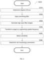
- FIG. 3is a flowchart illustrating a method S 220 for processing images for use in measuring biological processes according to an embodiment. The method is performed based on raw images showing cells at various stages of movement.
- S 310a degree of focus of each raw image is determined.
- S 310includes determining a relative degree of focus using a probabilistic method such as Absolute Central Moment. Determining the degree of focus allows for accounting for focus drift during the experiment shown in the images.
- a smoothing filteris applied to each raw image in order to result in smoothed images.
- the smoothing filteris a Savitzky-Golay filter. Use of such a filter allows for increasing the precision of the cell detection without distorting the signal tendency via, for example, a convolution procedure.
- S 320further includes normalizing the smoothed images based on a maximum value in the smoothed image.
- high pass filter imagesare generated based on the raw images and their respective normalized smoothed images.
- S 330includes dividing each raw image by the respective normalized smoothed image obtained at S 320 such that the result of the division is the high pass filter image.
- the high pass filter imagesare transformed into transformed images by augmenting the spatial frequency of cells shown therein.
- the transformationis utilized to create transformed images which mirrors the negative signal around the background of the images, thereby strengthening the high spatial frequency of cells shown in the images compared to the background.
- S 340includes normalizing each high pass filter image by its median to obtain a first result, multiplying the first result by a scalar C to obtain a second result, subtracting the scalar C from the second result to obtain a third result, and taking the absolute value of the third result to obtain the transformed image.
- the scalar Ccorresponds to the averaged value of the high pass filter image in the background. In an example implementation, the averaged value is a factor of 200.
- Equation 1I T is the transformed image, I HPF is the high pass filter image, and C is the scalar value.
- S 340further includes filtering the transformed images.
- the filtering of S 340is median filtering.
- processed imagesare generated using an appropriate sensitivity.
- S 350includes selecting the appropriate sensitivity for the images. Selecting the sensitivity includes adjusting the sensitivity until one or more sensitivity requirements are met. In particular, the sensitivity requirements may require that the sum of cells detected on both sides of a plate remain steady over time as demonstrated by the images. In an embodiment, the sensitivity is selected as described with respect to FIG. 4 .
- the resulting processed imagehas an appropriate sensitivity that allows for optimally accurate detection of cells therein.
- FIG. 6illustrates images 600 showing various stages of image processing according to the disclosed embodiments.
- the images 600include images labeled X1, X2, X4, X6, X7, and X8, which will now be described with respect to the steps S 310 through S 340 .
- the image X1is the raw image.
- the image X2is the smoothed image generated at S 320 .
- the image X4is the high pass filter image generated at S 330 .
- the image X6is the transformed image with a median filter applied.
- the image X7is an intermediate result of the processing performed at S 350 which involves applying a threshold based on the sensitivity which is ultimately selected.
- the image X8is a processed image generated as described with respect to S 350 and FIG. 4 .
- one or more morphological measuresare determined based on cells detected in the processed images.
- the morphological measuresmay include, but are not limited to, circularity, ratio between minor and major axes, area to convex area ratio, and area.
- the morphological measuresmay be determined based on each image to allow for tracking of the measures over time.
- S 360includes utilizing image recognition to identify outer bounds of a group of cells, and geometrical parameters such as radius, axes lengths, perimeter, and the like, may be calculated using known sizes of objects in the images (e.g., a known average size of each cell as measured using area, radius, etc.).
- the morphological measuresmay be utilized to determine other facets relevant to biological processes.
- the morphological measuresmay be utilized to determine how many migrated cells have become flat and therefore have already settled on the plate. This, in turn, may be utilized to determine cell states of these cells.
- the processing of images described aboveallows for more accurate determination of these morphological parameters.
- the circularity measuremay be computed as
- Ais the Area of the cells and P is the perimeter of the cells.
- a perfect circlewould have a circularity measure of 1, and the circularity measurement decreases the farther away from a circle.
- the ratio between distance of minor and major axesis a ratio of distances of each axis.
- the major axisis the axis including the most stretched-out component of the shape formed by the cells, while the minor axis is the axis orthogonal to the major axis. The value of this ratio is between 0 and 1.
- the area to convex area ratiomeasures the area of a shape formed by the cells relative to the convex shape surrounding the shape formed by the cells. The value of this ratio is between 0 and 1.
- the areais the area of the shape.
- the morphological measuresmay be utilized to collectively illustrate different facets of processes such as cell migration.
- processessuch as cell migration.
- the above measureshave biological relevance for some processes.
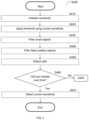
- FIG. 4is a flowchart illustrating a method S 350 for selecting sensitivity of cell detection according to an embodiment.
- a sensitivity for detecting cellsis initialized.
- the sensitivityis initialized to a default value of 0.7.
- a thresholdis applied to each image using the current sensitivity.
- the thresholdis computed as the product of Sensitivity and Focus.
- the value of Focusis equal to a degree of focus for each image (e.g., the degree of focus determined at S 310 , FIG. 3 ).
- each small objectis an object having a size below a threshold.
- the thresholdis 200 pmt.
- the thresholdmay be, for example, a threshold set by a user during an experiment or a predetermined threshold.
- S 430further includes obtaining the edge of each binary object.
- false positive objectsare filtered from each image. More specifically, false positive objects are filtered from a portion of each image showing one side of the plate based on the objects on the other side of the plate.
- a jitteris calculated for each side of the plate.
- the jitter around cell objects for each side of the plateis calculated as the sum of the absolute value of a difference in pixels intensity.
- the jitter of one side of the plateis compared to the jitter of the other side of the plate. If the jitter of the first side of the plate is less than the jitter of the second side of the plate, than objects on the first side object are determined to be false positives and filtered out.
- a relatively low jitter on the first side of the platetends to be indicative that an object is a shadow of a cell on the other side of the plate and, therefore, would be falsely detected as a cell.
- removing false positive objects based on jitterimproves the accuracy of the cell detection.
- the sum of cells in the imagesis steady over time when the sum of cells remains within a threshold of an initial sum of cells at a starting time.
- the values of the sumsare arranged in order based on times of their respective images.
- the sensitivity selectionmay be automated. Further, the automated sensitivity selection provides more objective evaluations of sensitivity than manual selection could provide. More specifically, if a human were to determine sensitivity based on manual observation of cells, the process would be subject to human error and would require subjective determinations of whether the total number of cells is remaining steady over time.
- FIG. 7is a graph 700 utilized to describe selection of cell detection sensitivity according to an embodiment.
- the graph 700illustrates an example of the expected changes in cell counts on the plate over time during an experiment in which cells do not proliferate. More specifically, during a typical cell migration experiment, it is expected that the number of cells on a first side (“Side A”) of a plate will decrease and that the number of cells on a second side (“Side B”) will monotonically increase.
- the disclosureillustrates various methods as subprocesses of other methods, but that at least some of the disclosed subprocesses may be performed as discrete processes without requiring the entire process.
- the methods described with respect to FIGS. 3 and 4may be performed without requiring the results of those methods being utilized to determine cell migration as described with respect to FIG. 2 .
- FIG. 2is described with respect to cell migration, other measurements of cell processes (e.g., measurements related to the cell cycle effect) may be equally determined based on images processed as described herein.
- FIG. 5is an example schematic diagram of a measurement system 130 according to an embodiment.
- the measurement system 130includes a processing circuitry 510 coupled to a memory 520 , a storage 530 , and a network interface 540 .
- the components of the measurement system 130may be communicatively connected via a bus 550 .
- the processing circuitry 510may be realized as one or more hardware logic components and circuits.
- illustrative types of hardware logic componentsinclude field programmable gate arrays (FPGAs), application-specific integrated circuits (ASICs), Application-specific standard products (ASSPs), system-on-a-chip systems (SOCs), graphics processing units (GPUs), tensor processing units (TPUs), general-purpose microprocessors, microcontrollers, digital signal processors (DSPs), and the like, or any other hardware logic components that can perform calculations or other manipulations of information.
- FPGAsfield programmable gate arrays
- ASICsapplication-specific integrated circuits
- ASSPsApplication-specific standard products
- SOCssystem-on-a-chip systems
- GPUsgraphics processing units
- TPUstensor processing units
- DSPsdigital signal processors
- the memory 520may be volatile (e.g., random access memory, etc.), non-volatile (e.g., read only memory, flash memory, etc.), or a combination thereof.
- software for implementing one or more embodiments disclosed hereinmay be stored in the storage 530 .
- the memory 520is configured to store such software.
- Softwareshall be construed broadly to mean any type of instructions, whether referred to as software, firmware, middleware, microcode, hardware description language, or otherwise. Instructions may include code (e.g., in source code format, binary code format, executable code format, or any other suitable format of code). The instructions, when executed by the processing circuitry 510 , cause the processing circuitry 510 to perform the various processes described herein.
- the storage 530may be magnetic storage, optical storage, and the like, and may be realized, for example, as flash memory or other memory technology, compact disk-read only memory (CD-ROM), Digital Versatile Disks (DVDs), or any other medium which can be used to store the desired information.
- flash memoryor other memory technology
- CD-ROMcompact disk-read only memory
- DVDsDigital Versatile Disks
- the network interface 540allows the measurement system 130 to communicate with databases 140 for the purpose of, for example, receiving images, and the like. Further, the network interface 540 allows the measurement system 130 to communicate with the user device 120 for the purpose of sending results of image processing, measurement, or both.
- the various embodiments disclosed hereincan be implemented as hardware, firmware, software, or any combination thereof.
- the softwareis preferably implemented as an application program tangibly embodied on a program storage unit or computer readable medium consisting of parts, or of certain devices and/or a combination of devices.
- the application programmay be uploaded to, and executed by, a machine comprising any suitable architecture.
- the machineis implemented on a computer platform having hardware such as one or more central processing units (“CPUs”), a memory, and input/output interfaces.
- CPUscentral processing units
- the computer platformmay also include an operating system and microinstruction code.
- any reference to an element herein using a designation such as “first,” “second,” and so forthdoes not generally limit the quantity or order of those elements. Rather, these designations are generally used herein as a convenient method of distinguishing between two or more elements or instances of an element. Thus, a reference to first and second elements does not mean that only two elements may be employed there or that the first element must precede the second element in some manner. Also, unless stated otherwise, a set of elements comprises one or more elements.
- the phrase “at least one of” followed by a listing of itemsmeans that any of the listed items can be utilized individually, or any combination of two or more of the listed items can be utilized. For example, if a system is described as including “at least one of A, B, and C,” the system can include A alone; B alone; C alone; 2 A; 2 B; 2 C; 3 A; A and B in combination; B and C in combination; A and C in combination; A, B, and C in combination; 2 A and C in combination; A, 3 B, and 2 C in combination; and the like.
Landscapes
- Engineering & Computer Science (AREA)
- Physics & Mathematics (AREA)
- General Physics & Mathematics (AREA)
- Theoretical Computer Science (AREA)
- Medical Informatics (AREA)
- General Health & Medical Sciences (AREA)
- Health & Medical Sciences (AREA)
- Nuclear Medicine, Radiotherapy & Molecular Imaging (AREA)
- Radiology & Medical Imaging (AREA)
- Quality & Reliability (AREA)
- Computer Vision & Pattern Recognition (AREA)
- Image Processing (AREA)
- Investigating Or Analysing Materials By Optical Means (AREA)
- Apparatus Associated With Microorganisms And Enzymes (AREA)
- Investigating Or Analysing Biological Materials (AREA)
Abstract
Description
where A is the Area of the cells and P is the perimeter of the cells. A perfect circle would have a circularity measure of 1, and the circularity measurement decreases the farther away from a circle.
Claims (22)
Priority Applications (1)
| Application Number | Priority Date | Filing Date | Title |
|---|---|---|---|
| US17/385,552US11995833B2 (en) | 2020-07-31 | 2021-07-26 | System and method for on-phase microscopy |
Applications Claiming Priority (2)
| Application Number | Priority Date | Filing Date | Title |
|---|---|---|---|
| US202063059310P | 2020-07-31 | 2020-07-31 | |
| US17/385,552US11995833B2 (en) | 2020-07-31 | 2021-07-26 | System and method for on-phase microscopy |
Publications (2)
| Publication Number | Publication Date |
|---|---|
| US20220036556A1 US20220036556A1 (en) | 2022-02-03 |
| US11995833B2true US11995833B2 (en) | 2024-05-28 |
Family
ID=80003145
Family Applications (1)
| Application Number | Title | Priority Date | Filing Date |
|---|---|---|---|
| US17/385,552Active2042-04-14US11995833B2 (en) | 2020-07-31 | 2021-07-26 | System and method for on-phase microscopy |
Country Status (2)
| Country | Link |
|---|---|
| US (1) | US11995833B2 (en) |
| WO (1) | WO2022023956A1 (en) |
Cited By (1)
| Publication number | Priority date | Publication date | Assignee | Title |
|---|---|---|---|---|
| US20220404258A1 (en)* | 2021-06-08 | 2022-12-22 | Solentim Ltd. | Automatic calibration |
Citations (36)
| Publication number | Priority date | Publication date | Assignee | Title |
|---|---|---|---|---|
| US4855242A (en)* | 1986-04-14 | 1989-08-08 | Joslin Diabetes Center, Inc. | Method of detecting antibodies |
| US5210018A (en)* | 1988-05-13 | 1993-05-11 | Eniricerche S.P.A. | Immunoenzymatic method in homogeneous phase for the determination of anti-plasmodium falciparum-sporozoite antibodies in human blood |
| US5514707A (en)* | 1992-12-24 | 1996-05-07 | Yale University | Inhibition of smooth muscle cell proliferation by 8-methoxypsoralen photoactivated by visible light |
| US5854223A (en)* | 1995-10-06 | 1998-12-29 | The Trustees Of Columbia University In The City Of New York | S-DC28 as an antirestenosis agent after balloon injury |
| US20030232407A1 (en)* | 2001-03-07 | 2003-12-18 | Senomyx, Inc. | T1R hetero-oligomeric taste receptors and cell lines that express said receptors and use thereof for identification of taste compounds |
| US20040091164A1 (en)* | 2002-11-11 | 2004-05-13 | Minolta Co., Ltd. | Image processing program product and device for executing retinex processing |
| US20050048045A1 (en)* | 2003-07-02 | 2005-03-03 | Board Of Regents, The University Of Texas System | Regulation of urokinase receptor expression by phosphoglycerate kinase |
| US6982171B2 (en) | 2002-03-12 | 2006-01-03 | Surface Logix, Inc. | Cell motility and chemotaxis test device and methods of using same |
| US20060172280A1 (en) | 2000-11-08 | 2006-08-03 | Enoch Kim | System for monitoring cell motility in real-time |
| US20060257013A1 (en)* | 2002-05-14 | 2006-11-16 | Peter Ramm | System and methods for rapid and automated screening of cells |
| CA2449628C (en) | 2001-06-07 | 2008-05-06 | Zheng Wei | Cell migration assay |
| CN100413320C (en) | 2003-05-29 | 2008-08-20 | 佳能株式会社 | Image taking apparatus |
| US20080254480A1 (en)* | 2007-04-11 | 2008-10-16 | University Of Pittsburgh - Of The Commonwealth System Of Higher Education | Microcytoxicity assay by pre-labeling target cells |
| US20100080439A1 (en) | 2008-04-04 | 2010-04-01 | Lina Jamil Karam | Automatic Cell Migration and Proliferation Analysis |
| JP4558047B2 (en) | 2008-01-23 | 2010-10-06 | オリンパス株式会社 | Microscope system, image generation method, and program |
| JP4575403B2 (en) | 1997-02-27 | 2010-11-04 | セロミックス インコーポレイテッド | Cell-based screening system |
| US20110165681A1 (en)* | 2009-02-26 | 2011-07-07 | Massachusetts Institute Of Technology | Light-Activated Proton Pumps and Applications Thereof |
| US20110190679A1 (en)* | 2008-08-15 | 2011-08-04 | Innovative Biotherapies, Inc. | Extracorporeal cell-based therapeutic device and delivery system |
| US20110262423A1 (en)* | 2008-11-17 | 2011-10-27 | Syntaxin Limited | Suppression of cancer |
| US20120070060A1 (en) | 2009-05-19 | 2012-03-22 | Ge Healthcare Bio-Sciences Ab | Method of dynamic cell tracking in a sample |
| KR101220002B1 (en) | 2004-12-22 | 2013-01-08 | 소니 주식회사 | Image processing apparatus, image processing method, image pickup apparatus, and recording medium |
| JP5161052B2 (en) | 2008-12-04 | 2013-03-13 | オリンパス株式会社 | Microscope system, specimen observation method and program |
| US20130194410A1 (en) | 2010-09-14 | 2013-08-01 | Ramot At Tel-Aviv University Ltd. | Cell occupancy measurement |
| US20130287702A1 (en) | 2008-08-14 | 2013-10-31 | Case Western Reserve University | Methods and compositions for the detection of cancer cells |
| US20160060676A1 (en) | 2014-08-28 | 2016-03-03 | Omnivision Technologies, Inc. | Automated Cell Growth/Migration Detection System And Associated Methods |
| US20180038868A1 (en)* | 2015-03-04 | 2018-02-08 | The University Of Chicago | Beta-catenin inhibitors in cancer immunotherapy |
| US20190117977A1 (en)* | 2016-04-04 | 2019-04-25 | General Electric Comany | Techniques for neuromodulation |
| US20190130161A1 (en) | 2017-10-31 | 2019-05-02 | Chung Yuan Christian University | Method and apparatus for image processing and visualization for analyzing cell kinematics in cell culture |
| US20200019748A1 (en) | 2018-07-10 | 2020-01-16 | SCREEN Holdings Co., Ltd. | Image processing method and recording medium |
| US20200090335A1 (en) | 2015-04-23 | 2020-03-19 | Bd Kiestra B.V. | Colony contrast gathering |
| US20200225238A1 (en)* | 2017-08-18 | 2020-07-16 | Cytogen, Inc. | Androgen receptor variant-based prostate cancer patient screening method |
| US20210241855A1 (en)* | 2018-05-02 | 2021-08-05 | Androvia Lifesciences, Llc | Methods and test kits for determining male fertility status |
| US20220064697A1 (en)* | 2018-12-13 | 2022-03-03 | President And Fellows Of Harvard College | Amplification methods and systems for merfish and other applications |
| US20220220565A1 (en)* | 2019-04-30 | 2022-07-14 | INSERM (Institut National de la Santé et de la Recherche Médicale) | Methods and compositions for treating melanoma |
| US20220339127A1 (en)* | 2019-09-13 | 2022-10-27 | The United States Of America,As Represented By The Secretary,Department Of Health And Human Services | Druggable target to treat retinal degeneration |
| US20230070181A1 (en)* | 2020-02-05 | 2023-03-09 | INSERM (Institut National de la Santé et de la Recherche Médicale) | Methods of treatment of cancer disease by targeting an epigenetic factor |
- 2021
- 2021-07-26USUS17/385,552patent/US11995833B2/enactiveActive
- 2021-07-26WOPCT/IB2021/056776patent/WO2022023956A1/ennot_activeCeased
Patent Citations (36)
| Publication number | Priority date | Publication date | Assignee | Title |
|---|---|---|---|---|
| US4855242A (en)* | 1986-04-14 | 1989-08-08 | Joslin Diabetes Center, Inc. | Method of detecting antibodies |
| US5210018A (en)* | 1988-05-13 | 1993-05-11 | Eniricerche S.P.A. | Immunoenzymatic method in homogeneous phase for the determination of anti-plasmodium falciparum-sporozoite antibodies in human blood |
| US5514707A (en)* | 1992-12-24 | 1996-05-07 | Yale University | Inhibition of smooth muscle cell proliferation by 8-methoxypsoralen photoactivated by visible light |
| US5854223A (en)* | 1995-10-06 | 1998-12-29 | The Trustees Of Columbia University In The City Of New York | S-DC28 as an antirestenosis agent after balloon injury |
| JP4575403B2 (en) | 1997-02-27 | 2010-11-04 | セロミックス インコーポレイテッド | Cell-based screening system |
| US20060172280A1 (en) | 2000-11-08 | 2006-08-03 | Enoch Kim | System for monitoring cell motility in real-time |
| US20030232407A1 (en)* | 2001-03-07 | 2003-12-18 | Senomyx, Inc. | T1R hetero-oligomeric taste receptors and cell lines that express said receptors and use thereof for identification of taste compounds |
| CA2449628C (en) | 2001-06-07 | 2008-05-06 | Zheng Wei | Cell migration assay |
| US6982171B2 (en) | 2002-03-12 | 2006-01-03 | Surface Logix, Inc. | Cell motility and chemotaxis test device and methods of using same |
| US20060257013A1 (en)* | 2002-05-14 | 2006-11-16 | Peter Ramm | System and methods for rapid and automated screening of cells |
| US20040091164A1 (en)* | 2002-11-11 | 2004-05-13 | Minolta Co., Ltd. | Image processing program product and device for executing retinex processing |
| CN100413320C (en) | 2003-05-29 | 2008-08-20 | 佳能株式会社 | Image taking apparatus |
| US20050048045A1 (en)* | 2003-07-02 | 2005-03-03 | Board Of Regents, The University Of Texas System | Regulation of urokinase receptor expression by phosphoglycerate kinase |
| KR101220002B1 (en) | 2004-12-22 | 2013-01-08 | 소니 주식회사 | Image processing apparatus, image processing method, image pickup apparatus, and recording medium |
| US20080254480A1 (en)* | 2007-04-11 | 2008-10-16 | University Of Pittsburgh - Of The Commonwealth System Of Higher Education | Microcytoxicity assay by pre-labeling target cells |
| JP4558047B2 (en) | 2008-01-23 | 2010-10-06 | オリンパス株式会社 | Microscope system, image generation method, and program |
| US20100080439A1 (en) | 2008-04-04 | 2010-04-01 | Lina Jamil Karam | Automatic Cell Migration and Proliferation Analysis |
| US20130287702A1 (en) | 2008-08-14 | 2013-10-31 | Case Western Reserve University | Methods and compositions for the detection of cancer cells |
| US20110190679A1 (en)* | 2008-08-15 | 2011-08-04 | Innovative Biotherapies, Inc. | Extracorporeal cell-based therapeutic device and delivery system |
| US20110262423A1 (en)* | 2008-11-17 | 2011-10-27 | Syntaxin Limited | Suppression of cancer |
| JP5161052B2 (en) | 2008-12-04 | 2013-03-13 | オリンパス株式会社 | Microscope system, specimen observation method and program |
| US20110165681A1 (en)* | 2009-02-26 | 2011-07-07 | Massachusetts Institute Of Technology | Light-Activated Proton Pumps and Applications Thereof |
| US20120070060A1 (en) | 2009-05-19 | 2012-03-22 | Ge Healthcare Bio-Sciences Ab | Method of dynamic cell tracking in a sample |
| US20130194410A1 (en) | 2010-09-14 | 2013-08-01 | Ramot At Tel-Aviv University Ltd. | Cell occupancy measurement |
| US20160060676A1 (en) | 2014-08-28 | 2016-03-03 | Omnivision Technologies, Inc. | Automated Cell Growth/Migration Detection System And Associated Methods |
| US20180038868A1 (en)* | 2015-03-04 | 2018-02-08 | The University Of Chicago | Beta-catenin inhibitors in cancer immunotherapy |
| US20200090335A1 (en) | 2015-04-23 | 2020-03-19 | Bd Kiestra B.V. | Colony contrast gathering |
| US20190117977A1 (en)* | 2016-04-04 | 2019-04-25 | General Electric Comany | Techniques for neuromodulation |
| US20200225238A1 (en)* | 2017-08-18 | 2020-07-16 | Cytogen, Inc. | Androgen receptor variant-based prostate cancer patient screening method |
| US20190130161A1 (en) | 2017-10-31 | 2019-05-02 | Chung Yuan Christian University | Method and apparatus for image processing and visualization for analyzing cell kinematics in cell culture |
| US20210241855A1 (en)* | 2018-05-02 | 2021-08-05 | Androvia Lifesciences, Llc | Methods and test kits for determining male fertility status |
| US20200019748A1 (en) | 2018-07-10 | 2020-01-16 | SCREEN Holdings Co., Ltd. | Image processing method and recording medium |
| US20220064697A1 (en)* | 2018-12-13 | 2022-03-03 | President And Fellows Of Harvard College | Amplification methods and systems for merfish and other applications |
| US20220220565A1 (en)* | 2019-04-30 | 2022-07-14 | INSERM (Institut National de la Santé et de la Recherche Médicale) | Methods and compositions for treating melanoma |
| US20220339127A1 (en)* | 2019-09-13 | 2022-10-27 | The United States Of America,As Represented By The Secretary,Department Of Health And Human Services | Druggable target to treat retinal degeneration |
| US20230070181A1 (en)* | 2020-02-05 | 2023-03-09 | INSERM (Institut National de la Santé et de la Recherche Médicale) | Methods of treatment of cancer disease by targeting an epigenetic factor |
Non-Patent Citations (8)
| Title |
|---|
| International Search Report and Written Opinion of International Searching Authority for PCT/IB2021/056776, ISA/IL, Jerusalem, Israel, Dated: Oct. 26, 2021. |
| Joe Clayton, Peter Brescia, and Peter Banks Agilent Technologies, Inc. "Automated Label-Free Method for Measuring Cell Migration in Real-Time with Oris Pro Assay". https://www.biotek.com/resources/application-notes/automated-label-free-method-for-measuring-cell-migration-in-real-time-with-oris-pro-assay/# :˜: text=%20Automated%20Label-Free%20Method%20for%20Measuring%20Cell%20Migration,3%20Materials%20and%20Methods.%20HT-1080% 20fibrosarcom . . . %20More%20. May 21, 2019. |
| Justus et al. "In vitro Cell Migration and Invasion Assays", Journal of Visualized Experiments, Jun. 1, 2014 (Year: 2014).* |
| Li et al. "Cellcounter: Novel Open-Source Software for Counting Cell Migration and Invasion In Vitro", Hindawi Publishing Corporation BioMed Research International vol. 2014, Article ID 863564, 6 pages (Year: 2014).* |
| Pijuan et al. ("In vitro Cell Migration, Invasion, and Adhesion Assays: From Cell Imaging to Data Analysis", Frontiers in Cell and Developmental Biology | www.frontiersin.org, Jun. 2019 | vol. 7 | Article 107 (Year: 2019).* |
| Platypus Techologies. "Cell Migration Assay: Oris™: a Simple Platform for Publication-Ready Data". https://www.platypustech.com/cell-based-assays/oris-cell-migration. Accessed Jul. 26, 2021. |
| Sartorius. "Empower your research with IncuCyte® Live-Cell Analysis Systems". https://www.sartorius.com/en/products/cell-analysis/incucyte-live-cell-analysis-system. Accessed Jul. 26, 2021. |
| Sartorius. "IncuCyte® Cell Migration Kit from Sartorius". https://www.news-medical.net/IncuCyte-Cell-Migration-Kit-from-Sartorius. Accessed Jul. 26, 2021. |
Cited By (2)
| Publication number | Priority date | Publication date | Assignee | Title |
|---|---|---|---|---|
| US20220404258A1 (en)* | 2021-06-08 | 2022-12-22 | Solentim Ltd. | Automatic calibration |
| US12306085B2 (en)* | 2021-06-08 | 2025-05-20 | Solentim Ltd. | Automatic calibration |
Also Published As
| Publication number | Publication date |
|---|---|
| US20220036556A1 (en) | 2022-02-03 |
| WO2022023956A1 (en) | 2022-02-03 |
Similar Documents
| Publication | Publication Date | Title |
|---|---|---|
| JP7596290B2 (en) | Automated Boundary Detection in Mass Spectrometry Data | |
| Yan et al. | Anomaly detection in images with smooth background via smooth-sparse decomposition | |
| US11346764B2 (en) | Image-based assay using intelligent monitoring structures | |
| Husham et al. | Comparative analysis between active contour and otsu thresholding segmentation algorithms in segmenting brain tumor magnetic resonance imaging | |
| US8484000B2 (en) | Detecting events of interest using quantum resonance interferometry | |
| WO2020055543A1 (en) | Image-based assay using intelligent monitoring structures | |
| Kuhn | Predictive modeling with R and the caret Package | |
| Ginley et al. | Unsupervised labeling of glomerular boundaries using Gabor filters and statistical testing in renal histology | |
| US11995833B2 (en) | System and method for on-phase microscopy | |
| Dey et al. | Unsupervised machine learning based SEM image denoising for robust contour detection | |
| CN109711441B (en) | Image classification method and device, storage medium and electronic equipment | |
| Poudel et al. | Active contours extension and similarity indicators for improved 3D segmentation of thyroid ultrasound images | |
| Czyzewski et al. | Detecting anomalies in X-ray diffraction images using convolutional neural networks | |
| Dodkins et al. | MKID digital readout tuning with deep learning | |
| US20220156321A1 (en) | Distance measurement for time series | |
| Schuch et al. | The rise of contour metrology from niche solution to versatile enabler | |
| WO2021021430A1 (en) | System and method for region detection in tissue sections using image registration | |
| Rana et al. | Deep machine learning based Image classification in hard disk drive manufacturing | |
| Xu et al. | Machine learning-assisted image label-free smartphone platform for rapid segmentation and robust multi-urinalysis | |
| EP4302077A1 (en) | Methods and systems for raman spectra-based identification of chemical compounds | |
| Krauter et al. | Determination of three optical properties from subdiffusive spatially resolved reflectance calculations | |
| Farrag et al. | Semi-automated myocardial segmentation in native T1-mapping CMR using deformable non-rigid registration of CINE images | |
| CN107664623B (en) | A method for extracting spectral features of substances | |
| Pai et al. | Image registration using stationary velocity fields parameterized by norm-minimizing wendland kernel | |
| Soltanian-Zadeh et al. | Fully automatic quantification of individual ganglion cells from AO-OCT volumes via weakly supervised learning |
Legal Events
| Date | Code | Title | Description |
|---|---|---|---|
| AS | Assignment | Owner name:THE JOAN AND IRWIN JACOBS TECHNION-CORNELL INSTITUTE, NEW YORK Free format text:ASSIGNMENT OF ASSIGNORS INTEREST;ASSIGNOR:BARBASH, SHAHAR;REEL/FRAME:056979/0850 Effective date:20210721 | |
| FEPP | Fee payment procedure | Free format text:ENTITY STATUS SET TO UNDISCOUNTED (ORIGINAL EVENT CODE: BIG.); ENTITY STATUS OF PATENT OWNER: SMALL ENTITY | |
| FEPP | Fee payment procedure | Free format text:ENTITY STATUS SET TO SMALL (ORIGINAL EVENT CODE: SMAL); ENTITY STATUS OF PATENT OWNER: SMALL ENTITY | |
| STPP | Information on status: patent application and granting procedure in general | Free format text:DOCKETED NEW CASE - READY FOR EXAMINATION | |
| STPP | Information on status: patent application and granting procedure in general | Free format text:NON FINAL ACTION MAILED | |
| STPP | Information on status: patent application and granting procedure in general | Free format text:RESPONSE TO NON-FINAL OFFICE ACTION ENTERED AND FORWARDED TO EXAMINER | |
| STPP | Information on status: patent application and granting procedure in general | Free format text:NOTICE OF ALLOWANCE MAILED -- APPLICATION RECEIVED IN OFFICE OF PUBLICATIONS | |
| ZAAB | Notice of allowance mailed | Free format text:ORIGINAL CODE: MN/=. | |
| STPP | Information on status: patent application and granting procedure in general | Free format text:PUBLICATIONS -- ISSUE FEE PAYMENT RECEIVED | |
| STPP | Information on status: patent application and granting procedure in general | Free format text:PUBLICATIONS -- ISSUE FEE PAYMENT VERIFIED | |
| STCF | Information on status: patent grant | Free format text:PATENTED CASE |