US11994833B2 - Building smart entity system with agent based data ingestion and entity creation using time series data - Google Patents
Building smart entity system with agent based data ingestion and entity creation using time series dataDownload PDFInfo
- Publication number
- US11994833B2 US11994833B2US16/533,499US201916533499AUS11994833B2US 11994833 B2US11994833 B2US 11994833B2US 201916533499 AUS201916533499 AUS 201916533499AUS 11994833 B2US11994833 B2US 11994833B2
- Authority
- US
- United States
- Prior art keywords
- entity
- data
- agent
- timeseries
- building
- Prior art date
- Legal status (The legal status is an assumption and is not a legal conclusion. Google has not performed a legal analysis and makes no representation as to the accuracy of the status listed.)
- Active, expires
Links
Images


Classifications
- G—PHYSICS
- G05—CONTROLLING; REGULATING
- G05B—CONTROL OR REGULATING SYSTEMS IN GENERAL; FUNCTIONAL ELEMENTS OF SUCH SYSTEMS; MONITORING OR TESTING ARRANGEMENTS FOR SUCH SYSTEMS OR ELEMENTS
- G05B15/00—Systems controlled by a computer
- G05B15/02—Systems controlled by a computer electric
- G—PHYSICS
- G06—COMPUTING OR CALCULATING; COUNTING
- G06F—ELECTRIC DIGITAL DATA PROCESSING
- G06F16/00—Information retrieval; Database structures therefor; File system structures therefor
- G06F16/20—Information retrieval; Database structures therefor; File system structures therefor of structured data, e.g. relational data
- G06F16/28—Databases characterised by their database models, e.g. relational or object models
- G06F16/284—Relational databases
- G06F16/288—Entity relationship models
- G—PHYSICS
- G06—COMPUTING OR CALCULATING; COUNTING
- G06N—COMPUTING ARRANGEMENTS BASED ON SPECIFIC COMPUTATIONAL MODELS
- G06N20/00—Machine learning
- G—PHYSICS
- G06—COMPUTING OR CALCULATING; COUNTING
- G06N—COMPUTING ARRANGEMENTS BASED ON SPECIFIC COMPUTATIONAL MODELS
- G06N3/00—Computing arrangements based on biological models
- G06N3/004—Artificial life, i.e. computing arrangements simulating life
- G06N3/006—Artificial life, i.e. computing arrangements simulating life based on simulated virtual individual or collective life forms, e.g. social simulations or particle swarm optimisation [PSO]
- G—PHYSICS
- G06—COMPUTING OR CALCULATING; COUNTING
- G06N—COMPUTING ARRANGEMENTS BASED ON SPECIFIC COMPUTATIONAL MODELS
- G06N5/00—Computing arrangements using knowledge-based models
- G06N5/04—Inference or reasoning models
- G06N5/043—Distributed expert systems; Blackboards
- H—ELECTRICITY
- H04—ELECTRIC COMMUNICATION TECHNIQUE
- H04L—TRANSMISSION OF DIGITAL INFORMATION, e.g. TELEGRAPHIC COMMUNICATION
- H04L12/00—Data switching networks
- H04L12/28—Data switching networks characterised by path configuration, e.g. LAN [Local Area Networks] or WAN [Wide Area Networks]
- H04L12/2803—Home automation networks
- H04L12/2807—Exchanging configuration information on appliance services in a home automation network
- H04L12/2809—Exchanging configuration information on appliance services in a home automation network indicating that an appliance service is present in a home automation network
- H—ELECTRICITY
- H04—ELECTRIC COMMUNICATION TECHNIQUE
- H04L—TRANSMISSION OF DIGITAL INFORMATION, e.g. TELEGRAPHIC COMMUNICATION
- H04L12/00—Data switching networks
- H04L12/28—Data switching networks characterised by path configuration, e.g. LAN [Local Area Networks] or WAN [Wide Area Networks]
- H04L12/2803—Home automation networks
- H04L12/2823—Reporting information sensed by appliance or service execution status of appliance services in a home automation network
- H04L12/2827—Reporting to a device within the home network; wherein the reception of the information reported automatically triggers the execution of a home appliance functionality
- G—PHYSICS
- G05—CONTROLLING; REGULATING
- G05B—CONTROL OR REGULATING SYSTEMS IN GENERAL; FUNCTIONAL ELEMENTS OF SUCH SYSTEMS; MONITORING OR TESTING ARRANGEMENTS FOR SUCH SYSTEMS OR ELEMENTS
- G05B2219/00—Program-control systems
- G05B2219/20—Pc systems
- G05B2219/26—Pc applications
- G05B2219/2642—Domotique, domestic, home control, automation, smart house
- H—ELECTRICITY
- H04—ELECTRIC COMMUNICATION TECHNIQUE
- H04L—TRANSMISSION OF DIGITAL INFORMATION, e.g. TELEGRAPHIC COMMUNICATION
- H04L12/00—Data switching networks
- H04L12/28—Data switching networks characterised by path configuration, e.g. LAN [Local Area Networks] or WAN [Wide Area Networks]
- H04L12/2803—Home automation networks
- H04L2012/2847—Home automation networks characterised by the type of home appliance used
- H04L2012/285—Generic home appliances, e.g. refrigerators
Definitions
- a building management systemis, in general, a system of devices configured to control, monitor, and manage equipment in or around a building or building area.
- a BMScan include, for example, a HVAC system, a security system, a lighting system, a fire alerting system, any other system that is capable of managing building functions or devices, or any combination thereof.
- a BMScan collect data from objects associated with a building, such as other BMSs, building subsystems, devices, sensors and other types of building equipment. Building management platforms are utilized to register and manage the objects, gather and analyze data produced by the objects, and provide recommendations or results based on the collected data. As the number of buildings transitioning to a smart building environment increases, the amount of data being produced and collected has been increasing exponentially. Accordingly, effective analysis of a plethora of collected data is desired.
- One implementation of the present disclosureis a building management system of a building including one or more memory devices configured to store instructions thereon, that, when executed by one or more processors, cause the one or more processors to generate agents, each agent of the agents paired with one entity of entities of an entity database, wherein the entity database includes relationships between the entities, wherein the entities represent physical building entities of the building including building equipment or building spaces.
- the instructionscause the one or more processors to communicate, by the agents, data of the physical building entities via agent communication channels and perform, by the agents, one or more operations for the entities based on the data.
- the instructionscause the one or more processors to query, by a first agent of the agents, the entity database to identify a communication channel associated with the first agent, update, by the first agent, one or more communication configurations of the first agent causing the first agent to communicate on the communication channel, and communicate, by the first agent, on the communication channel.
- the instructionscause the one or more processors to generate the agent communication channels based on the entities, identify one or more agents of the agents associated with each agent communication channel of the agent communication channels based on the entities and the relationships, instantiate the agent communication channels, and cause the agents to communicate on the agent communication channels.
- the instructionscause the one or more processors to generate a channel configuration for each of the agents causing each of the agents to perform at least one of publishing information to one or more agent communication channels of the agent communication channels or subscribing to the one or more agent communication channels and communicate the channel configuration of each of the agents to each of the agents.
- the building information management systemfurther includes devices, wherein each of the devices is configured to run one of the agents, wherein the devices are at least one of a sensor, an actuator, or a controller.
- instructionscause the one or more processors to run each of the agents.
- the instructionscause the one or more processors to receive an update to the entity database, the update including a new entity and an entity type for the new entity, identify whether the entity type of the new entity is a particular entity type of entity types, and instantiate a second agent communication channel associated with the new entity in response to a determination that the entity type of the new entity is the particular entity type.
- the update to the entity databaseincludes one or more new relationships to one or more existing entities of the entity database, wherein each of the one or more existing entities are associated with an existing agent.
- the instructionscause the one or more processors to identify the one or more existing entities based on the one or more new relationships, identify the existing agent associated with each of the one or more existing entities, and cause the existing agent associated with each of the one or more existing entities to communicate on the second agent communication channel.
- the agentsinclude a first agent and a second agent, wherein the first agent is associated with a first entity of the entities and the second agent is associated with a second entity of the entities.
- the instructionscause the one or more processors to generate an agent communication channel for a third entity of the entities and identify the first agent and the second agent by identifying a first relationship between the first entity and the third entity and a second relationship between the second entity and the third entity based on the relationships.
- the instructionscause the one or more processors to generate the agent communication channel for the third entity of the entities by determining that an entity type of the third entity is a particular entity type of different entity types.
- the particular entity typeis a space type defining at least one of a room, a zone, or the building.
- Another implementation of the present disclosureis a method of agent management for a building.
- the methodincludes generating, by one or more processing circuits, agents, each agent of the agents paired with one entity of entities of an entity database, wherein the entity database includes relationships between the entities, wherein the entities represent physical building entities of the building including building equipment or building spaces.
- the methodincludes communicating, by the one or more processing circuits via the agents, data of the physical building entities via agent communication channels and performing, by the one or more processing circuits via the agents, one or more operations for the entities based on the data.
- the methodincludes generating, by the one or more processing circuits, the agent communication channels based on the entities. In some embodiments, the method includes identifying, by the one or more processing circuits, one or more agents of the agents associated with each agent communication channel of the agent communication channels based on the entities and the relationships. In some embodiments, the method includes instantiating, by the one or more processing circuits, the agent communication channels and causing, by the one or more processing circuits, the agents to communicate on the agent communication channels.
- the methodincludes generating, by the one or more processing circuits, a channel configuration for each of the agents causing each of the agents to perform at least one of publishing information to one or more agent communication channels of the agent communication channels or subscribing to the one or more agent communication channels and communicating, by the one or more processing circuits, the channel configuration of each of the agents to each of the agents.
- the agentsinclude a first agent and a second agent, wherein the first agent is associated with a first entity of the entities and the second agent is associated with a second entity of the entities.
- the methodincludes generating, by the one or more processing circuits, an agent communication channel for a third entity of the entities. In some embodiments, the method includes identifying, by the one or more processing circuits, the first agent and the second agent by identifying a first relationship between the first entity and the third entity and a second relationship between the second entity and the third entity based on the relationships.
- the methodincludes generating, by the one or more processing circuits, the agent communication channel for the third entity of the entities by determining that an entity type of the third entity is a particular entity type of different entity types.
- the particular entity typeis a space type defining at least one of a room, a zone, or the building.
- Another implementation of the present disclosureis an information management system including one or more memory devices configured to store instructions and one or more processors configured to execute the instructions to generate agents, each agent of the agents paired with one entity of entities of an entity database, wherein the entity database includes relationships between the entities, wherein the entities represent physical entities.
- the one or more processorsare configured to execute the instructions to communicate, by the agents, data of the physical entities via agent communication channels and perform, by the agents, one or more operations for the entities based on the data.
- FIG. 1Another implementation of the present disclosure is a building management system including one or more memory devices configured to store instructions thereon, that, when executed by one or more processors, cause the one or more processors to receive a publication by an agent on an agent communication channel, the publication including timeseries data, identify, based on the publication, an object entity of an entity database associated with the agent, wherein the entity database includes one or more object entities and relationships between the one or more object entities and one or more data entities, identify a data entity related to the object entity based on a relationship of the relationships relating the object entity and the data entity, and ingest the timeseries data into the data entity.
- the instructionscause the one or more processors to receive, by a second agent, the publication by the agent on the agent communication channel and operate a physical building entity represented by the object entity based on the timeseries data.
- the instructionscause the one or more processors to receive, by a second agent, the publication by the agent on the agent communication channel, generate, by the second agent, one or more configuration updates for the agent based on the timeseries data, and ingest the one or more configuration updates into the entity database.
- the instructionscause the one or more processors to receive, by a second agent, the publication by the agent on the agent communication channel, identify, by the second agent, the data entity related to the object entity based on the relationship of the relationships relating the object entity and the data entity, and ingest, by the second agent, the timeseries data into the data entity.
- the agentis associated with the object entity
- the publicationincludes an author identifier identifying the agent.
- the instructionscause the one or more processors to identify, based on the publication, the object entity by identifying that the agent is associated with the object entity based on the author identifier.
- the building management systemfurther includes a device, wherein the device is configured to run the agent, wherein the device is at least one of a sensor, an actuator, or a controller.
- the instructionscause the one or more processors to run the agent.
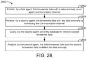
- the instructionscause the one or more processors to cause the agent to monitor the agent communication channel for second timeseries data, the second timeseries data including abnormal data, retrieve, from the entity database, third timeseries data, and analyze the second timeseries data and the third timeseries data to detect the abnormal data.
- the instructionscause the one or more processors to receive second timeseries data via the agent communication channel, the second timeseries data published on the agent communication channel by the agent, determine whether a second object entity of the entity database associated with the second timeseries data exists in the entity database, ingest the second timeseries data into the entity database based on the second object entity in response to a first determination that the second object entity existing, and generate the second object entity and ingest the second timeseries data into the entity database in response to a second determination that the second object entity does not exist.
- the instructionscause the one or more processors to generate the second object entity and ingest the second timeseries data into the entity database in response to the second determination that the second object entity does not exist by generating the second object entity, a second data entity, and a second relationship between the second object entity and the second data entity and ingesting the second timeseries data into the second data entity.
- the methodincludes receiving, by one or more processing circuits, a publication by an agent on an agent communication channel, the publication including timeseries data, identifying, by the one or more processing circuits, based on the publication, an object entity of an entity database associated with the agent, wherein the entity database includes one or more object entities and relationships between the one or more object entities and one or more data entities, identifying, by the one or more processing circuits, a data entity related to the object entity based on a relationship of the relationships relating the object entity and the data entity, and ingesting, by the one or more processing circuits, the timeseries data into the data entity.
- the methodincludes receiving, by the one or more processing circuits via a second agent, the publication by the agent on the agent communication channel and operating, by the one or more processing, a physical building entity represented by the object entity based on the timeseries data.
- the methodincludes receiving, by the one or more processing circuits via a second agent, the publication by the agent on the agent communication channel, generating, by the one or more processing circuits via the second agent, one or more configuration updates for the agent based on the timeseries data, and ingesting, by the one or more processing circuits via the second agent, the one or more configuration updates into the entity database.
- the methodincludes receiving, by the one or more processing circuits via a second agent, the publication by the agent on the agent communication channel, identifying, by the one or more processing circuits via the second agent, the data entity related to the object entity based on the relationship of the relationships relating the object entity and the data entity, and ingesting, by the one or more processing circuits via the second agent, the timeseries data into the data entity.
- the methodincludes monitoring, by the one or more processing circuits via the agent, the agent communication channel for second timeseries data, the second timeseries data including abnormal data, retrieving, by the one or more processing circuits via the agent, from the entity database, third timeseries data, and analyzing, by the one or more processing circuits via the agent, the second timeseries data and the third timeseries data to detect the abnormal data.
- the methodincludes receiving, by the one or more processing circuits, second timeseries data via the agent communication channel, the second timeseries data published on the agent communication channel by the agent, determining, by the one or more processing circuits, whether a second object entity of the entity database associated with the second timeseries data exists in the entity database, ingesting, by the one or more processing circuits, the second timeseries data into the entity database based on the second object entity in response to a first determination that the second object entity existing, and generating, by the one or more processing circuits, the second object entity and ingest the second timeseries data into the entity database in response to a second determination that the second object entity does not exist.
- the methodincludes generating, by the one or more processing circuits, the second object entity and ingest the second timeseries data into the entity database in response to the second determination that the second object entity does not exist by generating the second object entity, a second data entity, and a second relationship between the second object entity and the second data entity and ingesting the second timeseries data into the second data entity.
- an information management systemincluding one or more memory devices configured to store instructions thereon and one or more processors configured to execute the instructions to receive a publication by an agent on an agent communication channel, the publication including timeseries data, identify, based on the publication, an object entity of an entity database associated with the agent, wherein the entity database includes one or more object entities and relationships between the one or more object entities and one or more data entities, identify a data entity related to the object entity based on a relationship of the relationships relating the object entity and the data entity, and ingest the timeseries data into the data entity.
- the instructionscause the one or more processors to receive, by a second agent, the publication by the agent on the agent communication channel, generate, by the second agent, one or more configuration updates for the agent based on the timeseries data, and ingest the one or more configuration updates into the entity database.
- the instructionscause the one or more processors to receive, by a second agent, the publication by the agent on the agent communication channel, identify, by the second agent, the data entity related to the object entity based on the relationship of the relationships relating the object entity and the data entity, and ingest, by the second agent, the timeseries data into the data entity.
- FIG. 1is a block diagram of a smart building environment, according to an exemplary embodiment.
- FIG. 2is a perspective view of a smart building, according to an exemplary embodiment.
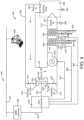
- FIG. 3is a block diagram of a waterside system, according to an exemplary embodiment.
- FIG. 4is a block diagram of an airside system, according to an exemplary embodiment.
- FIG. 5is a block diagram of a building management system, according to an exemplary embodiment.
- FIG. 6is a block diagram of another building management system, according to an exemplary embodiment.
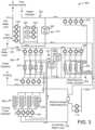
- FIG. 7is a block diagram illustrating an entity service of FIG. 6 in greater detail, according to an exemplary embodiment.
- FIG. 8in an example entity graph of entity data, according to an exemplary embodiment.
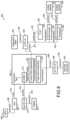
- FIG. 9is a block diagram illustrating timeseries service of FIG. 6 in greater detail, according to an exemplary embodiment.
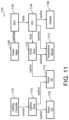
- FIG. 10is a flow diagram of a process or method for updating/creating an attribute of a related entity based on data received from a device of a building management subsystem, according to an exemplary embodiment.
- FIG. 11is an example entity graph of entity data, according to an exemplary embodiment.
- FIG. 12is a block diagram of an agent-entity system including a cloud building management platform configured to manage an entity database and agents, according to an exemplary embodiment.
- FIG. 13is a block diagram of the agent-entity system of FIG. 12 where the cloud building management platform is configured to implement the agents, according to an exemplary embodiment.
- FIG. 14is a block diagram of a publish-subscribe messaging pattern of agents of the agent-entity system of FIGS. 12 - 13 where a single publisher publishes messages to multiple subscribers of a single channel, according to an exemplary embodiment.
- FIG. 15is a block diagram of a publish-subscribe messaging patterns of agents of the agent-entity system of FIGS. 12 - 13 where a single publisher publishes messages to multiple channels and various subscribers receive the messages via channels that the subscribers are subscribed to, according to an exemplary embodiment.
- FIG. 16is an example channel hierarchal structure for the agent-entity system of FIGS. 12 - 13 , according to an exemplary embodiment.
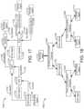
- FIG. 17is a block diagram of an entity database with multiple entities and relationships that can be stored by the agent-entity system of FIGS. 12 - 13 , according to an exemplary embodiment.
- FIG. 18is a block diagram of an agent channel hierarchical structure based on the entity database of FIG. 17 , according to an exemplary embodiment.
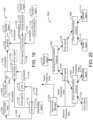
- FIG. 19is the entity database of FIG. 17 including a data entity where timeseries can be ingested, according to an exemplary embodiment.
- FIG. 20is the agent channel hierarchical structure of FIG. 18 where an agent publishes timeseries data on an communication channel and the timeseries data is ingested into the data entity of the entity database of FIG. 19 , according to an exemplary embodiment.
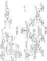
- FIG. 21is the entity database of FIG. 17 where an agent-entity manager queries the timeseries database based on a query received from an agent, according to an exemplary embodiment.
- FIG. 22is the agent channel hierarchical structure of FIG. 18 where an agent generates a query for the entity database of FIG. 21 to identify data to be analyzed to detect an abnormal timeseries data measurement, according to an exemplary embodiment.
- FIG. 23is a block diagram of system where a building agent monitors a communication channel for messages of another building agent and ingests timeseries data of the message into the entity database of FIG. 18 and operates physical building equipment based on the timeseries data, according to an exemplary embodiment.
- FIG. 24is a flow diagram of a process of generating agents for the entities of the entity database of FIG. 18 , generating communication channels for the agents to communicate on, and control physical devices by the agents based on the communicated data that can be performed by the agent-entity system of FIGS. 12 - 13 , according to an exemplary embodiment.
- FIG. 25is a flow diagram of a process of generating pairs between entities of the entity database of FIG. 18 and agents corresponding to each of the entities that can be performed by the agent-entity system of FIGS. 12 - 13 , according to an exemplary embodiment.
- FIG. 26is a flow diagram of a process of receiving a new entity for the entity database of FIG. 18 and generating a communication channel based on the new entity that can be performed by the agent-entity system of FIGS. 12 - 13 , according to an exemplary embodiment.
- FIG. 27is a flow diagram of a process of ingesting timeseries data into a data entity of the entity database of FIG. 18 , the timeseries data published by agents on a communications channel, where the process can be performed by the agent-entity system of FIGS. 12 - 13 , according to an exemplary embodiment.
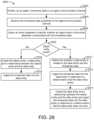
- FIG. 28is a flow diagram of a process of querying the entity database of FIG. 18 to extract information to be used to analyze timeseries data that can be performed by the agent-entity system of FIGS. 12 - 13 , according to an exemplary embodiment.
- FIG. 29is a flow diagram of a process of ingesting timeseries into the entity database of FIG. 18 and generating new data entities that can be performed by the agent-entity system of FIGS. 12 - 13 , according to an exemplary embodiment.
- various systems and methodsare shown for an agent-entity system configured to generate and manage agents and entities, according to an exemplary embodiment.
- the various systems and methodscan generate “Smart Entities,” i.e., pairs between entities of an entity database and artificial intelligence agents for data communication and building control.
- the various systems and methodscan perform timeseries based entity creation and maintenance using agents.
- the various systems and methodscan ingest timeseries data into an entity database for storage of timeseries data corresponding to various entities of the entity database, can generate new entities for the entity database based on the timeseries data, and perform analysis of entities based on the timeseries data.
- Entities of an entity databasecan be data structures representing physical building spaces, people, and/or building equipment.
- the entity databasecan include various types of entities, e.g., object entities and/or data entities.
- the object entitiescan represent particular a physical building, a floor of a building, a space of a building, a room of a building, a building occupant, and/or a physical piece of equipment.
- the data entitiescan represent data of the object entities.
- a data entitymay store, or may act as a reference to, timeseries data.
- a thermostat object entitymay be associated with a data entity of temperature measurements for a physical thermostat.
- the agentscan be configured to simulate a building or system, such that each space, equipment, and/or control function for the building or system is simulated by a software agent.
- various agentsare used to simulate, control, and/or monitor any suitable environmental or operational aspects of a building, such as temperature, humidity, particulate count, occupancy time (actual and/or expected), lighting, audio/visual, fire safety, electrical, security, access control, lifts/escalators, and/or the like.
- the use of agents to aid in simulation of a building or systemprovide multiple advantages to a BMS systems.
- agent based building simulationmay allow for a single integrated system from design to commissioning to operations.
- Agent based building simulationalso allows for heavy use and reuse of design inputs, as well as for ease of commissioning (e.g. such as by eliminating the need for explicit point binding.)
- Agentssuch as space agents, equipment agents, and control agents may be used, and may allow for goal-oriented optimization within a BMS. For example, each of the agents may communicate with each other via communication channels to achieve a particular optimization for a particular zone or space. Further, agents can be used to allow for agile deployment of new features (e.g. via the agents) when the BMS is in operations mode.
- the agentscan be run on different devices within the system (e.g. cloud, server, controller, smartboards, etc.) and can allow for system scalability without complexity (e.g. via agents forming building blocks.) Additionally, cloud replicas or virtual simulations of a building can allow for analytics and machine learning to be performed.
- Agent based BMS control systemsare further described in U.S. Pat. No. 9,817,383 (application Ser. No. 15/367,167), filed Dec. 1, 2016, the entire content of which is incorporated by reference herein.
- Agent based BMS dynamic channel communicationsare further described in U.S. patent application Ser. No. 15/934,593, filed Mar. 23, 2018, the entire content of which is incorporated by reference herein.
- agent based change generationis described in greater detail in U.S. patent application Ser. No. 16/036,685 filed Jul. 16, 2018, the entirety of which is incorporated by reference herein.
- the systemcan generate agents for communication and control of physical building equipment.
- the agentscan be generated based on entities of an entity database.
- the systemcan generate agents for particular spaces and/or equipment entities.
- the entitiesmay be data structures representing an entire building, the agents may be artificial intelligence modules configured to learn and/or take action on behalf of the entities.
- the entities of the entity databasecan be analyzed to identify one or multiple different agents to be generated, each agent corresponding to an entity of the entity database.
- the generated agentscan be configured to collect data from physical pieces of building equipment.
- the agentsindividually or together, can be configured to control the physical pieces of building equipment.
- the agentsare configured to work together, communicating data among each other via communication channels.
- the communication channelscan be subscriber-publisher based channels where each agent is configured to communicate data on particular channels and subscribe to particular channels to receive data.
- the channels used to communicate the datacan be generated based on entities of the entity database. For example, a particular entity of a particular entity type (e.g., a building entity) can be identified and a corresponding communication channel (e.g., a building communication channel) can be generated.
- the agents that are subscribed to the generated communication channelcan be based on the relationships of the entity database. For example, if a first entity representing a building floor is related to a second entity representing an entire building, a corresponding floor agent and a corresponding building agent can be configured to communicate on a building communication channel based on the relationship.
- the agentscan be enabled to receive related data for performing control operations on building equipment and/or send data to other agents.
- the agentscan be configured to manage the entity database based on timeseries data.
- the agentscan be configured to collect timeseries data of physical building equipment, the timeseries data representing measured environmental conditions, control decisions, etc.
- the agentscan be configured to ingest the collected timeseries data into the entity database.
- the agents, or a timeseries servicecan identify an object entity of the entity database and a corresponding data entity for storing the timeseries data.
- the corresponding data entitycan be identified based on a relationship between the object entity and the data entity.
- the agents, or an agent-entity managercan cause the timeseries data be ingested into the entity database.
- the entity databasestoring the ingested timeseries data, can be a repository of historical data that the agents can query and utilize to perform learning and/or control decisions.
- a first agentmonitors a communication channel where a second agent posts information.
- the first agentcan be configured to subscribe to information of the second channel and ingest any timeseries data of the second agent into the entity database.
- the timeseries data an agent collects via a communication channelcan be indicative of a newly installed physical device which is not represented by an entity.
- the timeseries datacan be analyzed by an agent and/or the agent-entity manager and a new entity for the entity database and/or new agent can be generated.
- a new temperature sensorcould be installed in a building. Since the temperature sensor is new, the entity database may not store an object entity representing the temperature sensor.
- the temperature sensorcan include a temperature sensor agent configured to publish timeseries temperature data of the temperature sensor on a zone communication channel.
- An agent for a physical building zone associated with the zone communication channel listening to messages on the zone communication channelcan cause a new entity representing the thermostat to be generated and added to the entity database.
- a data entity for storing the timeseries measurements of the sensorcan be generated and added to the entity database along with a relationship between the object entity and the data entity.
- the zone agentcan cause the data entity to be ingested with the timeseries measurements.
- the agentscan be configured to analyze timeseries data published on communication channels to identify data anomalies. For example, a data anomaly, a temperature measurement of a particular zone above a predefined amount, could indicate that there is a fire in the zone or that the sensor used to measure the temperature is defective.
- the analytics performed by the agents analyzing the timeseries datamay require additional timeseries data, e.g., historical timeseries data or data of other zones or similar sensors.
- the agentcan query the timeseries data for additional timeseries data and operate based on the result of the query.
- FIG. 1is a block diagram of a smart building environment 100 , according to some exemplary embodiments.
- Smart building environment 100is shown to include a building management platform 102 .
- Building management platform 102can be configured to collect data from a variety of different data sources.
- building management platform 102is shown collecting data from buildings 110 , 120 , 130 , and 140 .
- the buildingsmay include a school 110 , a hospital 120 , a factory 130 , an office building 140 , and/or the like.
- the present disclosureis not limited to the number or types of buildings 110 , 120 , 130 , and 140 shown in FIG. 1 .
- building management platform 102may be configured to collect data from one or more buildings, and the one or more buildings may be the same type of building, or may include one or more different types of buildings than that shown in FIG. 1 .
- Building management platform 102can be configured to collect data from a variety of devices 112 - 116 , 122 - 126 , 132 - 136 , and 142 - 146 , either directly (e.g., directly via network 104 ) or indirectly (e.g., via systems or applications in the buildings 110 , 120 , 130 , 140 ).
- devices 112 - 116 , 122 - 126 , 132 - 136 , and 142 - 146are internet of things (IoT) devices.
- IoT devicesmay include any of a variety of physical devices, sensors, actuators, electronics, vehicles, home appliances, and/or other items having network connectivity which enable IoT devices to communicate with building management platform 102 .
- IoT devicescan include smart home hub devices, smart house devices, doorbell cameras, air quality sensors, smart switches, smart lights, smart appliances, garage door openers, smoke detectors, heart monitoring implants, biochip transponders, cameras streaming live feeds, automobiles with built-in sensors, DNA analysis devices, field operation devices, tracking devices for people/vehicles/equipment, networked sensors, wireless sensors, wearable sensors, environmental sensors, RFID gateways and readers, IoT gateway devices, robots and other robotic devices, GPS devices, smart watches, virtual/augmented reality devices, and/or other networked or networkable devices. While the devices described herein are generally referred to as IoT devices, it should be understood that, in various embodiments, the devices referenced in the present disclosure could be any type of devices capable of communicating data over an electronic network.
- IoT devicesmay include sensors or sensor systems.
- IoT devicesmay include acoustic sensors, sound sensors, vibration sensors, automotive or transportation sensors, chemical sensors, electric current sensors, electric voltage sensors, magnetic sensors, radio sensors, environment sensors, weather sensors, moisture sensors, humidity sensors, flow sensors, fluid velocity sensors, ionizing radiation sensors, subatomic particle sensors, navigation instruments, position sensors, angle sensors, displacement sensors, distance sensors, speed sensors, acceleration sensors, optical sensors, light sensors, imaging devices, photon sensors, pressure sensors, force sensors, density sensors, level sensors, thermal sensors, heat sensors, temperature sensors, proximity sensors, presence sensors, and/or any other type of sensors or sensing systems.
- Examples of acoustic, sound, or vibration sensorsinclude geophones, hydrophones, lace sensors, guitar pickups, microphones, and seismometers.
- Examples of automotive or transportation sensorsinclude air flow meters, air-fuel ratio meters, AFR sensors, blind spot monitors, crankshaft position sensors, defect detectors, engine coolant temperature sensors, Hall effect sensors, knock sensors, map sensors, mass flow sensors, oxygen sensors, parking sensors, radar guns, speedometers, speed sensors, throttle position sensors, tire-pressure monitoring sensors, torque sensors, transmission fluid temperature sensors, turbine speed sensors, variable reluctance sensors, vehicle speed sensors, water sensors, and wheel speed sensors.
- Examples of chemical sensorsinclude breathalyzers, carbon dioxide sensors, carbon monoxide detectors, catalytic bead sensors, chemical field-effect transistors, chemiresistors, electrochemical gas sensors, electronic noses, electrolyte-insulator-semiconductor sensors, fluorescent chloride sensors, holographic sensors, hydrocarbon dew point analyzers, hydrogen sensors, hydrogen sulfide sensors, infrared point sensors, ion-selective electrodes, nondispersive infrared sensors, microwave chemistry sensors, nitrogen oxide sensors, olfactometers, optodes, oxygen sensors, ozone monitors, pellistors, pH glass electrodes, potentiometric sensors, redox electrodes, smoke detectors, and zinc oxide nanorod sensors.
- electromagnetic sensorsinclude current sensors, Daly detectors, electroscopes, electron multipliers, Faraday cups, galvanometers, Hall effect sensors, Hall probes, magnetic anomaly detectors, magnetometers, magnetoresistances, mems magnetic field sensors, metal detectors, planar hall sensors, radio direction finders, and voltage detectors.
- Examples of environmental sensorsinclude actinometers, air pollution sensors, bedwetting alarms, ceilometers, dew warnings, electrochemical gas sensors, fish counters, frequency domain sensors, gas detectors, hook gauge evaporimeters, humistors, hygrometers, leaf sensors, lysimeters, pyranometers, pyrgeometers, psychrometers, rain gauges, rain sensors, seismometers, SNOTEL sensors, snow gauges, soil moisture sensors, stream gauges, and tide gauges.
- Examples of flow and fluid velocity sensorsinclude air flow meters, anemometers, flow sensors, gas meter, mass flow sensors, and water meters.
- Examples of radiation and particle sensorsinclude cloud chambers, Geiger counters, Geiger-Muller tubes, ionisation chambers, neutron detections, proportional counters, scintillation counters, semiconductor detectors, and thermoluminescent dosimeters.
- Examples of navigation instrumentsinclude air speed indicators, altimeters, attitude indicators, depth gauges, fluxgate compasses, gyroscopes, inertial navigation systems, inertial reference units, magnetic compasses, MEM sensors, ring laser gyroscopes, turn coordinators, tialinx sensors, variometers, vibrating structure gyroscopes, and yaw rate sensors.
- position, angle, displacement, distance, speed, and acceleration sensorsexamples include auxanometers, capacitive displacement sensors, capacitive sensing devices, flex sensors, free fall sensors, gravimeters, gyroscopic sensors, impact sensors, inclinometers, integrated circuit piezoelectric sensors, laser rangefinders, laser surface velocimeters, LIDAR sensors, linear encoders, linear variable differential transformers (LVDT), liquid capacitive inclinometers odometers, photoelectric sensors, piezoelectric accelerometers, position sensors, position sensitive devices, angular rate sensors, rotary encoders, rotary variable differential transformers, selsyns, shock detectors, shock data loggers, tilt sensors, tachometers, ultrasonic thickness gauges, variable reluctance sensors, and velocity receivers.
- auxanometerscapacitive displacement sensors, capacitive sensing devices, flex sensors, free fall sensors, gravimeters, gyroscopic sensors, impact sensors, inclinometers, integrated circuit piezoelectric sensors
- optical, light, imaging, and photon sensorsexamples include charge-coupled devices, CMOS sensors, colorimeters, contact image sensors, electro-optical sensors, flame detectors, infra-red sensors, kinetic inductance detectors, led as light sensors, light-addressable potentiometric sensors, Nichols radiometers, fiber optic sensors, optical position sensors, thermopile laser sensors, photodetectors, photodiodes, photomultiplier tubes, phototransistors, photoelectric sensors, photoionization detectors, photomultipliers, photoresistors, photoswitches, phototubes, scintillometers, Shack-Hartmann sensors, single-photon avalanche diodes, superconducting nanowire single-photon detectors, transition edge sensors, visible light photon counters, and wavefront sensors.
- Examples of pressure sensorsinclude barographs, barometers, boost gauges, bourdon gauges, hot filament ionization gauges, ionization gauges, McLeod gauges, oscillating u-tubes, permanent downhole gauges, piezometers, pirani gauges, pressure sensors, pressure gauges, tactile sensors, and time pressure gauges.
- Examples of force, density, and level sensorsinclude bhangmeters, hydrometers, force gauge and force sensors, level sensors, load cells, magnetic level gauges, nuclear density gauges, piezocapacitive pressure sensors, piezoelectric sensors, strain gauges, torque sensors, and viscometers.
- thermal, heat, and temperature sensorsinclude bolometers, bimetallic strips, calorimeters, exhaust gas temperature gauges, flame detections, Gardon gauges, Golay cells, heat flux sensors, infrared thermometers, microbolometers, microwave radiometers, net radiometers, quartz thermometers, resistance thermometers, silicon bandgap temperature sensors, special sensor microwave/imagers, temperature gauges, thermistors, thermocouples, thermometers, and pyrometers.
- proximity and presence sensorsinclude alarm sensors, Doppler radars, motion detectors, occupancy sensors, proximity sensors, passive infrared sensors, reed switches, stud finders, triangulation sensors, touch switches, and wired gloves.
- different sensorssend measurements or other data to building management platform 102 using a variety of different communications protocols or data formats.
- Building management platform 102can be configured to ingest sensor data received in any protocol or data format and translate the inbound sensor data into a common data format.
- Building management platform 102can create a sensor object smart entity for each sensor that communicates with Building management platform 102 .
- Each sensor object smart entitymay include one or more static attributes that describe the corresponding sensor, one or more dynamic attributes that indicate the most recent values collected by the sensor, and/or one or more relational attributes that relate sensors object smart entities to each other and/or to other types of smart entities (e.g., space entities, system entities, data entities, etc.).
- building management platform 102stores sensor data using data entities. Each data entity may correspond to a particular sensor and may include a timeseries of data values received from the corresponding sensor.
- building management platform 102stores relational objects that define relationships between sensor object entities and the corresponding data entity. For example, each relational object may identify a particular sensor object entity, a particular data entity, and may define a link between such entities.
- Building management platform 102can collect data from a variety of external systems or services. For example, building management platform 102 is shown receiving weather data from a weather service 152 , news data from a news service 154 , documents and other document-related data from a document service 156 , and media (e.g., video, images, audio, social media, etc.) from a media service 158 . In some embodiments, building management platform 102 generates data internally. For example, building management platform 102 may include a web advertising system, a website traffic monitoring system, a web sales system, or other types of platform services that generate data. The data generated by building management platform 102 can be collected, stored, and processed along with the data received from other data sources.
- Building management platform 102can collect data directly from external systems or devices or via a network 104 (e.g., a WAN, the Internet, a cellular network, etc.). Building management platform 102 can process and transform collected data to generate timeseries data and entity data. Several features of building management platform 102 are described in more detail below.
- a network 104e.g., a WAN, the Internet, a cellular network, etc.
- FIG. 2shows a building 10 equipped with, for example, a HVAC system 200 .
- Building 10may be any of the buildings 210 , 220 , 230 , and 140 as shown in FIG. 1 , or may be any other suitable building that is communicatively connected to building management platform 202 .
- FIG. 3is a block diagram of a waterside system 300 which can be used to serve building 10 .
- FIG. 4is a block diagram of an airside system 400 which can be used to serve building 10 .
- FIG. 5is a block diagram of a building management system (BMS) which can be used to monitor and control building 10 .
- BMSbuilding management system
- a BMSis, in general, a system of devices configured to control, monitor, and manage equipment in or around a building or building area.
- a BMScan include, for example, a HVAC system, a security system, a lighting system, a fire alerting system, any other system that is capable of managing building functions or devices, or any combination thereof.
- each of the systemsmay include multiple sensors and other devices (e.g., IoT devices) for the proper operation, maintenance, monitoring, and the like of the respective systems.
- HVAC system 200can include multiple HVAC devices (e.g., heaters, chillers, air handling units, pumps, fans, thermal energy storage, etc.) configured to provide heating, cooling, ventilation, or other services for building 10 .
- HVAC system 200is shown to include a waterside system 220 and an airside system 230 .
- Waterside system 220may provide a heated or chilled fluid to an air handling unit of airside system 230 .
- Airside system 230may use the heated or chilled fluid to heat or cool an airflow provided to building 10 .
- An exemplary waterside system and airside system which can be used in HVAC system 200are described in greater detail with reference to FIGS. 3 and 4 .
- HVAC system 200is shown to include a chiller 202 , a boiler 204 , and a rooftop air handling unit (AHU) 206 .
- Waterside system 220may use boiler 204 and chiller 202 to heat or cool a working fluid (e.g., water, glycol, etc.) and may circulate the working fluid to AHU 206 .
- the HVAC devices of waterside system 220can be located in or around building 10 (as shown in FIG. 2 ) or at an offsite location such as a central plant (e.g., a chiller plant, a steam plant, a heat plant, etc.).
- the working fluidcan be heated in boiler 204 or cooled in chiller 202 , depending on whether heating or cooling is required in building 10 .
- Boiler 204may add heat to the circulated fluid, for example, by burning a combustible material (e.g., natural gas) or using an electric heating element.
- Chiller 202may place the circulated fluid in a heat exchange relationship with another fluid (e.g., a refrigerant) in a heat exchanger (e.g., an evaporator) to absorb heat from the circulated fluid.
- the working fluid from chiller 202 and/or boiler 204can be transported to AHU 206 via piping 208 .
- AHU 206may place the working fluid in a heat exchange relationship with an airflow passing through AHU 206 (e.g., via one or more stages of cooling coils and/or heating coils).
- the airflowcan be, for example, outside air, return air from within building 10 , or a combination of both.
- AHU 206may transfer heat between the airflow and the working fluid to provide heating or cooling for the airflow.
- AHU 206can include one or more fans or blowers configured to pass the airflow over or through a heat exchanger containing the working fluid. The working fluid may then return to chiller 202 or boiler 204 via piping 210 .
- Airside system 230may deliver the airflow supplied by AHU 206 (i.e., the supply airflow) to building 10 via air supply ducts 212 and may provide return air from building 10 to AHU 206 via air return ducts 214 .
- airside system 230includes multiple variable air volume (VAV) units 216 .
- VAV units 216can include dampers or other flow control elements that can be operated to control an amount of the supply airflow provided to individual zones of building 10 .
- airside system 230delivers the supply airflow into one or more zones of building 10 (e.g., via supply ducts 212 ) without using intermediate VAV units 216 or other flow control elements.
- AHU 206can include various sensors (e.g., temperature sensors, pressure sensors, etc.) configured to measure attributes of the supply airflow.
- AHU 206may receive input from sensors located within AHU 206 and/or within the building zone and may adjust the flow rate, temperature, or other attributes of the supply airflow through AHU 206 to achieve setpoint conditions for the building zone.
- waterside system 300may supplement or replace waterside system 220 in HVAC system 200 or can be implemented separate from HVAC system 200 .
- waterside system 300can include a subset of the HVAC devices in HVAC system 200 (e.g., boiler 204 , chiller 202 , pumps, valves, etc.) and may operate to supply a heated or chilled fluid to AHU 206 .
- the HVAC devices of waterside system 300can be located within building 10 (e.g., as components of waterside system 220 ) or at an offsite location such as a central plant.
- waterside system 300is shown as a central plant having subplants 302 - 312 .
- Subplants 302 - 312are shown to include a heater subplant 302 , a heat recovery chiller subplant 304 , a chiller subplant 306 , a cooling tower subplant 308 , a hot thermal energy storage (TES) subplant 310 , and a cold thermal energy storage (TES) subplant 312 .
- Subplants 302 - 312consume resources (e.g., water, natural gas, electricity, etc.) from utilities to serve thermal energy loads (e.g., hot water, cold water, heating, cooling, etc.) of a building or campus.
- heater subplant 302can be configured to heat water in a hot water loop 314 that circulates the hot water between heater subplant 302 and building 10 .
- Chiller subplant 306can be configured to chill water in a cold water loop 316 that circulates the cold water between chiller subplant 306 and building 10 .
- Heat recovery chiller subplant 304can be configured to transfer heat from cold water loop 316 to hot water loop 314 to provide additional heating for the hot water and additional cooling for the cold water.
- Condenser water loop 318may absorb heat from the cold water in chiller subplant 306 and reject the absorbed heat in cooling tower subplant 308 or transfer the absorbed heat to hot water loop 314 .
- Hot TES subplant 310 and cold TES subplant 312may store hot and cold thermal energy, respectively, for subsequent use.
- Hot water loop 314 and cold water loop 316may deliver the heated and/or chilled water to air handlers located on the rooftop of building 10 (e.g., AHU 206 ) or to individual floors or zones of building 10 (e.g., VAV units 216 ).
- the air handlerspush air past heat exchangers (e.g., heating coils or cooling coils) through which the water flows to provide heating or cooling for the air.
- the heated or cooled aircan be delivered to individual zones of building 10 to serve thermal energy loads of building 10 .
- the waterthen returns to subplants 302 - 312 to receive further heating or cooling.
- subplants 302 - 312are shown and described as heating and cooling water for circulation to a building, it is understood that any other type of working fluid (e.g., glycol, CO2, etc.) can be used in place of or in addition to water to serve thermal energy loads. In other embodiments, subplants 302 - 312 may provide heating and/or cooling directly to the building or campus without requiring an intermediate heat transfer fluid. These and other variations to waterside system 300 are within the teachings of the present disclosure.
- working fluide.g., glycol, CO2, etc.
- Each of subplants 302 - 312can include a variety of equipment configured to facilitate the functions of the subplant.
- heater subplant 302is shown to include heating elements 320 (e.g., boilers, electric heaters, etc.) configured to add heat to the hot water in hot water loop 314 .
- Heater subplant 302is also shown to include several pumps 322 and 324 configured to circulate the hot water in hot water loop 314 and to control the flow rate of the hot water through individual heating elements 320 .
- Chiller subplant 306is shown to include chillers 332 configured to remove heat from the cold water in cold water loop 316 .
- Chiller subplant 306is also shown to include several pumps 334 and 336 configured to circulate the cold water in cold water loop 316 and to control the flow rate of the cold water through individual chillers 332 .
- Heat recovery chiller subplant 304is shown to include heat recovery heat exchangers 326 (e.g., refrigeration circuits) configured to transfer heat from cold water loop 316 to hot water loop 314 .
- Heat recovery chiller subplant 304is also shown to include several pumps 328 and 330 configured to circulate the hot water and/or cold water through heat recovery heat exchangers 326 and to control the flow rate of the water through individual heat recovery heat exchangers 326 .
- Cooling tower subplant 308is shown to include cooling towers 338 configured to remove heat from the condenser water in condenser water loop 318 .
- Cooling tower subplant 308is also shown to include several pumps 340 configured to circulate the condenser water in condenser water loop 318 and to control the flow rate of the condenser water through individual cooling towers 338 .
- Hot TES subplant 310is shown to include a hot TES tank 342 configured to store the hot water for later use.
- Hot TES subplant 310may also include one or more pumps or valves configured to control the flow rate of the hot water into or out of hot TES tank 342 .
- Cold TES subplant 312is shown to include cold TES tanks 344 configured to store the cold water for later use.
- Cold TES subplant 312may also include one or more pumps or valves configured to control the flow rate of the cold water into or out of cold TES tanks 344 .
- one or more of the pumps in waterside system 300(e.g., pumps 322 , 324 , 328 , 330 , 334 , 336 , and/or 340 ) or pipelines in waterside system 300 include an isolation valve associated therewith. Isolation valves can be integrated with the pumps or positioned upstream or downstream of the pumps to control the fluid flows in waterside system 300 .
- waterside system 300can include more, fewer, or different types of devices and/or subplants based on the particular configuration of waterside system 300 and the types of loads served by waterside system 300 .
- airside system 400may supplement or replace airside system 230 in HVAC system 200 or can be implemented separate from HVAC system 200 .
- airside system 400can include a subset of the HVAC devices in HVAC system 200 (e.g., AHU 206 , VAV units 216 , ducts 212 - 214 , fans, dampers, etc.) and can be located in or around building 10 .
- Airside system 400may operate to heat or cool an airflow provided to building 10 using a heated or chilled fluid provided by waterside system 300 .
- airside system 400is shown to include an economizer-type air handling unit (AHU) 402 .
- Economizer-type AHUsvary the amount of outside air and return air used by the air handling unit for heating or cooling.
- AHU 402may receive return air 404 from building zone 406 via return air duct 408 and may deliver supply air 410 to building zone 406 via supply air duct 412 .
- AHU 402is a rooftop unit located on the roof of building 10 (e.g., AHU 206 as shown in FIG. 2 ) or otherwise positioned to receive both return air 404 and outside air 414 .
- AHU 402can be configured to operate exhaust air damper 416 , mixing damper 418 , and outside air damper 420 to control an amount of outside air 414 and return air 404 that combine to form supply air 410 . Any return air 404 that does not pass through mixing damper 418 can be exhausted from AHU 402 through exhaust damper 416 as exhaust air 422 .
- Each of dampers 416 - 420can be operated by an actuator.
- exhaust air damper 416can be operated by actuator 424
- mixing damper 418can be operated by actuator 426
- outside air damper 420can be operated by actuator 428 .
- Actuators 424 - 428may communicate with an AHU controller 430 via a communications link 432 .
- Actuators 424 - 428may receive control signals from AHU controller 430 and may provide feedback signals to AHU controller 430 .
- Feedback signalscan include, for example, an indication of a current actuator or damper position, an amount of torque or force exerted by the actuator, diagnostic information (e.g., results of diagnostic tests performed by actuators 424 - 428 ), status information, commissioning information, configuration settings, calibration data, and/or other types of information or data that can be collected, stored, or used by actuators 424 - 428 .
- diagnostic informatione.g., results of diagnostic tests performed by actuators 424 - 428
- status informatione.g., commissioning information
- configuration settingse.g., configuration settings, calibration data, and/or other types of information or data that can be collected, stored, or used by actuators 424 - 428 .
- AHU controller 430can be an economizer controller configured to use one or more control algorithms (e.g., state-based algorithms, extremum seeking control (ESC) algorithms, proportional-integral (PI) control algorithms, proportional-integral-derivative (PID) control algorithms, model predictive control (MPC) algorithms, feedback control algorithms, etc.) to control actuators 424 - 428 .
- control algorithmse.g., state-based algorithms, extremum seeking control (ESC) algorithms, proportional-integral (PI) control algorithms, proportional-integral-derivative (PID) control algorithms, model predictive control (MPC) algorithms, feedback control algorithms, etc.
- AHU 304is shown to include a cooling coil 434 , a heating coil 436 , and a fan 438 positioned within supply air duct 412 .
- Fan 438can be configured to force supply air 410 through cooling coil 434 and/or heating coil 436 and provide supply air 410 to building zone 406 .
- AHU controller 430may communicate with fan 438 via communications link 440 to control a flow rate of supply air 410 .
- AHU controller 430controls an amount of heating or cooling applied to supply air 410 by modulating a speed of fan 438 .
- Cooling coil 434may receive a chilled fluid from waterside system 300 (e.g., from cold water loop 316 ) via piping 442 and may return the chilled fluid to waterside system 300 via piping 444 .
- Valve 446can be positioned along piping 442 or piping 444 to control a flow rate of the chilled fluid through cooling coil 434 .
- cooling coil 434includes multiple stages of cooling coils that can be independently activated and deactivated (e.g., by AHU controller 430 , by BMS controller 466 , etc.) to modulate an amount of cooling applied to supply air 410 .
- Heating coil 436may receive a heated fluid from waterside system 300 (e.g., from hot water loop 314 ) via piping 448 and may return the heated fluid to waterside system 300 via piping 450 .
- Valve 452can be positioned along piping 448 or piping 450 to control a flow rate of the heated fluid through heating coil 436 .
- heating coil 436includes multiple stages of heating coils that can be independently activated and deactivated (e.g., by AHU controller 430 , by BMS controller 466 , etc.) to modulate an amount of heating applied to supply air 410 .
- valves 446 and 452can be controlled by an actuator.
- valve 446can be controlled by actuator 454 and valve 452 can be controlled by actuator 456 .
- Actuators 454 - 456may communicate with AHU controller 430 via communications links 458 - 460 .
- Actuators 454 - 456may receive control signals from AHU controller 430 and may provide feedback signals to controller 430 .
- AHU controller 430receives a measurement of the supply air temperature from a temperature sensor 462 positioned in supply air duct 412 (e.g., downstream of cooling coil 434 and/or heating coil 436 ).
- AHU controller 430may also receive a measurement of the temperature of building zone 406 from a temperature sensor 464 located in building zone 406 .
- AHU controller 430operates valves 446 and 452 via actuators 454 - 456 to modulate an amount of heating or cooling provided to supply air 410 (e.g., to achieve a setpoint temperature for supply air 410 or to maintain the temperature of supply air 410 within a setpoint temperature range).
- the positions of valves 446 and 452affect the amount of heating or cooling provided to supply air 410 by cooling coil 434 or heating coil 436 and may correlate with the amount of energy consumed to achieve a desired supply air temperature.
- AHU 430may control the temperature of supply air 410 and/or building zone 406 by activating or deactivating coils 434 - 436 , adjusting a speed of fan 438 , or a combination of both.
- airside system 400is shown to include a building management system (BMS) controller 466 and a client device 468 .
- BMS controller 466can include one or more computer systems (e.g., servers, supervisory controllers, subsystem controllers, etc.) that serve as system level controllers, application or data servers, head nodes, or master controllers for airside system 400 , waterside system 300 , HVAC system 200 , and/or other controllable systems that serve building 10 .
- computer systemse.g., servers, supervisory controllers, subsystem controllers, etc.
- application or data serverse.g., application or data servers, head nodes, or master controllers for airside system 400 , waterside system 300 , HVAC system 200 , and/or other controllable systems that serve building 10 .
- BMS controller 466may communicate with multiple downstream building systems or subsystems (e.g., HVAC system 200 , a security system, a lighting system, waterside system 300 , etc.) via a communications link 470 according to like or disparate protocols (e.g., LON, BACnet, etc.).
- AHU controller 430 and BMS controller 466can be separate (as shown in FIG. 4 ) or integrated.
- AHU controller 430can be a software module configured for execution by a processor of BMS controller 466 .
- AHU controller 430receives information from BMS controller 466 (e.g., commands, setpoints, operating boundaries, etc.) and provides information to BMS controller 466 (e.g., temperature measurements, valve or actuator positions, operating statuses, diagnostics, etc.). For example, AHU controller 430 may provide BMS controller 466 with temperature measurements from temperature sensors 462 - 464 , equipment on/off states, equipment operating capacities, and/or any other information that can be used by BMS controller 466 to monitor or control a variable state or condition within building zone 406 .
- BMS controller 466e.g., commands, setpoints, operating boundaries, etc.
- BMS controller 466e.g., temperature measurements, valve or actuator positions, operating statuses, diagnostics, etc.
- AHU controller 430may provide BMS controller 466 with temperature measurements from temperature sensors 462 - 464 , equipment on/off states, equipment operating capacities, and/or any other information that can be used by BMS controller 466 to monitor or control a variable
- Client device 468can include one or more human-machine interfaces or client interfaces (e.g., graphical user interfaces, reporting interfaces, text-based computer interfaces, client-facing web services, web servers that provide pages to web clients, etc.) for controlling, viewing, or otherwise interacting with HVAC system 200 , its subsystems, and/or devices.
- Client device 468can be a computer workstation, a client terminal, a remote or local interface, or any other type of user interface device.
- Client device 468can be a stationary terminal or a mobile device.
- client device 468can be a desktop computer, a computer server with a user interface, a laptop computer, a tablet, a smartphone, a PDA, or any other type of mobile or non-mobile device.
- Client device 468may communicate with BMS controller 466 and/or AHU controller 430 via communications link 472 .
- BMS 500a block diagram of a building management system (BMS) 500 is shown, according to some embodiments.
- BMS 500can be implemented in building 10 to automatically monitor and control various building functions.
- BMS 500is shown to include BMS controller 466 and building subsystems 528 .
- Building subsystems 528are shown to include a building electrical subsystem 534 , an information communication technology (ICT) subsystem 536 , a security subsystem 538 , a HVAC subsystem 540 , a lighting subsystem 542 , a lift/escalators subsystem 532 , and a fire safety subsystem 530 .
- building subsystems 528can include fewer, additional, or alternative subsystems.
- building subsystems 528may also or alternatively include a refrigeration subsystem, an advertising or signage subsystem, a cooking subsystem, a vending subsystem, a printer or copy service subsystem, or any other type of building subsystem that uses controllable equipment and/or sensors to monitor or control building 10 .
- building subsystems 528include waterside system 300 and/or airside system 400 , as described with reference to FIGS. 3 - 4 .
- HVAC subsystem 540can include many of the same components as HVAC system 200 , as described with reference to FIGS. 2 - 4 .
- HVAC subsystem 540can include a chiller, a boiler, any number of air handling units, economizers, field controllers, supervisory controllers, actuators, temperature sensors, and other devices for controlling the temperature, humidity, airflow, or other variable conditions within building 10 .
- Lighting subsystem 542can include any number of light fixtures, ballasts, lighting sensors, dimmers, or other devices configured to controllably adjust the amount of light provided to a building space.
- Security subsystem 538can include occupancy sensors, video surveillance cameras, digital video recorders, video processing servers, intrusion detection devices, access control devices and servers, or other security-related devices.
- BMS controller 466is shown to include a communications interface 507 and a BMS interface 509 .
- Interface 507may facilitate communications between BMS controller 466 and external applications (e.g., monitoring and reporting applications 522 , enterprise control applications 526 , remote systems and applications 544 , applications residing on client devices 548 , etc.) for allowing user control, monitoring, and adjustment to BMS controller 466 and/or subsystems 528 .
- Interface 507may also facilitate communications between BMS controller 466 and client devices 548 .
- BMS interface 509may facilitate communications between BMS controller 466 and building subsystems 528 (e.g., HVAC, lighting security, lifts, power distribution, business, etc.).
- Interfaces 507 , 509can be or include wired or wireless communications interfaces (e.g., jacks, antennas, transmitters, receivers, transceivers, wire terminals, etc.) for conducting data communications with building subsystems 528 or other external systems or devices.
- communications via interfaces 507 , 509can be direct (e.g., local wired or wireless communications) or via a communications network 546 (e.g., a WAN, the Internet, a cellular network, etc.).
- interfaces 507 , 509can include an Ethernet card and port for sending and receiving data via an Ethernet-based communications link or network.
- interfaces 507 , 509can include a Wi-Fi transceiver for communicating via a wireless communications network.
- one or both of interfaces 507 , 509can include cellular or mobile phone communications transceivers.
- communications interface 507is a power line communications interface and BMS interface 509 is an Ethernet interface.
- both communications interface 507 and BMS interface 509are Ethernet interfaces or are the same Ethernet interface.
- BMS controller 466is shown to include a processing circuit 504 including a processor 506 and memory 508 .
- Processing circuit 504can be communicably connected to BMS interface 509 and/or communications interface 507 such that processing circuit 504 and the various components thereof can send and receive data via interfaces 507 , 509 .
- Processor 506can be implemented as a general purpose processor, an application specific integrated circuit (ASIC), one or more field programmable gate arrays (FPGAs), a group of processing components, or other suitable electronic processing components.
- ASICapplication specific integrated circuit
- FPGAsfield programmable gate arrays
- Memory 508(e.g., memory, memory unit, storage device, etc.) can include one or more devices (e.g., RAM, ROM, Flash memory, hard disk storage, etc.) for storing data and/or computer code for completing or facilitating the various processes, layers and modules described in the present application.
- Memory 508can be or include volatile memory or non-volatile memory.
- Memory 508can include database components, object code components, script components, or any other type of information structure for supporting the various activities and information structures described in the present application.
- memory 508is communicably connected to processor 506 via processing circuit 504 and includes computer code for executing (e.g., by processing circuit 504 and/or processor 506 ) one or more processes described herein.
- BMS controller 466is implemented within a single computer (e.g., one server, one housing, etc.). In various other embodiments BMS controller 466 can be distributed across multiple servers or computers (e.g., that can exist in distributed locations). Further, while FIG. 4 shows applications 522 and 526 as existing outside of BMS controller 466 , in some embodiments, applications 522 and 526 can be hosted within BMS controller 466 (e.g., within memory 508 ).
- memory 508is shown to include an enterprise integration layer 510 , an automated measurement and validation (AM&V) layer 512 , a demand response (DR) layer 514 , a fault detection and diagnostics (FDD) layer 516 , an integrated control layer 518 , and a building subsystem integration later 520 .
- Layers 510 - 520can be configured to receive inputs from building subsystems 528 and other data sources, determine optimal control actions for building subsystems 528 based on the inputs, generate control signals based on the optimal control actions, and provide the generated control signals to building subsystems 528 .
- the following paragraphsdescribe some of the general functions performed by each of layers 510 - 520 in BMS 500 .
- Enterprise integration layer 510can be configured to serve clients or local applications with information and services to support a variety of enterprise-level applications.
- enterprise control applications 526can be configured to provide subsystem-spanning control to a graphical user interface (GUI) or to any number of enterprise-level business applications (e.g., accounting systems, user identification systems, etc.).
- GUIgraphical user interface
- Enterprise control applications 526may also or alternatively be configured to provide configuration GUIs for configuring BMS controller 466 .
- enterprise control applications 526can work with layers 510 - 520 to optimize building performance (e.g., efficiency, energy use, comfort, or safety) based on inputs received at interface 507 and/or BMS interface 509 .
- Building subsystem integration layer 520can be configured to manage communications between BMS controller 466 and building subsystems 528 .
- building subsystem integration layer 520may receive sensor data and input signals from building subsystems 528 and provide output data and control signals to building subsystems 528 .
- Building subsystem integration layer 520may also be configured to manage communications between building subsystems 528 .
- Building subsystem integration layer 520translates communications (e.g., sensor data, input signals, output signals, etc.) across multi-vendor/multi-protocol systems.
- Demand response layer 514can be configured to determine (e.g., optimize) resource usage (e.g., electricity use, natural gas use, water use, etc.) and/or the monetary cost of such resource usage to satisfy the demand of building 10 .
- the resource usage determinationcan be based on time-of-use prices, curtailment signals, energy availability, or other data received from utility providers, distributed energy generation systems 524 , energy storage 527 (e.g., hot TES 342 , cold TES 344 , etc.), or from other sources.
- Demand response layer 514may receive inputs from other layers of BMS controller 466 (e.g., building subsystem integration layer 520 , integrated control layer 518 , etc.).
- the inputs received from other layerscan include environmental or sensor inputs such as temperature, carbon dioxide levels, relative humidity levels, air quality sensor outputs, occupancy sensor outputs, room schedules, and the like.
- the inputsmay also include inputs such as electrical use (e.g., expressed in kWh), thermal load measurements, pricing information, projected pricing, smoothed pricing, curtailment signals from utilities, and the like.
- demand response layer 514includes control logic for responding to the data and signals it receives. These responses can include communicating with the control algorithms in integrated control layer 518 , changing control strategies, changing setpoints, or activating/deactivating building equipment or subsystems in a controlled manner. Demand response layer 514 may also include control logic configured to determine when to utilize stored energy. For example, demand response layer 514 may determine to begin using energy from energy storage 527 just prior to the beginning of a peak use hour.
- demand response layer 514includes a control module configured to actively initiate control actions (e.g., automatically changing setpoints) which reduce (e.g., minimize) energy costs based on one or more inputs representative of or based on demand (e.g., price, a curtailment signal, a demand level, etc.).
- demand response layer 514uses equipment models to determine an optimal set of control actions.
- the equipment modelscan include, for example, thermodynamic models describing the inputs, outputs, and/or functions performed by various sets of building equipment.
- Equipment modelsmay represent collections of building equipment (e.g., subplants, chiller arrays, etc.) or individual devices (e.g., individual chillers, heaters, pumps, etc.).
- Demand response layer 514may further include or draw upon one or more demand response policy definitions (e.g., databases, XML files, etc.).
- the policy definitionscan be edited or adjusted by a user (e.g., via a graphical user interface) so that the control actions initiated in response to demand inputs can be tailored for the user's application, desired comfort level, particular building equipment, or based on other concerns.
- the demand response policy definitionscan specify which equipment can be turned on or off in response to particular demand inputs, how long a system or piece of equipment should be turned off, what setpoints can be changed, what the allowable set point adjustment range is, how long to hold a high demand setpoint before returning to a normally scheduled setpoint, how close to approach capacity limits, which equipment modes to utilize, the energy transfer rates (e.g., the maximum rate, an alarm rate, other rate boundary information, etc.) into and out of energy storage devices (e.g., thermal storage tanks, battery banks, etc.), and when to dispatch on-site generation of energy (e.g., via fuel cells, a motor generator set, etc.).
- the energy transfer ratese.g., the maximum rate, an alarm rate, other rate boundary information, etc.
- energy storage devicese.g., thermal storage tanks, battery banks, etc.
- dispatch on-site generation of energye.g., via fuel cells, a motor generator set, etc.
- Integrated control layer 518can be configured to use the data input or output of building subsystem integration layer 520 and/or demand response later 514 to make control decisions. Due to the subsystem integration provided by building subsystem integration layer 520 , integrated control layer 518 can integrate control activities of the subsystems 528 such that the subsystems 528 behave as a single integrated supersystem. In some embodiments, integrated control layer 518 includes control logic that uses inputs and outputs from building subsystems to provide greater comfort and energy savings relative to the comfort and energy savings that separate subsystems could provide alone. For example, integrated control layer 518 can be configured to use an input from a first subsystem to make an energy-saving control decision for a second subsystem. Results of these decisions can be communicated back to building subsystem integration layer 520 .
- Integrated control layer 518is shown to be logically below demand response layer 514 .
- Integrated control layer 518can be configured to enhance the effectiveness of demand response layer 514 by enabling building subsystems 528 and their respective control loops to be controlled in coordination with demand response layer 514 .
- This configurationmay advantageously reduce disruptive demand response behavior relative to conventional systems.
- integrated control layer 518can be configured to assure that a demand response-driven upward adjustment to the setpoint for chilled water temperature (or another component that directly or indirectly affects temperature) does not result in an increase in fan energy (or other energy used to cool a space) that would result in greater total building energy use than was saved at the chiller.
- Integrated control layer 518can be configured to provide feedback to demand response layer 514 so that demand response layer 514 checks that constraints (e.g., temperature, lighting levels, etc.) are properly maintained even while demanded load shedding is in progress.
- the constraintsmay also include setpoint or sensed boundaries relating to safety, equipment operating limits and performance, comfort, fire codes, electrical codes, energy codes, and the like.
- Integrated control layer 518is also logically below fault detection and diagnostics layer 516 and automated measurement and validation layer 512 .
- Integrated control layer 518can be configured to provide calculated inputs (e.g., aggregations) to these higher levels based on outputs from more than one building subsystem.
- Automated measurement and validation (AM&V) layer 512can be configured to verify that control strategies commanded by integrated control layer 518 or demand response layer 514 are working properly (e.g., using data aggregated by AM&V layer 512 , integrated control layer 518 , building subsystem integration layer 520 , FDD layer 516 , or otherwise).
- the calculations made by AM&V layer 512can be based on building system energy models and/or equipment models for individual BMS devices or subsystems. For example, AM&V layer 512 may compare a model-predicted output with an actual output from building subsystems 528 to determine an accuracy of the model.
- FDD layer 516can be configured to provide on-going fault detection for building subsystems 528 , building subsystem devices (i.e., building equipment), and control algorithms used by demand response layer 514 and integrated control layer 518 .
- FDD layer 516may receive data inputs from integrated control layer 518 , directly from one or more building subsystems or devices, or from another data source.
- FDD layer 516may automatically diagnose and respond to detected faults. The responses to detected or diagnosed faults can include providing an alert message to a user, a maintenance scheduling system, or a control algorithm configured to attempt to repair the fault or to work-around the fault.
- FDD layer 516can be configured to output a specific identification of the faulty component or cause of the fault (e.g., loose damper linkage) using detailed subsystem inputs available at building subsystem integration layer 520 .
- FDD layer 516is configured to provide “fault” events to integrated control layer 518 which executes control strategies and policies in response to the received fault events.
- FDD layer 516(or a policy executed by an integrated control engine or business rules engine) may shut-down systems or direct control activities around faulty devices or systems to reduce energy waste, extend equipment life, or assure proper control response.
- FDD layer 516can be configured to store or access a variety of different system data stores (or data points for live data). FDD layer 516 may use some content of the data stores to identify faults at the equipment level (e.g., specific chiller, specific AHU, specific terminal unit, etc.) and other content to identify faults at component or subsystem levels.
- building subsystems 528may generate temporal (i.e., time-series) data indicating the performance of BMS 500 and the various components thereof.
- the data generated by building subsystems 528can include measured or calculated values that exhibit statistical characteristics and provide information about how the corresponding system or process (e.g., a temperature control process, a flow control process, etc.) is performing in terms of error from its setpoint. These processes can be examined by FDD layer 516 to expose when the system begins to degrade in performance and alert a user to repair the fault before it becomes more severe.
- BMS 600can be configured to collect data samples from building subsystems 528 and provide the data samples to Cloud building management platform 620 to generate raw timeseries data, derived timeseries data, and/or entity data from the data samples.
- Cloud building management platform 620may supplement or replace building management platform 102 shown in FIG. 1 or can be implemented separate from building management platform 102 .
- Cloud building management platform 620can process and transform the raw timeseries data to generate derived timeseries data.
- derived timeseries datais used to describe the result or output of a transformation or other timeseries processing operation performed by various services of the building management platform 620 (e.g., data aggregation, data cleansing, virtual point calculation, etc.).
- entity datais used to describe the attributes of various smart entities (e.g., IoT systems, devices, components, sensors, and the like) and the relationships between the smart entities.
- the derived timeseries datacan be provided to various applications 630 and/or stored in storage 614 (e.g., as materialized views of the raw timeseries data).
- Cloud building management platform 620separates data collection; data storage, retrieval, and analysis; and data visualization into three different layers. This allows Cloud building management platform 620 to support a variety of applications 630 that use the derived timeseries data and allows new applications 630 to reuse the existing infrastructure provided by Cloud building management platform 620 .
- BMS 600 and/or Cloud building management platform 620can be integrated within a single device (e.g., a supervisory controller, a BMS controller, etc.) or distributed across multiple separate systems or devices. In other embodiments, some or all of the components of BMS 600 and/or Cloud building management platform 620 can be implemented as part of a cloud-based computing system configured to receive and process data from one or more building management systems.
- some or all of the components of BMS 600 and/or Cloud building management platform 620can be components of a subsystem level controller (e.g., a HVAC controller), a subplant controller, a device controller (e.g., AHU controller 330 , a chiller controller, etc.), a field controller, a computer workstation, a client device, or any other system or device that receives and processes data from building systems and equipment.
- a subsystem level controllere.g., a HVAC controller
- a subplant controllere.g., a subplant controller
- a device controllere.g., AHU controller 330 , a chiller controller, etc.
- a field controllere.g., a computer workstation, a client device, or any other system or device that receives and processes data from building systems and equipment.
- BMS 600can include many of the same components as BMS 500 , as described with reference to FIG. 5 .
- BMS 600is shown to include a BMS interface 602 and a communications interface 604 .
- Interfaces 602 - 604can include wired or wireless communications interfaces (e.g., jacks, antennas, transmitters, receivers, transceivers, wire terminals, etc.) for conducting data communications with building subsystems 528 or other external systems or devices. Communications conducted via interfaces 602 - 604 can be direct (e.g., local wired or wireless communications) or via a communications network 546 (e.g., a WAN, the Internet, a cellular network, etc.).
- a communications network 546e.g., a WAN, the Internet, a cellular network, etc.
- Communications interface 604can facilitate communications between BMS 600 and external applications (e.g., remote systems and applications 544 ) for allowing user control, monitoring, and adjustment to BMS 600 . Communications interface 604 can also facilitate communications between BMS 600 and client devices 548 . BMS interface 602 can facilitate communications between BMS 600 and building subsystems 528 . BMS 600 can be configured to communicate with building subsystems 528 using any of a variety of building automation systems protocols (e.g., BACnet, Modbus, ADX, etc.). In some embodiments, BMS 600 receives data samples from building subsystems 528 and provides control signals to building subsystems 528 via BMS interface 602 .
- building automation systems protocolse.g., BACnet, Modbus, ADX, etc.
- Building subsystems 528can include building electrical subsystem 534 , information communication technology (ICT) subsystem 536 , security subsystem 538 , HVAC subsystem 540 , lighting subsystem 542 , lift/escalators subsystem 532 , and/or fire safety subsystem 530 , as described with reference to FIG. 5 .
- building subsystems 528can include fewer, additional, or alternative subsystems.
- building subsystems 528can also or alternatively include a refrigeration subsystem, an advertising or signage subsystem, a cooking subsystem, a vending subsystem, a printer or copy service subsystem, or any other type of building subsystem that uses controllable equipment and/or sensors to monitor or control building 10 .
- building subsystems 528include waterside system 300 and/or airside system 400 , as described with reference to FIGS. 3 - 4 .
- Each of building subsystems 528can include any number of devices, controllers, and connections for completing its individual functions and control activities.
- Building subsystems 528can include building equipment (e.g., sensors, air handling units, chillers, pumps, valves, etc.) configured to monitor and control a building condition such as temperature, humidity, airflow, etc.
- BMS 600is shown to include a processing circuit 606 including a processor 608 and memory 610 .
- Cloud building management platformmay include one or more processing circuits including one or more processors and memory.
- Each of the processorcan be a general purpose or specific purpose processor, an application specific integrated circuit (ASIC), one or more field programmable gate arrays (FPGAs), a group of processing components, or other suitable processing components.
- Each of the processorsis configured to execute computer code or instructions stored in memory or received from other computer readable media (e.g., CDROM, network storage, a remote server, etc.).
- Memorycan include one or more devices (e.g., memory units, memory devices, storage devices, etc.) for storing data and/or computer code for completing and/or facilitating the various processes described in the present disclosure.
- Memorycan include random access memory (RAM), read-only memory (ROM), hard drive storage, temporary storage, non-volatile memory, flash memory, optical memory, or any other suitable memory for storing software objects and/or computer instructions.
- RAMrandom access memory
- ROMread-only memory
- Memorycan include database components, object code components, script components, or any other type of information structure for supporting the various activities and information structures described in the present disclosure.
- Memorycan be communicably connected to the processors via the processing circuits and can include computer code for executing (e.g., by processor 508 ) one or more processes described herein.
- Cloud building management platform 620is shown to include a data collector 612 .
- Data collector 612is shown receiving data samples from building subsystems 528 via BMS interface 602 .
- the data collector 612may receive the data samples directly from the building subsystems 528 (e.g., via network 546 or via any suitable method).
- the data samplesinclude data values for various data points. The data values can be measured or calculated values, depending on the type of data point. For example, a data point received from a temperature sensor can include a measured data value indicating a temperature measured by the temperature sensor.
- a data point received from a chiller controllercan include a calculated data value indicating a calculated efficiency of the chiller.
- Data collector 612can receive data samples from multiple different devices (e.g., IoT devices, sensors, etc.) within building subsystems 528 .
- the data samplescan include one or more attributes that describe or characterize the corresponding data points.
- the data samplescan include a name attribute defining a point name or ID (e.g., “B1F4R2.T-Z”), a device attribute indicating a type of device from which the data samples is received (e.g., temperature sensor, humidity sensor, chiller, etc.), a unit attribute defining a unit of measure associated with the data value (e.g., ° F., ° C., kPA, etc.), and/or any other attribute that describes the corresponding data point or provides contextual information regarding the data point.
- the types of attributes included in each data pointcan depend on the communications protocol used to send the data samples to BMS 600 and/or Cloud building management platform 620 .
- data samples received via the ADX protocol or BACnet protocolcan include a variety of descriptive attributes along with the data value
- data samples received via the Modbus protocolmay include a lesser number of attributes (e.g., only the data value without any corresponding attributes).
- each data sampleis received with a timestamp indicating a time at which the corresponding data value was measured or calculated.
- data collector 612adds timestamps to the data samples based on the times at which the data samples are received.
- Data collector 612can generate raw timeseries data for each of the data points for which data samples are received.
- Each timeseriescan include a series of data values for the same data point and a timestamp for each of the data values.
- a timeseries for a data point provided by a temperature sensorcan include a series of temperature values measured by the temperature sensor and the corresponding times at which the temperature values were measured.
- An example of a timeseries which can be generated by data collector 612is as follows:
- Data collector 612can add timestamps to the data samples or modify existing timestamps such that each data sample includes a local timestamp.
- Each local timestampindicates the local time at which the corresponding data sample was measured or collected and can include an offset relative to universal time.
- the local timestampindicates the local time at the location the data point was measured at the time of measurement.
- the offsetindicates the difference between the local time and a universal time (e.g., the time at the international date line).
- the offsetcan be adjusted (e.g., +1:00 or ⁇ 1:00) depending on whether the time zone is in daylight savings time when the data sample is measured or collected.
- the combination of the local timestamp and the offsetprovides a unique timestamp across daylight saving time boundaries. This allows an application using the timeseries data to display the timeseries data in local time without first converting from universal time.
- the combination of the local timestamp and the offsetalso provides enough information to convert the local timestamp to universal time without needing to look up a schedule of when daylight savings time occurs. For example, the offset can be subtracted from the local timestamp to generate a universal time value that corresponds to the local timestamp without referencing an external database and without requiring any other information.
- data collector 612organizes the raw timeseries data.
- Data collector 612can identify a system or device associated with each of the data points. For example, data collector 612 can associate a data point with a temperature sensor, an air handler, a chiller, or any other type of system or device.
- a data entitymay be created for the data point, in which case, the data collector 612 (e.g., via entity service) can associate the data point with the data entity.
- data collectoruses the name of the data point, a range of values of the data point, statistical characteristics of the data point, or other attributes of the data point to identify a particular system or device associated with the data point.
- Data collector 612can then determine how that system or device relates to the other systems or devices in the building site from entity data. For example, data collector 612 can determine that the identified system or device is part of a larger system (e.g., a HVAC system) or serves a particular space (e.g., a particular building, a room or zone of the building, etc.) from the entity data. In some embodiments, data collector 512 uses or retrieves an entity graph (e.g., via entity service 626 ) when organizing the timeseries data.
- entity graphe.g., via entity service 626
- Data collector 612can provide the raw timeseries data to the services of Cloud building management platform 620 and/or store the raw timeseries data in storage 614 .
- Storage 614may be internal storage or external storage.
- storage 614can be internal storage with relation to Cloud building management platform 620 and/or BMS 600 , and/or may include a remote database, cloud-based data hosting, or other remote data storage.
- Storage 614can be configured to store the raw timeseries data obtained by data collector 612 , the derived timeseries data generated by Cloud building management platform 620 , and/or directed acyclic graphs (DAGs) used by Cloud building management platform 620 to process the timeseries data.
- DAGsdirected acyclic graphs
- Cloud building management platform 620can receive the raw timeseries data from data collector 612 and/or retrieve the raw timeseries data from storage 614 .
- Cloud building management platform 620can include a variety of services configured to analyze, process, and transform the raw timeseries data.
- Cloud building management platform 620is shown to include a security service 622 , an analytics service 624 , an entity service 626 , and a timeseries service 628 .
- Security service 622can assign security attributes to the raw timeseries data to ensure that the timeseries data are only accessible to authorized individuals, systems, or applications.
- Security service 622may include a messaging layer to exchange secure messages with the entity service 626 .
- security service 622may provide permission data to entity service 626 so that entity service 626 can determine the types of entity data that can be accessed by a particular entity or device.
- Entity service 624can assign entity information (or entity data) to the timeseries data to associate data points with a particular system, device, or space. Timeseries service 628 and analytics service 624 can apply various transformations, operations, or other functions to the raw timeseries data to generate derived timeseries data.
- timeseries service 628aggregates predefined intervals of the raw timeseries data (e.g., quarter-hourly intervals, hourly intervals, daily intervals, monthly intervals, etc.) to generate new derived timeseries of the aggregated values.
- These derived timeseriescan be referred to as “data rollups” since they are condensed versions of the raw timeseries data.
- the data rollups generated by timeseries service 628provide an efficient mechanism for applications 630 to query the timeseries data. For example, applications 630 can construct visualizations of the timeseries data (e.g., charts, graphs, etc.) using the pre-aggregated data rollups instead of the raw timeseries data.
- timeseries service 628calculates virtual points based on the raw timeseries data and/or the derived timeseries data.
- Virtual pointscan be calculated by applying any of a variety of mathematical operations (e.g., addition, subtraction, multiplication, division, etc.) or functions (e.g., average value, maximum value, minimum value, thermodynamic functions, linear functions, nonlinear functions, etc.) to the actual data points represented by the timeseries data.
- pointID 4enthalpy(pointID 5 , pointID 6 )
- the virtual data pointscan be stored as derived timeseries data.
- Applications 630can access and use the virtual data points in the same manner as the actual data points. Applications 630 may not need to know whether a data point is an actual data point or a virtual data point since both types of data points can be stored as derived timeseries data and can be handled in the same manner by applications 630 .
- the derived timeseriesare stored with attributes designating each data point as either a virtual data point or an actual data point. Such attributes allow applications 630 to identify whether a given timeseries represents a virtual data point or an actual data point, even though both types of data points can be handled in the same manner by applications 630 .
- analytics service 624analyzes the raw timeseries data and/or the derived timeseries data to detect faults.
- Analytics service 624can apply a set of fault detection rules to the timeseries data to determine whether a fault is detected at each interval of the timeseries.
- Fault detectionscan be stored as derived timeseries data.
- analytics service 624can generate a new fault detection timeseries with data values that indicate whether a fault was detected at each interval of the timeseries.
- the fault detection timeseriescan be stored as derived timeseries data along with the raw timeseries data in storage 614 .
- BMS 600is shown to include several applications 630 including an energy management application 632 , monitoring and reporting applications 634 , and enterprise control applications 636 . Although only a few applications 630 are shown, it is contemplated that applications 630 can include any of a variety of suitable applications configured to use the raw or derived timeseries generated by Cloud building management platform 620 . In some embodiments, applications 630 exist as a separate layer of BMS 600 (e.g., a part of Cloud building management platform 620 and/or data collector 612 ). In other embodiments, applications 630 can exist as remote applications that run on remote systems or devices (e.g., remote systems and applications 544 , client devices 548 , and/or the like).
- remote systems and applications 544e.g., remote systems and applications 544 , client devices 548 , and/or the like.
- Applications 630can use the derived timeseries data to perform a variety data visualization, monitoring, and/or control activities.
- energy management application 632 and monitoring and reporting application 634can use the derived timeseries data to generate user interfaces (e.g., charts, graphs, etc.) that present the derived timeseries data to a user.
- user interfacespresent the raw timeseries data and the derived data rollups in a single chart or graph.
- a dropdown selectorcan be provided to allow a user to select the raw timeseries data or any of the data rollups for a given data point.
- Enterprise control application 636can use the derived timeseries data to perform various control activities.
- enterprise control application 636can use the derived timeseries data as input to a control algorithm (e.g., a state-based algorithm, an extremum seeking control (ESC) algorithm, a proportional-integral (PI) control algorithm, a proportional-integral-derivative (PID) control algorithm, a model predictive control (MPC) algorithm, a feedback control algorithm, etc.) to generate control signals for building subsystems 528 .
- a control algorithme.g., a state-based algorithm, an extremum seeking control (ESC) algorithm, a proportional-integral (PI) control algorithm, a proportional-integral-derivative (PID) control algorithm, a model predictive control (MPC) algorithm, a feedback control algorithm, etc.
- a control algorithme.g., a state-based algorithm, an extremum seeking control (ESC) algorithm, a proportional-integral (PI) control algorithm, a proportion
- Entity service 626registers and manages various buildings (e.g., 110 - 140 ), spaces, persons, subsystems (e.g., 428 ), devices (e.g., 112 - 146 ), and other entities in the Cloud building management platform 620 .
- an entitymay be any person, place, or physical object, hereafter referred to as an object entity.
- an entitymay be any event, data point, or record structure, hereinafter referred to as data entity.
- relationships between entitiesmay be defined by relational objects.
- an object entitymay be defined as having at least three types of attributes.
- an object entitymay have a static attribute, a dynamic attribute, and a behavioral attribute.
- the static attributemay include any unique identifier of the object entity or characteristic of the object entity that either does not change over time or changes infrequently (e.g., a device ID, a person's name or social security number, a place's address or room number, and the like).
- the dynamic attributemay include a property of the object entity that changes over time (e.g., location, age, measurement, data point, and the like).
- the dynamic attribute of an object entitymay be linked to a data entity.
- the dynamic attribute of the object entitymay simply refer to a location (e.g., data/network address) or static attribute (e.g., identifier) of the linked data entity, which may store the data (e.g., the value or information) of the dynamic attribute.
- a locatione.g., data/network address
- static attributee.g., identifier
- the linked data entitymay be updated, while the object entity remains unchanged. Therefore, resources that would have been expended to update the object entity may be reduced.
- the present disclosureis not limited thereto.
- the linked data entitymay be configured to be updated each time a new data point is received, whereas the corresponding dynamic attribute of the object entity may be configured to be updated less often (e.g., at predetermined intervals less than the intervals during which the new data points are received).
- the dynamic attribute of the object entitymay include both a link to the data entity and either a portion of the data from the data entity or data derived from the data of the data entity.
- an object entity corresponding to the thermostatcould include the last temperature reading and a link to a data entity that stores a series of the last ten temperature readings received from the thermostat.
- the behavioral attributemay define a function of the object entity, for example, based on inputs, capabilities, and/or permissions.
- behavioral attributesmay define the types of inputs that the object entity is configured to accept, how the object entity is expected to respond under certain conditions, the types of functions that the object entity is capable of performing, and the like.
- the behavioral attribute of the personmay be his/her job title or job duties, user permissions to access certain systems or locations, expected location or behavior given a time of day, tendencies or preferences based on connected activity data received by entity service 626 (e.g., social media activity), and the like.
- the behavioral attributesmay include the types of inputs that the device can receive, the types of outputs that the device can generate, the types of controls that the device is capable of, the types of software or versions that the device currently has, known responses of the device to certain types of input (e.g., behavior of the device defined by its programming), and the like.
- the data entitymay be defined as having at least a static attribute and a dynamic attribute.
- the static attribute of the data entitymay include a unique identifier or description of the data entity. For example, if the data entity is linked to a dynamic attribute of an object entity, the static attribute of the data entity may include an identifier that is used to link to the dynamic attribute of the object entity.
- the dynamic attribute of the data entityrepresents the data for the dynamic attribute of the linked object entity.
- the dynamic attribute of the data entitymay represent some other data that is derived, analyzed, inferred, calculated, or determined based on data from data sources.
- the relational objectmay be defined as having at least a static attribute.
- the static attribute of the relational objectmay semantically define the type of relationship between two or more entities.
- a relational object for a relationship that semantically defines that Entity A has a part of Entity B, or that Entity B is a part of Entity Amay include:
- the relational objectis an object-oriented construct with predefined fields that define the relationship between two or more entities, regardless of the type of entities.
- Cloud building management platform 620can provide a rich set of pre-built entity models with standardized relational objects that can be used to describe how any two or more entities are semantically related, as well as how data is exchanged and/or processed between the entities. Accordingly, a global change to a definition or relationship of a relational object at the system level can be effected at the object level, without having to manually change the entity relationships for each object or entity individually. Further, in some embodiments, a global change at the system level can be propagated through to third-party applications integrated with Cloud building management platform 620 such that the global change can be implemented across all of the third-party applications without requiring manual implementation of the change in each disparate application.
- entity datais used to describe the attributes of various entities and the relationships between the entities.
- entity datamay be represented in the form of an entity graph.
- entity dataincludes any suitable predefined data models (e.g., as a table, JSON data, and/or the like), such as entity type or object, and further includes one or more relational objects that semantically define the relationships between the entities.
- the relational objectsmay help to semantically define, for example, hierarchical or directed relationships between the entities (e.g., entity X controls entity Y, entity A feeds entity B, entity 1 is located in entity 2 , and the like).
- an object entitye.g., IoT device
- entity type or objectwhich generally describes how data corresponding to the entity will be structured and stored.
- an entity type(or object) “Thermostat” may be represented via the below schema:
- ThermostatType, Model No, Device Name, Manufactured date, Serial number, MAC address, Location, Current air quality, Current indoor temperature, Current outdoor temperature, Target indoor temperature, Point schedule (e.g., BACnet schedule object) ⁇ where various attributes are static attributes (e.g., “Type,” “Model Number,” “Device Name,” etc.), dynamic attributes (e.g., “Current air quality,” “Current outdoor temperature,” etc.), or behavioral attributes (e.g., “Target indoor temperature,” etc.) for the object entity “thermostat.”
- static attributese.g., “Type,” “Model Number,” “Device Name,” etc.
- dynamic attributese.g., “Current air quality,” “Current outdoor temperature,” etc.
- behavioral attributese.g., “Target indoor temperature,” etc.
- An example of an object entity data model for a person named John Smith in a relational databasemay be represented by the below table:
- An example data entity for the data point “Current indoor temperature” for the “Thermostat” owned by John Smith in a relational databasemay be represented by the below table:
- Present-Value Description Device_Type Unit of measure 68“Current indoor Thermostat Degrees-F. temperature of John's house” where various attributes are static attributes (e.g., “Description” and “Device_Type”) and dynamic attributes (e.g., “Present-Value”).
- static attributese.g., “Description” and “Device_Type”
- dynamic attributese.g., “Present-Value”.
- entity datafurther includes the relational objects to semantically define the relationships between the entities, which may help to increase speeds in analyzing data, as well as provide ease of navigation and browsing.
- an entity graph 800 for the Thermostat object entity 802includes various class entities (e.g., User, Address, SetPoint Command, and Temperature Object), object entities (e.g., John and Thermostat), relational objects (e.g., isAKindOf, Owns, isLinked, hasStorage, and hasOperation), and data entities (AI 201 - 01 , TS ID 1, Daily Average 1, Abnormal indoor temp 1, AO 101 - 1 , and Geo 301 - 01 ).
- class entitiese.g., User, Address, SetPoint Command, and Temperature Object
- object entitiese.g., John and Thermostat
- relational objectse.g., isAKindOf, Owns, isLinked, hasStorage, and hasOperation
- data entitiesAI 201 - 01 , TS ID 1, Daily Average 1, Abnormal indoor temp 1, AO 101 - 1 , and Geo 301 - 01 ).
- the relational objectsdescribe the relationships between the various class, object, and data entities in a semantic and syntactic manner, so that an application or user viewing the entity graph 800 can quickly determine the relationships and data process flow of the Thermostat object entity 802 , without having to resort to a data base analyst or engineer to create, index, and/or manage the entities (e.g., using SQL or NoSQL).
- each of the entitiese.g., class entity, object entity, and data entity
- the relational objectsdefine the relationships or connections between the entities (or nodes).
- the entity graph 800shows that a person named John (object entity) 804 isAKindOf (relational object) 806 User (class entity) 808 .
- the Thermostat 802has a location attribute (dynamic attribute) 812 that isLinked (relational object) 814 to Geo 301 - 01 (data entity) 816 , which isAKindOf (relational object) 818 an Address (class entity) 820 .
- Geo 301 - 01 316should have a data point corresponding to an address.
- the Thermostat 802further includes a “Current indoor temperature” attribute (dynamic attribute) 822 that isLinked (relational object) 824 to AI 201 - 01 (data entity) 826 .
- AI 201 - 01 826isAKindOf (relational object) 828 Temperature Object (class entity) 830 .
- AI 201 - 01 826should contain some sort of temperature related data.
- AI 201 - 01 826hasStorage (relational object) 832 at TS ID 1 (data entity) 834 , which may be raw or derived timeseries data for the temperature readings.
- AI 201 - 01 826hasOperation (relational object) 836 of Daily Average 1 (data entity) 838 , which isAKindOf (relational object) 840 Analytic Operator (class entity) 842 .
- Daily Average 1results from an analytic operation that calculates the daily average of the indoor temperature.
- AI 201 - 01 826further hasOperation (relational object) 854 of Abnormal Indoor Temperature (data entity) 856 , which isAKindOf (relational object) 858 Analytic Operator (class entity) 860 .
- Abnormal Indoor Temperatureresults from an analytic operation to determine an abnormal temperature (e.g., exceeds or falls below a threshold value).
- the data entity AI 201 - 01 526may be represented by the following data model:
- point⁇ name: “AI 201-01”; type: “analog input”; value: 72; unit: “Degree-F”; source: “Temperature Sensor 1” ⁇
- pointis an example of a data entity that may be created by Cloud building management platform 620 to hold the value for the linked “Current indoor temperature” 822 dynamic attribute of the Thermostat entity 802
- sourceis the sensor or device in the Thermostat device that provides the data to the linked “Current indoor temperature” 822 dynamic attribute.
- the data entity TS Id 1 534may be represented, for example, by the following data model:
- the data entity Daily Average 1 838represents a specific analytic operator used to create the data entity for the average daily timeseries TS Id 1 834 based on the values of the corresponding data entity for point AI 201 - 01 826 .
- the relational object hasOperationshows that the AI 201 - 01 data entity 826 is used as an input to the specific logic/math operation represented by Daily Average 1 838 .
- TS Id 1 834might also include an attribute that identifies the analytic operator Daily Average 1 838 as the source of the data samples in the timeseries.
- the entity graph 800 for Thermostat 802shows that the “Target indoor temperature” attribute (dynamic attribute) 844 isLinked (relational attribute) 846 to the data entity AO 101 - 01 (data entity) 848 .
- AO 101 - 01 data entity 848isAKindOf (relational attribute) 850 SetPoint Command (class entity) 852 .
- the data in data entity AO 101 - 01 848may be set via a command by the user or other entity, and may be used to control the Thermostat object entity 802 .
- entity graph 800provides a user friendly view of the various relationships between the entities and data processing flow, which provides for ease of navigation, browsing, and analysis of data.
- any two entities (or nodes)can be connected to each other via one or more relational objects that define different relationships between the two entities (or nodes).
- the object entity John 804is shown to be connected to the object entity Thermostat 802 via one relational object Owns 810 .
- the object entity John 804can be connected to the object entity Thermostat 802 via more than one relational object, such that, in addition to the relational object Owns 810 , another relational object can define another relationship between the object entity John 804 and the object entity Activity Tracker 802 .
- another relational objectsuch as isInZone or isNotInZone can define whether or not John (or the entity object for John 804 ) is currently within the zone serviced by Thermostat 802 (e.g., via the relational object isInZone) or currently not within the zone serviced by Thermostat 802 (e.g., via the relational object isNotInZone).
- the relational object isInZonemay be created between the object entity for John 610 and the object entity for thermostat 802 .
- the relational object isNotInZonecan be created between the object entity for John 810 and the object entity for thermostat 802 .
- relational object isNotInZonecan be created by modifying the relational object isInZone or deleting the relational object isInZone and creating the relational object isNotInZone.
- relational objectscan be dynamically created, modified, or deleted as needed or desired.
- entity service 626may transforms raw data samples and/or raw timeseries data into data corresponding to entity data. For example, as discussed above with reference to FIG. 8 , entity service 626 can create data entities that use and/or represent data points in the timeseries data.
- Entity service 626includes a web service 702 , a registration service 704 , a management service 706 , a transformation service 708 , a search service 710 , and storage 712 .
- storage 712may be internal storage or external storage.
- storage 712may be storage 614 (see FIG. 6 ), internal storage with relation to entity service 626 , and/or may include a remote database, cloud-based data hosting, or other remote data storage.
- Web service 702can be configured to interact with web-based applications to send entity data and/or receive raw data (e.g., data samples, timeseries data, and the like).
- web service 702can provide an interface (e.g., API, UI/UX, and the like) to manage (e.g., register, create, edit, delete, and/or update) an entity (e.g., class entity, object entity, data entity, and/or the like) and the relational objects that define the relationships between the entities.
- web service 702provides entity data to web-based applications. For example, if one or more of applications 630 are web-based applications, web service 702 can provide entity data to the web-based applications.
- web service 702receives raw data samples and/or raw timeseries data including device information from a web-based data collector, or a web-based security service to identify authorized entities and to exchange secured messages. For example, if data collector 612 is a web-based application, web service 702 can receive the raw data samples and/or timeseries data including a device attribute indicating a type of device (e.g., IoT device) from which the data samples and/or timeseries data are received from data collector 612 . In some embodiments, web service 702 may message security service 622 to request authorization information and/or permission information of a particular user, building, BMS, building subsystem, device, application, or other entity.
- a web-based security serviceto identify authorized entities and to exchange secured messages. For example, if data collector 612 is a web-based application, web service 702 can receive the raw data samples and/or timeseries data including a device attribute indicating a type of device (e.g., IoT device) from which the data samples and
- web service 702receives derived timeseries data from timeseries service 628 , and/or may provide entity data to timeseries service 628 .
- the entity service 626processes and transforms the collected data to generate the entity data.
- the registration service 704can perform registration of devices and entities.
- registration service 704can communicate with building subsystems 528 and client devices 548 (e.g., via web service 702 ) to register each entity (e.g., building, BMS, building subsystems, devices, and the like) with Cloud building management platform 620 .
- registration service 704registers a particular building subsystem 528 (or the devices therein) with a specific user and/or a specific set of permissions and/or entitlements.
- a usermay register a device key and/or a device ID associated with the device via a web portal (e.g., web service 702 ).
- the device ID and the device keymay be unique to the device.
- the device IDmay be a unique number associated with the device such as a unique alphanumeric string, a serial number of the device, and/or any other static identifier.
- the deviceis provisioned by a manufacturer and/or any other entity.
- the device key and/or device IDare saved to the device or building subsystem 528 based on whether the device includes a trusted platform module (TPM). If the device includes a TPM, the device or building subsystem 528 may store the device key and/or device ID according to the protocols of the TPM. If the device does not include a TPM, the device or building subsystem 528 may store the device key and/or device ID in a file and/or file field which may be stored in a secure storage location. Further, in some embodiments, the device ID may be stored with BIOS software of the device. For example, a serial number of BIOS software may become and/or may be updated with the device ID.
- the device key and/or the device IDare uploaded to registration service 704 (e.g., an IoT hub such as AZURE® IoT Hub).
- registration service 704is configured to store the device key and the device ID in secure permanent storage and/or may be stored by security service 622 (e.g., by a security API).
- security service 622e.g., by a security API
- a manufacturer and/or any other individualmay register the device key and the device ID with registration service 704 (e.g., via web service 702 ).
- the device key and the device IDare linked to a particular profile associated with the building subsystem 528 or device and/or a particular user profile (e.g., a particular user).
- a device(or building subsystem 528 ) can be associated with a particular user.
- the device key and the device IDmake up the profile for device.
- the profilemay be registered as a device that has been manufactured and/or provisioned but has not yet been purchased by an end user.
- registration service 704adds and/or updates a device in an building hub device registry.
- registration service 704may determine if the device is already registered, can set various authentication values (e.g., device ID, device key), and can update the building hub device registry. In a similar manner, registration service 704 can update a document database with the various device registration information.
- registration service 704can be configured to create a virtual representation (e.g., “digital twins” or “shadow records”) of each object entity (e.g., person, room, building subsystem, device, and the like) in the building within Cloud building management platform 620 .
- the virtual representationsare smart entities that include attributes defining or characterizing the corresponding object and are associated to the corresponding object entity via relational objects defining the relationship of the object and the smart entity representation thereof.
- the virtual representationsmaintain shadow copies of the object entities with versioning information so that entity service 626 can store not only the most recent update of an attribute (e.g., a dynamic attribute) associated with the object, but records of previous states of the attributes (e.g., dynamic attributes) and/or entities.
- the shadow recordmay be created as a type of data entity that is related to a linked data entity corresponding to the dynamic attribute of the object entity (e.g., the person, room, building subsystem, device, and the like).
- the shadow entitymay be associated with the linked data entity via a relational object (e.g., isLinked, hasStorage, hasOperation, and the like).
- the shadow entitymay be used to determine additional analytics for the data point of the dynamic attribute.
- the shadow entitymay be used to determine an average value, an expected value, or an abnormal value of the data point from the dynamic attribute.
- Management service 706may create, modify, or update various attributes, data entities, and/or relational objects of the objects managed by entity service 626 for each entity rather than per class or type of entity. This allows for separate processing/analytics for each individual entity rather than only to a class or type of entity.
- Some attributes (or data entities)may correspond to, for example, the most recent value of a data point provided to BMS 600 or Cloud building management platform 620 via the raw data samples and/or timeseries data.
- the “Current indoor temperature” dynamic attribute of the “Thermostat” object entity 802 in the example discussed abovemay be the most recent value of indoor temperature provided by the Thermostat device.
- Management service 706can use the relational objects of the entity data for Thermostat to determine where to update the data of the attribute.
- Management service 706may determine that a data entity (e.g., AI 201 - 01 ) is linked to the “Current indoor temperature” dynamic attribute of Thermostat via an isLinked relational object. In this case, Management service 706 may automatically update the attribute data in the linked data entity. Further, if a linked data entity does not exist, Management service 706 can create a data entity (e.g., AI 201 - 01 ) and an instance of the isLinked relational object 824 to store and link the “Current indoor temperature” dynamic attribute of Thermostat therein. Accordingly, processing/analytics for Thermostat 802 may be automated.
- a data entitye.g., AI 201 - 01
- Management service 706may create a data entity (e.g., AI 201 - 01 ) and an instance of the isLinked relational object 824 to store and link the “Current indoor temperature” dynamic attribute of Thermostat therein. Accordingly, processing/analytics for Thermostat
- a “most recent view” attribute (or linked data entity) of a webpage object entitymay indicate the most recent time at which the webpage was viewed.
- Management service 706can use the entity data from a related click tracking system object entity or web server object entity to determine when the most recent view occurred and can automatically update the “most recent view” attribute (or linked data entity) of the webpage entity accordingly.
- Management service 706can use the relational objects in entity data to identify a related access control device (e.g., a card reader, a keypad, etc.) at the entrance/exit of a building object entity.
- Management service 706can use raw data received from the identified access control device to track the number of occupants entering and exiting the building object entity (e.g., via related card entities used by the occupants to enter and exit the building).
- management service 706may use derived timeseries data generated from timeseries service 628 to update or create a data entity (e.g., Daily Average 1) that uses or stores the data points in the derived timeseries data.
- the derived timeseries datamay include a virtual data point corresponding to the daily average steps calculated by timeseries service 628 , and management service 706 may update the data entity or entities that store or use the data corresponding to the virtual data point as determined via the relational objects.
- management service 706may automatically create a corresponding data entity and one or more relational objects that describe the relationship between the corresponding data entity and other entities.
- management service 706uses entity data and/or raw data from multiple different data sources to update the attributes (or corresponding data entities) of various object entities.
- an object entity representing a persone.g., a person's cellular device or other related object entity
- Management service 706can use relational objects of the person object entity to identify a related card device and/or a related card reader from a related building object entity (e.g., the building in which the person works) to determine the physical location of the person at any given time.
- management service 706can be configured to synchronize configuration settings, parameters, and other device-specific or object-specific information between the entities and Cloud building management platform 620 . In some embodiments, the synchronization occurs asynchronously. Management service 706 can be configured to manage device properties dynamically. The device properties, configuration settings, parameters, and other device-specific information can be synchronized between the smart entities created by and stored within Cloud building management platform 620 .
- management service 706is configured to manage a manifest for each of the building subsystems 528 (or devices therein).
- the manifestmay include a set of relationships between the building subsystems 528 and various entities. Further, the manifest may indicate a set of entitlements for the building subsystems 528 and/or entitlements of the various entities and/or other entities.
- the set of entitlementsmay allow a BMS 600 , building subsystem 528 and/or a user to perform certain actions within the building or (e.g., control, configure, monitor, and/or the like).
- transformation service 708can provide entity matching, cleansing, and correlation so that a unified cleansed view of the entity data including the entity related information (e.g., relational objects) can be provided.
- Transformation service 708can support semantic and syntactic relationship description in the form of standardized relational objects between the various entities. This may simplify machine learning because the relational objects themselves provide all the relationship description between the entities. Accordingly, the rich set of pre-built entity models and standardized relational objects may provide for rapid application development and data analytics.
- the search service 710provides a unified view of product related information in the form of the entity graph, which correlates entity relationships (via relational objects) among multiple data sources (e.g., CRM, ERP, MRP and the like).
- the search service 710is based on a schema-less and graph based indexing architecture.
- the search service 710provides the entity graph in which the entities are represented as nodes with relational objects defining the relationship between the entities (or nodes).
- the search service 710facilitates simple queries without having to search multiple levels of the hierarchical tree of the entity graph. For example, search service 710 can return results based on searching of entity type, individual entities, attributes, or even relational objects without requiring other levels or entities of the hierarchy to be searched.
- Timeseries service 628is shown to include a timeseries web service 902 , an events service 903 , a timeseries processing engine 904 , and a timeseries storage interface 916 .
- Timeseries web service 902can be configured to interact with web-based applications to send and/or receive timeseries data.
- timeseries web service 902provides timeseries data to web-based applications. For example, if one or more of applications 630 are web-based applications, timeseries web service 902 can provide derived timeseries data and/or raw timeseries data to the web-based applications.
- timeseries web service 902receives raw timeseries data from a web-based data collector.
- timeseries web service 902can receive raw data samples or raw timeseries data from data collector 612 .
- timeseries web service 902 and entity service web service 702may be integrated as parts of the same web service.
- Timeseries storage interface 916can be configured to store and read samples of various timeseries (e.g., raw timeseries data and derived timeseries data) and eventseries (described in greater detail below). Timeseries storage interface 916 can interact with storage 614 . For example, timeseries storage interface 916 can retrieve timeseries data from a timeseries database 928 within storage 614 . In some embodiments, timeseries storage interface 916 reads samples from a specified start time or start position in the timeseries to a specified stop time or a stop position in the timeseries. Similarly, timeseries storage interface 916 can retrieve eventseries data from an eventseries database 929 within storage 614 . Timeseries storage interface 916 can also store timeseries data in timeseries database 928 and can store eventseries data in eventseries database 929 . Advantageously, timeseries storage interface 916 provides a consistent interface which enables logical data independence.
- timeseries storage interface 916stores eventseries as lists of events having a start time, an end time, and a state.
- timeseries storage interface 916can store eventseries in the following format:
- timeseries storage interface 916stores timeseries and eventseries in a tabular format. Timeseries storage interface 916 can store timeseries and eventseries in various tables having a column for each attribute of the timeseries/eventseries samples (e.g., key, timestamp, value). The timeseries tables can be stored in timeseries database 928 , whereas the eventseries tables can be stored in eventseries database 929 . In some embodiments, timeseries storage interface 916 caches older data to storage 614 but stores newer data in RAM. This may improve read performance when the newer data are requested for processing.
- timeseries storage interface 916stores one or more samples with an attribute indicating a change in value relative to the previous sample value.
- the change in valuecan replace the actual value of the sample when the sample is stored in timeseries database 928 . This allows timeseries storage interface 916 to use fewer bits when storing samples and their corresponding values. Timeseries storage interface 916 can determine the value of any sample based on the value of the first sample and the change in value of each successive sample.
- timeseries storage interface 916invokes entity service 626 to create data entities in which samples of timeseries data and/or eventseries data can be stored.
- the data entitiescan include JSON objects or other types of data objects to store one or more timeseries samples and/or eventseries samples.
- Timeseries storage interface 916can be configured to add samples to the data entities and read samples from the data entities.
- timeseries storage interface 916can receive a set of samples from data collector 612 , entity service 626 , timeseries web service 902 , events service 903 , and/or timeseries processing engine 904 . Timeseries storage interface 916 can add the set of samples to a data entity by sending the samples to entity service 626 to be stored in the data entity, for example, or may directly interface with the data entity to add/modify the sample to the data entity.
- Timeseries storage interface 916can use data entities when reading samples from storage 614 .
- timeseries storage interface 916can retrieve a set of samples from storage 614 or from entity service 626 , and add the samples to a data entity (e.g., directly or via entity service 626 ).
- the set of samplesinclude all samples within a specified time period (e.g., samples with timestamps in the specified time period) or eventseries samples having a specified state. Timeseries storage interface 916 can provide the samples in the data entity to timeseries web service 902 , events service 903 , timeseries processing engine 904 , applications 630 , and/or other components configured to use the timeseries/eventseries samples.
- timeseries processing engine 904is shown to include several timeseries operators 906 .
- Timeseries operators 906can be configured to apply various operations, transformations, or functions to one or more input timeseries to generate output timeseries and/or eventseries.
- the input timeseriescan include raw timeseries data and/or derived timeseries data.
- Timeseries operators 906can be configured to calculate aggregate values, averages, or apply other mathematical operations to the input timeseries.
- timeseries operators 906generate virtual point timeseries by combining two or more input timeseries (e.g., adding the timeseries together), creating multiple output timeseries from a single input timeseries, or applying mathematical operations to the input timeseries.
- timeseries operators 906perform data cleansing operations or deduplication operations on an input timeseries. In some embodiments, timeseries operators 906 use the input timeseries to generate eventseries based on the values of the timeseries samples.
- the output timeseriescan be stored as derived timeseries data in storage 614 as one or more timeseries data entities. Similarly, the eventseries can be stored as eventseries data entities in storage 614 .
- timeseries operators 906do not change or replace the raw timeseries data, but rather generate various “views” of the raw timeseries data (e.g., as separate data entities) with corresponding relational objects defining the relationships between the raw timeseries data entity and the various views data entities.
- the viewscan be queried in the same manner as the raw timeseries data. For example, samples can be read from the raw timeseries data entity, transformed to create the view entity, and then provided as an output. Because the transformations used to create the views can be computationally expensive, the views can be stored as “materialized view” data entities in timeseries database 928 . Instances of relational objects can be created to define the relationship between the raw timeseries data entity and the materialize view data entities. These materialized views are referred to as derived data timeseries throughout the present disclosure.
- Timeseries operators 906can be configured to run at query time (e.g., when a request for derived data timeseries is received) or prior to query time (e.g., when new raw data samples are received, in response to a defined event or trigger, etc.). This flexibility allows timeseries operators 906 to perform some or all of their operations ahead of time and/or in response to a request for specific derived data timeseries. For example, timeseries operators 906 can be configured to pre-process one or more timeseries that are read frequently to ensure that the timeseries are updated whenever new data samples are received, and the pre-processed timeseries may be stored in a corresponding data entity for retrieval. However, timeseries operators 906 can be configured to wait until query time to process one or more timeseries that are read infrequently to avoid performing unnecessary processing operations.
- timeseries operators 906are triggered in a particular sequence defined by a directed acyclic graph (DAG).
- the DAGmay define a workflow or sequence of operations or transformations to apply to one or more input timeseries.
- the DAG for a raw data timeseriesmay include a data cleansing operation, an aggregation operation, and a summation operation (e.g., adding two raw data timeseries to create a virtual point timeseries).
- the DAGscan be stored in a DAG database 930 within storage 614 , or internally within timeseries processing engine 904 .
- DAGscan be retrieved by workflow manager 922 and used to determine how and when to process incoming data samples. Exemplary systems and methods for creating and using DAGs are described in greater detail below.
- Timeseries operators 906can perform aggregations for dashboards, cleansing operations, logical operations for rules and fault detection, machine learning predictions or classifications, call out to external services, or any of a variety of other operations which can be applied to timeseries data.
- the operations performed by timeseries operators 906are not limited to timeseries data.
- Timeseries operators 906can also operate on event data or function as a billing engine for a consumption or tariff-based billing system. Timeseries operators 906 are shown to include a sample aggregator 908 , a virtual point calculator 910 , a weather point calculator 912 , a fault detector 914 , and an eventseries generator 915 .
- timeseries processing engine 904is shown to include a DAG optimizer 918 .
- DAG optimizer 918can be configured to combine multiple DAGs or multiple steps of a DAG to improve the efficiency of the operations performed by timeseries operators 906 .
- both “Timeseries C” and “Timeseries E”can be computed in the same functional block to reduce the number of independent operations required to process the DAG.
- DAG optimizer 918combines DAGs or steps of a DAG in response to a determination that multiple DAGs or steps of a DAG will use similar or shared inputs (e.g., one or more of the same input timeseries). This allows the inputs to be retrieved and loaded once rather than performing two separate operations that both load the same inputs.
- DAG optimizer 918schedules timeseries operators 906 to nodes where data is resident in memory in order to further reduce the amount of data required to be loaded from the timeseries database 928 .
- Timeseries processing engine 904is shown to include a directed acyclic graph (DAG) generator 920 .
- DAG generator 920can be configured to generate one or more DAGs for each raw data timeseries.
- Each DAGmay define a workflow or sequence of operations which can be performed by timeseries operators 906 on the raw data timeseries.
- workflow manager 922can retrieve the corresponding DAG and use the DAG to determine how the raw data timeseries should be processed.
- the DAGsare declarative views which represent the sequence of operations applied to each raw data timeseries.
- the DAGsmay be designed for timeseries rather than structured query language (SQL).
- DAGsapply over windows of time.
- the timeseries processing operations defined by a DAGmay include a data aggregation operation that aggregates raw data samples having timestamps within a given time window.
- the start time and end time of the time windowmay be defined by the DAG and the timeseries to which the DAG is applied.
- the DAGmay define the duration of the time window over which the data aggregation operation will be performed.
- the DAGmay define the aggregation operation as an hourly aggregation (i.e., to produce an hourly data rollup timeseries), a daily aggregation (i.e., to produce a daily data rollup timeseries), a weekly aggregation (i.e., to produce a weekly data rollup timeseries), or any other aggregation duration.
- the position of the time windowe.g., a specific day, a specific week, etc.
- the aggregationmay be defined by the timestamps of the data samples of timeseries provided as an input to the DAG.
- sample aggregator 908can use the DAG to identify the duration of the time window (e.g., an hour, a day, a week, etc.) over which the data aggregation operation will be performed.
- Sample aggregator 908can use the timestamps of the data samples in the timeseries provided as an input to the DAG to identify the location of the time window (i.e., the start time and the end time).
- Sample aggregator 908can set the start time and end time of the time window such that the time window has the identified duration and includes the timestamps of the data samples.
- the time windowsare fixed, having predefined start times and end times (e.g., the beginning and end of each hour, day, week, etc.).
- the time windowsmay be sliding time windows, having start times and end times that depend on the timestamps of the data samples in the input timeseries.
- FIG. 10shows a flow diagram of a process or method for updating/creating a data entity based on data received from a device of a building subsystem, according to some embodiments.
- the processstarts, and when timeseries data (e.g., raw or input timeseries data) that has been generated for a device of a building subsystem (e.g., by the data collector) is received, the transformation service 708 may determine an identifier of the device from the received timeseries data at block 1005 .
- the transformation service 708may compare an identity static attribute from the data with identity static attributes of registered object entities to locate a data container for the device.
- the transformation service 708may invoke the registration service to register the device at block 1020 . If a match exists from the comparison at block 1015 , the transformation service 708 may generate an entity graph or retrieve entity data for the device at block 1025 . From the entity graph or entity data, transformation service 708 may determine if a corresponding data entity exists based on the relational objects (e.g., isLinked) for the device to update a dynamic attribute from the data at block 1025 . If not, management service 706 may create a data entity for the dynamic attribute and an instance of a corresponding relational object (e.g., isLinked) to define the relationship between the dynamic attribute and created data entity at block 1040 . If the corresponding data entity exists, management service 706 may update the data entity corresponding to the dynamic attribute from the data at block 1045 . Then, transformation service 708 may update or regenerate the entity graph or entity data at block 1050 , and the process may end.
- relational objectse.g., isLinked
- the HVAC fault detection applicationmay require additional information from various related subsystems and devices (e.g., entity objects), as well as the zones and rooms (e.g., entity objects) that the subsystems and devices are configured to serve, to properly determine or infer the cause of the abnormal measurement.
- entity objectse.g., entity objects
- zones and roomse.g., entity objects
- entity graph 1100represents each of the entities (e.g., Temperature Sensor 1112 and related entities) as nodes on the entity graph 1100 , and shows the relationship between the nodes (e.g., Temperature Sensor 1112 and related entities) via relational objects (e.g., feeds, hasPoint, hasPart, Controls, etc.).
- entity graph 1100shows that Temperature Sensor 1112 provides temperature readings (e.g., hasPoint) to the VAV 1104 and the HVAC Zone 1110 .
- An AHU 1102provides (e.g., feeds) the VAV 1104 with chilled and/or heated air.
- the AHU 1102receives/provides power readings (e.g., hasPoint) from/to a Power Meter 1108 .
- the VAV 1104provides (e.g., feeds) air to HVAC Zone 1110 using (e.g., hasPart) a Damper 1106 .
- the HVAC Zone 1110provides the air to Room 1114 .
- Rooms 1114 and 1120are located in (e.g., hasPart) Lighting Zone 1118 , which is controlled (e.g., controls) by Lighting Controller 1116 .
- the HVAC fault detection application and/or analytics service 624in response to receiving the faulty measurement from Temperature Sensor 1112 , can determine from the entity graph that the fault could be caused by some malfunction in one or more of the other related entities, and not necessarily a malfunction of the Temperature Sensor 1112 . Thus, the HVAC fault detection application and/or the analytics service 624 can further investigate into the other related entities to determine or infer the most likely cause of the fault.
- an agent-entity system 1200including the cloud building management platform 620 configured to generate and/or manage agents of the system 1200 and/or entities of an entity database, according to an exemplary embodiment.
- the cloud building management platform 620includes the timeseries database 928 , an entity database 1202 , an agent service 1214 , and an agent-entity manager 1204 .
- the entity database 1202can be the same as, or similar to, the entity graph 800 of FIG. 8 and/or the entity graph 1100 of FIG. 11 .
- the entity database 1202can be similar to, or the same as, the semantic models described with reference to U.S. patent application Ser. No. 16/379,646 filed Apr. 9, 2019, U.S. patent application Ser. No. 16/379,652 Apr. 9, 2019, U.S. patent application Ser. No. 16/379,661 filed Apr. 9, 2019, and U.S. patent application Ser. No. 16/379,666 filed Apr. 9, 2019, the entirety of which is incorporated by reference herein.
- the entity database 1202may be the same as, or similar to, the space graphs described with reference to U.S. patent application Ser. No. 16/260,078 filed Jan. 28, 2019, the entirety of which is incorporated by reference herein.
- the entity database 1202is configured to store entities of various types.
- the entitiesmay be the entity 1205 , the entity 1208 , and the entity 1210 .
- any number of entitiescan be stored by the entity database 1202 .
- the entity 1205 , the entity 1208 , and/or the entity 1210can be an object entity type or a data entity type.
- the object entity typecan represent physical buildings, building spaces, building floors, building subsystems, building equipment, building devices, occupants, etc.
- the data entitiescan store data for the object entities.
- a data entitycould store timeseries measurements of an object entity.
- the data entitiesthemselves store data.
- the data entitiesare or include a handle to data storage areas of the timeseries database 928 such that timeseries data is stored in the timeseries database 928 and linked to an object entity of the entity database 1202 via the handle of the data entity related to the object entity.
- the entities of the entity database 1202can be related via relationships.
- a relationship 1206 (“isRelatedTo”) between entity 1205 and 1208can indicate that the entity 1205 is related in a particular manner to the entity 1208 .
- the relationship 1212 (“isRelatedTo”)indicates that the entity 1208 is related to the entity 1210 .
- the relationshipcan be based on an ontology indicating that one entity is a data entity for an object entity, indicating that equipment represented by a first entity serves a space of a second entity, etc.
- the agent service 1214is configured to generate, instantiate, and/or manage agents 1224 and 1230 (or any other number of agents) and/or communication channels 1220 by which the agents 1224 and/or 1230 communicate.
- the agent service 1214includes an agent manager 1216 and a channel communication manager 1218 .
- the agent manager 1216can be configured to query entity database 1202 and/or receive information from the entity database 1202 in response to the query.
- the agent manager 1216queries the entity database 1202 periodically.
- the agent manager 1216can receive information identifying entities of the entity database 1202 and identify, whether an agent exists for each object entity of the entity database 1202 based on the query results. In response to identifying that an object entity of the entity database 1202 exists for which no corresponding agent has been instantiated, the agent manager 1216 can instantiate an agent for the object entity.
- the agents 1224 and/or 1230can be goal-reward based intelligence modules.
- the agents 1224 and/or 1230can include a set of rules defining a reward and a set of rules defining a goal.
- a goal for a thermostat agentcould be to cause an ambient temperature of a zone to be a setpoint temperature while using the least amount of energy.
- the rewardscan be rewards for causing the ambient temperature to be the setpoint temperature and/or causing a low amount of energy to be used to achieve the desired temperature.
- the agentcan generate and/or manipulate control operations overtime to maximize the rewards such that an optimal control decisions are implemented to control the temperature and reduce energy usage.
- the agents 1224 and/or 1230can utilize, and/or be updated based on, decision tree learning algorithms, association rule learning algorithms, artificial neural networks algorithms, deep learning algorithms, inductive logic programming algorithms, support vector machines algorithms, clustering algorithms, Bayesian network algorithms, reinforcement learning algorithms, representation learning algorithms, similarity and metric learning algorithms, sparse dictionary learning algorithms, and/or genetic algorithms.
- a machine learning modulemay provide generated machine learning algorithms to one or more software agents.
- the agentsthemselves include the machine learning module.
- the agents 1224 and 1230are implemented by the building device 1222 and the building device 1228 respectively.
- the building devices 1222 and/or 1228can be thermostats, controllers, VAVs, AHUs, boilers, chillers, sensors, actuators, etc.
- the building devices 1222 and/or 1228can be any building device described with reference to FIGS. 1 - 5 .
- the building devices 1222 and the building device 1228can be one or more physical computing devices of a building.
- the building devices 1222 and 1228can include processing circuits, processors, and/or memory devices to implement the agents 1224 and/or the agent 1230 , for example, processing circuits, processors, and/or memories similar to the processing circuit 606 , the processor 608 , and/or the memory 610 as described with reference to FIG. 6 .
- the agent manager 1216can be configured to maintain real time data relating to which agents are currently active, and which agents are not currently active. The agent manager 1216 may further maintain real time data relating to which entities of the entity database 1202 a particular agent is currently associated with. In one embodiment, the agent manager 1216 may generate a location based agent.
- the location based agentmay have defined parameters and permissions associated with a given location with a BMS and/or facility. For example, the executive suite may require additional permissions than a normal conference room.
- the agent manager 1216is configured to generate a function-based agent.
- the function based agentmay have defined parameters and permissions associated with a given function or series of functions associated with a BMS.
- the agent manager 514may generate a function-based agent such as an “energy management agent.”
- the energy management agentmay be defined to monitor and/or evaluate energy related data associated with a BMS.
- the energy management agentmay monitor and evaluate energy related data such as kWh, peak demand, etc.
- Other function-based agentsmay include chiller management agents, HVAC management agents, lighting management agents, etc.
- the function based agentsare configured by the agent manager 514 to generate context specific reports for related functions.
- the function-based agentsmay evaluate the user, type of available data, location, etc. and generate dynamic reports.
- the usercan define what parameters/data is requested in the reports.
- a usermay be able to modify the dynamically generated reports over time by indicating which data is and is not required and/or desired by the user. Further, the user can provide feedback to the function-based agent to provide additional guidance related to the frequency with which the reports should be generated (i.e. daily, weekly, monthly, etc.).
- a report generating agentmay also be generated to produce reports.
- the report generating agent 912may be able to generate reports across multiple locations and/or functions.
- the agent manager 1216may generate equipment agents for various building equipment (e.g., BMS devices) such as those described with reference to FIGS. 1 - 5 .
- Each equipment agentmay be associated with a specific device within the BMS, such that equipment agent for the specific device is a digital twin or shadow of the specific device.
- a VAVmay have an associated VAV agent
- a sensormay have an associated sensor agent
- an AHUmay have an associated AHU agent
- a chillermay have an associated chiller agent
- an RTUmay have an associated RTU agent
- an associated equipment agentis a software representation of the associated equipment, and may have the same states and controls of the associated equipment.
- a corresponding equipment agentmay have access to the same inputs and outputs as those of the associated equipment. Further, the corresponding equipment agent may be able to control and/or monitor various parameters of the associated equipment.
- an equipment agentis not limited to representing a single device or equipment, for example, an equipment agent may represent a logical group of devices or equipment (e.g., all AHUs, all VAVs, all temperature sensors, all thermostats, or the like).
- the agent manager 1216may generate space agents for various spaces (e.g., building, floor, room, zone, and/or the like) of a corresponding building.
- a space agentis not limited to representing a single space (e.g., building, floor, room, zone, and/or the like), for example, a space agent may represent a logical group of spaces (e.g., all meeting rooms on floor 5 , all restrooms in the building, or the like).
- each spacehas its own programmable optimization state (e.g., optimized for comfort, optimized for cost, or the like), and the space agent for each space represents the programmable optimization state for the space.
- the space agentmay monitor and control an environmental condition of the associated space based on the programmable optimization state for the space.
- space agentsown the temperature setpoint for their respective space, and can calculate the effective temperature setpoint for their respective space based on the optimization state of the space.
- space agentsmay be used to control and/or monitor other environmental conditions of their particular space, such as humidity, particulate count, occupancy time (actual and/or expected), lighting, audio/visual, fire safety, electrical, security, access control, and/or the like, for example.
- space agentsmay monitor the conditions and parameters of the space, as well as the health of the various equipment that serve the space. For example, the space agent may monitor the current temperature, humidity level, size, location, number of windows, number of occupants, occupancy patterns, and/or the like of the space. Further, the space agent may monitor the health or status of sensors, lighting devices, blinds or shades, VAV units, AHU, and/or other building equipment that serve the space. In some embodiments, the space agent may be a parent of all of the agents associated with the space. In some embodiments, space agents may have a hierarchal order such that a space agent of a higher order may override controls of each of the space agents (and/or other agents) of a lower order.
- a building agentmay be the parent of all of the floor agents in the building, each of the floor agents may be a parent of all of the room agents associated with a particular floor, each of the room agents may be a parent of all equipment agents that serve a particular room, and/or the like.
- the parent agentsmay communicate with each of the corresponding child agents by exchanging messages via channels that the parent agents and/or child agents are sub scribed to.
- control agentsmay be similar to function-based agents, but are configured to provide commands or logic to the other agents to optimize or override various control functions.
- control agentsinclude optimization algorithms that are used by the space agents to optimize a space for a given optimization state.
- the control agentscommunicate with the space agents to optimize or override controls of the equipment serving the particular space, and the space agents communicate with the equipment agents to provide controls to the equipment agents for controlling the equipment serving the particular space. Accordingly, each of the space agents and equipment agents are informed of the optimization or override commands, without the control agents having to determine the equipment and corresponding equipment agents that service a particular space.
- control agentscan communicate with the space agents and the equipment agents concurrently (or simultaneously) via a corresponding channel, which can reduce latencies in the communication chain.
- control agentscan include, for example, global data sharing agents, temporary occupancy override agents, scheduled exception agents, flow setpoint reset agents, optimal start/stop agents, reheat valve control agents, unoccupied mode night setback agents, chiller sequencing agents, and the like.
- agents described hereinare used to simulate a building and/or system, and communicate with each other by publishing messages via the communication channels 1220 which can be generated by and/or otherwise managed by the channel communication manager 1218 .
- the use of agents and agent-based communicationcan provide multiple advantages over current BMS systems.
- Agent-based communication systems described hereincan facilitate speed and efficiency improvements over other systems. For example, communication channels can be automatically created in response to a set of conditions, and may be dynamically modified according to changing events or conditions.
- the channel communication manager 1218can be configured to query the entity database 1202 .
- the channel communication manager 1218can identify, based on the result of the query, whether an object entity exists for which a communication channel 1220 should be generated.
- the channel communication manager 1218can be configured to store a predefined list of particular types of entity types. If an entity exits within the entity database 1202 that is an entity of the list of entity types, the channel communication manager 1218 can generate a corresponding communication channel.
- the listmay indicate that for any building entity, floor entity, and/or space entity, a corresponding communication channel should be generated.
- space communication channels representing physical spacescan be generated.
- the channel communication manager 1218can be configured to identify relationships to the space entities for which the space communication channels are generated.
- a thermostat entitymay have a relationship to a zone entity in the entity database 1202 .
- the channel communication manager 1218can generate a communication channel for the zone and configure a thermostat agent associated with the thermostat entity to publish messages to and/or subscribe to messages from, the zone communication channel by identifying the relationship between the thermostat entity and the zone entity.
- the channel communication manager 1218can configure the agents 1224 and/or 1230 to publish and/or subscribe to the communication channels 1220 by deploying channel configuration 1226 and/or 1232 to the agent 1224 and/or the agent 1230 respectively, the channel configurations 1226 and/or 1232 identifying publication and/or subscription rules for particular communication channels of the communication channels 1220 causing the respective agents 1224 and/or 1230 to publish particular types of data to particular communication channels and/or subscribe to particular communication channels.
- communication channelsmay be generated according to a particular pattern of object entities and/or relationships.
- the patternscan be stored as rules.
- the channel communication manager 1218can be configured to generate a communication channel for the particular rule.
- a rulemay define a temperature control communication channel for control information to be communicated on for a particular set of equipment.
- the rulemay indicate that if a thermostat entity is related to a VAV entity by a “controls” relationship and both the thermostat entity and the VAV entity are related to a zone entity by “isLocatedIn” relationships, a control communication channel should be generated.
- message passing via the communication channels 1220is implemented via a Redis Pub/Sub system.
- Redis Pub/Sub semanticsan agent or function may publish messages on any authorized channel arbitrarily simply by calling the PUBLISH command and specifying the name of the channel.
- abstractionprovides agents with no (direct) control over which channels they communicate on, in some embodiments.
- exceptionscan be configured using a link property of a configuration of an agent, in some embodiments.
- all messages and agent outputsare published on all the channels on which the agent is authorized to publish to, according to the semantics described above. A similar process may be used to decide which messages an agent should receive.
- the conditions for generating the communication channels 1220may be defined by the agents 1224 and/or 1230 , for example according to building management system controls, occupancy within spaces, and the like.
- the agents 1124 and/or 1230can perform some and/or all of the operations of the channel communication manager 1218 and/or can generate the channel configurations 1226 and/or 1232 .
- the agent 1230can be configured to query the entity database 1202 to identify whether an entity associated with the agent 1230 is related to a second entity for which a communication channel exists. In response to identifying such a relationship, the agent 1230 can be configured to update the channel configuration 1232 to communicate (e.g., publish to or subscribe to) on the identified communication channel.
- messagescan be automatically communicated upstream to parent agents (e.g., parent spaces) and/or downstream to child agents (e.g., child spaces, equipment, and/or the like).
- parent agentse.g., parent spaces
- child agentse.g., child spaces, equipment, and/or the like.
- ad hoc generation of communication channelsenables communication to be dynamically managed for a particular purpose. Accordingly, for example, messages that are sent, received, archived, and/or retrieved over a communication channel can be limited to the purpose (e.g., by limiting the devices that may publish messages, or the types of messages from each device) and dynamically modified.
- the communication channelmay in effect perform similar to a “filtered” channel, simplifying analysis of published information, requiring less data to be searched by subscribers to the communication channel (e.g., a building controller), and fewer computer processor cycles.
- the channel communication manager 1218can be configured to generate a communication channel associated with a space, equipment, control function, and/or the like, and manage registration of agents to the communication channel.
- the agentmay receive and/or publish messages over the communication channel as described herein.
- an agent associated with a computing devicemay be registered to a communication channel associated with a physical location zone when the geolocation overlaps with a portion of the physical location zone.
- the channel communication manager 1218can be configured to create a communication channel associated with a physical location zone in response to an occupancy level, as described herein.
- the channel communication manager 1218can be configured to register an agent associated with a BMS device during commissioning of the BMS device. For example, if a new BMS device is added and mapped to a building space (e.g., a zone, room, or floor in a building), the channel communication manager 1218 can be configured to automatically register the agent associated with the BMS device to a corresponding communication channel for the space.
- a building spacee.g., a zone, room, or floor in a building
- the channel communication manager 1218can be configured to create and/or manage a communication channel based on attributes associated with one or more agents. For example, employees of a business can each be associated with a computing device, whereby an agent associated with the computing device includes one or more attribute values indicating a job title, experience level, health information, etc.
- the channel communication manager 1218may be configured to create and/or manage a communication channel, for example to ensure the safety of the employees, mitigate business risks, and the like.
- the channel communication manager 1218can be configured to perform security related tasks for a communication channel. In some embodiments, the channel communication manager 1218 can be configured to perform an authentication process prior to or during registration of an agent to a communication channel. Any suitable authentication process may be used, including password, tokenization, biometric, and/or multi-factor systems. In some embodiments, the authentication process may vary depending upon a level of access or risk associated with registration of an agent to a communication channel.
- the channel communication manager 1218is configured to perform an authorization process to determine whether a particular agent has subscription access and/or a level of subscription access. For example, an agent associated with a temperature sensor may not be authorized to subscribe to messages from the communication channel, even though the agent associated with the temperature sensor is authorized to publish messages on the communication channel (e.g., relating to temperature measurements). In contrast, an agent associated with a thermostat may be authorized to publish messages as well as to subscribe to messages on the communication channel, for example to receive messages with information relating to a control setpoint. In either example, authorization may or may not be limited, e.g., to all messages of the channel, to building control messages of the channel, to temperature-related messages of the channel, and/or the like.
- an agent associated with a computing device of an independent contractormay have only limited subscription access to messages published over a channel (e.g., to receive security alerts).
- an agent associated with a computing device of a system level administrator or top-level executivemay be authorized to receive all messages published over a channel.
- the channel communication manager 1218is configured to perform an authorization process to determine whether a particular agent has publication access and/or a level of publication access.
- Publication accessmay be selectively configured based on the type of device, for example to limit the number of messages published over a channel and the corresponding data on the channel. For example, an agent associated with a building device may not have publication authorization or limited publication authorization based on a particular control circuit and inputs therein.
- the channel communication manager 1218is configured to store authentication and/or authorization information as one or more attributes of an agent. In some embodiments, the channel communication manager 1218 may be configured to interact with other devices or systems described herein to facilitate authentication and/or authorization. In some embodiments, authentication and/or authorization processes are handled by other devices or systems described herein, and not by the channel communication manager 1218 . For example, in some embodiments, authentication and/or authorization processes may be handled by one or more agents.
- the channel communication manager 1218is configured to store published messages of a communication channel.
- an agentcan be configured to retrieve stored messages.
- an agentmay be configured with an attribute relating to whether the agent has an “active” status, e.g., whether the agent is actively receiving and/or publishing messages to the channel.
- an agent with subscription to a communication channelmay be “inactive,” such that the agent does not actively receive published messages.
- the agentcan subsequently retrieve received messages from a database, as described herein.
- the agent-entity manager 1204can be configured to ingest information into the timeseries database 928 and/or into the entity database 1202 .
- the agent 1230may publish timeseries data on a communication channel 1220 monitored by the agent-entity manager 1204 .
- the agent-entity manager 1204can cause the timeseries data to be ingested into the timeseries database 928 and/or into the entity database 1202 .
- the agent-entity manager 1204identifies an entity assigned to store the timeseries data for the agent 1230 based on an author identifier of the publication (identifying the agent 1230 ).
- the agent-entity manager 1204can, in some embodiments, be configured to query the entity database 1202 and/or the timeseries database 928 for timeseries data.
- the agent 1230may require specific timeseries data of an entity of the entity database 1202 to perform a particular analysis.
- the agent-entity manager 1204can query the entity database 1202 and/or the timeseries database 928 based on a query request of the agent 1230 and provide the results to the agent 1230 .
- the agent 1230may have direct access to the entity database 1202 .
- the agent 1230can identify a particular entity to ingest data into and cause the data to be ingested into the particular entity.
- the agent 1230can be configured to directly query the entity database 1202 to retrieve data required for the agent 1230 to operate.
- the agent-entity system 1200is shown where the agents 1224 and 1230 are implemented by the cloud building management platform 620 .
- the agents 1224 and 1230are implemented on the cloud building management platform 620 .
- the agents 1224 and/or 1230though implemented within the cloud building management platform 620 , can be related to the building devices 1222 and/or 1228 .
- the agents 1224 and/or 1230can implement the manipulations by sending control messages to the building devices 1222 and/or 1228 via a network (e.g., the network 546 as described with reference to FIG. 5 ).
- a networke.g., the network 546 as described with reference to FIG. 5
- the local and remote deployment of FIGS. 12 - 13can be combined such that some agents are run locally within a building devices and other agents are run remotely.
- FIGS. 14 and 15various block diagrams illustrating a number of publish-subscribe messaging configurations between publishers and subscribers are shown, according to various exemplary embodiments.
- a first messaging pattern 1400illustrates a stand messaging scheme.
- a publisher 1402publishes a message onto a channel 1404 , which is then transmitted to subscribers 1406 , 1408 , and 1410 that are subscribed to the channel 1404 , as discussed above.
- a second messaging pattern 1500illustrates a publisher 1502 publishing a message, which is then received by a communication infrastructure system 1254 .
- the communication infrastructure system 1504may be configured to parse the message for a specific aspect, such as a topic, an associated space, associated equipment, etc.
- the communication infrastructure system 1504can then determine which channel 1506 and/or 1508 the message should be transmitted to, and provides the message to subscribers of that channel.
- the publisher 1502can publish messages to each of the channels 1506 and 1508 , which is then transmitted to subscribers 1510 , 1512 , and 1514 that are subscribed to the channels 1506 and 1508 . As shown in FIG.
- Example communication infrastructuresmay utilize decoupling and asynchronous delivery, as well as multiway delivery. This can allow for high throughput within the communication infrastructure. By using a message and channel based communication infrastructure, a scalable, persistent and anonymous communication scheme may be created.
- space agentsmay be generated to represent every space in a building.
- a building agent 1602may represent the entire building
- floor agents 1606 , 1608 , etc.may represent each respective floor in the building
- room agents 1612 , 1614 , 1616 , etc.may represent each room on each respective floor in the building.
- the building agent 1602may monitor, manage, or control each of the agents that serves the building, the floor agents 1606 , 1608 , etc., may monitor, manage, or control each of the agents that serves a corresponding floor, and the room agents 1612 , 1614 , 1616 , etc., may monitor, manage, or control each of the agents that serves a corresponding room.
- each of the space agentsmay have one or more associated communication channels, so that each of the space agents can communicate with other agents via their respective communication channels.
- a building channel 1604may be generated for the building agent 1602
- a floor channel 1610 , etc.may be generated for each of the floor agents 1606 , 1608 , etc.
- a room channel 1620 , etc.may be generated for each of the room agents 1612 , 1614 , 1616 , etc.
- the building agent 1302may communicate with each of the floor agents 1606 , 1608 , etc., via the building channel 1604
- each of the floor agents 1606 , 1608 , etc.may communicate with each of the room agents 1612 , 1614 , 1616 , etc., on their respective floors via their respective floor channels 1610 , etc.
- the building agent 1602 and each of the floor agents 1606 , 1608 , etc.may be registered on the building channel 1604 to publish and/or subscribe to messages received on the building channel 1604
- each of the floor agents 1606 , 1608 , etc., and their respective room agents 1612 , 1614 , 1616 , etc.may be registered on their respective floor channels 1610 , etc., to publish and/or subscribe to messages received on their respective floor channels 1610 , etc.
- each of the room agents 1612 , 1614 , 1616 , etc.may communicate with other agents (e.g., thermostat agent 1630 , temperature sensor agent 1628 , control agent 1626 , and/or the like) that serve their corresponding room via a corresponding room channel 1620 , etc.
- agentse.g., thermostat agent 1630 , temperature sensor agent 1628 , control agent 1626 , and/or the like
- each of the room agents 1612 , 1614 , 1616 , etc., and their respective other agents (e.g., thermostat agent 1630 , temperature sensor agent 1628 , control agent 1626 , and/or the like) that serve their corresponding roommay be registered on their respective room channels 1620 , etc., to publish and/or subscribe to messages received on their respective room channels 1620 , etc.
- messages that are published from parent agentscan be transmitted downstream to child agents, and messages that are published from the child agents can be transmitted upstream to the parent agents as needed or desired.
- the building agent 1602can publish an emergency message on the building channel 1604 , each of the floor agents 1606 , 1608 , etc., can receive the emergency message on the building channel 1604 and republish the emergency message on their respective floor channels 1610 , etc., each of the room agents 1612 , 1614 , 1616 , etc., can receive the emergency message on their respective floor channels 1610 , etc., and republish the emergency message on their respective room channels (and/or other channels) 1620 , etc., and each of the agents that serve their respective rooms can receive the emergency message on their respective room channels (and/or other channels) 1620 , etc.
- each of the agentscan implement emergency procedures and transmit messages that the emergency procedures have been implemented upstream via their respective channels in a similar manner, so that the building agent 1602 can receive the messages via the building channel 1604 .
- each of the child agentsmay also be registered to publish and/or subscribe to messages on each of their respective parent agents, grandparent agents, etc., so that messages published on the higher channels can be received concurrently (or simultaneously) by each of the child agents, grandchild agents, etc.
- other channelsmay also be generated for each of the space agents (or other agents) as needed or desired.
- the room agent 1612also has a corresponding command channel 1618 to control the control agent 1626 , VAV agent 1624 , and AHU agent 1622 via the command channel 1618 .
- each of the room channel 1620 and the command channel 1618receives the message to monitor, manage, or control the other agents that are subscribed to those channels.
- the present disclosureis not limited thereto, and it should be appreciated that any number of channels and type of channels as discussed above may be generated for the space agents and/or other agents as desired or required.
- the building agent 1602 and/or the floor agents 1606 , 1608 , etc.may also have a corresponding command channel to monitor and/or control various equipment or devices that serve the entire building (e.g., elevators, building access control devices, and/or the like) or floor.
- various equipment or devicese.g., elevators, building access control devices, and/or the like
- the entities 1716 - 1728represent a building and equipment and spaces of the building.
- the entities 1716 - 1728can be based on an ontology defining particular entity types (building, floor, room, zone, thermostat, actuator, etc.). More particularly, the thermostat entity 1716 represents a particular physical thermostat, the variable air volume (VAV) entity 1718 represents a physical VAV, the floor entity 1720 represents a physical floor of a physical building, the building entity 1722 represents the physical building, the floor entity 1724 represents another floor of the physical building, the zone sensor entity 1726 represents a physical zone sensor device, and the smart actuator entity 1728 represents a physical smart actuator device.
- VAVvariable air volume
- Each of the entities 1716 - 1728are associated with one of the agents 1702 - 1714 .
- the agents 1702 - 1714can be each generated for the entities 1716 - 1728 by the agent manager 1216 and the agents 1702 - 1714 can be the same as, or similar to, the agents 1224 and/or 1230 .
- the agents 1702 - 1714 in FIG. 17may be actual entities within the entity database 1202 or are not necessarily stored within the entity database 1202 .
- an agent identifier for each of the agents 1702 - 1714 and a relationship to the corresponding entityis stored in the entity database 1202 .
- the agents 1702 - 1714are stored within and/or operate within, the entity database 1202 .
- the entities 1716 - 1728 of the entity database 1202are related by relationships 1730 - 1740 .
- the relationships 1730 - 1740can be based on an ontology defining particular relationship types (e.g., isLocatedIn, controls, colltsDataFor, etc.).
- the thermostat entity 1716isLocatedIn (relationship 1732 ) floor entity 1720 indicating that the physical thermostat represented by the thermostat entity 1716 is located on the physical floor represented by the floor entity 1720 .
- the thermostat entity 1716controls (relationship 1730 ) the VAV entity 1718 indicating that the physical thermostat represented by the thermostat entity 1716 operates to control temperature by operating a physical VAV represented by the VAV entity 1718 by generating control decisions for the VAV.
- the VAV entity 1718isLocatedIn (relationship 1734 ) the floor entity 1720 indicating that the physical VAV represented by the VAV entity 1718 is physically located on the physical floor represented by the floor entity 1720 .
- the floor entity 1720isLocatedIn (relationship 1736 ) the building entity 1722 indicating that the physical floor represented by the floor entity 1720 is a floor of the physical building represented by the building entity 1722 .
- the floor entity 1724isLocatedIn (relationship 1738 ) the building entity 1722 indicating that the physical floor is another floor of the physical building represented by the building entity 1722 .
- the zone sensor entity 1726collectsDataFor (relationship 1735 ) the floor entity 1724 indicating that the measurements of the physical zone sensor represented by the zone sensor entity 1726 collects data for the physical floor represented by the floor entity 1724 .
- the smart actuator entity 1728isLocatedIn (relationship 1740 ) the floor entity 1724 indicating that the physical smart actuator represented by the smart actuator entity 1728 is located on the physical floor represented by the floor entity 1724 .
- an agent channel hierarchical structure 1800is shown based on the entities 1716 - 1728 of the entity database 1202 and the relationships between the entities 1716 - 1728 , the relationships 1730 - 1740 , according to an exemplary embodiment.
- the agent service 1214can be configured to generate the agent channel hierarchical structure 1800 by generating agents (e.g., performed by the agent manager 1216 ) and generating communication channels for the agents to communicate on (e.g., performed by the channel communication manager 1218 ).
- the agent service 1214generates the agents and/or communication channels based on the information of the entity database 1202 , e.g., based on the entities, entity types, and/or relationships between the entities.
- the agent service 1214can be configured to search or otherwise analyze some and/or all of the entities and/or relationships of the entity database 1202 .
- the agent service 1214can be configured to determine, for each entity of the entity database 1202 , whether a corresponding agent exists and, if one does not exist, generate and instantiate an agent.
- the agent service 1214can be configured to generate agent-entity pairs, e.g., as illustrated in FIG. 17 .
- the thermostat agent 1702may be paired with the thermostat entity 1716 .
- the building agent 1710can be paired with the building entity 1722 .
- the agent service 1214can be configured to store a set of predefined agent templates.
- the agent service 1214may store a thermostat agent template that includes software and/or code for operating the thermostat and learning for collected data overtime to improve the performance of the thermostat.
- the agent service 1214can be configured to store a building agent.
- the building agentcan include software and/or code for operating a high level building control algorithm, for example, a building energy savings algorithm, a building emergency response algorithm, etc.
- the building agentcan further include machine learning models for updating the algorithms over time.
- the agent service 1214can be configured to identify entities of the entity database 1202 corresponding to an agent template and instantiate the agent template for the identified agent. For example, the agent service 1214 can identify for the smart actuator entity 1728 that the agent service 1214 stores a smart actuator agent template. The agent service 1214 can instantiate the smart actuator agent template as the actuator agent 1714 . The agent service 1214 can identify, for each entity, the type of the entity, and select a corresponding agent type to be instantiated. In some embodiments, the agent service 1214 can parse the text of the entity to identify the type, e.g., the VAV entity 1718 can be identified as a VAV by analyzing the text “VAV” stored in the VAV entity 1718 .
- each of the entitiesmay have a relationship to a type entity.
- the type entitymay be “Thermostat Type.” Any entity which has a relationship “isATypeOf” to the thermostat type entity can be identified as having the thermostat type and thus, the agent service 1214 can identify a particular entity associated with a relationship “isATypeOf” to the thermostat type entity to identify that a thermostat agent should be generated for the particular entity.
- the agent service 1214can generate the communication channels by which the agents 1702 - 1714 communicate.
- the agent service 1214can be configured to generate the communication channels 1801 - 1806 .
- the agent service 1214can be configured to generate the communication channels 1801 - 1806 based on the entities and relationships of the entity database 1202 .
- the agent service 1214can be configured to generate a communication channel by identifying a particular entity of a particular type within the entity database 1202 and subscribe agents to the communication channel based on entities associated with the agents that are related to the particular entity via relationships.
- the agent service 1214can store a list of entity types that should have a corresponding communication channel.
- the entity typesmay be all space types, e.g., buildings, floors, rooms, zones, etc.
- the agent service 1214can be configured to generate an instantiate a communication channel.
- the agent service 1214can identify the building entity 1722 is a building type entity.
- the agent service 1214can generate the building communication channel 1802 .
- the agent service 1214can subscribe the agents 1704 - 1714 as publishers and/or subscribers to the generated communication channels 1802 - 1806 based on the relationships of the entity database 1202 .
- the floor entity 1720isLocatedIn (relationship 1736 ) the building entity 1722 . Since the floor entity 1720 is related to the building entity 1722 , the agent service 1214 can be configured to cause the floor agent 1706 to subscribe to, and/or publish on, the building communication channel 1802 generated based on the building entity 1722 .
- the floor entity 1724isLocatedIn (relationship 1738 ). The agent service 1214 can identify the relationship 1738 and, in response to the identification, cause the floor agent 1708 associated with the floor entity 1724 to be subscribe to and/or publish on, the building communication channel 1802 .
- the thermostat agent 1702publishes timeseries data onto the floor communication channel 1804 .
- the timeseries datacan be data of a physical thermostat that the thermostat agent 1702 operates on, and/or otherwise operates for.
- the timeseries datacould be temperature measurements.
- the timeseries datacould be VAV control commands.
- other agents subscribed to the floor communication channel 1804can receive the published timeseries data and operate based upon the timeseries data.
- the VAV agent 1704could control a physical VAV based on the published timeseries data.
- the published timeseries datacan be ingested into the entity database 1202 .
- another agent subscribed to the floor communication channel 1804is configured to ingest all timeseries data into the entity database 1202 .
- the floor agent 1706can receive the published timeseries data and cause (e.g., by communicating with the agent-entity manager 1204 ) the timeseries data to be ingested.
- the agent-entity manager 1204is subscribed to the floor communication channel 1804 and causes the data to be ingested into the entity database 1202 .
- the entity database 1202includes a thermostat data entity 1906 .
- the thermostat data entity 1906is configured to store timeseries data associated with the thermostat entity 1716 .
- the thermostat data entity 1906can be a timeseries data store for a particular data point.
- the thermostat data entity 1906is a handle to a data storage location within the timeseries database 928 .
- the agent-entity manager 1204 and/or the floor agent 1706can identify, based on the published timeseries data, a particular target entity within the entity database 1202 .
- the agent-entity manager 1204 and/or the floor agent 1706can identify the thermostat entity 1716 as the target entity since the published timeseries data is published by the thermostat agent 1702 associated with the thermostat entity 1716 .
- the publicationcan include an author identifier identifying the agent publishing the message, the corresponding entity can be identified by comparing a string of the entity to the author identifier.
- the agent-entity manager 1204 and/or the floor agent 1706can identify the target entity in this manner with the author identifier.
- the agent-entity manager 1204 and/or the floor agent 1706can identify the thermostat data entity 1906 to ingest the published timeseries data into by analyzing the relationships of the thermostat entity 1716 to identify a data entity related to the thermostat entity 1716 .
- the has relationship 1908relates the thermostat entity 1716 (an object entity) to the thermostat data entity 1906 (a data entity). Based on the relationship 1908 , the agent-entity manager 1204 can ingest the published timeseries data into the thermostat data entity 1906 .
- the agent-entity manager 1204 and/or the floor agent 1706can ingest timeseries data that was not published on a communication channel.
- the floor agent 1706can generate control decisions for a particular floor of a building. While the floor agent 1706 may publish the control decisions on the building communication channel 1802 and/or the floor communication channel 1804 , the floor agent 1706 may also ingest the control decisions into the entity database 1202 . Similarly, the floor agent 1706 may provide the control decisions to the agent-entity manager 1204 and cause the agent-entity manager 1204 to ingest the data into the entity database 1202 .
- the agent-entity manager 1204 and/or the floor agent 1706can be configured to identify a data entity to ingest timeseries data generated by the floor agent 1706 .
- the timeseries datais occupancy data or occupancy counts for a particular floor.
- the floor agent 1706may collect occupancy detections from multiple different thermostats on the floor communication channel 1804 and generate a floor occupancy timeseries.
- the agent-entity manager 1204 and/or the floor agent 1706can identify the floor data entity 1902 to ingest the timeseries data into by identifying a data entity (the floor data entity 1902 ) configured to store the timeseries data based on the “has” relationship 1904 between the floor entity 1720 related to the floor agent 1706 and the floor data entity 1902 .
- an agentis shown querying the entity database 1202 to retrieve information to analyze, according to an exemplary embodiment.
- the agent-entity manager 1204queries the entity database 1202 based on an agent query received from one of the agents 1702 - 1714 .
- the agentmay require timeseries data to be used in performing an analysis algorithm, performing a building control algorithm, etc.
- the agent-entity manager 1204can retrieve the timeseries data requested by the agent query and return the result to the requesting agent.
- the floor agent 1706is shown generating an agent query.
- the floor agent 1706can receive a publication on the floor communication channel 1804 .
- the publicationcan be timeseries data collected (or generated) by the thermostat agent 1702 and published by the thermostat agent 1702 to the floor communication channel 1804 .
- the published timeseries datamay include an abnormal data measurement.
- the floor agent 1706receives the timeseries data with no indication of the abnormal measurement.
- the floor agent 1706may run one or more analysis algorithms for analyzing timeseries data and detecting an abnormal data value in the timeseries data.
- the floor agent 1706may require additional timeseries data to perform the analysis. For example, the data of a first thermostat can be compared to data of a thermostat to determine whether the first thermostat is deviating in performance from the second thermostat. In this regard, the floor agent 1706 may generate an agent query to cause the agent-entity manager 1204 to retrieve the requested data (query the entity database 1202 ). Based on both the published timeseries data and the resulting timeseries query data, the floor agent 1706 can run one or more analysis algorithms, implement one or more control updates, and/or generate one or more alarms based on the analysis.
- FIG. 23a block diagram of a system 2300 where a building entity ingests timeseries data and/or settings updates for entities is shown, according to an exemplary embodiment.
- the system 2300includes a communication channel 1220 which may be the same as and/or similar to the communication channels 1802 - 1806 as described with reference to FIGS. 18 , 20 , and 22 .
- the building agents 2304 and 2320 - 2324can be configured to subscribe to and/or publish messages on the communication channel 1220 .
- the building agents 2304 and 2320 - 2324can be the same as or similar to the agents described with reference to FIGS. 12 - 22 .
- the building agents 2320 - 2324can be configured to publish messages 2308 - 2312 respectively on the communication channel 1220 .
- the messagesmay each include timeseries data 2314 - 2318 generated by, or collected by, the building agents 2320 - 2324 .
- the building agent 2304can be configured to subscribe to messages of the communication channel 1220 .
- the building agent 2304can be configured to handle data for a particular one of the building agents 2320 - 2324 .
- the building agent 2304can be assigned to handled data for the building agent 2324 .
- the building agent 2304can monitor the messages of the communication channel 1220 until a message is published by the building agent 2324 (the message 2312 ).
- the building agent 2304can be configured to retrieve the message. Based on the timeseries data 2318 of the message 2312 , the building agent 2304 can ingest the timeseries data into the entity database 1202 . The building agent 2304 can perform the ingestion according to the timeseries ingestion described with reference to FIGS. 19 - 20 . Furthermore, the building agent 2304 can generate one or more settings or configuration updates for the building agent 2324 . These settings and/or configuration updates can further be ingested into the entity database 1202 .
- the building agent 2304can operate physical equipment 2302 . Furthermore, in some embodiments, rather than directly operating the physical equipment 2303 , the building agent 2304 can publish the settings updates on the communication channel 1220 . The building agent 2324 can receive the settings updates and/or operate the physical equipment 2302 based on the settings updates.
- the physical equipment 2303can be configured to control one or more environmental conditions of a building and can be thermostats, air conditioners, AHUs, VAVs, and/or any other piece of equipment described with reference to FIGS. 1 - 5 .
- the building agent 2324could be an agent for a thermostat, i.e., the physical equipment 2302 may be the thermostat.
- the building agent 2304may be a space agent configured to control a particular floor of a building where the thermostat is located.
- the space agentcan be configured to generate high level control decisions for the floor of the building while thermostat agents or other controllers perform low level implementation of the high level control decisions. Part of the high level control decisions may be generating settings updates for the thermostats.
- the floor agentmay receive and ingest timeseries data of thermostat on the floor into the entity database.
- the building agent 2304can generate settings updates for all and/or some of the thermostats.
- the floor agentcan ingest the settings updates into the entity database 1202 and/or send the settings updates to the thermostat agents.
- the thermostat agentqueries the entity database 1202 and receives the settings updates and operates the thermostat based on the settings updates.
- the timeseries data collected by the floor agentmay be total equipment runtime.
- the building agent 2304can identify the energy usage caused by each thermostat and/or collectively for the floor.
- the floor agentmay include one or more goals for reducing the energy usage of the floor to a particular amount and can generate one or more settings for each of the thermostat agents.
- the settings updatesmay indicate an energy usage amount for each thermostat.
- the floor thermostatcan ingest the energy usage amounts into the entity database 1202 and/or deploy the energy usage amounts to each of the thermostat which in turn may operate physical equipment to meet the goal identified by the floor agent.
- each thermostat entitycan query the entity database 1202 to retrieve the energy usage amounts for the respective thermostat.
- the cloud building management platform 620is configured to perform some and/or all of the steps of the process 2400 .
- components of the cloud building management platform 620can be configured to perform some and/or all of the steps of the process 2400 , e.g., the agent-entity manager 1204 and/or the agent service 1214 .
- the agents described with reference to FIGS. 12 - 23are configured to perform some and/or all of the process 2400 . Any other computing system and/or device described herein can be configured to perform the process 2400 .
- the process 2400starts and a space agent is generated by the agent service 1214 to represent a space within a building.
- the spacemay be the building, floor, room, zone, and/or the like.
- the space agentis configured to maintain an environmental condition (e.g., temperature setpoint, schedule, occupancy status, and/or the like) of the space based on an optimization state (e.g., optimized for costs, optimized for comfort, and/or the like) of the space.
- an environmental conditione.g., temperature setpoint, schedule, occupancy status, and/or the like
- optimization statee.g., optimized for costs, optimized for comfort, and/or the like
- an equipment agentis generated by the agent service 1214 to represent a device that serves the space.
- the devicemay be, for example, a BMS device, such as a thermostat, temperature sensor, AHU, VAV, and/or the like.
- the devicemay be any suitable device, such as an audio visual device, blinds or shades, digital clock, and/or the like.
- the equipment agentcontrols and/or monitors the device, such that the equipment agent has the same input/output functions of the device.
- the deviceis located within the space, whereas in other embodiments, the device is located outside the space but configured to serve the space.
- a control agentis generated by the agent service 1214 .
- the control agenthas control functions that override or optimize various control functions.
- the control agentmay be, for example, a global data sharing agent, a temporary occupancy override agent, a scheduled exception agent, a flow setpoint reset agent, an optimal start/stop agent, a reheat valve control agent, an unoccupied mode night setback agent, a chiller sequencing agent, and/or the like.
- the control functions(or control logic) may correspond to the optimization state of the space.
- the control functionsoverride the optimization state of the space. For example, if the optimization state of the space is to conserve energy at a certain time of day, the control function may override the optimization state for occupant comfort during the certain time of day when the space is still occupied.
- a space communication channel associated with the spacemay be generated by the agent service 1214 .
- each of the space agent, equipment agent, and control agentmay be registered on the space communication channel in step 2410 .
- each of the space agent, equipment agent, and control agentmay be configured to publish and/or subscribe to messages received on the space communication channel.
- published messagesmay be received from the space agent, the equipment agent, and/or the control agent and transmitted to at least one of the space agent, the equipment agent, or the control agent via the space communication channel.
- a state of the devicemay be changed based on at least one of the messages in step 2412 . For example, if the device is a VAV and the message relates to a changed temperature setpoint, the VAV may open a damper to change its state based on the temperature setpoint.
- the spacemay be a room within a building, and a floor agent may be generated by the agent service 1214 to represent a floor within the building on which the room is located.
- the agent service 1214may generate a building agent to represent the building.
- the agent service 1214may generate a floor communication channel associated with the floor and a building communication channel associated with the building.
- the building agent and the floor agentmay be registered on the building communication channel to exchange messages.
- the floor agent and the room agentmay be registered on the room communication channel to exchange messages.
- the building agentmay override controls of the other agents (e.g., floor agent, room agent, equipment agent, and/or control agent) by publishing messages over the building communication channel
- the floor agentmay override controls of the other agents by publishing messages on the floor communication channel.
- the cloud building management platform 620is configured to perform some and/or all of the steps of the process 2500 .
- components of the cloud building management platform 620can be configured to perform some and/or all of the steps of the process 2500 , e.g., the agent-entity manager 1204 and/or the agent service 1214 .
- the agents described with reference to FIGS. 12 - 23are configured to perform some and/or all of the process 2500 . Any other computing system and/or device described herein can be configured to perform the process 2500 .
- the agent service 1214generates agents where each agent is paired with an entity of an entity database, the entity database storing the entities and relationships between the entities.
- the agent service 1214can identify entities of particular types within the entity database 1202 . For example, entities representing spaces, buildings, equipment, etc.
- a corresponding agentcan be generated by the agent service 1214 such that each agent is paired with one of the entities.
- the agent service 1214generates one or more communication channels for the agents generated in the step 2502 to communicate on based on the entities of the entity database and/or the relationships between the entities. For example, some entities and/or patterns between the entities identified by the relationships between the entities, the agent service 1214 can generate corresponding communication channels. For example, for a building entity, the agent service 1214 can identify that a corresponding communication channel should be generated. Certain types of entities, e.g., entities representing buildings, floors rooms, etc. can be stored in a list by the agent service 1214 . In response to detecting an entity of a type of the types store din the list, the agent service 1214 can generate a corresponding communication channel.
- entitiese.g., entities representing buildings, floors rooms, etc.
- the agent service 1214can generate a corresponding communication channel.
- the agent service 1214identifies a pattern of entities and relationships. Based on an identification of the pattern, the agent service 1214 can generate an agent corresponding to the pattern. For example, a zone sensor entity and a smart actuator entity may each include a relationship to a space entity indicating that a physical sensor and a physical actuator are located in the same physical space. Furthermore, the smart actuator entity may have a relationship to the zone sensor entity indicating that the physical smart actuator operates based on measurements of the physical zone sensor. In this regard, a control communication channel for agents responsible for operating the sensor and actuator can be generated.
- the agent service 1214causes the agents generated in the step 2502 to be configured as publishers and/or subscribers to the communication channels generated in the step 2504 .
- the agent service 1214can identify relationships of the entity database 1202 indicative of a subscription and/or publish configuration. For example, referring to FIG. 18 , the sensor agent 1712 and the actuator agent 1714 can be subscribed to and/or configured to publish on, the floor communication channel 1806 .
- the agent service 1214can identify the communication configuration by analyzing the entity database 1202 , i.e., by identifying that the smart actuator entity 1728 has a relationship 1740 (isLocatedIn) to the floor entity 1724 (the entity for which the channel 1806 is generated).
- a similar relationship 1735(collectsDataFor) can be identified to cause the sensor agent 1712 to be configured to subscribe to and/or publish on the floor communication channel 1806 .
- the agents generated in the step 2502can communicate on the communication channels generated in the step 2504 based on the publication and/or subscription configurations generated in the step 2506 .
- the agentseach based on their respective subscription and/or publication configurations, can publish data to the communication channels and/or receive data of the communication channels they are subscribed to.
- the data of each of the agentsmay be data of physical entities (e.g., building equipment).
- a thermostat agentmay publish data collected by, and/or generated by, a physical thermostat.
- the data communicationcan be agent generated information, e.g., operating settings updates, control commands, equipment performance predictions, analytics data, etc.
- the agentscan represent physical spaces, control algorithms, etc.
- a particular spacemay have an agent analyzing occupant activities in the space (e.g., temperature setpoint requests, occupancy times, etc.) and can identify a comfort schedule for the space which the space agent can publish to a corresponding space communication channel.
- the agentscan perform one or more operations to control physical pieces of building equipment on behalf of the entities represented by the agents.
- the agentscan operate based on data of the agents received via the communication channels from other agents.
- a sensor agentmay receive sensor data for a physical sensor, cleanse and/or improve the sensor data, and publish the sensor data on a space communication channel.
- An environmental controller agent subscribed to the space communication channelcan receive the published sensor data and perform one or more control settings updates to control an environmental space based on the sensor data.
- the cloud building management platform 620is configured to perform some and/or all of the steps of the process 2600 .
- components of the cloud building management platform 620can be configured to perform some and/or all of the steps of the process 2600 , e.g., the agent-entity manager 1204 and/or the agent service 1214 .
- the agents described with reference to FIGS. 12 - 23are configured to perform some and/or all of the process 2600 . Any other computing system and/or device described herein can be configured to perform the process 2600 .
- the cloud building management platform 620receives an update to the entity database 1202 , the update can be a new entity and/or one or more new relationships associated with the new entity.
- the new entity and the one or more new relationshipscan be defined by a user, i.e., a user may review, via a user device (e.g., the client devices 548 ) the entities and relationships of the entity database 1202 .
- the usermay cause one or more entities and/or relationships between entities to be added to the entity database 1202 by providing input via the client devices 548 .
- the cloud building management platform 620can cause the entity database 1202 to store the new entity and/or the one or more new relationships.
- the agent service 1214can analyze the new entity to identify a type of the new entity and whether the type is one of a set of types.
- the set of typesmay indicate particular entity types for which communication channels should be generated. The types could be particular spaces, e.g., campuses, buildings, floors, rooms, zones, etc.
- the agent service 1214in response to a determination that the new entity is an entity type of the set of entity types, can generate a communication channel associated with the new entity.
- the new communication channelcan be the same as or similar to, the communication channels described with reference to FIGS. 12 - 23 .
- the agent service 1214identifies one or more agents associated with one or more entities that should be configured to communication on the communication channel generated in the step 2608 by determining that the one or more new relationships form a relationship between the one or more entities and the new entity. In response to this identification, in step 2612 , the agent service 1214 can configured the one or more agents to communicate on the communication channel generated in the step 2608 .
- the cloud building management platform 620is configured to perform some and/or all of the steps of the process 2700 .
- components of the cloud building management platform 620can be configured to perform some and/or all of the steps of the process 2700 , e.g., the agent-entity manager 1204 and/or the agent service 1214 .
- the agents described with reference to FIGS. 12 - 23are configured to perform some and/or all of the process 2700 . Any other computing system and/or device described herein can be configured to perform the process 2700 .
- the process 2700is performed by a single agent such that a single agent publishes timeseries data and ingests the timeseries data into an entity database.
- an agentpublishes timeseries data to a communication channel and the agent-entity manager 1204 monitors the communication channel and ingests the timeseries data into the entity database.
- a first agentcan publish timeseries data on an agent communication channel.
- the timeseries datacan be environmental measurement data at points in time, fault timeseries identifying fault presence over time, control timeseries indicating control settings over time, etc.
- the first agentcan be associated with a first piece of building equipment and can be configured to receive the timeseries data from the first piece of physical building equipment.
- the first agentitself generates the timeseries data.
- the agentrepresents physical spaces in some embodiments and the timeseries data of the physical space can be based on agent generated information and/or other timeseries data received from other agents associated with physical equipment of the space.
- the timeseries data published by the agentcan first be generated from other timeseries data, e.g., the agent can perform the timeseries processing operations described with reference to FIG. 9 and elsewhere herein.
- the first agentmay include and/or store communication configuration identifying the agent to publish and/or subscribe to various communication channels.
- the configurationindicates that certain types of data should be published on certain communication channels.
- the first agentcan, based on the stored communication configuration, publish the timeseries data on the agent communication channel.
- a second agent monitoring the agent communication channelreceive the published timeseries data.
- the second agentcan be configured to perform various control operations based on the published timeseries data, perform various analytics based on the timeseries data.
- the second agentstores a communication configuration causing the second agent to be subscribed to the agent communication channel.
- the communication configurationcan cause the second agent to publish and/or subscribe to one or multiple different communication channels.
- the second agentbased on the timeseries data, the second agent generates one or more settings updates for the first agent to operate based on.
- the second agentidentifies, based on an entity database including one or more interconnected entities connected by one or more relationships, an object entity of the entity database associated with the timeseries data.
- the second agentcan identify a particular object entity of the entity database associated with the first entity that originally published the timeseries data.
- the second entitycan identify a data entity linked to the object entity by a relationship.
- the object entitymay be a type of entity representing physical equipment (e.g., a space entity, a building entity, an equipment entity) while the data entity may represent a data point (e.g., a temperature data point, a settings data point, etc.). Since the data entity is related to the object entity, the second agent can determine to ingest the timeseries data in the data entity.
- the second agentcan ingest the timeseries data into the data entity.
- a copy of the original timeseries datacan be saved within the entity database.
- other datais ingested into to the data entity, or another data entity related to the object entity.
- the second agentmay perform timeseries processing to generate additional timeseries data based on the published timeseries data of the step 2702 can cause the additional timeseries data to be ingested into the entity database.
- the second agentgenerates operating settings (e.g., temperature setpoints, valve positions, energy usage targets, etc.) for the first agent and communications the operating settings back to the first agent and/or ingests the operating settings into the entity database.
- the cloud building management platform 620is configured to perform some and/or all of the steps of the process 2800 .
- components of the cloud building management platform 620can be configured to perform some and/or all of the steps of the process 2800 , e.g., the agent-entity manager 1204 and/or the agent service 1214 .
- the agents described with reference to FIGS. 12 - 23are configured to perform some and/or all of the process 2800 . Any other computing system and/or device described herein can be configured to perform the process 2800 .
- the process 2800some of the steps are performed by a first agent while other steps are performed by a second agent.
- the process 2800is performed by a single agent such that a single agent publishes timeseries data and analyzes the timeseries data to detect a data anomaly.
- an agentpublishes timeseries data to a communication channel and the agent-entity manager 1204 monitors the communication channel and analyzes the timeseries data to detect the data anomaly.
- a first agentpublishes timeseries data including a data anomaly on an agent communications channel.
- the step 2802may be the same as, or similar to, the step 2702 as described with reference to FIG. 27 .
- the timeseries datacan include a data anomaly, i.e., one or more data points that indicate an underlying fault and/or abnormal operation of the first agent and/or physical equipment associated with the first agent.
- a second agentcan be assigned to analyze the timeseries data to detect the data anomaly and generate one or more resolutions to the data anomaly, e.g., cause the first agent to reset, recalibrate the first agent and/o the equipment associated with the first agent, generate a fault report for review by a user and/or service repair individual, etc.
- the second agentreceives the timeseries data published on by first agent in the step 2802 .
- the second agentcan be subscribed to the communication channel.
- the step 2804can be the same as or similar to the step 2704 .
- the second agentcan query an entity database to retrieve second timeseries data.
- the second agentcan identify the data anomaly within the first timeseries data.
- the second agentmay require additional timeseries data to perform the analysis.
- the second agentmay require historical data of the first agent.
- the second agentmay require timeseries data of similar agents in order to compare the performance of the first agent to another agent.
- the second agentcan generate a query for timeseries data for a first entity associated with the first agent and/or for a second entity of the same type as the first entity.
- the second agentanalyzes the first timeseries data received in the step 2804 and the second timeseries data.
- the analysiscan be a timeseries analysis configured to compare differences between the first timeseries data and the second timeseries data to identify normal data value ranges and abnormal data measurements, i.e., the data anomaly.
- the analysiscan identify whether the performance of the agent and/or the equipment associated with the first agent is drifting from a normal performance level to an abnormal performance level.
- the cloud building management platform 620is configured to perform some and/or all of the steps of the process 2900 .
- components of the cloud building management platform 620can be configured to perform some and/or all of the steps of the process 2900 , e.g., the agent-entity manager 1204 and/or the agent service 1214 .
- the agents described with reference to FIGS. 12 - 23are configured to perform some and/or all of the process 2900 . Any other computing system and/or device described herein can be configured to perform the process 2900 .
- the process 2900is performed by a single agent such that a single agent publishes timeseries data, causes new entities to be generated and added to an entity database, and causes the timeseries data to be ingested into the entity database.
- an agentpublishes timeseries data to a communication channel and the agent-entity manager 1204 monitors the communication channel, adds new entities to the entity database, and ingests the data into the entity database.
- an agentpublishes timeseries data on an agent communication channel.
- the step 2902may be the same as, or similar to, the steps 2702 and/or 2704 as described with reference to FIGS. 27 and 28 .
- the timeseries data published on the agent communication channelis received.
- Another agent, or the agent-entity manager 1204can be subscribed to the agent communication channel and can receive the timeseries data.
- the step 2904can be the same as, or similar to, the steps 2704 and/or 2804 as described with reference to FIGS. 27 and 28 .
- an entity databaseis queried to determine whether an entity of the entity database is associated with the timeseries data published and received in the steps 2902 and 2904 .
- the querycan be generated to identify entities associated with the agent that published the data in the step 2902 .
- a second agentgenerates the query and queries the entity database 1202 to identify whether an entity exists associated with the agent.
- the querymay specify a type for the entity, i.e., an object entity.
- the agent-entity manager 104queries the entity database 1202 instead of, or on behalf of the second or first agent.
- an agent and/or the agent-entity manager 104can determine whether to proceed to steps 2916 - 2918 or steps 2910 - 2914 . If the object entity does not exist for the agent of the step 2902 , the process 2900 proceeds to create the object entity, a data entity, and a relationship between the object entity and the data entity in the step 2916 .
- the object entitycan be generated to be a type corresponding to the agent of the step 2902 . For example, if the agent is a building agent, the object entity generated can be a building entity. Similarly, if the agent is a thermostat agent, the object entity generated can be a thermostat agent.
- the process 2900can proceed to step 2910 is the object entity does exist.
- a determinationcan be made whether a data entity is related to the object entity.
- the entity databasemay include a relationship between the object entity and a data entity. If no such relationship exists, the object entity may not be associated with any data entity.
- the timeseries datacan be ingested into the data entity in step 2912 . However, if the data entity does not exist, the data entity can be generated along with a relationship to the object entity and the timeseries data is ingested into the data entity in the step 2914 .
- the present disclosurecontemplates methods, systems and program products on any machine-readable media for accomplishing various operations.
- the embodiments of the present disclosurecan be implemented using existing computer processors, or by a special purpose computer processor for an appropriate system, incorporated for this or another purpose, or by a hardwired system.
- Embodiments within the scope of the present disclosureinclude program products comprising machine-readable media for carrying or having machine-executable instructions or data structures stored thereon.
- Such machine-readable mediacan be any available media that can be accessed by a general purpose or special purpose computer or other machine with a processor.
- machine-readable mediacan comprise RAM, ROM, EPROM, EEPROM, CD-ROM or other optical disk storage, magnetic disk storage or other magnetic storage devices, or any other medium which can be used to carry or store desired program code in the form of machine-executable instructions or data structures and which can be accessed by a general purpose or special purpose computer or other machine with a processor. Combinations of the above are also included within the scope of machine-readable media.
- Machine-executable instructionsinclude, for example, instructions and data which cause a general purpose computer, special purpose computer, or special purpose processing machines to perform a certain function or group of functions.
- client or “server”include all kinds of apparatus, devices, and machines for processing data, including by way of example a programmable processor, a computer, a system on a chip, or multiple ones, or combinations, of the foregoing.
- the apparatusmay include special purpose logic circuitry, e.g., a field programmable gate array (FPGA) or an application specific integrated circuit (ASIC).
- FPGAfield programmable gate array
- ASICapplication specific integrated circuit
- the apparatusmay also include, in addition to hardware, code that creates an execution environment for the computer program in question (e.g., code that constitutes processor firmware, a protocol stack, a database management system, an operating system, a cross-platform runtime environment, a virtual machine, or a combination of one or more of them).
- the apparatus and execution environmentmay realize various different computing model infrastructures, such as web services, distributed computing and grid computing infrastructures.
- a computer program(also known as a program, software, software application, script, or code) may be written in any form of programming language, including compiled or interpreted languages, declarative or procedural languages, and it may be deployed in any form, including as a stand-alone program or as a module, component, subroutine, object, or other unit suitable for use in a computing environment.
- a computer programmay, but need not, correspond to a file in a file system.
- a programmay be stored in a portion of a file that holds other programs or data (e.g., one or more scripts stored in a markup language document), in a single file dedicated to the program in question, or in multiple coordinated files (e.g., files that store one or more modules, sub programs, or portions of code).
- a computer programmay be deployed to be executed on one computer or on multiple computers that are located at one site or distributed across multiple sites and interconnected by a communication network.
- the processes and logic flows described in this specificationmay be performed by one or more programmable processors executing one or more computer programs to perform actions by operating on input data and generating output.
- the processes and logic flowsmay also be performed by, and apparatus may also be implemented as, special purpose logic circuitry (e.g., an FPGA or an ASIC).
- processors suitable for the execution of a computer programinclude, by way of example, both general and special purpose microprocessors, and any one or more processors of any kind of digital computer.
- a processorwill receive instructions and data from a read only memory or a random access memory or both.
- the essential elements of a computerare a processor for performing actions in accordance with instructions and one or more memory devices for storing instructions and data.
- a computerwill also include, or be operatively coupled to receive data from or transfer data to, or both, one or more mass storage devices for storing data (e.g., magnetic, magneto-optical disks, or optical disks).
- mass storage devicesfor storing data (e.g., magnetic, magneto-optical disks, or optical disks).
- a computerneed not have such devices.
- a computermay be embedded in another device (e.g., a mobile telephone, a personal digital assistant (PDA), a mobile audio or video player, a game console, a Global Positioning System (GPS) receiver, or a portable storage device (e.g., a universal serial bus (USB) flash drive), etc.).
- Devices suitable for storing computer program instructions and datainclude all forms of non-volatile memory, media and memory devices, including by way of example semiconductor memory devices (e.g., EPROM, EEPROM, and flash memory devices; magnetic disks, e.g., internal hard disks or removable disks; magneto-optical disks; and CD ROM and DVD-ROM disks).
- the processor and the memorymay be supplemented by, or incorporated in, special purpose logic circuitry.
- the steps and operations described hereinmay be performed on one processor or in a combination of two or more processors.
- the various operationscould be performed in a central server or set of central servers configured to receive data from one or more devices (e.g., edge computing devices/controllers) and perform the operations.
- the operationsmay be performed by one or more local controllers or computing devices (e.g., edge devices), such as controllers dedicated to and/or located within a particular building or portion of a building.
- the operationsmay be performed by a combination of one or more central or offsite computing devices/servers and one or more local controllers/computing devices. All such implementations are contemplated within the scope of the present disclosure.
- Such computer-readable storage media and/or one or more controllersmay be implemented as one or more central servers, one or more local controllers or computing devices (e.g., edge devices), any combination thereof, or any other combination of storage media and/or controllers regardless of the location of such devices.
- implementations of the subject matter described in this specificationmay be implemented on a computer having a display device (e.g., a CRT (cathode ray tube), LCD (liquid crystal display), OLED (organic light emitting diode), TFT (thin-film transistor), or other flexible configuration, or any other monitor for displaying information to the user and a keyboard, a pointing device, e.g., a mouse, trackball, etc., or a touch screen, touch pad, etc.) by which the user may provide input to the computer.
- a display devicee.g., a CRT (cathode ray tube), LCD (liquid crystal display), OLED (organic light emitting diode), TFT (thin-film transistor), or other flexible configuration, or any other monitor for displaying information to the user and a keyboard, a pointing device, e.g., a mouse, trackball, etc., or a touch screen, touch pad, etc.
- a computermay interact with a user by sending documents to and receiving documents from a device that is used by the user; for example, by sending web pages to a web browser on a user's client device in response to requests received from the web browser.
- Implementations of the subject matter described in this disclosuremay be implemented in a computing system that includes a back-end component (e.g., as a data server), or that includes a middleware component (e.g., an application server), or that includes a front end component (e.g., a client computer) having a graphical user interface or a web browser through which a user may interact with an implementation of the subject matter described in this disclosure, or any combination of one or more such back end, middleware, or front end components.
- the components of the systemmay be interconnected by any form or medium of digital data communication (e.g., a communication network). Examples of communication networks include a LAN and a WAN, an inter-network (e.g., the Internet), and peer-to-peer networks (e.g., ad hoc peer-to-peer networks).
- the term “substantially,” “about,” and similar termsare used as terms of approximation and not as terms of degree, and are intended to account for the inherent variations in measured or calculated values that would be recognized by those of ordinary skill in the art. Further, the use of “may” when describing embodiments of the present disclosure refers to “one or more embodiments of the present disclosure.” As used herein, the terms “use,” “using,” and “used” may be considered synonymous with the terms “utilize,” “utilizing,” and “utilized,” respectively. Also, the term “exemplary” is intended to refer to an example or illustration.
Landscapes
- Engineering & Computer Science (AREA)
- Theoretical Computer Science (AREA)
- Physics & Mathematics (AREA)
- Automation & Control Theory (AREA)
- General Physics & Mathematics (AREA)
- General Engineering & Computer Science (AREA)
- Databases & Information Systems (AREA)
- Data Mining & Analysis (AREA)
- Software Systems (AREA)
- Computing Systems (AREA)
- Artificial Intelligence (AREA)
- Evolutionary Computation (AREA)
- Mathematical Physics (AREA)
- Signal Processing (AREA)
- Computational Linguistics (AREA)
- Computer Networks & Wireless Communication (AREA)
- Biophysics (AREA)
- Biomedical Technology (AREA)
- Life Sciences & Earth Sciences (AREA)
- Computer Vision & Pattern Recognition (AREA)
- Medical Informatics (AREA)
- Health & Medical Sciences (AREA)
- General Health & Medical Sciences (AREA)
- Molecular Biology (AREA)
- Computer And Data Communications (AREA)
- Management, Administration, Business Operations System, And Electronic Commerce (AREA)
Abstract
Description
- [<key, timestamp1, value1>, <key, timestamp2, value2>, <key, timestamp3, value3>]
where key is an identifier of the source of the raw data samples (e.g., timeseries ID, sensor ID, device ID, etc.), timestamp identifies the time at which the ith sample was collected, and valueiindicates the value of the ith sample.
- [<key, timestamp1, value1>, <key, timestamp2, value2>, <key, timestamp3, value3>]
| Thermostat{ | |||
| Type, | |||
| Model No, | |||
| Device Name, | |||
| Manufactured date, | |||
| Serial number, | |||
| MAC address, | |||
| Location, | |||
| Current air quality, | |||
| Current indoor temperature, | |||
| Current outdoor temperature, | |||
| Target indoor temperature, | |||
| Point schedule (e.g., BACnet schedule object) | |||
| } | |||
where various attributes are static attributes (e.g., “Type,” “Model Number,” “Device Name,” etc.), dynamic attributes (e.g., “Current air quality,” “Current outdoor temperature,” etc.), or behavioral attributes (e.g., “Target indoor temperature,” etc.) for the object entity “thermostat.” In a relational database, the object “Thermostat” is a table name, and the attributes represents column names.
| First | |||||
| Name | Last Name | Tel. No. | Age | Location | Job Title |
| John | Smith | (213)220-XXXX | 36 | Home | Engineer |
where various attributes are static attributes (e.g., “First Name,” “Last Name,” etc.), dynamic attributes (e.g., “Age,” “Location,” etc.), or behavioral attributes (e.g., “Engineer”) for the object entity “John Smith.”
| Present-Value | Description | Device_Type | Unit of measure |
| 68 | “Current indoor | Thermostat | Degrees-F. |
| temperature | |||
| of John's house” | |||
where various attributes are static attributes (e.g., “Description” and “Device_Type”) and dynamic attributes (e.g., “Present-Value”).
| point { | |||
| name: “AI 201-01”; | |||
| type: “analog input”; | |||
| value: 72; | |||
| unit: “Degree-F”; | |||
| source: “ | |||
| } | |||
where “point” is an example of a data entity that may be created by Cloud
| timeseries { | |||
| name: “ | |||
| type: “Daily Average”; | |||
| values: “[68, 20666 70, 69, 71]; | |||
| unit: “Degree-F”; | |||
| point: “AI 201-01”; | |||
| source: “ | |||
| } | |||
where the data
- [<key, timestamp1, value1>, <key, timestamp2, value2>, <key, timestamp3, value3>]
where key is an identifier of the source of the data samples (e.g., timeseries ID, sensor ID, device ID, etc.), timestamp identifies a time associated with the ith sample, and valueiindicates the value of the ith sample.
- [<key, timestamp1, value1>, <key, timestamp2, value2>, <key, timestamp3, value3>]
- [<eventID1, start_timestamp1, end_timestamp1, state1>, . . . , <eventIDN, start_timestampN, end_timestampN, stateN>]
where eventIDiis an identifier of the ith event, start_timestampiis the time at which the ith event started, end_timestampiis the time at which the ith event ended, state describes a state or condition associated with the ith event (e.g., cold, hot, warm, etc.), and N is the total number of events in the eventseries.
- [<eventID1, start_timestamp1, end_timestamp1, state1>, . . . , <eventIDN, start_timestampN, end_timestampN, stateN>]
Claims (21)
Priority Applications (5)
| Application Number | Priority Date | Filing Date | Title |
|---|---|---|---|
| US16/533,499US11994833B2 (en) | 2017-02-10 | 2019-08-06 | Building smart entity system with agent based data ingestion and entity creation using time series data |
| US16/723,224US11275348B2 (en) | 2017-02-10 | 2019-12-20 | Building system with digital twin based agent processing |
| US17/510,774US11774930B2 (en) | 2017-02-10 | 2021-10-26 | Building system with digital twin based agent processing |
| US18/375,871US12292720B2 (en) | 2017-02-10 | 2023-10-02 | Building system with digital twin based agent processing |
| US19/027,996US20250164950A1 (en) | 2017-02-10 | 2025-01-17 | Building system with digital twin based agent processing |
Applications Claiming Priority (11)
| Application Number | Priority Date | Filing Date | Title |
|---|---|---|---|
| US201762457654P | 2017-02-10 | 2017-02-10 | |
| US15/644,560US10417245B2 (en) | 2017-02-10 | 2017-07-07 | Building management system with eventseries processing |
| US15/644,581US10169486B2 (en) | 2017-02-10 | 2017-07-07 | Building management system with timeseries processing |
| US15/644,519US10095756B2 (en) | 2017-02-10 | 2017-07-07 | Building management system with declarative views of timeseries data |
| US201762533581P | 2017-07-17 | 2017-07-17 | |
| US201762564247P | 2017-09-27 | 2017-09-27 | |
| US201762611974P | 2017-12-29 | 2017-12-29 | |
| US201762611984P | 2017-12-29 | 2017-12-29 | |
| US16/036,685US11280509B2 (en) | 2017-07-17 | 2018-07-16 | Systems and methods for agent based building simulation for optimal control |
| US16/143,243US10515098B2 (en) | 2017-02-10 | 2018-09-26 | Building management smart entity creation and maintenance using time series data |
| US16/533,499US11994833B2 (en) | 2017-02-10 | 2019-08-06 | Building smart entity system with agent based data ingestion and entity creation using time series data |
Related Parent Applications (2)
| Application Number | Title | Priority Date | Filing Date |
|---|---|---|---|
| US16/036,685Continuation-In-PartUS11280509B2 (en) | 2017-02-10 | 2018-07-16 | Systems and methods for agent based building simulation for optimal control |
| US16/143,243Continuation-In-PartUS10515098B2 (en) | 2017-02-10 | 2018-09-26 | Building management smart entity creation and maintenance using time series data |
Related Child Applications (1)
| Application Number | Title | Priority Date | Filing Date |
|---|---|---|---|
| US16/723,224ContinuationUS11275348B2 (en) | 2017-02-10 | 2019-12-20 | Building system with digital twin based agent processing |
Publications (2)
| Publication Number | Publication Date |
|---|---|
| US20190361412A1 US20190361412A1 (en) | 2019-11-28 |
| US11994833B2true US11994833B2 (en) | 2024-05-28 |
Family
ID=68614534
Family Applications (5)
| Application Number | Title | Priority Date | Filing Date |
|---|---|---|---|
| US16/533,499Active2037-08-27US11994833B2 (en) | 2017-02-10 | 2019-08-06 | Building smart entity system with agent based data ingestion and entity creation using time series data |
| US16/723,224ActiveUS11275348B2 (en) | 2017-02-10 | 2019-12-20 | Building system with digital twin based agent processing |
| US17/510,774ActiveUS11774930B2 (en) | 2017-02-10 | 2021-10-26 | Building system with digital twin based agent processing |
| US18/375,871ActiveUS12292720B2 (en) | 2017-02-10 | 2023-10-02 | Building system with digital twin based agent processing |
| US19/027,996PendingUS20250164950A1 (en) | 2017-02-10 | 2025-01-17 | Building system with digital twin based agent processing |
Family Applications After (4)
| Application Number | Title | Priority Date | Filing Date |
|---|---|---|---|
| US16/723,224ActiveUS11275348B2 (en) | 2017-02-10 | 2019-12-20 | Building system with digital twin based agent processing |
| US17/510,774ActiveUS11774930B2 (en) | 2017-02-10 | 2021-10-26 | Building system with digital twin based agent processing |
| US18/375,871ActiveUS12292720B2 (en) | 2017-02-10 | 2023-10-02 | Building system with digital twin based agent processing |
| US19/027,996PendingUS20250164950A1 (en) | 2017-02-10 | 2025-01-17 | Building system with digital twin based agent processing |
Country Status (1)
| Country | Link |
|---|---|
| US (5) | US11994833B2 (en) |
Families Citing this family (67)
| Publication number | Priority date | Publication date | Assignee | Title |
|---|---|---|---|---|
| US10031494B2 (en) | 2014-08-15 | 2018-07-24 | Honeywell International Inc. | Dashboard and button/tile system for an interface |
| US11774920B2 (en) | 2016-05-04 | 2023-10-03 | Johnson Controls Technology Company | Building system with user presentation composition based on building context |
| EP3452964A1 (en) | 2016-05-04 | 2019-03-13 | Johnson Controls Technology Company | Systems and methods for agent interaction with building management system |
| US10417451B2 (en) | 2017-09-27 | 2019-09-17 | Johnson Controls Technology Company | Building system with smart entity personal identifying information (PII) masking |
| US11226597B2 (en) | 2016-07-11 | 2022-01-18 | Johnson Controls Technology Company | Systems and methods for interaction with a building management system |
| US10505756B2 (en) | 2017-02-10 | 2019-12-10 | Johnson Controls Technology Company | Building management system with space graphs |
| US11226598B2 (en) | 2016-05-04 | 2022-01-18 | Johnson Controls Technology Company | Building system with user presentation composition based on building context |
| US12184444B2 (en) | 2017-02-10 | 2024-12-31 | Johnson Controls Technology Company | Space graph based dynamic control for buildings |
| US11280509B2 (en)* | 2017-07-17 | 2022-03-22 | Johnson Controls Technology Company | Systems and methods for agent based building simulation for optimal control |
| US10515098B2 (en) | 2017-02-10 | 2019-12-24 | Johnson Controls Technology Company | Building management smart entity creation and maintenance using time series data |
| US11360447B2 (en)* | 2017-02-10 | 2022-06-14 | Johnson Controls Technology Company | Building smart entity system with agent based communication and control |
| US11764991B2 (en) | 2017-02-10 | 2023-09-19 | Johnson Controls Technology Company | Building management system with identity management |
| US11994833B2 (en) | 2017-02-10 | 2024-05-28 | Johnson Controls Technology Company | Building smart entity system with agent based data ingestion and entity creation using time series data |
| US11307538B2 (en) | 2017-02-10 | 2022-04-19 | Johnson Controls Technology Company | Web services platform with cloud-eased feedback control |
| US11042144B2 (en) | 2017-03-24 | 2021-06-22 | Johnson Controls Technology Company | Building management system with dynamic channel communication |
| EP3601895B1 (en) | 2017-03-31 | 2023-03-01 | Honeywell International Inc. | Method for providing a comfort dashboard and non-transitory computer-readable medium |
| WO2018232147A1 (en) | 2017-06-15 | 2018-12-20 | Johnson Controls Technology Company | Building management system with artificial intelligence for unified agent based control of building subsystems |
| US10962945B2 (en) | 2017-09-27 | 2021-03-30 | Johnson Controls Technology Company | Building management system with integration of data into smart entities |
| US11120012B2 (en) | 2017-09-27 | 2021-09-14 | Johnson Controls Tyco IP Holdings LLP | Web services platform with integration and interface of smart entities with enterprise applications |
| DE102017219260A1 (en)* | 2017-10-26 | 2019-05-02 | BSH Hausgeräte GmbH | Control of a household appliance |
| WO2019204792A1 (en)* | 2018-04-20 | 2019-10-24 | Emerson Climate Technologies, Inc. | Coordinated control of standalone and building indoor air quality devices and systems |
| US12078373B2 (en) | 2018-04-20 | 2024-09-03 | Copeland Lp | Systems and methods for adjusting mitigation thresholds |
| US11486593B2 (en) | 2018-04-20 | 2022-11-01 | Emerson Climate Technologies, Inc. | Systems and methods with variable mitigation thresholds |
| US11994313B2 (en) | 2018-04-20 | 2024-05-28 | Copeland Lp | Indoor air quality sensor calibration systems and methods |
| WO2019204790A1 (en) | 2018-04-20 | 2019-10-24 | Emerson Climate Technologies, Inc. | Systems and methods with variable mitigation thresholds |
| US12276951B2 (en) | 2018-06-08 | 2025-04-15 | SmithGroup Companies, Inc. | Intelligent building management systems |
| US10908564B2 (en)* | 2018-06-08 | 2021-02-02 | Smithgroup, Inc. | Intelligent building management systems |
| US11366865B1 (en)* | 2018-09-05 | 2022-06-21 | Amazon Technologies, Inc. | Distributed querying of computing hubs |
| US10978199B2 (en) | 2019-01-11 | 2021-04-13 | Honeywell International Inc. | Methods and systems for improving infection control in a building |
| US10956348B2 (en)* | 2019-06-28 | 2021-03-23 | Johnson Controls Technology Company | Modular architecture for control and monitoring of edge devices in a building management system |
| TWI708946B (en)* | 2019-09-06 | 2020-11-01 | 研能科技股份有限公司 | Fluid molecule system handled by artificial intelligence internet of things |
| EP3835895B1 (en)* | 2019-12-13 | 2025-02-26 | Tata Consultancy Services Limited | Multi-agent deep reinforcement learning for dynamically controlling electrical equipment in buildings |
| US11769066B2 (en) | 2021-11-17 | 2023-09-26 | Johnson Controls Tyco IP Holdings LLP | Building data platform with digital twin triggers and actions |
| US12231255B2 (en)* | 2019-12-31 | 2025-02-18 | Tyco Fire & Security Gmbh | Building data platform with graph projections |
| US11894944B2 (en) | 2019-12-31 | 2024-02-06 | Johnson Controls Tyco IP Holdings LLP | Building data platform with an enrichment loop |
| US11029675B1 (en)* | 2020-01-28 | 2021-06-08 | sensemetrics, Inc. | Extensible industrial internet of things platform |
| US11537386B2 (en) | 2020-04-06 | 2022-12-27 | Johnson Controls Tyco IP Holdings LLP | Building system with dynamic configuration of network resources for 5G networks |
| US20210383200A1 (en)* | 2020-06-05 | 2021-12-09 | PassiveLogic, Inc. | Neural Network Methods for Defining System Topology |
| US20210390474A1 (en) | 2020-06-15 | 2021-12-16 | Honeywell International Inc. | Dashboard for multi site management system |
| US11913659B2 (en) | 2020-06-15 | 2024-02-27 | Honeywell International Inc. | Systems and methods for monitoring operation of an HVAC system |
| US11823295B2 (en) | 2020-06-19 | 2023-11-21 | Honeywell International, Inc. | Systems and methods for reducing risk of pathogen exposure within a space |
| US12131828B2 (en) | 2020-06-22 | 2024-10-29 | Honeywell Internationa Inc. | Devices, systems, and methods for assessing facility compliance with infectious disease guidance |
| US12346381B2 (en) | 2020-09-30 | 2025-07-01 | Tyco Fire & Security Gmbh | Building management system with semantic model integration |
| US11894145B2 (en) | 2020-09-30 | 2024-02-06 | Honeywell International Inc. | Dashboard for tracking healthy building performance |
| CN112116493B (en)* | 2020-10-29 | 2021-09-14 | 南方电网电力科技股份有限公司 | Flow adjusting method and system for superheater of coal-fired power plant |
| US11951626B2 (en)* | 2020-11-04 | 2024-04-09 | Baker Hughes Oilfield Operations Llc | Autonomous fluid management using fluid digital twins |
| US12061852B2 (en) | 2020-12-02 | 2024-08-13 | Kyndryl, Inc. | Generating digital building representations and mapping to different environments |
| US11372383B1 (en) | 2021-02-26 | 2022-06-28 | Honeywell International Inc. | Healthy building dashboard facilitated by hierarchical model of building control assets |
| US11853100B2 (en)* | 2021-04-12 | 2023-12-26 | EMC IP Holding Company LLC | Automated delivery of cloud native application updates using one or more user-connection gateways |
| CN113609242B (en)* | 2021-08-16 | 2023-08-18 | 中铁建工集团有限公司 | Intelligent building space operation and maintenance big data holographic visualization system and construction method |
| US11863626B2 (en) | 2021-08-31 | 2024-01-02 | Accenture Global Solutions Limited | Complex system for message downlink channel control |
| US11934966B2 (en) | 2021-11-17 | 2024-03-19 | Johnson Controls Tyco IP Holdings LLP | Building data platform with digital twin inferences |
| US12399467B2 (en) | 2021-11-17 | 2025-08-26 | Tyco Fire & Security Gmbh | Building management systems and methods for tuning fault detection thresholds |
| US20230152757A1 (en)* | 2021-11-17 | 2023-05-18 | Johnson Controls Tyco IP Holdings LLP | Building data platform with digital twin based fault detection and diagnostics |
| US11704311B2 (en) | 2021-11-24 | 2023-07-18 | Johnson Controls Tyco IP Holdings LLP | Building data platform with a distributed digital twin |
| US12271164B2 (en) | 2022-02-22 | 2025-04-08 | Tyco Fire & Security Gmbh | Modular controller for a building management system |
| WO2023218311A1 (en)* | 2022-05-12 | 2023-11-16 | Beca Limited | Systems and methods for optimization of a building management system |
| US12063239B2 (en)* | 2022-05-23 | 2024-08-13 | Human Security, Inc. | Human or bot activity detection |
| US20230418639A1 (en)* | 2022-06-22 | 2023-12-28 | Nutanix, Inc. | Database server agent |
| EP4562482A1 (en) | 2022-07-27 | 2025-06-04 | Telefonaktiebolaget LM Ericsson (publ) | Method and network node for transfer of a digital twin of a network |
| US12431621B2 (en) | 2023-01-26 | 2025-09-30 | Honeywell International Inc. | Compact dual band antenna |
| WO2024215877A1 (en) | 2023-04-12 | 2024-10-17 | Tyco Fire & Security Gmbh | Building management system with generative ai-based equipment services |
| US12242937B1 (en) | 2023-04-12 | 2025-03-04 | Tyco Fire & Security Gmbh | Building management system with generative AI-based root cause prediction |
| US12181844B2 (en) | 2023-04-12 | 2024-12-31 | Tyco Fire & Security Gmbh | Building management system with natural language model-based data structure generation |
| US12406232B2 (en) | 2023-04-12 | 2025-09-02 | Tyco Fire & Security Gmbh | Building management system with generative AI-based automated flexible customer report generation and standardization |
| US12282305B2 (en) | 2023-04-12 | 2025-04-22 | Tyco Fire & Security Gmbh | Building management system with generative AI-based predictive maintenance |
| WO2024250009A1 (en) | 2023-06-02 | 2024-12-05 | Phaidra, Inc. | Industrial process control using unstructured data |
Citations (443)
| Publication number | Priority date | Publication date | Assignee | Title |
|---|---|---|---|---|
| US5301109A (en) | 1990-06-11 | 1994-04-05 | Bell Communications Research, Inc. | Computerized cross-language document retrieval using latent semantic indexing |
| US5446677A (en) | 1994-04-28 | 1995-08-29 | Johnson Service Company | Diagnostic system for use in an environment control network |
| US5581478A (en) | 1995-04-13 | 1996-12-03 | Cruse; Michael | Facility environmental control system |
| JPH1049552A (en) | 1996-08-05 | 1998-02-20 | Shimizu Corp | Centralized energy management and analysis system |
| US5812962A (en) | 1996-12-09 | 1998-09-22 | White Oak Borough Authority | Method and apparatus for organizing storing and retrieving information to administer a sewer system |
| US5960381A (en) | 1998-07-07 | 1999-09-28 | Johnson Controls Technology Company | Starfield display of control system diagnostic information |
| US5973662A (en) | 1997-04-07 | 1999-10-26 | Johnson Controls Technology Company | Analog spectrum display for environmental control |
| US6014612A (en) | 1997-10-02 | 2000-01-11 | Fisher Controls International, Inc. | Remote diagnostics in a process control network having distributed control functions |
| US6031547A (en) | 1997-11-10 | 2000-02-29 | Lam Research Corporation | Computer graphical status display |
| US6134511A (en) | 1998-04-15 | 2000-10-17 | Subbarao; Krishnappa | Method and apparatus for improving building energy simulations |
| US6157943A (en) | 1998-11-12 | 2000-12-05 | Johnson Controls Technology Company | Internet access to a facility management system |
| US6285966B1 (en) | 1998-06-25 | 2001-09-04 | Fisher Controls International, Inc. | Function block apparatus for viewing data in a process control system |
| US20020010562A1 (en) | 1999-02-22 | 2002-01-24 | Fisher Rosemount Systems, Inc. | Diagnostics in a process control system |
| US20020016639A1 (en) | 1996-10-01 | 2002-02-07 | Intelihome, Inc., Texas Corporation | Method and apparatus for improved building automation |
| JP2002056054A (en) | 2000-08-07 | 2002-02-20 | Ainet Group Kk | Online construction database registration/retrieval/ management system |
| US6363422B1 (en) | 1998-06-24 | 2002-03-26 | Robert R. Hunter | Multi-capability facilities monitoring and control intranet for facilities management system |
| US6385510B1 (en) | 1997-12-03 | 2002-05-07 | Klaus D. Hoog | HVAC remote monitoring system |
| US6389331B1 (en) | 1999-03-11 | 2002-05-14 | Johnson Controls Technology Company | Technique for monitoring performance of a facility management system |
| US20020059229A1 (en) | 2000-10-04 | 2002-05-16 | Nsk Ltd. | Method and system for providing performance index information of a machine element, and method and system for supporting selection of a machine element |
| US6401027B1 (en) | 1999-03-19 | 2002-06-04 | Wenking Corp. | Remote road traffic data collection and intelligent vehicle highway system |
| US6437691B1 (en) | 1999-01-09 | 2002-08-20 | Heat-Timer Corporation | Electronic message delivery system utilizable in the monitoring of remote equipment and method of same |
| US20020123864A1 (en) | 2001-03-01 | 2002-09-05 | Evren Eryurek | Remote analysis of process control plant data |
| US20020147506A1 (en) | 2001-03-01 | 2002-10-10 | Evren Eryurek | Fiducial technique for estimating and using degradation levels in a process plant |
| US6477518B1 (en) | 2000-01-31 | 2002-11-05 | Visteon Global Technologies, Inc. | Method of knowledge-based engineering cost and weight estimation of an HVAC air-handling assembly for a climate control system |
| US6487457B1 (en) | 1999-02-12 | 2002-11-26 | Honeywell International, Inc. | Database for a remotely accessible building information system |
| US20020177909A1 (en) | 2001-03-23 | 2002-11-28 | Ye Fu | Multi-variable control loop assessment |
| US6493755B1 (en) | 1999-01-15 | 2002-12-10 | Compaq Information Technologies Group, L.P. | Automatic notification rule definition for a network management system |
| US20030005486A1 (en) | 2001-05-29 | 2003-01-02 | Ridolfo Charles F. | Health monitoring display system for a complex plant |
| US20030014130A1 (en) | 2001-05-04 | 2003-01-16 | Alain Grumelart | Process control loop analysis system |
| US20030073432A1 (en) | 2001-10-16 | 2003-04-17 | Meade, William K. | Mobile computing device with method and system for interrupting content performance among appliances |
| JP2003162573A (en) | 2001-11-28 | 2003-06-06 | E & E Planning:Kk | Building energy management method and management system |
| US6577323B1 (en) | 1999-07-01 | 2003-06-10 | Honeywell Inc. | Multivariable process trend display and methods regarding same |
| US20030158704A1 (en) | 2000-11-27 | 2003-08-21 | Phil Triginai | Apparatus and method for diagnosing performance of air-conditioning systems |
| US20030171851A1 (en) | 2002-03-08 | 2003-09-11 | Peter J. Brickfield | Automatic energy management and energy consumption reduction, especially in commercial and multi-building systems |
| US6626366B2 (en) | 2000-09-13 | 2003-09-30 | Miura Co., Ltd. | System for servicing and maintaining heat supply equipment |
| US20030200059A1 (en) | 2002-04-18 | 2003-10-23 | International Business Machines Corporation | Method and system of an integrated simulation tool using business patterns and scripts |
| US6646660B1 (en) | 2000-09-29 | 2003-11-11 | Advanced Micro Devices Inc. | Method and apparatus for presenting process control performance data |
| US6704016B1 (en) | 2000-05-08 | 2004-03-09 | 3Com Corporation | Method and apparatus for the graphical presentation of selected data |
| US20040068390A1 (en) | 2002-10-04 | 2004-04-08 | Saunders Michael A. | Compressor performance calculator |
| US6732540B2 (en) | 2002-07-19 | 2004-05-11 | Hitachi Plant Engineering & Construction Co., Ltd. | Air conditioning plant and control method thereof |
| US20040128314A1 (en) | 2002-12-30 | 2004-07-01 | International Business Machines Corporation | Method, system, and program for optimization of temporal and spatial data processing |
| US20040133314A1 (en) | 2002-03-28 | 2004-07-08 | Ehlers Gregory A. | System and method of controlling an HVAC system |
| US6764019B1 (en) | 2000-06-30 | 2004-07-20 | Miura Co., Ltd. | Method for servicing and maintaining heat supply equipment |
| US20040199360A1 (en) | 2001-08-31 | 2004-10-07 | Mats Friman | Method and system for analysing control circuit performance in industrial process |
| US6816811B2 (en) | 2001-06-21 | 2004-11-09 | Johnson Controls Technology Company | Method of intelligent data analysis to detect abnormal use of utilities in buildings |
| US6826454B2 (en) | 2001-09-19 | 2004-11-30 | Louis E. Sulfstede | Air conditioning diagnostic analyzer |
| US6823680B2 (en) | 2000-11-22 | 2004-11-30 | Copeland Corporation | Remote data acquisition system and method |
| JP2005050098A (en) | 2003-07-28 | 2005-02-24 | Takenaka Komuten Co Ltd | Construction process visualization method |
| US6865511B2 (en) | 2002-12-10 | 2005-03-08 | Abb Inc. | Process and device for evaluating the performance of a process control system |
| US20050055308A1 (en) | 2000-07-19 | 2005-03-10 | Meyer Mark Gregory | Global asset risk management system and methods |
| US20050108262A1 (en) | 2003-11-13 | 2005-05-19 | Fawcett John Jr. | Systems and methods for retrieving data |
| US20050154494A1 (en) | 2003-09-26 | 2005-07-14 | Osman Ahmed | Integrated building environment data system |
| US20050278703A1 (en) | 2004-06-15 | 2005-12-15 | K5 Systems Inc. | Method for using statistical analysis to monitor and analyze performance of new network infrastructure or software applications for deployment thereof |
| US20050283337A1 (en) | 2004-06-22 | 2005-12-22 | Mehmet Sayal | System and method for correlation of time-series data |
| US20050289467A1 (en) | 2004-06-28 | 2005-12-29 | Raphael Imhof | Method and apparatus for representing a building system |
| US6986138B1 (en) | 1999-04-08 | 2006-01-10 | Hitachi, Ltd. | Virtual work flow management method |
| US7031880B1 (en) | 2004-05-07 | 2006-04-18 | Johnson Controls Technology Company | Method and apparatus for assessing performance of an environmental control system |
| US20060095521A1 (en) | 2004-11-04 | 2006-05-04 | Seth Patinkin | Method, apparatus, and system for clustering and classification |
| US20060140207A1 (en) | 2004-12-29 | 2006-06-29 | Eschbach Jeffrey T | Selectively receiving data in a multicast environment |
| US20060184479A1 (en) | 2005-02-14 | 2006-08-17 | Levine Joel H | System and method for automatically categorizing objects using an empirically based goodness of fit technique |
| US20060200476A1 (en) | 2005-03-03 | 2006-09-07 | Microsoft Corporation | Creating, storing and viewing process models |
| US20060265751A1 (en) | 2005-05-18 | 2006-11-23 | Alcatel | Communication network security risk exposure management systems and methods |
| US20060271589A1 (en) | 2005-02-21 | 2006-11-30 | Horowitz Stephen A | Enterprise controller display method |
| JP2007018322A (en) | 2005-07-08 | 2007-01-25 | Yamatake Corp | Energy saving amount estimation apparatus, method, and program |
| US20070028179A1 (en) | 2002-12-31 | 2007-02-01 | Levin Issac S | Method and apparatus to present an integrated process modeler |
| US20070203693A1 (en) | 2002-05-22 | 2007-08-30 | Estes Timothy W | Knowledge Discovery Agent System and Method |
| US20070261062A1 (en) | 2006-04-25 | 2007-11-08 | Emerson Retail Services, Inc. | Building system event manager |
| US20070273610A1 (en) | 2006-05-26 | 2007-11-29 | Itt Manufacturing Enterprises, Inc. | System and method to display maintenance and operational instructions of an apparatus using augmented reality |
| US20070273497A1 (en) | 2006-05-24 | 2007-11-29 | Tekuya Kuroda | Security monitoring device, security monitoring system and security monitoring method |
| US20080034425A1 (en) | 2006-07-20 | 2008-02-07 | Kevin Overcash | System and method of securing web applications across an enterprise |
| JP4073946B1 (en) | 2007-03-30 | 2008-04-09 | 三菱電機株式会社 | Information processing device |
| WO2008043082A2 (en) | 2006-10-05 | 2008-04-10 | Splunk Inc. | Time series search engine |
| US20080097816A1 (en) | 2006-04-07 | 2008-04-24 | Juliana Freire | Analogy based updates for rapid development of data processing results |
| US20080094230A1 (en) | 2006-10-23 | 2008-04-24 | Motorola, Inc. | Using location capabilities of a mobile device to permit users to avoid potentially harmful interactions |
| JP2008107930A (en) | 2006-10-23 | 2008-05-08 | Omron Corp | Risk monitoring device, risk monitoring system, and risk monitoring method |
| CN101206673A (en) | 2007-12-25 | 2008-06-25 | 北京科文书业信息技术有限公司 | Intelligent error correcting system and method in network searching process |
| US7401057B2 (en) | 2002-12-10 | 2008-07-15 | Asset Trust, Inc. | Entity centric computer system |
| US20080186160A1 (en) | 2007-02-06 | 2008-08-07 | Jun-Tae Kim | Integrated management system for multi-air conditioner and integrated management method thereof |
| CN101248984A (en) | 2007-02-23 | 2008-08-27 | 株式会社日立制作所 | Information Management Systems and Servers |
| US20080249756A1 (en) | 2007-04-06 | 2008-10-09 | Pongsak Chaisuparasmikul | Method and system for integrating computer aided design and energy simulation |
| US20080252723A1 (en) | 2007-02-23 | 2008-10-16 | Johnson Controls Technology Company | Video processing systems and methods |
| US20080281472A1 (en) | 2007-03-01 | 2008-11-13 | Syracuse University | Open Web Services-Based Indoor Climate Control System |
| WO2009020158A1 (en) | 2007-08-06 | 2009-02-12 | Panasonic Electric Works Co., Ltd. | Device management system |
| US20090063678A1 (en) | 2007-08-24 | 2009-03-05 | Kabushiki Kaisha Toshiba | Equipment set generation support apparatus and method |
| CN101415011A (en) | 2008-10-31 | 2009-04-22 | 北京工业大学 | Safety effective data polymerization method for wireless sensor network |
| US7552467B2 (en) | 2006-04-24 | 2009-06-23 | Jeffrey Dean Lindsay | Security systems for protecting an asset |
| CN101478848A (en) | 2009-01-21 | 2009-07-08 | 深圳市力诚照明电器有限公司 | Regulating and controlling system for road lighting apparatus |
| US20090195349A1 (en) | 2008-02-01 | 2009-08-06 | Energyhub | System and method for home energy monitor and control |
| US7627544B2 (en) | 2005-05-20 | 2009-12-01 | Microsoft Corporation | Recognizing event patterns from event streams |
| US7657540B1 (en) | 2003-02-04 | 2010-02-02 | Seisint, Inc. | Method and system for linking and delinking data records |
| US20100045439A1 (en) | 2008-08-22 | 2010-02-25 | Pusan National University Industry-University Cooperation Foundation | Method for optimization in RFID location recognition system using blueprint |
| US20100058248A1 (en) | 2008-08-29 | 2010-03-04 | Johnson Controls Technology Company | Graphical user interfaces for building management systems |
| US20100131533A1 (en) | 2008-11-25 | 2010-05-27 | Ortiz Joseph L | System for automatic organization and communication of visual data based on domain knowledge |
| US7818249B2 (en) | 2001-01-02 | 2010-10-19 | Verizon Patent And Licensing Inc. | Object-oriented method, system and medium for risk management by creating inter-dependency between objects, criteria and metrics |
| US20100274366A1 (en) | 2009-04-15 | 2010-10-28 | DiMi, Inc. | Monitoring and control systems and methods |
| US20100281387A1 (en) | 2009-05-01 | 2010-11-04 | Johnson Controls Technology Company | Systems and methods for managing building automation systems and it systems |
| US20100286937A1 (en) | 2009-05-08 | 2010-11-11 | Jay Hedley | Building energy consumption analysis system |
| US20100324962A1 (en) | 2009-06-22 | 2010-12-23 | Johnson Controls Technology Company | Smart building manager |
| US20110015802A1 (en) | 2009-07-20 | 2011-01-20 | Imes Kevin R | Energy management system and method |
| US7889051B1 (en) | 2003-09-05 | 2011-02-15 | The Watt Stopper Inc | Location-based addressing lighting and environmental control system, device and method |
| US20110047418A1 (en) | 2009-06-22 | 2011-02-24 | Johnson Controls Technology Company | Systems and methods for using rule-based fault detection in a building management system |
| US20110061015A1 (en) | 2009-06-22 | 2011-03-10 | Johnson Controls Technology Company | Systems and methods for statistical control and fault detection in a building management system |
| US20110071685A1 (en) | 2009-09-03 | 2011-03-24 | Johnson Controls Technology Company | Creation and use of software defined building objects in building management systems and applications |
| US7917570B2 (en) | 2004-12-24 | 2011-03-29 | Panasonic Corporation | Sensor device which measures surrounding conditions and obtains a newly measured value, retrieval device which utilizes a network to search sensor devices, and relay device which relays a communication between the sensor device and the retrieval device |
| US20110077950A1 (en) | 2009-09-28 | 2011-03-31 | Disney Enterprises, Inc. | Risk profiling system and method |
| CN102004859A (en) | 2010-12-01 | 2011-04-06 | 南京工业大学 | On-line diagnosis method of building abnormal energy consumption branches |
| US20110087988A1 (en) | 2009-10-12 | 2011-04-14 | Johnson Controls Technology Company | Graphical control elements for building management systems |
| US20110087650A1 (en) | 2009-10-06 | 2011-04-14 | Johnson Controls Technology Company | Creation and use of causal relationship models in building management systems and applications |
| US20110088000A1 (en) | 2009-10-06 | 2011-04-14 | Johnson Controls Technology Company | Systems and methods for displaying a hierarchical set of building management system information |
| US20110125737A1 (en) | 2009-11-21 | 2011-05-26 | Microsoft Corporation | Type Projection Query Of An Instance Space |
| US20110137853A1 (en) | 2009-10-06 | 2011-06-09 | Johnson Controls Technology Company | Systems and methods for reporting a cause of an event or equipment state using causal relationship models in a building management system |
| US20110154363A1 (en) | 2009-12-21 | 2011-06-23 | Amit Karmarkar | Smart device configured to determine higher-order context data |
| US20110153603A1 (en)* | 2009-12-17 | 2011-06-23 | Yahoo! Inc. | Time series storage for large-scale monitoring system |
| US20110157357A1 (en) | 2009-12-31 | 2011-06-30 | Honeywell International Inc. | Combined real-time data and live video system |
| US20110178977A1 (en) | 2009-06-22 | 2011-07-21 | Johnson Controls Technology Company | Building management system with fault analysis |
| CN102136100A (en) | 2010-01-25 | 2011-07-27 | 索尼公司 | Power Management Apparatus, Electronic Appliance, and Method of Managing Power |
| CN102136099A (en) | 2010-01-25 | 2011-07-27 | 索尼公司 | Analysis server and data analyzing method |
| US20110191343A1 (en) | 2008-05-19 | 2011-08-04 | Roche Diagnostics International Ltd. | Computer Research Tool For The Organization, Visualization And Analysis Of Metabolic-Related Clinical Data And Method Thereof |
| US7996488B1 (en) | 2006-11-27 | 2011-08-09 | Disney Enterprises, Inc. | Systems and methods for interconnecting media applications and services with automated workflow orchestration |
| WO2011100255A2 (en) | 2010-02-09 | 2011-08-18 | Johnson Controls Technology Company | Systems and methods for measuring and verifying energy savings in buildings |
| US20110205022A1 (en) | 2010-02-24 | 2011-08-25 | Cavallaro Richard H | Tracking system |
| US20110218777A1 (en) | 2010-03-03 | 2011-09-08 | Honeywell International Inc. | System and method for generating a building information model |
| CN102201065A (en) | 2011-05-16 | 2011-09-28 | 天津大学 | Method for detecting monitored video abnormal event based on trace analysis |
| US20110264725A1 (en) | 2002-07-27 | 2011-10-27 | Siemens Industry, Inc. | Method and System for Obtaining Operational Data and Service Information for a Building Site |
| US20120005220A1 (en) | 2010-06-30 | 2012-01-05 | Microsoft Corporation | Dynamic asset monitoring and management using a continuous event processing platform |
| US20120011141A1 (en) | 2010-07-07 | 2012-01-12 | Johnson Controls Technology Company | Query engine for building management systems |
| US20120011126A1 (en) | 2010-07-07 | 2012-01-12 | Johnson Controls Technology Company | Systems and methods for facilitating communication between a plurality of building automation subsystems |
| US8104044B1 (en) | 2007-07-31 | 2012-01-24 | Amazon Technologies, Inc. | System and method for client-side widget communication |
| US20120064923A1 (en) | 2009-08-21 | 2012-03-15 | Allure Energy, Inc. | Method for zone based energy management system with scalable map interface |
| US20120062577A1 (en) | 2010-09-13 | 2012-03-15 | Mark Nixon | Methods and apparatus to display process control information |
| US20120072480A1 (en) | 2010-09-22 | 2012-03-22 | Microsoft Corporation | Elastic management framework |
| US20120083930A1 (en) | 2010-09-30 | 2012-04-05 | Robert Bosch Gmbh | Adaptive load management: a system for incorporating customer electrical demand information for demand and supply side energy management |
| US20120100825A1 (en) | 2010-10-21 | 2012-04-26 | Sherman Michael Jay | Method and apparatus for prioritizing and routing emergent activity reporting |
| US20120101637A1 (en) | 2009-08-21 | 2012-04-26 | Imes Kevin R | Zone based system for altering an operating condition |
| US20120136485A1 (en) | 2010-11-19 | 2012-05-31 | Weber Theodore E | Control System and Method for Managing Wireless and Wired Components |
| US20120158633A1 (en) | 2002-12-10 | 2012-06-21 | Jeffrey Scott Eder | Knowledge graph based search system |
| US8229470B1 (en) | 2010-10-22 | 2012-07-24 | Narus, Inc. | Correlating user interests and location in a mobile network |
| CN102650876A (en) | 2012-02-17 | 2012-08-29 | 深圳市新基点智能技术有限公司 | Real-time energy saving linkage control device and method for intelligent building |
| US20120259583A1 (en) | 2009-06-22 | 2012-10-11 | Johnson Controls Technology Company | Automated fault detection and diagnostics in a building management system |
| US20120272228A1 (en) | 2011-04-20 | 2012-10-25 | Raj Narayan Marndi | Method and apparatus for determining compatible versions of dependent entities in a computer system |
| US20120278051A1 (en) | 2011-04-29 | 2012-11-01 | International Business Machines Corporation | Anomaly detection, forecasting and root cause analysis of energy consumption for a portfolio of buildings using multi-step statistical modeling |
| EP2528033A1 (en) | 2011-05-24 | 2012-11-28 | Honeywell International Inc. | Virtual sub-metering using combined classifiers |
| US20130007063A1 (en) | 2011-06-30 | 2013-01-03 | Nokia Corporation | Method and apparatus for real-time processing of data items |
| US20130038707A1 (en) | 2011-08-09 | 2013-02-14 | Tyco Healthcare Group Lp | Apparatus and Method for Using Augmented Reality Vision System in Surgical Procedures |
| US20130038430A1 (en) | 2010-03-03 | 2013-02-14 | Wireless Energy Management Systems Internatioal Limited | Building management system |
| US20130060820A1 (en) | 2011-09-01 | 2013-03-07 | Tata Consultancy Services Limited | Data Masking Setup |
| US8401991B2 (en) | 2008-08-08 | 2013-03-19 | Oracle International Corporation | Database-based inference engine for RDFS/OWL constructs |
| US20130085719A1 (en) | 2011-10-03 | 2013-04-04 | Siemens Ag | Application-generated function block for data exchange between control programs and building automation objects |
| US20130086010A1 (en) | 2011-09-30 | 2013-04-04 | Johnson Controls Technology Company | Systems and methods for data quality control and cleansing |
| US20130086497A1 (en) | 2011-09-30 | 2013-04-04 | Siemens Aktiengesellschaft | Management system using function abstraction for output generation |
| US20130097706A1 (en) | 2011-09-16 | 2013-04-18 | Veracode, Inc. | Automated behavioral and static analysis using an instrumented sandbox and machine learning classification for mobile security |
| CN103069444A (en) | 2010-03-24 | 2013-04-24 | 宝美瑞思网络公司 | Workflow-based session management |
| US20130103221A1 (en) | 2010-07-16 | 2013-04-25 | Verizon Patent And Licensing, Inc. | Remote energy management using persistent smart grid network context |
| US20130170710A1 (en) | 2010-08-09 | 2013-07-04 | Valeo Schalter Und Sensoren Gmbh | Method for supporting a user of a motor vehicle in operating the vehicle and portable communication device |
| US8495745B1 (en) | 2009-11-30 | 2013-07-23 | Mcafee, Inc. | Asset risk analysis |
| US8503330B1 (en) | 2010-03-05 | 2013-08-06 | Daintree Networks, Pty. Ltd. | Wireless system commissioning and optimization |
| US20130204836A1 (en) | 2012-02-08 | 2013-08-08 | Electronics And Telecommunications Research Institute | Method and apparatus for constructing data warehouse to manage mass building energy information |
| JP2013152618A (en) | 2012-01-25 | 2013-08-08 | Hitachi Building Systems Co Ltd | Energy consumption management system |
| US20130247205A1 (en) | 2010-07-14 | 2013-09-19 | Mcafee, Inc. | Calculating quantitative asset risk |
| US20130246916A1 (en) | 2012-03-19 | 2013-09-19 | Robert Reimann | Context-Based User Music Menu Systems and Methods |
| US20130254739A1 (en) | 2012-03-21 | 2013-09-26 | International Business Machines Corporation | Generating a semantic graph that allows a user to intelligently and efficiently connect with people and assets involved in projects |
| US20130262035A1 (en) | 2012-03-28 | 2013-10-03 | Michael Charles Mills | Updating rollup streams in response to time series of measurement data |
| US20130268128A1 (en) | 2011-08-25 | 2013-10-10 | Siemens Industry, Inc. | Shared configuration data in a building automation system controller |
| US20130275908A1 (en) | 2012-04-16 | 2013-10-17 | Rockwell Automation Technologies, Inc. | Mapping between hierarchies in an industrial automation system |
| US20130275174A1 (en) | 2012-03-13 | 2013-10-17 | Lutron Electronics Co., Inc. | Mobile and/or cloud based tool for enabling accurate information of new and retrofit projects |
| US20130298244A1 (en) | 2012-05-01 | 2013-11-07 | Taasera, Inc. | Systems and methods for threat identification and remediation |
| US20130331995A1 (en) | 2012-06-08 | 2013-12-12 | Howard Rosen | Thermostat with Selectable Embedded Preprogrammed Energy Savings Profiles |
| US20130338970A1 (en) | 2012-06-14 | 2013-12-19 | Joseph P. Reghetti | Cradle to grave design and management of systems |
| US8620841B1 (en) | 2012-08-31 | 2013-12-31 | Nest Labs, Inc. | Dynamic distributed-sensor thermostat network for forecasting external events |
| US20140032506A1 (en) | 2012-06-12 | 2014-01-30 | Quality Attributes Software, Inc. | System and methods for real-time detection, correction, and transformation of time series data |
| US20140059483A1 (en) | 2012-08-21 | 2014-02-27 | Trane International Inc. | Mobile device with graphical user interface for interacting with a building automation system |
| JP2014044457A (en) | 2012-08-24 | 2014-03-13 | Hitachi Consumer Electronics Co Ltd | System for supporting continuation of energy-saving action |
| US20140081652A1 (en) | 2012-09-14 | 2014-03-20 | Risk Management Solutions Llc | Automated Healthcare Risk Management System Utilizing Real-time Predictive Models, Risk Adjusted Provider Cost Index, Edit Analytics, Strategy Management, Managed Learning Environment, Contact Management, Forensic GUI, Case Management And Reporting System For Preventing And Detecting Healthcare Fraud, Abuse, Waste And Errors |
| US20140135952A1 (en) | 2012-11-15 | 2014-05-15 | Samsung Electronics Co., Ltd. | Home network system |
| US8731724B2 (en) | 2009-06-22 | 2014-05-20 | Johnson Controls Technology Company | Automated fault detection and diagnostics in a building management system |
| US8737334B2 (en) | 2009-12-07 | 2014-05-27 | Lg Electronics Inc. | Method for transmitting a sounding reference signal in an uplink comp communication system, and apparatus for same |
| US20140152651A1 (en) | 2012-11-30 | 2014-06-05 | Honeywell International Inc. | Three dimensional panorama image generation systems and methods |
| US8751487B2 (en) | 2011-02-28 | 2014-06-10 | International Business Machines Corporation | Generating a semantic graph relating information assets using feedback re-enforced search and navigation |
| US20140172184A1 (en) | 2012-12-18 | 2014-06-19 | ThinkEco, Inc. | Systems and Methods for Plug Load Control and Management |
| US20140189861A1 (en) | 2012-10-16 | 2014-07-03 | Bikram Kumar Gupta | System and method for correlating network information with subscriber information in a mobile network environment |
| US20140188451A1 (en) | 2011-08-01 | 2014-07-03 | Nec Corporation | Distributed processing management server, distributed system and distributed processing management method |
| US20140205155A1 (en) | 2013-01-22 | 2014-07-24 | Amerasia International Technology, Inc. | Event registration and management system and method employing geo-tagging and biometrics |
| US20140207282A1 (en) | 2013-01-18 | 2014-07-24 | Irobot Corporation | Mobile Robot Providing Environmental Mapping for Household Environmental Control |
| US8805995B1 (en) | 2008-05-23 | 2014-08-12 | Symantec Corporation | Capturing data relating to a threat |
| CN104040583A (en) | 2011-09-02 | 2014-09-10 | 汉特能源智商公司 | Dynamic tagging to create logical models and optimize caching in energy management systems |
| US20140258052A1 (en) | 2011-10-03 | 2014-09-11 | Avocent Huntsville Corp. | Data center infrastructure management system having real time enhanced reality tablet |
| US20140269614A1 (en) | 2013-03-15 | 2014-09-18 | Facebook, Inc. | Portable Platform for Networked Computing |
| US20140278461A1 (en) | 2013-03-15 | 2014-09-18 | Memorial Sloan-Kettering Cancer Center | System and method for integrating a medical sequencing apparatus and laboratory system into a medical facility |
| US20140277765A1 (en) | 2013-03-15 | 2014-09-18 | University Of Southern California | Human-building interaction framework for personalized comfort driven system operations in buildings |
| US8843238B2 (en) | 2011-09-30 | 2014-09-23 | Johnson Controls Technology Company | Systems and methods for controlling energy use in a building management system using energy budgets |
| US20140327555A1 (en) | 2013-04-23 | 2014-11-06 | Canary Connect, Inc. | Monitoring & security systems and methods with learning capabilities |
| US20150019174A1 (en) | 2013-07-09 | 2015-01-15 | Honeywell International Inc. | Ontology driven building audit system |
| US8941465B2 (en) | 2010-12-02 | 2015-01-27 | Viscount Security Systems Inc. | System and method for secure entry using door tokens |
| US20150042240A1 (en) | 2013-08-12 | 2015-02-12 | Abl Ip Holding Llc | Lighting element-centric network of networks |
| US8990127B2 (en) | 2009-06-22 | 2015-03-24 | Commonwealth Scientific And Industrial Research Organisation | Method and system for ontology-driven querying and programming of sensors |
| US20150105917A1 (en) | 2013-10-15 | 2015-04-16 | Panasonic Intellectual Property Corporation Of America | Control method for air-conditioning equipment, program, and mobile information terminal |
| US20150112763A1 (en)* | 2013-10-18 | 2015-04-23 | Gridpoint, Inc. | Real time energy consumption management of appliances, devices, and equipment used in high-touch and on-demand services and operations |
| CN104603832A (en) | 2012-05-04 | 2015-05-06 | 西门子工业公司 | Method and system for improving time cost and accuracy of energy usage benchmarking |
| US20150148961A1 (en) | 2013-11-27 | 2015-05-28 | Electronics And Telecommunications Research Institute | Building data managing apparatus and building management system comprising thereof |
| US20150145468A1 (en) | 2013-11-27 | 2015-05-28 | Spreadtrum Communications (Shanghai) Co., Ltd. | Device and chip for controlling charging, and user terminal |
| US20150156031A1 (en) | 2012-09-21 | 2015-06-04 | Google Inc. | Environmental sensing with a doorbell at a smart-home |
| US20150168931A1 (en) | 2013-01-10 | 2015-06-18 | Kwang-Hone Jin | System for controlling lighting and security by using switch device having built-in bluetooth module |
| US20150172300A1 (en) | 2013-12-17 | 2015-06-18 | Hoplite Industries, Inc. | Behavioral model based malware protection system and method |
| CN104731896A (en) | 2015-03-18 | 2015-06-24 | 北京百度网讯科技有限公司 | Data processing method and system |
| US20150178421A1 (en) | 2013-12-20 | 2015-06-25 | BrightBox Technologies, Inc. | Systems for and methods of modeling, step-testing, and adaptively controlling in-situ building components |
| US9070113B2 (en) | 2010-12-17 | 2015-06-30 | Verizon Patent And Licensing Inc. | Stock keeping units for content processing |
| US20150186777A1 (en) | 2013-12-30 | 2015-07-02 | International Business Machines Corporation | Automated creation of semantically-enriched diagnosis models |
| US20150202962A1 (en) | 2014-01-21 | 2015-07-23 | Honda Motor Co., Ltd. | System and method for providing an augmented reality vehicle interface |
| WO2015106702A1 (en) | 2014-01-17 | 2015-07-23 | 杭州赫智电子科技有限公司 | Cloud platform control method, based on sdmp protocol, for smart device |
| US20150235267A1 (en) | 2014-02-19 | 2015-08-20 | Cox Target Media, Inc. | Systems and methods for delivering content |
| US20150241895A1 (en) | 2012-09-05 | 2015-08-27 | Siemens Corporation | Tablet based distributed intelligent load management |
| US20150244732A1 (en) | 2011-11-03 | 2015-08-27 | Cyphort Inc. | Systems And Methods For Malware Detection And Mitigation |
| US20150244730A1 (en) | 2014-02-24 | 2015-08-27 | Cyphort Inc. | System And Method For Verifying And Detecting Malware |
| CN104919484A (en) | 2013-01-22 | 2015-09-16 | 株式会社日立制作所 | Energy management device and energy management system |
| US20150263900A1 (en) | 2014-03-11 | 2015-09-17 | Schlumberger Technology Corporation | High performance distributed computing environment particularly suited for reservoir modeling and simulation |
| US20150261863A1 (en) | 2014-03-11 | 2015-09-17 | Tata Consultancy Services Limited | Method and system for identifying a sensor to be deployed in a physical environment |
| WO2015145648A1 (en) | 2014-03-27 | 2015-10-01 | 株式会社 日立製作所 | Disaster handling support system and disaster handling support method |
| US20150286969A1 (en) | 2014-04-08 | 2015-10-08 | Northrop Grumman Systems Corporation | System and method for providing a scalable semantic mechanism for policy-driven assessment and effective action taking on dynamically changing data |
| US20150295796A1 (en) | 2014-04-15 | 2015-10-15 | Splunk Inc. | Adjusting network data storage based on event stream statistics |
| US20150304193A1 (en) | 2012-04-18 | 2015-10-22 | Yokogawa Electric Corporation | Controller, control system, and control method |
| US20150316918A1 (en) | 2002-10-22 | 2015-11-05 | Fisher-Rosemount Systems, Inc. | Smart Process Modules and Objects in Process Plants |
| US9185095B1 (en) | 2012-03-20 | 2015-11-10 | United Services Automobile Association (Usaa) | Behavioral profiling method and system to authenticate a user |
| US20150324422A1 (en) | 2014-05-08 | 2015-11-12 | Marvin Elder | Natural Language Query |
| US20150323948A1 (en) | 2014-05-08 | 2015-11-12 | Electronics And Telecommunications Research Institute | System for analyzing building energy consumption information |
| US9196009B2 (en) | 2009-06-22 | 2015-11-24 | Johnson Controls Technology Company | Systems and methods for detecting changes in energy usage in a building |
| US20150341212A1 (en) | 2014-04-15 | 2015-11-26 | Splunk Inc. | Visualizations of statistics associated with captured network data |
| US20150348417A1 (en) | 2014-05-30 | 2015-12-03 | Ford Global Technologies, Llc | Boundary detection system |
| US20150356419A1 (en) | 2012-05-04 | 2015-12-10 | Intelligent Buildings, Llc | Building analytic device |
| US20150373022A1 (en) | 2014-06-23 | 2015-12-24 | Google Inc. | Selectively Restricting Communications from Third Party Applications/Devices to Electronic Devices |
| US20150379080A1 (en) | 2014-06-30 | 2015-12-31 | Tektronix, Inc. | Dynamic selection of source table for db rollup aggregation and query rewrite based on model driven definitions and cardinality estimates |
| US9229966B2 (en) | 2008-09-15 | 2016-01-05 | Palantir Technologies, Inc. | Object modeling for exploring large data sets |
| US20160011753A1 (en) | 2014-07-09 | 2016-01-14 | Siemens Industry, Inc. | Integration of building automation systems in a logical graphics display without scale and a geographic display with scale |
| US20160023960A1 (en) | 2009-09-28 | 2016-01-28 | Fbsciences Holdings, Inc. | Fertilizer compositions and methods |
| US20160035246A1 (en) | 2014-07-31 | 2016-02-04 | Peter M. Curtis | Facility operations management using augmented reality |
| US20160033946A1 (en) | 2014-07-31 | 2016-02-04 | Honeywell International Inc. | Building management system analysis |
| WO2016020953A1 (en) | 2014-08-06 | 2016-02-11 | 三菱電機株式会社 | Management device and management method |
| CA2957726A1 (en) | 2014-08-26 | 2016-03-03 | Johnson Solid State, Llc | Hvac control system and methods for operating same |
| US20160065601A1 (en) | 2014-02-24 | 2016-03-03 | Cyphort Inc. | System And Method For Detecting Lateral Movement And Data Exfiltration |
| US9286582B2 (en) | 2009-06-22 | 2016-03-15 | Johnson Controls Technology Company | Systems and methods for detecting changes in energy usage in a building |
| US20160078229A1 (en) | 2014-02-24 | 2016-03-17 | Cyphort Inc. | System And Method For Threat Risk Scoring Of Security Threats |
| US20160090839A1 (en) | 2014-11-26 | 2016-03-31 | Larry G. Stolarczyk | Method of protecting the health and well-being of coal mine machine operators |
| US9311807B2 (en) | 2014-09-03 | 2016-04-12 | Oberon, Inc. | Environmental monitor device |
| US20160109867A1 (en) | 2013-05-14 | 2016-04-21 | Omron Corporation | Simulation method, recording medium wherein simulation program is stored, simulation device, and system |
| US20160119434A1 (en) | 2013-05-06 | 2016-04-28 | Convida Wireless LLC | Intelligent negotiation service for internet of things |
| US20160127712A1 (en) | 2013-06-27 | 2016-05-05 | Abb Technology Ltd | Method and video communication device for transmitting video to a remote user |
| US9344751B1 (en) | 2015-05-08 | 2016-05-17 | Istreamplanet Co. | Coordination of fault-tolerant video stream processing in cloud-based video streaming system |
| CN105591583A (en) | 2010-03-08 | 2016-05-18 | 江森自控科技公司 | Method For Controlling A Permanent Magnet Synchronous Motor |
| US20160139752A1 (en) | 2013-06-18 | 2016-05-19 | Samsung Electronics Co., Ltd. | User terminal apparatus and management method of home network thereof |
| CN105659263A (en) | 2013-09-26 | 2016-06-08 | 英国电讯有限公司 | Sequence identification |
| US20160163186A1 (en) | 2014-12-09 | 2016-06-09 | Edison Global Circuits, Llc | Integrated hazard risk management and mitigation system |
| US20160170390A1 (en) | 2014-12-16 | 2016-06-16 | Samsung Electronics Co., Ltd. | Method and apparatus for controlling device using a service rule |
| US20160171862A1 (en) | 2014-12-15 | 2016-06-16 | Saptarshi DAS | Dynamic virtual fencing for a hazardous environment |
| US20160173816A1 (en) | 2013-08-16 | 2016-06-16 | Siemens Healthcare Diagnostics Inc. | User Interface Tool Kit for Mobile Devices |
| US20160179315A1 (en) | 2014-12-18 | 2016-06-23 | Aditazz, Inc. | Room plan generation user interface for component placement configuration |
| US20160179342A1 (en) | 2014-12-18 | 2016-06-23 | Aditazz, Inc. | Room plan generation user interface for room plan selection |
| US20160179990A1 (en) | 2014-12-18 | 2016-06-23 | Aditazz, Inc. | Room plan generation user interface for rule configuration |
| US20160195856A1 (en) | 2014-01-08 | 2016-07-07 | Yechezkal Evan Spero | Integrated Docking System for Intelligent Devices |
| US20160203036A1 (en) | 2015-01-09 | 2016-07-14 | Ecorithm, Inc. | Machine learning-based fault detection system |
| US20160212165A1 (en) | 2013-09-30 | 2016-07-21 | Hewlett Packard Enterprise Development Lp | Hierarchical threat intelligence |
| US20160239756A1 (en) | 2013-10-10 | 2016-08-18 | Ge Intelligent Platforms, Inc. | Correlation and annotation of time series data sequences to extracted or existing discrete data |
| US20160247129A1 (en) | 2015-02-25 | 2016-08-25 | Siemens Corporation | Digital twins for energy efficient asset maintenance |
| KR20160102923A (en) | 2015-02-23 | 2016-08-31 | 한남대학교 산학협력단 | Apparatus for detecting intrusion |
| US20160260063A1 (en) | 2015-03-03 | 2016-09-08 | Adp, Llc | Dynamic nodes for managing organization structure |
| US20160277374A1 (en) | 2011-10-31 | 2016-09-22 | Reid Consulting Group | System and method for securely storing and sharing information |
| US20160292303A1 (en) | 2015-04-03 | 2016-10-06 | Oracle International Corporation | Distributed graph processing system that support remote data read with proactive bulk data transfer |
| US20160313751A1 (en) | 2015-04-23 | 2016-10-27 | Johnson Controls Technology Company | Hvac controller with predictive cost optimization |
| US20160313752A1 (en) | 2015-04-23 | 2016-10-27 | Johnson Controls Technology Company | Building management system with linked thermodynamic models for hvac equipment |
| US20160313902A1 (en) | 2015-04-27 | 2016-10-27 | David M. Hill | Mixed environment display of attached control elements |
| US20160342906A1 (en) | 2013-07-11 | 2016-11-24 | Neura, Inc. | Situation forecast mechanisms for internet of things integration platform |
| US9507686B2 (en) | 2013-12-20 | 2016-11-29 | Netapp, Inc. | System, method, and computer program product for monitoring health of computer system assets |
| US20160350364A1 (en) | 2015-06-01 | 2016-12-01 | Siemens Aktiengesellschaft | Method And Computer Program Product For Semantically Representing A System Of Devices |
| CN106204392A (en) | 2016-07-05 | 2016-12-07 | 杨林 | Environment risk source early warning system |
| US20160357828A1 (en) | 2015-06-05 | 2016-12-08 | Palantir Technologies Inc. | Time-series data storage and processing database system |
| US20160357521A1 (en) | 2015-06-08 | 2016-12-08 | Cisco Technology, Inc. | Integrated developer environment for internet of things applications |
| US20160358432A1 (en) | 2014-07-29 | 2016-12-08 | GeoFrenzy, Inc. | Systems and methods for geofence security |
| US20160363336A1 (en) | 2013-08-18 | 2016-12-15 | Sensibo Ltd. | Method and apparatus for controlling an hvac system |
| US9524594B2 (en) | 2014-01-10 | 2016-12-20 | Honeywell International Inc. | Mobile access control system and method |
| US20160370258A1 (en) | 2015-06-19 | 2016-12-22 | Johnson Controls Technology Company | Building management system with voting-based fault detection and diagnostics |
| US20160378306A1 (en) | 2015-06-26 | 2016-12-29 | Iconics, Inc. | Asset-driven dynamically composed visualization system |
| US20160379326A1 (en) | 2015-06-25 | 2016-12-29 | Marie N. Chan-Gove | Risk modeling system |
| US20170006135A1 (en) | 2015-01-23 | 2017-01-05 | C3, Inc. | Systems, methods, and devices for an enterprise internet-of-things application development platform |
| US20170011318A1 (en) | 2015-07-09 | 2017-01-12 | Johnson Controls Technology Company | Automated monitoring and service provider recommendation platform for hvac equipment |
| US20170017221A1 (en) | 2015-07-16 | 2017-01-19 | Siemens Aktiengesellschaft | Knowledge-based programmable logic controller with flexible in-field knowledge management and analytics |
| US9558196B2 (en) | 2012-12-18 | 2017-01-31 | Cisco Technology, Inc. | Automatic correlation of dynamic system events within computing devices |
| US20170039255A1 (en) | 2015-08-03 | 2017-02-09 | Tata Consultancy Services Ltd. | Computer Implemented System and Method for Integrating and Presenting Heterogeneous Information |
| CN106406806A (en) | 2016-09-19 | 2017-02-15 | 北京智能管家科技有限公司 | A control method and device for intelligent apparatuses |
| US20170046025A1 (en) | 2015-08-10 | 2017-02-16 | Apple Inc. | Devices, Methods, and Graphical User Interfaces for Manipulating User Interface Objects with Visual and/or Haptic Feedback |
| US20170053441A1 (en) | 2015-08-19 | 2017-02-23 | Honeywell International Inc. | Augmented reality-based wiring, commissioning and monitoring of controllers |
| US20170052536A1 (en) | 2014-05-28 | 2017-02-23 | Siemens Schweiz Ag | System and method for fault analysis and prioritization |
| US20170054594A1 (en) | 2008-08-11 | 2017-02-23 | Chris DeCenzo | Virtual device systems and methods |
| WO2017035536A1 (en) | 2015-08-27 | 2017-03-02 | FogHorn Systems, Inc. | Edge intelligence platform, and internet of things sensor streams system |
| US20170063894A1 (en) | 2015-08-31 | 2017-03-02 | Splunk Inc. | Network Security Threat Detection by User/User-Entity Behavioral Analysis |
| US20170068409A1 (en) | 2015-09-04 | 2017-03-09 | Nuwafin Holdings Ltd | Computer implemented system and method for dynamically modeling relationships between entities |
| US20170070775A1 (en) | 2015-09-03 | 2017-03-09 | EchoStar Technologies, L.L.C. | Methods and systems for coordinating home automation activity |
| US20170075984A1 (en) | 2015-09-14 | 2017-03-16 | International Business Machines Corporation | Identifying entity mappings across data assets |
| US20170084168A1 (en) | 2013-02-21 | 2017-03-23 | Thai Oil Public Company Limited | Methods, systems, and devices for managing a plurality of alarms |
| US20170093915A1 (en) | 2015-09-25 | 2017-03-30 | Intel Corporation | Methods and apparatus to facilitate end-user defined policy management |
| US20170091277A1 (en) | 2015-09-30 | 2017-03-30 | Sap Se | Analysing internet of things |
| US20170090437A1 (en) | 2015-09-25 | 2017-03-30 | Intel Corporation | Environment customization |
| US20170093700A1 (en) | 2015-09-30 | 2017-03-30 | WoT. io, Inc. | Device platform integrating disparate data sources |
| US20170098086A1 (en) | 2015-10-06 | 2017-04-06 | Netflix, Inc. | Systems and Methods for Security And Risk Assessment And Testing Of Applications |
| US20170103327A1 (en) | 2011-04-22 | 2017-04-13 | Angel A. Penilla | Methods and Cloud Processing Systems for Processing Data Streams From Data Producing Objects of Vehicle and Home Entities |
| US20170103403A1 (en) | 2015-10-12 | 2017-04-13 | International Business Machines Corporation | Transaction data analysis |
| US20170118237A1 (en) | 2015-10-21 | 2017-04-27 | E8 Security, Inc. | Modeling behavior in a network |
| US20170123389A1 (en) | 2015-10-30 | 2017-05-04 | International Business Machines Corporation | Managing internet of things collection having different capabilities |
| US9652813B2 (en) | 2012-08-08 | 2017-05-16 | The Johns Hopkins University | Risk analysis engine |
| US9658607B2 (en) | 2011-10-03 | 2017-05-23 | Siemens Schweiz Ag | System, method and apparatus for grouping building automation objects for group communication within a building automation system |
| US20170180147A1 (en) | 2015-12-21 | 2017-06-22 | Hartford Fire Insurance Company | Sensors and system for accessing and validating sensor data |
| US20170177715A1 (en) | 2015-12-21 | 2017-06-22 | Adobe Systems Incorporated | Natural Language System Question Classifier, Semantic Representations, and Logical Form Templates |
| US20170188216A1 (en) | 2015-12-27 | 2017-06-29 | AMOTZ Koskas | Personal emergency saver system and method |
| CN106960269A (en) | 2017-02-24 | 2017-07-18 | 浙江鹏信信息科技股份有限公司 | Safe emergence treating method and system based on analytic hierarchy process (AHP) |
| US20170205099A1 (en)* | 2016-01-19 | 2017-07-20 | Honeywell International Inc. | System that automatically infers equipment details from controller configuration details |
| US20170212482A1 (en) | 2016-01-22 | 2017-07-27 | Johnson Controls Technology Company | Building energy management system with energy analytics |
| US20170212668A1 (en) | 2016-01-22 | 2017-07-27 | Johnson Controls Technology Company | Building energy management system with ad hoc dashboard |
| US20170220641A1 (en) | 2016-02-01 | 2017-08-03 | Clement Chi | Context-based view service |
| US20170230930A1 (en) | 2016-02-09 | 2017-08-10 | Siemens Schweiz Ag | Method And Arrangement For Commissioning A Building Automation System |
| US20170235817A1 (en) | 2016-02-12 | 2017-08-17 | Nutanix, Inc. | Entity database feedback aggregation |
| US20170251182A1 (en) | 2016-02-26 | 2017-08-31 | BOT Home Automation, Inc. | Triggering Actions Based on Shared Video Footage from Audio/Video Recording and Communication Devices |
| CN107147639A (en) | 2017-05-08 | 2017-09-08 | 国家电网公司 | A real-time security early warning method based on complex event processing |
| US20170270124A1 (en) | 2016-03-17 | 2017-09-21 | Kabushiki Kaisha Toshiba | Data Management Device, Data Management System, and Data Management Method |
| US20170278003A1 (en) | 2014-12-15 | 2017-09-28 | Huawei Technologies Co., Ltd. | Complex Event Processing Method, Apparatus, and System |
| US20170277769A1 (en) | 2016-03-28 | 2017-09-28 | Netapp, Inc. | Techniques to manage time-varying cluster configuration information |
| US20170286572A1 (en) | 2016-03-31 | 2017-10-05 | General Electric Company | Digital twin of twinned physical system |
| US20170294132A1 (en) | 2016-04-06 | 2017-10-12 | Gulfstream Aerospace Corporation | Wearable aircraft towing collision warning devices and methods |
| US9800648B2 (en) | 2015-03-05 | 2017-10-24 | International Business Machines Corporation | Channel ownership in a publish-subscribe system |
| US20170315522A1 (en) | 2016-04-27 | 2017-11-02 | Samsung Sds Co., Ltd. | Virtual simulator and building management system including the same |
| US20170315697A1 (en) | 2016-04-27 | 2017-11-02 | Crestron Electronics, Inc. | Three-dimensional building management system visualization |
| US9811249B2 (en) | 2012-02-24 | 2017-11-07 | Honeywell International Inc. | Generating an operational user interface for a building management system |
| US20170323389A1 (en) | 2016-05-05 | 2017-11-09 | Sensormatic Electronics, LLC | Method and Apparatus for Evaluating Risk Based on Sensor Monitoring |
| US20170323240A1 (en) | 2016-05-06 | 2017-11-09 | General Electric Company | Computing system to control the use of physical state attainment with inspection |
| US20170322534A1 (en) | 2016-05-04 | 2017-11-09 | Johnson Controls Technology Company | Systems and methods for agent interaction with building management system |
| US9817383B1 (en) | 2016-07-11 | 2017-11-14 | Johnson Controls Technology Company | Systems and methods for agent interaction with building management system |
| WO2017194244A1 (en) | 2016-05-12 | 2017-11-16 | Continental Automotive Gmbh | Turbine for an exhaust turbocharger having a two-channel turbine housing and a valve for channel connection |
| US20170329289A1 (en) | 2016-05-13 | 2017-11-16 | Atigeo Corp. | Using sensor data to assist in controlling a target system by modeling the functionality of the target system |
| US20170336770A1 (en) | 2014-12-27 | 2017-11-23 | Switchee Limited | System and method for conrolling energy consuming devices within a building |
| WO2017205330A1 (en) | 2016-05-25 | 2017-11-30 | Tyco Fire & Security Gmbh | Dynamic threat analysis engine for mobile users |
| US20170345287A1 (en) | 2016-05-31 | 2017-11-30 | Honeywell International Inc. | Reducing nuisance notifications from a building automation system |
| US9838844B2 (en) | 2015-09-25 | 2017-12-05 | Ca, Inc. | Using augmented reality to assist data center operators |
| US20170357225A1 (en) | 2016-06-14 | 2017-12-14 | Johnson Controls Technology Company | Building management system with virtual points and optimized data integration |
| WO2017213918A1 (en) | 2016-06-06 | 2017-12-14 | Sensormatic Electronics, LLC | Method and apparatus for increasing the density of data surrounding an event |
| US20170357490A1 (en) | 2016-06-14 | 2017-12-14 | Johnson Controls Technology Company | Building management system with framework agnostic user interface description |
| US20170357908A1 (en) | 2016-06-13 | 2017-12-14 | General Electric Company | Method and system of alarm rationalization in an industrial control system |
| US20180013579A1 (en) | 2015-01-02 | 2018-01-11 | Systech Corporation | Control infrastructure |
| US20180012159A1 (en) | 2016-07-06 | 2018-01-11 | International Business Machines Corporation | System, method, and recording medium for risk optimization through equipment, user, and site modeling |
| CN107598928A (en) | 2017-10-25 | 2018-01-19 | 中国科学院沈阳自动化研究所 | Camera and robot control system and its automatic adaptation method based on semantic model |
| US9886478B2 (en) | 2005-10-07 | 2018-02-06 | Honeywell International Inc. | Aviation field service report natural language processing |
| US20180039238A1 (en) | 2016-08-03 | 2018-02-08 | Siemens Schweiz Ag | System and method for detecting faults and/or for providing optimization measures to enhance the performance of one or more buildings |
| CA3043996A1 (en) | 2016-08-09 | 2018-02-15 | Johnson Solid State, Llc | Temperature control system and methods for operating same |
| US20180048485A1 (en) | 2016-02-09 | 2018-02-15 | Bruce A. Pelton | Integrated building management sensor system |
| US20180069932A1 (en) | 2015-03-24 | 2018-03-08 | Carrier Corporation | Floor-plan based learning and registration of distributed devices |
| US20180075038A1 (en) | 2015-03-27 | 2018-03-15 | British Telecommunications Public Limited Company | Anomaly detection by multi-level tolerance relations |
| US9948359B2 (en) | 2013-09-20 | 2018-04-17 | At&T Intellectual Property I, L.P. | Secondary short-range wireless assist for wireless-based access control |
| US20180114140A1 (en) | 2016-10-26 | 2018-04-26 | International Business Machines Corporation | Automatic identification and deployment of virtual sensor models |
| US20180119975A1 (en) | 2016-10-31 | 2018-05-03 | Johnson Controls Technology Company | Building automation systems for online, offline, and hybrid licensing of distributed edge devices |
| US20180137288A1 (en) | 2016-11-15 | 2018-05-17 | ERPScan B.V. | System and method for modeling security threats to prioritize threat remediation scheduling |
| EP3324306A1 (en) | 2016-11-21 | 2018-05-23 | Sap Se | Cognitive enterprise system |
| US20180157930A1 (en) | 2014-11-18 | 2018-06-07 | Elwha Llc | Satellite constellation with image edge processing |
| US20180162400A1 (en) | 2016-12-08 | 2018-06-14 | Hassa M. Abdar | Controlling a motor vehicle based upon wind |
| US20180167762A1 (en) | 2016-12-13 | 2018-06-14 | Universal Electronics Inc. | Apparatus, system and method for promoting apps to smart devices |
| US20180176241A1 (en) | 2016-12-21 | 2018-06-21 | Hewlett Packard Enterprise Development Lp | Abnormal behavior detection of enterprise entities using time-series data |
| US10015069B1 (en) | 2013-03-14 | 2018-07-03 | Komodo Systems Inc. | System and apparatus for monitoring networks and quality-of-service elements within networks |
| US20180198627A1 (en) | 2017-01-06 | 2018-07-12 | Microsoft Technology Licensing, Llc | Cryptographic operations in an isolated collection |
| WO2018132112A1 (en) | 2017-01-16 | 2018-07-19 | Siemens Aktiengesellschaft | Digital twin graph |
| US20180203961A1 (en) | 2016-03-16 | 2018-07-19 | Kabushiki Kaisha Toshiba | Operation draft plan creation apparatus, operation draft plan creation method, non-transitory computer readable medium, and operation draft plan creation system |
| US20180232423A1 (en) | 2017-02-10 | 2018-08-16 | Johnson Controls Technology Company | Building management system with eventseries processing |
| US20180239322A1 (en) | 2015-07-28 | 2018-08-23 | Panasonic Intellectual Property Management Co., Ltd. | Information creation method, storage medium, information creation device, and information creation system |
| US20180239982A1 (en) | 2014-11-18 | 2018-08-23 | Elwha Llc | Satellite with machine vision |
| US20180276962A1 (en) | 2015-05-01 | 2018-09-27 | Intamac Systems Limited | Monitoring and automation systems, and related methods |
| US20180275625A1 (en) | 2017-03-24 | 2018-09-27 | Johnson Controls Technology Company | Building management system with dynamic channel communication |
| US20180292797A1 (en) | 2014-11-18 | 2018-10-11 | Siemens Aktiengesellschaft | Semantic contextualization in a programmable logic controller |
| US20180309818A1 (en) | 2017-04-21 | 2018-10-25 | Johnson Controls Technology Company | Building management system with distributed data collection and gateway services |
| US20180336785A1 (en) | 2017-05-18 | 2018-11-22 | Ford Global Technologies, Llc | Vehicle ice strike prediction |
| US20180356775A1 (en) | 2017-06-12 | 2018-12-13 | PassiveLogic, Inc. | Heuristic method of automated and learning control, and building automation systems thereof |
| US20180359111A1 (en) | 2017-06-13 | 2018-12-13 | PassiveLogic, Inc. | Automatic control method of generating sub-systems and sub-system arbitration from the deconstruction of a complex equipment graph |
| US20180364654A1 (en) | 2017-06-15 | 2018-12-20 | Johnson Controls Technology Company | Building management system with artificial intelligence for unified agent based control of building subsystems |
| US10169454B2 (en) | 2016-05-17 | 2019-01-01 | Xerox Corporation | Unsupervised ontology-based graph extraction from texts |
| US10170123B2 (en) | 2014-05-30 | 2019-01-01 | Apple Inc. | Intelligent assistant for home automation |
| US10171297B2 (en) | 2016-07-07 | 2019-01-01 | Honeywell International Inc. | Multivariable controller for coordinated control of computing devices and building infrastructure in data centers or other locations |
| US10171586B2 (en) | 2013-07-11 | 2019-01-01 | Neura, Inc. | Physical environment profiling through Internet of Things integration platform |
| US20190003297A1 (en)* | 2015-08-14 | 2019-01-03 | Schlumberger Technology Corporation | Bore penetration data matching |
| US20190005025A1 (en) | 2017-06-29 | 2019-01-03 | International Business Machines Corporation | Performing semantic graph search |
| US20190013023A1 (en) | 2017-07-05 | 2019-01-10 | Johnson Controls Technology Company | Systems and methods for conversational interaction with a building automation system |
| US20190017719A1 (en) | 2017-07-17 | 2019-01-17 | Johnson Controls Technology Company | Systems and methods for agent based building simulation for optimal control |
| US10187258B2 (en) | 2016-04-26 | 2019-01-22 | Cognito Networks, Inc. | Creating and managing dynamic internet of things entities |
| US20190025771A1 (en) | 2017-02-10 | 2019-01-24 | Johnson Controls Technology Company | Web services platform with cloud-based feedback control |
| US20190037135A1 (en) | 2017-07-26 | 2019-01-31 | Sony Corporation | Image Processing Method and Device for Composite Selfie Image Composition for Remote Users |
| US20190042988A1 (en) | 2017-08-03 | 2019-02-07 | Telepathy Labs, Inc. | Omnichannel, intelligent, proactive virtual agent |
| US20190088106A1 (en) | 2017-09-19 | 2019-03-21 | Hedge Tactical Solutions | Active Alert System |
| US20190096217A1 (en) | 2017-09-27 | 2019-03-28 | Johnson Controls Technology Company | Building risk analysis system with global risk dashboard |
| US20190102840A1 (en) | 2017-09-06 | 2019-04-04 | Swiss Reinsurance Company Ltd. | Electronic System for Dynamic, Quasi-Realtime Measuring and Identifying Driver Maneuvers Solely Based on Mobile Phone Telemetry, and a Corresponding Method Thereof |
| US20190121801A1 (en) | 2017-10-24 | 2019-04-25 | Ge Inspection Technologies, Lp | Generating Recommendations Based on Semantic Knowledge Capture |
| US20190138512A1 (en) | 2017-09-27 | 2019-05-09 | Johnson Controls Technology Company | Building risk analysis system with dynamic and base line risk |
| US20190147883A1 (en) | 2017-07-05 | 2019-05-16 | Johnson Controls Technology Company | Building automation system with nlp service abstraction |
| US20190158309A1 (en) | 2017-02-10 | 2019-05-23 | Johnson Controls Technology Company | Building management system with space graphs |
| US20190163152A1 (en) | 2016-08-11 | 2019-05-30 | Iteros, Inc. | Power sharing in a mesh energy system |
| US20190258620A1 (en)* | 2016-11-14 | 2019-08-22 | Mitsubishi Electric Corporation | Data management apparatus and computer readable medium |
| US10397013B1 (en) | 2012-04-11 | 2019-08-27 | Google Llc | User interfaces, systems and methods for configuring smart devices for interoperability with a smart hub device |
| US20190310979A1 (en) | 2016-07-06 | 2019-10-10 | Mitsubishi Electric Corporation | Anomaly data priority assessment device and anomaly data priority assessment method |
| US20190361411A1 (en) | 2017-02-10 | 2019-11-28 | Johnson Controls Technology Company | Building smart entity system with agent based communication and control |
| US20190377306A1 (en) | 2018-06-12 | 2019-12-12 | PassiveLogic, Inc. | Predictive control loops using time-based simulation and building-automation systems thereof |
| US10515098B2 (en) | 2017-02-10 | 2019-12-24 | Johnson Controls Technology Company | Building management smart entity creation and maintenance using time series data |
| US10514963B2 (en) | 2014-12-08 | 2019-12-24 | View, Inc. | Multiple interacting systems at a site |
| US10534326B2 (en) | 2015-10-21 | 2020-01-14 | Johnson Controls Technology Company | Building automation system with integrated building information model |
| US10564993B2 (en) | 2017-11-07 | 2020-02-18 | General Electric Company | Contextual digital twin runtime environment |
| WO2020061621A1 (en) | 2018-09-24 | 2020-04-02 | Willow Technology Corporation Pty Ltd | Technology configured to facilitate monitoring of operational parameters and maintenance conditions of physical infrastructure |
| US20200159376A1 (en) | 2018-11-19 | 2020-05-21 | Johnson Controls Technology Company | Building system with semantic modeling based user interface graphics and visualization generation |
| EP3268821B1 (en) | 2015-03-11 | 2020-07-15 | Siemens Industry, Inc. | Cascaded identification in building automation |
| US20200226156A1 (en) | 2019-01-14 | 2020-07-16 | Salesforce.Com, Inc. | Systems, methods, and apparatuses for executing a graph query against a graph representing a plurality of data stores |
| US10760815B2 (en) | 2017-12-19 | 2020-09-01 | Honeywell International Inc. | Building system commissioning using mixed reality |
| US20200285203A1 (en) | 2019-03-07 | 2020-09-10 | Honeywell International Inc. | Systems and approaches for establishing relationships between building automation system components |
| US10798175B1 (en) | 2019-06-28 | 2020-10-06 | CohesionIB | IoT contextually-aware digital twin with enhanced discovery |
| AU2019226217A1 (en) | 2019-05-03 | 2020-11-19 | Willow IP Pty Ltd | Configuration of a digital twin for a building or other facility via bim data extraction and asset register mapping |
| US10845771B2 (en) | 2017-05-22 | 2020-11-24 | PassiveLogic, Inc. | Automated method of generalized building automation from atomic physical models and control loops thereof |
| AU2019226264A1 (en) | 2019-05-06 | 2020-11-26 | Willow IP Pty Ltd | Systems configured to enable isolated client device interaction with building automation and control (bac) networks, including third-party application access framework |
| US10854194B2 (en) | 2017-02-10 | 2020-12-01 | Johnson Controls Technology Company | Building system with digital twin based data ingestion and processing |
| US10862928B1 (en) | 2020-06-12 | 2020-12-08 | Sailpoint Technologies, Inc. | System and method for role validation in identity management artificial intelligence systems using analysis of network identity graphs |
| US10871756B2 (en) | 2014-08-26 | 2020-12-22 | Johnson Solid State, Llc | Temperature control system and methods for operating same |
| US20210043221A1 (en) | 2018-07-12 | 2021-02-11 | Honeywell International Inc. | Monitoring industrial equipment using audio |
| US20210042299A1 (en) | 2013-02-08 | 2021-02-11 | Douglas T. Migliori | Metadata-driven computing system |
| US20210044957A1 (en) | 2016-01-15 | 2021-02-11 | Koninklijke Kpn N.V. | System and Methods for Registering Wireless Devices and Transmitting Information |
| US10951713B2 (en) | 2019-06-28 | 2021-03-16 | CohesionIB | IoT analytics edge application on IoT gateway |
| US10969133B2 (en) | 2017-05-31 | 2021-04-06 | PassiveLogic, Inc. | Methodology of occupant comfort management in buildings using occupant comfort models and user interfaces thereof |
| US10986121B2 (en) | 2019-01-24 | 2021-04-20 | Darktrace Limited | Multivariate network structure anomaly detector |
| US20210118067A1 (en) | 2016-12-15 | 2021-04-22 | Siemens Aktiengesellschaft | Configuration and parameterization of energy control system |
| US11041650B2 (en) | 2019-05-20 | 2021-06-22 | Honeywell International Inc. | Cloud and edge integrated energy optimizer |
| US11054796B2 (en) | 2014-08-15 | 2021-07-06 | Honeywell International Inc. | Dashboard and button/tile system for an interface |
| US20210325070A1 (en) | 2020-04-15 | 2021-10-21 | Honeywell International Inc. | Building supervisory control system having safety features |
| US20210342961A1 (en) | 2020-04-30 | 2021-11-04 | Honeywell International Inc. | Smart building score interface |
| US20210381711A1 (en) | 2020-06-05 | 2021-12-09 | PassiveLogic, Inc. | Traveling Comfort Information |
| US11229138B1 (en) | 2020-08-26 | 2022-01-18 | PassiveLogic, Inc. | Controller modules |
| WO2022042925A1 (en) | 2020-08-25 | 2022-03-03 | Siemens Aktiengesellschaft | Method and assembly for presenting a three-dimensional building model on a display device on the basis of a knowledge graph |
| US11275348B2 (en) | 2017-02-10 | 2022-03-15 | Johnson Controls Technology Company | Building system with digital twin based agent processing |
| US20220121965A1 (en) | 2020-10-16 | 2022-04-21 | Honeywell International Inc. | Extensible object model and graphical user interface enabling modeling |
| US11314788B2 (en) | 2017-09-27 | 2022-04-26 | Johnson Controls Tyco IP Holdings LLP | Smart entity management for building management systems |
| US11314726B2 (en) | 2017-09-27 | 2022-04-26 | Johnson Controls Tyco IP Holdings LLP | Web services for smart entity management for sensor systems |
| US20220138684A1 (en) | 2020-10-29 | 2022-05-05 | PassiveLogic, Inc. | Automated Bill of Materials |
| US20220150124A1 (en) | 2020-11-11 | 2022-05-12 | Mapped Inc. | Automatic discovery of automated digital systems through link salience |
| US20220215264A1 (en) | 2021-01-07 | 2022-07-07 | PassiveLogic, Inc. | Heterogenous Neural Network |
| US20230010757A1 (en) | 2021-07-12 | 2023-01-12 | PassiveLogic, Inc. | Device energy use determination |
| US20230071312A1 (en) | 2021-09-08 | 2023-03-09 | PassiveLogic, Inc. | External Activation of Quiescent Device |
| US20230076011A1 (en) | 2021-09-08 | 2023-03-09 | PassiveLogic, Inc. | External Activating of Quiescent Device |
| US20230083703A1 (en) | 2021-09-15 | 2023-03-16 | PassiveLogic, Inc. | Capturing Environmental Features Using 2D and 3D Scans |
| US20230214555A1 (en) | 2021-12-30 | 2023-07-06 | PassiveLogic, Inc. | Simulation Training |
Family Cites Families (26)
| Publication number | Priority date | Publication date | Assignee | Title |
|---|---|---|---|---|
| US6163781A (en) | 1997-09-11 | 2000-12-19 | Physician Weblink Technology Services, Inc. | Object-to-relational data converter mapping attributes to object instance into relational tables |
| US6629097B1 (en) | 1999-04-28 | 2003-09-30 | Douglas K. Keith | Displaying implicit associations among items in loosely-structured data sets |
| US6609132B1 (en) | 2000-04-11 | 2003-08-19 | Revelink, Inc. | Object data model for a framework for creation, update and view navigation of data objects and textual annotations of relations between data objects |
| US7423527B2 (en) | 2004-02-13 | 2008-09-09 | Blue Vector Systems | Radio frequency identification (RFID) network system and method |
| US7649450B2 (en) | 2006-10-05 | 2010-01-19 | Campion Jr Christopher M | Method and apparatus for authenticated on-site testing, inspection, servicing and control of life-safety equipment and reporting of same using a remote accessory |
| US9709965B2 (en) | 2008-12-04 | 2017-07-18 | Baselayer Technology, Llc | Data center intelligent control and optimization |
| US9411327B2 (en) | 2012-08-27 | 2016-08-09 | Johnson Controls Technology Company | Systems and methods for classifying data in building automation systems |
| US9323736B2 (en) | 2012-10-05 | 2016-04-26 | Successfactors, Inc. | Natural language metric condition alerts generation |
| WO2015026366A1 (en) | 2013-08-23 | 2015-02-26 | Nuance Communications, Inc. | Multiple pass automatic speech recognition methods and apparatus |
| US20160255139A1 (en) | 2016-03-12 | 2016-09-01 | Yogesh Chunilal Rathod | Structured updated status, requests, user data & programming based presenting & accessing of connections or connectable users or entities and/or link(s) |
| US9825899B2 (en) | 2014-07-10 | 2017-11-21 | Facebook, Inc. | Systems and methods for directng messages based on social data |
| US11080295B2 (en) | 2014-11-11 | 2021-08-03 | Adobe Inc. | Collecting, organizing, and searching knowledge about a dataset |
| US20160179063A1 (en) | 2014-12-17 | 2016-06-23 | Microsoft Technology Licensing, Llc | Pipeline generation for data stream actuated control |
| US9953081B2 (en) | 2015-02-26 | 2018-04-24 | Accenture Global Services Limited | System for linking diverse data systems |
| US11216020B2 (en) | 2015-05-04 | 2022-01-04 | Johnson Controls Tyco IP Holdings LLP | Mountable touch thermostat using transparent screen technology |
| US11768004B2 (en) | 2016-03-31 | 2023-09-26 | Johnson Controls Tyco IP Holdings LLP | HVAC device registration in a distributed building management system |
| US10417451B2 (en) | 2017-09-27 | 2019-09-17 | Johnson Controls Technology Company | Building system with smart entity personal identifying information (PII) masking |
| WO2018031468A1 (en) | 2016-08-09 | 2018-02-15 | The Joan and Irwin Jacobs Technion-Cornell Institute | Techniques for secure data management |
| US10298411B2 (en) | 2016-10-24 | 2019-05-21 | Crestron Electronics, Inc. | Building management system that determines building utilization |
| US10684033B2 (en) | 2017-01-06 | 2020-06-16 | Johnson Controls Technology Company | HVAC system with automated device pairing |
| US10452043B2 (en) | 2017-02-10 | 2019-10-22 | Johnson Controls Technology Company | Building management system with nested stream generation |
| EP3619477B1 (en) | 2017-05-01 | 2024-03-13 | Johnson Controls Tyco IP Holdings LLP | Flow control device for an hvac system |
| US20190138970A1 (en)* | 2017-11-07 | 2019-05-09 | General Electric Company | Contextual digital twin |
| US11411999B2 (en) | 2018-10-29 | 2022-08-09 | Johnson Controls Tyco IP Holdings LLP | Building system with dynamic manufacturer usage description (MUD) files based on building model queries |
| US20230252205A1 (en) | 2022-02-09 | 2023-08-10 | PassiveLogic, Inc. | Simulation Warmup |
| US20230334200A1 (en) | 2022-04-15 | 2023-10-19 | PassiveLogic, Inc. | Aligning Polygon-like Representations With Inaccuracies |
- 2019
- 2019-08-06USUS16/533,499patent/US11994833B2/enactiveActive
- 2019-12-20USUS16/723,224patent/US11275348B2/enactiveActive
- 2021
- 2021-10-26USUS17/510,774patent/US11774930B2/enactiveActive
- 2023
- 2023-10-02USUS18/375,871patent/US12292720B2/enactiveActive
- 2025
- 2025-01-17USUS19/027,996patent/US20250164950A1/enactivePending
Patent Citations (549)
| Publication number | Priority date | Publication date | Assignee | Title |
|---|---|---|---|---|
| US5301109A (en) | 1990-06-11 | 1994-04-05 | Bell Communications Research, Inc. | Computerized cross-language document retrieval using latent semantic indexing |
| US5446677A (en) | 1994-04-28 | 1995-08-29 | Johnson Service Company | Diagnostic system for use in an environment control network |
| US5581478A (en) | 1995-04-13 | 1996-12-03 | Cruse; Michael | Facility environmental control system |
| JPH1049552A (en) | 1996-08-05 | 1998-02-20 | Shimizu Corp | Centralized energy management and analysis system |
| US20020016639A1 (en) | 1996-10-01 | 2002-02-07 | Intelihome, Inc., Texas Corporation | Method and apparatus for improved building automation |
| US5812962A (en) | 1996-12-09 | 1998-09-22 | White Oak Borough Authority | Method and apparatus for organizing storing and retrieving information to administer a sewer system |
| US5973662A (en) | 1997-04-07 | 1999-10-26 | Johnson Controls Technology Company | Analog spectrum display for environmental control |
| US6014612A (en) | 1997-10-02 | 2000-01-11 | Fisher Controls International, Inc. | Remote diagnostics in a process control network having distributed control functions |
| US6031547A (en) | 1997-11-10 | 2000-02-29 | Lam Research Corporation | Computer graphical status display |
| US6385510B1 (en) | 1997-12-03 | 2002-05-07 | Klaus D. Hoog | HVAC remote monitoring system |
| US6134511A (en) | 1998-04-15 | 2000-10-17 | Subbarao; Krishnappa | Method and apparatus for improving building energy simulations |
| US6363422B1 (en) | 1998-06-24 | 2002-03-26 | Robert R. Hunter | Multi-capability facilities monitoring and control intranet for facilities management system |
| US6285966B1 (en) | 1998-06-25 | 2001-09-04 | Fisher Controls International, Inc. | Function block apparatus for viewing data in a process control system |
| US5960381A (en) | 1998-07-07 | 1999-09-28 | Johnson Controls Technology Company | Starfield display of control system diagnostic information |
| US6157943A (en) | 1998-11-12 | 2000-12-05 | Johnson Controls Technology Company | Internet access to a facility management system |
| US6437691B1 (en) | 1999-01-09 | 2002-08-20 | Heat-Timer Corporation | Electronic message delivery system utilizable in the monitoring of remote equipment and method of same |
| US6493755B1 (en) | 1999-01-15 | 2002-12-10 | Compaq Information Technologies Group, L.P. | Automatic notification rule definition for a network management system |
| US6487457B1 (en) | 1999-02-12 | 2002-11-26 | Honeywell International, Inc. | Database for a remotely accessible building information system |
| US20020010562A1 (en) | 1999-02-22 | 2002-01-24 | Fisher Rosemount Systems, Inc. | Diagnostics in a process control system |
| US6389331B1 (en) | 1999-03-11 | 2002-05-14 | Johnson Controls Technology Company | Technique for monitoring performance of a facility management system |
| US6401027B1 (en) | 1999-03-19 | 2002-06-04 | Wenking Corp. | Remote road traffic data collection and intelligent vehicle highway system |
| US6986138B1 (en) | 1999-04-08 | 2006-01-10 | Hitachi, Ltd. | Virtual work flow management method |
| US6577323B1 (en) | 1999-07-01 | 2003-06-10 | Honeywell Inc. | Multivariable process trend display and methods regarding same |
| US6477518B1 (en) | 2000-01-31 | 2002-11-05 | Visteon Global Technologies, Inc. | Method of knowledge-based engineering cost and weight estimation of an HVAC air-handling assembly for a climate control system |
| US6704016B1 (en) | 2000-05-08 | 2004-03-09 | 3Com Corporation | Method and apparatus for the graphical presentation of selected data |
| US6764019B1 (en) | 2000-06-30 | 2004-07-20 | Miura Co., Ltd. | Method for servicing and maintaining heat supply equipment |
| US20050055308A1 (en) | 2000-07-19 | 2005-03-10 | Meyer Mark Gregory | Global asset risk management system and methods |
| JP2002056054A (en) | 2000-08-07 | 2002-02-20 | Ainet Group Kk | Online construction database registration/retrieval/ management system |
| US6626366B2 (en) | 2000-09-13 | 2003-09-30 | Miura Co., Ltd. | System for servicing and maintaining heat supply equipment |
| US6646660B1 (en) | 2000-09-29 | 2003-11-11 | Advanced Micro Devices Inc. | Method and apparatus for presenting process control performance data |
| US6782385B2 (en) | 2000-10-04 | 2004-08-24 | Nsk Ltd. | Method and system for providing performance index information of a machine element, and method and system for supporting selection of a machine element |
| US20020059229A1 (en) | 2000-10-04 | 2002-05-16 | Nsk Ltd. | Method and system for providing performance index information of a machine element, and method and system for supporting selection of a machine element |
| US6823680B2 (en) | 2000-11-22 | 2004-11-30 | Copeland Corporation | Remote data acquisition system and method |
| US20030158704A1 (en) | 2000-11-27 | 2003-08-21 | Phil Triginai | Apparatus and method for diagnosing performance of air-conditioning systems |
| US7818249B2 (en) | 2001-01-02 | 2010-10-19 | Verizon Patent And Licensing Inc. | Object-oriented method, system and medium for risk management by creating inter-dependency between objects, criteria and metrics |
| US20020123864A1 (en) | 2001-03-01 | 2002-09-05 | Evren Eryurek | Remote analysis of process control plant data |
| US20020147506A1 (en) | 2001-03-01 | 2002-10-10 | Evren Eryurek | Fiducial technique for estimating and using degradation levels in a process plant |
| US6925338B2 (en) | 2001-03-01 | 2005-08-02 | Fisher-Rosemount Systems, Inc. | Fiducial technique for estimating and using degradation levels in a process plant |
| US6813532B2 (en) | 2001-03-01 | 2004-11-02 | Fisher-Rosemount Systems, Inc. | Creation and display of indices within a process plant |
| US20020177909A1 (en) | 2001-03-23 | 2002-11-28 | Ye Fu | Multi-variable control loop assessment |
| US20030014130A1 (en) | 2001-05-04 | 2003-01-16 | Alain Grumelart | Process control loop analysis system |
| US20030005486A1 (en) | 2001-05-29 | 2003-01-02 | Ridolfo Charles F. | Health monitoring display system for a complex plant |
| US6816811B2 (en) | 2001-06-21 | 2004-11-09 | Johnson Controls Technology Company | Method of intelligent data analysis to detect abnormal use of utilities in buildings |
| US20040199360A1 (en) | 2001-08-31 | 2004-10-07 | Mats Friman | Method and system for analysing control circuit performance in industrial process |
| US6826454B2 (en) | 2001-09-19 | 2004-11-30 | Louis E. Sulfstede | Air conditioning diagnostic analyzer |
| US20030073432A1 (en) | 2001-10-16 | 2003-04-17 | Meade, William K. | Mobile computing device with method and system for interrupting content performance among appliances |
| JP2003162573A (en) | 2001-11-28 | 2003-06-06 | E & E Planning:Kk | Building energy management method and management system |
| US20030171851A1 (en) | 2002-03-08 | 2003-09-11 | Peter J. Brickfield | Automatic energy management and energy consumption reduction, especially in commercial and multi-building systems |
| US8078330B2 (en) | 2002-03-08 | 2011-12-13 | Intercap Capital Partners, Llc | Automatic energy management and energy consumption reduction, especially in commercial and multi-building systems |
| US20040133314A1 (en) | 2002-03-28 | 2004-07-08 | Ehlers Gregory A. | System and method of controlling an HVAC system |
| US20030200059A1 (en) | 2002-04-18 | 2003-10-23 | International Business Machines Corporation | Method and system of an integrated simulation tool using business patterns and scripts |
| US20070203693A1 (en) | 2002-05-22 | 2007-08-30 | Estes Timothy W | Knowledge Discovery Agent System and Method |
| US6732540B2 (en) | 2002-07-19 | 2004-05-11 | Hitachi Plant Engineering & Construction Co., Ltd. | Air conditioning plant and control method thereof |
| US20110264725A1 (en) | 2002-07-27 | 2011-10-27 | Siemens Industry, Inc. | Method and System for Obtaining Operational Data and Service Information for a Building Site |
| US20040068390A1 (en) | 2002-10-04 | 2004-04-08 | Saunders Michael A. | Compressor performance calculator |
| US20150316918A1 (en) | 2002-10-22 | 2015-11-05 | Fisher-Rosemount Systems, Inc. | Smart Process Modules and Objects in Process Plants |
| US6865511B2 (en) | 2002-12-10 | 2005-03-08 | Abb Inc. | Process and device for evaluating the performance of a process control system |
| US20120158633A1 (en) | 2002-12-10 | 2012-06-21 | Jeffrey Scott Eder | Knowledge graph based search system |
| US7401057B2 (en) | 2002-12-10 | 2008-07-15 | Asset Trust, Inc. | Entity centric computer system |
| US20040128314A1 (en) | 2002-12-30 | 2004-07-01 | International Business Machines Corporation | Method, system, and program for optimization of temporal and spatial data processing |
| US20070028179A1 (en) | 2002-12-31 | 2007-02-01 | Levin Issac S | Method and apparatus to present an integrated process modeler |
| US7657540B1 (en) | 2003-02-04 | 2010-02-02 | Seisint, Inc. | Method and system for linking and delinking data records |
| JP2005050098A (en) | 2003-07-28 | 2005-02-24 | Takenaka Komuten Co Ltd | Construction process visualization method |
| US7889051B1 (en) | 2003-09-05 | 2011-02-15 | The Watt Stopper Inc | Location-based addressing lighting and environmental control system, device and method |
| US20050154494A1 (en) | 2003-09-26 | 2005-07-14 | Osman Ahmed | Integrated building environment data system |
| US20050108262A1 (en) | 2003-11-13 | 2005-05-19 | Fawcett John Jr. | Systems and methods for retrieving data |
| US7031880B1 (en) | 2004-05-07 | 2006-04-18 | Johnson Controls Technology Company | Method and apparatus for assessing performance of an environmental control system |
| US20050278703A1 (en) | 2004-06-15 | 2005-12-15 | K5 Systems Inc. | Method for using statistical analysis to monitor and analyze performance of new network infrastructure or software applications for deployment thereof |
| US20050283337A1 (en) | 2004-06-22 | 2005-12-22 | Mehmet Sayal | System and method for correlation of time-series data |
| US20050289467A1 (en) | 2004-06-28 | 2005-12-29 | Raphael Imhof | Method and apparatus for representing a building system |
| US20060095521A1 (en) | 2004-11-04 | 2006-05-04 | Seth Patinkin | Method, apparatus, and system for clustering and classification |
| US7917570B2 (en) | 2004-12-24 | 2011-03-29 | Panasonic Corporation | Sensor device which measures surrounding conditions and obtains a newly measured value, retrieval device which utilizes a network to search sensor devices, and relay device which relays a communication between the sensor device and the retrieval device |
| US20060140207A1 (en) | 2004-12-29 | 2006-06-29 | Eschbach Jeffrey T | Selectively receiving data in a multicast environment |
| US20060184479A1 (en) | 2005-02-14 | 2006-08-17 | Levine Joel H | System and method for automatically categorizing objects using an empirically based goodness of fit technique |
| US20060271589A1 (en) | 2005-02-21 | 2006-11-30 | Horowitz Stephen A | Enterprise controller display method |
| US20060200476A1 (en) | 2005-03-03 | 2006-09-07 | Microsoft Corporation | Creating, storing and viewing process models |
| US20060265751A1 (en) | 2005-05-18 | 2006-11-23 | Alcatel | Communication network security risk exposure management systems and methods |
| US7627544B2 (en) | 2005-05-20 | 2009-12-01 | Microsoft Corporation | Recognizing event patterns from event streams |
| JP2007018322A (en) | 2005-07-08 | 2007-01-25 | Yamatake Corp | Energy saving amount estimation apparatus, method, and program |
| US9886478B2 (en) | 2005-10-07 | 2018-02-06 | Honeywell International Inc. | Aviation field service report natural language processing |
| US20080097816A1 (en) | 2006-04-07 | 2008-04-24 | Juliana Freire | Analogy based updates for rapid development of data processing results |
| US7552467B2 (en) | 2006-04-24 | 2009-06-23 | Jeffrey Dean Lindsay | Security systems for protecting an asset |
| US20070261062A1 (en) | 2006-04-25 | 2007-11-08 | Emerson Retail Services, Inc. | Building system event manager |
| US20070273497A1 (en) | 2006-05-24 | 2007-11-29 | Tekuya Kuroda | Security monitoring device, security monitoring system and security monitoring method |
| US20070273610A1 (en) | 2006-05-26 | 2007-11-29 | Itt Manufacturing Enterprises, Inc. | System and method to display maintenance and operational instructions of an apparatus using augmented reality |
| US20080034425A1 (en) | 2006-07-20 | 2008-02-07 | Kevin Overcash | System and method of securing web applications across an enterprise |
| US20160070736A1 (en) | 2006-10-05 | 2016-03-10 | Splunk Inc. | Determining Timestamps To Be Associated With Events In Machine Data |
| WO2008043082A2 (en) | 2006-10-05 | 2008-04-10 | Splunk Inc. | Time series search engine |
| JP2008107930A (en) | 2006-10-23 | 2008-05-08 | Omron Corp | Risk monitoring device, risk monitoring system, and risk monitoring method |
| US20080094230A1 (en) | 2006-10-23 | 2008-04-24 | Motorola, Inc. | Using location capabilities of a mobile device to permit users to avoid potentially harmful interactions |
| US7996488B1 (en) | 2006-11-27 | 2011-08-09 | Disney Enterprises, Inc. | Systems and methods for interconnecting media applications and services with automated workflow orchestration |
| US20080186160A1 (en) | 2007-02-06 | 2008-08-07 | Jun-Tae Kim | Integrated management system for multi-air conditioner and integrated management method thereof |
| US20080252723A1 (en) | 2007-02-23 | 2008-10-16 | Johnson Controls Technology Company | Video processing systems and methods |
| CN101248984A (en) | 2007-02-23 | 2008-08-27 | 株式会社日立制作所 | Information Management Systems and Servers |
| US20080281472A1 (en) | 2007-03-01 | 2008-11-13 | Syracuse University | Open Web Services-Based Indoor Climate Control System |
| JP4073946B1 (en) | 2007-03-30 | 2008-04-09 | 三菱電機株式会社 | Information processing device |
| US20080249756A1 (en) | 2007-04-06 | 2008-10-09 | Pongsak Chaisuparasmikul | Method and system for integrating computer aided design and energy simulation |
| US8104044B1 (en) | 2007-07-31 | 2012-01-24 | Amazon Technologies, Inc. | System and method for client-side widget communication |
| WO2009020158A1 (en) | 2007-08-06 | 2009-02-12 | Panasonic Electric Works Co., Ltd. | Device management system |
| US20090063678A1 (en) | 2007-08-24 | 2009-03-05 | Kabushiki Kaisha Toshiba | Equipment set generation support apparatus and method |
| CN101206673A (en) | 2007-12-25 | 2008-06-25 | 北京科文书业信息技术有限公司 | Intelligent error correcting system and method in network searching process |
| US20150185261A1 (en) | 2008-02-01 | 2015-07-02 | Energyhub | System and method for home energy monitor and control |
| US20090195349A1 (en) | 2008-02-01 | 2009-08-06 | Energyhub | System and method for home energy monitor and control |
| US20110191343A1 (en) | 2008-05-19 | 2011-08-04 | Roche Diagnostics International Ltd. | Computer Research Tool For The Organization, Visualization And Analysis Of Metabolic-Related Clinical Data And Method Thereof |
| US8805995B1 (en) | 2008-05-23 | 2014-08-12 | Symantec Corporation | Capturing data relating to a threat |
| US8401991B2 (en) | 2008-08-08 | 2013-03-19 | Oracle International Corporation | Database-based inference engine for RDFS/OWL constructs |
| US20170054594A1 (en) | 2008-08-11 | 2017-02-23 | Chris DeCenzo | Virtual device systems and methods |
| US20100045439A1 (en) | 2008-08-22 | 2010-02-25 | Pusan National University Industry-University Cooperation Foundation | Method for optimization in RFID location recognition system using blueprint |
| US20100058248A1 (en) | 2008-08-29 | 2010-03-04 | Johnson Controls Technology Company | Graphical user interfaces for building management systems |
| US9229966B2 (en) | 2008-09-15 | 2016-01-05 | Palantir Technologies, Inc. | Object modeling for exploring large data sets |
| CN101415011A (en) | 2008-10-31 | 2009-04-22 | 北京工业大学 | Safety effective data polymerization method for wireless sensor network |
| US20100131533A1 (en) | 2008-11-25 | 2010-05-27 | Ortiz Joseph L | System for automatic organization and communication of visual data based on domain knowledge |
| CN101478848A (en) | 2009-01-21 | 2009-07-08 | 深圳市力诚照明电器有限公司 | Regulating and controlling system for road lighting apparatus |
| US20100274366A1 (en) | 2009-04-15 | 2010-10-28 | DiMi, Inc. | Monitoring and control systems and methods |
| US20100281387A1 (en) | 2009-05-01 | 2010-11-04 | Johnson Controls Technology Company | Systems and methods for managing building automation systems and it systems |
| US20100286937A1 (en) | 2009-05-08 | 2010-11-11 | Jay Hedley | Building energy consumption analysis system |
| US9753455B2 (en) | 2009-06-22 | 2017-09-05 | Johnson Controls Technology Company | Building management system with fault analysis |
| US20120259583A1 (en) | 2009-06-22 | 2012-10-11 | Johnson Controls Technology Company | Automated fault detection and diagnostics in a building management system |
| US20110061015A1 (en) | 2009-06-22 | 2011-03-10 | Johnson Controls Technology Company | Systems and methods for statistical control and fault detection in a building management system |
| US8600556B2 (en) | 2009-06-22 | 2013-12-03 | Johnson Controls Technology Company | Smart building manager |
| US8990127B2 (en) | 2009-06-22 | 2015-03-24 | Commonwealth Scientific And Industrial Research Organisation | Method and system for ontology-driven querying and programming of sensors |
| US9196009B2 (en) | 2009-06-22 | 2015-11-24 | Johnson Controls Technology Company | Systems and methods for detecting changes in energy usage in a building |
| US8731724B2 (en) | 2009-06-22 | 2014-05-20 | Johnson Controls Technology Company | Automated fault detection and diagnostics in a building management system |
| US8788097B2 (en) | 2009-06-22 | 2014-07-22 | Johnson Controls Technology Company | Systems and methods for using rule-based fault detection in a building management system |
| US8532839B2 (en) | 2009-06-22 | 2013-09-10 | Johnson Controls Technology Company | Systems and methods for statistical control and fault detection in a building management system |
| US8532808B2 (en) | 2009-06-22 | 2013-09-10 | Johnson Controls Technology Company | Systems and methods for measuring and verifying energy savings in buildings |
| US9286582B2 (en) | 2009-06-22 | 2016-03-15 | Johnson Controls Technology Company | Systems and methods for detecting changes in energy usage in a building |
| US20110178977A1 (en) | 2009-06-22 | 2011-07-21 | Johnson Controls Technology Company | Building management system with fault analysis |
| US20100324962A1 (en) | 2009-06-22 | 2010-12-23 | Johnson Controls Technology Company | Smart building manager |
| US20110047418A1 (en) | 2009-06-22 | 2011-02-24 | Johnson Controls Technology Company | Systems and methods for using rule-based fault detection in a building management system |
| US20110015802A1 (en) | 2009-07-20 | 2011-01-20 | Imes Kevin R | Energy management system and method |
| US20120101637A1 (en) | 2009-08-21 | 2012-04-26 | Imes Kevin R | Zone based system for altering an operating condition |
| US20130167035A1 (en) | 2009-08-21 | 2013-06-27 | Kevin R. Imes | Method for zone based energy management with web browser interface |
| US20120064923A1 (en) | 2009-08-21 | 2012-03-15 | Allure Energy, Inc. | Method for zone based energy management system with scalable map interface |
| US20150204563A1 (en) | 2009-08-21 | 2015-07-23 | Allure Energy, Inc. | Auto-adaptable energy management apparatus |
| US20120135759A1 (en) | 2009-08-21 | 2012-05-31 | Imes Kevin R | Method for zone based energy management system with scalable map interface |
| US20110071685A1 (en) | 2009-09-03 | 2011-03-24 | Johnson Controls Technology Company | Creation and use of software defined building objects in building management systems and applications |
| US20160023960A1 (en) | 2009-09-28 | 2016-01-28 | Fbsciences Holdings, Inc. | Fertilizer compositions and methods |
| US20110077950A1 (en) | 2009-09-28 | 2011-03-31 | Disney Enterprises, Inc. | Risk profiling system and method |
| US8635182B2 (en) | 2009-10-06 | 2014-01-21 | Johnson Controls Technology Company | Systems and methods for reporting a cause of an event or equipment state using causal relationship models in a building management system |
| US20110137853A1 (en) | 2009-10-06 | 2011-06-09 | Johnson Controls Technology Company | Systems and methods for reporting a cause of an event or equipment state using causal relationship models in a building management system |
| US20110087650A1 (en) | 2009-10-06 | 2011-04-14 | Johnson Controls Technology Company | Creation and use of causal relationship models in building management systems and applications |
| US20110088000A1 (en) | 2009-10-06 | 2011-04-14 | Johnson Controls Technology Company | Systems and methods for displaying a hierarchical set of building management system information |
| US20120022698A1 (en) | 2009-10-06 | 2012-01-26 | Johnson Controls Technology Company | Systems and methods for reporting a cause of an event or equipment state using causal relationship models in a building management system |
| US20110087988A1 (en) | 2009-10-12 | 2011-04-14 | Johnson Controls Technology Company | Graphical control elements for building management systems |
| US20110125737A1 (en) | 2009-11-21 | 2011-05-26 | Microsoft Corporation | Type Projection Query Of An Instance Space |
| US8495745B1 (en) | 2009-11-30 | 2013-07-23 | Mcafee, Inc. | Asset risk analysis |
| US8737334B2 (en) | 2009-12-07 | 2014-05-27 | Lg Electronics Inc. | Method for transmitting a sounding reference signal in an uplink comp communication system, and apparatus for same |
| US20110153603A1 (en)* | 2009-12-17 | 2011-06-23 | Yahoo! Inc. | Time series storage for large-scale monitoring system |
| US20110154363A1 (en) | 2009-12-21 | 2011-06-23 | Amit Karmarkar | Smart device configured to determine higher-order context data |
| US20110157357A1 (en) | 2009-12-31 | 2011-06-30 | Honeywell International Inc. | Combined real-time data and live video system |
| CN102136100A (en) | 2010-01-25 | 2011-07-27 | 索尼公司 | Power Management Apparatus, Electronic Appliance, and Method of Managing Power |
| CN102136099A (en) | 2010-01-25 | 2011-07-27 | 索尼公司 | Analysis server and data analyzing method |
| WO2011100255A2 (en) | 2010-02-09 | 2011-08-18 | Johnson Controls Technology Company | Systems and methods for measuring and verifying energy savings in buildings |
| US20110205022A1 (en) | 2010-02-24 | 2011-08-25 | Cavallaro Richard H | Tracking system |
| US20130038430A1 (en) | 2010-03-03 | 2013-02-14 | Wireless Energy Management Systems Internatioal Limited | Building management system |
| US20110218777A1 (en) | 2010-03-03 | 2011-09-08 | Honeywell International Inc. | System and method for generating a building information model |
| US8503330B1 (en) | 2010-03-05 | 2013-08-06 | Daintree Networks, Pty. Ltd. | Wireless system commissioning and optimization |
| CN105591583A (en) | 2010-03-08 | 2016-05-18 | 江森自控科技公司 | Method For Controlling A Permanent Magnet Synchronous Motor |
| CN103069444A (en) | 2010-03-24 | 2013-04-24 | 宝美瑞思网络公司 | Workflow-based session management |
| US20120005220A1 (en) | 2010-06-30 | 2012-01-05 | Microsoft Corporation | Dynamic asset monitoring and management using a continuous event processing platform |
| US20130339292A1 (en) | 2010-07-07 | 2013-12-19 | Johnson Controls Technology Company | Systems and methods for facilitating communication between a plurality of building automation subsystems |
| US9189527B2 (en) | 2010-07-07 | 2015-11-17 | Johnson Controls Technology Company | Systems and methods for facilitating communication between a plurality of building automation subsystems |
| US8516016B2 (en) | 2010-07-07 | 2013-08-20 | Johnson Controls Technology Company | Systems and methods for facilitating communication between a plurality of building automation subsystems |
| US8682921B2 (en) | 2010-07-07 | 2014-03-25 | Johnson Controls Technology Company | Query engine for building management systems |
| US20120011141A1 (en) | 2010-07-07 | 2012-01-12 | Johnson Controls Technology Company | Query engine for building management systems |
| US20120011126A1 (en) | 2010-07-07 | 2012-01-12 | Johnson Controls Technology Company | Systems and methods for facilitating communication between a plurality of building automation subsystems |
| US9116978B2 (en) | 2010-07-07 | 2015-08-25 | Johnson Controls Technology Company | Query engine for building management systems |
| US20130247205A1 (en) | 2010-07-14 | 2013-09-19 | Mcafee, Inc. | Calculating quantitative asset risk |
| US20130103221A1 (en) | 2010-07-16 | 2013-04-25 | Verizon Patent And Licensing, Inc. | Remote energy management using persistent smart grid network context |
| US20130170710A1 (en) | 2010-08-09 | 2013-07-04 | Valeo Schalter Und Sensoren Gmbh | Method for supporting a user of a motor vehicle in operating the vehicle and portable communication device |
| US20120062577A1 (en) | 2010-09-13 | 2012-03-15 | Mark Nixon | Methods and apparatus to display process control information |
| US20120072480A1 (en) | 2010-09-22 | 2012-03-22 | Microsoft Corporation | Elastic management framework |
| US20120083930A1 (en) | 2010-09-30 | 2012-04-05 | Robert Bosch Gmbh | Adaptive load management: a system for incorporating customer electrical demand information for demand and supply side energy management |
| US8874071B2 (en) | 2010-10-21 | 2014-10-28 | Digital Sandbox | Method and apparatus for prioritizing and routing emergent activity reporting |
| US20120100825A1 (en) | 2010-10-21 | 2012-04-26 | Sherman Michael Jay | Method and apparatus for prioritizing and routing emergent activity reporting |
| US8229470B1 (en) | 2010-10-22 | 2012-07-24 | Narus, Inc. | Correlating user interests and location in a mobile network |
| US20120136485A1 (en) | 2010-11-19 | 2012-05-31 | Weber Theodore E | Control System and Method for Managing Wireless and Wired Components |
| CN102004859A (en) | 2010-12-01 | 2011-04-06 | 南京工业大学 | On-line diagnosis method of building abnormal energy consumption branches |
| US8941465B2 (en) | 2010-12-02 | 2015-01-27 | Viscount Security Systems Inc. | System and method for secure entry using door tokens |
| US9070113B2 (en) | 2010-12-17 | 2015-06-30 | Verizon Patent And Licensing Inc. | Stock keeping units for content processing |
| US8751487B2 (en) | 2011-02-28 | 2014-06-10 | International Business Machines Corporation | Generating a semantic graph relating information assets using feedback re-enforced search and navigation |
| US20120272228A1 (en) | 2011-04-20 | 2012-10-25 | Raj Narayan Marndi | Method and apparatus for determining compatible versions of dependent entities in a computer system |
| US20170103327A1 (en) | 2011-04-22 | 2017-04-13 | Angel A. Penilla | Methods and Cloud Processing Systems for Processing Data Streams From Data Producing Objects of Vehicle and Home Entities |
| US20120278051A1 (en) | 2011-04-29 | 2012-11-01 | International Business Machines Corporation | Anomaly detection, forecasting and root cause analysis of energy consumption for a portfolio of buildings using multi-step statistical modeling |
| US8738334B2 (en) | 2011-04-29 | 2014-05-27 | International Business Machines Corporation | Anomaly detection, forecasting and root cause analysis of energy consumption for a portfolio of buildings using multi-step statistical modeling |
| CN102201065A (en) | 2011-05-16 | 2011-09-28 | 天津大学 | Method for detecting monitored video abnormal event based on trace analysis |
| EP2528033A1 (en) | 2011-05-24 | 2012-11-28 | Honeywell International Inc. | Virtual sub-metering using combined classifiers |
| US20130007063A1 (en) | 2011-06-30 | 2013-01-03 | Nokia Corporation | Method and apparatus for real-time processing of data items |
| US20140188451A1 (en) | 2011-08-01 | 2014-07-03 | Nec Corporation | Distributed processing management server, distributed system and distributed processing management method |
| US20130038707A1 (en) | 2011-08-09 | 2013-02-14 | Tyco Healthcare Group Lp | Apparatus and Method for Using Augmented Reality Vision System in Surgical Procedures |
| US20130268128A1 (en) | 2011-08-25 | 2013-10-10 | Siemens Industry, Inc. | Shared configuration data in a building automation system controller |
| US20130060820A1 (en) | 2011-09-01 | 2013-03-07 | Tata Consultancy Services Limited | Data Masking Setup |
| CN104040583A (en) | 2011-09-02 | 2014-09-10 | 汉特能源智商公司 | Dynamic tagging to create logical models and optimize caching in energy management systems |
| US20130097706A1 (en) | 2011-09-16 | 2013-04-18 | Veracode, Inc. | Automated behavioral and static analysis using an instrumented sandbox and machine learning classification for mobile security |
| US20130086497A1 (en) | 2011-09-30 | 2013-04-04 | Siemens Aktiengesellschaft | Management system using function abstraction for output generation |
| US20130086010A1 (en) | 2011-09-30 | 2013-04-04 | Johnson Controls Technology Company | Systems and methods for data quality control and cleansing |
| US9354968B2 (en) | 2011-09-30 | 2016-05-31 | Johnson Controls Technology Company | Systems and methods for data quality control and cleansing |
| US8843238B2 (en) | 2011-09-30 | 2014-09-23 | Johnson Controls Technology Company | Systems and methods for controlling energy use in a building management system using energy budgets |
| WO2013050333A1 (en) | 2011-10-03 | 2013-04-11 | Siemens Aktiengesellschaft | Application-generated function block for data exchange between control programs and building automation objects |
| US20130085719A1 (en) | 2011-10-03 | 2013-04-04 | Siemens Ag | Application-generated function block for data exchange between control programs and building automation objects |
| US9658607B2 (en) | 2011-10-03 | 2017-05-23 | Siemens Schweiz Ag | System, method and apparatus for grouping building automation objects for group communication within a building automation system |
| US20140258052A1 (en) | 2011-10-03 | 2014-09-11 | Avocent Huntsville Corp. | Data center infrastructure management system having real time enhanced reality tablet |
| US20160277374A1 (en) | 2011-10-31 | 2016-09-22 | Reid Consulting Group | System and method for securely storing and sharing information |
| US20150244732A1 (en) | 2011-11-03 | 2015-08-27 | Cyphort Inc. | Systems And Methods For Malware Detection And Mitigation |
| JP2013152618A (en) | 2012-01-25 | 2013-08-08 | Hitachi Building Systems Co Ltd | Energy consumption management system |
| US20130204836A1 (en) | 2012-02-08 | 2013-08-08 | Electronics And Telecommunications Research Institute | Method and apparatus for constructing data warehouse to manage mass building energy information |
| CN102650876A (en) | 2012-02-17 | 2012-08-29 | 深圳市新基点智能技术有限公司 | Real-time energy saving linkage control device and method for intelligent building |
| US9811249B2 (en) | 2012-02-24 | 2017-11-07 | Honeywell International Inc. | Generating an operational user interface for a building management system |
| US20130275174A1 (en) | 2012-03-13 | 2013-10-17 | Lutron Electronics Co., Inc. | Mobile and/or cloud based tool for enabling accurate information of new and retrofit projects |
| US20130246916A1 (en) | 2012-03-19 | 2013-09-19 | Robert Reimann | Context-Based User Music Menu Systems and Methods |
| US9185095B1 (en) | 2012-03-20 | 2015-11-10 | United Services Automobile Association (Usaa) | Behavioral profiling method and system to authenticate a user |
| US20130254739A1 (en) | 2012-03-21 | 2013-09-26 | International Business Machines Corporation | Generating a semantic graph that allows a user to intelligently and efficiently connect with people and assets involved in projects |
| US20130262035A1 (en) | 2012-03-28 | 2013-10-03 | Michael Charles Mills | Updating rollup streams in response to time series of measurement data |
| US10397013B1 (en) | 2012-04-11 | 2019-08-27 | Google Llc | User interfaces, systems and methods for configuring smart devices for interoperability with a smart hub device |
| US20130275908A1 (en) | 2012-04-16 | 2013-10-17 | Rockwell Automation Technologies, Inc. | Mapping between hierarchies in an industrial automation system |
| US20130297050A1 (en) | 2012-04-16 | 2013-11-07 | Rockwell Automation Technologies, Inc. | Multiple applications utilized in an industrial automation system displayed as a single application |
| US20150304193A1 (en) | 2012-04-18 | 2015-10-22 | Yokogawa Electric Corporation | Controller, control system, and control method |
| US20130298244A1 (en) | 2012-05-01 | 2013-11-07 | Taasera, Inc. | Systems and methods for threat identification and remediation |
| US20150356419A1 (en) | 2012-05-04 | 2015-12-10 | Intelligent Buildings, Llc | Building analytic device |
| CN104603832A (en) | 2012-05-04 | 2015-05-06 | 西门子工业公司 | Method and system for improving time cost and accuracy of energy usage benchmarking |
| US20130331995A1 (en) | 2012-06-08 | 2013-12-12 | Howard Rosen | Thermostat with Selectable Embedded Preprogrammed Energy Savings Profiles |
| US20140032506A1 (en) | 2012-06-12 | 2014-01-30 | Quality Attributes Software, Inc. | System and methods for real-time detection, correction, and transformation of time series data |
| US20130338970A1 (en) | 2012-06-14 | 2013-12-19 | Joseph P. Reghetti | Cradle to grave design and management of systems |
| US9652813B2 (en) | 2012-08-08 | 2017-05-16 | The Johns Hopkins University | Risk analysis engine |
| US20140059483A1 (en) | 2012-08-21 | 2014-02-27 | Trane International Inc. | Mobile device with graphical user interface for interacting with a building automation system |
| JP2014044457A (en) | 2012-08-24 | 2014-03-13 | Hitachi Consumer Electronics Co Ltd | System for supporting continuation of energy-saving action |
| US8620841B1 (en) | 2012-08-31 | 2013-12-31 | Nest Labs, Inc. | Dynamic distributed-sensor thermostat network for forecasting external events |
| US20150241895A1 (en) | 2012-09-05 | 2015-08-27 | Siemens Corporation | Tablet based distributed intelligent load management |
| US20140081652A1 (en) | 2012-09-14 | 2014-03-20 | Risk Management Solutions Llc | Automated Healthcare Risk Management System Utilizing Real-time Predictive Models, Risk Adjusted Provider Cost Index, Edit Analytics, Strategy Management, Managed Learning Environment, Contact Management, Forensic GUI, Case Management And Reporting System For Preventing And Detecting Healthcare Fraud, Abuse, Waste And Errors |
| US20150156031A1 (en) | 2012-09-21 | 2015-06-04 | Google Inc. | Environmental sensing with a doorbell at a smart-home |
| US20140189861A1 (en) | 2012-10-16 | 2014-07-03 | Bikram Kumar Gupta | System and method for correlating network information with subscriber information in a mobile network environment |
| US20140135952A1 (en) | 2012-11-15 | 2014-05-15 | Samsung Electronics Co., Ltd. | Home network system |
| US20140152651A1 (en) | 2012-11-30 | 2014-06-05 | Honeywell International Inc. | Three dimensional panorama image generation systems and methods |
| US20140172184A1 (en) | 2012-12-18 | 2014-06-19 | ThinkEco, Inc. | Systems and Methods for Plug Load Control and Management |
| US9558196B2 (en) | 2012-12-18 | 2017-01-31 | Cisco Technology, Inc. | Automatic correlation of dynamic system events within computing devices |
| US20150168931A1 (en) | 2013-01-10 | 2015-06-18 | Kwang-Hone Jin | System for controlling lighting and security by using switch device having built-in bluetooth module |
| US20140207282A1 (en) | 2013-01-18 | 2014-07-24 | Irobot Corporation | Mobile Robot Providing Environmental Mapping for Household Environmental Control |
| CN104919484A (en) | 2013-01-22 | 2015-09-16 | 株式会社日立制作所 | Energy management device and energy management system |
| US20140205155A1 (en) | 2013-01-22 | 2014-07-24 | Amerasia International Technology, Inc. | Event registration and management system and method employing geo-tagging and biometrics |
| US20210042299A1 (en) | 2013-02-08 | 2021-02-11 | Douglas T. Migliori | Metadata-driven computing system |
| US20170084168A1 (en) | 2013-02-21 | 2017-03-23 | Thai Oil Public Company Limited | Methods, systems, and devices for managing a plurality of alarms |
| US10015069B1 (en) | 2013-03-14 | 2018-07-03 | Komodo Systems Inc. | System and apparatus for monitoring networks and quality-of-service elements within networks |
| US20140269614A1 (en) | 2013-03-15 | 2014-09-18 | Facebook, Inc. | Portable Platform for Networked Computing |
| US20140277765A1 (en) | 2013-03-15 | 2014-09-18 | University Of Southern California | Human-building interaction framework for personalized comfort driven system operations in buildings |
| US20140278461A1 (en) | 2013-03-15 | 2014-09-18 | Memorial Sloan-Kettering Cancer Center | System and method for integrating a medical sequencing apparatus and laboratory system into a medical facility |
| US20140327555A1 (en) | 2013-04-23 | 2014-11-06 | Canary Connect, Inc. | Monitoring & security systems and methods with learning capabilities |
| US20160119434A1 (en) | 2013-05-06 | 2016-04-28 | Convida Wireless LLC | Intelligent negotiation service for internet of things |
| US20160109867A1 (en) | 2013-05-14 | 2016-04-21 | Omron Corporation | Simulation method, recording medium wherein simulation program is stored, simulation device, and system |
| US20160139752A1 (en) | 2013-06-18 | 2016-05-19 | Samsung Electronics Co., Ltd. | User terminal apparatus and management method of home network thereof |
| US20160127712A1 (en) | 2013-06-27 | 2016-05-05 | Abb Technology Ltd | Method and video communication device for transmitting video to a remote user |
| US20150019174A1 (en) | 2013-07-09 | 2015-01-15 | Honeywell International Inc. | Ontology driven building audit system |
| US20160342906A1 (en) | 2013-07-11 | 2016-11-24 | Neura, Inc. | Situation forecast mechanisms for internet of things integration platform |
| US10171586B2 (en) | 2013-07-11 | 2019-01-01 | Neura, Inc. | Physical environment profiling through Internet of Things integration platform |
| US20150042240A1 (en) | 2013-08-12 | 2015-02-12 | Abl Ip Holding Llc | Lighting element-centric network of networks |
| US20160173816A1 (en) | 2013-08-16 | 2016-06-16 | Siemens Healthcare Diagnostics Inc. | User Interface Tool Kit for Mobile Devices |
| US20160363336A1 (en) | 2013-08-18 | 2016-12-15 | Sensibo Ltd. | Method and apparatus for controlling an hvac system |
| US9948359B2 (en) | 2013-09-20 | 2018-04-17 | At&T Intellectual Property I, L.P. | Secondary short-range wireless assist for wireless-based access control |
| US20160239660A1 (en) | 2013-09-26 | 2016-08-18 | British Telecommunications Public Limited Company | Sequence identification |
| CN105659263A (en) | 2013-09-26 | 2016-06-08 | 英国电讯有限公司 | Sequence identification |
| US20160212165A1 (en) | 2013-09-30 | 2016-07-21 | Hewlett Packard Enterprise Development Lp | Hierarchical threat intelligence |
| US20160239756A1 (en) | 2013-10-10 | 2016-08-18 | Ge Intelligent Platforms, Inc. | Correlation and annotation of time series data sequences to extracted or existing discrete data |
| US20150105917A1 (en) | 2013-10-15 | 2015-04-16 | Panasonic Intellectual Property Corporation Of America | Control method for air-conditioning equipment, program, and mobile information terminal |
| US20150112763A1 (en)* | 2013-10-18 | 2015-04-23 | Gridpoint, Inc. | Real time energy consumption management of appliances, devices, and equipment used in high-touch and on-demand services and operations |
| US20150145468A1 (en) | 2013-11-27 | 2015-05-28 | Spreadtrum Communications (Shanghai) Co., Ltd. | Device and chip for controlling charging, and user terminal |
| US20150148961A1 (en) | 2013-11-27 | 2015-05-28 | Electronics And Telecommunications Research Institute | Building data managing apparatus and building management system comprising thereof |
| US20150172300A1 (en) | 2013-12-17 | 2015-06-18 | Hoplite Industries, Inc. | Behavioral model based malware protection system and method |
| US9507686B2 (en) | 2013-12-20 | 2016-11-29 | Netapp, Inc. | System, method, and computer program product for monitoring health of computer system assets |
| US20150178421A1 (en) | 2013-12-20 | 2015-06-25 | BrightBox Technologies, Inc. | Systems for and methods of modeling, step-testing, and adaptively controlling in-situ building components |
| US20150186777A1 (en) | 2013-12-30 | 2015-07-02 | International Business Machines Corporation | Automated creation of semantically-enriched diagnosis models |
| US20170351957A1 (en) | 2013-12-30 | 2017-12-07 | International Business Machines Corporation | Automated creation of semantically-enriched diagnosis models |
| US20160195856A1 (en) | 2014-01-08 | 2016-07-07 | Yechezkal Evan Spero | Integrated Docking System for Intelligent Devices |
| US9524594B2 (en) | 2014-01-10 | 2016-12-20 | Honeywell International Inc. | Mobile access control system and method |
| WO2015106702A1 (en) | 2014-01-17 | 2015-07-23 | 杭州赫智电子科技有限公司 | Cloud platform control method, based on sdmp protocol, for smart device |
| US20150202962A1 (en) | 2014-01-21 | 2015-07-23 | Honda Motor Co., Ltd. | System and method for providing an augmented reality vehicle interface |
| US20150235267A1 (en) | 2014-02-19 | 2015-08-20 | Cox Target Media, Inc. | Systems and methods for delivering content |
| US20150244730A1 (en) | 2014-02-24 | 2015-08-27 | Cyphort Inc. | System And Method For Verifying And Detecting Malware |
| US20160078229A1 (en) | 2014-02-24 | 2016-03-17 | Cyphort Inc. | System And Method For Threat Risk Scoring Of Security Threats |
| US20160065601A1 (en) | 2014-02-24 | 2016-03-03 | Cyphort Inc. | System And Method For Detecting Lateral Movement And Data Exfiltration |
| US20150261863A1 (en) | 2014-03-11 | 2015-09-17 | Tata Consultancy Services Limited | Method and system for identifying a sensor to be deployed in a physical environment |
| US20150263900A1 (en) | 2014-03-11 | 2015-09-17 | Schlumberger Technology Corporation | High performance distributed computing environment particularly suited for reservoir modeling and simulation |
| WO2015145648A1 (en) | 2014-03-27 | 2015-10-01 | 株式会社 日立製作所 | Disaster handling support system and disaster handling support method |
| US20150286969A1 (en) | 2014-04-08 | 2015-10-08 | Northrop Grumman Systems Corporation | System and method for providing a scalable semantic mechanism for policy-driven assessment and effective action taking on dynamically changing data |
| US20150295796A1 (en) | 2014-04-15 | 2015-10-15 | Splunk Inc. | Adjusting network data storage based on event stream statistics |
| US20150341212A1 (en) | 2014-04-15 | 2015-11-26 | Splunk Inc. | Visualizations of statistics associated with captured network data |
| US20150323948A1 (en) | 2014-05-08 | 2015-11-12 | Electronics And Telecommunications Research Institute | System for analyzing building energy consumption information |
| US20150324422A1 (en) | 2014-05-08 | 2015-11-12 | Marvin Elder | Natural Language Query |
| US20170052536A1 (en) | 2014-05-28 | 2017-02-23 | Siemens Schweiz Ag | System and method for fault analysis and prioritization |
| US20150348417A1 (en) | 2014-05-30 | 2015-12-03 | Ford Global Technologies, Llc | Boundary detection system |
| US10170123B2 (en) | 2014-05-30 | 2019-01-01 | Apple Inc. | Intelligent assistant for home automation |
| US20150373022A1 (en) | 2014-06-23 | 2015-12-24 | Google Inc. | Selectively Restricting Communications from Third Party Applications/Devices to Electronic Devices |
| US20150379080A1 (en) | 2014-06-30 | 2015-12-31 | Tektronix, Inc. | Dynamic selection of source table for db rollup aggregation and query rewrite based on model driven definitions and cardinality estimates |
| US20160011753A1 (en) | 2014-07-09 | 2016-01-14 | Siemens Industry, Inc. | Integration of building automation systems in a logical graphics display without scale and a geographic display with scale |
| US20160358432A1 (en) | 2014-07-29 | 2016-12-08 | GeoFrenzy, Inc. | Systems and methods for geofence security |
| US20160035246A1 (en) | 2014-07-31 | 2016-02-04 | Peter M. Curtis | Facility operations management using augmented reality |
| US20160033946A1 (en) | 2014-07-31 | 2016-02-04 | Honeywell International Inc. | Building management system analysis |
| WO2016020953A1 (en) | 2014-08-06 | 2016-02-11 | 三菱電機株式会社 | Management device and management method |
| US20170198932A1 (en) | 2014-08-06 | 2017-07-13 | Mitsubishi Electric Corporation | Management system and management method |
| US11054796B2 (en) | 2014-08-15 | 2021-07-06 | Honeywell International Inc. | Dashboard and button/tile system for an interface |
| US9447985B2 (en) | 2014-08-26 | 2016-09-20 | Johnson Solid State, Llc | HVAC control system and methods for operating same |
| EP3186687A4 (en) | 2014-08-26 | 2017-11-01 | Johnson Solid State, LLC | Hvac control system and methods for operating same |
| US10871756B2 (en) | 2014-08-26 | 2020-12-22 | Johnson Solid State, Llc | Temperature control system and methods for operating same |
| CA2957726A1 (en) | 2014-08-26 | 2016-03-03 | Johnson Solid State, Llc | Hvac control system and methods for operating same |
| US10908578B2 (en) | 2014-08-26 | 2021-02-02 | Johnson Solid State, Llc | Temperature control system and methods for operating same |
| US10921768B2 (en) | 2014-08-26 | 2021-02-16 | Johnson Solid State, Llc | Temperature control system and methods for operating same |
| EP3186687A1 (en) | 2014-08-26 | 2017-07-05 | Johnson Solid State, LLC | Hvac control system and methods for operating same |
| US11156978B2 (en) | 2014-08-26 | 2021-10-26 | Johnson Solid State, Llc | Intelligent ventilation control for optimizing HVAC operations |
| US9311807B2 (en) | 2014-09-03 | 2016-04-12 | Oberon, Inc. | Environmental monitor device |
| US20180239982A1 (en) | 2014-11-18 | 2018-08-23 | Elwha Llc | Satellite with machine vision |
| US20180292797A1 (en) | 2014-11-18 | 2018-10-11 | Siemens Aktiengesellschaft | Semantic contextualization in a programmable logic controller |
| US20180157930A1 (en) | 2014-11-18 | 2018-06-07 | Elwha Llc | Satellite constellation with image edge processing |
| US20160090839A1 (en) | 2014-11-26 | 2016-03-31 | Larry G. Stolarczyk | Method of protecting the health and well-being of coal mine machine operators |
| US10514963B2 (en) | 2014-12-08 | 2019-12-24 | View, Inc. | Multiple interacting systems at a site |
| US20160163186A1 (en) | 2014-12-09 | 2016-06-09 | Edison Global Circuits, Llc | Integrated hazard risk management and mitigation system |
| US20160171862A1 (en) | 2014-12-15 | 2016-06-16 | Saptarshi DAS | Dynamic virtual fencing for a hazardous environment |
| US20170278003A1 (en) | 2014-12-15 | 2017-09-28 | Huawei Technologies Co., Ltd. | Complex Event Processing Method, Apparatus, and System |
| US20160170390A1 (en) | 2014-12-16 | 2016-06-16 | Samsung Electronics Co., Ltd. | Method and apparatus for controlling device using a service rule |
| US20190094824A1 (en) | 2014-12-16 | 2019-03-28 | Samsung Electronics Co., Ltd. | Method and apparatus for controlling device using a service rule |
| US20160179990A1 (en) | 2014-12-18 | 2016-06-23 | Aditazz, Inc. | Room plan generation user interface for rule configuration |
| US20160179315A1 (en) | 2014-12-18 | 2016-06-23 | Aditazz, Inc. | Room plan generation user interface for component placement configuration |
| US20160179342A1 (en) | 2014-12-18 | 2016-06-23 | Aditazz, Inc. | Room plan generation user interface for room plan selection |
| US20170336770A1 (en) | 2014-12-27 | 2017-11-23 | Switchee Limited | System and method for conrolling energy consuming devices within a building |
| US10116461B2 (en) | 2015-01-02 | 2018-10-30 | Systech Corporation | Control infrastructure |
| US10536295B2 (en) | 2015-01-02 | 2020-01-14 | Systech Corporation | Control infrastructure |
| US20180013579A1 (en) | 2015-01-02 | 2018-01-11 | Systech Corporation | Control infrastructure |
| US20190268178A1 (en) | 2015-01-02 | 2019-08-29 | Systech Corporation | Control infrastructure |
| US20160203036A1 (en) | 2015-01-09 | 2016-07-14 | Ecorithm, Inc. | Machine learning-based fault detection system |
| US20170006135A1 (en) | 2015-01-23 | 2017-01-05 | C3, Inc. | Systems, methods, and devices for an enterprise internet-of-things application development platform |
| KR20160102923A (en) | 2015-02-23 | 2016-08-31 | 한남대학교 산학협력단 | Apparatus for detecting intrusion |
| US10762475B2 (en) | 2015-02-25 | 2020-09-01 | Siemens Schweiz Ag | Digital twins for energy efficient asset maintenance |
| US20160247129A1 (en) | 2015-02-25 | 2016-08-25 | Siemens Corporation | Digital twins for energy efficient asset maintenance |
| US20160260063A1 (en) | 2015-03-03 | 2016-09-08 | Adp, Llc | Dynamic nodes for managing organization structure |
| US9800648B2 (en) | 2015-03-05 | 2017-10-24 | International Business Machines Corporation | Channel ownership in a publish-subscribe system |
| EP3268821B1 (en) | 2015-03-11 | 2020-07-15 | Siemens Industry, Inc. | Cascaded identification in building automation |
| US10824120B2 (en) | 2015-03-11 | 2020-11-03 | Siemens Industry, Inc. | Diagnostics in building automation |
| CN104731896A (en) | 2015-03-18 | 2015-06-24 | 北京百度网讯科技有限公司 | Data processing method and system |
| US20180069932A1 (en) | 2015-03-24 | 2018-03-08 | Carrier Corporation | Floor-plan based learning and registration of distributed devices |
| US20180075038A1 (en) | 2015-03-27 | 2018-03-15 | British Telecommunications Public Limited Company | Anomaly detection by multi-level tolerance relations |
| US20160292303A1 (en) | 2015-04-03 | 2016-10-06 | Oracle International Corporation | Distributed graph processing system that support remote data read with proactive bulk data transfer |
| US20160313751A1 (en) | 2015-04-23 | 2016-10-27 | Johnson Controls Technology Company | Hvac controller with predictive cost optimization |
| US20160313752A1 (en) | 2015-04-23 | 2016-10-27 | Johnson Controls Technology Company | Building management system with linked thermodynamic models for hvac equipment |
| US20160313902A1 (en) | 2015-04-27 | 2016-10-27 | David M. Hill | Mixed environment display of attached control elements |
| US20180276962A1 (en) | 2015-05-01 | 2018-09-27 | Intamac Systems Limited | Monitoring and automation systems, and related methods |
| US9344751B1 (en) | 2015-05-08 | 2016-05-17 | Istreamplanet Co. | Coordination of fault-tolerant video stream processing in cloud-based video streaming system |
| US20160350364A1 (en) | 2015-06-01 | 2016-12-01 | Siemens Aktiengesellschaft | Method And Computer Program Product For Semantically Representing A System Of Devices |
| US20160357828A1 (en) | 2015-06-05 | 2016-12-08 | Palantir Technologies Inc. | Time-series data storage and processing database system |
| US20160357521A1 (en) | 2015-06-08 | 2016-12-08 | Cisco Technology, Inc. | Integrated developer environment for internet of things applications |
| US20160370258A1 (en) | 2015-06-19 | 2016-12-22 | Johnson Controls Technology Company | Building management system with voting-based fault detection and diagnostics |
| US20160379326A1 (en) | 2015-06-25 | 2016-12-29 | Marie N. Chan-Gove | Risk modeling system |
| US20160378306A1 (en) | 2015-06-26 | 2016-12-29 | Iconics, Inc. | Asset-driven dynamically composed visualization system |
| US20170011318A1 (en) | 2015-07-09 | 2017-01-12 | Johnson Controls Technology Company | Automated monitoring and service provider recommendation platform for hvac equipment |
| US20170017221A1 (en) | 2015-07-16 | 2017-01-19 | Siemens Aktiengesellschaft | Knowledge-based programmable logic controller with flexible in-field knowledge management and analytics |
| US20180239322A1 (en) | 2015-07-28 | 2018-08-23 | Panasonic Intellectual Property Management Co., Ltd. | Information creation method, storage medium, information creation device, and information creation system |
| US20170039255A1 (en) | 2015-08-03 | 2017-02-09 | Tata Consultancy Services Ltd. | Computer Implemented System and Method for Integrating and Presenting Heterogeneous Information |
| US20170046025A1 (en) | 2015-08-10 | 2017-02-16 | Apple Inc. | Devices, Methods, and Graphical User Interfaces for Manipulating User Interface Objects with Visual and/or Haptic Feedback |
| US20190003297A1 (en)* | 2015-08-14 | 2019-01-03 | Schlumberger Technology Corporation | Bore penetration data matching |
| US20170053441A1 (en) | 2015-08-19 | 2017-02-23 | Honeywell International Inc. | Augmented reality-based wiring, commissioning and monitoring of controllers |
| WO2017035536A1 (en) | 2015-08-27 | 2017-03-02 | FogHorn Systems, Inc. | Edge intelligence platform, and internet of things sensor streams system |
| US20170134415A1 (en) | 2015-08-31 | 2017-05-11 | Splunk Inc. | Network Security Threat Detection by User/User-Entity Behavioral Analysis |
| US20170063894A1 (en) | 2015-08-31 | 2017-03-02 | Splunk Inc. | Network Security Threat Detection by User/User-Entity Behavioral Analysis |
| US20170070775A1 (en) | 2015-09-03 | 2017-03-09 | EchoStar Technologies, L.L.C. | Methods and systems for coordinating home automation activity |
| US20170068409A1 (en) | 2015-09-04 | 2017-03-09 | Nuwafin Holdings Ltd | Computer implemented system and method for dynamically modeling relationships between entities |
| US20170075984A1 (en) | 2015-09-14 | 2017-03-16 | International Business Machines Corporation | Identifying entity mappings across data assets |
| US20170090437A1 (en) | 2015-09-25 | 2017-03-30 | Intel Corporation | Environment customization |
| US20170093915A1 (en) | 2015-09-25 | 2017-03-30 | Intel Corporation | Methods and apparatus to facilitate end-user defined policy management |
| US9838844B2 (en) | 2015-09-25 | 2017-12-05 | Ca, Inc. | Using augmented reality to assist data center operators |
| US20170091277A1 (en) | 2015-09-30 | 2017-03-30 | Sap Se | Analysing internet of things |
| US20170093700A1 (en) | 2015-09-30 | 2017-03-30 | WoT. io, Inc. | Device platform integrating disparate data sources |
| US20170098086A1 (en) | 2015-10-06 | 2017-04-06 | Netflix, Inc. | Systems and Methods for Security And Risk Assessment And Testing Of Applications |
| US20170103403A1 (en) | 2015-10-12 | 2017-04-13 | International Business Machines Corporation | Transaction data analysis |
| US20170118237A1 (en) | 2015-10-21 | 2017-04-27 | E8 Security, Inc. | Modeling behavior in a network |
| US20170118240A1 (en) | 2015-10-21 | 2017-04-27 | E8 Security, Inc. | Detecting security threats in a local network |
| US20170118236A1 (en) | 2015-10-21 | 2017-04-27 | E8 Security, Inc. | Security feature extraction for a network |
| US10389742B2 (en) | 2015-10-21 | 2019-08-20 | Vmware, Inc. | Security feature extraction for a network |
| US10534326B2 (en) | 2015-10-21 | 2020-01-14 | Johnson Controls Technology Company | Building automation system with integrated building information model |
| US10630706B2 (en) | 2015-10-21 | 2020-04-21 | Vmware, Inc. | Modeling behavior in a network |
| US20170123389A1 (en) | 2015-10-30 | 2017-05-04 | International Business Machines Corporation | Managing internet of things collection having different capabilities |
| US20170180147A1 (en) | 2015-12-21 | 2017-06-22 | Hartford Fire Insurance Company | Sensors and system for accessing and validating sensor data |
| US20170177715A1 (en) | 2015-12-21 | 2017-06-22 | Adobe Systems Incorporated | Natural Language System Question Classifier, Semantic Representations, and Logical Form Templates |
| US20170188216A1 (en) | 2015-12-27 | 2017-06-29 | AMOTZ Koskas | Personal emergency saver system and method |
| US20210044957A1 (en) | 2016-01-15 | 2021-02-11 | Koninklijke Kpn N.V. | System and Methods for Registering Wireless Devices and Transmitting Information |
| US20170205099A1 (en)* | 2016-01-19 | 2017-07-20 | Honeywell International Inc. | System that automatically infers equipment details from controller configuration details |
| US20170212482A1 (en) | 2016-01-22 | 2017-07-27 | Johnson Controls Technology Company | Building energy management system with energy analytics |
| US20170212668A1 (en) | 2016-01-22 | 2017-07-27 | Johnson Controls Technology Company | Building energy management system with ad hoc dashboard |
| US11073976B2 (en) | 2016-01-22 | 2021-07-27 | Johnson Controls Technology Company | Building system with a building graph |
| US10921972B2 (en) | 2016-01-22 | 2021-02-16 | Johnson Controls Technology Company | Building system with data model including bidirectional relationships |
| US10055114B2 (en) | 2016-01-22 | 2018-08-21 | Johnson Controls Technology Company | Building energy management system with ad hoc dashboard |
| US20170220641A1 (en) | 2016-02-01 | 2017-08-03 | Clement Chi | Context-based view service |
| US20180048485A1 (en) | 2016-02-09 | 2018-02-15 | Bruce A. Pelton | Integrated building management sensor system |
| US20170230930A1 (en) | 2016-02-09 | 2017-08-10 | Siemens Schweiz Ag | Method And Arrangement For Commissioning A Building Automation System |
| US20170235817A1 (en) | 2016-02-12 | 2017-08-17 | Nutanix, Inc. | Entity database feedback aggregation |
| US20170251182A1 (en) | 2016-02-26 | 2017-08-31 | BOT Home Automation, Inc. | Triggering Actions Based on Shared Video Footage from Audio/Video Recording and Communication Devices |
| US20180203961A1 (en) | 2016-03-16 | 2018-07-19 | Kabushiki Kaisha Toshiba | Operation draft plan creation apparatus, operation draft plan creation method, non-transitory computer readable medium, and operation draft plan creation system |
| US20170270124A1 (en) | 2016-03-17 | 2017-09-21 | Kabushiki Kaisha Toshiba | Data Management Device, Data Management System, and Data Management Method |
| US20170277769A1 (en) | 2016-03-28 | 2017-09-28 | Netapp, Inc. | Techniques to manage time-varying cluster configuration information |
| US20170286572A1 (en) | 2016-03-31 | 2017-10-05 | General Electric Company | Digital twin of twinned physical system |
| US20170294132A1 (en) | 2016-04-06 | 2017-10-12 | Gulfstream Aerospace Corporation | Wearable aircraft towing collision warning devices and methods |
| US10187258B2 (en) | 2016-04-26 | 2019-01-22 | Cognito Networks, Inc. | Creating and managing dynamic internet of things entities |
| US20170315522A1 (en) | 2016-04-27 | 2017-11-02 | Samsung Sds Co., Ltd. | Virtual simulator and building management system including the same |
| US20170315697A1 (en) | 2016-04-27 | 2017-11-02 | Crestron Electronics, Inc. | Three-dimensional building management system visualization |
| US20170322534A1 (en) | 2016-05-04 | 2017-11-09 | Johnson Controls Technology Company | Systems and methods for agent interaction with building management system |
| US20170323389A1 (en) | 2016-05-05 | 2017-11-09 | Sensormatic Electronics, LLC | Method and Apparatus for Evaluating Risk Based on Sensor Monitoring |
| WO2017192422A1 (en) | 2016-05-05 | 2017-11-09 | Sensormatic Electronics, Inc. | Method and apparatus for evaluating risk based on sensor monitoring |
| US20170323240A1 (en) | 2016-05-06 | 2017-11-09 | General Electric Company | Computing system to control the use of physical state attainment with inspection |
| WO2017194244A1 (en) | 2016-05-12 | 2017-11-16 | Continental Automotive Gmbh | Turbine for an exhaust turbocharger having a two-channel turbine housing and a valve for channel connection |
| US20170329289A1 (en) | 2016-05-13 | 2017-11-16 | Atigeo Corp. | Using sensor data to assist in controlling a target system by modeling the functionality of the target system |
| US10169454B2 (en) | 2016-05-17 | 2019-01-01 | Xerox Corporation | Unsupervised ontology-based graph extraction from texts |
| WO2017205330A1 (en) | 2016-05-25 | 2017-11-30 | Tyco Fire & Security Gmbh | Dynamic threat analysis engine for mobile users |
| US20170345287A1 (en) | 2016-05-31 | 2017-11-30 | Honeywell International Inc. | Reducing nuisance notifications from a building automation system |
| WO2017213918A1 (en) | 2016-06-06 | 2017-12-14 | Sensormatic Electronics, LLC | Method and apparatus for increasing the density of data surrounding an event |
| US20170357908A1 (en) | 2016-06-13 | 2017-12-14 | General Electric Company | Method and system of alarm rationalization in an industrial control system |
| US20170357225A1 (en) | 2016-06-14 | 2017-12-14 | Johnson Controls Technology Company | Building management system with virtual points and optimized data integration |
| US20170357490A1 (en) | 2016-06-14 | 2017-12-14 | Johnson Controls Technology Company | Building management system with framework agnostic user interface description |
| US10055206B2 (en) | 2016-06-14 | 2018-08-21 | Johnson Controls Technology Company | Building management system with framework agnostic user interface description |
| CN106204392A (en) | 2016-07-05 | 2016-12-07 | 杨林 | Environment risk source early warning system |
| US20190310979A1 (en) | 2016-07-06 | 2019-10-10 | Mitsubishi Electric Corporation | Anomaly data priority assessment device and anomaly data priority assessment method |
| US20180012159A1 (en) | 2016-07-06 | 2018-01-11 | International Business Machines Corporation | System, method, and recording medium for risk optimization through equipment, user, and site modeling |
| US10171297B2 (en) | 2016-07-07 | 2019-01-01 | Honeywell International Inc. | Multivariable controller for coordinated control of computing devices and building infrastructure in data centers or other locations |
| US9817383B1 (en) | 2016-07-11 | 2017-11-14 | Johnson Controls Technology Company | Systems and methods for agent interaction with building management system |
| US20180024520A1 (en) | 2016-07-11 | 2018-01-25 | Johnson Controls Technology Company | Systems and methods for agent interaction with building management system |
| US20180039238A1 (en) | 2016-08-03 | 2018-02-08 | Siemens Schweiz Ag | System and method for detecting faults and/or for providing optimization measures to enhance the performance of one or more buildings |
| EP3497377A1 (en) | 2016-08-09 | 2019-06-19 | Johnson Solid State, LLC | Temperature control system and methods for operating same |
| CA3043996A1 (en) | 2016-08-09 | 2018-02-15 | Johnson Solid State, Llc | Temperature control system and methods for operating same |
| US20190163152A1 (en) | 2016-08-11 | 2019-05-30 | Iteros, Inc. | Power sharing in a mesh energy system |
| CN106406806A (en) | 2016-09-19 | 2017-02-15 | 北京智能管家科技有限公司 | A control method and device for intelligent apparatuses |
| US20180114140A1 (en) | 2016-10-26 | 2018-04-26 | International Business Machines Corporation | Automatic identification and deployment of virtual sensor models |
| US20180119975A1 (en) | 2016-10-31 | 2018-05-03 | Johnson Controls Technology Company | Building automation systems for online, offline, and hybrid licensing of distributed edge devices |
| US20190258620A1 (en)* | 2016-11-14 | 2019-08-22 | Mitsubishi Electric Corporation | Data management apparatus and computer readable medium |
| US20180137288A1 (en) | 2016-11-15 | 2018-05-17 | ERPScan B.V. | System and method for modeling security threats to prioritize threat remediation scheduling |
| EP3324306A1 (en) | 2016-11-21 | 2018-05-23 | Sap Se | Cognitive enterprise system |
| US20180162400A1 (en) | 2016-12-08 | 2018-06-14 | Hassa M. Abdar | Controlling a motor vehicle based upon wind |
| US20180167762A1 (en) | 2016-12-13 | 2018-06-14 | Universal Electronics Inc. | Apparatus, system and method for promoting apps to smart devices |
| US20210118067A1 (en) | 2016-12-15 | 2021-04-22 | Siemens Aktiengesellschaft | Configuration and parameterization of energy control system |
| US20180176241A1 (en) | 2016-12-21 | 2018-06-21 | Hewlett Packard Enterprise Development Lp | Abnormal behavior detection of enterprise entities using time-series data |
| US20180198627A1 (en) | 2017-01-06 | 2018-07-12 | Microsoft Technology Licensing, Llc | Cryptographic operations in an isolated collection |
| WO2018132112A1 (en) | 2017-01-16 | 2018-07-19 | Siemens Aktiengesellschaft | Digital twin graph |
| US11038709B2 (en) | 2017-02-10 | 2021-06-15 | Johnson Controls Technology Company | Building system with a space graph with entity relationships and ingested data |
| US11070390B2 (en) | 2017-02-10 | 2021-07-20 | Johnson Controls Technology Company | Building system with a space graph with new entity relationship updates |
| US11275348B2 (en) | 2017-02-10 | 2022-03-15 | Johnson Controls Technology Company | Building system with digital twin based agent processing |
| US10854194B2 (en) | 2017-02-10 | 2020-12-01 | Johnson Controls Technology Company | Building system with digital twin based data ingestion and processing |
| US11113295B2 (en) | 2017-02-10 | 2021-09-07 | Johnson Controls Technology Company | Building management system with declarative views of timeseries data |
| US11108587B2 (en) | 2017-02-10 | 2021-08-31 | Johnson Controls Tyco IP Holdings LLP | Building management system with space graphs |
| US20190361411A1 (en) | 2017-02-10 | 2019-11-28 | Johnson Controls Technology Company | Building smart entity system with agent based communication and control |
| US20190158309A1 (en) | 2017-02-10 | 2019-05-23 | Johnson Controls Technology Company | Building management system with space graphs |
| US10515098B2 (en) | 2017-02-10 | 2019-12-24 | Johnson Controls Technology Company | Building management smart entity creation and maintenance using time series data |
| US20190025771A1 (en) | 2017-02-10 | 2019-01-24 | Johnson Controls Technology Company | Web services platform with cloud-based feedback control |
| US11016998B2 (en) | 2017-02-10 | 2021-05-25 | Johnson Controls Technology Company | Building management smart entity creation and maintenance using time series data |
| US20180232423A1 (en) | 2017-02-10 | 2018-08-16 | Johnson Controls Technology Company | Building management system with eventseries processing |
| US11024292B2 (en) | 2017-02-10 | 2021-06-01 | Johnson Controls Technology Company | Building system with entity graph storing events |
| CN106960269A (en) | 2017-02-24 | 2017-07-18 | 浙江鹏信信息科技股份有限公司 | Safe emergence treating method and system based on analytic hierarchy process (AHP) |
| US11042144B2 (en) | 2017-03-24 | 2021-06-22 | Johnson Controls Technology Company | Building management system with dynamic channel communication |
| US20180275625A1 (en) | 2017-03-24 | 2018-09-27 | Johnson Controls Technology Company | Building management system with dynamic channel communication |
| US20180309818A1 (en) | 2017-04-21 | 2018-10-25 | Johnson Controls Technology Company | Building management system with distributed data collection and gateway services |
| CN107147639A (en) | 2017-05-08 | 2017-09-08 | 国家电网公司 | A real-time security early warning method based on complex event processing |
| US20180336785A1 (en) | 2017-05-18 | 2018-11-22 | Ford Global Technologies, Llc | Vehicle ice strike prediction |
| US10845771B2 (en) | 2017-05-22 | 2020-11-24 | PassiveLogic, Inc. | Automated method of generalized building automation from atomic physical models and control loops thereof |
| US10969133B2 (en) | 2017-05-31 | 2021-04-06 | PassiveLogic, Inc. | Methodology of occupant comfort management in buildings using occupant comfort models and user interfaces thereof |
| US10705492B2 (en) | 2017-06-12 | 2020-07-07 | PassiveLogic, Inc. | Heuristic method of automated and learning control, and building automation systems thereof |
| US20180356775A1 (en) | 2017-06-12 | 2018-12-13 | PassiveLogic, Inc. | Heuristic method of automated and learning control, and building automation systems thereof |
| US20200348632A1 (en) | 2017-06-12 | 2020-11-05 | PassiveLogic, Inc. | Heuristic method of automated and learning control, and building automation systems thereof |
| US20180359111A1 (en) | 2017-06-13 | 2018-12-13 | PassiveLogic, Inc. | Automatic control method of generating sub-systems and sub-system arbitration from the deconstruction of a complex equipment graph |
| US10708078B2 (en) | 2017-06-13 | 2020-07-07 | PassiveLogic, Inc. | Automatic control method of generating sub-systems and sub-system arbitration from the deconstruction of a complex equipment graph |
| US20200336328A1 (en) | 2017-06-13 | 2020-10-22 | PassiveLogic, Inc. | Automatic control method of generating sub-systems and sub-system arbitration from the deconstruction of a complex equipment graph |
| US20180364654A1 (en) | 2017-06-15 | 2018-12-20 | Johnson Controls Technology Company | Building management system with artificial intelligence for unified agent based control of building subsystems |
| US20190005025A1 (en) | 2017-06-29 | 2019-01-03 | International Business Machines Corporation | Performing semantic graph search |
| US20190013023A1 (en) | 2017-07-05 | 2019-01-10 | Johnson Controls Technology Company | Systems and methods for conversational interaction with a building automation system |
| US20190147883A1 (en) | 2017-07-05 | 2019-05-16 | Johnson Controls Technology Company | Building automation system with nlp service abstraction |
| US20190017719A1 (en) | 2017-07-17 | 2019-01-17 | Johnson Controls Technology Company | Systems and methods for agent based building simulation for optimal control |
| US20190037135A1 (en) | 2017-07-26 | 2019-01-31 | Sony Corporation | Image Processing Method and Device for Composite Selfie Image Composition for Remote Users |
| US20190042988A1 (en) | 2017-08-03 | 2019-02-07 | Telepathy Labs, Inc. | Omnichannel, intelligent, proactive virtual agent |
| US20190102840A1 (en) | 2017-09-06 | 2019-04-04 | Swiss Reinsurance Company Ltd. | Electronic System for Dynamic, Quasi-Realtime Measuring and Identifying Driver Maneuvers Solely Based on Mobile Phone Telemetry, and a Corresponding Method Thereof |
| US20190088106A1 (en) | 2017-09-19 | 2019-03-21 | Hedge Tactical Solutions | Active Alert System |
| US20190138512A1 (en) | 2017-09-27 | 2019-05-09 | Johnson Controls Technology Company | Building risk analysis system with dynamic and base line risk |
| US11314788B2 (en) | 2017-09-27 | 2022-04-26 | Johnson Controls Tyco IP Holdings LLP | Smart entity management for building management systems |
| US11314726B2 (en) | 2017-09-27 | 2022-04-26 | Johnson Controls Tyco IP Holdings LLP | Web services for smart entity management for sensor systems |
| US20190096217A1 (en) | 2017-09-27 | 2019-03-28 | Johnson Controls Technology Company | Building risk analysis system with global risk dashboard |
| US20190121801A1 (en) | 2017-10-24 | 2019-04-25 | Ge Inspection Technologies, Lp | Generating Recommendations Based on Semantic Knowledge Capture |
| CN107598928A (en) | 2017-10-25 | 2018-01-19 | 中国科学院沈阳自动化研究所 | Camera and robot control system and its automatic adaptation method based on semantic model |
| US10564993B2 (en) | 2017-11-07 | 2020-02-18 | General Electric Company | Contextual digital twin runtime environment |
| US10760815B2 (en) | 2017-12-19 | 2020-09-01 | Honeywell International Inc. | Building system commissioning using mixed reality |
| US10921760B2 (en) | 2018-06-12 | 2021-02-16 | PassiveLogic, Inc. | Predictive control loops using time-based simulation and building-automation systems thereof |
| US20190377306A1 (en) | 2018-06-12 | 2019-12-12 | PassiveLogic, Inc. | Predictive control loops using time-based simulation and building-automation systems thereof |
| US20210043221A1 (en) | 2018-07-12 | 2021-02-11 | Honeywell International Inc. | Monitoring industrial equipment using audio |
| AU2019351573A1 (en) | 2018-09-24 | 2021-05-20 | Willow IP Pty Ltd | Technology configured to facilitate monitoring of operational parameters and maintenance conditions of physical infrastructure |
| WO2020061621A1 (en) | 2018-09-24 | 2020-04-02 | Willow Technology Corporation Pty Ltd | Technology configured to facilitate monitoring of operational parameters and maintenance conditions of physical infrastructure |
| US20200159182A1 (en) | 2018-11-19 | 2020-05-21 | Johnson Controls Technology Company | Building system with semantic modeling based configuration and deployment of building applications |
| US20200159723A1 (en) | 2018-11-19 | 2020-05-21 | Johnson Controls Technology Company | Building system with semantic modeling based searching |
| US20200159376A1 (en) | 2018-11-19 | 2020-05-21 | Johnson Controls Technology Company | Building system with semantic modeling based user interface graphics and visualization generation |
| US20200159173A1 (en) | 2018-11-19 | 2020-05-21 | Johnson Controls Technology Company | Building system with semantic modeling based custom logic generation |
| US20200226156A1 (en) | 2019-01-14 | 2020-07-16 | Salesforce.Com, Inc. | Systems, methods, and apparatuses for executing a graph query against a graph representing a plurality of data stores |
| US10986121B2 (en) | 2019-01-24 | 2021-04-20 | Darktrace Limited | Multivariate network structure anomaly detector |
| US20200285203A1 (en) | 2019-03-07 | 2020-09-10 | Honeywell International Inc. | Systems and approaches for establishing relationships between building automation system components |
| AU2019226217A1 (en) | 2019-05-03 | 2020-11-19 | Willow IP Pty Ltd | Configuration of a digital twin for a building or other facility via bim data extraction and asset register mapping |
| US20200387576A1 (en) | 2019-05-03 | 2020-12-10 | Willow Technology Corporation Pty Ltd | Configuration of a digital twin for a building or other facility via bim data extraction and asset register mapping |
| AU2019226264A1 (en) | 2019-05-06 | 2020-11-26 | Willow IP Pty Ltd | Systems configured to enable isolated client device interaction with building automation and control (bac) networks, including third-party application access framework |
| US20200396208A1 (en) | 2019-05-06 | 2020-12-17 | Willow Technology Corporation Pty Ltd | Systems configured to enable isolated client device interaction with building automation and control (bac) networks, including third-party application access framework |
| US11041650B2 (en) | 2019-05-20 | 2021-06-22 | Honeywell International Inc. | Cloud and edge integrated energy optimizer |
| US10951713B2 (en) | 2019-06-28 | 2021-03-16 | CohesionIB | IoT analytics edge application on IoT gateway |
| US10798175B1 (en) | 2019-06-28 | 2020-10-06 | CohesionIB | IoT contextually-aware digital twin with enhanced discovery |
| US20210325070A1 (en) | 2020-04-15 | 2021-10-21 | Honeywell International Inc. | Building supervisory control system having safety features |
| US20210342961A1 (en) | 2020-04-30 | 2021-11-04 | Honeywell International Inc. | Smart building score interface |
| US20210383041A1 (en) | 2020-06-05 | 2021-12-09 | PassiveLogic, Inc. | In-situ thermodynamic model training |
| US20210383200A1 (en) | 2020-06-05 | 2021-12-09 | PassiveLogic, Inc. | Neural Network Methods for Defining System Topology |
| US20210381712A1 (en) | 2020-06-05 | 2021-12-09 | PassiveLogic, Inc. | Determining demand curves from comfort curves |
| US20210383042A1 (en) | 2020-06-05 | 2021-12-09 | PassiveLogic, Inc. | Creating equipment control sequences from constraint data |
| US20210383236A1 (en) | 2020-06-05 | 2021-12-09 | PassiveLogic, Inc. | Sensor Fusion Quality Of Data Determination |
| US20210382445A1 (en) | 2020-06-05 | 2021-12-09 | PasssiveLogic, Inc. | Control sequence generation system and methods |
| US20210383235A1 (en) | 2020-06-05 | 2021-12-09 | PassiveLogic, Inc. | Neural networks with subdomain training |
| US20210383219A1 (en) | 2020-06-05 | 2021-12-09 | PassiveLogic, Inc. | Neural Network Initialization |
| US20210381711A1 (en) | 2020-06-05 | 2021-12-09 | PassiveLogic, Inc. | Traveling Comfort Information |
| US10862928B1 (en) | 2020-06-12 | 2020-12-08 | Sailpoint Technologies, Inc. | System and method for role validation in identity management artificial intelligence systems using analysis of network identity graphs |
| WO2022042925A1 (en) | 2020-08-25 | 2022-03-03 | Siemens Aktiengesellschaft | Method and assembly for presenting a three-dimensional building model on a display device on the basis of a knowledge graph |
| US20220066432A1 (en) | 2020-08-26 | 2022-03-03 | PassiveLogic, Inc. | Control System Having an Adjacent Electronic Display for Auto Labeling and Guided Wiring |
| US20220066528A1 (en) | 2020-08-26 | 2022-03-03 | PassiveLogic, Inc. | Energy Efficient Sensor |
| US20220067230A1 (en) | 2020-08-26 | 2022-03-03 | PassiveLogic, Inc. | Building Automation Programming Using UI Representations of Physical Models |
| US20220066761A1 (en) | 2020-08-26 | 2022-03-03 | PassiveLogic, Inc. | Semantic Lowering |
| US20220067227A1 (en) | 2020-08-26 | 2022-03-03 | PassiveLogic, Inc. | Automated Point Mapping Generation |
| US20220067226A1 (en) | 2020-08-26 | 2022-03-03 | PassiveLogic, Inc. | Automated Point Mapping Interface |
| US20220070293A1 (en) | 2020-08-26 | 2022-03-03 | PassiveLogic, Inc. | Automated Line Testing |
| US20220069863A1 (en) | 2020-08-26 | 2022-03-03 | PassiveLogic Inc. | Perceptible Indicators Of Wires Being Attached Correctly To Controller |
| US20220066722A1 (en) | 2020-08-26 | 2022-03-03 | PassiveLogic, Inc. | Controller With Moveable Interactive Screen |
| US20220066434A1 (en) | 2020-08-26 | 2022-03-03 | PassiveLogic, Inc. | Automated Commissioning |
| US20220066405A1 (en) | 2020-08-26 | 2022-03-03 | Troy Aaron Harvey | Methods and systems of building automation STATE load and user preference via network systems activity |
| US20220066402A1 (en) | 2020-08-26 | 2022-03-03 | PassiveLogic, Inc. | Distributed building automation controllers |
| US11229138B1 (en) | 2020-08-26 | 2022-01-18 | PassiveLogic, Inc. | Controller modules |
| US20220066754A1 (en) | 2020-08-26 | 2022-03-03 | PassiveLogic, Inc. | Semantic Labeling Analysis |
| US20220121965A1 (en) | 2020-10-16 | 2022-04-21 | Honeywell International Inc. | Extensible object model and graphical user interface enabling modeling |
| US20220138684A1 (en) | 2020-10-29 | 2022-05-05 | PassiveLogic, Inc. | Automated Bill of Materials |
| WO2022103829A1 (en) | 2020-11-11 | 2022-05-19 | Mapped Inc. | Automatic discovery of automated digital systems through link salience |
| US11556105B2 (en) | 2020-11-11 | 2023-01-17 | Mapped Inc. | Graph data enrichment |
| WO2022103824A1 (en) | 2020-11-11 | 2022-05-19 | Mapped Inc. | Data mapping based on device profiles |
| US20220150124A1 (en) | 2020-11-11 | 2022-05-12 | Mapped Inc. | Automatic discovery of automated digital systems through link salience |
| WO2022103820A1 (en) | 2020-11-11 | 2022-05-19 | Mapped Inc. | Automated data integration pipeline with storage and enrichment |
| WO2022103831A1 (en) | 2020-11-11 | 2022-05-19 | Mapped Inc. | Subtended device mapping through controller introspection |
| WO2022103813A1 (en) | 2020-11-11 | 2022-05-19 | Mapped Inc. | Automatic discovery of relationships among equipment through observation over time |
| WO2022103822A1 (en) | 2020-11-11 | 2022-05-19 | Mapped Inc. | Graph data enrichment |
| WO2022103812A1 (en) | 2020-11-11 | 2022-05-19 | Mapped Inc. | Automatic discovery of relationships among equipment through automated cycling and observation |
| EP4226263A1 (en) | 2020-11-11 | 2023-08-16 | Mapped Inc. | Graph data enrichment |
| US11586167B2 (en) | 2020-11-11 | 2023-02-21 | Mapped Inc. | Automatic discovery of relationships among equipment through observation over time |
| US20220147000A1 (en) | 2020-11-11 | 2022-05-12 | Mapped Inc. | Automated data integration pipeline with storage and enrichment |
| US11561523B2 (en) | 2020-11-11 | 2023-01-24 | Mapped Inc. | Subtended device mapping through controller introspection |
| US11561522B2 (en) | 2020-11-11 | 2023-01-24 | Mapped Inc. | Data mapping based on device profiles |
| US11573551B2 (en) | 2020-11-11 | 2023-02-07 | Mapped Inc. | Automatic discovery of relationships among equipment through automated cycling and observation |
| US20220215264A1 (en) | 2021-01-07 | 2022-07-07 | PassiveLogic, Inc. | Heterogenous Neural Network |
| US20230010757A1 (en) | 2021-07-12 | 2023-01-12 | PassiveLogic, Inc. | Device energy use determination |
| US20230071312A1 (en) | 2021-09-08 | 2023-03-09 | PassiveLogic, Inc. | External Activation of Quiescent Device |
| US20230076011A1 (en) | 2021-09-08 | 2023-03-09 | PassiveLogic, Inc. | External Activating of Quiescent Device |
| US20230083703A1 (en) | 2021-09-15 | 2023-03-16 | PassiveLogic, Inc. | Capturing Environmental Features Using 2D and 3D Scans |
| US20230214555A1 (en) | 2021-12-30 | 2023-07-06 | PassiveLogic, Inc. | Simulation Training |
Non-Patent Citations (110)
| Title |
|---|
| Austrailian Office Action on AU Appl. No. 2019304871 dated Feb. 19, 2024 (4 pages). |
| Balaji et al, "Brick: Towards a Unified Metadata Schema for Buildings," dated Nov. 16-17, 2016, 10 pages. |
| Balaji et al, Brick: Metadata schema for portable smart building applications, dated Sep. 25, 2017, 20 pages. |
| Balaji et al, Demo Abstract: Portable Queries Using the Brick Schema for Building Applications, dated Nov. 16-17, 2016, 2 pages. |
| Bhattacharya et al., Short Paper: Analyzing Metadata Schemas for Buildings—The Good, The Bad and The Ugly, ACM, Nov. 4-5, 2015, 4 pages. |
| Bhattacharya, A., "Enabling Scalable Smart-Building Analytics," Electrical Engineering and Computer Sciences, University of California at Berkeley, Technical Report No. UCB/EECS-2016-201, Dec. 15, 2016 (121 pages). |
| Brick: Metadata schema for portable smart building applications, dated Sep. 15, 2018, 3 pages, (Abstract). |
| Brick: Towards a Unified Metadata Schema for Buildings, dated Nov. 16, 2016, 46 pages. |
| Building Blocks for Smart Buildings, BrickSchema.org, Mar. 2019, 17 pages. |
| Chinese Notice of Allowance on CN Appl. No. 201780089444.9 dated May 24, 2023 (25 pages with English language abstract). |
| Chinese Office Action on CN Appl. No. 201780003995.9 dated Apr. 8, 2021 (21 pages with English language translation). |
| Chinese Office action on CN Appl. No. 201780043400.2 dated Apr. 25, 2021 (15 pages with English language translation). |
| Chinese Office Action on CN Appl. No. 201780089444.9 dated Feb. 17, 2022 (67 pages with English language translation). |
| Chinese Office Action on CN Appl. No. 201780089444.9 dated Nov. 4, 2022 (75 pages with English language translation). |
| Coolinglogic, "CoolingLogic: Up early, saving billions." URL: http://coolinglogic.com/documents/MarketingFlyer_FINAL_HiRes8.5x11.pdf, retrieved from internet Oct. 27, 2022 (1 page). |
| Curry, E et al., "Linking building data in the cloud: Integrating cross-domain building data using linked data." Advanced Engineering Informatics, 2013, 27 (pp. 206-219). |
| Digital Platform Litigation Documents Part 1, includes cover letter, dismissal of case DDE-1-21-cv-01796, IPR2023-00022 (documents filed Jan. 26, 2023-Oct. 7, 2022), and IPR2023-00085 (documents filed Jan. 26, 2023-Oct. 20, 2022) (748 pages total). |
| Digital Platform Litigation Documents Part 10, includes DDE-1-21-cv-01796 (documents filed Nov. 1, 2022-Dec. 22, 2021 (1795 pages total). |
| Digital Platform Litigation Documents Part 2, includes IPR2023-00085 (documents filed Oct. 20, 22) (172 pages total). |
| Digital Platform Litigation Documents Part 3, includes IPR2023-00085 (documents filed Oct. 20, 2022) and IPR2023-00170 (documents filed Nov. 28, 2022-Nov. 7, 2022) (397 pages total). |
| Digital Platform Litigation Documents Part 4, includes IPR2023-00170 (documents filed Nov. 7, 2022) and IPR2023-00217 (documents filed Jan. 18, 2023-Nov. 15, 2022) (434 pages total). |
| Digital Platform Litigation Documents Part 5, includes IPR2023-00217 (documents filed Nov. 15, 2022) and IPR2023-00257 (documents filed Jan. 25, 2023-Nov. 23, 2022) (316 pages total). |
| Digital Platform Litigation Documents Part 6, includes IPR2023-00257 (documents filed Nov. 23, 2022) and IPR 2023-00346 (documents filed Jan. 13, 2023-Dec. 13, 2022) (295 pages total). |
| Digital Platform Litigation Documents Part 7, includes IPR 2023-00346 (documents filed Dec. 13, 2022) and IPR2023-00347 (documents filed Jan. 3, 2023-Dec. 13, 2022) (217 pages total). |
| Digital Platform Litigation Documents Part 8, includes IPR2023-00347 (documents filed Dec. 13, 2022), EDTX-2-22-cv-00243 (documents filed Sep. 20, 2022-Jun. 29, 2022), and DDE-1-21-cv-01796 (documents filed Feb. 3, 2023-Jan. 10, 2023 (480 pages total). |
| Digital Platform Litigation Documents Part 9, includes DDE-1-21-cv-01796 (documents filed Jan. 10, 2023-Nov. 1, 2022 (203 pages total). |
| El Kaed, C. et al., "Building management insights driven by a multi-system semantic representation approach," 2016 IEEE 3rd World Forum on Internet of Things (WF-IoT), Dec. 12-14, 2016, (pp. 520-525). |
| Ellis, C. et al., "Creating a room connectivity graph of a building from per-room sensor units." BuildSys '12, Toronto, ON, Canada, Nov. 6, 2012 (7 pages). |
| Extended European Search Report issued in EP Application No. 18196948.6 dated Apr. 10, 2019, 9 pages. |
| Fierro et al., Beyond a House of Sticks: Formalizing Metadata Tags with Brick, dated Nov. 13-14, 2019, 10 pages. |
| Fierro et al., Dataset: An Open Dataset and Collection Tool for BMS Point Labels, dated Nov. 10, 2019, 3 pages. |
| Fierro et al., Design and Analysis of a Query Processor for Brick, dated Jan. 2018, 25 pages. |
| Fierro et al., Design and Analysis of a Query Processor for Brick, dated Nov. 8-9, 2017, 10 pages. |
| Fierro et al., Mortar: An Open Testbed for Portable Building Analytics, dated Nov. 7-8, 2018, 10 pages. |
| Fierro et al., Why Brick is a Game Changer for Smart Buildings, Memoori Webinar, 2019, 67 pages. |
| Fierro, G., "Design of an Effective Ontology and Query Processor Enabling Portable Building Applications," Electrical Engineering and Computer Sciences, University of California at Berkeley, Technical Report No. UCB/EECS-2019-106, Jue 27, 2019 (118 pages). |
| Fierro, Writing Portable Building Analytics with the Brick Metadata Schema, UC Berkeley ACM E-Energy, 2019, 39 pages. |
| File History for U.S. Appl. No. 12/776,159, filed May 7, 2010 (722 pages). |
| Final Conference Program, ACM BuildSys 2016, Stanford, CA, USA, Nov. 15-17, 2016 (7 pages). |
| Gao et al., A large-scale evaluation of automated metadata inference approaches on sensors from air handling units, dated May 1, 2018, pp. 14-30. |
| Harvey, T., "Quantum Part 3: The Tools of Autonomy, How PassiveLogic's Quantum Creator and Autonomy Studio software works," URL: https://www.automatedbuildings.com/news/jan22/articles/passive/211224010000passive.html, Jan. 2022 (7 pages). |
| Harvey, T., "Quantum: The Digital Twin Standard for Buildings," URL: https://www.automatedbuildings.com/news/feb21/articles/passivelogic/210127124501passivelogic.html , Feb. 2021 (6 pages). |
| Hu, S. et al., "Building performance optimisation: A hybrid architecture for the integration of contextual information and time-series data," Automation in Construction, 2016, 70 (pp. 51-61). |
| Incomplete File of Communication with Various Companies, etc. in 2016 - 2021, URL: http://coolinglogic.com/documents/22072101_Letters_and_Signature_Receipts.pdf, published, as one document, on: Jul. 21, 2022 (211 pages). |
| International Search Report and Written Opinion for PCT/US2017/013831, dated Mar. 31, 2017, 14 pages. |
| International Search Report and Written Opinion for PCT/US2017/035524, dated Jul. 24, 2017, 14 pages. |
| International Search Report and Written Opinion on PCT/US2017/013647, dated Apr. 18, 2017, 10 pages. |
| International Search Report and Written Opinion on PCT/US2017/052060, dated Oct. 5, 2017, 11 pages. |
| International Search Report and Written Opinion on PCT/US2017/052633, dated Oct. 23, 2017, 9 pages. |
| International Search Report and Written Opinion on PCT/US2017/052829, dated Nov. 27, 2017, 24 pages. |
| International Search Report and Written Opinion on PCT/US2018/024068, dated Jun. 15, 2018, 22 pages. |
| International Search Report and Written Opinion on PCT/US2018/052971, dated Mar. 1, 2019, 19 pages. |
| International Search Report and Written Opinion on PCT/US2018/052974, dated Dec. 19, 2018, 13 pages. |
| International Search Report and Written Opinion on PCT/US2018/052975, dated Jan. 2, 2019, 13 pages. |
| International Search Report and Written Opinion on PCT/US2018/052994, dated Jan. 7, 2019, 15 pages. |
| International Search Report and Written Opinion on PCT/US2019/015481, dated May 17, 2019, 78 pages. |
| International Search Report and Written Opinion on PCT/US2020/058381, dated Jan. 27, 2021, 30 pages. |
| Japanese Office Action on JP Appl. No. 2018-534963 dated May 11, 2021 (16 pages with English language translation). |
| Johnson Heating and Cooling L.L.C., "Divine Grace Building Automation (Images)," URL: http://cooljohnson.com/Building-Automation-Systems-Michigan/Oakland-County-Michigan/Building-Automation-Images.html, retrieved from internet Oct. 27, 2022 (8 pages). |
| Johnson Heating and Cooling L.L.C., "Divine Grace Building Automation," URL: http://cooljohnson.com/Building-Automation-Systems-Michigan/Oakland-County-Michigan/Building-Automation-Divine-Grace.html, retrieved from internet Oct. 27, 2022 (3 pages). |
| Johnson Heating and Cooling L.L.C., "Excel Rehabilitation Building Automation," URL: http://cooljohnson.com/Building-Automation-Systems-Michigan/Waterford-Michigan/Building-Automation-System—Excel.html, retrieved from internet Oct. 27, 2022 (2 pages). |
| Johnson Heating and Cooling L.L.C., "Intertek Testing Services Building Automation," URL: http://cooljohnson.com/Building-Automation-Systems-Michigan/Plymouth-Michigan/Building-Automation-System-Plymouth-Michigan.html, retrieved from internet Oct. 27, 2022 (8 pages). |
| Johnson Heating and Cooling L.L.C., "Jla Medical Building Building Automation," URL: http://cooljohnson.com/Building-Automation-Systems-Michigan/Waterford-Michigan/Building-Automation-System—JLA.html, retrieved from internet Oct. 27, 2022 (3 pages). |
| Johnson Heating and Cooling L.L.C., "Mosaic Christian Building Automation (Images)," URL: http://cooljohnson.com/Building-Automation-Systems-Michigan/Detroit/Building-Automation-Images.html, retrieved from internet Oct. 27, 2022 (12 pages). |
| Johnson Heating and Cooling L.L.C., "Mosaic Christian Building Automation," URL: http://cooljohnson.com/Building-Automation-Systems-Michigan/Detroit/Mosaic-Christian.html, retrieved from internet Oct. 27, 2022 (5 pages). |
| Johnson Heating and Cooling L.L.C., "Shepherd's Gate Lutheran Church Building Automation," URL: http://cooljohnson.com/Building-Automation-Systems-Michigan/Shelby-Township-Michigan/Building-Automation-Systems-SG.html, retrieved from internet Oct. 27, 2022 (3 pages). |
| Johnson Heating and Cooling L.L.C., "St. Clair County Residence Building Automation," URL: http://cooljohnson.com/Building-Automation-Systems-Michigan/St-Clair-Michigan/Building-Automation-System-St-Clair-Michigan.html, retrieved from internet Oct. 27, 2022 (4 pages). |
| Johnson Heating and Cooling L.L.C., "St. Joseph Mercy Oakland U. C. Building Automation," URL: http://cooljohnson.com/Building-Automation-Systems-Michigan/Waterford-Michigan/Building-Automation-Systems-SJMO.html, retrieved from internet Oct. 27, 2022 (2 pages). |
| Johnson Heating and Cooling L.L.C., "Waterford Internal Medicine Building Automation," URL: http://cooljohnson.com/Building-Automation-Systems-Michigan/Waterford-Michigan/Building-Automation-Systems-WIM.html, retrieved from internet Oct. 27, 2022 (3 pages). |
| Johnson Heating and Cooling, LLC, "Building Automation Clawson Michigan 2.0," URL: http://cooljohnson.com/Building-Automation-Systems-Michigan/Clawson-Michigan/Building-Automation-Clawson-Manor-2.html, retrieved from the internet Oct. 27, 2022 (6 pages). |
| Johnson Heating and Cooling, LLC, "Building Automation Images Clawson Michigan 2.0," URL: http://cooljohnson.com/Building-Automation-Systems-Michigan/Clawson-Michigan/Building-Automation-Clawson-Manor-2-Images.html, retrieved from the internet Oct. 27, 2022 (14 pages). |
| Johnson Heating and Cooling, LLC, "Building Automation System Clawson Michigan Clawson Manor," URL: http://cooljohnson.com/Building-Automation-Systems-Michigan/Clawson-Michigan/Building-Automation-System-Clawson-Manor.html; retrieved from the internet Oct. 27, 2022 (3 pages). |
| Johnson Heating and Cooling, LLC, "Building Automation System in Michigan Images," URL: http://cooljohnson.com/Building-Automation-Systems-Michigan/Macomb-County-Michigan/Building-Automation-Images.html; retrieved from the internet Oct. 27, 2022 (13 pages). |
| Johnson Heating and Cooling, LLC, "Building Automation System in Michigan," URL: http://cooljohnson.com/Building-Automation-Systems-Michigan/Macomb-County-Michigan/Building-Automation-Confidential-Customer.html; retrieved from the internet, Oct. 27, 2022 (4 pages). |
| Johnson Solid State LLC, "Building Automation Equipment," URL: http://cooljohnson.com/Video/Building_Automation/Confidential_Customer_BLD_2/Building_Automation_Equipment.mp4, retrieved from internet Oct. 27, 2022 (35 pages). |
| Johnson Solid State LLC, "Building Automation Gui," Url: http://cooljohnson.com/Video/Building_Automation/Confidential_Customer_BLD_2/Building_Automation_GUI.mp4, retrieved from internet Oct. 27, 2022 (24 pages). |
| Johnson Solid State LLC, "Cooling Logic Overview," URL: http://coolinglogic.com/documents/CoolingLogic_Overview_High_Quality.mp4, retrieved from internet Oct. 27, 2022 (16 pages). |
| Johnson Solid State LLC, "So what is CoolingLogic™?" URL: http://coolinglogic.com/Coolinglogic-How-it-Works.html, retrieved from the internet Oct. 27, 2022 (3 pages). |
| Johnson, David, "A Method to Increase HVAC System Efficiency And Decrease Energy Consumption," White Paper: Johnson Solid State, LLC, Url: http://coolinglogic.com/documents/16102106_White_Paper_High_Resolution_Protected.pdf, Sep. 24, 2016 (51 pages). |
| Johnson, David, "CoolingLogic™: Changing the Way You Cool," Report: Johnson Solid State, LLC, URL: http://coolinglogic.com/documents/18111303_Changing_the_way_you_Cool.pdf, Nov. 7, 2018 (12 pages). |
| Johnson, David, "CoolingLogic™: Mosaic Christian Church A Case Study," Report: Johnson Solid State, LLC, URL: http://coolinglogic.com/documents/19020301_Mosaic_Christian_Coolinglogic_Case_Study.pdf, Feb. 2, 2019 (140 pages). |
| Johnson, David, "Excel Rehabilitation Building Automation: Building Automation System User Manual ," URL: http://cooljohnson.com/Building-Automation-Systems-Michigan/Waterford-Michigan/Building-Automation-System-Excel-Manual.html, 2012 (10 pages). |
| Johnson, David, "Temperature Control System and Methods for Operating Same," Pre-Publication printout of U.S. Appl. No. 15/231,943, filed Aug. 9, 2016, URL: http://coolinglogic.com/documents/16080901_CIP_As_Filed.pdf (99 pages). |
| Koh et al., "Scrabble: Transferrable Semi-Automated Semantic Metadata Normalization using Intermediate Representation," Nov. 7-8, 2018, 10 pages. |
| Koh et al., Plaster: An Integration, Benchmark, and Development Framework for Metadata Normalization Methods, dated Nov. 7-8, 2018, 10 pages. |
| Koh et al., Who can Access What, and When?, dated Nov. 13-14, 2019, 4 pages. |
| Li et al., Event Stream Processing with Out-of-Order Data Arrival, International Conferences on Distributed Computing Systems, 2007, 8 pages. |
| Meng et al., "Design and Implementation of EPCglobal Application Level Events Engine," Computer Engineering, Jun. 20, 2008, vol. 34, No. 12 (pp. 248, 249, 253). |
| Metadata Schema for Buildings, 3 pages, Brickschema.org (Cannot confirm date.). |
| Nissin Electric Co., Ltd., "Smart power supply system (SPSS)," Outline of the scale verification plan, Nissin Electric Technical Report, Japan, Apr. 23, 2014, vol. 59, No. 1 (23 pages). |
| Passivelogic, "Explorer: Digital Twin Standard for Autonomous Systems. Made interactive." URL: https://passivelogic.com/software/quantum-explorer/, retrieved from internet Jan. 4, 2023 (13 pages). |
| Passivelogic, "Quantum: The Digital Twin Standard for Autonomous Systems, A physics-based ontology for next-generation control and AI." URL: https://passivelogic.com/software/quantum-standard/, retrieved from internet Jan. 4, 2023 (20 pages). |
| Priyadarshana et al., "Multi-agent Controlled Building Management System," International Conference on Innovation in Power and Advanced Computing Technologies (i-PACT2017), 5 pages, Apr. 21, 2017. |
| Quantum Alliance, "Quantum Explorer Walkthrough," 2022, (7 pages) (screenshots from video). |
| Results of the Partial International Search for PCT/US2018/052971, dated Jan. 3, 2019, 3 pages. |
| Search Report and Written Opinion for Singapore Patent App. No. 11201907381U dated Oct. 7, 2020, 9 pages. |
| Sinha, Sudhi and Al Huraimel, Khaled, "Reimagining Businesses with AI" John Wiley & Sons, Inc., Hoboken, NJ, USA, 2021 (156 pages). |
| Sinha, Sudhi R. and Park, Youngchoon, "Building an Effective IoT Ecosystem for Your Business," Johnson Controls International, Springer International Publishing, 2017 (286 pages). |
| Sinha, Sudhi, "Making Big Data Work For Your Business: A guide to effective Big Data analytics," Impackt Publishing LTD., Birmingham, UK, Oct. 2014 (170 pages). |
| The Virtual Nuclear Tourist, "Calvert Cliffs Nuclear Power Plant," URL: http://www.nucleartourist.com/US/calvert.htm, Jan. 11, 2006 (2 pages). |
| U.S. Appl. No. 17/566,029, Passivelogic, Inc. |
| U.S. Appl. No. 17/567,275, Passivelogic, Inc. |
| U.S. Appl. No. 17/722,115, Passivelogic Inc. |
| University of California At Berkeley, Eecs Department, "Enabling Scalable Smart-Building Analytics," URL: https://www2.eecs.berkeley.edu/Pubs/TechRpts/2016/EECS-2016-201.html, retrieved from internet Feb. 15, 2022 (7 pages). |
| Van Hoof, Bert, "Announcing Azure Digital Twins: Create digital replicas of spaces and infrastructure using cloud, AI and IoT," URL: https://azure.microsoft.com/en-US/blog/announcing-azure-digital-twins-create-digital-replicas-of-spaces-and-infrastructure-using-cloud-ai-and-iot/, Sep. 24, 2018 (11 pages). |
| W3C, "Sparql: Query Language for RDF," located on The Wayback Machine, URL: https://web.archive.org/web/20161230061728/http://www.w3.org/TR/rdf-sparql-query/), retrieved from internet Nov. 15, 2022 (89 pages). |
| Wei Su et al., "Development and Implementation of Software Gateways of Fire Fighting Subsystem Running on EBI," Control, Automation and Systems Engineering, Jul. 2009. IITA International Conference on, IEEE, pp. 9-12. |
| White et al., "Reduce building maintenance costs with AWS IoT TwinMaker Knowledge Graph," The Internet of Things on AWS—Official Blog, URL: https://aws.amazon.com/blogs/iot/reduce-building-maintenance-costs-with-aws-iot-twinmaker-knowledge-graph/, Nov. 18, 2022 (10 pages). |
| Written Opinion for Singapore Application No. 11201907381U, dated Sep. 20, 2021, 6 pages. |
| Zhou, Q. et al., "Knowledge-infused and Consistent Complex Event Processing over Real-time and Persistent Streams," Further Generation Computer Systems, 2017, 76 (pp. 391-406). |
Also Published As
| Publication number | Publication date |
|---|---|
| US11275348B2 (en) | 2022-03-15 |
| US20190361412A1 (en) | 2019-11-28 |
| US20240103467A1 (en) | 2024-03-28 |
| US20250164950A1 (en) | 2025-05-22 |
| US20200133213A1 (en) | 2020-04-30 |
| US12292720B2 (en) | 2025-05-06 |
| US20220043410A1 (en) | 2022-02-10 |
| US11774930B2 (en) | 2023-10-03 |
Similar Documents
| Publication | Publication Date | Title |
|---|---|---|
| US12292720B2 (en) | Building system with digital twin based agent processing | |
| US11778030B2 (en) | Building smart entity system with agent based communication and control | |
| US11762886B2 (en) | Building system with entity graph commands | |
| US11158306B2 (en) | Building system with entity graph commands | |
| US20220309082A1 (en) | Smart entity management for building management systems | |
| US12400035B2 (en) | Building system with smart entity personal identifying information (PII) masking | |
| US11094186B2 (en) | Systems and methods for managing alarm data of multiple locations | |
| WO2019067631A1 (en) | Building management system with smart entities, timeseries, nested stream generation, cloud control, and id management and assurance services | |
| US11361040B2 (en) | Systems and methods for providing persona-adjusted data |
Legal Events
| Date | Code | Title | Description |
|---|---|---|---|
| FEPP | Fee payment procedure | Free format text:ENTITY STATUS SET TO UNDISCOUNTED (ORIGINAL EVENT CODE: BIG.); ENTITY STATUS OF PATENT OWNER: LARGE ENTITY | |
| STPP | Information on status: patent application and granting procedure in general | Free format text:APPLICATION DISPATCHED FROM PREEXAM, NOT YET DOCKETED | |
| STPP | Information on status: patent application and granting procedure in general | Free format text:DOCKETED NEW CASE - READY FOR EXAMINATION | |
| AS | Assignment | Owner name:JOHNSON CONTROLS TECHNOLOGY COMPANY, MICHIGAN Free format text:ASSIGNMENT OF ASSIGNORS INTEREST;ASSIGNOR:SINHA, SUDHI R.;REEL/FRAME:052201/0400 Effective date:20200123 | |
| AS | Assignment | Owner name:JOHNSON CONTROLS TECHNOLOGY COMPANY, MICHIGAN Free format text:ASSIGNMENT OF ASSIGNORS INTEREST;ASSIGNORS:PARK, YOUNGCHOON;VENKITESWARAN, VAIDHYANATHAN;PAULSON, ERIK S.;AND OTHERS;REEL/FRAME:052461/0837 Effective date:20200415 | |
| STPP | Information on status: patent application and granting procedure in general | Free format text:NON FINAL ACTION MAILED | |
| STPP | Information on status: patent application and granting procedure in general | Free format text:RESPONSE TO NON-FINAL OFFICE ACTION ENTERED AND FORWARDED TO EXAMINER | |
| STPP | Information on status: patent application and granting procedure in general | Free format text:FINAL REJECTION MAILED | |
| STPP | Information on status: patent application and granting procedure in general | Free format text:RESPONSE AFTER FINAL ACTION FORWARDED TO EXAMINER | |
| STPP | Information on status: patent application and granting procedure in general | Free format text:ADVISORY ACTION MAILED | |
| STPP | Information on status: patent application and granting procedure in general | Free format text:NOTICE OF ALLOWANCE MAILED -- APPLICATION RECEIVED IN OFFICE OF PUBLICATIONS | |
| ZAAA | Notice of allowance and fees due | Free format text:ORIGINAL CODE: NOA | |
| ZAAB | Notice of allowance mailed | Free format text:ORIGINAL CODE: MN/=. | |
| STPP | Information on status: patent application and granting procedure in general | Free format text:DOCKETED NEW CASE - READY FOR EXAMINATION | |
| STPP | Information on status: patent application and granting procedure in general | Free format text:NOTICE OF ALLOWANCE MAILED -- APPLICATION RECEIVED IN OFFICE OF PUBLICATIONS | |
| ZAAA | Notice of allowance and fees due | Free format text:ORIGINAL CODE: NOA | |
| ZAAB | Notice of allowance mailed | Free format text:ORIGINAL CODE: MN/=. | |
| STPP | Information on status: patent application and granting procedure in general | Free format text:AWAITING TC RESP, ISSUE FEE PAYMENT VERIFIED | |
| STPP | Information on status: patent application and granting procedure in general | Free format text:PUBLICATIONS -- ISSUE FEE PAYMENT VERIFIED | |
| STPP | Information on status: patent application and granting procedure in general | Free format text:WITHDRAW FROM ISSUE AWAITING ACTION | |
| STPP | Information on status: patent application and granting procedure in general | Free format text:NOTICE OF ALLOWANCE MAILED -- APPLICATION RECEIVED IN OFFICE OF PUBLICATIONS | |
| STPP | Information on status: patent application and granting procedure in general | Free format text:PUBLICATIONS -- ISSUE FEE PAYMENT VERIFIED | |
| STCF | Information on status: patent grant | Free format text:PATENTED CASE | |
| STPP | Information on status: patent application and granting procedure in general | Free format text:WITHDRAW FROM ISSUE AWAITING ACTION | |
| STPP | Information on status: patent application and granting procedure in general | Free format text:AWAITING TC RESP., ISSUE FEE NOT PAID | |
| STPP | Information on status: patent application and granting procedure in general | Free format text:PUBLICATIONS -- ISSUE FEE PAYMENT VERIFIED | |
| STCF | Information on status: patent grant | Free format text:PATENTED CASE |