US11993992B2 - Modified cement retainer with milling assembly - Google Patents
Modified cement retainer with milling assemblyDownload PDFInfo
- Publication number
- US11993992B2 US11993992B2US17/897,987US202217897987AUS11993992B2US 11993992 B2US11993992 B2US 11993992B2US 202217897987 AUS202217897987 AUS 202217897987AUS 11993992 B2US11993992 B2US 11993992B2
- Authority
- US
- United States
- Prior art keywords
- tool
- wellbore
- milling tool
- well
- milling
- Prior art date
- Legal status (The legal status is an assumption and is not a legal conclusion. Google has not performed a legal analysis and makes no representation as to the accuracy of the status listed.)
- Active, expires
Links
Images


Classifications
- E—FIXED CONSTRUCTIONS
- E21—EARTH OR ROCK DRILLING; MINING
- E21B—EARTH OR ROCK DRILLING; OBTAINING OIL, GAS, WATER, SOLUBLE OR MELTABLE MATERIALS OR A SLURRY OF MINERALS FROM WELLS
- E21B29/00—Cutting or destroying pipes, packers, plugs or wire lines, located in boreholes or wells, e.g. cutting of damaged pipes, of windows; Deforming of pipes in boreholes or wells; Reconditioning of well casings while in the ground
- E21B29/002—Cutting, e.g. milling, a pipe with a cutter rotating along the circumference of the pipe
- E—FIXED CONSTRUCTIONS
- E21—EARTH OR ROCK DRILLING; MINING
- E21B—EARTH OR ROCK DRILLING; OBTAINING OIL, GAS, WATER, SOLUBLE OR MELTABLE MATERIALS OR A SLURRY OF MINERALS FROM WELLS
- E21B23/00—Apparatus for displacing, setting, locking, releasing or removing tools, packers or the like in boreholes or wells
- E21B23/06—Apparatus for displacing, setting, locking, releasing or removing tools, packers or the like in boreholes or wells for setting packers
- E—FIXED CONSTRUCTIONS
- E21—EARTH OR ROCK DRILLING; MINING
- E21B—EARTH OR ROCK DRILLING; OBTAINING OIL, GAS, WATER, SOLUBLE OR MELTABLE MATERIALS OR A SLURRY OF MINERALS FROM WELLS
- E21B33/00—Sealing or packing boreholes or wells
- E21B33/10—Sealing or packing boreholes or wells in the borehole
- E21B33/13—Methods or devices for cementing, for plugging holes, crevices or the like
Definitions
- This disclosurerelates to wellbore operations, for example, wellbore drilling and makeover operations.
- Hydrocarbons trapped in subsurface reservoirscan be raised to the surface of the Earth (that is, produced) through wellbores formed from the surface to the subsurface reservoirs.
- Wellbore drilling systemsare used to drill wellbores through a subterranean zone (for example, a formation, a portion of a formation or multiple formations) to the subsurface reservoir.
- Wellbore drilling operationsinvolve lowering well tools into the wellbore and perform operations inside the wellbore using the lowered tools.
- Cementingis one such operation in which cement is flowed from the surface to a downhole location and allowed to harden. The cement is flowed through a cement retainer. In some instances, removing the cement retainer or other cement-flowing tool from the wellbore can be more expensive than simply milling through the tool and flowing the resulting debris from within the wellbore.
- This disclosurerelates to a modified cement retainer with milling assembly.
- a wellbore milling toolis positioned in a hollow portion of an elongate well tool body.
- the wellbore milling tool and the well tool bodydefine a cement flow pathway from end to end.
- the wellbore milling toolis connected to the well tool body by a tool retainer.
- the well tool body with the connected wellbore milling toolis lowered into a wellbore formed from a surface through a subterranean zone.
- the well tool bodyis installed within the wellbore at a downhole location. After the installing, the well tool body is sealingly attached to an inner wall of the wellbore at the downhole location.
- cementis flowed through the cement flow pathway to a wellbore location that is downhole of the downhole location.
- the tool retaineris activated to separate the wellbore milling tool from the well tool body.
- the well tool bodyis milled with the wellbore milling tool.
- An aspect combinable with any other aspectincludes the following features. Flowing the cement and milling the well tool body are implemented in a single trip into the wellbore.
- a packeris attached to the well tool body. To install the well tool body within the wellbore at the downhole location, the packer is deployed at the downhole location to seal against the inner wall of the wellbore.
- An aspect combinable with any other aspectincludes the following features.
- An inner diameter of the hollow portion in which the wellbore milling tool is positionedis greater than or equal to an outer diameter of a remainder of the body.
- An aspect combinable with any other aspectincludes the following features.
- An outer diameter of the wellbore milling toolis greater than or equal to the outer diameter of the remainder of the body.
- the tool retainerincludes a shear pin. To connect the wellbore milling tool to the well tool body by the tool retainer, the shear pin is passed through a circumferential surface of the body and a notch formed on a side of the wellbore milling tool.
- An aspect combinable with any other aspectincludes the following features.
- To activate the tool retainer to separate the wellbore milling tool from the well tool bodythe wellbore milling tool and the well tool body are moved axially relative to each other causing the shear pin to be sheared.
- the toolincludes an elongate body that includes a first hollow portion near a first end of the body and a second portion near a second end of the body.
- a wellbore milling toolis positioned within the first hollow portion.
- the wellbore milling toolis configured to perform milling operations within a wellbore.
- a cement flow pathwayis defined within the body and the wellbore milling tool.
- the cement flow pathwayextends from the first end of the body to the second end of the body, and passes through the wellbore milling tool.
- the cement flow pathwayis configured to allow flow of cement through the well tool.
- a tool retaineris attached to the body.
- the tool retaineris configured to retain the wellbore milling tool within the first hollow portion of the elongate body and to allow lowering the wellbore milling tool attached to the body within the wellbore.
- a packeris attached to the second portion.
- the packeris configured to seal against an inner wall of the wellbore.
- An aspect combinable with any other aspectincludes the following features.
- An inner diameter of the first hollow portionis greater than or equal to an outer diameter of a remainder of the body.
- An aspect combinable with any other aspectincludes the following features.
- An outer diameter of the wellbore milling toolis greater than or equal to the outer diameter of the remainder of the body.
- the tool retainerincludes a shear pin passing through a circumferential surface of the body and a notch formed on a side of the wellbore milling tool.
- the shear pinis made of a material that is configured to be sheared in response to an axial movement of the wellbore milling tool and the body relative to each other.
- An aspect combinable with any other aspectincludes the following features.
- the material with which the shear pin is madeis millable by the wellbore milling tool.
- a stringis connected to the wellbore milling tool.
- the stringis configured to lower the well tool inside the wellbore.
- a string millis attached to the string axially uphole of the wellbore milling tool.
- FIG. 1is a schematic diagram of an example of a well with the well tool described in this disclosure.
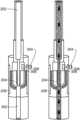
- FIGS. 2 A and 2 Bare schematic diagrams of a tool layout of the well tool of FIG. 1 .
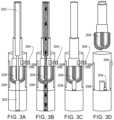
- FIGS. 3 A- 3 Dare schematic diagrams of an example of an operation of the well tool of FIG. 1 .
- FIG. 4is a flowchart of an example of a process of using the well tool of FIG. 1 .
- Wellbore operationsincluding cementing operations performed during drilling and workover.
- a cement retaineris lowered into a wellbore and is installed (or set) at a desired downhole location. Cementing operations are then performed by flowing cement through the cement retainer.
- a wellbore milling toolis lowered into the wellbore to mill the cement retainer and the top of the cement to a desired depth. This disclosure describes a well tool and a method associated with the well tool that will enable a one-trip system to set the cement retainer, perform the cementing operation and mill through the cement retainer.
- one-tripit is meant that the well tool that can perform the cementing operation and the milling operation is lowered into the wellbore in a single trip. Further, without needing another trip and using components of the well tool already lowered into the wellbore during the single trip, the cementing operation and then the milling operation are performed at the downhole location within the wellbore.
- time to implement the excesstime to set up a rig to implement the excess trip and costs and equipment associated with excess trips can be reduced. Human error that results in choosing a milling tool of incorrect size or type can be reduced or eliminated by implementing the operations described in this disclosure.
- FIG. 1is a schematic diagram of an example of a well 100 with the well tool 102 described in this disclosure.
- the well 100includes a wellbore 104 formed from a surface 106 through a subterranean zone 108 towards a subsurface reservoir (not shown).
- the well tool 102is lowered into the wellbore 104 to a desired downhole location 110 .
- the well tool 102is installed or set. Setting the well tool 102 at the downhole location 110 isolates a well region 112 downhole of the downhole location 110 from a well region 114 uphole of the downhole location 110 .
- the well tool 102can be used to perform cementing operations in which cement is flowed from the surface 106 , through the well tool 102 and to the well region 112 downhole of the downhole location 110 . Then, without raising the well tool 102 out of the wellbore 104 and without lowering another well tool into the wellbore 104 (i.e., in a single trip), portions of the well tool 102 are milled. The resulting debris can be flowed out of the wellbore 104 during a subsequent well operation.
- FIGS. 2 A and 2 Bare schematic diagrams of a tool layout of the well tool 102 of FIG. 1 .
- FIGS. 2 A and 2 Bshow the well tool 102 disassembled and assembled, respectively.
- the well tool 102includes a string 202 that can be lowered into the wellbore 104 from a rig or equipment disposed at the surface 106 of the wellbore 104 .
- the string 202can include coiled tubing, wireline, slickline or similar wellbore tubulars.
- a wellbore milling tool 204is attached to an end of the string 202 that is lowered into the wellbore 104 .
- the wellbore milling tool 204can perform wellbore milling operations.
- the tool 204can mill through components installed in the well. To do so, the string 202 can be rotated to cause the wellbore milling tool 204 to rotate. Or, the string 202 can be periodically raised and lowered to cause the wellbore milling tool 204 to also be raised and lowered. During such rotational or axial motion, the wellbore milling tool 204 mills through any component that contacts the tool 204 .
- a fluid flow pathway( FIGS. 3 A- 3 D ) is formed through the wellbore milling tool 204 .
- the fluid flow pathwayis formed as a hollow portion extending from one end of the tool 204 to the other end of the tool 204 .
- the string 202is also hollow and axially coupled to the fluid flow pathway formed in the tool 204 .
- Fluidse.g., cement, can be flowed through the fluid flow pathway from the surface 106 , through the string 202 and through the fluid flow pathway formed in the tool 204 .
- the well tool 102includes an elongate body 206 that is hollow and defines different portions (i.e., axial length segments) of different sizes. That is, while all the axial length segments are hollow, an inner diameter and an outer diameter of one axial length segment is different from an inner diameter and an outer diameter, respectively, of another axial length segment.
- the body 206includes a first portion 208 near a first end of the body 206 and a second portion 210 near a second end of the body 206 .
- the first portion 208has an inner diameter that is greater than an outer diameter of the milling tool 204 .
- the first portion 208has an axial length equal to or greater than an axial length of the milling tool 204 .
- the milling tool 204can be positioned and completely contained within the first portion 208 , as shown in FIG. 2 B .
- the remainder of the body 206forms a second portion 210 that can have the same or different outer diameters. But, the outer diameter of the milling tool 204 is greater than the largest outer diameter of the second portion 210 . In this arrangement, the milling tool 204 can mill through an entirety of the second portion 210 .
- a packer 212(or similar sealing assembly) is attached to the second portion 210 , e.g., nearer to an end of the second portion 210 .
- the packer 210allows the well tool 102 to be installed or set within the wellbore 104 at the desired downhole location 110 as described with reference to FIG. 1 .
- an outer diameter of the axial length of the second portion 210 to which packer 212 is attachedis equal to an outer diameter of the milling tool 204 so that the milling tool 204 can mill through the packer 212 without damaging the packer 212 .
- the hollow portions that extend from end to end within the body 206extend the fluid flow pathway defined by the milling tool 204 .
- Fluidse.g., cement
- the cementcan be flowed through the well tool 102 to the well region 112 ( FIG. 1 ) downhole of the downhole location 110 ( FIG. 1 ).
- a tool retainer( FIGS. 3 A- 3 D ) is attached to the body 206 .
- the tool retaineris configured to retain the milling tool 204 within the first portion 208 and to allow lowering the milling tool 204 attached to the body 206 within the wellbore 104 .
- the tool retainercan be activated to allow the milling tool 204 to separate from the body 206 .
- the tool retaineris activated after the cementing operations have been performed by flowing cement through the fluid flow pathway.
- FIGS. 3 A- 3 Dare schematic diagrams of an example of an operation of the well tool 102 .
- FIGS. 3 A- 3 Dshow the milling tool 204 ( FIG. 2 ), attached to the string 202 ( FIG. 2 ), wholly contained within the first portion 208 and lowered into the wellbore (not shown in FIGS. 3 A- 3 D ).
- the tool 102defines a fluid flow pathway 302 .
- the tool retainerretains the milling tool 204 within the first portion 208 such that the milling tool 204 and the body 206 ( FIG. 2 ) can be lowered into the wellbore 104 ( FIG. 1 ) together in a single trip.
- the tool retainerincludes a shear pin 304 that passes through a circumferential surface 306 of the body 206 (specifically, the first portion 208 ).
- the tool retaineralso includes a notch 308 formed on a side of the milling tool 204 .
- the shear pin 304When the shear pin 304 is radially inserted through the circumferential surface 306 into the notch 308 , the shear pin 304 locks the milling tool 204 and the first portion 208 such that the two components move together axially within the wellbore 104 ( FIG. 1 ).
- the well tool 102is set at the desired downhole location 110 ( FIG. 1 ) by deploying the packer 212 ( FIG.
- a relative axial movement between the milling tool 204 and the body 206causes the shearing pin 304 to be sheared.
- the shearing pin 304can be made of a material that can be sheared when the string 202 , to which the milling tool 204 is attached, is pulled in an uphole direction after the packer 212 ( FIG. 2 ) has been deployed.
- FIG. 3 Ashows that the first portion 208 with the milling tool 204 retained by the tool retainer is lowered into the wellbore 104 (not shown in FIG. 3 A ).
- the packer 212(not shown in FIG. 3 A ) is deployed once the body 206 reaches the desired downhole location 110 (not shown in FIG. 3 A ).
- the fluid flow pathway 302extends from the surface 106 of the wellbore 104 through the string 202 and the milling tool 204 , through the hollow portion defined by the body 206 to the downhole end of the body 206 .
- a separate elongate hollow tubular 302can be disposed within the body 206 and connected (e.g., axially, end-to-end) to the milling tool 204 .
- the tubular 302can extend from the downhole end of the milling tool 204 to the downhole end of the body 206 .
- FIG. 3 Bshows fluids, e.g., cement, being flowed through the fluid flow pathway 302 .
- the cementis flowed from the surface 106 of the wellbore 104 to the wellbore region 112 ( FIG. 1 ) that is downhole of the desired downhole location 110 ( FIG. 1 ) where the packer 212 is deployed.
- FIG. 3 Cshows that the cement flow through the fluid flow pathway 302 has been stopped.
- the string 202is pulled axially in an uphole direction causing the shearing pin 304 to be sheared. Consequently, the milling tool 204 is no longer connected to the first portion 208 of the body 206 .
- FIG. 3 Dshows the milling tool 204 being raised uphole of the body 206 (specifically, uphole of the first portion 208 ).
- the string 202can then be rotated or moved axially in an uphole-downhole direction (or both), and the milling tool 204 can be brought into contact with the body 206 to mill the body 206 . Because the inner diameter of the first portion 208 is greater than the outer diameter of the milling tool 204 , the axial uphole-downhole motion can be implemented to contact the milling tool 204 against the first portion 208 to mill the first portion 208 .
- the rotational motion of the milling tool 204can mill the remainder of the body 206 .
- the shearing pin 306 and any other component of the tool retainerare made of millable materials that can also be milled by the milling tool 204 . In this manner, the cementing and milling operations are implemented in one-trip. That is, a separate trip to lower a milling tool to remove the body is unnecessary. In addition, the milling tool 204 need not be removed from within the wellbore 104 to mill the body.
- FIG. 4is a flowchart of an example of a process 400 of using the well tool of FIG. 1 .
- the well tool 102is formed by positioning the milling tool 204 within the first portion 208 of the body 206 .
- the milling tool 204is connected to the body 206 , specifically the first portion 208 , by the tool retainer.
- the well tool body 206 with the connected wellbore milling tool 204is lowered into the wellbore 104 .
- the body 206is installed within the wellbore 104 at the desired downhole location 110 , for example, by deploying the packer 212 .
- the body 206is sealingly attached to an inner wall of the wellbore 104 at the downhole location 110 .
- cementis flowed through the fluid flow pathway (the cement flow pathway) to the wellbore location 112 that is downhole of the downhole location 110 .
- the tool retaineris activated to separate the milling tool 204 from the body 206 .
- the body 206is milled with the milling tool 204 . In this manner, flowing of the cement and milling of the body 206 are implemented in a single trip into the wellbore 104 .
Landscapes
- Life Sciences & Earth Sciences (AREA)
- Engineering & Computer Science (AREA)
- Geology (AREA)
- Mining & Mineral Resources (AREA)
- Physics & Mathematics (AREA)
- Environmental & Geological Engineering (AREA)
- Fluid Mechanics (AREA)
- General Life Sciences & Earth Sciences (AREA)
- Geochemistry & Mineralogy (AREA)
- Milling Processes (AREA)
Abstract
Description
This disclosure relates to wellbore operations, for example, wellbore drilling and makeover operations.
Hydrocarbons trapped in subsurface reservoirs can be raised to the surface of the Earth (that is, produced) through wellbores formed from the surface to the subsurface reservoirs. Wellbore drilling systems are used to drill wellbores through a subterranean zone (for example, a formation, a portion of a formation or multiple formations) to the subsurface reservoir. Wellbore drilling operations involve lowering well tools into the wellbore and perform operations inside the wellbore using the lowered tools. Cementing is one such operation in which cement is flowed from the surface to a downhole location and allowed to harden. The cement is flowed through a cement retainer. In some instances, removing the cement retainer or other cement-flowing tool from the wellbore can be more expensive than simply milling through the tool and flowing the resulting debris from within the wellbore.
This disclosure relates to a modified cement retainer with milling assembly.
Certain aspects of the subject matter described here can be implemented as a method. A wellbore milling tool is positioned in a hollow portion of an elongate well tool body. The wellbore milling tool and the well tool body define a cement flow pathway from end to end. The wellbore milling tool is connected to the well tool body by a tool retainer. The well tool body with the connected wellbore milling tool is lowered into a wellbore formed from a surface through a subterranean zone. The well tool body is installed within the wellbore at a downhole location. After the installing, the well tool body is sealingly attached to an inner wall of the wellbore at the downhole location. After installing the well tool body, cement is flowed through the cement flow pathway to a wellbore location that is downhole of the downhole location. After flowing the cement, the tool retainer is activated to separate the wellbore milling tool from the well tool body. After separating the wellbore milling tool from the well tool body, the well tool body is milled with the wellbore milling tool.
An aspect combinable with any other aspect includes the following features. Flowing the cement and milling the well tool body are implemented in a single trip into the wellbore.
An aspect combinable with any other aspect includes the following features. A packer is attached to the well tool body. To install the well tool body within the wellbore at the downhole location, the packer is deployed at the downhole location to seal against the inner wall of the wellbore.
An aspect combinable with any other aspect includes the following features. An inner diameter of the hollow portion in which the wellbore milling tool is positioned is greater than or equal to an outer diameter of a remainder of the body.
An aspect combinable with any other aspect includes the following features. An outer diameter of the wellbore milling tool is greater than or equal to the outer diameter of the remainder of the body.
An aspect combinable with any other aspect includes the following features. The tool retainer includes a shear pin. To connect the wellbore milling tool to the well tool body by the tool retainer, the shear pin is passed through a circumferential surface of the body and a notch formed on a side of the wellbore milling tool.
An aspect combinable with any other aspect includes the following features. To activate the tool retainer to separate the wellbore milling tool from the well tool body, the wellbore milling tool and the well tool body are moved axially relative to each other causing the shear pin to be sheared.
Certain aspects of the subject matter described here can be implemented as a well tool. The tool includes an elongate body that includes a first hollow portion near a first end of the body and a second portion near a second end of the body. A wellbore milling tool is positioned within the first hollow portion. The wellbore milling tool is configured to perform milling operations within a wellbore. A cement flow pathway is defined within the body and the wellbore milling tool. The cement flow pathway extends from the first end of the body to the second end of the body, and passes through the wellbore milling tool. The cement flow pathway is configured to allow flow of cement through the well tool. A tool retainer is attached to the body. The tool retainer is configured to retain the wellbore milling tool within the first hollow portion of the elongate body and to allow lowering the wellbore milling tool attached to the body within the wellbore.
An aspect combinable with any other aspect includes the following features. A packer is attached to the second portion. The packer is configured to seal against an inner wall of the wellbore.
An aspect combinable with any other aspect includes the following features. An inner diameter of the first hollow portion is greater than or equal to an outer diameter of a remainder of the body.
An aspect combinable with any other aspect includes the following features. An outer diameter of the wellbore milling tool is greater than or equal to the outer diameter of the remainder of the body.
An aspect combinable with any other aspect includes the following features. The tool retainer includes a shear pin passing through a circumferential surface of the body and a notch formed on a side of the wellbore milling tool. The shear pin is made of a material that is configured to be sheared in response to an axial movement of the wellbore milling tool and the body relative to each other.
An aspect combinable with any other aspect includes the following features. The material with which the shear pin is made is millable by the wellbore milling tool.
An aspect combinable with any other aspect includes the following features. A string is connected to the wellbore milling tool. The string is configured to lower the well tool inside the wellbore. A string mill is attached to the string axially uphole of the wellbore milling tool.
The details of one or more implementations of the subject matter described in this specification are set forth in the accompanying drawings and the description below. Other features, aspects, and advantages of the subject matter will become apparent from the description, the drawings, and the claims.
Like reference numbers and designations in the various drawings indicate like elements.
Wellbore operations including cementing operations performed during drilling and workover. In one run (or trip) a cement retainer is lowered into a wellbore and is installed (or set) at a desired downhole location. Cementing operations are then performed by flowing cement through the cement retainer. In another, separate run (or separate trip), a wellbore milling tool is lowered into the wellbore to mill the cement retainer and the top of the cement to a desired depth. This disclosure describes a well tool and a method associated with the well tool that will enable a one-trip system to set the cement retainer, perform the cementing operation and mill through the cement retainer. By “one-trip,” it is meant that the well tool that can perform the cementing operation and the milling operation is lowered into the wellbore in a single trip. Further, without needing another trip and using components of the well tool already lowered into the wellbore during the single trip, the cementing operation and then the milling operation are performed at the downhole location within the wellbore. By reducing multiple trips to a single trip, time to implement the excess, time to set up a rig to implement the excess trip and costs and equipment associated with excess trips can be reduced. Human error that results in choosing a milling tool of incorrect size or type can be reduced or eliminated by implementing the operations described in this disclosure.
In some implementations, a fluid flow pathway (FIGS.3A-3D ) is formed through thewellbore milling tool 204. For example, the fluid flow pathway is formed as a hollow portion extending from one end of thetool 204 to the other end of thetool 204. Thestring 202 is also hollow and axially coupled to the fluid flow pathway formed in thetool 204. Fluids, e.g., cement, can be flowed through the fluid flow pathway from thesurface 106, through thestring 202 and through the fluid flow pathway formed in thetool 204.
Thewell tool 102 includes anelongate body 206 that is hollow and defines different portions (i.e., axial length segments) of different sizes. That is, while all the axial length segments are hollow, an inner diameter and an outer diameter of one axial length segment is different from an inner diameter and an outer diameter, respectively, of another axial length segment. Thebody 206 includes afirst portion 208 near a first end of thebody 206 and asecond portion 210 near a second end of thebody 206. Thefirst portion 208 has an inner diameter that is greater than an outer diameter of themilling tool 204. Thefirst portion 208 has an axial length equal to or greater than an axial length of themilling tool 204. In this arrangement, themilling tool 204 can be positioned and completely contained within thefirst portion 208, as shown inFIG.2B . The remainder of thebody 206 forms asecond portion 210 that can have the same or different outer diameters. But, the outer diameter of themilling tool 204 is greater than the largest outer diameter of thesecond portion 210. In this arrangement, themilling tool 204 can mill through an entirety of thesecond portion 210.
A packer212 (or similar sealing assembly) is attached to thesecond portion 210, e.g., nearer to an end of thesecond portion 210. Thepacker 210 allows thewell tool 102 to be installed or set within thewellbore 104 at the desireddownhole location 110 as described with reference toFIG.1 . In some implementations, an outer diameter of the axial length of thesecond portion 210 to whichpacker 212 is attached is equal to an outer diameter of themilling tool 204 so that themilling tool 204 can mill through thepacker 212 without damaging thepacker 212.
The hollow portions that extend from end to end within thebody 206 extend the fluid flow pathway defined by themilling tool 204. Fluids, e.g., cement, can be flowed through the fluid flow pathway from thesurface 106, through thestring 202, through the fluid flow pathway formed in thetool 204, through the hollow portions within thebody 206 and to locations downhole of thetool 102. In particular, the cement can be flowed through thewell tool 102 to the well region112 (FIG.1 ) downhole of the downhole location110 (FIG.1 ).
A tool retainer (FIGS.3A-3D ) is attached to thebody 206. The tool retainer is configured to retain themilling tool 204 within thefirst portion 208 and to allow lowering themilling tool 204 attached to thebody 206 within thewellbore 104. As described below with reference toFIGS.3A-3D , once thewell tool 102 has been installed or set within thewellbore 104 at the desireddownhole location 110, the tool retainer can be activated to allow themilling tool 204 to separate from thebody 206. In operation, the tool retainer is activated after the cementing operations have been performed by flowing cement through the fluid flow pathway.
Thus, particular implementations of the subject matter have been described. Other implementations are within the scope of the following claims. In some cases, the actions recited in the claims can be performed in a different order and still achieve desirable results. In addition, the processes depicted in the accompanying figures do not necessarily require the particular order shown, or sequential order, to achieve desirable results. In certain implementations, multitasking and parallel processing may be advantageous.
Claims (14)
1. A method comprising:
positioning a wellbore milling tool in a hollow portion of an elongate well tool body, wherein the wellbore milling tool and the well tool body define a cement flow pathway from end to end;
connecting the wellbore milling tool to the well tool body by a tool retainer;
lowering the well tool body with the connected wellbore milling tool into a wellbore formed from a surface through a subterranean zone;
installing the well tool body within the wellbore at a downhole location, wherein, after the installing, the well tool body is sealingly attached to an inner wall of the wellbore at the downhole location;
after installing the well tool body, flowing cement through the cement flow pathway to a wellbore location that is downhole of the downhole location;
after flowing the cement, activating the tool retainer to separate the wellbore milling tool from the well tool body; and
after separating the wellbore milling tool from the well tool body, milling the well tool body with the wellbore milling tool.
2. The method ofclaim 1 , wherein flowing the cement and milling the well tool body are implemented in a single trip into the wellbore.
3. The method ofclaim 1 , wherein a packer is attached to the well tool body, wherein installing the well tool body within the wellbore at the downhole location comprises deploying the packer at the downhole location to seal against the inner wall of the wellbore.
4. The method ofclaim 3 , wherein an outer diameter of the wellbore milling tool is greater than or equal to the outer diameter of the remainder of the body.
5. The method ofclaim 1 , wherein an inner diameter of the hollow portion in which the wellbore milling tool is positioned is greater than or equal to an outer diameter of a remainder of the body.
6. The method ofclaim 1 , wherein the tool retainer comprises a shear pin, wherein connecting the wellbore milling tool to the well tool body by the tool retainer comprises passing the shear pin through a circumferential surface of the body and a notch formed on a side of the wellbore milling tool.
7. The method ofclaim 6 , wherein activating the tool retainer to separate the wellbore milling tool from the well tool body comprises axially moving the wellbore milling tool and the well tool body relative to each other causing the shear pin to be sheared.
8. A well tool comprising:
an elongate body comprising a first hollow portion near a first end of the body and a second portion near a second end of the body;
a wellbore milling tool positioned within the first hollow portion, the wellbore milling tool configured to perform milling operations within a wellbore;
a cement flow pathway defined within the body and the wellbore milling tool, the cement flow pathway extending from the first end of the body to the second end of the body and passing through the wellbore milling tool, the cement flow pathway configured to allow flow of cement through the well tool; and
a tool retainer attached to the body, the tool retainer configured to retain the wellbore milling tool within the first hollow portion of the elongate body and to allow lowering the wellbore milling tool attached to the body within the wellbore.
9. The well tool ofclaim 8 , further comprising a packer attached to the second portion, the packer configured to seal against an inner wall of the wellbore.
10. The well tool ofclaim 8 , wherein an inner diameter of the first hollow portion is greater than or equal to an outer diameter of a remainder of the body.
11. The well tool ofclaim 10 , wherein an outer diameter of the wellbore milling tool is greater than or equal to the outer diameter of the remainder of the body.
12. The well tool ofclaim 8 , wherein the tool retainer comprises a shear pin passing through a circumferential surface of the body and a notch formed on a side of the wellbore milling tool, wherein the shear pin is made of a material that is configured to be sheared in response to an axial movement of the wellbore milling tool and the body relative to each other.
13. The well tool ofclaim 12 , wherein the material with which the shear pin is made is millable by the wellbore milling tool.
14. The well tool ofclaim 8 , further comprising:
a string connected to the wellbore milling tool, the string configured to lower the well tool inside the wellbore; and
a string mill attached to the string axially uphole of the wellbore milling tool.
Priority Applications (1)
| Application Number | Priority Date | Filing Date | Title |
|---|---|---|---|
| US17/897,987US11993992B2 (en) | 2022-08-29 | 2022-08-29 | Modified cement retainer with milling assembly |
Applications Claiming Priority (1)
| Application Number | Priority Date | Filing Date | Title |
|---|---|---|---|
| US17/897,987US11993992B2 (en) | 2022-08-29 | 2022-08-29 | Modified cement retainer with milling assembly |
Publications (2)
| Publication Number | Publication Date |
|---|---|
| US20240068312A1 US20240068312A1 (en) | 2024-02-29 |
| US11993992B2true US11993992B2 (en) | 2024-05-28 |
Family
ID=89998906
Family Applications (1)
| Application Number | Title | Priority Date | Filing Date |
|---|---|---|---|
| US17/897,987Active2042-11-26US11993992B2 (en) | 2022-08-29 | 2022-08-29 | Modified cement retainer with milling assembly |
Country Status (1)
| Country | Link |
|---|---|
| US (1) | US11993992B2 (en) |
Cited By (1)
| Publication number | Priority date | Publication date | Assignee | Title |
|---|---|---|---|---|
| US12352115B1 (en) | 2024-01-09 | 2025-07-08 | Saudi Arabian Oil Company | Wellbore tubular centralizer tool |
Citations (191)
| Publication number | Priority date | Publication date | Assignee | Title |
|---|---|---|---|---|
| US880404A (en) | 1907-10-24 | 1908-02-25 | Robert G Sanford | Pipe-fishing tool. |
| US1591264A (en) | 1923-10-10 | 1926-07-06 | Lawrence F Baash | Attachment for fishing tools |
| US1789993A (en) | 1929-08-02 | 1931-01-27 | Switzer Frank | Casing ripper |
| US1896482A (en) | 1930-03-17 | 1933-02-07 | Erd V Crowell | Cement retainer |
| US1949498A (en) | 1931-07-06 | 1934-03-06 | Hydril Co | Pump-down plug |
| US2121051A (en) | 1937-07-14 | 1938-06-21 | Baker Oil Tools Inc | Cement retainer |
| US2121002A (en) | 1936-10-10 | 1938-06-21 | Baker Oil Tools Inc | Cement retainer and bridge plug for well casings |
| US2187487A (en) | 1939-01-14 | 1940-01-16 | Baker Oil Tools Inc | Bridge plug |
| US2189697A (en) | 1939-03-20 | 1940-02-06 | Baker Oil Tools Inc | Cement retainer |
| US2222233A (en) | 1939-03-24 | 1940-11-19 | Mize Loyd | Cement retainer |
| US2286075A (en) | 1941-01-21 | 1942-06-09 | Phillips Petroleum Co | Thermit welding apparatus |
| US2304793A (en) | 1941-06-09 | 1942-12-15 | Calpat Corp | Method of and apparatus for cutting pipe |
| US2316402A (en) | 1940-08-19 | 1943-04-13 | Arthur B Canon | Cementing wells |
| US2327092A (en) | 1941-04-21 | 1943-08-17 | Halliburton Oil Well Cementing | Apparatus for cementing wells |
| US2411260A (en) | 1941-05-16 | 1946-11-19 | Baker Oil Tools Inc | Apparatus for supporting and cementing liners or casings in well bores |
| US2546978A (en) | 1946-02-18 | 1951-04-03 | California Research Corp | Well liner and method of cementing |
| US2672199A (en) | 1948-03-12 | 1954-03-16 | Patrick A Mckenna | Cement retainer and bridge plug |
| US2707998A (en) | 1950-09-26 | 1955-05-10 | Baker Oil Tools Inc | Setting tool, dump bailer, and well packer apparatus |
| US2728599A (en) | 1952-12-23 | 1955-12-27 | Moore George Waldo | Apparatus for recovering junk from a well bore |
| US2751010A (en) | 1954-11-18 | 1956-06-19 | Houston Engineers Inc | Junk basket |
| US2806532A (en) | 1953-10-12 | 1957-09-17 | Baker Oil Tools Inc | Method and apparatus for pressuring well bores |
| US2881838A (en) | 1953-10-26 | 1959-04-14 | Pan American Petroleum Corp | Heavy oil recovery |
| US2912273A (en) | 1954-09-23 | 1959-11-10 | Houston Oil Field Mat Co Inc | Pipe engaging tool |
| US2912053A (en) | 1954-02-25 | 1959-11-10 | Christian W Breukelman | Squeeze cementing tools |
| US2915127A (en) | 1956-03-29 | 1959-12-01 | Abendroth O'farrel | Fluid controlled junk basket |
| US2965175A (en) | 1949-06-25 | 1960-12-20 | Dailey Oil Tools Inc | Pipe puller |
| US2965177A (en) | 1957-08-12 | 1960-12-20 | Wash Overshot And Spear Engine | Fishing tool apparatus |
| US3116799A (en) | 1960-08-01 | 1964-01-07 | Drilling Control Corp | Whipstock apparatus and method of using the same |
| GB958734A (en) | 1962-08-28 | 1964-05-27 | Shell Int Research | Apparatus adapted to be pumped througth a pipe |
| US3147536A (en) | 1961-10-27 | 1964-09-08 | Kammerer Jr Archer W | Apparatus for milling tubular strings in well bores |
| US3225828A (en) | 1963-06-05 | 1965-12-28 | American Coldset Corp | Downhole vertical slotting tool |
| US3369603A (en) | 1965-09-02 | 1968-02-20 | Phillips Petroleum Co | Plugging of a formation adjacent an oil stratum |
| US3381748A (en) | 1965-12-16 | 1968-05-07 | Exxon Production Research Co | Method for sealing leaks in production packers |
| US3382925A (en) | 1966-01-17 | 1968-05-14 | James R. Jennings | Reverse circulating junk basket |
| US3667721A (en) | 1970-04-13 | 1972-06-06 | Rucker Co | Blowout preventer |
| US3897038A (en) | 1973-01-22 | 1975-07-29 | Hydril Co | Blowout preventer with variable inside diameter |
| US3915426A (en) | 1973-01-26 | 1975-10-28 | Hydril Co | Blowout preventer with variable inside diameter |
| US4030354A (en) | 1976-02-27 | 1977-06-21 | Scott Kenneth F | Testing of ram and annular blowout preventers |
| US4042019A (en) | 1976-03-15 | 1977-08-16 | Henning Jack A | Wireline actuated tubing cutter |
| US4059155A (en) | 1976-07-19 | 1977-11-22 | International Enterprises, Inc. | Junk basket and method of removing foreign material from a well |
| US4099699A (en) | 1976-09-10 | 1978-07-11 | Cameron Iron Works, Inc. | Annular blowout preventer |
| GB2021178A (en) | 1978-05-18 | 1979-11-28 | Baker Int Corp | Well packer |
| US4190112A (en) | 1978-09-11 | 1980-02-26 | Davis Carl A | Pump down wipe plug and cementing/drilling process |
| US4227573A (en) | 1978-11-16 | 1980-10-14 | Otis Engineering Corporation | Reinforced seal unit for pumpdown pistons or well swabs |
| US4254983A (en) | 1979-09-19 | 1981-03-10 | Halliburton Company | Retriever tool |
| US4276931A (en) | 1979-10-25 | 1981-07-07 | Tri-State Oil Tool Industries, Inc. | Junk basket |
| US4285400A (en) | 1980-07-14 | 1981-08-25 | Baker International Corporation | Releasing tool for pressure activated packer |
| US4289200A (en) | 1980-09-24 | 1981-09-15 | Baker International Corporation | Retrievable well apparatus |
| US4296822A (en) | 1979-11-26 | 1981-10-27 | Omega Tools International | Multipurpose fluid flow assisted downhole tool |
| US4349071A (en) | 1980-11-07 | 1982-09-14 | Dresser Industries, Inc. | Cement retainer and setting tool assembly |
| US4391326A (en) | 1981-01-22 | 1983-07-05 | Dresser Industries, Inc. | Stinger assembly for oil well tool |
| US4407367A (en) | 1978-12-28 | 1983-10-04 | Hri, Inc. | Method for in situ recovery of heavy crude oils and tars by hydrocarbon vapor injection |
| US4412130A (en) | 1981-04-13 | 1983-10-25 | Standard Oil Company | Downhole device to detect differences in fluid density |
| US4413642A (en) | 1977-10-17 | 1983-11-08 | Ross Hill Controls Corporation | Blowout preventer control system |
| US4422948A (en) | 1981-09-08 | 1983-12-27 | Mayco Wellchem, Inc. | Lost circulation material |
| US4538684A (en) | 1984-04-09 | 1985-09-03 | Shell Western F&P Inc. | Repair of shallow casing leaks in oil wells |
| US4562888A (en) | 1984-01-12 | 1986-01-07 | Collet James R | Tubing head adapter and valve |
| US4611658A (en) | 1984-09-26 | 1986-09-16 | Baker Oil Tools, Inc. | High pressure retrievable gravel packing apparatus |
| US4696502A (en) | 1985-08-19 | 1987-09-29 | Smith International | Dual string packer mill |
| US4735268A (en) | 1986-10-02 | 1988-04-05 | The Western Company Of North America | Mechanical setting tool |
| US4791992A (en) | 1987-08-18 | 1988-12-20 | Dresser Industries, Inc. | Hydraulically operated and released isolation packer |
| US4834184A (en) | 1988-09-22 | 1989-05-30 | Halliburton Company | Drillable, testing, treat, squeeze packer |
| US4869321A (en) | 1989-02-10 | 1989-09-26 | Camco, Incorporated | Method of plugging openings in well conduits |
| WO1989012728A1 (en) | 1988-06-13 | 1989-12-28 | Parker Marvin T | In-well heat exchange method for improved recovery of subterranean fluids with poor flowability |
| US4898245A (en) | 1987-01-28 | 1990-02-06 | Texas Iron Works, Inc. | Retrievable well bore tubular member packer arrangement and method |
| US4928762A (en) | 1989-02-13 | 1990-05-29 | Halliburton Company | Retrievable bridge plug and packer |
| US4953617A (en) | 1989-10-19 | 1990-09-04 | Baker Hughes Incorporated | Apparatus for setting and retrieving a bridge plug from a subterranean well |
| US5012863A (en) | 1988-06-07 | 1991-05-07 | Smith International, Inc. | Pipe milling tool blade and method of dressing same |
| US5117909A (en) | 1990-10-25 | 1992-06-02 | Atlantic Richfield Company | Well conduit sealant and placement method |
| US5129956A (en) | 1989-10-06 | 1992-07-14 | Digital Equipment Corporation | Method and apparatus for the aqueous cleaning of populated printed circuit boards |
| US5176208A (en) | 1991-03-20 | 1993-01-05 | Ponder Fishing Tools, Inc. | Reverse circulation tool handling cuttings and debris |
| US5178219A (en) | 1991-06-27 | 1993-01-12 | Halliburton Company | Method and apparatus for performing a block squeeze cementing job |
| US5197547A (en) | 1992-05-18 | 1993-03-30 | Morgan Allen B | Wireline set packer tool arrangement |
| AU636642B2 (en) | 1989-08-23 | 1993-05-06 | Mobil Oil Corporation | A method for gravel packing a well |
| US5295541A (en) | 1992-12-22 | 1994-03-22 | Mobil Oil Corporation | Casing repair using a plastic resin |
| US5330000A (en) | 1992-09-22 | 1994-07-19 | Halliburton Company | Squeeze packer latch |
| US5358048A (en) | 1993-04-27 | 1994-10-25 | Ctc International | Hydraulic port collar |
| US5507346A (en) | 1994-08-26 | 1996-04-16 | Halliburton Company | Composite well flow conductor |
| US5580114A (en) | 1994-11-25 | 1996-12-03 | Baker Hughes Incorporated | Hydraulically actuated fishing tool |
| US5678635A (en) | 1994-04-06 | 1997-10-21 | Tiw Corporation | Thru tubing bridge plug and method |
| US5775428A (en)* | 1996-11-20 | 1998-07-07 | Baker Hughes Incorporated | Whipstock-setting apparatus |
| US5833001A (en) | 1996-12-13 | 1998-11-10 | Schlumberger Technology Corporation | Sealing well casings |
| US5842518A (en) | 1997-10-14 | 1998-12-01 | Soybel; Joshua Richard | Method for drilling a well in unconsolidated and/or abnormally pressured formations |
| US5924489A (en) | 1994-06-24 | 1999-07-20 | Hatcher; Wayne B. | Method of severing a downhole pipe in a well borehole |
| US5944101A (en) | 1998-06-15 | 1999-08-31 | Atlantic Richfield Company | Apparatus for milling a window in well tubular |
| US6138764A (en) | 1999-04-26 | 2000-10-31 | Camco International, Inc. | System and method for deploying a wireline retrievable tool in a deviated well |
| US6276452B1 (en) | 1998-03-11 | 2001-08-21 | Baker Hughes Incorporated | Apparatus for removal of milling debris |
| US6371204B1 (en) | 2000-01-05 | 2002-04-16 | Union Oil Company Of California | Underground well kick detector |
| US20020053428A1 (en) | 1999-11-30 | 2002-05-09 | Walter Maples | Reverse circulation junk basket |
| WO2002090711A2 (en) | 2001-05-04 | 2002-11-14 | Weatherford/Lamb, Inc. | Combined perforation and cement retainer tool for plugging a wellbore |
| US6491108B1 (en) | 2000-06-30 | 2002-12-10 | Bj Services Company | Drillable bridge plug |
| US20030047312A1 (en) | 2001-09-10 | 2003-03-13 | Bell William T. | Drill pipe explosive severing tool |
| US20030132224A1 (en) | 2000-03-30 | 2003-07-17 | Canitron Systems, Inc. | Oil and gas well alloy squeezing method and apparatus |
| US6688386B2 (en) | 2002-01-18 | 2004-02-10 | Stream-Flo Industries Ltd. | Tubing hanger and adapter assembly |
| GB2392183A (en) | 2002-08-22 | 2004-02-25 | Baker Hughes Inc | Well pump capsule |
| US20040040707A1 (en) | 2002-08-29 | 2004-03-04 | Dusterhoft Ronald G. | Well treatment apparatus and method |
| US6768106B2 (en) | 2001-09-21 | 2004-07-27 | Schlumberger Technology Corporation | Method of kick detection and cuttings bed buildup detection using a drilling tool |
| US6808023B2 (en) | 2002-10-28 | 2004-10-26 | Schlumberger Technology Corporation | Disconnect check valve mechanism for coiled tubing |
| US6899178B2 (en) | 2000-09-28 | 2005-05-31 | Paulo S. Tubel | Method and system for wireless communications for downhole applications |
| US20050167097A1 (en) | 2002-04-18 | 2005-08-04 | Sommers Michael T. | Patriot retrievable production packer |
| US20050263282A1 (en) | 2002-08-14 | 2005-12-01 | Steven Jeffrey | Well abandonment apparatus |
| US7049272B2 (en) | 2002-07-16 | 2006-05-23 | Santrol, Inc. | Downhole chemical delivery system for oil and gas wells |
| US7096950B2 (en) | 2000-10-27 | 2006-08-29 | Specialised Petroleum Services Group Limited | Combined milling and scraping tool |
| US20060213656A1 (en) | 2005-03-23 | 2006-09-28 | Clifton Harold D | Rotational set well packer device |
| US7117956B2 (en) | 2004-07-07 | 2006-10-10 | Halliburton Energy Services, Inc. | Pipe conveyed explosive with self contained actuation |
| US7188674B2 (en) | 2002-09-05 | 2007-03-13 | Weatherford/Lamb, Inc. | Downhole milling machine and method of use |
| US7188675B2 (en) | 2005-01-14 | 2007-03-13 | M-I L.L.C. | Finger boot basket |
| US7231975B2 (en) | 2001-10-08 | 2007-06-19 | Schlumberger Technology Corporation | Borehole stabilisation |
| US20070137528A1 (en) | 2003-05-14 | 2007-06-21 | Sylvaine Le Roy-Delage | Self adaptive cement systems |
| US7249633B2 (en) | 2001-06-29 | 2007-07-31 | Bj Services Company | Release tool for coiled tubing |
| US20070181304A1 (en) | 2006-02-08 | 2007-08-09 | Rankin E Edward | Method and Apparatus for Completing a Horizontal Well |
| US7255178B2 (en) | 2000-06-30 | 2007-08-14 | Bj Services Company | Drillable bridge plug |
| US7284611B2 (en) | 2004-11-05 | 2007-10-23 | Halliburton Energy Services, Inc. | Methods and compositions for controlling lost circulation in subterranean operations |
| AU2007249417A1 (en) | 2006-05-08 | 2007-11-22 | Mako Rentals, Inc. | Downhole swivel apparatus and method |
| US7405182B2 (en) | 2002-01-30 | 2008-07-29 | Turbo-Chem International, Inc. | Composition for decreasing lost circulation during well operation |
| US7424909B2 (en) | 2004-02-27 | 2008-09-16 | Smith International, Inc. | Drillable bridge plug |
| US20080236841A1 (en) | 2005-04-15 | 2008-10-02 | Caledus Limited | Downhole Swivel Sub |
| US20080251253A1 (en) | 2007-04-13 | 2008-10-16 | Peter Lumbye | Method of cementing an off bottom liner |
| US20080314591A1 (en) | 2007-06-21 | 2008-12-25 | Hales John H | Single trip well abandonment with dual permanent packers and perforating gun |
| US7488705B2 (en) | 2004-12-08 | 2009-02-10 | Halliburton Energy Services, Inc. | Oilwell sealant compositions comprising alkali swellable latex |
| US7497260B2 (en) | 2002-04-02 | 2009-03-03 | Specialised Petroleum Services Group Limited | Junk removal tool |
| US20090194290A1 (en) | 2007-08-09 | 2009-08-06 | Dtc International, Inc. | Control system for blowout preventer stack |
| US7591305B2 (en) | 2002-04-18 | 2009-09-22 | Tejas Complete Solutions, Lp | Patriot retrievable production packer |
| US20090250220A1 (en) | 2006-11-21 | 2009-10-08 | Prospector Drilling & Tool, Inc. | Internal pipe slot tool |
| US7600572B2 (en) | 2000-06-30 | 2009-10-13 | Bj Services Company | Drillable bridge plug |
| CA2734032A1 (en) | 2008-08-12 | 2010-02-18 | Qinglin Wu | Thermoplastic cellulosic fiber blends as lost circulation materials |
| US7712527B2 (en) | 2007-04-02 | 2010-05-11 | Halliburton Energy Services, Inc. | Use of micro-electro-mechanical systems (MEMS) in well treatments |
| US7762323B2 (en) | 2006-09-25 | 2010-07-27 | W. Lynn Frazier | Composite cement retainer |
| US7802621B2 (en) | 2006-04-24 | 2010-09-28 | Halliburton Energy Services, Inc. | Inflow control devices for sand control screens |
| US20100263856A1 (en) | 2009-04-17 | 2010-10-21 | Lynde Gerald D | Slickline Conveyed Bottom Hole Assembly with Tractor |
| US20100270018A1 (en) | 2009-04-23 | 2010-10-28 | Paul Howlett | Fishing tool |
| WO2010132807A2 (en) | 2009-05-15 | 2010-11-18 | Baker Hughes Incorporated | Packer retrieving mill with debris removal |
| US20110036570A1 (en) | 2009-08-14 | 2011-02-17 | La Rovere Thomas A | Method and apparatus for well casing shoe seal |
| US20110067869A1 (en) | 2009-10-14 | 2011-03-24 | Bour Daniel L | In situ decomposition of carbonyls at high temperature for fixing incomplete and failed well seals |
| US7934552B2 (en) | 2005-09-08 | 2011-05-03 | Thomas La Rovere | Method and apparatus for well casing repair and plugging utilizing molten metal |
| US7965175B2 (en) | 2005-05-10 | 2011-06-21 | Hochiki Corporation | Sounder |
| US8002049B2 (en) | 2003-05-13 | 2011-08-23 | Schlumberger Technology Corporation | Well treating method to prevent or cure lost-circulation |
| US20110203794A1 (en) | 2010-02-23 | 2011-08-25 | Tesco Corporation | Apparatus and Method for Cementing Liner |
| US20110278021A1 (en) | 2010-05-13 | 2011-11-17 | Weatherford/Lamb, Inc. | Wellhead Control Line Deployment |
| US20120012335A1 (en) | 2010-07-13 | 2012-01-19 | Richard White | Sealing adapter for well tubing head |
| US20120118571A1 (en) | 2010-11-12 | 2012-05-17 | Shaohua Zhou | Tool for recovering junk and debris from a wellbore of a well |
| US20120170406A1 (en) | 2005-08-01 | 2012-07-05 | Baker Hughes Incorporated | Early Kick Detection in an Oil and Gas Well |
| WO2012164023A1 (en) | 2011-05-31 | 2012-12-06 | Welltec A/S | Downhole tubing cutter tool |
| GB2492663A (en) | 2011-07-05 | 2013-01-09 | Bruce Arnold Tunget | Deformed of blocked passage access |
| US8496055B2 (en) | 2008-12-30 | 2013-07-30 | Schlumberger Technology Corporation | Efficient single trip gravel pack service tool |
| US20130240207A1 (en) | 2012-03-15 | 2013-09-19 | W. Lynn Frazier | Cement retainer and squeeze technique |
| US20130296199A1 (en) | 2008-12-11 | 2013-11-07 | Schlumberger Technology Corporation | Drilling lost circulation material |
| US8579024B2 (en) | 2010-07-14 | 2013-11-12 | Team Oil Tools, Lp | Non-damaging slips and drillable bridge plug |
| US20140158350A1 (en) | 2012-12-12 | 2014-06-12 | Baker Hughes Incorporated | All purpose pumpdown instrument |
| US8770276B1 (en) | 2011-04-28 | 2014-07-08 | Exelis, Inc. | Downhole tool with cones and slips |
| US20150122495A1 (en)* | 2013-11-06 | 2015-05-07 | Baker Hughes Incoporated | Single Trip Cement Thru Open Hole Whipstick |
| US20150226017A1 (en)* | 2012-08-23 | 2015-08-13 | M-I L.L.C. | Drilling assembly |
| US9133671B2 (en) | 2011-11-14 | 2015-09-15 | Baker Hughes Incorporated | Wireline supported bi-directional shifting tool with pumpdown feature |
| US9212532B2 (en) | 2010-04-13 | 2015-12-15 | Managed Pressure Operations PTE, Limited | Blowout preventer assembly |
| US20160084034A1 (en) | 2013-04-18 | 2016-03-24 | Thomas Roane | One-trip packer and perforating gun system |
| US9359861B2 (en) | 2010-12-28 | 2016-06-07 | Texproil S.R.L. | Downhole packer tool with dummy slips |
| US9416617B2 (en) | 2013-02-12 | 2016-08-16 | Weatherford Technology Holdings, Llc | Downhole tool having slip inserts composed of different materials |
| US20160237810A1 (en) | 2015-02-17 | 2016-08-18 | Board Of Regents, The University Of Texas System | Method and apparatus for early detection of kicks |
| US20160281458A1 (en) | 2015-03-24 | 2016-09-29 | Donald R. Greenlee | Retrievable Downhole Tool |
| US20160305215A1 (en) | 2015-04-18 | 2016-10-20 | Michael J. Harris | Frac Plug |
| US20160340994A1 (en) | 2015-05-21 | 2016-11-24 | Thru Tubing Solutions, Inc. | Advancement of a tubular string into a wellbore |
| US20170044864A1 (en) | 2015-08-10 | 2017-02-16 | Csi Technologies Llc | Method of sealing wells by squeezing sealant |
| US9574417B2 (en) | 2013-06-05 | 2017-02-21 | Baker Hughes Incorporated | Wireline hydraulic driven mill bottom hole assemblies and methods of using same |
| US20170058628A1 (en) | 2015-09-01 | 2017-03-02 | Cameron International Corporation | Blowout Preventer Including Blind Seal Assembly |
| US20170067313A1 (en) | 2014-01-31 | 2017-03-09 | Archer Oiltools As | Straddle tool with disconnect between seals |
| WO2017043977A1 (en) | 2015-09-11 | 2017-03-16 | Wellguard As | A plugging tool, and method of plugging a well |
| US20170089166A1 (en) | 2015-09-24 | 2017-03-30 | Bakken Ball Retrieval, LLC | Fracturing Ball Retrieval Device and Method |
| US9657213B2 (en) | 2014-10-20 | 2017-05-23 | Kraton Polymers U.S. Llc | Curable, resealable, swellable, reactive sealant composition for zonal isolation and well integrity |
| DK2236742T3 (en) | 2009-03-25 | 2017-08-21 | Weatherford Tech Holdings Llc | PROCEDURE AND DEVICE FOR A PACKER DEVICE |
| CN107387018A (en) | 2017-07-28 | 2017-11-24 | 四机赛瓦石油钻采设备有限公司 | A kind of one-trip string completes the instrument set with squeeze method construction of cement retainer |
| US20180010418A1 (en) | 2011-08-22 | 2018-01-11 | Downhole Technology, Llc | Downhole tool and method of use |
| WO2018017104A1 (en) | 2016-07-21 | 2018-01-25 | Landmark Graphics Corporation | Method for slim hole single trip remedial or plug and abandonment cement barrier |
| US20180119507A1 (en)* | 2016-10-28 | 2018-05-03 | Baker Hughes Incorporated | Method and system for abandoning a cased boreole |
| US20180128071A1 (en)* | 2016-11-04 | 2018-05-10 | Baker Hughes Incorporated | Debris Bridge Monitoring and Removal for Uphole Milling System |
| US20180187498A1 (en) | 2017-01-03 | 2018-07-05 | General Electric Company | Systems and methods for early well kick detection |
| US20180245427A1 (en) | 2015-09-25 | 2018-08-30 | Halliburton Energy Services, Inc. | Swellable technology for downhole fluids detection |
| US20190024473A1 (en) | 2017-07-18 | 2019-01-24 | Schlumberger Technology Corporation | Rotating annular preventer and methods of use thereof |
| US10280706B1 (en) | 2018-08-31 | 2019-05-07 | Harvey Sharp, III | Hydraulic setting tool apparatus and method |
| US20190186232A1 (en) | 2017-12-19 | 2019-06-20 | Weatherford Technology Holdings, Llc | Packing Element Booster with Ratchet Mechanism |
| US20190203551A1 (en) | 2016-07-20 | 2019-07-04 | Halliburton Energy Services, Inc. | Retractable pump down ring |
| WO2019132877A1 (en) | 2017-12-27 | 2019-07-04 | Fmc Technologies, Inc. | Compact over pull-push stroking tool |
| US20190284898A1 (en) | 2018-03-14 | 2019-09-19 | Archer Oiltools As | Tandem releasable bridge plug system and method for setting such tandem releasable plugs |
| US20190284893A1 (en)* | 2016-11-09 | 2019-09-19 | National Oilwell Varco, L.P. | Production Tubing Conversion Device and Methods of Use |
| US20200040683A1 (en)* | 2018-08-01 | 2020-02-06 | Weatherford Technology Holdings, Llc | Apparatus and method for forming a lateral wellbore |
| US20200056446A1 (en) | 2018-08-14 | 2020-02-20 | Saudi Arabian Oil Company | Tandem Cement Retainer and Bridge Plug |
| US20200157903A1 (en)* | 2018-11-15 | 2020-05-21 | Saudi Arabian Oil Company | Milling wellbores |
| US20200325746A1 (en)* | 2017-07-13 | 2020-10-15 | Tyrfing Innovation As | A downhole apparatus and a method at a downhole location |
| US20210140267A1 (en) | 2019-11-11 | 2021-05-13 | Saudi Arabian Oil Company | Setting and unsetting a production packer |
| US11142976B2 (en) | 2019-02-12 | 2021-10-12 | Saudi Arabian Oil Company | Positioning downhole-type tools |
| US20230091920A1 (en)* | 2021-09-20 | 2023-03-23 | Saudi Arabian Oil Company | Adjustable mill |
| US20230272672A1 (en)* | 2022-02-25 | 2023-08-31 | Saudi Arabian Oil Company | Modified whipstock design integrating cleanout and setting mechanisms |
- 2022
- 2022-08-29USUS17/897,987patent/US11993992B2/enactiveActive
Patent Citations (202)
| Publication number | Priority date | Publication date | Assignee | Title |
|---|---|---|---|---|
| US880404A (en) | 1907-10-24 | 1908-02-25 | Robert G Sanford | Pipe-fishing tool. |
| US1591264A (en) | 1923-10-10 | 1926-07-06 | Lawrence F Baash | Attachment for fishing tools |
| US1789993A (en) | 1929-08-02 | 1931-01-27 | Switzer Frank | Casing ripper |
| US1896482A (en) | 1930-03-17 | 1933-02-07 | Erd V Crowell | Cement retainer |
| US1949498A (en) | 1931-07-06 | 1934-03-06 | Hydril Co | Pump-down plug |
| US2121002A (en) | 1936-10-10 | 1938-06-21 | Baker Oil Tools Inc | Cement retainer and bridge plug for well casings |
| US2121051A (en) | 1937-07-14 | 1938-06-21 | Baker Oil Tools Inc | Cement retainer |
| US2187487A (en) | 1939-01-14 | 1940-01-16 | Baker Oil Tools Inc | Bridge plug |
| US2189697A (en) | 1939-03-20 | 1940-02-06 | Baker Oil Tools Inc | Cement retainer |
| US2222233A (en) | 1939-03-24 | 1940-11-19 | Mize Loyd | Cement retainer |
| US2316402A (en) | 1940-08-19 | 1943-04-13 | Arthur B Canon | Cementing wells |
| US2286075A (en) | 1941-01-21 | 1942-06-09 | Phillips Petroleum Co | Thermit welding apparatus |
| US2327092A (en) | 1941-04-21 | 1943-08-17 | Halliburton Oil Well Cementing | Apparatus for cementing wells |
| US2411260A (en) | 1941-05-16 | 1946-11-19 | Baker Oil Tools Inc | Apparatus for supporting and cementing liners or casings in well bores |
| US2304793A (en) | 1941-06-09 | 1942-12-15 | Calpat Corp | Method of and apparatus for cutting pipe |
| US2546978A (en) | 1946-02-18 | 1951-04-03 | California Research Corp | Well liner and method of cementing |
| US2672199A (en) | 1948-03-12 | 1954-03-16 | Patrick A Mckenna | Cement retainer and bridge plug |
| US2965175A (en) | 1949-06-25 | 1960-12-20 | Dailey Oil Tools Inc | Pipe puller |
| US2707998A (en) | 1950-09-26 | 1955-05-10 | Baker Oil Tools Inc | Setting tool, dump bailer, and well packer apparatus |
| US2728599A (en) | 1952-12-23 | 1955-12-27 | Moore George Waldo | Apparatus for recovering junk from a well bore |
| US2806532A (en) | 1953-10-12 | 1957-09-17 | Baker Oil Tools Inc | Method and apparatus for pressuring well bores |
| US2881838A (en) | 1953-10-26 | 1959-04-14 | Pan American Petroleum Corp | Heavy oil recovery |
| US2912053A (en) | 1954-02-25 | 1959-11-10 | Christian W Breukelman | Squeeze cementing tools |
| US2912273A (en) | 1954-09-23 | 1959-11-10 | Houston Oil Field Mat Co Inc | Pipe engaging tool |
| US2751010A (en) | 1954-11-18 | 1956-06-19 | Houston Engineers Inc | Junk basket |
| US2915127A (en) | 1956-03-29 | 1959-12-01 | Abendroth O'farrel | Fluid controlled junk basket |
| US2965177A (en) | 1957-08-12 | 1960-12-20 | Wash Overshot And Spear Engine | Fishing tool apparatus |
| US3116799A (en) | 1960-08-01 | 1964-01-07 | Drilling Control Corp | Whipstock apparatus and method of using the same |
| US3147536A (en) | 1961-10-27 | 1964-09-08 | Kammerer Jr Archer W | Apparatus for milling tubular strings in well bores |
| GB958734A (en) | 1962-08-28 | 1964-05-27 | Shell Int Research | Apparatus adapted to be pumped througth a pipe |
| US3225828A (en) | 1963-06-05 | 1965-12-28 | American Coldset Corp | Downhole vertical slotting tool |
| US3369603A (en) | 1965-09-02 | 1968-02-20 | Phillips Petroleum Co | Plugging of a formation adjacent an oil stratum |
| US3381748A (en) | 1965-12-16 | 1968-05-07 | Exxon Production Research Co | Method for sealing leaks in production packers |
| US3382925A (en) | 1966-01-17 | 1968-05-14 | James R. Jennings | Reverse circulating junk basket |
| US3667721A (en) | 1970-04-13 | 1972-06-06 | Rucker Co | Blowout preventer |
| US3897038A (en) | 1973-01-22 | 1975-07-29 | Hydril Co | Blowout preventer with variable inside diameter |
| US3915426A (en) | 1973-01-26 | 1975-10-28 | Hydril Co | Blowout preventer with variable inside diameter |
| US4030354A (en) | 1976-02-27 | 1977-06-21 | Scott Kenneth F | Testing of ram and annular blowout preventers |
| US4042019A (en) | 1976-03-15 | 1977-08-16 | Henning Jack A | Wireline actuated tubing cutter |
| US4059155A (en) | 1976-07-19 | 1977-11-22 | International Enterprises, Inc. | Junk basket and method of removing foreign material from a well |
| US4099699A (en) | 1976-09-10 | 1978-07-11 | Cameron Iron Works, Inc. | Annular blowout preventer |
| US4413642A (en) | 1977-10-17 | 1983-11-08 | Ross Hill Controls Corporation | Blowout preventer control system |
| GB2021178A (en) | 1978-05-18 | 1979-11-28 | Baker Int Corp | Well packer |
| US4190112A (en) | 1978-09-11 | 1980-02-26 | Davis Carl A | Pump down wipe plug and cementing/drilling process |
| US4227573A (en) | 1978-11-16 | 1980-10-14 | Otis Engineering Corporation | Reinforced seal unit for pumpdown pistons or well swabs |
| US4407367A (en) | 1978-12-28 | 1983-10-04 | Hri, Inc. | Method for in situ recovery of heavy crude oils and tars by hydrocarbon vapor injection |
| US4254983A (en) | 1979-09-19 | 1981-03-10 | Halliburton Company | Retriever tool |
| US4276931A (en) | 1979-10-25 | 1981-07-07 | Tri-State Oil Tool Industries, Inc. | Junk basket |
| US4296822A (en) | 1979-11-26 | 1981-10-27 | Omega Tools International | Multipurpose fluid flow assisted downhole tool |
| US4285400A (en) | 1980-07-14 | 1981-08-25 | Baker International Corporation | Releasing tool for pressure activated packer |
| US4289200A (en) | 1980-09-24 | 1981-09-15 | Baker International Corporation | Retrievable well apparatus |
| US4349071A (en) | 1980-11-07 | 1982-09-14 | Dresser Industries, Inc. | Cement retainer and setting tool assembly |
| US4391326A (en) | 1981-01-22 | 1983-07-05 | Dresser Industries, Inc. | Stinger assembly for oil well tool |
| US4412130A (en) | 1981-04-13 | 1983-10-25 | Standard Oil Company | Downhole device to detect differences in fluid density |
| US4422948A (en) | 1981-09-08 | 1983-12-27 | Mayco Wellchem, Inc. | Lost circulation material |
| US4562888A (en) | 1984-01-12 | 1986-01-07 | Collet James R | Tubing head adapter and valve |
| US4538684A (en) | 1984-04-09 | 1985-09-03 | Shell Western F&P Inc. | Repair of shallow casing leaks in oil wells |
| US4611658A (en) | 1984-09-26 | 1986-09-16 | Baker Oil Tools, Inc. | High pressure retrievable gravel packing apparatus |
| US4696502A (en) | 1985-08-19 | 1987-09-29 | Smith International | Dual string packer mill |
| US4735268A (en) | 1986-10-02 | 1988-04-05 | The Western Company Of North America | Mechanical setting tool |
| US4898245A (en) | 1987-01-28 | 1990-02-06 | Texas Iron Works, Inc. | Retrievable well bore tubular member packer arrangement and method |
| US4791992A (en) | 1987-08-18 | 1988-12-20 | Dresser Industries, Inc. | Hydraulically operated and released isolation packer |
| US5012863A (en) | 1988-06-07 | 1991-05-07 | Smith International, Inc. | Pipe milling tool blade and method of dressing same |
| WO1989012728A1 (en) | 1988-06-13 | 1989-12-28 | Parker Marvin T | In-well heat exchange method for improved recovery of subterranean fluids with poor flowability |
| US4834184A (en) | 1988-09-22 | 1989-05-30 | Halliburton Company | Drillable, testing, treat, squeeze packer |
| US4869321A (en) | 1989-02-10 | 1989-09-26 | Camco, Incorporated | Method of plugging openings in well conduits |
| US4928762A (en) | 1989-02-13 | 1990-05-29 | Halliburton Company | Retrievable bridge plug and packer |
| AU636642B2 (en) | 1989-08-23 | 1993-05-06 | Mobil Oil Corporation | A method for gravel packing a well |
| US5129956A (en) | 1989-10-06 | 1992-07-14 | Digital Equipment Corporation | Method and apparatus for the aqueous cleaning of populated printed circuit boards |
| US4953617A (en) | 1989-10-19 | 1990-09-04 | Baker Hughes Incorporated | Apparatus for setting and retrieving a bridge plug from a subterranean well |
| US5117909A (en) | 1990-10-25 | 1992-06-02 | Atlantic Richfield Company | Well conduit sealant and placement method |
| US5176208A (en) | 1991-03-20 | 1993-01-05 | Ponder Fishing Tools, Inc. | Reverse circulation tool handling cuttings and debris |
| US5178219A (en) | 1991-06-27 | 1993-01-12 | Halliburton Company | Method and apparatus for performing a block squeeze cementing job |
| US5197547A (en) | 1992-05-18 | 1993-03-30 | Morgan Allen B | Wireline set packer tool arrangement |
| US5330000A (en) | 1992-09-22 | 1994-07-19 | Halliburton Company | Squeeze packer latch |
| US5295541A (en) | 1992-12-22 | 1994-03-22 | Mobil Oil Corporation | Casing repair using a plastic resin |
| US5358048A (en) | 1993-04-27 | 1994-10-25 | Ctc International | Hydraulic port collar |
| US5678635A (en) | 1994-04-06 | 1997-10-21 | Tiw Corporation | Thru tubing bridge plug and method |
| US5924489A (en) | 1994-06-24 | 1999-07-20 | Hatcher; Wayne B. | Method of severing a downhole pipe in a well borehole |
| US5507346A (en) | 1994-08-26 | 1996-04-16 | Halliburton Company | Composite well flow conductor |
| US5580114A (en) | 1994-11-25 | 1996-12-03 | Baker Hughes Incorporated | Hydraulically actuated fishing tool |
| US5775428A (en)* | 1996-11-20 | 1998-07-07 | Baker Hughes Incorporated | Whipstock-setting apparatus |
| US5833001A (en) | 1996-12-13 | 1998-11-10 | Schlumberger Technology Corporation | Sealing well casings |
| US5842518A (en) | 1997-10-14 | 1998-12-01 | Soybel; Joshua Richard | Method for drilling a well in unconsolidated and/or abnormally pressured formations |
| US6276452B1 (en) | 1998-03-11 | 2001-08-21 | Baker Hughes Incorporated | Apparatus for removal of milling debris |
| US5944101A (en) | 1998-06-15 | 1999-08-31 | Atlantic Richfield Company | Apparatus for milling a window in well tubular |
| US6138764A (en) | 1999-04-26 | 2000-10-31 | Camco International, Inc. | System and method for deploying a wireline retrievable tool in a deviated well |
| US20020053428A1 (en) | 1999-11-30 | 2002-05-09 | Walter Maples | Reverse circulation junk basket |
| US6371204B1 (en) | 2000-01-05 | 2002-04-16 | Union Oil Company Of California | Underground well kick detector |
| US20030132224A1 (en) | 2000-03-30 | 2003-07-17 | Canitron Systems, Inc. | Oil and gas well alloy squeezing method and apparatus |
| US7600572B2 (en) | 2000-06-30 | 2009-10-13 | Bj Services Company | Drillable bridge plug |
| US6491108B1 (en) | 2000-06-30 | 2002-12-10 | Bj Services Company | Drillable bridge plug |
| US7255178B2 (en) | 2000-06-30 | 2007-08-14 | Bj Services Company | Drillable bridge plug |
| US6899178B2 (en) | 2000-09-28 | 2005-05-31 | Paulo S. Tubel | Method and system for wireless communications for downhole applications |
| US7096950B2 (en) | 2000-10-27 | 2006-08-29 | Specialised Petroleum Services Group Limited | Combined milling and scraping tool |
| WO2002090711A2 (en) | 2001-05-04 | 2002-11-14 | Weatherford/Lamb, Inc. | Combined perforation and cement retainer tool for plugging a wellbore |
| US6595289B2 (en) | 2001-05-04 | 2003-07-22 | Weatherford/Lamb, Inc. | Method and apparatus for plugging a wellbore |
| US7249633B2 (en) | 2001-06-29 | 2007-07-31 | Bj Services Company | Release tool for coiled tubing |
| US20030047312A1 (en) | 2001-09-10 | 2003-03-13 | Bell William T. | Drill pipe explosive severing tool |
| US6768106B2 (en) | 2001-09-21 | 2004-07-27 | Schlumberger Technology Corporation | Method of kick detection and cuttings bed buildup detection using a drilling tool |
| US7231975B2 (en) | 2001-10-08 | 2007-06-19 | Schlumberger Technology Corporation | Borehole stabilisation |
| US6688386B2 (en) | 2002-01-18 | 2004-02-10 | Stream-Flo Industries Ltd. | Tubing hanger and adapter assembly |
| US7405182B2 (en) | 2002-01-30 | 2008-07-29 | Turbo-Chem International, Inc. | Composition for decreasing lost circulation during well operation |
| US7497260B2 (en) | 2002-04-02 | 2009-03-03 | Specialised Petroleum Services Group Limited | Junk removal tool |
| US20050167097A1 (en) | 2002-04-18 | 2005-08-04 | Sommers Michael T. | Patriot retrievable production packer |
| US7591305B2 (en) | 2002-04-18 | 2009-09-22 | Tejas Complete Solutions, Lp | Patriot retrievable production packer |
| US7049272B2 (en) | 2002-07-16 | 2006-05-23 | Santrol, Inc. | Downhole chemical delivery system for oil and gas wells |
| US20050263282A1 (en) | 2002-08-14 | 2005-12-01 | Steven Jeffrey | Well abandonment apparatus |
| GB2392183A (en) | 2002-08-22 | 2004-02-25 | Baker Hughes Inc | Well pump capsule |
| US20040040707A1 (en) | 2002-08-29 | 2004-03-04 | Dusterhoft Ronald G. | Well treatment apparatus and method |
| US7188674B2 (en) | 2002-09-05 | 2007-03-13 | Weatherford/Lamb, Inc. | Downhole milling machine and method of use |
| US6808023B2 (en) | 2002-10-28 | 2004-10-26 | Schlumberger Technology Corporation | Disconnect check valve mechanism for coiled tubing |
| US8002049B2 (en) | 2003-05-13 | 2011-08-23 | Schlumberger Technology Corporation | Well treating method to prevent or cure lost-circulation |
| US20070137528A1 (en) | 2003-05-14 | 2007-06-21 | Sylvaine Le Roy-Delage | Self adaptive cement systems |
| US7424909B2 (en) | 2004-02-27 | 2008-09-16 | Smith International, Inc. | Drillable bridge plug |
| US7117956B2 (en) | 2004-07-07 | 2006-10-10 | Halliburton Energy Services, Inc. | Pipe conveyed explosive with self contained actuation |
| US7284611B2 (en) | 2004-11-05 | 2007-10-23 | Halliburton Energy Services, Inc. | Methods and compositions for controlling lost circulation in subterranean operations |
| US7488705B2 (en) | 2004-12-08 | 2009-02-10 | Halliburton Energy Services, Inc. | Oilwell sealant compositions comprising alkali swellable latex |
| US7188675B2 (en) | 2005-01-14 | 2007-03-13 | M-I L.L.C. | Finger boot basket |
| US20060213656A1 (en) | 2005-03-23 | 2006-09-28 | Clifton Harold D | Rotational set well packer device |
| US20080236841A1 (en) | 2005-04-15 | 2008-10-02 | Caledus Limited | Downhole Swivel Sub |
| US7965175B2 (en) | 2005-05-10 | 2011-06-21 | Hochiki Corporation | Sounder |
| US20120170406A1 (en) | 2005-08-01 | 2012-07-05 | Baker Hughes Incorporated | Early Kick Detection in an Oil and Gas Well |
| US9109433B2 (en) | 2005-08-01 | 2015-08-18 | Baker Hughes Incorporated | Early kick detection in an oil and gas well |
| US7934552B2 (en) | 2005-09-08 | 2011-05-03 | Thomas La Rovere | Method and apparatus for well casing repair and plugging utilizing molten metal |
| US20070181304A1 (en) | 2006-02-08 | 2007-08-09 | Rankin E Edward | Method and Apparatus for Completing a Horizontal Well |
| US7802621B2 (en) | 2006-04-24 | 2010-09-28 | Halliburton Energy Services, Inc. | Inflow control devices for sand control screens |
| AU2007249417A1 (en) | 2006-05-08 | 2007-11-22 | Mako Rentals, Inc. | Downhole swivel apparatus and method |
| US7762323B2 (en) | 2006-09-25 | 2010-07-27 | W. Lynn Frazier | Composite cement retainer |
| US20090250220A1 (en) | 2006-11-21 | 2009-10-08 | Prospector Drilling & Tool, Inc. | Internal pipe slot tool |
| US7712527B2 (en) | 2007-04-02 | 2010-05-11 | Halliburton Energy Services, Inc. | Use of micro-electro-mechanical systems (MEMS) in well treatments |
| US20080251253A1 (en) | 2007-04-13 | 2008-10-16 | Peter Lumbye | Method of cementing an off bottom liner |
| US20080314591A1 (en) | 2007-06-21 | 2008-12-25 | Hales John H | Single trip well abandonment with dual permanent packers and perforating gun |
| US20090194290A1 (en) | 2007-08-09 | 2009-08-06 | Dtc International, Inc. | Control system for blowout preventer stack |
| CA2734032A1 (en) | 2008-08-12 | 2010-02-18 | Qinglin Wu | Thermoplastic cellulosic fiber blends as lost circulation materials |
| US9410066B2 (en) | 2008-12-11 | 2016-08-09 | Schlumberger Technology Corporation | Drilling lost circulation material |
| US20130296199A1 (en) | 2008-12-11 | 2013-11-07 | Schlumberger Technology Corporation | Drilling lost circulation material |
| US8496055B2 (en) | 2008-12-30 | 2013-07-30 | Schlumberger Technology Corporation | Efficient single trip gravel pack service tool |
| DK2236742T3 (en) | 2009-03-25 | 2017-08-21 | Weatherford Tech Holdings Llc | PROCEDURE AND DEVICE FOR A PACKER DEVICE |
| US20100263856A1 (en) | 2009-04-17 | 2010-10-21 | Lynde Gerald D | Slickline Conveyed Bottom Hole Assembly with Tractor |
| US20100270018A1 (en) | 2009-04-23 | 2010-10-28 | Paul Howlett | Fishing tool |
| WO2010132807A2 (en) | 2009-05-15 | 2010-11-18 | Baker Hughes Incorporated | Packer retrieving mill with debris removal |
| US20110036570A1 (en) | 2009-08-14 | 2011-02-17 | La Rovere Thomas A | Method and apparatus for well casing shoe seal |
| US20110067869A1 (en) | 2009-10-14 | 2011-03-24 | Bour Daniel L | In situ decomposition of carbonyls at high temperature for fixing incomplete and failed well seals |
| US20110203794A1 (en) | 2010-02-23 | 2011-08-25 | Tesco Corporation | Apparatus and Method for Cementing Liner |
| US9212532B2 (en) | 2010-04-13 | 2015-12-15 | Managed Pressure Operations PTE, Limited | Blowout preventer assembly |
| US20110278021A1 (en) | 2010-05-13 | 2011-11-17 | Weatherford/Lamb, Inc. | Wellhead Control Line Deployment |
| US20120012335A1 (en) | 2010-07-13 | 2012-01-19 | Richard White | Sealing adapter for well tubing head |
| US8579024B2 (en) | 2010-07-14 | 2013-11-12 | Team Oil Tools, Lp | Non-damaging slips and drillable bridge plug |
| US20120118571A1 (en) | 2010-11-12 | 2012-05-17 | Shaohua Zhou | Tool for recovering junk and debris from a wellbore of a well |
| US8453724B2 (en) | 2010-11-12 | 2013-06-04 | Saudi Arabian Oil Company | Tool for recovering junk and debris from a wellbore of a well |
| US9359861B2 (en) | 2010-12-28 | 2016-06-07 | Texproil S.R.L. | Downhole packer tool with dummy slips |
| US8770276B1 (en) | 2011-04-28 | 2014-07-08 | Exelis, Inc. | Downhole tool with cones and slips |
| WO2012164023A1 (en) | 2011-05-31 | 2012-12-06 | Welltec A/S | Downhole tubing cutter tool |
| GB2492663A (en) | 2011-07-05 | 2013-01-09 | Bruce Arnold Tunget | Deformed of blocked passage access |
| US20180010418A1 (en) | 2011-08-22 | 2018-01-11 | Downhole Technology, Llc | Downhole tool and method of use |
| US9133671B2 (en) | 2011-11-14 | 2015-09-15 | Baker Hughes Incorporated | Wireline supported bi-directional shifting tool with pumpdown feature |
| US20130240207A1 (en) | 2012-03-15 | 2013-09-19 | W. Lynn Frazier | Cement retainer and squeeze technique |
| US20150226017A1 (en)* | 2012-08-23 | 2015-08-13 | M-I L.L.C. | Drilling assembly |
| US20140158350A1 (en) | 2012-12-12 | 2014-06-12 | Baker Hughes Incorporated | All purpose pumpdown instrument |
| US9416617B2 (en) | 2013-02-12 | 2016-08-16 | Weatherford Technology Holdings, Llc | Downhole tool having slip inserts composed of different materials |
| US20160084034A1 (en) | 2013-04-18 | 2016-03-24 | Thomas Roane | One-trip packer and perforating gun system |
| US9574417B2 (en) | 2013-06-05 | 2017-02-21 | Baker Hughes Incorporated | Wireline hydraulic driven mill bottom hole assemblies and methods of using same |
| AU2017225085A1 (en) | 2013-11-06 | 2017-09-28 | Baker Hughes, A Ge Company, Llc | Single trip cement thru open hole whipstock |
| US20150122495A1 (en)* | 2013-11-06 | 2015-05-07 | Baker Hughes Incoporated | Single Trip Cement Thru Open Hole Whipstick |
| US9695639B2 (en)* | 2013-11-06 | 2017-07-04 | Baker Hughes Incorporated | Single trip cement thru open hole whipstick |
| US20170067313A1 (en) | 2014-01-31 | 2017-03-09 | Archer Oiltools As | Straddle tool with disconnect between seals |
| US9657213B2 (en) | 2014-10-20 | 2017-05-23 | Kraton Polymers U.S. Llc | Curable, resealable, swellable, reactive sealant composition for zonal isolation and well integrity |
| US20160237810A1 (en) | 2015-02-17 | 2016-08-18 | Board Of Regents, The University Of Texas System | Method and apparatus for early detection of kicks |
| US20160281458A1 (en) | 2015-03-24 | 2016-09-29 | Donald R. Greenlee | Retrievable Downhole Tool |
| US20160305215A1 (en) | 2015-04-18 | 2016-10-20 | Michael J. Harris | Frac Plug |
| US20160340994A1 (en) | 2015-05-21 | 2016-11-24 | Thru Tubing Solutions, Inc. | Advancement of a tubular string into a wellbore |
| US20170044864A1 (en) | 2015-08-10 | 2017-02-16 | Csi Technologies Llc | Method of sealing wells by squeezing sealant |
| US20170058628A1 (en) | 2015-09-01 | 2017-03-02 | Cameron International Corporation | Blowout Preventer Including Blind Seal Assembly |
| WO2017043977A1 (en) | 2015-09-11 | 2017-03-16 | Wellguard As | A plugging tool, and method of plugging a well |
| US20180252069A1 (en) | 2015-09-11 | 2018-09-06 | Wellguard As | A Plugging Tool, and Method of Plugging a Well |
| US20170089166A1 (en) | 2015-09-24 | 2017-03-30 | Bakken Ball Retrieval, LLC | Fracturing Ball Retrieval Device and Method |
| US20180245427A1 (en) | 2015-09-25 | 2018-08-30 | Halliburton Energy Services, Inc. | Swellable technology for downhole fluids detection |
| US20190203551A1 (en) | 2016-07-20 | 2019-07-04 | Halliburton Energy Services, Inc. | Retractable pump down ring |
| WO2018017104A1 (en) | 2016-07-21 | 2018-01-25 | Landmark Graphics Corporation | Method for slim hole single trip remedial or plug and abandonment cement barrier |
| US20180119507A1 (en)* | 2016-10-28 | 2018-05-03 | Baker Hughes Incorporated | Method and system for abandoning a cased boreole |
| US20180128071A1 (en)* | 2016-11-04 | 2018-05-10 | Baker Hughes Incorporated | Debris Bridge Monitoring and Removal for Uphole Milling System |
| US20190284893A1 (en)* | 2016-11-09 | 2019-09-19 | National Oilwell Varco, L.P. | Production Tubing Conversion Device and Methods of Use |
| US20180187498A1 (en) | 2017-01-03 | 2018-07-05 | General Electric Company | Systems and methods for early well kick detection |
| US20200325746A1 (en)* | 2017-07-13 | 2020-10-15 | Tyrfing Innovation As | A downhole apparatus and a method at a downhole location |
| US20190024473A1 (en) | 2017-07-18 | 2019-01-24 | Schlumberger Technology Corporation | Rotating annular preventer and methods of use thereof |
| CN107387018A (en) | 2017-07-28 | 2017-11-24 | 四机赛瓦石油钻采设备有限公司 | A kind of one-trip string completes the instrument set with squeeze method construction of cement retainer |
| US20190186232A1 (en) | 2017-12-19 | 2019-06-20 | Weatherford Technology Holdings, Llc | Packing Element Booster with Ratchet Mechanism |
| WO2019132877A1 (en) | 2017-12-27 | 2019-07-04 | Fmc Technologies, Inc. | Compact over pull-push stroking tool |
| US20190284898A1 (en) | 2018-03-14 | 2019-09-19 | Archer Oiltools As | Tandem releasable bridge plug system and method for setting such tandem releasable plugs |
| US20200040683A1 (en)* | 2018-08-01 | 2020-02-06 | Weatherford Technology Holdings, Llc | Apparatus and method for forming a lateral wellbore |
| US20200056446A1 (en) | 2018-08-14 | 2020-02-20 | Saudi Arabian Oil Company | Tandem Cement Retainer and Bridge Plug |
| US11391113B2 (en) | 2018-08-14 | 2022-07-19 | Saudi Arabian Oil Company | Tandem cement retainer and bridge plug |
| US10837254B2 (en) | 2018-08-14 | 2020-11-17 | Saudi Arabian Oil Company | Tandem cement retainer and bridge plug |
| US20210025259A1 (en) | 2018-08-14 | 2021-01-28 | Saudi Arabian Oil Company | Tandem Cement Retainer and Bridge Plug |
| US10280706B1 (en) | 2018-08-31 | 2019-05-07 | Harvey Sharp, III | Hydraulic setting tool apparatus and method |
| US20200157903A1 (en)* | 2018-11-15 | 2020-05-21 | Saudi Arabian Oil Company | Milling wellbores |
| US11142976B2 (en) | 2019-02-12 | 2021-10-12 | Saudi Arabian Oil Company | Positioning downhole-type tools |
| US11230904B2 (en) | 2019-11-11 | 2022-01-25 | Saudi Arabian Oil Company | Setting and unsetting a production packer |
| US20210140267A1 (en) | 2019-11-11 | 2021-05-13 | Saudi Arabian Oil Company | Setting and unsetting a production packer |
| US20230091920A1 (en)* | 2021-09-20 | 2023-03-23 | Saudi Arabian Oil Company | Adjustable mill |
| US20230272672A1 (en)* | 2022-02-25 | 2023-08-31 | Saudi Arabian Oil Company | Modified whipstock design integrating cleanout and setting mechanisms |
Non-Patent Citations (3)
| Title |
|---|
| Bruton et al., "Whipstock Options for Sidetracking," Oilfield Review, vol. 26, No. 1, Spring 2014, 10 pages. |
| Scribd [online], "Milling Practices and Procedures," retrieved from URL <https://www.scribd.com/document/358420338/Milling-Rev-2-Secured>, 80 pages. |
| Tam International Inflatable and Swellable Packers, "TAM Scab Liner brochure," Tam International, available on or before Nov. 15, 2016, 4 pages. |
Cited By (1)
| Publication number | Priority date | Publication date | Assignee | Title |
|---|---|---|---|---|
| US12352115B1 (en) | 2024-01-09 | 2025-07-08 | Saudi Arabian Oil Company | Wellbore tubular centralizer tool |
Also Published As
| Publication number | Publication date |
|---|---|
| US20240068312A1 (en) | 2024-02-29 |
Similar Documents
| Publication | Publication Date | Title |
|---|---|---|
| US10731417B2 (en) | Reduced trip well system for multilateral wells | |
| US6012526A (en) | Method for sealing the junctions in multilateral wells | |
| US5228518A (en) | Downhole activated process and apparatus for centralizing pipe in a wellbore | |
| US5224556A (en) | Downhole activated process and apparatus for deep perforation of the formation in a wellbore | |
| US7640984B2 (en) | Method for drilling and casing a wellbore with a pump down cement float | |
| CA2550096C (en) | Method and apparatus for friction reduction in a downhole tool | |
| AU733035B2 (en) | Casing mounted lateral liner seal housing | |
| EP3161249B1 (en) | Multi-lateral well system | |
| US20100181079A1 (en) | Method and apparatus for cementing a liner in a borehole using a tubular member having an obstruction | |
| US11608717B2 (en) | Tool deployment and cleanout system | |
| US11492861B2 (en) | Packer assembly for use within a borehole | |
| WO2014137914A1 (en) | Liner top cleaning method prior to bha removal in drilling with advancing liner systems | |
| US11993992B2 (en) | Modified cement retainer with milling assembly | |
| WO1998009054A9 (en) | Cement reinforced inflatable seal for a junction of a multilateral | |
| WO1998009054A1 (en) | Cement reinforced inflatable seal for a junction of a multilateral | |
| EP3538739B1 (en) | Production tubing conversion device and methods of use | |
| NO20210901A1 (en) | Hydraulic landing nipple | |
| US11566492B1 (en) | Downhole tool with casing scraper with induced rotation | |
| US9127522B2 (en) | Method and apparatus for sealing an annulus of a wellbore | |
| WO2020117208A1 (en) | Systems and methods for positioning an isolation device in a borehole | |
| US20020053433A1 (en) | Cement diverter system for multilateral junctions and method for cementing a junction | |
| US12371967B2 (en) | Wellbore operations system and method | |
| US11566471B2 (en) | Selectively openable communication port for a wellbore drilling system | |
| WO1995017577A1 (en) | Apparatus and method for completing a well | |
| AU772417B2 (en) | Method for sealing the junctions in multilateral wells |
Legal Events
| Date | Code | Title | Description |
|---|---|---|---|
| FEPP | Fee payment procedure | Free format text:ENTITY STATUS SET TO UNDISCOUNTED (ORIGINAL EVENT CODE: BIG.); ENTITY STATUS OF PATENT OWNER: LARGE ENTITY | |
| AS | Assignment | Owner name:SAUDI ARABIAN OIL COMPANY, SAUDI ARABIA Free format text:ASSIGNMENT OF ASSIGNORS INTEREST;ASSIGNOR:AL-MOUSA, AHMED ABDULAZIZ;REEL/FRAME:060936/0360 Effective date:20220828 | |
| STPP | Information on status: patent application and granting procedure in general | Free format text:NOTICE OF ALLOWANCE MAILED -- APPLICATION RECEIVED IN OFFICE OF PUBLICATIONS | |
| STPP | Information on status: patent application and granting procedure in general | Free format text:PUBLICATIONS -- ISSUE FEE PAYMENT VERIFIED | |
| STCF | Information on status: patent grant | Free format text:PATENTED CASE |