US11992751B2 - Virtual reality hand gesture generation - Google Patents
Virtual reality hand gesture generationDownload PDFInfo
- Publication number
- US11992751B2 US11992751B2US17/229,619US202117229619AUS11992751B2US 11992751 B2US11992751 B2US 11992751B2US 202117229619 AUS202117229619 AUS 202117229619AUS 11992751 B2US11992751 B2US 11992751B2
- Authority
- US
- United States
- Prior art keywords
- data
- force
- controller
- touch
- user
- Prior art date
- Legal status (The legal status is an assumption and is not a legal conclusion. Google has not performed a legal analysis and makes no representation as to the accuracy of the status listed.)
- Active, expires
Links
Images


Classifications
- A—HUMAN NECESSITIES
- A63—SPORTS; GAMES; AMUSEMENTS
- A63F—CARD, BOARD, OR ROULETTE GAMES; INDOOR GAMES USING SMALL MOVING PLAYING BODIES; VIDEO GAMES; GAMES NOT OTHERWISE PROVIDED FOR
- A63F13/00—Video games, i.e. games using an electronically generated display having two or more dimensions
- A63F13/20—Input arrangements for video game devices
- A63F13/21—Input arrangements for video game devices characterised by their sensors, purposes or types
- A63F13/213—Input arrangements for video game devices characterised by their sensors, purposes or types comprising photodetecting means, e.g. cameras, photodiodes or infrared cells
- A—HUMAN NECESSITIES
- A63—SPORTS; GAMES; AMUSEMENTS
- A63F—CARD, BOARD, OR ROULETTE GAMES; INDOOR GAMES USING SMALL MOVING PLAYING BODIES; VIDEO GAMES; GAMES NOT OTHERWISE PROVIDED FOR
- A63F13/00—Video games, i.e. games using an electronically generated display having two or more dimensions
- A63F13/20—Input arrangements for video game devices
- A63F13/21—Input arrangements for video game devices characterised by their sensors, purposes or types
- A63F13/218—Input arrangements for video game devices characterised by their sensors, purposes or types using pressure sensors, e.g. generating a signal proportional to the pressure applied by the player
- A—HUMAN NECESSITIES
- A63—SPORTS; GAMES; AMUSEMENTS
- A63F—CARD, BOARD, OR ROULETTE GAMES; INDOOR GAMES USING SMALL MOVING PLAYING BODIES; VIDEO GAMES; GAMES NOT OTHERWISE PROVIDED FOR
- A63F13/00—Video games, i.e. games using an electronically generated display having two or more dimensions
- A63F13/20—Input arrangements for video game devices
- A63F13/24—Constructional details thereof, e.g. game controllers with detachable joystick handles
- A—HUMAN NECESSITIES
- A63—SPORTS; GAMES; AMUSEMENTS
- A63F—CARD, BOARD, OR ROULETTE GAMES; INDOOR GAMES USING SMALL MOVING PLAYING BODIES; VIDEO GAMES; GAMES NOT OTHERWISE PROVIDED FOR
- A63F13/00—Video games, i.e. games using an electronically generated display having two or more dimensions
- A63F13/40—Processing input control signals of video game devices, e.g. signals generated by the player or derived from the environment
- A63F13/42—Processing input control signals of video game devices, e.g. signals generated by the player or derived from the environment by mapping the input signals into game commands, e.g. mapping the displacement of a stylus on a touch screen to the steering angle of a virtual vehicle
- A63F13/428—Processing input control signals of video game devices, e.g. signals generated by the player or derived from the environment by mapping the input signals into game commands, e.g. mapping the displacement of a stylus on a touch screen to the steering angle of a virtual vehicle involving motion or position input signals, e.g. signals representing the rotation of an input controller or a player's arm motions sensed by accelerometers or gyroscopes
- A—HUMAN NECESSITIES
- A63—SPORTS; GAMES; AMUSEMENTS
- A63F—CARD, BOARD, OR ROULETTE GAMES; INDOOR GAMES USING SMALL MOVING PLAYING BODIES; VIDEO GAMES; GAMES NOT OTHERWISE PROVIDED FOR
- A63F13/00—Video games, i.e. games using an electronically generated display having two or more dimensions
- A63F13/60—Generating or modifying game content before or while executing the game program, e.g. authoring tools specially adapted for game development or game-integrated level editor
- A63F13/67—Generating or modifying game content before or while executing the game program, e.g. authoring tools specially adapted for game development or game-integrated level editor adaptively or by learning from player actions, e.g. skill level adjustment or by storing successful combat sequences for re-use
- G—PHYSICS
- G06—COMPUTING OR CALCULATING; COUNTING
- G06F—ELECTRIC DIGITAL DATA PROCESSING
- G06F3/00—Input arrangements for transferring data to be processed into a form capable of being handled by the computer; Output arrangements for transferring data from processing unit to output unit, e.g. interface arrangements
- G06F3/01—Input arrangements or combined input and output arrangements for interaction between user and computer
- G06F3/011—Arrangements for interaction with the human body, e.g. for user immersion in virtual reality
- G—PHYSICS
- G06—COMPUTING OR CALCULATING; COUNTING
- G06F—ELECTRIC DIGITAL DATA PROCESSING
- G06F3/00—Input arrangements for transferring data to be processed into a form capable of being handled by the computer; Output arrangements for transferring data from processing unit to output unit, e.g. interface arrangements
- G06F3/01—Input arrangements or combined input and output arrangements for interaction between user and computer
- G06F3/017—Gesture based interaction, e.g. based on a set of recognized hand gestures
- G—PHYSICS
- G06—COMPUTING OR CALCULATING; COUNTING
- G06F—ELECTRIC DIGITAL DATA PROCESSING
- G06F3/00—Input arrangements for transferring data to be processed into a form capable of being handled by the computer; Output arrangements for transferring data from processing unit to output unit, e.g. interface arrangements
- G06F3/01—Input arrangements or combined input and output arrangements for interaction between user and computer
- G06F3/03—Arrangements for converting the position or the displacement of a member into a coded form
- G06F3/0304—Detection arrangements using opto-electronic means
- G06F3/0325—Detection arrangements using opto-electronic means using a plurality of light emitters or reflectors or a plurality of detectors forming a reference frame from which to derive the orientation of the object, e.g. by triangulation or on the basis of reference deformation in the picked up image
- G—PHYSICS
- G06—COMPUTING OR CALCULATING; COUNTING
- G06F—ELECTRIC DIGITAL DATA PROCESSING
- G06F3/00—Input arrangements for transferring data to be processed into a form capable of being handled by the computer; Output arrangements for transferring data from processing unit to output unit, e.g. interface arrangements
- G06F3/01—Input arrangements or combined input and output arrangements for interaction between user and computer
- G06F3/03—Arrangements for converting the position or the displacement of a member into a coded form
- G06F3/033—Pointing devices displaced or positioned by the user, e.g. mice, trackballs, pens or joysticks; Accessories therefor
- G06F3/0346—Pointing devices displaced or positioned by the user, e.g. mice, trackballs, pens or joysticks; Accessories therefor with detection of the device orientation or free movement in a 3D space, e.g. 3D mice, 6-DOF [six degrees of freedom] pointers using gyroscopes, accelerometers or tilt-sensors
- G—PHYSICS
- G06—COMPUTING OR CALCULATING; COUNTING
- G06F—ELECTRIC DIGITAL DATA PROCESSING
- G06F3/00—Input arrangements for transferring data to be processed into a form capable of being handled by the computer; Output arrangements for transferring data from processing unit to output unit, e.g. interface arrangements
- G06F3/01—Input arrangements or combined input and output arrangements for interaction between user and computer
- G06F3/03—Arrangements for converting the position or the displacement of a member into a coded form
- G06F3/033—Pointing devices displaced or positioned by the user, e.g. mice, trackballs, pens or joysticks; Accessories therefor
- G06F3/0354—Pointing devices displaced or positioned by the user, e.g. mice, trackballs, pens or joysticks; Accessories therefor with detection of 2D relative movements between the device, or an operating part thereof, and a plane or surface, e.g. 2D mice, trackballs, pens or pucks
- G06F3/03547—Touch pads, in which fingers can move on a surface
- G—PHYSICS
- G06—COMPUTING OR CALCULATING; COUNTING
- G06F—ELECTRIC DIGITAL DATA PROCESSING
- G06F3/00—Input arrangements for transferring data to be processed into a form capable of being handled by the computer; Output arrangements for transferring data from processing unit to output unit, e.g. interface arrangements
- G06F3/01—Input arrangements or combined input and output arrangements for interaction between user and computer
- G06F3/03—Arrangements for converting the position or the displacement of a member into a coded form
- G06F3/033—Pointing devices displaced or positioned by the user, e.g. mice, trackballs, pens or joysticks; Accessories therefor
- G06F3/038—Control and interface arrangements therefor, e.g. drivers or device-embedded control circuitry
- G—PHYSICS
- G06—COMPUTING OR CALCULATING; COUNTING
- G06T—IMAGE DATA PROCESSING OR GENERATION, IN GENERAL
- G06T19/00—Manipulating 3D models or images for computer graphics
- G06T19/006—Mixed reality
Definitions
- the video game industryhas spawned many innovations in both hardware and software.
- various hand-held video game controllershave been designed, manufactured, and sold for a variety of game applications.
- Some of the innovationshave applicability outside of the video game industry, such as controllers for industrial machines, defense systems, robotics, etc.
- VRvirtual reality
- controllers for VR systemshave to perform several different functions and meet strict (and sometimes competing) design constraints while often optimizing certain desired characteristics.
- these controllersinclude sensors for measuring a force of a user's grip, which in turn is used for performing a predefined gameplay function.
- sensors for measuring a force of a user's gripwhich in turn is used for performing a predefined gameplay function.
- sensorshave been utilized in an effort to meet these objectives, including, among others, a force sensing resistor (FSR), which uses variable resistance to measure an amount of force applied to the FSR.
- FSRforce sensing resistor
- existing controllers with FSRstend to exhibit fairly crude response times. Additionally, the controller may fail to accurately depict and sense hand positions, gestures, and/or movement throughout a gameplay experience.
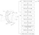
- FIG. 1depicts an environment of a user interacting with a virtual reality (VR) system according to an example embodiment of the present disclosure.
- VRvirtual reality
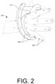
- FIG. 2depicts an example controller in a user's hand according to an example embodiment of the present disclosure.
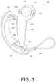
- FIG. 3depicts an example controller according to an example embodiment of the present disclosure.
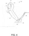
- FIG. 4depicts the example controller of FIG. 3 in a user's hand according to an example embodiment of the present disclosure.
- FIG. 5depicts the example controller of FIG. 3 in a user's hand according to an example embodiment of the present disclosure.
- FIG. 6depicts the example controller of FIG. 3 in a user's hand according to an example embodiment of the present disclosure.
- FIG. 7depicts a pair of example controllers according to an example embodiment of the present disclosure.
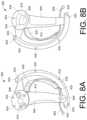
- FIG. 8 Adepicts a front view of the example right-hand controller according to another example embodiment of the present disclosure.
- FIG. 8 Bdepicts a back view of the example right-hand controller of FIG. 8 A .
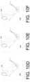
- FIG. 9 Adepicts an example force sensing resistor (FSR) according to an example embodiment of the present disclosure.
- FIG. 9 Bdepicts a front view of the example FSR of FIG. 9 A .
- FIG. 9 Cdepicts a cross section of the example FSR of FIG. 9 B , taken along Section A-A of FIG. 9 B .
- FIG. 10 Adepicts a first hand gesture of a user holding an example controller according to an example embodiment of the present disclosure.
- FIG. 10 Bdepicts a second hand gesture of a user holding an example controller according to an example embodiment of the present disclosure.
- FIG. 10 Cdepicts a third hand gesture of a user holding an example controller according to an example embodiment of the present disclosure.
- FIG. 10 Ddepicts a fourth hand gesture of a user holding an example controller according to an example embodiment of the present disclosure.
- FIG. 10 Edepicts a fifth hand gesture of a user holding an example controller according to an example embodiment of the present disclosure.
- FIG. 10 Fdepicts a sixth hand gesture of a user holding an example controller according to an example embodiment of the present disclosure.
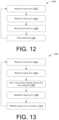
- FIG. 11depicts an example process according to an example embodiment of the present disclosure.
- FIG. 12depicts an example process for training model(s) according to an example embodiment of the present disclosure.
- FIG. 13depicts an example process for using touch input to generate gestures according to an example embodiment of the present disclosure.
- An example motion capture systemmay include cameras, projectors, and/or other sensors positioned about an environment to track a movement of the controller, as well as movement of a user operating the controller.
- a plurality of camerasmay mount within the environment and capture images of the controller and the user.
- the plurality of camerasmay capture some or all angles and positions within the environment.
- the plurality of camerasmay focus on or capture images within a predefined range or area of the environment.
- the camerasmay detect positions and orientations of the user and/or the controller(s), respectively.
- the controller(s) and/or the usermay include markers, respectively.
- the markersmay couple to the controller and/or the user.
- the markersmay include a digital watermark, an infrared reflector, or the like.
- the motion capture system(s)may project light into the environment, which is then reflected by the markers.
- the camerasmay capture incident light reflected by the markers and the motion capture system(s) may track and plot the locations of the markers within the environment to determine movements, positions, and/or orientations of the controller and/or the user.
- An example controllermay be held by the user and may include one or more force sensing resistors (FSRs) or other types of sensors that detect touch input from the user.
- FSRforce sensing resistors
- an FSRmay couple to a surface of the controller, such as a structure mounted within a handle of the controller and/or a structure mounted underneath at least one thumb-operated control of the controller.
- the FSRmay measure a resistance value that corresponds to an amount of force applied by the user.
- the FSRmay also associate the force(s) with a particular location, region, and/or portion of the controller. For example, the FSR may determine an amount of force applied to an outer surface of the handle and/or may determine location(s) on the controller corresponding to touch input from the user.
- the controllermay determine, via force data generated by the FSR, an amount of force in which the user squeezes the handle of the controller and/or an amount of force with which the user presses buttons on the controller.
- the controllermay translate presses or squeezes of varying force into digitized numerical values used for video game control and/or game mechanics.
- the FSRmay act as a switch to detect when an applied force exceeds a threshold, which in some instances, may dynamically update and/or adjust.
- the thresholdmay adjust to a lower value to reduce hand fatigue during gameplay (e.g., when the user presses a control associated with the FSR to shoot a weapon frequently during gameplay). Conversely, the threshold may adjust to a higher value to reduce instances of accidental control operation.
- the controllermay also include an array of proximity sensors that are spatially distributed along a length of the handle and that are responsive to a proximity of the user's fingers.
- the proximity sensorsmay include any suitable technology, such as capacitive sensors, for sensing a touch input and/or a proximity of the hand of the user relative to the controller.
- the array of proximity sensorsmay generate touch data that indicates a location of finger(s) grasping the controller or when the user is not grasping the controller, a distance disposed between the handle and the fingers of the user (e.g., through measuring capacitance).
- the proximity sensorsmay also detect a hand size of the user grasping the controller, which may configure the controller according to different settings. For instance, depending on the hand size, the controller may adjust to make force-based input easier for users with smaller hands.
- the motion capture system(s)may capture motion data of the hand and/or the controller, while the controller may capture touch data corresponding to touch inputs at the controller and force data associated with the touch inputs of the user.
- the motion data, the touch data, and/or the force datamay be associated with one another to generate models that are indicative of hand gestures of the user.
- the usermay include markers placed on his or her knuckles, finger tips, wrist, joints, and so forth.
- the controllermay also include markers (e.g., top, bottom, sides, etc.).
- the marker(s)may reflect incident light.
- the motion capture systemmay detect and record movements of the user's hand(s) and the position of the controller(s) via the cameras detecting positions of the markers.
- the projectors of the motion capture system(s)may project infrared light, which is then reflected by the markers on the hand and/or the controller.
- the cameras of the motion capture system(s)may capture images of the environment. The images are utilized to indicate the positions of the markers within the environment.
- the positions of the markersare tracked over time and animated within a three-dimensional (3D) virtual space. This tracking may allow for the generation of animated 3D skeletal data (or models). For instance, the user may grip the controller with a clinched first or two fingers (e.g., pinky finger and ring finger). The cameras may capture the positions of the user's finger tips, knuckles, and/or other portions of the hand, wrist, and/or arm via the markers. In some instances, the positions are relative to the controller.
- the array of proximity sensorsmay detect touch input, or a lack of touch input, at the controller.
- the touch datamay indicate the locations of the fingers of the user relative to the controller, for instance, through measuring capacitance.
- the capacitancemay vary with the distance disposed between the finger and the controller. In doing so, the controller may detect when the user grips the controller with one finger, two fingers, three fingers, and so forth. With the capacitance, the controller may also detect the relative placement of the fingers with respect to the controller, such as when the fingers of the user are not touching the controller.
- the FSRmay capture force data representative of force values received by the controller(s) (e.g., forces in which the user grips the controller). For instance, as the user grips the controller body with a clinched first or two fingers, the FSR may capture force values corresponding to these respective grips. As an example, the FSR may detect an increase in force values when the user grips the controller with a clinched first as compared to when the user grips the controller with two fingers.
- the touch data and the force datamay be associated with one another.
- the force values detected on the controllermay be associated with certain locations of the controller.
- the touch data and the force datamay be associated with one another to determine which fingers of the user grasp the controller, as well as the relative force each finger the user grasps the controller. The same may be said when the user grips the controller with two fingers, where force values are detected and associated with certain portions of the controller body. Knowing where the touch input is received, from the array of proximity sensors, as well as the amount of force the user grips the controller, as detected by the FSR, the controller and/or another communicatively coupled remote system may associate the touch input with certain fingers of the user. In some instances, through correlating time stamps associated with the touch data with time stamps of the force data, the controller (or another communicatively coupled remote system) may associate the touch data and the force data
- the amount of force with which the user grips the controlleri.e., the force data
- the location of the touch input or lack thereof on the controlleri.e., the touch data
- motion captured by the camera of the motion capture systemi.e., the motion data
- the motion capture systemmay associate a clinched first (e.g., using the motion data) with the touch data and/or the force data received at the controller.
- the motion datamay indicate the hand gesture (e.g., two finger grip) while the touch data may indicate the proximity of the hand (or fingers) to the controller and the force data may indicate how firm a user grips the controller.
- modelsmay be generated and trained to indicate gestures of the user. The models may continuously be trained to become more accurate overtime.
- the modelsmay characterize touch input at the controller and/or force values associated with the touch input to generate animations of a hand gesture on a display and the VR environment may utilize the models for use in gameplay. More particularly, the models may input the touch data and/or the force data to generate hand gestures within the VR environment.
- the gesturesmay include various video game controls, such as crushing a rock or squeezing a balloon (e.g., clinched first gesture), toggling through available weapons usable by a game character (e.g., scrolling or sliding fingers along the controller), dropping objects (e.g., open hand gesture), firing a weapon (e.g., pinky finger, ring finger, middle finger touching the controller but index finger and thumb are pointed outward), and so forth.
- the model(s)may utilize previously generated animations and/or image data when rendering and/or generating the hand gestures for display.
- FIG. 1depicts an example environment 100 in which a motion capture system(s) 102 and a user 104 reside.
- the motion capture system(s) 102is shown mounted to walls of the environment 100 , however, in some instances, the motion capture system(s) 102 may mount elsewhere within the environment 100 (e.g., ceiling, floor, etc.).
- FIG. 1illustrates four motion capture system(s) 102
- the environment 100may include more than or less than four motion capture system(s) 102 .
- the motion capture system(s) 102may include projector(s) configured to generate and project light and/or images 106 within/into the environment 100 .
- the images 106may include visible light images perceptible to the user 104 , visible light images imperceptible to the user 104 , images with non-visible light, and/or a combination thereof.
- the projector(s)may include any number of technologies capable of generating the images 106 and projecting the images 106 onto a surface or objects within the environment 100 .
- suitable technologiesmay include a digital micromirror device (DMD), liquid crystal on silicon display (LCOS), liquid crystal display, 3LCD, and so forth.
- DMDdigital micromirror device
- LCOSliquid crystal on silicon display
- 3LCDliquid crystal display
- the projector(s)may have a field of view which describes a particular solid angle and the field of view may vary according to changes in the configuration of the projector(s). For example, the field of view may narrow upon application of a zoom.
- the motion capture system(s) 102may include high resolution cameras, infrared (IR) detectors, sensors, and so forth.
- the camera(s)may image the environment 100 in visible light wavelengths, non-visible light wavelengths, or both.
- the camera(s)also have a field of view that describes a particular solid angle and the field of view of the camera may vary according to changes in the configuration of the camera(s). For example, an optical zoom of the camera(s) may narrow the camera field of view.
- the environment 100may include a plurality of cameras and/or a varying type of camera.
- the camerasmay include a three-dimensional (3D), an infrared (IR) camera, and/or a red-green-blue (RGB) camera.
- the 3D camera and the IR cameramay capture information for detecting depths of objects within the environment (e.g., markers) while the RGB camera may detect edges of objects by identifying changes in color within the environment 100 .
- the motion capture system(s) 102may include a single camera configured to perform all of the aforementioned functions.
- One or more components of the motion capture system(s) 102may mount to a chassis with a fixed orientation or may mount to the chassis via an actuator, such that the chassis and/or the one or more components may move.
- the actuatorsmay include piezoelectric actuators, motors, linear actuators, and other devices configured to displace or move the chassis and/or the one more components mounted thereto, such as the projector(s) and/or the camera(s).
- the actuatormay comprise a pan motor, a tilt motor, and so forth.
- the pan motormay rotate the chassis in a yawing motion while the tilt motor may change the pitch of the chassis.
- the chassismay additionally or alternatively include a roll motor, which allows the chassis to move in a rolling motion. By panning, tilting, and/or rolling the chassis, the motion capture system(s) 102 may capture different views of the environment 100 .
- the motion capture system(s) 102may also include a ranging system.
- the ranging systemmay provide distance information from the motion capture system(s) 102 to a scanned entity, object (e.g., the user 104 and/or the controller 110 ), and/or a set of objects.
- the ranging systemmay comprise and/or use radar, light detection and ranging (LIDAR), ultrasonic ranging, stereoscopic ranging, structured light analysis, time-of-flight observations (e.g., measuring time-of-flight round trip for pixels sensed at a camera), and so forth.
- LIDARlight detection and ranging
- ultrasonic rangingultrasonic ranging
- stereoscopic rangingstructured light analysis
- time-of-flight observationse.g., measuring time-of-flight round trip for pixels sensed at a camera
- the projector(s)may project a structured light pattern within the environment 100 and the camera(s) may capture an image of the reflected light pattern.
- the motion capture system(s) 102may determine or know distance(s) between the respective components of the motion capture system(s) 102 , which may aid in the recovery of the structured light pattern and/or other light data from the environment 100 .
- the motion capture system(s) 102may also use the distances to calculate other distances, dimensions, and/or otherwise aid in the characterization of entities or objects within the environment 100 . In implementations where the relative angle and size of the projector field of view and camera field of view may vary, the motion capture system(s) 102 may determine and/or know such dimensions.
- the user 104may wear a VR headset 108 and hold the controllers 110 .
- the VR headset 108may include an internal display (not shown) that presents a simulated view of a virtual environment, gameplay, or shows objects within virtual space.
- the VR headset 108may include a headband along with additional sensors.
- the VR headset 108may comprise a helmet or cap and include sensors located at various positions on the top of the helmet or cap to receive optical signals.
- the user 104 and/or the controllers 110may include markers.
- the motion capture system(s) 102via the projector(s) projecting light and the camera(s) capturing images of the reflections of the markers, may detect a position of the user 104 and/or the controllers 110 within the environment 100 .
- the markersmay be utilized to determine an orientation and/or position of the user 104 , or portions of the user 104 (e.g., hands or fingers) within the environment 100 , as well as an orientation and/or position of the controller 110 within the environment 100 .
- the ranging systemmay also aid in determining locations of the user 104 (or portions thereof) and the controllers 110 through determining distances between the motion capture system(s) 102 and the markers.
- the motion capture system(s) 102 , the VR headset 108 , and/or the controllers 110may communicatively couple to one or more remote computing resource(s) 112 .
- the remote computing resource(s) 112may be remote from the environment 100 and the motion capture system(s) 102 , the VR headset 108 , and/or the controllers 110 .
- the motion capture system(s) 102 , the VR headset 108 , and/or the controllers 110may communicatively couple to the remote computing resource(s) 112 over a network 114 .
- the motion capture system(s) 102 , the VR headset 108 , and/or the controllers 110may communicatively couple to the network 114 via wired technologies (e.g., wires, USB, fiber optic cable, etc.), wireless technologies (e.g., RF, cellular, satellite, Bluetooth, etc.), and/or other connection technologies.
- the network 114is representative of any type of communication network, including data and/or voice network, and may be implemented using wired infrastructure (e.g., cable, CATS, fiber optic cable, etc.), a wireless infrastructure (e.g., RF, cellular, microwave, satellite, Bluetooth, etc.), and/or other connection technologies.
- the remote computing resource(s) 112may be implemented as one or more servers and may, in some instances, form a portion of a network-accessible computing platform implemented as a computing infrastructure of processors, storage, software, data access, and so forth that is maintained and accessible via a network such as the Internet.
- the remote computing resource(s) 112do not require end-user knowledge of the physical location and configuration of the system that delivers the services. Common expressions associated with these remote computing resource(s) 112 may include “on-demand computing,” “software as a service (SaaS),” “platform computing,” “network-accessible platform,” “cloud services,” “data centers,” and so forth.
- the motion capture system(s) 102 , the VR headset 108 , and/or the controllers 110may include one or more communication interfaces to facilitate the wireless connection to the network 114 and/or to one or more remote computing resource(s) 112 . Additionally, the one or more communication interfaces may also permit transmission of data between the motion capture system(s) 102 , the VR headset 108 , and/or the controllers 110 (e.g., communication between one another). In some instances, however, the one or more communication interfaces may also include wired connections.
- the remote computing resource(s) 112include a processor(s) 116 and memory 118 , which may store or otherwise have access to one or more model(s) 120 .
- the remote computing resource(s) 112may receive motion data 122 from the motion capture system(s) 102 and touch data 124 and/or force data 126 from the controllers 110 .
- the touch data 124may include a touch profile indicating a location (or locations) on the controller(s) 110 corresponding to touch input of the user.
- the touch data 124may also indicate a lack of touch input on the controller(s) 110 . In doing so, the touch data 124 may indicate which finger(s) is/are touching the controller, and/or what portions of the finger(s) touch the controller(s) 110 .
- an array of proximity sensorse.g., capacitive sensors spatially distributed along a handle of the controller 110 may detect the touch input and generate and/or transmit the touch data to the remote computing resource(s) 112 .
- the FSRmay generate force data 126 that indicates force values of the touch input on the controller 110 .
- the touch data 124 and/or the force data 126may indicate a hand position, grip, or gesture of the hand within the VR environment.
- the remote computing resource(s) 112may transmit animation(s) 128 or other image data to the VR headset 108 for display.
- the remote computing resource(s) 112may utilize the model(s) 120 to generate the animations 128 displayed on the VR headset 108 .
- the remote computing resource(s) 112may generate and/or train the model(s) 120 using the motion data 122 , the touch data 124 , and/or the force data 126 .
- the remote computing resource(s) 112may generate and/or train the model(s) 120 through interactions with users and receiving the motion data 122 , the touch data 124 , and/or the force data 126 .
- the processor(s) 116may analyze the motion data 122 and correlate the motion data 122 with the touch data 124 and/or the force data 126 . Additionally, the processor(s) 116 may analyze the touch data 124 and associate the touch data 124 with the force data 126 .
- the processor(s) 116may correlate a time associated with a capture of the motion data 122 to learn characteristics of the users. For instance, the processor(s) 116 may learn characteristics of the touch data 124 (e.g., location on the controller 110 ) and/or the force data 126 and associate these characteristics with particular gestures of the hand. After performing the data analysis, the processor(s) 116 may generate the model(s) 120 to correlate the motion data 122 , the touch data 124 , and/or the force data 126 . In other words, the processor(s) 116 may analyze the touch data 124 and/or the force data 126 to correlate or otherwise associate the touch data 124 and/or the force data 126 with hand gestures, as represented by the motion data 122 .
- the processor(s) 116may analyze the touch data 124 and/or the force data 126 to correlate or otherwise associate the touch data 124 and/or the force data 126 with hand gestures, as represented by the motion data 122 .
- Training the model(s) 120 based on the motion data 122 , the touch data 124 , and/or the force data 126permits the model(s) 120 to determine hand gestures using the touch data 124 and/or the force data 126 received in subsequent interactions by users (i.e., during gameplay). That is, the model(s) 120 may receive the touch data 124 and/or the force data 126 as inputs, and utilize the touch data 124 and/or the force data 126 to determine a hand gesture of the user 104 . For example, when a user is holding the controller 110 , the controller 110 may receive the touch data 124 generated by the array of the proximity sensors, where the touch data 124 indicates a location of the touch input at the controller 110 .
- the touch data 124may also indicate a proximity of the hand of the user with respect to the controller 110 through measuring a capacitance value between fingers of the user and the controller 110 . For instance, the user may hover his or her fingers above the controller 110 .
- the controller 110may transmit the touch data 124 to the remote computing resource(s) 112 , where the touch data 124 is input into the model(s) 120 .
- the FSR of the controller 110may generate the force data 126 indicating an amount of force associated with the touch input.
- the controller 110may transmit the force data 126 to the remote computing resource(s) 112 .
- the processor(s) 116may select one or more of the model(s) 120 based on characteristics of the touch data 124 and/or the force data 126 . For example, the processor(s) 116 may select certain model(s) 120 for generating hand gestures based on the amount of force the user 104 grips the controller 110 (using the force data 126 ) and/or a location of the grip of the user 104 on the controller 110 (using the touch data 124 ).
- the processor(s) 116may select the model(s) 120 based in part on other user characteristics, such as on user interests, gender, age, etc. For instance, depending on how the user 104 holds the controller 110 and/or where the controller 110 receives touch input, the processor(s) 116 may identify an age and/or hand size of the user 104 . Such information may be utilized to select different model(s) 120 and/or generate the animation(s) 128 representative of the hands of the user 104 .
- the processor(s) 116may input the touch data 124 into the model(s) 120 .
- the processor(s) 116using the model(s) 120 , may generate the animation(s) 128 corresponding to the touch data 124 and/or the force data 126 .
- the processor(s) 116may determine the user is holding the controller 110 with a clinched fist.
- the processor(s) 116may generate the animation 128 depicting the clinched first of the user 104 and transmit the animation 128 to the VR headset 108 for display.
- the processor(s) 116may utilize rankings to determine the most probabilistic hand gesture represented by the touch data 124 and/or the force data 126 utilizing profiles stored in association with the model(s) 120 . For instance, the processor(s) 116 may compare the touch data 124 and/or the force data 126 to a portion of the model(s) 120 or all of the model(s) 120 to determine a probability that particular hand gestures correspond to the touch input of the user. In such instances, the model(s) 120 may be stored in association with touch data 124 that indicates a location of touch input received at the controller 110 and/or force data 126 that indicates a relative force of the touch input at the controller 110 .
- the touch data 124 and/or the force data 126may characterize the model(s) 120 . Accordingly, during gameplay, when the remote computing resource(s) 112 receives touch data 124 and/or the force data 126 , the remote computing resource(s) 112 may select one or more model(s) 120 to generate the animation 128 by comparing the received touch data 124 and/or the force data 126 with the touch data and/or the force data stored in association with the model(s) 120 , respectively.
- the remote computing resource(s) 112may also perform predictive modeling for future events.
- the predictive modelingmay determine a probability of whether an outcome may occur or may not occur.
- the processor(s) 116may determine a probability of future hand gestures utilizing the motion data 122 , the touch data 124 , and/or the force data 126 available from the memory 118 .
- the processor(s) 116may predict a forthcoming second hand gesture and generate the second hand gesture for display on the VR headset 108 .
- the processor(s) 116may utilize previous motion data 122 , touch data 124 , and/or force data 126 to predict future hand gestures of the user 104 and generate corresponding animation(s) 128 .
- the predictionmay reduce a latency time between gestures generated by the remote computing resource(s) 112 that are displayed on the VR headset 108 .
- the processor(s) 116may determine a certain probability and/or confidence associated with a predicted gesture. For instance, if a predicted second hand gesture is within a certain confidence level or threshold, the processor(s) 116 may generate an animation(s) 128 corresponding to the second hand gesture and provide the gesture to the VR headset 108 for display.
- validation operationsmay validate an accuracy of the model(s) 120 . That is, as noted above, through iteratively capturing the motion data 122 , the touch data 124 , and/or the force data 126 , the processors(s) 116 may train the model(s) 120 to better correlate the touch data 124 and/or the force data 126 with hand gestures represented within the motion data 122 (e.g., machine learning algorithms or techniques). Training the model(s) 120 may increase the accuracy that the displayed animation(s) 128 is/are representative of the touch data 124 and/or the force data 126 received at the controller 110 .
- the processor(s) 116may also include components that learn the model(s) 120 based on interactions with different types of users. For instance, the processor(s) 116 may build and/or refine the model(s) 120 , or may learn combinations and/or blendings of existing model(s) 120 .
- the model generation techniques described hereinmay also include at least one of gradient boosting techniques and/or hyperparameter tuning to train the model(s) 120 .
- Gradient boostingmay include, for example, producing a prediction model in the form of an ensemble of weak prediction models, which may be decision trees.
- the prediction modelmay be built in a stage-wise fashion and may allow optimization of an arbitrary differential loss function.
- Hyperparameter tuningmay include optimization of hyperparameters during a training process. For example, the model 120 may receive a training data set. In evaluating the aggregate accuracy of the model 120 , hyperparameters may be tuned.
- training the model(s) 120may involve identifying input features that increase the accuracy of the model(s) 120 and/or other input features that decrease the accuracy of the model(s) 120 or have no or little effect on the model(s) 120 .
- the model(s) 120may be refitted to utilize the features that increase accuracy while refraining from utilizing the features that decrease accuracy or have no or little effect on accuracy.
- a processorsuch as processor(s) 116
- the processor(s) 116may include a graphics processing unit (GPU), a microprocessor, a digital signal processor or other processing units or components known in the art. Alternatively, or in addition, the functionally described herein can be performed, at least in part, by one or more hardware logic components.
- illustrative types of hardware logic componentsinclude field-programmable gate arrays (FPGAs), application-specific integrated circuits (ASICs), application-specific standard products (ASSPs), system-on-a-chip systems (SOCs), complex programmable logic devices (CPLDs), etc.
- FPGAsfield-programmable gate arrays
- ASICsapplication-specific integrated circuits
- ASSPsapplication-specific standard products
- SOCssystem-on-a-chip systems
- CPLDscomplex programmable logic devices
- each of the processor(s) 116may possess its own local memory, which also may store program components, program data, and/or one or more operating systems.
- the memory 118may include volatile and nonvolatile memory, removable and non-removable media implemented in any method or technology for storage of information, such as computer-readable instructions, data structures, program component, or other data.
- Such memory 118may include, but is not limited to, RAM, ROM, EEPROM, flash memory or other memory technology, CD-ROM, digital versatile disks (DVD) or other optical storage, magnetic cassettes, magnetic tape, magnetic disk storage or other magnetic storage devices, RAID storage systems, or any other medium which can be used to store the desired information and which can be accessed by a computing device.
- the memory 118may be implemented as computer-readable storage media (“CRSM”), which may be any available physical media accessible by the processor(s) 116 to execute instructions stored on the memory 118 .
- CRSMcomputer-readable storage media
- CRSMmay include random access memory (“RAM”) and Flash memory.
- RAMrandom access memory
- CRSMmay include, but is not limited to, read-only memory (“ROM”), electrically erasable programmable read-only memory (“EEPROM”), or any other tangible medium which can be used to store the desired information and which can be accessed by the processor(s).
- ROMread-only memory
- EEPROMelectrically erasable programmable read-only memory
- FIG. 2shows a user 104 holding a controller 110 (which may represent, and/or be similar to the controller 110 of FIG. 1 ).
- the controller 110may include markers 200 , which may couple and/or attach to any portion of the controller 110 , such as handles, straps, grips, and so forth.
- potions of the user 104may include markers 202 that attach on and/or along a hand of the user 104 , such as fingertips, knuckles, finger joints, wrists, and so forth.
- the markers 200 , 202may attach to the user 104 and/or the controller 110 , respectively, using adhesives.
- the markers 200 , 202may include infrared elements, reflectors, and/or images that are responsive to electromagnetic radiation (e.g., infrared light) emitted by the projector(s) of the motion capture system(s) 102 . Additionally, or alternatively, the markers 200 , 202 may include tracking beacons that emit electromagnetic radiation (e.g., infrared light) captured by the cameras of the motion capture system(s) 102 .
- electromagnetic radiatione.g., infrared light
- the motion capture system(s) 102may scan at least a portion of an environment, such as the environment 100 , and objects contained therein to detect the markers 200 , 202 .
- the projector(s)may project infrared light towards the user 104 and the controller(s) 110
- the markers 200 , 202may reflect the light
- the camera(s) and/or the sensors of the motion capture system(s) 102may capture the reflected light.
- a position and/or orientation of the controller(s) 110 and/or the hand of the user 104may be determined.
- the remote computing resource(s) 112may analyze and parse images captured by the cameras and identify positions of the markers 200 , 202 within the environment 100 .
- the remote computing resource(s) 112may determine, using the position of the markers 200 , 202 , gestures, hand positions, finger positions, and so forth made by the user 104 (i.e., which fingers are extended, curled, etc.).
- the motion capture system(s) 102may utilize information about a location/pattern of the markers 200 , 202 to generate a skeletal model representing (e.g., animated 3D skeletal model) of the hand or gestures of the hand (e.g., clinched fist).
- FIGS. 3 - 7depict an example controller 300 (which may represent, and/or be similar to the controller 110 of FIGS. 1 and 2 ) according to an example embodiment of the present disclosure.
- an electronic systemsuch as a VR video gaming system, a robot, weapon, or medical device, may utilize the controller 300 .
- the controller 300may include a controller body 310 having a handle 312 , and a hand retainer 320 to retain the controller 300 in the hand of a user (e.g. the user's left hand).
- the handle 312may comprise a substantially cylindrical tubular housing. In this context, a substantially cylindrical shape need not have a constant diameter, or a perfectly circular cross-section.
- the controller body 310may include a head (between the handle 312 and a distal end 311 ), which may optionally include one or more thumb-operated controls 314 , 315 , 316 .
- the headmay include a tilting button, or any other button, knob, wheel, joystick, or trackball considered as a thumb-operated control conveniently manipulated by a thumb of a user during normal operation and while the controller 300 is held in the hand of the user.
- the controller 300may include a tracking member 330 that is fixed to the controller body 310 , and may include two noses 332 , 334 , each protruding from a corresponding one of two opposing distal ends of the tracking member 330 .
- the tracking member 330may comprise a tracking arc having an arcuate shape.
- the tracking member 330may include a plurality of tracking transducers disposed therein/thereon (which may represent, and/or be similar to the markers 200 , 202 of FIG. 2 ).
- each protruding nose 332 , 334may include at least one tracking transducer.
- the controller body 310may include tracking transducers, with at least one distal tracking transducer disposed adjacent the distal end 311 .
- the tracking transducerswhich may include tracking sensors, may respond to electromagnetic radiation (e.g. infrared light) emitted by the motion capture system(s) 102 .
- the tracking transducersmay include tracking beacons that emit electromagnetic radiation (e.g. infrared light) that is received by cameras of the motion capture system(s) 102 .
- the projectors of the motion capture system(s) 102may widely broadcast pulsed infrared light towards the controller 300 .
- the plurality of tracking transducers of the tracking member 330may include infrared light sensors that receive or shadow from the broadcasted pulsed infrared light.
- the tracking transducers in each nose 332 , 334e.g., three sensors in each nose
- a material of the tracking member 330 and/or the controller body 310may include a substantially rigid material such as hard plastic, which are firmly fixed together to not appreciably translate or rotate relative to each other.
- the tracking member 330may couple to the controller body 310 at two locations.
- the hand retainer 320may attach to the controller 300 (e.g., the controller body 310 and/or the tracking member 330 ) adjacent those two locations, to bias the palm of the user against the outside surface of the handle 312 between the two locations.
- the tracking member 330 and the controller body 310may comprise an integral monolithic component having material continuity, rather than being assembled together.
- a single injection-molding processmay mold the tracking member 330 and the controller body 310 together, resulting in one integral hard plastic component that comprises both the tracking member 330 and the controller body 310 .
- the tracking member 330 and the controller body 310may comprise separately fabricated parts that are later assembled together. In either instance, the tracking member 330 may affix to the controller body 310 .
- the hand retainer 320is shown in the open position in FIG. 3 .
- the hand retainer 320may optionally bias in the open position by a curved resilient member 322 to facilitate the insertion of the left hand of the user between the hand retainer 320 and the controller body 310 when the user grasps for the controller 300 with his or her vision blocked by a VR headset (e.g., VR headset 108 ).
- the curved resilient member 322may comprise a flexible metal strip that elastically bends, or may comprise an alternative plastic material, such as nylon that may bend substantially elastically.
- a cushion or fabric material 324e.g., a neoprene sheath
- the fabric material 324may adhere to only the side of the curved resilient member 322 , such as on a side that faces the hand of the user.
- the hand retainer 320may adjust in length, for example, by including a draw cord 326 that is cinched by a spring-biased chock 328 .
- the draw cord 326may have an excess length used as a lanyard.
- the cushion or fabric material 324may couple to the draw cord 326 .
- the tension of the cinched draw cord 326may preload the curved resilient member 322 .
- the tension that the curved resilient member 322 imparts to the hand retainer 320may cause the hand retainer 320 to automatically open when the draw cord 326 is un-cinched.
- the length of a hand retainer 320may adjust in other ways, such as a cleat, an elastic band (that temporarily stretches when the hand is inserted, so that it applies elastic tension to press against the back of the hand), a hook & loop strap attachment that allows length adjustment, etc.
- the hand retainer 320may dispose between the handle 312 and the tracking member 330 , and contact the back of the user's hand.
- FIG. 4shows the controller 300 during operation with the left hand of the user inserted therein but not grasping the controller body 310 .
- the hand retainer 320is closed and tightened over the hand to physically bias the palm of the user against the outside surface of the handle 312 .
- the hand retainer 320may retain the controller 300 within the hand of the user even in instances where the user is not grasping the controller body 310 .
- the handle 312 of the controller body 310includes an array of proximity sensors that are spatially distributed partially or completely around its outer surface.
- the proximity sensors of the array of proximity sensorsare not necessarily of equal size and do not necessarily have equal spacing between them.
- the array of proximity sensorsmay comprise a grid spatially distributed about the controller body 310 .
- the array of proximity sensorsis responsive to the proximity of the finger(s) of the user relative to the outside surface of the handle 312 .
- the array of proximity sensorsmay include an array of capacitive sensors embedded under the outer surface of the handle 312 , where the outer surface comprises an electrically insulative material to sense touch from the user.
- the capacitance between the array of capacitive sensors and a portion of the hand of the usermay be inversely related to the distance therebetween.
- an RC oscillator circuitmay connect to an element of the array of capacitive sensors and noting that the time constant of the RC oscillator circuit, and therefore the period and frequency of oscillation, will vary with the capacitance. In this way, the circuit may detect a release of finger(s) from the outer surface of the handle 312 .
- the array of proximity sensorsmay generate touch data (e.g., the touch data 124 ) in response to touch input from the user, where the touch data indicates the proximity of the finger(s) of the user relative to the outside surface of the handle 312 .
- the hand retainer 320when tightly closed around the hand of the user, may prevent the controller 300 from falling out of hand and the fingers from excessively translating relative to the array of proximity sensors on the handle 312 , thereby reliably sensing finger motion and position.
- the motion capture system(s) 102 and/or the remote computing resource(s) 112may include an algorithm embodying anatomically-possible motions of fingers to better use the touch data 124 from the array of proximity sensors to render the opening of a controlled character's hand, finger pointing, or other motions of fingers relative to the controller 300 or relative to each other (e.g., hand gestures).
- the user's movement of the controller 300 and/or fingersmay help control a VR gaming system, defense system, medical system, industrial robot or machine, or another device.
- the systemmay render a throwing motion based on the movement of the tracking transducers, and may render the release of a thrown object based on sensing the release of the user's fingers (e.g., using the touch data 124 ) from the outer surface of the handle 312 of the controller 300 .
- the hand retainer 320may therefore allow the user to “let go” of the controller 300 without the controller 300 actually separating from the hand, or being, thrown, and/or dropped to the floor, which may enable additional functionality of the controlled electronic system. For example, sensing a release and/or a restoration of the user's grasp of the handle 312 of the controller body 310 may indicate a corresponding throwing and/or grasping of objects within gameplay. The hand retainer 320 may therefore safely secure and retain the hand of the user during such animations. In some instances, the location of the hand retainer 320 in the embodiment of FIGS. 3 - 7 may help the tracking member 330 to protect back of user's hand from impacts in real world, for example, when the user moves in response to a prompt sensed in the VR environment (e.g., while practically blinded by the VR headset 108 ).
- the controller 300may include a FSR to detect force values associated with touches from the user (e.g., the force data 126 ).
- the force data 126may be utilized in conjunction with the touch data 124 to indicate movements and/or grips of the user with a VR environment.
- the controller 300may include a rechargeable battery disposed within the controller body 310 and/or the hand retainer 320 (e.g. hand retention strap) may include an electrically-conductive charging wire electrically coupled to the rechargeable battery.
- the controller 300may also include a radio frequency (RF) transmitter for communication with the rest of the motion capture system(s) 102 .
- the rechargeable batterymay power the RF transmitter and may respond to the thumb-operated controls 314 , 315 , 316 , the array of proximity sensors in the handle 312 of the controller body 310 , and/or tracking sensors in the tracking member 330 .
- FIGS. 5 and 6depict the controller 300 during operation when the hand retainer 320 is closed and when the hand grasps the controller body 310 .
- FIGS. 5 and 6also illustrate that the thumb may operate one or more of the thumb-operated controls (e.g., the track pad 316 ).
- FIG. 7shows that in certain embodiments, the controller 300 may comprise a left controller in a pair of controllers that may include a similar right controller 700 .
- the controllers 300 , 700may individually generate the touch data 124 and/or the force data 126 from the array of proximity sensors and the FSR, respectively, from both of a user's hands, simultaneously.
- the remote computing resource(s) 112may receive the motion data 122 (from the camera(s) of the motion capture system(s) 102 ) as well as the touch data 124 and/or the force data 126 (from the controllers 300 , 700 ) to enhance a VR experience.
- FIGS. 8 A and 8 Bdepict a front view of right-hand controller 800 a back view of the right-hand controller 800 , respectively, according to another example embodiment of the present disclosure.
- the right-hand controller 800may include components discussed above with regard to the controller(s) 110 of FIG. 1 and/or the controller 300 of FIGS. 3 - 7 .
- the controller 800may include a controller body comprising a head 810 and a handle 812 .
- the head 810may include at least one thumb-operated control A, B, 808 , and may also include a control operable by the index finger (e.g., trigger 809 ).
- the handle 812may comprise a tubular housing that is partially wrapped by an outer shell 840 .
- the inner surface of the outer shell 840may include a spatially distributed array of proximity sensors.
- the array of proximity sensorsmay respond to a proximity of the user's fingers relative to the outer shell 840 .
- the proximity sensors of the array of proximity sensorsare not necessarily of equal size, nor are they necessarily spaced regularly or equally from each other.
- the array of proximity sensorsmay be a plurality of capacitive sensors that may connect to a flex circuit bonded to the inner surface of the outer shell 840 .
- a tracking member 830may affix to the controller body at the head 810 and at an end of the handle 812 .
- a hand retainer 820is configured to physically bias the user's palm against the outer shell 840 , between the head 810 and the end of the handle 812 .
- the hand retainer 820is preferably disposed between the handle 812 and the tracking member 830 , and may comprise a hand retention strap adjusts in length and contacts the back of the user's hand. In the embodiment of FIGS.
- the hand retainer 820may include a draw cord 828 that may adjust in length by a cord lock 826 (adjacent a distal end of the handle 812 ) that selectively prevents sliding motion by the draw cord 828 at the location of the cord lock 826 .
- tracking transducers 832 , 833are disposed on the tracking member 830 .
- protruding noses at opposing distal ends of the tracking member 830may include the tracking transducers 822 , 833 .
- a distal region of the head 810may include additional tracking transducers 834 .
- the tracking transducers 832 , 833 , and 834may include tracking sensors that respond to electromagnetic radiation (e.g., infrared light) emitted by the motion capture system(s) 102 , or may include tracking beacons that emit electromagnetic radiation (e.g., infrared light) received by the motion capture system(s) 102 .
- the motion capture system(s) 102may include projector(s) that widely broadcast pulsed infrared light towards the controller 800 .
- the plurality of tracking transducers 832 , 833 , and 834may include infrared light sensors that receive the broadcasted pulsed infrared light.
- the motion capture system(s) 102may receive the response of the tracking sensors and the motion capture system(s) 102 and/or the remote computing resource(s) 112 may interpret such response to effectively track the location and orientation of the controller 800 .
- a printed circuit boardmay mount within the handle 812 and electrically connect components within the controller 800 (e.g., buttons, battery, etc.).
- the PCBmay include a force sensing resistor (FSR) and the controller 800 may include a plunger that conveys a compressive force applied via the outer shell 840 towards the outside of the tubular housing of the handle inward to the FSR.
- FSRforce sensing resistor
- the FSRin conjunction with the array of proximity sensor, may facilitate sensing of both the onset of grasping by the user, and the relative strength of such grasping by the user, which may facilitate certain gameplay features.
- FIGS. 9 A- 9 Cdepict different views of a force sensing resistor (FSR) 900 according to an example embodiment of the present disclosure.
- the FSR 900may include a first substrate 902 , which in some instances may include polyimide.
- the FSR 900may further include a second substrate 904 disposed on (or over) the first substrate 902 .
- the first substrate 902 and the second substrate 904may comprise the two primary substrates (or layers) of the FSR 900 (i.e., a 2-layer FSR 900 ).
- the FSR 900may include additional layers.
- the first substrate 902may represent a “bottom” or “base” substrate with respect to the two primary substrates of the FSR 900 , however, in some instances, there may be layers of material behind (or below) the first substrate 902 (i.e., in the negative Z direction, as depicted in FIG. 9 C ).
- the first substrate 902includes a conductive material disposed on a front surface (i.e., the surface facing in the positive Z direction) of the first substrate 902 .
- the conductive materialmay include a plurality of interdigitated metal fingers.
- the second substrate 904(sometimes referred to as a resistive “membrane”) may include a resistive material disposed on a back surface (i.e., the surface facing the negative Z direction) of the second substrate 904 .
- This resistive materialmay include a semiconductive material, such as an ink composition (e.g., silver ink, carbon ink, mixtures thereof, etc.), that exhibits some level of electrical resistance (e.g., a relatively high sheet resistance within a range of 300 kiloOhm (kOhm) per square (kOhm/sq) to 400 kOhm/sq).
- the sheet resistance of the second substrate 904is 350 kOhm/sq.
- the second substrate 904may include other sheet resistance values, including those outside of the sheet resistance ranges specified herein, such as when the FSR 900 is used in other applications (e.g., non-controller based applications).
- a material of the second substrate 904may include mylar, with the resistive material disposed on a back surface of the second substrate 904 .
- the second substrate 904may include made of polyimide having a resistive material (e.g., a conductive ink composition) on the back surface. Using polyimide for the second substrate 904 may allow for mass manufacturing of the FSR 900 using a reflow oven, whereas mylar may not withstand such high temperatures.
- the FSR 900may include one or more spacer layers interposed between the first substrate 902 and the second substrate 904 so that a center portion of the second substrate 904 may suspend over the first substrate 902 and spaced a distance therefrom.
- FIG. 9 Cshows two spacer layers including, without limitation, a coverlay 906 disposed on the first substrate 902 at a periphery of the first substrate 902 , and a layer of adhesive 908 disposed on the coverlay 906 .
- a material of the coverlay 906may include polyimide, and may thus include the same material as the first substrate 902 .
- a thickness (as measured in the Z direction) of the coverlay 906may range from 10 microns to 15 microns.
- a thickness (as measured in the Z direction) of the layer of adhesive 908may range from 50 microns to 130 microns.
- the total distance at which the second substrate 904 is spaced from the first substrate 902may, therefore, be the sum of the thicknesses of the one or more spacer layers (e.g., the thickness of the coverlay 906 plus the thickness of the layer of adhesive 908 ).
- These layersmay include thicknesses that are outside of the thickness ranges specified herein, such as when the FSR 900 is used in other applications, such as non-controller based applications. As such, these thickness ranges are to be understood as non-limiting.
- the thickness of the layer of adhesive 908is made as thin as possible (e.g., at the lower end of the specified thickness range) to allow for an initial response (e.g., the FSR 900 starts detecting an input) under a very light applied force, F.
- the adhesives, both materials and a thickness thereof,may vary to increase or decrease a stiffness of the FSR 900 .
- the substrate 904may include an actuator 910 (such as a disk-shaped, compliant plunger) configured to convey a force, F, onto a front surface of the second substrate 904 .
- a material of the actuator 910may include Poron, which is a compliant material that deforms to a degree upon application of a force upon the actuator 910 .
- the actuator 910may be concentric with a center of an active area of the FSR 900 in order to center the applied force, F.
- the actuator 910may also span a portion of the active area of the FSR 900 to evenly distribute the applied force, F, across that portion of the active area of the FSR 900 .
- a thickness (as measured in the Z direction) of the second substrate 904may include a range of 50 microns to 130 microns.
- the second substrate 904is flexible.
- a material of the second substrate 904may include mylar, which is flexible at a thickness within the above-specified range.
- Functional operation of the FSR 900relies on the flexibility of the second substrate 904 in order for the resistive material on the back surface of the second substrate 904 to come into contact with the conductive material on the front surface of the first substrate 902 under a compressive force, F, applied to the actuator 910 .
- a thickness (as measured in the Z direction) of the first substrate 902may include a range of 20 microns to 30 microns.
- a thickness (as measured in the Z direction) of the actuator 910may range from 780 microns to 810 microns. These layers may include thicknesses that are outside of the thickness ranges specified herein, such as when the FSR 900 is used in other applications (e.g., non-controller based applications). As such, these thickness ranges are to be understood as non-limiting.
- the FSR 900may exhibit varying resistance in response to a variable force, F, applied to the actuator 910 .
- Fvariable force
- the FSR 900may include a “ShuntMode” FSR 900 or a “ThruMode” FSR 900 .
- the conductive material disposed on the front surface of the first substrate 902may include a plurality of interdigitated metal fingers.
- the resistive material on the back surface of the second substrate 904may come into contact with some of the interdigitated metal fingers, which shunts the interdigitated metal fingers, thereby varying the resistance across the output terminals of the FSR 900 .
- An example conductive for the interdigitated metal fingersmay include copper, such as HA copper or RA copper.
- the interdigitated metal fingersmay also include gold plating.
- a subtractive manufacturing processmay form the plurality of interdigitated metal fingers.
- a finger width and spacing between interdigitated metal fingersmay provide an optimal balance between maximum sensitivity of the FSR 900 and minimize manufacturing etch tolerance.
- the interdigitated metal fingersmay include a uniform pattern or non-uniform patterns (e.g., denser fingers toward a center and less dense fingers toward the outside).
- there may be no additional copper plating over the base layer copper prior to gold platingas adding additional copper plating over the base layer copper prior to gold-plating may cause an undesirable increase of detected resistance.
- the omission of any additional copper plating on the interdigitated metal fingers prior to the gold platingmay achieve optimal sensitivity in the FSR 900 .
- the conductive material on the first substrate 902may include a solid area of conductive material with a semiconductive (or resistive) material disposed on the conductive material.
- the second substrate 904may have a similar construction (e.g., a solid area of conductive material having a semiconductive (or resistive) material disposed thereon).
- the solid area of conductive material on each substrate ( 902 and 904 )may couple to an individual output terminal and excitation current may pass through one layer to the other when the two substrates ( 902 and 904 ) come into contact under an applied force, F.
- the FSR 900may exhibit less hysteresis and higher repeatability (from one FSR 900 to another FSR 900 ), as compared to conventional FSRs, such as those that use mylar as the material for the bottom substrate.
- Loading hysteresisdescribes the effect of previously applied forces on the current FSR 900 resistance.
- the response curveis also monotonic and models true analog input that may be leveraged for a number of game mechanics in a VR gaming system, such as to crush a virtual rock, squeeze a virtual balloon, etc.
- the FSR 900is, in actuality, sensitive to applied pressure (force ⁇ area) because equal amounts of force applied at a small point verses a larger area on front surface of the second substrate 904 may result in a different resistance response of the FSR 900 .
- the actuator 910may play a role in maintaining repeatability across FSRs 900 in terms of the response curves under the applied force, F.
- the FSR 900may include an open-circuit under no external force (or load).
- a threshold circuitmay set a threshold resistance value at which the first substrate 902 and the second substrate 904 are considered to be “in contact,” meaning that the FSR 900 may represent an open-circuit until the threshold resistance value is met, even if the two primary substrates (i.e., 902 and 904 ) are actually in contact.
- the FSR 900may mount on a planar surface of a structure within a handheld controller, such as the controller 110 , 300 , and 800 disclosed herein.
- the FSR 900may mount at any suitable location within the controller body to measure a resistance value that corresponds to an amount of force associated with touch inputs of the user applied to an outer surface of the controller body (e.g., a force applied by a finger pressing upon a control, a force applied by a hand squeezing the handle of the controller).
- the FSR 900may mount on a planar surface of the PCB, which itself may mount within the tubular housing of the handle.
- the plungermay interface with the actuator 910 of the FSR 900 , which may allow for conveying a compressive force from the plunger to the actuator 910 .
- Other configurationsare possible, however, where the plunger is omitted, and the actuator 910 may interface with a portion of the tubular housing of the handle.
- the FSR 900may mount on a planar surface of a structure within a head (between the handle and a distal end).
- the structuremay mount within the head underneath one or more of the thumb-operated controls.
- the FSR 900may mount underneath the thumb-operated control (e.g., a track pad).
- the controllermay include multiple FSRs 900 disposed within the controller body, such as one or more FSRs 900 mounted within the handle and/or one or more FSRs 900 mounted underneath one or more corresponding controls on the head of the controller body.
- the FSR 900may enable variable analog inputs when implemented in a controller. For instance, squeezing the handle or pressing upon the thumb-operated control(s) with varying amounts of force may cause a resistance of the FSR 900 to vary with the applied force, F. The resistance may be converted into a varying digitized value that represents the FSR input for controlling game mechanics (e.g., picking up and throwing objects).
- the FSR 900may utilize different touches or touch styles.
- a “Simple Threshold” stylemay mean that a FSR input event occurs when the digitized FSR input value meets or exceeds a threshold value. Because the digitized FSR input value corresponds to a particular resistance value measured by the FSR 900 , which, in turn, corresponds to a particular amount of force applied to the FSR 900 , one can also think of this style of “Soft Press” as registering a FSR input event when the resistance value measured by the FSR 900 meets a threshold resistance value, and/or when the applied force F meets a threshold amount of force.
- the handle of the controllere.g., the controller 110 , 300 , and/or 800
- the handlemay be squeezed until a threshold amount of force is reached, and, in response, the FSR 900 input event is registered as a “Soft Press.”
- the force required to “unpress”may be a fraction of the threshold value for debounce purposes and/or to mimic a tact switch with a physical snap ratio.
- a “Hair Trigger” stylemay set a baseline threshold value, and once a digitized FSR input value associated with the FSR 900 meets or exceeds the baseline threshold value, the binding is activated (i.e., a FSR input event is registered, akin to a press-and-hold button actuation). Thereafter, any subsequent decrease in force deactivates the binding (i.e., the FSR input event is “unregistered,” akin to a user letting go of a button), and any increase in force after deactivating the binding operates to activate the binding again.
- a “Hip Fire” stylemay be similar to the “Simple Threshold” style of Soft Press, except that the “Hip Fire” style utilizes a time delay so that, in a configuration with multiple levels of bindings, the time delay can be used to ignore lower FSR input values if a higher threshold value is reached quickly enough.
- the amount of time delayvaries between the different sub-styles (e.g., Aggressive, Normal, and Relaxed).
- an additional Soft Press Thresholdmay include a multi-level threshold, such as the thresholds for the “Hip Fire” style of Soft Press.
- the different styles of Soft Press for FSR-based inputmay enable a number of different game-related, analog inputs by virtue of the user squeezing or pressing a FSR-based input mechanism with varying force.
- a VR gamemay allow a user to crush a rock or squeeze a balloon by squeezing the handle of the controller body with increasing force.
- a shooting-based gamemay allow the user to toggle between different types of weapons by pressing a thumb-operated control with different levels of applied force.
- the usermay adjust the thresholds to reduce hand fatigue relating to actuation of the FSR-based input mechanism.
- the thresholdmay include a default threshold value for a particular game (e.g., a lower default threshold value for a shooting game, a higher default threshold value for an exploration game, etc.).
- FIGS. 10 A- 10 Fillustrate different variations of a user 1000 holding a controller 1002 (which may represent, and/or be similar to the controller 110 of FIGS. 1 and 2 , the controller 300 of FIGS. 3 - 7 , and/or the controller 800 of FIG. 8 ).
- the remote computing resource(s) 112may generate an animation (e.g., the animation 128 ) for display on the VR headset 108 .
- the animationmay resemble the hand gestures depicted in FIGS. 10 A- 10 F , respectively. That is, using previously trained model(s) 120 , the remote computing resource(s) 112 may generate images of the hand based on the touch data 124 and/or force data 126 received from the controller(s) 1002 .
- the user 1000is shown holding the controller 1002 with an open grip.
- the fingers and the thumb of the user 1000are not contacting the controller 1002 but instead, the controller 1002 may contact the palm of the user 1000 .
- the controller 1002may detect this contact, generate the touch data 124 and/or the force data 126 , and transmit the touch data 124 and/or the force data 126 to the remote computing resource(s) 112 .
- the touch data 124may represent or indicate the palm of the user 1000 touches the controller 1002 .
- the force data 126may indicate a level of force the palm of the user 1000 is biased against the controller 1002 .
- the controller 1002may only generate the touch data 124 indicative of the proximity of the finger(s) of the user relative to the outside surface of the handle 312 .
- the remote computing resource(s)may input the touch data 124 and/or the force data 126 into the model(s) 120 which may generate hand image data (e.g., the animation 128 ) corresponding to an open hand gesture.
- the remote computing resource(s) 112may select specified model(s) 120 for inputting the touch data 124 and/or the force data 126 .
- an open hand gesturemay represent picking up an object, dropping an object, and so forth.
- FIG. 10 Billustrates the user 1000 holding the controller 1002 with all four fingers and the thumb.
- the touch data 124 generated by the array of proximity sensors of the controller 1002may indicate the grasp of the user 1000 .
- the force data 126 generated by the FSR(e.g., the FSR 900 ) may indicate the force in which the user 1000 grasps the controller 1002 .
- the controller 1002may transmit the touch data 124 and/or the force data 126 to the remote computing resource(s) 112 where the remote computing resource(s) 112 may select the model(s) 120 corresponding to the touch data 124 and/or the force data 126 .
- the animation 128 corresponding to the model(s) 120may generate a hand gesture that represents a closed first gesture, a grabbing gesture, and so forth.
- FIG. 10 Cillustrates the user 1000 holding the controller 1002 with all four fingers but not the thumb.
- the remote computing resource(s) 112may utilize the touch data 124 and/or the force data 126 to determine associated model(s) 120 , where the model(s) 120 indicate that the user 1000 holds an object with all four fingers but not the thumb.
- the model(s) 120may generate the animation 128 for display on the VR headset 108 representing this configuration of touch on the controller 1002 (e.g., thumbs up, trigger actuator, etc.).
- FIG. 10 Dillustrates the user 1000 holding the controller 1002 with the middle finger and the ring finger.
- the touch data 124may indicate the touch of the middle finger and the ring finger.
- the touch data 124may also indicate the proximity of the index finger and the pinky finger (which to do not contact the controller 1002 ) relative to the outside surface of the handle of the controller 1002 .
- the force data 126may indicate the force values associated with the grip of the middle finger and/or the ring finger of the user 1000 .
- the model(s) 120may generate an associated animation 128 according to the touches of the middle finger and ring finger as well as their associated force values.
- FIG. 10 Eillustrates the user 1000 holding the controller 1002 with the ring finger and the pinky finger.
- the remote computing resource(s) 112may utilize the touch data 124 associated with the touch of the ring finger and the pinky finger and/or a lack of touch of the index finger and/or the middle finger, to select associated model(s) 120 , a corresponding animation 128 , and generate a hand gesture for display on the VR headset 108 .
- the remote computing resource(s) 112may also utilize force data 126 generated from the FSR in selecting model(s) 120 and generating the hand gesture.
- FIG. 10 Fillustrates the user holding the controller 1002 with the index finger, the middle finger, and the pinky finger.
- the remote computing resource(s) 112utilize the touch data 124 and/or the force data 126 to generate an associated hand gesture on the VR headset 108 , such as the user 1000 firing a weapon.
- FIGS. 10 A- 10 Fillustrate particular combinations of the fingers and thumb of the user 1000 touching the controller 1002 to generate an associated hand gesture
- the controller 1002may detect the location associated with the touch input, using the array of proximity sensors, as well as a force associated with the touch input of the user 1000 , using the FSR 900 .
- the controller 1002may transmit the touch data 124 and/or the force data 126 to the remote computing resource(s) 112 , where the remote computing resource(s) 112 may select the model(s) 120 corresponding to the touch data 124 and/or the force data 126 .
- the model(s) 120are previously trained and/or generated utilizing previous motion data 122 , the touch data 124 , and/or the force data 126 . Accordingly, at a later instance, through receiving the touch data 124 and/or the force data 126 , the remote computing resource(s) 112 may associate the touch data 124 and/or the force data 126 with one or more model(s) 120 . As the model(s) 120 are associated with an animation 128 , the remote computing resource(s) 112 may select one or more model(s) 120 , generate a corresponding animation 128 , and transmit the animation 128 to the VR headset 108 for display.
- FIGS. 11 - 13illustrate various processes according to the embodiments of the instant application.
- the processes described hereinare illustrated as collections of blocks in logical flow diagrams, which represent a sequence of operations, some or all of which may be implemented in hardware, software, or a combination thereof.
- the blocksmay represent computer-executable instructions stored on one or more computer-readable media that, when executed by one or more processors, program the processors to perform the recited operations.
- computer-executable instructionsinclude routines, programs, objects, components, data structures and the like that perform particular functions or implement particular data types.
- the order in which the blocks are describedshould not be construed as a limitation, unless specifically noted.
- the process 1100may receive touch data corresponding to a touch input at a controller.
- the touch datamay represent location(s) on the controller where the touch input was received and/or the proximity of the finger(s) of the user relative to the controller (e.g., capacitance values from an array of proximity sensors or capacitive sensors).
- the process 1100may receive force data corresponding to the touch input at the controller.
- the force datamay represent an amount of force associated with the touch input at the controller.
- the force datamay be received when the force values are over a certain force threshold.
- the process 1100may receive motion data corresponding to a movement of a user operating the controller.
- the motion datamay represent movements of a user, such as a movement of the user's finger(s) and wrist(s).
- the motion datamay also represent a motion of the controller.
- the process 1100may train model(s) using the touch data, the force data, and/or the motion data. For instance, to train the model(s), the process 1100 may associate the touch data, the force data, and/or the motion data to correspond movements of the user, as represented by the motion data. That is, using the touch data, the force data, and/or the motion data, the process 1100 may train model(s) to learn characteristics of the touch of the user and associate these characteristics with certain hand gestures, as determined from the motion data. In some instances, the characteristics may include a location and a force of the touch input(s) on the controller.
- the touch data, the force data, and/or the motion datamay be associated utilizing time stamps corresponding to when the touch data, the force data, and/or the motion data was captured, respectively.
- the process 1100may correlate the touch data and/or the force data with the motion data and identify hand gesture(s) of the user. In training the model(s), at later instances, the process 1100 may receive the touch data and/or the force data and determine an associated gesture (without receiving motion data).
- the process 1100may loop to block 1102 to receive additional touch data, additional force data (e.g., block 1104 ), and/or additional motion data (e.g., block 1106 ).
- This additional datamay be utilized to further train the model(s), which may allow for a more accurate hand gesture determination based on the touch data and/or the force data received at later instances (e.g., during gameplay). That is, the process 1100 may continue to correlate the touch data, the force data, and/or the motion data such that when the process 1100 receives subsequent touch data and/or force data, the process 1100 may accurately determine an associated hand gesture corresponding to the touch data and/or the force data (via the model(s)).
- correlating the touch data, the force data, and/or the motion datamay involve matching time stamps of the touch data, time stamps of the force data, and/or time stamps of the motion data.
- the process 1100may receive touch data.
- the touch data received at block 1110may correspond to touch data received during gameplay.
- the process 1100may receive force data.
- the force data received at block 1112may correspond to touch data received during gameplay.
- the process 1100may select a model(s).
- the touch data received at block 1110may be compared with touch data or a touch profile corresponding to previously generated model(s). Additionally, or alternatively, selecting the model(s) may involve comparing the force data received at block 1112 with force data or the touch profile corresponding to previously generated model(s).
- the touch profile of the model(s)may include force values associated with force data representing the hand gesture of the model(s) and/or the location associated with the touch data representing the hand gesture of the model(s).
- the touch datamay indicate a touch input at a center of the controller, such as the middle finger and/or the index finger touching the controller (e.g., FIG. 10 D ). In some instances, the touch data may associate the touch input with certain fingers of the user and/or may indicate those fingers not touching the controller. Using the touch data and/or the force data, a corresponding model may be selected.
- the process 1100may input the touch data and/or the force data into the model(s). More particularly, because the model(s) are previously been trained to associate the touch data and/or the force data with motion data and corresponding hand gestures, once trained, the model(s) may receive the touch data and/or the force data and determine hand gestures. In other words, the touch data may indicate which fingers grasp the controller or which fingers do not grasp the controller, as well as a location on the controller corresponding to the touch, or lack thereof. Accordingly, after the model(s) are trained, the model(s) may accept touch data and/or the force data representing touch from a user received during gameplay.
- the process 1100may generate image data corresponding to the touch data and/or the force data. For instance, after inputting the touch data and/or the force data into the model(s), the process 1100 may use the touch data and/or the force to generate a hand gesture.
- the process 1100may present the image data on a display.
- the representation of the hand gesture on the displaymay correspond to the hand gesture of the user interacting with the controller.
- the processmay perform blocks 1110 - 1120 in real-time and/or substantially contemporaneously with each other.
- the process 1100may loop to block 1110 . Therein, the process 1100 may repeat between blocks 1110 and 1120 to continuously receive touch data and/or force data and generate animations corresponding to the touch input from the user. In doing so, as a user plays a game, the touch data and/or the force data received from the controller may change, depending on the levels, scenes, frame, and so forth in the game. Through continuously inputting the touch data and/or the force data into the model(s), the process 1100 may select a corresponding model(s) and continuously generate hand gestures for display.
- the process 1100 between block 1102 and block 1108may occur during a first instance of time where the user is not playing in a gameplay mode and where the model(s) are trained.
- the training (or generation) of the model(s)may occur at a facility where the motion data (captured from the motion capture system(s) 102 ), the touch data, and/or the force data are captured and correlated with one another to associate the touch data and/or the force data with particular hand gestures.
- the process 1100 between block 1110 and block 1120may occur while the user is in gameplay mode.
- the process 1200may receive touch data corresponding to a touch input at a controller.
- the remote computing resource(s) 112may receive the touch data 124 from the controller (e.g., the controller 110 , 300 , and/or 800 ).
- the touch data 124may represent the location(s) on the controller corresponding to the touch input(s) of the user.
- the touch data 124may indicate that all four fingers of the user are touching the controller, a location of the touch(es), or in some instances, which fingers are not touching the controller and/or which areas of the controller do not receive touch input.
- the process 1200may receive force data corresponding to the touch input at the controller.
- the remote computing resource(s) 112may receive the force data 126 from the controller (e.g., the controller 110 , 300 , and/or 800 ).
- the force data 126may represent an amount of force associated with the touch input at the controller or the relative strength associated with a grip of the user on the controller. In instances, were the user does not grip the controller (for instance, as shown in FIG. 10 A ), the remote computing resource(s) 112 may not receive the force data 126 from the controller.
- the process 1200may receive motion data corresponding to a movement of a user operating the controller.
- the remote computing resource(s) 112may receive the motion data 122 from the motion capture system(s) 102 .
- the motion data 122may represent movements of a user and/or movements of the controller, using the markers 200 , 202 .
- projector(s) of the motion capture system(s) 102may project light onto markers 200 , 202 disposed on the user and/or the controller.
- the markers 200 , 202may reflect this light, which is then captured by camera(s) of the motion capture system(s) 102 .
- the process 1200may train a model(s) using the touch data, the force data, and/or the motion data.
- the remote computing resource(s) 112may train (or generate) the model(s) 120 using the motion data 122 , the touch data 124 , and/or the force data 126 .
- training the model(s) 120may involve associating the touch data 124 , the force data 126 , and/or the motion data 122 to determine characteristics of the touch data 124 and/or the force data 126 that correspond to movements of the user.
- the remote computing resource(s) 112may generate image data or an animation(s) corresponding to the touch data 124 received from the controller.
- the remote computing resource(s) 112may correlate the touch data 124 and/or the force data 126 with a gesture of the user using the previous motion data 122 .
- associating the touch data 124 , the force data 126 , and/or the motion data 122may involve matching time stamps of the touch data 124 , time stamps of the force data 126 , and time stamps of the motion data 122 .
- the remote computing resource(s) 112may learn (e.g., using machine learning algorithms), how the touch data 124 and/or the force data 126 relates to hand gestures of the user. From block 1208 , the process 1200 may loop to block 1202 to receive additional touch data 124 , additional force data 126 , and/or additional motion data 122 . For instance, the remote computing resource(s) 112 may receive additional touch data 124 (e.g., block 1202 ), additional force data 126 (e.g., block 1204 ), and/or additional motion data 122 (e.g., block 1206 ) to train the model(s) 120 . Training the model(s) 120 may allow for a more accurate determination of the hand gesture performed by the user.
- additional touch data 124e.g., block 1202
- additional force data 126e.g., block 1204
- additional motion data 122e.g., block 1206
- the process 1300may receive touch data.
- the remote computing resource(s) 112may receive, from the controller (e.g., the controller 110 , 300 , and/or 800 ), the touch data 124 .
- the controllere.g., the controller 110 , 300 , and/or 800
- an array of proximity sensors of the controllermay generate the touch data 124 .
- the touch data 124may indicate the placement of the user's fingers or hand on the controller 110 .
- the process 1300may receive force data.
- the remote computing resource(s) 112may receive, from the controller (e.g., the controller 110 , 300 , and/or 800 ), the force data 126 .
- an FSRe.g., the FSR 900
- the controllermay generate the force data 126 , which may indicate an amount of force associated with touches of the user on the controller.
- the process 1300may input the touch data and/or the force data into the model(s).
- the processor(s) 116 of the remote computing resource(s) 112may input the touch data 124 and/or the force data 126 into the model(s) 120 .
- the model(s) 120are previously trained to associate the touch data 124 and/or the force data 126 with the motion data 122 and hand gestures, once trained, the model(s) 120 may receive the touch data 124 and/or the force data 126 to determine hand gestures.
- the remote computing resource(s) 112may selectively input the touch data 124 and/or the force data 126 into model(s) 120 that closely match or are associated with the touch data 124 and/or the force data 126 . For instance, if the touch data 124 indicates that the user grips the controller 110 with four fingers, the processor(s) 116 may select a model 120 that corresponds to a four-finger grip.
- the process 1300may generate image data corresponding to the touch data and/or the force data.
- the processor(s) 116 of the remote computing resource(s) 112using the model(s) 120 , may determine a hand gesture corresponding to the touch data 124 and/or the force data 126 .
- the remote computing resource(s) 112may generate image data, such as the animation 128 , corresponding to the hand gesture.
- the model(s) 120may generate the animation 128 of the hand utilizing the touch data 124 and/or the force data 126 (e.g., crushing a rock or dropping an object).
- the process 1300may present the image data on a display.
- the remote computing resource(s) 112may transmit the image data to the VR headset 108 (or another computing device), whereby the VR headset 108 may display the image data.
- the VR headset 108may display the hand gesture on the display according to the touch data 124 and/or the force data 126 received at the controller(s) 110 .
- the representation of the hand gesture on the display of the VR headset 108may correlate with the hand gesture in which the user interacts with the controller(s) 110 .
- the process 1300may perform blocks 1302 - 1310 in real-time and/or substantially contemporaneously with each other. Additional, the pre-generation of the model(s) 120 may allow for faster computing when receiving the touch data 124 and/or the force data 126 to generate an associated hand gesture.
- the process 1300may loop to block 1302 , where the process 1300 may repeat between blocks 1302 and 1310 to continuously generate image data.
- the touch data 124 and/or the force data 126 corresponding to how the user holds and grips the controller 110may update, and through inputting the touch data 124 and/or the force data 126 into the model(s) 120 , the process 1300 may continuously generate hand gestures for display on the VR headset 108 .
Landscapes
- Engineering & Computer Science (AREA)
- Multimedia (AREA)
- General Engineering & Computer Science (AREA)
- Theoretical Computer Science (AREA)
- Human Computer Interaction (AREA)
- Physics & Mathematics (AREA)
- General Physics & Mathematics (AREA)
- Computer Graphics (AREA)
- Computer Hardware Design (AREA)
- Software Systems (AREA)
- User Interface Of Digital Computer (AREA)
Abstract
Description
Claims (20)
Priority Applications (1)
| Application Number | Priority Date | Filing Date | Title |
|---|---|---|---|
| US17/229,619US11992751B2 (en) | 2016-10-11 | 2021-04-13 | Virtual reality hand gesture generation |
Applications Claiming Priority (7)
| Application Number | Priority Date | Filing Date | Title |
|---|---|---|---|
| US29/580,635USD806173S1 (en) | 2016-10-11 | 2016-10-11 | Controller |
| US201762520958P | 2017-06-16 | 2017-06-16 | |
| US15/679,521US10391400B1 (en) | 2016-10-11 | 2017-08-17 | Electronic controller with hand retainer and finger motion sensing |
| US15/834,372US10307669B2 (en) | 2016-10-11 | 2017-12-07 | Electronic controller with finger sensing and an adjustable hand retainer |
| US201862687780P | 2018-06-20 | 2018-06-20 | |
| US16/195,718US10987573B2 (en) | 2016-10-11 | 2018-11-19 | Virtual reality hand gesture generation |
| US17/229,619US11992751B2 (en) | 2016-10-11 | 2021-04-13 | Virtual reality hand gesture generation |
Related Parent Applications (1)
| Application Number | Title | Priority Date | Filing Date |
|---|---|---|---|
| US16/195,718ContinuationUS10987573B2 (en) | 2016-10-11 | 2018-11-19 | Virtual reality hand gesture generation |
Publications (2)
| Publication Number | Publication Date |
|---|---|
| US20210228978A1 US20210228978A1 (en) | 2021-07-29 |
| US11992751B2true US11992751B2 (en) | 2024-05-28 |
Family
ID=66327102
Family Applications (2)
| Application Number | Title | Priority Date | Filing Date |
|---|---|---|---|
| US16/195,718Active2037-03-15US10987573B2 (en) | 2016-10-11 | 2018-11-19 | Virtual reality hand gesture generation |
| US17/229,619Active2037-04-06US11992751B2 (en) | 2016-10-11 | 2021-04-13 | Virtual reality hand gesture generation |
Family Applications Before (1)
| Application Number | Title | Priority Date | Filing Date |
|---|---|---|---|
| US16/195,718Active2037-03-15US10987573B2 (en) | 2016-10-11 | 2018-11-19 | Virtual reality hand gesture generation |
Country Status (1)
| Country | Link |
|---|---|
| US (2) | US10987573B2 (en) |
Families Citing this family (57)
| Publication number | Priority date | Publication date | Assignee | Title |
|---|---|---|---|---|
| US10391400B1 (en) | 2016-10-11 | 2019-08-27 | Valve Corporation | Electronic controller with hand retainer and finger motion sensing |
| US10691233B2 (en) | 2016-10-11 | 2020-06-23 | Valve Corporation | Sensor fusion algorithms for a handheld controller that includes a force sensing resistor (FSR) |
| US10888773B2 (en) | 2016-10-11 | 2021-01-12 | Valve Corporation | Force sensing resistor (FSR) with polyimide substrate, systems, and methods thereof |
| US10649583B1 (en) | 2016-10-11 | 2020-05-12 | Valve Corporation | Sensor fusion algorithms for a handheld controller that includes a force sensing resistor (FSR) |
| US10307669B2 (en) | 2016-10-11 | 2019-06-04 | Valve Corporation | Electronic controller with finger sensing and an adjustable hand retainer |
| US10987573B2 (en) | 2016-10-11 | 2021-04-27 | Valve Corporation | Virtual reality hand gesture generation |
| US10898797B2 (en) | 2016-10-11 | 2021-01-26 | Valve Corporation | Electronic controller with finger sensing and an adjustable hand retainer |
| US10549183B2 (en) | 2016-10-11 | 2020-02-04 | Valve Corporation | Electronic controller with a hand retainer, outer shell, and finger sensing |
| US11625898B2 (en) | 2016-10-11 | 2023-04-11 | Valve Corporation | Holding and releasing virtual objects |
| US11185763B2 (en) | 2016-10-11 | 2021-11-30 | Valve Corporation | Holding and releasing virtual objects |
| US11184574B2 (en) | 2017-07-17 | 2021-11-23 | Facebook, Inc. | Representing real-world objects with a virtual reality environment |
| US10521947B2 (en)* | 2017-09-29 | 2019-12-31 | Sony Interactive Entertainment Inc. | Rendering of virtual hand pose based on detected hand input |
| WO2019142329A1 (en)* | 2018-01-19 | 2019-07-25 | 株式会社ソニー・インタラクティブエンタテインメント | Information processing device, information processing system, information processing method, and program |
| US10639543B2 (en)* | 2018-03-23 | 2020-05-05 | Valve Corporation | Handheld controllers with touch-sensitive controls |
| KR20210049783A (en)* | 2018-08-24 | 2021-05-06 | 소니 주식회사 | Image processing apparatus, image processing method and image processing program |
| TWI760654B (en)* | 2018-11-12 | 2022-04-11 | 宏達國際電子股份有限公司 | Virtual reality controller |
| EP3677997B1 (en)* | 2019-01-03 | 2021-10-13 | HTC Corporation | Electronic system and controller |
| JP7353773B2 (en)* | 2019-03-18 | 2023-10-02 | 株式会社ソニー・インタラクティブエンタテインメント | Devices with multiple markers |
| US11287505B2 (en) | 2019-05-13 | 2022-03-29 | Cast Group Of Companies Inc. | Electronic tracking device and related system |
| US10890983B2 (en) | 2019-06-07 | 2021-01-12 | Facebook Technologies, Llc | Artificial reality system having a sliding menu |
| GB2586789A (en)* | 2019-08-30 | 2021-03-10 | Sony Interactive Entertainment Inc | Controlling data processing |
| US11086476B2 (en)* | 2019-10-23 | 2021-08-10 | Facebook Technologies, Llc | 3D interactions with web content |
| US11599257B2 (en)* | 2019-11-12 | 2023-03-07 | Cast Group Of Companies Inc. | Electronic tracking device and charging apparatus |
| US11144128B2 (en)* | 2019-11-20 | 2021-10-12 | Verizon Patent And Licensing Inc. | Systems and methods for controlling video wall content using air gestures |
| US11475639B2 (en) | 2020-01-03 | 2022-10-18 | Meta Platforms Technologies, Llc | Self presence in artificial reality |
| WO2021155233A1 (en)* | 2020-01-29 | 2021-08-05 | Google Llc | Interactive touch cord with microinteractions |
| US11900784B2 (en)* | 2020-05-26 | 2024-02-13 | Motorola Mobility Llc | Electronic device having capacitance-based force sensing |
| US11763177B2 (en) | 2020-05-26 | 2023-09-19 | Motorola Mobility Llc | Electronic device having capacitance-based force sensing for user interface input |
| BR112022023836A2 (en)* | 2020-05-29 | 2022-12-20 | Sony Interactive Entertainment Inc | INPUT DEVICE |
| US11320896B2 (en)* | 2020-08-03 | 2022-05-03 | Facebook Technologies, Llc. | Systems and methods for object tracking using fused data |
| GB2599891A (en)* | 2020-08-28 | 2022-04-20 | Eaton Intelligent Power Ltd | A grip analysis system and method |
| US12223104B2 (en) | 2020-12-22 | 2025-02-11 | Meta Platforms Technologies, Llc | Partial passthrough in virtual reality |
| USD1027039S1 (en) | 2021-01-04 | 2024-05-14 | Htc Corporation | Remote controller |
| US12183035B1 (en) | 2021-03-08 | 2024-12-31 | Meta Platforms, Inc. | System and method for positioning a 3D eyeglasses model |
| US11762481B2 (en)* | 2021-04-23 | 2023-09-19 | Lucasfilm Entertainment Company Ltd. | Light capture device |
| US11978154B2 (en) | 2021-04-23 | 2024-05-07 | Lucasfilm Entertainment Company Ltd. | System and techniques for lighting adjustment for an immersive content production system |
| US11887251B2 (en) | 2021-04-23 | 2024-01-30 | Lucasfilm Entertainment Company Ltd. | System and techniques for patch color correction for an immersive content production system |
| US12373999B2 (en) | 2021-04-23 | 2025-07-29 | Lucasfilm Entertainment Company Ltd. | User interfaces for color and lighting adjustments for an immersive content production system |
| US11726552B1 (en)* | 2021-04-30 | 2023-08-15 | Meta Platforms Technologies, Llc | Systems and methods for rendering a trigger finger |
| US11504615B1 (en)* | 2021-05-18 | 2022-11-22 | Valve Corporation | Electronic controller with linear hand strap adjuster |
| US11295503B1 (en) | 2021-06-28 | 2022-04-05 | Facebook Technologies, Llc | Interactive avatars in artificial reality |
| CN117813581A (en) | 2021-06-29 | 2024-04-02 | 创峰科技 | Multi-angle hand tracking |
| US12014030B2 (en) | 2021-08-18 | 2024-06-18 | Bank Of America Corporation | System for predictive virtual scenario presentation |
| US12430951B2 (en)* | 2021-11-05 | 2025-09-30 | Htc Corporation | Method and system for detecting hand gesture, and computer readable storage medium |
| US11836205B2 (en) | 2022-04-20 | 2023-12-05 | Meta Platforms Technologies, Llc | Artificial reality browser configured to trigger an immersive experience |
| US12032731B2 (en) | 2022-05-05 | 2024-07-09 | Meta Platforms Technologies, Llc | Self-tracking controller for interaction in an artificial reality environment |
| US20230419617A1 (en) | 2022-06-22 | 2023-12-28 | Meta Platforms Technologies, Llc | Virtual Personal Interface for Control and Travel Between Virtual Worlds |
| US12277301B2 (en) | 2022-08-18 | 2025-04-15 | Meta Platforms Technologies, Llc | URL access to assets within an artificial reality universe on both 2D and artificial reality interfaces |
| US12097427B1 (en) | 2022-08-26 | 2024-09-24 | Meta Platforms Technologies, Llc | Alternate avatar controls |
| US12175603B2 (en) | 2022-09-29 | 2024-12-24 | Meta Platforms Technologies, Llc | Doors for artificial reality universe traversal |
| US12218944B1 (en) | 2022-10-10 | 2025-02-04 | Meta Platform Technologies, LLC | Group travel between artificial reality destinations |
| US12387449B1 (en) | 2023-02-08 | 2025-08-12 | Meta Platforms Technologies, Llc | Facilitating system user interface (UI) interactions in an artificial reality (XR) environment |
| US12400414B2 (en) | 2023-02-08 | 2025-08-26 | Meta Platforms Technologies, Llc | Facilitating system user interface (UI) interactions in an artificial reality (XR) environment |
| US20240281070A1 (en)* | 2023-02-16 | 2024-08-22 | Meta Platforms Technologies, Llc | Simultaneous Controller and Touch Interactions |
| USD1060272S1 (en)* | 2023-04-26 | 2025-02-04 | XYZ Reality Limited | Controller |
| US20250044880A1 (en)* | 2023-08-01 | 2025-02-06 | Apple Inc. | Handheld Input Devices |
| US12333089B2 (en)* | 2023-11-27 | 2025-06-17 | Htc Corporation | Method for managing sensor data, host, and computer readable storage medium |
Citations (172)
| Publication number | Priority date | Publication date | Assignee | Title |
|---|---|---|---|---|
| US4489302A (en) | 1979-09-24 | 1984-12-18 | Eventoff Franklin Neal | Electronic pressure sensitive force transducer |
| US4586056A (en) | 1983-07-15 | 1986-04-29 | Matsushita Electric Industrial Co., Inc. | Thermal head |
| US4845457A (en) | 1987-11-25 | 1989-07-04 | Kabushiki Kaisha Cubic Engineering | Deformable type variable resistor element |
| US5184120A (en) | 1991-04-04 | 1993-02-02 | Motorola, Inc. | Menu selection using adaptive force sensing resistor |
| JPH0520135U (en) | 1991-08-28 | 1993-03-12 | 日本電子機器株式会社 | Anomaly detection device for micro computer system |
| US5302936A (en) | 1992-09-02 | 1994-04-12 | Interlink Electronics, Inc. | Conductive particulate force transducer |
| JPH084858A (en) | 1994-06-14 | 1996-01-12 | Bando Chem Ind Ltd | Auto tensioner |
| US5731516A (en) | 1995-06-07 | 1998-03-24 | Handfield; Michael | System and method for monitoring a pneumatic tire |
| JPH10154436A (en) | 1996-11-22 | 1998-06-09 | Hosiden Corp | Membrane switch |
| US5912612A (en) | 1997-10-14 | 1999-06-15 | Devolpi; Dean R. | Multi-speed multi-direction analog pointing device |
| US6097374A (en) | 1997-03-06 | 2000-08-01 | Howard; Robert Bruce | Wrist-pendent wireless optical keyboard |
| US6222526B1 (en) | 1998-10-29 | 2001-04-24 | Quentin J. Holmes | Hand held ergonomic computer controller |
| JP2001159569A (en) | 1999-12-02 | 2001-06-12 | Denso Corp | Pressure sensor |
| JP2001194232A (en) | 2000-01-14 | 2001-07-19 | Sony Corp | Optical sensor device and display device |
| US20010008389A1 (en) | 1998-09-11 | 2001-07-19 | Bogdan Serban | Force sensor |
| US6285276B1 (en) | 1997-07-30 | 2001-09-04 | Still & Saxby S.A.R.L. | Control device for an industrial truck |
| US20010035856A1 (en) | 2000-05-08 | 2001-11-01 | Myers Christopher S. | Palm-held computer pointing devices |
| US20020010020A1 (en) | 2000-04-26 | 2002-01-24 | Glen Johnson | Friction enhancing accessories for game controllers |
| US6388556B1 (en) | 2000-09-07 | 2002-05-14 | Fujikura Ltd. | Film pressure sensitive resistor and pressure sensitive sensor |
| JP2002315097A (en) | 2001-04-16 | 2002-10-25 | Mitsubishi Electric Corp | Pressure sensitive device and method of manufacturing semiconductor substrate used therein |
| US6484136B1 (en)* | 1999-10-21 | 2002-11-19 | International Business Machines Corporation | Language model adaptation via network of similar users |
| US20020175894A1 (en) | 2001-03-06 | 2002-11-28 | Vince Grillo | Hand-supported mouse for computer input |
| US20030006962A1 (en) | 2001-07-06 | 2003-01-09 | Bajramovic Mark B. | Computer mouse on a glove |
| JP2003045262A (en) | 2001-07-27 | 2003-02-14 | Polymatech Co Ltd | Membrane type pressure-sensitive sheet and its manufacturing method |
| US20030043014A1 (en) | 2001-09-04 | 2003-03-06 | Tetsuzo Nakazawa | Pressure sensitive sensor |
| JP2003090773A (en) | 2001-09-19 | 2003-03-28 | Polymatech Co Ltd | Pressure-sensitive sensor and method of detecting pressing force of pressure-sensitive sensor |
| US20030090465A1 (en) | 2001-11-09 | 2003-05-15 | Dellinger Terry L. | Hand-held trackball computer pointing device |
| US6567071B1 (en) | 1994-08-16 | 2003-05-20 | Kenneth J. Curran | Postitioning system using infrared radiation |
| US6570078B2 (en) | 1998-05-15 | 2003-05-27 | Lester Frank Ludwig | Tactile, visual, and array controllers for real-time control of music signal processing, mixing, video, and lighting |
| US20040012557A1 (en) | 2002-07-18 | 2004-01-22 | Sony Computer Entertainment Inc. | Hand-held computer interactive device |
| US20040130528A1 (en) | 2003-01-07 | 2004-07-08 | Baker Jeffrey R. | Miniature highly manufacturable mouse pointing device |
| US6829942B2 (en) | 2002-06-27 | 2004-12-14 | Denso Corporation | Pressure sensor |
| US20050151725A1 (en) | 2003-12-30 | 2005-07-14 | Jennings Christopher P. | User interface device |
| US20050172734A1 (en) | 2004-02-10 | 2005-08-11 | Gunilla Alsio | Data input device |
| US20050179644A1 (en) | 2002-03-12 | 2005-08-18 | Gunilla Alsio | Data input device |
| US20050259069A1 (en) | 2004-05-21 | 2005-11-24 | Interlink Electronics, Inc. | Force sensing pointing device with click function |
| US20060111180A1 (en) | 2004-11-25 | 2006-05-25 | Zeroplus Technology Co., Ltd. | Touch-control game controller |
| US20060146018A1 (en) | 2005-01-04 | 2006-07-06 | Arneson Theodore R | Joystick with tactile feedback |
| US7112755B2 (en) | 2003-05-21 | 2006-09-26 | Nitta Corporation | Pressure-sensitive sensor |
| US20060293864A1 (en) | 2005-06-10 | 2006-12-28 | Soss David A | Sensor baseline compensation in a force-based touch device |
| US20070078316A1 (en) | 2005-09-30 | 2007-04-05 | Carine Hoarau | Medical sensor and technique for using the same |
| US20070080816A1 (en) | 2005-10-12 | 2007-04-12 | Haque M A | Vigilance monitoring technique for vehicle operators |
| US20070119698A1 (en) | 2005-11-28 | 2007-05-31 | Synaptics Incorporated | Methods and systems for implementing modal changes in a device in response to proximity and force indications |
| US20070146349A1 (en) | 2005-12-27 | 2007-06-28 | Interlink Electronics, Inc. | Touch input device having interleaved scroll sensors |
| EP1832321A2 (en) | 2006-03-08 | 2007-09-12 | Nintendo Co., Ltd. | Motion determining apparatus and storage medium having motion determining program stored thereon |
| US20070227256A1 (en)* | 2006-03-31 | 2007-10-04 | Cypress Semiconductor Corporation | Method and apparatus for sensing the force with which a button is pressed |
| US20070249422A1 (en) | 2005-10-11 | 2007-10-25 | Zeetoo, Inc. | Universal Controller For Toys And Games |
| US20070279380A1 (en) | 2006-05-31 | 2007-12-06 | Bruno Rafael Murillo | Computer input device |
| US20080136778A1 (en) | 2006-12-05 | 2008-06-12 | Eli Hursh | Mouse device for a computer |
| US20080146336A1 (en) | 2002-12-04 | 2008-06-19 | Philip Feldman | Exercise Gaming Device and Method of Facilitating User Exercise During Video Game Play |
| US20080141950A1 (en) | 2006-12-14 | 2008-06-19 | Glazer Shelly K | Retractable leash assembly |
| US20080261693A1 (en) | 2008-05-30 | 2008-10-23 | Sony Computer Entertainment America Inc. | Determination of controller three-dimensional location using image analysis and ultrasonic communication |
| US20080261695A1 (en) | 2007-04-19 | 2008-10-23 | Adam Wesley Coe | Game controller |
| US20080311990A1 (en) | 2007-06-13 | 2008-12-18 | Cheng Uei Precision Industry Co., Ltd. | Position system for interactive gaming device and method using the same |
| US20090005166A1 (en) | 2006-03-10 | 2009-01-01 | Nintendo Co., Ltd. | Accelerometer-based controller |
| US7528337B2 (en) | 2007-05-15 | 2009-05-05 | Panasonic Corporation | Pressure sensitive conductive sheet and panel switch using same |
| US20090143141A1 (en) | 2002-08-06 | 2009-06-04 | Igt | Intelligent Multiplayer Gaming System With Multi-Touch Display |
| US20090205878A1 (en) | 2008-01-08 | 2009-08-20 | David Taylor | Touchpad for providing touch stick functionality in a game controller for providing relative and absolute position input |
| US20090256817A1 (en) | 2008-02-28 | 2009-10-15 | New York University | Method and apparatus for providing input to a processor, and a sensor pad |
| US20090305786A1 (en) | 2008-06-05 | 2009-12-10 | Hon Hai Precision Industry Co., Ltd. | Infrared light bar and game device using same |
| US20100090949A1 (en) | 2008-07-22 | 2010-04-15 | Shanda Computer (Shanghai) Co., Ltd. | Method and Apparatus for Input Device |
| US20100160045A1 (en) | 2008-12-22 | 2010-06-24 | Yoichi Yamada | Game apparatus and computer-readable recording medium recording game program |
| US20100194682A1 (en) | 2009-01-30 | 2010-08-05 | Research In Motion Limited | Method for tap detection and for interacting with a handheld electronic device, and a handheld electronic device configured therefor |
| US20100233929A1 (en) | 2008-03-24 | 2010-09-16 | Tsutomu Shibata | Method of manufacturing spark plug |
| US20100245239A1 (en) | 2009-03-25 | 2010-09-30 | Ippasa, Llc | Pressure sensing controller |
| US20100323783A1 (en) | 2009-06-23 | 2010-12-23 | Nintendo Co., Ltd. | Game apparatus and storage medium having stored thereon game program |
| US20110003641A1 (en) | 2008-02-19 | 2011-01-06 | Konami Digital Entertainment Co., Ltd. | Game device, game control method, information recording medium, and program |
| US20110018803A1 (en) | 2006-02-08 | 2011-01-27 | Underkoffler John S | Spatial, Multi-Modal Control Device For Use With Spatial Operating System |
| US20110059796A1 (en) | 2009-09-10 | 2011-03-10 | Nintendo Co., Ltd. | Illumination device |
| US20110080339A1 (en) | 2009-10-07 | 2011-04-07 | AFA Micro Co. | Motion Sensitive Gesture Device |
| US20110084932A1 (en) | 2009-10-13 | 2011-04-14 | Research In Motion Limited | Portable electronic device including touch-sensitive display and method of controlling same |
| US7932892B2 (en) | 2005-10-11 | 2011-04-26 | Zeemote Technology Inc. | Human interface input acceleration system |
| US20110159959A1 (en) | 2009-12-24 | 2011-06-30 | Sony Computer Entertainment Inc. | Wireless Device Pairing Methods |
| US20110221564A1 (en) | 2010-03-12 | 2011-09-15 | Almax Manufacturing Corporation | Switch using variable resistance layer to control state |
| US8062126B2 (en) | 2004-01-16 | 2011-11-22 | Sony Computer Entertainment Inc. | System and method for interfacing with a computer program |
| US20110303519A1 (en) | 2010-06-11 | 2011-12-15 | Panasonic Corporation | Multi-directional switch |
| CN102334086A (en) | 2009-01-26 | 2012-01-25 | 泽罗技术(2009)有限公司 | Apparatus and method for monitoring the behavior of objects |
| US20120088580A1 (en) | 2010-02-03 | 2012-04-12 | Nintendo Co., Ltd. | Display device, game system, and game process method |
| JP2012099047A (en) | 2010-11-05 | 2012-05-24 | Tokai Rubber Ind Ltd | Input device |
| US20120143091A1 (en) | 2010-12-02 | 2012-06-07 | Mark Annett | System and Method for Tongue Force Detection and Exercise |
| US20120214594A1 (en) | 2011-02-18 | 2012-08-23 | Microsoft Corporation | Motion recognition |
| US8274358B2 (en) | 2010-06-18 | 2012-09-25 | Shin-Etsu Polymer Co., Ltd. | Multidirectional input member and electrical device having same |
| US20120308140A1 (en) | 2011-06-06 | 2012-12-06 | Microsoft Corporation | System for recognizing an open or closed hand |
| JP2012247372A (en) | 2011-05-30 | 2012-12-13 | Nippon Mektron Ltd | Pressure sensor, manufacturing method thereof, and pressure detection module |
| JP2012249978A (en) | 2011-06-06 | 2012-12-20 | Namco Bandai Games Inc | Program, information storage medium, game device and server system |
| US20120326911A1 (en) | 2011-06-27 | 2012-12-27 | Denso Corporation | Electrical device |
| US20130027341A1 (en) | 2010-04-16 | 2013-01-31 | Mastandrea Nicholas J | Wearable motion sensing computing interface |
| US20130093202A1 (en) | 2011-10-12 | 2013-04-18 | Pei-Lin Huang | Hand Straps on a Tablet-Style Electronic Device's Jacket |
| US20130096849A1 (en) | 2011-10-14 | 2013-04-18 | Nextinput Inc. | Force Sensitive Interface Device and Methods of Using Same |
| US20140015633A1 (en) | 2011-03-25 | 2014-01-16 | Panasonic Corporation | Pressure-sensitive switch |
| US8636199B1 (en) | 2005-08-25 | 2014-01-28 | Hewlett-Packard Development Company, L.P. | System and method for matching a media manipulation with a media manipulation template |
| US20140098018A1 (en) | 2012-10-04 | 2014-04-10 | Microsoft Corporation | Wearable sensor for tracking articulated body-parts |
| US8754746B2 (en) | 2009-11-16 | 2014-06-17 | Broadcom Corporation | Hand-held gaming device that identifies user based upon input from touch sensitive panel |
| US8816964B2 (en) | 2010-11-26 | 2014-08-26 | Mckesson Financial Holdings | Sensor-augmented, gesture-enabled keyboard and associated apparatus and computer-readable storage medium |
| US20140240267A1 (en) | 2010-04-23 | 2014-08-28 | Handscape Inc. | Method Using a Finger Above a Touchpad for Controlling a Computerized System |
| US20140253305A1 (en) | 2013-03-11 | 2014-09-11 | Amazon Technologies, Inc. | Force sensing input device |
| US20140274397A1 (en) | 2013-03-13 | 2014-09-18 | Visual Music Systems, Inc. | Platform for finger controls |
| US20140313168A1 (en) | 2010-04-23 | 2014-10-23 | Handscape Inc. | Method for user input from alternative touchpads of a computerized system |
| US20140366650A1 (en) | 2012-01-31 | 2014-12-18 | Smart Skin Technologies, Inc. | Pressure Mapping and Orientation Sensing System |
| US20150084884A1 (en) | 2012-03-15 | 2015-03-26 | Ibrahim Farid Cherradi El Fadili | Extending the free fingers typing technology and introducing the finger taps language technology |
| US20150091858A1 (en) | 2013-09-27 | 2015-04-02 | Sensel, Inc. | Resistive Touch Sensor System and Method |
| US20150120777A1 (en) | 2013-10-24 | 2015-04-30 | Olivia Ramos | System and Method for Mining Data Using Haptic Feedback |
| US20150352437A1 (en) | 2014-06-09 | 2015-12-10 | Bandai Namco Games Inc. | Display control method for head mounted display (hmd) and image generation device |
| US20150359457A1 (en) | 2012-12-17 | 2015-12-17 | Reflx Labs, Inc. | Foot-mounted sensor systems for tracking body movement |
| JP2015232542A (en) | 2014-05-14 | 2015-12-24 | パナソニックIpマネジメント株式会社 | Grip sensor |
| US20160026253A1 (en) | 2014-03-11 | 2016-01-28 | Magic Leap, Inc. | Methods and systems for creating virtual and augmented reality |
| US20160030835A1 (en) | 2013-07-12 | 2016-02-04 | Chris Argiro | Video-game console for allied touchscreen media |
| JP2016024707A (en) | 2014-07-23 | 2016-02-08 | 国立大学法人東京工業大学 | Tactile sense presentation device and force-tactile sense presentation system |
| WO2016038953A1 (en) | 2014-09-10 | 2016-03-17 | ソニー株式会社 | Detection device, detection method, control device, and control method |
| US20160085355A1 (en) | 2010-02-03 | 2016-03-24 | Cypress Semiconductor Corporation | Force sensor baseline calibration |
| US20160124500A1 (en) | 2014-10-29 | 2016-05-05 | Lg Electronics Inc. | Watch type control device |
| US20160246369A1 (en) | 2015-02-20 | 2016-08-25 | Sony Computer Entertainment Inc. | Magnetic tracking of glove fingertips |
| US20160259404A1 (en) | 2015-03-05 | 2016-09-08 | Magic Leap, Inc. | Systems and methods for augmented reality |
| WO2016140924A1 (en) | 2015-03-01 | 2016-09-09 | Tactical Haptics | Embedded grasp sensing devices, systems, and methods |
| US20160283008A1 (en) | 2010-10-12 | 2016-09-29 | New York University | Method and Apparatus for Sensing Utilizing Tiles |
| CN106030267A (en) | 2014-12-24 | 2016-10-12 | 日本梅克特隆株式会社 | Pressure-sensitive element and pressure sensor |
| US20160306932A1 (en) | 2015-04-20 | 2016-10-20 | Kali Care, Inc. | Wearable system for healthcare management |
| US20160317267A1 (en) | 2013-12-12 | 2016-11-03 | Koninklijke Philips N.V. | Toothbrush with variable touch selection system and method of operation thereof |
| US20160342218A1 (en) | 2015-05-20 | 2016-11-24 | Survios, Inc. | Systems and methods for natural motion interaction with a virtual environment |
| US9508504B2 (en) | 2013-10-30 | 2016-11-29 | Panasonic Intellectual Property Management Co., Ltd. | Pressure-sensitive switch, manufacturing method for same, touch panel including pressure-sensitive switch, and manufacturing method for touch panel |
| US20160356658A1 (en) | 2015-06-08 | 2016-12-08 | Yu-Kuang Hou | Force sensing resistor with external conductive layer |
| US20160357261A1 (en) | 2015-06-03 | 2016-12-08 | Oculus Vr, Llc | Virtual Reality System with Head-Mounted Display, Camera and Hand-Held Controllers |
| US20160364002A1 (en)* | 2015-06-09 | 2016-12-15 | Dell Products L.P. | Systems and methods for determining emotions based on user gestures |
| US20160364910A1 (en) | 2015-06-11 | 2016-12-15 | Oculus Vr, Llc | Hand-Held Controllers with Light-Emitting Diodes Synchronized to an External Camera |
| US20170031502A1 (en) | 2014-09-26 | 2017-02-02 | Sensel Inc. | Systems and methods for manipulating a virtual environment |
| US20170060230A1 (en) | 2015-08-26 | 2017-03-02 | Google Inc. | Dynamic switching and merging of head, gesture and touch input in virtual reality |
| US20170101111A1 (en) | 2013-03-15 | 2017-04-13 | Honda Motor Co., Ltd. | System and method for controlling vehicle systems in a vehicle |
| US20170131767A1 (en) | 2015-11-05 | 2017-05-11 | Oculus Vr, Llc | Controllers with asymmetric tracking patterns |
| US20170135586A1 (en) | 2014-07-08 | 2017-05-18 | Lg Electronics Inc. | Measuring apparatus and werable device comprising same |
| US20170139481A1 (en) | 2015-11-12 | 2017-05-18 | Oculus Vr, Llc | Method and apparatus for detecting hand gestures with a handheld controller |
| CN106708253A (en) | 2015-11-16 | 2017-05-24 | 广东虚拟现实科技有限公司 | Signal collecting method used for controller and controller |
| US20170177102A1 (en) | 2015-12-18 | 2017-06-22 | Oculus Vr, Llc | Handheld controller with activation sensors |
| US9690408B1 (en) | 2014-09-26 | 2017-06-27 | Apple Inc. | Electronic device with an integrated touch sensing and force sensing device |
| US9696223B2 (en) | 2012-09-17 | 2017-07-04 | Tk Holdings Inc. | Single layer force sensor |
| US20170192495A1 (en) | 2015-12-30 | 2017-07-06 | Oculus Vr, Llc | Tracking constellation assembly for use in a virtual reality system |
| US20170189798A1 (en) | 2015-12-31 | 2017-07-06 | Oculus Vr, Llc | Handheld controller with hand detection sensors |
| US20170192506A1 (en) | 2015-12-30 | 2017-07-06 | Oculus Vr, Llc | Handheld controller with trigger button and sensor retainer assembly |
| US20170189800A1 (en) | 2015-12-31 | 2017-07-06 | The Bearded Bear, LLC | Handheld Controller Grip Attachment |
| US20170205903A1 (en) | 2015-03-05 | 2017-07-20 | Magic Leap, Inc. | Systems and methods for augmented reality |
| WO2017149888A1 (en) | 2016-03-04 | 2017-09-08 | 株式会社ソニー・インタラクティブエンタテインメント | Operation apparatus |
| US20170348592A1 (en) | 2016-06-06 | 2017-12-07 | Nintendo Co., Ltd. | Gaming device, gaming system, non-transitory storage medium having stored therein gaming program, and swing input determination method |
| US20170351345A1 (en) | 2015-02-27 | 2017-12-07 | Hewlett-Packard Development Company, L.P. | Detecting finger movements |
| US20180025531A1 (en) | 2016-07-20 | 2018-01-25 | Colopl, Inc. | Method of providing virtual space, method of providing virtual experience, program and recording medium therefor |
| WO2018016107A1 (en) | 2016-07-21 | 2018-01-25 | 株式会社ソニー・インタラクティブエンタテインメント | Operating device and control system |
| US20180059901A1 (en) | 2016-08-23 | 2018-03-01 | Gullicksen Brothers, LLC | Controlling objects using virtual rays |
| US20180075658A1 (en) | 2016-09-15 | 2018-03-15 | Microsoft Technology Licensing, Llc | Attribute detection tools for mixed reality |
| US20180099219A1 (en) | 2016-10-11 | 2018-04-12 | Valve Corporation | Electronic controller with finger sensing and an adjustable hand retainer |
| US20180104576A1 (en) | 2016-10-11 | 2018-04-19 | Valve Corporation | Electronic controller with a hand retainer, outer shell, and finger sensing |
| US9950256B2 (en) | 2010-08-05 | 2018-04-24 | Nri R&D Patent Licensing, Llc | High-dimensional touchpad game controller with multiple usage and networking modalities |
| US20180161670A1 (en) | 2016-12-12 | 2018-06-14 | Evgeny Boev | Single-Handed Input Controller and Method |
| WO2018110432A1 (en) | 2016-12-15 | 2018-06-21 | 株式会社ソニー・インタラクティブエンタテインメント | Information processing system, controller device, controller device control method and program |
| JPWO2017150127A1 (en) | 2016-03-04 | 2018-06-28 | 株式会社ソニー・インタラクティブエンタテインメント | Control device and control program |
| US20180188816A1 (en) | 2017-01-04 | 2018-07-05 | Htc Corporation | Controller for finger gesture recognition and method for recognizing finger gesture |
| US20180188831A1 (en) | 2017-01-02 | 2018-07-05 | Merge Labs, Inc. | Three-dimensional augmented reality object user interface functions |
| US20180264357A1 (en) | 2016-10-11 | 2018-09-20 | Valve Corporation | Sensor Fusion Algorithms for a Handheld Controller that Includes a Force Sensing Resistor (FSR) |
| US20180272232A1 (en) | 2016-10-11 | 2018-09-27 | Valve Corporation | Force sensing resistor (fsr) with polyimide substrate, systems, and methods thereof |
| US20180335853A1 (en) | 2017-05-19 | 2018-11-22 | Htc Corporation | Electronic system and proximity sensing method |
| US20190076716A1 (en) | 2017-09-12 | 2019-03-14 | Intel Corporation | Activity training system |
| US20190102927A1 (en)* | 2017-09-29 | 2019-04-04 | Sony Interactive Entertainment Inc. | Rendering of virtual hand pose based on detected hand input |
| US20190138107A1 (en) | 2016-10-11 | 2019-05-09 | Valve Corporation | Virtual reality hand gesture generation |
| US20190155384A1 (en) | 2016-06-28 | 2019-05-23 | Against Gravity Corp. | Systems and methods for assisting virtual gestures based on viewing frustum |
| US10353506B2 (en) | 2017-06-16 | 2019-07-16 | Apple Inc. | Dual resistive strain and pressure sensor for force touch |
| US10386224B2 (en) | 2016-10-25 | 2019-08-20 | Studio 1 Labs Inc. | Flexible conductive apparatus and systems for detecting pressure |
| US10391400B1 (en) | 2016-10-11 | 2019-08-27 | Valve Corporation | Electronic controller with hand retainer and finger motion sensing |
| US10427035B2 (en) | 2015-06-09 | 2019-10-01 | Microsoft Technology Licensing, Llc | Game controller with removable trigger accessory |
| US20190308110A1 (en) | 2016-06-21 | 2019-10-10 | Hori Co., Ltd. | Controllers for game machines |
| US10441881B2 (en) | 2015-01-09 | 2019-10-15 | Ironburg Inventions Limited | Controller for a games console |
| US10444094B1 (en) | 2017-07-14 | 2019-10-15 | Flex Ltd. | Bladder system for force sensitive resistors (FSR) sensors |
| US20190325651A1 (en) | 2016-10-11 | 2019-10-24 | Valve Corporation | Holding and Releasing Virtual Objects |
| US20200246691A1 (en) | 2016-10-11 | 2020-08-06 | Valve Corporation | Electronic controller with finger sensing and an adjustable hand retainer |
| JPWO2019142329A1 (en) | 2018-01-19 | 2020-09-03 | 株式会社ソニー・インタラクティブエンタテインメント | Information processing equipment, information processing system, information processing method, and program |
| US11185763B2 (en) | 2016-10-11 | 2021-11-30 | Valve Corporation | Holding and releasing virtual objects |
Family Cites Families (1)
| Publication number | Priority date | Publication date | Assignee | Title |
|---|---|---|---|---|
| WO2018179180A1 (en) | 2017-03-29 | 2018-10-04 | 株式会社ホリ | Game machine controller |
- 2018
- 2018-11-19USUS16/195,718patent/US10987573B2/enactiveActive
- 2021
- 2021-04-13USUS17/229,619patent/US11992751B2/enactiveActive
Patent Citations (195)
| Publication number | Priority date | Publication date | Assignee | Title |
|---|---|---|---|---|
| US4489302A (en) | 1979-09-24 | 1984-12-18 | Eventoff Franklin Neal | Electronic pressure sensitive force transducer |
| US4586056A (en) | 1983-07-15 | 1986-04-29 | Matsushita Electric Industrial Co., Inc. | Thermal head |
| US4845457A (en) | 1987-11-25 | 1989-07-04 | Kabushiki Kaisha Cubic Engineering | Deformable type variable resistor element |
| US5184120A (en) | 1991-04-04 | 1993-02-02 | Motorola, Inc. | Menu selection using adaptive force sensing resistor |
| JPH0520135U (en) | 1991-08-28 | 1993-03-12 | 日本電子機器株式会社 | Anomaly detection device for micro computer system |
| US5302936A (en) | 1992-09-02 | 1994-04-12 | Interlink Electronics, Inc. | Conductive particulate force transducer |
| JPH084858A (en) | 1994-06-14 | 1996-01-12 | Bando Chem Ind Ltd | Auto tensioner |
| US6567071B1 (en) | 1994-08-16 | 2003-05-20 | Kenneth J. Curran | Postitioning system using infrared radiation |
| US5731516A (en) | 1995-06-07 | 1998-03-24 | Handfield; Michael | System and method for monitoring a pneumatic tire |
| JPH10154436A (en) | 1996-11-22 | 1998-06-09 | Hosiden Corp | Membrane switch |
| US6097374A (en) | 1997-03-06 | 2000-08-01 | Howard; Robert Bruce | Wrist-pendent wireless optical keyboard |
| US6285276B1 (en) | 1997-07-30 | 2001-09-04 | Still & Saxby S.A.R.L. | Control device for an industrial truck |
| US5912612A (en) | 1997-10-14 | 1999-06-15 | Devolpi; Dean R. | Multi-speed multi-direction analog pointing device |
| US6570078B2 (en) | 1998-05-15 | 2003-05-27 | Lester Frank Ludwig | Tactile, visual, and array controllers for real-time control of music signal processing, mixing, video, and lighting |
| US20010008389A1 (en) | 1998-09-11 | 2001-07-19 | Bogdan Serban | Force sensor |
| US6222526B1 (en) | 1998-10-29 | 2001-04-24 | Quentin J. Holmes | Hand held ergonomic computer controller |
| US6484136B1 (en)* | 1999-10-21 | 2002-11-19 | International Business Machines Corporation | Language model adaptation via network of similar users |
| JP2001159569A (en) | 1999-12-02 | 2001-06-12 | Denso Corp | Pressure sensor |
| JP2001194232A (en) | 2000-01-14 | 2001-07-19 | Sony Corp | Optical sensor device and display device |
| US20020010020A1 (en) | 2000-04-26 | 2002-01-24 | Glen Johnson | Friction enhancing accessories for game controllers |
| US20010035856A1 (en) | 2000-05-08 | 2001-11-01 | Myers Christopher S. | Palm-held computer pointing devices |
| US6388556B1 (en) | 2000-09-07 | 2002-05-14 | Fujikura Ltd. | Film pressure sensitive resistor and pressure sensitive sensor |
| US20020175894A1 (en) | 2001-03-06 | 2002-11-28 | Vince Grillo | Hand-supported mouse for computer input |
| JP2002315097A (en) | 2001-04-16 | 2002-10-25 | Mitsubishi Electric Corp | Pressure sensitive device and method of manufacturing semiconductor substrate used therein |
| US20030006962A1 (en) | 2001-07-06 | 2003-01-09 | Bajramovic Mark B. | Computer mouse on a glove |
| JP2003045262A (en) | 2001-07-27 | 2003-02-14 | Polymatech Co Ltd | Membrane type pressure-sensitive sheet and its manufacturing method |
| US20030043014A1 (en) | 2001-09-04 | 2003-03-06 | Tetsuzo Nakazawa | Pressure sensitive sensor |
| JP2003090773A (en) | 2001-09-19 | 2003-03-28 | Polymatech Co Ltd | Pressure-sensitive sensor and method of detecting pressing force of pressure-sensitive sensor |
| US20030090465A1 (en) | 2001-11-09 | 2003-05-15 | Dellinger Terry L. | Hand-held trackball computer pointing device |
| US20050179644A1 (en) | 2002-03-12 | 2005-08-18 | Gunilla Alsio | Data input device |
| US6829942B2 (en) | 2002-06-27 | 2004-12-14 | Denso Corporation | Pressure sensor |
| US20040012557A1 (en) | 2002-07-18 | 2004-01-22 | Sony Computer Entertainment Inc. | Hand-held computer interactive device |
| JP2005537596A (en) | 2002-07-18 | 2005-12-08 | 株式会社ソニー・コンピュータエンタテインメント | Grasping computer interactive device |
| US20090143141A1 (en) | 2002-08-06 | 2009-06-04 | Igt | Intelligent Multiplayer Gaming System With Multi-Touch Display |
| US20080146336A1 (en) | 2002-12-04 | 2008-06-19 | Philip Feldman | Exercise Gaming Device and Method of Facilitating User Exercise During Video Game Play |
| US20040130528A1 (en) | 2003-01-07 | 2004-07-08 | Baker Jeffrey R. | Miniature highly manufacturable mouse pointing device |
| US7112755B2 (en) | 2003-05-21 | 2006-09-26 | Nitta Corporation | Pressure-sensitive sensor |
| US20050151725A1 (en) | 2003-12-30 | 2005-07-14 | Jennings Christopher P. | User interface device |
| US8062126B2 (en) | 2004-01-16 | 2011-11-22 | Sony Computer Entertainment Inc. | System and method for interfacing with a computer program |
| US20050172734A1 (en) | 2004-02-10 | 2005-08-11 | Gunilla Alsio | Data input device |
| US20050259069A1 (en) | 2004-05-21 | 2005-11-24 | Interlink Electronics, Inc. | Force sensing pointing device with click function |
| US20060111180A1 (en) | 2004-11-25 | 2006-05-25 | Zeroplus Technology Co., Ltd. | Touch-control game controller |
| US20060146018A1 (en) | 2005-01-04 | 2006-07-06 | Arneson Theodore R | Joystick with tactile feedback |
| US20060293864A1 (en) | 2005-06-10 | 2006-12-28 | Soss David A | Sensor baseline compensation in a force-based touch device |
| US8636199B1 (en) | 2005-08-25 | 2014-01-28 | Hewlett-Packard Development Company, L.P. | System and method for matching a media manipulation with a media manipulation template |
| US20070078316A1 (en) | 2005-09-30 | 2007-04-05 | Carine Hoarau | Medical sensor and technique for using the same |
| US20130063342A1 (en) | 2005-10-11 | 2013-03-14 | Zeemote Technology Inc. | Human interface input acceleration system |
| US20070249422A1 (en) | 2005-10-11 | 2007-10-25 | Zeetoo, Inc. | Universal Controller For Toys And Games |
| US7932892B2 (en) | 2005-10-11 | 2011-04-26 | Zeemote Technology Inc. | Human interface input acceleration system |
| US20070080816A1 (en) | 2005-10-12 | 2007-04-12 | Haque M A | Vigilance monitoring technique for vehicle operators |
| US20070119698A1 (en) | 2005-11-28 | 2007-05-31 | Synaptics Incorporated | Methods and systems for implementing modal changes in a device in response to proximity and force indications |
| US20070146349A1 (en) | 2005-12-27 | 2007-06-28 | Interlink Electronics, Inc. | Touch input device having interleaved scroll sensors |
| US20110018803A1 (en) | 2006-02-08 | 2011-01-27 | Underkoffler John S | Spatial, Multi-Modal Control Device For Use With Spatial Operating System |
| EP1832321A2 (en) | 2006-03-08 | 2007-09-12 | Nintendo Co., Ltd. | Motion determining apparatus and storage medium having motion determining program stored thereon |
| US20090005166A1 (en) | 2006-03-10 | 2009-01-01 | Nintendo Co., Ltd. | Accelerometer-based controller |
| US20070227256A1 (en)* | 2006-03-31 | 2007-10-04 | Cypress Semiconductor Corporation | Method and apparatus for sensing the force with which a button is pressed |
| US20070279380A1 (en) | 2006-05-31 | 2007-12-06 | Bruno Rafael Murillo | Computer input device |
| US20080136778A1 (en) | 2006-12-05 | 2008-06-12 | Eli Hursh | Mouse device for a computer |
| US20080141950A1 (en) | 2006-12-14 | 2008-06-19 | Glazer Shelly K | Retractable leash assembly |
| US20080261695A1 (en) | 2007-04-19 | 2008-10-23 | Adam Wesley Coe | Game controller |
| US7528337B2 (en) | 2007-05-15 | 2009-05-05 | Panasonic Corporation | Pressure sensitive conductive sheet and panel switch using same |
| US20080311990A1 (en) | 2007-06-13 | 2008-12-18 | Cheng Uei Precision Industry Co., Ltd. | Position system for interactive gaming device and method using the same |
| US20090205878A1 (en) | 2008-01-08 | 2009-08-20 | David Taylor | Touchpad for providing touch stick functionality in a game controller for providing relative and absolute position input |
| US20110003641A1 (en) | 2008-02-19 | 2011-01-06 | Konami Digital Entertainment Co., Ltd. | Game device, game control method, information recording medium, and program |
| US20090256817A1 (en) | 2008-02-28 | 2009-10-15 | New York University | Method and apparatus for providing input to a processor, and a sensor pad |
| US20100233929A1 (en) | 2008-03-24 | 2010-09-16 | Tsutomu Shibata | Method of manufacturing spark plug |
| US20080261693A1 (en) | 2008-05-30 | 2008-10-23 | Sony Computer Entertainment America Inc. | Determination of controller three-dimensional location using image analysis and ultrasonic communication |
| US20090305786A1 (en) | 2008-06-05 | 2009-12-10 | Hon Hai Precision Industry Co., Ltd. | Infrared light bar and game device using same |
| US20100090949A1 (en) | 2008-07-22 | 2010-04-15 | Shanda Computer (Shanghai) Co., Ltd. | Method and Apparatus for Input Device |
| US20100160045A1 (en) | 2008-12-22 | 2010-06-24 | Yoichi Yamada | Game apparatus and computer-readable recording medium recording game program |
| CN102334086A (en) | 2009-01-26 | 2012-01-25 | 泽罗技术(2009)有限公司 | Apparatus and method for monitoring the behavior of objects |
| JP2012515966A (en) | 2009-01-26 | 2012-07-12 | ズッロ・テクノロジーズ・(2009)・リミテッド | Device and method for monitoring the behavior of an object |
| US20100194682A1 (en) | 2009-01-30 | 2010-08-05 | Research In Motion Limited | Method for tap detection and for interacting with a handheld electronic device, and a handheld electronic device configured therefor |
| US20100245239A1 (en) | 2009-03-25 | 2010-09-30 | Ippasa, Llc | Pressure sensing controller |
| US20100323783A1 (en) | 2009-06-23 | 2010-12-23 | Nintendo Co., Ltd. | Game apparatus and storage medium having stored thereon game program |
| US20110059796A1 (en) | 2009-09-10 | 2011-03-10 | Nintendo Co., Ltd. | Illumination device |
| US20110080339A1 (en) | 2009-10-07 | 2011-04-07 | AFA Micro Co. | Motion Sensitive Gesture Device |
| US20110084932A1 (en) | 2009-10-13 | 2011-04-14 | Research In Motion Limited | Portable electronic device including touch-sensitive display and method of controlling same |
| US8754746B2 (en) | 2009-11-16 | 2014-06-17 | Broadcom Corporation | Hand-held gaming device that identifies user based upon input from touch sensitive panel |
| US20110159959A1 (en) | 2009-12-24 | 2011-06-30 | Sony Computer Entertainment Inc. | Wireless Device Pairing Methods |
| US20120088580A1 (en) | 2010-02-03 | 2012-04-12 | Nintendo Co., Ltd. | Display device, game system, and game process method |
| US20160085355A1 (en) | 2010-02-03 | 2016-03-24 | Cypress Semiconductor Corporation | Force sensor baseline calibration |
| US20110221564A1 (en) | 2010-03-12 | 2011-09-15 | Almax Manufacturing Corporation | Switch using variable resistance layer to control state |
| CN102195631A (en) | 2010-03-12 | 2011-09-21 | 阿尔马克斯制造公司 | Switch using variable resistance layer to control state |
| US20130027341A1 (en) | 2010-04-16 | 2013-01-31 | Mastandrea Nicholas J | Wearable motion sensing computing interface |
| US20140240267A1 (en) | 2010-04-23 | 2014-08-28 | Handscape Inc. | Method Using a Finger Above a Touchpad for Controlling a Computerized System |
| US20140313168A1 (en) | 2010-04-23 | 2014-10-23 | Handscape Inc. | Method for user input from alternative touchpads of a computerized system |
| US20110303519A1 (en) | 2010-06-11 | 2011-12-15 | Panasonic Corporation | Multi-directional switch |
| US8586882B2 (en) | 2010-06-11 | 2013-11-19 | Panasonic Corporation | Multi-directional switch |
| US8274358B2 (en) | 2010-06-18 | 2012-09-25 | Shin-Etsu Polymer Co., Ltd. | Multidirectional input member and electrical device having same |
| US9950256B2 (en) | 2010-08-05 | 2018-04-24 | Nri R&D Patent Licensing, Llc | High-dimensional touchpad game controller with multiple usage and networking modalities |
| US20160283008A1 (en) | 2010-10-12 | 2016-09-29 | New York University | Method and Apparatus for Sensing Utilizing Tiles |
| JP2012099047A (en) | 2010-11-05 | 2012-05-24 | Tokai Rubber Ind Ltd | Input device |
| US8816964B2 (en) | 2010-11-26 | 2014-08-26 | Mckesson Financial Holdings | Sensor-augmented, gesture-enabled keyboard and associated apparatus and computer-readable storage medium |
| US20120143091A1 (en) | 2010-12-02 | 2012-06-07 | Mark Annett | System and Method for Tongue Force Detection and Exercise |
| US20120214594A1 (en) | 2011-02-18 | 2012-08-23 | Microsoft Corporation | Motion recognition |
| US20140015633A1 (en) | 2011-03-25 | 2014-01-16 | Panasonic Corporation | Pressure-sensitive switch |
| JP2012247372A (en) | 2011-05-30 | 2012-12-13 | Nippon Mektron Ltd | Pressure sensor, manufacturing method thereof, and pressure detection module |
| JP2012249978A (en) | 2011-06-06 | 2012-12-20 | Namco Bandai Games Inc | Program, information storage medium, game device and server system |
| US20120308140A1 (en) | 2011-06-06 | 2012-12-06 | Microsoft Corporation | System for recognizing an open or closed hand |
| US20120326911A1 (en) | 2011-06-27 | 2012-12-27 | Denso Corporation | Electrical device |
| US20130093202A1 (en) | 2011-10-12 | 2013-04-18 | Pei-Lin Huang | Hand Straps on a Tablet-Style Electronic Device's Jacket |
| US20130096849A1 (en) | 2011-10-14 | 2013-04-18 | Nextinput Inc. | Force Sensitive Interface Device and Methods of Using Same |
| US20140366650A1 (en) | 2012-01-31 | 2014-12-18 | Smart Skin Technologies, Inc. | Pressure Mapping and Orientation Sensing System |
| US20150084884A1 (en) | 2012-03-15 | 2015-03-26 | Ibrahim Farid Cherradi El Fadili | Extending the free fingers typing technology and introducing the finger taps language technology |
| US9696223B2 (en) | 2012-09-17 | 2017-07-04 | Tk Holdings Inc. | Single layer force sensor |
| US20140098018A1 (en) | 2012-10-04 | 2014-04-10 | Microsoft Corporation | Wearable sensor for tracking articulated body-parts |
| US20150359457A1 (en) | 2012-12-17 | 2015-12-17 | Reflx Labs, Inc. | Foot-mounted sensor systems for tracking body movement |
| US20140253305A1 (en) | 2013-03-11 | 2014-09-11 | Amazon Technologies, Inc. | Force sensing input device |
| US20140274397A1 (en) | 2013-03-13 | 2014-09-18 | Visual Music Systems, Inc. | Platform for finger controls |
| US20170101111A1 (en) | 2013-03-15 | 2017-04-13 | Honda Motor Co., Ltd. | System and method for controlling vehicle systems in a vehicle |
| US20160030835A1 (en) | 2013-07-12 | 2016-02-04 | Chris Argiro | Video-game console for allied touchscreen media |
| US20150091858A1 (en) | 2013-09-27 | 2015-04-02 | Sensel, Inc. | Resistive Touch Sensor System and Method |
| US20150120777A1 (en) | 2013-10-24 | 2015-04-30 | Olivia Ramos | System and Method for Mining Data Using Haptic Feedback |
| US9508504B2 (en) | 2013-10-30 | 2016-11-29 | Panasonic Intellectual Property Management Co., Ltd. | Pressure-sensitive switch, manufacturing method for same, touch panel including pressure-sensitive switch, and manufacturing method for touch panel |
| US20160317267A1 (en) | 2013-12-12 | 2016-11-03 | Koninklijke Philips N.V. | Toothbrush with variable touch selection system and method of operation thereof |
| US20160026253A1 (en) | 2014-03-11 | 2016-01-28 | Magic Leap, Inc. | Methods and systems for creating virtual and augmented reality |
| JP2015232542A (en) | 2014-05-14 | 2015-12-24 | パナソニックIpマネジメント株式会社 | Grip sensor |
| US20150352437A1 (en) | 2014-06-09 | 2015-12-10 | Bandai Namco Games Inc. | Display control method for head mounted display (hmd) and image generation device |
| US20170135586A1 (en) | 2014-07-08 | 2017-05-18 | Lg Electronics Inc. | Measuring apparatus and werable device comprising same |
| JP2016024707A (en) | 2014-07-23 | 2016-02-08 | 国立大学法人東京工業大学 | Tactile sense presentation device and force-tactile sense presentation system |
| JPWO2016038953A1 (en) | 2014-09-10 | 2017-06-22 | ソニー株式会社 | DETECTING DEVICE, DETECTING METHOD, CONTROL DEVICE, AND CONTROL METHOD |
| WO2016038953A1 (en) | 2014-09-10 | 2016-03-17 | ソニー株式会社 | Detection device, detection method, control device, and control method |
| CN106575164A (en) | 2014-09-10 | 2017-04-19 | 索尼公司 | Detection device, detection method, control device, and control method |
| US20170031502A1 (en) | 2014-09-26 | 2017-02-02 | Sensel Inc. | Systems and methods for manipulating a virtual environment |
| US9690408B1 (en) | 2014-09-26 | 2017-06-27 | Apple Inc. | Electronic device with an integrated touch sensing and force sensing device |
| US20170031503A1 (en) | 2014-09-26 | 2017-02-02 | Sensel Inc. | Systems and methods for manipulating a virtual environment |
| US20160124500A1 (en) | 2014-10-29 | 2016-05-05 | Lg Electronics Inc. | Watch type control device |
| JPWO2016103350A1 (en) | 2014-12-24 | 2017-09-28 | 日本メクトロン株式会社 | Pressure sensitive element and pressure sensor |
| US20160327441A1 (en) | 2014-12-24 | 2016-11-10 | Nippon Mektron, Ltd. | Pressure sensing element and pressure sensor |
| CN106030267A (en) | 2014-12-24 | 2016-10-12 | 日本梅克特隆株式会社 | Pressure-sensitive element and pressure sensor |
| US10441881B2 (en) | 2015-01-09 | 2019-10-15 | Ironburg Inventions Limited | Controller for a games console |
| US20160246369A1 (en) | 2015-02-20 | 2016-08-25 | Sony Computer Entertainment Inc. | Magnetic tracking of glove fingertips |
| US20170351345A1 (en) | 2015-02-27 | 2017-12-07 | Hewlett-Packard Development Company, L.P. | Detecting finger movements |
| US20180067545A1 (en) | 2015-03-01 | 2018-03-08 | Tactical Haptics | Embedded grasp sensing devices, systems, and methods |
| WO2016140924A1 (en) | 2015-03-01 | 2016-09-09 | Tactical Haptics | Embedded grasp sensing devices, systems, and methods |
| US20160259404A1 (en) | 2015-03-05 | 2016-09-08 | Magic Leap, Inc. | Systems and methods for augmented reality |
| US20170205903A1 (en) | 2015-03-05 | 2017-07-20 | Magic Leap, Inc. | Systems and methods for augmented reality |
| US20160306932A1 (en) | 2015-04-20 | 2016-10-20 | Kali Care, Inc. | Wearable system for healthcare management |
| US20160342218A1 (en) | 2015-05-20 | 2016-11-24 | Survios, Inc. | Systems and methods for natural motion interaction with a virtual environment |
| US20160357261A1 (en) | 2015-06-03 | 2016-12-08 | Oculus Vr, Llc | Virtual Reality System with Head-Mounted Display, Camera and Hand-Held Controllers |
| US20160356658A1 (en) | 2015-06-08 | 2016-12-08 | Yu-Kuang Hou | Force sensing resistor with external conductive layer |
| US10427035B2 (en) | 2015-06-09 | 2019-10-01 | Microsoft Technology Licensing, Llc | Game controller with removable trigger accessory |
| US20160364002A1 (en)* | 2015-06-09 | 2016-12-15 | Dell Products L.P. | Systems and methods for determining emotions based on user gestures |
| US20160364910A1 (en) | 2015-06-11 | 2016-12-15 | Oculus Vr, Llc | Hand-Held Controllers with Light-Emitting Diodes Synchronized to an External Camera |
| US20170060230A1 (en) | 2015-08-26 | 2017-03-02 | Google Inc. | Dynamic switching and merging of head, gesture and touch input in virtual reality |
| US20170131767A1 (en) | 2015-11-05 | 2017-05-11 | Oculus Vr, Llc | Controllers with asymmetric tracking patterns |
| US20170139481A1 (en) | 2015-11-12 | 2017-05-18 | Oculus Vr, Llc | Method and apparatus for detecting hand gestures with a handheld controller |
| CN106708253A (en) | 2015-11-16 | 2017-05-24 | 广东虚拟现实科技有限公司 | Signal collecting method used for controller and controller |
| US20170177102A1 (en) | 2015-12-18 | 2017-06-22 | Oculus Vr, Llc | Handheld controller with activation sensors |
| US20170192495A1 (en) | 2015-12-30 | 2017-07-06 | Oculus Vr, Llc | Tracking constellation assembly for use in a virtual reality system |
| US20170192506A1 (en) | 2015-12-30 | 2017-07-06 | Oculus Vr, Llc | Handheld controller with trigger button and sensor retainer assembly |
| US20170189798A1 (en) | 2015-12-31 | 2017-07-06 | Oculus Vr, Llc | Handheld controller with hand detection sensors |
| US20170189800A1 (en) | 2015-12-31 | 2017-07-06 | The Bearded Bear, LLC | Handheld Controller Grip Attachment |
| US20190009172A1 (en) | 2016-03-04 | 2019-01-10 | Sony Interactive Entertainment Inc. | Operation apparatus |
| WO2017149888A1 (en) | 2016-03-04 | 2017-09-08 | 株式会社ソニー・インタラクティブエンタテインメント | Operation apparatus |
| JPWO2017150127A1 (en) | 2016-03-04 | 2018-06-28 | 株式会社ソニー・インタラクティブエンタテインメント | Control device and control program |
| JP2017217139A (en) | 2016-06-06 | 2017-12-14 | 任天堂株式会社 | Game device, game system, game program, and swing input determination method |
| US20170348592A1 (en) | 2016-06-06 | 2017-12-07 | Nintendo Co., Ltd. | Gaming device, gaming system, non-transitory storage medium having stored therein gaming program, and swing input determination method |
| US20190308110A1 (en) | 2016-06-21 | 2019-10-10 | Hori Co., Ltd. | Controllers for game machines |
| US20190155384A1 (en) | 2016-06-28 | 2019-05-23 | Against Gravity Corp. | Systems and methods for assisting virtual gestures based on viewing frustum |
| US20180025531A1 (en) | 2016-07-20 | 2018-01-25 | Colopl, Inc. | Method of providing virtual space, method of providing virtual experience, program and recording medium therefor |
| WO2018016107A1 (en) | 2016-07-21 | 2018-01-25 | 株式会社ソニー・インタラクティブエンタテインメント | Operating device and control system |
| US20180059901A1 (en) | 2016-08-23 | 2018-03-01 | Gullicksen Brothers, LLC | Controlling objects using virtual rays |
| US20180075658A1 (en) | 2016-09-15 | 2018-03-15 | Microsoft Technology Licensing, Llc | Attribute detection tools for mixed reality |
| US20180104576A1 (en) | 2016-10-11 | 2018-04-19 | Valve Corporation | Electronic controller with a hand retainer, outer shell, and finger sensing |
| US10307669B2 (en) | 2016-10-11 | 2019-06-04 | Valve Corporation | Electronic controller with finger sensing and an adjustable hand retainer |
| US20180272232A1 (en) | 2016-10-11 | 2018-09-27 | Valve Corporation | Force sensing resistor (fsr) with polyimide substrate, systems, and methods thereof |
| US20220040566A1 (en) | 2016-10-11 | 2022-02-10 | Valve Corporation | Holding and Releasing Virtual Objects |
| US11185763B2 (en) | 2016-10-11 | 2021-11-30 | Valve Corporation | Holding and releasing virtual objects |
| US20210129016A1 (en) | 2016-10-11 | 2021-05-06 | Valve Corporation | Electronic controller with finger sensing and an adjustable hand retainer |
| US10987573B2 (en)* | 2016-10-11 | 2021-04-27 | Valve Corporation | Virtual reality hand gesture generation |
| US20190138107A1 (en) | 2016-10-11 | 2019-05-09 | Valve Corporation | Virtual reality hand gesture generation |
| US20210069582A1 (en) | 2016-10-11 | 2021-03-11 | Valve Corporation | Force sensing resistor (fsr) with polyimide substrate, systems, and methods thereof |
| US10549183B2 (en) | 2016-10-11 | 2020-02-04 | Valve Corporation | Electronic controller with a hand retainer, outer shell, and finger sensing |
| US10898796B2 (en) | 2016-10-11 | 2021-01-26 | Valve Corporation | Electronic controller with finger sensing and an adjustable hand retainer |
| US20190232160A1 (en) | 2016-10-11 | 2019-08-01 | Valve Corporation | Electronic controller with finger sensing and an adjustable hand retainer |
| US20190344173A1 (en) | 2016-10-11 | 2019-11-14 | Valve Corporation | Electronic controller with hand retainer and finger motion sensing |
| US10391400B1 (en) | 2016-10-11 | 2019-08-27 | Valve Corporation | Electronic controller with hand retainer and finger motion sensing |
| US20200246691A1 (en) | 2016-10-11 | 2020-08-06 | Valve Corporation | Electronic controller with finger sensing and an adjustable hand retainer |
| US20180264357A1 (en) | 2016-10-11 | 2018-09-20 | Valve Corporation | Sensor Fusion Algorithms for a Handheld Controller that Includes a Force Sensing Resistor (FSR) |
| US20180099219A1 (en) | 2016-10-11 | 2018-04-12 | Valve Corporation | Electronic controller with finger sensing and an adjustable hand retainer |
| US20200218377A1 (en) | 2016-10-11 | 2020-07-09 | Valve Corporation | Sensor fusion algorithms for a handheld controller that includes a force sensing resistor (fsr) |
| US20190325651A1 (en) | 2016-10-11 | 2019-10-24 | Valve Corporation | Holding and Releasing Virtual Objects |
| US10386224B2 (en) | 2016-10-25 | 2019-08-20 | Studio 1 Labs Inc. | Flexible conductive apparatus and systems for detecting pressure |
| US20180161670A1 (en) | 2016-12-12 | 2018-06-14 | Evgeny Boev | Single-Handed Input Controller and Method |
| WO2018110432A1 (en) | 2016-12-15 | 2018-06-21 | 株式会社ソニー・インタラクティブエンタテインメント | Information processing system, controller device, controller device control method and program |
| US20180188831A1 (en) | 2017-01-02 | 2018-07-05 | Merge Labs, Inc. | Three-dimensional augmented reality object user interface functions |
| US20180188816A1 (en) | 2017-01-04 | 2018-07-05 | Htc Corporation | Controller for finger gesture recognition and method for recognizing finger gesture |
| US20180335853A1 (en) | 2017-05-19 | 2018-11-22 | Htc Corporation | Electronic system and proximity sensing method |
| US10353506B2 (en) | 2017-06-16 | 2019-07-16 | Apple Inc. | Dual resistive strain and pressure sensor for force touch |
| US10444094B1 (en) | 2017-07-14 | 2019-10-15 | Flex Ltd. | Bladder system for force sensitive resistors (FSR) sensors |
| US20190076716A1 (en) | 2017-09-12 | 2019-03-14 | Intel Corporation | Activity training system |
| US20190102927A1 (en)* | 2017-09-29 | 2019-04-04 | Sony Interactive Entertainment Inc. | Rendering of virtual hand pose based on detected hand input |
| JPWO2019142329A1 (en) | 2018-01-19 | 2020-09-03 | 株式会社ソニー・インタラクティブエンタテインメント | Information processing equipment, information processing system, information processing method, and program |
Non-Patent Citations (72)
| Title |
|---|
| Brown et al, "5 improvements we're excited to see from Valve's ‘Knuckles’ controllers", retrieved on Jan. 20, 2019 at <<https://www.vrheads.com/5-Improvements-were-exclted-see-valves-knuckles-controllers>>, VR Heads, Jul. 11, 2017. |
| Brown, Exploring the Magic behind the HTC Vive Controller, retrieved on Feb. 17, 2021 at https://www.vrheads.com/exposing-magic-behind-htc-vive-controller, VRHeads, Jul. 28, 2016. |
| Chinese Office Action dated Aug. 31, 2023 for Chinese Patent Application No. 201980041062.8, a foreign counterpart to U.S. Pat. No. 11,625,898, 20 pages. |
| Chinese Office Action dated Jan. 29, 2022 for Chinese Patent Application No. 201980033009.3, a foreign counterpart to U.S. Pat. No. 10,888,773, 11 pages. |
| Chinese Office Action dated Jul. 4, 2023 for Chinese Patent Application No. 202080017176.1, a foreign counterpart to U.S. Pat. No. 10,649,583, 54 pages. |
| Chinese Office Action dated Sep. 9, 2022 for Chinese Patent Application No. 201980033009.3, a foreign counterpart to U.S. Pat. No. 10,888,773, 20 pages. |
| EP Search Report from corresponding EP Application No. 188864854 dated Mar. 1, 2021, 12 pages. |
| European Office Action dated Oct. 6, 2022 for European Patent Application No. 1886397.1, a foreign counterpart to U.S. Pat. No. 10,307,669, 4 pages. |
| European Search Report dated Feb. 9, 2022 for European Patent Application No. 19822879.3, 12 pages. |
| Extended European Search Report dated Feb. 10, 2022 for European Patent Application No. 19822522.9, 12 pages. |
| Extended European Search Report dated Feb. 9, 2022 for European Patent Application No. 19804090.9, 11 pages. |
| Extended European Search Report dated Jul. 27, 2022 for European Patent Application No. 19804424.0, 16 pages. |
| Extended European Search Report dated Mar. 22, 2022 for European Patent Application No. 19822748.0, 7 pages. |
| Extended European Search Report dated Oct. 20, 2022 for European Patent Application No. 20795133.6, 8 pages. |
| Extended European Search Report dated Sep. 27, 2022 for European Patent Application No. 20763949.3, 7 pages. |
| Final Office Action dated Feb. 4, 2020 for U.S. Appl. No. 16/010,385 "Electronic Controller with Finger Motion Sensing" Nietfeld, 12 pages. |
| Final Office Action dated Jul. 29, 2019 for U.S. Appl. No. 15/834,425 "Electronic Controller with a Hand Retainer, outer shell, and finger sensing" Hope, 23 pages. |
| Freescale Semiconductor, Inc. "Touch Sensors", 2009, <<https://www.freescale.com/touch>>, 2 pages. |
| Invitation to Pay Fees dated Aug. 6, 2019 for Application PCT/US2019/32982 "Sensor Fusion Algorithms for a Handheld Controller That Includes a Force Sensing Resistor (FSR)", 2 pages. |
| Japanese Office Action dated Jun. 27, 2023 for Japanese Patent Application No. 2020-570710, a foreign counterpart to U.S. Pat. No. 11,185,763, 2 pgs. |
| Japanese Office Action dated May 31, 2022 for Japanese Patent Application No. 2019-569344, a foreign counterpart to U.S. Pat. No. 10,874,939, 4 pages. |
| Korean Office Action dated Feb. 13, 2023, for Korean patent application No. 2020-7000029, a foreign counterpart to U.S. Pat. No. 10,874,939, 5 pages. |
| Kry, et al, "Grasp Recognition and Manipulation with the Tango", in Experimental Robotics, Jan. 1, 2006, vol. 39, pp. 551-559. |
| Mayer, et al, "Estimating the Finger Orientation on Capacitive Touchscreens Using Convolutional Neural Networks", Proceedings of the 2017 ACM International Conference on Interactive Surfaces and Spaces, Oct. 17, 2017, pp. 220-229. |
| Mogura Inc., "Thorough comparison! Features and usability of 11 types of VR controllers", MoguLive, Dec. 26, 2017, retrieved from the internet <URL:https://www.moguravr.com/vr-controller-2/>. |
| Mogura Inc., "Valve's new VR controller "Knuckles" developer version compared with previous controllers", Mogura VR News, Jul. 1, 2017, retrieved from the interent <URL:https://www.moguravr.com/valves-knuckles-controllers/>. |
| Non Final Office Action dated Jan. 18, 2019 for U.S. Appl. No. 15/834,425 "Electronic Controller with a Hand Retainer, outer shell, and finger sensing" Hope, 20 pages. |
| Non Final Office Action dated Jan. 8, 2019 for U.S. Appl. No. 15/679,521 "Electronic Controller with Hand Retainer and Finger Motion Sensing" Mucha, 11 pages. |
| Non Final Office Action dated Jan. 8, 2019 for U.S. Appl. No. 15/834,425 "Electronic Controller with a Hand Retainer, outer shell, and finger sensing" Hope, 11 pages. |
| Non Final Office Action dated Jul. 15, 2019 for U.S. Appl. No. 16/010,385 "Electronic Controller with Finger Motion Sensing" Nietfeld, 11 pages. |
| Non Final Office Action dated Jul. 20, 2020 for U.S. Appl. No. 16/389,499, "Holding and Releasing Virtual Objects", Bradner, 22 pages. |
| Non Final Office Action dated Jul. 23, 2019 for U.S. Appl. No. 15/984,245 "Sensor Fusion Algorithms for a Handheld Controller that Includes a Force Sensing Resistor (FSR)" Dalton, 18 pages. |
| Non Final Office Action dated Jun. 12, 2020 for U.S. Appl. No. 16/392,497, "Electronic Controller with Finger Sensing and an Adjustable Hand Retainer", Petersen, 13 pages. |
| Non Final Office Action dated Jun. 18, 2020 for U.S. Appl. No. 16/377,058, "Electronic Controller with Finger Sensing and an Adjustable Hand Retainer", Hope, 18 pages. |
| Non Final Office Action dated Jun. 22, 2020 for U.S. Appl. No. 16/195,718, "Virtual Reality Hand Gesture Generation", Nietfeld, 26 pages. |
| Non Final Office Action dated Mar. 18, 2020 for U.S. Appl. No. 15/984,231 "Force Sensing Resistor (FSR) With Polyimide Substrate, Systems, and Methods Thereof", Campbell, 12 pages. |
| Non Final Office Action dated Sep. 18, 2019 for U.S. Appl. No. 16/289,420 "Sensor Fusion Algorithms for a Handheld Controller that Includes a Force Sensing Resistor (FSR)" Leinbaugh, 13 pages. |
| Non Final Office Action dated Sep. 19, 2019 for U.S. Appl. No. 15/984,231 "Force Sensing Resistor (FSR) with Polyimide Substrate, Systems, and Methods Thereof" Campbell, 35 pages. |
| Notification of Transmittal of the International Search Report and the Written Opinion of the International Search Authority, or the Declaration (in English) of Int. App. No. PCT/US18/37952, filed on Jun. 15, 2018, dated Sep. 10, 2018 from ISA/US, 19 pages. |
| Office Action for U.S. Appl. No. 16/389,499, dated Oct. 7, 2020, Bradner, "Holding and Releasing Virtual Objects",24 Pages. |
| Office Action for U.S. Appl. No. 16/389,629, dated Nov. 30, 2020, Bradner, "Holding and Releasing Virtual Objects", 11 Pages. |
| Office Action for U.S. Appl. No. 16/520,201, dated Apr. 12, 2021, Mucha, "Electronic Controller with Hand Retainer and Finger Motion Sensing", 19 Pages. |
| Office Action for U.S. Appl. No. 16/950,661, dated Nov. 29, 2021, Campbell, "Force Sensing Resistor (FSR) with Polyimide Substrate, Systems, and Methods Thereof", 9 pages. |
| Office Action for U.S. Appl. No. 17/148,362, dated Feb. 17, 2023, Eric James Hope, "Electronic Controller with Finger Sensing and an Adjustable Hand Retainer", 25 pages. |
| Office Action for U.S. Appl. No. 17/148,362, dated Jun. 24, 2022, Hope, "Electronic Controller with Finger Sensing and an Adjustable Hand Retainer", 21 pages. |
| Office Action for U.S. Appl. No. 17/148,362, dated Mar. 17, 2022, "Electronic Controller with Finger Sensing and an Adjustable Hand Retainer", 16 Pages. |
| Office Action for U.S. Appl. No. 17/409,357, dated Mar. 15, 2023, Keith Bradner, "Holding and Releasing Virtual Objects", 19 pages. |
| Partial European Search Report dated Feb. 16, 2022 for European Patent Application No. 19804424.0, 12 pages. |
| Seungju, et al., "Grip-Ball: A spherical multi-touch interface for interacting with virtual worlds", Consumer Electronics, 2013 IEEE Conference, Jan. 11, 2013, pp. 600-601. |
| SlagCoin Instruction Manual for a Joystick Controller "SlagCoin Appendix—Joystick Controller" last updated Feb. 25, 2009 www.slagcoin.com/joystick.html 52 pages. |
| The European Office Action dated Apr. 3, 2023 for European patent application No. 18886485.4, a foreign counterpart of U.S. Pat. No. 10,549,183, 5 pages. |
| The European Office Action dated May 19, 2023 for European patent application No. 18817972.5, a foreign counterpart of U.S. Pat. No. 10,874,939, 3 pages. |
| The Extended European Search Report dated Aug. 9, 2021 for European Patent Application No. 18886397.1, 8 pages. |
| The Extended European Search Report dated Jan. 27, 2021 for European Patent Application No. 18817972.5, 7 pages. |
| The International Preliminary Report on Patentability dated Sep. 10, 2021, for PCT App. No. PCT/US20/20084. |
| The International Report on Preliminary Patentability for PCT Application No. PCT/US20/28517, dated Nov. 4, 2021, 9 pages. |
| The Japanese Office Action dated Jun. 13, 2023 for Japanese patent application No. 2020-570949, a foreign counterpart of U.S. Pat. No. 11,625,898, 2 pages. |
| The Japanese Office Action dated Mar. 22, 2023 for Japanese patent application No. 2020-564742, a foreign counterpart of U.S. Pat. No. 10,888,773, 6 pages. |
| The Japanese Office Action dated Mar. 5, 2023 for Japanese patent application No. 2020-564742, a foreign counterpart of U.S. Pat. No. 10,888,773, 6 pages. |
| The PCT Search Report and Written Opinion dated Aug. 15, 2019 for PCT Application No. PCT/US2019/032968, 12 pages. |
| The PCT Search Report and Written Opinion dated Feb. 6, 2019 for PCT Application No. PCT/US2018/064116, 8 pages. |
| The PCT Search Report and Written Opinion dated Feb. 8, 2019 for PCT Application No. PCT/US2018/064120, 11 pages. |
| The PCT Search Report and Written Opinion dated Jul. 1, 2020 for PCT Application No. PCT/US2020/028517, 13 pages. |
| The PCT Search Report and Written Opinion dated Jul. 24, 2019 for PCT Application No. PCT/US19/32928, 4 pages. |
| The PCT Search Report and Written Opinion dated Oct. 8, 2019 for PCT Application No. PCT/US19/32982, 11 pages. |
| The PCT Search Report and Written Opinion dated Sep. 10, 2019 for PCT Application No. PCT/US2019/037794, 10 pages. |
| The PCT Search Report and Written Opinion dated Sep. 17, 2019 for PCT Application No. PCT/US2019/037802, 7 pages. |
| Translated Chinese Office Action dated Mar. 25, 2023 for Chinese patent application No. 201880039971.3, a foreign counterpart of U.S. Pat. No. 10,874,939, 13 pages. |
| Valve Corporation, "Knuckles EV2: What's New", Sep. 2018, retrieved from Internet <URL:https://steamcommunity com/sharedfiles/filedetails/?id=1411984190>, 7 Pages. |
| Valve, "Knuckles EV2: Adjust Strap", YouTube, Jun. 2018, retrieved from internet:<URL: https:llwww.youtube.com/watch?time_ continue=6&v=H ExyOQX5POs&feature=emb title>, 18 pages. |
| VertigoGames, "Unboxing the SteamVR Knuckle Controllers", retrieved from <<www.youtube.com/watch?v=-ntz8UdssBk>, Jun. 30, 2017. |
| WICO Corporation Consumer Division Manual for "WICO Command Control" Trackball controller, 1982, 6 pages. |
Also Published As
| Publication number | Publication date |
|---|---|
| US10987573B2 (en) | 2021-04-27 |
| US20210228978A1 (en) | 2021-07-29 |
| US20190138107A1 (en) | 2019-05-09 |
Similar Documents
| Publication | Publication Date | Title |
|---|---|---|
| US11992751B2 (en) | Virtual reality hand gesture generation | |
| KR102810896B1 (en) | Create virtual reality hand gestures | |
| US11294485B2 (en) | Sensor fusion algorithms for a handheld controller that includes a force sensing resistor (FSR) | |
| US11465041B2 (en) | Force sensing resistor (FSR) with polyimide substrate, systems, and methods thereof | |
| US12042718B2 (en) | Holding and releasing virtual objects | |
| US11625898B2 (en) | Holding and releasing virtual objects | |
| US10649583B1 (en) | Sensor fusion algorithms for a handheld controller that includes a force sensing resistor (FSR) | |
| JP7620061B2 (en) | SENSOR FUSION ALGORITHM FOR HANDHELD CONTROLLER INCLUDING FORCE SENSING RESISTOR (FSR) | |
| CN112512648A (en) | Holding and releasing virtual objects | |
| CN112219246B (en) | Force Sensing Resistor (FSR) with polyimide substrate, system and method thereof | |
| JP7383647B2 (en) | Holding and releasing virtual objects |
Legal Events
| Date | Code | Title | Description |
|---|---|---|---|
| AS | Assignment | Owner name:VALVE CORPORATION, WASHINGTON Free format text:ASSIGNMENT OF ASSIGNORS INTEREST;ASSIGNORS:NIETFELD, SCOTT DOUGLAS;VAN DEN HEUVEL, JOE;REEL/FRAME:056000/0388 Effective date:20181127 | |
| FEPP | Fee payment procedure | Free format text:ENTITY STATUS SET TO UNDISCOUNTED (ORIGINAL EVENT CODE: BIG.); ENTITY STATUS OF PATENT OWNER: SMALL ENTITY | |
| FEPP | Fee payment procedure | Free format text:ENTITY STATUS SET TO SMALL (ORIGINAL EVENT CODE: SMAL); ENTITY STATUS OF PATENT OWNER: SMALL ENTITY | |
| STPP | Information on status: patent application and granting procedure in general | Free format text:APPLICATION DISPATCHED FROM PREEXAM, NOT YET DOCKETED | |
| STPP | Information on status: patent application and granting procedure in general | Free format text:DOCKETED NEW CASE - READY FOR EXAMINATION | |
| STPP | Information on status: patent application and granting procedure in general | Free format text:RESPONSE TO NON-FINAL OFFICE ACTION ENTERED AND FORWARDED TO EXAMINER | |
| STPP | Information on status: patent application and granting procedure in general | Free format text:FINAL REJECTION MAILED | |
| STPP | Information on status: patent application and granting procedure in general | Free format text:RESPONSE AFTER FINAL ACTION FORWARDED TO EXAMINER | |
| STPP | Information on status: patent application and granting procedure in general | Free format text:ADVISORY ACTION MAILED | |
| STPP | Information on status: patent application and granting procedure in general | Free format text:DOCKETED NEW CASE - READY FOR EXAMINATION | |
| STPP | Information on status: patent application and granting procedure in general | Free format text:NOTICE OF ALLOWANCE MAILED -- APPLICATION RECEIVED IN OFFICE OF PUBLICATIONS | |
| STPP | Information on status: patent application and granting procedure in general | Free format text:PUBLICATIONS -- ISSUE FEE PAYMENT RECEIVED | |
| STPP | Information on status: patent application and granting procedure in general | Free format text:PUBLICATIONS -- ISSUE FEE PAYMENT VERIFIED | |
| STCF | Information on status: patent grant | Free format text:PATENTED CASE |