US11992235B2 - System to differentiate and identify types of tissue within a region proximate to a working end of a surgical instrument - Google Patents
System to differentiate and identify types of tissue within a region proximate to a working end of a surgical instrumentDownload PDFInfo
- Publication number
- US11992235B2 US11992235B2US16/077,041US201716077041AUS11992235B2US 11992235 B2US11992235 B2US 11992235B2US 201716077041 AUS201716077041 AUS 201716077041AUS 11992235 B2US11992235 B2US 11992235B2
- Authority
- US
- United States
- Prior art keywords
- light
- pulsatile component
- tissue
- surgical instrument
- working end
- Prior art date
- Legal status (The legal status is an assumption and is not a legal conclusion. Google has not performed a legal analysis and makes no representation as to the accuracy of the status listed.)
- Active, expires
Links
- 230000000541pulsatile effectEffects0.000claimsabstractdescription71
- 238000000034methodMethods0.000claimsdescription47
- 230000015654memoryEffects0.000claimsdescription4
- 210000001519tissueAnatomy0.000description101
- 210000001367arteryAnatomy0.000description17
- 238000000429assemblyMethods0.000description14
- 230000000712assemblyEffects0.000description14
- 210000004204blood vesselAnatomy0.000description10
- 238000002474experimental methodMethods0.000description10
- 210000005228liver tissueAnatomy0.000description10
- 230000008859changeEffects0.000description7
- 238000001514detection methodMethods0.000description7
- 230000007246mechanismEffects0.000description7
- 239000008280bloodSubstances0.000description5
- 210000004369bloodAnatomy0.000description5
- 230000035515penetrationEffects0.000description5
- 239000000523sampleSubstances0.000description5
- 238000000926separation methodMethods0.000description5
- 238000001356surgical procedureMethods0.000description5
- 230000008901benefitEffects0.000description4
- 230000017531blood circulationEffects0.000description4
- 239000002872contrast mediaSubstances0.000description4
- 210000000577adipose tissueAnatomy0.000description3
- 230000000694effectsEffects0.000description3
- 239000012530fluidSubstances0.000description3
- 230000006870functionEffects0.000description3
- 210000003205muscleAnatomy0.000description3
- 210000005166vasculatureAnatomy0.000description3
- 238000012800visualizationMethods0.000description3
- 238000004458analytical methodMethods0.000description2
- 210000001715carotid arteryAnatomy0.000description2
- 239000003795chemical substances by applicationSubstances0.000description2
- 230000004069differentiationEffects0.000description2
- 238000005516engineering processMethods0.000description2
- 230000002349favourable effectEffects0.000description2
- 210000004185liverAnatomy0.000description2
- 238000002324minimally invasive surgeryMethods0.000description2
- 239000013307optical fiberSubstances0.000description2
- 230000010349pulsationEffects0.000description2
- 206010067484Adverse reactionDiseases0.000description1
- 206010010356Congenital anomalyDiseases0.000description1
- HTTJABKRGRZYRN-UHFFFAOYSA-NHeparinChemical compoundOC1C(NC(=O)C)C(O)OC(COS(O)(=O)=O)C1OC1C(OS(O)(=O)=O)C(O)C(OC2C(C(OS(O)(=O)=O)C(OC3C(C(O)C(O)C(O3)C(O)=O)OS(O)(=O)=O)C(CO)O2)NS(O)(=O)=O)C(C(O)=O)O1HTTJABKRGRZYRN-UHFFFAOYSA-N0.000description1
- 208000008589ObesityDiseases0.000description1
- 208000024248Vascular System injuryDiseases0.000description1
- 208000012339Vascular injuryDiseases0.000description1
- 230000006838adverse reactionEffects0.000description1
- 238000003491arrayMethods0.000description1
- 238000004364calculation methodMethods0.000description1
- 238000012512characterization methodMethods0.000description1
- 238000006243chemical reactionMethods0.000description1
- 238000004891communicationMethods0.000description1
- 210000002808connective tissueAnatomy0.000description1
- 230000001351cycling effectEffects0.000description1
- 230000006378damageEffects0.000description1
- 230000001934delayEffects0.000description1
- 230000001419dependent effectEffects0.000description1
- 238000010586diagramMethods0.000description1
- 230000035487diastolic blood pressureEffects0.000description1
- 230000003205diastolic effectEffects0.000description1
- 238000002224dissectionMethods0.000description1
- 238000009826distributionMethods0.000description1
- 229940079593drugDrugs0.000description1
- 239000003814drugSubstances0.000description1
- 239000000835fiberSubstances0.000description1
- 229960002897heparinDrugs0.000description1
- 229920000669heparinPolymers0.000description1
- 238000001727in vivoMethods0.000description1
- 238000002955isolationMethods0.000description1
- 210000003734kidneyAnatomy0.000description1
- 238000002357laparoscopic surgeryMethods0.000description1
- 210000004072lungAnatomy0.000description1
- 239000002906medical wasteSubstances0.000description1
- 238000012978minimally invasive surgical procedureMethods0.000description1
- 238000010606normalizationMethods0.000description1
- 235000020824obesityNutrition0.000description1
- 210000000056organAnatomy0.000description1
- 230000000149penetrating effectEffects0.000description1
- 210000005084renal tissueAnatomy0.000description1
- 238000002432robotic surgeryMethods0.000description1
- 238000005070samplingMethods0.000description1
- 230000037390scarringEffects0.000description1
- 230000035807sensationEffects0.000description1
- 230000035945sensitivityEffects0.000description1
- 238000006467substitution reactionMethods0.000description1
- 230000035488systolic blood pressureEffects0.000description1
- 238000012360testing methodMethods0.000description1
- 230000002792vascularEffects0.000description1
- 230000003966vascular damageEffects0.000description1
Images


Classifications
- A—HUMAN NECESSITIES
- A61—MEDICAL OR VETERINARY SCIENCE; HYGIENE
- A61B—DIAGNOSIS; SURGERY; IDENTIFICATION
- A61B17/00—Surgical instruments, devices or methods
- A61B17/28—Surgical forceps
- A61B17/29—Forceps for use in minimally invasive surgery
- A—HUMAN NECESSITIES
- A61—MEDICAL OR VETERINARY SCIENCE; HYGIENE
- A61B—DIAGNOSIS; SURGERY; IDENTIFICATION
- A61B5/00—Measuring for diagnostic purposes; Identification of persons
- A61B5/02—Detecting, measuring or recording for evaluating the cardiovascular system, e.g. pulse, heart rate, blood pressure or blood flow
- A61B5/024—Measuring pulse rate or heart rate
- A61B5/02416—Measuring pulse rate or heart rate using photoplethysmograph signals, e.g. generated by infrared radiation
- A—HUMAN NECESSITIES
- A61—MEDICAL OR VETERINARY SCIENCE; HYGIENE
- A61B—DIAGNOSIS; SURGERY; IDENTIFICATION
- A61B5/00—Measuring for diagnostic purposes; Identification of persons
- A61B5/103—Measuring devices for testing the shape, pattern, colour, size or movement of the body or parts thereof, for diagnostic purposes
- A61B5/107—Measuring physical dimensions, e.g. size of the entire body or parts thereof
- A61B5/1076—Measuring physical dimensions, e.g. size of the entire body or parts thereof for measuring dimensions inside body cavities, e.g. using catheters
- A—HUMAN NECESSITIES
- A61—MEDICAL OR VETERINARY SCIENCE; HYGIENE
- A61B—DIAGNOSIS; SURGERY; IDENTIFICATION
- A61B5/00—Measuring for diagnostic purposes; Identification of persons
- A61B5/48—Other medical applications
- A61B5/4887—Locating particular structures in or on the body
- A61B5/489—Blood vessels
- A—HUMAN NECESSITIES
- A61—MEDICAL OR VETERINARY SCIENCE; HYGIENE
- A61B—DIAGNOSIS; SURGERY; IDENTIFICATION
- A61B17/00—Surgical instruments, devices or methods
- A61B17/12—Surgical instruments, devices or methods for ligaturing or otherwise compressing tubular parts of the body, e.g. blood vessels or umbilical cord
- A61B17/128—Surgical instruments, devices or methods for ligaturing or otherwise compressing tubular parts of the body, e.g. blood vessels or umbilical cord for applying or removing clamps or clips
- A61B17/1285—Surgical instruments, devices or methods for ligaturing or otherwise compressing tubular parts of the body, e.g. blood vessels or umbilical cord for applying or removing clamps or clips for minimally invasive surgery
- A—HUMAN NECESSITIES
- A61—MEDICAL OR VETERINARY SCIENCE; HYGIENE
- A61B—DIAGNOSIS; SURGERY; IDENTIFICATION
- A61B18/00—Surgical instruments, devices or methods for transferring non-mechanical forms of energy to or from the body
- A61B18/04—Surgical instruments, devices or methods for transferring non-mechanical forms of energy to or from the body by heating
- A61B18/08—Surgical instruments, devices or methods for transferring non-mechanical forms of energy to or from the body by heating by means of electrically-heated probes
- A61B18/082—Probes or electrodes therefor
- A61B18/085—Forceps, scissors
- A—HUMAN NECESSITIES
- A61—MEDICAL OR VETERINARY SCIENCE; HYGIENE
- A61B—DIAGNOSIS; SURGERY; IDENTIFICATION
- A61B17/00—Surgical instruments, devices or methods
- A61B2017/00017—Electrical control of surgical instruments
- A61B2017/00022—Sensing or detecting at the treatment site
- A61B2017/00057—Light
- A—HUMAN NECESSITIES
- A61—MEDICAL OR VETERINARY SCIENCE; HYGIENE
- A61B—DIAGNOSIS; SURGERY; IDENTIFICATION
- A61B17/00—Surgical instruments, devices or methods
- A61B2017/00017—Electrical control of surgical instruments
- A61B2017/00115—Electrical control of surgical instruments with audible or visual output
- A—HUMAN NECESSITIES
- A61—MEDICAL OR VETERINARY SCIENCE; HYGIENE
- A61B—DIAGNOSIS; SURGERY; IDENTIFICATION
- A61B17/00—Surgical instruments, devices or methods
- A61B17/068—Surgical staplers, e.g. containing multiple staples or clamps
- A61B17/072—Surgical staplers, e.g. containing multiple staples or clamps for applying a row of staples in a single action, e.g. the staples being applied simultaneously
- A61B2017/07214—Stapler heads
- A—HUMAN NECESSITIES
- A61—MEDICAL OR VETERINARY SCIENCE; HYGIENE
- A61B—DIAGNOSIS; SURGERY; IDENTIFICATION
- A61B17/00—Surgical instruments, devices or methods
- A61B17/28—Surgical forceps
- A61B17/29—Forceps for use in minimally invasive surgery
- A61B2017/2926—Details of heads or jaws
- A—HUMAN NECESSITIES
- A61—MEDICAL OR VETERINARY SCIENCE; HYGIENE
- A61B—DIAGNOSIS; SURGERY; IDENTIFICATION
- A61B17/00—Surgical instruments, devices or methods
- A61B17/32—Surgical cutting instruments
- A61B2017/320044—Blunt dissectors
- A—HUMAN NECESSITIES
- A61—MEDICAL OR VETERINARY SCIENCE; HYGIENE
- A61B—DIAGNOSIS; SURGERY; IDENTIFICATION
- A61B90/00—Instruments, implements or accessories specially adapted for surgery or diagnosis and not covered by any of the groups A61B1/00 - A61B50/00, e.g. for luxation treatment or for protecting wound edges
- A61B90/08—Accessories or related features not otherwise provided for
- A61B2090/0807—Indication means
- A—HUMAN NECESSITIES
- A61—MEDICAL OR VETERINARY SCIENCE; HYGIENE
- A61B—DIAGNOSIS; SURGERY; IDENTIFICATION
- A61B2505/00—Evaluating, monitoring or diagnosing in the context of a particular type of medical care
- A61B2505/05—Surgical care
Definitions
- This patentis directed to a system and method for determining the characteristics of a tissue, and in particular to a system and method using reflected light that includes a non-pulsating component and a pulsating component.
- the ability to determine the presence or absence of a vessel within the surgical fieldprovides valuable advantages to the surgeon or surgical team and is of particular importance for minimally-invasive procedures where direct visualization and tactile methods of identification have been lost
- the ability not simply to detect, but also to characterize, the identified vasculatureprovides additional important advantages.
- this informationmay be characterized as real-time or near real-time (e.g., ⁇ 2 seconds). If considerable time is required for analysis, then at a minimum this delay will increase the time required to perform the procedure. In addition, the delay may increase surgeon fatigue, because the surgeon will be required to move at a deliberate pace to compensate for the delay between motion of the instrument and delivery of the information. Such delays may in fact hinder adoption of the system, even if the information provided reduces the risk of vascular injury.
- vasculature and other tissueswithout the need to use a contrast medium or agent.
- a contrast agentto identify vasculature has become conventional, the use of the agent still adds to the complexity of the procedure. The use of the agent may require additional equipment that would not otherwise be required, and increase the medical waste generated by the procedure. Further, the use of the contrast agent adds a risk of adverse reaction by the patient.
- tissue characteristicssuch as vessel presence, vessel size, tissue type, and tissue depth
- tissue characteristicssuch as vessel presence, vessel size, tissue type, and tissue depth
- a surgical system used to determine the presence of a vessel within a region proximate to a working end of a surgical instrumentincludes at least one light emitter disposed at the working end of the surgical instrument, and at least one light sensor disposed at the working end of the surgical instrument and configured to receive light emitted from the at least one light emitter and reflected from the region, the at least one light sensor adapted to generate a signal comprising a first pulsatile component and a second non-pulsatile component.
- the systemalso includes a controller coupled to the at least one light sensor, the controller comprising a splitter to separate the first pulsatile component from the second non-pulsatile component and an analyzer to determine the presence of the vessel within the region proximate to the working end of the surgical instrument based on the first pulsatile component.
- a method of determining the presence of a vessel within a region proximate to a working end of a surgical instrumentincludes emitting light at the working end of the surgical instrument in the direction of the region, sensing light reflected from the region at the working end of the surgical instrument, generating a signal having a first pulsatile component and a second non-pulsatile component based on the light sensed at the working end of the surgical instrument, and determining the presence of the vessel within the region proximate to the working end of the surgical instrument based on the first pulsatile component of the signal.
- a surgical system used to differentiate between types of tissue within a region proximate to a working end of a surgical instrumentincludes at least one light emitter disposed at the working end of the surgical instrument, and at least one light sensor disposed at the working end of the surgical instrument and configured to receive light emitted from the at least one light emitter and reflected from the region, the at least one light sensor adapted to generate a signal comprising a first pulsatile component and a second non-pulsatile component.
- the systemalso includes a controller coupled to the at least one light sensor, the controller comprising a splitter to separate the first pulsatile component from the second non-pulsatile component and an analyzer to differentiate between types of tissue within the region proximate to the working end of the surgical instrument based on the second non-pulsatile component.
- FIG. 1is a schematic diagram of a surgical system according to an embodiment of the present disclosure
- FIG. 2is an enlarged, fragmentary view of an embodiment of the surgical instrument with light emitter and light sensor in fixed relation to each other, with a section of a vessel illustrated as proximate the light emitter and light sensor;
- FIG. 3is an enlarged, fragmentary view of an embodiment of a surgical instrument with light emitter and light sensor moveable relative to each other to vary the spacing therebetween, with a section of a vessel illustrated as proximate the light emitter and light sensor;
- FIG. 4is a perspective view of an embodiment of a surgical instrument with light emitter and light sensor moveable relative to each other to vary the angle of the light emitter and/or light sensor relative to a surface of the surgical instrument;
- FIG. 5is an enlarged, perspective view of the light emitter, the light sensor and the mechanism to vary the angle of the light emitter and/or light sensor relative to the surface of the surgical instrument;
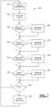
- FIG. 6is a flowchart of an embodiment of a method of operating the surgical system of FIG. 1 ;
- FIG. 7is a flowchart of an embodiment of a method of determining the presence of a vessel used in the method of FIG. 6 ;
- FIG. 8is a graph of the normalized values of the non-pulsatile (DC) component of a signal generated by a light sensor for tissue-only subjects of various tissue types;
- FIG. 9is a graph of the magnitudes of the non-pulsatile (DC) component of a signal generated by a light sensor for a tissue-only subject and a tissue/vessel assembly over a range of tissue thicknesses;
- FIG. 10is a graph of the magnitudes of the pulsatile (AC) component of a signal generated by a light sensor for a tissue-only subject and a tissue/vessel assembly over a range of tissue thicknesses;
- FIG. 11is a graph of the magnitudes of an Eigen-derived metric for tissue-only subjects and tissue/vessel assemblies over a range of tissue types for 660 nm or 910 nm wavelengths of emitted light;
- FIG. 12is a graph of the magnitudes of an autocorrelation metric for tissue-only subjects and tissue/vessel assemblies over a range of tissue types, the subjects, assemblies and tissue types being arranged in the same order as FIG. 11 ;
- FIG. 13is a graph of the magnitudes of a correlation coefficient metric for tissue-only subjects and tissue/vessel assemblies over a range of tissue types.
- FIG. 14is a graph of the magnitudes of a peak metric for tissue-only subjects and tissue/vessel assemblies over a range of tissue types, the subjects, assemblies and tissue types being arranged in the same order as FIG. 13 .
- a surgical systemincludes at least one light emitter, at least one light sensor, and a controller.
- the systemmay also include a surgical instrument as well.
- the systemmay be used to determine the presence of a vessel within a region proximate to a working end of the surgical instrument.
- the systemmay be used to determine the presence of a vessel within the region proximate to the working end of the surgical instrument regardless of the presence or the type of tissue surrounding the vessel.
- the embodiments of the system described belowperform determinations relative to the presence of the vessel within the targeted region based on the reflected light as determined by the light sensor. According to other embodiments, it may be possible to determine characteristics of the vessel, or to determine if other types of tissue (other than vessels) are present and to differentiate between the different tissue types.
- FIGS. 1 - 5illustrate an embodiment of such a surgical system 100 used to determine the presence of a vessel, V, disposed within a region 102 of tissue, T, proximate to a working end 104 of a surgical instrument 106 .
- the vessel Vmay be connected to other vessels with the region 102 of tissue T, and in addition, the vessel V may extend beyond the region 102 so as to be in fluid communication with other organs (e.g., the heart) also found in the body of the patient.
- other organse.g., the heart
- tissue Tappears in FIGS. 1 and 2 to surround fully the vessel V (in terms of both circumference and length) to a particular depth, this need not be the case in all instances where the system 100 is used.
- the tissue Tmay only partially surround the circumference of and/or only surround a section of the length of the vessel V, or the tissue T may overlie the vessel V in a very thin layer.
- the vessel Vmay be a blood vessel
- the tissue Tmay be connective tissue, adipose tissue and/or liver tissue.
- the surgical system 100includes at least one light emitter 110 (or simply the light emitter 110 ), at least one light sensor or detector 112 (or simply the light sensor 112 ), and a controller 114 coupled to the light emitter 110 and the light sensor 112 .
- the system 100also may include the surgical instrument 106 .
- the light emitter 110is disposed at the working end 104 of the surgical instrument 106 .
- the light sensor 112is also disposed at the working end 104 of the surgical instrument 106 .
- the light emitter 110 and the light sensor 112may be disposed in fixed relation to each other, for example on a single jaw of a two device, such as a thermal ligation device, or on a blunt end of a laparoscopic tool (e.g., a Kittner dissector or suction irrigator).
- a Kittner dissectore.g., a Kittner dissector or suction irrigator.
- the light emitter 110 and the light sensor 112may be disposed so that the spacing between the light emitter 110 and the light sensor 112 may be adjusted, for example by positioning the light emitter 110 at the end or tip of one of the jaws of a two-jaw device and the light sensor 112 at the end or tip of the other the jaws of the two-jaw device.
- the light emitter 110 and/or the light sensor 112may be disposed so that the angle between the light emitter 110 and/or light sensor 112 may be adjusted relative to a surface of the surgical instrument, for example by positioning the light emitter 110 and/or the light sensor 112 on a frame that is at a minimum adjustable about an axis.
- the light emitter 110is adapted to emit light of at least one wavelength.
- the light emitter 110may emit light having a wavelength of 660 nm. This may be achieved with a single element, or a plurality of elements (which elements may be arranged or configured into an array, for example, as explained in detail below).
- the light sensor 112is adapted to detect light at the at least one wavelength (e.g., 660 nm).
- the light sensor 112also may include one or more elements, which elements may be arranged or configured into an array.
- the light emitter 110may be configured to emit light of at least two different wavelengths, and the light sensor 112 may be configured to detect light at the at least two different wavelengths.
- the light emitter 110may emit and the light sensor 112 may detect light in the visible range and light in the near-infrared or infrared range.
- the light emitter 110may emit and the light sensor 112 may detect light at 660 nm and at 910 nm.
- Such an embodimentmay be used, for example, to ensure optimal penetration of blood vessel V and the surrounding tissue T under in vivo conditions.
- the light emitter 110may emit light of a plurality of different wavelengths (e.g., white light), and the light sensor 112 may be configured to detect light at one or more of the wavelengths.
- a plurality of different wavelengthse.g., white light
- light of a third wavelengthmay also be emitted and sensed. That is, if the method of detection is found to be sensitive to varying rates of blood flow in the vessel of interest, light at 810 nm (i.e., at the isobestic point) may be emitted and sensed to permit normalization of the results to limit or eliminate the effects of changes in blood flow rate.
- the individual light sensor 112is adapted to generate a signal comprising a first pulsatile component and a second non-pulsatile component.
- the first pulsatile componentmay be an alternating current (AC) component of the signal
- the second non-pulsatile componentmay be a direct current (DC) component.
- the pulsatile and non-pulsatile informationmay be generated for each element of the array, or at least for each element of the array that defines the at least one row of the array.
- a blood vesselmay be described as having a characteristic pulsation of approximately 60 pulses (or beats) per minute. While this may vary with the patient's age and condition, the range of pulsation is typically between 60 and 100 pulses (or beats) per minute.
- the light sensor 112will produce a signal (that is passed to the controller 114 ) with a particular AC waveform that corresponds to the movement of the blood through the vessel.
- the AC waveformcorresponds to the light reflected by the pulsatile blood flow within the vessel.
- the DC componentcorresponds principally to light reflected and scattered by the superficial tissues.
- the controller 114is coupled to the light sensor 112 , and includes a splitter 116 to separate the first pulsatile component from the second non-pulsatile component for the light sensor 112 .
- the controller 114also includes an analyzer 118 to determine at least the presence the vessel V within the region 102 proximate to the working end 104 of the surgical instrument 106 based on the pulsatile component.
- the controller 114may be coupled to an output device or indicator 130 (see FIG. 1 ), which may provide a visible, audible, tactile or other signal to the user of the instrument 106 .
- the splitter 116 and the analyzer 118may be defined by one or more electrical circuit components.
- one or more processorsmay be programmed to perform the actions of the splitter 116 and the analyzer 118 .
- the splitter 116 and the analyzer 118may be defined in part by electrical circuit components and in part by a processor programmed to perform the actions of the splitter 116 and the analyzer 118 .
- the splitter 116may include or be defined by the processor programmed to separate the first pulsatile component from the second non-pulsatile component.
- the analyzer 118may include or be defined by the processor programmed to determine the presence of (or to quantify the size of) the vessel V within the region 102 proximate to the working end 104 of the surgical instrument 106 based on the first pulsatile component.
- the instructions by which the processor is programmedmay be stored on a memory associated with the processor, which memory may include one or more tangible non-transitory computer readable memories, having computer executable instructions stored thereon, which when executed by the processor, may cause the one or more processors to carry out one or more actions.
- a method 200 of determining if the presence of a vessel V within a region 102 proximate to a working end 104 of a surgical instrument 106may be described. The method 200 may be carried out, for example, using a system 100 as described above in regard to FIG. 1 . As illustrated in FIG. 6 , the method 200 of operating the system 100 includes emitting light at a working end 104 of a surgical instrument 106 at block 202 and sensing light at the working end 104 of the surgical instrument 106 at one or more light sensors at block 204 . As explained above, the light emitted may include light of at least two different wavelengths, and the sensing step may thus include sensing light of at least two different wavelengths. According to one embodiment, the light used may have wavelengths of 660 nm and 910 nm. The method 200 continues at block 206 wherein a pulsatile component is separated from a non-pulsatile component of the signal generated by the light sensor.
- one or more parametersare determined based on the pulsatile component of the signal. For example, according to the illustrated embodiment, four different parameters may be determined. First, an Eigen-derived metric may be determined that quantifies the number of principal components present in the signal and determines the dominating signal in a complex signal. Second, an autocorrelation metric may be determined that is representative of the amplitude of the autocorrelation of the detector signal at the zero th lag. Third, a correlation coefficient metric may be determined that quantifies the correlation coefficient between different parts of the complex signal. Fourth, a peak metric may be determined that quantifies the number of signal peaks present in the complex signal.
- an Eigen-derived metricmay be determined that quantifies the number of principal components present in the signal and determines the dominating signal in a complex signal.
- an autocorrelation metricmay be determined that is representative of the amplitude of the autocorrelation of the detector signal at the zero th lag. Third, a correlation coefficient metric may be determined that quantifies the correlation coefficient between different parts of
- the parametersare interrogated to determine if the tissue present proximate to the emitter 110 /sensor 112 pair is a vessel or some other type of tissue.
- the interrogationmay simply be whether a vessel is present proximate the working end 104 of the instrument 106 . If there is a vessel present, the method 200 may proceed to block 212 , and activate one or more of the output devices 130 (e.g., a “vessel present” message displayed on the display 130 - 2 , for example).
- no output device 130is activated, although it will be recognized that an alternative output device could instead be activated or the output device 130 activated in block 212 could be activated, but a different indication provided to the user (e.g., a “no vessel” message displayed on the display 130 - 2 , for example).
- the specific method for carrying out the interrogationmay vary, but one embodiment of a method carried out at least as part of block 210 is illustrated in FIG. 7 .
- the method 220 of FIG. 7begins at block 222 with the parameters having been calculated, although the method could alternatively begin with the calculation of the parameters.
- the method 220relies on a series of comparisons being made between the parameters and thresholds for these parameters. These thresholds may be set using empirically derived data, for example, or theoretically determined. Typically, but not necessarily, the comparison includes determining if the parameter exceeds a predetermined threshold. If at least two of the four parameters suggest that a vessel is present after comparison with the respective thresholds, then the method 220 indicates that a vessel is present proximate to the working end 104 of the instrument 106 . If less than two of the parameters suggest that a vessel is present after comparison with the thresholds, then the method 220 provides no indication.
- the method 220uses a variable, or count, to store information regarding the number of comparisons that suggest a vessel is present. Each time the method 220 determines that one of the comparisons suggests that a vessel is present, the count is increased by one. If the comparison does not suggest that a vessel is present, then the count is not increased. In a final step, the count is compared to a further threshold, defined in accordance with the aforementioned criteria (i.e., two or more favorable comparisons indicating a vessel is present, less than two indicating only tissue).
- the general operation of the method 220may be varied in a number of ways. For example, a greater or lesser number of parameters may be included in the determination.
- the sensitivity of the comparisonneed not be an all-or-nothing comparison, but a range of values may be assigned based on the comparison of the calculated parameter and preexisting empirically or theoretically determined thresholds (or ranges). Further, the determination that a vessel is present could be based on at least three or more favorable comparisons, rather than at least two.
- a single variable to store the results of each comparisonmay be replaced by a variety of different options, such as the setting of a flag (e.g., 1/0 or T/F) for each of the comparisons, which flags are then read once all of the comparisons have been made.
- a flage.g., 1/0 or T/F
- Other embodimentsmay implement further alternatives in addition to or in substitution for these enumerated options.
- the countis initialized, for example to one, at block 224 .
- a first comparisonis made at block 226 of the Eigen-derived metric and its respective threshold. If the Eigen-derived metric exceeds the threshold, then the method 220 passes to block 228 and the count is increased by one. The method 220 then continues to block 230 . If the Eigen-derived metric does not exceed the threshold, then the method 220 passes directly to block 230 and the count remains the same.
- comparisonsare made for the other parameters at blocks 230 , 234 , 238 , and the count is increased at blocks 232 , 236 , 240 if the respective thresholds are exceeded. It will be recognized that while the comparisons made at blocks 226 , 230 , 234 involve determining if the parameter exceeds a threshold, the comparison made at block 238 is whether the parameter is lower than the respective threshold. It will also be recognized that the order of the comparisons made at blocks 226 , 230 , 234 , 238 may be made in any order or even simultaneously; the order illustrated was selected simply for ease of explanation and not by way of limitation.
- the method 220passes to block 242 , where the count is compared to its respective threshold. According to the embodiment illustrated, if the count is three or greater, the method 220 provides an indication to the user that a vessel is present (e.g., via any of the output devices 130 ). On the other hand, if the count does not exceed three at block 242 , the method 220 returns to block 222 .
- the DC profilemay be used to adapt the intensity emitted by the light emitter 110 .
- the intensity of the light emitter 110plays an important role in the accuracy of vessel detection (and potentially tissue type and/or vessel size determination). If the intensity of the light emitter 110 is set too low, too much light may be absorbed by the tissue. In such a circumstance, the sensor 112 may not be able to detect the pulsatile nature of the vessel, and it may be difficult to differentiate the vessel (e.g., artery) from the surrounding tissue (i.e., low resolution). Similar error may result if the intensity is set too high. Therefore, it would be desirable to provide a method and mechanism for selection of the intensity of the light emitter 110 that would limit the consequences of using an intensity that was either too low or too high for conditions.
- the amplitude of the DC componentmay be compared to a predetermined value, or range, and if the calculated amplitude is equal to the value or within the range, the intensity is unchanged. To the extent that the amplitude is not equal to the value or falls outside the range, then the intensity is changed, with the increase or decrease in intensity dependent upon on whether the amplitude is greater than the upper limit of the range or below the lower limit of the range, for example.
- the rangemay be empirically derived.
- the DC componentmay also be used to differentiate between different types of tissue, particularly where the tissue thickness is known. That is, different tissue types scatter light to different degrees. Consequently, the DC component may be determined when either different wavelengths or different intensities of light are used, and then the DC component may be compared to a predetermined value or range to determine the tissue type present.
- a combination of normalized DC components in at least two wavelengthse.g., 660 nm and 910 nm
- the ratio of the normalized DC components at the two wavelengthsmay be compared against a look-up table prepared using empirically derived values.
- a combination of multiple intensities of light of a single wavelengthis used, and the rate of change of the DC component with increase light intensity is determined.
- FIG. 8provides one set of normalized DC components that may be used in performing this determination, which figure is discussed in greater detail below. Even if the specific tissue type cannot be determined, the tissue type can be classified as minimally scattering (like liver or kidney tissue) or highly scattering (like muscle or adipose tissue), and such a determination or differentiation may be performed with a single wavelength (e.g., 660 nm) through comparison of the normalized DC component and the LED intensity values.
- a single wavelengthe.g., 660 nm
- the DC componentmay be used to determine the thickness of a known type of tissue. That is, for a known tissue type and constant intensity, the thickness of the tissue present between the emitter/sensor and a vessel of interest may be calculated based on the DC component.
- the emitter 110 and the sensor 112are described as disposed at the working end 104 of the surgical instrument 106 , it will be recognized that not all of the components that define the emitter 110 and the sensor 112 need be disposed at the working end of the instrument 106 . That is, the emitter 110 may comprise a light emitting diode, and that component may be disposed at the working end 104 . Alternatively, the emitter 110 may include a length of optical fiber and a light source, the source disposed remotely from the working end 104 and the fiber having a first end optically coupled to the source and a second end disposed at the working end 104 .
- an emitter 110would still be described as disposed at the working end 104 because the light is emitted in the direction of the tissue at the working end 104 of the instrument 106 .
- a similar arrangementmay be described for the sensor 112 wherein an optical fiber has a first end disposed facing the tissue and a second end optically coupled to other components that collectively define the sensor 112 .
- the light emitter 110 and light sensor 112are disposed generally facing in a common direction (i.e., the direction of the tissue sample of interest). This does not require the emitter 110 and the sensor 112 to be generally disposed in a common plane (see the embodiment of FIGS. 4 and 5 ), although this is preferred.
- the emitter 110 and sensor 112may be formed integrally (i.e., as one piece) with jaws 180 , 182 of a surgical instrument 106 , although other options are possible, as discussed above. In this manner, light emitted by the emitter 110 and scattered by the tissue of interest may be captured by the light sensor 112 .
- the spacing between the emitter 110 and the sensor 112may influence the light received by the sensor 112 .
- an ensemble of independent photonsreturn to the surface and reach the sensor 112 .
- Some of the detected photonstravel a short distance from the plane of the emitter and detector and exit at the site of the sensor 112 , while some photons travel farther into the tissue before exiting at the surface without being absorbed (photons that are absorbed cannot contribute to the photocurrent).
- Path length distributions and the penetration depth of photons that reach the sensor 112vary as a function of emitter-sensor separation, with maximum effective photon depth penetration values several times greater than the physical emitter-sensor separation. For example, it has been determined that a spacing between the emitter 110 and the sensor 112 of 5 mm may permit detection of vessels from 0 mm to 12 mm from the surface of the tissue.
- adjusting the angle of the emitter 110 and/or sensor 112may provide a similar effect. That is, similar to the way in which a change in the linear distance between the emitter 110 and the sensor 112 allows for the sampling of a different proportion of long-traveling photons at the surface sensor 112 , a variation in angle of the emitter 110 and/or sensor 112 can change the depth and the distance to which the photons travel before being sampled by the sensor 112 . As a consequence, changes in the angle of the emitter and/or sensor are believed to permit the depth at which vessels can be detected by the instrument 106 to be varied.
- the emitter 110 and sensor 112may be disposed so as to be mounted in a fixed relationship to each other, or a moveable or adjustable relationship.
- FIG. 2illustrates an embodiment wherein emitter 110 and sensor 112 are at a fixed spacing relative to each other, in that they are both mounted in a first jaw 180 of the instrument 106 . Such an embodiment would permit the user to be confident that the vessels detected are within 12 mm from the working end 104 of the instrument 106 .
- the emitter 110 and the sensor 112 of the embodiment of FIG. 2also have a fixed angular relationship between the emitter 110 and the sensor 112 relative to a surface of the surgical instrument 106 .
- FIG. 3has the sensor 112 mounted in a first jaw 180 of the instrument 106 and the emitter 110 mounted in a second jaw 182 of the tool 106 .
- Such an embodimentwould permit the user to vary the depth of detection simply by varying the distance between the jaws 180 , 182 of the instrument 106 : with the jaws 180 , 182 closed, the user may probe for shallow vessels (i.e., vessels disposed within 12 mm of the tissue surface), while with the jaws 180 , 182 open, the user may probe for deeper vessels (i.e., vessels disposed greater than 12 mm below the tissue surface).
- shallow vesselsi.e., vessels disposed within 12 mm of the tissue surface
- the jaws 180 , 182 openthe user may probe for deeper vessels (i.e., vessels disposed greater than 12 mm below the tissue surface).
- the control structure for operating the jaws 180 , 182may include a mechanism for modifying the distance between the jaws 180 , 182 in a controlled fashion (e.g., in discrete increments) so that the user can determine the jaw spacing (and thus the detection depth) without visualization of the jaws 180 , 182 .
- the system 100may provide a mechanism for determining the distance between the jaws 180 , 182 , which may be used in conjunction with the control structure or separate from it.
- the distance between the jaws 180 , 182may be measured using a potentiometer, whereby a moveable object is connected directly to a rotational shaft or slider of the potentiometer, and a reference voltage is applied across the two outer fixed connections forming the resistive element.
- a potentiometerwhereby a moveable object is connected directly to a rotational shaft or slider of the potentiometer, and a reference voltage is applied across the two outer fixed connections forming the resistive element.
- This configurationproduces a potential or voltage divider type circuit output, which is proportional to the shaft position.
- an absolute position rotary encodercould be used to determine the angle between the jaws 180 , 182 of the instrument 106 when they are not in a parallel configuration
- FIGS. 4 and 5A further alternative embodiment is illustrated in FIGS. 4 and 5 .
- the emitter 110 and the sensor 112are each attached to a separate frame 300 , 302 .
- the frames 300 , 302are each rotatable about an axis of rotation 304 , 306 ; while the axes of rotation 304 , 306 are parallel to each other, as best seen in FIG. 5 , this need not be the case according to all embodiments.
- the frames 300 , 302may be pivotal about more than one axis.
- shafts 308 , 310are provided that connect the frames 300 , 302 to a rotary actuator, such as a bi-directional motor 312 , 314 .
- the motor 312 , 314may be connected to a connector such that each motor 312 , 314 (and thus each frame 300 , 302 ) is adjustable independently, or such that the motors 312 , 314 may be adjusted together.
- a potentiometercould be included and used to determine the change in angle of either the emitter 110 or sensor 112 during operation.
- the light emitter 110may include one or more elements. According to such an embodiment, all of the elements may be adapted to emit light at a particular wavelength (e.g., 660 nm), or certain elements may emit light at different wavelengths than other elements. It is believed that a system with multiple light emitters 110 and/or multiple sensors 112 will increase the signal-to-noise ratio and the spatial resolution compared to a system containing a single emitter 110 and sensor 112 .
- the diodesmay be arranged in the form of a one-dimensional, two-dimensional or three-dimensional array.
- An example of a one-dimensional arraymay include disposing the diodes along a line in a single plane, while an example of a two-dimensional array may include disposing the diodes in a plurality of rows and columns in a single plane. Further example of a two-dimensional array may include disposing the diodes along a line on or in a curved surface.
- a three-dimensional arraymay include diodes disposed in more than one plane, such as in a plurality of rows and columns on or in a curved surface.
- the light sensor 112also may include one or more individual elements. As was the case with the light emitter 110 , the elements of the light sensor 112 may be arranged in an array, and the discussion about the arrays above applied with equal force here.
- the light sensor 112may include a mechanism for physically excluding photons reaching the sensor 112 from a range of angles.
- This mechanismcan consist of a mask or grated layer to physically filter any photons that are not reaching the sensor 112 at a nearly perpendicular angle. It has been observed that the mean depth penetration of the photons leaving the emitter 110 is equal to just over half the distance of source-detector separation ( ⁇ 2.5 mm penetration for our 5 mm spacing). This mechanism will increase the proportion of long-traveling and deep penetrating photons that are received by the sensor 112 thus increasing the depth at which the vessels can be detected by the instrument.
- the system 100may include hardware and software in addition to the emitter 110 , sensor 112 , and controller 114 .
- a drive controllermay be provided to control the switching of the individual emitter elements.
- a multiplexermay be provided where more than one sensor 112 is included, which multiplexer may be coupled to the sensors 112 and to an amplifier.
- the controller 114may include filters and analog-to-digital conversion as may be required.
- a variety of output devicesmay be used. As illustrated in FIG. 1 , a light emitting diode 130 - 1 may be attached to or incorporated into the associated surgical instrument 106 , and may even be disposed at the working end 104 of the instrument 106 . Alternatively or in addition, an alert may be displayed on a video monitor 130 - 2 being used for the surgery, or may cause an image on the monitor to change color or to flash, change size or otherwise change appearance.
- the indicator 130may be in the form of or include a speaker 130 - 3 that provides an auditory alarm.
- the indicator 130also may be in the form of or may incorporate a safety lockout 130 - 4 associated with the surgical instrument 106 that interrupts use of the instrument 106 .
- the lockoutcould prevent ligation or cauterization where the surgical instrument 106 is a thermal ligature device.
- the indicator 130also may be in the form of a haptic feedback system, such as a vibrator 130 - 5 , which may be attached to or formed integral with a handle or handpiece of the surgical instrument 106 to provide a tactile indication or alarm. Various combinations of these particular forms of the indicator 130 may also be used.
- the surgical system 100may also include the surgical instrument 106 with the working end 104 , to which the light emitter 110 and light sensor 112 are attached (in the alternative, removably/reversibly or permanently/irreversibly).
- the light emitter 110 and the light sensor 112may instead be formed integrally (i.e., as one piece) with the surgical instrument 106 . It is further possible that the light emitter 110 and light sensor 112 be attached to a separate instrument or tool that is used in conjunction with the surgical instrument or tool 106 , such as a blunt end of a dissection tool.
- the surgical instrument 106may be a thermal ligature device in one embodiment.
- the surgical instrument 106may simply be a grasper or grasping forceps having opposing jaws.
- the surgical instrumentmay be other surgical instruments such as surgical staplers, clip appliers, and robotic surgical systems, for example.
- the surgical instrumentmay have no other function that to carry the light emitters/light sensors and to place them within a surgical field. The illustration of a single embodiment is not intended to preclude the use of the system 100 with other surgical instruments or tools 106 .
- a first set of experimentsused an excised porcine carotid artery covered with porcine adipose or liver tissues of variable thickness.
- a submersible DC pumpwas used to simulate the pulsatile flow of fluid found in such blood vessels.
- the pumpwas capable of operation at between 40 and 80 cycles per minute, and could provide a flow rate that could be set to a particular value.
- the fluid usedwas porcine whole blood to which heparin had been added and that was maintained at an elevated temperature to maintain physiological viscosity.
- the bloodwas pumped at 60 cycles per minute and at a flow rate of 500 mL per minute.
- a light emitterwas disposed on a common surface with a light sensor and disposed opposite the various tissue-only assemblies.
- the light emitterincluded a single light emitting diode that emitted light at 660 nm and 910 nm.
- the light sensorwas a single element capable of detecting light at 660 nm and 910 nm.
- the results of the experimentsare plotted in FIG. 8 , where each bar represents the average normalized DC value for that given tissue type over multiple thicknesses (ranging from 2 mm to 12 mm). The standard deviation is given for samples of the same given tissue type. Highly scattering tissues (i.e., adipose and muscle) result in a higher normalized DC value than those that have lower scattering properties (i.e. liver and lung), thus allowing for the differentiation between tissue type using a combination of the LED intensity and DC output.
- a second set of experimentsinvolved a light emitter disposed on a common surface with a light sensor and disposed opposite the liver tissue-only subject or the liver tissue/excised porcine carotid artery assembly.
- the light emitterincluded a single light emitting diode that emitted light at 660 nm and 910 nm.
- the light sensorwas a single element capable of detecting light at 660 nm and 910 nm.
- the results of the experimentsare plotted in FIGS. 9 and 10 , with the non-pulsatile component illustrated in FIG. 9 and the pulsatile component illustrated in FIG. 10 .
- FIG. 9it will be recognized that there is very little variation in the non-pulsatile component of signal representative of the reflected light received by the sensor 112 between the liver tissue-only subject (left-hand element of each pair) and the liver tissue/porcine artery assembly (right-hand element of each pair). This is generally the case regardless of the thickness of liver tissue used in the subject or assembly.
- FIG. 10there was considerable difference in the pulsatile component between the liver tissue-only subject and the liver tissue/porcine artery assembly, with the more significant differences seen at lesser thicknesses of tissue used.
- a third set of experimentsused different types of tissue (i.e., adipose, liver, kidney and muscle) and excised porcine arteries.
- the light emitter/sensorwas used with tissue-only subjects and with assemblies including a porcine artery covered with tissue.
- the assemblieswere prepared using porcine arteries ranging in diameter from 2.5 mm to 6 mm, and covered in tissue ranging in thickness from 2 mm to 15 mm.
- a light emitterwas disposed on a common surface with a light sensor and disposed opposite the tissue-only subject or tissue/artery assembly.
- the light emitterincluded a single light emitting diode that emitted light at 660 nm and 910 nm.
- the light sensorwas a single element capable of detecting light at 660 nm and 910 nm.
- Eigen-derived, Autocorrelation, Correlation Coefficient, and Peakwere calculated for each pair of test runs (tissue-only, tissue/artery assembly). The results of the experiments are plotted in FIGS. 11 - 14 , with FIG. 11 including the results for the Eigen value, FIG. 12 including the results for the Autocorrelation, FIG.
- FIGS. 11 and 13including the results for the Correlation Coefficient
- FIG. 14including the results for the Peak.
- the identification of the results relative to tissue type and subject/assemblyare found in each of FIGS. 11 and 13 , with FIGS. 12 and 14 following a similar order as to tissue type and subject/assembly.
- the Eigen-derived valueexceeded a particular threshold (e.g., 60 ) for the tissue/artery assemblies, while the parameter did not exceed the threshold for the tissue-only sample.
- the autocorrelation parameterexceeded a threshold of approximately 1000 for the tissue artery/assemblies, while the parameter did not exceed the threshold for the tissue-only sample.
- the valueswere generally positive for the tissue/artery assemblies, and negative for tissue-only samples (i.e., a threshold of zero).
Landscapes
- Health & Medical Sciences (AREA)
- Life Sciences & Earth Sciences (AREA)
- Surgery (AREA)
- Veterinary Medicine (AREA)
- Public Health (AREA)
- General Health & Medical Sciences (AREA)
- Animal Behavior & Ethology (AREA)
- Engineering & Computer Science (AREA)
- Biomedical Technology (AREA)
- Heart & Thoracic Surgery (AREA)
- Medical Informatics (AREA)
- Molecular Biology (AREA)
- Pathology (AREA)
- Biophysics (AREA)
- Physics & Mathematics (AREA)
- Cardiology (AREA)
- Vascular Medicine (AREA)
- Dentistry (AREA)
- Oral & Maxillofacial Surgery (AREA)
- Physiology (AREA)
- Ophthalmology & Optometry (AREA)
- Nuclear Medicine, Radiotherapy & Molecular Imaging (AREA)
- Investigating Or Analysing Materials By Optical Means (AREA)
- Surgical Instruments (AREA)
- Measurement Of The Respiration, Hearing Ability, Form, And Blood Characteristics Of Living Organisms (AREA)
Abstract
Description
Claims (19)
Priority Applications (1)
| Application Number | Priority Date | Filing Date | Title |
|---|---|---|---|
| US16/077,041US11992235B2 (en) | 2016-02-12 | 2017-02-10 | System to differentiate and identify types of tissue within a region proximate to a working end of a surgical instrument |
Applications Claiming Priority (3)
| Application Number | Priority Date | Filing Date | Title |
|---|---|---|---|
| US201662294996P | 2016-02-12 | 2016-02-12 | |
| US16/077,041US11992235B2 (en) | 2016-02-12 | 2017-02-10 | System to differentiate and identify types of tissue within a region proximate to a working end of a surgical instrument |
| PCT/US2017/017436WO2017139624A1 (en) | 2016-02-12 | 2017-02-10 | Determination of the presence of a vessel within a region proximate to a working end of a surgical instrument |
Related Parent Applications (1)
| Application Number | Title | Priority Date | Filing Date |
|---|---|---|---|
| PCT/US2017/017436A-371-Of-InternationalWO2017139624A1 (en) | 2016-02-12 | 2017-02-10 | Determination of the presence of a vessel within a region proximate to a working end of a surgical instrument |
Related Child Applications (1)
| Application Number | Title | Priority Date | Filing Date |
|---|---|---|---|
| US18/670,522ContinuationUS20240307084A1 (en) | 2016-02-12 | 2024-05-21 | System and Method for Determining Tissue Characteristics |
Publications (2)
| Publication Number | Publication Date |
|---|---|
| US20190046220A1 US20190046220A1 (en) | 2019-02-14 |
| US11992235B2true US11992235B2 (en) | 2024-05-28 |
Family
ID=58213328
Family Applications (2)
| Application Number | Title | Priority Date | Filing Date |
|---|---|---|---|
| US16/077,041Active2037-12-21US11992235B2 (en) | 2016-02-12 | 2017-02-10 | System to differentiate and identify types of tissue within a region proximate to a working end of a surgical instrument |
| US18/670,522PendingUS20240307084A1 (en) | 2016-02-12 | 2024-05-21 | System and Method for Determining Tissue Characteristics |
Family Applications After (1)
| Application Number | Title | Priority Date | Filing Date |
|---|---|---|---|
| US18/670,522PendingUS20240307084A1 (en) | 2016-02-12 | 2024-05-21 | System and Method for Determining Tissue Characteristics |
Country Status (5)
| Country | Link |
|---|---|
| US (2) | US11992235B2 (en) |
| EP (1) | EP3413792B1 (en) |
| JP (1) | JP6951348B2 (en) |
| ES (1) | ES2969019T3 (en) |
| WO (1) | WO2017139624A1 (en) |
Families Citing this family (18)
| Publication number | Priority date | Publication date | Assignee | Title |
|---|---|---|---|---|
| US11399898B2 (en) | 2012-03-06 | 2022-08-02 | Briteseed, Llc | User interface for a system used to determine tissue or artifact characteristics |
| WO2015148504A1 (en) | 2014-03-25 | 2015-10-01 | Briteseed Llc | Vessel detector and method of detection |
| EP3545830B1 (en) | 2015-02-19 | 2022-01-05 | Briteseed, LLC | System for determining vessel edge |
| ES2892526T3 (en) | 2015-02-19 | 2022-02-04 | Briteseed Llc | System for determining the size of a vessel by light absorption |
| WO2017062720A1 (en) | 2015-10-08 | 2017-04-13 | Briteseed Llc | System and method for determining vessel size |
| EP4026489B1 (en) | 2016-08-30 | 2025-07-30 | Briteseed, LLC | System for determining vessel size with angular distortion compensation |
| US11723600B2 (en) | 2017-09-05 | 2023-08-15 | Briteseed, Llc | System and method used to determine tissue and/or artifact characteristics |
| US11696777B2 (en) | 2017-12-22 | 2023-07-11 | Briteseed, Llc | Compact system used to determine tissue or artifact characteristics |
| EP3740117A1 (en)* | 2018-01-18 | 2020-11-25 | Briteseed, LLC | System and method for detecting and/or determining characteristics of tissue |
| JP7394117B2 (en) | 2018-08-20 | 2023-12-07 | ブライトシード・エルエルシー | A stimulation system used to detect or identify tissue or artifacts |
| EP3902471B1 (en) | 2018-12-30 | 2024-09-18 | Briteseed, LLC | A system used to detect or differentiate tissue or an artifact |
| US11553956B2 (en)* | 2019-04-04 | 2023-01-17 | Cilag Gmbh International | Surgical devices with visual indicators |
| US20230056943A1 (en)* | 2019-12-13 | 2023-02-23 | Dinesh Vyas | Stapler apparatus and methods for use |
| US12290258B2 (en) | 2019-12-13 | 2025-05-06 | Dinesh Vyas | Stapler apparatus and methods for use |
| US11925347B2 (en) | 2019-12-13 | 2024-03-12 | Dinesh Vyas | Stapler apparatus and methods for use |
| WO2022011063A1 (en) | 2020-07-08 | 2022-01-13 | Briteseed, Llc | System and method used to detect or differentiate tissue or an artifact |
| JP2025519340A (en) | 2022-05-11 | 2025-06-26 | ブライトシード・エルエルシー | Graphical interface for the system used to determine tissue properties |
| WO2025064423A1 (en) | 2023-09-21 | 2025-03-27 | Briteseed, Llc | System and method for excitation and detection of fluorescent indicators |
Citations (98)
| Publication number | Priority date | Publication date | Assignee | Title |
|---|---|---|---|---|
| GB1445678A (en) | 1972-06-30 | 1976-08-11 | Secr Social Service Brit | Clinical device comprising a catheter |
| US5129400A (en) | 1989-04-10 | 1992-07-14 | Kowa Company Ltd. | Ophthalmological measurement method and apparatus |
| US5259761A (en) | 1990-08-06 | 1993-11-09 | Jenifer M. Schnettler | Tooth vitality probe and process |
| JPH105245A (en) | 1996-06-25 | 1998-01-13 | Shimadzu Corp | Surgical operation support device |
| US5762609A (en) | 1992-09-14 | 1998-06-09 | Sextant Medical Corporation | Device and method for analysis of surgical tissue interventions |
| US5769791A (en) | 1992-09-14 | 1998-06-23 | Sextant Medical Corporation | Tissue interrogating device and methods |
| WO1998027865A1 (en) | 1996-12-23 | 1998-07-02 | Benaron David A | Device and method for classification of tissue |
| US6178340B1 (en) | 1998-08-24 | 2001-01-23 | Eduardo Svetliza | Three-dimensional infrared imager for subcutaneous puncture and study of vascular network |
| WO2001060427A2 (en) | 2000-02-15 | 2001-08-23 | Transvascular, Inc. | Sterility barriers for insertion of non-sterile apparatus into catheters or other medical devices |
| US6374128B1 (en) | 1998-11-20 | 2002-04-16 | Fuji Photo Film Co., Ltd. | Blood vessel imaging system |
| US20020169381A1 (en) | 2000-04-18 | 2002-11-14 | Asada Haruhiko H. | Photoplethysmograph signal-to-noise line enhancement |
| JP2003019116A (en) | 2001-07-05 | 2003-01-21 | Canon Inc | Ophthalmic measurement device |
| US20030036685A1 (en) | 2000-04-27 | 2003-02-20 | Vitalsines International, Inc. | Physiological signal monitoring system |
| US20030036751A1 (en) | 2001-05-30 | 2003-02-20 | Anderson R. Rox | Apparatus and method for laser treatment with spectroscopic feedback |
| WO2003039326A2 (en) | 2001-11-07 | 2003-05-15 | Mills Alexander K | Method for noninvasive continuous determination of physiologic characteristics |
| US6569104B2 (en) | 1998-07-16 | 2003-05-27 | Canon Kabushiki Kaisha | Blood vessel detecting apparatus |
| US20030120306A1 (en) | 2000-04-21 | 2003-06-26 | Vascular Control System | Method and apparatus for the detection and occlusion of blood vessels |
| WO2004030527A1 (en) | 2002-10-03 | 2004-04-15 | Etview Ltd. | Tube for inspecting internal organs of a body |
| US20040111085A1 (en) | 1999-07-20 | 2004-06-10 | Singh Ajoy Inder | Method and apparatus for arterial ablation |
| US20050143662A1 (en) | 2000-05-03 | 2005-06-30 | Rocky Mountain Biosystems, Inc. | Optical imaging of subsurface anatomical structures and biomolecules |
| US6922577B2 (en) | 2002-02-15 | 2005-07-26 | Denso Corporation | Optical measuring device having d.c. component elimination |
| US20050180620A1 (en) | 2002-05-09 | 2005-08-18 | Kiyoaki Takiguchi | Method of detecting biological pattern, biological pattern detector, method of biological certificate and biological certificate apparatus |
| WO2005091978A2 (en) | 2004-03-22 | 2005-10-06 | Vanderbilt University | System and methods for surgical instrument disablement via image-guided position feedback |
| US20060020212A1 (en) | 2004-07-26 | 2006-01-26 | Tianning Xu | Portable vein locating device |
| US7006861B2 (en) | 1995-06-07 | 2006-02-28 | Board Of Trustees Of The University Of Arkansas | Method and apparatus for detecting electro-magnetic reflection from biological tissue |
| US20060052850A1 (en) | 2004-09-03 | 2006-03-09 | Darmos George P | Hybrid cannula/electrode medical device and method |
| US20060100523A1 (en) | 2004-11-08 | 2006-05-11 | Ogle John S | Noninvasive blood vessel location device and method |
| US20060155194A1 (en) | 2005-01-13 | 2006-07-13 | Ronald Marcotte | Method for detecting occlusions and leakages in subcutaneous blood vessels |
| US7112201B2 (en) | 2001-10-22 | 2006-09-26 | Surgrx Inc. | Electrosurgical instrument and method of use |
| US20070038118A1 (en) | 2005-08-10 | 2007-02-15 | Depue Marshall Thomas | Subcutaneous tissue imager |
| US7235072B2 (en) | 2003-02-20 | 2007-06-26 | Sherwood Services Ag | Motion detector for controlling electrosurgical output |
| WO2008082992A1 (en) | 2007-01-04 | 2008-07-10 | Boston Scientific Limited | Locating and occluding vessels |
| US20090018414A1 (en) | 2007-03-23 | 2009-01-15 | Mehrdad Toofan | Subcutanous Blood Vessels Imaging System |
| US20090054908A1 (en) | 2005-04-15 | 2009-02-26 | Jason Matthew Zand | Surgical instruments with sensors for detecting tissue properties, and system using such instruments |
| US7515265B2 (en) | 2005-04-28 | 2009-04-07 | Research Foundation Of The City University Of New York | Imaging systems and methods to improve backscattering imaging using circular polarization memory |
| WO2009144653A2 (en) | 2008-05-30 | 2009-12-03 | Koninklijke Philips Electronics N.V. | Needle with integrated photon detector |
| JP2010081972A (en) | 2008-09-29 | 2010-04-15 | Olympus Corp | Surgical treatment system and surgical treatment instrument |
| US7740591B1 (en) | 2003-12-01 | 2010-06-22 | Ric Investments, Llc | Apparatus and method for monitoring pressure related changes in the extra-thoracic arterial circulatory system |
| US7749217B2 (en) | 2002-05-06 | 2010-07-06 | Covidien Ag | Method and system for optically detecting blood and controlling a generator during electrosurgery |
| US20100222786A1 (en) | 2003-02-21 | 2010-09-02 | Kassab Ghassan S | Devices, systems, and methods for removing targeted lesions from vessels |
| US20100249763A1 (en) | 2007-05-14 | 2010-09-30 | The Regents Of The University Of Colorado | Laser Tissue Fusion of Septal Membranes |
| US20110021925A1 (en) | 2006-06-29 | 2011-01-27 | Fred Wood | Mounted vein contrast enchancer |
| WO2011013132A1 (en) | 2009-07-30 | 2011-02-03 | Oxitone Medical Ltd. | Photoplethysmography device and method |
| US7904138B2 (en) | 2006-01-10 | 2011-03-08 | Accuvein Llc | Micro vein enhancer |
| US7983738B2 (en) | 2006-01-10 | 2011-07-19 | Accuvein, Llc | Three dimensional imaging of veins |
| EP2353534A1 (en) | 2010-01-29 | 2011-08-10 | Tyco Healthcare Group, LP | Surgical forceps capable of adjusting seal plate width based on vessel size |
| US20110245685A1 (en) | 2010-04-02 | 2011-10-06 | Seiko Epson Corporation | Blood vessel display device |
| US8058771B2 (en) | 2008-08-06 | 2011-11-15 | Ethicon Endo-Surgery, Inc. | Ultrasonic device for cutting and coagulating with stepped output |
| US20120016362A1 (en) | 2002-04-25 | 2012-01-19 | Tyco Healthcare Group Lp | Surgical Instrument Including MEMS Devices |
| US8118206B2 (en) | 2008-03-15 | 2012-02-21 | Surgisense Corporation | Sensing adjunct for surgical staplers |
| US20120046555A1 (en) | 2009-03-13 | 2012-02-23 | Tetsuro Takamatsu | Body tissue imaging using raman scattering light |
| US8123745B2 (en) | 2007-06-29 | 2012-02-28 | Biosense Webster, Inc. | Ablation catheter with optically transparent, electrically conductive tip |
| US20120105812A1 (en)* | 2010-08-12 | 2012-05-03 | Octrolix Bv | Scanning Laser Projector |
| US20120143182A1 (en) | 2010-12-07 | 2012-06-07 | Immersion Corporation | Electrosurgical sealing tool having haptic feedback |
| US20120172842A1 (en) | 2010-12-30 | 2012-07-05 | Ran Sela | Method of assembling a positioning sensor and associated wiring on a medical tool |
| US20120179011A1 (en) | 2007-06-12 | 2012-07-12 | Jim Moon | Optical sensors for use in vital sign monitoring |
| JP2012152493A (en) | 2011-01-28 | 2012-08-16 | Seiko Epson Corp | Pulse wave signal measuring device and program |
| US8255040B2 (en) | 2006-06-29 | 2012-08-28 | Accuvein, Llc | Micro vein enhancer |
| US20120296205A1 (en) | 2011-05-16 | 2012-11-22 | Tyco Healthcare Group Lp | Optical Recognition of Tissue and Vessels |
| US8380291B2 (en) | 2006-06-29 | 2013-02-19 | Accuvein Inc. | Scanned laser vein contrast enhancer |
| US8417306B2 (en) | 2007-02-16 | 2013-04-09 | Mespere Lifesciences Inc. | Method and device for measuring parameters of cardiac function |
| US8463364B2 (en) | 2009-07-22 | 2013-06-11 | Accuvein Inc. | Vein scanner |
| US8467857B2 (en) | 2008-04-11 | 2013-06-18 | Seoul National University R & Db Foundation | Hypodermic vein detection imaging apparatus based on infrared optical system |
| US8483805B2 (en) | 2011-01-24 | 2013-07-09 | Act Medical Service Co., Ltd. | Vessel pulse wave measurement system conducting vessel pulse wave measurement by obtaining pulsation waveform of blood vessel |
| US8483819B2 (en) | 2009-12-17 | 2013-07-09 | Korea Advanced Institute Of Science And Technology | Modulator of vascular permeability using pulsed laser and method for modulating vascular permeability using the same |
| US8489178B2 (en) | 2006-06-29 | 2013-07-16 | Accuvein Inc. | Enhanced laser vein contrast enhancer with projection of analyzed vein data |
| US20130226013A1 (en) | 2007-11-09 | 2013-08-29 | Western Clinical Engineering, Ltd. | Method for Measuring Tourniquet Limb Occlusion Pressure |
| WO2013134411A1 (en) | 2012-03-06 | 2013-09-12 | Briteseed, Llc | Surgical tool with integrated sensor |
| US20130267874A1 (en) | 2012-04-09 | 2013-10-10 | Amy L. Marcotte | Surgical instrument with nerve detection feature |
| US8586924B2 (en) | 2010-09-13 | 2013-11-19 | Lawrence Livermore National Security, Llc | Enhancement of the visibility of objects located below the surface of a scattering medium |
| US20140016132A1 (en)* | 2011-03-25 | 2014-01-16 | Hutchinson Technology Incorporated | Systems and Methods for Measuring Oxygenation |
| US8649848B2 (en) | 2006-03-28 | 2014-02-11 | The United States Of America, As Represented By The Secretary Of The Air Force | Synchronization of illumination source and sensor for improved visualization of subcutaneous structures |
| US8649568B2 (en) | 2007-07-20 | 2014-02-11 | Sony Corporation | Vein authentication apparatus, imaging apparatus for vein authentication, and vein illuminating method |
| US8682418B2 (en) | 2011-02-01 | 2014-03-25 | Olympus Medical Systems Corp. | Diagnosis supporting apparatus and control method of diagnosis supporting apparatus |
| US20140086459A1 (en) | 2012-09-27 | 2014-03-27 | Truelight Corporation | Biometric Authentication Device and Method |
| US20140100455A1 (en) | 2006-01-10 | 2014-04-10 | Ron Goldman | Scanned Laser Vein Contrast Enhancer |
| JP2014087387A (en) | 2012-10-29 | 2014-05-15 | Yamaguchi Univ | Pulse measuring apparatus, and safety confirmation report system using the same |
| US20140155753A1 (en) | 2011-08-01 | 2014-06-05 | James E. McGuire, Jr. | Disposable light source for enhanced visualization of subcutaneous structures |
| JP2014132992A (en) | 2013-01-10 | 2014-07-24 | Mitsubishi Electric Corp | Blood vessel detecting apparatus |
| US8792967B2 (en) | 2004-12-28 | 2014-07-29 | Sony Corporation | Bioimaging apparatus |
| US20140236019A1 (en) | 2011-08-14 | 2014-08-21 | Uzi Rahum | Device, system and method for blood vessel imaging and marking |
| US20140276088A1 (en) | 2013-03-15 | 2014-09-18 | Steven H. Drucker | Illumination Optics for a Visible or Infrared Based Apparatus and Methods for Viewing or Imaging Blood Vessels |
| US20140303437A1 (en)* | 2011-12-28 | 2014-10-09 | Olympus Corporation | Stereo-endoscope device, stereo-endoscope system, and stereo-endoscope robot |
| US20140313482A1 (en) | 2009-11-30 | 2014-10-23 | The Board Of Trustees Of The University Of Illinois | Assessment of microvascular circulation |
| WO2014194317A1 (en) | 2013-05-31 | 2014-12-04 | Covidien Lp | Surgical device with an end-effector assembly and system for monitoring of tissue during a surgical procedure |
| US20150011896A1 (en) | 2012-01-19 | 2015-01-08 | Technion Research & Development Foundation Limited | Vessel imaging system and method |
| US20150051460A1 (en) | 2012-04-04 | 2015-02-19 | Noopur Saxena | System and method for locating blood vessels and analysing blood |
| US20150057511A1 (en)* | 2012-03-28 | 2015-02-26 | Wayne State University | Sensor and method for continuous health monitoring |
| US20150223694A1 (en)* | 2012-08-31 | 2015-08-13 | Hitachi Medical Corporation | Biophotonic Measurement Apparatus and Biophotonic Measurement Method Using Same |
| US9114226B1 (en) | 2009-07-08 | 2015-08-25 | Vioptix, Inc. | Devices and monitoring systems for locating a blood vessel |
| WO2015148504A1 (en) | 2014-03-25 | 2015-10-01 | Briteseed Llc | Vessel detector and method of detection |
| WO2016134327A1 (en) | 2015-02-19 | 2016-08-25 | Briteseed Llc | System for determining vessel size using light absorption |
| WO2016134330A1 (en) | 2015-02-19 | 2016-08-25 | Briteseed Llc | System and method for determining vessel size and/or edge |
| US9526921B2 (en) | 2010-11-05 | 2016-12-27 | Ethicon Endo-Surgery, Llc | User feedback through end effector of surgical instrument |
| WO2017062720A1 (en) | 2015-10-08 | 2017-04-13 | Briteseed Llc | System and method for determining vessel size |
| WO2017139642A1 (en) | 2016-02-13 | 2017-08-17 | Briteseed Llc | System and method for electrical coupling of a surgical system or part thereof |
| US20170367580A1 (en)* | 2014-10-29 | 2017-12-28 | Spectral Md, Inc. | Reflective mode multi-spectral time-resolved optical imaging methods and apparatuses for tissue classification |
| WO2018044722A1 (en) | 2016-08-30 | 2018-03-08 | Briteseed Llc | System and method for determining vessel size with angular distortion compensation |
- 2017
- 2017-02-10USUS16/077,041patent/US11992235B2/enactiveActive
- 2017-02-10JPJP2018542207Apatent/JP6951348B2/enactiveActive
- 2017-02-10WOPCT/US2017/017436patent/WO2017139624A1/ennot_activeCeased
- 2017-02-10EPEP17708610.5Apatent/EP3413792B1/enactiveActive
- 2017-02-10ESES17708610Tpatent/ES2969019T3/enactiveActive
- 2024
- 2024-05-21USUS18/670,522patent/US20240307084A1/enactivePending
Patent Citations (122)
| Publication number | Priority date | Publication date | Assignee | Title |
|---|---|---|---|---|
| GB1445678A (en) | 1972-06-30 | 1976-08-11 | Secr Social Service Brit | Clinical device comprising a catheter |
| US5129400A (en) | 1989-04-10 | 1992-07-14 | Kowa Company Ltd. | Ophthalmological measurement method and apparatus |
| US5259761A (en) | 1990-08-06 | 1993-11-09 | Jenifer M. Schnettler | Tooth vitality probe and process |
| US5762609A (en) | 1992-09-14 | 1998-06-09 | Sextant Medical Corporation | Device and method for analysis of surgical tissue interventions |
| US5769791A (en) | 1992-09-14 | 1998-06-23 | Sextant Medical Corporation | Tissue interrogating device and methods |
| US5772597A (en) | 1992-09-14 | 1998-06-30 | Sextant Medical Corporation | Surgical tool end effector |
| US5785658A (en)* | 1992-09-14 | 1998-07-28 | Sexant Medical Corporation | In vivo tissue analysis methods and apparatus |
| US5807261A (en) | 1992-09-14 | 1998-09-15 | Sextant Medical Corporation | Noninvasive system for characterizing tissue in vivo |
| US6594518B1 (en) | 1993-02-26 | 2003-07-15 | David A. Benaron | Device and method for classification of tissue |
| US5987346A (en) | 1993-02-26 | 1999-11-16 | Benaron; David A. | Device and method for classification of tissue |
| US7006861B2 (en) | 1995-06-07 | 2006-02-28 | Board Of Trustees Of The University Of Arkansas | Method and apparatus for detecting electro-magnetic reflection from biological tissue |
| JPH105245A (en) | 1996-06-25 | 1998-01-13 | Shimadzu Corp | Surgical operation support device |
| WO1998027865A1 (en) | 1996-12-23 | 1998-07-02 | Benaron David A | Device and method for classification of tissue |
| US6569104B2 (en) | 1998-07-16 | 2003-05-27 | Canon Kabushiki Kaisha | Blood vessel detecting apparatus |
| US6178340B1 (en) | 1998-08-24 | 2001-01-23 | Eduardo Svetliza | Three-dimensional infrared imager for subcutaneous puncture and study of vascular network |
| US6374128B1 (en) | 1998-11-20 | 2002-04-16 | Fuji Photo Film Co., Ltd. | Blood vessel imaging system |
| US20040111085A1 (en) | 1999-07-20 | 2004-06-10 | Singh Ajoy Inder | Method and apparatus for arterial ablation |
| WO2001060427A2 (en) | 2000-02-15 | 2001-08-23 | Transvascular, Inc. | Sterility barriers for insertion of non-sterile apparatus into catheters or other medical devices |
| US20020169381A1 (en) | 2000-04-18 | 2002-11-14 | Asada Haruhiko H. | Photoplethysmograph signal-to-noise line enhancement |
| US20030120306A1 (en) | 2000-04-21 | 2003-06-26 | Vascular Control System | Method and apparatus for the detection and occlusion of blood vessels |
| US20030036685A1 (en) | 2000-04-27 | 2003-02-20 | Vitalsines International, Inc. | Physiological signal monitoring system |
| US20050143662A1 (en) | 2000-05-03 | 2005-06-30 | Rocky Mountain Biosystems, Inc. | Optical imaging of subsurface anatomical structures and biomolecules |
| US20030036751A1 (en) | 2001-05-30 | 2003-02-20 | Anderson R. Rox | Apparatus and method for laser treatment with spectroscopic feedback |
| JP2003019116A (en) | 2001-07-05 | 2003-01-21 | Canon Inc | Ophthalmic measurement device |
| US7112201B2 (en) | 2001-10-22 | 2006-09-26 | Surgrx Inc. | Electrosurgical instrument and method of use |
| WO2003039326A2 (en) | 2001-11-07 | 2003-05-15 | Mills Alexander K | Method for noninvasive continuous determination of physiologic characteristics |
| US6922577B2 (en) | 2002-02-15 | 2005-07-26 | Denso Corporation | Optical measuring device having d.c. component elimination |
| US20120016362A1 (en) | 2002-04-25 | 2012-01-19 | Tyco Healthcare Group Lp | Surgical Instrument Including MEMS Devices |
| US7749217B2 (en) | 2002-05-06 | 2010-07-06 | Covidien Ag | Method and system for optically detecting blood and controlling a generator during electrosurgery |
| US20050180620A1 (en) | 2002-05-09 | 2005-08-18 | Kiyoaki Takiguchi | Method of detecting biological pattern, biological pattern detector, method of biological certificate and biological certificate apparatus |
| WO2004030527A1 (en) | 2002-10-03 | 2004-04-15 | Etview Ltd. | Tube for inspecting internal organs of a body |
| US7235072B2 (en) | 2003-02-20 | 2007-06-26 | Sherwood Services Ag | Motion detector for controlling electrosurgical output |
| US20100222786A1 (en) | 2003-02-21 | 2010-09-02 | Kassab Ghassan S | Devices, systems, and methods for removing targeted lesions from vessels |
| US7740591B1 (en) | 2003-12-01 | 2010-06-22 | Ric Investments, Llc | Apparatus and method for monitoring pressure related changes in the extra-thoracic arterial circulatory system |
| WO2005091978A2 (en) | 2004-03-22 | 2005-10-06 | Vanderbilt University | System and methods for surgical instrument disablement via image-guided position feedback |
| US20060020212A1 (en) | 2004-07-26 | 2006-01-26 | Tianning Xu | Portable vein locating device |
| US20060052850A1 (en) | 2004-09-03 | 2006-03-09 | Darmos George P | Hybrid cannula/electrode medical device and method |
| US20060100523A1 (en) | 2004-11-08 | 2006-05-11 | Ogle John S | Noninvasive blood vessel location device and method |
| US8792967B2 (en) | 2004-12-28 | 2014-07-29 | Sony Corporation | Bioimaging apparatus |
| US20060155194A1 (en) | 2005-01-13 | 2006-07-13 | Ronald Marcotte | Method for detecting occlusions and leakages in subcutaneous blood vessels |
| US20090054908A1 (en) | 2005-04-15 | 2009-02-26 | Jason Matthew Zand | Surgical instruments with sensors for detecting tissue properties, and system using such instruments |
| US7515265B2 (en) | 2005-04-28 | 2009-04-07 | Research Foundation Of The City University Of New York | Imaging systems and methods to improve backscattering imaging using circular polarization memory |
| US20070038118A1 (en) | 2005-08-10 | 2007-02-15 | Depue Marshall Thomas | Subcutaneous tissue imager |
| US8818493B2 (en) | 2006-01-10 | 2014-08-26 | Accuvein, Inc. | Three-dimensional imaging of veins |
| US8712498B2 (en) | 2006-01-10 | 2014-04-29 | Accuvein Inc. | Micro vein enhancer |
| US8150500B2 (en) | 2006-01-10 | 2012-04-03 | Accuvein Inc. | Micro vein enhancer |
| US20140100455A1 (en) | 2006-01-10 | 2014-04-10 | Ron Goldman | Scanned Laser Vein Contrast Enhancer |
| US7904138B2 (en) | 2006-01-10 | 2011-03-08 | Accuvein Llc | Micro vein enhancer |
| US7983738B2 (en) | 2006-01-10 | 2011-07-19 | Accuvein, Llc | Three dimensional imaging of veins |
| US8478386B2 (en) | 2006-01-10 | 2013-07-02 | Accuvein Inc. | Practitioner-mounted micro vein enhancer |
| US20130102905A1 (en) | 2006-01-10 | 2013-04-25 | Ron Goldman | Micro Vein Enhancer |
| US8295904B2 (en) | 2006-01-10 | 2012-10-23 | Accuvein, Llc | Micro vein enhancer |
| US8073531B2 (en) | 2006-01-10 | 2011-12-06 | Accuvein, Llc | Micro vein enhancer |
| US8750970B2 (en) | 2006-01-10 | 2014-06-10 | Accu Vein, Inc. | Micro vein enhancer |
| US8649848B2 (en) | 2006-03-28 | 2014-02-11 | The United States Of America, As Represented By The Secretary Of The Air Force | Synchronization of illumination source and sensor for improved visualization of subcutaneous structures |
| US8706200B2 (en) | 2006-06-29 | 2014-04-22 | Accuvein, Inc. | Scanned laser vein contrast enhancer |
| US8255040B2 (en) | 2006-06-29 | 2012-08-28 | Accuvein, Llc | Micro vein enhancer |
| US8489178B2 (en) | 2006-06-29 | 2013-07-16 | Accuvein Inc. | Enhanced laser vein contrast enhancer with projection of analyzed vein data |
| US20110021925A1 (en) | 2006-06-29 | 2011-01-27 | Fred Wood | Mounted vein contrast enchancer |
| US8391960B2 (en) | 2006-06-29 | 2013-03-05 | Accuvein Inc. | Scanned laser vein contrast enhancer |
| US8838210B2 (en) | 2006-06-29 | 2014-09-16 | AccuView, Inc. | Scanned laser vein contrast enhancer using a single laser |
| US8380291B2 (en) | 2006-06-29 | 2013-02-19 | Accuvein Inc. | Scanned laser vein contrast enhancer |
| US8244333B2 (en) | 2006-06-29 | 2012-08-14 | Accuvein, Llc | Scanned laser vein contrast enhancer |
| US20140194751A1 (en) | 2006-06-29 | 2014-07-10 | Ron Goldman | Scanned Laser Vein Contrast Enhancer Using One Laser for a Detection Mode and a Display Mode |
| WO2008082992A1 (en) | 2007-01-04 | 2008-07-10 | Boston Scientific Limited | Locating and occluding vessels |
| US8417306B2 (en) | 2007-02-16 | 2013-04-09 | Mespere Lifesciences Inc. | Method and device for measuring parameters of cardiac function |
| US20090018414A1 (en) | 2007-03-23 | 2009-01-15 | Mehrdad Toofan | Subcutanous Blood Vessels Imaging System |
| US20100249763A1 (en) | 2007-05-14 | 2010-09-30 | The Regents Of The University Of Colorado | Laser Tissue Fusion of Septal Membranes |
| US20120179011A1 (en) | 2007-06-12 | 2012-07-12 | Jim Moon | Optical sensors for use in vital sign monitoring |
| US8123745B2 (en) | 2007-06-29 | 2012-02-28 | Biosense Webster, Inc. | Ablation catheter with optically transparent, electrically conductive tip |
| US8649568B2 (en) | 2007-07-20 | 2014-02-11 | Sony Corporation | Vein authentication apparatus, imaging apparatus for vein authentication, and vein illuminating method |
| US20130226013A1 (en) | 2007-11-09 | 2013-08-29 | Western Clinical Engineering, Ltd. | Method for Measuring Tourniquet Limb Occlusion Pressure |
| US8118206B2 (en) | 2008-03-15 | 2012-02-21 | Surgisense Corporation | Sensing adjunct for surgical staplers |
| US8467857B2 (en) | 2008-04-11 | 2013-06-18 | Seoul National University R & Db Foundation | Hypodermic vein detection imaging apparatus based on infrared optical system |
| WO2009144653A2 (en) | 2008-05-30 | 2009-12-03 | Koninklijke Philips Electronics N.V. | Needle with integrated photon detector |
| US8058771B2 (en) | 2008-08-06 | 2011-11-15 | Ethicon Endo-Surgery, Inc. | Ultrasonic device for cutting and coagulating with stepped output |
| JP2010081972A (en) | 2008-09-29 | 2010-04-15 | Olympus Corp | Surgical treatment system and surgical treatment instrument |
| US20120046555A1 (en) | 2009-03-13 | 2012-02-23 | Tetsuro Takamatsu | Body tissue imaging using raman scattering light |
| US9114226B1 (en) | 2009-07-08 | 2015-08-25 | Vioptix, Inc. | Devices and monitoring systems for locating a blood vessel |
| US8463364B2 (en) | 2009-07-22 | 2013-06-11 | Accuvein Inc. | Vein scanner |
| WO2011013132A1 (en) | 2009-07-30 | 2011-02-03 | Oxitone Medical Ltd. | Photoplethysmography device and method |
| US20140313482A1 (en) | 2009-11-30 | 2014-10-23 | The Board Of Trustees Of The University Of Illinois | Assessment of microvascular circulation |
| US8483819B2 (en) | 2009-12-17 | 2013-07-09 | Korea Advanced Institute Of Science And Technology | Modulator of vascular permeability using pulsed laser and method for modulating vascular permeability using the same |
| EP2353534A1 (en) | 2010-01-29 | 2011-08-10 | Tyco Healthcare Group, LP | Surgical forceps capable of adjusting seal plate width based on vessel size |
| US20110245685A1 (en) | 2010-04-02 | 2011-10-06 | Seiko Epson Corporation | Blood vessel display device |
| US20120105812A1 (en)* | 2010-08-12 | 2012-05-03 | Octrolix Bv | Scanning Laser Projector |
| US8586924B2 (en) | 2010-09-13 | 2013-11-19 | Lawrence Livermore National Security, Llc | Enhancement of the visibility of objects located below the surface of a scattering medium |
| US9526921B2 (en) | 2010-11-05 | 2016-12-27 | Ethicon Endo-Surgery, Llc | User feedback through end effector of surgical instrument |
| US20120143182A1 (en) | 2010-12-07 | 2012-06-07 | Immersion Corporation | Electrosurgical sealing tool having haptic feedback |
| US20120172842A1 (en) | 2010-12-30 | 2012-07-05 | Ran Sela | Method of assembling a positioning sensor and associated wiring on a medical tool |
| US8483805B2 (en) | 2011-01-24 | 2013-07-09 | Act Medical Service Co., Ltd. | Vessel pulse wave measurement system conducting vessel pulse wave measurement by obtaining pulsation waveform of blood vessel |
| JP2012152493A (en) | 2011-01-28 | 2012-08-16 | Seiko Epson Corp | Pulse wave signal measuring device and program |
| US8682418B2 (en) | 2011-02-01 | 2014-03-25 | Olympus Medical Systems Corp. | Diagnosis supporting apparatus and control method of diagnosis supporting apparatus |
| US20140016132A1 (en)* | 2011-03-25 | 2014-01-16 | Hutchinson Technology Incorporated | Systems and Methods for Measuring Oxygenation |
| US20120296205A1 (en) | 2011-05-16 | 2012-11-22 | Tyco Healthcare Group Lp | Optical Recognition of Tissue and Vessels |
| WO2012158774A1 (en) | 2011-05-16 | 2012-11-22 | Tyco Healthcare Group Lp | Optical recognition of tissue and vessels |
| US20140155753A1 (en) | 2011-08-01 | 2014-06-05 | James E. McGuire, Jr. | Disposable light source for enhanced visualization of subcutaneous structures |
| US20140236019A1 (en) | 2011-08-14 | 2014-08-21 | Uzi Rahum | Device, system and method for blood vessel imaging and marking |
| JP2015502197A (en) | 2011-11-09 | 2015-01-22 | ソテラ ワイヤレス,インコーポレイテッド | Optical sensor for use in vital sign monitoring |
| US20140303437A1 (en)* | 2011-12-28 | 2014-10-09 | Olympus Corporation | Stereo-endoscope device, stereo-endoscope system, and stereo-endoscope robot |
| US20150011896A1 (en) | 2012-01-19 | 2015-01-08 | Technion Research & Development Foundation Limited | Vessel imaging system and method |
| WO2013134411A1 (en) | 2012-03-06 | 2013-09-12 | Briteseed, Llc | Surgical tool with integrated sensor |
| US20150066000A1 (en) | 2012-03-06 | 2015-03-05 | Briteseed Llc | Surgical Tool With Integrated Sensor |
| US20150057511A1 (en)* | 2012-03-28 | 2015-02-26 | Wayne State University | Sensor and method for continuous health monitoring |
| US20150051460A1 (en) | 2012-04-04 | 2015-02-19 | Noopur Saxena | System and method for locating blood vessels and analysing blood |
| US20130267874A1 (en) | 2012-04-09 | 2013-10-10 | Amy L. Marcotte | Surgical instrument with nerve detection feature |
| US20150223694A1 (en)* | 2012-08-31 | 2015-08-13 | Hitachi Medical Corporation | Biophotonic Measurement Apparatus and Biophotonic Measurement Method Using Same |
| US20140086459A1 (en) | 2012-09-27 | 2014-03-27 | Truelight Corporation | Biometric Authentication Device and Method |
| JP2014087387A (en) | 2012-10-29 | 2014-05-15 | Yamaguchi Univ | Pulse measuring apparatus, and safety confirmation report system using the same |
| JP2014132992A (en) | 2013-01-10 | 2014-07-24 | Mitsubishi Electric Corp | Blood vessel detecting apparatus |
| US20140276088A1 (en) | 2013-03-15 | 2014-09-18 | Steven H. Drucker | Illumination Optics for a Visible or Infrared Based Apparatus and Methods for Viewing or Imaging Blood Vessels |
| WO2014194317A1 (en) | 2013-05-31 | 2014-12-04 | Covidien Lp | Surgical device with an end-effector assembly and system for monitoring of tissue during a surgical procedure |
| WO2015148504A1 (en) | 2014-03-25 | 2015-10-01 | Briteseed Llc | Vessel detector and method of detection |
| US20170181701A1 (en) | 2014-03-25 | 2017-06-29 | Briteseed Llc | Vessel detector and method of detection |
| US20170367580A1 (en)* | 2014-10-29 | 2017-12-28 | Spectral Md, Inc. | Reflective mode multi-spectral time-resolved optical imaging methods and apparatuses for tissue classification |
| WO2016134327A1 (en) | 2015-02-19 | 2016-08-25 | Briteseed Llc | System for determining vessel size using light absorption |
| WO2016134330A1 (en) | 2015-02-19 | 2016-08-25 | Briteseed Llc | System and method for determining vessel size and/or edge |
| US20180042522A1 (en) | 2015-02-19 | 2018-02-15 | Briteseed Llc | System For Determining Vessel Size Using Light Absorption |
| US20180098705A1 (en) | 2015-02-19 | 2018-04-12 | Briteseed Llc | System and Method for Determining Vessel Size and/or Edge |
| WO2017062720A1 (en) | 2015-10-08 | 2017-04-13 | Briteseed Llc | System and method for determining vessel size |
| WO2017139642A1 (en) | 2016-02-13 | 2017-08-17 | Briteseed Llc | System and method for electrical coupling of a surgical system or part thereof |
| WO2018044722A1 (en) | 2016-08-30 | 2018-03-08 | Briteseed Llc | System and method for determining vessel size with angular distortion compensation |
Non-Patent Citations (19)
| Title |
|---|
| Akl et al., Performance Assessment of an Opto-Fluidic Phantom Mimicking Porcine Liver Parenchyma, J. Bio. Optics, vol. 17(7) 077008-1 to 077008-9 (Jul. 2012). |
| Ci et al. 1999 Applied Spectrosc. 53:312-5 (Year: 1999).* |
| Comtois et al., A Comparative Evaluation of Adaptive Noise Cancellation Algorithms for Minimizing Motion Artifacts in a Forehead-Mounted Wearable Pulse Oximeter, Conf. Proc. IEEE Eng. Med. Biol. Soc., 1528-31 (2007). |
| Figueiras et al., Self-Mixing Microprobe for Monitoring Microvascular Perfusion in Rat Brain, Med. Bio. Eng'r Computing 51:103-112 (Oct. 12, 2012). |
| Hammer et al., A Simple Algorithm for In Vivo Ocular Fundus Oximetry Compensating for Non-Haemoglobin Absorption and Scattering, Phys. Med. Bio. vol. 47, N233-N238 (Aug. 21, 2002). |
| Ibey et al., Processing of Pulse Oximeter Signals Using Adaptive Filtering and Autocorrelation to Isolate Perfusion and Oxygenation Components, Proc SPIE, vol. 5702, 54-60 (2005). |
| International Search Report and Written Opinion, counterpart PCT application PCT/US2017/017436, 15 pages (dated May 19, 2017). |
| Japanese Search Report with English translation, counterpart Japanese App. No. 2018-542207 (dated Jan. 15, 2021) (29 pages). |
| Li et al. 2006 Optic Express 14:7841-7851 (Year: 2006).* |
| Li et al., Pulsation-Resolved Deep Tissue Dynamics Measured with Diffusing-Wave Spectroscopy, Optics Express, vol. 14, No. 17, 7841-7851 (Aug. 21, 2006). |
| Lopez Doc No. AN4327 Pulse Oximeter Fundamentals and Design—Freescale Semiconductor INC 99pages (Year: 2011).* |
| Mendelson et al., In-vitro Evaluation of a Dual Oxygen Saturation/Hematocrit Intravascular Fiberoptic Catheter, Biomed Instrum. Technol. 24(3):199-206 (May/Jun. 1990). |
| Narasimha-Iyer et al. 2007 IEEE Transactions on Biomedical Engineering 54:1427-1435 (Year: 2007).* |
| Notice of Reasons for Refusal with English translation, counterpart Japanese App. No. 2018-542207 (dated Jan. 26, 2021) (6 pages). |
| Phelps et al., Rapid Ratiometric Determination of Hemoglobin Concentration using UV-VIS Diffuse Reflectance at Isobestic Wavelengths, Optics Express, vol. 18, No. 18, 18779-18792 (Aug. 30, 2010). |
| Subramanian, An Autocorrelation-Based Time Domain Analysis Technique for Monitoring Perfusion and Oxygenation in Transplanted Organs, IEEE Trans. Bio. Eng'g, vol. 52, No. 7, 1355-1358 (Jul. 2005). |
| Subramanian, Real Time Perfusion and Oxygenation Monitoring in an Implantable Optical Sensor, Thesis Texas A&M Univ. (Dec. 2004). |
| Subramanian, Real-Time Separation of Perfusion and Oxygenation Signals for an Implantable Sensor Using Adaptive Filtering, IEEE Trans. Bio. Eng'g, vol. 52, No. 12, 2016-2023 (Dec. 2005). |
| Thatcher et al. 2016 Advances in Wound Care 5 360-378 (Year: 2016).* |
Also Published As
| Publication number | Publication date |
|---|---|
| US20240307084A1 (en) | 2024-09-19 |
| US20190046220A1 (en) | 2019-02-14 |
| JP2019511262A (en) | 2019-04-25 |
| ES2969019T3 (en) | 2024-05-16 |
| EP3413792B1 (en) | 2023-12-13 |
| WO2017139624A1 (en) | 2017-08-17 |
| JP6951348B2 (en) | 2021-10-20 |
| EP3413792A1 (en) | 2018-12-19 |
Similar Documents
| Publication | Publication Date | Title |
|---|---|---|
| US20240307084A1 (en) | System and Method for Determining Tissue Characteristics | |
| EP3840632B1 (en) | A system with applied stimulation used to detect or differentiate tissue or artifact | |
| US12201385B2 (en) | User interface for a system used to determine tissue or artifact characteristics | |
| US20230085251A1 (en) | System and Method for Determining Vessel Size and/or Edge | |
| US11969258B2 (en) | System and method for determining vessel size | |
| EP3258840B1 (en) | System and method for determining vessel size using light absorption | |
| JP7366032B2 (en) | Systems and methods for detecting and/or determining tissue characteristics | |
| US11992338B2 (en) | System and method used to detect or differentiate tissue or an artifact | |
| US20240023889A1 (en) | System and Method Used to Detect or Differentiate Tissue or an Artifact | |
| WO2025064423A1 (en) | System and method for excitation and detection of fluorescent indicators |
Legal Events
| Date | Code | Title | Description |
|---|---|---|---|
| FEPP | Fee payment procedure | Free format text:ENTITY STATUS SET TO UNDISCOUNTED (ORIGINAL EVENT CODE: BIG.); ENTITY STATUS OF PATENT OWNER: SMALL ENTITY | |
| AS | Assignment | Owner name:BRITESEED, LLC, ILLINOIS Free format text:ASSIGNMENT OF ASSIGNORS INTEREST;ASSIGNORS:CHATURVEDI, AMAL;SUBRAMANIAN, HARIHARAN;GUNN, JONATHAN;AND OTHERS;REEL/FRAME:046611/0212 Effective date:20160303 | |
| FEPP | Fee payment procedure | Free format text:ENTITY STATUS SET TO SMALL (ORIGINAL EVENT CODE: SMAL); ENTITY STATUS OF PATENT OWNER: SMALL ENTITY | |
| STPP | Information on status: patent application and granting procedure in general | Free format text:APPLICATION DISPATCHED FROM PREEXAM, NOT YET DOCKETED | |
| STPP | Information on status: patent application and granting procedure in general | Free format text:DOCKETED NEW CASE - READY FOR EXAMINATION | |
| STPP | Information on status: patent application and granting procedure in general | Free format text:NON FINAL ACTION MAILED | |
| STPP | Information on status: patent application and granting procedure in general | Free format text:RESPONSE TO NON-FINAL OFFICE ACTION ENTERED AND FORWARDED TO EXAMINER | |
| STPP | Information on status: patent application and granting procedure in general | Free format text:FINAL REJECTION MAILED | |
| STPP | Information on status: patent application and granting procedure in general | Free format text:DOCKETED NEW CASE - READY FOR EXAMINATION | |
| STPP | Information on status: patent application and granting procedure in general | Free format text:NOTICE OF ALLOWANCE MAILED -- APPLICATION RECEIVED IN OFFICE OF PUBLICATIONS | |
| ZAAB | Notice of allowance mailed | Free format text:ORIGINAL CODE: MN/=. | |
| STPP | Information on status: patent application and granting procedure in general | Free format text:PUBLICATIONS -- ISSUE FEE PAYMENT VERIFIED | |
| STCF | Information on status: patent grant | Free format text:PATENTED CASE |