US11992222B2 - Surgical clip - Google Patents
Surgical clipDownload PDFInfo
- Publication number
- US11992222B2 US11992222B2US17/127,973US202017127973AUS11992222B2US 11992222 B2US11992222 B2US 11992222B2US 202017127973 AUS202017127973 AUS 202017127973AUS 11992222 B2US11992222 B2US 11992222B2
- Authority
- US
- United States
- Prior art keywords
- leg member
- surgical clip
- width
- teeth
- lateral protrusion
- Prior art date
- Legal status (The legal status is an assumption and is not a legal conclusion. Google has not performed a legal analysis and makes no representation as to the accuracy of the status listed.)
- Active, expires
Links
- 210000001519tissueAnatomy0.000description34
- 230000001965increasing effectEffects0.000description7
- 230000014759maintenance of locationEffects0.000description5
- 238000004519manufacturing processMethods0.000description4
- 230000007704transitionEffects0.000description4
- 210000004204blood vesselAnatomy0.000description3
- 230000002349favourable effectEffects0.000description3
- 210000005003heart tissueAnatomy0.000description3
- 210000001165lymph nodeAnatomy0.000description3
- 230000013011matingEffects0.000description3
- 230000004048modificationEffects0.000description3
- 238000012986modificationMethods0.000description3
- 210000005036nerveAnatomy0.000description3
- -1polyethylene terephthalatePolymers0.000description3
- 230000000295complement effectEffects0.000description2
- 230000006835compressionEffects0.000description2
- 238000007906compressionMethods0.000description2
- 210000001096cystic ductAnatomy0.000description2
- 238000012976endoscopic surgical procedureMethods0.000description2
- 230000002708enhancing effectEffects0.000description2
- 208000014674injuryDiseases0.000description2
- 239000000463materialSubstances0.000description2
- 229920001707polybutylene terephthalatePolymers0.000description2
- 229920000139polyethylene terephthalatePolymers0.000description2
- 239000005020polyethylene terephthalateSubstances0.000description2
- 229920006324polyoxymethylenePolymers0.000description2
- 230000002787reinforcementEffects0.000description2
- 230000008733traumaEffects0.000description2
- 229930040373ParaformaldehydeNatural products0.000description1
- 229930182556PolyacetalNatural products0.000description1
- 239000000560biocompatible materialSubstances0.000description1
- 238000004891communicationMethods0.000description1
- 229920001577copolymerPolymers0.000description1
- 229920006351engineering plasticPolymers0.000description1
- 238000001125extrusionMethods0.000description1
- 229920001519homopolymerPolymers0.000description1
- 238000001746injection mouldingMethods0.000description1
- 229910052751metalInorganic materials0.000description1
- 239000002184metalSubstances0.000description1
- 150000002739metalsChemical class0.000description1
- 238000000034methodMethods0.000description1
- 230000000116mitigating effectEffects0.000description1
- 238000002355open surgical procedureMethods0.000description1
- 229920000642polymerPolymers0.000description1
- 238000001356surgical procedureMethods0.000description1
- 239000012815thermoplastic materialSubstances0.000description1
Images


Classifications
- A—HUMAN NECESSITIES
- A61—MEDICAL OR VETERINARY SCIENCE; HYGIENE
- A61B—DIAGNOSIS; SURGERY; IDENTIFICATION
- A61B17/00—Surgical instruments, devices or methods
- A61B17/12—Surgical instruments, devices or methods for ligaturing or otherwise compressing tubular parts of the body, e.g. blood vessels or umbilical cord
- A61B17/122—Clamps or clips, e.g. for the umbilical cord
Definitions
- the present inventionrelates generally to medical devices, and more particularly, to surgical clips for ligation of tissue.
- Ligation of tissueis a common practice for many surgical procedures. This may be performed by closing the vessel with a surgical clip or by suturing the vessel with the surgical thread.
- the use of surgical threadrequires complex manipulations of a needle and surgical thread to form knots required to secure the vessel. Such complex manipulations are time consuming and difficult to perform, particularly in endoscopic surgical procedures characterized by limited space and/or visibility.
- surgical clipsare relatively quick and easy to apply. Accordingly, the use of surgical clips in endoscopic and open surgical procedures has grown dramatically.
- the present inventorsrecognize that there is a need to improve one or more features of the surgical clips, such as the tissue-retaining capacity and/or torsional rigidity of the surgical clip.
- the disclosed devices and methodsare directed to mitigating or overcoming one or more of the problems set forth above and/or other problems in the prior art.
- the surgical clipmay include a first leg member having a first inner surface with a curvature, the first leg member having a first thickness in a vertical direction, a first width in a lateral direction, and a first length in a longitudinal direction, where the first width is greater than the first thickness along at least half of the first length.
- the surgical clipmay also include a second leg member having a second inner surface with a curvature, the second leg member having a plurality of teeth.
- the first widthis greater than a second width of an inner portion of the first leg member. In some embodiments the first width is greater than a third width of an outer portion of the first leg member. In some embodiments, the first width is defined by at least one lateral protrusion extending from at least one side surface of the first leg member. In some embodiments, the at least one lateral protrusion extends at least half of the first length. In some embodiments, the at least one lateral protrusion extends at least two-thirds of the first length. In some embodiments, the at least one lateral protrusion does not extend the entire first length.
- the surgical clipfurther includes at least one boss member on a distal portion of the first leg member, where a distal end of the at least one lateral protrusion is proximal of the at least one boss member.
- the surgical clipfurther includes a hinge member pivotably joining the first leg member and the second leg member, where a proximal end of the at least one lateral protrusion is distal of the hinge member.
- the at least one lateral protrusionincludes a first lateral protrusion on a first side surface of the first leg member and a second lateral protrusion on a second side surface of the first leg member.
- the plurality of teethare disposed laterally of the second inner surface, the plurality of teeth being configured to extend past the first inner surface when the surgical clip is in a closed configuration. In some embodiments, the plurality of teeth extend from at least one side surface of the second leg member. In some embodiments, the plurality of teeth includes a first row of teeth and a second row of teeth, and the first row of teeth and the second row of teeth are configured to receive the first inner surface therebetween in a closed configuration. In some embodiments, the first row of teeth and the second row of teeth are staggered longitudinally, the first row of teeth are spaced apart longitudinally and the second row of teeth are spaced apart longitudinally. In some embodiments, the first inner surface and/or the second inner surface is substantially smooth.
- the first inner surfacehas a concave curvature extending from a proximal portion to a distal portion of the first leg member
- the second inner surfacehas a convex curvature extending from a proximal portion to a distal portion of the second leg member.
- the second leg memberhas a heel at a proximal portion of the second inner surface.
- the surgical clipis a one-piece polymeric body.
- the surgical clipfurther includes a hook member on a distal portion of the first leg member; and a tip member on a distal portion of the second leg member, where the hook member is configured to receive the tip member to retain the surgical clip in a closed configuration.
- the surgical clipmay include a first leg member, a second leg member, and a hinge member.
- the first leg membermay have a first inner surface with a concave curvature, a first outer surface, a first lateral protrusion extending from a first side surface, and a second lateral protrusion extending from a second side surface, the first leg member having a first thickness in a vertical direction defined between the first inner surface and the first outer surface, a first width in a lateral direction defined between the first lateral protrusion and the second lateral protrusion, and a first length in a longitudinal direction, where the first width is greater than the first thickness along at least half of the first length, the first width is greater than a second width of an inner portion of the first leg member, and the first width is greater than a third width of an outer portion of the first leg member.
- the second leg membermay have a second inner surface with a convex curvature, the second leg member having a plurality of teeth disposed laterally of the second inner surface, and the plurality of teeth being configured to extend past the first inner surface when the surgical clip is in a closed configuration.
- the hinge membermay pivotably join the first leg member and the second leg member, where a proximal end of each of the first lateral protrusion and the second lateral protrusion is distal of the hinge member.
- the surgical clipmay include at least one boss member on a distal portion of the first leg member, where a distal end of each of the first lateral protrusion and the second lateral protrusion is proximal of the at least one boss member.
- the surgical clipmay further include a hook member on a distal portion of the first leg member, and a tip member on a distal portion of the second leg member, where the hook member is configured to receive the tip member to retain the surgical clip in the closed configuration.
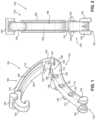
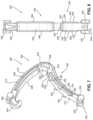
- FIG. 1illustrates an exemplary perspective view of a first exemplary embodiment of a surgical clip in an open configuration according to the present invention.
- FIG. 2illustrates an exemplary frontal view of the surgical clip of FIG. 1 .
- FIG. 3illustrates an exemplary side view of the surgical clip of FIGS. 1 and 2 .
- FIG. 4illustrates an exemplary side view of the surgical clip of FIGS. 1 - 3 in a closed configuration.
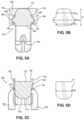
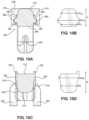
- FIG. 5 Aillustrates an exemplary cut-away view of a first leg member of the surgical clip of FIGS. 1 - 4 .
- FIG. 5 Billustrates an exemplary cross-section of the cut-away view of FIG. 5 A .
- FIG. 5 Cillustrates an exemplary cut-away view of a second leg member of the surgical clip of FIGS. 1 - 5 B .
- FIG. 5 Dillustrates an exemplary cross-section of the cutaway view of FIG. 5 C .
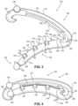
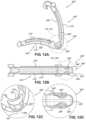
- FIG. 6illustrates an exemplary perspective view of a second exemplary embodiment of a surgical clip in an open configuration.
- FIG. 7illustrates an exemplary perspective view of a third exemplary embodiment of a surgical clip in an open configuration.
- FIG. 8illustrates an exemplary frontal view of the surgical clip of FIG. 7 .
- FIG. 9illustrates an exemplary side view of the surgical clip of FIGS. 7 and 8 .
- FIG. 10 Aillustrates an exemplary cutaway view of a first leg member of the surgical clip of FIGS. 7 - 9 .
- FIG. 10 Billustrates an exemplary cross-section of the cutaway view of FIG. 10 A .
- FIG. 10 Cillustrates an exemplary cutaway view of a second leg member of the surgical clip of FIGS. 7 - 10 B .
- FIG. 10 Dillustrates an exemplary cross-section of the cutaway view of FIG. 10 C .
- FIGS. 11 A-Dillustrate a first exemplary embodiment of a grooved hinge member of the surgical clip of FIGS. 7 - 10 D .
- FIGS. 12 A-Dillustrate a second exemplary embodiment of a grooved hinge member of the surgical clip of FIGS. 7 - 10 D .
- the present inventionis generally directed to a surgical clip configured to compress and/or ligate tissue (e.g., blood vessels, lymph nodes, nerves, cystic tubes, or cardiac tissue).
- tissuee.g., blood vessels, lymph nodes, nerves, cystic tubes, or cardiac tissue.
- the surgical clipmay provide elongated leg members to increase the tissue-retaining capacity.
- the surgical clipmay be sized to fit in a 5 mm clip applier, but have an increased capacity compared to other 5 mm clips.
- the surgical clipmay have at least one lateral protrusion or wing member extending along at least one of the lateral sides of the leg member.
- the lateral protrusionsmay provide the leg member with an increased aspect ratio (width/thickness).
- the surgical clipis relatively wider along a portion of the thickness to increase the stiffness along at least a portion of the length of the leg member.
- the surgical clipmay also have improved teeth that receive a tissue clamping inner surface therebetween for increased axial security of tissue.
- the surgical clipmay further have features that retain tissue proximate the hinge as the surgical clip closes.
- the surgical clipmay also have rounded leg and/or hinge profiles enhancing applier jaw strength and facilitating easier loading from a cartridge.
- the surgical clipmay have an improved hinge member.
- the hinge membermay be improved by removing material to form grooves in one or more side surfaces and/or an outer surface to reduce thickness. The grooves may improve the performance of the surgical clip during closure and/or provide features that could be used to help stabilize the surgical clip in the jaws of a clip applier, for example, if the clip applier had mating features.
- the term “longitudinal”is directed to the dimension which extends along the length of the surgical clip and/or leg members from their respective proximal portions to their respective distal portions, as would be commonly understood by one of skill in the art.
- the term “length”refers to a dimension of the surgical clip and/or one or more components along its longitudinal direction.
- the “transverse” directionis directed to any axis or direction which is orthogonal to the longitudinal lengths of the surgical clip or leg members.
- the term “vertical”refers to a dimension of the surgical clip and/or one or more components along a compression axis of the leg members.
- the term “thickness”refers to the dimension between opposing edges of the surgical clip and/or one or more components along the compression or vertical direction.
- the term “width”refers to a dimension of the surgical clip and/or one or more components in a lateral direction substantially transverse to the length and the thickness.
- the term “concave” and “convex”refers to the curvature of a surface or component visible when viewing an exterior of the surface or component. Similar terminology is used throughout the written disclosure, unless otherwise indicated.
- FIGS. 1 - 5 Dillustrate a first embodiment of a surgical clip 100 of the present invention.
- the surgical clip 100may include a first leg member 102 having a proximal portion and a distal portion, and a second leg member 104 having a proximal portion and a distal portion.
- the first and second leg members 102 , 104may be integrally joined at the proximal portions by a hinge member 106 .
- the first and second leg members 102 , 104may be curved along their lengths and include curved surfaces.
- the first leg member 102may include a first inner surface 108 and a first outer surface 110
- the second leg member 104may include a second inner surface 112 and a second outer surface 114 .
- the first inner surface 108 and second outer surface 110may extend laterally between first side surfaces 116
- the second inner surface 112 and second outer surface 114may extend laterally between second side surfaces 118 .
- the first inner surface 108may have a concave curvature
- the first outer surface 110may have a convex curvature, each along the length of the first leg member 102 .
- the second inner surface 112may have a convex curvature
- the second outer surface 114may have a concave curvature, each along the length of the second leg member 104 .
- the concave curvature of the first inner surface 108 and/or the convex curvature of the first outer surface 110may extend from the respective proximal portion to the respective distal portion, substantially the entire length of the first leg member 102 .
- the convex curvature of the second inner surface 112 and/or the concave curvature of the second outer surface 114may extend from the respective proximal portion to the respective distal portion, substantially the entire length of the second leg member 104 .
- the curvatures of the first leg member 102 and the second leg member 104may substantially match, and the respective concavity/convexity of the first inner surface 108 and the second inner surface 112 may substantially match.
- the first and second leg member 102 , 104may bend and/or straighten as the surgical clip 100 closes, and the first and second inner surfaces 108 , 112 may be approximated or contact in a closed configuration, as illustrated in FIG. 4 .
- Further discussion of the general curvatures of the leg members 102 , 104 and closure of the surgical clip 100can be found in U.S. Pat. No. 4,834,096, the entire disclosure of which is incorporated herein by reference.
- the hinge member 106may be resiliently flexible and integral to the first and second leg members 102 , 104 .
- the hinge member 106may have a concave inner surface 120 joining the first inner surface 108 and the second inner surface 112 and a convex outer surface 122 joining the first outer surface 110 and the second outer surface 114 .
- the hinge member 106may define an opening 123 through a thickness between the inner and outer surfaces 120 , 122 , and the inner surface 120 may define a groove or slot 124 on its inside.
- the groove 124may be configured to receive tissue extending between the leg members 102 , 104 .
- the surgical clip 100may further have a convex portion or heel 126 on a proximal portion of the second leg member 104 at a distal end of the groove 124 .
- the heel 126may have a convex curvature having a smaller radius of curvature than the remaining length of the second inner surface 112 , providing the heel 126 with increased convexity.
- the heel 126may include at least one tooth 128 to increase securement of the tissue in the groove 124 .
- the heel 126may include a single tooth 128 extending substantially the width of the heel 126 . As further illustrated in FIG.
- the heel 126 and/or at least one tooth 128may be at least partially received in an opposing portion of the groove 124 in the closed configuration securing the tissue in the groove 124 .
- the at least one tooth 128may be angled proximally from the heel 126 toward the hinge member 106 to provide a counterforce to further prevent pull-off of the surgical clip 100 .
- the surgical clip 100may also include a latching mechanism having one or more latching elements.
- the first leg member 102may transition to a hook member 140 at its distal portion
- the second leg member 104may transition to a complementary grooved tip member 142 at its distal portion.
- a distal portion of the hook member 140may curve inwardly and point generally toward the hinge member 106 .
- the hook member 140may have one or more transverse beveled surfaces and a concave inner surface which merges with the first inner surface 108 to define a latching recess.
- the tip member 142may define a V-shaped groove or slot configured to receive the beveled surfaces of the hook member 140 , as the hook member 140 opens or deflects around the tip member 142 and/or the second leg member 104 compresses.
- the hook member 140 and the tip member 142may engage to form the latching mechanism.
- the latching recessmay receive the tip member 142 in the course of compressing the surgical clip 100 into the closed configuration (e.g., FIG. 4 ) when secured position around a vessel or other tissue.
- the leg members 102 , 104may include one or more boss members along the length to engage jaws of the clip applier.
- the first leg member 102may include one or more boss members 150 protruding perpendicular to opposing side surfaces adjacent to the distal portion of the first leg member 102 and immediately proximal of the hook member 140 .
- the one or more boss members 150may be cylindrical and project outwardly beyond each of the side surfaces 116 of first leg member 102 .
- the boss members 150may include a bridge section extending the width of the first leg member 102 and joining opposing boss members 150 extending laterally of the side surfaces 116 .
- the second leg member 104may also include one or more boss members 152 at the distal portion spaced apart by the slot of the tip member 142 .
- the boss members 152may be cylindrical and protrude perpendicularly to opposing side surfaces 118 of the second leg member 104 , extending longitudinally forward beyond the point of tip member 142 and outwardly beyond the side surfaces 118 of second leg member 104 .
- the jaws of the clip appliermay engage the boss members 150 , 152 and pivot the leg members 102 , 104 about the hinge member 106 to compress the surgical clip 100 into the closed and/or latched configuration around a vessel.
- the surgical clip 100may include a plurality of teeth 130 .
- the teeth 130may be substantially rigid, such that the teeth 130 do not substantially deflect when engaging tissue.
- the teeth 130may be positioned out-board relative to the surgical clip 100 .
- the term “out-board”refers to the positioning of the teeth 130 laterally of the inner surface 112 .
- the teeth 130may be attached to and extend from at least one of the side surfaces 118 and/or substantially perpendicular to the second inner surface 112 .
- the teeth 130may have a first portion 132 forming a base integrated into the second side surface 118 , and a second portion 134 protruding from the second leg member 104 toward the first leg member 102 .
- the first and second portions 132 , 134may be spaced apart from respective first and second portions 132 , 134 of adjacent teeth 130 .
- the first portion 132may be longitudinally wider than the second portion 134 to increase securement of the teeth 130 to the side surfaces 118 .
- the teeth 130may have a substantially flat outer lateral side surface and a substantially flat inner side surface (defined by the exposed surface of the second portion 134 extending perpendicular from the inner surface 112 ), as illustrate in FIGS. 5 C and 5 D .
- the substantially flat inner side surface of the second portions 134may make a flush interface or minimal gap with the side surfaces 116 of the first leg member 102 .
- the second portion 134may further have a substantially flat inner surface extending substantially parallel to the second inner surface 112 to reduce trauma on the ligated tissue.
- the teeth 130may form a first row of teeth 130 integrated into a first side surface 118 and a second row of teeth 130 integrated into a second side surface 118 .
- the teeth 130may be positioned to clear the first inner surface 108 and extend along the side surfaces 116 of the first leg member 102 to enable the surgical clip 100 to close with minimal or no gap between the inner surfaces 108 , 112 ensuring effective closure of small vessels.
- the first and second rows of teeth 130may be configured to receive the first inner surface 108 therebetween in the closed configuration, as illustrated in FIG. 4 .
- the teeth 130may extend from the second side surfaces 118 past the first and second inner surfaces 108 , 112 , and along or parallel to one of the first side surfaces 116 .
- the teeth 130may overlap the first and second side surfaces 116 , 118 and pass the first and second inner surfaces 108 , 112 .
- the teeth 130may be sufficiently spaced apart from each other along the longitudinal axis of the second leg member 104 , thus do not pinch tissue between adjacent teeth 130 .
- the teeth 130 of the first and second rowsmay be staggered, alternating along the longitudinal axis of the inner surface 112 .
- the configuration of the teeth 130may provide a favorable tortuous engagement of tissue with closely approximated tissue engaging surfaces.
- the larger size of the teeth 130may improve tissue retention and prevent the tissue from slipping out of the surgical clip.
- the teeth 130may further be easy to mold and not interfere with clip appliers.
- the first inner surface 108 and the second inner surface 112may be substantially smooth (e.g., substantially without teeth) for substantially the entire length or majority of the length of the first and second leg members 102 , 104 , with the exception for example of the tooth 128 on the heel 126 .
- the first inner surface 108may be completely without teeth, and the second inner surface 112 may be without teeth for the majority of its length. Further discussion of features of the out-board teeth 130 can be found in U.S. Patent Publication No. 2018/0368852, the entire disclosure of which is incorporated herein by reference.
- the first leg member 102may have at least one wing member or lateral protrusion 160 extending laterally from one of the first side surfaces 116 .
- the at least one lateral protrusion 160may include a first lateral protrusion 160 extending from a first side surface 116 and a second lateral protrusion 160 extending from a second side surface 116 .
- the lateral protrusions 160may reinforce and stabilize the leg member 102 by increasing torsional stiffness.
- the lateral protrusions 160may enable the first leg member 102 to be longer without compromising the torsional and/or tissue retention strength of the surgical clip 100 .
- the lateral protrusions 160may extend longitudinally for at least half of the length of the first leg member 102 .
- the lateral protrusions 160may extend longitudinally for at least two-thirds of the length of the first leg member 102 . However, the lateral protrusion 160 may not extend the entire length of the first leg member 102 . Thus, the lateral protrusions 160 may have a distal end that is proximal of the at least one boss member 150 to prevent interference with the clip applier interface and/or a proximal end that is distal of the hinge member 106 to maintain the flexibility of the hinge member, reducing the pivoting stiffness of the leg members 102 , 104 . Furthermore, the width of the surgical clip 100 at the lateral protrusions 160 may be narrower than the width of the surgical clip 100 at the boss members 150 .
- the protrusion 160may have an inner surface 164 spaced vertically from the first inner surface 108 and an outer surface 166 spaced vertically from the first outer surface 110 .
- the spacing of the inner surface 164 of the protrusion from the first inner surface 108may prevent interference with tissue ligation and allow the teeth 130 to receive the inner surface 108 therebetween.
- the inner surface 164may be substantially flat and extend substantially perpendicular from the side surface 116 to further reduce any interference with the teeth 130 and/or provide a surface for the teeth 130 to engage in the closed configuration.
- the outer surface 166may be angled, tapered, and/or curved (concave or convex) to increase the stability of the protrusion 160 and facilitate manufacturing. As illustrated, the side surface of the protrusion 160 may be free and substantially flat. The spacing of the lateral protrusion 160 from the first inner surface 108 and first outer surface 110 may further optimize the reinforcement of the surgical clip 100 .
- the first leg member 102may have a protrusion width (w 1 P ) defined by side surfaces of opposing protrusions 160 .
- the protrusion width (w 1 P )may be greater than a first inner width (w 1 I ) defined by the dimension between the side surfaces 116 positioned between the protrusions 160 and the first inner surface 108 .
- the protrusion width (w 1 P )may also be greater than a first outer width (w 1 O ) defined by the dimension between the side surfaces 116 and positioned between the protrusion 160 and to the first outer surface 110 .
- the protrusion width (w 1 P )may further be greater than a first thickness (t 1 ) defined by the dimension between the first inner surface 108 and the first outer surface 110 .
- the protrusions 160may extend for at least half of the length of the first leg member 102 , thus the protrusion width (w 1 P ) may be greater than the first thickness (t 1 ), first inner width (w 1 I ), and/or the first outer width (w 1 O ) for at least half of the length of the first leg member 102 .
- the protrusion width (w 1 P )may be greater than the first thickness (t 1 ), first inner width (w 1 I ), and/or the first outer width (w 1 O ) for at least two-third of the length of the first leg member 102 .
- the distal end of the at least one lateral protrusion 160may define a distal surface that extends substantially perpendicular to the first side surface 116 , first inner surface 108 and/or the first outer surface 110 .
- the proximal end of the at least one lateral protrusion 160may define a proximal surface that extends at an angle proximally relative to the first inner surface 110 .
- the first leg member 102may have substantially flat side surfaces 116 distal and proximal of the lateral protrusions 160 (between the lateral protrusion 160 and the boss member 152 and/or between the lateral protrusion 160 and the hinge member 106 ).
- Each of the lateral protrusions 160may themselves have a width from the respective side surface 116 no greater than a quarter of the first inner width (w 1 I ) and the first outer width (w 1 O ).
- the lateral protrusions 160may be only on the first leg member 102 , thus the second leg member 104 may be without a lateral protrusion.
- the protrusion width (w 1 P ) of the first leg member 102may be greater than a second width (w 2 ) of the second leg member 104 defined by the dimension between the second side surfaces 118 , at cross-sections excluding and including the alternating, staggered teeth 130 (although the teeth 130 are not considered part of the side surfaces 118 ).
- the lateral protrusions 160 on the first leg member 102may provide sufficient rigidity to the surgical clip 100 in the closed configuration, and the first leg member 102 having the hook member 140 may require additional rigidity and stability as the surgical clip 100 closes.
- FIGS. 1 - 5 Dillustrate a single lateral protrusion 160 extending from each side surface 116 , which facilitates manufacturing of the surgical clip 100 .
- the surgical clip 100may include a plurality of lateral protrusions 160 on each side surface 116 (e.g. longitudinally aligned and/or spaced apart) collectively extending the lengths as described herein.
- FIG. 6illustrates a second embodiment of a surgical clip 100 ′ of the present invention.
- the surgical clip 100 ′may include a first leg member 102 ′ having a proximal portion and a distal portion, and a second leg member 104 ′ having a proximal portion and a distal portion.
- the first and second leg members 102 ′, 104 ′may be integrally joined at the proximal portions by a hinge member 106 ′.
- the surgical clip 100 ′is a modification of the surgical clip 100 , thus substantially the entire discussion of FIGS. 1 - 5 D applies to the surgical clip 100 ′ (except when otherwise indicated) and is expressly incorporated herein for brevity sake.
- the surgical clip 100 ′differs from the surgical clip 100 in that the surgical clip 100 ′ includes a plurality of teeth 136 ′ on the inner surface 108 ′ of the first leg member 102 ′.
- the plurality of teeth 136 ′may form first and second staggered rows longitudinally along the first inner surface 108 ′.
- the plurality of teeth 136 ′may be angled proximally toward the hinge member 106 ′.
- the combination of the teeth 136 ′ extending from the first inner surface 108 ′ and the out-board teeth 130 ′ extending from the second side surfaces 118 ′may provide favorable retention strength based on the type and mechanical properties of the tissue.
- the second inner surface 112 ′may be substantially smooth and engage the teeth 136 ′ of the first inner surface 108 ′.
- FIGS. 7 - 10 Dillustrate a third embodiment of a surgical clip 200 of the present invention.
- the surgical clip 200may include a first leg member 202 having a proximal portion and a distal portion, and a second leg member 204 having a proximal portion and a distal portion.
- the first and second leg members 202 , 204may be integrally joined at the proximal portions by a hinge member 206 .
- the first and second leg members 202 , 204may be curved along their lengths and include curved surfaces.
- the first leg member 202may include a first inner surface 208 and a first outer surface 210
- the second leg member 204may include a second inner surface 212 and a second outer surface 214 .
- the first inner surface 208 and second outer surface 210may extend laterally between first side surfaces 216
- the second inner surface 212 and second outer surface 214may extend laterally between second side surfaces 218 .
- the first inner surface 208may have a concave curvature
- the first outer surface 210may have a convex curvature, each along the length of the first leg member 202 .
- the second inner surface 212may have a convex curvature
- the second outer surface 214may have a concave curvature, each along the length of the second leg member 204 .
- the concave curvature of the first inner surface 208 and/or the convex curvature of the first outer surface 210may extend from the respective proximal portion to the respective distal portion, substantially the entire length of the first leg member 202 .
- the convex curvature of the second inner surface 212 and/or the concave curvature of the second outer surface 214may extend from the respective proximal portion to the respective distal portion, substantially the entire length of the second leg member 204 .
- the curvatures of the first leg member 202 and the second leg member 204may substantially match, and the respective concavity/convexity of the first inner surface 208 and the second inner surface 212 may substantially match.
- the first and second leg member 202 , 204may bend and/or straighten as the surgical clip 200 closes, and the first and second inner surfaces 208 , 212 may be approximated or contact in a closed configuration, (e.g., as similarly illustrated in FIG. 4 ). Further discussion of the general curvatures of the leg members 202 , 204 and closure of the surgical clip 200 can be found in U.S. Pat. No. 4,834,096, the entire disclosure of which is incorporated herein by reference.
- the hinge member 206may be resiliently flexible and integral to the first and second leg members 202 , 204 .
- the hinge member 206may have a concave inner surface 220 joining the first inner surface 208 and the second inner surface 212 and a convex outer surface 222 joining the first outer surface 210 and the second outer surface 214 .
- the hinge member 206may define an opening 223 through a thickness between the inner and outer surfaces 220 , 222 , and the inner surface 220 may define a groove or slot 224 on its inside.
- the groove 224may be configured to receive tissue extending between the leg members 202 , 204 .
- the surgical clip 200may further have a convex portion or heel 226 on a proximal portion of the second leg member 204 at a distal end of the groove 224 .
- the heel 226may have a convex curvature having a smaller radius of curvature than the remaining length of the second inner surface 212 , providing the heel 226 with increased convexity.
- the heel 226may include at least one tooth 228 to increase securement of the tissue in the groove 224 .
- the heel 226may include a single tooth 228 extending substantially the width of the heel 226 .
- the heel 226 and/or at least one tooth 228may be at least partially received in an opposing portion of the groove 224 in the closed configuration securing the tissue in the groove 224 (e.g., as similarly illustrated in FIG. 4 ). As illustrated in FIG. 9 , the at least one tooth 228 may be angled proximally from the heel 226 toward the hinge member 206 to provide a counterforce to further prevent pull-off of the surgical clip 200 .
- the surgical clip 200may also include a latching mechanism having one or more latching elements.
- the first leg member 202may transition to a hook member 240 at its distal portion
- the second leg member 204may transition to a complementary grooved tip member 242 at its distal portion.
- a distal portion of the hook member 240may curve inwardly and point generally toward the hinge member 206 .
- the hook member 240may have one or more transverse beveled surfaces and a concave inner surface which merges with the first inner surface 208 to define a latching recess.
- the tip member 242may define a V-shaped groove or slot configured to receive the beveled surfaces of the hook member 240 , as the hook member 240 opens or deflects around the tip member 242 and/or the second leg member 204 compresses.
- the hook member 240 and the tip member 242may engage to form the latching mechanism.
- the latching recessmay receive the tip member 242 in the course of compressing the surgical clip 200 into the closed configuration (e.g., as similarly illustrated in FIG. 4 ) when secured position around a vessel or other tissue.
- the leg members 202 , 204may include one or more boss members along the length to engage jaws of the clip applier.
- the first leg member 202may include one or more boss members 250 protruding perpendicular to opposing side surfaces adjacent to the distal portion of the first leg member 202 and immediately proximal of the hook member 240 .
- the one or more boss members 250may be cylindrical and project outwardly beyond each of the side surfaces 216 of first leg member 202 .
- the boss members 250may include a bridge section extending the width of the first leg member 202 and joining opposing boss members 250 extending laterally of the side surfaces 216 .
- the second leg member 204may also include one or more boss members 252 at the distal portion spaced apart by the slot of the tip member 242 .
- the boss members 252may be cylindrical and protrude perpendicularly to opposing side surfaces 218 of the second leg member 204 , extending longitudinally forward beyond the point of tip member 242 and outwardly beyond the side surfaces 218 of second leg member 204 .
- the jaws of the clip appliermay engage the boss members 250 , 252 and pivot the leg members 202 , 204 about the hinge member 206 to compress the surgical clip 200 into the closed and/or latched configuration around a vessel.
- the surgical clip 200may include a plurality of teeth 230 .
- the teeth 230may be substantially rigid, such that the teeth 230 do not substantially deflect when engaging tissue.
- the teeth 230may be positioned out-board relative to the surgical clip 200 .
- the term “out-board”refers to the positioning of the teeth 230 laterally of the inner surface 212 .
- the teeth 230may extend inwardly from at least one wing member or lateral protrusion 262 extending perpendicularly from at least one of the side surfaces 218 .
- the teeth 230may have a substantially flat outer lateral side surface and a substantially flat inner side surface (defined by the exposed surface extending perpendicular from the inner surface 212 ), as illustrate in FIGS. 10 C and 10 D .
- the substantially flat inner side surface of the teeth 230may make a flush interface or minimal gap with the side surfaces 216 of the first leg member 202 .
- the teeth 230may further have a substantially flat inner surface extending substantially parallel to the second inner surface 212 to reduce trauma on the ligated tissue.
- the teeth 230may form a first row of teeth 230 extending from a first lateral protrusion 262 integrated into a first side surface 218 and a second row of teeth 230 extending from a second lateral protrusion 262 integrated into a second side surface 218 .
- the teeth 230may be positioned to clear the first inner surface 208 and extend along the side surfaces 216 of the first leg member 202 to enable the surgical clip 200 to close with minimal or no gap between the inner surfaces 208 , 212 ensuring effective closure of small vessels.
- the first and second rows of teeth 230may be configured to receive the first inner surface 208 therebetween in the closed configuration (e.g., as similarly illustrated in FIG. 4 ).
- the teeth 230may extend from the lateral protrusions 262 past the first inner surfaces 208 , and along or parallel to one of the first side surfaces 216 .
- the teeth 230may be sufficiently spaced apart from each other along the longitudinal axis of the second leg member 204 , thus do not pinch tissue between adjacent teeth 230 .
- the teeth 230 of the first and second rowsmay be staggered, alternating along the longitudinal axis of the inner surface 212 .
- the configuration of the teeth 230may provide a favorable tortuous engagement of tissue with closely approximated tissue engaging surfaces.
- the larger size of the teeth 230may improve tissue retention and prevent the tissue from slipping out of the surgical clip.
- the teeth 230may further be easy to mold and not interfere with clip appliers.
- the first inner surface 208 and the second inner surface 212may be substantially smooth (e.g., substantially without teeth) for substantially the entire length or majority of the length of the first and second leg members 202 , 204 , with the exception for example of the tooth 228 on the heel 226 .
- the first inner surface 208may be completely without teeth, and the second inner surface 212 may be without teeth for the majority of its length. Further discussion of features of the out-board teeth 230 can be found in U.S. Patent Publication No. 2018/0368852, the entire disclosure of which is incorporated herein by reference.
- the first leg member 202may have at least one wing member or lateral protrusion 260 extending laterally from one of the first side surfaces 216 .
- the at least one lateral protrusion 260may include a first lateral protrusion 260 extending from a first side surface 216 and a second lateral protrusion 260 extending from a second side surface 216 .
- the lateral protrusions 260may reinforce and stabilize the leg member 202 by increasing torsional stiffness.
- the lateral protrusions 260may enable the first leg member 202 to be longer without compromising the torsional and/or tissue retention strength of the surgical clip 200 .
- the lateral protrusions 260may extend longitudinally for at least half of the length of the first leg member 202 . In some embodiments, the lateral protrusions 260 may extend longitudinally for at least two-thirds of the length of the first leg member 202 . However, the lateral protrusion 260 may not extend the entire length of the first leg member 202 . Thus, the lateral protrusions 260 may have a distal end that is proximal of the at least one boss member 250 to prevent interference with the clip applier interface and/or a proximal end that is distal of the hinge member 206 to maintain the flexibility of the hinge member, reducing the pivoting stiffness of the leg members 202 , 204 .
- the width of the surgical clip 200 at the lateral protrusions 260may be narrower than the width of the surgical clip 200 at the boss members 250 .
- the protrusion 260may have an inner surface 264 spaced vertically from the first inner surface 208 and an outer surface 266 spaced vertically from the first outer surface 210 . The spacing of the inner surface 264 of the protrusion from the first inner surface 208 may prevent interference with tissue ligation and allow the teeth 230 to receive the inner surface 208 therebetween.
- the inner surface 264may be substantially flat and extend substantially perpendicular from the side surface 216 to further reduce any interference with the teeth 230 and/or provide a surface for the teeth 230 to engage in the closed configuration.
- the outer surface 266may be angled, tapered, and/or curved (concave or convex) to increase the stability of the protrusion 260 and facilitate manufacturing.
- the side surface of the protrusion 260may be free and substantially flat. The spacing of the lateral protrusion 260 from the first inner surface 208 and first outer surface 210 may further optimize the reinforcement of the surgical clip 200 .
- the first leg member 202may have a protrusion width (w 1 P ) defined by side surfaces of opposing protrusions 260 .
- the protrusion width (w 1 P )may be greater than a first inner width (w 1 I ) defined by the dimension between the side surfaces 216 positioned between the protrusion 260 and the first inner surface 208 .
- the protrusion width (w 1 P )may also be greater than a first outer width (w 1 O ) defined by the dimension between the side surfaces 216 and positioned between the protrusion 260 and to the first outer surface 210 .
- the protrusion width (w 1 P )may further be greater than a first thickness (t 1 ) defined by the dimension between the first inner surface 208 and the first outer surface 210 .
- the protrusions 260may extend for at least half of the length of the first leg member 202 , thus the protrusion width (w 1 P ) may be greater than the first thickness (t 1 ), first inner width (w 1 I ), and/or the first outer width (w 1 O ) for at least half of the length of the first leg member 202 .
- the protrusion width (w 1 P )may be greater than the first thickness (t 1 ), first inner width (w 1 I ), and/or the first outer width (w 1 O ) for at least two-third of the length of the first leg member 202 .
- the distal end of the at least one lateral protrusion 260may define a distal surface that extends substantially perpendicular to the first inner surface 208 and the first outer surface 210 .
- the proximal end of the at least one lateral protrusion 260may define a proximal surface that extends at an angle proximally relative to the first inner surface 208 .
- the first leg member 202may have substantially flat side surfaces 216 distal and proximal of the lateral protrusions 260 (e.g., between the lateral protrusion 260 and the boss member 250 and/or between the lateral protrusion 260 and the hinge member 206 ).
- the outer surfaces 210 , 214 ofmay have a rounded curvature extending between the respective side surfaces 216 , 218 enhancing applier jaw strength and facilitating easier loading from a cartridge.
- the outer surface 222 of the hinge member 206may have a similar rounded curvature.
- Each of the lateral protrusions 260may themselves have a width from the respective side surface 216 no greater than a quarter of the first inner width (w 1 I ) and the first outer width (w 1 O ).
- FIGS. 7 - 10 Dillustrate a single lateral protrusion 260 extending from each side surface 216 , which facilitates manufacturing of the surgical clip 200 .
- the surgical clip 200may include a plurality of lateral protrusions 260 on each side surface 216 (e.g. longitudinally aligned and/or spaced apart) collectively extending the lengths as described herein.
- the second leg member 204may have a protrusion width (w 2 P ) defined by side surfaces of opposing protrusions 262 .
- the protrusion width (w 2 P )may be greater than a width (w 2 ) defined by the dimension between the side surfaces 218 and positioned between the protrusion 260 and to the second outer surface 214 .
- the protrusion width (w 2 P )may further be greater than a second thickness (t 2 ) defined by the dimension between the second inner surface 212 and the second outer surface 214 .
- the protrusion 262may extend for at least half of the length of the second leg member 204 , thus the protrusion width (w 2 P ) may be greater than the second thickness (t 2 ), and/or the second width (w 2 ) for at least half of the length of the second leg member 204 . In embodiments where the protrusion 262 extends for at least two-thirds of the length of the second leg member 204 , the protrusion width (w 2 P ) may be greater than the second thickness (t 2 ), and/or the second width (w 2 ) for at least two-third of the length of the second leg member 204 .
- the distal end of the at least one lateral protrusion 262may defined a distal surface that extends substantially perpendicular to the first side surface 216 , the second inner surface 210 , and/or the second outer surface 210 .
- the proximal end of the at least one lateral protrusion 262may define a proximal surface that extends at an angle proximally relative to the second outer surface 214 and distally relative to the second inner surface 212 .
- the second leg member 204may have substantially flat side surfaces 218 distal and/or proximal of the lateral protrusions 262 (e.g., between the lateral protrusion 262 and the boss member 252 and/or between the lateral protrusion 262 and the hinge member 206 ).
- FIGS. 11 A-Dillustrate a fourth embodiment of a surgical clip 200 ′ of the present invention.
- the surgical clip 200 ′may include a first leg member 202 ′ having a proximal portion and a distal portion, and a second leg member 204 ′ having a proximal portion and a distal portion.
- the first and second leg members 202 ′, 204 ′may be integrally joined at the proximal portions by a hinge member 206 ′.
- the surgical clip 200 ′is a modification of the surgical clip 200 , thus substantially the entire discussion of FIGS. 7 - 10 D applies to the surgical clip 200 ′ (except when otherwise indicated) and is expressly incorporated herein for brevity sake.
- the hinge member 206 ′may further have one or more grooves 280 ′ in the outer surface 220 ′ extending between the opposing side surfaces 282 ′ of the hinge member 206 ′.
- the hinge member 206 ′may include three grooves, one at the apex of the outer surface 222 ′ and two on opposing sides of the apex.
- the hinge member 206 ′may have a single groove 280 ′, for example, at the apex of the outer surface 222 ′.
- the grooves 280 ′may not extend completely through a thickness of the hinge member 206 ′ to the opening 223 ′, such that the grooves 280 ′ are not in communication with the opening 223 ′.
- the grooves 280 ′may be substantially U-shaped and have curved or tapered side portions extending to the side surfaces 282 ′.
- the grooves 280 ′may improve the performance of the surgical clip 200 ′ during closure and/or provide features that may be used to help stabilize the surgical clip 200 ′ in the jaws of a clip applier, for example, if the clip applier had mating features.
- FIGS. 12 A-Dillustrate a fifth embodiment of a surgical clip 200 ′′ of the present invention.
- the surgical clip 200 ′′may include a first leg member 202 ′′ having a proximal portion and a distal portion, and a second leg member 204 ′′ having a proximal portion and a distal portion.
- the first and second leg members 202 ′′, 204 ′′may be integrally joined at the proximal portions by a hinge member 206 ′′.
- the surgical clip 200 ′′is a modification of the surgical clip 200 , thus substantially the entire discussion of FIGS. 7 - 10 D applies to the surgical clip 200 ′′ (except when otherwise indicated) and is expressly incorporated herein for brevity sake.
- the hinge member 206 ′′may further have one or more grooves 280 ′′ in one or more of the side surfaces 282 ′′.
- the hinge member 206 ′′may include two grooves, one each in opposing side surfaces 282 ′′.
- the grooves 280 ′′may extend from the outer surface 222 ′′ through the side surfaces 282 ′′ and into the opening 223 ′′.
- the grooves 280 ′′may be substantially U-shaped and have curved or tapered side portions.
- the grooves 280 ′′may improve the performance of the surgical clip 200 ′′ during closure and/or provide features that may be used to help stabilize the surgical clip 200 ′′ in the jaws of a clip applier, for example, if the clip applier had mating features.
- the various embodiments of the surgical clips of the present inventionmay be made of any suitable size and may be applied to any number of tissues, such as blood vessels, lymph nodes, nerves, cystic ducts, and cardiac tissue.
- the various embodiments of the surgical clipsmay be constructed from any suitable biocompatible material, such as metals and polymers.
- the present inventionis particularly suitable for practice with polymeric clips.
- the various embodiments of the surgical clips 100 , 100 ′, 200 , 200 ′, 200 ′′preferably consist of a one-piece integral polymeric body formed from injection-molding, extrusion, or otherwise processed from a suitable strong biocompatible engineering plastic.
- Exemplary materialsinclude homopolymer or co-polymer polyacetal, polyethylene terephthalate (PET), polybutylene terephthalate (PBT), polyoxymethylene, or other thermoplastic materials.
Landscapes
- Health & Medical Sciences (AREA)
- Surgery (AREA)
- Life Sciences & Earth Sciences (AREA)
- Heart & Thoracic Surgery (AREA)
- Molecular Biology (AREA)
- Vascular Medicine (AREA)
- Engineering & Computer Science (AREA)
- Biomedical Technology (AREA)
- Reproductive Health (AREA)
- Medical Informatics (AREA)
- Nuclear Medicine, Radiotherapy & Molecular Imaging (AREA)
- Animal Behavior & Ethology (AREA)
- General Health & Medical Sciences (AREA)
- Public Health (AREA)
- Veterinary Medicine (AREA)
- Surgical Instruments (AREA)
- Materials For Medical Uses (AREA)
Abstract
Description
Claims (19)
Priority Applications (2)
| Application Number | Priority Date | Filing Date | Title |
|---|---|---|---|
| US17/127,973US11992222B2 (en) | 2019-12-19 | 2020-12-18 | Surgical clip |
| US18/674,267US20240307067A1 (en) | 2019-12-19 | 2024-05-24 | Surgical clip |
Applications Claiming Priority (2)
| Application Number | Priority Date | Filing Date | Title |
|---|---|---|---|
| US201962950819P | 2019-12-19 | 2019-12-19 | |
| US17/127,973US11992222B2 (en) | 2019-12-19 | 2020-12-18 | Surgical clip |
Related Child Applications (1)
| Application Number | Title | Priority Date | Filing Date |
|---|---|---|---|
| US18/674,267ContinuationUS20240307067A1 (en) | 2019-12-19 | 2024-05-24 | Surgical clip |
Publications (2)
| Publication Number | Publication Date |
|---|---|
| US20210186511A1 US20210186511A1 (en) | 2021-06-24 |
| US11992222B2true US11992222B2 (en) | 2024-05-28 |
Family
ID=74191903
Family Applications (2)
| Application Number | Title | Priority Date | Filing Date |
|---|---|---|---|
| US17/127,973Active2041-08-21US11992222B2 (en) | 2019-12-19 | 2020-12-18 | Surgical clip |
| US18/674,267PendingUS20240307067A1 (en) | 2019-12-19 | 2024-05-24 | Surgical clip |
Family Applications After (1)
| Application Number | Title | Priority Date | Filing Date |
|---|---|---|---|
| US18/674,267PendingUS20240307067A1 (en) | 2019-12-19 | 2024-05-24 | Surgical clip |
Country Status (8)
| Country | Link |
|---|---|
| US (2) | US11992222B2 (en) |
| EP (1) | EP4076216A1 (en) |
| JP (2) | JP2023507792A (en) |
| KR (2) | KR102800799B1 (en) |
| CN (1) | CN114929119A (en) |
| AU (2) | AU2020405150B2 (en) |
| CA (1) | CA3162053A1 (en) |
| WO (1) | WO2021127540A1 (en) |
Cited By (3)
| Publication number | Priority date | Publication date | Assignee | Title |
|---|---|---|---|---|
| US20230123832A1 (en)* | 2021-09-01 | 2023-04-20 | Boston Scientific Scimed, Inc. | Devices, systems, and methods for clamping a leaflet of a heart valve |
| US20240307067A1 (en)* | 2019-12-19 | 2024-09-19 | Teleflex Medical Incorporated | Surgical clip |
| US12426889B2 (en) | 2017-11-14 | 2025-09-30 | Teleflex Medical Incorporated | Surgical clip |
Families Citing this family (8)
| Publication number | Priority date | Publication date | Assignee | Title |
|---|---|---|---|---|
| CA3068282C (en) | 2017-06-22 | 2022-06-28 | Teleflex Medical Incorporated | Surgical clip |
| US12290258B2 (en) | 2019-12-13 | 2025-05-06 | Dinesh Vyas | Stapler apparatus and methods for use |
| US20230056943A1 (en)* | 2019-12-13 | 2023-02-23 | Dinesh Vyas | Stapler apparatus and methods for use |
| US11925347B2 (en) | 2019-12-13 | 2024-03-12 | Dinesh Vyas | Stapler apparatus and methods for use |
| AU2022270758A1 (en) | 2021-05-07 | 2023-11-23 | Teleflex Medical Incorporated | Device and method for unlatching a surgical clip |
| KR102705086B1 (en)* | 2022-01-26 | 2024-09-11 | 주식회사 티플랜트 | Medical ligation clips |
| US20250281185A1 (en)* | 2022-03-28 | 2025-09-11 | Korea University Research And Business Foundation | Vascular clip for blood flow control |
| US12433710B1 (en) | 2024-06-17 | 2025-10-07 | Ohio State Innovation Foundation | Device to restrain opening of an off-the-shelf surgical instrument |
Citations (248)
| Publication number | Priority date | Publication date | Assignee | Title |
|---|---|---|---|---|
| US1728322A (en) | 1928-02-22 | 1929-09-17 | Badrian Max | Device for elastically clamping off the male urethra |
| US2384697A (en) | 1944-10-18 | 1945-09-11 | Riccardi Peter | Umbilical clip |
| US2498372A (en) | 1946-10-04 | 1950-02-21 | Jr Frederick F Kortlucke | Clamping device |
| US2598901A (en) | 1950-03-10 | 1952-06-03 | Garland Mather | Clamp for constricting flexible tubular elements and the like |
| US2626608A (en) | 1949-12-08 | 1953-01-27 | Garland Mather | Clamp for umbilical cords and the like |
| US2635238A (en) | 1949-07-11 | 1953-04-21 | Garland Mather | Apparatus for clamping umbilical cords and the like |
| US3171184A (en) | 1962-10-30 | 1965-03-02 | Posse Nils Lage Wilhelm | Clamp |
| US3503397A (en) | 1967-09-21 | 1970-03-31 | American Hospital Supply Corp | Atraumatic surgical clamp |
| US3766925A (en) | 1971-05-25 | 1973-10-23 | Eljay Hospital Prod Corp | Surgical clamp with cam-action lever |
| US3825012A (en) | 1973-04-13 | 1974-07-23 | H Nicoll | Reusable umbilical cord clamp for veterinary use |
| US3867944A (en) | 1972-10-27 | 1975-02-25 | Wood Ernest C | Hemostatic clip and applicator therefor |
| US3874042A (en) | 1973-01-22 | 1975-04-01 | Biospectrum Inc | Clamp for thin walled tubing |
| US3924629A (en) | 1973-01-20 | 1975-12-09 | Taichiro Akiyama | Method for closing a cut end of a blood vessel |
| GB2025511A (en) | 1978-07-17 | 1980-01-23 | Hollister Inc | Clamp |
| US4227730A (en) | 1979-05-29 | 1980-10-14 | Baxter Travenol Laboratories, Inc. | Gripper member for retention of a plastic tube |
| GB2054027A (en) | 1979-06-18 | 1981-02-11 | Ethicon Inc | Plastic ligating clips |
| GB2069848A (en) | 1980-02-25 | 1981-09-03 | Ethicon Inc | Double-latched plastic ligating clips |
| US4337774A (en) | 1978-06-14 | 1982-07-06 | Metatech Corporation | Micro surgical clip |
| US4340061A (en) | 1977-10-25 | 1982-07-20 | Mayfield Education And Research Fund | Aneurysm clip |
| US4345600A (en) | 1980-08-04 | 1982-08-24 | Senco Products, Inc. | Purse-stringer |
| US4346869A (en) | 1981-03-12 | 1982-08-31 | Macneill Robert L | Tube clamp |
| JPS5841541A (en) | 1981-08-27 | 1983-03-10 | エチコン・インコ−ポレ−テツド | hemostatic clip |
| US4390019A (en) | 1979-02-28 | 1983-06-28 | Leveen Harry H | Blood vessel clamp |
| EP0086640A2 (en) | 1982-02-12 | 1983-08-24 | Ethicon, Inc. | Non-metallic, bio-compatible hemostatic clips |
| US4418694A (en) | 1979-06-18 | 1983-12-06 | Ethicon, Inc. | Non-metallic, bio-compatible hemostatic clips |
| US4434795A (en) | 1979-06-18 | 1984-03-06 | Ethicon, Inc. | Instrument for applying ligating clips |
| US4450840A (en) | 1982-02-26 | 1984-05-29 | Ethicon, Inc. | Ligating clip with flanged base having a recessed engaging face |
| US4458682A (en) | 1982-08-02 | 1984-07-10 | Ethicon, Inc. | Non-metallic, bio-compatible hemostatic clips (ring lock clips) |
| EP0122046A1 (en) | 1983-03-11 | 1984-10-17 | Ethicon, Inc. | Absorbable fastening device with internal locking means |
| US4487205A (en) | 1982-04-26 | 1984-12-11 | Ethicon, Inc. | Non-metallic, bio-compatible hemostatic clips |
| US4519392A (en) | 1982-10-12 | 1985-05-28 | Lingua Robert W | Hemostasing muscle clips for needleless surgery |
| US4527562A (en) | 1979-06-18 | 1985-07-09 | Ethicon, Inc. | Non-metallic, bio-compatible hemostatic clips |
| US4550729A (en) | 1981-08-27 | 1985-11-05 | Ethicon, Inc. | Non-metallic, bio-compatible hemostatic clips with interlocking latch means |
| US4558699A (en) | 1983-01-03 | 1985-12-17 | Bashour Samuel B | Method of and apparatus for restricting the passage of food through the stomach |
| US4579118A (en) | 1983-06-01 | 1986-04-01 | Ethicon, Inc. | Hemostatic clip with penetration means |
| US4588160A (en) | 1985-03-27 | 1986-05-13 | Sherwood Medical Company | Tube clamping device |
| US4589626A (en) | 1985-03-13 | 1986-05-20 | Bioresearch Inc. | Hose clamp |
| EP0201344A2 (en) | 1985-05-10 | 1986-11-12 | Ethicon, Inc. | Ligating clip and clip applier |
| US4638804A (en) | 1980-02-25 | 1987-01-27 | Ethicon, Inc. | Double-latched non-metallic, bio-compatible hemostatic clip |
| US4667671A (en) | 1985-11-15 | 1987-05-26 | Danzig Fred G | Apparatus for ligating blood vessels, nerves and other anatomical structures |
| US4673161A (en) | 1985-03-27 | 1987-06-16 | Sherwood Medical Company | Tube clamping device |
| US4712549A (en) | 1985-07-01 | 1987-12-15 | Edward Weck & Co. | Automatic hemostatic clip applier |
| US4716886A (en) | 1986-05-01 | 1988-01-05 | Norman Schulman | Umbilical cord clamp and cutters |
| US4726372A (en) | 1986-09-19 | 1988-02-23 | Metatech Corporation | Hemostatic clip |
| US4807622A (en) | 1985-09-20 | 1989-02-28 | Kato Hatsujo Kaisha, Ltd. | Tube cutting and separating implement for conduit of blood or the like |
| US4822348A (en) | 1987-05-13 | 1989-04-18 | Donn Casey | Surgical clips |
| EP0314064A2 (en) | 1987-10-26 | 1989-05-03 | Pilling Weck Incorporated | Plastic ligating clips |
| US4844066A (en) | 1987-04-06 | 1989-07-04 | Richard-Allan Medical Industries, Inc. | Surgical clip |
| US4870965A (en) | 1988-03-04 | 1989-10-03 | Jahanger Mohammed S | Umbilical cord cutting and clamping device |
| US4936447A (en) | 1989-09-26 | 1990-06-26 | Horizon Surgical Inc. | Hemostatic clip holder |
| US4938215A (en) | 1986-05-01 | 1990-07-03 | Norman M. Schulman | Umbilical cord clamp and cutters |
| US4938765A (en) | 1989-06-22 | 1990-07-03 | Life Centers, Inc. | Surgical silicon loops |
| US4942886A (en) | 1989-02-22 | 1990-07-24 | Timmons John W | External incontinency device |
| US4950275A (en) | 1989-07-19 | 1990-08-21 | Cyanamid Italia S.P.A. | Bowel-anastomosis-ring holder pincers |
| US4955897A (en) | 1988-08-22 | 1990-09-11 | Ship Arthur G | Tissue forceps |
| US4961499A (en) | 1990-01-04 | 1990-10-09 | Pilling Co. | Hemostatic clip cartridge |
| US4972949A (en) | 1989-09-26 | 1990-11-27 | Horizon Surgical, Inc. | Hemostatic clip holder for small clips |
| US4976722A (en)* | 1989-05-22 | 1990-12-11 | Ethicon, Inc. | Surgical hemostatic clips |
| US5002552A (en) | 1987-11-10 | 1991-03-26 | Donn Casey | Surgical clip |
| US5009657A (en) | 1989-12-14 | 1991-04-23 | Mohammed S. Jahanger | Umbilical cord cutting and clamping device |
| KR910007490A (en) | 1989-10-17 | 1991-05-30 | 니콜라스 피.말라레스티닉 | Penetrating plastic ligating clip |
| US5026382A (en) | 1990-08-27 | 1991-06-25 | Horizon Surgical, Inc. | Hemostatic clip |
| US5046611A (en) | 1990-10-22 | 1991-09-10 | Edward Weck Incorporated | Hemostatic clip cartridge |
| US5047038A (en) | 1985-07-01 | 1991-09-10 | Edward Weck Incorporated | Automatic hemostatic clip applier |
| US5078731A (en) | 1990-06-05 | 1992-01-07 | Hayhurst John O | Suture clip |
| US5100416A (en) | 1989-10-17 | 1992-03-31 | Edward Weck Incorporated | Ligating clip applying instrument |
| US5104395A (en) | 1989-07-03 | 1992-04-14 | Edward Weck Incorporated | Automatic hemostatic clip applicator |
| US5112343A (en) | 1991-04-05 | 1992-05-12 | Edward Weck Incorporated | Endoscopic clip appliers |
| US5127915A (en) | 1984-10-29 | 1992-07-07 | Mattson Philip D | Surgical instrument for severing and clamping an umbilical cord |
| US5160339A (en) | 1991-06-18 | 1992-11-03 | Ethicon, Inc. | Endoscopic suture clip |
| US5171251A (en) | 1992-03-02 | 1992-12-15 | Ethicon, Inc. | Surgical clip having hole therein and method of anchoring suture |
| US5171253A (en) | 1991-03-22 | 1992-12-15 | Klieman Charles H | Velcro-like closure system with absorbable suture materials for absorbable hemostatic clips and surgical strips |
| US5171252A (en) | 1991-02-05 | 1992-12-15 | Friedland Thomas W | Surgical fastening clip formed of a shape memory alloy, a method of making such a clip and a method of using such a clip |
| US5201416A (en) | 1990-10-22 | 1993-04-13 | Edward Weck Incorporated | Hemostatic clip cartridge |
| US5222961A (en) | 1989-12-26 | 1993-06-29 | Naomi Nakao | Endoscopic stapling device and related staple |
| US5234449A (en) | 1992-07-16 | 1993-08-10 | Ethicon, Inc. | Suture clip with reduced hinge mass |
| US5242456A (en) | 1991-11-21 | 1993-09-07 | Kensey Nash Corporation | Apparatus and methods for clamping tissue and reflecting the same |
| US5259405A (en) | 1992-01-29 | 1993-11-09 | Hua Chou Kuo | Structure of a barette |
| US5279416A (en) | 1992-06-05 | 1994-01-18 | Edward Weck Incorporated | Ligating device cartridge with separable retainer |
| US5330442A (en) | 1992-10-09 | 1994-07-19 | United States Surgical Corporation | Suture retaining clip |
| US5330487A (en) | 1992-12-17 | 1994-07-19 | Tfi Acquistion Corp. | Drive mechanism for surgical instruments |
| US5366458A (en) | 1990-12-13 | 1994-11-22 | United States Surgical Corporation | Latchless surgical clip |
| US5366459A (en) | 1987-05-14 | 1994-11-22 | Inbae Yoon | Surgical clip and clip application procedures |
| US5441509A (en) | 1992-04-28 | 1995-08-15 | Minnesota Mining And Manufacturing Company | Vessel clips |
| US5462555A (en) | 1993-12-30 | 1995-10-31 | United States Surgical Corporation | Umbilical cord clip and applicator |
| US5474572A (en) | 1993-01-07 | 1995-12-12 | Hayhurst; John O. | Clip for suture |
| US5487746A (en) | 1994-11-23 | 1996-01-30 | Yu; George W. | Surgical clip having a longitudinal opening through which clamped tissue protrudes |
| US5501693A (en) | 1994-07-06 | 1996-03-26 | United States Surgical Corporation | Surgical hemostatic clip |
| US5509920A (en) | 1993-04-16 | 1996-04-23 | United States Surgical Corporation | Surgical hemostatic clip |
| US5549621A (en) | 1993-05-14 | 1996-08-27 | Byron C. Sutherland | Apparatus and method for performing vertical banded gastroplasty |
| US5575802A (en) | 1994-01-15 | 1996-11-19 | Femcare (Cyprus) Limited | Medical clip |
| US5667516A (en) | 1995-05-01 | 1997-09-16 | Allen; Sean A. | Mechanism for cutting an umbilical cord |
| US5676676A (en) | 1995-08-30 | 1997-10-14 | Porter; Wayne | Ligating clip having ramp-shaped vessel-clamping members |
| US5697938A (en) | 1993-09-30 | 1997-12-16 | Price Invena Aps | Device for squeezing and cutting an umbilical cord |
| US5713912A (en) | 1995-08-30 | 1998-02-03 | Stress Management, Inc. | Ligating clip having ramp-shaped vessel clamping members and tool for applying same |
| US5713911A (en) | 1996-10-03 | 1998-02-03 | United States Surgical Corporation | Surgical clip |
| US5722982A (en) | 1996-09-26 | 1998-03-03 | University Technology Corporation | Strabismus surgery apparatus and method |
| US5725542A (en) | 1995-03-09 | 1998-03-10 | Yoon; Inbae | Multifunctional spring clips and cartridges and applicators therefor |
| US5810853A (en) | 1996-01-16 | 1998-09-22 | Yoon; Inbae | Knotting element for use in suturing anatomical tissue and methods therefor |
| US5846255A (en) | 1996-01-31 | 1998-12-08 | Casey Medical Products Limited | Surgical clip |
| US5908430A (en) | 1995-06-07 | 1999-06-01 | Appleby; Timothy | Easy loading hemostatic clip and cartridge |
| US5921991A (en) | 1997-10-23 | 1999-07-13 | Biomax Technologies Inc. | Multi-colored umbilical cord clamp |
| US5925052A (en) | 1996-06-26 | 1999-07-20 | Simmons; Paul L. | Umbilical surgical scissors |
| US5997548A (en) | 1998-07-22 | 1999-12-07 | Jahanger; Mohammed S. | Umbilical cord cutting and clamping device |
| US6015417A (en) | 1996-01-25 | 2000-01-18 | Reynolds, Jr.; Walker | Surgical fastener |
| USRE36720E (en) | 1990-12-13 | 2000-05-30 | United States Surgical Corporation | Apparatus and method for applying latchless surgical clips |
| US6099539A (en) | 1998-07-27 | 2000-08-08 | Thomas J. Fogarty | Surgical clamp pad with interdigitating teeth |
| US6131576A (en) | 1998-03-23 | 2000-10-17 | Davis; Paul K. | Male incontinence clamp, kit and method of use |
| GB2353710A (en) | 1999-08-06 | 2001-03-07 | Henleys Medical Supplies Ltd | Umbilical cord clamp |
| US6210419B1 (en) | 1998-12-18 | 2001-04-03 | Aesculap Ag & Co. Kg | Surgical clip |
| US6217590B1 (en) | 1999-01-22 | 2001-04-17 | Scion International, Inc. | Surgical instrument for applying multiple staples and cutting blood vessels and organic structures and method therefor |
| WO2001035837A1 (en) | 1999-11-14 | 2001-05-25 | Starburst Technologies Limited | Surgical instrument for clamping and cutting an umbilical cord |
| WO2001037742A2 (en) | 1999-11-29 | 2001-05-31 | General Surgical Innovations, Inc. | Blood vessel clip and applicator |
| US6261303B1 (en) | 1998-12-18 | 2001-07-17 | Aesculap Ag & Co. Kg | Surgical clip |
| US6273903B1 (en) | 1999-11-08 | 2001-08-14 | Peter J. Wilk | Endoscopic stapling device and related staple |
| US6305387B1 (en) | 2000-03-14 | 2001-10-23 | Becky K. Atchison | Hair styling tool |
| US6312445B1 (en) | 1997-12-18 | 2001-11-06 | Novare Surgical Systems, Inc. | Vascular clamps and surgical retractors with directional filaments for tissue engagement |
| US20010049540A1 (en) | 2000-02-10 | 2001-12-06 | Santilli Albert N. | Aorta cross clamp assembly |
| US6348057B1 (en) | 2000-08-18 | 2002-02-19 | Kencap Ltd. | Umbilical cord clamp and cutter |
| US6349727B1 (en) | 2000-05-25 | 2002-02-26 | Pos-T-Vac, Inc. | Penile clamp for inhibiting incontinence |
| US6391035B1 (en) | 2000-03-24 | 2002-05-21 | Timothy Appleby | Hemostatic clip removal instrument |
| US20020068946A1 (en) | 2000-12-06 | 2002-06-06 | Kortenbach Juergen A. | Apparatus for the endoluminal treatment of gastroesophageal reflux disease (GERD) |
| US6419682B1 (en) | 2000-03-24 | 2002-07-16 | Timothy Appleby | Hemostatic clip cartridge |
| US20020111640A1 (en) | 2001-02-13 | 2002-08-15 | Krause William R. | Urological device for the incontinent male |
| US6485503B2 (en) | 2000-05-19 | 2002-11-26 | Coapt Systems, Inc. | Multi-point tissue tension distribution device, a brow and face lift variation, and a method of tissue approximation using the device |
| JP2002345828A (en) | 2001-05-23 | 2002-12-03 | Asahi Optical Co Ltd | Endoscope clip device |
| US20030074009A1 (en) | 2001-10-16 | 2003-04-17 | Cetus, Lc | Umbilical cord cutting and clamping device |
| US20030236537A1 (en) | 1999-08-09 | 2003-12-25 | Applied Medical Resources Corporation | Surgical instruments with improved traction |
| US6699258B1 (en) | 1999-11-17 | 2004-03-02 | Femcare (Cyprus) Limited | Sterilization and ligation clips |
| US20040059359A1 (en) | 2002-09-20 | 2004-03-25 | Wilson Donald F. | Ligating clip with integral penetrating hook |
| US6719766B1 (en) | 2000-08-24 | 2004-04-13 | Novare Surgical Systems, Inc. | Surgical clamp pads having surface overlay |
| WO2004043225A2 (en) | 2002-11-08 | 2004-05-27 | Maternus Partners, Ltd. | Umbilical cord clamp and cutter |
| US20040112392A1 (en) | 2002-12-11 | 2004-06-17 | Parkes Richard A. | Urinary-control device |
| US20040129277A1 (en) | 2002-12-11 | 2004-07-08 | Parkes Richard A. | Urinary-control device |
| US6824547B2 (en) | 2001-07-13 | 2004-11-30 | Pilling Weck Incorporated | Endoscopic clip applier and method |
| US6880699B2 (en) | 2002-08-27 | 2005-04-19 | Pilling Weck Incorporated | Cartridge for holding asymmetric surgical clips |
| US20050149069A1 (en) | 2001-12-04 | 2005-07-07 | Bertolero Arthur A. | Left atrial appendage devices and methods |
| US20050165422A1 (en)* | 2004-01-22 | 2005-07-28 | Pilling Weck Incorporated | Ligating clip with integral cutting guide |
| US20050165423A1 (en) | 2004-01-23 | 2005-07-28 | Pilling Weck Incorporated | Ligating clip with integral tissue-securing mechanism |
| US20050165429A1 (en) | 2004-01-23 | 2005-07-28 | Peter Douglas | Surgical clamp possessing a combined parallel and scissor style clamp head |
| US20050165421A1 (en) | 2004-01-22 | 2005-07-28 | Pilling Weck Incorporated | Ligating clip with integral interlocking latch mechanism |
| US20050165424A1 (en) | 2004-01-28 | 2005-07-28 | Pilling Weck Incorporated | Surgical clip with integral suture-securing mechanism |
| US20050273122A1 (en) | 2004-06-02 | 2005-12-08 | Microline, Inc. | Clip with enhanced gripping arrangement |
| US20050277959A1 (en) | 2004-05-26 | 2005-12-15 | Idx Medical, Ltd. | Apparatus and methods for occluding a hollow anatomical structure |
| US20060100649A1 (en) | 2002-12-17 | 2006-05-11 | Hart Charles C | Surgical staple-clip and applier |
| US7052504B2 (en) | 2002-11-19 | 2006-05-30 | Teleflex Incorporated | Automated-feed surgical clip applier and related methods |
| US20060129170A1 (en) | 2001-07-31 | 2006-06-15 | Research Surgical Pty Ltd. | Surgical clamps |
| US20060200179A1 (en)* | 2003-01-29 | 2006-09-07 | Barker Stephen G E | Surgical clips without protusions |
| US20060217749A1 (en) | 2005-03-24 | 2006-09-28 | Pilling Weck Incorporated | Reduced closure force ligating clip |
| WO2006102578A1 (en) | 2005-03-24 | 2006-09-28 | Pilling Weck Incorporated | Reduced closure force ligating clip |
| US7131977B2 (en) | 2002-08-27 | 2006-11-07 | Pilling Weck Incorporated | Apparatus and method for removing a clip |
| US20070016228A1 (en) | 2005-07-13 | 2007-01-18 | Boston Scientific Scimed, Inc. | Surgical clip applicator and apparatus including the same |
| US20070083218A1 (en) | 2005-10-12 | 2007-04-12 | A Morris Steven | Coated ligating clip |
| US7211091B2 (en) | 2002-08-27 | 2007-05-01 | Pilling Weck Incorporated | Fingertip-actuated surgical clip applier and related methods |
| US7211092B2 (en) | 2002-11-19 | 2007-05-01 | Pilling Weck Incorporated | Automated-feed surgical clip applier and related methods |
| US20070118161A1 (en) | 2005-11-22 | 2007-05-24 | Kennedy Daniel L | Non-snag polymer ligating clip |
| US20070149988A1 (en) | 2005-12-22 | 2007-06-28 | Michler Robert E | Exclusion of the left atrial appendage |
| US20070149989A1 (en) | 2005-12-22 | 2007-06-28 | Santilli Albert N | Vascular and Intestinal Occlusion |
| US20070173866A1 (en) | 2006-01-23 | 2007-07-26 | Tyco Healthcare Group, Lp | Surgical hemostatic clip |
| US20070213747A1 (en) | 2006-03-09 | 2007-09-13 | Leonid Monassevitch | Surgical compression clips |
| US20070213585A1 (en) | 2006-03-09 | 2007-09-13 | Leonid Monassevitch | Endoscopic full thickness resection using surgical compression clips |
| US20070276417A1 (en) | 2004-07-02 | 2007-11-29 | Mendes Jr Jose B | Laterally Curved Surgical Clip |
| US20080039879A1 (en) | 2006-08-09 | 2008-02-14 | Chin Albert K | Devices and methods for atrial appendage exclusion |
| US20080045981A1 (en) | 2005-04-22 | 2008-02-21 | Ilya Margolin | Ligating clip and ligating clip applicator |
| US20080103512A1 (en) | 2006-10-23 | 2008-05-01 | G&L Consulting, Llc | Clamping system and method for fusing vertebral elements in a spine |
| US20080208324A1 (en) | 2007-02-23 | 2008-08-28 | Glithero Jason I | Method and apparatus for occluding an anatomical structure |
| US20080287976A1 (en) | 2007-05-14 | 2008-11-20 | Weaner Lauren S | Gastric band with engagement member |
| US20080312670A1 (en) | 2006-01-11 | 2008-12-18 | Aesculap Ag | Surgical ligature clip |
| US20090012545A1 (en) | 2005-07-14 | 2009-01-08 | Idx Medical, Ltd. | Apparatus and Methods for Occluding a Hallow Anatomical Structure |
| US20090088786A1 (en) | 2007-09-27 | 2009-04-02 | Zook Ronald E | Method of Performing a Suprapubic Transurethral Cystostomy and Associated Procedures and Apparatus Therefor |
| EP2074954A1 (en) | 2007-12-31 | 2009-07-01 | Teleflex Medical Incorporated | Ligation clip with flexible clamping feature |
| CN101507646A (en) | 2009-03-26 | 2009-08-19 | 杭州康基医疗器械有限公司 | Vascular clamp, closed tongs, vascular clamp die and production method of vascular clamp |
| US7585304B2 (en) | 2004-02-02 | 2009-09-08 | Teleflex Medical Incorporated | Endoscopic clip applying apparatus with improved aperture for clip release and related method |
| US20090240266A1 (en) | 2008-03-21 | 2009-09-24 | Dennis William G | Vessel Occlusion Clip and Application Thereof |
| CN101543418A (en) | 2009-04-30 | 2009-09-30 | 何定甫 | Single-side umbilical clamp |
| US20090306619A1 (en) | 2002-01-31 | 2009-12-10 | Jean-Marie Mathias | Irreversibly Closable Flow Control Clamp and Fluid Processing Set |
| US20100114131A1 (en) | 2008-11-05 | 2010-05-06 | Adam Rotunda | Skin tag removal system |
| GB2465560A (en) | 2008-11-19 | 2010-05-26 | Frank Vinzenz Benedikt | Absorbable veterinary sterilisation clamp |
| US20100211080A1 (en) | 2009-02-13 | 2010-08-19 | Dean Trivisani | Umbiliguard |
| US20100274268A1 (en) | 2009-04-24 | 2010-10-28 | Singh Errol O | Squeeze-to-set medical clamp |
| US20110022079A1 (en) | 2009-01-08 | 2011-01-27 | Coherex Medical, Inc. | Medical device for modification of left atrial appendage and related systems and methods |
| CN102028517A (en) | 2011-01-21 | 2011-04-27 | 常州市三联星海医疗器械制造有限公司 | Tissue clamp |
| US7963964B2 (en) | 2000-02-10 | 2011-06-21 | Santilli Albert N | Surgical clamp assembly with electrodes |
| US7992757B2 (en) | 2006-05-03 | 2011-08-09 | Raptor Ridge Llc | Systems and methods of tissue closure |
| US20110245848A1 (en) | 2002-08-08 | 2011-10-06 | Interrad Medical, Inc. | Non-invasive surgical ligation clip system and method of using |
| US20110270285A1 (en) | 2009-07-23 | 2011-11-03 | Lissa Fernando Cesar Toniazzi | Disposition introduced to a surgical clip |
| US20110295291A1 (en) | 2010-05-28 | 2011-12-01 | Dean Trivisani | Novel Vascular Clamp |
| US20120027804A1 (en) | 2008-11-06 | 2012-02-02 | Aesculap Ag | Medical product, in particular for management of tissue repair |
| US20120083803A1 (en) | 2010-10-02 | 2012-04-05 | Patel Manoj B | Asymmetrical surgical clip with penetrating lock, non-slip clamping surface, severable hinge, hinge boss and pivoting applicator tip |
| WO2012075532A1 (en) | 2010-12-07 | 2012-06-14 | Globetek 2000 Pty Ltd | Surgical clip and clip manipulation device therefor |
| US8262639B2 (en) | 2002-01-31 | 2012-09-11 | Fenwal, Inc. | Irreversible flow control clamp |
| US20120312858A1 (en) | 2011-06-09 | 2012-12-13 | Mangesh Patankar | Surgical fastener applying apparatus |
| US20130006271A1 (en) | 2011-03-29 | 2013-01-03 | Ocunetics, Inc. | Fasteners, Deployment Systems, and Methods for Ophthalmic Tissue Closure and Fixation of Ophthalmic Prostheses and Other Uses |
| US20130226200A1 (en) | 2012-02-28 | 2013-08-29 | Boston Scientific Scimed, Inc. | Clip applier |
| US20130245653A1 (en) | 2012-03-19 | 2013-09-19 | Craig Michael Litherland | Zero artifact vascular clip method and apparatus |
| US20130245651A1 (en) | 2010-03-09 | 2013-09-19 | Teleflex Medical Incorporated | Narrow Profile Surgical Ligation Clip |
| US20130253540A1 (en) | 2011-09-15 | 2013-09-26 | Teleflex Medical Incorporated | Automatic surgical ligation clip applier |
| US20130261642A1 (en) | 2011-09-15 | 2013-10-03 | Teleflex Medical Incorporated | Manual surgical ligation clip applier |
| US20140018832A1 (en)* | 2013-09-13 | 2014-01-16 | Ethicon Endo-Surgery, Inc. | Method For Applying A Surgical Clip Having A Compliant Portion |
| CN103919589A (en) | 2014-03-10 | 2014-07-16 | 浙江微度医疗器械有限公司 | Anti-shedding hemostatic clamp |
| US8795302B2 (en) | 2003-03-14 | 2014-08-05 | Teresa Kathleen Wild | Surgical clip |
| US20140236170A1 (en) | 2011-03-21 | 2014-08-21 | The Administrators Of The Tulane Educational Fund | Multi-component detachable jaw tools and methods of using and making same |
| US20140243862A1 (en)* | 2011-10-20 | 2014-08-28 | Atsina Surgical, Llc | Ligation clip |
| CN104039247A (en) | 2011-09-14 | 2014-09-10 | 泰利福医疗公司 | Narrow profile surgical ligation clip |
| US8945157B2 (en) | 2009-09-25 | 2015-02-03 | Boston Scientific Scimed, Inc. | Devices for approximating tissue and related methods of use |
| US20150066064A1 (en) | 2010-05-19 | 2015-03-05 | University Of Utah Research Foundation | Tissue stabilization system |
| US20150127027A1 (en) | 2013-11-04 | 2015-05-07 | Biomet Sports Medicine, Llc | Tissue Contacting Member |
| US9084596B2 (en) | 2012-02-27 | 2015-07-21 | Cook Medical Technologies Llc | Suture clamp and gastrointestinal suture anchor set device using same |
| CN105054989A (en) | 2015-07-03 | 2015-11-18 | 桐庐洲济医疗器械有限公司 | Disposable vascular clamp |
| US9220507B1 (en) | 2012-10-14 | 2015-12-29 | Manoj B. Patel | Tissue spreading vascular clips with locking mechanism and non-slip clamping surfaces |
| CN105387298A (en) | 2014-08-21 | 2016-03-09 | 诺信公司 | Reusable clamp with latch release arm for connecting conduit sections and associated methods |
| US9282972B1 (en) | 2012-10-14 | 2016-03-15 | Innovative Urololy, Llc | Surgical clips with penetrating locking mechanism and non-slip clamping surfaces |
| CN105534558A (en) | 2016-02-04 | 2016-05-04 | 徐斌 | Vascular clamp |
| CN105682569A (en) | 2013-11-04 | 2016-06-15 | 柯惠Lp公司 | Surgical fastener applying apparatus |
| WO2016094647A1 (en) | 2014-12-12 | 2016-06-16 | Atricure, Inc. | Occlusion clip |
| KR20160115163A (en) | 2015-03-26 | 2016-10-06 | 주식회사 메타바이오메드 | Surgical clips |
| WO2016205343A1 (en) | 2015-06-16 | 2016-12-22 | Nanova Biomaterials, Inc. | Anti-migration surgical ligation clip |
| CN106264646A (en) | 2016-08-29 | 2017-01-04 | 张大宏 | Strongly run-resistant hemostatic clamp |
| US20170009895A1 (en) | 2015-07-07 | 2017-01-12 | Halkey-Roberts Corporation | Tubing Clamp |
| US20170027576A1 (en) | 2015-07-30 | 2017-02-02 | Teleflex Medical Incorporated | Snap-on surgical clip cartridge |
| US20170209151A1 (en) | 2016-05-25 | 2017-07-27 | Geoff Brown | Surgical ligation clip |
| US20170311954A1 (en) | 2016-04-28 | 2017-11-02 | Wieslaw Mieczyslaw Brodaczewski | Polymeric ligating clip |
| WO2018027032A1 (en) | 2016-08-03 | 2018-02-08 | Teleflex Medical Incorporated | Surgical ligation clip |
| US20180221029A1 (en) | 2017-02-03 | 2018-08-09 | Pavel Menn | Ligation clip |
| US20180271532A1 (en) | 2017-03-21 | 2018-09-27 | Teleflex Medical Incorporated | Surgical clip and clip applier |
| US20180271536A1 (en) | 2017-03-21 | 2018-09-27 | Teleflex Medical Incorporated | Flexible stabilizing member for a clip applier |
| US20180271527A1 (en) | 2017-03-21 | 2018-09-27 | Teleflex Medical Incorporated | Clip applier having stabilizing member |
| US20180271535A1 (en) | 2017-03-21 | 2018-09-27 | Teleflex Medical Incorporated | Clip applier with replaceable tips |
| WO2018196935A1 (en) | 2017-04-27 | 2018-11-01 | Price Invena Aps | A clamp and cutting device |
| US20180368852A1 (en)* | 2017-06-22 | 2018-12-27 | Teleflex Medical Incorporated | Surgical clip |
| WO2019099462A1 (en) | 2017-11-14 | 2019-05-23 | Teleflex Medical Incorporated | Surgical clip |
| US10327762B2 (en) | 2015-07-17 | 2019-06-25 | Suturegard Medical, Inc. | Suture locks |
| WO2019169580A1 (en) | 2018-03-07 | 2019-09-12 | Covidien Lp | Ligation clip with retention features |
| EP3552561A2 (en) | 2018-04-11 | 2019-10-16 | Covidien LP | Ligation clip with latching and retention features |
| US20190314031A1 (en)* | 2018-04-11 | 2019-10-17 | Covidien Lp | Ligation clip with latching and retention features |
| US20200046359A1 (en) | 2018-08-13 | 2020-02-13 | Covidien Lp | Ligation clip with improved hinge |
| WO2020102700A1 (en) | 2018-11-16 | 2020-05-22 | Telelflex Medical Incorporated | Surgical clip |
| US10687822B2 (en) | 2015-07-24 | 2020-06-23 | Cliptip Medical Ltd | Thickness-adjustable hemostatic clips, clip appliers, and applications thereof |
| US10722235B2 (en) | 2017-05-11 | 2020-07-28 | Covidien Lp | Spring-release surgical clip |
| US20200352574A1 (en) | 2017-10-30 | 2020-11-12 | Teleflex Medical Incorporated | Latching wire clip |
| US20210128159A1 (en) | 2018-07-18 | 2021-05-06 | Teleflex Medical Incorporated | Clip applier and cartridge |
| US20210267604A1 (en) | 2018-11-16 | 2021-09-02 | Teleflex Medical Incorporated | Clip cartridge |
| US20210298758A1 (en) | 2020-03-26 | 2021-09-30 | Covidien Lp | Interoperative clip loading device |
| US20210346028A1 (en) | 2020-05-11 | 2021-11-11 | Grena Usa Llc | Ligating clip |
| US11179161B1 (en) | 2020-07-08 | 2021-11-23 | A2 Medical Systems LLC | Ligation clips with anti-migration features |
| US11246600B1 (en) | 2020-08-13 | 2022-02-15 | Geoff Brown | Surgical ligation clip with advanced incising means and bifurcated guide track |
| US20220047269A1 (en) | 2019-09-26 | 2022-02-17 | Teleflex Medical Incorporated | Clip applier |
| US11304704B2 (en) | 2018-08-22 | 2022-04-19 | Covidien Lp | Surgical clip applier and ligation clips |
Family Cites Families (2)
| Publication number | Priority date | Publication date | Assignee | Title |
|---|---|---|---|---|
| US5860989A (en)* | 1997-04-16 | 1999-01-19 | Cetus, L.C. | Umbilical cord blood extractor |
| EP4076216A1 (en)* | 2019-12-19 | 2022-10-26 | Teleflex Medical Incorporated | Surgical clip |
- 2020
- 2020-12-18EPEP20842816.9Apatent/EP4076216A1/enactivePending
- 2020-12-18CNCN202080088556.4Apatent/CN114929119A/enactivePending
- 2020-12-18USUS17/127,973patent/US11992222B2/enactiveActive
- 2020-12-18KRKR1020227024196Apatent/KR102800799B1/enactiveActive
- 2020-12-18KRKR1020257013180Apatent/KR20250057951A/enactivePending
- 2020-12-18AUAU2020405150Apatent/AU2020405150B2/enactiveActive
- 2020-12-18CACA3162053Apatent/CA3162053A1/enactivePending
- 2020-12-18JPJP2022538179Apatent/JP2023507792A/enactivePending
- 2020-12-18WOPCT/US2020/066178patent/WO2021127540A1/ennot_activeCeased
- 2024
- 2024-03-08JPJP2024036113Apatent/JP2024056082A/enactivePending
- 2024-05-24USUS18/674,267patent/US20240307067A1/enactivePending
- 2024-07-10AUAU2024204741Apatent/AU2024204741A1/enactivePending
Patent Citations (356)
| Publication number | Priority date | Publication date | Assignee | Title |
|---|---|---|---|---|
| US1728322A (en) | 1928-02-22 | 1929-09-17 | Badrian Max | Device for elastically clamping off the male urethra |
| US2384697A (en) | 1944-10-18 | 1945-09-11 | Riccardi Peter | Umbilical clip |
| US2498372A (en) | 1946-10-04 | 1950-02-21 | Jr Frederick F Kortlucke | Clamping device |
| US2635238A (en) | 1949-07-11 | 1953-04-21 | Garland Mather | Apparatus for clamping umbilical cords and the like |
| US2626608A (en) | 1949-12-08 | 1953-01-27 | Garland Mather | Clamp for umbilical cords and the like |
| US2598901A (en) | 1950-03-10 | 1952-06-03 | Garland Mather | Clamp for constricting flexible tubular elements and the like |
| US3171184A (en) | 1962-10-30 | 1965-03-02 | Posse Nils Lage Wilhelm | Clamp |
| US3503397A (en) | 1967-09-21 | 1970-03-31 | American Hospital Supply Corp | Atraumatic surgical clamp |
| US3766925A (en) | 1971-05-25 | 1973-10-23 | Eljay Hospital Prod Corp | Surgical clamp with cam-action lever |
| US3867944A (en) | 1972-10-27 | 1975-02-25 | Wood Ernest C | Hemostatic clip and applicator therefor |
| US3924629A (en) | 1973-01-20 | 1975-12-09 | Taichiro Akiyama | Method for closing a cut end of a blood vessel |
| US3874042A (en) | 1973-01-22 | 1975-04-01 | Biospectrum Inc | Clamp for thin walled tubing |
| US3825012A (en) | 1973-04-13 | 1974-07-23 | H Nicoll | Reusable umbilical cord clamp for veterinary use |
| US4340061A (en) | 1977-10-25 | 1982-07-20 | Mayfield Education And Research Fund | Aneurysm clip |
| US4337774A (en) | 1978-06-14 | 1982-07-06 | Metatech Corporation | Micro surgical clip |
| GB2025511A (en) | 1978-07-17 | 1980-01-23 | Hollister Inc | Clamp |
| US4212303A (en) | 1978-07-17 | 1980-07-15 | Hollister Incorporated | Umbilical cord clamp |
| US4390019A (en) | 1979-02-28 | 1983-06-28 | Leveen Harry H | Blood vessel clamp |
| US4227730A (en) | 1979-05-29 | 1980-10-14 | Baxter Travenol Laboratories, Inc. | Gripper member for retention of a plastic tube |
| US4434795A (en) | 1979-06-18 | 1984-03-06 | Ethicon, Inc. | Instrument for applying ligating clips |
| US4418694A (en) | 1979-06-18 | 1983-12-06 | Ethicon, Inc. | Non-metallic, bio-compatible hemostatic clips |
| US4527562A (en) | 1979-06-18 | 1985-07-09 | Ethicon, Inc. | Non-metallic, bio-compatible hemostatic clips |
| GB2054027A (en) | 1979-06-18 | 1981-02-11 | Ethicon Inc | Plastic ligating clips |
| GB2069848A (en) | 1980-02-25 | 1981-09-03 | Ethicon Inc | Double-latched plastic ligating clips |
| US4638804A (en) | 1980-02-25 | 1987-01-27 | Ethicon, Inc. | Double-latched non-metallic, bio-compatible hemostatic clip |
| JPS56151034A (en) | 1980-02-25 | 1981-11-21 | Ethicon Inc | Plastic double latch clamp clip |
| US4345600A (en) | 1980-08-04 | 1982-08-24 | Senco Products, Inc. | Purse-stringer |
| US4346869A (en) | 1981-03-12 | 1982-08-31 | Macneill Robert L | Tube clamp |
| JPS5841541A (en) | 1981-08-27 | 1983-03-10 | エチコン・インコ−ポレ−テツド | hemostatic clip |
| US4449531A (en) | 1981-08-27 | 1984-05-22 | Ethicon, Inc. | Non-metallic, bio-compatible hemostatic clips with interlocking latch means |
| US4550729A (en) | 1981-08-27 | 1985-11-05 | Ethicon, Inc. | Non-metallic, bio-compatible hemostatic clips with interlocking latch means |
| US4476865A (en) | 1982-02-12 | 1984-10-16 | Ethicon, Inc. | Non-metallic, bio-compatible hemostatic clips |
| JPS58146341A (en) | 1982-02-12 | 1983-08-31 | エチコン・インコ−ポレ−テツド | Hemostatic clip |
| EP0086640A2 (en) | 1982-02-12 | 1983-08-24 | Ethicon, Inc. | Non-metallic, bio-compatible hemostatic clips |
| US4450840A (en) | 1982-02-26 | 1984-05-29 | Ethicon, Inc. | Ligating clip with flanged base having a recessed engaging face |
| US4487205A (en) | 1982-04-26 | 1984-12-11 | Ethicon, Inc. | Non-metallic, bio-compatible hemostatic clips |
| US4458682A (en) | 1982-08-02 | 1984-07-10 | Ethicon, Inc. | Non-metallic, bio-compatible hemostatic clips (ring lock clips) |
| US4519392A (en) | 1982-10-12 | 1985-05-28 | Lingua Robert W | Hemostasing muscle clips for needleless surgery |
| US4558699A (en) | 1983-01-03 | 1985-12-17 | Bashour Samuel B | Method of and apparatus for restricting the passage of food through the stomach |
| EP0122046A1 (en) | 1983-03-11 | 1984-10-17 | Ethicon, Inc. | Absorbable fastening device with internal locking means |
| US4579118A (en) | 1983-06-01 | 1986-04-01 | Ethicon, Inc. | Hemostatic clip with penetration means |
| US5127915A (en) | 1984-10-29 | 1992-07-07 | Mattson Philip D | Surgical instrument for severing and clamping an umbilical cord |
| US4589626A (en) | 1985-03-13 | 1986-05-20 | Bioresearch Inc. | Hose clamp |
| US4588160A (en) | 1985-03-27 | 1986-05-13 | Sherwood Medical Company | Tube clamping device |
| US4673161A (en) | 1985-03-27 | 1987-06-16 | Sherwood Medical Company | Tube clamping device |
| EP0201344A2 (en) | 1985-05-10 | 1986-11-12 | Ethicon, Inc. | Ligating clip and clip applier |
| JPS61259652A (en) | 1985-05-10 | 1986-11-17 | エチコン・インコ−ポレ−テツド | Bonding clip and clip adapting instrument |
| US4712549A (en) | 1985-07-01 | 1987-12-15 | Edward Weck & Co. | Automatic hemostatic clip applier |
| US5047038A (en) | 1985-07-01 | 1991-09-10 | Edward Weck Incorporated | Automatic hemostatic clip applier |
| US4807622A (en) | 1985-09-20 | 1989-02-28 | Kato Hatsujo Kaisha, Ltd. | Tube cutting and separating implement for conduit of blood or the like |
| US4667671A (en) | 1985-11-15 | 1987-05-26 | Danzig Fred G | Apparatus for ligating blood vessels, nerves and other anatomical structures |
| US4716886A (en) | 1986-05-01 | 1988-01-05 | Norman Schulman | Umbilical cord clamp and cutters |
| US4938215A (en) | 1986-05-01 | 1990-07-03 | Norman M. Schulman | Umbilical cord clamp and cutters |
| US4726372A (en) | 1986-09-19 | 1988-02-23 | Metatech Corporation | Hemostatic clip |
| US4844066A (en) | 1987-04-06 | 1989-07-04 | Richard-Allan Medical Industries, Inc. | Surgical clip |
| US4822348A (en) | 1987-05-13 | 1989-04-18 | Donn Casey | Surgical clips |
| US5366459A (en) | 1987-05-14 | 1994-11-22 | Inbae Yoon | Surgical clip and clip application procedures |
| EP0314064A2 (en) | 1987-10-26 | 1989-05-03 | Pilling Weck Incorporated | Plastic ligating clips |
| US4834096A (en) | 1987-10-26 | 1989-05-30 | Edward Weck Incorporated | Plastic ligating clips |
| US5002552A (en) | 1987-11-10 | 1991-03-26 | Donn Casey | Surgical clip |
| US4870965A (en) | 1988-03-04 | 1989-10-03 | Jahanger Mohammed S | Umbilical cord cutting and clamping device |
| US4955897A (en) | 1988-08-22 | 1990-09-11 | Ship Arthur G | Tissue forceps |
| US4942886A (en) | 1989-02-22 | 1990-07-24 | Timmons John W | External incontinency device |
| US5062846A (en) | 1989-03-28 | 1991-11-05 | Edward Weck Incorporated | Penetrating plastic ligating clip |
| US4976722A (en)* | 1989-05-22 | 1990-12-11 | Ethicon, Inc. | Surgical hemostatic clips |
| US4938765A (en) | 1989-06-22 | 1990-07-03 | Life Centers, Inc. | Surgical silicon loops |
| US5104395A (en) | 1989-07-03 | 1992-04-14 | Edward Weck Incorporated | Automatic hemostatic clip applicator |
| US4950275A (en) | 1989-07-19 | 1990-08-21 | Cyanamid Italia S.P.A. | Bowel-anastomosis-ring holder pincers |
| US4972949A (en) | 1989-09-26 | 1990-11-27 | Horizon Surgical, Inc. | Hemostatic clip holder for small clips |
| US4936447A (en) | 1989-09-26 | 1990-06-26 | Horizon Surgical Inc. | Hemostatic clip holder |
| US5100416A (en) | 1989-10-17 | 1992-03-31 | Edward Weck Incorporated | Ligating clip applying instrument |
| KR910007490A (en) | 1989-10-17 | 1991-05-30 | 니콜라스 피.말라레스티닉 | Penetrating plastic ligating clip |
| JPH03178648A (en) | 1989-10-17 | 1991-08-02 | Edward Weck Inc | Penetration type plastic clip for clipper |
| US5009657A (en) | 1989-12-14 | 1991-04-23 | Mohammed S. Jahanger | Umbilical cord cutting and clamping device |
| US5222961A (en) | 1989-12-26 | 1993-06-29 | Naomi Nakao | Endoscopic stapling device and related staple |
| US4961499A (en) | 1990-01-04 | 1990-10-09 | Pilling Co. | Hemostatic clip cartridge |
| US5078731A (en) | 1990-06-05 | 1992-01-07 | Hayhurst John O | Suture clip |
| US5026382A (en) | 1990-08-27 | 1991-06-25 | Horizon Surgical, Inc. | Hemostatic clip |
| US5201416A (en) | 1990-10-22 | 1993-04-13 | Edward Weck Incorporated | Hemostatic clip cartridge |
| US5046611A (en) | 1990-10-22 | 1991-09-10 | Edward Weck Incorporated | Hemostatic clip cartridge |
| US5474732A (en) | 1990-12-13 | 1995-12-12 | United States Surgical Corporation | Forming latchless surgical clip and fixture for use therein |
| US5366458A (en) | 1990-12-13 | 1994-11-22 | United States Surgical Corporation | Latchless surgical clip |
| USRE36720E (en) | 1990-12-13 | 2000-05-30 | United States Surgical Corporation | Apparatus and method for applying latchless surgical clips |
| US5395381A (en) | 1990-12-13 | 1995-03-07 | United States Surgical Corporation | Apparatus and method for applying latchless surgical clips |
| US5171252A (en) | 1991-02-05 | 1992-12-15 | Friedland Thomas W | Surgical fastening clip formed of a shape memory alloy, a method of making such a clip and a method of using such a clip |
| US5171253A (en) | 1991-03-22 | 1992-12-15 | Klieman Charles H | Velcro-like closure system with absorbable suture materials for absorbable hemostatic clips and surgical strips |
| US5112343A (en) | 1991-04-05 | 1992-05-12 | Edward Weck Incorporated | Endoscopic clip appliers |
| US5160339A (en) | 1991-06-18 | 1992-11-03 | Ethicon, Inc. | Endoscopic suture clip |
| JPH05176936A (en) | 1991-06-18 | 1993-07-20 | Ethicon Inc | Suture clip in endoscope operation |
| US5242456A (en) | 1991-11-21 | 1993-09-07 | Kensey Nash Corporation | Apparatus and methods for clamping tissue and reflecting the same |
| US5259405A (en) | 1992-01-29 | 1993-11-09 | Hua Chou Kuo | Structure of a barette |
| US5171251A (en) | 1992-03-02 | 1992-12-15 | Ethicon, Inc. | Surgical clip having hole therein and method of anchoring suture |
| US5441509A (en) | 1992-04-28 | 1995-08-15 | Minnesota Mining And Manufacturing Company | Vessel clips |
| US5279416A (en) | 1992-06-05 | 1994-01-18 | Edward Weck Incorporated | Ligating device cartridge with separable retainer |
| US5234449A (en) | 1992-07-16 | 1993-08-10 | Ethicon, Inc. | Suture clip with reduced hinge mass |
| US5330442A (en) | 1992-10-09 | 1994-07-19 | United States Surgical Corporation | Suture retaining clip |
| US5376101A (en) | 1992-10-09 | 1994-12-27 | The United States Surgical Corporation | Suture retaining clip |
| US5330487A (en) | 1992-12-17 | 1994-07-19 | Tfi Acquistion Corp. | Drive mechanism for surgical instruments |
| US5474572A (en) | 1993-01-07 | 1995-12-12 | Hayhurst; John O. | Clip for suture |
| US5626592A (en) | 1993-04-16 | 1997-05-06 | United States Surgical Corporation | Surgical hemostatic clip |
| US5509920A (en) | 1993-04-16 | 1996-04-23 | United States Surgical Corporation | Surgical hemostatic clip |
| US5549621A (en) | 1993-05-14 | 1996-08-27 | Byron C. Sutherland | Apparatus and method for performing vertical banded gastroplasty |
| US5697938A (en) | 1993-09-30 | 1997-12-16 | Price Invena Aps | Device for squeezing and cutting an umbilical cord |
| US5947980A (en) | 1993-09-30 | 1999-09-07 | Price Invena Aps | Device for squeezing and cutting an umbilical cord |
| US5462555A (en) | 1993-12-30 | 1995-10-31 | United States Surgical Corporation | Umbilical cord clip and applicator |
| US5575802A (en) | 1994-01-15 | 1996-11-19 | Femcare (Cyprus) Limited | Medical clip |
| US5501693A (en) | 1994-07-06 | 1996-03-26 | United States Surgical Corporation | Surgical hemostatic clip |
| US5487746A (en) | 1994-11-23 | 1996-01-30 | Yu; George W. | Surgical clip having a longitudinal opening through which clamped tissue protrudes |
| US5725542A (en) | 1995-03-09 | 1998-03-10 | Yoon; Inbae | Multifunctional spring clips and cartridges and applicators therefor |
| US5667516A (en) | 1995-05-01 | 1997-09-16 | Allen; Sean A. | Mechanism for cutting an umbilical cord |
| US5908430A (en) | 1995-06-07 | 1999-06-01 | Appleby; Timothy | Easy loading hemostatic clip and cartridge |
| US5713912A (en) | 1995-08-30 | 1998-02-03 | Stress Management, Inc. | Ligating clip having ramp-shaped vessel clamping members and tool for applying same |
| US5676676A (en) | 1995-08-30 | 1997-10-14 | Porter; Wayne | Ligating clip having ramp-shaped vessel-clamping members |
| US5810853A (en) | 1996-01-16 | 1998-09-22 | Yoon; Inbae | Knotting element for use in suturing anatomical tissue and methods therefor |
| US6015417A (en) | 1996-01-25 | 2000-01-18 | Reynolds, Jr.; Walker | Surgical fastener |
| US5846255A (en) | 1996-01-31 | 1998-12-08 | Casey Medical Products Limited | Surgical clip |
| US5925052A (en) | 1996-06-26 | 1999-07-20 | Simmons; Paul L. | Umbilical surgical scissors |
| US5722982A (en) | 1996-09-26 | 1998-03-03 | University Technology Corporation | Strabismus surgery apparatus and method |
| US5713911A (en) | 1996-10-03 | 1998-02-03 | United States Surgical Corporation | Surgical clip |
| US5921991A (en) | 1997-10-23 | 1999-07-13 | Biomax Technologies Inc. | Multi-colored umbilical cord clamp |
| US6461368B2 (en) | 1997-12-18 | 2002-10-08 | Novare Surgical Systems, Inc. | Vascular clamps and surgical retractors with directional filaments for tissue engagement |
| US6312445B1 (en) | 1997-12-18 | 2001-11-06 | Novare Surgical Systems, Inc. | Vascular clamps and surgical retractors with directional filaments for tissue engagement |
| US6131576A (en) | 1998-03-23 | 2000-10-17 | Davis; Paul K. | Male incontinence clamp, kit and method of use |
| US5997548A (en) | 1998-07-22 | 1999-12-07 | Jahanger; Mohammed S. | Umbilical cord cutting and clamping device |
| US6099539A (en) | 1998-07-27 | 2000-08-08 | Thomas J. Fogarty | Surgical clamp pad with interdigitating teeth |
| US6989017B2 (en) | 1998-07-27 | 2006-01-24 | Thomas J. Fogarty | Surgical clamp pad with interdigitating teeth |
| US6387106B1 (en) | 1998-07-27 | 2002-05-14 | Thomas J. Fogarty, M.D. | Surgical clamp pad with interdigitating teeth |
| US20020183785A1 (en) | 1998-07-27 | 2002-12-05 | Howell Thomas A. | Surgical clamp pad with interdigitatin teeth |
| US6206896B1 (en) | 1998-07-27 | 2001-03-27 | Thomas J. Fogarty | Surgical clamp pad with interdigitating teeth |
| US6261303B1 (en) | 1998-12-18 | 2001-07-17 | Aesculap Ag & Co. Kg | Surgical clip |
| US6210419B1 (en) | 1998-12-18 | 2001-04-03 | Aesculap Ag & Co. Kg | Surgical clip |
| US6217590B1 (en) | 1999-01-22 | 2001-04-17 | Scion International, Inc. | Surgical instrument for applying multiple staples and cutting blood vessels and organic structures and method therefor |
| GB2353710A (en) | 1999-08-06 | 2001-03-07 | Henleys Medical Supplies Ltd | Umbilical cord clamp |
| US20030236537A1 (en) | 1999-08-09 | 2003-12-25 | Applied Medical Resources Corporation | Surgical instruments with improved traction |
| US6273903B1 (en) | 1999-11-08 | 2001-08-14 | Peter J. Wilk | Endoscopic stapling device and related staple |
| US6780195B2 (en) | 1999-11-14 | 2004-08-24 | Starburst Technologies Limited | Device for clamping and cutting a flexible deformable tube |
| WO2001035837A1 (en) | 1999-11-14 | 2001-05-25 | Starburst Technologies Limited | Surgical instrument for clamping and cutting an umbilical cord |
| US20020169459A1 (en) | 1999-11-14 | 2002-11-14 | Michael Porat | Device for clamping and cutting a flexible deformable tube |
| US6699258B1 (en) | 1999-11-17 | 2004-03-02 | Femcare (Cyprus) Limited | Sterilization and ligation clips |
| US8137368B2 (en) | 1999-11-29 | 2012-03-20 | Tyco Healthcare Group Lp | Method for blood vessel clip application |
| EP1233705A2 (en) | 1999-11-29 | 2002-08-28 | General Surgical Innovations, Inc. | Blood vessel clip and applicator background of the invention |
| WO2001037742A2 (en) | 1999-11-29 | 2001-05-31 | General Surgical Innovations, Inc. | Blood vessel clip and applicator |
| US6537289B1 (en) | 1999-11-29 | 2003-03-25 | General Surgical Innovations, Inc. | Blood vessel clip applicator |
| US20010049540A1 (en) | 2000-02-10 | 2001-12-06 | Santilli Albert N. | Aorta cross clamp assembly |
| US7963964B2 (en) | 2000-02-10 | 2011-06-21 | Santilli Albert N | Surgical clamp assembly with electrodes |
| US6305387B1 (en) | 2000-03-14 | 2001-10-23 | Becky K. Atchison | Hair styling tool |
| US6391035B1 (en) | 2000-03-24 | 2002-05-21 | Timothy Appleby | Hemostatic clip removal instrument |
| US6419682B1 (en) | 2000-03-24 | 2002-07-16 | Timothy Appleby | Hemostatic clip cartridge |
| US6485503B2 (en) | 2000-05-19 | 2002-11-26 | Coapt Systems, Inc. | Multi-point tissue tension distribution device, a brow and face lift variation, and a method of tissue approximation using the device |
| US6349727B1 (en) | 2000-05-25 | 2002-02-26 | Pos-T-Vac, Inc. | Penile clamp for inhibiting incontinence |
| US6348057B1 (en) | 2000-08-18 | 2002-02-19 | Kencap Ltd. | Umbilical cord clamp and cutter |
| US6719766B1 (en) | 2000-08-24 | 2004-04-13 | Novare Surgical Systems, Inc. | Surgical clamp pads having surface overlay |
| US20020068946A1 (en) | 2000-12-06 | 2002-06-06 | Kortenbach Juergen A. | Apparatus for the endoluminal treatment of gastroesophageal reflux disease (GERD) |
| US20020111640A1 (en) | 2001-02-13 | 2002-08-15 | Krause William R. | Urological device for the incontinent male |
| JP2002345828A (en) | 2001-05-23 | 2002-12-03 | Asahi Optical Co Ltd | Endoscope clip device |
| US7402164B2 (en) | 2001-06-05 | 2008-07-22 | Watson Jr Richard L | Umbilical cord clamp and cutter |
| US20040172043A1 (en) | 2001-06-05 | 2004-09-02 | Watson Richard L. | Umbilical cord clamp and cutter |
| US6824547B2 (en) | 2001-07-13 | 2004-11-30 | Pilling Weck Incorporated | Endoscopic clip applier and method |
| US20060129170A1 (en) | 2001-07-31 | 2006-06-15 | Research Surgical Pty Ltd. | Surgical clamps |
| US7329266B2 (en) | 2001-07-31 | 2008-02-12 | Research Surgical Pty Ltd | Surgical clamps |
| US20030074009A1 (en) | 2001-10-16 | 2003-04-17 | Cetus, Lc | Umbilical cord cutting and clamping device |
| US6638282B2 (en) | 2001-10-16 | 2003-10-28 | Cetus, Lc | Umbilical cord cutting and clamping device |
| US20050149069A1 (en) | 2001-12-04 | 2005-07-07 | Bertolero Arthur A. | Left atrial appendage devices and methods |
| US8262639B2 (en) | 2002-01-31 | 2012-09-11 | Fenwal, Inc. | Irreversible flow control clamp |
| US8517970B2 (en) | 2002-01-31 | 2013-08-27 | Fenwal, Inc. | Irreversibly closable flow control clamp and fluid processing set |
| US20090306619A1 (en) | 2002-01-31 | 2009-12-10 | Jean-Marie Mathias | Irreversibly Closable Flow Control Clamp and Fluid Processing Set |
| US20110245848A1 (en) | 2002-08-08 | 2011-10-06 | Interrad Medical, Inc. | Non-invasive surgical ligation clip system and method of using |
| US6880699B2 (en) | 2002-08-27 | 2005-04-19 | Pilling Weck Incorporated | Cartridge for holding asymmetric surgical clips |
| US7211091B2 (en) | 2002-08-27 | 2007-05-01 | Pilling Weck Incorporated | Fingertip-actuated surgical clip applier and related methods |
| US7131977B2 (en) | 2002-08-27 | 2006-11-07 | Pilling Weck Incorporated | Apparatus and method for removing a clip |
| US20040059359A1 (en) | 2002-09-20 | 2004-03-25 | Wilson Donald F. | Ligating clip with integral penetrating hook |
| US6863675B2 (en) | 2002-09-20 | 2005-03-08 | Pilling Weck Incorporated | Ligating clip with integral penetrating hook |
| WO2004043225A2 (en) | 2002-11-08 | 2004-05-27 | Maternus Partners, Ltd. | Umbilical cord clamp and cutter |
| US7211092B2 (en) | 2002-11-19 | 2007-05-01 | Pilling Weck Incorporated | Automated-feed surgical clip applier and related methods |
| US7052504B2 (en) | 2002-11-19 | 2006-05-30 | Teleflex Incorporated | Automated-feed surgical clip applier and related methods |
| US20040112392A1 (en) | 2002-12-11 | 2004-06-17 | Parkes Richard A. | Urinary-control device |
| US7107995B2 (en) | 2002-12-11 | 2006-09-19 | C&L Medical Supply Corporation | Urinary-control device |
| US20040129277A1 (en) | 2002-12-11 | 2004-07-08 | Parkes Richard A. | Urinary-control device |
| US6843253B2 (en) | 2002-12-11 | 2005-01-18 | C&L Medical Supply Corporation | Urinary-control device |
| US20060100649A1 (en) | 2002-12-17 | 2006-05-11 | Hart Charles C | Surgical staple-clip and applier |
| US20060200179A1 (en)* | 2003-01-29 | 2006-09-07 | Barker Stephen G E | Surgical clips without protusions |
| US8795302B2 (en) | 2003-03-14 | 2014-08-05 | Teresa Kathleen Wild | Surgical clip |
| US7316696B2 (en) | 2004-01-22 | 2008-01-08 | Teleflex Medical Incorporated | Ligating clip with integral interlocking latch mechanism |
| US20050165422A1 (en)* | 2004-01-22 | 2005-07-28 | Pilling Weck Incorporated | Ligating clip with integral cutting guide |
| US7326223B2 (en) | 2004-01-22 | 2008-02-05 | Teleflex Medical Incorporated | Ligating clip with integral cutting guide |
| US20050165421A1 (en) | 2004-01-22 | 2005-07-28 | Pilling Weck Incorporated | Ligating clip with integral interlocking latch mechanism |
| US20050165429A1 (en) | 2004-01-23 | 2005-07-28 | Peter Douglas | Surgical clamp possessing a combined parallel and scissor style clamp head |
| US20050165423A1 (en) | 2004-01-23 | 2005-07-28 | Pilling Weck Incorporated | Ligating clip with integral tissue-securing mechanism |
| US20050165424A1 (en) | 2004-01-28 | 2005-07-28 | Pilling Weck Incorporated | Surgical clip with integral suture-securing mechanism |
| US7001412B2 (en) | 2004-01-28 | 2006-02-21 | Pilling Weck Incorporated | Surgical clip with integral suture-securing mechanism |
| US7585304B2 (en) | 2004-02-02 | 2009-09-08 | Teleflex Medical Incorporated | Endoscopic clip applying apparatus with improved aperture for clip release and related method |
| US8465507B2 (en) | 2004-05-26 | 2013-06-18 | Idx Medical, Ltd. | Apparatus and methods for occluding a hollow anatomical structure |
| US20130245652A1 (en) | 2004-05-26 | 2013-09-19 | The Cleveland Clinic Foundation | Apparatus and methods for occluding a hollow anatomical structure |
| US20050277959A1 (en) | 2004-05-26 | 2005-12-15 | Idx Medical, Ltd. | Apparatus and methods for occluding a hollow anatomical structure |
| US20150320426A1 (en) | 2004-05-26 | 2015-11-12 | Idx Medical, Ltd. | Apparatus and methods for occluding a hollow anatomical structure |
| US10285712B2 (en) | 2004-05-26 | 2019-05-14 | Idx Medical, Ltd. | Apparatus and methods for occluding a hollow anatomical structure |
| US9119627B2 (en) | 2004-05-26 | 2015-09-01 | Idx Medical, Ltd | Apparatus and methods for occluding a hollow anatomical structure |
| US20100082047A1 (en) | 2004-05-26 | 2010-04-01 | Idx Medical, Ltd. | Apparatus and methods for occluding a hollow anatomical structure |
| US7645285B2 (en) | 2004-05-26 | 2010-01-12 | Idx Medical, Ltd | Apparatus and methods for occluding a hollow anatomical structure |
| US20050273122A1 (en) | 2004-06-02 | 2005-12-08 | Microline, Inc. | Clip with enhanced gripping arrangement |
| US20070276417A1 (en) | 2004-07-02 | 2007-11-29 | Mendes Jr Jose B | Laterally Curved Surgical Clip |
| US20060217749A1 (en) | 2005-03-24 | 2006-09-28 | Pilling Weck Incorporated | Reduced closure force ligating clip |
| WO2006102578A1 (en) | 2005-03-24 | 2006-09-28 | Pilling Weck Incorporated | Reduced closure force ligating clip |
| JP2008543354A (en) | 2005-03-24 | 2008-12-04 | テレフレックス・メディカル・インコーポレイテッド | Ligation clip with reduced closing force |
| US20080045981A1 (en) | 2005-04-22 | 2008-02-21 | Ilya Margolin | Ligating clip and ligating clip applicator |
| US20150190137A1 (en) | 2005-07-13 | 2015-07-09 | Atricure, Inc. | Surgical clip applicator and apparatus including the same |
| US10758243B2 (en) | 2005-07-13 | 2020-09-01 | Atricure, Inc. | Surgical clip applicator and apparatus including the same |
| US8945151B2 (en) | 2005-07-13 | 2015-02-03 | Atricure, Inc. | Surgical clip applicator and apparatus including the same |
| US20070016228A1 (en) | 2005-07-13 | 2007-01-18 | Boston Scientific Scimed, Inc. | Surgical clip applicator and apparatus including the same |
| US20090012545A1 (en) | 2005-07-14 | 2009-01-08 | Idx Medical, Ltd. | Apparatus and Methods for Occluding a Hallow Anatomical Structure |
| US20070083218A1 (en) | 2005-10-12 | 2007-04-12 | A Morris Steven | Coated ligating clip |
| US20090088783A1 (en) | 2005-11-22 | 2009-04-02 | Kennedy Daniel L | Non-snag polymer ligating clip |
| US20070118161A1 (en) | 2005-11-22 | 2007-05-24 | Kennedy Daniel L | Non-snag polymer ligating clip |
| US9486225B2 (en) | 2005-12-22 | 2016-11-08 | Robert E. Michler | Exclusion of the left atrial appendage |
| US10426488B2 (en) | 2005-12-22 | 2019-10-01 | Robert E. Michler | Exclusion of the left atrial appendage |
| US9480480B2 (en) | 2005-12-22 | 2016-11-01 | Albert N. Santilli | Vascular and intestinal occlusion |
| US20170065280A1 (en) | 2005-12-22 | 2017-03-09 | Robert E. Micher | Exclusion of the Left Atrial Appendage |
| US20070149988A1 (en) | 2005-12-22 | 2007-06-28 | Michler Robert E | Exclusion of the left atrial appendage |
| US20070149989A1 (en) | 2005-12-22 | 2007-06-28 | Santilli Albert N | Vascular and Intestinal Occlusion |
| US20080312670A1 (en) | 2006-01-11 | 2008-12-18 | Aesculap Ag | Surgical ligature clip |
| US20070173866A1 (en) | 2006-01-23 | 2007-07-26 | Tyco Healthcare Group, Lp | Surgical hemostatic clip |
| US7892244B2 (en) | 2006-03-09 | 2011-02-22 | Niti Surgical Solutions Ltd. | Surgical compression clips |
| US20110112559A1 (en) | 2006-03-09 | 2011-05-12 | Niti Surgical Solutions Ltd. | Surgical compression clips |
| US7635374B2 (en) | 2006-03-09 | 2009-12-22 | Niti Surgical Solutions Ltd. | Endoscopic full thickness resection using surgical compression clips |
| US20100331862A1 (en) | 2006-03-09 | 2010-12-30 | Niti Surgical Solutions Ltd. | Tissue compression using surgical clips |
| US20070213747A1 (en) | 2006-03-09 | 2007-09-13 | Leonid Monassevitch | Surgical compression clips |
| US20070213585A1 (en) | 2006-03-09 | 2007-09-13 | Leonid Monassevitch | Endoscopic full thickness resection using surgical compression clips |
| US7992757B2 (en) | 2006-05-03 | 2011-08-09 | Raptor Ridge Llc | Systems and methods of tissue closure |
| US20080039879A1 (en) | 2006-08-09 | 2008-02-14 | Chin Albert K | Devices and methods for atrial appendage exclusion |
| US20080103512A1 (en) | 2006-10-23 | 2008-05-01 | G&L Consulting, Llc | Clamping system and method for fusing vertebral elements in a spine |
| US20080208324A1 (en) | 2007-02-23 | 2008-08-28 | Glithero Jason I | Method and apparatus for occluding an anatomical structure |
| US20080287976A1 (en) | 2007-05-14 | 2008-11-20 | Weaner Lauren S | Gastric band with engagement member |
| US20090088786A1 (en) | 2007-09-27 | 2009-04-02 | Zook Ronald E | Method of Performing a Suprapubic Transurethral Cystostomy and Associated Procedures and Apparatus Therefor |
| US10542998B2 (en) | 2007-12-31 | 2020-01-28 | Teleflex Medical Incorporated | Ligation clip with flexible clamping feature |
| EP2074954A1 (en) | 2007-12-31 | 2009-07-01 | Teleflex Medical Incorporated | Ligation clip with flexible clamping feature |
| US20200155158A1 (en) | 2007-12-31 | 2020-05-21 | Teleflex Medical Incorporated | Ligation clip with flexible clamping feature |
| US9445820B2 (en) | 2007-12-31 | 2016-09-20 | Teleflex Medical Incorporated | Ligation clip with flexible clamping feature |
| US20090171380A1 (en)* | 2007-12-31 | 2009-07-02 | Whiting Paul E | Ligation clip with flexible clamping feature |
| US20160354089A1 (en) | 2007-12-31 | 2016-12-08 | Teleflex Medical Incorporated | Ligation clip with flexible clamping feature |
| US20090240266A1 (en) | 2008-03-21 | 2009-09-24 | Dennis William G | Vessel Occlusion Clip and Application Thereof |
| US20100114131A1 (en) | 2008-11-05 | 2010-05-06 | Adam Rotunda | Skin tag removal system |
| US20120027804A1 (en) | 2008-11-06 | 2012-02-02 | Aesculap Ag | Medical product, in particular for management of tissue repair |
| GB2465560A (en) | 2008-11-19 | 2010-05-26 | Frank Vinzenz Benedikt | Absorbable veterinary sterilisation clamp |
| US20110022079A1 (en) | 2009-01-08 | 2011-01-27 | Coherex Medical, Inc. | Medical device for modification of left atrial appendage and related systems and methods |
| US20100211080A1 (en) | 2009-02-13 | 2010-08-19 | Dean Trivisani | Umbiliguard |
| CN101507646A (en) | 2009-03-26 | 2009-08-19 | 杭州康基医疗器械有限公司 | Vascular clamp, closed tongs, vascular clamp die and production method of vascular clamp |
| US20100274268A1 (en) | 2009-04-24 | 2010-10-28 | Singh Errol O | Squeeze-to-set medical clamp |
| CN101543418A (en) | 2009-04-30 | 2009-09-30 | 何定甫 | Single-side umbilical clamp |
| US20110270285A1 (en) | 2009-07-23 | 2011-11-03 | Lissa Fernando Cesar Toniazzi | Disposition introduced to a surgical clip |
| US8945157B2 (en) | 2009-09-25 | 2015-02-03 | Boston Scientific Scimed, Inc. | Devices for approximating tissue and related methods of use |
| US20130245651A1 (en) | 2010-03-09 | 2013-09-19 | Teleflex Medical Incorporated | Narrow Profile Surgical Ligation Clip |
| US10136898B2 (en) | 2010-03-09 | 2018-11-27 | Teleflex Medical Incorporated | Narrow profile surgical ligation clip |
| US20150066064A1 (en) | 2010-05-19 | 2015-03-05 | University Of Utah Research Foundation | Tissue stabilization system |
| US20170325818A1 (en) | 2010-05-28 | 2017-11-16 | Dean Trivisani | Novel Vascular Clamp |
| US20110295291A1 (en) | 2010-05-28 | 2011-12-01 | Dean Trivisani | Novel Vascular Clamp |
| US20120083803A1 (en) | 2010-10-02 | 2012-04-05 | Patel Manoj B | Asymmetrical surgical clip with penetrating lock, non-slip clamping surface, severable hinge, hinge boss and pivoting applicator tip |
| US10335157B2 (en) | 2010-10-02 | 2019-07-02 | Covidien Lp | Asymmetrical surgical clip with penetrating lock, non-slip clamping surface, severable hinge, hinge boss and pivoting applicator tip |
| WO2012075532A1 (en) | 2010-12-07 | 2012-06-14 | Globetek 2000 Pty Ltd | Surgical clip and clip manipulation device therefor |
| US20140058411A1 (en) | 2010-12-07 | 2014-02-27 | Mikhail Soutorine | Surgical Clip and Clip Manipulation Device Therefor |
| US20180344321A1 (en) | 2010-12-07 | 2018-12-06 | Globetek 2000 Pty Ltd | Surgical Clip and Clip Manipulation Device Therefor |
| CN102028517A (en) | 2011-01-21 | 2011-04-27 | 常州市三联星海医疗器械制造有限公司 | Tissue clamp |
| US20140236170A1 (en) | 2011-03-21 | 2014-08-21 | The Administrators Of The Tulane Educational Fund | Multi-component detachable jaw tools and methods of using and making same |
| US20130006271A1 (en) | 2011-03-29 | 2013-01-03 | Ocunetics, Inc. | Fasteners, Deployment Systems, and Methods for Ophthalmic Tissue Closure and Fixation of Ophthalmic Prostheses and Other Uses |
| US20120312858A1 (en) | 2011-06-09 | 2012-12-13 | Mangesh Patankar | Surgical fastener applying apparatus |
| CN102860850A (en) | 2011-06-09 | 2013-01-09 | Tyco医疗健康集团 | Surgical fastener applying apparatus |
| CN104039247A (en) | 2011-09-14 | 2014-09-10 | 泰利福医疗公司 | Narrow profile surgical ligation clip |
| US10130373B2 (en) | 2011-09-15 | 2018-11-20 | Teleflex Medical Incorporated | Automatic surgical ligation clip applier |
| US20130253540A1 (en) | 2011-09-15 | 2013-09-26 | Teleflex Medical Incorporated | Automatic surgical ligation clip applier |
| US20160151073A1 (en) | 2011-09-15 | 2016-06-02 | Teleflex Medical Incorporated | Automatic surgical ligation clip applier |
| US9271737B2 (en) | 2011-09-15 | 2016-03-01 | Teleflex Medical Incorporated | Automatic surgical ligation clip applier |
| US20170020530A1 (en) | 2011-09-15 | 2017-01-26 | Teleflex Medical Incorporated | Manual surgical ligation clip applier |
| US10307166B2 (en) | 2011-09-15 | 2019-06-04 | Teleflex Medical Incorporated | Manual surgical ligation clip applier |
| US9456824B2 (en) | 2011-09-15 | 2016-10-04 | Teleflex Medical Incorporated | Manual surgical ligation clip applier |
| US20130261642A1 (en) | 2011-09-15 | 2013-10-03 | Teleflex Medical Incorporated | Manual surgical ligation clip applier |
| US20180168659A1 (en) | 2011-10-20 | 2018-06-21 | Teleflex Life Sciences Unlimited Company | Ligation clip |
| US9855053B2 (en) | 2011-10-20 | 2018-01-02 | Teleflex Life Sciences Unlimited Copmany | Ligation clip |
| US20210045745A1 (en) | 2011-10-20 | 2021-02-18 | Teleflex Life Sciences Pte. Ltd. | Ligation clip |
| US10820909B2 (en) | 2011-10-20 | 2020-11-03 | Teleflex Life Sciences Pte. Ltd. | Ligation clip |
| JP2014534014A (en) | 2011-10-20 | 2014-12-18 | アトシナ サージカル, エルエルシー | Ligation clip |
| US20140243862A1 (en)* | 2011-10-20 | 2014-08-28 | Atsina Surgical, Llc | Ligation clip |
| US9084596B2 (en) | 2012-02-27 | 2015-07-21 | Cook Medical Technologies Llc | Suture clamp and gastrointestinal suture anchor set device using same |
| US20130226200A1 (en) | 2012-02-28 | 2013-08-29 | Boston Scientific Scimed, Inc. | Clip applier |
| US20130245653A1 (en) | 2012-03-19 | 2013-09-19 | Craig Michael Litherland | Zero artifact vascular clip method and apparatus |
| US9220507B1 (en) | 2012-10-14 | 2015-12-29 | Manoj B. Patel | Tissue spreading vascular clips with locking mechanism and non-slip clamping surfaces |
| US20190314025A1 (en) | 2012-10-14 | 2019-10-17 | Covidien Lp | SURGICAL CLIPS WITH PENETRATING LOCKing mechanism and NON-SLIP CLAMPING SURFACES |
| US10729448B2 (en) | 2012-10-14 | 2020-08-04 | Covidien Lp | Surgical clips with penetrating locking mechanism and non-slip clamping surfaces |
| US20200008810A1 (en) | 2012-10-14 | 2020-01-09 | Covidien Lp | Tissue spreading vascular clips with locking mechanism and non-slip clamping surfaces |
| US9282972B1 (en) | 2012-10-14 | 2016-03-15 | Innovative Urololy, Llc | Surgical clips with penetrating locking mechanism and non-slip clamping surfaces |
| US20140018832A1 (en)* | 2013-09-13 | 2014-01-16 | Ethicon Endo-Surgery, Inc. | Method For Applying A Surgical Clip Having A Compliant Portion |
| US20160262756A1 (en) | 2013-11-04 | 2016-09-15 | Covidien Lp | Surgical fastener applying apparatus |
| CN105682569A (en) | 2013-11-04 | 2016-06-15 | 柯惠Lp公司 | Surgical fastener applying apparatus |
| US20150127027A1 (en) | 2013-11-04 | 2015-05-07 | Biomet Sports Medicine, Llc | Tissue Contacting Member |
| CN103919589A (en) | 2014-03-10 | 2014-07-16 | 浙江微度医疗器械有限公司 | Anti-shedding hemostatic clamp |
| US20190072217A1 (en) | 2014-08-21 | 2019-03-07 | Nordson Corporation | Reusable clamp with latch release arm for connecting conduit sections and associated methods |
| CN105387298A (en) | 2014-08-21 | 2016-03-09 | 诺信公司 | Reusable clamp with latch release arm for connecting conduit sections and associated methods |
| US9901352B2 (en) | 2014-12-12 | 2018-02-27 | Atricure, Inc. | Occlusion clip |
| WO2016094647A1 (en) | 2014-12-12 | 2016-06-16 | Atricure, Inc. | Occlusion clip |
| US20160174981A1 (en) | 2014-12-12 | 2016-06-23 | Atricure, Inc. | Occlusion clip |
| KR20160115163A (en) | 2015-03-26 | 2016-10-06 | 주식회사 메타바이오메드 | Surgical clips |
| WO2016205343A1 (en) | 2015-06-16 | 2016-12-22 | Nanova Biomaterials, Inc. | Anti-migration surgical ligation clip |
| US20210228212A1 (en) | 2015-06-16 | 2021-07-29 | Nanova Biomaterials, Inc. | Anti-migration surgical ligation clip |
| US10881414B2 (en) | 2015-06-16 | 2021-01-05 | Nanoya Biomaterials, Inc. | Anti-migration surgical ligation clip |
| US20180185029A1 (en) | 2015-06-16 | 2018-07-05 | Nanova Biomaterials, Inc. | Anti-migration surgical ligation clip |
| CN105054989A (en) | 2015-07-03 | 2015-11-18 | 桐庐洲济医疗器械有限公司 | Disposable vascular clamp |
| US20170009895A1 (en) | 2015-07-07 | 2017-01-12 | Halkey-Roberts Corporation | Tubing Clamp |
| US10384049B2 (en) | 2015-07-07 | 2019-08-20 | Halkey-Roberts Corporation | Tubing clamp |
| US10327762B2 (en) | 2015-07-17 | 2019-06-25 | Suturegard Medical, Inc. | Suture locks |
| US10687822B2 (en) | 2015-07-24 | 2020-06-23 | Cliptip Medical Ltd | Thickness-adjustable hemostatic clips, clip appliers, and applications thereof |
| US10383637B2 (en) | 2015-07-30 | 2019-08-20 | Teleflex Medical Incorporated | Snap-on surgical clip cartridge |
| US20170027576A1 (en) | 2015-07-30 | 2017-02-02 | Teleflex Medical Incorporated | Snap-on surgical clip cartridge |
| CN105534558A (en) | 2016-02-04 | 2016-05-04 | 徐斌 | Vascular clamp |
| US10265079B2 (en) | 2016-04-28 | 2019-04-23 | Grena Usa Llc | Polymeric ligating clip |
| US20170311954A1 (en) | 2016-04-28 | 2017-11-02 | Wieslaw Mieczyslaw Brodaczewski | Polymeric ligating clip |
| US20170209151A1 (en) | 2016-05-25 | 2017-07-27 | Geoff Brown | Surgical ligation clip |
| US10258345B2 (en) | 2016-05-25 | 2019-04-16 | Geoff Brown | Surgical ligation clip |
| US10548609B2 (en) | 2016-08-03 | 2020-02-04 | Teleflex Medical Incorporated | Surgical ligation clip |
| WO2018027032A1 (en) | 2016-08-03 | 2018-02-08 | Teleflex Medical Incorporated | Surgical ligation clip |
| US20200170645A1 (en) | 2016-08-03 | 2020-06-04 | Teleflex Medical Incorporated | Surgical ligation clip |
| US20180036008A1 (en) | 2016-08-03 | 2018-02-08 | Teleflex Medical Incorporated | Surgical ligation clip |
| EP3493747A1 (en) | 2016-08-03 | 2019-06-12 | Teleflex Medical Incorporated | Surgical ligation clip |
| CN106264646A (en) | 2016-08-29 | 2017-01-04 | 张大宏 | Strongly run-resistant hemostatic clamp |
| US10201353B2 (en) | 2017-02-03 | 2019-02-12 | Pavel Menn | Ligation clip |
| US20180221029A1 (en) | 2017-02-03 | 2018-08-09 | Pavel Menn | Ligation clip |
| US20180271535A1 (en) | 2017-03-21 | 2018-09-27 | Teleflex Medical Incorporated | Clip applier with replaceable tips |
| US20180271536A1 (en) | 2017-03-21 | 2018-09-27 | Teleflex Medical Incorporated | Flexible stabilizing member for a clip applier |
| US20180271527A1 (en) | 2017-03-21 | 2018-09-27 | Teleflex Medical Incorporated | Clip applier having stabilizing member |
| US20180271532A1 (en) | 2017-03-21 | 2018-09-27 | Teleflex Medical Incorporated | Surgical clip and clip applier |
| US10925616B2 (en) | 2017-03-21 | 2021-02-23 | Teleflex Medical Incorporated | Clip applier with replaceable tips |
| WO2018196935A1 (en) | 2017-04-27 | 2018-11-01 | Price Invena Aps | A clamp and cutting device |
| US10722235B2 (en) | 2017-05-11 | 2020-07-28 | Covidien Lp | Spring-release surgical clip |
| US10945740B2 (en) | 2017-06-22 | 2021-03-16 | Teleflex Medical Incorporated | Surgical clip |
| US20180368852A1 (en)* | 2017-06-22 | 2018-12-27 | Teleflex Medical Incorporated | Surgical clip |
| WO2018237277A1 (en) | 2017-06-22 | 2018-12-27 | Teleflex Medical Incorporated | SURGICAL FORCEPS |
| US20200352574A1 (en) | 2017-10-30 | 2020-11-12 | Teleflex Medical Incorporated | Latching wire clip |
| US11291459B2 (en) | 2017-10-30 | 2022-04-05 | Teleflex Medical Incorporated | Latching wire clip |
| US20200360021A1 (en) | 2017-11-14 | 2020-11-19 | Teleflex Medical Incorporated | Surgical clip |
| WO2019099462A1 (en) | 2017-11-14 | 2019-05-23 | Teleflex Medical Incorporated | Surgical clip |
| US20200405315A1 (en)* | 2018-03-07 | 2020-12-31 | Covidien Lp | Ligation clip with retention features |
| WO2019169580A1 (en) | 2018-03-07 | 2019-09-12 | Covidien Lp | Ligation clip with retention features |
| US20190314026A1 (en) | 2018-04-11 | 2019-10-17 | Covidien Lp | Ligation clip with latching and retention features |
| US20190314031A1 (en)* | 2018-04-11 | 2019-10-17 | Covidien Lp | Ligation clip with latching and retention features |
| US10932788B2 (en) | 2018-04-11 | 2021-03-02 | Covidien Lp | Ligation clip with latching and retention features |
| US10932789B2 (en) | 2018-04-11 | 2021-03-02 | Covidien Lp | Ligation clip with latching and retention features |
| EP3552561A2 (en) | 2018-04-11 | 2019-10-16 | Covidien LP | Ligation clip with latching and retention features |
| US20210128159A1 (en) | 2018-07-18 | 2021-05-06 | Teleflex Medical Incorporated | Clip applier and cartridge |
| US20200046359A1 (en) | 2018-08-13 | 2020-02-13 | Covidien Lp | Ligation clip with improved hinge |
| US11304704B2 (en) | 2018-08-22 | 2022-04-19 | Covidien Lp | Surgical clip applier and ligation clips |
| US20210267604A1 (en) | 2018-11-16 | 2021-09-02 | Teleflex Medical Incorporated | Clip cartridge |
| US20210267603A1 (en) | 2018-11-16 | 2021-09-02 | Teleflex Medical Incorporated | Surgical clip |
| WO2020102700A1 (en) | 2018-11-16 | 2020-05-22 | Telelflex Medical Incorporated | Surgical clip |
| US20220047269A1 (en) | 2019-09-26 | 2022-02-17 | Teleflex Medical Incorporated | Clip applier |
| US20210298758A1 (en) | 2020-03-26 | 2021-09-30 | Covidien Lp | Interoperative clip loading device |
| US20210346028A1 (en) | 2020-05-11 | 2021-11-11 | Grena Usa Llc | Ligating clip |
| US11179161B1 (en) | 2020-07-08 | 2021-11-23 | A2 Medical Systems LLC | Ligation clips with anti-migration features |
| US11246600B1 (en) | 2020-08-13 | 2022-02-15 | Geoff Brown | Surgical ligation clip with advanced incising means and bifurcated guide track |
| US20220047266A1 (en) | 2020-08-13 | 2022-02-17 | Geoff Brown | Surgical ligation clip with advanced incising means and bifurcated guide track |
Non-Patent Citations (3)
| Title |
|---|
| International Preliminary Report on Patentability and Written Opinion issued in PCT/US2019/061767, dated May 27, 2021. |
| International Search Report and Written Opinion issued in PCT/US2019/061767, dated Jan. 13, 2020. |
| International Search Report and Written Opinion issued in PCT/US2020/066178, dated Apr. 6, 2021. |
Cited By (3)
| Publication number | Priority date | Publication date | Assignee | Title |
|---|---|---|---|---|
| US12426889B2 (en) | 2017-11-14 | 2025-09-30 | Teleflex Medical Incorporated | Surgical clip |
| US20240307067A1 (en)* | 2019-12-19 | 2024-09-19 | Teleflex Medical Incorporated | Surgical clip |
| US20230123832A1 (en)* | 2021-09-01 | 2023-04-20 | Boston Scientific Scimed, Inc. | Devices, systems, and methods for clamping a leaflet of a heart valve |
Also Published As
| Publication number | Publication date |
|---|---|
| AU2020405150A1 (en) | 2022-06-30 |
| KR20250057951A (en) | 2025-04-29 |
| JP2024056082A (en) | 2024-04-19 |
| KR20220116005A (en) | 2022-08-19 |
| AU2024204741A1 (en) | 2024-08-01 |
| CN114929119A (en) | 2022-08-19 |
| JP2023507792A (en) | 2023-02-27 |
| US20240307067A1 (en) | 2024-09-19 |
| WO2021127540A1 (en) | 2021-06-24 |
| AU2020405150B2 (en) | 2024-04-11 |
| CA3162053A1 (en) | 2021-06-24 |
| KR102800799B1 (en) | 2025-04-28 |
| EP4076216A1 (en) | 2022-10-26 |
| US20210186511A1 (en) | 2021-06-24 |
Similar Documents
| Publication | Publication Date | Title |
|---|---|---|
| US11992222B2 (en) | Surgical clip | |
| US20230225739A1 (en) | Surgical clip and clip applier | |
| US20230126151A1 (en) | Flexible stabilizing member for a clip applier | |
| US20240188962A1 (en) | Surgical clip | |
| US10925616B2 (en) | Clip applier with replaceable tips | |
| US11266408B2 (en) | Clip applier having stabilizing member | |
| JP7303877B2 (en) | surgical clip | |
| US12426889B2 (en) | Surgical clip |
Legal Events
| Date | Code | Title | Description |
|---|---|---|---|
| FEPP | Fee payment procedure | Free format text:ENTITY STATUS SET TO UNDISCOUNTED (ORIGINAL EVENT CODE: BIG.); ENTITY STATUS OF PATENT OWNER: LARGE ENTITY | |
| STPP | Information on status: patent application and granting procedure in general | Free format text:APPLICATION DISPATCHED FROM PREEXAM, NOT YET DOCKETED | |
| STPP | Information on status: patent application and granting procedure in general | Free format text:DOCKETED NEW CASE - READY FOR EXAMINATION | |
| STPP | Information on status: patent application and granting procedure in general | Free format text:NON FINAL ACTION MAILED | |
| AS | Assignment | Owner name:JPMORGAN CHASE BANK, N.A., AS ADMINISTRATIVE AGENT, ILLINOIS Free format text:SECURITY INTEREST;ASSIGNOR:TELEFLEX MEDICAL INCORPORATED;REEL/FRAME:062173/0234 Effective date:20221220 | |
| STPP | Information on status: patent application and granting procedure in general | Free format text:FINAL REJECTION MAILED | |
| STPP | Information on status: patent application and granting procedure in general | Free format text:RESPONSE AFTER FINAL ACTION FORWARDED TO EXAMINER | |
| STPP | Information on status: patent application and granting procedure in general | Free format text:ADVISORY ACTION MAILED | |
| STPP | Information on status: patent application and granting procedure in general | Free format text:DOCKETED NEW CASE - READY FOR EXAMINATION | |
| STPP | Information on status: patent application and granting procedure in general | Free format text:NOTICE OF ALLOWANCE MAILED -- APPLICATION RECEIVED IN OFFICE OF PUBLICATIONS | |
| ZAAB | Notice of allowance mailed | Free format text:ORIGINAL CODE: MN/=. | |
| AS | Assignment | Owner name:TELEFLEX MEDICAL INCORPORATED, NORTH CAROLINA Free format text:ASSIGNMENT OF ASSIGNORS INTEREST;ASSIGNORS:SHELLENBERGER, CARSON;ENNISS, IAN;SIGNING DATES FROM 20240327 TO 20240404;REEL/FRAME:067091/0348 | |
| STPP | Information on status: patent application and granting procedure in general | Free format text:PUBLICATIONS -- ISSUE FEE PAYMENT RECEIVED | |
| STPP | Information on status: patent application and granting procedure in general | Free format text:PUBLICATIONS -- ISSUE FEE PAYMENT VERIFIED | |
| STCF | Information on status: patent grant | Free format text:PATENTED CASE |