US11992183B2 - Shaft actuating handle - Google Patents
Shaft actuating handleDownload PDFInfo
- Publication number
- US11992183B2 US11992183B2US17/037,296US202017037296AUS11992183B2US 11992183 B2US11992183 B2US 11992183B2US 202017037296 AUS202017037296 AUS 202017037296AUS 11992183 B2US11992183 B2US 11992183B2
- Authority
- US
- United States
- Prior art keywords
- handle
- proximal
- handle member
- distal
- actuation sleeve
- Prior art date
- Legal status (The legal status is an assumption and is not a legal conclusion. Google has not performed a legal analysis and makes no representation as to the accuracy of the status listed.)
- Active, expires
Links
Images


Classifications
- A—HUMAN NECESSITIES
- A61—MEDICAL OR VETERINARY SCIENCE; HYGIENE
- A61B—DIAGNOSIS; SURGERY; IDENTIFICATION
- A61B1/00—Instruments for performing medical examinations of the interior of cavities or tubes of the body by visual or photographical inspection, e.g. endoscopes; Illuminating arrangements therefor
- A61B1/00147—Holding or positioning arrangements
- A—HUMAN NECESSITIES
- A61—MEDICAL OR VETERINARY SCIENCE; HYGIENE
- A61B—DIAGNOSIS; SURGERY; IDENTIFICATION
- A61B1/00—Instruments for performing medical examinations of the interior of cavities or tubes of the body by visual or photographical inspection, e.g. endoscopes; Illuminating arrangements therefor
- A61B1/00131—Accessories for endoscopes
- A61B1/00133—Drive units for endoscopic tools inserted through or with the endoscope
- A—HUMAN NECESSITIES
- A61—MEDICAL OR VETERINARY SCIENCE; HYGIENE
- A61B—DIAGNOSIS; SURGERY; IDENTIFICATION
- A61B1/00—Instruments for performing medical examinations of the interior of cavities or tubes of the body by visual or photographical inspection, e.g. endoscopes; Illuminating arrangements therefor
- A61B1/00131—Accessories for endoscopes
- A61B1/00135—Oversleeves mounted on the endoscope prior to insertion
- A—HUMAN NECESSITIES
- A61—MEDICAL OR VETERINARY SCIENCE; HYGIENE
- A61B—DIAGNOSIS; SURGERY; IDENTIFICATION
- A61B1/00—Instruments for performing medical examinations of the interior of cavities or tubes of the body by visual or photographical inspection, e.g. endoscopes; Illuminating arrangements therefor
- A61B1/00147—Holding or positioning arrangements
- A61B1/00149—Holding or positioning arrangements using articulated arms
- A—HUMAN NECESSITIES
- A61—MEDICAL OR VETERINARY SCIENCE; HYGIENE
- A61B—DIAGNOSIS; SURGERY; IDENTIFICATION
- A61B1/00—Instruments for performing medical examinations of the interior of cavities or tubes of the body by visual or photographical inspection, e.g. endoscopes; Illuminating arrangements therefor
- A61B1/005—Flexible endoscopes
- A61B1/0051—Flexible endoscopes with controlled bending of insertion part
- A61B1/0052—Constructional details of control elements, e.g. handles
- A—HUMAN NECESSITIES
- A61—MEDICAL OR VETERINARY SCIENCE; HYGIENE
- A61B—DIAGNOSIS; SURGERY; IDENTIFICATION
- A61B1/00—Instruments for performing medical examinations of the interior of cavities or tubes of the body by visual or photographical inspection, e.g. endoscopes; Illuminating arrangements therefor
- A61B1/267—Instruments for performing medical examinations of the interior of cavities or tubes of the body by visual or photographical inspection, e.g. endoscopes; Illuminating arrangements therefor for the respiratory tract, e.g. laryngoscopes, bronchoscopes
- A61B1/2676—Bronchoscopes
- A—HUMAN NECESSITIES
- A61—MEDICAL OR VETERINARY SCIENCE; HYGIENE
- A61B—DIAGNOSIS; SURGERY; IDENTIFICATION
- A61B17/00—Surgical instruments, devices or methods
- A61B17/00234—Surgical instruments, devices or methods for minimally invasive surgery
- A—HUMAN NECESSITIES
- A61—MEDICAL OR VETERINARY SCIENCE; HYGIENE
- A61B—DIAGNOSIS; SURGERY; IDENTIFICATION
- A61B34/00—Computer-aided surgery; Manipulators or robots specially adapted for use in surgery
- A61B34/30—Surgical robots
- A—HUMAN NECESSITIES
- A61—MEDICAL OR VETERINARY SCIENCE; HYGIENE
- A61M—DEVICES FOR INTRODUCING MEDIA INTO, OR ONTO, THE BODY; DEVICES FOR TRANSDUCING BODY MEDIA OR FOR TAKING MEDIA FROM THE BODY; DEVICES FOR PRODUCING OR ENDING SLEEP OR STUPOR
- A61M25/00—Catheters; Hollow probes
- A61M25/01—Introducing, guiding, advancing, emplacing or holding catheters
- A61M25/0105—Steering means as part of the catheter or advancing means; Markers for positioning
- A61M25/0133—Tip steering devices
- A61M25/0136—Handles therefor
- A—HUMAN NECESSITIES
- A61—MEDICAL OR VETERINARY SCIENCE; HYGIENE
- A61B—DIAGNOSIS; SURGERY; IDENTIFICATION
- A61B10/00—Instruments for taking body samples for diagnostic purposes; Other methods or instruments for diagnosis, e.g. for vaccination diagnosis, sex determination or ovulation-period determination; Throat striking implements
- A61B10/02—Instruments for taking cell samples or for biopsy
- A61B10/04—Endoscopic instruments, e.g. catheter-type instruments
- A61B2010/045—Needles
- A—HUMAN NECESSITIES
- A61—MEDICAL OR VETERINARY SCIENCE; HYGIENE
- A61B—DIAGNOSIS; SURGERY; IDENTIFICATION
- A61B17/00—Surgical instruments, devices or methods
- A61B17/00234—Surgical instruments, devices or methods for minimally invasive surgery
- A61B2017/00292—Surgical instruments, devices or methods for minimally invasive surgery mounted on or guided by flexible, e.g. catheter-like, means
- A61B2017/003—Steerable
- A—HUMAN NECESSITIES
- A61—MEDICAL OR VETERINARY SCIENCE; HYGIENE
- A61B—DIAGNOSIS; SURGERY; IDENTIFICATION
- A61B34/00—Computer-aided surgery; Manipulators or robots specially adapted for use in surgery
- A61B34/30—Surgical robots
- A61B2034/301—Surgical robots for introducing or steering flexible instruments inserted into the body, e.g. catheters or endoscopes
- A—HUMAN NECESSITIES
- A61—MEDICAL OR VETERINARY SCIENCE; HYGIENE
- A61M—DEVICES FOR INTRODUCING MEDIA INTO, OR ONTO, THE BODY; DEVICES FOR TRANSDUCING BODY MEDIA OR FOR TAKING MEDIA FROM THE BODY; DEVICES FOR PRODUCING OR ENDING SLEEP OR STUPOR
- A61M25/00—Catheters; Hollow probes
- A61M25/01—Introducing, guiding, advancing, emplacing or holding catheters
- A61M25/0105—Steering means as part of the catheter or advancing means; Markers for positioning
- A61M25/0113—Mechanical advancing means, e.g. catheter dispensers
Definitions
- the present disclosurerelates generally to surgical devices, and more particularly to a handle for actuating extension and retraction of a remotely-disposed instrument via a shaft coupled between the handle and the instrument.
- Endoscopymay involve accessing and visualizing the inside of a patient's airways for diagnostic and/or therapeutic purposes.
- a flexible tubular toolknown as a bronchoscope
- the bronchoscopecan have an interior lumen (a “working channel”) providing a pathway to the tissue site, and catheters and various medical tools can be inserted through the working channel to the tissue site.
- a handleconfigured to drive movement of a bronchoscopy instrument, the handle extending along a longitudinal axis between a proximal end and a distal end of the handle and comprising a casing having an inner surface defining an internal volume including a spring housing portion; a proximal handle member positioned at least partly within a proximal portion of the internal volume of the casing and including a first helical cam interface, the proximal handle member configured to couple to a proximal end of an elongate channel extending beyond the distal end of the handle with a distal end of the elongate channel coupled to the bronchoscopy instrument; an actuation sleeve positioned at least partly within a distal portion of the internal volume of the casing and including a proximal portion having a second helical cam interface engaging the first helical cam interface, a rotation grip extending distally from the proximal portion of the actuation sleeve, and
- the springis positioned to compress and expand along the longitudinal axis during movement of the actuation sleeve via the plunger.
- the second helical cam interface engaging the first helical cam interfaceis configured to translate rotation of the rotation grip into linear motion of the proximal handle member along the longitudinal axis of the device, and wherein the linear motion of the proximal handle member is configured to drive the movement of the instrument via the elongate channel.
- the second helical cam interface engaging the first helical cam interfacetranslates proximal retraction of the plunger grip into proximal motion of the proximal handle member along the longitudinal axis of the device, and wherein the linear motion of the proximal handle member is configured to drive proximal retraction of the instrument via the elongate channel; and the spring is positioned to compress as the plunger grip is retracted proximally such that, upon release of the plunger grip, a bias of the spring drives distal linear motion of the proximal handle member along the longitudinal axis of the device, and wherein the linear motion of the proximal handle member is configured to drive distal extension of the instrument.
- Some implementationsfurther comprise a distal handle member positioned within the casing; and an internal receiving portion at a distal portion of the proximal handle member, wherein a proximal portion of the distal handle member is positioned within the internal receiving portion. Some implementations further comprise a lumen extending through the device along the longitudinal axis, wherein a distal portion of the lumen extends through the distal handle member and a proximal portion of the lumen extends through the proximal handle member.
- Some implementationsfurther comprise a distal aperture formed in a distal end of the distal handle member, wherein the lumen is sized to accommodate positioning of the elongate channel within the lumen, and wherein the distal aperture is sized to accommodate passage of the elongate channel through the distal aperture.
- Some implementationsfurther comprise a peg extending inwardly within the internal volume of the casing; an aperture in the distal handle member sized and positioned to receive the peg, wherein the distal handle member is fixed relative to the casing via the received peg; and an elongate slot formed in a wall of the proximal handle member, wherein the elongate slot is sized and positioned to slide around the peg with the wall of the proximal handle member positioned between the casing and the distal handle member.
- Some implementationsfurther comprise a fluid fitting at a proximal end of the proximal handle member, the fluid fitting configured to couple to an aspiration device or a respiration device. Some implementations further comprise a flexible shaft portion of the proximal handle member positioned between the second helical cam interface and the fluid fitting, wherein the fluid fitting is fixed relative to the casing. In some implementations, the flexible shaft portion comprises a length of coiled conduit. Some implementations further comprise a rigid shaft portion of proximal handle member extending between the second helical cam interface and the fluid fitting, wherein a proximal portion of rigid shaft portion is coupled to the fluid fitting, and wherein the rigid shaft portion is slidably engaged with a proximal aperture of the casing.
- Some implementationsfurther comprise a proximal flange of actuation sleeve and an internal flange positioned at a distal end of the spring housing portion, wherein the spring biases the proximal flange against the internal flange in its extended state.
- Some implementationsfurther comprise a support annulus of the proximal handle member sized to slidably engage a proximal portion of the internal volume of the casing.
- a handleconfigured to drive movement of an instrument, the handle extending along a longitudinal axis between a proximal end and a distal end of the handle and comprising a casing having an inner surface defining an internal volume; a proximal handle member configured to couple to a channel extending beyond the distal end of the handle to the instrument; an actuation sleeve; a rotational motion transmitting interface coupling the proximal handle member to the actuation sleeve and configured to translate rotational motion of the actuation sleeve into linear motion of the proximal handle member along the longitudinal axis of the handle; and a plunging mechanism configured to drive distal movement of the proximal handle member along the longitudinal axis, the plunging mechanism comprising a biasing element positioned to compress and expand along the longitudinal axis during movement of the actuation sleeve.
- expansion of the biasing elementdrives the distal movement of the proximal handle member along the longitudinal axis.
- the plunging mechanismcomprises a grip of the actuation sleeve positioned such that pressure applied to the grip drives proximal movement of the actuation sleeve along the longitudinal axis and drives compression of the biasing element.
- the rotational motion transmitting interface coupling the proximal handle member to the actuation sleeveis configured to transmit the proximal and distal movement of the actuation sleeve to the proximal handle member.
- the biasing elementcomprises one of a spring, opposing magnets, hydraulic fluid, and a shape memory alloy.
- an apparatusconfigured to drive movement of an instrument, the apparatus extending along a longitudinal axis between a proximal end and a distal end of the apparatus and comprising: a casing having an inner surface defining an internal volume; an actuation sleeve configured to impart linear motion along the longitudinal axis to the instrument and including a grip extending beyond a distal end of the casing; and a biasing element within the internal volume, the biasing element positioned to compress and expand along the longitudinal axis during movement of the actuation sleeve wherein expansion of the biasing element drives linear movement of the actuation sleeve in a proximal direction along the longitudinal axis.
- the gripis positioned such that pressure applied to the grip drives the linear movement of the actuation sleeve along the longitudinal axis and drives compression of the biasing element.
- Some implementationsfurther comprise a proximal handle member; and a rotational motion transmitting interface coupling the proximal handle member to the actuation sleeve and configured to translate rotational motion of the actuation sleeve into linear motion of the proximal handle member along the longitudinal axis of the handle, wherein the rotational motion transmitting interface coupling the proximal handle member to the actuation sleeve is further configured to transmit the linear movement of the actuation sleeve to the proximal handle member.
- Some implementationsfurther comprise a distal handle member positioned at least partly within the actuation sleeve and comprising a rounded protrusion, wherein the actuation sleeve comprises at least one detent positioned to engage the rounded protrusion during rotation of the actuation sleeve. Some implementations further comprise a lock to fix relative positioning of the actuation sleeve and the proximal handle member prior to actuating linear movement of the actuation sleeve.
- the biasing elementcomprises one of a spring, opposing magnets, hydraulic fluid, and a shape memory alloy.
- Another aspectrelates to a method of accessing a target tissue site of a patient with an instrument, the method comprising actuating a first motion transmitting interface of a delivery handle coupled to the instrument, wherein actuating the first motion transmitting interface causes a distal end of the instrument to advance through a working channel of a bronchoscope inserted at least partly into the patient; determining that the distal end of the instrument is positioned within the target tissue site; and actuating a second motion transmitting interface of the delivery handle, wherein actuating the second motion transmitting interface causes extension and retraction of the distal end of the instrument, by at least applying a pressure to a portion of the delivery handle to compress a biasing element of the second motion transmitting interface, and drive retracting motion of the instrument to withdraw the distal end of the instrument from the tissue site, and releasing at least some of the pressure from the portion of the delivery handle to allow expansion of the second motion transmitting interface, wherein the expansion of the biasing element drives the distal end of the instrument into the tissue site.
- actuating the first motion transmitting mechanism and actuating the second motion transmitting mechanismare performed by a single hand of a user of the delivery handle.
- releasing the expansion of the biasing elementdrives the distal end of the instrument up to approximately 2 cm.
- releasing the expansion of the biasing elementdrives the distal end of the instrument up to an extension length of the distal end.
- Some implementationsfurther comprise configuring the delivery handle to provide a structural limit on a distance the biasing element drives the distal end of the instrument prior to actuating the second motion transmitting interface.
- actuating the first motion transmitting interfacecauses the distal end of the instrument to extend up to approximately 3 cm beyond a distal end of the working channel.
- actuating the first motion transmitting interface and actuating the second motion transmitting interfaceare performed by a robotic control system.
- a robotic systemcomprising an instrument, comprising a tool coupled to a distal end of a shaft; and a handle extending along a longitudinal axis and configured to drive movement of the tool with the shaft extending through a distal end of the handle, the handle comprising a member configured to move along the longitudinal axis, wherein a proximal end of the shaft is coupled to the movable member, an actuation sleeve having at least one grip portion, a motion transmitting interface coupling the member to the actuation sleeve and configured to translate rotational motion of the actuation sleeve into motion of the member along the longitudinal axis, and a biasing element positioned to compress and expand along the longitudinal axis of the handle in response to a plunging motion of the actuation sleeve driven by application and release of pressure on the at least one grip portion, wherein the motion transmitting interface is configured to translate the plunging motion of the actuation sleeve into motion of
- the controllercomprises at least one computer-readable memory having stored thereon executable instructions; and one or more processors in communication with the at least one computer-readable memory and configured to execute the instructions to cause the system to at least actuate the rotational motion and the plunging motion.
- the controllercomprises an input device configured to receive control signals from a user, and wherein the one or more processors are configured to execute the instructions to cause the system to at least actuate the rotational motion and the plunging motion responsive to the control signals.
- the instrumentcomprises a jacket coupled to the distal end of the handle and positioned around the shaft.
- the handleis configured to drive movement of the tool relative to the jacket.
- FIGS. 1 A- 1 Fillustrate an embodiment of a medical instrument including a shaft manipulating handle as described herein.
- FIGS. 2 A- 2 Dillustrate another embodiment of a shaft manipulating handle as described herein.
- FIGS. 3 A and 3 Billustrate photos of an example shaft manipulating handle as described herein.
- FIGS. 4 A- 4 Hillustrate another embodiment of a shaft manipulating handle as described herein.
- FIGS. 5 A- 5 Eillustrate various alternate handle embodiments
- FIG. 6depicts a schematic diagram of a robotic surgical system for actuating a handle as described herein.
- FIG. 7depicts a flowchart of an embodiment of a process for driving movement of a medical instrument using a handle as described herein.
- TBNAtransbronchial needle aspiration
- a TBNA techniquecan involve manipulating a biopsy needle through a flexible bronchoscope.
- a physiciancan use chest scans to identify the location of a mass to be biopsied and to guide positioning of the bronchoscope within the patient's airways towards that mass.
- an elongate, tubular jacket containing the biopsy needlecan be advanced through the working channel to the sampling area.
- the target tissuecan then be pierced by extending the needle out of the jacket, and aspiration can be applied to aid sample acquisition.
- aspirationinvolves holding the proximal end of a tube attached to the needle by hand and manually moving the tube backward and forward relative to the bronchoscope to repeatedly puncture the tissue site with the needle.
- the needlecan be retracted back into the sheath and withdrawn through the working channel.
- sample analysiscan be performed in the same room as the TBNA procedure, and depending upon results of the analysis further TBNA sample acquisition and/or other tissue sampling or treatment can be performed.
- bronchoscopy techniques including TBNAcan have difficulty accessing masses at the periphery of the lungs, particularly if such masses are still relatively small, for example around 8 mm or smaller.
- This limitationcan prevent successful use of bronchoscopy in diagnosing and staging cancerous masses in early stages, a timeframe during which such masses may be more easily treatable and may not have spread to other places in the patient's body.
- Another consideration with bronchoscopy at the lung peripheryrelates to the risk of pneumothorax if the needle (or other tool) is not carefully controlled and thus pierces the lung.
- existing bronchoscopy systems usable for TBNA and other airway sampling and treatment techniquesrequire multi-handed operation, often involving multiple people to position and maintain the bronchoscope and then to actuate movement of instruments through the bronchoscope working channel.
- Embodiments of the disclosurerelate to actuating handles, specifically handles for actuating extension and retraction of a medical tool disposed remotely from the handle via a shaft coupled between the handle and the tool. Further, the described handles provide multiple modalities for moving such tools.
- the handlecan include mechanisms that permit control of linear motion of the shaft secured within the handle, for example including one or both of a rotational interface and a plunging interface.
- the rotational interfacecan allow for fine-control positioning of the shaft, for example by allowing a user to rotate the rotational interface to extend or retract the shaft.
- Some implementations of the rotational interfacecan include detents to provide physical feedback (e.g., haptic feedback) to the user regarding when the rotation has caused a certain interval of the extension or retraction.
- the plunging interfacecan enable a faster linear motion, for example by implementing a biasing mechanism such as a spring that compresses during retraction of the shaft and then releases to drive rapid linear motion in the extension direction.
- the disclosed handlecan provide enhanced control of the medical tool through the multiple motion-transmitting interfaces, and can be sized such that both interfaces are capable of use by a single hand. Beneficially, this can allow a physician to actuate tool motion themselves during an endoscopic procedure without requiring another person to assist.
- the rotational interfacecan be structured to provide sufficient extension of the tool to reach the lung periphery from the distal end of the working channel, thus improving access to previously inaccessible masses peripheral lung regions. Further in the context of use with a bronchial tool, the rotational interface can be structured to only allow extension of the tool tip by a specified amount that is equal to or slightly smaller than (e.g., several millimeters) the expected distance between the working channel distal end and the outer edge of the lung. For example, some bronchoscope systems can position the working channel distal end approximately 2.5 cm to 3 cm from the outer edge of the lung.
- a handle designed for use with such a systemcan limit needle extension to 2.5 cm or 3 cm in order to enable biopsy of a mass at the lung periphery while reducing the risk of pneumothorax. It will be appreciated that this specific distance is provided for example only, and that different handles according to the present disclosure can be made to provide specific extension distances corresponding to specific bronchoscopes.
- the plunging interfacecan beneficially be designed in such embodiments to withdraw the needle or tool from the tissue site so that the maximum extension distance of the rotational interface is not exceeded. Releasing the tool back into the tissue site with force via the biasing element of the plunging interface can beneficially aid in collection of tissue samples in some embodiments.
- a handlecan be provided for an elongate medical instrument designed to be operated through a working channel positioned in a body cavity of a patient.
- the medical instrumentcan have an elongate shaft, tube, or wire coupled to a tool.
- the instrumentcan be a flexible sheath containing biopsy needle coupled to a distal end of a tube, with the needle positioned at a distal end of the flexible sheath.
- toolsthat can be used with the disclosed handles include brushes (e.g., a cytology brushes), needle-tipped cytology brushes, forceps (e.g.
- biopsy forcepsa biopsy forceps
- basketsbone biopsy needles
- fiducial markersand their delivery mechanisms
- diathermy snareslaproscopic tools
- angioplasty balloonsangioplasty balloons
- stentsor other endoscopic or catheter-delivered or catheter-based medical instruments or tools.
- distalrefers to the end of the scope or tool positioned closest to the patient tissue site during use
- proximalrefers to the end of the sheath or tool positioned closest to the operator (e.g., a physician or a robotic control system).
- the operatore.g., a physician or a robotic control system
- a “remotely-disposed” toolrefers to the tool being located at or beyond the distal end of a working channel with the handle being located at or beyond the proximal end of the working channel.
- the term remotely-disposedcan also refer to tools that are not inserted through any working channel but are separated from the handle by a distance spanning an elongate jacket containing the tool, for example a catheter positioned through a blood vessel or other luminous passage of a patient.
- a biasing elementcan be one or more of a spring, opposing magnets, hydraulic systems, compressible shape memory alloys, and other mechanisms that can store potential energy in compression or extension and then effect movement due to release of the potential energy during the other of extension or compression.
- the term “dithering”refers to a back and forth motion of a medical instrument such as a biopsy needle, for example by extension and retraction of the instrument using the plunging interface of the handle described herein.
- the back and forth motion of the medical instrumentoccurs independent of the movement of the instrument's jacket such that the jacket of the medical instrument remains relatively stationary during the dithering.
- the disclosed systems and techniquescan provide advantages for bronchoscopic needle biopsies and other applications, including manipulation of other endoscopic, laparoscopic, and/or catheter-delivered tools.
- the disclosed handlesare described in many portions of the present disclosure within the context of bronchoscopy biopsy needles, it should be understood that such handles can also be used with other remotely-disposed tools in order to provide the disclosed benefits.
- the disclosed handleis illustrated and described with both the plunging and rotational interfaces, it will be appreciated that alternatives can include one of these interfaces without the other, and that the plunging features from the various embodiments described herein can be combined with the rotational features from other embodiments described herein.
- Robotic surgical systemscan utilize endoscopic instruments to perform minimally invasive endoscopic procedures robotically.
- some implementations of the disclosurerelate to surgical instruments and systems that include shaft actuation handles that can advantageously be used in robotically-guided (whether fully automated robotic systems or robotic systems that provide some level of assistance) medical procedures, and methods of performing a medical procedure under guidance of a robotic surgical system.
- a robotic armcan be configured to control the rotation and plunging motions described herein.
- Drive signals for such actuationcan be supplied by the robotic surgical system, for example in response to user input via an input device and/or computer-controlled surgical processes.
- FIGS. 1 A- 1 Fillustrate an embodiment of a medical instrument 100 including a shaft manipulating handle 105 , jacket 150 , conduit 154 , and tool 156 .
- FIG. 1 Aillustrates an outer view of the instrument 100 and the rotational 160 modality.
- FIG. 1 Billustrates an outer view of the instrument 100 and the plunging 165 modality.
- FIG. 1 Cillustrates a cutaway view of the handle 105 of the instrument 100 .
- FIG. 1 Dillustrates a cutaway view of a portion of the handle 105 with the actuation sleeve 120 shown with reduced opacity to reveal interior structures.
- FIG. 1 Eillustrates an outer view of the distal handle member 140
- FIG. 1 Fillustrates a cross-sectional view of the distal handle member 140 within the actuation sleeve 120 .
- FIGS. 1 A- 1 Fare discussed together in portions of the description below due to the overlap of depicted features.
- the handle 105includes an actuation sleeve 120 , distal handle member 140 , casing 110 , and fluid fitting 135 .
- the actuation sleeve 120includes a rotational wheel grip 124 and a plunger grip 122 .
- an operatorcan drive motion of the tool 156 relative to the jacket 150 by rotating 160 the rotational wheel grip 124 , which causes rotation of the actuation sleeve 120 around the longitudinal axis of the handle 105 .
- Rotation 160 in one directioncan cause extension of the tool 156 from the jacket 150 .
- Rotation in the other directioncan retract the tool 156 back into the jacket 150 .
- the internal components of the handle 105 that transfer this motion to the tool 156are described in more detail below.
- the components of the handle 105can be structured to provide physical feedback to the user at predetermined intervals to assist in fine control of the tool extension.
- the plunging modalitycan be driven in one direction by an application of force by the operator to plunger grip 122 and driven in the opposite direction by a biasing element upon release of the force.
- the biasing element and internal components of the handle the handle 105 that transfer this motion to the tool 156are discussed in more detail below.
- the actuation sleeve 120is drawn proximally as shown by arrow 165 in FIG. 1 B , for example by application of pressure to the plunging surface 122 , the biasing element can be compressed. Upon release of at least some of the pressure from the plunging grip 122 the biasing element can expand, thereby driving distal motion of the actuation sleeve 120 .
- the fluid fitting 135may remain stationary with respect to the casing 110 of the handle.
- the plunging modalitycan be useful for effecting a dithering motion of the tool.
- the toolcan be extended to a desired maximum distance using the rotational modality, such as a desired distance into patient tissue.
- an operatorcan retract the actuation sleeve, thereby driving retraction of the tool proximally towards the operator and away from the patient tissue.
- complete retraction of the actuation sleeve 120can retract the tool by approximately 1.5 cm, approximately 2 cm, or another desired distance.
- the plunging motionmay not cause further extension of the tool. This can be beneficial during use in pulmonary procedures near the lung periphery to mitigate the risk of pneumothorax.
- Dithering of a toolsuch as a biopsy needle, which refers to the repeated retraction and extension as can be caused by multiple uses of the plunging modality, can assist in acquisition of a suitable tissue sample.
- the jacket 150 , conduit 154 , and tool 156 of the medical instrumentare illustrated together with the handle 105 in FIGS. 1 A- 1 C .
- the jacket 150extends from a distal aperture 141 of the handle 105 through strain relief 159 , and can contain some or all of the conduit 154 and tool 156 in various configurations.
- the tool 156is depicted as a needle and the conduit 154 has an interior lumen 152 that provides at least a portion of a fluid pathway between a proximal aperture of the fluid coupling 135 of the handle 105 and the distal end of the tool 156 .
- the tool 156can be a biopsy needle such as an aspiration needle configured for acquisition of tissue samples or can be configured for delivery of therapeutic agents to a tissue site.
- the tool 156can be a brush (e.g., a cytology brush), a needle-tipped cytology brush, forceps (e.g. biopsy forceps), or other tools as described above.
- the conduitmay have no interior lumen and instead may have a solid cross-section or be composed of braided strands.
- FIGS. 1 C and 1 Dshow internal components of the handle 105 .
- the handle 105includes a casing 110 , actuation sleeve 120 , proximal handle member 130 , and distal handle member 140 . These components can be printed, molded, or machined from suitable materials including plastics, metals, and composites. Extending from a distal aperture 141 of the handle 105 is a flexible, tubular jacket 150 . A strain relief 159 may be fitted with the distal end of the handle 105 around the jacket 150 .
- a conduit 154is positioned within the interior lumen of the jacket 150 and coupled to a medical tool 156 at its distal end and to the proximal handle member 130 at its proximal end.
- linear motion of the proximal handle member 130 along a longitudinal axis of the handle 105 via one or both of the rotational and plunging modalities described hereincan drive corresponding motion of the conduit 154 , thus driving extension and retraction of the tool relative to the distal end of the jacket 150 .
- the casing 110can provide an internal volume to enclose at least a portion of the moving parts of the handle 105 , and can provide an external surface sized and shaped to provide a comfortable surface for grasping with a single hand in some implementations. For example, a user can hold a portion of the casing 110 in the palm and heel of the hand while manipulating the actuation sleeve 120 with the fingers, thereby allowing the user to control extension and retraction of the tool 156 with a single hand.
- the casing 110can include a distal aperture 111 at its distal end and a proximal aperture 116 at its proximal end.
- a portion of the internal volume of the casingcan provide a housing 113 for constraining the range of motion of the actuation sleeve 120 .
- This housing 113can have a larger diameter than a distal portion of the internal volume in some embodiments in order to provide an annular surface for engaging the flange 128 of the actuation sleeve at a fully retracted position of the actuation sleeve 120 .
- the flange 128 of the actuation sleevecan abut a flange 117 of the casing 110 at a fully extended position.
- the flange 117can serve to limit the extension of the actuation sleeve 120 relative to the casing 110 .
- the length of the housing 113can be selected to correspond to the desired range of motion of the actuation sleeve 120 .
- the positioning of flange 117 along the longitudinal axis of the handle 105may not be fixed, and an operator can adjust its positioning to provide control over the desired plunging distance.
- the housing 113can additionally contain a spring or other biasing element, for example a pair of opposing magnets, a chamber of compressible hydraulic fluid, or a shape memory alloy.
- the annular proximal surface of the housing 113can engage a proximal portion of the biasing element, and a distal portion of the biasing element can engage the flange 128 of the actuation sleeve 120 .
- the biasing elementcan be compressed by proximal movement of the flange 128 of the actuation sleeve 120 .
- the biasing elementUpon release of the pressure on the plunging grip the biasing element will expand and drive the actuation sleeve 120 distally until flange 128 abuts flange 117 of casing 110 , thereby driving the tool back to its extended position.
- the casing 110can also include at least one prong 114 positioned to extend into the aperture 144 of the distal handle member 140 to secure the distal handle member 140 relative to the casing 110 .
- the prong extending of the portion of casing 110 shown in FIG. 1 Cis positioned behind the conduit 154 , and for reference a similar prong 314 A, 314 B are shown in FIG. 3 A .
- the prong 114can have a length sufficient to be secured within the aperture 144 of the distal handle member 140 without occluding the lumen through which conduit 154 passes. As such, the prong 114 can have a length of less than half the diameter of the internal volume of the casing 110 .
- the actuation sleeve 120can have a proximal flange 128 , a cylindrical body 125 extending from the flange 128 to a rotational wheel grip 124 , plunger grip 122 , and an internal cam interface (shown and described in actuation sleeve FIG. 1 D ).
- Rotational wheel grip 124can be used to facilitate the rotational modality described and the plunger grip 122 can be used to facilitate the plunging modality as described above.
- rotational wheel grip 124can provide a number of grip surfaces extending radially from the distal end of the actuation sleeve.
- Plunger grip 122can provide a surface that allows a user to exert force on a portion of the actuation sleeve 120 to draw actuation sleeve 120 proximally, and can be formed for example by a distal surface of the rotational wheel.
- the cylindrical body 125can be sized to slide through the distal aperture 111 of the casing 110 during manipulation of the actuation sleeve 120 within the casing 110 , and the flange 128 can abut the flange 117 of the casing 110 to provide a mechanical stop for forward extension of the actuation sleeve 120 .
- the proximal handle member 130can include, from its proximal end towards its distal end: fluid fitting 135 , proximal portion 136 , recess 137 , elongate slot 132 , support annulus 133 , and external cam interface 131 .
- a portion of the external cam interface 131is visible in FIG. 1 C , and its interaction with an internal cam interface. An internal cam interface and the interaction between the external cam interface 131 and the internal cam interface is discussed in more detail below with respect to FIG. 1 D .
- the conduit 154 attached to tool 156can be secured within recess 137 , for example by bonding via an adhesive.
- linear motion of the proximal handle member 130can transfer to the tool 156 via the conduit 154 , allowing manipulation of the handle 105 to drive extension and retraction of tool 156 from jacket 150 .
- the recess 137can be structured to mechanically mate with a corresponding feature on the conduit 154 to facilitate use of the handle 105 with a number of different conduits and tools.
- the handle 105may be sterilizable and reusable while the conduit, tool, and jacket may be disposable.
- the entire instrument 100may be entirely sterilizable and reusable or designed as a disposable single unit.
- Fluid fitting 135can be a threaded connector for securing to a corresponding threaded connector of an aspiration device, a respiration device, or device containing therapeutic agents.
- the fluid fitting 135can be a Luer lock.
- the fluid fitting 135can be secured within the proximal aperture 116 of the casing 110 in some embodiments. Securing the fluid fitting 135 to the casing 110 can provide benefits in terms of stability of the aspiration device when secured to the fluid fitting 135 .
- the proximal portion 136 of proximal handle member 130can comprise a length of coiled tubing in some implementations having the fluid fitting 135 fixed to the casing 110 .
- Thiscan provide a flexible fluid path that accommodates linear motion of the proximal handle member 130 .
- the proximal portion 136can be coiled HDPE tubing, and, in some embodiments, this can be a portion of the conduit 154 positioned proximally from the bonding recess 137 .
- a sleeve of polyolefin heat shrinkcan be used to secure the coiled tubing to the fluid fitting in some implementations.
- Elongate slot 132can have a length and width sufficient to allow the prong of the casing 110 that secures the distal handle member 140 to slide through the slot 132 as the proximal handle member 130 moves linearly within the casing 110 .
- Support annulus 133can have an outer diameter that substantially matches the inner diameter of a proximal portion of the interior volume of the casing 110 to slidably engage the inner wall of the casing and provide stability to the proximal handle member 130 during linear movement.
- the distal handle member 140can have a proximal shaft 143 positioned partially within the actuation sleeve 120 and partially within the proximal handle member 130 .
- the proximal shaft 143can have a recess or aperture 144 sized to accept the prong 114 of the casing 110 , thereby fixing the position of the distal handle member relative to the casing 110 .
- an internal cam interface 126 of the actuation sleeve 120can be formed as grooves extending in a helical or spiral structure around the inner surface of the actuation sleeve 120
- external cam interface 131can be formed as ridges extending in a helical or spiral structure around the exterior surface of the proximal handle member 130 .
- the internal cam interface 126can comprise ridges and the external cam interface 131 can comprise grooves.
- the external cam interface 131can be positioned at least partly within the actuation sleeve 120 .
- the external cam interface 131can engage the internal cam interface 126 of the actuation sleeve 120 to form a motion transmitting interface for transmitting rotational or linear motion of the actuation sleeve 120 to the proximal handle member 130 .
- the internal cam interface 126comprises grooves
- the external cam interface 131can comprise ridges angled to engage the grooves.
- the internal cam interface 126comprises ridges
- the external cam interface 131can comprise grooves angled to be engaged by the ridges.
- the engaged external and internal cam interfaces 131 , 126 shown in FIG. 1 Dcan transfer the rotational motion of the actuation sleeve 120 to linear motion of the proximal handle member 130 .
- the engaged external and internal cam interfaces 131 , 126can transfer the linear plunging motion of the actuation sleeve 120 to the proximal handle member 130 and thus to the conduit 154 and tool 156 shown in FIGS. 1 A- 1 C .
- some embodimentsmay provide a lock for the actuation sleeve 120 to prevent further rotation during the plunging modality.
- the bond between the conduit 154 and the proximal handle member 130can, in turn, transfer this motion to the tool to drive the extension and/or retraction.
- the distal end of the distal handle member 140can include a position indicator 142 and a rounded protrusion 145 .
- the position indicator 142can line up with extension distance markings on a distal surface of the actuation sleeve 120 (see FIG. 2 C and associated description for an example) in order to provide an operator with a visual indication of how far the tool is extending from the jacket 150 based on the rotation of the actuation sleeve 120 .
- the rounded protrusion 145can be sized to allow rotation of the actuation sleeve 120 around the rounded protrusion 145 while slightly compressing the rounded protrusion 145 inwardly into the distal handle member 140 .
- the actuation sleeve 120can have one or more detents 127 sized to receive the uncompressed rounded protrusion 145 to provide physical feedback to an operator when the actuation sleeve 120 has been rotated a specified amount and to gently lock the position of the actuation sleeve 120 relative to the distal handle member 140 .
- the actuation sleeve 120can include a number of such detents aligned with distance markings visible to the user.
- the actuation sleeve 120can provide a detent and marking at intervals corresponding to every 1, 2, 5, or 10 mm of extension or retraction of the tool.
- One examplecan be configured to provide up to 30 mm of extension and can have a detent corresponding to every 5 mm of extension.
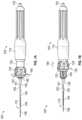
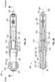
- FIGS. 2 A- 2 Dillustrate another embodiment of a shaft manipulating handle 205 as described herein.
- FIG. 2 Aillustrates a cutaway view of the casing 210 of the handle 205 to reveal the actuation sleeve 120 and proximal handle member 230 within, with the actuation sleeve 120 shown with a slight opacity reduction to reveal the internal cam interface 228 .
- FIG. 2 Billustrates a cross-sectional view of the handle 205 .
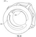
- FIG. 2 Cillustrates a perspective view of the actuation sleeve 220 of the handle 205 .
- FIGS. 2 A- 2 Dwill be discussed together below.
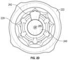
- FIG. 2 Dillustrates a front view of the handle.
- the handle 205can be operated in both rotational and plunging modalities for fine tool driving and dithering.
- the handle 205includes a casing 210 , actuation sleeve 220 , proximal handle member 230 , and distal handle member 240 positioned along a longitudinal axis 280 .
- a lumen 285(shown in FIG. 2 D ) can form a fluid pathway from the proximal end of the handle 205 to the distal end of the handle 205 .
- the casing 210can provide an internal volume to enclose at least a portion of the moving parts of the handle 205 , and can provide an external surface sized and shaped to provide a comfortable surface for grasping with a single hand in some implementations.
- the casing 210can include a distal aperture at its distal end and a proximal aperture at its proximal end.
- the casing 210can also include at least one prong 214 positioned to extend into the aperture 244 of the distal handle member 240 without occluding the handle lumen 285 in order to secure the distal handle member 240 relative to the casing 210 .
- a portion of the internal volume of the casingcan provide a housing 213 for constraining the range of motion of the actuation sleeve 220 and housing a biasing element.
- actuation sleeve 220can have a proximal flange 228 , a cylindrical body 225 extending from the flange 228 to a rotational wheel grip 224 , plunger grip 222 , and an internal cam interface 226 .
- Rotational wheel grip 224can be used to facilitate the rotational modality described herein
- the plunger grip 222can be used to facilitate the plunging modality described herein.
- FIG. 2 Cillustrates a perspective view showing example ridges forming the internal cam interface 226 .
- the proximal handle member 230can include, from its proximal end towards its distal end: fluid fitting 235 , proximal portion 236 , recess 237 for coupling with a tool conduit, elongate slot 232 , support annulus 233 , and external cam interface 231 .
- Proximal portion 236can comprise a flexible length of tubing as discussed above or can comprise a rigid shaft. If proximal portion 236 comprises a rigid shaft, the fluid fitting 235 can be at a proximal end of the rigid shaft and can move relative to the casing 210 during motion of the proximal handle member 230 .
- the external cam interface 231can be positioned at least partly within the actuation sleeve 220 .
- the external cam interface 231can engage the internal cam interface 226 of the actuation sleeve 220 to form a motion transmitting interface for transmitting rotational or linear motion of the actuation sleeve 220 to the proximal handle member 230 .
- the distal handle member 240can include a proximal shaft 243 positioned partially within the actuation sleeve 220 and partially within an internal receiving volume 239 of the proximal handle member 230 .
- the proximal shaft 243can have a recess or aperture 244 sized to accept the prong(s) 214 of the casing 210 , thereby fixing the position of the distal handle member 240 relative to the casing 210 .
- the distal handle member 240can include distal aperture 241 through which the conduit secured to the proximal handle member 230 may extend.
- FIG. 2 Dillustrates an example design for the distal end of the handle relating to markings for providing visual extension distance indicators.
- Position indicator 242can line up with (or be positioned between) radially-spaced distance indicators 229 on the actuation sleeve 220 .
- the tool coupled to handle 205may be positioned with its distal tip at or near the distal end of a jacket.
- Rotation of the actuation handle 240can cause controlled extension of the tool from the jacket, and the radially-spaced distance indicators 229 can provide visual indications of how far the distal tip of the tool is extended beyond the distal end of the jacket. Though illustrated as triangular configurations, other designs may use dots, lines, numerical markings, or a combination of these.
- FIGS. 3 A and 3 Billustrate photos of an example shaft manipulating handle 305 as described herein.
- FIG. 3 Aillustrates a disassembled view of the handle 305 .
- FIG. 3 Billustrates an assembled view of the handle 305 with the first casing portion 310 A removed to show the arrangement of the proximal handle member 330 , spring 390 , actuation sleeve 320 , and distal handle member 340 .
- the handle 305can include a casing, actuation sleeve 320 , proximal handle member 330 , distal handle member 340 , and can also include the spring 390 .
- the casingcan be formed in first and second portions 310 A, 310 B that can secure together around the cylindrical body 325 of the actuation sleeve 320 and a distal portion of the proximal handle member 330 .
- the casing 310 A, 310 Bcan provide an internal volume to enclose at least a portion of the moving parts of the handle 305 , and can provide an external surface sized and shaped to provide a comfortable surface for grasping with a single hand in some implementations.
- the casing 310 A, 310 Bcan include a distal aperture 311 at its distal end and a proximal aperture 316 at its proximal end.
- Each half of casing 310 A, 310 Bcan include a prong 314 A, 314 B positioned to extend into the aperture 344 of the distal handle member 340 without occluding a lumen extending through the handle 305 .
- thiscan secure the positioning of the distal handle member 340 relative to the casing 410 .
- a portion of the internal volume of the casingcan provide a housing 313 for constraining the range of motion of the actuation sleeve 320 and for housing spring 390 .
- actuation sleeve 320can have a proximal flange 328 , a cylindrical body 325 extending from the flange 328 to a rotational wheel grip 324 , plunger grip 322 , and an internal cam interface 326 (within the actuation sleeve 320 but not visible in FIG. 3 A ).
- Rotational wheel grip 324can be used to facilitate the rotational modality described herein
- the plunger grip 322can be used to facilitate the plunging modality described herein.
- the proximal handle member 330can include, from its proximal end towards its distal end: fluid fitting 335 , proximal portion 334 , a fastener or fastening mechanism (not shown) for coupling with a tool conduit, a pair of elongate slots 332 , support annulus 333 , and external cam interface 331 .
- Proximal portion 334can comprise a rigid shaft having fluid fitting 335 at a proximal end of the rigid shaft.
- fluid fitting 335can move relative to the casing 410 during motion of the proximal handle member 330 and the proximal portion 334 can be sized to pass through the proximal aperture 316 of the casing 310 A, 310 B.
- the external cam interface 331can be positioned at least partly within the actuation sleeve 320 .
- the external cam interface 331can engage the internal cam interface 326 of the actuation sleeve 320320 to form a motion transmitting interface for transmitting rotational or linear motion of the actuation sleeve 320 to the proximal handle member 330 .
- the distal handle member 340can include a proximal shaft 343 positioned partially within the actuation sleeve 320320 and partially within the proximal handle member 330 .
- the proximal shaft 343can have an aperture 344 sized to accept the prongs 314 A, 314 B of the casing 310 A, 310 B, thereby fixing the position of the distal handle member 340 relative to the casing 310 A, 310 B as shown in FIG. 3 B .
- the distal handle member 340can include distal aperture 341 through which the conduit secured to the proximal handle member 330 may extend and can include rotation indicator 342 .
- FIG. 3 Bthe actuation sleeve 320 , proximal handle member 330 , distal handle member 340 , and spring 390 are assembled with portion 310 B of the casing in place and portion 310 A open to show the interior configuration.
- FIG. 3 Billustrates how the spring 390 can be secured within the housing 313 to bias the actuation handle 320 distally with flange 328 pressed against flange 317 of the casing.
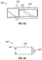
- FIGS. 4 A- 4 Hillustrate another embodiment of a shaft manipulating handle 4405 as described herein.
- the handlecan be used with any of the tools described herein.
- FIGS. 4 A- 5 Dillustrate the handle 405 in various states of retraction and extension.
- FIG. 4 Aillustrates the handle 405 in a full extension position 400 A. In implementations used to drive movement of a biopsy needle through a jacket, for example, the needle would be extended out of the jacket to its maximum extension distance with the handle 405 in the position 400 A of FIG. 4 A .
- FIG. 4 Billustrates the handle 405 in a retraction position 400 B showing the full retraction available via the rotational modality.
- FIG. 4 Cillustrates the handle 405 in a full retraction position 400 C showing the full retraction available via both the rotational modality and the plunging modality.
- the needleIn the example implementation used to drive movement of the biopsy needle, the needle would be retracted into the jacket to its maximum retraction distance with the handle 405 in the position 400 C of FIG. 4 C .
- the handle 4405can return to the position 400 B of FIG. 4 B via force from a biasing element.
- FIG. 4 Dillustrates the handle 405 in an intermediate retraction position 400 D showing the full retraction available via the plunging modality at an intermediate extension via the rotational modality.
- FIG. 4 Drepresents one option for dithering a tool into and out of a tissue site in use.
- the tool coupled to the handlewould be driven distally with force from the biasing element.
- FIGS. 4 E- 4 Hillustrate the components of the handle 405 .
- FIG. 4 Eillustrates the base 410 of the handle
- FIG. 4 Fillustrates the shaft 420 of the handle
- FIG. 4 Gillustrates the cam 430 of the handle
- FIG. 4 Hillustrates the cap 440 of the handle.
- the base 410includes a grip portion 411 having an internal pocket 412 , a body 413 having an inner channel 415 , side slots 416 , and prongs 414 .
- the grip portion 411can be rotated or plunged by an operator (human or robotic) to actuate the shaft of a medical instrument coupled to the handle.
- the base 410provides a supporting structure for the other components of the handle.
- the body 413can extend distally from the grip portion 414 and can be formed as two elongate members each having an arc-shaped cross section. These two elongate members can be separated on opposing sides of the base 410 by gaps to form side slots 416 .
- These slots 416 between the elongated memberscan slidably engage the cross-pin members 423 of the shaft 420 to prevent the shaft 420 from rotating relative to the base 410 .
- the outer surfaces of the elongate members of the body 413provide an approximately cylindrical surface for slidably engaging the inner surface 433 of the cam 430 during operation of the handle.
- the internal pocket 412provides a space for containing a spring or other biasing element that can push against the flange 431 of the cam 430 .
- the inner channel 415provides an internal cylindrical pathway within which the shaft 420 can move linearly during use.
- the prongs 414can provide a locking interface for the cap 440 .
- the shaft 420includes an elongated body 422 with a cross-pin feature 423 and an attachment site 421 for fluidically coupling with an aspiration device.
- the shaft 420can include an interior pathway or lumen, for example to facilitate provision of aspiration through the lumen of an elongate instrument movable via the handle.
- the shaft 420 of the handlewould be operably coupled to the proximal end of the elongate shaft of the medical instrument to drive extension and retraction of the tool coupled to the distal end of the shaft.
- linear motion of this shaftis an objective of the handle.
- the cam 430includes flange 431 , inner diameter 433 , and a helical groove 432 along its internal surface.
- the groove 432can be sized to receive the cross-pin of the shaft 420 and to act as a female internal cam interface.
- This cam interfacecan have the illustrated helical groove, or can have any spiral profile to achieve the desired linear motion of the shaft for a given amount of twist on the cam 430 .
- Flange 431can be used as a grip to facilitate the retraction of the plunging motion of the handle and can engage a biasing element in the pocket 412 to drive extension of the plunging motion upon release of proximally-directed pressure from the flange 431 .
- the cap 440fastens to prongs 414 of the base 410 via fastening features 441 .
- the cap 440provides a physical stop to prevent the cam 430 from moving off the base 410 .
- the cap 440can include an aperture 443 through which a tubular jacket of an instrument may be passed, as described above.
- FIGS. 4 A- 4 His a spring or other biasing mechanism that would be placed in the pocket 412 of the base 410 to return the cam 430 to a full-forward position when no proximal linear force is exerted upon it.
- FIGS. 5 A- 5 Eillustrate various alternate handle embodiments.
- FIG. 5 Aillustrates one embodiment of a handle 500 A having a jacket 515 extending therefrom and having motion interfaces including a plunging interface 505 and an in-line linear slider 510 .
- a conduit having a tool at its distal endcan be positioned within the jacket 515 .
- the distal end of the toolcan be positioned at or proximally to the distal end of the jacket.
- movement of the toolcan be driven by movement of the conduit.
- the slider 510includes a tab 512 slidable within a track 514 .
- the tab 512can be coupled to an internal drive member that, in turn, is coupled to a proximal end of the conduit.
- linear motion 516 of the tab 512can translate 1:1 into extension or retraction of the instrument relative to the distal end of the jacket 515 .
- the tab 512When the tab 512 is positioned at a proximal end 518 A of the track 514 the tool can be in a fully retracted position relative to the jacket 515 .
- the tab 512When the tab 512 is positioned at the distal end 518 A of the track 514 the tool can be in a fully extended position relative to the jacket 515 .
- the tab 512can be slid to any intermediate position between the proximal and distal ends 518 A, 518 B and may lock in place.
- the tab 512may include a button that, when depressed, allows the sliding motion 516 and that, when released, locks the slider.
- distance markingscan be provided along the handle at or near the track 514 to indicate how far the tool is extended.
- the plunging interface 505can be retracted proximally to withdraw an extended tool proximally into the jacket 515 and may be biased to return to the illustrated extended position upon release of force from the plunging interface 505 .
- the plunging interface 505can be used to actuate a dithering motion as described above.
- the plunging interface 505can extend the tool and be biased toward the retracted position.
- the tab 512can slide through the track 514 to provide a visual indication of the extension and/or retraction distance of the tool.
- FIGS. 5 B- 5 Dillustrate another embodiment of the handle 500 B having the jacket 515 and the plunging interface 505 , and also having a rack and pinion actuator 520 .
- the tool and conduitcan be positioned at least partly within the jacket 515 and the rack and pinion actuator 520 can drive the fine-control extension and retraction of the tool.
- FIG. 5 Bdepicts a cutaway top view of the handle 500 B and shows the outline of both the exterior and interior components of the rack and pinion actuator 520 , with dashed lines showing the outline of elements positioned behind other elements (from the perspective of the illustrated viewpoint).
- the rack and pinion actuator 520includes a rotational wheel 521 having a detent 522 to facilitate grip during rotation by a user. Alternate embodiments could additionally or alternatively include ridges around the outer circumference of the wheel 521 .
- the wheel 521is coupled to a gear 523 having a number of radial teeth. These teeth can engage corresponding teeth 525 in a rack 524 to actuate linear motion along the longitudinal axis of the handle 500 B in response to rotation 530 of the wheel 521 .
- the rack 524can move linearly within the handle 500 B and can be coupled to the internal drive member that, in turn, is coupled to the proximal end of the conduit. Thus, movement of the rack 524 can translate 1:1 into extension or retraction of the instrument relative to the distal end of the jacket 515 .
- the wheel 521 and gear 523can move linearly along the handle and the gear 523 can be coupled to the internal drive member to actuate the tool extension and retraction.
- the wheel 521is located on the outside of the handle 500 B.
- the gear 523 and rack 524are positioned within the handle 500 B.
- the plunging interface 505 of the handle 500 Bcan be retracted proximally and/or extended distally to withdraw or extend the tool relative to the jacket 515 and may be biased to return to its initial position upon release of force from the plunging interface 505 .
- the plunging interface 505can be used to actuate a dithering motion as described above.
- the wheel 521may rotate and/or the entire rack and pinion actuator 520 can move proximally and distally. This can be accompanied by distance markings to provide a visual indication of the extension and/or retraction distance of the tool.
- FIG. 5 Eillustrates another embodiment of the handle 500 B having the jacket 515 and the plunging interface 505 , and also having an incremental rotation actuator 540 .
- FIG. 5 Edepicts a cutaway top view of the handle 500 C and shows the outline of both the exterior and interior components of the rack and incremental rotation actuator 540 , with dashed lines showing the outline of elements positioned behind other elements (from the perspective of the illustrated viewpoint).
- the tool and conduitcan be positioned at least partly within the jacket 515 and the rack and incremental rotation actuator 540 can drive the fine-control extension and retraction of the tool.
- the incremental rotation actuator 540includes a rotational wheel 541 having a number of spokes 542 extending inwardly (e.g., toward the interior of the handle 500 C) from the wheel 541 .
- the top or user-facing side of the wheel 541can have a detent and/or ridges around its circumference to facilitate grip during rotation by a user, similar to the wheel 521 of FIG. 5 C .
- the incremental rotation actuator 540also includes a gear 543 and a rack 546 .
- the gear 543can include a number of first teeth 544 that are engaged by the spokes 542 .
- the gear 543can also rotate by a predetermined amount corresponding to the number of the first teeth 544 and the number of spokes 542 .
- a number of second teeth 545also rotate.
- the second teeth 545can engage the teeth 547 of the rack 546 to move the rack 546 linearly within the handle 500 C.
- the rack 546can be coupled to the internal drive member that, in turn, is coupled to the proximal end of the conduit.
- movement of the rack 524can translate 1:1 into extension or retraction of the instrument relative to the distal end of the jacket 515 .
- ten degrees of rotationcan correspond to a 5 mm movement of the tool.
- Other embodimentscan be designed to correlate other degrees of rotation with other movement distances.
- the handle 500 Ccan provide for movement of the tool in predetermined increments based on the rotation 550 of the wheel 541 .
- the plunging interface 505 of handle 500 Ccan be retracted proximally and/or extended distally to withdraw or extend the tool relative to the jacket 515 and may be biased to return to its initial position upon release of force from the plunging interface 505 .
- the plunging interface 505can be used to actuate a dithering motion as described above.
- the wheel 541may rotate and/or the entire incremental rotation actuator 540 can move proximally and distally. This can be accompanied by distance markings to provide a visual indication of the extension and/or retraction distance of the tool.
- FIG. 6depicts a schematic diagram of a robotic surgical system 600 for actuating a handle 605 as described herein. Though shown with a particular configuration of the handle 605 , any of the described handles can be used with such a system 600 .
- the instrument handlemay have a barcode, radio-frequency identifier (RFID), or other suitable identifier to enable the robotic surgical system 600 to identify the handle.
- RFIDradio-frequency identifier
- the example robotic system 600includes an articulated arm 610 configured to locate, and maintain positioning of, the handle 605 .
- a first grip portion 625for controlling aspiration or administering therapeutics and two additional grip portions 615 , 620 that can open to receive the handle 5605 and close around respective portions of the handle 605 .
- the first grip portion 625can include one or more actuators for gripping and controlling a source of negative (or positive pressure) and/or therapeutics.
- the first grip portion 625can include a first actuator for attaching a syringe and a second actuator for robotically controlling a plunger of the syringe.
- the second grip portion 615may maintain a stationary grip and positioning on the handle 605 to provide stability.
- the third grip portion 620can be configured to effect the rotational modality of the handle described herein by rotating a wheel or grip of the handle. Further, the third grip portion 620 can be configured to move laterally with respect to the longitudinal axis of the handle to provide the plunging modality described herein. In other embodiments the second grip portion 615 can move to effect the plunging and rotational modalities, alone or in combination with movement of the third grip portion 620 .
- the grip portions 615 , 620 , 625can be driven by one or more motors and appropriate actuation mechanisms.
- the robotic surgical system 600is shown with one embodiment of a handle 605 as described herein. Other embodiments of the robotic surgical system 600 can be used to operate variations of the disclosed handle embodiments, for example including different actuation interfaces (e.g., two plunging interfaces, two rotational interfaces, etc.).
- the robotic surgical system 600can be configured to control and any or all of the handle actuations, for example the fine control extension/retraction only, dithering only, or both as described above.
- the robotic surgical system 600can include a processor(s) and memory.
- the memorycan store instructions for operation of the various components of the robotic surgical system 600 as well as data produced and used during a surgical procedure.
- the processor(s)can execute these instructions and process such data to cause operation of the system 600 .
- the robotic surgical system 600can include other components, for example one or more input devices for receiving user input to control motion of surgical instruments (e.g., joysticks, handles, computer mice, trackpads, and gesture detection systems), instrument drivers to effect the motion of the surgical instruments, an additional grip portion for securing and controlling motion of an aspiration device coupled to the handle, a display screen, and the like.
- surgical instrumentse.g., joysticks, handles, computer mice, trackpads, and gesture detection systems
- instrument driversto effect the motion of the surgical instruments
- an additional grip portionfor securing and controlling motion of an aspiration device coupled to the handle, a display screen, and the like.
- FIG. 7depicts a flowchart of an embodiment of a process 700 for driving movement of a medical instrument using the handles described herein, for example, handles 105 , 205 , 305 , 405 , 500 A- 500 C, and 605 as described above).
- the process 700can be implemented by a human operator manually manipulating the handle, a robotic control system operator (such as system 600 described above) mechanically manipulating the handle as directed by a human operator or autonomously, or a combination thereof.
- the operatore.g., a human operator or autonomous surgical robot
- the operatorcan position a jacket containing an instrument at or near a tissue site of a patient.
- the instrumentcan be positioned with its distal tip at or near the distal end of the jacket 150 and a conduit 154 or shaft can extend from the proximal end of the tool through the jacket.
- the jacketcan be inserted through the working channel of an endoscope such as a bronchoscope in some embodiments, and the tool can be a needle, brush, forceps, or the like.
- the conduitcan be coupled to a handle 105 , 205 , 305 , 405 , 500 A- 500 C, 605 for driving linear motion of the conduit relative to the jacket.
- the operatorcan actuate a first motion transmitting interface of the delivery handle 105 , 205 , 305 , 405 , 500 A- 500 C, 605 coupled to the instrument to drive the distal end of the instrument to advance through the jacket.
- thiscan involve actuation of a rotational modality of the handle, for example by rotational grip 122 , 222 , 322 or actuation of the motion mechanisms described with respect to handles 500 A- 500 C. Actuation of such a modality can allow the operator to exert fine control over extending the distal tip of the instrument out from the distal end of the jacket. In some procedures, this can involve extending the distal tip of the instrument until it has pierced patient tissue.
- the operatorcan determine that the distal end of the instrument is positioned at the target tissue site.
- a physicianmay view an image or video of the tissue site via an imaging device at the distal end of an endoscope working channel and may visually confirm that the instrument is positioned at or within the target tissue site. For example, this can be accomplished via fluoroscopy.
- the physicianmay view a rendering or model of the positioning of the instrument relative to the patient tissue site to make this determination, for example as output from a robotic bronchoscopy navigation system.
- block 715can be performed programmatically via automated image analysis and/or navigation.
- the operatorcan actuate a second motion transmitting interface of the delivery handle 105 , 205 , 305 , 405 , 500 A- 500 C, 605 to drive extension and retraction of the distal end of the instrument. As described above and shown in the example of FIG. 1 B , this can involve actuation of a plunging modality, for example by plunging grip 122 , 222 , 322 .
- actuation of the second motion transmitting interfacecan involve a first step of retraction and a second step of extension.
- the operatorcan apply pressure to a portion of the delivery handle to (1) compress a biasing element of the second motion transmitting interface, and (2) drive retracting motion of the instrument to withdraw the distal end of the instrument from the tissue site.
- the operatorcan release at least some of the pressure from the portion of the delivery handle to allow expansion of the second motion transmitting interface to drive the distal end of the into the tissue site.
- the handlecan be structured such that application of pressure results in extension of the tool and release of the pressure retracts the tool. Repetition of blocks 725 and 760 can generate a dithering motion of the tool through repeated extension and retraction which, as described above, may be beneficial in tissue sampling.
- the instrumentcan be withdrawn back into the jacket, for example via the first motion transmitting interface, and the jacket can be withdrawn from the patient tissue site. Any obtained sample can be expelled from the instrument for the desired analysis.
- Implementations disclosed hereinprovide systems, methods and apparatus for actuating extension and retraction of a remotely-disposed instrument by way of linear motion of a shaft of the instrument secured within a handle.
- Couplemay indicate either an indirect connection or a direct connection.
- first componentmay be either indirectly connected to the second component via another component or directly connected to the second component.
- the robotic motion actuation functions described hereinmay be stored as one or more instructions on a processor-readable or computer-readable medium.
- the term “computer-readable medium”refers to any available medium that can be accessed by a computer or processor.
- a mediummay comprise RAM, ROM, EEPROM, flash memory, CD-ROM or other optical disk storage, magnetic disk storage or other magnetic storage devices, or any other medium that can be used to store desired program code in the form of instructions or data structures and that can be accessed by a computer.
- a computer-readable mediummay be tangible and non-transitory.
- the term “code”may refer to software, instructions, code or data that is/are executable by a computing device or processor.
- the methods disclosed hereincomprise one or more steps or actions for achieving the described method.
- the method steps and/or actionsmay be interchanged with one another without departing from the scope of the claims.
- the order and/or use of specific steps and/or actionsmay be modified without departing from the scope of the claims.
- the term “plurality”denotes two or more. For example, a plurality of components indicates two or more components.
- the term “determining”encompasses a wide variety of actions and, therefore, “determining” can include calculating, computing, processing, deriving, investigating, looking up (e.g., looking up in a table, a database or another data structure), ascertaining and the like. Also, “determining” can include receiving (e.g., receiving information), accessing (e.g., accessing data in a memory) and the like. Also, “determining” can include resolving, selecting, choosing, establishing and the like.
Landscapes
- Health & Medical Sciences (AREA)
- Life Sciences & Earth Sciences (AREA)
- Surgery (AREA)
- Engineering & Computer Science (AREA)
- Public Health (AREA)
- Veterinary Medicine (AREA)
- Animal Behavior & Ethology (AREA)
- General Health & Medical Sciences (AREA)
- Biomedical Technology (AREA)
- Heart & Thoracic Surgery (AREA)
- Nuclear Medicine, Radiotherapy & Molecular Imaging (AREA)
- Medical Informatics (AREA)
- Molecular Biology (AREA)
- Biophysics (AREA)
- Radiology & Medical Imaging (AREA)
- Pathology (AREA)
- Physics & Mathematics (AREA)
- Optics & Photonics (AREA)
- Pulmonology (AREA)
- Hematology (AREA)
- Anesthesiology (AREA)
- Physiology (AREA)
- Otolaryngology (AREA)
- Robotics (AREA)
- Surgical Instruments (AREA)
- Endoscopes (AREA)
- Media Introduction/Drainage Providing Device (AREA)
- Mechanically-Actuated Valves (AREA)
- Mechanical Control Devices (AREA)
- Domestic Plumbing Installations (AREA)
Abstract
Description
Claims (20)
Priority Applications (1)
| Application Number | Priority Date | Filing Date | Title |
|---|---|---|---|
| US17/037,296US11992183B2 (en) | 2017-03-28 | 2020-09-29 | Shaft actuating handle |
Applications Claiming Priority (3)
| Application Number | Priority Date | Filing Date | Title |
|---|---|---|---|
| US201762477872P | 2017-03-28 | 2017-03-28 | |
| US15/937,516US10792466B2 (en) | 2017-03-28 | 2018-03-27 | Shaft actuating handle |
| US17/037,296US11992183B2 (en) | 2017-03-28 | 2020-09-29 | Shaft actuating handle |
Related Parent Applications (1)
| Application Number | Title | Priority Date | Filing Date |
|---|---|---|---|
| US15/937,516ContinuationUS10792466B2 (en) | 2017-03-28 | 2018-03-27 | Shaft actuating handle |
Publications (2)
| Publication Number | Publication Date |
|---|---|
| US20210008341A1 US20210008341A1 (en) | 2021-01-14 |
| US11992183B2true US11992183B2 (en) | 2024-05-28 |
Family
ID=63671975
Family Applications (2)
| Application Number | Title | Priority Date | Filing Date |
|---|---|---|---|
| US15/937,516ActiveUS10792466B2 (en) | 2017-03-28 | 2018-03-27 | Shaft actuating handle |
| US17/037,296Active2039-01-10US11992183B2 (en) | 2017-03-28 | 2020-09-29 | Shaft actuating handle |
Family Applications Before (1)
| Application Number | Title | Priority Date | Filing Date |
|---|---|---|---|
| US15/937,516ActiveUS10792466B2 (en) | 2017-03-28 | 2018-03-27 | Shaft actuating handle |
Country Status (7)
| Country | Link |
|---|---|
| US (2) | US10792466B2 (en) |
| EP (1) | EP3599979A4 (en) |
| JP (1) | JP7159192B2 (en) |
| KR (1) | KR102545869B1 (en) |
| CN (1) | CN108934160B (en) |
| AU (1) | AU2018244318B2 (en) |
| WO (1) | WO2018183393A1 (en) |
Cited By (1)
| Publication number | Priority date | Publication date | Assignee | Title |
|---|---|---|---|---|
| RU231567U1 (en)* | 2024-07-31 | 2025-01-31 | Общество с ограниченной ответственностью "НПК Вектор" | Endoscopic device for fine needle aspiration biopsy |
Families Citing this family (191)
| Publication number | Priority date | Publication date | Assignee | Title |
|---|---|---|---|---|
| US8414505B1 (en) | 2001-02-15 | 2013-04-09 | Hansen Medical, Inc. | Catheter driver system |
| WO2005087128A1 (en) | 2004-03-05 | 2005-09-22 | Hansen Medical, Inc. | Robotic catheter system |
| JP2009500086A (en) | 2005-07-01 | 2009-01-08 | ハンセン メディカル,インク. | Robotic guide catheter system |
| US9232959B2 (en) | 2007-01-02 | 2016-01-12 | Aquabeam, Llc | Multi fluid tissue resection methods and devices |
| US12290277B2 (en) | 2007-01-02 | 2025-05-06 | Aquabeam, Llc | Tissue resection with pressure sensing |
| ES2769535T3 (en) | 2008-03-06 | 2020-06-26 | Aquabeam Llc | Tissue ablation and cauterization with optical energy carried in a fluid stream |
| US9254123B2 (en) | 2009-04-29 | 2016-02-09 | Hansen Medical, Inc. | Flexible and steerable elongate instruments with shape control and support elements |
| US8672837B2 (en) | 2010-06-24 | 2014-03-18 | Hansen Medical, Inc. | Methods and devices for controlling a shapeable medical device |
| US20120071752A1 (en) | 2010-09-17 | 2012-03-22 | Sewell Christopher M | User interface and method for operating a robotic medical system |
| US20120191079A1 (en) | 2011-01-20 | 2012-07-26 | Hansen Medical, Inc. | System and method for endoluminal and translumenal therapy |
| US20130030363A1 (en) | 2011-07-29 | 2013-01-31 | Hansen Medical, Inc. | Systems and methods utilizing shape sensing fibers |
| US10238837B2 (en) | 2011-10-14 | 2019-03-26 | Intuitive Surgical Operations, Inc. | Catheters with control modes for interchangeable probes |
| US9387048B2 (en) | 2011-10-14 | 2016-07-12 | Intuitive Surgical Operations, Inc. | Catheter sensor systems |
| US9452276B2 (en) | 2011-10-14 | 2016-09-27 | Intuitive Surgical Operations, Inc. | Catheter with removable vision probe |
| US20130303944A1 (en) | 2012-05-14 | 2013-11-14 | Intuitive Surgical Operations, Inc. | Off-axis electromagnetic sensor |
| EP3351196A1 (en) | 2012-02-29 | 2018-07-25 | Procept Biorobotics Corporation | Automated image-guided tissue resection and treatment |
| US10383765B2 (en) | 2012-04-24 | 2019-08-20 | Auris Health, Inc. | Apparatus and method for a global coordinate system for use in robotic surgery |
| US20130317519A1 (en) | 2012-05-25 | 2013-11-28 | Hansen Medical, Inc. | Low friction instrument driver interface for robotic systems |
| US20140148673A1 (en) | 2012-11-28 | 2014-05-29 | Hansen Medical, Inc. | Method of anchoring pullwire directly articulatable region in catheter |
| US10231867B2 (en) | 2013-01-18 | 2019-03-19 | Auris Health, Inc. | Method, apparatus and system for a water jet |
| US9668814B2 (en) | 2013-03-07 | 2017-06-06 | Hansen Medical, Inc. | Infinitely rotatable tool with finite rotating drive shafts |
| US10149720B2 (en) | 2013-03-08 | 2018-12-11 | Auris Health, Inc. | Method, apparatus, and a system for facilitating bending of an instrument in a surgical or medical robotic environment |
| US9566414B2 (en) | 2013-03-13 | 2017-02-14 | Hansen Medical, Inc. | Integrated catheter and guide wire controller |
| US9057600B2 (en) | 2013-03-13 | 2015-06-16 | Hansen Medical, Inc. | Reducing incremental measurement sensor error |
| US9326822B2 (en) | 2013-03-14 | 2016-05-03 | Hansen Medical, Inc. | Active drives for robotic catheter manipulators |
| US20140277334A1 (en) | 2013-03-14 | 2014-09-18 | Hansen Medical, Inc. | Active drives for robotic catheter manipulators |
| US11213363B2 (en) | 2013-03-14 | 2022-01-04 | Auris Health, Inc. | Catheter tension sensing |
| US9173713B2 (en) | 2013-03-14 | 2015-11-03 | Hansen Medical, Inc. | Torque-based catheter articulation |
| US9271663B2 (en) | 2013-03-15 | 2016-03-01 | Hansen Medical, Inc. | Flexible instrument localization from both remote and elongation sensors |
| US9283046B2 (en) | 2013-03-15 | 2016-03-15 | Hansen Medical, Inc. | User interface for active drive apparatus with finite range of motion |
| US20140276647A1 (en) | 2013-03-15 | 2014-09-18 | Hansen Medical, Inc. | Vascular remote catheter manipulator |
| US10376672B2 (en) | 2013-03-15 | 2019-08-13 | Auris Health, Inc. | Catheter insertion system and method of fabrication |
| US9408669B2 (en) | 2013-03-15 | 2016-08-09 | Hansen Medical, Inc. | Active drive mechanism with finite range of motion |
| US20140276936A1 (en) | 2013-03-15 | 2014-09-18 | Hansen Medical, Inc. | Active drive mechanism for simultaneous rotation and translation |
| US10849702B2 (en) | 2013-03-15 | 2020-12-01 | Auris Health, Inc. | User input devices for controlling manipulation of guidewires and catheters |
| US9014851B2 (en) | 2013-03-15 | 2015-04-21 | Hansen Medical, Inc. | Systems and methods for tracking robotically controlled medical instruments |
| US9452018B2 (en) | 2013-03-15 | 2016-09-27 | Hansen Medical, Inc. | Rotational support for an elongate member |
| US9629595B2 (en) | 2013-03-15 | 2017-04-25 | Hansen Medical, Inc. | Systems and methods for localizing, tracking and/or controlling medical instruments |
| US11020016B2 (en) | 2013-05-30 | 2021-06-01 | Auris Health, Inc. | System and method for displaying anatomy and devices on a movable display |
| WO2014201165A1 (en) | 2013-06-11 | 2014-12-18 | Auris Surgical Robotics, Inc. | System for robotic assisted cataract surgery |
| US10426661B2 (en) | 2013-08-13 | 2019-10-01 | Auris Health, Inc. | Method and apparatus for laser assisted cataract surgery |
| EP3060157B1 (en) | 2013-10-24 | 2019-12-11 | Auris Health, Inc. | System for robotic-assisted endolumenal surgery |
| EP3243476B1 (en) | 2014-03-24 | 2019-11-06 | Auris Health, Inc. | Systems and devices for catheter driving instinctiveness |
| US10046140B2 (en) | 2014-04-21 | 2018-08-14 | Hansen Medical, Inc. | Devices, systems, and methods for controlling active drive systems |
| US10569052B2 (en) | 2014-05-15 | 2020-02-25 | Auris Health, Inc. | Anti-buckling mechanisms for catheters |
| US9561083B2 (en) | 2014-07-01 | 2017-02-07 | Auris Surgical Robotics, Inc. | Articulating flexible endoscopic tool with roll capabilities |
| US10792464B2 (en) | 2014-07-01 | 2020-10-06 | Auris Health, Inc. | Tool and method for using surgical endoscope with spiral lumens |
| US9744335B2 (en) | 2014-07-01 | 2017-08-29 | Auris Surgical Robotics, Inc. | Apparatuses and methods for monitoring tendons of steerable catheters |
| EP3200718A4 (en) | 2014-09-30 | 2018-04-25 | Auris Surgical Robotics, Inc | Configurable robotic surgical system with virtual rail and flexible endoscope |
| US10499999B2 (en) | 2014-10-09 | 2019-12-10 | Auris Health, Inc. | Systems and methods for aligning an elongate member with an access site |
| US10314463B2 (en) | 2014-10-24 | 2019-06-11 | Auris Health, Inc. | Automated endoscope calibration |
| US11819636B2 (en) | 2015-03-30 | 2023-11-21 | Auris Health, Inc. | Endoscope pull wire electrical circuit |
| US20160287279A1 (en) | 2015-04-01 | 2016-10-06 | Auris Surgical Robotics, Inc. | Microsurgical tool for robotic applications |
| WO2016164824A1 (en) | 2015-04-09 | 2016-10-13 | Auris Surgical Robotics, Inc. | Surgical system with configurable rail-mounted mechanical arms |
| US9622827B2 (en) | 2015-05-15 | 2017-04-18 | Auris Surgical Robotics, Inc. | Surgical robotics system |
| CN108348133B (en) | 2015-09-09 | 2020-11-13 | 奥瑞斯健康公司 | Instrument Manipulators for Surgical Robotic Systems |
| JP6824967B2 (en) | 2015-09-18 | 2021-02-03 | オーリス ヘルス インコーポレイテッド | Tubular net navigation |
| US9949749B2 (en) | 2015-10-30 | 2018-04-24 | Auris Surgical Robotics, Inc. | Object capture with a basket |
| US9955986B2 (en) | 2015-10-30 | 2018-05-01 | Auris Surgical Robotics, Inc. | Basket apparatus |
| US10231793B2 (en) | 2015-10-30 | 2019-03-19 | Auris Health, Inc. | Object removal through a percutaneous suction tube |
| US10143526B2 (en) | 2015-11-30 | 2018-12-04 | Auris Health, Inc. | Robot-assisted driving systems and methods |
| US10932861B2 (en) | 2016-01-14 | 2021-03-02 | Auris Health, Inc. | Electromagnetic tracking surgical system and method of controlling the same |
| US10932691B2 (en) | 2016-01-26 | 2021-03-02 | Auris Health, Inc. | Surgical tools having electromagnetic tracking components |
| US11324554B2 (en) | 2016-04-08 | 2022-05-10 | Auris Health, Inc. | Floating electromagnetic field generator system and method of controlling the same |
| US10454347B2 (en) | 2016-04-29 | 2019-10-22 | Auris Health, Inc. | Compact height torque sensing articulation axis assembly |
| US11037464B2 (en) | 2016-07-21 | 2021-06-15 | Auris Health, Inc. | System with emulator movement tracking for controlling medical devices |
| US10463439B2 (en) | 2016-08-26 | 2019-11-05 | Auris Health, Inc. | Steerable catheter with shaft load distributions |
| US11241559B2 (en) | 2016-08-29 | 2022-02-08 | Auris Health, Inc. | Active drive for guidewire manipulation |
| KR20230096148A (en) | 2016-08-31 | 2023-06-29 | 아우리스 헬스, 인코포레이티드 | Length conservative surgical instrument |
| US9931025B1 (en)* | 2016-09-30 | 2018-04-03 | Auris Surgical Robotics, Inc. | Automated calibration of endoscopes with pull wires |
| US10543048B2 (en) | 2016-12-28 | 2020-01-28 | Auris Health, Inc. | Flexible instrument insertion using an adaptive insertion force threshold |
| US10136959B2 (en) | 2016-12-28 | 2018-11-27 | Auris Health, Inc. | Endolumenal object sizing |
| US10244926B2 (en) | 2016-12-28 | 2019-04-02 | Auris Health, Inc. | Detecting endolumenal buckling of flexible instruments |
| CN108934160B (en) | 2017-03-28 | 2021-08-31 | 奥瑞斯健康公司 | Shaft actuating handle |
| WO2018183727A1 (en) | 2017-03-31 | 2018-10-04 | Auris Health, Inc. | Robotic systems for navigation of luminal networks that compensate for physiological noise |
| US10285574B2 (en) | 2017-04-07 | 2019-05-14 | Auris Health, Inc. | Superelastic medical instrument |
| EP3606400B1 (en) | 2017-04-07 | 2022-03-09 | Auris Health, Inc. | Patient introducer alignment |
| KR102643758B1 (en) | 2017-05-12 | 2024-03-08 | 아우리스 헬스, 인코포레이티드 | Biopsy devices and systems |
| KR102576296B1 (en) | 2017-05-17 | 2023-09-08 | 아우리스 헬스, 인코포레이티드 | Interchangeable working channels |
| US10022192B1 (en) | 2017-06-23 | 2018-07-17 | Auris Health, Inc. | Automatically-initialized robotic systems for navigation of luminal networks |
| US11026758B2 (en) | 2017-06-28 | 2021-06-08 | Auris Health, Inc. | Medical robotics systems implementing axis constraints during actuation of one or more motorized joints |
| WO2019005696A1 (en) | 2017-06-28 | 2019-01-03 | Auris Health, Inc. | Electromagnetic distortion detection |
| CN116725667A (en) | 2017-06-28 | 2023-09-12 | 奥瑞斯健康公司 | System for providing positioning information and method for positioning an instrument within an anatomical structure |
| US10299870B2 (en) | 2017-06-28 | 2019-05-28 | Auris Health, Inc. | Instrument insertion compensation |
| US10426559B2 (en) | 2017-06-30 | 2019-10-01 | Auris Health, Inc. | Systems and methods for medical instrument compression compensation |
| US10464209B2 (en) | 2017-10-05 | 2019-11-05 | Auris Health, Inc. | Robotic system with indication of boundary for robotic arm |
| US10016900B1 (en) | 2017-10-10 | 2018-07-10 | Auris Health, Inc. | Surgical robotic arm admittance control |
| US10145747B1 (en) | 2017-10-10 | 2018-12-04 | Auris Health, Inc. | Detection of undesirable forces on a surgical robotic arm |
| US11058493B2 (en) | 2017-10-13 | 2021-07-13 | Auris Health, Inc. | Robotic system configured for navigation path tracing |
| US10555778B2 (en) | 2017-10-13 | 2020-02-11 | Auris Health, Inc. | Image-based branch detection and mapping for navigation |
| EP3684282B1 (en) | 2017-12-06 | 2024-02-21 | Auris Health, Inc. | Systems to correct for uncommanded instrument roll |
| WO2019113391A1 (en) | 2017-12-08 | 2019-06-13 | Auris Health, Inc. | System and method for medical instrument navigation and targeting |
| JP7208237B2 (en) | 2017-12-08 | 2023-01-18 | オーリス ヘルス インコーポレイテッド | Systems and medical devices for performing medical procedures |
| CN111770736A (en) | 2017-12-11 | 2020-10-13 | 奥瑞斯健康公司 | Systems and methods for instrument-based insertion architectures |
| US11510736B2 (en) | 2017-12-14 | 2022-11-29 | Auris Health, Inc. | System and method for estimating instrument location |
| WO2019125964A1 (en) | 2017-12-18 | 2019-06-27 | Auris Health, Inc. | Methods and systems for instrument tracking and navigation within luminal networks |
| USD901018S1 (en) | 2018-01-17 | 2020-11-03 | Auris Health, Inc. | Controller |
| USD932628S1 (en) | 2018-01-17 | 2021-10-05 | Auris Health, Inc. | Instrument cart |
| KR102264368B1 (en) | 2018-01-17 | 2021-06-17 | 아우리스 헬스, 인코포레이티드 | Surgical platform with adjustable arm support |
| EP3740150A4 (en) | 2018-01-17 | 2021-11-03 | Auris Health, Inc. | SURGICAL ROBOTIC SYSTEMS WITH IMPROVED ROBOTIC ARMS |
| USD901694S1 (en) | 2018-01-17 | 2020-11-10 | Auris Health, Inc. | Instrument handle |
| USD873878S1 (en) | 2018-01-17 | 2020-01-28 | Auris Health, Inc. | Robotic arm |
| USD924410S1 (en) | 2018-01-17 | 2021-07-06 | Auris Health, Inc. | Instrument tower |
| KR20240118200A (en) | 2018-02-13 | 2024-08-02 | 아우리스 헬스, 인코포레이티드 | System and method for driving medical instrument |
| JP7225259B2 (en) | 2018-03-28 | 2023-02-20 | オーリス ヘルス インコーポレイテッド | Systems and methods for indicating probable location of instruments |
| CN117017505A (en) | 2018-03-28 | 2023-11-10 | 奥瑞斯健康公司 | Composite instrument and robotic system |
| WO2019191144A1 (en) | 2018-03-28 | 2019-10-03 | Auris Health, Inc. | Systems and methods for registration of location sensors |
| US10872449B2 (en) | 2018-05-02 | 2020-12-22 | Covidien Lp | System and method for constructing virtual radial ultrasound images from CT data and performing a surgical navigation procedure using virtual ultrasound images |
| US11179213B2 (en) | 2018-05-18 | 2021-11-23 | Auris Health, Inc. | Controllers for robotically-enabled teleoperated systems |
| US10905499B2 (en) | 2018-05-30 | 2021-02-02 | Auris Health, Inc. | Systems and methods for location sensor-based branch prediction |
| MX2020012904A (en) | 2018-05-31 | 2021-02-26 | Auris Health Inc | Image-based airway analysis and mapping. |
| KR102567087B1 (en) | 2018-05-31 | 2023-08-17 | 아우리스 헬스, 인코포레이티드 | Robotic systems and methods for navigation of luminal networks detecting physiological noise |
| JP7371026B2 (en) | 2018-05-31 | 2023-10-30 | オーリス ヘルス インコーポレイテッド | Path-based navigation of tubular networks |
| JP7267309B2 (en) | 2018-06-07 | 2023-05-01 | オーリス ヘルス インコーポレイテッド | Robotic medical system with high-strength instruments |
| KR102712920B1 (en) | 2018-06-27 | 2024-10-07 | 아우리스 헬스, 인코포레이티드 | Alignment and attachment systems for medical devices |
| WO2020005370A1 (en) | 2018-06-27 | 2020-01-02 | Auris Health, Inc. | Systems and techniques for providing multiple perspectives during medical procedures |
| JP7391886B2 (en) | 2018-06-28 | 2023-12-05 | オーリス ヘルス インコーポレイテッド | Medical system incorporating pulley sharing |
| WO2020033318A1 (en) | 2018-08-07 | 2020-02-13 | Auris Health, Inc. | Combining strain-based shape sensing with catheter control |
| WO2020036685A1 (en) | 2018-08-15 | 2020-02-20 | Auris Health, Inc. | Medical instruments for tissue cauterization |
| WO2020036686A1 (en) | 2018-08-17 | 2020-02-20 | Auris Health, Inc. | Bipolar medical instrument |
| CN113164184B (en) | 2018-08-24 | 2024-06-14 | 奥瑞斯健康公司 | Medical instrument capable of being controlled manually and robotically |
| JP7427654B2 (en) | 2018-09-17 | 2024-02-05 | オーリス ヘルス インコーポレイテッド | Systems and methods for performing associated medical procedures |
| CN112804933B (en) | 2018-09-26 | 2024-10-18 | 奥瑞斯健康公司 | Articulating medical device |
| CN112770689B (en) | 2018-09-26 | 2024-07-19 | 奥瑞斯健康公司 | Systems and instruments for suction and irrigation |
| WO2020069080A1 (en) | 2018-09-28 | 2020-04-02 | Auris Health, Inc. | Devices, systems, and methods for manually and robotically driving medical instruments |
| KR102852843B1 (en) | 2018-09-28 | 2025-09-03 | 아우리스 헬스, 인코포레이티드 | System and method for docking medical devices |
| CN112804959B (en) | 2018-09-28 | 2025-01-28 | 奥瑞斯健康公司 | Robotic systems and methods for accompanying endoscopic and percutaneous medical procedures |
| US11576738B2 (en) | 2018-10-08 | 2023-02-14 | Auris Health, Inc. | Systems and instruments for tissue sealing |
| WO2020131529A1 (en) | 2018-12-20 | 2020-06-25 | Auris Health, Inc. | Shielding for wristed instruments |
| US11254009B2 (en) | 2018-12-20 | 2022-02-22 | Auris Health, Inc. | Systems and methods for robotic arm alignment and docking |
| CN113226202B (en) | 2018-12-28 | 2024-12-03 | 奥瑞斯健康公司 | Percutaneous sheath and method for robotic medical system |
| WO2020139973A1 (en) | 2018-12-28 | 2020-07-02 | Auris Health, Inc. | Medical instrument with articulable segment |
| EP3883492B1 (en) | 2019-01-25 | 2025-05-21 | Auris Health, Inc. | Vessel sealer with heating capabilities |
| US11857277B2 (en) | 2019-02-08 | 2024-01-02 | Auris Health, Inc. | Robotically controlled clot manipulation and removal |
| CN113453642B (en) | 2019-02-22 | 2025-06-03 | 奥瑞斯健康公司 | Surgical platform with motorized arm for adjustable arm support |
| US10945904B2 (en) | 2019-03-08 | 2021-03-16 | Auris Health, Inc. | Tilt mechanisms for medical systems and applications |
| WO2020197671A1 (en) | 2019-03-22 | 2020-10-01 | Auris Health, Inc. | Systems and methods for aligning inputs on medical instruments |
| EP3908201B1 (en) | 2019-03-25 | 2024-04-24 | Auris Health, Inc. | Instruments for medical stapling |
| US11617627B2 (en) | 2019-03-29 | 2023-04-04 | Auris Health, Inc. | Systems and methods for optical strain sensing in medical instruments |
| EP3952779A4 (en) | 2019-04-08 | 2023-01-18 | Auris Health, Inc. | SYSTEMS, PROCESSES AND WORKFLOW FOR CONCURRENT PROCEEDINGS |
| KR102285586B1 (en)* | 2019-06-21 | 2021-08-04 | 한국과학기술원 | Gripper used in master device for surgery |
| CN114126529A (en) | 2019-06-25 | 2022-03-01 | 奥瑞斯健康公司 | Medical instrument including a wrist with hybrid redirecting surfaces |
| US12023119B2 (en) | 2019-06-26 | 2024-07-02 | Auris Health, Inc. | Systems and methods for robotic arm alignment and docking |
| WO2020263629A1 (en) | 2019-06-27 | 2020-12-30 | Auris Health, Inc. | Systems and methods for a medical clip applier |
| WO2020264418A1 (en) | 2019-06-28 | 2020-12-30 | Auris Health, Inc. | Console overlay and methods of using same |
| WO2020263949A1 (en) | 2019-06-28 | 2020-12-30 | Auris Health, Inc. | Medical instruments including wrists with hybrid redirect surfaces |
| US11896330B2 (en) | 2019-08-15 | 2024-02-13 | Auris Health, Inc. | Robotic medical system having multiple medical instruments |
| USD975275S1 (en) | 2019-08-15 | 2023-01-10 | Auris Health, Inc. | Handle for a medical instrument |
| WO2021028883A1 (en) | 2019-08-15 | 2021-02-18 | Auris Health, Inc. | Medical device having multiple bending sections |
| USD978348S1 (en) | 2019-08-15 | 2023-02-14 | Auris Health, Inc. | Drive device for a medical instrument |
| US11272995B2 (en) | 2019-08-15 | 2022-03-15 | Auris Health, Inc. | Axial motion drive devices, systems, and methods for a robotic medical system |
| US11207141B2 (en) | 2019-08-30 | 2021-12-28 | Auris Health, Inc. | Systems and methods for weight-based registration of location sensors |
| US11147633B2 (en) | 2019-08-30 | 2021-10-19 | Auris Health, Inc. | Instrument image reliability systems and methods |
| EP4025921A4 (en) | 2019-09-03 | 2023-09-06 | Auris Health, Inc. | DETECTION AND COMPENSATION OF ELECTROMAGNETIC DISTORTION |
| CN114375182A (en) | 2019-09-10 | 2022-04-19 | 奥瑞斯健康公司 | System and method for kinematic optimization using shared robot degrees of freedom |
| US10959792B1 (en) | 2019-09-26 | 2021-03-30 | Auris Health, Inc. | Systems and methods for collision detection and avoidance |
| WO2021059100A1 (en) | 2019-09-26 | 2021-04-01 | Auris Health, Inc. | Systems and methods for collision avoidance using object models |
| US11737845B2 (en) | 2019-09-30 | 2023-08-29 | Auris Inc. | Medical instrument with a capstan |
| US10966816B1 (en) | 2019-10-18 | 2021-04-06 | Sparta Biopharma LLC | Connective tissue to bone interface scaffolds |
| US11737835B2 (en) | 2019-10-29 | 2023-08-29 | Auris Health, Inc. | Braid-reinforced insulation sheath |
| CN114727850A (en) | 2019-11-21 | 2022-07-08 | 奥瑞斯健康公司 | Systems and methods for draping surgical systems |
| CN110897659B (en)* | 2019-12-11 | 2021-03-16 | 山东大学 | Modular surgical robot capable of realizing conversion between single hole and multiple holes |
| WO2021137081A1 (en)* | 2019-12-30 | 2021-07-08 | Auris Health, Inc. | Medical instrument with shaft actuating handle configured to accept stylet |
| WO2021137108A1 (en) | 2019-12-31 | 2021-07-08 | Auris Health, Inc. | Alignment interfaces for percutaneous access |
| CN114901188A (en) | 2019-12-31 | 2022-08-12 | 奥瑞斯健康公司 | Dynamic pulley system |
| EP4084721B1 (en) | 2019-12-31 | 2025-10-01 | Auris Health, Inc. | Anatomical feature identification and targeting |
| WO2021137109A1 (en) | 2019-12-31 | 2021-07-08 | Auris Health, Inc. | Alignment techniques for percutaneous access |
| EP4084724A4 (en) | 2019-12-31 | 2023-12-27 | Auris Health, Inc. | ADVANCED BASKET DRIVE MODE |
| KR20220137044A (en)* | 2020-02-04 | 2022-10-11 | 보스톤 싸이엔티픽 싸이메드 인코포레이티드 | Rotatable Medical Devices |
| US20210275154A1 (en)* | 2020-03-03 | 2021-09-09 | Merit Medical Systems, Inc. | Bone biopsy device and related methods |
| US12370002B2 (en) | 2020-03-30 | 2025-07-29 | Auris Health, Inc. | Workspace optimization for robotic surgery |
| US11737663B2 (en) | 2020-03-30 | 2023-08-29 | Auris Health, Inc. | Target anatomical feature localization |
| US20210298725A1 (en)* | 2020-03-31 | 2021-09-30 | Gyrus Acmi, Inc. D/B/A Olympus Surgical Technologies America | Rotatable tissue sampling device |
| US11701492B2 (en) | 2020-06-04 | 2023-07-18 | Covidien Lp | Active distal tip drive |
| CN115802975A (en) | 2020-06-29 | 2023-03-14 | 奥瑞斯健康公司 | System and method for detecting contact between a connecting rod and an external object |
| CN115734765A (en) | 2020-06-30 | 2023-03-03 | 奥瑞斯健康公司 | Robotic medical system with crash proximity indicator |
| US11357586B2 (en) | 2020-06-30 | 2022-06-14 | Auris Health, Inc. | Systems and methods for saturated robotic movement |
| US12383352B2 (en) | 2020-08-13 | 2025-08-12 | Covidien Lp | Endoluminal robotic (ELR) systems and methods |
| US12256923B2 (en) | 2020-08-13 | 2025-03-25 | Covidien Lp | Endoluminal robotic systems and methods for suturing |
| JP7555637B2 (en)* | 2020-11-18 | 2024-09-25 | エルエヌ ロボティクス インコーポレイテッド | Treatment tool control device |
| US20240261085A1 (en)* | 2021-04-05 | 2024-08-08 | Sparta Biopharma Inc. | Tools and methods for graft deployment |
| EP4346982A1 (en)* | 2021-06-03 | 2024-04-10 | Boston Scientific Scimed Inc. | Devices and systems for extracting a ureteral stent |
| CN113350660B (en)* | 2021-07-20 | 2023-06-09 | 苏州赛纳思医疗科技有限公司 | Catheter assembly |
| CN114010265B (en)* | 2021-09-15 | 2022-09-23 | 苏州中科华影健康科技有限公司 | Surgical clamp for surgical robot and surgical robot |
| EP4412690A4 (en)* | 2021-10-08 | 2025-07-16 | Spiro Robotics Inc | NAVIGATION AND CONTROL FOR AIRWAY MANAGEMENT PROCEDURES, ARRANGEMENTS AND SYSTEMS |
| US12303220B2 (en) | 2022-01-26 | 2025-05-20 | Covidien Lp | Autonomous endobronchial access with an EM guided catheter |
| JP2023167241A (en) | 2022-05-11 | 2023-11-24 | 日本圧着端子製造株式会社 | FFC/FPC connector |
| DE102022112562A1 (en) | 2022-05-19 | 2023-11-23 | Tuebingen Scientific Medical Gmbh | Surgical instrument with a handle |
| US20240081628A1 (en)* | 2022-09-09 | 2024-03-14 | Intuitive Surgical Operations, Inc. | Systems and methods for orienting tools within flexible elongated devices |
| EP4454570A1 (en) | 2023-04-27 | 2024-10-30 | FUJIFILM Corporation | Device and system for fine needle aspiration |
| CN119344650A (en)* | 2024-10-30 | 2025-01-24 | 南京市浦口医院 | A multifunctional and positionable intelligent bronchoscope |
Citations (398)
| Publication number | Priority date | Publication date | Assignee | Title |
|---|---|---|---|---|
| US3763860A (en) | 1971-08-26 | 1973-10-09 | H Clarke | Laparoscopy instruments and method for suturing and ligation |
| US4040413A (en) | 1974-07-18 | 1977-08-09 | Fuji Photo Optical Co. Ltd. | Endoscope |
| US4198960A (en) | 1977-01-31 | 1980-04-22 | Olympus Optical Co., Ltd. | Apparatus for removing a foreign matter having individually operable trapping and flexing wires, a central channel for illumination, suction and injection and a laterally disposed bore for feeding fluids |
| US4470407A (en) | 1982-03-11 | 1984-09-11 | Laserscope, Inc. | Endoscopic device |
| US4532935A (en)* | 1982-11-01 | 1985-08-06 | Wang Ko P | Bronchoscopic needle assembly |
| US4685458A (en) | 1984-03-01 | 1987-08-11 | Vaser, Inc. | Angioplasty catheter and method for use thereof |
| US4747405A (en) | 1984-03-01 | 1988-05-31 | Vaser, Inc. | Angioplasty catheter |
| US4854301A (en) | 1986-11-13 | 1989-08-08 | Olympus Optical Co., Ltd. | Endoscope apparatus having a chair with a switch |
| US4898574A (en) | 1986-05-08 | 1990-02-06 | Olympus Optical Co., Ltd. | Lithotomic apparatus |
| US4983165A (en) | 1990-01-23 | 1991-01-08 | Loiterman David A | Guidance system for vascular catheter or the like |
| WO1991009375A1 (en) | 1989-12-11 | 1991-06-27 | Caterpillar Inc. | Integrated vehicle positioning and navigation system, apparatus and method |
| US5029574A (en) | 1988-04-14 | 1991-07-09 | Okamoto Industries, Inc. | Endoscopic balloon with a protective film thereon |
| US5085659A (en) | 1990-11-21 | 1992-02-04 | Everest Medical Corporation | Biopsy device with bipolar coagulation capability |
| US5196023A (en) | 1990-02-05 | 1993-03-23 | Werner Martin | Surgical needle holder and cutter for an endo-suture, endo-ligature or the like |
| US5217465A (en) | 1992-02-28 | 1993-06-08 | Alcon Surgical, Inc. | Flexible and steerable aspiration tip for microsurgery |
| US5308323A (en) | 1988-06-06 | 1994-05-03 | Sumitomo Electric Industries. Ltd. | Multiple compartment balloon catheter |
| US5318589A (en) | 1992-04-15 | 1994-06-07 | Microsurge, Inc. | Surgical instrument for endoscopic surgery |
| US5325848A (en) | 1992-09-10 | 1994-07-05 | Ethicon, Inc. | Endoscopic tissue manipulator with expandable frame |
| US5342381A (en) | 1993-02-11 | 1994-08-30 | Everest Medical Corporation | Combination bipolar scissors and forceps instrument |
| US5344395A (en) | 1989-11-13 | 1994-09-06 | Scimed Life Systems, Inc. | Apparatus for intravascular cavitation or delivery of low frequency mechanical energy |
| US5353783A (en) | 1991-12-09 | 1994-10-11 | Nakao Naomi L | Endoscopic method using sheath |
| US5370609A (en) | 1990-08-06 | 1994-12-06 | Possis Medical, Inc. | Thrombectomy device |
| US5372124A (en) | 1991-04-10 | 1994-12-13 | Olympus Optical Co., Ltd. | Treating instrument |
| US5411016A (en) | 1994-02-22 | 1995-05-02 | Scimed Life Systems, Inc. | Intravascular balloon catheter for use in combination with an angioscope |
| US5431649A (en) | 1993-08-27 | 1995-07-11 | Medtronic, Inc. | Method and apparatus for R-F ablation |
| US5441485A (en) | 1994-02-24 | 1995-08-15 | Peters; Michael J. | Bladder catheter |
| US5449356A (en) | 1991-10-18 | 1995-09-12 | Birtcher Medical Systems, Inc. | Multifunctional probe for minimally invasive surgery |
| US5450843A (en) | 1991-05-29 | 1995-09-19 | Origin Medsystems, Inc. | Retraction apparatus and methods for endoscopic surgery |
| US5472426A (en) | 1991-09-12 | 1995-12-05 | B.E.I. Medical | Cervical discectomy instruments |
| US5496267A (en) | 1990-11-08 | 1996-03-05 | Possis Medical, Inc. | Asymmetric water jet atherectomy |
| US5501667A (en) | 1994-03-15 | 1996-03-26 | Cordis Corporation | Perfusion balloon and method of use and manufacture |
| US5520684A (en) | 1993-06-10 | 1996-05-28 | Imran; Mir A. | Transurethral radio frequency apparatus for ablation of the prostate gland and method |
| US5545170A (en) | 1992-10-09 | 1996-08-13 | Innovasive Devices, Inc. | Surgical instrument |
| US5562678A (en) | 1995-06-02 | 1996-10-08 | Cook Pacemaker Corporation | Needle's eye snare |
| US5562648A (en) | 1995-03-31 | 1996-10-08 | E. I. Du Pont De Nemours And Company | Adult incontinent absorbent undergarment |
| US5562239A (en) | 1994-04-28 | 1996-10-08 | Ethicon Endo-Surgery, Inc. | Identification device for surgical instrument |
| US5573535A (en) | 1994-09-23 | 1996-11-12 | United States Surgical Corporation | Bipolar surgical instrument for coagulation and cutting |
| US5572999A (en) | 1992-05-27 | 1996-11-12 | International Business Machines Corporation | Robotic system for positioning a surgical instrument relative to a patient's body |
| US5613973A (en) | 1995-03-10 | 1997-03-25 | Wilson Greatbatch Ltd. | Laraposcopic surgical grasper having an attachable strap |
| US5645083A (en) | 1994-02-10 | 1997-07-08 | Essig; Mitchell N. | Peritoneal surgical method |
| US5653374A (en) | 1994-08-05 | 1997-08-05 | United States Surgical Corporation | Self-contained powered surgical apparatus |
| US5658311A (en) | 1996-07-05 | 1997-08-19 | Schneider (Usa) Inc. | High pressure expander bundle for large diameter stent deployment |
| US5695500A (en) | 1991-06-13 | 1997-12-09 | International Business Machines Corporation | System for manipulating movement of a surgical instrument with computer controlled brake |
| US5697949A (en) | 1995-05-18 | 1997-12-16 | Symbiosis Corporation | Small diameter endoscopic instruments |
| US5710870A (en) | 1995-09-07 | 1998-01-20 | California Institute Of Technology | Decoupled six degree-of-freedom robot manipulator |
| US5716325A (en) | 1990-03-02 | 1998-02-10 | General Surgical Innovations, Inc. | Arthroscopic retractors and method of using the same |
| US5788667A (en) | 1996-07-19 | 1998-08-04 | Stoller; Glenn | Fluid jet vitrectomy device and method for use |
| US5792165A (en) | 1993-07-21 | 1998-08-11 | Charles H. Klieman | Endoscopic instrument with detachable end effector |
| US5797900A (en) | 1996-05-20 | 1998-08-25 | Intuitive Surgical, Inc. | Wrist mechanism for surgical instrument for performing minimally invasive surgery with enhanced dexterity and sensitivity |
| US5810770A (en) | 1996-12-13 | 1998-09-22 | Stryker Corporation | Fluid management pump system for surgical procedures |
| US5893045A (en) | 1996-05-17 | 1999-04-06 | Mitsubishi Denki Kabushiki Kaisha | Navigation apparatus with relationship between guide target intersections |
| US5893869A (en) | 1997-02-19 | 1999-04-13 | University Of Iowa Research Foundation | Retrievable inferior vena cava filter system and method for use thereof |
| US5897491A (en) | 1995-08-30 | 1999-04-27 | Explorent Chirurgische Instruments Gmbh | Device for endoscopic examinations |
| US5924175A (en) | 1997-04-29 | 1999-07-20 | Lippitt; Robert G. | Annularly expanding and retracting gripping and releasing mechanism |
| US5989230A (en) | 1996-01-11 | 1999-11-23 | Essex Technology, Inc. | Rotate to advance catheterization system |
| US6071281A (en) | 1998-05-05 | 2000-06-06 | Ep Technologies, Inc. | Surgical method and apparatus for positioning a diagnostic or therapeutic element within the body and remote power control unit for use with same |
| US6093157A (en) | 1997-10-22 | 2000-07-25 | Scimed Life Systems, Inc. | Radiopaque guide wire |
| US6110171A (en) | 1999-03-09 | 2000-08-29 | Everest Medical Corporation | Electrosurgical cutting and coagulating instrument for open surgery |
| US6120498A (en) | 1998-03-05 | 2000-09-19 | Jani; Mahendra G. | Aspirating handpieces for laser surgical operations |
| US6120476A (en) | 1997-12-01 | 2000-09-19 | Cordis Webster, Inc. | Irrigated tip catheter |
| US6156030A (en) | 1997-06-04 | 2000-12-05 | Y-Beam Technologies, Inc. | Method and apparatus for high precision variable rate material removal and modification |
| US6174318B1 (en) | 1998-04-23 | 2001-01-16 | Scimed Life Systems, Inc. | Basket with one or more moveable legs |
| US6183435B1 (en) | 1999-03-22 | 2001-02-06 | Cordis Webster, Inc. | Multi-directional steerable catheters and control handles |
| US6193673B1 (en)* | 1998-02-20 | 2001-02-27 | United States Surgical Corporation | Biopsy instrument driver apparatus |
| US6206903B1 (en) | 1999-10-08 | 2001-03-27 | Intuitive Surgical, Inc. | Surgical tool with mechanical advantage |
| US6322557B1 (en) | 1997-12-10 | 2001-11-27 | Fedorov Svyatoslav Nikolaevich | Device for removing cataracts |
| US20020019644A1 (en) | 1999-07-12 | 2002-02-14 | Hastings Roger N. | Magnetically guided atherectomy |
| US6375635B1 (en) | 1999-05-18 | 2002-04-23 | Hydrocision, Inc. | Fluid jet surgical instruments |
| US6394998B1 (en) | 1999-01-22 | 2002-05-28 | Intuitive Surgical, Inc. | Surgical tools for use in minimally invasive telesurgical applications |
| US6405078B1 (en) | 1999-01-15 | 2002-06-11 | Biosense Webster, Inc. | Porous irrigated tip electrode catheter |
| US20020111608A1 (en) | 2001-01-18 | 2002-08-15 | George Baerveldt | Minimally invasive glaucoma surgical instrument and method |
| US6440061B1 (en) | 2000-03-24 | 2002-08-27 | Donald E. Wenner | Laparoscopic instrument system for real-time biliary exploration and stone removal |
| US20030004455A1 (en) | 2001-06-28 | 2003-01-02 | Kadziauskas Kenneth E. | Bi-manual phaco needle |
| US6508823B1 (en) | 1998-06-17 | 2003-01-21 | Saphir Medical | Pneumatic control handpiece for surgical and medical use |
| US6522906B1 (en) | 1998-12-08 | 2003-02-18 | Intuitive Surgical, Inc. | Devices and methods for presenting and regulating auxiliary information on an image display of a telesurgical system to assist an operator in performing a surgical procedure |
| US20030040681A1 (en) | 1999-03-09 | 2003-02-27 | Advance Sentry Corporation | Biopsy apparatus and method of obtaining biopsy sample |
| US20030065358A1 (en) | 2001-08-06 | 2003-04-03 | Frecker Mary I. | Multifunctional tool and method for minimally invasive surgery |
| US6577891B1 (en) | 1998-12-22 | 2003-06-10 | Bruker Optik Gmbh | IR spectroscopic endoscope with inflatable balloon |
| US20030109889A1 (en) | 2001-12-12 | 2003-06-12 | Steve Mercereau | Articulating stone basket |
| US20030109877A1 (en) | 1999-10-08 | 2003-06-12 | Intuitive Surgical, Inc. | Minimally invasive surgical hook apparatus and method for using same |
| US6580938B1 (en) | 1997-02-25 | 2003-06-17 | Biosense, Inc. | Image-guided thoracic therapy and apparatus therefor |
| EP1321106A1 (en) | 1996-02-08 | 2003-06-25 | Symbiosis Corporation | Endoscopic robotic surgical tools and methods |
| US20030158545A1 (en) | 2000-09-28 | 2003-08-21 | Arthrocare Corporation | Methods and apparatus for treating back pain |
| US20030208189A1 (en) | 2001-10-19 | 2003-11-06 | Payman Gholam A. | Integrated system for correction of vision of the human eye |
| US6676668B2 (en) | 2001-12-12 | 2004-01-13 | C.R. Baed | Articulating stone basket |
| US6685698B2 (en) | 2000-07-27 | 2004-02-03 | Intuitive Surgical, Inc. | Roll-pitch-roll surgical tool |
| US6706050B1 (en) | 1996-05-10 | 2004-03-16 | Emmanuil Giannadakis | System of laparoscopic-endoscopic surgery |
| US20040143253A1 (en) | 2003-01-17 | 2004-07-22 | Vanney Guy P. | Ablation catheter assembly having a virtual electrode comprising portholes |
| US20040153093A1 (en) | 2003-01-31 | 2004-08-05 | Advanced Medical Optics, Inc. | Bi-manual phacoemulsification apparatus and method |
| US6775404B1 (en) | 1999-03-18 | 2004-08-10 | University Of Washington | Apparatus and method for interactive 3D registration of ultrasound and magnetic resonance images based on a magnetic position sensor |
| US20040158261A1 (en) | 2002-05-15 | 2004-08-12 | Vu Dinh Q. | Endoscopic device for spill-proof laparoscopic ovarian cystectomy |
| US20040186349A1 (en) | 2002-12-24 | 2004-09-23 | Usgi Medical Corp. | Apparatus and methods for achieving endoluminal access |
| US20040193146A1 (en) | 2001-02-15 | 2004-09-30 | Endo Via Medical, Inc. | Robotically controlled surgical instruments |
| US20040210116A1 (en) | 2003-04-16 | 2004-10-21 | Granit Medical Innovation, Inc. | Endoscopic retractor instrument and associated method |
| US20040253079A1 (en) | 2003-06-11 | 2004-12-16 | Dan Sanchez | Surgical instrument with a universal wrist |
| US20050033270A1 (en) | 1998-11-20 | 2005-02-10 | Intuitive Surgical, Inc. | Stabilizer for robotic beating-heart surgery |
| US20050054900A1 (en) | 2003-07-21 | 2005-03-10 | Vanderbilt University | Ophthalmic orbital surgery apparatus and method and image-guided navigation system |
| US20050085838A1 (en)* | 2003-02-25 | 2005-04-21 | Bennie Thompson | Method of operating a biopsy device |
| US20050159645A1 (en) | 2003-11-12 | 2005-07-21 | Bertolero Arthur A. | Balloon catheter sheath |
| JP2005270464A (en) | 2004-03-25 | 2005-10-06 | Terumo Corp | Catheter for removing and sucking foreign matter inside blood vessel |
| US20050240178A1 (en) | 2000-12-29 | 2005-10-27 | Intuitive Surgical, Inc. | Bipolar cauterizing instrument |
| US20050261705A1 (en) | 2004-05-21 | 2005-11-24 | Gist Christopher W | Device to remove kidney stones |
| US20060015133A1 (en) | 2000-07-24 | 2006-01-19 | Jeffrey Grayzel | Stiffened balloon catheter for dilatation and stenting |
| US20060058813A1 (en) | 2004-09-15 | 2006-03-16 | Scimed Life Systems | Atraumatic medical device |
| US20060116693A1 (en) | 2004-12-01 | 2006-06-01 | Weisenburgh William B Ii | Apparatus and method for stone capture and removal |
| US20060135963A1 (en) | 2004-09-09 | 2006-06-22 | Kick George F | Expandable gastrointestinal sheath |
| US20060156875A1 (en) | 2005-01-19 | 2006-07-20 | Depuy Mitek, Inc. | Fluid cutting device and method of use |
| US20060189891A1 (en) | 2004-12-15 | 2006-08-24 | Irving Waxman | Flexible elongate surgical needle device having a tissue engaging section being of greater flexibility than an intermediate section, and methods of using the device |
| JP2006334149A (en) | 2005-06-02 | 2006-12-14 | Olympus Medical Systems Corp | Endoscope catheter with balloon |
| US20070016164A1 (en) | 2005-06-28 | 2007-01-18 | Dudney Joshua L | Actuation handle for a catheter |
| US20070027443A1 (en) | 2005-06-29 | 2007-02-01 | Ondine International, Ltd. | Hand piece for the delivery of light and system employing the hand piece |
| US20070027534A1 (en) | 2005-07-27 | 2007-02-01 | Bjarne Bergheim | Methods and systems for cardiac valve delivery |
| US20070032906A1 (en) | 2002-08-13 | 2007-02-08 | Sutherland Garnette R | Microsurgical robot system |
| US20070106304A1 (en) | 2005-11-03 | 2007-05-10 | Vance Products Incorporated D/B/A Cook Urological Incorporated | Articulating basket with simultaneous basket extension or basket retraction |
| US20070106147A1 (en) | 2005-11-01 | 2007-05-10 | Altmann Andres C | Controlling direction of ultrasound imaging catheter |
| US20070135803A1 (en) | 2005-09-14 | 2007-06-14 | Amir Belson | Methods and apparatus for performing transluminal and other procedures |
| US7233820B2 (en) | 2002-04-17 | 2007-06-19 | Superdimension Ltd. | Endoscope structures and techniques for navigating to a target in branched structure |
| US20070156019A1 (en) | 2005-12-30 | 2007-07-05 | Larkin David Q | Robotic surgery system including position sensors using fiber bragg gratings |
| US20070208375A1 (en) | 2006-02-23 | 2007-09-06 | Kouji Nishizawa | Surgical device |
| US20070213668A1 (en) | 2006-03-07 | 2007-09-13 | Aaron Spitz | Foot Operated Irrigation Control Apparatus for Medical Procedures |
| US20070239178A1 (en) | 2002-08-14 | 2007-10-11 | Hansen Medical, Inc. | Robotic medical instrument system |
| US7282055B2 (en) | 2001-03-13 | 2007-10-16 | Olympus Corporation | Medical retrieval instrument |
| US20070250111A1 (en) | 2006-04-25 | 2007-10-25 | Ifung Lu | Medical instrument having an articulatable end effector |
| EP1849423A2 (en) | 2006-04-24 | 2007-10-31 | Ethicon Endo-Surgery, Inc. | Medical instrument having a medical snare |
| US20070293721A1 (en) | 2004-03-29 | 2007-12-20 | Pinhas Gilboa | Endoscope Structures And Techniques For Navigating To A Target In Branched Structure |
| US20070299427A1 (en) | 2006-06-14 | 2007-12-27 | Yeung Benny H B | Surgical manipulator |
| US20080015566A1 (en) | 2006-07-13 | 2008-01-17 | Steve Livneh | Surgical sealing and cutting apparatus |
| US20080021440A1 (en) | 2004-09-30 | 2008-01-24 | Solomon Todd R | Electro-mechancial strap stack in robotic arms |
| US20080033467A1 (en) | 2006-06-08 | 2008-02-07 | Olympus Medical Systems Corp. | Calculus crushing apparatus and medical procedure using endoscope |
| US20080046122A1 (en) | 2003-06-30 | 2008-02-21 | Intuitive Surgical, Inc. | Maximum torque driving of robotic surgical tools in robotic surgical systems |
| US20080065111A1 (en) | 2005-12-30 | 2008-03-13 | Blumenkranz Stephen J | Force sensing for surgical instruments |
| US20080125698A1 (en) | 2006-09-08 | 2008-05-29 | Advanced Medical Optics, Inc. | Systems and methods for power and flow rate control |
| WO2008065600A2 (en) | 2006-11-27 | 2008-06-05 | Koninklijke Philips Electronics, N.V. | System and method for fusing real-time ultrasound images with pre-acquired medical images |
| US20080187101A1 (en) | 2006-10-16 | 2008-08-07 | Oraya Therapeutics, Inc. | Orthovoltage radiotherapy |
| US20080196533A1 (en) | 2003-11-14 | 2008-08-21 | Massimo Bergamasco | Remotely Actuated Robotic Wrist |
| US20080228104A1 (en) | 2004-03-11 | 2008-09-18 | Uber Arthur E | Energy Assisted Medical Devices, Systems and Methods |
| WO2008111070A2 (en) | 2007-03-12 | 2008-09-18 | David Tolkowsky | Devices and methods for performing medical procedures in tree-like luminal structures |
| US20090012507A1 (en) | 2007-03-13 | 2009-01-08 | William Culbertson | Method for patterned plasma-mediated modification of the crystalline lens |
| US20090030446A1 (en) | 2007-07-25 | 2009-01-29 | Measamer John P | Tissue Manipulator |
| US20090036900A1 (en) | 2007-02-02 | 2009-02-05 | Hansen Medical, Inc. | Surgery methods using a robotic instrument system |
| US20090043305A1 (en) | 2004-08-24 | 2009-02-12 | Erbe Elektromedizin Gmbh | Surgical instrument |
| US20090082634A1 (en) | 2007-09-25 | 2009-03-26 | Biten Kishore Kathrani | Surgical method |
| US20090088774A1 (en) | 2007-09-30 | 2009-04-02 | Nitish Swarup | Apparatus and method of user interface with alternate tool mode for robotic surgical tools |
| US20090105723A1 (en) | 2007-10-22 | 2009-04-23 | Boston Scientific Scimed, Inc. | Steerable stone basket |
| US20090131885A1 (en) | 2006-11-08 | 2009-05-21 | Takayuki Akahoshi | Curved Irrigation/Aspiration Needle |
| CN101443069A (en) | 2006-05-17 | 2009-05-27 | 圣朱德医疗有限公司房颤分公司 | Auto lock for catheter handle |
| US20090161827A1 (en) | 2007-12-23 | 2009-06-25 | Oraya Therapeutics, Inc. | Methods and devices for detecting, controlling, and predicting radiation delivery |
| US7559934B2 (en) | 2003-04-07 | 2009-07-14 | Scimed Life Systems, Inc. | Beaded basket retrieval device |
| CN100515347C (en) | 2002-03-19 | 2009-07-22 | 巴德都柏林Itc有限公司 | Biopsy device and biopsy needle module insertable therein |
| US20090227861A1 (en) | 2008-03-06 | 2009-09-10 | Vida Diagnostics, Inc. | Systems and methods for navigation within a branched structure of a body |
| US20090227998A1 (en) | 2008-03-06 | 2009-09-10 | Aquabeam Llc | Tissue ablation and cautery with optical energy carried in fluid stream |
| US20090248041A1 (en) | 2008-03-31 | 2009-10-01 | Intuitive Surgical, Inc. | Robotic surgical tools for laser marking and laser cutting |
| US20090248043A1 (en) | 1998-12-08 | 2009-10-01 | Intuitive Surgical, Inc. | Mechanical actuator interface system for robotic surgical tools |
| US20090264878A1 (en) | 2008-04-21 | 2009-10-22 | Electro Medical Associates, Llc | Devices and methods for ablating and removing a tissue mass |
| US20090270760A1 (en) | 2008-04-23 | 2009-10-29 | Leimbach Jessica P | Biopsy Devices |
| US20090287188A1 (en) | 2008-05-13 | 2009-11-19 | Boston Scientific Scimed, Inc. | Steering system with locking mechanism |
| US20090299352A1 (en) | 2007-12-21 | 2009-12-03 | Boston Scientific Scimed, Inc. | Steerable laser-energy delivery device |
| WO2009148317A1 (en) | 2008-06-05 | 2009-12-10 | Technische Universiteit Delft | Automatic catheter positioning system |
| US20090312773A1 (en) | 2008-06-13 | 2009-12-17 | Ramiro Cabrera | Endoscopic stitching devices |
| US20100004642A1 (en) | 2008-07-02 | 2010-01-07 | Lumpkin Christopher F | Selectively bendable laser fiber for surgical laser probe |
| US20100010504A1 (en) | 2006-09-19 | 2010-01-14 | The Trustees Of Columbia University In The City Of New York | Systems, devices, and methods for surgery on a hollow anatomically suspended organ |
| US20100011901A1 (en) | 2008-07-16 | 2010-01-21 | Intuitive Surgical, Inc. | Four-cable wrist with solid surface cable channels |
| US20100011900A1 (en) | 2008-07-16 | 2010-01-21 | Intuitive Surgical, Inc. | Backend mechanism for four-cable wrist |
| US20100016852A1 (en) | 2008-07-16 | 2010-01-21 | Intuitive Surgical, Inc. | Medical instrument electronically energized using drive cables |
| US20100081965A1 (en) | 2008-10-01 | 2010-04-01 | John Mugan | Needle biopsy device |
| US20100082017A1 (en) | 2008-09-26 | 2010-04-01 | Advanced Medical Optics, Inc. | Laser modification of intraocular lens |
| US7736356B2 (en) | 2001-06-29 | 2010-06-15 | Intutive Surgical Operations, Inc. | Surgical tool having positively positionable tendon-actuated multi-disk wrist joint |
| US20100179632A1 (en) | 2009-01-12 | 2010-07-15 | Medtronic Vascular, Inc. | Robotic Fenestration Device Having Impedance Measurement |
| US20100204605A1 (en) | 2009-02-12 | 2010-08-12 | Keimar, Inc. | Physiological parameter sensors |
| US20100204646A1 (en) | 2009-02-11 | 2010-08-12 | Gianni Plicchi | Robotic manipulator for the remote maneuvering of catheters |
| US20100217235A1 (en) | 2007-02-15 | 2010-08-26 | Thorstenson Chad A | Catheter and method of manufacture |
| US20100228249A1 (en) | 2009-03-09 | 2010-09-09 | Intuitive Surgical, Inc. | User interfaces for electrosurgical tools in robotic surgical systems |
| US20100225209A1 (en) | 2009-03-09 | 2010-09-09 | Intuitive Surgical, Inc. | Ergonomic surgeon control console in robotic surgical systems |
| US20100268211A1 (en) | 2009-04-17 | 2010-10-21 | Kim Manwaring | Inductively Heated Multi-Mode Bipolar Surgical Tool |
| US20100312141A1 (en)* | 2009-05-08 | 2010-12-09 | Broncus Technologies, Inc. | Tissue sampling devices, systems and methods |
| US20100331858A1 (en) | 2008-01-30 | 2010-12-30 | The Trustees Of Columbia University In The City Of New York | Systems, devices, and methods for robot-assisted micro-surgical stenting |
| US20110015483A1 (en) | 2009-07-16 | 2011-01-20 | Federico Barbagli | Endoscopic robotic catheter system |
| US7901348B2 (en) | 2003-12-12 | 2011-03-08 | University Of Washington | Catheterscope 3D guidance and interface system |
| US20110071541A1 (en) | 2009-09-23 | 2011-03-24 | Intuitive Surgical, Inc. | Curved cannula |
| US20110071543A1 (en) | 2009-09-23 | 2011-03-24 | Intuitive Surgical, Inc. | Curved cannula surgical system control |
| US20110106146A1 (en) | 2008-05-30 | 2011-05-05 | Chang Wook Jeong | Tool for minimally invasive surgery |
| US20110125165A1 (en) | 2008-05-16 | 2011-05-26 | The Johns Hopkins University | System and method for macro-micro distal dexterity enhancement in micro-surgery of the eye |
| US7963911B2 (en) | 2004-02-09 | 2011-06-21 | Smart Medical Systems Ltd. | Locomotive endoscope assembly for fluid supply |
| US20110152880A1 (en) | 2009-12-23 | 2011-06-23 | Hansen Medical, Inc. | Flexible and steerable elongate instruments with torsion control |
| US20110160713A1 (en) | 2009-09-24 | 2011-06-30 | Ceramoptec Industries Inc. | Twister fiber optic systems and their use in medical applications |
| US20110167611A1 (en) | 2006-11-16 | 2011-07-14 | Intuitive Surgical Operations, Inc. | Methods for Two-Piece End-Effectors of Robotic Surgical Tools |
| US7987046B1 (en) | 2007-04-04 | 2011-07-26 | Garmin Switzerland Gmbh | Navigation device with improved user interface and mounting features |
| US8002713B2 (en) | 2002-03-19 | 2011-08-23 | C. R. Bard, Inc. | Biopsy device and insertable biopsy needle module |
| US20110213362A1 (en) | 2010-02-26 | 2011-09-01 | Tyco Healthcare Group Lp | Drive Mechanism for Articulation of a Surgical Instrument |
| US20110224660A1 (en) | 2008-12-02 | 2011-09-15 | Ceramoptec Industries Inc. | Diode Laser Induced Vapor/Plasma Mediated Medical Procedures and Device |
| US8038598B2 (en) | 2006-05-15 | 2011-10-18 | Baystate Health, Inc. | Balloon endoscope device |
| US20110257641A1 (en) | 2010-04-14 | 2011-10-20 | Roger Hastings | Phototherapy for renal denervation |
| US20110276085A1 (en) | 2010-05-04 | 2011-11-10 | Jacek Krzyzanowski | End effector assembly with increased clamping force for a surgical instrument |
| US20110313343A1 (en) | 2010-06-18 | 2011-12-22 | Alcon Research, Ltd. | Phacoemulsification Fluidics System Having a Single Pump Head |
| WO2011161218A1 (en) | 2010-06-23 | 2011-12-29 | Renzo Marco Giovanni Brun Del Re | Hand-held biopsy support tool |
| US8092397B2 (en) | 2006-02-22 | 2012-01-10 | Hansen Medical, Inc. | Apparatus for measuring distal forces on a working instrument |
| US20120069167A1 (en) | 2009-05-18 | 2012-03-22 | Koninklijke Philips Electronics N.V. | Marker-free tracking registration and calibration for em-tracked endoscopic system |
| US20120130275A1 (en)* | 2009-08-12 | 2012-05-24 | C.R. Bard, Inc. | Biopsy apparatus having integrated thumbwheel mechanism for manual rotation of biopsy cannula |
| US8187173B2 (en) | 2007-08-28 | 2012-05-29 | Olympus Medical Systems Corp. | Apparatus for advancing an endoscope and method for manipulating the apparatus for advancing an endoscope |
| US20120138660A1 (en) | 2005-08-31 | 2012-06-07 | Ethicon Endo-Surgery, Inc. | Robotically-controlled cable-based surgical end effectors |
| US20120138586A1 (en) | 2010-09-25 | 2012-06-07 | Queen's University At Kingston | Methods and systems for coherent imaging and feedback control for modification of materials |
| US20120209315A1 (en) | 2009-10-27 | 2012-08-16 | Universitat Politecnica De Catalunya | Minimally invasive laparoscopic surgical pliers |
| US8257303B2 (en) | 2005-07-01 | 2012-09-04 | Hansen Medical, Inc. | Robotic catheter system and methods |
| US20120232342A1 (en) | 2009-10-15 | 2012-09-13 | Boris Reydel | Disposable and reusable comlex shaped see-through endoscope |
| US20120253277A1 (en) | 2008-03-17 | 2012-10-04 | Boston Scientific Scimed, Inc. | Steering mechanism |
| US20120259320A1 (en) | 2011-04-07 | 2012-10-11 | Frieder Loesel | System and Method for Performing Lens Fragmentation |
| US20120296318A1 (en) | 2011-05-16 | 2012-11-22 | Wellhoefer Armin | System and process for surgical treatment of an eye as well as process for calibrating a system of such a type |
| US20130006144A1 (en) | 2011-06-28 | 2013-01-03 | Michael Clancy | Biopsy needle with flexible length |
| US20130035537A1 (en) | 2011-08-05 | 2013-02-07 | Wallace Daniel T | Robotic systems and methods for treating tissue |
| US20130053877A1 (en) | 2010-02-05 | 2013-02-28 | Imds Corporation | Multiple Function Surgical Instrument |
| US20130066136A1 (en) | 2010-11-24 | 2013-03-14 | Mount Sinai School Of Medicine | Magnetic based device for retrieving a misplaced article |
| US20130085442A1 (en) | 2010-06-13 | 2013-04-04 | Motus Gi Medical Technologies Ltd. | Systems and methods for cleaning body cavities |
| US20130085486A1 (en) | 2011-10-03 | 2013-04-04 | Biolase, Inc. | Surgical Laser Cutting Device |
| US20130096574A1 (en) | 2011-10-18 | 2013-04-18 | Hyosig Kang | System and method for robotic surgery |
| US20130096422A1 (en) | 2010-02-15 | 2013-04-18 | The University Of Texas At Austin | Interventional photoacoustic imaging system |
| US20130110107A1 (en) | 2011-10-31 | 2013-05-02 | Paul Smith | Endoscopic instrument having a deflectable distal tool |
| US20130110042A1 (en) | 2008-05-12 | 2013-05-02 | Mayo Foundation For Medical Education And Research | Hemostatic Devices and Methods for Use Thereof |
| US20130116716A1 (en) | 2010-11-16 | 2013-05-09 | Deutsches Zentrum Fuer Luft-Und Raumfahrt E.V. | Liquid-jet scalpel |
| US20130144395A1 (en) | 2011-12-02 | 2013-06-06 | Ethicon Endo-Surgery, Inc. | Elbow assembly for surgical devices |
| US20130144274A1 (en) | 2011-12-02 | 2013-06-06 | Ethicon Endo-Surgery, Inc. | Surgical methods using a surgical device having a fixed angular orientation |
| US8480595B2 (en) | 2006-12-13 | 2013-07-09 | Devicor Medical Products, Inc. | Biopsy device with motorized needle cocking |
| US20130190796A1 (en) | 2010-07-13 | 2013-07-25 | Loma Vista Medical, Inc. | "inflatable medical devices" |
| WO2013107468A1 (en) | 2012-01-18 | 2013-07-25 | Wavelight Gmbh | Adjusting laser energy in accordace with optical density |
| US20130226161A1 (en) | 2012-02-25 | 2013-08-29 | Adam L. Hickenbotham | Devices and Methods for Improving Vision Using Laser Photomiosis |
| US20130225997A1 (en) | 2012-02-28 | 2013-08-29 | Spiration, Inc. | Lung biopsy needle |
| US8523762B2 (en) | 2005-11-04 | 2013-09-03 | Olympus Medical Systems Corp. | Endoscope system, endoscope, supporting member, and method of using endoscope system |
| WO2013130895A1 (en) | 2012-02-29 | 2013-09-06 | Aquabeam, Llc | Automated image-guided tissue resection and treatment |
| CN103298414A (en) | 2010-09-20 | 2013-09-11 | 随行医疗技术公司 | System for providing surgical access |
| US20130233908A1 (en) | 2011-04-19 | 2013-09-12 | Cardica, Inc. | Active wedge and i-beam for surgical stapler |
| US8540748B2 (en) | 2008-07-07 | 2013-09-24 | Intuitive Surgical Operations, Inc. | Surgical instrument wrist |
| US20130253267A1 (en) | 2011-09-07 | 2013-09-26 | Ashford & St Peter's Hospital | Laparoscopic surgery |
| US20130303876A1 (en) | 2012-03-28 | 2013-11-14 | Mark Gelfand | Carotid body modulation planning and assessment |
| US20130334281A1 (en) | 2012-06-19 | 2013-12-19 | Covidien Lp | Apparatus for endoscopic procedures |
| US20130345686A1 (en) | 2011-12-01 | 2013-12-26 | Joe Denton Brown | End Fire Fiber Arrangements with Improved Erosion Resistance |
| US20140005681A1 (en) | 2012-06-29 | 2014-01-02 | Ethicon Endo-Surgery, Inc. | Ultrasonic surgical instruments with control mechanisms |
| US20140039681A1 (en) | 2012-08-03 | 2014-02-06 | Stryker Corporation | Surgical Manipulator Capable of Controlling a Surgical Instrument in Multiple Modes |
| US20140046308A1 (en) | 2011-05-12 | 2014-02-13 | Carl Zeiss Meditec Ag | Laser instrument for eye therapy |
| US20140051985A1 (en) | 2012-08-17 | 2014-02-20 | Tailin Fan | Percutaneous nephrolithotomy target finding system |
| US20140058428A1 (en)* | 2012-08-27 | 2014-02-27 | Facet Technologies, Llc | Twist-to-charge mechanism of lancing device |
| US20140058365A1 (en) | 2007-12-17 | 2014-02-27 | Josef F. Bille | System and Method for Using Compensating Incisions in Intrastromal Refractive Surgery |
| US20140100445A1 (en) | 2011-12-15 | 2014-04-10 | Imricor Medical Systems, Inc. | Mri compatible handle and steerable sheath |
| US20140142591A1 (en) | 2012-04-24 | 2014-05-22 | Auris Surgical Robotics, Inc. | Method, apparatus and a system for robotic assisted surgery |
| US20140163318A1 (en) | 2012-12-12 | 2014-06-12 | Boston Scientific Scimed, Inc. | Method and system for transhiatal esophagectomy |
| US20140194905A1 (en) | 2013-01-08 | 2014-07-10 | Boston Scientific Scimed, Inc. | Low profile medical device and related methods of use |
| US20140194859A1 (en) | 2013-01-10 | 2014-07-10 | Pravoslava IANCHULEV | System and method of performing femtosecond laser accomodative capsulotomy |
| US8801601B2 (en) | 2009-03-26 | 2014-08-12 | Intuitive Surgical Operations, Inc. | Method and system for providing visual guidance to an operator for steering a tip of an endoscopic device toward one or more landmarks in a patient |
| US20140243849A1 (en) | 2013-02-26 | 2014-08-28 | Remzi Saglam | Remotely-operated robotic control system for use with a medical instrument and associated use thereof |
| US8820603B2 (en) | 2006-01-31 | 2014-09-02 | Ethicon Endo-Surgery, Inc. | Accessing data stored in a memory of a surgical instrument |
| US20140246473A1 (en) | 2013-03-01 | 2014-09-04 | Ethicon Endo-Surgery, Inc. | Rotary powered surgical instruments with multiple degrees of freedom |
| US20140257333A1 (en) | 2013-03-07 | 2014-09-11 | Intuitive Surgical Operations, Inc. | Hybrid manual and robotic interventional instruments and methods of use |
| US20140275956A1 (en) | 2013-03-14 | 2014-09-18 | Tailin Fan | Surgical positioning circuit |
| US20140276723A1 (en) | 2013-03-13 | 2014-09-18 | Ethicon Endo-Surgery, Inc. | Electrosurgical device with disposable shaft having rack and pinion drive |
| US20140276956A1 (en) | 2011-11-04 | 2014-09-18 | Titan Medical Inc. | Apparatus and method for controlling an end-effector assembly |
| US8858424B2 (en) | 2007-02-14 | 2014-10-14 | Olympus Medical Systems Corp. | Endoscopic system for surgical instrument position control and position control method thereof |
| US20140309649A1 (en) | 2013-01-18 | 2014-10-16 | Auris Surgical Robotics, Inc. | Method, apparatus and system for a water jet |
| US20140309655A1 (en) | 2013-04-16 | 2014-10-16 | Calcula Technologies, Inc. | Device for removing kidney stones |
| US20140316203A1 (en) | 2013-04-22 | 2014-10-23 | Gyrus Acmi, Inc. | Surgeon Controlled Endoscope Device and Method |
| US8882660B2 (en) | 2009-05-29 | 2014-11-11 | Nanyang Technological University | Robotic system for flexible endoscopy |
| US20140357984A1 (en) | 2013-05-30 | 2014-12-04 | Translucent Medical, Inc. | System and method for displaying anatomy and devices on a movable display |
| US20140364870A1 (en) | 2013-06-11 | 2014-12-11 | Auris Surgical Robotics, Inc. | Method, apparatus, and a system for robotic assisted cataract surgery |
| US20140379000A1 (en) | 2013-03-08 | 2014-12-25 | Auris Surgical Robotics, Inc. | Method, apparatus, and a system forfacilitating bending of an instrument in asurgical or medical robotic environment |
| US8945163B2 (en) | 2009-04-01 | 2015-02-03 | Ethicon Endo-Surgery, Inc. | Methods and devices for cutting and fastening tissue |
| US8956280B2 (en) | 2002-05-30 | 2015-02-17 | Intuitive Surgical Operations, Inc. | Apparatus and methods for placing leads using direct visualization |
| US20150051592A1 (en) | 2013-08-13 | 2015-02-19 | Auris Surgical Robotics, Inc. | Method and apparatus for laser assisted cataract surgery |
| US20150080879A1 (en) | 2013-09-16 | 2015-03-19 | Ethicon Endo-Surgery, Inc. | Integrated systems for electrosurgical steam or smoke control |
| US20150101442A1 (en) | 2013-03-08 | 2015-04-16 | Auris Surgical Robotics, Inc. | Method, apparatus, and a system for facilitating bending of an instrument in a surgical or medical robotic environment |
| US20150119638A1 (en) | 2013-10-24 | 2015-04-30 | Auris Surgical Robotics, Inc. | Instrument device manipulator with tension sensing apparatus |
| US20150127045A1 (en) | 2012-07-17 | 2015-05-07 | Richard Wolf Gmbh | Endoscopic instrument |
| CN104619281A (en) | 2012-04-12 | 2015-05-13 | Ams研究公司 | Surgical laser systems and laser lithotripsy techniques |
| US20150133960A1 (en) | 2012-04-27 | 2015-05-14 | Kuka Laboratories Gmbh | Robotic Surgery System |
| US20150164522A1 (en) | 2013-12-12 | 2015-06-18 | Boston Scientific Scimed, Inc. | Adjustable medical retrieval devices and related methods of use |
| US20150201917A1 (en) | 2014-01-17 | 2015-07-23 | Merit Medical Systems, Inc. | Flush cut biopsy needle assembly and method of use |
| US20150282964A1 (en) | 2014-04-04 | 2015-10-08 | W. L. Gore & Associates, Inc. | Deployment handle for a medical device deployment system |
| WO2015153174A1 (en) | 2014-04-02 | 2015-10-08 | Intuitive Surgical Operations, Inc. | Devices, systems, and methods using a steerable stylet and flexible needle |
| US20150314110A1 (en) | 2014-05-05 | 2015-11-05 | Hansen Medical, Inc. | Balloon visualization for traversing a vessel |
| US20150313503A1 (en) | 2012-11-20 | 2015-11-05 | University Of Washington Through Its Center For Commercialization | Electromagnetic sensor integration with ultrathin scanning fiber endoscope |
| US20150335480A1 (en) | 2012-04-24 | 2015-11-26 | Auris Surgical Robotics, Inc. | Apparatus and method for a global coordinate system for use in robotic surgery |
| US20160001038A1 (en) | 2014-07-01 | 2016-01-07 | Auris Surgical Robotics, Inc. | Tool and method for using surgical endoscope with spiral lumens |
| US20160022289A1 (en) | 2014-07-28 | 2016-01-28 | Shaw P. Wan | Suction evacuation device |
| US20160022466A1 (en) | 2014-07-24 | 2016-01-28 | Lim Innovations, Inc. | Sequential series of orthopedic devices that include incremental changes in form |
| US20160030073A1 (en) | 2013-03-14 | 2016-02-04 | Brigham And Women's Hospital, Inc. | System and method for laparoscopic morcellator |
| US20160045208A1 (en) | 2014-08-14 | 2016-02-18 | Boston Scientific Scimed, Inc. | Kidney stone suction device |
| US20160066935A1 (en) | 2014-09-08 | 2016-03-10 | Boston Scientific Scimed, Inc. | Retrieval devices and related methods of use |
| US9345456B2 (en) | 2004-03-24 | 2016-05-24 | Devicor Medical Products, Inc. | Biopsy device |
| US20160158490A1 (en) | 2014-11-05 | 2016-06-09 | Clph, Llc | Catheter devices and methods for making them |
| US20160183841A1 (en) | 2013-08-15 | 2016-06-30 | Intuitive Surgical Operations Inc. | Graphical User Interface For Catheter Positioning And Insertion |
| US20160199984A1 (en) | 2015-01-14 | 2016-07-14 | Kuka Roboter Gmbh | Method for the Alignment of a Multiaxial Manipulator with an Input Device |
| US20160235495A1 (en) | 2008-03-10 | 2016-08-18 | Hansen Medical, Inc. | Robotic ablation catheter |
| WO2016137612A1 (en) | 2015-02-26 | 2016-09-01 | Covidien Lp | Robotically controlling remote center of motion with software and guide tube |
| US20160249932A1 (en) | 2013-10-26 | 2016-09-01 | The United States Of America,As Represented By The Secretary,Department Of Health And Human Services | Atrial appendage ligation |
| US20160270865A1 (en) | 2014-07-01 | 2016-09-22 | Auris Surgical Robotics, Inc. | Reusable catheter with disposable balloon attachment and tapered tip |
| US9452276B2 (en) | 2011-10-14 | 2016-09-27 | Intuitive Surgical Operations, Inc. | Catheter with removable vision probe |
| US20160279394A1 (en) | 2011-01-20 | 2016-09-29 | Hansen Medical, Inc. | System and method for endoluminal and translumenal therapy |
| US9460536B2 (en) | 2013-03-06 | 2016-10-04 | Olympus Corporation | Endoscope system and method for operating endoscope system that display an organ model image to which an endoscopic image is pasted |
| US20160287279A1 (en) | 2015-04-01 | 2016-10-06 | Auris Surgical Robotics, Inc. | Microsurgical tool for robotic applications |
| US20160296294A1 (en) | 2014-07-01 | 2016-10-13 | Auris Surgical Robotics, Inc. | Surgical system with configurable rail-mounted mechanical arms |
| US20160303743A1 (en) | 2013-12-11 | 2016-10-20 | Covidien Lp | Wrist and jaw assemblies for robotic surgical systems |
| US20160310146A1 (en) | 2015-04-23 | 2016-10-27 | Via Surgical Ltd. | Surgical fastener delivery and locking mechanism |
| US20160331358A1 (en) | 2013-12-13 | 2016-11-17 | Intuitive Surgical Operations, Inc. | Telescoping biopsy needle |
| US9504604B2 (en) | 2011-12-16 | 2016-11-29 | Auris Surgical Robotics, Inc. | Lithotripsy eye treatment |
| CN205729413U (en) | 2014-07-30 | 2016-11-30 | 柯惠有限合伙公司 | Device for aspiration biopsy |
| US20160367324A1 (en) | 2014-03-20 | 2016-12-22 | Olympus Corporation | Insertion shape detection apparatus |
| US20160374541A1 (en) | 2014-10-24 | 2016-12-29 | Auris Surgical Robotics, Inc. | Automated endoscope calibration |
| US20170007337A1 (en) | 2014-07-01 | 2017-01-12 | Auris Surgical Robotics, Inc. | Driver-mounted torque sensing mechanism |
| US9561083B2 (en) | 2014-07-01 | 2017-02-07 | Auris Surgical Robotics, Inc. | Articulating flexible endoscopic tool with roll capabilities |
| US20170049471A1 (en) | 2015-08-20 | 2017-02-23 | Boston Scientific Scimed, Inc. | Medical device and related methods |
| US20170055995A1 (en) | 2013-01-14 | 2017-03-02 | Intuitive Surgical Operations, Inc. | Clamping instrument |
| US20170065227A1 (en) | 2014-05-06 | 2017-03-09 | St. Jude Medical, Cardiology Division, Inc. | Electrode support structure assembly |
| US20170065365A1 (en) | 2013-10-24 | 2017-03-09 | Auris Surgical Robotics, Inc. | Instrument Device Manipulator with Surgical Tool De-Articulation |
| US9592042B2 (en) | 2010-04-13 | 2017-03-14 | Central Manchester University Hospitals Nhs Foundation Trust | Surgical device and methods |
| US20170071584A1 (en) | 2014-06-04 | 2017-03-16 | Olympus Corporation | Joining structure and biopsy needle |
| US9597152B2 (en) | 2011-09-10 | 2017-03-21 | Cook Medical Technologies Llc | Control handles for medical devices |
| US20170095295A1 (en) | 2015-10-02 | 2017-04-06 | Ethicon Endo-Surgery, Llc | System and method of converting user input into motion of a surgical instrument via a robotic surgical system |
| US9622827B2 (en) | 2015-05-15 | 2017-04-18 | Auris Surgical Robotics, Inc. | Surgical robotics system |
| US20170119481A1 (en) | 2015-10-30 | 2017-05-04 | Auris Surgical Robotics, Inc. | Process for percutaneous operations |
| US20170119412A1 (en) | 2015-10-30 | 2017-05-04 | Auris Surgical Robotics, Inc. | Object capture with a basket |
| US20170119411A1 (en) | 2015-10-30 | 2017-05-04 | Auris Surgical Robotics, Inc. | Basket apparatus |
| US20170135706A1 (en) | 2010-06-29 | 2017-05-18 | Mighty Oak Medical, Inc. | Patient-matched apparatus and methods for performing surgical procedures |
| US20170151416A1 (en) | 2015-12-01 | 2017-06-01 | Invivo Therapeutics Corporation | Methods and Systems for Delivery of a Trail of a Therapeutic Substance into an Anatomical Space |
| US20170172553A1 (en) | 2015-12-10 | 2017-06-22 | Cambridge Medical Robotics Limited | Pulley arrangement for articulating a surgical instrument |
| WO2017114855A1 (en) | 2015-12-29 | 2017-07-06 | Koninklijke Philips N.V. | System, control unit and method for control of a surgical robot |
| US20170202627A1 (en) | 2016-01-14 | 2017-07-20 | Auris Surgical Robotics, Inc. | Electromagnetic tracking surgical system and method of controlling the same |
| US20170209073A1 (en) | 2016-01-26 | 2017-07-27 | Auris Surgical Robotics, Inc. | Surgical tools having electromagnetic tracking components |
| US9727963B2 (en) | 2015-09-18 | 2017-08-08 | Auris Surgical Robotics, Inc. | Navigation of tubular networks |
| US9730757B2 (en) | 2011-02-17 | 2017-08-15 | Kuka Roboter Gmbh | Surgical instrument |
| US9737371B2 (en) | 2014-09-30 | 2017-08-22 | Auris Surgical Robotics, Inc. | Configurable robotic surgical system with virtual rail and flexible endoscope |
| US9744335B2 (en) | 2014-07-01 | 2017-08-29 | Auris Surgical Robotics, Inc. | Apparatuses and methods for monitoring tendons of steerable catheters |
| US20170252096A1 (en) | 2016-03-07 | 2017-09-07 | Ethicon Llc | Robotic Bi-Polar Instruments |
| US20170265923A1 (en) | 2010-11-01 | 2017-09-21 | Atricure, Inc. | Robotic toolkit |
| US20170265954A1 (en) | 2016-03-17 | 2017-09-21 | Intuitive Surgical Operations, Inc. | Stapler with cable-driven advanceable clamping element and dual distal pulleys |
| US20170290631A1 (en) | 2016-04-08 | 2017-10-12 | Auris Surgical Robotics, Inc. | Floating electromagnetic field generator system and method of controlling the same |
| US9788910B2 (en) | 2014-07-01 | 2017-10-17 | Auris Surgical Robotics, Inc. | Instrument-mounted tension sensing mechanism for robotically-driven medical instruments |
| US20170303889A1 (en) | 2016-04-21 | 2017-10-26 | Covidien Lp | Biopsy devices and methods of use thereof |
| US20170319289A1 (en) | 2014-12-17 | 2017-11-09 | Kuka Roboter Gmbh | System for robot-assisted medical treatment |
| US9818681B2 (en) | 2014-12-25 | 2017-11-14 | Shinko Electric Industries Co., Ltd. | Wiring substrate |
| US20170367782A1 (en) | 2015-09-09 | 2017-12-28 | Auris Surgical Robotics, Inc. | Instrument device manipulator with back-mounted tool attachment mechanism |
| US20180000563A1 (en) | 2016-06-17 | 2018-01-04 | Yaser Shanjani | Intraoral appliances with sensing |
| US9867635B2 (en) | 2013-03-08 | 2018-01-16 | Auris Surgical Robotics, Inc. | Method, apparatus and system for a water jet |
| US20180025666A1 (en) | 2016-07-21 | 2018-01-25 | Auris Surgical Robotics, Inc. | System with emulator movement tracking for controlling medical devices |
| US20180049824A1 (en) | 2016-08-16 | 2018-02-22 | Ethicon Endo-Surgery, Llc | Robotics Tool Exchange |
| US20180055583A1 (en) | 2016-08-31 | 2018-03-01 | Auris Surgical Robotics, Inc. | Length conservative surgical instrument |
| US9918681B2 (en) | 2011-09-16 | 2018-03-20 | Auris Surgical Robotics, Inc. | System and method for virtually tracking a surgical tool on a movable display |
| US9931025B1 (en) | 2016-09-30 | 2018-04-03 | Auris Surgical Robotics, Inc. | Automated calibration of endoscopes with pull wires |
| WO2018069679A1 (en) | 2016-10-14 | 2018-04-19 | Cambridge Medical Robotics Limited | Driving arrangement for articulating a surgical instrument |
| US20180177556A1 (en) | 2016-12-28 | 2018-06-28 | Auris Surgical Robotics, Inc. | Flexible instrument insertion using an adaptive insertion force threshold |
| US20180177383A1 (en) | 2016-12-28 | 2018-06-28 | Auris Surgical Robotics, Inc. | Detecting endolumenal buckling of flexible instruments |
| US10016900B1 (en) | 2017-10-10 | 2018-07-10 | Auris Health, Inc. | Surgical robotic arm admittance control |
| US20180193049A1 (en) | 2017-01-10 | 2018-07-12 | Sandy Lawrence Heck | Multifunction surgical instrument for use in laparoscopic surgery |
| US10022192B1 (en) | 2017-06-23 | 2018-07-17 | Auris Health, Inc. | Automatically-initialized robotic systems for navigation of luminal networks |
| US20180280660A1 (en) | 2017-03-28 | 2018-10-04 | Auris Health, Inc. | Shaft actuating handle |
| US20180279852A1 (en) | 2017-03-31 | 2018-10-04 | Auris Health, Inc. | Robotic systems for navigation of luminal networks that compensate for physiological noise |
| US20180289243A1 (en) | 2017-04-07 | 2018-10-11 | Auris Health, Inc. | Superelastic medical instrument |
| US20180289431A1 (en) | 2017-04-07 | 2018-10-11 | Auris Health, Inc. | Patient introducer alignment |
| US20180296285A1 (en) | 2015-10-16 | 2018-10-18 | Medical Microinstruments S.p.A. | Surgical tool for robotic surgery and robotic surgical assembly |
| WO2018189722A1 (en) | 2017-04-14 | 2018-10-18 | Medical Microinstruments S.p.A. | Robotic microsurgical assembly |
| US20180325499A1 (en) | 2017-05-12 | 2018-11-15 | Auris Health, Inc. | Biopsy apparatus and system |
| US20180333044A1 (en) | 2017-05-17 | 2018-11-22 | Auris Health, Inc. | Exchangeable working channel |
| US10136959B2 (en) | 2016-12-28 | 2018-11-27 | Auris Health, Inc. | Endolumenal object sizing |
| US10145747B1 (en) | 2017-10-10 | 2018-12-04 | Auris Health, Inc. | Detection of undesirable forces on a surgical robotic arm |
| US20190000576A1 (en) | 2017-06-28 | 2019-01-03 | Auris Health, Inc. | Medical robotics systems implementing axis constraints during actuation of one or more motorized joints |
| US20190000560A1 (en) | 2017-06-28 | 2019-01-03 | Auris Health, Inc. | Electromagnetic distortion detection |
| US20190000566A1 (en) | 2017-06-30 | 2019-01-03 | Auris Health, Inc. | Systems and methods for medical instrument compression compensation |
| US20190000559A1 (en) | 2017-06-28 | 2019-01-03 | Auris Health, Inc. | Electromagnetic field generator alignment |
| US20190083183A1 (en) | 2015-04-09 | 2019-03-21 | Auris Health, Inc. | Surgical system with configurable rail-mounted mechanical arms |
| US20190099231A1 (en) | 2017-09-29 | 2019-04-04 | Ethicon Llc | Power axle wrist for robotic surgical tool |
| US20190105776A1 (en) | 2017-10-05 | 2019-04-11 | Auris Health, Inc. | Robotic system with indication of boundary for robotic arm |
| US20190110839A1 (en) | 2017-10-13 | 2019-04-18 | Auris Health, Inc. | Robotic system configured for navigation path tracing |
| US20190110843A1 (en) | 2017-10-13 | 2019-04-18 | Auris Health, Inc. | Image-based branch detection and mapping for navigation |
| US10299870B2 (en) | 2017-06-28 | 2019-05-28 | Auris Health, Inc. | Instrument insertion compensation |
| US20190167366A1 (en) | 2017-12-06 | 2019-06-06 | Auris Health, Inc. | Systems and methods to correct for uncommanded instrument roll |
| US20190175287A1 (en) | 2017-12-11 | 2019-06-13 | Auris Health, Inc. | Systems and methods for instrument based insertion architectures |
| US20190175799A1 (en) | 2017-12-08 | 2019-06-13 | Auris Health, Inc. | Directed fluidics |
| US20190175062A1 (en) | 2017-12-08 | 2019-06-13 | Auris Health, Inc. | System and method for medical instrument navigation and targeting |
| US20190183587A1 (en) | 2017-12-18 | 2019-06-20 | Auris Health, Inc. | Methods and systems for instrument tracking and navigation within luminal networks |
| US20190183585A1 (en) | 2017-12-14 | 2019-06-20 | Auris Health, Inc. | System and method for estimating instrument location |
| US20190216550A1 (en) | 2018-01-17 | 2019-07-18 | Auris Health, Inc. | Surgical robotics systems with improved robotic arms |
| US20190216576A1 (en) | 2018-01-17 | 2019-07-18 | Auris Health, Inc. | Surgical platform with adjustable arm supports |
| US20190239890A1 (en) | 2018-02-08 | 2019-08-08 | Ethicon Llc | Surgical clip applier with parallel closure jaws |
| US20190246882A1 (en) | 2018-02-13 | 2019-08-15 | Auris Health, Inc. | System and method for driving medical instrument |
| US20190269468A1 (en) | 2018-03-01 | 2019-09-05 | Auris Health, Inc. | Methods and systems for mapping and navigation |
| US20190298160A1 (en) | 2018-03-28 | 2019-10-03 | Auris Health, Inc. | Systems and methods for displaying estimated location of instrument |
| US20190298465A1 (en) | 2018-03-29 | 2019-10-03 | Auris Health, Inc. | Robotically-enabled medical systems with multifunction end effectors having rotational offsets |
| US20190298460A1 (en) | 2018-03-28 | 2019-10-03 | Auris Health, Inc. | Medical instruments with variable bending stiffness profiles |
| US20190365209A1 (en) | 2018-05-31 | 2019-12-05 | Auris Health, Inc. | Robotic systems and methods for navigation of luminal network that detect physiological noise |
| US20190365486A1 (en) | 2018-05-31 | 2019-12-05 | Auris Health, Inc. | Path-based navigation of tubular networks |
| US20190365479A1 (en) | 2018-05-30 | 2019-12-05 | Auris Health, Inc. | Systems and methods for location sensor-based branch prediction |
| US20190375383A1 (en) | 2018-06-06 | 2019-12-12 | Sensata Technologies, Inc. | Electromechanical braking connector |
| US20190374297A1 (en) | 2018-06-07 | 2019-12-12 | Auris Health, Inc. | Robotic medical systems with high force instruments |
| US20190380787A1 (en) | 2018-05-31 | 2019-12-19 | Auris Health, Inc. | Image-based airway analysis and mapping |
| US20200000533A1 (en) | 2018-06-28 | 2020-01-02 | Auris Health, Inc. | Medical systems incorporating pulley sharing |
| US10524866B2 (en) | 2018-03-28 | 2020-01-07 | Auris Health, Inc. | Systems and methods for registration of location sensors |
| US20200093549A1 (en) | 2018-09-26 | 2020-03-26 | Auris Health, Inc. | Systems and instruments for suction and irrigation |
| US20200107894A1 (en) | 2018-10-08 | 2020-04-09 | Auris Health, Inc. | Systems and instruments for tissue sealing |
| US10639114B2 (en) | 2018-08-17 | 2020-05-05 | Auris Health, Inc. | Bipolar medical instrument |
| US20200163726A1 (en) | 2010-09-17 | 2020-05-28 | Auris Health, Inc. | Systems and methods for positioning an elongate member inside a body |
| US20200197112A1 (en) | 2018-12-20 | 2020-06-25 | Auris Health, Inc. | Shielding for wristed instruments |
| US20200305989A1 (en) | 2019-03-25 | 2020-10-01 | Auris Health, Inc. | Systems and methods for medical stapling |
| US10828118B2 (en) | 2018-08-15 | 2020-11-10 | Auris Health, Inc. | Medical instruments for tissue cauterization |
Family Cites Families (1)
| Publication number | Priority date | Publication date | Assignee | Title |
|---|---|---|---|---|
| US7105016B2 (en)* | 2002-04-23 | 2006-09-12 | Medtronic Vascular, Inc. | Integrated mechanical handle with quick slide mechanism |
- 2018
- 2018-03-27CNCN201880001519.8Apatent/CN108934160B/enactiveActive
- 2018-03-27USUS15/937,516patent/US10792466B2/enactiveActive
- 2018-03-27KRKR1020187028149Apatent/KR102545869B1/enactiveActive
- 2018-03-27JPJP2019553015Apatent/JP7159192B2/enactiveActive
- 2018-03-27EPEP18775684.6Apatent/EP3599979A4/ennot_activeWithdrawn
- 2018-03-27WOPCT/US2018/024663patent/WO2018183393A1/ennot_activeCeased
- 2018-03-27AUAU2018244318Apatent/AU2018244318B2/enactiveActive
- 2020
- 2020-09-29USUS17/037,296patent/US11992183B2/enactiveActive
Patent Citations (496)
| Publication number | Priority date | Publication date | Assignee | Title |
|---|---|---|---|---|
| US3763860A (en) | 1971-08-26 | 1973-10-09 | H Clarke | Laparoscopy instruments and method for suturing and ligation |
| US4040413A (en) | 1974-07-18 | 1977-08-09 | Fuji Photo Optical Co. Ltd. | Endoscope |
| US4198960A (en) | 1977-01-31 | 1980-04-22 | Olympus Optical Co., Ltd. | Apparatus for removing a foreign matter having individually operable trapping and flexing wires, a central channel for illumination, suction and injection and a laterally disposed bore for feeding fluids |
| US4470407A (en) | 1982-03-11 | 1984-09-11 | Laserscope, Inc. | Endoscopic device |
| US4532935A (en)* | 1982-11-01 | 1985-08-06 | Wang Ko P | Bronchoscopic needle assembly |
| US4685458A (en) | 1984-03-01 | 1987-08-11 | Vaser, Inc. | Angioplasty catheter and method for use thereof |
| US4747405A (en) | 1984-03-01 | 1988-05-31 | Vaser, Inc. | Angioplasty catheter |
| US4898574A (en) | 1986-05-08 | 1990-02-06 | Olympus Optical Co., Ltd. | Lithotomic apparatus |
| US4854301A (en) | 1986-11-13 | 1989-08-08 | Olympus Optical Co., Ltd. | Endoscope apparatus having a chair with a switch |
| US5029574A (en) | 1988-04-14 | 1991-07-09 | Okamoto Industries, Inc. | Endoscopic balloon with a protective film thereon |
| US5308323A (en) | 1988-06-06 | 1994-05-03 | Sumitomo Electric Industries. Ltd. | Multiple compartment balloon catheter |
| US5344395A (en) | 1989-11-13 | 1994-09-06 | Scimed Life Systems, Inc. | Apparatus for intravascular cavitation or delivery of low frequency mechanical energy |
| WO1991009375A1 (en) | 1989-12-11 | 1991-06-27 | Caterpillar Inc. | Integrated vehicle positioning and navigation system, apparatus and method |
| US4983165A (en) | 1990-01-23 | 1991-01-08 | Loiterman David A | Guidance system for vascular catheter or the like |
| US5196023A (en) | 1990-02-05 | 1993-03-23 | Werner Martin | Surgical needle holder and cutter for an endo-suture, endo-ligature or the like |
| US5716325A (en) | 1990-03-02 | 1998-02-10 | General Surgical Innovations, Inc. | Arthroscopic retractors and method of using the same |
| US5370609A (en) | 1990-08-06 | 1994-12-06 | Possis Medical, Inc. | Thrombectomy device |
| US5496267A (en) | 1990-11-08 | 1996-03-05 | Possis Medical, Inc. | Asymmetric water jet atherectomy |
| US5085659A (en) | 1990-11-21 | 1992-02-04 | Everest Medical Corporation | Biopsy device with bipolar coagulation capability |
| US5372124A (en) | 1991-04-10 | 1994-12-13 | Olympus Optical Co., Ltd. | Treating instrument |
| US5450843A (en) | 1991-05-29 | 1995-09-19 | Origin Medsystems, Inc. | Retraction apparatus and methods for endoscopic surgery |
| US5695500A (en) | 1991-06-13 | 1997-12-09 | International Business Machines Corporation | System for manipulating movement of a surgical instrument with computer controlled brake |
| US5472426A (en) | 1991-09-12 | 1995-12-05 | B.E.I. Medical | Cervical discectomy instruments |
| US5449356A (en) | 1991-10-18 | 1995-09-12 | Birtcher Medical Systems, Inc. | Multifunctional probe for minimally invasive surgery |
| US5353783A (en) | 1991-12-09 | 1994-10-11 | Nakao Naomi L | Endoscopic method using sheath |
| US5217465A (en) | 1992-02-28 | 1993-06-08 | Alcon Surgical, Inc. | Flexible and steerable aspiration tip for microsurgery |
| US5318589A (en) | 1992-04-15 | 1994-06-07 | Microsurge, Inc. | Surgical instrument for endoscopic surgery |
| US5572999A (en) | 1992-05-27 | 1996-11-12 | International Business Machines Corporation | Robotic system for positioning a surgical instrument relative to a patient's body |
| US5325848A (en) | 1992-09-10 | 1994-07-05 | Ethicon, Inc. | Endoscopic tissue manipulator with expandable frame |
| US5545170A (en) | 1992-10-09 | 1996-08-13 | Innovasive Devices, Inc. | Surgical instrument |
| US5342381A (en) | 1993-02-11 | 1994-08-30 | Everest Medical Corporation | Combination bipolar scissors and forceps instrument |
| US5520684A (en) | 1993-06-10 | 1996-05-28 | Imran; Mir A. | Transurethral radio frequency apparatus for ablation of the prostate gland and method |
| US5792165A (en) | 1993-07-21 | 1998-08-11 | Charles H. Klieman | Endoscopic instrument with detachable end effector |
| US5431649A (en) | 1993-08-27 | 1995-07-11 | Medtronic, Inc. | Method and apparatus for R-F ablation |
| US5645083A (en) | 1994-02-10 | 1997-07-08 | Essig; Mitchell N. | Peritoneal surgical method |
| US5411016A (en) | 1994-02-22 | 1995-05-02 | Scimed Life Systems, Inc. | Intravascular balloon catheter for use in combination with an angioscope |
| US5441485A (en) | 1994-02-24 | 1995-08-15 | Peters; Michael J. | Bladder catheter |
| US5501667A (en) | 1994-03-15 | 1996-03-26 | Cordis Corporation | Perfusion balloon and method of use and manufacture |
| US5562239A (en) | 1994-04-28 | 1996-10-08 | Ethicon Endo-Surgery, Inc. | Identification device for surgical instrument |
| US5653374A (en) | 1994-08-05 | 1997-08-05 | United States Surgical Corporation | Self-contained powered surgical apparatus |
| US5573535A (en) | 1994-09-23 | 1996-11-12 | United States Surgical Corporation | Bipolar surgical instrument for coagulation and cutting |
| US5613973A (en) | 1995-03-10 | 1997-03-25 | Wilson Greatbatch Ltd. | Laraposcopic surgical grasper having an attachable strap |
| US5562648A (en) | 1995-03-31 | 1996-10-08 | E. I. Du Pont De Nemours And Company | Adult incontinent absorbent undergarment |
| US5697949A (en) | 1995-05-18 | 1997-12-16 | Symbiosis Corporation | Small diameter endoscopic instruments |
| US5562678A (en) | 1995-06-02 | 1996-10-08 | Cook Pacemaker Corporation | Needle's eye snare |
| US5897491A (en) | 1995-08-30 | 1999-04-27 | Explorent Chirurgische Instruments Gmbh | Device for endoscopic examinations |
| US5710870A (en) | 1995-09-07 | 1998-01-20 | California Institute Of Technology | Decoupled six degree-of-freedom robot manipulator |
| US5989230A (en) | 1996-01-11 | 1999-11-23 | Essex Technology, Inc. | Rotate to advance catheterization system |
| EP1321106A1 (en) | 1996-02-08 | 2003-06-25 | Symbiosis Corporation | Endoscopic robotic surgical tools and methods |
| US6706050B1 (en) | 1996-05-10 | 2004-03-16 | Emmanuil Giannadakis | System of laparoscopic-endoscopic surgery |
| US5893045A (en) | 1996-05-17 | 1999-04-06 | Mitsubishi Denki Kabushiki Kaisha | Navigation apparatus with relationship between guide target intersections |
| US5797900A (en) | 1996-05-20 | 1998-08-25 | Intuitive Surgical, Inc. | Wrist mechanism for surgical instrument for performing minimally invasive surgery with enhanced dexterity and sensitivity |
| US5658311A (en) | 1996-07-05 | 1997-08-19 | Schneider (Usa) Inc. | High pressure expander bundle for large diameter stent deployment |
| US5788667A (en) | 1996-07-19 | 1998-08-04 | Stoller; Glenn | Fluid jet vitrectomy device and method for use |
| US5810770A (en) | 1996-12-13 | 1998-09-22 | Stryker Corporation | Fluid management pump system for surgical procedures |
| US5893869A (en) | 1997-02-19 | 1999-04-13 | University Of Iowa Research Foundation | Retrievable inferior vena cava filter system and method for use thereof |
| US6580938B1 (en) | 1997-02-25 | 2003-06-17 | Biosense, Inc. | Image-guided thoracic therapy and apparatus therefor |
| US5924175A (en) | 1997-04-29 | 1999-07-20 | Lippitt; Robert G. | Annularly expanding and retracting gripping and releasing mechanism |
| US6156030A (en) | 1997-06-04 | 2000-12-05 | Y-Beam Technologies, Inc. | Method and apparatus for high precision variable rate material removal and modification |
| US6093157A (en) | 1997-10-22 | 2000-07-25 | Scimed Life Systems, Inc. | Radiopaque guide wire |
| US6120476A (en) | 1997-12-01 | 2000-09-19 | Cordis Webster, Inc. | Irrigated tip catheter |
| US6322557B1 (en) | 1997-12-10 | 2001-11-27 | Fedorov Svyatoslav Nikolaevich | Device for removing cataracts |
| US6193673B1 (en)* | 1998-02-20 | 2001-02-27 | United States Surgical Corporation | Biopsy instrument driver apparatus |
| US6120498A (en) | 1998-03-05 | 2000-09-19 | Jani; Mahendra G. | Aspirating handpieces for laser surgical operations |
| US6174318B1 (en) | 1998-04-23 | 2001-01-16 | Scimed Life Systems, Inc. | Basket with one or more moveable legs |
| US6071281A (en) | 1998-05-05 | 2000-06-06 | Ep Technologies, Inc. | Surgical method and apparatus for positioning a diagnostic or therapeutic element within the body and remote power control unit for use with same |
| US6508823B1 (en) | 1998-06-17 | 2003-01-21 | Saphir Medical | Pneumatic control handpiece for surgical and medical use |
| US20050033270A1 (en) | 1998-11-20 | 2005-02-10 | Intuitive Surgical, Inc. | Stabilizer for robotic beating-heart surgery |
| US20090248043A1 (en) | 1998-12-08 | 2009-10-01 | Intuitive Surgical, Inc. | Mechanical actuator interface system for robotic surgical tools |
| US6522906B1 (en) | 1998-12-08 | 2003-02-18 | Intuitive Surgical, Inc. | Devices and methods for presenting and regulating auxiliary information on an image display of a telesurgical system to assist an operator in performing a surgical procedure |
| US6577891B1 (en) | 1998-12-22 | 2003-06-10 | Bruker Optik Gmbh | IR spectroscopic endoscope with inflatable balloon |
| US6405078B1 (en) | 1999-01-15 | 2002-06-11 | Biosense Webster, Inc. | Porous irrigated tip electrode catheter |
| US6394998B1 (en) | 1999-01-22 | 2002-05-28 | Intuitive Surgical, Inc. | Surgical tools for use in minimally invasive telesurgical applications |
| US20020111621A1 (en) | 1999-01-22 | 2002-08-15 | Intuitive Surgical, Inc. | Surgical tools for use in minimally invasive telesurgical applications |
| US20030040681A1 (en) | 1999-03-09 | 2003-02-27 | Advance Sentry Corporation | Biopsy apparatus and method of obtaining biopsy sample |
| US6110171A (en) | 1999-03-09 | 2000-08-29 | Everest Medical Corporation | Electrosurgical cutting and coagulating instrument for open surgery |
| US6775404B1 (en) | 1999-03-18 | 2004-08-10 | University Of Washington | Apparatus and method for interactive 3D registration of ultrasound and magnetic resonance images based on a magnetic position sensor |
| US6183435B1 (en) | 1999-03-22 | 2001-02-06 | Cordis Webster, Inc. | Multi-directional steerable catheters and control handles |
| US6375635B1 (en) | 1999-05-18 | 2002-04-23 | Hydrocision, Inc. | Fluid jet surgical instruments |
| US20020019644A1 (en) | 1999-07-12 | 2002-02-14 | Hastings Roger N. | Magnetically guided atherectomy |
| US6206903B1 (en) | 1999-10-08 | 2001-03-27 | Intuitive Surgical, Inc. | Surgical tool with mechanical advantage |
| US20030109877A1 (en) | 1999-10-08 | 2003-06-12 | Intuitive Surgical, Inc. | Minimally invasive surgical hook apparatus and method for using same |
| US6440061B1 (en) | 2000-03-24 | 2002-08-27 | Donald E. Wenner | Laparoscopic instrument system for real-time biliary exploration and stone removal |
| US20060015133A1 (en) | 2000-07-24 | 2006-01-19 | Jeffrey Grayzel | Stiffened balloon catheter for dilatation and stenting |
| US6685698B2 (en) | 2000-07-27 | 2004-02-03 | Intuitive Surgical, Inc. | Roll-pitch-roll surgical tool |
| US20030158545A1 (en) | 2000-09-28 | 2003-08-21 | Arthrocare Corporation | Methods and apparatus for treating back pain |
| US20050240178A1 (en) | 2000-12-29 | 2005-10-27 | Intuitive Surgical, Inc. | Bipolar cauterizing instrument |
| US20020111608A1 (en) | 2001-01-18 | 2002-08-15 | George Baerveldt | Minimally invasive glaucoma surgical instrument and method |
| US20040193146A1 (en) | 2001-02-15 | 2004-09-30 | Endo Via Medical, Inc. | Robotically controlled surgical instruments |
| US7282055B2 (en) | 2001-03-13 | 2007-10-16 | Olympus Corporation | Medical retrieval instrument |
| US20030004455A1 (en) | 2001-06-28 | 2003-01-02 | Kadziauskas Kenneth E. | Bi-manual phaco needle |
| US7736356B2 (en) | 2001-06-29 | 2010-06-15 | Intutive Surgical Operations, Inc. | Surgical tool having positively positionable tendon-actuated multi-disk wrist joint |
| US20030065358A1 (en) | 2001-08-06 | 2003-04-03 | Frecker Mary I. | Multifunctional tool and method for minimally invasive surgery |
| US20030208189A1 (en) | 2001-10-19 | 2003-11-06 | Payman Gholam A. | Integrated system for correction of vision of the human eye |
| US6676668B2 (en) | 2001-12-12 | 2004-01-13 | C.R. Baed | Articulating stone basket |
| US20030109889A1 (en) | 2001-12-12 | 2003-06-12 | Steve Mercereau | Articulating stone basket |
| CN100515347C (en) | 2002-03-19 | 2009-07-22 | 巴德都柏林Itc有限公司 | Biopsy device and biopsy needle module insertable therein |
| US8002713B2 (en) | 2002-03-19 | 2011-08-23 | C. R. Bard, Inc. | Biopsy device and insertable biopsy needle module |
| US7233820B2 (en) | 2002-04-17 | 2007-06-19 | Superdimension Ltd. | Endoscope structures and techniques for navigating to a target in branched structure |
| US20040158261A1 (en) | 2002-05-15 | 2004-08-12 | Vu Dinh Q. | Endoscopic device for spill-proof laparoscopic ovarian cystectomy |
| US8956280B2 (en) | 2002-05-30 | 2015-02-17 | Intuitive Surgical Operations, Inc. | Apparatus and methods for placing leads using direct visualization |
| US20070032906A1 (en) | 2002-08-13 | 2007-02-08 | Sutherland Garnette R | Microsurgical robot system |
| US20070239178A1 (en) | 2002-08-14 | 2007-10-11 | Hansen Medical, Inc. | Robotic medical instrument system |
| US20040186349A1 (en) | 2002-12-24 | 2004-09-23 | Usgi Medical Corp. | Apparatus and methods for achieving endoluminal access |
| US20040143253A1 (en) | 2003-01-17 | 2004-07-22 | Vanney Guy P. | Ablation catheter assembly having a virtual electrode comprising portholes |
| US20040153093A1 (en) | 2003-01-31 | 2004-08-05 | Advanced Medical Optics, Inc. | Bi-manual phacoemulsification apparatus and method |
| US20050085838A1 (en)* | 2003-02-25 | 2005-04-21 | Bennie Thompson | Method of operating a biopsy device |
| US7559934B2 (en) | 2003-04-07 | 2009-07-14 | Scimed Life Systems, Inc. | Beaded basket retrieval device |
| US20040210116A1 (en) | 2003-04-16 | 2004-10-21 | Granit Medical Innovation, Inc. | Endoscopic retractor instrument and associated method |
| US20040253079A1 (en) | 2003-06-11 | 2004-12-16 | Dan Sanchez | Surgical instrument with a universal wrist |
| US20080046122A1 (en) | 2003-06-30 | 2008-02-21 | Intuitive Surgical, Inc. | Maximum torque driving of robotic surgical tools in robotic surgical systems |
| US20050054900A1 (en) | 2003-07-21 | 2005-03-10 | Vanderbilt University | Ophthalmic orbital surgery apparatus and method and image-guided navigation system |
| US20050159645A1 (en) | 2003-11-12 | 2005-07-21 | Bertolero Arthur A. | Balloon catheter sheath |
| US20080196533A1 (en) | 2003-11-14 | 2008-08-21 | Massimo Bergamasco | Remotely Actuated Robotic Wrist |
| US7901348B2 (en) | 2003-12-12 | 2011-03-08 | University Of Washington | Catheterscope 3D guidance and interface system |
| US7963911B2 (en) | 2004-02-09 | 2011-06-21 | Smart Medical Systems Ltd. | Locomotive endoscope assembly for fluid supply |
| US20080228104A1 (en) | 2004-03-11 | 2008-09-18 | Uber Arthur E | Energy Assisted Medical Devices, Systems and Methods |
| US9345456B2 (en) | 2004-03-24 | 2016-05-24 | Devicor Medical Products, Inc. | Biopsy device |
| JP2005270464A (en) | 2004-03-25 | 2005-10-06 | Terumo Corp | Catheter for removing and sucking foreign matter inside blood vessel |
| US20070293721A1 (en) | 2004-03-29 | 2007-12-20 | Pinhas Gilboa | Endoscope Structures And Techniques For Navigating To A Target In Branched Structure |
| US20050261705A1 (en) | 2004-05-21 | 2005-11-24 | Gist Christopher W | Device to remove kidney stones |
| US20090043305A1 (en) | 2004-08-24 | 2009-02-12 | Erbe Elektromedizin Gmbh | Surgical instrument |
| US20060135963A1 (en) | 2004-09-09 | 2006-06-22 | Kick George F | Expandable gastrointestinal sheath |
| US20060058813A1 (en) | 2004-09-15 | 2006-03-16 | Scimed Life Systems | Atraumatic medical device |
| US20080021440A1 (en) | 2004-09-30 | 2008-01-24 | Solomon Todd R | Electro-mechancial strap stack in robotic arms |
| US20060116693A1 (en) | 2004-12-01 | 2006-06-01 | Weisenburgh William B Ii | Apparatus and method for stone capture and removal |
| US20060189891A1 (en) | 2004-12-15 | 2006-08-24 | Irving Waxman | Flexible elongate surgical needle device having a tissue engaging section being of greater flexibility than an intermediate section, and methods of using the device |
| US20060156875A1 (en) | 2005-01-19 | 2006-07-20 | Depuy Mitek, Inc. | Fluid cutting device and method of use |
| JP2006334149A (en) | 2005-06-02 | 2006-12-14 | Olympus Medical Systems Corp | Endoscope catheter with balloon |
| US20070016164A1 (en) | 2005-06-28 | 2007-01-18 | Dudney Joshua L | Actuation handle for a catheter |
| US20070027443A1 (en) | 2005-06-29 | 2007-02-01 | Ondine International, Ltd. | Hand piece for the delivery of light and system employing the hand piece |
| US8257303B2 (en) | 2005-07-01 | 2012-09-04 | Hansen Medical, Inc. | Robotic catheter system and methods |
| US20070027534A1 (en) | 2005-07-27 | 2007-02-01 | Bjarne Bergheim | Methods and systems for cardiac valve delivery |
| US20120138660A1 (en) | 2005-08-31 | 2012-06-07 | Ethicon Endo-Surgery, Inc. | Robotically-controlled cable-based surgical end effectors |
| US20070135803A1 (en) | 2005-09-14 | 2007-06-14 | Amir Belson | Methods and apparatus for performing transluminal and other procedures |
| US20070106147A1 (en) | 2005-11-01 | 2007-05-10 | Altmann Andres C | Controlling direction of ultrasound imaging catheter |
| US20070106304A1 (en) | 2005-11-03 | 2007-05-10 | Vance Products Incorporated D/B/A Cook Urological Incorporated | Articulating basket with simultaneous basket extension or basket retraction |
| US20140058404A1 (en) | 2005-11-03 | 2014-02-27 | Cook Medical Technologies Llc | Articulating basket with simultaneous basket extension or basket retraction |
| US8523762B2 (en) | 2005-11-04 | 2013-09-03 | Olympus Medical Systems Corp. | Endoscope system, endoscope, supporting member, and method of using endoscope system |
| US20080065111A1 (en) | 2005-12-30 | 2008-03-13 | Blumenkranz Stephen J | Force sensing for surgical instruments |
| US20070156019A1 (en) | 2005-12-30 | 2007-07-05 | Larkin David Q | Robotic surgery system including position sensors using fiber bragg gratings |
| US8820603B2 (en) | 2006-01-31 | 2014-09-02 | Ethicon Endo-Surgery, Inc. | Accessing data stored in a memory of a surgical instrument |
| US8092397B2 (en) | 2006-02-22 | 2012-01-10 | Hansen Medical, Inc. | Apparatus for measuring distal forces on a working instrument |
| US20070208375A1 (en) | 2006-02-23 | 2007-09-06 | Kouji Nishizawa | Surgical device |
| US20070213668A1 (en) | 2006-03-07 | 2007-09-13 | Aaron Spitz | Foot Operated Irrigation Control Apparatus for Medical Procedures |
| EP1849423A2 (en) | 2006-04-24 | 2007-10-31 | Ethicon Endo-Surgery, Inc. | Medical instrument having a medical snare |
| US20070250111A1 (en) | 2006-04-25 | 2007-10-25 | Ifung Lu | Medical instrument having an articulatable end effector |
| US8038598B2 (en) | 2006-05-15 | 2011-10-18 | Baystate Health, Inc. | Balloon endoscope device |
| CN101443069A (en) | 2006-05-17 | 2009-05-27 | 圣朱德医疗有限公司房颤分公司 | Auto lock for catheter handle |
| US20080033467A1 (en) | 2006-06-08 | 2008-02-07 | Olympus Medical Systems Corp. | Calculus crushing apparatus and medical procedure using endoscope |
| US20070299427A1 (en) | 2006-06-14 | 2007-12-27 | Yeung Benny H B | Surgical manipulator |
| US20080015566A1 (en) | 2006-07-13 | 2008-01-17 | Steve Livneh | Surgical sealing and cutting apparatus |
| US20080125698A1 (en) | 2006-09-08 | 2008-05-29 | Advanced Medical Optics, Inc. | Systems and methods for power and flow rate control |
| US20100010504A1 (en) | 2006-09-19 | 2010-01-14 | The Trustees Of Columbia University In The City Of New York | Systems, devices, and methods for surgery on a hollow anatomically suspended organ |
| US20080187101A1 (en) | 2006-10-16 | 2008-08-07 | Oraya Therapeutics, Inc. | Orthovoltage radiotherapy |
| US20090131885A1 (en) | 2006-11-08 | 2009-05-21 | Takayuki Akahoshi | Curved Irrigation/Aspiration Needle |
| US20110238064A1 (en) | 2006-11-16 | 2011-09-29 | Intuitive Surgical Operations, Inc. | Apparatus with Two-Piece End-Effectors for Robotic Surgical Tools |
| US20110167611A1 (en) | 2006-11-16 | 2011-07-14 | Intuitive Surgical Operations, Inc. | Methods for Two-Piece End-Effectors of Robotic Surgical Tools |
| WO2008065600A2 (en) | 2006-11-27 | 2008-06-05 | Koninklijke Philips Electronics, N.V. | System and method for fusing real-time ultrasound images with pre-acquired medical images |
| WO2008065600A3 (en) | 2006-11-27 | 2009-11-26 | Koninklijke Philips Electronics, N.V. | System and method for fusing real-time ultrasound images with pre-acquired medical images |
| US8480595B2 (en) | 2006-12-13 | 2013-07-09 | Devicor Medical Products, Inc. | Biopsy device with motorized needle cocking |
| US20090036900A1 (en) | 2007-02-02 | 2009-02-05 | Hansen Medical, Inc. | Surgery methods using a robotic instrument system |
| US20120253332A1 (en) | 2007-02-02 | 2012-10-04 | Hansen Medical, Inc. | Surgery methods using a robotic instrument system |
| US8858424B2 (en) | 2007-02-14 | 2014-10-14 | Olympus Medical Systems Corp. | Endoscopic system for surgical instrument position control and position control method thereof |
| US20100217235A1 (en) | 2007-02-15 | 2010-08-26 | Thorstenson Chad A | Catheter and method of manufacture |
| WO2008111070A3 (en) | 2007-03-12 | 2010-02-18 | David Tolkowsky | Devices and methods for performing medical procedures in tree-like luminal structures |
| WO2008111070A2 (en) | 2007-03-12 | 2008-09-18 | David Tolkowsky | Devices and methods for performing medical procedures in tree-like luminal structures |
| US20090012507A1 (en) | 2007-03-13 | 2009-01-08 | William Culbertson | Method for patterned plasma-mediated modification of the crystalline lens |
| US7987046B1 (en) | 2007-04-04 | 2011-07-26 | Garmin Switzerland Gmbh | Navigation device with improved user interface and mounting features |
| US20090030446A1 (en) | 2007-07-25 | 2009-01-29 | Measamer John P | Tissue Manipulator |
| US8187173B2 (en) | 2007-08-28 | 2012-05-29 | Olympus Medical Systems Corp. | Apparatus for advancing an endoscope and method for manipulating the apparatus for advancing an endoscope |
| US20090082634A1 (en) | 2007-09-25 | 2009-03-26 | Biten Kishore Kathrani | Surgical method |
| US20090088774A1 (en) | 2007-09-30 | 2009-04-02 | Nitish Swarup | Apparatus and method of user interface with alternate tool mode for robotic surgical tools |
| US20090105723A1 (en) | 2007-10-22 | 2009-04-23 | Boston Scientific Scimed, Inc. | Steerable stone basket |
| US20140058365A1 (en) | 2007-12-17 | 2014-02-27 | Josef F. Bille | System and Method for Using Compensating Incisions in Intrastromal Refractive Surgery |
| US20090299352A1 (en) | 2007-12-21 | 2009-12-03 | Boston Scientific Scimed, Inc. | Steerable laser-energy delivery device |
| US20090161827A1 (en) | 2007-12-23 | 2009-06-25 | Oraya Therapeutics, Inc. | Methods and devices for detecting, controlling, and predicting radiation delivery |
| US20100331858A1 (en) | 2008-01-30 | 2010-12-30 | The Trustees Of Columbia University In The City Of New York | Systems, devices, and methods for robot-assisted micro-surgical stenting |
| US20090227998A1 (en) | 2008-03-06 | 2009-09-10 | Aquabeam Llc | Tissue ablation and cautery with optical energy carried in fluid stream |
| US20090227861A1 (en) | 2008-03-06 | 2009-09-10 | Vida Diagnostics, Inc. | Systems and methods for navigation within a branched structure of a body |
| US20160235495A1 (en) | 2008-03-10 | 2016-08-18 | Hansen Medical, Inc. | Robotic ablation catheter |
| US20120253277A1 (en) | 2008-03-17 | 2012-10-04 | Boston Scientific Scimed, Inc. | Steering mechanism |
| US20090248041A1 (en) | 2008-03-31 | 2009-10-01 | Intuitive Surgical, Inc. | Robotic surgical tools for laser marking and laser cutting |
| US20090264878A1 (en) | 2008-04-21 | 2009-10-22 | Electro Medical Associates, Llc | Devices and methods for ablating and removing a tissue mass |
| US20090270760A1 (en) | 2008-04-23 | 2009-10-29 | Leimbach Jessica P | Biopsy Devices |
| US20130110042A1 (en) | 2008-05-12 | 2013-05-02 | Mayo Foundation For Medical Education And Research | Hemostatic Devices and Methods for Use Thereof |
| US20090287188A1 (en) | 2008-05-13 | 2009-11-19 | Boston Scientific Scimed, Inc. | Steering system with locking mechanism |
| US20110125165A1 (en) | 2008-05-16 | 2011-05-26 | The Johns Hopkins University | System and method for macro-micro distal dexterity enhancement in micro-surgery of the eye |
| US20110106146A1 (en) | 2008-05-30 | 2011-05-05 | Chang Wook Jeong | Tool for minimally invasive surgery |
| WO2009148317A1 (en) | 2008-06-05 | 2009-12-10 | Technische Universiteit Delft | Automatic catheter positioning system |
| US20090312773A1 (en) | 2008-06-13 | 2009-12-17 | Ramiro Cabrera | Endoscopic stitching devices |
| US20100004642A1 (en) | 2008-07-02 | 2010-01-07 | Lumpkin Christopher F | Selectively bendable laser fiber for surgical laser probe |
| US8540748B2 (en) | 2008-07-07 | 2013-09-24 | Intuitive Surgical Operations, Inc. | Surgical instrument wrist |
| US20100011901A1 (en) | 2008-07-16 | 2010-01-21 | Intuitive Surgical, Inc. | Four-cable wrist with solid surface cable channels |
| US20100011900A1 (en) | 2008-07-16 | 2010-01-21 | Intuitive Surgical, Inc. | Backend mechanism for four-cable wrist |
| US20160051318A1 (en) | 2008-07-16 | 2016-02-25 | Intuitive Surgical Operations, Inc. | Medical instrument electrically energized using drive cables |
| US20100016852A1 (en) | 2008-07-16 | 2010-01-21 | Intuitive Surgical, Inc. | Medical instrument electronically energized using drive cables |
| US20100082017A1 (en) | 2008-09-26 | 2010-04-01 | Advanced Medical Optics, Inc. | Laser modification of intraocular lens |
| US20100081965A1 (en) | 2008-10-01 | 2010-04-01 | John Mugan | Needle biopsy device |
| US20130310819A1 (en) | 2008-12-02 | 2013-11-21 | Biolitec Pharma Marketing Ltd. | Laser plasma modulator system for endoscopy and endocavitary surgery |
| US20110224660A1 (en) | 2008-12-02 | 2011-09-15 | Ceramoptec Industries Inc. | Diode Laser Induced Vapor/Plasma Mediated Medical Procedures and Device |
| US20100179632A1 (en) | 2009-01-12 | 2010-07-15 | Medtronic Vascular, Inc. | Robotic Fenestration Device Having Impedance Measurement |
| US20100204646A1 (en) | 2009-02-11 | 2010-08-12 | Gianni Plicchi | Robotic manipulator for the remote maneuvering of catheters |
| US20100204605A1 (en) | 2009-02-12 | 2010-08-12 | Keimar, Inc. | Physiological parameter sensors |
| US20100228249A1 (en) | 2009-03-09 | 2010-09-09 | Intuitive Surgical, Inc. | User interfaces for electrosurgical tools in robotic surgical systems |
| US20100225209A1 (en) | 2009-03-09 | 2010-09-09 | Intuitive Surgical, Inc. | Ergonomic surgeon control console in robotic surgical systems |
| US8801601B2 (en) | 2009-03-26 | 2014-08-12 | Intuitive Surgical Operations, Inc. | Method and system for providing visual guidance to an operator for steering a tip of an endoscopic device toward one or more landmarks in a patient |
| US8945163B2 (en) | 2009-04-01 | 2015-02-03 | Ethicon Endo-Surgery, Inc. | Methods and devices for cutting and fastening tissue |
| US20100268211A1 (en) | 2009-04-17 | 2010-10-21 | Kim Manwaring | Inductively Heated Multi-Mode Bipolar Surgical Tool |
| US20100312141A1 (en)* | 2009-05-08 | 2010-12-09 | Broncus Technologies, Inc. | Tissue sampling devices, systems and methods |
| US20120069167A1 (en) | 2009-05-18 | 2012-03-22 | Koninklijke Philips Electronics N.V. | Marker-free tracking registration and calibration for em-tracked endoscopic system |
| US8882660B2 (en) | 2009-05-29 | 2014-11-11 | Nanyang Technological University | Robotic system for flexible endoscopy |
| US20110015483A1 (en) | 2009-07-16 | 2011-01-20 | Federico Barbagli | Endoscopic robotic catheter system |
| US20120130275A1 (en)* | 2009-08-12 | 2012-05-24 | C.R. Bard, Inc. | Biopsy apparatus having integrated thumbwheel mechanism for manual rotation of biopsy cannula |
| US20110071541A1 (en) | 2009-09-23 | 2011-03-24 | Intuitive Surgical, Inc. | Curved cannula |
| US20110071543A1 (en) | 2009-09-23 | 2011-03-24 | Intuitive Surgical, Inc. | Curved cannula surgical system control |
| US20110160713A1 (en) | 2009-09-24 | 2011-06-30 | Ceramoptec Industries Inc. | Twister fiber optic systems and their use in medical applications |
| US20120232342A1 (en) | 2009-10-15 | 2012-09-13 | Boris Reydel | Disposable and reusable comlex shaped see-through endoscope |
| US20120209315A1 (en) | 2009-10-27 | 2012-08-16 | Universitat Politecnica De Catalunya | Minimally invasive laparoscopic surgical pliers |
| US20110152880A1 (en) | 2009-12-23 | 2011-06-23 | Hansen Medical, Inc. | Flexible and steerable elongate instruments with torsion control |
| US20130053877A1 (en) | 2010-02-05 | 2013-02-28 | Imds Corporation | Multiple Function Surgical Instrument |
| US20130096422A1 (en) | 2010-02-15 | 2013-04-18 | The University Of Texas At Austin | Interventional photoacoustic imaging system |
| US20110213362A1 (en) | 2010-02-26 | 2011-09-01 | Tyco Healthcare Group Lp | Drive Mechanism for Articulation of a Surgical Instrument |
| US9592042B2 (en) | 2010-04-13 | 2017-03-14 | Central Manchester University Hospitals Nhs Foundation Trust | Surgical device and methods |
| US20110257641A1 (en) | 2010-04-14 | 2011-10-20 | Roger Hastings | Phototherapy for renal denervation |
| US20110276085A1 (en) | 2010-05-04 | 2011-11-10 | Jacek Krzyzanowski | End effector assembly with increased clamping force for a surgical instrument |
| US20130085442A1 (en) | 2010-06-13 | 2013-04-04 | Motus Gi Medical Technologies Ltd. | Systems and methods for cleaning body cavities |
| US20110313343A1 (en) | 2010-06-18 | 2011-12-22 | Alcon Research, Ltd. | Phacoemulsification Fluidics System Having a Single Pump Head |
| WO2011161218A1 (en) | 2010-06-23 | 2011-12-29 | Renzo Marco Giovanni Brun Del Re | Hand-held biopsy support tool |
| US20170135706A1 (en) | 2010-06-29 | 2017-05-18 | Mighty Oak Medical, Inc. | Patient-matched apparatus and methods for performing surgical procedures |
| US20130190796A1 (en) | 2010-07-13 | 2013-07-25 | Loma Vista Medical, Inc. | "inflatable medical devices" |
| US20200163726A1 (en) | 2010-09-17 | 2020-05-28 | Auris Health, Inc. | Systems and methods for positioning an elongate member inside a body |
| CN103298414A (en) | 2010-09-20 | 2013-09-11 | 随行医疗技术公司 | System for providing surgical access |
| US20120138586A1 (en) | 2010-09-25 | 2012-06-07 | Queen's University At Kingston | Methods and systems for coherent imaging and feedback control for modification of materials |
| US20170265923A1 (en) | 2010-11-01 | 2017-09-21 | Atricure, Inc. | Robotic toolkit |
| US20130116716A1 (en) | 2010-11-16 | 2013-05-09 | Deutsches Zentrum Fuer Luft-Und Raumfahrt E.V. | Liquid-jet scalpel |
| US20130066136A1 (en) | 2010-11-24 | 2013-03-14 | Mount Sinai School Of Medicine | Magnetic based device for retrieving a misplaced article |
| US10350390B2 (en) | 2011-01-20 | 2019-07-16 | Auris Health, Inc. | System and method for endoluminal and translumenal therapy |
| US20190314616A1 (en) | 2011-01-20 | 2019-10-17 | Auris Health, Inc. | System and method for endoluminal and translumenal therapy |
| US20160279394A1 (en) | 2011-01-20 | 2016-09-29 | Hansen Medical, Inc. | System and method for endoluminal and translumenal therapy |
| US9730757B2 (en) | 2011-02-17 | 2017-08-15 | Kuka Roboter Gmbh | Surgical instrument |
| US20120259320A1 (en) | 2011-04-07 | 2012-10-11 | Frieder Loesel | System and Method for Performing Lens Fragmentation |
| US20130233908A1 (en) | 2011-04-19 | 2013-09-12 | Cardica, Inc. | Active wedge and i-beam for surgical stapler |
| US20140046308A1 (en) | 2011-05-12 | 2014-02-13 | Carl Zeiss Meditec Ag | Laser instrument for eye therapy |
| US20120296318A1 (en) | 2011-05-16 | 2012-11-22 | Wellhoefer Armin | System and process for surgical treatment of an eye as well as process for calibrating a system of such a type |
| US20130006144A1 (en) | 2011-06-28 | 2013-01-03 | Michael Clancy | Biopsy needle with flexible length |
| US20130035537A1 (en) | 2011-08-05 | 2013-02-07 | Wallace Daniel T | Robotic systems and methods for treating tissue |
| US20130253267A1 (en) | 2011-09-07 | 2013-09-26 | Ashford & St Peter's Hospital | Laparoscopic surgery |
| US9597152B2 (en) | 2011-09-10 | 2017-03-21 | Cook Medical Technologies Llc | Control handles for medical devices |
| US9918681B2 (en) | 2011-09-16 | 2018-03-20 | Auris Surgical Robotics, Inc. | System and method for virtually tracking a surgical tool on a movable display |
| US20130085486A1 (en) | 2011-10-03 | 2013-04-04 | Biolase, Inc. | Surgical Laser Cutting Device |
| US9452276B2 (en) | 2011-10-14 | 2016-09-27 | Intuitive Surgical Operations, Inc. | Catheter with removable vision probe |
| US20130096574A1 (en) | 2011-10-18 | 2013-04-18 | Hyosig Kang | System and method for robotic surgery |
| US20130110107A1 (en) | 2011-10-31 | 2013-05-02 | Paul Smith | Endoscopic instrument having a deflectable distal tool |
| US20140276956A1 (en) | 2011-11-04 | 2014-09-18 | Titan Medical Inc. | Apparatus and method for controlling an end-effector assembly |
| US20130345686A1 (en) | 2011-12-01 | 2013-12-26 | Joe Denton Brown | End Fire Fiber Arrangements with Improved Erosion Resistance |
| US20130144274A1 (en) | 2011-12-02 | 2013-06-06 | Ethicon Endo-Surgery, Inc. | Surgical methods using a surgical device having a fixed angular orientation |
| US20130144395A1 (en) | 2011-12-02 | 2013-06-06 | Ethicon Endo-Surgery, Inc. | Elbow assembly for surgical devices |
| US20140100445A1 (en) | 2011-12-15 | 2014-04-10 | Imricor Medical Systems, Inc. | Mri compatible handle and steerable sheath |
| US9504604B2 (en) | 2011-12-16 | 2016-11-29 | Auris Surgical Robotics, Inc. | Lithotripsy eye treatment |
| WO2013107468A1 (en) | 2012-01-18 | 2013-07-25 | Wavelight Gmbh | Adjusting laser energy in accordace with optical density |
| US20150202085A1 (en) | 2012-01-18 | 2015-07-23 | Wavelight Gmbh | Adjusting laser energy in accordance with optical density |
| US20130226161A1 (en) | 2012-02-25 | 2013-08-29 | Adam L. Hickenbotham | Devices and Methods for Improving Vision Using Laser Photomiosis |
| US20130225997A1 (en) | 2012-02-28 | 2013-08-29 | Spiration, Inc. | Lung biopsy needle |
| WO2013130895A1 (en) | 2012-02-29 | 2013-09-06 | Aquabeam, Llc | Automated image-guided tissue resection and treatment |
| US20130303876A1 (en) | 2012-03-28 | 2013-11-14 | Mark Gelfand | Carotid body modulation planning and assessment |
| CN104619281A (en) | 2012-04-12 | 2015-05-13 | Ams研究公司 | Surgical laser systems and laser lithotripsy techniques |
| US20140142591A1 (en) | 2012-04-24 | 2014-05-22 | Auris Surgical Robotics, Inc. | Method, apparatus and a system for robotic assisted surgery |
| US20150335480A1 (en) | 2012-04-24 | 2015-11-26 | Auris Surgical Robotics, Inc. | Apparatus and method for a global coordinate system for use in robotic surgery |
| US10383765B2 (en) | 2012-04-24 | 2019-08-20 | Auris Health, Inc. | Apparatus and method for a global coordinate system for use in robotic surgery |
| US20150133960A1 (en) | 2012-04-27 | 2015-05-14 | Kuka Laboratories Gmbh | Robotic Surgery System |
| US20130334281A1 (en) | 2012-06-19 | 2013-12-19 | Covidien Lp | Apparatus for endoscopic procedures |
| US20140005681A1 (en) | 2012-06-29 | 2014-01-02 | Ethicon Endo-Surgery, Inc. | Ultrasonic surgical instruments with control mechanisms |
| US20150127045A1 (en) | 2012-07-17 | 2015-05-07 | Richard Wolf Gmbh | Endoscopic instrument |
| US20140039681A1 (en) | 2012-08-03 | 2014-02-06 | Stryker Corporation | Surgical Manipulator Capable of Controlling a Surgical Instrument in Multiple Modes |
| US20140051985A1 (en) | 2012-08-17 | 2014-02-20 | Tailin Fan | Percutaneous nephrolithotomy target finding system |
| US20140058428A1 (en)* | 2012-08-27 | 2014-02-27 | Facet Technologies, Llc | Twist-to-charge mechanism of lancing device |
| JP2015530149A (en) | 2012-08-27 | 2015-10-15 | ファセット テクノロジーズ エルエルシーFacet Technologies, LLC | Twist loading mechanism of puncture device |
| US20150313503A1 (en) | 2012-11-20 | 2015-11-05 | University Of Washington Through Its Center For Commercialization | Electromagnetic sensor integration with ultrathin scanning fiber endoscope |
| US20140163318A1 (en) | 2012-12-12 | 2014-06-12 | Boston Scientific Scimed, Inc. | Method and system for transhiatal esophagectomy |
| US20140194905A1 (en) | 2013-01-08 | 2014-07-10 | Boston Scientific Scimed, Inc. | Low profile medical device and related methods of use |
| US20140194859A1 (en) | 2013-01-10 | 2014-07-10 | Pravoslava IANCHULEV | System and method of performing femtosecond laser accomodative capsulotomy |
| US20170055995A1 (en) | 2013-01-14 | 2017-03-02 | Intuitive Surgical Operations, Inc. | Clamping instrument |
| US10231867B2 (en) | 2013-01-18 | 2019-03-19 | Auris Health, Inc. | Method, apparatus and system for a water jet |
| US20190151148A1 (en) | 2013-01-18 | 2019-05-23 | Auris Health, Inc. | Method, apparatus and system for a water jet |
| US20140309649A1 (en) | 2013-01-18 | 2014-10-16 | Auris Surgical Robotics, Inc. | Method, apparatus and system for a water jet |
| US20140243849A1 (en) | 2013-02-26 | 2014-08-28 | Remzi Saglam | Remotely-operated robotic control system for use with a medical instrument and associated use thereof |
| US20140246473A1 (en) | 2013-03-01 | 2014-09-04 | Ethicon Endo-Surgery, Inc. | Rotary powered surgical instruments with multiple degrees of freedom |
| US9460536B2 (en) | 2013-03-06 | 2016-10-04 | Olympus Corporation | Endoscope system and method for operating endoscope system that display an organ model image to which an endoscopic image is pasted |
| US20140257333A1 (en) | 2013-03-07 | 2014-09-11 | Intuitive Surgical Operations, Inc. | Hybrid manual and robotic interventional instruments and methods of use |
| JP2016515847A (en) | 2013-03-07 | 2016-06-02 | インテュイティブ サージカル オペレーションズ, インコーポレイテッド | Manual and robotic hybrid interventional instruments and methods of use |
| US9867635B2 (en) | 2013-03-08 | 2018-01-16 | Auris Surgical Robotics, Inc. | Method, apparatus and system for a water jet |
| US20140379000A1 (en) | 2013-03-08 | 2014-12-25 | Auris Surgical Robotics, Inc. | Method, apparatus, and a system forfacilitating bending of an instrument in asurgical or medical robotic environment |
| US10080576B2 (en) | 2013-03-08 | 2018-09-25 | Auris Health, Inc. | Method, apparatus, and a system for facilitating bending of an instrument in a surgical or medical robotic environment |
| US20150101442A1 (en) | 2013-03-08 | 2015-04-16 | Auris Surgical Robotics, Inc. | Method, apparatus, and a system for facilitating bending of an instrument in a surgical or medical robotic environment |
| US10149720B2 (en) | 2013-03-08 | 2018-12-11 | Auris Health, Inc. | Method, apparatus, and a system for facilitating bending of an instrument in a surgical or medical robotic environment |
| US20180360435A1 (en) | 2013-03-08 | 2018-12-20 | Auris Health, Inc. | Method, apparatus, and system for facilitating bending of an instrument in a surgical or medical robotic environment |
| US20140276723A1 (en) | 2013-03-13 | 2014-09-18 | Ethicon Endo-Surgery, Inc. | Electrosurgical device with disposable shaft having rack and pinion drive |
| US20140275956A1 (en) | 2013-03-14 | 2014-09-18 | Tailin Fan | Surgical positioning circuit |
| US20160030073A1 (en) | 2013-03-14 | 2016-02-04 | Brigham And Women's Hospital, Inc. | System and method for laparoscopic morcellator |
| US20140309655A1 (en) | 2013-04-16 | 2014-10-16 | Calcula Technologies, Inc. | Device for removing kidney stones |
| US20140316203A1 (en) | 2013-04-22 | 2014-10-23 | Gyrus Acmi, Inc. | Surgeon Controlled Endoscope Device and Method |
| US20140357984A1 (en) | 2013-05-30 | 2014-12-04 | Translucent Medical, Inc. | System and method for displaying anatomy and devices on a movable display |
| US10744035B2 (en) | 2013-06-11 | 2020-08-18 | Auris Health, Inc. | Methods for robotic assisted cataract surgery |
| US20140364870A1 (en) | 2013-06-11 | 2014-12-11 | Auris Surgical Robotics, Inc. | Method, apparatus, and a system for robotic assisted cataract surgery |
| US20200121502A1 (en) | 2013-08-13 | 2020-04-23 | Auris Health, Inc. | Method and apparatus for laser assisted cataract surgery |
| US10426661B2 (en) | 2013-08-13 | 2019-10-01 | Auris Health, Inc. | Method and apparatus for laser assisted cataract surgery |
| US20150051592A1 (en) | 2013-08-13 | 2015-02-19 | Auris Surgical Robotics, Inc. | Method and apparatus for laser assisted cataract surgery |
| US20160183841A1 (en) | 2013-08-15 | 2016-06-30 | Intuitive Surgical Operations Inc. | Graphical User Interface For Catheter Positioning And Insertion |
| US20150080879A1 (en) | 2013-09-16 | 2015-03-19 | Ethicon Endo-Surgery, Inc. | Integrated systems for electrosurgical steam or smoke control |
| US20150164596A1 (en) | 2013-10-24 | 2015-06-18 | Auris Surgical Robotics, Inc. | Endoscopic device with double-helical lumen design |
| US10219874B2 (en) | 2013-10-24 | 2019-03-05 | Auris Health, Inc. | Instrument device manipulator with tension sensing apparatus |
| US20150164594A1 (en) | 2013-10-24 | 2015-06-18 | Auris Surgical Robotics, Inc. | Endoscopic device with helical lumen design |
| US20190223974A1 (en) | 2013-10-24 | 2019-07-25 | Auris Health, Inc. | Endoscopic device with helical lumen design |
| US10405939B2 (en) | 2013-10-24 | 2019-09-10 | Auris Health, Inc. | Endoscopic device with helical lumen design |
| US10405940B2 (en) | 2013-10-24 | 2019-09-10 | Auris Health, Inc. | Endoscopic device with double-helical lumen design |
| US20190336238A1 (en) | 2013-10-24 | 2019-11-07 | Auris Health, Inc. | Instrument device manipulator with tension sensing apparatus |
| US9713509B2 (en) | 2013-10-24 | 2017-07-25 | Auris Surgical Robotics, Inc. | Instrument device manipulator with back-mounted tool attachment mechanism |
| US20150119638A1 (en) | 2013-10-24 | 2015-04-30 | Auris Surgical Robotics, Inc. | Instrument device manipulator with tension sensing apparatus |
| US9763741B2 (en) | 2013-10-24 | 2017-09-19 | Auris Surgical Robotics, Inc. | System for robotic-assisted endolumenal surgery and related methods |
| US9980785B2 (en) | 2013-10-24 | 2018-05-29 | Auris Health, Inc. | Instrument device manipulator with surgical tool de-articulation |
| US20170065365A1 (en) | 2013-10-24 | 2017-03-09 | Auris Surgical Robotics, Inc. | Instrument Device Manipulator with Surgical Tool De-Articulation |
| US20170065364A1 (en) | 2013-10-24 | 2017-03-09 | Auris Surgical Robotics, Inc. | Instrument device manipulator with roll mechanism |
| US9993313B2 (en) | 2013-10-24 | 2018-06-12 | Auris Health, Inc. | Instrument device manipulator with roll mechanism |
| US9737373B2 (en) | 2013-10-24 | 2017-08-22 | Auris Surgical Robotics, Inc. | Instrument device manipulator and surgical drape |
| US9844412B2 (en) | 2013-10-24 | 2017-12-19 | Auris Surgical Robotics, Inc. | Methods and apparatus for constructing endoscopic device with helical lumen design |
| US20160249932A1 (en) | 2013-10-26 | 2016-09-01 | The United States Of America,As Represented By The Secretary,Department Of Health And Human Services | Atrial appendage ligation |
| US20160303743A1 (en) | 2013-12-11 | 2016-10-20 | Covidien Lp | Wrist and jaw assemblies for robotic surgical systems |
| US20150164522A1 (en) | 2013-12-12 | 2015-06-18 | Boston Scientific Scimed, Inc. | Adjustable medical retrieval devices and related methods of use |
| US20160331358A1 (en) | 2013-12-13 | 2016-11-17 | Intuitive Surgical Operations, Inc. | Telescoping biopsy needle |
| US20150201917A1 (en) | 2014-01-17 | 2015-07-23 | Merit Medical Systems, Inc. | Flush cut biopsy needle assembly and method of use |
| US20160367324A1 (en) | 2014-03-20 | 2016-12-22 | Olympus Corporation | Insertion shape detection apparatus |
| US20170095234A1 (en) | 2014-04-02 | 2017-04-06 | Intuitive Surgical Operations, Inc. | Devices, Systems, and Methods Using a Steerable Stylet and Flexible Needle |
| WO2015153174A1 (en) | 2014-04-02 | 2015-10-08 | Intuitive Surgical Operations, Inc. | Devices, systems, and methods using a steerable stylet and flexible needle |
| US20150282964A1 (en) | 2014-04-04 | 2015-10-08 | W. L. Gore & Associates, Inc. | Deployment handle for a medical device deployment system |
| US20150314110A1 (en) | 2014-05-05 | 2015-11-05 | Hansen Medical, Inc. | Balloon visualization for traversing a vessel |
| US20170065227A1 (en) | 2014-05-06 | 2017-03-09 | St. Jude Medical, Cardiology Division, Inc. | Electrode support structure assembly |
| US20170071584A1 (en) | 2014-06-04 | 2017-03-16 | Olympus Corporation | Joining structure and biopsy needle |
| US20160270865A1 (en) | 2014-07-01 | 2016-09-22 | Auris Surgical Robotics, Inc. | Reusable catheter with disposable balloon attachment and tapered tip |
| US10398518B2 (en) | 2014-07-01 | 2019-09-03 | Auris Health, Inc. | Articulating flexible endoscopic tool with roll capabilities |
| US20170333679A1 (en) | 2014-07-01 | 2017-11-23 | Auris Surgical Robotics, Inc. | Apparatuses and methods for monitoring tendons of steerable catheters |
| US20160296294A1 (en) | 2014-07-01 | 2016-10-13 | Auris Surgical Robotics, Inc. | Surgical system with configurable rail-mounted mechanical arms |
| US20170100199A1 (en) | 2014-07-01 | 2017-04-13 | Auris Surgical Robotics, Inc. | Articulating flexible endoscopic tool with roll capabilities |
| US10159533B2 (en) | 2014-07-01 | 2018-12-25 | Auris Health, Inc. | Surgical system with configurable rail-mounted mechanical arms |
| US10792464B2 (en) | 2014-07-01 | 2020-10-06 | Auris Health, Inc. | Tool and method for using surgical endoscope with spiral lumens |
| US9561083B2 (en) | 2014-07-01 | 2017-02-07 | Auris Surgical Robotics, Inc. | Articulating flexible endoscopic tool with roll capabilities |
| US9788910B2 (en) | 2014-07-01 | 2017-10-17 | Auris Surgical Robotics, Inc. | Instrument-mounted tension sensing mechanism for robotically-driven medical instruments |
| US10493241B2 (en) | 2014-07-01 | 2019-12-03 | Auris Health, Inc. | Apparatuses and methods for monitoring tendons of steerable catheters |
| US9744335B2 (en) | 2014-07-01 | 2017-08-29 | Auris Surgical Robotics, Inc. | Apparatuses and methods for monitoring tendons of steerable catheters |
| US20190380797A1 (en) | 2014-07-01 | 2019-12-19 | Auris Health, Inc. | Medical instrument having translatable spool |
| US20160001038A1 (en) | 2014-07-01 | 2016-01-07 | Auris Surgical Robotics, Inc. | Tool and method for using surgical endoscope with spiral lumens |
| US20170007337A1 (en) | 2014-07-01 | 2017-01-12 | Auris Surgical Robotics, Inc. | Driver-mounted torque sensing mechanism |
| US20160022466A1 (en) | 2014-07-24 | 2016-01-28 | Lim Innovations, Inc. | Sequential series of orthopedic devices that include incremental changes in form |
| US20160022289A1 (en) | 2014-07-28 | 2016-01-28 | Shaw P. Wan | Suction evacuation device |
| CN205729413U (en) | 2014-07-30 | 2016-11-30 | 柯惠有限合伙公司 | Device for aspiration biopsy |
| US20160045208A1 (en) | 2014-08-14 | 2016-02-18 | Boston Scientific Scimed, Inc. | Kidney stone suction device |
| US20160066935A1 (en) | 2014-09-08 | 2016-03-10 | Boston Scientific Scimed, Inc. | Retrieval devices and related methods of use |
| US20170340396A1 (en) | 2014-09-30 | 2017-11-30 | Auris Surgical Robotics, Inc. | Configurable robotic surgical system with virtual rail and flexible endoscope |
| US9737371B2 (en) | 2014-09-30 | 2017-08-22 | Auris Surgical Robotics, Inc. | Configurable robotic surgical system with virtual rail and flexible endoscope |
| US10667871B2 (en) | 2014-09-30 | 2020-06-02 | Auris Health, Inc. | Configurable robotic surgical system with virtual rail and flexible endoscope |
| US10314463B2 (en) | 2014-10-24 | 2019-06-11 | Auris Health, Inc. | Automated endoscope calibration |
| US20160374541A1 (en) | 2014-10-24 | 2016-12-29 | Auris Surgical Robotics, Inc. | Automated endoscope calibration |
| US20160158490A1 (en) | 2014-11-05 | 2016-06-09 | Clph, Llc | Catheter devices and methods for making them |
| US20170319289A1 (en) | 2014-12-17 | 2017-11-09 | Kuka Roboter Gmbh | System for robot-assisted medical treatment |
| US9818681B2 (en) | 2014-12-25 | 2017-11-14 | Shinko Electric Industries Co., Ltd. | Wiring substrate |
| US20160199984A1 (en) | 2015-01-14 | 2016-07-14 | Kuka Roboter Gmbh | Method for the Alignment of a Multiaxial Manipulator with an Input Device |
| WO2016137612A1 (en) | 2015-02-26 | 2016-09-01 | Covidien Lp | Robotically controlling remote center of motion with software and guide tube |
| US20170165011A1 (en) | 2015-04-01 | 2017-06-15 | Auris Surgical Robotics, Inc. | Microsurgical tool for robotic applications |
| US20160287279A1 (en) | 2015-04-01 | 2016-10-06 | Auris Surgical Robotics, Inc. | Microsurgical tool for robotic applications |
| US10639109B2 (en) | 2015-04-01 | 2020-05-05 | Auris Health, Inc. | Microsurgical tool for robotic applications |
| US20200315717A1 (en) | 2015-04-01 | 2020-10-08 | Auris Health, Inc. | Microsurgical tool for robotic applications |
| US10702348B2 (en) | 2015-04-09 | 2020-07-07 | Auris Health, Inc. | Surgical system with configurable rail-mounted mechanical arms |
| US20190083183A1 (en) | 2015-04-09 | 2019-03-21 | Auris Health, Inc. | Surgical system with configurable rail-mounted mechanical arms |
| US20160310146A1 (en) | 2015-04-23 | 2016-10-27 | Via Surgical Ltd. | Surgical fastener delivery and locking mechanism |
| US20170172673A1 (en) | 2015-05-15 | 2017-06-22 | Auris Surgical Robotics, Inc. | Surgical robotics system |
| US10500001B2 (en) | 2015-05-15 | 2019-12-10 | Auris Health, Inc. | Surgical robotics system |
| US9636184B2 (en) | 2015-05-15 | 2017-05-02 | Auris Surgical Robotics, Inc. | Swivel bed for a surgical robotics system |
| US9622827B2 (en) | 2015-05-15 | 2017-04-18 | Auris Surgical Robotics, Inc. | Surgical robotics system |
| US20190290109A1 (en) | 2015-06-26 | 2019-09-26 | Auris Health, Inc. | Automated endoscope calibration |
| US20170049471A1 (en) | 2015-08-20 | 2017-02-23 | Boston Scientific Scimed, Inc. | Medical device and related methods |
| US10631949B2 (en) | 2015-09-09 | 2020-04-28 | Auris Health, Inc. | Instrument device manipulator with back-mounted tool attachment mechanism |
| US20180271616A1 (en) | 2015-09-09 | 2018-09-27 | Auris Health, Inc. | Instrument device manipulator with roll mechanism |
| US20170367782A1 (en) | 2015-09-09 | 2017-12-28 | Auris Surgical Robotics, Inc. | Instrument device manipulator with back-mounted tool attachment mechanism |
| US20190228528A1 (en) | 2015-09-18 | 2019-07-25 | Auris Health, Inc. | Navigation of tubular networks |
| US20190228525A1 (en) | 2015-09-18 | 2019-07-25 | Auris Health, Inc. | Navigation of tubular networks |
| US9727963B2 (en) | 2015-09-18 | 2017-08-08 | Auris Surgical Robotics, Inc. | Navigation of tubular networks |
| US10482599B2 (en) | 2015-09-18 | 2019-11-19 | Auris Health, Inc. | Navigation of tubular networks |
| US10169875B2 (en) | 2015-09-18 | 2019-01-01 | Auris Health, Inc. | Navigation of tubular networks |
| US20170365055A1 (en) | 2015-09-18 | 2017-12-21 | Auris Surgical Robotics, Inc. | Navigation of tubular networks |
| US20170095295A1 (en) | 2015-10-02 | 2017-04-06 | Ethicon Endo-Surgery, Llc | System and method of converting user input into motion of a surgical instrument via a robotic surgical system |
| US20180296285A1 (en) | 2015-10-16 | 2018-10-18 | Medical Microinstruments S.p.A. | Surgical tool for robotic surgery and robotic surgical assembly |
| US20180221038A1 (en) | 2015-10-30 | 2018-08-09 | Auris Health, Inc. | Object capture with a basket |
| US10639108B2 (en) | 2015-10-30 | 2020-05-05 | Auris Health, Inc. | Process for percutaneous operations |
| US9949749B2 (en) | 2015-10-30 | 2018-04-24 | Auris Surgical Robotics, Inc. | Object capture with a basket |
| US20190274764A1 (en) | 2015-10-30 | 2019-09-12 | Auris Health, Inc. | Object removal through a percutaneous suction tube |
| US9955986B2 (en) | 2015-10-30 | 2018-05-01 | Auris Surgical Robotics, Inc. | Basket apparatus |
| US20200330167A1 (en) | 2015-10-30 | 2020-10-22 | Auris Health, Inc. | Process for percutaneous operations |
| US20170119413A1 (en) | 2015-10-30 | 2017-05-04 | Auris Surgical Robotics, Inc. | Object removal through a percutaneous suction tube |
| US10231793B2 (en) | 2015-10-30 | 2019-03-19 | Auris Health, Inc. | Object removal through a percutaneous suction tube |
| US20170119481A1 (en) | 2015-10-30 | 2017-05-04 | Auris Surgical Robotics, Inc. | Process for percutaneous operations |
| US20180221039A1 (en) | 2015-10-30 | 2018-08-09 | Auris Health, Inc. | Basket apparatus |
| US20170119411A1 (en) | 2015-10-30 | 2017-05-04 | Auris Surgical Robotics, Inc. | Basket apparatus |
| US20170119412A1 (en) | 2015-10-30 | 2017-05-04 | Auris Surgical Robotics, Inc. | Object capture with a basket |
| US20170151416A1 (en) | 2015-12-01 | 2017-06-01 | Invivo Therapeutics Corporation | Methods and Systems for Delivery of a Trail of a Therapeutic Substance into an Anatomical Space |
| US20170172553A1 (en) | 2015-12-10 | 2017-06-22 | Cambridge Medical Robotics Limited | Pulley arrangement for articulating a surgical instrument |
| WO2017114855A1 (en) | 2015-12-29 | 2017-07-06 | Koninklijke Philips N.V. | System, control unit and method for control of a surgical robot |
| US20170202627A1 (en) | 2016-01-14 | 2017-07-20 | Auris Surgical Robotics, Inc. | Electromagnetic tracking surgical system and method of controlling the same |
| US20170209073A1 (en) | 2016-01-26 | 2017-07-27 | Auris Surgical Robotics, Inc. | Surgical tools having electromagnetic tracking components |
| US20170252096A1 (en) | 2016-03-07 | 2017-09-07 | Ethicon Llc | Robotic Bi-Polar Instruments |
| US20170265954A1 (en) | 2016-03-17 | 2017-09-21 | Intuitive Surgical Operations, Inc. | Stapler with cable-driven advanceable clamping element and dual distal pulleys |
| US20170290631A1 (en) | 2016-04-08 | 2017-10-12 | Auris Surgical Robotics, Inc. | Floating electromagnetic field generator system and method of controlling the same |
| US20170303889A1 (en) | 2016-04-21 | 2017-10-26 | Covidien Lp | Biopsy devices and methods of use thereof |
| US20180000563A1 (en) | 2016-06-17 | 2018-01-04 | Yaser Shanjani | Intraoral appliances with sensing |
| US20180025666A1 (en) | 2016-07-21 | 2018-01-25 | Auris Surgical Robotics, Inc. | System with emulator movement tracking for controlling medical devices |
| US20180049824A1 (en) | 2016-08-16 | 2018-02-22 | Ethicon Endo-Surgery, Llc | Robotics Tool Exchange |
| US10682189B2 (en) | 2016-08-31 | 2020-06-16 | Auris Health, Inc. | Length conservative surgical instrument |
| US20180250083A1 (en) | 2016-08-31 | 2018-09-06 | Auris Health, Inc. | Length conservative surgical instrument |
| US20180055583A1 (en) | 2016-08-31 | 2018-03-01 | Auris Surgical Robotics, Inc. | Length conservative surgical instrument |
| US9962228B2 (en) | 2016-08-31 | 2018-05-08 | Auris Surgical Robotics, Inc. | Length conservative surgical instrument |
| US20180214011A1 (en) | 2016-09-30 | 2018-08-02 | Auris Health, Inc. | Automated calibration of surgical instruments with pull wires |
| US9931025B1 (en) | 2016-09-30 | 2018-04-03 | Auris Surgical Robotics, Inc. | Automated calibration of endoscopes with pull wires |
| WO2018069679A1 (en) | 2016-10-14 | 2018-04-19 | Cambridge Medical Robotics Limited | Driving arrangement for articulating a surgical instrument |
| US20180177383A1 (en) | 2016-12-28 | 2018-06-28 | Auris Surgical Robotics, Inc. | Detecting endolumenal buckling of flexible instruments |
| US10244926B2 (en) | 2016-12-28 | 2019-04-02 | Auris Health, Inc. | Detecting endolumenal buckling of flexible instruments |
| US10543048B2 (en) | 2016-12-28 | 2020-01-28 | Auris Health, Inc. | Flexible instrument insertion using an adaptive insertion force threshold |
| US20190175009A1 (en) | 2016-12-28 | 2019-06-13 | Auris Health, Inc. | Endolumenal object sizing |
| US10136959B2 (en) | 2016-12-28 | 2018-11-27 | Auris Health, Inc. | Endolumenal object sizing |
| US20180177556A1 (en) | 2016-12-28 | 2018-06-28 | Auris Surgical Robotics, Inc. | Flexible instrument insertion using an adaptive insertion force threshold |
| US20180193049A1 (en) | 2017-01-10 | 2018-07-12 | Sandy Lawrence Heck | Multifunction surgical instrument for use in laparoscopic surgery |
| US10792466B2 (en) | 2017-03-28 | 2020-10-06 | Auris Health, Inc. | Shaft actuating handle |
| US20180280660A1 (en) | 2017-03-28 | 2018-10-04 | Auris Health, Inc. | Shaft actuating handle |
| US20180279852A1 (en) | 2017-03-31 | 2018-10-04 | Auris Health, Inc. | Robotic systems for navigation of luminal networks that compensate for physiological noise |
| US20180289431A1 (en) | 2017-04-07 | 2018-10-11 | Auris Health, Inc. | Patient introducer alignment |
| US20190328213A1 (en) | 2017-04-07 | 2019-10-31 | Auris Health, Inc. | Superelastic medical instrument |
| US10285574B2 (en) | 2017-04-07 | 2019-05-14 | Auris Health, Inc. | Superelastic medical instrument |
| US20180289243A1 (en) | 2017-04-07 | 2018-10-11 | Auris Health, Inc. | Superelastic medical instrument |
| US10743751B2 (en) | 2017-04-07 | 2020-08-18 | Auris Health, Inc. | Superelastic medical instrument |
| WO2018189722A1 (en) | 2017-04-14 | 2018-10-18 | Medical Microinstruments S.p.A. | Robotic microsurgical assembly |
| US20180325499A1 (en) | 2017-05-12 | 2018-11-15 | Auris Health, Inc. | Biopsy apparatus and system |
| US10716461B2 (en) | 2017-05-17 | 2020-07-21 | Auris Health, Inc. | Exchangeable working channel |
| US20180333044A1 (en) | 2017-05-17 | 2018-11-22 | Auris Health, Inc. | Exchangeable working channel |
| US10022192B1 (en) | 2017-06-23 | 2018-07-17 | Auris Health, Inc. | Automatically-initialized robotic systems for navigation of luminal networks |
| US20190216548A1 (en) | 2017-06-23 | 2019-07-18 | Auris Health, Inc. | Robotic systems for determining a roll of a medical device in luminal networks |
| US10159532B1 (en) | 2017-06-23 | 2018-12-25 | Auris Health, Inc. | Robotic systems for determining a roll of a medical device in luminal networks |
| US20190262086A1 (en) | 2017-06-28 | 2019-08-29 | Auris Health, Inc. | Instrument insertion compensation |
| US10299870B2 (en) | 2017-06-28 | 2019-05-28 | Auris Health, Inc. | Instrument insertion compensation |
| US20190000576A1 (en) | 2017-06-28 | 2019-01-03 | Auris Health, Inc. | Medical robotics systems implementing axis constraints during actuation of one or more motorized joints |
| US20190000560A1 (en) | 2017-06-28 | 2019-01-03 | Auris Health, Inc. | Electromagnetic distortion detection |
| US20190000559A1 (en) | 2017-06-28 | 2019-01-03 | Auris Health, Inc. | Electromagnetic field generator alignment |
| US10426559B2 (en) | 2017-06-30 | 2019-10-01 | Auris Health, Inc. | Systems and methods for medical instrument compression compensation |
| US20190000566A1 (en) | 2017-06-30 | 2019-01-03 | Auris Health, Inc. | Systems and methods for medical instrument compression compensation |
| US20190099231A1 (en) | 2017-09-29 | 2019-04-04 | Ethicon Llc | Power axle wrist for robotic surgical tool |
| US20190105776A1 (en) | 2017-10-05 | 2019-04-11 | Auris Health, Inc. | Robotic system with indication of boundary for robotic arm |
| US10464209B2 (en) | 2017-10-05 | 2019-11-05 | Auris Health, Inc. | Robotic system with indication of boundary for robotic arm |
| US20190105785A1 (en) | 2017-10-10 | 2019-04-11 | Auris Health, Inc. | Surgical robotic arm admittance control |
| US10539478B2 (en) | 2017-10-10 | 2020-01-21 | Auris Health, Inc. | Detection of misalignment of robotic arms |
| US10016900B1 (en) | 2017-10-10 | 2018-07-10 | Auris Health, Inc. | Surgical robotic arm admittance control |
| US20190107454A1 (en) | 2017-10-10 | 2019-04-11 | Auris Health, Inc. | Detection of misalignment of robotic arms |
| US10434660B2 (en) | 2017-10-10 | 2019-10-08 | Auris Health, Inc. | Surgical robotic arm admittance control |
| US10145747B1 (en) | 2017-10-10 | 2018-12-04 | Auris Health, Inc. | Detection of undesirable forces on a surgical robotic arm |
| US20190110839A1 (en) | 2017-10-13 | 2019-04-18 | Auris Health, Inc. | Robotic system configured for navigation path tracing |
| US20190110843A1 (en) | 2017-10-13 | 2019-04-18 | Auris Health, Inc. | Image-based branch detection and mapping for navigation |
| US10555778B2 (en) | 2017-10-13 | 2020-02-11 | Auris Health, Inc. | Image-based branch detection and mapping for navigation |
| US20190167366A1 (en) | 2017-12-06 | 2019-06-06 | Auris Health, Inc. | Systems and methods to correct for uncommanded instrument roll |
| US20190175799A1 (en) | 2017-12-08 | 2019-06-13 | Auris Health, Inc. | Directed fluidics |
| US20190175062A1 (en) | 2017-12-08 | 2019-06-13 | Auris Health, Inc. | System and method for medical instrument navigation and targeting |
| US10470830B2 (en) | 2017-12-11 | 2019-11-12 | Auris Health, Inc. | Systems and methods for instrument based insertion architectures |
| US20190175287A1 (en) | 2017-12-11 | 2019-06-13 | Auris Health, Inc. | Systems and methods for instrument based insertion architectures |
| US20190183585A1 (en) | 2017-12-14 | 2019-06-20 | Auris Health, Inc. | System and method for estimating instrument location |
| US20190183587A1 (en) | 2017-12-18 | 2019-06-20 | Auris Health, Inc. | Methods and systems for instrument tracking and navigation within luminal networks |
| US10517692B2 (en) | 2018-01-17 | 2019-12-31 | Auris Health, Inc. | Surgical platform with adjustable arm supports |
| US20190216576A1 (en) | 2018-01-17 | 2019-07-18 | Auris Health, Inc. | Surgical platform with adjustable arm supports |
| US20190216550A1 (en) | 2018-01-17 | 2019-07-18 | Auris Health, Inc. | Surgical robotics systems with improved robotic arms |
| US20190239890A1 (en) | 2018-02-08 | 2019-08-08 | Ethicon Llc | Surgical clip applier with parallel closure jaws |
| US20190246882A1 (en) | 2018-02-13 | 2019-08-15 | Auris Health, Inc. | System and method for driving medical instrument |
| US10765303B2 (en) | 2018-02-13 | 2020-09-08 | Auris Health, Inc. | System and method for driving medical instrument |
| US20190269468A1 (en) | 2018-03-01 | 2019-09-05 | Auris Health, Inc. | Methods and systems for mapping and navigation |
| US20190298160A1 (en) | 2018-03-28 | 2019-10-03 | Auris Health, Inc. | Systems and methods for displaying estimated location of instrument |
| US10524866B2 (en) | 2018-03-28 | 2020-01-07 | Auris Health, Inc. | Systems and methods for registration of location sensors |
| US20190298460A1 (en) | 2018-03-28 | 2019-10-03 | Auris Health, Inc. | Medical instruments with variable bending stiffness profiles |
| US20190298465A1 (en) | 2018-03-29 | 2019-10-03 | Auris Health, Inc. | Robotically-enabled medical systems with multifunction end effectors having rotational offsets |
| US20190365479A1 (en) | 2018-05-30 | 2019-12-05 | Auris Health, Inc. | Systems and methods for location sensor-based branch prediction |
| US20190365486A1 (en) | 2018-05-31 | 2019-12-05 | Auris Health, Inc. | Path-based navigation of tubular networks |
| US20190365209A1 (en) | 2018-05-31 | 2019-12-05 | Auris Health, Inc. | Robotic systems and methods for navigation of luminal network that detect physiological noise |
| US20190380787A1 (en) | 2018-05-31 | 2019-12-19 | Auris Health, Inc. | Image-based airway analysis and mapping |
| US20190375383A1 (en) | 2018-06-06 | 2019-12-12 | Sensata Technologies, Inc. | Electromechanical braking connector |
| US10751140B2 (en) | 2018-06-07 | 2020-08-25 | Auris Health, Inc. | Robotic medical systems with high force instruments |
| US20190374297A1 (en) | 2018-06-07 | 2019-12-12 | Auris Health, Inc. | Robotic medical systems with high force instruments |
| US20200000533A1 (en) | 2018-06-28 | 2020-01-02 | Auris Health, Inc. | Medical systems incorporating pulley sharing |
| US10828118B2 (en) | 2018-08-15 | 2020-11-10 | Auris Health, Inc. | Medical instruments for tissue cauterization |
| US20200222134A1 (en) | 2018-08-17 | 2020-07-16 | Auris Health, Inc. | Medical instrument with mechanical interlock |
| US10639114B2 (en) | 2018-08-17 | 2020-05-05 | Auris Health, Inc. | Bipolar medical instrument |
| US20200093549A1 (en) | 2018-09-26 | 2020-03-26 | Auris Health, Inc. | Systems and instruments for suction and irrigation |
| US20200107894A1 (en) | 2018-10-08 | 2020-04-09 | Auris Health, Inc. | Systems and instruments for tissue sealing |
| US20200197112A1 (en) | 2018-12-20 | 2020-06-25 | Auris Health, Inc. | Shielding for wristed instruments |
| US20200305989A1 (en) | 2019-03-25 | 2020-10-01 | Auris Health, Inc. | Systems and methods for medical stapling |
Non-Patent Citations (20)
| Title |
|---|
| AU Examination Report for Appl. No. 2018244318, dated Aug. 9, 2023, 3 pages. |
| AU Examination Report for Appl. No. 2018244318, dated Mar. 9, 2023, 3 pages. |
| AU Examination Report for Appl. No. 2018244318, dated Nov. 10, 2022, 4 pages. |
| Devin V. Amin et al., Ultrasound Registration of the Bone Surface for Surgical Navigation, Computer Aided Surgery, 8:1-16, 2003, 17 pages. |
| Final Rejection for U.S. Appl. No. 15/937,516, dated Sep. 23, 2019, 14 pages. |
| Heinz-Theo Luebbers et al., Comparison of different registration methods for surgical navigation in cranio-maxillofacial surgery, Journal of Cranio-Maxillofacial Surgery, 36:109-116, 2008, 8 pages. |
| International Search Report and Written Opinion dated Aug. 1, 2018 in application No. PCT/US18/24663. |
| Intuitive, System, Instruments, and Accessories User Manual, 91 pages. |
| Ion by Intuitive, available at https://www.intuitive.com/en-us/products-and-services/ion, last accessed Aug. 12, 2021, 6 pages. |
| Jeffrey H. Shuhaiber, Augmented Reality in Surgery, Archive of Surgery, 139:170-174, Feb. 2004, 5 pages. |
| JP Office Action for appl. no. 2019553015, dated Mar. 29, 2022, 6 pages. |
| Matthias Baumhauer et al., Navigation in Endoscopic Soft Tissue Surgery—Perspectives and Limitations, Journal of Endourology, 22(4):1-15, 2008, 16 pages. |
| MicroBIRD Product Brochure, Ascension Technology Corporation, available at http://www.ascension-tech.com/products/microbird.php, Jun. 12, 2019, 3 pages. |
| Non-Final Rejection for U.S. Appl. No. 15/937,516, dated May 3, 2019, 13 pages. |
| Notice of Acceptance for Appl. No. 2018244318, dated Nov. 2, 2023, 3 pages. |
| Notice of Allowance for U.S. Appl. No. 15/937,516, dated Jul. 27, 2020, 2 pages. |
| Notice of Allowance for U.S. Appl. No. 15/937,516, dated Jun. 4, 2020, 7 pages. |
| Notice of Preliminary Rejection for Appl. No. 1020187028149, dated Sep. 22, 2022, 11 pages. |
| Robert Galloway & Terry Peters, Chapter 1: Overview and History of Image-Guided Interventions; David Holmes III et al, Chapter 3: Visualization in Image-Guided Interventions; Ziv Yaniv, Chapter 6: Rigid Registration, in Image-Guided Interventions: Technology and Applications, Terry Peters & Kevin Cleary eds., 2008, 95 pages. |
| Sargent, Dusty & Chen, Chao-I & Wang, Yuanfang, Cross Modality Registration of Video and Magnetic Tracker Data for 3D Appearance and Structure Modeling. Proceedings of SPIE—The International Society for Optical Engineering, 2010, 8 pages. |
Cited By (1)
| Publication number | Priority date | Publication date | Assignee | Title |
|---|---|---|---|---|
| RU231567U1 (en)* | 2024-07-31 | 2025-01-31 | Общество с ограниченной ответственностью "НПК Вектор" | Endoscopic device for fine needle aspiration biopsy |
Also Published As
| Publication number | Publication date |
|---|---|
| JP2020516339A (en) | 2020-06-11 |
| KR20190128984A (en) | 2019-11-19 |
| EP3599979A1 (en) | 2020-02-05 |
| US10792466B2 (en) | 2020-10-06 |
| KR102545869B1 (en) | 2023-06-23 |
| US20210008341A1 (en) | 2021-01-14 |
| CN108934160A (en) | 2018-12-04 |
| US20180280660A1 (en) | 2018-10-04 |
| JP7159192B2 (en) | 2022-10-24 |
| AU2018244318A1 (en) | 2019-10-03 |
| CN108934160B (en) | 2021-08-31 |
| EP3599979A4 (en) | 2021-01-06 |
| AU2018244318B2 (en) | 2023-11-16 |
| WO2018183393A1 (en) | 2018-10-04 |
Similar Documents
| Publication | Publication Date | Title |
|---|---|---|
| US11992183B2 (en) | Shaft actuating handle | |
| US20210196251A1 (en) | Medical instrument with shaft actuating handle configured to accept stylet | |
| KR102636777B1 (en) | SUPERELASTIC MEDICAL INSTRUMENT | |
| US20240008861A1 (en) | Pliant biopsy needle system | |
| CN106456935B (en) | Devices, systems and methods using steerable stylets and flexible needles | |
| CN107072721B (en) | Guide apparatus for delivery of flexible instruments and methods of use | |
| US11957308B2 (en) | Medical appliance for controlling medical device through catheter sheath based on pneumatic action | |
| CN118251184A (en) | Biopsy tools | |
| CN114828725A (en) | Devices for interventional and surgical procedures and methods of use thereof | |
| WO2025130982A1 (en) | Percutaneous tunnel-type bendable ultrasonic pulmonary endoscope | |
| CN114159165A (en) | System for coupling and storing imaging instruments | |
| CN117694974A (en) | Ultrasonic pulmonary endoscope |
Legal Events
| Date | Code | Title | Description |
|---|---|---|---|
| FEPP | Fee payment procedure | Free format text:ENTITY STATUS SET TO UNDISCOUNTED (ORIGINAL EVENT CODE: BIG.); ENTITY STATUS OF PATENT OWNER: LARGE ENTITY | |
| STPP | Information on status: patent application and granting procedure in general | Free format text:APPLICATION DISPATCHED FROM PREEXAM, NOT YET DOCKETED | |
| AS | Assignment | Owner name:AURIS HEALTH, INC., CALIFORNIA Free format text:ASSIGNMENT OF ASSIGNORS INTEREST;ASSIGNORS:LANDEY, CASEY TEAL;CONNOLLY, RYAN JEFFREY;SIGNING DATES FROM 20180507 TO 20180510;REEL/FRAME:054781/0450 Owner name:CORPUS MEDICAL INC., CALIFORNIA Free format text:ASSIGNMENT OF ASSIGNORS INTEREST;ASSIGNOR:SNYDER, BRETT ANDREW;REEL/FRAME:054781/0470 Effective date:20180507 Owner name:AURIS HEALTH, INC., CALIFORNIA Free format text:ASSIGNMENT OF ASSIGNORS INTEREST;ASSIGNOR:CORPUS MEDICAL INC.;REEL/FRAME:054781/0480 Effective date:20180706 Owner name:AURIS HEALTH, INC., CALIFORNIA Free format text:CHANGE OF NAME;ASSIGNOR:AURIS SURGICAL ROBOTICS, INC.;REEL/FRAME:054895/0436 Effective date:20180316 | |
| STPP | Information on status: patent application and granting procedure in general | Free format text:DOCKETED NEW CASE - READY FOR EXAMINATION | |
| STPP | Information on status: patent application and granting procedure in general | Free format text:NON FINAL ACTION MAILED | |
| STPP | Information on status: patent application and granting procedure in general | Free format text:FINAL REJECTION MAILED | |
| STPP | Information on status: patent application and granting procedure in general | Free format text:ADVISORY ACTION MAILED | |
| STPP | Information on status: patent application and granting procedure in general | Free format text:DOCKETED NEW CASE - READY FOR EXAMINATION | |
| STPP | Information on status: patent application and granting procedure in general | Free format text:NON FINAL ACTION MAILED | |
| STPP | Information on status: patent application and granting procedure in general | Free format text:RESPONSE TO NON-FINAL OFFICE ACTION ENTERED AND FORWARDED TO EXAMINER | |
| STPP | Information on status: patent application and granting procedure in general | Free format text:NOTICE OF ALLOWANCE MAILED -- APPLICATION RECEIVED IN OFFICE OF PUBLICATIONS | |
| ZAAB | Notice of allowance mailed | Free format text:ORIGINAL CODE: MN/=. | |
| STPP | Information on status: patent application and granting procedure in general | Free format text:PUBLICATIONS -- ISSUE FEE PAYMENT VERIFIED | |
| STCF | Information on status: patent grant | Free format text:PATENTED CASE |