US11986590B2 - Vaporizer wicking elements including a hollow core - Google Patents
Vaporizer wicking elements including a hollow coreDownload PDFInfo
- Publication number
- US11986590B2 US11986590B2US16/453,953US201916453953AUS11986590B2US 11986590 B2US11986590 B2US 11986590B2US 201916453953 AUS201916453953 AUS 201916453953AUS 11986590 B2US11986590 B2US 11986590B2
- Authority
- US
- United States
- Prior art keywords
- wick
- cartridge
- vaporizer
- hollow core
- heating element
- Prior art date
- Legal status (The legal status is an assumption and is not a legal conclusion. Google has not performed a legal analysis and makes no representation as to the accuracy of the status listed.)
- Active, expires
Links
Images


Classifications
- A—HUMAN NECESSITIES
- A61—MEDICAL OR VETERINARY SCIENCE; HYGIENE
- A61M—DEVICES FOR INTRODUCING MEDIA INTO, OR ONTO, THE BODY; DEVICES FOR TRANSDUCING BODY MEDIA OR FOR TAKING MEDIA FROM THE BODY; DEVICES FOR PRODUCING OR ENDING SLEEP OR STUPOR
- A61M15/00—Inhalators
- A61M15/06—Inhaling appliances shaped like cigars, cigarettes or pipes
- A—HUMAN NECESSITIES
- A24—TOBACCO; CIGARS; CIGARETTES; SIMULATED SMOKING DEVICES; SMOKERS' REQUISITES
- A24B—MANUFACTURE OR PREPARATION OF TOBACCO FOR SMOKING OR CHEWING; TOBACCO; SNUFF
- A24B15/00—Chemical features or treatment of tobacco; Tobacco substitutes, e.g. in liquid form
- A24B15/10—Chemical features of tobacco products or tobacco substitutes
- A24B15/16—Chemical features of tobacco products or tobacco substitutes of tobacco substitutes
- A24B15/167—Chemical features of tobacco products or tobacco substitutes of tobacco substitutes in liquid or vaporisable form, e.g. liquid compositions for electronic cigarettes
- A—HUMAN NECESSITIES
- A24—TOBACCO; CIGARS; CIGARETTES; SIMULATED SMOKING DEVICES; SMOKERS' REQUISITES
- A24F—SMOKERS' REQUISITES; MATCH BOXES; SIMULATED SMOKING DEVICES
- A24F40/00—Electrically operated smoking devices; Component parts thereof; Manufacture thereof; Maintenance or testing thereof; Charging means specially adapted therefor
- A24F40/40—Constructional details, e.g. connection of cartridges and battery parts
- A24F40/44—Wicks
- A—HUMAN NECESSITIES
- A61—MEDICAL OR VETERINARY SCIENCE; HYGIENE
- A61M—DEVICES FOR INTRODUCING MEDIA INTO, OR ONTO, THE BODY; DEVICES FOR TRANSDUCING BODY MEDIA OR FOR TAKING MEDIA FROM THE BODY; DEVICES FOR PRODUCING OR ENDING SLEEP OR STUPOR
- A61M11/00—Sprayers or atomisers specially adapted for therapeutic purposes
- A61M11/04—Sprayers or atomisers specially adapted for therapeutic purposes operated by the vapour pressure of the liquid to be sprayed or atomised
- A61M11/041—Sprayers or atomisers specially adapted for therapeutic purposes operated by the vapour pressure of the liquid to be sprayed or atomised using heaters
- A61M11/042—Sprayers or atomisers specially adapted for therapeutic purposes operated by the vapour pressure of the liquid to be sprayed or atomised using heaters electrical
- H—ELECTRICITY
- H05—ELECTRIC TECHNIQUES NOT OTHERWISE PROVIDED FOR
- H05B—ELECTRIC HEATING; ELECTRIC LIGHT SOURCES NOT OTHERWISE PROVIDED FOR; CIRCUIT ARRANGEMENTS FOR ELECTRIC LIGHT SOURCES, IN GENERAL
- H05B3/00—Ohmic-resistance heating
- H05B3/40—Heating elements having the shape of rods or tubes
- H05B3/42—Heating elements having the shape of rods or tubes non-flexible
- H05B3/44—Heating elements having the shape of rods or tubes non-flexible heating conductor arranged within rods or tubes of insulating material
- A—HUMAN NECESSITIES
- A24—TOBACCO; CIGARS; CIGARETTES; SIMULATED SMOKING DEVICES; SMOKERS' REQUISITES
- A24F—SMOKERS' REQUISITES; MATCH BOXES; SIMULATED SMOKING DEVICES
- A24F40/00—Electrically operated smoking devices; Component parts thereof; Manufacture thereof; Maintenance or testing thereof; Charging means specially adapted therefor
- A24F40/10—Devices using liquid inhalable precursors
- A—HUMAN NECESSITIES
- A61—MEDICAL OR VETERINARY SCIENCE; HYGIENE
- A61M—DEVICES FOR INTRODUCING MEDIA INTO, OR ONTO, THE BODY; DEVICES FOR TRANSDUCING BODY MEDIA OR FOR TAKING MEDIA FROM THE BODY; DEVICES FOR PRODUCING OR ENDING SLEEP OR STUPOR
- A61M16/00—Devices for influencing the respiratory system of patients by gas treatment, e.g. ventilators; Tracheal tubes
- A61M16/0003—Accessories therefor, e.g. sensors, vibrators, negative pressure
- A61M2016/0015—Accessories therefor, e.g. sensors, vibrators, negative pressure inhalation detectors
- A61M2016/0018—Accessories therefor, e.g. sensors, vibrators, negative pressure inhalation detectors electrical
- A—HUMAN NECESSITIES
- A61—MEDICAL OR VETERINARY SCIENCE; HYGIENE
- A61M—DEVICES FOR INTRODUCING MEDIA INTO, OR ONTO, THE BODY; DEVICES FOR TRANSDUCING BODY MEDIA OR FOR TAKING MEDIA FROM THE BODY; DEVICES FOR PRODUCING OR ENDING SLEEP OR STUPOR
- A61M16/00—Devices for influencing the respiratory system of patients by gas treatment, e.g. ventilators; Tracheal tubes
- A61M16/0003—Accessories therefor, e.g. sensors, vibrators, negative pressure
- A61M2016/0027—Accessories therefor, e.g. sensors, vibrators, negative pressure pressure meter
Definitions
- the subject matter described hereinrelates to vaporizer devices, including various embodiments of a wick for assisting with vaporizing vaporizable material.
- Electronic vaporizerstypically use an atomizer system that includes a wicking element with a resistive heating element.
- a vaporizer devicethe user inhales an aerosol, commonly called vapor, which may be generated by the heating element that vaporizes (e.g., causing a liquid or solid to at least partially transition to the gas phase) a vaporizable material.
- the vaporizable material used with a vaporizercan be provided within a cartridge.
- Some cartridgesinclude a wicking element that may serve at least two purposes: to draw liquid from the reservoir to the atomizer where it can be vaporized by the heating element, and to allow air to enter the reservoir to replace at least some of the volume of liquid removed.
- a wicking elementmay serve at least two purposes: to draw liquid from the reservoir to the atomizer where it can be vaporized by the heating element, and to allow air to enter the reservoir to replace at least some of the volume of liquid removed.
- the heating elementmay be activated.
- air drawn into the vaporizer as a result of the puffmay pass over the saturated wick and heating element, thereby allowing the passing air to collect vapor that may condense and enter the user's lungs.
- capillary action of the wickmay pull more liquid from the reservoir into the wick and at least some air may enter the reservoir through the wick to replace the volume of fluid drawn out of the reservoir.
- wicking elementssuch as various embodiments of thermal and hollow wicks for use in a vaporizer device.
- Thermal and hollow wick configurations consistent with implementations described hereinmay provide benefits, such as for example by enhancing performance of a vaporizer device in vaporizing a vaporizable material.
- a cartridge for a vaporization deviceincludes a reservoir configured to hold a vaporizable material, a wick that is configured to draw the vaporizable material from the reservoir to a vaporization region, and a heating element.
- the wickincludes a porous wicking material surrounding at least a part of a hollow core.
- the heating elementis disposed within the vaporization region and adjacent the wick and is configured to heat the vaporizable material drawn from the reservoir.
- a wickis configured to be included in a cartridge for use in a vaporization device.
- the wickincludes a porous wicking material surrounding at least a portion of a hollow core and a support structure configured to retain a shape of the hollow core.
- the hollow core of the wickmay be in fluid communication with the reservoir.
- the hollow core of the wickmay be configured to extend between opposing ends of the wick.
- the opposing ends of the wickmay each include an opening that allows the vaporizable material to flow into the hollow core.
- the support structuremay include a spring having a helical shape.
- the shape of the hollow coremay include a cylindrical shape.
- the porous wicking materialmay allow one or more of a radially directed absorption of the vaporizable material and/or an axially directed absorption of the vaporizable material.
- the hollow coremay be void of material and/or the vaporizable material may be a liquid.
- the hollow coremay include a thermally conductive material extending therethrough.
- the heating elementmay be a coil that wraps around a circumference of the wick.
- the heating elementmay be in thermal communication with the wick thereby allowing the heating element to increase a temperature of at least the porous wicking material.
- a methodin another interrelated aspect of the current subject matter, includes drawing a vaporizable material along a wick in a first direction.
- the wickincludes a porous wicking material surrounding at least a portion of a hollow core.
- the methodalso includes drawing the vaporizable material along the wick in a second direction, which is orthogonal to the first direction and which extends between the hollow core and an outer surface of the porous wicking material.
- the first directionmay extend parallel to a longitudinal axis of the wick.
- the methodmay further include transferring heat along a thermally conductive material extending along the hollow core.
- FIG. 1 Aillustrates a block diagram illustrating features of a vaporizer device having a vaporizer cartridge and a vaporizer device body, consistent with implementations of the current subject matter;
- FIG. 1 Billustrates a top view of an embodiment of the vaporizer device of FIG. 1 A showing a vaporizer cartridge separated from a vaporizer device body;
- FIG. 2illustrates a top perspective view of a vaporizer cartridge
- FIG. 3illustrates a schematic representation of a vaporizer cartridge including a wick
- FIG. 4illustrates an end perspective view of an embodiment of a wick including a hollow core
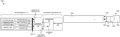
- FIG. 5illustrates a graph showing a total particulate mass (TPM) of vaporizable material that may be vaporized using an embodiment of a wick having a hollow core;
- TPMtotal particulate mass
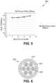
- FIG. 6illustrates a cross-sectional view of a first embodiment of a wick including a thermal core
- FIG. 7 Aillustrates a side view of a second embodiment of a wick including a thermal core
- FIG. 7 Billustrates an end view of the wick of FIG. 7 A ;
- FIG. 8 Aillustrates a side view of a third embodiment of a wick including a thermal core
- FIG. 8 Billustrates an end view of the wick of FIG. 8 A ;
- FIG. 9 Aillustrates a side view of a fourth embodiment of a wick including a thermal core
- FIG. 9 Billustrates an end view of the wick of FIG. 9 A ;
- FIG. 10 Aillustrates a side view of a fifth embodiment of a wick including a thermal core
- FIG. 10 Billustrates an end view of the wick of FIG. 10 A ;
- FIG. 11 Aillustrates a side view of a sixth embodiment of a wick including a thermal core
- FIG. 11 Billustrates an end view of the wick of FIG. 11 A ;
- FIG. 12shows a process flow diagram illustrating aspects of a method having one or more features consistent with implementations of the current subject matter.
- vaporizer devicesincluding vaporizers configured to couple with vaporizer cartridges containing one or more vaporizable materials for vaporization and inhalation by a user.
- vaporizeris used generically in the following description to refer to a vaporizer device. Examples of vaporizers consistent with implementations of the current subject matter include electronic vaporizers or the like. Such vaporizers are generally portable, hand-held devices that heat a vaporizable material to provide an inhalable dose of the material.
- the vaporizable material used with a vaporizermay optionally be provided within a cartridge (e.g., a part of the vaporizer that contains the vaporizable material in a reservoir or other container and that can be refillable when empty or disposable in favor of a new cartridge containing additional vaporizable material of a same or different type).
- a vaporizermay be a cartridge-using vaporizer, a cartridge-less vaporizer, or a multi-use vaporizer capable of use with or without a cartridge.
- a multi-use vaporizermay include a heating chamber (e.g., an oven) configured to receive a vaporizable material directly in the heating chamber and also to receive a cartridge or other replaceable device having a reservoir, a volume, or the like for at least partially containing a usable amount of vaporizable material.
- a heating chambere.g., an oven
- a cartridge or other replaceable devicehaving a reservoir, a volume, or the like for at least partially containing a usable amount of vaporizable material.
- a vaporizermay be configured for use with liquid vaporizable material (e.g., a carrier solution in which an active and/or inactive ingredient(s) are suspended or held in solution or a neat liquid form of the vaporizable material itself) or a solid vaporizable material.
- liquid vaporizable materiale.g., a carrier solution in which an active and/or inactive ingredient(s) are suspended or held in solution or a neat liquid form of the vaporizable material itself
- solid vaporizable materiale.g., a carrier solution in which an active and/or inactive ingredient(s) are suspended or held in solution or a neat liquid form of the vaporizable material itself
- Some currently available cartridgesinclude a wick configured to draw vaporizable material from the reservoir to the atomizer.
- Wicks used in currently available vaporizersmay be formed by bundling together fine, continuous filaments of silica glass or cotton fibers to form a cord or rope, and may be characterized by a nominal outer diameter, number of threads, and/or a linear density.
- such wickscan have a capillary flow rate (a rate at which liquid is drawn into and along the length of the wick) that results in inefficient and ineffective use and vaporization of the vaporizable material.
- the vaporizable materialmay not be replenished along the wick fast enough to allow for subsequent puffs from the vaporizer device to result in sufficient or desired amounts of vaporized material for inhalation.
- the capillary flow ratecan be further decreased, thereby further negatively affecting the amount of vaporizable material that is able to be vaporized during subsequent puffs from the vaporizer.
- High-viscosity solutionse.g., vaporizable oils
- Implementations of the current subject matterinclude various embodiments of a wick that may be included in a vaporizer cartridge for improving the efficiency and effectiveness of vaporizing at least one vaporizable material contained within one or more reservoirs of the vaporizer cartridge.
- some implementations of the wick described hereininclude a hollow fluid chamber or passageway (referred to herein as a “hollow wick”).
- the fluid chamber or passageway of the hollow wickcan assist with shortening the flow path through the wick thereby increasing the rate at which vaporizable fluid can be transferred from the reservoir to the vaporization chamber, as will be described in greater detail below.
- some implementations of the wick described hereininclude one or more thermally conductive materials (referred to herein as a “thermal wick”).
- thermally conductive materialsmay increase thermal conductivity capabilities of the thermal wick, such as compared to wicks used in currently available vaporizers. This may allow a greater length of the thermal wick to reach a higher temperature more quickly, which may lower the viscosity of vaporizable fluid in the thermal wick and adjacent reservoir. Such lowered viscosity may allow increased capillary action along the thermal wick.
- the increase in capillary actionmay also assist with allowing air to travel through the thermal wick more efficiently and effectively for relieving a pressure drop in the reservoir due to vaporizable fluid being drawn out of the reservoir (e.g., by capillary action of the wick and subsequent vaporization by a heating element).
- the thermal wickmay also distribute excess temperature gradients along the thermal wick, thereby reducing or eliminating hot spots and cold spots that can be common in wicks used in currently available vaporizers. Additionally, the thermal wick may have a decreased heat-up time compared to wicks used in currently available vaporizers.
- Various embodiments of the thermal wickare described in greater detail below.
- a vaporizer 100typically includes a power source 112 (such as a battery which may be a rechargeable battery), and a controller 104 (e.g., a processor, circuitry, etc. capable of executing logic) for controlling delivery of heat to an atomizer 141 to cause a vaporizable material to be converted from a condensed form (e.g., a solid, a liquid, a solution, a suspension, a part of an at least partially unprocessed plant material, etc.) to the gas phase.
- the controller 104may be part of one or more printed circuit boards (PCBs) consistent with certain implementations of the current subject matter.
- At least some of the gas-phase vaporizable materialmay condense to form particulate matter in at least a partial local equilibrium with the gas phase as part of an aerosol, which can form some or all of an inhalable dose provided by the vaporizer 100 for a given puff or draw on the vaporizer.
- the interplay between gas and condensed phases in an aerosol generated by a vaporizercan be complex and dynamic, as factors such as ambient temperature, relative humidity, chemistry, flow conditions in airflow paths (both inside the vaporizer and in the airways of a human or other animal), mixing of the gas-phase or aerosol-phase vaporizable material with other air streams, etc. may affect one or more physical parameters of an aerosol.
- the inhalable dosemay exist predominantly in the gas phase (i.e., formation of condensed phase particles may be very limited).
- Vaporizers for use with liquid vaporizable materialstypically include an atomizer 141 in which a wicking element (also referred to herein as a wick) conveys an amount of a liquid vaporizable material to a part of the atomizer that includes a heating element.
- the wicking elementis generally configured to draw liquid vaporizable material from a reservoir configured to contain (and that may in use contain) the liquid vaporizable material such that the liquid vaporizable material may be vaporized by heat delivered from a heating element.
- the wicking elementmay also optionally allow air to enter the reservoir to replace the volume of liquid removed.
- capillary actionpulls liquid vaporizable material into the wick for vaporization by the heating element (described herein), and air may, in some implementations of the current subject matter, return to the reservoir through the wick to at least partially equalize pressure in the reservoir.
- Other approaches to allowing air back into the reservoir to equalize pressureare also within the scope of the current subject matter.
- the heating elementcan be or include one or more of a conductive heater, a radiative heater, and a convective heater.
- a resistive heating elementwhich can be constructed of or at least include a material (e.g., a metal or alloy, for example a nickel-chromium alloy, or a non-metallic resistor) configured to dissipate electrical power in the form of heat when electrical current is passed through one or more resistive segments of the heating element.
- an atomizercan include a heating element that includes resistive coil or other heating element wrapped around, positioned within, integrated into a bulk shape of, pressed into thermal contact with, or otherwise arranged to deliver heat to a wicking element to cause a liquid vaporizable material drawn by the wicking element from a reservoir to be vaporized for subsequent inhalation by a user in a gas and/or a condensed (e.g., aerosol particles or droplets) phase.
- wicking element, heating element, and/or atomizer assembly configurationsare also possible, as discussed further below.
- Certain vaporizersmay also or alternatively be configured to create an inhalable dose of gas-phase and/or aerosol-phase vaporizable material via heating of a non-liquid vaporizable material, such as for example a solid-phase vaporizable material (e.g., a wax or the like) or plant material (e.g., tobacco leaves and/or parts of tobacco leaves) containing the vaporizable material.
- a resistive heating elementmay be part of or otherwise incorporated into or in thermal contact with the walls of an oven or other heating chamber into which the non-liquid vaporizable material is placed.
- a resistive heating element or elementsmay be used to heat air passing through or past the non-liquid vaporizable material to cause convective heating of the non-liquid vaporizable material.
- a resistive heating element or elementsmay be disposed in intimate contact with plant material such that direct conductive heating of the plant material occurs from within a mass of the plant material (e.g., as opposed to only by conduction inward form walls of an oven).
- the heating elementmay be activated (e.g., a controller, which is optionally part of a vaporizer body as discussed below, may cause current to pass from the power source through a circuit including the resistive heating element, which is optionally part of a vaporizer cartridge as discussed below), in association with a user puffing (e.g., drawing, inhaling, etc.) on a mouthpiece 130 of the vaporizer to cause air to flow from an air inlet, along an airflow path that passes an atomizer (e.g., wicking element and heating element), optionally through one or more condensation areas or chambers, to an air outlet in the mouthpiece. Incoming air passing along the airflow path passes over, through, etc.
- a controllerwhich is optionally part of a vaporizer body as discussed below, may cause current to pass from the power source through a circuit including the resistive heating element, which is optionally part of a vaporizer cartridge as discussed below
- a user puffinge.g., drawing, inhaling, etc.
- the atomizerwhere gas phase vaporizable material is entrained into the air.
- the entrained gas-phase vaporizable materialmay condense as it passes through the remainder of the airflow path such that an inhalable dose of the vaporizable material in an aerosol form can be delivered from the air outlet (e.g., in a mouthpiece 130 for inhalation by a user).
- Activation of the heating elementmay be caused by automatic detection of the puff based on one or more of signals generated by one or more sensors 113 , such as for example a pressure sensor or sensors disposed to detect pressure along the airflow path relative to ambient pressure (or optionally to measure changes in absolute pressure), one or more motion sensors of the vaporizer, one or more flow sensors of the vaporizer, a capacitive lip sensor of the vaporizer; in response to detection of interaction of a user with one or more input devices 116 (e.g., buttons or other tactile control devices of the vaporizer 100 ), receipt of signals from a computing device in communication with the vaporizer; and/or via other approaches for determining that a puff is occurring or imminent.
- sensors 113such as for example a pressure sensor or sensors disposed to detect pressure along the airflow path relative to ambient pressure (or optionally to measure changes in absolute pressure), one or more motion sensors of the vaporizer, one or more flow sensors of the vaporizer, a capacitive lip sensor of the vaporizer; in response to
- a vaporizerconsistent with implementations of the current subject matter may be configured to connect (e.g., wirelessly or via a wired connection) to a computing device (or optionally two or more devices) in communication with the vaporizer.
- the controller 104may include communication hardware 105 .
- the controller 104may also include a memory 108 .
- a computing devicecan be a component of a vaporizer system that also includes the vaporizer 100 , and can include its own communication hardware, which can establish a wireless communication channel with the communication hardware 105 of the vaporizer 100 .
- a computing device used as part of a vaporizer systemmay include a general-purpose computing device (e.g., a smartphone, a tablet, a personal computer, some other portable device such as a smartwatch, or the like) that executes software to produce a user interface for enabling a user of the device to interact with a vaporizer.
- a general-purpose computing devicee.g., a smartphone, a tablet, a personal computer, some other portable device such as a smartwatch, or the like
- a user interfacefor enabling a user of the device to interact with a vaporizer.
- such a device used as part of a vaporizer systemcan be a dedicated piece of hardware such as a remote control or other wireless or wired device having one or more physical or soft (e.g., configurable on a screen or other display device and selectable via user interaction with a touch-sensitive screen or some other input device like a mouse, pointer, trackball, cursor buttons, or the like) interface controls.
- the vaporizercan also include one or more output 117 features or devices for providing information to the user.
- a computing device that is part of a vaporizer system as defined abovecan be used for any of one or more functions, such as controlling dosing (e.g., dose monitoring, dose setting, dose limiting, user tracking, etc.), controlling sessioning (e.g., session monitoring, session setting, session limiting, user tracking, etc.), controlling nicotine delivery (e.g., switching between nicotine and non-nicotine vaporizable material, adjusting an amount of nicotine delivered, etc.), obtaining locational information (e.g., location of other users, retailer/commercial venue locations, vaping locations, relative or absolute location of the vaporizer itself, etc.), vaporizer personalization (e.g., naming the vaporizer, locking/password protecting the vaporizer, adjusting one or more parental controls, associating the vaporizer with a user group, registering the vaporizer with a manufacturer or warranty maintenance organization, etc.), engaging in social activities (e.g., games, social media communications, interacting with one or more groups, etc.) with other users,
- the terms “sessioning”, “session”, “vaporizer session,” or “vapor session,”are used generically to refer to a period devoted to the use of the vaporizer.
- the periodcan include a time period, a number of doses, an amount of vaporizable material, and/or the like.
- a computing deviceprovides signals related to activation of the resistive heating element
- the computing deviceexecutes one or more computer instructions sets to provide a user interface and underlying data handling.
- detection by the computing device of user interaction with one or more user interface elementscan cause the computing device to signal the vaporizer 100 to activate the heating element, either to a full operating temperature for creation of an inhalable dose of vapor/aerosol.
- Other functions of the vaporizermay be controlled by interaction of a user with a user interface on a computing device in communication with the vaporizer.
- the temperature of a resistive heating element of a vaporizermay depend on a number of factors, including an amount of electrical power delivered to the resistive heating element and/or a duty cycle at which the electrical power is delivered, conductive heat transfer to other parts of the electronic vaporizer and/or to the environment, latent heat losses due to vaporization of a vaporizable material from the wicking element and/or the atomizer as a whole, and convective heat losses due to airflow (e.g., air moving across the heating element or the atomizer as a whole when a user inhales on the electronic vaporizer).
- a vaporizermay, in some implementations of the current subject matter, make use of signals from a pressure sensor to determine when a user is inhaling.
- the pressure sensorcan be positioned in the airflow path and/or can be connected (e.g., by a passageway or other path) to an airflow path connecting an inlet for air to enter the device and an outlet via which the user inhales the resulting vapor and/or aerosol such that the pressure sensor experiences pressure changes concurrently with air passing through the vaporizer device from the air inlet to the air outlet.
- the heating elementmay be activated in association with a user's puff, for example by automatic detection of the puff, for example by the pressure sensor detecting a pressure change in the airflow path.
- the pressure sensor(as well as any other sensors 113 ) can be positioned on or coupled (e.g., electrically or electronically connected, either physically or via a wireless connection) to the controller 104 (e.g., a printed circuit board assembly or other type of circuit board).
- the controller 104e.g., a printed circuit board assembly or other type of circuit board.
- the seal 121which can be a gasket, may be configured to at least partially surround the pressure sensor such that connections of the pressure sensor to internal circuitry of the vaporizer are separated from a part of the pressure sensor exposed to the airflow path.
- the seal 121may also separate parts of one or more electrical connections between a vaporizer body 110 and a vaporizer cartridge 120 .
- Such arrangements of a seal 121 in a vaporizer 100can be helpful in mitigating against potentially disruptive impacts on vaporizer components resulting from interactions with environmental factors such as water in the vapor or liquid phases, other fluids such as the vaporizable material, etc. and/or to reduce escape of air from the designed airflow path in the vaporizer.
- Unwanted air, liquid or other fluid passing and/or contacting circuitry of the vaporizercan cause various unwanted effects, such as alter pressure readings, and/or can result in the buildup of unwanted material, such as moisture, the vaporizable material, etc.
- Leaks in the seal 121can also result in a user inhaling air that has passed over parts of the vaporizer device containing or constructed of materials that may not be desirable to be inhaled.
- a general class of vaporizers that have recently gained popularityincludes a vaporizer body 110 that includes a controller 104 , a power source 112 (e.g., battery), one more sensors 113 , charging contacts, a seal 121 , and a cartridge receptacle 118 configured to receive a vaporizer cartridge 120 for coupling with the vaporizer body through one or more of a variety of attachment structures.
- vaporizer cartridge 120includes a reservoir 140 for containing a liquid vaporizable material and a mouthpiece 130 for delivering an inhalable dose to a user.
- the vaporizer cartridgecan include an atomizer 141 having a wicking element and a heating element, or alternatively, one or both of the wicking element and the heating element can be part of the vaporizer body.
- the vaporizercan be configured to supply liquid vaporizer material from a reservoir in the vaporizer cartridge to the atomizer part(s) included in the vaporizer body.
- a vaporizer cartridgemay include a mass of a plant material that is processed and formed to have direct contact with parts of one or more resistive heating elements, and such a vaporizer cartridge may be configured to be coupled mechanically and electrically to a vaporizer body the includes a processor, a power source, and electrical contacts for connecting to corresponding cartridge contacts for completing a circuit with the one or more resistive heating elements.
- the vaporizer 100may include electrical connection features (e.g., means for completing a circuit) for completing a circuit that includes the controller 104 (e.g., a printed circuit board, a microcontroller, or the like), the power source, and the heating element.
- electrical connection featurese.g., means for completing a circuit
- the controller 104e.g., a printed circuit board, a microcontroller, or the like
- These featuresmay include at least two contacts on a bottom surface of the vaporizer cartridge 120 (referred to herein as cartridge contacts 124 ) and at least two contacts disposed near a base of the cartridge receptacle (referred to herein as receptacle contacts 125 ) of the vaporizer 100 such that the cartridge contacts 124 and the receptacle contacts 125 make electrical connections when the vaporizer cartridge 120 is inserted into and coupled with the cartridge receptacle 118 .
- the circuit completed by these electrical connectionscan allow delivery of electrical current to the resistive heating element and may further be used for additional functions, such as for example for measuring a resistance of the resistive heating element for use in determining and/or controlling a temperature of the resistive heating element based on a thermal coefficient of resistivity of the resistive heating element, for identifying a cartridge based on one or more electrical characteristics of a resistive heating element or the other circuitry of the vaporizer cartridge, etc.
- the at least two cartridge contacts and the at least two receptacle contactscan be configured to electrically connect in either of at least two orientations.
- one or more circuits necessary for operation of the vaporizercan be completed by insertion of a vaporizer cartridge 120 in the cartridge receptacle 118 in a first rotational orientation (around an axis along which the end of the vaporizer cartridge having the cartridge is inserted into the cartridge receptacle 118 of the vaporizer body 110 ) such that a first cartridge contact of the at least two cartridge contacts 124 is electrically connected to a first receptacle contact of the at least two receptacle contacts 125 and a second cartridge contact of the at least two cartridge contacts 124 is electrically connected to a second receptacle contact of the at least two receptacle contacts 125 .
- the one or more circuits necessary for operation of the vaporizercan be completed by insertion of a vaporizer cartridge 120 in the cartridge receptacle 118 in a second rotational orientation such that the first cartridge contact of the at least two cartridge contacts 124 is electrically connected to the second receptacle contact of the at least two receptacle contacts 125 and the second cartridge contact of the at least two cartridge contacts 124 is electrically connected to the first receptacle contact of the at least two receptacle contacts 125 .
- This feature of a vaporizer cartridge 120being reversible insertable into a cartridge receptacle 118 of the vaporizer body 110 is described further below.
- the vaporizer body 110includes a detent (e.g., a dimple, protrusion, etc.) protruding inwardly from an inner surface the cartridge receptacle 118 .
- a detente.g., a dimple, protrusion, etc.
- One or more exterior surfaces of the vaporizer cartridge 120can include corresponding recesses (not shown in FIG. 1 A ) that can fit and/or otherwise snap over such detents when an end of the vaporizer cartridge 120 inserted into the cartridge receptacle 118 on the vaporizer body 110 .
- the detent into the vaporizer body 110may fit within and/or otherwise be held within the recesses of the vaporizer cartridge 120 to hold the vaporizer cartridge 120 in place when assembled.
- Such a detent-recess assemblycan provide enough support to hold the vaporizer cartridge 120 in place to ensure good contact between the at least two cartridge contacts 124 and the at least two receptacle contacts 125 , while allowing release of the vaporizer cartridge 120 from the vaporizer body 110 when a user pulls with reasonable force on the vaporizer cartridge 120 to disengage the vaporizer cartridge 120 from the cartridge receptacle 118 .
- the shape of the vaporizer cartridge, or at least a shape of the end of the vaporizer cartridge that is configured for insertion into the cartridge receptaclemay have rotational symmetry of at least order two.
- the vaporizer cartridge or at least the insertable end of the vaporizer cartridgemay be symmetric upon a rotation of 180° around an axis along which the vaporizer cartridge is inserted into the cartridge receptacle.
- the circuitry of the vaporizermay support identical operation regardless of which symmetrical orientation of the vaporizer cartridge occurs.
- the vaporizer cartridge, or at least an end of the vaporizer cartridge configured for insertion in the cartridge receptaclemay have a non-circular cross section transverse to the axis along which the vaporizer cartridge is inserted into the cartridge receptacle.
- the non-circular cross sectionmay be approximately rectangular, approximately elliptical (e.g., have an approximately oval shape), non-rectangular but with two sets of parallel or approximately parallel opposing sides (e.g., having a parallelogram-like shape), or other shapes having rotational symmetry of at least order two.
- the at least two cartridge contacts and the at least two receptacle contactscan take various forms.
- one or both sets of contactsmay include conductive pins, tabs, posts, receiving holes for pins or posts, or the like.
- Some types of contactsmay include springs or other urging features to cause better physical and electrical contact between the contacts on the vaporizer cartridge and the vaporizer body.
- the electrical contactsmay optionally be gold-plated, and/or can include other materials.
- FIG. 1 Billustrates an embodiment of the vaporizer body 110 having a cartridge receptacle 118 into which the vaporizer cartridge 120 may be releasably inserted.
- FIG. 1 Bshows a top view of the vaporizer 100 illustrating the cartridge being positioned for insertion into the vaporizer body 110 .
- airmay pass between an outer surface of the vaporizer cartridge 120 and an inner surface of a cartridge receptacle 118 on the vaporizer body 110 . Air can then be drawn into an insertable end 122 of the cartridge, through the vaporization chamber that includes or contains the heating element and wick, and out through an outlet of the mouthpiece 130 for delivery of the inhalable aerosol to a user.
- the reservoir 140 of the vaporizer cartridge 120may be formed in whole or in part from translucent material such that a level of vaporizable material 102 is visible along the vaporizer cartridge 120 .
- FIG. 2illustrates an embodiment of a vaporizer cartridge 120 including a wick 103 (e.g., a thermal wick or a hollow wick) consistent with implementations of the current subject matter.
- the vaporizer cartridge 120includes a reservoir 140 configured to hold a vaporizable material and a proximal mouthpiece 130 .
- the vaporizer cartridge 120may also include cartridge contacts 124 at a distal end that is configured to mate with a conductive connector of a power source, such as a body of a vaporizer device to which the vaporizer cartridge 120 may couple thereto.
- the vaporizer cartridge 120may also include a resistive heating element 115 (such as atomizer 141 , shown in FIG. 1 A ) adjacent the wick 103 .
- the heating element 115may be conductively connected to cartridge contacts 124 .
- an air path 150may extend through the reservoir 140 .
- FIG. 3illustrates a schematic representation of a vaporizer cartridge 200 in which a wick 203 , consistent with implementations of the current subject matter, may be incorporated, such as either the hollow or thermal wicks described herein.
- the vaporizer cartridge 200includes a reservoir 206 for holding a vaporizable material 204 such as a liquid, gel, solid, semi-solid, or wax vaporizable material including but not limited to nicotine oil, cannabis oil, glycerol, vegetable glycerin, glycol, propylene glycol, water, flavorants, additives, and/or the like.
- the vaporizable material 204may include one or more active agents, including nicotine, cannabinoids, terpenes, or any combinations thereof.
- the reservoir 206can include two chambers that are in fluid communication with each other, however, they can be separated (e.g., holding different vaporizable materials).
- An air path 205extends through the vaporizer cartridge 200 such that air may be drawn in from the bottom or base of the vaporizer cartridge 200 at an air inlet 201 and pulled over and/or around a heating element 202 and the wick 203 .
- the heating element 202e.g., a resistive heating coil
- the vaporizer cartridge 200may include a vaporization chamber 220 that includes the wick 203 and heating element 202 .
- the vaporization chamber 220is a chamber through which the airflow passes and the vaporizable material 204 is vaporized.
- the wick 203may include at least one porous material that draws the vaporizable material 204 from the reservoir 206 to the vaporization chamber 220 .
- airmay flow into the air inlet 201 .
- the heating element 202may be activated (e.g., by a pressure sensor, pushbutton, etc.) thereby vaporizing the vaporizable material saturating the wick 203 .
- the incoming airmay flow through the vaporization chamber 220 , including over the wick 203 and/or heating element 202 , and collect the vaporized vaporizable material.
- the vaporized materialmay be condensed and inhaled as an aerosol via the air path 205 .
- Embodiments of the thermal wick and hollow wickcan be implemented in a variety of cartridges, including vaporizer cartridge 120 and vaporizer cartridge 200 for improving the efficiency and effectiveness of vaporizing one or more vaporizable materials with a vaporizer.
- FIG. 4illustrates an embodiment of a hollow wick 303 that may be incorporated in any of the cartridges and/or vaporizer devices disclosed herein.
- the hollow wick 303includes an outer porous jacket 307 that at least partly surrounds a hollow core or fluid passageway 330 .
- the hollow wick 303may be positioned adjacent a heating element, such as a coiled heating element 302 that may be wound around a length of the hollow wick 303 .
- the outer porous jacket 307can be formed out of a variety of materials, such as fibrous braided or woven high temperature resistant material (e.g., silica, cotton, etc.), that may have a high porosity. Such high porosity of the outer porous jacket 307 allows the outer porous jacket 307 to draw vaporizable material axially along the length of the hollow wick 303 , such as from the reservoir to near or adjacent to the heating element for vaporization in the vaporization chamber.
- a high temperature resistant materiale.g., silica, cotton, etc.
- an inner wall 332 of the outer porous jacket 307forms the fluid passageway 330 .
- the fluid passageway 330 of the hollow wick 303is open and void of material comprising the hollow wick 303 . Additionally, one or both opposing ends of the hollow wick 303 may be open thereby allowing vaporizable fluid 304 contained in the reservoir to flow into the fluid passageway 330 , as shown in FIG. 4 .
- the vaporizable fluid 304can be absorbed through the inner wall 332 and radially through the outer porous jacket 307 towards the heating element 302 or outer surface of the hollow wick 303 .
- the hollow wick 303enables both axial capillary action and radial capillary action (e.g., orthogonal to axial capillary action) of the vaporizable fluid 304 .
- Thisincreases the rate and volume of vaporizable fluid 304 that can be vaporized in the vaporization chamber. For example, a shorter distance is required for vaporizable fluid 304 to travel radially from the fluid passageway 330 to the heating element 302 (or sufficiently close thereto) for becoming vaporized in the vaporization chamber compared to vaporizable fluid 304 that travels axially from one or both ends of the hollow wick 303 to the heating element 302 (or sufficiently close thereto) for becoming vaporized.
- the cartridgecan be configured such that both ends of the hollow wick 303 are in contact with vaporizable fluid contained in the reservoir of the cartridge.
- the hollow wick 303is cylindrical in shape, however, the hollow wick 303 may include a variety of shapes and sizes without departing from the scope of this disclosure.
- the hollow wick 303can include a square, rectangular, elliptical, triangular, or other shaped cross-section.
- the fluid passageway 330may have the same, similar, or different cross-sectional shape as the outer diameter of the hollow wick 303 .
- the hollow wick 303includes an internal support, such as the internal support 340 illustrated in FIG. 4 that assists with retaining the shape of the fluid passageway 330 .
- the internal support 340includes an elongated helical coil or spring having a circular cross-section and an outer diameter that is configured to mate against the inner wall 332 of the fluid passageway 330 thereby assisting with retaining a cylindrical shape of the fluid passageway 330 .
- the internal support 340can include any number of shapes and configurations and can be made of a variety of materials (such as a metal or plastic material) without departing from the scope of this disclosure.
- the hollow wick 303can provide a variety of benefits, including allowing the hollow wick 303 to have a smaller outer diameter while still achieving improved and/or desired effects associated with effective and efficient vaporization, as discussed herein. Additionally, the hollow wick 303 provides improved permeability (fluid flow) by allowing the vaporizable fluid 304 to flow through the hollow wick 303 (via the fluid passageway 330 ), thereby allowing absorption of the vaporizable fluid 304 both in the radial and axial directions along the hollow wick 303 . Thermal benefits of the hollow wick 303 may include conductive losses to the vaporizable fluid that cause a change in the vaporizable fluid properties (e.g., viscosity, surface tension, etc.). Other benefits are within the scope of this disclosure.
- FIG. 5illustrates a graph 350 showing an example total particulate mass (TPM) of vaporizable material vaporized with a hollow wick consistent with various implementations of the current subject matter.
- TPMtotal particulate mass
- the average TPM per puffcan increase with successive puffs, thereby illustrating a potential benefit of the hollow wick, which is to efficiently and effectively draw vaporizable fluid toward the heating element for becoming vaporized, including after successive puffs from the vaporizer.
- FIG. 6illustrates a first embodiment of a thermal wick 403 that includes an outer porous jacket 407 and a thermally conductive core 408 .
- the outer porous jacket 407may include a bundle of fibers, such as silica fibers.
- the thermally conductive core 408forms a central core region of the thermal wick 403 .
- the outer porous jacket 407surrounds or substantially surrounds the thermally conductive core 408 .
- a separate sleeve 410 made of a porous wicking materialmay surround the silica fibers making up the outer porous jacket 407 .
- an axial thermal conductivity of the outer porous jacketis ⁇ 1.4 W/mK.
- the thermally conductive core 408may be made of, for example, a stainless steel material, such as a stainless steel rope made from multiple twisted bundles of wire each containing individual strands of wire.
- the wires of the stainless steel ropeare each approximately 0.15 mm diameter/strand, and the overall rope diameter is approximately 1.5 mm.
- the overall outside diameter of the thermal wick 403may be approximately 2 mm, although other diameters may be used, including, for example, 0.5 mm to 5 mm diameters.
- the thermally conductive core 408 of the thermal wick 403includes stainless steel fibers. This may increase the void volume along the thermally conductive core 408 and also increase the thermal conductivity of the thermally conductive core 408 .
- the thermal conductivitymay be approximately 15 W/mK, such as when the thermally conductive core includes nichrome fibers. In some embodiments, the thermal conductivity may be approximately 50 W/mK to approximately 60 W/mK, such as when the thermally conductive core includes stainless steel fibers.
- the outer porous jacket 407 in this examplemay serve more than one purpose.
- the less thermally conductive outer porous jacket 407may radially surround the thermally conductive core 408 to electrically isolate and protect the heating coil, which may be wrapped around the thermal wick 403 , from shorting on the thermally conductive core 408 .
- the outer porous jacket 407may also provide a capillary path to mitigate leakage through and around the thermally conductive core 408 .
- the thermally conductive core 408may be exposed at the ends to aid in the heating of the vaporizable material contained in the adjacent reservoir.
- thermally conductive material of the thermal wick 403is typically electrically isolated from the heating element (e.g., heating element 115 ) by an outer porous jacket having a lower thermal conductivity, when power is applied to the heating element to vaporize the vaporizable material, the thermal wick 403 is heated by conduction and/or convection.
- the thermal wick 403may be heated to a temperature that is below a vaporization temperature of the vaporizable material.
- the thermal wick 403is passively heated by the heating element.
- the thermal wick 403may be heated separately or additionally from the heating element, and may be, for example, heated by a separate heater.
- a separate (typically lower-temperature/warming) heaterwhich is also referred to herein as a wick heater, may therefore be thermally connected to the thermally conductive portion(s) of the thermal wick 403 , and this separate heater may be driven from a separate heating circuit from the heating/vaporizing heating coil.
- the wick heater(warming heater) may be driven from the same control circuit of the heating coil (or, for example, connected in series or parallel to the control circuit and/or the heating coil).
- the thermal wick 403may be heated while the device is “on”, even when the heating coil of the vaporizer/atomizer is not active.
- the thermally conductive materialmay be a resistive heating material and/or a material having a high thermal conductivity.
- the thermally conductive materialmay have a thermal conductance that is greater than that of the porous wicking material.
- the thermal conductance of the thermally conductive materialmay be at least about 5% greater than that of the porous wicking material.
- the thermal conductance of the thermally conductive materialmay be greater than that of the porous wicking material by approximately 3-9 W/mK.
- the thermal conductivity at or near room temperature of the thermally conductive material in the thermal wickmay be greater than, for example, 5 ⁇ , 10 ⁇ , 15 ⁇ , and/or 20 ⁇ the thermal conductivity of standard wicking materials, such as cotton, silica, etc.
- thermally conductive materialsinclude but are not limited to copper (which has a high thermal conductivity of approximately 385 W/mK), steel, stainless steel, aluminum, titanium, nickel, or any metal/metal combination.
- the thermally conductive materialis non-reactive with the vaporizable material.
- a coating or platinge.g., an inert plating may also be incorporated.
- the thermal wickmay have an increased thermal conductivity compared to silica or cotton wicks used in currently available vaporizers, and may optionally be electrically conductive.
- the thermal wickmay include a ceramic material (or other porous material) that is formed in the shape of a tube or cylinder with thermally conductive particles (e.g., copper flakes or pieces) embedded or dispersed throughout.
- An outer porous jacket of either the thermal wick or the hollow wick 303may be made from any braided, stranded, or amorphous material which is not electrically conductive and which is stable at vaporization temperatures.
- the outer porous jacketmay be formed of or include silica, cotton, glass (e.g., glass fibers), fiberglass, ceramic, or another porous material.
- the outer porous jacketcan be a perforated material or tube.
- the outer porous jacketmay be characterized as having a low thermal conductivity. For example, materials with a thermal conductivity less than 3 W/mK (e.g., at or near 25° C.) may be referred to as low thermal conductivity materials.
- the porous wicking materialcan include a bundle of approximately 17,000 silica fibers, each approximately with a 0.009 mm diameter, with the bundle constrained to a diameter of ⁇ 2 mm and cut to a length of approximately 10 mm.
- the wick consistent with implementations of the current subject matterinclude at least one feature associated with the hollow wick 303 and the thermal wick 403 .
- the internal support 340 of the hollow wick 303 illustrated in FIG. 4can be made of a thermally conductive material. This can allow the internal support 340 to provide features and effects similar to the thermally conductive core 408 of the thermal wick 403 .
- FIGS. 7 A and 7 Billustrate another embodiment of a thermal wick 503 including a thermally conductive core 508 extending the length of the thermal wick 503 .
- the thermally conductive core 508is radially surrounded by an outer porous jacket 507 having a lower thermal conductivity.
- the ends of the thermally conductive core 508may be exposed, as shown in FIGS. 7 A and 7 B .
- the thermally conductive core 508may be solid and/or not include fluid or air passageways.
- FIGS. 8 A and 8 Billustrate another embodiment of a thermal wick 603 including an inner core region made up of thermally conductive components or strands 608 and gaps or voids 611 positioned between the thermally conductive strands 608 .
- the gaps or voids 611may be air or fluid gaps.
- An outer porous jacket 607surrounds the inner core region of thermally conductive strands 608 and voids 611 .
- FIGS. 9 A and 9 Billustrate another embodiment of a thermal wick 703 including a conductive core 708 with a high thermal conductivity material (e.g., wires, braids, fibers, etc., of stainless steel, for example).
- the conductive core 708extends along the length of the thermal wick 703 and is surrounded by an outer porous jacket 707 that has a lower thermal conductivity and is electrically conductive.
- the high thermal conductivity materialmay be evenly or near evenly distributed through the volume of the thermal wick 703 .
- the thermal wick 703may also include internal void or gap regions (e.g., around the high thermal conductivity material).
- the individual strands of high thermal conductivity materialmay be woven, braided, or otherwise in thermal contact with each other at various points along the length of the thermal wick 703 .
- FIGS. 10 A and 10 Billustrate another embodiment of a thermal wick 803 including a plurality of high thermal conductivity strands 808 arranged along an inner peripheral region that is covered by an outer porous jacket 807 having lower thermal conductivity properties.
- the central region or core 810may be the same material as the outer porous jacket, providing a larger cross-sectional area for wicking.
- thermally conductive materialmay be formed into a filament, rope, bundle, chain, weave, braid, or the like, and may generally extend along all or a majority of the length of the thermal wick.
- the ends of the thermal wickmay be open (e.g., exposing the high thermally conductive material to the vaporizable material in the reservoir), or they may be covered by the outer wicking material (e.g., low thermal conductivity material or insulating material) or by another material.
- FIGS. 11 A and 11 Billustrate another embodiment of a thermal wick 903 including a thermally conductive core 908 surrounded by an outer porous jacket 907 .
- the thermally conductive core 908is a chamber containing a fluid 914 , such as water.
- the ends of the thermal wick 903are sealed with end caps 912 to contain the fluid 914 within the thermally conductive core 908 .
- the end caps 912may be formed of the same material as the thermally conductive core 908 . This configuration results in significant heat transfer improvements and has a low thermal mass due to the configuration of the thermally conductive core 908 .
- any of the thermal wick embodiments described hereinmay include a plurality of voids/air gaps within the volume of the thermal wick.
- the volumemay include 2%-25% of voids/air gaps. These voids/air gaps may be near or adjacent to the high thermal conductivity material.
- the wicks described hereinmay be any appropriate diameter and length.
- the thermal wickmay have a diameter of approximately 0.5 mm-10 mm and a length of between approximately 0.5 mm and 30 mm.
- a thermal wickmay have a core containing between approximately 1 and 10,000 strands in a variety of orientations.
- the strand diametersmay range from, for example, approximately 0.005 mm to 9.000 mm.
- the thermal coremay also be a tube, or tubes, e.g., of approximately 0.25-9.25 mm outside diameter with a length of approximately 0.5-30 mm.
- the tube(s)may also have radial holes or slots to facilitate fluid transfer out of or between the tube(s).
- the thermal coremay also be made of standard wicking fibers, such as silica, which are co-woven with some fraction of metallic fibers of a similar diameter. Metallic fiber fractions may range from 1-99%.
- the outer 0.25 mm, for example, of this coremay be made of non-conductive (e.g., non-metallic) wicking material, including fibers, to prevent the heating coil from shorting.
- FIG. 12shows a process flow diagram 1200 illustrating aspects of a method having one or more features consistent with implementations of the current subject matter.
- a vaporizable materialis drawn, through a wick, from a reservoir of a vaporization device to a vaporization region.
- the wickcan include any of the hollow wick or thermal wick embodiments disclosed herein.
- the vaporization regionis heated with a heating element disposed adjacent the wick and near or within the vaporization chamber. The heating causes vaporization of the vaporizable material in the vaporization chamber.
- the vaporized vaporizable materialis entrained in a flow of air directed to a mouthpiece of the vaporization device for inhalation by a user.
- references to a structure or feature that is disposed “adjacent” another featuremay have portions that overlap or underlie the adjacent feature.
- phrases such as “at least one of” or “one or more of”may occur followed by a conjunctive list of elements or features.
- the term “and/or”may also occur in a list of two or more elements or features. Unless otherwise implicitly or explicitly contradicted by the context in which it used, such a phrase is intended to mean any of the listed elements or features individually or any of the recited elements or features in combination with any of the other recited elements or features.
- the phrases “at least one of A and B;” “one or more of A and B;” and “A and/or B”are each intended to mean “A alone, B alone, or A and B together.”
- a similar interpretationis also intended for lists including three or more items.
- the phrases “at least one of A, B, and C;” “one or more of A, B, and C;” and “A, B, and/or C”are each intended to mean “A alone, B alone, C alone, A and B together, A and C together, B and C together, or A and B and C together.”
- Use of the term “based on,” above and in the claimsis intended to mean, “based at least in part on,” such that an unrecited feature or element is also permissible.
- spatially relative termssuch as “forward”, “rearward”, “under”, “below”, “lower”, “over”, “upper” and the like, may be used herein for ease of description to describe one element or feature's relationship to another element(s) or feature(s) as illustrated in the figures. It will be understood that the spatially relative terms are intended to encompass different orientations of the device in use or operation in addition to the orientation depicted in the figures. For example, if a device in the figures is inverted, elements described as “under” or “beneath” other elements or features would then be oriented “over” the other elements or features. Thus, the exemplary term “under” can encompass both an orientation of over and under.
- the devicemay be otherwise oriented (rotated 90 degrees or at other orientations) and the spatially relative descriptors used herein interpreted accordingly.
- the terms “upwardly”, “downwardly”, “vertical”, “horizontal” and the likeare used herein for the purpose of explanation only unless specifically indicated otherwise.
- first and secondmay be used herein to describe various features/elements (including steps), these features/elements should not be limited by these terms, unless the context indicates otherwise. These terms may be used to distinguish one feature/element from another feature/element. Thus, a first feature/element discussed below could be termed a second feature/element, and similarly, a second feature/element discussed below could be termed a first feature/element without departing from the teachings provided herein.
- One or more aspects or features of the subject matter described hereincan be realized in digital electronic circuitry, integrated circuitry, specially designed application specific integrated circuits (ASICs), field programmable gate arrays (FPGAs) computer hardware, firmware, software, and/or combinations thereof.
- ASICsapplication specific integrated circuits
- FPGAsfield programmable gate arrays
- These various aspects or featurescan include implementation in one or more computer programs that are executable and/or interpretable on a programmable system including at least one programmable processor, which can be special or general purpose, coupled to receive data and instructions from, and to transmit data and instructions to, a storage system, at least one input device, and at least one output device.
- the programmable system or computing systemmay include clients and servers.
- a client and serverare generally remote from each other and typically interact through a communication network. The relationship of client and server arises by virtue of computer programs running on the respective computers and having a client-server relationship to each other.
- machine-readable signalrefers to any signal used to provide machine instructions and/or data to a programmable processor.
- the machine-readable mediumcan store such machine instructions non-transitorily, such as for example as would a non-transient solid-state memory or a magnetic hard drive or any equivalent storage medium.
- the machine-readable mediumcan alternatively or additionally store such machine instructions in a transient manner, such as for example, as would a processor cache or other random access memory associated with one or more physical processor cores.
Landscapes
- Health & Medical Sciences (AREA)
- Engineering & Computer Science (AREA)
- Biomedical Technology (AREA)
- Animal Behavior & Ethology (AREA)
- Veterinary Medicine (AREA)
- Public Health (AREA)
- General Health & Medical Sciences (AREA)
- Anesthesiology (AREA)
- Life Sciences & Earth Sciences (AREA)
- Heart & Thoracic Surgery (AREA)
- Hematology (AREA)
- Pulmonology (AREA)
- Bioinformatics & Cheminformatics (AREA)
- Chemical & Material Sciences (AREA)
- General Chemical & Material Sciences (AREA)
- Chemical Kinetics & Catalysis (AREA)
- Catching Or Destruction (AREA)
Abstract
Description
Claims (28)
Priority Applications (1)
| Application Number | Priority Date | Filing Date | Title |
|---|---|---|---|
| US16/453,953US11986590B2 (en) | 2018-06-26 | 2019-06-26 | Vaporizer wicking elements including a hollow core |
Applications Claiming Priority (2)
| Application Number | Priority Date | Filing Date | Title |
|---|---|---|---|
| US201862690315P | 2018-06-26 | 2018-06-26 | |
| US16/453,953US11986590B2 (en) | 2018-06-26 | 2019-06-26 | Vaporizer wicking elements including a hollow core |
Publications (2)
| Publication Number | Publication Date |
|---|---|
| US20190387797A1 US20190387797A1 (en) | 2019-12-26 |
| US11986590B2true US11986590B2 (en) | 2024-05-21 |
Family
ID=67297351
Family Applications (1)
| Application Number | Title | Priority Date | Filing Date |
|---|---|---|---|
| US16/453,953Active2042-05-30US11986590B2 (en) | 2018-06-26 | 2019-06-26 | Vaporizer wicking elements including a hollow core |
Country Status (3)
| Country | Link |
|---|---|
| US (1) | US11986590B2 (en) |
| EP (1) | EP3813914B1 (en) |
| WO (1) | WO2020006148A1 (en) |
Families Citing this family (18)
| Publication number | Priority date | Publication date | Assignee | Title |
|---|---|---|---|---|
| US10772354B2 (en) | 2016-05-31 | 2020-09-15 | Altria Client Services Llc | Heater and wick assembly for an aerosol generating system |
| EP3675661B1 (en) | 2017-08-28 | 2023-06-07 | Juul Labs, Inc. | Wick for vaporizer device |
| CN110754696A (en) | 2018-07-23 | 2020-02-07 | 尤尔实验室有限公司 | Airflow management for evaporator units |
| CN119632302A (en) | 2018-07-31 | 2025-03-18 | 尤尔实验室有限公司 | Cartridge-based heat-without-burn vaporizer |
| US11413409B2 (en) | 2018-09-12 | 2022-08-16 | Juul Labs, Inc. | Vaporizer including positive temperature coefficient of resistivity (PTCR) heating element |
| US12256784B2 (en) | 2018-10-17 | 2025-03-25 | Juul Labs, Inc. | Cartridge for a vaporizer device |
| USD920568S1 (en)* | 2018-10-22 | 2021-05-25 | Tuanfang Liu | Electronic cigarette |
| ES2932748T3 (en) | 2018-11-05 | 2023-01-25 | Juul Labs Inc | Cartridges for vaporizer devices |
| US11156766B2 (en) | 2018-11-19 | 2021-10-26 | Rai Strategic Holdings, Inc. | Aerosol delivery device |
| US11372153B2 (en) | 2018-11-19 | 2022-06-28 | Rai Strategic Holdings, Inc. | Cartridge orientation for selection of a control function in a vaporization system |
| WO2020183476A1 (en)* | 2019-03-12 | 2020-09-17 | Syqe Medical Ltd | System and method for authentication and system and method for authentication based personal service |
| JP7645032B2 (en)* | 2019-11-18 | 2025-03-13 | 東京エレクトロン株式会社 | Streamlined Carburetor Core |
| CA3162544A1 (en) | 2019-12-23 | 2021-07-01 | Pax Labs, Inc. | Vaporizer cartridge |
| IL277423B (en)* | 2020-09-16 | 2022-09-01 | Syqe Medical Ltd | Devices and methods for oral authentication with short delay time |
| USD1028336S1 (en) | 2021-06-22 | 2024-05-21 | Pax Labs, Inc. | Vaporizer cartridge |
| EP4440354A1 (en)* | 2021-12-01 | 2024-10-09 | JT International S.A. | A wicking element for a heating system for an aerosol generating set, and associated heating system and manufacturing method |
| KR102830124B1 (en)* | 2022-03-10 | 2025-07-07 | 주식회사 케이티앤지 | Heating structure and aerosol generating device |
| EP4467016A1 (en)* | 2023-05-23 | 2024-11-27 | JT International SA | Aerosal generating systems and cartridges for use in aerosol generating systems |
Citations (222)
| Publication number | Priority date | Publication date | Assignee | Title |
|---|---|---|---|---|
| US5303720A (en) | 1989-05-22 | 1994-04-19 | R. J. Reynolds Tobacco Company | Smoking article with improved insulating material |
| US6155268A (en) | 1997-07-23 | 2000-12-05 | Japan Tobacco Inc. | Flavor-generating device |
| US6598607B2 (en) | 2001-10-24 | 2003-07-29 | Brown & Williamson Tobacco Corporation | Non-combustible smoking device and fuel element |
| US6909840B2 (en) | 2002-06-06 | 2005-06-21 | S. C. Johnson & Son, Inc. | Localized surface volatilization |
| US20080056691A1 (en) | 2006-05-19 | 2008-03-06 | Wingo James P | Vapor dispenser with indicator |
| CN101228969A (en) | 2008-02-02 | 2008-07-30 | 龙功运 | Electronic cigarette |
| CN201375023Y (en) | 2009-04-15 | 2010-01-06 | 中国科学院理化技术研究所 | A heating and atomizing electronic cigarette powered by a capacitor |
| US20100065653A1 (en) | 2008-08-01 | 2010-03-18 | Wingo James P | Wicks for dispensers of vaporizable materials |
| US7726320B2 (en) | 2006-10-18 | 2010-06-01 | R. J. Reynolds Tobacco Company | Tobacco-containing smoking article |
| US7793861B2 (en) | 2007-01-17 | 2010-09-14 | The Dial Corporation | Piston actuated vapor-dispersing device |
| CN101862038A (en) | 2009-04-15 | 2010-10-20 | 中国科学院理化技术研究所 | A heating and atomizing electronic cigarette powered by a capacitor |
| WO2011146174A2 (en) | 2010-05-15 | 2011-11-24 | Nathan Andrew Terry | Volume liquid storage reservoir in a personal vaporizing inhaler |
| EP2404515A1 (en) | 2009-02-11 | 2012-01-11 | Lik Hon | Improved atomizing electronic cigarette |
| JP2012506263A (en) | 2008-10-23 | 2012-03-15 | ブッフベルガー,ヘルムート | Inhaler |
| KR200461404Y1 (en) | 2011-09-23 | 2012-07-13 | 주식회사 페로젠 | Smart electronic cigarette |
| WO2013060781A1 (en) | 2011-10-27 | 2013-05-02 | Philip Morris Products S.A. | Aerosol generating system with improved aerosol production |
| US20130104916A1 (en) | 2011-10-28 | 2013-05-02 | Evolv, Llc | Electronic vaporizer that simulates smoking with power control |
| EP2614731A1 (en) | 2012-01-12 | 2013-07-17 | Shenzhen First Union Technology Co., Ltd. | An atomizer for electronic cigarette |
| US20130192623A1 (en) | 2012-01-31 | 2013-08-01 | Altria Client Services Inc. | Electronic cigarette |
| US20130192618A1 (en) | 2012-01-31 | 2013-08-01 | Yonghai Li | Atomizer for electronic cigarette |
| KR20130092252A (en) | 2012-02-10 | 2013-08-20 | 황일영 | Wick for electronic cigar |
| US20130213419A1 (en) | 2012-02-22 | 2013-08-22 | Altria Client Services Inc. | Electronic smoking article and improved heater element |
| CN103338664A (en) | 2010-12-24 | 2013-10-02 | 菲利普莫里斯生产公司 | An aerosol generating system having means for handling consumption of a liquid substrate |
| US20130255702A1 (en) | 2012-03-28 | 2013-10-03 | R.J. Reynolds Tobacco Company | Smoking article incorporating a conductive substrate |
| CN203234036U (en) | 2012-07-23 | 2013-10-16 | 刘秋明 | Electronic cigarette |
| US20130284192A1 (en) | 2012-04-25 | 2013-10-31 | Eyal Peleg | Electronic cigarette with communication enhancements |
| US20130306064A1 (en) | 2010-12-03 | 2013-11-21 | Philip Morris Products S.A. | Aerosol Generating System with Prevention of Condensate Leakage |
| US20140000638A1 (en) | 2012-06-28 | 2014-01-02 | R.J. Reynolds Tobacco Company | Reservoir and heater system for controllable delivery of multiple aerosolizable materials in an electronic smoking article |
| GB2504076A (en) | 2012-07-16 | 2014-01-22 | Nicoventures Holdings Ltd | Electronic smoking device |
| US20140069424A1 (en) | 2012-09-10 | 2014-03-13 | Jeffrey Poston | Device for vaporizing liquid for inhalation |
| US8678012B2 (en) | 2010-06-09 | 2014-03-25 | Yonghai Li | Tobacco solution atomizing device for electronic cigarette |
| US20140109898A1 (en) | 2012-10-23 | 2014-04-24 | Shenzhen First Union Technology Co., Ltd. | Atomizing device and electronic cigarette having same |
| US20140109921A1 (en) | 2012-09-29 | 2014-04-24 | Shenzhen Smoore Technology Limited | Electronic cigarette |
| US20140130817A1 (en) | 2012-11-15 | 2014-05-15 | Shenzhen First Union Technology Co., Ltd. | Atomizing device and electronic cigarette having same |
| US20140150785A1 (en) | 2012-12-05 | 2014-06-05 | Vire, L.L.C. | Electronic cigarette or inhaler |
| CN103859604A (en) | 2014-01-23 | 2014-06-18 | 深圳市康尔科技有限公司 | Heating component and atomizing structure of electronic cigarette |
| WO2014101734A1 (en) | 2012-12-28 | 2014-07-03 | Shenzhen Smoore Technology Limited | Electronic atomizing inhalation device |
| US20140182612A1 (en) | 2012-12-28 | 2014-07-03 | Shenzhen Smoore Technology Limited | Electronic atomizing inhalation device |
| US20140196733A1 (en) | 2013-01-15 | 2014-07-17 | Qiuming Liu | Electronic Cigarette |
| US20140209108A1 (en) | 2013-01-31 | 2014-07-31 | Shenzhen First Union Technology Co., Ltd. | Atomizing device and electronic cigarette having same |
| US20140209105A1 (en) | 2013-01-30 | 2014-07-31 | R.J. Reynolds Tobacco Company | Wick suitable for use in an electronic smoking article |
| CN104010529A (en) | 2011-09-28 | 2014-08-27 | 菲利普莫里斯生产公司 | Permeable thermistor foil for evaporating fluid from a single use mouthpiece with evaporator membrane |
| WO2014130692A1 (en) | 2013-02-22 | 2014-08-28 | Altria Client Services Inc. | Electronic smoking article |
| US20140261488A1 (en) | 2013-03-15 | 2014-09-18 | Altria Client Services Inc. | Electronic smoking article |
| US20140261487A1 (en) | 2013-03-14 | 2014-09-18 | R. J. Reynolds Tobacco Company | Electronic smoking article with improved storage and transport of aerosol precursor compositions |
| WO2014150979A2 (en) | 2013-03-15 | 2014-09-25 | R. J. Reynolds Tobacco Company | Heating elements formed from a sheet of a material, inputs and methods for the production of atomizers, cartridge for an aerosol delivery device and method for assembling a cartridge for a smoking article |
| US20140299137A1 (en) | 2013-04-05 | 2014-10-09 | Johnson Creek Enterprises, LLC | Electronic cigarette and method and apparatus for controlling the same |
| US8857446B2 (en) | 2010-12-09 | 2014-10-14 | Shenzhen Smaco Technology Ltd. | Disposable atomizer of electronic cigarette |
| TW201438608A (en) | 2013-04-11 | 2014-10-16 | Ruyan Invest Holdong Ltd | Electronic cigarette with sealed cartridge |
| GB2513637A (en) | 2013-05-02 | 2014-11-05 | Nicoventures Holdings Ltd | Electronic cigarette |
| US20140332022A1 (en) | 2013-05-07 | 2014-11-13 | Shenzhen First Union Technology Co., Ltd. | Atomizing device and electronic cigarette having same |
| CN203986105U (en) | 2014-06-20 | 2014-12-10 | 姚潮涌 | Many tastes electronic cigarette |
| JP2015500025A (en) | 2011-12-08 | 2015-01-05 | フィリップ・モーリス・プロダクツ・ソシエテ・アノニム | Aerosol generator with capillary interface |
| US20150007836A1 (en) | 2013-07-08 | 2015-01-08 | Shenzhen First Union Technology Co., Ltd. | Atomizer and electronic cigarette having same |
| US20150027455A1 (en) | 2013-07-24 | 2015-01-29 | Sis Resources, Ltd. | Solid core electronic cigarette |
| CN204132390U (en) | 2014-07-17 | 2015-02-04 | 深圳市贝斯鼎科技有限公司 | A kind of novel controlled smoke liquid atomization device |
| US20150040929A1 (en) | 2012-04-26 | 2015-02-12 | Fontem Holdings 1 B.V. | Electronic cigarette with sealed cartridge |
| US9010335B1 (en) | 2014-05-13 | 2015-04-21 | Njoy, Inc. | Mechanisms for vaporizing devices |
| CN204317492U (en) | 2014-11-14 | 2015-05-13 | 深圳市合元科技有限公司 | Be applicable to atomising device and the electronic cigarette of fluid matrix |
| US20150164146A1 (en) | 2013-12-13 | 2015-06-18 | Shenzhen First Union Technology Co., Ltd. | Atomizer and electronic cigarette having same |
| US20150181943A1 (en) | 2013-12-31 | 2015-07-02 | Shenzhen First Union Technology Co., Ltd. | Atomizer and electronic cigarette having same |
| US20150181944A1 (en) | 2013-12-31 | 2015-07-02 | Shenzhen First Union Technology Co., Ltd. | Electronic cigarette |
| US9072321B2 (en) | 2009-09-18 | 2015-07-07 | Minilogic Device Corporation Ltd. | Electronic smoke |
| US20150201674A1 (en) | 2014-01-17 | 2015-07-23 | R.J. Reynolds Tobacco Company | Electronic smoking article with improved storage of aerosol precursor compositions |
| WO2015107552A1 (en) | 2014-01-17 | 2015-07-23 | Godfrey Phillips India Limited | Device and method of vaporizing a liquid material |
| WO2015109476A1 (en) | 2014-01-23 | 2015-07-30 | 深圳市康尔科技有限公司 | Heating assembly of electronic cigarette, and atomizing structure |
| US20150208729A1 (en) | 2013-12-23 | 2015-07-30 | Ploom, Inc. | Vaporization device systems and methods |
| US20150217068A1 (en) | 2014-02-04 | 2015-08-06 | George Wakalopulos | Electric wick and heater for portable vaporizer |
| GB201511359D0 (en) | 2015-06-29 | 2015-08-12 | Nicoventures Holdings Ltd | Electronic vapour provision system |
| US20150237916A1 (en) | 2012-09-11 | 2015-08-27 | Philip Morris Products S.A. | Device and method for controlling an electrical heater to limit temperature |
| KR101554435B1 (en) | 2014-11-20 | 2015-09-18 | 오장희 | Electronic cigarette |
| EP2925395A1 (en) | 2012-11-28 | 2015-10-07 | E-Nicotine Technology, Inc. | Methods and devices for compound delivery |
| US20150282529A1 (en) | 2014-04-08 | 2015-10-08 | Shenzhen First Union Technology Co., Ltd. | Atomizer and electronic cigarette having same |
| US20150296886A1 (en) | 2014-04-17 | 2015-10-22 | Shenzhen First Union Technology Co., Ltd. | Atomizing device and electronic cigarette having same |
| US20150296887A1 (en)* | 2011-03-30 | 2015-10-22 | Shenzhen Kanger Technology Co., Ltd. | Ceramic heating elements for electronic cigarettes |
| US20150305408A1 (en) | 2014-04-24 | 2015-10-29 | Kimree Hi-Tech Inc. | Atomizer and electronic cigarette |
| US20150305407A1 (en) | 2014-04-28 | 2015-10-29 | Shenzhen First Union Technology Co., Ltd. | Aerosol inhaling device |
| US20150305406A1 (en) | 2014-04-28 | 2015-10-29 | Shenzhen First Union Technology Co., Ltd. | Atomizer and electronic cigarette having same |
| CN105011375A (en) | 2015-07-21 | 2015-11-04 | 昆山祥维电子科技有限公司 | Electronic cigarette capable of achieving automatic control of atomization wire resistance value |
| JP2015198985A (en) | 2011-07-27 | 2015-11-12 | バットマーク・リミテッド | inhaler component |
| US9204670B2 (en) | 2010-04-09 | 2015-12-08 | Huizhou Kimree Technology Co., Ltd. Shenzhen Branch | Electronic cigarette atomization device |
| US20150357839A1 (en) | 2014-06-09 | 2015-12-10 | Silergy Semiconductor Technology (Hangzhou) Ltd. | Electronic cigarette and integrated circuit therefor |
| CN105188428A (en) | 2013-05-02 | 2015-12-23 | 尼科创业控股有限公司 | Electronic cigarette |
| US9220303B2 (en) | 2013-05-08 | 2015-12-29 | Shenzhen First Union Technology Co., Ltd. | Cartridge, atomizing device and electronic cigarette having same |
| US20150374035A1 (en) | 2013-01-24 | 2015-12-31 | Loec, Inc. | Method, composition and apparatus for functionalization of aerosols from non combustible smoking articles |
| US20160000147A1 (en) | 2014-07-07 | 2016-01-07 | Shenzhen First Union Technology Co., Ltd. | Atomizing head, atomizer and electronic cigarette having same |
| US20160007655A1 (en) | 2014-07-11 | 2016-01-14 | Shenzhen First Union Technology Co., Ltd. | Atomizer and electronic cigarette having same |
| US20160044964A1 (en) | 2014-08-13 | 2016-02-18 | Huizhou Kimree Technology Co., Ltd | Atomizer and electronic cigarette |
| WO2016023181A1 (en) | 2014-08-13 | 2016-02-18 | 惠州市吉瑞科技有限公司 | Atomizer and electronic cigarette |
| US20160044966A1 (en) | 2014-08-12 | 2016-02-18 | Shenzhen First Union Technology Co., Ltd. | Atomizer and electronic cigarette having same |
| WO2016023183A1 (en) | 2014-08-13 | 2016-02-18 | 惠州市吉瑞科技有限公司 | Atomizer and electronic cigarette |
| WO2016023182A1 (en) | 2014-08-13 | 2016-02-18 | 惠州市吉瑞科技有限公司 | Atomizer and electronic cigarette |
| WO2016023809A1 (en) | 2014-08-13 | 2016-02-18 | Philip Morris Products S.A. | Aerosol-generating system comprising multi-purpose computing device |
| CN105357995A (en) | 2013-03-15 | 2016-02-24 | 奥驰亚客户服务有限责任公司 | Electronic smoking article |
| US20160057811A1 (en) | 2014-08-22 | 2016-02-25 | Fontem Holdings 2 B.V. | Method, system and device for controlling a heating element |
| CN105394816A (en) | 2015-10-22 | 2016-03-16 | 深圳麦克韦尔股份有限公司 | Electronic cigarette and atomization assembly and atomization element thereof |
| US20160073693A1 (en) | 2013-05-02 | 2016-03-17 | Nicoventures Holdings Limited | Electronic cigarette |
| CN105473012A (en) | 2013-06-14 | 2016-04-06 | Pax实验室公司 | Multiple heating elements with individual vaporizable materials in an electronic vaporization device |
| WO2016054793A1 (en) | 2014-10-09 | 2016-04-14 | 惠州市吉瑞科技有限公司 | Electronic cigarette |
| US20160113326A1 (en) | 2014-10-24 | 2016-04-28 | Shenzhen First Union Technology Co., Ltd. | Atomizer and aerosol inhaling device having same |
| US20160128390A1 (en) | 2013-06-24 | 2016-05-12 | Kimree Hi-Tech Inc. | Electronic cigarette heat-generating device and electronic cigarette |
| US20160135506A1 (en) | 2014-11-19 | 2016-05-19 | Fontem Holdings 2 B.V. | Method, composition and apparatus for functionalization of aerosols from non combustible smoking articles |
| WO2016079155A1 (en) | 2014-11-17 | 2016-05-26 | Mcneil Ab | Electronic nicotine delivery system |
| US20160143360A1 (en) | 2014-11-19 | 2016-05-26 | Fontem Holdings 2 B.V. | Method, composition and apparatus for functionalization of aerosols from non combustible smoking articles |
| US20160150828A1 (en) | 2014-12-02 | 2016-06-02 | Gabriel Marc Goldstein | Vaporizing reservoir |
| US20160157523A1 (en) | 2013-07-30 | 2016-06-09 | Smart Chip Microelectronic Co. Limited | Electronic smoking apparatus and flavoured vapour generating apparatus |
| US20160174611A1 (en) | 2013-12-23 | 2016-06-23 | James Monsees | Vaporization device systems and methods |
| US20160183596A1 (en) | 2014-12-30 | 2016-06-30 | Lubby Holdings, LLC | Personal vaporizer |
| US20160192707A1 (en) | 2015-01-05 | 2016-07-07 | Shenzhen First Union Technology Co., Ltd. | Replaceable atomizing unit, atomizer and electronic cigarette having same |
| US9386805B2 (en) | 2012-07-09 | 2016-07-12 | Huizhou Kimree Technology Co., Ltd., Shenzhen Branch | Electronic cigarette |
| US20160219938A1 (en) | 2013-09-13 | 2016-08-04 | Nicodart, Inc. | Programmable electronic vaporizing apparatus and smoking cessation system |
| US9427026B2 (en) | 2010-12-09 | 2016-08-30 | Shenzhen Smaco Technology Limited | Electronic cigarette for convenient battery charging and atomizer starting |
| US20160255876A1 (en) | 2015-03-04 | 2016-09-08 | Altria Client Services Inc. | E-vaping device |
| WO2016145072A1 (en) | 2015-03-10 | 2016-09-15 | R. J. Reynolds Tobacco Company | Aerosol delivery device with microfluidic delivery component |
| US20160262453A1 (en) | 2015-03-09 | 2016-09-15 | R.J. Reynolds Tobacco Company | Aerosol Delivery Device Including a Wave Guide and Related Method |
| US9456632B2 (en) | 2006-05-16 | 2016-10-04 | Fontem Holdings 1 B.V. | Electronic cigarette |
| US9456633B2 (en) | 2012-04-01 | 2016-10-04 | Huizhou Kimree Technology Co., Ltd., Shenzhen Branch | Atomizing device and electronic cigarette using the same |
| EP3078281A1 (en) | 2015-04-10 | 2016-10-12 | Fontem Holdings 1 B.V. | Electronic cigarette with woven fiber tube atomizer |
| US20160295915A1 (en) | 2013-12-16 | 2016-10-13 | Philip Morris Products S.A. | Aerosol-generating device comprising a heat exchanger |
| US20160309786A1 (en) | 2015-04-23 | 2016-10-27 | Arie Holtz | Unitary heating element and heater assemblies, cartridges, and e-vapor devices including a unitary heating element |
| US20160331035A1 (en) | 2015-05-15 | 2016-11-17 | Lunatech, Llc | Electronic vapor device in cooperation with wireless communication device |
| US20160334119A1 (en) | 2015-05-15 | 2016-11-17 | Lunatech, Llc | Integration of vaporized or nebulized air in medical environments |
| US9497997B2 (en) | 2014-01-27 | 2016-11-22 | Shenzhen Smaco Technology Limited | Integral disposable electronic cigarette |
| CN205695698U (en) | 2016-03-15 | 2016-11-23 | 惠州市吉瑞科技有限公司深圳分公司 | Electronic smoke atomizer and heater shaped device thereof |
| US20160341419A1 (en) | 2015-05-18 | 2016-11-24 | E.G.O. Elektro-Geraetebau Gmbh | Heating device for heating fluids, and method for operating a heating device of this kind |
| US9504279B2 (en) | 2011-05-12 | 2016-11-29 | Shenzhen Smoore Technology Limited | Automization nozzle of electronic atomization inhaler |
| WO2016187943A1 (en) | 2015-05-22 | 2016-12-01 | 深圳市腾烟科技有限公司 | Electronic cigarette atomizer with oil locking function |
| US9510624B2 (en) | 2011-09-05 | 2016-12-06 | Shenzhen First Union Technology Co., Ltd. | Disposable electronic cigarette |
| US20160360790A1 (en) | 2015-06-09 | 2016-12-15 | Peter William Calfee | Portable vaporizer for dosing concentrate material |
| WO2016202033A1 (en) | 2015-06-17 | 2016-12-22 | 深圳市新宜康科技有限公司 | Top gas-intake electronic cigarette atomizing apparatus |
| US9526272B2 (en) | 2013-03-22 | 2016-12-27 | Huizhou Kimree Technology Co., Ltd. Shenzhen Branch | Electronic cigarette |
| KR101691984B1 (en) | 2015-03-20 | 2017-01-03 | 주식회사 케이티앤지 | Multi cartridge type electronic cigarette apparatus |
| CA2868914C (en) | 2012-04-01 | 2017-01-03 | Kimree Hi-Tech Inc. | Atomization device and electronic cigarette thereof |
| WO2017001352A2 (en) | 2015-06-29 | 2017-01-05 | Philip Morris Products S.A. | Cartridge and device for an aerosol-generating system |
| US20170006917A1 (en) | 2015-07-07 | 2017-01-12 | Altria Client Services Inc. | E-vapor device including capsule containing pre-vapor formulation |
| US20170006916A1 (en) | 2014-04-03 | 2017-01-12 | Kimree Hi-Tech Inc. | Atomizer and electric cigarette |
| US20170027232A1 (en) | 2014-04-04 | 2017-02-02 | Enovap | Device for adjusting an amount of an active substance inhaled by a user and communicating portable terminal |
| US20170027223A1 (en) | 2015-07-29 | 2017-02-02 | Cloud V Enterprises | Vaporizer With Multiple-Chamber Heating |
| US20170043106A1 (en) | 2015-03-23 | 2017-02-16 | Stamford Devices Limited | Aerosol generator |
| US20170045150A1 (en) | 2014-02-28 | 2017-02-16 | Beyond Twenty Ltd. | Electronic vaporiser system |
| US20170043910A1 (en) | 2014-04-29 | 2017-02-16 | Jt International S.A. | Packaging assembly |
| US20170045994A1 (en) | 2014-02-28 | 2017-02-16 | Beyond Twenty Ltd. | Electronic vaporiser system |
| US20170056883A1 (en) | 2014-02-14 | 2017-03-02 | Oxford University Innovation Limited | In situ control of fluid menisci |
| WO2017036829A1 (en) | 2015-08-28 | 2017-03-09 | Fontem Holdings 1 B.V. | Electronic smoking device with liquid reservoir/wick portion |
| US9603390B2 (en) | 2014-05-23 | 2017-03-28 | Shenzhen First Union Technology Co., Ltd. | Atomizer and electronic cigarette having same |
| US9609893B2 (en) | 2013-03-15 | 2017-04-04 | Rai Strategic Holdings, Inc. | Cartridge and control body of an aerosol delivery device including anti-rotation mechanism and related method |
| WO2017054424A1 (en) | 2015-09-28 | 2017-04-06 | 深圳市新宜康科技有限公司 | Electronic cigarette |
| US20170099878A1 (en) | 2014-02-28 | 2017-04-13 | Beyond Twenty Ltd. | Electronic vaporiser system |
| US20170105453A1 (en) | 2015-12-25 | 2017-04-20 | Shenzhen First Union Technology Co., Ltd. | Atomizer and electronic smoking device having same |
| US20170105454A1 (en) | 2015-12-31 | 2017-04-20 | Shenzhen First Union Technology Co., Ltd. | Heating assembly, atomizer and electronic cigarette having same |
| WO2017072284A1 (en) | 2015-10-28 | 2017-05-04 | Fontem Holdings 1 B.V. | Electronic smoking device, cartomizer and liquid reservoir |
| US20170127723A1 (en) | 2015-11-05 | 2017-05-11 | Shenzhen Smaco Technology Limited | Ceramic atomizing wick and cigarette cartridge |
| US9648909B2 (en) | 2015-04-30 | 2017-05-16 | Shenzhen Smoore Tech. Ltd. | Porous ceramic material, manufacturing method and use thereof |
| CN106686996A (en) | 2016-10-26 | 2017-05-17 | 深圳麦克韦尔股份有限公司 | Electronic cigarette and its atomizing core and atomizer |
| US20170135399A1 (en) | 2015-11-13 | 2017-05-18 | Shmuel Gavrielov | E-vaping section and e-vaping device, and a method of manufacturing thereof |
| EP3170414A1 (en) | 2015-11-19 | 2017-05-24 | Fontem Holdings 1 B.V. | Module for powering an electronic smoking device portion |
| WO2017093535A1 (en) | 2015-12-03 | 2017-06-08 | Jt International S.A. | Heating system and method for an inhaler device |
| US20170156399A1 (en) | 2015-12-07 | 2017-06-08 | Giant Concepts LLC | Inhalation device with metering |
| US9675117B2 (en) | 2013-01-10 | 2017-06-13 | Shenzhen First Union Technology Co., Ltd. | Atomizer for electronic cigarette and electronic cigarette having the same |
| US9675118B2 (en) | 2014-08-29 | 2017-06-13 | Shenzhen Smoore Technology Limited | Electronic cigarette and atomizer assembly mounting base thereof |
| US20170196263A1 (en) | 2016-01-12 | 2017-07-13 | R.J. Reynolds Tobacco Company | Hall effect current sensor for an aerosol delivery device |
| US20170208868A1 (en) | 2016-01-21 | 2017-07-27 | Shenzhen First Union Technology Co., Ltd. | Electronic cigarette |
| JP2017127649A (en) | 2011-04-22 | 2017-07-27 | チョン・コーポレーション | Drug delivery system |
| EP3200559A2 (en)* | 2016-04-21 | 2017-08-02 | Shenzhen First Union Technology Co., Ltd. | Heating device, atomizing unit, atomizer and electronic cigarette having same |
| US20170224018A1 (en) | 2016-04-22 | 2017-08-10 | Shenzhen First Union Technology Co., Ltd. | Atomizer of electronic cigarette, ceramic heating atomizing core and ceramic heater therein |
| US20170224017A1 (en) | 2016-04-26 | 2017-08-10 | Shenzhen First Union Technology Co., Ltd. | Electronic cigarette |
| US9730471B2 (en) | 2013-08-07 | 2017-08-15 | Shenzhen First Union Technology Co., Ltd. | Atomizer and electronic cigarette having same |
| US20170233114A1 (en) | 2013-03-15 | 2017-08-17 | Pax Labs, Inc. | Fillable vaporizer cartridge and method of filling |
| US20170231286A1 (en) | 2014-10-17 | 2017-08-17 | Fontem Holdings 1 B.V. | Capsule having a liquid transporting element for uses with an electronic smoking device |
| US20170231282A1 (en) | 2013-03-15 | 2017-08-17 | Pax Labs, Inc. | Securely attaching cartridges for vaporizer devices |
| US20170231276A1 (en) | 2016-02-12 | 2017-08-17 | Oleg Mironov | Aerosol-generating system with puff detector |
| US20170238617A1 (en) | 2015-11-06 | 2017-08-24 | Mark Scatterday | Electronic vaporizer |
| US20170259170A1 (en) | 2016-03-10 | 2017-09-14 | Pax Labs, Inc. | Vaporization device having integrated games |
| US20170273360A1 (en) | 2017-05-17 | 2017-09-28 | Rai Strategic Holdings, Inc. | Aerosol delivery device |
| US20170280779A1 (en) | 2015-01-22 | 2017-10-05 | Joyetech Europe Holding Gmbh | Electronic cigarette temperature control system and method, and electronic cigarette with the same |
| WO2017176111A1 (en) | 2016-04-04 | 2017-10-12 | Sluis Cigar Machinery B.V. | E-cigarette |
| US20170340018A1 (en) | 2016-05-31 | 2017-11-30 | Michel THORENS | Refillable aerosol-generating article |
| WO2017207443A1 (en) | 2016-05-31 | 2017-12-07 | Philip Morris Products S.A. | Aerosol-generating device having a side cavity |
| WO2017207419A1 (en) | 2016-05-31 | 2017-12-07 | Philip Morris Products S.A. | Aerosol generating device with integral heater assembly |
| US20170367402A1 (en) | 2016-06-24 | 2017-12-28 | Raymond Lau | Cartridge for e-vaping device with open-microchannels |
| US20170367407A1 (en) | 2014-11-17 | 2017-12-28 | Mcneil Ab | Disposable cartridge for use in an electronic nicotine delivery system |
| US9861130B2 (en) | 2013-11-12 | 2018-01-09 | Shenzhen First Union Technology Co., Ltd. | Atomizing assembly, atomizer and electronic cigarette having same |
| US20180007972A1 (en)* | 2016-05-31 | 2018-01-11 | Michel THORENS | Aerosol-generating system including an aerosol-generating article, and an electrically operated aerosol-generating device |
| US20180027877A1 (en) | 2016-07-29 | 2018-02-01 | Altria Client Services Llc | Method of making a heater of an electronic vaping device |
| US20180027879A1 (en) | 2016-08-01 | 2018-02-01 | Altrica Client Services LLC | Cartridge and e-vaping device with serpentine heater |
| US20180035713A1 (en) | 2016-08-02 | 2018-02-08 | Altria Client Services Llc | Collapsible fiber matrix reservoir for an e-vaping device |
| US20180037381A1 (en) | 2016-08-08 | 2018-02-08 | Juul Labs, Inc. | Storage containers for vaporizer cartridges |
| US20180043115A1 (en) | 2016-07-29 | 2018-02-15 | Pax Labs, Inc. | Methods and apparatuses for concentrate vaporization |
| EP3292773A1 (en) | 2015-10-21 | 2018-03-14 | Shenzhen Smoore Technology Limited | Electronic cigarette and method for manufacturing atomizing assembly thereof |
| EP2928330B1 (en) | 2012-12-07 | 2018-03-21 | R. J. Reynolds Tobacco Company | Apparatus and method for winding a substantially continuous heating element about a substantially continuous wick |
| US20180077967A1 (en) | 2016-09-22 | 2018-03-22 | Pax Labs, Inc. | Leak-resistant vaporizer device |
| US20180098576A1 (en) | 2015-05-26 | 2018-04-12 | Philip Morris Products S.A. | Controlling an aerosol-generating system |
| US20180098575A1 (en) | 2015-04-28 | 2018-04-12 | Shenzhen Smoore Technology Limited | Inhaler and Atomization Component Thereof |
| US20180110263A1 (en) | 2015-04-15 | 2018-04-26 | Fontem Holdings 1 B.V. | Electronic smoking device |
| CN207285198U (en) | 2017-08-28 | 2018-05-01 | 云南中烟工业有限责任公司 | A kind of pumping equipment with sheet of metal fibers |
| US20180116292A1 (en) | 2016-08-05 | 2018-05-03 | Juul Labs, Inc. | Anenometric-assisted control of a vaporizer |
| WO2018078546A2 (en) | 2016-10-27 | 2018-05-03 | Mcneil Ab | A vapor generating device and a method for generating vapor |
| CA2935072C (en) | 2014-01-29 | 2018-05-15 | Batmark Limited | Aerosol-forming member |
| US20180146711A1 (en) | 2016-11-29 | 2018-05-31 | Ben Mazur | Aerosol-generating system and method of dispensing liquid aerosol-forming substrate with pumped air |
| US9986761B2 (en) | 2009-12-30 | 2018-06-05 | Philip Morris Usa Inc. | Heater for an electrically heated aerosol generating system |
| US9986762B2 (en) | 2014-09-17 | 2018-06-05 | Fontem Holdings 4 B.V. | Device for storing and vaporizing liquid media |
| US20180162769A1 (en) | 2015-08-10 | 2018-06-14 | Schott Ag | Open-pore sintered glasses for use in electronic cigarettes |
| US20180160735A1 (en) | 2015-06-02 | 2018-06-14 | Fontem Holdings 1 B.V. | Electronic smoking device |
| US20180160737A1 (en) | 2016-12-12 | 2018-06-14 | Vmr Products Llc | Vaporizer cartridge |
| US9999250B2 (en) | 2010-05-15 | 2018-06-19 | Rai Strategic Holdings, Inc. | Vaporizer related systems, methods, and apparatus |
| US20180177240A1 (en) | 2016-12-27 | 2018-06-28 | Juul Labs, Inc. | Thermal wick for electronic vaporizers |
| US20180184722A1 (en) | 2015-09-01 | 2018-07-05 | Beyond Twenty Ltd. | Electronic vaporiser system |
| US20180220707A1 (en) | 2015-08-06 | 2018-08-09 | Fontem Holdings 1 B.V. | Electronic smoking device with a glass capillary tube |
| US20180279679A1 (en) | 2015-10-01 | 2018-10-04 | Nicoventures Holdings Limited | Aerosol provision system |
| US20180296777A1 (en) | 2010-05-15 | 2018-10-18 | Rai Strategic Holdings, Inc. | Vaporizer related systems, methods, and apparatus |
| CN108697175A (en) | 2016-03-11 | 2018-10-23 | 菲利普莫里斯生产公司 | Electrical steam cigarette device with inner conductive element |
| US10131532B2 (en) | 2014-02-28 | 2018-11-20 | Beyond Twenty Ltd. | Electronic vaporiser system |
| US10285444B2 (en) | 2017-04-27 | 2019-05-14 | Rai Strategic Holdings, Inc. | Aerosol delivery device including a ceramic wicking element |
| CN209090052U (en) | 2018-08-28 | 2019-07-12 | 深圳市合元科技有限公司 | e-cigarette |
| US20190246693A1 (en) | 2016-03-24 | 2019-08-15 | Nicoventures Holdings Limited | Vapor provision device |
| US20190373953A1 (en) | 2018-06-07 | 2019-12-12 | Juul Labs, Inc. | Cartridges for Vaporizer Devices |
| US20200107585A1 (en) | 2018-10-08 | 2020-04-09 | Juul Labs, Inc. | Heating element |
| WO2020081849A2 (en) | 2018-10-17 | 2020-04-23 | Juul Labs, Inc. | Cartridge for a vaporizer device |
| US20200128874A1 (en) | 2018-10-17 | 2020-04-30 | Juul Labs, Inc. | Cartridge for a vaporizer device |
| US20200221771A1 (en) | 2017-08-28 | 2020-07-16 | Juul Labs, Inc. | Wick for Vaporizer Device |
| US20200275696A1 (en) | 2019-02-28 | 2020-09-03 | Juul Labs, Inc. | Vaporizer Device with Vaporizer Cartridge |
| EP3562535B1 (en) | 2016-12-29 | 2021-04-14 | Philip Morris Products S.A. | Aerosol delivery system |
Family Cites Families (1)
| Publication number | Priority date | Publication date | Assignee | Title |
|---|---|---|---|---|
| GB201801146D0 (en)* | 2018-01-24 | 2018-03-07 | Nicoventures Trading Ltd | Aerosol source for a vapour provision system |
- 2019
- 2019-06-26EPEP19740203.5Apatent/EP3813914B1/enactiveActive
- 2019-06-26WOPCT/US2019/039349patent/WO2020006148A1/ennot_activeCeased
- 2019-06-26USUS16/453,953patent/US11986590B2/enactiveActive
Patent Citations (249)
| Publication number | Priority date | Publication date | Assignee | Title |
|---|---|---|---|---|
| US5303720A (en) | 1989-05-22 | 1994-04-19 | R. J. Reynolds Tobacco Company | Smoking article with improved insulating material |
| US6155268A (en) | 1997-07-23 | 2000-12-05 | Japan Tobacco Inc. | Flavor-generating device |
| US6598607B2 (en) | 2001-10-24 | 2003-07-29 | Brown & Williamson Tobacco Corporation | Non-combustible smoking device and fuel element |
| US6909840B2 (en) | 2002-06-06 | 2005-06-21 | S. C. Johnson & Son, Inc. | Localized surface volatilization |
| US9456632B2 (en) | 2006-05-16 | 2016-10-04 | Fontem Holdings 1 B.V. | Electronic cigarette |
| US20080056691A1 (en) | 2006-05-19 | 2008-03-06 | Wingo James P | Vapor dispenser with indicator |
| US7726320B2 (en) | 2006-10-18 | 2010-06-01 | R. J. Reynolds Tobacco Company | Tobacco-containing smoking article |
| US7793861B2 (en) | 2007-01-17 | 2010-09-14 | The Dial Corporation | Piston actuated vapor-dispersing device |
| CN101228969A (en) | 2008-02-02 | 2008-07-30 | 龙功运 | Electronic cigarette |
| US20100065653A1 (en) | 2008-08-01 | 2010-03-18 | Wingo James P | Wicks for dispensers of vaporizable materials |
| JP2012506263A (en) | 2008-10-23 | 2012-03-15 | ブッフベルガー,ヘルムート | Inhaler |
| US9320300B2 (en) | 2009-02-11 | 2016-04-26 | Fontem Holdings 1 B.V. | Electronic cigarette |
| EP2404515A1 (en) | 2009-02-11 | 2012-01-11 | Lik Hon | Improved atomizing electronic cigarette |
| CN201375023Y (en) | 2009-04-15 | 2010-01-06 | 中国科学院理化技术研究所 | A heating and atomizing electronic cigarette powered by a capacitor |
| CN101862038A (en) | 2009-04-15 | 2010-10-20 | 中国科学院理化技术研究所 | A heating and atomizing electronic cigarette powered by a capacitor |
| US9072321B2 (en) | 2009-09-18 | 2015-07-07 | Minilogic Device Corporation Ltd. | Electronic smoke |
| US9986761B2 (en) | 2009-12-30 | 2018-06-05 | Philip Morris Usa Inc. | Heater for an electrically heated aerosol generating system |
| US9204670B2 (en) | 2010-04-09 | 2015-12-08 | Huizhou Kimree Technology Co., Ltd. Shenzhen Branch | Electronic cigarette atomization device |
| WO2011146174A2 (en) | 2010-05-15 | 2011-11-24 | Nathan Andrew Terry | Volume liquid storage reservoir in a personal vaporizing inhaler |
| US20180296777A1 (en) | 2010-05-15 | 2018-10-18 | Rai Strategic Holdings, Inc. | Vaporizer related systems, methods, and apparatus |
| US9999250B2 (en) | 2010-05-15 | 2018-06-19 | Rai Strategic Holdings, Inc. | Vaporizer related systems, methods, and apparatus |
| US8678012B2 (en) | 2010-06-09 | 2014-03-25 | Yonghai Li | Tobacco solution atomizing device for electronic cigarette |
| US20130306064A1 (en) | 2010-12-03 | 2013-11-21 | Philip Morris Products S.A. | Aerosol Generating System with Prevention of Condensate Leakage |
| US8857446B2 (en) | 2010-12-09 | 2014-10-14 | Shenzhen Smaco Technology Ltd. | Disposable atomizer of electronic cigarette |
| US9427026B2 (en) | 2010-12-09 | 2016-08-30 | Shenzhen Smaco Technology Limited | Electronic cigarette for convenient battery charging and atomizer starting |
| CN103338664B (en) | 2010-12-24 | 2017-02-22 | 菲利普莫里斯生产公司 | An aerosol generating system having means for handling consumption of a liquid substrate |
| CN103338664A (en) | 2010-12-24 | 2013-10-02 | 菲利普莫里斯生产公司 | An aerosol generating system having means for handling consumption of a liquid substrate |
| US20150296887A1 (en)* | 2011-03-30 | 2015-10-22 | Shenzhen Kanger Technology Co., Ltd. | Ceramic heating elements for electronic cigarettes |
| JP2017127649A (en) | 2011-04-22 | 2017-07-27 | チョン・コーポレーション | Drug delivery system |
| US9504279B2 (en) | 2011-05-12 | 2016-11-29 | Shenzhen Smoore Technology Limited | Automization nozzle of electronic atomization inhaler |
| JP2015198985A (en) | 2011-07-27 | 2015-11-12 | バットマーク・リミテッド | inhaler component |
| US9510624B2 (en) | 2011-09-05 | 2016-12-06 | Shenzhen First Union Technology Co., Ltd. | Disposable electronic cigarette |
| KR200461404Y1 (en) | 2011-09-23 | 2012-07-13 | 주식회사 페로젠 | Smart electronic cigarette |
| CN104010529B (en) | 2011-09-28 | 2016-08-17 | 菲利普莫里斯生产公司 | Evaporator device |
| CN104010529A (en) | 2011-09-28 | 2014-08-27 | 菲利普莫里斯生产公司 | Permeable thermistor foil for evaporating fluid from a single use mouthpiece with evaporator membrane |
| WO2013060781A1 (en) | 2011-10-27 | 2013-05-02 | Philip Morris Products S.A. | Aerosol generating system with improved aerosol production |
| US20130104916A1 (en) | 2011-10-28 | 2013-05-02 | Evolv, Llc | Electronic vaporizer that simulates smoking with power control |
| JP2015500025A (en) | 2011-12-08 | 2015-01-05 | フィリップ・モーリス・プロダクツ・ソシエテ・アノニム | Aerosol generator with capillary interface |
| EP3072407A1 (en) | 2011-12-08 | 2016-09-28 | Philip Morris Products S.a.s. | An aerosol-generating device with a capillary interface |
| EP2614731A1 (en) | 2012-01-12 | 2013-07-17 | Shenzhen First Union Technology Co., Ltd. | An atomizer for electronic cigarette |
| US20130192618A1 (en) | 2012-01-31 | 2013-08-01 | Yonghai Li | Atomizer for electronic cigarette |
| US20130192623A1 (en) | 2012-01-31 | 2013-08-01 | Altria Client Services Inc. | Electronic cigarette |
| KR20130092252A (en) | 2012-02-10 | 2013-08-20 | 황일영 | Wick for electronic cigar |
| CN104540404A (en) | 2012-02-22 | 2015-04-22 | 奥驰亚客户服务公司 | Electronic smoking article and improved heater element |
| JP2015509718A (en) | 2012-02-22 | 2015-04-02 | アルトリア クライアント サービシーズ インコーポレイテッドAltria Client Services Inc. | Electronic smoking article and improved heater element |
| US20130213419A1 (en) | 2012-02-22 | 2013-08-22 | Altria Client Services Inc. | Electronic smoking article and improved heater element |
| US20130255702A1 (en) | 2012-03-28 | 2013-10-03 | R.J. Reynolds Tobacco Company | Smoking article incorporating a conductive substrate |
| CA2868914C (en) | 2012-04-01 | 2017-01-03 | Kimree Hi-Tech Inc. | Atomization device and electronic cigarette thereof |
| US9456633B2 (en) | 2012-04-01 | 2016-10-04 | Huizhou Kimree Technology Co., Ltd., Shenzhen Branch | Atomizing device and electronic cigarette using the same |
| US20130284192A1 (en) | 2012-04-25 | 2013-10-31 | Eyal Peleg | Electronic cigarette with communication enhancements |
| US20150040929A1 (en) | 2012-04-26 | 2015-02-12 | Fontem Holdings 1 B.V. | Electronic cigarette with sealed cartridge |
| US20140000638A1 (en) | 2012-06-28 | 2014-01-02 | R.J. Reynolds Tobacco Company | Reservoir and heater system for controllable delivery of multiple aerosolizable materials in an electronic smoking article |
| US9386805B2 (en) | 2012-07-09 | 2016-07-12 | Huizhou Kimree Technology Co., Ltd., Shenzhen Branch | Electronic cigarette |
| US20150208728A1 (en) | 2012-07-16 | 2015-07-30 | Nicoventures Holdings Limited | Electronic vapour provision device |
| GB2504076A (en) | 2012-07-16 | 2014-01-22 | Nicoventures Holdings Ltd | Electronic smoking device |
| US9943108B2 (en) | 2012-07-16 | 2018-04-17 | Nicoventures Holdings Limited | Electronic vapor provision device |
| JP2015524258A (en) | 2012-07-16 | 2015-08-24 | ニコベンチャーズ ホールディングス リミテッド | Electronic vapor supply device |
| CN104684422A (en) | 2012-07-16 | 2015-06-03 | 尼科投资控股有限公司 | E-steam delivery device |
| CN203234036U (en) | 2012-07-23 | 2013-10-16 | 刘秋明 | Electronic cigarette |
| US20140069424A1 (en) | 2012-09-10 | 2014-03-13 | Jeffrey Poston | Device for vaporizing liquid for inhalation |
| US20150237916A1 (en) | 2012-09-11 | 2015-08-27 | Philip Morris Products S.A. | Device and method for controlling an electrical heater to limit temperature |
| US20140109921A1 (en) | 2012-09-29 | 2014-04-24 | Shenzhen Smoore Technology Limited | Electronic cigarette |
| US20140109898A1 (en) | 2012-10-23 | 2014-04-24 | Shenzhen First Union Technology Co., Ltd. | Atomizing device and electronic cigarette having same |
| US20140130817A1 (en) | 2012-11-15 | 2014-05-15 | Shenzhen First Union Technology Co., Ltd. | Atomizing device and electronic cigarette having same |
| EP2925395A1 (en) | 2012-11-28 | 2015-10-07 | E-Nicotine Technology, Inc. | Methods and devices for compound delivery |
| US20140150785A1 (en) | 2012-12-05 | 2014-06-05 | Vire, L.L.C. | Electronic cigarette or inhaler |
| EP2928330B1 (en) | 2012-12-07 | 2018-03-21 | R. J. Reynolds Tobacco Company | Apparatus and method for winding a substantially continuous heating element about a substantially continuous wick |
| WO2014101734A1 (en) | 2012-12-28 | 2014-07-03 | Shenzhen Smoore Technology Limited | Electronic atomizing inhalation device |
| US20140182612A1 (en) | 2012-12-28 | 2014-07-03 | Shenzhen Smoore Technology Limited | Electronic atomizing inhalation device |
| US9675117B2 (en) | 2013-01-10 | 2017-06-13 | Shenzhen First Union Technology Co., Ltd. | Atomizer for electronic cigarette and electronic cigarette having the same |
| US20140196733A1 (en) | 2013-01-15 | 2014-07-17 | Qiuming Liu | Electronic Cigarette |
| US20150374035A1 (en) | 2013-01-24 | 2015-12-31 | Loec, Inc. | Method, composition and apparatus for functionalization of aerosols from non combustible smoking articles |
| US20140209105A1 (en) | 2013-01-30 | 2014-07-31 | R.J. Reynolds Tobacco Company | Wick suitable for use in an electronic smoking article |
| US8910640B2 (en) | 2013-01-30 | 2014-12-16 | R.J. Reynolds Tobacco Company | Wick suitable for use in an electronic smoking article |
| US20140209108A1 (en) | 2013-01-31 | 2014-07-31 | Shenzhen First Union Technology Co., Ltd. | Atomizing device and electronic cigarette having same |
| CN105208882A (en) | 2013-02-22 | 2015-12-30 | 奥驰亚客户服务有限责任公司 | Electronic smoking article |
| CN105208882B (en) | 2013-02-22 | 2019-07-23 | 奥驰亚客户服务有限责任公司 | Electrical smoking utensil |
| WO2014130692A1 (en) | 2013-02-22 | 2014-08-28 | Altria Client Services Inc. | Electronic smoking article |
| US20140261487A1 (en) | 2013-03-14 | 2014-09-18 | R. J. Reynolds Tobacco Company | Electronic smoking article with improved storage and transport of aerosol precursor compositions |
| US20170231282A1 (en) | 2013-03-15 | 2017-08-17 | Pax Labs, Inc. | Securely attaching cartridges for vaporizer devices |
| US20140261488A1 (en) | 2013-03-15 | 2014-09-18 | Altria Client Services Inc. | Electronic smoking article |
| US20170233114A1 (en) | 2013-03-15 | 2017-08-17 | Pax Labs, Inc. | Fillable vaporizer cartridge and method of filling |
| WO2014150979A2 (en) | 2013-03-15 | 2014-09-25 | R. J. Reynolds Tobacco Company | Heating elements formed from a sheet of a material, inputs and methods for the production of atomizers, cartridge for an aerosol delivery device and method for assembling a cartridge for a smoking article |
| US9609893B2 (en) | 2013-03-15 | 2017-04-04 | Rai Strategic Holdings, Inc. | Cartridge and control body of an aerosol delivery device including anti-rotation mechanism and related method |
| CN105357995A (en) | 2013-03-15 | 2016-02-24 | 奥驰亚客户服务有限责任公司 | Electronic smoking article |
| US9526272B2 (en) | 2013-03-22 | 2016-12-27 | Huizhou Kimree Technology Co., Ltd. Shenzhen Branch | Electronic cigarette |
| US20140299137A1 (en) | 2013-04-05 | 2014-10-09 | Johnson Creek Enterprises, LLC | Electronic cigarette and method and apparatus for controlling the same |
| TW201438608A (en) | 2013-04-11 | 2014-10-16 | Ruyan Invest Holdong Ltd | Electronic cigarette with sealed cartridge |
| US10111466B2 (en) | 2013-05-02 | 2018-10-30 | Nicoventures Holdings Limited | Electronic cigarette |
| CN105188428A (en) | 2013-05-02 | 2015-12-23 | 尼科创业控股有限公司 | Electronic cigarette |
| US20160106155A1 (en) | 2013-05-02 | 2016-04-21 | Nicoventures Holdings Limited | Electronic cigarette |
| US20160073693A1 (en) | 2013-05-02 | 2016-03-17 | Nicoventures Holdings Limited | Electronic cigarette |
| GB2513637A (en) | 2013-05-02 | 2014-11-05 | Nicoventures Holdings Ltd | Electronic cigarette |
| US20140332022A1 (en) | 2013-05-07 | 2014-11-13 | Shenzhen First Union Technology Co., Ltd. | Atomizing device and electronic cigarette having same |
| US9220303B2 (en) | 2013-05-08 | 2015-12-29 | Shenzhen First Union Technology Co., Ltd. | Cartridge, atomizing device and electronic cigarette having same |
| CN105473012A (en) | 2013-06-14 | 2016-04-06 | Pax实验室公司 | Multiple heating elements with individual vaporizable materials in an electronic vaporization device |
| US20160128390A1 (en) | 2013-06-24 | 2016-05-12 | Kimree Hi-Tech Inc. | Electronic cigarette heat-generating device and electronic cigarette |
| US20150007836A1 (en) | 2013-07-08 | 2015-01-08 | Shenzhen First Union Technology Co., Ltd. | Atomizer and electronic cigarette having same |
| US20150027455A1 (en) | 2013-07-24 | 2015-01-29 | Sis Resources, Ltd. | Solid core electronic cigarette |
| US20160157523A1 (en) | 2013-07-30 | 2016-06-09 | Smart Chip Microelectronic Co. Limited | Electronic smoking apparatus and flavoured vapour generating apparatus |
| US9730471B2 (en) | 2013-08-07 | 2017-08-15 | Shenzhen First Union Technology Co., Ltd. | Atomizer and electronic cigarette having same |
| US20160219938A1 (en) | 2013-09-13 | 2016-08-04 | Nicodart, Inc. | Programmable electronic vaporizing apparatus and smoking cessation system |
| US9861130B2 (en) | 2013-11-12 | 2018-01-09 | Shenzhen First Union Technology Co., Ltd. | Atomizing assembly, atomizer and electronic cigarette having same |
| US20150164146A1 (en) | 2013-12-13 | 2015-06-18 | Shenzhen First Union Technology Co., Ltd. | Atomizer and electronic cigarette having same |
| US20160295915A1 (en) | 2013-12-16 | 2016-10-13 | Philip Morris Products S.A. | Aerosol-generating device comprising a heat exchanger |
| US20150208729A1 (en) | 2013-12-23 | 2015-07-30 | Ploom, Inc. | Vaporization device systems and methods |
| US20160174611A1 (en) | 2013-12-23 | 2016-06-23 | James Monsees | Vaporization device systems and methods |
| US20150181943A1 (en) | 2013-12-31 | 2015-07-02 | Shenzhen First Union Technology Co., Ltd. | Atomizer and electronic cigarette having same |
| US20150181944A1 (en) | 2013-12-31 | 2015-07-02 | Shenzhen First Union Technology Co., Ltd. | Electronic cigarette |
| US20150201674A1 (en) | 2014-01-17 | 2015-07-23 | R.J. Reynolds Tobacco Company | Electronic smoking article with improved storage of aerosol precursor compositions |
| WO2015107552A1 (en) | 2014-01-17 | 2015-07-23 | Godfrey Phillips India Limited | Device and method of vaporizing a liquid material |
| WO2015109476A1 (en) | 2014-01-23 | 2015-07-30 | 深圳市康尔科技有限公司 | Heating assembly of electronic cigarette, and atomizing structure |
| CN103859604B (en) | 2014-01-23 | 2017-05-31 | 深圳市康尔科技有限公司 | The heat generating component and atomization structure of electronic cigarette |
| CN103859604A (en) | 2014-01-23 | 2014-06-18 | 深圳市康尔科技有限公司 | Heating component and atomizing structure of electronic cigarette |
| US9497997B2 (en) | 2014-01-27 | 2016-11-22 | Shenzhen Smaco Technology Limited | Integral disposable electronic cigarette |
| CA2935072C (en) | 2014-01-29 | 2018-05-15 | Batmark Limited | Aerosol-forming member |
| US20150217068A1 (en) | 2014-02-04 | 2015-08-06 | George Wakalopulos | Electric wick and heater for portable vaporizer |
| US20170056883A1 (en) | 2014-02-14 | 2017-03-02 | Oxford University Innovation Limited | In situ control of fluid menisci |
| US20170099878A1 (en) | 2014-02-28 | 2017-04-13 | Beyond Twenty Ltd. | Electronic vaporiser system |
| US20170045150A1 (en) | 2014-02-28 | 2017-02-16 | Beyond Twenty Ltd. | Electronic vaporiser system |
| US10131532B2 (en) | 2014-02-28 | 2018-11-20 | Beyond Twenty Ltd. | Electronic vaporiser system |
| US20170045994A1 (en) | 2014-02-28 | 2017-02-16 | Beyond Twenty Ltd. | Electronic vaporiser system |
| US20170006916A1 (en) | 2014-04-03 | 2017-01-12 | Kimree Hi-Tech Inc. | Atomizer and electric cigarette |
| US20170027232A1 (en) | 2014-04-04 | 2017-02-02 | Enovap | Device for adjusting an amount of an active substance inhaled by a user and communicating portable terminal |
| US20150282529A1 (en) | 2014-04-08 | 2015-10-08 | Shenzhen First Union Technology Co., Ltd. | Atomizer and electronic cigarette having same |
| US20150296886A1 (en) | 2014-04-17 | 2015-10-22 | Shenzhen First Union Technology Co., Ltd. | Atomizing device and electronic cigarette having same |
| US20150305408A1 (en) | 2014-04-24 | 2015-10-29 | Kimree Hi-Tech Inc. | Atomizer and electronic cigarette |
| US20150305407A1 (en) | 2014-04-28 | 2015-10-29 | Shenzhen First Union Technology Co., Ltd. | Aerosol inhaling device |
| US20150305406A1 (en) | 2014-04-28 | 2015-10-29 | Shenzhen First Union Technology Co., Ltd. | Atomizer and electronic cigarette having same |
| US20170043910A1 (en) | 2014-04-29 | 2017-02-16 | Jt International S.A. | Packaging assembly |
| US9010335B1 (en) | 2014-05-13 | 2015-04-21 | Njoy, Inc. | Mechanisms for vaporizing devices |
| US9603390B2 (en) | 2014-05-23 | 2017-03-28 | Shenzhen First Union Technology Co., Ltd. | Atomizer and electronic cigarette having same |
| US20150357839A1 (en) | 2014-06-09 | 2015-12-10 | Silergy Semiconductor Technology (Hangzhou) Ltd. | Electronic cigarette and integrated circuit therefor |
| CN203986105U (en) | 2014-06-20 | 2014-12-10 | 姚潮涌 | Many tastes electronic cigarette |
| US20160000147A1 (en) | 2014-07-07 | 2016-01-07 | Shenzhen First Union Technology Co., Ltd. | Atomizing head, atomizer and electronic cigarette having same |
| US20160007655A1 (en) | 2014-07-11 | 2016-01-14 | Shenzhen First Union Technology Co., Ltd. | Atomizer and electronic cigarette having same |
| CN204132390U (en) | 2014-07-17 | 2015-02-04 | 深圳市贝斯鼎科技有限公司 | A kind of novel controlled smoke liquid atomization device |
| US20160044966A1 (en) | 2014-08-12 | 2016-02-18 | Shenzhen First Union Technology Co., Ltd. | Atomizer and electronic cigarette having same |
| WO2016023809A1 (en) | 2014-08-13 | 2016-02-18 | Philip Morris Products S.A. | Aerosol-generating system comprising multi-purpose computing device |
| WO2016023181A1 (en) | 2014-08-13 | 2016-02-18 | 惠州市吉瑞科技有限公司 | Atomizer and electronic cigarette |
| WO2016023183A1 (en) | 2014-08-13 | 2016-02-18 | 惠州市吉瑞科技有限公司 | Atomizer and electronic cigarette |
| US20160044964A1 (en) | 2014-08-13 | 2016-02-18 | Huizhou Kimree Technology Co., Ltd | Atomizer and electronic cigarette |
| WO2016023182A1 (en) | 2014-08-13 | 2016-02-18 | 惠州市吉瑞科技有限公司 | Atomizer and electronic cigarette |
| US20160057811A1 (en) | 2014-08-22 | 2016-02-25 | Fontem Holdings 2 B.V. | Method, system and device for controlling a heating element |
| US9675118B2 (en) | 2014-08-29 | 2017-06-13 | Shenzhen Smoore Technology Limited | Electronic cigarette and atomizer assembly mounting base thereof |
| US9986762B2 (en) | 2014-09-17 | 2018-06-05 | Fontem Holdings 4 B.V. | Device for storing and vaporizing liquid media |
| WO2016054793A1 (en) | 2014-10-09 | 2016-04-14 | 惠州市吉瑞科技有限公司 | Electronic cigarette |
| US20170231286A1 (en) | 2014-10-17 | 2017-08-17 | Fontem Holdings 1 B.V. | Capsule having a liquid transporting element for uses with an electronic smoking device |
| US20160113326A1 (en) | 2014-10-24 | 2016-04-28 | Shenzhen First Union Technology Co., Ltd. | Atomizer and aerosol inhaling device having same |
| CN204317492U (en) | 2014-11-14 | 2015-05-13 | 深圳市合元科技有限公司 | Be applicable to atomising device and the electronic cigarette of fluid matrix |
| EP3020292A1 (en) | 2014-11-14 | 2016-05-18 | Shenzhen First Union Technology Co., Ltd. | Atomizing device and electronic cigarette having same |
| US20160135505A1 (en)* | 2014-11-14 | 2016-05-19 | Shenzhen First Union Technology Co., Ltd. | Atomizing device and electronic cigarette having same |
| WO2016079155A1 (en) | 2014-11-17 | 2016-05-26 | Mcneil Ab | Electronic nicotine delivery system |
| US20170367407A1 (en) | 2014-11-17 | 2017-12-28 | Mcneil Ab | Disposable cartridge for use in an electronic nicotine delivery system |
| US20160143360A1 (en) | 2014-11-19 | 2016-05-26 | Fontem Holdings 2 B.V. | Method, composition and apparatus for functionalization of aerosols from non combustible smoking articles |
| US20160135506A1 (en) | 2014-11-19 | 2016-05-19 | Fontem Holdings 2 B.V. | Method, composition and apparatus for functionalization of aerosols from non combustible smoking articles |
| KR101554435B1 (en) | 2014-11-20 | 2015-09-18 | 오장희 | Electronic cigarette |
| US20160150828A1 (en) | 2014-12-02 | 2016-06-02 | Gabriel Marc Goldstein | Vaporizing reservoir |
| US20160183596A1 (en) | 2014-12-30 | 2016-06-30 | Lubby Holdings, LLC | Personal vaporizer |
| US10070668B2 (en) | 2015-01-05 | 2018-09-11 | Shenzhen First Union Technology Co., Ltd. | Replaceable atomizing unit, atomizer and electronic cigarette having same |
| US20160192707A1 (en) | 2015-01-05 | 2016-07-07 | Shenzhen First Union Technology Co., Ltd. | Replaceable atomizing unit, atomizer and electronic cigarette having same |
| US20170280779A1 (en) | 2015-01-22 | 2017-10-05 | Joyetech Europe Holding Gmbh | Electronic cigarette temperature control system and method, and electronic cigarette with the same |
| US20160255876A1 (en) | 2015-03-04 | 2016-09-08 | Altria Client Services Inc. | E-vaping device |
| US20160262453A1 (en) | 2015-03-09 | 2016-09-15 | R.J. Reynolds Tobacco Company | Aerosol Delivery Device Including a Wave Guide and Related Method |
| JP2018509158A (en) | 2015-03-10 | 2018-04-05 | アール・エイ・アイ・ストラテジック・ホールディングス・インコーポレイテッド | Aerosol delivery device comprising a microfluidic delivery component |
| WO2016145072A1 (en) | 2015-03-10 | 2016-09-15 | R. J. Reynolds Tobacco Company | Aerosol delivery device with microfluidic delivery component |
| KR101691984B1 (en) | 2015-03-20 | 2017-01-03 | 주식회사 케이티앤지 | Multi cartridge type electronic cigarette apparatus |
| US20170043106A1 (en) | 2015-03-23 | 2017-02-16 | Stamford Devices Limited | Aerosol generator |
| US20180064169A1 (en) | 2015-04-10 | 2018-03-08 | Fontem Holdings 1 B.V. | Electronic cigarette with woven fiber tube atomizer |
| EP3078281A1 (en) | 2015-04-10 | 2016-10-12 | Fontem Holdings 1 B.V. | Electronic cigarette with woven fiber tube atomizer |
| US20180110263A1 (en) | 2015-04-15 | 2018-04-26 | Fontem Holdings 1 B.V. | Electronic smoking device |
| US20160309786A1 (en) | 2015-04-23 | 2016-10-27 | Arie Holtz | Unitary heating element and heater assemblies, cartridges, and e-vapor devices including a unitary heating element |
| US20180098575A1 (en) | 2015-04-28 | 2018-04-12 | Shenzhen Smoore Technology Limited | Inhaler and Atomization Component Thereof |
| US9648909B2 (en) | 2015-04-30 | 2017-05-16 | Shenzhen Smoore Tech. Ltd. | Porous ceramic material, manufacturing method and use thereof |
| US20160334119A1 (en) | 2015-05-15 | 2016-11-17 | Lunatech, Llc | Integration of vaporized or nebulized air in medical environments |
| US20160331035A1 (en) | 2015-05-15 | 2016-11-17 | Lunatech, Llc | Electronic vapor device in cooperation with wireless communication device |
| US20160341419A1 (en) | 2015-05-18 | 2016-11-24 | E.G.O. Elektro-Geraetebau Gmbh | Heating device for heating fluids, and method for operating a heating device of this kind |
| WO2016187943A1 (en) | 2015-05-22 | 2016-12-01 | 深圳市腾烟科技有限公司 | Electronic cigarette atomizer with oil locking function |
| US20180098576A1 (en) | 2015-05-26 | 2018-04-12 | Philip Morris Products S.A. | Controlling an aerosol-generating system |
| US20180160735A1 (en) | 2015-06-02 | 2018-06-14 | Fontem Holdings 1 B.V. | Electronic smoking device |
| US20160360790A1 (en) | 2015-06-09 | 2016-12-15 | Peter William Calfee | Portable vaporizer for dosing concentrate material |
| WO2016202033A1 (en) | 2015-06-17 | 2016-12-22 | 深圳市新宜康科技有限公司 | Top gas-intake electronic cigarette atomizing apparatus |
| GB201511359D0 (en) | 2015-06-29 | 2015-08-12 | Nicoventures Holdings Ltd | Electronic vapour provision system |
| US20180168227A1 (en) | 2015-06-29 | 2018-06-21 | Nicoventures Holdings Limited | Electronic vapour provision system |
| WO2017001352A2 (en) | 2015-06-29 | 2017-01-05 | Philip Morris Products S.A. | Cartridge and device for an aerosol-generating system |
| US20170006917A1 (en) | 2015-07-07 | 2017-01-12 | Altria Client Services Inc. | E-vapor device including capsule containing pre-vapor formulation |
| CN105011375A (en) | 2015-07-21 | 2015-11-04 | 昆山祥维电子科技有限公司 | Electronic cigarette capable of achieving automatic control of atomization wire resistance value |
| US20170027223A1 (en) | 2015-07-29 | 2017-02-02 | Cloud V Enterprises | Vaporizer With Multiple-Chamber Heating |
| US20180220707A1 (en) | 2015-08-06 | 2018-08-09 | Fontem Holdings 1 B.V. | Electronic smoking device with a glass capillary tube |
| US20180162769A1 (en) | 2015-08-10 | 2018-06-14 | Schott Ag | Open-pore sintered glasses for use in electronic cigarettes |
| WO2017036829A1 (en) | 2015-08-28 | 2017-03-09 | Fontem Holdings 1 B.V. | Electronic smoking device with liquid reservoir/wick portion |
| US20180184722A1 (en) | 2015-09-01 | 2018-07-05 | Beyond Twenty Ltd. | Electronic vaporiser system |
| WO2017054424A1 (en) | 2015-09-28 | 2017-04-06 | 深圳市新宜康科技有限公司 | Electronic cigarette |
| US20180279679A1 (en) | 2015-10-01 | 2018-10-04 | Nicoventures Holdings Limited | Aerosol provision system |
| EP3292773A1 (en) | 2015-10-21 | 2018-03-14 | Shenzhen Smoore Technology Limited | Electronic cigarette and method for manufacturing atomizing assembly thereof |
| CN105394816A (en) | 2015-10-22 | 2016-03-16 | 深圳麦克韦尔股份有限公司 | Electronic cigarette and atomization assembly and atomization element thereof |
| US20170112193A1 (en) | 2015-10-22 | 2017-04-27 | Shenzhen Smoore Technology Limited | Electronic Cigarette and Atomizing Assembly and Atomizing Element Thereof |
| WO2017072284A1 (en) | 2015-10-28 | 2017-05-04 | Fontem Holdings 1 B.V. | Electronic smoking device, cartomizer and liquid reservoir |
| US20170127723A1 (en) | 2015-11-05 | 2017-05-11 | Shenzhen Smaco Technology Limited | Ceramic atomizing wick and cigarette cartridge |
| US20170238617A1 (en) | 2015-11-06 | 2017-08-24 | Mark Scatterday | Electronic vaporizer |
| US20170135399A1 (en) | 2015-11-13 | 2017-05-18 | Shmuel Gavrielov | E-vaping section and e-vaping device, and a method of manufacturing thereof |
| EP3170414A1 (en) | 2015-11-19 | 2017-05-24 | Fontem Holdings 1 B.V. | Module for powering an electronic smoking device portion |
| WO2017093535A1 (en) | 2015-12-03 | 2017-06-08 | Jt International S.A. | Heating system and method for an inhaler device |
| US20170156399A1 (en) | 2015-12-07 | 2017-06-08 | Giant Concepts LLC | Inhalation device with metering |
| US20170105453A1 (en) | 2015-12-25 | 2017-04-20 | Shenzhen First Union Technology Co., Ltd. | Atomizer and electronic smoking device having same |
| US20170105454A1 (en) | 2015-12-31 | 2017-04-20 | Shenzhen First Union Technology Co., Ltd. | Heating assembly, atomizer and electronic cigarette having same |
| US20170196263A1 (en) | 2016-01-12 | 2017-07-13 | R.J. Reynolds Tobacco Company | Hall effect current sensor for an aerosol delivery device |
| US20170208868A1 (en) | 2016-01-21 | 2017-07-27 | Shenzhen First Union Technology Co., Ltd. | Electronic cigarette |
| US20170231276A1 (en) | 2016-02-12 | 2017-08-17 | Oleg Mironov | Aerosol-generating system with puff detector |
| US20170259170A1 (en) | 2016-03-10 | 2017-09-14 | Pax Labs, Inc. | Vaporization device having integrated games |
| CN108697175B (en) | 2016-03-11 | 2021-07-13 | 菲利普莫里斯生产公司 | Electronic vaping device with internal conductive elements |
| CN108697175A (en) | 2016-03-11 | 2018-10-23 | 菲利普莫里斯生产公司 | Electrical steam cigarette device with inner conductive element |
| CN205695698U (en) | 2016-03-15 | 2016-11-23 | 惠州市吉瑞科技有限公司深圳分公司 | Electronic smoke atomizer and heater shaped device thereof |
| US20190246693A1 (en) | 2016-03-24 | 2019-08-15 | Nicoventures Holdings Limited | Vapor provision device |
| WO2017176111A1 (en) | 2016-04-04 | 2017-10-12 | Sluis Cigar Machinery B.V. | E-cigarette |
| US20170215481A1 (en) | 2016-04-21 | 2017-08-03 | Shenzhen First Union Technology Co., Ltd. | Heating device, atomizing unit, atomizer and electronic cigarette having same |
| EP3200559A2 (en)* | 2016-04-21 | 2017-08-02 | Shenzhen First Union Technology Co., Ltd. | Heating device, atomizing unit, atomizer and electronic cigarette having same |
| US10136675B2 (en) | 2016-04-22 | 2018-11-27 | Shenzhen First Union Technology Co., Ltd. | Atomizer of electronic cigarette, ceramic heating atomizing core and ceramic heater therein |
| US20170224018A1 (en) | 2016-04-22 | 2017-08-10 | Shenzhen First Union Technology Co., Ltd. | Atomizer of electronic cigarette, ceramic heating atomizing core and ceramic heater therein |
| US20170224017A1 (en) | 2016-04-26 | 2017-08-10 | Shenzhen First Union Technology Co., Ltd. | Electronic cigarette |
| US20170340018A1 (en) | 2016-05-31 | 2017-11-30 | Michel THORENS | Refillable aerosol-generating article |
| US20180007972A1 (en)* | 2016-05-31 | 2018-01-11 | Michel THORENS | Aerosol-generating system including an aerosol-generating article, and an electrically operated aerosol-generating device |
| WO2017207419A1 (en) | 2016-05-31 | 2017-12-07 | Philip Morris Products S.A. | Aerosol generating device with integral heater assembly |
| WO2017207443A1 (en) | 2016-05-31 | 2017-12-07 | Philip Morris Products S.A. | Aerosol-generating device having a side cavity |
| US20170367402A1 (en) | 2016-06-24 | 2017-12-28 | Raymond Lau | Cartridge for e-vaping device with open-microchannels |
| US20180043115A1 (en) | 2016-07-29 | 2018-02-15 | Pax Labs, Inc. | Methods and apparatuses for concentrate vaporization |
| US20180027877A1 (en) | 2016-07-29 | 2018-02-01 | Altria Client Services Llc | Method of making a heater of an electronic vaping device |
| US20180027879A1 (en) | 2016-08-01 | 2018-02-01 | Altrica Client Services LLC | Cartridge and e-vaping device with serpentine heater |
| US20180035713A1 (en) | 2016-08-02 | 2018-02-08 | Altria Client Services Llc | Collapsible fiber matrix reservoir for an e-vaping device |
| US20180116292A1 (en) | 2016-08-05 | 2018-05-03 | Juul Labs, Inc. | Anenometric-assisted control of a vaporizer |
| US20180037381A1 (en) | 2016-08-08 | 2018-02-08 | Juul Labs, Inc. | Storage containers for vaporizer cartridges |
| US20180077967A1 (en) | 2016-09-22 | 2018-03-22 | Pax Labs, Inc. | Leak-resistant vaporizer device |
| CN106686996A (en) | 2016-10-26 | 2017-05-17 | 深圳麦克韦尔股份有限公司 | Electronic cigarette and its atomizing core and atomizer |
| CN106686996B (en) | 2016-10-26 | 2021-01-08 | 深圳麦克韦尔科技有限公司 | Electronic cigarette and atomizing core and atomizer thereof |
| WO2018078546A2 (en) | 2016-10-27 | 2018-05-03 | Mcneil Ab | A vapor generating device and a method for generating vapor |
| US20180146711A1 (en) | 2016-11-29 | 2018-05-31 | Ben Mazur | Aerosol-generating system and method of dispensing liquid aerosol-forming substrate with pumped air |
| US20180160737A1 (en) | 2016-12-12 | 2018-06-14 | Vmr Products Llc | Vaporizer cartridge |
| US20180177240A1 (en) | 2016-12-27 | 2018-06-28 | Juul Labs, Inc. | Thermal wick for electronic vaporizers |
| EP3562535B1 (en) | 2016-12-29 | 2021-04-14 | Philip Morris Products S.A. | Aerosol delivery system |
| US10285444B2 (en) | 2017-04-27 | 2019-05-14 | Rai Strategic Holdings, Inc. | Aerosol delivery device including a ceramic wicking element |
| US20170273360A1 (en) | 2017-05-17 | 2017-09-28 | Rai Strategic Holdings, Inc. | Aerosol delivery device |
| CN207285198U (en) | 2017-08-28 | 2018-05-01 | 云南中烟工业有限责任公司 | A kind of pumping equipment with sheet of metal fibers |
| US20200221771A1 (en) | 2017-08-28 | 2020-07-16 | Juul Labs, Inc. | Wick for Vaporizer Device |
| US20190373953A1 (en) | 2018-06-07 | 2019-12-12 | Juul Labs, Inc. | Cartridges for Vaporizer Devices |
| CN209090052U (en) | 2018-08-28 | 2019-07-12 | 深圳市合元科技有限公司 | e-cigarette |
| US20200107585A1 (en) | 2018-10-08 | 2020-04-09 | Juul Labs, Inc. | Heating element |
| US20200128874A1 (en) | 2018-10-17 | 2020-04-30 | Juul Labs, Inc. | Cartridge for a vaporizer device |
| WO2020081849A2 (en) | 2018-10-17 | 2020-04-23 | Juul Labs, Inc. | Cartridge for a vaporizer device |
| US20200275696A1 (en) | 2019-02-28 | 2020-09-03 | Juul Labs, Inc. | Vaporizer Device with Vaporizer Cartridge |
Non-Patent Citations (4)
| Title |
|---|
| International Search Report issued for International Patent Application No. PCT/US2017/068577, mailed on Apr. 23, 2018, 5 pages. |
| U.S. Appl. No. 15/855,890, filed Dec. 27, 2017, U.S. Pat. No. 11,129,414. |
| U.S. Appl. No. 17/481,119, filed Sep. 21, 2021. |
| U.S. Appl. No. 17/483,569, filed Sep. 23, 2021. |
Also Published As
| Publication number | Publication date |
|---|---|
| EP3813914B1 (en) | 2023-10-25 |
| WO2020006148A1 (en) | 2020-01-02 |
| US20190387797A1 (en) | 2019-12-26 |
| EP3813914A1 (en) | 2021-05-05 |
Similar Documents
| Publication | Publication Date | Title |
|---|---|---|
| US11986590B2 (en) | Vaporizer wicking elements including a hollow core | |
| JP7167028B2 (en) | Thermal conductive core for electronic vaporizer | |
| US12108502B2 (en) | Electronic cigarette and atomizing assembly and atomizing element thereof | |
| US20240365443A1 (en) | Heating element | |
| US11553734B2 (en) | Cartridges for vaporizer devices | |
| JP2022543463A (en) | Vaporizable material inserts for vaporizer devices | |
| US12156543B2 (en) | Vaporizable material insert for vaporizer device | |
| HK40058431A (en) | Cartridge for a vaporizer device and vaporizer device | |
| HK40058431B (en) | Cartridge for a vaporizer device and vaporizer device |
Legal Events
| Date | Code | Title | Description |
|---|---|---|---|
| FEPP | Fee payment procedure | Free format text:ENTITY STATUS SET TO UNDISCOUNTED (ORIGINAL EVENT CODE: BIG.); ENTITY STATUS OF PATENT OWNER: LARGE ENTITY | |
| STPP | Information on status: patent application and granting procedure in general | Free format text:APPLICATION DISPATCHED FROM PREEXAM, NOT YET DOCKETED | |
| AS | Assignment | Owner name:CORTLAND CAPITAL MARKET SERVICES LLC, ILLINOIS Free format text:SECURITY INTEREST;ASSIGNOR:JUUL LABS, INC.;REEL/FRAME:049948/0881 Effective date:20190802 | |
| AS | Assignment | Owner name:JUUL LABS, INC., CALIFORNIA Free format text:ASSIGNMENT OF ASSIGNORS INTEREST;ASSIGNORS:CHRISTENSEN, STEVEN;GOULD, ALEXANDER J.;LEON DUQUE, ESTEBAN;SIGNING DATES FROM 20190607 TO 20190617;REEL/FRAME:051540/0308 | |
| STPP | Information on status: patent application and granting procedure in general | Free format text:DOCKETED NEW CASE - READY FOR EXAMINATION | |
| AS | Assignment | Owner name:MUFG UNION BANK, N.A., CALIFORNIA Free format text:PATENT SECURITY AGREEMENT;ASSIGNOR:JUUL LABS, INC.;REEL/FRAME:053535/0433 Effective date:20200528 | |
| STPP | Information on status: patent application and granting procedure in general | Free format text:NON FINAL ACTION COUNTED, NOT YET MAILED | |
| STPP | Information on status: patent application and granting procedure in general | Free format text:NON FINAL ACTION MAILED | |
| STPP | Information on status: patent application and granting procedure in general | Free format text:RESPONSE TO NON-FINAL OFFICE ACTION ENTERED AND FORWARDED TO EXAMINER | |
| STPP | Information on status: patent application and granting procedure in general | Free format text:NON FINAL ACTION MAILED | |
| AS | Assignment | Owner name:JUUL LABS, INC., DISTRICT OF COLUMBIA Free format text:RELEASE BY SECURED PARTY;ASSIGNOR:MUFG UNION BANK, N.A.;REEL/FRAME:060446/0261 Effective date:20220425 | |
| STPP | Information on status: patent application and granting procedure in general | Free format text:RESPONSE TO NON-FINAL OFFICE ACTION ENTERED AND FORWARDED TO EXAMINER | |
| AS | Assignment | Owner name:ALTER DOMUS (US) LLC, ILLINOIS Free format text:SECURITY INTEREST;ASSIGNOR:JUUL LABS, INC.;REEL/FRAME:061578/0865 Effective date:20220930 | |
| AS | Assignment | Owner name:JUUL LABS, INC., DISTRICT OF COLUMBIA Free format text:RELEASE BY SECURED PARTY;ASSIGNOR:CORTLAND CAPITAL MARKET SERVICES LLC;REEL/FRAME:061587/0947 Effective date:20220930 | |
| STPP | Information on status: patent application and granting procedure in general | Free format text:NON FINAL ACTION MAILED | |
| AS | Assignment | Owner name:JLI NATIONAL SETTLEMENT TRUST, CALIFORNIA Free format text:SECURITY INTEREST;ASSIGNOR:JUUL LABS, INC.;REEL/FRAME:062114/0195 Effective date:20221207 | |
| AS | Assignment | Owner name:JLI NATIONAL SETTLEMENT TRUST, CALIFORNIA Free format text:CORRECTIVE ASSIGNMENT TO CORRECT THE THE ASSIGNEE ADDRESS PREVIOUSLY RECORDED AT REEL: 062114 FRAME: 0196. ASSIGNOR(S) HEREBY CONFIRMS THE ASSIGNMENT;ASSIGNOR:JUUL LABS, INC.;REEL/FRAME:062214/0142 Effective date:20221207 | |
| STPP | Information on status: patent application and granting procedure in general | Free format text:NON FINAL ACTION MAILED | |
| AS | Assignment | Owner name:ALTER DOMUS (US) LLC, ILLINOIS Free format text:SECURITY INTEREST;ASSIGNORS:JUUL LABS, INC.;VMR PRODUCTS LLC;ENVENIO INC.;REEL/FRAME:064252/0225 Effective date:20230706 | |
| STPP | Information on status: patent application and granting procedure in general | Free format text:RESPONSE TO NON-FINAL OFFICE ACTION ENTERED AND FORWARDED TO EXAMINER | |
| STPP | Information on status: patent application and granting procedure in general | Free format text:NOTICE OF ALLOWANCE MAILED -- APPLICATION RECEIVED IN OFFICE OF PUBLICATIONS | |
| ZAAB | Notice of allowance mailed | Free format text:ORIGINAL CODE: MN/=. | |
| STPP | Information on status: patent application and granting procedure in general | Free format text:NOTICE OF ALLOWANCE MAILED -- APPLICATION RECEIVED IN OFFICE OF PUBLICATIONS | |
| STPP | Information on status: patent application and granting procedure in general | Free format text:DOCKETED NEW CASE - READY FOR EXAMINATION | |
| STPP | Information on status: patent application and granting procedure in general | Free format text:NOTICE OF ALLOWANCE MAILED -- APPLICATION RECEIVED IN OFFICE OF PUBLICATIONS | |
| ZAAB | Notice of allowance mailed | Free format text:ORIGINAL CODE: MN/=. | |
| STPP | Information on status: patent application and granting procedure in general | Free format text:PUBLICATIONS -- ISSUE FEE PAYMENT VERIFIED | |
| STCF | Information on status: patent grant | Free format text:PATENTED CASE | |
| AS | Assignment | Owner name:ENVENIO INC., CANADA Free format text:RELEASE BY SECURED PARTY;ASSIGNOR:ALTER DOMUS (US) LLC;REEL/FRAME:069185/0228 Effective date:20240912 Owner name:VMR PRODUCTS LLC, FLORIDA Free format text:RELEASE BY SECURED PARTY;ASSIGNOR:ALTER DOMUS (US) LLC;REEL/FRAME:069185/0228 Effective date:20240912 Owner name:JUUL LABS, INC., DISTRICT OF COLUMBIA Free format text:RELEASE BY SECURED PARTY;ASSIGNOR:ALTER DOMUS (US) LLC;REEL/FRAME:069185/0228 Effective date:20240912 |