US11986120B2 - Process for making a portable beverage product and a filling line therefore - Google Patents
Process for making a portable beverage product and a filling line thereforeDownload PDFInfo
- Publication number
- US11986120B2 US11986120B2US17/058,164US201817058164AUS11986120B2US 11986120 B2US11986120 B2US 11986120B2US 201817058164 AUS201817058164 AUS 201817058164AUS 11986120 B2US11986120 B2US 11986120B2
- Authority
- US
- United States
- Prior art keywords
- chamber
- separation device
- production line
- ingredient
- container
- Prior art date
- Legal status (The legal status is an assumption and is not a legal conclusion. Google has not performed a legal analysis and makes no representation as to the accuracy of the status listed.)
- Active, expires
Links
Images


Classifications
- A—HUMAN NECESSITIES
- A47—FURNITURE; DOMESTIC ARTICLES OR APPLIANCES; COFFEE MILLS; SPICE MILLS; SUCTION CLEANERS IN GENERAL
- A47J—KITCHEN EQUIPMENT; COFFEE MILLS; SPICE MILLS; APPARATUS FOR MAKING BEVERAGES
- A47J31/00—Apparatus for making beverages
- A47J31/005—Portable or compact beverage making apparatus, e.g. for travelling, for use in automotive vehicles
- A—HUMAN NECESSITIES
- A47—FURNITURE; DOMESTIC ARTICLES OR APPLIANCES; COFFEE MILLS; SPICE MILLS; SUCTION CLEANERS IN GENERAL
- A47J—KITCHEN EQUIPMENT; COFFEE MILLS; SPICE MILLS; APPARATUS FOR MAKING BEVERAGES
- A47J31/00—Apparatus for making beverages
- A47J31/002—Apparatus for making beverages following a specific operational sequence, e.g. for improving the taste of the extraction product
- B—PERFORMING OPERATIONS; TRANSPORTING
- B65—CONVEYING; PACKING; STORING; HANDLING THIN OR FILAMENTARY MATERIAL
- B65B—MACHINES, APPARATUS OR DEVICES FOR, OR METHODS OF, PACKAGING ARTICLES OR MATERIALS; UNPACKING
- B65B29/00—Packaging of materials presenting special problems
- B65B29/02—Packaging of substances, e.g. tea, which are intended to be infused in the package
- B—PERFORMING OPERATIONS; TRANSPORTING
- B65—CONVEYING; PACKING; STORING; HANDLING THIN OR FILAMENTARY MATERIAL
- B65B—MACHINES, APPARATUS OR DEVICES FOR, OR METHODS OF, PACKAGING ARTICLES OR MATERIALS; UNPACKING
- B65B29/00—Packaging of materials presenting special problems
- B65B29/10—Packaging two or more different substances isolated from one another in the package but capable of being mixed without opening the package, e.g. forming packages containing a resin and hardener isolated by a frangible partition
- B—PERFORMING OPERATIONS; TRANSPORTING
- B65—CONVEYING; PACKING; STORING; HANDLING THIN OR FILAMENTARY MATERIAL
- B65D—CONTAINERS FOR STORAGE OR TRANSPORT OF ARTICLES OR MATERIALS, e.g. BAGS, BARRELS, BOTTLES, BOXES, CANS, CARTONS, CRATES, DRUMS, JARS, TANKS, HOPPERS, FORWARDING CONTAINERS; ACCESSORIES, CLOSURES, OR FITTINGS THEREFOR; PACKAGING ELEMENTS; PACKAGES
- B65D81/00—Containers, packaging elements, or packages, for contents presenting particular transport or storage problems, or adapted to be used for non-packaging purposes after removal of contents
- B65D81/32—Containers, packaging elements, or packages, for contents presenting particular transport or storage problems, or adapted to be used for non-packaging purposes after removal of contents for packaging two or more different materials which must be maintained separate prior to use in admixture
- B65D81/3205—Separate rigid or semi-rigid containers joined to each other at their external surfaces
- B65D81/3211—Separate rigid or semi-rigid containers joined to each other at their external surfaces coaxially and provided with means facilitating admixture
Definitions
- the inventionrelates to a process for making a portable beverage product. Particularly, the invention relates to a process for the manufacturing of a beverage can allowing the user to prepare the beverage at the time of consumption.
- a prior art process for making a portable beverage productincludes the basic steps of: providing a portable container with an aperture, for example a can, inserting an amount of a beverage into said container, closing the container.
- a beverage canis filled with the beverage, usually after purging the air, and immediately closed with a lid which is suitably crimped on the upper edge of the can.
- the processmay include adding a gas, usually carbon dioxide, for artificially adding bubbles to the beverage.
- This processprovides a ready to drink beverage product, for example a soft drink can. However, it is not suitable for the manufacturing of a product allowing self-preparation of the beverage at the time of consumption.
- the inventionaims to provide a process for the manufacturing of a beverage product, wherein the product allows self-preparation of the beverage by contacting at least a first liquid ingredient with a second ingredient.
- the inventionaims to a process for the manufacturing of a product which contains, in a single package, both the first ingredient and the second ingredient and allows the preparation of the beverage at the time of consumption.
- the aimis reached with a process according to the present disclosure.
- Some preferred embodimentsare also described in the present disclosure.
- the processincludes the following steps: the first liquid ingredient is introduced in the container; the separation device is placed above the liquid level so that the second chamber is above the separation device; said separation device is placed at a suitable height relative to the walls of the container, said height being selected so that the second chamber has a volume equal to or greater than the volume of first ingredient contained in the first chamber.
- the processincludes the step of positioning a hollow filtering device inside the second chamber, and said filtering device contains, or is suitable to contain, said at least one second ingredient.
- the processincludes the step of loading the filtering device, before insertion into the container, with said at least one second ingredient.
- the processincludes the step of loading the filtering device, after insertion into the container with said at least one second ingredient.
- the processpreferably includes the step of loading the at least one second ingredient in a solid form which is soluble in the first ingredient, or is adapted to deliver an infusion process upon contact with the first ingredient.
- the processincludes the step of laying said at least one ingredient directly onto part of an upper surface of the separating device.
- the processincludes selecting the separating device in the form of a baffle and laying the second ingredient over said baffle.
- the processincludes the step of wrapping said at least one second ingredient totally or partially by a filtering structure independent from the separation device.
- the processincludes selecting said filtering structure in the form of any of: a net, a fabric, a filter made of a nonwoven material, a filter made of nylon or another plastic material.
- the processincludes the step of selecting the at least one second ingredient in the form of a powder.
- the processincludes the step of: selecting pure coffee or a coffee-containing powder as the second ingredient.
- the processmay include the step of including a freeze-dried (lyophilised) product in the second ingredient.
- the processmay include selecting a freeze-dried product including meat or vegetables.
- the processmay include the provision of the separation device with a removable barrier in the form of any of: a baffle, a septum, a frangible barrier.
- the processincludes selecting a removable barrier designed to be removed or broken in response to a predetermined action of the user.
- the processincludes providing the separation device with a frangible barrier to be perforated by the user.
- the processincludes arranging the separation device in order to provide the break or removal of the removable barrier by an increase of the pressure of the liquid contained in the first chamber. Such increase of pressure may be given by heating the container.
- the processcomprises the step of: providing the separation device with a frangible barrier and with perforation means adapted to perforate said frangible barrier in order to open said connecting path.
- the processincludes the step of providing the container with perforation means which can be operated by the user.
- the processincludes the step of placing the perforation means in a position accessible by the user when the user opens the container for the use.
- the processincludes the step of: providing the separation device with a housing and placing a filtering device containing, or suitable to contain, the at least one first ingredient in said housing.
- the processcomprises the step of providing said housing in the form of a hollow chamber. More preferably, the process comprises the step of arranging said hollow chamber to form part of said connecting path, so that the first liquid ingredient can traverse the hollow chamber and enter the filtering device when flowing from the first chamber to the second chamber.
- the passage of the first liquid ingredient through the hollow chamber to enter the filtering devicemay result in a process of infusion according to the nature of the ingredients which are adopted in the course of the process.
- the processcomprises selecting the second ingredient in the form of a powder so that an infusion is performed when the first liquid ingredient at a hot temperature comes into contact with said powder.
- the processincludes the step of: giving a hollow shape to the separation device or to a part of the same, such that said separation device or said part of the separation device can be loaded with said at least one second ingredient and act as a filtering device.
- the processincludes: providing the separation device with a housing in the form of a through hole, fixing a connecting path through said hole in a sealed manner so that said connecting path becomes part of the separation device and closing said connecting path by said removable barrier.
- the processincludes the step of adopting more than one pieces to form the separation device and connecting said pieces in a sealed manner so to perform a unique separation device structure.
- the processincludes the step of shaping in the form of a tube at least one of said pieces to be connected and inserting said tube in a sealed manner in a housing of the separation device wherein said housing is realized in the form of a through hole, one end of said tube being closed by a frangible barrier.
- the processcomprises the provision of a separation device including at least a first component and a second component, and the process also comprises the steps of:
- the processmay include the provision of the second component in the form of a displaceable perforation means adapted to perforate the frangible barrier and open the above mentioned connecting path.
- the processmay comprise the insertion of the second component together with the first component or after the first component.
- the processmay comprise that the first component and the second component are inserted manually or, more preferably, mechanically in an automated process.
- the processincludes the step of: providing the second component in the form of a rod which is inserted through said housing into said connecting path.
- the processincludes the step of positioning the separation device such that the second chamber is above the first chamber.
- the processincludes that the container is vertically arranged and the separation device is placed at a suitable height relative to the container, so that the volume of the container is divided into a bottom first chamber and upper second chamber.
- the processincludes a step of sterilization of the container, before the insertion of the separation device.
- the processincludes providing a can as the portable container.
- the processcomprises the step of selecting a metal or aluminium can. Aluminium is preferred because it can be efficiently recycled.
- the processmay include selecting a can made of aluminium and plastics.
- the processincludes selecting a metal can of a standard size.
- the processmay include the provision of a can of a standard size of 25 cm 3 , 33 cm 3 or 50 cm 3 .
- the processincludes the step of selecting a container made of a material suitable for microwave heating.
- the processincludes inserting water into the container.
- the processincludes the step of purging air from the second chamber and introducing an inert gas in the second chamber.
- the processincludes selecting nitrogen as inert gas.
- the processincludes the step of introducing a selected amount of a propeller gas in the first chamber.
- Said propeller gasmay be selected to promote the flow of the first liquid from the first chamber to the second chamber in response to the action of the user.
- the processincludes that said propeller gas is also selected to act as a foaming and/or texturing agent, i.e. to give the beverage a desired foaming and/or texture.
- the processincludes the introduction of said propeller gas under pressure.
- the processincludes the step of selecting nitrogen as the above mentioned propeller gas.
- nitrogenas the propeller gas is particularly preferred in combination with the second ingredient being coffee or a coffee-based ingredient, suitable for the preparation of coffee. It has been noted that nitrogen provides an agreeable foaming effect in the preparation of coffee.
- the processincludes: applying at least one piece containing a ferromagnetic material to the outside bottom of the container. This piece allows induction heating of the container.
- the processincludes the step of selecting said piece containing ferromagnetic material in the form of an adhesive label. This facilitates the step of application of said ferromagnetic piece, e.g. to the bottom of a metal can.
- the processincludes the step of providing one or more structural parts of the container with safety means adapted to avoid overpressure of the container.
- the processincludes the step of: providing said one or more structural parts of the container with a weakened portion adapted to break in case of overpressure inside the container.
- the processcomprises the step of making a thinner portion of the container or of the cover, so that the thinner portion can break in the event of overpressure.
- the processincludes the step of providing at least one surface of the container with a thermo-insulating layer or a thermo-insulating element. More preferably, the process includes selecting a thermo-insulating element in the form of a ring and placing said ring around the container. Accordingly, the process allows drinking directly from the container even if the container is at high temperature.
- the processcomprises the step of selecting pure coffee or a coffee-containing powder as the second ingredient.
- the processprovides that the separation device, relative to the container, is positioned in such a way that the second chamber has a volume equal to or greater than the volume of the first ingredient contained in the first chamber.
- the processmay also provide that the separation device, relative to the container, is positioned in such a way that the second chamber has a volume which is at least equal to a volume of the first ingredient which is intended to pass from the first chamber to the second chamber, during the preparation of the beverage.
- An aspect of the inventionis also a production line.
- the process of the inventionprovides the packing of both the first ingredient and the second ingredient in a sealed package, the two ingredients being temporarily isolated by the separation device.
- the processalso provides said connecting path wherein the first ingredient is admitted in response to the action of the user which removes the removable barrier.
- a beveragein a product obtainable with the process of the invention, can be prepared when the removable barrier is removed and the first ingredient flows through the connecting path.
- the beverageis collected in the second chamber and said second chamber can be accessed by the user for consumption of the beverage.
- the second chambercan be accessed by removing the cover of the container or by opening a suitable aperture of the cover.
- the processcomprises the provision of a hollow filtering chamber in the separation device and, accordingly, an infusion process will take place in the hollow filtering chamber.
- the userdoes not need fresh water or any other fresh ingredient for the preparation of the intended beverage.
- the beverageis freshly prepared in response to the action of the user by putting the container in contact with a heating source, when the first ingredient comes into contact with the second ingredient.
- the flavour of the resulting fresh prepared beverageis therefore better than that of a conventional pre-packed beverage.
- the process of the inventioncan be used, in a preferred application, for making a self-preparable canned coffee; the process however can be also used for making different beverage products.
- the step of provision of said propeller gasfacilitates the preparation of the beverage and the transfer of the liquid from the first chamber to the second chamber.
- the provision of a suitable propeller gasalso provides a foaming effect, giving the final beverage a desired texture and flavour.
- the process of the present inventionmay include that the container is arranged for preparation of the beverage upon heating the container.
- the processmay include the step of arranging the container in such a way that heating the container results in a slight pressurization of the first ingredient in the first chamber, and said pressurization promotes the flow through the connecting path to the second chamber.
- the step of provision of a ferromagnetic applianceallows the heating of the container by induction.
- the step of providing a thermo-insulating elementis advantageous in these embodiments, because it allows drinking directly from the hot container.
- FIG. 1shows a scheme of an embodiment of a process for making a beverage product according to one embodiment or aspect of the invention
- FIG. 2shows a scheme of an embodiment of a process for making a beverage product according to one embodiment or aspect of the invention
- FIG. 3shows a scheme of an embodiment of a process for making a beverage product according to one embodiment or aspect of the invention
- FIG. 4shows the use of a beverage product obtained with the process shown in FIGS. 1 - 3 ;
- FIG. 5shows another embodiment of the process for making a beverage product according to another embodiment or aspect of the invention.
- FIG. 6shows another embodiment of the process for making a beverage product according to another embodiment or aspect of the invention.
- FIG. 7shows another embodiment of the process for making a beverage product according to another embodiment or aspect of the invention.
- FIG. 8shows another embodiment of the process for making a beverage product according to another embodiment or aspect of the invention.
- FIG. 9shows yet another embodiment of the process for making a beverage product according to yet another embodiment or aspect of the invention.
- an aluminium can 1 with a top aperture 2is filled with a first ingredient in the form of a liquid, such as water 3 , by means of a filling head 4 .
- a filling head 4Before this filling operation, air can be removed from the can 1 e.g. by insufflation of nitrogen or another inert gas.
- the filling head 4delivers a predetermined amount of the liquid 3 , until the latter reaches a desired level 5 in the bottom of the can 1 .
- FIG. 2illustrates a subsequent step wherein a separation device 10 is introduced in the can 1 through the aperture 2 .
- the separation device 10includes a container 11 .
- the inner space of the can 1is divided into a first chamber 12 and a second chamber 13 .
- the first chamber 12is below the separation device 10 and contains the amount of water previously introduced by the filling head 4 .
- the second chamber 13is provided by the container 11 and is designed to collect an intended amount of the water 3 , which is the amount that will pass into the second chamber during the preparation of the beverage.
- the second chamber 13has a volume greater than the volume of water contained in the first chamber 12 ( FIG. 3 ).
- a residual amount of watermay also remain in the first chamber after preparation of the beverage.
- the separation device 10includes an infusion chamber 14 filled with an additional ingredient 15 for the preparation of a beverage, for example coffee 15 .
- the first chamber 12 and the second chamber 13are separated by the walls of the container 11 .
- the separation device 10includes at least one frangible seal 16 between the first chamber 12 and the infusion chamber 14 .
- the separation device 10includes a permeable passage between the infusion chamber 14 and the second chamber 13 .
- said permeable passageincludes a permeable wall 17 .
- the frangible seal 16may be a part of a surface of the container 11 , for example a part of the bottom wall 18 .
- the can 1is then closed, in a sealed manner, by placing a lid 19 on top of the can 1 and container 11 .
- the second chamber 13is accessible by a user (consumer) e.g. by removing the lid 19 or by means of a suitable opening on the lid 19 .
- FIG. 4illustrates operation of the device, in the embodiment of FIGS. 1 to 3 .
- a predetermined action of the usercauses the rupture of the frangible seal 16 .
- Said predetermined actionmay include the perforation of the seal 16 with a suitable perforation means, e.g. a cannule or a movable rod.
- the perforation meansmay be part of the separation device.
- the water 3 initially contained in the first chamber 12is then transferred into the second chamber 13 , passing through the infusion chamber 14 and the permeable wall 17 , as shown by the arrows of FIG. 4 .
- the motive force of said transfermay be pressurization of the water 3 due to a heating of the can 1 .
- the water 3therefore contacts the ingredient 15 and starts an infusion process; the resulting beverage is collected in the second chamber 13 .
- the beveragecan be consumed from said second chamber 13 which is directly accessible by the user, e.g. opening the can.
- FIGS. 5 to 8illustrate an embodiment of the process comprising the provision of a separation device 110 including a first component (housing) 111 and a second component (filter) 112 .
- the housing 111is introduced first in the can 1 , and then the filter 112 is fitted into the housing 111 .
- the processincludes a step of selecting a housing 111 having a bottom duct 113 closed by a frangible membrane 114 .
- the housing 111is positioned in such a way that the end of said bottom duct 113 is immersed in the water 3 .
- the filter 112is selected having an infusion chamber 115 , a bottom duct 116 and an upper duct 117 with one or more aperture 118 .
- the infusion chamber 115is filled, before insertion into the container 1 , with the second ingredient, e.g. coffee.
- the filter 112is positioned in such a way that the aforesaid duct 116 fits into the duct 113 of the housing 111 , and an outer thread 118 of the filter duct 116 mates with an inner thread 119 of the housing duct 113 .
- the filter 112is positioned in such a way that the bottom end remains above the membrane 114 .
- the container 1after insertion of said housing 111 and filter 112 , is closed with a top cover.
- a rotation of the filter 112 relative to the housing 111causes the duct 116 to break the membrane 114 , allowing a water flow (induced e.g. by heating) from the first chamber 12 to the second chamber 13 , via a connecting path including the duct 116 , the infusion chamber 115 , the upper duct 117 and the apertures 118 .
- the hot waterWhile traversing the infusion chamber 115 , the hot water performs an infusion process with the coffee powder and a fresh prepared coffee is collected in the chamber 13 .
- the rotation of the filter 112can be made by the user, after opening the container 1 by removing the top cover.
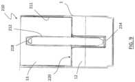
- FIG. 9illustrates another embodiment wherein the process comprises the provision of a separation device 210 including a first component selected as housing 211 and a second component selected as duct 212 .
- the piercing of the membrane 214is made by the lower end of the duct 212 , which operates similar to the duct 116 of the above described embodiment.
- the processincludes the step of depositing the second ingredient (e.g. soluble coffee) on a surface 220 of the housing 211 and, accordingly, no infusion chamber is required.
- the second ingrediente.g. soluble coffee
- a connecting pathis formed by the duct 212 itself. Water flows through the duct 212 and apertures 218 into the chamber 13 , where it comes into contact with the soluble coffee contained in the housing 211 .
- the processincludes the step of providing a duct 212 which is fixed (i.e. not displaceable) relative to the housing 211 .
- the processmay comprise the provision of a movable rod inside the duct 212 .
Landscapes
- Engineering & Computer Science (AREA)
- Mechanical Engineering (AREA)
- Food Science & Technology (AREA)
- Apparatus For Making Beverages (AREA)
- Tea And Coffee (AREA)
- Non-Alcoholic Beverages (AREA)
- Packages (AREA)
- Closures For Containers (AREA)
Abstract
Description
- positioning said first component to provide a frangible seal between the first chamber and the second chamber; and
- positioning the second component in a position, relative to the first component, wherein the second component can be operated by the user to break said frangible seal and open said connecting path from the first chamber to the second chamber via said housing.
Claims (20)
Applications Claiming Priority (1)
| Application Number | Priority Date | Filing Date | Title |
|---|---|---|---|
| PCT/EP2018/063839WO2019223884A1 (en) | 2018-05-25 | 2018-05-25 | Process for making a portable beverage product and a filling line therefore |
Publications (2)
| Publication Number | Publication Date |
|---|---|
| US20210137301A1 US20210137301A1 (en) | 2021-05-13 |
| US11986120B2true US11986120B2 (en) | 2024-05-21 |
Family
ID=62555038
Family Applications (1)
| Application Number | Title | Priority Date | Filing Date |
|---|---|---|---|
| US17/058,164Active2040-02-18US11986120B2 (en) | 2018-05-25 | 2018-05-25 | Process for making a portable beverage product and a filling line therefore |
Country Status (16)
| Country | Link |
|---|---|
| US (1) | US11986120B2 (en) |
| EP (1) | EP3802333A1 (en) |
| JP (1) | JP7175033B2 (en) |
| KR (1) | KR102565507B1 (en) |
| CN (1) | CN112292329B (en) |
| AU (1) | AU2018424303B2 (en) |
| BR (1) | BR112020023796B1 (en) |
| CA (1) | CA3099458A1 (en) |
| IL (1) | IL278883B2 (en) |
| MX (1) | MX2020012665A (en) |
| RU (1) | RU2765024C1 (en) |
| SA (1) | SA520420612B1 (en) |
| SG (1) | SG11202011009QA (en) |
| UA (1) | UA127591C2 (en) |
| WO (1) | WO2019223884A1 (en) |
| ZA (1) | ZA202007254B (en) |
Families Citing this family (2)
| Publication number | Priority date | Publication date | Assignee | Title |
|---|---|---|---|---|
| CN112292329B (en)* | 2018-05-25 | 2023-05-12 | 阿利斯特拉股份公司 | Method for producing a portable beverage product and filling line therefor |
| CN116508918A (en)* | 2023-04-17 | 2023-08-01 | 广西冰客食品有限公司 | A kind of preparation method of citrus pulp |
Citations (36)
| Publication number | Priority date | Publication date | Assignee | Title |
|---|---|---|---|---|
| US865776A (en)* | 1907-04-15 | 1907-09-10 | Bernath Georg | Coffee-pot. |
| US2570997A (en)* | 1946-11-16 | 1951-10-09 | Mcgraw Electric Co | Coffee maker |
| US3077156A (en)* | 1957-11-12 | 1963-02-12 | Egi Mario | Percolator |
| US3111079A (en)* | 1960-07-08 | 1963-11-19 | Lescure Henri | Coffee-pots of the pressure type |
| US4167899A (en)* | 1977-08-12 | 1979-09-18 | Mccormick James B | Disposable unitary coffee maker |
| US4381696A (en)* | 1981-04-27 | 1983-05-03 | Mirro Corporation | Microwave coffee making apparatus |
| US4498375A (en)* | 1984-03-01 | 1985-02-12 | Dante Bedini | Automatic coffee pot |
| US4516484A (en)* | 1983-03-23 | 1985-05-14 | Alfonso Bialetti & C., Fonderia In Conchiglia S.P.A. | Household appliance for preparing hot beverages |
| US4577080A (en)* | 1985-03-19 | 1986-03-18 | Gee Associates | Coffee maker adapted for use in a microwave oven |
| US4642443A (en)* | 1981-11-16 | 1987-02-10 | Northland Aluminum Products, Inc. | Apparatus for brewing coffee in microwave ovens |
| US4721835A (en)* | 1986-10-06 | 1988-01-26 | Helmut Welker | Microwave brewing cup |
| US5079396A (en)* | 1989-12-20 | 1992-01-07 | Kraft General Foods, Inc. | Microwave coffee percolating device |
| SU1761112A1 (en) | 1990-07-02 | 1992-09-15 | Научно-исследовательский институт радиотехнической аппаратуры | Coffee-machine |
| US5281785A (en)* | 1992-02-20 | 1994-01-25 | Lacrex S.A. | Apparatus for preparing beverages in a microwave oven |
| US6026733A (en)* | 1993-03-26 | 2000-02-22 | Micro Lungo, Inc. | Device for making coffee and espresso beverages in microwave oven |
| US20050109213A1 (en)* | 2003-11-20 | 2005-05-26 | Srd Pharmaceuticals, Inc. | Disposable coffee maker |
| US6912949B2 (en)* | 2000-10-04 | 2005-07-05 | Adriana Brizio | Coffee maker |
| US20060165851A1 (en)* | 2003-02-20 | 2006-07-27 | Adriana Brizio | Beverage preservation and distribution can, also usable for the extemporaneous preparation of beverages by extraction and/or infusion |
| EP1827181B1 (en) | 2005-06-08 | 2008-04-23 | Massimo Crescenzi | Moka coffee machine and method for preparing a coffee-flavoured drink |
| USD586172S1 (en)* | 2006-12-20 | 2009-02-10 | Adriana Brizio | Coffee machine |
| US20090229472A1 (en)* | 2008-03-12 | 2009-09-17 | Ferrara Jr Daniel A | Brewing system and packaging |
| WO2010031440A1 (en) | 2008-09-19 | 2010-03-25 | Adriana Brizio | Can for the extemporaneous preparation of beverages by extraction and/or infusion, provided with a safety lid |
| WO2010045983A1 (en) | 2008-10-24 | 2010-04-29 | Alistella S.A. | Device for extemporaneously preparing a hot beverage from a soluble powder |
| WO2010067326A1 (en) | 2008-12-12 | 2010-06-17 | B & B Studio Di Francesco Baldacci | Disposable device for preparing hot beverages |
| US20110168659A1 (en)* | 2010-01-08 | 2011-07-14 | Strong Energy Biotechnical Development Co., Ltd | Bottle Cap Device |
| US20120031277A1 (en)* | 2010-08-08 | 2012-02-09 | Chun-Shu Hsieh | Drink can |
| CN203865264U (en) | 2014-06-05 | 2014-10-08 | 赵震 | Self-heating ring-pull can |
| DE102013207734A1 (en) | 2013-04-26 | 2014-10-30 | Lisa Dräxlmaier GmbH | Interior assembly with a drinking cup arranged at a tapping point |
| US20150056341A1 (en)* | 2013-08-20 | 2015-02-26 | 2266170 Ontario Inc. | Capsule containing a dosing agent and system and process for making same |
| US9126731B2 (en)* | 2007-10-25 | 2015-09-08 | The Sunrider Corporation | Safety sealed reservoir cap |
| US9332873B2 (en)* | 2013-03-08 | 2016-05-10 | Jung-Jung TIEN | Lid structure configured for easy disassembly and cleaning |
| CN105683055A (en) | 2013-10-28 | 2016-06-15 | 田永馥 | Capsule cap for beverage container |
| US9402503B2 (en)* | 2009-07-06 | 2016-08-02 | Hendrik Meyl | Apparatus and method for preparing beverages by electromagnetic radiation |
| US20160347503A1 (en)* | 2015-05-29 | 2016-12-01 | Sam Tung Tsui | Collapsible Heatable Liquid Containers |
| WO2017162898A1 (en) | 2016-03-21 | 2017-09-28 | Isidro Aythami Sanchez Carrasco | Disposable device for preparing infusions |
| US20210137301A1 (en)* | 2018-05-25 | 2021-05-13 | Alistella Sa | Process for Making a Portable Beverage Product and a Filling Line Therefore |
- 2018
- 2018-05-25CNCN201880093793.2Apatent/CN112292329B/enactiveActive
- 2018-05-25JPJP2020565854Apatent/JP7175033B2/enactiveActive
- 2018-05-25UAUAA202007967Apatent/UA127591C2/enunknown
- 2018-05-25EPEP18729608.2Apatent/EP3802333A1/enactivePending
- 2018-05-25AUAU2018424303Apatent/AU2018424303B2/enactiveActive
- 2018-05-25SGSG11202011009QApatent/SG11202011009QA/enunknown
- 2018-05-25BRBR112020023796-5Apatent/BR112020023796B1/enactiveIP Right Grant
- 2018-05-25USUS17/058,164patent/US11986120B2/enactiveActive
- 2018-05-25RURU2020141626Apatent/RU2765024C1/enactive
- 2018-05-25KRKR1020207037129Apatent/KR102565507B1/enactiveActive
- 2018-05-25WOPCT/EP2018/063839patent/WO2019223884A1/ennot_activeCeased
- 2018-05-25ILIL278883Apatent/IL278883B2/enunknown
- 2018-05-25CACA3099458Apatent/CA3099458A1/enactivePending
- 2018-05-25MXMX2020012665Apatent/MX2020012665A/enunknown
- 2020
- 2020-11-20ZAZA2020/07254Apatent/ZA202007254B/enunknown
- 2020-11-22SASA520420612Apatent/SA520420612B1/enunknown
Patent Citations (45)
| Publication number | Priority date | Publication date | Assignee | Title |
|---|---|---|---|---|
| US865776A (en)* | 1907-04-15 | 1907-09-10 | Bernath Georg | Coffee-pot. |
| US2570997A (en)* | 1946-11-16 | 1951-10-09 | Mcgraw Electric Co | Coffee maker |
| US3077156A (en)* | 1957-11-12 | 1963-02-12 | Egi Mario | Percolator |
| US3111079A (en)* | 1960-07-08 | 1963-11-19 | Lescure Henri | Coffee-pots of the pressure type |
| US4167899A (en)* | 1977-08-12 | 1979-09-18 | Mccormick James B | Disposable unitary coffee maker |
| US4381696A (en)* | 1981-04-27 | 1983-05-03 | Mirro Corporation | Microwave coffee making apparatus |
| US4642443A (en)* | 1981-11-16 | 1987-02-10 | Northland Aluminum Products, Inc. | Apparatus for brewing coffee in microwave ovens |
| US4516484A (en)* | 1983-03-23 | 1985-05-14 | Alfonso Bialetti & C., Fonderia In Conchiglia S.P.A. | Household appliance for preparing hot beverages |
| US4498375A (en)* | 1984-03-01 | 1985-02-12 | Dante Bedini | Automatic coffee pot |
| US4577080A (en)* | 1985-03-19 | 1986-03-18 | Gee Associates | Coffee maker adapted for use in a microwave oven |
| US4721835A (en)* | 1986-10-06 | 1988-01-26 | Helmut Welker | Microwave brewing cup |
| US5079396A (en)* | 1989-12-20 | 1992-01-07 | Kraft General Foods, Inc. | Microwave coffee percolating device |
| SU1761112A1 (en) | 1990-07-02 | 1992-09-15 | Научно-исследовательский институт радиотехнической аппаратуры | Coffee-machine |
| US5281785A (en)* | 1992-02-20 | 1994-01-25 | Lacrex S.A. | Apparatus for preparing beverages in a microwave oven |
| US6026733A (en)* | 1993-03-26 | 2000-02-22 | Micro Lungo, Inc. | Device for making coffee and espresso beverages in microwave oven |
| US6912949B2 (en)* | 2000-10-04 | 2005-07-05 | Adriana Brizio | Coffee maker |
| US20060165851A1 (en)* | 2003-02-20 | 2006-07-27 | Adriana Brizio | Beverage preservation and distribution can, also usable for the extemporaneous preparation of beverages by extraction and/or infusion |
| US7569240B2 (en)* | 2003-02-20 | 2009-08-04 | Adriana Brizio | Beverage preservation and distribution can, also usable for the extemporaneous preparation of beverages by extraction and/or infusion |
| US20050109213A1 (en)* | 2003-11-20 | 2005-05-26 | Srd Pharmaceuticals, Inc. | Disposable coffee maker |
| EP1827181B1 (en) | 2005-06-08 | 2008-04-23 | Massimo Crescenzi | Moka coffee machine and method for preparing a coffee-flavoured drink |
| ES2307197T3 (en) | 2005-06-08 | 2008-11-16 | Massimo Crescenzi | MACHINE TYPE MOKA FOR THE PREPARATION OF COFFEE INFUSIONS AND METHOD FOR THE PREPARATION OF SUCH INFUSIONS. |
| US7832329B2 (en)* | 2005-06-08 | 2010-11-16 | Massimo Crescenzi | Moka coffee machine and method for preparing a coffee-flavoured drink |
| USD586172S1 (en)* | 2006-12-20 | 2009-02-10 | Adriana Brizio | Coffee machine |
| US9126731B2 (en)* | 2007-10-25 | 2015-09-08 | The Sunrider Corporation | Safety sealed reservoir cap |
| US20090229472A1 (en)* | 2008-03-12 | 2009-09-17 | Ferrara Jr Daniel A | Brewing system and packaging |
| US20110056944A1 (en)* | 2008-09-19 | 2011-03-10 | Adriana Brizio | Can for the extemporaneous preparation of beverages by extraction and/or infusion, provided with a safety lid |
| US9259117B2 (en)* | 2008-09-19 | 2016-02-16 | Adriana Brizio | Can for the extemporaneous preparation of beverages by extraction and/or infusion, provided with a safety lid |
| WO2010031440A1 (en) | 2008-09-19 | 2010-03-25 | Adriana Brizio | Can for the extemporaneous preparation of beverages by extraction and/or infusion, provided with a safety lid |
| US9101241B2 (en)* | 2008-10-24 | 2015-08-11 | Alistella S.A. | Device for extemporaneously preparing a hot beverage from a soluble powder |
| WO2010045983A1 (en) | 2008-10-24 | 2010-04-29 | Alistella S.A. | Device for extemporaneously preparing a hot beverage from a soluble powder |
| US20110168030A1 (en)* | 2008-10-24 | 2011-07-14 | Alistella S.A. | Device for extemporaneously preparing a hot beverage from a soluble powder |
| WO2010067326A1 (en) | 2008-12-12 | 2010-06-17 | B & B Studio Di Francesco Baldacci | Disposable device for preparing hot beverages |
| US9402503B2 (en)* | 2009-07-06 | 2016-08-02 | Hendrik Meyl | Apparatus and method for preparing beverages by electromagnetic radiation |
| US20110168659A1 (en)* | 2010-01-08 | 2011-07-14 | Strong Energy Biotechnical Development Co., Ltd | Bottle Cap Device |
| US20120031277A1 (en)* | 2010-08-08 | 2012-02-09 | Chun-Shu Hsieh | Drink can |
| US9332873B2 (en)* | 2013-03-08 | 2016-05-10 | Jung-Jung TIEN | Lid structure configured for easy disassembly and cleaning |
| DE102013207734A1 (en) | 2013-04-26 | 2014-10-30 | Lisa Dräxlmaier GmbH | Interior assembly with a drinking cup arranged at a tapping point |
| US20150056341A1 (en)* | 2013-08-20 | 2015-02-26 | 2266170 Ontario Inc. | Capsule containing a dosing agent and system and process for making same |
| CN105683055A (en) | 2013-10-28 | 2016-06-15 | 田永馥 | Capsule cap for beverage container |
| US9637290B2 (en)* | 2013-10-28 | 2017-05-02 | Chung A Ram Co., Ltd. | Capsule cap for beverage container |
| CN203865264U (en) | 2014-06-05 | 2014-10-08 | 赵震 | Self-heating ring-pull can |
| US20160347503A1 (en)* | 2015-05-29 | 2016-12-01 | Sam Tung Tsui | Collapsible Heatable Liquid Containers |
| WO2017162898A1 (en) | 2016-03-21 | 2017-09-28 | Isidro Aythami Sanchez Carrasco | Disposable device for preparing infusions |
| EP3434158A1 (en) | 2016-03-21 | 2019-01-30 | Isidro Aythami Sanchez Carrasco | Disposable device for preparing infusions |
| US20210137301A1 (en)* | 2018-05-25 | 2021-05-13 | Alistella Sa | Process for Making a Portable Beverage Product and a Filling Line Therefore |
Also Published As
| Publication number | Publication date |
|---|---|
| US20210137301A1 (en) | 2021-05-13 |
| RU2765024C1 (en) | 2022-01-24 |
| AU2018424303B2 (en) | 2024-05-16 |
| BR112020023796A2 (en) | 2021-02-23 |
| CN112292329A (en) | 2021-01-29 |
| CN112292329B (en) | 2023-05-12 |
| BR112020023796B1 (en) | 2023-12-12 |
| KR102565507B1 (en) | 2023-08-10 |
| IL278883B1 (en) | 2024-12-01 |
| EP3802333A1 (en) | 2021-04-14 |
| SG11202011009QA (en) | 2020-12-30 |
| JP2021525088A (en) | 2021-09-24 |
| CA3099458A1 (en) | 2019-11-28 |
| AU2018424303A1 (en) | 2020-11-26 |
| MX2020012665A (en) | 2021-02-15 |
| JP7175033B2 (en) | 2022-11-18 |
| UA127591C2 (en) | 2023-10-25 |
| IL278883A (en) | 2021-01-31 |
| WO2019223884A1 (en) | 2019-11-28 |
| IL278883B2 (en) | 2025-04-01 |
| SA520420612B1 (en) | 2024-02-12 |
| KR20210014138A (en) | 2021-02-08 |
| ZA202007254B (en) | 2025-07-30 |
Similar Documents
| Publication | Publication Date | Title |
|---|---|---|
| AU2004212687B9 (en) | Beverage preservation and distribution can, also usable for the extemporaneous preparation of beverages by extraction and/or infusion | |
| RU2533706C2 (en) | Capsule for food products preparation in food products preparation machine | |
| US9516970B2 (en) | Apparatus for creating a consumable liquid food or beverage product from frozen contents | |
| KR101829946B1 (en) | Beverage cartridge | |
| US11986120B2 (en) | Process for making a portable beverage product and a filling line therefore | |
| US20050238769A1 (en) | Method of producing a packaged product | |
| HK1088796B (en) | Beverage preservation and distribution can, also usable for the extemporaneous preparation of beverages by extraction and/or infusion | |
| HK1158472B (en) | Device for extemporaneously preparing a hot beverage from a soluble powder | |
| HK1158472A (en) | Device for extemporaneously preparing a hot beverage from a soluble powder |
Legal Events
| Date | Code | Title | Description |
|---|---|---|---|
| AS | Assignment | Owner name:ALISTELLA SA, SWITZERLAND Free format text:ASSIGNMENT OF ASSIGNORS INTEREST;ASSIGNOR:BRIZIO, ADRIANA;REEL/FRAME:054453/0311 Effective date:20201117 | |
| FEPP | Fee payment procedure | Free format text:ENTITY STATUS SET TO UNDISCOUNTED (ORIGINAL EVENT CODE: BIG.); ENTITY STATUS OF PATENT OWNER: SMALL ENTITY | |
| FEPP | Fee payment procedure | Free format text:ENTITY STATUS SET TO SMALL (ORIGINAL EVENT CODE: SMAL); ENTITY STATUS OF PATENT OWNER: SMALL ENTITY | |
| STPP | Information on status: patent application and granting procedure in general | Free format text:APPLICATION DISPATCHED FROM PREEXAM, NOT YET DOCKETED | |
| STPP | Information on status: patent application and granting procedure in general | Free format text:DOCKETED NEW CASE - READY FOR EXAMINATION | |
| STPP | Information on status: patent application and granting procedure in general | Free format text:NON FINAL ACTION MAILED | |
| STPP | Information on status: patent application and granting procedure in general | Free format text:RESPONSE TO NON-FINAL OFFICE ACTION ENTERED AND FORWARDED TO EXAMINER | |
| STPP | Information on status: patent application and granting procedure in general | Free format text:NOTICE OF ALLOWANCE MAILED -- APPLICATION RECEIVED IN OFFICE OF PUBLICATIONS | |
| STPP | Information on status: patent application and granting procedure in general | Free format text:AWAITING TC RESP., ISSUE FEE NOT PAID | |
| STPP | Information on status: patent application and granting procedure in general | Free format text:NOTICE OF ALLOWANCE MAILED -- APPLICATION RECEIVED IN OFFICE OF PUBLICATIONS | |
| STPP | Information on status: patent application and granting procedure in general | Free format text:PUBLICATIONS -- ISSUE FEE PAYMENT VERIFIED | |
| STCF | Information on status: patent grant | Free format text:PATENTED CASE | |
| CC | Certificate of correction |