US11984768B2 - Hydroelectric generator for faucet and flush valve - Google Patents
Hydroelectric generator for faucet and flush valveDownload PDFInfo
- Publication number
- US11984768B2 US11984768B2US17/234,588US202117234588AUS11984768B2US 11984768 B2US11984768 B2US 11984768B2US 202117234588 AUS202117234588 AUS 202117234588AUS 11984768 B2US11984768 B2US 11984768B2
- Authority
- US
- United States
- Prior art keywords
- power
- power source
- hydroelectric generator
- generator assembly
- assembly
- Prior art date
- Legal status (The legal status is an assumption and is not a legal conclusion. Google has not performed a legal analysis and makes no representation as to the accuracy of the status listed.)
- Active, expires
Links
Images


Classifications
- H—ELECTRICITY
- H02—GENERATION; CONVERSION OR DISTRIBUTION OF ELECTRIC POWER
- H02K—DYNAMO-ELECTRIC MACHINES
- H02K11/00—Structural association of dynamo-electric machines with electric components or with devices for shielding, monitoring or protection
- H02K11/0094—Structural association with other electrical or electronic devices
- E—FIXED CONSTRUCTIONS
- E03—WATER SUPPLY; SEWERAGE
- E03C—DOMESTIC PLUMBING INSTALLATIONS FOR FRESH WATER OR WASTE WATER; SINKS
- E03C1/00—Domestic plumbing installations for fresh water or waste water; Sinks
- E03C1/02—Plumbing installations for fresh water
- E03C1/05—Arrangements of devices on wash-basins, baths, sinks, or the like for remote control of taps
- E03C1/055—Electrical control devices, e.g. with push buttons, control panels or the like
- E03C1/057—Electrical control devices, e.g. with push buttons, control panels or the like touchless, i.e. using sensors
- F—MECHANICAL ENGINEERING; LIGHTING; HEATING; WEAPONS; BLASTING
- F03—MACHINES OR ENGINES FOR LIQUIDS; WIND, SPRING, OR WEIGHT MOTORS; PRODUCING MECHANICAL POWER OR A REACTIVE PROPULSIVE THRUST, NOT OTHERWISE PROVIDED FOR
- F03B—MACHINES OR ENGINES FOR LIQUIDS
- F03B13/00—Adaptations of machines or engines for special use; Combinations of machines or engines with driving or driven apparatus; Power stations or aggregates
- H—ELECTRICITY
- H02—GENERATION; CONVERSION OR DISTRIBUTION OF ELECTRIC POWER
- H02K—DYNAMO-ELECTRIC MACHINES
- H02K7/00—Arrangements for handling mechanical energy structurally associated with dynamo-electric machines, e.g. structural association with mechanical driving motors or auxiliary dynamo-electric machines
- H02K7/18—Structural association of electric generators with mechanical driving motors, e.g. with turbines
- H02K7/1807—Rotary generators
- H02K7/1823—Rotary generators structurally associated with turbines or similar engines
- E—FIXED CONSTRUCTIONS
- E03—WATER SUPPLY; SEWERAGE
- E03C—DOMESTIC PLUMBING INSTALLATIONS FOR FRESH WATER OR WASTE WATER; SINKS
- E03C1/00—Domestic plumbing installations for fresh water or waste water; Sinks
- E03C1/02—Plumbing installations for fresh water
- E03C1/04—Water-basin installations specially adapted to wash-basins or baths
- E—FIXED CONSTRUCTIONS
- E03—WATER SUPPLY; SEWERAGE
- E03D—WATER-CLOSETS OR URINALS WITH FLUSHING DEVICES; FLUSHING VALVES THEREFOR
- E03D1/00—Water flushing devices with cisterns ; Setting up a range of flushing devices or water-closets; Combinations of several flushing devices
- E03D1/30—Valves for high or low level cisterns; Their arrangement ; Flushing mechanisms in the cistern, optionally with provisions for a pre-or a post- flushing and for cutting off the flushing mechanism in case of leakage
- F—MECHANICAL ENGINEERING; LIGHTING; HEATING; WEAPONS; BLASTING
- F05—INDEXING SCHEMES RELATING TO ENGINES OR PUMPS IN VARIOUS SUBCLASSES OF CLASSES F01-F04
- F05B—INDEXING SCHEME RELATING TO WIND, SPRING, WEIGHT, INERTIA OR LIKE MOTORS, TO MACHINES OR ENGINES FOR LIQUIDS COVERED BY SUBCLASSES F03B, F03D AND F03G
- F05B2220/00—Application
- F05B2220/20—Application within closed fluid conduits, e.g. pipes
- F—MECHANICAL ENGINEERING; LIGHTING; HEATING; WEAPONS; BLASTING
- F05—INDEXING SCHEMES RELATING TO ENGINES OR PUMPS IN VARIOUS SUBCLASSES OF CLASSES F01-F04
- F05B—INDEXING SCHEME RELATING TO WIND, SPRING, WEIGHT, INERTIA OR LIKE MOTORS, TO MACHINES OR ENGINES FOR LIQUIDS COVERED BY SUBCLASSES F03B, F03D AND F03G
- F05B2260/00—Function
- F05B2260/42—Storage of energy
- Y—GENERAL TAGGING OF NEW TECHNOLOGICAL DEVELOPMENTS; GENERAL TAGGING OF CROSS-SECTIONAL TECHNOLOGIES SPANNING OVER SEVERAL SECTIONS OF THE IPC; TECHNICAL SUBJECTS COVERED BY FORMER USPC CROSS-REFERENCE ART COLLECTIONS [XRACs] AND DIGESTS
- Y02—TECHNOLOGIES OR APPLICATIONS FOR MITIGATION OR ADAPTATION AGAINST CLIMATE CHANGE
- Y02B—CLIMATE CHANGE MITIGATION TECHNOLOGIES RELATED TO BUILDINGS, e.g. HOUSING, HOUSE APPLIANCES OR RELATED END-USER APPLICATIONS
- Y02B10/00—Integration of renewable energy sources in buildings
- Y02B10/50—Hydropower in dwellings
- Y—GENERAL TAGGING OF NEW TECHNOLOGICAL DEVELOPMENTS; GENERAL TAGGING OF CROSS-SECTIONAL TECHNOLOGIES SPANNING OVER SEVERAL SECTIONS OF THE IPC; TECHNICAL SUBJECTS COVERED BY FORMER USPC CROSS-REFERENCE ART COLLECTIONS [XRACs] AND DIGESTS
- Y10—TECHNICAL SUBJECTS COVERED BY FORMER USPC
- Y10T—TECHNICAL SUBJECTS COVERED BY FORMER US CLASSIFICATION
- Y10T137/00—Fluid handling
- Y10T137/9464—Faucets and spouts
Definitions
- the present disclosurerelates to faucets and flush valves, and more specifically, to a hydroelectric generator for use with a faucet and a flush valve.
- Typical hydroelectric turbine generatorsare large and bulky. These hydroelectric generators are only capable of being installed at a specific position on a faucet or flush valve due to size, weight, and shape constraints of the hydroelectric generator.
- the ability to incorporate a hydroelectric generator into a plumbing fixtureextends the life of the fixture by tapping into electricity generated by the usual flow of water through the fixture.
- the electricity generated by the hydroelectric generatorcan be harvested and stored for later use by the fixture.
- the flexibility of the configuration of the hydroelectric generator assembly, as described herein,provides for an efficient generation of electricity and modularity for installation depending on customer needs.
- the inventionprovides a plumbing system for generating electrical power, the plumbing system including a hydroelectric generator assembly configured to generate power, a power source arranged in parallel with the hydroelectric generator assembly, an interconnecting power harness in communication with the hydroelectric generator assembly and the power source, and a plumbing fixture in communication with the interconnecting power harness, wherein the plumbing fixture includes a valve and a sensor configured to detect the presence of a user, wherein the hydroelectric generator assembly is configured to provide power to the valve.
- the inventionprovides a plumbing system for generating and storing electrical power, the plumbing system including a hydroelectric generator assembly configured to generate power, a power bank configured to store power generated by the hydroelectric generator assembly, a first power source arranged in parallel with the hydroelectric generator assembly and in communication with the power bank, a plumbing fixture in communication with the power source, wherein the plumbing fixture includes a valve and a sensor configured to detect the presence of a user, and an end point device including an electronic processor, the electronic processor powered by a second power source local to the end point device, wherein the end point device is in communication with the power bank, the hydroelectric generator assembly, and the plumbing fixture
- the inventionprovides a plumbing system for generating and storing electrical power within a facility, the plumbing system including a hydroelectric generator assembly configured to generate power, a power bank configured to store power generated by the hydroelectric generator assembly, a plurality of power sources in communication with the power bank, a plurality of plumbing fixtures associated with the facility, wherein each of the plurality of plumbing fixtures are in communication with the power source, and an end point device in communication with the power bank, the hydroelectric generator assembly, and the plurality of plumbing fixtures, the end point device including an electronic processor configured to receive data from at least one of the plurality of plumbing fixtures and transmit the data to a remote device.
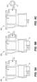
- FIG. 1is a perspective view of a hydroelectric generator assembly embodying the invention.
- FIG. 2is another perspective view of the hydroelectric generator assembly of FIG. 1 .
- FIG. 3is a perspective, cross-sectional view of an alternative hydroelectric generator assembly embodying the invention.
- FIG. 4is an exploded view of a faucet assembly including the hydroelectric generator assembly of FIG. 1 .
- FIGS. 5 A- 5 Gare side views of the faucet assembly of FIG. 4 , including the hydroelectric generator assembly of FIG. 1 positioned at various locations.
- FIGS. 6 A- 6 Gare schematic wire diagrams of the faucet assembly.
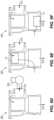
- FIGS. 7 A- 7 Bare side views of an alternative hydroelectric generator assembly embodying the invention.
- FIG. 8is an exploded view of a flush valve assembly including the hydroelectric generator assembly of FIGS. 7 A- 7 B .
- FIGS. 9 A- 9 Fare side views of the flush valve assembly of FIG. 10 , including the hydroelectric generator assembly of FIGS. 7 A- 7 B positioned at various locations.
- FIGS. 10 A- 10 Care side views of a vacuum breaker tube of the flush valve assembly of FIG. 8 , including the hydroelectric generator assembly of FIGS. 7 A- 7 B positioned at various locations.
- FIG. 11is a side view of the flush valve assembly of FIG. 8 , including the hydroelectric generator assembly of FIGS. 7 A- 7 B positioned at an alternative position.
- FIGS. 12 A- 12 Bare side views of the flush valve assembly of FIG. 8 , including the hydroelectric generator assembly of FIGS. 7 A- 7 B positioned at an alternative position.
- FIG. 13is a schematic diagram of a system configured to generate and deliver power to the faucet assembly of FIG. 4 and/or the flush valve assembly of FIG. 8 .
- FIG. 14is a schematic diagram of an alternative system configured to generate and deliver power to the faucet assembly of FIG. 4 and/or the flush valve assembly of FIG. 8 .
- FIG. 15is a schematic diagram of an end point device included in the system of FIG. 14 .
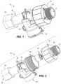
- FIGS. 1 - 2illustrate a hydroelectric generator assembly 10 according to an embodiment of the invention.
- the hydroelectric generator assembly 10includes an inlet 14 and an outlet 18 , such that the inlet 14 receives water from a water supply and dispenses water at the outlet 18 .
- the hydroelectric generator assembly 10is modular and may be positioned at various locations within a faucet assembly 100 in order to extract electrical energy from the water supply, as will be described in more detail below.
- the hydroelectric generator assembly 10is operable to extract kinetic energy from water flowing into the inlet 14 of the hydroelectric generator assembly 10 and convert the kinetic energy into electrical energy.
- the hydroelectric generator assembly 10includes a main housing 22 , a coupling 24 , and an extension 26 of the housing 22 .
- the hydroelectric generator assembly 10additionally includes the inlet 14 , which receives water from a water supply, and the outlet 18 , which dispenses water out of the hydroelectric generator assembly 10 .
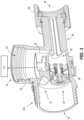
- the housing 22includes a first chamber 30 having an upper section and a lower section.
- the first chamber 30includes a first flow path 31 through the upper section and a second flow path 33 through the lower section for the water after it enters the inlet 14 and traverses to get to the outlet 18 .
- the upper section of the first chamber 30includes an AC generator assembly 32 including a turbine positioned on a drive shaft.
- the AC generator assembly 32includes a rotor and a stator and is positioned on a first end of the drive shaft.
- the statorincludes several blades positioned around the rotor.
- the AC generator assembly 32can be embodied as a three-phase AC brushless motor. However, the AC generator assembly 32 may include alternative configurations.
- the turbineis positioned on a second end of the drive shaft, opposite the first end.
- the turbineis coupled to the rotor and the stator via the drive shaft.
- the turbineincludes several blades circumferentially spaced around the drive shaft and are directly positioned within a flow path of the water.
- the blades of the turbinerotate, converting the energy of the flowing water into mechanical energy.
- the bladesdirect a flow of water toward the rotor, causing the rotor to spin. Rotation of the rotor subsequently causes rotation of the drive shaft, thereby generating electrical current.
- the lower section of the first chamber 30is configured to receive an in-line check valve 38 to control the flow rate of the water in the first flow path 31 and the second flow path 33 , and, which provides optimal performance of the turbine.
- the second chamber 34includes attachment points to connect to the power storage device to store electrical energy harvested from the hydroelectric generator assembly 10 , as will be described in more detail below.
- the coupling 24is a cylindrical cap coupled to a first end 22 a ( FIG. 2 ) of the main housing 22 .
- the coupling 24includes a port 28 , which forms the inlet 14 of the hydroelectric generator assembly 10 .
- the port 28is cylindrical and includes external threads, which allow the coupling 24 to couple the hydroelectric generator assembly 10 to a component within the faucet assembly 100 .
- the coupling 24may additionally or alternatively include a flange to couple the hydroelectric generator assembly 10 to the faucet assembly 100 .
- the port 28may be positioned directly on the main housing 22 , rather than including a separate, removable coupling 24 .
- the hydroelectric generator assembly 10is electrically connected to a power storage device 35 , which is within housing 37 to store electrical energy harvested from the AC generator assembly 32 .
- the power storage device 35may include one or more batteries.
- the batterymay be an alkaline battery, NiCD battery, a lithium ion battery, lithium-polymer battery, or rechargeable versions of these batteries, or include alternative configurations.
- the housing 37includes an AC to DC converter and can include a controller, such as a processor.
- the hydroelectric generator assembly 10additionally includes an extraction mechanism (not shown) and a storage mechanism (not shown), as will be discussed in further detail below.
- the extraction mechanismis configured to extract electrical energy generated by the AC generator assembly 32 , and the storage mechanism stores the electrical energy.
- the electrical energyis additionally capable of being supplied in various methods, as will be described in further detail below.
- the housing extension 26forms the outlet 18 of the hydroelectric generator assembly 10 , such that water flows out of the hydroelectric generator assembly 10 via the extension 26 .
- the extension 26includes an outer surface having a threaded portion configured to receive a nut 62 .
- the nut 62is positioned on an outer surface of the extension 26 and is configured to spin relative to the extension 26 .
- the nut 62is configured to couple the hydroelectric generator assembly 10 to an incoming main waterline of the faucet assembly 100 .
- One or more supply conduitsmay be positioned between the nut 62 and the faucet assembly 100 .
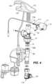
- the hydroelectric generator assembly 10may be positioned within the faucet assembly 100 .
- the faucet assembly 100includes a filter 104 , a solenoid valve 108 , and a faucet 112 .
- the filter 104filters water coming into the faucet assembly 100 via a faucet inlet 116 , and is in connection with a water source.
- the solenoid valve 108is configured to open and close, thereby allowing or preventing the flow of water through the faucet assembly 100 . Specifically, when a user places their hands adjacent a sensor 120 positioned on the faucet 112 (or depresses an actuator), the solenoid valve 108 moves to an “open” position, thereby allowing the flow of water through the assembly 100 .
- the faucet 112includes an outlet 124 of the faucet assembly 100 and dispenses water after it has passed through the assembly 100 .
- the hydroelectric generator assembly 10is typically positioned between the faucet 112 and the solenoid valve 108 of the faucet assembly 100 .
- the hydroelectric generator inlet 14is coupled to an outlet 108 a of the solenoid valve 108
- the hydroelectric generator outlet 18e.g., the connection shaft 58
- the connection shaft 58is coupled to an inlet 112 a of the faucet 112 via the nut 62 .
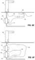
- the hydroelectric generator assembly 10may be positioned at various different locations of the faucet assembly 100 .
- the hydroelectric generator assembly 10may be positioned upstream of the faucet assembly inlet 116 .
- the hydroelectric generator assembly 10may be positioned within a mainline of the faucet assembly 100 behind a wall, or may be positioned immediately upstream of the filter 104 .
- the hydroelectric generator assembly 10may be positioned within a control valve 128 of the faucet assembly 100 .
- the hydroelectric generator assembly 10may be positioned downstream of the filter 104 and downstream of the solenoid valve 108 .
- the hydroelectric generator assembly 10may be positioned downstream of the solenoid valve 108 and upstream of the faucet 112 .
- the hydroelectric generator assembly 10is positioned below a surface (e.g., countertop) which supports the faucet assembly 100 .
- the hydroelectric generator assembly 10may be positioned within the filter 104 of the faucet assembly 100 .
- the hydroelectric generator assembly 10may be positioned within the faucet 112 .
- FIG. 5 Cillustrates the hydroelectric generator assembly 10 positioned adjacent the faucet inlet 112 a
- FIG. 5 Dillustrates the hydroelectric generator assembly 10 positioned within the faucet assembly outlet 124 .
- the hydroelectric generator assembly 10may be positioned outside the faucet 112 . Specifically, the hydroelectric generator assembly 10 is coupled to the faucet assembly outlet 124 .
- Positioning the hydroelectric generator assembly 10 at the various positions illustrated in FIGS. 5 A- 5 Gprovides various advantages for the faucet assembly 100 .
- the modular size of the hydroelectric generator assembly 10enables for optimal operating differential pressure loss for the turbine 42 .
- the modular functionality of the hydroelectric generator assembly 10also allows for more flexibility in the sizing, clearance, form factor, and access of the hydroelectric generator assembly 10 and the faucet assembly 100 . Additionally, the ability to position the hydroelectric generator assembly 10 at various positions with the faucet assembly 100 simplifies installation and removal of the generator 10 , while also facilitating maintenance and/or replacement.
- FIGS. 6 A- 6 Gschematically illustrate various wiring diagrams in connection with the hydroelectric generator assembly 10 and the faucet assembly 100 .
- the faucet assembly 100is in electrical connection with a gear-operated ceramic disc valve 132 via a first wire 136 .
- the disc valve 132can be used in place of the solenoid valve 108 .
- the first wire 136electrically links the sensor 120 to the valve 132 to operate the valve as described above.
- the gear-operated ceramic disc valve 132is in electrical connection with a first power source 140 via a second wire 144 , thereby connecting the first power source 140 with the faucet assembly 100 .
- the first power source 140may be an AC power source or a DC power source.
- the wires described herein and belowmay be implemented in a wireless manner via Bluetooth or other suitable wireless communication protocols.
- the faucet assembly 100is in electrical connection with the gear-operated ceramic disc valve 132 via the first wire 136 , and the gear operated disc-valve 132 is in electrical connection with the first power source 140 via the second wire 144 . Additionally, the faucet assembly 100 is in electrical connection with a hardwired connected edge device 148 via a third wire 152 , and the hardwired connected edge device 148 is in electrical connection with a second power source 156 via a fourth wire 160 .
- the second power source 156may provide an additional source of power to the faucet assembly 100 in the event that the first power source 140 fails.
- the second power source 156may be an AC power source or a DC power source.
- the faucet assembly 100is in electrical connection with the gear-operated ceramic disc valve 132 via the first wire 136 .
- the gear-operated ceramic disc valve 132includes a first integrated battery pack 164 , allowing the battery pack 164 to provide power to the ceramic disc valve 132 and the sensor 120 of the faucet assembly 100 .
- the faucet assembly 100is in electrical connection with the gear-operated ceramic disc valve 132 via the first wire 136 , and the gear-operated ceramic disc valve 132 includes the first integrated battery pack 164 .
- the gear-operated ceramic disc valve 164is additionally in electrical connection with the first power source 140 via the second wire 144 .
- the first integrated battery pack 164may provide an additional source of power to the ceramic disc valve 132 and/or the sensor 120 of the faucet assembly 100 in the event that the first power source 140 fails.
- the faucet assembly 100is in electrical connection with a battery connected edge device 168 via the first wire 136
- the ceramic disc valve 132is in electrical connection with the battery connected edge device 168 via the second wire 144 , thereby electrically linking the faucet assembly 100 and the ceramic disc valve 132 via the edge device 168
- the ceramic disc valve 132additionally includes the first integrated battery pack 164 .
- the faucet assembly 100is in electrical connection with the ceramic disc valve 132 via the first wire 136 , and the ceramic disc valve 132 includes the first integrated battery pack 164 .
- the ceramic disc valve 132is additionally in electrical connection with the hydroelectric generator assembly 10 via the second wire 144 , thereby electrically linking the faucet assembly 100 to the hydroelectric generator assembly 10 via the ceramic disc valve 132 .
- the hydroelectric generator assembly 10additionally includes a second battery pack 172 to provide power to the hydroelectric generator assembly 10 and/or the faucet assembly 100 .
- the generator assembly 10is fluidly connected to the faucet 100 and valve 132 as described above.
- the faucet assembly 100is in electrical connection with the battery connected edge device 168 via the first wire 136 .
- the battery connected edge device 168is in electrical connection with the ceramic disc valve 132 via the second wire 144 , and is in electrical connection with the hydroelectric generator assembly 10 via the third wire 152 .
- the ceramic disc valve 132is in electrical connection with the hydroelectric generator assembly 10 via the fourth wire 160 .
- the ceramic disc valve 132 and the hydroelectric generator assembly 10include the integrated battery packs 164 , 172 .
- the edge device 168is capable of distributing power between the faucet assembly 100 , the ceramic disc valve 132 , and the hydroelectric generator 10 .
- FIGS. 7 A- 7 Billustrate an alternative hydroelectric generator assembly 10 ′, with like components of the hydroelectric generator assembly 10 designated with an apostrophe.
- the hydroelectric generator assembly 10 ′is similar to the hydroelectric generator assembly 10 but is sized and shaped to be positioned within a flush valve assembly 200 .
- the flush valve assembly 200includes a main housing 204 and a solenoid valve 208 .
- the solenoid valve 208may be replaced with a ceramic disc valve.
- the main housing 204includes an inlet 212 , which is in connection with a water source, and an outlet 216 , which dispenses water out of the flush valve assembly 200 .
- the solenoid valve 208is configured to open and close, thereby allowing or preventing the flow of water through the flush valve assembly 200 .
- the control systeminstructs the solenoid valve 208 to move to an “open” position, thereby allowing the flow of water through the assembly 200 .
- the control systeminstructs the solenoid valve 208 to move to a “closed” position, thereby preventing the flow of water through the assembly 200 .
- the hydroelectric generator assembly 10 ′is typically positioned between the solenoid valve 208 and the outlet 216 .
- the hydroelectric generator inlet 14 ′is coupled to an outlet 208 a of the solenoid valve 208 , and the hydroelectric generator outlet 18 ′ (e.g., the connection shaft) is connected to the flush valve assembly outlet 216 .
- the hydroelectric generator assembly 10 ′may be positioned at various different locations of the flush valve assembly 200 .
- the hydroelectric generator assembly 10 ′may be positioned at the flush valve outlet 216 .
- the hydroelectric generator assembly 10 ′may be positioned immediately upstream of the flush valve assembly outlet 216 .
- the hydroelectric generator assembly 10 ′may be positioned adjacent (e.g., immediately downstream) to the flush valve assembly inlet 212 .
- the hydroelectric generator assembly 10 ′may be positioned at the flush valve assembly inlet 212 or upstream of the flush valve assembly inlet 212 .
- the hydroelectric generator assembly 10 ′may be positioned within a stop valve 224 , which is upstream of the flush valve assembly inlet 212 .
- the hydroelectric generator assembly 10 ′may be positioned within a 90-degree valve 228 , which is upstream of the flush valve assembly inlet 212 .
- the hydroelectric generator assembly 10 ′may be positioned within the solenoid valve 208 , or upstream of the solenoid valve 208 .
- a vacuum breaker tube 300may be positioned in connection with the flush valve assembly 200 .
- the hydroelectric generator assembly 10 ′may be positioned at various locations of the vacuum breaker tube 300 .
- the hydroelectric generator assembly 10 ′may be positioned on or immediately downstream of an outlet 304 of the vacuum breaker tube 300 .
- the hydroelectric generator assembly 10 ′may be positioned on or immediately upstream of an inlet 308 of the vacuum breaker tube 300 .
- the hydroelectric generator assembly 10 ′may alternatively be positioned at various locations within the vacuum breaker tube 300 , as illustrated in FIG. 10 B .
- the hydroelectric generator assembly 10 ′may be coupled to the flush valve assembly outlet 216 , such that the hydroelectric generator 10 ′ is removable and separate from the flush valve assembly 200 .
- various wires in connection with the hydroelectric generator assembly 10 ′are coupled to a surface of the flush valve 200 , electrically coupling the hydroelectric generator 10 ′ to the flush valve assembly 200 .
- FIGS. 12 A- 12 Billustrate another embodiment in which the hydroelectric generator assembly 10 ′ is coupled to the flush valve assembly inlet 212 .
- the hydroelectric generator assembly 10 ′includes an integrated stop and can be mounted directly to a wall.
- Positioning the hydroelectric generator assembly 10 ′ at the various positions illustrated in FIGS. 9 A- 11provides various advantages for the flush valve assembly 200 .
- the modular size of the hydroelectric generator assembly 10 ′enables for optimal operating differential pressure loss for the turbine 42 ′.
- the modular functionality of the hydroelectric generator assembly 10 ′also allows for more flexibility in the sizing, clearance, form factor, and access of the hydroelectric generator assembly 10 ′ and the flush valve assembly 200 .
- the ability to position the hydroelectric generator assembly 10 ′ at various positions within the flush valve assembly 200simplifies installation and removal of the generator assembly 10 ′, while also facilitating maintenance and/or replacement.
- the hydroelectric generator assembly 10 , 10 ′includes the extraction mechanism operable to extract electrical energy generated by the AC generator assembly 32 .
- the extraction mechanismis a wire extending from the AC generator assembly 32 to the power storage device.
- the energy generated by the AC generator assembly 32is single-phase AC.
- the extraction mechanismmay include an inline bypass for optimal power extraction.
- the hydroelectric generator assembly 10 , 10 ′may alternatively include a spring contact coupled to the turbine.
- the housing 22 , 22 ′includes a corresponding metal contact.
- the spring contact and the housing contactmay be coupled in order to transfer energy from the turbine to the power storage device.
- the hydroelectric generator assembly 10 , 10 ′may include an AC/DC converter.
- the AC/DC converterincludes suitable electronics, which are operable to transfer electrical energy from the turbine to the power storage device (e.g., one or more batteries.
- the power extraction mechanismmay additionally include a pressure detection mechanism for measuring the pressure of the turbine during operation.
- the pressure detection mechanismmay measure a differential pressure of the turbine over the course of operation. If the differential pressure exceeds a predetermined value, the controller may detect that a leak has occurred within the turbine.
- the extraction mechanismmay use an inductive coupling to transfer electric energy (e.g., charge) to the battery.
- the extraction mechanismmay implement alternative methods to wirelessly charge the battery.
- the power extraction mechanismmay additionally or alternatively include a solar mechanism.
- the solar mechanismincludes a solar panel positioned on the housing 22 , 22 ′ of the hydroelectric generator assembly 10 , 10 ′, which harvests light from the surrounding environment.
- the solar panelmay operate in tandem with the turbine to collect additional energy.
- the hydroelectric generator assembly 10 , 10 ′includes the storage mechanism operable to store electrical energy extracted via the extraction mechanism.
- the storage mechanismis the rechargeable, lithium-ion battery.
- the storage mechanismmay be an alternative type of rechargeable, or non-rechargeable, battery.
- the storage mechanismmay be one or more super capacitors.
- the storage mechanismmay be a consolidated power bank for shared storage and usage (e.g., communal power).
- the storage mechanismis a pressure cartridge.
- the cartridgesstore electrical energy using gas cylinders.
- the storage mechanismmay be a spring or a flywheel configured to store power.
- FIG. 13illustrates a system 1000 capable of generating power and delivering power to the solenoid valve 108 , 208 of the faucet assembly 100 and/or the flush valve assembly 200 .
- the system 1000includes one of the hydroelectric generators assembly 10 , 10 ′, the faucet assembly 100 and/or the flush valve assembly 200 , a power source 1005 , and an interconnecting power harness 1010 .
- the generator assembly 10 , 10 ′, the faucet assembly 100 and/or the flush valve assembly 200 , the power source 1005 , and the interconnecting power harness 1010are electrically connected via one or more wires.
- the hydroelectric generator assembly 10 , 10 ′is in electrical connection with the interconnecting power harness 1010 via a first wire 1015 .
- the interconnecting power harness 1010includes a first diode 1020 (e.g., a blocking diode, a steering diode, a flyback diode, etc.).
- the first diode 1020allows current to flow into the interconnecting power harness 1010 and prevents current from flowing out of the interconnecting power harness 1010 .
- the hydroelectric generator assembly 10 , 10 ′may be replaced or used in conjunction with an AC power adapter source (e.g., a wall outlet) 1025 .
- the power source 1005is in electrical connection with the interconnecting power harness 1010 via a second wire 1030 .
- the power source 1005is an auxiliary battery pack and is arranged in parallel with the hydroelectric generator assembly 10 , 10 ′.
- the second wire 1030includes a second diode 1035 (e.g., a blocking diode, a steering diode, a flyback diode, etc.) upstream of the power source 1005 .
- the second diode 1035allows current to flow out of the power source 1005 and prevents current from flowing into the power source 1005 .
- the interconnecting power harness 1010is in electrical connection with the solenoid valve 108 , 208 via a third wire 1040
- the solenoid valve 108 , 208is in electrical connection with the sensor 120 , 220 of the faucet assembly 100 or the flush valve assembly 200 via a fourth wire 1045
- the solenoid valve 108 , 208includes a third diode 1050 (e.g., a blocking diode, a steering diode, a flyback diode, etc.).
- the third diode 1050allows current to flow into the solenoid valve 108 , 208 and prevents current from flowing out of the solenoid valve 108 , 208 .
- the solenoid valve 108 , 208is actuated.
- the power source 1005provides power to the solenoid valve 108 , 208 via the second wire 1030 and the third wire 1040 .
- the hydroelectric generator assembly 10 , 10 ′provides power to the solenoid valve 108 , 208 via the first wired communication line 1015 and the third wire 1040 .
- FIG. 14illustrates a system 2000 for generating and delivering the power to the solenoid valve of the faucet assembly 100 and/or the flush valve assembly 200 within a facility.
- the system 2000is additionally capable of storing generated energy, as will be described in more detail below.
- the system 2000includes at least one of the hydroelectric generator assemblies 10 , 10 ′, the faucet assembly 100 and/or the flush valve assembly 200 , a power bank 2005 , a power source 2010 , and an end point device 2015 .
- the generator assembly 10 , 10 ′, the faucet assembly 100 and/or the flush valve assembly 200 , the power bank, the power source, and the battery powered endpointcommunicate over one or more wired or wireless communication networks.
- Portions of the communication networksmay be implemented using a wireless area network (“WAN”), such as the Internet or LoRa system, a local area network (“LAN”), such as BluetoothTM network or Wi-Fi, and combinations or derivations thereof.
- WANwireless area network
- LANlocal area network
- components of the systemmay be configured to communicate via Bluetooth, Wi-Fi, Zigbee, LTE/Cellular, wired ethernet, RS485/RS232, or the like.
- one or more components of the systemcommunicate directly as compared to through the communication network.
- the power bankis in communication with the hydroelectric generator assembly 10 , 10 ′, the power source 2010 , and the end point device 2015 .
- the power bank 2005is configured to store electrical energy generated by the generator assembly 10 , 10 ′.
- the power bank 2005may recharge the power source 2010 and/or the end point device 2015 when they are depleted.
- the hydroelectric generator 10 , 10 ′may be replaced or used in conjunction with an AC power source (e.g., a wall outlet) 2080 .
- the power source 2010is in communication with the solenoid valve 108 , 208 via a first communication line 2020 .
- the power source 2010is an auxiliary battery pack.
- the first communication line 2020includes a first diode 2025 (e.g., a blocking diode, a steering diode, a flyback diode, etc.) upstream of the power source 2010 .
- the first diode 2025allows current to flow out of the power source 2010 and prevents current from flowing into the power source 2010 .
- the end point device 2015is in communication with the hydroelectric generator assembly 10 , 10 ′ via a second communication line 2030 , the end point device 2015 is in communication with the sensor 120 , 220 of the faucet assembly 100 and/or flush valve assembly 200 via a third communication line 2035 , and the end point device 2015 is in communication with the solenoid valve 108 , 208 via a fourth communication line 2040 .
- the fourth communication line 2040includes a second diode 2045 (e.g., a blocking diode, a steering diode, a flyback diode, etc.) upstream of the solenoid valve 108 , 208 .
- the second diode 2045allows current to flow into the solenoid valve 108 , 208 and prevents current from flowing out of the solenoid valve 108 , 208 .
- the end point device 2015includes an electronic processor 2050 , a memory 2055 , a communication interface 2060 , and a power source 2065 .
- the electronic processor 2050 , the memory 2055 , the communication interface 2060 , and the power source 2065communicate wirelessly, over one or more communication lines or buses, or a combination thereof.
- the processor 2050is configured to access and execute computer-readable instructions (“software”) stored in the memory.
- the softwaremay include firmware, one or more applications, program data, filters, rules, one or more program modules, and other executable instructions.
- the softwaremay include instructions and associated data for performing a set of functions, including the methods described herein.
- the electronic processor 2050is configured to enable management and/or monitoring of the operation of the solenoid valve either directly or indirectly.
- the electronic processor 2050enables management and/or monitoring of the operation of the solenoid valve 108 , 208 by receiving data from the solenoid valve 108 , 208 , converting the data for transmission, and enabling transmission of the converted data to, for example, a facility device, a server, a user device, etc.
- the end point device 2015may be in communication with multiple solenoid valves, or other fixtures within a facility. In such instances, the end point device 2015 may receive data from multiple solenoid valves.
- a third diode 2070(e.g., a blocking diode, a steering diode, a flyback diode, etc.) is in communication with and positioned upstream from the power source 2065 of the end point device 2015 .
- the third diode 2070allows current to flow out of the power source 2065 and prevents current from flowing into the power source 2065 .
- a fourth diode 2075(e.g., a blocking diode, a steering diode, a flyback diode, etc.) is in communication with the second communication line 2030 , the third communication line 2035 , and the fourth communication line 2040 .
- the fourth diode 2075allows current to flow out of the hydroelectric generator assembly 10 , 10 ′, the solenoid valve 108 , 208 , and the sensor 120 , 220 and prevents current from into the hydroelectric generator assembly 10 , 10 ′, the solenoid valve 108 , 208 , and the sensor 120 , 220 .
- a power end point 2080is thereby formed between the third diode 2070 and the fourth diode 2075 .
- one or more components of the end point device 2015may be distributed among multiple devices, integrated into a single device, or a combination thereof. In some embodiments, the end point device 2015 may perform additional functionality described herein. In some embodiments, the end point device 2015 may include additional, different, or fewer components than those described above. In some embodiments, the system 2000 may include multiple end point devices.
- the solenoid valve 108 , 208is actuated.
- the power source 2010provides power to the solenoid valve 108 , 208 via the first communication line 2020 .
- power generated by the hydroelectric generator assembly 10 , 10 ′is being stored in the power bank 2005 , such that in the event that the power source 2010 or the power source 2065 of the end point device 2015 is depleted, the power bank 2005 provides power (e.g., charges) the power source(s) 2010 , 2065 .
- the hydroelectric generator assembly 10 , 10 ′ and the power bank 2005extend the life of the system 2000 , as there is a continuous supply of power available for the power source(s) 2010 , 2065 .
- the use of the hydroelectric generator assembly 10 , 10 ′ and the power bank 2005thereby allows the system 2000 to provide power to multiple devices (e.g., multiple solenoid valves, end point devices, other fixtures, etc.) within a facility.
Landscapes
- Engineering & Computer Science (AREA)
- Water Supply & Treatment (AREA)
- Health & Medical Sciences (AREA)
- Life Sciences & Earth Sciences (AREA)
- Hydrology & Water Resources (AREA)
- Public Health (AREA)
- Power Engineering (AREA)
- Chemical & Material Sciences (AREA)
- Combustion & Propulsion (AREA)
- Mechanical Engineering (AREA)
- General Engineering & Computer Science (AREA)
- Other Liquid Machine Or Engine Such As Wave Power Use (AREA)
- Domestic Plumbing Installations (AREA)
Abstract
Description
Claims (20)
Priority Applications (1)
| Application Number | Priority Date | Filing Date | Title |
|---|---|---|---|
| US17/234,588US11984768B2 (en) | 2020-04-17 | 2021-04-19 | Hydroelectric generator for faucet and flush valve |
Applications Claiming Priority (2)
| Application Number | Priority Date | Filing Date | Title |
|---|---|---|---|
| US202063011915P | 2020-04-17 | 2020-04-17 | |
| US17/234,588US11984768B2 (en) | 2020-04-17 | 2021-04-19 | Hydroelectric generator for faucet and flush valve |
Publications (2)
| Publication Number | Publication Date |
|---|---|
| US20210324828A1 US20210324828A1 (en) | 2021-10-21 |
| US11984768B2true US11984768B2 (en) | 2024-05-14 |
Family
ID=78081483
Family Applications (1)
| Application Number | Title | Priority Date | Filing Date |
|---|---|---|---|
| US17/234,588Active2041-11-07US11984768B2 (en) | 2020-04-17 | 2021-04-19 | Hydroelectric generator for faucet and flush valve |
Country Status (2)
| Country | Link |
|---|---|
| US (1) | US11984768B2 (en) |
| CA (1) | CA3115592A1 (en) |
Families Citing this family (1)
| Publication number | Priority date | Publication date | Assignee | Title |
|---|---|---|---|---|
| CN114142652B (en)* | 2021-11-15 | 2023-02-28 | 杭州爱纬斯电子有限公司 | Energy-saving direct current motor |
Citations (147)
| Publication number | Priority date | Publication date | Assignee | Title |
|---|---|---|---|---|
| US4520516A (en) | 1983-09-23 | 1985-06-04 | Parsons Natan E | Ultrasonic flow-control system |
| US4731545A (en) | 1986-03-14 | 1988-03-15 | Desai & Lerner | Portable self-contained power conversion unit |
| US4839039A (en) | 1986-02-28 | 1989-06-13 | Recurrent Solutions Limited Partnership | Automatic flow-control device |
| US4854499A (en) | 1985-12-11 | 1989-08-08 | Eli Neuman | Temperature sensitive shower diverter valve and method for diverting shower water |
| US4951915A (en) | 1990-01-10 | 1990-08-28 | Piao Lin C | Electronic water flow control device |
| WO1990010119A1 (en) | 1989-02-24 | 1990-09-07 | Cosmos Entwicklungs- Und Forschungsanstalt | Sanitary fitting for water faucets |
| US5349985A (en) | 1991-07-20 | 1994-09-27 | Cosmos Entwicklungs-Und Forschungsanstalt | Plumbing fixture |
| US5566702A (en) | 1994-12-30 | 1996-10-22 | Philipp; Harald | Adaptive faucet controller measuring proximity and motion |
| US5813655A (en) | 1996-10-11 | 1998-09-29 | Pinchott; Gordon A. | Remote-control on/off valve |
| US5819336A (en) | 1995-01-03 | 1998-10-13 | Integrated Technology Systems, Inc. | Control system for automatic control of a water rinsing system |
| US5868311A (en) | 1997-09-03 | 1999-02-09 | Cretu-Petra; Eugen | Water faucet with touchless controls |
| US6036333A (en) | 1999-05-04 | 2000-03-14 | Spiller; Andrew | Water faucet generated emergency lighting system |
| US6509652B2 (en) | 2000-09-06 | 2003-01-21 | Kabushiki Kaisha Sankyo Seiki Seisakusho | Small-sized hydroelectric power generating apparatus |
| US6559553B2 (en) | 2000-09-06 | 2003-05-06 | Kabushiki Kaisha Sankyo Seiki Seisakusho | Small-sized hydroelectric power generating apparatus |
| US6768218B2 (en) | 2001-02-09 | 2004-07-27 | Sankyo Seiki Mfg. Co., Ltd. | Small hydroelectric power generator |
| US20040258567A1 (en) | 2003-06-19 | 2004-12-23 | Kokin Daniel E. | Device and method for monitoring and illuminating a fluid |
| US6876100B2 (en) | 2000-05-17 | 2005-04-05 | Kabushiki Kaisha Sankyo Seiki Seisakusho | Small power generating device and water faucet device |
| US6895985B2 (en) | 2003-03-17 | 2005-05-24 | Computerized Smart Faucet Ltd. | Smart device and system for improved domestic use and saving of water |
| US20050183195A1 (en) | 2004-02-20 | 2005-08-25 | Chi-Chen Hsu | Sanitary ware capable of automatic generation and charge |
| US7005758B2 (en) | 2003-05-19 | 2006-02-28 | Sankyo Seiki Mfg. Co., Ltd. | Hydraulic power generating device |
| EP1196721B1 (en) | 1999-11-16 | 2006-05-24 | Robert Bosch Gmbh | Device for generating an electrical voltage for components of a gas-fired water heater |
| WO2006063586A1 (en) | 2004-12-14 | 2006-06-22 | Masco Corporation (A Delaware Corporation) | Electronically controlled mixer tap |
| US7075768B2 (en) | 2000-11-14 | 2006-07-11 | Toto Ltd. | Faucet controller |
| US7074008B2 (en) | 2003-12-11 | 2006-07-11 | Taiyo Kagaku Kabushiki Kaisha | Small-sized hydroelectric generator |
| US7121495B2 (en) | 2004-03-05 | 2006-10-17 | Great Stuff, Inc. | Generator for powering a reel from a fluid flow |
| US20060283973A1 (en) | 2005-06-09 | 2006-12-21 | Bean John H Jr | Energy saving shower head |
| EP1147594B1 (en) | 1999-11-16 | 2007-02-14 | Robert Bosch Gmbh | Hydraulic turbogenerator |
| US20070176774A1 (en) | 2006-02-01 | 2007-08-02 | Sloan Valve Company | Imbedded intelligent water and device monitoring system |
| US7253536B2 (en) | 2003-03-28 | 2007-08-07 | Toto Ltd. | Water supply apparatus |
| US7252431B1 (en) | 2003-10-28 | 2007-08-07 | Caramanna A Gregory | Water temperature monitoring apparatus |
| US7270748B1 (en) | 2004-09-21 | 2007-09-18 | Next Energy Wave, Inc. | Sterilizing water faucet |
| US20080022920A1 (en) | 2006-07-10 | 2008-01-31 | Patent-Treuhand-Gesellschaft Fur Elektrische Gluhlampen Mbh | Energy transducer module and light apparatus |
| WO2008026537A1 (en) | 2006-08-28 | 2008-03-06 | Toto Ltd. | Power generator for faucet |
| WO2008061928A1 (en) | 2006-11-21 | 2008-05-29 | Osram Gesellschaft mit beschränkter Haftung | Water tap and method of irradiating water in a water tap |
| US7392817B2 (en) | 2006-10-12 | 2008-07-01 | Castlebridge Enterprises, Inc. | Water conservation safety shut-off valve |
| US20080169249A1 (en) | 2004-06-18 | 2008-07-17 | Ultra Violet Star Holding B.V. | Method and Apparatus For Clearing Water From Micro-Organisms, and Water Supply System and Shower Unit Provided With Such Apparatus |
| US20080231056A1 (en) | 2007-03-20 | 2008-09-25 | Chang Ting Wen | Hydroelectric generator turbine flow guide structure |
| US20080284175A1 (en) | 2005-09-30 | 2008-11-20 | Hydro-Industries Tynat Ltd. | Self-Powered Non-Contact Water Appliance |
| US7458520B2 (en) | 2005-04-19 | 2008-12-02 | Masco Corporation Of Indiana | Electronic proportioning valve |
| US20090008943A1 (en) | 2007-07-05 | 2009-01-08 | John Joseph Kemper | Residential hydroelectric generator |
| US7508318B2 (en) | 2005-04-08 | 2009-03-24 | H20Flo, Llc | Apparatus, system and method for monitoring, recording and billing for individual fixture and unit water usage in a multi-unit structure |
| US20090121044A1 (en) | 2007-11-08 | 2009-05-14 | Rober Lo | Water outlet having temperature sensor |
| US20090154524A1 (en) | 2006-04-28 | 2009-06-18 | Agostino Girelli | Integrated System for Hydro-Thermo-Sanitary Apparatuses |
| US20090188995A1 (en) | 2007-11-30 | 2009-07-30 | Toto Ltd. | Faucet apparatus |
| US7608936B2 (en) | 2007-07-23 | 2009-10-27 | Toto Ltd. | Faucet generator |
| WO2010084593A1 (en) | 2009-01-22 | 2010-07-29 | Toto株式会社 | Generator for a faucet |
| US7825531B2 (en) | 2006-03-27 | 2010-11-02 | Nidec Sankyo Corporation | Hydraulic power generating device and manufacturing method therefor |
| US20100308587A1 (en) | 2009-06-06 | 2010-12-09 | Tu Seng-Da | Mini-turbine driven by fluid power for electricity generation |
| US7871057B2 (en) | 2006-12-04 | 2011-01-18 | Toto Ltd. | Sensor actuated faucet |
| US20110043113A1 (en) | 2009-08-19 | 2011-02-24 | Mao-Sheng Weng | Faucet assembly |
| US7919877B2 (en) | 2007-07-23 | 2011-04-05 | Toto Ltd. | Faucet generator |
| US7932618B2 (en) | 2003-10-09 | 2011-04-26 | Access Business Group International Llc | Miniature hydro-power generation system power management |
| WO2011055362A1 (en) | 2009-11-04 | 2011-05-12 | A2 Design Solutions | Attachable water meter |
| US7945973B2 (en) | 2006-04-06 | 2011-05-24 | Obalit Khorshid | Fluid control system, device and method |
| US7956480B2 (en) | 2007-11-02 | 2011-06-07 | Toto Ltd. | Faucet generator |
| WO2011096281A1 (en) | 2010-02-02 | 2011-08-11 | Toto株式会社 | Electricity generator for faucet |
| US20110203364A1 (en)* | 2008-08-23 | 2011-08-25 | Amphiro Ag | Method and Apparatus for Determining Resource Consumption |
| US8006712B2 (en) | 2006-10-27 | 2011-08-30 | Kum F Boey | Faucet control system and method |
| WO2011148399A1 (en) | 2010-05-28 | 2011-12-01 | Crs S.P.A. | Power supply device for a tap component and tap component thereof |
| US20120018179A1 (en) | 2009-01-16 | 2012-01-26 | Benjamin Adair Munro | Fire suppresion |
| US20120031498A1 (en) | 2007-12-17 | 2012-02-09 | Aharon Carmel | Water supply system and method |
| US8152142B2 (en) | 2006-10-05 | 2012-04-10 | Nissho Engineering Co., Ltd. | Service water pipe faucet direct-connected ozone water producer with self-power generator |
| US20120137426A1 (en) | 2010-12-07 | 2012-06-07 | Hsiang Hung Wang | Automatic water flow controller for faucet |
| US20120192965A1 (en) | 2009-04-23 | 2012-08-02 | Shay Popper | Water supply system with recirculation |
| WO2012125054A2 (en) | 2011-03-14 | 2012-09-20 | Bucevac Zoran | Automatic faucets and pissoirs for enormous water amount saving |
| CA2738379A1 (en) | 2011-04-26 | 2012-10-26 | Globe Union Industrial Corp. | Hands-free faucet |
| US20120273703A1 (en) | 2011-04-27 | 2012-11-01 | Weimien Hsu | Hands-free Faucet |
| US20120318386A1 (en) | 2010-02-25 | 2012-12-20 | Cristobal Guzman | Flow controller for liquids, having an energy supply by means of the flow |
| US8355822B2 (en) | 2009-12-29 | 2013-01-15 | Masco Corporation Of Indiana | Method of controlling a valve |
| US8408517B2 (en) | 2009-12-29 | 2013-04-02 | Masco Corporation Of Indiana | Water delivery device |
| US8413952B2 (en) | 2003-03-11 | 2013-04-09 | Oblamatik Ag | Method for controlling the water supply in a sanitary installation |
| US8421032B2 (en) | 2008-09-12 | 2013-04-16 | Ksb Aktiengesellschaft | Disinfecting device having a power supply and a fluid outlet |
| US8448715B2 (en) | 2006-10-04 | 2013-05-28 | Sensorjet Holdings Limited | Fire suppression |
| US8448664B2 (en) | 2011-05-16 | 2013-05-28 | Fujian Xihe Sanitary Ware Technology Co., Ltd. | Fluid control device with fluid temperature display |
| US8461705B2 (en) | 2009-09-29 | 2013-06-11 | Toto Ltd | Faucet hydroelectric generator |
| US8464998B2 (en) | 2006-09-22 | 2013-06-18 | Advanced Modern Technologies Corporation | Automate fluid flow control system |
| US8686586B1 (en) | 2012-12-21 | 2014-04-01 | Agreat Shower & Sanitary (Xiamen) Co., Ltd. | Lighting micro hydraulic power generator |
| US8695132B2 (en) | 2010-12-28 | 2014-04-15 | Teng-Chen WU | Shower head |
| US8698333B2 (en) | 2009-09-23 | 2014-04-15 | Zurn Industries, Llc | Flush valve hydrogenerator |
| US8800960B2 (en) | 2012-10-03 | 2014-08-12 | Ching-Yen Hsu | Automatic water supply control device |
| US8807521B2 (en) | 2010-05-25 | 2014-08-19 | Kerry Dunki-Jacobs | Flow control system |
| US20140246099A1 (en)* | 2011-03-15 | 2014-09-04 | Sloan Valve Company | Automatic faucets |
| US8840845B2 (en) | 2010-12-07 | 2014-09-23 | Biological Illumination, Llc | LED fluid purification system and method |
| US20140312253A1 (en) | 2011-12-05 | 2014-10-23 | Livne Gan | Compact self powered and automated attachment to a fluid system |
| US8878383B2 (en) | 2010-03-30 | 2014-11-04 | Toto Ltd. | Faucet device |
| US8893320B2 (en) | 2007-10-24 | 2014-11-25 | Michael Klicpera | Water dispensing apparatus with activation and/or deactivation means |
| US9062439B2 (en) | 2010-08-10 | 2015-06-23 | Saydoeasy Co., Ltd. | Temperature displaying device for faucet |
| WO2015198325A1 (en) | 2014-06-26 | 2015-12-30 | Livne Gan | A compact self powered and automated attachment to a fluid system |
| US9273798B2 (en) | 2006-09-22 | 2016-03-01 | Jorge Maercovich | Automate fluid flow control system |
| US20160077530A1 (en) | 2014-09-12 | 2016-03-17 | Michael T. Moran | Smart valve for controlling a plumbing fixture |
| US9359747B2 (en) | 2011-03-14 | 2016-06-07 | Aquis Sanitaer Ag | Sanitary fitting comprising a fitting housing and an electrical control unit |
| US9366014B2 (en) | 2011-03-14 | 2016-06-14 | Aquis Sanitaer Ag | Sanitary fitting comprising a fitting housing and a control unit |
| WO2016105296A1 (en) | 2014-12-26 | 2016-06-30 | Eczacibaşi Yapi Gereçleri̇ Sanayi̇ Ve Ti̇caret Anoni̇m Şi̇rketi̇ | Self-powered faucet with temperature and flow rate indication |
| US9486817B2 (en) | 2013-03-15 | 2016-11-08 | Delta Faucet Company | Ozone shower device |
| US20170009435A1 (en) | 2015-07-07 | 2017-01-12 | Stephen S. Burns | Shower head water regulator |
| US9574336B1 (en) | 2016-04-17 | 2017-02-21 | Jorge Maercovich | Ceramic value actuation control for flush urinal and toilet apparatus |
| US9574331B2 (en) | 2012-06-18 | 2017-02-21 | Kenneth McLeod Wright | Shower flow monitor and display |
| US9587384B2 (en) | 2012-10-31 | 2017-03-07 | Zurn Industries, Llc | Modular sensor activated faucet |
| US20170089317A1 (en) | 2015-09-29 | 2017-03-30 | Fujian Xihe Sanitary Ware Technology Co., Ltd. | Water outlet device of self power generation |
| WO2017111736A1 (en) | 2015-12-26 | 2017-06-29 | Eczacibaşi Yapi Gereçleri̇ Sanayi̇ Ve Ticaret Ανονi̇μ Şi̇rketi̇ | System capable of supplying electrical energy simultaneously to more than one fixture requiring electrical energy |
| WO2017111739A1 (en) | 2015-12-26 | 2017-06-29 | Eczacibaşi Yapi Gereçleri̇ Sanayi̇ Ve Ti̇caret Anoni̇m Şi̇rketi̇ | System capable of supplying energy to bathroom products requiring electrical energy |
| US9702128B2 (en) | 2014-12-18 | 2017-07-11 | Delta Faucet Company | Faucet including capacitive sensors for hands free fluid flow control |
| US20170260722A1 (en)* | 2016-03-08 | 2017-09-14 | FLOWE.green, LLC | System and method for a smart faucet |
| US9808397B2 (en) | 2012-01-05 | 2017-11-07 | Kenneth William Breau | Powered apparatus for fluid applications |
| US20170328045A1 (en) | 2016-05-13 | 2017-11-16 | Toto Ltd. | Faucet apparatus |
| US20170336235A1 (en) | 2016-05-21 | 2017-11-23 | The Archer School for Girls | Water monitoring system with adjustable aerator |
| US20180038229A1 (en) | 2012-08-17 | 2018-02-08 | Spinergy Pty Ltd | Inline power generator |
| US9927276B2 (en) | 2014-03-31 | 2018-03-27 | Smart And Blue | Method and device for monitoring the flow of a liquid |
| US9958418B2 (en) | 2015-07-01 | 2018-05-01 | Toto Ltd. | Touch detection device used in water handling equipment, and faucet apparatus including the same |
| WO2018151675A1 (en) | 2017-02-17 | 2018-08-23 | Rigel Technology (S) Pte Ltd | System and method for operating a faucet |
| US10077848B2 (en) | 2014-12-24 | 2018-09-18 | Jorge Maercovich | Motorized fluid flow control valve |
| US10087608B2 (en) | 2013-03-14 | 2018-10-02 | Ecolab Usa Inc. | Sink mounted product dispensing hand washing faucet |
| WO2018176508A1 (en) | 2017-03-30 | 2018-10-04 | 江苏磊源智能科技有限公司 | Faucet having bent tube and metal housing |
| WO2018218372A1 (en) | 2017-06-01 | 2018-12-06 | M.I.S. Electronics Inc. | Fluid dispensing system |
| US20180371729A1 (en) | 2015-12-28 | 2018-12-27 | Panasonic Intellectual Property Management Co., Ltd. | Sensor and faucet device with sensor |
| US20190010682A1 (en) | 2017-07-06 | 2019-01-10 | Scott Wright | Systems, Devices, and/or Methods for Managing Showers |
| US10183853B2 (en) | 2017-01-30 | 2019-01-22 | Eemax, Inc. | Fluid heating system |
| US10208465B2 (en) | 2014-09-24 | 2019-02-19 | Celec Conception Electronique En Abrege Celec | Infra-red control device |
| US20190063049A1 (en) | 2017-08-29 | 2019-02-28 | Chun-Ping WANG | Faucet |
| US10267432B2 (en) | 2017-05-26 | 2019-04-23 | Agreat Shower & Sanitary (Xiamen) Co., Ltd. | Display device of faucet |
| US10273668B2 (en) | 2014-12-02 | 2019-04-30 | Toto Ltd. | Automatic water faucet device |
| US10309809B2 (en) | 2015-01-14 | 2019-06-04 | Neoperl Gmbh | Apparatus for detecting stagnant water |
| US10323969B2 (en) | 2015-08-17 | 2019-06-18 | Scott F Geller | Fluid signaling device |
| US10386211B2 (en) | 2014-03-10 | 2019-08-20 | Driblet Labs, LLC | Smart water management system |
| US10428498B1 (en) | 2017-06-14 | 2019-10-01 | Sarah Montague | Touchless water and liquid soap dispensing faucet |
| US10443561B1 (en) | 2018-05-15 | 2019-10-15 | Shun-Ming Yang | Hydroelectric power generation device for operation with water flow of sanitary piping |
| US10456793B2 (en) | 2014-01-20 | 2019-10-29 | Nikles Tec Italia S.R.L. | Cartridges and dispenser devices for jets of water incorporating such cartridges |
| US10471375B1 (en) | 2015-12-31 | 2019-11-12 | Tern Water, Inc. | Electronic water filter assembly with faucet connectors and dissimilar, upstream frusto-conical, downstream tubular-shaped, media |
| US20190383693A1 (en) | 2018-06-13 | 2019-12-19 | Gentex Corporation | Plumbing monitoring system |
| US10514172B2 (en) | 2018-01-15 | 2019-12-24 | Advanced Conservation Technology Distribution, Inc. | Fluid distribution system |
| WO2020003017A1 (en) | 2018-06-26 | 2020-01-02 | Kumar S Suresh | A water shower and a method to save water |
| US10544571B2 (en) | 2016-03-25 | 2020-01-28 | Spectrum Brands, Inc. | Electronic faucet with spatial orientation control system |
| WO2020044361A1 (en) | 2018-08-28 | 2020-03-05 | Vijay PRASAD | Conserved power, energy saving, i r sensors & circuits for automatic urinal flushings/wc flushings and auto taps (faucets) which runs upto 3.5 million cycles |
| US10590636B2 (en) | 2015-03-06 | 2020-03-17 | Grohe Ag | Hybrid fitting with water jet detection |
| US20200089262A1 (en) | 2018-09-17 | 2020-03-19 | Delta Faucet Company | Metered dispense input device |
| US20200157788A1 (en) | 2018-11-16 | 2020-05-21 | Bradley Fixtures Corporation | Fixture Pod for a Lavatory Fixture |
| US10745893B2 (en) | 2017-07-19 | 2020-08-18 | Google Llc | User friendly systems and devices facilitating water conservation in the smart home |
| US10753337B2 (en) | 2012-10-30 | 2020-08-25 | Jain Irrigation Systems Limited | Motion control system and method with energy harvesting |
| US10767354B2 (en) | 2017-06-13 | 2020-09-08 | Spectrum Brands, Inc. | Electronic faucet with smart features |
| WO2020188248A1 (en) | 2019-03-15 | 2020-09-24 | Colin Gooch | A water flow device |
| US10819186B2 (en) | 2018-03-01 | 2020-10-27 | Edna Rose Conness | Hydroelectric charging assembly |
| US10815958B2 (en) | 2018-02-02 | 2020-10-27 | Carl L. C. Kah, III | Adapter element with integrated water turbine generator |
| US10837161B2 (en) | 2009-12-16 | 2020-11-17 | Kohler Co. | Touchless faucet assembly and method of operation |
| US10907330B2 (en) | 2018-03-29 | 2021-02-02 | Shanghai Kohler Electronics Ltd. | Multifunction faucet |
| US10928229B2 (en) | 2016-05-24 | 2021-02-23 | Ketos Inc. | Self-charging water usage monitor, systems, and methods |
| US10934992B2 (en) | 2019-02-18 | 2021-03-02 | Toto Ltd. | Hydraulic generator, spouting apparatus, and method for manufacturing hydraulic generator |
| US10947740B2 (en) | 2018-06-19 | 2021-03-16 | Raimondi S.P.A. | Levelling spacer device |
- 2021
- 2021-04-19CACA3115592Apatent/CA3115592A1/enactivePending
- 2021-04-19USUS17/234,588patent/US11984768B2/enactiveActive
Patent Citations (152)
| Publication number | Priority date | Publication date | Assignee | Title |
|---|---|---|---|---|
| US4520516A (en) | 1983-09-23 | 1985-06-04 | Parsons Natan E | Ultrasonic flow-control system |
| US4854499A (en) | 1985-12-11 | 1989-08-08 | Eli Neuman | Temperature sensitive shower diverter valve and method for diverting shower water |
| US4839039B2 (en) | 1986-02-28 | 1998-12-29 | Recurrent Solutions Ltd | Automatic flow-control device |
| US4839039A (en) | 1986-02-28 | 1989-06-13 | Recurrent Solutions Limited Partnership | Automatic flow-control device |
| US4839039B1 (en) | 1986-02-28 | 1994-02-22 | Recurrent Solutions Limited Partnership | |
| US4731545A (en) | 1986-03-14 | 1988-03-15 | Desai & Lerner | Portable self-contained power conversion unit |
| WO1990010119A1 (en) | 1989-02-24 | 1990-09-07 | Cosmos Entwicklungs- Und Forschungsanstalt | Sanitary fitting for water faucets |
| US4951915A (en) | 1990-01-10 | 1990-08-28 | Piao Lin C | Electronic water flow control device |
| US5349985A (en) | 1991-07-20 | 1994-09-27 | Cosmos Entwicklungs-Und Forschungsanstalt | Plumbing fixture |
| US5566702A (en) | 1994-12-30 | 1996-10-22 | Philipp; Harald | Adaptive faucet controller measuring proximity and motion |
| US5819336A (en) | 1995-01-03 | 1998-10-13 | Integrated Technology Systems, Inc. | Control system for automatic control of a water rinsing system |
| US5813655A (en) | 1996-10-11 | 1998-09-29 | Pinchott; Gordon A. | Remote-control on/off valve |
| US5868311A (en) | 1997-09-03 | 1999-02-09 | Cretu-Petra; Eugen | Water faucet with touchless controls |
| US6036333A (en) | 1999-05-04 | 2000-03-14 | Spiller; Andrew | Water faucet generated emergency lighting system |
| EP1147594B1 (en) | 1999-11-16 | 2007-02-14 | Robert Bosch Gmbh | Hydraulic turbogenerator |
| EP1196721B1 (en) | 1999-11-16 | 2006-05-24 | Robert Bosch Gmbh | Device for generating an electrical voltage for components of a gas-fired water heater |
| US6876100B2 (en) | 2000-05-17 | 2005-04-05 | Kabushiki Kaisha Sankyo Seiki Seisakusho | Small power generating device and water faucet device |
| US6509652B2 (en) | 2000-09-06 | 2003-01-21 | Kabushiki Kaisha Sankyo Seiki Seisakusho | Small-sized hydroelectric power generating apparatus |
| US6559553B2 (en) | 2000-09-06 | 2003-05-06 | Kabushiki Kaisha Sankyo Seiki Seisakusho | Small-sized hydroelectric power generating apparatus |
| US7075768B2 (en) | 2000-11-14 | 2006-07-11 | Toto Ltd. | Faucet controller |
| US6768218B2 (en) | 2001-02-09 | 2004-07-27 | Sankyo Seiki Mfg. Co., Ltd. | Small hydroelectric power generator |
| US8413952B2 (en) | 2003-03-11 | 2013-04-09 | Oblamatik Ag | Method for controlling the water supply in a sanitary installation |
| US6895985B2 (en) | 2003-03-17 | 2005-05-24 | Computerized Smart Faucet Ltd. | Smart device and system for improved domestic use and saving of water |
| US7253536B2 (en) | 2003-03-28 | 2007-08-07 | Toto Ltd. | Water supply apparatus |
| US7005758B2 (en) | 2003-05-19 | 2006-02-28 | Sankyo Seiki Mfg. Co., Ltd. | Hydraulic power generating device |
| US20040258567A1 (en) | 2003-06-19 | 2004-12-23 | Kokin Daniel E. | Device and method for monitoring and illuminating a fluid |
| US7932618B2 (en) | 2003-10-09 | 2011-04-26 | Access Business Group International Llc | Miniature hydro-power generation system power management |
| US7252431B1 (en) | 2003-10-28 | 2007-08-07 | Caramanna A Gregory | Water temperature monitoring apparatus |
| US7074008B2 (en) | 2003-12-11 | 2006-07-11 | Taiyo Kagaku Kabushiki Kaisha | Small-sized hydroelectric generator |
| US20050183195A1 (en) | 2004-02-20 | 2005-08-25 | Chi-Chen Hsu | Sanitary ware capable of automatic generation and charge |
| US7121495B2 (en) | 2004-03-05 | 2006-10-17 | Great Stuff, Inc. | Generator for powering a reel from a fluid flow |
| US20080169249A1 (en) | 2004-06-18 | 2008-07-17 | Ultra Violet Star Holding B.V. | Method and Apparatus For Clearing Water From Micro-Organisms, and Water Supply System and Shower Unit Provided With Such Apparatus |
| US7270748B1 (en) | 2004-09-21 | 2007-09-18 | Next Energy Wave, Inc. | Sterilizing water faucet |
| WO2006063586A1 (en) | 2004-12-14 | 2006-06-22 | Masco Corporation (A Delaware Corporation) | Electronically controlled mixer tap |
| US7508318B2 (en) | 2005-04-08 | 2009-03-24 | H20Flo, Llc | Apparatus, system and method for monitoring, recording and billing for individual fixture and unit water usage in a multi-unit structure |
| US7458520B2 (en) | 2005-04-19 | 2008-12-02 | Masco Corporation Of Indiana | Electronic proportioning valve |
| US20060283973A1 (en) | 2005-06-09 | 2006-12-21 | Bean John H Jr | Energy saving shower head |
| US20080284175A1 (en) | 2005-09-30 | 2008-11-20 | Hydro-Industries Tynat Ltd. | Self-Powered Non-Contact Water Appliance |
| US20070176774A1 (en) | 2006-02-01 | 2007-08-02 | Sloan Valve Company | Imbedded intelligent water and device monitoring system |
| US7825531B2 (en) | 2006-03-27 | 2010-11-02 | Nidec Sankyo Corporation | Hydraulic power generating device and manufacturing method therefor |
| US7945973B2 (en) | 2006-04-06 | 2011-05-24 | Obalit Khorshid | Fluid control system, device and method |
| US20090154524A1 (en) | 2006-04-28 | 2009-06-18 | Agostino Girelli | Integrated System for Hydro-Thermo-Sanitary Apparatuses |
| US20080022920A1 (en) | 2006-07-10 | 2008-01-31 | Patent-Treuhand-Gesellschaft Fur Elektrische Gluhlampen Mbh | Energy transducer module and light apparatus |
| WO2008026537A1 (en) | 2006-08-28 | 2008-03-06 | Toto Ltd. | Power generator for faucet |
| US8464998B2 (en) | 2006-09-22 | 2013-06-18 | Advanced Modern Technologies Corporation | Automate fluid flow control system |
| US9273798B2 (en) | 2006-09-22 | 2016-03-01 | Jorge Maercovich | Automate fluid flow control system |
| US8448715B2 (en) | 2006-10-04 | 2013-05-28 | Sensorjet Holdings Limited | Fire suppression |
| US8152142B2 (en) | 2006-10-05 | 2012-04-10 | Nissho Engineering Co., Ltd. | Service water pipe faucet direct-connected ozone water producer with self-power generator |
| US7392817B2 (en) | 2006-10-12 | 2008-07-01 | Castlebridge Enterprises, Inc. | Water conservation safety shut-off valve |
| US8006712B2 (en) | 2006-10-27 | 2011-08-30 | Kum F Boey | Faucet control system and method |
| WO2008061928A1 (en) | 2006-11-21 | 2008-05-29 | Osram Gesellschaft mit beschränkter Haftung | Water tap and method of irradiating water in a water tap |
| US7871057B2 (en) | 2006-12-04 | 2011-01-18 | Toto Ltd. | Sensor actuated faucet |
| US20080231056A1 (en) | 2007-03-20 | 2008-09-25 | Chang Ting Wen | Hydroelectric generator turbine flow guide structure |
| US20090008943A1 (en) | 2007-07-05 | 2009-01-08 | John Joseph Kemper | Residential hydroelectric generator |
| US7919877B2 (en) | 2007-07-23 | 2011-04-05 | Toto Ltd. | Faucet generator |
| US7608936B2 (en) | 2007-07-23 | 2009-10-27 | Toto Ltd. | Faucet generator |
| US8893320B2 (en) | 2007-10-24 | 2014-11-25 | Michael Klicpera | Water dispensing apparatus with activation and/or deactivation means |
| US7956480B2 (en) | 2007-11-02 | 2011-06-07 | Toto Ltd. | Faucet generator |
| US20090121044A1 (en) | 2007-11-08 | 2009-05-14 | Rober Lo | Water outlet having temperature sensor |
| US20090188995A1 (en) | 2007-11-30 | 2009-07-30 | Toto Ltd. | Faucet apparatus |
| US20120031498A1 (en) | 2007-12-17 | 2012-02-09 | Aharon Carmel | Water supply system and method |
| US20110203364A1 (en)* | 2008-08-23 | 2011-08-25 | Amphiro Ag | Method and Apparatus for Determining Resource Consumption |
| US8421032B2 (en) | 2008-09-12 | 2013-04-16 | Ksb Aktiengesellschaft | Disinfecting device having a power supply and a fluid outlet |
| US20120018179A1 (en) | 2009-01-16 | 2012-01-26 | Benjamin Adair Munro | Fire suppresion |
| WO2010084593A1 (en) | 2009-01-22 | 2010-07-29 | Toto株式会社 | Generator for a faucet |
| US20120192965A1 (en) | 2009-04-23 | 2012-08-02 | Shay Popper | Water supply system with recirculation |
| US20100308587A1 (en) | 2009-06-06 | 2010-12-09 | Tu Seng-Da | Mini-turbine driven by fluid power for electricity generation |
| US20110043113A1 (en) | 2009-08-19 | 2011-02-24 | Mao-Sheng Weng | Faucet assembly |
| US8698333B2 (en) | 2009-09-23 | 2014-04-15 | Zurn Industries, Llc | Flush valve hydrogenerator |
| US8461705B2 (en) | 2009-09-29 | 2013-06-11 | Toto Ltd | Faucet hydroelectric generator |
| WO2011055362A1 (en) | 2009-11-04 | 2011-05-12 | A2 Design Solutions | Attachable water meter |
| US10837161B2 (en) | 2009-12-16 | 2020-11-17 | Kohler Co. | Touchless faucet assembly and method of operation |
| US8408517B2 (en) | 2009-12-29 | 2013-04-02 | Masco Corporation Of Indiana | Water delivery device |
| US8355822B2 (en) | 2009-12-29 | 2013-01-15 | Masco Corporation Of Indiana | Method of controlling a valve |
| WO2011096281A1 (en) | 2010-02-02 | 2011-08-11 | Toto株式会社 | Electricity generator for faucet |
| US20120318386A1 (en) | 2010-02-25 | 2012-12-20 | Cristobal Guzman | Flow controller for liquids, having an energy supply by means of the flow |
| US8878383B2 (en) | 2010-03-30 | 2014-11-04 | Toto Ltd. | Faucet device |
| US8807521B2 (en) | 2010-05-25 | 2014-08-19 | Kerry Dunki-Jacobs | Flow control system |
| WO2011148399A1 (en) | 2010-05-28 | 2011-12-01 | Crs S.P.A. | Power supply device for a tap component and tap component thereof |
| US9062439B2 (en) | 2010-08-10 | 2015-06-23 | Saydoeasy Co., Ltd. | Temperature displaying device for faucet |
| US8840845B2 (en) | 2010-12-07 | 2014-09-23 | Biological Illumination, Llc | LED fluid purification system and method |
| US20120137426A1 (en) | 2010-12-07 | 2012-06-07 | Hsiang Hung Wang | Automatic water flow controller for faucet |
| US8695132B2 (en) | 2010-12-28 | 2014-04-15 | Teng-Chen WU | Shower head |
| US9359747B2 (en) | 2011-03-14 | 2016-06-07 | Aquis Sanitaer Ag | Sanitary fitting comprising a fitting housing and an electrical control unit |
| WO2012125054A2 (en) | 2011-03-14 | 2012-09-20 | Bucevac Zoran | Automatic faucets and pissoirs for enormous water amount saving |
| US9366014B2 (en) | 2011-03-14 | 2016-06-14 | Aquis Sanitaer Ag | Sanitary fitting comprising a fitting housing and a control unit |
| US20140246099A1 (en)* | 2011-03-15 | 2014-09-04 | Sloan Valve Company | Automatic faucets |
| US10508423B2 (en) | 2011-03-15 | 2019-12-17 | Sloan Valve Company | Automatic faucets |
| CA2738379A1 (en) | 2011-04-26 | 2012-10-26 | Globe Union Industrial Corp. | Hands-free faucet |
| US20120273703A1 (en) | 2011-04-27 | 2012-11-01 | Weimien Hsu | Hands-free Faucet |
| US8448664B2 (en) | 2011-05-16 | 2013-05-28 | Fujian Xihe Sanitary Ware Technology Co., Ltd. | Fluid control device with fluid temperature display |
| US20140312253A1 (en) | 2011-12-05 | 2014-10-23 | Livne Gan | Compact self powered and automated attachment to a fluid system |
| US9808397B2 (en) | 2012-01-05 | 2017-11-07 | Kenneth William Breau | Powered apparatus for fluid applications |
| US9574331B2 (en) | 2012-06-18 | 2017-02-21 | Kenneth McLeod Wright | Shower flow monitor and display |
| US20180038229A1 (en) | 2012-08-17 | 2018-02-08 | Spinergy Pty Ltd | Inline power generator |
| US8800960B2 (en) | 2012-10-03 | 2014-08-12 | Ching-Yen Hsu | Automatic water supply control device |
| US10753337B2 (en) | 2012-10-30 | 2020-08-25 | Jain Irrigation Systems Limited | Motion control system and method with energy harvesting |
| US9587384B2 (en) | 2012-10-31 | 2017-03-07 | Zurn Industries, Llc | Modular sensor activated faucet |
| US8686586B1 (en) | 2012-12-21 | 2014-04-01 | Agreat Shower & Sanitary (Xiamen) Co., Ltd. | Lighting micro hydraulic power generator |
| US10087608B2 (en) | 2013-03-14 | 2018-10-02 | Ecolab Usa Inc. | Sink mounted product dispensing hand washing faucet |
| US9486817B2 (en) | 2013-03-15 | 2016-11-08 | Delta Faucet Company | Ozone shower device |
| US10456793B2 (en) | 2014-01-20 | 2019-10-29 | Nikles Tec Italia S.R.L. | Cartridges and dispenser devices for jets of water incorporating such cartridges |
| US10386211B2 (en) | 2014-03-10 | 2019-08-20 | Driblet Labs, LLC | Smart water management system |
| US9927276B2 (en) | 2014-03-31 | 2018-03-27 | Smart And Blue | Method and device for monitoring the flow of a liquid |
| WO2015198325A1 (en) | 2014-06-26 | 2015-12-30 | Livne Gan | A compact self powered and automated attachment to a fluid system |
| US20160077530A1 (en) | 2014-09-12 | 2016-03-17 | Michael T. Moran | Smart valve for controlling a plumbing fixture |
| US10208465B2 (en) | 2014-09-24 | 2019-02-19 | Celec Conception Electronique En Abrege Celec | Infra-red control device |
| US10273668B2 (en) | 2014-12-02 | 2019-04-30 | Toto Ltd. | Automatic water faucet device |
| US9702128B2 (en) | 2014-12-18 | 2017-07-11 | Delta Faucet Company | Faucet including capacitive sensors for hands free fluid flow control |
| US10077848B2 (en) | 2014-12-24 | 2018-09-18 | Jorge Maercovich | Motorized fluid flow control valve |
| WO2016105296A1 (en) | 2014-12-26 | 2016-06-30 | Eczacibaşi Yapi Gereçleri̇ Sanayi̇ Ve Ti̇caret Anoni̇m Şi̇rketi̇ | Self-powered faucet with temperature and flow rate indication |
| US10309809B2 (en) | 2015-01-14 | 2019-06-04 | Neoperl Gmbh | Apparatus for detecting stagnant water |
| US10590636B2 (en) | 2015-03-06 | 2020-03-17 | Grohe Ag | Hybrid fitting with water jet detection |
| US9958418B2 (en) | 2015-07-01 | 2018-05-01 | Toto Ltd. | Touch detection device used in water handling equipment, and faucet apparatus including the same |
| US20170009435A1 (en) | 2015-07-07 | 2017-01-12 | Stephen S. Burns | Shower head water regulator |
| US10323969B2 (en) | 2015-08-17 | 2019-06-18 | Scott F Geller | Fluid signaling device |
| US20170089317A1 (en) | 2015-09-29 | 2017-03-30 | Fujian Xihe Sanitary Ware Technology Co., Ltd. | Water outlet device of self power generation |
| WO2017111736A1 (en) | 2015-12-26 | 2017-06-29 | Eczacibaşi Yapi Gereçleri̇ Sanayi̇ Ve Ticaret Ανονi̇μ Şi̇rketi̇ | System capable of supplying electrical energy simultaneously to more than one fixture requiring electrical energy |
| WO2017111739A1 (en) | 2015-12-26 | 2017-06-29 | Eczacibaşi Yapi Gereçleri̇ Sanayi̇ Ve Ti̇caret Anoni̇m Şi̇rketi̇ | System capable of supplying energy to bathroom products requiring electrical energy |
| US20180371729A1 (en) | 2015-12-28 | 2018-12-27 | Panasonic Intellectual Property Management Co., Ltd. | Sensor and faucet device with sensor |
| US10471375B1 (en) | 2015-12-31 | 2019-11-12 | Tern Water, Inc. | Electronic water filter assembly with faucet connectors and dissimilar, upstream frusto-conical, downstream tubular-shaped, media |
| US10227760B2 (en) | 2016-03-08 | 2019-03-12 | Flowe Green, LLC | System and method for a smart faucet |
| US20170260722A1 (en)* | 2016-03-08 | 2017-09-14 | FLOWE.green, LLC | System and method for a smart faucet |
| US10544571B2 (en) | 2016-03-25 | 2020-01-28 | Spectrum Brands, Inc. | Electronic faucet with spatial orientation control system |
| US20170298608A1 (en) | 2016-04-17 | 2017-10-19 | Jorge Maercovich | Valve Actuation Control for Flush Urinal and Toilet Apparatus |
| US9574336B1 (en) | 2016-04-17 | 2017-02-21 | Jorge Maercovich | Ceramic value actuation control for flush urinal and toilet apparatus |
| US20170328045A1 (en) | 2016-05-13 | 2017-11-16 | Toto Ltd. | Faucet apparatus |
| US20170336235A1 (en) | 2016-05-21 | 2017-11-23 | The Archer School for Girls | Water monitoring system with adjustable aerator |
| US10928229B2 (en) | 2016-05-24 | 2021-02-23 | Ketos Inc. | Self-charging water usage monitor, systems, and methods |
| US10183853B2 (en) | 2017-01-30 | 2019-01-22 | Eemax, Inc. | Fluid heating system |
| WO2018151675A1 (en) | 2017-02-17 | 2018-08-23 | Rigel Technology (S) Pte Ltd | System and method for operating a faucet |
| WO2018176508A1 (en) | 2017-03-30 | 2018-10-04 | 江苏磊源智能科技有限公司 | Faucet having bent tube and metal housing |
| US10267432B2 (en) | 2017-05-26 | 2019-04-23 | Agreat Shower & Sanitary (Xiamen) Co., Ltd. | Display device of faucet |
| WO2018218372A1 (en) | 2017-06-01 | 2018-12-06 | M.I.S. Electronics Inc. | Fluid dispensing system |
| US10767354B2 (en) | 2017-06-13 | 2020-09-08 | Spectrum Brands, Inc. | Electronic faucet with smart features |
| US10428498B1 (en) | 2017-06-14 | 2019-10-01 | Sarah Montague | Touchless water and liquid soap dispensing faucet |
| US20190010682A1 (en) | 2017-07-06 | 2019-01-10 | Scott Wright | Systems, Devices, and/or Methods for Managing Showers |
| US10745893B2 (en) | 2017-07-19 | 2020-08-18 | Google Llc | User friendly systems and devices facilitating water conservation in the smart home |
| US20190063049A1 (en) | 2017-08-29 | 2019-02-28 | Chun-Ping WANG | Faucet |
| US10514172B2 (en) | 2018-01-15 | 2019-12-24 | Advanced Conservation Technology Distribution, Inc. | Fluid distribution system |
| US10815958B2 (en) | 2018-02-02 | 2020-10-27 | Carl L. C. Kah, III | Adapter element with integrated water turbine generator |
| US10819186B2 (en) | 2018-03-01 | 2020-10-27 | Edna Rose Conness | Hydroelectric charging assembly |
| US10907330B2 (en) | 2018-03-29 | 2021-02-02 | Shanghai Kohler Electronics Ltd. | Multifunction faucet |
| US10443561B1 (en) | 2018-05-15 | 2019-10-15 | Shun-Ming Yang | Hydroelectric power generation device for operation with water flow of sanitary piping |
| US20190383693A1 (en) | 2018-06-13 | 2019-12-19 | Gentex Corporation | Plumbing monitoring system |
| US10947740B2 (en) | 2018-06-19 | 2021-03-16 | Raimondi S.P.A. | Levelling spacer device |
| WO2020003017A1 (en) | 2018-06-26 | 2020-01-02 | Kumar S Suresh | A water shower and a method to save water |
| WO2020044361A1 (en) | 2018-08-28 | 2020-03-05 | Vijay PRASAD | Conserved power, energy saving, i r sensors & circuits for automatic urinal flushings/wc flushings and auto taps (faucets) which runs upto 3.5 million cycles |
| US20200089262A1 (en) | 2018-09-17 | 2020-03-19 | Delta Faucet Company | Metered dispense input device |
| US20200157788A1 (en) | 2018-11-16 | 2020-05-21 | Bradley Fixtures Corporation | Fixture Pod for a Lavatory Fixture |
| US10934992B2 (en) | 2019-02-18 | 2021-03-02 | Toto Ltd. | Hydraulic generator, spouting apparatus, and method for manufacturing hydraulic generator |
| WO2020188248A1 (en) | 2019-03-15 | 2020-09-24 | Colin Gooch | A water flow device |
Also Published As
| Publication number | Publication date |
|---|---|
| CA3115592A1 (en) | 2021-10-17 |
| US20210324828A1 (en) | 2021-10-21 |
Similar Documents
| Publication | Publication Date | Title |
|---|---|---|
| US11101666B2 (en) | Power supply charging system | |
| US9698598B2 (en) | Electrical vehicle charging using fuel cell system | |
| EP3058637B1 (en) | Auxiliary power system for turbine-based energy generation system | |
| US7642748B2 (en) | Battery charging system and method of operating same | |
| CN202250607U (en) | Redundant pitch control system | |
| US11374428B2 (en) | Mechanical renewable green energy production | |
| KR20100049064A (en) | Method and apparatus for grid loss ride through for wind turbine pitch control system | |
| US11984768B2 (en) | Hydroelectric generator for faucet and flush valve | |
| JP3781977B2 (en) | Distributed power supply network | |
| CN207603229U (en) | Power grid frequency modulation device based on flywheel energy storage system | |
| US20180062481A1 (en) | Water line electric turbine generator | |
| US20160181909A1 (en) | Electric unit for a pump-storage power plant | |
| WO2022201829A1 (en) | Power conversion system and vehicle connection device | |
| KR20140087930A (en) | Battery energy storage system and controlling method using the same | |
| WO2024102844A1 (en) | Modular systems for hydrogen generation and methods of operating thereof | |
| JP6188128B2 (en) | Fluid transfer system | |
| JP2015208204A (en) | power supply control device | |
| CN223124646U (en) | Drilling hybrid energy storage system based on super capacitor and battery | |
| JP2015061358A (en) | Waste heat power generation system | |
| WO2009103092A2 (en) | System for generation of electricity | |
| JP2020127326A (en) | Construction method, wiring system, manufacturing method, and electromagnetic breaker | |
| WO2011033765A1 (en) | Energy-saving system, energy-saving device, and energy-saving type air compressor | |
| WO2016147164A1 (en) | Method and apparatus for supplying electric energy to one user device | |
| ITPI20090132A1 (en) | APPARATUS FOR RECEIVING ELECTRIC ENERGY FROM THE FLUID OF A FLUID, IN PARTICULAR TO ELECTRICALLY FEED EQUIPMENT ASSOCIATED WITH THE TRANSPORT OF SUCH FLUIDS |
Legal Events
| Date | Code | Title | Description |
|---|---|---|---|
| FEPP | Fee payment procedure | Free format text:ENTITY STATUS SET TO UNDISCOUNTED (ORIGINAL EVENT CODE: BIG.); ENTITY STATUS OF PATENT OWNER: LARGE ENTITY | |
| STPP | Information on status: patent application and granting procedure in general | Free format text:DOCKETED NEW CASE - READY FOR EXAMINATION | |
| STPP | Information on status: patent application and granting procedure in general | Free format text:NON FINAL ACTION MAILED | |
| STPP | Information on status: patent application and granting procedure in general | Free format text:NON FINAL ACTION MAILED | |
| STPP | Information on status: patent application and granting procedure in general | Free format text:RESPONSE TO NON-FINAL OFFICE ACTION ENTERED AND FORWARDED TO EXAMINER | |
| AS | Assignment | Owner name:ZURN INDUSTRIES, LLC, WISCONSIN Free format text:ASSIGNMENT OF ASSIGNORS INTEREST;ASSIGNORS:SALAY, JACK;WILLIAMS, CHADWICK;LEON, CESAR;AND OTHERS;SIGNING DATES FROM 20210816 TO 20231116;REEL/FRAME:065677/0674 | |
| AS | Assignment | Owner name:ZURN INDUSTRIES, LLC, WISCONSIN Free format text:ASSIGNMENT OF ASSIGNORS INTEREST;ASSIGNOR:MERCER, KEITH;REEL/FRAME:065829/0331 Effective date:20231208 | |
| AS | Assignment | Owner name:CREDIT SUISSE AG, CAYMAN ISLANDS BRANCH, AS ADMINISTRATIVE AGENT AND COLLATERAL AGENT, NEW YORK Free format text:PATENT SECURITY AGREEMENT;ASSIGNOR:ZURN WATER, LLC;REEL/FRAME:066293/0879 Effective date:20231215 | |
| STPP | Information on status: patent application and granting procedure in general | Free format text:NOTICE OF ALLOWANCE MAILED -- APPLICATION RECEIVED IN OFFICE OF PUBLICATIONS | |
| ZAAB | Notice of allowance mailed | Free format text:ORIGINAL CODE: MN/=. | |
| AS | Assignment | Owner name:ZURN WATER, LLC, WISCONSIN Free format text:ASSIGNMENT OF ASSIGNORS INTEREST;ASSIGNOR:ZURN INDUSTRIES, LLC;REEL/FRAME:066337/0918 Effective date:20231208 Owner name:ZURN INDUSTRIES, LLC, WISCONSIN Free format text:CONVERSION;ASSIGNOR:ZURN INDUSTRIES, LLC;REEL/FRAME:066336/0603 Effective date:20231025 | |
| STPP | Information on status: patent application and granting procedure in general | Free format text:PUBLICATIONS -- ISSUE FEE PAYMENT RECEIVED | |
| STPP | Information on status: patent application and granting procedure in general | Free format text:PUBLICATIONS -- ISSUE FEE PAYMENT VERIFIED | |
| STCF | Information on status: patent grant | Free format text:PATENTED CASE |