US11983046B2 - Translating pivot hinge - Google Patents
Translating pivot hingeDownload PDFInfo
- Publication number
- US11983046B2 US11983046B2US17/463,845US202117463845AUS11983046B2US 11983046 B2US11983046 B2US 11983046B2US 202117463845 AUS202117463845 AUS 202117463845AUS 11983046 B2US11983046 B2US 11983046B2
- Authority
- US
- United States
- Prior art keywords
- bracket
- housing portion
- base
- gear
- housing
- Prior art date
- Legal status (The legal status is an assumption and is not a legal conclusion. Google has not performed a legal analysis and makes no representation as to the accuracy of the status listed.)
- Active
Links
Images


Classifications
- G—PHYSICS
- G06—COMPUTING OR CALCULATING; COUNTING
- G06F—ELECTRIC DIGITAL DATA PROCESSING
- G06F1/00—Details not covered by groups G06F3/00 - G06F13/00 and G06F21/00
- G06F1/16—Constructional details or arrangements
- G06F1/1613—Constructional details or arrangements for portable computers
- G06F1/1633—Constructional details or arrangements of portable computers not specific to the type of enclosures covered by groups G06F1/1615 - G06F1/1626
- G06F1/1675—Miscellaneous details related to the relative movement between the different enclosures or enclosure parts
- G06F1/1681—Details related solely to hinges
- E—FIXED CONSTRUCTIONS
- E05—LOCKS; KEYS; WINDOW OR DOOR FITTINGS; SAFES
- E05D—HINGES OR SUSPENSION DEVICES FOR DOORS, WINDOWS OR WINGS
- E05D11/00—Additional features or accessories of hinges
- E05D11/10—Devices for preventing movement between relatively-movable hinge parts
- E05D11/1028—Devices for preventing movement between relatively-movable hinge parts for maintaining the hinge in two or more positions, e.g. intermediate or fully open
- E—FIXED CONSTRUCTIONS
- E05—LOCKS; KEYS; WINDOW OR DOOR FITTINGS; SAFES
- E05D—HINGES OR SUSPENSION DEVICES FOR DOORS, WINDOWS OR WINGS
- E05D3/00—Hinges with pins
- E05D3/06—Hinges with pins with two or more pins
- E05D3/12—Hinges with pins with two or more pins with two parallel pins and one arm
- E05D3/122—Gear hinges
- G—PHYSICS
- G06—COMPUTING OR CALCULATING; COUNTING
- G06F—ELECTRIC DIGITAL DATA PROCESSING
- G06F1/00—Details not covered by groups G06F3/00 - G06F13/00 and G06F21/00
- G06F1/16—Constructional details or arrangements
- G06F1/1613—Constructional details or arrangements for portable computers
- G06F1/1615—Constructional details or arrangements for portable computers with several enclosures having relative motions, each enclosure supporting at least one I/O or computing function
- G06F1/1616—Constructional details or arrangements for portable computers with several enclosures having relative motions, each enclosure supporting at least one I/O or computing function with folding flat displays, e.g. laptop computers or notebooks having a clamshell configuration, with body parts pivoting to an open position around an axis parallel to the plane they define in closed position
- G06F1/1618—Constructional details or arrangements for portable computers with several enclosures having relative motions, each enclosure supporting at least one I/O or computing function with folding flat displays, e.g. laptop computers or notebooks having a clamshell configuration, with body parts pivoting to an open position around an axis parallel to the plane they define in closed position the display being foldable up to the back of the other housing with a single degree of freedom, e.g. by 360° rotation over the axis defined by the rear edge of the base enclosure
- G—PHYSICS
- G06—COMPUTING OR CALCULATING; COUNTING
- G06F—ELECTRIC DIGITAL DATA PROCESSING
- G06F1/00—Details not covered by groups G06F3/00 - G06F13/00 and G06F21/00
- G06F1/16—Constructional details or arrangements
- G06F1/20—Cooling means
- G06F1/203—Cooling means for portable computers, e.g. for laptops
Definitions
- the present inventionrelates in general to the field of portable information handling system housing hinges, and more particularly to an information handling system translating pivot hinge.
- An information handling systemgenerally processes, compiles, stores, and/or communicates information or data for business, personal, or other purposes thereby allowing users to take advantage of the value of the information.
- information handling systemsmay also vary regarding what information is handled, how the information is handled, how much information is processed, stored, or communicated, and how quickly and efficiently the information may be processed, stored, or communicated.
- the variations in information handling systemsallow for information handling systems to be general or configured for a specific user or specific use such as financial transaction processing, airline reservations, enterprise data storage, or global communications.
- information handling systemsmay include a variety of hardware and software components that may be configured to process, store, and communicate information and may include one or more computer systems, data storage systems, and networking systems.
- Portable information handling systemsintegrate processing components, a display and a power source in a portable housing to support mobile operations.
- Portable information handling systemsallow end users to carry a system between meetings, during travel, and between home and office locations so that an end user has access to processing capabilities while mobile.
- Portable information handling systems having a convertible configurationtypically include multiple separate housing portions that rotationally couple to each other so that the system converts between closed and open positions.
- a main housing portionintegrates processing components and a keyboard and rotationally couples with hinges to a lid housing portion that integrates a display.
- the lid housing portionrotates approximately ninety degrees to a raised position above the main housing portion so that an end user can type inputs while viewing the display.
- convertible information handling systemsrotate the lid housing portion to a closed position over the main housing portion to protect the keyboard and display, thus reducing the system footprint for improved storage and mobility.
- One difficulty with convertible portable information handling systemsis that the processing components in the main housing portion tend to generate thermal energy that can result in operating temperatures in excess of component constraints.
- a cooling fan that generates a cooling airflowcan help to reduce housing interior temperatures
- low profile housingstend to constrict airflow with a relatively high airflow impedance.
- One way to reduce airflow impedanceis to use the full height of the housing to support airflow intake and/or exhaust by coupling the lid housing portion to rotate about an axis set forward from the rear of the main housing portion. The effect of this approach is to provide the entire height of the rear side of the housing to allow airflow through and to have the lid housing portion coupled with a seam that is visible from above the information handling system.
- One difficulty with the coupling of the lid housing portion at the main housing portion upper surfaceis that some amount of gap is generally needed along the seam between the main and lid housing portions to provide room for the lid housing portion to cleanly open and close as it rotates relative to the main housing portion.
- the amount of gapvaries based upon housing dimensions and tends to increase with greater lid housing portion thickness.
- a system and methodare provided which substantially reduce the disadvantages and problems associated with previous methods and systems for managing an information handling system pivot axis as the housing rotates between open and closed positions. Rotation of a housing first and second portions about a hinge is translated to a sliding movement of the hinge pivot axis to adjust a distance between first and second housing portions based upon rotational orientation. Reducing the distance between the housing portions in a closed position minimizes an appearance of a gap at the information handling system upper surface.
- a portable information handling systemprocesses information with processing components disposed in a portable housing having a main housing portion rotationally coupled to a lid housing portion with first and second hinges.
- the processing componentsinclude a processor that executes instructions to process information, a memory to store the instructions and information, and a display to present the information as visual images.
- the first and second hingesrotate the housing portions about a pivot axis that shifts laterally forwards and backwards as the housing rotational orientation changes to adjust the distance between the housing portions.
- the main housing portionhas a full housing height at the rear side of the housing to help promote rejection of excess thermal energy from the housing and a forward extended upper side from the rear of the housing to a midpoint at which the lid housing portion rear side meets the main housing portion along a seam.
- the hinge pivot axisshifts rearward as the housing rotates to a closed position to minimize the size of the seam and shifts forward as the housing rotates to an open position to ensure adequate space for passage of the lid housing portion by the main housing portion forward extended upper side.
- the hingehas a base coupled to the main housing portion that slidingly engages a main body supporting a rack and pinion gear assembly.
- a gear integrated with a bracket coupled to the lid housing portionengages a pinion gear of the main body to translate bracket rotation to the main body through a rack gear integrated in the base and engaged with the pinion gear.
- a torque elementmay provide friction that resists hinge rotation by working against the bracket gear, the pinion gear and/or sliding members of the base that engage with the main body.
- an information handling system portable housinghaving a seam between housing portions minimizes the size of the seam by sliding the hinge rotation axis as the housing opens and closes. Sliding the pivot axis of the hinge to reduce the distance between housing portions as the hinge closes the housing reduces the seam between the housing portions for a more aesthetically pleasing appearance. Having the seam between the housing portions disposed at the housing upper surface provides the full housing height at the rear of the housing for providing space for a thermal solution.
- the pivot axis hingehas a robust structure that survives repeated usage cycles with minimal housing wobble in response to torsion operating on the housing as the housing portions rotate.
- FIG. 1depicts an upper view of a portable information handling system having a housing with a seam between housing portions at a midpoint location;
- FIG. 2depicts a side perspective sectional view of the housing having a pivot axis hinge to manage the seam distance between the housing portions;
- FIGS. 3 A, 3 B, 3 C and 3 Ddepict a portable information handling system having a pivot hinge sliding from a rearward to a forward position as the housing rotates from a closed to an open position;
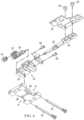
- FIG. 4depicts a side perspective view of a pivot hinge configured to slide a rotational axis as the hinge rotational orientation changes;
- FIG. 5depicts an exploded upper perspective view of the pivot hinge
- FIG. 6depicts an exploded lower perspective view of the pivot hinge.
- a portable information handling systemrotationally couples housing portions with a pivot hinge that shifts its rotational axis position as the housing portion rotational orientation changes.
- an information handling systemmay include any instrumentality or aggregate of instrumentalities operable to compute, classify, process, transmit, receive, retrieve, originate, switch, store, display, manifest, detect, record, reproduce, handle, or utilize any form of information, intelligence, or data for business, scientific, control, or other purposes.
- an information handling systemmay be a personal computer, a network storage device, or any other suitable device and may vary in size, shape, performance, functionality, and price.
- the information handling systemmay include random access memory (RAM), one or more processing resources such as a central processing unit (CPU) or hardware or software control logic, ROM, and/or other types of nonvolatile memory. Additional components of the information handling system may include one or more disk drives, one or more network ports for communicating with external devices as well as various input and output (I/O) devices, such as a keyboard, a mouse, and a video display. The information handling system may also include one or more buses operable to transmit communications between the various hardware components.
- RAMrandom access memory
- processing resourcessuch as a central processing unit (CPU) or hardware or software control logic
- ROMread-only memory
- Additional components of the information handling systemmay include one or more disk drives, one or more network ports for communicating with external devices as well as various input and output (I/O) devices, such as a keyboard, a mouse, and a video display.
- I/Oinput and output
- the information handling systemmay also include one or more buses operable to transmit communications between the various hardware components.
- an upper viewdepicts a portable information handling system 10 having a housing 12 with a seam between housing portions at a midpoint location.
- a main housing portion 14acts as a base of information handling system 10
- a lid housing portion 16rotationally couples to main housing portion 14 with hinges 18 that rotate lid housing portion 16 between open and closed positions.
- the example main housing portion 14has a forward extended upper side that couples to hinges 18 and defines a seam along the upper side of housing 12 where the forward extended upper side meets the lid housing portion rear side.
- a motherboard 20couples in main housing portion 14 to support interfacing of processing components that cooperate to process information.
- a central processing unit (CPU) 22executes instructions to process information, such as instructions of an operating system and applications.
- a random access memory (RAM) 24stores the instructions and information to support CPU 22 operations.
- a solid state drive (SSD) 26 or other type of persistent non-transitory memorystores the instructions and information in power off states for recall to RAM 24 at power up.
- a graphics processing unit (GPU) 28interfaces with CPU 22 and processes the information to generate visual images for presentation at a display integrated in lid housing portion 16 , such as defining the visual image as pixel values.
- An embedded controller 30manages operations of the information handling system at a physical level, such as the application of power, the maintenance of thermal constraints and interactions with peripheral devices.
- Portable information handling system 10has a forward extended upper side of main housing portion 14 so that the rear side of main housing portion 14 has the full housing height to include thermal energy management components, such as a cooling fan and venting.
- thermal energy management componentssuch as a cooling fan and venting.
- One difficulty with this approachis that a seam is defined at the upper surface of housing 12 where main housing portion 14 meets lid housing portion 16 .
- the seamhas to provide a sufficient distance between main housing portion 14 and lid housing portion 16 so that rotation about hinges 18 does not bind at the intersection of the housing portions.
- an excess seam distanceis unsightly.
- hinges 18slide the pivot axis for housing rotation forward as the housing rotates from a closed to an open position, thereby avoiding binding of the main and lid housing portions.
- Each hingetranslates the pivot point as it opens and closes to provide clearance for the hinge up assembly to the base as it opens and minimize the gap at the upper surface of housing 12 when it closes.
- the pivot axis forward and rearward movementis accomplished with a rack and pinion gear mechanism that includes a torque element to manage hinge rotation and a defined rotational movement, such as between a closed position to a 135 degree open position.
- a side perspective sectional view of the housing 12depicts a pivot axis hinge 18 to manage the seam distance between the housing portions.
- main housing portion 14 at the rear side of housing 12has the full Z-height available to manage thermal energy rejection from the system out the rear side of housing 12 .
- Hinge 18couples to an upper surface of main housing portion 14 along a perimeter of housing 12 with a bracket extending inward to couple with lid housing portion 16 .
- Hinge 18is disposed at the upper surface of main housing portion 14 with motherboard 20 coupled within main housing portion 14 below.
- hinge 18is positioned over an extension by main housing portion 14 into the rear side of lid housing portion 16 to align the hinge bracket with the seam defined by the meeting of the rear side of lid housing portion 16 and the forward extended upper side of main housing portion 14 .
- the proximity of the pivot axis of hinge 18 to the seamhelps to reduce the distance between the housing portions at the seam.
- coupling hinge 18 at the location of the seamallows forward sliding motion of the hinge to move the hinge pivot so as to provide clearance for rotation of the housing portions from the closed to the open position.
- FIGS. 3 A, 3 B, 3 C and 3 Da portable information handling system is depicted having a pivot hinge 18 sliding from a rearward to a forward position as the housing 12 rotates from a closed to an open position.
- FIG. 3 Adepicts housing 12 in a closed position having lid housing portion 16 closed over top of main housing portion 14 with hinge 18 having a gear assembly 32 in a rearward position relative to a base assembly 34 so that the rotational axis of hinge 18 minimizes the distance between main housing portion 14 and lid housing portion 16 .
- FIG. 3 Adepicts housing 12 in a closed position having lid housing portion 16 closed over top of main housing portion 14 with hinge 18 having a gear assembly 32 in a rearward position relative to a base assembly 34 so that the rotational axis of hinge 18 minimizes the distance between main housing portion 14 and lid housing portion 16 .
- FIG. 3 Adepicts housing 12 in a closed position having lid housing portion 16 closed over top of main housing portion 14 with hinge 18 having a gear assembly 32 in a rearward position relative
- 3 Bdepicts lid housing portion 16 rotating upward and away from main housing portion 14 about hinge 18 , such as to expose a display integrated in the bottom surface of lid housing portion 16 and a keyboard integrated in the upper surface of main housing portion 14 .
- hinge 18 gear assembly 32slides forward relative to base assembly 34 as indicated by arrow 36 to increase the distance between lid housing portion 16 and main housing portion 14 , thereby providing clearance for the rotation from the closed towards the open position.
- the forward sliding motion of gear assembly 32has the effect of moving the pivot axis of hinge 18 forward as the rotational orientation of the lid and main housing portions increase.
- FIG. 3 Cdepicts a housing rotational orientation of approximately 90 degrees where a display in lid housing portion 16 is held substantially perpendicular to a keyboard in the upper surface of main housing portion 14 .
- FIG. 3 Ddepicts a rotation of approximately 135 degrees of lid housing portion 16 relative to main housing portion 14 with gear assembly 32 slid fully forward in base assembly 34 .
- the rotational range of the housingis defined by the amount of sliding permitted for gear assembly 32 within base assembly 34 , which provides a defined rotational range that does not involve any physical contact of the housing portions at a rotational limiter.
- Rotation of lid housing portion 16 from the fully open position depicted by FIG. 3 D to the closed position depicted by FIG. 3 Atranslates rotation about hinge 18 that slides gear assembly 32 in the opposite direction relative to base assembly 34 , thereby decreasing the distance between the housing portions as the closed position approaches to minimize the gap along the seam between the housing portions in the closed position.
- a side perspective viewdepicts a pivot hinge 18 configured to slide a rotational axis as the hinge rotational orientation changes.
- a base assembly 34couples in a fixed location relative to a first housing portion and a gear assembly 32 slides relative to base assembly 34 to move the rotational axis of a bracket 46 that couples to a second housing portion.
- Bracket 46has an axle 44 with a bracket gear 50 that rotates as bracket 46 rotates responsive to movement of a housing portion coupled to bracket 46 .
- Bracket gear 50engages with a rack and pinion gear assembly 48 integrated in a main body 42 of gear assembly 32 and configured to slide main body 42 along sliding members 40 that pass through main body 42 .
- the parallel sliding membersprovide stability for the translating bracket that attaches the rotational shaft, such as by maintaining a sliding path for the translating bracket in the presence of torsional forces.
- a base 38 of base assembly 34has sliding members 40 coupled across a central opening 41 (labeled in FIG. 6 ) that provides room for sliding movement of main body 42 .
- a torque element 52couples to axle 44 of bracket 46 to resist rotation of bracket 46 .
- Torque element 52 in the example embodimentalso couples with rack and pinion assembly 48 to distribute resistance to rotation across gear assembly 32 for a more regulated feel.
- a torque elementmay provide resistance to sliding motion of main body 42 along sliding member 40 , such as by compression against sliding members 40 from torque elements coupled at main body 42 .
- FIGS. 5 and 6exploded perspective views depict the pivot hinge 18 .
- FIG. 5depicts an upper and lower exploded view of pivot hinge 18 and
- FIG. 6depicts a lower exploded view of pivot hinge 18 .
- FIGS. 4 , 5 and 6depict a pivot hinge 18 configured to couple to a right side of a main housing portion having the bracket 46 directed inwards towards a central position of the housing.
- FIG. 3depicts a pivot hinge configured to couple to a left and right side of a main housing portion with the bracket 46 on each hinge directed inwards when hinge 18 couples to the main housing portion at a left and right side.
- the bracket of each hinge 18is disposed at an opposing side, the structure that holds the bracket in place and adjusts the pivot axis of the bracket is similar for each hinge with a symmetrical opposite construction.
- Base 38is configured to couple to a fixed location of a main housing portion and integrates a rack gear 58 that aligns to engage with a pinion gear 56 coupled within the main body housing 60 , which aligns pinion gear 56 to engage with bracket gear 50 .
- Main body housing 60 and coupling element 62hold the gear assembly 32 in an engaged state so that rotation of bracket 46 translates through pinion gear 56 to rack gear 58 and results in a sliding motion of main body housing 60 relative to base 38 .
- Sliding members 40are threaded pins that engage with base 38 and insert through openings of main body housing 60 to support the sliding motion.
- Coupling element 62couples to main body housing 60 with screws 68 to hold bracket 46 in place and having bracket gear 50 engaged with pinion gear 56 .
- a housing bracket plate 64couples with rivets 66 to bracket 46 for additional structural support.
- rack gear 58with base 38
- alternative embodimentsmay arrange the rack, pinion gear and bracket gear in alternative ways to achieve the desired sliding of axis about which bracket 46 rotates, such as integrating the rack in main body housing 60 .
Landscapes
- Engineering & Computer Science (AREA)
- Theoretical Computer Science (AREA)
- Computer Hardware Design (AREA)
- Physics & Mathematics (AREA)
- Human Computer Interaction (AREA)
- General Engineering & Computer Science (AREA)
- General Physics & Mathematics (AREA)
- Mechanical Engineering (AREA)
- Mathematical Physics (AREA)
- Casings For Electric Apparatus (AREA)
- Hinges (AREA)
- Telephone Set Structure (AREA)
Abstract
Description
Claims (11)
Priority Applications (3)
| Application Number | Priority Date | Filing Date | Title |
|---|---|---|---|
| US17/463,845US11983046B2 (en) | 2021-09-01 | 2021-09-01 | Translating pivot hinge |
| CN202111390336.XACN115729317A (en) | 2021-09-01 | 2021-11-22 | Translational pivot hinge |
| TW110146377ATWI798988B (en) | 2021-09-01 | 2021-12-10 | Hinge, information handling system, and method for opening and closing information handling system housing |
Applications Claiming Priority (1)
| Application Number | Priority Date | Filing Date | Title |
|---|---|---|---|
| US17/463,845US11983046B2 (en) | 2021-09-01 | 2021-09-01 | Translating pivot hinge |
Publications (2)
| Publication Number | Publication Date |
|---|---|
| US20230068228A1 US20230068228A1 (en) | 2023-03-02 |
| US11983046B2true US11983046B2 (en) | 2024-05-14 |
Family
ID=85287003
Family Applications (1)
| Application Number | Title | Priority Date | Filing Date |
|---|---|---|---|
| US17/463,845ActiveUS11983046B2 (en) | 2021-09-01 | 2021-09-01 | Translating pivot hinge |
Country Status (3)
| Country | Link |
|---|---|
| US (1) | US11983046B2 (en) |
| CN (1) | CN115729317A (en) |
| TW (1) | TWI798988B (en) |
Cited By (2)
| Publication number | Priority date | Publication date | Assignee | Title |
|---|---|---|---|---|
| US20240143040A1 (en)* | 2022-10-31 | 2024-05-02 | Lenovo (Singapore) Pte. Ltd. | Computing Device |
| US20240401390A1 (en)* | 2023-06-01 | 2024-12-05 | Sinher Technology Inc. | Double-shaft hinge with single-shaft implementation mode |
Families Citing this family (2)
| Publication number | Priority date | Publication date | Assignee | Title |
|---|---|---|---|---|
| TWI783789B (en)* | 2021-11-23 | 2022-11-11 | 富世達股份有限公司 | Front and rear sliding hinges |
| US11847000B2 (en)* | 2021-12-30 | 2023-12-19 | Acer Incorporated | Portable electronic device |
Citations (23)
| Publication number | Priority date | Publication date | Assignee | Title |
|---|---|---|---|---|
| US20100027224A1 (en)* | 2008-08-01 | 2010-02-04 | Htc Corporation | Electronic device |
| US7886903B1 (en) | 2008-09-19 | 2011-02-15 | Aileron Designs, LLC | Articulated notebook computer cover and mounting device |
| US7975348B2 (en) | 2008-06-27 | 2011-07-12 | Shin Zu Shing Co., Ltd. | Pivoting slide hinge |
| US20150305185A1 (en)* | 2013-07-30 | 2015-10-22 | Alanna M. Koser | Hinge assembly |
| US9632529B2 (en) | 2011-11-18 | 2017-04-25 | Wistron Corporation | Portable computer |
| US20180067520A1 (en)* | 2016-09-02 | 2018-03-08 | Microsoft Technology Licensing, Llc | Electronic device hinge assembly |
| US20180230724A1 (en)* | 2017-02-08 | 2018-08-16 | Compal Electronics, Inc. | Hinge module and electronic device using the same |
| US20180373296A1 (en)* | 2017-06-27 | 2018-12-27 | Microsoft Technology Licensing, Llc | Systems and methods of lateral torsional resistance in a hinge |
| US20190166703A1 (en)* | 2017-11-28 | 2019-05-30 | Samsung Electronics Co., Ltd. | Foldable display device |
| US20190317552A1 (en)* | 2018-04-17 | 2019-10-17 | Acer Incorporated | Laptop computer |
| US10725505B1 (en) | 2019-09-26 | 2020-07-28 | Dell Products L.P. | Synchronized expandable hinge assembly |
| TWI707093B (en) | 2018-09-12 | 2020-10-11 | 仁寶電腦工業股份有限公司 | Sliding hinge and electronic deivce having the same |
| US10852776B1 (en) | 2019-09-26 | 2020-12-01 | Dell Products L.P. | Synchronized single axle hinge |
| TWI713433B (en) | 2018-12-18 | 2020-12-11 | 仁寶電腦工業股份有限公司 | Expansion hinge and electronic deivce having the same |
| TWI721687B (en) | 2018-12-07 | 2021-03-11 | 仁寶電腦工業股份有限公司 | Hidden hinge and electronic deivce having the same |
| US20210181808A1 (en)* | 2019-12-13 | 2021-06-17 | Huawei Technologies Co., Ltd. | Hinge and mobile terminal |
| US11042198B2 (en)* | 2018-06-21 | 2021-06-22 | Compal Electronics, Inc. | Hinge module and electronic device |
| CN113015947A (en) | 2018-10-12 | 2021-06-22 | 谷歌有限责任公司 | Hinge mechanism of gear set with slider for foldable display device |
| CN113202857A (en) | 2021-07-05 | 2021-08-03 | 武汉华星光电半导体显示技术有限公司 | Hinge, flexible display panel and electronic device |
| US20210396056A1 (en)* | 2020-06-18 | 2021-12-23 | Leohab Enterprise Co., Ltd. | Pivot Device Having Components Translatable During Rotation |
| US20210405711A1 (en)* | 2020-06-30 | 2021-12-30 | Dell Products L.P. | Information handling system variable torque hinge |
| US20220011827A1 (en)* | 2020-07-13 | 2022-01-13 | Samsung Electronics Co., Ltd. | Structure of hinge for foldable electronic device, and electronic device including the same |
| US20220221913A1 (en)* | 2021-01-14 | 2022-07-14 | Acer Incorporated | Portable electronic device |
Family Cites Families (4)
| Publication number | Priority date | Publication date | Assignee | Title |
|---|---|---|---|---|
| CN202560799U (en)* | 2012-03-14 | 2012-11-28 | 欣日兴精密电子(苏州)有限公司 | Pivot device having synchronous translation and rotation functions and clamshell type electronic device of pivot device |
| TWI674603B (en)* | 2017-02-08 | 2019-10-11 | 仁寶電腦工業股份有限公司 | Electronic device and hinge assembly thereof |
| US11243578B2 (en)* | 2019-08-02 | 2022-02-08 | Dell Products L.P. | Gear synchronized dual axis pivot hinge |
| CN213393123U (en)* | 2020-10-14 | 2021-06-08 | 新日兴股份有限公司 | Pivot device and electronic device using same |
- 2021
- 2021-09-01USUS17/463,845patent/US11983046B2/enactiveActive
- 2021-11-22CNCN202111390336.XApatent/CN115729317A/enactivePending
- 2021-12-10TWTW110146377Apatent/TWI798988B/enactive
Patent Citations (38)
| Publication number | Priority date | Publication date | Assignee | Title |
|---|---|---|---|---|
| US7975348B2 (en) | 2008-06-27 | 2011-07-12 | Shin Zu Shing Co., Ltd. | Pivoting slide hinge |
| US8111506B2 (en)* | 2008-08-01 | 2012-02-07 | Htc Corporation | Electronic device |
| US20100027224A1 (en)* | 2008-08-01 | 2010-02-04 | Htc Corporation | Electronic device |
| US7886903B1 (en) | 2008-09-19 | 2011-02-15 | Aileron Designs, LLC | Articulated notebook computer cover and mounting device |
| US9632529B2 (en) | 2011-11-18 | 2017-04-25 | Wistron Corporation | Portable computer |
| US20150305185A1 (en)* | 2013-07-30 | 2015-10-22 | Alanna M. Koser | Hinge assembly |
| US9258914B2 (en)* | 2013-07-30 | 2016-02-09 | Intel Corporation | Hinge assembly |
| US10488882B2 (en)* | 2016-09-02 | 2019-11-26 | Microsoft Technology Licensing, Llc | Electronic device hinge assembly |
| US20180067520A1 (en)* | 2016-09-02 | 2018-03-08 | Microsoft Technology Licensing, Llc | Electronic device hinge assembly |
| US10174535B2 (en)* | 2017-02-08 | 2019-01-08 | Compal Electronics, Inc. | Hinge module and electronic device using the same |
| US20180230724A1 (en)* | 2017-02-08 | 2018-08-16 | Compal Electronics, Inc. | Hinge module and electronic device using the same |
| US20180373296A1 (en)* | 2017-06-27 | 2018-12-27 | Microsoft Technology Licensing, Llc | Systems and methods of lateral torsional resistance in a hinge |
| US10606321B2 (en)* | 2017-06-27 | 2020-03-31 | Microsoft Technology Licensing, Llc | Systems and methods of lateral torsional resistance in a hinge |
| US20220291724A1 (en)* | 2017-11-28 | 2022-09-15 | Samsung Electronics Co., Ltd. | Foldable display device |
| US10775852B2 (en)* | 2017-11-28 | 2020-09-15 | Samsung Electronics Co., Ltd. | Foldable display device |
| US20190166703A1 (en)* | 2017-11-28 | 2019-05-30 | Samsung Electronics Co., Ltd. | Foldable display device |
| US20200371564A1 (en)* | 2017-11-28 | 2020-11-26 | Samsung Electronics Co., Ltd. | Foldable display device |
| US11340663B2 (en)* | 2017-11-28 | 2022-05-24 | Samsung Electronics Co., Ltd. | Foldable display device |
| US20210255672A1 (en)* | 2017-11-28 | 2021-08-19 | Samsung Electronics Co., Ltd. | Foldable display device |
| US11061445B2 (en)* | 2017-11-28 | 2021-07-13 | Samsung Electronics Co., Ltd. | Foldable display device |
| US20190317552A1 (en)* | 2018-04-17 | 2019-10-17 | Acer Incorporated | Laptop computer |
| US10642309B2 (en)* | 2018-04-17 | 2020-05-05 | Acer Incorporated | Laptop computer |
| US11042198B2 (en)* | 2018-06-21 | 2021-06-22 | Compal Electronics, Inc. | Hinge module and electronic device |
| TWI707093B (en) | 2018-09-12 | 2020-10-11 | 仁寶電腦工業股份有限公司 | Sliding hinge and electronic deivce having the same |
| CN113015947A (en) | 2018-10-12 | 2021-06-22 | 谷歌有限责任公司 | Hinge mechanism of gear set with slider for foldable display device |
| TWI721687B (en) | 2018-12-07 | 2021-03-11 | 仁寶電腦工業股份有限公司 | Hidden hinge and electronic deivce having the same |
| TWI713433B (en) | 2018-12-18 | 2020-12-11 | 仁寶電腦工業股份有限公司 | Expansion hinge and electronic deivce having the same |
| US10725505B1 (en) | 2019-09-26 | 2020-07-28 | Dell Products L.P. | Synchronized expandable hinge assembly |
| US10852776B1 (en) | 2019-09-26 | 2020-12-01 | Dell Products L.P. | Synchronized single axle hinge |
| US11467633B2 (en)* | 2019-12-13 | 2022-10-11 | Huawei Technologies Co., Ltd. | Hinge and mobile terminal |
| US20210181808A1 (en)* | 2019-12-13 | 2021-06-17 | Huawei Technologies Co., Ltd. | Hinge and mobile terminal |
| US20210396056A1 (en)* | 2020-06-18 | 2021-12-23 | Leohab Enterprise Co., Ltd. | Pivot Device Having Components Translatable During Rotation |
| US11396766B2 (en)* | 2020-06-18 | 2022-07-26 | Leohab Enterprise Co., Ltd. | Pivot device having components translatable during rotation |
| US20210405711A1 (en)* | 2020-06-30 | 2021-12-30 | Dell Products L.P. | Information handling system variable torque hinge |
| US20220011827A1 (en)* | 2020-07-13 | 2022-01-13 | Samsung Electronics Co., Ltd. | Structure of hinge for foldable electronic device, and electronic device including the same |
| US20220221913A1 (en)* | 2021-01-14 | 2022-07-14 | Acer Incorporated | Portable electronic device |
| US11474569B2 (en)* | 2021-01-14 | 2022-10-18 | Acer Incorporated | Portable electronic device |
| CN113202857A (en) | 2021-07-05 | 2021-08-03 | 武汉华星光电半导体显示技术有限公司 | Hinge, flexible display panel and electronic device |
Non-Patent Citations (1)
| Title |
|---|
| U.S. Appl. No. 17/171,255, filed Feb. 9, 2021, entitled "Portable Information Handling System Hinge With Hybrid Rotation for Distributed Torque," by inventors Duck Soo Choi. |
Cited By (3)
| Publication number | Priority date | Publication date | Assignee | Title |
|---|---|---|---|---|
| US20240143040A1 (en)* | 2022-10-31 | 2024-05-02 | Lenovo (Singapore) Pte. Ltd. | Computing Device |
| US12436576B2 (en)* | 2022-10-31 | 2025-10-07 | Lenovo (Singapore) Pte. Ltd. | Computing device |
| US20240401390A1 (en)* | 2023-06-01 | 2024-12-05 | Sinher Technology Inc. | Double-shaft hinge with single-shaft implementation mode |
Also Published As
| Publication number | Publication date |
|---|---|
| TW202312833A (en) | 2023-03-16 |
| TWI798988B (en) | 2023-04-11 |
| US20230068228A1 (en) | 2023-03-02 |
| CN115729317A (en) | 2023-03-03 |
Similar Documents
| Publication | Publication Date | Title |
|---|---|---|
| US11983046B2 (en) | Translating pivot hinge | |
| US11435786B2 (en) | Portable information handling system flexible display with alternating slide support frame | |
| US10558245B2 (en) | Information handling system narrow width hinge | |
| US20200233466A1 (en) | Multi-axis hinge translation to adjust housing position relative to flexible display position | |
| US8274784B2 (en) | Adjustable multi-orientation display support system | |
| US11573598B2 (en) | Electronic device | |
| US7251129B2 (en) | Two-way auto-locking tablet PC hinge | |
| US7239504B2 (en) | Snap-in floating hinge cap for portable computer | |
| US8902585B2 (en) | Portable computer | |
| US10761571B1 (en) | Linkage assembly for a portable electronic device | |
| US8605430B2 (en) | Mobile electronic device | |
| US20110292605A1 (en) | Heat-dissipating hinge and a portable electronic device with the same | |
| US10168746B2 (en) | Hinge mechanism for a computing device | |
| US7055160B1 (en) | Bezel door for computer enclosure | |
| US20200133336A1 (en) | Electronic device with dual display | |
| US9857833B2 (en) | Information handling system low profile hinge | |
| US10470564B2 (en) | Support device | |
| US20220397933A1 (en) | Computing device mechanisms | |
| US10310556B2 (en) | Information handling system multi-torque dual axis hinge | |
| US20060077621A1 (en) | Pivoting LapTop Computer | |
| US20140111925A1 (en) | Electronic device | |
| US8564959B2 (en) | System and method for attaching portion of equipment to remainder of equipment | |
| US20160224071A1 (en) | Information Handling System Having Separately Articulating Tail Piece | |
| US20090079201A1 (en) | System and Method for Self-Stowing Information Handling System Lid Latch | |
| US11334120B2 (en) | Information handling system kickstand hinge |
Legal Events
| Date | Code | Title | Description |
|---|---|---|---|
| AS | Assignment | Owner name:DELL PRODUCTS L.P., TEXAS Free format text:ASSIGNMENT OF ASSIGNORS INTEREST;ASSIGNORS:SANCHEZ, ANTHONY J.;PESCETTO, MICHAEL J.;DRACA, BORIS;AND OTHERS;SIGNING DATES FROM 20210818 TO 20210826;REEL/FRAME:057355/0579 | |
| FEPP | Fee payment procedure | Free format text:ENTITY STATUS SET TO UNDISCOUNTED (ORIGINAL EVENT CODE: BIG.); ENTITY STATUS OF PATENT OWNER: LARGE ENTITY | |
| STPP | Information on status: patent application and granting procedure in general | Free format text:NON FINAL ACTION MAILED | |
| STPP | Information on status: patent application and granting procedure in general | Free format text:FINAL REJECTION MAILED | |
| STPP | Information on status: patent application and granting procedure in general | Free format text:ADVISORY ACTION MAILED | |
| STPP | Information on status: patent application and granting procedure in general | Free format text:DOCKETED NEW CASE - READY FOR EXAMINATION | |
| STPP | Information on status: patent application and granting procedure in general | Free format text:FINAL REJECTION MAILED | |
| STPP | Information on status: patent application and granting procedure in general | Free format text:DOCKETED NEW CASE - READY FOR EXAMINATION | |
| STPP | Information on status: patent application and granting procedure in general | Free format text:NON FINAL ACTION MAILED | |
| STPP | Information on status: patent application and granting procedure in general | Free format text:RESPONSE TO NON-FINAL OFFICE ACTION ENTERED AND FORWARDED TO EXAMINER | |
| STPP | Information on status: patent application and granting procedure in general | Free format text:NOTICE OF ALLOWANCE MAILED -- APPLICATION RECEIVED IN OFFICE OF PUBLICATIONS | |
| ZAAB | Notice of allowance mailed | Free format text:ORIGINAL CODE: MN/=. | |
| STPP | Information on status: patent application and granting procedure in general | Free format text:PUBLICATIONS -- ISSUE FEE PAYMENT VERIFIED | |
| STCF | Information on status: patent grant | Free format text:PATENTED CASE |