US11981498B2 - Thermally insulated air cargo container - Google Patents
Thermally insulated air cargo containerDownload PDFInfo
- Publication number
- US11981498B2 US11981498B2US16/913,410US202016913410AUS11981498B2US 11981498 B2US11981498 B2US 11981498B2US 202016913410 AUS202016913410 AUS 202016913410AUS 11981498 B2US11981498 B2US 11981498B2
- Authority
- US
- United States
- Prior art keywords
- core
- skin
- vacuum
- panel
- filler material
- Prior art date
- Legal status (The legal status is an assumption and is not a legal conclusion. Google has not performed a legal analysis and makes no representation as to the accuracy of the status listed.)
- Active, expires
Links
- 239000000463materialSubstances0.000claimsabstractdescription94
- 239000000945fillerSubstances0.000claimsabstractdescription80
- 238000000034methodMethods0.000claimsabstractdescription17
- 238000012546transferMethods0.000claimsabstractdescription11
- 238000004519manufacturing processMethods0.000claimsabstractdescription7
- 239000006260foamSubstances0.000claimsdescription90
- 230000004888barrier functionEffects0.000claimsdescription71
- 239000012530fluidSubstances0.000claimsdescription16
- 238000004891communicationMethods0.000claimsdescription15
- 238000007789sealingMethods0.000claimsdescription6
- 238000012544monitoring processMethods0.000claimsdescription3
- 239000011162core materialSubstances0.000description237
- 239000004743PolypropyleneSubstances0.000description31
- 229920001155polypropylenePolymers0.000description31
- VYPSYNLAJGMNEJ-UHFFFAOYSA-NSilicium dioxideChemical compoundO=[Si]=OVYPSYNLAJGMNEJ-UHFFFAOYSA-N0.000description29
- 239000000853adhesiveSubstances0.000description27
- 230000001070adhesive effectEffects0.000description27
- 241000264877Hippospongia communisSpecies0.000description25
- 229920001169thermoplasticPolymers0.000description19
- 239000004416thermosoftening plasticSubstances0.000description19
- 239000000835fiberSubstances0.000description15
- 239000000377silicon dioxideSubstances0.000description14
- 239000007787solidSubstances0.000description13
- -1polypropylenePolymers0.000description12
- 239000004698PolyethyleneSubstances0.000description10
- 229920000573polyethylenePolymers0.000description10
- 239000011152fibreglassSubstances0.000description9
- 230000001965increasing effectEffects0.000description9
- 239000004744fabricSubstances0.000description8
- 238000009413insulationMethods0.000description8
- 230000008569processEffects0.000description7
- 239000000839emulsionSubstances0.000description6
- 230000009467reductionEffects0.000description6
- 238000005057refrigerationMethods0.000description6
- 229920005989resinPolymers0.000description6
- 239000011347resinSubstances0.000description6
- 238000003856thermoformingMethods0.000description6
- 230000000007visual effectEffects0.000description6
- 208000033255Progressive myoclonic epilepsy type 1Diseases0.000description5
- 230000008901benefitEffects0.000description5
- 239000011230binding agentSubstances0.000description5
- 239000010408filmSubstances0.000description5
- 230000036961partial effectEffects0.000description5
- 230000008439repair processEffects0.000description5
- 230000035945sensitivityEffects0.000description5
- 229920001187thermosetting polymerPolymers0.000description5
- 229920005830Polyurethane FoamPolymers0.000description4
- 239000002131composite materialSubstances0.000description4
- 238000010276constructionMethods0.000description4
- 238000010030laminatingMethods0.000description4
- 238000003475laminationMethods0.000description4
- 239000000843powderSubstances0.000description4
- 230000002829reductive effectEffects0.000description4
- 239000004964aerogelSubstances0.000description3
- 229910052782aluminiumInorganic materials0.000description3
- XAGFODPZIPBFFR-UHFFFAOYSA-NaluminiumChemical compound[Al]XAGFODPZIPBFFR-UHFFFAOYSA-N0.000description3
- 239000011248coating agentSubstances0.000description3
- 238000000576coating methodMethods0.000description3
- 230000003247decreasing effectEffects0.000description3
- 230000009970fire resistant effectEffects0.000description3
- 238000010438heat treatmentMethods0.000description3
- 229910052751metalInorganic materials0.000description3
- 239000002184metalSubstances0.000description3
- 239000002245particleSubstances0.000description3
- 229920000728polyesterPolymers0.000description3
- 239000012815thermoplastic materialSubstances0.000description3
- 239000004831Hot glueSubstances0.000description2
- 238000005452bendingMethods0.000description2
- 230000001010compromised effectEffects0.000description2
- 230000001419dependent effectEffects0.000description2
- 239000004794expanded polystyreneSubstances0.000description2
- 239000006261foam materialSubstances0.000description2
- 239000011888foilSubstances0.000description2
- 238000007689inspectionMethods0.000description2
- 230000000670limiting effectEffects0.000description2
- 238000002844meltingMethods0.000description2
- 230000008018meltingEffects0.000description2
- 229920006254polymer filmPolymers0.000description2
- 230000001681protective effectEffects0.000description2
- 238000012795verificationMethods0.000description2
- 239000011800void materialSubstances0.000description2
- 229920000049Carbon (fiber)Polymers0.000description1
- CURLTUGMZLYLDI-UHFFFAOYSA-NCarbon dioxideChemical compoundO=C=OCURLTUGMZLYLDI-UHFFFAOYSA-N0.000description1
- 239000004593EpoxySubstances0.000description1
- 229920000271Kevlar®Polymers0.000description1
- 229920000784NomexPolymers0.000description1
- 239000004677NylonSubstances0.000description1
- 239000004696Poly ether ether ketoneSubstances0.000description1
- 239000004962Polyamide-imideSubstances0.000description1
- 239000004697PolyetherimideSubstances0.000description1
- 239000004642PolyimideSubstances0.000description1
- 239000004734Polyphenylene sulfideSubstances0.000description1
- 229910000831SteelInorganic materials0.000description1
- 229920001494TechnoraPolymers0.000description1
- 230000002745absorbentEffects0.000description1
- 239000002250absorbentSubstances0.000description1
- 239000004760aramidSubstances0.000description1
- 229920003235aromatic polyamidePolymers0.000description1
- 239000011324beadSubstances0.000description1
- 230000005540biological transmissionEffects0.000description1
- 235000011089carbon dioxideNutrition0.000description1
- 239000004917carbon fiberSubstances0.000description1
- 239000000919ceramicSubstances0.000description1
- 239000002666chemical blowing agentSubstances0.000description1
- 230000000295complement effectEffects0.000description1
- 239000004020conductorSubstances0.000description1
- 238000007596consolidation processMethods0.000description1
- 238000001816coolingMethods0.000description1
- 238000005553drillingMethods0.000description1
- 238000001035dryingMethods0.000description1
- 230000000694effectsEffects0.000description1
- 238000005516engineering processMethods0.000description1
- 125000003700epoxy groupChemical group0.000description1
- 239000002657fibrous materialSubstances0.000description1
- 239000000446fuelSubstances0.000description1
- 230000006698inductionEffects0.000description1
- 230000001939inductive effectEffects0.000description1
- 239000012774insulation materialSubstances0.000description1
- 150000002739metalsChemical class0.000description1
- 239000012229microporous materialSubstances0.000description1
- 239000002557mineral fiberSubstances0.000description1
- 239000000203mixtureSubstances0.000description1
- 238000012986modificationMethods0.000description1
- 230000004048modificationEffects0.000description1
- 239000004763nomexSubstances0.000description1
- 229910052755nonmetalInorganic materials0.000description1
- 150000002843nonmetalsChemical class0.000description1
- 239000004745nonwoven fabricSubstances0.000description1
- 229920001778nylonPolymers0.000description1
- 230000000149penetrating effectEffects0.000description1
- ISWSIDIOOBJBQZ-UHFFFAOYSA-Nphenol groupChemical groupC1(=CC=CC=C1)OISWSIDIOOBJBQZ-UHFFFAOYSA-N0.000description1
- 229920003023plasticPolymers0.000description1
- 239000004033plasticSubstances0.000description1
- 229920003192poly(bis maleimide)Polymers0.000description1
- 229920002312polyamide-imidePolymers0.000description1
- 229920000647polyepoxidePolymers0.000description1
- 229920002530polyetherether ketonePolymers0.000description1
- 229920001601polyetherimidePolymers0.000description1
- 229920001721polyimidePolymers0.000description1
- 229920000069polyphenylene sulfidePolymers0.000description1
- 239000004814polyurethaneSubstances0.000description1
- 239000011148porous materialSubstances0.000description1
- 239000010453quartzSubstances0.000description1
- 230000002787reinforcementEffects0.000description1
- 238000000926separation methodMethods0.000description1
- 239000010959steelSubstances0.000description1
- 239000004950technoraSubstances0.000description1
- 238000009823thermal laminationMethods0.000description1
- 150000003568thioethersChemical class0.000description1
- 229920001567vinyl ester resinPolymers0.000description1
- 125000000391vinyl groupChemical group[H]C([*])=C([H])[H]0.000description1
- 238000003466weldingMethods0.000description1
Images


Classifications
- B—PERFORMING OPERATIONS; TRANSPORTING
- B65—CONVEYING; PACKING; STORING; HANDLING THIN OR FILAMENTARY MATERIAL
- B65D—CONTAINERS FOR STORAGE OR TRANSPORT OF ARTICLES OR MATERIALS, e.g. BAGS, BARRELS, BOTTLES, BOXES, CANS, CARTONS, CRATES, DRUMS, JARS, TANKS, HOPPERS, FORWARDING CONTAINERS; ACCESSORIES, CLOSURES, OR FITTINGS THEREFOR; PACKAGING ELEMENTS; PACKAGES
- B65D81/00—Containers, packaging elements, or packages, for contents presenting particular transport or storage problems, or adapted to be used for non-packaging purposes after removal of contents
- B65D81/38—Containers, packaging elements, or packages, for contents presenting particular transport or storage problems, or adapted to be used for non-packaging purposes after removal of contents with thermal insulation
- B65D81/3813—Containers, packaging elements, or packages, for contents presenting particular transport or storage problems, or adapted to be used for non-packaging purposes after removal of contents with thermal insulation rigid container being in the form of a box, tray or like container
- B65D81/3823—Containers, packaging elements, or packages, for contents presenting particular transport or storage problems, or adapted to be used for non-packaging purposes after removal of contents with thermal insulation rigid container being in the form of a box, tray or like container formed of different materials, e.g. laminated or foam filling between walls
- B—PERFORMING OPERATIONS; TRANSPORTING
- B32—LAYERED PRODUCTS
- B32B—LAYERED PRODUCTS, i.e. PRODUCTS BUILT-UP OF STRATA OF FLAT OR NON-FLAT, e.g. CELLULAR OR HONEYCOMB, FORM
- B32B17/00—Layered products essentially comprising sheet glass, or glass, slag, or like fibres
- B32B17/02—Layered products essentially comprising sheet glass, or glass, slag, or like fibres in the form of fibres or filaments
- B—PERFORMING OPERATIONS; TRANSPORTING
- B32—LAYERED PRODUCTS
- B32B—LAYERED PRODUCTS, i.e. PRODUCTS BUILT-UP OF STRATA OF FLAT OR NON-FLAT, e.g. CELLULAR OR HONEYCOMB, FORM
- B32B19/00—Layered products comprising a layer of natural mineral fibres or particles, e.g. asbestos, mica
- B32B19/04—Layered products comprising a layer of natural mineral fibres or particles, e.g. asbestos, mica next to another layer of the same or of a different material
- B32B19/045—Layered products comprising a layer of natural mineral fibres or particles, e.g. asbestos, mica next to another layer of the same or of a different material of synthetic resin
- B—PERFORMING OPERATIONS; TRANSPORTING
- B32—LAYERED PRODUCTS
- B32B—LAYERED PRODUCTS, i.e. PRODUCTS BUILT-UP OF STRATA OF FLAT OR NON-FLAT, e.g. CELLULAR OR HONEYCOMB, FORM
- B32B19/00—Layered products comprising a layer of natural mineral fibres or particles, e.g. asbestos, mica
- B32B19/04—Layered products comprising a layer of natural mineral fibres or particles, e.g. asbestos, mica next to another layer of the same or of a different material
- B32B19/047—Layered products comprising a layer of natural mineral fibres or particles, e.g. asbestos, mica next to another layer of the same or of a different material of foam
- B—PERFORMING OPERATIONS; TRANSPORTING
- B32—LAYERED PRODUCTS
- B32B—LAYERED PRODUCTS, i.e. PRODUCTS BUILT-UP OF STRATA OF FLAT OR NON-FLAT, e.g. CELLULAR OR HONEYCOMB, FORM
- B32B27/00—Layered products comprising a layer of synthetic resin
- B32B27/12—Layered products comprising a layer of synthetic resin next to a fibrous or filamentary layer
- B—PERFORMING OPERATIONS; TRANSPORTING
- B32—LAYERED PRODUCTS
- B32B—LAYERED PRODUCTS, i.e. PRODUCTS BUILT-UP OF STRATA OF FLAT OR NON-FLAT, e.g. CELLULAR OR HONEYCOMB, FORM
- B32B27/00—Layered products comprising a layer of synthetic resin
- B32B27/32—Layered products comprising a layer of synthetic resin comprising polyolefins
- B—PERFORMING OPERATIONS; TRANSPORTING
- B32—LAYERED PRODUCTS
- B32B—LAYERED PRODUCTS, i.e. PRODUCTS BUILT-UP OF STRATA OF FLAT OR NON-FLAT, e.g. CELLULAR OR HONEYCOMB, FORM
- B32B3/00—Layered products comprising a layer with external or internal discontinuities or unevennesses, or a layer of non-planar shape; Layered products comprising a layer having particular features of form
- B32B3/02—Layered products comprising a layer with external or internal discontinuities or unevennesses, or a layer of non-planar shape; Layered products comprising a layer having particular features of form characterised by features of form at particular places, e.g. in edge regions
- B32B3/06—Layered products comprising a layer with external or internal discontinuities or unevennesses, or a layer of non-planar shape; Layered products comprising a layer having particular features of form characterised by features of form at particular places, e.g. in edge regions for securing layers together; for attaching the product to another member, e.g. to a support, or to another product, e.g. groove/tongue, interlocking
- B—PERFORMING OPERATIONS; TRANSPORTING
- B32—LAYERED PRODUCTS
- B32B—LAYERED PRODUCTS, i.e. PRODUCTS BUILT-UP OF STRATA OF FLAT OR NON-FLAT, e.g. CELLULAR OR HONEYCOMB, FORM
- B32B37/00—Methods or apparatus for laminating, e.g. by curing or by ultrasonic bonding
- B32B37/14—Methods or apparatus for laminating, e.g. by curing or by ultrasonic bonding characterised by the properties of the layers
- B32B37/142—Laminating of sheets, panels or inserts, e.g. stiffeners, by wrapping in at least one outer layer, or inserting into a preformed pocket
- B—PERFORMING OPERATIONS; TRANSPORTING
- B32—LAYERED PRODUCTS
- B32B—LAYERED PRODUCTS, i.e. PRODUCTS BUILT-UP OF STRATA OF FLAT OR NON-FLAT, e.g. CELLULAR OR HONEYCOMB, FORM
- B32B37/00—Methods or apparatus for laminating, e.g. by curing or by ultrasonic bonding
- B32B37/14—Methods or apparatus for laminating, e.g. by curing or by ultrasonic bonding characterised by the properties of the layers
- B32B37/16—Methods or apparatus for laminating, e.g. by curing or by ultrasonic bonding characterised by the properties of the layers with all layers existing as coherent layers before laminating
- B32B37/18—Methods or apparatus for laminating, e.g. by curing or by ultrasonic bonding characterised by the properties of the layers with all layers existing as coherent layers before laminating involving the assembly of discrete sheets or panels only
- B—PERFORMING OPERATIONS; TRANSPORTING
- B32—LAYERED PRODUCTS
- B32B—LAYERED PRODUCTS, i.e. PRODUCTS BUILT-UP OF STRATA OF FLAT OR NON-FLAT, e.g. CELLULAR OR HONEYCOMB, FORM
- B32B5/00—Layered products characterised by the non- homogeneity or physical structure, i.e. comprising a fibrous, filamentary, particulate or foam layer; Layered products characterised by having a layer differing constitutionally or physically in different parts
- B32B5/02—Layered products characterised by the non- homogeneity or physical structure, i.e. comprising a fibrous, filamentary, particulate or foam layer; Layered products characterised by having a layer differing constitutionally or physically in different parts characterised by structural features of a fibrous or filamentary layer
- B32B5/022—Non-woven fabric
- B—PERFORMING OPERATIONS; TRANSPORTING
- B32—LAYERED PRODUCTS
- B32B—LAYERED PRODUCTS, i.e. PRODUCTS BUILT-UP OF STRATA OF FLAT OR NON-FLAT, e.g. CELLULAR OR HONEYCOMB, FORM
- B32B5/00—Layered products characterised by the non- homogeneity or physical structure, i.e. comprising a fibrous, filamentary, particulate or foam layer; Layered products characterised by having a layer differing constitutionally or physically in different parts
- B32B5/02—Layered products characterised by the non- homogeneity or physical structure, i.e. comprising a fibrous, filamentary, particulate or foam layer; Layered products characterised by having a layer differing constitutionally or physically in different parts characterised by structural features of a fibrous or filamentary layer
- B32B5/024—Woven fabric
- B—PERFORMING OPERATIONS; TRANSPORTING
- B32—LAYERED PRODUCTS
- B32B—LAYERED PRODUCTS, i.e. PRODUCTS BUILT-UP OF STRATA OF FLAT OR NON-FLAT, e.g. CELLULAR OR HONEYCOMB, FORM
- B32B5/00—Layered products characterised by the non- homogeneity or physical structure, i.e. comprising a fibrous, filamentary, particulate or foam layer; Layered products characterised by having a layer differing constitutionally or physically in different parts
- B32B5/02—Layered products characterised by the non- homogeneity or physical structure, i.e. comprising a fibrous, filamentary, particulate or foam layer; Layered products characterised by having a layer differing constitutionally or physically in different parts characterised by structural features of a fibrous or filamentary layer
- B32B5/026—Knitted fabric
- B—PERFORMING OPERATIONS; TRANSPORTING
- B32—LAYERED PRODUCTS
- B32B—LAYERED PRODUCTS, i.e. PRODUCTS BUILT-UP OF STRATA OF FLAT OR NON-FLAT, e.g. CELLULAR OR HONEYCOMB, FORM
- B32B5/00—Layered products characterised by the non- homogeneity or physical structure, i.e. comprising a fibrous, filamentary, particulate or foam layer; Layered products characterised by having a layer differing constitutionally or physically in different parts
- B32B5/22—Layered products characterised by the non- homogeneity or physical structure, i.e. comprising a fibrous, filamentary, particulate or foam layer; Layered products characterised by having a layer differing constitutionally or physically in different parts characterised by the presence of two or more layers which are next to each other and are fibrous, filamentary, formed of particles or foamed
- B32B5/24—Layered products characterised by the non- homogeneity or physical structure, i.e. comprising a fibrous, filamentary, particulate or foam layer; Layered products characterised by having a layer differing constitutionally or physically in different parts characterised by the presence of two or more layers which are next to each other and are fibrous, filamentary, formed of particles or foamed one layer being a fibrous or filamentary layer
- B32B5/245—Layered products characterised by the non- homogeneity or physical structure, i.e. comprising a fibrous, filamentary, particulate or foam layer; Layered products characterised by having a layer differing constitutionally or physically in different parts characterised by the presence of two or more layers which are next to each other and are fibrous, filamentary, formed of particles or foamed one layer being a fibrous or filamentary layer another layer next to it being a foam layer
- B—PERFORMING OPERATIONS; TRANSPORTING
- B32—LAYERED PRODUCTS
- B32B—LAYERED PRODUCTS, i.e. PRODUCTS BUILT-UP OF STRATA OF FLAT OR NON-FLAT, e.g. CELLULAR OR HONEYCOMB, FORM
- B32B7/00—Layered products characterised by the relation between layers; Layered products characterised by the relative orientation of features between layers, or by the relative values of a measurable parameter between layers, i.e. products comprising layers having different physical, chemical or physicochemical properties; Layered products characterised by the interconnection of layers
- B32B7/04—Interconnection of layers
- B32B7/12—Interconnection of layers using interposed adhesives or interposed materials with bonding properties
- B—PERFORMING OPERATIONS; TRANSPORTING
- B32—LAYERED PRODUCTS
- B32B—LAYERED PRODUCTS, i.e. PRODUCTS BUILT-UP OF STRATA OF FLAT OR NON-FLAT, e.g. CELLULAR OR HONEYCOMB, FORM
- B32B2250/00—Layers arrangement
- B32B2250/03—3 layers
- B—PERFORMING OPERATIONS; TRANSPORTING
- B32—LAYERED PRODUCTS
- B32B—LAYERED PRODUCTS, i.e. PRODUCTS BUILT-UP OF STRATA OF FLAT OR NON-FLAT, e.g. CELLULAR OR HONEYCOMB, FORM
- B32B2250/00—Layers arrangement
- B32B2250/40—Symmetrical or sandwich layers, e.g. ABA, ABCBA, ABCCBA
- B—PERFORMING OPERATIONS; TRANSPORTING
- B32—LAYERED PRODUCTS
- B32B—LAYERED PRODUCTS, i.e. PRODUCTS BUILT-UP OF STRATA OF FLAT OR NON-FLAT, e.g. CELLULAR OR HONEYCOMB, FORM
- B32B2260/00—Layered product comprising an impregnated, embedded, or bonded layer wherein the layer comprises an impregnation, embedding, or binder material
- B32B2260/02—Composition of the impregnated, bonded or embedded layer
- B32B2260/021—Fibrous or filamentary layer
- B—PERFORMING OPERATIONS; TRANSPORTING
- B32—LAYERED PRODUCTS
- B32B—LAYERED PRODUCTS, i.e. PRODUCTS BUILT-UP OF STRATA OF FLAT OR NON-FLAT, e.g. CELLULAR OR HONEYCOMB, FORM
- B32B2260/00—Layered product comprising an impregnated, embedded, or bonded layer wherein the layer comprises an impregnation, embedding, or binder material
- B32B2260/04—Impregnation, embedding, or binder material
- B32B2260/046—Synthetic resin
- B—PERFORMING OPERATIONS; TRANSPORTING
- B32—LAYERED PRODUCTS
- B32B—LAYERED PRODUCTS, i.e. PRODUCTS BUILT-UP OF STRATA OF FLAT OR NON-FLAT, e.g. CELLULAR OR HONEYCOMB, FORM
- B32B2262/00—Composition or structural features of fibres which form a fibrous or filamentary layer or are present as additives
- B32B2262/02—Synthetic macromolecular fibres
- B32B2262/0261—Polyamide fibres
- B32B2262/0269—Aromatic polyamide fibres
- B—PERFORMING OPERATIONS; TRANSPORTING
- B32—LAYERED PRODUCTS
- B32B—LAYERED PRODUCTS, i.e. PRODUCTS BUILT-UP OF STRATA OF FLAT OR NON-FLAT, e.g. CELLULAR OR HONEYCOMB, FORM
- B32B2262/00—Composition or structural features of fibres which form a fibrous or filamentary layer or are present as additives
- B32B2262/10—Inorganic fibres
- B32B2262/101—Glass fibres
- B—PERFORMING OPERATIONS; TRANSPORTING
- B32—LAYERED PRODUCTS
- B32B—LAYERED PRODUCTS, i.e. PRODUCTS BUILT-UP OF STRATA OF FLAT OR NON-FLAT, e.g. CELLULAR OR HONEYCOMB, FORM
- B32B2262/00—Composition or structural features of fibres which form a fibrous or filamentary layer or are present as additives
- B32B2262/10—Inorganic fibres
- B32B2262/105—Ceramic fibres
- B—PERFORMING OPERATIONS; TRANSPORTING
- B32—LAYERED PRODUCTS
- B32B—LAYERED PRODUCTS, i.e. PRODUCTS BUILT-UP OF STRATA OF FLAT OR NON-FLAT, e.g. CELLULAR OR HONEYCOMB, FORM
- B32B2262/00—Composition or structural features of fibres which form a fibrous or filamentary layer or are present as additives
- B32B2262/10—Inorganic fibres
- B32B2262/106—Carbon fibres, e.g. graphite fibres
- B—PERFORMING OPERATIONS; TRANSPORTING
- B32—LAYERED PRODUCTS
- B32B—LAYERED PRODUCTS, i.e. PRODUCTS BUILT-UP OF STRATA OF FLAT OR NON-FLAT, e.g. CELLULAR OR HONEYCOMB, FORM
- B32B2266/00—Composition of foam
- B32B2266/02—Organic
- B32B2266/0214—Materials belonging to B32B27/00
- B32B2266/025—Polyolefin
- B—PERFORMING OPERATIONS; TRANSPORTING
- B32—LAYERED PRODUCTS
- B32B—LAYERED PRODUCTS, i.e. PRODUCTS BUILT-UP OF STRATA OF FLAT OR NON-FLAT, e.g. CELLULAR OR HONEYCOMB, FORM
- B32B2305/00—Condition, form or state of the layers or laminate
- B32B2305/02—Cellular or porous
- B32B2305/022—Foam
- B—PERFORMING OPERATIONS; TRANSPORTING
- B32—LAYERED PRODUCTS
- B32B—LAYERED PRODUCTS, i.e. PRODUCTS BUILT-UP OF STRATA OF FLAT OR NON-FLAT, e.g. CELLULAR OR HONEYCOMB, FORM
- B32B2305/00—Condition, form or state of the layers or laminate
- B32B2305/02—Cellular or porous
- B32B2305/024—Honeycomb
- B—PERFORMING OPERATIONS; TRANSPORTING
- B32—LAYERED PRODUCTS
- B32B—LAYERED PRODUCTS, i.e. PRODUCTS BUILT-UP OF STRATA OF FLAT OR NON-FLAT, e.g. CELLULAR OR HONEYCOMB, FORM
- B32B2305/00—Condition, form or state of the layers or laminate
- B32B2305/02—Cellular or porous
- B32B2305/026—Porous
- B—PERFORMING OPERATIONS; TRANSPORTING
- B32—LAYERED PRODUCTS
- B32B—LAYERED PRODUCTS, i.e. PRODUCTS BUILT-UP OF STRATA OF FLAT OR NON-FLAT, e.g. CELLULAR OR HONEYCOMB, FORM
- B32B2307/00—Properties of the layers or laminate
- B32B2307/30—Properties of the layers or laminate having particular thermal properties
- B32B2307/304—Insulating
- B—PERFORMING OPERATIONS; TRANSPORTING
- B32—LAYERED PRODUCTS
- B32B—LAYERED PRODUCTS, i.e. PRODUCTS BUILT-UP OF STRATA OF FLAT OR NON-FLAT, e.g. CELLULAR OR HONEYCOMB, FORM
- B32B2307/00—Properties of the layers or laminate
- B32B2307/30—Properties of the layers or laminate having particular thermal properties
- B32B2307/306—Resistant to heat
- B32B2307/3065—Flame resistant or retardant, fire resistant or retardant
- B—PERFORMING OPERATIONS; TRANSPORTING
- B32—LAYERED PRODUCTS
- B32B—LAYERED PRODUCTS, i.e. PRODUCTS BUILT-UP OF STRATA OF FLAT OR NON-FLAT, e.g. CELLULAR OR HONEYCOMB, FORM
- B32B2439/00—Containers; Receptacles
- B32B2439/40—Closed containers
- B32B2439/62—Boxes, cartons, cases
- B—PERFORMING OPERATIONS; TRANSPORTING
- B32—LAYERED PRODUCTS
- B32B—LAYERED PRODUCTS, i.e. PRODUCTS BUILT-UP OF STRATA OF FLAT OR NON-FLAT, e.g. CELLULAR OR HONEYCOMB, FORM
- B32B2605/00—Vehicles
- B32B2605/18—Aircraft
- B—PERFORMING OPERATIONS; TRANSPORTING
- B32—LAYERED PRODUCTS
- B32B—LAYERED PRODUCTS, i.e. PRODUCTS BUILT-UP OF STRATA OF FLAT OR NON-FLAT, e.g. CELLULAR OR HONEYCOMB, FORM
- B32B3/00—Layered products comprising a layer with external or internal discontinuities or unevennesses, or a layer of non-planar shape; Layered products comprising a layer having particular features of form
- B32B3/10—Layered products comprising a layer with external or internal discontinuities or unevennesses, or a layer of non-planar shape; Layered products comprising a layer having particular features of form characterised by a discontinuous layer, i.e. formed of separate pieces of material
- B32B3/12—Layered products comprising a layer with external or internal discontinuities or unevennesses, or a layer of non-planar shape; Layered products comprising a layer having particular features of form characterised by a discontinuous layer, i.e. formed of separate pieces of material characterised by a layer of regularly- arranged cells, e.g. a honeycomb structure
- B—PERFORMING OPERATIONS; TRANSPORTING
- B32—LAYERED PRODUCTS
- B32B—LAYERED PRODUCTS, i.e. PRODUCTS BUILT-UP OF STRATA OF FLAT OR NON-FLAT, e.g. CELLULAR OR HONEYCOMB, FORM
- B32B5/00—Layered products characterised by the non- homogeneity or physical structure, i.e. comprising a fibrous, filamentary, particulate or foam layer; Layered products characterised by having a layer differing constitutionally or physically in different parts
- B32B5/18—Layered products characterised by the non- homogeneity or physical structure, i.e. comprising a fibrous, filamentary, particulate or foam layer; Layered products characterised by having a layer differing constitutionally or physically in different parts characterised by features of a layer of foamed material
- B—PERFORMING OPERATIONS; TRANSPORTING
- B65—CONVEYING; PACKING; STORING; HANDLING THIN OR FILAMENTARY MATERIAL
- B65D—CONTAINERS FOR STORAGE OR TRANSPORT OF ARTICLES OR MATERIALS, e.g. BAGS, BARRELS, BOTTLES, BOXES, CANS, CARTONS, CRATES, DRUMS, JARS, TANKS, HOPPERS, FORWARDING CONTAINERS; ACCESSORIES, CLOSURES, OR FITTINGS THEREFOR; PACKAGING ELEMENTS; PACKAGES
- B65D81/00—Containers, packaging elements, or packages, for contents presenting particular transport or storage problems, or adapted to be used for non-packaging purposes after removal of contents
- B65D81/38—Containers, packaging elements, or packages, for contents presenting particular transport or storage problems, or adapted to be used for non-packaging purposes after removal of contents with thermal insulation
- B—PERFORMING OPERATIONS; TRANSPORTING
- B65—CONVEYING; PACKING; STORING; HANDLING THIN OR FILAMENTARY MATERIAL
- B65D—CONTAINERS FOR STORAGE OR TRANSPORT OF ARTICLES OR MATERIALS, e.g. BAGS, BARRELS, BOTTLES, BOXES, CANS, CARTONS, CRATES, DRUMS, JARS, TANKS, HOPPERS, FORWARDING CONTAINERS; ACCESSORIES, CLOSURES, OR FITTINGS THEREFOR; PACKAGING ELEMENTS; PACKAGES
- B65D88/00—Large containers
- B65D88/02—Large containers rigid
- B65D88/12—Large containers rigid specially adapted for transport
- B65D88/14—Large containers rigid specially adapted for transport by air
- B—PERFORMING OPERATIONS; TRANSPORTING
- B65—CONVEYING; PACKING; STORING; HANDLING THIN OR FILAMENTARY MATERIAL
- B65D—CONTAINERS FOR STORAGE OR TRANSPORT OF ARTICLES OR MATERIALS, e.g. BAGS, BARRELS, BOTTLES, BOXES, CANS, CARTONS, CRATES, DRUMS, JARS, TANKS, HOPPERS, FORWARDING CONTAINERS; ACCESSORIES, CLOSURES, OR FITTINGS THEREFOR; PACKAGING ELEMENTS; PACKAGES
- B65D90/00—Component parts, details or accessories for large containers
- B65D90/02—Wall construction
- B65D90/022—Laminated structures
- B—PERFORMING OPERATIONS; TRANSPORTING
- B65—CONVEYING; PACKING; STORING; HANDLING THIN OR FILAMENTARY MATERIAL
- B65D—CONTAINERS FOR STORAGE OR TRANSPORT OF ARTICLES OR MATERIALS, e.g. BAGS, BARRELS, BOTTLES, BOXES, CANS, CARTONS, CRATES, DRUMS, JARS, TANKS, HOPPERS, FORWARDING CONTAINERS; ACCESSORIES, CLOSURES, OR FITTINGS THEREFOR; PACKAGING ELEMENTS; PACKAGES
- B65D90/00—Component parts, details or accessories for large containers
- B65D90/02—Wall construction
- B65D90/08—Interconnections of wall parts; Sealing means therefor
- B—PERFORMING OPERATIONS; TRANSPORTING
- B65—CONVEYING; PACKING; STORING; HANDLING THIN OR FILAMENTARY MATERIAL
- B65D—CONTAINERS FOR STORAGE OR TRANSPORT OF ARTICLES OR MATERIALS, e.g. BAGS, BARRELS, BOTTLES, BOXES, CANS, CARTONS, CRATES, DRUMS, JARS, TANKS, HOPPERS, FORWARDING CONTAINERS; ACCESSORIES, CLOSURES, OR FITTINGS THEREFOR; PACKAGING ELEMENTS; PACKAGES
- B65D90/00—Component parts, details or accessories for large containers
- B65D90/48—Arrangements of indicating or measuring devices
- B65D90/50—Arrangements of indicating or measuring devices of leakage-indicating devices
- B65D90/505—Arrangements of indicating or measuring devices of leakage-indicating devices comprising porous spaces or porous layers in walls
- B65D90/507—Arrangements of indicating or measuring devices of leakage-indicating devices comprising porous spaces or porous layers in walls under pressure or vacuum
Definitions
- the present disclosurerelates to the field of transportation, and, more particularly, to thermally insulated cargo containers for aircraft.
- Air cargois typically transported in a container generally referred to as Unit Load Device (“ULD”), which is stowed in a cargo hold of an aircraft, which can either be below and/or above the deck, e.g., below the deck in a passenger aircraft or below and above the deck in transport aircraft.
- ULDUnit Load Device
- the outer size and shape of ULDsvary depending upon the type of aircraft such that the outer dimensions of the ULDs are determined by the type of aircraft.
- one end or side of the ULDis open for loading and unloading cargo.
- Various door closurescan be used for opening and closing the open ends ULDs.
- the unloaded weight of the ULDsignificant as even a slight reduction in the unloaded weight of the ULD will result in substantial savings in the cost of fuel to transport the ULD over its life.
- a reduction in the unloaded weight of the ULDwill allow for an increased weight capacity for cargo.
- Transporting perishable air cargomay require a ULD to be insulated and/or refrigerated. Some perishable air cargo may require an interior of a ULD to be maintained below a specific temperature or within a specific temperature range.
- insulated panels including foam cores or foam cores with air pocketshave been used to achieve a suitable R-value.
- the foam coresgenerally have an R-value of R-5 per inch and tend to be thick, e.g., at least 1 inch, to achieve a suitable R-value.
- the thickness of the panelsmay reduce cargo space within a ULD and/or increase an unloaded weight of the ULD.
- specialized refrigeration equipmentthat is certified for use in aircraft is used and disposed within the ULD or secured to the ULD.
- the specialized refrigeration equipmentcan also include batteries that are certified for use in aircraft.
- the refrigeration equipment and batteriestend to be heavy and bulky increasing the weight of the ULD and reducing cargo space of a ULD.
- the ULDs disclosed hereininclude a vacuum insulated composite structural panels that have suitable R-values for transporting perishable air cargo, have reduced unloaded weight when compared to typical insulated panels, have reduced thickness when compared to typical insulated panels, and maintain panel toughness and stiffness.
- the disclosed panelsmay have an R-value greater than R-15 per panel and may have an R-value greater than R-45 per panel.
- the increased R-valueallows for a vacuum insulated panel of the same R-value to have a thickness 50% to 90% less than a foam core panel having a similar R-value.
- the reduction in thicknessmay decrease a weight of the vacuum insulated panel compared to a foam core panel.
- the reduction in thickness and/or weightmay allow for increased cargo capacity of a ULD constructed with vacuum insulated panels.
- a thermally insulated panelin an embodiment of the present disclosure, includes a first skin, a second skin spaced apart from the first skin, and a core that is disposed between and bonded to the first skin and the second skin such that the core transfers loads between the first skin and the second skin.
- the coreincludes a porous filler material that has a vacuum drawn therein such that the core resists transfer of thermal energy through the panel.
- the panelincludes a first barrier between the first skin and the core and a second barrier between the second skin and the core.
- the first and second barrierssealing the core such that a core vacuum is maintained within the core.
- the coremay include a foam core that is bonded to the first skin and the second skin.
- the foam coreencapsulating the porous filler material therein.
- the first and second barriersseal the foam core such that a core vacuum is maintained within the foam core.
- the panelmay include a third barrier disposed about the porous filler material such that the porous filler material is encapsulated within the third barrier.
- the third barriermay be disposed within the foam core.
- the porous filler materialmay have a filler vacuum therein that is greater than the core vacuum.
- the panelincludes a vacuum port that is secured to the first skin or the second skin.
- the vacuum portmay be in fluid combination with the foam core and configured to allow the core vacuum to be drawn within the foam core after the panel is constructed.
- the panelmay include a vacuum indicator that is configured to provide indicia of a desired vacuum within the panel.
- the vacuum indicatormay be disposed within the porous filler material to provide indicia of a desired vacuum within the porous filler material or may be disposed in the vacuum ort to provide indicia of a desired vacuum within the foam core.
- the vacuum indicatormay be mechanical or electrical.
- the vacuum indicatormay be configured to provide wireless, wired, or mechanical monitoring of a vacuum within the porous filler material or the foam core.
- the panelincludes a barrier that encapsulates the porous filler material such that the porous filler material such that the porous filler material has a filler vacuum therein.
- the coremay include a foam core that is bonded to the first skin and the second skin.
- the foam coremay encapsulate the porous filler material therein.
- the first and second barriersmay seal the foam core such that a core vacuum is maintained within the foam core.
- first and second skinare joined at edge portions of the panel.
- the first and second skinsmay form a seal with one another in the edge portions to seal the core.
- the panelmay include a rigid frame that is disposed about edge portions of the core and is disposed between the first skin and the second skin.
- the rigid framemay include a frame pocket that is defined therein.
- the frame pocketmay have a frame vacuum defined therein.
- the frame pocketmay be in fluid communication with the core such that a vacuum within the core is equalized with the frame pocket.
- the frame pocketincludes a microporous frame filler material.
- the rigid framemay define a C-profile with the core received within the C-profile of the rigid frame.
- the coreincludes an internal porous structure that includes at least one of a plurality of randomly oriented tubes, a plurality of stacked tubes parallel to the first skin and the second skin, a repeating honeycomb structure extending perpendicular to the first skin and the second skin, a porous foam, or combinations thereof.
- the porous filler materialmay be disposed within the internal porous structure.
- a thermally insulated containerin another embodiment, includes a first thermally insulated panel as detailed herein and a second thermally insulated panel as detailed herein.
- the first panelhas a first edge portion and the second panel has a second edge portion.
- the first and second edge portionssecure the first panel relative to the second panel such that the first and second panels define a cargo space therebetween.
- a methodin another embodiment, includes forming a core with a porous filler material therein, applying a first skin over the core, applying a second skin over the core, and sealing edge portions of the core such that the core is sealed within the first and second skins.
- the porous filler materialhas a vacuum defined therein.
- a thermally insulated panel for a containerin another embodiment, includes a first skin, a second skin, and an envelope positioned between the first and second skins.
- the second skinis spaced apart from the first skin and is joined with the first skin at edge portions thereof.
- the first and second skinsforming a seal with one another in the edge portions to define a sealed pocket therein.
- the pockethaving a vacuum therein.
- the panelincludes an envelope positioned between the first and second skins.
- the pocketmay be defined within the envelope.
- the first and second skinsmay encapsulate the envelope.
- the envelopemay be secured directly to each of the first skin and the second skin.
- the panelmay include a port that is secured to the first skin or the second skin.
- the portmay include a resealable passageway that is in communication with the pocket. The passageway may be configured to permit a vacuum to be drawn within the pocket.
- the panelincludes a vacuum indicator secured to the first or second skin.
- the vacuum indicatoris in communication with the pocket and is configured to provide indicia of a desired vacuum within the pocket.
- the vacuum indicatormay be mechanical and configured to provide visual indicia of a desired vacuum within the pocket. Additionally or alternatively, the vacuum indicator may be electrical and configured to provide visual indicia of a desired vacuum within the pocket.
- the panelincludes struts disposed within the envelope.
- Each strutmay extend in a direction from the first skin towards the second skin and be configured to maintain a distance between the first and second skins.
- the strutsmay form a honeycomb structure between the first and second skins.
- Each strutmay define or contain a portion of the pocket therein.
- the panelmay include a filler material disposed within the portion of the pocket.
- the filler materialmay be configured to provide rigidity to the strut.
- the filler materialmay be a porous fabric or foam.
- Each strutmay include a passage in communication with an adjacent strut such that vacuum equalization occurs within the entire pocket.
- the panelmay include a port and/or a vacuum indicator as indicated above that is in communication in the pocket.
- the panelincludes a foam core disposed between the first and second skins.
- the pocketmay be defined within the core.
- the panelmay include an envelope disposed within the core and about the pocket.
- the panelmay include a filler material within the envelope that is configured to prevent the envelope from collapsing.
- the filler materialmay be a porous fabric or foam.
- the edge portionsare formed to secure to a frame or an adjacent panel.
- the envelopemay form a seal in each of the edge portions to seal the pocket.
- the skinsmay form a seal within one another in each of the edge portions to seal the envelope therewithin.
- a thermally insulated containerin another embodiment, includes a first thermally insulated panel and a second thermally insulated panel that define a cargo space therebetween.
- the first and second thermally insulated panelsmay be any of the thermally insulated panels detailed herein.
- the containerincludes a frame disposed about the cargo space.
- the first and second panelsmay each be secured to the frame.
- the containerincludes a third thermally insulated panel.
- the third thermally insulated panelmay be any of the thermally insulated panels detailed herein.
- the third thermally insulated panelmay be secured directly to each of the first and second panels.
- a method of manufacturing a thermally insulated panelincludes applying a first skin over a core, applying a second skin over the core, thermoforming edge portions of the first and second skins and the core, and establishing a vacuum within the pocket after thermoforming edge portions of the first and second skins.
- Thermoforming the first and second skinsinclude the first and second skins forming a seal therebetween and forming a sealed pocket therewithin.
- the coreis within the pocket.
- the methodincludes installing a port to one of the skins, the port may include a resealable passageway in communication with the pocket. Establishing a vacuum within the pocket may include drawing a vacuum through the passageway of the port to establish a vacuum within the pocket. Drawing the vacuum through the passageway of the port may occur after encapsulating the envelope within the skins.
- the methodincludes installing a vacuum indicator one of the skins.
- the vacuum indicatormay be configured to provide indicia of a desired vacuum within the pocket.
- the methodincludes applying an envelope over the core before applying the first and second skins over the core. Applying the first skin over the core may include applying the first skin over the envelope. Applying the second skin over the core may include applying the second skin over the envelope.
- a thermally insulated panelin another embodiment, includes a first skin, a second skin, a rigid frame, and a porous core.
- the rigid frameis disposed between the first skin and the second skin.
- the porous coreis disposed between the first skin and the second skin with the frame surrounding the core.
- the coreencapsulated to from a pocket.
- the pocketat a vacuum to thermally insulate the panel.
- the panelincludes a barrier that is positioned between the first and second skins.
- the pocket defined within the barrierThe barrier may be secured directly to each of the first skin and the second skin.
- the barriermay be secured directly to the frame and the core.
- the panelincludes a filler material disposed within the core.
- the filler materialmay include fiberglass mats, silica, or a combination thereof.
- the panelincludes a port that is secured to the first or second skin.
- the portmay include a resealable passageway that is in communion with the pocket.
- the passagewaymay be configured to permit a vacuum to be drawn within the pocket.
- the portmay include a vacuum indicator that is in fluid communication with the pocket.
- the vacuum indicatoris configured to provide indicia of a desired vacuum within the pocket.
- the vacuum indicatormay be mechanical and configured to provide visual indicia of a desired vacuum within the pocket.
- the vacuum indicatormay be electrical and be configured to provide visual indicia of a desired vacuum within the pocket.
- the coremay include a plurality of rigid tubes.
- the rigid tubesmay be randomly orientated within the core.
- the rigid tubesmay be stacked in an orientation parallel to the skins.
- the coremay include a honeycomb structure that extends between the first skin and the second skin.
- the honeycomb structuremay include holes in walls thereof such that vacuum equalization occurs within the pocket.
- the frameincludes edge portions that are configured to attach to a container frame or an adjacent panel.
- the edge portionmay be integrally formed with the frame or are releaseably secured to the frame.
- the framemay define a sealed frame pocket that has a vacuum drawn therein.
- the frame pocketis in fluid communication with the pocket.
- the framemay include frame elements and joint elements that are bonded together to form the frame.
- the framemay define a shape of the panel.
- the framemay have a C-profile that receives the core therein.
- a thermally insulated containerin another embodiment, includes a first thermally insulated panel as detailed herein, a second thermally insulated panel as detailed herein. The first and second panels defining a cargo space therebetween.
- the containerincludes a container frame that is disposed about the cargo space.
- the first and second panelsmay each be secured to the frame.
- the containermay include a third thermally insulated panel as detailed herein.
- the third panelmay be secured directly to each of the first and second panels.
- a method of manufacturing a thermally insulated panelincludes applying a first skin over a first side of a core and a frame, applying a second skin over a second side of the core and the frame, laminating the first skin, the second skin, the core, and the frame to form a sealed pocket therein, and establishing a vacuum within the pocket after laminating.
- the second side of the core and the frameopposite the first side.
- the coreis sealed within the pocket.
- the methodincludes installing a port in one of the first or second skins.
- the portmay include a resealable passageway in fluid communication with the pocket.
- Establishing a vacuum within the pocketmay include drawing a vacuum through the passageway of the port to establish a vacuum within the pocket.
- the methodincludes applying a first barrier over the first side of the core and the frame such that the first skin is applied to the first barrier and applying a second barrier over the second side of the core and the frame such that the second skin is applied to the second barrier.
- a method of repairing a vacuum insulated panelincludes locating a damaged area of a vacuum insulated panel, applying a patch over the damaged area of the vacuum insulated panel to seal a pocket of the vacuum insulated panel, and drawing a vacuum within the pocket after applying the patch over the damage area.
- applying the patch over the damaged areaincludes laminating the patch to a skin of the vacuum insulated panel.
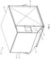
- FIG. 1is a perspective view of an air cargo container according to an embodiment of the present disclosure
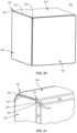
- FIG. 2is a partial, schematic sectional, perspective view of a thermally insulated panel of the container of FIG. 1 ;
- FIG. 3is a cross-sectional view of a corner of the container of FIG. 1 ;
- FIG. 4is a partial perspective, schematic cutaway view of a central portion of another exemplary thermally insulated panel for use with the container of FIG. 1 ;
- FIG. 5is a partial, schematic sectional, perspective view another exemplary thermally insulated panel for use with the container of FIG. 1 ;
- FIG. 6is an enlargement of a portion of the panel of FIG. 5 ;
- FIG. 7is an enlargement of another portion of the panel of FIG. 5 ;
- FIG. 8is a perspective view of another thermally insulated panel according to an embodiment of the present disclosure.
- FIG. 9is a partial cross-sectional view of the panel of FIG. 8 ;
- FIG. 10is a partial cross-sectional view of a core of the panel FIG. 8 according to an embodiment of the present disclosure
- FIG. 11is a perspective view of another thermally insulated panel according to an embodiment of the present disclosure with a skin thereof removed;
- FIG. 12is a cutaway, perspective view of the panel of FIG. 11 ;
- FIG. 13is a perspective view of the panel of FIG. 11 ;
- FIG. 14is a perspective view of the frame of the panel of FIG. 8 ;
- FIG. 15is a perspective view of another frame provided in accordance with an embodiment of the present disclosure.
- FIG. 16is a cross-sectional view of the frame of FIG. 15 ;
- FIG. 17is a cross-sectional view of another frame provided in accordance with an embodiment of the present disclosure.
- FIG. 18is a perspective view of another panel provided in accordance with an embodiment of the present disclosure.
- FIG. 20is a perspective view of a cargo container provided in accordance with an embodiment of the present disclosure including panels of FIG. 18 ;
- the phrases “unit load device” (ULD) or “air cargo container,”is defined as containers used to load luggage, freight, mail, and the like on aircraft including wide-body aircraft and narrow-body aircraft. While the containers described herein are directed to ULDs for use with aircraft, it is contemplated that cargo containers including the disclosed vacuum insulated panels may be used in other transportation vehicles such as trucks, trailers, ships, or trains such that the described use with aircraft should not be seen as limiting. In addition, while the panels described herein are described with respect to forming air cargo containers, it is contemplated that the panels described herein may be used with other transportation vehicles or as structural panels for construction such as interior or exterior walls, refrigerator panels, etc. As used herein, the term “vacuum” refers to a pressure of 3 ⁇ 10 3 Pa or less.
- the temperature of cargo within a ULD designed with thermal insulation properties in mindmay extend how long cargo is able to maintain a desired internal temperature.
- the desired internal temperaturemay be above or below an ambient temperature.
- a thermally insulated ULDmay maintain an internal temperature range with a decreased amount of passive temperature control material, e.g., dry ice, or a decreased size of active cooling/heating equipment, e.g., refrigeration/heating equipment.
- an exemplary air cargo container or ULDis provided in accordance with the present disclosure and is referred to generally as container 100 .
- the container 100is a half-with ULD for use below a deck of an aircraft.
- the container 100may be designed to load luggage, freight, or mail in an aircraft.
- the cargo container 100may have other shapes for a position within a given aircraft or for a type of a given aircraft.
- the container 100may be configured as a full-width ULD.
- the container 100may include a frame 102 presenting a generally rectangular shape with an offset designed to more closely follow the outline of the aircraft.
- the container 100may further include a cargo opening defined by a portion of the frame 102 .
- the frame 102may be formed from any substantially rigid material, such as aluminum, steel, composites, temperature resistant plastics, other metals, or other non-metals.
- the frame 102may support a plurality of panels 104 forming the walls, and optionally the roof and floor of the container 100 .
- the panels 104may be constructed together such that a separate frame, e.g., frame 102 , may be eliminated.
- the panels 104will be described in greater detail below and are designed for lightweight, thermal insulating, and high strength characteristics.
- the cargo openingmay be substantially sealed, and selectively closed, by a door 106 .
- the door 106may be a rigid door or may be a flexible door or curtain. When the door 106 is a rigid door, the door 106 may have similar construction to any of the panels detailed below. Alternatively, the door 106 may be insulated in another manner allowing the door 106 to be flexible.
- the panel 104includes skins 122 , a foam core 126 , and a vacuum insulated panel (VIP) 130 .
- the skins 122may be formed of fibers embedded in a resin that binds the fibers together. Suitable fibers may include fiberglass, basalt/mineral fibers, aramid cloth, mat and non-wovens (e.g., Nomex®, Kevlar®, or Technora®s), carbon fibers, ceramic fibers, or quartz fibers.
- the fibers of the skins 122may be laid up in a unidirectional pattern, can be woven, knit, or formed as a non-woven web. Bulk properties are then generated by the number of layers and the fiber angle of each layer compared to the other layers.
- the thickness of the skins 122can be discretely changed by varying the number of layers, or by the thickness of each individual layer, or by a combination of both. All layers can be of the same fiber material or can be of different fiber blends.
- the resinis used to bind the fibers together to form the rigid skins 122 .
- the resinmay include phenolic and polyimides including bismaleimides, epoxies, polyesters, or vinyl esters.
- the resinmay also include polyphenylene sulfide and similar sulfides, polyether imide, polyamide imide, polyetheretherketone, polypropylene, nylon, polyester, or other thermoplastics.
- the core 126is laminated between the skins 122 such that the skins 122 and the core 126 are prevented from sliding or shifting relative to one another in a length or width direction of the panel 104 .
- the skins 122 and the core 126may be secured or attached together in various ways.
- the skins 122may be adhered to the core 126 by the resin.
- the panel 104may include fibers inserted through the skins 122 and the core 126 .
- suitable fibersreference may be made to U.S. Pat. No. 8,002,919, the entire contents of which are hereby incorporated by reference.
- the skins 122 and the core 126may be attached by a coating and/or an adhesive on a surface of the skins 122 in contact with the core 126 and/or on surfaces of the core 126 in contact with the skins 122 .
- the core 126includes a pocket 127 defined therein.
- the pocket 127is positioned such that the core 126 surrounds the pocket 127 on all sides.
- the pocket 127extends towards each edge of the panel 104 such that the pocket 127 is defined substantially at all points between the skins 122 .
- the VIP 130is embedded within the pocket 127 .
- the VIP 130includes a filler material 132 and a barrier or envelope 134 .
- the filler material 132may be a porous fabric or a porous foam material.
- the envelope 134is disposed over the filler material 132 such that the filler material 132 is hermetically sealed within the interior of the VIP 130 .
- the envelope 134may be a thin metallic layer, e.g., an aluminum layer, that is impenetrable.
- a vacuumis applied such that when the envelope 134 is sealed over the filler material 132 , the envelope 134 holds a vacuum therewithin.
- the filler material 132prevents the envelope 134 from collapsing and maintains a volume within the envelope 134 .
- the VIP 130may have an R-value above R-15 per inch of thickness, e.g., R-20, R-30, R-40, R-45, or R-50 per inch of thickness.
- the skins 122 and the core 126provide protection to the envelope 134 to prevent the seal of the envelope 134 from being compromised and thus, prevent the VIP 130 from losing its vacuum.
- a VIP 130may be created having dimensions substantially equal to the finished panel 104 .
- the VIP 130may have a length slightly less than a desired length of the finished panel 104 , e.g., 2 inches to 12 inches less, and may have a width slightly less than a desired width of the finished panel 104 , e.g., 2 inches to 12 inches less.
- the VIP 130may have a thickness substantially equal to the thickness of the finished panel 104 , e.g., 70 percent to 90 percent of the thickness of the finished panel.
- the VIP 130is embedded within the core 126 .
- the core 126may be formed about the VIP 130 such that the VIP 130 is embedded within the pocket 127 of the core 126 .
- the VIP 130 and the core 126may be bonded together such that the VIP 130 and the core 126 have a shear strength of 5 lb./ft. 2 .
- the skins 122are applied over the core 126 to encapsulate the entire core 126 .
- the skins 122are laid over the core 126 as one or more fiber sheets or layers and then the resin is poured over or distributed through the fiber sheets or layers to form the skins 122 and/or to bond the skins 122 to the core 126 .
- Edge portions 121 of the panel 104may be formed by thermoforming the edge portions 121 to a desired shape. Specifically, the skins 122 , the core 126 , and the VIP 130 may form a flat panel with substantially linear edge portions 121 . The edge portions 121 may then be thermoformed to a desired shape. As shown in FIG. 2 , the edge portion 121 is formed in an arc to fit over a rounded structural member of the frame 102 ( FIG. 1 ) or over a rounded edge portion of another panel, e.g., panel 104 . Thermoforming the edge portions 121 also joins the skins 122 to one another such that a seal is formed between the skins 122 which encapsulates the core 126 within the skins 122 . The seal between the skins 122 may prevent air from escaping an interior of the panel 104 , e.g., the core 126 , or from entering the interior of the panel 104 , e.g., vacuum escaping the panel 104 .
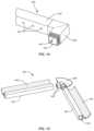
- the edge portion 121 of one panel 104may secure to the edge portion 121 of another panel 104 with a tubular insert 109 received at the joint.
- the tubular insert 109may be vacuum insulated and/or foam insulated such that a completed container 100 has edge-to-edge insulation for each panel 104 .
- the tubular insert 109may be compressed within the edge portions 121 of the adjacent panels 104 to secure the tubular insert 109 between the edge portions 121 .
- the shape of the edge portion 121allows the edge portion 121 of the panel 104 to be secured to a tubular frame member.
- the edge portions 121may include one or more openings (not shown) to allow fasteners to pass through the edge portion 121 to secure the edge portions 121 to the frame 102 and/or to another panel 104 .
- FIG. 4another panel 204 is provided in accordance with the present disclosure and may be used as one or more sides of a ULD, e.g., container 100 ( FIG. 1 ).
- the panel 204includes skins 222 and struts 224 .
- the skins 222are similar to the skins 122 detailed above and as such will not be detailed below for brevity.
- the panel 204may also include an envelope 234 .
- the struts 224are positioned to define a space or pocket 227 between the skins 222 . As shown, the struts 224 form a honeycomb structure with each honeycomb structure defining a portion of the pocket 227 . The struts 224 are covered by skins 222 which seals the pocket 227 such that the struts 224 form a rigid structure to prevent the skins 222 from shifting in a length or width direction or from collapsing. While the struts 224 are shown as honeycomb structures, the struts 224 may be cylindrical with a pocket, e.g., pocket 227 , defined therein or may be a solid column having a circular, rectangular, or polygonal cross-section.
- the struts 224may be formed of a thermoplastic, e.g., thermoplastic polypropylene.
- Each honeycomb structure of the struts 224includes one or more passages 230 in a sidewall thereof to allow air to pass between the portions of the pocket 227 such that the entire pocket 227 within the envelope 234 has the same vacuum, e.g., allows for vacuum equalization.
- the skins 222are configured to encapsulate the pocket 227 such that a vacuum can be drawn within the pocket 227 as detailed below.
- the skins 222are capable of maintaining a vacuum within the pocket 227 .
- the panel 204may include an envelope 234 between each of the skins 222 and the struts 224 such that the envelope 234 defines the pocket 227 and is encapsulated within the skins 222 .
- the skins 222provide protection for the envelope 234 to prevent the envelope 234 from being damaged, punctured, or breached which would compromise the pocket 227 , e.g., releasing a vacuum within the pocket.
- the edge portions 221 of the panel 204may be formed by thermoforming the skins 222 , the envelope 234 , and/or the struts 224 into a desired shape as detailed above with respect to the edge portions 121 of the panel 104 ( FIG. 2 ).
- the panel 204may include a filler material 226 disposed within one or more of the portions of the pocket 227 .
- the filler material 226may be a porous fabric, porous foam material, or a microporous material such as fiberglass mat, fumed or precipitated silica, aerogels, or similarly effective insulation materials that allows air or vacuum to pass therethrough while providing additional strength to prevent the skins 222 and/or the envelope 234 from shifting in a length or width direction relative to one another or from collapsing towards one another.
- the filler material 226may be a fire resistant material allowing the entire panel 204 to be fire resistant.
- another panel 304is provided in accordance with the present disclosure and may be used as one or more sides of a ULD, e.g., container 100 ( FIG. 1 ).
- the panel 304includes skins 322 and a core 326 .
- the skins 322are similar to the skins 122 detailed above with respect to the panel 104 and will not be detailed herein for brevity.
- the panel 304may also include an envelope 334 .
- the core 326is formed of a porous foam that substantially fills a space or pocket 327 .
- the core 326may be an open cell foam, sintered bead foam, or microporous inorganic powders or fibers such that air and/or vacuum may flow through the pocket 327 to allow for vacuum equalization within the pocket 327 .
- the core 326provides rigidity to the pocket 327 and prevents the pocket 327 from collapsing when a vacuum is applied within the pocket 327 as detailed below.
- the skins 322are positioned about the core 326 to seal the pocket 327 .
- the skins 322are bonded to the core 326 .
- the edge portions 321 of the panel 304are thermoformed such that the skins 322 are joined together to encapsulate the core 326 within the pocket 327 and to form a seal such that the pocket 327 is hermetically sealed.
- the panel 304includes an envelope 334 between the core 326 and the skins 322 .
- the envelope 334is impermeable and is positioned about the core 326 to hermetically seal the pocket 327 .
- the envelope 334may be formed a thin metallic foil or sheet, e.g., an aluminum foil or sheet.
- the envelope 334is encapsulated within the skins 322 and is bonded to both the skins 322 and the core 326 .
- the envelope 334may include a polypropylene, polyethylene, or film adhesive coating on one or both sides to bond to the skins 322 and/or the core 326 .
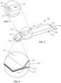
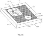
- the panel 304includes a port 350 secured through one of the skins 322 , and one of the envelopes 334 when present, to provide access to the pocket 327 .
- the port 350may be secured to a skin 322 that is configured to be disposed within an interior or cargo space of a finished container or to be disposed on an exterior of a finished container.
- the port 350includes a resealable passageway 352 that extends through the port 350 and into the pocket 327 .
- the port 350forms a seal with the skin 322 and/or the envelope 334 as to not compromise the pocket 327 .
- the port 350may be adhered and/or mechanically secured to the skin 322 and/or the envelope 334 .
- the passageway 352may include a one-way valve (not shown) that allows airflow out of the pocket 327 and prevents airflow into the pocket 327 .
- the panel 304may also include a vacuum indicator 340 that accesses the pocket 327 to indicate a vacuum within the pocket 327 without compromising the integrity of the pocket 327 .
- the vacuum indicator 340includes an indicator that provides visual indicia that the vacuum within the pocket 327 is at least a desired vacuum.
- the vacuum indicator 340may be mechanical and/or electrical.
- the vacuum indicator 340may include a light that illuminates when the vacuum within the pocket 327 is at a desired vacuum and/or when the vacuum is below a desired vacuum.
- the vacuum indicator 340may include a mechanical switch that changes a visible color of the vacuum indicator 340 when the vacuum within the pocket 370 is at or below desired vacuum.
- the vacuum indicator 340allows for a quick and nondestructive verification or inspection of the vacuum within the pocket 327 of the panel 304 .
- the vacuum indicator 340may be secured to the same or opposite skin 322 as the port 350 .
- the vacuum indicator 340provides a signal indicating an amount of vacuum within the pocket 327 .
- the vacuum indicator 340may transmit an electronic signal that is received by a controller 105 ( FIG. 1 ) secured to the container 100 or separate from the container 100 .
- the controller 105may allow for centralized verification that all the panels, e.g., panel 304 , of the container 100 have a desired vacuum, the vacuum of each panel, and/or which panels are below a desired vacuum.
- the vacuum indicator 340may include internal vacuum transducers disposed within pocket 327 .
- the internal vacuum transducermay include a transmitter such as a RFID, Bluetooth®, or other wireless technologies to provide remote monitoring of a vacuum within the pocket 327 .
- the vacuum indicator 340provides audible indicia when the vacuum is below a desired level.
- the vacuum indicator 340 and the port 350are described for use with the panel 304 ; however, it is contemplated that similar vacuum indicators and/or ports may also be used with panel 104 or panel 204 detailed above and panel 400 detailed below.
- the core 326is cut or formed to a desired dimension of the finished panel 304 .
- the envelope 334is then applied to both sides of the core 326 .
- envelopes 334may include coating or film adhesive to bond to the core 326 .
- a skin 322is applied or secured to each envelope 334 .
- the skins 322may be applied directly to the core 326 .
- the edge portions 321 of the panel 304are then formed such that the skins 322 are joined together such that the pocket 327 is hermetically sealed within the skins 322 .
- the envelopes 334are also joined together such that the pocket 327 is hermetically sealed by the envelopes 334 and the skins 322 are joined together to encapsulate the envelopes 334 .
- the edge portions 321are formed to a desired shape depending on the construction of a particular container, e.g., container 100 , as detailed above. As shown, the edge portions 321 are angled to abut edge portions of another panel without a separate frame, e.g., frame 102 ( FIG. 1 ).
- the edge portions 321may include a flange 323 that is configured to secure to another panel adjacent the panel 304 to secure the panel 304 to the adjacent panel.
- the flange 323may include one or more openings to allow fasteners to pass therethrough without compromising the pocket 327 .
- the flange 323includes fasteners disposed along one or more surfaces thereof to permanently or releaseably secure to an adjacent panel.
- the flange 323may include hook and loop fasteners on one or more surfaces to releaseably secure the flange 323 to an adjacent panel.
- the edge portions 321may be curved in a similar manner to edge portions 121 detailed above.
- the edge portions 321are formed in a similar manner to the edge portions 121 ( FIG. 4 ) such that the edge portions 321 of adjacent panels 304 can be secured together and a tubular insert, e.g., tubular insert 109 , can be secured between the adjacent panels 304 to provide edge to edge insulation.
- a tubular inserte.g., tubular insert 109
- the vacuum indicator 340 and/or the port 350are secured through one of the skins 322 and in communication with the pocket 327 .
- the vacuum indicator 340 and the port 350may be installed adjacent one another or remote to one another.
- the vacuum indicator 340 and the port 350are installed in opposite skins 322 , e.g., the vacuum indicator 340 may be installed in an external skin 322 and the port 350 may be installed in an interior skin 322 .
- the panel 304includes multiple ports 350 and/or vacuum indicators 340 . With the port 350 secured to the panel 304 , an adapter (not shown) is placed in communication with the passageway 352 of the port 350 .
- the adaptermay be a needle (not shown) that is passed through the passageway 352 of the port 350 and into the pocket 327 .
- the passageway 352forms a seal with the adapter to prevent air from passing into the pocket 327 .
- a sealis formed about the adapter, e.g., when the adapter is a needle, to prevent air from passing into or out of the pocket 327 about the adapter.
- the adapterforms a seal about the passageway 352 and opens a one-way valve of the passageway 352 when a vacuum is drawn through the adapter.
- a vacuumis then drawn through the adapter such that a vacuum is drawn within the pocket 327 .
- the vacuumis drawn through the adapter until the pocket 327 achieves a desired vacuum.
- the vacuum indicator 340may provide visual, audible, and/or electronic indicia of the desired vacuum within the pocket 327 .
- the adapteris separated from the port 350 such that the passageway 352 reseals. If the port 350 includes a cap, the cap may be installed over the passageway 352 after the adapter is removed.
- the vacuum indicator 340allows for noninvasive and instant inspection of a vacuum within the pocket 327 of the panel 304 . If the vacuum within the pocket 327 is below the desired vacuum, the panel 304 may be replaced and/or repaired. It is contemplated that the when a breach of the skin 322 and/or the envelope 334 of a panel 304 develops, a patch (not shown) may be applied over the breach to reseal the pocket 327 .
- the repairmay include removing a portion of the skin 322 to expose the core 326 and/or the envelope 334 and applying a patch directly to the exposed core 326 and/or envelope 334 over the breach. With the patch applied, the port 350 may be used to establish the desired vacuum within the pocket 327 .
- the repair processmay be completed on-site and may be completed with a universal patch kit. Such a repair process may allow for a reduction in inventory of repair parts. Such a reduction may reduce the cost and inventory requirements for repairs.
- the panel 400includes a skins 422 , a core 426 , and a frame 440 .
- the skins 422may be composite skins similar to the skins 122 detailed above.
- the skins 422 and the frame 440define a pocket 427 therewithin.
- the pocket 427includes the core 426 encapsulated therein.
- the panel 400includes a film or barrier 428 that is disposed between each skin 422 and the frame 440 such that the sealed pocket 427 is formed about the core 426 .
- the barrier 428is secured to an inner surface of the skin 422 and the outer surface of the frame 440 and the core 426 by an adhesive.
- the barrier 428 and the frame 440hermetically seal the pocket 427 such that vacuum is maintained within the pocket 427 as detailed below.
- the barrier 428may be disposed within the skin 422 as detailed below.
- the core 426is formed of a material and has a structure to provide sufficient structural properties to resist a vacuum load within the pocket 427 and to effectively transfer load through a thickness of the panel 400 .
- the core 426may have a compressive strength greater than 20 psi (138 kPa) to resist vacuum load and to prevent local structural buckling during bending of the panel 400 .
- the core 426may have a shear strength greater than 20 psi (138 kPa) to transfer load through a thickness of the panel 400 such that the panel 400 is capable of being used as a structural panel.
- interlaminar friction as a result of the internal vacuummay be 15 psi such that a shear strength of the structure of the core 426 may be less than 20 psi dependent on the effectiveness of this interlaminar friction generating additional shear strength.
- the core 426may have a traverse tensile strength greater than 5 psi (35 kPa) to minimize cohesive failure of the core 426 which is exhibited by separation of the skins 422 . The traverse tensile strength may also be assisted by the internal vacuum within the pocket 427 .
- the core 426may have a low thermal conductivity to minimize thermal bridging effects between the skins 422 .
- the pocket 427may be void of fluid, e.g., air, such that a total vacuum is formed within the pocket 427 .
- fluide.g., air
- the insulative benefit of the pocket 427may be at a maximum.
- the insulative benefit of the pocket 427is significantly reduced when compared to the pocket 427 being void of all fluid.
- the core 426may be filled with the filler material 436 which is a non- or low conductive material as described in greater detail below.
- the core 426may include an internal porous structure that extends between the skins 422 and meets the structural requirements of the core 426 .
- the internal porous structuremay be porous foam, a plurality of rigid tubes randomly oriented, a plurality of rigid tubes in a stacked orientation extending perpendicular to the skins 422 , a repeating honeycomb structure extending perpendicular to the skins 422 , or combinations thereof.
- the core 426may include a porous foam such as a porous expanded polypropylene (PEPP) foams.
- PEPP foamsmay have a density of 2.8 lbs/ft 3 (45 kg/m 3 ) which have been tested to provide both the desired structural and insulative values for the core 426 .
- the PEPP foammay be formed by bonding randomly oriented foam tubes with a length to diameter ratio less than 10 by putting the foam tubes in a mold cavity and applying heat, e.g., pressurized steam.
- PEPP foamsBy forming the PEPP foam in this manner allows for the introduction of a filler material 436 such as small particle silica into the voids in the tubes may decrease the sensitivity of the insulative value to vacuum levels within the core 426 .
- PEPP foamsare thermoplastic in nature, the PEPP foams are compatible with thermal lamination to the skins 422 or the barrier 428 such that a continuous lamination process may be used to form the panel 400 as detailed below.
- the core 426may include a porous tubular structure which is formed of rigid tubes 1436 to create a porous structure that meets the structural requirements of the core 426 .
- the porous tubular structureis formed of polypropylene (PP) tubes 1436 that are co-extruded with a thin layer of low melting material 1437 such as polyethylene (PE) on the outer surface thereof.
- the PE layer 1437serves as an adhesive to bond the PP tubes 1436 together.
- the length to diameter ratio of the PP tubes 1436may be less than five to one to allow the PP tubes 1436 to form a random structure when mixed together.
- the outside diameter to wall thickness ratio of the PP tubes 1436should be sufficient to meet the structural requirements of the core 426 , e.g., the compressive and the shear strengths, which is dependent on the modulus of the PP forming the PP tubes 1436 .
- the PP tubes 1436are disposed in a mold or a layup, the PP tubes 1436 are consolidated by heating the PP tubes 1436 to the melting point of the PE layer 1437 but not to the heat deflection temperature of the PP such that the PE layers 1437 bond together to form a structure that meets the structural requirements of the core 426 .
- the PP tubes 1436are compatible with the skins 422 and the barrier such that the PP tubes 1436 can be bonded to the skins 422 or the barrier 428 in a continuous lamination process.
- a filler material 436such as a small particle silica can be used to fill voids within the PP tubes before consolidation of the PP tubes 1436 .
- a radial compressive strength of each of the PP tubes 1436can be optimized to push any of the silica from a bonding area between individual PP tubes 1436 such that a bond can be formed between adjacent PP tubes 1436 .
- the PP tubes 1436may be orientated randomly within the core 426 or, as shown in FIG. 10 , the PP tubes 1436 can be stacked parallel to the skins 422 to form the core 426 .
- Such a constructionis similar to a honeycomb structure lying flat instead of on edge.
- Such a structuremay include a filler material 436 in interstitial spaces between the tubes 1436 , e.g., silica.
- the filler material 436may decrease sensitivity to vacuum pressure and also improve compressive and shear strength of the core 426 .
- a ratio of the wall thickness to the outside diameteris increased to meet the structural requirements of the core 426 , e.g., the compressive loading requirement.
- stacked parallel PP tubes 1436is may have more predictable structural and thermal properties than a random version while being more cumbersome and expensive to produce.
- larger contact areas between tubes 1436may create high thermal transmission through the core.
- a porous thermoset polyurethane (PU) foammay be used as the core 426 .
- the thermal insulation value of an envelope with a PU foamtends to have high sensitivity to a vacuum within the pocket 427 .
- a PU foamis not compatible with the skins 422 or the barrier 428 such that a thermoplastic film adhesive may be required to laminate the PU foam to the skins 422 or the barrier 428 .
- a thermoset porous expanded polystyrene (EPS)may be used to form the core 425 . Similar to PU foam cores, a thermoplastic film adhesive is necessary to bond the EPS to the skins 422 or the barrier 428 .
- a porous thermoplastic honeycombmay be used to form the core 426 .
- the honeycomb structure of the core 426allows the core 426 to meet the required structural requirements detailed above.
- the thermoplastic material forming the walls of the honeycombis considered a thermally insulative material, in a high-performance environment such as the panels detailed herein, conduction between the skins 422 through the walls of the honeycomb can reduce thermal performance.
- holes to increase the porosity of the honeycomb structuree.g., holes 230 , may provide a thermal break in the walls and reduce this conduction.
- the honeycomb structuremay include multiple layers of honeycomb that are offset from one another to reduce condition between the skins 422 .
- the offset honeycomb layersmay also allow for porosity of the honeycomb structure without including holes in the walls. It is also contemplated that the honeycomb structure may be filled with a filler material 436 , e.g., silica, to reduce a sensitivity of the thermal insulation of the honeycomb structure to a vacuum level.
- the repeating honeycomb structuremay be hexagonal as shown or may have other repeating shapes including, but not limited to, circular, triangular, rectangular, pentagonal, octagonal, or star. The shape of the honeycomb may reduce thermal conductivity between the skins 422 and the honeycombs themselves.
- the core 426may include filler material 436 disposed within the pocket 427 which is porous such that fluid may flow within the pocket 427 . Allowing fluid to flow within the pocket 427 allows fluid to be equally distributed or to be removed from the pocket 427 .
- the filler materialmay be fiberglass strand mats, fumed or precipitated hydrophilic silica powder, aerogel materials, or open-cell foam.
- the filler material 436may include small amounts of thermoplastic binder such as a PE emulsion or a PP emulsion which can be added to the silica, fiberglass matting, or a combination thereof. The filler material 436 may be dried to remove any residual moisture therein.
- the core 426may be heat pressed into a consolidated core 426 such that the core 426 including the filler material 436 meets the structural requirements of the core 426 .
- a binder that adheres adjacent particles or fibers forming the consolidated core 426e.g., a PE emulsion or a PP emulsion, may softer such that the filler material 436 may flow through the consolidated core 426 . It is appreciated that as the amount of binder increases, thermal conductivity through the core 426 may be increased such that for each type of core material there may be an optimal combination of binder and core material to provide the structural requirements of the core 426 and maximize the insulative value of the core 426 .
- the filler material 436is a three-dimensional loose fiberglass cloth, e.g., fiberglass woven cloth, that is interspersed with fumed or precipitated silica.
- the fiberglass clothmay provide the tensile and shear strength while the silica improves the insulative value of the core 426 .
- Such a core 426may be brittle such that when impacted the core 426 may crack which may reduce compressive and shear strength or reduce insulative performance.
- the skins 422may provide protection for the core 426 to prevent damage to the core 426 and to hold the core 426 together to increase the strength of a panel 400 having such a core 426 .
- the protection provided by the skins 422may be increased when combined with a rigid frame, e.g., frame 440 .
- the consolidated coremay be inserted into the frame 440 , with the barrier 428 adhered to the frame 440 and the core 426 to form the pocket 427 therein.
- the core 426consists of the filler material 436 that is bound together with the binder, e.g., PP emulsion or PE emulsion.
- the panel 400may include a solid core area 460 that allows for drilling through or premade holes 462 in the panel 400 .
- the solid core area 460may be provided to allow for fasteners to pass through the panel 400 without compromising a vacuum within the pocket 427 of the panel 400 as described above.
- the solid core area 460may allow for a fastener to secure a component to the panel 400 , e.g., a refrigeration component or shelf, without compromising the vacuum of the panel 400 .
- the solid core area 460may be formed from a solid PP element that is inserted into the core 426 .
- the solid core area 460may have a diameter of at least three times a hole through or a fastener passing through the solid core area 460 . In some embodiments, the solid core area 460 may be less than three times larger than a hole or fastener passing therethrough.
- the solid core area 460may be bonded to the barrier 428 and/or the skins 422 such that the solid core area 460 is fixed within the panel 400 .
- the frame 440is a rigid frame that holds a predetermined shape. As shown, the frame 440 is a hollow frame that is sealed to form a frame pocket 445 .
- the frame 440may include openings 443 such that the frame pocket 445 may be in fluid communication with the pocket 427 of the core 426 to equalize a vacuum between the pockets 427 and 445 .
- the frame pocket 445may be filled with a frame filler material (not explicitly shown) which may be the same or different from the filler material of the pocket 427 .
- the frame filler materialmay be a porous material such as fiberglass strand mats, fumed or precipitated silica power, aerogel materials, open-cell foam, or combinations thereof.
- the panel 440may have a consistent edge-to-edge insulative value. This insulative value may be greater than a R-15 per inch of thickness of the panel 400 , e.g., R-25, R-30, R-40, R-45, or R-50 per inch.
- a frame element 442is mated to a joint element 446 with a seal formed in a joint between the frame element 442 and the joint element 446 .
- the joint element 446includes a connector 448 which is received in a frame element 442 to secure the frame and joint elements 442 , 446 together.
- the connector 448extends from the joint element 446 and is received in the frame element 442 ; however, this may be reversed.
- the connector 448may include one or more steps.
- the stepsmay mate with complementary steps of the frame element 442 .
- the steps of the frame element 442may be machined after the frame element 442 is extruded. Alternatively, the steps may have an increased amount of seal material to form primary and secondary seals or bonds with the frame element 442 .
- Each one of the stepsmay include a seal material that bonds the frame element 442 to the joint element 446 .
- the seal materialmay be an O-ring, an adhesive, or a combination thereof to bond the frame element 442 to the joint element 446 .
- the frame element 442 and/or the joint element 446may be formed of a thermoplastic material that is extruded or molded into the desired shape or form and the seal material may be an adhesive such as a thermoset adhesive or a heat-activated thermoplastic adhesive.
- the seal materialis a heat-activated thermoplastic adhesive which includes a conductive metal powder therein or added thereto such that when the frame element 442 receives the joint element 446 , an inductive coil can be used to inductively heat the metal powder and the thermoplastic adhesive such that the frame element 442 is bonded to and forms a seal with the joint element 446 .
- the thermoplastic adhesivemay also include a chemical blowing agent such that when the thermoplastic adhesive is activated, the thermoplastic adhesive may expand to fill voids and enhance the seal of the joint between the joint element 446 and the frame element 442 .
- the frame 440may include an edge portions or geometry 449 that is shaped to secure the panel 400 to adjacent panels 400 or another support member.
- the edge geometry 449may be configured to secure the panel 400 to other panels 400 .
- the edge geometry 449may be shaped to mate or be received in the edge geometry 449 of an adjacent panel 400 such that the panels 400 may be secured together by passing a fastener through the edge geometry 449 as described above.
- a fastenermay pass through the edge geometry 449 of a panel 400 and secure the panel to a frame member of a cargo container.
- the frame elements 442may include detachable edge geometry 479 .
- the frame element 442includes a connector 472 , e.g., a dovetail, that is received in a receiver 474 of the detachable edge geometry 479 .
- the edge geometry 479may be formed manner similar to the edge geometry 449 detailed above such that the edge geometry 479 may be secured to edge geometry of an adjacent panel 400 .
- the frame element 442defines the receiver and the detachable edge geometry includes the connector 472 .
- the frame 440is formed of frame elements 442 having a substantially square cross-section; however, in some embodiments the frame elements 442 ′ may have a C-channel profile as shown in FIG. 12 with the core 426 received within the channel formed by the frame element 442 ′. In such embodiments, the core 426 may provide edge-to-edge insulation with the frame 440 providing reinforcement and strength to the edge of the panel.
- the barrier 428may be a metalized polymer film such as polyester with a layer of hot melt adhesive on one or both sides thereof.
- a metalized polymer filmhas been shown to maintain a high degree of internal vacuum for an extended time, e.g., 20 years or more.
- the hot-melt adhesivemay be a thermoplastic adhesive such as low density PE adhesive or a PP adhesive.
- the barrier 428may be placed in multiple locations relative to the core 426 and the skins 422 .
- the materials forming the core 426are not compatible with the skins 422 , e.g., a thermoset material
- the barrier 428may be placed between the core 426 and the skins 422 .
- the strength of the core 426 to skin 422 bondis based entirely on the strength of the adhesive.
- the thickness of the adhesive to create a strong bondmay make a substantial difference in the overall strength of the panel 400 .
- the barrier 428may be within the skin 422 . Placing the barrier 428 within the skin 422 may protect the barrier 428 and may provide a higher strength bond between the skin 422 and the core 426 .
- a possible layup for such a configurationmay be a 4-ply skin which may have a layup from an internal or core side to an external side of a 0° layer/a 90° layer/the barrier 428 /a 90° layer/a 0° layer/a protective outer layer.
- the protective outer layermay be an infrared reflective layer and/or may be a waterproof layer.
- the panel 400may be formed by the following process with reference to panel 400 of FIGS. 8 and 9 .
- the processincludes forming the core 426 as detailed above. With the core 426 consolidated, the core 426 is prepared by pre-drying the core 426 . Additionally or alternatively, an absorbent material, e.g., hydrophilic silica, may be applied to or positioned within the core 426 to eliminate any internal moisture or fluids therein. With the core 426 prepared, the frame 440 is placed or formed around the core 426 such that the core 426 is within the frame 440 . The frame 440 may be formed in a manner consistent with the description above.
- a barrier 428is applied over both sides of the frame 440 and the core 426 .
- the skins 422are then applied over the barrier 428 such that the barriers 428 , the core 426 , and the frame 440 are between the skins 422 .
- the barriers 428are within the skins, the skins 422 are applied directly over the frame 440 and the core 422 .
- the barrier 428may include a thermoplastic adhesive on both sides thereof such that the barriers 428 are bonded on one side, e.g., an internal side, to the core 426 and the frame 440 and on the other side, e.g., an external side, to the skin 422 .
- the panel 400is formed by thermally laminating the skins 422 to the barriers 428 and the barriers to the core 426 and the frame 440 .
- This lamination processmay be a single lamination process to form the panel 400 .
- the barriers 428 and the frame 440form the pocket 427 within the skins 422 .
- a vacuum port 450is bonded into the panel 440 .
- the vacuum port 450is secured to one of the skins 422 to allow for drawing of a vacuum within the pocket 427 for a new or a repaired panel 400 .
- the vacuum port 450is installed in the panel 400 after the panel 400 is formed.
- one of the skins 422 and a portion of the core 426is machined to create a seat 451 to receive the vacuum port 450 .
- the seat 451may have a width, length, and/or depth less than the dimensions of the vacuum port 450 such that when the vacuum port 450 is inserted into the seat 451 , the vacuum port forms a seal, e.g., a hermetic seal, with the skin 422 , the core 426 , and the barrier 428 such that the vacuum port 450 forms a seal of the pocket 427 .
- the vacuum port 450may be bonded using thermoset adhesive, ultrasonic welding, heat-activated thermoplastic adhesive, or induction heat-activated thermoplastic adhesive.
- the vacuum port 450With the vacuum port 450 installed in the panel 400 , a vacuum is drawn through a resealable passageway 452 of the vacuum port 450 .
- the vacuummay be drawn with a high-performance vacuum pump such that an internal pressure within the pocket is less than 1 mbar.
- the vacuum port 450includes is similar to the vacuum port 350 detailed above and includes a resealable passageway 452 that is in fluid communication with the pocket 427 when the vacuum port 450 is installed.
- the vacuum port 450may include a vacuum indicator 454 similar to the vacuum indicator 340 detailed above. After the vacuum is drawn within the pocket 427 through the vacuum port 450 , the vacuum within the pocket 427 may be tested for vacuum integrity. The vacuum may be tested with a vacuum indictor 454 of the vacuum port 450 or may be tested with a vacuum gauge connected to the passageway 452 .
- the panel 400may be repaired if damage. Specifically, a patch of new skin material and barrier may be placed over the damaged area and laminated to the panel 400 to reform and seal the pocket 427 . With the damaged area repaired, the vacuum port 450 may be used to redraw a vacuum within the pocket 427 to reestablish a vacuum within the pocket and restore the insulative value of the panel 400 .
- the panel 500includes skins 522 , a foam core 526 , and a VIP 530 .
- the panel 500includes barriers 528 .
- the skins 522 , the foam core 526 , and the barriers 528are similar to the composite skins, the foam cores, and the barriers detailed above and will not be described in detail with respect to panel 500 except for differences with the descriptions above.
- the panel 500may include a vacuum port 550 similar to the vacuum ports 350 , 450 detailed above and will not be detailed herein for brevity.
- the VIP 530is disposed within a pocket 527 defined within the foam core 526 .
- the VIP 530may be premanufactured or preassembled before being disposed within the foam core 526 and include a barrier or envelope 534 that is disposed over a filler material 532 .
- the envelope 534maintains a vacuum within the VIP 530 .
- the VIP 530may have a substantially trapezoidal shape or any suitable shape for being disposed within a pocket 527 defined within the foam core 526 .
- the foam core 526surrounds or encapsulates the VIP 530 to protect the VIP 530 and may be considered a buffer layer.
- the foam core 526may provide a strong bond between the skins 522 and the VIP 530 such that the foam core 526 receives the higher shear and bending loads of the panel 500 when compared to the VIP 530 .
- the foam core 526may be a closed foam or may be a porous foam.
- the foam core 526when the foam core 526 is a porous foam, the foam core 526 may be encapsulated by barriers 528 that are sealed together in edge portions 521 thereof in a similar manner to the forming of edge portions 321 detailed above.
- the edge portions 521may include flanges 523 similar to the flanges 323 detailed above.
- the barriers 528encapsulate the foam core 526 such that a vacuum may be drawn in the foam core 526 in addition to the vacuum within the VIP 530 .
- the panel 500includes an internal rigid frame at the edges thereof similar to the rigid frame 440 detailed above with respect to the panel 400 .
- the vacuum within the foam core 526may be less than the vacuum within the VIP 530 and may provide additional insulative value to the panel 500 .
- the vacuum within the foam core 526may extend a life of a vacuum within the VIP 530 , e.g., reduce leakage of the VIP 530 .
- the VIP 530may continue to function, e.g., maintain a vacuum therein.
- the VIP 530may include a vacuum indicator 539 disposed therein that provides a signal to a remote device indicative of the vacuum within the VIP 530 .
- the vacuum indicator 539may be a RFID or a Bluetooth® transmitter.
- the panel 500includes the vacuum port 550 that includes a passageway 552 and a vacuum indicator 554 .
- the vacuum port 550is disposed through a skin 522 and into the foam core 526 without penetrating the VIP 530 .
- the vacuum port 550forms a seal with the skin 522 and the barrier 528 such that the foam core 526 is sealed.
- the vacuum port 550may be used in a manner as detailed above with respect to vacuum ports 350 , 450 to draw or redraw a vacuum within the foam core 526 .
- the foam core 526may have an insulative value of R-5 when fluid is disposed therein and may have an insulative value of R-20 when a vacuum is drawn therein.
- the panels 500may form a cargo container 501 with a frame 540 .
- the frame 540includes frame elements 542 and joint elements 580 that form the rigid frame 540 .
- the frame elements 542 and the joint elements 580may include insulation in the form of foam and/or filler material as detailed above such that the cargo container 501 includes edge-to-edge insulation and may be considered entirely insulated.
- the frame elements 542 and/or joint elements 580may be filled with a filler material 546 or foam (not explicitly shown) that is encapsulated by a frame barrier 548 .
- the filler material 546 , foam, and the frame barrier 548may be similar to the filler materials, the foams, and the barriers detailed above and will not be detailed herein for brevity.
- the frame elements 542 and/or the joint elements 580may have a vacuum drawn therein to increase an insulative value of the frame 540 .
- the flanges 523 of the panels 500may be secured to the frame 540 by an adhesive, e.g., thermoplastic adhesive, that bonds the panels 500 to the frame 540 . Additionally or alternatively, the flanges 523 may be secured to the frame 540 by one or more fasteners passing therethrough. The fasteners may be secured into a solid core portion of the frame 540 which are similar to the solid core portions 460 detailed above.
- the panels detailed hereinare described with respect to an air cargo container. However, it is contemplated that the panels detailed herein may be constructed with structural characteristics suitable for other applications including cargo containers for use on trucks, ships, or trains. Such cargo containers by be in the form of a trailer for a truck, a shipping container for a ship, or a train car.
- the panels detailed hereinmay be suitable for buildings requiring insulated walls.
- the panels detailed hereinmay be suitable for exterior walls or as an insulating layer on the outer surface of a wall.
- the panels detailed hereinmay be used to construct refrigeration units such as those used in hospitality, restaurant, or laboratory environments.
- the enclosure or containerWhen an enclosure or container is formed of the panels detailed herein, the enclosure or container may maintain an elevated or a reduced temperature to an environment surrounding the enclosure or container with minimal transfer of energy through the panels.
Landscapes
- Engineering & Computer Science (AREA)
- Mechanical Engineering (AREA)
- Textile Engineering (AREA)
- Packages (AREA)
- Thermal Insulation (AREA)
Abstract
Description
Claims (20)
Priority Applications (3)
| Application Number | Priority Date | Filing Date | Title |
|---|---|---|---|
| PCT/US2020/039893WO2020264346A1 (en) | 2019-06-28 | 2020-06-26 | Thermally insulated air cargo container |
| US16/913,410US11981498B2 (en) | 2019-06-28 | 2020-06-26 | Thermally insulated air cargo container |
| US18/649,013US20240278973A1 (en) | 2019-06-28 | 2024-04-29 | Thermally insulated air cargo container |
Applications Claiming Priority (2)
| Application Number | Priority Date | Filing Date | Title |
|---|---|---|---|
| US201962867964P | 2019-06-28 | 2019-06-28 | |
| US16/913,410US11981498B2 (en) | 2019-06-28 | 2020-06-26 | Thermally insulated air cargo container |
Related Child Applications (1)
| Application Number | Title | Priority Date | Filing Date |
|---|---|---|---|
| US18/649,013ContinuationUS20240278973A1 (en) | 2019-06-28 | 2024-04-29 | Thermally insulated air cargo container |
Publications (2)
| Publication Number | Publication Date |
|---|---|
| US20200407149A1 US20200407149A1 (en) | 2020-12-31 |
| US11981498B2true US11981498B2 (en) | 2024-05-14 |
Family
ID=74044412
Family Applications (2)
| Application Number | Title | Priority Date | Filing Date |
|---|---|---|---|
| US16/913,410Active2040-11-02US11981498B2 (en) | 2019-06-28 | 2020-06-26 | Thermally insulated air cargo container |
| US18/649,013PendingUS20240278973A1 (en) | 2019-06-28 | 2024-04-29 | Thermally insulated air cargo container |
Family Applications After (1)
| Application Number | Title | Priority Date | Filing Date |
|---|---|---|---|
| US18/649,013PendingUS20240278973A1 (en) | 2019-06-28 | 2024-04-29 | Thermally insulated air cargo container |
Country Status (4)
| Country | Link |
|---|---|
| US (2) | US11981498B2 (en) |
| EP (1) | EP3990271A4 (en) |
| CN (1) | CN114206602A (en) |
| WO (1) | WO2020264346A1 (en) |
Families Citing this family (6)
| Publication number | Priority date | Publication date | Assignee | Title |
|---|---|---|---|---|
| WO2017091761A1 (en) | 2015-11-25 | 2017-06-01 | Yeti Coolers, Llc | Insulating container having vacuum insulated panels and method |
| US12091239B2 (en) | 2021-11-11 | 2024-09-17 | Advanced Composite Structures, Llc | Formed structural panel with open core |
| NL2030461B1 (en)* | 2022-01-07 | 2023-07-12 | Champion Link Int Corp | Decorative panel and method for producing a panel |
| US20240035680A1 (en)* | 2022-08-01 | 2024-02-01 | Cody Johnson | Active Thermal Transportation System (ATTS) |
| EP4140723A3 (en)* | 2022-11-18 | 2023-05-24 | SABIC Global Technologies B.V. | Shipping container |
| WO2025101916A1 (en)* | 2023-11-08 | 2025-05-15 | Multiscale Systems, Inc. | Advanced vacuum-enhanced origami composite sandwich panels and assembly methods for optimal thermal performance |
Citations (261)
| Publication number | Priority date | Publication date | Assignee | Title |
|---|---|---|---|---|
| US1557382A (en) | 1923-01-20 | 1925-10-13 | Hookless Fastener Co | Multiple-slide closure |
| US2495636A (en) | 1944-05-22 | 1950-01-24 | Cons Vultee Aircraft Corp | Insulating pad |
| US3160307A (en) | 1962-07-13 | 1964-12-08 | Willard L Morrison | Insulated shipper container |
| US3161258A (en) | 1961-11-29 | 1964-12-15 | Mohasco Ind Inc | Sound insulating material and method of making the same |
| US3165760A (en) | 1961-05-08 | 1965-01-19 | Abajian Aram Christian | Infant's crib |
| GB995420A (en) | 1961-07-28 | 1965-06-16 | Werner Schuler | Improvements in or relating to an article of clothing |
| US3251399A (en) | 1963-12-26 | 1966-05-17 | Grossman Manny | Window cover acting as storm window |
| US3372729A (en) | 1965-09-22 | 1968-03-12 | Carl E. Lindenmayer | Draperies and drapery material |
| US3556448A (en) | 1968-02-29 | 1971-01-19 | Cargo Systems Inc | Structural panel, and pallet formed thereby |
| US3558423A (en) | 1967-10-16 | 1971-01-26 | Electronized Chem Corp | Low loss electrical printed circuit board comprising polyolefin,fiberglass and metallic foil |
| US3586013A (en) | 1969-06-30 | 1971-06-22 | Coleman Co | Tent with drop cloth threshold construction |
| US3591034A (en) | 1968-08-24 | 1971-07-06 | Burger Eisenwerke Ag | Transport crate |
| US3616838A (en) | 1969-11-12 | 1971-11-02 | Samuel J Barr | Weather shield means for sliding doors |
| US3657042A (en) | 1968-01-24 | 1972-04-18 | Seprosy Soc Europ Pour La Tran | Process for manufacture of laminated sections |
| US3657036A (en) | 1969-10-02 | 1972-04-18 | Nat Gypsum Co | Method for production of rigid polyurethane articles |
| US3671542A (en) | 1966-06-13 | 1972-06-20 | Du Pont | Optically anisotropic aromatic polyamide dopes |
| US3709552A (en) | 1969-10-10 | 1973-01-09 | Shellag Estates Ltd | Van bodies |
| US3723234A (en) | 1971-04-27 | 1973-03-27 | Chapman Ind Inc | Knit reinforcing fabric and resin laminate |
| US3785694A (en) | 1971-12-13 | 1974-01-15 | Retsel Inc | Flexible cover assembly |
| US3856072A (en) | 1971-12-30 | 1974-12-24 | Igloo Flex Ab | Flexible wall section, in particular for heating or refrigerating chambers |
| US3951284A (en) | 1972-08-18 | 1976-04-20 | Du Pont Of Canada, Ltd. | Device for transporting bulk materials and methods |
| US4046186A (en) | 1976-02-12 | 1977-09-06 | Transequip Inc. | Cargo container opening cover |
| JPS5388072A (en) | 1977-01-14 | 1978-08-03 | Marugo Kougiyou Kk | Method for making work glove with rubber coating |
| US4131150A (en) | 1977-05-16 | 1978-12-26 | Papadakis Edythe A | Zipper-type window for homes |
| US4137394A (en) | 1976-05-20 | 1979-01-30 | Stamicarbon, B.V. | Process for continuous preparation of fibrous polymer crystals |
| US4212406A (en) | 1978-08-04 | 1980-07-15 | Swiss Aluminium Ltd. | Container, in particular for transporting freight by air |
| DE3004699A1 (en) | 1979-02-08 | 1980-08-21 | Stamicarbon | FILAMENTS WITH GREAT TENSILE STRENGTH AND LARGE MODULE |
| US4221256A (en) | 1976-08-09 | 1980-09-09 | Yoshida Kogyo K.K. | Slide fastener-operated top hood for trucks |
| GB2051667A (en) | 1979-06-27 | 1981-01-21 | Stamicarbon | Preparing polyethylene filaments |
| US4284119A (en) | 1979-07-23 | 1981-08-18 | Martin Overhead Door And Electronics Co. | Overhead door and overhead door section system and method |
| US4304824A (en) | 1980-11-10 | 1981-12-08 | Karpinski Ralph E | Flexible modular insulation |
| US4335774A (en) | 1980-01-14 | 1982-06-22 | Price Timothy K | Thermal window barrier of soft fabric |
| US4356138A (en) | 1981-01-15 | 1982-10-26 | Allied Corporation | Production of high strength polyethylene filaments |
| US4391865A (en) | 1981-10-05 | 1983-07-05 | Constance Lillie B | Thermal drapery construction |
| US4406318A (en) | 1982-07-08 | 1983-09-27 | Cornell Research Foundation, Inc. | Drapery assembly including insulated drapery liner |
| US4413110A (en) | 1981-04-30 | 1983-11-01 | Allied Corporation | High tenacity, high modulus polyethylene and polypropylene fibers and intermediates therefore |
| US4424253A (en) | 1981-04-10 | 1984-01-03 | E. I. Du Pont De Nemours & Co. | Laminated sheet structures |
| US4429730A (en) | 1981-01-28 | 1984-02-07 | Transequip Limited | Cargo container cover |
| US4440711A (en) | 1982-09-30 | 1984-04-03 | Allied Corporation | Method of preparing high strength and modulus polyvinyl alcohol fibers |
| US4457985A (en) | 1982-03-19 | 1984-07-03 | Allied Corporation | Ballistic-resistant article |
| US4493870A (en) | 1982-12-02 | 1985-01-15 | Akzo Nv | Flexible layered product |
| US4535027A (en) | 1983-04-20 | 1985-08-13 | Japan Exlan Company Limited | High strength polyacrylonitrile fiber and method of producing the same |
| US4538663A (en) | 1983-04-21 | 1985-09-03 | Robert Looker | Cargo container |
| US4545611A (en) | 1982-12-09 | 1985-10-08 | Tautliner Inc. | Van body with pleated sides |
| US4557961A (en) | 1983-05-27 | 1985-12-10 | The Boeing Company | Light-weight, fire-retardant structural panel |
| US4597818A (en) | 1984-01-25 | 1986-07-01 | Nippon Petrochemicals Company, Limited | Method for producing laminated sheets or films |
| US4599267A (en) | 1982-09-30 | 1986-07-08 | Allied Corporation | High strength and modulus polyvinyl alcohol fibers and method of their preparation |
| US4600235A (en) | 1984-08-30 | 1986-07-15 | White Automotive Corporation | Jeep top fastening means |
| US4601405A (en) | 1985-09-26 | 1986-07-22 | The Boeing Company | Closure system for a containerized cargo handling sleeve |
| US4738371A (en) | 1986-11-04 | 1988-04-19 | Wakeman John A | Pallet wrap |
| US4780351A (en) | 1985-12-19 | 1988-10-25 | Wheelabrator Corporation Of Canada Limited | Protective cover |
| US4795047A (en) | 1986-06-16 | 1989-01-03 | Century Aero Products International, Inc. | Container and construction therefor |
| US4802233A (en) | 1984-02-01 | 1989-01-31 | Thermal Bags By Ingrid, Inc. | Thermally insulated food bag |
| US4852316A (en) | 1987-11-13 | 1989-08-01 | Composite Panel Manufacturing | Exterior wall panel |
| US4863779A (en) | 1986-03-24 | 1989-09-05 | Kimberly-Clark Corporation | Composite elastomeric material |
| US4874648A (en) | 1988-03-17 | 1989-10-17 | Sorrento Engineer, Inc. | Method of making flame resistant polyimide foam insulation and the resulting insulation |
| US4876774A (en) | 1982-09-30 | 1989-10-31 | Allied-Signal Inc. | Method for preparing heat set fabrics |
| US4894281A (en) | 1987-05-29 | 1990-01-16 | Mitsui Petrochemical Industries, Ltd. | Fiber-reinforced polymer molded body |
| US4895878A (en) | 1987-09-18 | 1990-01-23 | Recticel | Flexible polyurethane foam having a high fire resistance |
| US4911317A (en) | 1988-08-19 | 1990-03-27 | Aar Corporation | Controlled environment storage system |
| US4957804A (en) | 1988-10-14 | 1990-09-18 | Hendrix Batting Company | Fibrous support cushion |
| US4983433A (en) | 1988-12-26 | 1991-01-08 | Toyo Boseki Kabushiki Kaisha | Fiber reinforced plastic and its reinforcement |
| US4983449A (en) | 1989-09-27 | 1991-01-08 | Polyguard Products Incorporated | Protective wrapping material |
| US4991640A (en) | 1988-04-29 | 1991-02-12 | Ontario Limited | Fastening means for fastening a flexible sheet to a body |
| US5018328A (en)* | 1989-12-18 | 1991-05-28 | Whirlpool Corporation | Multi-compartment vacuum insulation panels |
| US5082721A (en) | 1989-02-16 | 1992-01-21 | Smith Novis W Jr | Fabrics for protective garment or cover |
| US5105970A (en) | 1990-03-16 | 1992-04-21 | Cargo Technology Corporation | Freight container insulating system and method |
| US5143245A (en) | 1990-03-16 | 1992-09-01 | Cargo Technology Corporation | Leak-proof insulating system for freight containers |
| US5160767A (en) | 1987-04-30 | 1992-11-03 | American National Can Company | Peelable packaging and sheet materials and compositions for use therein |
| US5160472A (en) | 1984-10-24 | 1992-11-03 | Zachariades Anagnostis E | Method of producing composite structures of ultra-high-molecular-weight polymers, such as ultra-high-molecular-weight polyethylene products |
| US5169697A (en) | 1990-05-25 | 1992-12-08 | Kappler Safety Group | Seaming tape for composite chemical barrier fabrics and method of forming bonded seams |
| EP0520745A1 (en) | 1991-06-25 | 1992-12-30 | Lite Flite Limited | Air cargo containers |
| US5183176A (en) | 1989-11-14 | 1993-02-02 | Meier & Niehaus Gmbh | Lining for receptacles |
| US5248364A (en) | 1991-12-30 | 1993-09-28 | Eastman Kodak Company | Polypropylene laminates and process for the production thereof |
| US5261536A (en) | 1988-10-25 | 1993-11-16 | Mobil Oil Corporation | Multi-layer coextruded polyolefin stretch wrap films |
| US5266390A (en) | 1992-06-19 | 1993-11-30 | Tufco Industries Inc. | Multi-layered plastic dropcloth and like sheet-like covers |
| US5284540A (en) | 1990-01-10 | 1994-02-08 | Lenzing Ag | Method of making laminates from polyethylene foils and the like |
| US5286576A (en) | 1989-08-21 | 1994-02-15 | The B. F. Goodrich Company | Compression molded flame retardant and high impact strength ultra high molecular weight polyethylene composition |
| US5360129A (en) | 1989-11-08 | 1994-11-01 | Royal Ordnance Plc | Containers for use on aircraft for the protection of aircraft structures |
| US5377856A (en) | 1993-03-29 | 1995-01-03 | Brierton; Dennis M. | Air cargo security vault |
| US5389448A (en) | 1990-08-13 | 1995-02-14 | W.R. Grace & Co.-Conn. | Blends of polypropylene and ethylene copolymer and films made from the blend |
| US5395682A (en) | 1993-07-20 | 1995-03-07 | Holland; John E. | Cargo curtain |
| US5401344A (en) | 1993-06-22 | 1995-03-28 | Dickson; Lawrence J. | Method and apparatus for producing shipping rolls of wrinkle free composite sheet material |
| USRE34892E (en) | 1985-12-27 | 1995-04-04 | Century Aero Products International, Inc. | Container and construction therefor |
| DE4441842A1 (en) | 1993-11-27 | 1995-06-01 | Akzo Nobel Nv | Vandal and theft resistant tarpaulin |
| US5431284A (en) | 1988-10-25 | 1995-07-11 | Mobil Oil Corporation | Multi-layer coextruded polyolefin stretch wrapped plurality of goods |
| US5443874A (en) | 1993-05-24 | 1995-08-22 | Mitsubishi Petrochemical Co., Ltd. | Hollow multi-layer molding |
| US5445883A (en) | 1989-05-08 | 1995-08-29 | Nippon Oil Co., Ltd. | Laminate |
| US5454471A (en) | 1993-03-24 | 1995-10-03 | W. L. Gore & Associates, Inc. | Insulative food container employing breathable polymer laminate |
| US5460884A (en) | 1994-08-25 | 1995-10-24 | Kimberly-Clark Corporation | Soft and strong thermoplastic polymer fibers and nonwoven fabric made therefrom |
| US5472760A (en) | 1993-06-25 | 1995-12-05 | W. L. Gore & Associates, Inc. | Vehicle insulation |
| US5480706A (en) | 1991-09-05 | 1996-01-02 | Alliedsignal Inc. | Fire resistant ballistic resistant composite armor |
| US5490567A (en) | 1994-06-23 | 1996-02-13 | Ohio Fire Absorbent, Inc. | Fire extinguishing blanket |
| US5500305A (en) | 1990-09-24 | 1996-03-19 | Aladdin Industries, Inc. | Vacuum insulated panel and method of making a vacuum insulated panel |
| US5529363A (en) | 1994-03-17 | 1996-06-25 | Borowski, Jr.; Leonard R. | Thermal draft guard for automotive vehicles |
| US5547536A (en) | 1994-05-17 | 1996-08-20 | Park; Andrew D. | Method for fabricating a ballistic laminate structure |
| US5567498A (en) | 1993-09-24 | 1996-10-22 | Alliedsignal Inc. | Textured ballistic article |
| US5570801A (en) | 1995-10-17 | 1996-11-05 | Delta Air Lines, Inc. | Barless cargo container cover combination |
| US5578373A (en) | 1990-11-01 | 1996-11-26 | Nippon Oil Co., Ltd. | Split polyethylene stretched material and process for producing the same |
| US5601201A (en) | 1994-04-29 | 1997-02-11 | Satco Inc. | Air cargo container |
| US5601897A (en)* | 1994-10-17 | 1997-02-11 | Owens-Corning Fiberglass Technology Inc. | Vacuum insulation panel having carbonized asphalt coated glass fiber filler |
| US5652041A (en) | 1993-09-01 | 1997-07-29 | Buerger; Gernot K. | Nonwoven composite material and method for making same |
| US5658037A (en) | 1994-03-31 | 1997-08-19 | Evans; Jeffrey L. | Retractable closure system |
| US5667002A (en) | 1996-10-17 | 1997-09-16 | Air Cargo Equipment Corporation | Single-point tensioning door system for containers |
| US5677029A (en) | 1990-11-19 | 1997-10-14 | Alliedsignal Inc. | Ballistic resistant fabric articles |
| US5702657A (en) | 1994-12-27 | 1997-12-30 | Nippon Oil Co., Ltd. | Method for the continuous production of a polyethylene material having high strength and high modulus of elasticity |
| US5761854A (en) | 1993-07-19 | 1998-06-09 | Weatherhaven Resources, Ltd. | Collapsible portable containerized shelter |
| US5789327A (en) | 1995-08-28 | 1998-08-04 | Rousseau; Wm. Richard | Armor panel |
| US5819474A (en) | 1994-09-20 | 1998-10-13 | Strom; Willard H. | Temporary shelter and method of making same |
| US5851668A (en) | 1992-11-24 | 1998-12-22 | Hoechst Celanese Corp | Cut-resistant fiber containing a hard filler |
| US5867002A (en) | 1992-01-31 | 1999-02-02 | Valeo Climatisation | Electromechanical device with variable resistance circuit for controlling a load, particularly of an electric motor |
| US5888610A (en) | 1995-06-08 | 1999-03-30 | Aerospatiale Societe Nationale Industrielle | Method for producing a panel or the like with structural and acoustic properties and panel obtained by said method |
| US5916672A (en) | 1997-04-25 | 1999-06-29 | Brunswick Corporation | Thermoplastic multi-layer composite structure |
| US5915445A (en) | 1997-02-21 | 1999-06-29 | Wihag Nutzfahrzeugtechnik Gmbh&Co. Kg | Sectional overhead gate |
| US5927025A (en) | 1997-10-01 | 1999-07-27 | Fairborn Usa Inc. | Mechanical retractable railway dock shelter |
| JPH11210353A (en) | 1998-01-22 | 1999-08-03 | Daiko Kinzoku Kogyo Kk | Sheet shutter |
| US5958805A (en) | 1998-04-17 | 1999-09-28 | Quinones; Victor Manuel | Tear/puncture resistant semi-laminate material |
| US5979684A (en) | 1995-07-14 | 1999-11-09 | Toray Industries, Inc, | Cargo container |
| US6054205A (en) | 1997-05-29 | 2000-04-25 | Clark-Schwebel Tech-Fab Company | Glass fiber facing sheet and method of making same |
| US6080474A (en) | 1997-10-08 | 2000-06-27 | Hoechst Celanese Corporation | Polymeric articles having improved cut-resistance |
| US6113031A (en) | 1998-11-09 | 2000-09-05 | Sikorsky Aircraft Corporation | Cargo bin assembly for use in a helicopter cargo hold |
| GB2349140A (en) | 1999-04-21 | 2000-10-25 | Air Cargo Equipment | Cargo container |
| US6156682A (en) | 1998-09-18 | 2000-12-05 | Findlay Industries, Inc. | Laminated structures with multiple denier polyester core fibers, randomly oriented reinforcement fibers, and methods of manufacture |
| US6161714A (en) | 1995-07-14 | 2000-12-19 | Toray Industries, Inc. | Cargo container |
| US6164030A (en) | 1996-07-29 | 2000-12-26 | Bayer Aktiengesellschaft | Fixed vacuum insulation panel |
| US20010001466A1 (en) | 1998-09-25 | 2001-05-24 | Fingerhut Solomon M. | Explosion resistant aircraft cargo container |
| US6280546B1 (en) | 1997-10-24 | 2001-08-28 | Jhrg, Llc | Method of making a cut and abrasion resistant laminate |
| US6291049B1 (en) | 1998-10-20 | 2001-09-18 | Aztex, Inc. | Sandwich structure and method of making same |
| WO2001074688A1 (en) | 2000-03-30 | 2001-10-11 | Parkfleet Holdings Limited | Improvements to air cargo containers |
| US6322873B1 (en) | 1999-09-17 | 2001-11-27 | Furio Orologio | Fire retardant cavity filled insulation pack |
| US6358591B1 (en) | 1999-06-04 | 2002-03-19 | Orcon Corporation | Fire-blocking insulation blanket |
| US6435101B1 (en) | 1998-03-25 | 2002-08-20 | Burrell Leder Beltech, Inc. | Flexible vandal-resistant panels |
| US20020114937A1 (en)* | 2000-04-06 | 2002-08-22 | Albert Donald F. | Insulated barriers and methods for producing same |
| US6446751B1 (en) | 1999-09-14 | 2002-09-10 | Georgia Tech Research Corporation | Apparatus and method for reducing noise levels |
| US6503856B1 (en) | 2000-12-05 | 2003-01-07 | Hexcel Corporation | Carbon fiber sheet materials and methods of making and using the same |
| US6511730B1 (en) | 1999-05-27 | 2003-01-28 | Hexcel Corporation | Fire resistant composite panel |
| US6513703B2 (en) | 2001-04-02 | 2003-02-04 | Victory Packaging, Inc. | Packing system for perishable goods |
| US20030098250A1 (en) | 2001-11-27 | 2003-05-29 | Azad Sabounjian | Popup wardrobe |
| US20030106414A1 (en) | 2001-12-12 | 2003-06-12 | Ming-Jong Wang | Blast-resistant cargo container |
| US20040017789A1 (en) | 2000-08-21 | 2004-01-29 | Hoeynck Andreas | Method for controlling access in a radio communications system |
| US6701948B2 (en) | 2000-11-24 | 2004-03-09 | Brian David Jopp | Portable shelter's modular shell including displaceable/connectable walls |
| US20040045847A1 (en) | 2000-03-30 | 2004-03-11 | David Fairbank | Air cargo containers |
| US20040058119A1 (en) | 2000-08-21 | 2004-03-25 | Energy Storage Technologies, Inc. | Vacuum insulated panel and container |
| US20040058603A1 (en) | 2002-09-23 | 2004-03-25 | Hayes James F. | Laminated tarp material |
| US6711872B2 (en) | 2001-07-30 | 2004-03-30 | International Paper Company | Lightweight panel construction |
| US20040092379A1 (en) | 2002-03-04 | 2004-05-13 | Albert Lewis | High temperature glass fiber insulation |
| US20040105994A1 (en) | 2002-12-03 | 2004-06-03 | Pang-Chia Lu | Thermoplastic film structures with a low melting point outer layer |
| US6755232B1 (en) | 2000-06-26 | 2004-06-29 | Jhrg, Llc | Fabric closure for open-end cargo containers |
| US6758057B2 (en) | 2002-07-30 | 2004-07-06 | Vince, Ii Gerard C. | Bimodal refrigeration system and method |
| JP2004203395A (en) | 2002-12-24 | 2004-07-22 | Nissha Printing Co Ltd | Heat-insulating cover for freight |
| WO2004071885A2 (en) | 2003-02-13 | 2004-08-26 | Martin Marietta Materials, Inc. | Insulated cargo containers |
| US6787228B2 (en) | 2001-05-09 | 2004-09-07 | Glen Raven, Inc. | Flame-resistant and high visibility fabric and apparel formed therefrom |
| US6800367B2 (en) | 2002-04-25 | 2004-10-05 | Chapman Thermal Products, Inc. | Fire retardant and heat resistant yarns and fabrics incorporating metallic or other high strength filaments |
| US6802551B2 (en) | 2001-08-23 | 2004-10-12 | Chad Nelson | Thermal barriers and seals for climate controlled transportation |
| US6818091B1 (en) | 1997-10-24 | 2004-11-16 | Jhrg, Llc | Cut and puncture resistant laminated fabric |
| US20040226309A1 (en) | 2003-02-17 | 2004-11-18 | Broussard Kenneth W. | Temperature controlled, pallet-sized shipping container |
| US6825137B2 (en) | 2001-12-19 | 2004-11-30 | Telair International Incorporated | Lightweight ballistic resistant rigid structural panel |
| WO2005016643A1 (en) | 2002-04-30 | 2005-02-24 | Aerospace Composite Structures, Llc | Method of thermoforming frtp sandwich panels, thermoformed articles, modular container |
| US20050074593A1 (en) | 2000-12-27 | 2005-04-07 | Webcore Technologies, Inc. | Fiber reinforced composite cores and panels |
| US20050109382A1 (en) | 2003-11-20 | 2005-05-26 | Kyong Jai Choi | Waterproof structure of tent door and method for forming the same |
| US20050142971A1 (en) | 2003-12-26 | 2005-06-30 | Hung-En Chen | Fabric membrane texture and manufacturing method thereof |
| US6918501B2 (en) | 2002-04-01 | 2005-07-19 | Industrial Technology Research Institute | Strengthened door for a blast-resistant cargo container |
| US6926188B2 (en) | 2001-03-26 | 2005-08-09 | Nec Corporation | Transfer apparatus for arraying small conductive bumps on a substrate and/ or chip |
| CN1659402A (en) | 2002-05-31 | 2005-08-24 | 松下冷机株式会社 | Vacuum heat insulating material, manufacturing method thereof, and refrigerator using same |
| US20050192366A1 (en)* | 2004-01-06 | 2005-09-01 | Aspen Aerogels, Inc. | Ormosil aerogels containing silicon bonded polymethacrylate |
| US20050211839A1 (en) | 2004-03-11 | 2005-09-29 | Sami Movsesian | Modularized insulation, systems, apparatus, and methods |
| US6962188B2 (en) | 2001-04-02 | 2005-11-08 | Dynaco International, S.A. | Device with flexible shutter |
| US6992027B1 (en) | 2000-11-13 | 2006-01-31 | Hexcel Composites Ltd | Composite panel with fire resistant face sheets |
| US20060035555A1 (en) | 2004-06-22 | 2006-02-16 | Vasanthakumar Narayanan | Durable and fire resistant nonwoven composite fabric based military combat uniform garment |
| US7001857B2 (en) | 2001-04-19 | 2006-02-21 | Groep Masureel Veredeling | Basalt containing fabric |
| US20060138911A1 (en) | 2004-11-12 | 2006-06-29 | Ransom Robert M | Portable, selectively-reversible enclosure |
| US20060189236A1 (en) | 2005-02-18 | 2006-08-24 | Davis George K | Fire-resistant ultra-lightweight panel with three-dimensional surface design |
| US7112299B2 (en) | 2003-07-09 | 2006-09-26 | Michael Merrick | Systems and methods for fabricating composite fiberglass laminate articles |
| US7111661B2 (en) | 1997-06-20 | 2006-09-26 | Rite-Hite Holding Corporation | Quick-action rolling shutter door |
| US20060239791A1 (en) | 2005-04-22 | 2006-10-26 | Morris Kevin B | Inflatable cargo cover and method of covering cargo |
| US7210492B2 (en) | 2004-01-08 | 2007-05-01 | William Gerrie | Retractable rain cover for a golf cart |
| US7264878B2 (en) | 2004-10-21 | 2007-09-04 | Ucar Carbon Company Inc. | Laminated carbon foam sandwich for naval decking |
| US20070256379A1 (en) | 2006-05-08 | 2007-11-08 | Edwards Christopher M | Composite panels |
| US20070289682A1 (en) | 2006-06-01 | 2007-12-20 | Graham Young | Pallet bag |
| US20080003075A1 (en) | 2006-06-22 | 2008-01-03 | Amsafe Bridport Limited | Cargo pallet cover |
| US20080070024A1 (en) | 2006-08-10 | 2008-03-20 | Curran William F | Layered fire retardant barrier panel |
| US20080102721A1 (en) | 2006-10-31 | 2008-05-01 | Holland John E | Puncture and abrasion resistant, air and water impervious laminated fabric |
| US20080110580A1 (en) | 2006-11-14 | 2008-05-15 | Rite-Hite Holding Corporation | Insulated curtain for a door |
| US20080145592A1 (en) | 2001-04-06 | 2008-06-19 | Ebert Composites Corporation | Composite Sandwich Panel and Method of Making Same |
| US20080197649A1 (en) | 2007-02-15 | 2008-08-21 | Blue Planet Logistics | Method and apparatus for transporting cargo that is temperature or moisture sensitive |
| US20080302049A1 (en) | 2007-06-08 | 2008-12-11 | Kathleen Antoinette Stoneburner | Insulated fabric pocket panels |
| US20080311336A1 (en) | 2005-04-29 | 2008-12-18 | Woodbridge Foam Corporation | Foam Laminate Product and Process for Production Thereof |
| US20080313980A1 (en) | 2007-06-25 | 2008-12-25 | Jhrg, Llc | Zippered storm panel system for windows and doors |
| US20090004393A1 (en) | 2007-06-29 | 2009-01-01 | Rodgers Steven R | Thermally Conductive Structural Composite Material and Method |
| US20090062432A1 (en) | 2007-06-11 | 2009-03-05 | Doesburg Van I | Novel polyurethane compositions including castor oil |
| US20090140097A1 (en) | 2007-03-26 | 2009-06-04 | Collier Robert P | Flexible composite multiple layer fire-resistant insulation structure |
| US20090183808A1 (en) | 2008-01-20 | 2009-07-23 | Robert Spencer Sappington | Golf Cart Cover Magnetic Door |
| US20090209155A1 (en) | 2008-02-15 | 2009-08-20 | Chapman Thermal Products, Inc. | Layered thermally-insulating fabric with thin heat reflective and heat distributing core |
| US20090214849A1 (en)* | 2001-04-06 | 2009-08-27 | Ebert Composites Corporation | Composite Laminate Structure |
| US20090258180A1 (en) | 2008-02-15 | 2009-10-15 | Chapman Thermal Products, Inc. | Layered thermally-insulating fabric with an insulating core |
| US20100132894A1 (en) | 2008-12-01 | 2010-06-03 | Knutson Perry W | Flexible insulated door panels with internal baffles |
| USD617522S1 (en) | 2008-09-22 | 2010-06-08 | Nordisk Aviation Products A.S. | Cargo pallet |
| US20100151189A1 (en)* | 2007-07-31 | 2010-06-17 | The Boeing Company | Composite Structure Having Reinforced Core and Method of Making Same |
| WO2010088811A1 (en) | 2009-02-04 | 2010-08-12 | 台湾怀霖工业股份有限公司 | Aviation container structure with safety locking device |
| US20100209679A1 (en) | 2007-10-16 | 2010-08-19 | Tompkins Thomas L | Flexible laminate sheet materials |
| US20100243807A1 (en) | 2009-03-31 | 2010-09-30 | The Boeing Company | Aircraft insulation systems and methods |
| US7805897B2 (en) | 2007-06-25 | 2010-10-05 | Jhrg, Llc | Storm panel for protecting windows and doors during high winds |
| WO2010112188A2 (en) | 2009-04-02 | 2010-10-07 | Ewald Dörken Ag | Insulating means for producing a heat insulating system, heat insulating system and building shell comprising a heat insulating system |
| US20100270318A1 (en) | 2009-04-24 | 2010-10-28 | Dagher Habib J | Panel assembly for cargo containers |
| KR20100119939A (en) | 2009-05-04 | 2010-11-12 | 한국과학기술원 | Vacuum insulator and envelope for vacuum insulator |
| US7846528B2 (en) | 2001-04-06 | 2010-12-07 | Ebert Composites Corporation | Composite laminate structure |
| USD630815S1 (en) | 2010-06-08 | 2011-01-11 | Nordisk Aviation Products As | Cargo pallet |
| US20110047934A1 (en)* | 2009-08-31 | 2011-03-03 | Glacier Bay, Inc. | Flexible vacuum chamber |
| US7901537B2 (en) | 2003-08-20 | 2011-03-08 | Great Dane Limited Partnership | Liner panel having barrier layer |
| US7913511B2 (en) | 2005-06-08 | 2011-03-29 | Doubleday Acquisitions, Llc | Cargo container for transporting temperature sensitive items |
| US20110091713A1 (en) | 2005-12-21 | 2011-04-21 | Miller Douglas J | Fire Resistant Composite Panel |
| US20110136401A1 (en) | 2009-12-04 | 2011-06-09 | AA Technology LLC | "Basalt Composite Panel" |
| US7972698B2 (en) | 2004-10-21 | 2011-07-05 | Graftech International Holdings Inc. | Carbon foam core panels |
| KR20110077859A (en) | 2009-12-30 | 2011-07-07 | (주)엘지하우시스 | Vacuum Insulator and Method of Manufacturing the Same |
| US20110180959A1 (en) | 2002-04-30 | 2011-07-28 | Matthew William Donnelly | Method of thermoforming fiber reinforced thermoplastic sandwich panels, thermoformed articles, and modular container structure assembled therefrom |
| US8002919B2 (en) | 2001-04-06 | 2011-08-23 | Ebert Composites Corporation | Method of inserting Z-axis reinforcing fibers into a composite laminate |
| US20110274915A1 (en) | 2010-05-10 | 2011-11-10 | Biff Roberson | Recycled plastic chip panel construction |
| US20120018102A1 (en) | 2010-07-26 | 2012-01-26 | Mark Ungs | Flexible insulated door panels with internal baffles |
| US20120111862A1 (en) | 2007-08-06 | 2012-05-10 | Peter Trepte | Container Side Wall, Container with such a Container Side Wall, and Product-Transporting Receptacle with such a Container |
| US20120118881A1 (en) | 2010-11-16 | 2012-05-17 | Jhrg, Llc | Fabric closure with an access opening for cargo containers |
| US20120118882A1 (en) | 2010-11-16 | 2012-05-17 | Advanced Composite Structures, Llc | Fabric closure with an access opening for cargo containers |
| CN102477778A (en) | 2010-11-25 | 2012-05-30 | 欧文斯科宁知识产权资产有限公司 | Prefabricated heat-retaining composite plate and assembly, prefabricating method and mould profile thereof as well as template and concrete slab comprising composite plate |
| US20120151851A1 (en) | 2010-06-24 | 2012-06-21 | Mobile Medical International Corporation | Expandable iso shelters |
| WO2012085212A2 (en) | 2010-12-22 | 2012-06-28 | Hw Verwaltungs Gmbh | Wall structure for thermally insulated containers having an extended temperature usage range |
| CN102529193A (en) | 2012-02-03 | 2012-07-04 | 苏州新颖新材料科技股份有限公司 | Nano-vacuum insulation panel for refrigerator |
| US20120266561A1 (en) | 2011-04-19 | 2012-10-25 | Lockheed Martin Corporation | Lightweight beam structure |
| US8322955B2 (en) | 2009-05-14 | 2012-12-04 | Nordisk Aviation Products As | RFID adapter and RFID enabled cargo pallet |
| US8342588B2 (en) | 2007-01-24 | 2013-01-01 | Martin Marietta Materials, Inc. | Insulated composite body panel structure for a refrigerated truck body |
| US20130032260A1 (en) | 2011-08-02 | 2013-02-07 | Amsafe Bridport Limited | Deployment kit |
| US20130161331A1 (en) | 2011-12-27 | 2013-06-27 | Advanced Composite Structures, Llc | Air cargo container |
| WO2013106640A1 (en) | 2012-01-12 | 2013-07-18 | Advanced Composite Structures, Llc | Easily removeable and replaceable connection for air cargo container doors |
| GB2501053A (en) | 2011-10-20 | 2013-10-16 | Geoffrey Peter Lyon | Insulating material comprising bubble layers between reflective layers |
| US20130340953A1 (en) | 2012-06-25 | 2013-12-26 | Perry W. Knutson | Insulated door panels |
| US20140191446A1 (en)* | 2013-01-08 | 2014-07-10 | Ford Global Technologies, Llc | Method of forming insulating articles with reduced thickness variation |
| US8784605B2 (en) | 2010-06-02 | 2014-07-22 | International Composites Technologies, Inc. | Process for making lightweight laminated panel material for construction of cargo containers |
| US8839842B2 (en) | 2011-10-21 | 2014-09-23 | Rite-Hite Holding Corporation | Insulated washdown flexible walls and curtains |
| CN104100062A (en) | 2014-08-06 | 2014-10-15 | 苏州卓越工程塑料有限公司 | Light heat insulation plate for ceiling |
| US20140329429A1 (en) | 2013-05-06 | 2014-11-06 | Milliken & Company | Fiber reinforced structural element |
| US20140335750A1 (en) | 2013-03-13 | 2014-11-13 | Cubic Tech Corporation | Flexible composite systems |
| US20140367393A1 (en) | 2013-06-17 | 2014-12-18 | Sonoco Development, Inc. | Thermally insulated polyurethane shipper and method of making same |
| US20150053086A1 (en) | 2011-08-15 | 2015-02-26 | E I Du Pont De Nemours And Company | Breathable product for protective mass transportation and cold chain applications |
| US8973769B2 (en) | 2011-06-07 | 2015-03-10 | Telair International Gmbh | Cargo holding device in particular for loading aircraft, and method for the production of a cargo holding device |
| US9051014B2 (en) | 2012-02-09 | 2015-06-09 | Great Dane Limited Partnership | Thermal-insulated wall and liner |
| WO2015108422A1 (en) | 2014-01-20 | 2015-07-23 | Zodiac Aircatering Equipment Europe B.V. | A galley container and a cooling element to cool the interior of the galley container |
| US9090392B2 (en) | 2012-08-09 | 2015-07-28 | Signode Industrial Group Llc | Shipping container liner |
| US20150210035A1 (en) | 2012-08-27 | 2015-07-30 | Bayer Materialscience Ag | Sandwich composite element having improved mechanical properties and method for production |
| US20150246749A1 (en) | 2014-02-28 | 2015-09-03 | Telair International Gmbh | Floor Element for a Cargo Container and/or a Cargo Pallet, and Method for Production of a Corresponding Floor Element |
| USD740555S1 (en) | 2012-06-06 | 2015-10-13 | Telair International Gmbh | Container |
| US20150343736A1 (en) | 2014-05-27 | 2015-12-03 | E I Du Pont De Nemours And Company | Composite sheet and cargo container comprising same |
| US20160039172A1 (en) | 2014-08-11 | 2016-02-11 | E I Du Pont De Nemours And Company | Composite sheet and cargo container comprising same |
| US9296555B2 (en) | 2012-12-03 | 2016-03-29 | E I Du Pont De Nemours And Company | Composite sheet and cargo container comprising same |
| US20160107816A1 (en) | 2014-10-15 | 2016-04-21 | Check Corporation | Portable container with temperature controllable compartment |
| US20160130066A1 (en) | 2013-06-03 | 2016-05-12 | Sonoco Development, Inc. | Thermally Insulated VIP Sandwich Shipper |
| US9487953B2 (en) | 2013-10-30 | 2016-11-08 | Owens Corning Intellectual Capital, Llc | Vacuum insulated panel |
| US20160332417A1 (en) | 2015-05-12 | 2016-11-17 | E I Du Pont De Nemours And Company | Composite sheet and cargo container comprising same |
| US20170043687A1 (en) | 2012-04-23 | 2017-02-16 | Global Ip Holdings, Llc | Cargo management system including a vehicle load floor having a cellulose-based core and made by a composite, compression molding process and having a wood grain finish |
| US20170096295A1 (en) | 2015-10-05 | 2017-04-06 | Advanced Composite Structures, Llc | Air cargo container and curtain for the same |
| US20170108261A1 (en) | 2013-12-09 | 2017-04-20 | Kenneth W. Broussard | Modular temperature controlled shipping container |
| CN207585186U (en) | 2017-12-18 | 2018-07-06 | 潘国权 | A kind of cold-storage intellectual access cargo aircraft |
| WO2018142133A1 (en) | 2017-01-31 | 2018-08-09 | Hunt Technology Limited | Improvements relating to insulation |
| US10894661B2 (en) | 2018-03-29 | 2021-01-19 | Advanced Composite Structures, Llc | Fabric air cargo container doors having improved fastening system |
- 2020
- 2020-06-26USUS16/913,410patent/US11981498B2/enactiveActive
- 2020-06-26CNCN202080054385.3Apatent/CN114206602A/enactivePending
- 2020-06-26WOPCT/US2020/039893patent/WO2020264346A1/ennot_activeCeased
- 2020-06-26EPEP20831845.1Apatent/EP3990271A4/enactivePending
- 2024
- 2024-04-29USUS18/649,013patent/US20240278973A1/enactivePending
Patent Citations (300)
| Publication number | Priority date | Publication date | Assignee | Title |
|---|---|---|---|---|
| US1557382A (en) | 1923-01-20 | 1925-10-13 | Hookless Fastener Co | Multiple-slide closure |
| US2495636A (en) | 1944-05-22 | 1950-01-24 | Cons Vultee Aircraft Corp | Insulating pad |
| US3165760A (en) | 1961-05-08 | 1965-01-19 | Abajian Aram Christian | Infant's crib |
| GB995420A (en) | 1961-07-28 | 1965-06-16 | Werner Schuler | Improvements in or relating to an article of clothing |
| US3161258A (en) | 1961-11-29 | 1964-12-15 | Mohasco Ind Inc | Sound insulating material and method of making the same |
| US3160307A (en) | 1962-07-13 | 1964-12-08 | Willard L Morrison | Insulated shipper container |
| US3251399A (en) | 1963-12-26 | 1966-05-17 | Grossman Manny | Window cover acting as storm window |
| US3372729A (en) | 1965-09-22 | 1968-03-12 | Carl E. Lindenmayer | Draperies and drapery material |
| US3671542A (en) | 1966-06-13 | 1972-06-20 | Du Pont | Optically anisotropic aromatic polyamide dopes |
| US3558423A (en) | 1967-10-16 | 1971-01-26 | Electronized Chem Corp | Low loss electrical printed circuit board comprising polyolefin,fiberglass and metallic foil |
| US3657042A (en) | 1968-01-24 | 1972-04-18 | Seprosy Soc Europ Pour La Tran | Process for manufacture of laminated sections |
| US3556448A (en) | 1968-02-29 | 1971-01-19 | Cargo Systems Inc | Structural panel, and pallet formed thereby |
| US3591034A (en) | 1968-08-24 | 1971-07-06 | Burger Eisenwerke Ag | Transport crate |
| US3586013A (en) | 1969-06-30 | 1971-06-22 | Coleman Co | Tent with drop cloth threshold construction |
| US3657036A (en) | 1969-10-02 | 1972-04-18 | Nat Gypsum Co | Method for production of rigid polyurethane articles |
| US3709552A (en) | 1969-10-10 | 1973-01-09 | Shellag Estates Ltd | Van bodies |
| US3616838A (en) | 1969-11-12 | 1971-11-02 | Samuel J Barr | Weather shield means for sliding doors |
| US3723234A (en) | 1971-04-27 | 1973-03-27 | Chapman Ind Inc | Knit reinforcing fabric and resin laminate |
| US3785694A (en) | 1971-12-13 | 1974-01-15 | Retsel Inc | Flexible cover assembly |
| US3856072A (en) | 1971-12-30 | 1974-12-24 | Igloo Flex Ab | Flexible wall section, in particular for heating or refrigerating chambers |
| US3951284A (en) | 1972-08-18 | 1976-04-20 | Du Pont Of Canada, Ltd. | Device for transporting bulk materials and methods |
| US4046186A (en) | 1976-02-12 | 1977-09-06 | Transequip Inc. | Cargo container opening cover |
| US4137394A (en) | 1976-05-20 | 1979-01-30 | Stamicarbon, B.V. | Process for continuous preparation of fibrous polymer crystals |
| US4221256A (en) | 1976-08-09 | 1980-09-09 | Yoshida Kogyo K.K. | Slide fastener-operated top hood for trucks |
| JPS5388072A (en) | 1977-01-14 | 1978-08-03 | Marugo Kougiyou Kk | Method for making work glove with rubber coating |
| US4131150A (en) | 1977-05-16 | 1978-12-26 | Papadakis Edythe A | Zipper-type window for homes |
| US4212406A (en) | 1978-08-04 | 1980-07-15 | Swiss Aluminium Ltd. | Container, in particular for transporting freight by air |
| DE3004699A1 (en) | 1979-02-08 | 1980-08-21 | Stamicarbon | FILAMENTS WITH GREAT TENSILE STRENGTH AND LARGE MODULE |
| GB2051667A (en) | 1979-06-27 | 1981-01-21 | Stamicarbon | Preparing polyethylene filaments |
| US4284119A (en) | 1979-07-23 | 1981-08-18 | Martin Overhead Door And Electronics Co. | Overhead door and overhead door section system and method |
| US4335774A (en) | 1980-01-14 | 1982-06-22 | Price Timothy K | Thermal window barrier of soft fabric |
| US4304824A (en) | 1980-11-10 | 1981-12-08 | Karpinski Ralph E | Flexible modular insulation |
| US4356138A (en) | 1981-01-15 | 1982-10-26 | Allied Corporation | Production of high strength polyethylene filaments |
| US4429730A (en) | 1981-01-28 | 1984-02-07 | Transequip Limited | Cargo container cover |
| US4424253A (en) | 1981-04-10 | 1984-01-03 | E. I. Du Pont De Nemours & Co. | Laminated sheet structures |
| US4413110A (en) | 1981-04-30 | 1983-11-01 | Allied Corporation | High tenacity, high modulus polyethylene and polypropylene fibers and intermediates therefore |
| US4391865A (en) | 1981-10-05 | 1983-07-05 | Constance Lillie B | Thermal drapery construction |
| US4457985A (en) | 1982-03-19 | 1984-07-03 | Allied Corporation | Ballistic-resistant article |
| US4406318A (en) | 1982-07-08 | 1983-09-27 | Cornell Research Foundation, Inc. | Drapery assembly including insulated drapery liner |
| US4440711A (en) | 1982-09-30 | 1984-04-03 | Allied Corporation | Method of preparing high strength and modulus polyvinyl alcohol fibers |
| US4876774A (en) | 1982-09-30 | 1989-10-31 | Allied-Signal Inc. | Method for preparing heat set fabrics |
| US4599267A (en) | 1982-09-30 | 1986-07-08 | Allied Corporation | High strength and modulus polyvinyl alcohol fibers and method of their preparation |
| US4493870B1 (en) | 1982-12-02 | 1997-10-14 | Akzo Nv | Flexible layered product |
| US4493870A (en) | 1982-12-02 | 1985-01-15 | Akzo Nv | Flexible layered product |
| US4545611A (en) | 1982-12-09 | 1985-10-08 | Tautliner Inc. | Van body with pleated sides |
| US4535027A (en) | 1983-04-20 | 1985-08-13 | Japan Exlan Company Limited | High strength polyacrylonitrile fiber and method of producing the same |
| US4538663A (en) | 1983-04-21 | 1985-09-03 | Robert Looker | Cargo container |
| US4557961A (en) | 1983-05-27 | 1985-12-10 | The Boeing Company | Light-weight, fire-retardant structural panel |
| US4597818A (en) | 1984-01-25 | 1986-07-01 | Nippon Petrochemicals Company, Limited | Method for producing laminated sheets or films |
| US4802233A (en) | 1984-02-01 | 1989-01-31 | Thermal Bags By Ingrid, Inc. | Thermally insulated food bag |
| US4600235A (en) | 1984-08-30 | 1986-07-15 | White Automotive Corporation | Jeep top fastening means |
| US5160472A (en) | 1984-10-24 | 1992-11-03 | Zachariades Anagnostis E | Method of producing composite structures of ultra-high-molecular-weight polymers, such as ultra-high-molecular-weight polyethylene products |
| US4601405A (en) | 1985-09-26 | 1986-07-22 | The Boeing Company | Closure system for a containerized cargo handling sleeve |
| US4780351A (en) | 1985-12-19 | 1988-10-25 | Wheelabrator Corporation Of Canada Limited | Protective cover |
| USRE34892E (en) | 1985-12-27 | 1995-04-04 | Century Aero Products International, Inc. | Container and construction therefor |
| US4863779A (en) | 1986-03-24 | 1989-09-05 | Kimberly-Clark Corporation | Composite elastomeric material |
| US4795047A (en) | 1986-06-16 | 1989-01-03 | Century Aero Products International, Inc. | Container and construction therefor |
| US4738371A (en) | 1986-11-04 | 1988-04-19 | Wakeman John A | Pallet wrap |
| US5160767A (en) | 1987-04-30 | 1992-11-03 | American National Can Company | Peelable packaging and sheet materials and compositions for use therein |
| US4894281A (en) | 1987-05-29 | 1990-01-16 | Mitsui Petrochemical Industries, Ltd. | Fiber-reinforced polymer molded body |
| US4895878A (en) | 1987-09-18 | 1990-01-23 | Recticel | Flexible polyurethane foam having a high fire resistance |
| US4852316A (en) | 1987-11-13 | 1989-08-01 | Composite Panel Manufacturing | Exterior wall panel |
| US4874648A (en) | 1988-03-17 | 1989-10-17 | Sorrento Engineer, Inc. | Method of making flame resistant polyimide foam insulation and the resulting insulation |
| US4991640A (en) | 1988-04-29 | 1991-02-12 | Ontario Limited | Fastening means for fastening a flexible sheet to a body |
| US4911317A (en) | 1988-08-19 | 1990-03-27 | Aar Corporation | Controlled environment storage system |
| US4957804A (en) | 1988-10-14 | 1990-09-18 | Hendrix Batting Company | Fibrous support cushion |
| US5431284A (en) | 1988-10-25 | 1995-07-11 | Mobil Oil Corporation | Multi-layer coextruded polyolefin stretch wrapped plurality of goods |
| US5261536A (en) | 1988-10-25 | 1993-11-16 | Mobil Oil Corporation | Multi-layer coextruded polyolefin stretch wrap films |
| US4983433A (en) | 1988-12-26 | 1991-01-08 | Toyo Boseki Kabushiki Kaisha | Fiber reinforced plastic and its reinforcement |
| US5082721A (en) | 1989-02-16 | 1992-01-21 | Smith Novis W Jr | Fabrics for protective garment or cover |
| US5445883A (en) | 1989-05-08 | 1995-08-29 | Nippon Oil Co., Ltd. | Laminate |
| US5286576A (en) | 1989-08-21 | 1994-02-15 | The B. F. Goodrich Company | Compression molded flame retardant and high impact strength ultra high molecular weight polyethylene composition |
| US4983449B1 (en) | 1989-09-27 | 1997-01-28 | Polyguard Products Inc | Protective wrapping material |
| US4983449A (en) | 1989-09-27 | 1991-01-08 | Polyguard Products Incorporated | Protective wrapping material |
| US5360129A (en) | 1989-11-08 | 1994-11-01 | Royal Ordnance Plc | Containers for use on aircraft for the protection of aircraft structures |
| US5183176A (en) | 1989-11-14 | 1993-02-02 | Meier & Niehaus Gmbh | Lining for receptacles |
| US5018328A (en)* | 1989-12-18 | 1991-05-28 | Whirlpool Corporation | Multi-compartment vacuum insulation panels |
| US5284540A (en) | 1990-01-10 | 1994-02-08 | Lenzing Ag | Method of making laminates from polyethylene foils and the like |
| US5143245A (en) | 1990-03-16 | 1992-09-01 | Cargo Technology Corporation | Leak-proof insulating system for freight containers |
| US5105970A (en) | 1990-03-16 | 1992-04-21 | Cargo Technology Corporation | Freight container insulating system and method |
| US5169697A (en) | 1990-05-25 | 1992-12-08 | Kappler Safety Group | Seaming tape for composite chemical barrier fabrics and method of forming bonded seams |
| US5389448A (en) | 1990-08-13 | 1995-02-14 | W.R. Grace & Co.-Conn. | Blends of polypropylene and ethylene copolymer and films made from the blend |
| US5500305A (en) | 1990-09-24 | 1996-03-19 | Aladdin Industries, Inc. | Vacuum insulated panel and method of making a vacuum insulated panel |
| US5578373A (en) | 1990-11-01 | 1996-11-26 | Nippon Oil Co., Ltd. | Split polyethylene stretched material and process for producing the same |
| US5677029A (en) | 1990-11-19 | 1997-10-14 | Alliedsignal Inc. | Ballistic resistant fabric articles |
| US5398831A (en) | 1991-06-25 | 1995-03-21 | Lite Flite Limited | Air cargo containers |
| EP0520745A1 (en) | 1991-06-25 | 1992-12-30 | Lite Flite Limited | Air cargo containers |
| US5480706A (en) | 1991-09-05 | 1996-01-02 | Alliedsignal Inc. | Fire resistant ballistic resistant composite armor |
| US5248364A (en) | 1991-12-30 | 1993-09-28 | Eastman Kodak Company | Polypropylene laminates and process for the production thereof |
| US5867002A (en) | 1992-01-31 | 1999-02-02 | Valeo Climatisation | Electromechanical device with variable resistance circuit for controlling a load, particularly of an electric motor |
| US5266390A (en) | 1992-06-19 | 1993-11-30 | Tufco Industries Inc. | Multi-layered plastic dropcloth and like sheet-like covers |
| US5851668A (en) | 1992-11-24 | 1998-12-22 | Hoechst Celanese Corp | Cut-resistant fiber containing a hard filler |
| US5976998A (en) | 1992-11-24 | 1999-11-02 | Hoechst Celanese Corporation | Cut resistant non-woven fabrics |
| US6103372A (en) | 1992-11-24 | 2000-08-15 | Hoechst Celanese Corporation | Filled cut-resistant fiber |
| US5454471A (en) | 1993-03-24 | 1995-10-03 | W. L. Gore & Associates, Inc. | Insulative food container employing breathable polymer laminate |
| US5377856A (en) | 1993-03-29 | 1995-01-03 | Brierton; Dennis M. | Air cargo security vault |
| US5443874A (en) | 1993-05-24 | 1995-08-22 | Mitsubishi Petrochemical Co., Ltd. | Hollow multi-layer molding |
| US5401344A (en) | 1993-06-22 | 1995-03-28 | Dickson; Lawrence J. | Method and apparatus for producing shipping rolls of wrinkle free composite sheet material |
| US5472760A (en) | 1993-06-25 | 1995-12-05 | W. L. Gore & Associates, Inc. | Vehicle insulation |
| US5761854A (en) | 1993-07-19 | 1998-06-09 | Weatherhaven Resources, Ltd. | Collapsible portable containerized shelter |
| US5395682A (en) | 1993-07-20 | 1995-03-07 | Holland; John E. | Cargo curtain |
| US5652041A (en) | 1993-09-01 | 1997-07-29 | Buerger; Gernot K. | Nonwoven composite material and method for making same |
| US5567498A (en) | 1993-09-24 | 1996-10-22 | Alliedsignal Inc. | Textured ballistic article |
| DE4441842A1 (en) | 1993-11-27 | 1995-06-01 | Akzo Nobel Nv | Vandal and theft resistant tarpaulin |
| US5529363A (en) | 1994-03-17 | 1996-06-25 | Borowski, Jr.; Leonard R. | Thermal draft guard for automotive vehicles |
| US5658037A (en) | 1994-03-31 | 1997-08-19 | Evans; Jeffrey L. | Retractable closure system |
| US5601201A (en) | 1994-04-29 | 1997-02-11 | Satco Inc. | Air cargo container |
| US5547536A (en) | 1994-05-17 | 1996-08-20 | Park; Andrew D. | Method for fabricating a ballistic laminate structure |
| US5490567A (en) | 1994-06-23 | 1996-02-13 | Ohio Fire Absorbent, Inc. | Fire extinguishing blanket |
| US5460884A (en) | 1994-08-25 | 1995-10-24 | Kimberly-Clark Corporation | Soft and strong thermoplastic polymer fibers and nonwoven fabric made therefrom |
| US5819474A (en) | 1994-09-20 | 1998-10-13 | Strom; Willard H. | Temporary shelter and method of making same |
| US5601897A (en)* | 1994-10-17 | 1997-02-11 | Owens-Corning Fiberglass Technology Inc. | Vacuum insulation panel having carbonized asphalt coated glass fiber filler |
| US5702657A (en) | 1994-12-27 | 1997-12-30 | Nippon Oil Co., Ltd. | Method for the continuous production of a polyethylene material having high strength and high modulus of elasticity |
| US5888610A (en) | 1995-06-08 | 1999-03-30 | Aerospatiale Societe Nationale Industrielle | Method for producing a panel or the like with structural and acoustic properties and panel obtained by said method |
| US6161714A (en) | 1995-07-14 | 2000-12-19 | Toray Industries, Inc. | Cargo container |
| US5979684A (en) | 1995-07-14 | 1999-11-09 | Toray Industries, Inc, | Cargo container |
| US5789327A (en) | 1995-08-28 | 1998-08-04 | Rousseau; Wm. Richard | Armor panel |
| US5570801A (en) | 1995-10-17 | 1996-11-05 | Delta Air Lines, Inc. | Barless cargo container cover combination |
| US6164030A (en) | 1996-07-29 | 2000-12-26 | Bayer Aktiengesellschaft | Fixed vacuum insulation panel |
| US5667002A (en) | 1996-10-17 | 1997-09-16 | Air Cargo Equipment Corporation | Single-point tensioning door system for containers |
| US5915445A (en) | 1997-02-21 | 1999-06-29 | Wihag Nutzfahrzeugtechnik Gmbh&Co. Kg | Sectional overhead gate |
| US5916672A (en) | 1997-04-25 | 1999-06-29 | Brunswick Corporation | Thermoplastic multi-layer composite structure |
| US6054205A (en) | 1997-05-29 | 2000-04-25 | Clark-Schwebel Tech-Fab Company | Glass fiber facing sheet and method of making same |
| US7111661B2 (en) | 1997-06-20 | 2006-09-26 | Rite-Hite Holding Corporation | Quick-action rolling shutter door |
| US5927025A (en) | 1997-10-01 | 1999-07-27 | Fairborn Usa Inc. | Mechanical retractable railway dock shelter |
| US6080474A (en) | 1997-10-08 | 2000-06-27 | Hoechst Celanese Corporation | Polymeric articles having improved cut-resistance |
| US6818091B1 (en) | 1997-10-24 | 2004-11-16 | Jhrg, Llc | Cut and puncture resistant laminated fabric |
| US6280546B1 (en) | 1997-10-24 | 2001-08-28 | Jhrg, Llc | Method of making a cut and abrasion resistant laminate |
| JPH11210353A (en) | 1998-01-22 | 1999-08-03 | Daiko Kinzoku Kogyo Kk | Sheet shutter |
| US6435101B1 (en) | 1998-03-25 | 2002-08-20 | Burrell Leder Beltech, Inc. | Flexible vandal-resistant panels |
| US5958805A (en) | 1998-04-17 | 1999-09-28 | Quinones; Victor Manuel | Tear/puncture resistant semi-laminate material |
| US6156682A (en) | 1998-09-18 | 2000-12-05 | Findlay Industries, Inc. | Laminated structures with multiple denier polyester core fibers, randomly oriented reinforcement fibers, and methods of manufacture |
| US6237793B1 (en) | 1998-09-25 | 2001-05-29 | Century Aero Products International, Inc. | Explosion resistant aircraft cargo container |
| US20010001466A1 (en) | 1998-09-25 | 2001-05-24 | Fingerhut Solomon M. | Explosion resistant aircraft cargo container |
| US6749076B2 (en) | 1998-09-25 | 2004-06-15 | Telair International Incorporated | High-strength laminate panel container |
| US6291049B1 (en) | 1998-10-20 | 2001-09-18 | Aztex, Inc. | Sandwich structure and method of making same |
| US6113031A (en) | 1998-11-09 | 2000-09-05 | Sikorsky Aircraft Corporation | Cargo bin assembly for use in a helicopter cargo hold |
| GB2349140A (en) | 1999-04-21 | 2000-10-25 | Air Cargo Equipment | Cargo container |
| US6511730B1 (en) | 1999-05-27 | 2003-01-28 | Hexcel Corporation | Fire resistant composite panel |
| US6358591B1 (en) | 1999-06-04 | 2002-03-19 | Orcon Corporation | Fire-blocking insulation blanket |
| US6446751B1 (en) | 1999-09-14 | 2002-09-10 | Georgia Tech Research Corporation | Apparatus and method for reducing noise levels |
| US6322873B1 (en) | 1999-09-17 | 2001-11-27 | Furio Orologio | Fire retardant cavity filled insulation pack |
| US20040045847A1 (en) | 2000-03-30 | 2004-03-11 | David Fairbank | Air cargo containers |
| WO2001074688A1 (en) | 2000-03-30 | 2001-10-11 | Parkfleet Holdings Limited | Improvements to air cargo containers |
| US20020114937A1 (en)* | 2000-04-06 | 2002-08-22 | Albert Donald F. | Insulated barriers and methods for producing same |
| US6755232B1 (en) | 2000-06-26 | 2004-06-29 | Jhrg, Llc | Fabric closure for open-end cargo containers |
| US20040058119A1 (en) | 2000-08-21 | 2004-03-25 | Energy Storage Technologies, Inc. | Vacuum insulated panel and container |
| US20040017789A1 (en) | 2000-08-21 | 2004-01-29 | Hoeynck Andreas | Method for controlling access in a radio communications system |
| US6992027B1 (en) | 2000-11-13 | 2006-01-31 | Hexcel Composites Ltd | Composite panel with fire resistant face sheets |
| US6701948B2 (en) | 2000-11-24 | 2004-03-09 | Brian David Jopp | Portable shelter's modular shell including displaceable/connectable walls |
| US6503856B1 (en) | 2000-12-05 | 2003-01-07 | Hexcel Corporation | Carbon fiber sheet materials and methods of making and using the same |
| US20050074593A1 (en) | 2000-12-27 | 2005-04-07 | Webcore Technologies, Inc. | Fiber reinforced composite cores and panels |
| US6926188B2 (en) | 2001-03-26 | 2005-08-09 | Nec Corporation | Transfer apparatus for arraying small conductive bumps on a substrate and/ or chip |
| US6962188B2 (en) | 2001-04-02 | 2005-11-08 | Dynaco International, S.A. | Device with flexible shutter |
| US6513703B2 (en) | 2001-04-02 | 2003-02-04 | Victory Packaging, Inc. | Packing system for perishable goods |
| US8002919B2 (en) | 2001-04-06 | 2011-08-23 | Ebert Composites Corporation | Method of inserting Z-axis reinforcing fibers into a composite laminate |
| US20090214849A1 (en)* | 2001-04-06 | 2009-08-27 | Ebert Composites Corporation | Composite Laminate Structure |
| US20080145592A1 (en) | 2001-04-06 | 2008-06-19 | Ebert Composites Corporation | Composite Sandwich Panel and Method of Making Same |
| US7785693B2 (en) | 2001-04-06 | 2010-08-31 | Ebert Composites Corporation | Composite laminate structure |
| US7846528B2 (en) | 2001-04-06 | 2010-12-07 | Ebert Composites Corporation | Composite laminate structure |
| US7001857B2 (en) | 2001-04-19 | 2006-02-21 | Groep Masureel Veredeling | Basalt containing fabric |
| US6787228B2 (en) | 2001-05-09 | 2004-09-07 | Glen Raven, Inc. | Flame-resistant and high visibility fabric and apparel formed therefrom |
| US6711872B2 (en) | 2001-07-30 | 2004-03-30 | International Paper Company | Lightweight panel construction |
| US7114756B2 (en) | 2001-08-23 | 2006-10-03 | Fg Products, Inc. | Thermal barriers and seals for climate controlled transportation |
| US6802551B2 (en) | 2001-08-23 | 2004-10-12 | Chad Nelson | Thermal barriers and seals for climate controlled transportation |
| US20030098250A1 (en) | 2001-11-27 | 2003-05-29 | Azad Sabounjian | Popup wardrobe |
| US20030106414A1 (en) | 2001-12-12 | 2003-06-12 | Ming-Jong Wang | Blast-resistant cargo container |
| US6825137B2 (en) | 2001-12-19 | 2004-11-30 | Telair International Incorporated | Lightweight ballistic resistant rigid structural panel |
| US20040092379A1 (en) | 2002-03-04 | 2004-05-13 | Albert Lewis | High temperature glass fiber insulation |
| US6918501B2 (en) | 2002-04-01 | 2005-07-19 | Industrial Technology Research Institute | Strengthened door for a blast-resistant cargo container |
| US6800367B2 (en) | 2002-04-25 | 2004-10-05 | Chapman Thermal Products, Inc. | Fire retardant and heat resistant yarns and fabrics incorporating metallic or other high strength filaments |
| US7087300B2 (en) | 2002-04-25 | 2006-08-08 | Chapman Thermal Products, Inc. | Fire retardant and heat resistant yarns and fabrics incorporating metallic or other high strength filaments |
| US20110180959A1 (en) | 2002-04-30 | 2011-07-28 | Matthew William Donnelly | Method of thermoforming fiber reinforced thermoplastic sandwich panels, thermoformed articles, and modular container structure assembled therefrom |
| WO2005016643A1 (en) | 2002-04-30 | 2005-02-24 | Aerospace Composite Structures, Llc | Method of thermoforming frtp sandwich panels, thermoformed articles, modular container |
| US7311216B2 (en) | 2002-04-30 | 2007-12-25 | Aerobox Composites Structures, Llc | Modular container assembled from fiber reinforced thermoplastic sandwich panels |
| CN1659402A (en) | 2002-05-31 | 2005-08-24 | 松下冷机株式会社 | Vacuum heat insulating material, manufacturing method thereof, and refrigerator using same |
| US6758057B2 (en) | 2002-07-30 | 2004-07-06 | Vince, Ii Gerard C. | Bimodal refrigeration system and method |
| US20040058603A1 (en) | 2002-09-23 | 2004-03-25 | Hayes James F. | Laminated tarp material |
| US20040105994A1 (en) | 2002-12-03 | 2004-06-03 | Pang-Chia Lu | Thermoplastic film structures with a low melting point outer layer |
| JP2004203395A (en) | 2002-12-24 | 2004-07-22 | Nissha Printing Co Ltd | Heat-insulating cover for freight |
| US7748172B2 (en) | 2003-02-13 | 2010-07-06 | Martin Marietta Materials, IInc. | Insulated cargo containers |
| US20070034110A1 (en) | 2003-02-13 | 2007-02-15 | Zupancich Ronald J | Insulated cargo containers |
| WO2004071885A2 (en) | 2003-02-13 | 2004-08-26 | Martin Marietta Materials, Inc. | Insulated cargo containers |
| US20040226309A1 (en) | 2003-02-17 | 2004-11-18 | Broussard Kenneth W. | Temperature controlled, pallet-sized shipping container |
| US7112299B2 (en) | 2003-07-09 | 2006-09-26 | Michael Merrick | Systems and methods for fabricating composite fiberglass laminate articles |
| US7901537B2 (en) | 2003-08-20 | 2011-03-08 | Great Dane Limited Partnership | Liner panel having barrier layer |
| US7195025B2 (en) | 2003-11-20 | 2007-03-27 | Cabela's, Inc. | Waterproof structure of tent door and method for forming the same |
| US20050109382A1 (en) | 2003-11-20 | 2005-05-26 | Kyong Jai Choi | Waterproof structure of tent door and method for forming the same |
| US20050142971A1 (en) | 2003-12-26 | 2005-06-30 | Hung-En Chen | Fabric membrane texture and manufacturing method thereof |
| US20050192366A1 (en)* | 2004-01-06 | 2005-09-01 | Aspen Aerogels, Inc. | Ormosil aerogels containing silicon bonded polymethacrylate |
| US7210492B2 (en) | 2004-01-08 | 2007-05-01 | William Gerrie | Retractable rain cover for a golf cart |
| US20050211839A1 (en) | 2004-03-11 | 2005-09-29 | Sami Movsesian | Modularized insulation, systems, apparatus, and methods |
| US20060035555A1 (en) | 2004-06-22 | 2006-02-16 | Vasanthakumar Narayanan | Durable and fire resistant nonwoven composite fabric based military combat uniform garment |
| US7972698B2 (en) | 2004-10-21 | 2011-07-05 | Graftech International Holdings Inc. | Carbon foam core panels |
| US7264878B2 (en) | 2004-10-21 | 2007-09-04 | Ucar Carbon Company Inc. | Laminated carbon foam sandwich for naval decking |
| US20060138911A1 (en) | 2004-11-12 | 2006-06-29 | Ransom Robert M | Portable, selectively-reversible enclosure |
| US20060189236A1 (en) | 2005-02-18 | 2006-08-24 | Davis George K | Fire-resistant ultra-lightweight panel with three-dimensional surface design |
| US20060239791A1 (en) | 2005-04-22 | 2006-10-26 | Morris Kevin B | Inflatable cargo cover and method of covering cargo |
| US20080311336A1 (en) | 2005-04-29 | 2008-12-18 | Woodbridge Foam Corporation | Foam Laminate Product and Process for Production Thereof |
| US7913511B2 (en) | 2005-06-08 | 2011-03-29 | Doubleday Acquisitions, Llc | Cargo container for transporting temperature sensitive items |
| US20110091713A1 (en) | 2005-12-21 | 2011-04-21 | Miller Douglas J | Fire Resistant Composite Panel |
| US20070256379A1 (en) | 2006-05-08 | 2007-11-08 | Edwards Christopher M | Composite panels |
| US20070289682A1 (en) | 2006-06-01 | 2007-12-20 | Graham Young | Pallet bag |
| US20080003075A1 (en) | 2006-06-22 | 2008-01-03 | Amsafe Bridport Limited | Cargo pallet cover |
| US20080070024A1 (en) | 2006-08-10 | 2008-03-20 | Curran William F | Layered fire retardant barrier panel |
| US7622406B2 (en) | 2006-10-31 | 2009-11-24 | Jhrg, Llc | Puncture and abrasion resistant, air and water impervious laminated fabric |
| WO2008054731A2 (en) | 2006-10-31 | 2008-05-08 | Jhrg, Llc | Puncture and abrasion resistant, air and water impervious laminated fabric |
| US20080102721A1 (en) | 2006-10-31 | 2008-05-01 | Holland John E | Puncture and abrasion resistant, air and water impervious laminated fabric |
| US7828029B2 (en) | 2006-10-31 | 2010-11-09 | Jhrg, Llc | Puncture and abrasion resistant, air and water impervious laminated fabric |
| US7820570B2 (en) | 2006-10-31 | 2010-10-26 | Jhrg, Llc | Puncture and abrasion resistant, air and water impervious laminated fabric |
| US20080110580A1 (en) | 2006-11-14 | 2008-05-15 | Rite-Hite Holding Corporation | Insulated curtain for a door |
| US8342588B2 (en) | 2007-01-24 | 2013-01-01 | Martin Marietta Materials, Inc. | Insulated composite body panel structure for a refrigerated truck body |
| US20080197649A1 (en) | 2007-02-15 | 2008-08-21 | Blue Planet Logistics | Method and apparatus for transporting cargo that is temperature or moisture sensitive |
| US20090140097A1 (en) | 2007-03-26 | 2009-06-04 | Collier Robert P | Flexible composite multiple layer fire-resistant insulation structure |
| US20080302049A1 (en) | 2007-06-08 | 2008-12-11 | Kathleen Antoinette Stoneburner | Insulated fabric pocket panels |
| US20090062432A1 (en) | 2007-06-11 | 2009-03-05 | Doesburg Van I | Novel polyurethane compositions including castor oil |
| US20080313980A1 (en) | 2007-06-25 | 2008-12-25 | Jhrg, Llc | Zippered storm panel system for windows and doors |
| US7805897B2 (en) | 2007-06-25 | 2010-10-05 | Jhrg, Llc | Storm panel for protecting windows and doors during high winds |
| US20090004393A1 (en) | 2007-06-29 | 2009-01-01 | Rodgers Steven R | Thermally Conductive Structural Composite Material and Method |
| US20100151189A1 (en)* | 2007-07-31 | 2010-06-17 | The Boeing Company | Composite Structure Having Reinforced Core and Method of Making Same |
| US20120111862A1 (en) | 2007-08-06 | 2012-05-10 | Peter Trepte | Container Side Wall, Container with such a Container Side Wall, and Product-Transporting Receptacle with such a Container |
| US20100209679A1 (en) | 2007-10-16 | 2010-08-19 | Tompkins Thomas L | Flexible laminate sheet materials |
| US20090183808A1 (en) | 2008-01-20 | 2009-07-23 | Robert Spencer Sappington | Golf Cart Cover Magnetic Door |
| US20090258180A1 (en) | 2008-02-15 | 2009-10-15 | Chapman Thermal Products, Inc. | Layered thermally-insulating fabric with an insulating core |
| US20090209155A1 (en) | 2008-02-15 | 2009-08-20 | Chapman Thermal Products, Inc. | Layered thermally-insulating fabric with thin heat reflective and heat distributing core |
| USD617522S1 (en) | 2008-09-22 | 2010-06-08 | Nordisk Aviation Products A.S. | Cargo pallet |
| US20100132894A1 (en) | 2008-12-01 | 2010-06-03 | Knutson Perry W | Flexible insulated door panels with internal baffles |
| WO2010088811A1 (en) | 2009-02-04 | 2010-08-12 | 台湾怀霖工业股份有限公司 | Aviation container structure with safety locking device |
| US20100243807A1 (en) | 2009-03-31 | 2010-09-30 | The Boeing Company | Aircraft insulation systems and methods |
| EP2414599A2 (en) | 2009-04-02 | 2012-02-08 | Ewald Dörken Ag | Insulating means for producing a heat insulating system, heat insulating system and building shell comprising a heat insulating system |
| WO2010112188A2 (en) | 2009-04-02 | 2010-10-07 | Ewald Dörken Ag | Insulating means for producing a heat insulating system, heat insulating system and building shell comprising a heat insulating system |
| US20100270318A1 (en) | 2009-04-24 | 2010-10-28 | Dagher Habib J | Panel assembly for cargo containers |
| KR20100119939A (en) | 2009-05-04 | 2010-11-12 | 한국과학기술원 | Vacuum insulator and envelope for vacuum insulator |
| US8322955B2 (en) | 2009-05-14 | 2012-12-04 | Nordisk Aviation Products As | RFID adapter and RFID enabled cargo pallet |
| US20110047934A1 (en)* | 2009-08-31 | 2011-03-03 | Glacier Bay, Inc. | Flexible vacuum chamber |
| US20110136401A1 (en) | 2009-12-04 | 2011-06-09 | AA Technology LLC | "Basalt Composite Panel" |
| KR20110077859A (en) | 2009-12-30 | 2011-07-07 | (주)엘지하우시스 | Vacuum Insulator and Method of Manufacturing the Same |
| US20110274915A1 (en) | 2010-05-10 | 2011-11-10 | Biff Roberson | Recycled plastic chip panel construction |
| US8784605B2 (en) | 2010-06-02 | 2014-07-22 | International Composites Technologies, Inc. | Process for making lightweight laminated panel material for construction of cargo containers |
| USD630815S1 (en) | 2010-06-08 | 2011-01-11 | Nordisk Aviation Products As | Cargo pallet |
| US20150267396A1 (en) | 2010-06-24 | 2015-09-24 | Philip T. CANTIN | Expandable iso shelters |
| US20120151851A1 (en) | 2010-06-24 | 2012-06-21 | Mobile Medical International Corporation | Expandable iso shelters |
| US20120018102A1 (en) | 2010-07-26 | 2012-01-26 | Mark Ungs | Flexible insulated door panels with internal baffles |
| US9174797B2 (en) | 2010-11-16 | 2015-11-03 | Advanced Composite Structures, Llc | Fabric closure with an access opening for cargo containers |
| US20120118881A1 (en) | 2010-11-16 | 2012-05-17 | Jhrg, Llc | Fabric closure with an access opening for cargo containers |
| US20120118882A1 (en) | 2010-11-16 | 2012-05-17 | Advanced Composite Structures, Llc | Fabric closure with an access opening for cargo containers |
| US20160046441A1 (en) | 2010-11-16 | 2016-02-18 | Advanced Composite Structures, Llc | Fabric closure with an access opening for cargo containers |
| US8479801B2 (en) | 2010-11-16 | 2013-07-09 | Advanced Composite Structures, Llc | Fabric closure with an access opening for cargo containers |
| US9174796B2 (en) | 2010-11-16 | 2015-11-03 | Advanced Composite Structures, Llc | Fabric closure with an access opening for cargo containers |
| CN102477778A (en) | 2010-11-25 | 2012-05-30 | 欧文斯科宁知识产权资产有限公司 | Prefabricated heat-retaining composite plate and assembly, prefabricating method and mould profile thereof as well as template and concrete slab comprising composite plate |
| US20140059961A1 (en)* | 2010-11-25 | 2014-03-06 | Owens Corning Intellectual Capital, Llc | Prefabricated thermal insulating composite panel, assembly thereof, moulded panel and concrete slab comprising same, method and mould profile for prefabricating same |
| WO2012085212A2 (en) | 2010-12-22 | 2012-06-28 | Hw Verwaltungs Gmbh | Wall structure for thermally insulated containers having an extended temperature usage range |
| US20120266561A1 (en) | 2011-04-19 | 2012-10-25 | Lockheed Martin Corporation | Lightweight beam structure |
| US8973769B2 (en) | 2011-06-07 | 2015-03-10 | Telair International Gmbh | Cargo holding device in particular for loading aircraft, and method for the production of a cargo holding device |
| EP2734458A2 (en) | 2011-07-18 | 2014-05-28 | Advanced Composite Structures, LLC | Fabric closure with an access opening for cargo containers |
| WO2013012782A2 (en) | 2011-07-18 | 2013-01-24 | Jhrg, Llc | Fabric closure with an access opening for cargo containers |
| US20130032260A1 (en) | 2011-08-02 | 2013-02-07 | Amsafe Bridport Limited | Deployment kit |
| US20150013275A1 (en) | 2011-08-02 | 2015-01-15 | Amsafe Bridport Limited | Deployment kit |
| US9827529B2 (en) | 2011-08-15 | 2017-11-28 | E I Du Pont De Nemours And Company | Breathable product for protective mass transportation and cold chain applications |
| US20150053086A1 (en) | 2011-08-15 | 2015-02-26 | E I Du Pont De Nemours And Company | Breathable product for protective mass transportation and cold chain applications |
| GB2501053A (en) | 2011-10-20 | 2013-10-16 | Geoffrey Peter Lyon | Insulating material comprising bubble layers between reflective layers |
| US8839842B2 (en) | 2011-10-21 | 2014-09-23 | Rite-Hite Holding Corporation | Insulated washdown flexible walls and curtains |
| CN104093645A (en) | 2011-12-27 | 2014-10-08 | 高等复合结构有限责任公司 | Air cargo container |
| US20130161331A1 (en) | 2011-12-27 | 2013-06-27 | Advanced Composite Structures, Llc | Air cargo container |
| US20160137408A1 (en) | 2011-12-27 | 2016-05-19 | Advanced Composite Structures, Llc | Air cargo container |
| WO2013101529A1 (en) | 2011-12-27 | 2013-07-04 | Advanced Composite Structures, Llc | Air cargo container |
| US9834374B2 (en) | 2011-12-27 | 2017-12-05 | Advanced Composite Structures, Llc | Air cargo container |
| US9248958B2 (en) | 2011-12-27 | 2016-02-02 | Advanced Composite Structures, Llc | Air cargo container |
| WO2013106640A1 (en) | 2012-01-12 | 2013-07-18 | Advanced Composite Structures, Llc | Easily removeable and replaceable connection for air cargo container doors |
| CN102529193A (en) | 2012-02-03 | 2012-07-04 | 苏州新颖新材料科技股份有限公司 | Nano-vacuum insulation panel for refrigerator |
| US9051014B2 (en) | 2012-02-09 | 2015-06-09 | Great Dane Limited Partnership | Thermal-insulated wall and liner |
| US20150246511A1 (en) | 2012-02-09 | 2015-09-03 | Great Dane Limited Partnership | Thermal-insulated wall and liner |
| US20170043687A1 (en) | 2012-04-23 | 2017-02-16 | Global Ip Holdings, Llc | Cargo management system including a vehicle load floor having a cellulose-based core and made by a composite, compression molding process and having a wood grain finish |
| USD740555S1 (en) | 2012-06-06 | 2015-10-13 | Telair International Gmbh | Container |
| USD740556S1 (en) | 2012-06-06 | 2015-10-13 | Telair International Gmbh | Container |
| US20130340953A1 (en) | 2012-06-25 | 2013-12-26 | Perry W. Knutson | Insulated door panels |
| US9090392B2 (en) | 2012-08-09 | 2015-07-28 | Signode Industrial Group Llc | Shipping container liner |
| US20150210035A1 (en) | 2012-08-27 | 2015-07-30 | Bayer Materialscience Ag | Sandwich composite element having improved mechanical properties and method for production |
| US9296555B2 (en) | 2012-12-03 | 2016-03-29 | E I Du Pont De Nemours And Company | Composite sheet and cargo container comprising same |
| US20140191446A1 (en)* | 2013-01-08 | 2014-07-10 | Ford Global Technologies, Llc | Method of forming insulating articles with reduced thickness variation |
| US20140335750A1 (en) | 2013-03-13 | 2014-11-13 | Cubic Tech Corporation | Flexible composite systems |
| US20140329429A1 (en) | 2013-05-06 | 2014-11-06 | Milliken & Company | Fiber reinforced structural element |
| US20160130066A1 (en) | 2013-06-03 | 2016-05-12 | Sonoco Development, Inc. | Thermally Insulated VIP Sandwich Shipper |
| US20140367393A1 (en) | 2013-06-17 | 2014-12-18 | Sonoco Development, Inc. | Thermally insulated polyurethane shipper and method of making same |
| US9487953B2 (en) | 2013-10-30 | 2016-11-08 | Owens Corning Intellectual Capital, Llc | Vacuum insulated panel |
| US20170108261A1 (en) | 2013-12-09 | 2017-04-20 | Kenneth W. Broussard | Modular temperature controlled shipping container |
| WO2015108422A1 (en) | 2014-01-20 | 2015-07-23 | Zodiac Aircatering Equipment Europe B.V. | A galley container and a cooling element to cool the interior of the galley container |
| US20150246749A1 (en) | 2014-02-28 | 2015-09-03 | Telair International Gmbh | Floor Element for a Cargo Container and/or a Cargo Pallet, and Method for Production of a Corresponding Floor Element |
| US20150343736A1 (en) | 2014-05-27 | 2015-12-03 | E I Du Pont De Nemours And Company | Composite sheet and cargo container comprising same |
| CN104100062A (en) | 2014-08-06 | 2014-10-15 | 苏州卓越工程塑料有限公司 | Light heat insulation plate for ceiling |
| US20160039172A1 (en) | 2014-08-11 | 2016-02-11 | E I Du Pont De Nemours And Company | Composite sheet and cargo container comprising same |
| US20160107816A1 (en) | 2014-10-15 | 2016-04-21 | Check Corporation | Portable container with temperature controllable compartment |
| US9930997B2 (en) | 2014-10-15 | 2018-04-03 | Check Corporation | Portable container with temperature controllable compartment |
| US20160332417A1 (en) | 2015-05-12 | 2016-11-17 | E I Du Pont De Nemours And Company | Composite sheet and cargo container comprising same |
| US20170096295A1 (en) | 2015-10-05 | 2017-04-06 | Advanced Composite Structures, Llc | Air cargo container and curtain for the same |
| US20180290827A1 (en) | 2015-10-05 | 2018-10-11 | Advanced Composite Structures, Llc | Air cargo container and curtain for the same |
| US11084652B2 (en) | 2015-10-05 | 2021-08-10 | Advanced Composite Structures, Llc | Air cargo container and curtain for the same |
| WO2018142133A1 (en) | 2017-01-31 | 2018-08-09 | Hunt Technology Limited | Improvements relating to insulation |
| CN207585186U (en) | 2017-12-18 | 2018-07-06 | 潘国权 | A kind of cold-storage intellectual access cargo aircraft |
| US10894661B2 (en) | 2018-03-29 | 2021-01-19 | Advanced Composite Structures, Llc | Fabric air cargo container doors having improved fastening system |
Non-Patent Citations (14)
| Title |
|---|
| Chinese Office Action for App. No. 202080054385.3, dated Mar. 18, 2024, 12 pgs. |
| Chinese Office Action for CN 202080054385.3 and machine translation, dated Sep. 11, 2023, 24 pgs. |
| English abstract of DE4441842, Nov. 3, 1997, 18 pgs. |
| English abstract of JP 11210353, last printed Dec. 31, 2015, 2 pgs. |
| English translation of the abstract of DE 3004699, last printed Oct. 17, 2011, 3 pgs. |
| European Search Report for Application No. 20831845.1, dated Nov. 29, 2022, 7 pgs. |
| Hammond el al. "Application of Vacuum Insulation Panel in the cold chain—Analysis of viability", London South Bank niversity, Jul. 28, 2014. |
| International Search Report and Written Opinion for PCT/US2020/039893 dated Sep. 30, 2020. |
| Internet advertisement for Pitched-based Carbon Fiber/Composite, http://www.nsc.co.jp/nsmat/English/business_domain/bd09.html, last printed Jan. 31, 2012, 2 pgs. |
| Internet advertisement for Transonite Sandwich Panels, http://www.ebertcomposites.com/transonite.html, last printed Jan. 31, 2012, 2 pgs. |
| Internet advertisement for Vince Kelly's Carbon-Fiber Technology, http://www.goecities.com/capecanaveral/1320/, last printed Jan. 31, 2012, 16 pgs. |
| Internet Wikipedia encyclopedia on Carbon (fiber), http://en.wikipedia.org/wiki/Carbon_(fiber), last printed Jan. 31, 2012, 5 pgs. |
| Supreme Zipper Industries, Zipper Chain, 2010 copyright, last printed Dec. 31, 2015, 2 pgs. |
| Supreme Zipper Industries, Zipper Terminology Guide, 2010 copyright, last printed Dec. 31, 2015, 10 pgs. |
Also Published As
| Publication number | Publication date |
|---|---|
| US20200407149A1 (en) | 2020-12-31 |
| CN114206602A (en) | 2022-03-18 |
| EP3990271A1 (en) | 2022-05-04 |
| EP3990271A4 (en) | 2022-12-28 |
| WO2020264346A1 (en) | 2020-12-30 |
| US20240278973A1 (en) | 2024-08-22 |
Similar Documents
| Publication | Publication Date | Title |
|---|---|---|
| US11981498B2 (en) | Thermally insulated air cargo container | |
| US8342588B2 (en) | Insulated composite body panel structure for a refrigerated truck body | |
| US7334697B2 (en) | ISO container | |
| KR102197514B1 (en) | Vacuum insulation panel | |
| US20100294782A1 (en) | Transport Container | |
| KR20070091534A (en) | Vacuum Insulator and Insulated Box | |
| CA2674479A1 (en) | Vacuum insulation panel and method for the production thereof | |
| US20240425271A1 (en) | Formed structural panel with open core | |
| AU2014333649B2 (en) | Self-supporting box for thermally insulating a fluid storage tank and method for producing such a box | |
| JP5907204B2 (en) | Manufacturing method of vacuum insulation | |
| AU2014276646A1 (en) | Method for manufacturing a freestanding body for thermal insulation of a vessel for storing a fluid and freestanding body produced thereby | |
| JP2006194559A (en) | Insulated box using vacuum insulation | |
| JP2007321925A (en) | Vacuum heat insulating material and manufacturing method thereof | |
| US11858431B2 (en) | 3D thermoformed element | |
| DK2794429T3 (en) | Cargo container, method. | |
| KR101558953B1 (en) | Heat insulator with advanced performance | |
| HK40070645A (en) | Thermally insulated air cargo container | |
| JP3870511B2 (en) | Insulated wall structure | |
| WO2014183622A1 (en) | Vacuum thermal-insulation layer having plurality of unit cavities, and method for producing same | |
| KR20160089060A (en) | Heat insulator with advanced performance | |
| CN211344470U (en) | Vacuum insulation panel provided with mounting holes and free of surface damage | |
| CN118382587B (en) | Formed structural panel with open core | |
| JPWO2016190176A1 (en) | Laminated insulation with through hole and insulation structure | |
| CN1980831A (en) | Insulation process | |
| US12410940B2 (en) | Self-adhering duct insulation product |
Legal Events
| Date | Code | Title | Description |
|---|---|---|---|
| FEPP | Fee payment procedure | Free format text:ENTITY STATUS SET TO UNDISCOUNTED (ORIGINAL EVENT CODE: BIG.); ENTITY STATUS OF PATENT OWNER: SMALL ENTITY | |
| FEPP | Fee payment procedure | Free format text:ENTITY STATUS SET TO SMALL (ORIGINAL EVENT CODE: SMAL); ENTITY STATUS OF PATENT OWNER: SMALL ENTITY | |
| STPP | Information on status: patent application and granting procedure in general | Free format text:DOCKETED NEW CASE - READY FOR EXAMINATION | |
| STPP | Information on status: patent application and granting procedure in general | Free format text:NON FINAL ACTION MAILED | |
| STPP | Information on status: patent application and granting procedure in general | Free format text:RESPONSE TO NON-FINAL OFFICE ACTION ENTERED AND FORWARDED TO EXAMINER | |
| STPP | Information on status: patent application and granting procedure in general | Free format text:DOCKETED NEW CASE - READY FOR EXAMINATION | |
| STPP | Information on status: patent application and granting procedure in general | Free format text:NON FINAL ACTION MAILED | |
| STPP | Information on status: patent application and granting procedure in general | Free format text:RESPONSE TO NON-FINAL OFFICE ACTION ENTERED AND FORWARDED TO EXAMINER | |
| STPP | Information on status: patent application and granting procedure in general | Free format text:NOTICE OF ALLOWANCE MAILED -- APPLICATION RECEIVED IN OFFICE OF PUBLICATIONS | |
| AS | Assignment | Owner name:ADVANCED COMPOSITE STRUCTURES, LLC, SOUTH CAROLINA Free format text:ASSIGNMENT OF ASSIGNORS INTEREST;ASSIGNOR:PHERSON, THOMAS R., MR.;REEL/FRAME:066896/0372 Effective date:20220502 | |
| STPP | Information on status: patent application and granting procedure in general | Free format text:AWAITING TC RESP., ISSUE FEE NOT PAID | |
| STPP | Information on status: patent application and granting procedure in general | Free format text:PUBLICATIONS -- ISSUE FEE PAYMENT VERIFIED | |
| STCF | Information on status: patent grant | Free format text:PATENTED CASE |