US11981285B2 - Method and apparatus for preventing theft of catalytic converter - Google Patents
Method and apparatus for preventing theft of catalytic converterDownload PDFInfo
- Publication number
- US11981285B2 US11981285B2US17/531,993US202117531993AUS11981285B2US 11981285 B2US11981285 B2US 11981285B2US 202117531993 AUS202117531993 AUS 202117531993AUS 11981285 B2US11981285 B2US 11981285B2
- Authority
- US
- United States
- Prior art keywords
- circuit
- wire loop
- key
- alarm
- catalytic converter
- Prior art date
- Legal status (The legal status is an assumption and is not a legal conclusion. Google has not performed a legal analysis and makes no representation as to the accuracy of the status listed.)
- Active
Links
- 230000003197catalytic effectEffects0.000titleclaimsabstractdescription26
- 238000000034methodMethods0.000titledescription2
- 238000003780insertionMethods0.000claimsabstractdescription28
- 230000037431insertionEffects0.000claimsabstractdescription28
- 238000001514detection methodMethods0.000claimsabstractdescription25
- 238000012544monitoring processMethods0.000claimsabstractdescription15
- 230000003213activating effectEffects0.000claimsabstractdescription5
- 238000004891communicationMethods0.000claimsabstractdescription5
- 238000012360testing methodMethods0.000description5
- 230000009849deactivationEffects0.000description3
- 230000000717retained effectEffects0.000description3
- CURLTUGMZLYLDI-UHFFFAOYSA-NCarbon dioxideChemical compoundO=C=OCURLTUGMZLYLDI-UHFFFAOYSA-N0.000description2
- KDLHZDBZIXYQEI-UHFFFAOYSA-NPalladiumChemical compound[Pd]KDLHZDBZIXYQEI-UHFFFAOYSA-N0.000description2
- 229910000831SteelInorganic materials0.000description2
- 230000008901benefitEffects0.000description2
- 238000012986modificationMethods0.000description2
- 230000004048modificationEffects0.000description2
- BASFCYQUMIYNBI-UHFFFAOYSA-NplatinumChemical compound[Pt]BASFCYQUMIYNBI-UHFFFAOYSA-N0.000description2
- 239000010970precious metalSubstances0.000description2
- 239000010959steelSubstances0.000description2
- UGFAIRIUMAVXCW-UHFFFAOYSA-NCarbon monoxideChemical compound[O+]#[C-]UGFAIRIUMAVXCW-UHFFFAOYSA-N0.000description1
- MWUXSHHQAYIFBG-UHFFFAOYSA-NNitric oxideChemical classO=[N]MWUXSHHQAYIFBG-UHFFFAOYSA-N0.000description1
- 230000004913activationEffects0.000description1
- 239000000853adhesiveSubstances0.000description1
- 230000001070adhesive effectEffects0.000description1
- 230000004075alterationEffects0.000description1
- 239000011324beadSubstances0.000description1
- 229910002092carbon dioxideInorganic materials0.000description1
- 239000001569carbon dioxideSubstances0.000description1
- 229910002091carbon monoxideInorganic materials0.000description1
- 239000003054catalystSubstances0.000description1
- 150000001875compoundsChemical class0.000description1
- 238000010586diagramMethods0.000description1
- 238000005516engineering processMethods0.000description1
- 229930195733hydrocarbonNatural products0.000description1
- 150000002430hydrocarbonsChemical class0.000description1
- 238000009434installationMethods0.000description1
- VUZPPFZMUPKLLV-UHFFFAOYSA-Nmethane;hydrateChemical compoundC.OVUZPPFZMUPKLLV-UHFFFAOYSA-N0.000description1
- 229910052763palladiumInorganic materials0.000description1
- 229910052697platinumInorganic materials0.000description1
- 238000012545processingMethods0.000description1
- 229910052703rhodiumInorganic materials0.000description1
- 239000010948rhodiumSubstances0.000description1
- MHOVAHRLVXNVSD-UHFFFAOYSA-Nrhodium atomChemical compound[Rh]MHOVAHRLVXNVSD-UHFFFAOYSA-N0.000description1
- 231100000331toxicToxicity0.000description1
- 230000002588toxic effectEffects0.000description1
- 230000000007visual effectEffects0.000description1
- XLYOFNOQVPJJNP-UHFFFAOYSA-NwaterSubstancesOXLYOFNOQVPJJNP-UHFFFAOYSA-N0.000description1
Images


Classifications
- G—PHYSICS
- G08—SIGNALLING
- G08B—SIGNALLING OR CALLING SYSTEMS; ORDER TELEGRAPHS; ALARM SYSTEMS
- G08B13/00—Burglar, theft or intruder alarms
- G08B13/02—Mechanical actuation
- G08B13/14—Mechanical actuation by lifting or attempted removal of hand-portable articles
- G08B13/1445—Mechanical actuation by lifting or attempted removal of hand-portable articles with detection of interference with a cable tethering an article, e.g. alarm activated by detecting detachment of article, breaking or stretching of cable
- B—PERFORMING OPERATIONS; TRANSPORTING
- B60—VEHICLES IN GENERAL
- B60R—VEHICLES, VEHICLE FITTINGS, OR VEHICLE PARTS, NOT OTHERWISE PROVIDED FOR
- B60R25/00—Fittings or systems for preventing or indicating unauthorised use or theft of vehicles
- B60R25/10—Fittings or systems for preventing or indicating unauthorised use or theft of vehicles actuating a signalling device
- B60R25/1004—Alarm systems characterised by the type of sensor, e.g. current sensing means
- B—PERFORMING OPERATIONS; TRANSPORTING
- B60—VEHICLES IN GENERAL
- B60R—VEHICLES, VEHICLE FITTINGS, OR VEHICLE PARTS, NOT OTHERWISE PROVIDED FOR
- B60R25/00—Fittings or systems for preventing or indicating unauthorised use or theft of vehicles
- B60R25/20—Means to switch the anti-theft system on or off
- G—PHYSICS
- G08—SIGNALLING
- G08B—SIGNALLING OR CALLING SYSTEMS; ORDER TELEGRAPHS; ALARM SYSTEMS
- G08B29/00—Checking or monitoring of signalling or alarm systems; Prevention or correction of operating errors, e.g. preventing unauthorised operation
- G08B29/12—Checking intermittently signalling or alarm systems
- G—PHYSICS
- G08—SIGNALLING
- G08B—SIGNALLING OR CALLING SYSTEMS; ORDER TELEGRAPHS; ALARM SYSTEMS
- G08B3/00—Audible signalling systems; Audible personal calling systems
- B—PERFORMING OPERATIONS; TRANSPORTING
- B60—VEHICLES IN GENERAL
- B60R—VEHICLES, VEHICLE FITTINGS, OR VEHICLE PARTS, NOT OTHERWISE PROVIDED FOR
- B60R25/00—Fittings or systems for preventing or indicating unauthorised use or theft of vehicles
- B60R25/10—Fittings or systems for preventing or indicating unauthorised use or theft of vehicles actuating a signalling device
- B60R2025/1013—Alarm systems characterised by the type of warning signal, e.g. visual, audible
Definitions
- This inventiongenerally pertains to the field of antitheft devices. This invention specifically pertains to the field of electronic antitheft devices provided to deter or prevent theft of a catalytic converter in an automobile or SUV.
- Catalytic convertersare used in the exhaust systems of automobiles for the purpose of improving air quality by reducing toxic emissions, including carbon monoxide, unburnt hydrocarbons, and nitrogen oxide compounds by chemically catalyzing the emissions into common compounds such as carbon dioxide and water.
- Catalytic converterscan include precious metals such as platinum, palladium and rhodium which are effective catalysts for producing the catalyzing reaction.
- catalytic convertersare very expensive, making them the target of theft.
- an antitheft systemincluding a wire loop for completing the electrical circuit.
- One or more securing componentsare provided for securing some or all of the wire loop in contact with the device(s) to be protected.
- the device to be protectedcan be an automotive catalytic converter and wherein the securing component(s) can be one or more fixed clamps for securing some portion or the entirety of the wire loop alongside a vehicle exhaust system including the catalytic converter.
- a monitoring circuitis provided in electrical communication with the wire loop, for monitoring the electrical circuit monitored by the wire loop.
- a detector circuitis connected to the monitoring circuit, for detecting a discontinuity in the electrical circuit indicative of a disconnection or separating of the wire loop(s).
- An alarm circuitis connected to the detector circuit, for activating an alarm upon detection of the discontinuity in the electrical circuit.
- the present antitheft systemfurther includes a key-activated arming circuit having a key detection circuit for detecting a key insertion signal indicative of insertion of a removable key.
- the arming circuitalso includes a wire loop detection circuit for detecting a wire loop(s) insertion signal indicative of insertion of the wire loop corresponding to establishment of the electrical circuit.
- the arming circuitalso includes a control logic circuit which: 1) receives the key insertion signal from the key detection circuit, 2) subsequently receives the wire loop(s) insertion signal from the wire loop detection circuit, and 3) subsequently arms the arming circuit.
- An alarm deactivation circuitis also included for receiving a second key insertion signal from the key detection circuit and deactivating the alarm circuit to disable the alarm.
- the key detection circuitincludes a key switch, actuated by insertion of the key, to produce the key insertion signal.
- the present removable keyincludes a shaft and the key detection circuit cooperates with a socket, mounted onto an exterior of a housing, for receiving the shaft of the removable key.
- the wire loopincludes a coaxial plug for electrically connecting respective two ends of the wire loop(s).
- the wire loop detection circuitcooperates with a coaxial socket, mounted onto an exterior of a housing, for receiving the coaxial plug of the wire loop.
- the present antitheft systemalso includes a test circuit comprising a user-actuated switch connected to the alarm circuit, for test activating the alarm.
- the alarmpreferably includes a sound transducer for generating an audible alarm signal.
- the present antitheft systemprovides an electronic deterrent to the theft of catalytic converters.
- the present antitheft systemis inexpensive and thus cost-effective for deploying with multiple vehicles.
- the present antitheft systemis uncomplicated while remaining an effective deterrent to catalytic converter theft.
- the disclosed antitheft systemmay take physical form in certain parts and arrangement of parts, embodiments of which will be described in detail in this specification and illustrated in the accompanying drawings which form a part hereof and wherein:
- FIG. 1is a block diagram generally depicting components of the present antitheft system in accordance with an exemplary embodiment.
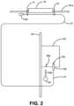
- FIG. 2is a high-level representation of the installation of the present antitheft system in a vehicle in accordance with an exemplary embodiment.
- FIG. 3is a schematic view depicting an alarm module with components in accordance with an exemplary embodiment.
- FIG. 1generally depicts an antitheft system 10 in accordance with an exemplary embodiment.
- a wire loop 12is provided for conducting an electrical current to establish an electrical circuit.
- the wire loop 12is a wire having two ends that connect to the antitheft system 10 and looped over to produce a return wire having two portions that can be run concurrently together.
- the wire loop 12can be a common, non-heat-or-weather-resistant coaxial cable having a looped end.
- the wire loop 12can be a weather-resistant, metal-clad return wire that can withstand temperatures up to 2800 degrees Celsius, such as might be encountered in close contact with an active automotive exhaust system.
- the end of the wire loop 12can include an end cap 12 a , which could be formed of an adhesive bead, to define a terminal longitudinal extent of the return wire.
- the antitheft systemalso includes one or more securing components 14 for securing some portion or the entirety of the wire loop 12 in contact with a device 16 to be protected from theft.
- the device 16 to be protectedcan be an automotive catalytic converter
- the securing component(s) 14can be one or more clamps for securing the wire loop 12 (or a portion thereof) alongside and adjacent to exhaust pipes 16 a of a vehicle exhaust system including the catalytic converter 16 .
- the clamps 14are preferably looped around the tubular circumference of the exhaust pipes 16 a with the wire loop 12 sandwiched between the clamps 14 and the catalytic converter 16 .
- the clamps 14are mounted snugly in close proximity with the ends of the catalytic converter 16 in a substantially abutting relationship, so as to not allow any gap between the clamps 14 and the converter 16 . In this manner, any attempt to cut free the catalytic converter 16 (such as with a reciprocating saw, i.e., a “sawzall” or portable band saw) will result in severing the wire loop 12 , thereby triggering the alarm (as explained in detail hereinbelow).
- Other clamps 14can be placed circumferentially around the exhaust pipes 16 a , along the longitudinal extent of the exhaust pipes 16 a , in order to secure the wire loop 12 into close contact with the exhaust system.
- the wire loop 12is configured to run along the exhaust pipes 16 a to enter into the engine compartment.
- An alarm module 20can be retained in engine compartment of the vehicle, secured under the hood of the vehicle, preferably mounted to the side of the firewall 18 within the engine compartment.
- the alarm module 20can be powered by the vehicle battery or by an independent battery.
- the wire loop 12is then plugged into the alarm module 20 to implement the operation of the antitheft system 10 .
- the antitheft system 10includes a monitoring circuit 22 , in electrical communication with the wire loop 12 , for monitoring the electrical circuit established in the wire loop 12 . This monitoring is performed to observe whether an unbroken current path is maintained through the wire loop 12 , indicative of normal operation.
- a detector circuit 24is connected to the monitoring circuit 22 for detecting a discontinuity in the electrical circuit indicative of a disconnection of the wire loop 12 , as would occur in the event that the wire loop 12 is either severed during a theft attempt or unplugged in an attempt to circumvent and defeat the antitheft system 10 .
- the discontinuity or current in the wireis detected by a control logic circuit (described in detail hereinbelow) with the result of no ground detected, which activates an audible alarm.
- the control logic circuitcontinuously verifies the continuity of the wire. Once activated, the alarm will continue to sound until the module is disabled, for example, by insertion of a key.
- An alarm circuit 26is connected to the detector circuit 24 for activating an alarm upon detection of the discontinuity in the electrical circuit indicative of severing the wire loop 12 in a theft attempt. A suitable alarm is issued upon activation, as will be explained in detail hereinbelow.
- the present antitheft system 10also includes a key-activated arming circuit 30 including a key detection circuit 32 for generating a key insertion signal indicative of insertion of a removable key 34 .
- the key detection circuit 32can be a key switch, actuated by insertion of the key, to generate the key insertion signal.
- the present system 10also includes a wire loop detection circuit 36 for generating a wire loop insertion signal indicative of insertion of the wire loop 12 corresponding to establishment of the electrical circuit.
- the arming circuit 30also includes the aforementioned control logic circuit 38 which:
- the present antitheft system 10also includes an alarm deactivation circuit 40 for receiving a second key insertion signal from the key detection circuit 32 and deactivating the alarm circuit 26 to disable the alarm.
- an alarm deactivation circuit 40for receiving a second key insertion signal from the key detection circuit 32 and deactivating the alarm circuit 26 to disable the alarm.
- the removable key 34is inserted again, which generates another key insertion signal which is interpreted by the system 10 as a deactivation signal, thereby disabling the alarm.
- the removable key 34has a shaft 34 a , preferably elongated and cylindrical.
- the key detection circuit 32is configured to cooperate with a socket 34 b , which is mounted onto an exterior of a housing (i.e., of the module 20 ).
- the socket 34 bis configured for receiving the shaft 34 a of the removable key 34 .
- the wire loop 12is configured to terminate with a coaxial plug 12 b for electrically connecting respective two ends of the wire loop 12 .
- the wire loop detection circuit 36is configured to cooperate with a coaxial socket 12 c , mounted onto an exterior of the housing (i.e., the module 20 ), for receiving the coaxial plug 12 c of the wire loop 12 .
- the antitheft system 10also includes a test circuit 42 , including a user-actuated switch 44 , where the test circuit 42 is connected to the alarm circuit 26 , to enable a user to selectively for test activate the alarm.
- the switch 44can be connected to a button mounted on the outside of the module 20 , where pressing the button activates the alarm.
- the alarmpreferably includes a sound transducer 46 for generating an audible alarm signal, which can deter a prospective thief from stealing the converter 16 .
- the alarmcan additionally or alternatively include a wireless connection to a network node which can transmit a signal which can, in turn, generate an audible and/or visual indicator observed in a remote location, such as a security office or police station. Further, the alarm can also optionally be armed using a key fob associated with the vehicle.
- the present antitheft system 10 and the electronic circuits and components described hereinabovecan be retained in the module 20 , which is preferably a small box formed of plastic.
- a common type C batterycan be used to power the system 10 .
- the system 10can be alternatively wired to receive power from the vehicle battery.
- at least some of the present components for each vehiclecan alternatively be distributed and located elsewhere as part of a networked antitheft distributed system, along with other similar components for other vehicles, all without departing from the present invention.
- the electronic circuits and components described hereinabovecan be analog or digital circuits and components preferably mounted on one or more printed circuit boards and retained in the module 20 .
- at least some of the electronic circuits and other components described hereinabovecan be alternatively implemented as software components in a computer system, all without departing from the present invention.
Landscapes
- Engineering & Computer Science (AREA)
- Physics & Mathematics (AREA)
- General Physics & Mathematics (AREA)
- Mechanical Engineering (AREA)
- Computer Security & Cryptography (AREA)
- Burglar Alarm Systems (AREA)
Abstract
Description
- 1) receives the key insertion signal from the
key detection circuit 32, - 2) subsequently receives the wire loop insertion signal from the wire
loop detection circuit 36, and - 3) subsequently arms the arming
circuit 30.
Thecontrol logic circuit 38 can include processing circuitry to detect the order in which the signals are detected, that the key insertion signal is received first, followed by the wire loop insertion signal, so that the armingcircuit 30 is only armed after these signals are received in this correct order. The armingcircuit 30 is in communication with themonitoring circuit 22 so that the armingcircuit 30 is only armed and activates themonitoring circuit 22 after the aforementioned signals are received in the correct order as indicated hereinabove.
- 1) receives the key insertion signal from the
Claims (2)
Priority Applications (1)
| Application Number | Priority Date | Filing Date | Title |
|---|---|---|---|
| US17/531,993US11981285B2 (en) | 2021-11-22 | 2021-11-22 | Method and apparatus for preventing theft of catalytic converter |
Applications Claiming Priority (1)
| Application Number | Priority Date | Filing Date | Title |
|---|---|---|---|
| US17/531,993US11981285B2 (en) | 2021-11-22 | 2021-11-22 | Method and apparatus for preventing theft of catalytic converter |
Publications (2)
| Publication Number | Publication Date |
|---|---|
| US20230158997A1 US20230158997A1 (en) | 2023-05-25 |
| US11981285B2true US11981285B2 (en) | 2024-05-14 |
Family
ID=86385100
Family Applications (1)
| Application Number | Title | Priority Date | Filing Date |
|---|---|---|---|
| US17/531,993ActiveUS11981285B2 (en) | 2021-11-22 | 2021-11-22 | Method and apparatus for preventing theft of catalytic converter |
Country Status (1)
| Country | Link |
|---|---|
| US (1) | US11981285B2 (en) |
Cited By (1)
| Publication number | Priority date | Publication date | Assignee | Title |
|---|---|---|---|---|
| US12351126B1 (en)* | 2022-10-13 | 2025-07-08 | David Rosales | Alarm system and method for detecting a removal of a catalytic converter or other item |
Families Citing this family (2)
| Publication number | Priority date | Publication date | Assignee | Title |
|---|---|---|---|---|
| US20230264654A1 (en)* | 2015-02-24 | 2023-08-24 | Innovative Aftermarket Group | Catalytic converter alarm |
| US20250101900A1 (en)* | 2023-09-23 | 2025-03-27 | Timothy William Edgin | Catalytic Converter Theft Prevention Device |
Citations (31)
| Publication number | Priority date | Publication date | Assignee | Title |
|---|---|---|---|---|
| US3824540A (en)* | 1972-07-27 | 1974-07-16 | K Smith | Bicycle lock and alarm apparatus |
| US3848229A (en)* | 1971-04-09 | 1974-11-12 | Little Inc A | Electronic lock system |
| US3974492A (en)* | 1974-05-07 | 1976-08-10 | Fahir Girismen | Alarm system |
| US4620182A (en)* | 1985-01-10 | 1986-10-28 | Check Mate Systems, Inc. | Security apparatus for retail goods |
| US4909199A (en)* | 1987-09-10 | 1990-03-20 | Nissan Motor Co., Ltd. | System for controlling ignition device for vehicle |
| US4958084A (en)* | 1983-12-23 | 1990-09-18 | Mr. Gasket Co. | Self-contained anti-theft device for motor vehicles |
| US5074672A (en)* | 1990-10-26 | 1991-12-24 | Westinghouse Electric Corp. | Arrangement for monitoring temperatures of water-cooled electric generator windings |
| US5408213A (en)* | 1993-05-12 | 1995-04-18 | Ungarsohn; Benjamin I. | Portable breakaway alarm system |
| US5517848A (en)* | 1993-03-16 | 1996-05-21 | Mitsubishi Denki Kabushiki Kaisha | Exhaust gas purification system for internal combustion engine, and apparatus and method for controlling the same |
| US5612878A (en)* | 1995-06-22 | 1997-03-18 | Joao; Raymond A. | Apparatus and method for motor vehicle anti-theft and/or theft deterrence |
| US5729191A (en)* | 1995-04-14 | 1998-03-17 | Kenneth E. Flick | Vehicle security system having enhanced control features |
| US5889463A (en)* | 1997-01-08 | 1999-03-30 | Judd; Dennis L. | Anti-theft device |
| US20030128118A1 (en)* | 2002-01-04 | 2003-07-10 | Leyden Roger J. | Voltage selectable alarm sensor |
| US6690277B1 (en)* | 2000-03-24 | 2004-02-10 | Henry Louis Hansen | Security system |
| US20040135680A1 (en)* | 2003-01-13 | 2004-07-15 | Jacobs Ruby L. Handler | Vehicle anti-carjacking and theft prevention device incorporating a sensor deactivating system |
| US20050179548A1 (en)* | 2004-02-13 | 2005-08-18 | Kittel Mark D. | Tamper monitoring article, system and method |
| US20100052907A1 (en)* | 2008-02-29 | 2010-03-04 | John Alfred Shannon | Bicycle or other mobile object anti-theft alarm device |
| US20110036130A1 (en)* | 2009-08-17 | 2011-02-17 | Karla Jean Hisler | Catalytic converter theft deterrent device |
| US8002232B2 (en) | 2009-04-08 | 2011-08-23 | Monat Technologies | System and method of catalytic converter theft deterrence |
| US20110254661A1 (en)* | 2005-12-23 | 2011-10-20 | Invue Security Products Inc. | Programmable security system and method for protecting merchandise |
| US8068027B2 (en)* | 2004-03-30 | 2011-11-29 | Hi-G-Tek Ltd. | Monitorable locking assemblies |
| US8094019B1 (en)* | 2005-11-29 | 2012-01-10 | Vanguard Products Group, Inc. | Self-shunting security device |
| US20120299755A1 (en)* | 2011-05-24 | 2012-11-29 | Spireon, Inc. | Security cable monitoring system |
| US20130249682A1 (en)* | 2011-10-27 | 2013-09-26 | Ford Global Technologies, Llc | Vehicle wireless charger safety system |
| JP2013201799A (en)* | 2012-03-23 | 2013-10-03 | Takigen Mfg Co Ltd | Cable fitting for solar cell module |
| CN203520940U (en)* | 2013-10-12 | 2014-04-02 | 天津市万博线缆有限公司 | Soft-grade fireproof cable |
| US20140104048A1 (en)* | 2011-05-27 | 2014-04-17 | Filip De Kock | Anti-theft system for an automotive exhaust component |
| US20140176320A1 (en)* | 2012-12-24 | 2014-06-26 | Ford Global Technologies, Llc | Resistance-based catalytic converter protection systems and configurations |
| US20140266654A1 (en)* | 2013-03-15 | 2014-09-18 | Par-Tech, Inc. | Anti-tampering system for vehicular component |
| US8910986B1 (en)* | 2013-06-12 | 2014-12-16 | Ford Global Technologies, Llc | Bonded and rotatable vehicle sensor assembly |
| US8963699B2 (en)* | 2012-05-08 | 2015-02-24 | David P. Potter | Catalytic converter theft protection arrangement |
- 2021
- 2021-11-22USUS17/531,993patent/US11981285B2/enactiveActive
Patent Citations (31)
| Publication number | Priority date | Publication date | Assignee | Title |
|---|---|---|---|---|
| US3848229A (en)* | 1971-04-09 | 1974-11-12 | Little Inc A | Electronic lock system |
| US3824540A (en)* | 1972-07-27 | 1974-07-16 | K Smith | Bicycle lock and alarm apparatus |
| US3974492A (en)* | 1974-05-07 | 1976-08-10 | Fahir Girismen | Alarm system |
| US4958084A (en)* | 1983-12-23 | 1990-09-18 | Mr. Gasket Co. | Self-contained anti-theft device for motor vehicles |
| US4620182A (en)* | 1985-01-10 | 1986-10-28 | Check Mate Systems, Inc. | Security apparatus for retail goods |
| US4909199A (en)* | 1987-09-10 | 1990-03-20 | Nissan Motor Co., Ltd. | System for controlling ignition device for vehicle |
| US5074672A (en)* | 1990-10-26 | 1991-12-24 | Westinghouse Electric Corp. | Arrangement for monitoring temperatures of water-cooled electric generator windings |
| US5517848A (en)* | 1993-03-16 | 1996-05-21 | Mitsubishi Denki Kabushiki Kaisha | Exhaust gas purification system for internal combustion engine, and apparatus and method for controlling the same |
| US5408213A (en)* | 1993-05-12 | 1995-04-18 | Ungarsohn; Benjamin I. | Portable breakaway alarm system |
| US5729191A (en)* | 1995-04-14 | 1998-03-17 | Kenneth E. Flick | Vehicle security system having enhanced control features |
| US5612878A (en)* | 1995-06-22 | 1997-03-18 | Joao; Raymond A. | Apparatus and method for motor vehicle anti-theft and/or theft deterrence |
| US5889463A (en)* | 1997-01-08 | 1999-03-30 | Judd; Dennis L. | Anti-theft device |
| US6690277B1 (en)* | 2000-03-24 | 2004-02-10 | Henry Louis Hansen | Security system |
| US20030128118A1 (en)* | 2002-01-04 | 2003-07-10 | Leyden Roger J. | Voltage selectable alarm sensor |
| US20040135680A1 (en)* | 2003-01-13 | 2004-07-15 | Jacobs Ruby L. Handler | Vehicle anti-carjacking and theft prevention device incorporating a sensor deactivating system |
| US20050179548A1 (en)* | 2004-02-13 | 2005-08-18 | Kittel Mark D. | Tamper monitoring article, system and method |
| US8068027B2 (en)* | 2004-03-30 | 2011-11-29 | Hi-G-Tek Ltd. | Monitorable locking assemblies |
| US8094019B1 (en)* | 2005-11-29 | 2012-01-10 | Vanguard Products Group, Inc. | Self-shunting security device |
| US20110254661A1 (en)* | 2005-12-23 | 2011-10-20 | Invue Security Products Inc. | Programmable security system and method for protecting merchandise |
| US20100052907A1 (en)* | 2008-02-29 | 2010-03-04 | John Alfred Shannon | Bicycle or other mobile object anti-theft alarm device |
| US8002232B2 (en) | 2009-04-08 | 2011-08-23 | Monat Technologies | System and method of catalytic converter theft deterrence |
| US20110036130A1 (en)* | 2009-08-17 | 2011-02-17 | Karla Jean Hisler | Catalytic converter theft deterrent device |
| US20120299755A1 (en)* | 2011-05-24 | 2012-11-29 | Spireon, Inc. | Security cable monitoring system |
| US20140104048A1 (en)* | 2011-05-27 | 2014-04-17 | Filip De Kock | Anti-theft system for an automotive exhaust component |
| US20130249682A1 (en)* | 2011-10-27 | 2013-09-26 | Ford Global Technologies, Llc | Vehicle wireless charger safety system |
| JP2013201799A (en)* | 2012-03-23 | 2013-10-03 | Takigen Mfg Co Ltd | Cable fitting for solar cell module |
| US8963699B2 (en)* | 2012-05-08 | 2015-02-24 | David P. Potter | Catalytic converter theft protection arrangement |
| US20140176320A1 (en)* | 2012-12-24 | 2014-06-26 | Ford Global Technologies, Llc | Resistance-based catalytic converter protection systems and configurations |
| US20140266654A1 (en)* | 2013-03-15 | 2014-09-18 | Par-Tech, Inc. | Anti-tampering system for vehicular component |
| US8910986B1 (en)* | 2013-06-12 | 2014-12-16 | Ford Global Technologies, Llc | Bonded and rotatable vehicle sensor assembly |
| CN203520940U (en)* | 2013-10-12 | 2014-04-02 | 天津市万博线缆有限公司 | Soft-grade fireproof cable |
Cited By (1)
| Publication number | Priority date | Publication date | Assignee | Title |
|---|---|---|---|---|
| US12351126B1 (en)* | 2022-10-13 | 2025-07-08 | David Rosales | Alarm system and method for detecting a removal of a catalytic converter or other item |
Also Published As
| Publication number | Publication date |
|---|---|
| US20230158997A1 (en) | 2023-05-25 |
Similar Documents
| Publication | Publication Date | Title |
|---|---|---|
| US11981285B2 (en) | Method and apparatus for preventing theft of catalytic converter | |
| US6480098B2 (en) | Remote vehicle control system including common carrier paging receiver and related methods | |
| US20020113704A1 (en) | Wireless transmitting security cable | |
| US20040075539A1 (en) | Vehicle monitoring system | |
| CN112997222A (en) | Cable lock system and method | |
| US7233245B2 (en) | Theft prevention system for motorcycle | |
| JP4085990B2 (en) | Vehicle anti-theft system and vehicle anti-theft method | |
| US7187284B2 (en) | Active anti-theft device for securing property | |
| US20090101484A1 (en) | Anti-theft battery switch box system | |
| WO2000007158A1 (en) | Emergency reporting apparatus with self-diagnostic function | |
| US20030227377A1 (en) | Wireless security notification and control system | |
| JP4192072B2 (en) | Vehicle anti-theft device | |
| JPH10315917A (en) | Alarm device of abnormal condition such as theft of automobile | |
| US5473305A (en) | Auto security system with two-stage disarming | |
| JP3613393B2 (en) | Anti-theft device for movable items | |
| CN1451573A (en) | Active distress anti-theft system and method thereof | |
| US6337626B1 (en) | User recognition system | |
| US20040183376A1 (en) | Vehicle theft deterrent system | |
| JP3735349B2 (en) | Vehicle anti-theft device and system | |
| KR200142633Y1 (en) | Antitheft vehicle security system | |
| JP2007112211A (en) | Audio controller | |
| CN200997159Y (en) | Wireless safety device of motorcycle and automobile | |
| CN201170911Y (en) | Apparatus for preventing automobile from stealing | |
| CN2477487Y (en) | Antitheft anti-rubbing device of automobile | |
| CN2404767Y (en) | Automobile theft-proof alarming device using paging network |
Legal Events
| Date | Code | Title | Description |
|---|---|---|---|
| AS | Assignment | Owner name:SWIVLER, INC., WASHINGTON Free format text:ASSIGNMENT OF ASSIGNORS INTEREST;ASSIGNORS:WHITE, RICK A;SMIT, NICK J.;REEL/FRAME:058178/0064 Effective date:20211117 | |
| FEPP | Fee payment procedure | Free format text:ENTITY STATUS SET TO UNDISCOUNTED (ORIGINAL EVENT CODE: BIG.); ENTITY STATUS OF PATENT OWNER: SMALL ENTITY | |
| FEPP | Fee payment procedure | Free format text:ENTITY STATUS SET TO SMALL (ORIGINAL EVENT CODE: SMAL); ENTITY STATUS OF PATENT OWNER: SMALL ENTITY | |
| STPP | Information on status: patent application and granting procedure in general | Free format text:RESPONSE TO NON-FINAL OFFICE ACTION ENTERED AND FORWARDED TO EXAMINER | |
| STPP | Information on status: patent application and granting procedure in general | Free format text:FINAL REJECTION MAILED | |
| STPP | Information on status: patent application and granting procedure in general | Free format text:RESPONSE AFTER FINAL ACTION FORWARDED TO EXAMINER | |
| STPP | Information on status: patent application and granting procedure in general | Free format text:ADVISORY ACTION MAILED | |
| STPP | Information on status: patent application and granting procedure in general | Free format text:RESPONSE AFTER FINAL ACTION FORWARDED TO EXAMINER | |
| STPP | Information on status: patent application and granting procedure in general | Free format text:NOTICE OF ALLOWANCE MAILED -- APPLICATION RECEIVED IN OFFICE OF PUBLICATIONS | |
| STPP | Information on status: patent application and granting procedure in general | Free format text:PUBLICATIONS -- ISSUE FEE PAYMENT VERIFIED | |
| STCF | Information on status: patent grant | Free format text:PATENTED CASE |