US11980938B2 - Bladed disk repair process with shield - Google Patents
Bladed disk repair process with shieldDownload PDFInfo
- Publication number
- US11980938B2 US11980938B2US17/534,111US202117534111AUS11980938B2US 11980938 B2US11980938 B2US 11980938B2US 202117534111 AUS202117534111 AUS 202117534111AUS 11980938 B2US11980938 B2US 11980938B2
- Authority
- US
- United States
- Prior art keywords
- shield member
- partial blade
- blade
- shield
- substrate
- Prior art date
- Legal status (The legal status is an assumption and is not a legal conclusion. Google has not performed a legal analysis and makes no representation as to the accuracy of the status listed.)
- Active, expires
Links
- 230000008439repair processEffects0.000titledescription23
- 239000000463materialSubstances0.000claimsabstractdescription136
- 238000000034methodMethods0.000claimsabstractdescription129
- 238000004519manufacturing processMethods0.000claimsabstractdescription24
- 238000000151depositionMethods0.000claimsabstractdescription22
- 239000000654additiveSubstances0.000claimsabstractdescription21
- 230000000996additive effectEffects0.000claimsabstractdescription21
- 239000000758substrateSubstances0.000claimsdescription103
- 238000001816coolingMethods0.000claimsdescription33
- 239000000203mixtureSubstances0.000claimsdescription30
- 239000000155meltSubstances0.000claimsdescription24
- 239000000919ceramicSubstances0.000claimsdescription11
- 239000012530fluidSubstances0.000claimsdescription11
- 229910052782aluminiumInorganic materials0.000claimsdescription10
- 229910052802copperInorganic materials0.000claimsdescription10
- 239000010949copperSubstances0.000claimsdescription10
- RYGMFSIKBFXOCR-UHFFFAOYSA-NCopperChemical compound[Cu]RYGMFSIKBFXOCR-UHFFFAOYSA-N0.000claimsdescription9
- XAGFODPZIPBFFR-UHFFFAOYSA-NaluminiumChemical compound[Al]XAGFODPZIPBFFR-UHFFFAOYSA-N0.000claimsdescription9
- 230000008021depositionEffects0.000claimsdescription9
- 229910000990Ni alloyInorganic materials0.000claimsdescription6
- 229910001069Ti alloyInorganic materials0.000claimsdescription6
- 230000015572biosynthetic processEffects0.000claimsdescription6
- 239000007789gasSubstances0.000description51
- 230000008569processEffects0.000description51
- 238000010586diagramMethods0.000description19
- 239000010410layerSubstances0.000description14
- 239000000843powderSubstances0.000description11
- 238000003860storageMethods0.000description10
- 230000006870functionEffects0.000description9
- 239000012809cooling fluidSubstances0.000description8
- 238000004891communicationMethods0.000description7
- XKRFYHLGVUSROY-UHFFFAOYSA-NArgonChemical compound[Ar]XKRFYHLGVUSROY-UHFFFAOYSA-N0.000description6
- PNEYBMLMFCGWSK-UHFFFAOYSA-Naluminium oxideInorganic materials[O-2].[O-2].[O-2].[Al+3].[Al+3]PNEYBMLMFCGWSK-UHFFFAOYSA-N0.000description6
- 229910000883Ti6Al4VInorganic materials0.000description4
- 229910045601alloyInorganic materials0.000description4
- 239000000956alloySubstances0.000description4
- 230000004888barrier functionEffects0.000description4
- 238000012544monitoring processMethods0.000description4
- 238000012545processingMethods0.000description4
- PZNSFCLAULLKQX-UHFFFAOYSA-NBoron nitrideChemical compoundN#BPZNSFCLAULLKQX-UHFFFAOYSA-N0.000description3
- 229910052786argonInorganic materials0.000description3
- 238000011109contaminationMethods0.000description3
- 229910052593corundumInorganic materials0.000description3
- 238000013500data storageMethods0.000description3
- 238000010438heat treatmentMethods0.000description3
- 229910000816inconels 718Inorganic materials0.000description3
- 239000011261inert gasSubstances0.000description3
- 238000003754machiningMethods0.000description3
- 229920000642polymerPolymers0.000description3
- 238000012546transferMethods0.000description3
- 230000000007visual effectEffects0.000description3
- 238000003466weldingMethods0.000description3
- 229910001845yogo sapphireInorganic materials0.000description3
- -1RR1000Inorganic materials0.000description2
- 238000003491arrayMethods0.000description2
- 230000008901benefitEffects0.000description2
- 229910052796boronInorganic materials0.000description2
- 229910010293ceramic materialInorganic materials0.000description2
- 238000004590computer programMethods0.000description2
- 238000005516engineering processMethods0.000description2
- 239000000835fiberSubstances0.000description2
- 230000004927fusionEffects0.000description2
- 239000001307heliumSubstances0.000description2
- 229910052734heliumInorganic materials0.000description2
- SWQJXJOGLNCZEY-UHFFFAOYSA-Nhelium atomChemical compound[He]SWQJXJOGLNCZEY-UHFFFAOYSA-N0.000description2
- 238000003384imaging methodMethods0.000description2
- 229910000880inconels 792Inorganic materials0.000description2
- 239000007788liquidSubstances0.000description2
- 238000002844meltingMethods0.000description2
- 230000008018meltingEffects0.000description2
- 229910052751metalInorganic materials0.000description2
- 239000002184metalSubstances0.000description2
- 239000012768molten materialSubstances0.000description2
- 230000003287optical effectEffects0.000description2
- 238000011897real-time detectionMethods0.000description2
- 239000000523sampleSubstances0.000description2
- 230000001052transient effectEffects0.000description2
- 229910052582BNInorganic materials0.000description1
- ZOXJGFHDIHLPTG-UHFFFAOYSA-NBoronChemical compound[B]ZOXJGFHDIHLPTG-UHFFFAOYSA-N0.000description1
- 238000005054agglomerationMethods0.000description1
- 230000002776aggregationEffects0.000description1
- 239000003570airSubstances0.000description1
- 238000005275alloyingMethods0.000description1
- 238000005524ceramic coatingMethods0.000description1
- 229910052804chromiumInorganic materials0.000description1
- 239000004020conductorSubstances0.000description1
- 239000002826coolantSubstances0.000description1
- 239000000112cooling gasSubstances0.000description1
- 238000005520cutting processMethods0.000description1
- 230000008014freezingEffects0.000description1
- 238000007710freezingMethods0.000description1
- 230000005484gravityEffects0.000description1
- 238000003780insertionMethods0.000description1
- 230000037431insertionEffects0.000description1
- 238000005304joiningMethods0.000description1
- 229910052748manganeseInorganic materials0.000description1
- 150000002739metalsChemical class0.000description1
- 229910052750molybdenumInorganic materials0.000description1
- 229910052759nickelInorganic materials0.000description1
- PXHVJJICTQNCMI-UHFFFAOYSA-NnickelSubstances[Ni]PXHVJJICTQNCMI-UHFFFAOYSA-N0.000description1
- 229910052758niobiumInorganic materials0.000description1
- 239000002245particleSubstances0.000description1
- 230000005855radiationEffects0.000description1
- 238000001228spectrumMethods0.000description1
- 239000002344surface layerSubstances0.000description1
- 238000001931thermographyMethods0.000description1
- 239000010936titaniumSubstances0.000description1
- 229910052719titaniumInorganic materials0.000description1
- XLYOFNOQVPJJNP-UHFFFAOYSA-NwaterSubstancesOXLYOFNOQVPJJNP-UHFFFAOYSA-N0.000description1
Images


Classifications
- B—PERFORMING OPERATIONS; TRANSPORTING
- B22—CASTING; POWDER METALLURGY
- B22F—WORKING METALLIC POWDER; MANUFACTURE OF ARTICLES FROM METALLIC POWDER; MAKING METALLIC POWDER; APPARATUS OR DEVICES SPECIALLY ADAPTED FOR METALLIC POWDER
- B22F10/00—Additive manufacturing of workpieces or articles from metallic powder
- B22F10/20—Direct sintering or melting
- B22F10/25—Direct deposition of metal particles, e.g. direct metal deposition [DMD] or laser engineered net shaping [LENS]
- B—PERFORMING OPERATIONS; TRANSPORTING
- B22—CASTING; POWDER METALLURGY
- B22F—WORKING METALLIC POWDER; MANUFACTURE OF ARTICLES FROM METALLIC POWDER; MAKING METALLIC POWDER; APPARATUS OR DEVICES SPECIALLY ADAPTED FOR METALLIC POWDER
- B22F10/00—Additive manufacturing of workpieces or articles from metallic powder
- B22F10/50—Treatment of workpieces or articles during build-up, e.g. treatments applied to fused layers during build-up
- B—PERFORMING OPERATIONS; TRANSPORTING
- B23—MACHINE TOOLS; METAL-WORKING NOT OTHERWISE PROVIDED FOR
- B23K—SOLDERING OR UNSOLDERING; WELDING; CLADDING OR PLATING BY SOLDERING OR WELDING; CUTTING BY APPLYING HEAT LOCALLY, e.g. FLAME CUTTING; WORKING BY LASER BEAM
- B23K26/00—Working by laser beam, e.g. welding, cutting or boring
- B23K26/34—Laser welding for purposes other than joining
- B23K26/342—Build-up welding
- B—PERFORMING OPERATIONS; TRANSPORTING
- B23—MACHINE TOOLS; METAL-WORKING NOT OTHERWISE PROVIDED FOR
- B23K—SOLDERING OR UNSOLDERING; WELDING; CLADDING OR PLATING BY SOLDERING OR WELDING; CUTTING BY APPLYING HEAT LOCALLY, e.g. FLAME CUTTING; WORKING BY LASER BEAM
- B23K26/00—Working by laser beam, e.g. welding, cutting or boring
- B23K26/70—Auxiliary operations or equipment
- B23K26/702—Auxiliary equipment
- B23K26/703—Cooling arrangements
- B—PERFORMING OPERATIONS; TRANSPORTING
- B23—MACHINE TOOLS; METAL-WORKING NOT OTHERWISE PROVIDED FOR
- B23K—SOLDERING OR UNSOLDERING; WELDING; CLADDING OR PLATING BY SOLDERING OR WELDING; CUTTING BY APPLYING HEAT LOCALLY, e.g. FLAME CUTTING; WORKING BY LASER BEAM
- B23K26/00—Working by laser beam, e.g. welding, cutting or boring
- B23K26/70—Auxiliary operations or equipment
- B23K26/702—Auxiliary equipment
- B23K26/706—Protective screens
- B—PERFORMING OPERATIONS; TRANSPORTING
- B23—MACHINE TOOLS; METAL-WORKING NOT OTHERWISE PROVIDED FOR
- B23P—METAL-WORKING NOT OTHERWISE PROVIDED FOR; COMBINED OPERATIONS; UNIVERSAL MACHINE TOOLS
- B23P6/00—Restoring or reconditioning objects
- B23P6/002—Repairing turbine components, e.g. moving or stationary blades, rotors
- B23P6/007—Repairing turbine components, e.g. moving or stationary blades, rotors using only additive methods, e.g. build-up welding
- B—PERFORMING OPERATIONS; TRANSPORTING
- B28—WORKING CEMENT, CLAY, OR STONE
- B28B—SHAPING CLAY OR OTHER CERAMIC COMPOSITIONS; SHAPING SLAG; SHAPING MIXTURES CONTAINING CEMENTITIOUS MATERIAL, e.g. PLASTER
- B28B1/00—Producing shaped prefabricated articles from the material
- B28B1/001—Rapid manufacturing of 3D objects by additive depositing, agglomerating or laminating of material
- B—PERFORMING OPERATIONS; TRANSPORTING
- B33—ADDITIVE MANUFACTURING TECHNOLOGY
- B33Y—ADDITIVE MANUFACTURING, i.e. MANUFACTURING OF THREE-DIMENSIONAL [3-D] OBJECTS BY ADDITIVE DEPOSITION, ADDITIVE AGGLOMERATION OR ADDITIVE LAYERING, e.g. BY 3-D PRINTING, STEREOLITHOGRAPHY OR SELECTIVE LASER SINTERING
- B33Y10/00—Processes of additive manufacturing
- B—PERFORMING OPERATIONS; TRANSPORTING
- B33—ADDITIVE MANUFACTURING TECHNOLOGY
- B33Y—ADDITIVE MANUFACTURING, i.e. MANUFACTURING OF THREE-DIMENSIONAL [3-D] OBJECTS BY ADDITIVE DEPOSITION, ADDITIVE AGGLOMERATION OR ADDITIVE LAYERING, e.g. BY 3-D PRINTING, STEREOLITHOGRAPHY OR SELECTIVE LASER SINTERING
- B33Y80/00—Products made by additive manufacturing
- F—MECHANICAL ENGINEERING; LIGHTING; HEATING; WEAPONS; BLASTING
- F01—MACHINES OR ENGINES IN GENERAL; ENGINE PLANTS IN GENERAL; STEAM ENGINES
- F01D—NON-POSITIVE DISPLACEMENT MACHINES OR ENGINES, e.g. STEAM TURBINES
- F01D5/00—Blades; Blade-carrying members; Heating, heat-insulating, cooling or antivibration means on the blades or the members
- F01D5/005—Repairing methods or devices
- F—MECHANICAL ENGINEERING; LIGHTING; HEATING; WEAPONS; BLASTING
- F01—MACHINES OR ENGINES IN GENERAL; ENGINE PLANTS IN GENERAL; STEAM ENGINES
- F01D—NON-POSITIVE DISPLACEMENT MACHINES OR ENGINES, e.g. STEAM TURBINES
- F01D5/00—Blades; Blade-carrying members; Heating, heat-insulating, cooling or antivibration means on the blades or the members
- F01D5/12—Blades
- F01D5/28—Selecting particular materials; Particular measures relating thereto; Measures against erosion or corrosion
- F01D5/284—Selection of ceramic materials
- F—MECHANICAL ENGINEERING; LIGHTING; HEATING; WEAPONS; BLASTING
- F01—MACHINES OR ENGINES IN GENERAL; ENGINE PLANTS IN GENERAL; STEAM ENGINES
- F01D—NON-POSITIVE DISPLACEMENT MACHINES OR ENGINES, e.g. STEAM TURBINES
- F01D5/00—Blades; Blade-carrying members; Heating, heat-insulating, cooling or antivibration means on the blades or the members
- F01D5/34—Rotor-blade aggregates of unitary construction, e.g. formed of sheet laminae
- F—MECHANICAL ENGINEERING; LIGHTING; HEATING; WEAPONS; BLASTING
- F28—HEAT EXCHANGE IN GENERAL
- F28F—DETAILS OF HEAT-EXCHANGE AND HEAT-TRANSFER APPARATUS, OF GENERAL APPLICATION
- F28F1/00—Tubular elements; Assemblies of tubular elements
- F28F1/10—Tubular elements and assemblies thereof with means for increasing heat-transfer area, e.g. with fins, with projections, with recesses
- F28F1/12—Tubular elements and assemblies thereof with means for increasing heat-transfer area, e.g. with fins, with projections, with recesses the means being only outside the tubular element
- B—PERFORMING OPERATIONS; TRANSPORTING
- B22—CASTING; POWDER METALLURGY
- B22F—WORKING METALLIC POWDER; MANUFACTURE OF ARTICLES FROM METALLIC POWDER; MAKING METALLIC POWDER; APPARATUS OR DEVICES SPECIALLY ADAPTED FOR METALLIC POWDER
- B22F12/00—Apparatus or devices specially adapted for additive manufacturing; Auxiliary means for additive manufacturing; Combinations of additive manufacturing apparatus or devices with other processing apparatus or devices
- B22F12/38—Housings, e.g. machine housings
- B—PERFORMING OPERATIONS; TRANSPORTING
- B22—CASTING; POWDER METALLURGY
- B22F—WORKING METALLIC POWDER; MANUFACTURE OF ARTICLES FROM METALLIC POWDER; MAKING METALLIC POWDER; APPARATUS OR DEVICES SPECIALLY ADAPTED FOR METALLIC POWDER
- B22F2998/00—Supplementary information concerning processes or compositions relating to powder metallurgy
- B22F2998/10—Processes characterised by the sequence of their steps
- B—PERFORMING OPERATIONS; TRANSPORTING
- B22—CASTING; POWDER METALLURGY
- B22F—WORKING METALLIC POWDER; MANUFACTURE OF ARTICLES FROM METALLIC POWDER; MAKING METALLIC POWDER; APPARATUS OR DEVICES SPECIALLY ADAPTED FOR METALLIC POWDER
- B22F2999/00—Aspects linked to processes or compositions used in powder metallurgy
- B—PERFORMING OPERATIONS; TRANSPORTING
- B22—CASTING; POWDER METALLURGY
- B22F—WORKING METALLIC POWDER; MANUFACTURE OF ARTICLES FROM METALLIC POWDER; MAKING METALLIC POWDER; APPARATUS OR DEVICES SPECIALLY ADAPTED FOR METALLIC POWDER
- B22F5/00—Manufacture of workpieces or articles from metallic powder characterised by the special shape of the product
- B22F5/009—Manufacture of workpieces or articles from metallic powder characterised by the special shape of the product of turbine components other than turbine blades
- B—PERFORMING OPERATIONS; TRANSPORTING
- B22—CASTING; POWDER METALLURGY
- B22F—WORKING METALLIC POWDER; MANUFACTURE OF ARTICLES FROM METALLIC POWDER; MAKING METALLIC POWDER; APPARATUS OR DEVICES SPECIALLY ADAPTED FOR METALLIC POWDER
- B22F7/00—Manufacture of composite layers, workpieces, or articles, comprising metallic powder, by sintering the powder, with or without compacting wherein at least one part is obtained by sintering or compression
- B22F7/06—Manufacture of composite layers, workpieces, or articles, comprising metallic powder, by sintering the powder, with or without compacting wherein at least one part is obtained by sintering or compression of composite workpieces or articles from parts, e.g. to form tipped tools
- B22F7/062—Manufacture of composite layers, workpieces, or articles, comprising metallic powder, by sintering the powder, with or without compacting wherein at least one part is obtained by sintering or compression of composite workpieces or articles from parts, e.g. to form tipped tools involving the connection or repairing of preformed parts
- B—PERFORMING OPERATIONS; TRANSPORTING
- B23—MACHINE TOOLS; METAL-WORKING NOT OTHERWISE PROVIDED FOR
- B23K—SOLDERING OR UNSOLDERING; WELDING; CLADDING OR PLATING BY SOLDERING OR WELDING; CUTTING BY APPLYING HEAT LOCALLY, e.g. FLAME CUTTING; WORKING BY LASER BEAM
- B23K2101/00—Articles made by soldering, welding or cutting
- B23K2101/001—Turbines
- B—PERFORMING OPERATIONS; TRANSPORTING
- B33—ADDITIVE MANUFACTURING TECHNOLOGY
- B33Y—ADDITIVE MANUFACTURING, i.e. MANUFACTURING OF THREE-DIMENSIONAL [3-D] OBJECTS BY ADDITIVE DEPOSITION, ADDITIVE AGGLOMERATION OR ADDITIVE LAYERING, e.g. BY 3-D PRINTING, STEREOLITHOGRAPHY OR SELECTIVE LASER SINTERING
- B33Y30/00—Apparatus for additive manufacturing; Details thereof or accessories therefor
- F—MECHANICAL ENGINEERING; LIGHTING; HEATING; WEAPONS; BLASTING
- F05—INDEXING SCHEMES RELATING TO ENGINES OR PUMPS IN VARIOUS SUBCLASSES OF CLASSES F01-F04
- F05D—INDEXING SCHEME FOR ASPECTS RELATING TO NON-POSITIVE-DISPLACEMENT MACHINES OR ENGINES, GAS-TURBINES OR JET-PROPULSION PLANTS
- F05D2230/00—Manufacture
- F05D2230/30—Manufacture with deposition of material
- F05D2230/31—Layer deposition
- F—MECHANICAL ENGINEERING; LIGHTING; HEATING; WEAPONS; BLASTING
- F05—INDEXING SCHEMES RELATING TO ENGINES OR PUMPS IN VARIOUS SUBCLASSES OF CLASSES F01-F04
- F05D—INDEXING SCHEME FOR ASPECTS RELATING TO NON-POSITIVE-DISPLACEMENT MACHINES OR ENGINES, GAS-TURBINES OR JET-PROPULSION PLANTS
- F05D2230/00—Manufacture
- F05D2230/80—Repairing, retrofitting or upgrading methods
- F—MECHANICAL ENGINEERING; LIGHTING; HEATING; WEAPONS; BLASTING
- F05—INDEXING SCHEMES RELATING TO ENGINES OR PUMPS IN VARIOUS SUBCLASSES OF CLASSES F01-F04
- F05D—INDEXING SCHEME FOR ASPECTS RELATING TO NON-POSITIVE-DISPLACEMENT MACHINES OR ENGINES, GAS-TURBINES OR JET-PROPULSION PLANTS
- F05D2300/00—Materials; Properties thereof
- F05D2300/20—Oxide or non-oxide ceramics
- Y—GENERAL TAGGING OF NEW TECHNOLOGICAL DEVELOPMENTS; GENERAL TAGGING OF CROSS-SECTIONAL TECHNOLOGIES SPANNING OVER SEVERAL SECTIONS OF THE IPC; TECHNICAL SUBJECTS COVERED BY FORMER USPC CROSS-REFERENCE ART COLLECTIONS [XRACs] AND DIGESTS
- Y02—TECHNOLOGIES OR APPLICATIONS FOR MITIGATION OR ADAPTATION AGAINST CLIMATE CHANGE
- Y02P—CLIMATE CHANGE MITIGATION TECHNOLOGIES IN THE PRODUCTION OR PROCESSING OF GOODS
- Y02P10/00—Technologies related to metal processing
- Y02P10/25—Process efficiency
Definitions
- the present disclosuregenerally relates to techniques for repairing a bladed disk using, e.g., an additive manufacturing process.
- Integrally bladed diskswhich may be called blisks, are used in low-pressure compressor (LPC) and high-pressure compressor (HPC) stages of gas turbine engines.
- LPClow-pressure compressor
- HPChigh-pressure compressor
- the blisksmay weigh less and have lower leakage than separate blades and disks, facilitating gas turbine engine efficiency.
- multiple blisksmay be metallurgically bonded or welded together to make blisk drums. Although this may further reduce component weight compared to separate blisks mechanically attached to each other, it increases manufacturing and repair costs.
- the disclosuredescribes a method that includes positioning a shield member around a perimeter of a partial blade extending from a rotor disk of a bladed disk, the shield member being positioned adjacent to a build surface of the partial blade; and depositing, with the shield member around the perimeter of the partial blade, a material on the build surface using an additive manufacturing technique to form a repaired portion on the build surface of the partial blade.
- the disclosuredescribed a system including a bladed disk including a plurality of blades extending from a rotor disk, wherein at least one of the plurality of blades includes a partial blade portion; and a shield member configured to be positioned around a perimeter of a partial blade extending from the rotor disk of a bladed disk, the shield member being configured to be positioned adjacent to a build surface of the partial blade.
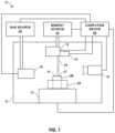
- FIG. 1is a conceptual block diagram illustrating an example system for forming a component and/or repairing a damaged component using a directed energy deposition additive manufacturing process.
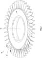
- FIG. 2is a conceptual diagram illustrating an example gas turbine blisk including an example partial blade.
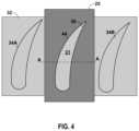
- FIG. 3is a conceptual diagram illustrating the example partial blade of FIG. 2 including an example shield member positioned around the partial blade.
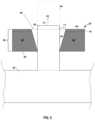
- FIGS. 4 and 5are conceptual diagrams illustrating an example shield member positioned around a partial blade.
- FIGS. 6 A and 6 Bare conceptual diagrams illustrating another example shield member.
- FIG. 7is a conceptual diagram illustrating another example shield member.
- FIG. 8is a conceptual diagram illustrating another example shield member.
- FIG. 9is a conceptual diagram illustrating another example shield member.
- FIGS. 10 A and 10 Bare conceptual diagrams illustrating another example shield member.
- FIG. 11is a flow diagram illustrating an example technique for repairing or otherwise forming all or a portion of a blade of a blisk using an additive manufacturing technique in accordance with the disclosure.
- the disclosuredescribes systems and techniques for repairing one or more damaged blades on a bladed disk (referred to as a blisk).
- DEDdirected energy deposition
- suitable additive manufacturing techniquesmay be used to deposit at least one layer of material on a build surface of a partial blade to repair a damaged portion of the blade on the blisk.
- Repair of a bladed disk through directed energy depositionmay require the removal of the damaged blades (e.g., by machining or otherwise mechanically cutting out the damage portion) to produce a partial blade and then replacing the removed portion by programmatically moving over the surface with an intersecting laser and metallic powder stream that is melted in a melt pool on the build surface of the partial blade. This process can effectively produce a near-net shape repaired blade with base material properties.
- the energetic processmay cause spatter of material from the melt pool.
- This spattermay be generated through molten material ejection from the melt pool or agglomeration of semi-molten powder particulates.
- This spatterremains molten/semi-molten until it contacts a cold surface such as the other portions of the blisk (e.g., the annulus between blades, blade filets, and intact blades) on both the repaired and neighboring stages (e.g., in the case of compressor blisks).
- a polymer-based ceramic tapemay be used to mask adjacent blades of the blisk near the blade being repaired.
- the use of a polymer-based ceramic tapehas been found to be inadequate as the temperature of the spatter, errant laser strikes, and the radiative heat of the blisk lead exceed the char temperature of the polymer-based ceramic tape.
- a shield membermay employed during a DED process or other additive manufacturing (AM) process to repair a blade.
- a shielding membermay be located around at least a portion of the perimeter of the partial blade (e.g., the portion of a blade that is attached to the rotor disk that remains after the damaged portion has been removed) defining the build surface.
- the shielding membermay be configured to physically shield non-repaired areas of the blisk, such as, portions of the partial blade adjacent the build surface, surfaces of neighboring blades and/or other portions of the blisk such as the annulus between blades or blade filets from material spatter from the additive manufacturing process.
- the shielding membermay physically shield such portions of the blisk by covering or otherwise providing a physical barrier that prevent spatter from the DED process used to build the blade being repaired from being deposited (e.g., by splatter) on the surface of the shielded portion. Instead, the splatter may be deposited on the surface of the shield member which may be removed once the DED process is complete.
- the shield memberincludes a substrate including one or more apertures into the substrate.
- the shield membermay be a substrate with a single aperture, where the partial blade defining the build surface during the repair is configured to be positioned within the aperture during the DED process.
- the partial blademay extend through the aperture so that the build surface of the partial blade is above the surface plane of the shield member.
- the shield memberincludes a chamfer around the area where the partial blade protrudes from the aperture through the upper surface of the shield member, e.g., to prevent the joining of the shield member and the blade through unintentional welding, e.g., due to the heat transferred to the shield member and/or partial blade during the DED process.
- the aperture in the substrate of the shield membermay be tapered such that a gap between the shield member and partial blade is reduced when moving in a direction away from the build surface of the partial blade.
- the shielding membermay be formed of a material that is chemically compatible with the composition of the blade being repaired, e.g., in addition to the neighboring blades and rotor of the blisk.
- the shield membermay be formed of material that has relatively high thermal conductivity such as aluminum, copper, or some combination thereof.
- the shield membermay be formed of the base material used for the blisk being repaired (e.g., titanium alloys such as Ti-6-2-4-2, Ti-6-2-4-6, and Ti-6-4; and/or nickel alloy such as: IN718, RR1000, and IN792).
- the shield membermay be formed of, or otherwise include, a ceramic (such as Alumina—Al2O3 or Boron Nitride—BN), or other chemically inert barrier layers to prevent interdiffusion and contamination of the blisk.
- the entire shield memberhas substantially the same composition while in other examples, the shield member may have discrete sections having different compositions.
- a shield membermay be formed of a ceramic material in the portion of the shield that interfaces with the partial blade being repaired or other portions of the blisk, with all or some of the remaining portions being formed of a material with high thermal conductivity, e.g., to transfer heat away from the surface of the shield member so that splatter cools rapidly on the surface of the shield member and the temperature of the blisk does not increase above a desired level.
- the shielding membermay be configured to remove heat from the partial blade (and/or the surfaces of neighboring blades and rotor of the blisk) resulting from the additive manufacturing technique by conducting heat away from the partial blade.
- all or portions of the shield membermay be formed of a material such as copper or aluminum with a relatively high thermal conductivity.
- the shield membermay have a sufficient volume so that the shield member may act as a heat sink for the heat transferred into the shield member.
- the shield membermay have one or more cooling passageways for a cooling fluid to be transferred through during a DED or other AM process.
- the shielding membermay include internal cooling passages for the flow of argon, water, air or inert gas or other liquid or gas coolant, e.g., to ensure that the shielding member remains below its melting temperature and to capture “splatter” particles through freezing on the surface of the shield member to prevent any secondary ricochets.
- the cooling fluidmay be actively pumped through the passageway(s) or may flow through the passageways using gas pressure (e.g., in the case of a compressed gas for the cooling fluid).
- the shield membermay be formed of two or more portions that may be assembled around a partial blade to act as a shield during a DED process to repair the partial blade by depositing layers of material on the build surface of the partial blade.
- the shield membermay include first and second portions split about the one or more apertures formed in the shield member substrate. The first and second portions may be configured to allow the shield member to be assembled around the partial blade in “clam-shell” arrangement and subsequently disassembled from around the blade after the repair is complete.
- the shield membermay be configured to surround the perimeter of one or more blades on the blisk not being repaired in addition to one or more partial blades being repaired.
- a shield membermay be arranged around the perimeter of one or more blades directly adjacent to a blade being repaired, e.g., with the shield member also being arranged around the partial blade being repaired.
- the shield membermay include multiple apertures in the shield substrate, with each aperture being configured to be positioned around a respective blade or partial blade of the blisk.
- the shield membermay extend radially or about the radius of the blisk to some degree to protect neighboring blades or stages.
- multiple shield membersmay be used during a DED process to repair one or more partial blades, e.g., rather than a single unitary shield member.
- Each of the multiple shieldsmay include one or more apertures, with each aperture being configured to be positioned around a blade that is being repaired or a blade that is not being repaired, e.g., an undamaged blade next to a partial blade.
- the DED processmay include hybrid DED including additive and subtractive steps, wire arc additively manufacturing (WAAM), laser blown powder electron beam—directed energy deposition, and the like.
- WAAMwire arc additively manufacturing
- laser blown powder electron beam—directed energy depositionand the like.
- other suitable AM techniquesare contemplated.
- FIG. 1is a conceptual diagram illustrating an example system 10 for repairing one or more damaged blade of blisk 28 using a DED process. While system 10 and the techniques described herein are primarily described with regard to repairing a damaged blade of blisk 28 , such systems and techniques may be used to form a blade of blisk 25 regardless of whether or not the blade being formed is replacing a blade that has been damaged. In some examples, the systems and techniques of the disclosure may be employed to form a blade for a blisk, where the blade being formed is not replacing a blade that was previously damaged but instead replacing the blade for another reason or even forming an original blade of blisk 28 .
- the example system 10 illustrated in FIG. 1includes an enclosure 12 , which encloses a stage 14 , an energy delivery head 16 , at least one sensor 18 , a gas delivery device 20 , and a material delivery device 30 .
- System 10also includes an energy source 22 , which is operatively coupled to energy delivery head 16 and a gas source 24 , which is fluidly connected to gas delivery device 20 .
- system 10further includes a computing device 26 , which is communicatively connected to energy source 22 , gas source 24 , gas delivery device 20 , energy delivery head 16 , at least one sensor 18 , stage 14 , and material delivery device 30 .
- blisk 28includes blades extending from a central rotor disk of blisk 28 .
- blisk 28may be used in a gas turbine engine.
- blisk 28may be used for a compressor blade, fan blade, or other bladed component of a gas turbine engine.
- FIG. 2is a conceptual diagram illustrating an example blisk 28 .
- blisk 28includes a plurality of blades (such as blades 34 A and 34 B) extending a radial direction from rotor disk 32 .
- the blades of blisk 28are evenly dispersed around the outer circumference of rotor disk 32 and are separated by spaces at the outer surface of rotor disk 32 .
- rotor disk 32may rotate about its central axis 38 .
- blade 36may define only a partial blade.
- blade 36may have been damaged during operation of blisk 28 in a gas turbine engine, e.g., by a bird strike or impact by another foreign object. Prior to the damage, partial blade 36 may have had substantially the same size and shape of neighboring blades 34 A and 34 B.
- partial blade 36is shorter than blades 34 A and 34 B, which may be a result of a portion of a larger blade being removed as a result of the damage or mechanical removal of a portion of the blade that included damage.
- a surface of blade 36may define a build surface 31 of blisk 28 onto which material is added, e.g., in layers, by system 10 to reform a portion of the blade so that blade returns to the size and shape of the other blades on rotor disk 32 such as blades 34 A and 34 B.
- Blisk 28may be formed of materials including metals and alloys, alone, or with one or more metallic, alloy, or ceramic coatings.
- blisk 28may include a titanium alloy or a nickel alloy.
- Example alloysinclude Ti-6Al-4V, Ti-6Al-2Sn-4Zr-2Mo, Ti-6Al-2Sn-4Zn-6Mo, and Inconel 718, an alloy including about (by mass) 50-55% Ni, about 17-21% Cr, about 2.8-3.3% Mo, about 4.75-5.5% Nb, about 1% Co, about 0.35% Mn, about 0.2-0.8% Cu, about 0.65-1.15% Al, about 0.3% Ti, about 0.35% Si, about 0.08% C, about 0.015% S, about 0.015% P, about 0.006% B, and a balance Fe.
- enclosure 12may substantially enclose (e.g., enclose or nearly enclose) stage 14 , energy delivery head 16 , at least one sensor 18 , gas delivery device 20 , blisk 28 , and material delivery device 30 .
- enclosure 12may contain a substantially inert atmosphere (e.g., helium, argon, or the like) during operation of system 10 .
- stage 14may be configured to selectively position and restrain blisk 28 in place relative to stage 14 during the formation of a portion of partial blade 38 of blisk 28 , e.g., to repair partial blade 38 .
- stage 14is movable relative to energy delivery head 16 , gas delivery device 20 , at least one sensor 18 , and/or material delivery device 30 .
- stage 14may be translatable and/or rotatable along at least one axis (e.g., using a 5-axis motion system) to position blisk 28 relative to energy delivery head 16 , gas delivery device 20 , and/or at least one sensor 18 .
- At least one of energy delivery head 16 , gas delivery device 20 , and/or at least one sensor 18may be movable relative to stage 14 to position the at least one of energy delivery head 16 , gas delivery device 20 , and/or at least one sensor 18 relative to blisk 28 .
- energy delivery head 16may be coupled (e.g., mechanically attached) to material delivery device 30 , such that positioning energy delivery head 16 relative to stage 14 also positions material delivery device 30 relative to stage 14 .
- Energy source 22may include, for example, a laser source, such as a CO laser, a CO 2 laser, a Nd:YAG laser, or the like. Energy source 22 may be selected to provide energy with a predetermined wavelength or wavelength spectrum that may be absorbed by the material to be added to partial blade 36 of blisk 28 during the DED process or repair or otherwise form a substantially whole blade from partial blade 36 of blisk 28 . Energy source 22 may be operatively connected to energy delivery head 16 , which aims an energy beam 29 toward build surface 31 of partial blade 36 of blisk 28 during formation or repair of partial blade 36 of blisk 28 .
- a laser sourcesuch as a CO laser, a CO 2 laser, a Nd:YAG laser, or the like.
- Energy source 22may be selected to provide energy with a predetermined wavelength or wavelength spectrum that may be absorbed by the material to be added to partial blade 36 of blisk 28 during the DED process or repair or otherwise form a substantially whole blade from partial blade 36 of bli
- energy delivery head 16may be movable in at least one dimension (e.g., translatable and/or rotatable) under control of computing device 26 to direct the focal spot 27 of energy beam 29 toward a selected location of portion of blisk 28 having partial blade 36 .
- the movement of energy delivery head 16 and/or stage 14may also control the angle of energy beam 18 relative to build surface 31 on partial blade 36 .
- energy delivery head 16may define a relatively small size in at least one dimension.
- blisk 28may be relatively small and/or may define a complex shape with relatively small spacing between adjacent structures.
- a gas turbine bliskmay include a plurality of blades with a spacing of less than 1.0 inch (2.54 cm).
- the energy delivery head 16may be sufficiently small to allow head 16 to be positioned to direct focal spot 27 toward portions of a blisk 28 that is small or that has structural features that result in small working spaces between the structural features.
- Computing device 26may control at least one of the power level of energy source 22 , the focal spot size of the energy beam delivered adjacent to build surface 31 of blisk 28 defined by partial blade 36 , the relative movement of the focal spot 27 of the energy beam 29 relative to blisk 28 , a pause time between bursts of energy, the standoff between the focal point and build surface 31 of blisk 28 , the angle of energy beam 18 relative to build surface 31 , or tool path.
- the tool pathmay include the width of the overlap between adjacent passes of the energy beam focal spot and the build-up rate.
- Computing device 26may control the at least one of these parameters to control the amount of material added to blisk 28 at a given time and/or to control metallurgical properties of the added material.
- energy delivery head 16may be scanned (e.g., translated) relative to build surface 31 of blisk 28 being repaired to scan the focal spot relative to build surface 31 of blisk 28 being repaired, and the material may be fused in a general shape corresponding to the scanned path of the focal spot.
- System 10also includes gas source 24 .
- Gas source 24may include, for example, a source of helium, argon, or other substantially inert gas.
- the gasmay function as a cooling gas, which cools a portion of blisk 28 by flowing past the portion of blisk 28 .
- a substantially inert gasmay include a gas that does not react with blisk 28 or the material being added to blisk 28 during the DED MA forming or repair process.
- Gas source 24is fluidically coupled to gas delivery device 20 .
- FIG. 1illustrates system 10 including a single gas delivery device 20
- system 10may include at least one gas delivery device 20 , such as a plurality of gas delivery devices.
- Gas source 24may be fluidically coupled to gas delivery device 20 using a tube, pipe, conduit, or the like, that allows fluid communication between gas source 24 and gas delivery device 20 .
- gas delivery device 20may be movable relative to blisk 28 under control of computing device 26 . This may allow computing device 26 to control delivery of gas to a selected portion of blisk 28 to achieve controlled cooling of the selected portion of blisk 28 .
- each outlet 20may be independently controllable by computing device 26 to independently cool selected portions of blisk 28 .
- system 10also may include a material delivery device 30 .
- Material delivery device 30may be configured to deliver material to the location of blisk 28 being formed or repaired. The material then may be heated by energy delivered by energy delivery head 16 to add the material to blisk 28 .
- energy delivery head 16may form a melt pool on build surface 31 , and the material from material delivery device 30 is delivered to the melt pool such that the material is melted by the melt pool on build surface 31 .
- the materialmay be supplied by material delivery device 30 in powder form or wire form.
- the material to be delivered to material delivery device 30may include a composition substantially the same as (e.g., the same or nearly the same as) the composition of the material from which blisk 28 and/or partial blade 36 is formed. In other examples, the material to be delivered to material delivery device 30 may include a composition different from the composition of the material from which blisk 28 and/or partial blade 30 is formed.
- material delivery device 30may be mechanically attached to or integrated into energy delivery head 16 . In some examples, this may facilitate coordinated positioning of energy delivery head 16 relative to the location at which material is delivered. In other examples, material delivery device 30 may be separate from energy delivery head 16 .
- material delivery device 30may deliver the material in powder form, wire form, or the like.
- material in powder formmay be blown by material delivery device 30 to deliver the material adjacent to build surface 31 .
- material delivery device 30may be positioned and configured to deliver material adjacent to build surface 31 .
- Computing device 26also may control the rate at which material is delivered by material delivery device 30 adjacent to blisk 28 .
- the materialmay be delivered to a melt pool formed on build surface 31 , where the material then melts and subsequently solidifies to form an additive layer of material. The process may be repeated to form multiple layers of material which form a repaired portion of partial blade 36 .
- At least one sensor 18may be configured to detect at least one parameter indicative of the status of blisk 28 during formation or repair of partial blade 36 of blisk 28 .
- at least one sensor 18may monitor a characteristic of a melt pool formed during addition of the material to blisk 28 , a geometry of blisk 28 , or the like.
- the at least one sensor 18may include, for example, a visual or thermal imaging system, a laser, sonar, probe, or the like.
- At least one sensor 18may include a sensor for monitoring a characteristic of a melt pool formed during addition of the material to blisk 28 .
- the sensormay include an imaging system, such as a visual or thermal camera, e.g., camera to visible light or infrared (IR) radiation.
- a visible light cameramay monitor the geometry of the melt pool, e.g., a width, diameter, shape, or the like.
- a thermal (or IR) cameramay be used to detect the size, temperature, or both of the melt pool.
- a thermal cameramay be used to detect the temperature of the melt pool at multiple positions within the melt pool, such as a leading edge, a center, and a trailing edge of the melt pool.
- the imaging systemmay include a relatively high-speed camera capable of capturing image data at a rate of tens or hundreds of frames per second or more, which may facilitate real-time detection of the characteristic of the melt pool.
- At least one sensor 18may include a sensor for monitoring a geometry of blisk 28 .
- the sensor for monitoring the geometry of blisk 28may include, for example, a visual camera, such as a high-resolution vision system and/or a laser vision sensor, a sonar, a physical probe, or the like.
- the sensormay monitor at least one aspect of the geometry of blisk 28 , including a geometry of a surface feature of blisk 28 , a layer geometry of a layer being added to blisk 28 , a distortion of the geometry of blisk 28 compared to a predicted or reference geometry, or the like.
- the layer geometrymay indicate overbuild (excess material added to the component compared to what is expected), underbuild (insufficient material added to the component compared to what is expected), or a correct amount of build.
- the sensor for monitoring the geometry of blisk 28may include a relatively high-speed camera capable of capturing image data at a rate of tens or hundreds of frames per second or more, which may facilitate real-time detection of the geometry of blisk 28 during formation or repair of blisk 28 .
- Computing device 26may include, for example, a desktop computer, a laptop computer, a workstation, a server, a mainframe, a cloud computing system, or the like.
- Computing device 26may include or may be one or more processors including processing circuitry, such as one or more digital signal processors (DSPs), general purpose microprocessors, application specific integrated circuits (ASICs), field programmable logic arrays (FPGAs), or other equivalent integrated or discrete logic circuitry.
- DSPsdigital signal processors
- ASICsapplication specific integrated circuits
- FPGAsfield programmable logic arrays
- the term “processor” or “processing circuitry” as used hereinmay refer to any of the foregoing structure or any other structure suitable for implementation of the techniques described herein.
- the functionality of computing device 26may be provided within dedicated hardware and/or software modules.
- Computing device 26is configured to control operation of system 10 , including, for example, stage 14 , at least one sensor 18 , gas delivery device 20 , gas source 24 , energy source 22 , energy delivery head 16 , and/or material delivery device 30 .
- Computing device 26may be communicatively coupled to at least one of stage 14 , at least one sensor 18 , gas delivery device 20 , gas source 24 , energy source 22 , energy delivery head 16 , and/or material delivery device 30 using respective communication connections.
- the communication connectionsmay include network links, such as Ethernet, ATM, or other network connections. Such connections may be wireless and/or wired connections.
- the communication connectionsmay include other types of device connections, such as USB, IEEE 1394, or the like.
- Computing device 26may be configured to control operation of stage 14 , at least one sensor 18 , energy delivery head 16 , and/or gas delivery device 20 to position blisk 28 relative to at least one sensor 18 , energy delivery head 16 , and/or gas delivery device 20 .
- computing device 26may control stage 14 at least one sensor 18 , energy delivery head 16 , and/or gas delivery device 20 to translate and/or rotate along at least one axis to position blisk 28 relative to at least one sensor 18 , energy delivery head 16 , and/or gas delivery device 20 .
- Positioning blisk 28 relative to at least one sensor 18 , energy delivery head 16 , and/or gas delivery device 20may include positioning a predetermined surface (e.g., a surface to which material is to be added) of blisk 28 in a predetermined orientation relative to at least one sensor 18 , energy delivery head 16 , and/or gas delivery device 20 .
- a predetermined surfacee.g., a surface to which material is to be added
- shield member 25may be positioned adjacent to a portion of blisk 28 during the deposition of material by system 10 using a DED process, as described herein.
- the DED processmay be used to repair partial blade 36 of blisk by building up the deposited material on build surface 31 in the manner described to re-form the portion of partial blade 36 that was damaged or otherwise previously removed.
- the repaired blademay be formed by system 10 to be at or near net shape, or additional processing steps after the DED process may be required, such as machining to form the desired shape of the repaired blade.
- Shield member 25may be positioned around a portion of partial blade 36 adjacent to build surface 31 , e.g., to function in the manner described herein during the DED process to rebuild partial blade 36 .
- FIGS. 3 - 5are conceptual diagrams illustrating the portion of blisk 28 shown in FIG. 2 that includes partial blade 31 extending radially from blisk rotor 32 .
- shield member 25is also shown positioned around the perimeter 44 of partial blisk 36 .
- FIG. 4is a plan view also showing neighboring blades 34 A and 34 B, which also extend from blisk rotor 32 .
- FIG. 5is a view of partial blisk 36 prior to being repaired shown along cross-section A-A in FIG. 4 . While the example shield member 25 in FIGS.
- shield member 25may be configured to be positioned around multiple blades and/or partial blades, e.g., as shown in the example of FIGS. 6 A, 6 B, and 7 .
- shield member 25may include shield substrate 42 having aperture 40 .
- Aperture 40may be sized and shaped such that partial blisk 36 extends through aperture 40 in shield substrate 42 when shield member 25 is positioned around perimeter 44 .
- Shield member 25may physically shield portions of partial blisk 36 and/or additional portions of blisk 28 during the DED process performed by system 10 while leaving build surface 31 of partial blisk 31 exposed to energy beam 29 to allow for material from material delivery device 30 to be delivered to, e.g., a melt pool formed on build surface 31 .
- the plane of the top surface 48 of shield substrate 42is below the plane of build surface 31 .
- build surface 31may be substantially even with the surface plane of top surface 48 of shield substrate 42 or build surface 31 may be recessed into aperture 40 of shield substrate 42 so that build surface 31 is below the surface plane of top surface 48 of shield substrate 42 .
- materialmay be deposited on build surface 31 of partial blade 36 to build partial blade 25 in build direction 52 , e.g., to form repaired blade portion 54 (indicated by the dashed line in FIG. 5 ).
- repaired blade portion 54is formed via the DED process (as well as other optional steps such as machining), the combination of repaired blade portion 54 and partial blade 36 may form a repaired blade (e.g., a blade having a geometry that is the same as neighboring blades 34 A and 34 B.
- aperture 40may be configured such that partial blade 36 may be inserted through aperture 40 to position shield member 25 around perimeter 44 of partial blade 36 as desired.
- shield substrate 42may be formed of two or more pieces that may be assembled around perimeter 44 of partial blade 36 as desired.
- shield member 25may be formed two pieces that may be assembled around partial blade 36 in a clam shell configuration, such as described below with regard to the examples shown in FIGS. 6 A and 6 B . The pieces of shield member 25 may be assembled and temporarily attached to each other so that shield member 25 is positioned around partial blade 36 during a DED process to repair partial blade 36 in the manner described herein. After the process, shield member 25 may be disassembled or otherwise removed from the position around partial blade 36 .
- aperture 40 in shield substrate 42may be chamfered around top surface 48 , e.g., such that gap 17 exists between partial blade 36 and shield substrate 42 at top surface 48 .
- Aperture 40may taper from top surface 48 to bottom surface 50 of shield substrate 42 in some examples as shown in FIG. 5 .
- shield substrate 42may be in contact with partial blade 36 at a portion of perimeter 44 , e.g., at or near bottom surface 50 of shield substrate 42 , while in other portions a space such as gap 17 may be present.
- gap 17 between shield substrate 42 and partial blade 36prevent or reduce the welding of shield substrate 42 to partial blade 36 during the DED process, e.g., due to heating of partial blade 36 near build surface 31 , and/or attachment of shield substrate 42 to partial blade 36 from splatter of material from build surface 31 .
- gap 17may be at least about 0.5 millimeters, or at least about 1 millimeter, such about 0.5 millimeters to about 3 millimeters. Other values are contemplated.
- Shield member 25may be configured to transfer heat away from partial blade 36 during the DED process and/or provide a surface onto which splatter or other material from material delivery device 30 that does not remain on build surface 31 to cool and solidify rather than be directed to other surfaces of blisk 28 .
- shield substrate 42may be formed of a material that has relatively high thermal conductivity. This may allow heat to be transferred away from partial blade 36 that results from the DED process, e.g., resulting from the application of energy from energy beam 29 . This may prevent unintentional welding of shield substrate 42 to partial blade 36 , or undesired heating of partial blade 36 .
- the mass of shield substrate 42functions as a heat sink for heat generated from the DED process and transferred into shield substrate 42 .
- shield substrate 42may allow for the rapid cooling of material splattered onto a surface of shield substrate 42 to solidify the material rather that allow the material to remain molten and prevent secondary ricochets of the material onto other portions of blisk 28 .
- shield substrate 42may be formed of (e.g., comprise, consist, or consist essentially of) aluminum, copper, or other relatively high thermally conductive material (e.g., with a thermal conductivity of at least about 100 W/mK), and/or the base material for partial blade 36 and/or other portions of blisk 28 .
- Example materialsmay include titanium alloys such as Ti-6Al-2Sn-4Zr-2Mo, Ti-6Al-2Sn-4Zn-6Mo, and Ti-6Al-4V, or nickel alloys such as Inconel 718, RR1000, and Inconel 792.
- shield substrate 42may be formed of (e.g., comprise, consist, or consist essentially of) a ceramic such as alumina (Al 2 O 3 ) or boron nitride (BN) or other chemically inert material (e.g., as a barrier layer that defines a surface portion of substrate 42 ) to prevent interdiffusion and/or contamination of the blisk.
- a ceramicsuch as alumina (Al 2 O 3 ) or boron nitride (BN) or other chemically inert material (e.g., as a barrier layer that defines a surface portion of substrate 42 ) to prevent interdiffusion and/or contamination of the blisk.
- all or a portion of substrate 42may be formed of a material that is chemically compatible with the composition of partial blade 36 and/or the composition of the material being deposited on build surface 31 using the DED process.
- the materialmay be non-reactive with the blisk/blade material or the same material as the blis
- shield substrate 42has a substantially uniform composition throughout while in other examples the composition of shield substrate 42 may vary, e.g., with different discrete portions having different compositions such as the example described with regard to FIG. 7 below.
- portions of shield substrate 42 that interface with partial blade 36 such as the walls of aperture 40may be formed of a ceramic material while top surface 48 may be formed of a material that has relatively high thermally conductivity.
- Shield substrate 42may have any suitable thickness 56 from top surface 48 to bottom surface 50 . Thickness 56 may be selected such that the shield member 25 functions in the manner described herein. In some examples, thickness 56 may be selected such that there is an adequate volume of shield substrate 42 for substrate 42 to function as a heat sink during a DED process, e.g., to maintain partial blade 36 below a particular threshold temperature. In some examples, thickness 56 may be selected such that there is an adequate volume of shield substrate 42 for substrate 42 to allow for heat to be transferred away from top surface 48 or other surface of substrate 42 so that spatter or other molten material from the DED process applied to build surface cools and solidifies on the surface, e.g., rather than ricocheting onto another surface of blisk 28 . In some examples, thickness 56 may be at least about 5 millimeters such as about 5 millimeters to about 15 millimeters. Other values are contemplated.
- the example shield member 25 in FIGS. 3 - 5includes a single aperture 40 in shield substrate 42 so that shield member 25 may be positioned around a single partial blade 36 . As shown in FIG. 4 , shield member 25 may be situated between neighboring blades 34 A and 34 B when positioned around partial blade 36 . In other examples, shield member 25 may include multiple apertures (e.g., 2 to 20 apertures or 3 to 5 apertures) so that shield member 25 may be positioned around multiple blades (including one or more partial blades being repaired by a DED process and/or one or more other blades such as neighboring blades 34 A and 34 B that are not being repaired by the DED process.
- multiple aperturese.g., 2 to 20 apertures or 3 to 5 apertures
- FIGS. 6 A and 6 Bare conceptual diagrams illustrating another example shield member 65 .
- Shield member 65may be substantially similar to examples of shield member 25 described herein and like features are similarly numbered.
- shield member 65includes three apertures 40 A- 40 C formed in shield substrate 42 .
- Apertures 40 A- 40 Cextend through shield substrate 42 from top surface 48 to bottom surface 50 .
- shield substrate 42has curved top and bottom surfaces 48 and 50 which may match the curvature of blisk rotor 32 when shield member 65 is positioned around multiple partial and/or full blades of, e.g., blisk 28 .
- shield member 65may be positioned around three partial blades adjacent to each other on the outer perimeter of blisk rotor 32 .
- Each of the partial bladesmay be similar to partial blade 36 and each of the partial blades may extend through a respective one of apertures 40 A- 40 C so that shield substrate 42 at least partially surrounds the perimeter of each partial blade, e.g., in the same orientation described for shield member 25 and partial blade 36 .
- shield member 65is positioned around the partial blades in such a manner, a DED process may be used to build up the blade to repair or otherwise form the blades as described herein.
- Shield member 65may function similar to that described for shield member 25 during the DED process.
- one or more of apertures 40 A- 40 Cmay be occupied with a full blade that does not need repair during the DED process.
- shield substrate 42 of shield member 65includes first portion 62 A and second portion 62 B, which may be separated from each other along interface 64 .
- first portion 62 A and second portion 62 B of shield substrate 42may be separated along interface 64 and then reassembled around three full or partial blades, e.g., with respective full blades occupying each of apertures 40 A- 40 C.
- first portion 62 A and second portion 62 B of shield substrate 42may be attached to each other when placed over partial and/or full blades but then detached from each other along interface 64 after the DED process to build one or more of the blades to remove shield member 65 .
- First portion 62 A and second portion 62 Bmay be detachably coupled to each other in any suitable manner.
- first portion 62 A and second portion 62 Bmay be mechanically fastened to each other using one or more fasteners or removably coupled to each other using magnets or otherwise using magnetic forces.
- the configuration of first portion 62 A and second portion 62 B of shield substrate 42may be referred to as a clam-shell configuration.
- FIG. 7is a conceptual diagram illustrating another example shield member 75 .
- Shield member 75may be substantially similar to examples of shield member 65 described herein and like features are similarly numbered.
- shield substrate 42 of shield member 75is divided into a plurality of discrete sections 66 and 68 .
- First sections 66surround apertures 40 A- 40 C and are separated by second sections 68 .
- First and second sections 66 and 68combine to form substrate 42 .
- First sections 66may have a different composition that second sections 68 .
- first sections 66may be formed of a ceramic composition such as alumina or boron nitride (e.g., as a high temperature material and/or a material that is chemically compatible with the adjacent portions of blisk 28 ), and second sections 68 maybe formed of a high thermal conductivity material such as copper or aluminum (e.g., to provide a surface onto which material splatter may cool relatively quickly).
- shield member 65may have a surface layer such as layer 70 indicated in FIG. 5 , that has a discrete composition, such as a high thermal conductivity material composition or other composition described herein with the remaining portions of shield substrate 42 having a different composition.
- FIG. 8is a conceptual diagram illustrating another example shield member 85 .
- Shield member 85may be substantially similar to examples of shield member 65 described herein and like features are similarly numbered.
- shield substrate 42 of shield member 85includes passageways 86 extending through substrate 42 adjacent to apertures 40 A- 40 C.
- a fluidmay flow through passageways 86 .
- the cooling fluidmay remove heat from shield substrate 42 that results from laser reflection or other heating caused by energy source 29 .
- the cooling fluidmay remove heat from shield substrate 42 that results from heat transferred to shield substrate 42 from the blades within apertures 40 A- 40 C, which removes heat from the blades within apertures 40 A- 40 C to cool those portions of blisk 28 during the DED process.
- cooling passageways 86may be concentrated adjacent to apertures 40 A- 40 C while in other examples, passageways 86 may be evenly distributed throughout shield substrate 42 . While the example of FIG. 8 shows multiple passageways 86 through substrate 42 , in other examples, a single continuous passageway may be formed in substrate 42 along any desired path.
- the cooling fluidmay be a liquid or gas.
- the fluidmay be actively pumped through passageways 86 , e.g., under the control of computing device 26 , or may flow through passageways 86 using gas pressure, e.g., in the case of a compressed gas supplied to passageways 86 , e.g., under the control of computing device 26 .
- computing device 26may be configured to control the flow of cooling fluid through passageways 86 to maintain substrate 42 and/or the portion of blisk extending through apertures 40 A- 40 C below a threshold temperature level (e.g., by adjusting the flow rate of the fluid to control the amount of heat transferred into the fluid from substrate 42 and/or blisk 28 .
- FIG. 9is a conceptual diagram illustrating another example shield member 125 .
- Shield member 125may be substantially similar to examples of shield member 25 described herein (e.g., with regard to FIGS. 4 and 5 ) and like features are similarly numbered.
- Shield member 25is shown positioned around blade 36 of blisk 128 B of an assembly including multiple blisks.
- the blisk 128 Bis adjacent to neighboring blisks 128 A and 128 C.
- Each of blisks 128 A- 128 Cincludes a plurality of blades (such as blade 134 ) extending from a rotor disk (such as rotor disk 132 ).
- Each bliskmay define a respective stage of a multi-stage compressor.
- shield member 125includes shield substrate 132 with blade 134 (which may be a partial/damaged blade) extending through an aperture (not labelled in FIG. 9 ) in shield substrate 132 .
- shield member 25may be positioned around blade 134 to shield portions of blisk 128 B as well as blisks 128 A and 128 C, e.g., during a DED process to repair partial blade 36 .
- shield member 125includes walls 143 A- 143 D surrounding the perimeter of shield substrate 142 .
- Walls 143 A- 143 D(collectively “wall 143 ”) extend vertically from shield substrate 142 (extending in the same direction as the build direction and/or in a direction substantially parallel to the direction from which blade 134 extends from rotor disk 132 ).
- Walls 143 A- 143 D of shield member 125may function to further protect blade disk 132 and the blades of blisk 128 B adjacent to blade 134 , as well neighboring blisks 128 A and 128 C, e.g., during an additive manufacturing process to build or rebuild all or a portion of blade 134 .
- wall 143extends around the entire outer perimeter of blade 134 . In other examples, wall 143 may only extends around a portion of the perimeter of blade 134 .
- Shield member 125also includes a plurality of cooling structures (such as cooling fin structure 145 ) on wall 143 .
- Each cooling structureincludes a plurality of cooling fins extending away from wall 143 to increase the surface area available to exchange heat with the external environment. This may help cool walls 143 and/or shield substrate 142 , e.g., during an additively manufacturing process on blade 134 in the manner described herein.
- shield member 125includers for distinct cooling structures 145 although any suitable number may be employed. In some examples, substantially all or only a portion of the outer surface of wall 143 may be covered by fins of cooling structure 145 .
- Shield substrate 142 , wall 143 , and cooling structure 145may be formed of any suitable materials.
- substrate 142 , wall 143 and cooling structure 145are formed of the same or different materials.
- shield substrate 142 , wall 143 , and/or cooling structure 145may be formed of copper, aluminum, or other high thermal conductivity material (e.g., a thermal conductivity of at least about 100 W/mK).
- FIGS. 10 A and 10 Bare conceptual diagram illustrating another example shield member 225 .
- FIG. 10 Ashows a perspective view
- FIG. 10 Bshows an overhead or plan view.
- Shield member 125may be substantially similar to examples of shield member 25 described herein (e.g., with regard to FIGS. 4 and 5 ) and like features are similarly numbered (e.g., with cooling structure 245 being the same or substantially similar to cooling structure 145 ).
- shield member 225is positioned around blade 234 of blisk 228 B, with blisk 228 B being located between blisk 228 A and 228 C.
- Shield member 225includes shield substrate 242 with wall 243 extending vertically from the plane of substrate 242 .
- Wall 243includes four cooling structures 245 .
- shield member 225includes insert 247 located in opening 251 formed in shield substrate 242 .
- Insert 247includes first insert portion 247 A and second insert portion 247 which combine to fit within opening 251 .
- the combination of insertion portions 247 A and 247 Bform aperture 240 in which blade 234 is located.
- shield member 225may be used to shield multiple different sized blades so long at the blades within opening 251 in substrate. For example, for a blade that has a smaller outer perimeter than blade 234 , shield member 225 may be employed but with a different insert 247 (e.g., another two or multiple pieces insert which define another aperture that more closely fits the dimensions of the smaller blade. In this manner, shield member 225 may be used for different sized blades with only different inserts being used for the different blades.
- Insert 247may be formed of a material that is the same or different than substrate 242 .
- insert 247may be made from a material that is chemically compatible with the blisk 228 B and/or blade 234 or the same material as blisk 228 B and/or blade 234 .
- Example materials for insert 247may include titanium alloys such as Ti-6Al-2Sn-4Zr-2Mo, Ti-6Al-2Sn-4Zn-6Mo, and Ti-6Al-4V, or nickel alloys such as Inconel 718, RR1000, and Inconel 792.
- insert 247may be formed of (e.g., comprise, consist, or consist essentially of) a ceramic such as alumina (Al 2 O 3 ) or boron nitride (BN) or other chemically inert material (e.g., as a barrier layer that defines a surface portion of substrate 42 ) to prevent interdiffusion and/or contamination of the blisk.
- All or a portion of insert 247may be formed of a material that is chemically compatible with the composition of partial blade 234 and/or the composition of the material being deposited on build surface using the DED process.
- the materialmay be non-reactive with the blisk/blade material or the same material as the blisk/blade material.
- Substrate 242may be formed of a the same or similar material.
- shield member 225also includers openings 249 A and 249 B at edge locations of substrate 242 . Such openings may allow for excess powder or other material deposited during the additive manufacturing process to be removed from the surface of substrate 242 . In some examples, the surface of substrate 242 may be sloped towards openings 249 A and 249 B to allow for gravity to assist in the removal of the power/other material through the openings. Shield member 225 may include one or multiple openings such as openings 249 A and 249 B.
- FIG. 11is a flow diagram illustrating an example technique for repairing or otherwise forming all or a portion of a blade on a blisk.
- FIG. 11is described with regard a DED process carried out by system 10 to repair partial blade 36 of blisk 28 with shield member 25 .
- the disclosurecontemplates other examples beyond those described.
- shield member 25may be positioned around partial blade 36 so that a portion of partial blade 36 extends through aperture 40 and shield substrate 42 surrounds perimeter 44 of partial blade 36 ( 90 ), e.g., in the configuration shown in FIGS. 3 - 5 .
- Partial blade 36may be a blade of blisk 28 that has been damaged (e.g., by a bird strike or other impact from a foreign objection during operation of a gas turbine engine that employs blisk 28 as a component).
- the damagemay be repair by building a repair portion onto build surface 31 of partial blade 36 , e.g., to restore the blade to its original form.
- a damage portion of the blademay be cut away or otherwise removed to leave partial blade 36 with build surface 31 .
- surface 31Before building up the material on build surface 31 , surface 31 may be prepared using any suitable technique to help the material bond to surface 31 .
- system 10may deposit material on build surface 31 to form repaired portion 54 ( 92 ).
- System 10may build the repaired portion of the blade on build surface 31 using a DED process such as that described above with regard to system 10 of FIG. 1 .
- material from material delivery device 30may be delivered to a melt pool formed on build surface 31 by energy beam 29 from energy source 22 , which may be subsequently cooled to form a layer of the deposited material.
- One or more successive layers of materialmay be built up on surface 31 using this process to form the repaired portion 54 (or some approximation of the desired repaired portion 54 ).
- the repaired portion 54may be wholly or partly formed using additively manufacturing techniques such as a DED process.
- additively manufacturing techniquessuch as a DED process.
- suitable AM techniquesinclude powder bed fusion techniques, hybrid deposition machine techniques (e.g., using both additive/subtractive steps), or fused filament fabrication techniques (e.g., using sinterable metallic powder loaded filament).
- shield member 25may be wholly or partly formed using additively manufacturing techniques such as a DED process, powder bed fusion techniques, hybrid deposition machines techniques (e.g., using both additive/subtractive steps), or fused filament fabrication techniques (e.g., using sinterable metallic powder loaded filament).
- Shield member 25may remain around partial blade 36 during the DED process.
- shield member 25may be moved radially up partial blade 36 while the repaired portion 54 is being built, e.g., so that top surface 48 remains near the top build surface during the build process.
- a cooling fluidmay be delivered through passageways in substrate 42 of shield member 25 during the DED process to actively cool substrate 42 and/or partial blade 36 , e.g., as described above.
- shield member 25may be removed from partial blade 36 ( 94 ).
- the repaired portion 54 and/or partial blade 36may then be optionally machined so that the resulting blade exhibits the desired geometry ( 96 ).
- Computer-readable mediamay include computer-readable storage media, which corresponds to a tangible medium such as data storage media, or communication media including any medium that facilitates transfer of a computer program from one place to another, e.g., according to a communication protocol.
- Computer-readable mediagenerally may correspond to (1) tangible computer-readable storage media or computer-readable storage device, which is non-transitory or (2) a communication medium such as a signal or carrier wave.
- Data storage mediamay be any available media that can be accessed by one or more computers or one or more processors to retrieve instructions, code and/or data structures for implementation of the techniques described in this disclosure.
- a computer program productmay include a computer-readable medium.
- such computer-readable storage mediacan comprise RAM, ROM, EEPROM, CD-ROM or other optical disk storage, magnetic disk storage, or other magnetic storage devices, flash memory, or any other medium that can be used to store desired program code in the form of instructions or data structures and that can be accessed by a computer.
- any connectionis properly termed a computer-readable medium.
- a computer-readable mediumFor example, if instructions are transmitted from a website, server, or other remote source using a coaxial cable, fiber optic cable, twisted pair, digital subscriber line (DSL), or wireless technologies such as infrared, radio, and microwave, then the coaxial cable, fiber optic cable, twisted pair, DSL, or wireless technologies such as infrared, radio, and microwave are included in the definition of medium.
- DSLdigital subscriber line
- Disk and discinclude compact disc (CD), laser disc, optical disc, digital versatile disc (DVD), floppy disk and Blu-ray disc, where disks usually reproduce data magnetically, while discs reproduce data optically with lasers. Combinations of the above should also be included within the scope of computer-readable media.
- processorssuch as one or more digital signal processors (DSPs), general purpose microprocessors, application specific integrated circuits (ASICs), field programmable logic arrays (FPGAs), or other equivalent integrated or discrete logic circuitry.
- DSPsdigital signal processors
- ASICsapplication specific integrated circuits
- FPGAsfield programmable logic arrays
- processorsmay refer to any of the foregoing structure or any other structure suitable for implementation of the techniques described herein.
- the functionality described hereinmay be provided within dedicated hardware and/or software modules. Also, the techniques could be fully implemented in one or more circuits or logic elements.
- the techniques of this disclosuremay be implemented in a wide variety of devices or apparatuses, including a wireless handset, an integrated circuit (IC) or a set of ICs (e.g., a chip set).
- ICintegrated circuit
- a set of ICse.g., a chip set.
- Various components, modules, or unitsare described in this disclosure to emphasize functional aspects of devices configured to perform the disclosed techniques, but do not necessarily require realization by different hardware units. Rather, as described above, various units may be combined in a hardware unit or provided by a collection of interoperative hardware units, including one or more processors as described above, in conjunction with suitable software and/or firmware.
- a methodcomprising: positioning a shield member around a perimeter of a partial blade extending from a rotor disk of a bladed disk, the shield member being positioned adjacent to a build surface of the partial blade; and depositing, with the shield member around the perimeter of the partial blade, a material on the build surface using an additive manufacturing technique to form a repaired portion on the build surface of the partial blade.
- Clause 2The method of clause 1, wherein the shield member defines an aperture, and the partial blade extends through the aperture of the shield member in a radial direction from a rotor of the bladed disk.
- Clause 3The method of clause 1 or 2, wherein the shield member defines at least one cooling passageway, the method further comprising: cooling the shield member by passing a fluid through the cooling passageway while depositing the material on the build surface of the blade.
- Clause 5The method of clause 3, wherein the fluid comprises a compressed gas.
- Clause 6The method of any one of clauses 1-5, wherein a portion of the aperture is chamfered such that a gap exists between a top surface of the shield member and the partial blade when the partial blade extends through the aperture in the shield member.
- Clause 7The method of any one of clauses 1-6, wherein the shield member is formed of composition including at least one of aluminum, copper, titanium alloy, nickel alloy, or a ceramic.
- Clause 8The method of any one of clauses 1-7, wherein the shield member includes a plurality of discrete sections each formed of a different composition.
- Clause 9The method of any one of clauses 1-8, wherein the plurality of discrete sections includes a first section that defines the aperture, the first section being formed of a composition including a ceramic.
- Clause 10The method of any one of clauses 1-9, wherein the plurality of discrete sections includes a first section that defines a top surface of the shield member, the first section being formed of a composition including at least one of copper or aluminum.
- Clause 11The method of any one of clauses 1-10, wherein the shield member including a first portion and a second portion, wherein positioning the shield member around a perimeter of a partial blade includes assembling the first portion and the second portion of the shield member around the perimeter of the partial blade.
- Clause 12The method of any one of clauses 1-11, further comprising adjusting a position of the shield member relative to the partial blade periodically during the formation of the repaired portion.
- Clause 13The method of any one of clauses 1-12, wherein the additive manufacturing technique comprises a directed energy deposition technique.
- Clause 14The method of any one of clauses 1-13, wherein depositing, with the shield member around the perimeter of the partial blade, the material on the build surface comprises: forming a melt pool on the build surface; and delivering the material to the melt pool to form a respective layer of material on the build surface when the melt pool cools.
- Clause 15The method of any one of clauses 1-14, wherein the shield member includes a shield substrate defining an opening, and an insert that fits within the opening of the shield substrate, wherein positioning the shield member around a perimeter of the partial blade includes: positioning the partial blade within an aperture in the insert; and positioning the opening of the shield substrate around the insert with the partial blade within the aperture of the insert.
- Clause 16The method of any one of clauses 1-15, wherein the shield member includes a shield substrate and a vertical wall around a perimeter of the shield substrate.
- Clause 17The method of clause 16, wherein the shield member includes at least one cooling structure including cooling fins located on the vertical wall of the substrate.
- Clause 18The method of any one of clauses 15-17, wherein the shield substrate is formed from a first material and the insert is formed of a second material that is different from the first material.
- a systemcomprising: a bladed disk including a plurality of blades extending from a rotor disk, wherein at least one of the plurality of blades includes a partial blade portion; and a shield member configured to be positioned around a perimeter of a partial blade extending from the rotor disk of a bladed disk, the shield member being configured to be positioned adjacent to a build surface of the partial blade.
- Clause 20The system of clause 19, wherein the system is configured to perform the method of any one of clauses 1-18.
Landscapes
- Engineering & Computer Science (AREA)
- Mechanical Engineering (AREA)
- Physics & Mathematics (AREA)
- Chemical & Material Sciences (AREA)
- Manufacturing & Machinery (AREA)
- Optics & Photonics (AREA)
- Materials Engineering (AREA)
- Plasma & Fusion (AREA)
- General Engineering & Computer Science (AREA)
- Ceramic Engineering (AREA)
- Geometry (AREA)
- Thermal Sciences (AREA)
- Powder Metallurgy (AREA)
Abstract
Description
Claims (19)
Priority Applications (1)
| Application Number | Priority Date | Filing Date | Title |
|---|---|---|---|
| US17/534,111US11980938B2 (en) | 2020-11-24 | 2021-11-23 | Bladed disk repair process with shield |
Applications Claiming Priority (2)
| Application Number | Priority Date | Filing Date | Title |
|---|---|---|---|
| US202063117750P | 2020-11-24 | 2020-11-24 | |
| US17/534,111US11980938B2 (en) | 2020-11-24 | 2021-11-23 | Bladed disk repair process with shield |
Publications (2)
| Publication Number | Publication Date |
|---|---|
| US20220161326A1 US20220161326A1 (en) | 2022-05-26 |
| US11980938B2true US11980938B2 (en) | 2024-05-14 |
Family
ID=81657986
Family Applications (1)
| Application Number | Title | Priority Date | Filing Date |
|---|---|---|---|
| US17/534,111Active2042-03-10US11980938B2 (en) | 2020-11-24 | 2021-11-23 | Bladed disk repair process with shield |
Country Status (1)
| Country | Link |
|---|---|
| US (1) | US11980938B2 (en) |
Cited By (1)
| Publication number | Priority date | Publication date | Assignee | Title |
|---|---|---|---|---|
| US20250067198A1 (en)* | 2023-08-21 | 2025-02-27 | Raytheon Technologies Corporation | Integral stator vane weld shield |
Families Citing this family (6)
| Publication number | Priority date | Publication date | Assignee | Title |
|---|---|---|---|---|
| US12318877B2 (en)* | 2022-04-05 | 2025-06-03 | Rtx Corporation | Blend approach based inspection and analysis systems and methods |
| US12410711B2 (en) | 2022-04-05 | 2025-09-09 | Rtx Corporation | Bladed rotor inspection, analysis and repair systems and methods |
| CN115178963B (en)* | 2022-07-28 | 2024-05-24 | 哈尔滨工业大学 | Welding repair method and repair device for blisk |
| CN115446546B (en)* | 2022-09-02 | 2024-07-19 | 中国航发北京航空材料研究院 | Deformation control device and method for manufacturing process of high-temperature alloy integral She Panzeng material |
| CN117020656B (en)* | 2023-07-28 | 2024-05-07 | 南京理工大学 | Complex metal component increase-measurement-decrease integrated forming system and processing method |
| CN120306822B (en)* | 2025-06-11 | 2025-08-19 | 西安蓝想新材料科技有限公司 | Method and equipment for removing ceramic coating of turbine blade of aero-engine by laser |
Citations (92)
| Publication number | Priority date | Publication date | Assignee | Title |
|---|---|---|---|---|
| US3854842A (en) | 1973-04-30 | 1974-12-17 | Gen Electric | Rotor blade having improved tip cap |
| US4073599A (en) | 1976-08-26 | 1978-02-14 | Westinghouse Electric Corporation | Hollow turbine blade tip closure |
| US4214355A (en) | 1977-12-21 | 1980-07-29 | General Electric Company | Method for repairing a turbomachinery blade tip |
| US4232995A (en) | 1978-11-27 | 1980-11-11 | General Electric Company | Gas seal for turbine blade tip |
| US4247254A (en) | 1978-12-22 | 1981-01-27 | General Electric Company | Turbomachinery blade with improved tip cap |
| US4390320A (en) | 1980-05-01 | 1983-06-28 | General Electric Company | Tip cap for a rotor blade and method of replacement |
| US4411597A (en) | 1981-03-20 | 1983-10-25 | The United States Of America As Represented By The Administrator Of The National Aeronautics And Space Administration | Tip cap for a rotor blade |
| US5038014A (en) | 1989-02-08 | 1991-08-06 | General Electric Company | Fabrication of components by layered deposition |
| WO1992008592A1 (en) | 1990-11-09 | 1992-05-29 | Dtm Corporation | Controlled gas flow for selective laser sintering |
| US5183385A (en) | 1990-11-19 | 1993-02-02 | General Electric Company | Turbine blade squealer tip having air cooling holes contiguous with tip interior wall surface |
| US5478537A (en) | 1992-09-24 | 1995-12-26 | Sunburst Chemicals, Inc. | Detergent dispenser for use with solid casting detergent |
| US5479704A (en) | 1993-08-13 | 1996-01-02 | Mtu Motoren-Und Turbinen Union Munchen Gmbh | Process for repairing damaged blades of turboengines |
| US5554837A (en) | 1993-09-03 | 1996-09-10 | Chromalloy Gas Turbine Corporation | Interactive laser welding at elevated temperatures of superalloy articles |
| WO2000000921A1 (en) | 1998-06-30 | 2000-01-06 | Jyoti Mazumder | Apparatus and methods for laser cladding |
| US6146476A (en) | 1999-02-08 | 2000-11-14 | Alvord-Polk, Inc. | Laser-clad composite cutting tool and method |
| US6172327B1 (en) | 1998-07-14 | 2001-01-09 | General Electric Company | Method for laser twist welding of compressor blisk airfoils |
| US20010002287A1 (en) | 1998-01-12 | 2001-05-31 | University Of Central Florida | One-step rapid manufacturing of metal and composite parts |
| US6269540B1 (en) | 1998-10-05 | 2001-08-07 | National Research Council Of Canada | Process for manufacturing or repairing turbine engine or compressor components |
| US6326585B1 (en) | 1998-07-14 | 2001-12-04 | General Electric Company | Apparatus for laser twist weld of compressor blisks airfoils |
| US6376211B1 (en) | 1999-07-12 | 2002-04-23 | Xoma Technology Ltd. | Agents and methods for inhibiting F1/F0 ATPase |
| US6459951B1 (en) | 1999-09-10 | 2002-10-01 | Sandia Corporation | Direct laser additive fabrication system with image feedback control |
| US6502303B2 (en) | 2001-05-07 | 2003-01-07 | Chromalloy Gas Turbine Corporation | Method of repairing a turbine blade tip |
| US6553275B1 (en) | 1999-03-11 | 2003-04-22 | Jyoti Mazumder | In-situ stress monitoring during direct material deposition process |
| US20030075836A1 (en) | 2001-10-24 | 2003-04-24 | Fong Jon Jody | Cooling techniques in solid freeform fabrication |
| US6588103B2 (en) | 2000-04-03 | 2003-07-08 | Alstom (Switzerland) Ltd | Tip material for a turbine blade and method of manufacturing or repairing a tip of a turbine blade |
| JP2004188451A (en) | 2002-12-10 | 2004-07-08 | Sony Corp | Device and method for laser beam machining |
| US20040133298A1 (en) | 2002-10-31 | 2004-07-08 | Ehsan Toyserkani | System and method for closed-loop control of laser cladding by powder injection |
| EP1466718A2 (en) | 2003-04-09 | 2004-10-13 | 3D Systems, Inc. | Sintering using thermal image feedback |
| US20050023256A1 (en) | 2003-07-31 | 2005-02-03 | Srikanth Sankaranarayanan | 3-D adaptive laser powder fusion welding |
| US20050040147A1 (en) | 2002-02-20 | 2005-02-24 | Matthias Hoebel | Method of controlled remelting of or laser metal forming on the surface of an article |
| US20050133527A1 (en) | 1999-07-07 | 2005-06-23 | Optomec Design Company | Powder feeder for material deposition systems |
| US20060032840A1 (en) | 2002-08-28 | 2006-02-16 | Vijayavel Bagavath-Singh | Part-geometry independent real time closed loop weld pool temperature control system for multi-layer dmd process |
| US7001151B2 (en) | 2004-03-02 | 2006-02-21 | General Electric Company | Gas turbine bucket tip cap |
| US20060054079A1 (en) | 2004-09-16 | 2006-03-16 | Withey Paul A | Forming structures by laser deposition |
| EP1674658A1 (en) | 2004-12-23 | 2006-06-28 | General Electric Company | Repair of gas turbine blade tip without recoating the repaired blade tip |
| US20060193612A1 (en) | 2005-02-25 | 2006-08-31 | Snecma | Method of repairing a one-piece bladed disc, start-of-run and end-of-run test pieces |
| EP1701004A1 (en) | 2005-02-09 | 2006-09-13 | General Electric Company | Gas turbine blade having a monocrystalline airfoil with a repair squealer tip, and repair method |
| US20070175875A1 (en) | 2004-02-25 | 2007-08-02 | Ingo Uckelmann | Method and device use to produce a set of control data for producing products by free-form sintering and/or melting, in addition to a device for the production thereof |
| US7286893B1 (en) | 1998-06-30 | 2007-10-23 | Jyoti Mazumder | Tailoring residual stress and hardness during direct metal deposition |
| EP1880793A2 (en) | 2006-07-20 | 2008-01-23 | Honeywell International Inc. | High pressure single turbine blade tip repair with laser cladding |
| US20080135530A1 (en) | 2006-12-11 | 2008-06-12 | General Electric Company | Method of modifying the end wall contour in a turbine using laser consolidation and the turbines derived therefrom |
| US20080173624A1 (en) | 2007-01-19 | 2008-07-24 | S.E. Huffman Corp (A South Carolina Corporation) | Method and apparatus for repairing turbine components |
| US20080178994A1 (en) | 2007-01-31 | 2008-07-31 | General Electric Company | Laser net shape manufacturing using an adaptive toolpath deposition method |
| US20080201947A1 (en) | 2004-09-04 | 2008-08-28 | Karl-Hermann Richter | Method For Repairing Turbo Machine Blades |
| US7423236B2 (en) | 2001-11-17 | 2008-09-09 | Insstek Inc | Method and system for real-time monitoring and controlling height of deposit by using image photographing and image processing technology in laser cladding and laser-aided direct metal manufacturing process |
| US20080257263A1 (en) | 2007-04-23 | 2008-10-23 | Applied Materials, Inc. | Cooling shield for substrate processing chamber |
| US20080296270A1 (en) | 2007-05-31 | 2008-12-04 | Lijun Song | Real-time implementation of generalized predictive algorithm for direct metal deposition (dmd) process control |
| US20080314878A1 (en) | 2007-06-22 | 2008-12-25 | General Electric Company | Apparatus and method for controlling a machining system |
| US20090001059A1 (en) | 2007-06-27 | 2009-01-01 | Martin Spallek | Method and apparatus for the repair of gas-turbine blisks |
| US7472478B2 (en) | 2004-10-29 | 2009-01-06 | Honeywell International Inc. | Adaptive machining and weld repair process |
| EP2014413A1 (en) | 2007-07-12 | 2009-01-14 | Lufthansa Technik AG | Assembly, method and device for maintaining gas turbine blades |
| EP2028342A2 (en) | 2007-08-21 | 2009-02-25 | United Technologies Corporation | Method of repair of a turbine blade tip |
| GB2453945A (en) | 2007-10-23 | 2009-04-29 | Rolls Royce Plc | Apparatus for Additive Manufacture Welding |
| US7600977B2 (en) | 2006-05-08 | 2009-10-13 | General Electric Company | Turbine blade tip cap |
| US7704565B2 (en) | 2006-11-22 | 2010-04-27 | The Boeing Company | Method of making a layered component with vector discrimination in a variable deposition rate process |
| US20100170878A1 (en) | 2007-06-12 | 2010-07-08 | Gregory Thomas Krause | System, method, and apparatus for repair of components |
| US20100176097A1 (en) | 2009-01-12 | 2010-07-15 | Rolls-Royce Deutschland Ltd & Co Kg | Arrangement for the repair of the blades of blisk drums by means of laser deposition welding |
| US7765022B2 (en) | 1998-06-30 | 2010-07-27 | The P.O.M. Group | Direct metal deposition apparatus utilizing rapid-response diode laser source |
| US7784668B2 (en) | 2005-12-16 | 2010-08-31 | United Technologies Corporation | Repair method for propagating epitaxial crystalline structures by heating to within 0-100° f of the solidus |
| US20110061591A1 (en) | 2009-09-17 | 2011-03-17 | Sciaky, Inc. | Electron beam layer manufacturing |
| US20110069301A1 (en) | 2008-05-19 | 2011-03-24 | Ulrich Marzok | Method and device for sintering an object while determining the geometric surface profile of the object |
| US20110103967A1 (en) | 2009-11-02 | 2011-05-05 | Alstom Technology Ltd | Abrasive single-crystal turbine blade |
| US20110100964A1 (en) | 2008-04-10 | 2011-05-05 | Bernd Burbaum | Welding process with a controlled temperature profile and a device therefor |
| US20110150636A1 (en) | 2009-12-22 | 2011-06-23 | United Technologies Corporation | In-situ turbine blade tip repair |
| US7984547B2 (en) | 2003-08-18 | 2011-07-26 | Mtu Aero Engines Gmbh | Method for manufacturing and/or repairing components for gas turbines |
| US8085053B2 (en) | 2008-12-23 | 2011-12-27 | Biosense Webster, Inc. | Twisted-pair electrical cable testing |
| US8096030B2 (en) | 2007-10-18 | 2012-01-17 | Siemens Aktiengesellschaft | Mobile repair apparatus for repairing a stationary rotor seal of a turbo machine |
| US8383985B2 (en) | 2007-02-21 | 2013-02-26 | United Technologies Corporation | System and method for an integrated additive manufacturing cell for complex components |
| EP2586562A2 (en) | 2011-10-28 | 2013-05-01 | General Electric Company | Methods for repairing turbine blade tips |
| US8452073B2 (en) | 2009-04-08 | 2013-05-28 | The United States Of America As Represented By The Administrator Of The National Aeronautics And Space Administration | Closed-loop process control for electron beam freeform fabrication and deposition processes |
| US20130178952A1 (en) | 2010-06-28 | 2013-07-11 | Precitec Itm Gmbh | Method for closed-loop controlling a laser processing operation and laser material processing head using the same |
| US20130228560A1 (en) | 2010-10-18 | 2013-09-05 | Georgia Tech Research Corporation | In-process weld geometry methods & systems |
| US20130298400A1 (en) | 2012-05-09 | 2013-11-14 | Mrinal Munshi | Method of providing a turbine blade tip repair |
| US8629368B2 (en) | 2006-01-30 | 2014-01-14 | Dm3D Technology, Llc | High-speed, ultra precision manufacturing station that combines direct metal deposition and EDM |
| US8726501B2 (en) | 2009-08-31 | 2014-05-20 | General Electric Company | Method of welding single crystal turbine blade tips with an oxidation-resistant filler material |
| US20140163717A1 (en) | 2012-11-08 | 2014-06-12 | Suman Das | Systems and methods for additive manufacturing and repair of metal components |
| US20140259589A1 (en) | 2013-03-15 | 2014-09-18 | Rolls-Royce Corporation | Repair of gas turbine engine components |
| US8875392B2 (en) | 2006-10-18 | 2014-11-04 | MTU Aero Engines AG | High-pressure turbine blade and procedure for repair of high-pressure turbine blades |
| US20140339206A1 (en) | 2011-11-11 | 2014-11-20 | Siemens Aktiengesellschaft | Remelting method and subsequent refilling and component |
| US20150041025A1 (en) | 2012-03-19 | 2015-02-12 | Bae Systems Plc | Additive layer manufacturing |
| US20150040364A1 (en) | 2013-08-09 | 2015-02-12 | Mitsubishi Heavy Industries, Ltd. | Repairing method |
| US20150048058A1 (en) | 2012-09-12 | 2015-02-19 | Gerald J. Bruck | Method for automated superalloy laser cladding with 3d imaging weld path control |
| US20150079306A1 (en) | 2013-09-17 | 2015-03-19 | Slm Solutions Gmbh | Method and apparatus for repairing a component |
| US8996156B2 (en) | 2009-08-20 | 2015-03-31 | Siemens Aktiengesellschaft | Automated repair method and system |
| US9061375B2 (en) | 2009-12-23 | 2015-06-23 | General Electric Company | Methods for treating superalloy articles, and related repair processes |
| US9085980B2 (en) | 2011-03-04 | 2015-07-21 | Honeywell International Inc. | Methods for repairing turbine components |
| US20150202717A1 (en) | 2014-01-22 | 2015-07-23 | Siemens Energy, Inc. | Method for processing a part with an energy beam |
| US9126287B2 (en) | 2012-03-12 | 2015-09-08 | Siemens Energy, Inc. | Advanced pass progression for build-up welding |
| US20160303798A1 (en) | 2013-12-20 | 2016-10-20 | United Technologies Corporation | Method and device for manufacturing of three dimensional objects utilizing direct plasma arc |
| US20180111197A1 (en) | 2016-10-21 | 2018-04-26 | Velo3D, Inc. | Operation of three-dimensional printer components |
| US20180274104A1 (en) | 2015-02-04 | 2018-09-27 | Siemens Aktiengesellschaft | Cold Gas Dynamic Spraying Using A Mask |
| US10406760B2 (en) | 2015-01-06 | 2019-09-10 | Rolls-Royce Corporation | Neuro-fuzzy logic for controlling material addition processes |
- 2021
- 2021-11-23USUS17/534,111patent/US11980938B2/enactiveActive
Patent Citations (108)
| Publication number | Priority date | Publication date | Assignee | Title |
|---|---|---|---|---|
| US3854842A (en) | 1973-04-30 | 1974-12-17 | Gen Electric | Rotor blade having improved tip cap |
| US4073599A (en) | 1976-08-26 | 1978-02-14 | Westinghouse Electric Corporation | Hollow turbine blade tip closure |
| US4214355A (en) | 1977-12-21 | 1980-07-29 | General Electric Company | Method for repairing a turbomachinery blade tip |
| US4232995A (en) | 1978-11-27 | 1980-11-11 | General Electric Company | Gas seal for turbine blade tip |
| US4247254A (en) | 1978-12-22 | 1981-01-27 | General Electric Company | Turbomachinery blade with improved tip cap |
| US4390320A (en) | 1980-05-01 | 1983-06-28 | General Electric Company | Tip cap for a rotor blade and method of replacement |
| US4411597A (en) | 1981-03-20 | 1983-10-25 | The United States Of America As Represented By The Administrator Of The National Aeronautics And Space Administration | Tip cap for a rotor blade |
| US5038014A (en) | 1989-02-08 | 1991-08-06 | General Electric Company | Fabrication of components by layered deposition |
| WO1992008592A1 (en) | 1990-11-09 | 1992-05-29 | Dtm Corporation | Controlled gas flow for selective laser sintering |
| US5183385A (en) | 1990-11-19 | 1993-02-02 | General Electric Company | Turbine blade squealer tip having air cooling holes contiguous with tip interior wall surface |
| US5478537A (en) | 1992-09-24 | 1995-12-26 | Sunburst Chemicals, Inc. | Detergent dispenser for use with solid casting detergent |
| US5479704A (en) | 1993-08-13 | 1996-01-02 | Mtu Motoren-Und Turbinen Union Munchen Gmbh | Process for repairing damaged blades of turboengines |
| US5554837A (en) | 1993-09-03 | 1996-09-10 | Chromalloy Gas Turbine Corporation | Interactive laser welding at elevated temperatures of superalloy articles |
| US20010002287A1 (en) | 1998-01-12 | 2001-05-31 | University Of Central Florida | One-step rapid manufacturing of metal and composite parts |
| WO2000000921A1 (en) | 1998-06-30 | 2000-01-06 | Jyoti Mazumder | Apparatus and methods for laser cladding |
| US6122564A (en) | 1998-06-30 | 2000-09-19 | Koch; Justin | Apparatus and methods for monitoring and controlling multi-layer laser cladding |
| US7286893B1 (en) | 1998-06-30 | 2007-10-23 | Jyoti Mazumder | Tailoring residual stress and hardness during direct metal deposition |
| US7765022B2 (en) | 1998-06-30 | 2010-07-27 | The P.O.M. Group | Direct metal deposition apparatus utilizing rapid-response diode laser source |
| US6172327B1 (en) | 1998-07-14 | 2001-01-09 | General Electric Company | Method for laser twist welding of compressor blisk airfoils |
| US6326585B1 (en) | 1998-07-14 | 2001-12-04 | General Electric Company | Apparatus for laser twist weld of compressor blisks airfoils |
| US6269540B1 (en) | 1998-10-05 | 2001-08-07 | National Research Council Of Canada | Process for manufacturing or repairing turbine engine or compressor components |
| US6146476A (en) | 1999-02-08 | 2000-11-14 | Alvord-Polk, Inc. | Laser-clad composite cutting tool and method |
| US6553275B1 (en) | 1999-03-11 | 2003-04-22 | Jyoti Mazumder | In-situ stress monitoring during direct material deposition process |
| US20050133527A1 (en) | 1999-07-07 | 2005-06-23 | Optomec Design Company | Powder feeder for material deposition systems |
| US6376211B1 (en) | 1999-07-12 | 2002-04-23 | Xoma Technology Ltd. | Agents and methods for inhibiting F1/F0 ATPase |
| US6459951B1 (en) | 1999-09-10 | 2002-10-01 | Sandia Corporation | Direct laser additive fabrication system with image feedback control |
| US6588103B2 (en) | 2000-04-03 | 2003-07-08 | Alstom (Switzerland) Ltd | Tip material for a turbine blade and method of manufacturing or repairing a tip of a turbine blade |
| US6811379B2 (en) | 2000-04-03 | 2004-11-02 | Alstom Technology Ltd | Tip material for a turbine blade and method of manufacturing or repairing a tip of a turbine blade |
| US6502303B2 (en) | 2001-05-07 | 2003-01-07 | Chromalloy Gas Turbine Corporation | Method of repairing a turbine blade tip |
| US20040166187A1 (en) | 2001-10-24 | 2004-08-26 | 3D Systems, Inc. | Cooling techniques in solid freeform fabrication |
| US20030075836A1 (en) | 2001-10-24 | 2003-04-24 | Fong Jon Jody | Cooling techniques in solid freeform fabrication |
| US7423236B2 (en) | 2001-11-17 | 2008-09-09 | Insstek Inc | Method and system for real-time monitoring and controlling height of deposit by using image photographing and image processing technology in laser cladding and laser-aided direct metal manufacturing process |
| US20090024243A1 (en) | 2001-11-17 | 2009-01-22 | Insstek Inc. | Method and system for real-time monitoring and controlling height of deposit by using image photographing and image processing technology in laser cladding and laser-aided direct metal manufacturing process |
| US20050040147A1 (en) | 2002-02-20 | 2005-02-24 | Matthias Hoebel | Method of controlled remelting of or laser metal forming on the surface of an article |
| US20060032840A1 (en) | 2002-08-28 | 2006-02-16 | Vijayavel Bagavath-Singh | Part-geometry independent real time closed loop weld pool temperature control system for multi-layer dmd process |
| US20040133298A1 (en) | 2002-10-31 | 2004-07-08 | Ehsan Toyserkani | System and method for closed-loop control of laser cladding by powder injection |
| US7043330B2 (en) | 2002-10-31 | 2006-05-09 | Ehsan Toyserkani | System and method for closed-loop control of laser cladding by powder injection |
| JP2004188451A (en) | 2002-12-10 | 2004-07-08 | Sony Corp | Device and method for laser beam machining |
| EP1466718A2 (en) | 2003-04-09 | 2004-10-13 | 3D Systems, Inc. | Sintering using thermal image feedback |
| US20040200816A1 (en) | 2003-04-09 | 2004-10-14 | 3D Systems, Inc. | Sintering using thermal image feedback |
| US20050023256A1 (en) | 2003-07-31 | 2005-02-03 | Srikanth Sankaranarayanan | 3-D adaptive laser powder fusion welding |
| US7984547B2 (en) | 2003-08-18 | 2011-07-26 | Mtu Aero Engines Gmbh | Method for manufacturing and/or repairing components for gas turbines |
| US20070175875A1 (en) | 2004-02-25 | 2007-08-02 | Ingo Uckelmann | Method and device use to produce a set of control data for producing products by free-form sintering and/or melting, in addition to a device for the production thereof |
| US7001151B2 (en) | 2004-03-02 | 2006-02-21 | General Electric Company | Gas turbine bucket tip cap |
| US20080201947A1 (en) | 2004-09-04 | 2008-08-28 | Karl-Hermann Richter | Method For Repairing Turbo Machine Blades |
| US20060054079A1 (en) | 2004-09-16 | 2006-03-16 | Withey Paul A | Forming structures by laser deposition |
| US7472478B2 (en) | 2004-10-29 | 2009-01-06 | Honeywell International Inc. | Adaptive machining and weld repair process |
| US7587818B2 (en) | 2004-12-23 | 2009-09-15 | General Electric Company | Repair of gas turbine blade tip without recoating the repaired blade tip |
| EP1674658A1 (en) | 2004-12-23 | 2006-06-28 | General Electric Company | Repair of gas turbine blade tip without recoating the repaired blade tip |
| EP1701004A1 (en) | 2005-02-09 | 2006-09-13 | General Electric Company | Gas turbine blade having a monocrystalline airfoil with a repair squealer tip, and repair method |
| US7278829B2 (en) | 2005-02-09 | 2007-10-09 | General Electric Company | Gas turbine blade having a monocrystalline airfoil with a repair squealer tip, and repair method |
| US20060193612A1 (en) | 2005-02-25 | 2006-08-31 | Snecma | Method of repairing a one-piece bladed disc, start-of-run and end-of-run test pieces |
| US8049132B2 (en) | 2005-02-25 | 2011-11-01 | SNECMA et SNECMA Services | Method of repairing a blisk and test pieces by welding |
| US7784668B2 (en) | 2005-12-16 | 2010-08-31 | United Technologies Corporation | Repair method for propagating epitaxial crystalline structures by heating to within 0-100° f of the solidus |
| US8629368B2 (en) | 2006-01-30 | 2014-01-14 | Dm3D Technology, Llc | High-speed, ultra precision manufacturing station that combines direct metal deposition and EDM |
| US7600977B2 (en) | 2006-05-08 | 2009-10-13 | General Electric Company | Turbine blade tip cap |
| US20100257733A1 (en) | 2006-07-20 | 2010-10-14 | Honeywell International, Inc. | High pressure single crystal turbine blade tip repair with laser cladding |
| EP1880793A2 (en) | 2006-07-20 | 2008-01-23 | Honeywell International Inc. | High pressure single turbine blade tip repair with laser cladding |
| US8875392B2 (en) | 2006-10-18 | 2014-11-04 | MTU Aero Engines AG | High-pressure turbine blade and procedure for repair of high-pressure turbine blades |
| US7704565B2 (en) | 2006-11-22 | 2010-04-27 | The Boeing Company | Method of making a layered component with vector discrimination in a variable deposition rate process |
| US20080135530A1 (en) | 2006-12-11 | 2008-06-12 | General Electric Company | Method of modifying the end wall contour in a turbine using laser consolidation and the turbines derived therefrom |
| US20080173624A1 (en) | 2007-01-19 | 2008-07-24 | S.E. Huffman Corp (A South Carolina Corporation) | Method and apparatus for repairing turbine components |
| US20080178994A1 (en) | 2007-01-31 | 2008-07-31 | General Electric Company | Laser net shape manufacturing using an adaptive toolpath deposition method |
| US8383985B2 (en) | 2007-02-21 | 2013-02-26 | United Technologies Corporation | System and method for an integrated additive manufacturing cell for complex components |
| US20080257263A1 (en) | 2007-04-23 | 2008-10-23 | Applied Materials, Inc. | Cooling shield for substrate processing chamber |
| US9044827B2 (en) | 2007-05-31 | 2015-06-02 | Dm3D Technology, Llc | Real-time implementation of generalized predictive algorithm for direct metal deposition (DMD) process control |
| US20080296270A1 (en) | 2007-05-31 | 2008-12-04 | Lijun Song | Real-time implementation of generalized predictive algorithm for direct metal deposition (dmd) process control |
| US20100170878A1 (en) | 2007-06-12 | 2010-07-08 | Gregory Thomas Krause | System, method, and apparatus for repair of components |
| US20080314878A1 (en) | 2007-06-22 | 2008-12-25 | General Electric Company | Apparatus and method for controlling a machining system |
| US20090001059A1 (en) | 2007-06-27 | 2009-01-01 | Martin Spallek | Method and apparatus for the repair of gas-turbine blisks |
| EP2014413A1 (en) | 2007-07-12 | 2009-01-14 | Lufthansa Technik AG | Assembly, method and device for maintaining gas turbine blades |
| US8684790B2 (en) | 2007-07-12 | 2014-04-01 | Lufthansa Technik Ag | Method and arrangement for maintenance of gas-turbine blades |
| US8091228B2 (en) | 2007-08-21 | 2012-01-10 | United Technologies Corporation | Method repair of turbine blade tip |
| EP2028342A2 (en) | 2007-08-21 | 2009-02-25 | United Technologies Corporation | Method of repair of a turbine blade tip |
| US8096030B2 (en) | 2007-10-18 | 2012-01-17 | Siemens Aktiengesellschaft | Mobile repair apparatus for repairing a stationary rotor seal of a turbo machine |
| GB2453945A (en) | 2007-10-23 | 2009-04-29 | Rolls Royce Plc | Apparatus for Additive Manufacture Welding |
| US20110100964A1 (en) | 2008-04-10 | 2011-05-05 | Bernd Burbaum | Welding process with a controlled temperature profile and a device therefor |
| US20110069301A1 (en) | 2008-05-19 | 2011-03-24 | Ulrich Marzok | Method and device for sintering an object while determining the geometric surface profile of the object |
| US8085053B2 (en) | 2008-12-23 | 2011-12-27 | Biosense Webster, Inc. | Twisted-pair electrical cable testing |
| US20100176097A1 (en) | 2009-01-12 | 2010-07-15 | Rolls-Royce Deutschland Ltd & Co Kg | Arrangement for the repair of the blades of blisk drums by means of laser deposition welding |
| US8452073B2 (en) | 2009-04-08 | 2013-05-28 | The United States Of America As Represented By The Administrator Of The National Aeronautics And Space Administration | Closed-loop process control for electron beam freeform fabrication and deposition processes |
| US8996156B2 (en) | 2009-08-20 | 2015-03-31 | Siemens Aktiengesellschaft | Automated repair method and system |
| US8726501B2 (en) | 2009-08-31 | 2014-05-20 | General Electric Company | Method of welding single crystal turbine blade tips with an oxidation-resistant filler material |
| US20110061591A1 (en) | 2009-09-17 | 2011-03-17 | Sciaky, Inc. | Electron beam layer manufacturing |
| US20110103967A1 (en) | 2009-11-02 | 2011-05-05 | Alstom Technology Ltd | Abrasive single-crystal turbine blade |
| US20110150636A1 (en) | 2009-12-22 | 2011-06-23 | United Technologies Corporation | In-situ turbine blade tip repair |
| US9061375B2 (en) | 2009-12-23 | 2015-06-23 | General Electric Company | Methods for treating superalloy articles, and related repair processes |
| US20130178952A1 (en) | 2010-06-28 | 2013-07-11 | Precitec Itm Gmbh | Method for closed-loop controlling a laser processing operation and laser material processing head using the same |
| US9355441B2 (en) | 2010-06-28 | 2016-05-31 | Precitec Kg | Method for closed-loop controlling a laser processing operation and laser material processing head using the same |
| US20130228560A1 (en) | 2010-10-18 | 2013-09-05 | Georgia Tech Research Corporation | In-process weld geometry methods & systems |
| US9085980B2 (en) | 2011-03-04 | 2015-07-21 | Honeywell International Inc. | Methods for repairing turbine components |
| EP2586562A2 (en) | 2011-10-28 | 2013-05-01 | General Electric Company | Methods for repairing turbine blade tips |
| US20130104397A1 (en) | 2011-10-28 | 2013-05-02 | General Electric Company | Methods for repairing turbine blade tips |
| US20140339206A1 (en) | 2011-11-11 | 2014-11-20 | Siemens Aktiengesellschaft | Remelting method and subsequent refilling and component |
| US9126287B2 (en) | 2012-03-12 | 2015-09-08 | Siemens Energy, Inc. | Advanced pass progression for build-up welding |
| US20150041025A1 (en) | 2012-03-19 | 2015-02-12 | Bae Systems Plc | Additive layer manufacturing |
| US20130298400A1 (en) | 2012-05-09 | 2013-11-14 | Mrinal Munshi | Method of providing a turbine blade tip repair |
| US20150048058A1 (en) | 2012-09-12 | 2015-02-19 | Gerald J. Bruck | Method for automated superalloy laser cladding with 3d imaging weld path control |
| US20140163717A1 (en) | 2012-11-08 | 2014-06-12 | Suman Das | Systems and methods for additive manufacturing and repair of metal components |
| US20140259589A1 (en) | 2013-03-15 | 2014-09-18 | Rolls-Royce Corporation | Repair of gas turbine engine components |
| US9943933B2 (en) | 2013-03-15 | 2018-04-17 | Rolls-Royce Corporation | Repair of gas turbine engine components |
| US20150040364A1 (en) | 2013-08-09 | 2015-02-12 | Mitsubishi Heavy Industries, Ltd. | Repairing method |
| US20150079306A1 (en) | 2013-09-17 | 2015-03-19 | Slm Solutions Gmbh | Method and apparatus for repairing a component |
| US20160303798A1 (en) | 2013-12-20 | 2016-10-20 | United Technologies Corporation | Method and device for manufacturing of three dimensional objects utilizing direct plasma arc |
| US20150202717A1 (en) | 2014-01-22 | 2015-07-23 | Siemens Energy, Inc. | Method for processing a part with an energy beam |
| US10406760B2 (en) | 2015-01-06 | 2019-09-10 | Rolls-Royce Corporation | Neuro-fuzzy logic for controlling material addition processes |
| US20180274104A1 (en) | 2015-02-04 | 2018-09-27 | Siemens Aktiengesellschaft | Cold Gas Dynamic Spraying Using A Mask |
| US20180111197A1 (en) | 2016-10-21 | 2018-04-26 | Velo3D, Inc. | Operation of three-dimensional printer components |
Non-Patent Citations (7)
| Title |
|---|
| "LightSPEE3D 3D Metal Printer," accessed from https://www.spee3d.com/product/lightspee3d/, accessed on Dec. 13, 2021, 4 pp. |
| Jang et al., "Neuro-Fuzzy Modeling and Control," Proceedings of the IEEE, vol. 83, No. 3 , Mar. 1995, 29 pp. |
| Song et al., "Control of Melt Pool Temperature and Deposition Height During Direct Metal Deposition Process," International Journal of Advanced Manufacturing Technology, vol. 58, May 27, 2011, pp. 247-256. |
| Tang et al. "Variable Powder Flow Rate Control in Laser Metal Deposition Processes", University of Missouri-Rolla, Aug. 21, 2007, pp. 22-48. |
| Tang et al., "Melt Pool Temperature Control for Laser Metal Deposition Processes—Part 1: Online Temperature Control, Journal of Manufacturing Science and Engineering", vol. 132, Feb. 2010, pp. 011010-1 to 011010-9. |
| U.S. Appl. No. 17/551,480, filed Dec. 15, 2021, by Shuck et al. |
| Yin et al., "Cold Spray Additive Manufacturing and Repair: Fundamentals and Applications," Additive Manufacturing, vol. 21, May 2018, pp. 628-650. |
Cited By (2)
| Publication number | Priority date | Publication date | Assignee | Title |
|---|---|---|---|---|
| US20250067198A1 (en)* | 2023-08-21 | 2025-02-27 | Raytheon Technologies Corporation | Integral stator vane weld shield |
| US12253003B1 (en)* | 2023-08-21 | 2025-03-18 | Rtx Corporation | Integral stator vane weld shield |
Also Published As
| Publication number | Publication date |
|---|---|
| US20220161326A1 (en) | 2022-05-26 |
Similar Documents
| Publication | Publication Date | Title |
|---|---|---|
| US11980938B2 (en) | Bladed disk repair process with shield | |
| CA2906400C (en) | Repair of gas turbine engine components | |
| US6172327B1 (en) | Method for laser twist welding of compressor blisk airfoils | |
| US6326585B1 (en) | Apparatus for laser twist weld of compressor blisks airfoils | |
| EP3061557B1 (en) | Repair of dual walled metallic components using directed energy deposition material addition | |
| US10610933B2 (en) | Method of manufacturing turbine airfoil with open tip casting and tip component thereof | |
| US10625342B2 (en) | Method of repairing turbine component | |
| US7009137B2 (en) | Laser powder fusion repair of Z-notches with nickel based superalloy powder | |
| CA2284759C (en) | Process for manufacturing or repairing turbine engine or compressor components | |
| US11154956B2 (en) | Method of repairing turbine component using ultra-thin plate | |
| US20180238173A1 (en) | Method of manufacturing turbine airfoil and tip component thereof | |
| US11179816B2 (en) | Method of manufacturing turbine airfoil and tip component thereof using ceramic core with witness feature | |
| EP2030718A1 (en) | Method of repairing nickel-based alloy articles | |
| US10717130B2 (en) | Method of manufacturing turbine airfoil and tip component thereof | |
| JP2015033717A (en) | Repair method | |
| JP2015534507A (en) | Superalloy components and electroslag and electrogas repair of superalloy components | |
| US11629412B2 (en) | Cold spray deposited masking layer | |
| US20080189946A1 (en) | Dimensional restoration of stator inner shrouds | |
| EP3668680A1 (en) | Laser metal deposition with cored filler wire | |
| US20220088679A1 (en) | Metal matrix composite seal using directed energy deposition | |
| CN114131191A (en) | Welding method of deformed superalloy impact tube and cast superalloy guide vane |
Legal Events
| Date | Code | Title | Description |
|---|---|---|---|
| AS | Assignment | Owner name:ROLLS-ROYCE CORPORATION, INDIANA Free format text:ASSIGNMENT OF ASSIGNORS INTEREST;ASSIGNORS:NELSON, SCOTT;SHUCK, QUINLAN YEE;DAUM, PETER E.;AND OTHERS;SIGNING DATES FROM 20211119 TO 20211123;REEL/FRAME:058199/0064 Owner name:ROLLS-ROYCE PLC, UNITED KINGDOM Free format text:ASSIGNMENT OF ASSIGNORS INTEREST;ASSIGNOR:JONES, MARTYN ANTHONY;REEL/FRAME:058199/0112 Effective date:20211122 | |
| FEPP | Fee payment procedure | Free format text:ENTITY STATUS SET TO UNDISCOUNTED (ORIGINAL EVENT CODE: BIG.); ENTITY STATUS OF PATENT OWNER: LARGE ENTITY | |
| STPP | Information on status: patent application and granting procedure in general | Free format text:DOCKETED NEW CASE - READY FOR EXAMINATION | |
| STPP | Information on status: patent application and granting procedure in general | Free format text:NON FINAL ACTION MAILED | |
| STPP | Information on status: patent application and granting procedure in general | Free format text:RESPONSE TO NON-FINAL OFFICE ACTION ENTERED AND FORWARDED TO EXAMINER | |
| STPP | Information on status: patent application and granting procedure in general | Free format text:NOTICE OF ALLOWANCE MAILED -- APPLICATION RECEIVED IN OFFICE OF PUBLICATIONS | |
| STPP | Information on status: patent application and granting procedure in general | Free format text:PUBLICATIONS -- ISSUE FEE PAYMENT RECEIVED | |
| STPP | Information on status: patent application and granting procedure in general | Free format text:PUBLICATIONS -- ISSUE FEE PAYMENT VERIFIED | |
| STCF | Information on status: patent grant | Free format text:PATENTED CASE |