US11980351B2 - Device for visible puncture - Google Patents
Device for visible punctureDownload PDFInfo
- Publication number
- US11980351B2 US11980351B2US17/080,823US202017080823AUS11980351B2US 11980351 B2US11980351 B2US 11980351B2US 202017080823 AUS202017080823 AUS 202017080823AUS 11980351 B2US11980351 B2US 11980351B2
- Authority
- US
- United States
- Prior art keywords
- hole
- balloon
- axial
- needle tube
- wall
- Prior art date
- Legal status (The legal status is an assumption and is not a legal conclusion. Google has not performed a legal analysis and makes no representation as to the accuracy of the status listed.)
- Active, expires
Links
- 239000007924injectionSubstances0.000claimsabstractdescription35
- 238000002347injectionMethods0.000claimsabstractdescription35
- 239000012530fluidSubstances0.000claimsabstractdescription25
- XLYOFNOQVPJJNP-UHFFFAOYSA-NwaterSubstancesOXLYOFNOQVPJJNP-UHFFFAOYSA-N0.000claimsdescription25
- 238000003466weldingMethods0.000claimsdescription8
- 230000007704transitionEffects0.000claimsdescription3
- 239000000835fiberSubstances0.000description11
- 238000001356surgical procedureMethods0.000description4
- 210000000244kidney pelvisAnatomy0.000description3
- FAPWRFPIFSIZLT-UHFFFAOYSA-MSodium chlorideChemical compound[Na+].[Cl-]FAPWRFPIFSIZLT-UHFFFAOYSA-M0.000description2
- 238000000034methodMethods0.000description2
- 238000012986modificationMethods0.000description2
- 230000004048modificationEffects0.000description2
- 239000013307optical fiberSubstances0.000description2
- 208000032843HemorrhageDiseases0.000description1
- 208000034158bleedingDiseases0.000description1
- 230000000740bleeding effectEffects0.000description1
- 210000002615epidermisAnatomy0.000description1
- 238000002682general surgeryMethods0.000description1
- 238000003384imaging methodMethods0.000description1
- 239000002504physiological saline solutionSubstances0.000description1
- 230000006641stabilisationEffects0.000description1
- 238000011105stabilizationMethods0.000description1
- 238000002604ultrasonographyMethods0.000description1
- 210000002700urineAnatomy0.000description1
Images


Classifications
- A—HUMAN NECESSITIES
- A61—MEDICAL OR VETERINARY SCIENCE; HYGIENE
- A61M—DEVICES FOR INTRODUCING MEDIA INTO, OR ONTO, THE BODY; DEVICES FOR TRANSDUCING BODY MEDIA OR FOR TAKING MEDIA FROM THE BODY; DEVICES FOR PRODUCING OR ENDING SLEEP OR STUPOR
- A61M29/00—Dilators with or without means for introducing media, e.g. remedies
- A61M29/02—Dilators made of swellable material
- A—HUMAN NECESSITIES
- A61—MEDICAL OR VETERINARY SCIENCE; HYGIENE
- A61B—DIAGNOSIS; SURGERY; IDENTIFICATION
- A61B1/00—Instruments for performing medical examinations of the interior of cavities or tubes of the body by visual or photographical inspection, e.g. endoscopes; Illuminating arrangements therefor
- A61B1/313—Instruments for performing medical examinations of the interior of cavities or tubes of the body by visual or photographical inspection, e.g. endoscopes; Illuminating arrangements therefor for introducing through surgical openings, e.g. laparoscopes
- A—HUMAN NECESSITIES
- A61—MEDICAL OR VETERINARY SCIENCE; HYGIENE
- A61B—DIAGNOSIS; SURGERY; IDENTIFICATION
- A61B1/00—Instruments for performing medical examinations of the interior of cavities or tubes of the body by visual or photographical inspection, e.g. endoscopes; Illuminating arrangements therefor
- A61B1/00064—Constructional details of the endoscope body
- A61B1/00071—Insertion part of the endoscope body
- A61B1/0008—Insertion part of the endoscope body characterised by distal tip features
- A61B1/00087—Tools
- A—HUMAN NECESSITIES
- A61—MEDICAL OR VETERINARY SCIENCE; HYGIENE
- A61B—DIAGNOSIS; SURGERY; IDENTIFICATION
- A61B1/00—Instruments for performing medical examinations of the interior of cavities or tubes of the body by visual or photographical inspection, e.g. endoscopes; Illuminating arrangements therefor
- A61B1/00131—Accessories for endoscopes
- A61B1/00135—Oversleeves mounted on the endoscope prior to insertion
- A—HUMAN NECESSITIES
- A61—MEDICAL OR VETERINARY SCIENCE; HYGIENE
- A61B—DIAGNOSIS; SURGERY; IDENTIFICATION
- A61B1/00—Instruments for performing medical examinations of the interior of cavities or tubes of the body by visual or photographical inspection, e.g. endoscopes; Illuminating arrangements therefor
- A61B1/04—Instruments for performing medical examinations of the interior of cavities or tubes of the body by visual or photographical inspection, e.g. endoscopes; Illuminating arrangements therefor combined with photographic or television appliances
- A61B1/044—Instruments for performing medical examinations of the interior of cavities or tubes of the body by visual or photographical inspection, e.g. endoscopes; Illuminating arrangements therefor combined with photographic or television appliances for absorption imaging
- A—HUMAN NECESSITIES
- A61—MEDICAL OR VETERINARY SCIENCE; HYGIENE
- A61B—DIAGNOSIS; SURGERY; IDENTIFICATION
- A61B17/00—Surgical instruments, devices or methods
- A61B17/34—Trocars; Puncturing needles
- A61B17/3415—Trocars; Puncturing needles for introducing tubes or catheters, e.g. gastrostomy tubes, drain catheters
- A—HUMAN NECESSITIES
- A61—MEDICAL OR VETERINARY SCIENCE; HYGIENE
- A61B—DIAGNOSIS; SURGERY; IDENTIFICATION
- A61B17/00—Surgical instruments, devices or methods
- A61B17/34—Trocars; Puncturing needles
- A61B17/3417—Details of tips or shafts, e.g. grooves, expandable, bendable; Multiple coaxial sliding cannulas, e.g. for dilating
- A61B17/3421—Cannulas
- A—HUMAN NECESSITIES
- A61—MEDICAL OR VETERINARY SCIENCE; HYGIENE
- A61B—DIAGNOSIS; SURGERY; IDENTIFICATION
- A61B90/00—Instruments, implements or accessories specially adapted for surgery or diagnosis and not covered by any of the groups A61B1/00 - A61B50/00, e.g. for luxation treatment or for protecting wound edges
- A61B90/36—Image-producing devices or illumination devices not otherwise provided for
- A61B90/37—Surgical systems with images on a monitor during operation
- A—HUMAN NECESSITIES
- A61—MEDICAL OR VETERINARY SCIENCE; HYGIENE
- A61B—DIAGNOSIS; SURGERY; IDENTIFICATION
- A61B1/00—Instruments for performing medical examinations of the interior of cavities or tubes of the body by visual or photographical inspection, e.g. endoscopes; Illuminating arrangements therefor
- A61B1/00163—Optical arrangements
- A61B1/00165—Optical arrangements with light-conductive means, e.g. fibre optics
- A—HUMAN NECESSITIES
- A61—MEDICAL OR VETERINARY SCIENCE; HYGIENE
- A61B—DIAGNOSIS; SURGERY; IDENTIFICATION
- A61B17/00—Surgical instruments, devices or methods
- A61B17/34—Trocars; Puncturing needles
- A—HUMAN NECESSITIES
- A61—MEDICAL OR VETERINARY SCIENCE; HYGIENE
- A61B—DIAGNOSIS; SURGERY; IDENTIFICATION
- A61B17/00—Surgical instruments, devices or methods
- A61B17/34—Trocars; Puncturing needles
- A61B17/3478—Endoscopic needles, e.g. for infusion
- A—HUMAN NECESSITIES
- A61—MEDICAL OR VETERINARY SCIENCE; HYGIENE
- A61B—DIAGNOSIS; SURGERY; IDENTIFICATION
- A61B17/00—Surgical instruments, devices or methods
- A61B17/34—Trocars; Puncturing needles
- A61B17/3403—Needle locating or guiding means
- A61B2017/3413—Needle locating or guiding means guided by ultrasound
- A—HUMAN NECESSITIES
- A61—MEDICAL OR VETERINARY SCIENCE; HYGIENE
- A61B—DIAGNOSIS; SURGERY; IDENTIFICATION
- A61B17/00—Surgical instruments, devices or methods
- A61B17/34—Trocars; Puncturing needles
- A61B2017/348—Means for supporting the trocar against the body or retaining the trocar inside the body
- A61B2017/3482—Means for supporting the trocar against the body or retaining the trocar inside the body inside
- A61B2017/3484—Anchoring means, e.g. spreading-out umbrella-like structure
- A61B2017/3486—Balloon
- A—HUMAN NECESSITIES
- A61—MEDICAL OR VETERINARY SCIENCE; HYGIENE
- A61B—DIAGNOSIS; SURGERY; IDENTIFICATION
- A61B90/00—Instruments, implements or accessories specially adapted for surgery or diagnosis and not covered by any of the groups A61B1/00 - A61B50/00, e.g. for luxation treatment or for protecting wound edges
- A61B90/36—Image-producing devices or illumination devices not otherwise provided for
- A61B90/361—Image-producing devices, e.g. surgical cameras
- A61B2090/3614—Image-producing devices, e.g. surgical cameras using optical fibre
- A—HUMAN NECESSITIES
- A61—MEDICAL OR VETERINARY SCIENCE; HYGIENE
- A61B—DIAGNOSIS; SURGERY; IDENTIFICATION
- A61B2217/00—General characteristics of surgical instruments
- A61B2217/002—Auxiliary appliance
- A61B2217/007—Auxiliary appliance with irrigation system
- A—HUMAN NECESSITIES
- A61—MEDICAL OR VETERINARY SCIENCE; HYGIENE
- A61M—DEVICES FOR INTRODUCING MEDIA INTO, OR ONTO, THE BODY; DEVICES FOR TRANSDUCING BODY MEDIA OR FOR TAKING MEDIA FROM THE BODY; DEVICES FOR PRODUCING OR ENDING SLEEP OR STUPOR
- A61M2205/00—General characteristics of the apparatus
- A61M2205/58—Means for facilitating use, e.g. by people with impaired vision
- A61M2205/583—Means for facilitating use, e.g. by people with impaired vision by visual feedback
Definitions
- the disclosurerelates to a device for visible puncture.
- a conventional device for puncturecomprises a puncture needle, a guide wire, and a sheath.
- the puncture needleWhen in use, the puncture needle is first guided to, for example, renal pelvis or calyces of a patient, and then the needle core of the puncture needle is withdrawn. Observe whether there is a urine on the needle core to judge the success or failure of the puncture operation. If not, the puncture operation is repeated. If so, the needle core is removed and the sheath is inserted to produce a channel, and the guide wire is introduced to the operation site through the channel. Thereafter, the guide wire is stabilized, the sheath is withdrawn, and a balloon is introduced to the renal pelvis or calyces of the patient along the guide wire. The balloon is filled with normal saline via an external water injection tube and an external syringe. The use of the device is time-consuming, inefficient, and costly.
- the disclosureprovides a device for visible puncture, the device comprising a balloon, a canula, a needle tube, an image acquisition device, and a fluid injection tube.
- the ballooncomprises a first end comprising a first hole, and a second end comprising a second hole.
- the canulacomprises a first axial through hole.
- the needle tubecomprises a second axial through hole and is disposed in the first axial through hole.
- the image acquisition deviceis disposed in the second axial through hole.
- the balloonis axially disposed on the canula; the first end of the balloon is disposed on an outer wall of a front end of the needle tube, and the second end of the balloon is disposed on an outer wall of a front end of the canula; a rear end of the canula is in conjunction with the outer wall of the needle tube; the second axial through hole comprises a fluid channel disposed between the outer wall of the needle tube and an inner wall of the balloon, and between the outer wall of the needle tube and an inner wall of the canula.
- the fluid injection tubeis connected to the fluid channel.
- the devicefurther comprises a water injection tube communicating with the second axial through hole;
- the image acquisition devicecomprises a first outer wall facing the water injection tube and a second outer wall back to back with the first outer wall;
- a first channelis disposed between an inner wall of the needle tube and the first outer wall of the image acquisition device; and the first channel communicates with the water injection tube.
- the devicefurther comprises an instrument delivery pipe communicating with the second axial through hole and facing the second outer wall; the water injection tube and the instrument delivery pipe are disconnected in the second axial through hole; a second channel is disposed between the inner wall of the needle tube and the second outer wall of the image acquisition device; and the second channel communicates with the instrument delivery pipe.
- the devicefurther comprises a handle; the rear end of the canula and a rear end of the needle tube are fixed in the handle; the handle comprises a first cylindrical holder, a second cylindrical holder coaxially fixed on the first cylindrical holder, and a tapered holder coaxially fixed on the second cylindrical holder; a diameter of the second cylindrical holder is larger than a diameter of the first cylindrical holder; a transition section of the second cylindrical holder and the tapered holder comprises a clamping part shaped like a finger; and the tapered holder comprises a rear end having an annular circumferential surface.
- the fluid injection tubecomprises a first front end fixed in the handle, and a first rear end comprising a first joint for fluid injection;
- the water injection tubecomprises a second front end fixed in the handle, and a second rear end comprising a second joint for water injection;
- the instrument delivery pipecomprises a third front end fixed in the handle, and a third rear end comprising a third joint for instrument introduction; and the rear end of the needle tube is connected to a fourth joint communicating with the image acquisition device.
- the image acquisition devicecomprises a first end fixed on the inner wall of the needle tube, and a second end passing through the fourth joint.
- the ballooncomprises a first welding part and a second welding part fixed on the outer wall of the front end of the needle tube and the outer wall of the front end of the canula, respectively.
- the devicefurther comprises a sheath disposed on the balloon; the sheath comprises a third axial through hole; when the balloon is filled with a fluid and expanded to show a maximum section width, and the maximum section width is smaller than an inner diameter of the sheath.
- a radial section of the balloonis circular, and an axial section of the balloon comprises a rectangular center and two circular ends.
- the front end of the needle tubecomprises a tapered head;
- the tapered headcomprises a tapered front end and a flat rear end;
- the tapered headfurther comprises a central hole communicating with the second axial through hole and the central hole has the same diameter as the second axial through hole;
- the first end of the balloonis fixed on the flat rear end of the tapered head, and an outer diameter of the flat rear end of the tapered head is the same as an outer diameter of the first end of the balloon.
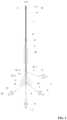
- FIG. 1is a top view of a device for visible puncture according to one embodiment of the disclosure
- FIG. 2is a sectional view taken from line A-A in FIG. 1 ;
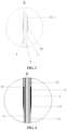
- FIG. 3is a local enlarged view of part A in FIG. 2 ;
- FIG. 4is a local enlarged view of part B in FIG. 2 ;
- FIG. 5is a local enlarged view of part C in FIG. 2 ;
- FIG. 6is a local enlarged view of part D in FIG. 2 .
- the disclosureprovides a device for visible puncture comprising a balloon 1 , a canula 2 , and a water inlet tube (a fluid injection tube 11 ).
- a needle tube 4is disposed in the needle tube 4 .
- the ballooncomprises a first end comprising a first hole and a second end comprising a second hole.
- the balloon 1comprises a first welding part 16 and a second welding part 17 fixed on the outer wall of the front end of the needle tube 4 and the outer wall of the front end of the canula 2 , respectively.
- the rear end of the needle tube 4passes through the canula 2 .
- the rear end of the canula 2is in conjunction with the outer wall of the needle tube 4 .
- a fluid channelis disposed between the outer wall of the needle tube 4 and the inner wall of the balloon 1 , and between the outer wall of the needle tube 4 and the inner wall of the canula 2 .
- a fluid injection tube 11is connected to the fluid channel.
- the fluid injection tube 11comprises a first joint 3 for fluid injection.
- the canula 2comprises a first axial through hole.
- the needle tube 4comprises a second axial through hole 6 .
- the needle tube 4is disposed in the first axial through hole.
- An image acquisition device 5(fiber scope, for example) is disposed in the second axial through hole 6 .
- the second axial through hole 6is connected to a water injection tube 7 .
- the water injection tube 7is connected to a second joint 8 for water injection.
- An instrument delivery pipe 19(a guide wire pipe, for example) is connected to the second axial through hole 6 .
- the water injection tube 7 and the instrument delivery pipe 19are disconnected in the second axial through hole.
- the image acquisition device 5comprises a first outer wall facing the water injection tube and a second outer wall back to back with the first outer wall; a first channel 13 is disposed between an inner wall of the needle tube and the first outer wall of the image acquisition device 5 ; and the first channel 13 communicates with the water injection tube 7 .
- a second channel 21is disposed between the inner wall of the needle tube and the second outer wall of the image acquisition device 5 ; and the second channel 21 communicates with the instrument delivery pipe 19 .
- the device for visible puncturefurther comprises a handle 10 .
- the instrument delivery pipe 19comprises a third front end fixed in the handle 10 , and a third rear end comprising a third joint 20 for instrument introduction.
- the rear end of the needle tube 4is connected to a fourth joint 9 communicating with the image acquisition device 5 .
- the front end of the needle tube 4comprises a tapered head 4 . 1 ;
- the tapered head 4 . 1comprises a tapered front end and a flat rear end;
- the tapered head 4 . 1further comprises a central hole communicating with the second axial through hole 6 and the central hole has the same diameter as the second axial through hole 6 ;
- the first end of the balloonis fixed on the flat rear end of the tapered head 4 . 1 , and an outer diameter of the flat rear end of the tapered head 4 . 1 is the same as an outer diameter of the first end of the balloon 1 .
- the tapered head 4 . 1is a part of the needle tube 4 or is soldered on the needle tube 4 .
- the fiber scope(the image acquisition device) is integrated with or independent from the needle tube 4 .
- the front end of the image acquisition device 5is fixed on the inner wall of the needle tube, and the rear end passes through the second axial through hole 6 and the fourth joint 9 .
- the rear end of the canula 2 and the rear end of the needle tube 4are fixed in the handle 10 .
- the rear end of the needle tube 4passes through the handle 10 and is connected to the fourth joint 9 .
- One end of the fluid injection tube 11is connected to the canula 2 , and the other end passes through the handle and is connected to the first joint.
- One end of the water injection tube 7is connected to the needle tube 4 , and the other end passes through the handle and is connected to the second joint 8 .
- the handlecomprises a first cylindrical holder 10 . 1 , a second cylindrical holder 10 . 2 coaxially fixed on the first cylindrical holder, and a tapered holder 10 . 3 coaxially fixed on the second cylindrical holder; a diameter of the second cylindrical holder is larger than a diameter of the first cylindrical holder; a transition section of the second cylindrical holder and the tapered holder 10 . 3 comprises a clamping part 14 shaped like a finger (this is convenient for a user to hold the device); and the tapered holder 10 . 3 comprises a rear end having an annular circumferential surface 15 (this is convenient for the operator to hold, increasing the friction force of hands, thus ensuring the stable operation of the medical staff).
- the device for visible punctureincorporates the needle tube 4 and the balloon 1 , and the fiber scope is built-in in the device or introduced temporarily as needed. Using the device, the puncture position can be clearly observed thus improving the operation accuracy.
- a convention puncture devicewhich involves the withdrawal of the puncture needle, the placement and stabilization of the guide wire, the withdrawal of the sheath of the puncture needle, the expansion of the sheath core along the guide wire, and the withdrawal of the sheath core, the operation of the device of the disclosure is simple.
- the operations of the puncture and the expansionare fulfilled in the same device, without the operations of withdrawal or replacement of the guide wire, thus saving the usage of consumable items, reducing the operation time, reducing the risk of surgery, reducing the cost of surgery, and reducing the pain of patients.
- the state of the renal collection systemcan be monitored through the fiber optic mirror to reduce the risk of bleeding.
- the device of the disclosurecan be applied in general surgery, neurosurgery, urology, hepatobiliary surgery, gynecology and so on.
Landscapes
- Health & Medical Sciences (AREA)
- Life Sciences & Earth Sciences (AREA)
- Surgery (AREA)
- Heart & Thoracic Surgery (AREA)
- Veterinary Medicine (AREA)
- Nuclear Medicine, Radiotherapy & Molecular Imaging (AREA)
- Public Health (AREA)
- General Health & Medical Sciences (AREA)
- Animal Behavior & Ethology (AREA)
- Engineering & Computer Science (AREA)
- Biomedical Technology (AREA)
- Medical Informatics (AREA)
- Molecular Biology (AREA)
- Pathology (AREA)
- Radiology & Medical Imaging (AREA)
- Physics & Mathematics (AREA)
- Optics & Photonics (AREA)
- Biophysics (AREA)
- Gastroenterology & Hepatology (AREA)
- Gynecology & Obstetrics (AREA)
- Oral & Maxillofacial Surgery (AREA)
- Vascular Medicine (AREA)
- Anesthesiology (AREA)
- Hematology (AREA)
- Infusion, Injection, And Reservoir Apparatuses (AREA)
- Surgical Instruments (AREA)
Abstract
Description
- 1) The fiber scope is inserted into the second axial through
hole 6 and locked in a target location. Thesheath 18 is disposed on the needle tube4 (if the fiber scope is integrated with theneedle tube 4, only need to dispose the sheath on the needle tube4). Thesheath 18 is a hollow pipe; when theballoon 1 is filled with a fluid and expanded to show a maximum section width, and the maximum section width of theballoon 1 is smaller than the inner diameter of thesheath 18. - 2) The optical fiber of the fiber scope is connected to a camera system until a normal image can be seen on the display.
- 3) The device for visible puncture is held by hand. Under B-ultrasound equipment, the
needle tube 4, theballoon 1, andcanula 2 cooperate with each other for puncture. Theneedle tube 4 reaches the renal pelvis and renal calices through the epidermis. The renal collection system can be seen on the optical fiber mirror. If the imaging is not clear, a small amount of physiological saline can be injected into theneedle tube 4 through the second joint8 to clear the vision so as to determine the puncture position of the renal collection system. - 4) When the
needle tube 4 reaches the target position, normal saline is injected into theballoon 1 through a water filling connector to expand theballoon 1 using a syringe. When the pressure on the syringe reaches the set pressure (25 atmospheres), stop filling water and hold for 30 seconds. Thesheath 18 is pushed forward along theneedle tube 4 and sheathed on theballoon 1. Thereafter, the water in theballoon 1 is drained and the balloon is taken out. Thus, thesheath 18 stays in an expanded channel completed by theballoon 1, so that the expanded state is remained, that is to say, the working channel of percutaneous renal surgery is established.
- 1) The fiber scope is inserted into the second axial through
Claims (9)
Applications Claiming Priority (3)
| Application Number | Priority Date | Filing Date | Title |
|---|---|---|---|
| CN201810395296.X | 2018-04-27 | ||
| CN201810395296.XACN108543201B (en) | 2018-04-27 | 2018-04-27 | Visual puncture sacculus device |
| PCT/CN2018/104295WO2019205409A1 (en) | 2018-04-27 | 2018-09-06 | Balloon device for visible puncture |
Related Parent Applications (1)
| Application Number | Title | Priority Date | Filing Date |
|---|---|---|---|
| PCT/CN2018/104295Continuation-In-PartWO2019205409A1 (en) | 2018-04-27 | 2018-09-06 | Balloon device for visible puncture |
Publications (2)
| Publication Number | Publication Date |
|---|---|
| US20210038250A1 US20210038250A1 (en) | 2021-02-11 |
| US11980351B2true US11980351B2 (en) | 2024-05-14 |
Family
ID=63512988
Family Applications (1)
| Application Number | Title | Priority Date | Filing Date |
|---|---|---|---|
| US17/080,823Active2041-01-02US11980351B2 (en) | 2018-04-27 | 2020-10-26 | Device for visible puncture |
Country Status (3)
| Country | Link |
|---|---|
| US (1) | US11980351B2 (en) |
| CN (1) | CN108543201B (en) |
| WO (1) | WO2019205409A1 (en) |
Families Citing this family (6)
| Publication number | Priority date | Publication date | Assignee | Title |
|---|---|---|---|---|
| US12071228B1 (en)* | 2019-03-28 | 2024-08-27 | Snap Inc. | Drone with propeller guard configured as an airfoil |
| CN111110333A (en)* | 2020-02-19 | 2020-05-08 | 上海英诺伟医疗器械有限公司 | Percutaneous nephropuncture dilation kit, method of use thereof, and surgical assembly |
| CN112972013B (en)* | 2021-02-19 | 2022-05-20 | 北京医院 | Visual intervention path establishing system |
| CN113100887B (en)* | 2021-04-06 | 2022-05-06 | 首都医科大学宣武医院 | A tertiary puncture cannula assembly for trigeminal meniscus balloon compression |
| CN113974723B (en)* | 2021-11-24 | 2024-06-18 | 河南印何阗生物科技有限公司 | Visual deep brain operation puncture drainage retracting guide tube |
| US12383244B2 (en) | 2021-11-30 | 2025-08-12 | Vhmed (Nantong) Co. Ltd. | Specimen retrieval bag, specimen retrieval device and method for using specimen retrieval device |
Citations (6)
| Publication number | Priority date | Publication date | Assignee | Title |
|---|---|---|---|---|
| US4315512A (en)* | 1980-01-24 | 1982-02-16 | Fogarty Thomas J | Piston extension balloon dilatation catheter apparatus and method |
| US20050004522A1 (en)* | 2003-05-06 | 2005-01-06 | Asahi Intecc Co., Ltd. | Infusion device |
| US20050228452A1 (en)* | 2004-02-11 | 2005-10-13 | Mourlas Nicholas J | Steerable catheters and methods for using them |
| US20060004286A1 (en)* | 2004-04-21 | 2006-01-05 | Acclarent, Inc. | Methods and devices for performing procedures within the ear, nose, throat and paranasal sinuses |
| US20090062872A1 (en)* | 2007-08-27 | 2009-03-05 | Singfatt Chin | Balloon cannula system for accessing and visualizing spine and related methods |
| US11376037B2 (en)* | 2020-05-08 | 2022-07-05 | Covidien Lp | Surgical access device including dual lumen cannula for anchor inflation and deflation |
Family Cites Families (17)
| Publication number | Priority date | Publication date | Assignee | Title |
|---|---|---|---|---|
| JP4846396B2 (en)* | 2006-03-10 | 2011-12-28 | テルモ株式会社 | Introducer guide and introducer circuit |
| US10058235B2 (en)* | 2011-03-01 | 2018-08-28 | Sanovas Intellectual Property, Llc | Steerable catheter |
| CN202161387U (en)* | 2011-06-22 | 2012-03-14 | 常州市久虹医疗器械有限公司 | Vertebral expansion balloon catheter |
| CN202478274U (en)* | 2012-03-15 | 2012-10-10 | 段丙志 | Medical puncture flusher |
| CN104918535A (en)* | 2012-12-24 | 2015-09-16 | 萨诺瓦斯股份有限公司 | Anchored working channel |
| CN103055409B (en)* | 2013-01-31 | 2014-08-13 | 四川大学华西医院 | Transthoracic puncture aorta intubation tube suitable for minimally invasive cardiac surgery |
| CN103222888A (en)* | 2013-04-26 | 2013-07-31 | 广州宝胆医疗器械科技有限公司 | Peritonrocentesis mirror |
| CN203954436U (en)* | 2014-06-11 | 2014-11-26 | 常州市久虹医疗器械有限公司 | The sacculus dilating catheter of exchange guidewire fast |
| WO2016006188A1 (en)* | 2014-07-08 | 2016-01-14 | 富士フイルム株式会社 | Photoacoustic image generation device and insert |
| CN204563263U (en)* | 2015-04-13 | 2015-08-19 | 广东博迈医疗器械有限公司 | The sacculus dilating catheter that a kind of ability of puncture is good |
| CN104815388B (en)* | 2015-04-19 | 2017-10-10 | 苏州爱得科技发展股份有限公司 | A kind of vertebral body augmentation formation system |
| CN205964572U (en)* | 2016-05-26 | 2017-02-22 | 广州医科大学附属第一医院 | Visual attraction system of washing of percutaneous aspiration |
| CN207136892U (en)* | 2017-01-26 | 2018-03-27 | 南京鼓楼医院 | Medical percutaneous punctures semilunar ganglion balloon compression art trochar |
| CN206777388U (en)* | 2017-05-18 | 2017-12-22 | 中国人民解放军总医院 | The arteriopuncture sleeve pipe of end of tape sacculus |
| CN107374697B (en)* | 2017-07-11 | 2022-03-29 | 蓝线铂立医疗科技(上海)有限公司 | Disposable visible dilating sheath for percutaneous nephroscope |
| CN107596539B (en)* | 2017-10-17 | 2020-01-03 | 上海英诺伟医疗器械有限公司 | Balloon dilatation catheter |
| CN209464480U (en)* | 2018-04-27 | 2019-10-08 | 武汉佑康科技有限公司 | A kind of visual puncturing balloon-system |
- 2018
- 2018-04-27CNCN201810395296.XApatent/CN108543201B/enactiveActive
- 2018-09-06WOPCT/CN2018/104295patent/WO2019205409A1/ennot_activeCeased
- 2020
- 2020-10-26USUS17/080,823patent/US11980351B2/enactiveActive
Patent Citations (6)
| Publication number | Priority date | Publication date | Assignee | Title |
|---|---|---|---|---|
| US4315512A (en)* | 1980-01-24 | 1982-02-16 | Fogarty Thomas J | Piston extension balloon dilatation catheter apparatus and method |
| US20050004522A1 (en)* | 2003-05-06 | 2005-01-06 | Asahi Intecc Co., Ltd. | Infusion device |
| US20050228452A1 (en)* | 2004-02-11 | 2005-10-13 | Mourlas Nicholas J | Steerable catheters and methods for using them |
| US20060004286A1 (en)* | 2004-04-21 | 2006-01-05 | Acclarent, Inc. | Methods and devices for performing procedures within the ear, nose, throat and paranasal sinuses |
| US20090062872A1 (en)* | 2007-08-27 | 2009-03-05 | Singfatt Chin | Balloon cannula system for accessing and visualizing spine and related methods |
| US11376037B2 (en)* | 2020-05-08 | 2022-07-05 | Covidien Lp | Surgical access device including dual lumen cannula for anchor inflation and deflation |
Also Published As
| Publication number | Publication date |
|---|---|
| WO2019205409A1 (en) | 2019-10-31 |
| CN108543201A (en) | 2018-09-18 |
| CN108543201B (en) | 2024-10-01 |
| US20210038250A1 (en) | 2021-02-11 |
Similar Documents
| Publication | Publication Date | Title |
|---|---|---|
| US11980351B2 (en) | Device for visible puncture | |
| US20210038251A1 (en) | Device for visibly puncturing animal tissue or organ | |
| US5601533A (en) | Endoscopic puncture needle device | |
| US5569204A (en) | Aspiration catheter arrangement | |
| JP2801556B2 (en) | Apparatus for introducing a catheter into a body cavity | |
| US4524770A (en) | Endoscope injection needle | |
| CN112584736B (en) | Multi-channel flexible ureteroscope | |
| US3786810A (en) | Placement apparatus for positioning an elongated element in a body lument | |
| CN108992144B (en) | Dilating sheath and endoscope with dilating sheath | |
| WO2019028458A1 (en) | Veress-type needles with illuminated guidance and safety features | |
| JPS62133969A (en) | Disposable catheter introducing apparatus for staying in blood vessel | |
| US11382662B2 (en) | Trocars and veress-type needles with illuminated guidance and safety features | |
| CN108433757B (en) | Visible puncture sampler with combined inner sheath and outer sheath | |
| JP2013013592A (en) | Dilator device for ventricular puncture | |
| JP2018175755A (en) | Device for removing intracerebral hematoma | |
| CN110897601A (en) | Ureter soft lens diagnosis and treatment method and device integrated with guide sheath | |
| US20200330082A1 (en) | Endoscopic Cannula for Fallopian Tube Access | |
| JPH0654862A (en) | Surgical cannula with lighting | |
| CN212816204U (en) | Ureter soft lens integrated with guide sheath | |
| CN110840391A (en) | Combined nephroscope | |
| CN209203454U (en) | A kind of expansion sheath and the endoscope with expansion sheath | |
| US10695038B2 (en) | Devices, systems, and methods for obtaining a tissue sample | |
| CN213190057U (en) | Device for windowing inner film | |
| JP2006130292A (en) | Instrument for re-insertion of gastrostoma tube | |
| CN209464474U (en) | A kind of mobile balloon-system of visual puncturing |
Legal Events
| Date | Code | Title | Description |
|---|---|---|---|
| AS | Assignment | Owner name:WUHAN YOUCARE TECHNOLOGY CO., LTD., CHINA Free format text:ASSIGNMENT OF ASSIGNORS INTEREST;ASSIGNORS:LI, JIANXING;LI, JINPING;LIU, CHENGPENG;AND OTHERS;REEL/FRAME:054171/0022 Effective date:20201013 | |
| FEPP | Fee payment procedure | Free format text:ENTITY STATUS SET TO UNDISCOUNTED (ORIGINAL EVENT CODE: BIG.); ENTITY STATUS OF PATENT OWNER: SMALL ENTITY | |
| FEPP | Fee payment procedure | Free format text:ENTITY STATUS SET TO SMALL (ORIGINAL EVENT CODE: SMAL); ENTITY STATUS OF PATENT OWNER: SMALL ENTITY | |
| STPP | Information on status: patent application and granting procedure in general | Free format text:APPLICATION DISPATCHED FROM PREEXAM, NOT YET DOCKETED | |
| STPP | Information on status: patent application and granting procedure in general | Free format text:DOCKETED NEW CASE - READY FOR EXAMINATION | |
| STPP | Information on status: patent application and granting procedure in general | Free format text:NON FINAL ACTION MAILED | |
| STPP | Information on status: patent application and granting procedure in general | Free format text:RESPONSE TO NON-FINAL OFFICE ACTION ENTERED AND FORWARDED TO EXAMINER | |
| STPP | Information on status: patent application and granting procedure in general | Free format text:NOTICE OF ALLOWANCE MAILED -- APPLICATION RECEIVED IN OFFICE OF PUBLICATIONS | |
| ZAAB | Notice of allowance mailed | Free format text:ORIGINAL CODE: MN/=. | |
| STPP | Information on status: patent application and granting procedure in general | Free format text:PUBLICATIONS -- ISSUE FEE PAYMENT VERIFIED | |
| STCF | Information on status: patent grant | Free format text:PATENTED CASE |