US11978283B2 - Mirroring device with a hands-free mode - Google Patents
Mirroring device with a hands-free modeDownload PDFInfo
- Publication number
- US11978283B2 US11978283B2US17/249,855US202117249855AUS11978283B2US 11978283 B2US11978283 B2US 11978283B2US 202117249855 AUS202117249855 AUS 202117249855AUS 11978283 B2US11978283 B2US 11978283B2
- Authority
- US
- United States
- Prior art keywords
- user
- menu option
- hand
- video feed
- video
- Prior art date
- Legal status (The legal status is an assumption and is not a legal conclusion. Google has not performed a legal analysis and makes no representation as to the accuracy of the status listed.)
- Active
Links
Images


Classifications
- G—PHYSICS
- G06—COMPUTING OR CALCULATING; COUNTING
- G06V—IMAGE OR VIDEO RECOGNITION OR UNDERSTANDING
- G06V40/00—Recognition of biometric, human-related or animal-related patterns in image or video data
- G06V40/20—Movements or behaviour, e.g. gesture recognition
- G06V40/28—Recognition of hand or arm movements, e.g. recognition of deaf sign language
- G—PHYSICS
- G06—COMPUTING OR CALCULATING; COUNTING
- G06F—ELECTRIC DIGITAL DATA PROCESSING
- G06F3/00—Input arrangements for transferring data to be processed into a form capable of being handled by the computer; Output arrangements for transferring data from processing unit to output unit, e.g. interface arrangements
- G06F3/01—Input arrangements or combined input and output arrangements for interaction between user and computer
- G06F3/011—Arrangements for interaction with the human body, e.g. for user immersion in virtual reality
- G—PHYSICS
- G02—OPTICS
- G02B—OPTICAL ELEMENTS, SYSTEMS OR APPARATUS
- G02B27/00—Optical systems or apparatus not provided for by any of the groups G02B1/00 - G02B26/00, G02B30/00
- G02B27/01—Head-up displays
- G02B27/017—Head mounted
- G02B27/0172—Head mounted characterised by optical features
- G—PHYSICS
- G06—COMPUTING OR CALCULATING; COUNTING
- G06F—ELECTRIC DIGITAL DATA PROCESSING
- G06F3/00—Input arrangements for transferring data to be processed into a form capable of being handled by the computer; Output arrangements for transferring data from processing unit to output unit, e.g. interface arrangements
- G06F3/01—Input arrangements or combined input and output arrangements for interaction between user and computer
- G06F3/017—Gesture based interaction, e.g. based on a set of recognized hand gestures
- G—PHYSICS
- G06—COMPUTING OR CALCULATING; COUNTING
- G06F—ELECTRIC DIGITAL DATA PROCESSING
- G06F3/00—Input arrangements for transferring data to be processed into a form capable of being handled by the computer; Output arrangements for transferring data from processing unit to output unit, e.g. interface arrangements
- G06F3/01—Input arrangements or combined input and output arrangements for interaction between user and computer
- G06F3/03—Arrangements for converting the position or the displacement of a member into a coded form
- G06F3/0304—Detection arrangements using opto-electronic means
- G—PHYSICS
- G06—COMPUTING OR CALCULATING; COUNTING
- G06F—ELECTRIC DIGITAL DATA PROCESSING
- G06F3/00—Input arrangements for transferring data to be processed into a form capable of being handled by the computer; Output arrangements for transferring data from processing unit to output unit, e.g. interface arrangements
- G06F3/01—Input arrangements or combined input and output arrangements for interaction between user and computer
- G06F3/048—Interaction techniques based on graphical user interfaces [GUI]
- G06F3/0481—Interaction techniques based on graphical user interfaces [GUI] based on specific properties of the displayed interaction object or a metaphor-based environment, e.g. interaction with desktop elements like windows or icons, or assisted by a cursor's changing behaviour or appearance
- G06F3/04812—Interaction techniques based on cursor appearance or behaviour, e.g. being affected by the presence of displayed objects
- G—PHYSICS
- G06—COMPUTING OR CALCULATING; COUNTING
- G06F—ELECTRIC DIGITAL DATA PROCESSING
- G06F3/00—Input arrangements for transferring data to be processed into a form capable of being handled by the computer; Output arrangements for transferring data from processing unit to output unit, e.g. interface arrangements
- G06F3/01—Input arrangements or combined input and output arrangements for interaction between user and computer
- G06F3/048—Interaction techniques based on graphical user interfaces [GUI]
- G06F3/0481—Interaction techniques based on graphical user interfaces [GUI] based on specific properties of the displayed interaction object or a metaphor-based environment, e.g. interaction with desktop elements like windows or icons, or assisted by a cursor's changing behaviour or appearance
- G06F3/0482—Interaction with lists of selectable items, e.g. menus
- G—PHYSICS
- G06—COMPUTING OR CALCULATING; COUNTING
- G06F—ELECTRIC DIGITAL DATA PROCESSING
- G06F3/00—Input arrangements for transferring data to be processed into a form capable of being handled by the computer; Output arrangements for transferring data from processing unit to output unit, e.g. interface arrangements
- G06F3/01—Input arrangements or combined input and output arrangements for interaction between user and computer
- G06F3/048—Interaction techniques based on graphical user interfaces [GUI]
- G06F3/0484—Interaction techniques based on graphical user interfaces [GUI] for the control of specific functions or operations, e.g. selecting or manipulating an object, an image or a displayed text element, setting a parameter value or selecting a range
- G06F3/04847—Interaction techniques to control parameter settings, e.g. interaction with sliders or dials
- G—PHYSICS
- G06—COMPUTING OR CALCULATING; COUNTING
- G06F—ELECTRIC DIGITAL DATA PROCESSING
- G06F3/00—Input arrangements for transferring data to be processed into a form capable of being handled by the computer; Output arrangements for transferring data from processing unit to output unit, e.g. interface arrangements
- G06F3/14—Digital output to display device ; Cooperation and interconnection of the display device with other functional units
- G06F3/1454—Digital output to display device ; Cooperation and interconnection of the display device with other functional units involving copying of the display data of a local workstation or window to a remote workstation or window so that an actual copy of the data is displayed simultaneously on two or more displays, e.g. teledisplay
- G—PHYSICS
- G06—COMPUTING OR CALCULATING; COUNTING
- G06V—IMAGE OR VIDEO RECOGNITION OR UNDERSTANDING
- G06V40/00—Recognition of biometric, human-related or animal-related patterns in image or video data
- G06V40/20—Movements or behaviour, e.g. gesture recognition
- G06V40/23—Recognition of whole body movements, e.g. for sport training
- H—ELECTRICITY
- H04—ELECTRIC COMMUNICATION TECHNIQUE
- H04N—PICTORIAL COMMUNICATION, e.g. TELEVISION
- H04N23/00—Cameras or camera modules comprising electronic image sensors; Control thereof
- H04N23/60—Control of cameras or camera modules
- H04N23/61—Control of cameras or camera modules based on recognised objects
- H04N23/611—Control of cameras or camera modules based on recognised objects where the recognised objects include parts of the human body
- H—ELECTRICITY
- H04—ELECTRIC COMMUNICATION TECHNIQUE
- H04N—PICTORIAL COMMUNICATION, e.g. TELEVISION
- H04N23/00—Cameras or camera modules comprising electronic image sensors; Control thereof
- H04N23/60—Control of cameras or camera modules
- H04N23/62—Control of parameters via user interfaces
- G—PHYSICS
- G02—OPTICS
- G02B—OPTICAL ELEMENTS, SYSTEMS OR APPARATUS
- G02B27/00—Optical systems or apparatus not provided for by any of the groups G02B1/00 - G02B26/00, G02B30/00
- G02B27/01—Head-up displays
- G02B27/017—Head mounted
- G02B2027/0178—Eyeglass type
Definitions
- This disclosurerelates to electronic mirroring devices.
- Some electronics-enabled devicesinclude front-facing cameras. These cameras allow users to see themselves on a screen of the devices. Namely, these devices include a camera on a same side of the device as the display screen of the devices. Such front-facing cameras are usually used to capture selfies or to assist in capturing a video of a user performing some task or activity.
- FIG. 1is a diagrammatic representation of a networked environment in which the present disclosure may be deployed, in accordance with some examples.
- FIG. 2is a diagrammatic representation of a messaging system, in accordance with some examples, that has both client-side and server-side functionality.
- FIG. 3is a diagrammatic representation of a data structure as maintained in a database, in accordance with some examples.
- FIG. 4is a diagrammatic representation of a message, in accordance with some examples.
- FIG. 5is a perspective view of an eyewear device, in accordance with some examples.
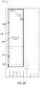
- FIGS. 6 A and 6 Bare diagrammatic representations of an electronic mirroring device, in accordance with some examples.
- FIG. 7is a flowchart showing example operations of the hands-free control system, in accordance with some examples.
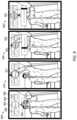
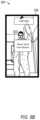
- FIGS. 8 and 9 A -Care illustrative screens of the hands-free control system, in accordance with some examples.
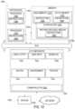
- FIG. 10is a diagrammatic representation of a machine in the form of a computer system within which a set of instructions may be executed for causing the machine to perform any one or more of the methodologies discussed herein, in accordance with some examples.
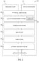
- FIG. 11is a block diagram showing a software architecture within which examples may be implemented.
- Typical systemsallow users to create personal videos by using a front-facing camera of a mobile device.
- the front-facing cameraBy using the front-facing camera the user can see themselves on the screen of the phone while recording a video. This ensures that the user is capturing a video of what the user intends.
- a typical mobile phoneincludes a front-facing camera and the user can interact with the touchscreen of the mobile phone to select between various options to capturing a video of the user. Namely, the user can select an option on the touchscreen by making physical contact with the screen to start capturing a video clip of the user with the front-facing camera. After the user selects the option, the user has to position the mobile phone in a way that captures a full body of the user and then the user has to back away from the mobile phone.
- the disclosed examplesimprove the efficiency of using the electronic device by enabling a user to remotely control an electronic mirroring device, such as a front-facing video camera of a mobile phone, using a hand (or other body part) as a cursor.
- an electronic mirroring devicesuch as a front-facing video camera of a mobile phone
- the disclosed examplescan capture, by an electronic mirroring device, a video feed received from a camera of the electronic mirroring device which depicts a user.
- the electronic mirroring devicedisplays one or more menu options on the video feed that depicts the user.
- the usercan see themselves in the screen of the device (e.g., the screen of the device displays a video being received from the front-facing camera of the device while the front-facing camera is pointing towards the user) from far away or while the user is standing at a desired location for capturing the video and the user can see one or more video clip capture control options overlaid on top of the video of the user.
- the electronic mirroring deviceidentifies a hand of the user in the video feed and determines that a position of the hand in the video feed overlaps a position of a given menu option of the one or more menu options.
- the electronic mirroring deviceperforms an operation associated with the given menu option in response to determining that the position of the hand in the video feed overlaps the position of the given menu option. Specifically, the user can move his or her hand around and use the hand as a cursor to select between the menu options that are displayed.
- the electronic mirroring devicecan be fixed on a camera stand so that the front-facing camera is pointing towards a target or object to be captured. After fixing the electronic mirroring device on the camera stand the user can back away and control options that are displayed on the electronic mirroring device by making various hand movements.
- the capture of video clips using a front-facing camerais simplified and improved which reduces the number of takes a user has to perform and reduce the amount of editing needed to finalize a video clip. This reduces the amount of resources needed to operate a given device and improves the overall efficiency of electronic devices. This increases the efficiency, appeal, and utility of electronic devices.
- the electronic mirroring deviceincludes a combination of an electronic eyewear device facing a static non-electronic or electronic mirror.
- the usercan wear the electronic eyewear device to view the static mirror through lenses of the electronic eyewear device to see themselves.
- the electronic mirroring deviceincludes a camera that points towards the static mirror and captures a video of the user in the mirror.
- the electronic eyewear devicedisplays one or more menu options in the lenses of the electronic eyewear device at a position in relation to the user in the mirror. This makes it appear to the user as if the menu options are being displayed on the mirror above, below or next to the user.
- the usercan move their hand and use the hand as a cursor to select between the menu options to control capture of a video clip of the user.
- FIG. 1is a block diagram showing an example messaging system 100 for exchanging data (e.g., messages and associated content) over a network.
- the messaging system 100includes multiple instances of a client device 102 , each of which hosts a number of applications, including a messaging client 104 and other external applications 109 (e.g., third-party applications).
- Each messaging client 104is communicatively coupled to other instances of the messaging client 104 (e.g., hosted on respective other client devices 102 ), a messaging server system 108 and external app(s) servers 110 via a network 112 (e.g., the Internet).
- a messaging client 104can also communicate with locally-hosted third-party applications 109 using Applications Program Interfaces (APIs).
- APIsApplication Program Interfaces
- the messaging system 100includes an eyewear device 119 , which hosts a hands-free control system 107 , among other applications.
- the eyewear device 119is communicatively coupled to the client device 102 via the network 112 (which may include via a dedicated short-range communication path, such as a BluetoothTM or WiFi direct connection).
- the messaging system 100includes an electronic mirroring device 130 , which may host another instance of the hands-free control system 107 , among other applications.
- the electronic mirroring device 130can include similar functionality as the client devices 102 .
- the hands-free control system 107allows a user to navigate through and select between various menu options that are displayed on a screen of the eyewear device 119 or the mirroring device 130 using the user's hand as a cursor.
- the hands-free control system 107can receive or capture a video feed from a camera of the eyewear device 119 or the mirroring device 130 .
- the hands-free control system 107can receive or capture a video feed from a front-facing camera of the mirroring device 130 , such as the front-facing camera of a mobile phone.
- the hands-free control system 107can receive or capture a video feed from a camera of the eyewear device 119 that is pointing towards a static mirror.
- the static mirrorreflects an image of the user which is captured as a video feed by the camera of the eyewear device 119 .
- the hands-free control system 107displays one or more menu options on the display of the mirroring device 130 or within lenses of the eyewear device 119 .
- the hands-free control system 107detects a hand of the user in the video feed, such as using an object recognition process. Once the hand of the user is detected, the hands-free control system 107 determines whether the hand is in a particular configuration corresponding to cursor control. For example, the hands-free control system 107 determines that the hand is in an open palm configuration where the front of the palm is facing the camera (or the front of the palm is being reflected by a static mirror towards the camera of the eyewear device 119 ).
- the hands-free control system 107displays an animated cursor centered on the palm of the hand on the display of the mirroring device 130 or within lenses of the eyewear device 119 .
- the animated cursorcan include one or more concentric circles, squares, triangles or any other suitable shape that shrink or expand in size continuously or periodically.
- the hands-free control system 107tracks movement of the hand in the video feed and continuously moves the animated cursor to indicate to the user where the hand is currently positioned in the screen.
- the hands-free control system 107determines that the hand position overlaps a given menu option that is displayed.
- the hands-free control system 107displays an animated timer.
- the animated timercan be a circular progress bar that is displayed around the given menu option (e.g., to encircle the given menu option).
- the progress barcan also be non-circular and can be displayed adjacent to the given menu option or at any other suitable position.
- the circular progress barincludes a line that progresses in a circular manner from a start position to an end position (which can be the start position) after completing one full cycle or circle around the progress bar.
- the circular progress barcan progress at a rate that is fast enough for the line to reach the end position from the start position within a given period of time (e.g., 2 seconds).
- the hands-free control system 107determines that the hand continued to overlap the position of the given menu option for the entire duration of the animated timer. For example, the hands-free control system 107 determines that the hand remained at the position of the given menu option from the time at which the animated timer was displayed and started to the time at which the animated timer reached a threshold time value (e.g., 2 seconds). In response, the hands-free control system 107 activates a function or performs an operation associated with the given menu option.
- a threshold time valuee.g. 2 seconds
- the given menu optionis a video clip capture duration option.
- the operation associated with the given menu optionincludes the display of another or second menu option for performing an adjustment associated with the given menu option.
- the second menu option that is displayedmay allow the user to set the video clip time duration.
- the video clip time durationspecifies the duration of the video that is captured after the video clip capture option is selected. For example, if the video clip time duration is 5 seconds, a 5 second video clip is captured and generated from the video feed received from the front-facing camera.
- the given menu optionis a video modification, augmented reality selection, or image filter option.
- the operation associated with the given menu optionincludes the display of another or second menu option for performing an adjustment associated with the given menu option.
- the second menu option that is displayedmay allow the user to select between various types of video modifications (e.g., contrast, brightness, color scheme, and so forth), augmented reality options (e.g., selecting between different types of augmented reality elements that are displayed during capture of a video clip), or different types of image filters (e.g., daytime filter, nighttime filter, and so forth).
- the hands-free control system 107determines that the position of the hand has been moved to the position at which the second menu option is displayed. In response to determining that the position of the hand in the video feed overlaps the position on the screen at which the second menu option is displayed, the hands-free control system 107 enables the user to perform an adjustment using the second menu option.
- the second menu optionmay include a horizontal slider.
- the hands-free control system 107determines that the hand overlaps the position of the horizontal slider and is moved towards a particular direction (e.g., moved to the right), the hands-free control system 107 moves the slider along the particular direction to increase or decrease the video clip duration setting or select between various video modification types, augmented reality options, or image filters.
- the hands-free control system 107After modifying the second menu option (e.g., video clip duration) using the hand, the hands-free control system 107 detects that the hand has been moved back to the position of the given menu option (e.g., for capturing a video clip). In response, the hands-free control system 107 again displays the animated timer. Upon expiration of the animated timer and in response to determining that the hand has remained positioned over the given menu option for the duration of the animated timer, the hands-free control system 107 activates the video clip capture option. Namely, the hands-free control system 107 starts capturing a video clip from the video feed received by the front-facing camera for the duration set by the second menu option.
- the hands-free control system 107starts capturing a video clip from the video feed received by the front-facing camera for the duration set by the second menu option.
- Other menu options that are displayed by the hands-free control system 107include an undo video clip option and a share video clip option (selection of which allows the user to specify different recipients to whom the previously captured video clip(s) will be sent).
- the hands-free control system 107detects that the undo video clip option is selected when the position of the hand of the user is determined to overlap the position of the undo video clip option.
- the hands-free control system 107activates the undo video clip option to erase the previously captured video clip in response to determining that the hand remains positioned over the undo video clip option for a duration of an animated timer.
- the animated timer that is displayed for the different menu optionscan have the same value (e.g., each can be set to 2 seconds) or can be set to different values.
- the animated timer that is displayed and used to determine whether to activate or select a menu option over which the user's hand is positioned in the video feedcan be set to a first value for a video clip capture menu option (e.g., 4 seconds) and can be set to a second value for the undo video clip option (e.g., 6 seconds).
- the hands-free control system 107determines that the hand of the user has been moved away from the position of the given menu option before the animated timer reaches its specified value (e.g., before the timer expires). In response, the hands-free control system 107 removes the display of the animated timer and prevents the selection or operation associated with the given menu option from being performed.
- the hands-free control system 107can communicate with an on-board camera of the eyewear device 119 to determine or detect presence of a user's hand within view of the lenses of the eyewear device 119 .
- the cameramay continuously or periodically scan real-world objects that are included in one or more images or a real-time video feed of the camera.
- the hands-free control system 107may determine whether the real-world objects correspond to a human hand. In response to determining that the real-world objects correspond to a human hand, the hands-free control system 107 may determine that a user's hand has been detected within view of the lenses of the eyewear device 119 .
- the camera of the eyewear device 119can point towards a static mirror and can display the one or more menu options within lenses of the eyewear device 119 positioned within the static mirror.
- the static mirrorcan reflect an image of the user wearing the eyewear device 119 .
- the camera of the eyewear device 119can capture the reflection from the static mirror and process the reflection to detect the hand of the user.
- the hands-free control system 107can then determine and track the position of the hand of the user and determine that the hand of the user is in a particular configuration (e.g., an open palm configuration) to act as a cursor. In such cases, the hands-free control system 107 displays the animated cursor at the tracked hand position and activates menu options when the hand position overlaps the position of different ones of the menu options.
- the electronic mirroring devicecan be fixed on a camera stand so that the front-facing camera is pointing towards a target or object to be captured.
- the hands-free control system 107can be integrated and run on the electronic mirroring device After fixing the electronic mirroring device on the camera stand, the user can back away and control options that are displayed on the electronic mirroring device by making various hand movements.
- the hands-free control system 107can track the movement of the hands in the images captured by the front-facing camera and navigate to and select various displayed options.
- a messaging client 104is able to communicate and exchange data with other messaging clients 104 , the eyewear device 119 , and with the messaging server system 108 via the network 112 .
- the data exchanged between messaging clients 104 , and between a messaging client 104 and the messaging server system 108includes functions (e.g., commands to invoke functions) as well as payload data (e.g., text, audio, video or other multimedia data).
- the messaging server system 108provides server-side functionality via the network 112 to a particular messaging client 104 . While certain functions of the messaging system 100 are described herein as being performed by either a messaging client 104 or by the messaging server system 108 , the location of certain functionality either within the messaging client 104 or the messaging server system 108 may be a design choice. For example, it may be technically preferable to initially deploy certain technology and functionality within the messaging server system 108 but to later migrate this technology and functionality to the messaging client 104 where a client device 102 has sufficient processing capacity.
- the messaging server system 108supports various services and operations that are provided to the messaging client 104 . Such operations include transmitting data to, receiving data from, and processing data generated by the messaging client 104 .
- This datamay include message content, client device information, geolocation information, media augmentation and overlays, message content persistence conditions, social network information, and live event information, as examples.
- Data exchanges within the messaging system 100are invoked and controlled through functions available via user interfaces (UIs) of the messaging client 104 .
- UIsuser interfaces
- an Application Program Interface (API) server 116is coupled to, and provides a programmatic interface to, application servers 114 .
- the application servers 114are communicatively coupled to a database server 120 , which facilitates access to a database 126 that stores data associated with messages processed by the application servers 114 .
- a web server 128is coupled to the application servers 114 , and provides web-based interfaces to the application servers 114 . To this end, the web server 128 processes incoming network requests over the Hypertext Transfer Protocol (HTTP) and several other related protocols.
- HTTPHypertext Transfer Protocol
- the Application Program Interface (API) server 116receives and transmits message data (e.g., commands and message payloads) between the client device 102 and the application servers 114 .
- message datae.g., commands and message payloads
- the Application Program Interface (API) server 116provides a set of interfaces (e.g., routines and protocols) that can be called or queried by the messaging client 104 in order to invoke functionality of the application servers 114 .
- the Application Program Interface (API) server 116exposes various functions supported by the application servers 114 , including account registration, login functionality, the sending of messages, via the application servers 114 , from a particular messaging client 104 to another messaging client 104 , the sending of media files (e.g., images or video) from a messaging client 104 to a messaging server 118 , and for possible access by another messaging client 104 , the settings of a collection of media data (e.g., story), the retrieval of a list of friends of a user of a client device 102 , the retrieval of such collections, the retrieval of messages and content, the addition and deletion of entities (e.g., friends) to an entity graph (e.g., a social graph), the location of friends within a social graph, and opening an application event (e.g., relating to the messaging client 104 ).
- entity graphe.g., a social graph
- an application evente.g., relating to the messaging client 104
- the application servers 114host a number of server applications and subsystems, including for example a messaging server 118 , an image processing server 122 , and a social network server 124 .
- the messaging server 118implements a number of message processing technologies and functions, particularly related to the aggregation and other processing of content (e.g., textual and multimedia content) included in messages received from multiple instances of the messaging client 104 .
- contente.g., textual and multimedia content
- the text and media content from multiple sourcesmay be aggregated into collections of content (e.g., called stories or galleries). These collections are then made available to the messaging client 104 .
- Other processor- and memory-intensive processing of datamay also be performed server-side by the messaging server 118 , in view of the hardware requirements for such processing.
- the application servers 114also include an image processing server 122 that is dedicated to performing various image processing operations, typically with respect to images or video within the payload of a message sent from or received at the messaging server 118 .
- Image processing server 122is used to implement scan functionality of the augmentation system 208 .
- Scan functionalityincludes activating and providing one or more augmented reality experiences on a client device 102 when an image is captured by the client device 102 .
- the messaging client 104 on the client device 102can be used to activate a camera.
- the cameradisplays one or more real-time images or a video to a user along with one or more icons or identifiers of one or more augmented reality experiences.
- the usercan select a given one of the identifiers to launch the corresponding augmented reality experience.
- Launching the augmented reality experienceincludes obtaining one or more augmented reality items associated with the augmented reality experience and overlaying the augmented reality items on top of the images or video being presented.
- the social network server 124supports various social networking functions and services and makes these functions and services available to the messaging server 118 . To this end, the social network server 124 maintains and accesses an entity graph 308 (as shown in FIG. 3 ) within the database 126 . Examples of functions and services supported by the social network server 124 include the identification of other users of the messaging system 100 with which a particular user has relationships or is “following,” and also the identification of other entities and interests of a particular user.
- an external resourcee.g., a third-party application 109 or applet
- features and functions of an external resourceare made available to a user via an interface of the messaging client 104 .
- the messaging client 104receives a user selection of an option to launch or access features of an external resource (e.g., a third-party resource), such as external apps 109 .
- the external resourcemay be a third-party application (external apps 109 ) installed on the client device 102 (e.g., a “native app”), or a small-scale version of the third-party application (e.g., an “applet”) that is hosted on the client device 102 or remote of the client device 102 (e.g., on third-party servers 110 ).
- the small-scale version of the third-party applicationincludes a subset of features and functions of the third-party application (e.g., the full-scale, native version of the third-party standalone application) and is implemented using a markup-language document.
- the small-scale version of the third-party application(e.g., an “applet”) is a web-based, markup-language version of the third-party application and is embedded in the messaging client 104 .
- an appletmay incorporate a scripting language (e.g., a .*js file or a .json file) and a style sheet (e.g., a .*ss file).
- the messaging client 104determines whether the selected external resource is a web-based external resource or a locally-installed external application.
- external applications 109that are locally installed on the client device 102 can be launched independently of and separately from the messaging client 104 , such as by selecting an icon, corresponding to the external application 109 , on a home screen of the client device 102 .
- Small-scale versions of such external applicationscan be launched or accessed via the messaging client 104 and, in some examples, no or limited portions of the small-scale external application can be accessed outside of the messaging client 104 .
- the small-scale external applicationcan be launched by the messaging client 104 receiving, from a external app(s) server 110 , a markup-language document associated with the small-scale external application and processing such a document.
- the messaging client 104In response to determining that the external resource is a locally-installed external application 109 , the messaging client 104 instructs the client device 102 to launch the external application 109 by executing locally-stored code corresponding to the external application 109 . In response to determining that the external resource is a web-based resource, the messaging client 104 communicates with the external app(s) servers 110 to obtain a markup-language document corresponding to the selected resource. The messaging client 104 then processes the obtained markup-language document to present the web-based external resource within a user interface of the messaging client 104 .
- the messaging client 104can notify a user of the client device 102 , or other users related to such a user (e.g., “friends”), of activity taking place in one or more external resources.
- the messaging client 104can provide participants in a conversation (e.g., a chat session) in the messaging client 104 with notifications relating to the current or recent use of an external resource by one or more members of a group of users.
- One or more userscan be invited to join in an active external resource or to launch a recently-used but currently inactive (in the group of friends) external resource.
- the external resourcecan provide participants in a conversation, each using a respective messaging client messaging clients 104 , with the ability to share an item, status, state, or location in an external resource with one or more members of a group of users into a chat session.
- the shared itemmay be an interactive chat card with which members of the chat can interact, for example, to launch the corresponding external resource, view specific information within the external resource, or take the member of the chat to a specific location or state within the external resource.
- response messagescan be sent to users on the messaging client 104 .
- the external resourcecan selectively include different media items in the responses, based on a current context of the external resource.
- the messaging client 104can present a list of the available external resources (e.g., third-party or external applications 109 or applets) to a user to launch or access a given external resource.
- This listcan be presented in a context-sensitive menu.
- the icons representing different ones of the external application 109 (or applets)can vary based on how the menu is launched by the user (e.g., from a conversation interface or from a non-conversation interface).
- FIG. 2is a block diagram illustrating further details regarding the messaging system 100 , according to some examples.
- the messaging system 100is shown to comprise the messaging client 104 and the application servers 114 .
- the messaging system 100embodies a number of subsystems, which are supported on the client side by the messaging client 104 and on the sever side by the application servers 114 .
- These subsystemsinclude, for example, an ephemeral timer system 202 , a collection management system 204 , an augmentation system 208 , a map system 210 , a game system 212 , and an external resource system 220 .
- the ephemeral timer system 202is responsible for enforcing the temporary or time-limited access to content by the messaging client 104 and the messaging server 118 .
- the ephemeral timer system 202incorporates a number of timers that, based on duration and display parameters associated with a message, or collection of messages (e.g., a story), selectively enable access (e.g., for presentation and display) to messages and associated content via the messaging client 104 . Further details regarding the operation of the ephemeral timer system 202 are provided below.
- the collection management system 204is responsible for managing sets or collections of media (e.g., collections of text, image video, and audio data).
- a collection of contente.g., messages, including images, video, text, and audio
- Such a collectionmay be made available for a specified time period, such as the duration of an event to which the content relates. For example, content relating to a music concert may be made available as a “story” for the duration of that music concert.
- the collection management system 204may also be responsible for publishing an icon that provides notification of the existence of a particular collection to the user interface of the messaging client 104 .
- the collection management system 204furthermore includes a curation interface 206 that allows a collection manager to manage and curate a particular collection of content.
- the curation interface 206enables an event organizer to curate a collection of content relating to a specific event (e.g., delete inappropriate content or redundant messages).
- the collection management system 204employs machine vision (or image recognition technology) and content rules to automatically curate a content collection. In certain examples, compensation may be paid to a user for the inclusion of user-generated content into a collection. In such cases, the collection management system 204 operates to automatically make payments to such users for the use of their content.
- the augmentation system 208provides various functions that enable a user to augment (e.g., annotate or otherwise modify or edit) media content associated with a message.
- the augmentation system 208provides functions related to the generation and publishing of media overlays for messages processed by the messaging system 100 .
- the augmentation system 208operatively supplies a media overlay or augmentation (e.g., an image filter) to the messaging client 104 based on a geolocation of the client device 102 .
- the augmentation system 208operatively supplies a media overlay to the messaging client 104 based on other information, such as social network information of the user of the client device 102 .
- a media overlaymay include audio and visual content and visual effects.
- audio and visual contentexamples include pictures, texts, logos, animations, and sound effects.
- An example of a visual effectincludes color overlaying.
- the audio and visual content or the visual effectscan be applied to a media content item (e.g., a photo) at the client device 102 .
- the media overlaymay include text, a graphical element, or image that can be overlaid on top of a photograph taken by the client device 102 .
- the media overlayincludes an identification of a location overlay (e.g., Venice beach), a name of a live event, or a name of a merchant overlay (e.g., Beach Coffee House).
- the augmentation system 208uses the geolocation of the client device 102 to identify a media overlay that includes the name of a merchant at the geolocation of the client device 102 .
- the media overlaymay include other indicia associated with the merchant.
- the media overlaysmay be stored in the database 126 and accessed through the database server 120 .
- the augmentation system 208provides a user-based publication platform that enables users to select a geolocation on a map and upload content associated with the selected geolocation. The user may also specify circumstances under which a particular media overlay should be offered to other users. The augmentation system 208 generates a media overlay that includes the uploaded content and associates the uploaded content with the selected geolocation.
- the augmentation system 208provides a merchant-based publication platform that enables merchants to select a particular media overlay associated with a geolocation via a bidding process. For example, the augmentation system 208 associates the media overlay of the highest bidding merchant with a corresponding geolocation for a predefined amount of time.
- the augmentation system 208communicates with the image processing server 122 to obtain augmented reality experiences and presents identifiers of such experiences in one or more user interfaces (e.g., as icons over a real-time image or video or as thumbnails or icons in interfaces dedicated for presented identifiers of augmented reality experiences).
- one or more images, videos, or augmented reality graphical elementsare retrieved and presented as an overlay on top of the images or video captured by the client device 102 .
- the camerais switched to a front-facing view (e.g., the front-facing camera of the client device 102 is activated in response to activation of a particular augmented reality experience) and the images from the front-facing camera of the client device 102 start being displayed on the client device 102 instead of the rear-facing camera of the client device 102 .
- the one or more images, videos, or augmented reality graphical elementsare retrieved and presented as an overlay on top of the images that are captured and displayed by the front-facing camera of the client device 102 .
- the map system 210provides various geographic location functions, and supports the presentation of map-based media content and messages by the messaging client 104 .
- the map system 210enables the display of user icons or avatars (e.g., stored in profile data 316 ) on a map to indicate a current or past location of “friends” of a user, as well as media content (e.g., collections of messages including photographs and videos) generated by such friends, within the context of a map.
- a message posted by a user to the messaging system 100 from a specific geographic locationmay be displayed within the context of a map at that particular location to “friends” of a specific user on a map interface of the messaging client 104 .
- a usercan furthermore share his or her location and status information (e.g., using an appropriate status avatar) with other users of the messaging system 100 via the messaging client 104 , with this location and status information being similarly displayed within the context of a map interface of the messaging client 104 to selected users.
- location and status informatione.g., using an appropriate status avatar
- the game system 212provides various gaming functions within the context of the messaging client 104 .
- the messaging client 104provides a game interface providing a list of available games (e.g., web-based games or web-based applications) that can be launched by a user within the context of the messaging client 104 , and played with other users of the messaging system 100 .
- the messaging system 100further enables a particular user to invite other users to participate in the play of a specific game, by issuing invitations to such other users from the messaging client 104 .
- the messaging client 104also supports both voice and text messaging (e.g., chats) within the context of gameplay, provides a leaderboard for the games, and also supports the provision of in-game rewards (e.g., coins and items).
- the external resource system 220provides an interface for the messaging client 104 to communicate with external app(s) servers 110 to launch or access external resources.
- Each external resource (apps) server 110hosts, for example, a markup language (e.g., HTML5) based application or small-scale version of an external application (e.g., game, utility, payment, or ride-sharing application that is external to the messaging client 104 ).
- the messaging client 104may launch a web-based resource (e.g., application) by accessing the HTML5 file from the external resource (apps) servers 110 associated with the web-based resource.
- applications hosted by external resource servers 110are programmed in JavaScript leveraging a Software Development Kit (SDK) provided by the messaging server 118 .
- SDKSoftware Development Kit
- the SDKincludes Application Programming Interfaces (APIs) with functions that can be called or invoked by the web-based application.
- APIsApplication Programming Interfaces
- the messaging server 118includes a JavaScript library that provides a given third-party resource access to certain user data of the messaging client 104 .
- HTML5is used as an example technology for programming games, but applications and resources programmed based on other technologies can be used.
- the SDKis downloaded by an external resource (apps) server 110 from the messaging server 118 or is otherwise received by the external resource (apps) server 110 .
- the SDKis included as part of the application code of a web-based external resource.
- the code of the web-based resourcecan then call or invoke certain functions of the SDK to integrate features of the messaging client 104 into the web-based resource.
- the SDK stored on the messaging server 118effectively provides the bridge between an external resource (e.g., third-party or external applications 109 or applets and the messaging client 104 ). This provides the user with a seamless experience of communicating with other users on the messaging client 104 , while also preserving the look and feel of the messaging client 104 .
- the SDKfacilitates communication between external resource servers 110 and the messaging client 104 .
- a Web ViewJavaScriptBridgerunning on a client device 102 establishes two one-way communication channels between a external resource and the messaging client 104 . Messages are sent between the external resource and the messaging client 104 via these communication channels asynchronously.
- Each SDK function invocationis sent as a message and callback.
- Each SDK functionis implemented by constructing a unique callback identifier and sending a message with that callback identifier.
- each external resource server 110provides an HTML5 file corresponding to the web-based external resource to the messaging server 118 .
- the messaging server 118can add a visual representation (such as a box art or other graphic) of the web-based external resource in the messaging client 104 . Once the user selects the visual representation or instructs the messaging client 104 through a GUI of the messaging client 104 to access features of the web-based external resource, the messaging client 104 obtains the HTML5 file and instantiates the resources necessary to access the features of the web-based external resource.
- the messaging client 104presents a graphical user interface (e.g., a landing page or title screen) for an external resource. During, before, or after presenting the landing page or title screen, the messaging client 104 determines whether the launched external resource has been previously authorized to access user data of the messaging client 104 . In response to determining that the launched external resource has been previously authorized to access user data of the messaging client 104 , the messaging client 104 presents another graphical user interface of the external resource that includes functions and features of the external resource.
- a graphical user interfacee.g., a landing page or title screen
- the messaging client 104slides up (e.g., animates a menu as surfacing from a bottom of the screen to a middle of or other portion of the screen) a menu for authorizing the external resource to access the user data.
- the menuidentifies the type of user data that the external resource will be authorized to use.
- the messaging client 104adds the external resource to a list of authorized external resources and allows the external resource to access user data from the messaging client 104 .
- the external resourceis authorized by the messaging client 104 to access the user data in accordance with an OAuth 2 framework.
- the messaging client 104controls the type of user data that is shared with external resources based on the type of external resource being authorized.
- external resources that include full-scale external applicationse.g., a third-party or external application 109
- a first type of user datae.g., only two-dimensional avatars of users with or without different avatar characteristics.
- external resources that include small-scale versions of external applicationse.g., web-based versions of third-party applications
- a second type of user datae.g., payment information, two-dimensional avatars of users, three-dimensional avatars of users, and avatars with various avatar characteristics.
- Avatar characteristicsinclude different ways to customize a look and feel of an avatar, such as different poses, facial features, clothing, and so forth.
- FIG. 3is a schematic diagram illustrating data structures 300 , which may be stored in the database 126 of the messaging server system 108 , according to certain examples. While the content of the database 126 is shown to comprise a number of tables, it will be appreciated that the data could be stored in other types of data structures (e.g., as an object-oriented database).
- the database 126includes message data stored within a message table 302 .
- This message dataincludes, for any particular one message, at least message sender data, message recipient (or receiver) data, and a payload. Further details regarding information that may be included in a message, and included within the message data stored in the message table 302 , is described below with reference to FIG. 4 .
- An entity table 306stores entity data, and is linked (e.g., referentially) to an entity graph 308 and profile data 316 .
- Entities for which records are maintained within the entity table 306may include individuals, corporate entities, organizations, objects, places, events, and so forth. Regardless of entity type, any entity regarding which the messaging server system 108 stores data may be a recognized entity. Each entity is provided with a unique identifier, as well as an entity type identifier (not shown).
- the entity graph 308stores information regarding relationships and associations between entities. Such relationships may be social, professional (e.g., work at a common corporation or organization) interested-based or activity-based, merely for example.
- the profile data 316stores multiple types of profile data about a particular entity.
- the profile data 316may be selectively used and presented to other users of the messaging system 100 , based on privacy settings specified by a particular entity.
- the profile data 316includes, for example, a user name, telephone number, address, settings (e.g., notification and privacy settings), as well as a user-selected avatar representation (or collection of such avatar representations).
- a particular usermay then selectively include one or more of these avatar representations within the content of messages communicated via the messaging system 100 , and on map interfaces displayed by messaging clients 104 to other users.
- the collection of avatar representationsmay include “status avatars,” which present a graphical representation of a status or activity that the user may select to communicate at a particular time.
- the profile data 316 for the groupmay similarly include one or more avatar representations associated with the group, in addition to the group name, members, and various settings (e.g., notifications) for the relevant group.
- the database 126also stores augmentation data, such as overlays or filters, in an augmentation table 310 .
- augmentation datais associated with and applied to videos (for which data is stored in a video table 304 ) and images (for which data is stored in an image table 312 ).
- Filtersare overlays that are displayed as overlaid on an image or video during presentation to a recipient user. Filters may be of various types, including user-selected filters from a set of filters presented to a sending user by the messaging client 104 when the sending user is composing a message. Other types of filters include geolocation filters (also known as geo-filters), which may be presented to a sending user based on geographic location. For example, geolocation filters specific to a neighborhood or special location may be presented within a user interface by the messaging client 104 , based on geolocation information determined by a Global Positioning System (GPS) unit of the client device 102 .
- GPSGlobal Positioning System
- Another type of filteris a data filter, which may be selectively presented to a sending user by the messaging client 104 , based on other inputs or information gathered by the client device 102 during the message creation process.
- data filtersinclude current temperature at a specific location, a current speed at which a sending user is traveling, battery life for a client device 102 , or the current time.
- augmented reality content itemse.g., corresponding to applying augmented reality experiences.
- An augmented reality content item or augmented reality itemmay be a real-time special effect and sound that may be added to an image or a video.
- augmentation dataincludes augmented reality content items, overlays, image transformations, AR images, and similar terms that refer to modifications that may be applied to image data (e.g., videos or images).
- multiple augmented reality content items that apply different pseudorandom movement modelscan be applied to the same content by selecting different augmented reality content items for the content.
- real-time video capturemay be used with an illustrated modification to show how video images currently being captured by sensors of a client device 102 would modify the captured data. Such data may simply be displayed on the screen and not stored in memory, or the content captured by the device sensors may be recorded and stored in memory with or without the modifications (or both).
- a preview featurecan show how different augmented reality content items will look within different windows in a display at the same time. This can, for example, enable multiple windows with different pseudorandom animations to be viewed on a display at the same time.
- Data and various systems using augmented reality content items or other such transform systems to modify content using this datacan thus involve detection of objects (e.g., faces, hands, bodies, cats, dogs, surfaces, objects, etc.), tracking of such objects as they leave, enter, and move around the field of view in video frames, and the modification or transformation of such objects as they are tracked.
- objectse.g., faces, hands, bodies, cats, dogs, surfaces, objects, etc.
- tracking of points on an objectmay be used to place an image or texture (which may be two dimensional or three dimensional) at the tracked position.
- neural network analysis of video framesmay be used to place images, models, or textures in content (e.g., images or frames of video).
- Augmented reality content itemsthus refer both to the images, models, and textures used to create transformations in content, as well as to additional modeling and analysis information needed to achieve such transformations with object detection, tracking, and placement.
- Real-time video processingcan be performed with any kind of video data (e.g., video streams, video files, etc.) saved in a memory of a computerized system of any kind.
- video datae.g., video streams, video files, etc.
- a usercan load video files and save them in a memory of a device, or can generate a video stream using sensors of the device.
- any objectscan be processed using a computer animation model, such as a human's face and parts of a human body, animals, or non-living things such as chairs, cars, or other objects.
- elements to be transformedare identified by the computing device, and then detected and tracked if they are present in the frames of the video.
- the elements of the objectare modified according to the request for modification, thus transforming the frames of the video stream. Transformation of frames of a video stream can be performed by different methods for different kinds of transformation. For example, for transformations of frames mostly referring to changing forms of object's elements, characteristic points for each element of an object are calculated (e.g., using an Active Shape Model (ASM) or other known methods). Then, a mesh based on the characteristic points is generated for each of the at least one element of the object. This mesh is used in the following stage of tracking the elements of the object in the video stream.
- ASMActive Shape Model
- the mentioned mesh for each elementis aligned with a position of each element. Then, additional points are generated on the mesh.
- a first set of first pointsis generated for each element based on a request for modification, and a set of second points is generated for each element based on the set of first points and the request for modification.
- the frames of the video streamcan be transformed by modifying the elements of the object on the basis of the sets of first and second points and the mesh.
- a background of the modified objectcan be changed or distorted as well by tracking and modifying the background.
- transformations changing some areas of an object using its elementscan be performed by calculating characteristic points for each element of an object and generating a mesh based on the calculated characteristic points. Points are generated on the mesh, and then various areas based on the points are generated. The elements of the object are then tracked by aligning the area for each element with a position for each of the at least one element, and properties of the areas can be modified based on the request for modification, thus transforming the frames of the video stream. Depending on the specific request for modification, properties of the mentioned areas can be transformed in different ways.
- Such modificationsmay involve changing color of areas; removing at least some part of areas from the frames of the video stream; including one or more new objects into areas which are based on a request for modification; and modifying or distorting the elements of an area or object.
- any combination of such modifications or other similar modificationsmay be used.
- some characteristic pointscan be selected as control points to be used in determining the entire state-space of options for the model animation.
- a computer animation model to transform image data using face detectionthe face is detected on an image with use of a specific face detection algorithm (e.g., Viola-Jones). Then, an Active Shape Model (ASM) algorithm is applied to the face region of an image to detect facial feature reference points.
- ASMActive Shape Model
- featuresare located using a landmark, which represents a distinguishable point present in most of the images under consideration.
- a landmarkwhich represents a distinguishable point present in most of the images under consideration.
- For facial landmarksfor example, the location of the left eye pupil may be used. If an initial landmark is not identifiable (e.g., if a person has an eyepatch), secondary landmarks may be used. Such landmark identification procedures may be used for any such objects.
- a set of landmarksforms a shape. Shapes can be represented as vectors using the coordinates of the points in the shape. One shape is aligned to another with a similarity transform (allowing translation, scaling, and rotation) that minimizes the average Euclidean distance between shape points. The mean shape is the mean of the aligned training shapes.
- a search for landmarks from the mean shape aligned to the position and size of the face determined by a global face detectoris started. Such a search then repeats the steps of suggesting a tentative shape by adjusting the locations of shape points by template matching of the image texture around each point and then conforming the tentative shape to a global shape model until convergence occurs.
- individual template matchesare unreliable, and the shape model pools the results of the weak template matches to form a stronger overall classifier. The entire search is repeated at each level in an image pyramid, from coarse to fine resolution.
- a transformation systemcan capture an image or video stream on a client device (e.g., the client device 102 ) and perform complex image manipulations locally on the client device 102 while maintaining a suitable user experience, computation time, and power consumption.
- the complex image manipulationsmay include size and shape changes, emotion transfers (e.g., changing a face from a frown to a smile), state transfers (e.g., aging a subject, reducing apparent age, changing gender), style transfers, graphical element application, and any other suitable image or video manipulation implemented by a convolutional neural network that has been configured to execute efficiently on the client device 102 .
- a computer animation model to transform image datacan be used by a system where a user may capture an image or video stream of the user (e.g., a selfie) using a client device 102 having a neural network operating as part of a messaging client 104 operating on the client device 102 .
- the transformation system operating within the messaging client 104determines the presence of a face within the image or video stream and provides modification icons associated with a computer animation model to transform image data, or the computer animation model can be present as associated with an interface described herein.
- the modification iconsinclude changes that may be the basis for modifying the user's face within the image or video stream as part of the modification operation.
- the transformation systeminitiates a process to convert the image of the user to reflect the selected modification icon (e.g., generate a smiling face on the user).
- a modified image or video streammay be presented in a graphical user interface displayed on the client device 102 as soon as the image or video stream is captured, and a specified modification is selected.
- the transformation systemmay implement a complex convolutional neural network on a portion of the image or video stream to generate and apply the selected modification. That is, the user may capture the image or video stream and be presented with a modified result in real-time or near real-time once a modification icon has been selected. Further, the modification may be persistent while the video stream is being captured, and the selected modification icon remains toggled. Machine-taught neural networks may be used to enable such modifications.
- the graphical user interfacemay supply the user with additional interaction options. Such options may be based on the interface used to initiate the content capture and selection of a particular computer animation model (e.g., initiation from a content creator user interface).
- a modificationmay be persistent after an initial selection of a modification icon.
- the usermay toggle the modification on or off by tapping or otherwise selecting the face being modified by the transformation system and store it for later viewing or browse to other areas of the imaging application.
- the usermay toggle the modification on or off globally by tapping or selecting a single face modified and displayed within a graphical user interface.
- individual faces, among a group of multiple facesmay be individually modified, or such modifications may be individually toggled by tapping or selecting the individual face or a series of individual faces displayed within the graphical user interface.
- a story table 314stores data regarding collections of messages and associated image, video, or audio data, which are compiled into a collection (e.g., a story or a gallery).
- the creation of a particular collectionmay be initiated by a particular user (e.g., each user for which a record is maintained in the entity table 306 ).
- a usermay create a “personal story” in the form of a collection of content that has been created and sent/broadcast by that user.
- the user interface of the messaging client 104may include an icon that is user-selectable to enable a sending user to add specific content to his or her personal story.
- a collectionmay also constitute a “live story,” which is a collection of content from multiple users that is created manually, automatically, or using a combination of manual and automatic techniques.
- a “live story”may constitute a curated stream of user-submitted content from various locations and events. Users whose client devices have location services enabled and are at a common location event at a particular time may, for example, be presented with an option, via a user interface of the messaging client 104 , to contribute content to a particular live story. The live story may be identified to the user by the messaging client 104 , based on his or her location. The end result is a “live story” told from a community perspective.
- a further type of content collectionis known as a “location story,” which enables a user whose client device 102 is located within a specific geographic location (e.g., on a college or university campus) to contribute to a particular collection.
- a contribution to a location storymay require a second degree of authentication to verify that the end user belongs to a specific organization or other entity (e.g., is a student on the university campus).
- the video table 304stores video data that, in one example, is associated with messages for which records are maintained within the message table 302 .
- the image table 312stores image data associated with messages for which message data is stored in the entity table 306 .
- the entity table 306may associate various augmentations from the augmentation table 310 with various images and videos stored in the image table 312 and the video table 304 .
- FIG. 4is a schematic diagram illustrating a structure of a message 400 , according to some examples, generated by a messaging client 104 for communication to a further messaging client 104 or the messaging server 118 .
- the content of a particular message 400is used to populate the message table 302 stored within the database 126 , accessible by the messaging server 118 .
- the content of a message 400is stored in memory as “in-transit” or “in-flight” data of the client device 102 or the application servers 114 .
- a message 400is shown to include the following example components:
- the contents (e.g., values) of the various components of message 400may be pointers to locations in tables within which content data values are stored.
- an image value in the message image payload 406may be a pointer to (or address of) a location within an image table 312 .
- values within the message video payload 408may point to data stored within a video table 304
- values stored within the message augmentation data 412may point to data stored in an augmentation table 310
- values stored within the message story identifier 418may point to data stored in a story table 314
- values stored within the message sender identifier 422 and the message receiver identifier 424may point to user records stored within an entity table 306 .
- FIG. 5shows a front perspective view of an eyewear device 119 in the form of a pair of smart glasses that include a hands-free control system 107 according to one example.
- the eyewear device 119includes a body 503 comprising a front piece or frame 506 and a pair of temples 509 connected to the frame 506 for supporting the frame 506 in position on a user's face when the eyewear device 119 is worn.
- the frame 506can be made from any suitable material such as plastics or metal, including any suitable shape memory alloy.
- the eyewear device 119includes a pair of optical elements in the form of a pair of lenses 512 held by corresponding optical element holders in the form of a pair of rims 515 forming part of the frame 506 .
- the rims 515are connected by a bridge 518 .
- one or both of the optical elementscan be a display, a display assembly, or a lens and display combination.
- the frame 506includes a pair of end pieces 521 defining lateral end portions of the frame 506 .
- a variety of electronics componentsare housed in one or both of the end pieces 521 .
- the temples 509are coupled to the respective end pieces 521 .
- the temples 509are coupled to the frame 506 by respective hinges so as to be hingedly movable between a wearable mode and a collapsed mode in which the temples 509 are pivoted towards the frame 506 to lie substantially flat against it.
- the temples 509can be coupled to the frame 506 by any suitable means, or can be rigidly or fixedly secured to the frame 506 so as to be integral therewith.
- each of the temples 509that includes a front portion of that is coupled to the frame 506 and any suitable rear portion for coupling to the ear of the user, such as the curves or cute piece illustrated in the example example of FIG. 5 .
- the frame 506is formed of a single piece of material, so as to have a unitary or monolithic construction.
- the whole of the body 503can be of the unitary or monolithic construction.
- the eyewear device 119has onboard electronics components including a computing device, such as a computer 524 , or low power processor, which can in different examples be of any suitable type so as to be carried by the body 503 .
- the computer 524is at least partially housed in one or both of the temples 509 .
- various components of the computer 524are housed in the lateral end pieces 521 of the frame 506 .
- the computer 524includes one or more processors with memory (e.g., a volatile storage device, such as random access memory or registers), a storage device (e.g., a non-volatile storage device), wireless communication circuitry (e.g., BLE communication devices and/or WiFi direct devices), and a power source.
- the computer 524comprises low-power circuitry, high-speed circuitry, and, in some examples, a display processor.
- Various examplesmay include these elements in different configurations or integrated together in different ways.
- the computer 524additionally includes a battery 527 or other suitable portable power supply.
- the battery 527is disposed in one of the temples 509 .
- the battery 527is shown as being disposed in one of the end pieces 521 , being electrically coupled to the remainder of the computer 524 housed in the corresponding end piece 521 .
- the eyewear device 119is camera-enabled, in this example comprising a camera 530 mounted in one of the end pieces 521 and facing forwards so as to be aligned more or less with the direction of view of a wearer of the eyewear device 119 .
- the camera 530is configured to capture digital images (also referred to herein as digital photographs or pictures) as well as digital video content. Operation of the camera 530 is controlled by a camera controller provided by the computer 524 , image data representative of images or video captured by the camera 530 being temporarily stored on a memory forming part of the computer 524 .
- the eyewear device 119can have a pair of cameras 530 , e.g. housed by the respective end pieces 521 .
- the onboard computer 524 , camera 530 , and the lenses 512are configured together to provide a hands-free control system 107 that automatically activates a video clip capture mode in which one or more video clip generation options are displayed when a static mirror is within view of the lenses 512 .
- the hands-free control system 107allows the user to navigate through video clip capture and share functions by using a reflection of the hand in the static mirror captured by the camera 530 as a cursor.
- the lenses 512can display virtual content or one or more virtual objects or menu options so they appear in the reflection of the user in the static mirror. This makes it appear to the user that the reflection of the user in the static mirror includes the virtual content or one or more virtual objects or menu options.
- the hands-free control system 107detects movement of the user's hand within the reflection of the user in the static mirror and performs selections between the displayed virtual content, objects or menu options based on movement and position of the reflection of the hand in the static mirror. This gives the user the illusion that the user is interacting with an electronic mirroring device. Namely, by wearing the eyewear device 119 and focusing on a static mirror, the user is given the impression that the user is interacting with an electronic device that has a front-facing camera and is displaying a video feed on the screen facing the user.
- the eyewear device 119can control user interaction with the virtual content based on hand movement that appears in the reflection of the user in the static mirror in the one or more images captured by the camera 530 .
- the user interactioncan control video clip capture.
- the eyewear device 119can capture a video clip of the reflection of the user in the static mirror having a duration set by the options selected by the user using the hand as a cursor.
- the user interactioncan navigate through a video modification options and video clip options.
- the user interactioncan navigate through a conversation the user is involved in, such as by scrolling through various three-dimensional or two-dimensional conversation elements (e.g., chat bubbles) displayed in the lenses at a position of the static mirror which reflects the user and selecting individual conversation elements to respond to generate messages to transmit to participants of the conversation.
- various three-dimensional or two-dimensional conversation elementse.g., chat bubbles
- the eyewear device 119further includes one or more communication devices, such as Bluetooth low energy (BLE) communication interface.
- BLE communication interfaceenables the eyewear device 119 to communicate wirelessly with the client device 102 .
- Other forms of wireless communicationcan also be employed instead of, or in addition to, the BLE communication interface, such as a WiFi direct interface.
- the BLE communication interfaceimplements a standard number of BLE communication protocols.
- a first of the communications protocols implemented by the BLE interface of the eyewear device 119enables an unencrypted link to be established between the eyewear device 119 and the client device 102 .
- the link-layer communication(the physical interface or medium) between the eyewear device 119 and the client device 102 includes unencrypted data.
- the application layer(the communication layer operating on the physically exchanged data) encrypts and decrypts data that is physically exchanged in unencrypted form over the link layer of the BLE communication interface. In this way, data exchanged over the physical layer can freely be read by an eavesdropping device, but the eavesdropping device will not be able to decipher the data that is exchanged without performing a decryption operation in the application layer.
- a second of the communications protocols implemented by the BLE interface of the eyewear device 119enables an encrypted link to be established between the eyewear device 119 and the client device 102 .
- the link-layer communication(the physical interface) between the eyewear device 119 and the client device 102 receives data from the application layer and adds a first type of encryption to the data before exchanging the data over the physical medium.
- the application layer(the communication layer operating on the physically exchanged data) may or may not use a second type of encryption to encrypt and decrypt data that is physically exchanged in encrypted form, using the first type of encryption, over the link layer of the BLE communication interface.
- datacan be first encrypted by the application layer and then be further encrypted by the physical layer before being exchanged over the physical medium. Following the exchange over the physical medium, the data is then decrypted by the physical layer and then decrypted again (e.g., using a different type of encryption) by the application layer. In this way, data exchanged over the physical layer cannot be read by an eavesdropping device as the data is encrypted in the physical medium.
- the client device 102communicates with the eyewear device 119 using the first protocol to exchange images or videos or virtual content between the messaging client 104 and the eyewear device 119 .
- FIG. 6 Ais a diagrammatic representation of an electronic mirroring device 130 that includes a hands-free control system 107 , in accordance with some examples.
- the electronic mirroring device 130includes a front-facing camera 610 (e.g., a red, green and blue camera), a depth sensor 620 , a mirror, screen or display 640 (e.g., 1000+nits display), power and navigation buttons 660 , a light-emitting diode (LED) light 630 , a communication device 661 (e.g., WiFi or Bluetooth), and a speaker and microphone 650 .
- the functions and features of the mirroring device 130can be controlled from up to 10 or more meters away from the mirroring device 130 . Namely, a user can stand 10 or more meters away from the mirroring device 130 and control and activate various features, functions and options to capture a video clip or perform other operations.
- the front-facing camera 610captures an image or video and displays the image or video that is captured on the display 640 .
- the display 640when viewed by a user appears to be a mirror that reflects an image of the user.
- facial recognition techniquescan be employed to provide a display on the screen of various user-specific options.
- the optionscan include video clip generation options or messaging or communication options.
- the power and navigation buttons 660can be used to turn ON/OFF the electronic mirroring device 130 .
- the display 640no longer provides a reflection and instead is turned off and is blacked out.
- the electronic mirroring device 130allows the user to interact with options presented on the display 640 using the hand of the user as a cursor.
- the hands-free control system 107can detect and track movement of the user's hand captured by the camera 610 and perform selections of different options that are displayed on the display 640 .
- the usercan alternatively perform selections by physically interacting with the electronic mirroring device 130 and pressing the navigation buttons 660 .
- the LED light 630is a physical light that is placed around the border of the electronic mirroring device 130 .
- the LED light 630can be set to any desired color. For example, a first user can set the LED light 630 to a first color and a second user can set the LED light 630 to another color.
- the electronic mirroring device 130activates the LED light 630 and sets the light to the first color.
- the electronic mirroring device 130transitions the LED light 630 from the first color to the second color.
- the brightness of the LED light 630can continuously transition from a first brightness setting to a second brightness setting to simulate animation of the LED light 630 .
- the LED light 630can be set to a static brightness setting.
- the brightness of the LED light 630can start being animated by transitioning between different brightness settings continuously.
- the LED light 630can be integrated or implemented as part of the screen of the mirroring device 130 rather than being implemented by a physical LED light.
- a set of pixels around a border of the screen of the mirroring device 130can be set to a specified brightness and color to mimic the function of the LED light 630 .
- the set of pixels around the border of the screencan be activated to illuminate the on-screen buttons and improve the quality and brightness of the video feed back captured.
- the LED light 630(implemented as a border of pixels or as physical LED lights around the mirroring device 130 ) improves the ability of the mirroring device 130 in track a position of the user's body, hand, body parts or fingers to enable remote control of the mirroring device 130 .
- the communication device 660allows the electronic mirroring device 130 to send and receive audio/video to/from other users.
- the electronic mirroring device 130can capture a video clip and send the video clip to one or more other users through the communication device 660 .
- the communication device 660can also include cellular technology allowing a user to place phone calls to other users.
- the speaker and microphone 650can receive verbal commands from the user to control the mirroring device 130 and to talk with other users.
- the speaker and microphone 650can be used to capture audio while capturing video of the user to generate a video clip.
- the speaker and microphone 650can be used to output audio of a video clip received by the user.
- FIG. 6 Bis a diagrammatic representation of the electronic mirroring device 130 that includes a hands-free control system 107 , in accordance with some examples.
- the electronic mirroring device 130is a stationary device that stands on a floor of a household or other physical establishment.
- the electronic mirroring device 130has a height 690 that is greater than a height 692 of an average user (e.g., the height is greater than 5 feet or 6 feet). It is to be understood that other sized electronic mirroring devices can be used in example embodiments.
- the electronic mirroring device 130provides in the display screen 682 a reflection of the user as captured by the camera 610 of the electronic mirroring device 130 .
- the electronic mirroring device 130presents one or more options 680 through which the user can navigate using the user's hand as a cursor, as controlled by the hands-free control system 107 .
- FIG. 7is a flowchart illustrating example operations of the hands-free control system 107 in performing a process 700 , according to example examples.
- the process 700may be embodied in computer-readable instructions for execution by one or more processors such that the operations of the process 700 may be performed in part or in whole by the functional components of the hands-free control system 107 ; accordingly, the process 700 is described below by way of example with reference thereto. However, in other examples, at least some of the operations of the process 700 may be deployed on various other hardware configurations.
- the process 700is therefore not intended to be limited to the hands-free control system 107 and can be implemented in whole, or in part, by any other component. Some or all of the operations of process 700 can be in parallel, out of order, or entirely omitted.
- the hands-free control system 107captures a video feed received from a camera of the electronic mirroring device, the video feed depicting a user.
- the electronic mirroring device 130displays a video feed of the user on a screen 682 based on images captured by the front-facing camera of the electronic mirroring device 130 .
- the videois captured by a camera of an eyewear device 119 focused on a static mirror that reflects an image of the user.
- the hands-free control system 107displays one or more menu options on the video feed that depicts the user.
- the electronic mirroring device 130displays one or more menu options 680 .
- the hands-free control system 107identifies a hand (or other body part) of the user in the video feed. For example, the electronic mirroring device 130 determines that the hand of the user is in an open-palm (or other pre-defined) configuration where the palm of the hand faces the camera of the electronic mirroring device 130 . In response, the electronic mirroring device 130 activates an animated cursor that tracks the position of the hand. The animated cursor is displayed on the screen of the electronic mirroring device 130 or within lenses of the eyewear device 119 at a position of the static mirror. The animated cursor tracks the movement of the hand and is repositioned to remain centered on where the hand is currently positioned.
- the hands-free control system 107determines that a position of the hand in the video feed overlaps a position of a given menu option of the one or more menu options. For example, the electronic mirroring device 130 determines that the hand has been positioned over a given one of the menu options 680 . In response, the electronic mirroring device 130 displays an animated timer that indicates when the given menu option will be activated if the user keeps their hand positioned over the given menu option.
- the hands-free control system 107performs an operation associated with the given menu option in response to determining that the position of the hand in the video feed overlaps the position of the given menu option. For example, the electronic mirroring device 130 determines that the hand remained positioned over the given menu option for the duration of the animated timer (e.g., 4 seconds). In response, the electronic mirroring device 130 activates the corresponding function or operation of the given menu option (e.g., starts capturing a video clip or presents a second menu option for performing a modification or adjustment to the given menu option).
- the electronic mirroring device 130activates the corresponding function or operation of the given menu option (e.g., starts capturing a video clip or presents a second menu option for performing a modification or adjustment to the given menu option).
- a usercan physically position the mirroring device 130 and activate the front-facing camera.
- the hands-free control system 107detects that the user physically taps on an on-screen capture option.
- the hands-free control system 107activates a countdown timer giving the user enough time to back away from the mirroring device 130 before the video clip starts being recorded.
- the hands-free control system 107activates control over the displayed on-screen options using hand gestures after a full body of the user is detected in the screen or video feed captured by the mirroring device 130 .
- the hands-free control system 107activates control over the displayed on-screen options using hand gestures after a full body of the user is detected in the screen or video feed captured by the mirroring device 130 .
- the hands-free control system 107activates a timer before a video clip starts being captured after detecting the full body of the user in the video feed.
- the hands-free control system 107adjusts features and functions of the video clip and starts capturing the video clip after detecting movement of the user's hand over certain on-screen options.
- the hands-free control system 107implements voice control as a modality for hand-free operation of the mirroring device 130 .
- the hands-free control system 107can use rich natural language instead of basic key words to enable a user to remotely control capture of a video clip or performance of other functions.
- the usercan speak a command, such as “I want a 10 second video with a dog lens”.
- the hands-free control system 107interprets the command to automatically set the clip duration to 10 seconds and activates a filter matching the requested dog lens or sets other visual effects based on the command.
- the hands-free control system 107displays a countdown timer and starts capturing the video clip with the specified parameters of the voice command at the end of the countdown timer.
- FIGS. 8 - 9 A -Care illustrative screens of a graphical user interface of the hands-free control system 107 according to example examples.
- the screens shown in FIGS. 8 - 9 A -Cmay be provided by the messaging client 104 of one or more client devices 102 , other applications implemented on one or more client devices 102 , the electronic mirroring device 130 , the eyewear device 119 , or any combination thereof.
- the screen 800 of FIG. 8shows a screen of an electronic mirroring device 130 in which a video feed of a user captured by the front-facing camera is shown.
- the hands-free control system 107displays a menu tray or options region 803 .
- the options region 803includes a set of options for creating, editing and sharing video clips. Other options besides those shown can also be provided, such as messaging options, media navigation options, video modification options, and so forth.
- the options region 803 that is shown in this exampleincludes an undo video clip option 804 , a video clip generation option 805 , and a share video clip option 806 .
- the undo video clip option 804when selected, deletes the previously captured video clip or one or more segments of one or more previously captured video clips.
- the video clip generation option 805when selected, triggers the capture and recording of a video clip based on the video feed received by the front-facing camera of a specified duration (e.g., 5 second video clip).
- the video clip generation option 805when first selected, causes a second menu option for adjusting a duration of the video clip to be presented. When subsequently selected, the video clip generation option 805 begins capturing and storing the video of the adjusted duration specified by the second menu option.
- the share video clip option 806when selected, causes a list of recipients to be presented to the user.
- the hands-free control system 107receives a selection of one or more recipients from the user (e.g., based on movement of the hand) and then sends the last captured video clip or video clip segments to the designated recipients.
- the hands-free control system 107detects a hand 801 of the user in the video feed.
- the hands-free control system 107determines that the hand is in a particular predetermined configuration (e.g., a palm of the hand is open and faces the camera of the electronic mirroring device 130 ).
- the hands-free control system 107displays an animated cursor 802 .
- the animated cursorincludes one or more concentric circles, squares, triangles or other suitable shapes that shrink and expand in size and diameter continuously. Namely, the concentric circles, squares or triangles transition between a first size and diameter to a larger second size and diameter and then back to the first size and diameter continuously.
- the hands-free control system 107determines movement of the user's hand 801 , the hands-free control system 107 updates the position of the animated cursor 802 to track the position of the hand 801 .
- the hands-free control system 107determines that the current position of the hand overlaps a region of the video feed in which a given menu option of the menu options regions 803 is displayed.
- the hands-free control system 107displays a screen 810 in which an animated timer 811 is presented on top of or adjacent to the given menu option (e.g., option 805 ) over which the user's hand overlaps.
- the animated timer 811can be a circular progress bar that is displayed around the given menu option 805 (e.g., to encircle the given menu option 805 ).
- the progress barcan also be non-circular and can be displayed adjacent to the given menu option or at any other suitable position.
- the circular progress barincludes a line that progresses in a circular manner from a start position to an end position (which can be the start position) after completing one full cycle or circle around the progress bar.
- the circular progress barcan progress at a rate that is fast enough for the line to reach the end position from the start position within a given period of time (e.g., 2 seconds).
- the hands-free control system 107determines that the hand has remained positioned over the given menu option 805 for the entire duration of the animated timer 811 . If so, the hands-free control system 107 activates the function or operation (selects) the menu option 805 . If the hands-free control system 107 determines that the hand has been moved away to no longer overlap the position of the given menu option 805 , the hands-free control system 107 stops the animated timer 811 and prevents selection of the given menu option 805 .
- the hands-free control system 107determines that the hand has remained positioned over the given menu option 805 for the entire duration of the animated timer 811 .
- the hands-free control system 107presents an activation or selection indicator 831 , as shown in screen 830 .
- the activation or selection indicator 831can be a checkmark that replaces the icon representing the given menu option 805 .
- the hands-free control system 107determines that the given menu option 805 is associated with a second menu option for performing adjustments to the given menu option 805 . In response, the hands-free control system 107 displays the second menu option 832 in the screen 830 after the given menu option 805 is selected.
- the hands-free control system 107determines that the hand 801 has been moved to the position on the display at which the second menu option 832 is displayed. In response, the hands-free control system 107 presents a second animated timer. If the hands-free control system 107 determines that the hand has remained positioned over the second menu option 832 for the entire duration of the second animated timer, the hands-free control system 107 tracks movement of the hand to perform selections of the second menu option 832 .
- the second menu option 832can be a slider that can be moved to change the video clip duration of the video clip captured in response to selection of the video clip generation option 805 .
- the hands-free control system 107can determine that the hand has been moved to the right by a given amount and, in response, the hands-free control system 107 increases the duration of the video clip. As the hand continues being moved further to the right, the video clip duration continues to be increased. Similarly, the hands-free control system 107 can determine that the hand has been moved to the left by a given amount and, in response, the hands-free control system 107 decreases the duration of the video clip. As the hand continues being moved further to the left, the video clip duration continues to be decreased.
- the video clip durationhas been increased from 5 seconds to 6 seconds because the hands-free control system 107 determines that the hand has been moved to the right by a specified amount to drag the slider 841 to the right to increase the duration of the video clip.
- each of the options shown in the options region 803can be distributed on different parts of the screen and/or the body of the user depicted in the video feed. For example, a first option to change a background color or filter can be displayed over the left shoulder of the user depicted in the video feed, a second option to start capturing the video clip can be displayed in the center of the screen, such as over the user's chest or stomach, and a third option to change a duration of the video clip can be displayed over the right shoulder of the user depicted in the video feed.
- the positions of the optionscan remain static or can be dynamically adjusted as the user moves around the screen so as to continuously maintain a particular position relative to the user.
- the hands-free control system 107detects that a position of the hand has been hovered over the first option and remained at that position for a threshold period of time (e.g., 1 second). In response, the hands-free control system 107 displays the slider 841 to modify a background color or filter being applied to the video feed.
- the slider 841can be displayed as an arc or rainbow that extends from the first option and ends at the third option (e.g., extends from the left shoulder over a head of the user and ends at the right shoulder).
- the hands-free control system 107detects that the hand has been moved over the slider and adjusts the color of the background or filter being applied as the hand position changes to different points along the slider 841 .
- the hands-free control system 107After adjusting the color of the background or filter, the hands-free control system 107 detects the user's hand positioned away from the slider 841 and away from any other option that is displayed. In response, the hands-free control system 107 maintains the current color of the background of filter. The hands-free control system 107 detects that the user's hand is now positioned over the third option to change a duration of the video clip and remains at that position for the threshold period of time. In response, the hands-free control system 107 replaces the function of the slider 841 to correspond to another function, such as changing the clip duration. The hands-free control system 107 detects movement of the hand to different positions along the slider 841 and, in response, the hands-free control system 107 adjusts the duration of the video clip that will be captured.
- the hands-free control system 107detects a position of the hand over the second option for a threshold period of time. In response, the hands-free control system 107 begins capturing a video clip based on the functions and features set by the first and third options. The hands-free control system 107 presents a countdown timer indicating when the clip will start being recorded.
- the hands-free control system 107determines that the hand has been moved back up to overlap with the given menu option 805 after interacting with the second menu option 832 .
- the hands-free control system 107presents an animated timer and determines that the hand has remained positioned over the given menu option 805 for the entire duration of the animated timer. If so, the hands-free control system 107 presents screen 900 ( FIG. 9 A ) with an icon 920 that replaces the given menu option 805 indicating that recording of a video clip is in progress.
- the hands-free control system 107presents a recording progress bar 910 that has a duration that corresponds to the previously selected video clip duration. This informs the user how much time remains to complete recording the video clip. After the recording progress bar 910 ends, the recording is automatically stopped and the user is provided with the options to undo the recording or share the recording with one or more recipients.
- FIG. 9 Bshows a screen 901 of an electronic mirroring device 130 in which a video feed of a user captured by the front-facing camera is shown.
- a capture option 930is displayed at a static position (e.g., at a top of the screen).
- An instruction 932is provided to the user requesting that the user move the user's hand over the capture option 930 to start capturing a video clip.
- the hands-free control system 107starts capturing a video clip of the user (e.g., after presenting a countdown timer).
- the hands-free control system 107activates the option in response to determining that a particular gesture (e.g., waving the hand) is performed at a display position of the option.
- a particular gesturee.g., waving the hand
- the on-screen optioncan be displayed at a particular position on the user's body.
- the capture option 940(to start capturing a video clip) is presented over the head of the user depicted in the video feed.
- the position of the capture option 940is continuously adjusted to track the head of the user as the user moves around the video feed. For example, if the user moves a few inches in the video feed to the right, the capture option 940 is also moved by the same distance in the video feed to the right.
- the hands-free control system 107In response to detecting that the user's hand has waved over the capture option 940 , the hands-free control system 107 starts capturing a video clip of the user (e.g., after presenting a countdown timer). Namely, in the embodiment shown in screen 902 , rather than waiting for the user's hand to remain positioned over an on-screen option for a threshold period of time to activate the option, the hands-free control system 107 activates the option in response to determining that a particular gesture (e.g., waving the hand) is performed at a display position of the option.
- a particular gesturee.g., waving the hand
- FIG. 10is a diagrammatic representation of the machine 1000 within which instructions 1008 (e.g., software, a program, an application, an applet, an app, or other executable code) for causing the machine 1000 to perform any one or more of the methodologies discussed herein may be executed.
- the instructions 1008may cause the machine 1000 to execute any one or more of the methods described herein.
- the instructions 1008transform the general, non-programmed machine 1000 into a particular machine 1000 programmed to carry out the described and illustrated functions in the manner described.
- the machine 1000may operate as a standalone device or may be coupled (e.g., networked) to other machines.
- the machine 1000may operate in the capacity of a server machine or a client machine in a server-client network environment, or as a peer machine in a peer-to-peer (or distributed) network environment.
- the machine 1000may comprise, but not be limited to, a server computer, a client computer, a personal computer (PC), a tablet computer, a laptop computer, a netbook, a set-top box (STB), a personal digital assistant (PDA), an entertainment media system, a cellular telephone, a smartphone, a mobile device, a wearable device (e.g., a smartwatch), a smart home device (e.g., a smart appliance), other smart devices, a web appliance, a network router, a network switch, a network bridge, or any machine capable of executing the instructions 1008 , sequentially or otherwise, that specify actions to be taken by the machine 1000 .
- PCpersonal computer
- PDApersonal digital assistant
- machine 1000may comprise the client device 102 or any one of a number of server devices forming part of the messaging server system 108 .
- the machine 1000may also comprise both client and server systems, with certain operations of a particular method or algorithm being performed on the server-side and with certain operations of the particular method or algorithm being performed on the client-side.
- the machine 1000may include processors 1002 , memory 1004 , and input/output (I/O) components 1038 , which may be configured to communicate with each other via a bus 1040 .
- the processors 1002e.g., a Central Processing Unit (CPU), a Reduced Instruction Set Computing (RISC) Processor, a Complex Instruction Set Computing (CISC) Processor, a Graphics Processing Unit (GPU), a Digital Signal Processor (DSP), an Application Specific Integrated Circuit (ASIC), a Radio-Frequency Integrated Circuit (RFIC), another processor, or any suitable combination thereof
- the processors 1002may include, for example, a processor 1006 and a processor 1010 that execute the instructions 1008 .
- processoris intended to include multi-core processors that may comprise two or more independent processors (sometimes referred to as “cores”) that may execute instructions contemporaneously.
- FIG. 10shows multiple processors 1002
- the machine 1000may include a single processor with a single-core, a single processor with multiple cores (e.g., a multi-core processor), multiple processors with a single core, multiple processors with multiples cores, or any combination thereof.
- the memory 1004includes a main memory 1012 , a static memory 1014 , and a storage unit 1016 , all accessible to the processors 1002 via the bus 1040 .
- the main memory 1004 , the static memory 1014 , and the storage unit 1016store the instructions 1008 embodying any one or more of the methodologies or functions described herein.
- the instructions 1008may also reside, completely or partially, within the main memory 1012 , within the static memory 1014 , within machine-readable medium 1018 within the storage unit 1016 , within at least one of the processors 1002 (e.g., within the processor's cache memory), or any suitable combination thereof, during execution thereof by the machine 1000 .
- the I/O components 1038may include a wide variety of components to receive input, provide output, produce output, transmit information, exchange information, capture measurements, and so on.
- the specific I/O components 1038 that are included in a particular machinewill depend on the type of machine. For example, portable machines such as mobile phones may include a touch input device or other such input mechanisms, while a headless server machine will likely not include such a touch input device. It will be appreciated that the I/O components 1038 may include many other components that are not shown in FIG. 10 .
- the I/O components 1038may include user output components 1024 and user input components 1026 .
- the user output components 1024may include visual components (e.g., a display such as a plasma display panel (PDP), a light-emitting diode (LED) display, a liquid crystal display (LCD), a projector, or a cathode ray tube (CRT)), acoustic components (e.g., speakers), haptic components (e.g., a vibratory motor, resistance mechanisms), other signal generators, and so forth.
- visual componentse.g., a display such as a plasma display panel (PDP), a light-emitting diode (LED) display, a liquid crystal display (LCD), a projector, or a cathode ray tube (CRT)
- acoustic componentse.g., speakers
- haptic componentse.g., a vibratory motor, resistance mechanisms
- the user input components 1026may include alphanumeric input components (e.g., a keyboard, a touch screen configured to receive alphanumeric input, a photo-optical keyboard, or other alphanumeric input components), point-based input components (e.g., a mouse, a touchpad, a trackball, a joystick, a motion sensor, or another pointing instrument), tactile input components (e.g., a physical button, a touch screen that provides location and force of touches or touch gestures, or other tactile input components), audio input components (e.g., a microphone), and the like.
- alphanumeric input componentse.g., a keyboard, a touch screen configured to receive alphanumeric input, a photo-optical keyboard, or other alphanumeric input components
- point-based input componentse.g., a mouse, a touchpad, a trackball, a joystick, a motion sensor, or another pointing instrument
- tactile input componentse.g., a physical button,
- the I/O components 1038may include biometric components 1028 , motion components 1030 , environmental components 1032 , or position components 1034 , among a wide array of other components.
- the biometric components 1028include components to detect expressions (e.g., hand expressions, facial expressions, vocal expressions, body gestures, or eye-tracking), measure biosignals (e.g., blood pressure, heart rate, body temperature, perspiration, or brain waves), identify a person (e.g., voice identification, retinal identification, facial identification, fingerprint identification, or electroencephalogram-based identification), and the like.
- the motion components 1030include acceleration sensor components (e.g., accelerometer), gravitation sensor components, rotation sensor components (e.g., gyroscope).
- the environmental components 1032include, for example, one or cameras (with still image/photograph and video capabilities), illumination sensor components (e.g., photometer), temperature sensor components (e.g., one or more thermometers that detect ambient temperature), humidity sensor components, pressure sensor components (e.g., barometer), acoustic sensor components (e.g., one or more microphones that detect background noise), proximity sensor components (e.g., infrared sensors that detect nearby objects), gas sensors (e.g., gas detection sensors to detection concentrations of hazardous gases for safety or to measure pollutants in the atmosphere), or other components that may provide indications, measurements, or signals corresponding to a surrounding physical environment.
- illumination sensor componentse.g., photometer
- temperature sensor componentse.g., one or more thermometers that detect ambient temperature
- humidity sensor componentse.g., pressure sensor components (e.g., barometer)
- acoustic sensor componentse.g., one or more microphones that detect background noise
- proximity sensor componentse.
- the client device 102may have a camera system comprising, for example, front cameras on a front surface of the client device 102 and rear cameras on a rear surface of the client device 102 .
- the front camerasmay, for example, be used to capture still images and video of a user of the client device 102 (e.g., “selfies”), which may then be augmented with augmentation data (e.g., filters) described above.
- the rear camerasmay, for example, be used to capture still images and videos in a more traditional camera mode, with these images similarly being augmented with augmentation data.
- the client device 102may also include a 360° camera for capturing 360° photographs and videos.
- the camera system of a client device 102may include dual rear cameras (e.g., a primary camera as well as a depth-sensing camera), or even triple, quad or penta rear camera configurations on the front and rear sides of the client device 102 .
- These multiple cameras systemsmay include a wide camera, an ultra-wide camera, a telephoto camera, a macro camera, and a depth sensor, for example.
- the position components 1034include location sensor components (e.g., a GPS receiver component), altitude sensor components (e.g., altimeters or barometers that detect air pressure from which altitude may be derived), orientation sensor components (e.g., magnetometers), and the like.
- location sensor componentse.g., a GPS receiver component
- altitude sensor componentse.g., altimeters or barometers that detect air pressure from which altitude may be derived
- orientation sensor componentse.g., magnetometers
- the I/O components 1038further include communication components 1036 operable to couple the machine 1000 to a network 1020 or devices 1022 via respective coupling or connections.
- the communication components 1036may include a network interface component or another suitable device to interface with the network 1020 .
- the communication components 1036may include wired communication components, wireless communication components, cellular communication components, Near Field Communication (NFC) components, Bluetooth® components (e.g., Bluetooth® Low Energy), WiFi® components, and other communication components to provide communication via other modalities.
- the devices 1022may be another machine or any of a wide variety of peripheral devices (e.g., a peripheral device coupled via a USB).
- the communication components 1036may detect identifiers or include components operable to detect identifiers.
- the communication components 1036may include Radio Frequency Identification (RFID) tag reader components, NFC smart tag detection components, optical reader components (e.g., an optical sensor to detect one-dimensional bar codes such as Universal Product Code (UPC) bar code, multi-dimensional bar codes such as Quick Response (QR) code, Aztec code, Data Matrix, Dataglyph, MaxiCode, PDF417, Ultra Code, UCC RSS-2D bar code, and other optical codes), or acoustic detection components (e.g., microphones to identify tagged audio signals).
- RFIDRadio Frequency Identification
- NFC smart tag detection componentse.g., an optical sensor to detect one-dimensional bar codes such as Universal Product Code (UPC) bar code, multi-dimensional bar codes such as Quick Response (QR) code, Aztec code, Data Matrix, Dataglyph, MaxiCode, PDF417, Ultra Code, UCC RSS-2D bar code, and other optical codes
- RFIDRadio Fre
- IPInternet Protocol
- Wi-Fi®Wireless Fidelity
- NFC beacona variety of information may be derived via the communication components 1036 , such as location via Internet Protocol (IP) geolocation, location via Wi-Fi® signal triangulation, location via detecting an NFC beacon signal that may indicate a particular location, and so forth.
- IPInternet Protocol
- the various memoriesmay store one or more sets of instructions and data structures (e.g., software) embodying or used by any one or more of the methodologies or functions described herein. These instructions (e.g., the instructions 1008 ), when executed by processors 1002 , cause various operations to implement the disclosed examples.
- the instructions 1008may be transmitted or received over the network 1020 , using a transmission medium, via a network interface device (e.g., a network interface component included in the communication components 1036 ) and using any one of several well-known transfer protocols (e.g., hypertext transfer protocol (HTTP)). Similarly, the instructions 1008 may be transmitted or received using a transmission medium via a coupling (e.g., a peer-to-peer coupling) to the devices 1022 .
- a network interface devicee.g., a network interface component included in the communication components 1036
- HTTPhypertext transfer protocol
- the instructions 1008may be transmitted or received using a transmission medium via a coupling (e.g., a peer-to-peer coupling) to the devices 1022 .
- FIG. 11is a block diagram 1100 illustrating a software architecture 1104 , which can be installed on any one or more of the devices described herein.
- the software architecture 1104is supported by hardware such as a machine 1102 that includes processors 1120 , memory 1126 , and I/O components 1138 .
- the software architecture 1104can be conceptualized as a stack of layers, where each layer provides a particular functionality.
- the software architecture 1104includes layers such as an operating system 1112 , libraries 1110 , frameworks 1108 , and applications 1106 .
- the applications 1106invoke API calls 1150 through the software stack and receive messages 1152 in response to the API calls 1150 .
- the operating system 1112manages hardware resources and provides common services.
- the operating system 1112includes, for example, a kernel 1114 , services 1116 , and drivers 1122 .
- the kernel 1114acts as an abstraction layer between the hardware and the other software layers.
- the kernel 1114provides memory management, processor management (e.g., scheduling), component management, networking, and security settings, among other functionality.
- the services 1116can provide other common services for the other software layers.
- the drivers 1122are responsible for controlling or interfacing with the underlying hardware.
- the drivers 1122can include display drivers, camera drivers, BLUETOOTH® or BLUETOOTH® Low Energy drivers, flash memory drivers, serial communication drivers (e.g., USB drivers), WI-FI® drivers, audio drivers, power management drivers, and so forth.
- the libraries 1110provide a common low-level infrastructure used by the applications 1106 .
- the libraries 1110can include system libraries 1118 (e.g., C standard library) that provide functions such as memory allocation functions, string manipulation functions, mathematic functions, and the like.
- the libraries 1110can include API libraries 1124 such as media libraries (e.g., libraries to support presentation and manipulation of various media formats such as Moving Picture Experts Group-4 (MPEG4), Advanced Video Coding (H.264 or AVC), Moving Picture Experts Group Layer-3 (MP3), Advanced Audio Coding (AAC), Adaptive Multi-Rate (AMR) audio codec, Joint Photographic Experts Group (JPEG or JPG), or Portable Network Graphics (PNG)), graphics libraries (e.g., an OpenGL framework used to render in two dimensions (2D) and three dimensions (3D) in a graphic content on a display), database libraries (e.g., SQLite to provide various relational database functions), web libraries (e.g., WebKit to provide web browsing functionality), and the
- the frameworks 1108provide a common high-level infrastructure that is used by the applications 1106 .
- the frameworks 1108provide various graphical user interface (GUI) functions, high-level resource management, and high-level location services.
- GUIgraphical user interface
- the frameworks 1108can provide a broad spectrum of other APIs that can be used by the applications 1106 , some of which may be specific to a particular operating system or platform.
- the applications 1106may include a home application 1136 , a contacts application 1130 , a browser application 1132 , a book reader application 1134 , a location application 1142 , a media application 1144 , a messaging application 1146 , a game application 1148 , and a broad assortment of other applications such as a external application 1140 .
- the applications 1106are programs that execute functions defined in the programs.
- Various programming languagescan be employed to create one or more of the applications 1106 , structured in a variety of manners, such as object-oriented programming languages (e.g., Objective-C, Java, or C++) or procedural programming languages (e.g., C or assembly language).
- the external application 1140may be mobile software running on a mobile operating system such as IOSTM, ANDROIDTM, WINDOWS® Phone, or another mobile operating system.
- the external application 1140can invoke the API calls 1150 provided by the operating system 1112 to facilitate functionality described herein.
- CARRIER SIGNALin this context refers to any intangible medium that is capable of storing, encoding, or carrying transitory or non-transitory instructions for execution by the machine, and includes digital or analog communications signals or other intangible medium to facilitate communication of such instructions. Instructions may be transmitted or received over the network using a transitory or non-transitory transmission medium via a network interface device and using any one of a number of well-known transfer protocols.
- CLIENT DEVICEin this context refers to any machine that interfaces to a communications network to obtain resources from one or more server systems or other client devices.
- a client devicemay be, but is not limited to, a mobile phone, desktop computer, laptop, PDAs, smart phones, tablets, ultra books, netbooks, laptops, multi-processor systems, microprocessor-based or programmable consumer electronics, game consoles, set-top boxes, or any other communication device that a user may use to access a network.
- “COMMUNICATIONS NETWORK” in this contextrefers to one or more portions of a network that may be an ad hoc network, an intranet, an extranet, a virtual private network (VPN), a local area network (LAN), a wireless LAN (WLAN), a wide area network (WAN), a wireless WAN (WWAN), a metropolitan area network (MAN), the Internet, a portion of the Internet, a portion of the Public Switched Telephone Network (PSTN), a plain old telephone service (POTS) network, a cellular telephone network, a wireless network, a Wi-Fi® network, another type of network, or a combination of two or more such networks.
- VPNvirtual private network
- LANlocal area network
- WLANwireless LAN
- WANwide area network
- WWANwireless WAN
- MANmetropolitan area network
- PSTNPublic Switched Telephone Network
- POTSplain old telephone service
- a network or a portion of a networkmay include a wireless or cellular network and the coupling may be a Code Division Multiple Access (CDMA) connection, a Global System for Mobile communications (GSM) connection, or other type of cellular or wireless coupling.
- CDMACode Division Multiple Access
- GSMGlobal System for Mobile communications
- the couplingmay implement any of a variety of types of data transfer technology, such as Single Carrier Radio Transmission Technology (1xRTT), Evolution-Data Optimized (EVDO) technology, General Packet Radio Service (GPRS) technology, Enhanced Data rates for GSM Evolution (EDGE) technology, third Generation Partnership Project (3GPP) including 3G, fourth generation wireless (4G) networks, Universal Mobile Telecommunications System (UMTS), High Speed Packet Access (HSPA), Worldwide Interoperability for Microwave Access (WiMAX), Long Term Evolution (LTE) standard, others defined by various standard setting organizations, other long range protocols, or other data transfer technology.
- 1xRTTSingle Carrier Radio Transmission Technology
- GPRSGeneral Packet Radio Service
- EDGEEnhanced Data rates for GSM Evolution
- 3GPPThird Generation Partnership Project
- 4Gfourth generation wireless (4G) networks
- Universal Mobile Telecommunications System (UMTS)Universal Mobile Telecommunications System
- HSPAHigh Speed Packet Access
- WiMAXWorldwide Interoperability for Microwave Access
- LTE
- EPHEMERAL MESSAGEin this context refers to a message that is accessible for a time-limited duration.
- An ephemeral messagemay be a text, an image, a video, and the like.
- the access time for the ephemeral messagemay be set by the message sender. Alternatively, the access time may be a default setting or a setting specified by the recipient. Regardless of the setting technique, the message is transitory.
- MACHINE-READABLE MEDIUMin this context refers to a component, device, or other tangible media able to store instructions and data temporarily or permanently and may include, but is not limited to, random-access memory (RAM), read-only memory (ROM), buffer memory, flash memory, optical media, magnetic media, cache memory, other types of storage (e.g., Erasable Programmable Read-Only Memory (EEPROM)) and/or any suitable combination thereof.
- RAMrandom-access memory
- ROMread-only memory
- buffer memoryflash memory
- optical mediamagnetic media
- cache memoryother types of storage
- machine-readable mediumshould be taken to include a single medium or multiple media (e.g., a centralized or distributed database, or associated caches and servers) able to store instructions.
- machine-readable mediumshall also be taken to include any medium, or combination of multiple media, that is capable of storing instructions (e.g., code) for execution by a machine, such that the instructions, when executed by one or more processors of the machine, cause the machine to perform any one or more of the methodologies described herein. Accordingly, a “machine-readable medium” refers to a single storage apparatus or device, as well as “cloud-based” storage systems or storage networks that include multiple storage apparatus or devices. The term “machine-readable medium” excludes signals per se.
- COMPONENTin this context refers to a device, physical entity, or logic having boundaries defined by function or subroutine calls, branch points, APIs, or other technologies that provide for the partitioning or modularization of particular processing or control functions. Components may be combined via their interfaces with other components to carry out a machine process.
- a componentmay be a packaged functional hardware unit designed for use with other components and a part of a program that usually performs a particular function of related functions.
- Componentsmay constitute either software components (e.g., code embodied on a machine-readable medium) or hardware components.
- a “hardware component”is a tangible unit capable of performing certain operations and may be configured or arranged in a certain physical manner.
- one or more computer systemse.g., a standalone computer system, a client computer system, or a server computer system
- one or more hardware components of a computer systeme.g., a processor or a group of processors
- softwaree.g., an application or application portion
- a hardware componentmay also be implemented mechanically, electronically, or any suitable combination thereof.
- a hardware componentmay include dedicated circuitry or logic that is permanently configured to perform certain operations.
- a hardware componentmay be a special-purpose processor, such as a Field-Programmable Gate Array (FPGA) or an ASIC.
- FPGAField-Programmable Gate Array
- a hardware componentmay also include programmable logic or circuitry that is temporarily configured by software to perform certain operations.
- a hardware componentmay include software executed by a general-purpose processor or other programmable processor. Once configured by such software, hardware components become specific machines (or specific components of a machine) uniquely tailored to perform the configured functions and are no longer general-purpose processors.
- hardware componentshould be understood to encompass a tangible entity, be that an entity that is physically constructed, permanently configured (e.g., hardwired), or temporarily configured (e.g., programmed) to operate in a certain manner or to perform certain operations described herein.
- hardware componentsare temporarily configured (e.g., programmed)
- each of the hardware componentsneed not be configured or instantiated at any one instance in time.
- a hardware componentcomprises a general-purpose processor configured by software to become a special-purpose processor
- the general-purpose processormay be configured as respectively different special-purpose processors (e.g., comprising different hardware components) at different times.
- Softwareaccordingly configures a particular processor or processors, for example, to constitute a particular hardware component at one instance of time and to constitute a different hardware component at a different instance of time.
- Hardware componentscan provide information to, and receive information from, other hardware components. Accordingly, the described hardware components may be regarded as being communicatively coupled. Where multiple hardware components exist contemporaneously, communications may be achieved through signal transmission (e.g., over appropriate circuits and buses) between or among two or more of the hardware components. In examples in which multiple hardware components are configured or instantiated at different times, communications between such hardware components may be achieved, for example, through the storage and retrieval of information in memory structures to which the multiple hardware components have access. For example, one hardware component may perform an operation and store the output of that operation in a memory device to which it is communicatively coupled. A further hardware component may then, at a later time, access the memory device to retrieve and process the stored output.
- Hardware componentsmay also initiate communications with input or output devices, and can operate on a resource (e.g., a collection of information).
- a resourcee.g., a collection of information.
- the various operations of example methods described hereinmay be performed, at least partially, by one or more processors that are temporarily configured (e.g., by software) or permanently configured to perform the relevant operations. Whether temporarily or permanently configured, such processors may constitute processor-implemented components that operate to perform one or more operations or functions described herein.
- processor-implemented componentrefers to a hardware component implemented using one or more processors.
- the methods described hereinmay be at least partially processor-implemented, with a particular processor or processors being an example of hardware.
- At least some of the operations of a methodmay be performed by one or more processors or processor-implemented components.
- the one or more processorsmay also operate to support performance of the relevant operations in a “cloud computing” environment or as a “software as a service” (SaaS).
- SaaSsoftware as a service
- at least some of the operationsmay be performed by a group of computers (as examples of machines including processors), with these operations being accessible via a network (e.g., the Internet) and via one or more appropriate interfaces (e.g., an API).
- the performance of certain of the operationsmay be distributed among the processors, not only residing within a single machine, but deployed across a number of machines.
- the processors or processor-implemented componentsmay be located in a single geographic location (e.g., within a home environment, an office environment, or a server farm). In other example examples, the processors or processor-implemented components may be distributed across a number of geographic locations.
- PROCESSORin this context refers to any circuit or virtual circuit (a physical circuit emulated by logic executing on an actual processor) that manipulates data values according to control signals (e.g., “commands,” “op codes,” “machine code,”, etc.) and which produces corresponding output signals that are applied to operate a machine.
- a processormay, for example, be a Central Processing Unit (CPU), a Reduced Instruction Set Computing (RISC) processor, a Complex Instruction Set Computing (CISC) processor, a Graphics Processing Unit (GPU), a Digital Signal Processor (DSP), an ASIC, a Radio-Frequency Integrated Circuit (RFIC) or any combination thereof.
- a processormay further be a multi-core processor having two or more independent processors (sometimes referred to as “cores”) that may execute instructions contemporaneously.
- TIMESTAMPin this context refers to a sequence of characters or encoded information identifying when a certain event occurred, for example giving date and time of day, sometimes accurate to a small fraction of a second.
- Modulescan constitute either software modules (e.g., code embodied on a machine-readable medium or in a transmission signal) or hardware modules.
- a “hardware module”is a tangible unit capable of performing certain operations and can be configured or arranged in a certain physical manner.
- one or more computer systemse.g., a standalone computer system, a client computer system, or a server computer system
- one or more hardware modules of a computer systeme.g., a processor or group of processors
- softwaree.g., an application or application portion
- a hardware moduleis implemented mechanically, electronically, or any suitable combination thereof.
- a hardware modulecan include dedicated circuitry or logic that is permanently configured to perform certain operations.
- a hardware modulecan be a special-purpose processor, such as a Field-Programmable Gate Array (FPGA) or an Application-Specific Integrated Circuit (ASIC).
- a hardware modulemay also include programmable logic or circuitry that is temporarily configured by software to perform certain operations.
- a hardware modulecan include software encompassed within a general-purpose processor or other programmable processor. It will be appreciated that the decision to implement a hardware module mechanically, in dedicated and permanently configured circuitry, or in temporarily configured circuitry (e.g., configured by software) can be driven by cost and time considerations.
- hardware moduleshould be understood to encompass a tangible entity, be that an entity that is physically constructed, permanently configured (e.g., hardwired), or temporarily configured (e.g., programmed) to operate in a certain manner or to perform certain operations described herein.
- “hardware-implemented module”refers to a hardware module. Considering examples in which hardware modules are temporarily configured (e.g., programmed), each of the hardware modules need not be configured or instantiated at any one instance in time. For example, where a hardware module comprises a general-purpose processor configured by software to become a special-purpose processor, the general-purpose processor may be configured as respectively different special-purpose processors (e.g., comprising different hardware modules) at different times. Software can accordingly configure a particular processor or processors, for example, to constitute a particular hardware module at one instance of time and to constitute a different hardware module at a different instance of time.
- Hardware modulescan provide information to, and receive information from, other hardware modules. Accordingly, the described hardware modules can be regarded as being communicatively coupled. Where multiple hardware modules exist contemporaneously, communications can be achieved through signal transmission (e.g., over appropriate circuits and buses) between or among two or more of the hardware modules. In examples in which multiple hardware modules are configured or instantiated at different times, communications between or among such hardware modules may be achieved, for example, through the storage and retrieval of information in memory structures to which the multiple hardware modules have access. For example, one hardware module performs an operation and stores the output of that operation in a memory device to which it is communicatively coupled. A further hardware module can then, at a later time, access the memory device to retrieve and process the stored output. Hardware modules can also initiate communications with input or output devices, and can operate on a resource (e.g., a collection of information).
- a resourcee.g., a collection of information
- processorsthat are temporarily configured (e.g., by software) or permanently configured to perform the relevant operations. Whether temporarily or permanently configured, such processors constitute processor-implemented modules that operate to perform one or more operations or functions described herein.
- processor-implemented modulerefers to a hardware module implemented using one or more processors.
- the methods described hereincan be at least partially processor-implemented, with a particular processor or processors being an example of hardware.
- a particular processor or processorsbeing an example of hardware.
- the operations of a methodcan be performed by one or more processors or processor-implemented modules.
- the one or more processorsmay also operate to support performance of the relevant operations in a “cloud computing” environment or as a “software as a service” (SaaS).
- SaaSsoftware as a service
- at least some of the operationsmay be performed by a group of computers (as examples of machines including processors), with these operations being accessible via a network (e.g., the Internet) and via one or more appropriate interfaces (e.g., an API).
- processorsmay be distributed among the processors, not only residing within a single machine, but deployed across a number of machines.
- the processors or processor-implemented modulesare located in a single geographic location (e.g., within a home environment, an office environment, or a server farm). In other example examples, the processors or processor-implemented modules are distributed across a number of geographic locations.
Landscapes
- Engineering & Computer Science (AREA)
- Theoretical Computer Science (AREA)
- General Engineering & Computer Science (AREA)
- Physics & Mathematics (AREA)
- General Physics & Mathematics (AREA)
- Human Computer Interaction (AREA)
- Multimedia (AREA)
- Health & Medical Sciences (AREA)
- General Health & Medical Sciences (AREA)
- Psychiatry (AREA)
- Social Psychology (AREA)
- Computer Vision & Pattern Recognition (AREA)
- Signal Processing (AREA)
- Optics & Photonics (AREA)
- User Interface Of Digital Computer (AREA)
Abstract
Description
- message identifier402: a unique identifier that identifies the
message 400. - message text payload404: text, to be generated by a user via a user interface of the
client device 102, and that is included in themessage 400. - message image payload406: image data, captured by a camera component of a
client device 102 or retrieved from a memory component of aclient device 102, and that is included in themessage 400. Image data for a sent or receivedmessage 400 may be stored in the image table312. - message video payload408: video data, captured by a camera component or retrieved from a memory component of the
client device 102, and that is included in themessage 400. Video data for a sent or receivedmessage 400 may be stored in the video table304. - message audio payload410: audio data, captured by a microphone or retrieved from a memory component of the
client device 102, and that is included in themessage 400. - message augmentation data412: augmentation data (e.g., filters, stickers, or other annotations or enhancements) that represents augmentations to be applied to
message image payload 406,message video payload 408, or messageaudio payload 410 of themessage 400. Augmentation data for a sent or receivedmessage 400 may be stored in the augmentation table310. - message duration parameter414: parameter value indicating, in seconds, the amount of time for which content of the message (e.g., the
message image payload 406,message video payload 408, message audio payload410) is to be presented or made accessible to a user via themessaging client 104. - message geolocation parameter416: geolocation data (e.g., latitudinal and longitudinal coordinates) associated with the content payload of the message. Multiple
message geolocation parameter 416 values may be included in the payload, each of these parameter values being associated with respect to content items included in the content (e.g., a specific image within themessage image payload 406, or a specific video in the message video payload408). - message story identifier418: identifier values identifying one or more content collections (e.g., “stories” identified in the story table314) with which a particular content item in the
message image payload 406 of themessage 400 is associated. For example, multiple images within themessage image payload 406 may each be associated with multiple content collections using identifier values. - message tag420: each
message 400 may be tagged with multiple tags, each of which is indicative of the subject matter of content included in the message payload. For example, where a particular image included in themessage image payload 406 depicts an animal (e.g., a lion), a tag value may be included within themessage tag 420 that is indicative of the relevant animal. Tag values may be generated manually, based on user input, or may be automatically generated using, for example, image recognition. - message sender identifier422: an identifier (e.g., a messaging system identifier, email address, or device identifier) indicative of a user of the
client device 102 on which themessage 400 was generated and from which themessage 400 was sent. - message receiver identifier424: an identifier (e.g., a messaging system identifier, email address, or device identifier) indicative of a user of the
client device 102 to which themessage 400 is addressed.
- message identifier402: a unique identifier that identifies the
Claims (18)
Priority Applications (5)
| Application Number | Priority Date | Filing Date | Title |
|---|---|---|---|
| US17/249,855US11978283B2 (en) | 2021-03-16 | 2021-03-16 | Mirroring device with a hands-free mode |
| KR1020237035047AKR20230156407A (en) | 2021-03-16 | 2022-03-11 | Mirroring device with hands-free mode |
| EP22713840.1AEP4309023A1 (en) | 2021-03-16 | 2022-03-11 | Mirroring device with a hands-free mode |
| PCT/US2022/071089WO2022198179A1 (en) | 2021-03-16 | 2022-03-11 | Mirroring device with a hands-free mode |
| CN202280021546.8ACN117043719A (en) | 2021-03-16 | 2022-03-11 | Mirror device with hands-free mode |
Applications Claiming Priority (1)
| Application Number | Priority Date | Filing Date | Title |
|---|---|---|---|
| US17/249,855US11978283B2 (en) | 2021-03-16 | 2021-03-16 | Mirroring device with a hands-free mode |
Publications (2)
| Publication Number | Publication Date |
|---|---|
| US20220300732A1 US20220300732A1 (en) | 2022-09-22 |
| US11978283B2true US11978283B2 (en) | 2024-05-07 |
Family
ID=80978800
Family Applications (1)
| Application Number | Title | Priority Date | Filing Date |
|---|---|---|---|
| US17/249,855ActiveUS11978283B2 (en) | 2021-03-16 | 2021-03-16 | Mirroring device with a hands-free mode |
Country Status (5)
| Country | Link |
|---|---|
| US (1) | US11978283B2 (en) |
| EP (1) | EP4309023A1 (en) |
| KR (1) | KR20230156407A (en) |
| CN (1) | CN117043719A (en) |
| WO (1) | WO2022198179A1 (en) |
Cited By (1)
| Publication number | Priority date | Publication date | Assignee | Title |
|---|---|---|---|---|
| US12164699B2 (en) | 2021-03-16 | 2024-12-10 | Snap Inc. | Mirroring device with pointing based navigation |
Families Citing this family (10)
| Publication number | Priority date | Publication date | Assignee | Title |
|---|---|---|---|---|
| US11734959B2 (en) | 2021-03-16 | 2023-08-22 | Snap Inc. | Activating hands-free mode on mirroring device |
| US11978283B2 (en) | 2021-03-16 | 2024-05-07 | Snap Inc. | Mirroring device with a hands-free mode |
| USD998637S1 (en) | 2021-03-16 | 2023-09-12 | Snap Inc. | Display screen or portion thereof with a graphical user interface |
| US11908243B2 (en) | 2021-03-16 | 2024-02-20 | Snap Inc. | Menu hierarchy navigation on electronic mirroring devices |
| US11798201B2 (en) | 2021-03-16 | 2023-10-24 | Snap Inc. | Mirroring device with whole-body outfits |
| US11763496B2 (en) | 2021-09-30 | 2023-09-19 | Lemon Inc. | Social networking based on asset items |
| US12067159B2 (en) | 2021-11-04 | 2024-08-20 | Microsoft Technology Licensing, Llc. | Multi-factor intention determination for augmented reality (AR) environment control |
| US12295081B2 (en)* | 2022-01-06 | 2025-05-06 | Comcast Cable Communications, Llc | Video display environmental lighting |
| CN114598815B (en)* | 2022-03-02 | 2024-01-05 | 北京字跳网络技术有限公司 | Shooting method, shooting device, electronic equipment and storage medium |
| US11689695B1 (en)* | 2022-12-15 | 2023-06-27 | Northern Trust Corporation | Computing technologies for screensharing |
Citations (292)
| Publication number | Priority date | Publication date | Assignee | Title |
|---|---|---|---|---|
| JPS5497931U (en) | 1977-12-23 | 1979-07-11 | ||
| US5880731A (en) | 1995-12-14 | 1999-03-09 | Microsoft Corporation | Use of avatars with automatic gesturing and bounded interaction in on-line chat session |
| US6023270A (en) | 1997-11-17 | 2000-02-08 | International Business Machines Corporation | Delivery of objects in a virtual world using a descriptive container |
| US6067085A (en) | 1997-08-08 | 2000-05-23 | International Business Machines Corp. | Method and apparatus for displaying a cursor on a display |
| US6160899A (en)* | 1997-07-22 | 2000-12-12 | Lg Electronics Inc. | Method of application menu selection and activation using image cognition |
| US6191773B1 (en) | 1995-04-28 | 2001-02-20 | Matsushita Electric Industrial Co., Ltd. | Interface apparatus |
| US6223165B1 (en) | 1999-03-22 | 2001-04-24 | Keen.Com, Incorporated | Method and apparatus to connect consumer to expert |
| JP2001230801A (en) | 2000-02-14 | 2001-08-24 | Sony Corp | Communication system and its method, communication service server and communication terminal |
| US20020067362A1 (en) | 1998-11-06 | 2002-06-06 | Agostino Nocera Luciano Pasquale | Method and system generating an avatar animation transform using a neutral face image |
| US20020126161A1 (en) | 1994-07-05 | 2002-09-12 | Hitachi, Ltd. | Information processing system |
| US20020169644A1 (en) | 2000-05-22 | 2002-11-14 | Greene William S. | Method and system for implementing a management operations center in a global ecosystem of interrelated services |
| WO2003094072A1 (en) | 2002-05-03 | 2003-11-13 | Hyun-Gi An | System and method for providing avatar mail |
| US6772195B1 (en) | 1999-10-29 | 2004-08-03 | Electronic Arts, Inc. | Chat clusters for a virtual world application |
| WO2004095308A1 (en) | 2003-04-21 | 2004-11-04 | Eulen, Inc. | Method and system for expressing avatar that correspond to message and sentence inputted of using natural language processing technology |
| US6842779B1 (en) | 1998-03-11 | 2005-01-11 | Yasuo Nishizawa | Agent accessory tool cooperating with integrated application on WEB server by HTTP protocol |
| US20050162419A1 (en) | 2002-03-26 | 2005-07-28 | Kim So W. | System and method for 3-dimension simulation of glasses |
| US20050206610A1 (en) | 2000-09-29 | 2005-09-22 | Gary Gerard Cordelli | Computer-"reflected" (avatar) mirror |
| WO2006107182A1 (en) | 2005-04-08 | 2006-10-12 | Nhn Corporation | System and method for providing avatar with variable appearance |
| US20060294465A1 (en) | 2005-06-22 | 2006-12-28 | Comverse, Inc. | Method and system for creating and distributing mobile avatars |
| US20070113181A1 (en) | 2003-03-03 | 2007-05-17 | Blattner Patrick D | Using avatars to communicate real-time information |
| US20070168863A1 (en) | 2003-03-03 | 2007-07-19 | Aol Llc | Interacting avatars in an instant messaging communication session |
| US20070176921A1 (en) | 2006-01-27 | 2007-08-02 | Koji Iwasaki | System of developing urban landscape by using electronic data |
| WO2007134402A1 (en) | 2006-05-24 | 2007-11-29 | Mor(F) Dynamics Pty Ltd | Instant messaging system |
| US7342587B2 (en) | 2004-10-12 | 2008-03-11 | Imvu, Inc. | Computer-implemented system and method for home page customization and e-commerce support |
| US20080141181A1 (en) | 2006-12-07 | 2008-06-12 | Kabushiki Kaisha Toshiba | Information processing apparatus, information processing method, and program |
| US20080158222A1 (en) | 2006-12-29 | 2008-07-03 | Motorola, Inc. | Apparatus and Methods for Selecting and Customizing Avatars for Interactive Kiosks |
| US7468729B1 (en) | 2004-12-21 | 2008-12-23 | Aol Llc, A Delaware Limited Liability Company | Using an avatar to generate user profile information |
| US20090012788A1 (en) | 2007-07-03 | 2009-01-08 | Jason Andre Gilbert | Sign language translation system |
| US20090016617A1 (en) | 2007-07-13 | 2009-01-15 | Samsung Electronics Co., Ltd. | Sender dependent messaging viewer |
| US20090055484A1 (en) | 2007-08-20 | 2009-02-26 | Thanh Vuong | System and method for representation of electronic mail users using avatars |
| US20090070688A1 (en) | 2007-09-07 | 2009-03-12 | Motorola, Inc. | Method and apparatus for managing interactions |
| US20090099925A1 (en) | 2007-10-04 | 2009-04-16 | Mehta Kaushal N | Apparatus and Method for Virtual World Item Searching |
| US20090106672A1 (en) | 2007-10-18 | 2009-04-23 | Sony Ericsson Mobile Communications Ab | Virtual world avatar activity governed by person's real life activity |
| US20090158170A1 (en) | 2007-12-14 | 2009-06-18 | Rajesh Narayanan | Automatic profile-based avatar generation |
| US20090177976A1 (en) | 2008-01-09 | 2009-07-09 | Bokor Brian R | Managing and presenting avatar mood effects in a virtual world |
| US20090202114A1 (en) | 2008-02-13 | 2009-08-13 | Sebastien Morin | Live-Action Image Capture |
| US20090243824A1 (en) | 2008-03-31 | 2009-10-01 | Magna Mirrors Of America, Inc. | Interior rearview mirror system |
| US20090265604A1 (en) | 2008-04-21 | 2009-10-22 | Microsoft Corporation | Graphical representation of social network vitality |
| US20090300525A1 (en) | 2008-05-27 | 2009-12-03 | Jolliff Maria Elena Romera | Method and system for automatically updating avatar to indicate user's status |
| US20090303984A1 (en) | 2008-06-09 | 2009-12-10 | Clark Jason T | System and method for private conversation in a public space of a virtual world |
| US7636755B2 (en) | 2002-11-21 | 2009-12-22 | Aol Llc | Multiple avatar personalities |
| US7639251B2 (en) | 2005-12-31 | 2009-12-29 | Tencent Technology (Shenzhen) Company Ltd. | Method of displaying 3-D avatar and system thereof |
| US20100011422A1 (en) | 2006-02-16 | 2010-01-14 | Wee-World Limited | Portable account information |
| US20100023885A1 (en) | 2008-07-14 | 2010-01-28 | Microsoft Corporation | System for editing an avatar |
| US20100115426A1 (en) | 2008-11-05 | 2010-05-06 | Yahoo! Inc. | Avatar environments |
| EP2184092A2 (en) | 2008-11-06 | 2010-05-12 | Disney Enterprises, Inc. | System and method for server-side avatar pre-rendering |
| US20100156787A1 (en)* | 2008-12-19 | 2010-06-24 | Brother Kogyo Kabushiki Kaisha | Head mount display |
| US20100162149A1 (en) | 2008-12-24 | 2010-06-24 | At&T Intellectual Property I, L.P. | Systems and Methods to Provide Location Information |
| US20100169185A1 (en) | 2008-06-18 | 2010-07-01 | Keith Cottingham | Self-Designed Maquettes Using Rapid Prototyping |
| US20100203968A1 (en) | 2007-07-06 | 2010-08-12 | Sony Computer Entertainment Europe Limited | Apparatus And Method Of Avatar Customisation |
| US7775885B2 (en) | 2005-10-14 | 2010-08-17 | Leviathan Entertainment, Llc | Event-driven alteration of avatars |
| US20100227682A1 (en) | 2009-03-04 | 2010-09-09 | Microsoft Corporation | Awarding of avatar items in video game environment |
| US20100306710A1 (en)* | 2009-05-29 | 2010-12-02 | Microsoft Corporation | Living cursor control mechanics |
| US7859551B2 (en) | 1993-10-15 | 2010-12-28 | Bulman Richard L | Object customization and presentation system |
| US7885931B2 (en) | 2003-08-26 | 2011-02-08 | Samsung Electronics Co., Ltd. | Apparatus and method for processing a data backup service for use in a mobile terminal |
| US7925703B2 (en) | 2000-12-26 | 2011-04-12 | Numedeon, Inc. | Graphical interactive interface for immersive online communities |
| US20110093780A1 (en) | 2009-10-16 | 2011-04-21 | Microsoft Corporation | Advertising avatar |
| US20110115798A1 (en) | 2007-05-10 | 2011-05-19 | Nayar Shree K | Methods and systems for creating speech-enabled avatars |
| US20110134047A1 (en) | 2009-12-04 | 2011-06-09 | Microsoft Corporation | Multi-modal interaction on multi-touch display |
| US20110148864A1 (en) | 2009-12-18 | 2011-06-23 | Electronics And Telecommunications Research Institute | Method and apparatus for creating high-quality user-customized 3d avatar |
| US7971156B2 (en) | 2007-01-12 | 2011-06-28 | International Business Machines Corporation | Controlling resource access based on user gesturing in a 3D captured image stream of the user |
| US7996793B2 (en) | 2009-01-30 | 2011-08-09 | Microsoft Corporation | Gesture recognizer system architecture |
| US20110239136A1 (en) | 2010-03-10 | 2011-09-29 | Oddmobb, Inc. | Instantiating widgets into a virtual social venue |
| US20110301934A1 (en) | 2010-06-04 | 2011-12-08 | Microsoft Corporation | Machine based sign language interpreter |
| US8088044B2 (en) | 2008-03-03 | 2012-01-03 | Nike, Inc. | Interactive athletic equipment system |
| US8095878B2 (en) | 2008-06-23 | 2012-01-10 | International Business Machines Corporation | Method for spell check based upon target and presence of avatars within a virtual environment |
| US8108774B2 (en) | 2008-09-26 | 2012-01-31 | International Business Machines Corporation | Avatar appearance transformation in a virtual universe |
| US8117281B2 (en) | 2006-11-02 | 2012-02-14 | Addnclick, Inc. | Using internet content as a means to establish live social networks by linking internet users to each other who are simultaneously engaged in the same and/or similar content |
| US8130219B2 (en) | 2007-06-11 | 2012-03-06 | Autodesk, Inc. | Metadata for avatar generation in virtual environments |
| US8146005B2 (en) | 2007-08-07 | 2012-03-27 | International Business Machines Corporation | Creating a customized avatar that reflects a user's distinguishable attributes |
| US20120075168A1 (en)* | 2010-09-14 | 2012-03-29 | Osterhout Group, Inc. | Eyepiece with uniformly illuminated reflective display |
| US8151191B2 (en) | 2007-12-07 | 2012-04-03 | International Business Machines Corporation | Managing objectionable material in 3D immersive virtual worlds |
| US20120113106A1 (en) | 2010-11-04 | 2012-05-10 | Electronics And Telecommunications Research Institute | Method and apparatus for generating face avatar |
| US20120124458A1 (en) | 2010-11-17 | 2012-05-17 | Nazareno Brier Cruzada | Social networking website & web-based system for collecting & presenting real-time user generated information on parties & events. |
| US20120130717A1 (en) | 2010-11-19 | 2012-05-24 | Microsoft Corporation | Real-time Animation for an Expressive Avatar |
| US20120179472A1 (en) | 2011-01-06 | 2012-07-12 | Samsung Electronics Co., Ltd. | Electronic device controlled by a motion and controlling method thereof |
| WO2012139276A1 (en) | 2011-04-11 | 2012-10-18 | Intel Corporation | Avatar facial expression techniques |
| US8384719B2 (en) | 2008-08-01 | 2013-02-26 | Microsoft Corporation | Avatar items and animations |
| WO2013027893A1 (en) | 2011-08-22 | 2013-02-28 | Kang Jun-Kyu | Apparatus and method for emotional content services on telecommunication devices, apparatus and method for emotion recognition therefor, and apparatus and method for generating and matching the emotional content using same |
| USRE44054E1 (en) | 2000-12-08 | 2013-03-05 | Ganz | Graphic chatting with organizational avatars |
| US8396708B2 (en) | 2009-02-18 | 2013-03-12 | Samsung Electronics Co., Ltd. | Facial expression representation apparatus |
| CN103049761A (en) | 2013-01-21 | 2013-04-17 | 中国地质大学(武汉) | Sign language recognition method and system based on sign language gloves |
| US8425322B2 (en) | 2007-03-01 | 2013-04-23 | Sony Computer Entertainment America Inc. | System and method for communicating with a virtual world |
| US20130103760A1 (en) | 2011-04-11 | 2013-04-25 | Robert K. Golding | Location-sensitive virtual identity system, apparatus, method and computer-readable medium |
| US8458601B2 (en) | 2008-12-04 | 2013-06-04 | International Business Machines Corporation | System and method for item inquiry and information presentation via standard communication paths |
| US8462198B2 (en) | 2009-12-29 | 2013-06-11 | Industrial Technology Research Institute | Animation generation systems and methods |
| US8484158B2 (en) | 2010-02-01 | 2013-07-09 | International Business Machines Corporation | Managing information about avatars across virtual worlds |
| US8487938B2 (en) | 2009-01-30 | 2013-07-16 | Microsoft Corporation | Standard Gestures |
| US8495503B2 (en) | 2002-06-27 | 2013-07-23 | International Business Machines Corporation | Indicating the context of a communication |
| US8495505B2 (en) | 2008-01-10 | 2013-07-23 | International Business Machines Corporation | Perspective based tagging and visualization of avatars in a virtual world |
| US8504926B2 (en) | 2007-01-17 | 2013-08-06 | Lupus Labs Ug | Model based avatars for virtual presence |
| US20130201187A1 (en) | 2011-08-09 | 2013-08-08 | Xiaofeng Tong | Image-based multi-view 3d face generation |
| US20130242064A1 (en) | 2012-03-15 | 2013-09-19 | Ronaldo Luiz Lisboa Herdy | Apparatus, system, and method for providing social content |
| US20130249948A1 (en) | 2011-08-26 | 2013-09-26 | Reincloud Corporation | Providing interactive travel content at a display device |
| US20130257877A1 (en) | 2012-03-30 | 2013-10-03 | Videx, Inc. | Systems and Methods for Generating an Interactive Avatar Model |
| US8559980B2 (en) | 2011-09-02 | 2013-10-15 | John J. Pujol | Method and system for integrated messaging and location services |
| WO2013152454A1 (en) | 2012-04-09 | 2013-10-17 | Intel Corporation | System and method for avatar management and selection |
| US8564621B2 (en) | 2010-08-11 | 2013-10-22 | International Business Machines Corporation | Replicating changes between corresponding objects |
| US8564710B2 (en) | 2010-09-17 | 2013-10-22 | Olympus Imaging Corp. | Photographing apparatus and photographing method for displaying information related to a subject |
| US8581911B2 (en) | 2008-12-04 | 2013-11-12 | Intific, Inc. | Training system and methods for dynamically injecting expression information into an animated facial mesh |
| WO2013166588A1 (en) | 2012-05-08 | 2013-11-14 | Bitstrips Inc. | System and method for adaptable avatars |
| US8597121B2 (en) | 2008-06-30 | 2013-12-03 | Accenture Global Services Limited | Modification of avatar attributes for use in a gaming system via a moderator interface |
| US8601051B2 (en) | 2007-04-28 | 2013-12-03 | Tencent Technology (Shenzhen) Company Ltd. | Method, system and apparatus for changing avatar in online game |
| US8601379B2 (en) | 2006-05-07 | 2013-12-03 | Sony Computer Entertainment Inc. | Methods for interactive communications with real time effects and avatar environment interaction |
| US8632408B2 (en) | 2007-03-01 | 2014-01-21 | Sony Computer Entertainment Europe Limited | Entertainment device and method |
| US20140032331A1 (en) | 2012-01-13 | 2014-01-30 | Le Metier De Beaute | Method for interacting with customers at a point of sale for goods or services |
| US20140035913A1 (en) | 2012-08-03 | 2014-02-06 | Ebay Inc. | Virtual dressing room |
| US8648865B2 (en) | 2008-09-26 | 2014-02-11 | International Business Machines Corporation | Variable rendering of virtual universe avatars |
| US20140043234A1 (en)* | 2009-10-13 | 2014-02-13 | Pointgrab Ltd. | Computer vision gesture based control of a device |
| US20140043329A1 (en) | 2011-03-21 | 2014-02-13 | Peng Wang | Method of augmented makeover with 3d face modeling and landmark alignment |
| US8659548B2 (en) | 2007-07-27 | 2014-02-25 | Qualcomm Incorporated | Enhanced camera-based input |
| WO2014031899A1 (en) | 2012-08-22 | 2014-02-27 | Goldrun Corporation | Augmented reality virtual content platform apparatuses, methods and systems |
| US20140055554A1 (en) | 2011-12-29 | 2014-02-27 | Yangzhou Du | System and method for communication using interactive avatar |
| US8683354B2 (en) | 2008-10-16 | 2014-03-25 | At&T Intellectual Property I, L.P. | System and method for distributing an avatar |
| US8692830B2 (en) | 2010-06-01 | 2014-04-08 | Apple Inc. | Automatic avatar creation |
| US20140129343A1 (en) | 2012-11-08 | 2014-05-08 | Microsoft Corporation | Dynamic targeted advertising avatar |
| US20140125678A1 (en) | 2012-07-11 | 2014-05-08 | GeriJoy Inc. | Virtual Companion |
| US8723789B1 (en) | 2011-02-11 | 2014-05-13 | Imimtek, Inc. | Two-dimensional method and system enabling three-dimensional user interaction with a device |
| JP5497931B2 (en) | 2012-05-30 | 2014-05-21 | 株式会社コナミデジタルエンタテインメント | Application device, control method of application device, and program |
| US20140171036A1 (en) | 2009-11-18 | 2014-06-19 | Gwendolyn Simmons | Method of communication |
| US8812171B2 (en) | 2007-04-26 | 2014-08-19 | Ford Global Technologies, Llc | Emotive engine and method for generating a simulated emotion for an information system |
| US8810513B2 (en) | 2012-02-02 | 2014-08-19 | Kodak Alaris Inc. | Method for controlling interactive display system |
| US8832201B2 (en) | 2008-08-18 | 2014-09-09 | International Business Machines Corporation | Method, system and program product for providing selective enhanced privacy and control features to one or more portions of an electronic message |
| US8832552B2 (en) | 2008-04-03 | 2014-09-09 | Nokia Corporation | Automated selection of avatar characteristics for groups |
| US8839327B2 (en) | 2008-06-25 | 2014-09-16 | At&T Intellectual Property Ii, Lp | Method and apparatus for presenting media programs |
| KR101445263B1 (en) | 2010-12-22 | 2014-09-30 | 주식회사 케이티 | System and method for providing personalized content |
| US8856691B2 (en) | 2009-05-29 | 2014-10-07 | Microsoft Corporation | Gesture tool |
| US8890926B2 (en) | 2011-11-02 | 2014-11-18 | Microsoft Corporation | Automatic identification and representation of most relevant people in meetings |
| US8892999B2 (en) | 2007-11-30 | 2014-11-18 | Nike, Inc. | Interactive avatar for social network services |
| WO2014194439A1 (en) | 2013-06-04 | 2014-12-11 | Intel Corporation | Avatar-based video encoding |
| US20140380249A1 (en) | 2013-06-25 | 2014-12-25 | Apple Inc. | Visual recognition of gestures |
| US8924250B2 (en) | 2007-09-13 | 2014-12-30 | International Business Machines Corporation | Advertising in virtual environments based on crowd statistics |
| US20150029094A1 (en) | 2012-10-22 | 2015-01-29 | Sony Corporation | User interface with location mapping |
| US8963926B2 (en) | 2006-07-11 | 2015-02-24 | Pandoodle Corporation | User customized animated video and method for making the same |
| US8982110B2 (en) | 2005-03-01 | 2015-03-17 | Eyesmatch Ltd | Method for image transformation, augmented reality, and teleperence |
| US8989786B2 (en) | 2011-04-21 | 2015-03-24 | Walking Thumbs, Llc | System and method for graphical expression during text messaging communications |
| US20150120293A1 (en) | 2013-10-29 | 2015-04-30 | At&T Intellectual Property I, Lp | Method and system for adjusting user speech in a communication session |
| US20150123890A1 (en) | 2013-11-04 | 2015-05-07 | Microsoft Corporation | Two hand natural user input |
| US20150193111A1 (en) | 2013-10-01 | 2015-07-09 | Google Inc. | Providing Intent-Based Feedback Information On A Gesture Interface |
| US9086776B2 (en) | 2010-03-29 | 2015-07-21 | Microsoft Technology Licensing, Llc | Modifying avatar attributes |
| US9105014B2 (en) | 2009-02-03 | 2015-08-11 | International Business Machines Corporation | Interactive avatar in messaging environment |
| US9110502B2 (en) | 2011-12-16 | 2015-08-18 | Ryan Fink | Motion sensing display apparatuses |
| US20150370320A1 (en) | 2014-06-20 | 2015-12-24 | Medibotics Llc | Smart Clothing with Human-to-Computer Textile Interface |
| US9225897B1 (en) | 2014-07-07 | 2015-12-29 | Snapchat, Inc. | Apparatus and method for supplying content aware photo filters |
| US9230160B1 (en) | 2012-08-27 | 2016-01-05 | Amazon Technologies, Inc. | Method, medium, and system for online ordering using sign language |
| US20160004320A1 (en) | 2013-02-19 | 2016-01-07 | Brilliantservice Co., Ltd. | Tracking display system, tracking display program, tracking display method, wearable device using these, tracking display program for wearable device, and manipulation method for wearable device |
| US20160012771A1 (en) | 2001-10-24 | 2016-01-14 | Semiconductor Energy Laboratory Co., Ltd. | Semiconductor device and driving method thereof |
| US9241184B2 (en) | 2011-06-01 | 2016-01-19 | At&T Intellectual Property I, L.P. | Clothing visualization |
| US9250707B2 (en) | 2012-09-24 | 2016-02-02 | Lg Electronics Inc. | Image display apparatus and method for operating the same |
| US9256860B2 (en) | 2012-12-07 | 2016-02-09 | International Business Machines Corporation | Tracking participation in a shared media session |
| US9276886B1 (en) | 2014-05-09 | 2016-03-01 | Snapchat, Inc. | Apparatus and method for dynamically configuring application component tiles |
| US20160063613A1 (en) | 2014-08-30 | 2016-03-03 | Lucy Ma Zhao | Providing a virtual shopping environment for an item |
| US20160063588A1 (en) | 2014-08-28 | 2016-03-03 | Akshay Gadre | Methods and systems for virtual fitting rooms or hybrid stores |
| US9298257B2 (en) | 2010-12-01 | 2016-03-29 | Samsung Electronics Co., Ltd. | Apparatus and method for controlling avatar using expression control point |
| US9314692B2 (en) | 2012-09-21 | 2016-04-19 | Luxand, Inc. | Method of creating avatar from user submitted image |
| US20160134840A1 (en) | 2014-07-28 | 2016-05-12 | Alexa Margaret McCulloch | Avatar-Mediated Telepresence Systems with Enhanced Filtering |
| US9349218B2 (en) | 2012-07-26 | 2016-05-24 | Qualcomm Incorporated | Method and apparatus for controlling augmented reality |
| US9361510B2 (en) | 2013-12-13 | 2016-06-07 | Intel Corporation | Efficient facial landmark tracking using online shape regression method |
| WO2016090605A1 (en) | 2014-12-11 | 2016-06-16 | Intel Corporation | Avatar selection mechanism |
| US9378576B2 (en) | 2013-06-07 | 2016-06-28 | Faceshift Ag | Online modeling for real-time facial animation |
| US9402057B2 (en) | 2012-04-02 | 2016-07-26 | Argela Yazilim ve Bilisim Teknolojileri San. ve Tic. A.S. | Interactive avatars for telecommunication systems |
| US9412192B2 (en) | 2013-08-09 | 2016-08-09 | David Mandel | System and method for creating avatars or animated sequences using human body features extracted from a still image |
| US20160234149A1 (en) | 2015-02-05 | 2016-08-11 | Nintendo Co., Ltd. | Storage medium, communication terminal, and display method |
| US20160266653A1 (en) | 2013-04-15 | 2016-09-15 | Zte Corporation | Gesture control method, apparatus and system |
| US9460541B2 (en) | 2013-03-29 | 2016-10-04 | Intel Corporation | Avatar animation, social networking and touch screen applications |
| WO2016168591A1 (en) | 2015-04-16 | 2016-10-20 | Robert Bosch Gmbh | System and method for automated sign language recognition |
| US9489760B2 (en) | 2013-11-14 | 2016-11-08 | Intel Corporation | Mechanism for facilitating dynamic simulation of avatars corresponding to changing user performances as detected at computing devices |
| US9503845B2 (en) | 2014-04-17 | 2016-11-22 | Paypal, Inc. | Image customization to enhance transaction experience |
| US9508197B2 (en) | 2013-11-01 | 2016-11-29 | Microsoft Technology Licensing, Llc | Generating an avatar from real time image data |
| US9544257B2 (en) | 2014-04-04 | 2017-01-10 | Blackberry Limited | System and method for conducting private messaging |
| US20170035191A1 (en) | 2015-08-04 | 2017-02-09 | Tienchi Hu | Neck strap structure and auxiliary member thereof |
| US9576400B2 (en) | 2010-04-07 | 2017-02-21 | Apple Inc. | Avatar editing environment |
| US9592449B2 (en) | 2012-07-05 | 2017-03-14 | Aristocrat Technologies Australia Pty Limited | Gaming system and method of gaming for controlling the display of appearance characteristics of an avatar |
| US20170080346A1 (en) | 2014-05-01 | 2017-03-23 | Mohamad Abbas | Methods and systems relating to personalized evolving avatars |
| US20170087473A1 (en) | 2015-09-29 | 2017-03-30 | Sportsworld, Inc. | Virtual environments for managing and interacting with virtual sports leagues |
| US20170118145A1 (en) | 2015-10-21 | 2017-04-27 | Futurefly Ltd. | Method of using emoji to control and enrich 3d chat environments |
| US20170123487A1 (en) | 2015-10-30 | 2017-05-04 | Ostendo Technologies, Inc. | System and methods for on-body gestural interfaces and projection displays |
| US9648376B2 (en) | 2008-10-01 | 2017-05-09 | At&T Intellectual Property I, L.P. | Presentation of an avatar in a media communication system |
| US9706040B2 (en) | 2013-10-31 | 2017-07-11 | Udayakumar Kadirvel | System and method for facilitating communication via interaction with an avatar |
| US9705831B2 (en) | 2013-05-30 | 2017-07-11 | Snap Inc. | Apparatus and method for maintaining a message thread with opt-in permanence for entries |
| US20170199855A1 (en) | 2016-01-11 | 2017-07-13 | BuilderFish, LLC | System and method for providing a time-based presentation of a user-navigable project model |
| US20170235848A1 (en) | 2012-08-29 | 2017-08-17 | Dennis Van Dusen | System and method for fuzzy concept mapping, voting ontology crowd sourcing, and technology prediction |
| US9742713B2 (en) | 2013-05-30 | 2017-08-22 | Snap Inc. | Apparatus and method for maintaining a message thread with opt-in permanence for entries |
| US9746990B2 (en) | 2012-09-28 | 2017-08-29 | Intel Corporation | Selectively augmenting communications transmitted by a communication device |
| US9744466B2 (en) | 2008-03-13 | 2017-08-29 | Mattel, Inc. | Widgetized avatar and a method and system of creating and using same |
| US20170277684A1 (en) | 2016-03-28 | 2017-09-28 | Avaya Inc. | Sign language communication with communication devices |
| US20170277685A1 (en) | 2016-03-25 | 2017-09-28 | Fuji Xerox Co., Ltd. | Information processing apparatus, information processing method, and non-transitory computer readable medium storing program |
| US20170285345A1 (en) | 2016-03-31 | 2017-10-05 | Ron Ferens | Augmented reality in a field of view including a reflection |
| US20170287060A1 (en)* | 2016-03-31 | 2017-10-05 | Samsung Electronics Co., Ltd. | Method for composing image and electronic device thereof |
| US9792714B2 (en) | 2013-03-20 | 2017-10-17 | Intel Corporation | Avatar-based transfer protocols, icon generation and doll animation |
| US20170313248A1 (en) | 2014-09-19 | 2017-11-02 | Be Topnotch, Llc | Display rear passenger view on a display screen in vehicle |
| US20170312634A1 (en) | 2016-04-28 | 2017-11-02 | Uraniom | System and method for personalized avatar generation, especially for computer games |
| US9839844B2 (en) | 2011-03-01 | 2017-12-12 | Disney Enterprises, Inc. | Sprite strip renderer |
| US9883838B2 (en) | 2012-10-09 | 2018-02-06 | Kc Holdings I | Personalized avatar responsive to user physical state and context |
| US20180047200A1 (en)* | 2016-08-11 | 2018-02-15 | Jibjab Media Inc. | Combining user images and computer-generated illustrations to produce personalized animated digital avatars |
| US9898849B2 (en) | 2014-11-05 | 2018-02-20 | Intel Corporation | Facial expression based avatar rendering in video animation and method |
| US9911073B1 (en) | 2016-03-18 | 2018-03-06 | Snap Inc. | Facial patterns for optical barcodes |
| US20180091732A1 (en)* | 2016-09-23 | 2018-03-29 | Apple Inc. | Avatar creation and editing |
| US9936165B2 (en) | 2012-09-06 | 2018-04-03 | Intel Corporation | System and method for avatar creation and synchronization |
| US20180115503A1 (en) | 2016-10-24 | 2018-04-26 | Dorian Franklin Baldwin | Generating and displaying customized avatars in electronic messages |
| US9959037B2 (en) | 2016-05-18 | 2018-05-01 | Apple Inc. | Devices, methods, and graphical user interfaces for messaging |
| US9980100B1 (en) | 2017-08-31 | 2018-05-22 | Snap Inc. | Device location based on machine learning classifications |
| US9990373B2 (en) | 2013-02-06 | 2018-06-05 | John A. Fortkort | Creation and geospatial placement of avatars based on real-world interactions |
| US20180158370A1 (en) | 2016-12-07 | 2018-06-07 | Thomas William Pryor | Hand motion interpretation and communication apparatus |
| WO2018129531A1 (en) | 2017-01-09 | 2018-07-12 | Snap Inc. | Surface aware lens |
| US10042418B2 (en) | 2004-07-30 | 2018-08-07 | Apple Inc. | Proximity detector in handheld device |
| US10039988B2 (en) | 2011-12-09 | 2018-08-07 | Microsoft Technology Licensing, Llc | Persistent customized social media environment |
| US10052026B1 (en) | 2017-03-06 | 2018-08-21 | Bao Tran | Smart mirror |
| US20180292907A1 (en) | 2015-05-28 | 2018-10-11 | Itay Katz | Gesture control system and method for smart home |
| US10102423B2 (en) | 2016-06-30 | 2018-10-16 | Snap Inc. | Object modeling and replacement in a video stream |
| US10116598B2 (en) | 2012-08-15 | 2018-10-30 | Imvu, Inc. | System and method for increasing clarity and expressiveness in network communications |
| US20180315134A1 (en) | 2017-04-27 | 2018-11-01 | Snap Inc. | Live location sharing using virtual avatars |
| US20180315076A1 (en) | 2017-04-28 | 2018-11-01 | Snap Inc. | Methods and systems for server generation of interactive advertising with content collections |
| US10165261B2 (en) | 2016-10-04 | 2018-12-25 | Facebook, Inc. | Controls and interfaces for user interactions in virtual spaces |
| US20190057616A1 (en) | 2008-07-28 | 2019-02-21 | Breakthrough Performancetech, Llc | Systems and methods for computerized interactive skill training |
| US10242477B1 (en) | 2017-01-16 | 2019-03-26 | Snap Inc. | Coded vision system |
| US20190121522A1 (en)* | 2017-10-21 | 2019-04-25 | EyeCam Inc. | Adaptive graphic user interfacing system |
| US10284508B1 (en) | 2014-10-02 | 2019-05-07 | Snap Inc. | Ephemeral gallery of ephemeral messages with opt-in permanence |
| WO2019089613A1 (en) | 2017-10-30 | 2019-05-09 | Snap Inc. | Animated chat presence |
| WO2019094618A1 (en) | 2017-11-08 | 2019-05-16 | Signall Technologies Zrt | Computer vision based sign language interpreter |
| US10295338B2 (en) | 2013-07-12 | 2019-05-21 | Magic Leap, Inc. | Method and system for generating map data from an image |
| US10325416B1 (en) | 2018-05-07 | 2019-06-18 | Apple Inc. | Avatar creation user interface |
| US20190251749A1 (en) | 2018-02-14 | 2019-08-15 | Adobe Inc. | Augmented Reality Mirror System |
| US10439972B1 (en) | 2013-05-30 | 2019-10-08 | Snap Inc. | Apparatus and method for maintaining a message thread with opt-in permanence for entries |
| US10475225B2 (en) | 2015-12-18 | 2019-11-12 | Intel Corporation | Avatar animation system |
| US20190371028A1 (en)* | 2016-01-19 | 2019-12-05 | Magic Leap, Inc. | Augmented reality systems and methods utilizing reflections |
| US10504266B2 (en) | 2003-03-03 | 2019-12-10 | Microsoft Technology Licensing, Llc | Reactive avatars |
| US10509466B1 (en) | 2011-05-11 | 2019-12-17 | Snap Inc. | Headwear with computer and optical element for use therewith and systems utilizing same |
| US20190384407A1 (en) | 2018-06-14 | 2019-12-19 | Dell Products, L.P. | TWO-HANDED GESTURE SEQUENCES IN VIRTUAL, AUGMENTED, AND MIXED REALITY (xR) APPLICATIONS |
| US10514876B2 (en) | 2014-12-19 | 2019-12-24 | Snap Inc. | Gallery of messages from individuals with a shared interest |
| US20200025041A1 (en) | 2018-07-18 | 2020-01-23 | United Technologies Corporation | Necked debris separator for a gas turbine engine |
| US10573048B2 (en) | 2016-07-25 | 2020-02-25 | Oath Inc. | Emotional reaction sharing |
| US10579869B1 (en) | 2017-07-18 | 2020-03-03 | Snap Inc. | Virtual object machine learning |
| US20200104040A1 (en) | 2018-10-01 | 2020-04-02 | T1V, Inc. | Simultaneous gesture and touch control on a display |
| US10614855B2 (en) | 2017-12-15 | 2020-04-07 | Snap Inc. | Spherical video editing |
| US20200151489A1 (en) | 2018-11-13 | 2020-05-14 | Nvidia Corporation | Determining associations between objects and persons using machine learning models |
| US10657701B2 (en) | 2016-06-30 | 2020-05-19 | Sony Interactive Entertainment Inc. | Dynamic entering and leaving of virtual-reality environments navigated by different HMD users |
| US10712901B2 (en) | 2018-06-27 | 2020-07-14 | Facebook Technologies, Llc | Gesture-based content sharing in artificial reality environments |
| US10748347B1 (en) | 2016-01-29 | 2020-08-18 | Snap Inc. | Local augmented reality persistent sticker objects |
| US20200336705A1 (en) | 2018-01-06 | 2020-10-22 | CareOS | Smart mirror system and methods of use thereof |
| US10845511B2 (en) | 2016-06-30 | 2020-11-24 | Hewlett-Packard Development Company, L.P. | Smart mirror |
| US20200387214A1 (en) | 2019-06-07 | 2020-12-10 | Facebook Technologies, Llc | Artificial reality system having a self-haptic virtual keyboard |
| US20200404161A1 (en) | 2012-08-27 | 2020-12-24 | Snap Inc. | Device and method for photo and video capture |
| US20210011612A1 (en) | 2019-07-11 | 2021-01-14 | Snap Inc. | Edge gesture interface with smart interactions |
| US20210026454A1 (en) | 2019-07-26 | 2021-01-28 | Google Llc | Robust Radar-Based Gesture-Recognition by User Equipment |
| US20210055838A1 (en) | 2014-04-01 | 2021-02-25 | Hallmark Cards, Incorporated | Augmented Reality Appearance Enhancement |
| US20210055801A1 (en) | 2019-08-23 | 2021-02-25 | Lg Electronics Inc. | Multimedia device and method for controlling the same |
| US20210074016A1 (en) | 2019-09-09 | 2021-03-11 | Snap Inc. | Hand pose estimation from stereo cameras |
| US10958608B1 (en) | 2014-10-02 | 2021-03-23 | Snap Inc. | Ephemeral gallery of visual media messages |
| US10962809B1 (en) | 2018-01-10 | 2021-03-30 | Snap Inc. | Eyewear device with finger activated touch sensor |
| US10997787B2 (en) | 2018-12-05 | 2021-05-04 | Snap Inc. | 3D hand shape and pose estimation |
| US10996846B2 (en) | 2018-09-28 | 2021-05-04 | Snap Inc. | Neural network system for gesture, wear, activity, or carry detection on a wearable or mobile device |
| US11003307B1 (en) | 2019-06-07 | 2021-05-11 | Facebook Technologies, Llc | Artificial reality systems with drawer simulation gesture for gating user interface elements |
| US11012390B1 (en) | 2019-03-28 | 2021-05-18 | Snap Inc. | Media content response in a messaging system |
| US20210166732A1 (en) | 2014-02-05 | 2021-06-03 | Snap Inc. | Method for triggering events in a video |
| US11036368B1 (en) | 2019-03-29 | 2021-06-15 | Snap Inc. | Messaging system with message transmission user interface |
| US11055920B1 (en) | 2019-06-27 | 2021-07-06 | Facebook Technologies, Llc | Performing operations using a mirror in an artificial reality environment |
| US11062498B1 (en) | 2019-12-30 | 2021-07-13 | Snap Inc. | Animated pull-to-refresh |
| US20210241529A1 (en) | 2020-02-05 | 2021-08-05 | Snap Inc. | Augmented reality session creation using skeleton tracking |
| US11087728B1 (en) | 2019-12-21 | 2021-08-10 | Snap Inc. | Computer vision and mapping for audio applications |
| US11092998B1 (en) | 2018-01-12 | 2021-08-17 | Snap Inc. | Eyewear device with fingerprint sensor for user input |
| US11106342B1 (en) | 2019-06-03 | 2021-08-31 | Snap Inc. | User interfaces to facilitate multiple modes of electronic communication |
| US11126206B2 (en) | 2016-06-30 | 2021-09-21 | Snap Inc. | Motion and image-based control system |
| US20210303140A1 (en) | 2020-03-26 | 2021-09-30 | Snap Inc. | Combining first user interface content into second user interface |
| US20210303075A1 (en) | 2020-03-30 | 2021-09-30 | Snap Inc. | Gesture-based shared ar session creation |
| US20210303077A1 (en) | 2020-03-26 | 2021-09-30 | Snap Inc. | Navigating through augmented reality content |
| US20210300709A1 (en) | 2020-03-26 | 2021-09-30 | Gerber Technology Llc | Overlay sheet tensioner apparatus |
| US11143867B2 (en) | 2017-08-25 | 2021-10-12 | Snap Inc. | Wristwatch based interface for augmented reality eyewear |
| US11169600B1 (en) | 2019-12-06 | 2021-11-09 | Snap Inc. | Virtual object display interface between a wearable device and a mobile device |
| US20210382564A1 (en) | 2015-06-16 | 2021-12-09 | Snap Inc. | Radial gesture navigation |
| US20210405761A1 (en) | 2020-06-29 | 2021-12-30 | Ilteris Canberk | Augmented reality experiences with object manipulation |
| WO2022005693A1 (en) | 2020-06-29 | 2022-01-06 | Snap Inc. | Augmented reality experiences using speech and text captions |
| US11227626B1 (en) | 2018-05-21 | 2022-01-18 | Snap Inc. | Audio response messages |
| US20220072383A1 (en)* | 2020-09-09 | 2022-03-10 | Johnson Health Tech. Co., Ltd. | Interactive exercise apparatus |
| US20220084108A1 (en) | 2019-01-21 | 2022-03-17 | Eshakti.Com Pvt Ltd | Apparel visualization system and method thereof |
| WO2022060549A2 (en) | 2020-09-18 | 2022-03-24 | Snap Inc. | Tracking hand gestures for interactive game control in augmented reality |
| WO2022066578A1 (en) | 2020-09-28 | 2022-03-31 | Snap Inc. | Touchless photo capture in response to detected hand gestures |
| US20220188539A1 (en) | 2020-12-16 | 2022-06-16 | Snap Inc. | Eyewear including sign language to speech translation |
| US20220192346A1 (en) | 2019-05-06 | 2022-06-23 | CareOS | Smart mirror system and methods of use thereof |
| US20220206588A1 (en) | 2020-12-29 | 2022-06-30 | Snap Inc. | Micro hand gestures for controlling virtual and graphical elements |
| US20220245967A1 (en) | 2020-01-21 | 2022-08-04 | Samsung Electronics Co., Ltd. | Display device and control method thereof |
| US20220261066A1 (en)* | 2021-02-15 | 2022-08-18 | Apple Inc. | Systems, Methods, and Graphical User Interfaces for Automatic Measurement in Augmented Reality Environments |
| WO2022198182A1 (en) | 2021-03-16 | 2022-09-22 | Snap Inc. | Activating a hands-free mode of operating an electronic mirroring device |
| US20220301231A1 (en) | 2021-03-16 | 2022-09-22 | Snap Inc. | Mirroring device with whole-body outfits |
| US20220300081A1 (en) | 2021-03-16 | 2022-09-22 | Snap Inc. | Mirroring device with pointing based navigation |
| WO2022198179A1 (en) | 2021-03-16 | 2022-09-22 | Snap Inc. | Mirroring device with a hands-free mode |
| US20220300730A1 (en) | 2021-03-16 | 2022-09-22 | Snap Inc. | Menu hierarchy navigation on electronic mirroring devices |
| WO2022216784A1 (en) | 2021-04-08 | 2022-10-13 | Snap Inc. | Bimanual interactions between mapped hand regions for controlling virtual and graphical elements |
| US20220334649A1 (en) | 2021-04-19 | 2022-10-20 | Snap Inc. | Hand gestures for animating and controlling virtual and graphical elements |
| WO2022245765A1 (en) | 2021-05-19 | 2022-11-24 | Snap Inc. | Beacons for localization and content delivery to wearable devices |
| US11531402B1 (en) | 2021-02-25 | 2022-12-20 | Snap Inc. | Bimanual gestures for controlling virtual and graphical elements |
| US20230065031A1 (en) | 2021-09-01 | 2023-03-02 | Snap Inc. | Controlling interactive fashion based on body gestures |
- 2021
- 2021-03-16USUS17/249,855patent/US11978283B2/enactiveActive
- 2022
- 2022-03-11EPEP22713840.1Apatent/EP4309023A1/enactivePending
- 2022-03-11CNCN202280021546.8Apatent/CN117043719A/enactivePending
- 2022-03-11WOPCT/US2022/071089patent/WO2022198179A1/ennot_activeCeased
- 2022-03-11KRKR1020237035047Apatent/KR20230156407A/enactivePending
Patent Citations (331)
| Publication number | Priority date | Publication date | Assignee | Title |
|---|---|---|---|---|
| JPS5497931U (en) | 1977-12-23 | 1979-07-11 | ||
| US7859551B2 (en) | 1993-10-15 | 2010-12-28 | Bulman Richard L | Object customization and presentation system |
| US20020126161A1 (en) | 1994-07-05 | 2002-09-12 | Hitachi, Ltd. | Information processing system |
| US6191773B1 (en) | 1995-04-28 | 2001-02-20 | Matsushita Electric Industrial Co., Ltd. | Interface apparatus |
| US5880731A (en) | 1995-12-14 | 1999-03-09 | Microsoft Corporation | Use of avatars with automatic gesturing and bounded interaction in on-line chat session |
| US6160899A (en)* | 1997-07-22 | 2000-12-12 | Lg Electronics Inc. | Method of application menu selection and activation using image cognition |
| US6067085A (en) | 1997-08-08 | 2000-05-23 | International Business Machines Corp. | Method and apparatus for displaying a cursor on a display |
| US6023270A (en) | 1997-11-17 | 2000-02-08 | International Business Machines Corporation | Delivery of objects in a virtual world using a descriptive container |
| US6842779B1 (en) | 1998-03-11 | 2005-01-11 | Yasuo Nishizawa | Agent accessory tool cooperating with integrated application on WEB server by HTTP protocol |
| US20020067362A1 (en) | 1998-11-06 | 2002-06-06 | Agostino Nocera Luciano Pasquale | Method and system generating an avatar animation transform using a neutral face image |
| US6223165B1 (en) | 1999-03-22 | 2001-04-24 | Keen.Com, Incorporated | Method and apparatus to connect consumer to expert |
| US6772195B1 (en) | 1999-10-29 | 2004-08-03 | Electronic Arts, Inc. | Chat clusters for a virtual world application |
| JP2001230801A (en) | 2000-02-14 | 2001-08-24 | Sony Corp | Communication system and its method, communication service server and communication terminal |
| US20020169644A1 (en) | 2000-05-22 | 2002-11-14 | Greene William S. | Method and system for implementing a management operations center in a global ecosystem of interrelated services |
| US20050206610A1 (en) | 2000-09-29 | 2005-09-22 | Gary Gerard Cordelli | Computer-"reflected" (avatar) mirror |
| USRE44054E1 (en) | 2000-12-08 | 2013-03-05 | Ganz | Graphic chatting with organizational avatars |
| US7925703B2 (en) | 2000-12-26 | 2011-04-12 | Numedeon, Inc. | Graphical interactive interface for immersive online communities |
| US20160012771A1 (en) | 2001-10-24 | 2016-01-14 | Semiconductor Energy Laboratory Co., Ltd. | Semiconductor device and driving method thereof |
| US20050162419A1 (en) | 2002-03-26 | 2005-07-28 | Kim So W. | System and method for 3-dimension simulation of glasses |
| WO2003094072A1 (en) | 2002-05-03 | 2003-11-13 | Hyun-Gi An | System and method for providing avatar mail |
| US8495503B2 (en) | 2002-06-27 | 2013-07-23 | International Business Machines Corporation | Indicating the context of a communication |
| US7636755B2 (en) | 2002-11-21 | 2009-12-22 | Aol Llc | Multiple avatar personalities |
| US10504266B2 (en) | 2003-03-03 | 2019-12-10 | Microsoft Technology Licensing, Llc | Reactive avatars |
| US20070113181A1 (en) | 2003-03-03 | 2007-05-17 | Blattner Patrick D | Using avatars to communicate real-time information |
| US20070168863A1 (en) | 2003-03-03 | 2007-07-19 | Aol Llc | Interacting avatars in an instant messaging communication session |
| WO2004095308A1 (en) | 2003-04-21 | 2004-11-04 | Eulen, Inc. | Method and system for expressing avatar that correspond to message and sentence inputted of using natural language processing technology |
| US7885931B2 (en) | 2003-08-26 | 2011-02-08 | Samsung Electronics Co., Ltd. | Apparatus and method for processing a data backup service for use in a mobile terminal |
| US10042418B2 (en) | 2004-07-30 | 2018-08-07 | Apple Inc. | Proximity detector in handheld device |
| US7342587B2 (en) | 2004-10-12 | 2008-03-11 | Imvu, Inc. | Computer-implemented system and method for home page customization and e-commerce support |
| US7468729B1 (en) | 2004-12-21 | 2008-12-23 | Aol Llc, A Delaware Limited Liability Company | Using an avatar to generate user profile information |
| US8982110B2 (en) | 2005-03-01 | 2015-03-17 | Eyesmatch Ltd | Method for image transformation, augmented reality, and teleperence |
| WO2006107182A1 (en) | 2005-04-08 | 2006-10-12 | Nhn Corporation | System and method for providing avatar with variable appearance |
| US20060294465A1 (en) | 2005-06-22 | 2006-12-28 | Comverse, Inc. | Method and system for creating and distributing mobile avatars |
| US7775885B2 (en) | 2005-10-14 | 2010-08-17 | Leviathan Entertainment, Llc | Event-driven alteration of avatars |
| US7639251B2 (en) | 2005-12-31 | 2009-12-29 | Tencent Technology (Shenzhen) Company Ltd. | Method of displaying 3-D avatar and system thereof |
| US20070176921A1 (en) | 2006-01-27 | 2007-08-02 | Koji Iwasaki | System of developing urban landscape by using electronic data |
| US20100011422A1 (en) | 2006-02-16 | 2010-01-14 | Wee-World Limited | Portable account information |
| US8601379B2 (en) | 2006-05-07 | 2013-12-03 | Sony Computer Entertainment Inc. | Methods for interactive communications with real time effects and avatar environment interaction |
| WO2007134402A1 (en) | 2006-05-24 | 2007-11-29 | Mor(F) Dynamics Pty Ltd | Instant messaging system |
| US8963926B2 (en) | 2006-07-11 | 2015-02-24 | Pandoodle Corporation | User customized animated video and method for making the same |
| US8117281B2 (en) | 2006-11-02 | 2012-02-14 | Addnclick, Inc. | Using internet content as a means to establish live social networks by linking internet users to each other who are simultaneously engaged in the same and/or similar content |
| US20080141181A1 (en) | 2006-12-07 | 2008-06-12 | Kabushiki Kaisha Toshiba | Information processing apparatus, information processing method, and program |
| US20080158222A1 (en) | 2006-12-29 | 2008-07-03 | Motorola, Inc. | Apparatus and Methods for Selecting and Customizing Avatars for Interactive Kiosks |
| US7971156B2 (en) | 2007-01-12 | 2011-06-28 | International Business Machines Corporation | Controlling resource access based on user gesturing in a 3D captured image stream of the user |
| US8504926B2 (en) | 2007-01-17 | 2013-08-06 | Lupus Labs Ug | Model based avatars for virtual presence |
| US8425322B2 (en) | 2007-03-01 | 2013-04-23 | Sony Computer Entertainment America Inc. | System and method for communicating with a virtual world |
| US8632408B2 (en) | 2007-03-01 | 2014-01-21 | Sony Computer Entertainment Europe Limited | Entertainment device and method |
| US8812171B2 (en) | 2007-04-26 | 2014-08-19 | Ford Global Technologies, Llc | Emotive engine and method for generating a simulated emotion for an information system |
| US8601051B2 (en) | 2007-04-28 | 2013-12-03 | Tencent Technology (Shenzhen) Company Ltd. | Method, system and apparatus for changing avatar in online game |
| US20110115798A1 (en) | 2007-05-10 | 2011-05-19 | Nayar Shree K | Methods and systems for creating speech-enabled avatars |
| US8130219B2 (en) | 2007-06-11 | 2012-03-06 | Autodesk, Inc. | Metadata for avatar generation in virtual environments |
| US20090012788A1 (en) | 2007-07-03 | 2009-01-08 | Jason Andre Gilbert | Sign language translation system |
| US20100203968A1 (en) | 2007-07-06 | 2010-08-12 | Sony Computer Entertainment Europe Limited | Apparatus And Method Of Avatar Customisation |
| US20090016617A1 (en) | 2007-07-13 | 2009-01-15 | Samsung Electronics Co., Ltd. | Sender dependent messaging viewer |
| US8659548B2 (en) | 2007-07-27 | 2014-02-25 | Qualcomm Incorporated | Enhanced camera-based input |
| US8146005B2 (en) | 2007-08-07 | 2012-03-27 | International Business Machines Corporation | Creating a customized avatar that reflects a user's distinguishable attributes |
| US20090055484A1 (en) | 2007-08-20 | 2009-02-26 | Thanh Vuong | System and method for representation of electronic mail users using avatars |
| US20090070688A1 (en) | 2007-09-07 | 2009-03-12 | Motorola, Inc. | Method and apparatus for managing interactions |
| US8924250B2 (en) | 2007-09-13 | 2014-12-30 | International Business Machines Corporation | Advertising in virtual environments based on crowd statistics |
| US20090099925A1 (en) | 2007-10-04 | 2009-04-16 | Mehta Kaushal N | Apparatus and Method for Virtual World Item Searching |
| US20090106672A1 (en) | 2007-10-18 | 2009-04-23 | Sony Ericsson Mobile Communications Ab | Virtual world avatar activity governed by person's real life activity |
| US8892999B2 (en) | 2007-11-30 | 2014-11-18 | Nike, Inc. | Interactive avatar for social network services |
| US8151191B2 (en) | 2007-12-07 | 2012-04-03 | International Business Machines Corporation | Managing objectionable material in 3D immersive virtual worlds |
| US20090158170A1 (en) | 2007-12-14 | 2009-06-18 | Rajesh Narayanan | Automatic profile-based avatar generation |
| US20090177976A1 (en) | 2008-01-09 | 2009-07-09 | Bokor Brian R | Managing and presenting avatar mood effects in a virtual world |
| US8495505B2 (en) | 2008-01-10 | 2013-07-23 | International Business Machines Corporation | Perspective based tagging and visualization of avatars in a virtual world |
| US20090202114A1 (en) | 2008-02-13 | 2009-08-13 | Sebastien Morin | Live-Action Image Capture |
| US8088044B2 (en) | 2008-03-03 | 2012-01-03 | Nike, Inc. | Interactive athletic equipment system |
| US9744466B2 (en) | 2008-03-13 | 2017-08-29 | Mattel, Inc. | Widgetized avatar and a method and system of creating and using same |
| US20090243824A1 (en) | 2008-03-31 | 2009-10-01 | Magna Mirrors Of America, Inc. | Interior rearview mirror system |
| US8832552B2 (en) | 2008-04-03 | 2014-09-09 | Nokia Corporation | Automated selection of avatar characteristics for groups |
| US20090265604A1 (en) | 2008-04-21 | 2009-10-22 | Microsoft Corporation | Graphical representation of social network vitality |
| US20090300525A1 (en) | 2008-05-27 | 2009-12-03 | Jolliff Maria Elena Romera | Method and system for automatically updating avatar to indicate user's status |
| US20090303984A1 (en) | 2008-06-09 | 2009-12-10 | Clark Jason T | System and method for private conversation in a public space of a virtual world |
| US20100169185A1 (en) | 2008-06-18 | 2010-07-01 | Keith Cottingham | Self-Designed Maquettes Using Rapid Prototyping |
| US8095878B2 (en) | 2008-06-23 | 2012-01-10 | International Business Machines Corporation | Method for spell check based upon target and presence of avatars within a virtual environment |
| US8839327B2 (en) | 2008-06-25 | 2014-09-16 | At&T Intellectual Property Ii, Lp | Method and apparatus for presenting media programs |
| US8597121B2 (en) | 2008-06-30 | 2013-12-03 | Accenture Global Services Limited | Modification of avatar attributes for use in a gaming system via a moderator interface |
| US20100023885A1 (en) | 2008-07-14 | 2010-01-28 | Microsoft Corporation | System for editing an avatar |
| US20190057616A1 (en) | 2008-07-28 | 2019-02-21 | Breakthrough Performancetech, Llc | Systems and methods for computerized interactive skill training |
| US8384719B2 (en) | 2008-08-01 | 2013-02-26 | Microsoft Corporation | Avatar items and animations |
| US8832201B2 (en) | 2008-08-18 | 2014-09-09 | International Business Machines Corporation | Method, system and program product for providing selective enhanced privacy and control features to one or more portions of an electronic message |
| US8648865B2 (en) | 2008-09-26 | 2014-02-11 | International Business Machines Corporation | Variable rendering of virtual universe avatars |
| US8108774B2 (en) | 2008-09-26 | 2012-01-31 | International Business Machines Corporation | Avatar appearance transformation in a virtual universe |
| US9648376B2 (en) | 2008-10-01 | 2017-05-09 | At&T Intellectual Property I, L.P. | Presentation of an avatar in a media communication system |
| US8683354B2 (en) | 2008-10-16 | 2014-03-25 | At&T Intellectual Property I, L.P. | System and method for distributing an avatar |
| US20100115426A1 (en) | 2008-11-05 | 2010-05-06 | Yahoo! Inc. | Avatar environments |
| EP2184092A2 (en) | 2008-11-06 | 2010-05-12 | Disney Enterprises, Inc. | System and method for server-side avatar pre-rendering |
| US8581911B2 (en) | 2008-12-04 | 2013-11-12 | Intific, Inc. | Training system and methods for dynamically injecting expression information into an animated facial mesh |
| US8458601B2 (en) | 2008-12-04 | 2013-06-04 | International Business Machines Corporation | System and method for item inquiry and information presentation via standard communication paths |
| US20100156787A1 (en)* | 2008-12-19 | 2010-06-24 | Brother Kogyo Kabushiki Kaisha | Head mount display |
| US20100162149A1 (en) | 2008-12-24 | 2010-06-24 | At&T Intellectual Property I, L.P. | Systems and Methods to Provide Location Information |
| US8487938B2 (en) | 2009-01-30 | 2013-07-16 | Microsoft Corporation | Standard Gestures |
| US7996793B2 (en) | 2009-01-30 | 2011-08-09 | Microsoft Corporation | Gesture recognizer system architecture |
| US9105014B2 (en) | 2009-02-03 | 2015-08-11 | International Business Machines Corporation | Interactive avatar in messaging environment |
| US9749270B2 (en) | 2009-02-03 | 2017-08-29 | Snap Inc. | Interactive avatar in messaging environment |
| US8396708B2 (en) | 2009-02-18 | 2013-03-12 | Samsung Electronics Co., Ltd. | Facial expression representation apparatus |
| US20100227682A1 (en) | 2009-03-04 | 2010-09-09 | Microsoft Corporation | Awarding of avatar items in video game environment |
| US8856691B2 (en) | 2009-05-29 | 2014-10-07 | Microsoft Corporation | Gesture tool |
| US20100306710A1 (en)* | 2009-05-29 | 2010-12-02 | Microsoft Corporation | Living cursor control mechanics |
| US20140043234A1 (en)* | 2009-10-13 | 2014-02-13 | Pointgrab Ltd. | Computer vision gesture based control of a device |
| US20110093780A1 (en) | 2009-10-16 | 2011-04-21 | Microsoft Corporation | Advertising avatar |
| US20140171036A1 (en) | 2009-11-18 | 2014-06-19 | Gwendolyn Simmons | Method of communication |
| US8487888B2 (en) | 2009-12-04 | 2013-07-16 | Microsoft Corporation | Multi-modal interaction on multi-touch display |
| US20110134047A1 (en) | 2009-12-04 | 2011-06-09 | Microsoft Corporation | Multi-modal interaction on multi-touch display |
| US20110148864A1 (en) | 2009-12-18 | 2011-06-23 | Electronics And Telecommunications Research Institute | Method and apparatus for creating high-quality user-customized 3d avatar |
| US8462198B2 (en) | 2009-12-29 | 2013-06-11 | Industrial Technology Research Institute | Animation generation systems and methods |
| US8484158B2 (en) | 2010-02-01 | 2013-07-09 | International Business Machines Corporation | Managing information about avatars across virtual worlds |
| US20110239136A1 (en) | 2010-03-10 | 2011-09-29 | Oddmobb, Inc. | Instantiating widgets into a virtual social venue |
| US9086776B2 (en) | 2010-03-29 | 2015-07-21 | Microsoft Technology Licensing, Llc | Modifying avatar attributes |
| US9576400B2 (en) | 2010-04-07 | 2017-02-21 | Apple Inc. | Avatar editing environment |
| US8692830B2 (en) | 2010-06-01 | 2014-04-08 | Apple Inc. | Automatic avatar creation |
| US20110301934A1 (en) | 2010-06-04 | 2011-12-08 | Microsoft Corporation | Machine based sign language interpreter |
| US8564621B2 (en) | 2010-08-11 | 2013-10-22 | International Business Machines Corporation | Replicating changes between corresponding objects |
| US20120075168A1 (en)* | 2010-09-14 | 2012-03-29 | Osterhout Group, Inc. | Eyepiece with uniformly illuminated reflective display |
| US8564710B2 (en) | 2010-09-17 | 2013-10-22 | Olympus Imaging Corp. | Photographing apparatus and photographing method for displaying information related to a subject |
| US20120113106A1 (en) | 2010-11-04 | 2012-05-10 | Electronics And Telecommunications Research Institute | Method and apparatus for generating face avatar |
| US20120124458A1 (en) | 2010-11-17 | 2012-05-17 | Nazareno Brier Cruzada | Social networking website & web-based system for collecting & presenting real-time user generated information on parties & events. |
| US20120130717A1 (en) | 2010-11-19 | 2012-05-24 | Microsoft Corporation | Real-time Animation for an Expressive Avatar |
| US9298257B2 (en) | 2010-12-01 | 2016-03-29 | Samsung Electronics Co., Ltd. | Apparatus and method for controlling avatar using expression control point |
| KR101445263B1 (en) | 2010-12-22 | 2014-09-30 | 주식회사 케이티 | System and method for providing personalized content |
| US20120179472A1 (en) | 2011-01-06 | 2012-07-12 | Samsung Electronics Co., Ltd. | Electronic device controlled by a motion and controlling method thereof |
| US8723789B1 (en) | 2011-02-11 | 2014-05-13 | Imimtek, Inc. | Two-dimensional method and system enabling three-dimensional user interaction with a device |
| US9839844B2 (en) | 2011-03-01 | 2017-12-12 | Disney Enterprises, Inc. | Sprite strip renderer |
| US20140043329A1 (en) | 2011-03-21 | 2014-02-13 | Peng Wang | Method of augmented makeover with 3d face modeling and landmark alignment |
| US20130103760A1 (en) | 2011-04-11 | 2013-04-25 | Robert K. Golding | Location-sensitive virtual identity system, apparatus, method and computer-readable medium |
| US9330483B2 (en) | 2011-04-11 | 2016-05-03 | Intel Corporation | Avatar facial expression techniques |
| WO2012139276A1 (en) | 2011-04-11 | 2012-10-18 | Intel Corporation | Avatar facial expression techniques |
| US8989786B2 (en) | 2011-04-21 | 2015-03-24 | Walking Thumbs, Llc | System and method for graphical expression during text messaging communications |
| US10509466B1 (en) | 2011-05-11 | 2019-12-17 | Snap Inc. | Headwear with computer and optical element for use therewith and systems utilizing same |
| US9241184B2 (en) | 2011-06-01 | 2016-01-19 | At&T Intellectual Property I, L.P. | Clothing visualization |
| US20130201187A1 (en) | 2011-08-09 | 2013-08-08 | Xiaofeng Tong | Image-based multi-view 3d face generation |
| WO2013027893A1 (en) | 2011-08-22 | 2013-02-28 | Kang Jun-Kyu | Apparatus and method for emotional content services on telecommunication devices, apparatus and method for emotion recognition therefor, and apparatus and method for generating and matching the emotional content using same |
| US20130249948A1 (en) | 2011-08-26 | 2013-09-26 | Reincloud Corporation | Providing interactive travel content at a display device |
| US8559980B2 (en) | 2011-09-02 | 2013-10-15 | John J. Pujol | Method and system for integrated messaging and location services |
| US8890926B2 (en) | 2011-11-02 | 2014-11-18 | Microsoft Corporation | Automatic identification and representation of most relevant people in meetings |
| US10039988B2 (en) | 2011-12-09 | 2018-08-07 | Microsoft Technology Licensing, Llc | Persistent customized social media environment |
| US9110502B2 (en) | 2011-12-16 | 2015-08-18 | Ryan Fink | Motion sensing display apparatuses |
| US20140055554A1 (en) | 2011-12-29 | 2014-02-27 | Yangzhou Du | System and method for communication using interactive avatar |
| US20170310934A1 (en) | 2011-12-29 | 2017-10-26 | Intel Corporation | System and method for communication using interactive avatar |
| US20140032331A1 (en) | 2012-01-13 | 2014-01-30 | Le Metier De Beaute | Method for interacting with customers at a point of sale for goods or services |
| US8810513B2 (en) | 2012-02-02 | 2014-08-19 | Kodak Alaris Inc. | Method for controlling interactive display system |
| US20130242064A1 (en) | 2012-03-15 | 2013-09-19 | Ronaldo Luiz Lisboa Herdy | Apparatus, system, and method for providing social content |
| US20130257877A1 (en) | 2012-03-30 | 2013-10-03 | Videx, Inc. | Systems and Methods for Generating an Interactive Avatar Model |
| US9402057B2 (en) | 2012-04-02 | 2016-07-26 | Argela Yazilim ve Bilisim Teknolojileri San. ve Tic. A.S. | Interactive avatars for telecommunication systems |
| US9357174B2 (en) | 2012-04-09 | 2016-05-31 | Intel Corporation | System and method for avatar management and selection |
| WO2013152454A1 (en) | 2012-04-09 | 2013-10-17 | Intel Corporation | System and method for avatar management and selection |
| US10155168B2 (en) | 2012-05-08 | 2018-12-18 | Snap Inc. | System and method for adaptable avatars |
| US20170113140A1 (en) | 2012-05-08 | 2017-04-27 | Bitstrips Inc. | System and method for generating and displaying avatars |
| US20190001223A1 (en) | 2012-05-08 | 2019-01-03 | Jacob Edward Blackstock | System and method for generating and displaying avatars |
| WO2013166588A1 (en) | 2012-05-08 | 2013-11-14 | Bitstrips Inc. | System and method for adaptable avatars |
| JP5497931B2 (en) | 2012-05-30 | 2014-05-21 | 株式会社コナミデジタルエンタテインメント | Application device, control method of application device, and program |
| US9592449B2 (en) | 2012-07-05 | 2017-03-14 | Aristocrat Technologies Australia Pty Limited | Gaming system and method of gaming for controlling the display of appearance characteristics of an avatar |
| US20140125678A1 (en) | 2012-07-11 | 2014-05-08 | GeriJoy Inc. | Virtual Companion |
| US9349218B2 (en) | 2012-07-26 | 2016-05-24 | Qualcomm Incorporated | Method and apparatus for controlling augmented reality |
| US20140035913A1 (en) | 2012-08-03 | 2014-02-06 | Ebay Inc. | Virtual dressing room |
| US10116598B2 (en) | 2012-08-15 | 2018-10-30 | Imvu, Inc. | System and method for increasing clarity and expressiveness in network communications |
| WO2014031899A1 (en) | 2012-08-22 | 2014-02-27 | Goldrun Corporation | Augmented reality virtual content platform apparatuses, methods and systems |
| US20150206349A1 (en)* | 2012-08-22 | 2015-07-23 | Goldrun Corporation | Augmented reality virtual content platform apparatuses, methods and systems |
| US20200404161A1 (en) | 2012-08-27 | 2020-12-24 | Snap Inc. | Device and method for photo and video capture |
| US9230160B1 (en) | 2012-08-27 | 2016-01-05 | Amazon Technologies, Inc. | Method, medium, and system for online ordering using sign language |
| US20170235848A1 (en) | 2012-08-29 | 2017-08-17 | Dennis Van Dusen | System and method for fuzzy concept mapping, voting ontology crowd sourcing, and technology prediction |
| US9936165B2 (en) | 2012-09-06 | 2018-04-03 | Intel Corporation | System and method for avatar creation and synchronization |
| US9314692B2 (en) | 2012-09-21 | 2016-04-19 | Luxand, Inc. | Method of creating avatar from user submitted image |
| US9250707B2 (en) | 2012-09-24 | 2016-02-02 | Lg Electronics Inc. | Image display apparatus and method for operating the same |
| US9746990B2 (en) | 2012-09-28 | 2017-08-29 | Intel Corporation | Selectively augmenting communications transmitted by a communication device |
| US9883838B2 (en) | 2012-10-09 | 2018-02-06 | Kc Holdings I | Personalized avatar responsive to user physical state and context |
| US20150029094A1 (en) | 2012-10-22 | 2015-01-29 | Sony Corporation | User interface with location mapping |
| US20140129343A1 (en) | 2012-11-08 | 2014-05-08 | Microsoft Corporation | Dynamic targeted advertising avatar |
| US9256860B2 (en) | 2012-12-07 | 2016-02-09 | International Business Machines Corporation | Tracking participation in a shared media session |
| CN103049761B (en) | 2013-01-21 | 2016-08-03 | 中国地质大学(武汉) | Sign Language Recognition Method based on sign language glove and system |
| CN103049761A (en) | 2013-01-21 | 2013-04-17 | 中国地质大学(武汉) | Sign language recognition method and system based on sign language gloves |
| US9990373B2 (en) | 2013-02-06 | 2018-06-05 | John A. Fortkort | Creation and geospatial placement of avatars based on real-world interactions |
| US20160004320A1 (en) | 2013-02-19 | 2016-01-07 | Brilliantservice Co., Ltd. | Tracking display system, tracking display program, tracking display method, wearable device using these, tracking display program for wearable device, and manipulation method for wearable device |
| US9792714B2 (en) | 2013-03-20 | 2017-10-17 | Intel Corporation | Avatar-based transfer protocols, icon generation and doll animation |
| US9460541B2 (en) | 2013-03-29 | 2016-10-04 | Intel Corporation | Avatar animation, social networking and touch screen applications |
| US20160266653A1 (en) | 2013-04-15 | 2016-09-15 | Zte Corporation | Gesture control method, apparatus and system |
| US9742713B2 (en) | 2013-05-30 | 2017-08-22 | Snap Inc. | Apparatus and method for maintaining a message thread with opt-in permanence for entries |
| US10439972B1 (en) | 2013-05-30 | 2019-10-08 | Snap Inc. | Apparatus and method for maintaining a message thread with opt-in permanence for entries |
| US9705831B2 (en) | 2013-05-30 | 2017-07-11 | Snap Inc. | Apparatus and method for maintaining a message thread with opt-in permanence for entries |
| WO2014194439A1 (en) | 2013-06-04 | 2014-12-11 | Intel Corporation | Avatar-based video encoding |
| US9589357B2 (en) | 2013-06-04 | 2017-03-07 | Intel Corporation | Avatar-based video encoding |
| US9378576B2 (en) | 2013-06-07 | 2016-06-28 | Faceshift Ag | Online modeling for real-time facial animation |
| US20140380249A1 (en) | 2013-06-25 | 2014-12-25 | Apple Inc. | Visual recognition of gestures |
| US10295338B2 (en) | 2013-07-12 | 2019-05-21 | Magic Leap, Inc. | Method and system for generating map data from an image |
| US9412192B2 (en) | 2013-08-09 | 2016-08-09 | David Mandel | System and method for creating avatars or animated sequences using human body features extracted from a still image |
| US20150193111A1 (en) | 2013-10-01 | 2015-07-09 | Google Inc. | Providing Intent-Based Feedback Information On A Gesture Interface |
| US20150120293A1 (en) | 2013-10-29 | 2015-04-30 | At&T Intellectual Property I, Lp | Method and system for adjusting user speech in a communication session |
| US9706040B2 (en) | 2013-10-31 | 2017-07-11 | Udayakumar Kadirvel | System and method for facilitating communication via interaction with an avatar |
| US9697635B2 (en) | 2013-11-01 | 2017-07-04 | Microsoft Technology Licensing, Llc | Generating an avatar from real time image data |
| US9508197B2 (en) | 2013-11-01 | 2016-11-29 | Microsoft Technology Licensing, Llc | Generating an avatar from real time image data |
| US20150123890A1 (en) | 2013-11-04 | 2015-05-07 | Microsoft Corporation | Two hand natural user input |
| US9489760B2 (en) | 2013-11-14 | 2016-11-08 | Intel Corporation | Mechanism for facilitating dynamic simulation of avatars corresponding to changing user performances as detected at computing devices |
| US9361510B2 (en) | 2013-12-13 | 2016-06-07 | Intel Corporation | Efficient facial landmark tracking using online shape regression method |
| US20210166732A1 (en) | 2014-02-05 | 2021-06-03 | Snap Inc. | Method for triggering events in a video |
| US20210055838A1 (en) | 2014-04-01 | 2021-02-25 | Hallmark Cards, Incorporated | Augmented Reality Appearance Enhancement |
| US9544257B2 (en) | 2014-04-04 | 2017-01-10 | Blackberry Limited | System and method for conducting private messaging |
| US9503845B2 (en) | 2014-04-17 | 2016-11-22 | Paypal, Inc. | Image customization to enhance transaction experience |
| US20170080346A1 (en) | 2014-05-01 | 2017-03-23 | Mohamad Abbas | Methods and systems relating to personalized evolving avatars |
| US9276886B1 (en) | 2014-05-09 | 2016-03-01 | Snapchat, Inc. | Apparatus and method for dynamically configuring application component tiles |
| US20150370320A1 (en) | 2014-06-20 | 2015-12-24 | Medibotics Llc | Smart Clothing with Human-to-Computer Textile Interface |
| US9225897B1 (en) | 2014-07-07 | 2015-12-29 | Snapchat, Inc. | Apparatus and method for supplying content aware photo filters |
| US20160134840A1 (en) | 2014-07-28 | 2016-05-12 | Alexa Margaret McCulloch | Avatar-Mediated Telepresence Systems with Enhanced Filtering |
| US20160063588A1 (en) | 2014-08-28 | 2016-03-03 | Akshay Gadre | Methods and systems for virtual fitting rooms or hybrid stores |
| US20160063613A1 (en) | 2014-08-30 | 2016-03-03 | Lucy Ma Zhao | Providing a virtual shopping environment for an item |
| US20170313248A1 (en) | 2014-09-19 | 2017-11-02 | Be Topnotch, Llc | Display rear passenger view on a display screen in vehicle |
| US10284508B1 (en) | 2014-10-02 | 2019-05-07 | Snap Inc. | Ephemeral gallery of ephemeral messages with opt-in permanence |
| US10958608B1 (en) | 2014-10-02 | 2021-03-23 | Snap Inc. | Ephemeral gallery of visual media messages |
| US9898849B2 (en) | 2014-11-05 | 2018-02-20 | Intel Corporation | Facial expression based avatar rendering in video animation and method |
| WO2016090605A1 (en) | 2014-12-11 | 2016-06-16 | Intel Corporation | Avatar selection mechanism |
| US10514876B2 (en) | 2014-12-19 | 2019-12-24 | Snap Inc. | Gallery of messages from individuals with a shared interest |
| US10097492B2 (en) | 2015-02-05 | 2018-10-09 | Nintendo Co., Ltd. | Storage medium, communication terminal, and display method for enabling users to exchange messages |
| US20160234149A1 (en) | 2015-02-05 | 2016-08-11 | Nintendo Co., Ltd. | Storage medium, communication terminal, and display method |
| WO2016168591A1 (en) | 2015-04-16 | 2016-10-20 | Robert Bosch Gmbh | System and method for automated sign language recognition |
| US20180292907A1 (en) | 2015-05-28 | 2018-10-11 | Itay Katz | Gesture control system and method for smart home |
| US20210382564A1 (en) | 2015-06-16 | 2021-12-09 | Snap Inc. | Radial gesture navigation |
| US20170035191A1 (en) | 2015-08-04 | 2017-02-09 | Tienchi Hu | Neck strap structure and auxiliary member thereof |
| US20170087473A1 (en) | 2015-09-29 | 2017-03-30 | Sportsworld, Inc. | Virtual environments for managing and interacting with virtual sports leagues |
| US20170118145A1 (en) | 2015-10-21 | 2017-04-27 | Futurefly Ltd. | Method of using emoji to control and enrich 3d chat environments |
| US20170123487A1 (en) | 2015-10-30 | 2017-05-04 | Ostendo Technologies, Inc. | System and methods for on-body gestural interfaces and projection displays |
| US10475225B2 (en) | 2015-12-18 | 2019-11-12 | Intel Corporation | Avatar animation system |
| US20170199855A1 (en) | 2016-01-11 | 2017-07-13 | BuilderFish, LLC | System and method for providing a time-based presentation of a user-navigable project model |
| US20190371028A1 (en)* | 2016-01-19 | 2019-12-05 | Magic Leap, Inc. | Augmented reality systems and methods utilizing reflections |
| US10748347B1 (en) | 2016-01-29 | 2020-08-18 | Snap Inc. | Local augmented reality persistent sticker objects |
| US10262250B1 (en) | 2016-03-18 | 2019-04-16 | Snap Inc. | Facial patterns for optical barcodes |
| US9911073B1 (en) | 2016-03-18 | 2018-03-06 | Snap Inc. | Facial patterns for optical barcodes |
| US20170277685A1 (en) | 2016-03-25 | 2017-09-28 | Fuji Xerox Co., Ltd. | Information processing apparatus, information processing method, and non-transitory computer readable medium storing program |
| US20170277684A1 (en) | 2016-03-28 | 2017-09-28 | Avaya Inc. | Sign language communication with communication devices |
| US20170285345A1 (en) | 2016-03-31 | 2017-10-05 | Ron Ferens | Augmented reality in a field of view including a reflection |
| US20170287060A1 (en)* | 2016-03-31 | 2017-10-05 | Samsung Electronics Co., Ltd. | Method for composing image and electronic device thereof |
| US20170312634A1 (en) | 2016-04-28 | 2017-11-02 | Uraniom | System and method for personalized avatar generation, especially for computer games |
| US9959037B2 (en) | 2016-05-18 | 2018-05-01 | Apple Inc. | Devices, methods, and graphical user interfaces for messaging |
| US11126206B2 (en) | 2016-06-30 | 2021-09-21 | Snap Inc. | Motion and image-based control system |
| US10657701B2 (en) | 2016-06-30 | 2020-05-19 | Sony Interactive Entertainment Inc. | Dynamic entering and leaving of virtual-reality environments navigated by different HMD users |
| US10102423B2 (en) | 2016-06-30 | 2018-10-16 | Snap Inc. | Object modeling and replacement in a video stream |
| US10845511B2 (en) | 2016-06-30 | 2020-11-24 | Hewlett-Packard Development Company, L.P. | Smart mirror |
| US10573048B2 (en) | 2016-07-25 | 2020-02-25 | Oath Inc. | Emotional reaction sharing |
| US20180047200A1 (en)* | 2016-08-11 | 2018-02-15 | Jibjab Media Inc. | Combining user images and computer-generated illustrations to produce personalized animated digital avatars |
| US10362219B2 (en) | 2016-09-23 | 2019-07-23 | Apple Inc. | Avatar creation and editing |
| US20180091732A1 (en)* | 2016-09-23 | 2018-03-29 | Apple Inc. | Avatar creation and editing |
| US20190098291A1 (en) | 2016-10-04 | 2019-03-28 | Facebook, Inc. | Controls and Interfaces for User Interactions in Virtual Spaces |
| US10165261B2 (en) | 2016-10-04 | 2018-12-25 | Facebook, Inc. | Controls and interfaces for user interactions in virtual spaces |
| US20180113587A1 (en) | 2016-10-24 | 2018-04-26 | Nicholas Richard Allen | Generating and displaying customized avatars in media overlays |
| WO2018102562A1 (en) | 2016-10-24 | 2018-06-07 | Snap Inc. | Generating and displaying customized avatars in electronic messages |
| US20180115503A1 (en) | 2016-10-24 | 2018-04-26 | Dorian Franklin Baldwin | Generating and displaying customized avatars in electronic messages |
| WO2018081013A1 (en) | 2016-10-24 | 2018-05-03 | Snap Inc. | Generating and displaying customized avatars in media overlays |
| CN109863532A (en) | 2016-10-24 | 2019-06-07 | 斯纳普公司 | Generating and displaying custom avatars in a media overlay |
| US20180158370A1 (en) | 2016-12-07 | 2018-06-07 | Thomas William Pryor | Hand motion interpretation and communication apparatus |
| US10242503B2 (en) | 2017-01-09 | 2019-03-26 | Snap Inc. | Surface aware lens |
| WO2018129531A1 (en) | 2017-01-09 | 2018-07-12 | Snap Inc. | Surface aware lens |
| CN110168478A (en) | 2017-01-09 | 2019-08-23 | 斯纳普公司 | Surface Recognition Lens |
| US20190188920A1 (en) | 2017-01-09 | 2019-06-20 | Snap Inc. | Surface aware lens |
| US10242477B1 (en) | 2017-01-16 | 2019-03-26 | Snap Inc. | Coded vision system |
| US10052026B1 (en) | 2017-03-06 | 2018-08-21 | Bao Tran | Smart mirror |
| US20180315133A1 (en) | 2017-04-27 | 2018-11-01 | Snap Inc. | Location-based virtual avatars |
| US20180315134A1 (en) | 2017-04-27 | 2018-11-01 | Snap Inc. | Live location sharing using virtual avatars |
| US20180315076A1 (en) | 2017-04-28 | 2018-11-01 | Snap Inc. | Methods and systems for server generation of interactive advertising with content collections |
| US10579869B1 (en) | 2017-07-18 | 2020-03-03 | Snap Inc. | Virtual object machine learning |
| US11030454B1 (en) | 2017-07-18 | 2021-06-08 | Snap Inc. | Virtual object machine learning |
| US20210397000A1 (en) | 2017-08-25 | 2021-12-23 | Snap Inc. | Wristwatch based interface for augmented reality eyewear |
| US11143867B2 (en) | 2017-08-25 | 2021-10-12 | Snap Inc. | Wristwatch based interface for augmented reality eyewear |
| US9980100B1 (en) | 2017-08-31 | 2018-05-22 | Snap Inc. | Device location based on machine learning classifications |
| US20190121522A1 (en)* | 2017-10-21 | 2019-04-25 | EyeCam Inc. | Adaptive graphic user interfacing system |
| WO2019089613A1 (en) | 2017-10-30 | 2019-05-09 | Snap Inc. | Animated chat presence |
| US20210174034A1 (en) | 2017-11-08 | 2021-06-10 | Signall Technologies Zrt | Computer vision based sign language interpreter |
| EP3707693A1 (en) | 2017-11-08 | 2020-09-16 | Signall Technologies Zrt | Computer vision based sign language interpreter |
| WO2019094618A1 (en) | 2017-11-08 | 2019-05-16 | Signall Technologies Zrt | Computer vision based sign language interpreter |
| US10614855B2 (en) | 2017-12-15 | 2020-04-07 | Snap Inc. | Spherical video editing |
| US20200336705A1 (en) | 2018-01-06 | 2020-10-22 | CareOS | Smart mirror system and methods of use thereof |
| US10962809B1 (en) | 2018-01-10 | 2021-03-30 | Snap Inc. | Eyewear device with finger activated touch sensor |
| US11092998B1 (en) | 2018-01-12 | 2021-08-17 | Snap Inc. | Eyewear device with fingerprint sensor for user input |
| US20190251749A1 (en) | 2018-02-14 | 2019-08-15 | Adobe Inc. | Augmented Reality Mirror System |
| US10325416B1 (en) | 2018-05-07 | 2019-06-18 | Apple Inc. | Avatar creation user interface |
| US11227626B1 (en) | 2018-05-21 | 2022-01-18 | Snap Inc. | Audio response messages |
| US20190384407A1 (en) | 2018-06-14 | 2019-12-19 | Dell Products, L.P. | TWO-HANDED GESTURE SEQUENCES IN VIRTUAL, AUGMENTED, AND MIXED REALITY (xR) APPLICATIONS |
| US10606364B2 (en) | 2018-06-14 | 2020-03-31 | Dell Products, L.P. | Two-handed gesture sequences in virtual, augmented, and mixed reality (xR) applications |
| US10712901B2 (en) | 2018-06-27 | 2020-07-14 | Facebook Technologies, Llc | Gesture-based content sharing in artificial reality environments |
| US20200025041A1 (en) | 2018-07-18 | 2020-01-23 | United Technologies Corporation | Necked debris separator for a gas turbine engine |
| US10996846B2 (en) | 2018-09-28 | 2021-05-04 | Snap Inc. | Neural network system for gesture, wear, activity, or carry detection on a wearable or mobile device |
| US20200104040A1 (en) | 2018-10-01 | 2020-04-02 | T1V, Inc. | Simultaneous gesture and touch control on a display |
| US20200151489A1 (en) | 2018-11-13 | 2020-05-14 | Nvidia Corporation | Determining associations between objects and persons using machine learning models |
| US10997787B2 (en) | 2018-12-05 | 2021-05-04 | Snap Inc. | 3D hand shape and pose estimation |
| US20220084108A1 (en) | 2019-01-21 | 2022-03-17 | Eshakti.Com Pvt Ltd | Apparel visualization system and method thereof |
| US11012390B1 (en) | 2019-03-28 | 2021-05-18 | Snap Inc. | Media content response in a messaging system |
| US11036368B1 (en) | 2019-03-29 | 2021-06-15 | Snap Inc. | Messaging system with message transmission user interface |
| US20220192346A1 (en) | 2019-05-06 | 2022-06-23 | CareOS | Smart mirror system and methods of use thereof |
| US11106342B1 (en) | 2019-06-03 | 2021-08-31 | Snap Inc. | User interfaces to facilitate multiple modes of electronic communication |
| US11003307B1 (en) | 2019-06-07 | 2021-05-11 | Facebook Technologies, Llc | Artificial reality systems with drawer simulation gesture for gating user interface elements |
| US20200387214A1 (en) | 2019-06-07 | 2020-12-10 | Facebook Technologies, Llc | Artificial reality system having a self-haptic virtual keyboard |
| US11055920B1 (en) | 2019-06-27 | 2021-07-06 | Facebook Technologies, Llc | Performing operations using a mirror in an artificial reality environment |
| US11307747B2 (en) | 2019-07-11 | 2022-04-19 | Snap Inc. | Edge gesture interface with smart interactions |
| US20210011612A1 (en) | 2019-07-11 | 2021-01-14 | Snap Inc. | Edge gesture interface with smart interactions |
| US20210026454A1 (en) | 2019-07-26 | 2021-01-28 | Google Llc | Robust Radar-Based Gesture-Recognition by User Equipment |
| US20210055801A1 (en) | 2019-08-23 | 2021-02-25 | Lg Electronics Inc. | Multimedia device and method for controlling the same |
| US20210074016A1 (en) | 2019-09-09 | 2021-03-11 | Snap Inc. | Hand pose estimation from stereo cameras |
| US11169600B1 (en) | 2019-12-06 | 2021-11-09 | Snap Inc. | Virtual object display interface between a wearable device and a mobile device |
| US11087728B1 (en) | 2019-12-21 | 2021-08-10 | Snap Inc. | Computer vision and mapping for audio applications |
| US11062498B1 (en) | 2019-12-30 | 2021-07-13 | Snap Inc. | Animated pull-to-refresh |
| US20220245967A1 (en) | 2020-01-21 | 2022-08-04 | Samsung Electronics Co., Ltd. | Display device and control method thereof |
| US20210241529A1 (en) | 2020-02-05 | 2021-08-05 | Snap Inc. | Augmented reality session creation using skeleton tracking |
| US20210303077A1 (en) | 2020-03-26 | 2021-09-30 | Snap Inc. | Navigating through augmented reality content |
| US20210303140A1 (en) | 2020-03-26 | 2021-09-30 | Snap Inc. | Combining first user interface content into second user interface |
| US20210300709A1 (en) | 2020-03-26 | 2021-09-30 | Gerber Technology Llc | Overlay sheet tensioner apparatus |
| US20210303075A1 (en) | 2020-03-30 | 2021-09-30 | Snap Inc. | Gesture-based shared ar session creation |
| KR20220158824A (en) | 2020-03-30 | 2022-12-01 | 스냅 인코포레이티드 | Gesture-based shared AR session creation |
| US20210405761A1 (en) | 2020-06-29 | 2021-12-30 | Ilteris Canberk | Augmented reality experiences with object manipulation |
| WO2022005693A1 (en) | 2020-06-29 | 2022-01-06 | Snap Inc. | Augmented reality experiences using speech and text captions |
| WO2022005687A1 (en) | 2020-06-29 | 2022-01-06 | Snap Inc. | Augmented reality experiences with object manipulation |
| US20220072383A1 (en)* | 2020-09-09 | 2022-03-10 | Johnson Health Tech. Co., Ltd. | Interactive exercise apparatus |
| WO2022060549A2 (en) | 2020-09-18 | 2022-03-24 | Snap Inc. | Tracking hand gestures for interactive game control in augmented reality |
| US11546505B2 (en) | 2020-09-28 | 2023-01-03 | Snap Inc. | Touchless photo capture in response to detected hand gestures |
| WO2022066578A1 (en) | 2020-09-28 | 2022-03-31 | Snap Inc. | Touchless photo capture in response to detected hand gestures |
| WO2022132381A1 (en) | 2020-12-16 | 2022-06-23 | Snap Inc. | Eyewear including sign language to speech translation |
| US20220188539A1 (en) | 2020-12-16 | 2022-06-16 | Snap Inc. | Eyewear including sign language to speech translation |
| US20220206588A1 (en) | 2020-12-29 | 2022-06-30 | Snap Inc. | Micro hand gestures for controlling virtual and graphical elements |
| WO2022146678A1 (en) | 2020-12-29 | 2022-07-07 | Snap Inc. | Micro hand gestures for controlling virtual and graphical elements |
| US20220261066A1 (en)* | 2021-02-15 | 2022-08-18 | Apple Inc. | Systems, Methods, and Graphical User Interfaces for Automatic Measurement in Augmented Reality Environments |
| US11531402B1 (en) | 2021-02-25 | 2022-12-20 | Snap Inc. | Bimanual gestures for controlling virtual and graphical elements |
| US20220300730A1 (en) | 2021-03-16 | 2022-09-22 | Snap Inc. | Menu hierarchy navigation on electronic mirroring devices |
| WO2022198179A1 (en) | 2021-03-16 | 2022-09-22 | Snap Inc. | Mirroring device with a hands-free mode |
| US20220300081A1 (en) | 2021-03-16 | 2022-09-22 | Snap Inc. | Mirroring device with pointing based navigation |
| US20220300731A1 (en) | 2021-03-16 | 2022-09-22 | Snap Inc. | Activating hands-free mode on mirroring device |
| US20220301231A1 (en) | 2021-03-16 | 2022-09-22 | Snap Inc. | Mirroring device with whole-body outfits |
| WO2022198182A1 (en) | 2021-03-16 | 2022-09-22 | Snap Inc. | Activating a hands-free mode of operating an electronic mirroring device |
| US11734959B2 (en) | 2021-03-16 | 2023-08-22 | Snap Inc. | Activating hands-free mode on mirroring device |
| WO2022216784A1 (en) | 2021-04-08 | 2022-10-13 | Snap Inc. | Bimanual interactions between mapped hand regions for controlling virtual and graphical elements |
| US20220326781A1 (en) | 2021-04-08 | 2022-10-13 | Snap Inc. | Bimanual interactions between mapped hand regions for controlling virtual and graphical elements |
| US20220334649A1 (en) | 2021-04-19 | 2022-10-20 | Snap Inc. | Hand gestures for animating and controlling virtual and graphical elements |
| WO2022225761A1 (en) | 2021-04-19 | 2022-10-27 | Snap Inc. | Hand gestures for animating and controlling virtual and graphical elements |
| WO2022245765A1 (en) | 2021-05-19 | 2022-11-24 | Snap Inc. | Beacons for localization and content delivery to wearable devices |
| US20230065031A1 (en) | 2021-09-01 | 2023-03-02 | Snap Inc. | Controlling interactive fashion based on body gestures |
Non-Patent Citations (38)
Cited By (1)
| Publication number | Priority date | Publication date | Assignee | Title |
|---|---|---|---|---|
| US12164699B2 (en) | 2021-03-16 | 2024-12-10 | Snap Inc. | Mirroring device with pointing based navigation |
Also Published As
| Publication number | Publication date |
|---|---|
| US20220300732A1 (en) | 2022-09-22 |
| CN117043719A (en) | 2023-11-10 |
| WO2022198179A1 (en) | 2022-09-22 |
| KR20230156407A (en) | 2023-11-14 |
| EP4309023A1 (en) | 2024-01-24 |
Similar Documents
| Publication | Publication Date | Title |
|---|---|---|
| US11908243B2 (en) | Menu hierarchy navigation on electronic mirroring devices | |
| EP4309024B1 (en) | Activating a hands-free mode of operating an electronic mirroring device | |
| US11798201B2 (en) | Mirroring device with whole-body outfits | |
| US11978283B2 (en) | Mirroring device with a hands-free mode | |
| US12164699B2 (en) | Mirroring device with pointing based navigation | |
| US11797162B2 (en) | 3D painting on an eyewear device | |
| US20220198603A1 (en) | Recentering ar/vr content on an eyewear device | |
| US12229342B2 (en) | Gesture control on an eyewear device | |
| US12105283B2 (en) | Conversation interface on an eyewear device | |
| US12135862B2 (en) | Media content player on an eyewear device | |
| US11782577B2 (en) | Media content player on an eyewear device | |
| US12236512B2 (en) | Avatar call on an eyewear device | |
| EP4268057A1 (en) | Gesture control on an eyewear device | |
| US20240050856A1 (en) | External controller for an eyewear device | |
| WO2022140117A1 (en) | 3d painting on an eyewear device | |
| US20250053226A1 (en) | Selecting ar buttons on a hand | |
| US12443335B2 (en) | 3D painting on an eyewear device | |
| US20250259398A1 (en) | Maintaining ar/vr content at a re-defined position |
Legal Events
| Date | Code | Title | Description |
|---|---|---|---|
| FEPP | Fee payment procedure | Free format text:ENTITY STATUS SET TO UNDISCOUNTED (ORIGINAL EVENT CODE: BIG.); ENTITY STATUS OF PATENT OWNER: LARGE ENTITY | |
| STPP | Information on status: patent application and granting procedure in general | Free format text:RESPONSE TO NON-FINAL OFFICE ACTION ENTERED AND FORWARDED TO EXAMINER | |
| STPP | Information on status: patent application and granting procedure in general | Free format text:FINAL REJECTION MAILED | |
| ZAAA | Notice of allowance and fees due | Free format text:ORIGINAL CODE: NOA | |
| ZAAB | Notice of allowance mailed | Free format text:ORIGINAL CODE: MN/=. | |
| AS | Assignment | Owner name:SNAP INC., CALIFORNIA Free format text:ASSIGNMENT OF ASSIGNORS INTEREST;ASSIGNORS:EIRINBERG, DYLAN SHANE;GOODRICH, KYLE;MCPHEE, ANDREW JAMES;AND OTHERS;SIGNING DATES FROM 20210301 TO 20210308;REEL/FRAME:063191/0155 | |
| STPP | Information on status: patent application and granting procedure in general | Free format text:NON FINAL ACTION MAILED | |
| STPP | Information on status: patent application and granting procedure in general | Free format text:RESPONSE TO NON-FINAL OFFICE ACTION ENTERED AND FORWARDED TO EXAMINER | |
| STPP | Information on status: patent application and granting procedure in general | Free format text:NOTICE OF ALLOWANCE MAILED -- APPLICATION RECEIVED IN OFFICE OF PUBLICATIONS | |
| ZAAB | Notice of allowance mailed | Free format text:ORIGINAL CODE: MN/=. | |
| STPP | Information on status: patent application and granting procedure in general | Free format text:PUBLICATIONS -- ISSUE FEE PAYMENT VERIFIED | |
| STPP | Information on status: patent application and granting procedure in general | Free format text:AWAITING TC RESP, ISSUE FEE PAYMENT VERIFIED | |
| STPP | Information on status: patent application and granting procedure in general | Free format text:PUBLICATIONS -- ISSUE FEE PAYMENT VERIFIED | |
| STCF | Information on status: patent grant | Free format text:PATENTED CASE | |
| CC | Certificate of correction |