US11976481B2 - Safety rail system - Google Patents
Safety rail systemDownload PDFInfo
- Publication number
- US11976481B2 US11976481B2US16/067,935US201716067935AUS11976481B2US 11976481 B2US11976481 B2US 11976481B2US 201716067935 AUS201716067935 AUS 201716067935AUS 11976481 B2US11976481 B2US 11976481B2
- Authority
- US
- United States
- Prior art keywords
- rail
- post
- height
- mesh
- component
- Prior art date
- Legal status (The legal status is an assumption and is not a legal conclusion. Google has not performed a legal analysis and makes no representation as to the accuracy of the status listed.)
- Active, expires
Links
- 238000010276constructionMethods0.000claimsabstractdescription22
- 230000007246mechanismEffects0.000claimsdescription34
- 230000002441reversible effectEffects0.000claimsdescription3
- 238000009434installationMethods0.000description7
- 239000007787solidSubstances0.000description7
- 239000000463materialSubstances0.000description6
- 238000000034methodMethods0.000description6
- 238000004804windingMethods0.000description6
- 229910000831SteelInorganic materials0.000description5
- 239000010959steelSubstances0.000description5
- 238000011161developmentMethods0.000description4
- 230000018109developmental processEffects0.000description4
- RTZKZFJDLAIYFH-UHFFFAOYSA-NDiethyl etherChemical compoundCCOCCRTZKZFJDLAIYFH-UHFFFAOYSA-N0.000description2
- 208000027418Wounds and injuryDiseases0.000description2
- 230000004888barrier functionEffects0.000description2
- 230000008901benefitEffects0.000description2
- 230000006378damageEffects0.000description2
- 230000000694effectsEffects0.000description2
- 238000009415formworkMethods0.000description2
- 208000014674injuryDiseases0.000description2
- 238000011068loading methodMethods0.000description2
- 230000004048modificationEffects0.000description2
- 238000012986modificationMethods0.000description2
- 239000011120plywoodSubstances0.000description2
- 230000008569processEffects0.000description2
- 230000001681protective effectEffects0.000description2
- 229910001209Low-carbon steelInorganic materials0.000description1
- 238000007792additionMethods0.000description1
- 230000002411adverseEffects0.000description1
- 230000004075alterationEffects0.000description1
- XAGFODPZIPBFFR-UHFFFAOYSA-NaluminiumChemical compound[Al]XAGFODPZIPBFFR-UHFFFAOYSA-N0.000description1
- 229910052782aluminiumInorganic materials0.000description1
- 239000004411aluminiumSubstances0.000description1
- 238000009412basement excavationMethods0.000description1
- 230000034994deathEffects0.000description1
- 231100000517deathToxicity0.000description1
- 230000001419dependent effectEffects0.000description1
- 230000007717exclusionEffects0.000description1
- 239000000835fiberSubstances0.000description1
- 238000009408flooringMethods0.000description1
- 238000007373indentationMethods0.000description1
- 229920000642polymerPolymers0.000description1
- 230000002265preventionEffects0.000description1
- 238000009436residential constructionMethods0.000description1
- 238000005096rolling processMethods0.000description1
- 238000003466weldingMethods0.000description1
Images


Classifications
- E—FIXED CONSTRUCTIONS
- E04—BUILDING
- E04G—SCAFFOLDING; FORMS; SHUTTERING; BUILDING IMPLEMENTS OR AIDS, OR THEIR USE; HANDLING BUILDING MATERIALS ON THE SITE; REPAIRING, BREAKING-UP OR OTHER WORK ON EXISTING BUILDINGS
- E04G21/00—Preparing, conveying, or working-up building materials or building elements in situ; Other devices or measures for constructional work
- E04G21/32—Safety or protective measures for persons during the construction of buildings
- E04G21/3204—Safety or protective measures for persons during the construction of buildings against falling down
- E04G21/3223—Means supported by building floors or flat roofs, e.g. safety railings
- E—FIXED CONSTRUCTIONS
- E04—BUILDING
- E04G—SCAFFOLDING; FORMS; SHUTTERING; BUILDING IMPLEMENTS OR AIDS, OR THEIR USE; HANDLING BUILDING MATERIALS ON THE SITE; REPAIRING, BREAKING-UP OR OTHER WORK ON EXISTING BUILDINGS
- E04G21/00—Preparing, conveying, or working-up building materials or building elements in situ; Other devices or measures for constructional work
- E04G21/32—Safety or protective measures for persons during the construction of buildings
- E04G21/3261—Safety-nets; Safety mattresses; Arrangements on buildings for connecting safety-lines
- E04G21/3295—Guide tracks for safety lines
- E—FIXED CONSTRUCTIONS
- E04—BUILDING
- E04G—SCAFFOLDING; FORMS; SHUTTERING; BUILDING IMPLEMENTS OR AIDS, OR THEIR USE; HANDLING BUILDING MATERIALS ON THE SITE; REPAIRING, BREAKING-UP OR OTHER WORK ON EXISTING BUILDINGS
- E04G21/00—Preparing, conveying, or working-up building materials or building elements in situ; Other devices or measures for constructional work
- E04G21/32—Safety or protective measures for persons during the construction of buildings
- E04G21/3204—Safety or protective measures for persons during the construction of buildings against falling down
- E04G21/3223—Means supported by building floors or flat roofs, e.g. safety railings
- E04G21/3233—Means supported by building floors or flat roofs, e.g. safety railings without permanent provision in the floor or roof
- E—FIXED CONSTRUCTIONS
- E04—BUILDING
- E04G—SCAFFOLDING; FORMS; SHUTTERING; BUILDING IMPLEMENTS OR AIDS, OR THEIR USE; HANDLING BUILDING MATERIALS ON THE SITE; REPAIRING, BREAKING-UP OR OTHER WORK ON EXISTING BUILDINGS
- E04G21/00—Preparing, conveying, or working-up building materials or building elements in situ; Other devices or measures for constructional work
- E04G21/32—Safety or protective measures for persons during the construction of buildings
- E04G21/3261—Safety-nets; Safety mattresses; Arrangements on buildings for connecting safety-lines
- E04G21/3266—Safety nets
- E—FIXED CONSTRUCTIONS
- E04—BUILDING
- E04G—SCAFFOLDING; FORMS; SHUTTERING; BUILDING IMPLEMENTS OR AIDS, OR THEIR USE; HANDLING BUILDING MATERIALS ON THE SITE; REPAIRING, BREAKING-UP OR OTHER WORK ON EXISTING BUILDINGS
- E04G21/00—Preparing, conveying, or working-up building materials or building elements in situ; Other devices or measures for constructional work
- E04G21/32—Safety or protective measures for persons during the construction of buildings
- E04G21/3261—Safety-nets; Safety mattresses; Arrangements on buildings for connecting safety-lines
- E04G21/3276—Arrangements on buildings for connecting safety-lines
- E—FIXED CONSTRUCTIONS
- E04—BUILDING
- E04G—SCAFFOLDING; FORMS; SHUTTERING; BUILDING IMPLEMENTS OR AIDS, OR THEIR USE; HANDLING BUILDING MATERIALS ON THE SITE; REPAIRING, BREAKING-UP OR OTHER WORK ON EXISTING BUILDINGS
- E04G5/00—Component parts or accessories for scaffolds
- E04G5/14—Railings
- E—FIXED CONSTRUCTIONS
- E04—BUILDING
- E04G—SCAFFOLDING; FORMS; SHUTTERING; BUILDING IMPLEMENTS OR AIDS, OR THEIR USE; HANDLING BUILDING MATERIALS ON THE SITE; REPAIRING, BREAKING-UP OR OTHER WORK ON EXISTING BUILDINGS
- E04G5/00—Component parts or accessories for scaffolds
- E04G5/14—Railings
- E04G5/142—Railings extensible or telescopic
- E—FIXED CONSTRUCTIONS
- E04—BUILDING
- E04G—SCAFFOLDING; FORMS; SHUTTERING; BUILDING IMPLEMENTS OR AIDS, OR THEIR USE; HANDLING BUILDING MATERIALS ON THE SITE; REPAIRING, BREAKING-UP OR OTHER WORK ON EXISTING BUILDINGS
- E04G7/00—Connections between parts of the scaffold
- E04G7/02—Connections between parts of the scaffold with separate coupling elements
- E04G7/06—Stiff scaffolding clamps for connecting scaffold members of common shape
- E04G7/12—Clamps or clips for crossing members
- E04G7/14—Clamps or clips for crossing members for clamping the members independently
- E—FIXED CONSTRUCTIONS
- E04—BUILDING
- E04H—BUILDINGS OR LIKE STRUCTURES FOR PARTICULAR PURPOSES; SWIMMING OR SPLASH BATHS OR POOLS; MASTS; FENCING; TENTS OR CANOPIES, IN GENERAL
- E04H17/00—Fencing, e.g. fences, enclosures, corrals
- E04H17/14—Fences constructed of rigid elements, e.g. with additional wire fillings or with posts
- E04H17/20—Posts therefor
- E04H17/21—Posts therefor with hollow cross sections
- E—FIXED CONSTRUCTIONS
- E04—BUILDING
- E04G—SCAFFOLDING; FORMS; SHUTTERING; BUILDING IMPLEMENTS OR AIDS, OR THEIR USE; HANDLING BUILDING MATERIALS ON THE SITE; REPAIRING, BREAKING-UP OR OTHER WORK ON EXISTING BUILDINGS
- E04G5/00—Component parts or accessories for scaffolds
- E04G5/14—Railings
- E04G5/145—Toe boards therefor
Definitions
- guard railsalso known as safety rails.
- Present day safety railscomprise a series of horizontal rails attached to posts that attach firmly to the building in regular intervals under construction. Posts come in a number of standard sizes, including 1.1 m, 1.5 m and 2 m in height.
- Construction workersoften require different barrier heights at different stages of a construction project.
- a buildermay only wish to have safety perimeter railing at a lower height of 1.1 m.
- thisallows the window installers that are required on site to take perimeter windows or facade out of the side of the building.
- Higher guardrailsmake this activity substantially more difficult and cumbersome.
- different tradessuch as plumbers and plasterers and electricians need to work on short access ladders at approximately 1 m high and, close to the perimeter of the building. For this type of work, the trades people are vulnerable to potentially falling off these access ladders and over the 1.1 m high handrail and consequently over the edge of the building. Therefore a higher handrail system of 1.5 m to 2.4 is required.
- a companymay have a stock of different height guard rails for use on various construction projects and it would be advantageous to be able to carry a single set of guard rails for deployment on any job and which can be adjusted to suit the height requirements of that individual job or that stage of construction.
- the inventionprovides a post for a temporary safety rail system comprising a base for reversible engagement with a floor, a rail holder to hold a rail in reversibly fixed engagement with the post and a plurality of components which are together operable to adjust the height of the post.
- the postmay preferably comprise a first component and a second component wherein the components are slidable about one another to adjust the height.
- the second componentis concentrically slidable within the first component and in some embodiments, the components are telescopic to adjust the height.
- the rail holdercomprises one or more of: a clamp, an aperture, a slot, a bracket, a screw, a bolt, a wing nut.
- the rail holdermay also for example comprise an internal aperture defined in the post and it may define an aperture to receive a rail and a clamp to reversibly fix the rail in secure engagement with the post.
- Some preferred embodimentscomprise a plurality of rail holders which are optionally sited in vertical or horizontal series.
- the apparatus of the inventioncomprises a stop to restrict downward movement of an upper post component relative to a lower post component.
- the stopmay pass through an aperture defined by the lower post component and optionally under or through the upper post component.
- the rail holder of the inventionmay optionally be integrally formed with the post or removable from the post.
- the inventionalso provides a method of installing an adjustable height safety rail apparatus comprising
- the inventionalso provides a mesh support for a safety rail apparatus comprising a first component and a second component which are together operable to adjust the height of the support, a fixing means to reversibly fix the support at a selected height, a cross piece for supporting a mesh and a cross piece holder to hold a cross piece in reversibly fixed engagement with the mesh support.
- the supportmay comprise a first component and a second component wherein the components are slidable about one another to adjust the height which may for example be arranged so that the second component is concentrically slidable within the first component.
- the supportmay also comprise a first component and a second component wherein the components are telescopic to adjust the height.
- the cross piece holdercomprises one or more of: a clamp, an aperture, a slot, a bracket, a screw, a bolt, a wing nut and in some, the cross piece holder defines an aperture to receive a rail and a clamp to reversibly fix the rail in secure engagement with the mesh support.
- the supportcomprises a stop to restrict downward movement of an upper post component relative to a lower post component.
- the stopmay pass through an aperture defined by the lower post component and optionally under or through the upper post component.
- the cross piece holderis optionally integrally formed with the post or removable from the post and in some, the cross piece is integrally formed with the post or removable from the post.
- Some preferred embodiments of a support according to the inventioncomprise an outrigger element.
- the inventionalso provides a safety post for providing a safety anchor point comprising a post according to claim 1 and a fixture to fix the base to a floor, wherein the post provides support for at least 12 kN load.
- the inventionalso provides a post or stanchion for a construction safety rail system comprising a plurality of components which are together operable to enable the total height of the post to be adjusted.
- a rail for a construction safety rail systemas herein described.
- Operability of the componentsmay be by any suitable means.
- a post for a construction safety rail systemcomprising a first component and a second component which are together operable to enable the total height of the post to be adjusted.
- Operability of the first and second componentsmay be by any suitable means.
- At least one componentis slidable within or along another.
- one componentis concentrically slidable within another.
- Such slidable engagementmay for example be telescopic (for example, a telescopic staunchion).
- a winding mechanismto wind one component relative to the other between heights.
- Such a winding mechanismmust be sufficiently robust so as to meet the strength requirements of relevant safety standards.
- the winding mechanismuses one or more gears to enable steady movement and preferably is lockable so as to set the height of the safety rail system at a wide variety of heights.
- the two componentsare hingedly connected and operability to adjust height is by moving one component relative to the other about the hinge mechanism.
- the two componentsare able to be reversibly engaged at different heights in a non-slidable manner.
- one componentmay comprise one or more engagement points at which one or more corresponding engagement points along the second component may engage.
- An example of such an engagement mechanismis a key hole shaped slot through which a pin with a wide head is slotted.
- Some embodimentsmay require that the first and second components are capable of fixed engagement (such as by locking) in position for operation.
- a fixing element of the inventionsuch as this is referred to herein as a ‘locking mechanism’.
- Such a locking mechanismmay be required to ensure that the apparatus has sufficient strength to provide the intended safety benefit.
- embodiments which use a slidable mechanismmay comprise one or more pins or screws which pass at least partially through the body of each component when in position so as to ‘lock’ them in place at the selected position.
- the inventionalso provides a rail engaging mechanism for a safety rail system comprising a component to engage with the substantially horizontal rails which form part of the overall system or apparatus.
- Such railsmay engage with the rail engagement mechanism or indeed a post of the invention in any suitable manner and must be strong enough to comply with local safety and legal requirements.
- the postcomprises a mechanism to fix the rail in engagement (preferably reversibly) with the post.
- Some embodiments of this mechanismcomprise a pin or screw member which may optionally press against the rail and therefore fix it in place, or pass at least partially through the rail to so fix it in place.
- Some embodimentsmay comprise an indentation in the surface of the rail to receive such a screw or pin member.
- Some embodimentsfurther comprise a rest on which the rail rests or an aperture through which a rail may at least partially pass in order to provide further stability in fixing it relative to the post.
- Such an aperturemay be of any suitable shape, in some embodiments it is generally rectangular, in others it is generally D shaped, it may also be any other suitable functional shape, such as circular, triangular, etc.
- the rail engagement systemmay be such that the rails are fixed in any suitable configuration, for example, in front of and behind one another or above and below each other, or they may abut one another, or for example adjacent rails may engage with each other so as to ‘lock’ together.
- Such engagement between adjacent railsmay be of any suitable type, for example telescopic, pin, screws, bolts, cam device, and so on.
- the mechanism for fixing the rail in engagement with the postis able to be positioned at a plurality of positions along the post.
- this mechanismis removable from the post member and can be placed at any required position. It may for example be slidably engageable with the post or a portion of it (for example an upper telescopic section) so as to enable a rail to be set at a plurality of heights.
- one or more of these mechanismsis fixed whilst one or more of the others are moveable.
- the top-most mechanismis fixed near the top of an adjustable section of a post, and additional mechanisms can be added as required. In such embodiments, only the top, fixed mechanism may be required when the post is at a low
- the mechanismsmay remain attached to the post even when not in use so as to minimise additional items to be removed and stored or handled during the project. This embodiment also minimises the risk of lost components for the system.
- the safety rail post and system of the inventioneasily transforms from a lower handrail, such as for example 900, 1 m or 1.1 m or 1.2 m high, that may be desirable at one stage of a project to a 1.5 m-2.5 m high (for example 1.5 or 1.6 or 1.7 or 1.8 or 1.9 or 2.0 or 2.1 or 2.2 or 2.3 or 2.4 or 2.5 m) handrail system that may for example be more desirable at a different stage of the project.
- a lower handrailsuch as for example 900, 1 m or 1.1 m or 1.2 m high
- 1.5 m-2.5 m highfor example 1.5 or 1.6 or 1.7 or 1.8 or 1.9 or 2.0 or 2.1 or 2.2 or 2.3 or 2.4 or 2.5 m
- height adjustmentcan be done without the removal of the existing lower (for example 1.1 m high) safety rail already in place.
- Most posts according to the inventionmust be capable of solid, safe fixing to a solid structure in order to provide the stability required. This may be achieved in any suitable way.
- a post according to the inventionmay also comprise a support member such as a base plate to provide support and a means of fixing the post at a location, for example to the floor or the ground.
- the support membermay be of any suitable construction suitable to provide the strength required to maintain the post in an upright position and withstand loads as required by relevant safety standards.
- the base platemay also incorporate a means of allowing a kick plate or board to be attached as may be required by law in some locations.
- a post according to inventioncomprises a base which is capable of reversible fixing to a solid structure, such as the floor of a building under construction, or the ground, etc.
- the basemay be fixed in any suitable manner. In some embodiments it is screwed or bolted to the solid structure, in others it may be clamped or a receiver or spigot cast into the floor or welded, for example.
- a support member or base according to the inventionmay comprise additional structural support such as a stub post or spigot welded to the structure that can engage with the post, for example a support defining a generally triangular shaped structure between a base plate and the post.
- a supportcomprises a triangular stiffening wedge or an additional diagonal brace connecting reversibly to the side of the post and the floor.
- the post and safety rail system of the inventionreduces costs to a builder by reducing the need to purchase or hire posts of multiple heights, by reducing ‘downtime’ whilst rail posts are replaced to increase their height.
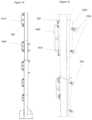
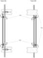
- FIG. 1is a side view of the first and second components according to one preferred embodiment of the invention.
- FIG. 2is a side view of the embodiment of FIG. 1 with the first and second components engaged ready for use.
- FIG. 3is a top perspective view of the first component of the post according to
- FIG. 1is a top view of the first and second components from FIG. 1 .
- FIG. 4is a top view of the first and second components from FIG. 1 .
- FIGS. 5 and 6are further side perspective views of the embodiment of FIG. 1 .
- FIG. 7is a side perspective view of another example safety rail post and system according to the invention which has been set up to show its in-use configuration.
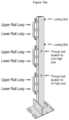
- FIG. 8depicts three safety posts according to the invention set at different heights.
- FIGS. 9 a and 9 bdepict another embodiment of a safety post according to the invention wherein the post defines an aperture serves as rail holder.
- FIGS. 10 a , 10 b , 11 and 12depict further example alternative posts according to the invention.
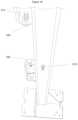
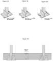
- FIG. 13is a side elevation view of an example safety post according to the invention comprising a baseplate with supports.
- FIG. 14is a side view of another example safety plate, also with a baseplate and support.
- FIG. 15is a side perspective view of another safety post and a detachable rail connector ( 1520 ) according to the invention.
- FIG. 16is a side elevation view of an example safety post according to the invention comprising a baseplate with supports.
- FIG. 17 adepicts the top section of an example safety post according to the invention.
- FIG. 17 bdepicts an example rail engaging mechanism according to the invention.
- FIGS. 18 a - 18 odepict an example installation method for a safety rail apparatus according to the invention.
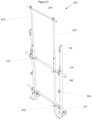
- FIG. 19depicts a safety post and rail system according to the invention comprising outrigger elements and protective netting.
- FIG. 20depicts a side perspective view of the top end of a safety net arrangement including outrigger posts according to the invention.
- FIG. 21depicts a side elevation view of an example extendable net support enclosure system according to the invention.
- FIGS. 22 and 23are front and rear views of the support of FIG. 21 .
- FIGS. 24 a and 24 bare side views of the support of FIG. 21 .
- FIGS. 25 a and 25 bare views of the support of FIG. 21 from above and below respectively.
- FIG. 26depicts a safety anchor comprising a safety post according to the invention.
- FIG. 27depicts an example tethering system for a safety rail system according to the invention.
- the various heights required during a construction projectare readily accommodated by an apparatus of the invention.
- the workersmay only require the safety rail to be at for example, 900 mm or 1 m or 1.1 m high. This allows the window or facade installers that are required on site to take perimeter windows or facade out of the side of the building. Higher guardrails make this activity substantially more difficult and cumbersome.
- different tradessuch as plumbers, plasterers and electricians need to work on short access ladders or scissor lifts at approximately 1 m to 1.2 m high and, close to the perimeter of the building.
- a handrail system according to the inventioncan be readily lowered again later in a project when other trades or processes are required.
- the apparatus of the inventionallows such modifications to readily occur without full replacement of the handrail system already in place, or without the need for numerous tools and without creating additional loose components (for example which have been removed) and which can get in the way and cause safety hazards.
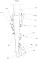
- FIG. 1is a side view of an example first component ( 100 ) and second component ( 110 ) according to one preferred embodiment of the invention in which, in use, the second component is slidably engaged with the first component.
- both componentscomprise posts or post members.
- the first componentcomprises apertures 310 to receive a rail and fixing means 320 (in this embodiment a bolt or screw) to reversibly fix a rail extending to an adjacent post therein.
- fixing means 320in this embodiment a bolt or screw
- second aperture 315which is intended to receive a second rail which is intended to extend to a different post, on the other side of this post.
- railscan extend through each aperture which makes for a stronger attachment, but also greater control in varying the distances between posts for different applications.
- the railswill overlap one another as depicted in FIG. 19 .
- the aperture memberdefines two adjacent apertures which together are directed along the axis of the post.
- the railsoverlap one another one above the other, but they may equally overlap horizontally or in other conformations or configurations.
- the railsdo not overlap. For example they may meet within the aperture member which defines the aperture, or they may be joined one to another lengthways, etc.
- Item 330which is the means of locking or fixing the first and second components (or posts) together is in this embodiment also a bolt or screw.
- the safety postcomprises base 340 with holes 350 for attachment to a flooring or the ground, and which has diagonal support 360 and horizontal supports 370 for support of a kick board 710 and for additional strength.
- FIG. 1also depicts an additional safety device 510 which in this embodiment is in the form of a pin which is attached to the first component by a cord.
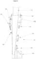
- FIG. 2depicts the same embodiment as FIG. 1 , with the first and second components or posts slidably engaged and fixed at an extended position using locking mechanism 330 which in this embodiment comprises a pair of bolts which are tightened so as to press against the upper post or second component and thereby hold it in place.
- locking mechanism 330which in this embodiment comprises a pair of bolts which are tightened so as to press against the upper post or second component and thereby hold it in place.
- FIG. 3is a top perspective view of the first component or lower post of the safety post according to FIG. 1 shown generally at 100 .
- Post component 100comprises an aperture 310 to receive a rail and fixing means 320 which in this embodiment comprises a bolt which is tightened down against the rail so as to reversibly ‘lock’ it in place.
- Post component 100also comprises base 340 and ‘locking mechanism’ 330 which is used to reversibly fix the first component to the second component at a selected height once the second component is slid within the body of the first component to the selected height.
- FIG. 4is a top view of the first ( 100 ) and second ( 110 ) components from FIG. 1 . This view also shows aperture 310 , fixing means 320 and locking mechanism 330 .
- FIGS. 5 and 6are further side views of the embodiment of FIG. 1 . Again, these views depict aperture 310 , fixing means 320 and locking mechanism 330 as well as base 340 with holes 350 for fixing to a floor and supports 360 and 370 .
- FIGS. 5 and 6also depict an additional safety device 510 which in this embodiment is in the form of a pin which is attached to the first component by a cord. This pin is used to provide a further, secure fixture between the first and second components by passing at least partially through each and thereby fixing them together.
- pin 510is particularly useful in providing additional safety in the event of a person or heavy weight falling on to the top rail from above.
- safety device 510is in the form of a bolt which passes through the first component 100 and below the second component 110 thus preventing it from collapsing into the first component.
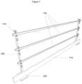
- FIG. 7is a side perspective view of another example safety rail post and system according to the invention which has been set up to show its in-use configuration with rails 720 engaged with through apertures 310 in aperture members and fixed with bolts 320 . It depicts apertures 310 to receive a rail and fixing means 320 (in this embodiment a bolt or screw) to reversibly fix a rail therein and base 340 . Also depicted in FIG. 7 is board 710 which functions as a kick board to stop items such as tools or fixtures or other debris from rolling along and off the edge of the floor.
- a rail and fixing means 320in this embodiment a bolt or screw
- Board 710can be fixed to posts according to the invention in any suitable manner, for example via screws into the baseplate, or a base plate support such as item 371 in FIG. 8 .
- FIG. 8depicts three safety posts according to the invention set at different heights. This figure highlights the invention's flexibility in allowing handrails to be set at numerous heights.
- Support 371is designed to add strength to the base and in some embodiments is used to fix a board such as a kickboard in place, for example via a bolt(s) or screw(s) engaged with one or more of holes 375 .
- FIGS. 9 a and 9 bdepict another embodiment of a safety post according to the invention shown generally at 900 .
- post 900defines an aperture 910 which serves as rail holder for rail 930 which is reversibly fixed in place by bolts 920 .
- first and second componentsare slidable (such as a telescopic embodiment)
- second componenteg. upper post
- Such an embodimentmay for example comprise a first component (eg lower post) which defines an aperture for receiving a rail and a second component which comprises two sub posts which themselves are slidable within the two sections either side of the aperture body of the first component.
- Items 935 and 936 in FIG. 9 adepict the corresponding two sections, but in this instance, in the second component, or upper post.
- FIGS. 10 a , 10 b , 11 and 12depict further example alternative posts according to the invention.
- Item 310 a in FIG. 10 ais an aperture akin to that of aperture 310 on the first component (or lower post) but placed on the second component (or upper post) and in this embodiment functions in the same way.
- FIG. 13is a side elevation view of an example safety post according to the invention comprising a baseplate with holes 350 and with supports 360 and 371 .
- Stop 1310(in this embodiment, in the form of a bolt), serves two purposes. Firstly, if a worker is working at height and falls on top of the handrail system this will prevent the top post collapsing into the bottom post and potentially allowing the worker to fall over the edge. Secondly, it serves as a stop to prevent fingers being crushed when an installer is adjusting the handrail system height they will need to loosen item 330 FIG. 11 . If they are not holding onto the top post item 110 it will drop into item 100 this would mean that apertures from the top post and bottom post would hit together similar to the middle post in FIG. 8 . If the installer had their hand in between these two posts at that time it could easily be crushed.
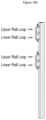
- FIGS. 12 , 14 and 15depict a further example safety post according to the invention with a further variation in the rail engaging mechanism.
- These embodimentsdepict an alternative extension post with only the upper rail engaging aperture members or D rings 1410 welded to the post and the lower set of D rings 1420 being configured to be detachable.
- Embodiments comprising such detachable aperture membersprovide a greater flexibility in the range of lengths that the overall, combined safety post can be set at. It will be appreciated that by detaching the lower aperture members, the upper post (or second component) can be slid to a lower position than if they were permanently fixed on.
- detachability of the lower aperture members of the second component (or upper post)is effected by having aperture members 1420 fixed (in this embodiment, welded) to plate 1510 which is fixed in place against the second component (or upper post) with fixtures 1530 (here bolts) passing through plate 1520 into engagement with plate 1510 .
- Other means of providing detachable aperture membersmight for example include using a keyhole slot and pin arrangement so that a set of aperture members with a base plate and pins can be fixed at one or more predetermined heights on the second component merely by sliding the pins of the aperture member plate into a corresponding set of slots on the second component to match the preferred height for the requirements.
- FIG. 16is another side elevation view of an example safety post according to the invention comprising a baseplate with supports.
- FIG. 17 adepicts the top section of an example safety post according to the invention and shows aperture 1710 for receiving a rail to be fixed and aperture 1720 for receiving a bolt to be tightened against the rail and thereby reversibly fix it in place.
- Hole 1730allows stop 1310 (in this embodiment a bolt) FIG. 16 to pass through and thereby fix the first and second components of the safety rail in place.
- some embodimentscomprise a plurality of such holes.
- such holespre determine the height of the top post for example, for ease of installation. As an example, if a bolt is installed in the lower of the two holes in all posts they will all be set up at 2 m high. If the bolt is placed in the top hole all posts will be set up at 2.4 m high. This saves time as it means the installer doesn't have to measure each post as they will all be set up at the same height.
- FIG. 17 bdepicts another example rail engaging mechanism according to the invention shown generally as 1750 .
- the rail engaging mechanismcomprises a plurality of apertures 1760 , each to receive a rail which is to be reversibly fixed in place with fixing means (here bolts) 1770 .
- the aperture memberdefines two adjacent apertures which together are directed at right angles to the axis of the post.
- the rails extending to each adjacent postoverlap in the horizontal plane, one behind the other. This is in contrast to the embodiment of FIG. 1 in which they are placed one above the other.
- the arrangement of FIG. 17 bmaximises the gap between the rails allowing workers to work through the handrail system without closer rails hindering their progress.
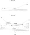
- FIGS. 18 a - 18 odepict an example installation method for a safety rail apparatus according to the invention.
- Guidelines for installation of an apparatus according to the inventioninclude:
- FIG. 18 adepicts an example base post of 1100 mm length. It is used as perimeter edge protection on concrete slabs or timber form work.
- FIG. 18 bdepicts an example extension post which is used to extend the base post from 110 anywhere up to 2400 mm.
- FIG. 18 cdepicts an example kickboard which in this example is 150 mm high.
- FIG. 18 ddepicts an example detachable rail bracket which is used as an additional rail holder when the extension post is extended above 2000 mm.
- FIG. 18 edepicts an example handrail which can be a variety of sizes. In this example it is 3200 mm length. Cross-sectionally it may for example be 50 mm ⁇ 25 mm ⁇ 2 mm or for example 38 mm ⁇ 25 mm ⁇ 2 mm.
- FIG. 18 adepicts an example base post of 1100 mm length. It is used as perimeter edge protection on concrete slabs or timber form work.
- FIG. 18 bdepicts an example extension post which is used to extend the base post from 110 anywhere up
- FIG. 18 fdepicts an M8 screw bolt for fixing the base into concrete.
- FIG. 18 gdepicts a 14 gauge timber screw for fixing the base plate into timber. Preferably at least 3 are used per post and preferably they are 14 mm ⁇ 90 mm type 17 screws and extend into the support beams below the floor.
- FIG. 18 hdepicts an example safety rail apparatus according after installation.
- FIG. 18 lattach the kickboard with a minimum of 4 screws per post.
- kick boardsoverlap at a point other than on the base posts there should be a minimum of 100 mm overlap with a minimum of 2 screws installed in the overlap to hold the kickboards together.
- FIG. 18 mfor higher rails, place the extension post into the base post and lock into place using the locking bolts provided in the base post.
- a through boltis provided in each base post to prevent the extension post from collapsing into the base post. This bolt must be moved to the higher location if the handrail is extended from 2 m to 2.4 m high.
- FIG. 18 odepicts a corner section of a safety rail apparatus according to the invention. Rails must not exceed 600 mm overhang from the post and rails must meet on corners.
- the post, rail and rail engaging means of the inventionmay be manufactured from any suitable materials.
- suitable materialsfor example steel, milled steel, aluminium, polymer, carbon-fibre, etc.
- Some embodiments of the inventionprovide a handrail system comprising posts and rails, the rails fixed to the posts by brackets welded to the posts and the posts fixed to the supporting floor (preferably a concrete floor) by screw anchors.
- the rail and post of the inventiondeflects less than 101 mm under application of 600 Newton horizontal and vertical loads.
- FIG. 19depicts a safety post and rail system according to the invention comprising outrigger elements and protective netting.
- FIG. 20depicts a side perspective view of the top end of a safety net arrangement including outrigger elements according to the invention.
- An outrigger element 1910 according to the inventionis typically attached to a post 1930 which may be a safety post according to the invention, or it may be attached to a separate post which may for example be separately fixed to a post or a horizontal rail according to the invention.
- the outrigger elements of the inventionmay extend out from the building site any suitable distance. Typically such distances comprise 0.5 m to 1.5 m, preferably 0.9 m to 1.3 m, and post preferably 1 to 1.2 m. Such outrigger elements are useful to provide an additional support for further safety features such as the netting 1920 also shown in these figures.
- the outrigger elementsmay be made from any suitable materials, but typically they are made from the same materials as the rail and posts of the rail apparatus.
- the outrigger elementsmay slidingly engage with the top of the posts and optionally be fixable in one or more positions, for example with a hole and button, or clip or slot and bolt, or other suitable mechanism.
- the safety post of the inventionitself comprises an outrigger element which may or may not be extendable therefrom.
- an outrigger elementmay attach separately to a rail rather than a post.
- the outrigger elementmay for example attach by means of a clamp, or bolt or clasp or any other suitable mechanism sufficient to hold the element in place and withstand forces that might be applied to it, for example if a tool or other item ,such as a bolt or a screw is dropped from an upper level and is caught by the netting.
- This featureadds an additional layer of safety on multi story construction sites regarding falling objects. Spacing of the outrigger elements can be discretionary, depending upon wind loadings or weight of proposed items that are intended to be prevented from falling .
- the outrigger elementscan also be installed as required, for example only on determined sections of one elevation of a building, or alternatively could be installed continuously and on multiple levels.
- outrigger elementsadd additional layer of safety to a building site by providing an additional catch nett for any minor items dropped by tradesman or blown over the side of buildings on windy days.
- the meshmay be of any suitable type capable of withstanding the forces applied when items are dropped on construction sites.
- the mesh or nettingis not too heavy which would adversely affect the primary function of the handrail system, that is to prevent people from falling from heights and comply with relevant safety standards.
- the mesh or nettingis not too heavy which would adversely affect the primary function of the handrail system, that is to prevent people from falling from heights and comply with relevant safety standards.
- the meshmay comprise: Debris mesh 18 ⁇ 18 ⁇ 15 ply, or Unigrid 25 ⁇ 25 mesh.
- Debris meshmust be tied to all handrails at 0.8 m centres along the rail, for example using electrical cable ties with a breaking load exceeding 18 kg each.
- the top of the debris meshmust be no more than 2.1 m for posts at the standard 3 m centres. If the applications requires debris mesh 2.4 m, reduce the post spacing to 2.3 m centres.
- the tie spacingshould be reduced by 25% and limit the top of Debris Mesh to 1.8 m
- All postsshould be fixed to concrete floors for example with 4 ⁇ M8 anchor screws, two at the front, two at the back.
- Example 4use of mesh for city buildings to 200 m, and suburban buildings to 100 m tall.
- the mesh(such as 18 ⁇ 18 ⁇ 15 ply debris mesh) must be tied to the handrail at no more than 1 m centres vertically and at 1.5 m centres along the rail. (No ties to the posts are needed.)
- the postsmay be at the standard spacing of 3 m.
- post spacingshould be reduced to 2 m.
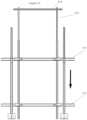
- FIG. 21depicts a side elevation view of an example extendable safety mesh support according to the invention shown generally at 210 attached to a safety rail post system according to the invention.
- This embodiment of the supportis fixed to rails 211 by clamps 212 which in this instance are simple L shaped screw-in clamps.
- Support posts 213extend vertically from the floor (and may for example be fixed to the floor) and engage the horizontal mesh rail 214 at their top.
- the extendable supports of this embodimentdo not comprise outrigger elements but it will be appreciated that they are readily attachable to the vertical posts 213 or such posts may come with outrigger elements pre-attached.
- Such embodimentsmay comprise a further mesh rail 214 at the ends of the outrigger posts to further support or fix the mesh at its most extreme point.
- FIGS. 22 and 23are front and rear views of the support of FIG. 21 .
- FIGS. 24 a and 24 bare side views of the support of FIG. 21 .
- FIGS. 25 a and 25 bare views of the support of FIG. 21 from above and below respectively.
- At least one componentis slidable within or along another.
- one componentis concentrically slidable within another.
- Such slidable engagementmay for example be telescopic (for example, a telescopic staunchion).
- a winding mechanismto wind one component relative to the other between heights.
- Such a winding mechanismmust be sufficiently robust so as to meet the strength requirements of relevant safety standards.
- the winding mechanismuses one or more gears to enable steady movement and preferably is lockable so as to set the height of the safety rail system at a wide variety of heights.
- the debris meshcan be readily extended from the ground all the way up to the underside of the floor slab above.
- mesh supports optionally attached to safety railswhich are fixed to safety rail posts according to the invention are fixed at 3 metre intervals with an optional horizontal rail at the top that connects them together.
- the meshcan be attached to the top rail 214 for example with cable ties and then the installer can simply raise the post inner post item ( 213 ) until it hits the underside of the concrete slab or structure above.
- a rope or cablecould be used in lieu to support the mesh .
- Such an embodimentprovides the building with a complete debris mesh screen preventing anything from going over the side of the building.
- the mesh support apparatus of the inventionprovides a complete curtain wall that can be operated from the inside of the building.
- itcan be fixed to a safety rail apparatus according to the invention, so that the mesh support apparatus can be produced with lighter materials which are for example cheaper and easier to handle and install, whilst receiving structural integrity from the safety rail post system of the invention.
- Another advantage of the mesh support apparatus of the inventionis that it can be installed whilst the installer is behind the safety rail system at all times (particularly important, for example on a 20 storey building), and the installer maintains their feet on the floor slab at all times. Therefore risk from elevated work (for example on ladders, scissor lifts etc) and particularly outside the safety rail, are eliminated.
- FIG. 26depicts a safety anchor (such as a fall arrest anchor) comprising a safety post according to the invention shown generally at 260 .
- the safety anchorcomprises sling 261 attached via device 262 (here a carabiner) which connects safety strap, which may for example comprise or connect to a harness.
- the anchoris designed to withstand a load of more than 12 kN (ultimate), preferably more than 13 and most preferably more than 15 kN. Some particular embodiments can withstand a 15.1 kN (ultimate) load in the direction of loading and some preferred embodiments can support a 1523 kg load.
- Anchorage to the flooris an important aspect of the safety anchor implementations of the invention.
- the floormust be at least equivalent to concrete which is 120 mm thick, preferably thicker.
- the bolts or screws used to fix the base of the safety post to the floormust be sufficiently strong so as to withstand the intended forces, for example at least as strong as 4 ⁇ M8 AnkaScrews fixed into the concrete.
- the screws or boltsshould be proof-torqued during installation for example to at least 40 Nm if not specified.
- the sling or safety device(such as a harness) is attached as close as possible to the base plate so as to maximise support. In some embodiments it is attached directly above the kick plate.
- a support member 264may comprise an attachment means, such as an appropriately rated aperture there through.
- FIG. 27depicts an example tethering system for a safety rail system according to the invention indicated generally by 270 .
- the handrailis installed it is behind steel screens, for the prevention of falling objections.
- the handrail systemmust be moved or altered after the screens have been removed and the external fagade of the building is not yet in place. In times such as these, falling objects are a major concern.
- the following tethering systemmay be used.
Landscapes
- Engineering & Computer Science (AREA)
- Architecture (AREA)
- Civil Engineering (AREA)
- Structural Engineering (AREA)
- Mechanical Engineering (AREA)
- Steps, Ramps, And Handrails (AREA)
- Emergency Lowering Means (AREA)
- Machines For Laying And Maintaining Railways (AREA)
- Bridges Or Land Bridges (AREA)
- Refuge Islands, Traffic Blockers, Or Guard Fence (AREA)
Abstract
Description
- a. placing a first base post at a desired location and fixing it to the underlying structure;
- b. placing a second base post at a desired location and fixing it to the underlying structure;
- c. installing one or more rails by placing them in contact with a rail holder associated with each of the first and second base posts and locking them in place;
- d. attaching a kick board to at least one base post;
- e. placing an extension post into each base post and locking them into place with a suitable locking device;
- f. installing one or more rails into the extension posts, by placing them in contact with a rail holder associated with each of the first and second extension posts and locking them in place;
- g. wherein, in steps a and b, one or more of the following fixtures are used:
- Posts are to be installed at a maximum of 3000 mm.
- Handrail heights are dictated by the relevant Standard and are dependent on the structure pitch.
- Where midrails are used, the nominal clear distance between rails shall not exceed 450 mm.
- The nominal clear distance between a midrail and a toe board or bottom rail shall not exceed 275 mm. In any section of edge protection, the rails shall be nominally parallel.
- It is important that the structure to which the temporary edge protection is to be attached can support the forces that may be applied when the edge protection restrains a person from falling from the edge.
- For posts 1.1 m high, minimum of 2×8 mm screw bolts per post, set as depicted in
FIG.18 i; - For posts greater than 1.1 m high, a minimum of 3×8 mm screw bolts per post, set as depicted in
FIG.18 j;
- For posts 1.1 m high, minimum of 2×8 mm screw bolts per post, set as depicted in
- For any height post, use a minimum of three14x90mm timber screws per post, set as depicted in
FIG.18k . Timber screws must go through plywood and into the timer support beams below.
- For any height post, use a minimum of three14x90mm timber screws per post, set as depicted in
- Posts 65×35×3 mm RHS (Rolled Hollow Section)×1100 high, with 50×25×3 mm RHS extension to give 2400 height.
- Posts at 1 to 3 m centres.
- Post bases 270×200×6 mm thick plate steel (PL) with fins in 4 mm plate steel
- Rails: 38×25×2 mm RHS.
- Posts 65×35×3 mm RHS (Rolled Hollow Section)×1100 high, with 50×25×3 mm RHS extension to give 2400 height.
- Into concrete for rails to 1100 high: 2/M8×60 Screw Bolts in diagonally opposite corners of the base plate.
- 1—attach a lanyard to one of the D rings on the nearest handrail post
- 2—attach other end of lanyard to
tethering bracket 271. - 3—Attach tethering bracket to approximate centre of handrail that the individual wishes to remove or alter. The tethering bracket must be fastened tightly to the rail.
- 4—once the proposed rail is attached firmly to the tethering bracket, loosen the holding screws in the handrail post and alter/remove as required.
- 5—repeat process until required task is complete.
Claims (7)
Applications Claiming Priority (9)
| Application Number | Priority Date | Filing Date | Title |
|---|---|---|---|
| AU2016903731AAU2016903731A0 (en) | 2016-09-16 | Safety rail post | |
| AU2016903731 | 2016-09-16 | ||
| AU2017902334 | 2017-06-19 | ||
| AU2017902334AAU2017902334A0 (en) | 2017-06-19 | Improved safety rail system | |
| AU2017903215AAU2017903215A0 (en) | 2017-08-11 | Further improved safety rail system | |
| AU2017903215 | 2017-08-11 | ||
| AU2017903629AAU2017903629A0 (en) | 2017-09-07 | Still further improved safety rail | |
| AU2017903629 | 2017-09-07 | ||
| PCT/AU2017/051002WO2018049477A1 (en) | 2016-09-16 | 2017-09-14 | Safety rail system |
Publications (2)
| Publication Number | Publication Date |
|---|---|
| US20200270882A1 US20200270882A1 (en) | 2020-08-27 |
| US11976481B2true US11976481B2 (en) | 2024-05-07 |
Family
ID=60118994
Family Applications (2)
| Application Number | Title | Priority Date | Filing Date |
|---|---|---|---|
| US16/067,935Active2041-11-04US11976481B2 (en) | 2016-09-16 | 2017-09-14 | Safety rail system |
| US18/375,649AbandonedUS20240060320A1 (en) | 2016-09-16 | 2023-10-02 | Safety rail system |
Family Applications After (1)
| Application Number | Title | Priority Date | Filing Date |
|---|---|---|---|
| US18/375,649AbandonedUS20240060320A1 (en) | 2016-09-16 | 2023-10-02 | Safety rail system |
Country Status (9)
| Country | Link |
|---|---|
| US (2) | US11976481B2 (en) |
| EP (1) | EP3469168B1 (en) |
| JP (2) | JP7547047B2 (en) |
| CN (2) | CN108699848A (en) |
| AU (7) | AU2017101261B4 (en) |
| CA (1) | CA3035382A1 (en) |
| GB (1) | GB2568830B (en) |
| HK (1) | HK1256206A1 (en) |
| WO (1) | WO2018049477A1 (en) |
Cited By (1)
| Publication number | Priority date | Publication date | Assignee | Title |
|---|---|---|---|---|
| US20230399862A1 (en)* | 2020-11-02 | 2023-12-14 | Harris Carpentry Contractors Limited | Truss support system |
Families Citing this family (23)
| Publication number | Priority date | Publication date | Assignee | Title |
|---|---|---|---|---|
| JP7547047B2 (en)* | 2016-09-16 | 2024-09-09 | ディバ インベストメンツ ピーティーワイ リミテッド アズ トラスティー フォー ハンドレイル ホールディング トラスト | Safety Rail System |
| SE1850037A1 (en)* | 2018-01-12 | 2019-07-13 | Boerjesson Tomas | Fastener |
| WO2019204621A1 (en)* | 2018-04-20 | 2019-10-24 | Deltak Manufacturing, Inc. | A scaffold gate toeboard assembly for use on a scaffold gate |
| AU2019216711B2 (en)* | 2018-08-17 | 2021-05-06 | Ewrg (South) Pty Ltd | Guardrail post |
| GB2579830A (en)* | 2018-12-17 | 2020-07-08 | Astute Safety Solutions Ltd | Connector plate |
| CN110792277A (en)* | 2019-10-10 | 2020-02-14 | 广西中煤地质有限责任公司 | Guardrail for building construction |
| US11851900B2 (en)* | 2020-01-30 | 2023-12-26 | James Croswell Brim, III | Temporary safety railing system and method |
| IT202000004384A1 (en)* | 2020-03-02 | 2021-09-02 | Lucio Filippelli | SAFETY DEVICE FOR BATTAGLIOLA IN USE IN SHIPYARDS |
| CN111877783B (en)* | 2020-06-29 | 2021-11-23 | 湖北精工工业建筑系统有限公司 | Lifeline upright post mounting and fastening device suitable for box-shaped steel beam |
| CN212958022U (en)* | 2020-07-29 | 2021-04-13 | 苏州云联东控信息科技有限公司 | Protection device of building materials equipment |
| EP4288623A4 (en)* | 2021-02-04 | 2025-01-08 | Mane Fencing Pty Ltd | Temporary building edge safety screen support |
| AT524584B1 (en) | 2021-03-09 | 2022-07-15 | Herbert Brodinger | handrail post |
| US12227244B2 (en)* | 2021-03-25 | 2025-02-18 | Safesmart Llc | Safety rail |
| CN113482376A (en)* | 2021-06-11 | 2021-10-08 | 中大建设股份有限公司 | Detachable hole protection method used in construction |
| KR102374490B1 (en)* | 2021-06-18 | 2022-03-14 | 노진오 | Easy-to-install safety structure for construction work |
| CN114086822B (en)* | 2022-01-20 | 2022-04-08 | 航城建设股份有限公司 | Safety enclosure device for building construction area and installation method thereof |
| PL441032A1 (en)* | 2022-04-26 | 2023-10-30 | Cbr Rock Master Spółka Z Ograniczoną Odpowiedzialnością Spółka Komandytowa | Shock-absorbing safety post |
| CN115450316B (en)* | 2022-09-22 | 2024-01-23 | 中国建筑第八工程局有限公司 | Assembled building frame |
| CN115434502A (en)* | 2022-09-28 | 2022-12-06 | 中能建建筑集团有限公司 | Attached lifting scaffold and construction method thereof |
| DE102022004178A1 (en)* | 2022-11-08 | 2024-05-08 | Ziwi Vertriebs Gmbh | Device for repelling animals, especially birds, preferably pigeons |
| DK181666B1 (en)* | 2023-05-02 | 2024-09-16 | Lone Gerda Neumann Eriksen | Holder assembly for guard rail system |
| KR200499303Y1 (en)* | 2024-02-05 | 2025-06-27 | 김용신 | Safety Railing |
| CN118958647B (en)* | 2024-10-21 | 2024-12-13 | 江苏迈朗建设工程有限公司 | Safety hanging basket for building construction |
Citations (79)
| Publication number | Priority date | Publication date | Assignee | Title |
|---|---|---|---|---|
| US2329415A (en)* | 1943-02-19 | 1943-09-14 | William G Osborne | Scaffold |
| US3589682A (en)* | 1968-11-30 | 1971-06-29 | Edward Earl Dickey | Safety fence support column |
| JPS50902A (en) | 1973-05-04 | 1975-01-08 | ||
| US3867997A (en)* | 1973-12-26 | 1975-02-25 | Jr Thomas Hyslop | Guard rail support for scaffold |
| US3949834A (en)* | 1975-03-19 | 1976-04-13 | Arthur Nusbaum | Safety net and adjustable support therefor |
| US3995833A (en)* | 1975-07-23 | 1976-12-07 | Jack McLaughlin | Removable guard rail stanchion apparatus |
| US4074791A (en)* | 1976-03-16 | 1978-02-21 | Inman Johnny K | Emergency fire net |
| US4078633A (en)* | 1976-02-09 | 1978-03-14 | Fahy Michael B | Modular staging with platform jacks |
| JPS59177478A (en) | 1983-03-28 | 1984-10-08 | 大木建設株式会社 | Fixing of handrail in wall type precast reinforced concrete building construction |
| US4598794A (en)* | 1985-03-22 | 1986-07-08 | Anderson Carl E | Scaffolding system |
| US4666131A (en)* | 1986-04-24 | 1987-05-19 | Kettelkamp Sr Ronald C | Adjustable guard rail stanchion member |
| US4691485A (en)* | 1982-11-30 | 1987-09-08 | Epitestudomanyi Intezet & Konnyuipari Szerelo es Epito Vallalat | Apparatus and process for the construction of monolithic ceilings |
| US4732234A (en)* | 1987-09-08 | 1988-03-22 | Morley Brickman | Perimeter safety net system for multi-story buildings under construction |
| US4815562A (en)* | 1988-03-28 | 1989-03-28 | Sinco, Inc. | Debris barrier |
| US4838382A (en)* | 1988-10-26 | 1989-06-13 | Arthur Nusbaum | Building safety net |
| US4856615A (en)* | 1988-09-20 | 1989-08-15 | Arthur Nusbaum | Safety net arrangement for multi-floor buildings under construction, and method |
| US4892169A (en)* | 1989-02-21 | 1990-01-09 | Sinco, Inc. | Perimeter debris net lifting system |
| US5012627A (en)* | 1989-05-25 | 1991-05-07 | Lundmark Bo J | Construction process for multiple-story concrete building |
| JPH0446025A (en) | 1990-06-13 | 1992-02-17 | Matsushita Electric Ind Co Ltd | Mold for optical parts molding |
| US5161641A (en)* | 1991-10-29 | 1992-11-10 | Arthur Nusbaum | Jointly movable safety net and curtain arrangement for multi-floor buildings under construction |
| WO1993020311A1 (en) | 1992-04-03 | 1993-10-14 | Peri Gmbh | Adjustable-height support for shuttering in the building trade |
| JPH0628089A (en) | 1992-07-10 | 1994-02-04 | Matsushita Electric Ind Co Ltd | Tablet device |
| JPH07127240A (en) | 1993-11-05 | 1995-05-16 | Kazuo Fukutome | Support for safety master rope on car body |
| USD373718S (en)* | 1995-03-10 | 1996-09-17 | Rondeau Donald G | Combined staging bracket and double sided clamp back rail |
| US5573227A (en)* | 1995-06-13 | 1996-11-12 | Hemauer; Thomas J. | Guardrail stanchion mounted onto building frame |
| US5582266A (en)* | 1994-09-15 | 1996-12-10 | Rexroad; John | Safety/debris net system |
| US5638917A (en)* | 1995-11-27 | 1997-06-17 | Vennen; Dennis L. | Scaffold bracket for roof structure installation |
| US5647451A (en)* | 1995-11-03 | 1997-07-15 | Reichel; Mark W. | Portable roof guard rail support device |
| US5718305A (en)* | 1996-11-01 | 1998-02-17 | Palmer; Theodore Richard | Safety harness attachment post assembly |
| US5829549A (en)* | 1996-09-11 | 1998-11-03 | Flynn; Richard A. | Walkway with rail system |
| US5884725A (en)* | 1994-06-23 | 1999-03-23 | Kookoala Pty Ltd | Scaffolding assembly |
| JPH11256835A (en) | 1998-03-12 | 1999-09-21 | Taisei Corp | Lifting handrail for stage |
| US6003631A (en)* | 1998-09-29 | 1999-12-21 | Knauth; Peter R. | Wall supported scaffolding device |
| US6015028A (en)* | 1997-05-14 | 2000-01-18 | Smith; Andrew C. | Pump jack hoisting apparatus including a safety railing for protecting workers from accidental falling |
| US6021702A (en)* | 1998-02-09 | 2000-02-08 | Rexroad; John | Aesthetic barrier/debris system and material |
| US6038829A (en)* | 1997-06-09 | 2000-03-21 | Franks; Bert | Adaptable safety rail system for flat roofs and parapets |
| US6039150A (en)* | 1995-05-03 | 2000-03-21 | Palmer; Theodore R. | Building guard rail scaffold assembly |
| US6336623B1 (en)* | 2000-08-21 | 2002-01-08 | Mccarthy John J. | Portable safety barrier |
| US20020139614A1 (en)* | 2001-11-21 | 2002-10-03 | Volkman John Michael | Hanging scaffold support |
| US20030132427A1 (en)* | 2001-09-05 | 2003-07-17 | Dwight Allenbaugh | Construction perimeter guard |
| US6722468B2 (en)* | 2002-02-01 | 2004-04-20 | James R. Albano | Suspended scaffolding system |
| EP1482104A1 (en) | 2003-05-28 | 2004-12-01 | Marc Antoine | Adjustable modular safety system for scaffold |
| US6842992B1 (en)* | 2003-11-07 | 2005-01-18 | Mark S. Gitt | Building wall layout tool |
| US20060090961A1 (en)* | 2004-11-02 | 2006-05-04 | John Rexroad | Safety net system |
| US20070246299A1 (en)* | 2006-03-31 | 2007-10-25 | Wright James E | Safety barrier stanchion |
| US20070252055A1 (en)* | 2004-07-29 | 2007-11-01 | Melic Jonny J | Guard rail safety system |
| US20090152048A1 (en)* | 2007-10-17 | 2009-06-18 | Neil Rooney | Scaffolding Arrangement and Method of Assembly |
| US20090159865A1 (en)* | 2007-12-21 | 2009-06-25 | Carvalho Joseph | Reusable temporary safety rail post |
| GB2468688A (en) | 2009-03-19 | 2010-09-22 | Slick Systems | Extendable safety barrier |
| WO2011082927A1 (en) | 2009-12-14 | 2011-07-14 | Peri Gmbh | Telescopic support for the construction industry |
| WO2011095289A1 (en) | 2010-02-02 | 2011-08-11 | Peri Gmbh | Railing element |
| WO2011095288A1 (en) | 2010-02-02 | 2011-08-11 | Peri Gmbh | Support device and shuttering system |
| EP2378032A1 (en) | 2010-04-16 | 2011-10-19 | Combisafe International Aktiebolag | Soft net containment |
| US20110272659A1 (en)* | 2010-05-07 | 2011-11-10 | Safety Maker, Inc. | Apparatus for Forming Temporary Guardrails on Stairs |
| US20110278526A1 (en)* | 2007-12-21 | 2011-11-17 | Carvalho Joseph | Reusable temporary safety rail post and extension kit |
| WO2012000591A1 (en) | 2010-06-29 | 2012-01-05 | Peri Gmbh | Side protection system |
| GB2483106A (en) | 2010-08-27 | 2012-02-29 | Galliford Try Infrastructure Ltd | Buttress support for a fall protection fence |
| US8132792B2 (en)* | 2005-05-09 | 2012-03-13 | Safety In A Second Ltd. | Temporary guard rail support |
| US8448923B1 (en)* | 2012-03-15 | 2013-05-28 | Dane Avery Schad | Elevated surface safety base and post apparatus |
| JP2014101642A (en) | 2012-11-16 | 2014-06-05 | Jfe Engineering Corp | Installation method of safety balustrade for working |
| US20140263904A1 (en)* | 2013-03-14 | 2014-09-18 | Heritage Research Group | Mse wall guardrail system |
| WO2014171536A1 (en) | 2013-04-18 | 2014-10-23 | 株式会社Aoi | Free handrail |
| KR101472962B1 (en) | 2014-04-30 | 2014-12-17 | (주)시우하이텍 | A height adjustable safety railing |
| US20150225912A1 (en)* | 2014-02-11 | 2015-08-13 | Rodrigo & Sequeira, Associados - Projectos Urbanos, Lda. | Modular demountable safety panels, compatible with application on concrete bases or metal barriers at motor racing circuits and their respective assembly process |
| US20150225919A1 (en)* | 2014-02-07 | 2015-08-13 | Bennie R. Wagler | Post-Frame Footing Assembly and Vertical Post |
| US9145694B2 (en)* | 2009-07-16 | 2015-09-29 | Quick Products Inc. | Platform support structures and platform assemblies |
| WO2016008215A1 (en) | 2014-07-15 | 2016-01-21 | 大连科德数控有限公司 | 5-axis and 6-axis mixing control method for industrial robot and system thereof |
| CN105587132A (en) | 2014-10-24 | 2016-05-18 | 夏安娜 | Building guardrail for civil engineering |
| US20160192989A1 (en)* | 2014-06-07 | 2016-07-07 | Peter M. Aman | Sterile ready-to-use surgical tool having wireless charging system capability |
| US20160305152A1 (en)* | 2013-03-14 | 2016-10-20 | Heritage Research Group | Mse wall guardrail system |
| CN106854938A (en) | 2015-12-09 | 2017-06-16 | 江苏蓝天环保集团股份有限公司 | A kind of Height Adjustable protection guardrail of assembly type |
| CN206346509U (en) | 2016-12-30 | 2017-07-21 | 中建三局第三建设工程有限责任公司 | A kind of new creeping formwork guard rail |
| US9731640B1 (en)* | 2013-11-15 | 2017-08-15 | Sam Cabris Asset Management, Llc | Mobile fall protection unit for flatbed platforms |
| WO2017174808A1 (en) | 2016-04-08 | 2017-10-12 | Bornack Gmbh & Co.Kg | Safety post |
| US20180127993A1 (en)* | 2016-11-07 | 2018-05-10 | Beziup Stanchion, LLC | Extendable construction stanchion |
| US20180347219A1 (en)* | 2017-06-01 | 2018-12-06 | Safety Guys, LLC | Building sheath drop netting system and related methodology |
| US10982454B2 (en)* | 2017-12-15 | 2021-04-20 | Jonathan J. Melic | Safety fence assembly |
| US20210238872A1 (en)* | 2020-01-30 | 2021-08-05 | Choate Construction Company, | Temporary safety railing system and method |
| US11236511B2 (en)* | 2019-04-23 | 2022-02-01 | Buildergear Corporation | Guard rail system and components |
Family Cites Families (17)
| Publication number | Priority date | Publication date | Assignee | Title |
|---|---|---|---|---|
| JPS50902Y1 (en)* | 1969-04-21 | 1975-01-11 | ||
| JPS4944723Y1 (en)* | 1973-11-15 | 1974-12-07 | ||
| JPS60148453U (en)* | 1984-03-15 | 1985-10-02 | 石川県瓦販売工事協同組合 | Fall prevention equipment for tile roofing workers |
| JPH0446025Y2 (en)* | 1987-12-02 | 1992-10-29 | ||
| JPH0628089U (en)* | 1992-09-08 | 1994-04-15 | 正義 三山 | Jig for temporary passage |
| US5645271A (en)* | 1994-07-11 | 1997-07-08 | Nunez; Marcos D. | Metal fence post with adjustable rail mounting |
| KR20010090349A (en)* | 2000-03-24 | 2001-10-18 | 김종권 | safety net installation with guide frame & winch |
| NZ530465A (en)* | 2003-12-24 | 2006-10-27 | Architectural Profiles Ltd | Post with central "I" beam part and exterior housing |
| CN201151887Y (en)* | 2007-11-02 | 2008-11-19 | 刘孔杰 | Liftable highway anti-collision guard rail column |
| JP2010185185A (en)* | 2009-02-10 | 2010-08-26 | Sekisui House Ltd | Temporary handrail and its construction method |
| CN201420385Y (en)* | 2009-04-29 | 2010-03-10 | 中铁十局集团有限公司 | Overhanging type unloading platform for building construction |
| CN203879034U (en)* | 2014-01-28 | 2014-10-15 | 逄紫薇 | Adjustable guardrail for building engineering |
| KR101475807B1 (en)* | 2014-06-11 | 2014-12-23 | 유한회사 도유 | Fence post of height adjustment |
| US9500000B2 (en)* | 2014-11-21 | 2016-11-22 | James E. McCarty | Fencing panel and method of assembly |
| CN205445131U (en)* | 2016-03-24 | 2016-08-10 | 台州正鼎建设有限公司 | Building construction rail guard |
| CN205654063U (en)* | 2016-05-17 | 2016-10-19 | 中国建筑第八工程局有限公司 | Tower crane concrete cap's safety protection platform is demolishd in high altitude |
| JP7547047B2 (en)* | 2016-09-16 | 2024-09-09 | ディバ インベストメンツ ピーティーワイ リミテッド アズ トラスティー フォー ハンドレイル ホールディング トラスト | Safety Rail System |
- 2017
- 2017-09-14JPJP2019501980Apatent/JP7547047B2/enactiveActive
- 2017-09-14AUAU2017101261Apatent/AU2017101261B4/ennot_activeExpired
- 2017-09-14AUAU2017326754Apatent/AU2017326754B2/enactiveActive
- 2017-09-14GBGB1900353.2Apatent/GB2568830B/enactiveActive
- 2017-09-14HKHK18115306.7Apatent/HK1256206A1/enunknown
- 2017-09-14CNCN201780011484.1Apatent/CN108699848A/enactivePending
- 2017-09-14WOPCT/AU2017/051002patent/WO2018049477A1/ennot_activeCeased
- 2017-09-14EPEP17849925.7Apatent/EP3469168B1/enactiveActive
- 2017-09-14CACA3035382Apatent/CA3035382A1/enactivePending
- 2017-09-14CNCN202510858724.8Apatent/CN120401836A/enactivePending
- 2017-09-14USUS16/067,935patent/US11976481B2/enactiveActive
- 2019
- 2019-01-10AUAU2019100019Apatent/AU2019100019B4/ennot_activeExpired
- 2020
- 2020-01-30AUAU2020100157Apatent/AU2020100157B4/ennot_activeExpired
- 2021
- 2021-01-05AUAU2021200026Apatent/AU2021200026A1/ennot_activeAbandoned
- 2022
- 2022-11-19AUAU2022271511Apatent/AU2022271511A1/ennot_activeAbandoned
- 2023
- 2023-03-27JPJP2023050336Apatent/JP2023085392A/enactivePending
- 2023-10-02USUS18/375,649patent/US20240060320A1/ennot_activeAbandoned
- 2025
- 2025-02-07AUAU2025200846Apatent/AU2025200846A1/enactivePending
Patent Citations (83)
| Publication number | Priority date | Publication date | Assignee | Title |
|---|---|---|---|---|
| US2329415A (en)* | 1943-02-19 | 1943-09-14 | William G Osborne | Scaffold |
| US3589682A (en)* | 1968-11-30 | 1971-06-29 | Edward Earl Dickey | Safety fence support column |
| GB1260565A (en) | 1968-11-30 | 1972-01-19 | Edward Earl Dickey | Safety fence support column |
| JPS50902A (en) | 1973-05-04 | 1975-01-08 | ||
| US3867997A (en)* | 1973-12-26 | 1975-02-25 | Jr Thomas Hyslop | Guard rail support for scaffold |
| US3949834A (en)* | 1975-03-19 | 1976-04-13 | Arthur Nusbaum | Safety net and adjustable support therefor |
| US3995833A (en)* | 1975-07-23 | 1976-12-07 | Jack McLaughlin | Removable guard rail stanchion apparatus |
| US4078633A (en)* | 1976-02-09 | 1978-03-14 | Fahy Michael B | Modular staging with platform jacks |
| US4074791A (en)* | 1976-03-16 | 1978-02-21 | Inman Johnny K | Emergency fire net |
| US4691485A (en)* | 1982-11-30 | 1987-09-08 | Epitestudomanyi Intezet & Konnyuipari Szerelo es Epito Vallalat | Apparatus and process for the construction of monolithic ceilings |
| JPS59177478A (en) | 1983-03-28 | 1984-10-08 | 大木建設株式会社 | Fixing of handrail in wall type precast reinforced concrete building construction |
| US4598794A (en)* | 1985-03-22 | 1986-07-08 | Anderson Carl E | Scaffolding system |
| US4666131A (en)* | 1986-04-24 | 1987-05-19 | Kettelkamp Sr Ronald C | Adjustable guard rail stanchion member |
| US4732234A (en)* | 1987-09-08 | 1988-03-22 | Morley Brickman | Perimeter safety net system for multi-story buildings under construction |
| US4815562A (en)* | 1988-03-28 | 1989-03-28 | Sinco, Inc. | Debris barrier |
| US4815562B1 (en)* | 1988-03-28 | 1995-10-17 | Sinco Inc | Debris barrier |
| US4856615A (en)* | 1988-09-20 | 1989-08-15 | Arthur Nusbaum | Safety net arrangement for multi-floor buildings under construction, and method |
| US4838382A (en)* | 1988-10-26 | 1989-06-13 | Arthur Nusbaum | Building safety net |
| US4892169A (en)* | 1989-02-21 | 1990-01-09 | Sinco, Inc. | Perimeter debris net lifting system |
| US5012627A (en)* | 1989-05-25 | 1991-05-07 | Lundmark Bo J | Construction process for multiple-story concrete building |
| JPH0446025A (en) | 1990-06-13 | 1992-02-17 | Matsushita Electric Ind Co Ltd | Mold for optical parts molding |
| US5161641A (en)* | 1991-10-29 | 1992-11-10 | Arthur Nusbaum | Jointly movable safety net and curtain arrangement for multi-floor buildings under construction |
| WO1993020311A1 (en) | 1992-04-03 | 1993-10-14 | Peri Gmbh | Adjustable-height support for shuttering in the building trade |
| JPH0628089A (en) | 1992-07-10 | 1994-02-04 | Matsushita Electric Ind Co Ltd | Tablet device |
| JPH07127240A (en) | 1993-11-05 | 1995-05-16 | Kazuo Fukutome | Support for safety master rope on car body |
| US5884725A (en)* | 1994-06-23 | 1999-03-23 | Kookoala Pty Ltd | Scaffolding assembly |
| US5582266A (en)* | 1994-09-15 | 1996-12-10 | Rexroad; John | Safety/debris net system |
| USD373718S (en)* | 1995-03-10 | 1996-09-17 | Rondeau Donald G | Combined staging bracket and double sided clamp back rail |
| US6039150A (en)* | 1995-05-03 | 2000-03-21 | Palmer; Theodore R. | Building guard rail scaffold assembly |
| US5573227A (en)* | 1995-06-13 | 1996-11-12 | Hemauer; Thomas J. | Guardrail stanchion mounted onto building frame |
| US5647451A (en)* | 1995-11-03 | 1997-07-15 | Reichel; Mark W. | Portable roof guard rail support device |
| US5638917A (en)* | 1995-11-27 | 1997-06-17 | Vennen; Dennis L. | Scaffold bracket for roof structure installation |
| US5829549A (en)* | 1996-09-11 | 1998-11-03 | Flynn; Richard A. | Walkway with rail system |
| US5718305A (en)* | 1996-11-01 | 1998-02-17 | Palmer; Theodore Richard | Safety harness attachment post assembly |
| US6015028A (en)* | 1997-05-14 | 2000-01-18 | Smith; Andrew C. | Pump jack hoisting apparatus including a safety railing for protecting workers from accidental falling |
| US6038829A (en)* | 1997-06-09 | 2000-03-21 | Franks; Bert | Adaptable safety rail system for flat roofs and parapets |
| US6021702A (en)* | 1998-02-09 | 2000-02-08 | Rexroad; John | Aesthetic barrier/debris system and material |
| JPH11256835A (en) | 1998-03-12 | 1999-09-21 | Taisei Corp | Lifting handrail for stage |
| US6003631A (en)* | 1998-09-29 | 1999-12-21 | Knauth; Peter R. | Wall supported scaffolding device |
| US6336623B1 (en)* | 2000-08-21 | 2002-01-08 | Mccarthy John J. | Portable safety barrier |
| US20030132427A1 (en)* | 2001-09-05 | 2003-07-17 | Dwight Allenbaugh | Construction perimeter guard |
| US6679482B2 (en)* | 2001-09-05 | 2004-01-20 | Al Plank & Scaffold Mfg., Inc. | Construction perimeter guard |
| US20020139614A1 (en)* | 2001-11-21 | 2002-10-03 | Volkman John Michael | Hanging scaffold support |
| US6722468B2 (en)* | 2002-02-01 | 2004-04-20 | James R. Albano | Suspended scaffolding system |
| EP1482104A1 (en) | 2003-05-28 | 2004-12-01 | Marc Antoine | Adjustable modular safety system for scaffold |
| US6842992B1 (en)* | 2003-11-07 | 2005-01-18 | Mark S. Gitt | Building wall layout tool |
| US20070252055A1 (en)* | 2004-07-29 | 2007-11-01 | Melic Jonny J | Guard rail safety system |
| US20060090961A1 (en)* | 2004-11-02 | 2006-05-04 | John Rexroad | Safety net system |
| US8132792B2 (en)* | 2005-05-09 | 2012-03-13 | Safety In A Second Ltd. | Temporary guard rail support |
| US20070246299A1 (en)* | 2006-03-31 | 2007-10-25 | Wright James E | Safety barrier stanchion |
| US20090152048A1 (en)* | 2007-10-17 | 2009-06-18 | Neil Rooney | Scaffolding Arrangement and Method of Assembly |
| US20110278526A1 (en)* | 2007-12-21 | 2011-11-17 | Carvalho Joseph | Reusable temporary safety rail post and extension kit |
| US20090159865A1 (en)* | 2007-12-21 | 2009-06-25 | Carvalho Joseph | Reusable temporary safety rail post |
| GB2468688A (en) | 2009-03-19 | 2010-09-22 | Slick Systems | Extendable safety barrier |
| US9145694B2 (en)* | 2009-07-16 | 2015-09-29 | Quick Products Inc. | Platform support structures and platform assemblies |
| WO2011082927A1 (en) | 2009-12-14 | 2011-07-14 | Peri Gmbh | Telescopic support for the construction industry |
| WO2011095288A1 (en) | 2010-02-02 | 2011-08-11 | Peri Gmbh | Support device and shuttering system |
| WO2011095289A1 (en) | 2010-02-02 | 2011-08-11 | Peri Gmbh | Railing element |
| EP2378032A1 (en) | 2010-04-16 | 2011-10-19 | Combisafe International Aktiebolag | Soft net containment |
| US20110272659A1 (en)* | 2010-05-07 | 2011-11-10 | Safety Maker, Inc. | Apparatus for Forming Temporary Guardrails on Stairs |
| WO2012000591A1 (en) | 2010-06-29 | 2012-01-05 | Peri Gmbh | Side protection system |
| GB2483106A (en) | 2010-08-27 | 2012-02-29 | Galliford Try Infrastructure Ltd | Buttress support for a fall protection fence |
| US8448923B1 (en)* | 2012-03-15 | 2013-05-28 | Dane Avery Schad | Elevated surface safety base and post apparatus |
| JP2014101642A (en) | 2012-11-16 | 2014-06-05 | Jfe Engineering Corp | Installation method of safety balustrade for working |
| US20160305152A1 (en)* | 2013-03-14 | 2016-10-20 | Heritage Research Group | Mse wall guardrail system |
| US20140263904A1 (en)* | 2013-03-14 | 2014-09-18 | Heritage Research Group | Mse wall guardrail system |
| WO2014171536A1 (en) | 2013-04-18 | 2014-10-23 | 株式会社Aoi | Free handrail |
| US9731640B1 (en)* | 2013-11-15 | 2017-08-15 | Sam Cabris Asset Management, Llc | Mobile fall protection unit for flatbed platforms |
| US20150225919A1 (en)* | 2014-02-07 | 2015-08-13 | Bennie R. Wagler | Post-Frame Footing Assembly and Vertical Post |
| US20150225912A1 (en)* | 2014-02-11 | 2015-08-13 | Rodrigo & Sequeira, Associados - Projectos Urbanos, Lda. | Modular demountable safety panels, compatible with application on concrete bases or metal barriers at motor racing circuits and their respective assembly process |
| KR101472962B1 (en) | 2014-04-30 | 2014-12-17 | (주)시우하이텍 | A height adjustable safety railing |
| US20160192989A1 (en)* | 2014-06-07 | 2016-07-07 | Peter M. Aman | Sterile ready-to-use surgical tool having wireless charging system capability |
| WO2016008215A1 (en) | 2014-07-15 | 2016-01-21 | 大连科德数控有限公司 | 5-axis and 6-axis mixing control method for industrial robot and system thereof |
| CN105587132A (en) | 2014-10-24 | 2016-05-18 | 夏安娜 | Building guardrail for civil engineering |
| CN106854938A (en) | 2015-12-09 | 2017-06-16 | 江苏蓝天环保集团股份有限公司 | A kind of Height Adjustable protection guardrail of assembly type |
| WO2017174808A1 (en) | 2016-04-08 | 2017-10-12 | Bornack Gmbh & Co.Kg | Safety post |
| US20180127993A1 (en)* | 2016-11-07 | 2018-05-10 | Beziup Stanchion, LLC | Extendable construction stanchion |
| US10689866B2 (en)* | 2016-11-07 | 2020-06-23 | Beziup Stanchion, LLC | Extendable construction stanchion |
| CN206346509U (en) | 2016-12-30 | 2017-07-21 | 中建三局第三建设工程有限责任公司 | A kind of new creeping formwork guard rail |
| US20180347219A1 (en)* | 2017-06-01 | 2018-12-06 | Safety Guys, LLC | Building sheath drop netting system and related methodology |
| US10982454B2 (en)* | 2017-12-15 | 2021-04-20 | Jonathan J. Melic | Safety fence assembly |
| US11236511B2 (en)* | 2019-04-23 | 2022-02-01 | Buildergear Corporation | Guard rail system and components |
| US20210238872A1 (en)* | 2020-01-30 | 2021-08-05 | Choate Construction Company, | Temporary safety railing system and method |
Non-Patent Citations (1)
| Title |
|---|
| <URL: http://www.ecaccesssolutions.com/ecas/forms/frmStockInfo_12.aspx>published on Sep. 23, 2009 as per 1 Wayback Machine **** Claims: 1-4. |
Cited By (1)
| Publication number | Priority date | Publication date | Assignee | Title |
|---|---|---|---|---|
| US20230399862A1 (en)* | 2020-11-02 | 2023-12-14 | Harris Carpentry Contractors Limited | Truss support system |
Also Published As
| Publication number | Publication date |
|---|---|
| GB201900353D0 (en) | 2019-02-27 |
| CA3035382A1 (en) | 2018-03-22 |
| AU2021200026A1 (en) | 2021-04-08 |
| US20240060320A1 (en) | 2024-02-22 |
| AU2017326754B2 (en) | 2020-10-22 |
| NZ748774A (en) | 2024-08-30 |
| US20200270882A1 (en) | 2020-08-27 |
| CN120401836A (en) | 2025-08-01 |
| CN108699848A (en) | 2018-10-23 |
| HK1256206A1 (en) | 2019-09-13 |
| GB2568830A (en) | 2019-05-29 |
| EP3469168C0 (en) | 2023-11-22 |
| AU2019100019B4 (en) | 2019-06-06 |
| JP2023085392A (en) | 2023-06-20 |
| AU2017101261B4 (en) | 2018-03-15 |
| AU2025200846A1 (en) | 2025-02-27 |
| AU2020100157A4 (en) | 2020-03-12 |
| JP7547047B2 (en) | 2024-09-09 |
| AU2017101261A4 (en) | 2017-10-26 |
| AU2019100019A4 (en) | 2019-02-14 |
| GB2568830B (en) | 2022-03-16 |
| EP3469168B1 (en) | 2023-11-22 |
| AU2017326754A1 (en) | 2018-07-12 |
| EP3469168A4 (en) | 2019-09-18 |
| AU2020100157B4 (en) | 2020-06-25 |
| AU2022271511A1 (en) | 2022-12-22 |
| JP2019534959A (en) | 2019-12-05 |
| EP3469168A1 (en) | 2019-04-17 |
| WO2018049477A1 (en) | 2018-03-22 |
Similar Documents
| Publication | Publication Date | Title |
|---|---|---|
| US20240060320A1 (en) | Safety rail system | |
| US6003630A (en) | Unilateral scaffold system | |
| RU2400609C2 (en) | Complex system of accident prevention support in construction | |
| US20120186066A1 (en) | Ladder access system and method for using same | |
| US20060054393A1 (en) | Modular safety railing system | |
| EP0606948B1 (en) | Universal supporting construction | |
| US20060213722A1 (en) | Adjustable Wall Mounted Walkway with Optional Handrail Attachment | |
| US20130193286A1 (en) | Portable and resuable connection device having secure anchor point | |
| US20240093519A1 (en) | Temporary building edge safety screen support | |
| US20120247872A1 (en) | Safety scaffold | |
| AU2009206174A1 (en) | Fall prevention system | |
| EP1876315A1 (en) | Integral safety system which can be used for construction | |
| NZ756444A (en) | Guardrail post | |
| CA2519076A1 (en) | Modular safety railing system | |
| CA2295679C (en) | Unilateral scaffold system | |
| PL67967Y1 (en) | Handle, especially for the construction industry, especially for securing danger zones | |
| PL67707Y1 (en) | Grip, preferably for building industry, preferably for protection of dangerous zones |
Legal Events
| Date | Code | Title | Description |
|---|---|---|---|
| FEPP | Fee payment procedure | Free format text:ENTITY STATUS SET TO UNDISCOUNTED (ORIGINAL EVENT CODE: BIG.); ENTITY STATUS OF PATENT OWNER: SMALL ENTITY | |
| FEPP | Fee payment procedure | Free format text:ENTITY STATUS SET TO SMALL (ORIGINAL EVENT CODE: SMAL); ENTITY STATUS OF PATENT OWNER: SMALL ENTITY | |
| STCB | Information on status: application discontinuation | Free format text:ABANDONED -- INCOMPLETE APPLICATION (PRE-EXAMINATION) | |
| STPP | Information on status: patent application and granting procedure in general | Free format text:APPLICATION DISPATCHED FROM PREEXAM, NOT YET DOCKETED | |
| STPP | Information on status: patent application and granting procedure in general | Free format text:DOCKETED NEW CASE - READY FOR EXAMINATION | |
| STPP | Information on status: patent application and granting procedure in general | Free format text:NON FINAL ACTION MAILED | |
| STPP | Information on status: patent application and granting procedure in general | Free format text:RESPONSE TO NON-FINAL OFFICE ACTION ENTERED AND FORWARDED TO EXAMINER | |
| STPP | Information on status: patent application and granting procedure in general | Free format text:NON FINAL ACTION MAILED | |
| STPP | Information on status: patent application and granting procedure in general | Free format text:DOCKETED NEW CASE - READY FOR EXAMINATION | |
| STPP | Information on status: patent application and granting procedure in general | Free format text:NON FINAL ACTION MAILED | |
| STPP | Information on status: patent application and granting procedure in general | Free format text:RESPONSE TO NON-FINAL OFFICE ACTION ENTERED AND FORWARDED TO EXAMINER | |
| STPP | Information on status: patent application and granting procedure in general | Free format text:FINAL REJECTION MAILED | |
| STPP | Information on status: patent application and granting procedure in general | Free format text:NOTICE OF ALLOWANCE MAILED -- APPLICATION RECEIVED IN OFFICE OF PUBLICATIONS | |
| STPP | Information on status: patent application and granting procedure in general | Free format text:AWAITING TC RESP., ISSUE FEE NOT PAID | |
| STPP | Information on status: patent application and granting procedure in general | Free format text:PUBLICATIONS -- ISSUE FEE PAYMENT VERIFIED Free format text:AWAITING TC RESP, ISSUE FEE PAYMENT VERIFIED | |
| STCF | Information on status: patent grant | Free format text:PATENTED CASE |