US11975157B2 - Method of manufacturing an elongated catheter having multiple sensors for three-dimensional location of the catheter - Google Patents
Method of manufacturing an elongated catheter having multiple sensors for three-dimensional location of the catheterDownload PDFInfo
- Publication number
- US11975157B2 US11975157B2US16/824,172US202016824172AUS11975157B2US 11975157 B2US11975157 B2US 11975157B2US 202016824172 AUS202016824172 AUS 202016824172AUS 11975157 B2US11975157 B2US 11975157B2
- Authority
- US
- United States
- Prior art keywords
- sensor
- elongated body
- end portion
- distal end
- catheter
- Prior art date
- Legal status (The legal status is an assumption and is not a legal conclusion. Google has not performed a legal analysis and makes no representation as to the accuracy of the status listed.)
- Active, expires
Links
Images


Classifications
- A—HUMAN NECESSITIES
- A61—MEDICAL OR VETERINARY SCIENCE; HYGIENE
- A61B—DIAGNOSIS; SURGERY; IDENTIFICATION
- A61B1/00—Instruments for performing medical examinations of the interior of cavities or tubes of the body by visual or photographical inspection, e.g. endoscopes; Illuminating arrangements therefor
- A61B1/267—Instruments for performing medical examinations of the interior of cavities or tubes of the body by visual or photographical inspection, e.g. endoscopes; Illuminating arrangements therefor for the respiratory tract, e.g. laryngoscopes, bronchoscopes
- A61B1/2676—Bronchoscopes
- A—HUMAN NECESSITIES
- A61—MEDICAL OR VETERINARY SCIENCE; HYGIENE
- A61M—DEVICES FOR INTRODUCING MEDIA INTO, OR ONTO, THE BODY; DEVICES FOR TRANSDUCING BODY MEDIA OR FOR TAKING MEDIA FROM THE BODY; DEVICES FOR PRODUCING OR ENDING SLEEP OR STUPOR
- A61M25/00—Catheters; Hollow probes
- A61M25/0043—Catheters; Hollow probes characterised by structural features
- A61M25/005—Catheters; Hollow probes characterised by structural features with embedded materials for reinforcement, e.g. wires, coils, braids
- A—HUMAN NECESSITIES
- A61—MEDICAL OR VETERINARY SCIENCE; HYGIENE
- A61M—DEVICES FOR INTRODUCING MEDIA INTO, OR ONTO, THE BODY; DEVICES FOR TRANSDUCING BODY MEDIA OR FOR TAKING MEDIA FROM THE BODY; DEVICES FOR PRODUCING OR ENDING SLEEP OR STUPOR
- A61M25/00—Catheters; Hollow probes
- A61M25/0009—Making of catheters or other medical or surgical tubes
- A—HUMAN NECESSITIES
- A61—MEDICAL OR VETERINARY SCIENCE; HYGIENE
- A61B—DIAGNOSIS; SURGERY; IDENTIFICATION
- A61B5/00—Measuring for diagnostic purposes; Identification of persons
- A61B5/06—Devices, other than using radiation, for detecting or locating foreign bodies ; Determining position of diagnostic devices within or on the body of the patient
- A61B5/065—Determining position of the probe employing exclusively positioning means located on or in the probe, e.g. using position sensors arranged on the probe
- A—HUMAN NECESSITIES
- A61—MEDICAL OR VETERINARY SCIENCE; HYGIENE
- A61M—DEVICES FOR INTRODUCING MEDIA INTO, OR ONTO, THE BODY; DEVICES FOR TRANSDUCING BODY MEDIA OR FOR TAKING MEDIA FROM THE BODY; DEVICES FOR PRODUCING OR ENDING SLEEP OR STUPOR
- A61M25/00—Catheters; Hollow probes
- A61M25/0009—Making of catheters or other medical or surgical tubes
- A61M25/0012—Making of catheters or other medical or surgical tubes with embedded structures, e.g. coils, braids, meshes, strands or radiopaque coils
- A—HUMAN NECESSITIES
- A61—MEDICAL OR VETERINARY SCIENCE; HYGIENE
- A61M—DEVICES FOR INTRODUCING MEDIA INTO, OR ONTO, THE BODY; DEVICES FOR TRANSDUCING BODY MEDIA OR FOR TAKING MEDIA FROM THE BODY; DEVICES FOR PRODUCING OR ENDING SLEEP OR STUPOR
- A61M25/00—Catheters; Hollow probes
- A61M25/0043—Catheters; Hollow probes characterised by structural features
- A—HUMAN NECESSITIES
- A61—MEDICAL OR VETERINARY SCIENCE; HYGIENE
- A61M—DEVICES FOR INTRODUCING MEDIA INTO, OR ONTO, THE BODY; DEVICES FOR TRANSDUCING BODY MEDIA OR FOR TAKING MEDIA FROM THE BODY; DEVICES FOR PRODUCING OR ENDING SLEEP OR STUPOR
- A61M25/00—Catheters; Hollow probes
- A61M25/01—Introducing, guiding, advancing, emplacing or holding catheters
- A61M25/0105—Steering means as part of the catheter or advancing means; Markers for positioning
- A61M25/0133—Tip steering devices
- A61M25/0136—Handles therefor
- A—HUMAN NECESSITIES
- A61—MEDICAL OR VETERINARY SCIENCE; HYGIENE
- A61B—DIAGNOSIS; SURGERY; IDENTIFICATION
- A61B34/00—Computer-aided surgery; Manipulators or robots specially adapted for use in surgery
- A61B34/30—Surgical robots
- A61B34/35—Surgical robots for telesurgery
- A—HUMAN NECESSITIES
- A61—MEDICAL OR VETERINARY SCIENCE; HYGIENE
- A61M—DEVICES FOR INTRODUCING MEDIA INTO, OR ONTO, THE BODY; DEVICES FOR TRANSDUCING BODY MEDIA OR FOR TAKING MEDIA FROM THE BODY; DEVICES FOR PRODUCING OR ENDING SLEEP OR STUPOR
- A61M25/00—Catheters; Hollow probes
- A61M25/0043—Catheters; Hollow probes characterised by structural features
- A61M2025/0063—Catheters; Hollow probes characterised by structural features having means, e.g. stylets, mandrils, rods or wires to reinforce or adjust temporarily the stiffness, column strength or pushability of catheters which are already inserted into the human body
- A—HUMAN NECESSITIES
- A61—MEDICAL OR VETERINARY SCIENCE; HYGIENE
- A61M—DEVICES FOR INTRODUCING MEDIA INTO, OR ONTO, THE BODY; DEVICES FOR TRANSDUCING BODY MEDIA OR FOR TAKING MEDIA FROM THE BODY; DEVICES FOR PRODUCING OR ENDING SLEEP OR STUPOR
- A61M25/00—Catheters; Hollow probes
- A61M25/01—Introducing, guiding, advancing, emplacing or holding catheters
- A61M25/0105—Steering means as part of the catheter or advancing means; Markers for positioning
- A61M2025/0166—Sensors, electrodes or the like for guiding the catheter to a target zone, e.g. image guided or magnetically guided
- A—HUMAN NECESSITIES
- A61—MEDICAL OR VETERINARY SCIENCE; HYGIENE
- A61M—DEVICES FOR INTRODUCING MEDIA INTO, OR ONTO, THE BODY; DEVICES FOR TRANSDUCING BODY MEDIA OR FOR TAKING MEDIA FROM THE BODY; DEVICES FOR PRODUCING OR ENDING SLEEP OR STUPOR
- A61M25/00—Catheters; Hollow probes
- A61M25/01—Introducing, guiding, advancing, emplacing or holding catheters
- A61M2025/0175—Introducing, guiding, advancing, emplacing or holding catheters having telescopic features, interengaging nestable members movable in relations to one another
- A—HUMAN NECESSITIES
- A61—MEDICAL OR VETERINARY SCIENCE; HYGIENE
- A61M—DEVICES FOR INTRODUCING MEDIA INTO, OR ONTO, THE BODY; DEVICES FOR TRANSDUCING BODY MEDIA OR FOR TAKING MEDIA FROM THE BODY; DEVICES FOR PRODUCING OR ENDING SLEEP OR STUPOR
- A61M25/00—Catheters; Hollow probes
- A61M25/0043—Catheters; Hollow probes characterised by structural features
- A61M25/0045—Catheters; Hollow probes characterised by structural features multi-layered, e.g. coated
Definitions
- the disclosurerelates to elongated catheters and, more specifically, to methods of manufacturing elongated catheters including sensors for three-dimensional location of the catheter.
- a common interventional procedure in the field of pulmonary medicineis bronchoscopy, in which a bronchoscope is inserted into the airways through the patient's nose or mouth.
- the structure of a bronchoscopegenerally includes a long, thin, flexible tube that typically contains three elements: an illumination assembly for illuminating the region distal to the bronchoscope's tip via an optical fiber connected to an external light source; an imaging assembly for delivering back a video image from the bronchoscope's distal tip; and a lumen or working channel through which instruments may be inserted, including but not limited to placement (e.g., guide wires), diagnostic (e.g., biopsy tools) and therapeutic (e.g., treatment catheters or laser, cryogenic, radio frequency, or microwave tissue treatment probes) instruments.
- placemente.g., guide wires
- diagnostice.g., biopsy tools
- therapeutice.g., treatment catheters or laser, cryogenic, radio frequency, or microwave tissue treatment probes
- a catheter having an extended working channelmay be inserted through a working channel of a bronchoscope to enable navigation to sites too remote and having luminal diameters too small for the bronchoscope.
- a locatable guideis positioned at a distal end of the extended working channel to guide the catheter to targeted tissue.
- the locatable guideis removed from the extended working channel.
- an instrumentmay be inserted through the extended working channel in order to act on the targeted tissue (e.g., perform a biopsy or ablation of the targeted tissue).
- the locatable guideis removed, the location of the catheter is no longer visible.
- a flexible catheterin an aspect of the disclosure, includes an elongated body, a first monolithic wire, and a second monolithic wire.
- the elongated bodyhas a proximal end portion, a distal end portion, and a wall that defines a working channel therethrough.
- the first monolithic wireforms a first sensor that is disposed in the distal end portion of the elongated body.
- the first sensoris configured to detect the position of a distal end of the elongated body within anatomy of a patient.
- the second monolithic wireforms a second sensor that is disposed in the distal end portion of the elongated body a known distance from the first sensor.
- the first and second sensorsare configured to determine the position of the distal end portion within six degrees-of-freedom.
- the first sensoris formed from turns of the first wire about the working channel in the distal end portion.
- the first wiremay include first and second leads that form a first twisted pair proximal of the turns.
- the first twisted pairmay extend to a proximal end portion of the elongated body.
- the second sensormay be formed from a coil of the second wire.
- the second wiremay include third and fourth leads that form a second twisted pair proximal of the coil.
- the second twisted pairmay extend to a proximal end portion of the elongated body.
- the first twisted pairmay be helically wound about the working channel between the first sensor and the proximal end portion of the elongated body.
- the coilmay be disposed within the wall of the elongated body and positioned between two adjacent helical wraps of the first twisted pair.
- the second twisted pairmay be helically wound about the working channel between the second sensor and the proximal end portion of the elongated body.
- the second twisted pairmay be interleaved with the first twisted pair along the elongated body.
- the first and second wiresare disposed entirely within the wall of the elongated body distal of the proximal end portion.
- the elongated bodymay include a braid that defines the working channel and an outer coating disposed over the braid for isolating the working channel from an environment surrounding the flexible catheter.
- the first and second twisted pairsmay follow the braid such that a thickness of the wall is smooth between the proximal and distal end portions of the elongated body.
- the flexible catheteris substantially rigid between the first and second sensors.
- the second sensormay be configured to determine the orientation of the distal end portion.
- the flexible cathetermay flexible between the first and second sensors.
- the second sensormay be configured to determine the deflection of the distal end portion between the first and second sensors.
- the second sensormay be configured to determine an arc of the catheter between the second sensor and the first sensor.
- the flexible cathetermay further include a third monolithic wire forming a third sensor disposed on the elongated body a known distance proximally of the second sensor.
- the third sensormay be configured to determine an arc of the catheter between the third sensor and the second sensor.
- a catheter systemin another aspect of the disclosure, includes a flexible catheter, and a handle.
- the flexible catheterincludes an elongated body, a first monolithic wire, and a second monolithic wire.
- the elongated bodyhas a proximal end portion and a distal end portion.
- the elongated bodyhas a wall that defines a working channel therethrough.
- the first monolithic wireforms a first sensor disposed in the distal end portion of the elongated body.
- the first sensoris configured to detect the position of a distal end of the elongated body within an anatomy of a patient.
- the second monolithic wireis forms a second sensor that is disposed in the distal end portion of the elongated body a known distance from the first sensor.
- the handleis disposed over the proximal end portion of the elongated body.
- the handleis longitudinally and rotatably fixed to the flexible catheter.
- the handleincludes an adapter in electrical communication with the first and second sensors.
- the first and second sensorsare configured to determine the position of the distal end portion within six degrees-of-freedom.
- the catheter systemincludes a telescopic channel disposed over a portion of the elongated body and is coupled to a distal end of the handle.
- a method of manufacturing a flexible catheter that is locatable within six degrees-of-freedomincludes placing a first sensor, placing a second sensor, helically winding a first twisted pair of leads, helically winding a second twisted pair of leads, and forming an outer coating.
- Placing the first sensorincludes the first sensor being formed of a first monolithic wire about a distal end portion of a working channel.
- Placing the second sensorincludes the second sensor being formed of a second monolithic wire along the working channel a known distance from the first sensor.
- Helically winding the first pair of twisted pair of leadsincludes the first twisted pair of leads being part of the first monolithic wire extending proximally from the first sensor to a proximal end portion of the working channel.
- Helically winding the second twisted pair of leadsincludes the second twisted pair of leads being part of the second monolithic wire extending proximally from the second sensors to the proximal end portion of the working channel such that the second twisted pair of lead is interleaved with the first twisted pair of leads.
- Forming the outer coating over the working channelembeds the first and second wires within a wall of the flexible catheter to have a constant diameter distal of the proximal end portion of the working channel.
- placing the first sensor about the distal end portion of the working channelincludes winding the first monolithic wire about the distal end portion of the working channel.
- Placing the second sensor along the working channelmay include placing the second sensor between two adjacent windings of the first twisted pair.
- the methodincludes forming the second sensor by forming a coil in the second wire. Placing the second sensor along the working channel may include selecting the known distance such that the flexible catheter is rigid between the first and second sensors. Alternatively, placing the second sensor along the working channel may include selecting the known distance such that the flexible catheter is flexible between the first and second sensors.
- placing the second sensor along the working channelis subsequent to helically winding the first twisted pair of leads.
- helically winding the first pair of leadsoccurs simultaneously with helically winding the second pair of leads.
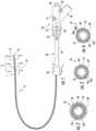
- FIG. 1is a side view of a catheter assembly provided in accordance with the disclosure
- FIG. 2is a cross-sectional view of the catheter assembly of FIG. 1 taken along the section line 2 - 2 of FIG. 1 ;
- FIG. 3is a cross-section view of the catheter assembly of FIG. 1 taken along the section line 3 - 3 of FIG. 1 ;
- FIG. 4is a cross-section view of the catheter assembly of FIG. 1 taken along the section line 4 - 4 of FIG. 1
- FIG. 5is a side view of an inner liner of the catheter assembly of FIG. 1 over a mandrel;
- FIG. 6is a side view of a braid over the inner liner of FIG. 5 ;
- FIG. 7is an enlarged view of the area of detail of FIG. 6 ;
- FIG. 8is an enlarged view of the area of detail of FIG. 6 ;
- FIG. 9is a side view of wires turned over the braid of FIG. 6 towards a proximal end of the braid;
- FIG. 10is a side view of a first outer tube slid over a proximal end of the braid of FIG. 9 ;
- FIG. 11is a side view of an outer sleeve positioned over the first outer tube of FIG. 10 ;
- FIG. 12is a side view of the wires wrapped over a portion of the first outer tube and the outer sleeve of FIG. 11 ;
- FIG. 13is a side view of a second outer tube slid over a distal end of the braid, a portion of the wires, a portion of the first outer tube, and a portion of the outer sleeve of FIG. 12 ;
- FIG. 14is a side view of an outer coating formed over the braid from the first and second outer tubes with the wires unwrapped from over the outer sleeve and the outer sleeve removed from over the first outer tube of FIG. 13 ;
- FIG. 15is a side view of the catheter of FIG. 1 being cut to length from the braid, wires, and outer coating of FIG. 14 ;
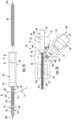
- FIG. 16is a side view of a proximal end portion of the catheter of FIG. 15 positioned in a body of a handle assembly with a half-shell of the body removed;
- FIG. 17is a side view of the catheter assembly of FIG. 1 with the half-shell of the body removed;
- FIG. 18is a schematic illustration of a robotic surgical system configured for use in accordance with the disclosure.
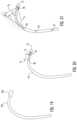
- FIG. 19is a side view of a distal end portion of a prior art catheter having a single sensor
- FIG. 20is a side view of the distal end portion of the catheter assembly of FIG. 1 where a second sensor is positioned a first distance from a first sensor;
- FIG. 21is a side view of the distal end portion of the catheter assembly of FIG. 1 where a second sensor is positioned a second distance from a first sensor.
- Some cathetershave been developed with a single sensor for locating a distal end of the catheter within the anatomy of a patient. Such catheters may be limited to obtaining the location of the catheter within five degrees-of-freedom. There is a need for a catheter having sensors capable of determining the location of the catheter within six degrees-of-freedom.
- the disclosuregenerally provides a catheter having an Extended Working Channel (EWC) and a first sensor positioned at a distal end of the EWC for locating the distal end of the EWC within the anatomy of a patient and a second sensor spaced apart from the first sensor a known distance to determine the position of the first sensor relative to the second sensor such that the position of the distal end of the EWC is determinable within six degrees-of-freedom (DOF).
- EWCExtended Working Channel
- DOFdegrees-of-freedom
- such a catheteris locatable during an entire procedure such that the changes in the location of the distal end of the catheter are detectable and/or the catheter is repositionable during the procedure when an instrument positioned within the EWC.
- such a cathetermay be manufactured without increasing a wall thickness of the catheter or an overall diameter of the catheter.
- the term “clinician”refers to a doctor, a nurse, or any other care provider and may include support personnel.
- proximalrefers to the portion of the device or component thereof that is closest to the clinician and the term “distal” refers to the portion of the device or component thereof that is farthest from the clinician.
- a catheter assembly 10is provided in accordance with the disclosure and includes a handle assembly 20 , a telescopic channel 30 , and an elongated catheter 50 having a proximal portion 52 ( FIG. 12 ) and a distal portion 54 .
- the handle assembly 20is positioned over the proximal portion 52 of the catheter 50 to permit a clinician to manipulate the catheter assembly 10 .
- the telescopic channel 30is positioned over the catheter 50 between the proximal portion 52 and the distal portion 54 to provide lateral support for the elongated catheter 50 .
- the telescopic channel 30includes a proximal or first end 32 that is coupled to a distal end 24 of the handle assembly 20 and a distal or second end 36 that is configured to couple the catheter assembly 10 to a bronchoscope (not shown).
- the telescopic channel 30includes an extendable body portion 34 between the first and second ends 32 , 36 that are expandable along a longitudinal axis and substantially rigid transverse to the longitudinal axis.
- the extendable body portion 34allows the first end 32 to translate along and rotate about the longitudinal axis relative to the second end 36 .
- the proximal portion 52 of the catheter 50translates and rotates with the first end 32 of the telescopic channel 30 .
- Examples of methods of marking the location of and registering a pathway to targeted tissuemay be found in commonly assigned U.S. Patent Publication Nos. 2016/0000414 and 2016/0000356. Examples of guiding a catheter to and treating targeted tissue may be found in commonly assigned U.S. Pat. Nos. 9,459,770 and 9,247,992. Examples of bronchoscopes, handles, and support systems for microwave ablation catheters may be found in commonly assigned U.S. Pat. No. 9,867,665.
- the catheter 50has a proximal end 53 ( FIG. 13 ) and a distal end 55 and defines an EWC 56 therebetween.
- the EWC 56allows instruments (not shown) to be inserted through the catheter 50 to treat targeted tissue adjacent the distal end 55 of the catheter 50 .
- the catheter 50includes a first sensor 58 disposed at the distal portion 54 of the catheter 50 adjacent the distal end 55 of the catheter 50 such that the distal end 55 of the catheter 50 is locatable within the anatomy of a patient.
- the catheter 50also includes a second sensor 80 disposed in the distal portion 54 of the catheter 50 disposed proximal of the first sensor 58 .
- the catheter 50includes an inner liner 60 , a braid 64 , and an outer coating 68 .
- the inner liner 60defines the EWC 56 that passes entirely through the catheter 50 . It is contemplated that the catheter 50 may be constructed without the inner liner 60 such that the braid 64 defines the EWC 56 .
- the first sensor 58is formed of a wire 71 ( FIG. 6 ) turned over the braid 64 and covered by the outer coating 68 to form the first sensor 58 .
- the wire 71includes leads 76 a , 76 b that proximally follow the braid 64 to the proximal portion 52 ( FIG. 12 ) of the catheter 50 .
- the portions of the wire 71e.g., the first sensor 58 and the leads 76 a , 76 b
- the wire 71is monolithically formed (i.e., the wire 71 is a continuous wire without any solder joints between different portions thereof).
- the second sensor 80is formed of a wire 81 that is coiled and covered by the outer coating 68 .
- the wire 81includes leads 86 a , 86 b that proximally follow the braid 64 to the proximal portion 52 of the catheter 50 .
- the portions of the wire 81e.g., the second sensor 80 and the leads 86 a , 86 b
- the wire 81is monolithically formed.
- the inner liner 60 and the outer coating 68are formed from polymer tubes, as detailed below, which are made from of a reflowable polymer material (e.g., Arnitel®, Hytrel®, Pebax®, polytetrafluoroethylene (PTFE)) which may bond to the braid 64 , the wire 71 , the wire 81 , and to one another.
- the braid 64is constructed of a mesh of between 16 and 32 of similar or varying material cords woven together (e.g., stainless steel, Dacron®, polyethylene naphthalate (PEN), polyethylene terephthalate (PET), and/or insulated electrical wire).
- the wires 71 , 81are solid core magnetic wire with a thin dielectric coating (e.g., a copper wire with a polyimide coating).
- the inner liner 60is slid over a mandrel 100 .
- the mandrel 100provides rigidity to the flexible components of the catheter 50 while the catheter 50 is assembled.
- the inner liner 60has an inner diameter substantially equal to but slightly larger than an outer diameter of the mandrel 100 and has a length substantially equal to a length of the mandrel 100 .
- the mandrel 100may be coated with a PTFE coating to assist in sliding the inner liner 60 over the mandrel 100 and to prevent the inner liner 60 from bonding to the mandrel 100 .
- the outer diameter of the mandrel 100is substantially equal to a desired diameter of the EWC 56 ( FIG. 2 ) and the length of the mandrel 100 is longer than a final desired length of the catheter 50 .
- the mandrel 100may have a diameter in a range of about 0.050 to about 0.100 inches (e.g., about 0.090 inches) and have a length in a range of about 30 to about 90 inches (e.g., about 62 inches).
- the braid 64is formed over the inner liner 60 with portions of the braid 64 extending beyond the ends of the mandrel 100 such that the mandrel 100 and the inner liner 60 are completely within the braid 64 .
- the ends 65 a , 65 b of the braid 64 that extend beyond the mandrel 100may have a diameter less than the diameter of the mandrel 100 .
- the ends 65 a , 65 b of the braid 64may retain the mandrel 100 within the braid 64 during construction of the catheter 50 . It is contemplated that the braid 64 may be performed and slid over the inner liner 60 and the mandrel 100 .
- the braid 64is formed by helically weaving cords 66 of material over a cylinder (e.g., the inner liner 60 and the mandrel 100 .
- the cords 66define channels 67 therebetween that follow the helical pattern of the cords 66 .
- the pitch of the cords 66is in a range of about 0.125 to about 0.225 (e.g., about 0.177).
- the braid 64may compress the inner liner 60 over the mandrel 100 .
- the braid 64has an outer diameter in a range of about 0.052 to about 0.102 inches (e.g., 0.092 inches). It is contemplated that the inner liner 60 , the braid 64 , and the mandrel 100 may be supplied as a preassembled unit.
- the first sensor 58is formed by turning the wire 71 over the braid 64 , or over the mandrel 100 and inner liner 60 just distal to the braid termination, transverse to a longitudinal axis of the braid to form turns 72 over the braid 64 , or over the mandrel 100 and inner liner 60 .
- the turns 72may include an inner layer 72 a and an outer layer 72 b of turns 72 .
- Each layer of turns 72 a, 72 bmay include a range of about 25 to about 200 individual turns 72 (e.g., about 100 individual turns) of the wire 71 .
- the number of turns 72 in the inner layer 72 amay be substantially equal to the number of turns 72 of the outer layer 72 b.
- the first sensor 58includes two layers of turns 72 a, 72 b ; however, it is contemplated that the first sensor 58 may include a single layer of turns 72 or may include more than two layers of turns 72 .
- the number of turns 72 of the wire 71is proportional to signal strength of the first sensor 58 . That is, as the number of turns 72 increases, the signal strength of the first sensor 58 increases. As the number of layers of turns 72 is increased, the flexibility of the catheter 50 in the area of the turns 72 is reduced and the diameter of the catheter 50 in the area of the turns 72 is increased.
- the total length of the layers 72 a , 72 b of the turns 72is in a range of about 0.04 to about 0.36 inches (e.g., about 0.18 inches). As the total length of the layers 72 a , 72 b is increased, the flexibility of the catheter 50 in the area of the turns 72 is reduced. Thus, the number of layers of turns 72 , the length of the turns 72 , and the total number of turns 72 is a compromise between the signal strength of the first sensor 58 and the flexibility and size of the catheter 50 .
- the turns 72are formed by ends or leads 76 a , 76 b of the wire 71 being turned around about the braid 64 .
- the inner and outer layers 72 a , 72 bmay be formed simultaneously by beginning at a distance spaced away from a distal end 65 b of the braid 64 .
- the inner layer 72 ais formed by a first lead 76 a being turned around the braid 64 in a first direction substantially transverse to a longitudinal axis of the braid 64 while proximally traversing an outer surface of the braid 64 .
- the outer layer 72 bis formed by a second lead 76 b being turned around the braid 64 and the inner layer 72 a in a second direction, opposite to the first direction, substantially transverse to a longitudinal axis of the braid 64 while proximally traversing the inner layer 72 a .
- the turning of the second lead 76 btrails the turning of the first lead 76 a in a range of about 1 to about 5 turns 72 of the wire 71 (e.g., 2 turns) to allow the inner layer 72 a to form before being covered by the outer layer 72 b .
- the turns 72begin spaced away from the distal end 65 b of the braid 64 a distance in a range of about 0.0 to about 3.0 inches (e.g., about 0.5 inches).
- the turns 72are spaced away a distance from the distal end 65 b of the braid 64 large enough to ensure that the inner liner 60 and the braid 64 are substantially cylindrical in shape in the region of the turns 72 while minimizing the distance the turns 72 are space away from the distal end 65 b to reduce wasted materials.
- first sensor 58includes an odd number of turns 72
- one leadexits the first sensor 58 at a proximal end of the first sensor 58 and the other lead exits the sensor at a distal end of the first sensor 58 .
- the lead that exits the first sensor 58 at the distal endis placed under or over the turns 72 prior to wrapping the leads 76 a , 76 b over the braid 64 as detailed below.
- a support tube or layermay be positioned over the braid 64 before the wire 71 is wrapped over the braid 64 to form the first sensor 58 or may be placed over the first sensor 58 after the wire 71 is wrapped over the braid to form the first sensor 58 .
- the support layermay be a ferro-metallic tube or a powder with resin that is configured to strengthen or support the first sensor 58 to prevent the first sensor 58 from deforming when used.
- the support layermay increase the signal strength of the first sensor 58 such that the length and/or number of turns 72 required to achieve a desired signal strength for the first sensor 58 may be reduced.
- the leads 76 a , 76 bare brought together within a channel 67 defined between two cords 66 of the braid 64 at a proximal end of the turns 72 to form a twisted pair 78 .
- the leads 76 a , 76 b of the wire 71are twisted together to form the twisted pair 78 to reduce or eliminate a signal from being generated by the wire 71 along the length of the braid 64 (i.e., utilizing the constructive interference to minimize the signal generated).
- the leads 76 a , 76 bare twisted together in a range of about 5 to about 15 twists per inch (e.g., about 10 twists per inch) of the wire 71 .
- the twisted pair 78 of leads 76 a , 76 bis wrapped around the braid 64 within a channel 67 of the braid 64 such that the twisted pair 78 of leads 76 a , 76 b follows the pitch of the braid 64 . Wrapping the twisted pair 78 of leads 76 a , 76 b helically around the braid 64 may increase the fatigue life of the leads 76 a , 76 b in response to flexing of the catheter 50 along its longitudinal axis.
- the twisted pair 78 of leads 76 a , 76 bis wrapped about the braid 64 from the turns 72 along a substantial length of the braid 64 towards a proximal end 65 a of the braid 64 .
- the twisted pair 78 of leads 76 a , 76 bare wrapped about the braid 64 in a clockwise direction when viewed from the proximal end 65 a of the braid 64 ; however, the twisted pair 78 of leads 76 a , 76 b may be wrapped about the braid 64 in a counter-clockwise direction when viewed from the proximal end 65 a of the braid 64 .
- Forming the turns 72 and the twisted pair 78 of leads 76 a , 76 b with a single continuous wireincreases the service life of the catheter 50 by eliminating the need for a connection (e.g., a soldered connection) between the turns 72 and each of the twisted pair 78 of leads 76 a , 76 b ; however, in some embodiments, the turns 72 may be soldered to the twisted pair 78 of leads 76 a , 76 b
- a single device or a combination of devicesmay be used to turn the wire 71 about the braid 64 to form the turns 72 , twist the pair of leads 76 a , 76 b of the wire 71 together, and wrap the twisted pair 78 of leads 76 a , 76 b of the wire 71 about the braid 64 .
- Such a device for turning/wrapping the wire 71is disclosed in U.S. patent application Ser. No. 15/879,087, filed Jan.
- turns 72 and the twisted pair 78 of leads 76 a , 76 bmay be performed apart from the braid and then positioned or loaded over the braid 64 . Once the turns 72 are loaded over the braid 64 , the twisted pair 78 of leads 76 a , 76 b is wrapped about the braid 64 as detailed above.
- the second sensor 80is formed of a coil 82 of the wire 81 and is spaced proximally from the first sensor 58 a distance D ( FIG. 6 ).
- the coil 82is formed by turns of the wire 81 which form a loop and may include between 5 and 20 turns of the wire 81 , e.g., 10 turns.
- the coil 82is laid over the braid 64 in a position such that the coil 82 will be disposed between wraps of the twisted pair 78 of leads 76 a , 76 b.
- the wire 81includes two leads 86 a , 86 b that form a twisted pair 88 within a channel 67 defined between two cords 66 of the braid 64 .
- the leads 86 a , 86 b of the wire 81are twisted together to form the twisted pair 88 to reduce or eliminate a signal from being generated by the wire 81 along the length of the braid 64 (i.e., utilizing the constructive interference to minimize the signal generated).
- Forming the coil 82 and the twisted pair 88 of leads 86 a , 86 b with a single continuous wireincreases the service life of the catheter 50 by eliminating the need for a connection (e.g., a soldered connection) between the coil 82 and each of the twisted pair 88 of leads 86 a , 86 b.
- a connectione.g., a soldered connection
- the leads 86 a , 86 bare twisted together in a range of about 5 to about 15 twists per inch (e.g., about 10 twists per inch) of the wire 81 .
- the twisted pair 88 of leads 86 a , 86 bis wrapped around the braid 64 within a channel 67 of the braid 64 such that the twisted pair 88 of leads 86 a , 86 b follows the pitch of the braid 64 . Wrapping the twisted pair 88 of leads 86 a , 86 b helically around the braid 64 may increase the fatigue life of the leads 86 a , 86 b in response to flexing of the catheter 50 along its longitudinal axis.
- the twisted pair 88 of leads 86 a , 86 bis wrapped about the braid 64 from the wraps 82 along a substantial length of the braid 64 towards a proximal end 65 a of the braid 64 .
- the twisted pair 88 of leads 86 a , 86 bare wrapped about the braid 64 in the same direction as the twisted pair 78 of leads 76 a , 76 b such that the twisted pair 88 is disposed between or interleaved with the twisted pair 78 along the braid 64 such that a diameter of the braid 64 is unchanged in areas having the twisted pairs 78 , 88 .
- the coil 82may be positioned on the braid 64 and the twisted pair 88 wrapped about the braid 64 simultaneously with the wire 71 forming turns 72 and the twisted pair 78 being wrapped about the braid 64 or the coil 82 may be positioned on the braid 64 and the twisted pair 88 wrapped about the braid 64 before or after the wire 71 forming turns 72 and the twisted pair 78 being wrapped about the braid 64 .
- the coil 82is temporarily held in place relative to one or more of the cords 66 of the braid 64 by one or more ties 83 .
- the ties 83may be constructed of a variety of materials including conductive or non-conductive materials.
- the ties 83may be constructed of a polymer that is melted into tubes or sleeves of the catheter, e.g., inner tube 69 or outer tube 70 detailed below.
- the coil 82is temporarily held in place relative to one or more of the cords 66 by adhesive that is placed on the coil 82 or the cords 66 .
- the coil 82is pressed into the braid 64 such that the coil 82 is held in place without adhesive or ties 83 .
- the inner liner 60flows through the braid 64 such that when the coil 82 is pressed into the braid 64 , the coil 82 is temporarily held in place along the braid 64 by the inner liner 60 .
- a first outer tube 69is slid over the proximal end 65 a of the braid 64 until a proximal end 69 a of the first outer tube 69 is adjacent to the twisted pairs 78 , 88 .
- the first outer tube 69is a polymer tube which is then covered by heat shrink to melt or reflow the polymer such that the first outer tube 69 reflows or bonds to the braid 64 .
- the inner liner 60 within the first outer tube 69may be reflowed to bond with the braid 64 and the first outer tube 69 .
- the outer diameter of the first outer tube 69may be slightly reduced as the first outer tube 69 is reflowed.
- an outer sleeve 110is slid over the reflowed first outer tube 69 until a distal end 112 of the outer sleeve 110 is adjacent a distal end 69 a of the first outer tube 69 .
- a portion 69 b of the first outer tube 69is exposed between the twisted pairs 78 , 88 and the outer sleeve 110 .
- the twisted pairs 78 , 88are then wrapped over the exposed portion 69 b of the reflowed first outer tube 69 and over the outer sleeve 110 as shown in FIG. 12 with the twisted pairs 78 , 88 interleaved with one another.
- the outer sleeve 110is constructed of or lined with PTFE such that the outer sleeve 110 and the twisted pairs 78 , 88 are prevented from bonding to a portion of the reflowed first outer tube 69 covered by the outer sleeve 110 .
- a second outer tube 70is slid over the distal end 65 b of the braid 64 , the first sensor 58 , the coil 82 of the second sensor, the twisted pairs 78 , 88 , the exposed portion 69 b of the first outer tube 69 , and a portion of the outer sleeve 110 .
- the second outer tube 70Similar to the first outer tube 69 , the second outer tube 70 has an inner diameter slightly larger than the braid 64 such that the second outer tube 70 freely slides over the braid 64 , the wire 71 , the wire 81 , the reflowed first outer tube 64 , and the outer sleeve 110 .
- a proximal end 70 a of the second outer tube 70is positioned along the outer sleeve 110 .
- the second outer tube 70is a polymer tube which is then covered by heat shrink to reflow the polymer such that the second outer tube 70 bonds to the braid 64 and to the exposed portion 69 b of the first outer tube 69 .
- the inner liner 60 and the first inner tube 69 within the second outer tube 70may be reflowed to bond with the braid 64 , the second outer tube 70 , the wire 71 , and the wire 81 .
- the first and second outer tubes 69 , 70form the outer coating 68 as a continuous layer of polymer over the braid 64 and a substantial portion of the wires 71 , 81 .
- the outer coating 68is substantially smooth and seals the EWC 64 ( FIG.
- the outer coating 68is translucent or transparent; however, the outer coating 68 may be opaque and have a desired color (e.g., blue or white).
- the twisted pairs 78 , 88are unwrapped from over the outer sleeve 110 in a manner not to damage the leads 76 a , 76 b , 86 a , 86 b . Then the outer sleeve 110 is peeled off or removed from over the portion of the outer coating 68 previously formed from first outer tube 69 . Any portion of the second outer tube 70 that is formed over the outer sleeve 110 is separated from the outer coating 68 and discarded.
- the catheter 50is cut adjacent the proximal end 65 a of the braid 64 to define a proximal end 53 of the catheter 50 .
- the catheter 50is cut a distance spaced away from a point 77 where the leads 76 a , 76 b , 86 a , 86 b pass through the outer coating 68 to leave a proximal portion 52 of the catheter 50 where the leads 76 a , 76 b , 86 a , 86 b are not wrapped around the braid 64 .
- the catheter 50is also cut adjacent the first sensor 58 to define the distal end 55 of the catheter 50 .
- the cut adjacent the first sensor 58is spaced apart a minimal distance from the first sensor 58 to prevent discontinuities in the wire 71 forming the first sensor 58 ; however, this distance is minimized to allow the first sensor 58 to be positioned as close to the distal end 55 of the catheter as possible.
- the distal end 55 of the catheter 50may be reflowed to seal the portions of the braid 64 exposed by cutting adjacent the sensor. Additionally or alternatively, a catheter tip (not shown) may also be bonded to the distal end 55 of the catheter 50 . After the catheter 50 is cut, the catheter 50 has a total length of about 30 to about 90 inches (e.g., about 60 inches) from the proximal end 53 to the distal end 55 .
- a hub 90is positioned over the proximal portion 52 of the catheter 50 .
- the hub 90defines a channel 91 therethrough and includes a proximal guide portion 92 , a central collar 94 , and a distal collar 96 .
- the proximal portion 52 of the catheter 50is positioned within the channel 91 of the hub 90 such that the proximal end 53 of the catheter is adjacent the central collar 94 of the hub 90 .
- the hub 90is then bonded to the proximal portion 52 of the catheter 50 .
- the hub 90may be reflowed into the outer coating 68 of the catheter 50 or bonded to the outer coating 68 using adhesives.
- the proximal guide portion 92is configured to guide an instrument (not shown) into the EWC ( FIG. 3 ) of the catheter 50 .
- the handle assembly 20is coupled over the proximal portion 52 of the catheter 50 .
- the handle assembly 20includes a body 21 formed from two half shells coupled together over the proximal portion 52 of the catheter 50 .
- Each of the half shells of the body 21is substantially similar to one another and is joined along the longitudinal axis of the catheter 50 .
- the body 21has a proximal end 22 , a distal end 24 , and a connector portion 26 .
- the body 21defines a catheter passage 28 that is configured to receive the catheter 50 with the hub 90 bonded to the distal end 52 .
- the catheter passage 28includes an enlarged proximal portion 29 including a first recess 29 a and a second recess 29 b .
- the proximal portion 29is sized to receive the hub 90 to longitudinally fix the catheter 50 relative to the handle 20 .
- the first recess 29 ais sized to receive the central collar 94 of the hub 90 and the second recess 29 b is sized to receive the distal collar 96 of the hub 90 .
- the proximal portion 29 of the catheter passage 28 between the first and second recesses 29 a , 29 bhas a diameter smaller than the first and second recesses 29 a , 29 b to fix the hub 90 within the catheter passage 28 .
- the hub 90is frictionally engaged with the body 21 to rotatably secure the hub 90 within the catheter passage 28 . It is contemplated that the hub 90 may be adhered to the body 21 within the catheter passage 28 .
- the handle 20includes an electrical coupling 190 disposed within a cavity 27 of the connector portion 26 of the handle 20 .
- the electrical coupling 190includes an internal connector 192 , an external connector 194 , and a collar 196 positioned between the internal and external connectors 192 , 194 .
- the collar 196is received by the connector portion 26 of the handle 20 to form a seal to isolate the internal connector 192 within the cavity 27 of the connector portion 26 .
- the cavity 27 of the connector portion 26is isolated from the external environment by a seal formed by the walls defining the catheter passage 28 engaging the outer coating 68 of the catheter 50 and the seal formed by the collar 196 engaging walls defining the cavity 27 of the connector portion 26 .
- the point 77 at which the twisted pairs 78 , 88 exit through the outer coating 68 of the catheter 50is positioned within the cavity 27 of the connector portion 26 .
- the leads 76 a , 76 b and leads 86 a , 86 bare untwisted from one another and electrically coupled (e.g., soldered) separately to the internal connector 192 .
- the internal connector 192is in electrical communication with the external connector 194 such that an adapter (not shown) may be coupled to the external connector 194 to supply electrical energy to the first sensor 58 and the second sensor 80 ( FIG. 1 ) through the external connector 194 via the wires 71 , 81 respectively. Examples of systems and methods for using the first and second sensors 58 , 80 to guide the catheter 50 to targeted tissue may be found in commonly assigned U.S. Pat. Nos. 9,459,770 and 9,247,992.
- the distal end 24 of the body 21defines an opening 25 a configured to receive the first end 32 of the telescopic channel 30 .
- the body 21may define a slot 25 b parallel to the catheter passage 28 and in communication with the opening 25 a to receive a clip 33 of the first end 32 of the telescopic channel 30 to rotatably fix the first end 32 of the telescopic channel 30 to the body 21 .
- the distal end 24 of the body 21may also include a ring 25 c positioned about an outer surface of the body 21 transverse to the longitudinal axis of the catheter passage 28 and over the slot 25 b .
- the clip 33 of the first end 32 of the telescopic channel 30may engage the ring 25 c when the clip 33 is disposed within the slot 25 b to longitudinally the first end 32 of the telescopic channel 30 to the body 21 of the handle 20 .
- the telescopic channel 30may be attached a bronchoscope (not shown) and the catheter 50 of the catheter assembly 10 may be inserted through the first end 32 of the telescopic channel 30 until the distal end 24 of the handle 20 receives the first end 32 of the telescopic channel 30 .
- the catheter 50is constructed over a braid 64 .
- the catheter 50does not include the braid 64 and is formed of the liners and tubes that are flowed into one another to form a catheter 50 of unitary construction having first and second sensors 58 , 80 .
- the handle assembly 20is coupled to a proximal portion of the catheter 50 ; however, the catheter 50 may have a variety of handle assemblies 20 or no handle assembly 20 coupled to the proximal portion of the catheter 50 .
- a medical work stationis shown generally as robotic system or work station 1000 and generally may include a plurality of robot arms 1002 , 1003 ; a control device 1004 ; and an operating console 1005 coupled with control device 1004 .
- Operating console 1005may include a display device 1006 , which may be set up in particular to display three-dimensional images; and manual input devices 1007 , 1008 , by means of which a clinician, may be able to telemanipulate robot arms 1002 , 1003 in a first operating mode.
- Each of the robot arms 1002 , 1003may include a plurality of members, which are connected through joints, and an attaching device 1009 , 1011 , to which may be attached, for example, the catheter 50 and/or the handle assembly 20 , in accordance with any one of several embodiments disclosed herein.
- Robot arms 1002 , 1003may be driven by electric drives (not shown) that are connected to control device 1004 .
- Control device 1004e.g., a computer
- Control device 1004may be set up to activate the drives, in particular by means of a computer program, in such a way that robot arms 1002 , 1003 , the attaching devices 1009 , 1011 , e.g., the catheter 50 and/or the handle assembly 20 , execute a desired movement according to a movement defined by means of manual input devices 1007 , 1008 .
- Control device 1004may also be set up in such a way that it regulates the movement of robot arms 1002 , 1003 and/or of the drives.
- Medical work station 1000may be configured for use on a patient 1013 lying on a patient table 1012 to be treated in a minimally invasive manner by means of the localization system. Medical work station 1000 may also include more than two robot arms 1002 , 1003 , the additional robot arms likewise being connected to control device 1004 and being telemanipulatable by means of operating console 1005 . Medical work station 1000 may include a database 1014 , in particular coupled to with control device 1004 , in which are stored, for example, pre-operative data from patient/living being 1013 and/or anatomical atlases.
- the prior art catheter 250is shown with a single sensor 258 .
- the single sensor 258can only account for 5 Degrees-of-Freedom (DOF) of the prior art catheter 250 .
- DOFDegrees-of-Freedom
- the single sensor 258does not provide an indication of the rotation of the prior art catheter 250 .
- the catheter 50is provided with the second sensor 80 disposed a distance D 1 along the catheter 50 from the first sensor 58 .
- the distance D 1is relatively small such that the second sensor 80 is spaced apart from the first sensor 58 a short distance in a range of about 0.25 inches to about 1 inch.
- the catheter 50 between the first and second sensors 58 , 80is substantially rigid such that a vector V 1 from the second sensor 80 to the first sensor 58 determines an orientation of catheter 50 such that rotation of the catheter 50 can be determined.
- the catheter 50can be tracked through 6 DOF.
- the catheter 50is provided with the second sensor 80 disposed a distance D 2 along the catheter 50 from the first sensor 58 .
- the distance D 2is larger than the distance D 1 such that the catheter 50 is flexible between the first and second sensors 58 , 80 .
- the distance D 2may be in a range of about 2 inches to about 4 inches.
- the vector V 1defines the position of the first sensor 58 relative to the second sensor 80 and when the distal end 55 of the catheter 50 is in the second position P 2 , the vector V 2 defines the position of the first sensor 58 relative to the second sensor 80 such that a vector V 3 defines the deflection of the distal end 55 of the catheter 50 such that the torsional behavior of the catheter 50 can be determined such that the catheter 50 can be tracked through 6 DOF.
- the catheter 50may include more than two sensors, such as third and fourth sensors 85 , 87 spaced along the length of the catheter 50 .
- the catheter 50may include any suitable number of sensors, such as four or more.
- the third and fourth sensors 85 , 87may be disposed proximally of the first and second sensors 58 , 80 .
- the third and fourth sensors 85 , 87enable a determination of the entire catheter shape from the catheter tip 55 to the proximal-most sensor.
- the 5 DOF of each sensor 58 , 80 , 85 , 87may be determined along with the distance between each of the sensors 58 , 80 , 85 , 87 .
Landscapes
- Health & Medical Sciences (AREA)
- Life Sciences & Earth Sciences (AREA)
- Engineering & Computer Science (AREA)
- Veterinary Medicine (AREA)
- General Health & Medical Sciences (AREA)
- Public Health (AREA)
- Biomedical Technology (AREA)
- Heart & Thoracic Surgery (AREA)
- Animal Behavior & Ethology (AREA)
- Biophysics (AREA)
- Pulmonology (AREA)
- Hematology (AREA)
- Anesthesiology (AREA)
- Surgery (AREA)
- Medical Informatics (AREA)
- Molecular Biology (AREA)
- Physics & Mathematics (AREA)
- Nuclear Medicine, Radiotherapy & Molecular Imaging (AREA)
- Pathology (AREA)
- Robotics (AREA)
- Physiology (AREA)
- Optics & Photonics (AREA)
- Otolaryngology (AREA)
- Radiology & Medical Imaging (AREA)
- Human Computer Interaction (AREA)
- Media Introduction/Drainage Providing Device (AREA)
Abstract
Description
Claims (14)
Priority Applications (4)
| Application Number | Priority Date | Filing Date | Title |
|---|---|---|---|
| US16/824,172US11975157B2 (en) | 2019-04-12 | 2020-03-19 | Method of manufacturing an elongated catheter having multiple sensors for three-dimensional location of the catheter |
| EP20169159.9AEP3721786A1 (en) | 2019-04-12 | 2020-04-09 | Catheter with a working channel and with sensors for determining a position and a method of manufacturing a catheter |
| CN202010277462.3ACN111803778B (en) | 2019-04-12 | 2020-04-10 | Method for manufacturing a flexible catheter positionable within six degrees of freedom, a flexible catheter, and a catheter system |
| US18/626,939US20240245885A1 (en) | 2019-04-12 | 2024-04-04 | Method of manufacturing an elongated catheter having multiple sensors for three-dimensional location of the catheter |
Applications Claiming Priority (2)
| Application Number | Priority Date | Filing Date | Title |
|---|---|---|---|
| US201962833166P | 2019-04-12 | 2019-04-12 | |
| US16/824,172US11975157B2 (en) | 2019-04-12 | 2020-03-19 | Method of manufacturing an elongated catheter having multiple sensors for three-dimensional location of the catheter |
Related Child Applications (1)
| Application Number | Title | Priority Date | Filing Date |
|---|---|---|---|
| US18/626,939ContinuationUS20240245885A1 (en) | 2019-04-12 | 2024-04-04 | Method of manufacturing an elongated catheter having multiple sensors for three-dimensional location of the catheter |
Publications (2)
| Publication Number | Publication Date |
|---|---|
| US20200324077A1 US20200324077A1 (en) | 2020-10-15 |
| US11975157B2true US11975157B2 (en) | 2024-05-07 |
Family
ID=70285564
Family Applications (2)
| Application Number | Title | Priority Date | Filing Date |
|---|---|---|---|
| US16/824,172Active2042-09-20US11975157B2 (en) | 2019-04-12 | 2020-03-19 | Method of manufacturing an elongated catheter having multiple sensors for three-dimensional location of the catheter |
| US18/626,939PendingUS20240245885A1 (en) | 2019-04-12 | 2024-04-04 | Method of manufacturing an elongated catheter having multiple sensors for three-dimensional location of the catheter |
Family Applications After (1)
| Application Number | Title | Priority Date | Filing Date |
|---|---|---|---|
| US18/626,939PendingUS20240245885A1 (en) | 2019-04-12 | 2024-04-04 | Method of manufacturing an elongated catheter having multiple sensors for three-dimensional location of the catheter |
Country Status (3)
| Country | Link |
|---|---|
| US (2) | US11975157B2 (en) |
| EP (1) | EP3721786A1 (en) |
| CN (1) | CN111803778B (en) |
Families Citing this family (3)
| Publication number | Priority date | Publication date | Assignee | Title |
|---|---|---|---|---|
| DE102018121206A1 (en)* | 2018-08-30 | 2020-03-05 | Karl Storz Se & Co. Kg | Endoscopic shaft with a layered structure and method for producing such |
| CN112775624A (en)* | 2020-12-25 | 2021-05-11 | 湖南瑞邦医疗科技发展有限公司 | Method for machining clamp pipe and clamp pipe obtained by machining method |
| WO2024166097A1 (en)* | 2023-02-08 | 2024-08-15 | Magnisity Ltd. | Combined curve temperature and shape sensor |
Citations (148)
| Publication number | Priority date | Publication date | Assignee | Title |
|---|---|---|---|---|
| US4202352A (en) | 1978-04-06 | 1980-05-13 | Research Development Corporation | Apparatus for measurement of expired gas concentration in infants |
| US5358496A (en) | 1991-10-18 | 1994-10-25 | Ethicon, Inc. | Endoscopic tissue manipulator |
| US5592939A (en) | 1995-06-14 | 1997-01-14 | Martinelli; Michael A. | Method and system for navigating a catheter probe |
| US6086586A (en) | 1998-09-14 | 2000-07-11 | Enable Medical Corporation | Bipolar tissue grasping apparatus and tissue welding method |
| US6104944A (en) | 1997-11-17 | 2000-08-15 | Martinelli; Michael A. | System and method for navigating a multiple electrode catheter |
| US6213995B1 (en) | 1999-08-31 | 2001-04-10 | Phelps Dodge High Performance Conductors Of Sc And Ga, Inc. | Flexible tubing with braided signal transmission elements |
| US6493573B1 (en) | 1999-10-28 | 2002-12-10 | Winchester Development Associates | Method and system for navigating a catheter probe in the presence of field-influencing objects |
| US6533784B2 (en) | 2001-02-24 | 2003-03-18 | Csaba Truckai | Electrosurgical working end for transecting and sealing tissue |
| BR0013237A (en) | 1999-08-12 | 2003-07-15 | Johnson & Johnson | Antibacterial heterobicyclic substituted phenyl oxazolidinones |
| US6636757B1 (en) | 2001-06-04 | 2003-10-21 | Surgical Navigation Technologies, Inc. | Method and apparatus for electromagnetic navigation of a surgical probe near a metal object |
| US6656177B2 (en) | 2000-10-23 | 2003-12-02 | Csaba Truckai | Electrosurgical systems and techniques for sealing tissue |
| MXPA03005028A (en) | 2000-12-06 | 2004-01-29 | Johnson & Johnson | 6-0-carbamoyl ketolide derivatives of erythromycin useful as antibacterials. |
| US6802843B2 (en) | 2001-09-13 | 2004-10-12 | Csaba Truckai | Electrosurgical working end with resistive gradient electrodes |
| US6834201B2 (en) | 2001-01-29 | 2004-12-21 | Stereotaxis, Inc. | Catheter navigation within an MR imaging device |
| US6835336B2 (en) | 1997-10-03 | 2004-12-28 | Ethicon, Inc. | Methods for making biopolymer sponge tubes |
| US6892091B1 (en) | 2000-02-18 | 2005-05-10 | Biosense, Inc. | Catheter, method and apparatus for generating an electrical map of a chamber of the heart |
| US6913579B2 (en) | 2001-05-01 | 2005-07-05 | Surgrx, Inc. | Electrosurgical working end and method for obtaining tissue samples for biopsy |
| US20050165276A1 (en) | 2004-01-28 | 2005-07-28 | Amir Belson | Methods and apparatus for accessing and treating regions of the body |
| US20060235457A1 (en) | 2005-04-15 | 2006-10-19 | Amir Belson | Instruments having a rigidizable external working channel |
| US20070135803A1 (en) | 2005-09-14 | 2007-06-14 | Amir Belson | Methods and apparatus for performing transluminal and other procedures |
| US7496394B2 (en) | 2004-11-15 | 2009-02-24 | Biosense Webster, Inc. | Internal reference coronary sinus catheter |
| US7515954B2 (en) | 2006-06-13 | 2009-04-07 | Rhythmia Medical, Inc. | Non-contact cardiac mapping, including moving catheter and multi-beat integration |
| US7599730B2 (en) | 2002-11-19 | 2009-10-06 | Medtronic Navigation, Inc. | Navigation system for cardiac therapies |
| US7650178B2 (en) | 2004-04-30 | 2010-01-19 | University Of Basel | Magnetic field sensor-based navigation system to track MR image-guided interventional procedures |
| US7697972B2 (en) | 2002-11-19 | 2010-04-13 | Medtronic Navigation, Inc. | Navigation system for cardiac therapies |
| US7806829B2 (en) | 1998-06-30 | 2010-10-05 | St. Jude Medical, Atrial Fibrillation Division, Inc. | System and method for navigating an ultrasound catheter to image a beating heart |
| US7818044B2 (en) | 2003-10-17 | 2010-10-19 | Medtronic Navigation, Inc. | Method and apparatus for surgical navigation |
| US7822464B2 (en) | 2004-12-01 | 2010-10-26 | Siemens Aktiengesellschaft | Guidewire for vascular catheters |
| US7869854B2 (en) | 2006-02-23 | 2011-01-11 | Magnetecs, Inc. | Apparatus for magnetically deployable catheter with MOSFET sensor and method for mapping and ablation |
| US20110066029A1 (en) | 2009-09-11 | 2011-03-17 | Medtronic, Inc. | Electromagnetic Medical Device |
| US7947000B2 (en) | 2003-09-12 | 2011-05-24 | Intuitive Surgical Operations, Inc. | Cannula system for free-space navigation and method of use |
| US7981038B2 (en) | 2005-10-11 | 2011-07-19 | Carnegie Mellon University | Sensor guided catheter navigation system |
| US8016749B2 (en) | 2006-03-21 | 2011-09-13 | Boston Scientific Scimed, Inc. | Vision catheter having electromechanical navigation |
| US8057397B2 (en) | 2007-05-16 | 2011-11-15 | General Electric Company | Navigation and imaging system sychronized with respiratory and/or cardiac activity |
| US8157789B2 (en) | 2007-05-24 | 2012-04-17 | Endosense Sa | Touch sensing catheter |
| US8175681B2 (en) | 2008-12-16 | 2012-05-08 | Medtronic Navigation Inc. | Combination of electromagnetic and electropotential localization |
| US8208990B2 (en) | 2005-12-12 | 2012-06-26 | Siemens Aktiengesellschaft | Catheter device |
| US8239001B2 (en) | 2003-10-17 | 2012-08-07 | Medtronic Navigation, Inc. | Method and apparatus for surgical navigation |
| CN102641153A (en) | 2010-12-30 | 2012-08-22 | 韦伯斯特生物官能公司 | Catheter with single axial sensors |
| US8298227B2 (en) | 2008-05-14 | 2012-10-30 | Endosense Sa | Temperature compensated strain sensing catheter |
| US8358128B2 (en) | 2008-11-28 | 2013-01-22 | General Electric Company | Surgical navigation system with magnetoresistance sensors |
| US8380276B2 (en) | 2010-08-16 | 2013-02-19 | Biosense Webster, Inc. | Catheter with thin film pressure sensing distal tip |
| US8380279B2 (en) | 2005-05-11 | 2013-02-19 | The University Of Houston System | Intraluminal multifunctional sensor system and method of use |
| US8388541B2 (en) | 2007-11-26 | 2013-03-05 | C. R. Bard, Inc. | Integrated system for intravascular placement of a catheter |
| US20130096385A1 (en) | 2011-10-14 | 2013-04-18 | Intuitive Surgical Operations, Inc. | Vision probe and catheter systems |
| US8428691B2 (en) | 2004-11-23 | 2013-04-23 | St. Jude Medical, Atrial Fibrillation Division, Inc. | Method and apparatus for localizing an ultrasound catheter |
| US8480653B2 (en) | 2007-05-23 | 2013-07-09 | Biosense Webster, Inc. | Magnetically guided catheter with concentric needle port |
| US8483800B2 (en) | 2008-11-29 | 2013-07-09 | General Electric Company | Surgical navigation enabled imaging table environment |
| US8556883B2 (en) | 2012-02-27 | 2013-10-15 | Rafic Saleh | Medical surgical navigation sensor mounting system |
| US8571636B2 (en) | 2006-03-29 | 2013-10-29 | Stryker Corporation | Shielded surgical navigation system that determines the position and orientation of the tracked object with real and virtual dipoles |
| US8611986B2 (en) | 2005-05-05 | 2013-12-17 | Stryker Corporation | System and method for electromagnetic navigation in the vicinity of a metal object |
| US8611984B2 (en) | 2009-04-08 | 2013-12-17 | Covidien Lp | Locatable catheter |
| US8611983B2 (en) | 2005-01-18 | 2013-12-17 | Philips Electronics Ltd | Method and apparatus for guiding an instrument to a target in the lung |
| US20140052018A1 (en) | 2012-08-15 | 2014-02-20 | Intuitive Surgical Operations, Inc. | Specimen removal bag and methods of using same |
| US8781555B2 (en) | 2007-11-26 | 2014-07-15 | C. R. Bard, Inc. | System for placement of a catheter including a signal-generating stylet |
| US20140235943A1 (en) | 2013-02-15 | 2014-08-21 | Intuitive Surgical Operations, Inc. | Vision Probe with Access Port |
| US8849382B2 (en) | 2007-11-26 | 2014-09-30 | C. R. Bard, Inc. | Apparatus and display methods relating to intravascular placement of a catheter |
| CN104271035A (en) | 2012-05-07 | 2015-01-07 | 圣犹达医疗用品电生理部门有限公司 | Medical device guidewire with helical cutout and coating |
| US8948853B2 (en) | 2006-06-13 | 2015-02-03 | Rhythmia Medical, Inc. | Cardiac mapping with catheter shape information |
| US9055883B2 (en) | 2007-05-16 | 2015-06-16 | General Electric Company | Surgical navigation system with a trackable ultrasound catheter |
| US9220558B2 (en) | 2010-10-27 | 2015-12-29 | Boston Scientific Scimed, Inc. | RF renal denervation catheter with multiple independent electrodes |
| US20160001038A1 (en) | 2014-07-01 | 2016-01-07 | Auris Surgical Robotics, Inc. | Tool and method for using surgical endoscope with spiral lumens |
| US9259269B2 (en) | 2012-08-07 | 2016-02-16 | Covidien Lp | Microwave ablation catheter and method of utilizing the same |
| US20160067450A1 (en) | 2014-09-10 | 2016-03-10 | Intuitive Surgical Operations, Inc. | Flexible instrument with nested conduits |
| US20160113729A1 (en)* | 2009-03-10 | 2016-04-28 | Medtronic Xomed, Inc. | Navigated Malleable Surgical Instrument |
| US20160158490A1 (en) | 2014-11-05 | 2016-06-09 | Clph, Llc | Catheter devices and methods for making them |
| US9381063B2 (en) | 2012-07-13 | 2016-07-05 | Magnetecs Inc. | Method and apparatus for magnetically guided catheter for renal denervation employing MOSFET sensor array |
| US9387048B2 (en) | 2011-10-14 | 2016-07-12 | Intuitive Surgical Operations, Inc. | Catheter sensor systems |
| US9452276B2 (en) | 2011-10-14 | 2016-09-27 | Intuitive Surgical Operations, Inc. | Catheter with removable vision probe |
| US9480415B2 (en) | 2013-04-26 | 2016-11-01 | Medtronic Navigation, Inc. | Electromagnetic coil apparatuses for surgical navigation and corresponding methods |
| US20160331358A1 (en) | 2013-12-13 | 2016-11-17 | Intuitive Surgical Operations, Inc. | Telescoping biopsy needle |
| US20160374676A1 (en) | 2011-02-15 | 2016-12-29 | Intuitive Surgical Operations, Inc. | Methods and systems for detecting staple cartridge misfire or failure |
| US20170020628A1 (en) | 2013-11-25 | 2017-01-26 | Body Vision Medical Ltd. | Surgical devices and methods of use thereof |
| US20170079546A1 (en)* | 2015-09-23 | 2017-03-23 | Covidien Lp | Method of manufacturing an elongated catheter having sensor and an extended working channel |
| US20170087333A1 (en) | 2010-12-30 | 2017-03-30 | Mediguide Ltd. | Method of assembling a positioning sensor and associated wiring on a medical tool |
| US20170112588A1 (en) | 2015-10-26 | 2017-04-27 | Neuwave Medical, Inc. | Apparatuses for securing a medical device and related methods thereof |
| CN106714719A (en) | 2014-09-15 | 2017-05-24 | 导管治疗有限公司 | An irrigated ablation catheter and process thereof |
| US9681859B2 (en) | 2012-02-28 | 2017-06-20 | Eth Zurich | Magnetic navigation system with soft magnetic core electromagnets for operation in the non-linear regime |
| US9693820B2 (en) | 2013-03-15 | 2017-07-04 | St. Jude Medical, Atrial Fibrillation Division, Inc. | System for detecting catheter electrodes entering into and exiting from an introducer |
| US9724154B2 (en) | 2014-11-24 | 2017-08-08 | Biosense Webster (Israel) Ltd. | Irrigated ablation catheter with multiple sensors |
| US20170224338A1 (en) | 2016-02-08 | 2017-08-10 | Ethicon, Inc. | Elastic Tissue Reinforcing Fastener |
| US20170238795A1 (en) | 2014-08-14 | 2017-08-24 | Intuitive Surgical Operations, Inc. | Systems and Methods for Cleaning an Endoscopic Instrument |
| US20170258309A1 (en) | 2016-03-14 | 2017-09-14 | Intuitive Surgical Operations, Inc. | Endoscopic instrument with compliant thermal interface |
| US20170274189A1 (en) | 2016-03-24 | 2017-09-28 | Ethicon, Inc. | Single lumen balloon delivery catheter with lumen bypass at balloon |
| US9801630B2 (en) | 2014-06-10 | 2017-10-31 | Ethicon Llc | Methods and devices for reinforcing a staple line |
| CN107529989A (en) | 2015-04-14 | 2018-01-02 | 皇家飞利浦有限公司 | The endovascular device formed with polymer jacket, system and method around the communication line being wrapped in around core member |
| US9854991B2 (en) | 2013-03-15 | 2018-01-02 | Medtronic Navigation, Inc. | Integrated navigation array |
| US20180001058A1 (en) | 2015-01-12 | 2018-01-04 | Intuitive Surgical Operations, Inc. | Devices, Systems, and Methods for Anchoring Actuation Wires to a Steerable Instrument |
| US9901714B2 (en) | 2008-08-22 | 2018-02-27 | C. R. Bard, Inc. | Catheter assembly including ECG sensor and magnetic assemblies |
| US20180064904A1 (en) | 2002-09-12 | 2018-03-08 | Intuitive Surgical Operations, Inc. | Shape-transferring cannula system and method of use |
| US9972082B2 (en) | 2012-02-22 | 2018-05-15 | Veran Medical Technologies, Inc. | Steerable surgical catheter having biopsy devices and related systems and methods for four dimensional soft tissue navigation |
| EP3326551A1 (en) | 2011-02-15 | 2018-05-30 | Intuitive Surgical Operations Inc. | Systems for detecting clamping or firing failure |
| US10029037B2 (en) | 2014-04-15 | 2018-07-24 | Tc1 Llc | Sensors for catheter pumps |
| US20180214138A9 (en) | 2014-04-02 | 2018-08-02 | Intuitive Surgical Operations, Inc. | Devices, Systems, and Methods Using a Steerable Stylet and Flexible Needle |
| US20180221039A1 (en) | 2015-10-30 | 2018-08-09 | Auris Health, Inc. | Basket apparatus |
| EP3367915A1 (en) | 2015-10-30 | 2018-09-05 | Auris Health, Inc. | Process for percutaneous operations |
| US10070802B2 (en) | 2007-04-23 | 2018-09-11 | Medtronic Navigation, Inc. | Methods and apparatus for electromagnetic navigation of a magnetic stimulation probe |
| US10172973B2 (en) | 2015-08-31 | 2019-01-08 | Ethicon Llc | Surgical adjuncts and medicants for promoting lung function |
| US10206686B2 (en) | 2014-06-10 | 2019-02-19 | Ethicon Llc | Bronchus sealants and methods of sealing bronchial tubes |
| US20190076143A1 (en) | 2015-11-13 | 2019-03-14 | Intuitive Surgical Operations, Inc. | Stapler anvil with compliant tip |
| US10278588B2 (en) | 2005-02-02 | 2019-05-07 | Intuitive Surgical Operations, Inc. | Electrophysiology mapping and visualization system |
| US10300246B2 (en) | 2011-08-23 | 2019-05-28 | Jaywant Philip Parmar | EM guidance device for a device enabled for endovascular navigation placement including a remote operator capability and EM endoluminal imaging technique |
| US20190192143A1 (en) | 2015-08-31 | 2019-06-27 | Ethicon Llc | Inducing tissue adhesions using surgical adjuncts and medicants |
| US20190200984A1 (en) | 2017-12-28 | 2019-07-04 | Ethicon Llc | Safety systems for smart powered surgical stapling |
| US10349938B2 (en) | 2015-08-31 | 2019-07-16 | Ethicon Llc | Surgical adjuncts with medicants affected by activator materials |
| US10349890B2 (en) | 2015-06-26 | 2019-07-16 | C. R. Bard, Inc. | Connector interface for ECG-based catheter positioning system |
| US20190223693A1 (en) | 2002-09-12 | 2019-07-25 | Intuitive Surgical Operations, Inc. | Shape-transferring cannula system and method of use |
| US20190231449A1 (en) | 2016-07-01 | 2019-08-01 | Intuitive Surgical Operations, Inc. | Systems and methods for flexible computer-assisted instrument control |
| US20190239724A1 (en) | 2016-10-07 | 2019-08-08 | Body Vision Medical Ltd. | Devices for use in interventional and surgical procedures and methods of use thereof |
| US20190246876A1 (en) | 2018-02-15 | 2019-08-15 | Neuwave Medical, Inc. | Compositions and methods for directing endoscopic devices |
| US10390889B2 (en) | 2010-07-26 | 2019-08-27 | St Jude Medical International Holding S.Á R.L. | Removable navigation system and method for a medical device |
| US10391277B2 (en) | 2011-02-18 | 2019-08-27 | Voxel Rad, Ltd. | Systems and methods for 3D stereoscopic angiovision, angionavigation and angiotherapeutics |
| US20190269885A1 (en) | 2018-03-05 | 2019-09-05 | Intuitive Surgical Operations, Inc. | Deployable bellows for delivery of a flexible, elongate device and methods of use |
| US10418705B2 (en) | 2016-10-28 | 2019-09-17 | Covidien Lp | Electromagnetic navigation antenna assembly and electromagnetic navigation system including the same |
| US10413272B2 (en) | 2016-03-08 | 2019-09-17 | Covidien Lp | Surgical tool with flex circuit ultrasound sensor |
| US20190290375A1 (en) | 2016-04-29 | 2019-09-26 | Intuitive Surgical Operations, Inc. | Compliant mechanisms having inverted tool members |
| US10426555B2 (en) | 2015-06-03 | 2019-10-01 | Covidien Lp | Medical instrument with sensor for use in a system and method for electromagnetic navigation |
| US10446931B2 (en) | 2016-10-28 | 2019-10-15 | Covidien Lp | Electromagnetic navigation antenna assembly and electromagnetic navigation system including the same |
| US20190328213A1 (en) | 2017-04-07 | 2019-10-31 | Auris Health, Inc. | Superelastic medical instrument |
| US10478254B2 (en) | 2016-05-16 | 2019-11-19 | Covidien Lp | System and method to access lung tissue |
| EP3576598A1 (en) | 2017-02-01 | 2019-12-11 | Intuitive Surgical Operations Inc. | Systems and methods of registration for image-guided procedures |
| US10506946B2 (en) | 2015-12-15 | 2019-12-17 | St. Jude Medical International Holding S.ár.l. | Motion box visualization for electromagnetic sensor tracking system |
| US10517505B2 (en) | 2016-10-28 | 2019-12-31 | Covidien Lp | Systems, methods, and computer-readable media for optimizing an electromagnetic navigation system |
| US20200008827A1 (en) | 2016-09-14 | 2020-01-09 | Intuitive Surgical Operations, Inc. | Joint assemblies with cross-axis flexural pivots |
| US20200022767A1 (en) | 2017-12-11 | 2020-01-23 | Auris Health, Inc. | Systems and methods for instrument based insertion architectures |
| US20200029948A1 (en) | 2018-07-26 | 2020-01-30 | Intuitive Surgical Operations, Inc. | Systems and methods of steerable elongate device |
| US20200030575A1 (en) | 2018-07-25 | 2020-01-30 | Intuitive Surgical Operations, Inc. | Systems and methods for use of a variable stiffness flexible elongate device |
| US20200069384A1 (en) | 2014-07-28 | 2020-03-05 | Intuitive Surgical Operations, Inc. | Guide apparatus for delivery of a flexible instrument and methods of use |
| US10582914B2 (en) | 2016-01-15 | 2020-03-10 | Covidien Lp | Navigable endobronchial tool to access tissue outside a bronchus |
| US10583270B2 (en) | 2016-03-14 | 2020-03-10 | Covidien Lp | Compound curve navigation catheter |
| US20200077991A1 (en) | 2016-05-31 | 2020-03-12 | Intuitive Surgical Operations, Inc. | Pliant biopsy needle system |
| US20200100776A1 (en) | 2017-02-09 | 2020-04-02 | Intuitive Surgical Operations, Inc. | System and method of accessing encapsulated targets |
| US10610308B2 (en) | 2017-02-01 | 2020-04-07 | Acclarent, Inc. | Navigation guidewire with interlocked coils |
| US10615500B2 (en) | 2016-10-28 | 2020-04-07 | Covidien Lp | System and method for designing electromagnetic navigation antenna assemblies |
| US20200107894A1 (en) | 2018-10-08 | 2020-04-09 | Auris Health, Inc. | Systems and instruments for tissue sealing |
| US10617324B2 (en) | 2014-04-23 | 2020-04-14 | Veran Medical Technologies, Inc | Apparatuses and methods for endobronchial navigation to and confirmation of the location of a target tissue and percutaneous interception of the target tissue |
| US10624701B2 (en) | 2014-04-23 | 2020-04-21 | Veran Medical Technologies, Inc. | Apparatuses and methods for registering a real-time image feed from an imaging device to a steerable catheter |
| US20200121170A1 (en) | 2014-09-10 | 2020-04-23 | Intuitive Surgical Operations, Inc. | Devices, systems, and methods using mating catheter tips and tools |
| US10638952B2 (en) | 2016-10-28 | 2020-05-05 | Covidien Lp | Methods, systems, and computer-readable media for calibrating an electromagnetic navigation system |
| US10638953B2 (en) | 2012-02-03 | 2020-05-05 | Intuitive Surgical Operations, Inc. | Steerable flexible needle with embedded shape sensing |
| US20200222666A1 (en) | 2017-07-21 | 2020-07-16 | Intuitive Surgical Operations, Inc. | Flexible elongate device systems and methods |
| US10716637B2 (en) | 2013-10-25 | 2020-07-21 | Intuitive Surgical Operations, Inc. | Flexible instrument with grooved steerable tube |
| US10729886B2 (en) | 2016-08-24 | 2020-08-04 | Intuitive Surgical Operations, Inc. | Axial support structure for a flexible elongate device |
| US20200261175A1 (en) | 2016-09-30 | 2020-08-20 | Intuitive Surgical Operations, Inc. | Variable-length guide apparatus for delivery of a flexible instrument and methods of use |
| US20200305983A1 (en) | 2019-03-29 | 2020-10-01 | Auris Health, Inc. | Systems and methods for optical strain sensing in medical instruments |
| US10792022B2 (en) | 2009-05-08 | 2020-10-06 | Broncus Medical Inc. | Tissue sampling devices, systems and methods |
| US20200383750A1 (en) | 2017-11-14 | 2020-12-10 | Intuitive Surgical Operations, Inc. | Systems and methods for cleaning endoscopic instruments |
| US10881385B2 (en) | 2016-09-13 | 2021-01-05 | Intuitive Surgical Operations, Inc. | Radial telescoping guide apparatus for delivery of a flexible instrument and methods of use |
Family Cites Families (9)
| Publication number | Priority date | Publication date | Assignee | Title |
|---|---|---|---|---|
| EP1843810A1 (en)* | 2005-01-14 | 2007-10-17 | Micronix Pty Ltd | Guiding insert assembly for a catheter used with a catheter position guidance system |
| US20070055326A1 (en)* | 2005-07-21 | 2007-03-08 | Farley Brian E | Method of treating a hollow anatomical structure with a thermal catheter |
| DE102010043584A1 (en) | 2010-11-08 | 2012-05-10 | Kuka Laboratories Gmbh | Medical workstation |
| CA2839158A1 (en)* | 2011-06-13 | 2012-12-20 | Angiometrix Corporation | Multifunctional guidewire assemblies and system for analyzing anatomical and functional parameters |
| US9459770B2 (en) | 2013-03-15 | 2016-10-04 | Covidien Lp | Pathway planning system and method |
| AU2014317930B2 (en) | 2013-09-06 | 2018-11-08 | Covidien Lp | Microwave ablation catheter, handle, and system |
| AU2015283946B2 (en) | 2014-07-02 | 2019-09-12 | Covidien Lp | Real-time automatic registration feedback |
| US20160000414A1 (en) | 2014-07-02 | 2016-01-07 | Covidien Lp | Methods for marking biopsy location |
| US10849521B2 (en)* | 2015-12-23 | 2020-12-01 | Biosense Webster (Israel) Ltd. | Multi-layered catheter shaft construction with embedded single axial sensors, and related methods |
- 2020
- 2020-03-19USUS16/824,172patent/US11975157B2/enactiveActive
- 2020-04-09EPEP20169159.9Apatent/EP3721786A1/enactivePending
- 2020-04-10CNCN202010277462.3Apatent/CN111803778B/enactiveActive
- 2024
- 2024-04-04USUS18/626,939patent/US20240245885A1/enactivePending
Patent Citations (192)
| Publication number | Priority date | Publication date | Assignee | Title |
|---|---|---|---|---|
| US4202352A (en) | 1978-04-06 | 1980-05-13 | Research Development Corporation | Apparatus for measurement of expired gas concentration in infants |
| US5358496A (en) | 1991-10-18 | 1994-10-25 | Ethicon, Inc. | Endoscopic tissue manipulator |
| US5592939A (en) | 1995-06-14 | 1997-01-14 | Martinelli; Michael A. | Method and system for navigating a catheter probe |
| US6835336B2 (en) | 1997-10-03 | 2004-12-28 | Ethicon, Inc. | Methods for making biopolymer sponge tubes |
| US6104944A (en) | 1997-11-17 | 2000-08-15 | Martinelli; Michael A. | System and method for navigating a multiple electrode catheter |
| US8333705B2 (en) | 1998-06-30 | 2012-12-18 | St. Jude Medical, Atrial Fibrillation Division, Inc. | System and method for navigating an ultrasound catheter to image a beating heart |
| US7806829B2 (en) | 1998-06-30 | 2010-10-05 | St. Jude Medical, Atrial Fibrillation Division, Inc. | System and method for navigating an ultrasound catheter to image a beating heart |
| US8876723B2 (en) | 1998-06-30 | 2014-11-04 | St. Jude Medical, Atrial Fibrillation Division, Inc. | System and method for navigating an ultrasound catheter to image a beating heart |
| US6086586A (en) | 1998-09-14 | 2000-07-11 | Enable Medical Corporation | Bipolar tissue grasping apparatus and tissue welding method |
| BR0013237A (en) | 1999-08-12 | 2003-07-15 | Johnson & Johnson | Antibacterial heterobicyclic substituted phenyl oxazolidinones |
| US6213995B1 (en) | 1999-08-31 | 2001-04-10 | Phelps Dodge High Performance Conductors Of Sc And Ga, Inc. | Flexible tubing with braided signal transmission elements |
| US6493573B1 (en) | 1999-10-28 | 2002-12-10 | Winchester Development Associates | Method and system for navigating a catheter probe in the presence of field-influencing objects |
| US8290572B2 (en) | 1999-10-28 | 2012-10-16 | Medtronic Navigation, Inc. | Method and system for navigating a catheter probe in the presence of field-influencing objects |
| US7797032B2 (en) | 1999-10-28 | 2010-09-14 | Medtronic Navigation, Inc. | Method and system for navigating a catheter probe in the presence of field-influencing objects |
| US6892091B1 (en) | 2000-02-18 | 2005-05-10 | Biosense, Inc. | Catheter, method and apparatus for generating an electrical map of a chamber of the heart |
| US6656177B2 (en) | 2000-10-23 | 2003-12-02 | Csaba Truckai | Electrosurgical systems and techniques for sealing tissue |
| MXPA03005028A (en) | 2000-12-06 | 2004-01-29 | Johnson & Johnson | 6-0-carbamoyl ketolide derivatives of erythromycin useful as antibacterials. |
| BR0116004A (en) | 2000-12-06 | 2004-06-22 | Ortho Mcneil Pharm Inc | Erythromycin 6-o-carbamoyl ketolide derivatives useful as antibacterials |
| US6834201B2 (en) | 2001-01-29 | 2004-12-21 | Stereotaxis, Inc. | Catheter navigation within an MR imaging device |
| US6533784B2 (en) | 2001-02-24 | 2003-03-18 | Csaba Truckai | Electrosurgical working end for transecting and sealing tissue |
| US6913579B2 (en) | 2001-05-01 | 2005-07-05 | Surgrx, Inc. | Electrosurgical working end and method for obtaining tissue samples for biopsy |
| US9675424B2 (en) | 2001-06-04 | 2017-06-13 | Surgical Navigation Technologies, Inc. | Method for calibrating a navigation system |
| US6636757B1 (en) | 2001-06-04 | 2003-10-21 | Surgical Navigation Technologies, Inc. | Method and apparatus for electromagnetic navigation of a surgical probe near a metal object |
| US6802843B2 (en) | 2001-09-13 | 2004-10-12 | Csaba Truckai | Electrosurgical working end with resistive gradient electrodes |
| US20180064904A1 (en) | 2002-09-12 | 2018-03-08 | Intuitive Surgical Operations, Inc. | Shape-transferring cannula system and method of use |
| US20190223693A1 (en) | 2002-09-12 | 2019-07-25 | Intuitive Surgical Operations, Inc. | Shape-transferring cannula system and method of use |
| US7599730B2 (en) | 2002-11-19 | 2009-10-06 | Medtronic Navigation, Inc. | Navigation system for cardiac therapies |
| US7697972B2 (en) | 2002-11-19 | 2010-04-13 | Medtronic Navigation, Inc. | Navigation system for cardiac therapies |
| US8060185B2 (en) | 2002-11-19 | 2011-11-15 | Medtronic Navigation, Inc. | Navigation system for cardiac therapies |
| US8467853B2 (en) | 2002-11-19 | 2013-06-18 | Medtronic Navigation, Inc. | Navigation system for cardiac therapies |
| US7947000B2 (en) | 2003-09-12 | 2011-05-24 | Intuitive Surgical Operations, Inc. | Cannula system for free-space navigation and method of use |
| US7971341B2 (en) | 2003-10-17 | 2011-07-05 | Medtronic Navigation, Inc. | Method of forming an electromagnetic sensing coil in a medical instrument for a surgical navigation system |
| US8271069B2 (en) | 2003-10-17 | 2012-09-18 | Medtronic Navigation, Inc. | Method and apparatus for surgical navigation |
| US7818044B2 (en) | 2003-10-17 | 2010-10-19 | Medtronic Navigation, Inc. | Method and apparatus for surgical navigation |
| US8239001B2 (en) | 2003-10-17 | 2012-08-07 | Medtronic Navigation, Inc. | Method and apparatus for surgical navigation |
| US20050165276A1 (en) | 2004-01-28 | 2005-07-28 | Amir Belson | Methods and apparatus for accessing and treating regions of the body |
| US7650178B2 (en) | 2004-04-30 | 2010-01-19 | University Of Basel | Magnetic field sensor-based navigation system to track MR image-guided interventional procedures |
| US7496394B2 (en) | 2004-11-15 | 2009-02-24 | Biosense Webster, Inc. | Internal reference coronary sinus catheter |
| US8428691B2 (en) | 2004-11-23 | 2013-04-23 | St. Jude Medical, Atrial Fibrillation Division, Inc. | Method and apparatus for localizing an ultrasound catheter |
| US7822464B2 (en) | 2004-12-01 | 2010-10-26 | Siemens Aktiengesellschaft | Guidewire for vascular catheters |
| US8611983B2 (en) | 2005-01-18 | 2013-12-17 | Philips Electronics Ltd | Method and apparatus for guiding an instrument to a target in the lung |
| US10278588B2 (en) | 2005-02-02 | 2019-05-07 | Intuitive Surgical Operations, Inc. | Electrophysiology mapping and visualization system |
| US20060235457A1 (en) | 2005-04-15 | 2006-10-19 | Amir Belson | Instruments having a rigidizable external working channel |
| US8611986B2 (en) | 2005-05-05 | 2013-12-17 | Stryker Corporation | System and method for electromagnetic navigation in the vicinity of a metal object |
| US8380279B2 (en) | 2005-05-11 | 2013-02-19 | The University Of Houston System | Intraluminal multifunctional sensor system and method of use |
| US20070135803A1 (en) | 2005-09-14 | 2007-06-14 | Amir Belson | Methods and apparatus for performing transluminal and other procedures |
| US9566043B2 (en) | 2005-10-11 | 2017-02-14 | Carnegie Mellon University | Sensor guided catheter navigation system |
| US9017260B2 (en) | 2005-10-11 | 2015-04-28 | Carnegie Mellon University | Sensor guided catheter navigation system |
| US9861338B2 (en) | 2005-10-11 | 2018-01-09 | Carnegie Mellon University | Sensor guided catheter navigation system |
| US8480588B2 (en) | 2005-10-11 | 2013-07-09 | Carnegie Mellon University | Sensor guided catheter navigation system |
| US7981038B2 (en) | 2005-10-11 | 2011-07-19 | Carnegie Mellon University | Sensor guided catheter navigation system |
| US8208990B2 (en) | 2005-12-12 | 2012-06-26 | Siemens Aktiengesellschaft | Catheter device |
| US7869854B2 (en) | 2006-02-23 | 2011-01-11 | Magnetecs, Inc. | Apparatus for magnetically deployable catheter with MOSFET sensor and method for mapping and ablation |
| US8016749B2 (en) | 2006-03-21 | 2011-09-13 | Boston Scientific Scimed, Inc. | Vision catheter having electromechanical navigation |
| US8571636B2 (en) | 2006-03-29 | 2013-10-29 | Stryker Corporation | Shielded surgical navigation system that determines the position and orientation of the tracked object with real and virtual dipoles |
| US7515954B2 (en) | 2006-06-13 | 2009-04-07 | Rhythmia Medical, Inc. | Non-contact cardiac mapping, including moving catheter and multi-beat integration |
| US7930018B2 (en) | 2006-06-13 | 2011-04-19 | Rhythmia Medical, Inc. | Cardiac mapping, including moving catheter and multi-beat integration |
| US8948853B2 (en) | 2006-06-13 | 2015-02-03 | Rhythmia Medical, Inc. | Cardiac mapping with catheter shape information |
| US10070802B2 (en) | 2007-04-23 | 2018-09-11 | Medtronic Navigation, Inc. | Methods and apparatus for electromagnetic navigation of a magnetic stimulation probe |
| US8057397B2 (en) | 2007-05-16 | 2011-11-15 | General Electric Company | Navigation and imaging system sychronized with respiratory and/or cardiac activity |
| US9055883B2 (en) | 2007-05-16 | 2015-06-16 | General Electric Company | Surgical navigation system with a trackable ultrasound catheter |
| US8480653B2 (en) | 2007-05-23 | 2013-07-09 | Biosense Webster, Inc. | Magnetically guided catheter with concentric needle port |
| US9919131B2 (en) | 2007-05-23 | 2018-03-20 | Biosense Webster, Inc. | Magnetically guided catheter with concentric needle port |
| US9017283B2 (en) | 2007-05-23 | 2015-04-28 | Biosense Webster, Inc. | Magnetically guided catheter with concentric needle port |
| US8157789B2 (en) | 2007-05-24 | 2012-04-17 | Endosense Sa | Touch sensing catheter |
| US8388541B2 (en) | 2007-11-26 | 2013-03-05 | C. R. Bard, Inc. | Integrated system for intravascular placement of a catheter |
| US9526440B2 (en) | 2007-11-26 | 2016-12-27 | C.R. Bard, Inc. | System for placement of a catheter including a signal-generating stylet |
| US8849382B2 (en) | 2007-11-26 | 2014-09-30 | C. R. Bard, Inc. | Apparatus and display methods relating to intravascular placement of a catheter |
| US9999371B2 (en) | 2007-11-26 | 2018-06-19 | C. R. Bard, Inc. | Integrated system for intravascular placement of a catheter |
| US10165962B2 (en) | 2007-11-26 | 2019-01-01 | C. R. Bard, Inc. | Integrated systems for intravascular placement of a catheter |
| US8781555B2 (en) | 2007-11-26 | 2014-07-15 | C. R. Bard, Inc. | System for placement of a catheter including a signal-generating stylet |
| US9681823B2 (en) | 2007-11-26 | 2017-06-20 | C. R. Bard, Inc. | Integrated system for intravascular placement of a catheter |
| US8298227B2 (en) | 2008-05-14 | 2012-10-30 | Endosense Sa | Temperature compensated strain sensing catheter |
| US9901714B2 (en) | 2008-08-22 | 2018-02-27 | C. R. Bard, Inc. | Catheter assembly including ECG sensor and magnetic assemblies |
| US8358128B2 (en) | 2008-11-28 | 2013-01-22 | General Electric Company | Surgical navigation system with magnetoresistance sensors |
| US8483800B2 (en) | 2008-11-29 | 2013-07-09 | General Electric Company | Surgical navigation enabled imaging table environment |
| US8175681B2 (en) | 2008-12-16 | 2012-05-08 | Medtronic Navigation Inc. | Combination of electromagnetic and electropotential localization |
| US20160113729A1 (en)* | 2009-03-10 | 2016-04-28 | Medtronic Xomed, Inc. | Navigated Malleable Surgical Instrument |
| US10154798B2 (en) | 2009-04-08 | 2018-12-18 | Covidien Lp | Locatable catheter |
| US9113813B2 (en) | 2009-04-08 | 2015-08-25 | Covidien Lp | Locatable catheter |
| US8611984B2 (en) | 2009-04-08 | 2013-12-17 | Covidien Lp | Locatable catheter |
| US10792022B2 (en) | 2009-05-08 | 2020-10-06 | Broncus Medical Inc. | Tissue sampling devices, systems and methods |
| US20110066029A1 (en) | 2009-09-11 | 2011-03-17 | Medtronic, Inc. | Electromagnetic Medical Device |
| US10390889B2 (en) | 2010-07-26 | 2019-08-27 | St Jude Medical International Holding S.Á R.L. | Removable navigation system and method for a medical device |
| US8380276B2 (en) | 2010-08-16 | 2013-02-19 | Biosense Webster, Inc. | Catheter with thin film pressure sensing distal tip |
| US9220558B2 (en) | 2010-10-27 | 2015-12-29 | Boston Scientific Scimed, Inc. | RF renal denervation catheter with multiple independent electrodes |
| CN102641153A (en) | 2010-12-30 | 2012-08-22 | 韦伯斯特生物官能公司 | Catheter with single axial sensors |
| US8792962B2 (en) | 2010-12-30 | 2014-07-29 | Biosense Webster, Inc. | Catheter with single axial sensors |
| US10405774B2 (en) | 2010-12-30 | 2019-09-10 | Biosense Webster, Inc. | Catheter with single axial sensors |
| US20170087333A1 (en) | 2010-12-30 | 2017-03-30 | Mediguide Ltd. | Method of assembling a positioning sensor and associated wiring on a medical tool |
| US20160374676A1 (en) | 2011-02-15 | 2016-12-29 | Intuitive Surgical Operations, Inc. | Methods and systems for detecting staple cartridge misfire or failure |
| EP3326551A1 (en) | 2011-02-15 | 2018-05-30 | Intuitive Surgical Operations Inc. | Systems for detecting clamping or firing failure |
| US10391277B2 (en) | 2011-02-18 | 2019-08-27 | Voxel Rad, Ltd. | Systems and methods for 3D stereoscopic angiovision, angionavigation and angiotherapeutics |
| US10300246B2 (en) | 2011-08-23 | 2019-05-28 | Jaywant Philip Parmar | EM guidance device for a device enabled for endovascular navigation placement including a remote operator capability and EM endoluminal imaging technique |
| US20130096385A1 (en) | 2011-10-14 | 2013-04-18 | Intuitive Surgical Operations, Inc. | Vision probe and catheter systems |
| US10653866B2 (en) | 2011-10-14 | 2020-05-19 | Intuitive Surgical Operations, Inc. | Catheter with removable vision probe |
| US9452276B2 (en) | 2011-10-14 | 2016-09-27 | Intuitive Surgical Operations, Inc. | Catheter with removable vision probe |
| US9387048B2 (en) | 2011-10-14 | 2016-07-12 | Intuitive Surgical Operations, Inc. | Catheter sensor systems |
| US10568700B2 (en) | 2011-10-14 | 2020-02-25 | Intuitive Surgical Operations, Inc. | Catheter sensor systems |
| US20200146757A1 (en) | 2011-10-14 | 2020-05-14 | Intuitive Surgical Operations, Inc. | Catheter sensor systems |
| US20200289023A1 (en) | 2012-02-03 | 2020-09-17 | Intuitive Surgical Operations, Inc. | Steerable flexible needle with embedded shape sensing |
| US10638953B2 (en) | 2012-02-03 | 2020-05-05 | Intuitive Surgical Operations, Inc. | Steerable flexible needle with embedded shape sensing |
| US10249036B2 (en) | 2012-02-22 | 2019-04-02 | Veran Medical Technologies, Inc. | Surgical catheter having side exiting medical instrument and related systems and methods for four dimensional soft tissue navigation |
| US10460437B2 (en) | 2012-02-22 | 2019-10-29 | Veran Medical Technologies, Inc. | Method for placing a localization element in an organ of a patient for four dimensional soft tissue navigation |
| US9972082B2 (en) | 2012-02-22 | 2018-05-15 | Veran Medical Technologies, Inc. | Steerable surgical catheter having biopsy devices and related systems and methods for four dimensional soft tissue navigation |
| US8556883B2 (en) | 2012-02-27 | 2013-10-15 | Rafic Saleh | Medical surgical navigation sensor mounting system |
| US9681859B2 (en) | 2012-02-28 | 2017-06-20 | Eth Zurich | Magnetic navigation system with soft magnetic core electromagnets for operation in the non-linear regime |
| CN104271035A (en) | 2012-05-07 | 2015-01-07 | 圣犹达医疗用品电生理部门有限公司 | Medical device guidewire with helical cutout and coating |
| US9381063B2 (en) | 2012-07-13 | 2016-07-05 | Magnetecs Inc. | Method and apparatus for magnetically guided catheter for renal denervation employing MOSFET sensor array |
| US9259269B2 (en) | 2012-08-07 | 2016-02-16 | Covidien Lp | Microwave ablation catheter and method of utilizing the same |
| US20140052018A1 (en) | 2012-08-15 | 2014-02-20 | Intuitive Surgical Operations, Inc. | Specimen removal bag and methods of using same |
| US20140235943A1 (en) | 2013-02-15 | 2014-08-21 | Intuitive Surgical Operations, Inc. | Vision Probe with Access Port |
| US9693820B2 (en) | 2013-03-15 | 2017-07-04 | St. Jude Medical, Atrial Fibrillation Division, Inc. | System for detecting catheter electrodes entering into and exiting from an introducer |
| US9854991B2 (en) | 2013-03-15 | 2018-01-02 | Medtronic Navigation, Inc. | Integrated navigation array |
| US9480415B2 (en) | 2013-04-26 | 2016-11-01 | Medtronic Navigation, Inc. | Electromagnetic coil apparatuses for surgical navigation and corresponding methods |
| US10716637B2 (en) | 2013-10-25 | 2020-07-21 | Intuitive Surgical Operations, Inc. | Flexible instrument with grooved steerable tube |
| US20200345436A1 (en) | 2013-10-25 | 2020-11-05 | Intuitive Surgical Operations, Inc. | Flexible instrument with grooved steerable tube |
| US20170020628A1 (en) | 2013-11-25 | 2017-01-26 | Body Vision Medical Ltd. | Surgical devices and methods of use thereof |
| US20200352675A1 (en) | 2013-11-25 | 2020-11-12 | Body Vision Medical Ltd. | Surgical devices and methods of use thereof |
| US20160331358A1 (en) | 2013-12-13 | 2016-11-17 | Intuitive Surgical Operations, Inc. | Telescoping biopsy needle |
| US10856855B2 (en) | 2013-12-13 | 2020-12-08 | Intuitive Surgical Operations, Inc. | Telescoping biopsy needle |
| US20180214138A9 (en) | 2014-04-02 | 2018-08-02 | Intuitive Surgical Operations, Inc. | Devices, Systems, and Methods Using a Steerable Stylet and Flexible Needle |
| US10779803B2 (en) | 2014-04-02 | 2020-09-22 | Intuitive Surgical Operations, Inc. | Devices, systems, and methods using a steerable stylet and flexible needle |
| US10029037B2 (en) | 2014-04-15 | 2018-07-24 | Tc1 Llc | Sensors for catheter pumps |
| US10617324B2 (en) | 2014-04-23 | 2020-04-14 | Veran Medical Technologies, Inc | Apparatuses and methods for endobronchial navigation to and confirmation of the location of a target tissue and percutaneous interception of the target tissue |
| US10624701B2 (en) | 2014-04-23 | 2020-04-21 | Veran Medical Technologies, Inc. | Apparatuses and methods for registering a real-time image feed from an imaging device to a steerable catheter |
| US10206686B2 (en) | 2014-06-10 | 2019-02-19 | Ethicon Llc | Bronchus sealants and methods of sealing bronchial tubes |
| US9801630B2 (en) | 2014-06-10 | 2017-10-31 | Ethicon Llc | Methods and devices for reinforcing a staple line |
| US20200406002A1 (en) | 2014-07-01 | 2020-12-31 | Auris Health, Inc. | Tool and method for using surgical endoscope with spiral lumens |
| US10792464B2 (en) | 2014-07-01 | 2020-10-06 | Auris Health, Inc. | Tool and method for using surgical endoscope with spiral lumens |
| US20160001038A1 (en) | 2014-07-01 | 2016-01-07 | Auris Surgical Robotics, Inc. | Tool and method for using surgical endoscope with spiral lumens |
| US20200069384A1 (en) | 2014-07-28 | 2020-03-05 | Intuitive Surgical Operations, Inc. | Guide apparatus for delivery of a flexible instrument and methods of use |
| US20170238795A1 (en) | 2014-08-14 | 2017-08-24 | Intuitive Surgical Operations, Inc. | Systems and Methods for Cleaning an Endoscopic Instrument |
| US20200268240A1 (en) | 2014-08-14 | 2020-08-27 | Intuitive Surgical Operations, Inc. | Systems and methods for cleaning an endoscopic instrument |
| US20200121170A1 (en) | 2014-09-10 | 2020-04-23 | Intuitive Surgical Operations, Inc. | Devices, systems, and methods using mating catheter tips and tools |
| US20160067450A1 (en) | 2014-09-10 | 2016-03-10 | Intuitive Surgical Operations, Inc. | Flexible instrument with nested conduits |
| CN106714719A (en) | 2014-09-15 | 2017-05-24 | 导管治疗有限公司 | An irrigated ablation catheter and process thereof |
| US20180361112A1 (en) | 2014-11-05 | 2018-12-20 | Clph, Llc | Catheter devices and methods for making them |
| US20160158490A1 (en) | 2014-11-05 | 2016-06-09 | Clph, Llc | Catheter devices and methods for making them |
| US9724154B2 (en) | 2014-11-24 | 2017-08-08 | Biosense Webster (Israel) Ltd. | Irrigated ablation catheter with multiple sensors |
| US20180001058A1 (en) | 2015-01-12 | 2018-01-04 | Intuitive Surgical Operations, Inc. | Devices, Systems, and Methods for Anchoring Actuation Wires to a Steerable Instrument |
| CN107529989A (en) | 2015-04-14 | 2018-01-02 | 皇家飞利浦有限公司 | The endovascular device formed with polymer jacket, system and method around the communication line being wrapped in around core member |
| US10426555B2 (en) | 2015-06-03 | 2019-10-01 | Covidien Lp | Medical instrument with sensor for use in a system and method for electromagnetic navigation |
| US10349890B2 (en) | 2015-06-26 | 2019-07-16 | C. R. Bard, Inc. | Connector interface for ECG-based catheter positioning system |
| US20190192143A1 (en) | 2015-08-31 | 2019-06-27 | Ethicon Llc | Inducing tissue adhesions using surgical adjuncts and medicants |
| US10172973B2 (en) | 2015-08-31 | 2019-01-08 | Ethicon Llc | Surgical adjuncts and medicants for promoting lung function |
| US10349938B2 (en) | 2015-08-31 | 2019-07-16 | Ethicon Llc | Surgical adjuncts with medicants affected by activator materials |
| US20170079546A1 (en)* | 2015-09-23 | 2017-03-23 | Covidien Lp | Method of manufacturing an elongated catheter having sensor and an extended working channel |
| US20170112588A1 (en) | 2015-10-26 | 2017-04-27 | Neuwave Medical, Inc. | Apparatuses for securing a medical device and related methods thereof |
| US20180221039A1 (en) | 2015-10-30 | 2018-08-09 | Auris Health, Inc. | Basket apparatus |
| EP3367915A1 (en) | 2015-10-30 | 2018-09-05 | Auris Health, Inc. | Process for percutaneous operations |
| EP3367915A4 (en) | 2015-10-30 | 2019-07-10 | Auris Health, Inc. | METHOD FOR PERCUTANEOUS OPERATIONS |
| US20190076143A1 (en) | 2015-11-13 | 2019-03-14 | Intuitive Surgical Operations, Inc. | Stapler anvil with compliant tip |
| US10506946B2 (en) | 2015-12-15 | 2019-12-17 | St. Jude Medical International Holding S.ár.l. | Motion box visualization for electromagnetic sensor tracking system |
| US10582914B2 (en) | 2016-01-15 | 2020-03-10 | Covidien Lp | Navigable endobronchial tool to access tissue outside a bronchus |
| US20170224338A1 (en) | 2016-02-08 | 2017-08-10 | Ethicon, Inc. | Elastic Tissue Reinforcing Fastener |
| US10413272B2 (en) | 2016-03-08 | 2019-09-17 | Covidien Lp | Surgical tool with flex circuit ultrasound sensor |
| US10583270B2 (en) | 2016-03-14 | 2020-03-10 | Covidien Lp | Compound curve navigation catheter |
| US20170258309A1 (en) | 2016-03-14 | 2017-09-14 | Intuitive Surgical Operations, Inc. | Endoscopic instrument with compliant thermal interface |
| US20200352427A1 (en) | 2016-03-14 | 2020-11-12 | Intuitive Surgical Operations, Inc. | Endoscopic instrument with compliant thermal interface |
| US20170274189A1 (en) | 2016-03-24 | 2017-09-28 | Ethicon, Inc. | Single lumen balloon delivery catheter with lumen bypass at balloon |
| US20190290375A1 (en) | 2016-04-29 | 2019-09-26 | Intuitive Surgical Operations, Inc. | Compliant mechanisms having inverted tool members |
| US10478254B2 (en) | 2016-05-16 | 2019-11-19 | Covidien Lp | System and method to access lung tissue |
| US20200077991A1 (en) | 2016-05-31 | 2020-03-12 | Intuitive Surgical Operations, Inc. | Pliant biopsy needle system |
| US20190231449A1 (en) | 2016-07-01 | 2019-08-01 | Intuitive Surgical Operations, Inc. | Systems and methods for flexible computer-assisted instrument control |
| US20200391010A1 (en) | 2016-08-24 | 2020-12-17 | Intuitive Surgical Operations, Inc. | Axial support structure for a flexible elongate device |
| US10729886B2 (en) | 2016-08-24 | 2020-08-04 | Intuitive Surgical Operations, Inc. | Axial support structure for a flexible elongate device |
| US10881385B2 (en) | 2016-09-13 | 2021-01-05 | Intuitive Surgical Operations, Inc. | Radial telescoping guide apparatus for delivery of a flexible instrument and methods of use |
| US20200008827A1 (en) | 2016-09-14 | 2020-01-09 | Intuitive Surgical Operations, Inc. | Joint assemblies with cross-axis flexural pivots |
| US20200261175A1 (en) | 2016-09-30 | 2020-08-20 | Intuitive Surgical Operations, Inc. | Variable-length guide apparatus for delivery of a flexible instrument and methods of use |
| US20190239724A1 (en) | 2016-10-07 | 2019-08-08 | Body Vision Medical Ltd. | Devices for use in interventional and surgical procedures and methods of use thereof |
| US10446931B2 (en) | 2016-10-28 | 2019-10-15 | Covidien Lp | Electromagnetic navigation antenna assembly and electromagnetic navigation system including the same |
| US10638952B2 (en) | 2016-10-28 | 2020-05-05 | Covidien Lp | Methods, systems, and computer-readable media for calibrating an electromagnetic navigation system |
| US10418705B2 (en) | 2016-10-28 | 2019-09-17 | Covidien Lp | Electromagnetic navigation antenna assembly and electromagnetic navigation system including the same |
| US10615500B2 (en) | 2016-10-28 | 2020-04-07 | Covidien Lp | System and method for designing electromagnetic navigation antenna assemblies |
| US10517505B2 (en) | 2016-10-28 | 2019-12-31 | Covidien Lp | Systems, methods, and computer-readable media for optimizing an electromagnetic navigation system |
| US10610308B2 (en) | 2017-02-01 | 2020-04-07 | Acclarent, Inc. | Navigation guidewire with interlocked coils |
| EP3576598A1 (en) | 2017-02-01 | 2019-12-11 | Intuitive Surgical Operations Inc. | Systems and methods of registration for image-guided procedures |
| US20200100776A1 (en) | 2017-02-09 | 2020-04-02 | Intuitive Surgical Operations, Inc. | System and method of accessing encapsulated targets |
| US20190328213A1 (en) | 2017-04-07 | 2019-10-31 | Auris Health, Inc. | Superelastic medical instrument |
| US20200367726A1 (en) | 2017-04-07 | 2020-11-26 | Auris Health, Inc. | Superelastic medical instrument |
| US10743751B2 (en) | 2017-04-07 | 2020-08-18 | Auris Health, Inc. | Superelastic medical instrument |
| US20200222666A1 (en) | 2017-07-21 | 2020-07-16 | Intuitive Surgical Operations, Inc. | Flexible elongate device systems and methods |
| US20200383750A1 (en) | 2017-11-14 | 2020-12-10 | Intuitive Surgical Operations, Inc. | Systems and methods for cleaning endoscopic instruments |
| US20200022767A1 (en) | 2017-12-11 | 2020-01-23 | Auris Health, Inc. | Systems and methods for instrument based insertion architectures |
| US20190200984A1 (en) | 2017-12-28 | 2019-07-04 | Ethicon Llc | Safety systems for smart powered surgical stapling |
| US20190246876A1 (en) | 2018-02-15 | 2019-08-15 | Neuwave Medical, Inc. | Compositions and methods for directing endoscopic devices |
| US20190269885A1 (en) | 2018-03-05 | 2019-09-05 | Intuitive Surgical Operations, Inc. | Deployable bellows for delivery of a flexible, elongate device and methods of use |
| US20200030575A1 (en) | 2018-07-25 | 2020-01-30 | Intuitive Surgical Operations, Inc. | Systems and methods for use of a variable stiffness flexible elongate device |
| US20200029948A1 (en) | 2018-07-26 | 2020-01-30 | Intuitive Surgical Operations, Inc. | Systems and methods of steerable elongate device |
| US20200107894A1 (en) | 2018-10-08 | 2020-04-09 | Auris Health, Inc. | Systems and instruments for tissue sealing |
| US20200305983A1 (en) | 2019-03-29 | 2020-10-01 | Auris Health, Inc. | Systems and methods for optical strain sensing in medical instruments |
Non-Patent Citations (3)
| Title |
|---|
| Communication pursuant to Article 94(3) EPC issued in European Patent Application No. 20169159.9 dated Apr. 14, 2023. |
| Extended European Search Report issued in European Patent Application No. 20169159.9 dated Sep. 9, 2020, 9 pages. |
| First Office Action issued in Chinese Patent application No. 202010277462.3 dated Jan. 29, 2024 with English translation. |
Also Published As
| Publication number | Publication date |
|---|---|
| EP3721786A1 (en) | 2020-10-14 |
| CN111803778B (en) | 2024-11-22 |
| US20200324077A1 (en) | 2020-10-15 |
| CN111803778A (en) | 2020-10-23 |
| US20240245885A1 (en) | 2024-07-25 |
Similar Documents
| Publication | Publication Date | Title |
|---|---|---|
| US11918338B2 (en) | Elongated catheter having sensor and an extended working channel | |
| US20240245885A1 (en) | Method of manufacturing an elongated catheter having multiple sensors for three-dimensional location of the catheter | |
| JP7220240B2 (en) | Steerable medical device with strain relief elements | |
| US12127797B2 (en) | Catheter sensor systems | |
| US20220313946A1 (en) | Catheter devices and methods for making them | |
| KR101478264B1 (en) | Navigated malleable surgical instrument | |
| EP3743148B1 (en) | Methods of manufacturing a catheter having a sensor | |
| JP6795977B2 (en) | Flexible equipment with embedded drive lines | |
| US20220126060A1 (en) | Reinforced center lumen for steerable device | |
| US20040097965A1 (en) | Multilumen body for an implantable medical device | |
| CN107567301A (en) | Miniature endoscope and zip mode conduit are manipulated with electrosurgery instrument | |
| US20100160772A1 (en) | Adaptable Image Guided Delivery System | |
| US20240316316A1 (en) | Apparatus and Methods to Modulate Stylet Stiffness Profile | |
| US20240207575A1 (en) | Method to improve and miniaturize a magnetic position sensor for a catheter or tool | |
| US11426235B2 (en) | Electrode loop assembly including shaped support tube and method of assembling same | |
| US20170020603A1 (en) | Tri-curve elongate medical device | |
| US10773051B2 (en) | Methods of manufacturing a catheter having a sensor | |
| US20250161632A1 (en) | Medical apparatus with wire anchors and method of use thereof |
Legal Events
| Date | Code | Title | Description |
|---|---|---|---|
| FEPP | Fee payment procedure | Free format text:ENTITY STATUS SET TO UNDISCOUNTED (ORIGINAL EVENT CODE: BIG.); ENTITY STATUS OF PATENT OWNER: LARGE ENTITY | |
| STPP | Information on status: patent application and granting procedure in general | Free format text:APPLICATION DISPATCHED FROM PREEXAM, NOT YET DOCKETED | |
| AS | Assignment | Owner name:COVIDIEN LP, MASSACHUSETTS Free format text:ASSIGNMENT OF ASSIGNORS INTEREST;ASSIGNORS:KNUTSON, NATHAN J.;WEINGARTEN, OREN P.;SIGNING DATES FROM 20200512 TO 20200513;REEL/FRAME:052800/0922 | |
| AS | Assignment | Owner name:COVIDIEN LP, MASSACHUSETTS Free format text:ASSIGNMENT OF ASSIGNORS INTEREST;ASSIGNORS:WEINGARTEN, OREN P.;KNUTSON, NATHAN J.;SIGNING DATES FROM 20200512 TO 20200513;REEL/FRAME:052814/0855 | |
| STPP | Information on status: patent application and granting procedure in general | Free format text:DOCKETED NEW CASE - READY FOR EXAMINATION | |
| STPP | Information on status: patent application and granting procedure in general | Free format text:NON FINAL ACTION MAILED | |
| STPP | Information on status: patent application and granting procedure in general | Free format text:NON FINAL ACTION MAILED | |
| STPP | Information on status: patent application and granting procedure in general | Free format text:RESPONSE TO NON-FINAL OFFICE ACTION ENTERED AND FORWARDED TO EXAMINER | |
| STPP | Information on status: patent application and granting procedure in general | Free format text:FINAL REJECTION MAILED | |
| STPP | Information on status: patent application and granting procedure in general | Free format text:RESPONSE AFTER FINAL ACTION FORWARDED TO EXAMINER | |
| STPP | Information on status: patent application and granting procedure in general | Free format text:NOTICE OF ALLOWANCE MAILED -- APPLICATION RECEIVED IN OFFICE OF PUBLICATIONS | |
| ZAAB | Notice of allowance mailed | Free format text:ORIGINAL CODE: MN/=. | |
| STPP | Information on status: patent application and granting procedure in general | Free format text:AWAITING TC RESP., ISSUE FEE NOT PAID | |
| STPP | Information on status: patent application and granting procedure in general | Free format text:PUBLICATIONS -- ISSUE FEE PAYMENT RECEIVED | |
| STPP | Information on status: patent application and granting procedure in general | Free format text:PUBLICATIONS -- ISSUE FEE PAYMENT VERIFIED | |
| STCF | Information on status: patent grant | Free format text:PATENTED CASE |