US11969596B2 - Implantable closed-loop neuromodulation device, systems, and methods of use - Google Patents
Implantable closed-loop neuromodulation device, systems, and methods of useDownload PDFInfo
- Publication number
- US11969596B2 US11969596B2US17/272,217US201917272217AUS11969596B2US 11969596 B2US11969596 B2US 11969596B2US 201917272217 AUS201917272217 AUS 201917272217AUS 11969596 B2US11969596 B2US 11969596B2
- Authority
- US
- United States
- Prior art keywords
- nerve
- electrode pads
- signal
- electrophysiological signal
- nerve fibers
- Prior art date
- Legal status (The legal status is an assumption and is not a legal conclusion. Google has not performed a legal analysis and makes no representation as to the accuracy of the status listed.)
- Active
Links
Images


Classifications
- A—HUMAN NECESSITIES
- A61—MEDICAL OR VETERINARY SCIENCE; HYGIENE
- A61N—ELECTROTHERAPY; MAGNETOTHERAPY; RADIATION THERAPY; ULTRASOUND THERAPY
- A61N1/00—Electrotherapy; Circuits therefor
- A61N1/18—Applying electric currents by contact electrodes
- A61N1/32—Applying electric currents by contact electrodes alternating or intermittent currents
- A61N1/36—Applying electric currents by contact electrodes alternating or intermittent currents for stimulation
- A61N1/3605—Implantable neurostimulators for stimulating central or peripheral nerve system
- A61N1/36128—Control systems
- A61N1/36135—Control systems using physiological parameters
- A—HUMAN NECESSITIES
- A61—MEDICAL OR VETERINARY SCIENCE; HYGIENE
- A61N—ELECTROTHERAPY; MAGNETOTHERAPY; RADIATION THERAPY; ULTRASOUND THERAPY
- A61N1/00—Electrotherapy; Circuits therefor
- A61N1/18—Applying electric currents by contact electrodes
- A61N1/32—Applying electric currents by contact electrodes alternating or intermittent currents
- A61N1/36—Applying electric currents by contact electrodes alternating or intermittent currents for stimulation
- A61N1/3605—Implantable neurostimulators for stimulating central or peripheral nerve system
- A61N1/36128—Control systems
- A61N1/36132—Control systems using patient feedback
- A—HUMAN NECESSITIES
- A61—MEDICAL OR VETERINARY SCIENCE; HYGIENE
- A61N—ELECTROTHERAPY; MAGNETOTHERAPY; RADIATION THERAPY; ULTRASOUND THERAPY
- A61N1/00—Electrotherapy; Circuits therefor
- A61N1/02—Details
- A61N1/04—Electrodes
- A61N1/05—Electrodes for implantation or insertion into the body, e.g. heart electrode
- A61N1/0551—Spinal or peripheral nerve electrodes
- A61N1/0556—Cuff electrodes
- A—HUMAN NECESSITIES
- A61—MEDICAL OR VETERINARY SCIENCE; HYGIENE
- A61N—ELECTROTHERAPY; MAGNETOTHERAPY; RADIATION THERAPY; ULTRASOUND THERAPY
- A61N1/00—Electrotherapy; Circuits therefor
- A61N1/18—Applying electric currents by contact electrodes
- A61N1/32—Applying electric currents by contact electrodes alternating or intermittent currents
- A61N1/36—Applying electric currents by contact electrodes alternating or intermittent currents for stimulation
- A61N1/3605—Implantable neurostimulators for stimulating central or peripheral nerve system
- A61N1/36125—Details of circuitry or electric components
- A—HUMAN NECESSITIES
- A61—MEDICAL OR VETERINARY SCIENCE; HYGIENE
- A61N—ELECTROTHERAPY; MAGNETOTHERAPY; RADIATION THERAPY; ULTRASOUND THERAPY
- A61N1/00—Electrotherapy; Circuits therefor
- A61N1/18—Applying electric currents by contact electrodes
- A61N1/32—Applying electric currents by contact electrodes alternating or intermittent currents
- A61N1/36—Applying electric currents by contact electrodes alternating or intermittent currents for stimulation
- A61N1/3605—Implantable neurostimulators for stimulating central or peripheral nerve system
- A61N1/36128—Control systems
- A61N1/36135—Control systems using physiological parameters
- A61N1/36139—Control systems using physiological parameters with automatic adjustment
- A—HUMAN NECESSITIES
- A61—MEDICAL OR VETERINARY SCIENCE; HYGIENE
- A61N—ELECTROTHERAPY; MAGNETOTHERAPY; RADIATION THERAPY; ULTRASOUND THERAPY
- A61N1/00—Electrotherapy; Circuits therefor
- A61N1/18—Applying electric currents by contact electrodes
- A61N1/32—Applying electric currents by contact electrodes alternating or intermittent currents
- A61N1/36—Applying electric currents by contact electrodes alternating or intermittent currents for stimulation
- A61N1/372—Arrangements in connection with the implantation of stimulators
- A61N1/378—Electrical supply
- A61N1/3787—Electrical supply from an external energy source
Definitions
- the present inventionrelates to an implantable closed-loop neuromodulation device, and methods of using the implantable device.
- the peripheral nervous system of an individualoperates activity of vital organs and physiological homeostasis with tight control. Electrical pulses transmitted through nerves can alter, for example, heart rates, inflammation, and bladder or bowel control. Certain medical conditions can arise when these neural signals fail to properly control the body, either by over-stimulating or under-stimulating target organs.
- Invasive methodshave been developed for treating abnormal physiological activity by controlling the electrical signals of the peripheral nervous system. Such methods can include implanting electrodes into the body of a patient, with the tips of the electrodes contacting target nerves. These electrodes generally have long leads that attach to an external device or a bulky implanted device, which subject the patient to substantial risk of infection or displacement of the electrodes. Additionally, because many of the methods are so invasive, certain treatments are limited to clinical settings, and cannot be used as an at-home remedy. Wholly implantable devices have been developed for less invasive treatment, but such devices are too large to be placed in many locations of the body. Therefore, the implanted devices require the use of long leads, which can be displaced or break.
- Closed-loop neuromodulation devicescan emit a neuromodulating electrical pulse in response to receiving a signal, such as an action potential transmitted by a nerve.
- signals transmitted by nervescan be compounded (i.e., compound action potentials), and can transmitted by one of several fascicles located within a nerve bundle. Therefore, many closed-loop devices detecting signals from a nerve are not sufficiently precise to distinguish between benign action potentials and action potentials originating form targeted downstream nerves.
- neural stimulation of many neuromodulation devicesemit a broad electrical pulse to a nerve, which results in stimulation of off-target downstream nerves.
- Implantable closed-loop neuromodulation deviceand methods of using the implantable device.
- an implantable closed-loop neuromodulation devicecomprises: one or more curved members extending from a body, the curved members configured to at least partially circumscribe a nerve, wherein the curved members comprise one or more electrode pads; the body comprising: an ultrasonic transducer configured to receive ultrasonic waves and convert energy from the ultrasonic waves into an electrical energy; and a computational circuit electrically connected to the one or more electrode pads, configured to: receive a detection signal based on a detected electrophysiological signal, generate a stimulation signal based on the detection signal, and operate the one or more electrode pads of the one or more curved members to emit an electrical pulse to the nerve based on the stimulation signal.
- the one or more curved memberscomprises a plurality of electrode pads positioned along the curved member.
- the one or more curved memberscomprises a curved electrode pad that at least partially circumscribes the nerve. In some embodiments, at least one of the one or more curved members comprises two or more curved electrode pads that each at least partially circumscribes the nerve on the same curved member.
- the one or more electrode pads or the plurality of electrode padscomprises three or more electrode pads.
- an implantable closed-loop neuromodulation devicecomprises one or more curved members extending from a body, each curved member comprising a plurality of electrode pads configured to be radially positioned around an axis parallel to the length of a nerve; the body comprising: an ultrasonic transducer configured to receive ultrasonic waves and convert energy from the ultrasonic waves into an electrical energy; and a computational circuit electrically connected to the plurality of electrode pads, configured to: receive a detection signal based on a detected electrophysiological signal, generate a stimulation signal based on the detection signal, and operate the plurality of electrode pads of at least one of the one or more curved members to emit an electrical pulse to the nerve based on the stimulation signal.
- the plurality of electrode padscomprises three or more electrode pads. In some embodiments, the electrode pads within the plurality of electrode pads are radially positioned in a common plane of the nerve. In some embodiments, the device is configured to detect the electrophysiological signal from a targeted subset of nerve fibers within the nerve. In some embodiments, the device is configured to detect the electrophysiological signal from one or more targeted fascicles within the nerve, one or more targeted afferent nerve fibers within the nerve, or one or more targeted efferent nerve fibers within the nerve. In some embodiments, the device is configured to detect the electrophysiological signal from two or more different targeted fascicles within the nerve.
- the deviceis configured to emit the electrical pulse to a targeted subset of nerve fibers within the nerve. In some embodiments, the device is configured to emit the electrical pulse to one or more targeted fascicles within the nerve, one or more targeted afferent nerve fibers within the nerve, or one or more targeted efferent nerve fibers within the nerve. In some embodiments, the device is configured to emit the electrical pulse to two or more different targeted fascicles within the nerve.
- the deviceis configured to detect the electrophysiological signal from a first targeted subset of nerve fibers within the nerve, and to emit the electrical pulse to a second targeted subset of nerve fibers within the nerve, wherein the first targeted subset of nerve fibers and the second targeted subset of nerve fibers are the same or different.
- the bodyfurther comprises a battery configured to receive the electrical energy from the ultrasonic transducer and power the computational circuit.
- the devicecomprises a non-transitory memory.
- the non-transitory memoryis configured to store data comprising data based on the detected electrophysiological signal, data based on the emitted electrical pulse, or data based on a detected or measured physiological condition.
- the non-transitory memoryis configured to store data received from an interrogator.
- the ultrasonic transduceris configured to emit ultrasonic backscatter waves that encode at least a portion of the data.
- the datacomprises a time stamp, a velocity, a direction, an amplitude, a frequency, or a waveform of the detected electrophysiological signal or the emitted electrical pulse.
- the non-transitory memoryis configured to store data acquired over a period of time. In some embodiments, the non-transitory memory stores one or more template detection signals or one or more template pulses. In some embodiments, the computational circuit is configured to generate the stimulation signal by comparing the detection signal to the one or more template detection signals. In some embodiments, generating the stimulation signal comprises retrieving a template pulse from the non-transitory memory, and generating the stimulation signal based on the retrieved template pulse.
- the stimulation signalis generated using a mathematical relationship between the detection single and the stimulation signal.
- the devicefurther comprises a sensor configured to detect or measure a physiological condition.
- the physiological conditionis temperature, pH, pressure, heart rate, strain, or presence or amount of an analyte.
- the detection signalcomprises a detected electrophysiological pulse component and an additional detected physiological condition component.
- the devicecomprises a first curved member comprising a first set of one or more electrode pads and a second curved member comprising a second set of one or more electrode pads, wherein the first curved member and the second curved member are each configured at least partially circumscribe the nerve at different positions along the length of the nerve.
- the first set of one or more electrode padscomprises a plurality of electrode pads positioned along the first curved member
- the second set of one or more electrode padscomprises a plurality of electrode pads positioned along the second curved member, or both.
- the first set of one or more electrode padscomprises a curved electrode pad that at least partially circumscribes the nerve
- the second set of one or more electrode padscomprises a curved electrode pad that at least partially circumscribes the nerve, or both.
- the first set of electrode pads and the second set of electrode padsare configured to detect the electrophysiological signal transmitted by the nerve.
- the devicefurther comprises a third curved member comprising a third plurality of electrode pads, wherein the third curved member is configured to be at least partially circumscribe the nerve at a position between the first curved member and the second curved member along the length of the nerve.
- the third set of electrode padscomprises a plurality of electrode pads positioned along the third curved member.
- the third set of electrode padscomprises a curved electrode pad that at least partially circumscribes the nerve.
- the computational circuitis configured to determine a subset of nerve fibers that transmits the electrophysiological signal based on the electrophysiological signal detected by one or more of the first plurality of electrode pads, the second plurality of electrode pads, or the third plurality of electrode pads.
- the subset of nerve fibers that transmits the electrophysiological signalis further determined based on data received from an interrogator.
- the first plurality of electrode pads, the second plurality of electrode pads, or the third plurality of electrode padsare configured to emit the electrical pulse to the nerve.
- the electrode pads within the first plurality of electrode pads, the second plurality of electrode pads, or the third plurality of electrode padsare configured to be selectively activated to emit the electrical pulse to a targeted subset of nerve fibers within the nerve.
- the devicecomprises: a first curved member comprising a first plurality of electrode pads, and a second curved member comprising a second plurality of electrode pads, the first plurality of electrode pads and the second plurality of electrode pads configured to detect the electrophysiological signal transmitted by the nerve; and a third curved member comprising a third plurality of electrode pads, and a fourth curved member comprising a fourth plurality of electrode pads, the third plurality of electrode pads and the fourth plurality of electrode pads configured to emit the electrical pulse; wherein the first plurality of electrodes, the second plurality of electrodes, the third plurality of electrodes, and the fourth plurality of electrodes are each configured to be radially positioned around the axis parallel to the nerve at different positions along the length of the nerve.
- the third curved member and the fourth curved memberare positioned between the first curved member and the second curved member along the length of the nerve.
- the devicefurther comprises a fifth curved member comprising a fifth plurality of electrode pads configured to detect the electrophysiological signal.
- the fifth curved memberis positioned between the third curved member and the fourth curved member along the length of the nerve.
- the computational circuitis configured to determine a subset of nerve fibers that transmits the electrophysiological signal based on the electrophysiological signal detected by one or more of the first plurality of electrode pads, the second plurality of electrode pads, or the fifth plurality of electrode pads.
- the subset of nerve fibers that transmits the electrophysiological signalis further determined based on data received from an interrogator.
- the electrode pads within the third plurality of electrode pads or the fourth plurality of electrode padsare configured to be selectively activated to emit the electrical pulse to a targeted subset of nerve fibers within the nerve.
- the devicecomprises a first curved member comprising a first electrode pad and a second curved member, wherein the first of electrode pad and the second electrode pad are each configured to at least partially surround the axis parallel to the length of the nerve at different positions along the length of the nerve.
- the first electrode pad and the second electrode padare configured to detect the electrophysiological signal transmitted by the nerve.
- the devicefurther comprises a third curved member comprising a third electrode pad configured to at least partially surround the axis parallel to the length of the nerve at a position between the first curved member and the second curved member along the length of the nerve.
- the computational circuitis configured to determine a subset of nerve fibers that transmits the electrophysiological signal based on the electrophysiological signal detected by one or more of the first electrode pad, the second electrode pad, or the third electrode pad. In some embodiments, the subset of nerve fibers that transmits the electrophysiological signal is further determined based on data received from an interrogator. In some embodiments, the first electrode pad, the second electrode pad, or the third electrode pad is configured to emit the electrical pulse to the nerve. In some embodiments, the first electrode pad, the second electrode pad, or the third electrode pad is configured to be selectively activated to emit the electrical pulse to a targeted subset of nerve fibers within the nerve.
- the devicecomprises: a first curved member comprising a first of electrode pad and a second curved member comprising a second electrode pad, the first electrode pad and the second electrode pad configured to detect the electrophysiological signal transmitted by the nerve; and a third curved member comprising a third electrode pad, and a fourth curved member comprising a fourth electrode pad, the third electrode pas and the fourth electrode pad configured to emit the electrical pulse; wherein the first electrode pad, the second electrode pad, the third electrode pad, and the fourth electrode pad are configured to at least partially surround an axis parallel to the length of a nerve at different positions along the length of the nerve.
- the third curved member and the fourth curved memberare positioned between the first curved member and the second curved member along the length of the nerve.
- the devicefurther comprises a fifth curved member comprising a fifth electrode pad configured to detect the electrophysiological signal.
- the fifth curved memberis positioned between the third curved member and the fourth curved member along the length of the nerve.
- the computational circuitis configured to determine a subset of nerve fibers that transmits the electrophysiological signal based on the electrophysiological signal detected by one or more of the first electrode pad, the second electrode pad, or the fifth electrode pad.
- the subset of nerve fibers that transmits the electrophysiological signalis further determined based on data received from an interrogator.
- the third electrode pads or the fourth electrode padis configured to be selectively activated to emit the electrical pulse to a targeted subset of nerve fibers within the nerve.
- the computational circuitis configured to determine a direction or a velocity of the electrophysiological signal.
- the one or more electrode pads or the plurality of electrode padsis configured to be positioned outside of the nerve and in electrical communication with the nerve.
- the one or more electrode pads or the plurality of electrode padsis configured to be in contact with the epineurium of the nerve. In some embodiments, the one or more electrode pads or the plurality of electrode pads is configured to penetrate the epineurium of the nerve at one or more locations.
- the computational circuitis configured to downsample the detection signal or a component of the detection signal. In some embodiments, the computational circuit is configured to generate the stimulation signal based on a direction, a velocity, a frequency, an amplitude, or a waveform of a compound action potential or a subset of the compound action potential transmitted by the nerve or a subset of nerve fibers within the nerve.
- the stimulation signalcomprises a timing, amplitude, frequency, or waveform of the electrical pulse emitted by the device.
- the interrogatoris an external device.
- the devicecomprises a non-transitory memory configured to store data based on the detected electrophysiological signal or the emitted electrical pulse
- the ultrasonic transduceris configured to emit ultrasonic backscatter waves that encode at least a portion of the data
- the interrogatoris configured to receive the ultrasonic backscatter waves.
- the interrogatoris further configured to decode the data.
- Also described hereinis a method of modulating neural activity, comprising: receiving ultrasonic waves at an ultrasonic transducer on a fully implanted closed-loop neuromodulation device; converting the ultrasonic waves into an electrical energy that powers the device; detecting, using the device, an electrophysiological signal transmitted by a targeted subset of nerve fibers within a nerve; generating, using the device, a stimulation signal based on the detected electrophysiological signal, emitting, using the device, an electrical pulse to the nerve based on the generated stimulation signal.
- the electrical pulseis emitted to a second targeted subset of nerve fibers within the nerve.
- a method of modulating neural activitycomprising: receiving ultrasonic waves at an ultrasonic transducer on a fully implanted closed-loop neuromodulation device; converting the ultrasonic waves into an electrical energy that powers the device; detecting, using the device, an electrophysiological signal transmitted by a nerve; generating, using the device, a stimulation signal based on the detected electrophysiological signal; emitting, using the device, an electrical pulse to a targeted subset of nerve fibers within the nerve based on the generated stimulation signal.
- the methodcomprises storing the electrical energy on a battery within the device. In some embodiments, the method comprises storing data based on the detected electrophysiological signal or the emitted electrical pulse on a non-transitory memory within the device. In some embodiments, the data comprise a time stamp, a frequency, an amplitude, a waveform, a velocity, or a direction of the detected electrophysiological signal or the emitted electrical pulse.
- the methodcomprises receiving data from an interrogator.
- the datais encoded in ultrasonic waves transmitted by the interrogator.
- the data received from the interrogatoris stored on a non-transitory memory within the device.
- the methodcomprises emitting an ultrasonic backscatter encoding at least a portion of the data stored on the non-transitory medium.
- the methodcomprises determining a direction or a velocity of the detected electrophysiological signal.
- the methodcomprises detecting or measuring a physiological condition.
- the physiological conditioncomprises temperature, pH, pressure, heart rate, strain, and/or presence or amount of an analyte.
- the methodcomprises downsampling the detected electrophysiological signal prior to generating the stimulation signal.
- the stimulation signalis generated based on a frequency, amplitude, or waveform of the detected electrophysiological signal.
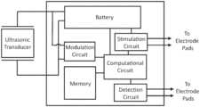
- FIG. 1illustrates a schematic of an exemplary body for the implantable closed-loop neuromodulation device described herein.
- FIG. 2 Aillustrates an exemplary implantable neuromodulation device with two curved members extending from a body and implanted on a nerve (shown as a cross-sectional plane).
- the curved memberspartially circumscribe the nerve, and include a plurality of electrode pads positioned along the curved member.
- FIG. 2 Billustrates an exemplary implantable neuromodulation device with a curve member that substantially circumscribes a nerve (shown as a cross-sectional plane).
- the curve memberincludes an electrode pad that partially circumscribes the nerve, although not to the same extent as the curved member.
- FIG. 3 Aillustrates a front view of an exemplary implantable closed-loop neuromodulation device with five curved members extending from a body and implanted on a nerve.
- FIG. 3 Billustrates a side view of the device illustrated in FIG. 3 A
- FIG. 3 Cillustrates a top view of the device illustrated in FIG. 3 A .
- FIG. 4shows an interrogator in communication with an implantable device through an ultrasonic transducer.
- the interrogatoremits carrier waves, which are received by the implantable device.
- the implantable devicethen emits an ultrasonic backscatter, which can be received by the interrogator.
- the ultrasonic backscatterencodes data or information about the implantable device.
- FIG. 5illustrates an exemplary interrogator that can be used in a system including the implantable device described herein.
- an implantable closed-loop neuromodulation devicethat includes one or more curved members that at least partially circumscribe a nerve or other filamentous tissue, and include one or more electrode pads.
- the one or more electrode padsmay be, for example, a plurality of electrode positioned along the curved member, or may be a curved electrode pad that at least partially circumscribes the nerve.
- the one or more curved memberextends from a device body, which houses one or more ultrasonic transducers and a computational circuit for on-board computing of a stimulation pulse in response to the device detecting an electrophysiological signal.
- the one or more ultrasonic transducerscan receive ultrasonic waves and convert energy from the ultrasonic waves into an electrical energy that can power the device.
- the electrical energyis stored in a battery, which is housed in the body of the device. The electrical energy powers the computational circuit, which is electrically connected to the electrode pads.
- the computational circuitallows for on-board computing so that the device can emit an electrical pulse in response to an electrophysiological signal detected by the device.
- an electrophysiological signal transmitted by the nervecan be detected by one or more (e.g., a plurality of) electrode pads on at least one of the one or more curved members of the device.
- the detection signal from the electrophysiological signal(which may be filtered, digitized, compressed, or otherwise processed) is received by the computational circuit, which generates a stimulation signal using the detection signal.
- the computational circuitcan further operate the one or more electrode pads on at least one of the one or more curved members (which may be the same as or different from the one or more electrodes and/or curved member that detected the electrophysiological signal) to emit an electrical pulse based on the generated stimulation signal.
- the curved membersinclude one or more electrode pads, and are configured to at least partially circumscribe a nerve.
- the one or more curved memberscomprises a plurality of electrode pads positioned along the curved member, or the one or more curved members comprises a curved electrode pad that at least partially circumscribes the nerve.
- This configurationallows for targeted detection or stimulation of nerve activity.
- a subset of electrode padscan be activated to target an electrical pulse to a subset of nerve fibers.
- the devicecan detect an electrophysiological signal transmitted by a subset of nerve fibers by detecting the electrophysiological signal using the plurality of electrode pads and deciphering signals detected by the electrode pads to determine the transmitting subset. Therefore, the device can be configured to detect an electrophysiological signal from a targeted fascicle within the nerve or emit an electrical pulse to a targeted fascicle within the nerve.
- Data related to the detected electrophysiological signal or the emitted electrical pulsecan be stored on a non-transitory memory within the body of the device.
- the datacan be transmitted to an external device, for example by encoding the data in ultrasonic backscatter waves emitted by the one or more ultrasonic transducers.
- the interrogatorcan transmit the ultrasonic waves to the device, for example the ultrasonic waves that are converted into the electrical energy by the one or more ultrasonic transducers of the device, and ultrasonic backscatter waves are emitted.
- the current flowing through the one or more ultrasonic transducerscan be modulated to encode the data, which causes the ultrasonic backscatter waves emitted by the one or more ultrasonic transducers to encode the data.
- the methodcan include receiving ultrasonic waves at one or more ultrasonic transducers of an implanted closed-loop neuromodulation device and converting the ultrasonic waves into an electrical energy that powers the device.
- the deviceis used to detect an electrophysiological signal transmitted by a targeted signaling fascicle within a nerve.
- the deviceis then used to automatically generate a stimulation signals using the detected electrophysiological signal, and to emit an electrical pulse to the nerve based on the generated stimulation signal.
- the electrical pulsecan be targeted to a targeted receiving fascicle within the nerve, which may be the same or different as the targeted signaling fascicle.
- a method of modulating neural activityincludes receiving ultrasonic waves at one or more ultrasonic transducers on a fully implanted closed-loop neuromodulation device, and converting the ultrasonic waves into an electrical energy that powers the device.
- the deviceis used to detect an electrophysiological signal transmitted by a nerve.
- the deviceis then used to generate a stimulation signal based on the detected electrophysiological signal, and emit an electrical pulse to a targeted receiving fascicle within the nerve based on the generated stimulation signal.
- references to “about” or “approximately” a value or parameter hereinincludes (and describes) variations that are directed to that value or parameter per se. For example, description referring to “about X” includes description of “X.”
- implantableand “implanted” refer to an object being fully implantable or fully implanted in a subject such that no portion of the object breaches the surface of the subject.
- a curved member that substantially surrounds a cross-section of a nerverefers to a curved member that surrounds 90% or more of the cross-section of the nerve.
- subjectand “patient” are used interchangeably herein to refer to a vertebrate animal.
- treatrefers to any action providing a benefit to a subject afflicted with a disease state or condition, including improvement in the condition through lessening, inhibition, suppression, or elimination of at least one symptom, delay in progression of the disease or condition, delay in recurrence of the disease or condition, or inhibition of the disease or condition.
- the implantable neuromodulation deviceis a closed-loop device that can detect an electrophysiological signal from a nerve or a subset of nerve fibers, and emit an electrical pulse to the nerve or a subset of nerve fibers of the nerve (which may be the same subset or a different subset of nerve fibers from which the electrophysiological signal was detect) in response to the detected electrophysiological signal.
- the implantable devicedetects a compound action potential (or a subset of the compound action potential) or other modulation of the electrophysiological signal, and the electrical pulse is emitted in response to the detected compound action potential (or subset thereof) or other modulation of the electrophysiological signal. Processing for the generation of the stimulation signal in response to the detected electrophysiological signal is performed by on-board computing using the computational circuit. Therefore, no external communication is needed to emit the electrical pulse in response to the detected electrophysiological signal.
- the implantable closed-loop neuromodulation deviceincludes one or more curved members that are configured to surround a nerve, and includes one or more (e.g., a plurality of) electrode pads that can detect an electrophysiological signal transmitted by the nerve and/or stimulate the nerve by emitting an electrical pulse.
- the devicecan include a plurality of curved members, with a first portion configured to detect the electrophysiological signal and a second portion configured to emit the electrical pulse.
- the curved memberscan include one or more (e.g., a plurality of) electrode pads on the inner surface of the curved members so that the electrode pads can be place in electrical communication with the never when implanted.
- the curved membersmay include a plurality of electrode pads positioned along the curved member, which at least partially encompasses the nerve, or the curve members may include a curved electrode pad that at least partially circumscribes the nerve.
- the curved membersubstantially surrounds a cross-section of the nerve, with the electrode pads on an inner surface of the curved member and radially positioned around an axis along the length of the nerve. In this configuration, the electrode pads are circularly aligned with the cross-section of the nerve.
- the curved membersinclude a plurality of electrode pads, which are radially positioned around an axis parallel to the length of the nerve, and are in electrical communication with the nerve when the implantable device is implanted.
- the curved membersextend from a body, which include one or more ultrasonic transducers configured to receive ultrasonic waves and convert energy from the ultrasonic waves into an electrical energy, and a computational circuit electrically connected to the plurality of electrode pads.
- the implantable deviceincludes one, two, three, or more ultrasonic transducers.
- the body of the devicecan house an integrated circuit, which includes the computational circuit, a modulation circuit, a detection circuit, and a stimulation circuit.
- the computational circuitis electrically connected to the plurality of electrode pads on the one or more curved members, and is configured to operate the electrode pads to emit an electrical pulse or detect an electrophysiological signal through the electrode pad.
- the computational circuitis configured to receive a detection signal, generate a stimulation signal using the detection signal, and operate the plurality of electrode pads of at least one of the one or more curved members to emit an electrical pulse to the nerve based on the stimulation signal.
- the detection signalis based on the detected electrophysiological signal.
- the detection signalmay be further based on an additional physiological condition, for example temperature, pressure, heart rate, pH, or detection or concentration of an analyte. That is, the detection signal may optionally include a detected electrophysiological signal component and a detected physiological condition component. In some embodiments, the physiological condition is detected or measured using a sensor, which may be on the device, as further described herein.
- an additional physiological conditionfor example temperature, pressure, heart rate, pH, or detection or concentration of an analyte.
- the detection signalmay optionally include a detected electrophysiological signal component and a detected physiological condition component.
- the physiological conditionis detected or measured using a sensor, which may be on the device, as further described herein.
- the computational circuitcan be a digital circuit, an analog circuit, or a mixed-signal integrated circuit.
- Exemplary computational circuitsinclude a microprocessor, a finite state machine (FSM), a field programmable gate array (FPGA), and a microcontroller.
- the integrated circuitincludes a volatile memory, which can be accessed by the computational circuit.
- the computational circuitis configured to selectively activate the electrode pads within the plurality of electrode pads for targeted emission of the electrical pulse, as further described herein.
- an electrophysiological signal transmitted by the nerveis detected by the electrode pads.
- the electrophysiological signalcan include a baseline signal, and an action potential or compound action potential transmitted by the nerve results in modulation of the electrophysiological signal.
- a detection signal based on the electrophysiological signal detected by the electrode pads of the deviceis received by the computational circuit.
- the detection signal received by the computational circuitmay be a raw electrophysiological signal detected by the device, or the electrophysiological signal may be processed (for example, amplified, digitized, and/or filtered) before being received by the computational circuit.
- the detection signalincludes a detected electrophysiological signal component and a physiological condition component, which can be together analyzed by the computational circuit to generate the stimulation signal.
- the detection signal(or the detected electrophysiological signal component of the detection signal) is compressed by the computational circuit or other suitable circuitry within the device. Compression of the detection signal allows for faster and more energy efficient processing by the computational circuit, which allows for a more efficient closed-loop device. For example, the battery life of the on-board batter is longer with less data processing, and the time delay between receiving the detection signal and generating the stimulation signal is decreased.
- compression of the detection signalcan include down sampling the detection signal by retaining a portion of the data points in the detection signal.
- the digital signalis compressed by identifying an electrophysiological signal spike above a baseline threshold, and using a timestamp associated with the electrophysiological signal spike as an input for the computational circuit.
- the detection signalcan be compared to a baseline signal, which may be an average signal (either electrophysiological signal, physiological condition, or both) detected for a period of time.
- the period of timecan be, for example about 1 minute or more (such as about 2 minutes or more, about 5 minutes or more, about 10 minutes or more, about 15 minutes or more, about 30 minutes or more, or about 45 minutes or more).
- the period of timeis about 1 hour or less (such as about 45 minutes or less, about 30 minutes or less, about 15 minutes or less, about 10 minutes or less, about 5 minutes or less, or about 2 minutes or less.
- a detected deviation of the detection signal from the baseline signalcan be used to trigger generation of the stimulation signal.
- the detected modulationis a signal input, which can be associated with one or more additional detected modulation in a temporal dimension.
- the computational signalanalyzes the non-compressed (e.g., raw) signal.
- the detected electrophysiological signal component of the detection signalincludes, for example, a velocity, a direction, a frequency, an amplitude, a waveform of a compound action potential or a subset of the compound action potential (such as one or more action potential) transmitted by the nerve or a subset of nerve fibers within the nerve.
- the detected electrophysiological signal componentmay additionally or alternatively include information related to the subset of nerve fibers from which the electrophysiological signal was detected (that is, a location of the subset of nerve fibers within the nerve). This information can be used by the computational circuit, for example, to select a template detection signal and/or generate the stimulation signal.
- a detection circuitcan be included in the integrated circuit, and electrically connected to the plurality of electrode pads configured to detect the electrophysiological signal.
- the detection circuitcan also optionally include an analog to digital converter (ADC), one or more filters, and/or one or more amplifiers.
- ADCanalog to digital converter
- the implantable devicefurther includes one or more sensors configured to measure or detect a physiological condition, such as an analyte, a pH, a temperature, a strain, a pulse rate, or a pressure (e.g., a blood pressure).
- a physiological conditionsuch as an analyte, a pH, a temperature, a strain, a pulse rate, or a pressure (e.g., a blood pressure).
- the physiological condition detected by the implantable devicecan optionally be a component, in addition to the detected electrophysiological signal, of the detection signal received by the computational circuit. Therefore, the detection signal including the detected electrophysiological signal component and the additionally detected physiological condition component is used by the computational circuit to generate the simulation signal.
- the detection signalcan include one or more detected signals (electrophysiological signal and/or physiological condition), which may be detected at different time points.
- a time stamp for the signalscan be associated with the detected signal, and can be included in the detection signal for analysis by the computational circuit. For example, a detection signal that includes a predetermined number of detected electrophysiological signal spikes within a period of time can result in the generation of a stimulation signal by the computational circuit.
- the computational circuitcan analyze the detection signal to generate a stimulation signal using the detection signal.
- the analysiscan include, for example, identifying a modulation of the detection signal (such as a modulation of the detected electrophysiological signal, the detected physiological condition, or both), which can act as a trigger for generation of the stimulation signal.
- the modulation of the electrophysiological signalcan indicate, for example, a compound action potential or a component of the compound action potential (e.g., one or more action potentials) that is being transmitted by the nerve.
- the stimulation signalcan be generated using a mathematical relationship between the detection signal and the stimulation signal.
- the computational circuitcan input the detection signal into the mathematical relationship to generate the stimulation signal.
- the mathematical relationshipcan be determine, for example, using machine learning or can be a pre-selected mathematical relationship.
- the computational circuituses a digital logic, an analog logic, an artificial neural network, a convolutional neural network (CNN), or neuromorphic computing to detect deviation of the detection signal from a baseline signal.
- CNNconvolutional neural network
- generating the stimulation signalcan include comparing the detection signal (which may include a detected electrophysiological signal component and/or a detected physiological signal component) to a template detection signal, and the stimulation signal is generated based on the variance or similarity between the detection signal and the template detection signal.
- One or more template detection signalscan be stored, for example, on a non-transitory memory in the body of the device.
- the computational circuitcan use, for example, a digital logic, an analog logic, an artificial neural network, a convolutional neural network (CNN), or neuromorphic computing to detect the variance or similarity between the detected electrophysiological signal and the template electrophysiological signal.
- CNNconvolutional neural network
- the stimulation signal generated by the computational circuitcan include information about the electrical pulse to be emitted by the device, such as amplitude, frequency, waveform, or targeted location (i.e., subset of nerve fibers) within the nerve.
- one or more template pulsesare stored on a non-transitory memory within the device (e.g., within the body of the device).
- the computational circuitcan generate the stimulation signal by retrieving a template pulse from the non-transitory memory using the detection signal. For example, generating the stimulation signal can include analyzing the detection signal, retrieving a template pulse from the non-transitory memory based on the analyzed detection signal, and generating the stimulation signal based on the retrieved template pulse. Depending on whether or how the detection signal is modulated from a baseline or compares to a template detection signal can determine which template pulse is retrieved or stimulation signal generated.
- the integrated circuitcan include a stimulation circuit, which is operated by the computational circuit and is electrically connected to electrode pads that emit the electrophysiological pulse.
- the stimulation circuitcan include a stimulating capacitor, which can be charged by the battery or electrical energy converted from the ultrasonic waves by the one or more ultrasonic transducers.
- the status of the stimulating capacitorfor example capacitor charge, can be determined by the computational circuit.
- the status of the stimulating capacitoris recorded on the non-transitory memory or encoded in ultrasonic backscatter waves through the modulation circuit operated by the computational circuit.
- the computational circuitoperates the electrode pads of at least one of the one or more curved members to emit an electrical pulse to the nerve based on the stimulation signal.
- the stimulation signalcan include a pulse amplitude, frequency, and/or waveform, and the computational circuit controls the electrode pads to emit the pulse in accordance with the stimulation signal.
- the devicecan include a capacitor (i.e., a stimulating capacitor), such as within the body of the device, which stores an electrical charge and is controlled by the computational circuit.
- the computational circuitcontrols the capacitor to emit the electrical pulse through the electrode pads.
- the computational circuitis configured to determine a stimulating capacitor status, such as a charge of the capacitor.
- the capacitor statuscan be stored in the non-transitory memory and/or encoded in ultrasonic backscatter waves.
- the implantable devicefurther includes a battery configured to receive the electrical energy from the one or more ultrasonic transducers and power the computational circuit. Inclusion of the battery allows the computational circuit to function without an external power source, including detecting an electrophysiological signal or emitting an electrical pulse to the nerve.
- the batterycan be contained within the body of the implantable device.
- the batterycan be, for example, a rechargeable electrochemical battery.
- the energy stored by the batterycan power the device, for example when the one or more ultrasonic transducers are not receiving ultrasonic waves.
- the batterycan be charged by transmitting ultrasonic waves to the device using an interrogator which are received by the one or more ultrasonic transducers.
- the one or more ultrasonic transducersconvert the ultrasonic waves into an electrical energy, and are electrically connected to the battery. In this manner, the electrical energy charges the battery of the device.
- the implantable closed-loop neuromodulation devicecan also include a non-transitory memory configured to store data based on an electrophysiological signal detected by the device or an electrical pulse emitted by the device.
- the datacan include, for example, a time stamp, a velocity, a direction, an amplitude, a frequency, or a waveform of a detected action potential or compound action potential; and/or a time stamp, an amplitude, a frequency, or a waveform of an electrical pulse emitted by implantable device.
- the non-transitory memorycan store data related to a detected physiological condition (such as temperature, pH, pressure, heart rate, strain, and/or presence or amount of an analyte).
- the data stored on the non-transitory memorymay be acquired over a period of time (such as about 1 minute or more, about 5 minutes or more, about 10 minutes or more, about 15 minutes or more, about 30 minutes or more, about 45 minutes or more, about 1 hour or more, about 2 hours or more, about 4 hours our more, about 6 hours or more, about 8 hours or more, about 12 hours or more, or about 24 hours or more).
- the deviceis configured to encode at least a portion of the data stored on the non-transitory memory in ultrasonic backscatter waves. This allows the data to be wirelessly transmitted to an interrogator, which may be implanted or external to the subject.
- Data encoded in the ultrasonic backscatter wavescan be compressed. Compression may be used, for example, for efficient transmission of the data due to bandwidth limits between the implantable device and the interrogator.
- data compressioncan include transmitting down sampled data from the detection signal, processed data, or one or more features in the signal (such as a time stamp of a detected electrophysiological signal spike).
- the implantable devicecan include a modulation circuit electrically connected to the one or more ultrasonic transducers.
- a currentis generated that flows through the one or more ultrasonic transducers and the modulation circuit.
- the computational circuitcan operate the modulation circuit to encode data stored on the non-transitory memory onto the current.
- the one or more ultrasonic transducers of the deviceemit ultrasonic backscatter waves, which can encode the data encoded into the current.
- the ultrasonic backscatter wavescan be received by an interrogator, which may be the same or different as the interrogator transmitting the ultrasonic waves to the implantable device, and the data encoded on the ultrasonic backscatter waves can be deciphered.
- the non-transitory memorycan also be used to store data transmitted to the device from an interrogator.
- the interrogatorcan transmit data (such as temperature data, or data related to some other physiological condition, such as an analyte concentration in the blood or interstitial fluid of a subject), which is received by the implantable device and can be stored on the non-transitory memory.
- the datacan be transmitted, for example, through ultrasonic waves that encode the data.
- the interrogatorcan transmit the ultrasonic waves, which are received by the ultrasonic transducer of the device and deciphered by the computational circuit.
- the non-transitory memorycan store one or more instructions for operating the device, which can be executed using the computational circuit.
- the non-transitory memorycan include instructions for receiving a detection signal based on detected electrophysiological signal; generating a stimulation signal using the detection signal; and operating the plurality of electrode pads of at least one of the one or more curved members to emit an electrical pulse to the nerve based on the stimulation signal.
- the non-transitory memoryincludes instructions for selectively activating one or more electrodes with the plurality of electrodes for targeted emission of the electrical pulse.
- the non-transitory memorycomprises instructions for analyzing a detected electrophysiological signal (and, optionally, a measured physiological condition), for example by determining a variance in the detected electrophysiological signal (and/or physiological condition) compared to a baseline electrophysiological signal (and/or physiological condition). In some embodiments, the non-transitory memory comprises instructions for comparing the detected electrophysiological signal (and/or physiological condition) to a template electrophysiological signal (and/or physiological condition).
- FIG. 1illustrates a schematic of an exemplary body for the implantable closed-loop neuromodulation device described herein.
- the bodyincludes an ultrasonic transducer electrically connected to a battery and a modulation circuit.
- the batteryis electrically connected to and powers a computational circuit, which is electrically connected to a non-transitory memory and the modulation circuit.
- the computational circuitis also electrically connected and is configured to operate the electrodes on the curved member or curved members of the device through a stimulation circuit or a detection circuit.
- Ultrasonic wavesare received by the ultrasonic transducer, which converts the energy from the ultrasonic waves into an electrical energy that charges the battery.
- the electrodes on the deviceare configured to detect an electrophysiological signal, and a detection signal based on the electrophysiological signal is received by the computational circuit.
- the detection signal received by the computational circuitmay be processed (for example, amplified, digitized, and/or filtered) by the detection circuit before being received by the computational circuit.
- the computational circuitaccesses the non-transitory memory to store data related to the detected electrophysiological signal.
- the computational circuitcan generate a stimulation signal based on the detection signal, and operate the electrodes to emit an electrical pulse to the nerve based on the stimulation signal.
- the computational circuitaccesses the non-transitory memory to store data related to the stimulation signal or electrical pulse emitted to the nerve.
- Data stored on the non-transitory memorycan be wirelessly transmitted through ultrasonic backscatter waves emitted by the ultrasonic transducer.
- the ultrasonic transducerreceives ultrasonic waves, and generates a current that flows through the modulation circuit.
- the computational circuitaccesses the memory and operates the modulation circuit to modulate the current flowing through the modulation circuit to encode the data.
- the ultrasonic backscatter waves emitted by the ultrasonic transducerthereby encode the data.
- the bodyincludes a housing, which can include a base, one or more sidewalls, and a top.
- the housingcan enclose the one or more ultrasonic transducers and the integrated circuit (which includes the computational circuit, the non-transitory memory, the battery, the modulation circuit, a detection circuit, and/or a stimulation circuit (which can include a stimulating capacitor)).
- the hosingmay be sealed closed (for example by soldering or laser welding) to prevent interstitial fluid from coming in contact with the ultrasonic transducer(s) and/or the integrated circuit.
- the housingis preferably made from a bioinert material, such as a bioinert metal (e.g., steel or titanium) or a bioinert ceramic (e.g., titania or alumina).
- a bioinert metale.g., steel or titanium
- a bioinert ceramice.g., titania or alumina
- the housing (or the top of the housing)may be thin to allow ultrasonic waves to penetrate through the housing.
- the thickness of the housingis about 100 micormeters ( ⁇ m) or less in thickness, such as about 75 ⁇ m or less, about 50 ⁇ m or less, about 25 ⁇ m or less, or about 10 ⁇ m or less.
- the thickness of the housingis about 5 ⁇ m to about 10 ⁇ m, about 10 ⁇ m to about 25 ⁇ m, about 25 ⁇ m to about 50 ⁇ m, about 50 ⁇ m to about 75 ⁇ m, or about 75 ⁇ m to about 100 ⁇ m in thickness.
- the body of the implantable deviceis relatively small, which allows for comfortable and long-term implantation while limiting tissue inflammation that is often associated with implantable devices.
- the longest dimension of the body of the deviceis about 10 mm or less, such as about 5 mm to about 9 mm, or about 6 mm to about 8 mm.
- the bodycomprises a material, such as a polymer, within the housing.
- the materialcan fill empty space within the housing to reduce acoustic impedance mismatch between the tissue outside of the housing and within the housing. Accordingly, the body of the device is preferably void of air or vacuum.
- One or more ultrasonic transducers of the implantable devicecan be a micro-machined ultrasonic transducer, such as a capacitive micro-machined ultrasonic transducer (CMUT) or a piezoelectric micro-machined ultrasonic transducer (PMUT), or can be a bulk piezoelectric transducer.
- CMUTcapacitive micro-machined ultrasonic transducer
- PMUTpiezoelectric micro-machined ultrasonic transducer
- Bulk piezoelectric transducerscan be any natural or synthetic material, such as a crystal, ceramic, or polymer.
- Exemplary bulk piezoelectric transducer materialsinclude barium titanate (BaTiO 3 ), lead zirconate titanate (PZT), zinc oxide (ZO), aluminum nitride (AlN), quartz, berlinite (AlPO 4 ), topaz, langasite (La 3 Ga 5 SiO 14 ), gallium orthophosphate (GaPO 4 ), lithium niobate (LiNbO 3 ), lithium tantalite (LiTaO 3 ), potassium niobate (KNbO 3 ), sodium tungstate (Na 2 WO 3 ), bismuth ferrite (BiFeO 3 ), polyvinylidene (di)fluoride (PVDF), and lead magnesium niobate-lead titanate (PMN-PT).
- barium titanateBaTiO 3
- PZTlead zirconate titanate
- ZOzinc oxide
- AlNaluminum nitride
- quartzquartz
- the bulk piezoelectric transduceris approximately cubic (i.e., an aspect ratio of about 1:1:1 (length:width:height). In some embodiments, the piezoelectric transducer is plate-like, with an aspect ratio of about 5:5:1 or greater in either the length or width aspect, such as about 7:5:1 or greater, or about 10:10:1 or greater. In some embodiments, the bulk piezoelectric transducer is long and narrow, with an aspect ratio of about 3:1:1 or greater, and where the longest dimension is aligned to the direction of the ultrasonic backscatter waves (i.e., the polarization axis).
- one dimension of the bulk piezoelectric transduceris equal to one half of the wavelength (k) corresponding to the drive frequency or resonant frequency of the transducer. At the resonant frequency, the ultrasound wave impinging on either the face of the transducer will undergo a 180° phase shift to reach the opposite phase, causing the largest displacement between the two faces.
- the height of the piezoelectric transduceris about 10 ⁇ m to about 1000 ⁇ m (such as about 40 ⁇ m to about 400 ⁇ m, about 100 ⁇ m to about 250 ⁇ m, about 250 ⁇ m to about 500 ⁇ m, or about 500 ⁇ m to about 1000 ⁇ m).
- the height of the piezoelectric transduceris about 5 mm or less (such as about 4 mm or less, about 3 mm or less, about 2 mm or less, about 1 mm or less, about 500 ⁇ m or less, about 400 ⁇ m or less, 250 ⁇ m or less, about 100 ⁇ m or less, or about 40 ⁇ m or less).
- the height of the piezoelectric transduceris about 20 ⁇ m or more (such as about 40 ⁇ m or more, about 100 ⁇ m or more, about 250 ⁇ m or more, about 400 ⁇ m or more, about 500 ⁇ m or more, about 1 mm or more, about 2 mm or more, about 3 mm or more, or about 4 mm or more) in length.
- the one or more ultrasonic transducershave a length of about 5 mm or less such as about 4 mm or less, about 3 mm or less, about 2 mm or less, about 1 mm or less, about 500 ⁇ m or less, about 400 ⁇ m or less, 250 ⁇ m or less, about 100 ⁇ m or less, or about 40 ⁇ m or less) in the longest dimension.
- the ultrasonic transducerhas a length of about 20 ⁇ m or more (such as about 40 ⁇ m or more, about 100 ⁇ m or more, about 250 ⁇ m or more, about 400 ⁇ m or more, about 500 ⁇ m or more, about 1 mm or more, about 2 mm or more, about 3 mm or more, or about 4 mm or more) in the longest dimension.
- the ultrasonic transduceris connected two electrodes to allow electrical communication with the computational circuit.
- the first electrodeis attached to a first face of the transducer and the second electrode is attached to a second face of the transducer, wherein the first face and the second face are opposite sides of the transducer along one dimension.
- the electrodescomprise silver, gold, platinum, platinum-black, poly(3,4-ethylenedioxythiophene (PEDOT), a conductive polymer (such as conductive PDMS or polyimide), or nickel.
- the axis between the electrodes of the transduceris orthogonal to the motion of the transducer.
- the curved members of the deviceextend from the body of the device to at least partially circumscribe a nerve, and one or more electrode pads are included on the curved members.
- the electrode padscan be configured to be in electrical communication with the nerve, for example to detect an electrophysiological signal transmitted by the nerve and/or emit one or more electrical pulses to the nerve.
- the one or more electrode padsmay be on an inner surface of the curved members, and the one or more curved members may engage the nerve or filamentous tissue that includes the nerve (such as a blood vessel connected to the nerve) to secure the device to the nerve or other filamentous tissue and position the electrode pads.
- the curved membersmay be flexible, which allows for deformation of the curved members during implantation of the device.
- the cured membersmay be flexed outwardly while the device is being positioned on the nerve. Release of the curved members allows the curved members to wrap around the nerve or filamentous tissue containing the nerve.
- the curved memberincludes two portions that are bridged by the body of the device.
- the electrode padmay, for example, be configured to at least partially surround an axis parallel to the length of a nerve, or a plurality of electrode pads may be configured to be radially positioned around the axis parallel to the length of the nerve.
- the devicemay include curved members with different electrode pad configurations.
- a devicemay include one or more curved members with a plurality of electrode pads positioned along the curved member, and one or more curved members with a curved electrode pad that at least partially circumscribes the nerve.
- the curved members that extend from the body of the deviceeach include a plurality of electrode pads configured to be radially positioned around the nerve (i.e., around an axis that runs parallel through the center of and along the length of the nerve) and in electrical communication with the nerve.
- the curved membersextend away from the body before curving toward the body as the curved members extend below the body, resulting in a ring-like structure that results in the curved members sustainably circumscribing a cross-section of the nerve or filamentous tissue that includes the nerve (such as a blood vessel connected to the nerve).
- the curved membersmake a single loop around the cross-section of the nerve.
- the electrode pads of a given curved memberare within the same cross-sectional location relative to the nerve.
- a space within the curved membercan be included to allow the device to be implanted on the nerve.
- the curved memberscan be flexible, which allows for deformation of the curved members during implantation of the device.
- the cured memberscan be flexed outwardly while the device is being positioned on the nerve. Release of the curved members allows the curved members to wrap around the nerve or filamentous tissue containing the nerve.
- the curved memberincludes two portions that are bridged by the body of the device.
- FIG. 2 Aillustrates an exemplary embodiment of a device with a first curved member and a second curved member that each partially circumscribe a nerve to engages the nerve.
- the device 200includes a body 202 attached to a first curved member 204 and a second curved member 206 .
- a plurality of electrodes 208 on the inner surface of the first curved member 204is positioned along the first curved member, 204
- plurality of electrodes 212is positioned along the second curved member 206 .
- the first curved member 204 and the second curved member 206are flexible members that are separated by a gap (i.e., a separation) 214 .
- first curved member 204 and the second curved member 206can be flexed outwardly (thereby widening the gap 214 ) to allow the nerve 208 to be positioned within the space between the curved members, and the curved members can be released so that the curved members wrap around the nerve.
- FIG. 2 Billustrates another exemplary embodiment of a device with a curved member that engages a nerve.
- the device 216includes a body 218 and a curved member 220 that substantially circumscribes a nerve 222 .
- the inner surface of the curved member 220includes a curved electrode pad 224 that circumscribes the nerve 222 .
- the curved member 220may be flexible, and a space 226 may be present between the body 218 and the end 228 of the curved member 220 (or between a first curved member a second curved member).
- the curved membermay be flexed outwardly to allow the nerve 222 to be positioned within the space formed by the curved member, and the curved member may be released so that the curved member wraps around the nerve 222 .
- a devicemay include a curved member as shown in FIG. 2 A and a curved member as shown in FIG. 2 B .
- the devicemay include first and second curved members (as shown in FIG. 2 A ) and a curved electrode (as shown in FIG. 2 B ).
- the devicemay include a curved member that substantially surrounds the nerve (e.g., as shown in FIG. 2 B ) with a plurality of electrode positioned along the curved member (e.g., as shown in FIG. 2 A ).
- the size, shape, and spacing of the one or more curved members on the devicecan depend on the type and size of tissue that device engages.
- the two or more curved membersare spaced by about 0.25 mm or more (such as about 0.5 mm or more, about 1 mm or more, about 2 mm or more, about 3 mm or more, about 4 mm or more, about 5 mm or more, about 6 mm or more, or about 7 mm or more).
- the two or more curved membersare space by about 8 mm or less (such as about 7 mm or less, about 6 mm or less, about 5 mm or less, about 4 mm or less, about 3 mm or less, about 2 mm or less, about 1 mm or less, or about 0.5 mm or less).
- the two or more curved memberscan be spaced by about 0.25 mm to about 0.5 mm, about 0.5 mm to about 1 mm, about 1 mm to about 2 mm, about 2 mm to about 3 mm, about 3 mm to about 4 mm, about 4 mm to about 5 mm, about 5 mm to about 6 mm, about 5 mm to about 7 mm, or about 7 mm to about 8 mm apart.
- the width of the curved memberscan also vary depending on the application of the device or the tissue engaged by the device.
- the width of the curved memberis about 100 ⁇ m or more (such as about 150 ⁇ m or more, about 250 ⁇ m or more, about 500 ⁇ m or more, about 1 mm or more, or about 1.5 mm or more). In some embodiments, the width of the curved member is about 2 mm or less (such as about 1.5 mm or less, about 1 mm or less, about 500 ⁇ m or less, about 250 ⁇ m or less, or about 150 ⁇ m or less.
- the width of the curved membersis about 100 ⁇ m to about 2 mm (such as about 100 ⁇ m to about 150 ⁇ m, about 150 ⁇ m to about 250 ⁇ m, about 250 ⁇ m to about 500 ⁇ m, about 500 ⁇ m to about 1 mm, about 1 mm to about 1.5 mm, or about 1.5 mm to about 2 mm).
- the inner surface of the curved membersform a cylindrical space through which the nerve and/or filamentous tissue passes. The diameter of the cylindrical space formed by the curved members depends on the target nerve and/or filamentous tissue that the implantable device will engage.
- the one or more curved members of the deviceform a cylindrical space with a diameter of about 50 ⁇ m to about 15 mm (for example, about 50 ⁇ m to about 100 ⁇ m, about 100 ⁇ m to about 250 ⁇ m, about 250 ⁇ m to about 500 ⁇ m, about 500 ⁇ m to about 1 mm, about 1 mm to about 1.5 mm, about 1.5 mm to about 2.5 mm, about 2.5 mm to about 5 mm, about 5 mm to about 10 mm, or about 10 mm to about 15 mm).
- a diameter of about 50 ⁇ m to about 15 mmfor example, about 50 ⁇ m to about 100 ⁇ m, about 100 ⁇ m to about 250 ⁇ m, about 250 ⁇ m to about 500 ⁇ m, about 500 ⁇ m to about 1 mm, about 1 mm to about 1.5 mm, about 1.5 mm to about 2.5 mm, about 2.5 mm to about 5 mm, about 5 mm to about 10 mm, or about 10 mm to about 15 mm).
- the one or more curved membersmay be configured to at least partially circumscribe the nerve or other filamentous tissue.
- the curved membermay be configured to circumscribe at least 25%, at least 33%, at least 50%, at least 66%, at least 75%, at least 90%, or at least 100% (for example, the curve member may completely surround the nerve or filamentous tissue, or may include more than one complete loop around the nerve or filamentous tissue) of the nerve or filamentous tissue.
- the one or more curved electrode padsmay circumscribe at least 25%, at least 33%, at least 50%, at least 66%, at least 75%, at least 90%, or at least 100% of the nerve, and the portion of the nerve circumscribed by the curved electrode pad may be the same or less than the portion of the nerve circumscribed by the curved member.
- the plurality of electrode pads positioned on the curved membermay be positioned along the full length of the curved member or a portion of the length of the curved member.
- the implantable deviceincludes one or more additional securing members configured to secure the implantable device to the filamentous tissue.
- securing memberscan include, for example, loops for suturing the implantable device to anatomical structure (such as the filamentous tissue or nerve, or other tissue surrounding the filamentous tissue or nerve), pins, or clamps.
- the implantable devicecan be sutured to the filamentous tissue or nerve, or tissue surrounding the filamentous tissue or nerve, to limit movement of the implantable device once implanted.
- the curved members of the implantable devicecan comprise a metal, metal alloy, ceramic, silicon, or a non-polymeric material.
- the curved membersmay be flexible, and are preferably sprung such that the curved members can be positioned around the nerve and/or filamentous tissue.
- the one or more curved members or a portion of the one or more curved membersare coated with an elastomeric coating or a non-elastomeric coating, which is preferably bioinert, such as polydimethylsioloxane (PDMS), a silicone, a urethane polymer, a poly(p-xylylene)polymer (such as a poly(p-xylylene) polymer sold under the tradename PARYLENE®), or a polyimide.
- the one or more curved memberseach include a plurality of electrode pads on an inner surface of the curved members.
- the electrode pads on the inner surface of the curved membersare not coated with the elastomeric coating or the non-elastomeric polymer coating, although may be coated with a conductive material (e.g., electroplated with a PEDOT polymer or a metal to improve electrical characteristics of the electrode pad). Accordingly, in some embodiments, only the outer surface of the curved member is coated with the coating. Optionally, the coating further coats the housing of the body.
- the one or more curved memberscan hold the implantable device in place on the nerve and/or filamentous tissue.
- the one or more curved membersallow for some rotational movement of the implantable device on the nerve and/or filamentous tissue.
- the one or more curved membersgrip the nerve and/or filamentous tissue by exerting an inward pressure on the nerve and/or filamentous tissue.
- the amount of inward pressure exerted by the one or more curved memberscan be determined based on the size and curvature of the curved members, as well as by the spring constant of the curved members. The inward pressure should be sufficient to hold the implantable device in place while the tissue heals after insertion, but not so high that the epineurium or vascular walls that contact the curved members are damaged.
- the inward pressure on the nerve or filamentous tissueis about 1 MPa or less (such as about 0.7 MPa or less, about 0.5 MPa or less, or about 0.3 MPa or less). In some embodiments, the inward pressure on the nerve or filamentous tissue is about 0.1 MPa to about 1 MPa (such as about 0.1 MPa to about 0.3 MPa, about 0.3 MPa to about 0.5 MPa, about 0.5 MPa to about 0.7 MPa, or about 0.7 MPa to about 1 MPa).
- the plurality of electrode pads on each curved memberis positioned on an inner surface of the curved member (that is, the surface of the curved surface that is configured to interface with the nerve and/or filamentous tissue).
- the plurality of electrode padsinclude 2, 3, 4, 5, 6, 7, 8, 9, 10, 11, 12, 13, 14, 15, 16, 17, 18, 19, 20, or more electrode pads, such as between about 3 and about 50 electrode pads, between about 3 and about 5 electrode pads, between about 5 and about 10 electrode pads, between about 10 and about 25 electrode pads, or between about 25 and about 50 electrode pads.
- the electrode pads within the plurality of electrode padscan be selectively activated by the computational circuit, which allows for targeted electrical pulse emission, as further described herein.
- the electrode padscan include any suitable conductive material, such as one or more of (or an alloy of one or more of) tungsten, platinum, palladium, gold, iridium, niobium, tantalum, or titanium.
- the material of the detecting electrode pads and the stimulating electrode padsmay be the same or different.
- the size and shape of the electrode padsmay also be the same or different. For example, electrode pads on a given curved members may be of the same or different size, and electrode pads on different curved members may be of the same or different size.
- the electrode pads of the implantable deviceare positioned by the curved members to be in electrical communication with the nerve.
- the electrode padsare not in direct contact with the nerve (for example outside and not indirect contact with the nerve), but are in electrical communication with the nerve.
- the electrode padsare positioned within about 2 mm (within about 1.8 mm, within about 1.6 mm, within about 1.4 mm, within about 1.2 mm, within about 1.0 mm, within about 0.8 mm, within about 0.6 mm, within about 0.4 mm, or within about 0.2 mm of the nerve.
- the plurality of electrode padsis configured to penetrate the epineurium of the nerve at one or more locations.
- the electrode padscan be needle-shaped, which allows for penetration of the epineurium.
- the electrode padsdirectly contact the nerve, for example the epineurium of the nerve.
- one or more of the curved members on the deviceis configured to detect the electrophysiological signal transmitted by the nerve. In some embodiments, one or more or more curved members on the device are configured to emit the electrical pulse. The one or more curved members that are configured to detect the electrophysiological signal transmitted by the nerve may be the same or different from the one or more curved members that are configured to emit the electrical pulse.
- the deviceincludes a first curved member that includes a first plurality of electrode pads configured to detect the electrophysiological signal transmitted by the nerve, and a second curved member that includes a second plurality of electrode pads configured to emit the electrical pulse to the nerve. In some embodiments, the device includes two, three, four, five, six, seven, eight or more curved members.
- the deviceincludes one, two, three, four, five, six, seven, eight or more curved members configured to detect the electrophysiological signal transmitted by the nerve, and one, two, three, four, five, six, seven, eight or more curved members configured to emit the electrical pulse.
- the curved members having electrode pads configured to detect the electrophysiological signal and the curved members having electrode pads configured to emit the electrical pulseare separate curved members to allow for concurrent detection of the electrophysiological signal and emission of the electrical pulse.
- Multiple curved memberscan be positioned along the length of the nerve. This configuration allows for electrophysiological signal detection and/or emission of an electrical pulse, which may be target to a subset of nerve fibers within the nerve, at different points along the length of the nerve.
- the computational circuitcan determine a direction and/or velocity of the electrophysiological signal transmitted by the nerve.
- direction of the electrophysiological signale.g., an efferent signal or an afferent signal
- the computational circuitcan use on a first time stamp of the electrophysiological signal detected by a first curved member and a second time stamp of the electrophysiological signal detected by the second curved member.
- the computational circuitcan further use the known distance between the first curved member and the second curved member.
- the identity of the electrophysiological signal detected by the electrode pads of the first curved member and the second curved memberis confirmed by comparing one or more electrophysiological signal features (e.g., amplitude, frequency, or waveform) detected by the electrode pads on the first curved member and the electrode pads of the second curved member.
- the implantable devicecan also include two or more curved members comprising a plurality of electrodes configured to emit an electrical pulse or an electrical pulse train.
- the two or more curved memberscan be positioned at different locations along the length of the nerve, and are configured to emit an electrical pulse at the different positions.
- the electrical pulse emitted by the two or more different curved membersmay be the same or different, and may be targeted to the same or different subset of curved members within the nerve.
- a first electrode pad (or a first plurality of electrode pads) on a first curved membercan emit an electrical pulse configured to block transmission of an electrophysiological signal by a first subset of nerve subset of nerve fibers
- a second electrode pad (or second plurality of electrode pads) on a second curved membercan be configured to emit an electrical pulse that stimulates a second subset of nerve fibers.
- the first subset of nerve fiberscan be, for example, efferent nerve fibers, while the second subset of nerve fibers is afferent nerve fibers.
- the first subset of nerve fibersare afferent nerve fibers
- the second subset of nerve fibersare efferent nerve fibers.
- the one or more electrode pads within the first plurality of electrode pads on the first curved member and one or more electrode pads within the second plurality of electrode pads on the second curved memberscan be operated for bipolar stimulation along the length of the nerve.
- the plurality of electrodes on the first curved member and the plurality of electrodes on the second curved membercan each emit a coordinated electrical pulse (that is, the electrical pulses emitted by the separate pluralities of electrodes are coordinated with each other), which can be used for specific focal stimulation.
- the devicecomprises a first curved member comprising a first plurality of electrode pads and a second curved member comprising a second plurality of electrode pads, wherein the first plurality of electrodes and the second plurality of electrodes are each configured to be radially positioned around the axis parallel to the length of the nerve at different positions along the length of the nerve.
- the first plurality of electrode pads and the second plurality of electrode padsare configured to detect the electrophysiological signal transmitted by the nerve.
- the deviceoptionally further comprises a third curved member comprising a third plurality of electrode pads, wherein the third plurality of electrode pads is configured to be radially positioned around the axis parallel to the length of the nerve at a position between the first curved member and the second curved member along the length of the nerve.
- the deviceincludes a first curved member comprising a first plurality of electrode pads and a second curved member comprising a second plurality of electrode pads, wherein the first plurality of electrodes and the second plurality of electrodes are each configured to be radially positioned around the axis parallel to the length of the nerve at different positions along the length of the nerve, wherein the first plurality of electrode pads or the second plurality of electrode pads are configured to emit the electrical pulse to the nerve.
- the electrode pads within the first plurality of electrode pads and/or the second plurality of electrode padsare configured to be selectively activated to emit the electrical pulse to the nerve for example by targeting a subset of nerve fibers within the nerve.
- the deviceincludes a first curved member comprising a first plurality of electrode pads, and a second curved member comprising a second plurality of electrode pads, the first plurality of electrode pads and the second plurality of electrode pads configured to detect the electrophysiological signal transmitted by the nerve; and a third curved member comprising a third plurality of electrode pads, and a fourth curved member comprising a fourth plurality of electrode pads, the third plurality of electrode pads and the fourth plurality of electrode pads configured to emit the electrical pulse; wherein the first plurality of electrodes, the second plurality of electrodes, the third plurality of electrodes, and the fourth plurality of electrodes are each configured to be radially positioned around the axis parallel to the nerve at different positions along the length of the nerve.
- the third curved member and the fourth curved memberare positioned between the first curved member and the second curved member along the length of the nerve.
- the devicefurther includes a fifth curved member comprising a fifth plurality of electrode pads configured to detect the electrophysiological signal or emit the electrical pulse.
- the fifth curved memberis optionally positioned between the third curved member and the fourth curved member along the length of the nerve.
- the first plurality of electrode pads, the second plurality of electrode pads, the third plurality of electrode pads, or the fourth plurality of electrode pads and/or the fifth plurality of electrode padsare configured to be selectively activated to emit the electrical pulse.
- FIGS. 3 A- 3 Cillustrate a front ( 3 A), side ( 3 B), and top ( 3 C) view of an exemplary implantable closed-loop neuromodulation device with five curved members extending ( 302 , 304 , 306 , 308 , and 310 ) from a body 312 , implanted on a nerve 314 .
- the body of the deviceincludes the integrated circuit 324 , a non-transitory memory 326 , a battery 328 , and an ultrasonic transducer 330 (such as a piezoelectric transducer).
- the curved memberscan include a first portion 302 a and a second portion 302 b bridged by the body 312 at point 316 .
- the first portion 302 a and the second portion 302 bare directly connected, and the curved member is attached to the body through a connecting member.
- the curved membersinclude a plurality of electrode pads 318 on the inner surface of the curved members, and the electrode pads 318 are radially positioned around an axis parallel to the length of the nerve.
- a separation 320 between the first portion 302 a and the 302 bis present along the curved member (which may be similarly present in other curved members of the device).
- the implantable devicecan be implanted by flexing the first portion and the second portion of the curved member outwardly, thereby expanding the size of the separation and allowing the nerve or other filamentous tissue to pass through the separation and fit within the cylindrical space formed by the curved members.
- the first portion and the second portion of the curved membercan be released, which allows the curved member to wrap around the nerve or other filamentous tissue.
- the plurality of electrode pads of the exemplary device shown in FIG. 3 Aare outside of the nerve, but in direct contact with the epineurium of the nerve.
- the nerveincludes several fascicles 322 within the nerve.
- the electrode pads 318 within a curved membercan be operated for targeted emission of an electrical pulse to one or more of the fascicles 322 or other subset of nerve fibers, and/or operated for targeted detection of an electrophysiological signal transmitted by one or more of the fascicles 322 or other subset of nerve fibers.
- the electrode pads 318can be selectively activated by the computational circuit within the integrated circuit 324 , which is housed within the body 212 , to emit an electric pulse targeted to one or more fascicles 322 .
- the electrode pads 218are operated by the computational circuit to detect an electrophysiological signal transmitted by one or more of the fascicles 322 within the nerve 314 .
- the curved memberscan be configured to detect the electrophysiological signal transmitted by the nerve or a subset of nerve fibers, emit an electrical pulse to the nerve or targeted to a subset of nerve fibers, or both detect the electrophysiological signal transmitted by the nerve or a subset of nerve fibers and emit an electrical pulse to the nerve or targeted to a subset of nerve fibers.
- curved members 302 , 306 , and 310can be configured to detect the electrophysiological signal transmitted by the nerve or a subset of nerve fibers, and curved members 304 and 308 can be configured to emit an electrical pulse to the nerve or targeted to a subset of nerve fibers.
- the one or more curved members of the implantable deviceare sized to engage a selected nerve or fibrous tissue containing a nerve.
- the nervecan be the spinal cord or a peripheral nerve.
- the nerveis an autonomic nerve or a somatic nerve.
- the nerveis a sympathetic nerve or a parasympathetic nerve.
- the nerveis a vagus nerve, a mesenteric nerve, a splenic nerve, a sciatic nerve, a tibial nerve, a pudendal nerve, a celiac ganglion, a sacral nerve, or any branch thereof.
- One or more of the curved members of the implantable devicecan be configured to detect the electrophysiological signal from a targeted subset of nerve fibers within the nerve.
- the subset of fiberscan be, for example, one or more (e.g., 2, 3, 4, or more) fascicles, or a portion of one or more (e.g., 2, 3, 4, or more) fascicles within the nerve.
- the subset of nerve fiberscomprises or consists of afferent nerve fibers within the nerve, or a subset of afferent nerve fibers within the nerve.
- the subset of nerve fiberscomprises or consists of efferent nerve fibers within the nerve, or a subset of efferent nerve fibers within the nerve.
- the subset of nerve fiberscomprises or consists of efferent nerve fibers within two or more fascicles within the nerve or afferent nerve fibers within two or more fascicles within the nerve.
- One or more techniquessuch as computational modeling (e.g., finite element models), inverse source estimation, multipole (e.g., tripole) neural recording, velocity-selective recording, or beamforming can be used to selectively target the subset of nerve fibers. See, for example, Taylor et al., Multiple - electrode nerve cuffs for low - velocity and velocity selective neural recording , Medical & Biological Engineering & Computing, vol. 42, pp. 634-643 (2004); and Wodlinger et al., Localization and Recovery of Peripheral Neural Sources with Beamforming Algorithms , IEEE Transactions on Neural Systems and Rehabilitation Engineering, vol. 17, no. 5, pp. 461468 (2009).
- the computational circuit of the implantable deviceoperates the plurality of electrodes on one or more curved members of the device for targeted detection of the electrophysiological signal.
- the computational circuitcan analyze the electrophysiological signal detected by all or a subset of the electrode pads to determine the subset of nerve fibers within the nerve that are transmitting the electrophysiological signal.
- Certain nervesmay transmit compound electrophysiological signal (or compound action potentials), which is the sum of the electrophysiological signals (or action potentials) simultaneously transmitted by two or more different subsets of nerve fibers.
- the computational circuitBased on the electrophysiological signal detected by the plurality of electrode pads, the computational circuit is able to determine which subset of nerve fibers transmits which electrophysiological signal.
- data received from the interrogator(such as temperature data, or data related to an analyte concentration or other physiological condition) is further used to determine which subset of nerve fibers transmits the electrophysiological signal.
- the computational circuitis configured to selectively detect an electrophysiological signal from a targeted subset of nerve fibers using velocity-selective recording, which may be combined with multipolar (e.g., tripolar) recording (which can include any number of tripoles within the plurality of electrodes on one or more curved members).
- velocity-selective recordingwhich may be combined with multipolar (e.g., tripolar) recording (which can include any number of tripoles within the plurality of electrodes on one or more curved members).
- Beamformingcan additionally or alternatively be used to detect the electrophysiological signals from the targeted subset of nerve fibers.
- a portion of or all of the electrode pads of one or more curved memberscan detect the electrophysiological signal from the nerve, and the computational circuit can determine the cross-sectional location of the transmitted signal within the nerve based on the differences in electrophysiological signal detected by a portion or all of the electrode pads of the one or more curved members.
- Stimulation of one or more nerves at a location separate from the location of the implanted devicecan result in a modulation of the electrophysiological signal at the location of the implanted device.
- the modulation of the electrophysiological signal detected at different subsets of nerve fibers within the nerve in electrical communication with the electrode pads of the devicecan be the result of stimulation in different distant nerves.
- stimulation of the splenic nervecan result in modulation of an electrophysiological signal detected from first subset of nerve fibers within the vagus nerve
- stimulation of a renal nervecan result in modulation of an electrophysiological signal detected from a second subset of nerve fibers within the vagus nerve. Therefore, an implantable device positioned on the vagus nerve can detect an electrophysiological signal from the first subset of nerve fibers to monitor stimulation of the splenic nerve, and a second subset of nerve fibers to monitor stimulation of the renal nerve.
- the implantable deviceis positioned at a first nerve locus and is configured to detect stimulation of a second nerve locus by selectively detecting an electrophysiological signal from a subset of nerve fibers within the first nerve locus that is associated with the second nerve locus.
- the first nerve locus and the second nerve locusare separated by one or more nerve branch points or one or more synapses.
- the second nerve locusis proximal to the brain relative to the first nerve locus, and in some embodiment the second nerve locus is distal from the brain relative to the first nerve locus.
- the targeted subset of nerve fiberscomprises or consists of afferent nerve fibers. In some embodiments, the targeted subset of nerve fibers comprises or consists of efferent nerve fibers.
- One or more of the curved members of the devicecan be configured to emit a targeted electrical pulse to a subset of nerve fibers within the nerve by selectively activating one or more electrode pads within the plurality of electrode pads on the curved member.
- the computational circuit of the devicecan operate the electrode pads to selectively activate the electrode pads. Selective activation can include, for example, activating a portion of the electrode pads within the plurality of electrode pads of one or more curved members and/or differentially activating all or a portion of the electrode pads within the plurality of electrode pads of the one or more curved members.
- the plurality of electrodescan therefore be operated to steer the electrical pulse emitted by the plurality of electrode pads to the target subset of nerve fibers.
- Electrodescan be selectively activated by the computational circuit to target the emitted electrical pulse to the subset of nerve fibers.
- the subset of nerve fibers targeted by the emitted electrical pulsecan be the same or different as the subset of nerve fibers from which the electrophysiological signal is detected.
- the one or more curved member configured to emit the targeted electrical pulsecan be the same or different as the one or more curved members on the device configured to detect the electrophysiological signal.
- the emitted targeted electrical pulsecan stimulate the nerve at the position of the implantable device.
- the subset of nerve fibers targeted by the electrical pulsecan be the same or a different subset of nerve fibers for which the electrophysiological signal is selectively detected.
- the subset of nerve fibers targeted by the electrical pulse emitted by the devicecan be, for example, one or more (e.g., 2, 3, 4, or more) fascicles, or a portion of one or more (e.g., 2, 3, 4, or more) fascicles within the nerve.
- the subset of nerve fiberscomprises or consists of afferent nerve fibers within the nerve, or a subset of afferent nerve fibers within the nerve.
- the subset of nerve fiberscomprises or consists of efferent nerve fibers within the nerve, or a subset of efferent nerve fibers within the nerve.
- the subset of nerve fiberscomprises or consists of efferent nerve fibers within two or more fascicles within the nerve or afferent nerve fibers within two or more fascicles within the nerve.
- Targeted stimulation of a subset of nerve fibers by emitting a targeted electrical pulse to the subset of nerve fiberscan result in stimulation of a nerve at a location distant from the position of the nerve.
- the distant nerve stimulated by the implantable devicedepends on the subset of nerves at the position of the implantable device targeted by the electrical pulse emitted by the device.
- the implantable deviceis positioned at a first nerve locus and is configured to stimulate a second nerve locus by emitting a targeted electrical pulse to a subset of nerve fibers within the first nerve locus that is associated with the second nerve locus.
- the first nerve locus and the second nerve locusare separated by one or more nerve branch points or one or more synapses.
- the second nerve locusis proximal to the brain relative to the first nerve locus, and in some embodiment the second nerve locus is distal from the brain relative to the first nerve locus.
- the targeted subset of nerve fiberscomprises or consists of afferent nerve fibers. In some embodiments, the targeted subset of nerve fibers comprises or consists of efferent nerve fibers.
- the implantable devicecan emit an electrical pulse in response to a detected electrophysiological signal through a closed-loop, on-board computational circuit
- a systemthat includes a closed-loop implantable device described herein and an interrogator configured to emit ultrasonic waves that power the device.
- the interrogatormay be an external (i.e., non-implanted) device or a separate but fully implanted device. If implanted, the interrogator can wirelessly communicate with an external device, for example using ultrasonic communication or radiofrequency (RF).
- the ultrasonic transducer in the implantable deviceis configured to receive the ultrasonic waves emitted by the interrogator, which converts the energy from the ultrasonic waves into an electrical energy.
- the electrical energycan be stored in a battery in the device, if present, and can be used to power device components such as the computational circuit.
- the interrogatoris configured to wirelessly communicate with the closed-loop implantable device through ultrasonic communication.
- the implantable devicereceives ultrasonic waves from the interrogator through the ultrasonic transducer of the implantable device.
- the ultrasonic waves transmitted by the interrogator to the implantable devicecan encode instructions for operating the implantable device, which can be received by the computational circuit. Vibrations of the ultrasonic transducer on the implantable device caused by the ultrasonic waves generate a voltage across the electric terminals of the transducer, and current flows through the device, including the integrated circuit.
- the ultrasonic waves encoding the information or instructions emitted by the interrogatorare received by the ultrasonic transducer in the implantable device.
- the information or instructionsare then encoded in an electrical current flowing through the ultrasonic transducer resulting from receiving the ultrasonic waves, and the encoded information or instructions can be deciphered by the computational circuit.
- the computational circuitstores the instructions or information on the non-transitory memory of the device.
- Information encoded in the ultrasonic waves emitted by the interrogator and received by the closed-loop implantable devicecan include, for example, instructions for starting or stopping closed-loop neuromodulation, one or more calibration instructions, one or more updates to the operation software, and/or or one or more templates (such as template electrophysiological signals, one or more template electrophysiological signals, and/or one or more template stimulation signals).
- the information encoded in the ultrasonic wavescan be processed by the computational circuit and/or stored on the non-transitory memory, if present.
- Calibration instructions for the devicecan include, for example, an association between (1) a subset of nerve fibers within the nerve, and (2) a nerve or a subset of nerve fibers, at a different nerve locus within the subject.
- the associationincludes instructions for stimulating a second nerve locus by emitting targeted electrical pulse to a subset of nerve fibers within a first nerve locus in electrical communication with the device. In some embodiments, the association includes instructions for detecting stimulation of a second nerve locus by selectively detecting an electrophysiological signal from a subset of nerve fibers at a first nerve locus in electrical communication with the device.
- the closed-loop implantable devicetransmits information to the interrogator through ultrasonic backscatter.
- FIG. 4shows an interrogator in communication with an implantable device through an ultrasonic transducer.
- the external ultrasonic transceiveremits ultrasonic waves (“carrier waves”), which can pass through tissue.
- the carrier wavescause mechanical vibrations on the ultrasonic transducer (e.g., a bulk piezoelectric transducer, a PUMT, or a CMUT).
- a voltage across the ultrasonic transduceris generated, which imparts a current flowing through an integrated circuit on the implantable device.
- the current flowing through to the ultrasonic transducercauses the transducer on the implantable device to emit backscatter ultrasonic waves.
- the integrated circuitmodulates the current flowing through the ultrasonic transducer to encode information, and the resulting ultrasonic backscatter waves encode the information.
- the backscatter wavescan be detected by the interrogator, and can be analyzed to interpret information encoded in the ultrasonic backscatter.
- Ultrasonic backscatter emitted from the implantable devicecan encode information relating to the implantable device.
- the ultrasonic backscattercan be received by the interrogator device (which may be the same or different from the interrogator that transmitted the ultrasonic waves received by the ultrasonic transducer in the implantable device), and deciphered to determine information encoded in the ultrasonic backscatter waves.
- the informationcan be encoded using a modulation circuit within the integrated circuit of the implantable device.
- the modulation circuitcan modulate the current flowing through the ultrasonic transducer to encode the information.
- the modulated currentflows through the ultrasonic transducer to modulate the ultrasonic backscatter, thereby encoding the information in the ultrasonic backscatter waves.
- the modulation circuitincludes one or more switches, such as an on/off switch or a field-effect transistor (FET).
- FETfield-effect transistor
- An exemplary FET that can be used with some embodiments of the implantable deviceis a metal-oxide-semiconductor field-effect transistor (MOSFET).
- MOSFETmetal-oxide-semiconductor field-effect transistor
- Information encoded in the ultrasonic backscatter emitted from the devicecan include information related to a detected electrophysiological signal, a detected physiological condition (e.g., temperature, pH, oxygen levels, pressure, etc.), information related to the device status (for example whether the device is in operation, or a stimulating capacitor status, such as stimulating capacitor charge), or information related to the emitted electrical pulse.
- the information related to the detected electrophysiological signalcan include information related to the subset of nerve fibers from which the electrophysiological signal is detected (e.g., location information), amplitude or frequency of the detected electrophysiological signal, similarity to a template electrophysiological pulse, and/or a time stamp of the detected electrophysiological signal.
- the information related to the detected physiological conditioncan include, for example, a temperature, a pH, an oxygen level, or a pressure; and/or a time stamp for the detected physiological condition.
- Information related to the emitted electrical pulsecan include, for example, information related to the subset of nerve fibers (e.g., a targeted location of the emitted electrical pulse); an amplitude, frequency, or waveform of the emitted electrical pulse, and/or a time stamp of the emitted electrical pulse.
- information encoded in the ultrasonic backscatterincludes a unique identifier for the implantable device, which is optionally a digitized unique identifier. This can be useful, for example, to ensure the interrogator is in communication with the correct implantable device when a plurality of implantable devices is implanted in the subject.
- the information encoded in the ultrasonic backscatterincludes a verification signal that verifies an electrical pulse was emitted by the implantable device.
- the information encoded in the ultrasonic backscatterincludes an amount of energy stored or a voltage in the energy storage circuit (or one or more capacitors in the energy storage circuit).
- the backscattered ultrasoundis digitized by the implantable device.
- the implantable devicecan include an oscilloscope or analog-to-digital converter (ADC) and/or a memory, which can digitally encode information in current (or impedance) fluctuations.
- ADCanalog-to-digital converter
- the digitized current fluctuations, which can encode informationare received by the ultrasonic transducer, which then transmits digitized acoustic waves.
- the digitized datacan compress the analog data, for example by using singular value decomposition (SVD) and least squares-based compression. In some embodiments, the compression is performed by a correlator or pattern detection algorithm.
- the backscatter signalmay go through a series of non-linear transformation, such as 4 th order Butterworth bandpass filter rectification integration of backscatter regions to generate a reconstruction data point at a single time instance.
- non-linear transformationsuch as 4 th order Butterworth bandpass filter rectification integration of backscatter regions to generate a reconstruction data point at a single time instance.
- Such transformationscan be done either in hardware (i.e., hard-coded) or in software.
- the digitized signalcompresses the size of the analog signal.
- the decreased size of the digitized signalcan allow for more efficient reporting of information encoded in the ultrasonic backscatter. By compressing the size of the transmitted information through digitization, potentially overlapping signals can be accurately transmitted.
- Communication between the interrogator and the implantable devicecan use a pulse-echo method of transmitting and receiving ultrasonic waves.
- the interrogatortransmits a series of interrogation pulses at a predetermined frequency, and then receives backscatter echoes from the implanted device.
- the pulsesare square, rectangular, triangular, sawtooth, or sinusoidal.
- the pulses outputcan be two-level (GND and POS), three-level (GND, NEG, POS), 5-level, or any other multiple-level (for example, if using 24-bit DAC).
- the pulsesare continuously transmitted by the interrogator during operation.
- a portion of the transducers on the interrogatorare configured to receive ultrasonic waves and a portion of the transducers on the interrogator are configured to transmit ultrasonic waves.
- Transducers configured to receive ultrasonic waves and transducers configured to transmit ultrasonic wavescan be on the same transducer array or on different transducer arrays of the interrogator.
- a transducer on the interrogatorcan be configured to alternatively transmit or receive the ultrasonic waves. For example, a transducer can cycle between transmitting one or more pulses and a pause period. The transducer is configured to transmit the ultrasonic waves when transmitting the one or more pulses, and can then switch to a receiving mode during the pause period.
- the interrogatorincludes one or more ultrasonic transducers, which can operate as an ultrasonic transmitter and/or an ultrasonic receiver (or as a transceiver, which can be configured to alternatively transmit or receive the ultrasonic waves).
- the one or more transducerscan be arranged as a transducer array, and the interrogator can optionally include one or more transducer arrays.
- the ultrasound transmitting functionis separated from the ultrasound receiving function on separate devices. That is, optionally, the interrogator comprises a first device that transmits ultrasonic waves to the implantable device, and a second device that receives ultrasonic backscatter from the implantable device.
- the transducers in the arraycan have regular spacing, irregular spacing, or be sparsely placed.
- the arrayis flexible. In some embodiments the array is planar, and in some embodiments the array is non-planar.
- FIG. 5An exemplary interrogator is shown in FIG. 5 .
- the illustrated interrogatorshows a transducer array with a plurality of ultrasonic transducers.
- the transducer arrayincludes 1 or more, 2 or more, 3 or more, 5 or more, 7 or more, 10 or more, 15 or more, 20 or more, 25 or more, 50 or more, 100 or more 250 or more, 500 or more, 1000 or more, 2500 or more, 5000 or more, or 10,000 or more transducers.
- the transducer arrayincludes 100,000 or fewer, 50,000 or fewer, 25,000 or fewer, 10,000 or fewer, 5000 or fewer, 2500 or fewer, 1000 or fewer, 500 or fewer, 200 or fewer, 150 or fewer, 100 or fewer, 90 or fewer, 80 or fewer, 70 or fewer, 60 or fewer, 50 or fewer, 40 or fewer, 30 or fewer, 25 or fewer, 20 or fewer, 15 or fewer, 10 or fewer, 7 or fewer or 5 or fewer transducers.
- the transducer arraycan be, for example a chip comprising 50 or more ultrasonic transducer pixels.
- the interrogator shown in FIG. 5illustrates a single transducer array; however the interrogator can include 1 or more, 2 or more, or 3 or more separate arrays.
- the interrogatorincludes 10 or fewer transducer arrays (such as 9, 8, 7, 6, 5, 4, 3, 2, or 1 transducer arrays).
- the separate arrayscan be placed at different points of a subject, and can communicate to the same or different implantable devices.
- the arraysare located on opposite sides of an implantable device.
- the interrogatorcan include an application specific integrated circuit (ASIC), which includes a channel for each transducer in the transducer array.
- the channelincludes a switch (indicated in FIG. 5 by “T/Rx”).
- the switchcan alternatively configure the transducer connected to the channel to transmit ultrasonic waves or receive ultrasonic waves.
- the switchcan isolate the ultrasound receiving circuit from the higher voltage ultrasound transmitting circuit.
- the transducer connected to the channelis configured only to receive or only to transmit ultrasonic waves, and the switch is optionally omitted from the channel.
- the channelcan include a delay control, which operates to control the transmitted ultrasonic waves.
- the delay controlcan control, for example, the phase shift, time delay, pulse frequency and/or wave shape (including amplitude and wavelength).
- the delay controlcan be connected to a level shifter, which shifts input pulses from the delay control to a higher voltage used by the transducer to transmit the ultrasonic waves.
- the data representing the wave shape and frequency for each channelcan be stored in a ‘wave table’. This allows the transmit waveform on each channel to be different.
- delay control and level shifterscan be used to stream data to the actual transmit signals to the transducer array.
- the transmit waveform for each channelcan be produced directly by a high-speed serial output of a microcontroller or other digital system and sent to the transducer element through a level shifter or high-voltage amplifier.
- the ASICincludes a charge pump (illustrated in FIG. 5 ) to convert a first voltage supplied to the ASIC to a higher second voltage, which is applied to the channel.
- the channelscan be controlled by a controller, such as a digital controller, which operates the delay control.
- the received ultrasonic wavesare converted to current by the transducers (set in a receiving mode), which is transmitted to a data capture circuit.
- an amplifieran analog-to-digital converter (ADC), a variable-gain-amplifier, or a time-gain-controlled variable-gain-amplifier which compensates for tissue loss, and/or a band pass filter is included in the receiving circuit.
- the ASICcan draw power from a power supply, such as a battery (which is preferred for a wearable embodiment of the interrogator).
- a 1.8V supplyis provided to the ASIC, which is increased by the charge pump to 32V, although any suitable voltage can be used.
- the interrogatorincludes a processor and or a non-transitory computer readable memory.
- the channel described abovedoes not include a T/Rx switch but instead contains independent Tx (transmit) and Rx (receive) with a high-voltage Rx (receiver circuit) in the form of a low noise amplifier with good saturation recovery.
- the T/Rx circuitincludes a circulator.
- the transducer arraycontains more transducer elements than processing channels in the interrogator transmit/receive circuitry, with a multiplexer choosing different sets of transmitting elements for each pulse. For example, 64 transmit receive channels connected via a 3:1 multiplexer to 192 physical transducer elements—with only 64 transducer elements active on a given pulse.
- the interrogator, or the transducer(s) of the interrogatoris wearable.
- the interrogator, or the transducer(s) of the interrogatormay be fixed to the body by a strap or adhesive.
- the interrogatorcan be a wand, which may be held by a user (such as a healthcare professional).
- the interrogatorcan be held to the body via suture, simple surface tension, a clothing-based fixation device such as a cloth wrap, a sleeve, an elastic band, or by sub-cutaneous fixation.
- the transducer or transducer array of the interrogatormay be positioned separately from the rest of the transducer.
- the transducer arraycan be fixed to the skin of a subject at a first location (such as proximal to one or more implanted devices), and the rest of the interrogator may be located at a second location, with a wire tethering the transducer or transducer array to the rest of the interrogator.
- the specific design of the transducer array of the interrogatordepends on the desired penetration depth, aperture size, and size of the individual transducers within the array.
- the Rayleigh distance, R, of the transducer arrayis computed as:
- the implantable deviceis approximately the same distance from the transducer array as the Rayleigh distance.
- the individual transducers in a transducer arraycan be modulated to control the Raleigh distance and the position of the beam of ultrasonic waves emitted by the transducer array through a process of beamforming or beam steering.
- Techniquessuch as linearly constrained minimum variance (LCMV) beamforming can be used to communicate a plurality of implantable devices with an external ultrasonic transceiver. See, for example, Bertrand et al., Beamforming Approaches for Untethered, Ultrasonic Neural Dust Motes for Cortical Recording: a Simulation Study, IEEE EMBC (August 2014).
- beam steeringis performed by adjusting the power or phase of the ultrasonic waves emitted by the transducers in an array.
- the interrogatorincludes one or more of instructions for beam steering ultrasonic waves using one or more transducers, instructions for determining the relative location of one or more implantable devices, instructions for monitoring the relative movement of one or more implantable devices, instructions for recording the relative movement of one or more implantable devices, and instructions for deconvoluting backscatter from a plurality of implantable devices.
- the interrogatoris controlled using a separate computer system, such as a mobile device (e.g., a smartphone or a table).
- the computer systemcan wirelessly communicate to the interrogator, for example through a network connection, a radiofrequency (RF) connection, or Bluetooth.
- the computer systemmay, for example, turn on or off the interrogator or analyze information encoded in ultrasonic waves received by the interrogator.
- an interrogatorcommunicates with a plurality of implantable devices. This can be performed, for example, using multiple-input, multiple output (MIMO) system theory. For example, communication between the interrogator and the plurality of implantable devices using time division multiplexing, spatial multiplexing, or frequency multiplexing.
- MIMOmultiple-input, multiple output
- the interrogatorcan receive a combined backscatter from the plurality of the implantable devices, which can be deconvoluted, thereby extracting information from each implantable device.
- interrogatorfocuses the ultrasonic waves transmitted from a transducer array to a particular implantable device through beam steering.
- the interrogatorfocuses the transmitted ultrasonic waves to a first implantable device, receives backscatter from the first implantable device, focuses transmitted ultrasonic waves to a second implantable device, and receives backscatter from the second implantable device.
- the interrogatortransmits ultrasonic waves to a plurality of implantable devices, and then receives ultrasonic waves from the plurality of implantable devices.
- Embodiment 1An implantable closed-loop neuromodulation device, comprising:
- Embodiment 2The device of embodiment 1, wherein the curved members comprise the one or more electrode pads configured to at least partially surround the axis parallel to the length of the nerve.
- Embodiment 3The device of embodiment 2, wherein the one or more electrode pads surrounds the axis parallel to the length of the nerve by at least 50%.
- Embodiment 4The device of embodiment 2, wherein the one or more electrode pads surrounds the axis parallel to the length of the nerve by at least 100%.
- Embodiment 5The device of any one of embodiments 1-4, wherein the one or more electrode pads configured to at least partially surround the axis parallel to the length of a nerve comprise two or more electrode pads on the same curved member.
- Embodiment 6The device of any one embodiments 1-5, wherein the electrode pads configured to at least partially surround the axis parallel to the length of the nerve partially surround the axis parallel to the length of the nerve in a cross-sectional plane of the nerve.
- Embodiment 7The device of any one of embodiments 1-6, wherein the curved members comprise the plurality of electrode pads configured to be radially positioned around the axis parallel to the length of the nerve.
- Embodiment 8An implantable closed-loop neuromodulation device, comprising:
- Embodiment 9The device of any one of embodiments 1-8, wherein the plurality of electrode pads comprises three or more electrode pads.
- Embodiment 10The device of any one of embodiments 1-9, wherein the electrode pads within the plurality of electrode pads are radially positioned in a common plane of the nerve.
- Embodiment 11The device of any one of embodiments 1-10, wherein the device is configured to detect the electrophysiological signal from a targeted subset of nerve fibers within the nerve.
- Embodiment 12The device of embodiment 11, wherein the device is configured to detect the electrophysiological signal from one or more targeted fascicles within the nerve, one or more targeted afferent nerve fibers within the nerve, or one or more targeted efferent nerve fibers within the nerve.
- Embodiment 13The device of embodiment 11, wherein the device is configured to detect the electrophysiological signal from two or more different targeted fascicles within the nerve.
- Embodiment 14The device of any one of embodiments 1-13, wherein the device is configured to emit the electrical pulse to a targeted subset of nerve fibers within the nerve.
- Embodiment 15The device of embodiment 14, wherein the device is configured to emit the electrical pulse to one or more targeted fascicles within the nerve, one or more targeted afferent nerve fibers within the nerve, or one or more targeted efferent nerve fibers within the nerve.
- Embodiment 16The device of embodiment 14, wherein the device is configured to emit the electrical pulse to two or more different targeted fascicles within the nerve.
- Embodiment 17The device of any one of embodiments 1-16, wherein the device is configured to detect the electrophysiological signal from a first targeted subset of nerve fibers within the nerve, and to emit the electrical pulse to a second targeted subset of nerve fibers within the nerve, wherein the first targeted subset of nerve fibers and the second targeted subset of nerve fibers are the same or different.
- Embodiment 18The device of any one of embodiments 1-17, wherein the body further comprises a battery configured to receive the electrical energy from the ultrasonic transducer and power the computational circuit.
- Embodiment 19The device of any one of embodiments 1-18, wherein the device comprises a non-transitory memory.
- Embodiment 20The device of embodiment 19, wherein the non-transitory memory is configured to store data comprising data based on the detected electrophysiological signal, data based on the emitted electrical pulse, or data based on a detected or measured physiological condition.
- Embodiment 21The device of embodiment 19 or 20, wherein the non-transitory memory is configured to store data received from an interrogator.
- Embodiment 22The device of embodiment 20 or 21, wherein the ultrasonic transducer is configured to emit ultrasonic backscatter waves that encode at least a portion of the data.
- Embodiment 23The device of any one of embodiments 20-22, wherein the data comprises a time stamp, a velocity, a direction, an amplitude, a frequency, or a waveform of the detected electrophysiological signal or the emitted electrical pulse.
- Embodiment 24The device of any one of embodiments 19-23, wherein the non-transitory memory is configured to store data acquired over a period of time.
- Embodiment 25The device of any one of embodiments 19-24, wherein the non-transitory memory stores one or more template detection signals or one or more template pulses.
- Embodiment 26The device of embodiment 25, wherein the computational circuit is configured to generate the stimulation signal by comparing the detection signal to the one or more template detection signals.
- Embodiment 27The device of embodiment 25 or 26, wherein generating the stimulation signal comprises retrieving a template pulse from the non-transitory memory, and generating the stimulation signal based on the retrieved template pulse.
- Embodiment 28The device of any one of embodiments 1-24, wherein the stimulation signal is generated using a mathematical relationship between the detection single and the stimulation signal.
- Embodiment 29The device of any one of embodiments 1-28, wherein the device further comprises a sensor configured to detect or measure a physiological condition.
- Embodiment 30The device of embodiment 29, wherein the physiological condition is temperature, pH, pressure, heart rate, strain, or presence or amount of an analyte.
- Embodiment 31The device of embodiment 29 or 30, wherein the detection signal comprises a detected electrophysiological pulse component and an additional detected physiological condition component.
- Embodiment 32The device of any one of embodiments 1-31, wherein the device comprises a first curved member comprising a first plurality of electrode pads and a second curved member comprising a second plurality of electrode pads, wherein the first plurality of electrode pads and the second plurality of electrode pads are each configured to be radially positioned around the axis parallel to the length of the nerve at different positions along the length of the nerve.
- Embodiment 33The device of embodiment 32, wherein the first plurality of electrode pads and the second plurality of electrode pads are configured to detect the electrophysiological signal transmitted by the nerve.
- Embodiment 34The device of embodiment 32 or 33, wherein the device further comprises a third curved member comprising a third plurality of electrode pads, wherein the third plurality of electrode pads is configured to be radially positioned around the axis parallel to the length of the nerve at a position between the first curved member and the second curved member along the length of the nerve.
- Embodiment 35The device of any one of embodiments 32-34, wherein the computational circuit is configured to determine a subset of nerve fibers that transmits the electrophysiological signal based on the electrophysiological signal detected by one or more of the first plurality of electrode pads, the second plurality of electrode pads, or the third plurality of electrode pads.
- Embodiment 36The device of embodiment 35, wherein the subset of nerve fibers that transmits the electrophysiological signal is further determined based on data received from an interrogator.
- Embodiment 37The device of any one of embodiments 32-36, wherein the first plurality of electrode pads, the second plurality of electrode pads, or the third plurality of electrode pads is configured to emit the electrical pulse to the nerve.
- Embodiment 38The device of embodiment 37, wherein the electrode pads within the first plurality of electrode pads, the second plurality of electrode pads, or the third plurality of electrode pads is configured to be selectively activated to emit the electrical pulse to a targeted subset of nerve fibers within the nerve.
- Embodiment 39The device of any one of embodiments 1-38, wherein the device comprises:
- Embodiment 40The device of embodiment 39, wherein the third curved member and the fourth curved member are positioned between the first curved member and the second curved member along the length of the nerve.
- Embodiment 41The device of embodiment 39 or 40, further comprising a fifth curved member comprising a fifth plurality of electrode pads configured to detect the electrophysiological signal.
- Embodiment 42The device of embodiment 41, wherein the fifth curved member is positioned between the third curved member and the fourth curved member along the length of the nerve.
- Embodiment 43The device of embodiment 41 or 42, wherein the computational circuit is configured to determine a subset of nerve fibers that transmits the electrophysiological signal based on the electrophysiological signal detected by one or more of the first plurality of electrode pads, the second plurality of electrode pads, or the fifth plurality of electrode pads.
- Embodiment 44The device of embodiment 43, wherein the subset of nerve fibers that transmits the electrophysiological signal is further determined based on data received from an interrogator.
- Embodiment 45The device of any one of embodiments 39-44, wherein the electrode pads within the third plurality of electrode pads or the fourth plurality of electrode pads is configured to be selectively activated to emit the electrical pulse to a targeted subset of nerve fibers within the nerve.
- Embodiment 46The device of any one of embodiments 1-31, wherein the device comprises a first curved member comprising a first electrode pad and a second curved member, wherein the first of electrode pad and the second electrode pad are each configured to at least partially surround the axis parallel to the length of the nerve at different positions along the length of the nerve.
- Embodiment 47The device of embodiment 46, wherein the first electrode pad and the second electrode pad are configured to detect the electrophysiological signal transmitted by the nerve.
- Embodiment 48The device of embodiment 46 or 47, wherein the device further comprises a third curved member comprising a third electrode pad configured to at least partially surround the axis parallel to the length of the nerve at a position between the first curved member and the second curved member along the length of the nerve.
- Embodiment 49The device of any one of embodiments 4648, wherein the computational circuit is configured to determine a subset of nerve fibers that transmits the electrophysiological signal based on the electrophysiological signal detected by one or more of the first electrode pad, the second electrode pad, or the third electrode pad.
- Embodiment 50The device of embodiment 49, wherein the subset of nerve fibers that transmits the electrophysiological signal is further determined based on data received from an interrogator.
- Embodiment 51The device of any one of embodiments 46-50, wherein the first electrode pad, the second electrode pad, or the third electrode pad is configured to emit the electrical pulse to the nerve.
- Embodiment 52The device of embodiment 51, wherein the first electrode pad, the second electrode pad, or the third electrode pad is configured to be selectively activated to emit the electrical pulse to a targeted subset of nerve fibers within the nerve.
- Embodiment 53The device of any one of embodiments 1-31, wherein the device comprises:
- Embodiment 54The device of embodiment 53, wherein the third curved member and the fourth curved member are positioned between the first curved member and the second curved member along the length of the nerve.
- Embodiment 55The device of embodiment 53 or 54, further comprising a fifth curved member comprising a fifth electrode pad configured to detect the electrophysiological signal.
- Embodiment 56The device of embodiment 55, wherein the fifth curved member is positioned between the third curved member and the fourth curved member along the length of the nerve.
- Embodiment 57The device of embodiment 55 or 56, wherein the computational circuit is configured to determine a subset of nerve fibers that transmits the electrophysiological signal based on the electrophysiological signal detected by one or more of the first electrode pad, the second electrode pad, or the fifth electrode pad.
- Embodiment 58The device of embodiment 57, wherein the subset of nerve fibers that transmits the electrophysiological signal is further determined based on data received from an interrogator.
- Embodiment 59The device of any one of embodiments 53-58, wherein the third electrode pads or the fourth electrode pad is configured to be selectively activated to emit the electrical pulse to a targeted subset of nerve fibers within the nerve.
- Embodiment 60The device of any one of embodiments 1-59, wherein the computational circuit is configured to determine a direction or a velocity of the electrophysiological signal.
- Embodiment 61The device of any one of embodiments 1-60, wherein the one or more electrode pads or the plurality of electrode pads is configured to be positioned outside of the nerve and in electrical communication with the nerve.
- Embodiment 62The device of embodiment 61, wherein the one or more electrode pads or the plurality of electrode pads is configured to be in contact with the epineurium of the nerve.
- Embodiment 63The device of any one of embodiments 1-62, wherein the one or more electrode pads or the plurality of electrode pads is configured to penetrate the epineurium of the nerve at one or more locations.
- Embodiment 64The device of any one of embodiments 1-63, wherein the computational circuit is configured to downsample the detection signal or a component of the detection signal.
- Embodiment 65The device of any one of embodiments 1-64, wherein the computational circuit is configured to generate the stimulation signal based on a direction, a velocity, a frequency, an amplitude, or a waveform of a compound action potential or a subset of the compound action potential transmitted by the nerve or a subset of nerve fibers within the nerve.
- Embodiment 66The device of any one of embodiments 1-65, wherein the stimulation signal comprises a timing, amplitude, frequency, or waveform of the electrical pulse emitted by the device.
- Embodiment 67A system, comprising the device of any one of embodiments 1-66 and an interrogator configured to emit ultrasonic waves that power the device.
- Embodiment 68The system of embodiment 67, wherein the interrogator is an external device.
- Embodiment 69The system of embodiment 67 or 68, wherein:
- Embodiment 70The system of embodiment 69, wherein the interrogator is further configured to decode the data.
- Embodiment 71A method of modulating neural activity, comprising:
- Embodiment 72The method of embodiment 71, wherein the electrical pulse is emitted to a second targeted subset of nerve fibers within the nerve.
- Embodiment 73A method of modulating neural activity, comprising:
- Embodiment 74The method of any one of embodiments 71-73, comprising storing the electrical energy on a battery within the device.
- Embodiment 75The method of any one of embodiments 71-74, comprising storing data based on the detected electrophysiological signal or the emitted electrical pulse on a non-transitory memory within the device.
- Embodiment 76The method of embodiment 75, wherein the data comprise a time stamp, a frequency, an amplitude, a waveform, a velocity, or a direction of the detected electrophysiological signal or the emitted electrical pulse.
- Embodiment 77The method of any one of embodiments 71-76, comprising receiving data from an interrogator.
- Embodiment 78The method of embodiment 77, wherein the data is encoded in ultrasonic waves transmitted by the interrogator.
- Embodiment 79The method of embodiment 77 or 78, wherein the data received from the interrogator is stored on a non-transitory memory within the device.
- Embodiment 80The method of any one of embodiments 71-79, comprising emitting an ultrasonic backscatter encoding at least a portion of the data stored on the non-transitory medium.
- Embodiment 81The method of any one of embodiments 71-79, comprising determining a direction or a velocity of the detected electrophysiological signal.
- Embodiment 82The method of any one of embodiments 71-81, comprising detecting or measuring a physiological condition.
- Embodiment 83The method of embodiment 82, wherein the physiological condition comprises temperature, pH, pressure, heart rate, strain, and/or presence or amount of an analyte.
- Embodiment 84The method of any one of embodiments 71-83, comprising downsampling the detected electrophysiological signal prior to generating the stimulation signal.
- Embodiment 85The method of any one of embodiments 71-84, wherein the stimulation signal is generated based on a frequency, amplitude, or waveform of the detected electrophysiological signal.
Landscapes
- Health & Medical Sciences (AREA)
- Life Sciences & Earth Sciences (AREA)
- Public Health (AREA)
- Veterinary Medicine (AREA)
- Radiology & Medical Imaging (AREA)
- Biomedical Technology (AREA)
- Animal Behavior & Ethology (AREA)
- General Health & Medical Sciences (AREA)
- Engineering & Computer Science (AREA)
- Nuclear Medicine, Radiotherapy & Molecular Imaging (AREA)
- Neurology (AREA)
- Neurosurgery (AREA)
- Biophysics (AREA)
- Physiology (AREA)
- Orthopedic Medicine & Surgery (AREA)
- Cardiology (AREA)
- Heart & Thoracic Surgery (AREA)
- Electrotherapy Devices (AREA)
Abstract
Description
where D is the size of the aperture and X is the wavelength of ultrasound in the propagation medium (i.e., the tissue). As understood in the art, the Rayleigh distance is the distance at which the beam radiated by the array is fully formed. That is, the pressure filed converges to a natural focus at the Rayleigh distance in order to maximize the received power. Therefore, in some embodiments, the implantable device is approximately the same distance from the transducer array as the Rayleigh distance.
- one or more curved members extending from a body, the curved members comprising one or more electrode pads configured to at least partially surround an axis parallel to the length of a nerve, or a plurality of electrode pads configured to be radially positioned around the axis parallel to the length of the nerve;
- the body comprising:
- an ultrasonic transducer configured to receive ultrasonic waves and convert energy from the ultrasonic waves into an electrical energy; and
- a computational circuit electrically connected to the one or more electrode pads or the plurality of electrode pads, configured to:
- receive a detection signal based on a detected electrophysiological signal,
- generate a stimulation signal based on the detection signal, and
- operate the one or more electrode pads or the plurality of electrode pads of at least one of the one or more curved members to emit an electrical pulse to the nerve based on the stimulation signal.
- one or more curved members extending from a body, each curved member comprising a plurality of electrode pads configured to be radially positioned around an axis parallel to the length of a nerve;
- the body comprising:
- an ultrasonic transducer configured to receive ultrasonic waves and convert energy from the ultrasonic waves into an electrical energy; and
- a computational circuit electrically connected to the plurality of electrode pads, configured to:
- receive a detection signal based on a detected electrophysiological signal,
- generate a stimulation signal based on the detection signal, and
- operate the plurality of electrode pads of at least one of the one or more curved members to emit an electrical pulse to the nerve based on the stimulation signal.
- a first curved member comprising a first plurality of electrode pads, and a second curved member comprising a second plurality of electrode pads, the first plurality of electrode pads and the second plurality of electrode pads configured to detect the electrophysiological signal transmitted by the nerve; and
- a third curved member comprising a third plurality of electrode pads, and a fourth curved member comprising a fourth plurality of electrode pads, the third plurality of electrode pads and the fourth plurality of electrode pads configured to emit the electrical pulse;
- wherein the first plurality of electrode pads, the second plurality of electrode pads, the third plurality of electrode pads, and the fourth plurality of electrode pads are each configured to be radially positioned around the axis parallel to the nerve at different positions along the length of the nerve.
- a first curved member comprising a first of electrode pad and a second curved member comprising a second electrode pad, the first electrode pad and the second electrode pad configured to detect the electrophysiological signal transmitted by the nerve; and
- a third curved member comprising a third electrode pad, and a fourth curved member comprising a fourth electrode pad, the third electrode pas and the fourth electrode pad configured to emit the electrical pulse;
- wherein the first electrode pad, the second electrode pad, the third electrode pad, and the fourth electrode pad are configured to at least partially surround an axis parallel to the length of a nerve at different positions along the length of the nerve.
- the device comprises a non-transitory memory configured to store data based on the detected electrophysiological signal or the emitted electrical pulse,
- the ultrasonic transducer is configured to emit ultrasonic backscatter waves that encode at least a portion of the data, and
- the interrogator is configured to receive the ultrasonic backscatter waves.
- receiving ultrasonic waves at an ultrasonic transducer on a fully implanted closed-loop neuromodulation device;
- converting the ultrasonic waves into an electrical energy that powers the device;
- detecting, using the device, an electrophysiological signal transmitted by a targeted subset of nerve fibers within a nerve;
- generating, using the device, a stimulation signal based on the detected electrophysiological signal;
- emitting, using the device, an electrical pulse to the nerve based on the generated stimulation signal.
- receiving ultrasonic waves at an ultrasonic transducer on a fully implanted closed-loop neuromodulation device;
- converting the ultrasonic waves into an electrical energy that powers the device;
- detecting, using the device, an electrophysiological signal transmitted by a nerve;
- generating, using the device, a stimulation signal based on the detected electrophysiological signal;
- emitting, using the device, an electrical pulse to a targeted subset of nerve fibers within the nerve based on the generated stimulation signal.
Claims (33)
Priority Applications (1)
| Application Number | Priority Date | Filing Date | Title |
|---|---|---|---|
| US17/272,217US11969596B2 (en) | 2018-08-29 | 2019-08-28 | Implantable closed-loop neuromodulation device, systems, and methods of use |
Applications Claiming Priority (3)
| Application Number | Priority Date | Filing Date | Title |
|---|---|---|---|
| US201862724253P | 2018-08-29 | 2018-08-29 | |
| US17/272,217US11969596B2 (en) | 2018-08-29 | 2019-08-28 | Implantable closed-loop neuromodulation device, systems, and methods of use |
| PCT/US2019/048647WO2020047152A1 (en) | 2018-08-29 | 2019-08-28 | Implantable closed-loop neuromodulation device, systems, and methods of use |
Related Parent Applications (1)
| Application Number | Title | Priority Date | Filing Date |
|---|---|---|---|
| PCT/US2019/048647A-371-Of-InternationalWO2020047152A1 (en) | 2018-08-29 | 2019-08-28 | Implantable closed-loop neuromodulation device, systems, and methods of use |
Related Child Applications (1)
| Application Number | Title | Priority Date | Filing Date |
|---|---|---|---|
| US18/414,173DivisionUS20240226567A1 (en) | 2018-08-29 | 2024-01-16 | Implantable closed-loop neuromodulation device, systems, and methods of use |
Publications (2)
| Publication Number | Publication Date |
|---|---|
| US20210308462A1 US20210308462A1 (en) | 2021-10-07 |
| US11969596B2true US11969596B2 (en) | 2024-04-30 |
Family
ID=69642990
Family Applications (2)
| Application Number | Title | Priority Date | Filing Date |
|---|---|---|---|
| US17/272,217ActiveUS11969596B2 (en) | 2018-08-29 | 2019-08-28 | Implantable closed-loop neuromodulation device, systems, and methods of use |
| US18/414,173PendingUS20240226567A1 (en) | 2018-08-29 | 2024-01-16 | Implantable closed-loop neuromodulation device, systems, and methods of use |
Family Applications After (1)
| Application Number | Title | Priority Date | Filing Date |
|---|---|---|---|
| US18/414,173PendingUS20240226567A1 (en) | 2018-08-29 | 2024-01-16 | Implantable closed-loop neuromodulation device, systems, and methods of use |
Country Status (14)
| Country | Link |
|---|---|
| US (2) | US11969596B2 (en) |
| EP (2) | EP3843830B1 (en) |
| JP (2) | JP7577646B2 (en) |
| KR (1) | KR20210053915A (en) |
| CN (1) | CN112969499A (en) |
| AU (1) | AU2019330008B2 (en) |
| BR (1) | BR112021003792A2 (en) |
| CA (1) | CA3109810A1 (en) |
| ES (1) | ES2985924T3 (en) |
| IL (2) | IL311077B2 (en) |
| MX (2) | MX2021002416A (en) |
| PL (1) | PL3843830T3 (en) |
| PT (1) | PT3843830T (en) |
| WO (1) | WO2020047152A1 (en) |
Cited By (4)
| Publication number | Priority date | Publication date | Assignee | Title |
|---|---|---|---|---|
| US12226636B2 (en) | 2018-04-19 | 2025-02-18 | Iota Biosciences, Inc. | Implants using ultrasonic communication for modulating splenic nerve activity |
| US12233269B2 (en) | 2019-01-04 | 2025-02-25 | Iota Biosciences, Inc. | Power controls for an implantable device powered using ultrasonic waves |
| US12274877B2 (en) | 2019-10-17 | 2025-04-15 | Iota Biosciences, Inc. | Devices and methods for modulating immune system activity in a cancer patient and treating cancer |
| US12357835B2 (en) | 2019-01-04 | 2025-07-15 | Iota Biosciences, Inc. | Ultrasound-based protocol for operating an implantable device |
Families Citing this family (14)
| Publication number | Priority date | Publication date | Assignee | Title |
|---|---|---|---|---|
| CA3029899A1 (en) | 2016-07-07 | 2018-01-11 | The Regents Of The University Of California | Implants using ultrasonic backscatter for detecting electrophysiological signals |
| US12311164B2 (en) | 2017-11-10 | 2025-05-27 | Board Of Regents, The University Of Texas System | Devices and methods for neuromodulation |
| CN112272575B (en) | 2018-04-19 | 2024-05-17 | 艾奧塔生物科技公司 | Implants using ultrasound communication for neural sensing and stimulation |
| US20230309831A1 (en)* | 2020-09-01 | 2023-10-05 | Aarhus Universitet | Implantable micro device with high data rate back scattering |
| US20220226641A1 (en) | 2021-01-19 | 2022-07-21 | Boston Scientific Neuromodulation Corporation | Electrical stimulation cuff devices and systems with directional electrode configurations |
| JP2024528491A (en) | 2021-06-29 | 2024-07-30 | ユーリンク ラブス,インコーポレイテッド | SYSTEM, DEVICE AND METHOD FOR ESTABLISHING WIRELESS LINKS ACROSS HETEROGENEOUS MEDIA - Patent application |
| US20230141622A1 (en)* | 2021-11-09 | 2023-05-11 | Medtronic, Inc. | Minimally invasive neurostimulation device with sensing capability |
| US20230191130A1 (en)* | 2021-12-17 | 2023-06-22 | Purdue Research Foundation | Reinforcement learning based closed-loop neuromodulation system |
| WO2024020233A1 (en)* | 2022-07-22 | 2024-01-25 | RBI Medical | System and method for nerve stimulation |
| KR102550699B1 (en)* | 2022-12-27 | 2023-07-04 | 주식회사 에너지마이닝 | An ultrasonic triboelectric generator using a grid structure based on resonance and an electroceutical for nerve stimulation with the same |
| US12218518B2 (en) | 2023-04-14 | 2025-02-04 | Ultrapower, Inc. | System and method for powering an implantable device using acoustic energy |
| WO2025076435A1 (en)* | 2023-10-06 | 2025-04-10 | Iota Biosciences, Inc. | Cranially mounted implantable neurostimulator housing and cradle thereof |
| GB202318357D0 (en)* | 2023-11-30 | 2024-01-17 | Ttp Plc | Closed-loop neuromodulation device and control method |
| CN117815546B (en)* | 2023-12-25 | 2024-08-27 | 国家康复辅具研究中心 | Tunable multi-frequency coupling deep tissue electrical stimulation system, method and storage medium |
Citations (164)
| Publication number | Priority date | Publication date | Assignee | Title |
|---|---|---|---|---|
| US5095905A (en) | 1990-06-07 | 1992-03-17 | Medtronic, Inc. | Implantable neural electrode |
| US6170488B1 (en) | 1999-03-24 | 2001-01-09 | The B. F. Goodrich Company | Acoustic-based remotely interrogated diagnostic implant device and system |
| US6200265B1 (en) | 1999-04-16 | 2001-03-13 | Medtronic, Inc. | Peripheral memory patch and access method for use with an implantable medical device |
| US20030236557A1 (en) | 2002-06-20 | 2003-12-25 | Whitehurst Todd K. | Cavernous nerve stimulation via unidirectional propagation of action potentials |
| US20050010265A1 (en) | 2003-04-02 | 2005-01-13 | Neurostream Technologies Inc. | Fully implantable nerve signal sensing and stimulation device and method for treating foot drop and other neurological disorders |
| US20050075702A1 (en) | 2003-10-01 | 2005-04-07 | Medtronic, Inc. | Device and method for inhibiting release of pro-inflammatory mediator |
| US20050075701A1 (en) | 2003-10-01 | 2005-04-07 | Medtronic, Inc. | Device and method for attenuating an immune response |
| US6885888B2 (en) | 2000-01-20 | 2005-04-26 | The Cleveland Clinic Foundation | Electrical stimulation of the sympathetic nerve chain |
| WO2006029257A2 (en) | 2004-09-08 | 2006-03-16 | Spinal Modulation Inc. | Neurostimulation methods and systems |
| US7024248B2 (en) | 2000-10-16 | 2006-04-04 | Remon Medical Technologies Ltd | Systems and methods for communicating with implantable devices |
| US20060136004A1 (en) | 2004-12-21 | 2006-06-22 | Ebr Systems, Inc. | Leadless tissue stimulation systems and methods |
| US20060178703A1 (en) | 2004-12-27 | 2006-08-10 | Huston Jared M | Treating inflammatory disorders by electrical vagus nerve stimulation |
| WO2006138068A2 (en) | 2005-06-13 | 2006-12-28 | Cardiac Pacemakers, Inc. | Vascularly stabilized peripheral nerve cuff assembly |
| EP1745818A1 (en) | 2005-07-20 | 2007-01-24 | Cyberonics, Inc. | Vagus nerve stimulation by electrical signals for controlling cerebellar tremor |
| US20070027486A1 (en) | 2005-07-29 | 2007-02-01 | Cyberonics, Inc. | Medical devices for enhancing intrinsic neural activity |
| US20070093875A1 (en) | 2005-10-24 | 2007-04-26 | Cardiac Pacemakers, Inc. | Implantable and rechargeable neural stimulator |
| WO2007090159A1 (en) | 2006-01-31 | 2007-08-09 | Medtronic, Inc. | Implantable sensor |
| US7283874B2 (en) | 2000-10-16 | 2007-10-16 | Remon Medical Technologies Ltd. | Acoustically powered implantable stimulating device |
| US20090018403A1 (en) | 2007-07-12 | 2009-01-15 | Sicel Technologies, Inc. | Trackable implantable sensor devices, systems, and related methods of operation |
| US20090210042A1 (en) | 2008-02-15 | 2009-08-20 | Angeltear Solutions Inc. | Adjustable tissue or nerve cuff and method of use |
| WO2009114689A1 (en) | 2008-03-12 | 2009-09-17 | The Trustees Of The University Of Pennsylvania | Flexible and scalable sensor arrays for recording and modulating physiologic activity |
| US20090248097A1 (en) | 2000-05-23 | 2009-10-01 | Feinstein Institute For Medical Research, The | Inhibition of inflammatory cytokine production by cholinergic agonists and vagus nerve stimulation |
| US20090275997A1 (en) | 2008-05-01 | 2009-11-05 | Michael Allen Faltys | Vagus nerve stimulation electrodes and methods of use |
| WO2009146030A1 (en) | 2008-03-31 | 2009-12-03 | The Feinstein Institute For Medical Research | Methods and systems for reducing inflammation by neuromodulation of t-cell activity |
| US7634318B2 (en) | 2007-06-14 | 2009-12-15 | Cardiac Pacemakers, Inc. | Multi-element acoustic recharging system |
| WO2010059617A2 (en) | 2008-11-18 | 2010-05-27 | Setpoint Medical Corporation | Devices and methods for optimizing electrode placement for anti-inflamatory stimulation |
| US20100145221A1 (en) | 2008-12-08 | 2010-06-10 | Brunnett William C | Nerve electrode |
| US7757565B2 (en) | 2006-08-24 | 2010-07-20 | Board Of Trustees Operating Michigan State University | Self-powered sensor |
| US7794499B2 (en) | 2004-06-08 | 2010-09-14 | Theken Disc, L.L.C. | Prosthetic intervertebral spinal disc with integral microprocessor |
| US20100268078A1 (en) | 1998-09-30 | 2010-10-21 | Scarantino Charles W | Methods and systems for monitoring patients undergoing treatment for cancer |
| WO2010144578A2 (en) | 2009-06-09 | 2010-12-16 | Setpoint Medical Corporation | Nerve cuff with pocket for leadless stimulator |
| US20100331933A1 (en) | 2009-06-29 | 2010-12-30 | Boston Scientific Neuromodulation Corporation | Microstimulator with flap electrodes |
| US20100331993A1 (en) | 2007-11-06 | 2010-12-30 | Universtat Rostock | Magnetically mounted artificial joint |
| CN101939048A (en) | 2007-12-12 | 2011-01-05 | 心脏起搏器股份公司 | System for delivering neurostimulation from pulmonary artery |
| US7894907B2 (en) | 2006-06-20 | 2011-02-22 | Ebr Systems, Inc. | Systems and methods for implantable leadless nerve stimulation |
| US7899542B2 (en) | 2006-06-20 | 2011-03-01 | Ebr Systems, Inc. | Systems and methods for implantable leadless spine stimulation |
| US20110054569A1 (en) | 2009-09-01 | 2011-03-03 | Zitnik Ralph J | Prescription pad for treatment of inflammatory disorders |
| WO2011079309A2 (en) | 2009-12-23 | 2011-06-30 | Setpoint Medical Corporation | Neural stimulation devices and systems for treatment of chronic inflammation |
| WO2012057868A1 (en) | 2010-10-28 | 2012-05-03 | Medtronic, Inc. | Distance measurement using implantable acoustic transducers |
| WO2012083259A2 (en) | 2010-12-17 | 2012-06-21 | Neural Diabetes Foundation, Inc. | Method, system and apparatus for control of pancreatic beta cell function to improve glucose homeostatis and insulin production |
| US20120185007A1 (en) | 2011-01-19 | 2012-07-19 | Ziegler Paul D | Vagal stimulation |
| WO2012103519A2 (en) | 2011-01-28 | 2012-08-02 | Stimwave Technologies Incorporated | Neural stimulator system |
| US8285389B2 (en) | 2003-12-24 | 2012-10-09 | Cardiac Pacemakers, Inc. | Automatic neural stimulation modulation based on motion and physiological activity |
| WO2012138782A1 (en) | 2011-04-04 | 2012-10-11 | Stimwave Technologies Incorporated | Implantable lead |
| WO2012154865A2 (en) | 2011-05-09 | 2012-11-15 | Setpoint Medical Corporation | Single-pulse activation of the cholinergic anti-inflammatory pathway to treat chronic inflammation |
| WO2013019757A2 (en) | 2011-07-29 | 2013-02-07 | Stimwave Technologies Incorporated | Remote control of power or polarity selection for a neural stimulator |
| WO2013025632A1 (en) | 2011-08-12 | 2013-02-21 | Stimwave Technologies Incorporated | Microwave field stimulator |
| WO2013028428A1 (en) | 2011-08-23 | 2013-02-28 | Cardiac Pacemakers, Inc. | Systems and methods to detect vagus capture |
| US20130062527A1 (en) | 2011-09-08 | 2013-03-14 | Elwha LLC, a limited liability company of the State of Delaware | Systems, devices, and methods including Implants for managing cumulative x-ray radiation dosage including x-ray radiation direction determination devices |
| WO2013040549A1 (en) | 2011-09-15 | 2013-03-21 | Stimwave Technologies Incorporated | Relay module for implant |
| WO2013044207A1 (en) | 2011-09-23 | 2013-03-28 | Setpoint Medical Corporation | Modulation of sirtuins by vagus nerve stimulation |
| US20130165998A1 (en) | 2004-11-18 | 2013-06-27 | Imad Libbus | System and method for closed-loop neural stimulation |
| US8478428B2 (en) | 2010-04-23 | 2013-07-02 | Cyberonics, Inc. | Helical electrode for nerve stimulation |
| WO2013134479A1 (en) | 2012-03-08 | 2013-09-12 | Medtronic Ardian Luxembourg Sarl | Neuromodulation and associated systems and methods for the management of pain |
| US20130310909A1 (en) | 2005-11-10 | 2013-11-21 | ElectroCore, LLC | Systems and methods for vagal nerve stimulation |
| US20130324891A1 (en) | 2010-08-31 | 2013-12-05 | Arizona Board Of Regents For And On Behalf Of Arizona State University | Apparatus, systems, and methods for current monitoring in ultrasound powered neurostimulation |
| US20140094887A1 (en) | 2012-10-02 | 2014-04-03 | Cardiac Pacemakers, Inc. | Pinch to open cuff electrode |
| WO2014089299A2 (en) | 2012-12-05 | 2014-06-12 | Perryman Laura Tyler | Devices and methods for connecting implantable devices to wireless energy |
| US8774928B2 (en) | 2002-08-19 | 2014-07-08 | Arizona Board of Regents on Behalf Arizona State University | Neurostimulator |
| US8805537B1 (en) | 2013-03-13 | 2014-08-12 | Medtronic, Inc. | Hybrid packing for implantable device |
| US20140228905A1 (en) | 2006-10-13 | 2014-08-14 | Cyberonics, Inc. | Obstructive sleep apnea treatment devices, systems and methods |
| US20140253435A1 (en) | 2013-03-11 | 2014-09-11 | The Regents Of The University Of California | In-air ultrasonic rangefinding and angle estimation |
| WO2014153218A1 (en) | 2013-03-14 | 2014-09-25 | Tyler Perryman Laura | Devices and methods for treating craniofacial pain |
| WO2014153219A1 (en) | 2013-03-14 | 2014-09-25 | Perryman Laura Tyler | Devices and methods for treating urological disorders |
| WO2014153228A1 (en) | 2013-03-14 | 2014-09-25 | Perryman Laura Tyler | Miniature implantable device and methods |
| WO2014153223A1 (en) | 2013-03-14 | 2014-09-25 | Perryman Laura Tyler | Treating inflammation, chronic pain and other disorders with neuromodulation |
| WO2014169145A1 (en) | 2013-04-10 | 2014-10-16 | Setpoint Medical Corporation | Closed-loop vagus nerve stimulation |
| US8874233B2 (en) | 2013-03-05 | 2014-10-28 | The Charles Stark Draper Laboratory, Inc. | Distributed neuro-modulation system with auxiliary stimulation-recording control units |
| US20140336474A1 (en) | 2013-05-13 | 2014-11-13 | The Board Of Trustees Of The Leland Stanford Junior University | Hybrid communication system for implantable devices and ultra-low power sensors |
| CN104254291A (en) | 2011-12-23 | 2014-12-31 | 维西克斯血管公司 | Methods and apparatuses for remodeling tissue of or adjacent to a body passage |
| US20150032178A1 (en) | 2011-03-10 | 2015-01-29 | ElectroCore, LLC | Non-invasive vagal nerve stimulation to treat disorders |
| US8996116B2 (en) | 2009-10-30 | 2015-03-31 | Setpoint Medical Corporation | Modulation of the cholinergic anti-inflammatory pathway to treat pain or addiction |
| US20150112233A1 (en) | 2012-05-22 | 2015-04-23 | Arizona Board Of Regents On Behalf Of Arizona State University | Apparatus, System and Method for Neurostimulation by High Frequency Ultrasound |
| CN104623808A (en) | 2013-11-14 | 2015-05-20 | 先健科技(深圳)有限公司 | Deep brain stimulation system |
| CN104736197A (en) | 2012-08-23 | 2015-06-24 | 恩多斯提姆公司 | Device and implantation system for electrical stimulation of biological systems |
| WO2015127476A1 (en) | 2014-02-24 | 2015-08-27 | Setpoint Medial Corporation | Vagus nerve stimulation screening test |
| WO2015142842A2 (en) | 2014-03-17 | 2015-09-24 | Towe Bruce C | Methods and systems for measuring tissue impedance and monitoring pvd treatment using neuro-implants with improved ultrasound powering |
| US9211410B2 (en) | 2009-05-01 | 2015-12-15 | Setpoint Medical Corporation | Extremely low duty-cycle activation of the cholinergic anti-inflammatory pathway to treat chronic inflammation |
| US9220897B2 (en) | 2011-04-04 | 2015-12-29 | Micron Devices Llc | Implantable lead |
| CN105228513A (en) | 2013-05-20 | 2016-01-06 | 心脏起搏器股份公司 | For detecting the method and apparatus of heart failure |
| US20160007893A1 (en) | 2013-02-06 | 2016-01-14 | Loxbridge Research Llp | Systems and methods for early disease detection and real-time disease monitoring |
| US20160015988A1 (en) | 2012-07-17 | 2016-01-21 | Laura Tyler Perryman | Treating inflammation, chronic pain and other disorders with neuromodulation |
| US20160023003A1 (en) | 2012-07-17 | 2016-01-28 | Laura Tyler Perryman | Miniature implantable device and methods |
| US20160038741A1 (en) | 2012-07-17 | 2016-02-11 | Laura TYLER PERRYMAN | Devices and methods for treating craniofacial pain |
| US20160045743A1 (en) | 2013-02-26 | 2016-02-18 | The Regents Of The University Of California | Electrical charge balancing method for functional stimulation using precision pulse width compensation |
| WO2016028608A1 (en) | 2014-08-17 | 2016-02-25 | Nine Continents Medical, Inc. | Miniature implatable neurostimulator system for sciatic nerves and their branches |
| US20160096016A1 (en) | 2008-03-31 | 2016-04-07 | Kevin J. Tracey | Methods and systems for reducing inflammation by neuromodulation and administration of an anti-inflammatory drug |
| US20160114165A1 (en) | 2014-10-24 | 2016-04-28 | Jacob A. Levine | Systems and methods for stimulating and/or monitoring loci in the brain to treat inflammation and to enhance vagus nerve stimulation |
| WO2016112398A1 (en) | 2015-01-09 | 2016-07-14 | Axonics Modulation Technologies, Inc. | Patient remote and associated methods of use with a nerve stimulation system |
| CN105848710A (en) | 2013-10-17 | 2016-08-10 | 费姆脉冲有限责任公司 | Device and method for stimulating nerves |
| EP2337609B1 (en) | 2008-08-14 | 2016-08-17 | Cardiac Pacemakers, Inc. | Performance assessment and adaptation of an acoustic communication link |
| US20160235329A1 (en) | 2015-02-13 | 2016-08-18 | The Charles Stark Draper Laboratory, Inc. | Nerve bundle cuff including electrodes and transducers |
| WO2016134199A1 (en) | 2015-02-20 | 2016-08-25 | The Feinstein Institute For Medical Research | Nerve stimulation for treatment of diseases and disorders |
| WO2016134197A1 (en) | 2015-02-20 | 2016-08-25 | The Feinstein Institute For Medical Research | Bioelectronic pharmaceuticals |
| WO2016168798A1 (en) | 2015-04-17 | 2016-10-20 | Micron Devices Llc | Flexible circuit for an impantable device |
| WO2016170510A1 (en) | 2015-04-24 | 2016-10-27 | Glaxosmithkline Intellectual Property Development Limited | Neuromodulation device |
| US20160331962A1 (en) | 2015-05-15 | 2016-11-17 | Ohio State Innovation Foundation | Methods for improving a patient's immune response |
| WO2016183353A1 (en) | 2015-05-12 | 2016-11-17 | Setpoint Medical Corporation | External programmer |
| US20160361535A1 (en) | 2015-06-11 | 2016-12-15 | Micron Devices Llc | Embedded fixation devices or leads |
| US20160367823A1 (en) | 2006-06-20 | 2016-12-22 | Ebr Systems, Inc. | Systems and methods for implantable leadless tissue stimulation |
| US20170001003A1 (en) | 2014-03-14 | 2017-01-05 | Nalu Medical, Inc. | Method and apparatus for versatile minimally invasive neuromodulators |
| US20170007853A1 (en) | 2015-07-10 | 2017-01-12 | Medtronic, Inc. | Physiological monitoring for ultrasound therapy |
| US9610442B2 (en) | 2015-05-21 | 2017-04-04 | The Governing Council Of The University Of Toronto | Systems and methods for treatment of urinary dysfunction |
| US20170095667A1 (en) | 2014-03-14 | 2017-04-06 | Nalu Medical, Inc. | Method and apparatus for neuromodulation treatments of pain and other conditions |
| US20170100605A1 (en) | 2015-05-15 | 2017-04-13 | Ohio State Innovation Foundation | Systems and methods of improving an immune disorder |
| US20170100589A1 (en) | 2015-05-15 | 2017-04-13 | Ohio State Innovation Foundation | Systems and methods of improving infections by neuromodulation of immune function |
| US20170100604A1 (en) | 2015-05-15 | 2017-04-13 | Ohio State Innovation Foundation | Systems and methods of improving metabolic syndrome |
| US20170100588A1 (en) | 2015-05-15 | 2017-04-13 | Ohio State Innovation Foundation | Systems and methods of improving cancer symptoms by neuromodulation of immune function |
| US9623253B2 (en) | 2012-07-17 | 2017-04-18 | Micron Devices, LLC | Devices and methods for treating urological disorders |
| US20170117753A1 (en) | 2015-10-21 | 2017-04-27 | The Board Of Trustees Of The Leland Stanford Junior University | Dynamic Reconfiguration for Maximizing the Overall Link Efficiency of Energy Receivers in a Reliable Implantable System |
| US20170125892A1 (en) | 2013-05-13 | 2017-05-04 | The Board Of Trustees Of The Leland Stanford Junior University | Single transducer for data and power in wirelessly powered devices |
| WO2017087681A1 (en) | 2015-11-17 | 2017-05-26 | Inspire Medical Systems, Inc. | Microstimulation sleep disordered breathing (sdb) therapy device |
| US20170197082A1 (en) | 2014-07-09 | 2017-07-13 | Dexing Pang | Device, system and method for nerve stimulation |
| US20170202467A1 (en) | 2016-01-20 | 2017-07-20 | Ralph J. ZITNIK | Implantable microstimulators and inductive charging systems |
| CN107073257A (en) | 2014-08-15 | 2017-08-18 | 艾克索尼克斯调制技术股份有限公司 | EMG lead positioning and stimulation titration in a neurostimulation system for treating overactive bladder |
| WO2017143191A1 (en) | 2016-02-17 | 2017-08-24 | Verily Life Sciences Llc | Nerve stimulation systems and methods using an external wireless power source |
| WO2017143185A1 (en) | 2016-02-17 | 2017-08-24 | Verily Life Sciences Llc | Wireless implant systems for sensing and stimulating nerves |
| CN107106840A (en) | 2014-10-07 | 2017-08-29 | 纽罗路普有限公司 | components that can be implanted |
| US20170266454A1 (en) | 2014-12-22 | 2017-09-21 | Newpace Ltd. | Wireless recharging system and method for flexible implantable subcutaneous medical device |
| US20170281954A1 (en) | 2016-04-04 | 2017-10-05 | Medtronic, Inc. | Ultrasound powered pulse delivery device |
| US20170319858A1 (en) | 2016-05-05 | 2017-11-09 | Piezo Energy Technologies Llc | Miniaturized Wireless Ultrasound Energy Transfer System for Powering a Bio-Implantable Medical Device |
| WO2018005848A1 (en) | 2016-06-29 | 2018-01-04 | Bright, Corinne | Treatment of sepsis and related inflammatory conditions by local neuromodulation of the autonomic nervous system |
| WO2018009905A2 (en) | 2016-07-07 | 2018-01-11 | The Regents Of The University Of California | Implants using ultrasonic backscatter for sensing physiological conditions |
| WO2018017591A1 (en) | 2016-07-18 | 2018-01-25 | Nuvasive, Inc. | Communication device and methods |
| US20180027077A1 (en) | 2015-01-26 | 2018-01-25 | Northeastern University | Software-Defined Implantable Ultrasonic Device for Use in the Internet of Medical Things |
| US20180055393A1 (en) | 2016-08-31 | 2018-03-01 | Medtronic Xomed, Inc. | System to Monitor Neural Integrity |
| US20180085593A1 (en) | 2015-10-21 | 2018-03-29 | Timothy A. Fayram | Devices, systems, and methods for stimulation therapy |
| CN107864633A (en) | 2014-12-19 | 2018-03-30 | 皮埃尔与玛丽·居里-巴黎第六大学 | Implantable ultrasound generating therapy device for brain therapy, apparatus comprising such a device and method of implementing such a device |
| WO2018081763A1 (en) | 2016-10-31 | 2018-05-03 | The Feinstein Institute For Medical Research | Techniques for neuromodulation using electromagnetic energy |
| WO2018087193A1 (en) | 2016-11-08 | 2018-05-17 | Galvani Bioelectronics Limited | Treatment of inflammatory disorders |
| US20180133474A1 (en) | 2007-10-09 | 2018-05-17 | Imthera Medical, Inc. | Apparatus, System, and Method for Selective Stimulation |
| WO2018089895A2 (en) | 2016-11-14 | 2018-05-17 | Verily Life Sciences Llc | Modular neuromodulation systems, methods of manufacture, and methods of treating rheumatoid arthritis |
| US9974593B2 (en) | 2012-03-08 | 2018-05-22 | Medtronic Ardian Luxembourg S.A.R.L. | Neuromodulation and associated systems and methods for the treatment of sexual dysfunction |
| US20180154142A1 (en) | 2016-12-05 | 2018-06-07 | Old Dominion University Research Foundation | Methods and devices for treatment of tumors with nano-pulse stimulation |
| US20180154156A1 (en) | 2016-12-02 | 2018-06-07 | Boston Scient Neuromodulation Corp | Methods and systems for selecting stimulation parameters for electrical stimulation devices |
| US20180161002A1 (en) | 2015-07-10 | 2018-06-14 | Medtronic, Inc. | Ultrasound delivery for diagnosis and/or therapy |
| WO2018118857A1 (en) | 2016-12-19 | 2018-06-28 | Ohio State Innovation Foundation | Systems and methods of improving an immune disorder |
| WO2018118861A1 (en) | 2016-12-19 | 2018-06-28 | Ohio State Innovation Foundation | Systems and methods of improving cancer symptoms by neuromodulation of immune function |
| WO2018118860A1 (en) | 2016-12-19 | 2018-06-28 | Ohio State Innovation Foundation | Systems and methods of improving an inflammatory disorder |
| US20180289971A1 (en) | 2017-01-30 | 2018-10-11 | NeuSpera Medical Inc. | Midfield transmitter and receiver systems |
| US20190022384A1 (en) | 2015-10-14 | 2019-01-24 | National University Corporation Kumamoto University | Device for suppressing inflammation and hyperimmunity, and method for suppressing inflammation and hyperimmunity |
| US10201706B2 (en) | 2015-05-15 | 2019-02-12 | Ohio State Innovation Foundation | Systems and methods of improving an inflammatory disorder |
| WO2019075203A1 (en) | 2017-10-11 | 2019-04-18 | The Board Of Trustees Of The Leland Stanford Junior University | Rf-ultrasound relay for efficient power and data transfer across interfaces |
| US10286206B2 (en) | 2011-09-01 | 2019-05-14 | Inspire Medical Systems, Inc. | Nerve cuff |
| WO2019122903A2 (en) | 2017-12-20 | 2019-06-27 | Galvani Bioelectronics Limited | Stimulation of a nerve supplying the spleen |
| WO2019122908A1 (en) | 2017-12-20 | 2019-06-27 | Galvani Bioelectronics Limited | Treatment of disorders associated with inflammation |
| WO2019204773A1 (en) | 2018-04-19 | 2019-10-24 | Iota Biosciences, Inc. | Implants using ultrasonic communication for neural sensing and stimulation |
| WO2019204769A1 (en) | 2018-04-19 | 2019-10-24 | Iota Biosciences, Inc. | Implants using ultrasonic communication for modulating splenic nerve activity |
| WO2020117967A1 (en) | 2018-12-06 | 2020-06-11 | Iota Biosciences, Inc. | Device networks for modulating neural activity |
| WO2020142733A1 (en) | 2019-01-04 | 2020-07-09 | Iota Biosciences, Inc. | Power controls for an implantable device powered using ultrasonic waves |
| WO2020142732A1 (en) | 2019-01-04 | 2020-07-09 | Iota Biosciences, Inc. | Ultrasound-based protocol for operating an implantable device |
| WO2020254798A1 (en) | 2019-06-19 | 2020-12-24 | Galvani Bioelectronics Limited | Stimulation of a nerve supplying the spleen |
| WO2021077020A1 (en) | 2019-10-17 | 2021-04-22 | Iota Biosciences, Inc. | Devices and methods for modulating immune system activity in a cancer patient and treating cancer |
| WO2021077022A1 (en) | 2019-10-17 | 2021-04-22 | Iota Biosciences, Inc. | Helical nerve cuff and related implantable devices |
| WO2021105699A1 (en) | 2019-11-27 | 2021-06-03 | Galvani Bioelectronics Limited | Neural interface system |
| WO2021105708A1 (en) | 2019-11-27 | 2021-06-03 | Galvani Bioelectronics Limited | System and methods for laparoscopic delivery and deployment of a neural interface |
| WO2021108810A1 (en) | 2019-11-27 | 2021-06-03 | Galvani Bioelectronics Limited | Electrode devices for neuromodulation and related methods |
| WO2021168229A1 (en) | 2020-02-19 | 2021-08-26 | Chan Zuckerberg Biohub, Inc. | A deep tissue ultrasonic implantable luminescence oxygen sensor |
| WO2021168163A1 (en) | 2020-02-19 | 2021-08-26 | Chan Zuckerberg Biohub, Inc. | Anchor loss in millimeter-scale ultrasonic wireless implantable devices |
| WO2021248013A1 (en) | 2020-06-04 | 2021-12-09 | Iota Biosciences, Inc. | Devices and methods for treating cancer by splanchnic nerve stimulation |
| WO2022035889A1 (en) | 2020-08-11 | 2022-02-17 | Iota Biosciences, Inc. | Ultrasonic implant and system for measurement of intraocular pressure |
| WO2022046770A1 (en) | 2020-08-24 | 2022-03-03 | Iota Biosciences, Inc. | Tracking an implantable device powered using ultrasonic waves |
| US20220296886A1 (en) | 2019-06-19 | 2022-09-22 | Galvani Bioelectronics Limited | System and Method for Monitoring Response to Neuromodulation |
| WO2023183891A2 (en) | 2022-03-23 | 2023-09-28 | Iota Biosciences, Inc. | Frequency modulated communication |
Family Cites Families (4)
| Publication number | Priority date | Publication date | Assignee | Title |
|---|---|---|---|---|
| EP1095670B1 (en)* | 1999-10-29 | 2008-05-07 | Compex Medical S.A | Neuromuscular stimulator with measurement of the muscular response on the electrical stimulation impulse |
| US8600521B2 (en)* | 2005-01-27 | 2013-12-03 | Cyberonics, Inc. | Implantable medical device having multiple electrode/sensor capability and stimulation based on sensed intrinsic activity |
| US7801601B2 (en)* | 2006-01-27 | 2010-09-21 | Cyberonics, Inc. | Controlling neuromodulation using stimulus modalities |
| US9421377B2 (en)* | 2013-12-17 | 2016-08-23 | Pacesetter, Inc. | Apparatus, method and system for closed-loop neurostimulation |
- 2019
- 2019-08-28ILIL311077Apatent/IL311077B2/enunknown
- 2019-08-28KRKR1020217008225Apatent/KR20210053915A/enactivePending
- 2019-08-28USUS17/272,217patent/US11969596B2/enactiveActive
- 2019-08-28CACA3109810Apatent/CA3109810A1/enactivePending
- 2019-08-28EPEP19854384.5Apatent/EP3843830B1/enactiveActive
- 2019-08-28ILIL280886Apatent/IL280886B2/enunknown
- 2019-08-28ESES19854384Tpatent/ES2985924T3/enactiveActive
- 2019-08-28BRBR112021003792-6Apatent/BR112021003792A2/enunknown
- 2019-08-28EPEP24175994.3Apatent/EP4397359A3/enactivePending
- 2019-08-28PTPT198543845Tpatent/PT3843830T/enunknown
- 2019-08-28CNCN201980072211.7Apatent/CN112969499A/enactivePending
- 2019-08-28MXMX2021002416Apatent/MX2021002416A/enunknown
- 2019-08-28WOPCT/US2019/048647patent/WO2020047152A1/ennot_activeCeased
- 2019-08-28JPJP2021510168Apatent/JP7577646B2/enactiveActive
- 2019-08-28AUAU2019330008Apatent/AU2019330008B2/enactiveActive
- 2019-08-28PLPL19854384.5Tpatent/PL3843830T3/enunknown
- 2021
- 2021-02-26MXMX2024010649Apatent/MX2024010649A/enunknown
- 2024
- 2024-01-16USUS18/414,173patent/US20240226567A1/enactivePending
- 2024-07-25JPJP2024120284Apatent/JP2024164017A/ennot_activeWithdrawn
Patent Citations (321)
| Publication number | Priority date | Publication date | Assignee | Title |
|---|---|---|---|---|
| US5282468A (en) | 1990-06-07 | 1994-02-01 | Medtronic, Inc. | Implantable neural electrode |
| US5095905A (en) | 1990-06-07 | 1992-03-17 | Medtronic, Inc. | Implantable neural electrode |
| US20100268078A1 (en) | 1998-09-30 | 2010-10-21 | Scarantino Charles W | Methods and systems for monitoring patients undergoing treatment for cancer |
| US6170488B1 (en) | 1999-03-24 | 2001-01-09 | The B. F. Goodrich Company | Acoustic-based remotely interrogated diagnostic implant device and system |
| US6200265B1 (en) | 1999-04-16 | 2001-03-13 | Medtronic, Inc. | Peripheral memory patch and access method for use with an implantable medical device |
| US6885888B2 (en) | 2000-01-20 | 2005-04-26 | The Cleveland Clinic Foundation | Electrical stimulation of the sympathetic nerve chain |
| US7778704B2 (en) | 2000-01-20 | 2010-08-17 | The Cleveland Clinic Foundation | Electrical stimulation of the sympathetic nerve chain |
| US20090248097A1 (en) | 2000-05-23 | 2009-10-01 | Feinstein Institute For Medical Research, The | Inhibition of inflammatory cytokine production by cholinergic agonists and vagus nerve stimulation |
| US7283874B2 (en) | 2000-10-16 | 2007-10-16 | Remon Medical Technologies Ltd. | Acoustically powered implantable stimulating device |
| US7756587B2 (en) | 2000-10-16 | 2010-07-13 | Cardiac Pacemakers, Inc. | Systems and methods for communicating with implantable devices |
| US7024248B2 (en) | 2000-10-16 | 2006-04-04 | Remon Medical Technologies Ltd | Systems and methods for communicating with implantable devices |
| US7617001B2 (en) | 2000-10-16 | 2009-11-10 | Remon Medical Technologies, Ltd | Systems and method for communicating with implantable devices |
| US20080108915A1 (en) | 2000-10-16 | 2008-05-08 | Remon Medical Technologies Ltd. | Acoustically powered implantable stimulating device |
| US8934972B2 (en) | 2000-10-16 | 2015-01-13 | Remon Medical Technologies, Ltd. | Acoustically powered implantable stimulating device |
| US20130238044A1 (en) | 2000-10-16 | 2013-09-12 | Remon Medical Technologies, Ltd. | Acoustically powered implantable stimulating device |
| US8577460B2 (en) | 2000-10-16 | 2013-11-05 | Remon Medical Technologies, Ltd | Acoustically powered implantable stimulating device |
| US20030236557A1 (en) | 2002-06-20 | 2003-12-25 | Whitehurst Todd K. | Cavernous nerve stimulation via unidirectional propagation of action potentials |
| US8774928B2 (en) | 2002-08-19 | 2014-07-08 | Arizona Board of Regents on Behalf Arizona State University | Neurostimulator |
| US20050010265A1 (en) | 2003-04-02 | 2005-01-13 | Neurostream Technologies Inc. | Fully implantable nerve signal sensing and stimulation device and method for treating foot drop and other neurological disorders |
| EP1648559B1 (en) | 2003-07-31 | 2015-09-16 | Remon Medical Technologies Ltd. | Acoustically powered implantable stimulating device |
| WO2005032653A1 (en) | 2003-10-01 | 2005-04-14 | Medtronic, Inc | Device and method for attenuating an immune response |
| US20060287678A1 (en) | 2003-10-01 | 2006-12-21 | Medtronic, Inc. | Device and method for inhibiting release of pro-inflammatory mediator |
| US7418292B2 (en) | 2003-10-01 | 2008-08-26 | Medtronic, Inc. | Device and method for attenuating an immune response |
| US7769442B2 (en) | 2003-10-01 | 2010-08-03 | Medtronic, Inc. | Device and method for inhibiting release of pro-inflammatory mediator |
| US20050075701A1 (en) | 2003-10-01 | 2005-04-07 | Medtronic, Inc. | Device and method for attenuating an immune response |
| US20050075702A1 (en) | 2003-10-01 | 2005-04-07 | Medtronic, Inc. | Device and method for inhibiting release of pro-inflammatory mediator |
| US8285389B2 (en) | 2003-12-24 | 2012-10-09 | Cardiac Pacemakers, Inc. | Automatic neural stimulation modulation based on motion and physiological activity |
| US7794499B2 (en) | 2004-06-08 | 2010-09-14 | Theken Disc, L.L.C. | Prosthetic intervertebral spinal disc with integral microprocessor |
| CN101048194A (en) | 2004-09-08 | 2007-10-03 | 脊髓调制公司 | Neurostimulation methods and systems |
| WO2006029257A2 (en) | 2004-09-08 | 2006-03-16 | Spinal Modulation Inc. | Neurostimulation methods and systems |
| US20130165998A1 (en) | 2004-11-18 | 2013-06-27 | Imad Libbus | System and method for closed-loop neural stimulation |
| US20060136004A1 (en) | 2004-12-21 | 2006-06-22 | Ebr Systems, Inc. | Leadless tissue stimulation systems and methods |
| US20060178703A1 (en) | 2004-12-27 | 2006-08-10 | Huston Jared M | Treating inflammatory disorders by electrical vagus nerve stimulation |
| WO2006138068A2 (en) | 2005-06-13 | 2006-12-28 | Cardiac Pacemakers, Inc. | Vascularly stabilized peripheral nerve cuff assembly |
| EP1745818A1 (en) | 2005-07-20 | 2007-01-24 | Cyberonics, Inc. | Vagus nerve stimulation by electrical signals for controlling cerebellar tremor |
| JP2007021225A (en) | 2005-07-20 | 2007-02-01 | Cyberonics Inc | Vagal stimulation by electrical signal for controlling cerebellar tremor |
| US20070027486A1 (en) | 2005-07-29 | 2007-02-01 | Cyberonics, Inc. | Medical devices for enhancing intrinsic neural activity |
| US20070093875A1 (en) | 2005-10-24 | 2007-04-26 | Cardiac Pacemakers, Inc. | Implantable and rechargeable neural stimulator |
| US20130073000A1 (en) | 2005-10-24 | 2013-03-21 | Abhi V. Chavan | Implantable and rechargeable neural stimulator |
| US7616990B2 (en) | 2005-10-24 | 2009-11-10 | Cardiac Pacemakers, Inc. | Implantable and rechargeable neural stimulator |
| US8660648B2 (en) | 2005-10-24 | 2014-02-25 | Cardiac Pacemakers, Inc. | Implantable and rechargeable neural stimulator |
| WO2007050657A1 (en) | 2005-10-24 | 2007-05-03 | Cardiac Pacemakers, Inc. | Implantable and rechargeable neural stimulator |
| US20130310909A1 (en) | 2005-11-10 | 2013-11-21 | ElectroCore, LLC | Systems and methods for vagal nerve stimulation |
| WO2007090159A1 (en) | 2006-01-31 | 2007-08-09 | Medtronic, Inc. | Implantable sensor |
| US7894907B2 (en) | 2006-06-20 | 2011-02-22 | Ebr Systems, Inc. | Systems and methods for implantable leadless nerve stimulation |
| US8494643B2 (en) | 2006-06-20 | 2013-07-23 | Ebr Systems, Inc. | Systems and methods for implantable leadless nerve stimulation |
| US20160367823A1 (en) | 2006-06-20 | 2016-12-22 | Ebr Systems, Inc. | Systems and methods for implantable leadless tissue stimulation |
| US8494642B2 (en) | 2006-06-20 | 2013-07-23 | Ebr Systems, Inc. | Systems and methods for implantable leadless spine stimulation |
| US7899542B2 (en) | 2006-06-20 | 2011-03-01 | Ebr Systems, Inc. | Systems and methods for implantable leadless spine stimulation |
| US7757565B2 (en) | 2006-08-24 | 2010-07-20 | Board Of Trustees Operating Michigan State University | Self-powered sensor |
| US20140228905A1 (en) | 2006-10-13 | 2014-08-14 | Cyberonics, Inc. | Obstructive sleep apnea treatment devices, systems and methods |
| US7634318B2 (en) | 2007-06-14 | 2009-12-15 | Cardiac Pacemakers, Inc. | Multi-element acoustic recharging system |
| US9731141B2 (en) | 2007-06-14 | 2017-08-15 | Cardiac Pacemakers, Inc. | Multi-element acoustic recharging system |
| US8340778B2 (en) | 2007-06-14 | 2012-12-25 | Cardiac Pacemakers, Inc. | Multi-element acoustic recharging system |
| EP2162185B1 (en) | 2007-06-14 | 2015-07-01 | Cardiac Pacemakers, Inc. | Multi-element acoustic recharging system |
| US20090018403A1 (en) | 2007-07-12 | 2009-01-15 | Sicel Technologies, Inc. | Trackable implantable sensor devices, systems, and related methods of operation |
| US20180133474A1 (en) | 2007-10-09 | 2018-05-17 | Imthera Medical, Inc. | Apparatus, System, and Method for Selective Stimulation |
| US20100331993A1 (en) | 2007-11-06 | 2010-12-30 | Universtat Rostock | Magnetically mounted artificial joint |
| CN101939048A (en) | 2007-12-12 | 2011-01-05 | 心脏起搏器股份公司 | System for delivering neurostimulation from pulmonary artery |
| US20090210042A1 (en) | 2008-02-15 | 2009-08-20 | Angeltear Solutions Inc. | Adjustable tissue or nerve cuff and method of use |
| WO2009114689A1 (en) | 2008-03-12 | 2009-09-17 | The Trustees Of The University Of Pennsylvania | Flexible and scalable sensor arrays for recording and modulating physiologic activity |
| JP2011513038A (en) | 2008-03-12 | 2011-04-28 | ザ トラスティーズ オブ ザ ユニバーシティ オブ ペンシルバニア | A flexible and expandable sensor array for recording and modulating physiological activity |
| WO2009146030A1 (en) | 2008-03-31 | 2009-12-03 | The Feinstein Institute For Medical Research | Methods and systems for reducing inflammation by neuromodulation of t-cell activity |
| US9211409B2 (en) | 2008-03-31 | 2015-12-15 | The Feinstein Institute For Medical Research | Methods and systems for reducing inflammation by neuromodulation of T-cell activity |
| US9662490B2 (en) | 2008-03-31 | 2017-05-30 | The Feinstein Institute For Medical Research | Methods and systems for reducing inflammation by neuromodulation and administration of an anti-inflammatory drug |
| US20160096016A1 (en) | 2008-03-31 | 2016-04-07 | Kevin J. Tracey | Methods and systems for reducing inflammation by neuromodulation and administration of an anti-inflammatory drug |
| US20090275997A1 (en) | 2008-05-01 | 2009-11-05 | Michael Allen Faltys | Vagus nerve stimulation electrodes and methods of use |
| EP2337609B1 (en) | 2008-08-14 | 2016-08-17 | Cardiac Pacemakers, Inc. | Performance assessment and adaptation of an acoustic communication link |
| WO2010059617A2 (en) | 2008-11-18 | 2010-05-27 | Setpoint Medical Corporation | Devices and methods for optimizing electrode placement for anti-inflamatory stimulation |
| EP2355893B1 (en) | 2008-11-18 | 2013-12-25 | Setpoint Medical Corporation | Devices for optimizing electrode placement for anti-inflamatory stimulation |
| WO2010059617A3 (en) | 2008-11-18 | 2010-09-16 | Setpoint Medical Corporation | Devices and methods for optimizing electrode placement for anti-inflamatory stimulation |
| US8412338B2 (en) | 2008-11-18 | 2013-04-02 | Setpoint Medical Corporation | Devices and methods for optimizing electrode placement for anti-inflamatory stimulation |
| US20100145221A1 (en) | 2008-12-08 | 2010-06-10 | Brunnett William C | Nerve electrode |
| US8515520B2 (en) | 2008-12-08 | 2013-08-20 | Medtronic Xomed, Inc. | Nerve electrode |
| US9849286B2 (en) | 2009-05-01 | 2017-12-26 | Setpoint Medical Corporation | Extremely low duty-cycle activation of the cholinergic anti-inflammatory pathway to treat chronic inflammation |
| US9211410B2 (en) | 2009-05-01 | 2015-12-15 | Setpoint Medical Corporation | Extremely low duty-cycle activation of the cholinergic anti-inflammatory pathway to treat chronic inflammation |
| EP2440284B1 (en) | 2009-06-09 | 2018-09-12 | Setpoint Medical Corporation | Nerve cuff with pocket for leadless stimulator |
| WO2010144578A2 (en) | 2009-06-09 | 2010-12-16 | Setpoint Medical Corporation | Nerve cuff with pocket for leadless stimulator |
| WO2010144578A3 (en) | 2009-06-09 | 2011-03-31 | Setpoint Medical Corporation | Nerve cuff with pocket for leadless stimulator |
| US9174041B2 (en) | 2009-06-09 | 2015-11-03 | Setpoint Medical Corporation | Nerve cuff with pocket for leadless stimulator |
| US10220203B2 (en) | 2009-06-09 | 2019-03-05 | Setpoint Medical Corporation | Nerve cuff with pocket for leadless stimulator |
| US9700716B2 (en) | 2009-06-09 | 2017-07-11 | Setpoint Medical Corporation | Nerve cuff with pocket for leadless stimulator |
| US8886339B2 (en) | 2009-06-09 | 2014-11-11 | Setpoint Medical Corporation | Nerve cuff with pocket for leadless stimulator |
| US20100331933A1 (en) | 2009-06-29 | 2010-12-30 | Boston Scientific Neuromodulation Corporation | Microstimulator with flap electrodes |
| WO2011028763A3 (en) | 2009-09-01 | 2011-07-14 | Setpoint Medical Corporation | Prescription pad for treatment of inflammatory disorders |
| US20110054569A1 (en) | 2009-09-01 | 2011-03-03 | Zitnik Ralph J | Prescription pad for treatment of inflammatory disorders |
| WO2011028763A2 (en) | 2009-09-01 | 2011-03-10 | Setpoint Medical Corporation | Prescription pad for treatment of inflammatory disorders |
| US8996116B2 (en) | 2009-10-30 | 2015-03-31 | Setpoint Medical Corporation | Modulation of the cholinergic anti-inflammatory pathway to treat pain or addiction |
| US20160067497A1 (en) | 2009-11-17 | 2016-03-10 | Setpoint Medical Corporation | Closed-loop vagus nerve stimulation |
| US20160331952A1 (en) | 2009-11-17 | 2016-11-17 | Michael A. Faltys | External programmer |
| US20150241447A1 (en) | 2009-11-17 | 2015-08-27 | Ralph J. ZITNIK | Vagus nerve stimulation screening test |
| US20180289970A1 (en) | 2009-12-23 | 2018-10-11 | Michael A. Faltys | Neural stimulation devices and systems for treatment of chronic inflammation |
| WO2011079309A2 (en) | 2009-12-23 | 2011-06-30 | Setpoint Medical Corporation | Neural stimulation devices and systems for treatment of chronic inflammation |
| CN102821814A (en) | 2009-12-23 | 2012-12-12 | 赛博恩特医疗器械公司 | Neurostimulation devices and systems for treating chronic inflammation |
| US9162064B2 (en) | 2009-12-23 | 2015-10-20 | Setpoint Medical Corporation | Neural stimulation devices and systems for treatment of chronic inflammation |
| EP2515996A2 (en) | 2009-12-23 | 2012-10-31 | Setpoint Medical Corporation | Neural stimulation devices and systems for treatment of chronic inflammation |
| US8855767B2 (en) | 2009-12-23 | 2014-10-07 | Setpoint Medical Corporation | Neural stimulation devices and systems for treatment of chronic inflammation |
| US9993651B2 (en) | 2009-12-23 | 2018-06-12 | Setpoint Medical Corporation | Neural stimulation devices and systems for treatment of chronic inflammation |
| US8612002B2 (en) | 2009-12-23 | 2013-12-17 | Setpoint Medical Corporation | Neural stimulation devices and systems for treatment of chronic inflammation |
| WO2011079309A3 (en) | 2009-12-23 | 2011-11-24 | Setpoint Medical Corporation | Neural stimulation devices and systems for treatment of chronic inflammation |
| US8478428B2 (en) | 2010-04-23 | 2013-07-02 | Cyberonics, Inc. | Helical electrode for nerve stimulation |
| US20130324891A1 (en) | 2010-08-31 | 2013-12-05 | Arizona Board Of Regents For And On Behalf Of Arizona State University | Apparatus, systems, and methods for current monitoring in ultrasound powered neurostimulation |
| WO2012057868A1 (en) | 2010-10-28 | 2012-05-03 | Medtronic, Inc. | Distance measurement using implantable acoustic transducers |
| WO2012083259A3 (en) | 2010-12-17 | 2013-09-12 | Neural Diabetes Llc | Method, system and apparatus for control of pancreatic beta cell function to improve glucose homeostatis and insulin production |
| EP2651431B1 (en) | 2010-12-17 | 2018-03-07 | Neural Diabetes LLC | System and apparatus for control of pancreatic beta cell function to improve glucose homeostatis and insulin production |
| WO2012083259A2 (en) | 2010-12-17 | 2012-06-21 | Neural Diabetes Foundation, Inc. | Method, system and apparatus for control of pancreatic beta cell function to improve glucose homeostatis and insulin production |
| US20150073510A1 (en) | 2010-12-17 | 2015-03-12 | Neural Diabetes, Llc | Method, System and Apparatus for Control of Pancreatic Beta Cell Function to Improve Glucose Homeostasis and Insulin Production |
| US8903501B2 (en) | 2010-12-17 | 2014-12-02 | Neural Diabetes | Method, system and apparatus for control of pancreatic beta cell function to improve glucose homeostasis and insulin production |
| US20120185007A1 (en) | 2011-01-19 | 2012-07-19 | Ziegler Paul D | Vagal stimulation |
| US9566449B2 (en) | 2011-01-28 | 2017-02-14 | Micro Devices, LLC | Neural stimulator system |
| US20180169423A1 (en) | 2011-01-28 | 2018-06-21 | Micron Devices Llc | Polarity Reversing Lead |
| US20180236248A1 (en) | 2011-01-28 | 2018-08-23 | Micron Devices Llc | Neural stimulator system |
| US9925384B2 (en) | 2011-01-28 | 2018-03-27 | Micron Devices Llc | Neural stimulator system |
| US20140336727A1 (en) | 2011-01-28 | 2014-11-13 | Micron Devices Llc | Microwave Field Stimulator |
| WO2012103519A3 (en) | 2011-01-28 | 2014-03-13 | Stimwave Technologies Incorporated | Neural stimulator system |
| US8849412B2 (en) | 2011-01-28 | 2014-09-30 | Micron Devices Llc | Microwave field stimulator |
| EP2667942A2 (en) | 2011-01-28 | 2013-12-04 | Stimwave Technologies Incorporated | Neural stimulator system |
| US9409030B2 (en) | 2011-01-28 | 2016-08-09 | Micron Devices Llc | Neural stimulator system |
| WO2012103519A2 (en) | 2011-01-28 | 2012-08-02 | Stimwave Technologies Incorporated | Neural stimulator system |
| US9199089B2 (en) | 2011-01-28 | 2015-12-01 | Micron Devices Llc | Remote control of power or polarity selection for a neural stimulator |
| US9757571B2 (en) | 2011-01-28 | 2017-09-12 | Micron Devices Llc | Remote control of power or polarity selection for a neural stimulator |
| US20150032178A1 (en) | 2011-03-10 | 2015-01-29 | ElectroCore, LLC | Non-invasive vagal nerve stimulation to treat disorders |
| EP2694154A1 (en) | 2011-04-04 | 2014-02-12 | Stimwave Technologies, Incorporated | Implantable lead |
| US9220897B2 (en) | 2011-04-04 | 2015-12-29 | Micron Devices Llc | Implantable lead |
| US20180008828A1 (en) | 2011-04-04 | 2018-01-11 | Micron Devices Llc | Implantable lead |
| WO2012138782A1 (en) | 2011-04-04 | 2012-10-11 | Stimwave Technologies Incorporated | Implantable lead |
| US9789314B2 (en) | 2011-04-04 | 2017-10-17 | Micron Devices Llc | Implantable lead |
| US20180117320A1 (en) | 2011-05-09 | 2018-05-03 | Jacob A. Levine | Extremely low duty-cycle activation of the cholinergic anti-inflammatory pathway to treat chronic inflammation |
| EP2707094B1 (en) | 2011-05-09 | 2016-02-03 | Setpoint Medical Corporation | Single-pulse activation of the cholinergic anti-inflammatory pathway to treat chronic inflammation |
| WO2012154865A3 (en) | 2011-05-09 | 2013-01-31 | Setpoint Medical Corporation | Single-pulse activation of the cholinergic anti-inflammatory pathway to treat chronic inflammation |
| WO2012154865A2 (en) | 2011-05-09 | 2012-11-15 | Setpoint Medical Corporation | Single-pulse activation of the cholinergic anti-inflammatory pathway to treat chronic inflammation |
| US8788034B2 (en) | 2011-05-09 | 2014-07-22 | Setpoint Medical Corporation | Single-pulse activation of the cholinergic anti-inflammatory pathway to treat chronic inflammation |
| WO2013019757A3 (en) | 2011-07-29 | 2014-05-08 | Stimwave Technologies Incorporated | Remote control of power or polarity selection for a neural stimulator |
| EP2736592B1 (en) | 2011-07-29 | 2018-01-10 | Micron Devices LLC | Remote control of power or polarity selection for a neural stimulator |
| WO2013019757A2 (en) | 2011-07-29 | 2013-02-07 | Stimwave Technologies Incorporated | Remote control of power or polarity selection for a neural stimulator |
| CN107789730A (en) | 2011-07-29 | 2018-03-13 | 米克伦设备有限责任公司 | Remote control for power or polarity selection of neurostimulators |
| EP3338855A1 (en) | 2011-07-29 | 2018-06-27 | Micron Devices LLC | Remote control of power or polarity selection for a neural stimulator |
| WO2013025632A1 (en) | 2011-08-12 | 2013-02-21 | Stimwave Technologies Incorporated | Microwave field stimulator |
| EP2741810A1 (en) | 2011-08-12 | 2014-06-18 | Stimwave Technologies Incorporated | Microwave field stimulator |
| JP2014525288A (en) | 2011-08-23 | 2014-09-29 | カーディアック ペースメイカーズ, インコーポレイテッド | System and method for detecting vagus nerve capture |
| WO2013028428A1 (en) | 2011-08-23 | 2013-02-28 | Cardiac Pacemakers, Inc. | Systems and methods to detect vagus capture |
| US10286206B2 (en) | 2011-09-01 | 2019-05-14 | Inspire Medical Systems, Inc. | Nerve cuff |
| US20130062527A1 (en) | 2011-09-08 | 2013-03-14 | Elwha LLC, a limited liability company of the State of Delaware | Systems, devices, and methods including Implants for managing cumulative x-ray radiation dosage including x-ray radiation direction determination devices |
| US20180264277A1 (en) | 2011-09-15 | 2018-09-20 | Micron Devices Llc | Relay module for implant |
| US9242103B2 (en) | 2011-09-15 | 2016-01-26 | Micron Devices Llc | Relay module for implant |
| EP3403690A1 (en) | 2011-09-15 | 2018-11-21 | Micron Devices, LLC | Relay module for implant |
| US9974965B2 (en) | 2011-09-15 | 2018-05-22 | Micron Devices Llc | Relay module for implant |
| EP2755718B1 (en) | 2011-09-15 | 2017-12-20 | Micron Devices LLC | Relay module for implant |
| WO2013040549A1 (en) | 2011-09-15 | 2013-03-21 | Stimwave Technologies Incorporated | Relay module for implant |
| US9833621B2 (en) | 2011-09-23 | 2017-12-05 | Setpoint Medical Corporation | Modulation of sirtuins by vagus nerve stimulation |
| WO2013044207A1 (en) | 2011-09-23 | 2013-03-28 | Setpoint Medical Corporation | Modulation of sirtuins by vagus nerve stimulation |
| CN104254291A (en) | 2011-12-23 | 2014-12-31 | 维西克斯血管公司 | Methods and apparatuses for remodeling tissue of or adjacent to a body passage |
| WO2013134479A1 (en) | 2012-03-08 | 2013-09-12 | Medtronic Ardian Luxembourg Sarl | Neuromodulation and associated systems and methods for the management of pain |
| US9974593B2 (en) | 2012-03-08 | 2018-05-22 | Medtronic Ardian Luxembourg S.A.R.L. | Neuromodulation and associated systems and methods for the treatment of sexual dysfunction |
| US20160038769A1 (en) | 2012-03-08 | 2016-02-11 | Carol Sullivan | Neuromodulation and associated systems and methods for the management of pain |
| US20150112233A1 (en) | 2012-05-22 | 2015-04-23 | Arizona Board Of Regents On Behalf Of Arizona State University | Apparatus, System and Method for Neurostimulation by High Frequency Ultrasound |
| US9717921B2 (en) | 2012-07-17 | 2017-08-01 | Micron Devices, LLC | Treating inflammation, chronic pain and other disorders with neuromodulation |
| US9623253B2 (en) | 2012-07-17 | 2017-04-18 | Micron Devices, LLC | Devices and methods for treating urological disorders |
| US20160015988A1 (en) | 2012-07-17 | 2016-01-21 | Laura Tyler Perryman | Treating inflammation, chronic pain and other disorders with neuromodulation |
| US20160023003A1 (en) | 2012-07-17 | 2016-01-28 | Laura Tyler Perryman | Miniature implantable device and methods |
| US20160038741A1 (en) | 2012-07-17 | 2016-02-11 | Laura TYLER PERRYMAN | Devices and methods for treating craniofacial pain |
| CN104736197A (en) | 2012-08-23 | 2015-06-24 | 恩多斯提姆公司 | Device and implantation system for electrical stimulation of biological systems |
| US20140094887A1 (en) | 2012-10-02 | 2014-04-03 | Cardiac Pacemakers, Inc. | Pinch to open cuff electrode |
| WO2014089299A3 (en) | 2012-12-05 | 2014-10-02 | Perryman Laura Tyler | Devices and methods for connecting implantable devices to wireless energy |
| WO2014089299A2 (en) | 2012-12-05 | 2014-06-12 | Perryman Laura Tyler | Devices and methods for connecting implantable devices to wireless energy |
| US20150297900A1 (en) | 2012-12-05 | 2015-10-22 | Micron Devices Llc | Devices and methods for connecting implantable devices to wireless energy |
| EP2928557A2 (en) | 2012-12-05 | 2015-10-14 | Micron Devices LLC | Devices and methods for connecting implantable devices to wireless energy |
| US20160007893A1 (en) | 2013-02-06 | 2016-01-14 | Loxbridge Research Llp | Systems and methods for early disease detection and real-time disease monitoring |
| US20160045743A1 (en) | 2013-02-26 | 2016-02-18 | The Regents Of The University Of California | Electrical charge balancing method for functional stimulation using precision pulse width compensation |
| US8874233B2 (en) | 2013-03-05 | 2014-10-28 | The Charles Stark Draper Laboratory, Inc. | Distributed neuro-modulation system with auxiliary stimulation-recording control units |
| US9174044B2 (en) | 2013-03-05 | 2015-11-03 | The Charles Stark Draper Laboratory, Inc. | Distributed neuro-modulation system with auxiliary stimulation-recording control units |
| US9597508B2 (en) | 2013-03-05 | 2017-03-21 | The Charles Stark Draper Laboratory, Inc. | Distributed neuro-modulation system with auxiliary stimulation-recording control units |
| US20140253435A1 (en) | 2013-03-11 | 2014-09-11 | The Regents Of The University Of California | In-air ultrasonic rangefinding and angle estimation |
| US8805537B1 (en) | 2013-03-13 | 2014-08-12 | Medtronic, Inc. | Hybrid packing for implantable device |
| WO2014153228A1 (en) | 2013-03-14 | 2014-09-25 | Perryman Laura Tyler | Miniature implantable device and methods |
| WO2014153223A1 (en) | 2013-03-14 | 2014-09-25 | Perryman Laura Tyler | Treating inflammation, chronic pain and other disorders with neuromodulation |
| WO2014153218A1 (en) | 2013-03-14 | 2014-09-25 | Tyler Perryman Laura | Devices and methods for treating craniofacial pain |
| WO2014153219A1 (en) | 2013-03-14 | 2014-09-25 | Perryman Laura Tyler | Devices and methods for treating urological disorders |
| WO2014169145A1 (en) | 2013-04-10 | 2014-10-16 | Setpoint Medical Corporation | Closed-loop vagus nerve stimulation |
| US9544068B2 (en) | 2013-05-13 | 2017-01-10 | The Board Of Trustees Of The Leland Stanford Junior University | Hybrid communication system for implantable devices and ultra-low power sensors |
| US20170125892A1 (en) | 2013-05-13 | 2017-05-04 | The Board Of Trustees Of The Leland Stanford Junior University | Single transducer for data and power in wirelessly powered devices |
| US10014570B2 (en) | 2013-05-13 | 2018-07-03 | The Board Of Trustees Of The Leland Stanford Junior University | Single transducer for data and power in wirelessly powered devices |
| US20140336474A1 (en) | 2013-05-13 | 2014-11-13 | The Board Of Trustees Of The Leland Stanford Junior University | Hybrid communication system for implantable devices and ultra-low power sensors |
| CN105228513A (en) | 2013-05-20 | 2016-01-06 | 心脏起搏器股份公司 | For detecting the method and apparatus of heart failure |
| EP3057652B1 (en) | 2013-10-17 | 2023-07-12 | Fempulse, LLC | Devices for stimulating nerves |
| CN105848710A (en) | 2013-10-17 | 2016-08-10 | 费姆脉冲有限责任公司 | Device and method for stimulating nerves |
| CN104623808A (en) | 2013-11-14 | 2015-05-20 | 先健科技(深圳)有限公司 | Deep brain stimulation system |
| WO2015127476A1 (en) | 2014-02-24 | 2015-08-27 | Setpoint Medial Corporation | Vagus nerve stimulation screening test |
| US20170095667A1 (en) | 2014-03-14 | 2017-04-06 | Nalu Medical, Inc. | Method and apparatus for neuromodulation treatments of pain and other conditions |
| US20170001003A1 (en) | 2014-03-14 | 2017-01-05 | Nalu Medical, Inc. | Method and apparatus for versatile minimally invasive neuromodulators |
| WO2015142842A2 (en) | 2014-03-17 | 2015-09-24 | Towe Bruce C | Methods and systems for measuring tissue impedance and monitoring pvd treatment using neuro-implants with improved ultrasound powering |
| US20170095198A1 (en) | 2014-03-17 | 2017-04-06 | Arizona Board Of Regents On Behalf Of Arizona State University | Methods and Systems for Measuring Tissue Impedance and Monitoring PVD Treatment Using Neuro-Implants with Improved Ultrasound Powering |
| WO2015142842A3 (en) | 2014-03-17 | 2015-11-26 | Towe Bruce C | Methods and systems for measuring tissue impedance and monitoring pvd treatment using neuro-implants with improved ultrasound powering |
| US20170197082A1 (en) | 2014-07-09 | 2017-07-13 | Dexing Pang | Device, system and method for nerve stimulation |
| CN107073257A (en) | 2014-08-15 | 2017-08-18 | 艾克索尼克斯调制技术股份有限公司 | EMG lead positioning and stimulation titration in a neurostimulation system for treating overactive bladder |
| WO2016028608A1 (en) | 2014-08-17 | 2016-02-25 | Nine Continents Medical, Inc. | Miniature implatable neurostimulator system for sciatic nerves and their branches |
| US20170173328A1 (en) | 2014-08-17 | 2017-06-22 | Nine Continents Medical, Inc. | Miniature implantable neurostimulator system for sciatic nerves and their branches |
| CN107106840A (en) | 2014-10-07 | 2017-08-29 | 纽罗路普有限公司 | components that can be implanted |
| US20170304630A1 (en) | 2014-10-07 | 2017-10-26 | Neuroloop GmbH | Implantable assembly |
| US20160114165A1 (en) | 2014-10-24 | 2016-04-28 | Jacob A. Levine | Systems and methods for stimulating and/or monitoring loci in the brain to treat inflammation and to enhance vagus nerve stimulation |
| CN107864633A (en) | 2014-12-19 | 2018-03-30 | 皮埃尔与玛丽·居里-巴黎第六大学 | Implantable ultrasound generating therapy device for brain therapy, apparatus comprising such a device and method of implementing such a device |
| US20170266454A1 (en) | 2014-12-22 | 2017-09-21 | Newpace Ltd. | Wireless recharging system and method for flexible implantable subcutaneous medical device |
| WO2016112398A1 (en) | 2015-01-09 | 2016-07-14 | Axonics Modulation Technologies, Inc. | Patient remote and associated methods of use with a nerve stimulation system |
| US20180027077A1 (en) | 2015-01-26 | 2018-01-25 | Northeastern University | Software-Defined Implantable Ultrasonic Device for Use in the Internet of Medical Things |
| US20160235329A1 (en) | 2015-02-13 | 2016-08-18 | The Charles Stark Draper Laboratory, Inc. | Nerve bundle cuff including electrodes and transducers |
| EP3259015A1 (en) | 2015-02-20 | 2017-12-27 | The Feinstein Institute for Medical Research | Bioelectronic pharmaceuticals |
| EP3259017A1 (en) | 2015-02-20 | 2017-12-27 | The Feinstein Institute for Medical Research | Nerve stimulation for treatment of diseases and disorders |
| WO2016134199A1 (en) | 2015-02-20 | 2016-08-25 | The Feinstein Institute For Medical Research | Nerve stimulation for treatment of diseases and disorders |
| WO2016134197A1 (en) | 2015-02-20 | 2016-08-25 | The Feinstein Institute For Medical Research | Bioelectronic pharmaceuticals |
| US20180021214A1 (en) | 2015-02-20 | 2018-01-25 | The Feinstein Institute For Medical Research | Bioelectronic pharmaceuticals |
| US20180021580A1 (en) | 2015-02-20 | 2018-01-25 | The Feinstein Institute For Medical Research | Nerve stimulation for treatment of diseases and disorders |
| WO2016168798A1 (en) | 2015-04-17 | 2016-10-20 | Micron Devices Llc | Flexible circuit for an impantable device |
| CN107614057A (en) | 2015-04-17 | 2018-01-19 | 微米器件有限责任公司 | Flexible circuit for implantable devices |
| WO2016170510A1 (en) | 2015-04-24 | 2016-10-27 | Glaxosmithkline Intellectual Property Development Limited | Neuromodulation device |
| US20180117319A1 (en) | 2015-04-24 | 2018-05-03 | Galvani Bioelectronics Limited | Neuromodulation device |
| EP3285856A1 (en) | 2015-04-24 | 2018-02-28 | Galvani Bioelectronics Limited | Neuromodulation device |
| WO2016183353A1 (en) | 2015-05-12 | 2016-11-17 | Setpoint Medical Corporation | External programmer |
| WO2016187114A1 (en) | 2015-05-15 | 2016-11-24 | Ohio State Innovation Foundation | Methods for improving a patient's immune response by delivering a therapy signal to the patient's sympathetic nervous system |
| US10201706B2 (en) | 2015-05-15 | 2019-02-12 | Ohio State Innovation Foundation | Systems and methods of improving an inflammatory disorder |
| US20170100588A1 (en) | 2015-05-15 | 2017-04-13 | Ohio State Innovation Foundation | Systems and methods of improving cancer symptoms by neuromodulation of immune function |
| US20160331962A1 (en) | 2015-05-15 | 2016-11-17 | Ohio State Innovation Foundation | Methods for improving a patient's immune response |
| US20170100604A1 (en) | 2015-05-15 | 2017-04-13 | Ohio State Innovation Foundation | Systems and methods of improving metabolic syndrome |
| US20170100589A1 (en) | 2015-05-15 | 2017-04-13 | Ohio State Innovation Foundation | Systems and methods of improving infections by neuromodulation of immune function |
| EP3294376A1 (en) | 2015-05-15 | 2018-03-21 | The Ohio State Innovation Foundation | Methods for improving a patient's immune response by delivering a therapy signal to the patient's sympathetic nervous system |
| US20170100605A1 (en) | 2015-05-15 | 2017-04-13 | Ohio State Innovation Foundation | Systems and methods of improving an immune disorder |
| US9610442B2 (en) | 2015-05-21 | 2017-04-04 | The Governing Council Of The University Of Toronto | Systems and methods for treatment of urinary dysfunction |
| US20160361535A1 (en) | 2015-06-11 | 2016-12-15 | Micron Devices Llc | Embedded fixation devices or leads |
| US20170007853A1 (en) | 2015-07-10 | 2017-01-12 | Medtronic, Inc. | Physiological monitoring for ultrasound therapy |
| US20180161002A1 (en) | 2015-07-10 | 2018-06-14 | Medtronic, Inc. | Ultrasound delivery for diagnosis and/or therapy |
| US20190022384A1 (en) | 2015-10-14 | 2019-01-24 | National University Corporation Kumamoto University | Device for suppressing inflammation and hyperimmunity, and method for suppressing inflammation and hyperimmunity |
| US10177606B2 (en) | 2015-10-21 | 2019-01-08 | The Board Of Trustees Of The Leland Stanford Junior University | Dynamic reconfiguration for maximizing the overall link efficiency of energy receivers in a reliable implantable system |
| US20180085593A1 (en) | 2015-10-21 | 2018-03-29 | Timothy A. Fayram | Devices, systems, and methods for stimulation therapy |
| US20170117753A1 (en) | 2015-10-21 | 2017-04-27 | The Board Of Trustees Of The Leland Stanford Junior University | Dynamic Reconfiguration for Maximizing the Overall Link Efficiency of Energy Receivers in a Reliable Implantable System |
| WO2017087681A1 (en) | 2015-11-17 | 2017-05-26 | Inspire Medical Systems, Inc. | Microstimulation sleep disordered breathing (sdb) therapy device |
| US20170202467A1 (en) | 2016-01-20 | 2017-07-20 | Ralph J. ZITNIK | Implantable microstimulators and inductive charging systems |
| WO2017143185A1 (en) | 2016-02-17 | 2017-08-24 | Verily Life Sciences Llc | Wireless implant systems for sensing and stimulating nerves |
| WO2017143191A1 (en) | 2016-02-17 | 2017-08-24 | Verily Life Sciences Llc | Nerve stimulation systems and methods using an external wireless power source |
| US9802055B2 (en) | 2016-04-04 | 2017-10-31 | Medtronic, Inc. | Ultrasound powered pulse delivery device |
| US20170281954A1 (en) | 2016-04-04 | 2017-10-05 | Medtronic, Inc. | Ultrasound powered pulse delivery device |
| US20170319858A1 (en) | 2016-05-05 | 2017-11-09 | Piezo Energy Technologies Llc | Miniaturized Wireless Ultrasound Energy Transfer System for Powering a Bio-Implantable Medical Device |
| WO2018005848A1 (en) | 2016-06-29 | 2018-01-04 | Bright, Corinne | Treatment of sepsis and related inflammatory conditions by local neuromodulation of the autonomic nervous system |
| US20190150883A1 (en) | 2016-07-07 | 2019-05-23 | The Regents Of The University Of California | Implants using ultrasonic backscatter for detecting electrophysiological signals |
| US20200023208A1 (en) | 2016-07-07 | 2020-01-23 | The Regents Of The University Of California | Implants using ultrasonic backscatter for sensing physiological conditions |
| US11786124B2 (en) | 2016-07-07 | 2023-10-17 | The Regents Of The University Of California | Implants using ultrasonic backscatter for radiation detection and oncology |
| WO2018009908A1 (en) | 2016-07-07 | 2018-01-11 | The Regents Of The University Of California | Implants using ultrasonic backscatter for radiation detection and oncology |
| US10898736B2 (en) | 2016-07-07 | 2021-01-26 | The Regents Of The University Of California | Implants using ultrasonic waves for stimulating tissue |
| US20200324148A1 (en) | 2016-07-07 | 2020-10-15 | The Regents Of The University Of California | Implants using ultrasonic backscatter for sensing physiological conditions |
| US20200289857A1 (en) | 2016-07-07 | 2020-09-17 | The Regents Of The University Of California | Implants using ultrasonic waves for stimulating tissue |
| US10765865B2 (en) | 2016-07-07 | 2020-09-08 | The Regents Of The University Of California | Implants using ultrasonic waves for stimulating tissue |
| US10744347B2 (en) | 2016-07-07 | 2020-08-18 | The Regents Of The University Of California | Implants using ultrasonic waves for stimulating tissue |
| US20200230441A1 (en) | 2016-07-07 | 2020-07-23 | The Regents Of The University Of California | Implants using ultrasonic waves for stimulating tissue |
| US10682530B2 (en) | 2016-07-07 | 2020-06-16 | The Regents Of The University Of California | Implants using ultrasonic backscatter for detecting electrophysiological signals |
| US20200114175A1 (en) | 2016-07-07 | 2020-04-16 | The Regents Of The University Of California | Implants using ultrasonic waves for stimulating tissue |
| US10576305B2 (en) | 2016-07-07 | 2020-03-03 | The Regents Of The University Of California | Implants using ultrasonic backscatter for sensing physiological conditions |
| US20180085605A1 (en) | 2016-07-07 | 2018-03-29 | The Regents Of The University Of California | Implants using ultrasonic backscatter for sensing physiological conditions |
| US20200023209A1 (en) | 2016-07-07 | 2020-01-23 | The Regents Of The University Of California | Implants using ultrasonic backscatter for detecting electrophysiological signals |
| US10118054B2 (en) | 2016-07-07 | 2018-11-06 | The Regents Of The University Of California | Implants using ultrasonic backscatter for sensing physiological conditions |
| WO2018009905A2 (en) | 2016-07-07 | 2018-01-11 | The Regents Of The University Of California | Implants using ultrasonic backscatter for sensing physiological conditions |
| US10300310B2 (en) | 2016-07-07 | 2019-05-28 | The Regents Of The University Of California | Implants using ultrasonic backscatter for sensing physiological conditions |
| WO2018009905A3 (en) | 2016-07-07 | 2018-02-15 | The Regents Of The University Of California | Implants using ultrasonic backscatter for sensing physiological conditions |
| US20190022427A1 (en) | 2016-07-07 | 2019-01-24 | The Regents Of The University Of California | Implants using ultrasonic backscatter for sensing physiological conditions |
| US20190022428A1 (en) | 2016-07-07 | 2019-01-24 | The Regents Of The University Of California | Implants using ultrasonic backscatter for sensing physiological conditions |
| WO2018009912A1 (en) | 2016-07-07 | 2018-01-11 | The Regents Of The University Of California | Implants using ultrasonic waves for stimulating tissue |
| WO2018009910A1 (en) | 2016-07-07 | 2018-01-11 | The Regents Of The University Of California | Implants using ultrasonic backscatter for detecting electrophysiological signals |
| US10300309B2 (en) | 2016-07-07 | 2019-05-28 | The Regents Of The University Of California | Implants using ultrasonic backscatter for sensing physiological conditions |
| US20190150884A1 (en) | 2016-07-07 | 2019-05-23 | The Regents Of The University Of California | Implants using ultrasonic waves for stimulating tissue |
| WO2018009911A1 (en) | 2016-07-07 | 2018-01-11 | The Regents Of The University Of California | Implants using ultrasonic backscatter for sensing electrical impedance of tissue |
| US20190150881A1 (en) | 2016-07-07 | 2019-05-23 | The Regents Of The University Of California | Implants using ultrasonic backscatter for radiation detection and oncology |
| US20190150882A1 (en) | 2016-07-07 | 2019-05-23 | The Regents Of The University Of California | Implants using ultrasonic backscatter for sensing electrical impedance of tissue |
| WO2018017591A1 (en) | 2016-07-18 | 2018-01-25 | Nuvasive, Inc. | Communication device and methods |
| US20180055393A1 (en) | 2016-08-31 | 2018-03-01 | Medtronic Xomed, Inc. | System to Monitor Neural Integrity |
| WO2018081826A1 (en) | 2016-10-31 | 2018-05-03 | General Electric Company | Techniques for neuromodulation |
| WO2018081763A1 (en) | 2016-10-31 | 2018-05-03 | The Feinstein Institute For Medical Research | Techniques for neuromodulation using electromagnetic energy |
| WO2018087193A1 (en) | 2016-11-08 | 2018-05-17 | Galvani Bioelectronics Limited | Treatment of inflammatory disorders |
| US20190290913A1 (en) | 2016-11-08 | 2019-09-26 | Galvani Bioelectronics Limited | Treatment of inflammatory disorders |
| WO2018089895A3 (en) | 2016-11-14 | 2018-06-14 | Verily Life Sciences Llc | Modular neuromodulation systems, methods of manufacture, and methods of treating rheumatoid arthritis |
| WO2018089895A2 (en) | 2016-11-14 | 2018-05-17 | Verily Life Sciences Llc | Modular neuromodulation systems, methods of manufacture, and methods of treating rheumatoid arthritis |
| US20180154156A1 (en) | 2016-12-02 | 2018-06-07 | Boston Scient Neuromodulation Corp | Methods and systems for selecting stimulation parameters for electrical stimulation devices |
| US20180154142A1 (en) | 2016-12-05 | 2018-06-07 | Old Dominion University Research Foundation | Methods and devices for treatment of tumors with nano-pulse stimulation |
| WO2018118860A1 (en) | 2016-12-19 | 2018-06-28 | Ohio State Innovation Foundation | Systems and methods of improving an inflammatory disorder |
| WO2018118866A1 (en) | 2016-12-19 | 2018-06-28 | Ohio State Innovation Foundation | Systems and methods of improving metabolic syndrome |
| WO2018118861A1 (en) | 2016-12-19 | 2018-06-28 | Ohio State Innovation Foundation | Systems and methods of improving cancer symptoms by neuromodulation of immune function |
| WO2018118857A1 (en) | 2016-12-19 | 2018-06-28 | Ohio State Innovation Foundation | Systems and methods of improving an immune disorder |
| WO2018118864A1 (en) | 2016-12-19 | 2018-06-28 | Ohio State Innovation Foundation | Systems and methods of improving infections by neuromodulation of immune function |
| US20180289971A1 (en) | 2017-01-30 | 2018-10-11 | NeuSpera Medical Inc. | Midfield transmitter and receiver systems |
| WO2019075203A1 (en) | 2017-10-11 | 2019-04-18 | The Board Of Trustees Of The Leland Stanford Junior University | Rf-ultrasound relay for efficient power and data transfer across interfaces |
| US20200257136A1 (en) | 2017-10-11 | 2020-08-13 | The Board of Trustees of the Leland Stanford Junioe University | RF-Ultrasound Relay for Efficient Power and Data Transfer Across Interfaces |
| US20200391035A1 (en) | 2017-12-20 | 2020-12-17 | Galvani Bioelectronics Limited | Stimulation of a nerve supplying the spleen |
| WO2019122903A2 (en) | 2017-12-20 | 2019-06-27 | Galvani Bioelectronics Limited | Stimulation of a nerve supplying the spleen |
| WO2019122908A1 (en) | 2017-12-20 | 2019-06-27 | Galvani Bioelectronics Limited | Treatment of disorders associated with inflammation |
| WO2019122903A3 (en) | 2017-12-20 | 2019-08-08 | Galvani Bioelectronics Limited | Stimulation of a nerve supplying the spleen |
| US20190321644A1 (en) | 2018-04-19 | 2019-10-24 | Iota Biosciences, Inc. | Implants using ultrasonic communication for neural sensing and stimulation |
| US20210268294A1 (en) | 2018-04-19 | 2021-09-02 | Iota Biosciences, Inc. | Implants using ultrasonic communication for neural sensing and stimulation |
| WO2019204769A1 (en) | 2018-04-19 | 2019-10-24 | Iota Biosciences, Inc. | Implants using ultrasonic communication for modulating splenic nerve activity |
| WO2019204773A1 (en) | 2018-04-19 | 2019-10-24 | Iota Biosciences, Inc. | Implants using ultrasonic communication for neural sensing and stimulation |
| US20190321640A1 (en)* | 2018-04-19 | 2019-10-24 | Iota Biosciences, Inc. | Implants using ultrasonic communication for modulating splenic nerve activity |
| US11717689B2 (en) | 2018-04-19 | 2023-08-08 | Iota Biosciences, Inc. | Implants using ultrasonic communication for neural sensing and stimulation |
| US11033746B2 (en) | 2018-04-19 | 2021-06-15 | Iota Biosciences, Inc. | Implants using ultrasonic communication for neural sensing and stimulation |
| WO2020117967A1 (en) | 2018-12-06 | 2020-06-11 | Iota Biosciences, Inc. | Device networks for modulating neural activity |
| US20220047869A1 (en) | 2018-12-06 | 2022-02-17 | Iota Biosciences, Inc. | Device networks for modulating neural activity |
| WO2020142733A1 (en) | 2019-01-04 | 2020-07-09 | Iota Biosciences, Inc. | Power controls for an implantable device powered using ultrasonic waves |
| WO2020142732A1 (en) | 2019-01-04 | 2020-07-09 | Iota Biosciences, Inc. | Ultrasound-based protocol for operating an implantable device |
| US20220143414A1 (en) | 2019-01-04 | 2022-05-12 | Iota Biosciences, Inc. | Ultrasound-based protocol for operating an implantable device |
| US20220062650A1 (en) | 2019-01-04 | 2022-03-03 | Iota Biosciences, Inc. | Power controls for an implantable device powered using ultrasonic waves |
| US20220296886A1 (en) | 2019-06-19 | 2022-09-22 | Galvani Bioelectronics Limited | System and Method for Monitoring Response to Neuromodulation |
| WO2020254798A1 (en) | 2019-06-19 | 2020-12-24 | Galvani Bioelectronics Limited | Stimulation of a nerve supplying the spleen |
| WO2021077020A1 (en) | 2019-10-17 | 2021-04-22 | Iota Biosciences, Inc. | Devices and methods for modulating immune system activity in a cancer patient and treating cancer |
| WO2021077022A1 (en) | 2019-10-17 | 2021-04-22 | Iota Biosciences, Inc. | Helical nerve cuff and related implantable devices |
| WO2021105708A1 (en) | 2019-11-27 | 2021-06-03 | Galvani Bioelectronics Limited | System and methods for laparoscopic delivery and deployment of a neural interface |
| WO2021105699A1 (en) | 2019-11-27 | 2021-06-03 | Galvani Bioelectronics Limited | Neural interface system |
| WO2021108810A1 (en) | 2019-11-27 | 2021-06-03 | Galvani Bioelectronics Limited | Electrode devices for neuromodulation and related methods |
| US20230089015A1 (en) | 2020-02-19 | 2023-03-23 | The Regents Of The University Of California | Anchor loss in millimeter-scale ultrasonic wireless implantable devices |
| WO2021168163A1 (en) | 2020-02-19 | 2021-08-26 | Chan Zuckerberg Biohub, Inc. | Anchor loss in millimeter-scale ultrasonic wireless implantable devices |
| US20230095948A1 (en) | 2020-02-19 | 2023-03-30 | The Regents Of The University Of California | A deep tissue ultrasonic implantable luminescence oxygen sensor |
| WO2021168229A1 (en) | 2020-02-19 | 2021-08-26 | Chan Zuckerberg Biohub, Inc. | A deep tissue ultrasonic implantable luminescence oxygen sensor |
| US20230233851A1 (en) | 2020-06-04 | 2023-07-27 | Iota Biosciences, Inc. | Devices and methods for treating cancer by splanchnic nerve stimulation |
| WO2021248013A1 (en) | 2020-06-04 | 2021-12-09 | Iota Biosciences, Inc. | Devices and methods for treating cancer by splanchnic nerve stimulation |
| WO2022035889A1 (en) | 2020-08-11 | 2022-02-17 | Iota Biosciences, Inc. | Ultrasonic implant and system for measurement of intraocular pressure |
| US20230301514A1 (en) | 2020-08-11 | 2023-09-28 | Iota Biosciences, Inc. | Ultrasonic implant and system for measurement of intraocular pressure |
| WO2022046770A1 (en) | 2020-08-24 | 2022-03-03 | Iota Biosciences, Inc. | Tracking an implantable device powered using ultrasonic waves |
| WO2023183891A2 (en) | 2022-03-23 | 2023-09-28 | Iota Biosciences, Inc. | Frequency modulated communication |
Non-Patent Citations (54)
| Title |
|---|
| Arbabian, A. et al. (Dec. 1, 2016). "Sound Technologies, Sound Bodies: Medical Implants With Ultrasonic Links," IEEE Microwave Magazine 17(12):39-54. |
| Bertrand, A. et al. (Aug. 2014). "Beamforming Approaches for Untethered, Ultrasonic Neural Dust Motes for Cortical Recording: A Simulation Study," IEEE EMBC, pp. 2625-2628. |
| Beyer, G.P. et al. (Jan. 1, 2008). "An Implantable MOSFET Dosimeter for the Measurement of Radiation Dose in Tissue During Cancer Therapy," IEEE Sensors Journal 8(1):38-51. |
| Brown, G.L. et al. (1957). "The Output of Sympathetic Transmitter From the Spleen of the Cat," J. Physiol. 138:81-102. |
| Carnevale, D. et al. (Sep. 27, 2016). "A Cholinergic-Sympathetic Pathway Primes Immunity In Hypertension and Mediates Brain-To-Spleen Communication," Nature Communications, 7:13035, 13 pages. |
| Celinskis, D. et al. (Aug. 26, 2014). "Wireless Impedance Measurements for Monitoring Peripheral Vascular Disease," 36th Annual International Conference of the IEEE Engineering in Medicine and Biology Society pp. 6937-6940. |
| Coldewey, D. (Dec. 27, 2018). "Iota Biosciences Raises $15M to Produce In-Body Sensors Smaller Than a Grain of Rice," TechCrunch, 4 pages. |
| Eckberg, D.L. et al. (1988). "Baroreflex Modulation of Sympathetic Activity and Sympathetic Neurotransmitters in Humans," Acta Physiol. Scand. 133:221-231. |
| Extended European Search Report, dated Apr. 8, 2022, for European Patent Application 19854384.5, 8 pages. |
| Extended European Search Report, dated Jan. 19, 2022, for European Patent Application 19788423.2, 12 pages. |
| Grossman, N. et al. (Jun. 1, 2017). "Noninvasive Deep Brain Stimulation via Temporally Interfering Electric Fields," Cell 169:1029-1041. |
| Guyot, M. et al. (2019, e-pub. Mar. 15, 2019). "Apical Splenic Nerve Electrical Stimulation Discloses an Anti-Inflammatory Pathway Relying on Adrenergic and Nicotinic Receptors in Myeloid Cells," Brain, Behavior, and Immunity 80:238-246. |
| Hellyer, J. et al. (Feb. 2014). "Autonomic Nerve Activity and Blood Pressure in Ambulatory Dogs," Heart Rhythm, 11(2):307-313, 14 pages. |
| International Preliminary Report on Patentability, dated Apr. 19, 2022, for PCT Application No. PCT/US2020/056159, filed Oct. 16, 2020, 10 pages. |
| International Preliminary Report on Patentability, dated Apr. 19, 2022, for PCT Application No. PCT/US2020/056161, filed Oct. 16, 2020, 8 pages. |
| International Preliminary Report on Patentability, dated Mar. 2, 2021 for PCT Application No. PCT/US2019/048647, filed Aug. 28, 2019, 7 pages. |
| International Preliminary Report on Patentability, dated Oct. 20, 2020 for PCT Application No. PCT/US2019/028385, filed Apr. 19, 2019, 7 pages. |
| International Search Report and Written Opinion, ated Jan. 21, 2021 for PCT Application No. PCT/US2020/056159, filed Oct. 16, 2020, 13 pages. |
| International Search Report and Written Opinion, dated Aug. 29, 2019 for PCT Application No. PCT/US2019/028385, filed Apr. 19, 2019, 10 pages. |
| International Search Report and Written Opinion, dated Feb. 26, 2021, for PCT Application No. PCT/US2020/056161, filed Oct. 16, 2020, 13 pages. |
| International Search Report and Written Opinion, dated Nov. 21, 2019, for PCT Application No. PCT/US2019/048647, filed Aug. 28, 2019, 9 pages. |
| Katafuchi, T. et al. (1993). "Roles of Sympathetic Nervous System in the Suppression of Cytotoxicity of Splenic Natural Killer Cells in the Rat," J. of Physiology 465:343-357. |
| Kay, J. (May 4, 2017). "Rodent Wearable Ultrasound Interrogation System for Wireless Neural Recording", Berkeley EECS, Technical Report No. UCS/EECS-2017-27, 50 pages. |
| Kees, M.G. et al. (2003). "Via β-Adrenoceptors, Stimulation of Extrasplenic Sympathetic Nerve Fibers Inhibits Lipopolysaccharide-Induced TNF Secretion in Perfused Rat Spleen," J. of Neuroimmunology 145:77-85. |
| Kirpekar, S.M. et al. (1967). "Release of Noradrenaline by Splenic Nerve Stimulation and Its Dependence of Calcium," J. Physiol. 188:219-234. |
| Mazzilli, F. et al. (Aug. 31-Sep. 4, 2010). "In-Vitro Platform to Study Ultrasound as Source for Wireless Energy Transfer and Communication for Implanted Medical Devices," 32nd Annual International Conference of the IEEE EMBS, pp. 3751-3754. |
| Mazzilli, F. et al. (Oct. 2014). "A 10.5 cm Ultrasound Link for Deep Implanted Medical Devices," IEEE Transactions on Biomedical Circuits and Systems 8(5):738-750. |
| Niijima, A. et al. (1991). "The Effects of Interleukin-1β on the Activity of Adrenal, Splenic and Renal Sympathetic Nerves in the Rat," J. of the Autonomic Nervous System 36:183-192. |
| Ninomiya, I. et al. (Nov. 1971). "Sympathetic Nerve Activity to the Spleen, Kidney, and Heart in Response to Baroceptor Input," American J. of Physiology 221(5):1346-1351. |
| Peisino, M. (May 17, 2013). "Deeply Implanted Medical Device Based on a Novel Ultrasonic Telemetry Technology," École Polytechnique Fédérale De Lausanne pp. 148. |
| Perrotta, M. et al. (2018, e-pub. Feb. 24, 2018). "The Interactions of the Immune System and the Brain in Hypertension," Current Hypertension Reports 20:7, 6 pages. |
| Piech, D.K. et al. (2017). "Rodent Wearable Ultrasound System for Wireless Neural Recording," 39th Annual International Conference of the IEEE Engineering in Medicine and Biology Society, EMBC, 5 pages. |
| Rayburn, E.R. et al. (2009). "Anti-Inflammatory Agents for Cancer Therapy," Mol. Cell. Pharmacol. 1(1):29-43, 20 pages. |
| Robertson, M.J. (Feb. 1, 2002). "Role of Chemokines in the Biology of Natural Killer Cells," J. Leukoc. Biol. 71:173-183. |
| Rosenberg, J. et al. (Mar. 2018, e-pub. Dec. 14. 2017). "CD+ T Cells and NK Cells: Parallel and Complementary Soldiers of Immunotherapy," Curr. Opin. Chem. Eng. 19:1-22. |
| Seo, D. (May 1, 2016). "Design of Ultrasonic Power Link for Neural Dust", Technical Report No. UCB/EECS-2016-21, Electrical Engineering and Computer Sciences University of California at Berkeley, 71 pages. |
| Seo, D. et al. (2015). "Ultrasonic Beamforming System for Interrogating Multiple Implantable Sensors," IEEE, pp. 2673-2676. |
| Seo, D. et al. (Apr. 1, 2015, e-pub. Aug. 7, 2014). "Model Validation of Untethered, Ultrasonic Neural Dust Motes for Cortical Recording," J. of Neuroscience Methods 244:114-122. |
| Seo, D. et al. (Aug. 3, 2016). "Wireless Recording in the Peripheral Nervous System with Ultrasonic Neural Dust," Neuron 91:529-539. |
| Seo, D. et al. (Jul. 8, 2013). "Neural Dust: Ultrasonic Low Power Solution for Chronic Brain-Machine Interfaces," Dept. of Electrical Engineering and Computer Sciences Berkley, CA. pp.1-11. |
| Simon, T. et al. (Nov. 11, 2019). "Stimulation of Splenic Neurovascular Bundle Protect Mice from Developing Collagen-Induced Arthritis," Abstract No. 998, 2 pages. |
| Straub, R. H. et al. (Jul. 2000). "A Bacteria-Induced Switch of Sympathetic Effector Mechanisms Augments Local Inhibition of TNF-α and IL-6 Secretion in the Spleen," The FASEB Journal 14:1380-1388. |
| Straub, R.H. et al. (2002). "Immunoregulation of IL-6 Secretion by Endogenous and Exogenous Adenosine and by Exogenous Purinergic Agonists in Splenic Tissue Slices," J. of Neuroimmunology 125:73-81. |
| Tang, H.-Y. et al. (Dec. 2015). "Miniaturizing Ultrasonic System for Portable Health Care and Fitness," IEEE Transactions on Biomedical Circuits and Systems 9(6):767-776. |
| Taylor, J. et al. (2004). "Multiple-Electrode Nerve Cuffs for Low-Velocity and Velocity-Selective Neural Recording," Medical & Biological Engineering & Computing 42:634-643. |
| Tsai, J.-Y. et al. (2011). "Ultrasonic Wireless Power and Data Communication for Neural Stimulation," 2011 IEEEE International Ultrasonics Symposium pp. 1052-1055. |
| U.S. Appl. No. 17/767,409, Carmena et al., filed Apr. 7, 2022. |
| U.S. Appl. No. 17/767,419, Maharbiz et al., filed Oct. 16, 2020. |
| U.S. Appl. No. 18/244,174, Maharbiz et al., filed Sep. 8, 2023. |
| U.S. Appl. No. 18/343,707, Maharbiz et al., filed Jun. 28, 2023. |
| U.S. Appl. No. 18/475,136, Carmena et al., filed Sep. 26, 2023. (Copy not submitted herewith pursuant to the waiver of 37 C.F.R. § 1.98(a)(2)(iii) issued by the Office on Sep. 21, 2004). |
| Weissleder, R. et al. (May 1, 2001). "Molecular Imaging," Radiology, Radiological Society of North America, Inc. 219(2):316-333. |
| Williams, J.M. et al. (1981). "Sympathetic Innervation of Murine Thymus and Spleen: Evidence for a Functional Link Between the Nervous and Immune Systems," Brain Research Bulletin 6:83-94. |
| Wodlinger, B. et al. (Oct. 2009). "Localization and Recovery of Peripheral Neural Sources With Beamforming Algorithms," IEEE Transactions on Neural Systems and Rehabilitation Engineering 17(5):461-468, 18 pages. |
Cited By (4)
| Publication number | Priority date | Publication date | Assignee | Title |
|---|---|---|---|---|
| US12226636B2 (en) | 2018-04-19 | 2025-02-18 | Iota Biosciences, Inc. | Implants using ultrasonic communication for modulating splenic nerve activity |
| US12233269B2 (en) | 2019-01-04 | 2025-02-25 | Iota Biosciences, Inc. | Power controls for an implantable device powered using ultrasonic waves |
| US12357835B2 (en) | 2019-01-04 | 2025-07-15 | Iota Biosciences, Inc. | Ultrasound-based protocol for operating an implantable device |
| US12274877B2 (en) | 2019-10-17 | 2025-04-15 | Iota Biosciences, Inc. | Devices and methods for modulating immune system activity in a cancer patient and treating cancer |
Also Published As
| Publication number | Publication date |
|---|---|
| CA3109810A1 (en) | 2020-03-05 |
| MX2024010649A (en) | 2024-09-06 |
| ES2985924T3 (en) | 2024-11-07 |
| JP2024164017A (en) | 2024-11-26 |
| JP2021535779A (en) | 2021-12-23 |
| EP3843830A4 (en) | 2022-05-11 |
| EP3843830A1 (en) | 2021-07-07 |
| EP4397359A2 (en) | 2024-07-10 |
| BR112021003792A2 (en) | 2021-05-18 |
| AU2019330008B2 (en) | 2025-02-27 |
| CN112969499A (en) | 2021-06-15 |
| US20240226567A1 (en) | 2024-07-11 |
| IL280886B2 (en) | 2024-08-01 |
| JP7577646B2 (en) | 2024-11-05 |
| PT3843830T (en) | 2024-06-21 |
| EP4397359A3 (en) | 2024-07-17 |
| WO2020047152A1 (en) | 2020-03-05 |
| IL280886A (en) | 2021-04-29 |
| KR20210053915A (en) | 2021-05-12 |
| IL280886B1 (en) | 2024-04-01 |
| PL3843830T3 (en) | 2024-08-12 |
| MX2021002416A (en) | 2021-07-15 |
| EP3843830B1 (en) | 2024-05-22 |
| IL311077A (en) | 2024-04-01 |
| IL311077B2 (en) | 2025-07-01 |
| IL311077B1 (en) | 2025-03-01 |
| US20210308462A1 (en) | 2021-10-07 |
| AU2019330008A1 (en) | 2021-03-11 |
Similar Documents
| Publication | Publication Date | Title |
|---|---|---|
| US20240226567A1 (en) | Implantable closed-loop neuromodulation device, systems, and methods of use | |
| US11717689B2 (en) | Implants using ultrasonic communication for neural sensing and stimulation | |
| JP7492514B2 (en) | Device network for regulating neural activity | |
| EP3781255B1 (en) | Implants using ultrasonic communication for modulating splenic nerve activity | |
| EP4045133B1 (en) | Helical nerve cuff and related implantable devices | |
| JP7535512B2 (en) | Ultrasound-Based Protocols for Activating Implantable Devices |
Legal Events
| Date | Code | Title | Description |
|---|---|---|---|
| FEPP | Fee payment procedure | Free format text:ENTITY STATUS SET TO UNDISCOUNTED (ORIGINAL EVENT CODE: BIG.); ENTITY STATUS OF PATENT OWNER: LARGE ENTITY | |
| STPP | Information on status: patent application and granting procedure in general | Free format text:APPLICATION UNDERGOING PREEXAM PROCESSING | |
| AS | Assignment | Owner name:IOTA BIOSCIENCES, INC., CALIFORNIA Free format text:ASSIGNMENT OF ASSIGNORS INTEREST;ASSIGNORS:CARMENA, JOSE M.;MAHARBIZ, MICHEL M.;NEELY, RYAN;REEL/FRAME:055742/0021 Effective date:20210317 | |
| STPP | Information on status: patent application and granting procedure in general | Free format text:DOCKETED NEW CASE - READY FOR EXAMINATION | |
| STPP | Information on status: patent application and granting procedure in general | Free format text:NON FINAL ACTION MAILED | |
| STPP | Information on status: patent application and granting procedure in general | Free format text:FINAL REJECTION MAILED | |
| STPP | Information on status: patent application and granting procedure in general | Free format text:DOCKETED NEW CASE - READY FOR EXAMINATION | |
| STPP | Information on status: patent application and granting procedure in general | Free format text:NOTICE OF ALLOWANCE MAILED -- APPLICATION RECEIVED IN OFFICE OF PUBLICATIONS | |
| ZAAB | Notice of allowance mailed | Free format text:ORIGINAL CODE: MN/=. | |
| STPP | Information on status: patent application and granting procedure in general | Free format text:AWAITING TC RESP., ISSUE FEE NOT PAID | |
| STPP | Information on status: patent application and granting procedure in general | Free format text:DOCKETED NEW CASE - READY FOR EXAMINATION | |
| STPP | Information on status: patent application and granting procedure in general | Free format text:NOTICE OF ALLOWANCE MAILED -- APPLICATION RECEIVED IN OFFICE OF PUBLICATIONS | |
| ZAAB | Notice of allowance mailed | Free format text:ORIGINAL CODE: MN/=. | |
| STPP | Information on status: patent application and granting procedure in general | Free format text:PUBLICATIONS -- ISSUE FEE PAYMENT RECEIVED | |
| STPP | Information on status: patent application and granting procedure in general | Free format text:PUBLICATIONS -- ISSUE FEE PAYMENT VERIFIED | |
| STPP | Information on status: patent application and granting procedure in general | Free format text:AWAITING TC RESP., ISSUE FEE NOT PAID | |
| STPP | Information on status: patent application and granting procedure in general | Free format text:DOCKETED NEW CASE - READY FOR EXAMINATION | |
| ZAAB | Notice of allowance mailed | Free format text:ORIGINAL CODE: MN/=. | |
| STPP | Information on status: patent application and granting procedure in general | Free format text:PUBLICATIONS -- ISSUE FEE PAYMENT VERIFIED | |
| STCF | Information on status: patent grant | Free format text:PATENTED CASE |