US11969588B2 - Blood pump with impeller rinse operation - Google Patents
Blood pump with impeller rinse operationDownload PDFInfo
- Publication number
- US11969588B2 US11969588B2US17/356,704US202117356704AUS11969588B2US 11969588 B2US11969588 B2US 11969588B2US 202117356704 AUS202117356704 AUS 202117356704AUS 11969588 B2US11969588 B2US 11969588B2
- Authority
- US
- United States
- Prior art keywords
- voltage waveform
- impeller
- stator
- controller
- phase
- Prior art date
- Legal status (The legal status is an assumption and is not a legal conclusion. Google has not performed a legal analysis and makes no representation as to the accuracy of the status listed.)
- Active, expires
Links
Images


Classifications
- A—HUMAN NECESSITIES
- A61—MEDICAL OR VETERINARY SCIENCE; HYGIENE
- A61M—DEVICES FOR INTRODUCING MEDIA INTO, OR ONTO, THE BODY; DEVICES FOR TRANSDUCING BODY MEDIA OR FOR TAKING MEDIA FROM THE BODY; DEVICES FOR PRODUCING OR ENDING SLEEP OR STUPOR
- A61M60/00—Blood pumps; Devices for mechanical circulatory actuation; Balloon pumps for circulatory assistance
- A61M60/80—Constructional details other than related to driving
- A61M60/802—Constructional details other than related to driving of non-positive displacement blood pumps
- A61M60/818—Bearings
- A61M60/824—Hydrodynamic or fluid film bearings
- A—HUMAN NECESSITIES
- A61—MEDICAL OR VETERINARY SCIENCE; HYGIENE
- A61M—DEVICES FOR INTRODUCING MEDIA INTO, OR ONTO, THE BODY; DEVICES FOR TRANSDUCING BODY MEDIA OR FOR TAKING MEDIA FROM THE BODY; DEVICES FOR PRODUCING OR ENDING SLEEP OR STUPOR
- A61M60/00—Blood pumps; Devices for mechanical circulatory actuation; Balloon pumps for circulatory assistance
- A61M60/10—Location thereof with respect to the patient's body
- A61M60/122—Implantable pumps or pumping devices, i.e. the blood being pumped inside the patient's body
- A61M60/126—Implantable pumps or pumping devices, i.e. the blood being pumped inside the patient's body implantable via, into, inside, in line, branching on, or around a blood vessel
- A61M60/148—Implantable pumps or pumping devices, i.e. the blood being pumped inside the patient's body implantable via, into, inside, in line, branching on, or around a blood vessel in line with a blood vessel using resection or like techniques, e.g. permanent endovascular heart assist devices
- A—HUMAN NECESSITIES
- A61—MEDICAL OR VETERINARY SCIENCE; HYGIENE
- A61M—DEVICES FOR INTRODUCING MEDIA INTO, OR ONTO, THE BODY; DEVICES FOR TRANSDUCING BODY MEDIA OR FOR TAKING MEDIA FROM THE BODY; DEVICES FOR PRODUCING OR ENDING SLEEP OR STUPOR
- A61M60/00—Blood pumps; Devices for mechanical circulatory actuation; Balloon pumps for circulatory assistance
- A61M60/10—Location thereof with respect to the patient's body
- A61M60/122—Implantable pumps or pumping devices, i.e. the blood being pumped inside the patient's body
- A61M60/165—Implantable pumps or pumping devices, i.e. the blood being pumped inside the patient's body implantable in, on, or around the heart
- A61M60/178—Implantable pumps or pumping devices, i.e. the blood being pumped inside the patient's body implantable in, on, or around the heart drawing blood from a ventricle and returning the blood to the arterial system via a cannula external to the ventricle, e.g. left or right ventricular assist devices
- A—HUMAN NECESSITIES
- A61—MEDICAL OR VETERINARY SCIENCE; HYGIENE
- A61M—DEVICES FOR INTRODUCING MEDIA INTO, OR ONTO, THE BODY; DEVICES FOR TRANSDUCING BODY MEDIA OR FOR TAKING MEDIA FROM THE BODY; DEVICES FOR PRODUCING OR ENDING SLEEP OR STUPOR
- A61M60/00—Blood pumps; Devices for mechanical circulatory actuation; Balloon pumps for circulatory assistance
- A61M60/20—Type thereof
- A61M60/205—Non-positive displacement blood pumps
- A61M60/216—Non-positive displacement blood pumps including a rotating member acting on the blood, e.g. impeller
- A61M60/226—Non-positive displacement blood pumps including a rotating member acting on the blood, e.g. impeller the blood flow through the rotating member having mainly radial components
- A61M60/232—Centrifugal pumps
- A—HUMAN NECESSITIES
- A61—MEDICAL OR VETERINARY SCIENCE; HYGIENE
- A61M—DEVICES FOR INTRODUCING MEDIA INTO, OR ONTO, THE BODY; DEVICES FOR TRANSDUCING BODY MEDIA OR FOR TAKING MEDIA FROM THE BODY; DEVICES FOR PRODUCING OR ENDING SLEEP OR STUPOR
- A61M60/00—Blood pumps; Devices for mechanical circulatory actuation; Balloon pumps for circulatory assistance
- A61M60/40—Details relating to driving
- A61M60/403—Details relating to driving for non-positive displacement blood pumps
- A61M60/419—Details relating to driving for non-positive displacement blood pumps the force acting on the blood contacting member being permanent magnetic, e.g. from a rotating magnetic coupling between driving and driven magnets
- A—HUMAN NECESSITIES
- A61—MEDICAL OR VETERINARY SCIENCE; HYGIENE
- A61M—DEVICES FOR INTRODUCING MEDIA INTO, OR ONTO, THE BODY; DEVICES FOR TRANSDUCING BODY MEDIA OR FOR TAKING MEDIA FROM THE BODY; DEVICES FOR PRODUCING OR ENDING SLEEP OR STUPOR
- A61M60/00—Blood pumps; Devices for mechanical circulatory actuation; Balloon pumps for circulatory assistance
- A61M60/40—Details relating to driving
- A61M60/403—Details relating to driving for non-positive displacement blood pumps
- A61M60/422—Details relating to driving for non-positive displacement blood pumps the force acting on the blood contacting member being electromagnetic, e.g. using canned motor pumps
- A—HUMAN NECESSITIES
- A61—MEDICAL OR VETERINARY SCIENCE; HYGIENE
- A61M—DEVICES FOR INTRODUCING MEDIA INTO, OR ONTO, THE BODY; DEVICES FOR TRANSDUCING BODY MEDIA OR FOR TAKING MEDIA FROM THE BODY; DEVICES FOR PRODUCING OR ENDING SLEEP OR STUPOR
- A61M60/00—Blood pumps; Devices for mechanical circulatory actuation; Balloon pumps for circulatory assistance
- A61M60/50—Details relating to control
- A61M60/508—Electronic control means, e.g. for feedback regulation
- A—HUMAN NECESSITIES
- A61—MEDICAL OR VETERINARY SCIENCE; HYGIENE
- A61M—DEVICES FOR INTRODUCING MEDIA INTO, OR ONTO, THE BODY; DEVICES FOR TRANSDUCING BODY MEDIA OR FOR TAKING MEDIA FROM THE BODY; DEVICES FOR PRODUCING OR ENDING SLEEP OR STUPOR
- A61M60/00—Blood pumps; Devices for mechanical circulatory actuation; Balloon pumps for circulatory assistance
- A61M60/80—Constructional details other than related to driving
- A61M60/802—Constructional details other than related to driving of non-positive displacement blood pumps
- A61M60/818—Bearings
- A61M60/82—Magnetic bearings
- A—HUMAN NECESSITIES
- A61—MEDICAL OR VETERINARY SCIENCE; HYGIENE
- A61M—DEVICES FOR INTRODUCING MEDIA INTO, OR ONTO, THE BODY; DEVICES FOR TRANSDUCING BODY MEDIA OR FOR TAKING MEDIA FROM THE BODY; DEVICES FOR PRODUCING OR ENDING SLEEP OR STUPOR
- A61M60/00—Blood pumps; Devices for mechanical circulatory actuation; Balloon pumps for circulatory assistance
- A61M60/80—Constructional details other than related to driving
- A61M60/855—Constructional details other than related to driving of implantable pumps or pumping devices
- A61M60/857—Implantable blood tubes
- A—HUMAN NECESSITIES
- A61—MEDICAL OR VETERINARY SCIENCE; HYGIENE
- A61M—DEVICES FOR INTRODUCING MEDIA INTO, OR ONTO, THE BODY; DEVICES FOR TRANSDUCING BODY MEDIA OR FOR TAKING MEDIA FROM THE BODY; DEVICES FOR PRODUCING OR ENDING SLEEP OR STUPOR
- A61M60/00—Blood pumps; Devices for mechanical circulatory actuation; Balloon pumps for circulatory assistance
- A61M60/80—Constructional details other than related to driving
- A61M60/855—Constructional details other than related to driving of implantable pumps or pumping devices
- A61M60/871—Energy supply devices; Converters therefor
- A61M60/878—Electrical connections within the patient's body
Definitions
- the present technologyis generally related to a method and system for moving the impeller of an implantable blood pump to order to increase washing of the impeller surfaces.
- Implantable blood pumps used as a mechanical circulatory support devices or “MCSDs”include a pumping mechanism to move blood from the heart out to the rest of the body.
- the pumping mechanismmay be a centrifugal flow pump, such as the HVAD® Pump manufactured by HeartWare, Inc. in Miami Lakes, Fla., USA.
- the HVAD® Pumpis further discussed in U.S. Pat. No. 8,512,013, the disclosure of which is hereby incorporated herein in its entirety.
- the blood pumpdraws blood from a source such as the right ventricle, left ventricle, right atrium, or left atrium of a patient's heart and impels the blood into an artery such as the patient's ascending aorta or peripheral artery.
- an impelleris positioned within a housing having an upstream inflow cannula and a downstream outlet.
- the impelleris configured to rotate along an axis defined by the rotor and to impel blood upstream from the inflow cannula downstream to the outlet.
- the impellerpumps blood in a direction substantially perpendicular to the axis about which it rotates.
- Dual statorsare included in the pump, one upstream of the impeller and one downstream from the impeller and are each configured to rotate the impeller to impel blood.
- Disposed between the impeller and each respective statoris a non-ferromagnetic ceramic disk that separates the respective stator from the impeller and provides a smooth surface to pump blood.
- the risk of thrombusis potential stagnation of blood proximate the ceramic disk.
- the techniques of this disclosuregenerally relate to a method and system for moving the impeller of an implantable blood pump to order to increase washing of the impeller surfaces.
- the present disclosureprovides a method of operating an implantable blood pump having a first stator, a second stator, and an impeller movably disposed there between.
- the methodincludes applying a first voltage waveform at first phase to the first stator to generate a magnetic field to rotate the impeller.
- a second voltage waveformis applied at a second phase shifted from the first phase to the second stator to rotate the impeller, the second voltage waveform is asymmetric to the first voltage waveform.
- the first voltage waveformis a square wave.
- the second voltage waveformis a square wave.
- second voltage waveformis trapezoidal.
- the first voltage waveformis applied while the impeller is rotating.
- first voltage waveform and the second voltage waveformeach have transition steps between positive and negative polarities of their respective waveforms, and wherein the first voltage waveform and the second voltage waveform each have the same polarity at their respective transition steps.
- the duration of the transition steps of the first voltage waveform and the second voltage waveformrange from 1-30 electrical degrees.
- the application of the first voltage waveform and the second voltage waveformmoves the impeller axially.
- a predetermined axial gapis maintained between the impeller and the first stator, and wherein the application of the first voltage waveform and the second voltage waveform temporarily increases the predetermined axial gap.
- the disclosureprovides a controller for an implantable blood pump having a first stator, a second stator, and an impeller movably disposed there between, the controller includes a control circuit configured to apply a first voltage waveform at first phase to the first stator to generate a magnetic field to rotate the impeller for a first period of time and apply a second voltage waveform phase shifted from the first phase to the second stator to rotate the impeller during the first period of time, the second voltage waveform being asymmetric to the first voltage waveform.
- control circuitis further configured to delay the application of the second voltage waveform by 60 degrees.
- the first voltage waveformis a square wave.
- the second voltage waveformis a square wave.
- the second voltage waveformis trapezoidal.
- the first period of timeoccurs while the impeller is rotating.
- control circuitis further configured to apply the first voltage waveform and the second voltage waveform during a second period of time different than the first period of time, and wherein during the second period of time, the first phase and the second phase are the same, and the first voltage waveform and the second voltage waveform are symmetric.
- the application of the first voltage waveform and the second voltage waveformmoves the impeller axially.
- a predetermined axial gapis maintained between the impeller and the first stator, and wherein the application of the first voltage waveform and the second voltage waveform temporarily increases the predetermined axial gap.
- a method of operating an implantable blood pump having a first stator, a second stator, and an impeller movably disposed there betweencomprises applying a first voltage waveform at first phase to the first stator to generate a magnetic field to rotate the impeller and applying a second voltage waveform at a second phase shifted from the first phase to the second stator to rotate the impeller, the second voltage waveform being asymmetric to the first voltage waveform, the first voltage waveform and the second voltage waveform each having transition steps between positive and negative polarities of their respective waveforms, and the first voltage waveform and the second voltage waveform each have the same polarity at their respective transition steps.
- a predetermined axial gapis maintained between the impeller and the first stator, and wherein the application of the first voltage waveform and the second voltage waveform temporarily increases the predetermined axial gap.
- FIG. 1is an exploded view of an exemplary blood pump constructed in accordance of the principles of the present application
- FIG. 2is cross-sectional view of the assembled blood pump shown in FIG. 1 ;
- FIG. 3is a diagram showing symmetric voltage trapezoidal waveforms applied to each respective stator during normal operation
- FIG. 4is a diagram showing the voltage waveforms shown in FIG. 3 with the second voltage waveform phase shifted 60 degrees;
- FIG. 5is a diagram showing asymmetric square voltage waveforms applied to each respective stator with each transition having the same polarity
- FIG. 6is a diagram showing the voltage waveforms shown in FIG. 5 with reduced slopes during transitions
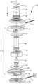
- FIG. 7is a diagram showing the asymmetric square voltage waveforms applied to each respective stator with the second voltage waveform phase shifted 60 degrees;
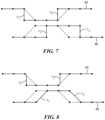
- FIG. 8is a diagram showing the first voltage waveform as substantially square waveform with a partially reduced slope during transition and a phase shifted by 60 degrees trapezoidal second voltage waveform.
- relational termssuch as “first” and “second,” “top” and “bottom,” and the like, may be used solely to distinguish one entity or element from another entity or element without necessarily requiring or implying any physical or logical relationship or order between such entities or elements.
- the terminology used hereinis for the purpose of describing particular embodiments only and is not intended to be limiting of the concepts described herein.
- the singular forms “a”, “an” and “the”are intended to include the plural forms as well, unless the context clearly indicates otherwise.
- the joining term, “in communication with” and the likemay be used to indicate electrical or data communication, which may be accomplished by physical contact, induction, electromagnetic radiation, radio signaling, infrared signaling or optical signaling, for example.
- electrical or data communicationmay be accomplished by physical contact, induction, electromagnetic radiation, radio signaling, infrared signaling or optical signaling, for example.
- the described techniquesmay be implemented in hardware, software, firmware, or any combination thereof. If implemented in software, the functions may be stored as one or more instructions or code on a computer-readable medium and executed by a hardware-based processing unit.
- Computer-readable mediamay include non-transitory computer-readable media, which corresponds to a tangible medium such as data storage media (e.g., RAM, ROM, EEPROM, flash memory, or any other medium that can be used to store desired program code in the form of instructions or data structures and that can be accessed by a computer).
- processorssuch as one or more digital signal processors (DSPs), general purpose microprocessors, application specific integrated circuits (ASICs), field programmable logic arrays (FPGAs), or other equivalent integrated or discrete logic circuitry.
- DSPsdigital signal processors
- ASICsapplication specific integrated circuits
- FPGAsfield programmable logic arrays
- processorsmay refer to any of the foregoing structure or any other physical structure suitable for implementation of the described techniques. Also, the techniques could be fully implemented in one or more circuits or logic elements.
- the blood pump 10includes a static structure or housing 12 which houses the components of the blood pump 10 .
- the housing 12includes an upper housing or first portion 14 , a lower housing or second portion 16 , and an inlet portion or inflow cannula 18 which includes an outer tube 18 a and an inner tube 18 b .
- the first portion 14 and the second portion 16cooperatively define a volute shaped chamber 20 having a major longitudinal axis 22 extending through the first portion 14 and inflow cannula 18 .
- the chamber 20defines a radius that increases progressively around the axis 22 to an outlet location on the periphery of the chamber 20 .
- the first portion 14 and the second portion 16define an outlet 24 in communication with chamber 20 .
- the first portion 14 and the second portion 16also define isolated chambers (not shown) separated from the volute chamber 20 by magnetically permeable walls.
- the inflow cannula 18is generally cylindrical and extends from first portion 14 and extends generally along axis 22 .
- the inflow cannula 18has an upstream end or proximal end 26 remote from second portion 16 and a downstream end or distal end 28 proximate the chamber 20 .
- the parts of the housing 12 mentioned aboveare fixedly connected to one another so that the housing 12 as a whole defines a continuous enclosed flow path.
- the flow pathextends from upstream end 26 at the upstream end of the flow path to the outlet 24 at the downstream end of the flow path.
- the upstream and downstream directions along the flow pathare indicated in FIG. 1 by the arrows U and D respectively.
- a post 30is mounted to second portion 16 along axis 22 .
- a generally disc shaped ferromagnetic rotor 32for example, and impeller with a central hole 34 , is mounted within chamber 20 for rotation about the axis 22 .
- Rotor 32includes a plurality of permanent magnets and also includes flow channels for transferring blood from adjacent the center of the rotor 32 to the periphery of the rotor 32 .
- post 30is received in the central hole of the rotor 32 .
- a first stator 36 having a plurality of coilsmay be disposed within the first portion 14 upstream from the rotor 32 .
- the first stator 36may be axially aligned with the rotor along axis 22 such that when a current is applied to the plurality of coils in the first stator 36 , the electromagnetic forces generated by the first stator 36 rotate the rotor 32 and pump blood.
- a second stator 38may be disposed within the second portion 16 downstream from the rotor 32 . The second stator 38 may be configured to operate in conjunction with or independently of the first stator 36 to rotate the rotor 32 .
- Electrical connectors 41 and 43are provided on the first portion 14 and the second portion 16 respectively for connecting the coils to a common source of power such as a controller 39 , shown connected to connector 41 , but is also connected to the pump by connector 43 .
- the controller 39is arranged and configured to apply power to the coils of the pump to create a rotating magnetic field which spins rotor 32 around axis 22 in a predetermined first direction of rotation, such as the direction R indicated by the arrow in FIG. 1 , i.e., counterclockwise as seen from the upstream end of inflow cannula 18 .
- the first directionmay be clockwise.
- Rotation of the rotor 32impels blood downstream along the flow path so that the blood moves in a downstream direction D along the flow path, and exits through the outlet 24 .
- hydrodynamic and magnetic bearings(not shown) support the rotor 32 and maintain the rotor 32 out of contact with the surfaces of the elements of the first portion 14 and the second portion 16 during operation.
- a first non-ferromagnetic disk 40may be disposed within the first portion 14 upstream from the rotor 32 between the first stator 36 and the rotor 32 and a second non-ferromagnetic disk 42 may be disposed downstream from the rotor 32 within the second portion 16 between the second stator 38 and the rotor 32 .
- the general arrangement of the components described abovemay be similar to the blood pump 10 used in the mechanical circulatory support device (“MCSD”) sold under the designation HVAD by HeartWare, Inc., assignee of the present application.
- MCSDmechanical circulatory support device
- HVADHeartWare, Inc.
- the arrangement of components such as the magnets, electromagnetic coils, and hydrodynamic bearings used in such a pump and variants of the same general designare described in U.S. Pat. Nos. 6,688,861; 7,575,423; 7,976,271; and 8,419,609, the disclosures of which are hereby incorporated by reference herein.
- the controller 39applies a first voltage waveform 44 to the first stator 36 and a second voltage waveform 46 to the second stator 38 .
- Each of the first voltage waveform 44 and the second voltage waveform 46provide power to rotate the impeller 32 independently of the other stator while the impeller is rotating after a startup sequence is initiated.
- the first voltage waveform 44is equal to and symmetric with the second voltage waveform 46 such that the net axial force on the impeller 32 is zero.
- the first and second voltage waveformsdefine trapezoidal waveforms with sloped transitions applied at the same phase.
- the transition step of each waveform described hereinrefers to portions of the respective waveforms in which the voltage transitions from a positive voltage to a negative voltage polarity or vice-verse. As shown in FIG. 3 , the slope of the transition portions (“t 1 ” or “t 2 ”) of the first and second voltage waveforms are equal, which creates a zero net axial force on the impeller 32 .
- the second voltage waveform 46is delayed or otherwise phase shifted 60 degrees from the configuration shown in FIG. 3 while both waveforms are trapezoidal. Although shown phase shifted 60 degrees, the second voltage waveform 46 may be phase shifted between 1-90 degrees in other configurations. As shown in FIG. 4 , owing to the second voltage waveform 46 being phased shifted by 60 degrees (illustrated by showing the in-phase transition in dashed lines), when the first voltage waveform 44 is at its maximum torque angle ( ⁇ max ) with respect to the second voltage waveform 46 of the second stator 38 , the impeller 32 is temporarily axially displaced toward the second stator 38 .
- ⁇ maxmaximum torque angle
- the first voltage waveform 44 and the second voltage waveform 46define square waves that are in phase, but asymmetric.
- the first voltage waveform 44 and the second voltage waveform 46have the same polarity during transitions steps. That is, rather than sloped transitions, the transitions may be substantially instantaneous.
- the net effect of both the first voltage waveform 44 and the second voltage waveform 46 during transition stepsis to place on the impeller 32 a net axial force, either toward the first stator 36 or toward the second stator 38 depending on the polarity during the transition step similar to the result of the phase delay described with respect to the configuration shown in FIG. 4 .
- the net axial force on the impeller 32 at t 1 or waveform 44is toward the second stator 38 .
- the transitionsare sloped similar to the square wave formation for the first voltage waveform 44 and the second voltage waveform 46 , however the transitions are less steep, as indicated by the dashed lines adjacent t 1 . That is, instead of a 90 degree transition, the slopes of the respective transitions are less steep using, for example, pulse width modulation.
- the durations of the transitions for the first voltage waveform 44 and the second voltage waveform 46are not zero, but extended to produce quieter running of the motor and still provides for axial movement of the impeller 32 .
- the durations of transitions “t 1 ” in FIG. 6 of the first voltage waveform 44 and the second voltage waveform 46may range from, for example, 1-30 electrical degrees to reduce acoustic noise.
- the first voltage waveform 44 and the second voltage waveform 46are asymmetric square waves, however, the second voltage waveform 46 is phase shifted, or otherwise delayed 60 degrees from the first voltage waveform 44 .
- the first voltage waveform 44provides more torque on the impeller 32 , is in sync with the impeller 32 , and provides an axial force on the impeller 32 toward the second stator 38 .
- the second voltage waveform 46provides less torque on the impeller 32 , but provides axial force toward the second stator 38 .
- first voltage waveform 44is substantially square with a portion of the transition sloped less steep as to reduce the axial force on the impeller 32 .
- the second voltage waveform 46is phase shifted by 60 degrees but still trapezoidal as to reduce acoustics.
- the application of particular first and second voltage waveformsmay be programmed by the controller 39 for a predetermined period of time.
- the controller 39may apply the first and second voltage waveforms shown in FIG. 3 during normal operation that apply no net axial force on the impeller 32 for a first predetermined period of time.
- the first and second voltage waveforms that apply a net axial force on the impeller 32may be applied during a second period of time as part of a rinse mode of operation.
- the application of a net axial force on the impeller 32may cause the impeller to momentarily be axially moved by, for example, a thousandth of an inch toward the second stator 38 .
- This momentary axial movement of the impeller 32may increase a washing effect and cause thrombus to be dislodged from the surface of the impeller 32 , or create a larger axial gap between the impeller 32 and the respective ceramic disks such that larger thrombus particles may be moved through the pump.
- a predetermined axial gapis 1 thousandth of an inch between disk 40 and the impeller 32 .
Landscapes
- Health & Medical Sciences (AREA)
- Heart & Thoracic Surgery (AREA)
- Engineering & Computer Science (AREA)
- Cardiology (AREA)
- Biomedical Technology (AREA)
- Veterinary Medicine (AREA)
- Mechanical Engineering (AREA)
- Anesthesiology (AREA)
- Public Health (AREA)
- Hematology (AREA)
- Life Sciences & Earth Sciences (AREA)
- Animal Behavior & Ethology (AREA)
- General Health & Medical Sciences (AREA)
- Vascular Medicine (AREA)
- Physics & Mathematics (AREA)
- Fluid Mechanics (AREA)
- External Artificial Organs (AREA)
- Structures Of Non-Positive Displacement Pumps (AREA)
Abstract
Description
Claims (16)
Priority Applications (1)
| Application Number | Priority Date | Filing Date | Title |
|---|---|---|---|
| US17/356,704US11969588B2 (en) | 2017-12-05 | 2021-06-24 | Blood pump with impeller rinse operation |
Applications Claiming Priority (3)
| Application Number | Priority Date | Filing Date | Title |
|---|---|---|---|
| US201762594697P | 2017-12-05 | 2017-12-05 | |
| US16/199,684US11065434B2 (en) | 2017-12-05 | 2018-11-26 | Blood pump with impeller rinse operation |
| US17/356,704US11969588B2 (en) | 2017-12-05 | 2021-06-24 | Blood pump with impeller rinse operation |
Related Parent Applications (1)
| Application Number | Title | Priority Date | Filing Date |
|---|---|---|---|
| US16/199,684ContinuationUS11065434B2 (en) | 2017-12-05 | 2018-11-26 | Blood pump with impeller rinse operation |
Publications (2)
| Publication Number | Publication Date |
|---|---|
| US20210322755A1 US20210322755A1 (en) | 2021-10-21 |
| US11969588B2true US11969588B2 (en) | 2024-04-30 |
Family
ID=64664506
Family Applications (2)
| Application Number | Title | Priority Date | Filing Date |
|---|---|---|---|
| US16/199,684Active2039-03-15US11065434B2 (en) | 2017-12-05 | 2018-11-26 | Blood pump with impeller rinse operation |
| US17/356,704Active2039-07-07US11969588B2 (en) | 2017-12-05 | 2021-06-24 | Blood pump with impeller rinse operation |
Family Applications Before (1)
| Application Number | Title | Priority Date | Filing Date |
|---|---|---|---|
| US16/199,684Active2039-03-15US11065434B2 (en) | 2017-12-05 | 2018-11-26 | Blood pump with impeller rinse operation |
Country Status (4)
| Country | Link |
|---|---|
| US (2) | US11065434B2 (en) |
| EP (1) | EP3720520B1 (en) |
| CN (1) | CN111491677B (en) |
| WO (1) | WO2019112825A1 (en) |
Families Citing this family (23)
| Publication number | Priority date | Publication date | Assignee | Title |
|---|---|---|---|---|
| WO2019112825A1 (en)* | 2017-12-05 | 2019-06-13 | Heartware, Inc. | Blood pump with impeller rinse operation |
| DE102018201030B4 (en) | 2018-01-24 | 2025-10-16 | Kardion Gmbh | Magnetic dome element with magnetic bearing function |
| DE102018207575A1 (en) | 2018-05-16 | 2019-11-21 | Kardion Gmbh | Magnetic face turning coupling for the transmission of torques |
| DE102018207611A1 (en) | 2018-05-16 | 2019-11-21 | Kardion Gmbh | Rotor bearing system |
| DE102018208539A1 (en) | 2018-05-30 | 2019-12-05 | Kardion Gmbh | A motor housing module for sealing an engine compartment of a motor of a cardiac assist system and cardiac assistance system and method for mounting a cardiac assist system |
| DE102018208541A1 (en) | 2018-05-30 | 2019-12-05 | Kardion Gmbh | Axial pump for a cardiac assist system and method of making an axial pump for a cardiac assist system |
| DE102018208550A1 (en) | 2018-05-30 | 2019-12-05 | Kardion Gmbh | A lead device for directing blood flow to a cardiac assist system, cardiac assist system, and method of making a lead device |
| DE102018208538A1 (en) | 2018-05-30 | 2019-12-05 | Kardion Gmbh | Intravascular blood pump and process for the production of electrical conductors |
| DE102018208936A1 (en) | 2018-06-06 | 2019-12-12 | Kardion Gmbh | Determining device and method for determining a viscosity of a fluid |
| DE102018208929A1 (en) | 2018-06-06 | 2019-12-12 | Kardion Gmbh | A method of determining a flow rate of fluid flowing through an implanted vascular support system |
| DE102018208899A1 (en) | 2018-06-06 | 2019-12-12 | Kardion Gmbh | A method for determining the speed of sound in a fluid in the region of an implanted vascular support system |
| DE102018208945A1 (en) | 2018-06-06 | 2019-12-12 | Kardion Gmbh | An analysis device and method for analyzing a viscosity of a fluid |
| DE102018208879A1 (en) | 2018-06-06 | 2020-01-30 | Kardion Gmbh | Method for determining a total fluid volume flow in the area of an implanted, vascular support system |
| DE102018208933A1 (en) | 2018-06-06 | 2019-12-12 | Kardion Gmbh | A method of determining a flow rate of fluid flowing through an implanted vascular support system |
| DE102018208862A1 (en) | 2018-06-06 | 2019-12-12 | Kardion Gmbh | Implantable vascular support system |
| DE102018208913A1 (en) | 2018-06-06 | 2019-12-12 | Kardion Gmbh | A method of operating an implanted ventricular assist device |
| DE102018210076A1 (en) | 2018-06-21 | 2019-12-24 | Kardion Gmbh | Method and device for detecting a state of wear of a cardiac support system, method and device for operating a cardiac support system and cardiac support system |
| DE102018210058A1 (en) | 2018-06-21 | 2019-12-24 | Kardion Gmbh | Stator blade device for guiding the flow of a fluid flowing out of an outlet opening of a heart support system, heart support system with stator blade device, method for operating a stator blade device and manufacturing method |
| DE102018211327A1 (en) | 2018-07-10 | 2020-01-16 | Kardion Gmbh | Impeller for an implantable vascular support system |
| DE102018212153A1 (en) | 2018-07-20 | 2020-01-23 | Kardion Gmbh | Inlet line for a pump unit of a cardiac support system, cardiac support system and method for producing an inlet line for a pump unit of a cardiac support system |
| CN112654389A (en) | 2018-08-07 | 2021-04-13 | 开迪恩有限公司 | Bearing device for a cardiac support system and method for flushing an intermediate space in a bearing device for a cardiac support system |
| US11318295B2 (en)* | 2019-02-28 | 2022-05-03 | Heartware, Inc. | HVAD rinse via a non-uniform thrust bearing gap |
| DE102020102474A1 (en) | 2020-01-31 | 2021-08-05 | Kardion Gmbh | Pump for conveying a fluid and method for manufacturing a pump |
Citations (25)
| Publication number | Priority date | Publication date | Assignee | Title |
|---|---|---|---|---|
| US4944748A (en) | 1986-10-12 | 1990-07-31 | Bramm Gunter W | Magnetically suspended and rotated rotor |
| US5208522A (en) | 1985-06-29 | 1993-05-04 | Griepentrog Hartmut F L | Machine with magnetic-borne rotor and electrical radial field motor-generator |
| US5385581A (en) | 1982-04-04 | 1995-01-31 | Life Extenders Corporation | Magnetically suspended and rotated rotor |
| US6183412B1 (en) | 1997-10-02 | 2001-02-06 | Micromed Technology, Inc. | Implantable pump system |
| US6227817B1 (en) | 1999-09-03 | 2001-05-08 | Magnetic Moments, Llc | Magnetically-suspended centrifugal blood pump |
| US6264635B1 (en)* | 1998-12-03 | 2001-07-24 | Kriton Medical, Inc. | Active magnetic bearing system for blood pump |
| US6293901B1 (en) | 1997-11-26 | 2001-09-25 | Vascor, Inc. | Magnetically suspended fluid pump and control system |
| US20030164654A1 (en) | 2002-02-25 | 2003-09-04 | Thaxton Edgar S. | Axially segmented permanent magnet synchronous machine with integrated magnetic bearings and active stator control of the axial degree-of-freedom |
| US6688861B2 (en) | 1996-02-20 | 2004-02-10 | Heartware, Inc. | Sealless rotary blood pump |
| US20040241019A1 (en) | 2003-05-28 | 2004-12-02 | Michael Goldowsky | Passive non-contacting smart bearing suspension for turbo blood-pumps |
| US20060247486A1 (en) | 2003-07-04 | 2006-11-02 | Nikolaus Mendler | Centrifugal pump |
| US7976271B2 (en) | 2006-01-13 | 2011-07-12 | Heartware, Inc. | Stabilizing drive for contactless rotary blood pump impeller |
| US20110238172A1 (en) | 2006-08-06 | 2011-09-29 | Mustafa Akdis | Blood pump |
| US20110243759A1 (en) | 2008-12-08 | 2011-10-06 | Takayoshi Ozaki | Centrifugal pump apparatus |
| US20120169167A1 (en) | 2010-12-30 | 2012-07-05 | Chung Yuan Christian University | Axial Hybrid Magnetic Bearing, Method for Operation thereof, and Structure for Rotor thereof |
| US8419609B2 (en) | 2005-10-05 | 2013-04-16 | Heartware Inc. | Impeller for a rotary ventricular assist device |
| US20140241904A1 (en) | 2013-02-27 | 2014-08-28 | Thoratec Corporation | Startup sequence for centrifugal pump with levitated impeller |
| US20160199556A1 (en) | 2013-08-16 | 2016-07-14 | Thorvascular Pty Ltd | Heart assist system and/or device |
| US20160235899A1 (en) | 2015-02-12 | 2016-08-18 | Thoratec Corporation | System and method for controlling the position of a levitated rotor |
| CN106574628A (en) | 2014-06-17 | 2017-04-19 | 同心医疗器械(美国)有限公司 | Centrifugal blood pump impeller and flow path |
| US9638202B2 (en) | 2010-09-14 | 2017-05-02 | Tc1 Llc | Centrifugal pump apparatus |
| US20170340788A1 (en) | 2012-11-06 | 2017-11-30 | Queen Mary University Of London | Mechanical circulatory support device with centrifugal impeller designed for implantation in the descending aorta |
| US20180369466A1 (en) | 2016-01-06 | 2018-12-27 | Bivacor Inc. | Heart pump with impeller axial position control |
| US20190054222A1 (en)* | 2017-08-16 | 2019-02-21 | Heartware, Inc. | Map measurement on vad patients with low pulsatility |
| US11065434B2 (en)* | 2017-12-05 | 2021-07-20 | Heartware, Inc. | Blood pump with impeller rinse operation |
Family Cites Families (16)
| Publication number | Priority date | Publication date | Assignee | Title |
|---|---|---|---|---|
| US6808482B1 (en)* | 1994-04-15 | 2004-10-26 | Allegheny-Singer Research Institute | Blood pump device and method of producing |
| WO2005030296A2 (en)* | 2003-09-25 | 2005-04-07 | Medforte Research Foundation | Axial-flow blood pump with magnetically suspended, radially and axially stabilized impeller |
| US8152493B2 (en)* | 2007-04-30 | 2012-04-10 | Hearthware Inc. | Centrifugal rotary blood pump with impeller having a hydrodynamic thrust bearing surface |
| EP2207966B1 (en)* | 2007-10-18 | 2020-02-12 | The Cleveland Clinic Foundation | Two-stage rotodynamic blood pump |
| EP2419159A4 (en)* | 2009-04-16 | 2017-07-19 | Bivacor Pty Ltd | Heart pump controller |
| EP2693609B1 (en)* | 2011-03-28 | 2017-05-03 | Thoratec Corporation | Rotation and drive device and centrifugal pump device using same |
| EP4252823A3 (en)* | 2012-08-15 | 2023-11-15 | Artio Medical, Inc. | Blood pump systems and methods |
| US9371826B2 (en)* | 2013-01-24 | 2016-06-21 | Thoratec Corporation | Impeller position compensation using field oriented control |
| CA2920740A1 (en)* | 2013-08-19 | 2015-02-26 | Heartware, Inc. | Multiband wireless power system |
| CN103893849B (en)* | 2014-04-15 | 2016-01-20 | 中南大学 | A kind of full-implantation type axial blood pump of air gaps magnetically-actuated and control method thereof |
| US20160166211A1 (en)* | 2014-12-02 | 2016-06-16 | Heartware, Inc. | Mean arterial pressure estimation |
| US9717832B2 (en)* | 2015-01-06 | 2017-08-01 | HeartWave, Inc. | Axial flow rotor with downstream bearing wash flow |
| US10371152B2 (en)* | 2015-02-12 | 2019-08-06 | Tc1 Llc | Alternating pump gaps |
| ES3032366T3 (en)* | 2015-03-18 | 2025-07-17 | Abiomed Europe Gmbh | Blood pump |
| EP3173109A1 (en)* | 2015-11-30 | 2017-05-31 | Fundacja Rozwoju Kardiochirurgii Im. Prof. Zbigniewa Religi | Method for controlling a centrifugal heart assist pomp impeller position |
| CN105477706B (en)* | 2016-01-14 | 2018-01-26 | 山东大学 | Double Stator Mixed Support Artificial Heart Pump |
- 2018
- 2018-11-26WOPCT/US2018/062431patent/WO2019112825A1/ennot_activeCeased
- 2018-11-26USUS16/199,684patent/US11065434B2/enactiveActive
- 2018-11-26EPEP18816424.8Apatent/EP3720520B1/enactiveActive
- 2018-11-26CNCN201880078562.4Apatent/CN111491677B/enactiveActive
- 2021
- 2021-06-24USUS17/356,704patent/US11969588B2/enactiveActive
Patent Citations (32)
| Publication number | Priority date | Publication date | Assignee | Title |
|---|---|---|---|---|
| US5385581A (en) | 1982-04-04 | 1995-01-31 | Life Extenders Corporation | Magnetically suspended and rotated rotor |
| US5208522A (en) | 1985-06-29 | 1993-05-04 | Griepentrog Hartmut F L | Machine with magnetic-borne rotor and electrical radial field motor-generator |
| US4944748A (en) | 1986-10-12 | 1990-07-31 | Bramm Gunter W | Magnetically suspended and rotated rotor |
| US7575423B2 (en) | 1996-02-20 | 2009-08-18 | Heartware, Inc. | Sealless rotary blood pump |
| US6688861B2 (en) | 1996-02-20 | 2004-02-10 | Heartware, Inc. | Sealless rotary blood pump |
| US6183412B1 (en) | 1997-10-02 | 2001-02-06 | Micromed Technology, Inc. | Implantable pump system |
| US6293901B1 (en) | 1997-11-26 | 2001-09-25 | Vascor, Inc. | Magnetically suspended fluid pump and control system |
| US6264635B1 (en)* | 1998-12-03 | 2001-07-24 | Kriton Medical, Inc. | Active magnetic bearing system for blood pump |
| US6227817B1 (en) | 1999-09-03 | 2001-05-08 | Magnetic Moments, Llc | Magnetically-suspended centrifugal blood pump |
| US20030164654A1 (en) | 2002-02-25 | 2003-09-04 | Thaxton Edgar S. | Axially segmented permanent magnet synchronous machine with integrated magnetic bearings and active stator control of the axial degree-of-freedom |
| CN1572331A (en) | 2003-05-28 | 2005-02-02 | 迈克尔·P·戈尔多夫斯基 | Passive non-contact intelligent bearing suspension of booster blood pump |
| US20040241019A1 (en) | 2003-05-28 | 2004-12-02 | Michael Goldowsky | Passive non-contacting smart bearing suspension for turbo blood-pumps |
| US20060247486A1 (en) | 2003-07-04 | 2006-11-02 | Nikolaus Mendler | Centrifugal pump |
| US8419609B2 (en) | 2005-10-05 | 2013-04-16 | Heartware Inc. | Impeller for a rotary ventricular assist device |
| US7976271B2 (en) | 2006-01-13 | 2011-07-12 | Heartware, Inc. | Stabilizing drive for contactless rotary blood pump impeller |
| US8512013B2 (en) | 2006-01-13 | 2013-08-20 | Heartware, Inc. | Hydrodynamic thrust bearings for rotary blood pumps |
| US20110238172A1 (en) | 2006-08-06 | 2011-09-29 | Mustafa Akdis | Blood pump |
| CN102239334A (en) | 2008-12-08 | 2011-11-09 | Ntn株式会社 | Centrifugal pump device |
| US20110243759A1 (en) | 2008-12-08 | 2011-10-06 | Takayoshi Ozaki | Centrifugal pump apparatus |
| US9638202B2 (en) | 2010-09-14 | 2017-05-02 | Tc1 Llc | Centrifugal pump apparatus |
| US20120169167A1 (en) | 2010-12-30 | 2012-07-05 | Chung Yuan Christian University | Axial Hybrid Magnetic Bearing, Method for Operation thereof, and Structure for Rotor thereof |
| US20170340788A1 (en) | 2012-11-06 | 2017-11-30 | Queen Mary University Of London | Mechanical circulatory support device with centrifugal impeller designed for implantation in the descending aorta |
| WO2014133942A1 (en) | 2013-02-27 | 2014-09-04 | Thoratec Corporation | Startup sequence for centrifugal pump with levitated impeller |
| US20140241904A1 (en) | 2013-02-27 | 2014-08-28 | Thoratec Corporation | Startup sequence for centrifugal pump with levitated impeller |
| US20160199556A1 (en) | 2013-08-16 | 2016-07-14 | Thorvascular Pty Ltd | Heart assist system and/or device |
| CN106574628A (en) | 2014-06-17 | 2017-04-19 | 同心医疗器械(美国)有限公司 | Centrifugal blood pump impeller and flow path |
| US20180045210A1 (en) | 2014-06-17 | 2018-02-15 | Ch Biomedical (Usa) Inc. | Centrifugal blood pump impeller and flow path |
| US20160235899A1 (en) | 2015-02-12 | 2016-08-18 | Thoratec Corporation | System and method for controlling the position of a levitated rotor |
| WO2016130944A1 (en) | 2015-02-12 | 2016-08-18 | Thoratec Corporation | System and method for controlling the position of a levitated rotor |
| US20180369466A1 (en) | 2016-01-06 | 2018-12-27 | Bivacor Inc. | Heart pump with impeller axial position control |
| US20190054222A1 (en)* | 2017-08-16 | 2019-02-21 | Heartware, Inc. | Map measurement on vad patients with low pulsatility |
| US11065434B2 (en)* | 2017-12-05 | 2021-07-20 | Heartware, Inc. | Blood pump with impeller rinse operation |
Non-Patent Citations (3)
| Title |
|---|
| First Office Action and Search Report, and translation thereof, from counterpart Chinese Application No. 201880078562.4 dated Nov. 16, 2022, 13 pp. |
| International Search Report and Written Opinion dated Feb. 28, 2019, for corresponding International Application No. PCT/US2018/062431; International Filing Date: Nov. 26, 2018 consisting of 14 pages. |
| Prosecution History from U.S. Appl. No. 16/199,684, filed from May 4, 2020 through Mar. 22, 2021, 57 pp. |
Also Published As
| Publication number | Publication date |
|---|---|
| US11065434B2 (en) | 2021-07-20 |
| CN111491677B (en) | 2023-12-01 |
| CN111491677A (en) | 2020-08-04 |
| US20210322755A1 (en) | 2021-10-21 |
| US20190167874A1 (en) | 2019-06-06 |
| EP3720520B1 (en) | 2024-07-03 |
| WO2019112825A1 (en) | 2019-06-13 |
| EP3720520A1 (en) | 2020-10-14 |
Similar Documents
| Publication | Publication Date | Title |
|---|---|---|
| US11969588B2 (en) | Blood pump with impeller rinse operation | |
| EP3615103B1 (en) | Anti-thrombus surface potential ceramic element | |
| EP3668561B1 (en) | Therapeutic uv blood treatment in a blood pump | |
| US11318295B2 (en) | HVAD rinse via a non-uniform thrust bearing gap | |
| US11534596B2 (en) | Pulsatile blood pump via contraction with smart material | |
| US11648393B2 (en) | Implantable blood pump with thrombus diverter | |
| US10441693B2 (en) | Axial flow blood pump with radially offset rotor | |
| CN111655307A (en) | Axial blood pump with impeller flush operation | |
| WO2021141693A1 (en) | Passive thrust bearing angle | |
| US12156745B2 (en) | Detection of hypertension in LVAD patients using speed change | |
| EP3852832B1 (en) | Method of starting a blood pump with an electrical fault |
Legal Events
| Date | Code | Title | Description |
|---|---|---|---|
| FEPP | Fee payment procedure | Free format text:ENTITY STATUS SET TO UNDISCOUNTED (ORIGINAL EVENT CODE: BIG.); ENTITY STATUS OF PATENT OWNER: LARGE ENTITY | |
| AS | Assignment | Owner name:HEARTWARE, INC., FLORIDA Free format text:ASSIGNMENT OF ASSIGNORS INTEREST;ASSIGNORS:EGLER, MARK S.;CASAS, FERNANDO;REYES, CARLOS;AND OTHERS;SIGNING DATES FROM 20190201 TO 20190225;REEL/FRAME:057363/0440 | |
| STPP | Information on status: patent application and granting procedure in general | Free format text:DOCKETED NEW CASE - READY FOR EXAMINATION | |
| STPP | Information on status: patent application and granting procedure in general | Free format text:RESPONSE TO NON-FINAL OFFICE ACTION ENTERED AND FORWARDED TO EXAMINER | |
| STPP | Information on status: patent application and granting procedure in general | Free format text:NON FINAL ACTION MAILED | |
| STPP | Information on status: patent application and granting procedure in general | Free format text:RESPONSE TO NON-FINAL OFFICE ACTION ENTERED AND FORWARDED TO EXAMINER | |
| STPP | Information on status: patent application and granting procedure in general | Free format text:NOTICE OF ALLOWANCE MAILED -- APPLICATION RECEIVED IN OFFICE OF PUBLICATIONS | |
| ZAAB | Notice of allowance mailed | Free format text:ORIGINAL CODE: MN/=. | |
| STPP | Information on status: patent application and granting procedure in general | Free format text:PUBLICATIONS -- ISSUE FEE PAYMENT RECEIVED | |
| STPP | Information on status: patent application and granting procedure in general | Free format text:PUBLICATIONS -- ISSUE FEE PAYMENT VERIFIED | |
| STCF | Information on status: patent grant | Free format text:PATENTED CASE | |
| AS | Assignment | Owner name:BOSTON SCIENTIFIC SCIMED, INC., MINNESOTA Free format text:ASSIGNMENT OF ASSIGNORS INTEREST;ASSIGNOR:HEARTWARE, INC.;REEL/FRAME:069431/0704 Effective date:20241108 |