US11969331B2 - System for treating embolism and associated devices and methods - Google Patents
System for treating embolism and associated devices and methodsDownload PDFInfo
- Publication number
- US11969331B2 US11969331B2US17/976,711US202217976711AUS11969331B2US 11969331 B2US11969331 B2US 11969331B2US 202217976711 AUS202217976711 AUS 202217976711AUS 11969331 B2US11969331 B2US 11969331B2
- Authority
- US
- United States
- Prior art keywords
- catheter
- aspiration
- clot
- vacuum
- syringe
- Prior art date
- Legal status (The legal status is an assumption and is not a legal conclusion. Google has not performed a legal analysis and makes no representation as to the accuracy of the status listed.)
- Active
Links
Images


Classifications
- A—HUMAN NECESSITIES
- A61—MEDICAL OR VETERINARY SCIENCE; HYGIENE
- A61F—FILTERS IMPLANTABLE INTO BLOOD VESSELS; PROSTHESES; DEVICES PROVIDING PATENCY TO, OR PREVENTING COLLAPSING OF, TUBULAR STRUCTURES OF THE BODY, e.g. STENTS; ORTHOPAEDIC, NURSING OR CONTRACEPTIVE DEVICES; FOMENTATION; TREATMENT OR PROTECTION OF EYES OR EARS; BANDAGES, DRESSINGS OR ABSORBENT PADS; FIRST-AID KITS
- A61F2/00—Filters implantable into blood vessels; Prostheses, i.e. artificial substitutes or replacements for parts of the body; Appliances for connecting them with the body; Devices providing patency to, or preventing collapsing of, tubular structures of the body, e.g. stents
- A61F2/01—Filters implantable into blood vessels
- A—HUMAN NECESSITIES
- A61—MEDICAL OR VETERINARY SCIENCE; HYGIENE
- A61B—DIAGNOSIS; SURGERY; IDENTIFICATION
- A61B17/00—Surgical instruments, devices or methods
- A61B17/12—Surgical instruments, devices or methods for ligaturing or otherwise compressing tubular parts of the body, e.g. blood vessels or umbilical cord
- A61B17/12022—Occluding by internal devices, e.g. balloons or releasable wires
- A61B17/12099—Occluding by internal devices, e.g. balloons or releasable wires characterised by the location of the occluder
- A61B17/12109—Occluding by internal devices, e.g. balloons or releasable wires characterised by the location of the occluder in a blood vessel
- A—HUMAN NECESSITIES
- A61—MEDICAL OR VETERINARY SCIENCE; HYGIENE
- A61M—DEVICES FOR INTRODUCING MEDIA INTO, OR ONTO, THE BODY; DEVICES FOR TRANSDUCING BODY MEDIA OR FOR TAKING MEDIA FROM THE BODY; DEVICES FOR PRODUCING OR ENDING SLEEP OR STUPOR
- A61M1/00—Suction or pumping devices for medical purposes; Devices for carrying-off, for treatment of, or for carrying-over, body-liquids; Drainage systems
- A61M1/80—Suction pumps
- A61M1/81—Piston pumps, e.g. syringes
- A61M1/815—Piston pumps, e.g. syringes the barrel serving as aspiration container, e.g. in a breast pump
- A—HUMAN NECESSITIES
- A61—MEDICAL OR VETERINARY SCIENCE; HYGIENE
- A61M—DEVICES FOR INTRODUCING MEDIA INTO, OR ONTO, THE BODY; DEVICES FOR TRANSDUCING BODY MEDIA OR FOR TAKING MEDIA FROM THE BODY; DEVICES FOR PRODUCING OR ENDING SLEEP OR STUPOR
- A61M1/00—Suction or pumping devices for medical purposes; Devices for carrying-off, for treatment of, or for carrying-over, body-liquids; Drainage systems
- A61M1/84—Drainage tubes; Aspiration tips
- A—HUMAN NECESSITIES
- A61—MEDICAL OR VETERINARY SCIENCE; HYGIENE
- A61B—DIAGNOSIS; SURGERY; IDENTIFICATION
- A61B17/00—Surgical instruments, devices or methods
- A61B17/22—Implements for squeezing-off ulcers or the like on inner organs of the body; Implements for scraping-out cavities of body organs, e.g. bones; for invasive removal or destruction of calculus using mechanical vibrations; for removing obstructions in blood vessels, not otherwise provided for
- A61B17/221—Gripping devices in the form of loops or baskets for gripping calculi or similar types of obstructions
- A—HUMAN NECESSITIES
- A61—MEDICAL OR VETERINARY SCIENCE; HYGIENE
- A61B—DIAGNOSIS; SURGERY; IDENTIFICATION
- A61B17/00—Surgical instruments, devices or methods
- A61B17/22—Implements for squeezing-off ulcers or the like on inner organs of the body; Implements for scraping-out cavities of body organs, e.g. bones; for invasive removal or destruction of calculus using mechanical vibrations; for removing obstructions in blood vessels, not otherwise provided for
- A61B17/22031—Gripping instruments, e.g. forceps, for removing or smashing calculi
- A61B2017/22034—Gripping instruments, e.g. forceps, for removing or smashing calculi for gripping the obstruction or the tissue part from inside
- A—HUMAN NECESSITIES
- A61—MEDICAL OR VETERINARY SCIENCE; HYGIENE
- A61B—DIAGNOSIS; SURGERY; IDENTIFICATION
- A61B17/00—Surgical instruments, devices or methods
- A61B17/22—Implements for squeezing-off ulcers or the like on inner organs of the body; Implements for scraping-out cavities of body organs, e.g. bones; for invasive removal or destruction of calculus using mechanical vibrations; for removing obstructions in blood vessels, not otherwise provided for
- A61B2017/22079—Implements for squeezing-off ulcers or the like on inner organs of the body; Implements for scraping-out cavities of body organs, e.g. bones; for invasive removal or destruction of calculus using mechanical vibrations; for removing obstructions in blood vessels, not otherwise provided for with suction of debris
- A—HUMAN NECESSITIES
- A61—MEDICAL OR VETERINARY SCIENCE; HYGIENE
- A61B—DIAGNOSIS; SURGERY; IDENTIFICATION
- A61B17/00—Surgical instruments, devices or methods
- A61B17/22—Implements for squeezing-off ulcers or the like on inner organs of the body; Implements for scraping-out cavities of body organs, e.g. bones; for invasive removal or destruction of calculus using mechanical vibrations; for removing obstructions in blood vessels, not otherwise provided for
- A61B17/221—Gripping devices in the form of loops or baskets for gripping calculi or similar types of obstructions
- A61B2017/2212—Gripping devices in the form of loops or baskets for gripping calculi or similar types of obstructions having a closed distal end, e.g. a loop
- A—HUMAN NECESSITIES
- A61—MEDICAL OR VETERINARY SCIENCE; HYGIENE
- A61B—DIAGNOSIS; SURGERY; IDENTIFICATION
- A61B2217/00—General characteristics of surgical instruments
- A61B2217/002—Auxiliary appliance
- A61B2217/005—Auxiliary appliance with suction drainage system
- A—HUMAN NECESSITIES
- A61—MEDICAL OR VETERINARY SCIENCE; HYGIENE
- A61M—DEVICES FOR INTRODUCING MEDIA INTO, OR ONTO, THE BODY; DEVICES FOR TRANSDUCING BODY MEDIA OR FOR TAKING MEDIA FROM THE BODY; DEVICES FOR PRODUCING OR ENDING SLEEP OR STUPOR
- A61M1/00—Suction or pumping devices for medical purposes; Devices for carrying-off, for treatment of, or for carrying-over, body-liquids; Drainage systems
- A61M1/02—Blood transfusion apparatus
- A61M1/0281—Apparatus for treatment of blood or blood constituents prior to transfusion, e.g. washing, filtering or thawing
- A—HUMAN NECESSITIES
- A61—MEDICAL OR VETERINARY SCIENCE; HYGIENE
- A61M—DEVICES FOR INTRODUCING MEDIA INTO, OR ONTO, THE BODY; DEVICES FOR TRANSDUCING BODY MEDIA OR FOR TAKING MEDIA FROM THE BODY; DEVICES FOR PRODUCING OR ENDING SLEEP OR STUPOR
- A61M1/00—Suction or pumping devices for medical purposes; Devices for carrying-off, for treatment of, or for carrying-over, body-liquids; Drainage systems
- A61M1/71—Suction drainage systems
- A61M1/79—Filters for solid matter
- A—HUMAN NECESSITIES
- A61—MEDICAL OR VETERINARY SCIENCE; HYGIENE
- A61M—DEVICES FOR INTRODUCING MEDIA INTO, OR ONTO, THE BODY; DEVICES FOR TRANSDUCING BODY MEDIA OR FOR TAKING MEDIA FROM THE BODY; DEVICES FOR PRODUCING OR ENDING SLEEP OR STUPOR
- A61M2205/00—General characteristics of the apparatus
- A61M2205/75—General characteristics of the apparatus with filters
- A61M2205/7545—General characteristics of the apparatus with filters for solid matter, e.g. microaggregates
- A—HUMAN NECESSITIES
- A61—MEDICAL OR VETERINARY SCIENCE; HYGIENE
- A61M—DEVICES FOR INTRODUCING MEDIA INTO, OR ONTO, THE BODY; DEVICES FOR TRANSDUCING BODY MEDIA OR FOR TAKING MEDIA FROM THE BODY; DEVICES FOR PRODUCING OR ENDING SLEEP OR STUPOR
- A61M2210/00—Anatomical parts of the body
- A61M2210/12—Blood circulatory system
- A—HUMAN NECESSITIES
- A61—MEDICAL OR VETERINARY SCIENCE; HYGIENE
- A61M—DEVICES FOR INTRODUCING MEDIA INTO, OR ONTO, THE BODY; DEVICES FOR TRANSDUCING BODY MEDIA OR FOR TAKING MEDIA FROM THE BODY; DEVICES FOR PRODUCING OR ENDING SLEEP OR STUPOR
- A61M25/00—Catheters; Hollow probes
- A61M25/10—Balloon catheters
Definitions
- the present technologyrelates generally to systems, methods, and devices for the intravascular treatment of emboli and/or thrombi within a blood vessel of a human patient.
- some embodiments of the present technologyrelate to systems for releasing stored vacuum pressure to aspirate clot material from a blood vessel.
- Thromboembolic eventsare characterized by an occlusion of a blood vessel.
- Thromboembolic disorderssuch as stroke, pulmonary embolism, heart attack, peripheral thrombosis, atherosclerosis, and the like, affect many people. These disorders are a major cause of morbidity and mortality.
- tissue ischemiadevelops.
- the ischemiawill progress to tissue infarction if the occlusion persists.
- infarctiondoes not develop or is greatly limited if the flow of blood is reestablished rapidly. Failure to reestablish blood flow can accordingly lead to the loss of limb, angina pectoris, myocardial infarction, stroke, or even death.
- DVTdeep venous thrombosis
- DVTcommonly occurs where there is a propensity for stagnated blood (e.g., long distance air travel, immobility, etc.) and clotting (e.g., cancer, recent surgery, such as orthopedic surgery, etc.).
- DVTcan obstruct drainage of venous blood from the legs leading to swelling, ulcers, pain and infection.
- DVTcan also create a reservoir in which blood clots can collect and then travel to other parts of the body including the heart, lungs, brain (stroke), abdominal organs, and/or extremities.
- the undesirable materialcan cause harm by obstructing pulmonary arteries—a condition known as pulmonary embolism.
- the obstructionIf the obstruction is upstream, in the main or large branch pulmonary arteries, it can severely compromise total blood flow within the lungs, and therefore the entire body. This can result in low blood pressure and shock.
- the obstructionIf the obstruction is downstream, in large to medium pulmonary artery branches, it can prevent a significant portion of the lung from participating in the exchange of gases to the blood resulting in low blood oxygen and buildup of blood carbon dioxide.
- Embolectomiesare a surgical technique involving incising a blood vessel and placing a balloon-tipped device (such as the Fogarty catheter) at the location of the occlusion.
- the balloonis then inflated at a point beyond the clot and used to withdraw the obstructing material back to the point of incision.
- the obstructing materialis then removed by the surgeon.
- a Fogarty cathetermay be problematic due to the possible risk of damaging the interior lining of the vessel as the catheter is being withdrawn.
- Percutaneous methodsare also utilized for reestablishing blood flow.
- a common percutaneous techniqueis referred to as balloon angioplasty where a balloon-tipped catheter is introduced to a blood vessel (e.g., typically through an introducing catheter). The balloon-tipped catheter is then advanced to the point of the occlusion and inflated to dilate the stenosis.
- Balloon angioplastyis appropriate for treating vessel stenosis, but it is generally not effective for treating acute thromboembolisms as none of the occlusive material is removed and restenosis regularly occurs after dilation.
- Another percutaneous techniqueinvolves placing a catheter near the clot and infusing streptokinase, urokinase, or other thrombolytic agents to dissolve the clot. Unfortunately, thrombolysis typically takes hours to days to be successful. Additionally, thrombolytic agents can cause hemorrhage, and in many patients the thrombolytic agents cannot be used at all.
- FIG. 1is a partially schematic side view of a clot removal system configured in accordance with the present technology.
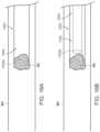
- FIG. 2is a side view of a locking syringe configured in accordance with the present technology.
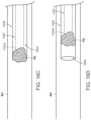
- FIG. 3 Ais a side view of a locking syringe configured in accordance with the present technology.
- FIG. 3 Bis a side view of an adaptor for connecting the locking syringe of FIG. 3 A to the clot removal system of FIG. 1 configured in accordance with the present technology.
- FIG. 3 Cis a side view of the adaptor of FIG. 3 B coupled to the locking syringe of FIG. 3 A .
- FIG. 3 Dis a side view of the locking syringe of FIG. 3 A coupled to the clot removal system of FIG. 1 via the adaptor of FIG. 3 B .
- FIG. 4 Ais a perspective side view of another pressure source configured in accordance with the present technology
- FIGS. 4 B and 4 Care enlarged schematic side views of the pressure source of FIG. 4 A during operation.
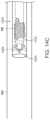
- FIG. 5is a cross-sectional side view of an automatic release syringe configured in accordance with the present technology.
- FIG. 6is a perspective top view of a syringe configured in accordance with the present technology.
- FIG. 7is a side view of an over-wire locking syringe configured in accordance with the present technology.
- FIG. 8is a flow diagram of a process or method for operating a clot removal system in accordance with the present technology.
- FIGS. 9 A- 9 Care side views of a proximal portion of the clot removal system of FIG. 1 during a clot removal procedure using the locking syringe of FIG. 3 in accordance with the present technology.
- FIGS. 10 A and 10 Bare schematic illustrations of a distal portion of the clot removal system of FIG. 1 during a clot removal procedure in accordance with the present technology.
- FIG. 11is a partially schematic side view of another clot removal system configured in accordance with the present technology.
- FIG. 12is a flow diagram of another process or method for operating a clot removal system in accordance with the present technology.
- FIGS. 13 A- 14 Care schematic illustrations of a distal portion of the clot removal system of FIG. 11 during a clot removal procedure in accordance with the present technology.
- FIG. 15is a flow diagram of another process or method for operating a clot removal system in accordance with the present technology.
- FIGS. 16 A- 16 Eare schematic illustrations of a distal portion of the clot removal system of FIG. 11 during a clot removal procedure in accordance with the present technology.
- FIG. 17is a partially schematic side view of another clot removal system configured in accordance with the present technology.
- FIGS. 18 A- 18 Hare side views of a distal portion of the clot removal system shown of FIG. 17 during a clot removal procedure in accordance with the present technology.
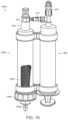
- FIG. 19is a perspective side view of a pressure source for filtering blood from aspirated clot material during a clot removal procedure configured in accordance with the present technology.
- FIG. 20 Ais a partially-exploded side view of a filter device and pressure source configured in accordance with the present technology.
- FIG. 20 Bis a perspective side view of the syringe of FIG. 20 A coupled to the filter device of the FIG. 20 A .
- FIG. 20 Cis a side view of the filter device and syringe of FIG. 20 B coupled to the clot removal system of FIG. 1 .
- FIGS. 20 D and 20 Eare side views of the syringe of FIG. 20 A coupled to the clot removal system of FIG. 1 for reintroducing blood to a patient.
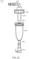
- FIG. 21 Ais a partially-exploded side view of a filter device, a pressure source, and a reinfusion syringe configured in accordance with the present technology.
- FIG. 21 Bis a perspective side view of the filter device of FIG. 21 A coupled to the pressure source and the reinfusion syringe of FIG. 21 A .
- FIG. 22is a partially-exploded side view of a filter device configured in accordance with the present technology.
- FIG. 23is a partially-exploded side view of a filter device configured in accordance with the present technology.
- FIG. 24is an enlarged isometric view of the clot removal system of FIG. 1 configured in accordance with the present technology.
- FIG. 25is an enlarged isometric view of the clot removal system of FIG. 1 configured in accordance with the present technology.
- a cathetercan be intravascularly positioned within a blood vessel such that a distal portion (e.g., a distal opening) of the catheter is positioned proximate to clot material within the blood vessel.
- the cathetercan be fluidly coupled to a pressure source via a valve or other fluid control device positioned outside of the patient. With the valve closed, the pressure source can be activated to charge a vacuum chamber of the pressure source with a vacuum. The valve can then be opened to apply the vacuum to the catheter to thereby aspirate at least a portion of the clot material from the blood vessel into the catheter.
- an interventional devicecan be delivered through the catheter and used to engage the clot material before and/or after the vacuum is applied to the catheter.
- the pressure sourceis configured to generate a vacuum and store the vacuum before the pressure source is fluidly connected to the catheter. Therefore, opening the fluid control device can instantaneously or nearly instantaneously apply the stored vacuum pressure to the catheter, thereby generating suction throughout the catheter. In particular, the suction is applied at the distal portion of the catheter proximate to the clot material. Pre-charging or storing the vacuum before applying the vacuum to the catheter can generate greater suction forces (and corresponding fluid flow velocities) at and/or near the distal portion of the catheter compared to, for example, simply activating the pressure source while it is fluidly connected to the catheter. The greater suction forces generated by application of the stored vacuum can be used to aspirate or otherwise remove clot material from within a blood vessel of a human patient.
- FIGS. 1 - 25suitable elements of the embodiments described with reference to FIGS. 1 - 25 can be used as standalone and/or self-contained devices.
- distal and proximalwithin this description, unless otherwise specified, the terms can reference a relative position of the portions of a catheter subsystem with reference to an operator and/or a location in the vasculature. Also, as used herein, the designations “rearward,” “forward,” “upward,” “downward,” etc. are not meant to limit the referenced component to use in a specific orientation. It will be appreciated that such designations refer to the orientation of the referenced component as illustrated in the Figures; the systems of the present technology can be used in any orientation suitable to the user.
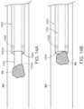
- FIG. 1is a partially schematic side view of a clot treatment or clot removal system comprising an aspiration assembly 10 (“assembly 10 ”) configured in accordance with an embodiment of the present technology.
- the assembly 10includes a catheter subsystem 100 , a tubing subsystem 120 , and a pressure source 140 .
- the catheter subsystem 100includes a catheter 102 (e.g., an aspiration catheter) comprising an elongated shaft defining a lumen 104 and having a distal portion 103 a and a proximal portion 103 b .
- the catheter subsystem 100further includes a valve 106 that can be integral with or coupled to the proximal portion 103 b of the catheter 102 .
- the valve 106includes a distal portion 107 a , a proximal portion 107 b , and a lumen 109 extending therethrough from the distal portion 107 a to the proximal portion 107 b .
- the valve 106further includes a flow controller (obscured in FIG. 1 ) in the lumen 109 .
- the valveis a hemostasis valve that is configured to maintain hemostasis during a clot removal procedure by preventing fluid flow in the proximal direction through the valve 106 as various components such as delivery sheaths, pull members, guidewires, interventional devices, other aspiration catheters (e.g., as described in detail with reference to FIGS.
- valve 106is inserted through the valve 106 to be delivered through the catheter 102 to a treatment site in a blood vessel.
- the valve 106further includes a branch or side port 108 positioned distally of the flow controller in the lumen 109 and configured to fluidly couple the lumen 104 of the catheter 102 to the tubing subsystem 120 .
- the valve 106includes buttons 101 that can be actuated (e.g., depressed) to open a conduit within the lumen 109 .
- the valve 106can be a valve of the type disclosed in U.S. patent application Ser. No. 16/117,519, filed Aug.
- the proximal portion 107 b of the valve 106is further configured to be detachably coupled (e.g., via a snap-fit arrangement) to a retraction/aspiration device for aspirating the lumen 104 of the catheter 102 and/or for retracting an interventional device, catheter, delivery sheath, catheter, etc., positioned within the lumen 104 .
- a retraction/aspiration devicefor aspirating the lumen 104 of the catheter 102 and/or for retracting an interventional device, catheter, delivery sheath, catheter, etc., positioned within the lumen 104 .
- the tubing subsystem 120fluidly couples the catheter subsystem 100 to the pressure source 140 .
- the tubing subsystem 120can include one or more tubing sections 124 (individually labeled as a first tubing section 124 a and a second tubing section 124 b ), at least one fluid control device 126 (e.g., a valve), and at least one connector 128 for fluidly coupling the tubing subsystem 120 to the pressure source 140 and/or other suitable components.
- the fluid control device 126is a stopcock that is fluidly coupled to (i) the side port 108 of the valve 106 via the first tubing section 124 a and (ii) the connector 128 via the second tubing section 124 b .
- the fluid control device 126can define a lumen having a diameter (or other cross-sectional dimension) that is greater than or equal to a diameter of the lumen 104 of the catheter 102 , a diameter of the first tubing section 124 a , and/or a diameter of the second tubing section 124 b.
- the fluid control device 126is externally operable by a user to regulate the flow of fluid therethrough and, specifically, from the lumen 104 of the catheter 102 to the pressure source 140 .
- the fluid control device 126can be a clamp that can be actuated (e.g., compressed or squeezed by the hand of a user) to partially or fully restrict fluid flow through the tubing section 124 a and/or the tubing section 124 b .
- the fluid control device 126can be omitted and its functionality incorporated into the pressure source 140 (e.g., as described in detail below with reference to FIG. 5 ).
- the fluid control device 126can include a quick-release mechanism (e.g., a spring-loaded apparatus) for rapidly opening, unclamping, etc., the fluid control device 126 to (e.g., instantaneously or nearly instantaneously) fluidly connect the pressure source 140 and the catheter 102 .
- the fluid control device 126can be opened/closed automatically (e.g., by a motor, switch, etc.).
- such a quick-release fluid control device 126can reduce the time needed for pressure in the assembly 10 to equalize after opening of the fluid control device 126 , and can thereby increase suction forces generated at the distal portion 103 a of the catheter 102 .
- the connector 128is a quick-release connector (e.g., a quick disconnect fitting) that enables rapid coupling/decoupling of the catheter 102 and the fluid control device 126 to/from the pressure source 140 .
- the tubing subsystem 120can have more or fewer tubing sections, connectors, and/or fluid control devices, and can have other suitable configurations.
- one or more of the componentscan be permanently connected and/or integrally formed.
- the pressure source 140is configured to generate (e.g., form, create, charge, build-up, etc.) a vacuum (e.g., negative relative pressure) and store the vacuum for subsequent application to the catheter subsystem 100 . Further details of suitable pressure sources are described in detail below with reference to FIGS. 2 - 7 .
- a usercan first close the fluid control device 126 before activating the pressure source 140 to build up vacuum pressure within the pressure source 140 (e.g., a vacuum chamber of the pressure source 140 ).
- the usercan control or select the volume of the generated vacuum. In this manner, a vacuum is charged within the pressure source 140 before the pressure source 140 is fluidly connected to the catheter subsystem 100 .
- the usercan open the fluid control device 126 to fluidly connect the pressure source 140 to the catheter subsystem 100 and thereby apply or release the vacuum stored in the pressure source 140 to the lumen 104 of the catheter 102 . Opening of the fluid control device 126 instantaneously or nearly instantaneously applies the stored vacuum pressure to the tubing subsystem 120 and the catheter 102 , thereby generating suction throughout the catheter 102 . In particular, the suction is applied at the distal portion 103 a of the catheter 102 .
- pre-charging or storing the vacuum before applying the vacuum to the lumen 104 of the catheter 102is expected to generate greater suction forces (and corresponding fluid flow velocities) at and/or near the distal portion 103 a of the catheter 102 compared to simply activating the pressure source 140 while it is fluidly connected to the catheter 102 .
- the suction forces generated by application of the stored vacuumcan be used to aspirate or otherwise remove clot material from within a blood vessel of a human patient.
- the assembly 10 of the present technologyincludes a pressure source (e.g., a vacuum source, negative pressure source, etc.) configured to charge a vacuum that can be applied to the catheter subsystem 100 to generate suction forces for aspirating clot material from within a blood vessel.
- a pressure sourcee.g., a vacuum source, negative pressure source, etc.
- the pressure sourcecan be any suitable source or combination of sources for generating and/or storing negative pressure.
- the pressure sourcecan be a pump (e.g., an electric pump coupled to a vacuum chamber) while, in other embodiments, the pressure source can include one or more syringes that can be actuated or otherwise activated by a user of the assembly 10 to generate and store a vacuum therein.
- FIG. 2is a side view of a pressure source 240 comprising a vacuum-pressure locking syringe (“syringe 240 ”) configured in accordance with the present technology.
- the syringe 240can be of the kind sold under the trademark “VacLok” by Merit Medical System, Inc.
- the syringe 240includes a plunger 242 slidably and rotatably positioned within a chamber or barrel 244 .
- the barrel 244is shown as transparent in FIG. 2 for the sake of clarity.
- the plunger 242includes a seal 243 and a plurality of index members 246 defining slots 248 between adjacent pairs thereof.
- a tab member 245projects inwardly from the interior surface of the barrel 244 and is configured to be removably positioned in the slots 248 for locking the plunger 242 in position relative to the barrel 244 .
- the barrel 244can be made of a transparent material that permits a user to visualize material (e.g., clot material) within the barrel 244 and to visualize the relative position between the slots 248 and tab member 245 for locking the syringe 240 .
- the syringe 240further includes a tip 247 for coupling the syringe 240 to the tubing subsystem 120 .
- the tip 247is a standard luer connector that can be coupled to the connector 128 via one or more suitable adaptors.
- the tip 247further defines a lumen or bore 249 having an inner diameter D 1 .
- the diameter D 1is about 0.103′′, or about 0.080′′ to about 0.200′′, or about 0.100′′ to about 0.150′′, or about 0.100′′ to about 0.110′′.
- the inner diameter D 1is about 14 French.
- a usercan first close the fluid control device 126 and then grip the plunger 242 and/or the barrel 244 to withdraw (e.g., retract) the plunger 242 at least partially out of the barrel 244 to thereby generate a vacuum in the barrel 244 .
- the usercan lock the plunger 242 by rotating the plunger 242 relative to the barrel 244 such that the tab member 245 is positioned within a corresponding one of the slots 248 .
- the syringe 240may not be a locking syringe, and the user can instead hold the plunger 242 in position relative to the barrel 244 .
- the usercan control the volume of the vacuum—by withdrawing the plunger 242 more or less—to provide a desired amount or level of suction/aspiration upon opening of the fluid control device 126 .
- the syringehas a volume of about 60 cc or less than about 60 cc.
- FIG. 3 Ais a side view of a pressure source 340 comprising a vacuum-pressure locking syringe (“syringe 340 ”) configured in accordance with the present technology.
- the syringe 340can have some features generally similar to the features of the syringe 240 described above with reference to FIG. 2 .
- the syringe 340includes a plunger 342 slidably and rotatably positioned within a barrel 344 , and the plunger 342 includes a plurality of index members 346 defining slots 348 between adjacent pairs thereof.
- the barrel 344is shown as transparent in FIG. 3 A (and FIG. 3 C ) for the sake of clarity.
- the syringe 340has a maximum volume of about 60 cc or greater than 60 cc.
- the syringe 340includes a large-bore tip 347 , such as a Toomey tip, defining an inner lumen or bore 349 .
- the bore 349can have an inner diameter D 2 that is greater than or equal to the largest inner diameter of the assembly 10 (e.g., of the catheter 102 and tubing subsystem 120 ).
- the tip 347can be about 26 French or greater. Accordingly, referring to FIGS. 2 and 3 A together, the diameter D 2 can be greater than the dimension D 1 . For example, the dimension D 2 can be about two, three, four, or more times greater than the diameter D 1 .
- FIG. 3 Bis a side view of an adaptor 350 for connecting the syringe 340 to the catheter subsystem 100 configured in accordance with the present technology.
- FIG. 3 Cis a side view of the adaptor 350 coupled to the syringe 340
- FIG. 3 Dis a side view of the syringe 340 coupled to the tubing subsystem 120 via the adaptor 350 .
- the adaptor 350is shown as partially transparent in FIG. 3 C for the sake of illustration. Referring to FIG.
- the adaptor 350includes (i) a first portion 351 defining a first lumen or bore 352 having an inner diameter D 3 , (ii) a second portion 353 defining a second lumen or bore 354 , and (iii) a stepped surface or interface 355 between the first and second portions 351 , 353 .
- the first portion 351can further include a seal 357 such as an O-Ring around an exterior surface thereof.
- the second bore 354 of the adaptor 350is configured to removably receive the tip 347 of the syringe 340 therein.
- the tip 347can be snuggly received in the second bore 354 via an interference fit.
- a seale.g., an O-ring
- the syringe 340can be permanently coupled or integrally formed with the adaptor 350 .
- the first portion 351 of the adaptor 350is configured to be removably positioned within the connector 128 of the tubing subsystem 120 to fluidly couple the syringe 340 to the tubing subsystem 120 .
- the first portion 351 of the adaptor 350can be pushed into the connector 128 until the interface 355 abuts the connector 128 .
- the seal 357seals the interface between the connector 128 and the adaptor 350 .
- the diameter D 3 of the first bore 352 of the adaptor 350can be selected to be about the same as or greater than the greatest inner diameter of the assembly 10 (e.g., of the catheter 102 and the tubing subsystem 120 ).
- the catheter 102can be about 9 French or greater, and the diameter D 3 can be selected to be larger than the size of the catheter 102 . Accordingly, when the fluid control device 126 is open, the continuous lumen between the catheter 102 and the syringe 340 can have a generally constant diameter and/or does not contain any narrowing at the interface between the syringe 340 and the tubing subsystem 120 .
- the adaptor 350can connect the syringe 340 and the tubing subsystem 120 without any restriction or narrowing of the fluid path.
- a standard luer connectore.g., the syringe 240
- Any narrowing of the fluid pathway between the catheter 102 and the syringe 340can reduce the volumetric flow rate (e.g., suction forces and fluid velocities) that can be generated when a vacuum stored in the syringe 340 is applied to the catheter 102 .
- the syringe 340 and the adaptor 350can reduce the fluid resistance in the assembly 10 and therefore facilitate a more rapid pressure equalization in the assembly 10 when the fluid control device 126 is opened to apply the charged vacuum to the catheter 102 .
- the pressure in the assembly 10can take about 1-2 seconds to equalize.
- the pressure in the assembly 10can take less than about 1 second (e.g., about 0.5 seconds) to equalize.
- Table 1illustrates representative pressure equalization times and associated flow rates when the syringe 240 is coupled to a 20 French catheter (i.e., the catheter 102 ).
- Table 2illustrates representative pressure equalization times and associated flow rates when the syringe 340 and the adaptor 350 are coupled to a 20 French catheter (i.e., the catheter 102 ).
- the syringe 340provides for relatively faster equalization times and correspondingly greater flow rates. It is expected that the more rapid pressure equalization and flow rates provided by the syringe 340 will provide correspondingly greater suction forces at the distal portion 103 a of the catheter 102 . That is, in general, it is expected that increasing the bore size of a syringe used to provide vacuum pressure will provide greater suction forces over a smaller period of time (e.g., will provide a larger vacuum impulse). In some embodiments, the greater suction forces can facilitate the removal of clot material from a blood vessel of a patient even where the clot material is strongly lodged or attached within the blood vessel (e.g., a chronic clot).
- the adaptor 350can couple the syringe 340 to the connector 128 without the need for any intervening tubing sections or additional adaptors.
- This arrangementcan minimize the total length, volume, etc., of the components fluidly coupling the catheter 102 to the syringe 340 . It is expected that the magnitude of suction forces generated at the distal portion 103 a of the catheter 102 —e.g., when a vacuum charged in the syringe 340 is applied to the catheter 102 by opening of the fluid control device 126 —is proportional to the length of the fluid path between the pressure source 340 and catheter 102 .
- operation of the assembly 10 with the syringe 340 and adaptor 350is expected to increase the suction forces generated at the distal portion 103 a of the catheter 102 .
- the greater suction forcescan facilitate the removal of clot material from a blood vessel of a patient even where the clot material is strongly lodged or attached within the blood vessel (e.g., a chronic clot).
- FIG. 4 Ais a side perspective view a pressure source 400 including the syringe 340 (“primary syringe 340 ”) shown in FIGS. 3 A- 3 D and a secondary syringe 460 configured in accordance with the present technology.
- the secondary syringe 460can include a plunger 462 slidably positioned within a chamber or barrel 464 .
- the primary and secondary syringes 340 , 460can have the same volume or different volumes.
- a tip 463 of the secondary syringe 460is coupled to a first one-way valve (e.g., a check valve) 470 via a coupling member 465 , such as a tube.
- a first one-way valvee.g., a check valve
- the first one-way valve 470is configured to fluidly connect the secondary syringe 460 to the ambient environment or another device coupled to the first one-way valve 470 .
- a second one-way valve (e.g., a check valve) 472spans between and is configured to fluidly connect the primary syringe 340 to the secondary syringe 460 . More specially, in the illustrated embodiment the second one-way valve 472 is connected between the first portion 351 of the adaptor 350 and the coupling member 465 . In other embodiments, the second one-way valve 472 can couple the primary and secondary syringes 340 , 460 in different manners.
- the second one-way valve 472can span between and directly connect the barrels 344 , 464 .
- the primary and secondary syringes 340 , 460can be coupled or fastened together via one or more connectors 474 that fix the positions of the barrel 344 , 464 relative to one another.
- the second one-way valve 472is a normally-open check valve configured to (i) permit fluid (e.g., air) flow from the primary syringe 340 and the adaptor 350 to the secondary syringe 460 and (ii) inhibit fluid flow in the opposite direction from the secondary syringe 460 into the primary syringe 340 .
- the second one-way valve 472has a cracking (e.g., opening) pressure of about 0 psi. In one aspect of the present technology, this arrangement maximizes the magnitude of the vacuum that can be charged within the primary syringe 340 .
- the cracking pressure of the second one-way valve 472does not reduce the effective vacuum within the primary syringe 340 .
- a normally-closed or other type of valvecould be used for the second one-way valve 472 .
- the vacuum efficiency of the pressure source 400would be reduced by the cracking pressure of the second one-way valve 472 .
- the first one-way valve 470can be a check valve configured to (i) permit fluid flow from the secondary syringe 460 to the ambient environment (or other device) and (ii) inhibit fluid flow in the opposite direction from the ambient environment into the secondary syringe 460 .
- FIGS. 4 B and 4 Care enlarged schematic side views of the pressure source 400 during operation. More specifically, FIGS. 4 B and 4 C illustrate fluid flow paths through the first and second one-way valves 470 , 472 during retraction and advancement, respectively, of the plunger 462 through the barrel 464 of the secondary syringe 460 .
- the first one-way valve 470is closed to inhibit fluid from flowing into the secondary syringe 460 while (ii) the second one-way valve is open 472 to permit fluid to flow from the primary syringe 340 , the catheter subsystem 100 ( FIG.
- the first one-way valve 470is open to permit fluid flow (e.g., fluid expulsion) from the secondary syringe 460 to the ambient environment (or other device) while (ii) the second one-way valve 472 is closed to inhibit fluid flow from the secondary syringe 460 into (e.g., back into) the primary syringe 360 , the catheter subsystem 100 , and/or the tubing subsystem 120 .
- This flow pathis indicated by the arrows A in FIG. 4 C .
- the pressure source 400can be coupled to the tubing subsystem 120 by coupling the primary syringe 340 to the connector 128 (e.g., as shown in FIG. 3 D ).
- the pressure sourceis coupled to the tubing subsystem 120 , retraction of the plunger 462 of the secondary syringe 460 evacuates an evacuatable volume of the assembly 10 .
- the fluid control device 126when the fluid control device 126 is closed, retraction of the plunger 462 of the secondary syringe 460 evacuates fluid, through the second one-way valve 472 , from (i) the primary syringe 340 (e.g., from the barrel 344 , the tip 347 , and/or the adaptor 350 ) and (ii) the portion of the tubing subsystem 120 between the fluid control device 126 and the primary syringe 340 .
- Thiscan enable a greater charged/stored vacuum to be generated for subsequent application to the catheter subsystem 100 for aspirating clot material.
- the plunger 462 of the secondary syringe 460can be withdrawn/advanced (e.g., “cycled”) one or more times before withdrawing the plunger 342 of the primary syringe 340 to evacuate air from (i) the tip 347 of the primary syringe 340 and/or (ii) the portion of the tubing subsystem 120 between the fluid control device 126 and the tip 347 .
- the plunger 462 of the secondary syringe 460can alternatively or additionally be withdrawn after withdrawing the plunger 342 of the primary syringe 340 to further evacuate the barrel 344 of the primary syringe 340 .
- the plunger 462can be cycled when the fluid control device 126 is open to, for example, facilitate the removal of clot material stuck or clogged within the catheter subsystem 100 . That is, cycling the secondary syringe 460 when the fluid control device 126 is open can generate vacuum pressure and suction in the catheter 102 to aid in the aspiration/removal of clot material.
- the volumes of the primary and secondary syringes 340 , 460can be selected based on one or more desired characteristics of a clot removal procedure using the pressure source 400 .
- the secondary syringe 460can have a larger volume than the primary syringe 340 to permit a high vacuum to be charged within the primary syringe 340 while also limiting blood loss from the patient.
- the pressure source 340permits a greater vacuum to be generated without increasing the volume of the primary syringe 340 .
- the vacuum generated by the primary syringe 340 aloneis directly proportional to the volume of the primary syringe 340 .
- the volume of the primary syringe 340must be increased.
- inclusion of the secondary syringe 460 in the pressure source 400 and the configuration of the first and second one-way valves 470 , 472allows the (e.g., maximum) generated vacuum to be independent of the volume of the primary syringe 340 . Therefore, for example, the generated vacuum can be increased without correspondingly increasing the volume of blood withdrawn from the patient when applying the vacuum to the catheter subsystem 100 .
- the primary syringe 340 of the pressure source 400can be replaced with a simple pressure vessel or other volume, such as a canister, barrel, tube, etc.
- a vacuumcan be generated in the canister simply by cycling the secondary syringe 460 one or more times.
- the secondary syringe 460can comprise a pump or vacuum source other than a syringe.
- the secondary syringe 460 or other vacuum sourcecan be fluidly coupled to the primary syringe 340 in other manners (e.g., via a different arrangement of check valves) to produce the same or similar flow patterns as shown in FIGS. 4 B and 4 C .
- the first and second one-way valves 470 , 472can be other types of flow control devices that are mechanically activated/deactivated (e.g., opened and closed) rather than passively operated via pressure differentials within the pressure source 400 .
- the flow control devices 470 , 472can be mechanically coupled to the plunger 462 of the secondary syringe 460 such that cycling the plunger 462 activates/deactivates the flow control devices 470 , 472 to operate the pressure source 400 in the manner illustrated in FIGS. 4 B and 4 C .
- FIG. 5is a side cross-sectional view of a pressure source 540 comprising an automatic release syringe (“syringe 540 ”) configured in accordance with the present technology.
- the syringe 540is configured to automatically apply a charged vacuum of a selected volume to the catheter subsystem 100 without requiring the actuation of an intervening fluid control device, such as the fluid control device 126 shown in FIG. 1 .
- the syringe 540can have some features generally similar to the features of the syringes 240 , 340 described in detail above with reference to FIGS. 2 and 3 A- 3 D .
- the syringe 540includes a first plunger 542 slidably positioned within a chamber or barrel 544 .
- the first plunger 542further includes a first seal 543 that engages an interior surface of the barrel 544 such that a vacuum is formed within the barrel 544 as the first plunger 542 is withdrawn through the barrel 544 .
- the syringe 540includes a tip 547 (e.g., a Toomey tip) for coupling the syringe 540 to the tubing subsystem 120 (e.g., via a Toomey tip adaptor) and defining a bore 549 .
- the bore 549has a relatively large diameter selected to provide rapid pressure equalization in the assembly 10 after a vacuum stored in the syringe 540 is released.
- the first plunger 542can further include (i) a grip portion 541 configured to be engaged by a user for retracting the first plunger 542 and (ii) a lumen 581 extending lengthwise therethrough.
- a plunger assembly 582is slidably positioned within and extends through the lumen 581 of the first plunger 542 .
- the plunger assembly 582includes (i) a second plunger 583 and (ii) a release member 584 slidably and/or rotatably positioned within a lumen 585 of the second plunger 583 .
- the release member 584includes an engagement member 586 configured to engage the grip portion 541 of the first plunger 542 when the first plunger 542 is withdrawn from the barrel 544 .
- the second plunger 583includes a second seal 587 configured to engage and seal an interior surface of the bore 549 of the syringe 540 to enable a vacuum to be formed in the barrel 544 as the first plunger 542 is withdrawn through the barrel 544 . That is, the second seal 587 can seal (e.g., fluidly disconnect) the barrel 544 of the syringe from the tubing subsystem 120 and the catheter subsystem 100 .
- the syringe 540can further include an O-ring 579 or other suitable component for sealing an interface between the first and second plungers 542 , 582 to maintain the vacuum formed within the barrel 544 , while also permitting the first plunger 542 to move (e.g., translate) relative to the second plunger 583 .
- the plunger assembly 582further includes a locking mechanism (not shown) configured to permit/inhibit the release member 584 from moving longitudinally relative to the second plunger 583 .
- a locking mechanism(not shown) configured to permit/inhibit the release member 584 from moving longitudinally relative to the second plunger 583 .
- rotation of the release member 584 in a first direction relative to the second plunger 583can lock the two components in position, while rotation of the release member 584 in a second direction relative to the second plunger 583 can unlock the two components so that the release member 584 can be withdrawn or pushed into the lumen 585 of the second plunger 583 .
- the release member 584 and the second plunger 583can be integrally formed or permanently locked together.
- the plunger assembly 582enables (i) a user of the syringe 540 to select a desired volume for a vacuum to be formed in the syringe 540 and (ii) the automatic release or application of a generated vacuum via opening (e.g., unplugging) of the bore 549 .
- a usercan first unlock the release member 584 and slide the release member 584 to a position corresponding to a desired vacuum volume.
- the release member 584can have tick marks 588 or other indicia along its length that correspond to a volume of the syringe 540 (e.g., a vacuum chamber volume).
- the usercan lock the release member 584 relative to the second plunger 583 (e.g., by rotating the release member 584 ) to inhibit relative movement of the two components.
- the usercan grasp the grip portion 541 to retract the first plunger 542 relative to the barrel 544 and the plunger assembly 582 to generate a vacuum within the barrel 544 between the first and second seals 543 , 587 .
- the grip portion 541engages the engagement member 586 of the release member 584 such that further retraction of the first plunger 542 simultaneously retracts the plunger assembly 582 .
- the syringe 540provides for the automatic release of charged vacuum pressure at a specified volume and with a single retraction of the first plunger 542 .
- the syringe 540has a built-in fluid control device and thus eliminates the need for a separate fluid control device 126 and/or an additional step for opening the fluid control device 126 .
- FIG. 6is a top perspective view of a pressure source 640 comprising a syringe (“syringe 640 ”) configured in accordance with the present technology.
- the syringe 640can include some features generally similar to the features of the syringes 240 , 340 , and 540 described in detail above with reference to FIGS. 2 - 3 D and 5 .
- the syringe 640includes a plunger 642 slidably positioned within a barrel 644 , and a tip 647 (e.g., a large-bore tip).
- the syringe 640further includes a lever or handle 690 operably coupled to the plunger 642 .
- the handle 690provides mechanical leverage for withdrawing the plunger 642 to create a vacuum within the barrel 644 .
- the handle 690can be coupled to a crossbar 691 that rotates relative to the plunger 642 via actuation (e.g., rotation) of the handle 690 .
- the crossbar 691can be coupled to a gear (obscured in FIG. 6 ) configured to engage a track 692 on the plunger 642 . Accordingly, rotation of the handle 690 in a first direction retracts the plunger 642 relative to the barrel 644 to charge a vacuum in the barrel 644 . And, rotation of the handle 690 in a second (e.g., opposite) direction advances the plunger 642 into the barrel 644 to, for example, expel fluid, material, etc., from the barrel 644 .
- the handle 690provides additional mechanical leverage relative to a standard syringe, and can thus reduce the force (e.g., strain, energy, etc.) required by a user of the syringe 640 to form a vacuum in the syringe 640 . Therefore, use of the syringe 640 can reduce the time needed to remove clot material with the assembly 10 .
- the syringe 640can have a volume greater than 60 cc (e.g., greater than 80 cc, greater than 100 cc, greater than 120 cc, greater than 140 cc, etc.).
- the syringe 640can have a volume of about 140 cc. With such large volumes, it may be difficult for some users to manually retract the plunger 642 without the additional mechanical leverage provided by the handle 690 . Thus, the syringe 640 can enable the use of larger volume syringes that can generate correspondingly greater suction forces in the catheter subsystem 100 .
- the side port 108 of the valve 106can be formed to have an angle A that is less than about 90°, less than about 75°, less than about 60°, less than about 45°, less than about 30°, less than about 15° etc.
- FIG. 24is an enlarged isometric view of the assembly 10 showing the pressure source 340 coupled directly to the proximal portion 107 b of the valve rather than to the connector 128 of the tubing subsystem 120 and the side port 108 of the valve 106 .
- FIG. 24is an enlarged isometric view of the assembly 10 showing the valve 106 and the tubing subsystem 120 coupled to the catheter 102 via a Y-connector 2590 .
- the tubing system 120is linearly coupled to the catheter 102 , and the valve 106 protrudes at an angle from the catheter 102 .
- a guidewire or other componentis positioned within the valve 106 during the duration of a clot removal procedure (e.g., for delivering interventional devices to a treatment site within a patient).
- the pressure source 140can be a syringe configured for over-wire delivery.
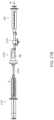
- FIG. 7is a side view of a pressure source 740 comprising a vacuum-pressure locking syringe (“syringe 740 ”) configured in accordance with the present technology for delivery and operation over a guidewire 794 .
- the syringe 740can have some features generally similar to the features of the syringe 340 described in detail above with reference to FIG. 3 .
- the syringe 740includes a plunger 742 slidably and rotatably positioned within a barrel 744 .
- the barrel 744is shown as transparent in FIG. 7 for the sake of clarity.
- the plunger 742includes a lumen 796 (shown in broken lines) extending longitudinally therethrough.
- the guidewire 794can be inserted through the lumen 796 of the plunger 742 such that the syringe 740 can be advanced over the guidewire 794 for attachment to the proximal portion 107 b of the valve 106 .
- the syringe 740can further include one or more sealing components (e.g., valves, O-rings, etc.; not shown) for maintaining a seal between the guidewire 794 and the plunger 742 to permit build-up and storage of a vacuum in the barrel 744 .
- sealing componentse.g., valves, O-rings, etc.; not shown
- pressure sources disclosed hereinmay be combined to, for example, include multiple pressure sources or pressure sources having different components or combinations of components.
- the secondary syringe 460FIGS. 4 A- 4 C
- the syringes 240 , 540 , 640 or 740FIGS. 2 and 5 - 7 , respectively
- multiple pressure sourcescan be coupled to the catheter 102 via the tubing subsystem 120 and/or via the valve 106 .
- the individual pressure sourcescan be the same or different, and can be coupled to the catheter subsystem 100 via a single fluid control device, such as the fluid control device 126 , or can be coupled to the catheter subsystem 100 via separate fluid control devices. Therefore, the profile of the vacuum applied to the catheter 102 can be selected or adjusted by using multiple different pressure sources.
- a specific vacuum profilecan depend at least on (i) the individual characteristics of the multiple pressure sources (e.g., volume, bore-size, etc.), (ii) the manner in which the pressure sources are coupled to the catheter subsystem 100 (e.g., via individual valves, via the same valve, etc.), and (iii) the timing of the application or release of the vacuum of each pressure source to the catheter subsystem 100 (e.g., staggered release, simultaneous release, etc.).
- the syringe 240 ( FIG. 2 ) and the syringe 340 ( FIG. 3 )can both be coupled to the tubing subsystem 120 via, for example, a Y-connector.
- opening the fluid control device 126can simultaneously apply the combined vacuum to the catheter 102 .
- the larger-bored syringe 340can provide a short but powerful impulse of vacuum pressure, while the smaller-bored syringe 240 can provide a longer and more sustained vacuum pull.
- This combinationcan apply a large, fast-acting suction force to dislodge and capture clot material in the catheter 102 , and simultaneously apply a more sustained suction force to capture more clot material.
- FIG. 8is a flow diagram of a process or method 800 for operating a clot removal system including the assembly 10 to remove clot material from within a blood vessel (e.g., a pulmonary blood vessel) of a human patient in accordance with the present technology.
- FIGS. 9 A- 9 Care side views of a proximal portion of the assembly 10
- FIGS. 10 A and 10 Bare schematic illustrations of a distal portion of the assembly 10 , during a clot removal procedure in accordance with embodiments of the present technology.
- FIGS. 9 A- 9 Care side views of the assembly 10 including the syringe 340 and adaptor 350 ( FIGS. 3 A- 3 D ), and FIGS.
- FIGS. 10 A and 10 Bare side views of the catheter 102 with the distal portion 103 a of the catheter 102 positioned proximate to an embolism or clot material PE within a blood vessel BV (e.g., a pulmonary blood vessel).
- BVe.g., a pulmonary blood vessel
- FIGS. 1 , 3 A- 3 D, and 9 A- 10 Bare side views of the catheter 102 with the distal portion 103 a of the catheter 102 positioned proximate to an embolism or clot material PE within a blood vessel BV (e.g., a pulmonary blood vessel).
- BVe.g., a pulmonary blood vessel
- the method 800includes positioning the distal portion 103 a of the catheter 102 proximate to clot material within a blood vessel of a human patient (e.g., at a treatment site).
- a distal terminus of the distal portion 103 a of the catheter 102is positioned proximate to a proximal portion of the clot material PE. It is expected that reducing the distance between the distal terminus of the catheter 102 and the proximal portion of the clot material PE—without contacting the clot material PE with the catheter 102 —will maximize the suction forces on the clot material PE when the fluid control device 126 is opened.
- the distal terminus of the catheter 102can be positioned at least partially within the clot material PE, or the distal terminus of the catheter 102 can be positioned distal of the clot material PE.
- the catheter subsystem 100can include an introducer (e.g., a Y-connector with a hemostasis valve; not shown) that can be partially inserted into the femoral vein.
- a guidewire(not shown) can be guided into the femoral vein through the introducer and navigated through the right atrium, the tricuspid valve, the right ventricle, the pulmonary valve, and into the main pulmonary artery.
- the guidewirecan be guided to one or more of the branches of the right pulmonary artery and/or the left pulmonary artery.
- the guidewirecan be extended entirely or partially through the clot material PE. In other embodiments, the guidewire can be extended to a location just proximal of the clot material PE.
- the catheter 102can be placed over the guidewire and advanced (e.g., as indicated by arrow A 1 ) to a position proximate to the clot material PE as illustrated in FIG. 10 A .
- a contrast agentcan be injected through the catheter 102 and viewed using fluoroscopic imaging techniques, as is known in the art.
- the valve 106can be opened to determine the position of the distal portion 103 a of the catheter 102 relative to the clot material PE.
- the activation buttons 101can be depressed to open the lumen 109 of the valve 106 . If there is substantially no back-bleeding through the valve 106 , the operator can determine that the distal portion 103 a of the catheter 102 is fully engaged with the clot material PE.
- the operatorcan determine that the distal portion 103 a of the catheter is not fully engaged with the clot material PE. Accordingly, to locate the distal portion 103 a of the catheter 102 just proximal of the clot material PE, the operator can (i) first determine that distal portion 103 a of the catheter is fully engaged with the clot material PE by activating the valve 106 and detecting no back-bleeding and (ii) then reposition the catheter 102 (e.g., by withdrawing the catheter 102 proximally) and activate the valve 106 until back-bleeding is detected—thereby confirming that the distal portion 103 a of the catheter 102 is positioned proximal of the clot material PE.
- the valve 106can be opened during retraction of the catheter 102 until back-bleeding is detected. In other embodiments, the valve 106 can be closed during retraction of the catheter 102 , and the catheter 106 can be retracted a set (e.g., predetermined) distance before the valve 106 is opened again. In one aspect of the present technology, determining the position of the distal portion 103 a of the catheter 102 via activation of the valve 106 can be used when it is difficult to determine the position of the catheter 102 via radiographic techniques. In contrast, many conventional hemostasis valves cannot be activated in this manner.
- the guidewirecan then be withdrawn while, in other embodiments, the guidewire can remain and can be used to guide other catheters (e.g., delivery catheters, additional aspiration catheters, etc.), interventional devices, etc., to the treatment site.
- catheterse.g., delivery catheters, additional aspiration catheters, etc.
- interventional devicesetc.
- the usercan gain access through the jugular vein, the subclavian vein, the brachial vein, or any other vein that connects or eventually leads to the superior vena cava.
- Use of other vessels that are closer to the right atrium of the patient's heartcan also be advantageous as it reduces the length of the instruments needed to reach the pulmonary embolism.
- the method 800includes coupling a pressure source (e.g., the syringe 340 ) to the catheter 102 via the fluid control device 126 .
- a pressure sourcee.g., the syringe 340
- the tip 347shown in FIGS. 3 A and 3 C but obscured in FIG. 9 A
- the adaptor 350can be coupled to the connector 128 via the adaptor 350 .
- the syringe 340is coupled to the catheter 102 , (i) opening the fluid control device 126 fluidly connects the syringe 340 to the lumen 104 of the catheter 102 , and (ii) closing the fluid control device 126 fluidly disconnects the syringe 340 from the lumen 104 of the catheter 102 .
- the fluid control device 126is in an open position in FIG. 9 A .
- the method 800includes activating the syringe 340 to generate a vacuum while the fluid control device 126 is closed.
- the usercan first actuate the fluid control device 126 to close the fluid control device 126 , and then retract the plunger 342 to generate a vacuum in the barrel 344 of the syringe 340 .
- the usercan subsequently lock the plunger 342 relative to the barrel 344 , as described in detail above, to store or maintain a vacuum of known volume in the syringe 340 .
- the syringe 340can be pre-charged with a vacuum before the vacuum is applied to the catheter 102 .
- many conventional aspiration techniquesinclude activating a negative pressure source (e.g., a pump, a syringe, etc.) while the pressure source is fluidly connected to a lumen to be aspirated.
- a negative pressure sourcee.g., a pump, a syringe, etc.
- the secondary syringe 460can be cycled one or more times before or after retracting the plunger 342 to increase the vacuum pressure.
- the method 800includes opening the fluid control device 126 to apply the vacuum to the lumen 104 of the catheter 102 .
- the usercan actuate (e.g., twist a handle of) the fluid control device 126 to open the fluid control device 126 and apply the vacuum stored in the syringe 340 to the catheter subsystem 100 .
- application of the vacuumcauses suction at the distal tip 103 a of the catheter 102 (e.g., as indicated by arrow A 2 ) that aspirates at least a portion of the clot material PE from the blood vessel BV and into the lumen 104 of the catheter 102 .
- opening the fluid control device 126instantaneously or nearly instantaneously generates suction at the distal portion 103 a of the catheter 102 .
- application of the vacuumcan generate suction for less than about 1 second (e.g., about 0.5 second), substantially less than about 1 second (e.g., about 0.3 second, about 0.1 second, etc.) less than about 2 seconds, or greater than about 2 seconds—until the pressure in the assembly 10 equalizes.
- the clot material PEcan be aspirated entirely through the lumen 104 of the catheter 102 and into the barrel 344 of the syringe 340 .
- the usercan determine whether subsequent steps for treating the clot material PE are necessary or desirable by visualizing the amount of clot material collected in the syringe 340 .
- FIG. 9 Cillustrates the syringe 340 and the tubing subsystem 120 after the fluid control device 126 has been opened to apply the vacuum stored in the syringe 340 to the catheter 102 .
- some of the clot material PEis visible in the syringe 340 .
- the fluid control device 126 or another fluid control devicecan be intermittently operated to provide discrete bursts of suction.
- the fluid control device 126can be quickly opened and closed to provide a first burst of suction (e.g., vacuum release) without fully equalizing the pressure in the assembly 10 .
- the fluid control device 126can then be opened again to provide a second burst of suction, or opened and closed repeatedly to provide a desired suction pattern.
- the assembly 10can be specifically configured to facilitate the application of multiple bursts of suction.
- the fluid control device 126can be spring-loaded, electronically controlled, etc., to rapidly open and close the valve, and/or (ii) the pressure source 140 can have a large vacuum chamber and/or small bore size to increase the time required for pressure in the assembly 10 to equalize (e.g., to increase a discharge time of the pressure source 140 ).
- discharging the vacuum stored in the pressure source to aspirate the lumen 104 of the catheter 102may not remove all of the clot material PE (or a desired amount of the clot material PE) from the blood vessel BV. That is, a single aspiration may not adequately remove the clot material PE from the blood vessel BV.
- the user of the assembly 10may wish to again apply vacuum pressure (conduct an “aspiration pass”) to remove all or a portion of the remaining clot material PE in the blood vessel BV.
- the pressure sourcecan be disconnected from the tubing subsystem 120 and drained (e.g., aspirated clot removal removed) before the method 800 returns to block 802 .
- the adaptor 350 and the syringe 340can be decoupled from the connector 128 , and the plunger 342 can be pushed into the barrel 344 to expel the clot material PE and associated fluid from the barrel 344 via the tip 347 .
- the pressure sourcecan then be re-coupled to the connector 128 (block 804 ), primed again (block 806 ), and the vacuum pressure discharged (block 808 ) to aspirate all or a portion of the remaining clot material PE.
- Blocks 802 - 808can be repeated until a desired amount of clot material is removed from the patient or until the catheter 102 becomes clogged.
- the fluid control device 126 and/or the valve 106can be opened to check for back bleeding. A lack of back bleeding can indicate that the catheter 102 is likely clogged.
- the barrel 344 of the syringe 340contains mostly air and relatively little blood and clot material (e.g., less than 5-10 cc) after aspiration of the catheter 102 (block 808 ), it can indicate that the catheter 102 is likely clogged.
- the method 800can proceed to block 810 and the catheter 102 can be removed from the patient.
- the catheter 102can be flushed and cleared prior to reentry into the patient (block 802 ).
- a different (e.g., new, unused, etc.) cathetercan be inserted into the patient and positioned to remove the remaining clot material PE from the patient.
- the syringe 340can be recharged and used to apply one or more subsequent vacuum pulses to the catheter 102 . More specifically, the fluid control device 126 can be closed and the syringe 340 can be removed from the connector 128 and evacuated to remove the clot material and blood therein. Then, blocks 804 - 808 can be repeated to apply another pulse of vacuum to the catheter 102 .
- the syringe 340can be “cycled” until the vacuum force on the clot material PE overcomes the forces between the clot material PE and the catheter 102 and sucks the clot material PE into the syringe 340 .
- the secondary syringe 460can be cycled one or more times to increase the vacuum in the assembly 10 (e.g., in the catheter 102 ) and thus increase the suction force exerted against the clot material PE.
- the secondary syringe 460can be cycled until the vacuum force on the clot material PE overcomes the forces between the clot material PE and the catheter 102 and sucks the clot material PE into the syringe 340 .
- a second clot removal assemblycan be telescoped through the first assembly 10 to facilitate removal of the clogged clot material PE.
- an interventional devicesuch as a clot removal and/or clot treatment device can be delivered to the treatment site through the catheter 102 for engaging and facilitating clot removal before and/or after application of a stored vacuum to the catheter 102 .
- Suitable interventional devices and associated methodsare disclosed in U.S. Pat. No. 9,526,864, filed Jun. 9, 2015, and titled “RETRACTION AND ASPIRATION DEVICE FOR TREATING EMBOLISM AND ASSOCIATED SYSTEMS AND METHODS,” and U.S. Pat. No. 8,784,434, filed Mar. 15, 2013, and titled “METHODS AND APPARATUS FOR TREATING EMBOLISM,” both of which are incorporated herein by reference in their entireties.
- the usercan first advance an interventional device to the treatment site and at least partially engage the clot material PE with the interventional device to loosen (e.g., scour) the clot material PE.
- loosening of the clot material PEcan facilitate the removal of the clot material PE upon a subsequent aspiration pass.
- the usercan use an interventional device to engage residual clot material PE ( FIG. 10 B ) after a first aspiration pass.
- FIG. 11is a partially schematic side view of another clot treatment or clot removal system configured in accordance with the present technology.
- the clot removal systemincludes a first aspiration assembly 20 and a second aspiration assembly 30 .
- the first and second aspiration assemblies 20 , 30(“assemblies 20 , 30 ”) can include some features generally similar to the features of the aspiration assembly 10 described in detail above with reference to FIGS. 1 - 10 B .
- the first aspiration assembly 20includes (i) a first catheter subsystem 1000 having a first catheter 1002 and a first valve 1006 , (ii) a first tubing subsystem 1020 having a first fluid control device 1026 (e.g., a stopcock), and (iii) a first pressure source 1040 that can be fluidly coupled to the first catheter subsystem 1000 via the first tubing subsystem 1020 .
- a first catheter subsystem 1000having a first catheter 1002 and a first valve 1006
- a first tubing subsystem 1020having a first fluid control device 1026 (e.g., a stopcock)
- a first pressure source 1040that can be fluidly coupled to the first catheter subsystem 1000 via the first tubing subsystem 1020 .
- the second aspiration assembly 30includes (i) a second catheter subsystem 1100 having a second catheter 1102 and a second valve 1106 , (ii) a second tubing subsystem 1120 having a second fluid control device 1126 (e.g., a stopcock), and (iii) a second pressure source 1140 that can be fluidly coupled to the second catheter subsystem 1100 via the second tubing subsystem 1120 .
- a second catheter subsystem 1100having a second catheter 1102 and a second valve 1106
- a second tubing subsystem 1120having a second fluid control device 1126 (e.g., a stopcock)
- a second pressure source 1140that can be fluidly coupled to the second catheter subsystem 1100 via the second tubing subsystem 1120 .
- the first and second catheters 1002 , 1102each comprise an elongated shaft defining a lumen 1004 , 1104 and having a distal portion 1003 a , 1103 a , respectively.
- the first and second valves 1006 , 1106each include (i) a distal portion 1007 a , 1107 a , (ii) a proximal portion 1007 b , 1107 b , (iii) a lumen 1009 , 1109 extending therethrough, and (iv) a flow controller (obscured in FIG. 10 ) in the lumen 1009 , 1109 , respectively.
- the first fluid control device 1026is operable to regulate or control fluid flow between (e.g., fluidly connect or disconnect) the first pressure source 1040 and the first catheter subsystem 1000 .
- the second fluid control device 1126is operable to regulate or control fluid flow between (e.g., fluidly connect or disconnect) the second pressure source 1140 and the second catheter subsystem 1100 .
- the second catheter 1102has a smaller cross-sectional dimension (e.g., diameter) than the first catheter 1002 so that the second catheter 1102 can be inserted through the first valve 1006 and into the lumen 1004 of the first catheter 1002 .
- the second catheter 1102can be telescoped through the lumen 1004 of the first catheter 1002 until the distal portion 1103 a of the second catheter 1102 extends beyond a distal terminus of the first catheter 1002 . Accordingly, the second catheter 1102 can be longer than the first catheter 1002 .
- the second catheter 1102can have a size of 16 French or smaller and the first catheter 1002 can have a size of 20 French or greater.
- the first valve 1006can provide a hemostatic seal that inhibits fluid flow (e.g., blood flow) through the first valve 1006 and from the first catheter subsystem 1000 when the second catheter 1102 is positioned within the first catheter 1002 .
- a sealing member 1499can be positioned between the first catheter 1002 and the second catheter 1102 for sealing the lumen 1004 of the first catheter 1002 when the second catheter 1102 is advanced distally past the sealing member.
- the first and second pressure sources 1040 , 1140are separate sources each configured to generate and store a vacuum for subsequent application to the first and second catheter subsystems 1000 , 1100 , respectively, as described in detail above with reference to FIGS. 1 - 10 B .
- one or both of the pressure sources 1040 , 1140can be configured to provide sustained negative pressure rather than a charge or burst of stored vacuum pressure.
- one of the pressures sources 1040 , 1140can be omitted, or the pressure sources 1040 , 1140 can be fluidly coupled and/or integrally formed.
- FIG. 12is a flow diagram of a process or method 1280 for operating a clot removal system including the assemblies 20 and 30 to remove clot material from within a blood vessel (e.g., a pulmonary blood vessel) of a human patient in accordance with the present technology.
- FIGS. 13 A- 13 Care schematic illustrations of a distal portion of the assemblies 20 , 30 during a clot removal procedure in accordance with the present technology.
- FIGS. 14 A- 14 Care schematic side views of a distal portion of the assemblies 20 , 30 during a clot removal procedure and including an optional sealing member in accordance with the present technology.
- the method 1280includes intravascularly positioning the first catheter 1002 within a human patient.
- FIG. 13 Aillustrates the first catheter 1002 after it has been advanced (e.g., as indicated by arrow A 1 ) to a position within a blood vessel BV (e.g., a pulmonary blood vessel). More specifically, the first catheter 1002 can be advanced within the blood vessel BV until the distal portion 1003 a of the first catheter 1002 is positioned proximal to clot material PE within the blood vessel BV.
- a blood vessel BVe.g., a pulmonary blood vessel
- the position of the distal portion 1003 a of the first catheter 1002 relative to the clot material PEcan be determined by activating the first valve 1006 and determining whether there is back-bleeding through the first valve 1006 , as described in detail above.
- the clot material PEis located within a branch (e.g., a reduced diameter portion) of the blood vessel BV.
- access to the blood vessel BVcan be achieved using an introducer and guidewire as described in detail above with reference to FIG. 8 .
- the method 1280includes advancing the second catheter 1102 through the first catheter 1002 until the distal portion 1103 a of the second catheter 1102 is positioned proximate to the clot material PE within the blood vessel BV (e.g., at a treatment site).
- the usercan first insert the distal portion 1103 a of the second catheter 1102 through the first valve 1006 before advancing the second catheter 1102 (e.g., as indicated by the arrow A 1 ) through the lumen 1004 of the first catheter 1002 .
- the first valve 1006can be actuated (e.g., by depressing one or more buttons) to open the lumen 1009 of the first valve 1006 so that the second catheter 1102 can be inserted therethrough.
- the position of the distal portion 1103 a of the second catheter 1102 relative to the clot material PEcan be determined by activating the second valve 1106 and determining whether there is back-bleeding through the second valve 1106 , as described in detail above.
- the (smaller) second catheter 1102can be intravascularly positioned proximate to the clot material PE before intravascularly positioning the (larger) first catheter 1002 .
- the second catheter 1102can act as a guide or rail for guiding the advancement of the first catheter 1002 to the treatment site.
- FIG. 13 Aillustrates the second catheter 1102 after it has been advanced through the first catheter 1002 and past a distal terminus of the first catheter 1002 to position a distal terminus of the second catheter 1102 proximate to a proximal portion of the clot material PE.
- the distal terminus of the second catheter 1102can be positioned at least partially within the clot material PE, or the distal terminus of the second catheter 1102 can be positioned distal of the clot material PE.
- the second catheter 1102because the second catheter 1102 has a smaller cross-sectional dimension than the first catheter 1002 , the second catheter 1102 can be advanced to narrower (e.g., more distal) treatment sites within the blood vessel BV.
- the first catheter 1002may be too large to be positioned within the branch of the blood vessel BV, while the second catheter 1102 can be positioned within the branch proximate to or within the clot material PE.
- the method 1280includes coupling the second pressure source 1140 to the second catheter 1102 via the second fluid control device 1126 .
- any one or combination of the pressure sources described in detail above with reference to FIGS. 2 - 7can be coupled to the second catheter 1102 via the second tubing subsystem 1120 .
- opening of the second fluid control device 1126fluidly connects the second pressure source 1140 to the lumen 1104 of the second catheter 1102
- closing of the second fluid control device 1126fluidly disconnects the second pressure source 1140 from the lumen 1104 of the second catheter 1102 .
- the method 1280can further include coupling the first pressure source 1040 to the first catheter 1002 (e.g., via the first tubing subsystem 1020 ).
- the method 1280includes activating the second pressure source 1140 to generate a vacuum while the second fluid control device 1126 is closed.
- the second pressure source 1140can be activated to build-up or pre-charge a vacuum for subsequent application to the second catheter 1102 .
- the first pressure source 1040can also be activated to generate and store a vacuum for subsequent application to the first catheter 1002 .
- the method 1280includes opening the second fluid control device 1126 to apply the vacuum stored in second pressure source 1140 to the lumen 1104 of the second catheter 1102 .
- application of the vacuumcauses suction (e.g., as indicated by arrow A 2 ) that aspirates at least a portion of the clot material PE from the blood vessel BV and into the lumen 1104 of the second catheter 1102 .
- opening the second fluid control device 1126instantaneously or nearly instantaneously generates suction at the distal portion 1103 a of the second catheter 1102 .
- pre-charging or storing the vacuum before applying the vacuum to the lumen 1104 of the second catheter 1102is expected to generate greater suction forces (and corresponding fluid flow velocities) at and/or near the distal portion 1103 a of the second catheter 1102 compared to simply activating the second pressure source 1140 while it is fluidly connected to the second catheter 1102 .
- the method 1280can further comprise opening the first fluid control device 1026 to generate suction at the distal portion 1003 a of the first catheter 1002 .
- the suction profile in the blood vessel BVcan be selected or modified based on the characteristics of the pressure sources 1040 , 1140 (e.g., volume, bore size, etc.) and the timing of the opening of the first and second fluid control devices 1026 , 1126 .
- the first fluid control device 1026can be opened at the same time as the second fluid control device 1126 to generate a combined and relatively large suction force in the blood vessel BV.
- the first fluid control device 1026can be opened after the second fluid control device 1126 to generate staggered or stepped suction forces in the blood vessel BV.
- the first fluid control device 1026can be opened after the second fluid control device 1126 to aspirate any of the clot material PE (i) remaining in the blood vessel BV after aspiration of the second catheter 1102 and/or (ii) stuck to or extending from the second catheter 1102 .
- the first pressure source 1040can be a pump or other source for providing sustained negative pressure—rather than a built-up charge of negative pressure—and thus can generate sustained (e.g., constant) suction at the distal portion 1003 a of the first catheter 1002 .
- the first fluid control device 1026can remain open during the clot removal procedure to provide sustained suction throughout the procedure.
- an interventional devicecan be delivered through the second catheter 1102 and used to engage the clot material PE before and/or after the vacuum is applied to the second catheter 1102 .
- an interventional devicecan be delivered through the second catheter 1102 and used to engage the clot material PE before and/or after the vacuum is applied to the second catheter 1102 .
- Specific details of suitable interventional devices and associated methods of useare disclosed in, for example, provisional U.S. patent application Ser. No. 16/258,344, filed Jan. 25, 2019, and titled “SINGLE INSERTION DELIVERY SYSTEM FOR TREATING EMBOLISM AND ASSOCIATED SYSTEMS AND METHODS,” which is incorporated herein by reference in its entirety.
- the method 1280includes retracting the second catheter 1102 proximally through the first catheter 1002 .
- multiple aspiration passescan be performed with the second catheter 1102 before retracting the second catheter 1102 .
- the first pressure source 1040 or another pressure source coupled to the first catheter 1002can be activated to generate suction (e.g., as indicated by arrow A 3 ) at the distal portion 1003 a of the first catheter 1002 during retraction of the second catheter 1102 .
- the suctioncan be constant or provided in one or more bursts, as described in detail above.
- the second catheter 1102can be fully withdrawn from the patient and disposed of or cleaned (e.g., flushed with a sterile liquid) for reuse.
- FIG. 14 Ais an enlarged view of the distal portion of the assemblies 20 , 30 shown in FIG. 13 C and illustrating a portion of the clot material PE stuck to or dangling from the distal portion 1103 a of the second catheter 1102 .
- an optional seal 1499is disposed between the first and second catheters 1002 , 1102 to facilitate the removal of such dangling clot material PE.
- the seal 1499(shown in cross-section) can be disposed between an outer surface of the second catheter 1102 and an inner surface of the first catheter 1002 .
- the seal 1499can be an O-ring, grommet, or other suitable component that fluidly disconnects the lumen 1004 of the first catheter 1002 from the blood vessel BV when the second catheter 1102 is positioned therethrough (e.g., when the distal terminus of the second catheter 1102 is positioned distally of the seal 1499 ).
- FIGS. 14 B and 14 Care enlarged views of the distal portion of the assemblies 20 , 30 and illustrating further retraction of the second catheter 1102 (and the dangling clot material PE) into the lumen 1004 of the first catheter 1002 .
- the first pressure source 1040can be activated to charge a vacuum in the lumen 1004 of the first catheter 1002 .
- the operatorcan open the first fluid control device 1026 and activate the first pressure source 1040 to build up the vacuum in the lumen 1004 of the first catheter 1002 . Referring to FIG.
- the suctionacts to separate or otherwise dislodge the clot material PE from the second catheter 1102 and pull the clot material PE proximally through the lumen 1004 of the first catheter 1002 .
- a second burst of suctionis automatically applied via the first catheter 1002 during retraction of the second catheter 1102 .
- the userdoes not need to take any additional step to release the vacuum stored in the first catheter 1002 —as release is automatically triggered by retraction of the second catheter 1102 .
- the usercan determine whether it is necessary or desirable to redeploy the second catheter 1102 or another catheter through the first catheter 1002 in order to remove any residual clot material PE that was not removed during the first aspiration pass and/or any clot material located elsewhere in the blood vessel BV (e.g., to initiate a second aspiration pass).
- the operatorcan visualize the amount of clot material PE collected in the first pressure source 1040 and/or the second pressure source 1140 to at least partially determine whether another aspiration pass is needed.
- the operatorcan rely on imaging (e.g., fluoroscopic imaging) of the blood vessel BV or other techniques known in the art to determine whether an additional aspiration pass is necessary or desirable.
- the usercan elect to fully withdraw the assemblies 20 , 30 from the patient at block 1296 . If clot material PE remains in the vessel, the method can return to block 1284 .
- the same second catheter 1102can be cleaned (e.g., flushed with saline) and advanced again through the first catheter 1002 until the distal portion 1103 a of the second catheter 1102 is positioned proximate to the remaining clot material PE within the blood vessel BV.
- a new second catheter 1102can be used for each pass to reduce the likelihood of contamination (e.g., reintroduction of clot material PE).
- the first catheter 1002can be aspirated (e.g., via the first pressure source 1040 ) prior to redeployment of the second catheter 1102 to, for example, remove any clot material PE that may be in the first catheter 1002 to inhibit its reintroduction into the blood vessel BV as the second catheter 1102 is advanced therethrough during another pass.
- the assemblies 20 , 30may be fully withdrawn from the patient (block 1294 ).
- the method 1280provides for an aspiration catheter to be deployed multiple times without requiring that the first catheter 1002 be removed after each deployment. Accordingly, the present technology allows for only a single insertion of a guide catheter during a procedure including multiple passes to remove clot material—increasing the speed of the procedure and reducing trauma to the patient since the guide catheter does not need to be reintroduced (e.g., advanced through the vasculature and past the heart) before each pass. Moreover, in certain embodiments, the present technology can enable the first catheter 1002 to be relocated to an alternate treatment site within the patient without removing the first catheter 1002 from the patient and, therefore, without reintroducing the first catheter 1002 through the heart.
- the first catheter 1002can be relocated to another treatment site within the lungs including a treatment site in the opposite lung. More specifically, (i) a dilator can be reintroduced into the first catheter 1002 , (ii) the first catheter 1002 can be withdrawn into the main pulmonary artery, (iii) a guidewire can be redirected to the new treatment site, (iv) the first catheter 1002 can be advanced over the guidewire to the new treatment site, and (v) the dilator can be removed.
- FIG. 15is a flow diagram of another process or method 1580 for operating a clot removal system including the assemblies 20 , 30 ( FIG. 1 ) to remove clot material from within a blood vessel (e.g., a pulmonary blood vessel) of a human patient in accordance with the present technology.
- FIG. 16 Ais an enlarged side view of a distal portion of the first assembly 20
- FIGS. 16 B- 16 Eare side views of a distal portion of the assemblies 20 , 30 during a clot removal procedure in which clot material clogs the first assembly 20 in accordance with the present technology.
- the method 1580includes intravascularly positioning the first catheter 1002 of the first assembly 20 within a human patient.
- the method 1580includes coupling the first pressure source 1040 to the first catheter 1002 via the first fluid control device 1026 .
- the method 1580includes activating the first pressure source 1040 to generate a vacuum while the first fluid control device 1026 is closed.
- the first pressure source 1040can be activated to build-up or pre-charge a vacuum for subsequent application to the first catheter 1002 .
- the method 1580includes opening the first fluid control device 1026 to apply the vacuum stored in the first pressure source 1040 to the lumen 1004 of the first catheter 1002 .
- opening the first fluid control device 1026instantaneously or nearly instantaneously generates suction at the distal portion 1003 a of the first catheter 1002 .
- FIG. 16 Ais an enlarged view of the distal portion of the first assembly 20 illustrating a portion of clot material PE that extends beyond from the distal portion 1003 a of the first catheter 1002 and blocks/clogs the lumen 1004 of the first catheter 1002 .
- a portion of the clot material PEis not within the first catheter 1002 .
- the method 1580can include determining whether the first catheter 1002 is clogged.
- the operatorcan determine that the first catheter 1002 is clogged based on the vacuum chamber of the first pressure source 1040 containing little to no clot material PE and blood. For example, since the clot material PE clogs the first catheter 1002 , the vacuum chamber of the first pressure source 1040 cavitates when the first fluid control device 1026 is opened. If the first catheter 1002 is not clogged, the method 1580 can proceed to block 1598 and the first catheter 1002 can be withdrawn from the patient or the operator can perform another aspiration pass (e.g., as described in detail above with reference to blocks 808 and 810 of the method 800 shown in FIG. 8 ).
- another aspiration passe.g., as described in detail above with reference to blocks 808 and 810 of the method 800 shown in FIG. 8 ).
- the method 1580can proceed to block 1592 which includes advancing the second catheter 1102 through the first catheter 1002 until the distal portion 1103 a of the second catheter 1102 is positioned in or proximate to the clogging clot material PE.
- FIG. 16 Billustrates the second catheter 1102 after it has been advanced to a position within the first catheter 1002 in which the distal terminus of the second catheter 1102 is at or proximate to the clogging clot material PE.
- the usercan first insert the distal portion 1103 a of the second catheter 1102 through the first valve 1006 ( FIG. 11 ) before advancing the second catheter 1102 through the lumen 1004 of the first catheter 1002 .
- the method 1580includes activating the second pressure source 1140 ( FIG. 11 ) coupled to the second catheter 1102 .
- the second pressure source 1140e.g., any one or combination of the pressure sources described in detail above with reference to FIGS. 2 - 7
- the second pressure source 1140can be coupled to the second catheter 1102 via the second fluid control device 1126 ( FIG. 11 ), and the second pressure source 1140 can be activated to build-up or pre-charge a vacuum while the second fluid control device 1126 is closed.
- the second fluid control device 1126can then be actuated to apply the vacuum stored in the second pressure source 1140 to the lumen 1104 of the second catheter 1102 .
- the second pressure source 1140can simply provide a sustained vacuum rather than an instantaneous release of vacuum. That is, in some embodiments the second pressure source 1140 is not pre-charged with a vacuum.
- Applying the vacuum to second catheter 1102can aspirate at least a portion of the clogging clot material PE into the second catheter 1102 and/or suck the clot material PE against the distal terminus of the second catheter 1102 .
- FIG. 16 Cillustrates a portion of the clot material PE stuck to or extending from the distal portion 1103 a of the second catheter 1102 after aspirating the second catheter 1102 .
- the added vacuum pressure generated through the second catheter 1102is still not enough to break apart the clot material PE such that it can be fully aspirated through the first and/or second catheters 1002 , 1102 .
- the clot material PEclogs the lumen 1004 of the first catheter 1002 .
- the added vacuum pressure from the second pressure source 1140is sufficient to break apart the clot material PE such that it is aspirated into, for example, the vacuum chambers of the first and/or second pressure sources 1040 , 1140 .
- the methodcan include retracting the second catheter 1102 and the clot material PE through the lumen 1004 of the first catheter 1002 .
- FIG. 16 Dillustrates retracting the second catheter 1102 , which in turn retracts the attached clot material PE, through the lumen 1004 of the first catheter 1002 .
- the second catheter 1102 and clot material PEcan be fully withdrawn through the first catheter 1002 .
- retracting the clot material PE through the first catheter 1002causes the clot material PE to break apart and be aspirated into the vacuum chambers of the first and/or second pressure sources 1040 , 1140 .
- 16 Eillustrates the clot material PE breaking apart as the vacuum of the first and/or second pressure sources 1040 , 1140 is instantaneously or nearly instantaneously released to suck the clot material PE proximally (e.g., as indicated by arrows A 5 ).
- the first and second catheters 1002 , 1102can be withdrawn from the patient or the operator can perform another aspiration pass using one or both of the first and second catheters 1002 , 1102 .
- the method 1580removes clot material even when a first aspiration pass clogs the first catheter 1002 . More particularly, the second catheter 1102 can be used to remove clogged clot material PE without requiring the first catheter 1002 and the clogged clot material PE to be withdrawn through the blood vessel BV.
- stored vacuum pressurecan be used to aspirate or suck clot material from a blood vessel and into a catheter without the need to engage an interventional device with the clot material.
- aspiration devices and techniques disclosed hereincan be used in conjunction with any suitable interventional device and/or during a clot removal procedure utilizing an interventional device.
- a clot removal systemcan be configured to apply stored vacuum pressure to a guide catheter to generate a burst of suction while an interventional device is retracted into and/or through the guide catheter.
- FIG. 17is a partially schematic view of a clot removal system 1700 (“system 1700 ”) configured in accordance with the present technology.
- the system 1700includes some features generally similar to the features of the clot removal system described in detail above with reference to FIG. 1 .
- the system 1700includes a catheter or sheath 1702 comprising an elongated shaft, and a valve 1706 coupled to a proximal portion of the sheath 1702 .
- the valve 1706has a side port 1708 that fluidly couples a lumen of the sheath 1702 to a tubing subsystem 1720 and a pressure source 1740 (shown schematically).
- a fluid control device 1726(e.g., a stopcock or clamp; shown schematically) is operable to fluidly disconnect or connect the pressure source 1740 from/to the lumen of the sheath 1702 .
- the pressure source 1740can be any suitable pressure source for generating and storing vacuum pressure, as described in detail above.
- the system 1700further includes (i) a self-expanding (e.g., mesh) funnel 1780 coupled to a proximal portion of the sheath 1702 and (ii) an interventional device (e.g., a thrombus extraction device) 1790 .
- the interventional device 1790includes an expandable coring element (e.g., a first portion) 1792 coupled to an expandable cylindrical element (e.g., a second portion) 1794 .
- the interventional device 1790is configured to self-expand from a compressed delivery state to an expanded deployed state. The interventional device 1790 is shown in the deployed state in FIG. 17 .
- An elongated shaft 1782 and/or one or more shafts positioned within the elongated shaft 1782are coupled to the interventional device 1790 and configured to retract, advance, and/or manipulate (e.g., move between the delivery and deployed states) the interventional device 1790 .
- the system 1700can be generally the same as or similar to any of the clot removal systems disclosed in U.S. Patent Application Publication No. 2018/0193043, filed Apr. 26, 2017, and titled “DEVICES AND METHODS FOR TREATING VASCULAR OCCLUSION,” which is incorporated herein by reference in its entirety.
- the system 1700is shown intravascularly positioned within a blood vessel BV of a human patient and proximate to clot material DV (e.g., a deep vein thrombus) within the blood vessel BV.
- clot material DVe.g., a deep vein thrombus
- FIG. 17shows the system 1700 after (i) advancing the sheath 1702 to a position proximate to a proximal portion 1785 b of the clot material DV, (ii) deploying the funnel 1780 , (iii) deploying the interventional device 1790 from the sheath 1702 (e.g., by advancing the interventional device 1790 through the valve 1706 and the sheath 1702 to a position distal of a distal portion 1785 a of the clot material DV), and (iv) expanding the interventional device 1790 from the compressed delivery state to the deployed state.
- FIGS. 18 A- 18 Hare enlarged views of a distal portion of the system 1700 during a clot removal procedure in accordance with the present technology.
- FIGS. 18 A- 18 Hillustrate the proximal retraction of the interventional device 1790 through the clot material DV to capture at least a portion of the clot material DV, and the subsequent joint retraction of the interventional device 1790 and the captured clot material DV into the funnel 1780 and the sheath 1702 .
- charged vacuum pressure generated in the vacuum source 1740can be applied to the sheath 1702 at one or more times during the illustrated process to generate suction for aspirating the captured clot material DV through the sheath 1702 and/or to inhibit clogging of the sheath 1702 .
- proximal retraction of the interventional device 1790causes the coring element 1792 to separate and/or core the distal end portion 1785 a of the clot material DV from the walls W of the blood vessel BV.
- FIG. 18 Bcontinued proximal retraction of the interventional device 1790 through the clot material DV causes the cylindrical element 1794 to capture the distal end portion 1785 a of the clot material therein.
- FIGS. 18 C- 18 Eillustrate further proximal retraction of the interventional device 1790 which causes further separation, coring, and/or capture of the clot material DV. As seen in FIG.
- proximal end portion 1785 b of the clot material DVis cored and captured as the interventional device 1790 is proximally retracted toward the funnel 1780 and the sheath 1702 .
- a first radiopaque marker 1887 acan be positioned on a distal end portion of the inner shaft 1884 and a second radiopaque marker 1887 b can be positioned on a distal end portion of the sheath 1702 .
- the interventional device 1790can be proximally retracted until a portion of the coring element 1792 is contained (e.g., positioned) within the funnel 1780 . More specifically, the interventional device 1790 can be proximally retracted until a mouth 1895 of the coring element 1792 is contained within the funnel 1780 . In some embodiments, the containment of the mouth 1895 within the funnel 1780 can be fluoroscopically verified by visualization of the radiopaque markers 1887 ( FIG. 18 E ).
- the mouth 1895can be determined as wholly contained within the funnel 1780 via fluoroscopic monitoring based on the alignment of the distal end portion of the inner shaft 1884 (e.g., the first radiopaque marker 1885 a ) relative to the distal end portion of the sheath 1702 (e.g., the second radiopaque marker 1885 b ).
- the interventional device 1790can be moved or transformed from the expanded deployed state to the compressed delivery state to compress and secure the clot material DV captured by the interventional device 1790 .
- the intermediate shaft 1884can be unlocked and/or decoupled from the inner shaft 1886 (e.g., via user actuation of a plunger or other device) such that the inner shaft 1886 can be advanced distally relative to the intermediate shaft 1884 to collapse or compress the interventional device 1790 .
- the interventional device 1790can be proximally retracted through the funnel 1780 and into the sheath 1702 as depicted in FIG. 18 G . As shown in FIG. 18 H , the interventional device 1790 can continue to be proximally retracted until the interventional device 1790 and the captured clot material DV are fully contained within the sheath 1702 . In some embodiments, the interventional device 1790 and the captured clot material DV can then be withdrawn through the sheath 1702 and the valve 1706 ( FIG. 17 ), and from the patient's body.
- the collapse of the interventional device 1790 and/or the retraction of the interventional device 1790 into the funnel 1780 and/or the sheath 1702can result in one or more portions of the clot material DV breaking away from the clot material DV contained in the interventional device 1790 .
- all or a portion of the captured clot material DVcan be extruded through pores of the (e.g., mesh) cylindrical element 1794 as the interventional device 1790 collapses.
- any such clot materialcan be captured by the funnel 1780 . Referring to FIG.
- the pressure source 1740can be activated to charge a vacuum, and the fluid control device 1726 can subsequently be opened to apply the charged vacuum to the sheath 1702 (as described in detail above).
- the vacuumcan be applied to the sheath 1702 at any point during retraction of the interventional device 1790 .
- application of the vacuumcan generate instantaneous or nearly instantaneous suction (e.g., as indicated by arrows A 6 ) at the distal end portion the sheath 1702 that can aspirate the extruded portions and/or other portions of the clot material DV into and/or through the sheath 1702 .
- the generated suctioncan aspirate some or all of the clot material DV captured by the funnel 1780 .
- application of a vacuum from the pressure source 1740can facilitate smooth retraction of the captured clot material DV through the sheath 1702 .
- a burst of suction generated by application of the vacuumcan help inhibit clogging of the sheath 1702 , and/or help resolve (e.g., break apart) a clog formed in the sheath 1702 during retraction.
- the systems and methods for clot removal described hereincan include applying a pre-charged vacuum to generate suction for aspirating clot removal from the blood vessel of a patient.
- aspiration of the clot materialalso aspirates blood from the patient. It can be advantageous to reintroduce the aspirated blood to the patient to lessen the trauma to the patient—especially where the removal procedure may comprise multiple aspiration passes that can together withdraw a significant amount of blood.
- the aspirated bloodis often mixed with clot material and is therefore not suitable for reintroduction into the patient.
- FIGS. 19 - 20 Eillustrate various devices for filtering aspirated blood from removed clot material to reintroduce the aspirated blood into the patient without reintroducing a significant amount of clot material.
- FIG. 19is a perspective side view of a pressure source 1900 for filtering blood from aspirated clot material during a clot removal procedure configured in accordance with the present technology.
- the pressure source 1900is generally similar to the pressure source 400 described in detail above with reference to FIGS. 4 A- 4 C .
- the pressure source 1900includes the secondary syringe 460 (“syringe 460 ”) and the first and second one-way valves 470 and 472 .
- the secondary syringe 460is coupled to a canister 1940 rather than the primary syringe 340 ( FIGS. 4 A- 4 C ).
- the canister 1940includes a tip (obscured) coupled to the adaptor 350 and is configured to be removably positioned within the connector 128 of the tubing subsystem 120 ( FIG. 1 ) to fluidly couple the canister 1940 to the tubing subsystem 120 . Because the canister 1940 does not include a plunger or other component for changing a volume thereof, the syringe 460 is the only vacuum source for evacuating the canister 1940 (e.g., via repeated cycling of the secondary syringe 460 ).
- the canister 1940further includes a filter 1942 .
- the canister 1940is shown as transparent in FIG. 19 for the sake of clarity.
- the filter 1942is coupled to and/or covers a removable end cap 1944 having a blood separation port 1946 .
- the filter 1942separates the blood from the clot material within the canister 1940 .
- the filtered bloodcan be removed via the blood separation port 1946 .
- a syringe(not shown) or other device can be fluidly coupled to the blood separation port 1946 and used to draw the blood through the filter 1942 and out of the canister 1940 .
- the filtered bloodcan then be reintroduced to the patient via, for example, the fluid control device 126 and/or the connector 128 of the tubing subsystem 120 .
- the end cap 1944can be removed from the canister 1940 (e.g., by unscrewing the end cap 1944 from the body of the canister 1940 ) for removing the captured clot material.
- the filter 1942is attached to the end cap 1944 such that removing the end cap 1944 removes the filter 1942 and permits clot material to be dumped, scooped, or otherwise removed from the canister 1940 .
- FIGS. 20 A- 20 Eillustrate a filter device 2050 for filtering blood from aspirated clot material during a clot removal procedure configured in accordance with the present technology.
- the filter device 2050is configured as an in-line filter for use with, for example, one or more of the pressure sources described in detail above with reference to FIGS. 2 - 7 .
- FIG. 20 Ais a partially-exploded side view of the filter device 2050 and the pressure source 340 ( FIGS. 3 A- 3 D ).
- the filter device 2050comprises a filter portion 2060 that is removably positionable within a barrel portion 2070 .
- the barrel portion 2070includes a barrel 2072 that defines a chamber 2074 , and a large bore tip 2076 configured to fluidly couple the chamber 2074 to external components, such as the tubing subsystem 120 (e.g., as shown in FIG. 20 C ).
- the filter portion 2060includes a seal 2062 configured to engage (i) an interior surface of the barrel 2072 when the filter portion 2060 is positioned within the chamber 2074 of the barrel portion 2070 and (ii) an exterior surface of the syringe 340 (e.g., an exterior surface of the barrel 344 ) when the syringe 340 is inserted into the filter device 2050 .
- the filter portion 2060can be permanently attached to or integrally formed with the barrel portion 2070 .
- the filter portion 2060further includes a filter (e.g., a mesh) 2064 configured (e.g., sized and shaped) to inhibit clot material from passing therethrough.
- the filter 2064can be configured to inhibit clots larger than about 100 ⁇ m (e.g., larger than about 110 ⁇ m) from passing therethrough.
- FIG. 20 Bis a perspective side view of the syringe 340 coupled to the filter device 2050 .
- the barrel 2072 of the barrel portion 2070is shown as transparent in FIG. 20 B (and FIGS. 20 C- 20 E ) for the sake of clarity.
- the seal 2062is positioned between the exterior surface of the barrel 344 of the syringe 340 and the interior surface of the barrel 2072 of the barrel portion 2070 .
- the filter 2064is positioned around (e.g., covers) the tip 347 of the syringe 340 to inhibit clot material from entering the barrel 344 of the syringe 340 during operation.
- FIG. 20 Cis a side view of the filter device 2050 and syringe 340 coupled to the tubing subsystem 120 of the assembly 10 . More specifically, the tip 2076 can be inserted into the connector 128 of the tubing subsystem 120 as described in detail above.
- the filter device 2050 and the syringe 340are coupled to the tubing subsystem 120 , the filter device 2050 is positioned in-line (e.g., in series) with the syringe 340 .
- the plunger 342 of the syringe 340has been withdrawn to generate negative pressure in the combined volume of the barrels 2072 and 344 .
- opening the fluid control device 126nearly instantaneously applies the negative pressure to the catheter 102 to generate suction therein.
- the filter portion 2060inhibits the clot material from entering the barrel 344 of the syringe 340 .
- aspirated bloodis collected in the barrel 344 of the syringe 340 while the aspirated clot material is collected in the barrel 2072 of the barrel portion 2070 of the filter device 2050 .
- clot material and bloodcan be separated during aspiration.
- FIGS. 20 D and 20 Eare side views of the syringe 340 coupled to the tubing subsystem 120 of the assembly 10 for reintroducing blood to a patient.
- the syringe 340can be decoupled from the filter device 2050 and directly coupled to the connector 128 . With the fluid control device 126 in an open position, the blood can then be reintroduced to the patient through the assembly 10 by depressing the plunger 342 of the syringe 340 .
- the syringe 340can be decoupled from the filter device 2050 and directly coupled to a port on the fluid control device 126 .
- the bloodcan then be reintroduced to the patient through the assembly 10 by depressing the plunger 342 of the syringe 340 .
- the filter portion 2060 of the filter device 2050can be removed from the barrel portion 2070 so that the collected clot material can be removed and the filter device 2050 cleaned.
- the filter device 2050 and a coupled pressure sourcecan be used to filter blood from clot material after—as opposed to during—an aspiration pass.
- the filter device 2050 and coupled pressure sourcecould be used to withdraw blood and clot material collected in the canister 1940 of the pressure source 1900 (e.g., where the canister 1940 does not include the filter 1942 ).
- FIGS. 21 A and 21 Billustrate a filter device 2150 for filtering blood from aspirated clot material during a clot removal procedure configured in accordance with the present technology.
- the filter device 2150is configured for use with, for example, one or more of the pressure sources described in detail above with reference to FIGS. 2 - 7 .
- FIG. 21 Ais a partially-exploded side view of the filter device 2150 and the pressure source 340 ( FIGS. 3 A- 3 D ).
- the filter device 2150includes a housing 2152 defining a chamber 2154 , a filter 2156 configured to be positioned within the housing 2152 , and a cap assembly 2160 configured to be releasably coupled to the housing 2152 (e.g., via a threaded connection, snap-fit connection, etc.).
- the filter 2156can have a porosity of between about 50-200 microns.
- the housing 2152can include a port 2153 configured to be removably, fluidly coupled to the pressure source 340 via a tubing subsystem 2120 .
- the tubing subsystem 2120includes tubing sections 2124 (individually labeled as a first tubing section 2124 a and a second tubing section 2124 b ), a fluid control device 2126 (e.g., a valve, stop cock, clamp, etc.), and a connector 2128 (e.g., a large bore connector) for fluidly coupling the tubing subsystem 2120 to the pressure source 340 .
- a fluid control device 2126e.g., a valve, stop cock, clamp, etc.
- a connector 2128e.g., a large bore connector
- the cap assembly 2160includes a fluid connector 2162 (e.g., a standard Luer or large bore connector) configured to be connected to a receiving/reinfusion syringe 2170 via, for example, a tubing section 2164 .
- the cap assembly 2160can include a valve (e.g., a one-way valve, a check valve, etc.) that provides for one-way fluid flow through filter assembly 2150 .
- FIG. 21 Bis a perspective side view of the filter device 2150 coupled to (i) the pressure source 340 via the tubing subsystem 2120 and (ii) the reinfusion syringe 2170 via the tubing section 2164 . More specifically, referring to FIGS.
- the tip 347 of the pressure source 340can be coupled to the connector 2128 of the tubing subsystem 2120 , and a tip 2172 of the reinfusion syringe 2170 can be coupled to the tubing section 2164 .
- the filter device 2150can be coupled to the pressure source 340 and/or the reinfusion syringe 2170 in other manners (e.g., directly such that the all or part of the tubing subsystem 120 is omitted).
- the filter device 2150can be directly attached to the side port 108 ( FIG. 1 ), an IV line (not shown), or another suitable connection point for reintroducing blood to the patient,
- the fluid control device 2128can be opened to fluidly connect the pressure source 340 to the filter device 2150 . Then, the operator can depress the plunger 342 of the pressure source 340 to drive the blood and clot material from the pressure source 340 into and/or through the filter device 2150 .
- the filter 2156 of the filter device 2150filters the blood from the clot material such that the blood flows into the reinfusion syringe 2170 and the clot material remains in the chamber 2154 of the filter device 2150 .
- blood Bfills the reinfusion syringe 2170 and clot material PE remains within the chamber 2154 of the filter device 2150 after depressing the plunger 342 of the pressure source 340 in the direction indicated by the arrow H.
- the reinfusion syringe 2170can be decoupled from the filter device 2150 so that the blood B can be reintroduced to the patient.
- the reinfusion syringe 2170could be directly coupled to a port on the fluid control device 126 ( FIG. 1 ).
- the cap assembly 2160can be decoupled from the housing 2152 of the filter device 2150 to, for example, permit an operator to remove the clot material PE collected in the housing 2152 and thereby clean and prepare the filter device 2150 for another use.
- FIG. 22is a partially-exploded side view of a filter device 2250 for filtering blood from aspirated clot material during a clot removal procedure configured in accordance with the present technology.
- the filter device 2250is configured for use with, for example, one or more of the pressure sources described in detail above with reference to FIGS. 2 - 7 .
- the filter device 2250is generally similar to the filter device 2150 described in detail with reference to FIGS. 21 A and 21 B .
- the filter device 2250includes a housing 2252 defining a chamber 2254 , a filter 2256 configured to be positioned within the housing 2252 , and a cap assembly 2260 configured to be releasably coupled to the housing 2252 .
- the filter device 2250includes a port 2253 that is directly connected to a connector 2228 configured to be coupled to a pressure source (e.g., the pressure source 340 shown in FIGS. 3 A- 3 D ).
- the cap assembly 2260includes a fluid connector 2162 (e.g., a standard Luer or large bore connector) configured to be connected to a reinfusion syringe, a sheath, an IV line, etc., (not shown).
- the fluid connector 2262is angled relative to the filter 2260 and/or the housing 2252 .
- the fluid connector 2262is formed to have an approximately right angle in FIG. 22 . In one aspect of the present technology, this arrangement makes the filter device more ergonomic during use.
- FIG. 23is a partially-exploded side view of a filter device 2350 for filtering blood from aspirated clot material during a clot removal procedure configured in accordance with the present technology.
- the filter device 2350is configured for use with, for example, one or more of the pressure sources described in detail above with reference to FIGS. 2 - 7 .
- the filter device 2350is generally identical to the filter device 2250 described in detail with reference to FIG. 22 —including, for example, the housing 2252 (“a first housing 2252 ”), the filter 2256 (“a first filter 2256 ”), and the cap assembly 2260 including the fluid connector 2262 (“a first fluid connector 2262 ”).
- a second housing 2382 and a second filter 2386are fluidly connected to the fluid connector 2262 .
- the second housing 2382includes a second fluid connector 2384 that can be fluidly connected to a reinfusion syringe, a sheath, an IV line, etc., (not shown).
- the second filter 2386is configured to provide a second stage of filtration.
- the first filter 2256has a larger porosity than the second filter 2386 .
- the first filter 2256can have a porosity of between about 50-200 microns and the second filter 2386 can have a porosity of between about 50-170 microns.
- the various embodiments of filter devices disclosed hereinmay have different components or combinations of components.
- the filter devices 2050 , 2150 , 2250 , and/or 2350(“the filter devices”) could be utilized with any of several different pressure sources other than the syringe 340 (e.g., those shown in FIGS. 2 and 4 - 7 ).
- the filter devicescan be formed as a component of the tubing subsystem 120 ( FIG. 1 ).
- the filter devicescan include any number of filters and/or housings to provide any number of filtration stages.
Landscapes
- Health & Medical Sciences (AREA)
- Heart & Thoracic Surgery (AREA)
- Life Sciences & Earth Sciences (AREA)
- Veterinary Medicine (AREA)
- Vascular Medicine (AREA)
- Engineering & Computer Science (AREA)
- Biomedical Technology (AREA)
- Animal Behavior & Ethology (AREA)
- General Health & Medical Sciences (AREA)
- Public Health (AREA)
- Surgery (AREA)
- Hematology (AREA)
- Anesthesiology (AREA)
- Medical Informatics (AREA)
- Oral & Maxillofacial Surgery (AREA)
- Transplantation (AREA)
- Nuclear Medicine, Radiotherapy & Molecular Imaging (AREA)
- Cardiology (AREA)
- Molecular Biology (AREA)
- Reproductive Health (AREA)
- Orthopedic Medicine & Surgery (AREA)
- Infusion, Injection, And Reservoir Apparatuses (AREA)
- External Artificial Organs (AREA)
- Surgical Instruments (AREA)
- Nitrogen And Oxygen Or Sulfur-Condensed Heterocyclic Ring Systems (AREA)
- Media Introduction/Drainage Providing Device (AREA)
Abstract
Description
| TABLE 1 | |||
| Pressure Equalization Time (seconds) | Flow Rate (cc/sec) | ||
| 2.0 | 30.0 | ||
| 1.9 | 31.6 | ||
| 1.8 | 33.3 | ||
| 1.7 | 35.3 | ||
| 1.6 | 37.5 | ||
| 1.5 | 40.0 | ||
| 1.4 | 42.9 | ||
| 1.3 | 46.2 | ||
| TABLE 2 | |||
| Pressure Equalization Time (seconds) | Flow Rate (cc/sec) | ||
| 0.9 | 66.7 | ||
| 0.8 | 75.0 | ||
| 0.7 | 85.7 | ||
| 0.6 | 100.0 | ||
| 0.5 | 120.0 | ||
| 0.4 | 150.0 | ||
| 0.3 | 200.0 | ||
| 0.2 | 300.0 | ||
| 0.1 | 600.0 | ||
Claims (20)
Priority Applications (19)
| Application Number | Priority Date | Filing Date | Title |
|---|---|---|---|
| US17/976,711US11969331B2 (en) | 2018-08-13 | 2022-10-28 | System for treating embolism and associated devices and methods |
| US18/167,757US11986382B2 (en) | 2018-08-13 | 2023-02-10 | System for treating embolism and associated devices and Methods |
| US18/180,016US11744691B2 (en) | 2018-08-13 | 2023-03-07 | System for treating embolism and associated devices and methods |
| US18/295,333US11969332B2 (en) | 2018-08-13 | 2023-04-04 | System for treating embolism and associated devices and methods |
| US18/329,414US11998436B2 (en) | 2018-08-13 | 2023-06-05 | System for treating embolism and associated devices and methods |
| US18/329,450US11969333B2 (en) | 2018-08-13 | 2023-06-05 | System for treating embolism and associated devices and methods |
| US18/329,433US11974909B2 (en) | 2018-08-13 | 2023-06-05 | System for treating embolism and associated devices and methods |
| US18/342,553US11974910B2 (en) | 2018-08-13 | 2023-06-27 | System for treating embolism and associated devices and methods |
| US18/342,480US11833023B2 (en) | 2018-08-13 | 2023-06-27 | System for treating embolism and associated devices and methods |
| US18/359,370US11890180B2 (en) | 2018-08-13 | 2023-07-26 | System for treating embolism and associated devices and methods |
| US18/453,793US11980537B2 (en) | 2018-08-13 | 2023-08-22 | System for treating embolism and associated devices and methods |
| US18/497,227US11963861B2 (en) | 2018-08-13 | 2023-10-30 | System for treating embolism and associated devices and methods |
| US18/597,580US20240245501A1 (en) | 2018-08-13 | 2024-03-06 | System for treating embolism and associated devices and methods |
| US18/597,616US20240245502A1 (en) | 2018-08-13 | 2024-03-06 | System for treating embolism and associated devices and methods |
| US18/619,012US20240285387A1 (en) | 2018-08-13 | 2024-03-27 | System for treating embolism and associated devices and methods |
| US18/646,372US20240307166A1 (en) | 2018-08-13 | 2024-04-25 | System for treating embolism and associated devices and methods |
| US18/646,438US20240407905A1 (en) | 2018-08-13 | 2024-04-25 | System for treating embolism and associated devices and methods |
| US18/816,428US20240415626A1 (en) | 2018-08-13 | 2024-08-27 | System for treating embolism and associated devices and methods |
| US18/816,593US20240415627A1 (en) | 2018-08-13 | 2024-08-27 | System for treating embolism and associated devices and methods |
Applications Claiming Priority (5)
| Application Number | Priority Date | Filing Date | Title |
|---|---|---|---|
| US201862718248P | 2018-08-13 | 2018-08-13 | |
| US201862718269P | 2018-08-13 | 2018-08-13 | |
| US16/536,185US11559382B2 (en) | 2018-08-13 | 2019-08-08 | System for treating embolism and associated devices and methods |
| US17/865,315US11642209B2 (en) | 2018-08-13 | 2022-07-14 | System for treating embolism and associated devices and methods |
| US17/976,711US11969331B2 (en) | 2018-08-13 | 2022-10-28 | System for treating embolism and associated devices and methods |
Related Parent Applications (1)
| Application Number | Title | Priority Date | Filing Date |
|---|---|---|---|
| US17/865,315ContinuationUS11642209B2 (en) | 2018-08-13 | 2022-07-14 | System for treating embolism and associated devices and methods |
Related Child Applications (1)
| Application Number | Title | Priority Date | Filing Date |
|---|---|---|---|
| US18/167,757ContinuationUS11986382B2 (en) | 2018-08-13 | 2023-02-10 | System for treating embolism and associated devices and Methods |
Publications (2)
| Publication Number | Publication Date |
|---|---|
| US20230062809A1 US20230062809A1 (en) | 2023-03-02 |
| US11969331B2true US11969331B2 (en) | 2024-04-30 |
Family
ID=69405204
Family Applications (22)
| Application Number | Title | Priority Date | Filing Date |
|---|---|---|---|
| US16/536,185Active2040-02-28US11559382B2 (en) | 2018-08-13 | 2019-08-08 | System for treating embolism and associated devices and methods |
| US17/865,280ActiveUS11554005B2 (en) | 2018-08-13 | 2022-07-14 | System for treating embolism and associated devices and methods |
| US17/865,315ActiveUS11642209B2 (en) | 2018-08-13 | 2022-07-14 | System for treating embolism and associated devices and methods |
| US17/976,711ActiveUS11969331B2 (en) | 2018-08-13 | 2022-10-28 | System for treating embolism and associated devices and methods |
| US18/167,757ActiveUS11986382B2 (en) | 2018-08-13 | 2023-02-10 | System for treating embolism and associated devices and Methods |
| US18/180,016ActiveUS11744691B2 (en) | 2018-08-13 | 2023-03-07 | System for treating embolism and associated devices and methods |
| US18/295,333ActiveUS11969332B2 (en) | 2018-08-13 | 2023-04-04 | System for treating embolism and associated devices and methods |
| US18/329,433ActiveUS11974909B2 (en) | 2018-08-13 | 2023-06-05 | System for treating embolism and associated devices and methods |
| US18/329,450ActiveUS11969333B2 (en) | 2018-08-13 | 2023-06-05 | System for treating embolism and associated devices and methods |
| US18/329,414ActiveUS11998436B2 (en) | 2018-08-13 | 2023-06-05 | System for treating embolism and associated devices and methods |
| US18/342,480ActiveUS11833023B2 (en) | 2018-08-13 | 2023-06-27 | System for treating embolism and associated devices and methods |
| US18/342,553ActiveUS11974910B2 (en) | 2018-08-13 | 2023-06-27 | System for treating embolism and associated devices and methods |
| US18/359,370ActiveUS11890180B2 (en) | 2018-08-13 | 2023-07-26 | System for treating embolism and associated devices and methods |
| US18/453,793ActiveUS11980537B2 (en) | 2018-08-13 | 2023-08-22 | System for treating embolism and associated devices and methods |
| US18/497,227ActiveUS11963861B2 (en) | 2018-08-13 | 2023-10-30 | System for treating embolism and associated devices and methods |
| US18/597,616PendingUS20240245502A1 (en) | 2018-08-13 | 2024-03-06 | System for treating embolism and associated devices and methods |
| US18/597,580PendingUS20240245501A1 (en) | 2018-08-13 | 2024-03-06 | System for treating embolism and associated devices and methods |
| US18/619,012PendingUS20240285387A1 (en) | 2018-08-13 | 2024-03-27 | System for treating embolism and associated devices and methods |
| US18/646,372PendingUS20240307166A1 (en) | 2018-08-13 | 2024-04-25 | System for treating embolism and associated devices and methods |
| US18/646,438PendingUS20240407905A1 (en) | 2018-08-13 | 2024-04-25 | System for treating embolism and associated devices and methods |
| US18/816,593PendingUS20240415627A1 (en) | 2018-08-13 | 2024-08-27 | System for treating embolism and associated devices and methods |
| US18/816,428PendingUS20240415626A1 (en) | 2018-08-13 | 2024-08-27 | System for treating embolism and associated devices and methods |
Family Applications Before (3)
| Application Number | Title | Priority Date | Filing Date |
|---|---|---|---|
| US16/536,185Active2040-02-28US11559382B2 (en) | 2018-08-13 | 2019-08-08 | System for treating embolism and associated devices and methods |
| US17/865,280ActiveUS11554005B2 (en) | 2018-08-13 | 2022-07-14 | System for treating embolism and associated devices and methods |
| US17/865,315ActiveUS11642209B2 (en) | 2018-08-13 | 2022-07-14 | System for treating embolism and associated devices and methods |
Family Applications After (18)
| Application Number | Title | Priority Date | Filing Date |
|---|---|---|---|
| US18/167,757ActiveUS11986382B2 (en) | 2018-08-13 | 2023-02-10 | System for treating embolism and associated devices and Methods |
| US18/180,016ActiveUS11744691B2 (en) | 2018-08-13 | 2023-03-07 | System for treating embolism and associated devices and methods |
| US18/295,333ActiveUS11969332B2 (en) | 2018-08-13 | 2023-04-04 | System for treating embolism and associated devices and methods |
| US18/329,433ActiveUS11974909B2 (en) | 2018-08-13 | 2023-06-05 | System for treating embolism and associated devices and methods |
| US18/329,450ActiveUS11969333B2 (en) | 2018-08-13 | 2023-06-05 | System for treating embolism and associated devices and methods |
| US18/329,414ActiveUS11998436B2 (en) | 2018-08-13 | 2023-06-05 | System for treating embolism and associated devices and methods |
| US18/342,480ActiveUS11833023B2 (en) | 2018-08-13 | 2023-06-27 | System for treating embolism and associated devices and methods |
| US18/342,553ActiveUS11974910B2 (en) | 2018-08-13 | 2023-06-27 | System for treating embolism and associated devices and methods |
| US18/359,370ActiveUS11890180B2 (en) | 2018-08-13 | 2023-07-26 | System for treating embolism and associated devices and methods |
| US18/453,793ActiveUS11980537B2 (en) | 2018-08-13 | 2023-08-22 | System for treating embolism and associated devices and methods |
| US18/497,227ActiveUS11963861B2 (en) | 2018-08-13 | 2023-10-30 | System for treating embolism and associated devices and methods |
| US18/597,616PendingUS20240245502A1 (en) | 2018-08-13 | 2024-03-06 | System for treating embolism and associated devices and methods |
| US18/597,580PendingUS20240245501A1 (en) | 2018-08-13 | 2024-03-06 | System for treating embolism and associated devices and methods |
| US18/619,012PendingUS20240285387A1 (en) | 2018-08-13 | 2024-03-27 | System for treating embolism and associated devices and methods |
| US18/646,372PendingUS20240307166A1 (en) | 2018-08-13 | 2024-04-25 | System for treating embolism and associated devices and methods |
| US18/646,438PendingUS20240407905A1 (en) | 2018-08-13 | 2024-04-25 | System for treating embolism and associated devices and methods |
| US18/816,593PendingUS20240415627A1 (en) | 2018-08-13 | 2024-08-27 | System for treating embolism and associated devices and methods |
| US18/816,428PendingUS20240415626A1 (en) | 2018-08-13 | 2024-08-27 | System for treating embolism and associated devices and methods |
Country Status (11)
| Country | Link |
|---|---|
| US (22) | US11559382B2 (en) |
| EP (2) | EP3836855B1 (en) |
| JP (2) | JP2021534851A (en) |
| CN (2) | CN120753729A (en) |
| AU (3) | AU2019321256B2 (en) |
| CA (1) | CA3114285A1 (en) |
| DK (1) | DK3836855T3 (en) |
| ES (1) | ES3000010T3 (en) |
| FI (1) | FI3836855T3 (en) |
| PT (1) | PT3836855T (en) |
| WO (1) | WO2020036809A1 (en) |
Cited By (8)
| Publication number | Priority date | Publication date | Assignee | Title |
|---|---|---|---|---|
| US12109384B2 (en) | 2017-09-06 | 2024-10-08 | Inari Medical, Inc. | Hemostasis valves and methods of use |
| US12156669B2 (en) | 2018-01-26 | 2024-12-03 | Inari Medical, Inc. | Single insertion delivery system for treating embolism and associated systems and methods |
| US12251120B2 (en) | 2017-01-10 | 2025-03-18 | Inari Medical, Inc. | Devices and methods for treating vascular occlusion |
| US12274459B2 (en) | 2019-10-16 | 2025-04-15 | Inari Medical, Inc. | Systems, devices, and methods for treating vascular occlusions |
| US12285182B2 (en) | 2018-10-10 | 2025-04-29 | Innova Vascular, Inc. | Devices and methods for removing an embolus |
| US12310608B2 (en) | 2015-10-23 | 2025-05-27 | Inari Medical, Inc. | Intravascular treatment of vascular occlusion and associated devices, systems, and methods |
| US12343028B2 (en) | 2013-10-21 | 2025-07-01 | Inari Medical, Inc. | Methods and apparatus for treating embolism |
| US12364496B2 (en) | 2022-01-11 | 2025-07-22 | Inari Medical, Inc. | Devices for removing clot material from intravascularly implanted devices, and associated systems and methods |
Families Citing this family (57)
| Publication number | Priority date | Publication date | Assignee | Title |
|---|---|---|---|---|
| US7686825B2 (en) | 2004-03-25 | 2010-03-30 | Hauser David L | Vascular filter device |
| US11589880B2 (en) | 2007-12-20 | 2023-02-28 | Angiodynamics, Inc. | System and methods for removing undesirable material within a circulatory system utilizing during a surgical procedure |
| US20170136158A1 (en) | 2015-10-16 | 2017-05-18 | Angiodynamics, Inc. | Systems and Methods for Removing Undesirable Material Within a Circulatory System |
| US10517617B2 (en) | 2007-12-20 | 2019-12-31 | Angiodynamics, Inc. | Systems and methods for removing undesirable material within a circulatory system utilizing a balloon catheter |
| US9055964B2 (en) | 2011-03-15 | 2015-06-16 | Angio Dynamics, Inc. | Device and method for removing material from a hollow anatomical structure |
| US12245788B2 (en) | 2011-03-15 | 2025-03-11 | Angiodynamics, Inc. | Device and method for removing material from a hollow anatomical structure |
| WO2014047650A1 (en) | 2012-09-24 | 2014-03-27 | Inceptus Medical LLC | Device and method for treating vascular occlusion |
| US8784434B2 (en) | 2012-11-20 | 2014-07-22 | Inceptus Medical, Inc. | Methods and apparatus for treating embolism |
| US10342571B2 (en) | 2015-10-23 | 2019-07-09 | Inari Medical, Inc. | Intravascular treatment of vascular occlusion and associated devices, systems, and methods |
| CN115300748A (en) | 2015-12-18 | 2022-11-08 | 伊纳里医疗有限公司 | Catheter shaft and related devices, systems and methods |
| WO2017147493A1 (en) | 2016-02-24 | 2017-08-31 | Incept, Llc | Enhanced flexibility neurovascular catheter |
| JP7264581B2 (en) | 2017-01-06 | 2023-04-25 | インセプト、リミテッド、ライアビリティ、カンパニー | Antithrombotic coating for aneurysm treatment devices |
| US12201315B2 (en) | 2017-10-16 | 2025-01-21 | Retriever Medical, Inc. | Clot removal methods and devices with multiple independently controllable elements |
| US12114877B2 (en) | 2017-10-16 | 2024-10-15 | Retriever Medical, Inc. | Clot removal methods and devices with multiple independently controllable elements |
| US10258357B1 (en) | 2017-10-16 | 2019-04-16 | Michael Bruce Horowitz | Catheter based retrieval device with proximal body having axial freedom of movement |
| US11395665B2 (en) | 2018-05-01 | 2022-07-26 | Incept, Llc | Devices and methods for removing obstructive material, from an intravascular site |
| US10716880B2 (en) | 2018-06-15 | 2020-07-21 | Incuvate, Llc | Systems and methods for aspiration and monitoring |
| US11471582B2 (en) | 2018-07-06 | 2022-10-18 | Incept, Llc | Vacuum transfer tool for extendable catheter |
| US11517335B2 (en) | 2018-07-06 | 2022-12-06 | Incept, Llc | Sealed neurovascular extendable catheter |
| CA3114285A1 (en) | 2018-08-13 | 2020-02-20 | Inari Medical, Inc. | System for treating embolism and associated devices and methods |
| WO2020069521A1 (en) | 2018-09-28 | 2020-04-02 | Flow Medical Corporation | Catheter apparatus |
| US11766539B2 (en) | 2019-03-29 | 2023-09-26 | Incept, Llc | Enhanced flexibility neurovascular catheter |
| US12274844B2 (en) | 2019-06-24 | 2025-04-15 | Covidien Lp | Thrombus removal device |
| US11134859B2 (en) | 2019-10-15 | 2021-10-05 | Imperative Care, Inc. | Systems and methods for multivariate stroke detection |
| EP4076611A4 (en) | 2019-12-18 | 2023-11-15 | Imperative Care, Inc. | Methods and systems for treating venous thromboembolic disease |
| US11638637B2 (en) | 2019-12-18 | 2023-05-02 | Imperative Care, Inc. | Method of removing embolic material with thrombus engagement tool |
| US20210316127A1 (en) | 2019-12-18 | 2021-10-14 | Imperative Care, Inc. | Hemostasis valve |
| US20230248502A1 (en) | 2019-12-18 | 2023-08-10 | Imperative Care, Inc. | Sterile field clot capture module for use in thrombectomy system |
| US11648020B2 (en) | 2020-02-07 | 2023-05-16 | Angiodynamics, Inc. | Device and method for manual aspiration and removal of an undesirable material |
| US11266825B2 (en)* | 2020-02-20 | 2022-03-08 | First Pass, Llc | Manual clot aspiration and filtration system and method of removing a clot |
| US12311093B2 (en)* | 2020-02-20 | 2025-05-27 | First Pass, Llc | Manual clot aspiration and filtration system and method of removing a clot |
| CN113747934B (en) | 2020-03-10 | 2024-07-09 | 因普瑞缇夫护理公司 | Enhanced flexibility neurovascular catheter |
| EP4171400A4 (en)* | 2020-06-26 | 2024-08-07 | Imperative Care, Inc. | ACCELERATED RESPONSE VACUUM SYSTEM |
| USD972720S1 (en) | 2021-02-04 | 2022-12-13 | Angiodynamics, Inc. | Port for aspiration device |
| USD1048407S1 (en) | 2021-02-04 | 2024-10-22 | Angiodynamics, Inc. | Manual mechanical aspiration device |
| USD1048408S1 (en) | 2021-02-04 | 2024-10-22 | Angiodynamics, Inc. | Handle for a manual mechanical aspiration device |
| AU2022231082A1 (en) | 2021-03-01 | 2023-09-21 | Endovascular Engineering, Inc. | Aspiration devices for treatment of thrombosis including expandable distal ends and systems and methods thereof |
| US12390236B2 (en) | 2021-03-10 | 2025-08-19 | Covidien Lp | Thrombus removal device |
| US11679195B2 (en) | 2021-04-27 | 2023-06-20 | Contego Medical, Inc. | Thrombus aspiration system and methods for controlling blood loss |
| JP2024518961A (en) | 2021-06-07 | 2024-05-08 | アバンテック バスキュラー コーポレイション | Hybrid Atherectomy Device |
| US20230052862A1 (en) | 2021-08-12 | 2023-02-16 | Imperative Care, Inc. | Sterile packaging assembly for robotic interventional device |
| USD1077996S1 (en) | 2021-10-18 | 2025-06-03 | Imperative Care, Inc. | Inline fluid filter |
| WO2023147460A1 (en) | 2022-01-27 | 2023-08-03 | Contego Medical, Inc. | Thrombectomy and aspiration system and methods of use |
| US12220139B2 (en) | 2022-03-20 | 2025-02-11 | Von Vascular, Inc. | System, devices and methods for removing obstructions in body lumens |
| WO2025174371A1 (en)* | 2024-02-15 | 2025-08-21 | Von Vascular, Inc. | System, devices and methods for removing obstructions in body lumens |
| JP2025511003A (en)* | 2022-03-31 | 2025-04-15 | イナリ メディカル, インコーポレイテッド | Hemofiltration device for use with a coagulation therapy system - Patent Application 20070123333 |
| CN115153752A (en)* | 2022-08-04 | 2022-10-11 | 上海恩盛医疗科技有限公司 | Connector and embolus removal system |
| US12053192B2 (en) | 2022-09-01 | 2024-08-06 | Endovascular Engineering, Inc. | Systems, devices, and methods for aspiration, including expandable structures and rotatable shafts |
| US12396741B2 (en)* | 2022-09-08 | 2025-08-26 | Siemens Healthineers Endovascular Robotics, Inc. | Systems and methods for thrombus aspiration |
| CN115531714A (en)* | 2022-10-24 | 2022-12-30 | 深圳市爱博医疗机器人有限公司 | Fluid control mechanism |
| CN116531052A (en)* | 2023-03-14 | 2023-08-04 | 上海恩盛医疗科技有限公司 | Embolic aspiration system |
| US12220140B1 (en) | 2023-08-16 | 2025-02-11 | Avantec Vascular Corporation | Thrombectomy devices with lateral and vertical bias |
| US12280222B2 (en) | 2023-08-28 | 2025-04-22 | Incuvate, Llc | Systems and methods for injection and aspiration |
| WO2025117864A1 (en)* | 2023-12-01 | 2025-06-05 | Inari Medical, Inc. | Filtering devices, such as for use with clot treatment systems, and associated systems and methods |
| US12171917B1 (en) | 2024-01-08 | 2024-12-24 | Imperative Care, Inc. | Devices for blood capture and reintroduction during aspiration procedure |
| WO2025178638A1 (en)* | 2024-02-23 | 2025-08-28 | Imperative Care, Inc. | Catheter system for treating thromboembolic disease having deep pulsatile suction with differential flow and method of using same |
| US12414785B1 (en) | 2025-03-17 | 2025-09-16 | Avantec Vascular Corporation | Cutters with pulsating vacuum control |
Citations (683)
| Publication number | Priority date | Publication date | Assignee | Title |
|---|---|---|---|---|
| US1101890A (en) | 1914-03-31 | 1914-06-30 | Louisa Catherine Tunstead | Garden-shears. |
| US2784717A (en) | 1954-11-29 | 1957-03-12 | Elbert O Thompson | Evacuative suction apparatus |
| US2846179A (en) | 1956-11-16 | 1958-08-05 | Monckton Mary Catherine | Sleeve valve |
| US2955592A (en) | 1955-12-29 | 1960-10-11 | Kenneth S Maclean | Diagnostic instrument |
| US3088363A (en) | 1962-07-17 | 1963-05-07 | Sparks William | Braiding apparatus |
| US3197173A (en) | 1960-07-12 | 1965-07-27 | John H Van Dyke | Pinch valve |
| US3416531A (en) | 1964-01-02 | 1968-12-17 | Edwards Miles Lowell | Catheter |
| US3435826A (en) | 1964-05-27 | 1969-04-01 | Edwards Lab Inc | Embolectomy catheter |
| US3438607A (en) | 1966-03-28 | 1969-04-15 | Omark Air Controls Inc | Valve for evacuator |
| US3515137A (en) | 1966-10-26 | 1970-06-02 | Deseret Pharma | Intravenous catheter unit with inserter means for sequential feeding of catheter |
| US3675657A (en) | 1969-07-14 | 1972-07-11 | Clebel Inc L Ange Gardien Co R | Tourniquet |
| US3785380A (en) | 1972-02-22 | 1974-01-15 | R Brumfield | Filtering blood sucker |
| US3860006A (en) | 1973-06-25 | 1975-01-14 | Kendall & Co | Suprapubic catheter system using an internal stylet |
| US3892161A (en) | 1974-06-06 | 1975-07-01 | Vincent Sokol | Braiding machine wire control |
| US3923065A (en) | 1974-09-09 | 1975-12-02 | Jerome Nozick | Embolectomy catheter |
| US4030503A (en) | 1975-11-05 | 1977-06-21 | Clark Iii William T | Embolectomy catheter |
| US4034642A (en) | 1976-09-27 | 1977-07-12 | Rockwell International Corporation | Braiding machine |
| US4222380A (en) | 1977-12-02 | 1980-09-16 | Olympus Optical Co., Ltd. | Celiac injector |
| US4243040A (en) | 1979-09-17 | 1981-01-06 | Beecher William H | Extracting device for removing objects from human body passages |
| GB1588072A (en) | 1977-02-11 | 1981-04-15 | Beecher W H | Extracting device for removing objects from human body passages |
| US4287808A (en) | 1975-12-10 | 1981-09-08 | National Research Development Corp. | Drive mechanism |
| US4324262A (en) | 1979-01-02 | 1982-04-13 | University Of Virginia Alumni Patents Foundation | Aspirating culture catheter and method of use |
| US4393872A (en) | 1980-05-27 | 1983-07-19 | Eder Instrument Co., Inc. | Aspirating surgical forceps |
| US4401107A (en) | 1982-04-20 | 1983-08-30 | Haber Terry M | Intestinal control valve |
| US4469100A (en) | 1983-03-14 | 1984-09-04 | Hardwick Charles W | Intussuscepting balloon catheter for stone extraction |
| US4523738A (en) | 1982-03-05 | 1985-06-18 | Red Valve Co. Inc. | Deformable sleeve for a pinch valve |
| US4551862A (en) | 1982-12-15 | 1985-11-12 | Haber Terry M | Prosthetic sphincter |
| US4604094A (en) | 1984-09-06 | 1986-08-05 | The United States Of America As Represented By The Secretary Of The Department Of Health And Human Services | Toposcopic catheter and method of fabrication |
| US4611594A (en) | 1984-04-11 | 1986-09-16 | Northwestern University | Medical instrument for containment and removal of calculi |
| US4634421A (en) | 1985-07-26 | 1987-01-06 | Johnson & Johnson Products Inc. | Valve for incontinent patients |
| US4643184A (en) | 1982-09-29 | 1987-02-17 | Mobin Uddin Kazi | Embolus trap |
| US4646736A (en) | 1984-09-10 | 1987-03-03 | E. R. Squibb & Sons, Inc. | Transluminal thrombectomy apparatus |
| US4650466A (en) | 1985-11-01 | 1987-03-17 | Angiobrade Partners | Angioplasty device |
| US4776337A (en) | 1985-11-07 | 1988-10-11 | Expandable Grafts Partnership | Expandable intraluminal graft, and method and apparatus for implanting an expandable intraluminal graft |
| US4790812A (en) | 1985-11-15 | 1988-12-13 | Hawkins Jr Irvin F | Apparatus and method for removing a target object from a body passsageway |
| US4863440A (en) | 1985-12-23 | 1989-09-05 | Thomas J. Fogarty | Pressurized manual advancement dilatation catheter |
| US4870953A (en) | 1987-11-13 | 1989-10-03 | Donmicheal T Anthony | Intravascular ultrasonic catheter/probe and method for treating intravascular blockage |
| US4883458A (en) | 1987-02-24 | 1989-11-28 | Surgical Systems & Instruments, Inc. | Atherectomy system and method of using the same |
| US4886062A (en) | 1987-10-19 | 1989-12-12 | Medtronic, Inc. | Intravascular radially expandable stent and method of implant |
| US4890611A (en) | 1988-04-05 | 1990-01-02 | Thomas J. Fogarty | Endarterectomy apparatus and method |
| US4898575A (en) | 1987-08-31 | 1990-02-06 | Medinnovations, Inc. | Guide wire following tunneling catheter system and method for transluminal arterial atherectomy |
| US4946440A (en) | 1988-10-05 | 1990-08-07 | Hall John E | Evertible membrane catheter and method of use |
| US4960259A (en) | 1987-09-17 | 1990-10-02 | Joka Kathetertechnik Gmbh | Shut-off valve for a liquid flow line or infusion device |
| US4978341A (en) | 1988-04-07 | 1990-12-18 | Schneider Europe | Introducer valve for a catheter arrangement |
| US4981478A (en) | 1988-09-06 | 1991-01-01 | Advanced Cardiovascular Systems | Composite vascular catheter |
| US5030201A (en) | 1989-11-24 | 1991-07-09 | Aubrey Palestrant | Expandable atherectomy catheter device |
| US5059178A (en) | 1988-08-03 | 1991-10-22 | Ya Wang D | Method of percutaneously removing a thrombus from a blood vessel by using catheters and system for removing a thrombus from a blood vessel by using catheters |
| US5100423A (en) | 1990-08-21 | 1992-03-31 | Medical Engineering & Development Institute, Inc. | Ablation catheter |
| US5127626A (en) | 1989-10-31 | 1992-07-07 | Applied Vascular Devices, Inc. | Apparatus for sealing around members extending therethrough |
| US5129910A (en) | 1991-07-26 | 1992-07-14 | The Regents Of The University Of California | Stone expulsion stent |
| US5135484A (en) | 1990-05-09 | 1992-08-04 | Pioneering Technologies, Inc. | Method of removing plaque from vessels |
| US5154724A (en) | 1990-05-14 | 1992-10-13 | Andrews Winston A | Atherectomy catheter |
| US5158533A (en) | 1991-03-26 | 1992-10-27 | Gish Biomedical, Inc. | Combined cardiotomy/venous/pleural drainage autotransfusion unit with filter and integral manometer and water seal |
| US5158564A (en) | 1990-02-14 | 1992-10-27 | Angiomed Ag | Atherectomy apparatus |
| US5192286A (en) | 1991-07-26 | 1993-03-09 | Regents Of The University Of California | Method and device for retrieving materials from body lumens |
| US5192290A (en) | 1990-08-29 | 1993-03-09 | Applied Medical Resources, Inc. | Embolectomy catheter |
| US5192274A (en) | 1991-05-08 | 1993-03-09 | Bierman Steven F | Anchor pad for catheterization system |
| US5197485A (en) | 1991-10-15 | 1993-03-30 | Pilling Co. | Method and apparatus for sampling aortic plaque |
| US5234403A (en) | 1990-05-25 | 1993-08-10 | Sumitomo Bakelite Co., Ltd. | Blood collecting apparatus |
| US5242461A (en) | 1991-07-22 | 1993-09-07 | Dow Corning Wright | Variable diameter rotating recanalization catheter and surgical method |
| US5244619A (en) | 1991-05-03 | 1993-09-14 | Burnham Warren R | Method of making catheter with irregular inner and/or outer surfaces to reduce travelling friction |
| US5323514A (en) | 1992-05-20 | 1994-06-28 | Yoshida Kogyo K. K. | Cord stopper |
| JPH06190049A (en) | 1992-07-22 | 1994-07-12 | Edward Iindo Dewar | Thrombosis removal catheter |
| US5329923A (en) | 1991-02-15 | 1994-07-19 | Lundquist Ingemar H | Torquable catheter |
| US5360417A (en) | 1992-04-24 | 1994-11-01 | United States Surgical Corporation | Valve assembly for introducing instruments into body cavities |
| US5364345A (en) | 1991-10-18 | 1994-11-15 | Imagyn Medical, Inc. | Method of tubal recanalization and catheter system therefor |
| US5376101A (en) | 1992-10-09 | 1994-12-27 | The United States Surgical Corporation | Suture retaining clip |
| US5383887A (en) | 1992-12-28 | 1995-01-24 | Celsa Lg | Device for selectively forming a temporary blood filter |
| US5389100A (en) | 1991-11-06 | 1995-02-14 | Imagyn Medical, Inc. | Controller for manipulation of instruments within a catheter |
| US5391152A (en) | 1993-03-12 | 1995-02-21 | C. R. Bard, Inc. | Catheter interlock assembly |
| US5419774A (en) | 1993-07-13 | 1995-05-30 | Scimed Life Systems, Inc. | Thrombus extraction device |
| US5421824A (en)* | 1988-02-10 | 1995-06-06 | Boston Scientific Corporation | Bladder evacuator |
| US5443443A (en) | 1984-05-14 | 1995-08-22 | Surgical Systems & Instruments, Inc. | Atherectomy system |
| US5456667A (en) | 1993-05-20 | 1995-10-10 | Advanced Cardiovascular Systems, Inc. | Temporary stenting catheter with one-piece expandable segment |
| JPH07323090A (en) | 1994-05-31 | 1995-12-12 | Terumo Corp | Medical tube |
| US5476450A (en) | 1993-11-04 | 1995-12-19 | Ruggio; Joseph M. | Apparatus and method for aspirating intravascular, pulmonary and cardiac obstructions |
| US5484418A (en) | 1991-12-13 | 1996-01-16 | Endovascular Technologies, Inc. | Dual valve reinforced sheath and method |
| US5490859A (en) | 1992-11-13 | 1996-02-13 | Scimed Life Systems, Inc. | Expandable intravascular occlusion material removal devices and methods of use |
| US5496365A (en) | 1992-07-02 | 1996-03-05 | Sgro; Jean-Claude | Autoexpandable vascular endoprosthesis |
| US5527326A (en) | 1992-12-29 | 1996-06-18 | Thomas J. Fogarty | Vessel deposit shearing apparatus |
| US5549626A (en) | 1994-12-23 | 1996-08-27 | New York Society For The Ruptured And Crippled Maintaining The Hospital For Special Surgery | Vena caval filter |
| US5591137A (en) | 1995-07-14 | 1997-01-07 | Merit Medical Systems, Inc. | Hemostasis valve with locking seal |
| WO1997017889A1 (en) | 1995-11-16 | 1997-05-22 | Applied Medical Resources Corporation | Intraluminal extraction catheter |
| US5639276A (en) | 1994-09-23 | 1997-06-17 | Rapid Development Systems, Inc. | Device for use in right ventricular placement and method for using same |
| US5653684A (en) | 1992-06-26 | 1997-08-05 | Schneider (Usa), Inc. | Catheter with expandable wire mesh tip |
| US5662703A (en) | 1995-04-14 | 1997-09-02 | Schneider (Usa) Inc. | Rolling membrane stent delivery device |
| US5746758A (en) | 1992-11-09 | 1998-05-05 | Evi Corporation | Intra-artery obstruction clearing apparatus and methods |
| US5749858A (en) | 1993-06-24 | 1998-05-12 | Schneider (Europe) A.G. | Method of using an aspiration catheter |
| US5769816A (en) | 1995-11-07 | 1998-06-23 | Embol-X, Inc. | Cannula with associated filter |
| US5782817A (en) | 1995-11-06 | 1998-07-21 | Cordis Corporation | Catheter introducer having toroidal valve |
| WO1998033443A1 (en) | 1997-02-03 | 1998-08-06 | Angioguard, Inc. | Vascular filter |
| US5800457A (en) | 1997-03-05 | 1998-09-01 | Gelbfish; Gary A. | Intravascular filter and associated methodology |
| WO1998039053A1 (en) | 1997-03-06 | 1998-09-11 | Scimed Life Systems, Inc. | Distal protection device and method |
| WO1998038920A1 (en) | 1997-03-06 | 1998-09-11 | Scimed Life Systems, Inc. | Distal protection device |
| US5827229A (en) | 1995-05-24 | 1998-10-27 | Boston Scientific Corporation Northwest Technology Center, Inc. | Percutaneous aspiration thrombectomy catheter system |
| WO1998051237A1 (en) | 1997-05-16 | 1998-11-19 | Jonathan Gertler | Catheter-filter set having a compliant seal |
| US5846251A (en) | 1996-07-22 | 1998-12-08 | Hart; Charles C. | Access device with expandable containment member |
| US5860938A (en) | 1996-03-07 | 1999-01-19 | Scimed Life Systems, Inc. | Medical pressure sensing guide wire |
| US5873882A (en) | 1995-03-28 | 1999-02-23 | Straub Medical Ag | Catheter for detaching abnormal deposits from blood vessels in humans |
| US5873866A (en) | 1995-01-13 | 1999-02-23 | Fuji Photo Optical Co., Ltd. | Flexible sheathing tube construction, and method for fabrication thereof |
| US5876414A (en) | 1995-03-28 | 1999-03-02 | Straub Medical Ag | Catheter for detaching abnormal deposits from blood vessels in humans |
| US5895406A (en) | 1996-01-26 | 1999-04-20 | Cordis Corporation | Axially flexible stent |
| US5908435A (en) | 1997-10-23 | 1999-06-01 | Samuels; Shaun L. W. | Expandable lumen device and method of use |
| US5911728A (en) | 1997-11-18 | 1999-06-15 | Cardiothoracic Systems, Inc. | Cannula purse string suture clamping device |
| US5911733A (en) | 1996-03-06 | 1999-06-15 | Parodi; Juan Carlos | Endovascular expander of a non-migrant positioning |
| US5911710A (en) | 1997-05-02 | 1999-06-15 | Schneider/Namic | Medical insertion device with hemostatic valve |
| US5911754A (en) | 1998-07-24 | 1999-06-15 | Uni-Cath Inc. | Flexible stent with effective strut and connector patterns |
| US5941869A (en) | 1997-02-12 | 1999-08-24 | Prolifix Medical, Inc. | Apparatus and method for controlled removal of stenotic material from stents |
| US5947985A (en) | 1997-11-12 | 1999-09-07 | Imran; Mir A. | Apparatus and method for cleaning diseased vein grafts |
| WO1999044542A2 (en) | 1998-03-05 | 1999-09-10 | Scimed Life Systems, Inc. | Distal protection device and method |
| US5951539A (en) | 1997-06-10 | 1999-09-14 | Target Therpeutics, Inc. | Optimized high performance multiple coil spiral-wound vascular catheter |
| US5954737A (en) | 1997-12-19 | 1999-09-21 | Neurovasx, Inc. | Thrombus macerator catheter |
| US5972019A (en) | 1996-07-25 | 1999-10-26 | Target Therapeutics, Inc. | Mechanical clot treatment device |
| US5971938A (en) | 1996-04-02 | 1999-10-26 | Hart; Charles C. | Access device with expandable containment member |
| US5971958A (en) | 1995-04-21 | 1999-10-26 | Medtronic Ave Inc. | Interlocking catheter assembly |
| US5974938A (en) | 1992-06-02 | 1999-11-02 | Lloyd; Carter Francis | Braiding machine |
| US5989233A (en) | 1996-03-19 | 1999-11-23 | Yoon; Inbae | Endoscopic portal having a universal seal and methods for introducing instruments therethrough |
| US5993483A (en) | 1997-07-17 | 1999-11-30 | Schneider (Usa) Inc | Stent and method of manufacturing same |
| US6017335A (en) | 1983-12-12 | 2000-01-25 | Burnham; Warren R. | Method for making a tubular product, especially a catheter, and article made thereby |
| US6030397A (en) | 1998-12-16 | 2000-02-29 | Micro Therapeutics, Inc. | Miniaturized medical brush |
| US6059814A (en) | 1997-06-02 | 2000-05-09 | Medtronic Ave., Inc. | Filter for filtering fluid in a bodily passageway |
| US6059745A (en) | 1997-05-20 | 2000-05-09 | Gelbfish; Gary A. | Thrombectomy device and associated method |
| US6066158A (en) | 1996-07-25 | 2000-05-23 | Target Therapeutics, Inc. | Mechanical clot encasing and removal wire |
| US6068645A (en) | 1999-06-07 | 2000-05-30 | Tu; Hosheng | Filter system and methods for removing blood clots and biological material |
| WO2000032118A1 (en) | 1998-12-01 | 2000-06-08 | Atropos Limited | A medical device comprising an evertable sleeve |
| WO2000053120A1 (en) | 1994-07-08 | 2000-09-14 | Microvena Corporation | Minimally invasive medical device deployment and retrieval system |
| US6126635A (en) | 1993-09-29 | 2000-10-03 | Advanced Cardiovascular Systems, Inc. | Adjustable treatment chamber catheter |
| US6142987A (en) | 1999-08-03 | 2000-11-07 | Scimed Life Systems, Inc. | Guided filter with support wire and methods of use |
| US6146403A (en) | 1997-05-22 | 2000-11-14 | Scimed Life Systems, Inc. | Variable expansion force stent |
| US6146396A (en) | 1999-03-05 | 2000-11-14 | Board Of Regents, The University Of Texas System | Declotting method and apparatus |
| US6152144A (en) | 1998-11-06 | 2000-11-28 | Appriva Medical, Inc. | Method and device for left atrial appendage occlusion |
| US6156055A (en) | 1999-03-23 | 2000-12-05 | Nitinol Medical Technologies Inc. | Gripping device for implanting, repositioning or extracting an object within a body vessel |
| US6165196A (en) | 1997-09-26 | 2000-12-26 | Corvascular Surgical Systems, Inc. | Perfusion-occlusion apparatus |
| US6168579B1 (en) | 1999-08-04 | 2001-01-02 | Scimed Life Systems, Inc. | Filter flush system and methods of use |
| US6179859B1 (en) | 1999-07-16 | 2001-01-30 | Baff Llc | Emboli filtration system and methods of use |
| US6221006B1 (en) | 1998-02-10 | 2001-04-24 | Artemis Medical Inc. | Entrapping apparatus and method for use |
| US6228060B1 (en) | 1998-09-02 | 2001-05-08 | Becton, Dickinson And Company | Blood seal having a spring-biased septum |
| US6238412B1 (en) | 1997-11-12 | 2001-05-29 | William Dubrul | Biological passageway occlusion removal |
| US6245078B1 (en) | 1999-04-26 | 2001-06-12 | Asahi Kogaku Kogyo Kabushiki Kaisha | Snare for endoscope |
| US20010004699A1 (en) | 1999-01-15 | 2001-06-21 | Ventrica, Inc. | Methods and devices for forming vascular anastomoses |
| US6254571B1 (en) | 1996-04-18 | 2001-07-03 | Applied Medical Resources Corporation | Remote clot management |
| US6258115B1 (en) | 1997-04-23 | 2001-07-10 | Artemis Medical, Inc. | Bifurcated stent and distal protection system |
| US6264663B1 (en) | 1995-10-06 | 2001-07-24 | Metamorphic Surgical Devices, Llc | Device for removing solid objects from body canals, cavities and organs including an invertable basket |
| US20010031981A1 (en) | 2000-03-31 | 2001-10-18 | Evans Michael A. | Method and device for locating guidewire and treating chronic total occlusions |
| US6306163B1 (en) | 1998-08-04 | 2001-10-23 | Advanced Cardiovascular Systems, Inc. | Assembly for collecting emboli and method of use |
| US20010041909A1 (en) | 1997-05-08 | 2001-11-15 | Embol-X, Inc. | Methods of protecting a patient from embolization during surgery |
| US20010041881A1 (en) | 1999-07-28 | 2001-11-15 | Scimed Life Systems, Inc. | Catheter having continuous lattice and coil reinforcement |
| JP2001522631A (en) | 1997-11-07 | 2001-11-20 | プロリフィックス メディカル, インコーポレイテッド | Method and system for treating obstruction in a body lumen |
| US6322572B1 (en) | 1999-08-10 | 2001-11-27 | Neurovasx, Inc. | Thrombus macerator catheter |
| US20010049486A1 (en) | 1999-12-31 | 2001-12-06 | Evans Michael A. | Method and system for re-infusing filtered bodily aspirates |
| US20010051810A1 (en) | 1998-02-10 | 2001-12-13 | Dubrul William Richard | Tissue separation medical device and method |
| WO2002002162A2 (en) | 2000-06-29 | 2002-01-10 | Concentric Medical, Inc. | Systems, methods and devices for removing obstructions from a blood vessel |
| US20020022859A1 (en) | 1999-03-12 | 2002-02-21 | Michael Hogendijk | Catheter having radially expandable main body |
| US20020022858A1 (en) | 1999-07-30 | 2002-02-21 | Demond Jackson F. | Vascular device for emboli removal having suspension strut and methods of use |
| US6350271B1 (en) | 1999-05-17 | 2002-02-26 | Micrus Corporation | Clot retrieval device |
| US20020026211A1 (en) | 1999-12-23 | 2002-02-28 | Farhad Khosravi | Vascular device having emboli and thrombus removal element and methods of use |
| US20020032455A1 (en) | 1999-08-10 | 2002-03-14 | Robert Boock | Clot disrupting wire/catheter assembly |
| US6361545B1 (en) | 1997-09-26 | 2002-03-26 | Cardeon Corporation | Perfusion filter catheter |
| US6364895B1 (en) | 1999-10-07 | 2002-04-02 | Prodesco, Inc. | Intraluminal filter |
| US6368339B1 (en) | 1994-07-08 | 2002-04-09 | Aga Medical Corporation | Method of forming medical devices: intra-vascular occlusion devices |
| US6383205B1 (en) | 1997-09-30 | 2002-05-07 | Target Therapeutics, Inc. | Mechanical clot treatment device with distal filter |
| US6402771B1 (en) | 1999-12-23 | 2002-06-11 | Guidant Endovascular Solutions | Snare |
| US6413235B1 (en) | 1998-03-13 | 2002-07-02 | Arteria Medical Science, Inc. | Protective device against embolization in carotid angioplasty |
| US20020095171A1 (en) | 2001-01-16 | 2002-07-18 | Scimed Life Systems, Inc. | Endovascular guidewire filter and methods of use |
| US20020095161A1 (en) | 2001-01-17 | 2002-07-18 | Dhindsa Avtar S. | Endoscopic stone extraction device with improved basket |
| US6423032B2 (en) | 1998-03-13 | 2002-07-23 | Arteria Medical Science, Inc. | Apparatus and methods for reducing embolization during treatment of carotid artery disease |
| US6432122B1 (en) | 1997-11-07 | 2002-08-13 | Salviac Limited | Embolic protection device |
| US20020111648A1 (en) | 1999-08-27 | 2002-08-15 | Kusleika Richard S. | Slideable vascular filter |
| US20020120277A1 (en) | 2001-02-12 | 2002-08-29 | Hauschild Sidney F. | Foreign body retrieval device and method |
| US6451036B1 (en) | 1998-04-10 | 2002-09-17 | Endicor Medical, Inc. | Rotational atherectomy system with stationary cutting elements |
| US6458103B1 (en) | 1998-10-23 | 2002-10-01 | Scimed Life Systems, Inc. | Axially activated hemostasis valve with lumen size selection |
| US20020147458A1 (en) | 2001-04-09 | 2002-10-10 | Scimed Life Systems, Inc. | Compressible atherectomy burr |
| US20020151918A1 (en) | 2001-04-17 | 2002-10-17 | Scimed Life Systems, Inc. | In-stent ablative tool |
| US20020156457A1 (en) | 1999-10-25 | 2002-10-24 | Fisher John S. | Emboli capturing device |
| US20020161392A1 (en) | 1998-04-27 | 2002-10-31 | Dubrul William R. | Particle-removing medical device and method |
| US6475236B1 (en) | 1997-02-07 | 2002-11-05 | Endosystems, Llc | Non-foreshortening intraluminal prosthesis |
| EP1254634A1 (en) | 2001-05-03 | 2002-11-06 | Radi Medical Systems Ab | Guiding tool for wound closure element |
| US20020169474A1 (en) | 1999-03-08 | 2002-11-14 | Microvena Corporation | Minimally invasive medical device deployment and retrieval system |
| US20020173819A1 (en) | 2001-05-21 | 2002-11-21 | Bacchus Vascular, Inc. | Apparatus and methods for capturing particulate material within blood vessels |
| US6485502B2 (en) | 2000-03-10 | 2002-11-26 | T. Anthony Don Michael | Vascular embolism prevention device employing filters |
| US20020188276A1 (en) | 2000-01-25 | 2002-12-12 | Bacchus Vascular, Inc. | Apparatus and methods for clot dissolution |
| US6508782B1 (en) | 1992-05-19 | 2003-01-21 | Bacchus Vascular, Inc. | Thrombolysis device |
| US6511492B1 (en) | 1998-05-01 | 2003-01-28 | Microvention, Inc. | Embolectomy catheters and methods for treating stroke and other small vessel thromboembolic disorders |
| US20030023263A1 (en) | 2001-07-24 | 2003-01-30 | Incept Llc | Apparatus and methods for aspirating emboli |
| US6514273B1 (en) | 2000-03-22 | 2003-02-04 | Endovascular Technologies, Inc. | Device for removal of thrombus through physiological adhesion |
| WO2003015840A2 (en) | 2001-08-17 | 2003-02-27 | Advanced Bio Prosthetic Surfaces, Ltd. | Embolic protection device |
| US6530935B2 (en) | 1996-02-02 | 2003-03-11 | Regents Of The University Of California, The | Clot capture coil and method of using the same |
| US6530923B1 (en) | 1998-02-10 | 2003-03-11 | Artemis Medical, Inc. | Tissue removal methods and apparatus |
| US6540722B1 (en) | 1999-12-30 | 2003-04-01 | Advanced Cardiovascular Systems, Inc. | Embolic protection devices |
| US6544279B1 (en) | 2000-08-09 | 2003-04-08 | Incept, Llc | Vascular device for emboli, thrombus and foreign body removal and methods of use |
| US6544278B1 (en) | 1998-11-06 | 2003-04-08 | Scimed Life Systems, Inc. | Rolling membrane stent delivery system |
| US6544276B1 (en) | 1996-05-20 | 2003-04-08 | Medtronic Ave. Inc. | Exchange method for emboli containment |
| US6551342B1 (en) | 2001-08-24 | 2003-04-22 | Endovascular Technologies, Inc. | Embolic filter |
| US6564828B1 (en) | 1999-12-27 | 2003-05-20 | Nippon Pillar Packing Co., Ltd. | Check valve |
| US6569181B1 (en) | 2000-12-20 | 2003-05-27 | Advanced Cardiovascular Systems, Inc. | Stent retrieval system |
| US6575995B1 (en) | 2000-07-14 | 2003-06-10 | Advanced Cardiovascular Systems, Inc. | Expandable cage embolic material filter system and method |
| US20030114875A1 (en) | 2001-12-17 | 2003-06-19 | Sjostrom Douglas D. | Cutting instrument |
| US20030116731A1 (en)* | 2001-12-04 | 2003-06-26 | William A. Cook Australia Pty Ltd. | Access valve |
| US20030125663A1 (en) | 2001-12-31 | 2003-07-03 | James Coleman | Dual-function catheter handle |
| US6589264B1 (en) | 1996-05-14 | 2003-07-08 | Edwards Lifesciences Corp. | Aortic occluder with associated filter and methods of use during cardiac surgery |
| US6589263B1 (en) | 1999-07-30 | 2003-07-08 | Incept Llc | Vascular device having one or more articulation regions and methods of use |
| US20030135151A1 (en) | 2002-01-15 | 2003-07-17 | Wenjie Deng | Powered surgical handpiece with precision suction control |
| US20030135230A1 (en) | 2002-01-17 | 2003-07-17 | Massey Joseph B. | Steerable dilatation system, dilator, and related methods for stepped dilatation |
| US20030135258A1 (en) | 2001-12-03 | 2003-07-17 | Xtent, Inc. | Apparatus and methods for delivery of braided prostheses |
| US6596011B2 (en) | 2001-06-12 | 2003-07-22 | Cordis Corporation | Emboli extraction catheter and vascular filter system |
| US6602271B2 (en) | 2000-05-24 | 2003-08-05 | Medtronic Ave, Inc. | Collapsible blood filter with optimal braid geometry |
| US6605074B2 (en) | 1999-03-16 | 2003-08-12 | Medtronic Ave, Inc. | Method for containing and removing occlusions in the carotid arteries |
| US6605102B1 (en) | 1994-07-08 | 2003-08-12 | Ev3, Inc. | Intravascular trap and method of trapping particles in bodily fluids |
| US20030153973A1 (en) | 2002-02-08 | 2003-08-14 | Naroun Soun | Braided modular stent with hourglass-shaped interfaces |
| US20030153873A1 (en) | 2000-03-13 | 2003-08-14 | Luther Ronald B. | Hard tip over-the-needle intravenous catheter |
| US6610077B1 (en) | 2001-01-23 | 2003-08-26 | Endovascular Technologies, Inc. | Expandable emboli filter and thrombectomy device |
| US20030168068A1 (en) | 2000-09-05 | 2003-09-11 | Poole Anthony George | Body cavity liner |
| US6620182B1 (en) | 1999-07-30 | 2003-09-16 | Incept Llc | Vascular filter having articulation region and methods of use in the ascending aorta |
| US20030176884A1 (en) | 2002-03-12 | 2003-09-18 | Marwane Berrada | Everted filter device |
| US6623460B1 (en) | 1998-12-08 | 2003-09-23 | St. Jude Medical, Daig Division | Partitioned hemostasis valve system |
| US20030191516A1 (en) | 2002-04-04 | 2003-10-09 | James Weldon | Delivery system and method for deployment of foreshortening endoluminal devices |
| US6635068B1 (en) | 1998-02-10 | 2003-10-21 | Artemis Medical, Inc. | Occlusion, anchoring, tensioning and flow direction apparatus and methods for use |
| US20030208224A1 (en) | 2002-05-06 | 2003-11-06 | Scimed Life Systems, Inc. | Inverted embolic protection filter |
| US6645222B1 (en) | 1998-05-13 | 2003-11-11 | Arteria Medical Science, Inc. | Puncture resistant branch artery occlusion device and methods of use |
| US20030216774A1 (en) | 2002-05-16 | 2003-11-20 | Scimed Life Systems, Inc. | Aortic filter |
| US20030225379A1 (en) | 2002-02-19 | 2003-12-04 | Medamicus, Inc. | Composite stasis valve |
| US6660014B2 (en) | 1999-12-06 | 2003-12-09 | Bacchus Vascular, Inc. | Systems and methods for clot disruption and retrieval |
| US6660013B2 (en) | 1999-10-05 | 2003-12-09 | Omnisonics Medical Technologies, Inc. | Apparatus for removing plaque from blood vessels using ultrasonic energy |
| US6663650B2 (en) | 2000-06-29 | 2003-12-16 | Concentric Medical, Inc. | Systems, methods and devices for removing obstructions from a blood vessel |
| US20040019310A1 (en) | 2002-07-29 | 2004-01-29 | Michael Hogendijk | Blood aspiration system and methods of use |
| US20040039351A1 (en) | 2002-06-07 | 2004-02-26 | Barrett Graham D. | Flow adaptive aspiration tubing and devices |
| US20040039412A1 (en) | 2002-08-20 | 2004-02-26 | Takaaki Isshiki | Thrombus capture catheter |
| WO2004018916A1 (en) | 2002-08-23 | 2004-03-04 | Asahi Organic Chemicals Industry Co., Ltd. | Pinch valve |
| US6702830B1 (en) | 1999-09-17 | 2004-03-09 | Bacchus Vascular, Inc. | Mechanical pump for removal of fragmented matter and methods of manufacture and use |
| JP2004097807A (en) | 2002-08-20 | 2004-04-02 | Nipro Corp | Thrombus capturing catheter |
| US20040068288A1 (en) | 1999-12-23 | 2004-04-08 | Olin Palmer | Intravascular device and system |
| US6719717B1 (en) | 2000-03-17 | 2004-04-13 | Advanced Research & Technology Institute, Inc. | Thrombectomy treatment system and method |
| US20040073243A1 (en) | 2000-06-29 | 2004-04-15 | Concentric Medical, Inc., A Delaware Corporation | Systems, methods and devices for removing obstructions from a blood vessel |
| US20040102807A1 (en) | 1999-09-21 | 2004-05-27 | Microvena Corporation | Temporary vascular filter |
| US20040122359A1 (en) | 2002-09-17 | 2004-06-24 | Kyphon Inc. | Apparatus and methods for mixing two components |
| US6755847B2 (en) | 2001-10-05 | 2004-06-29 | Scimed Life Systems, Inc. | Emboli capturing device and method of manufacture therefor |
| US20040127936A1 (en) | 2002-10-03 | 2004-07-01 | Amr Salahieh | Expandable retrieval device |
| US20040138692A1 (en) | 2003-01-13 | 2004-07-15 | Scimed Life Systems, Inc. | Embolus extractor |
| US20040138525A1 (en) | 2003-01-15 | 2004-07-15 | Usgi Medical Corp. | Endoluminal tool deployment system |
| US6767353B1 (en) | 2002-03-01 | 2004-07-27 | Samuel Shiber | Thrombectomy catheter |
| US20040167567A1 (en) | 2001-03-23 | 2004-08-26 | Cano Gerald G. | Method and apparatus for capturing objects beyond an operative site in medical procedures |
| US6800080B1 (en) | 1996-05-03 | 2004-10-05 | Scimed Life Systems, Inc. | Medical retrieval device |
| US20040199201A1 (en) | 2003-04-02 | 2004-10-07 | Scimed Life Systems, Inc. | Embolectomy devices |
| US20040199202A1 (en) | 1997-11-12 | 2004-10-07 | Genesis Technologies Llc | Biological passageway occlusion removal |
| US6818006B2 (en) | 2001-04-03 | 2004-11-16 | Medtronic Vascular, Inc. | Temporary intraluminal filter guidewire |
| US6824550B1 (en) | 2000-04-06 | 2004-11-30 | Norbon Medical, Inc. | Guidewire for crossing occlusions or stenosis |
| US6824545B2 (en) | 2000-06-29 | 2004-11-30 | Concentric Medical, Inc. | Systems, methods and devices for removing obstructions from a blood vessel |
| US6824553B1 (en) | 1995-04-28 | 2004-11-30 | Target Therapeutics, Inc. | High performance braided catheter |
| US6830561B2 (en) | 2002-05-08 | 2004-12-14 | Scimed Life Systems, Inc. | Catheter with protective sleeve |
| US20040260344A1 (en) | 2003-05-07 | 2004-12-23 | Anpa Medical, Inc. | Suture lock |
| US20040267272A1 (en) | 2003-05-12 | 2004-12-30 | Henniges Bruce D | Bone cement mixing and delivery system |
| US20050004534A1 (en) | 2001-12-26 | 2005-01-06 | Lockwood Jeffery S | Vented vacuum bandage and method |
| US6846029B1 (en) | 2001-08-09 | 2005-01-25 | Gary Dean Ragner | Torus-shaped mechanical gripper |
| US20050038468A1 (en) | 2003-07-03 | 2005-02-17 | Regents Of The University Of Minnesota | Medical device and method of intravenous filtration |
| US20050055047A1 (en) | 2003-09-04 | 2005-03-10 | Secant Medical, Llc | Endovascular snare for capture and removal of arterial emboli |
| US20050054995A1 (en)* | 2003-09-09 | 2005-03-10 | Barzell Winston E. | System and method for irrigation and tissue evacuation and collection |
| JP2005095242A (en) | 2003-09-22 | 2005-04-14 | Arata Ishimaru | Thromboembolus capture instrument |
| US20050085846A1 (en) | 2003-10-21 | 2005-04-21 | Scimed Life Systems, Inc. | Clot removal device |
| US20050085769A1 (en) | 2001-07-17 | 2005-04-21 | Kerberos Proximal Solutions | Fluid exchange system for controlled and localized irrigation and aspiration |
| US20050085849A1 (en) | 2000-06-29 | 2005-04-21 | Concentric Medical, Inc., A Delaware Corporation | Systems, methods and devices for removing obstructions from a blood vessel |
| US20050085826A1 (en) | 2003-10-21 | 2005-04-21 | Scimed Life Systems, Inc. | Unfolding balloon catheter for proximal embolus protection |
| WO2005046736A2 (en) | 2003-11-06 | 2005-05-26 | Possis Medical, Inc. | Thrombectomy catheter system with occluder and method of using same |
| US20050119668A1 (en) | 2003-09-18 | 2005-06-02 | Boston Scientific Scimed, Inc. | Medical retrieval devices and methods |
| US6902540B2 (en) | 2001-08-22 | 2005-06-07 | Gerald Dorros | Apparatus and methods for treating stroke and controlling cerebral flow characteristics |
| US20050131387A1 (en) | 2003-12-11 | 2005-06-16 | Pursley Matt D. | Catheter having fibrous reinforcement and method of making the same |
| US6908455B2 (en) | 2000-03-14 | 2005-06-21 | Mohammed Ali Hajianpour | Surgical suction probe system with an easily cleaned internal filter |
| US20050177132A1 (en) | 2004-02-09 | 2005-08-11 | Lentz David J. | Catheter articulation segment with alternating cuts |
| US20050187570A1 (en) | 2004-02-19 | 2005-08-25 | Applied Medical Resources Corporation | Embolectomy capture sheath |
| JP2005230132A (en) | 2004-02-18 | 2005-09-02 | Asahi Intecc Co Ltd | Medical treatment tool |
| US6939361B1 (en) | 1999-09-22 | 2005-09-06 | Nmt Medical, Inc. | Guidewire for a free standing intervascular device having an integral stop mechanism |
| US20050203605A1 (en) | 2004-03-15 | 2005-09-15 | Medtronic Vascular, Inc. | Radially crush-resistant stent |
| US6960222B2 (en) | 1998-03-13 | 2005-11-01 | Gore Enterprise Holdins, Inc. | Catheter having a funnel-shaped occlusion balloon of uniform thickness and methods of manufacture |
| US6960189B2 (en) | 2002-03-29 | 2005-11-01 | Gore Enterprise Holdings | Proximal catheter assembly allowing for natural and suction-assisted aspiration |
| JP2005323702A (en) | 2004-05-13 | 2005-11-24 | Asahi Intecc Co Ltd | Medical treatment tool |
| US20050283165A1 (en) | 2004-06-17 | 2005-12-22 | Gadberry Donald L | Hemostasis valve and method for assembling same |
| US20050283166A1 (en) | 2004-06-17 | 2005-12-22 | Secant Medical, Llc | Expandible snare |
| US20060020286A1 (en) | 2004-07-22 | 2006-01-26 | Volker Niermann | Device for filtering blood in a vessel with helical elements |
| US7004931B2 (en) | 2002-03-29 | 2006-02-28 | Gore Enterprise Holdings, Inc. | Proximal catheter assembly having a self-limiting aspiration valve |
| US20060047286A1 (en) | 2004-08-31 | 2006-03-02 | Stephen West | Clot retrieval device |
| US20060042786A1 (en) | 2004-09-01 | 2006-03-02 | Hon Hai Precision Industry Co., Ltd. | Heat pipe |
| WO2006029270A1 (en) | 2004-09-07 | 2006-03-16 | Smith & Nephew, Inc. | Methods and devices for sterile field transfer |
| US20060074401A1 (en) | 2004-09-30 | 2006-04-06 | Ross Christopher D | Guide catheter |
| JP2006094876A (en) | 2004-09-28 | 2006-04-13 | Asahi Intecc Co Ltd | Medical treatment tool |
| US20060089533A1 (en) | 2003-04-14 | 2006-04-27 | Softscope Medical Technologies, Inc. | Self-propellable endoscopic apparatus and method |
| US7036707B2 (en) | 1997-07-23 | 2006-05-02 | Hitachi, Ltd. | Friction stir welding method, frame members used therein, and product formed thereby |
| US7041084B2 (en) | 2001-05-24 | 2006-05-09 | Fojtik Shawn P | Hand-held, hand operated power syringe and methods |
| US7052500B2 (en) | 2001-10-19 | 2006-05-30 | Scimed Life Systems, Inc. | Embolus extractor |
| US7056328B2 (en) | 2002-09-18 | 2006-06-06 | Arnott Richard J | Apparatus for capturing objects beyond an operative site utilizing a capture device delivered on a medical guide wire |
| US7063707B2 (en) | 2002-03-06 | 2006-06-20 | Scimed Life Systems, Inc. | Medical retrieval device |
| US7069835B2 (en) | 2004-01-12 | 2006-07-04 | Surpass Medical Ltd. | Striped braided element |
| US20060155305A1 (en) | 2002-09-11 | 2006-07-13 | Franz Freudenthal | Extraction device |
| US20060173525A1 (en) | 2005-02-02 | 2006-08-03 | Percutaneous Systems, Inc. | Methods and systems for deploying luminal prostheses |
| US7094249B1 (en) | 1997-03-06 | 2006-08-22 | Boston Scientific Scimed, Inc. | Distal protection device and method |
| US20060195137A1 (en) | 2000-06-29 | 2006-08-31 | Concentric Medical, Inc. A Delaware Corporation | Systems, methods and devices for removing obstructions from a blood vessel |
| US20060200221A1 (en) | 2005-03-03 | 2006-09-07 | Andrzej Malewicz | Rolling membrane with hydraulic recapture means for self expanding stent |
| US20060217664A1 (en) | 2004-11-15 | 2006-09-28 | Hattler Brack G | Telescoping vascular dilator |
| US20060224177A1 (en) | 2005-04-01 | 2006-10-05 | Stephanos Finitsis | Thrombus removal system and process |
| US20060229645A1 (en) | 2005-04-07 | 2006-10-12 | Possis Medical, Inc. | Cross stream thrombectomy catheter with flexible and expandable cage |
| US7122034B2 (en) | 2004-05-27 | 2006-10-17 | St. Jude Medical, Atrial Fibrillation Division, Inc. | Curved ablation catheter |
| US7128073B1 (en) | 1998-11-06 | 2006-10-31 | Ev3 Endovascular, Inc. | Method and device for left atrial appendage occlusion |
| US20060247500A1 (en) | 2005-04-08 | 2006-11-02 | Voegele James W | Surgical access device |
| US20060253145A1 (en) | 2005-05-05 | 2006-11-09 | Lucas Paul R | Multi-functional thrombectomy device |
| WO2006124307A2 (en) | 2005-05-16 | 2006-11-23 | Fox Hollow Technologies, Inc. | Methods and systems for filtering aspirated materials |
| US20060264905A1 (en) | 2005-05-02 | 2006-11-23 | Pulsar Vascular, Inc. | Improved Catheters |
| US20060276874A1 (en) | 2005-05-27 | 2006-12-07 | Heart Leaflet Technologies, Inc. | Intravascular cuff |
| US20060282111A1 (en) | 2005-06-09 | 2006-12-14 | Baylor College Of Medicine | Segmented Embolectomy Catheter |
| US7152605B2 (en) | 1998-11-06 | 2006-12-26 | Ev3 Endovascular, Inc. | Adjustable left atrial appendage implant deployment system |
| US20060293696A1 (en) | 2005-04-18 | 2006-12-28 | Salviac Limited | Retrieval catheter |
| US20070010787A1 (en) | 2005-07-07 | 2007-01-11 | Hackett Steven S | Embolic protection device and methods of use |
| US20070038225A1 (en) | 2005-08-12 | 2007-02-15 | Cook Incorporated | Thrombus removal device |
| US7179273B1 (en) | 1999-06-21 | 2007-02-20 | Endovascular Technologies, Inc. | Filter/emboli extractor for use in variable sized blood vessels |
| US20070093744A1 (en) | 2004-01-20 | 2007-04-26 | Massachusetts General Hospital | Permanent thrombus filtering stent |
| US20070112374A1 (en) | 2005-10-18 | 2007-05-17 | Cook Incorporated | Invertible filter for embolic protection |
| US20070118165A1 (en) | 2004-03-08 | 2007-05-24 | Demello Jonathan R | System and method for removal of material from a blood vessel using a small diameter catheter |
| US20070149996A1 (en) | 2005-12-28 | 2007-06-28 | Medtronic Vascular, Inc. | Low profile filter |
| US20070161963A1 (en) | 2006-01-09 | 2007-07-12 | Smalling Medical Ventures, Llc | Aspiration thrombectomy catheter system, and associated methods |
| US7244243B2 (en) | 2005-03-10 | 2007-07-17 | Banning Gray Lary | Catheter for treatment of severe pulmonary emboli |
| US20070179513A1 (en) | 2004-01-09 | 2007-08-02 | Deutsch Harvey L | Method and device for removing an occlusion |
| WO2007092820A2 (en) | 2006-02-03 | 2007-08-16 | Lazarus Effect, Inc. | Methods and devices for restoring blood flow within blocked vasculature |
| US20070198028A1 (en) | 2004-08-23 | 2007-08-23 | Phenox Gmbh | Device for the Removal of Thrombi |
| US20070208361A1 (en) | 2006-03-06 | 2007-09-06 | Terumo Kabushiki Kaisha | Atherectomy catheter |
| US20070208367A1 (en) | 2006-02-01 | 2007-09-06 | The Cleveland Clinic Foundation | Method and apparatus for increasing blood flow through an obstructed blood vessel |
| US20070213765A1 (en) | 2002-07-12 | 2007-09-13 | Adams Daniel O | Device to create proximal stasis |
| US20070213753A1 (en) | 2006-03-08 | 2007-09-13 | Wilson-Cook Medical Inc. | Stent-cleaning assembly and method |
| US20070233043A1 (en) | 2006-03-31 | 2007-10-04 | Boston Scientific Scimed, Inc. | Flexible device shaft with angled spiral wrap |
| US7285126B2 (en) | 2000-06-29 | 2007-10-23 | Concentric Medical, Inc. | Systems, methods and devices for removing obstructions from a blood vessel |
| US20070255252A1 (en) | 2003-10-07 | 2007-11-01 | Mehta Bharat A | Embolectomy Catheter |
| US7300458B2 (en) | 2002-07-19 | 2007-11-27 | Micro Therapeutics, Inc. | Medical implant having a curlable matrix structure |
| US7306618B2 (en) | 1999-07-30 | 2007-12-11 | Incept Llc | Vascular device for emboli and thrombi removal and methods of use |
| US20070288054A1 (en) | 2006-06-13 | 2007-12-13 | Tanaka Don A | Vascular thrombectomby apparatus and method of use |
| US20080087853A1 (en) | 2006-10-13 | 2008-04-17 | Festo Ag & Co. | Pinch valve |
| US20080157017A1 (en) | 2007-01-03 | 2008-07-03 | Cook Incorporated | Valve assembly |
| US20080167678A1 (en) | 2007-01-05 | 2008-07-10 | Hesham Morsi | Embolectomy Catheter |
| US20080183136A1 (en) | 2007-01-29 | 2008-07-31 | Onset Medical Corporation | Expandable intra-aortic balloon pump sheath |
| US20080228209A1 (en) | 2004-03-08 | 2008-09-18 | Demello Richard M | System and method for removal of material from a blood vessel using a small diameter catheter |
| US20080234715A1 (en) | 2003-09-11 | 2008-09-25 | Depuy Mitek, Inc. | Tissue Extraction and Collection Device |
| US20080234722A1 (en) | 2006-06-14 | 2008-09-25 | Possis Medical, Inc. | Inferior vena cava filter on guidewire |
| US20080262528A1 (en) | 2007-04-17 | 2008-10-23 | Lazarus Effect, Inc. | Complex wire formed devices |
| US20080269798A1 (en) | 2003-09-17 | 2008-10-30 | Boston Scientific Scimed, Inc. | Embolectomy device |
| US20080294096A1 (en) | 2005-11-04 | 2008-11-27 | Medrad Inc. | Delivery of Agents Such as Cells to Tissue |
| US20080300466A1 (en) | 2007-05-30 | 2008-12-04 | Tyco Healthcare Group Lp | Self constricting orifice seal |
| US20080312681A1 (en)* | 2006-10-16 | 2008-12-18 | Possis Medical, Inc. | Catheter for removal of an organized embolic thrombus |
| US20090018566A1 (en) | 2006-06-30 | 2009-01-15 | Artheromed, Inc. | Atherectomy devices, systems, and methods |
| US7481805B2 (en) | 2002-06-27 | 2009-01-27 | Innoventus Project Ab | Drainage catheter |
| US20090054918A1 (en) | 2007-08-06 | 2009-02-26 | Henson Michael R | Thrombectomy System and Method |
| US20090062841A1 (en) | 2004-03-19 | 2009-03-05 | Aga Medical Corporation | Device for occluding vascular defects |
| US20090069828A1 (en) | 2007-04-17 | 2009-03-12 | Lazarus Effect, Inc. | Articulating retrieval devices |
| US20090076417A1 (en) | 2007-08-08 | 2009-03-19 | Gregory Allen Jones | Glide Clip |
| US7534234B2 (en) | 2006-05-09 | 2009-05-19 | Fojtik Shawn P | Hand-held aspiration syringe and methods |
| US20090163846A1 (en) | 2007-12-20 | 2009-06-25 | Vortex Medical | Systems and methods for removing undesirable material within a circulatory system |
| US20090160112A1 (en) | 2007-12-19 | 2009-06-25 | Boston Scientific Scimed, Inc. | Structure for use as part of a medical device |
| WO2009086482A1 (en) | 2007-12-26 | 2009-07-09 | Lazarus Effect, Inc. | Retrieval systems and methods for use thereof |
| US20090182362A1 (en) | 2008-01-11 | 2009-07-16 | Medtronic Vascular, Inc. | Obstruction Removal System |
| US20090192495A1 (en) | 2008-01-24 | 2009-07-30 | Boston Scientific Scimed, Inc. | Structure for use as part of a medical device |
| US20090281525A1 (en) | 2008-05-08 | 2009-11-12 | Becton, Dickinson And Company | Push-button blood control |
| US20090292307A1 (en) | 2008-05-22 | 2009-11-26 | Nasser Razack | Mechanical embolectomy device and method |
| US20090312786A1 (en) | 2008-06-12 | 2009-12-17 | Terumo Medical Corporation | Guide Sheath Dilator And Method Of Using The Same |
| WO2009155571A1 (en) | 2008-06-19 | 2009-12-23 | Coherex Medical, Inc. | Clot retrieval method and device |
| WO2010002549A2 (en) | 2008-06-08 | 2010-01-07 | Hotspur Technologies, Inc | Apparatus and methods for removing obstructive material from body lumens |
| US20100016837A1 (en) | 2008-07-18 | 2010-01-21 | Cook Incorporated | Introducer sheath having a braided member and methods of manufacture |
| WO2010010545A1 (en) | 2008-07-22 | 2010-01-28 | Neuravi Limited | Clot capture systems and associated methods |
| US20100030256A1 (en) | 1997-11-12 | 2010-02-04 | Genesis Technologies Llc | Medical Devices and Methods |
| WO2010023671A2 (en) | 2008-08-29 | 2010-03-04 | Rapid Medical Ltd. | Embolectomy device |
| US7674247B2 (en) | 2006-10-24 | 2010-03-09 | Control Medical Technology, Llc | Double barrel syringe and handles for use with double barrel syringes |
| US7678131B2 (en) | 2002-10-31 | 2010-03-16 | Advanced Cardiovascular Systems, Inc. | Single-wire expandable cages for embolic filtering devices |
| US20100087850A1 (en) | 2008-10-03 | 2010-04-08 | Nasser Razack | Mechanical Embolectomy Device and Method |
| US20100087844A1 (en) | 2008-10-06 | 2010-04-08 | Cook Incorporated | Mechanical thrombectomy device |
| US7695458B2 (en) | 2005-10-11 | 2010-04-13 | Tyco Healthcare Group Lp | IV catheter with in-line valve and methods related thereto |
| US20100094201A1 (en) | 2008-10-13 | 2010-04-15 | Boston Scientific Scimed, Inc. | Assisted aspiration catheter system |
| US20100106081A1 (en) | 2008-04-03 | 2010-04-29 | Zeev Brandeis | Apparatus and method for treating spider veins |
| US20100114017A1 (en) | 2002-07-23 | 2010-05-06 | Reverse Medical Corporation | Systems and methods for removing obstructive matter from body lumens and treating vascular defects |
| WO2010049121A2 (en) | 2008-10-29 | 2010-05-06 | Acandis Gmbh & Co. Kg | Medical device for recanalization of thrombi |
| US7713282B2 (en) | 1998-11-06 | 2010-05-11 | Atritech, Inc. | Detachable atrial appendage occlusion balloon |
| US20100121312A1 (en) | 2008-11-07 | 2010-05-13 | Biotronik Vi Patent Ag | Catheter Shaft |
| US20100137846A1 (en) | 2008-12-01 | 2010-06-03 | Percutaneous Systems, Inc. | Methods and systems for capturing and removing urinary stones from body cavities |
| US20100190156A1 (en) | 2006-08-07 | 2010-07-29 | Nsure Holding B.V. | Quality control of agricultural products based on gene expression |
| US7766934B2 (en) | 2005-07-12 | 2010-08-03 | Cook Incorporated | Embolic protection device with an integral basket and bag |
| US20100204712A1 (en) | 2009-02-11 | 2010-08-12 | Mark Mallaby | Neurovascular microcatheter device, system and methods for use thereof |
| US20100217276A1 (en) | 2008-12-23 | 2010-08-26 | Garrison Michi E | Methods and systems for treatment of acute ischemic stroke |
| WO2010102307A1 (en) | 2009-03-06 | 2010-09-10 | Lazarus Effect, Inc. | Retrieval systems and methods for use thereof |
| US20100249815A1 (en) | 2009-03-25 | 2010-09-30 | Cook Incorporated | Everted sheath thrombectomy device |
| US7815608B2 (en) | 2007-04-02 | 2010-10-19 | William Cook Australia Pty. Ltd. | High flex introducer assembly |
| US20100268264A1 (en) | 2007-10-26 | 2010-10-21 | Medrad, Inc. | Intravascular guidewire filter system for pulmonary embolism protection and embolism removal or maceration |
| US7837630B2 (en) | 2000-11-06 | 2010-11-23 | Suros Surgical Systems, Inc. | Fluid control element for biopsy apparatus |
| US20100318178A1 (en) | 2009-06-15 | 2010-12-16 | Perflow Medical Ltd. | Method and apparatus for allowing blood flow through an occluded vessel |
| US20110034987A1 (en) | 2009-08-04 | 2011-02-10 | Kennedy Kenneth C | Roll sleeve mechanism for proximal release stent |
| US20110034986A1 (en) | 2007-07-18 | 2011-02-10 | Chou Tony M | Systems and methods for treating a carotid artery |
| US20110054405A1 (en) | 2009-09-01 | 2011-03-03 | Pacesetter, Inc. | Hemostasis valve with iris seal |
| US20110060212A1 (en) | 2008-02-22 | 2011-03-10 | Micro Therapeutics, Inc. | Methods and apparatus for flow restoration |
| US7905877B1 (en) | 2006-05-12 | 2011-03-15 | Micrus Design Technology, Inc. | Double helix reinforced catheter |
| US7905896B2 (en) | 2004-03-04 | 2011-03-15 | Straub Medical Ag | Catheter for aspirating, fragmenting and removing material |
| WO2011032712A1 (en) | 2009-09-21 | 2011-03-24 | Alexandrina Magierka | Medical device |
| US20110071503A1 (en) | 2009-09-18 | 2011-03-24 | Takagi Ayumu | Catheter for coronary artery and engaging method therefor |
| US7938809B2 (en) | 2008-04-14 | 2011-05-10 | Merit Medical Systems, Inc. | Quick release hemostasis valve |
| US7938820B2 (en) | 2005-08-18 | 2011-05-10 | Lumen Biomedical, Inc. | Thrombectomy catheter |
| WO2011054531A2 (en) | 2009-11-05 | 2011-05-12 | Acandis Gmbh & Co. Kg | Medical device for the recanalisation of body cavities, set comprising such a device, and method for producing a medical device |
| US20110118817A1 (en) | 2009-11-17 | 2011-05-19 | Boston Scientific Scimed, Inc. | Stent delivery system |
| US20110144592A1 (en) | 2008-06-27 | 2011-06-16 | Singapore Health Services Pte. Ltd. | Haemostatic Valve |
| US20110152823A1 (en) | 2009-12-21 | 2011-06-23 | Acist Medical Systems, Inc. | Thrombus removal device and system |
| US20110152993A1 (en) | 2009-11-05 | 2011-06-23 | Sequent Medical Inc. | Multiple layer filamentary devices or treatment of vascular defects |
| US20110152889A1 (en) | 2009-12-23 | 2011-06-23 | Cook Incorporated | Wound Closure Device |
| WO2011073176A1 (en) | 2009-12-15 | 2011-06-23 | Novartis Ag | Syringe |
| US20110160742A1 (en) | 2007-10-17 | 2011-06-30 | Mindframe, Inc. | Method for providing progressive therapy for thrombus management |
| US20110190806A1 (en) | 2008-06-19 | 2011-08-04 | Angiodynamics, Inc. | Thrombectomy catheter and a device comprising the same |
| US7993302B2 (en) | 2006-05-09 | 2011-08-09 | Stephen Hebert | Clot retrieval device |
| US20110196414A1 (en) | 2010-02-05 | 2011-08-11 | Stephen Porter | Multimode occlusion and stenosis treatment apparatus and method of use |
| US20110196309A1 (en) | 2010-02-10 | 2011-08-11 | Wells John F | Multifunctional Device And Methods For Tissue Surgery |
| US20110213290A1 (en) | 2007-12-20 | 2011-09-01 | Vortex Medical | Systems and Methods for Removing Undesirable Material Within a Circulatory System |
| US20110213403A1 (en) | 2010-02-23 | 2011-09-01 | Maria Aboytes | Devices and methods for vascular recanalization |
| CN102186427A (en) | 2008-09-22 | 2011-09-14 | 浩特斯博尔技术公司 | Flow restoration systems and methods for use |
| US20110224707A1 (en) | 2008-08-19 | 2011-09-15 | Elina Miloslavski | Device for opening occluded blood vessels |
| US8021351B2 (en) | 2005-08-18 | 2011-09-20 | Medtronic Vascular, Inc. | Tracking aspiration catheter |
| US20110245807A1 (en) | 2008-12-11 | 2011-10-06 | Kaneka Corporation | Medical Tube |
| US20110251629A1 (en) | 2010-04-13 | 2011-10-13 | Galdonik Jason A | Embolectomy devices and methods for treatment of acute ischemic stroke condition |
| JP2011526820A (en) | 2008-07-03 | 2011-10-20 | ホットスパー テクノロジーズ,インコーポレイテッド | Apparatus and method for treating an obstruction in a body lumen |
| US20110264132A1 (en) | 2008-04-04 | 2011-10-27 | Reverse Medical Corporation | Multi-utilitarian microcatheter system and method of use |
| US20110264133A1 (en) | 2010-03-01 | 2011-10-27 | Tyco Healthcare Group Lp | Introducer sheaths, thrombus collection devices and associated methods |
| US20110265681A1 (en) | 2009-02-16 | 2011-11-03 | Fujifilm Corporation | Propellable apparatus and related methods |
| US8057497B1 (en) | 2009-07-28 | 2011-11-15 | Seshadri Raju | Thrombectomy removal device kit |
| US20110288572A1 (en) | 2010-01-22 | 2011-11-24 | Lazarus Effect, Inc. | Retrieval systems and methods for use thereof |
| US20110288529A1 (en) | 2010-05-19 | 2011-11-24 | Fulton Richard E | Augmented delivery catheter and method |
| US8070694B2 (en) | 2008-07-14 | 2011-12-06 | Medtronic Vascular, Inc. | Fiber based medical devices and aspiration catheters |
| US20110309037A1 (en) | 2004-06-23 | 2011-12-22 | Hee Young Lee | Method of Separating Free Oil from Fat |
| US20110319917A1 (en) | 2007-10-17 | 2011-12-29 | Mindframe, Inc. | Methods of managing neurovascular obstructions |
| US8088140B2 (en) | 2008-05-19 | 2012-01-03 | Mindframe, Inc. | Blood flow restorative and embolus removal methods |
| WO2012009675A2 (en) | 2010-07-15 | 2012-01-19 | Lazarus Effect, Inc. | Retrieval systems and methods for use thereof |
| WO2012011097A1 (en) | 2010-07-19 | 2012-01-26 | The Medical Research, Infrastructure and Health Services Fund of the Tel Aviv Medical Center | Device of removing embolisms |
| US8109962B2 (en) | 2005-06-20 | 2012-02-07 | Cook Medical Technologies Llc | Retrievable device having a reticulation portion with staggered struts |
| US20120059356A1 (en) | 2010-09-07 | 2012-03-08 | Di Palma Giorgio | Device and method for removing material from a hollow anatomical structure |
| US20120059309A1 (en) | 2010-09-07 | 2012-03-08 | Angiodynamics, Inc. | Fluid Delivery and Treatment Device and Method of Use |
| US20120083868A1 (en) | 2010-10-01 | 2012-04-05 | Micro Therapeutics, Inc | Methods and apparatuses for flow restoration and implanting members in the human body |
| WO2012049652A1 (en) | 2010-10-15 | 2012-04-19 | Endogrowth (Proprietary) Limited | An inversible tubular member and a gripping device including such a member |
| US20120095448A1 (en) | 2010-10-19 | 2012-04-19 | Asahi Intecc Co., Ltd. | Catheter assembly |
| US20120101480A1 (en) | 2010-10-21 | 2012-04-26 | Boston Scientific Scimed, Inc. | Catheter shaft |
| US20120109109A1 (en) | 2010-10-29 | 2012-05-03 | Asahi Intecc Co., Ltd. | Auxiliary dilator and catheter assembly having the same |
| WO2012065748A1 (en) | 2010-11-19 | 2012-05-24 | Phenox Gmbh | Thrombectomy device |
| US20120143239A1 (en) | 2010-12-03 | 2012-06-07 | Vortex Medical, Inc. | Devices and Methods for Removing Clots |
| US20120138832A1 (en) | 2010-12-01 | 2012-06-07 | Nelson Irrigation Corporation | Rotary pinch valve |
| US20120165919A1 (en) | 2007-06-04 | 2012-06-28 | Sequent Medical Inc. | Methods and devices for treatment of vascular defects |
| US20120172918A1 (en)* | 2010-12-30 | 2012-07-05 | Claret Medical, Inc. | Method of Accessing the Left Common Carotid Artery |
| US20120179181A1 (en) | 2009-08-27 | 2012-07-12 | Straub Medical Ag | Catheter comprising a protection system for aspirating, fragmenting and extracting removable material from hollow bodies or vessels of a human or animal body |
| US20120197277A1 (en) | 2011-02-01 | 2012-08-02 | Stinis Curtiss T | Vascular plaque removal systems, devices, and methods |
| US8246641B2 (en) | 2006-11-08 | 2012-08-21 | Cook Medical Technolgies, LLC | Thrombus removal device |
| WO2012114633A1 (en) | 2011-02-25 | 2012-08-30 | テルモ株式会社 | Medical connector |
| US8261648B1 (en) | 2011-10-17 | 2012-09-11 | Sequent Medical Inc. | Braiding mechanism and methods of use |
| WO2012120490A2 (en) | 2011-03-09 | 2012-09-13 | Neuravi Limited | A clot retrieval device for removing occlusive clot from a blood vessel |
| US20120232655A1 (en) | 2009-10-29 | 2012-09-13 | Xiros Limited | Knot slip resistant woven cord |
| US8267897B2 (en) | 2010-01-06 | 2012-09-18 | W. L. Gore & Associates, Inc. | Center twist hemostatic valve |
| US20120271231A1 (en) | 2011-04-25 | 2012-10-25 | Sony Agrawal | Aspiration thrombectomy device |
| US20120271105A1 (en) | 2011-04-20 | 2012-10-25 | Fujifilm Corporation | Endoscope insertion assisting device |
| US20120277788A1 (en) | 2009-12-01 | 2012-11-01 | Acandis Gmbh & Co. Kg | Medical device for insertion into a hollow organ and method for producing such a device |
| WO2012162437A1 (en) | 2011-05-23 | 2012-11-29 | Lazarus Effect, Inc. | Retrieval systems and methods for use thereof |
| US20120310166A1 (en)* | 2011-06-03 | 2012-12-06 | Cook Medical Technologies Llc | Hemostatic valve with multi-layer valve structure |
| US8357178B2 (en) | 2009-07-08 | 2013-01-22 | Concentric Medical, Inc. | Vascular and bodily duct treatment devices and methods |
| US8361104B2 (en) | 2004-09-17 | 2013-01-29 | Codman & Shurtleff, Inc. | Vascular occlusion device with an embolic mesh ribbon |
| US20130030460A1 (en) | 2011-07-26 | 2013-01-31 | Marks Michael P | Intravascular thromboembolectomy device and method using the same |
| US20130035628A1 (en) | 2011-08-05 | 2013-02-07 | Garrison Michi E | Methods and systems for treatment of acute ischemic stroke |
| US20130046332A1 (en) | 2011-08-19 | 2013-02-21 | Donald K Jones | Methods and systems for performing thrombectomy procedures |
| US8409215B2 (en) | 2000-06-29 | 2013-04-02 | Concentric Medical, Inc. | Systems, methods and devices for removing obstructions from a blood vessel |
| US20130096571A1 (en) | 2005-08-12 | 2013-04-18 | J. Mathieu Massicotte | Method and device fo extracting objects from the body |
| US20130102996A1 (en) | 2011-05-26 | 2013-04-25 | Reverse Medical Corporation | Pressure Activated Foreign Body Removal System and Method of Use |
| US20130116721A1 (en) | 2010-06-30 | 2013-05-09 | Terumo Kabushiki Kaisha | Medical Device |
| US20130116708A1 (en) | 2011-11-07 | 2013-05-09 | C.R. Bard, Inc. | Instruments for delivering transfascial sutures and methods of transfascial suturing |
| US20130123705A1 (en) | 2011-11-16 | 2013-05-16 | W. L. Gore & Associates, Inc. | Introducer sheath assembly having a locking dilator |
| US20130126559A1 (en) | 2010-04-30 | 2013-05-23 | Bayer Intellectual Property Gmbh | Displacement Syringe |
| US20130144326A1 (en) | 2008-07-22 | 2013-06-06 | Eamon Brady | Clot capture systems and associated methods |
| US20130150793A1 (en) | 2011-12-09 | 2013-06-13 | Jason Ryan Beissel | Novel enhanced introducer assembly |
| US8480708B2 (en) | 2007-01-23 | 2013-07-09 | Cvdevices, Llc | Devices, systems, and methods for percutaneous trans-septal left atrial appendage occlusion |
| GB2498349A (en) | 2012-01-10 | 2013-07-17 | Cook Medical Technologies Llc | Dynamic basket for capturing and removing a thrombus |
| US20130184703A1 (en) | 2012-01-17 | 2013-07-18 | Boston Scientific Scimed, Inc. | Renal nerve modulation devices and methods for making and using the same |
| US20130190701A1 (en) | 2012-01-19 | 2013-07-25 | Kirn Medical Design Llc | Medical tube unclogging system and related method |
| US20130197567A1 (en) | 2010-10-22 | 2013-08-01 | Neuravi Limited | Clot engagement and removal system |
| US20130197454A1 (en) | 2012-01-31 | 2013-08-01 | Terumo Kabushiki Kaisha | Catheter |
| US20130204297A1 (en) | 2012-02-07 | 2013-08-08 | Jeffry S. Melsheimer | Releasable suture clamp and suture anchor assembly including same |
| US8535283B2 (en) | 2007-02-09 | 2013-09-17 | Kci Licensing, Inc. | System and method for applying reduced pressure at a tissue site |
| US20130270161A1 (en) | 2012-04-12 | 2013-10-17 | Rajen Nirwal Kumar | Fluid filtering device and method |
| US20130281788A1 (en) | 2011-08-05 | 2013-10-24 | Silk Road Medical, Inc. | Methods and systems for treatment of acute ischemic stroke |
| US8568465B2 (en) | 2004-03-11 | 2013-10-29 | Pfm Medical Ag | Device for rechanneling a cavity, organ path or vessel |
| US8568432B2 (en) | 2008-11-27 | 2013-10-29 | Straub Medical Ag. | Catheter for aspirating, fragmenting and removing extractable material from blood vessels |
| US8579915B2 (en) | 2007-01-18 | 2013-11-12 | Concentric Medical, Inc. | Systems, methods and devices for removing obstructions from a blood vessel |
| US8585713B2 (en) | 2007-10-17 | 2013-11-19 | Covidien Lp | Expandable tip assembly for thrombus management |
| US20140005715A1 (en) | 2010-02-18 | 2014-01-02 | BiO2 Medical, Inc. | Vena cava filter catheter and method of use |
| US20140005713A1 (en) | 2012-06-27 | 2014-01-02 | Microvention, Inc. | Obstruction Removal System |
| US20140025048A1 (en) | 2004-12-01 | 2014-01-23 | Boston Scientific Scimed, Inc. | Single operator medical device handles and related methods of use |
| US8647367B2 (en) | 2007-01-23 | 2014-02-11 | Cvdevices, Llc | Devices, systems, and methods for percutaneous trans-septal left atrial appendage occlusion |
| US20140046243A1 (en) | 2012-08-13 | 2014-02-13 | Covidien Lp | Apparatus and methods for clot disruption and evacuation |
| US20140046133A1 (en) | 2011-03-25 | 2014-02-13 | Fujifilm Corporation | Self-propelling device |
| US20140052161A1 (en) | 2012-08-14 | 2014-02-20 | W. L. Gore & Associates, Inc. | Devices and systems for thrombus treatment |
| US8657867B2 (en) | 2008-12-30 | 2014-02-25 | C. R. Bard, Inc. | Stent delivery device |
| US20140074144A1 (en) | 2012-09-11 | 2014-03-13 | Tyco Healthcare Group Lp | Retrieval catheter with expandable tip |
| WO2014047650A1 (en) | 2012-09-24 | 2014-03-27 | Inceptus Medical LLC | Device and method for treating vascular occlusion |
| CN103764049A (en) | 2011-07-26 | 2014-04-30 | 迈克尔·P·马克思 | Endovascular thrombectomy device and method of use thereof |
| US20140121672A1 (en) | 2012-10-31 | 2014-05-01 | Covidien Lp | Thrombectomy device with distal protection |
| US8715314B1 (en) | 2013-03-15 | 2014-05-06 | Insera Therapeutics, Inc. | Vascular treatment measurement methods |
| US8721714B2 (en) | 2008-09-17 | 2014-05-13 | Medtronic Corevalve Llc | Delivery system for deployment of medical devices |
| WO2014081892A1 (en) | 2012-11-20 | 2014-05-30 | Robert Rosenbluth | Methods and apparatus for treating embolism |
| US20140155980A1 (en) | 2012-07-05 | 2014-06-05 | Cognition Medical Corp. | Methods, devices, and systems for postconditioning with clot removal |
| US20140155830A1 (en) | 1998-02-06 | 2014-06-05 | Bayer Medical Care Inc. | Direct stream hydrodynamic catheter system |
| US20140163615A1 (en) | 2012-12-12 | 2014-06-12 | Cook Medical Technologies Llc | Suture retention mechanism |
| US8753322B2 (en) | 2010-08-10 | 2014-06-17 | Spiracur Inc. | Controlled negative pressure apparatus and alarm mechanism |
| US20140180397A1 (en) | 2012-12-26 | 2014-06-26 | Stryker Nv Operations Limited | Multilayer stent |
| US20140180055A1 (en) | 2012-12-20 | 2014-06-26 | Volcano Corporation | Aspirating and removing biological material |
| US20140188127A1 (en) | 1997-11-12 | 2014-07-03 | Capture Vascular, Inc. | Medical device and method |
| US8777893B2 (en) | 2010-04-09 | 2014-07-15 | Medtronic, Inc. | Variable hemostasis valve and method of use |
| US8784469B2 (en) | 2011-06-30 | 2014-07-22 | Ghassan S. Kassab | Devices, systems, and methods for inverting and closing the left atrial appendage |
| CN103932756A (en) | 2014-03-21 | 2014-07-23 | 吴智群 | Thrombus aspiration system |
| US8795345B2 (en) | 2009-07-08 | 2014-08-05 | Concentric Medical, Inc. | Vascular and bodily duct treatment devices and methods |
| US20140222070A1 (en) | 2011-11-01 | 2014-08-07 | Zipline Medical, Inc. | Surgical Incision and Closure Apparatus |
| US8808259B2 (en)* | 2007-11-21 | 2014-08-19 | T.J. Smith & Nephew Limited | Suction device and dressing |
| US8814927B2 (en) | 2009-02-19 | 2014-08-26 | Taewoong Medical Co., Ltd. | Partially biodegradable stent |
| US20140243882A1 (en) | 2013-02-22 | 2014-08-28 | Jianlu Ma | Design and methods for a device with blood flow restriction feature for embolus removal in human vasculature |
| US8828044B2 (en) | 2011-02-11 | 2014-09-09 | Cook Medical Technologies Llc | Obstruction capture and removal device |
| US8826791B2 (en) | 2011-10-17 | 2014-09-09 | Sequent Medical, Inc. | Braiding mechanism and methods of use |
| US20140257253A1 (en) | 2013-03-11 | 2014-09-11 | Boston Scientific Scimed, Inc. | Medical device handles and related methods of use |
| US20140257363A1 (en) | 2013-03-08 | 2014-09-11 | John Lippert | Micro-fabricated embolic devices |
| US20140276403A1 (en) | 2013-03-13 | 2014-09-18 | DePuy Synthes Products, LLC | Ischemic stroke device |
| US8845621B2 (en) | 2010-10-19 | 2014-09-30 | Distal Access, Llc | Apparatus for rotating medical devices, systems including the apparatus, and associated methods |
| CN104068910A (en) | 2013-03-26 | 2014-10-01 | 上海微创医疗器械(集团)有限公司 | Blood vessel thrombus extracting system |
| US20140296868A1 (en) | 2013-03-29 | 2014-10-02 | Silk Road Medical, Inc. | Systems and methods for aspirating from a body lumen |
| US20140303658A1 (en) | 2013-02-13 | 2014-10-09 | Bayer Medical Care Inc. | Thrombectomy Catheter System |
| US20140330286A1 (en) | 2013-04-25 | 2014-11-06 | Michael P. Wallace | Methods and Devices for Removing Obstructing Material From the Human Body |
| US20140343593A1 (en) | 2010-10-06 | 2014-11-20 | Cruzar Medsystems, Inc. | Catheter with Vessel Lining and Methods for Using Same |
| US20140364896A1 (en) | 2013-06-07 | 2014-12-11 | Abott Cardiovascular Systems, Inc. | Device, system, and method for thrombus retrieval |
| US20140371779A1 (en)* | 2013-03-14 | 2014-12-18 | Neuravi Limited | Clot retrieval device for removing occlusive clot from a blood vessel |
| US20150005792A1 (en) | 2013-06-30 | 2015-01-01 | Jiyong Ahn | Manual thrombectomy device |
| US20150018860A1 (en) | 2013-07-12 | 2015-01-15 | Inceptus Medical, Llc | Methods and apparatus for treating small vessel thromboembolisms |
| WO2015006782A1 (en) | 2013-07-12 | 2015-01-15 | Inceptus Medical, Llc | Methods and apparatus for treating pulmonary embolism |
| US20150025555A1 (en) | 2013-05-29 | 2015-01-22 | Thomas A. Sos | Thrombus Removal and Intravascular Distal Embolic Protection Device |
| US8939991B2 (en) | 2008-06-08 | 2015-01-27 | Hotspur Technologies, Inc. | Apparatus and methods for removing obstructive material from body lumens |
| US20150032144A1 (en) | 2013-07-25 | 2015-01-29 | Covidien Lp | Vascular devices and methods with distal protection |
| US20150059908A1 (en) | 2013-08-29 | 2015-03-05 | NORRES Beteiligungs-GmbH | Plastic Hose with Fabric Reinforcement |
| US20150088190A1 (en) | 2013-09-24 | 2015-03-26 | Cook Medical Technologies Llc | Clot retrieval system with inverted sleeve |
| US9005172B2 (en) | 2013-01-04 | 2015-04-14 | HUBIOMED Co., Ltd. | Hemostasis valve device |
| US9011551B2 (en) | 2011-07-11 | 2015-04-21 | The Regents Of The University Of Michigan | Multimodality left atrial appendage occlusion device |
| WO2015061365A1 (en) | 2013-10-21 | 2015-04-30 | Inceptus Medical, Llc | Methods and apparatus for treating embolism |
| US20150127035A1 (en) | 2006-09-22 | 2015-05-07 | W.L. Gore & Associates, Inc. | Cerebral vasculature device |
| US9028401B1 (en)* | 2013-11-11 | 2015-05-12 | Cross Bay Medical, Inc. | Apparatus and methods for accessing and sealing bodily vessels and cavities |
| US20150133990A1 (en) | 2013-11-13 | 2015-05-14 | Covidien Lp | Galvanically assisted attachment of medical devices to thrombus |
| US20150150672A1 (en) | 2013-02-22 | 2015-06-04 | Jianlu Ma | Embolus removal device with blood flow restriction and related methods |
| US20150164666A1 (en) | 2013-08-27 | 2015-06-18 | Covidien Lp | Vascular intervention system |
| US20150173782A1 (en) | 2013-12-23 | 2015-06-25 | Silk Road Medical, Inc. | Methods and Systems for Treatment of Acute Ischemic Stroke |
| US20150190155A1 (en) | 2014-01-03 | 2015-07-09 | Legacy Ventures LLC | Clot Retrieval System |
| US20150209165A1 (en) | 2014-01-29 | 2015-07-30 | Concentric Medical, Inc. | Vascular and bodily duct treatment devices and methods |
| US9101382B2 (en) | 2009-02-18 | 2015-08-11 | Hotspur Technologies, Inc. | Apparatus and methods for treating obstructions within body lumens |
| WO2015121424A1 (en) | 2014-02-13 | 2015-08-20 | Technip France | Flexible pipe for transporting a fluid eqipped with a lazy-s-shaped insert and associated method for manufacture |
| AU2015210338A1 (en) | 2009-06-24 | 2015-08-27 | Shifamed Holdings, Llc | Steerable medical delivery devices and methods of use |
| US9125683B2 (en) | 2007-06-26 | 2015-09-08 | Roxwood Medical Inc. | Method and apparatus for placing a catheter within a vasculature |
| US20150250578A1 (en) | 2014-03-05 | 2015-09-10 | Cook Medical Technologies Llc | Medical device retrieval system and method |
| US20150265299A1 (en) | 2012-10-03 | 2015-09-24 | Christopher J. Cooper | Minimally Invasive Thrombectomy |
| US20150305859A1 (en) | 2014-04-28 | 2015-10-29 | Cook Medical Technologies Llc | Selective Fluid Barrier Valve Device and Method of Treatment |
| EP2942624A1 (en) | 2014-05-09 | 2015-11-11 | Hong Kim | Device and method for extracting concentrated plasma |
| WO2015179329A1 (en) | 2014-05-19 | 2015-11-26 | Walk Vascular, Llc | Systems and methods for removal of blood and thrombotic material |
| US20150352325A1 (en) | 2014-06-09 | 2015-12-10 | Inceptus Medical, Llc | Retraction and aspiration device for treating embolism and associated systems and methods |
| WO2015189354A1 (en) | 2014-06-13 | 2015-12-17 | Neuravi Limited | Devices for removal of acute blockages from blood vessels |
| US9216277B2 (en) | 2012-03-20 | 2015-12-22 | Cook Medical Technologies, LLC | Hemostasis mechanism and method |
| US20150374391A1 (en) | 2014-03-07 | 2015-12-31 | Inceptus Medical, Llc | Methods and apparatus for treating small vessel thromboembolisms |
| US9241669B2 (en) | 2012-07-18 | 2016-01-26 | Johnson & Johnson Vision Care, Inc. | Neuromuscular sensing for variable-optic electronic ophthalmic lens |
| US20160022293A1 (en) | 2004-04-15 | 2016-01-28 | Genesis Technologies Llc | Medical device and method |
| WO2016014955A1 (en) | 2014-07-24 | 2016-01-28 | Osteomedix, Inc. | Anatomical specimen collection device and system |
| US20160030708A1 (en) | 2014-07-30 | 2016-02-04 | Angiodynamics, Inc. | Rifled catheters and vascular access systems |
| US20160038267A1 (en) | 2013-03-15 | 2016-02-11 | Ams Research Corporation | Surgical implant system and method |
| US20160058540A1 (en) | 2013-04-12 | 2016-03-03 | T. Anthony Don Michael | Apparatus and procedure for trapping embolic debris |
| US20160074627A1 (en) | 2014-09-15 | 2016-03-17 | Orbusneich Medical, Inc. | Vascular Re-entry Catheter |
| US20160106353A1 (en) | 2013-07-31 | 2016-04-21 | Mann+Hummel Gmbh | Device for Cross Flow Filtration |
| EP3013404A1 (en) | 2013-06-28 | 2016-05-04 | Gmedix, Inc. | Introducer sheath for radial artery access |
| US20160135829A1 (en) | 2014-11-13 | 2016-05-19 | Angiodynamics, Inc. | Systems and methods for en bloc removal of undesirable material from passageways |
| US9351747B2 (en) | 2014-09-10 | 2016-05-31 | Vascular Solutions, Inc. | Capture assembly and method |
| US9358037B2 (en) | 2007-06-26 | 2016-06-07 | Roxwood Medical, Inc. | Method and apparatus for centering a microcatheter within a vasculature |
| US20160192912A1 (en) | 2007-01-23 | 2016-07-07 | Cvdevices, Llc | Devices, systems, and methods for atrial appendage occlusion using light cure |
| US20160206344A1 (en) | 2013-03-15 | 2016-07-21 | National University Of Ireland Galway | Device suitable for removing matter from inside the lumen and the wall of a body lumen |
| US20160220795A1 (en) | 2015-02-04 | 2016-08-04 | Teleflex Medical Incorporated | Flexible tip dilator |
| US20160220741A1 (en) | 2014-03-21 | 2016-08-04 | Route 92 Medical, Inc. | Rapid aspiration thrombectomy system and method |
| US9439664B2 (en) | 2013-05-29 | 2016-09-13 | Thomas A. Sos | Thrombus removal and intravascular distal embolic protection device |
| US9439751B2 (en) | 2013-03-15 | 2016-09-13 | Bolton Medical, Inc. | Hemostasis valve and delivery systems |
| US20160262774A1 (en)* | 2015-03-13 | 2016-09-15 | Terumo Kabushiki Kaisha | Medical device |
| US9463035B1 (en) | 2015-09-28 | 2016-10-11 | GW Medical LLC | Mechanical thrombectomy apparatuses and methods |
| CN106178227A (en) | 2015-04-30 | 2016-12-07 | 上海微创医疗器械(集团)有限公司 | Locking catheters sheath and the device of dilator |
| US20160367285A1 (en) | 2013-05-29 | 2016-12-22 | Thomas A. Sos | Thrombus removal and intravascular distal embolic protection device |
| US20170014560A1 (en) | 2015-07-13 | 2017-01-19 | Integrated Surgical LLC | Surgical suction device that uses positive pressure gas |
| US20170021130A1 (en) | 2013-06-20 | 2017-01-26 | Philip J. Dye | Intermittent urinary catheter |
| US20170037548A1 (en) | 2015-08-07 | 2017-02-09 | Nike, Inc. | Braiding Machine With Multiple Rings Of Spools |
| WO2017024258A1 (en) | 2015-08-06 | 2017-02-09 | Kp Medcure, Inc. | Axially lengthening thrombus capture system |
| US9566424B2 (en) | 2011-06-22 | 2017-02-14 | Perouse Medical | Hemostasis valve device for injecting a medical material into a patient, and related method |
| US20170042571A1 (en) | 2015-08-14 | 2017-02-16 | Edwards Lifesciences Corporation | Gripping and pushing device for medical instrument |
| US20170049942A1 (en) | 2015-08-20 | 2017-02-23 | Purecraft LLC | Liposuction device and system and use thereof |
| US9581942B1 (en) | 2005-03-23 | 2017-02-28 | Shippert Enterprises, Llc | Tissue transfer method and apparatus |
| US20170056032A1 (en) | 2015-08-28 | 2017-03-02 | Incuvate, Llc | Aspiration monitoring system and method |
| US20170058623A1 (en) | 2015-08-31 | 2017-03-02 | Cameron International Corporation | Annual Blowout Preventer with Radial Actuating Member |
| US9616213B2 (en) | 2014-07-09 | 2017-04-11 | Freudenberg Medical, Llc | Medical valve with a variable diameter seal |
| US20170100142A1 (en) | 2015-10-09 | 2017-04-13 | Incuvate, Llc | Systems and methods for management of thrombosis |
| US20170105743A1 (en) | 2014-06-13 | 2017-04-20 | Neuravi Limited | Devices and methods for removal of acute blockages from blood vessels |
| US20170113005A1 (en) | 2015-10-22 | 2017-04-27 | Human Med Ag | Device for transplanting body fat |
| US20170112513A1 (en) | 2015-10-23 | 2017-04-27 | Inari Medical | Intravascular treatment of vascular occlusion and associated devices, systems, and methods |
| US20170112514A1 (en) | 2015-10-23 | 2017-04-27 | Inari Medical | Intravascular treatment of vascular occlusion and associated devices, systems, and methods |
| US9643035B2 (en) | 2003-12-24 | 2017-05-09 | Kedge Holding B.V. | Safety device for a fall restraint |
| US20170143938A1 (en)* | 2015-11-23 | 2017-05-25 | Mivi Neuroscience, Inc. | Catheter systems for applying effective suction in remote vessels and thrombectomy procedures facilitated by catheter systems |
| US20170143880A1 (en) | 2014-09-29 | 2017-05-25 | Evan S. Luxon | Devices and methods for managing chest drainage |
| US20170143359A1 (en)* | 2015-08-06 | 2017-05-25 | Kp Medcure, Inc. | Axial lengthening thrombus capture system |
| WO2017106877A1 (en) | 2015-12-18 | 2017-06-22 | Inari Medical, Inc. | Catheter shaft and associated devices, systems, and methods |
| US20170172591A1 (en) | 2014-01-03 | 2017-06-22 | Legacy Ventures LLC | Clot retrieval system |
| US20170196576A1 (en) | 2016-01-11 | 2017-07-13 | Boston Scientific Scimed, Inc. | Irrigation devices, methods, and systems |
| US20170233908A1 (en) | 2016-01-27 | 2017-08-17 | Mark KROCZYNSKI | Rotary braiding machine |
| US20170252057A1 (en) | 2016-03-03 | 2017-09-07 | Boston Scientific Scimed, Inc. | Accessory devices for use with catheters |
| US20170303942A1 (en) | 2016-04-25 | 2017-10-26 | Stryker Corporation | Pre-loaded inverting tractor thrombectomy apparatuses and methods |
| US20170303939A1 (en) | 2016-04-25 | 2017-10-26 | Stryker Corporation | Methods for advancing inverting mechanical thrombectomy apparatuses in the vasculature |
| US20170303948A1 (en) | 2016-04-25 | 2017-10-26 | Stryker Corporation | Anti-jamming and macerating thrombectomy apparatuses and methods |
| US20170319221A1 (en) | 2016-05-06 | 2017-11-09 | Boston Scientific Scimed, Inc. | Medical systems, devices, and related methods |
| US20170340867A1 (en) | 2016-05-26 | 2017-11-30 | Merit Medical Systems, Inc. | Expandable introducer assembly |
| WO2017210487A1 (en) | 2016-06-03 | 2017-12-07 | Stryker Corporation | Inverting thrombectomy apparatuses |
| US9849014B2 (en) | 2002-03-12 | 2017-12-26 | Covidien Lp | Medical device delivery |
| US9848975B2 (en) | 2004-03-25 | 2017-12-26 | David L. Hauser | Method of removing a thrombus from a blood vessel |
| US20180014840A1 (en) | 2016-07-12 | 2018-01-18 | Cardioprolific Inc. | Methods and devices for clots and tissue removal |
| US9884387B2 (en) | 2006-01-31 | 2018-02-06 | Wisco Tailored Blanks Gmbh | Method and apparatus for the inductive high-frequency welding of metal products having different material thicknesses and/or material grades using at least two component induction conductors which are separable from one another |
| US20180042623A1 (en) | 2016-08-11 | 2018-02-15 | Stanley Batiste | Blood Clot Aspiration Catheter |
| US20180055999A1 (en) | 2016-09-01 | 2018-03-01 | Arthrex, Inc. | Binding syringe |
| US20180064454A1 (en)* | 2016-09-07 | 2018-03-08 | Neurovasc Technologies, Inc. | Clot Retrieval Device for Ischemic Stroke Treatment |
| US20180064453A1 (en)* | 2015-02-04 | 2018-03-08 | Route 92 Medical, Inc. | Rapid aspiration thrombectomy system and method |
| WO2018049317A1 (en) | 2016-09-12 | 2018-03-15 | Stryker Corporation | Self-rolling thrombectomy apparatuses and methods |
| WO2018065092A1 (en) | 2016-10-04 | 2018-04-12 | Prinzessin Von Isenburg Sarah | Compositions comprising adjustable concentrations of growth factors derived from blood serum and clot hypoxia-conditioned medium and methods of their production |
| US20180104404A1 (en) | 2016-10-14 | 2018-04-19 | Acclarent, Inc. | Apparatus and method for irrigating sinus cavity |
| US20180105963A1 (en) | 2016-10-14 | 2018-04-19 | Inceptus Medical, Llc | Braiding Machine and Methods of Use |
| WO2018080590A1 (en) | 2016-10-24 | 2018-05-03 | Inari Medical | Devices and methods for treating vascular occlusion |
| US9999493B2 (en) | 2015-08-06 | 2018-06-19 | Kp Medcure, Inc. | Axial lengthening thrombus capture system |
| US20180184912A1 (en)* | 2016-10-12 | 2018-07-05 | Firas Al-Ali | Pressure-sensing bleed-back control valve with improved sealing |
| DE102017004383B3 (en) | 2017-05-06 | 2018-07-12 | Michael Verlage | Fitting and fitting with fitting |
| WO2018148174A1 (en) | 2017-02-08 | 2018-08-16 | Kp Medcure, Inc. | Axial lengthening thrombus capture system |
| US20180236205A1 (en) | 2017-02-23 | 2018-08-23 | Boston Scientific Scimed, Inc. | Loading tools for use with medical devices |
| US20180250498A1 (en) | 2017-03-02 | 2018-09-06 | Covidien Lp | Flexible tip catheter |
| US20180256177A1 (en) | 2012-10-03 | 2018-09-13 | The University Of Toledo | Minimally Invasive Thrombectomy |
| US20190000492A1 (en)* | 2014-11-26 | 2019-01-03 | Neuravi Limited | Clot retrieval system for removing occlusive clot from a blood vessel |
| WO2019010318A1 (en) | 2017-07-06 | 2019-01-10 | Stryker Corporation | Inverting thrombectomy apparatuses and methods |
| US20190015298A1 (en) | 2017-07-17 | 2019-01-17 | Boston Scientific Scimed Inc. | Cryotherapeutic delivery device |
| US10183159B2 (en) | 2015-12-15 | 2019-01-22 | Heartstitch, Inc. | Constriction valve |
| US20190070401A1 (en) | 2017-09-06 | 2019-03-07 | Inari Medical, Inc. | Hemostasis valves and methods of use |
| US10226263B2 (en) | 2015-12-23 | 2019-03-12 | Incuvate, Llc | Aspiration monitoring system and method |
| WO2019075444A1 (en) | 2017-10-14 | 2019-04-18 | Inceptus Medical. Llc | Braiding machine and methods of use |
| US20190133624A1 (en) | 2017-11-09 | 2019-05-09 | Stryker Corporation | Inverting thrombectomy apparatuses having enhanced tracking |
| US10327883B2 (en) | 2013-11-28 | 2019-06-25 | Innovations Ltd. | Filtration and entrapment apparatus and method of use |
| US20190223893A1 (en) | 2014-03-11 | 2019-07-25 | Neuravi Limited | Clot retrieval system for removing occlusive clot from a blood vessel |
| US20190231373A1 (en) | 2018-01-26 | 2019-08-01 | Inari Medical, Inc. | Single insertion delivery system for treating embolism and associated systems and methods |
| US20190239910A1 (en) | 2016-07-26 | 2019-08-08 | Neuravi Limited | A clot retrieval system for removing occlusive clot from a blood vessel |
| US10383644B2 (en) | 2013-10-17 | 2019-08-20 | Covidien Lp | Mechanical thrombectomy with proximal occlusion |
| WO2019173475A1 (en) | 2018-03-07 | 2019-09-12 | Innovative Cardiovascular Solutions, Llc | Embolic protection device |
| US20190336142A1 (en) | 2018-01-26 | 2019-11-07 | Smith & Nephew, Inc. | Tissue collection and delivery device and methods of use thereof |
| US10478535B2 (en) | 2017-05-24 | 2019-11-19 | Mivi Neuroscience, Inc. | Suction catheter systems for applying effective aspiration in remote vessels, especially cerebral arteries |
| WO2019222117A1 (en) | 2018-05-14 | 2019-11-21 | Stryker Corporation | Inverting thrombectomy apparatuses and methods of use |
| US20190365395A1 (en) | 2018-05-30 | 2019-12-05 | eLum Technologies, Inc. | Integrated Thrombectomy and Filter Device and Methods of Use |
| US20190366036A1 (en) | 2018-06-01 | 2019-12-05 | Covidien Lp | Flexible tip catheter |
| WO2019246240A1 (en) | 2018-06-19 | 2019-12-26 | Intuitive Surgical Operations, Inc. | Systems and methods for holding a flexible elongate device in a pose |
| CN110652645A (en) | 2019-08-13 | 2020-01-07 | 上海沃比医疗科技有限公司 | Multilayer catheter body and catheter assembly therefor |
| US10531883B1 (en) | 2018-07-20 | 2020-01-14 | Syntheon 2.0, LLC | Aspiration thrombectomy system and methods for thrombus removal with aspiration catheter |
| US20200022711A1 (en) | 2018-07-19 | 2020-01-23 | Walk Vascular, Llc | Systems and methods for removal of blood and thrombotic material |
| US20200046368A1 (en) | 2018-08-13 | 2020-02-13 | Inari Medical, Inc. | System for treating embolism and associated devices and methods |
| US20200054861A1 (en) | 2018-08-14 | 2020-02-20 | Abiomed, Inc. | Expandable introducer sheath for medical device |
| US20200113412A1 (en) | 2018-10-12 | 2020-04-16 | Ambu A/S | Articulated tip part for an endoscope |
| US20200129741A1 (en) | 2018-10-25 | 2020-04-30 | Medtronic Vascular, Inc. | Devices and techniques for cardiovascular intervention |
| US20210038385A1 (en) | 2011-02-25 | 2021-02-11 | Edwards Lifesciences Corporation | Prosthetic heart valve delivery apparatus |
| US10960114B2 (en) | 2015-10-14 | 2021-03-30 | Mario GOISIS | Fat filtration device |
| WO2021067134A1 (en) | 2019-09-30 | 2021-04-08 | Becton, Dickinson And Company | Medicament filling system |
| US20210113224A1 (en) | 2019-10-16 | 2021-04-22 | Inari Medical, Inc. | Systems, devices, and methods for treating vascular occlusions |
| US20210128182A1 (en) | 2018-07-24 | 2021-05-06 | Penumbra, Inc. | Apparatus and Methods for Controlled Clot Aspiration |
| US11013523B2 (en) | 2015-01-13 | 2021-05-25 | Anaconda Biomed, S.L. | Thrombectomy device, system and method for extraction of vascular thrombi from a blood vessel |
| US20210186541A1 (en) | 2019-12-18 | 2021-06-24 | Inari Medical, Inc. | Devices and methods for treating vascular occlusion |
| US11065019B1 (en) | 2015-02-04 | 2021-07-20 | Route 92 Medical, Inc. | Aspiration catheter systems and methods of use |
| US20210315598A1 (en) | 2019-12-18 | 2021-10-14 | Imperative Care, Inc. | Methods of placing large bore aspiration catheters |
| WO2021248042A1 (en) | 2020-06-05 | 2021-12-09 | Inari Medical, Inc. | Recapturable funnel catheters, and associated systems and methods |
| US20210393278A1 (en) | 2020-06-23 | 2021-12-23 | Neuravi Limited | Clot retrieval device with flexible collapsible frame |
| US20210404464A1 (en) | 2018-11-26 | 2021-12-30 | S.P.M. Flow Control, Inc. | Suction Cover Assembly for Reciprocating Pumps |
| US11213356B2 (en) | 2010-09-17 | 2022-01-04 | Auris Health, Inc. | Systems and methods for positioning an elongate member inside a body |
| US20220015798A1 (en) | 2015-10-23 | 2022-01-20 | Inari Medical, Inc. | Intravascular treatment of vascular occlusion and associated devices, systems, and methods |
| US20220033888A1 (en) | 2018-12-10 | 2022-02-03 | 10X Genomics, Inc. | Generating capture probes for spatial analysis |
| WO2022032173A1 (en) | 2020-08-06 | 2022-02-10 | Inari Medical, Inc. | Automatically-locking vacuum syringes, and associated systems and methods |
| US20220142638A1 (en) | 2020-11-10 | 2022-05-12 | Inari Medical, Inc. | Devices for adjustably tensioning sutures, and associated systems and methods |
| US20220151647A1 (en) | 2020-11-18 | 2022-05-19 | Inari Medical, Inc. | Catheters having shaped distal portions, and associated systems and methods |
| US20220152355A1 (en) | 2020-11-18 | 2022-05-19 | Inari Medical, Inc. | Catheters having steerable distal portions, and associated systems and methods |
| US20220211400A1 (en) | 2012-09-24 | 2022-07-07 | Inari Medical, Inc. | Device and method for treating vascular occlusion |
| US11406801B2 (en) | 2017-10-27 | 2022-08-09 | Transit Scientific, LLC | Exoskeleton device with expandable section for scoring |
| US20230218310A1 (en) | 2022-01-11 | 2023-07-13 | Inari Medical, Inc. | Devices for removing clot material from intravascularly implanted devices, and associated systems and methods |
| US20230241302A1 (en) | 2022-01-31 | 2023-08-03 | Inari Medical, Inc. | Aspiration catheters having grooved inner surfaces, and associated systems and methods |
| US20230248380A1 (en) | 2022-02-08 | 2023-08-10 | Inari Medical, Inc. | Clot treatment systems with dilator locking mechanisms, and associated devices and methods |
| US20230310751A1 (en) | 2022-03-31 | 2023-10-05 | Inari Medical, Inc. | Blood-filtering devices for use with clot treatment systems |
| WO2023215779A2 (en) | 2022-05-04 | 2023-11-09 | Inari Medical, Inc. | Dilator for vascular access systems, and associated devices and methods |
| US20230389932A1 (en) | 2022-06-07 | 2023-12-07 | Inari Medical, Inc. | Clot treatment systems, such as for use in removing clot material from a left atrial appendage (laa), and associated devices and methods |
Family Cites Families (38)
| Publication number | Priority date | Publication date | Assignee | Title |
|---|---|---|---|---|
| US4036232A (en)* | 1976-04-19 | 1977-07-19 | Abbott Laboratories | Aspiration device |
| US4187849A (en)* | 1978-07-28 | 1980-02-12 | Stim Edward M | Suction curettage device with valve control and support means for differing diameter tubes |
| US6440148B1 (en) | 1984-05-14 | 2002-08-27 | Samuel Shiber | Stent unclogging system with stepped spiral |
| US4693257A (en)* | 1986-05-12 | 1987-09-15 | Markham Charles W | Needle aspiration biopsy device with enclosed fluid supply |
| US4873978A (en) | 1987-12-04 | 1989-10-17 | Robert Ginsburg | Device and method for emboli retrieval |
| US4880408A (en)* | 1988-05-02 | 1989-11-14 | Cumes David M | Medical irrigation device |
| US5011488A (en) | 1988-12-07 | 1991-04-30 | Robert Ginsburg | Thrombus extraction system |
| DE8910603U1 (en) | 1989-09-06 | 1989-12-07 | Günther, Rolf W., Prof. Dr. | Device for removing blood clots from arteries and veins |
| US5279546A (en)* | 1990-06-27 | 1994-01-18 | Lake Region Manufacturing Company, Inc. | Thrombolysis catheter system |
| US5053008A (en)* | 1990-11-21 | 1991-10-01 | Sandeep Bajaj | Intracardiac catheter |
| WO1993019679A1 (en) | 1992-04-07 | 1993-10-14 | The Johns Hopkins University | A percutaneous mechanical fragmentation catheter system |
| US5370653A (en) | 1993-07-22 | 1994-12-06 | Micro Therapeutics, Inc. | Thrombectomy method and apparatus |
| US5376071A (en)* | 1993-11-19 | 1994-12-27 | Henderson; David D. | Intravenous catheter assembly and method of insertion |
| US6152909A (en)* | 1996-05-20 | 2000-11-28 | Percusurge, Inc. | Aspiration system and method |
| WO1998038929A1 (en) | 1997-03-06 | 1998-09-11 | Percusurge, Inc. | Intravascular aspiration system |
| US5868708A (en) | 1997-05-07 | 1999-02-09 | Applied Medical Resources Corporation | Balloon catheter apparatus and method |
| US20030069601A1 (en)* | 1998-12-15 | 2003-04-10 | Closys Corporation | Clotting cascade initiating apparatus and methods of use |
| US6530939B1 (en) | 1999-07-30 | 2003-03-11 | Incept, Llc | Vascular device having articulation region and methods of use |
| US6436085B1 (en)* | 2000-08-03 | 2002-08-20 | Mark A. Lauer | Suction catheter system |
| US8734374B2 (en)* | 2007-12-20 | 2014-05-27 | Angiodynamics, Inc. | Systems and methods for removing undesirable material within a circulatory system during a surgical procedure |
| EP2456504B1 (en)* | 2009-07-23 | 2019-06-19 | Hotspur Technologies, Inc | Apparatus for treating obstructions within body lumens |
| US20110087173A1 (en)* | 2009-10-12 | 2011-04-14 | Sibbitt Jr Wilmer L | Automatic syringes |
| US8864811B2 (en)* | 2010-06-08 | 2014-10-21 | Veniti, Inc. | Bi-directional stent delivery system |
| US10195320B2 (en)* | 2012-04-12 | 2019-02-05 | Sisu Global Health, Inc. | Blood filtering component, apparatus, and method |
| WO2014089627A1 (en)* | 2012-12-14 | 2014-06-19 | Surlutions Pty Ltd | Surgical suction device |
| DK2968791T3 (en)* | 2013-03-15 | 2018-11-12 | Merit Medical Systems Inc | LOCKABLE SPRAY COLLECTIONS |
| US9514490B2 (en) | 2013-06-13 | 2016-12-06 | Elbex Video Ltd. | Method for propagating combination of signals for operating a closed circuit e-commerce |
| US9427335B2 (en)* | 2014-03-18 | 2016-08-30 | Biomet Biologics, LLC. | Method for rinsing and delivering bone graft |
| US9248221B2 (en)* | 2014-04-08 | 2016-02-02 | Incuvate, Llc | Aspiration monitoring system and method |
| US20160217261A1 (en) | 2014-09-18 | 2016-07-28 | Aetna Inc. | System for analyzing patient out-of-network utilization and improving retention |
| US20160166265A1 (en)* | 2014-12-16 | 2016-06-16 | Penumbra Inc. | Methods and Devices for Removal of Thromboembolic Material |
| US10238853B2 (en)* | 2015-04-10 | 2019-03-26 | Silk Road Medical, Inc. | Methods and systems for establishing retrograde carotid arterial blood flow |
| US20170043066A1 (en)* | 2015-08-12 | 2017-02-16 | TDL Innovations, LLC | Steerable Aspiration Catheter System |
| US10857301B2 (en)* | 2016-09-20 | 2020-12-08 | Endospace Corporation | Syringe with position locking plunger |
| US11229445B2 (en)* | 2016-10-06 | 2022-01-25 | Mivi Neuroscience, Inc. | Hydraulic displacement and removal of thrombus clots, and catheters for performing hydraulic displacement |
| US20180338770A1 (en)* | 2017-05-23 | 2018-11-29 | Asahi Intecc Co., Ltd. | Assistive jet aspiration thrombectomy catheter and method of using same |
| EP4554637A1 (en)* | 2022-07-12 | 2025-05-21 | Merit Medical Systems, Inc. | Vacuum drainage manifold systems and related methods |
| EP4583954A2 (en) | 2022-09-09 | 2025-07-16 | Inari Medical, Inc. | Catheters having multiple coil layers, and associated systems and methods |
- 2019
- 2019-08-08CACA3114285Apatent/CA3114285A1/enactivePending
- 2019-08-08PTPT198493033Tpatent/PT3836855T/enunknown
- 2019-08-08USUS16/536,185patent/US11559382B2/enactiveActive
- 2019-08-08JPJP2021507564Apatent/JP2021534851A/ennot_activeWithdrawn
- 2019-08-08DKDK19849303.3Tpatent/DK3836855T3/enactive
- 2019-08-08EPEP19849303.3Apatent/EP3836855B1/enactiveActive
- 2019-08-08FIFIEP19849303.3Tpatent/FI3836855T3/enactive
- 2019-08-08WOPCT/US2019/045794patent/WO2020036809A1/ennot_activeCeased
- 2019-08-08ESES19849303Tpatent/ES3000010T3/enactiveActive
- 2019-08-08CNCN202511018707.XApatent/CN120753729A/enactivePending
- 2019-08-08AUAU2019321256Apatent/AU2019321256B2/enactiveActive
- 2019-08-08EPEP24198020.0Apatent/EP4483821A1/enactivePending
- 2019-08-08CNCN201980067623.1Apatent/CN112867455B/enactiveActive
- 2022
- 2022-07-14USUS17/865,280patent/US11554005B2/enactiveActive
- 2022-07-14USUS17/865,315patent/US11642209B2/enactiveActive
- 2022-10-28USUS17/976,711patent/US11969331B2/enactiveActive
- 2023
- 2023-02-10USUS18/167,757patent/US11986382B2/enactiveActive
- 2023-03-07USUS18/180,016patent/US11744691B2/enactiveActive
- 2023-04-04USUS18/295,333patent/US11969332B2/enactiveActive
- 2023-06-05USUS18/329,433patent/US11974909B2/enactiveActive
- 2023-06-05USUS18/329,450patent/US11969333B2/enactiveActive
- 2023-06-05USUS18/329,414patent/US11998436B2/enactiveActive
- 2023-06-27USUS18/342,480patent/US11833023B2/enactiveActive
- 2023-06-27USUS18/342,553patent/US11974910B2/enactiveActive
- 2023-07-26USUS18/359,370patent/US11890180B2/enactiveActive
- 2023-08-22USUS18/453,793patent/US11980537B2/enactiveActive
- 2023-08-25AUAU2023219946Apatent/AU2023219946B2/enactiveActive
- 2023-10-30USUS18/497,227patent/US11963861B2/enactiveActive
- 2024
- 2024-03-06USUS18/597,616patent/US20240245502A1/enactivePending
- 2024-03-06USUS18/597,580patent/US20240245501A1/enactivePending
- 2024-03-27USUS18/619,012patent/US20240285387A1/enactivePending
- 2024-04-25USUS18/646,372patent/US20240307166A1/enactivePending
- 2024-04-25USUS18/646,438patent/US20240407905A1/enactivePending
- 2024-07-01JPJP2024106083Apatent/JP2024114953A/enactivePending
- 2024-08-27USUS18/816,593patent/US20240415627A1/enactivePending
- 2024-08-27USUS18/816,428patent/US20240415626A1/enactivePending
- 2024-12-04AUAU2024272093Apatent/AU2024272093A1/enactivePending
Patent Citations (1015)
| Publication number | Priority date | Publication date | Assignee | Title |
|---|---|---|---|---|
| US1101890A (en) | 1914-03-31 | 1914-06-30 | Louisa Catherine Tunstead | Garden-shears. |
| US2784717A (en) | 1954-11-29 | 1957-03-12 | Elbert O Thompson | Evacuative suction apparatus |
| US2955592A (en) | 1955-12-29 | 1960-10-11 | Kenneth S Maclean | Diagnostic instrument |
| US2846179A (en) | 1956-11-16 | 1958-08-05 | Monckton Mary Catherine | Sleeve valve |
| US3197173A (en) | 1960-07-12 | 1965-07-27 | John H Van Dyke | Pinch valve |
| US3088363A (en) | 1962-07-17 | 1963-05-07 | Sparks William | Braiding apparatus |
| US3416531A (en) | 1964-01-02 | 1968-12-17 | Edwards Miles Lowell | Catheter |
| US3435826A (en) | 1964-05-27 | 1969-04-01 | Edwards Lab Inc | Embolectomy catheter |
| US3438607A (en) | 1966-03-28 | 1969-04-15 | Omark Air Controls Inc | Valve for evacuator |
| US3515137A (en) | 1966-10-26 | 1970-06-02 | Deseret Pharma | Intravenous catheter unit with inserter means for sequential feeding of catheter |
| US3675657A (en) | 1969-07-14 | 1972-07-11 | Clebel Inc L Ange Gardien Co R | Tourniquet |
| US3785380A (en) | 1972-02-22 | 1974-01-15 | R Brumfield | Filtering blood sucker |
| US3860006A (en) | 1973-06-25 | 1975-01-14 | Kendall & Co | Suprapubic catheter system using an internal stylet |
| US3892161A (en) | 1974-06-06 | 1975-07-01 | Vincent Sokol | Braiding machine wire control |
| US3923065A (en) | 1974-09-09 | 1975-12-02 | Jerome Nozick | Embolectomy catheter |
| US4030503A (en) | 1975-11-05 | 1977-06-21 | Clark Iii William T | Embolectomy catheter |
| US4287808A (en) | 1975-12-10 | 1981-09-08 | National Research Development Corp. | Drive mechanism |
| US4034642A (en) | 1976-09-27 | 1977-07-12 | Rockwell International Corporation | Braiding machine |
| GB1588072A (en) | 1977-02-11 | 1981-04-15 | Beecher W H | Extracting device for removing objects from human body passages |
| US4222380A (en) | 1977-12-02 | 1980-09-16 | Olympus Optical Co., Ltd. | Celiac injector |
| US4324262A (en) | 1979-01-02 | 1982-04-13 | University Of Virginia Alumni Patents Foundation | Aspirating culture catheter and method of use |
| US4243040A (en) | 1979-09-17 | 1981-01-06 | Beecher William H | Extracting device for removing objects from human body passages |
| US4393872A (en) | 1980-05-27 | 1983-07-19 | Eder Instrument Co., Inc. | Aspirating surgical forceps |
| US4523738A (en) | 1982-03-05 | 1985-06-18 | Red Valve Co. Inc. | Deformable sleeve for a pinch valve |
| US4401107A (en) | 1982-04-20 | 1983-08-30 | Haber Terry M | Intestinal control valve |
| US4643184A (en) | 1982-09-29 | 1987-02-17 | Mobin Uddin Kazi | Embolus trap |
| US4551862A (en) | 1982-12-15 | 1985-11-12 | Haber Terry M | Prosthetic sphincter |
| US4469100A (en) | 1983-03-14 | 1984-09-04 | Hardwick Charles W | Intussuscepting balloon catheter for stone extraction |
| US6017335A (en) | 1983-12-12 | 2000-01-25 | Burnham; Warren R. | Method for making a tubular product, especially a catheter, and article made thereby |
| US4611594A (en) | 1984-04-11 | 1986-09-16 | Northwestern University | Medical instrument for containment and removal of calculi |
| US5443443A (en) | 1984-05-14 | 1995-08-22 | Surgical Systems & Instruments, Inc. | Atherectomy system |
| US4604094A (en) | 1984-09-06 | 1986-08-05 | The United States Of America As Represented By The Secretary Of The Department Of Health And Human Services | Toposcopic catheter and method of fabrication |
| US4646736A (en) | 1984-09-10 | 1987-03-03 | E. R. Squibb & Sons, Inc. | Transluminal thrombectomy apparatus |
| US4634421A (en) | 1985-07-26 | 1987-01-06 | Johnson & Johnson Products Inc. | Valve for incontinent patients |
| US4650466A (en) | 1985-11-01 | 1987-03-17 | Angiobrade Partners | Angioplasty device |
| US4776337A (en) | 1985-11-07 | 1988-10-11 | Expandable Grafts Partnership | Expandable intraluminal graft, and method and apparatus for implanting an expandable intraluminal graft |
| US4776337B1 (en) | 1985-11-07 | 2000-12-05 | Cordis Corp | Expandable intraluminal graft and method and apparatus for implanting an expandable intraluminal graft |
| US4790812A (en) | 1985-11-15 | 1988-12-13 | Hawkins Jr Irvin F | Apparatus and method for removing a target object from a body passsageway |
| US4863440A (en) | 1985-12-23 | 1989-09-05 | Thomas J. Fogarty | Pressurized manual advancement dilatation catheter |
| US4883458A (en) | 1987-02-24 | 1989-11-28 | Surgical Systems & Instruments, Inc. | Atherectomy system and method of using the same |
| US4898575A (en) | 1987-08-31 | 1990-02-06 | Medinnovations, Inc. | Guide wire following tunneling catheter system and method for transluminal arterial atherectomy |
| US4960259A (en) | 1987-09-17 | 1990-10-02 | Joka Kathetertechnik Gmbh | Shut-off valve for a liquid flow line or infusion device |
| US4886062A (en) | 1987-10-19 | 1989-12-12 | Medtronic, Inc. | Intravascular radially expandable stent and method of implant |
| US4870953A (en) | 1987-11-13 | 1989-10-03 | Donmicheal T Anthony | Intravascular ultrasonic catheter/probe and method for treating intravascular blockage |
| US5421824A (en)* | 1988-02-10 | 1995-06-06 | Boston Scientific Corporation | Bladder evacuator |
| US4890611A (en) | 1988-04-05 | 1990-01-02 | Thomas J. Fogarty | Endarterectomy apparatus and method |
| US4978341A (en) | 1988-04-07 | 1990-12-18 | Schneider Europe | Introducer valve for a catheter arrangement |
| US5059178A (en) | 1988-08-03 | 1991-10-22 | Ya Wang D | Method of percutaneously removing a thrombus from a blood vessel by using catheters and system for removing a thrombus from a blood vessel by using catheters |
| US4981478A (en) | 1988-09-06 | 1991-01-01 | Advanced Cardiovascular Systems | Composite vascular catheter |
| US4946440A (en) | 1988-10-05 | 1990-08-07 | Hall John E | Evertible membrane catheter and method of use |
| US5127626A (en) | 1989-10-31 | 1992-07-07 | Applied Vascular Devices, Inc. | Apparatus for sealing around members extending therethrough |
| US5030201A (en) | 1989-11-24 | 1991-07-09 | Aubrey Palestrant | Expandable atherectomy catheter device |
| US5158564A (en) | 1990-02-14 | 1992-10-27 | Angiomed Ag | Atherectomy apparatus |
| US5135484A (en) | 1990-05-09 | 1992-08-04 | Pioneering Technologies, Inc. | Method of removing plaque from vessels |
| US5154724A (en) | 1990-05-14 | 1992-10-13 | Andrews Winston A | Atherectomy catheter |
| US5234403A (en) | 1990-05-25 | 1993-08-10 | Sumitomo Bakelite Co., Ltd. | Blood collecting apparatus |
| US5100423A (en) | 1990-08-21 | 1992-03-31 | Medical Engineering & Development Institute, Inc. | Ablation catheter |
| US5192290A (en) | 1990-08-29 | 1993-03-09 | Applied Medical Resources, Inc. | Embolectomy catheter |
| US5329923A (en) | 1991-02-15 | 1994-07-19 | Lundquist Ingemar H | Torquable catheter |
| US5158533A (en) | 1991-03-26 | 1992-10-27 | Gish Biomedical, Inc. | Combined cardiotomy/venous/pleural drainage autotransfusion unit with filter and integral manometer and water seal |
| US5244619A (en) | 1991-05-03 | 1993-09-14 | Burnham Warren R | Method of making catheter with irregular inner and/or outer surfaces to reduce travelling friction |
| US5192274A (en) | 1991-05-08 | 1993-03-09 | Bierman Steven F | Anchor pad for catheterization system |
| US5242461A (en) | 1991-07-22 | 1993-09-07 | Dow Corning Wright | Variable diameter rotating recanalization catheter and surgical method |
| US5129910A (en) | 1991-07-26 | 1992-07-14 | The Regents Of The University Of California | Stone expulsion stent |
| US5192286A (en) | 1991-07-26 | 1993-03-09 | Regents Of The University Of California | Method and device for retrieving materials from body lumens |
| US5197485A (en) | 1991-10-15 | 1993-03-30 | Pilling Co. | Method and apparatus for sampling aortic plaque |
| US5364345A (en) | 1991-10-18 | 1994-11-15 | Imagyn Medical, Inc. | Method of tubal recanalization and catheter system therefor |
| US5389100A (en) | 1991-11-06 | 1995-02-14 | Imagyn Medical, Inc. | Controller for manipulation of instruments within a catheter |
| US5484418A (en) | 1991-12-13 | 1996-01-16 | Endovascular Technologies, Inc. | Dual valve reinforced sheath and method |
| US5360417A (en) | 1992-04-24 | 1994-11-01 | United States Surgical Corporation | Valve assembly for introducing instruments into body cavities |
| US6508782B1 (en) | 1992-05-19 | 2003-01-21 | Bacchus Vascular, Inc. | Thrombolysis device |
| US5323514A (en) | 1992-05-20 | 1994-06-28 | Yoshida Kogyo K. K. | Cord stopper |
| US5974938A (en) | 1992-06-02 | 1999-11-02 | Lloyd; Carter Francis | Braiding machine |
| US5653684A (en) | 1992-06-26 | 1997-08-05 | Schneider (Usa), Inc. | Catheter with expandable wire mesh tip |
| US5496365A (en) | 1992-07-02 | 1996-03-05 | Sgro; Jean-Claude | Autoexpandable vascular endoprosthesis |
| JPH06190049A (en) | 1992-07-22 | 1994-07-12 | Edward Iindo Dewar | Thrombosis removal catheter |
| US5376101A (en) | 1992-10-09 | 1994-12-27 | The United States Surgical Corporation | Suture retaining clip |
| US5746758A (en) | 1992-11-09 | 1998-05-05 | Evi Corporation | Intra-artery obstruction clearing apparatus and methods |
| US5490859A (en) | 1992-11-13 | 1996-02-13 | Scimed Life Systems, Inc. | Expandable intravascular occlusion material removal devices and methods of use |
| US5383887A (en) | 1992-12-28 | 1995-01-24 | Celsa Lg | Device for selectively forming a temporary blood filter |
| US5527326A (en) | 1992-12-29 | 1996-06-18 | Thomas J. Fogarty | Vessel deposit shearing apparatus |
| US5391152A (en) | 1993-03-12 | 1995-02-21 | C. R. Bard, Inc. | Catheter interlock assembly |
| US5456667A (en) | 1993-05-20 | 1995-10-10 | Advanced Cardiovascular Systems, Inc. | Temporary stenting catheter with one-piece expandable segment |
| US5749858A (en) | 1993-06-24 | 1998-05-12 | Schneider (Europe) A.G. | Method of using an aspiration catheter |
| US5419774A (en) | 1993-07-13 | 1995-05-30 | Scimed Life Systems, Inc. | Thrombus extraction device |
| US6126635A (en) | 1993-09-29 | 2000-10-03 | Advanced Cardiovascular Systems, Inc. | Adjustable treatment chamber catheter |
| US5476450A (en) | 1993-11-04 | 1995-12-19 | Ruggio; Joseph M. | Apparatus and method for aspirating intravascular, pulmonary and cardiac obstructions |
| JPH07323090A (en) | 1994-05-31 | 1995-12-12 | Terumo Corp | Medical tube |
| WO2000053120A1 (en) | 1994-07-08 | 2000-09-14 | Microvena Corporation | Minimally invasive medical device deployment and retrieval system |
| US6605102B1 (en) | 1994-07-08 | 2003-08-12 | Ev3, Inc. | Intravascular trap and method of trapping particles in bodily fluids |
| US6368339B1 (en) | 1994-07-08 | 2002-04-09 | Aga Medical Corporation | Method of forming medical devices: intra-vascular occlusion devices |
| US5639276A (en) | 1994-09-23 | 1997-06-17 | Rapid Development Systems, Inc. | Device for use in right ventricular placement and method for using same |
| US5549626A (en) | 1994-12-23 | 1996-08-27 | New York Society For The Ruptured And Crippled Maintaining The Hospital For Special Surgery | Vena caval filter |
| US5873866A (en) | 1995-01-13 | 1999-02-23 | Fuji Photo Optical Co., Ltd. | Flexible sheathing tube construction, and method for fabrication thereof |
| US5876414A (en) | 1995-03-28 | 1999-03-02 | Straub Medical Ag | Catheter for detaching abnormal deposits from blood vessels in humans |
| US5873882A (en) | 1995-03-28 | 1999-02-23 | Straub Medical Ag | Catheter for detaching abnormal deposits from blood vessels in humans |
| US5662703A (en) | 1995-04-14 | 1997-09-02 | Schneider (Usa) Inc. | Rolling membrane stent delivery device |
| US5971958A (en) | 1995-04-21 | 1999-10-26 | Medtronic Ave Inc. | Interlocking catheter assembly |
| US6824553B1 (en) | 1995-04-28 | 2004-11-30 | Target Therapeutics, Inc. | High performance braided catheter |
| US5827229A (en) | 1995-05-24 | 1998-10-27 | Boston Scientific Corporation Northwest Technology Center, Inc. | Percutaneous aspiration thrombectomy catheter system |
| US5591137A (en) | 1995-07-14 | 1997-01-07 | Merit Medical Systems, Inc. | Hemostasis valve with locking seal |
| US6264663B1 (en) | 1995-10-06 | 2001-07-24 | Metamorphic Surgical Devices, Llc | Device for removing solid objects from body canals, cavities and organs including an invertable basket |
| US5782817A (en) | 1995-11-06 | 1998-07-21 | Cordis Corporation | Catheter introducer having toroidal valve |
| US5769816A (en) | 1995-11-07 | 1998-06-23 | Embol-X, Inc. | Cannula with associated filter |
| WO1997017889A1 (en) | 1995-11-16 | 1997-05-22 | Applied Medical Resources Corporation | Intraluminal extraction catheter |
| US5895406A (en) | 1996-01-26 | 1999-04-20 | Cordis Corporation | Axially flexible stent |
| US6530935B2 (en) | 1996-02-02 | 2003-03-11 | Regents Of The University Of California, The | Clot capture coil and method of using the same |
| US8608754B2 (en) | 1996-02-02 | 2013-12-17 | The Regents Of The University Of California | Clot capture coil |
| US5911733A (en) | 1996-03-06 | 1999-06-15 | Parodi; Juan Carlos | Endovascular expander of a non-migrant positioning |
| US5860938A (en) | 1996-03-07 | 1999-01-19 | Scimed Life Systems, Inc. | Medical pressure sensing guide wire |
| US5989233A (en) | 1996-03-19 | 1999-11-23 | Yoon; Inbae | Endoscopic portal having a universal seal and methods for introducing instruments therethrough |
| US5971938A (en) | 1996-04-02 | 1999-10-26 | Hart; Charles C. | Access device with expandable containment member |
| US6254571B1 (en) | 1996-04-18 | 2001-07-03 | Applied Medical Resources Corporation | Remote clot management |
| US6800080B1 (en) | 1996-05-03 | 2004-10-05 | Scimed Life Systems, Inc. | Medical retrieval device |
| US6589264B1 (en) | 1996-05-14 | 2003-07-08 | Edwards Lifesciences Corp. | Aortic occluder with associated filter and methods of use during cardiac surgery |
| US6544276B1 (en) | 1996-05-20 | 2003-04-08 | Medtronic Ave. Inc. | Exchange method for emboli containment |
| US5846251A (en) | 1996-07-22 | 1998-12-08 | Hart; Charles C. | Access device with expandable containment member |
| US5972019A (en) | 1996-07-25 | 1999-10-26 | Target Therapeutics, Inc. | Mechanical clot treatment device |
| US6066158A (en) | 1996-07-25 | 2000-05-23 | Target Therapeutics, Inc. | Mechanical clot encasing and removal wire |
| WO1998033443A1 (en) | 1997-02-03 | 1998-08-06 | Angioguard, Inc. | Vascular filter |
| US6475236B1 (en) | 1997-02-07 | 2002-11-05 | Endosystems, Llc | Non-foreshortening intraluminal prosthesis |
| US5941869A (en) | 1997-02-12 | 1999-08-24 | Prolifix Medical, Inc. | Apparatus and method for controlled removal of stenotic material from stents |
| US5800457A (en) | 1997-03-05 | 1998-09-01 | Gelbfish; Gary A. | Intravascular filter and associated methodology |
| US20060100662A1 (en) | 1997-03-06 | 2006-05-11 | Daniel John M K | Distal protection device and method |
| WO1998039053A1 (en) | 1997-03-06 | 1998-09-11 | Scimed Life Systems, Inc. | Distal protection device and method |
| US7094249B1 (en) | 1997-03-06 | 2006-08-22 | Boston Scientific Scimed, Inc. | Distal protection device and method |
| WO1998038920A1 (en) | 1997-03-06 | 1998-09-11 | Scimed Life Systems, Inc. | Distal protection device |
| US7780696B2 (en) | 1997-03-06 | 2010-08-24 | Boston Scientific Scimed, Inc. | Distal protection device and method |
| US6245089B1 (en) | 1997-03-06 | 2001-06-12 | Scimed Life Systems, Inc. | Distal protection device and method |
| US20030083693A1 (en) | 1997-03-06 | 2003-05-01 | Scimed Life Systems, Inc. | Distal protection device and method |
| US6258115B1 (en) | 1997-04-23 | 2001-07-10 | Artemis Medical, Inc. | Bifurcated stent and distal protection system |
| US5911710A (en) | 1997-05-02 | 1999-06-15 | Schneider/Namic | Medical insertion device with hemostatic valve |
| US20010041909A1 (en) | 1997-05-08 | 2001-11-15 | Embol-X, Inc. | Methods of protecting a patient from embolization during surgery |
| WO1998051237A1 (en) | 1997-05-16 | 1998-11-19 | Jonathan Gertler | Catheter-filter set having a compliant seal |
| US6059745A (en) | 1997-05-20 | 2000-05-09 | Gelbfish; Gary A. | Thrombectomy device and associated method |
| US6146403A (en) | 1997-05-22 | 2000-11-14 | Scimed Life Systems, Inc. | Variable expansion force stent |
| US6059814A (en) | 1997-06-02 | 2000-05-09 | Medtronic Ave., Inc. | Filter for filtering fluid in a bodily passageway |
| US5951539A (en) | 1997-06-10 | 1999-09-14 | Target Therpeutics, Inc. | Optimized high performance multiple coil spiral-wound vascular catheter |
| US5993483A (en) | 1997-07-17 | 1999-11-30 | Schneider (Usa) Inc | Stent and method of manufacturing same |
| US7036707B2 (en) | 1997-07-23 | 2006-05-02 | Hitachi, Ltd. | Friction stir welding method, frame members used therein, and product formed thereby |
| US6165196A (en) | 1997-09-26 | 2000-12-26 | Corvascular Surgical Systems, Inc. | Perfusion-occlusion apparatus |
| US6361545B1 (en) | 1997-09-26 | 2002-03-26 | Cardeon Corporation | Perfusion filter catheter |
| US6383205B1 (en) | 1997-09-30 | 2002-05-07 | Target Therapeutics, Inc. | Mechanical clot treatment device with distal filter |
| US6159230A (en) | 1997-10-23 | 2000-12-12 | Samuels; Shaun L. W. | Expandable lumen device and method of use |
| US5908435A (en) | 1997-10-23 | 1999-06-01 | Samuels; Shaun L. W. | Expandable lumen device and method of use |
| US8852226B2 (en) | 1997-11-07 | 2014-10-07 | Salviac Limited | Vascular device for use during an interventional procedure |
| US6432122B1 (en) | 1997-11-07 | 2002-08-13 | Salviac Limited | Embolic protection device |
| JP2001522631A (en) | 1997-11-07 | 2001-11-20 | プロリフィックス メディカル, インコーポレイテッド | Method and system for treating obstruction in a body lumen |
| US20100114113A1 (en) | 1997-11-12 | 2010-05-06 | Genesis Technologies Llc | Occlusion Remover and Method |
| US20040199202A1 (en) | 1997-11-12 | 2004-10-07 | Genesis Technologies Llc | Biological passageway occlusion removal |
| US6238412B1 (en) | 1997-11-12 | 2001-05-29 | William Dubrul | Biological passageway occlusion removal |
| US20140236219A1 (en) | 1997-11-12 | 2014-08-21 | Capture Vascular, Inc. | Medical device and method |
| US5947985A (en) | 1997-11-12 | 1999-09-07 | Imran; Mir A. | Apparatus and method for cleaning diseased vein grafts |
| US20100030256A1 (en) | 1997-11-12 | 2010-02-04 | Genesis Technologies Llc | Medical Devices and Methods |
| US9186487B2 (en) | 1997-11-12 | 2015-11-17 | Genesis Technologies Llc | Medical device and method |
| US6699260B2 (en) | 1997-11-12 | 2004-03-02 | Genesis Technologies Llc | Tissue removal device and method |
| US20140188127A1 (en) | 1997-11-12 | 2014-07-03 | Capture Vascular, Inc. | Medical device and method |
| US5911728A (en) | 1997-11-18 | 1999-06-15 | Cardiothoracic Systems, Inc. | Cannula purse string suture clamping device |
| US5954737A (en) | 1997-12-19 | 1999-09-21 | Neurovasx, Inc. | Thrombus macerator catheter |
| US20140155830A1 (en) | 1998-02-06 | 2014-06-05 | Bayer Medical Care Inc. | Direct stream hydrodynamic catheter system |
| US7331980B2 (en) | 1998-02-10 | 2008-02-19 | Ethicon Endo-Surgery, Inc. | Occlusion, anchoring, tensioning and flow direction apparatus and methods for use |
| US6635068B1 (en) | 1998-02-10 | 2003-10-21 | Artemis Medical, Inc. | Occlusion, anchoring, tensioning and flow direction apparatus and methods for use |
| US6221006B1 (en) | 1998-02-10 | 2001-04-24 | Artemis Medical Inc. | Entrapping apparatus and method for use |
| US6530923B1 (en) | 1998-02-10 | 2003-03-11 | Artemis Medical, Inc. | Tissue removal methods and apparatus |
| US20010051810A1 (en) | 1998-02-10 | 2001-12-13 | Dubrul William Richard | Tissue separation medical device and method |
| US20050033172A1 (en) | 1998-02-10 | 2005-02-10 | Artemis Medical, Inc. | Tissue separation method |
| US6152946A (en) | 1998-03-05 | 2000-11-28 | Scimed Life Systems, Inc. | Distal protection device and method |
| WO1999044542A2 (en) | 1998-03-05 | 1999-09-10 | Scimed Life Systems, Inc. | Distal protection device and method |
| US6413235B1 (en) | 1998-03-13 | 2002-07-02 | Arteria Medical Science, Inc. | Protective device against embolization in carotid angioplasty |
| US6423032B2 (en) | 1998-03-13 | 2002-07-23 | Arteria Medical Science, Inc. | Apparatus and methods for reducing embolization during treatment of carotid artery disease |
| US6960222B2 (en) | 1998-03-13 | 2005-11-01 | Gore Enterprise Holdins, Inc. | Catheter having a funnel-shaped occlusion balloon of uniform thickness and methods of manufacture |
| US6451036B1 (en) | 1998-04-10 | 2002-09-17 | Endicor Medical, Inc. | Rotational atherectomy system with stationary cutting elements |
| US7232432B2 (en) | 1998-04-27 | 2007-06-19 | Artemis Medical, Inc. | Particle-removing medical device and method |
| US20020161392A1 (en) | 1998-04-27 | 2002-10-31 | Dubrul William R. | Particle-removing medical device and method |
| US20080015541A1 (en) | 1998-05-01 | 2008-01-17 | Rosenbluth Robert F | Embolectomy Catheters And Methods For Treating Stroke And Other Small Vessel Thromboembolic Disorders |
| US7691121B2 (en) | 1998-05-01 | 2010-04-06 | Microvention, Inc. | Embolectomy catheters and methods for treating stroke and other small vessel thromboembolic disorders |
| US20040133232A1 (en) | 1998-05-01 | 2004-07-08 | Microvention, Inc. | Embolectomy catheters and methods for treating stroke and other small vessel thromboembolic disorders |
| US8784441B2 (en) | 1998-05-01 | 2014-07-22 | Microvention, Inc. | Embolectomy catheters and methods for treating stroke and other small vessel thromboembolic disorders |
| US8100935B2 (en) | 1998-05-01 | 2012-01-24 | Microvention, Inc. | Embolectomy catheters and methods for treating stroke and other small vessel thromboembolic disorders |
| US6511492B1 (en) | 1998-05-01 | 2003-01-28 | Microvention, Inc. | Embolectomy catheters and methods for treating stroke and other small vessel thromboembolic disorders |
| US6645222B1 (en) | 1998-05-13 | 2003-11-11 | Arteria Medical Science, Inc. | Puncture resistant branch artery occlusion device and methods of use |
| US5911754A (en) | 1998-07-24 | 1999-06-15 | Uni-Cath Inc. | Flexible stent with effective strut and connector patterns |
| US6306163B1 (en) | 1998-08-04 | 2001-10-23 | Advanced Cardiovascular Systems, Inc. | Assembly for collecting emboli and method of use |
| US6228060B1 (en) | 1998-09-02 | 2001-05-08 | Becton, Dickinson And Company | Blood seal having a spring-biased septum |
| US6458103B1 (en) | 1998-10-23 | 2002-10-01 | Scimed Life Systems, Inc. | Axially activated hemostasis valve with lumen size selection |
| US7152605B2 (en) | 1998-11-06 | 2006-12-26 | Ev3 Endovascular, Inc. | Adjustable left atrial appendage implant deployment system |
| US8080032B2 (en) | 1998-11-06 | 2011-12-20 | Atritech, Inc. | Method and device for left atrial appendage occlusion |
| US7128073B1 (en) | 1998-11-06 | 2006-10-31 | Ev3 Endovascular, Inc. | Method and device for left atrial appendage occlusion |
| US7713282B2 (en) | 1998-11-06 | 2010-05-11 | Atritech, Inc. | Detachable atrial appendage occlusion balloon |
| US7722641B2 (en) | 1998-11-06 | 2010-05-25 | Atritech, Inc. | Filter mesh for preventing passage of embolic material form an atrial appendage |
| US9168043B2 (en) | 1998-11-06 | 2015-10-27 | Atritech, Inc. | Method for left atrial appendage occlusion |
| US8834519B2 (en) | 1998-11-06 | 2014-09-16 | Artritech, Inc. | Method and device for left atrial appendage occlusion |
| US8535343B2 (en) | 1998-11-06 | 2013-09-17 | Atritech, Inc. | Method for left atrial appendage occlusion |
| US6152144A (en) | 1998-11-06 | 2000-11-28 | Appriva Medical, Inc. | Method and device for left atrial appendage occlusion |
| US6544278B1 (en) | 1998-11-06 | 2003-04-08 | Scimed Life Systems, Inc. | Rolling membrane stent delivery system |
| US8523897B2 (en) | 1998-11-06 | 2013-09-03 | Atritech, Inc. | Device for left atrial appendage occlusion |
| US6942682B2 (en) | 1998-11-06 | 2005-09-13 | Boston Scientific Scimed, Inc. | Rolling membrane stent delivery system |
| WO2000032118A1 (en) | 1998-12-01 | 2000-06-08 | Atropos Limited | A medical device comprising an evertable sleeve |
| US6623460B1 (en) | 1998-12-08 | 2003-09-23 | St. Jude Medical, Daig Division | Partitioned hemostasis valve system |
| US6030397A (en) | 1998-12-16 | 2000-02-29 | Micro Therapeutics, Inc. | Miniaturized medical brush |
| US20010004699A1 (en) | 1999-01-15 | 2001-06-21 | Ventrica, Inc. | Methods and devices for forming vascular anastomoses |
| US6146396A (en) | 1999-03-05 | 2000-11-14 | Board Of Regents, The University Of Texas System | Declotting method and apparatus |
| US7578830B2 (en) | 1999-03-08 | 2009-08-25 | Kusleika Richard S | Minimally invasive medical device deployment and retrieval system |
| US20020169474A1 (en) | 1999-03-08 | 2002-11-14 | Microvena Corporation | Minimally invasive medical device deployment and retrieval system |
| US20020022859A1 (en) | 1999-03-12 | 2002-02-21 | Michael Hogendijk | Catheter having radially expandable main body |
| US6790204B2 (en) | 1999-03-16 | 2004-09-14 | Medtronic Vascular, Inc. | Method for containing and removing occlusions in the carotid arteries |
| US6605074B2 (en) | 1999-03-16 | 2003-08-12 | Medtronic Ave, Inc. | Method for containing and removing occlusions in the carotid arteries |
| US6156055A (en) | 1999-03-23 | 2000-12-05 | Nitinol Medical Technologies Inc. | Gripping device for implanting, repositioning or extracting an object within a body vessel |
| US6245078B1 (en) | 1999-04-26 | 2001-06-12 | Asahi Kogaku Kogyo Kabushiki Kaisha | Snare for endoscope |
| US20020049452A1 (en) | 1999-05-17 | 2002-04-25 | Kurz Daniel R. | Clot retrieval device |
| US6350271B1 (en) | 1999-05-17 | 2002-02-26 | Micrus Corporation | Clot retrieval device |
| US6692504B2 (en) | 1999-05-17 | 2004-02-17 | Micrus Corporation | Clot retrieval device |
| US6068645A (en) | 1999-06-07 | 2000-05-30 | Tu; Hosheng | Filter system and methods for removing blood clots and biological material |
| US20070191866A1 (en) | 1999-06-21 | 2007-08-16 | Endovascular Technologies, Inc. | Filter/emboli extractor for use in variable sized blood vessels |
| US7179273B1 (en) | 1999-06-21 | 2007-02-20 | Endovascular Technologies, Inc. | Filter/emboli extractor for use in variable sized blood vessels |
| US6179859B1 (en) | 1999-07-16 | 2001-01-30 | Baff Llc | Emboli filtration system and methods of use |
| US20010041881A1 (en) | 1999-07-28 | 2001-11-15 | Scimed Life Systems, Inc. | Catheter having continuous lattice and coil reinforcement |
| US9283066B2 (en) | 1999-07-30 | 2016-03-15 | Incept Llc | Vascular device for emboli, thrombus and foreign body removal and methods of use |
| US20020022858A1 (en) | 1999-07-30 | 2002-02-21 | Demond Jackson F. | Vascular device for emboli removal having suspension strut and methods of use |
| US6589263B1 (en) | 1999-07-30 | 2003-07-08 | Incept Llc | Vascular device having one or more articulation regions and methods of use |
| US6620182B1 (en) | 1999-07-30 | 2003-09-16 | Incept Llc | Vascular filter having articulation region and methods of use in the ascending aorta |
| US20030100919A1 (en) | 1999-07-30 | 2003-05-29 | Incept Llc | Vascular device for emboli, thrombus and foreign body removal and methods of use |
| US7306618B2 (en) | 1999-07-30 | 2007-12-11 | Incept Llc | Vascular device for emboli and thrombi removal and methods of use |
| US7993363B2 (en) | 1999-07-30 | 2011-08-09 | Incept, Llc | Vascular device for emboli and thrombi removal and methods of use |
| US8486105B2 (en) | 1999-07-30 | 2013-07-16 | Incept Llc | Vascular device for emboli and thrombi removal and methods of use |
| USRE43902E1 (en) | 1999-07-30 | 2013-01-01 | Incept, Llc | Vascular device for emboli, thrombus and foreign body removal and methods of use |
| US6142987A (en) | 1999-08-03 | 2000-11-07 | Scimed Life Systems, Inc. | Guided filter with support wire and methods of use |
| US6168579B1 (en) | 1999-08-04 | 2001-01-02 | Scimed Life Systems, Inc. | Filter flush system and methods of use |
| US6620148B1 (en) | 1999-08-04 | 2003-09-16 | Scimed Life Systems, Inc. | Filter flush system and methods of use |
| US20020032455A1 (en) | 1999-08-10 | 2002-03-14 | Robert Boock | Clot disrupting wire/catheter assembly |
| US6620179B2 (en) | 1999-08-10 | 2003-09-16 | Neurovasx, Inc. | Clot disrupting wire/catheter assembly |
| US6322572B1 (en) | 1999-08-10 | 2001-11-27 | Neurovasx, Inc. | Thrombus macerator catheter |
| US20020111648A1 (en) | 1999-08-27 | 2002-08-15 | Kusleika Richard S. | Slideable vascular filter |
| US6702830B1 (en) | 1999-09-17 | 2004-03-09 | Bacchus Vascular, Inc. | Mechanical pump for removal of fragmented matter and methods of manufacture and use |
| US20040102807A1 (en) | 1999-09-21 | 2004-05-27 | Microvena Corporation | Temporary vascular filter |
| US6939361B1 (en) | 1999-09-22 | 2005-09-06 | Nmt Medical, Inc. | Guidewire for a free standing intervascular device having an integral stop mechanism |
| US6660013B2 (en) | 1999-10-05 | 2003-12-09 | Omnisonics Medical Technologies, Inc. | Apparatus for removing plaque from blood vessels using ultrasonic energy |
| US6364895B1 (en) | 1999-10-07 | 2002-04-02 | Prodesco, Inc. | Intraluminal filter |
| US20020156457A1 (en) | 1999-10-25 | 2002-10-24 | Fisher John S. | Emboli capturing device |
| US6945977B2 (en) | 1999-12-06 | 2005-09-20 | Bacchus Vascular, Inc. | Systems and methods for clot disruption and retrieval |
| US6660014B2 (en) | 1999-12-06 | 2003-12-09 | Bacchus Vascular, Inc. | Systems and methods for clot disruption and retrieval |
| US20020026211A1 (en) | 1999-12-23 | 2002-02-28 | Farhad Khosravi | Vascular device having emboli and thrombus removal element and methods of use |
| US20040068288A1 (en) | 1999-12-23 | 2004-04-08 | Olin Palmer | Intravascular device and system |
| US6402771B1 (en) | 1999-12-23 | 2002-06-11 | Guidant Endovascular Solutions | Snare |
| US6564828B1 (en) | 1999-12-27 | 2003-05-20 | Nippon Pillar Packing Co., Ltd. | Check valve |
| US6540722B1 (en) | 1999-12-30 | 2003-04-01 | Advanced Cardiovascular Systems, Inc. | Embolic protection devices |
| US20010049486A1 (en) | 1999-12-31 | 2001-12-06 | Evans Michael A. | Method and system for re-infusing filtered bodily aspirates |
| US20020188276A1 (en) | 2000-01-25 | 2002-12-12 | Bacchus Vascular, Inc. | Apparatus and methods for clot dissolution |
| US7763010B2 (en) | 2000-01-25 | 2010-07-27 | Bacchus Vascular Inc. | Apparatus and methods for clot dissolution |
| US6485502B2 (en) | 2000-03-10 | 2002-11-26 | T. Anthony Don Michael | Vascular embolism prevention device employing filters |
| US20030153873A1 (en) | 2000-03-13 | 2003-08-14 | Luther Ronald B. | Hard tip over-the-needle intravenous catheter |
| US6908455B2 (en) | 2000-03-14 | 2005-06-21 | Mohammed Ali Hajianpour | Surgical suction probe system with an easily cleaned internal filter |
| US6719717B1 (en) | 2000-03-17 | 2004-04-13 | Advanced Research & Technology Institute, Inc. | Thrombectomy treatment system and method |
| US7004954B1 (en) | 2000-03-22 | 2006-02-28 | Endovascular Technologies, Inc. | Device for removal of thrombus through physiological adhesion |
| US6514273B1 (en) | 2000-03-22 | 2003-02-04 | Endovascular Technologies, Inc. | Device for removal of thrombus through physiological adhesion |
| US20010031981A1 (en) | 2000-03-31 | 2001-10-18 | Evans Michael A. | Method and device for locating guidewire and treating chronic total occlusions |
| US6824550B1 (en) | 2000-04-06 | 2004-11-30 | Norbon Medical, Inc. | Guidewire for crossing occlusions or stenosis |
| US6602271B2 (en) | 2000-05-24 | 2003-08-05 | Medtronic Ave, Inc. | Collapsible blood filter with optimal braid geometry |
| US20040073243A1 (en) | 2000-06-29 | 2004-04-15 | Concentric Medical, Inc., A Delaware Corporation | Systems, methods and devices for removing obstructions from a blood vessel |
| US6663650B2 (en) | 2000-06-29 | 2003-12-16 | Concentric Medical, Inc. | Systems, methods and devices for removing obstructions from a blood vessel |
| US6824545B2 (en) | 2000-06-29 | 2004-11-30 | Concentric Medical, Inc. | Systems, methods and devices for removing obstructions from a blood vessel |
| US7285126B2 (en) | 2000-06-29 | 2007-10-23 | Concentric Medical, Inc. | Systems, methods and devices for removing obstructions from a blood vessel |
| WO2002002162A2 (en) | 2000-06-29 | 2002-01-10 | Concentric Medical, Inc. | Systems, methods and devices for removing obstructions from a blood vessel |
| US20060195137A1 (en) | 2000-06-29 | 2006-08-31 | Concentric Medical, Inc. A Delaware Corporation | Systems, methods and devices for removing obstructions from a blood vessel |
| US8298257B2 (en) | 2000-06-29 | 2012-10-30 | Concentric Medical, Inc. | Systems, methods and devices for removing obstructions from a blood vessel |
| US20050085849A1 (en) | 2000-06-29 | 2005-04-21 | Concentric Medical, Inc., A Delaware Corporation | Systems, methods and devices for removing obstructions from a blood vessel |
| US8409215B2 (en) | 2000-06-29 | 2013-04-02 | Concentric Medical, Inc. | Systems, methods and devices for removing obstructions from a blood vessel |
| US6575995B1 (en) | 2000-07-14 | 2003-06-10 | Advanced Cardiovascular Systems, Inc. | Expandable cage embolic material filter system and method |
| US6544279B1 (en) | 2000-08-09 | 2003-04-08 | Incept, Llc | Vascular device for emboli, thrombus and foreign body removal and methods of use |
| US20030168068A1 (en) | 2000-09-05 | 2003-09-11 | Poole Anthony George | Body cavity liner |
| US7837630B2 (en) | 2000-11-06 | 2010-11-23 | Suros Surgical Systems, Inc. | Fluid control element for biopsy apparatus |
| US6569181B1 (en) | 2000-12-20 | 2003-05-27 | Advanced Cardiovascular Systems, Inc. | Stent retrieval system |
| US20020095171A1 (en) | 2001-01-16 | 2002-07-18 | Scimed Life Systems, Inc. | Endovascular guidewire filter and methods of use |
| US20020095161A1 (en) | 2001-01-17 | 2002-07-18 | Dhindsa Avtar S. | Endoscopic stone extraction device with improved basket |
| US6610077B1 (en) | 2001-01-23 | 2003-08-26 | Endovascular Technologies, Inc. | Expandable emboli filter and thrombectomy device |
| US20020120277A1 (en) | 2001-02-12 | 2002-08-29 | Hauschild Sidney F. | Foreign body retrieval device and method |
| US20040167567A1 (en) | 2001-03-23 | 2004-08-26 | Cano Gerald G. | Method and apparatus for capturing objects beyond an operative site in medical procedures |
| US6818006B2 (en) | 2001-04-03 | 2004-11-16 | Medtronic Vascular, Inc. | Temporary intraluminal filter guidewire |
| US20020147458A1 (en) | 2001-04-09 | 2002-10-10 | Scimed Life Systems, Inc. | Compressible atherectomy burr |
| US20020151918A1 (en) | 2001-04-17 | 2002-10-17 | Scimed Life Systems, Inc. | In-stent ablative tool |
| EP1254634A1 (en) | 2001-05-03 | 2002-11-06 | Radi Medical Systems Ab | Guiding tool for wound closure element |
| US20040098033A1 (en) | 2001-05-21 | 2004-05-20 | Bacchus Vascular, Inc. | Apparatus and methods for capturing particulate material within blood vessels |
| US20020173819A1 (en) | 2001-05-21 | 2002-11-21 | Bacchus Vascular, Inc. | Apparatus and methods for capturing particulate material within blood vessels |
| US7041084B2 (en) | 2001-05-24 | 2006-05-09 | Fojtik Shawn P | Hand-held, hand operated power syringe and methods |
| US6596011B2 (en) | 2001-06-12 | 2003-07-22 | Cordis Corporation | Emboli extraction catheter and vascular filter system |
| US7323002B2 (en) | 2001-06-12 | 2008-01-29 | Cordis Corporation | Emboli extraction catheter and vascular filter system |
| US20050085769A1 (en) | 2001-07-17 | 2005-04-21 | Kerberos Proximal Solutions | Fluid exchange system for controlled and localized irrigation and aspiration |
| US20030023263A1 (en) | 2001-07-24 | 2003-01-30 | Incept Llc | Apparatus and methods for aspirating emboli |
| US6846029B1 (en) | 2001-08-09 | 2005-01-25 | Gary Dean Ragner | Torus-shaped mechanical gripper |
| WO2003015840A2 (en) | 2001-08-17 | 2003-02-27 | Advanced Bio Prosthetic Surfaces, Ltd. | Embolic protection device |
| US6902540B2 (en) | 2001-08-22 | 2005-06-07 | Gerald Dorros | Apparatus and methods for treating stroke and controlling cerebral flow characteristics |
| US6551342B1 (en) | 2001-08-24 | 2003-04-22 | Endovascular Technologies, Inc. | Embolic filter |
| US6755847B2 (en) | 2001-10-05 | 2004-06-29 | Scimed Life Systems, Inc. | Emboli capturing device and method of manufacture therefor |
| US7320698B2 (en) | 2001-10-05 | 2008-01-22 | Boston Scientific Scimed, Inc. | Emboli capturing device and method of manufacture therefor |
| US7052500B2 (en) | 2001-10-19 | 2006-05-30 | Scimed Life Systems, Inc. | Embolus extractor |
| US20030135258A1 (en) | 2001-12-03 | 2003-07-17 | Xtent, Inc. | Apparatus and methods for delivery of braided prostheses |
| US20030116731A1 (en)* | 2001-12-04 | 2003-06-26 | William A. Cook Australia Pty Ltd. | Access valve |
| US20030114875A1 (en) | 2001-12-17 | 2003-06-19 | Sjostrom Douglas D. | Cutting instrument |
| US20050004534A1 (en) | 2001-12-26 | 2005-01-06 | Lockwood Jeffery S | Vented vacuum bandage and method |
| US20030125663A1 (en) | 2001-12-31 | 2003-07-03 | James Coleman | Dual-function catheter handle |
| US20030135151A1 (en) | 2002-01-15 | 2003-07-17 | Wenjie Deng | Powered surgical handpiece with precision suction control |
| US20030135230A1 (en) | 2002-01-17 | 2003-07-17 | Massey Joseph B. | Steerable dilatation system, dilator, and related methods for stepped dilatation |
| US20030153973A1 (en) | 2002-02-08 | 2003-08-14 | Naroun Soun | Braided modular stent with hourglass-shaped interfaces |
| US20030225379A1 (en) | 2002-02-19 | 2003-12-04 | Medamicus, Inc. | Composite stasis valve |
| US6767353B1 (en) | 2002-03-01 | 2004-07-27 | Samuel Shiber | Thrombectomy catheter |
| US7063707B2 (en) | 2002-03-06 | 2006-06-20 | Scimed Life Systems, Inc. | Medical retrieval device |
| US20030176884A1 (en) | 2002-03-12 | 2003-09-18 | Marwane Berrada | Everted filter device |
| US20120083824A1 (en) | 2002-03-12 | 2012-04-05 | Tyco Healthcare Group Lp | Everted filter device |
| US8092486B2 (en) | 2002-03-12 | 2012-01-10 | Tyco Healthcare Group Lp | Everted filter device |
| US20150196380A1 (en) | 2002-03-12 | 2015-07-16 | Covidien Lp | Everted filter device |
| US7621870B2 (en) | 2002-03-12 | 2009-11-24 | Ev3 Inc. | Everted filter device |
| US8956384B2 (en) | 2002-03-12 | 2015-02-17 | Covidien Lp | Everted filter device |
| US20100042136A1 (en) | 2002-03-12 | 2010-02-18 | Ev3 Inc. | Everted filter device |
| US20050283186A1 (en) | 2002-03-12 | 2005-12-22 | Ev3 Inc. | Everted filter device |
| US9849014B2 (en) | 2002-03-12 | 2017-12-26 | Covidien Lp | Medical device delivery |
| US6960189B2 (en) | 2002-03-29 | 2005-11-01 | Gore Enterprise Holdings | Proximal catheter assembly allowing for natural and suction-assisted aspiration |
| US7004931B2 (en) | 2002-03-29 | 2006-02-28 | Gore Enterprise Holdings, Inc. | Proximal catheter assembly having a self-limiting aspiration valve |
| US20030191516A1 (en) | 2002-04-04 | 2003-10-09 | James Weldon | Delivery system and method for deployment of foreshortening endoluminal devices |
| US20030208224A1 (en) | 2002-05-06 | 2003-11-06 | Scimed Life Systems, Inc. | Inverted embolic protection filter |
| US8070769B2 (en) | 2002-05-06 | 2011-12-06 | Boston Scientific Scimed, Inc. | Inverted embolic protection filter |
| US6830561B2 (en) | 2002-05-08 | 2004-12-14 | Scimed Life Systems, Inc. | Catheter with protective sleeve |
| US20030216774A1 (en) | 2002-05-16 | 2003-11-20 | Scimed Life Systems, Inc. | Aortic filter |
| US20040039351A1 (en) | 2002-06-07 | 2004-02-26 | Barrett Graham D. | Flow adaptive aspiration tubing and devices |
| US7481805B2 (en) | 2002-06-27 | 2009-01-27 | Innoventus Project Ab | Drainage catheter |
| US20070213765A1 (en) | 2002-07-12 | 2007-09-13 | Adams Daniel O | Device to create proximal stasis |
| US7300458B2 (en) | 2002-07-19 | 2007-11-27 | Micro Therapeutics, Inc. | Medical implant having a curlable matrix structure |
| US20100114017A1 (en) | 2002-07-23 | 2010-05-06 | Reverse Medical Corporation | Systems and methods for removing obstructive matter from body lumens and treating vascular defects |
| US20040019310A1 (en) | 2002-07-29 | 2004-01-29 | Michael Hogendijk | Blood aspiration system and methods of use |
| US7223253B2 (en) | 2002-07-29 | 2007-05-29 | Gore Enterprise Holdings, Inc. | Blood aspiration system and methods of use |
| JP2004097807A (en) | 2002-08-20 | 2004-04-02 | Nipro Corp | Thrombus capturing catheter |
| US20040039412A1 (en) | 2002-08-20 | 2004-02-26 | Takaaki Isshiki | Thrombus capture catheter |
| WO2004018916A1 (en) | 2002-08-23 | 2004-03-04 | Asahi Organic Chemicals Industry Co., Ltd. | Pinch valve |
| US20060155305A1 (en) | 2002-09-11 | 2006-07-13 | Franz Freudenthal | Extraction device |
| US20040122359A1 (en) | 2002-09-17 | 2004-06-24 | Kyphon Inc. | Apparatus and methods for mixing two components |
| US7056328B2 (en) | 2002-09-18 | 2006-06-06 | Arnott Richard J | Apparatus for capturing objects beyond an operative site utilizing a capture device delivered on a medical guide wire |
| US20040127936A1 (en) | 2002-10-03 | 2004-07-01 | Amr Salahieh | Expandable retrieval device |
| US7678131B2 (en) | 2002-10-31 | 2010-03-16 | Advanced Cardiovascular Systems, Inc. | Single-wire expandable cages for embolic filtering devices |
| US20040138692A1 (en) | 2003-01-13 | 2004-07-15 | Scimed Life Systems, Inc. | Embolus extractor |
| US20040138525A1 (en) | 2003-01-15 | 2004-07-15 | Usgi Medical Corp. | Endoluminal tool deployment system |
| US20040199201A1 (en) | 2003-04-02 | 2004-10-07 | Scimed Life Systems, Inc. | Embolectomy devices |
| WO2004093696A1 (en) | 2003-04-02 | 2004-11-04 | Boston Scientific Limited | Embolectomy devices |
| US20060089533A1 (en) | 2003-04-14 | 2006-04-27 | Softscope Medical Technologies, Inc. | Self-propellable endoscopic apparatus and method |
| US20040260344A1 (en) | 2003-05-07 | 2004-12-23 | Anpa Medical, Inc. | Suture lock |
| US20040267272A1 (en) | 2003-05-12 | 2004-12-30 | Henniges Bruce D | Bone cement mixing and delivery system |
| US20050038468A1 (en) | 2003-07-03 | 2005-02-17 | Regents Of The University Of Minnesota | Medical device and method of intravenous filtration |
| US20050055047A1 (en) | 2003-09-04 | 2005-03-10 | Secant Medical, Llc | Endovascular snare for capture and removal of arterial emboli |
| US20050054995A1 (en)* | 2003-09-09 | 2005-03-10 | Barzell Winston E. | System and method for irrigation and tissue evacuation and collection |
| US20080234715A1 (en) | 2003-09-11 | 2008-09-25 | Depuy Mitek, Inc. | Tissue Extraction and Collection Device |
| US20080269798A1 (en) | 2003-09-17 | 2008-10-30 | Boston Scientific Scimed, Inc. | Embolectomy device |
| US20050119668A1 (en) | 2003-09-18 | 2005-06-02 | Boston Scientific Scimed, Inc. | Medical retrieval devices and methods |
| JP2005095242A (en) | 2003-09-22 | 2005-04-14 | Arata Ishimaru | Thromboembolus capture instrument |
| US20070255252A1 (en) | 2003-10-07 | 2007-11-01 | Mehta Bharat A | Embolectomy Catheter |
| US20050085846A1 (en) | 2003-10-21 | 2005-04-21 | Scimed Life Systems, Inc. | Clot removal device |
| US20050085826A1 (en) | 2003-10-21 | 2005-04-21 | Scimed Life Systems, Inc. | Unfolding balloon catheter for proximal embolus protection |
| US8118829B2 (en) | 2003-10-21 | 2012-02-21 | Stryker Corporation | Clot removal device |
| WO2005046736A2 (en) | 2003-11-06 | 2005-05-26 | Possis Medical, Inc. | Thrombectomy catheter system with occluder and method of using same |
| US20050131387A1 (en) | 2003-12-11 | 2005-06-16 | Pursley Matt D. | Catheter having fibrous reinforcement and method of making the same |
| US9643035B2 (en) | 2003-12-24 | 2017-05-09 | Kedge Holding B.V. | Safety device for a fall restraint |
| US20070179513A1 (en) | 2004-01-09 | 2007-08-02 | Deutsch Harvey L | Method and device for removing an occlusion |
| US7069835B2 (en) | 2004-01-12 | 2006-07-04 | Surpass Medical Ltd. | Striped braided element |
| US20070093744A1 (en) | 2004-01-20 | 2007-04-26 | Massachusetts General Hospital | Permanent thrombus filtering stent |
| US20050177132A1 (en) | 2004-02-09 | 2005-08-11 | Lentz David J. | Catheter articulation segment with alternating cuts |
| JP2005230132A (en) | 2004-02-18 | 2005-09-02 | Asahi Intecc Co Ltd | Medical treatment tool |
| US20050187570A1 (en) | 2004-02-19 | 2005-08-25 | Applied Medical Resources Corporation | Embolectomy capture sheath |
| US7905896B2 (en) | 2004-03-04 | 2011-03-15 | Straub Medical Ag | Catheter for aspirating, fragmenting and removing material |
| US20070118165A1 (en) | 2004-03-08 | 2007-05-24 | Demello Jonathan R | System and method for removal of material from a blood vessel using a small diameter catheter |
| US20080228209A1 (en) | 2004-03-08 | 2008-09-18 | Demello Richard M | System and method for removal of material from a blood vessel using a small diameter catheter |
| US8568465B2 (en) | 2004-03-11 | 2013-10-29 | Pfm Medical Ag | Device for rechanneling a cavity, organ path or vessel |
| US20050203605A1 (en) | 2004-03-15 | 2005-09-15 | Medtronic Vascular, Inc. | Radially crush-resistant stent |
| US20090062841A1 (en) | 2004-03-19 | 2009-03-05 | Aga Medical Corporation | Device for occluding vascular defects |
| US11529158B2 (en) | 2004-03-25 | 2022-12-20 | Inari Medical, Inc. | Method for treating vascular occlusion |
| US10695159B2 (en) | 2004-03-25 | 2020-06-30 | David L. Hauser | Method of removing a thrombus from a large vein |
| US11832837B2 (en) | 2004-03-25 | 2023-12-05 | Inari Medical, Inc. | Method for treating vascular occlusion |
| US11832838B2 (en) | 2004-03-25 | 2023-12-05 | Inari Medical, Inc. | Method for treating vascular occlusion |
| US9848975B2 (en) | 2004-03-25 | 2017-12-26 | David L. Hauser | Method of removing a thrombus from a blood vessel |
| US20210022843A1 (en) | 2004-03-25 | 2021-01-28 | David L. Hauser | Method for treating vascular occlusion |
| US20220160383A1 (en) | 2004-03-25 | 2022-05-26 | Inari Medical, Inc. | Method for treating vascular occlusion |
| US20220125451A1 (en) | 2004-03-25 | 2022-04-28 | Inari Medical, Inc. | Method for treating vascular occlusion |
| US11839393B2 (en) | 2004-03-25 | 2023-12-12 | Inari Medical, Inc. | Method for treating vascular occlusion |
| US10799331B2 (en) | 2004-03-25 | 2020-10-13 | David L Hauser | System for removing a thrombus from a blood vessel |
| US20220000506A1 (en) | 2004-03-25 | 2022-01-06 | Inari Medical, Inc. | Method for treating vascular occlusion |
| US20220160381A1 (en) | 2004-03-25 | 2022-05-26 | Inari Medical, Inc. | Method for treating vascular occlusion |
| US20220160382A1 (en) | 2004-03-25 | 2022-05-26 | Inari Medical, Inc. | Method for treating vascular occlusion |
| US10016266B2 (en) | 2004-03-25 | 2018-07-10 | David L. Hauser | Method of removing a thrombus from a blood vessel |
| US20220000507A1 (en) | 2004-03-25 | 2022-01-06 | Inari Medical, Inc. | Method for treating vascular occlusion |
| US20220000505A1 (en) | 2004-03-25 | 2022-01-06 | Inari Medical, Inc. | Method for treating vascular occlusion |
| US20160022293A1 (en) | 2004-04-15 | 2016-01-28 | Genesis Technologies Llc | Medical device and method |
| JP2005323702A (en) | 2004-05-13 | 2005-11-24 | Asahi Intecc Co Ltd | Medical treatment tool |
| US7122034B2 (en) | 2004-05-27 | 2006-10-17 | St. Jude Medical, Atrial Fibrillation Division, Inc. | Curved ablation catheter |
| US20050283166A1 (en) | 2004-06-17 | 2005-12-22 | Secant Medical, Llc | Expandible snare |
| US20050283165A1 (en) | 2004-06-17 | 2005-12-22 | Gadberry Donald L | Hemostasis valve and method for assembling same |
| US20110309037A1 (en) | 2004-06-23 | 2011-12-22 | Hee Young Lee | Method of Separating Free Oil from Fat |
| US20060020286A1 (en) | 2004-07-22 | 2006-01-26 | Volker Niermann | Device for filtering blood in a vessel with helical elements |
| US20070198028A1 (en) | 2004-08-23 | 2007-08-23 | Phenox Gmbh | Device for the Removal of Thrombi |
| US20060047286A1 (en) | 2004-08-31 | 2006-03-02 | Stephen West | Clot retrieval device |
| US20060042786A1 (en) | 2004-09-01 | 2006-03-02 | Hon Hai Precision Industry Co., Ltd. | Heat pipe |
| WO2006029270A1 (en) | 2004-09-07 | 2006-03-16 | Smith & Nephew, Inc. | Methods and devices for sterile field transfer |
| US8361104B2 (en) | 2004-09-17 | 2013-01-29 | Codman & Shurtleff, Inc. | Vascular occlusion device with an embolic mesh ribbon |
| JP2006094876A (en) | 2004-09-28 | 2006-04-13 | Asahi Intecc Co Ltd | Medical treatment tool |
| US20060074401A1 (en) | 2004-09-30 | 2006-04-06 | Ross Christopher D | Guide catheter |
| US20080088055A1 (en) | 2004-09-30 | 2008-04-17 | Ross Christopher D | Method of Making a Guide Catheter |
| US20060217664A1 (en) | 2004-11-15 | 2006-09-28 | Hattler Brack G | Telescoping vascular dilator |
| US20140025048A1 (en) | 2004-12-01 | 2014-01-23 | Boston Scientific Scimed, Inc. | Single operator medical device handles and related methods of use |
| US20060173525A1 (en) | 2005-02-02 | 2006-08-03 | Percutaneous Systems, Inc. | Methods and systems for deploying luminal prostheses |
| US20060200221A1 (en) | 2005-03-03 | 2006-09-07 | Andrzej Malewicz | Rolling membrane with hydraulic recapture means for self expanding stent |
| US7244243B2 (en) | 2005-03-10 | 2007-07-17 | Banning Gray Lary | Catheter for treatment of severe pulmonary emboli |
| US9581942B1 (en) | 2005-03-23 | 2017-02-28 | Shippert Enterprises, Llc | Tissue transfer method and apparatus |
| US20060224177A1 (en) | 2005-04-01 | 2006-10-05 | Stephanos Finitsis | Thrombus removal system and process |
| US20060229645A1 (en) | 2005-04-07 | 2006-10-12 | Possis Medical, Inc. | Cross stream thrombectomy catheter with flexible and expandable cage |
| WO2006110186A2 (en) | 2005-04-07 | 2006-10-19 | Possis Medical, Inc. | Cross steam thrombectomy catheter with flexible and expandable cage |
| US20060247500A1 (en) | 2005-04-08 | 2006-11-02 | Voegele James W | Surgical access device |
| US20060293696A1 (en) | 2005-04-18 | 2006-12-28 | Salviac Limited | Retrieval catheter |
| US20060264905A1 (en) | 2005-05-02 | 2006-11-23 | Pulsar Vascular, Inc. | Improved Catheters |
| US20060253145A1 (en) | 2005-05-05 | 2006-11-09 | Lucas Paul R | Multi-functional thrombectomy device |
| WO2006124307A2 (en) | 2005-05-16 | 2006-11-23 | Fox Hollow Technologies, Inc. | Methods and systems for filtering aspirated materials |
| US20060276874A1 (en) | 2005-05-27 | 2006-12-07 | Heart Leaflet Technologies, Inc. | Intravascular cuff |
| US20060282111A1 (en) | 2005-06-09 | 2006-12-14 | Baylor College Of Medicine | Segmented Embolectomy Catheter |
| US8109962B2 (en) | 2005-06-20 | 2012-02-07 | Cook Medical Technologies Llc | Retrievable device having a reticulation portion with staggered struts |
| US20070010787A1 (en) | 2005-07-07 | 2007-01-11 | Hackett Steven S | Embolic protection device and methods of use |
| US7766934B2 (en) | 2005-07-12 | 2010-08-03 | Cook Incorporated | Embolic protection device with an integral basket and bag |
| US20070038225A1 (en) | 2005-08-12 | 2007-02-15 | Cook Incorporated | Thrombus removal device |
| US20130096571A1 (en) | 2005-08-12 | 2013-04-18 | J. Mathieu Massicotte | Method and device fo extracting objects from the body |
| US8021351B2 (en) | 2005-08-18 | 2011-09-20 | Medtronic Vascular, Inc. | Tracking aspiration catheter |
| US7938820B2 (en) | 2005-08-18 | 2011-05-10 | Lumen Biomedical, Inc. | Thrombectomy catheter |
| US7695458B2 (en) | 2005-10-11 | 2010-04-13 | Tyco Healthcare Group Lp | IV catheter with in-line valve and methods related thereto |
| US20070112374A1 (en) | 2005-10-18 | 2007-05-17 | Cook Incorporated | Invertible filter for embolic protection |
| US20080294096A1 (en) | 2005-11-04 | 2008-11-27 | Medrad Inc. | Delivery of Agents Such as Cells to Tissue |
| US20070149996A1 (en) | 2005-12-28 | 2007-06-28 | Medtronic Vascular, Inc. | Low profile filter |
| US20070161963A1 (en) | 2006-01-09 | 2007-07-12 | Smalling Medical Ventures, Llc | Aspiration thrombectomy catheter system, and associated methods |
| US9884387B2 (en) | 2006-01-31 | 2018-02-06 | Wisco Tailored Blanks Gmbh | Method and apparatus for the inductive high-frequency welding of metal products having different material thicknesses and/or material grades using at least two component induction conductors which are separable from one another |
| US20130165871A1 (en) | 2006-02-01 | 2013-06-27 | The Cleveland Clinic Foundation | Method and apparatus for increasing blood flow through an obstructed blood vessel |
| US20070208367A1 (en) | 2006-02-01 | 2007-09-06 | The Cleveland Clinic Foundation | Method and apparatus for increasing blood flow through an obstructed blood vessel |
| US20130066348A1 (en) | 2006-02-01 | 2013-03-14 | The Cleveland Clinic Foundation | Method and apparatus for increasing blood flow through an obstructed blood vessel |
| US8696622B2 (en) | 2006-02-01 | 2014-04-15 | DePuy Synthes Products, LLC | Method and apparatus for increasing blood flow through an obstructed blood vessel |
| US8317748B2 (en) | 2006-02-01 | 2012-11-27 | The Cleveland Clinic Foundation | Method and apparatus for increasing blood flow through an obstructed blood vessel |
| US8052640B2 (en) | 2006-02-01 | 2011-11-08 | The Cleveland Clinic Foundation | Method and apparatus for increasing blood flow through an obstructed blood vessel |
| WO2007092820A2 (en) | 2006-02-03 | 2007-08-16 | Lazarus Effect, Inc. | Methods and devices for restoring blood flow within blocked vasculature |
| US20140188143A1 (en) | 2006-02-03 | 2014-07-03 | Lazarus Effect, Inc. | Methods for restoring blood flow within blocked vasculature |
| US20070208361A1 (en) | 2006-03-06 | 2007-09-06 | Terumo Kabushiki Kaisha | Atherectomy catheter |
| US20070213753A1 (en) | 2006-03-08 | 2007-09-13 | Wilson-Cook Medical Inc. | Stent-cleaning assembly and method |
| US20070233043A1 (en) | 2006-03-31 | 2007-10-04 | Boston Scientific Scimed, Inc. | Flexible device shaft with angled spiral wrap |
| US7976511B2 (en) | 2006-05-09 | 2011-07-12 | Control Medical Technology, Llc | Hand-held aspiration syringe and methods |
| US7534234B2 (en) | 2006-05-09 | 2009-05-19 | Fojtik Shawn P | Hand-held aspiration syringe and methods |
| US7993302B2 (en) | 2006-05-09 | 2011-08-09 | Stephen Hebert | Clot retrieval device |
| US8491539B2 (en) | 2006-05-09 | 2013-07-23 | Control Medical Technology, Llc | Aspiration apparatus and methods |
| US7905877B1 (en) | 2006-05-12 | 2011-03-15 | Micrus Design Technology, Inc. | Double helix reinforced catheter |
| EP1867290A1 (en) | 2006-06-13 | 2007-12-19 | Cordis Corporation | Vascular thrombectomby apparatus and method of use |
| US20130289608A1 (en) | 2006-06-13 | 2013-10-31 | Cordis Corporation | Vascular thrombectomy apparatus and method of use |
| US20070288054A1 (en) | 2006-06-13 | 2007-12-13 | Tanaka Don A | Vascular thrombectomby apparatus and method of use |
| US20080234722A1 (en) | 2006-06-14 | 2008-09-25 | Possis Medical, Inc. | Inferior vena cava filter on guidewire |
| US20090018566A1 (en) | 2006-06-30 | 2009-01-15 | Artheromed, Inc. | Atherectomy devices, systems, and methods |
| US20100190156A1 (en) | 2006-08-07 | 2010-07-29 | Nsure Holding B.V. | Quality control of agricultural products based on gene expression |
| US20150127035A1 (en) | 2006-09-22 | 2015-05-07 | W.L. Gore & Associates, Inc. | Cerebral vasculature device |
| US7775501B2 (en) | 2006-10-13 | 2010-08-17 | Festo Ag & Co. | Pinch valve |
| US20080087853A1 (en) | 2006-10-13 | 2008-04-17 | Festo Ag & Co. | Pinch valve |
| US9149609B2 (en) | 2006-10-16 | 2015-10-06 | Embolitech, Llc | Catheter for removal of an organized embolic thrombus |
| US20080312681A1 (en)* | 2006-10-16 | 2008-12-18 | Possis Medical, Inc. | Catheter for removal of an organized embolic thrombus |
| US7674247B2 (en) | 2006-10-24 | 2010-03-09 | Control Medical Technology, Llc | Double barrel syringe and handles for use with double barrel syringes |
| US8337450B2 (en) | 2006-10-24 | 2012-12-25 | Control Medical Technology, Llc | Double barrel syringe and handles for use with double barrel syringes |
| US8246641B2 (en) | 2006-11-08 | 2012-08-21 | Cook Medical Technolgies, LLC | Thrombus removal device |
| US20080157017A1 (en) | 2007-01-03 | 2008-07-03 | Cook Incorporated | Valve assembly |
| US20080167678A1 (en) | 2007-01-05 | 2008-07-10 | Hesham Morsi | Embolectomy Catheter |
| US8579915B2 (en) | 2007-01-18 | 2013-11-12 | Concentric Medical, Inc. | Systems, methods and devices for removing obstructions from a blood vessel |
| US9566073B2 (en) | 2007-01-23 | 2017-02-14 | Cvdevices, Llc | Devices, systems, and methods for atrial appendage occlusion |
| US8647367B2 (en) | 2007-01-23 | 2014-02-11 | Cvdevices, Llc | Devices, systems, and methods for percutaneous trans-septal left atrial appendage occlusion |
| US10772636B2 (en) | 2007-01-23 | 2020-09-15 | Cvdevices, Llc | Atrial appendage occlusion systems and methods of using the same |
| US20160192912A1 (en) | 2007-01-23 | 2016-07-07 | Cvdevices, Llc | Devices, systems, and methods for atrial appendage occlusion using light cure |
| US11166703B2 (en) | 2007-01-23 | 2021-11-09 | Cvdevices, Llc | Devices, systems, and methods for atrial appendage occlusion using light cure |
| US8480708B2 (en) | 2007-01-23 | 2013-07-09 | Cvdevices, Llc | Devices, systems, and methods for percutaneous trans-septal left atrial appendage occlusion |
| US20080183136A1 (en) | 2007-01-29 | 2008-07-31 | Onset Medical Corporation | Expandable intra-aortic balloon pump sheath |
| US8535283B2 (en) | 2007-02-09 | 2013-09-17 | Kci Licensing, Inc. | System and method for applying reduced pressure at a tissue site |
| US7815608B2 (en) | 2007-04-02 | 2010-10-19 | William Cook Australia Pty. Ltd. | High flex introducer assembly |
| US20090069828A1 (en) | 2007-04-17 | 2009-03-12 | Lazarus Effect, Inc. | Articulating retrieval devices |
| US8535334B2 (en) | 2007-04-17 | 2013-09-17 | Lazarus Effect, Inc. | Complex wire formed devices |
| US8512352B2 (en) | 2007-04-17 | 2013-08-20 | Lazarus Effect, Inc. | Complex wire formed devices |
| US20140031856A1 (en) | 2007-04-17 | 2014-01-30 | Brian B. Martin | Complex wire formed devices |
| US20080262528A1 (en) | 2007-04-17 | 2008-10-23 | Lazarus Effect, Inc. | Complex wire formed devices |
| US20080300466A1 (en) | 2007-05-30 | 2008-12-04 | Tyco Healthcare Group Lp | Self constricting orifice seal |
| US20120165919A1 (en) | 2007-06-04 | 2012-06-28 | Sequent Medical Inc. | Methods and devices for treatment of vascular defects |
| US9125683B2 (en) | 2007-06-26 | 2015-09-08 | Roxwood Medical Inc. | Method and apparatus for placing a catheter within a vasculature |
| US9358037B2 (en) | 2007-06-26 | 2016-06-07 | Roxwood Medical, Inc. | Method and apparatus for centering a microcatheter within a vasculature |
| US10130385B2 (en) | 2007-06-26 | 2018-11-20 | Roxwood Medical Inc. | Method and apparatus for placing a catheter within a vasculature |
| US20110034986A1 (en) | 2007-07-18 | 2011-02-10 | Chou Tony M | Systems and methods for treating a carotid artery |
| US20090054918A1 (en) | 2007-08-06 | 2009-02-26 | Henson Michael R | Thrombectomy System and Method |
| US8343167B2 (en) | 2007-08-06 | 2013-01-01 | Reverse Medical Corporation | Thrombectomy system and method |
| US20090076417A1 (en) | 2007-08-08 | 2009-03-19 | Gregory Allen Jones | Glide Clip |
| US20110319917A1 (en) | 2007-10-17 | 2011-12-29 | Mindframe, Inc. | Methods of managing neurovascular obstructions |
| US8585713B2 (en) | 2007-10-17 | 2013-11-19 | Covidien Lp | Expandable tip assembly for thrombus management |
| US8945143B2 (en) | 2007-10-17 | 2015-02-03 | Covidien Lp | Expandable tip assembly for thrombus management |
| US8945172B2 (en) | 2007-10-17 | 2015-02-03 | Covidien Lp | Devices for restoring blood flow and clot removal during acute ischemic stroke |
| US20110160742A1 (en) | 2007-10-17 | 2011-06-30 | Mindframe, Inc. | Method for providing progressive therapy for thrombus management |
| US20110160763A1 (en) | 2007-10-17 | 2011-06-30 | Mindframe, Inc. | Blood flow restoration and thrombus management methods |
| US8574262B2 (en) | 2007-10-17 | 2013-11-05 | Covidien Lp | Revascularization devices |
| US8070791B2 (en) | 2007-10-17 | 2011-12-06 | Mindframe, Inc. | Multiple layer embolus removal |
| US20150209058A1 (en) | 2007-10-17 | 2015-07-30 | Covidien Lp | Expandable tip assembly for thrombus management |
| US8197493B2 (en) | 2007-10-17 | 2012-06-12 | Mindframe, Inc. | Method for providing progressive therapy for thrombus management |
| US8066757B2 (en) | 2007-10-17 | 2011-11-29 | Mindframe, Inc. | Blood flow restoration and thrombus management methods |
| US20100268264A1 (en) | 2007-10-26 | 2010-10-21 | Medrad, Inc. | Intravascular guidewire filter system for pulmonary embolism protection and embolism removal or maceration |
| US9827084B2 (en) | 2007-10-26 | 2017-11-28 | Embolitech, Llc | Intravascular guidewire filter system for pulmonary embolism protection and embolism removal or maceration |
| US20210137667A1 (en) | 2007-10-26 | 2021-05-13 | Surmodics Md, Llc | Intravascular guidewire filter system for pulmonary embolism protection and embolism removal or maceration |
| US8808259B2 (en)* | 2007-11-21 | 2014-08-19 | T.J. Smith & Nephew Limited | Suction device and dressing |
| US20090160112A1 (en) | 2007-12-19 | 2009-06-25 | Boston Scientific Scimed, Inc. | Structure for use as part of a medical device |
| US20110213290A1 (en) | 2007-12-20 | 2011-09-01 | Vortex Medical | Systems and Methods for Removing Undesirable Material Within a Circulatory System |
| US8075510B2 (en) | 2007-12-20 | 2011-12-13 | Vortex Medical, Inc. | Systems and methods for removing undesirable material within a circulatory system |
| WO2009082513A1 (en) | 2007-12-20 | 2009-07-02 | Vortex Medical | Systems and methods for removing undesirable material within a circulatory system |
| US20090163846A1 (en) | 2007-12-20 | 2009-06-25 | Vortex Medical | Systems and methods for removing undesirable material within a circulatory system |
| US8545526B2 (en) | 2007-12-26 | 2013-10-01 | Lazarus Effect, Inc. | Retrieval systems and methods for use thereof |
| WO2009086482A1 (en) | 2007-12-26 | 2009-07-09 | Lazarus Effect, Inc. | Retrieval systems and methods for use thereof |
| US9717514B2 (en) | 2007-12-26 | 2017-08-01 | Covidien Lp | Retrieval systems and methods for use thereof |
| US20090299393A1 (en) | 2007-12-26 | 2009-12-03 | Lazarus Effect, Inc. | Retrieval systems and methods for use thereof |
| US20140005717A1 (en) | 2007-12-26 | 2014-01-02 | Brian B. Martin | Retrieval systems and methods for use thereof |
| US20090182362A1 (en) | 2008-01-11 | 2009-07-16 | Medtronic Vascular, Inc. | Obstruction Removal System |
| US20090192495A1 (en) | 2008-01-24 | 2009-07-30 | Boston Scientific Scimed, Inc. | Structure for use as part of a medical device |
| US20110060212A1 (en) | 2008-02-22 | 2011-03-10 | Micro Therapeutics, Inc. | Methods and apparatus for flow restoration |
| US9161766B2 (en) | 2008-02-22 | 2015-10-20 | Covidien Lp | Methods and apparatus for flow restoration |
| US20100106081A1 (en) | 2008-04-03 | 2010-04-29 | Zeev Brandeis | Apparatus and method for treating spider veins |
| US20110264132A1 (en) | 2008-04-04 | 2011-10-27 | Reverse Medical Corporation | Multi-utilitarian microcatheter system and method of use |
| US7938809B2 (en) | 2008-04-14 | 2011-05-10 | Merit Medical Systems, Inc. | Quick release hemostasis valve |
| US20090281525A1 (en) | 2008-05-08 | 2009-11-12 | Becton, Dickinson And Company | Push-button blood control |
| US8088140B2 (en) | 2008-05-19 | 2012-01-03 | Mindframe, Inc. | Blood flow restorative and embolus removal methods |
| US20090292307A1 (en) | 2008-05-22 | 2009-11-26 | Nasser Razack | Mechanical embolectomy device and method |
| US8939991B2 (en) | 2008-06-08 | 2015-01-27 | Hotspur Technologies, Inc. | Apparatus and methods for removing obstructive material from body lumens |
| WO2010002549A2 (en) | 2008-06-08 | 2010-01-07 | Hotspur Technologies, Inc | Apparatus and methods for removing obstructive material from body lumens |
| US20090312786A1 (en) | 2008-06-12 | 2009-12-17 | Terumo Medical Corporation | Guide Sheath Dilator And Method Of Using The Same |
| US20110190806A1 (en) | 2008-06-19 | 2011-08-04 | Angiodynamics, Inc. | Thrombectomy catheter and a device comprising the same |
| WO2009155571A1 (en) | 2008-06-19 | 2009-12-23 | Coherex Medical, Inc. | Clot retrieval method and device |
| US20110144592A1 (en) | 2008-06-27 | 2011-06-16 | Singapore Health Services Pte. Ltd. | Haemostatic Valve |
| JP2011526820A (en) | 2008-07-03 | 2011-10-20 | ホットスパー テクノロジーズ,インコーポレイテッド | Apparatus and method for treating an obstruction in a body lumen |
| US8043313B2 (en) | 2008-07-03 | 2011-10-25 | Hotspur Technologies, Inc | Apparatus and methods for treating obstructions within body lumens |
| US9662129B2 (en) | 2008-07-14 | 2017-05-30 | Medtronic Inc. | Aspiration catheters for thrombus removal |
| US10058339B2 (en) | 2008-07-14 | 2018-08-28 | Medtronic, Inc. | Aspiration catheters for thrombus removal |
| US9532792B2 (en) | 2008-07-14 | 2017-01-03 | Medtronic, Inc. | Aspiration catheters for thrombus removal |
| US8070694B2 (en) | 2008-07-14 | 2011-12-06 | Medtronic Vascular, Inc. | Fiber based medical devices and aspiration catheters |
| US20200121334A1 (en) | 2008-07-14 | 2020-04-23 | Mivi Neuroscience, Inc. | Aspiration catheters for thrombus removal |
| US20100016837A1 (en) | 2008-07-18 | 2010-01-21 | Cook Incorporated | Introducer sheath having a braided member and methods of manufacture |
| WO2010010545A1 (en) | 2008-07-22 | 2010-01-28 | Neuravi Limited | Clot capture systems and associated methods |
| US20130144326A1 (en) | 2008-07-22 | 2013-06-06 | Eamon Brady | Clot capture systems and associated methods |
| US20110125181A1 (en) | 2008-07-22 | 2011-05-26 | Eamon Brady | Clot capture systems and associated methods |
| US20110224707A1 (en) | 2008-08-19 | 2011-09-15 | Elina Miloslavski | Device for opening occluded blood vessels |
| WO2010023671A2 (en) | 2008-08-29 | 2010-03-04 | Rapid Medical Ltd. | Embolectomy device |
| US8721714B2 (en) | 2008-09-17 | 2014-05-13 | Medtronic Corevalve Llc | Delivery system for deployment of medical devices |
| CN102186427A (en) | 2008-09-22 | 2011-09-14 | 浩特斯博尔技术公司 | Flow restoration systems and methods for use |
| US20100087850A1 (en) | 2008-10-03 | 2010-04-08 | Nasser Razack | Mechanical Embolectomy Device and Method |
| US8057496B2 (en) | 2008-10-06 | 2011-11-15 | Cook Medical Technologies Llc | Mechanical thrombectomy device |
| US20100087844A1 (en) | 2008-10-06 | 2010-04-08 | Cook Incorporated | Mechanical thrombectomy device |
| US20100094201A1 (en) | 2008-10-13 | 2010-04-15 | Boston Scientific Scimed, Inc. | Assisted aspiration catheter system |
| WO2010049121A2 (en) | 2008-10-29 | 2010-05-06 | Acandis Gmbh & Co. Kg | Medical device for recanalization of thrombi |
| US20100121312A1 (en) | 2008-11-07 | 2010-05-13 | Biotronik Vi Patent Ag | Catheter Shaft |
| US8568432B2 (en) | 2008-11-27 | 2013-10-29 | Straub Medical Ag. | Catheter for aspirating, fragmenting and removing extractable material from blood vessels |
| US20100137846A1 (en) | 2008-12-01 | 2010-06-03 | Percutaneous Systems, Inc. | Methods and systems for capturing and removing urinary stones from body cavities |
| US20110245807A1 (en) | 2008-12-11 | 2011-10-06 | Kaneka Corporation | Medical Tube |
| US20100217276A1 (en) | 2008-12-23 | 2010-08-26 | Garrison Michi E | Methods and systems for treatment of acute ischemic stroke |
| US9078682B2 (en) | 2008-12-23 | 2015-07-14 | Covidien Lp | Systems and methods for removing obstructive matter from body lumens and treating vascular defects |
| US20120101510A1 (en) | 2008-12-23 | 2012-04-26 | Reverse Medical Corporation | Systems And Methods For Removing Obstructive Matter From Body Lumens And Treating Vascular Defects |
| US8657867B2 (en) | 2008-12-30 | 2014-02-25 | C. R. Bard, Inc. | Stent delivery device |
| US20100204712A1 (en) | 2009-02-11 | 2010-08-12 | Mark Mallaby | Neurovascular microcatheter device, system and methods for use thereof |
| US20110265681A1 (en) | 2009-02-16 | 2011-11-03 | Fujifilm Corporation | Propellable apparatus and related methods |
| US9757137B2 (en) | 2009-02-18 | 2017-09-12 | Hotspur Technologies, Inc. | Apparatus and methods for treating obstructions within body lumens |
| US9101382B2 (en) | 2009-02-18 | 2015-08-11 | Hotspur Technologies, Inc. | Apparatus and methods for treating obstructions within body lumens |
| US8814927B2 (en) | 2009-02-19 | 2014-08-26 | Taewoong Medical Co., Ltd. | Partially biodegradable stent |
| US20160228134A1 (en) | 2009-03-06 | 2016-08-11 | Lazarus Effect, Inc. | Retrieval systems and methods for use thereof |
| WO2010102307A1 (en) | 2009-03-06 | 2010-09-10 | Lazarus Effect, Inc. | Retrieval systems and methods for use thereof |
| US20100249815A1 (en) | 2009-03-25 | 2010-09-30 | Cook Incorporated | Everted sheath thrombectomy device |
| US20120089216A1 (en) | 2009-06-15 | 2012-04-12 | Perflow Medical Ltd. | Method and apparatus for allowing blood flow through an occluded vessel |
| US20100318178A1 (en) | 2009-06-15 | 2010-12-16 | Perflow Medical Ltd. | Method and apparatus for allowing blood flow through an occluded vessel |
| AU2015210338A1 (en) | 2009-06-24 | 2015-08-27 | Shifamed Holdings, Llc | Steerable medical delivery devices and methods of use |
| US8357178B2 (en) | 2009-07-08 | 2013-01-22 | Concentric Medical, Inc. | Vascular and bodily duct treatment devices and methods |
| US8795345B2 (en) | 2009-07-08 | 2014-08-05 | Concentric Medical, Inc. | Vascular and bodily duct treatment devices and methods |
| US8057497B1 (en) | 2009-07-28 | 2011-11-15 | Seshadri Raju | Thrombectomy removal device kit |
| US20110034987A1 (en) | 2009-08-04 | 2011-02-10 | Kennedy Kenneth C | Roll sleeve mechanism for proximal release stent |
| US20120179181A1 (en) | 2009-08-27 | 2012-07-12 | Straub Medical Ag | Catheter comprising a protection system for aspirating, fragmenting and extracting removable material from hollow bodies or vessels of a human or animal body |
| US7967790B2 (en) | 2009-09-01 | 2011-06-28 | Pacesetter, Inc. | Hemostasis valve with iris seal |
| US20110054405A1 (en) | 2009-09-01 | 2011-03-03 | Pacesetter, Inc. | Hemostasis valve with iris seal |
| US20110071503A1 (en) | 2009-09-18 | 2011-03-24 | Takagi Ayumu | Catheter for coronary artery and engaging method therefor |
| WO2011032712A1 (en) | 2009-09-21 | 2011-03-24 | Alexandrina Magierka | Medical device |
| US20120232655A1 (en) | 2009-10-29 | 2012-09-13 | Xiros Limited | Knot slip resistant woven cord |
| WO2011054531A2 (en) | 2009-11-05 | 2011-05-12 | Acandis Gmbh & Co. Kg | Medical device for the recanalisation of body cavities, set comprising such a device, and method for producing a medical device |
| US20110152993A1 (en) | 2009-11-05 | 2011-06-23 | Sequent Medical Inc. | Multiple layer filamentary devices or treatment of vascular defects |
| US20110118817A1 (en) | 2009-11-17 | 2011-05-19 | Boston Scientific Scimed, Inc. | Stent delivery system |
| US20120277788A1 (en) | 2009-12-01 | 2012-11-01 | Acandis Gmbh & Co. Kg | Medical device for insertion into a hollow organ and method for producing such a device |
| WO2011073176A1 (en) | 2009-12-15 | 2011-06-23 | Novartis Ag | Syringe |
| US8771289B2 (en) | 2009-12-21 | 2014-07-08 | Acist Medical Systems, Inc. | Thrombus removal device and system |
| US20110152823A1 (en) | 2009-12-21 | 2011-06-23 | Acist Medical Systems, Inc. | Thrombus removal device and system |
| US20110152889A1 (en) | 2009-12-23 | 2011-06-23 | Cook Incorporated | Wound Closure Device |
| US8267897B2 (en) | 2010-01-06 | 2012-09-18 | W. L. Gore & Associates, Inc. | Center twist hemostatic valve |
| US8801748B2 (en) | 2010-01-22 | 2014-08-12 | Lazarus Effect, Inc. | Retrieval systems and methods for use thereof |
| US20110288572A1 (en) | 2010-01-22 | 2011-11-24 | Lazarus Effect, Inc. | Retrieval systems and methods for use thereof |
| US20110196414A1 (en) | 2010-02-05 | 2011-08-11 | Stephen Porter | Multimode occlusion and stenosis treatment apparatus and method of use |
| US20110196309A1 (en) | 2010-02-10 | 2011-08-11 | Wells John F | Multifunctional Device And Methods For Tissue Surgery |
| US8992504B2 (en) | 2010-02-18 | 2015-03-31 | BiO2 Medical, Inc. | Vena cava filter catheter and method of use |
| US20140005715A1 (en) | 2010-02-18 | 2014-01-02 | BiO2 Medical, Inc. | Vena cava filter catheter and method of use |
| US20110213403A1 (en) | 2010-02-23 | 2011-09-01 | Maria Aboytes | Devices and methods for vascular recanalization |
| US20150196744A1 (en) | 2010-02-23 | 2015-07-16 | Medina Medical, Inc. | Devices and method for vascular recanalization |
| US20110264133A1 (en) | 2010-03-01 | 2011-10-27 | Tyco Healthcare Group Lp | Introducer sheaths, thrombus collection devices and associated methods |
| US8777893B2 (en) | 2010-04-09 | 2014-07-15 | Medtronic, Inc. | Variable hemostasis valve and method of use |
| US20110251629A1 (en) | 2010-04-13 | 2011-10-13 | Galdonik Jason A | Embolectomy devices and methods for treatment of acute ischemic stroke condition |
| US20130126559A1 (en) | 2010-04-30 | 2013-05-23 | Bayer Intellectual Property Gmbh | Displacement Syringe |
| US9126016B2 (en) | 2010-05-19 | 2015-09-08 | Nfusion Vascular Systems Llc | Augmented delivery catheter and method |
| US20110288529A1 (en) | 2010-05-19 | 2011-11-24 | Fulton Richard E | Augmented delivery catheter and method |
| US20130116721A1 (en) | 2010-06-30 | 2013-05-09 | Terumo Kabushiki Kaisha | Medical Device |
| WO2012009675A2 (en) | 2010-07-15 | 2012-01-19 | Lazarus Effect, Inc. | Retrieval systems and methods for use thereof |
| US20140005712A1 (en) | 2010-07-15 | 2014-01-02 | Lazarus Effect, Inc. | Retrieval systems and methods for use thereof |
| WO2012011097A1 (en) | 2010-07-19 | 2012-01-26 | The Medical Research, Infrastructure and Health Services Fund of the Tel Aviv Medical Center | Device of removing embolisms |
| US8753322B2 (en) | 2010-08-10 | 2014-06-17 | Spiracur Inc. | Controlled negative pressure apparatus and alarm mechanism |
| US20120059356A1 (en) | 2010-09-07 | 2012-03-08 | Di Palma Giorgio | Device and method for removing material from a hollow anatomical structure |
| US20120059309A1 (en) | 2010-09-07 | 2012-03-08 | Angiodynamics, Inc. | Fluid Delivery and Treatment Device and Method of Use |
| US11213356B2 (en) | 2010-09-17 | 2022-01-04 | Auris Health, Inc. | Systems and methods for positioning an elongate member inside a body |
| US20120083868A1 (en) | 2010-10-01 | 2012-04-05 | Micro Therapeutics, Inc | Methods and apparatuses for flow restoration and implanting members in the human body |
| US20140343593A1 (en) | 2010-10-06 | 2014-11-20 | Cruzar Medsystems, Inc. | Catheter with Vessel Lining and Methods for Using Same |
| US20130226196A1 (en) | 2010-10-15 | 2013-08-29 | Endogrowth (Proprietary) Limited | Inversible tubular member and a gripping device including such a member |
| WO2012049652A1 (en) | 2010-10-15 | 2012-04-19 | Endogrowth (Proprietary) Limited | An inversible tubular member and a gripping device including such a member |
| US20120095448A1 (en) | 2010-10-19 | 2012-04-19 | Asahi Intecc Co., Ltd. | Catheter assembly |
| US8845621B2 (en) | 2010-10-19 | 2014-09-30 | Distal Access, Llc | Apparatus for rotating medical devices, systems including the apparatus, and associated methods |
| US20120101480A1 (en) | 2010-10-21 | 2012-04-26 | Boston Scientific Scimed, Inc. | Catheter shaft |
| US9463036B2 (en) | 2010-10-22 | 2016-10-11 | Neuravi Limited | Clot engagement and removal system |
| US20130197567A1 (en) | 2010-10-22 | 2013-08-01 | Neuravi Limited | Clot engagement and removal system |
| US20120109109A1 (en) | 2010-10-29 | 2012-05-03 | Asahi Intecc Co., Ltd. | Auxiliary dilator and catheter assembly having the same |
| WO2012065748A1 (en) | 2010-11-19 | 2012-05-24 | Phenox Gmbh | Thrombectomy device |
| US20120138832A1 (en) | 2010-12-01 | 2012-06-07 | Nelson Irrigation Corporation | Rotary pinch valve |
| US20120143239A1 (en) | 2010-12-03 | 2012-06-07 | Vortex Medical, Inc. | Devices and Methods for Removing Clots |
| US20120172918A1 (en)* | 2010-12-30 | 2012-07-05 | Claret Medical, Inc. | Method of Accessing the Left Common Carotid Artery |
| US20120197277A1 (en) | 2011-02-01 | 2012-08-02 | Stinis Curtiss T | Vascular plaque removal systems, devices, and methods |
| US8828044B2 (en) | 2011-02-11 | 2014-09-09 | Cook Medical Technologies Llc | Obstruction capture and removal device |
| US20210038385A1 (en) | 2011-02-25 | 2021-02-11 | Edwards Lifesciences Corporation | Prosthetic heart valve delivery apparatus |
| WO2012114633A1 (en) | 2011-02-25 | 2012-08-30 | テルモ株式会社 | Medical connector |
| WO2012120490A2 (en) | 2011-03-09 | 2012-09-13 | Neuravi Limited | A clot retrieval device for removing occlusive clot from a blood vessel |
| US9301769B2 (en) | 2011-03-09 | 2016-04-05 | Neuravi Limited | Clot retrieval device for removing clot from a blood vessel |
| US20130345739A1 (en) | 2011-03-09 | 2013-12-26 | Neuravi Limited | Clot retrieval device for removing occlusive clot from a blood vessel |
| US20140046133A1 (en) | 2011-03-25 | 2014-02-13 | Fujifilm Corporation | Self-propelling device |
| US20120271105A1 (en) | 2011-04-20 | 2012-10-25 | Fujifilm Corporation | Endoscope insertion assisting device |
| US20120271231A1 (en) | 2011-04-25 | 2012-10-25 | Sony Agrawal | Aspiration thrombectomy device |
| US20150018929A1 (en) | 2011-05-23 | 2015-01-15 | Lazarus Effect, Inc. | Retrieval systems and methods for use thereof |
| US8795305B2 (en) | 2011-05-23 | 2014-08-05 | Lazarus Effect, Inc. | Retrieval systems and methods for use thereof |
| WO2012162437A1 (en) | 2011-05-23 | 2012-11-29 | Lazarus Effect, Inc. | Retrieval systems and methods for use thereof |
| US20130317589A1 (en) | 2011-05-23 | 2013-11-28 | Lazarus Effect, Inc. | Retrieval systems and methods for use thereof |
| US20130102996A1 (en) | 2011-05-26 | 2013-04-25 | Reverse Medical Corporation | Pressure Activated Foreign Body Removal System and Method of Use |
| US20120310166A1 (en)* | 2011-06-03 | 2012-12-06 | Cook Medical Technologies Llc | Hemostatic valve with multi-layer valve structure |
| US9566424B2 (en) | 2011-06-22 | 2017-02-14 | Perouse Medical | Hemostasis valve device for injecting a medical material into a patient, and related method |
| US8784469B2 (en) | 2011-06-30 | 2014-07-22 | Ghassan S. Kassab | Devices, systems, and methods for inverting and closing the left atrial appendage |
| US9717488B2 (en) | 2011-06-30 | 2017-08-01 | Cvdevices, Llc | Devices and systems for inverting and closing the left atrial appendage |
| US9011551B2 (en) | 2011-07-11 | 2015-04-21 | The Regents Of The University Of Michigan | Multimodality left atrial appendage occlusion device |
| US20130030460A1 (en) | 2011-07-26 | 2013-01-31 | Marks Michael P | Intravascular thromboembolectomy device and method using the same |
| CN103764049A (en) | 2011-07-26 | 2014-04-30 | 迈克尔·P·马克思 | Endovascular thrombectomy device and method of use thereof |
| US20130035628A1 (en) | 2011-08-05 | 2013-02-07 | Garrison Michi E | Methods and systems for treatment of acute ischemic stroke |
| US20130281788A1 (en) | 2011-08-05 | 2013-10-24 | Silk Road Medical, Inc. | Methods and systems for treatment of acute ischemic stroke |
| US8784442B2 (en) | 2011-08-19 | 2014-07-22 | Empirilon Technology, Llc | Methods and systems for performing thrombectomy procedures |
| US20140336691A1 (en) | 2011-08-19 | 2014-11-13 | Donald K. Jones | Methods and systems for performing thrombectomy procedures |
| US20130046332A1 (en) | 2011-08-19 | 2013-02-21 | Donald K Jones | Methods and systems for performing thrombectomy procedures |
| US8833224B2 (en) | 2011-10-17 | 2014-09-16 | Sequent Medical, Inc. | Braiding mechanism and methods of use |
| US8820207B2 (en) | 2011-10-17 | 2014-09-02 | Sequent Medical, Inc. | Braiding mechanism and methods of use |
| US8261648B1 (en) | 2011-10-17 | 2012-09-11 | Sequent Medical Inc. | Braiding mechanism and methods of use |
| US8826791B2 (en) | 2011-10-17 | 2014-09-09 | Sequent Medical, Inc. | Braiding mechanism and methods of use |
| US20140318354A1 (en) | 2011-10-17 | 2014-10-30 | Sequent Medical Inc. | Braiding mechanism and methods of use |
| US20130092012A1 (en) | 2011-10-17 | 2013-04-18 | Sequent Medical Inc. | Braiding mechanism and methods of use |
| US20140222070A1 (en) | 2011-11-01 | 2014-08-07 | Zipline Medical, Inc. | Surgical Incision and Closure Apparatus |
| US20130116708A1 (en) | 2011-11-07 | 2013-05-09 | C.R. Bard, Inc. | Instruments for delivering transfascial sutures and methods of transfascial suturing |
| US20130123705A1 (en) | 2011-11-16 | 2013-05-16 | W. L. Gore & Associates, Inc. | Introducer sheath assembly having a locking dilator |
| US20130150793A1 (en) | 2011-12-09 | 2013-06-13 | Jason Ryan Beissel | Novel enhanced introducer assembly |
| US20150005781A1 (en) | 2012-01-10 | 2015-01-01 | Cook Medical Technologies Llc | Object capture device |
| GB2498349A (en) | 2012-01-10 | 2013-07-17 | Cook Medical Technologies Llc | Dynamic basket for capturing and removing a thrombus |
| US20130184703A1 (en) | 2012-01-17 | 2013-07-18 | Boston Scientific Scimed, Inc. | Renal nerve modulation devices and methods for making and using the same |
| US20130190701A1 (en) | 2012-01-19 | 2013-07-25 | Kirn Medical Design Llc | Medical tube unclogging system and related method |
| US20130197454A1 (en) | 2012-01-31 | 2013-08-01 | Terumo Kabushiki Kaisha | Catheter |
| US20130204297A1 (en) | 2012-02-07 | 2013-08-08 | Jeffry S. Melsheimer | Releasable suture clamp and suture anchor assembly including same |
| US9216277B2 (en) | 2012-03-20 | 2015-12-22 | Cook Medical Technologies, LLC | Hemostasis mechanism and method |
| US20130270161A1 (en) | 2012-04-12 | 2013-10-17 | Rajen Nirwal Kumar | Fluid filtering device and method |
| US20140005713A1 (en) | 2012-06-27 | 2014-01-02 | Microvention, Inc. | Obstruction Removal System |
| US20140155980A1 (en) | 2012-07-05 | 2014-06-05 | Cognition Medical Corp. | Methods, devices, and systems for postconditioning with clot removal |
| US9241669B2 (en) | 2012-07-18 | 2016-01-26 | Johnson & Johnson Vision Care, Inc. | Neuromuscular sensing for variable-optic electronic ophthalmic lens |
| US20140046243A1 (en) | 2012-08-13 | 2014-02-13 | Covidien Lp | Apparatus and methods for clot disruption and evacuation |
| US9204887B2 (en) | 2012-08-14 | 2015-12-08 | W. L. Gore & Associates, Inc. | Devices and systems for thrombus treatment |
| US20140052161A1 (en) | 2012-08-14 | 2014-02-20 | W. L. Gore & Associates, Inc. | Devices and systems for thrombus treatment |
| US20140074144A1 (en) | 2012-09-11 | 2014-03-13 | Tyco Healthcare Group Lp | Retrieval catheter with expandable tip |
| WO2014047650A1 (en) | 2012-09-24 | 2014-03-27 | Inceptus Medical LLC | Device and method for treating vascular occlusion |
| US20180256178A1 (en) | 2012-09-24 | 2018-09-13 | Inceptus Medical, Llc | Device and method for treating vascular occlusion |
| US10045790B2 (en) | 2012-09-24 | 2018-08-14 | Inari Medical, Inc. | Device and method for treating vascular occlusion |
| US20230070120A1 (en) | 2012-09-24 | 2023-03-09 | Inari Medical, Inc. | Device and method for treating vascular occlusion |
| US20150238207A1 (en) | 2012-09-24 | 2015-08-27 | Inceptus Medical LLC | Device and method for treating vascular occlusion |
| US20180344339A1 (en) | 2012-09-24 | 2018-12-06 | Inari Medical, Inc. | Device and method for treating vascular occlusion |
| US11147571B2 (en) | 2012-09-24 | 2021-10-19 | Inari Medical, Inc. | Device and method for treating vascular occlusion |
| US20220211400A1 (en) | 2012-09-24 | 2022-07-07 | Inari Medical, Inc. | Device and method for treating vascular occlusion |
| US20170189041A1 (en) | 2012-09-24 | 2017-07-06 | Inceptus Medical, Llc | Device and method for treating vascular occlusion |
| US20150265299A1 (en) | 2012-10-03 | 2015-09-24 | Christopher J. Cooper | Minimally Invasive Thrombectomy |
| US20180256177A1 (en) | 2012-10-03 | 2018-09-13 | The University Of Toledo | Minimally Invasive Thrombectomy |
| US9456834B2 (en) | 2012-10-31 | 2016-10-04 | Covidien Lp | Thrombectomy device with distal protection |
| US20140121672A1 (en) | 2012-10-31 | 2014-05-01 | Covidien Lp | Thrombectomy device with distal protection |
| US10335186B2 (en) | 2012-11-20 | 2019-07-02 | Inari Medical, Inc. | Methods and apparatus for treating embolism |
| US20170325839A1 (en) | 2012-11-20 | 2017-11-16 | Inceptus Medical, Llc | Methods and apparatus for treating embolism |
| US20160008014A1 (en) | 2012-11-20 | 2016-01-14 | Inceptus Medical, Llc | Methods and apparatus for treating embolism |
| US20160262790A1 (en) | 2012-11-20 | 2016-09-15 | Inceptus Medical, Llc | Methods and apparatus for treating embolism |
| US20230240705A1 (en) | 2012-11-20 | 2023-08-03 | Inari Medical, Inc. | Methods and apparatus for treating embolism |
| US20180296240A1 (en) | 2012-11-20 | 2018-10-18 | Inari Medical, Inc. | Methods and apparatus for treating embolism |
| US20230240706A1 (en) | 2012-11-20 | 2023-08-03 | Inari Medical, Inc. | Methods and apparatus for treating embolism |
| US11648028B2 (en) | 2012-11-20 | 2023-05-16 | Inari Medical, Inc. | Methods and apparatus for treating embolism |
| US9717519B2 (en) | 2012-11-20 | 2017-08-01 | Inceptus Medical, Llc | Methods and apparatus for treating embolism |
| WO2014081892A1 (en) | 2012-11-20 | 2014-05-30 | Robert Rosenbluth | Methods and apparatus for treating embolism |
| US20140155908A1 (en) | 2012-11-20 | 2014-06-05 | Inceptus Medical LLC | Methods And Apparatus For Treating Embolism |
| US20140324091A1 (en) | 2012-11-20 | 2014-10-30 | Inceptus Medical, Llc | Methods and apparatus for treating embolism |
| US10709471B2 (en) | 2012-11-20 | 2020-07-14 | Inari Medical, Inc. | Methods and apparatus for treating embolism |
| US20170105745A1 (en) | 2012-11-20 | 2017-04-20 | Inceptus Medical, Llc | Methods and apparatus for treating embolism |
| US10588655B2 (en) | 2012-11-20 | 2020-03-17 | Inari Medical, Inc. | Methods and apparatus for treating embolism |
| US20210330344A1 (en) | 2012-11-20 | 2021-10-28 | Inari Medical, Inc. | Methods and apparatus for treating embolism |
| US10004531B2 (en) | 2012-11-20 | 2018-06-26 | Inari Medical, Inc. | Methods and apparatus for treating embolism |
| US20150305756A1 (en) | 2012-11-20 | 2015-10-29 | Robert Rosenbluth | Methods and apparatus for treating embolism |
| US20230218313A1 (en) | 2012-11-20 | 2023-07-13 | Inari Medical, Inc. | Methods and apparatus for treating embolism |
| US20140163615A1 (en) | 2012-12-12 | 2014-06-12 | Cook Medical Technologies Llc | Suture retention mechanism |
| US20140180055A1 (en) | 2012-12-20 | 2014-06-26 | Volcano Corporation | Aspirating and removing biological material |
| US20140180397A1 (en) | 2012-12-26 | 2014-06-26 | Stryker Nv Operations Limited | Multilayer stent |
| US9005172B2 (en) | 2013-01-04 | 2015-04-14 | HUBIOMED Co., Ltd. | Hemostasis valve device |
| US20140303658A1 (en) | 2013-02-13 | 2014-10-09 | Bayer Medical Care Inc. | Thrombectomy Catheter System |
| US20150150672A1 (en) | 2013-02-22 | 2015-06-04 | Jianlu Ma | Embolus removal device with blood flow restriction and related methods |
| US20140243882A1 (en) | 2013-02-22 | 2014-08-28 | Jianlu Ma | Design and methods for a device with blood flow restriction feature for embolus removal in human vasculature |
| US20140257363A1 (en) | 2013-03-08 | 2014-09-11 | John Lippert | Micro-fabricated embolic devices |
| US20140257253A1 (en) | 2013-03-11 | 2014-09-11 | Boston Scientific Scimed, Inc. | Medical device handles and related methods of use |
| US20140276403A1 (en) | 2013-03-13 | 2014-09-18 | DePuy Synthes Products, LLC | Ischemic stroke device |
| US20160113665A1 (en) | 2013-03-14 | 2016-04-28 | Neuravi Limited | Clot retrieval device for removing clot from a blood vessel |
| US20150164523A1 (en) | 2013-03-14 | 2015-06-18 | Neuravi Limited | Clot retrieval device for removing occlusive clot from a blood vessel |
| US20160113664A1 (en) | 2013-03-14 | 2016-04-28 | Neuravi Limited | Clot retrieval device for removing clot from a blood vessel |
| US20160113663A1 (en) | 2013-03-14 | 2016-04-28 | Neuravi Limited | Clot retrieval device for removing clot from a blood vessel |
| US20160106448A1 (en) | 2013-03-14 | 2016-04-21 | Neuravi Limited | Clot retrieval device for removing clot from a blood vessel |
| US20160106449A1 (en) | 2013-03-14 | 2016-04-21 | Neuravi Limited | Clot retrieval device for removing clot from a blood vessel |
| US20140371779A1 (en)* | 2013-03-14 | 2014-12-18 | Neuravi Limited | Clot retrieval device for removing occlusive clot from a blood vessel |
| US9439751B2 (en) | 2013-03-15 | 2016-09-13 | Bolton Medical, Inc. | Hemostasis valve and delivery systems |
| US20160206344A1 (en) | 2013-03-15 | 2016-07-21 | National University Of Ireland Galway | Device suitable for removing matter from inside the lumen and the wall of a body lumen |
| US8715314B1 (en) | 2013-03-15 | 2014-05-06 | Insera Therapeutics, Inc. | Vascular treatment measurement methods |
| US20160038267A1 (en) | 2013-03-15 | 2016-02-11 | Ams Research Corporation | Surgical implant system and method |
| CN104068910A (en) | 2013-03-26 | 2014-10-01 | 上海微创医疗器械(集团)有限公司 | Blood vessel thrombus extracting system |
| US20140296868A1 (en) | 2013-03-29 | 2014-10-02 | Silk Road Medical, Inc. | Systems and methods for aspirating from a body lumen |
| US20160058540A1 (en) | 2013-04-12 | 2016-03-03 | T. Anthony Don Michael | Apparatus and procedure for trapping embolic debris |
| US20140330286A1 (en) | 2013-04-25 | 2014-11-06 | Michael P. Wallace | Methods and Devices for Removing Obstructing Material From the Human Body |
| US20160367285A1 (en) | 2013-05-29 | 2016-12-22 | Thomas A. Sos | Thrombus removal and intravascular distal embolic protection device |
| US9439664B2 (en) | 2013-05-29 | 2016-09-13 | Thomas A. Sos | Thrombus removal and intravascular distal embolic protection device |
| US20150025555A1 (en) | 2013-05-29 | 2015-01-22 | Thomas A. Sos | Thrombus Removal and Intravascular Distal Embolic Protection Device |
| US20140364896A1 (en) | 2013-06-07 | 2014-12-11 | Abott Cardiovascular Systems, Inc. | Device, system, and method for thrombus retrieval |
| US20170021130A1 (en) | 2013-06-20 | 2017-01-26 | Philip J. Dye | Intermittent urinary catheter |
| US20160151605A1 (en) | 2013-06-28 | 2016-06-02 | Gmedix, Inc. | Introducer sheath for radial artery access |
| EP3013404A1 (en) | 2013-06-28 | 2016-05-04 | Gmedix, Inc. | Introducer sheath for radial artery access |
| US20150005792A1 (en) | 2013-06-30 | 2015-01-01 | Jiyong Ahn | Manual thrombectomy device |
| US20150018859A1 (en) | 2013-07-12 | 2015-01-15 | Inceptus Medical, Llc | Methods and apparatus for treating pulmonary embolism |
| WO2015006782A1 (en) | 2013-07-12 | 2015-01-15 | Inceptus Medical, Llc | Methods and apparatus for treating pulmonary embolism |
| US9259237B2 (en) | 2013-07-12 | 2016-02-16 | Inceptus Medical, Llc | Methods and apparatus for treating pulmonary embolism |
| US20150018860A1 (en) | 2013-07-12 | 2015-01-15 | Inceptus Medical, Llc | Methods and apparatus for treating small vessel thromboembolisms |
| US20160143721A1 (en) | 2013-07-12 | 2016-05-26 | Inceptus Medical, Llc | Methods and apparatus for treating pulmonary embolism |
| US20150032144A1 (en) | 2013-07-25 | 2015-01-29 | Covidien Lp | Vascular devices and methods with distal protection |
| US20160106353A1 (en) | 2013-07-31 | 2016-04-21 | Mann+Hummel Gmbh | Device for Cross Flow Filtration |
| US20150164666A1 (en) | 2013-08-27 | 2015-06-18 | Covidien Lp | Vascular intervention system |
| US20150059908A1 (en) | 2013-08-29 | 2015-03-05 | NORRES Beteiligungs-GmbH | Plastic Hose with Fabric Reinforcement |
| US20150088190A1 (en) | 2013-09-24 | 2015-03-26 | Cook Medical Technologies Llc | Clot retrieval system with inverted sleeve |
| US10383644B2 (en) | 2013-10-17 | 2019-08-20 | Covidien Lp | Mechanical thrombectomy with proximal occlusion |
| US20190150959A1 (en) | 2013-10-21 | 2019-05-23 | Inari Medical, Inc. | Methods and apparatus for treating embolism |
| WO2015061365A1 (en) | 2013-10-21 | 2015-04-30 | Inceptus Medical, Llc | Methods and apparatus for treating embolism |
| US20160287276A1 (en) | 2013-10-21 | 2016-10-06 | Inceptus Medical, Llc | Methods and apparatus for treating embolism |
| US11058445B2 (en) | 2013-10-21 | 2021-07-13 | Inari Medical, Inc. | Methods and apparatus for treating embolism |
| US20220022898A1 (en) | 2013-10-21 | 2022-01-27 | Inari Medical, Inc. | Methods and apparatus for treating embolism |
| US10238406B2 (en) | 2013-10-21 | 2019-03-26 | Inari Medical, Inc. | Methods and apparatus for treating embolism |
| US9028401B1 (en)* | 2013-11-11 | 2015-05-12 | Cross Bay Medical, Inc. | Apparatus and methods for accessing and sealing bodily vessels and cavities |
| US20150133990A1 (en) | 2013-11-13 | 2015-05-14 | Covidien Lp | Galvanically assisted attachment of medical devices to thrombus |
| US10327883B2 (en) | 2013-11-28 | 2019-06-25 | Innovations Ltd. | Filtration and entrapment apparatus and method of use |
| US20150173782A1 (en) | 2013-12-23 | 2015-06-25 | Silk Road Medical, Inc. | Methods and Systems for Treatment of Acute Ischemic Stroke |
| US10384034B2 (en) | 2013-12-23 | 2019-08-20 | Silk Road Medical, Inc. | Transcarotid neurovascular catheter |
| US9265512B2 (en) | 2013-12-23 | 2016-02-23 | Silk Road Medical, Inc. | Transcarotid neurovascular catheter |
| US20170281204A1 (en)* | 2013-12-23 | 2017-10-05 | Route 92 Medical, Inc. | Methods and systems for treatment of acute ischemic stroke |
| US9155552B2 (en) | 2014-01-03 | 2015-10-13 | Legacy Ventures LLC | Clot retrieval system |
| US20170172591A1 (en) | 2014-01-03 | 2017-06-22 | Legacy Ventures LLC | Clot retrieval system |
| US20150190156A1 (en) | 2014-01-03 | 2015-07-09 | Legacy Ventures LLC | Clot Retrieval System |
| US20150190155A1 (en) | 2014-01-03 | 2015-07-09 | Legacy Ventures LLC | Clot Retrieval System |
| US9173668B2 (en) | 2014-01-03 | 2015-11-03 | Legacy Ventures LLC | Clot retrieval system |
| US20150209165A1 (en) | 2014-01-29 | 2015-07-30 | Concentric Medical, Inc. | Vascular and bodily duct treatment devices and methods |
| WO2015121424A1 (en) | 2014-02-13 | 2015-08-20 | Technip France | Flexible pipe for transporting a fluid eqipped with a lazy-s-shaped insert and associated method for manufacture |
| US20150250578A1 (en) | 2014-03-05 | 2015-09-10 | Cook Medical Technologies Llc | Medical device retrieval system and method |
| US20150374391A1 (en) | 2014-03-07 | 2015-12-31 | Inceptus Medical, Llc | Methods and apparatus for treating small vessel thromboembolisms |
| US20160113666A1 (en) | 2014-03-07 | 2016-04-28 | Inceptus Medical, Llc | Methods and apparatus for treating pulmonary embolism |
| US20190223893A1 (en) | 2014-03-11 | 2019-07-25 | Neuravi Limited | Clot retrieval system for removing occlusive clot from a blood vessel |
| US20160220741A1 (en) | 2014-03-21 | 2016-08-04 | Route 92 Medical, Inc. | Rapid aspiration thrombectomy system and method |
| CN103932756A (en) | 2014-03-21 | 2014-07-23 | 吴智群 | Thrombus aspiration system |
| US20150305859A1 (en) | 2014-04-28 | 2015-10-29 | Cook Medical Technologies Llc | Selective Fluid Barrier Valve Device and Method of Treatment |
| US9980813B2 (en) | 2014-04-28 | 2018-05-29 | Cook Medical Technologies Llc | Selective fluid barrier valve device and method of treatment |
| EP2942624A1 (en) | 2014-05-09 | 2015-11-11 | Hong Kim | Device and method for extracting concentrated plasma |
| WO2015179329A1 (en) | 2014-05-19 | 2015-11-26 | Walk Vascular, Llc | Systems and methods for removal of blood and thrombotic material |
| US9526865B2 (en) | 2014-06-09 | 2016-12-27 | Inceptus Medical, Llc | Retraction and aspiration device for treating embolism and associated systems and methods |
| US20150360001A1 (en) | 2014-06-09 | 2015-12-17 | Inceptus Medical, Llc | Retraction and aspiration device for treating embolism and associated systems and methods |
| US9526864B2 (en) | 2014-06-09 | 2016-12-27 | Inceptus Medical, Llc | Retraction and aspiration device for treating embolism and associated systems and methods |
| US10349960B2 (en) | 2014-06-09 | 2019-07-16 | Inari Medical, Inc. | Retraction and aspiration device for treating embolism and associated systems and methods |
| WO2015191646A1 (en) | 2014-06-09 | 2015-12-17 | Inceptus Medical, Llc | Retraction and aspiration device for treating embolism and associated systems and methods |
| US20170079672A1 (en) | 2014-06-09 | 2017-03-23 | Inceptus Medical, Llc | Retraction and aspiration device for treating embolism and associated systems and methods |
| US20150352325A1 (en) | 2014-06-09 | 2015-12-10 | Inceptus Medical, Llc | Retraction and aspiration device for treating embolism and associated systems and methods |
| US20190328411A1 (en) | 2014-06-13 | 2019-10-31 | Neuravi Limited | Devices and methods for removal of acute blockages from blood vessels |
| WO2015189354A1 (en) | 2014-06-13 | 2015-12-17 | Neuravi Limited | Devices for removal of acute blockages from blood vessels |
| US20170105743A1 (en) | 2014-06-13 | 2017-04-20 | Neuravi Limited | Devices and methods for removal of acute blockages from blood vessels |
| US9616213B2 (en) | 2014-07-09 | 2017-04-11 | Freudenberg Medical, Llc | Medical valve with a variable diameter seal |
| WO2016014955A1 (en) | 2014-07-24 | 2016-01-28 | Osteomedix, Inc. | Anatomical specimen collection device and system |
| US20160030708A1 (en) | 2014-07-30 | 2016-02-04 | Angiodynamics, Inc. | Rifled catheters and vascular access systems |
| US9351747B2 (en) | 2014-09-10 | 2016-05-31 | Vascular Solutions, Inc. | Capture assembly and method |
| US20160074627A1 (en) | 2014-09-15 | 2016-03-17 | Orbusneich Medical, Inc. | Vascular Re-entry Catheter |
| US20170143880A1 (en) | 2014-09-29 | 2017-05-25 | Evan S. Luxon | Devices and methods for managing chest drainage |
| US20160135829A1 (en) | 2014-11-13 | 2016-05-19 | Angiodynamics, Inc. | Systems and methods for en bloc removal of undesirable material from passageways |
| US20190000492A1 (en)* | 2014-11-26 | 2019-01-03 | Neuravi Limited | Clot retrieval system for removing occlusive clot from a blood vessel |
| US11013523B2 (en) | 2015-01-13 | 2021-05-25 | Anaconda Biomed, S.L. | Thrombectomy device, system and method for extraction of vascular thrombi from a blood vessel |
| US20230059721A1 (en) | 2015-02-04 | 2023-02-23 | Route 92 Medical, Inc. | Aspiration catheter systems and methods of use |
| US20210138194A1 (en) | 2015-02-04 | 2021-05-13 | Route 92 Medical, Inc. | Rapid aspiration thrombectomy system and method |
| US20160220795A1 (en) | 2015-02-04 | 2016-08-04 | Teleflex Medical Incorporated | Flexible tip dilator |
| US11065019B1 (en) | 2015-02-04 | 2021-07-20 | Route 92 Medical, Inc. | Aspiration catheter systems and methods of use |
| US20180064453A1 (en)* | 2015-02-04 | 2018-03-08 | Route 92 Medical, Inc. | Rapid aspiration thrombectomy system and method |
| US11224721B2 (en) | 2015-02-04 | 2022-01-18 | Route 92 Medical, Inc. | Rapid aspiration thrombectomy system and method |
| US20220370761A1 (en) | 2015-02-04 | 2022-11-24 | Route 92 Medical, Inc. | Aspiration catheter systems and methods of use |
| US11224450B2 (en) | 2015-02-04 | 2022-01-18 | Route 92 Medical, Inc. | Aspiration catheter systems and methods of use |
| US11185664B2 (en) | 2015-02-04 | 2021-11-30 | Route 92 Medical, Inc. | Rapid aspiration thrombectomy system and method |
| US11576691B2 (en) | 2015-02-04 | 2023-02-14 | Route 92 Medical, Inc. | Aspiration catheter systems and methods of use |
| US11395903B2 (en) | 2015-02-04 | 2022-07-26 | Route 92 Medical, Inc. | Rapid aspiration thrombectomy system and method |
| US10456555B2 (en) | 2015-02-04 | 2019-10-29 | Route 92 Medical, Inc. | Rapid aspiration thrombectomy system and method |
| US20200046940A1 (en) | 2015-02-04 | 2020-02-13 | Route 92 Medical, Inc. | Rapid aspiration thrombectomy system and method |
| EP4137070A1 (en) | 2015-02-04 | 2023-02-22 | Route 92 Medical, Inc. | Rapid aspiration thrombectomy system |
| EP3620204A1 (en) | 2015-02-04 | 2020-03-11 | Route 92 Medical, Inc. | Rapid aspiration thrombectomy system |
| US11305094B2 (en) | 2015-02-04 | 2022-04-19 | Route 92 Medical, Inc. | Rapid aspiration thrombectomy system and method |
| US11383064B2 (en) | 2015-02-04 | 2022-07-12 | Route 92 Medical, Inc. | Rapid aspiration thrombectomy system and method |
| US10485952B2 (en) | 2015-02-04 | 2019-11-26 | Route 92 Medical, Inc. | Rapid aspiration thrombectomy system and method |
| US20230122587A1 (en) | 2015-02-04 | 2023-04-20 | Route 92 Medical, Inc. | Aspiration catheter systems and methods of use |
| US20160262774A1 (en)* | 2015-03-13 | 2016-09-15 | Terumo Kabushiki Kaisha | Medical device |
| CN106178227A (en) | 2015-04-30 | 2016-12-07 | 上海微创医疗器械(集团)有限公司 | Locking catheters sheath and the device of dilator |
| US20170014560A1 (en) | 2015-07-13 | 2017-01-19 | Integrated Surgical LLC | Surgical suction device that uses positive pressure gas |
| US9844386B2 (en) | 2015-08-06 | 2017-12-19 | Kp Medcure, Inc. | Axial lengthening thrombus capture system |
| US9999493B2 (en) | 2015-08-06 | 2018-06-19 | Kp Medcure, Inc. | Axial lengthening thrombus capture system |
| US9636206B2 (en) | 2015-08-06 | 2017-05-02 | Kp Medcure, Inc. | Axial lengthening thrombus capture system |
| US9744024B2 (en) | 2015-08-06 | 2017-08-29 | Kp Medcure, Inc. | Axial lengthening thrombus capture system |
| US9579116B1 (en) | 2015-08-06 | 2017-02-28 | Kp Medcure, Inc. | Axial lengthening thrombus capture system |
| US20180125512A1 (en) | 2015-08-06 | 2018-05-10 | Kp Medcure, Inc. | Axial lengthening thrombus capture system |
| WO2017024258A1 (en) | 2015-08-06 | 2017-02-09 | Kp Medcure, Inc. | Axially lengthening thrombus capture system |
| US20170143359A1 (en)* | 2015-08-06 | 2017-05-25 | Kp Medcure, Inc. | Axial lengthening thrombus capture system |
| US20170037548A1 (en) | 2015-08-07 | 2017-02-09 | Nike, Inc. | Braiding Machine With Multiple Rings Of Spools |
| US20170042571A1 (en) | 2015-08-14 | 2017-02-16 | Edwards Lifesciences Corporation | Gripping and pushing device for medical instrument |
| US20170049942A1 (en) | 2015-08-20 | 2017-02-23 | Purecraft LLC | Liposuction device and system and use thereof |
| US20170056032A1 (en) | 2015-08-28 | 2017-03-02 | Incuvate, Llc | Aspiration monitoring system and method |
| US10648268B2 (en) | 2015-08-31 | 2020-05-12 | Cameron International Corporation | Annual blowout preventer with radial actuating member |
| US20170058623A1 (en) | 2015-08-31 | 2017-03-02 | Cameron International Corporation | Annual Blowout Preventer with Radial Actuating Member |
| US20170086864A1 (en) | 2015-09-28 | 2017-03-30 | E. Skott Greenhalgh | Mechanical thrombectomy apparatuses and methods |
| CN111281482A (en) | 2015-09-28 | 2020-06-16 | 斯瑞克公司 | Mechanical embolectomy device |
| US20190336148A1 (en) | 2015-09-28 | 2019-11-07 | Stryker Corporation | Mechanical thrombectomy apparatuses and methods |
| US10271864B2 (en) | 2015-09-28 | 2019-04-30 | Stryker Corporation | Mechanical thrombectomy apparatuses and methods |
| US9463035B1 (en) | 2015-09-28 | 2016-10-11 | GW Medical LLC | Mechanical thrombectomy apparatuses and methods |
| WO2017058280A1 (en) | 2015-09-28 | 2017-04-06 | GW Medical LLC | Mechanical thrombectomy apparatuses and methods |
| CN108348319A (en) | 2015-09-28 | 2018-07-31 | 斯瑞克公司 | Mechanical embolectomy device and method |
| US20170100142A1 (en) | 2015-10-09 | 2017-04-13 | Incuvate, Llc | Systems and methods for management of thrombosis |
| US10960114B2 (en) | 2015-10-14 | 2021-03-30 | Mario GOISIS | Fat filtration device |
| US20170113005A1 (en) | 2015-10-22 | 2017-04-27 | Human Med Ag | Device for transplanting body fat |
| US11918243B2 (en) | 2015-10-23 | 2024-03-05 | Inari Medical, Inc. | Intravascular treatment of vascular occlusion and associated devices, systems, and methods |
| US10524811B2 (en) | 2015-10-23 | 2020-01-07 | Inari Medical, Inc. | Intravascular treatment of vascular occlusion and associated devices, systems, and methods |
| US20180092652A1 (en) | 2015-10-23 | 2018-04-05 | Inari Medical, Inc. | Intravascular treatment of vascular occlusion and associated devices, systems, and methods |
| US11058451B2 (en) | 2015-10-23 | 2021-07-13 | Inari Medical, Inc. | Intravascular treatment of vascular occlusion and associated devices, systems, and methods |
| US10342571B2 (en) | 2015-10-23 | 2019-07-09 | Inari Medical, Inc. | Intravascular treatment of vascular occlusion and associated devices, systems, and methods |
| US20170265878A1 (en) | 2015-10-23 | 2017-09-21 | Inari Medical, Inc. | Intravascular treatment of vascular occlusion and associated devices, systems, and methods |
| US9844387B2 (en) | 2015-10-23 | 2017-12-19 | Inari Medical, Inc. | Intravascular treatment of vascular occlusion and associated devices, systems, and methods |
| US11918244B2 (en) | 2015-10-23 | 2024-03-05 | Inari Medical, Inc. | Intravascular treatment of vascular occlusion and associated devices, systems, and methods |
| WO2017070702A1 (en) | 2015-10-23 | 2017-04-27 | Inari Medical, Inc. | Intravascular treatment of vascular occlusion and associated devices, systems, and methods |
| US9700332B2 (en) | 2015-10-23 | 2017-07-11 | Inari Medical, Inc. | Intravascular treatment of vascular occlusion and associated devices, systems, and methods |
| US20170112513A1 (en) | 2015-10-23 | 2017-04-27 | Inari Medical | Intravascular treatment of vascular occlusion and associated devices, systems, and methods |
| US20230355259A1 (en) | 2015-10-23 | 2023-11-09 | Inari Medical, Inc. | Intravascular treatment of vascular occlusion and associated devices, systems, and methods |
| US20190321071A1 (en) | 2015-10-23 | 2019-10-24 | Inari Medical, Inc. | Intravascular treatment of vascular occlusion and associated devices, systems, and methods |
| US20170112514A1 (en) | 2015-10-23 | 2017-04-27 | Inari Medical | Intravascular treatment of vascular occlusion and associated devices, systems, and methods |
| US20220015798A1 (en) | 2015-10-23 | 2022-01-20 | Inari Medical, Inc. | Intravascular treatment of vascular occlusion and associated devices, systems, and methods |
| US20170143938A1 (en)* | 2015-11-23 | 2017-05-25 | Mivi Neuroscience, Inc. | Catheter systems for applying effective suction in remote vessels and thrombectomy procedures facilitated by catheter systems |
| US10183159B2 (en) | 2015-12-15 | 2019-01-22 | Heartstitch, Inc. | Constriction valve |
| US20180361116A1 (en) | 2015-12-18 | 2018-12-20 | Inari Medical, Inc. | Catheter shaft and associated devices, systems, and methods |
| US20220362512A1 (en) | 2015-12-18 | 2022-11-17 | Inari Medical, Inc. | Catheter shaft and associated devices, systems, and methods |
| US11433218B2 (en) | 2015-12-18 | 2022-09-06 | Inari Medical, Inc. | Catheter shaft and associated devices, systems, and methods |
| WO2017106877A1 (en) | 2015-12-18 | 2017-06-22 | Inari Medical, Inc. | Catheter shaft and associated devices, systems, and methods |
| US10226263B2 (en) | 2015-12-23 | 2019-03-12 | Incuvate, Llc | Aspiration monitoring system and method |
| US20170196576A1 (en) | 2016-01-11 | 2017-07-13 | Boston Scientific Scimed, Inc. | Irrigation devices, methods, and systems |
| US20170233908A1 (en) | 2016-01-27 | 2017-08-17 | Mark KROCZYNSKI | Rotary braiding machine |
| US20170252057A1 (en) | 2016-03-03 | 2017-09-07 | Boston Scientific Scimed, Inc. | Accessory devices for use with catheters |
| WO2017189535A2 (en) | 2016-04-25 | 2017-11-02 | Stryker Corporation | Anti-jamming and macerating thrombectomy apparatuses and methods |
| WO2017189615A1 (en) | 2016-04-25 | 2017-11-02 | Stryker Corporation | Clot-engulfing mechanical thrombectomy apparatuses |
| US10028759B2 (en) | 2016-04-25 | 2018-07-24 | Stryker Corporation | Anti-jamming and macerating thrombectomy apparatuses and methods |
| US20170303947A1 (en) | 2016-04-25 | 2017-10-26 | Stryker Corporation | Clot-engulfing mechanical thrombectomy apparatuses |
| US10010335B2 (en) | 2016-04-25 | 2018-07-03 | Stryker Corporation | Inverting mechanical thrombectomy apparatuses |
| US20180042626A1 (en) | 2016-04-25 | 2018-02-15 | Stryker Corporation | Pre-loaded inverting tractor thrombectomy apparatuses and methods |
| US20180042624A1 (en) | 2016-04-25 | 2018-02-15 | Stryker Corporation | Methods for advancing inverting mechanical thrombectomy apparatuses in the vasculature |
| WO2017189591A1 (en) | 2016-04-25 | 2017-11-02 | Stryker Corporation | Inverting mechanical thrombectomy apparatuses and methods of use in the vasculature |
| US9962178B2 (en) | 2016-04-25 | 2018-05-08 | Stryker Corporation | Pre-loaded inverting tractor thrombectomy apparatuses |
| US20170303942A1 (en) | 2016-04-25 | 2017-10-26 | Stryker Corporation | Pre-loaded inverting tractor thrombectomy apparatuses and methods |
| WO2017189550A1 (en) | 2016-04-25 | 2017-11-02 | Stryker Corporation | Pre-loaded inverting tractor thrombectomy apparatuses and methods |
| US20190117244A1 (en) | 2016-04-25 | 2019-04-25 | Stryker Corporation | Anti-jamming and macerating thrombectomy apparatuses and methods |
| US20170303939A1 (en) | 2016-04-25 | 2017-10-26 | Stryker Corporation | Methods for advancing inverting mechanical thrombectomy apparatuses in the vasculature |
| US20170303948A1 (en) | 2016-04-25 | 2017-10-26 | Stryker Corporation | Anti-jamming and macerating thrombectomy apparatuses and methods |
| US20190133622A1 (en) | 2016-04-25 | 2019-05-09 | Stryker Corporation | Anti-jamming and macerating thrombectomy apparatuses and methods |
| US20170319221A1 (en) | 2016-05-06 | 2017-11-09 | Boston Scientific Scimed, Inc. | Medical systems, devices, and related methods |
| US20170340867A1 (en) | 2016-05-26 | 2017-11-30 | Merit Medical Systems, Inc. | Expandable introducer assembly |
| WO2017210487A1 (en) | 2016-06-03 | 2017-12-07 | Stryker Corporation | Inverting thrombectomy apparatuses |
| US20170348014A1 (en) | 2016-06-03 | 2017-12-07 | Stryker Corporation | Inverting thrombectomy apparatuses and methods |
| US20180014840A1 (en) | 2016-07-12 | 2018-01-18 | Cardioprolific Inc. | Methods and devices for clots and tissue removal |
| US20190239910A1 (en) | 2016-07-26 | 2019-08-08 | Neuravi Limited | A clot retrieval system for removing occlusive clot from a blood vessel |
| US20180042623A1 (en) | 2016-08-11 | 2018-02-15 | Stanley Batiste | Blood Clot Aspiration Catheter |
| US20180055999A1 (en) | 2016-09-01 | 2018-03-01 | Arthrex, Inc. | Binding syringe |
| US20180064454A1 (en)* | 2016-09-07 | 2018-03-08 | Neurovasc Technologies, Inc. | Clot Retrieval Device for Ischemic Stroke Treatment |
| US20180070968A1 (en) | 2016-09-12 | 2018-03-15 | Stryker Corporation | Self-rolling thrombectomy apparatuses and methods |
| WO2018049317A1 (en) | 2016-09-12 | 2018-03-15 | Stryker Corporation | Self-rolling thrombectomy apparatuses and methods |
| WO2018065092A1 (en) | 2016-10-04 | 2018-04-12 | Prinzessin Von Isenburg Sarah | Compositions comprising adjustable concentrations of growth factors derived from blood serum and clot hypoxia-conditioned medium and methods of their production |
| US20180184912A1 (en)* | 2016-10-12 | 2018-07-05 | Firas Al-Ali | Pressure-sensing bleed-back control valve with improved sealing |
| US20180105963A1 (en) | 2016-10-14 | 2018-04-19 | Inceptus Medical, Llc | Braiding Machine and Methods of Use |
| US20180104404A1 (en) | 2016-10-14 | 2018-04-19 | Acclarent, Inc. | Apparatus and method for irrigating sinus cavity |
| WO2018080590A1 (en) | 2016-10-24 | 2018-05-03 | Inari Medical | Devices and methods for treating vascular occlusion |
| US20180193043A1 (en) | 2017-01-10 | 2018-07-12 | Inari Medical, Inc. | Devices and methods for treating vascular occlusion |
| US20230329734A1 (en) | 2017-01-10 | 2023-10-19 | Inari Medical, Inc. | Devices and methods for treating vascular occlusion |
| US20190046219A1 (en) | 2017-01-10 | 2019-02-14 | Inari Medical, Inc. | Devices and methods for treating vascular occlusion |
| US11806033B2 (en) | 2017-01-10 | 2023-11-07 | Inari Medical, Inc. | Devices and methods for treating vascular occlusion |
| US10098651B2 (en) | 2017-01-10 | 2018-10-16 | Inari Medical, Inc. | Devices and methods for treating vascular occlusion |
| US10912577B2 (en) | 2017-01-10 | 2021-02-09 | Inari Medical, Inc. | Devices and methods for treating vascular occlusion |
| US20210236148A1 (en) | 2017-01-10 | 2021-08-05 | Inari Medical, Inc. | Devices and methods for treating vascular occlusion |
| WO2018148174A1 (en) | 2017-02-08 | 2018-08-16 | Kp Medcure, Inc. | Axial lengthening thrombus capture system |
| US20180236205A1 (en) | 2017-02-23 | 2018-08-23 | Boston Scientific Scimed, Inc. | Loading tools for use with medical devices |
| US20180250498A1 (en) | 2017-03-02 | 2018-09-06 | Covidien Lp | Flexible tip catheter |
| US10926060B2 (en) | 2017-03-02 | 2021-02-23 | Covidien Lp | Flexible tip catheter |
| US11596768B2 (en) | 2017-03-02 | 2023-03-07 | Covidien Lp | Flexible tip catheter |
| EP3589348A1 (en) | 2017-03-02 | 2020-01-08 | Covidien LP | Flexible tip catheter |
| DE102017004383B3 (en) | 2017-05-06 | 2018-07-12 | Michael Verlage | Fitting and fitting with fitting |
| US10478535B2 (en) | 2017-05-24 | 2019-11-19 | Mivi Neuroscience, Inc. | Suction catheter systems for applying effective aspiration in remote vessels, especially cerebral arteries |
| WO2019010318A1 (en) | 2017-07-06 | 2019-01-10 | Stryker Corporation | Inverting thrombectomy apparatuses and methods |
| US20190015298A1 (en) | 2017-07-17 | 2019-01-17 | Boston Scientific Scimed Inc. | Cryotherapeutic delivery device |
| US11844921B2 (en) | 2017-09-06 | 2023-12-19 | Inari Medical, Inc. | Hemostasis valves and methods of use |
| US20220211992A1 (en) | 2017-09-06 | 2022-07-07 | Inari Medical, Inc. | Hemostasis valves and methods of use |
| US20190070401A1 (en) | 2017-09-06 | 2019-03-07 | Inari Medical, Inc. | Hemostasis valves and methods of use |
| US20230270991A1 (en) | 2017-09-06 | 2023-08-31 | Inari Medical, Inc. | Hemostasis valves and methods of use |
| US11697011B2 (en) | 2017-09-06 | 2023-07-11 | Inari Medical, Inc. | Hemostasis valves and methods of use |
| US11697012B2 (en) | 2017-09-06 | 2023-07-11 | Inari Medical, Inc. | Hemostasis valves and methods of use |
| US20220347455A1 (en) | 2017-09-06 | 2022-11-03 | Inari Medical, Inc. | Hemostasis valves and methods of use |
| WO2019050765A1 (en) | 2017-09-06 | 2019-03-14 | Inari Medical, Inc. | Hemostasis valves and methods of use |
| US11000682B2 (en) | 2017-09-06 | 2021-05-11 | Inari Medical, Inc. | Hemostasis valves and methods of use |
| US20210290925A1 (en) | 2017-09-06 | 2021-09-23 | Inari Medical, Inc. | Hemostasis valves and methods of use |
| WO2019075444A1 (en) | 2017-10-14 | 2019-04-18 | Inceptus Medical. Llc | Braiding machine and methods of use |
| US11406801B2 (en) | 2017-10-27 | 2022-08-09 | Transit Scientific, LLC | Exoskeleton device with expandable section for scoring |
| US20190133624A1 (en) | 2017-11-09 | 2019-05-09 | Stryker Corporation | Inverting thrombectomy apparatuses having enhanced tracking |
| US20190133623A1 (en) | 2017-11-09 | 2019-05-09 | Stryker Corporation | Inverting thrombectomy apparatuses having enhanced tracking |
| US20190133625A1 (en) | 2017-11-09 | 2019-05-09 | Stryker Corporation | Inverting thrombectomy apparatuses having enhanced tracking |
| US20190133627A1 (en) | 2017-11-09 | 2019-05-09 | Stryker Corporation | Inverting thrombectomy apparatuses having enhanced tracking |
| US20190133626A1 (en) | 2017-11-09 | 2019-05-09 | Stryker Corporation | Inverting thrombectomy apparatuses having enhanced tracking |
| WO2019094456A1 (en) | 2017-11-09 | 2019-05-16 | Stryker Corporation | Inverting thrombectomy apparatuses having enhanced tracking |
| US20220346814A1 (en) | 2018-01-26 | 2022-11-03 | Inari Medical, Inc. | Single insertion delivery system for treating embolism and associated systems and methods |
| US20220240959A1 (en) | 2018-01-26 | 2022-08-04 | Inari Medical, Inc. | Single insertion delivery system for treating embolism and associated systems and methods |
| US20240074771A1 (en) | 2018-01-26 | 2024-03-07 | Inari Medical, Inc. | Single insertion delivery system for treating embolism and associated systems and methods |
| US20190231373A1 (en) | 2018-01-26 | 2019-08-01 | Inari Medical, Inc. | Single insertion delivery system for treating embolism and associated systems and methods |
| US11849963B2 (en) | 2018-01-26 | 2023-12-26 | Inari Medical, Inc. | Single insertion delivery system for treating embolism and associated systems and methods |
| US20190336142A1 (en) | 2018-01-26 | 2019-11-07 | Smith & Nephew, Inc. | Tissue collection and delivery device and methods of use thereof |
| US20230046775A1 (en) | 2018-01-26 | 2023-02-16 | Inari Medical, Inc. | Single insertion delivery system for treating embolism and associated systems and methods |
| US20230363776A1 (en) | 2018-01-26 | 2023-11-16 | Inari Medical, Inc. | Single insertion delivery system for treating embolism and associated systems and methods |
| US20220346813A1 (en) | 2018-01-26 | 2022-11-03 | Inari Medical, Inc. | Single insertion delivery system for treating embolism and associated systems and methods |
| US11154314B2 (en) | 2018-01-26 | 2021-10-26 | Inari Medical, Inc. | Single insertion delivery system for treating embolism and associated systems and methods |
| WO2019173475A1 (en) | 2018-03-07 | 2019-09-12 | Innovative Cardiovascular Solutions, Llc | Embolic protection device |
| WO2019222117A1 (en) | 2018-05-14 | 2019-11-21 | Stryker Corporation | Inverting thrombectomy apparatuses and methods of use |
| US20190365395A1 (en) | 2018-05-30 | 2019-12-05 | eLum Technologies, Inc. | Integrated Thrombectomy and Filter Device and Methods of Use |
| EP3583972A2 (en) | 2018-06-01 | 2019-12-25 | Covidien LP | Flexible tip catheter |
| US10953195B2 (en) | 2018-06-01 | 2021-03-23 | Covidien Lp | Flexible tip catheter |
| US20210205577A1 (en) | 2018-06-01 | 2021-07-08 | Covidien Lp | Flexible tip catheter |
| US20190366036A1 (en) | 2018-06-01 | 2019-12-05 | Covidien Lp | Flexible tip catheter |
| WO2019246240A1 (en) | 2018-06-19 | 2019-12-26 | Intuitive Surgical Operations, Inc. | Systems and methods for holding a flexible elongate device in a pose |
| US20200022711A1 (en) | 2018-07-19 | 2020-01-23 | Walk Vascular, Llc | Systems and methods for removal of blood and thrombotic material |
| US10531883B1 (en) | 2018-07-20 | 2020-01-14 | Syntheon 2.0, LLC | Aspiration thrombectomy system and methods for thrombus removal with aspiration catheter |
| US20210128182A1 (en) | 2018-07-24 | 2021-05-06 | Penumbra, Inc. | Apparatus and Methods for Controlled Clot Aspiration |
| WO2020036809A1 (en) | 2018-08-13 | 2020-02-20 | Inari Medical, Inc. | System for treating embolism and associated devices and methods |
| US20230338130A1 (en) | 2018-08-13 | 2023-10-26 | Inari Medical, Inc. | System for treating embolism and associated devices and methods |
| US20220346800A1 (en) | 2018-08-13 | 2022-11-03 | Inari Medical, Inc. | System for treating embolism and associated devices and methods |
| US20240058113A1 (en) | 2018-08-13 | 2024-02-22 | Inari Medical, Inc. | System for treating embolism and associated devices and methods |
| US11554005B2 (en) | 2018-08-13 | 2023-01-17 | Inari Medical, Inc. | System for treating embolism and associated devices and methods |
| US11559382B2 (en) | 2018-08-13 | 2023-01-24 | Inari Medical, Inc. | System for treating embolism and associated devices and methods |
| US11890180B2 (en) | 2018-08-13 | 2024-02-06 | Inari Medical, Inc. | System for treating embolism and associated devices and methods |
| US20230390045A1 (en) | 2018-08-13 | 2023-12-07 | Inari Medical, Inc. | System for treating embolism and associated devices and methods |
| US11833023B2 (en) | 2018-08-13 | 2023-12-05 | Inari Medical, Inc. | System for treating embolism and associated devices and methods |
| US20230363883A1 (en) | 2018-08-13 | 2023-11-16 | Inari Medical, Inc. | System for treating embolism and associated devices and methods |
| US20230338131A1 (en) | 2018-08-13 | 2023-10-26 | Inari Medical, Inc. | System for treating embolism and associated devices and methods |
| US20200046368A1 (en) | 2018-08-13 | 2020-02-13 | Inari Medical, Inc. | System for treating embolism and associated devices and methods |
| US20230320834A1 (en) | 2018-08-13 | 2023-10-12 | Inari Medical, Inc. | System for treating embolism and associated devices and methods |
| US11642209B2 (en) | 2018-08-13 | 2023-05-09 | Inari Medical, Inc. | System for treating embolism and associated devices and methods |
| US20230233311A1 (en) | 2018-08-13 | 2023-07-27 | Inari Medical, Inc. | System for treating embolism and associated devices and methods |
| US20230200970A1 (en) | 2018-08-13 | 2023-06-29 | Inari Medical, Inc. | System for treating embolism and associated devices and methods |
| US11744691B2 (en) | 2018-08-13 | 2023-09-05 | Inari Medical, Inc. | System for treating embolism and associated devices and methods |
| US20230310137A1 (en) | 2018-08-13 | 2023-10-05 | Inari Medical, Inc. | System for treating embolism and associated devices and methods |
| US20230218383A1 (en) | 2018-08-13 | 2023-07-13 | Inari Medical, Inc. | System for treating embolism and associated devices and methods |
| US20230310138A1 (en) | 2018-08-13 | 2023-10-05 | Inari Medical, Inc. | System for treating embolism and associated devices and methods |
| US20200054861A1 (en) | 2018-08-14 | 2020-02-20 | Abiomed, Inc. | Expandable introducer sheath for medical device |
| US20200113412A1 (en) | 2018-10-12 | 2020-04-16 | Ambu A/S | Articulated tip part for an endoscope |
| US20200129741A1 (en) | 2018-10-25 | 2020-04-30 | Medtronic Vascular, Inc. | Devices and techniques for cardiovascular intervention |
| US20210404464A1 (en) | 2018-11-26 | 2021-12-30 | S.P.M. Flow Control, Inc. | Suction Cover Assembly for Reciprocating Pumps |
| US20220033888A1 (en) | 2018-12-10 | 2022-02-03 | 10X Genomics, Inc. | Generating capture probes for spatial analysis |
| CN110652645A (en) | 2019-08-13 | 2020-01-07 | 上海沃比医疗科技有限公司 | Multilayer catheter body and catheter assembly therefor |
| WO2021067134A1 (en) | 2019-09-30 | 2021-04-08 | Becton, Dickinson And Company | Medicament filling system |
| US20230355256A1 (en) | 2019-10-16 | 2023-11-09 | Inari Medical, Inc | Systems, devices, and methods for treating vascular occlusions |
| US20210113224A1 (en) | 2019-10-16 | 2021-04-22 | Inari Medical, Inc. | Systems, devices, and methods for treating vascular occlusions |
| WO2021076954A1 (en) | 2019-10-16 | 2021-04-22 | Inari Medical, Inc. | Systems, devices, and methods for treating vascular occlusions |
| US20210315598A1 (en) | 2019-12-18 | 2021-10-14 | Imperative Care, Inc. | Methods of placing large bore aspiration catheters |
| US20210186541A1 (en) | 2019-12-18 | 2021-06-24 | Inari Medical, Inc. | Devices and methods for treating vascular occlusion |
| US11259821B2 (en) | 2019-12-18 | 2022-03-01 | Imperative Care, Inc. | Aspiration system with accelerated response |
| US11439799B2 (en) | 2019-12-18 | 2022-09-13 | Imperative Care, Inc. | Split dilator aspiration system |
| US11457936B2 (en) | 2019-12-18 | 2022-10-04 | Imperative Care, Inc. | Catheter system for treating thromboembolic disease |
| US20210316127A1 (en) | 2019-12-18 | 2021-10-14 | Imperative Care, Inc. | Hemostasis valve |
| WO2021127202A1 (en) | 2019-12-18 | 2021-06-24 | Inari Medical, Inc. | Devices and methods for treating vascular occlusion |
| WO2021248042A1 (en) | 2020-06-05 | 2021-12-09 | Inari Medical, Inc. | Recapturable funnel catheters, and associated systems and methods |
| US20210378694A1 (en) | 2020-06-05 | 2021-12-09 | Inari Medical, Inc. | Recapturable funnel catheters, and associated systems and methods |
| US20210393278A1 (en) | 2020-06-23 | 2021-12-23 | Neuravi Limited | Clot retrieval device with flexible collapsible frame |
| US20220039815A1 (en) | 2020-08-06 | 2022-02-10 | Inari Medical, Inc. | Automatically-locking vacuum syringes, and associated systems and methods |
| WO2022032173A1 (en) | 2020-08-06 | 2022-02-10 | Inari Medical, Inc. | Automatically-locking vacuum syringes, and associated systems and methods |
| WO2022103848A1 (en) | 2020-11-10 | 2022-05-19 | Inari Medical, Inc. | Devices for adjustably tensioning sutures, and associated systems and methods |
| US20220142638A1 (en) | 2020-11-10 | 2022-05-12 | Inari Medical, Inc. | Devices for adjustably tensioning sutures, and associated systems and methods |
| WO2022109021A1 (en) | 2020-11-18 | 2022-05-27 | Inari Medical, Inc. | Catheters having shaped distal portions, and associated systems and methods |
| US20220152355A1 (en) | 2020-11-18 | 2022-05-19 | Inari Medical, Inc. | Catheters having steerable distal portions, and associated systems and methods |
| US20220151647A1 (en) | 2020-11-18 | 2022-05-19 | Inari Medical, Inc. | Catheters having shaped distal portions, and associated systems and methods |
| WO2022109034A1 (en) | 2020-11-18 | 2022-05-27 | Inari Medical, Inc. | Catheters having steerable distal portions, and associated systems and methods |
| US20230218310A1 (en) | 2022-01-11 | 2023-07-13 | Inari Medical, Inc. | Devices for removing clot material from intravascularly implanted devices, and associated systems and methods |
| WO2023137341A1 (en) | 2022-01-11 | 2023-07-20 | Inari Medical, Inc. | Devices for removing clot material from intravascularly implanted devices, and associated systems and methods |
| US20230241302A1 (en) | 2022-01-31 | 2023-08-03 | Inari Medical, Inc. | Aspiration catheters having grooved inner surfaces, and associated systems and methods |
| WO2023147353A1 (en) | 2022-01-31 | 2023-08-03 | Inari Medical, Inc. | Aspiration catheters having grooved inner surfaces, and associated systems and methods |
| WO2023154612A2 (en) | 2022-02-08 | 2023-08-17 | Inari Medical, Inc. | Clot treatment systems with dilator locking mechanisms, and associated devices and methods |
| US20230248380A1 (en) | 2022-02-08 | 2023-08-10 | Inari Medical, Inc. | Clot treatment systems with dilator locking mechanisms, and associated devices and methods |
| WO2023192925A2 (en) | 2022-03-31 | 2023-10-05 | Inari Medical, Inc. | Blood-filtering devices for use with clot treatment systems |
| US20230310751A1 (en) | 2022-03-31 | 2023-10-05 | Inari Medical, Inc. | Blood-filtering devices for use with clot treatment systems |
| US20230355938A1 (en) | 2022-05-04 | 2023-11-09 | Inari Medical, Inc. | Dilator for vascular access systems, and associated devices and methods |
| WO2023215779A2 (en) | 2022-05-04 | 2023-11-09 | Inari Medical, Inc. | Dilator for vascular access systems, and associated devices and methods |
| US20230389932A1 (en) | 2022-06-07 | 2023-12-07 | Inari Medical, Inc. | Clot treatment systems, such as for use in removing clot material from a left atrial appendage (laa), and associated devices and methods |
Non-Patent Citations (67)
| Title |
|---|
| Boston Scientific; Fetch(TM) 2 Aspiration Catheter (product information);retrieved from the internet: http://www.bostonscientific.com/en-US/products/thrombectomy-systems/fetch2-aspiration-catheter.html; 2 pgs.; retrieved/printed: Mar. 24, 2016. |
| Capture Vascular Systems; (company website); retrieved from the internet: http://www.capturevascular.com; 3 pgs.; retrieved/printed: Mar. 24, 2016. |
| Chinese First Office Action received for CN Application No. 201980067623.1, Applicant: Inari Medical, Inc., Date of Mailing: Jan. 31, 2024, 10 pages. |
| Covidien; Solitaire(TM) AS Neurovascular Remodeling Device (product information); retrieved from the internet: http://www.ev3.net/neuro/intl/remodeling-devices/solitaire-ab. htm; £ @2015; 2 pgs.; retrieved/printed: Mar. 24, 2016. |
| Edwards Lifesciences; Fogarty® Occlusion Catheters (product brochure); retrieved from the internet: http://web.archive.org/web/20150228193218/http://www.edwards.com/products/vascular/atraumaticocclusion/pages/occlusioncatheter.aspx; @2011; 2 pgs.; retrieved/printed: Mar. 24, 2011. |
| English translation of Japanese Office Action dated Jun. 7, 2023 for Japanese Application No. 2021- 507564, 7 pages. |
| English translation of Japanese Office Action received for JP Application No. 2022-574456, Applicant: Inari Medical, Inc, Date of Mailing: Jan. 23, 2024, 12 pages. |
| Extended European Search Report issued for EP Application No. 20877370.5, Date of Mailing: Oct. 17, 2023, 11 pages. |
| Gibbs, et al., "Temporary Stent as a bail-out device during percutaneous transluminal coronary angioplasty: preliminary clinical experience," British Heart Journal, 1994, 71:372-377, Oct. 12, 1993, 6 pgs. |
| Goldhaber, S. et al. "Percutaneous Mechanical Thrombectomy for Acute Pulmonary Embolism—A Double-Edged Sword," American College of CHEST Physicians, Aug. 2007, 132:2, 363-372. |
| Goldhaber, S., "Advanced treatment strategies for acute pulmonary embolism, including thrombolysis and embolectomy," Journal of Thrombosis and Haemostasis, 2009: 7 (Suppl. 1): 322-327. |
| Gross et al., "Dump the pump: manual aspiration thrombectomy (MAT) with a syringe is technically effective, expeditious, and cost-efficient," J NeuroIntervent Surg, 2018, 4 pages. |
| Gupta, S. et al., "Acute Pulmonary Embolism Advances in Treatment", JAPI, Association of Physicians India, Mar. 2008, vol. 56, 185-191. |
| International Search Report and Written Opinion for International App. No. PCT/US13/61470, dated Jan. 17, 2014, 7 pages. |
| International Search Report and Written Opinion for International App. No. PCT/US2014/046567, dated Nov. 3, 2014, 13 pages. |
| International Search Report and Written Opinion for International App. No. PCT/US2014/061645, dated Jan. 23, 2015, 15 pages. |
| International Search Report and Written Opinion for International App. No. PCT/US2015/034987 filed Jun. 9, 2015, Applicant: Inceptus Medical, LLC, dated Sep. 17, 2015, 12 pages. |
| International Search Report and Written Opinion for International App. No. PCT/US2016/058536, Date of Filing: Oct. 24, 2016, Applicant: Inari Medical, Inc., dated Mar. 13, 2017, 14 pages. |
| International Search Report and Written Opinion for International App. No. PCT/US2016/067628 filed Dec. 19, 2016, Applicant: Inari Medical, Inc., dated Apr. 10, 2017, 11 pages. |
| International Search Report and Written Opinion for International App. No. PCT/US2017/029696, Date of Filing: Apr. 26, 2017, Applicant: Inari Medical, Inc., dated Sep. 15, 2017, 19 pages. |
| International Search Report and Written Opinion for International App. No. PCT/US2018/048786, Date of Filing: Aug. 30, 2018, Applicant: Inari Medical, Inc., dated Dec. 13, 2018, 12 pages. |
| International Search Report and Written Opinion for International App. No. PCT/US2018/055780, Date of Filing: Oct. 13, 2018, Applicant: Inceptus Medical LLC., dated Jan. 22, 2019, 8 pages. |
| International Search Report and Written Opinion for International App. No. PCT/US2019/045794, Date of Filing: Aug. 8, 2019, Applicant: Inari Medical, Inc., dated Nov. 1, 2019, 17 pages. |
| International Search Report and Written Opinion for International App. No. PCT/US2020/055645, Date of Filing: Dec. 17, 2020; Applicant: Inari Medical, Inc., dated Apr. 14, 2021, 12 pages. |
| International Search Report and Written Opinion for International App. No. PCT/US2020/056067, Date of Filing: Oct. 16, 2020; Applicant: Inari Medical, Inc., dated Jan. 22, 2021, 8 pages. |
| International Search Report and Written Opinion for International App. No. PCT/US21/35965, Date of Filing: Jun. 4, 2021, Applicant: Inari Medical, Inc., dated Sep. 28, 2021, 12 pages. |
| International Search Report and Written Opinion for International App. No. PCT/US21/45072 Date of Filing: Aug. 6, 2021, Applicant: Inari Medical, Inc., dated Jan. 20, 2022, 10 pages. |
| International Search Report and Written Opinion for International App. No. PCT/US21/58793; Date of Filing: Nov. 10, 2021, Applicant: Inari Medical, Inc., dated Mar. 16, 2022, 13 pages. |
| International Search Report and Written Opinion for International App. No. PCT/US21/59718; Date of Filing: Nov. 17, 2021, Applicant: Inari Medical, Inc., dated Mar. 22, 2022, 13 pages. |
| International Search Report and Written Opinion for International App. No. PCT/US21/59735; Date of Filing: Nov. 17, 2021, Applicant: Inari Medical, Inc., dated Mar. 22, 2022, 11 pages. |
| International Search Report and Written Opinion for International App. No. PCT/US23/60502; Date of Filing: Jan. 11, 2023, Applicant: Inari Medical, Inc., dated May 25, 2023, 9 pages. |
| International Search Report and Written Opinion for International App. No. PCT/US23/60927; Date of Filing: Jan. 19, 2023, Applicant: Inari Medical, Inc., Date of Mailing: Jul. 20, 2023, 12 pages. |
| International Search Report and Written Opinion for International App. No. PCT/US23/61256; Date of Filing: Jan. 25, 2023, Applicant: Inari Medical, Inc., dated Jun. 7, 2023, 8 pages. |
| International Search Report and Written Opinion for International App. No. PCT/US23/65128; Date of Filing: Mar. 30, 2023, Applicant: Inari Medical, Inc., Date of Mailing: Nov. 14, 2023, 14 pages. |
| International Search Report and Written Opinion for International App. No. PCT/US23/66538; Date of Filing: May 3, 2023, Applicant: Inari Medical, Inc., Date of Mailing: Jan. 4, 2024, 14 pages. |
| International Search Report and Written Opinion for International App. No. PCT/US23/69892; Date of Filing: Jul. 10, 2023, Applicant: Inari Medical, Inc., Date of Mailing: Feb. 29, 2024, 12 pages. |
| International Search Report and Written Opinion for International App. No. PCT/US23/73765; Date of Filing: Sep. 8, 2023, Applicant: Inari Medical, Inc., Date of Mailing: Feb. 28, 2024, 7 pages. |
| International Search Report for International App. No. PCT/US13/71101, dated Mar. 31, 2014, 4 pages. |
| Konstantinides, S. et al., "Pulmonary embolism hotline 2012—Recent and expected trials", Thrombosis and Haemostasis, Jan. 9, 2013:33; 43-50. |
| Konstantinides, S. et al., "Pulmonary embolism: risk assessment and management", European Society of Cardiology; European Heart Journal, Sep. 7, 2012:33, 3014-3022. |
| Kucher, N. et al., "Management of Massive Pulmonary Embolism", Radiology, Sep. 2005:236:3 852-858. |
| Kucher, N. et al., "Percutaneous Catheter Thrombectomy Device for Acute Pulmonary Embolism: In Vitro and in Vivo Testing", Circulation, Sep. 2005:112:e28-e32. |
| Kucher, N. et al., "Randomized, Controlled Trial of Ultrasound-Assisted Catheter-Directed Thrombolysis for Acute Intermediate-Risk Pulmonary Embolism." Circulation, 2014, 129, p. 9 pages. |
| Kucher, N., "Catheter Interventions in Massive Pulmonary Embolism", Cardiology Rounds, Mar. 2006 vol. 10, Issue 3, 6 pages. |
| Kuo, W. et al., "Catheter-Directed Embolectomy, Fragmentation, and Thrombolysis for the Treatment of Massive Pulmonary Embolism After Failure of Systemic Thrombolysis", American College of CHEST Physicians 2008: 134:250-254. |
| Kuo, W. et al., "Catheter-directed Therapy for the Treatment of Massive Pulmonary Embolism: Systematic Review and Meta-analysis of Modern Techniques", Journal of Vascular and Interventional Radiology, Nov. 2009:20:1431-1440. |
| Kuo, W. MD, "Endovascular Therapy for Acute Pulmonary Embolism", Continuing Medical Education Society of Interventional Radiology ("CME"); Journal of Vascular and Interventional Radiology, Feb. 2012: 23:167-179. |
| Lee, L. et al., "Massive pulmonary embolism: review of management strategies with a focus on catheter-based techniques", Expert Rev. Cardiovasc. Ther. 8(6), 863-873 (2010). |
| Liu, S. et al., "Massive Pulmonary Embolism: Treatment with the Rotarex Thrombectomy System", Cardiovascular Interventional Radiology; 2011: 34:106-113. |
| Muller-Hulsbeck, S. et al. "Mechanical Thrombectomy of Major and Massive Pulmonary Embolism with Use of the Amplatz Thrombectomy Device", Investigative Radiology, Jun. 2001:36:6:317-322. |
| O'Sullivan; Thrombolysis versus thrombectomy in acute deep vein thrombosis; Interventional Cardiology; 3(5); pp. 589-596; Oct. 2011. |
| Penumbra, Inc .; Indigo® System (product information); retrieved from the internet: http://www.penumbrainc.com/peripherallpercutaneous-thromboembolectomy/indigo-system; 7 pgs.; retrieved/printed: Mar. 24, 2016. |
| Reekers, J. et al., "Mechanical Thrombectomy for Early Treatment of Massive Pulmonary Embolism", CardioVascular and Interventional Radiology, 2003: 26:246-250. |
| Schmitz-Rode et al., "New Mesh Basket for Percutaneous Removal of Wall-Adherent Thrombi in Dialysis Shunts," Cardiovasc Intervent Radiol 16:7-10 1993 4 pgs. |
| Schmitz-Rode et al., "Temporary Pulmonary Stent Placement as Emergency Treatment of Pulmonary Embolism," Journal of the American College of Cardiology, vol. 48, No. 4, 2006 (5 pgs.). |
| Schmitz-Rode, T. et al., "Massive Pulmonary Embolism: Percutaneous Emergency Treatment by Pigtail Rotation Catheter", JACC Journal of the American College of Cardiology, Aug. 2000:36:2:375-380. |
| Spiotta, A. et al., "Evolution of thrombectomy approaches and devices for acute stroke: a technical review." J NeuroIntervent Surg 2015, 7, p. 7 pages. |
| Svilaas, T. et al., "Thrombus Aspiration During Primary Percutaneous Coronary Intervention." The New England Journal of Medicine, 2008, vol. 358, No. 6, 11 pages. |
| Tapson, V., "Acute Pulmonary Embolism", The New England Journal of Medicine, Mar. 6, 2008:358:2037-52. |
| The Penumbra Pivotal Stroke Trial Investigators, "The Penumbra Pivotal Stroke Trial: Safety and Effectiveness of a New Generation of Mechanical Devices for Clot Removal in Intracranial Large Vessel Occlusive Disease." Stroke, 2009, 40: p. 9 pages. |
| Truong et al., "Mechanical Thrombectomy of Iliocaval Thrombosis Using a Protective Expandable Sheath," Cardiovasc Intervent Radiol27-254-258, 2004, 5 pgs. |
| Turk et al., "Adapt FAST study: a direct aspiration first pass technique for acute stroke thrombectomy." J NeuroIntervent Surg, vol. 6, 2014, 6 pages. |
| Uflacker, R., "Interventional Therapy for Pulmonary Embolism", Journal of Vascular and Interventional Radiology, Feb. 2001: 12:147-164. |
| Verma, R., MD et al. "Evaluation of a Newly Developed Percutaneous Thrombectomy Basket Device in Sheep With Central Pulmonary Embolisms", Investigative Radiology, Oct. 2006, 41, 729-734. |
| Vorwerk, D. MD, et al., "Use of a Temporary Caval Filter to Assist Percutaneous Iliocaval Thrombectomy: Experimental Results." SCVIR, 1995, 4 pages. |
| Wikipedia; Embolectomy; retrieved from the internet: https://en.wikipedia.org/wiki/Embolectomy; 4 pgs.; retrieved/printed: Mar. 24, 2016. |
| Youtube; Merci Retrieval System X Series Animation; uploaded Mar. 16, 2009 (product information); posted on May 7, 2009 by SSMDePAUL, time 1:09, retrieved from the internet: https://www.youtube.com/watch?v=MGX7deuFkhc; 3 pgs.; retrieved/printed: Mar. 24, 2016. |
Cited By (9)
| Publication number | Priority date | Publication date | Assignee | Title |
|---|---|---|---|---|
| US12343028B2 (en) | 2013-10-21 | 2025-07-01 | Inari Medical, Inc. | Methods and apparatus for treating embolism |
| US12310608B2 (en) | 2015-10-23 | 2025-05-27 | Inari Medical, Inc. | Intravascular treatment of vascular occlusion and associated devices, systems, and methods |
| US12251120B2 (en) | 2017-01-10 | 2025-03-18 | Inari Medical, Inc. | Devices and methods for treating vascular occlusion |
| US12109384B2 (en) | 2017-09-06 | 2024-10-08 | Inari Medical, Inc. | Hemostasis valves and methods of use |
| US12156669B2 (en) | 2018-01-26 | 2024-12-03 | Inari Medical, Inc. | Single insertion delivery system for treating embolism and associated systems and methods |
| US12239333B2 (en) | 2018-01-26 | 2025-03-04 | Inari Medical, Inc. | Single insertion delivery system for treating embolism and associated systems and methods |
| US12285182B2 (en) | 2018-10-10 | 2025-04-29 | Innova Vascular, Inc. | Devices and methods for removing an embolus |
| US12274459B2 (en) | 2019-10-16 | 2025-04-15 | Inari Medical, Inc. | Systems, devices, and methods for treating vascular occlusions |
| US12364496B2 (en) | 2022-01-11 | 2025-07-22 | Inari Medical, Inc. | Devices for removing clot material from intravascularly implanted devices, and associated systems and methods |
Also Published As
Similar Documents
| Publication | Publication Date | Title |
|---|---|---|
| US11969331B2 (en) | System for treating embolism and associated devices and methods |
Legal Events
| Date | Code | Title | Description |
|---|---|---|---|
| FEPP | Fee payment procedure | Free format text:ENTITY STATUS SET TO UNDISCOUNTED (ORIGINAL EVENT CODE: BIG.); ENTITY STATUS OF PATENT OWNER: LARGE ENTITY | |
| AS | Assignment | Owner name:INARI MEDICAL, INC., CALIFORNIA Free format text:ASSIGNMENT OF ASSIGNORS INTEREST;ASSIGNORS:MERRITT, BEN;MACIAS, JACQUELINE;STRAUSS, BRIAN MICHAEL;SIGNING DATES FROM 20180801 TO 20190801;REEL/FRAME:061709/0744 Owner name:INARI MEDICAL, INC., CALIFORNIA Free format text:ASSIGNMENT OF ASSIGNORS INTEREST;ASSIGNOR:TU, THOMAS;REEL/FRAME:061709/0826 Effective date:20180908 | |
| STPP | Information on status: patent application and granting procedure in general | Free format text:FINAL REJECTION MAILED | |
| STPP | Information on status: patent application and granting procedure in general | Free format text:DOCKETED NEW CASE - READY FOR EXAMINATION | |
| STPP | Information on status: patent application and granting procedure in general | Free format text:NOTICE OF ALLOWANCE MAILED -- APPLICATION RECEIVED IN OFFICE OF PUBLICATIONS | |
| ZAAB | Notice of allowance mailed | Free format text:ORIGINAL CODE: MN/=. | |
| STPP | Information on status: patent application and granting procedure in general | Free format text:DOCKETED NEW CASE - READY FOR EXAMINATION | |
| AS | Assignment | Owner name:INARI MEDICAL, INC., CALIFORNIA Free format text:ASSIGNMENT OF ASSIGNORS INTEREST;ASSIGNORS:THRESS, JOHN COLEMAN;LUBOCK, PAUL;SIGNING DATES FROM 20240116 TO 20240221;REEL/FRAME:066657/0282 | |
| ZAAB | Notice of allowance mailed | Free format text:ORIGINAL CODE: MN/=. | |
| STPP | Information on status: patent application and granting procedure in general | Free format text:AWAITING TC RESP, ISSUE FEE PAYMENT VERIFIED | |
| STPP | Information on status: patent application and granting procedure in general | Free format text:PUBLICATIONS -- ISSUE FEE PAYMENT VERIFIED | |
| STCF | Information on status: patent grant | Free format text:PATENTED CASE |